concurrent planning and execution for a walking robot
TRANSCRIPT

*
Concurrent Planning and Execution for a Walking Robot
Reid Simmons
CMU-RI-TR-90-16
School of Computer Science The Robotics Institute
Camegie Mellon University Pittsburgh, Pennsylvania 15213
July 1990
0 1990 Carnegie Mellon University
This research has been supported by NASA under contract NAGW-1175.
1
Table of Contents 1 Introduction 2 The Task Control Architecture 3 The Single-Leg Testbed 4 Concurrency 5 Results 6 Conclusions
1 1 3 7
11 13

ii
List of Figures Figure 1: A TCA Task Tree Figure 2: The Single-Leg Testbed Figure 3: A Typical Obstacle Course Figure 4: Modules for the Single-Leg Walking System Figure 5: Task Tree for the Sequential Walking System Figure 6: Timing Chart for a Typical Run Figure 7: Handling Multiple Resources Within the Controller Module Figure 8: Task Tree for the Concurrent Walking System Figure 9: Replanning Step After Failed Body Move Figure 10: Timing Chart for the Concurrent Walking System
3 4 5 5 6 7 9
10 10 12

Abstract
The Planetary Rover project is developing the Ambler, a novel legged robot, and an autonomous software system for walking the Ambler over rough terrain. As part of the project, we have developed a system that integrates perception, planning, and rea-ame control to navigate a single leg of the robot through complex obstacle courses. The system is integrated using the Task Control Architecture (TCA), a general-purpose set of utilities for building and controlling distributed mobile robot systems. The walking system, as originally implemented, utilized a sequential sense-plan-act conaol cycle. This report describes efforts to improve the performance of the system by concurrently planning and executing steps. Concurrency was achieve3 by modifying the existing sequential system to utilize TCA features such as resource management, monitors, temporal constraints, and hierarchical task trees. Performance was increased in excess of 30% with only a relatively modest effort to convert and test the system. The results lend support to the utility of using TCA to develop complex mobile robot systems.

1
1 Introduction
The Planetary Rover project is developing the Ambler, a novel six-legged robot, and software to autonomously walk the Ambler over rough terrain [ l , 2, 31. We have previously reported on a system that integrates perception, planning and real-time control to navigate a single leg of the Ambler through complex obstacle courses [5,7,9]. This report describes efforts to improve the performance of the single-leg system through the addition of concurrency.
The original single-leg walking system sequentially performed perception, planning, and execution of steps. After developing and debugging the system, we analyzed its time performance to determine potential areas for concurrency. The most promising area for increasing performance was in concurrently executing a step while planning the next one.
The necessary concurrency was achieved by modifying the original system to take advantage of utilities provided by the Task Control Architecture (TCA) [8, 101. TCA is a distributed system with centralized control that provides utilities for building and coordinating mobile robot systems. In particular, the concurrent walking system utilizes TCA facilities that support distributed processing, resource management, monitors, hierarchical task mes, and temporal synchronization of planned goals and commands.
The average walking speed of the concurrent system was 30% faster, while its competence was comparable to the sequential system, This performance level represents nearly continuous motion of the robot. Significantly, the conversion effort involved only minor modifications to the existing software. Specifically, the design, modification, and testing of the concurrent system were performed with only about two man-weeks of effort, compared to the several man- years needed to develop the original system.
Our experience with the single-leg walking system lends support to our general strategy of first developing a competent sequential system, then increasing performance by adding concurrency. A sequential system is easier to develop and debug, since temporal interactions are not a factor. Once developed, the perfomance of the system can be analyzed to discover potential areas for concurrency. Finally, the utilities of TCA can be used to facilitate the conversion to concurrent operation. In fact, our walking system can be easily configured to operate in either concurrent or sequential mode, which is useful when adding new capabilities.
The next section briefly describes the Task Control Architecture and the features that are salient to supporting concurrency. Section 3 introduces the single-leg tesrbed and the original sequential walking system. Section 4 focuses on the modifications needed for concurrent operation, and how the use of TCA facilitated the conversion. Section 5 presents performance results, and compares the sequential and concurrent performances.
2 The Task Control Architecture
The Task Control Architecture (TCA) is a general-purpose facility for building and controlling mobile robot systems [ 4 , 6 , 8 , lo]. TCA can be thought of as a high-level robot operating system that provides common mechanisms needed by many mobile robot applications. The mechanisms are meant to bridge the gap between task-level planners and real-time control systems. In particular, TCA supports 1) distributed processing, 2) resource management, 3 ) hierarchical task

3
commands E and F must be completed before command G can be scheduled for execution
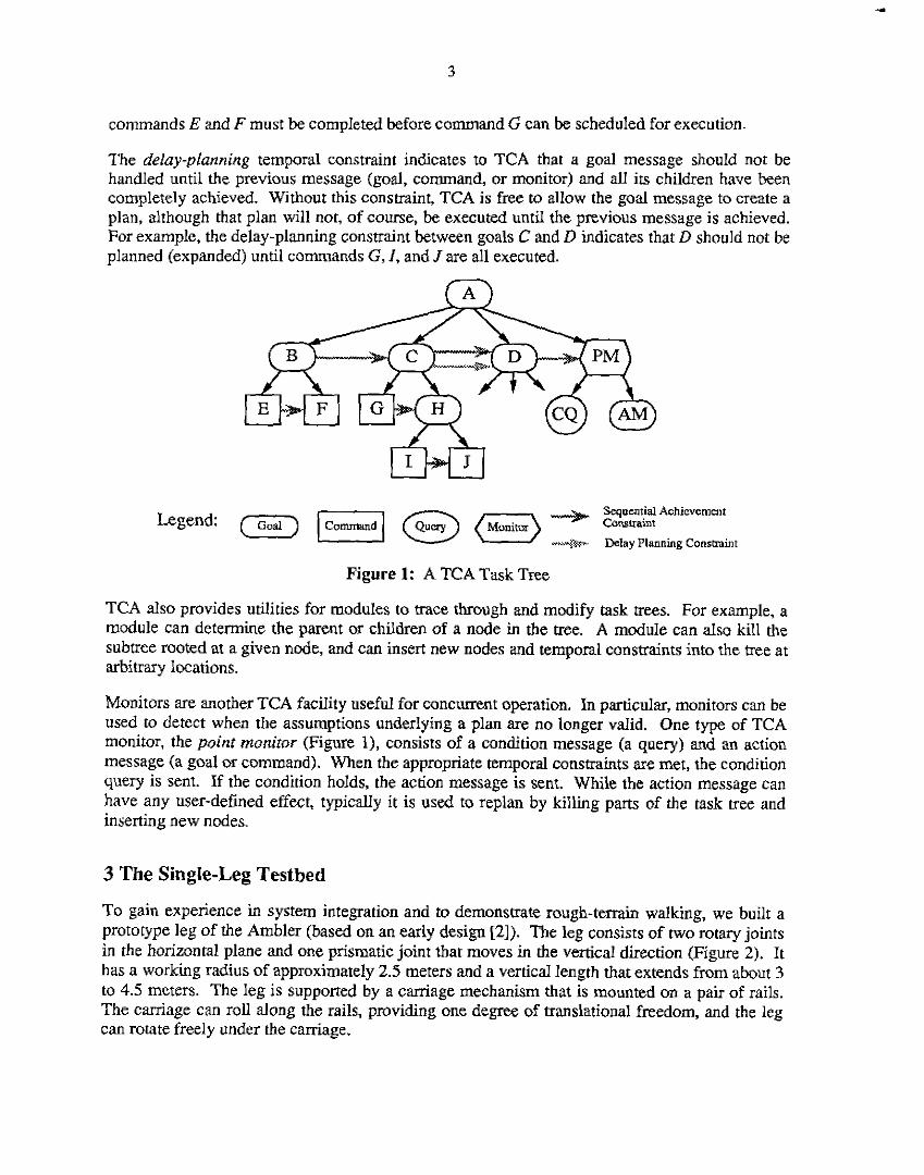
The delay-planning temporal constraint indicates to TCA that a goal message should not be handled until the previous message (goal, command, or monitor) and all its children have been completely achieved. Without this constraint, TCA is free to allow the goal message to create a plan, although that plan will not, of course, be executed until the previous message is achieved. For example, the delay-planning constraint between goals C and D indicates that D should not be planned (expanded) until commands G, I, and J are all executed.
Sequential Achievement --..). Conshaint --w- Delay Planning Consmint
Figure 1: A TCA Task Tree
TCA also provides utilities for modules to trace through and modify task trees. For exampIe, a module can determine the parent or children of a node in the tree. A module can also kill the subtree rooted at a given node, and can insert new nodes and temporal constraints into the tree at arbitrary locations.
Monitors are another TCA facility useful for concurrent operation. In particular, monitors can be used to detect when the assumptions underlying a plan are no longer valid. One type of TCA monitor, the point moniror (Figure 1). consists of a condition message (a query) and an action message (a goal or command). When the appropriate temporal constraints are met, the condition query is sent. If the condition holds, the action message is sent. While the action message can have any user-defined effect, typically it is used to replan by killing parts of the task tree and inserting new nodes.
3 The Single-Leg Testbed
To gain experience in system integration and to demonstrate rough-terrain walking, we built a prototype leg of the Ambler (based on an early design [21). The leg consists of two rotary joints in the horizontal plane and one prismatic joint that moves in the vertical direction (Figure 2). It has a working radius of approximately 2.5 meters and a vertical length that extends from about 3 to 4.5 meters. The leg is supported by a carriage mechanism that is mounted on a pair of rails. The carriage can roll along the rails, providing one degree of translational freedom, and the leg can rotate freely under the camage.

Figure 3: A Typical Obstacle Course
Gait manna
Leg Recovery Planner
5
Control
cc
..
where to place the foot and how far to move the carriage in order to advance with minimal risk to the mechanism. The Leg Recovery Planner (UP) determines a 3D trajectory to the planned footfall location that is energy and time efficient, and that avoids terrain collisions.
Conmller
Figure 4: Modules for the Single-Leg Walking System
To walk the leg down the obstacle course, the user specifies a goal location for the caniage to reach along the rails. The walking system is totally autonomous from that point on. A message to plan (and execute) the walk is sent to the Gait Planner. If the carriage position is close enough to the user-specified goal, the Gait Planner signals success. Otherwise, it requests two maps from the LTM Manager: a terrain elevation map, and a map that evaluates the goodness of

7
lShf
We have used the walking system described above to navigate the single leg through a number of complex obstacle courses, such as illustrated in Figure 3. While not perfect (primarily due to sensor and mechanism inaccuracies), the system is generally successful.
I I I I
4 Concurrency
Our primary concern in this report, however, is not the competence of the walking system but rather its time performance. Figure 6 presents a timing chart for a typical walk. The chart is produced by a program that analyzes log files produced by the TCA central control. It shows that the mechanism takes six steps in 13.5 minutes, while traveling about 8 meters (6Ocdmin). The darkly shaded areas of the chart represent times when a module is computing; lightly shaded areas =e times when a module is awaiting a reply from another module. To reduce the complexity of the chart, the 71 leg and body position queries to the Controller are not illustrated. In any event, they have negligible effects on the timings, since they are handled in less than 50msec each.
Fair Plnnorr
I LTM Manago
ni:m m.m m a m.m arm m m m m m v os;m I- 11- n w ,,m Figure 6: Timing Chart for a Typical Run
An analysis of the single-leg system indicated that we could significantly increase performance and achieve nearly continuous walking by executing one step while planning the next. First, there i s an obvious opportunity for concurrency, since the timing charts indicate that the Controller is idle a significant fraction of the time (about 35%), during which time the planners

9
general.
Wauring 1 Motion 1 Manager
Position
Manager
Control
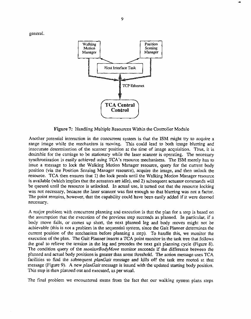
Figure 7: Handling Multiple Resources Within the Controller Module
Another potential interaction in the concurrent system is that the ISM might try to acquire a range image while the mechanism is moving. This could lead to both image blurring and inaccurate determination of the scanner position at the time of image acquisition. Thus, it is desirable for the carriage to be stationary while the laser scanner is operating. The necessary synchronization is easily achieved using TCA’s resource mechanisms. The ISM merely has to issue a message to lock the Waking Modon Manager resource, query for the current body position (via the Position Sensing Manager resource), acquire the image, and then unlock the resource. TCA then ensues that 1) the lock pends until the Walking Motion Manager resource is available (which implies that the actuators are idle), and 2) subsequent actuator commands will be queued until the resource is unlocked. In actual use, it turned out that the resource locking was not necessary, because the laser scanner was fast enough so that blurring was not a factor. The point remains, however, that the capability could have been easily added if it were deemed necessary .
A major problem with concurrent planning and execution is that the plan for a step is based on the assumption that the execution of the previous step succeeds as planned. In particular, if a body move fails, or comes up short, the next planned leg and body moves might not be achievable (this is not a problem in the sequential system, since the Gait Planner determines the current position of the mechanism before planning a step). To handle this, we monitor the execution of the plan. The Gait Planner inserts a TCA point monitor in the task tree that follows the goal to relieve the tension in the leg and precedes the next gait planning cycle (Figure 8). The condition query of the rnonirurBodyMove monitor succeeds if the difference between the planned and actual body positions is greater than some threshold. The action message uses TCA facilities to find the subsequent plunGuir message and kills off the task tree rooted at that message (Figure 9). A new planGair message is issued with the updated starting body position. This step is then planned out and executed, as per usual.
The final problem we encountered stems from the fact that our walking system plans steps

11
significantly faster than it executes them. Thus, if not controlled, the planning would soon get several steps ahead of the execution and would be operating at the limits of the perceived terrain (where the scanner's resolution is low). To prevent this, we limit the system to plan onIy one step ahead. This is accomplished by adding a delay-planning temporal constraint to the task tree to indicate that the planning of a plunGuit message must occur after the completion of the penultimate monirorBodyA4ove (Figure 8). The appropriate monitor message is easily found using TCA utilities for racing through task trees, and the necessary temporal constraint is encoded by a single line in the Gait Planner program:'
/* Reference to the next planGait message */ gaitRef = tcaCreateReference ("planGait") ; /* Find the parent of the current message */ lastGaitRef = tcaFindPatentReference(tcaRef) : if IlastGaitRef) ( / * Not the first step */
/* Find the point monitor of the penultimate step */ monitorRef = tcaFindChildByName (lastGaitRef, "monitorBodyMove") : /* Add the temporal constraint */ tcaTplConstrain(tcaEndOf(rcaHandlingOf(monitorRef)),
"<= I 7 , tcaStartOf (tcaPlanningOf (gaitRef) ) ) ;
All the modifications described above took only about two man-weeks of effort. We estimate about one mm-week was needed to analyze, design, code and test the concurrent system using a graphical simulator. Another 3 to 4 mandays were needed to enable the Controller module to handle multiple TCA messages simultaneously (this work was done by Gerry Roston and Christopher Fedor). Finally. 3 man-days were spent testing the concurrent system on the single- leg testbed and coIlecting data.
5 ResuIts
With the modifications described in the previous section in place, we repeated several of our walking experiments using the concunent system. The competence of the system was comparable to the sequential system: although not perfect, the system could reliably navigate complex obstacle courses,
The performance of the concurrent system increased substantially, on many trials achieving nearly continuous walking. Figure IO illustrates a typical case: the system took six steps in 8.75 minutes, for an average progress of about 90cdmin. This is a 35% increase in performance over the sequential system navigating the same obstacle course (Figure 3). The only significant idle times of the mechanism were during the first minute, when the first step was being planned, and while the LRP planned the third leg recovery, since this involved much search to find a long and circuitous path around the large Sun box (visible in Figure 3).
'Long-Ji Lin (personal communication) pointed out that the same effect could be obtained using fewer TCA messages by constraining the start of the planning of the planGai! message to occur after the s m t of h e achievement of its parent message.

13
acquire and process images whenever it was not busy (or in parallel with) answering queries. This pan of the project has been put on hold because planning/perception is not a bottleneck of system performance. We intend, however, to re-evaluate the situation when we gain experience with six-legged waking.
The timings presented in Figure 10 are typical of runs where everything worked right. Often, however, the body move procedure failed to achieve the requested position. Once in a while this occurred because the foot slipped while the carriage was moving. More often it occurred because, due to compliance in the leg, tension was built up in the system during a body move and this caused the carriage to move when the tension was relieved.
As described in Section 4, when the carriage fails to reach its requested position (within some tolerance) the monirorBodyMove point monitor kills the currently planned step and the system replans from the actual carriage position (Figure 9). This execution monitoring ensures that the competence of the system to navigate obstacle courses is not impaired. In addition, while the modon is no longer continuous, the performance is still no worse than the sequential system (and since the failures occur only rarely, the overall performance is usually still much better).
When the monitor kills the currently planned step, replanning almost always begins immediately. We noticed one case, however, in which replanning was delayed for some seconds. In that situation, the foot had slipped while the LRP was still planning the long leg move around the Sun box. Although TCA immediately killed its internal representation of the task tree, it does not have the means to actually interrupt another module. Thus, it merely allows the module to complete, while killing off any messages it issues (e.g., in this case, the fegMove command issued by the LRP was never sent to the Controller). While this is acceptable for the Ambler, we are currently investigating methods for interrupting message handlers on other modules. The difficulty is to avoid problems such as leaving global data structures inconsistent when a routine is unexpectedly interrupted. Our current thinking is to have the module implementor explicitly declare which message handlers are intemptible, and assume that the declaration implies that the associated code will not affect global data structures.
6 Conclusions
The primary conclusion from this work is how relatively easy it was to convert from sequential to concurrent operation by using TCA. We demonstrated a significant (in excess of 30%) increase in performance with no discernible impact on competence, and with relatively modest effckt to modify the existing code. In particular, the two man-week effort was small compared to the several man-years of work needed to develop the original waking system.
The results are encouraging because TCA was designed to facilitate the development of robot systems, which includes ease of converting them to take advantage of TCA’s distributed nature. While the original sequential system used TCA for communications and simple temporal sequencing, it did not take advantage of the full range of TCA features. Once the initial system was developed and tested, however, we incrementally modified it to achieve better performance. In particular, we found TCA’s resource management, task trees, temporal constraints, and monitor facilities to be quite useful. Our experience with the mobile manipulator also bears out the utility of TCA in constructing complex robot systems [6], but this is our first quantitative

1
1 Introduction
The Planetary Rover project is developing the Ambler, a novel six-legged robot, and software to autonomously walk the Ambler over rough terrain [l, 2,3]. We have previously reported on a system that integrates perception, planning and real-time control to navigate a single leg of the Ambler through complex obstacle courses [5,7,9]. This report describes efforts to improve the performance of the single-leg system through the addition of concurrency.
The original single-leg walking system sequentially performed perception, planning, and execution of steps. After developing and debugging the system, we analyzed its time performance to determine potential areas for concurrency, The most promising area for increasing performance was in concurrently executing a step while planning the next one.
The necessary concurrency was achieved by modifying the original system to take advantage of utilities provided by the Tusk Conrrol Architecture (TCA) [8, lo]. TCA is a distributed system with centraIized control that provides utilities for building and coordinating mobile robot systems. In particular, the concurrent walking system utilizes TCA facilities that suppon distributed processing, resource management, monitors, hierarchical task trees, and temporal synchronization of planned goals and commands.
The average walking speed of the concurrent system was 30% faster, while its competence was coniparable to the sequential system. This performance level represents nearly continuous modon of the robot. Significantly, the conversion effort involved only minor modifications to the existing software. Specifically, the design, modification, and testing of the concurrent system were performed with only about two man-weeks of effort, compared to the several man- years needed to develop the original system.
Our experience with the single-leg walking system lends support to our general strategy of first developing a competent sequential system, then increasing performance by adding concurrency. A sequential system is easier to develop and debug, since temporal interactions are not a factor. Once developed, the performance of the system can be analyzed to discover potential areas for concurrency. Finally, the utilities of TCA can be used to facilitate the conversion to concurrent operation. In fact, our walking system can be easily configured to operate in either concurrent or sequential mode, which is useful when adding new capabilities.
The next section briefly describes the Task Control Architecture. and the features that are salient to supporting concurrency. Section 3 introduces the single-leg testbed and the original sequential walking system. Section 4 focuses on the modifications needed for concurrent operation, and how the use of TCA facilitated the conversion. Section 5 presents performance results, and compares the sequential and concurrent performances.
2 The Task Control Architecture
The Task Control Architecture (TCA) is a general-purpose facility for building and controlling mobile robot systems [4 ,6 , 8, IO]. TCA can be thought of as a high-level robot operating system that provides common mechanisms needed by many mobile robot applications. The mechanisms are meant to bridge the gap between task-level planners and real-time control systems. In particular. TCA supports 1) distributed processing, 2) resource management, 3) hierarchical task

2
decomposition, 4) temporal synchronization of tasks, 5) execution monitoring, and 6) exception handling.
A robot system built using TCA consists of an arbitrary number of task-specific modules (Le.. processes), and a general-purpose central control module, The modules communicate with one another (and with the central control) by passing messages. All messages pass through the central control, which routes them to the appropriate modules. The routing information is determined when modules connect with the central control: modules register with TCA message names, descriptions of the data formats associated with the messages, and the names of procedures €or handling the messages.
TCA provides several different classes of messages. Query messages enable modules to get information from other modules. Query messages are blocking, pending receipt of a reply. Goal and command messages enable modules to create hierarchical plans, which the TCA central control maintains and schedules. Monitor messages enable modules to detect plan failures, and to react to environmental changes. Goal, command and monitor messages are non-blocking, that is, the message has not necessarily been handled by the time control returns to the module issuing the message. Their non-blocking nature is useful for doing concurrent planning and execution, for handling multiple tasks, and for exception handling, since it gives TCA control over when to schedule messages and when to preempt them.
TCA has several mechanisms for scheduling messages: resources, hierarchical task trees, and temporal constraints. A TCA resource is an abstract entity associated with modules and message handlers. By default, TCA treats a module as a resource of unit capacity, and only permits a single message destined for that module to be handled at a time. Additional messages are queued by the central control pending resource availability. TCA also provides utilities for associating multiple resources with a module, and €M associating specific message handlers with resources. For example, a real-time controller module could have one resource for its actuator commands and one for its sensor queries. This would enable TCA to simultaneously route a command and a query to the module (but not two simultaneous commands, since they share the same resource).
A module is also able to lock a resource, preventing other mdules from accessing the resource until it is unlocked. The lock message waits until the resource becomes available, at which time the lock is emplaced and control returns to the module that issued the lock message. Resource locking can be used to synchronize resources: to prevent image blurring, for instance, the actuator resource can be locked while a perception module acquires images.
TCA directly supports the creation and execution of hierarchical plans. For each message sent, TCA maintains a record of which message handler issued the message. TCA uses these records of invocation to form a hierarchical task pee (Figure 1). In addition to encoding parenuchild relationships between messages, the task tree includes temporal constraints on the planning and execution of messages. For example, a module can constrain one message to follow another sequentially. For commands or monitors, this means simply that the messages are handled in sequential order. For goals, TCA interprets the sequential-achievement constraint to mean that all the commands/monitors issued by one goal's message handler (or any of its children) must be handled before the commandslmonitors issued by another goal message can be executed. In Figure 1, for instance, the sequential-achievement constraint between goals B and C implies that
3
commands E and F must be completed before command G can be scheduled for execution
The delay-planning temporal constraint indicates to TCA that a goal message should not be handled until the previous message (goal, command, or monitor) and all its children have been completely achieved. Without this constraint, TCA is free to allow the goal message to create a plan, although that plan will not, of course, be executed until the previous message is achieved. For example, the delay-planning constraint between goals C and D indicates that D should not be planned (expanded) until commands G, I , and J are all executed.
Figure 1: A TCA Task Tree
TCA also provides utilities for modules to trace through and modify task trees. For example, a module can determine the parent or children of a node in the tree. A module can also kill the subtree rooted at a given node, and can insert new nodes and temporal constraints into the tree at arbitrary locations.
Monitors are another TCA facility useful for concurrent operation. In particular, monitors can be used to detect when the assumptions underlying a plan are no longer valid. One type of TCA monitor, the point moniror (Figure l), consists of a condition message (a query) and an action message (a goal or command). When the appropriate temporal constraints are met, the condition query is sent. If the condition holds, the action message is sent. While the action message can have any user-defined effect, typically it is used to replan by killing parts of the task tree and inserting new nodes.
3 The Single-Leg Testbed
To gain experience in system integration and to demonstrate rough-terrain walking, we built a prototype leg of the Ambler (based on an early design [2]). The leg consists of two rotary joints in the horizontal plane and one prismatic joint that moves in the vertical direction (Figure 2). It has a working radius of approximately 2.5 meters and a vertical length that extends from about 3 to 4.5 meters. The leg is supported by a carriage mechanism that is mounted on a pair of rails. The carriage can roll along the rails, providing one degree of translational freedom, and the leg can rotate freely under the camage.

Figure 2: The Single-Leg Testbed
Sensors include a potentiometer to measure the position and velocity of the carriage along the rails, incremental and absolute encoders to measure leg positions, and two inclinometers to measure the rotation of the carriage. A six-axis forcehorque sensor is attached to the bottom of the leg to measure the forces experienced by the mechanism as it moves. In addition, a scanning laser rangefinder is attached to the carriage to provide perception of the terrain.
An 1 lx6m ObStdCk course filled with over 40 tons of sand provides for a variety of “Mars-like” terrains (Figure 3). Terrain features are introduced by resculpting the surface to form hills and aenches, and by placing objects on the sand. We have used Styrofoam boulders, traffic cones, and large boxes to test the ability of the system to navigate over and around obstacles.
We have developed a software system integrating perception, planning and real-time control that enables the single leg to navigate the obstacle course [5,7,9]. The single-leg walking system consists of five modules, together with the TCA central control module (Figure 4). The Controller module handles all robot motions and responds to queries from other modules regarding leg position, carriage position and orientation, and force sensor readings. The Image Senring Manager {ISM) acquires images from the laser Scanner and determines the transformalion from scanner to world coordinates. The Local Terrain Map (LTMJ Manager processes scanner images to construct elevation maps of the terrain. The Gait Planner plans
4

Figure 3: A Typical Obstacle Course
where to place the foot and how far to move the carriage in order to advance with minimal risk to the mechanism. The Leg Recovery Planner (UP) determines a 3D trajectory to the planned footfall location that is energy and time efficient, and that avoids terrain collisions.
5
- 1
Human
Figure 4: Modules for the Single-Leg Walking System
To walk the leg down the obstacle course, the user specifies a goal location for the carriage to reach along the rails. The walking system is totally autonomous from that point on. A message to plan (and execute) the wak is sent to the Gait Planner. If the carriage position is close enough to the user-specified goal, the Gait Planner signals success. Otherwise, it requests two maps from the LTM Manager: a terrain elevation map, and a map that evaluates the goodness of

6
potential footfall locations. If the carriage position has changed from the last time a map request was issued, the LTM Manager requests a new scanner image from the ISM. In either case, the requested maps are constructed and sent back to the Gait Planner.
The Gait Planner uses a weighted sum to combine the terrain data with geomemc constraints on the leg's movement, and chooses the location that minimizes the sum. Based on the chosen location, the Gait Planner chooses a body move that maximizes forward progress. The Gait Planner sends the chosen footfall and body move to the TCA central control, along with a message to plan the next step (Figure 5).
Given the chosen footfall location, the LRP determines an obstacle-free trajectory from the leg's current location. The Controller then executes this trajectory and plants the foot at the desired location. After a successful leg move, TCA forwards to the Controller the body move generated by the Gait Planner. The Controller exerts enough force to compress the terrain, then relaxes to a force sufficient to provide traction. The horizontal (shoulder and elbow) joints are then actuated to drive the carriage forward. Finally, tension built up in the leg as a result of the body move is relieved, so that the leg does not slip when it is next lifted. At this point, TCA forwards the message to the Gait Planner to plan the next step.
Figure 5: Task Tree for the Sequential Walking System
The walking system utilizes the TCA temporal constraint mechanisms to coordinate the planning and execution of steps. For one, all gods and commands are constrained to be achieved sequentially. This provides the intuitive ordering that f i s t the leg is moved, then the body, then the next step is performed. In addition, a delay-planning constraint between the relieveLeg and planGair goals indicates that the next step should not be planned until the previous step is completed. This constraint forces the system to have a sequential plan-act cycle.

7
IShl
We have used the walking system described above to navigate the single leg through a number of complex obstacle courses, such as illustrated in Figure 3. While not perfect (primarily due to sensor and mechanism inaccuracies), the system is generally successful.
1 I I I
4 Concurrency
Our primary concern in this report, however, is not the competence of the waking system but rather its time performance. Figure 6 presents a timing chart for a typical walk. The chart is produced by a program that analyzes log files produced by the TCA central control. It shows that the mechanism takes six steps in 13.5 minutes, while traveling about 8 meters (60cmfmin). The darkly shaded areas of the chart represent times when a module is computing; lightly shaded areas are times when a module is awaiting a reply from another module. To reduce the complexity of the chart, the 71 leg and body position queries to the Controller are not illustrated. In any event, they have negligible effects on the timings, since they are handled in less than 50msec each.
I LTM Mnoagu
11 .g .:,,
I , , , , OLW m m m m a w Mm Om DI-M (.a mpm LOW nm L201 L 1 m
Figure 6: Timing Chart for a Typical Run
An analysis of the single-leg system indicated that we could significantly increase performance and achieve nearly continuous waking by executing one step while planning the next. First, there is an obvious opportunity for concurrency, since the timing charts indicate that the Conrroller is idle a significant fraction of the time (about 35%), during which time the planners

8
are busy. Second, continuous walking is attainable since the execution time of the Controller is greater than the sum of the planning and perception times. Third, planning in advance is feasible since our mechanism control is in general accurate enough so that the planned leg and body moves can be used as the starting points for planning the next step.
The first step in the conversion to concurrent operation is specifying that planning and execution should occur in parallel. This merely involved removing a single line of code that added the delay-planning temporal constraint in the original system (see Figure 5). With that constraint removed, TCA is free to schedule the next planCair message as soon as it is issued by the current planGait message handler.
In modifying the temporal constraints, care had to be taken to avoid introducing undesirable temporal interactions between modules. In analyzing timing cham for singIe-leg walking, several potential areas for interactions were discerned
1. The LTM Manager could read the body position while the leg was moving.
2. The ISM could acquire an image while the body was moving.
3. A planned body move that failed, or fell short of the goal, would invalidate assumptions made in planning the next step,
4. Planning could exceed the perception horizon.
Each of these problems was addressed by modifying the existing software to utilize various TCA features. Trying to query for the body position while the leg is moving posed a problem because, in the original system, the Controller was associated with only a single resource. Thus, TCA would permit the Controller to handle only one message at a time. This problem was easily overcome by defining two resources for the Controller: one to handle actuator commands (legMove and bodyMove messages) and one to handle sensor queries (legPosirion and bodyPosirion messages). Using multiple resources enables TCA to allow sensing queries to be processed while actuator commands are in progress. The Controller, which runs under a multi- tasking operating system, already utilized separate tasks for actuation and sensing, so the breakdown was quite natural.
Adapting the Controller itself to handle multiple requests was the most involved part of the conversion. The problem was to connect the Controller’s actuation and sensing tasks to TCA so that they could receive messages simultaneously. Normally, modules utilize TCA facilities that connect to the central control over mu” sockets, with TCA handling all communications. Our first implementation simply connected each task separately to the central control module, which did not work because of contention for the socket by the two tasks.
Our solution was to implement a single listening task (the Host Interface Task) together with the actuator (Walking Motion Manager) and sensing (Position Sensing Manager) tasks (Figure 7). The Host Interface Task receives messages from the TCA c e n d control, and uses semaphores to inform the Walking Motion Manager or Position Sensing Manager that a message was received. After completing the appropriate command or query, the tasks respond back to the central control module directly, using the standard TCA communication facilities. While this solution was designed specifically for the archicecture used by our real-time Controller, ir has led us to consider adding utilities to TCA to enable it to interface with multi-tasking environments in
9
general.
walking Motion
Manager
Position Scnsing Manager
TCP Ethernet
TCA Central Control
Figure 7: Handling Multiple Resources Within the Controller Module
Another potential interaction in the concurrent system is that the ISM might try to acquire a range image while the mechanism is moving. This could lead to both image blurring and inaccurate determination of the scanner position at the time of image acquisition. Thus, it is desirable for the carriage to be stationary while the laser scanner is operating. The necessary synchronization is easily achieved using TCA’s resource mechanisms. The ISM merely has to issue a message to lock the Walking Motion Manager resource, query for the current body position (via the Position Sensing Manager resource), acquire the image, and then unlock the resource. TCA then ensures that 1) the lock pends until the Walking Motion Manager resource is available (which implies that the actuators are idle), and 2) subsequent actuator commands will be queued until the resource is unlocked. In actual use, it turned out that the resource locking was not necessary, because the laser scanner was fast enough so that bluning was not a factor. The point remains, however, that the capability could have been easily added if it were deemed necessary.
A major problem with concurrent planning and execution is that the plan for a step is based on the assumption that the execution of the previous step succeeds as planned. In particular, if a body move fails, or comes up short, the next planned leg and body moves might not be achievable (this is not a problem in the sequential system, since the Gait Planner determines the current position of the mechanism before planning a step). To handle this, we monitor the execution of the plan. The Gait Planner inserts a TCA point monitor in the task tree that follows the goal to relieve the tension in the leg and precedes the next gait planning cycle (Figure 8). The condition query of the monirorBodyMove monitor succeeds if the difference between the planned and actual body positions is greater than some threshold. The action message uses TCA facilities to find the subsequent planGair message and kills off the task tree rooted at that message (Figure 9). A new planCair message is issued with the updated starting body position. This step is then planned out and executed, as per usual.
The final problem we encountered stems from the fact that our walking system plans steps

10
Sequential-Achiwancnt Legend: ("..1) pzzq @ (G) - ~ - a i n t --+* Delay-PIming Cormmint
Figure 8: Task Tree for the Concurrent Walking System
Figure 9: Replanning Step After Failed Body Move
11
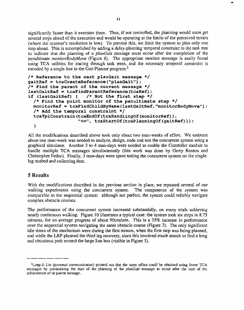
significantly faster than it executes them. Thus, if not controlled, the planning would soon get several steps ahead of the execution and would be operating at the limits of the perceived terrain (where the scanner's resolution is low). To prevent this, we limit the system to plan only one step ahead. This is accomplished by adding a delay-planning temporal constraint to the task tree to indicate that the planning of a planGair message must occur after the completion of the penultimate monirorBodyMove (Figure 8). The appropriate monitor message is easily found using TCA utilities for tracing through task trees, and the necessary temporal constraint is encoded by a single line in the Gait Planner program:'
/* Reference to the next planGait message */ gaitRef = tcaCreateReference ("planGait") ; /* Find the parent of the current message */ 1astGaitRef = tcaFindParentReference(tcaRef); if (1astGaitRef) { / * N o t the first step */
/ * Find the point monitor of the penultimate step */ monitorRef = tcaFindChildByName(lastGaitRef,"monitorBodyMove"); /* Add the temporal constraint */ tcaTplConstrain(tcaEndOf(tcaWandlingOf(monitorRef)),
1 I,<=" , tcaStartOf(tcaPlanningOf(gaitRef)));
All the modifications described above took only about two man-weeks of effort. We estimate about one man-week was needed to analyze, design, code and test the concurrent system using a graphical simulator. Another 3 to 4 man-days were needed to enable the Controller module to handle multiple TCA messages simultaneously (this work was done by Gerry Roston and Christopher Fedor). Finally, 3 man-days were spent testing the concurrent system on the single- leg testbed and collecting data.
5 Results
With the modifications described in the previous section in place, we repeated several of our walking experiments using the concurrent system. The competence of the system was comparable to the sequential system: although not perfect, the system could reliably navigate complex obstacle courses.
The performance of the concurrent system increased substantially, on many mals achieving nearly continuous walking. Figure. 10 illustrates a typical case: the system took six steps in 8.75 minutes, for an average progress of about 90cm/min. This is a 35% increase in performance over the sequential system navigating the same obstacle course (Figure 3). The only significant idle times of the mechanism were during the first minute, when the first step was being planned, and while the L W p l a ~ e d the third leg recovery, since this involved much search to find a long and circuitous path around the large Sun box (visible in Figure 3).
ILong-Ji Lin @cmnaI communication) pointed out h a t the same effect could be obtained using [ewer TCA messagu by constraining Ihe stan of the planning of rhe planGuit message to occur after the s m of the achievement of its parent message.

12
I o ~ m m m mm w m wm 0600 m m m m wm lam 1t-m llra ,,m
Figure 1 0 Timing Chart for the Concurrent Walking System
With respect to module utilization, the Controller increased from about 65% to over 80% utilization. Discounting the time needed to plan the first step (when the Controller has to be idle), utilization increases to about 95%, which is close to continuous walking. The LRP, LTM Manager and Gait Planner all approximately double their utilizations, from about 20% to 40% for the LRP and LTM Manager, and from 15% to 30% for the Gait Planner (these figures include times the modules spend waiting for queries to reply). The increased utilizations are largely due to decreased total running time for the walking system. The ISM remains relatively under- utilized, at about 5% of its capacity.
We also measured the utilization of the TCA central control module at about 3%. While, in theory, routing all messages through a central process could be a bottleneck, OUT empirical evidence with the single-leg system indicates otherwise. This observation is also supported by our experience using TCA to control an indoor mobile mampulator [6, 101.
Our timing analyses confirm that the Controller is highly utilized (it is the system bottleneck) and the planning and perception modules have significant excess capacity. This indicates that if the six-legged Ambler has similar speed characteristics, we can afford to spend much more time planning good footfalls, while maintaining the same high utilization of the mechanism.
We had originally intended to add concurrent perception, where the LTM Manager would
13
acquire and process images whenever it was not busy (or in parallel with) answering queries. This part of the project has been put on hold because planning/perception is not a bottleneck of system performance. We intend, however, to re-evaluate the situation when we gain experience with six-legged walking.
The timings presented in Figure 10 are typical of runs where everything worked right. Often, however, the body move procedure failed to achieve the requested position. Once in a while this occurred because the foot slipped while the carriage was moving. More often it occurred because, due to compliance in the leg, tension was built up in the system during a body move and this caused the carriage to move when the tension was relieved.
As described in Section 4, when the camage fails to reach its requested position (within some tolerance) the rnonirorBodyMove point monitor kills the currently planned step and the system replans from the actual carriage position (Figure 9). This execution monitoring ensures that the competence of the system to navigate obstacle courses is not impaired. In addition, while the motion is no longer continuous, the performance is still no worse than the sequential system (and since the failures occur only rarely, the overall performance is usually still much better).
When the monitor kills the currently planned step, replanning almost always begins immediately. We noticed one case, however, in which replanning was delayed for some seconds. In that situation, the foot had slipped while the LRP was still planning the long leg move around the Sun box. Although TCA immediately killed its internal representation of the task tree, it does not have the means to actually interrupt another module. Thus, it merely allows the module to complete, while killing off any messages it issues (e.g., in this case, the iegMove command issued by the LFW was never sent to the Controller). While this is acceptable for the Ambler, we are currently investigating methods for interrupting message handlers on other modules. The difficulty is to avoid problems such as leaving global data structures inconsistent when a routine is unexpectedly interrupted. Our current thinking is to have the module implementor explicitly declare which message handlers are interruptible, and assume that the declaration implies that the associated code will not affect global data structures.
6 Conclusions
The primary conclusion from this work is how relatively easy it was to convert from sequential to concurrent operation by using TCA. We demonstrated a significant (in excess of 30%) increase in performance with no discernible impact on competence, and with relatively modest effort to modify the existing code. In particular, the two man-week effort was small compared to the several man-years of work needed to develop the original walking system.
The results are encouraging because TCA was designed to facilitate the development of robot syste.ms, which includes ease of converting them to take advantage of TCA’s distributed nature. While the original sequential system used TCA for communications and simple temporal sequencing, it did not take advantage of the full range of TCA features. Once the initial system was developed and tested, however, we incrementally modified it to achieve better performance. In particular, we found TCA’s resource management, task trees, temporal constraints, and monitor facilities to be quite useful. Our experience with the mobile manipulator also bears out the utility of TCA in constructing complex robot systems 161, but this is our first quantitative

14
assessment of the performance increase and development time needed to attain concurrent operation.
We intend to travel the same route for the six-legged system: gaining experience with a sequential system before incrementally modifying it for concurrent operation. We also intend to further parallelize the six-legged system as our timing analyses point out potential performance bottlenecks.
Acknowledgements
Christopher Fedor, Gerry Roston and David Wettergreen aided in the design and implementation of the concurrency features for the walking system. In addition to them, numerous members of the Planetary Rover group were responsible for developing and testing the original single-leg walking system. Many thanks to David Wenergreen for reviewing drafts of this report. This research has been supponed by NASA under contract NAGW-1175.
References
1. Bares, J., Whittaker, W. Walking Robot with a Circulating Gait. Roc. of IEEE International Workshop on Intelligent Robots and Systems, Tsuchiura, Japan, July, 1990.
2. Bares, J., et al. Ambler: An Autonomous Rover for Planetary Exploration. IEEE Computer, Vol. 22, No. 6, 1989.
3. Bares, J,, Dowling, K., Krotkov, E. Configuration and Design of the Ambler Planetary Rover. Submitted to i-SAIRAS, 1990.
4. Fedor, C., Simmons, R. Task Control Architectwe User Manual. Planetary Rover Group, Camegie Mellon University, 1989.
5. Krotkov E., Simmons, R., Thorpe, C. Single-Leg Walking with Integrated Perception, Planning, and Control, Proc. of IEEE International Workshop on Intelligent Robots and Systems, Tsuchiura, Japan, July, 1990.
6. Lin, L.J., Simmons, R., and Fedor, C. Experience with a Task Control Architecture for Mobile Robots. Tech. Rept. CMU-RI-89-29, Robotics Institute, Camegie Mellon University, 1989.
7. Simmons, R., Krotkov, E. An Integrated System for Walking on Rough Terrain. Proceedings of Space Operations and Autonomous Robotics Conference, Albequerque, NM, July, 1990.
8. Simmons, R., Mitchell, T. A Task Control Architecture for Autonomous Robots. Proceedings of Space Operations and Autonomous Robotics Conference, Houston, TX, July, 1989.
9. Simmons, R., Krotkov, E., Roston, G. tntegrated System for Single-Leg Walking. Tech. Rept. CMU-RI-90-15, Robotics Institute, Carnegie Mellon University, July, 1990,
10. Simmons, R., Lin, L.J., Fedor, C. Auronomous Task Control for Mobile Robots. Proc. of IEEE Symposium on Intelligent Control, Philadelphia, PA, September, 1990.
Concurrent Planning and Execution for a Walking Robot
Reid Simmons School of Computer Science Camegie Mellon University
Pittsburgh, PA 15213
Abstract
The Planetary Rover project is developing the Ambler, a novel legged robot, and an autonomous software system for walking the Ambler over rough terrain. As part of the project, we have developed a system that integrates perception, planning, and real-time control to navigate a single leg of the robot through complex obstacle courses. The system is integrated using the Task Control Architecture (TCA), a general-purpose set of utilities for building and controlling distributed mobile robot systems. The walking system, as originally implemented, utilized a sequential sense-plan-act control cycle. This report describes efforts to improve the performance of the system by concurrently planning and executing steps. Concurrency was achieved by modifying the existing sequential system to utilize TCA features such as resource management, monitors, temporal constraints, and hierarchical task trees. Performance was increased in excess of 30% with only a relatively modest effort to convert and test the system. The results lend support to the utility of using TCA to develop complex mobile robot systems.