concurrent voc and aerosol removalsfrom air stream … · stabilized non-thermal...
TRANSCRIPT

Concurrent VOC and Aerosol Removals from Air Stream by Flow Stabilized Non-Thermal Plasma-Adsorbent-Catalyst Hybrid Systems
Jen-Shih Chang
McIARS and
Department of Engineering Physics McMaster University
Baltic Workshop, September,Griswold

Table of Contents
� Health Impact of VOCs: Cl-type vs HC type VOCs
� Conventional VOC treatment techniques
� Plasma VOC treatment
� Plasma- Catalysis/Adsorbent VOC treatment
� Concluding remarks

VOCs Problem
� Sick Building Syndrome -Indoor Air Quality
� Heath Problem via Air, Soil and Ground Water
� Chemical Industry vs Semiconductor Plants
� Clean Room-Air Re-circulation� PFCs in Semiconductor & Power Industries

VOC world wide 2009

Indoor Air Problems


Bounding Energy and Ionization Potential

Thermal Oxidation Treatment of VOCs

9
Regenerative Thermal Oxidizers (RTOs)
Figure 3: Schematic of RTO Process
Ideal Oxidation Reaction of VOCs:


Indoor Air Cleaning
� Baking of Room-3 to 7 days
� Continuous Force Air Re-circulation
� Indoor Air Cleaner-4 to 10hrs treatment with small flow rates –ideal for plasma systems
�Ozonizer based system is no longer in market and must be remove or control ozonegeneration below 0.1-0.2 ppm
�Ozone killer-MnO2‘
� Combined with air conditioning, water cluster ion generators, EHD flow (electric wind) gas blower etc.
Plasma Air Cleaner is on the market for past 10 years

Commercial Air Cleaner and Incinerator Cleaning System (Mizuno 2000)


Commercial Plasma Air Cleaners


Vibration Vibration Vibration Vibration ∝∝∝∝ HeatHeatHeatHeat
SolidSolidSolidSolid LiquidLiquidLiquidLiquid GasGasGasGas
PlasmaPlasmaPlasmaPlasma
VibratingVibratingVibratingVibrating
atomatomatomatom
Kinetic energy Kinetic energy Kinetic energy Kinetic energy ∝∝∝∝ HeatHeatHeatHeat
atomatomatomatomorororor
moleculemoleculemoleculemolecule
atomatomatomatom
dipoledipoledipoledipole 0(10)K0(10)K0(10)K0(10)K 0(100)K0(100)K0(100)K0(100)K
LatentLatentLatentLatentHeatHeatHeatHeat
LatentLatentLatentLatentHeatHeatHeatHeat
IonizationIonizationIonizationIonizationorororor
AttachmentAttachmentAttachmentAttachment0(100(100(100(103333----101010104444)K)K)K)K
Formation ofFormation ofFormation ofFormation ofPlasmaPlasmaPlasmaPlasma
What Is PlasmasWhat Is PlasmasWhat Is PlasmasWhat Is Plasmas
e
e
ee
ElectronElectronElectronElectron
AttachmentAttachmentAttachmentAttachment
Negative IonNegative IonNegative IonNegative Ion
IonizationIonizationIonizationIonization
Positive IonPositive IonPositive IonPositive Ion
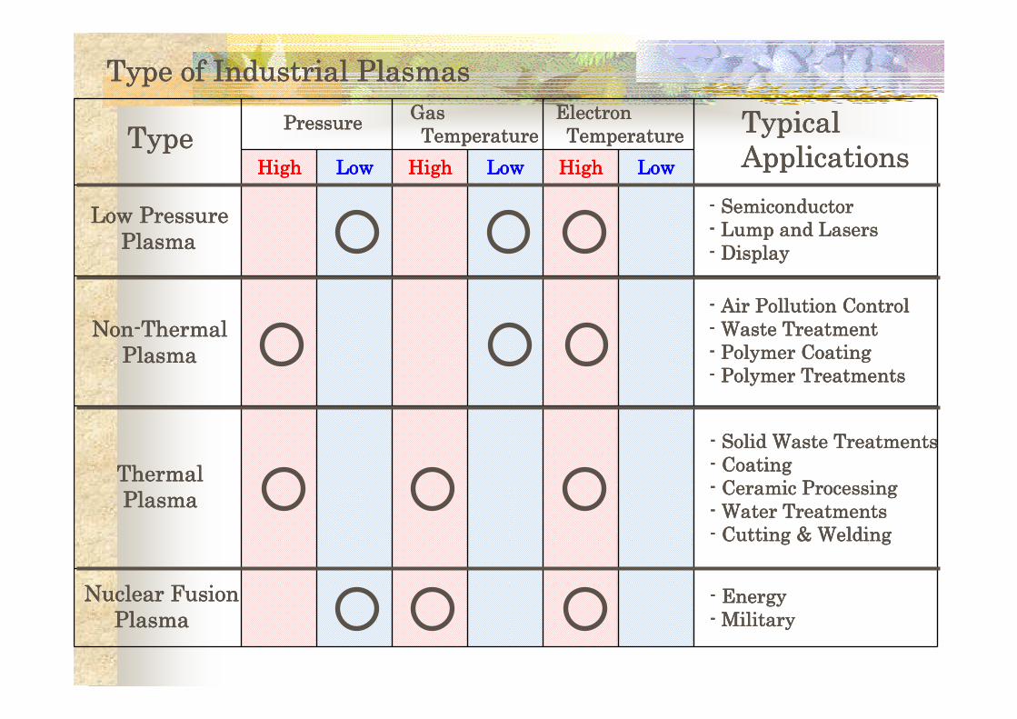
HighHighHighHigh LowLowLowLow HighHighHighHigh LowLowLowLow HighHighHighHigh LowLowLowLow
PressurePressurePressurePressureGas Gas Gas Gas TemperatureTemperatureTemperatureTemperature
Electron Electron Electron Electron TemperatureTemperatureTemperatureTemperatureTypeTypeTypeType
TypicalTypicalTypicalTypicalApplicationsApplicationsApplicationsApplications
Nuclear FusionNuclear FusionNuclear FusionNuclear FusionPlasmaPlasmaPlasmaPlasma
ThermalThermalThermalThermalPlasmaPlasmaPlasmaPlasma
NonNonNonNon----ThermalThermalThermalThermalPlasmaPlasmaPlasmaPlasma
Low PressureLow PressureLow PressureLow PressurePlasmaPlasmaPlasmaPlasma
---- SemiconductorSemiconductorSemiconductorSemiconductor---- Lump and LasersLump and LasersLump and LasersLump and Lasers---- DisplayDisplayDisplayDisplay
---- EnergyEnergyEnergyEnergy---- MilitaryMilitaryMilitaryMilitary
---- Solid Waste TreatmentsSolid Waste TreatmentsSolid Waste TreatmentsSolid Waste Treatments---- CoatingCoatingCoatingCoating---- Ceramic ProcessingCeramic ProcessingCeramic ProcessingCeramic Processing---- Water TreatmentsWater TreatmentsWater TreatmentsWater Treatments---- Cutting & WeldingCutting & WeldingCutting & WeldingCutting & Welding
---- Air Pollution ControlAir Pollution ControlAir Pollution ControlAir Pollution Control---- Waste TreatmentWaste TreatmentWaste TreatmentWaste Treatment---- Polymer CoatingPolymer CoatingPolymer CoatingPolymer Coating---- Polymer TreatmentsPolymer TreatmentsPolymer TreatmentsPolymer Treatments
Type of Industrial PlasmasType of Industrial PlasmasType of Industrial PlasmasType of Industrial Plasmas

Electron Impact Reactions and Electron Energy Distribution
� Thermal Plasma: Ionization dominated by Thermal Ionizations� Non-Thermal Plasma: Ionization dominated by Electron Impact
Ionizations
Around Tg = 2000 –3000 K

Effectiveness of Reactions-Ionic or Radical Reaction

Mechanism of Plasma Processes
Ion Induced Particle Formations (Chang 1996)

Plasma Density
Electron Temperature
Gas TemperatureElectric
FieldTreatment Flue
Gases
Power Supply&
ReactorImprovements
Electron Beam Very High Extremely High Low Very Low Acid Gases, VOCs DC → PulseEnergy
Efficiency
Barrier Discharge (silent/surface)
High Medium Low MediumOxidation of VOCs
or Acid Gases
Parallel plate↓
Trench, Pylamid
PressureDrop
Barrier Discharge(ferro-electric)
Low High Low Very HighPFCs, Oxidation of
VOCsShape of PelletsSphere → Hollow
Pressure drop &Energy
Efficiency
Pulsed Corona High Medium Low High VOCs Pulsed corona↓
Pulse Power
ElectronEnergy
Pulsed Power Very High High Medium High Acid Gases
Capillary High Low Medium Low VOCs
DC → AC/DC StabilityFlow StabilizedCorona
LocallyHigh
LocallyHigh
Low HighAcid Gases, VOCs,
Toxic Gases
Arc/PlasmaTorch
ExtremelyHigh
LocallyHigh
ExtremelyHigh
LowODS/VOCs*Toxic Gases
Lower PowerEnergy
Efficiency
RF Discharge High Medium High Low ODS/VOCs* Inductive → CapacitiveEnergy
Efficiency
MicrowaveDischarge
High Medium Medium Medium ODS/VOCs* Cavity → Torch Temperature
Table 1 Plasma parameters for gaseous pollution control plasma devices (*Waste gas destructions)
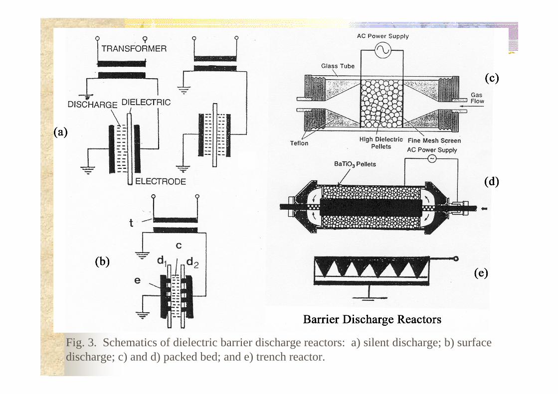
Fig. 3. Schematics of dielectric barrier discharge reactors: a) silent discharge; b) surface discharge; c) and d) packed bed; and e) trench reactor.
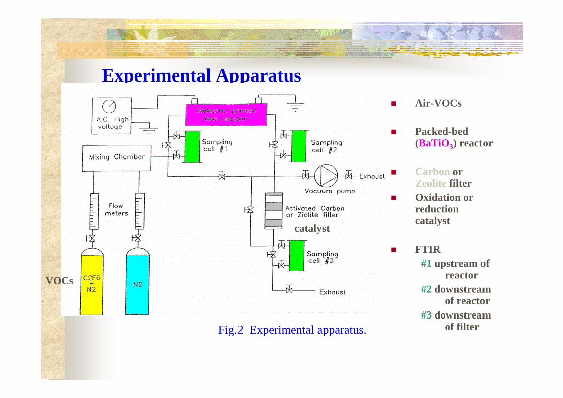
Fig.2 Experimental apparatus.
Experimental Apparatus� Air-VOCs
� Packed-bed (BaTiO3) reactor
� Carbon or Zeolite filter
� Oxidation or reduction catalyst
� FTIR#1 upstream of
reactor#2 downstream
of reactor#3 downstream
of filter
catalyst
VOCs

Plasma Catalytic or Adsorption Processes

The destruction effeciency for o-xylene and TCE in a gas mixture (111 ppm of xylene and 111 ppm of TCE) using the pulsed corona reactor for gas flow rate of (a) 0.7 L/min and (b) 1.0 L/min.

Toluene Decomposition

Cl-VOC Compounds
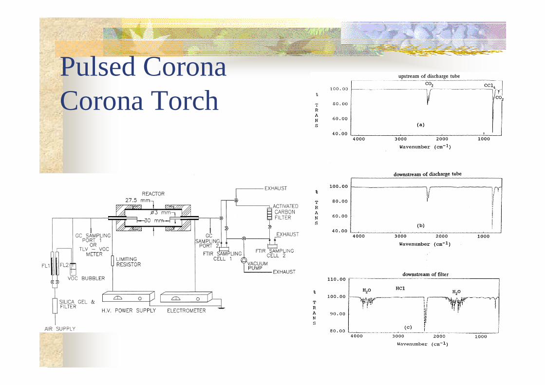
Pulsed Corona Corona Torch

CCl4 removal from Air Stream

Aerosol Formation

Example for plasma processes comparison chart for plasma-catalyst/adsorbent system
Oxidation /Reduction Catalyst
Capillary Wall and Pellets Act as Removable Filters

Energy Efficiency VOC Removal of dc vs Pulse

Why catalysis/adsorbent works under low gas temperature non-thermal plasmas
�Catalytic material site activation by a plasma vibrationally/rotationally and electronically excited molecules
�Prevent de-sorption of
pollutant but slowdownkinetic energy of molecules

114
114
85
85
mesh: 100 x 100
Units: [mm]13
pellets
reactor packed with pelletElectrodes
Schematics of catalytic packed bed reactor.
Pellet with catalyst
Catalytic material site

Powersupply
Pump
Environmentalchamber
Outlet VOCmeter
RH&Temp. transmitterMultimeter
Air inlet
C
Bubbly column
Digital oscilloscope
Probe
HV probe
Currenttransformer
Reactor
AC 7 kHzor Pulse 200 Hz
Vacuum
IR camera
Computer
Schematic of experimental
apparatus.
Adsorption of Gas and the Effect of Plasmas
Ceramics can adsorb various gases
andPlasma generated heat effects?

-1000
-800
-600-400
-2000
200
400
600800
1000
-8 -6 -4 -2 0 2 4 6 8
Vpp [kV]
Q [
nC]
-1000
-800
-600-400
-2000
200
400
600800
1000
-8 -6 -4 -2 0 2 4 6 8
Vpp [kV]
Q [
nC]
t = 0 [min.] t = 6 [min.]
-1500
-1000
-500
0
500
1000
1500
-8 -6 -4 -2 0 2 4 6 8
Vpp [kV]
Q [
nC]
-1000
-800
-600-400
-2000
200
400
600800
1000
-8 -6 -4 -2 0 2 4 6 8
Vpp [kV]
Q [
nC]
-2500
-2000
-1500
-1000
-500
0
500
1000
15002000
2500
-8 -6 -4 -2 0 2 4 6 8
Vpp [kV]
Q [
nC]
-1000
-800
-600
-400
-200
0
200
400
600800
1000
-8 -6 -4 -2 0 2 4 6 8
Vpp [kV]Q
[nC
]
Lissajous figures at (a) PV = 9, RH =
20%,(b) (b) PV = 6.5,
RH = 50% and(c) PV = 6.5, RH =
80%.
(a)
(b)
(c)
-8-6-4-202468
-100 -80 -60 -40 -20 0 20 40 60 80 100
Time [µs]
Vpp
[kV
]
-200-150-100-50050100150200
I [
mA
]
V
I

T = 1 [min.]
T = 4 [min.]
T = 10 [min.]
T = 1 [min.]
T = 4 [min.]
T = 11 [min.]
Transient IR thermal images at (a) PV = 8.5, RH 20%, (b) PV=6, RH 80%.
(a)(b)
0
50
100
150
200
250
300
0 5 10 15 20Time [min.]
Te
mp
. [o C
]
RH 20%
RH 80%
Reactor surface temperature transient for various reactors.

Principle of Plasma-Catalyst/Adsorbent System
Activation of catalysis site
Advantage Disadvantage
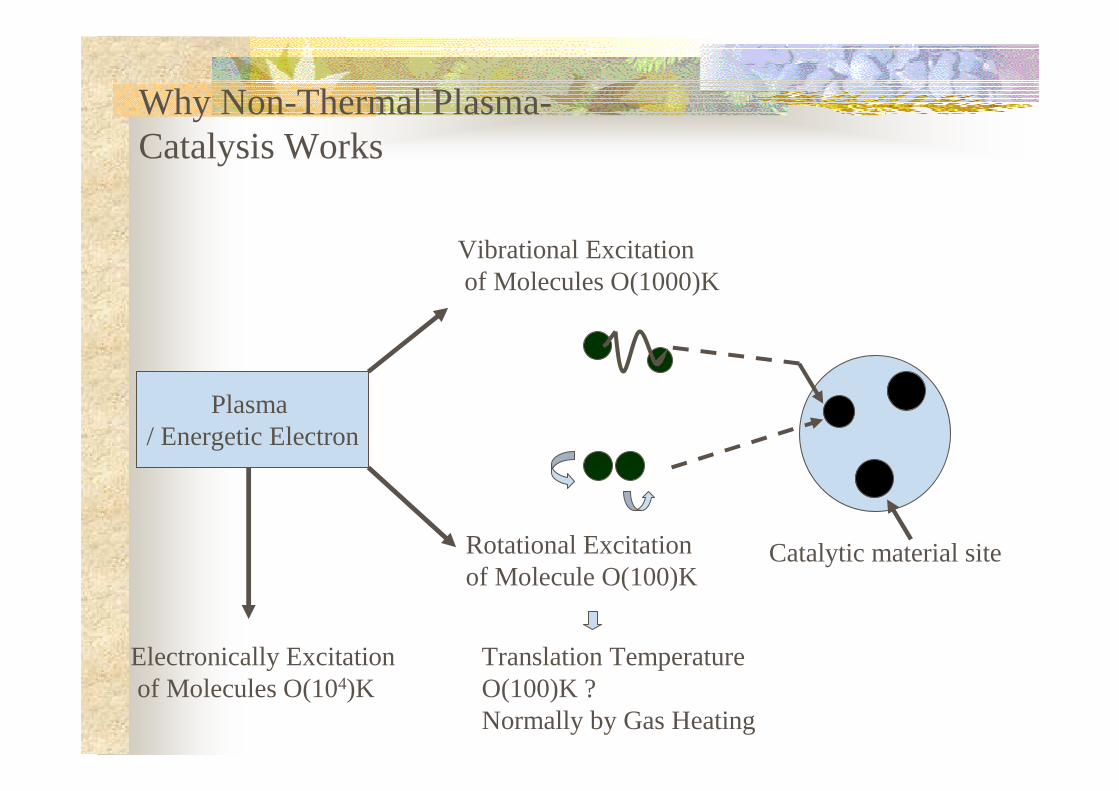
Catalytic material siteRotational Excitation of Molecule O(100)K
Why Non-Thermal Plasma-Catalysis Works
Vibrational Excitationof Molecules O(1000)K
Electronically Excitationof Molecules O(104)K
Plasma / Energetic Electron
Translation TemperatureO(100)K ?Normally by Gas Heating


Concluding Remarks� VOCs Plasma-Catalyst-Adsorbent
techniques now commertical for indoor air equipments, however, for larger Industrial system only limited commertialization has been aceived for 1000 Nm3/h level multi-module system.

