condensing boiler technology - ebmpapst.com · gas condensing technology: that’s ebm-papst since...
TRANSCRIPT
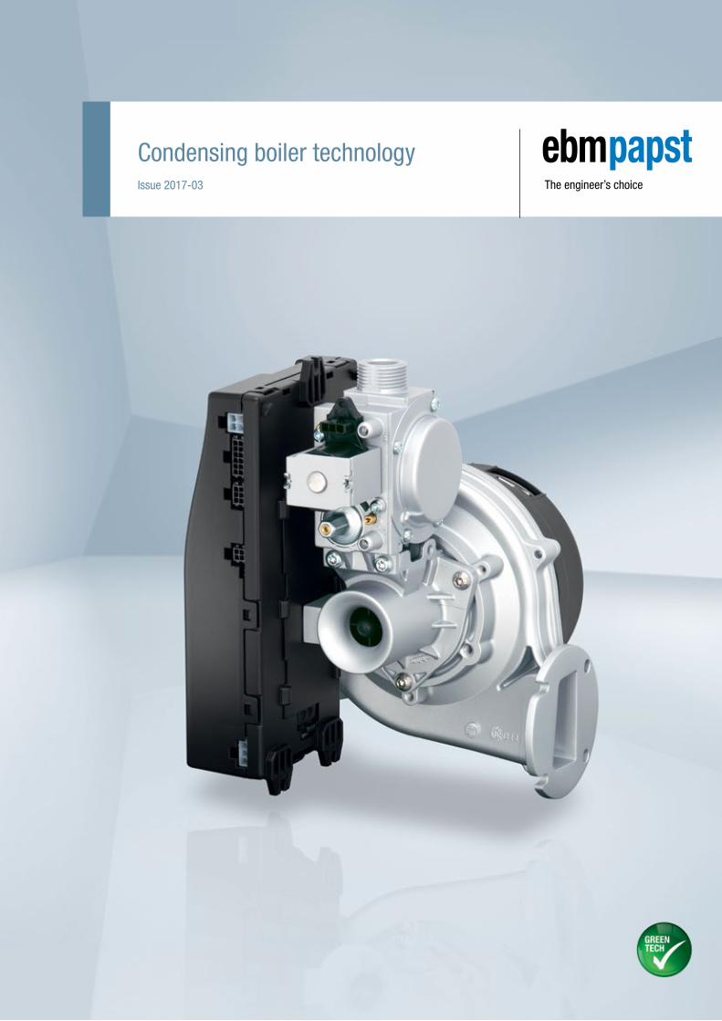
Issue 2017-03
Condensing boiler technology
2
Content
About ebm-papst 4
Laboratory equipment 8
Systems for condensing boiler technology 10
Radial blowers 14
Gas valves 30
Burner control units 36
ebm-papst representatives & subsidiaries 40
3
As technological leader for ventilation and drive engineering, ebm-papst is in demand as an engineering partner in many industries. With over 15,000 different products, we provide the right solution for just about any challenge. Our fans and drives are reliable, quiet and energy-efficient.
Six reasons that make us the ideal partner:
Our systems expertise.
You want the best solution for every project. The entire ventilation
system must thus be considered as a whole. And that’s what we do –
with motor technology that sets standards, sophisticated electronics
and aerodynamic designs – all from a single source and perfectly
matched.
Our spirit of invention.
We are also always able to develop customized solutions for you
with our versatile team of over 600 engineers and technicians.
Our lead in technology.
We are pioneers and leaders in the development of high-efficiency
EC technology. Already today almost all our products are also availa-
ble with GreenTech EC technology. The list of benefits is long: higher
efficiency, low maintenance, longer service life, sound reduction,
intelligent control characteristics and unrivalled energy efficiency.
Closeness to our customers.
ebm-papst has 25 production locations worldwide (including facilities
in Germany, China and the USA), together with 49 sales offices,
each of which has a dense network of sales representatives. You will
always have a local contact, someone who speaks your language and
knows your market.
Our standard of quality.
Our quality management is uncompromising, at every step in every
process. This is underscored by our certification according to inter-
national standards including DIN EN ISO 9001 and DIN EN ISO 14001.
Our sustainable approach.
Assuming responsibility for the environment, for our employees and
for society is an integral part of our corporate philosophy. We develop
products with an eye to maximum environmental compatibility,
in particular resource-preserving production methods. We promote
environmental awareness among our young staff and are actively
involved in sports, culture and education. That’s what makes us a
leading company – and an ideal partner for you.
About ebm-papst.
4
Gas condensing technology: That’s ebm-papst
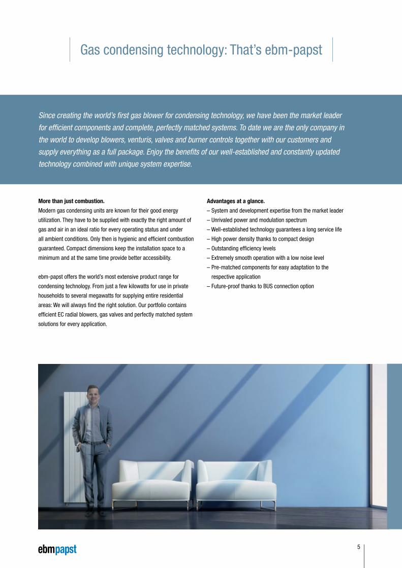
Since creating the world’s first gas blower for condensing technology, we have been the market leader for efficient components and complete, perfectly matched systems. To date we are the only company in the world to develop blowers, venturis, valves and burner controls together with our customers and supply everything as a full package. Enjoy the benefits of our well-established and constantly updated technology combined with unique system expertise.
More than just combustion.
Modern gas condensing units are known for their good energy
utilization. They have to be supplied with exactly the right amount of
gas and air in an ideal ratio for every operating status and under
all ambient conditions. Only then is hygienic and efficient combustion
guaranteed. Compact dimensions keep the installation space to a
minimum and at the same time provide better accessibility.
ebm-papst offers the world’s most extensive product range for
condensing technology. From just a few kilowatts for use in private
households to several megawatts for supplying entire residential
areas: We will always find the right solution. Our portfolio contains
efficient EC radial blowers, gas valves and perfectly matched system
solutions for every application.
Advantages at a glance.
– System and development expertise from the market leader
– Unrivaled power and modulation spectrum
– Well-established technology guarantees a long service life
– High power density thanks to compact design
– Outstanding efficiency levels
– Extremely smooth operation with a low noise level
– Pre-matched components for easy adaptation to the
respective application
– Future-proof thanks to BUS connection option
5
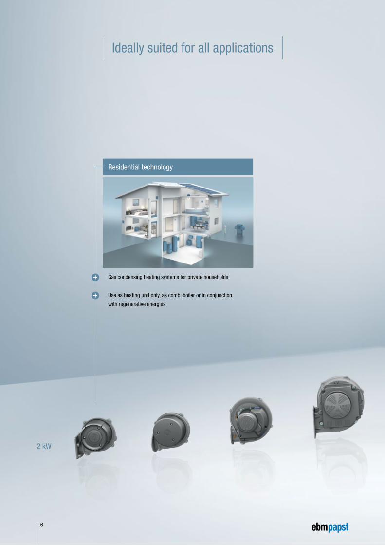
Ideally suited for all applications
2 kW
Gas condensing heating systems for private households
Use as heating unit only, as combi boiler or in conjunction
with regenerative energies
Residential technology
6
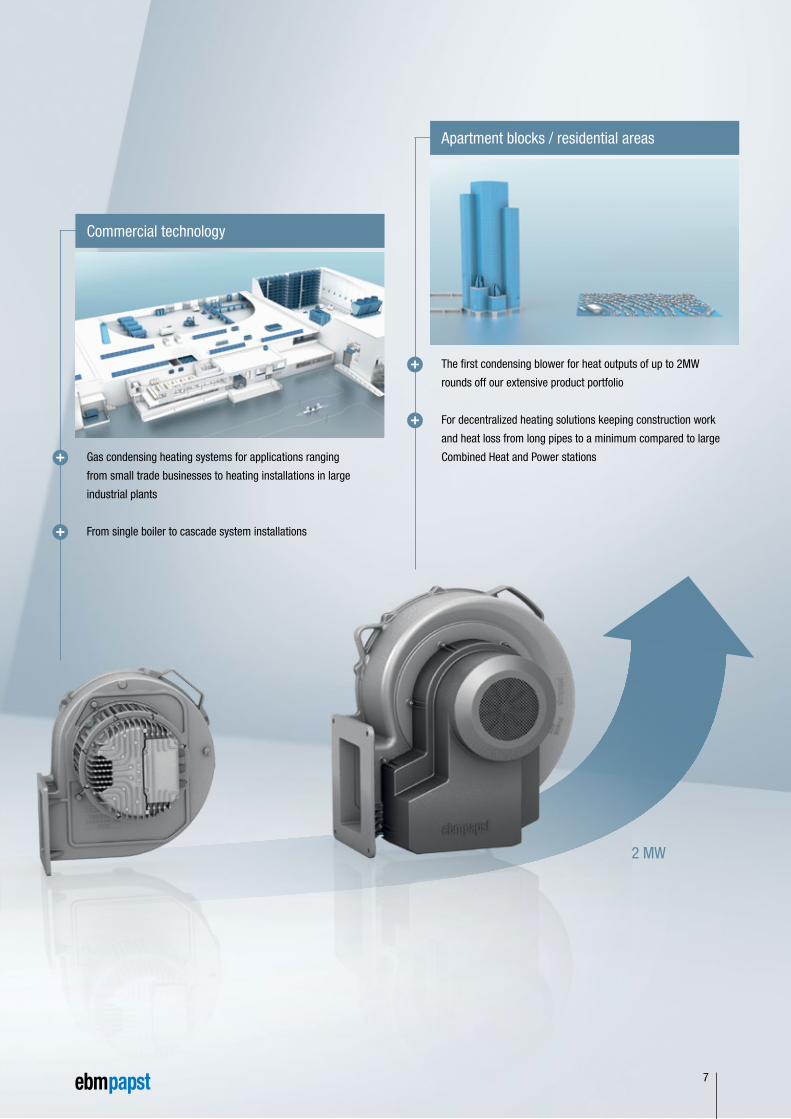
2 MW
Apartment blocks / residential areas
The first condensing blower for heat outputs of up to 2MW
rounds off our extensive product portfolio
For decentralized heating solutions keeping construction work
and heat loss from long pipes to a minimum compared to large
Combined Heat and Power stationsGas condensing heating systems for applications ranging
from small trade businesses to heating installations in large
industrial plants
From single boiler to cascade system installations
Commercial technology
7
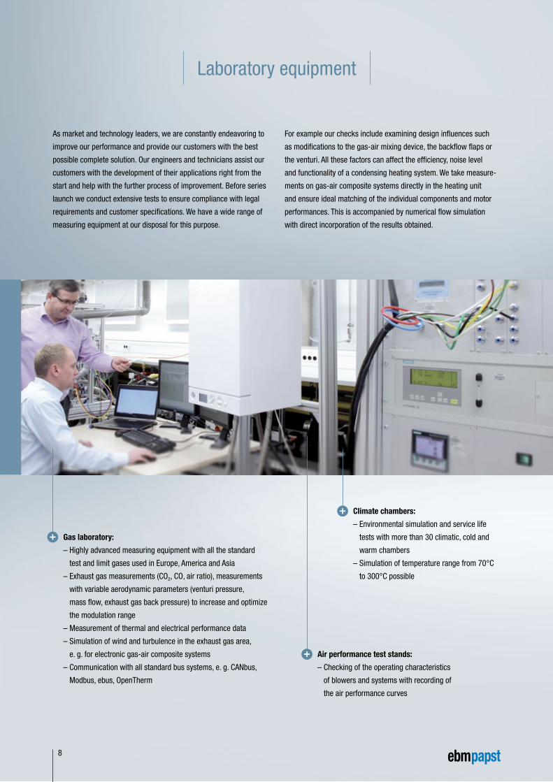
Laboratory equipment
As market and technology leaders, we are constantly endeavoring to
improve our performance and provide our customers with the best
possible complete solution. Our engineers and technicians assist our
customers with the development of their applications right from the
start and help with the further process of improvement. Before series
launch we conduct extensive tests to ensure compliance with legal
requirements and customer specifications. We have a wide range of
measuring equipment at our disposal for this purpose.
For example our checks include examining design influences such
as modifications to the gas-air mixing device, the backflow flaps or
the venturi. All these factors can affect the efficiency, noise level
and functionality of a condensing heating system. We take measure-
ments on gas-air composite systems directly in the heating unit
and ensure ideal matching of the individual components and motor
performances. This is accompanied by numerical flow simulation
with direct incorporation of the results obtained.
Gas laboratory:
– Highly advanced measuring equipment with all the standard
test and limit gases used in Europe, America and Asia
– Exhaust gas measurements (CO2, CO, air ratio), measurements
with variable aerodynamic parameters (venturi pressure,
mass flow, exhaust gas back pressure) to increase and optimize
the modulation range
– Measurement of thermal and electrical performance data
– Simulation of wind and turbulence in the exhaust gas area,
e. g. for electronic gas-air composite systems
– Communication with all standard bus systems, e. g. CANbus,
Modbus, ebus, OpenTherm
Air performance test stands:
– Checking of the operating characteristics
of blowers and systems with recording of
the air performance curves
Climate chambers:
– Environmental simulation and service life
tests with more than 30 climatic, cold and
warm chambers
– Simulation of temperature range from 70°C
to 300°C possible
8
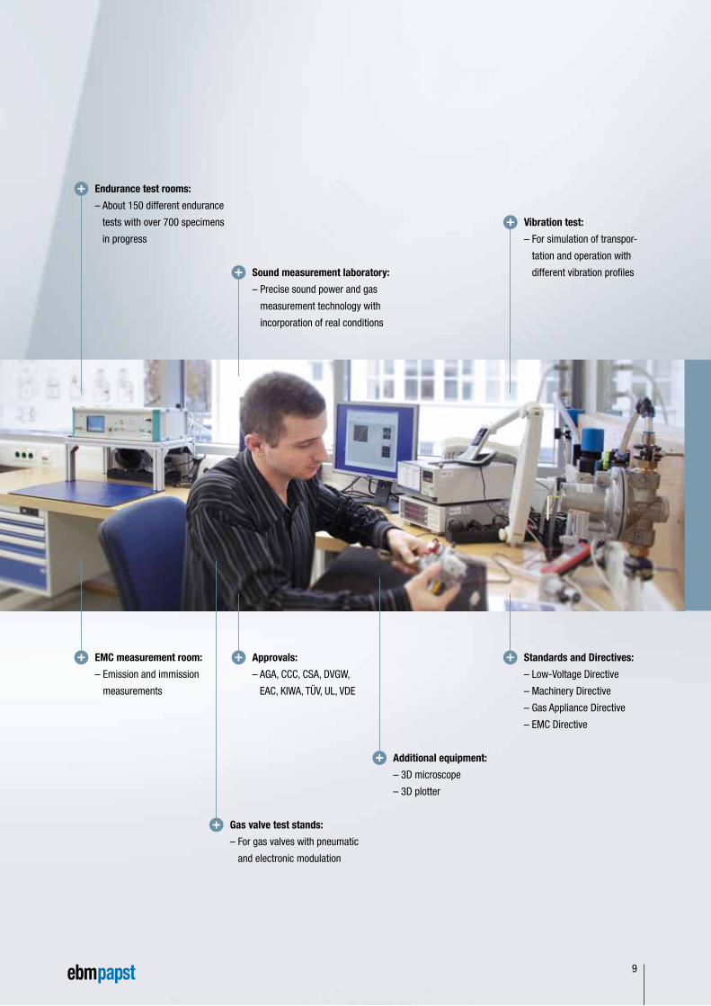
Endurance test rooms:
– About 150 different endurance
tests with over 700 specimens
in progress
EMC measurement room:
– Emission and immission
measurements
Gas valve test stands:
– For gas valves with pneumatic
and electronic modulation
Vibration test:
– For simulation of transpor-
tation and operation with
different vibration profiles
Approvals:
– AGA, CCC, CSA, DVGW,
EAC, KIWA, TÜV, UL, VDE
Standards and Directives:
– Low-Voltage Directive
– Machinery Directive
– Gas Appliance Directive
– EMC Directive
Sound measurement laboratory:
– Precise sound power and gas
measurement technology with
incorporation of real conditions
Additional equipment:
– 3D microscope
– 3D plotter
9
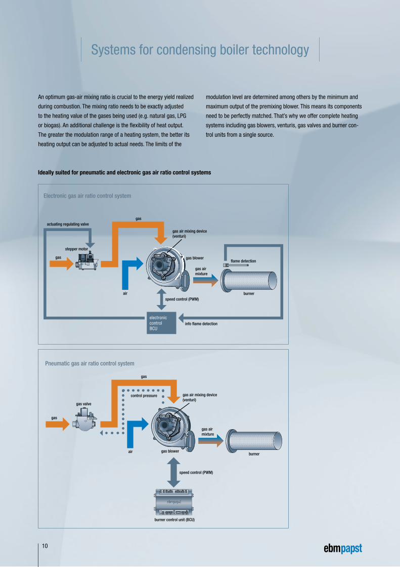
Pneumatic gas air ratio control system
air
gas air mixing device(venturi)
burner
control pressure
gas airmixture
gas
gas valve
gas blower
gas
speed control (PWM)
burner control unit (BCU)
Systems for condensing boiler technology
An optimum gas-air mixing ratio is crucial to the energy yield realized
during combustion. The mixing ratio needs to be exactly adjusted
to the heating value of the gases being used (e.g. natural gas, LPG
or biogas). An additional challenge is the flexibility of heat output.
The greater the modulation range of a heating system, the better its
heating output can be adjusted to actual needs. The limits of the
modulation level are determined among others by the minimum and
maximum output of the premixing blower. This means its components
need to be perfectly matched. That’s why we offer complete heating
systems including gas blowers, venturis, gas valves and burner con-
trol units from a single source.
Ideally suited for pneumatic and electronic gas air ratio control systems
10
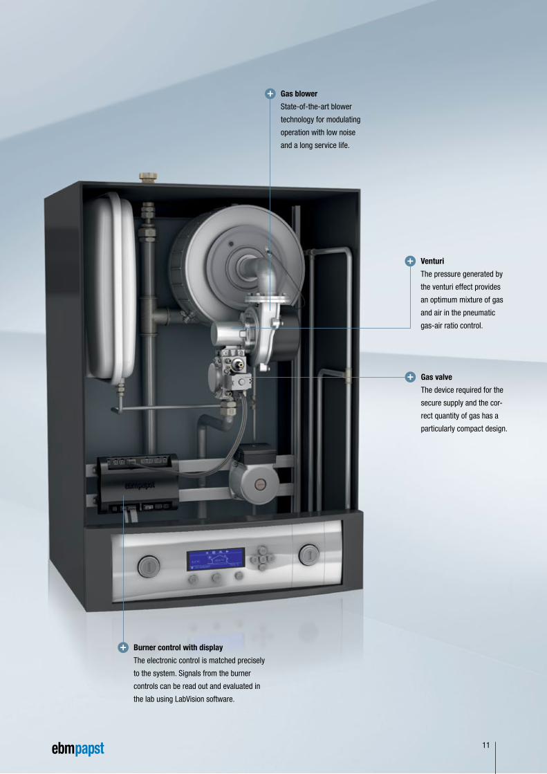
Venturi
The pressure generated by
the venturi effect provides
an optimum mixture of gas
and air in the pneumatic
gas-air ratio control.
Burner control with display
The electronic control is matched precisely
to the system. Signals from the burner
controls can be read out and evaluated in
the lab using LabVision software.
Gas blower
State-of-the-art blower
technology for modulating
operation with low noise
and a long service life.
Gas valve
The device required for the
secure supply and the cor-
rect quantity of gas has a
particularly compact design.
11
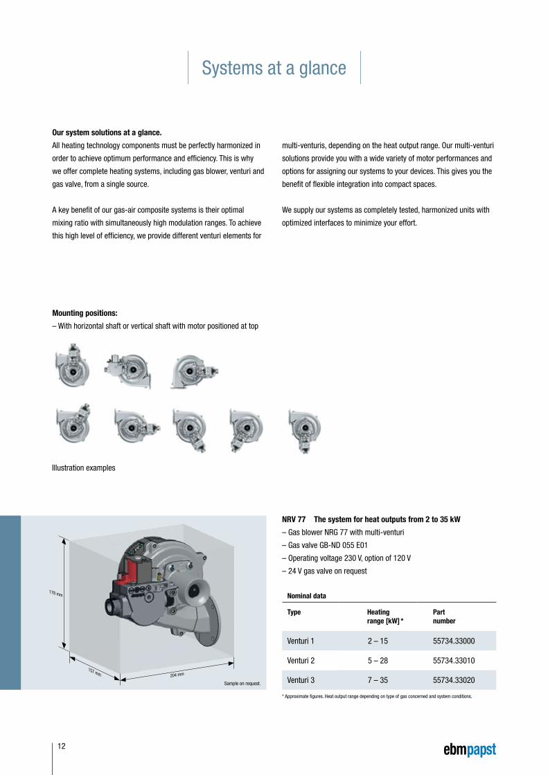
Systems at a glance
– Gas blower NRG 77 with multi-venturi
– Gas valve GB-ND 055 E01
– Operating voltage 230 V, option of 120 V
– 24 V gas valve on request
Sample on request.
Nominal data
Type Heating range [kW] *
Part number
Venturi 1 2 – 15 55734.33000
Venturi 2 5 – 28 55734.33010
Venturi 3 7 – 35 55734.33020
178 mm
157 mm 204 mm
NRV 77 The system for heat outputs from 2 to 35 kW
Our system solutions at a glance.
All heating technology components must be perfectly harmonized in
order to achieve optimum performance and efficiency. This is why
we offer complete heating systems, including gas blower, venturi and
gas valve, from a single source.
A key benefit of our gas-air composite systems is their optimal
mixing ratio with simultaneously high modulation ranges. To achieve
this high level of efficiency, we provide different venturi elements for
Mounting positions:
– With horizontal shaft or vertical shaft with motor positioned at top
Illustration examples
multi-venturis, depending on the heat output range. Our multi-venturi
solutions provide you with a wide variety of motor performances and
options for assigning our systems to your devices. This gives you the
benefit of flexible integration into compact spaces.
We supply our systems as completely tested, harmonized units with
optimized interfaces to minimize your effort.
* Approximate figures. Heat output range depending on type of gas concerned and system conditions.
12
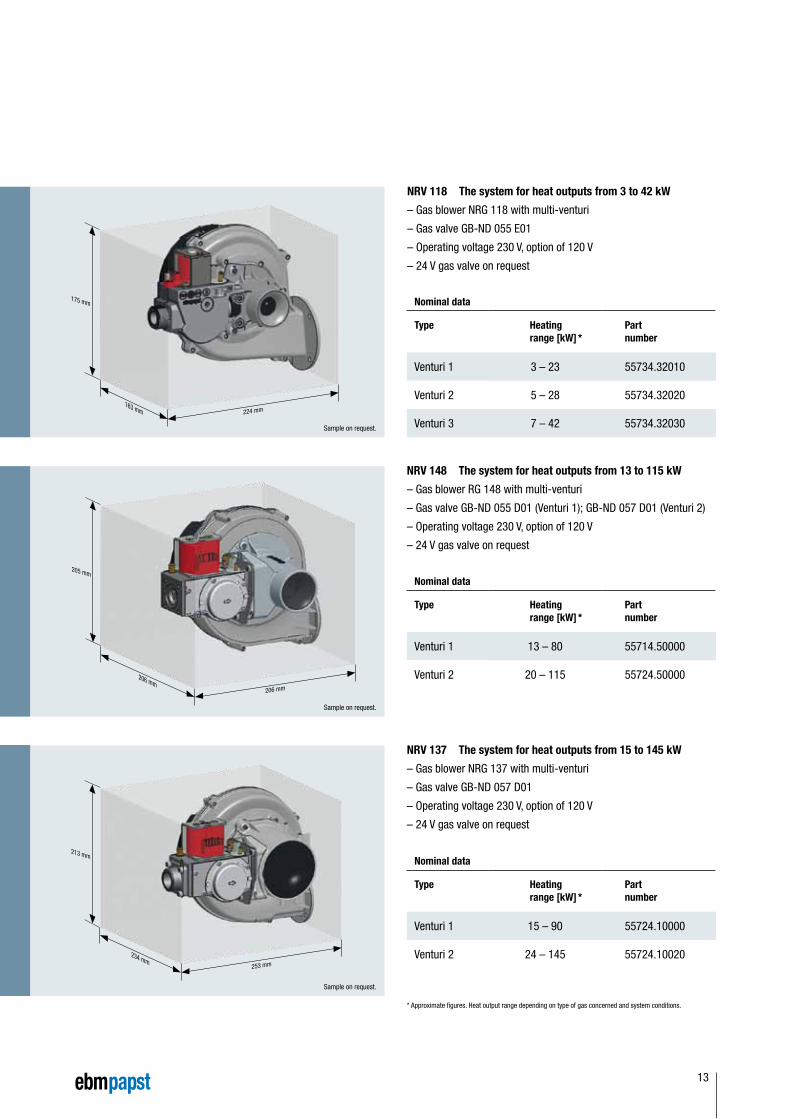
– Gas blower NRG 118 with multi-venturi
– Gas valve GB-ND 055 E01
– Operating voltage 230 V, option of 120 V
– 24 V gas valve on request
– Gas blower RG 148 with multi-venturi
– Gas valve GB-ND 055 D01 (Venturi 1); GB-ND 057 D01 (Venturi 2)
– Operating voltage 230 V, option of 120 V
– 24 V gas valve on request
– Gas blower NRG 137 with multi-venturi
– Gas valve GB-ND 057 D01
– Operating voltage 230 V, option of 120 V
– 24 V gas valve on request
Nominal data
Type Heating range [kW] *
Part number
Venturi 1 3 – 23 55734.32010
Venturi 2 5 – 28 55734.32020
Venturi 3 7 – 42 55734.32030
Nominal data
Type Heating range [kW] *
Part number
Venturi 1 13 – 80 55714.50000
Venturi 2 20 – 115 55724.50000
Nominal data
Type Heating range [kW] *
Part number
Venturi 1 15 – 90 55724.10000
Venturi 2 24 – 145 55724.10020
175 mm
163 mm 224 mm
213 mm
205 mm
234 mm
206 mm
253 mm
206 mm
NRV 118 The system for heat outputs from 3 to 42 kW
NRV 148 The system for heat outputs from 13 to 115 kW
NRV 137 The system for heat outputs from 15 to 145 kW
Sample on request.
Sample on request.
Sample on request.
* Approximate figures. Heat output range depending on type of gas concerned and system conditions.
13
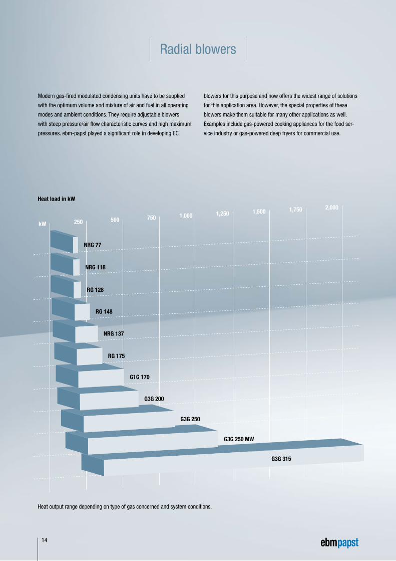
Radial blowers
Modern gas-fired modulated condensing units have to be supplied
with the optimum volume and mixture of air and fuel in all operating
modes and ambient conditions. They require adjustable blowers
with steep pressure/air flow characteristic curves and high maximum
pressures. ebm-papst played a significant role in developing EC
Heat output range depending on type of gas concerned and system conditions.
blowers for this purpose and now offers the widest range of solutions
for this application area. However, the special properties of these
blowers make them suitable for many other applications as well.
Examples include gas-powered cooking appliances for the food ser-
vice industry or gas-powered deep fryers for commercial use.
Heat load in kW
250 500 750 1,000 1,250 1,500 1,750 2,000
kW
G3G 250 MW
G3G 315
G3G 250
G3G 200
G1G 170
RG 175
NRG 137
RG 148
RG 128
NRG 118
NRG 77
14
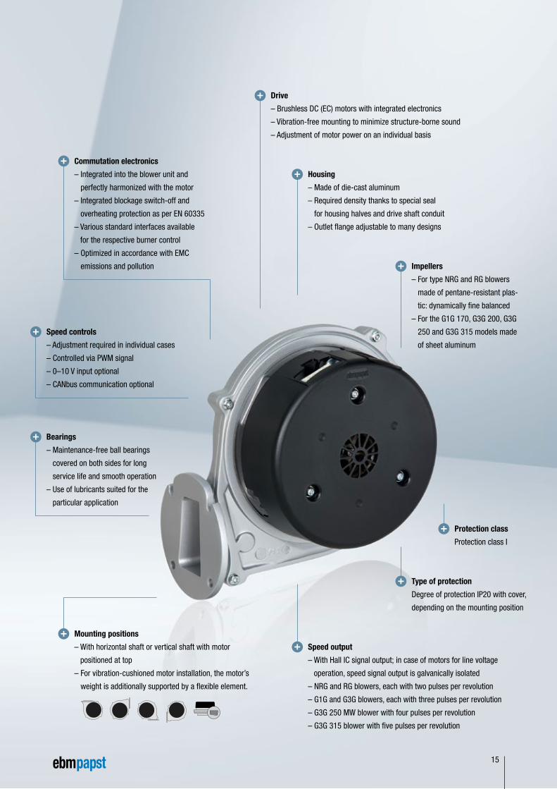
Drive
– Brushless DC (EC) motors with integrated electronics
– Vibration-free mounting to minimize structure-borne sound
– Adjustment of motor power on an individual basis
Housing
– Made of die-cast aluminum
– Required density thanks to special seal
for housing halves and drive shaft conduit
– Outlet flange adjustable to many designs
Speed output
– With Hall IC signal output; in case of motors for line voltage
operation, speed signal output is galvanically isolated
– NRG and RG blowers, each with two pulses per revolution
– G1G and G3G blowers, each with three pulses per revolution
– G3G 250 MW blower with four pulses per revolution
– G3G 315 blower with five pulses per revolution
Bearings
– Maintenance-free ball bearings
covered on both sides for long
service life and smooth operation
– Use of lubricants suited for the
particular application
Mounting positions
– With horizontal shaft or vertical shaft with motor
positioned at top
– For vibration-cushioned motor installation, the motor’s
weight is additionally supported by a flexible element.
Speed controls
– Adjustment required in individual cases
– Controlled via PWM signal
– 0–10 V input optional
– CANbus communication optional
Protection class
Protection class I
Type of protection
Degree of protection IP20 with cover,
depending on the mounting position
Impellers
– For type NRG and RG blowers
made of pentane-resistant plas-
tic: dynamically fine balanced
– For the G1G 170, G3G 200, G3G
250 and G3G 315 models made
of sheet aluminum
Commutation electronics
– Integrated into the blower unit and
perfectly harmonized with the motor
– Integrated blockage switch-off and
overheating protection as per EN 60335
– Various standard interfaces available
for the respective burner control
– Optimized in accordance with EMC
emissions and pollution
15
Curves
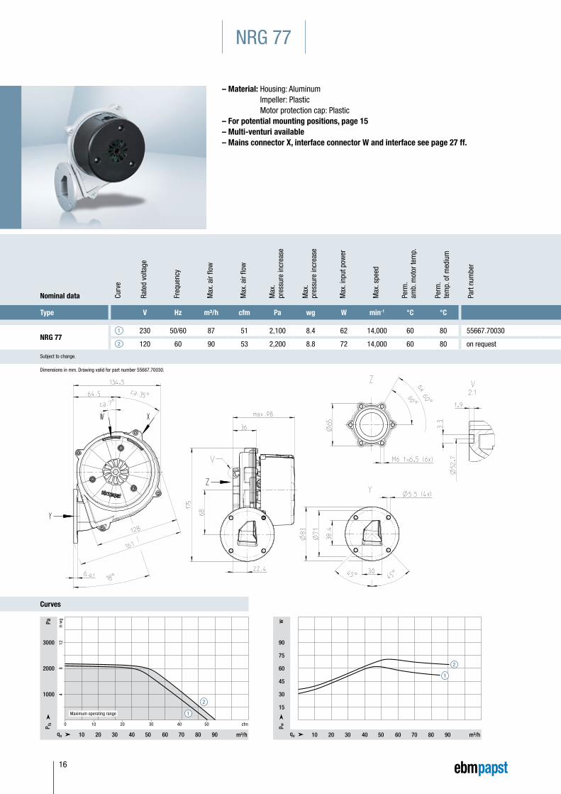
NRG 77
– Material: Housing: Aluminum Impeller: Plastic Motor protection cap: Plastic
– For potential mounting positions, page 15– Multi-venturi available– Mains connector X, interface connector W and interface see page 27 ff.
Nominal data Curv
e
Rate
d vo
ltage
Freq
uenc
y
Max
. air
flow
Max
. air
flow
Max
. pr
essu
re in
crea
se
Max
. pr
essu
re in
crea
se
Max
. inp
ut p
ower
Max
. spe
ed
Perm
. am
b. m
otor
tem
p.
Perm
. te
mp.
of m
ediu
m
Part
num
ber
Type V Hz m³/h cfm Pa wg W min-1 °C °C
NRG 771 230 50/60 87 51 2,100 8.4 62 14,000 60 80 55667.70030
2 120 60 90 53 2,200 8.8 72 14,000 60 80 on request
Subject to change.
Dimensions in mm. Drawing valid for part number 55667.70030.
NRG 77 Tabelle 1 GB
3000
2000
1000
10 20 30 40 50 cfm0
4
8
1
2
10 20 30 40 50 60 70 80 90
1
2
Maximum operating range
W
NRG 77 Tabelle 2
w
90
75
60
45
30
15
10 20 30 40 50 60 70 80 90
1
2
16
Curves
Nominal data Curv
e
Rate
d vo
ltage
Freq
uenc
y
Max
. air
flow
Max
. air
flow
Max
. pr
essu
re in
crea
se
Max
. pr
essu
re in
crea
se
Max
. inp
ut p
ower
Max
. spe
ed
Perm
. am
b. m
otor
tem
p.
Perm
. te
mp.
of m
ediu
m
Part
num
ber
Type V Hz m³/h cfm Pa wg W min-1 °C °C
NRG 771 230 50/60 87 51 2,100 8.4 62 14,000 60 80 55667.70030
2 120 60 90 53 2,200 8.8 72 14,000 60 80 on request
Subject to change.
Nominal data Curv
e
Rate
d vo
ltage
Freq
uenc
y
Max
. air
flow
Max
. air
flow
Max
. pr
essu
re in
crea
se
Max
. pr
essu
re in
crea
se
Max
. inp
ut p
ower
Max
. spe
ed
Perm
. am
b. m
otor
tem
p.
Perm
. te
mp.
of m
ediu
m
Part
num
ber
Type V Hz m³/h cfm Pa wg W min-1 °C °C
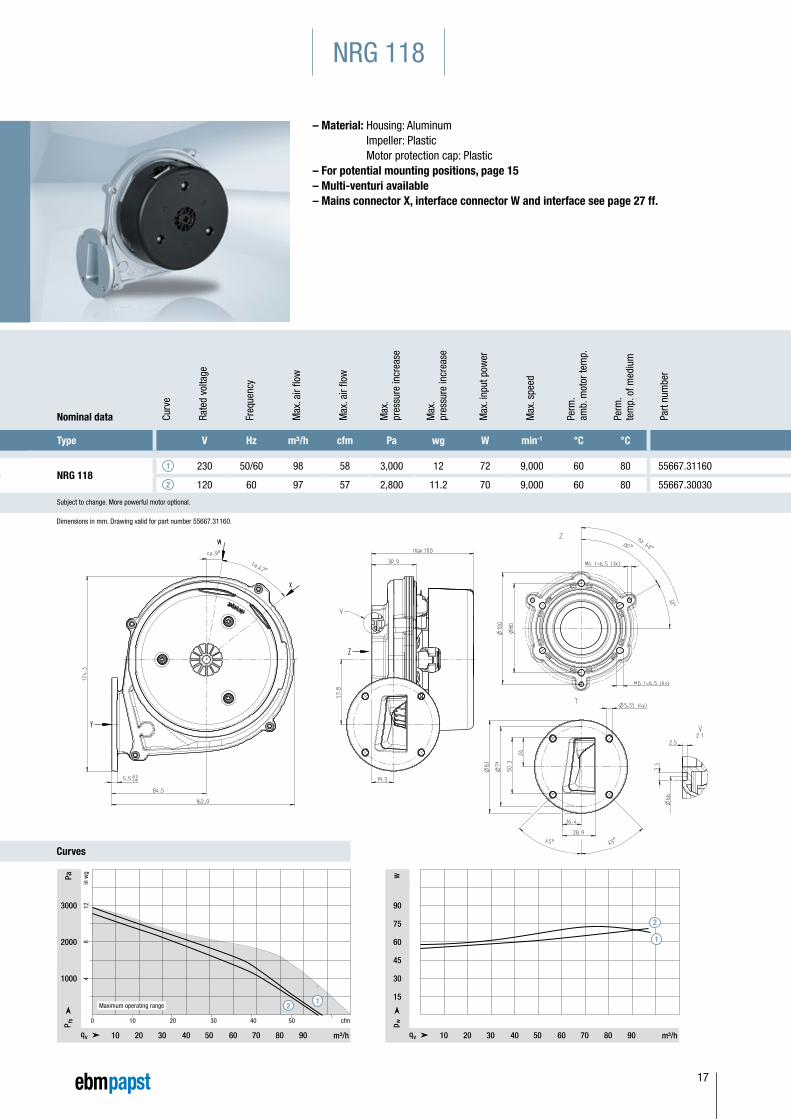
NRG 1181 230 50/60 98 58 3,000 12 72 9,000 60 80 55667.31160
2 120 60 97 57 2,800 11.2 70 9,000 60 80 55667.30030
Subject to change. More powerful motor optional.
Dimensions in mm. Drawing valid for part number 55667.31160.
– Material: Housing: Aluminum Impeller: Plastic Motor protection cap: Plastic
– For potential mounting positions, page 15– Multi-venturi available– Mains connector X, interface connector W and interface see page 27 ff.
NRG 118
NRG 118 Tabelle 1 GB
0
10 20 30 40 50 60 70 80 90
10 20 30 40 50 cfm
3000
2000
1000 4
8
1
2
12Maximum operating range
10 20 30 40 50 60 70 80 90
1
2
NRG 118 Tabelle 2
Ww
90
75
60
45
30
15
17
Curves
Nominal data Curv
e
Rate
d vo
ltage
Freq
uenc
y
Max
. air
flow
Max
. air
flow
Max
. pr
essu
re in
crea
se
Max
. pr
essu
re in
crea
se
Max
. inp
ut p
ower
Max
. spe
ed
Perm
. am
b. m
otor
tem
p.
Perm
. te
mp.
of m
ediu
m
Part
num
ber
Type V Hz m³/h cfm Pa wg W min-1 °C °C
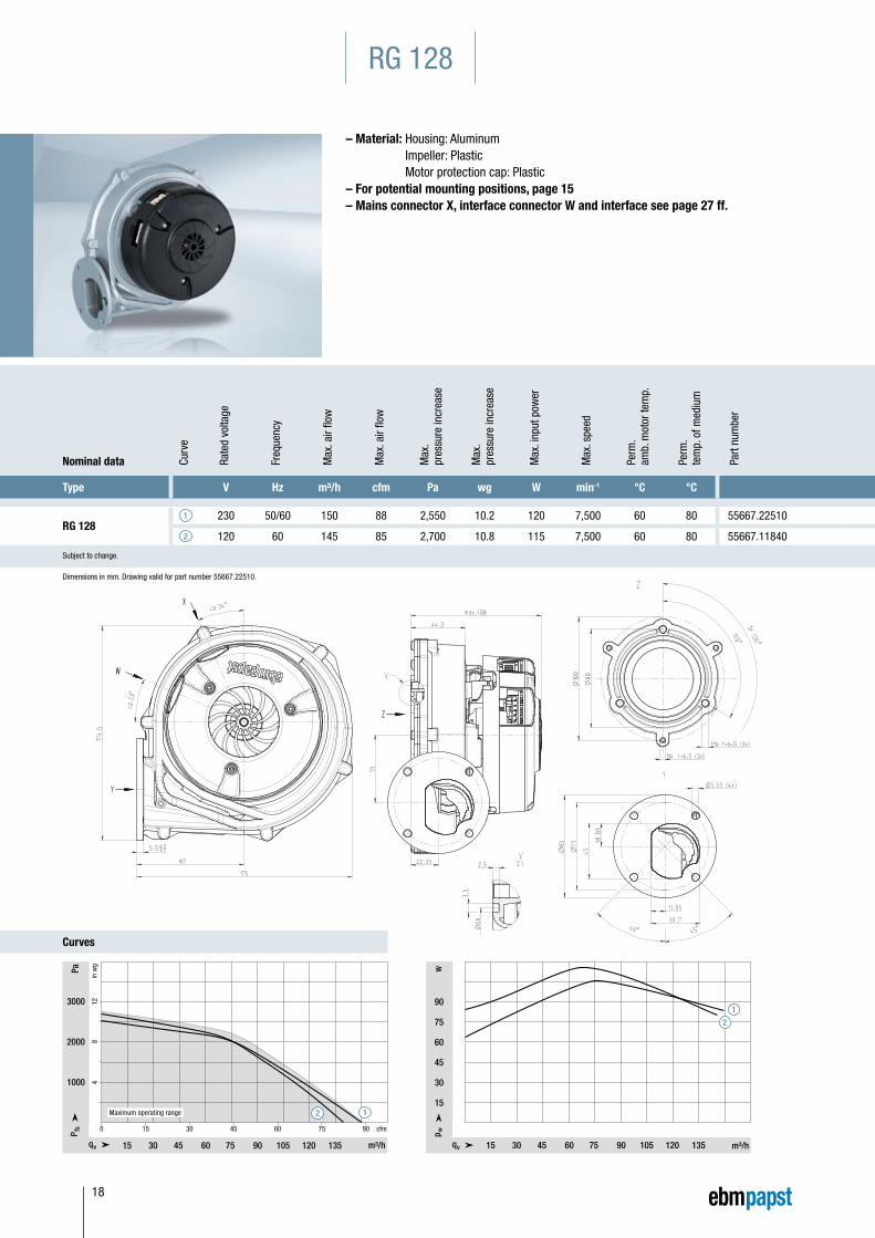
RG 1281 230 50/60 150 88 2,550 10.2 120 7,500 60 80 55667.22510
2 120 60 145 85 2,700 10.8 115 7,500 60 80 55667.11840
Subject to change.
RG 128
– Material: Housing: Aluminum Impeller: Plastic Motor protection cap: Plastic
– For potential mounting positions, page 15– Mains connector X, interface connector W and interface see page 27 ff.
Dimensions in mm. Drawing valid for part number 55667.22510.
12
RG 128 Tabelle 1 GB
15 30 45 60 75 90 105 120 135
3000
2000
1000
0 15 30 45 60 75 90 cfm
4
8
1
2
Maximum operating range
1
2
RG 128 Tabelle 2
90
75
60
45
30
15
Ww
15 30 45 60 75 90 105 120 135
18
Curves
Nominal data Curv
e
Rate
d vo
ltage
Freq
uenc
y
Max
. air
flow
Max
. air
flow
Max
. pr
essu
re in
crea
se
Max
. pr
essu
re in
crea
se
Max
. inp
ut p
ower
Max
. spe
ed
Perm
. am
b. m
otor
tem
p.
Perm
. te
mp.
of m
ediu
m
Part
num
ber
Type V Hz m³/h cfm Pa wg W min-1 °C °C
RG 1281 230 50/60 150 88 2,550 10.2 120 7,500 60 80 55667.22510
2 120 60 145 85 2,700 10.8 115 7,500 60 80 55667.11840
Subject to change.
Nominal data Curv
e
Rate
d vo
ltage
Freq
uenc
y
Max
. air
flow
Max
. air
flow
Max
. pr
essu
re in
crea
se
Max
. pr
essu
re in
crea
se
Max
. inp
ut p
ower
Max
. spe
ed
Perm
. am
b. m
otor
tem
p.
Perm
. te
mp.
of m
ediu
m
Part
num
ber
Type V Hz m³/h cfm Pa wg W min-1 °C °C
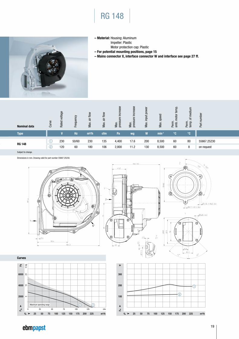
RG 1481 230 50/60 230 135 4,400 17.6 200 8,500 60 80 55667.25230
2 120 60 180 106 2,800 11.2 130 8,500 60 8 on request
Subject to change.
RG 148
– Material: Housing: Aluminum Impeller: Plastic Motor protection cap: Plastic
– For potential mounting positions, page 15– Mains connector X, interface connector W and interface see page 27 ff.
Dimensions in mm. Drawing valid for part number 55667.25230.
12
6000
4000
2000
25 50 75 100 125 cfm
25 50 75 100 125 150 175 200 225
RG 148 Tabelle 1 GB
8
16
24
0
Maximum operating range
1
2
25 50 75 100 125 150 175 200 225
RG 148 Tabelle 2
300
200
100
Ww
19
Curves
Nominal data Curv
e
Rate
d vo
ltage
Freq
uenc
y
Max
. air
flow
Max
. air
flow
Max
. pr
essu
re in
crea
se
Max
. pr
essu
re in
crea
se
Max
. inp
ut p
ower
Max
. spe
ed
Perm
. am
b. m
otor
tem
p.
Perm
. te
mp.
of m
ediu
m
Part
num
ber
Type V Hz m³/h cfm Pa wg W min-1 °C °C
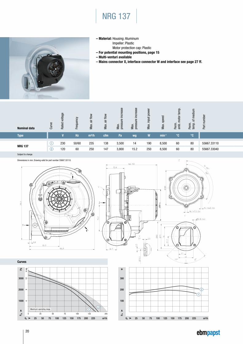
NRG 1371 230 50/60 235 138 3,500 14 190 8,500 60 80 55667.33110
2 120 60 250 147 3,800 15.2 250 8,500 60 80 55667.33040
Subject to change.
NRG 137
– Material: Housing: Aluminum Impeller: Plastic Motor protection cap: Plastic
– For potential mounting positions, page 15– Multi-venturi available– Mains connector X, interface connector W and interface see page 27 ff.
Dimensions in mm. Drawing valid for part number 55667.33110.
12
3000
2000
1000
25 50 75 100 125 150 175 200 225
NRG 137 Tabelle 1 GB
25 50 75 100 125 cfm0
4
8
1
2
Maximum operating range
1
2
25 50 75 100 125 150 175 200 225
NRG 137 Tabelle 2
300
200
100
Ww
20
Curves
Nominal data Curv
e
Rate
d vo
ltage
Freq
uenc
y
Max
. air
flow
Max
. air
flow
Max
. pr
essu
re in
crea
se
Max
. pr
essu
re in
crea
se
Max
. inp
ut p
ower
Max
. spe
ed
Perm
. am
b. m
otor
tem
p.
Perm
. te
mp.
of m
ediu
m
Part
num
ber
Type V Hz m³/h cfm Pa wg W min-1 °C °C
NRG 1371 230 50/60 235 138 3,500 14 190 8,500 60 80 55667.33110
2 120 60 250 147 3,800 15.2 250 8,500 60 80 55667.33040
Subject to change.
Nominal data Curv
e
Rate
d vo
ltage
Freq
uenc
y
Max
. air
flow
Max
. air
flow
Max
. pr
essu
re in
crea
se
Max
. pr
essu
re in
crea
se
Max
. inp
ut p
ower
Max
. spe
ed
Perm
. am
b. m
otor
tem
p.
Perm
. te
mp.
of m
ediu
m
Part
num
ber
Type V Hz m³/h cfm Pa wg W min-1 °C °C
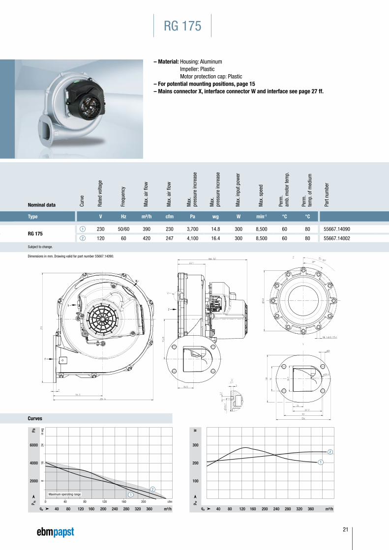
RG 1751 230 50/60 390 230 3,700 14.8 300 8,500 60 80 55667.14090
2 120 60 420 247 4,100 16.4 300 8,500 60 80 55667.14002
Subject to change.
RG 175
– Material: Housing: Aluminum Impeller: Plastic Motor protection cap: Plastic
– For potential mounting positions, page 15– Mains connector X, interface connector W and interface see page 27 ff.
Dimensions in mm. Drawing valid for part number 55667.14090.
40 80 120 160 200 cfm0
40 80 120 160 200 240 280 320 360
RG 175 Tabelle 1 GB
6000
4000
2000
8
16
24
12
Maximum operating range
300
200
100
Ww
40 80 120 160 200 240 280 320 360
RG 175 Tabelle 2 GB
1
2
21
Curves
Nominal data Curv
e
Rate
d vo
ltage
Freq
uenc
y
Max
. air
flow
Max
. air
flow
Max
. pr
essu
re in
crea
se
Max
. pr
essu
re in
crea
se
Max
. inp
ut p
ower
Max
. spe
ed
Perm
. am
b. m
otor
tem
p.
Perm
. te
mp.
of m
ediu
m
Part
num
ber
Type V Hz m³/h cfm Pa wg W min-1 °C °C
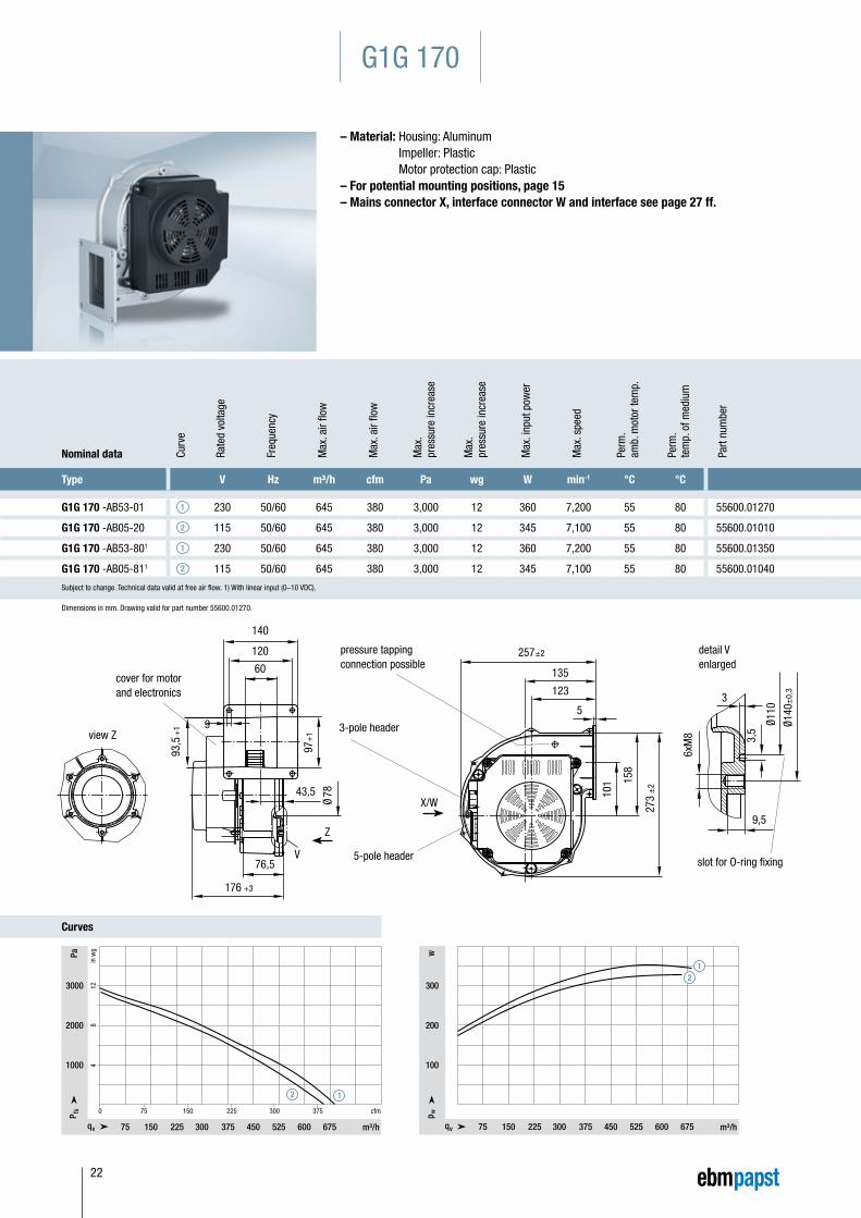
G1G 170 -AB53-01 1 230 50/60 645 380 3,000 12 360 7,200 55 80 55600.01270
G1G 170 -AB05-20 2 115 50/60 645 380 3,000 12 345 7,100 55 80 55600.01010
G1G 170 -AB53-801 1 230 50/60 645 380 3,000 12 360 7,200 55 80 55600.01350
G1G 170 -AB05-811 2 115 50/60 645 380 3,000 12 345 7,100 55 80 55600.01040
Subject to change. Technical data valid at free air flow. 1) With linear input (0–10 VDC).
G1G 170
– Material: Housing: Aluminum Impeller: Plastic Motor protection cap: Plastic
– For potential mounting positions, page 15– Mains connector X, interface connector W and interface see page 27 ff.
Dimensions in mm. Drawing valid for part number 55600.01270.
detail Venlarged
slot for O-ring fixing
Ø110
9,5
36x
M8 3,5
Ø140
±0,
3
257±227
3 ±
2
101 15
8
3-pole header
5-pole header
pressure tappingconnection possible
X/W
5
123
135
Ø 78
176 +3
76,5V
view Z
cover for motorand electronics
60
120
140
97+
1
93,5
+1
Z
9
43,5
75 150 225 300 375 cfm0
75 150 225 300 375 450 525 600 675
3000
2000
1000 4
8
1
2
G1G 170 Tabelle 1
12
300
200
100
Ww
75 150 225 300 375 450 525 600 675
G1G 170 Tabelle 2
12
22
Nominal data Curv
e
Rate
d vo
ltage
Freq
uenc
y
Max
. air
flow
Max
. air
flow
Max
. pr
essu
re in
crea
se
Max
. pr
essu
re in
crea
se
Max
. inp
ut p
ower
Max
. spe
ed
Perm
. am
b. m
otor
tem
p.
Perm
. te
mp.
of m
ediu
m
Part
num
ber
Type V Hz m³/h cfm Pa wg W min-1 °C °C
G1G 170 -AB53-01 1 230 50/60 645 380 3,000 12 360 7,200 55 80 55600.01270
G1G 170 -AB05-20 2 115 50/60 645 380 3,000 12 345 7,100 55 80 55600.01010
G1G 170 -AB53-801 1 230 50/60 645 380 3,000 12 360 7,200 55 80 55600.01350
G1G 170 -AB05-811 2 115 50/60 645 380 3,000 12 345 7,100 55 80 55600.01040
Subject to change. Technical data valid at free air flow. 1) With linear input (0–10 VDC).
Nominal data Curv
e
Rate
d vo
ltage
Freq
uenc
y
Max
. air
flow
Max
. air
flow
Max
. pr
essu
re in
crea
se
Max
. pr
essu
re in
crea
se
Max
. inp
ut p
ower
Max
. spe
ed
Perm
. am
b. m
otor
tem
p.
Perm
. te
mp.
of m
ediu
m
Part
num
ber
Type V Hz m³/h cfm Pa wg W min-1 °C °C
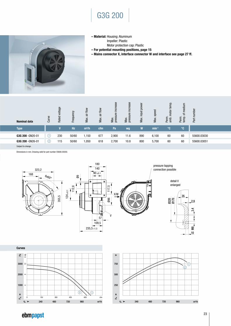
G3G 200 -GN20-01 1 230 50/60 1,150 677 2,900 11.6 890 6,100 60 60 55600.03030
G3G 200 -GN26-01 2 115 50/60 1,050 618 2,700 10.8 800 5,700 60 60 55600.03051
Subject to change.
G3G 200
– Material: Housing: Aluminum Impeller: Plastic Motor protection cap: Plastic
– For potential mounting positions, page 15– Mains connector X, interface connector W and interface see page 27 ff.
detail Venlarged
323,2
168 6x60°
90 ±0,1
235,5 =1,5
57
109,5
124
±0,
1
Ø9
Ø96
112,
8
117,
5
355,
5
pressure tappingconnection possible
X/W
V
140
180
Dimensions in mm. Drawing valid for part number 55600.03030.
Curves
12
150 300 450 600 cfm0
240 480 720 960
3000
2000
1000 4
8
1
2
G1G 200 Tabelle 1
12
750
500
250
Ww
240 480 720 960
G1G 200 Tabelle 2
23
6x60°
60°
view Z2,9
10 +1
M8
3,4 Ø1
85
Ø220
detail V enlarged
434 ±1
459
±1
265
pressure tapping is possible
8
204,5
X/W
Z
249 ±1,5
120,5
92
180
Ø120
66,3
169,
8
9
171
sideplates of housingsealed with rubber loop(NBR pentane-resistant)
V
220
Nominal data Curv
e
Rate
d vo
ltage
Freq
uenc
y
Max
. air
flow
Max
. air
flow
Max
. pr
essu
re in
crea
se
Max
. pr
essu
re in
crea
se
Max
. inp
ut p
ower
Max
. spe
ed
Perm
. am
b. m
otor
tem
p.
Perm
. te
mp.
of m
ediu
m
Part
num
ber
Type V Hz m³/h cfm Pa wg W min-1 °C °C
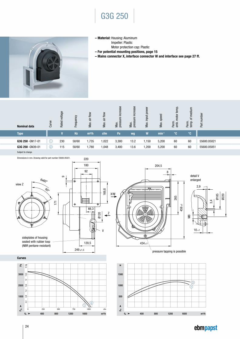
G3G 250 -GN17-01 1 230 50/60 1,735 1,022 3,300 13.2 1,150 5,200 60 60 55600.05021
G3G 250 -GN39-01 2 115 50/60 1,780 1,048 3,400 13.6 1,200 5,200 60 60 55600.05051
Subject to change.
G3G 250
– Material: Housing: Aluminum Impeller: Plastic Motor protection cap: Plastic
– For potential mounting positions, page 15– Mains connector X, interface connector W and interface see page 27 ff.
Dimensions in mm. Drawing valid for part number 55600.05021.
Curves
12
250 500 750 1000 cfm0
400 800 1200 1600
3000
2000
1000
2,4
4,8
7,2
9,6
12
14
,4
G3G 250 Tabelle 1
1
2
400 800 1200 1600
1500
1000
500
Ww
G3G 250 Tabelle 2
24
Nominal data Rate
d vo
ltage
Freq
uenc
y
Max
. air
flow
Max
. air
flow
Max
. pr
essu
re in
crea
se
Max
. pr
essu
re in
crea
se
Max
. inp
ut p
ower
Max
. spe
ed
Perm
. am
b. m
otor
tem
p.
Perm
. te
mp.
of m
ediu
m
Part
num
ber
Type V Hz m³/h cfm Pa wg W min-1 °C °C
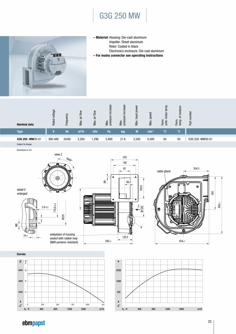
G3G 250 -MW50-01 380-480 50/60 2,200 1,296 5,400 21.6 2,500 6,400 50 50 G3G 250 -MW50-01
Subject to change.
Dimensions in mm.
Nominal data Curv
e
Rate
d vo
ltage
Freq
uenc
y
Max
. air
flow
Max
. air
flow
Max
. pr
essu
re in
crea
se
Max
. pr
essu
re in
crea
se
Max
. inp
ut p
ower
Max
. spe
ed
Perm
. am
b. m
otor
tem
p.
Perm
. te
mp.
of m
ediu
m
Part
num
ber
Type V Hz m³/h cfm Pa wg W min-1 °C °C
G3G 250 -GN17-01 1 230 50/60 1,735 1,022 3,300 13.2 1,150 5,200 60 60 55600.05021
G3G 250 -GN39-01 2 115 50/60 1,780 1,048 3,400 13.6 1,200 5,200 60 60 55600.05051
Subject to change.
G3G 250 MW
– Material: Housing: Die-cast aluminum Impeller: Sheet aluminum Rotor: Coated in black Electronics enclosure: Die-cast aluminum
– For mains connector see operating instructions
Curves
Ø220
178,
6+0,
3
5
2,9-0,3
10+1
M8
459±
1
265
434±1
204,5
66,3
6x60°
220
180
92
Ø9
Ø120
395±2
120,5
171
169,
8
Ø220
178,
6+0,
3
5
2,9-0,3
10+1
M8
459±
1
265
434±1
204,5
66,3
6x60°
220
180
92
Ø9
Ø120
395±2
120,5
171
169,
8
Ø220
178,
6+0,
3
5
2,9-0,3
10+1
M8
459±
1
265
434±1
204,5
66,3
6x60°
220
180
92
Ø9
Ø120
395±2
120,5
171
169,
8
detail V enlarged
cable gland
view Z
sideplates of housingsealed with rubber loop(NBR pentane-resistant)
Ø120
Z
V
250 500 750 1000 cfm0
400 800 1200 1600
6000
4000
2000
8
16
24
G3G 250 MW Tabelle 1
400 800 1200 1600
2250
1500
750
Ww
G3G 250 MW Tabelle 2
25
Nominal data Rate
d vo
ltage
Freq
uenc
y
Max
. air
flow
Max
. air
flow
Max
. pr
essu
re in
crea
se
Max
. pr
essu
re in
crea
se
Max
. inp
ut p
ower
Max
. spe
ed
Perm
. am
b. m
otor
tem
p.
Perm
. te
mp.
of m
ediu
m
Part
num
ber
Typ V Hz m³/h cfm Pa wg W min-1 °C °C
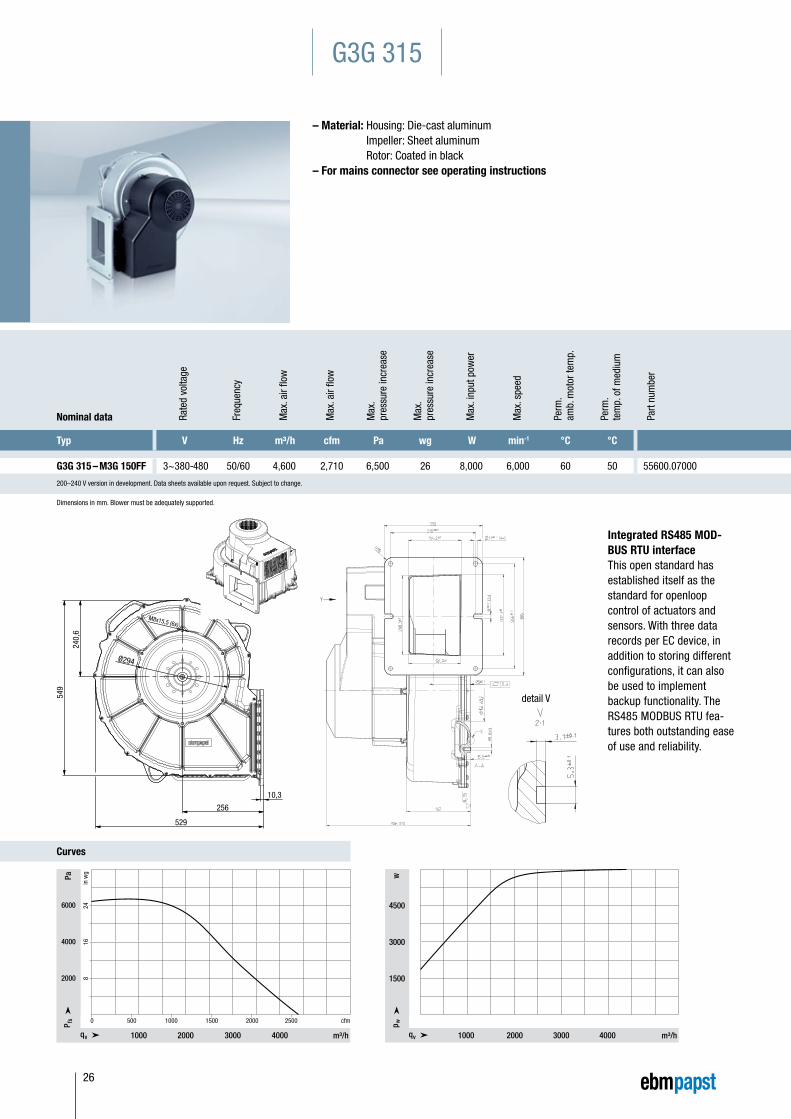
G3G 315 – M3G 150FF 3~380-480 50/60 4,600 2,710 6,500 26 8,000 6,000 60 50 55600.07000
200–240 V version in development. Data sheets available upon request. Subject to change.
G3G 315
– Material: Housing: Die-cast aluminum Impeller: Sheet aluminum Rotor: Coated in black
– For mains connector see operating instructions
Dimensions in mm. Blower must be adequately supported.
Integrated RS485 MOD-BUS RTU interfaceThis open standard has established itself as the standard for openloop control of actuators and sensors. With three data records per EC device, in addition to storing different configurations, it can also be used to implement backup functionality. The RS485 MODBUS RTU fea-tures both outstanding ease of use and reliability.
250
216
133,9
3,1
95
200,
7206,
926
6
300
Ø250
190
Ø154
,65,
3
Ø11 (4x)
529
256
10,3
Ø294
M8x15,5 (6x)
549
240,
6
162365
detail V
CurvesG3G 315 Tabelle 1
500 1000 1500 2000 2500 cfm0
1000 2000 3000 4000
6000
4000
2000 8 16
24
G3G 315 Tabelle 2
1000 2000 3000 4000
4500
3000
1500
Ww
26
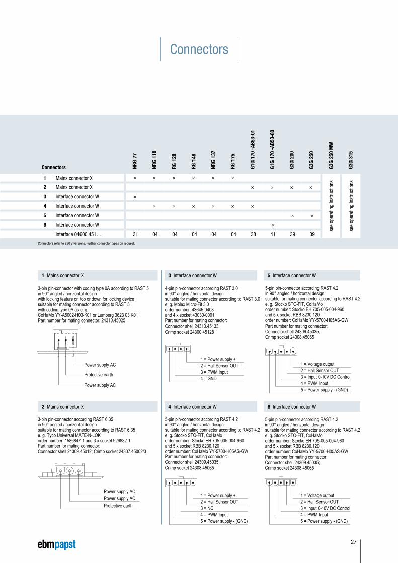
Connectors refer to 230 V versions. Further connector types on request.
Connectors
Connectors NRG
77
NRG
118
RG 1
28
RG 1
48
NRG
137
RG 1
75
G1G
170
-AB5
3-01
G1G
170
-AB5
3-80
G3G
200
G3G
250
G3G
250
MW
G3G
315
1 Mains connector X × × × × × ×
see
oper
atin
g in
stru
ctio
ns
see
oper
atin
g in
stru
ctio
ns
2 Mains connector X × × × ×
3 Interface connector W ×
4 Interface connector W × × × × × ×
5 Interface connector W × ×
6 Interface connector W ×
Interface 04600.451… 31 04 04 04 04 04 38 41 39 39
1 Mains connector X
2 Mains connector X
3 Interface connector W
4 Interface connector W
5 Interface connector W
6 Interface connector W
Power supply ACPower supply ACProtective earth
Part number for mating connector:Connector shell 24309.45012; Crimp socket 24307.45002/3
1 = Power supply +2 = Hall Sensor OUT3 = NC4 = PWM Input5 = Power supply - (GND)
1 = Power supply +2 = Hall Sensor OUT3 = PWM Input4 = GND
1 3 5
2 4 6
Part number for mating connector: 24310.45025 Part number for mating connector:Connector shell 24310.45133;Crimp socket 24300.45128
Part number for mating connector:Connector shell 24309.45035;Crimp socket 24308.45065
1 = Power supply +2 = Hall Sensor OUT3 = NC4 = PWM Input5 = Power supply - (GND)
Part number for mating connector:Connector shell 24309.45035;Crimp socket 24308.45065
1 = Voltage output2 = Hall Sensor OUT3 = Input 0-10V DC Control4 = PWM Input5 = Power supply - (GND)
Part number for mating connector:Connector shell 24309.45035;Crimp socket 24308.45065
3-pin pin-connector with coding type 0A according to RAST 5in 90° angled / horizontal designwith locking feature on top or down for locking devicesuitable for mating connector according to RAST 5with coding type 0A as e. g.CoHaMo YY-A5002-H03-K01 or Lumberg 3623 03 K01
Power supply AC
Protective earth
Power supply AC
3-pin pin-connector according RAST 6.35in 90° angled / horizontal designsuitable for mating connector according to RAST 6.35e. g. Tyco Universal MATE-N-LOKorder number: 1586847-1 and 3 x socket 926882-1
4-pin pin-connector according RAST 3.0in 90° angled / horizontal designsuitable for mating connector according to RAST 3.0e. g. Molex Micro-Fit 3.0order number: 43645-0408and 4 x socket 43030-0001
5-pin pin-connector according RAST 4.2in 90° angled / horizontal designsuitable for mating connector according to RAST 4.2e. g. Stocko STO-FIT, CoHaMoorder number: Stocko EH 705-005-004-960and 5 x socket RBB 8230.120order number: CoHaMo YY-5700-H05AS-GW
5-pin pin-connector according RAST 4.2in 90° angled / horizontal designsuitable for mating connector according to RAST 4.2e. g. Stocko STO-FIT, CoHaMoorder number: Stocko EH 705-005-004-960and 5 x socket RBB 8230.120order number: CoHaMo YY-5700-H05AS-GW
5-pin pin-connector according RAST 4.2in 90° angled / horizontal design suitable for mating connector according to RAST 4.2e. g. Stocko STO-FIT, CoHaMoorder number: Stocko EH 705-005-004-960and 5 x socket RBB 8230.120order number: CoHaMo YY-5700-H05AS-GW
27
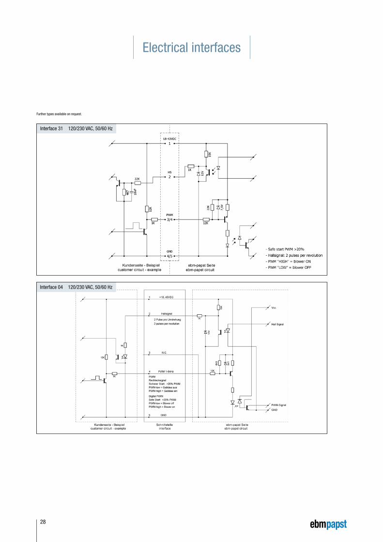
Electrical interfaces
Further types available on request.
Interface 04 120/230 VAC, 50/60 Hz
Interface 31 120/230 VAC, 50/60 Hz
28
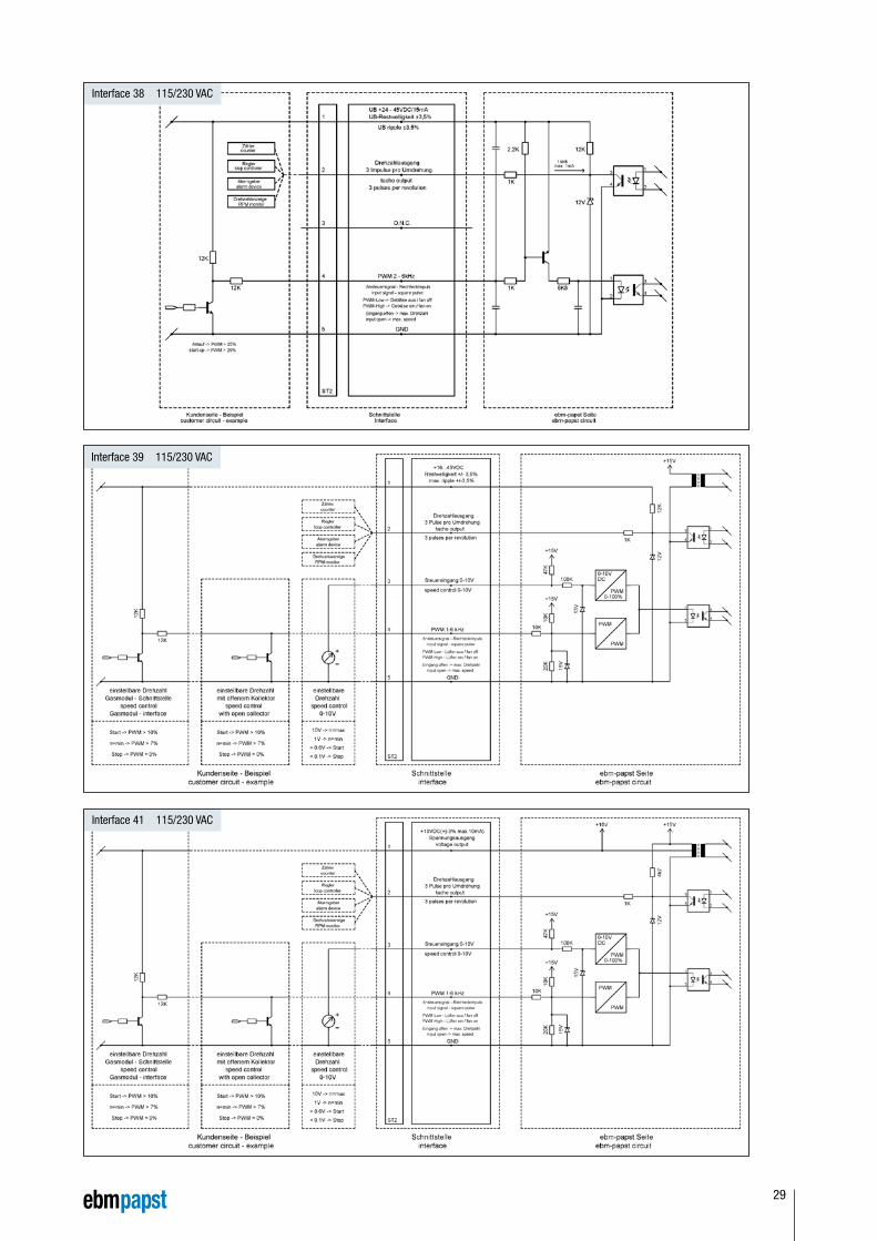
Interface 39 115/230 VAC
Interface 41 115/230 VAC
Interface 38 115/230 VAC
29
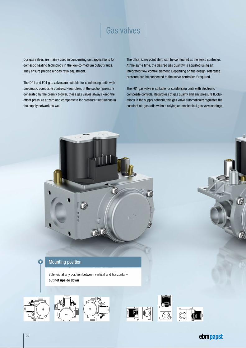
Solenoid at any position between vertical and horizontal –
but not upside down
Mounting position
Gas valves
Our gas valves are mainly used in condensing unit applications for
domestic heating technology in the low-to-medium output range.
They ensure precise air-gas ratio adjustment.
The D01 and E01 gas valves are suitable for condensing units with
pneumatic composite controls. Regardless of the suction pressure
generated by the premix blower, these gas valves always keep the
offset pressure at zero and compensate for pressure fluctuations in
the supply network as well.
The offset (zero point shift) can be configured at the servo controller.
At the same time, the desired gas quantity is adjusted using an
integrated flow control element. Depending on the design, reference
pressure can be connected to the servo controller if required.
The F01 gas valve is suitable for condensing units with electronic
composite controls. Regardless of gas quality and any pressure fluctu-
ations in the supply network, this gas valve automatically regulates the
constant air-gas ratio without relying on mechanical gas valve settings.
30
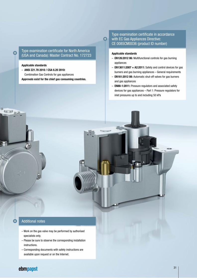
Applicable standards
– EN126:2012 06: Multifunctional controls for gas burning
appliances
– EN13611:2007 + A2:2011: Safety and control devices for gas
burners and gas burning appliances – General requirements
– EN161:2012 08: Automatic shut-off valves for gas burners
and gas appliances
– EN88-1:2011: Pressure regulators and associated safety
devices for gas appliances – Part 1: Pressure regulators for
inlet pressures up to and including 50 kPa
Type examination certificate in accordance with EC Gas Appliances Directive: CE 0085CM0036 (product ID number)
– Work on the gas valve may be performed by authorised
specialists only.
– Please be sure to observe the corresponding installation
instructions.
– Corresponding documents with safety instructions are
available upon request or on the Internet.
Additional notes
Applicable standards
– ANSI Z21.78 2010 / CSA 6.20 2010:
Combination Gas Controls for gas appliances
Approvals exist for the chief gas consuming countries.
Type examination certificate for North America (USA and Canada): Master Contract No. 172723
31
Vn [m3/h] Erdgas / Natural gas (dv = 0,65) °
∆p [m
bar]
2
3
4
5
6
1
8
10
20
30
40
60
80
100
50
2 3 4 5 6 71 8 9 10 20
Bedingungen: + 15° C / 59 °F, p = 1013 mbar
0,1 0,2 0,3 0,4 0,5 0,6 0,8
2 3 4 5 6 71 8 9 10 20 300,2 0,3 0,4 0,5 0,6 0,8
Vn [m3/h] Luft / Air (dv = 1,00) °
Nominal data Rate
d vo
ltage
Max
. inp
ut p
ower
Nom
inal
dia
met
er
Max
imum
in
let p
ress
ure
Flow
rate
(a
t Δp
= 5
mba
r)
Auto
mat
ic
shut
off v
alve
s (E
N161
)
Min
imum
si
gnal
pre
ssur
e
Open
ing
an
d cl
osin
g tim
e
Type V VA mbar m³/h Pa s
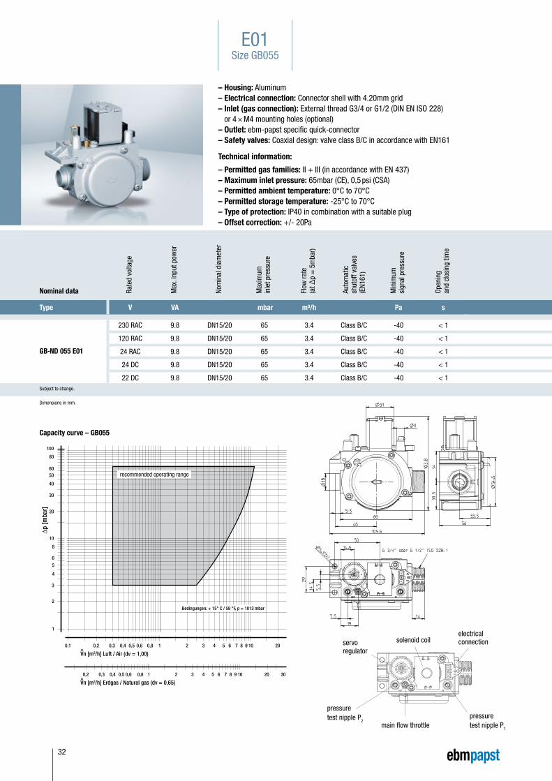
GB-ND 055 E01
230 RAC 9.8 DN15/20 65 3.4 Class B/C -40 < 1
120 RAC 9.8 DN15/20 65 3.4 Class B/C -40 < 1
24 RAC 9.8 DN15/20 65 3.4 Class B/C -40 < 1
24 DC 9.8 DN15/20 65 3.4 Class B/C -40 < 1
22 DC 9.8 DN15/20 65 3.4 Class B/C -40 < 1Subject to change.
Dimensions in mm.
– Housing: Aluminum– Electrical connection: Connector shell with 4.20mm grid– Inlet (gas connection): External thread G3/4 or G1/2 (DIN EN ISO 228)
or 4 × M4 mounting holes (optional)– Outlet: ebm-papst specific quick-connector– Safety valves: Coaxial design: valve class B/C in accordance with EN161
Technical information:
– Permitted gas families: II + III (in accordance with EN 437)– Maximum inlet pressure: 65mbar (CE), 0,5 psi (CSA)– Permitted ambient temperature: 0°C to 70°C– Permitted storage temperature: -25°C to 70°C – Type of protection: IP40 in combination with a suitable plug– Offset correction: +/- 20Pa
Capacity curve – GB055
electrical connectionsolenoid coil
main flow throttlepressure test nipple P1
pressure test nipple P2
servo regulator
E01Size GB055
recommended operating range
32
Nominal data Rate
d vo
ltage
Max
. inp
ut p
ower
Nom
inal
dia
met
er
Max
imum
inle
t pr
essu
re
Flow
rate
(a
t Δp
= 5
mba
r)
Auto
mat
ic
shut
off v
alve
s (E
N161
)
Min
imum
si
gnal
pre
ssur
e
Open
ing
and
clos
ing
time
Type V VA mbar m³/h Pa s
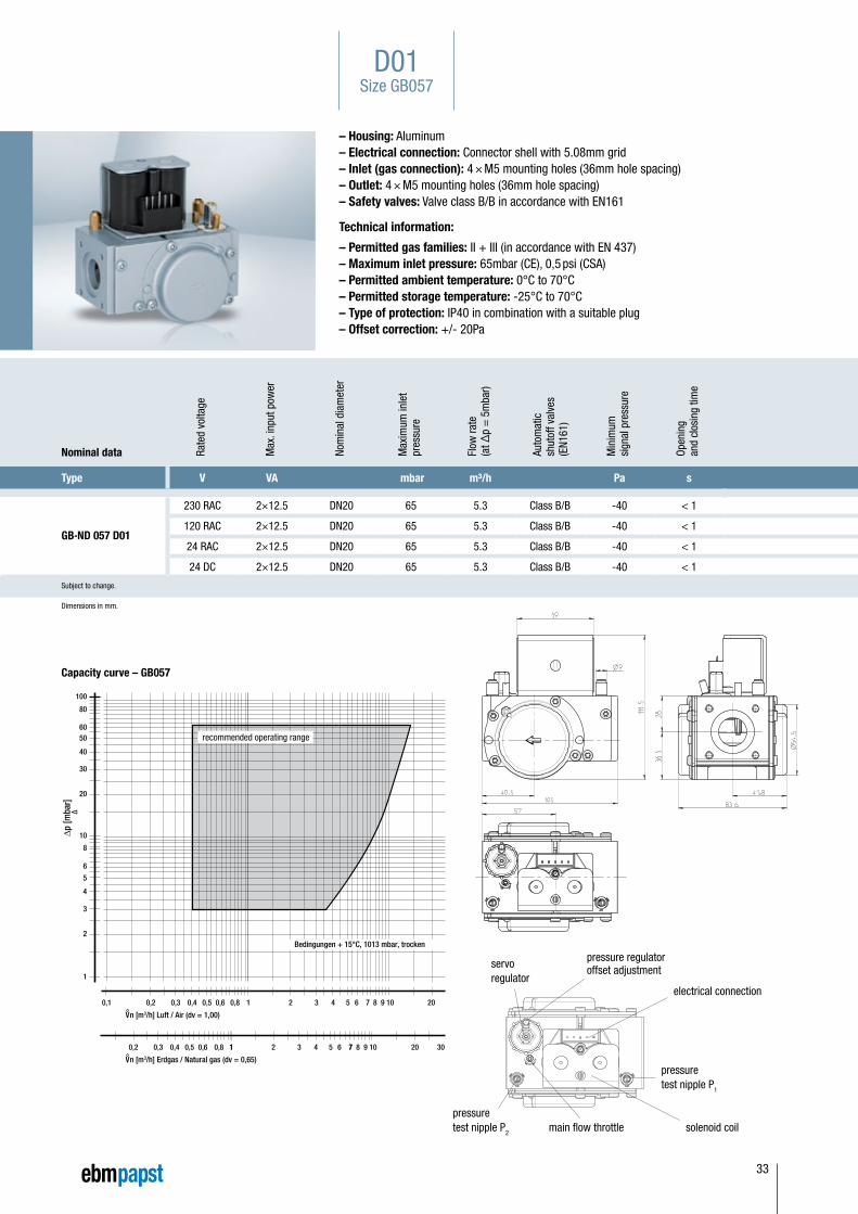
GB-ND 057 D01
230 RAC 2×12.5 DN20 65 5.3 Class B/B -40 < 1
120 RAC 2×12.5 DN20 65 5.3 Class B/B -40 < 1
24 RAC 2×12.5 DN20 65 5.3 Class B/B -40 < 1
24 DC 2×12.5 DN20 65 5.3 Class B/B -40 < 1
Subject to change.
Dimensions in mm.
– Housing: Aluminum– Electrical connection: Connector shell with 5.08mm grid– Inlet (gas connection): 4 × M5 mounting holes (36mm hole spacing)– Outlet: 4 × M5 mounting holes (36mm hole spacing)– Safety valves: Valve class B/B in accordance with EN161
Technical information:
– Permitted gas families: II + III (in accordance with EN 437)– Maximum inlet pressure: 65mbar (CE), 0,5 psi (CSA)– Permitted ambient temperature: 0°C to 70°C– Permitted storage temperature: -25°C to 70°C – Type of protection: IP40 in combination with a suitable plug– Offset correction: +/- 20Pa
Bedingungen + 15°C, 1013 mbar, trocken
V°n [m3/h] Erdgas / Natural gas (dv = 0,65)
V°n [m3/h] Luft / Air (dv = 1,00)
empfohlener Arbeitsbereich
∆p [m
bar]
2 3 4 5 6 71
2 3 4 5 6 71
8 9 10
71 8 9 10
20
20 30
0,1 0,2 0,3 0,4 0,5 0,6
0,2 0,3 0,4 0,5 0,6
0,8
0,8
∆
2
3
4
5
6
1
8
10
20
30
40
60
80
100
50
Capacity curve – GB057
electrical connection
solenoid coilmain flow throttle
pressure test nipple P1
pressure test nipple P2
servo regulator
pressure regulatoroffset adjustment
D01Size GB057
recommended operating range
33
∆p
[mba
r]∆
1
10
100
V°n [m3/h] Erdgas / Natural gas
V°n [m3/h] Luft / Air
0,01 0,1 1 10
°
0,0135 0,135 1,35 13,5
F01 - 12 mm
F01 - 8 mm
Bedingungen: 15° C, p=1013 mbar
empfohlener Arbeitsbereich
Nominal data Rate
d vo
ltage
Max
. inp
ut p
ower
Nom
inal
dia
met
er
Max
imum
in
let p
ress
ure
Flow
rate
(at Δ
p =
5
mba
r) St
eppe
r mot
or
mod
ule
with
nom
inal
di
amet
er 8
mm
Flow
rate
(at Δ
p =
5
mba
r) St
eppe
r mot
or
mod
ule
with
nom
inal
di
amet
er 1
2mm
Auto
mat
ic
shut
off v
alve
s (E
N161
)
Open
ing
and
clos
ing
time
Type V VA mbar m³/h m³/h s
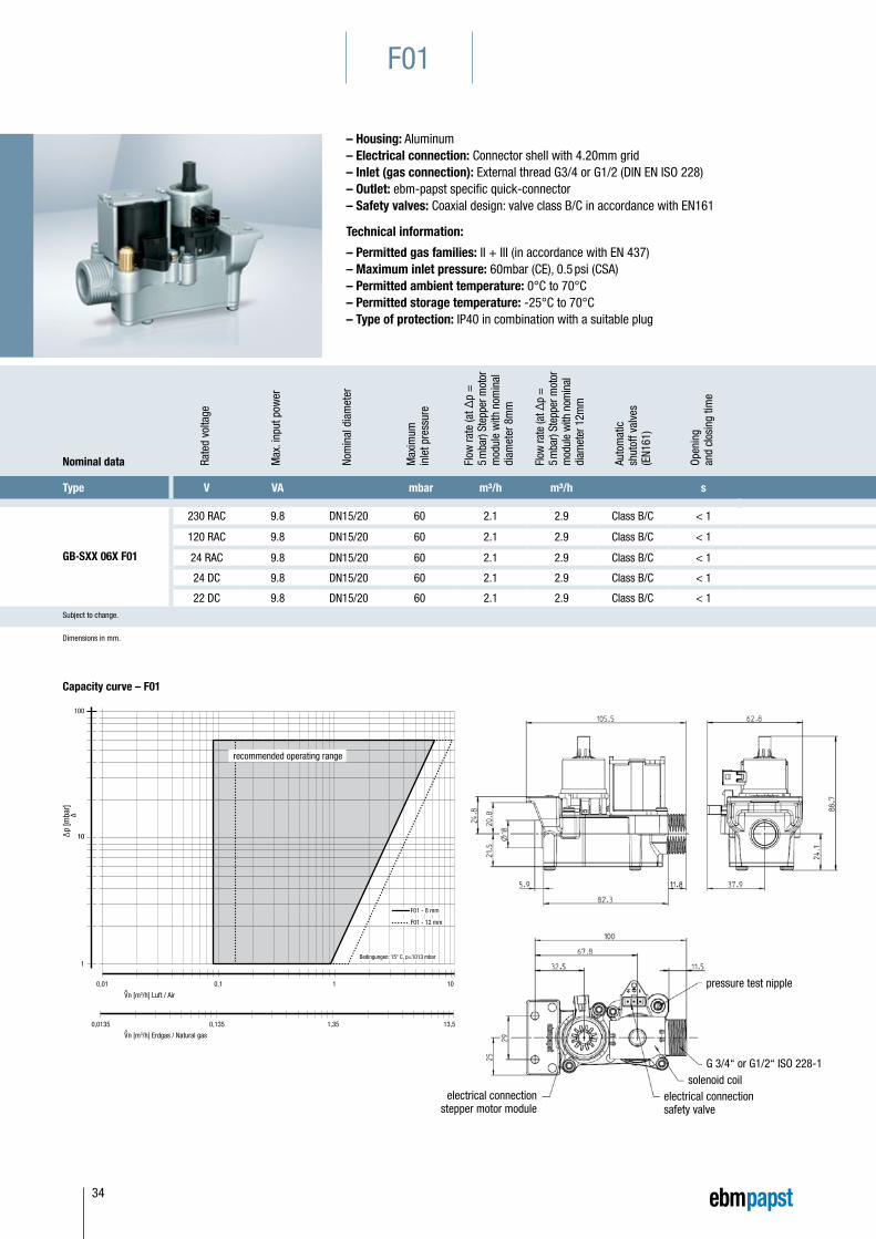
GB-SXX 06X F01
230 RAC 9.8 DN15/20 60 2.1 2.9 Class B/C < 1
120 RAC 9.8 DN15/20 60 2.1 2.9 Class B/C < 1
24 RAC 9.8 DN15/20 60 2.1 2.9 Class B/C < 1
24 DC 9.8 DN15/20 60 2.1 2.9 Class B/C < 1
22 DC 9.8 DN15/20 60 2.1 2.9 Class B/C < 1Subject to change.
– Housing: Aluminum– Electrical connection: Connector shell with 4.20mm grid– Inlet (gas connection): External thread G3/4 or G1/2 (DIN EN ISO 228)– Outlet: ebm-papst specific quick-connector– Safety valves: Coaxial design: valve class B/C in accordance with EN161
Technical information:
– Permitted gas families: II + III (in accordance with EN 437)– Maximum inlet pressure: 60mbar (CE), 0.5 psi (CSA)– Permitted ambient temperature: 0°C to 70°C– Permitted storage temperature: -25°C to 70°C – Type of protection: IP40 in combination with a suitable plug
F01
Capacity curve – F01
electrical connection stepper motor module
electrical connection safety valve
solenoid coilG 3/4“ or G1/2“ ISO 228-1
pressure test nipple
Dimensions in mm.
recommended operating range
34

35
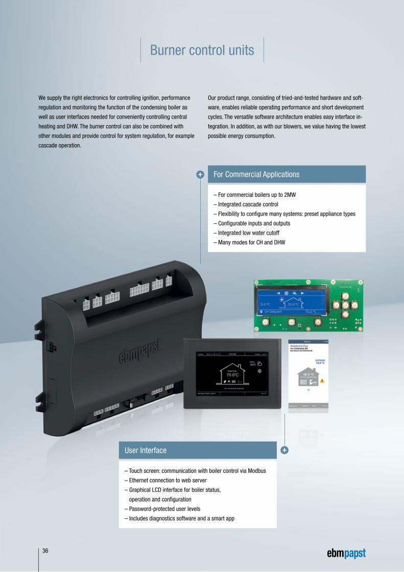
– For commercial boilers up to 2MW
– Integrated cascade control
– Flexibility to configure many systems: preset appliance types
– Configurable inputs and outputs
– Integrated low water cutoff
– Many modes for CH and DHW
For Commercial Applications
– Touch screen: communication with boiler control via Modbus
– Ethernet connection to web server
– Graphical LCD interface for boiler status,
operation and configuration
– Password-protected user levels
– Includes diagnostics software and a smart app
User Interface
Burner control units
We supply the right electronics for controlling ignition, performance
regulation and monitoring the function of the condensing boiler as
well as user interfaces needed for conveniently controlling central
heating and DHW. The burner control can also be combined with
other modules and provide control for system regulation, for example
cascade operation.
Our product range, consisting of tried-and-tested hardware and soft-
ware, enables reliable operating performance and short development
cycles. The versatile software architecture enables easy interface in-
tegration. In addition, as with our blowers, we value having the lowest
possible energy consumption.
36
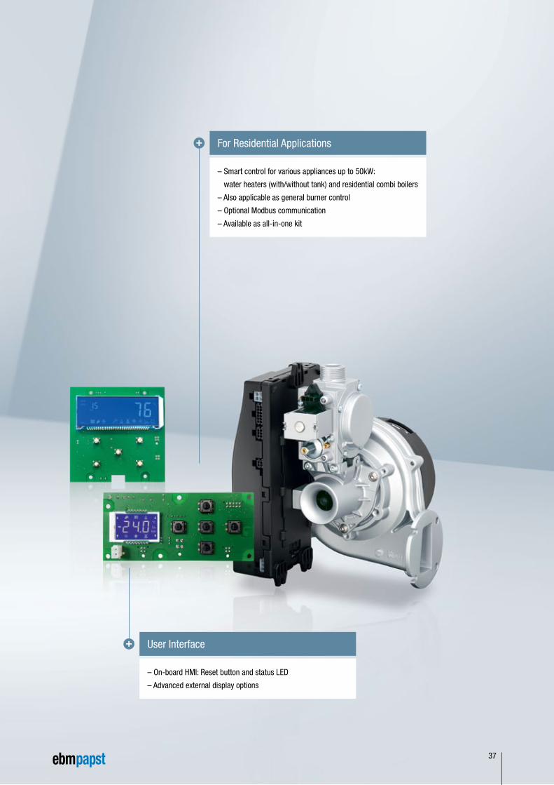
– Smart control for various appliances up to 50kW:
water heaters (with/without tank) and residential combi boilers
– Also applicable as general burner control
– Optional Modbus communication
– Available as all-in-one kit
For Residential Applications
– On-board HMI: Reset button and status LED
– Advanced external display options
User Interface
37
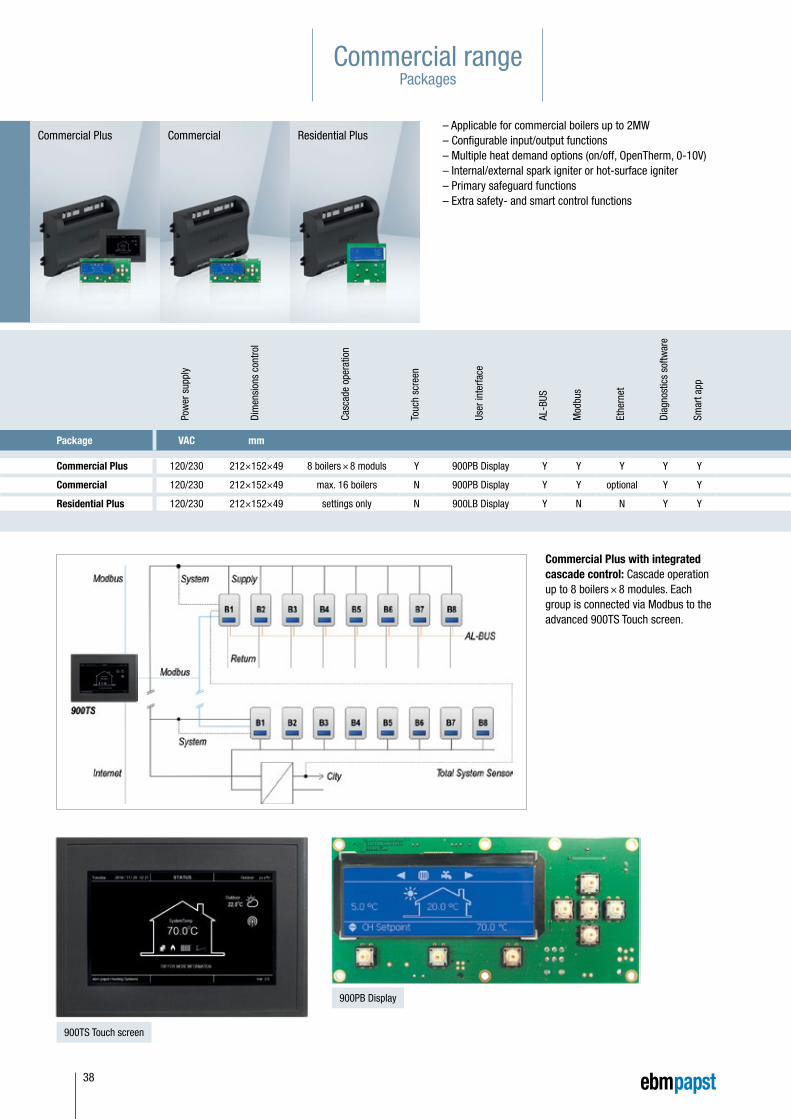
Commercial rangePackages
– Applicable for commercial boilers up to 2MW– Configurable input/output functions– Multiple heat demand options (on/off, OpenTherm, 0-10V)– Internal/external spark igniter or hot-surface igniter– Primary safeguard functions– Extra safety- and smart control functions
Commercial Plus with integrated cascade control: Cascade operation up to 8 boilers × 8 modules. Each group is connected via Modbus to the advanced 900TS Touch screen.
Pow
er s
uppl
y
Dim
ensi
ons
cont
rol
Casc
ade
oper
atio
n
Touc
h sc
reen
User
inte
rface
AL-B
US
Mod
bus
Ethe
rnet
Diag
nost
ics
softw
are
Smar
t app
Package VAC mm
Commercial Plus 120/230 212×152×49 8 boilers × 8 moduls Y 900PB Display Y Y Y Y Y
Commercial 120/230 212×152×49 max. 16 boilers N 900PB Display Y Y optional Y Y
Residential Plus 120/230 212×152×49 settings only N 900LB Display Y N N Y Y
900TS Touch screen
900PB Display
Commercial Plus Commercial Residential Plus
38
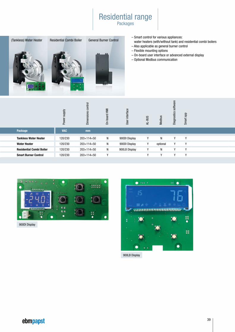
Residential rangePackages
– Smart control for various appliances: water heaters (with/without tank) and residential combi boilers
– Also applicable as general burner control– Flexible mounting options– On-board user interface or advanced external display– Optional Modbus communication
Pow
er s
uppl
y
Dim
ensi
ons
cont
rol
Casc
ade
oper
atio
n
Touc
h sc
reen
User
inte
rface
AL-B
US
Mod
bus
Ethe
rnet
Diag
nost
ics
softw
are
Smar
t app
Package VAC mm
Commercial Plus 120/230 212×152×49 8 boilers × 8 moduls Y 900PB Display Y Y Y Y Y
Commercial 120/230 212×152×49 max. 16 boilers N 900PB Display Y Y optional Y Y
Residential Plus 120/230 212×152×49 settings only N 900LB Display Y N N Y Y
Pow
er s
uppl
y
Dim
ensi
ons
cont
rol
On-b
oard
HM
I
User
inte
rface
AL-B
US
Mod
bus
Diag
nost
ics
softw
are
Smar
t app
Package VAC mm
Tankless Water Heater 120/230 203×114×50 N 900DI Display Y N Y Y
Water Heater 120/230 203×114×50 N 900DI Display Y optional Y Y
Residential Combi Boiler 120/230 203×114×50 N 900LB Display Y N Y Y
Smart Burner Control 120/230 203×114×50 Y Y Y Y Y
900DI Display
900LB Display
(Tankless) Water Heater Residential Combi Boiler General Burner Control
39
ebm-papst in Germany
40
ebm-papst Mulfingen GmbH & Co. KGBachmühle 274673 MulfingenGERMANYPhone +49 7938 81-0Fax +49 7938 [email protected]
ebm-papst St. Georgen GmbH & Co. KGHermann-Papst-Straße 178112 St. GeorgenGERMANYPhone +49 7724 81-0Fax +49 7724 [email protected]
ebm-papst Landshut GmbHHofmark-Aich-Straße 2584030 LandshutGERMANYPhone +49 871 707-0Fax +49 871 [email protected]
BerlinDipl.-Ing. (TH) Jens DuchowHändelstraße 716341 PanketalGERMANYPhone +49 30 944149-62Fax +49 30 [email protected]
BielefeldDipl.-Ing. (FH) Wolf-Jürgen WeberNiehausweg 1333739 BielefeldGERMANYPhone +49 5206 91732-31Fax +49 5206 [email protected]
DortmundDipl.-Ing. (FH) Hans-Joachim PundtAuf den Steinern 359519 Möhnesee-VöllinghausenGERMANYPhone +49 2925 800-407Fax +49 2925 [email protected]
FrankfurtDipl.-Ing. Christian KleffmannDr.-Hermann-Krause-Straße 2363452 HanauGERMANYPhone +49 6181 1898-12Fax +49 6181 [email protected]
HalleDipl.-Ing. (TU) Michael HanningLercheneck 406198 Salzatal / OT LieskauGERMANYPhone +49 345 55124-56Fax +49 345 [email protected]
HamburgIngenieurbüro Breuell GmbHIng. Dirk KahlElektroingenieurOststraße 9622844 NorderstedtGERMANYPhone +49 40 538092-19Fax +49 40 [email protected]
Heilbronn / HeidelbergDipl.-Ing. Mark GartnerGehrweg 1274199 UnterheinrietGERMANYPhone +49 7130 404569-1Fax +49 7130 [email protected]
KasselDipl.-Ing. (FH) Ralph BrückHoherainstraße 3 b35075 GladenbachGERMANYPhone +49 6462 4071-10Fax +49 6462 [email protected]
KoblenzWinfried SchaeferHinter der Kirch 1056767 UersfeldGERMANYPhone +49 2657 16-96Fax +49 2657 [email protected]
MunichDipl.-Wirt.-Ing. (FH) Jens PeterLandsbergerstraße 1486932 PürgenGERMANYPhone +49 8196 99877-54Fax +49 8196 [email protected]
NurembergDipl.-Wirt.-Ing. (FH) Axel ReschDr.-August-Koch-Str. 191639 Wolframs-EschenbachGERMANYPhone +49 9875 9783-170Fax +49 9875 [email protected]
OffenburgDipl.-Ing. (FH) Ralf BraunHubeneck 2177704 OberkirchGERMANYPhone +49 7802 9822-52Fax +49 7802 [email protected]
StuttgartDipl.-Ing. (FH) Rudi WeinmannHindenburgstraße 100/173207 PlochingenGERMANYPhone +49 7153 9289-80Fax +49 7153 [email protected]
UlmM.Sc. Reinhard SommerreißerAm Germanenring 1386674 Baar / SchwabenGERMANYPhone +49 8276 5899-775Fax +49 8276 [email protected]
Distributors
FrankfurtR.E.D. Handelsgesellschaft mbHGutenbergstraße 363110 Rodgau - JügesheimGERMANYPhone +49 6106 841-0Fax +49 6106 [email protected]
HamburgBreuell + Hilgenfeldt GmbHOststraße 9622844 NorderstedtGERMANYPhone +49 40 538092-20Fax +49 40 [email protected]
MunichA. Schweiger GmbHOhmstraße 182054 SauerlachGERMANYPhone +49 8104 897-0Fax +49 8104 [email protected]
(1 to 5 pieces)
NorthBreuell + Hilgenfeldt GmbHOststraße 9622844 NorderstedtGERMANYPhone +49 40 538092-20Fax +49 40 [email protected]
SouthHDS Ventilatoren Vertriebs GmbHGlaswiesenstraße 174677 DörzbachGERMANYPhone +49 7937 80355-20Fax +49 7937 [email protected]
fan agent compact fan agent motor specialist motor agent
ebm-papst in Europe
41
Europe
Austriaebm-papst Motoren & Ventilatoren GmbHStraubingstraße 174030 LinzAUSTRIAPhone +43 732 321150-0Fax +43 732 [email protected]
Belarusebm-papst Bel AgmbH4th Montazhnikov side streetHouse 6, Office 332BY-220019 MinskBELARUSPhone +375 17 2015216Fax +375 17 [email protected]
Belgiumebm-papst Benelux B.V.Sales office Belgium-LuxemburgRomeinsestraat 6/0101Research Park Haasrode3001 Heverlee-LeuvenBELGIUMPhone +32 16 396-200Fax +32 16 [email protected]
Bulgariaebm-papst Romania S.R.L.Str. Tarnavei No. 20500327 BrasovROMANIAPhone +40 268 331859Fax +40 268 [email protected]
Croatiaebm-papst Industries Kft.Ezred u. 2.1044 BudapestHUNGARYPhone +36 1 8722-190Fax +36 1 [email protected]
CyprusHelcomaE. Rota and Co. OEDavaki 6517672 Kallithea-AttikiGREECEPhone +30 210 9513-705Fax +30 210 [email protected]
Czech Republic / Slovakiaebm-papst CZ s.r.o.Kaštanová 34a620 00 BrnoCZECH REPUBLICPhone +420 544 502-411Fax +420 547 [email protected]
Denmarkebm-papst Denmark ApSVallensbækvej 212605 BrøndbyDENMARKPhone +45 43 631111Fax +45 43 [email protected]
Estoniaebm-papst Oy, Eesti FiliaalKesk tee 21Aaviku küla, Jüri Tehnopark75301 Rae Vald, HarjumaaESTONIAPhone +372 65569-78www.ebmpapst.ee
Finlandebm-papst OyPuistotie 102760 EspooFINLANDPhone +358 9 887022-0Fax +358 9 [email protected]
Franceebm-papst sarlParc d’Activités Nord1 rue Mohler – BP 6267212 Obernai CedexFRANCEPhone +33 3 88 66 88 [email protected]
GreeceHelcomaE. Rota and Co. OEDavaki 6517672 Kallithea-AttikiGREECEPhone +30 210 9513-705Fax +30 210 [email protected]
Hungaryebm-papst Industries Kft.Ezred u. 2.1044 BudapestHUNGARYPhone +36 1 8722-190Fax +36 1 [email protected]
IcelandRJ EngineersStangarhyl 1a110 ReykjavikICELANDPhone +354 567 8030Fax +354 567 [email protected]
Irelandebm-papst UK Ltd.Chelmsford Business ParkChelmsford Essex CM2 5EZUNITED KINGDOMPhone +44 1245 468555Fax +44 1245 [email protected]
AuBren LimitedPortlaoise Business & Technology ParkMountrath RoadPortlaoise, Co. LaoisIRELANDPhone +353 57 8664343Fax +353 57 [email protected]
Italyebm-papst SrlVia Cornaggia 10822076 Mozzate (Co)ITALYPhone +39 0331 836201Fax +39 0331 [email protected]
fan agent compact fan agent motor specialist motor agent
ebm-papst in Europe
42
Macedoniaebm-papst Industries Kft.Ezred u. 2.1044 BudapestHUNGARYPhone +36 1 8722-190Fax +36 1 [email protected]
Netherlandsebm-papst Benelux B.V.Polbeemd 7 - 5741 TP Beek en DonkP.O. Box 140 - 5740 AC Beek en DonkNETHERLANDSPhone +31 492 502-900Fax +31 492 [email protected]
ebm-papst Heating Systems B.V.Van Veldekekade 360 5216 KT ’s-Hertogenbosch NETHERLANDSPhone +31 73 648 89 00Fax +31 73 648 89 [email protected]
Norwayebm-papst ASP.B. 173 Holmlia1203 OsloNORWAYPhone +47 22 763340Fax +47 22 [email protected]
Polandebm-papst Polska Sp. z o.o.ul. Annopol 4A03236 WarszawaPOLANDPhone +48 22 6757819Fax +48 22 [email protected]
Portugalebm-papst (Portugal), Lda.Centro Empresarial de AlvercaRua de Adarse, Vale D’ErvasCorpo D / Fracção 32615-178 Alverca do RibatejoPORTUGALPhone +351 218 394 880Fax +351 218 394 [email protected]
Romaniaebm-papst Romania S.R.L.Str. Tarnavei Nr. 20500327 BrasovROMANIAPhone +40 268 331859Fax +40 268 [email protected]
Russiaebm-papst Rus GmbHOlimpiyskiy prospect 29A, office 418141006 Mytistschi, Oblast MoskauRUSSIAPhone +7 495 9807524Fax +7 495 [email protected]
ebm-papst Ural GmbHPosadskaja-Strasse, 23(E), 3620102 EkaterinburgRUSSIAPhone +7 343 2338000Fax +7 343 [email protected]
Serbia & Montenegroebm-papst Industries Kft.Ezred u. 2.1044 BudapestHUNGARYPhone +36 1 8722-190Fax +36 1 [email protected]
Spainebm-papst Ibérica S.L.Avda. del Sistema Solar, 2928830 San Fernando de Henares (Madrid)SPAINPhone +34 91 6780894Fax +34 91 [email protected]
Swedenebm-papst ABÄggelundavägen 217562 JärfällaSWEDENPhone +46 10 4544400Fax +46 8 [email protected]
Switzerlandebm-papst AGRütisbergstrasse 18156 OberhasliSWITZERLANDPhone +41 44 73220-70Fax +41 44 [email protected]
TurkeyAkantel Elektronik San. Tic. LTD. Sti.Atatürk Organize SanayiBölgesi 10007 SK. No.:635620 Cigli-IzmirTURKEYPhone +90 232 3282090Fax +90 232 [email protected]
Ukraineebm-papst Ukraine LLCLepse Boulevard, 4, Building 2103067 KievUKRAINEPhone +38 044 2063091Fax +38 044 2063091 [email protected]
United Kingdomebm-papst UK Ltd.Chelmsford Business ParkChelmsford Essex CM2 5EZUNITED KINGDOMPhone +44 1245 468555Fax +44 1245 [email protected]
ebm-papst Automotive & Drives (UK) Ltd.The SmithyFidlers LaneEast Ilsley, Berkshire RG20 7LGUNITED KINGDOMPhone +44 1635 2811-11Fax +44 1635 2811-61A&[email protected]
fan agent compact fan agent motor specialist motor agent
ebm-papst in America und Africa
43
America
Argentinaebm-papst de Argentina S.A.Hernandarias 148 Lomas del MiradorPcia. de Buenos Aires (1752)ARGENTINAPhone +54 11 46576135Fax +54 11 [email protected]
Brazilebm-papst Motores Ventiladores Ltda.Av. José Giorgi, 301 Galpões B6+B7Condominio Logical Center06707-100 Cotia - São PauloBRAZILPhone +55 11 4613-8700Fax +55 11 [email protected]
Canadaebm-papst Canada Inc.1800 Ironstone Manor, Unit 2Pickering, Ontario, L1W3J9CANADAPhone +1 905 420-3533Fax +1 905 [email protected]
Mexicoebm Industrial S. de R.L. de C.V.Paseo de Tamarindos 400-A-5to PisoCol. Bosques de las LomasMexico 05120, D.F.MEXICOPhone +52 55 3300-5144Fax +52 55 [email protected]
USAebm-papst Inc.P.O. Box 4009100 Hyde RoadFarmington, CT 06034UNITED STATESPhone +1 860 674-1515Fax +1 860 [email protected]
ebm-papst Automotive & Drives, Inc.3200 Greenfield, Suite 130Dearborn, MI 48120UNITED STATESPhone +1 313 406-8080Fax +1 313 [email protected]
Africa
South Africaebm-papst South Africa (Pty) Ltd.P.O. Box 31241119 Yacht Avenue2040 HoneydewSOUTH AFRICAPhone +27 11 794-3434Fax +27 11 [email protected]
fan agent compact fan agent motor specialist motor agent
ebm-papst in Asia
44 fan agent compact fan agent motor specialist motor agent
Asia
Chinaebm-papst Ventilator (Shanghai) Co., Ltd.No. 418, Huajing RoadWaiGaoQiao Free Trade ZoneNo. 2001, Yang Gao (N) Road200131 ShanghaiP.R. of CHINAPhone +86 21 5046-0183Fax +86 21 [email protected]
Hong Kongebm-papst Hong Kong Ltd.Room 17E, MG Tower133 Hoi Bun Road, Kwun TongHong KongP.R. of CHINAPhone +852 2145-8678Fax +852 [email protected]
Indiaebm-papst India Pvt. Ltd.26/3, G.N.T. Road, ErukkencherryChennai-600118INDIAPhone +91 44 25372556Fax +91 44 [email protected]
Indonesiaebm-papst IndonesiaRepresentative OfficeGerman Centre, 4th Floor, Suite 4470Jl. Kapt. Subijono Dj. Bumi Serpong Damai15321 TangerangINDONESIAPhone +62 21 5376250Fax +62 21 [email protected]
IsraelPolak Bros. Import Agencies Ltd.9 Hamefalsim StreetKiryat Arie, Petach-Tikva 49514ISRAELPhone +972 3 9100300Fax +972 3 [email protected]
Japanebm-papst Japan K.K.Attend on Tower 13FShinyokohama 2-8-12, Kohoku-ku222-0033 Yokohama-City, KanagawaJAPANPhone +81 45 47057-51Fax +81 45 [email protected]
Koreaebm-papst Korea Co. Ltd.6F, Trutec Bldg.12, WorldCupbuk-ro 56-gilMapo-Gu Seoul 03924KOREAPhone +82 2 366213-24Fax +82 2 [email protected] www.ebmpapst.co.kr
Malaysiaebm-papst MalaysiaRepresentative OfficeNo. 16-1, Jalan Putra Mahkota 7/5APutra HeightsSelangor Darul Ehsan47650 Subang JayaMALAYSIAPhone +60 3 5192-7688Fax +60 3 [email protected]
Philippines ebm-papst SEA Pte. Ltd.Representative Office (Philippines)ALPAP II BuildingTrade Street Corner Investment DriveUnit 1101 Madrigal Business Park1799 Ayala Alabang / Muntinlupa CityTelefon: +63 02 8042747Telefax: +63 02 [email protected]
Singaporeebm-papst SEA Pte. Ltd.9 Tai Seng Drive#03-01 Geo-Tele Centre, Lobby BSingapore 535227SINGAPOREPhone +65 65513789Fax +65 [email protected]
TaiwanETECO Engineering & Trading Corp.10F-I, No. 92, Teh-Wei Str.Tsow-Inn District, KaohsiungTAIWANPhone +886 7 557-4268Fax +886 7 [email protected]
Thailandebm-papst Thailand Co., Ltd.99/9 Moo 2, Central Chaengwattana Tower14th Floor, Room 1402Chaengwattana Road Bangtarad, Pakkret11120 NonthaburiTHAILANDPhone +66 2 8353785-7Fax +66 2 [email protected]
United Arab Emiratesebm-papst Middle East FZEPO Box 17755Jebel Ali Free Zone / FZS1 / AP05DubaiUNITED ARAB EMIRATESPhone +971 4 88608-26Fax +971 4 [email protected]
Vietnamebm-papst SEA Pte. Ltd.Representative OfficeRoom 402, 4th Floor, Saigon 3 Building140 Nguyen Van Thu StreetDakao Ward, District 1Ho Chi Minh CityVIETNAMPhone +848 3910 4099Fax +848 3910 [email protected]
ebm-papst in Oceania
45
Oceania
Australiaebm-papst A&NZ Pty Ltd.10 Oxford RoadLaverton North, Victoria, 3026AUSTRALIAPhone +61 3 9360-6400Fax +61 3 [email protected]
New Zealandebm-papst A&NZ Pty Ltd.61 Hugo Johnston Drive, Unit HPenrose 1061, AucklandNEW ZEALANDPO Box 112278,Penrose 1642, AucklandPhone +64 9 525-0245Fax +64 9 [email protected]
fan agent compact fan agent motor specialist motor agent

Notes
46
47

www.ebmpapst.comwww.ebmpapst-hs.nl
37895-7-8811 · 2017-03 · RU-1,5‘Printed in Germany
ebm-papst
Heating Systems B.V.
Van Veldekekade 360
5216 KT’s-Hertogenbosch
The Netherlands
Phone +31 73 64889-00
Fax +31 73 64889-11
ebm-papst
Landshut GmbH
Hofmark-Aich-Straße 25
84030 Landshut
Germany
Phone +49 871 707-0
Fax +49 871 707-465
FSC-Logo