cone drive single reduction units - 1.500 c.d. solid shaft ... · pdf filecone drive single...
TRANSCRIPT
3/16 X 3/32 KWY
3/16 X 3/32 KWY
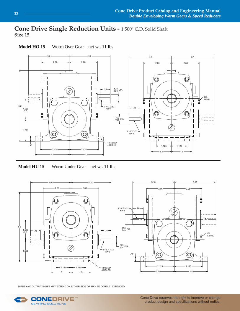
Model HO 15 Worm Over Gear net wt. 11 lbs
Model HU 15 Worm Under Gear net wt. 11 lbs
OILLEVEL
11/32 DIA4 HOLES
.75
3.03.0
2.06 2.06
.625
.624 DIA.
3.1 3.1
2.062.06
.750
.749 DIA.
.80
1.125 1.125
1.5 1.52.125 2.125
2.5 2.5
5.21.500C.D.
1.625
1.625
1.500C.D.
5.2
3.00 3.00
2.06 2.06
.75 .75
3.10
2.06 2.06
2.125 2.125
2.52.5
.40
11/32 DIA4 HOLES
1.125 1.125
1.5 1.5
3/16 X 3/32 KWY
3/16 X 3/32 KWY
.750
.749 DIA.
.625
.624 DIA.
OILLEVEL
.40
INPUT AND OUTPUT SHAFT MAY EXTEND ON EITHER SIDE OR MAY BE DOUBLE EXTENDED
3.10
.80
Cone Drive Single Reduction Units - 1.500" C.D. Solid ShaftSize 15
Cone Drive Product Catalog and Engineering ManualDouble Enveloping Worm Gears & Speed Reducers32
Cone Drive reserves the right to improve or change product design and specifi cations without notice.
TM

Cone Drive Single Reduction Units - 1.500" C.D. Solid ShaftSize 15 - Motorizing
Remarks: Reducer can be shipped with or without motor to suit requirements. Adapter fl ange will extend below footline of reducers.
15-M20Model MHO approx. .187Model MHU approx. 1.687
15-M20-48AModel MHU approx. .50
Used w/15-M20-48A
When ordering specify frame size used.
ShownModel MHO 15
NEMA C Face Motors
Hand of Assembly Floor Mounted UnitsWhen ordering, specify the assembly number required, selected from diagrams. The hand of assembly is always determined as a fl oor mounted unit.
HO #1 Shown HU
TOP VIEW
INPUT(DRIVE END)
1 2 3 4 5 6
Notes: Reducers may be used in fl oor, ceiling, or wall mounted positions.Unless specifi ed, standard reducers are supplied with right-hand helix gear sets.Reducers are designed for shaft rotation in either direction.See General information section.All units can be motorized.Other ratios are available on request.
Important: In any applications of Cone Drive products where breakage, damage, disconnection, any other malfunction of any drive train component, or excessive wear could result in personal injury or property damage, a fail-safe device capable of stopping and holding the load in the event of such an occurrence must be incorporated after the drive train.
CAUTION: It is the purchaser’s or user’s responsibility to guard all shafting in accordance with current local, state or federal requirements.
DIMENSIONSMOTOR REDUCER
FRAMESIZE
PILOTDIA.
SHAFT A FLGE.DIA.
COUPLINGNUMBERLGTH. DIA. KWY
48C 3.000 1.68 .500 FLAT 5.20 4.25 15-140-050/06256C 4.500 2.06 .625 3/16 5.58 6.50 15-140-062
143TC145TC 4.500 2.12 .875 3/16 5.58 6.50 15-140-062/088
15-140-050/075
AGMA HORSEPOWER & OUTPUT TORQUE RATINGS FOR 1.0 SERVICE FACTORWorm RPM
Ratio to 1 100 200 300 580 720 870 1150 1750
5Me.HP 0.24 0.45 0.64 1.13 1.35 1.58 1.94 2.51Effi ciency 89 90 91 91 91 92 92 92O.T. 670 635 610 560 540 530 490 420
10Me.HP 0.16 0.31 0.44 0.78 0.94 1.10 1.37 1.81Effi ciency 83 85 86 87 87 89 90 90O.T. 860 825 800 745 720 715 675 590
15Me.HP 0.13 0.25 0.36 0.63 0.76 0.89 1.11 1.48Effi ciency 79 81 82 85 85 87 88 88O.T. 990 955 925 880 855 845 805 705
20Me.HP 0.10 0.19 0.27 0.49 0.58 0.68 0.85 1.14Effi ciency 75 77 78 83 83 83 84 85O.T. 955 930 895 880 850 825 785 700
30Me.HP 0.07 0.13 0.18 0.33 0.40 0.46 0.58 0.77Effi ciency 68 70 72 75 75 79 80 80O.T. 880 855 835 805 780 795 760 665
40Me.HP 0.05 0.10 0.14 0.25 0.30 0.35 0.43 0.58Effi ciency 61 63 67 72 75 75 76 76O.T. 795 770 785 775 785 760 725 635
50Me.HP 0.04 0.08 0.11 0.20 0.24 0.28 0.35 0.46Effi ciency 54 60 64 70 70 72 73 73O.T. 705 735 750 755 735 730 700 610
60Me.HP 0.03 0.06 0.09 0.16 0.20 0.23 0.29 0.39Effi ciency 53 59 61 66 66 69 70 70O.T. 695 725 715 710 690 700 670 585
Key: Me.HP = Mech. Input Power (HP) O.T. = Output Torque (In. Lb.)
OUTPUT
INPUT INPUT
OUTPUT
3.125
A
.38
4 - 13/32 DIA HOLES ON 5.875 B.C.
MOTOR SHAFT DIA.
MOTORSHAFT
LENGTH
PILOT DIA.4.500
A
.504-9/32 DIA HOLESON 3.750 B.C.
15 - M20-48-A
PILOT DIA.3.000
15 - M20
COUPLING
3.0
TM
Cone Drive Product Catalog and Engineering ManualDouble Enveloping Worm Gears & Speed Reducers 33
Sales: 1-888-994-2663Sales Fax: 1-888-907-2663Traverse City, MI. 49685

2.9
4.60
1.06
.69
4.60
2.9
1.06
3.4 3.4
2.75
9.1 2.000C.D
3.62
3.5
.6875
.6865 DIA
2.75
4.06 4.062.4 2.1
1.191.1251.124 DIA
2.75 2.753.3 3.3
2.2 2.2
2.633.06
25/64 DIA4 HOLES
INPUT AND OUTPUT SHAFT MAY EXTEND ON EITHER SIDE OR MAY BE DOUBLE EXTENDED
BORE #
3/16 X 3/32 KWY
1/4 X 1/8 KWY
1.19
2.92 2.92
4.60 4.60
1.06
1.06
3.4 3.4
.69
3.62
9.1
3.5
2.000C.D
.688
.686 DIA
3/16 X 3/32 KWY
2.4 2.1
4.06 4.06
1.191.19
1.1251.124 DIA
2.75
2.00
3.3 3.3
25/64 DIA4 HOLES
1/4 X 1/8 KWY
2.2
3.06
2.2
2.63
2.9
2.9
4.59
4.59
1.88
1.88
4.2
BORE #
2.2
2.23.06
2.63
2.4
2.1
1.19
1.1251.124 DIA
2.00
2.00
1.19
4.06
4.06
1.06
.6875
.6865 DIA
1.06
25/64 DIA4 HOLES
3/16 X 3/32 KWY
1/4 X 1/8 KWY
3.5
Model HO SHOWorm Over Gear net wt. 26 lbs net wt. 27 lbs
Model HU SHUWorm Under Gear net wt. 26 lbs net wt. 27 lbs
Model HV SHVWorm Horizontal Gear Shaft Vertical net wt. 26 lbs net wt. 27 lbs
# SEE GEAR SHAFT CHARTSET SCREW END OF SHAFTMAY EXTEND ON EITHER SIDE
# SEE GEAR SHAFT CHARTSET SCREW END OF SHAFTMAY EXTEND ON EITHER SIDE
# SEE GEAR SHAFT CHARTSET SCREW END OF SHAFT MAY EXTEND ON EITHER SIDEWHEN REVIEWING END OF SHAFT MODEL, REFERTO COMPLETE DIMENSIONS ON SAME SOLIDSHAFT MODEL SHOWN AT LEFT.
2.75 2.75
BORE #
2.00 2.001.88 1.88 .19
1.88 1.88
FOOT BRACKET AVAILABLE ON REQUEST
FOOT BRACKET AVAILABLE ON REQUEST
3/8 BOLTS
.19 2.00
2.75
7.88
3.5
3.5
7.88
3/8 BOLTS
4.1
4.1
7.88
2.94 2.000C.D
25/64 DIA4 HOLES
25/64 DIA4 HOLES
Cone Drive Single Reduction Units - 2.000 " C.D. Size 20 Solid Shaft Hollow Shaft
Cone Drive Product Catalog and Engineering ManualDouble Enveloping Worm Gears & Speed Reducers34
Cone Drive reserves the right to improve or change product design and specifi cations without notice.
TM

Cone Drive Single Reduction Units - 2.000 " C.D. Size 20
Hand of Assembly Floor Mounted UnitsWhen ordering, specify the assembly number required, selected from diagrams. (Ceiling and wall mounted units follow in this section.)The hand of assembly is always determined as a fl oor mounted unit.
1 2 3 4 5 6
HO Worm Over SHOHU Worm Under SHU
#1 Shown
HV Vertical SHV#7A Shown
GEARSHAFTEXTENDEDOpposite Feet .............7A ............8A ............9A ............0AThru Feet ....................7B .............8B .............9B .............0BBoth Sides ...................7C .............8C .............9C .............0C
INPUT(DRIVE END)
TOP VIEW
Notes: Reducers may be used in fl oor, ceiling, or wall mounted positions, however they must be ordered for the position required so that suitable oil level, fi ller, and drains are provided.For cap and carrier dimensions not shown, see mounting section.All units can be motorized. Motor adapter to be located at extension end of input shaft.Set screw end of hollow shaft is considered the extension end.All standard units are supplied with right-hand helix gear sets. Units are designed for shaft rotation in either direction. For additional available ratios and left-hand helix gearing Contact Cone Drive.Refer to page 26 for lubrication information.
Important: In any applications of Cone Drive products where breakage, damage, disconnection, any other malfunction of any drive train component, or excessive wear could result in personal injury or property damage, a fail-safe device capable of stopping and holding the load in the event of such an occurrence must be incorporated after the drive train.
STANDARD HOLLOW GEAR SHAFT BORES
CAUTION: It is the purchaser’s or user’s responsibility to guard all shafting in accordance with current local, state or federal requirements.
BOREINCHES
GEARSHAFTNUMBER
KEYWAYSIZE
1.375* 20-S60-106 1/4 X 1/81.250* 20-S60-104 1/4 X 1/8
1.1875* 20-S60-103 1/4 X 1/81.125* 20-S60-102 1/4 X 1/81.000* 20-S60-100 1/4 X 1/8
Special hollow gear shaft bore sizes are available at additional cost.*AGMA StandardBore Tolerance: +.002, -.0002 set screws at long end of shaft.
AGMA HORSEPOWER & OUTPUT TORQUE RATINGS FOR 1.0 SERVICE FACTORWorm RPM
Ratio to 1 100 200 300 580 720 870 1150 1750
5
Me.HP 0.47 0.88 1.25 2.21 2.62 3.02 3.64 4.59Th.HP 0.40 0.73 1.04 1.84 2.18 2.52 3.03 3.43Effi ciency 89 90 91 91 91 92 92 92O.T. 1,330 1,250 1,200 1,095 1,045 1,010 920 760
10
Me.HP 0.32 0.61 0.86 1.53 1.83 2.11 2.57 3.28Th.HP 0.25 0.47 0.66 1.18 1.40 1.63 1.98 2.53Effi ciency 83 85 86 87 87 89 90 90O.T. 1,700 1,630 1,560 1,450 1,390 1,365 1,270 1,065
15
Me.HP 0.26 0.49 0.70 1.24 1.48 1.72 2.10 2.69Th.HP 0.18 0.33 0.47 0.83 0.99 1.15 1.40 1.79Effi ciency 79 81 82 85 85 87 88 88O.T. 1,965 1,880 1,810 1,715 1,655 1,625 1,515 1,280
20
Me.HP 0.20 0.38 0.54 0.95 1.13 1.32 1.61 2.06Th.HP 0.13 0.25 0.36 0.63 0.76 0.88 1.07 1.38Effi ciency 75 77 78 83 83 83 84 85O.T. 1,900 1,830 1,755 1,715 1,650 1,585 1,485 1,265
25
Me.HP 0.16 0.30 0.43 0.77 0.91 1.06 1.30 1.66Th.HP 0.11 0.20 0.29 0.51 0.61 0.71 0.87 1.11Effi ciency 71 75 77 81 81 83 84 84O.T. 1,810 1,795 1,745 1,685 1,625 1,595 1,495 1,260
30
Me.HP 0.14 0.25 0.36 0.64 0.77 0.89 1.09 1.40Th.HP 0.09 0.17 0.24 0.43 0.51 0.59 0.73 0.93Effi ciency 68 70 72 75 75 79 80 80O.T. 1,745 1,685 1,645 1,570 1,510 1,530 1,430 1,210
40
Me.HP 0.10 0.19 0.27 0.48 0.58 0.67 0.82 1.05Th.HP 0.07 0.13 0.18 0.32 0.38 0.45 0.55 0.70Effi ciency 61 63 67 72 75 75 76 76O.T. 1,570 1,525 1,535 1,515 1,515 1,460 1,365 1,155
50
Me.HP 0.08 0.15 0.22 0.39 0.46 0.54 0.66 0.84Th.HP 0.05 0.10 0.15 0.26 0.31 0.36 0.44 0.56Effi ciency 54 60 64 70 70 72 73 73O.T. 1,395 1,455 1,470 1,475 1,420 1,405 1,315 1,110
60
Me.HP 0.07 0.13 0.18 0.32 0.39 0.45 0.55 0.71Th.HP 0.05 0.09 0.12 0.22 0.26 0.30 0.37 0.47Effi ciency 53 59 61 66 66 69 70 70O.T. 1,370 1,435 1,400 1,395 1,340 1,350 1,265 1,070
Key: Me.HP = Mech. Input Power (HP) Th.HP = Thermal Input Power - No Fan O.T. = Output Torque (In. Lb.)
TOP VIEW
INPUT(DRIVE END)
OUTPUT
INPUT
INPUT
OUTPUT
INPUT
OUTPUT
INPUT
OUTPUT
TM
Cone Drive Product Catalog and Engineering ManualDouble Enveloping Worm Gears & Speed Reducers 35
Sales: 1-888-994-2663Sales Fax: 1-888-907-2663Traverse City, MI. 49685

3.7
5.25
1.00
.75
5.25
3.7
1.00
4.4 4.4
3.69
10.8
2.500C.D
4.25
3.9
.750
.749 DIA
3.69
4.50 4.503.4 3.4
1.391.2501.249 DIA
3.19 3.193.7 3.7
2.6 2.62.693.12
25/64 DIA4 HOLES
INPUT AND OUTPUT SHAFT MAY EXTEND ON EITHER SIDE OR MAY BE DOUBLE EXTENDED
BORE #3/16 X 3/32 KWY
1/4 X 1/8 KWY
1.39
5.25 5.25
3.7 3.7
1.00
1.00
4.4 4.4
.75
4.25
10.8
3.9
2.500C.D
.750
.749 DIA
3/16 X 3/32 KWY
2.6 2.64.50 4.50
1.39 1.39
1.2501.249 DIA
3.19 3.193.7 3.7
25/64 DIA4 HOLES
1/4 X 1/8 KWY
2.6
3.12
2.6
2.69
3.6
3.6
5.25
5.25
2.69
2.69
4.7
BORE #
2.6
2.6 3.12
2.69
2.6
2.6
1.39
1.2501.249 DIA
2.38
2.38
1.39
4.50
4.50
1.00.750.749 DIA
1.00
29/64 DIA4 HOLES
3/16 X 3/32 KWY
1/4 X 1/8 KWY
4.06
Model HO SHOWorm Over Gear net wt. 45 lbs net wt. 46 lbs
Model HU SHUWorm Under Gear net wt. 45 lbs net wt. 46 lbs
Model HV SHVWorm Horizontal Gear Shaft Vertical net wt. 45 lbs net wt. 46 lbs
# SEE GEAR SHAFT CHARTSET SCREW END OF SHAFTMAY EXTEND ON EITHER SIDE
# SEE GEAR SHAFT CHARTSET SCREW END OF SHAFTMAY EXTEND ON EITHER SIDE
# SEE GEAR SHAFT CHARTSET SCREW END OF SHAFTMAY EXTEND ON EITHER SIDE
3.69 3.69
BORE #
2.38 2.382.69 2.69 .19
2.69 2.69
FOOT BRACKET AVAILABLE ON REQUEST
FOOT BRACKET AVAILABLE ON REQUEST
7/16 BOLTS
.19 2.38 2.38
9.50
4.1
4.1
9.50
7/16 BOLTS
4.7
4.7
9.503.50 2.500
C.D
29/64 DIA4 HOLES
29/64 DIA4 HOLES
Cone Drive Single Reduction Units - 2.500" C.D. Size 25 Solid Shaft Hollow Shaft
Cone Drive Product Catalog and Engineering ManualDouble Enveloping Worm Gears & Speed Reducers36
Cone Drive reserves the right to improve or change product design and specifi cations without notice.
TM

OUTPUT
INPUT
INPUT
OUTPUT
INPUT
OUTPUT
INPUT
OUTPUT
Cone Drive Single Reduction Units - 2.500" C.D. Size 25
Notes: Reducers may be used in fl oor, ceiling, or wall mounted positions, however they must be ordered for the position required so that suitable oil level, fi ller, and drains are provided.For cap and carrier dimensions not shown, see mounting section.Steeple bearing arrangements follow in this section.All units can be motorized. Motor adapter to be located at extension end of input shaft.Set screw end of hollow shaft is considered the extension end.All standard units are supplied with right-hand helix gear sets. Units are designed for shaft rotation in either direction. For additional available ratios and left-hand helix gearing Contact Cone Drive.Refer to page 26 for lubrication information.
Important: In any applications of Cone Drive products where breakage, damage, disconnection, any other malfunction of any drive train component, or excessive wear could result in personal injury or property damage, a fail-safe device capable of stopping and holding the load in the event of such an occurrence must be incorporated after the drive train.
STANDARD HOLLOW GEAR SHAFT BORES
CAUTION: It is the purchaser’s or user’s responsibility to guard all shafting in accordance with current local, state or federal requirements.
BOREINCHES
GEARSHAFTNUMBER
KEYWAY SIZE
2.000* 25-S60-200 1/4 X 1/81.9375* 25-S60-115 1/4 X 1/81.6875* 25-S60-111 3/8 X 3/161.4375* 25-S60-107 3/8 X 3/161.250* 25-S60-104 1/4 X 1/8
1.1875* 25-S60-103 1/4 X 1/8Special hollow gear shaft bore sizes are available at additional cost.*AGMA StandardBore Tolerance: +.002, -.0002 set screws at long end of shaft.
Hand of Assembly Floor Mounted UnitsWhen ordering, specify the assembly number required, selected from diagrams. Ceiling and wall mounted units follow in this section.The hand of assembly is always determined as a fl oor mounted unit.
TOP VIEW
INPUT(DRIVE END)
1 2 3 4 5 6HO Worm Over SHOHU Worm Under SHU
#1 Shown
HV Vertical SHV#7A ShownGEARSHAFT
EXTENDEDOpposite Feet .............7A ............8A ............9A ............0AThru Feet ....................7B .............8B .............9B .............0BBoth Sides ...................7C .............8C .............9C .............0C
INPUT(DRIVE END)
TOP VIEW
AGMA Horsepower & Output Torque Ratings for 1.0 Service FactorWorm RPM
Ratio to 1 100 200 300 580 720 870 1150 1750
5
Me.HP 0.94 1.72 2.45 4.22 4.95 5.60 6.56 8.23Th.HP 0.78 1.43 2.04 3.52 4.02 4.20 4.54 5.00Effi ciency 89 90 91 91 91 92 92 92O.T. 2,625 2,440 2,345 2,090 1,975 1,870 1,655 1,365
10
Me.HP 0.65 1.19 1.69 2.95 3.49 3.97 4.72 5.93Th.HP 0.50 0.91 1.30 2.27 2.68 3.06 3.63 4.01Effi ciency 83 85 86 87 87 89 90 90O.T. 3,375 3,180 3,050 2,790 2,655 2,560 2,330 1,925
15
Me.HP 0.52 0.96 1.37 2.39 2.83 3.24 3.86 4.83Th.HP 0.35 0.64 0.91 1.60 1.89 2.16 2.57 3.22Effi ciency 79 81 82 85 85 87 88 88O.T. 3,895 3,675 3,535 3,320 3,165 3,060 2,795 2,300
20
Me.HP 0.40 0.74 1.05 1.83 2.17 2.48 2.96 3.71Th.HP 0.27 0.49 0.70 1.22 1.45 1.66 1.98 2.47Effi ciency 75 77 78 83 83 83 84 85O.T. 3,770 3,575 3,435 3,310 3,155 2,990 2,730 2,270
25
Me.HP 0.32 0.59 0.84 1.48 1.75 2.00 2.39 2.99Th.HP 0.21 0.40 0.56 0.98 1.17 1.33 1.59 2.00Effi ciency 71 75 77 81 81 83 84 84O.T. 3,595 3,505 3,415 3,250 3,100 3,010 2,750 2,265
30
Me.HP 0.27 0.50 0.71 1.24 1.46 1.68 2.00 2.52Th.HP 0.18 0.33 0.47 0.82 0.98 1.12 1.34 1.68Effi ciency 68 70 72 75 75 79 80 80O.T. 3,460 3,290 3,210 3,025 2,885 2,880 2,640 2,180
40
Me.HP 0.20 0.37 0.53 0.93 1.10 1.26 1.51 1.90Th.HP 0.13 0.25 0.35 0.62 0.74 0.84 1.01 1.26Effi ciency 61 63 67 72 75 75 76 76O.T. 3,115 2,970 3,000 2,920 2,900 2,745 2,515 2,080
50
Me.HP 0.16 0.30 0.43 0.75 0.89 1.01 1.21 1.52Th.HP 0.11 0.20 0.28 0.50 0.59 0.68 0.81 1.01Effi ciency 54 60 64 70 70 72 73 73O.T. 2,765 2,835 2,875 2,845 2,715 2,645 2,420 2,000
60
Me.HP 0.14 0.25 0.36 0.62 0.74 0.85 1.01 1.27Th.HP 0.09 0.17 0.24 0.42 0.49 0.56 0.67 0.85Effi ciency 53 59 61 66 66 69 70 70O.T. 2,715 2,795 2,740 2,685 2,560 2,535 2,330 1,920
Key: Me.HP = Mech. Input Power (HP) Th.HP = Thermal Input Power - No Fan O.T. = Output Torque (In. Lb.)
TM
Cone Drive Product Catalog and Engineering ManualDouble Enveloping Worm Gears & Speed Reducers 37
Sales: 1-888-994-2663Sales Fax: 1-888-907-2663Traverse City, MI. 49685

6.68 6.68
1.75
1.1
4.6 4.6 1.75
4.18 4.18
4.9
11.4
3.000 C.D
4.75
3.0
1.000.999 DIA
4.9
5.94 5.94
3.4 3.42.00
1.5001.499 DIA
2.81 2.81
3.5 3.5
3.4 3.44.06 3.56
9/16 DIA4 HOLES
INPUT AND OUTPUT SHAFT MAY EXTEND ON EITHER SIDE OR MAY BE DOUBLE EXTENDED
BORE #
1/4 X 1/8 KWY
3/8 X 3/16 KWY
2.00
6.68 6.68
4.6 4.61.75 1.75
4.18 4.18
4.9 4.9
1.1
4.75
12.8
4.5
3.000C.D
1.000.999 DIA
1/4 X 1/8 KWY
3.4 3.4
5.94 5.94
2.00 2.00
1.5001.499 DIA
2.81 2.81
3.5 3.5 9/16 DIA4 HOLES
3/8 X 3/16 KWY
BORE #
3.4
4.06
3.4
3.56
4.6
4.6
6.68
6.68
2.88
2.88
3.5
3.5
BORE #
3.625
3.4 3.56
4.06
.3
1.1
7.1
2.00
2.81
1.5001.499 DIA
9.6210.9
1.7
3.625
3.4
2.00
5.94
5.94
3.000 C.D
1.75
1.000.999 DIA
1.75
9/16 DIA4 HOLES
1/4 X 1/8 KWY3/8 X 3/16 KWY
.6
.3
Model HO SHOWorm Over Gear net wt. 73 lbs net wt. 92 lbs
Model HU SHUWorm Under Gear net wt. 83 lbs net wt. 90 lbs
Model HV SHVWorm Horizontal Gear Shaft Vertical net wt. 74 lbs net wt. 89 lbs
# SEE GEAR SHAFT CHARTSET SCREW END OF SHAFTMAY EXTEND ON EITHER SIDE
# SEE GEAR SHAFT CHARTSET SCREW END OF SHAFTMAY EXTEND ON EITHER SIDE
# SEE GEAR SHAFT CHARTSET SCREW END OF SHAFTMAY EXTEND ON EITHER SIDE
Cone Drive Single Reduction Units - 3.000" C.D.Size 30 Solid Shaft Hollow Shaft
Cone Drive Product Catalog and Engineering ManualDouble Enveloping Worm Gears & Speed Reducers38
Cone Drive reserves the right to improve or change product design and specifi cations without notice.
TM

Cone Drive Single Reduction Units - 3.000" C.D.Size 30
Notes: Reducers may be used in fl oor, ceiling, or wall mounted positions, however they must be ordered for the position required so that suitable oil level, grease fi ttings, fi ller, and drains are provided.For cap and carrier dimensions not shown, see mounting section.Steeple bearing arrangements follow in this section.All units can be motorized. Motor adapter to be located at extension end of input shaft.Set screw end of hollow shaft is considered the extension end.All standard units are supplied with right-hand helix gear sets. Units are designed for shaft rotation in either direction. For additional available ratios and left-hand helix gearing Contact Cone Drive.Refer to page 26 for lubrication information.
Important: In any applications of Cone Drive products where breakage, damage, disconnection, any other malfunction of any drive train component, or excessive wear could result in personal injury or property damage, a fail-safe device capable of stopping and holding the load in the event of such an occurrence must be incorporated after the drive train.
STANDARD HOLLOW GEAR SHAFT BORES
CAUTION: It is the purchaser’s or user’s responsibility to guard all shafting in accordance with current local, state or federal requirements.
BOREINCHES
GEARSHAFTNUMBER
KEYWAYSIZE
2.500* 30-S60-208 3/8 X 3/162.4375* 30-S60-207 3/8 X 3/162.1875* 30-S60-203 1/2 X 1/41.9375* 30-S60-115 1/2 X 1/41.6875* 30-S60-111 3/8 X 3/161.500* 30-S60-108 3/8 X 3/16
Special hollow gear shaft bore sizes are available at ad-ditional cost.*AGMA StandardBore Tolerance: +.002, -.0002 set screws at long end of shaft.
GEARSHAFTEXTENDEDOpposite Feet .............7A ............8A ............9A ............0AThru Feet ....................7B .............8B .............9B .............0BBoth Sides ...................7C .............8C .............9C .............0C
INPUT(DRIVE END
TOP VIEW
INPUT(DRIVE END)
1 2 3 4 5 6
AGMA Horsepower & Output Torque Ratings for 1.0 Service FactorWorm RPM
Ratio to 1 100 200 300 580 720 870 1150 1750
5
Me.HP 1.66 3.03 4.32 7.26 8.37 9.34 10.80 13.58Th.HP 1.37 2.03 2.55 3.63 4.06 4.25 4.59 5.05Effi ciency 89 90 91 91 91 92 92 92O.T. 4,645 4,300 4,130 3,590 3,335 3,115 2,725 2,250
10
Me.HP 1.15 2.11 3.00 5.17 6.05 6.84 8.03 10.05Th.HP 0.88 1.62 2.31 3.19 3.38 3.61 3.80 4.05Effi ciency 83 85 86 87 87 89 90 90O.T. 6,005 5,650 5,425 4,890 4,610 4,415 3,965 3,255
15
Me.HP 0.93 1.71 2.43 4.20 4.93 5.59 6.57 8.22Th.HP 0.62 1.14 1.62 2.71 2.87 2.99 3.12 3.33Effi ciency 79 81 82 85 85 87 88 88O.T. 6,930 6,530 6,275 5,825 5,500 5,285 4,755 3,910
20
Me.HP 0.71 1.31 1.86 3.23 3.79 4.30 5.07 6.34Th.HP 0.47 0.87 1.24 2.15 2.53 2.73 2.81 2.90Effi ciency 75 77 78 83 83 83 84 85O.T. 6,730 6,350 6,105 5,820 5,505 5,175 4,670 3,880
25
Me.HP 0.57 1.06 1.50 2.60 3.05 3.46 4.09 5.11Th.HP 0.38 0.70 1.00 1.73 2.03 2.29 2.34 2.43Effi ciency 71 75 77 81 81 83 84 84O.T. 6,415 6,235 6,070 5,715 5,410 5,210 4,705 3,865
30
Me.HP 0.48 0.88 1.26 2.18 2.56 2.91 3.43 4.29Th.HP 0.32 0.59 0.84 1.45 1.70 1.94 2.11 2.17Effi ciency 68 70 72 75 75 79 80 80O.T. 6,175 5,850 5,705 5,335 5,035 4,995 4,515 3,710
40
Me.HP 0.36 0.67 0.95 1.64 1.93 2.19 2.58 3.23Th.HP 0.24 0.44 0.63 1.09 1.28 1.46 1.72 1.93Effi ciency 61 63 67 72 75 75 76 76O.T. 5,555 5,280 5,325 5,135 5,060 4,755 4,300 3,535
50
Me.HP 0.29 0.53 0.76 1.32 1.55 1.76 2.07 2.60Th.HP 0.19 0.36 0.51 0.88 1.03 1.17 1.38 1.73Effi ciency 54 60 64 70 70 72 73 73O.T. 4,930 5,045 5,100 5,015 4,745 4,585 4,140 3,415
60
Me.HP 0.24 0.45 0.63 1.10 1.29 1.47 1.73 2.17Th.HP 0.16 0.30 0.42 0.73 0.86 0.98 1.15 1.44Effi ciency 53 59 61 66 66 69 70 70O.T. 4,845 4,965 4,865 4,735 4,480 4,400 3,975 3,275
Key: Me.HP = Mech. Input Power (HP) Th.HP = Thermal Input Power - No Fan
O.T. = Output Torque (In. Lb.)
Hand of Assembly Floor Mounted UnitsWhen ordering, specify the assembly number required, selected from diagrams. Ceiling and wall mounted units follow in this section.The hand of assembly is always determined as a fl oor mounted unit. HO Worm Over SHO
HU Worm Under SHU#1 Shown
INPUT
OUTPUT
INPUT
OUTPUT
INPUT
OUTPUT
INPUT
OUTPUT
HV Vertical SHV#7A Shown
TM
Cone Drive Product Catalog and Engineering ManualDouble Enveloping Worm Gears & Speed Reducers 39
Sales: 1-888-994-2663Sales Fax: 1-888-907-2663Traverse City, MI. 49685

7.75 7.75
2.62
1.3
5.2 5.2
2.62
4.88 4.88
5.4
12.8
3.500 C.D
5.375
3.51.18751.1865 DIA
5.4
7.88 7.88
4.2 4.22.62 2.62
1.8751.874 DIA
3.75 3.75
4.4 4.4
4.2 4.2
4.62 4.18
9/16 DIA4 HOLES
5.2 5.2
7.75 7.75
2.62 2.62
5.375
5.0
14.3
1.4
1.18751.1865 DIA
3.5000C.D
4.88 4.88
5.6 5.6
3.75 3.75
4.4 4.4
2.62 4.2 4.2
7.88 7.88
2.62
1.8751.874 DIA
9/16 DIA4 HOLES
4.62 4.18
4.2 4.2
BORE #
1.18751.1865 DIA
1/4 X 1/8 KWY
1.4 .4
3.25
.6
2.62 1.12
11.3112.7
1.8751.874 DIA 1/2 X 1/4 KWY
4.625
4.2
8.9
.4
4.2
4.625
9/16 DIA4 HOLES
INPUT AND OUTPUT SHAFT MAY EXTEND ON EITHER SIDE OR MAY BE DOUBLE EXTENDED
BORE #
1/4 X 1/8 KWY
1/4 X 1/8 KWY
1/2 X 1/4 KWY
1/2 X 1/4 KWY
2.62
4.625
4.18
7.88
7.88
BORE #
7.75
7.75
5.2
5.2
3.25
3.25
4.0
4.0
Model HO SHOWorm Over Gear net wt. 122 lbs net wt. 126 lbs
Model HU SHUWorm Under Gear net wt. 134 lbs net wt. 140 lbs
Model HV SHVWorm Horizontal Gear Shaft Vertical net wt. 120 lbs net wt. 123 lbs
# SEE GEAR SHAFT CHARTSET SCREW END OF SHAFTMAY EXTEND ON EITHER SIDE
# SEE GEAR SHAFT CHARTSET SCREW END OF SHAFTMAY EXTEND ON EITHER SIDE
# SEE GEAR SHAFT CHARTSET SCREW END OF SHAFTMAY EXTEND ON EITHER SIDE
Cone Drive Single Reduction Units - 3.500" C.D.Size 35 Solid Shaft Hollow Shaft
Cone Drive Product Catalog and Engineering ManualDouble Enveloping Worm Gears & Speed Reducers40
Cone Drive reserves the right to improve or change product design and specifi cations without notice.
TM

Cone Drive Single Reduction Units - 3.500" C.D.Size 35
Notes: Reducers may be used in fl oor, ceiling, or wall mounted positions, however they must be ordered for the position required so that suitable oil level, fi ller, and drains are provided.For cap and carrier dimensions not shown, see mounting section.Steeple bearing arrangements follow in this section.All units can be motorized. Motor adapter to be located at extension end of input shaft.Fan cooling can be supplied on models HU and HV only. Contact Cone Drive.Set screw end of hollow shaft is considered the extension end.All standard units are supplied with right-hand helix gear sets. Units are designed for shaft rotation in either direction. For additional available ratios and left-hand helix gearing Contact Cone Drive.Refer to page 26 for lubrication information.
Important: In any applications of Cone Drive products where breakage, damage, disconnection, any other malfunction of any drive train component, or excessive wear could result in personal injury or property damage, a fail-safe device capable of stopping and holding the load in the event of such an occurrence must be incorporated after the drive train.
STANDARD HOLLOW GEAR SHAFT BORES
CAUTION: It is the purchaser’s or user’s responsibility to guard all shafting in accordance with current local, state or federal requirements.
BOREINCHES
GEARSHAFTNUMBER
KEYWAYSIZE
2.750* 35-S60-212 3/8 X 3/162.6875* 35-S60-211 3/8 X 3/162.500* 35-S60-208 3/8 X 3/16
2.4375* 35-S60-207 5/8 X 5/162.1875* 35-S60-203 1/2 X 1/41.9375* 35-S60-115 1/2 X 1/41.6875* 35-S60-111 3/8 X 3/16
Special hollow gear shaft bore sizes are available at ad-ditional cost.*AGMA StandardBore Tolerance: +.002, -.0002 set screws at long end of shaft.
AGMA Horsepower & Output Torque Ratings for 1.0 Service FactorWorm RPM
Ratio to 1 100 200 300 580 720 870 1150 1750
5
Me.HP 3.06 5.59 7.91 12.97 14.79 16.37 19.11 23.54Th.HP 2.55 4.41 5.68 8.09 9.06 9.77 10.55 11.61Th.HP Fan 3.06 5.59 7.91 12.97 14.79 16.37 19.11 23.21Effi ciency 89 90 91 91 91 92 92 92O.T. 8,595 7,930 7,565 6,410 5,890 5,455 4,815 3,900
10
Me.HP 2.12 3.88 5.53 9.30 10.73 12.00 13.92 17.37Th.HP 1.63 2.98 4.26 6.57 7.19 7.67 8.25 8.80Th.HP Fan 2.12 3.88 5.53 9.30 10.73 12.00 13.92 17.37Effi ciency 83 85 86 87 87 89 90 90O.T. 11,095 10,385 9,995 8,795 8,170 7,735 6,865 5,630
15
Me.HP 1.71 3.14 4.48 7.56 8.76 9.81 11.40 14.27Th.HP 1.14 2.09 2.98 5.04 5.84 6.54 7.60 6.95Th.HP Fan 1.71 3.14 4.48 7.56 8.76 9.81 11.40 13.91Effi ciency 79 81 82 85 85 87 88 88O.T. 12,805 12,025 11,565 10,470 9,775 9,275 8,245 6,785
20
Me.HP 1.31 2.40 3.43 5.80 6.73 7.55 8.76 10.98Th.HP 0.88 1.60 2.29 3.87 4.48 5.03 5.58 5.82Th.HP Fan 1.31 2.40 3.43 5.80 6.73 7.55 8.76 10.98Effi ciency 75 77 78 83 83 83 84 85O.T. 12,410 11,655 11,235 10,465 9,775 9,080 8,065 6,725
25
Me.HP 1.06 1.94 2.77 4.68 5.43 6.10 7.07 8.84Th.HP 0.71 1.29 1.84 3.12 3.62 4.06 4.64 4.82Th.HP Fan 1.06 1.94 2.77 4.68 5.43 6.10 7.07 8.84Effi ciency 71 75 77 81 81 83 84 84O.T. 11,830 11,445 11,185 10,305 9,625 9,165 8,140 6,690
30
Me.HP 0.89 1.62 2.32 3.93 4.55 5.11 5.93 7.41Th.HP 0.59 1.08 1.54 2.62 3.03 3.41 3.95 4.17Th.HP Fan 0.89 1.62 2.32 3.93 4.55 5.11 5.93 7.41Effi ciency 68 70 72 75 75 79 80 80O.T. 11,390 10,740 10,515 9,610 8,960 8,770 7,795 6,405
40
Me.HP 0.67 1.22 1.74 2.96 3.42 3.85 4.47 5.57Th.HP 0.44 0.81 1.16 1.97 2.28 2.57 2.98 3.64Th.HP Fan 0.67 1.22 1.74 2.96 3.42 3.85 4.47 5.57Effi ciency 61 63 67 72 75 75 76 76O.T. 10,245 9,695 9,810 9,250 8,980 8,365 7,445 6,100
50
Me.HP 0.53 0.98 1.40 2.37 2.75 3.09 3.59 4.50Th.HP 0.36 0.65 0.93 1.58 1.83 2.06 2.39 3.00Th.HP Fan 0.53 0.98 1.40 2.37 2.75 3.09 3.59 4.50Effi ciency 54 60 64 70 70 72 73 73O.T. 9,095 9,255 9,395 9,020 8,425 8,055 7,170 5,915
60
Me.HP 0.45 0.82 1.17 1.98 2.29 2.58 2.99 3.75Th.HP 0.30 0.54 0.78 1.32 1.53 1.72 1.99 2.50Th.HP Fan 0.45 0.82 1.17 1.98 2.29 2.58 2.99 3.75Effi ciency 53 59 61 66 66 69 70 70O.T. 8,940 9,115 8,970 8,515 7,955 7,730 6,885 5,680
Key: Me.HP = Mech. Input Power (HP) Th.HP = Thermal Input Power - No Fan O.T. = Output Torque (In. Lb.) Th.HP Fan = Thermal Input Power - Fan
Hand of Assembly Floor Mounted UnitsWhen ordering, specify the assembly number required, selected from diagrams.Ceiling and wall mounted units follow in this section.The hand of assembly is always determined as a fl oor mounted unit.
TOP VIEW
INPUT(DRIVE END)
1 2 3 4 5 6
GEARSHAFTEXTENDEDOpposite Feet .............7A ............8A ............9A ............0AThru Feet ....................7B .............8B .............9B .............0BBoth Sides ...................7C .............8C .............9C .............0C
INPUT(DRIVE END)
TOP VIEW
HO Worm Over SHOHU Worm Under SHU
#1 Shown
INPUT
OUTPUT
INPUT
OUTPUT
INPUT
OUTPUT
INPUT
OUTPUT
HV Vertical SHV#7A Shown
TM
Cone Drive Product Catalog and Engineering ManualDouble Enveloping Worm Gears & Speed Reducers 41
Sales: 1-888-994-2663Sales Fax: 1-888-907-2663Traverse City, MI. 49685

9.31 9.31
3.0
1.4
6.1 6.0 3.0
6.33
5.565.56
14.4
6.00
3.9
1.5001.499 DIA
6.33
9.25 9.25
4.9 4.9
3.31 3.31
2.2502.249 DIA
4.25 4.25
5.0 5.0
6.1 6.0
9.31 9.31
3.0 3.0
1.5001.499 DIA
5.56 5.56
6.33 6.33
4.25 4.25
5.0 5.0
3.31 4.9 4.9
9.25 9.25
3.31
2.2502.249 DIA
11/16 DIA4 HOLES
5.88 5.18
5.0 5.0
6.1
6.0
9.31
9.31
3.0
4.25
4.25
5.0
5.0
3.0
1.5001.499 DIA
3/8 X 3/16 KWY
1.6
.2
4.25
.8 3.311.9
13.5015.0
2.2502.249 DIA
1/2 X 1/4 KWY
5.00
4.9
10.8
.1
INPUT AND OUTPUT SHAFT MAY EXTEND ON EITHER SIDE OR MAY BE DOUBLE EXTENDED
3/8 X 3/16 KWY
1/2 X 1/4 KWY
1/2 X 1/4 KWY
3.31
5.00
5.0
9.25
9.25
BORE #
BORE #
1.4
6.00
4.8
15.4
4.000 C.D
11/16 DIA4 HOLES
5.88 5.18
5.0 5.0
4.000 C.D
3/8 X 3/16 KWY
4.000 C.D
11/16 DIA4 HOLES
BORE #
5.18
5.88
Model HO SHOWorm Over Gear net wt. 175 lbs net wt. 185 lbs
Model HU SHUWorm Under Gear net wt. 187 lbs net wt. 197 lbs
Model HV SHVWorm Horizontal Gear Shaft Vertical net wt. 170 lbs net wt. 180 lbs
# SEE GEAR SHAFT CHARTSET SCREW END OF SHAFTMAY EXTEND ON EITHER SIDE
# SEE GEAR SHAFT CHARTSET SCREW END OF SHAFTMAY EXTEND ON EITHER SIDE
# SEE GEAR SHAFT CHARTSET SCREW END OF SHAFTMAY EXTEND ON EITHER SIDE
Cone Drive Single Reduction Units - 4.000" C.D.Size 40 Solid Shaft Hollow Shaft
Cone Drive Product Catalog and Engineering ManualDouble Enveloping Worm Gears & Speed Reducers42
Cone Drive reserves the right to improve or change product design and specifi cations without notice.
TM

Cone Drive Single Reduction Units - 4.000" C.D.Size 40
Notes: Reducers may be used in fl oor, ceiling, or wall mounted positions, however they must be ordered for the position required so that suitable oil level, filler, and drains are provided.For cap and carrier dimensions not shown, see mounting section.Steeple bearing arrangement follows in this section.All units can be motorized. Motor adapter to be located at extension end of input shaft.Fan cooling can be supplied with water cooling coils in oil sump. Units can be supplied with water cooling coils in oil sump. Set screw end of hollow shaft is considered the extension end.All standard units are supplied with right-hand helix gear sets. Units are designed for shaft rotation in either direction. For additional available ratios and left-hand helix gearing Contact Cone Drive.Refer to page 26 for lubrication information.
Important: In any applications of Cone Drive products where breakage, damage, disconnection, any other malfunction of any drive train component, or excessive wear could result in personal injury or property damage, a fail-safe device capable of stopping and holding the load in the event of such an occurrence must be incorporated after the drive train.STANDARD HOLLOW GEAR SHAFT BORES
CAUTION: It is the purchaser’s or user’s responsibility to guard all shafting in accordance with current local, state or federal requirements.
BOREINCHES
GEARSHAFTNUMBER
KEYWAYSIZE
2.9375* 40-S60-215 5/8 X 5/162.6875* 40-S60-211 5/8 X 5/162.4375* 40-S60-207 5/8 X 5/162.1875* 40-S60-203 5/8 X 5/16
Special hollow gear shaft bore sizes are available at ad-ditional cost.*AGMA StandardBore Tolerance: +.003, -.0002 set screws at long end of shaft.
Hand of Assembly Floor Mounted UnitsWhen ordering, specify the assembly number required, selected from diagrams. Ceiling and wall mounted units follow in this section.The hand of assembly is always determined as a fl oor mounted unit.
TOP VIEW
INPUT(DRIVE END)
1 2 3 4 5 6
GEARSHAFTEXTENDEDOpposite Feet .............7A ............8A ............9A ............0AThru Feet ....................7B .............8B .............9B .............0BBoth Sides ...................7C .............8C .............9C .............0C
INPUT(DRIVE END)
TOP VIEW
AGMA HORSEPOWER & OUTPUT TORQUE RATINGS FOR 1.0 SERVICE FACTORWorm RPM
Ratio to 1 100 200 300 580 720 870 1150 1750
5
Me.HP 4.39 8.03 11.27 17.98 20.30 22.40 25.99 31.84Th.HP 3.53 5.35 6.88 9.80 10.97 11.83 12.78 14.06Th.HP Fan 4.39 8.03 11.27 17.98 20.30 22.40 25.56 28.12Effi ciency 92 93 94 94 94 95 95 95O.T. 12,715 11,770 11,130 9,180 8,350 7,710 6,765 5,445
10
Me.HP 3.06 5.58 7.92 13.07 14.96 16.59 19.30 23.88Th.HP 2.35 4.29 5.80 7.96 8.71 9.30 9.99 10.66Th.HP Fan 3.06 5.58 7.92 13.07 14.96 16.59 19.30 21.33Effi ciency 86 88 89 90 90 92 93 93O.T. 16,570 15,475 14,800 12,780 11,785 11,055 9,835 8,000
15
Me.HP 2.47 4.51 6.42 10.65 12.22 13.57 15.73 19.58Th.HP 1.65 3.01 4.28 7.10 8.15 7.46 7.89 8.42Th.HP Fan 2.47 4.51 6.42 10.65 12.22 13.57 15.73 16.85Effi ciency 82 84 85 88 89 90 91 91O.T. 19,160 17,920 17,180 15,270 14,280 13,270 11,770 9,625
20
Me.HP 1.90 3.46 4.91 8.17 9.39 10.45 12.10 15.08Th.HP 1.26 2.31 3.28 5.45 6.19 6.50 6.76 7.05Th.HP Fan 1.90 3.46 4.91 8.17 9.39 10.45 12.10 14.10Effi ciency 78 80 81 86 86 86 87 88O.T. 18,635 17,430 16,720 15,275 14,130 13,020 11,535 9,555
25
Me.HP 1.53 2.79 3.96 6.60 7.58 8.44 9.80 12.14Th.HP 1.02 1.86 2.64 4.40 5.05 5.47 5.62 5.84Th.HP Fan 1.53 2.79 3.96 6.60 7.58 8.44 9.80 11.69Effi ciency 74 78 80 84 84 86 87 87O.T. 17,800 17,135 16,655 15,050 13,930 13,140 11,675 9,510
30
Me.HP 1.28 2.34 3.32 5.54 6.36 7.07 8.23 10.21Th.HP 0.85 1.56 2.21 3.69 4.24 4.71 4.91 5.05Th.HP Fan 1.28 2.34 3.32 5.54 6.36 7.07 8.23 10.11Effi ciency 71 73 75 78 81 82 83 83O.T. 17,170 16,125 15,700 14,080 13,535 12,595 11,230 9,155
40
Me.HP 0.96 1.76 2.50 4.17 4.79 5.33 6.19 7.68Th.HP 0.64 1.17 1.67 2.78 3.19 3.55 4.13 4.41Th.HP Fan 0.96 1.76 2.50 4.17 4.79 5.33 6.19 7.68Effi ciency 64 66 70 75 76 78 79 79O.T. 15,540 14,620 14,715 13,575 12,730 12,045 10,720 8,735
50
Me.HP 0.77 1.41 2.01 3.34 3.84 4.28 4.97 6.16Th.HP 0.52 0.94 1.34 2.23 2.56 2.85 3.31 3.92Th.HP Fan 0.77 1.41 2.01 3.34 3.84 4.28 4.97 6.16Effi ciency 57 63 67 73 74 75 76 76O.T. 13,880 13,990 14,125 13,250 12,430 11,610 10,340 8,425
60
Me.HP 0.64 1.18 1.68 2.79 3.20 3.57 4.14 5.14Th.HP 0.43 0.78 1.12 1.86 2.14 2.38 2.76 3.43Th.HP Fan 0.64 1.18 1.68 2.79 3.20 3.57 4.14 5.14Effi ciency 56 62 64 69 71 72 73 73O.T. 13,655 13,790 13,510 12,540 11,940 11,160 9,945 8,105
Key: Me.HP = Mech. Input Power (HP) Th.HP = Thermal Input Power - No Fan O.T. = Output Torque (In. Lb.) Th.HP Fan = Thermal Input Power - Fan
HO Worm Over SHOHU Worm Under SHU
#1 Shown
INPUT
OUTPUT
INPUT
OUTPUT
INPUT
OUTPUT
INPUT
OUTPUT
HV Vertical SHV#7A Shown
TM
Cone Drive Product Catalog and Engineering ManualDouble Enveloping Worm Gears & Speed Reducers 43
Sales: 1-888-994-2663Sales Fax: 1-888-907-2663Traverse City, MI. 49685

10.50 10.50
3.25
1.6
7.0 6.9 3.25
7.45
6.626.62
17.0
6.875
4.6
1.5001.499 DIA
7.45
10.31 10.31
5.7 5.73.62 3.62
2.7502.749 DIA
4.75 4.75
5.6 5.6
7.0 6.9
10.50 10.50
3.25 3.25
1.5001.499 DIA
13/16 DIA4 HOLES
Model HU SHU
3/8 X 3/16 KWY
Model HV SHV
Model HO SHO
INPUT AND OUTPUT SHAFT MAY EXTEND ON EITHER SIDE OR MAY BE DOUBLE EXTENDED
3/8 X 3/16 KWY
5/8 X 5/16 KWY
6.875
18.2
5.000 C.D
13/16 DIA4 HOLES
6.25 5.75
5.7 5.7
5.000 C.D
5/8 X 5/16 KWY
1.6
6.62
7.45 7.45
6.62
5.7
3/8 X 3/16 KWY
3.62 3.62
10.31
5.7
10.31
5.7
2.7502.749 DIA
4.75
5.65.6
4.75
5.7 5.7
6.25 5.75
BORE
BORE
7.0
6.9
10.50
10.50
3.25
3.25
1.5001.499 DIA
5.000 C.D
4.25
4.25
5.5
5.5
13/16 DIA4 HOLES
12.3
1.85
4.75
2.7502.749 DIA
15.2517.21
3.622.2
5.75
5.7
10.31
10.31
3.62
5/8 X 5/16 KWY
5.7
5.75
5.75
6.25
BORE.9
.05 .1
SEE GEAR SHAFT CHARTSET SCREW END OF SHAFTMAY EXTEND ON EITHER SIDE
SEE GEAR SHAFT CHARTSET SCREW END OF SHAFTMAY EXTEND ON EITHER SIDE
SEE GEAR SHAFT CHARTSET SCREW END OF SHAFTMAY EXTEND ON EITHER SIDE
Worm Over Gear net wt. 290 lbs net wt. 302 lbs
Worm Under Gear net wt. 305 lbs net wt. 317 lbs
Worm Horizontal Gear Shaft Vertical net wt. 295 lbs net wt. 307 lbs
Cone Drive Single Reduction Units - 5.000" C.D. Size 50 Solid Shaft Hollow Shaft
Cone Drive Product Catalog and Engineering ManualDouble Enveloping Worm Gears & Speed Reducers44
Cone Drive reserves the right to improve or change product design and specifi cations without notice.
TM

Cone Drive Single Reduction Units - 5.000" C.D. Size 50
Notes: Reducers may be used in fl oor, ceiling, or wall mounted positions, however they must be ordered for the position required so that suitable oil level, fi ller, and drains are provided.For cap and carrier dimensions not shown, see mounting section.Steeple bearing arrangements follow in this section.All units can be motorized. Motor adapter to be located at extension end of input shaft.Fan cooling can be supplied with water cooling coils in oil sump. Units can be supplied with water cooling coils in oil sump.Set screw end of hollow shaft is considered the extension end.All standard units are supplied with right-hand helix gear sets. Units are designed for shaft rotation in either direction. For additional available ratios and left-hand helix gearing Contact Cone Drive.Refer to page 26 for lubrication information.
Important: In any applications of Cone Drive products where breakage, damage, disconnection, any other malfunction of any drive train component, or excessive wear could result in personal injury or property damage, a fail-safe device capable of stopping and holding the load in the event of such an occurrence must be incorporated after the drive train.
CAUTION: It is the purchaser’s or user’s responsibility to guard all shafting in accordance with current local, state or federal requirements.
BOREINCHES
GEARSHAFTNUMBER
KEYWAYSIZE
3.4375* 50-S60-307 5/8 X 5/163.1875* 50-S60-303 5/8 X 5/162.750* 50-S60-212 5/8 X 5/16
Special hollow gear shaft bore sizes are available at ad-ditional cost.*AGMA StandardBore Tolerance: +.003, -.0002 set screws at long end of shaft.
STANDARD HOLLOW GEAR SHAFT BORES
TOP VIEW
INPUT(DRIVE END)
1 2 3 4 5 6 INPUT(DRIVE END)
TOP VIEW
GEARSHAFTEXTENDEDOpposite Feet .............7A ............8A ............9A ............0AThru Feet ....................7B .............8B .............9B .............0BBoth Sides ...................7C .............8C .............9C .............0C
Hand of Assembly Floor Mounted UnitsWhen ordering, specify the assembly number required, selected from diagrams. Ceiling and wall mounted units follow in this section.The hand of assembly is always determined as a fl oor mounted unit.
AGMA HORSEPOWER & OUTPUT TORQUE RATINGS FOR 1.0 SERVICE FACTOR Worm RPM
Ratio to 1 100 200 300 580 720 870 1150 1750
5
Me.HP 8.72 15.91 22.03 33.96 37.97 42.19 48.26 58.80Th.HP 4.41 6.67 8.59 12.24 13.70 14.77 15.96 17.55Th.HP Fan 8.72 13.35 17.18 24.48 27.39 29.54 31.91 35.10Effi ciency 92 93 94 94 94 95 95 95O.T. 25,270 23,305 21,750 17,340 15,620 14,515 12,560 10,060
10
Me.HP 6.02 11.02 15.43 24.48 27.54 30.43 35.34 43.33Th.HP 3.93 5.64 7.24 9.93 10.87 11.60 12.47 13.31Th.HP Fan 6.02 11.02 14.48 19.86 21.75 23.21 24.95 26.62Effi ciency 86 88 89 90 90 92 93 93O.T. 32,630 30,555 28,850 23,930 21,690 20,275 18,010 14,510
15
Me.HP 4.87 8.93 12.51 20.00 22.53 24.86 28.85 35.33Th.HP 3.25 5.95 6.08 8.22 8.81 9.31 9.85 10.52Th.HP Fan 4.87 8.93 12.16 16.44 17.61 18.63 19.69 21.03Effi ciency 82 84 85 88 89 90 91 91O.T. 37,735 35,450 33,500 28,675 26,325 24,310 21,575 17,365
20
Me.HP 3.72 6.83 9.58 15.36 17.27 19.06 22.19 27.33Th.HP 2.48 4.36 5.37 7.29 7.72 8.11 8.43 8.80Th.HP Fan 3.72 6.83 9.58 14.59 15.45 16.22 16.87 17.60Effi ciency 78 80 81 86 86 86 87 88O.T. 36,590 34,415 32,600 28,695 25,995 23,740 21,155 17,315
25
Me.HP 3.00 5.51 7.73 12.40 13.98 15.43 17.93 22.09Th.HP 2.00 3.67 4.63 6.33 6.60 6.82 7.02 7.29Th.HP Fan 3.00 5.51 7.73 12.40 13.21 13.64 14.04 14.59Effi ciency 74 78 80 84 84 86 87 87O.T. 35,005 33,840 32,480 28,280 25,690 24,030 21,365 17,300
30
Me.HP 2.52 4.62 6.49 10.41 11.74 12.97 15.07 18.51Th.HP 1.68 3.08 4.01 5.46 5.75 5.97 6.13 6.31Th.HP Fan 2.52 4.62 6.49 10.41 11.50 11.95 12.25 12.62Effi ciency 71 73 75 78 81 82 83 83O.T. 33,765 31,840 30,670 26,460 24,965 23,100 20,555 16,595
40
Me.HP 1.89 3.48 4.88 7.83 8.83 9.75 11.33 13.92Th.HP 1.26 2.32 3.25 5.22 4.90 5.14 5.32 5.50Th.HP Fan 1.89 3.48 4.88 7.83 8.83 9.75 10.64 11.00Effi ciency 64 66 70 75 76 78 79 79O.T. 30,520 28,915 28,700 25,515 23,485 22,035 19,615 15,835
50
Me.HP 1.52 2.79 3.92 6.28 7.10 7.82 9.12 11.17Th.HP 1.01 1.86 2.61 3.84 4.06 4.27 4.57 4.89Th.HP Fan 1.52 2.79 3.92 6.28 7.10 7.82 9.12 9.78Effi ciency 57 63 67 73 74 75 76 76O.T. 27,255 27,675 27,545 24,900 22,985 21,240 18,980 15,275
60
Me.HP 1.27 2.33 3.27 5.25 5.92 6.53 7.61 9.32Th.HP 0.84 1.55 2.18 3.39 3.58 3.79 4.13 4.40Th.HP Fan 1.27 2.33 3.27 5.25 5.92 6.53 7.61 8.80Effi ciency 56 62 64 69 71 72 73 73O.T. 26,810 27,270 26,345 23,620 22,085 20,420 18,255 14,695
70
Me.HP 1.09 2.00 2.80 4.51 5.08 5.60 6.53 8.00Th.HP 0.72 1.33 1.87 3.00 3.36 3.51 3.81 3.91Th.HP Fan 1.09 2.00 2.80 4.51 5.08 5.60 6.53 7.81Effi ciency 55 61 63 68 70 71 72 72O.T. 26,365 26,870 25,970 23,310 21,800 20,165 18,030 14,510
Key: Me.HP = Mech. Input Power (HP) Th.HP = Thermal Input Power - No Fan O.T. = Output Torque (In. Lb.) Th.HP Fan = Thermal Input Power - Fan
HO Worm Over SHOHU Worm Under SHU
#1 Shown
INPUT
OUTPUT
INPUT
OUTPUT
INPUT
OUTPUT
INPUT
OUTPUT
HV Vertical SHV#7A Shown
TM
Cone Drive Product Catalog and Engineering ManualDouble Enveloping Worm Gears & Speed Reducers 45
Sales: 1-888-994-2663Sales Fax: 1-888-907-2663Traverse City, MI. 49685

13/16 DIA4 HOLES
Model HU SHU
Model HV SHV
Model HO SHO
INPUT AND OUTPUT SHAFT MAY EXTEND ON EITHER SIDE OR MAY BE DOUBLE EXTENDED
3/8 X 3/16 KWY
SEE GEAR SHAFT CHART
13/16 DIA4 HOLES
3/4 X 3/8 KWY
7.6 7.64.0
4.9
6.000 C.D
7.75
19.1
1.8 7.12
7.95
7.12
7.95
1.7501.749 DIA
6.4
12.00
6.4
12.00
4.5
3.2503.249 DIA
5.62 5.62
6.45 6.45
11.75 11.75
4.54.0 6.4 6.4
7.50 6.75
BORE
6.5
6.000 C.D
7.75
20.9
7.12
7.6 7.6
11.75 11.75
7.12
7.95 7.95
1.7501.749 DIA
4.04.0
1.8
4.5 4.56.4 6.4
12.0 12.0
3.2503.249 DIA
5.62 5.62
6.45 6.45
6.4 6.4
7.50 6.75
BORE
BORE
7.6
7.6
11.75
11.75
4.0
4.0
1.7501.749 DIA
4.88
4.886.4
6.4
6.000 C.D
13/16 DIA4 HOLES
3/8 X 3/16 KWY
2.12
4.5
12.00
6.4
6.625
12.00
4.5
17.38
19.9
3.2503.249 DIA
5.50
.2 1.8
3/4 X 3/8 KWY
3/8 X 3/16 KWY
6.4
6.625
6.75
7.50
.2
3/4 X 3/8KWY
.9
13.9
Worm Under Gear net wt. 396 lbs
Worm Horizontal Gear Shaft Vertical net wt. 418 lbs
Worm Over Gear net wt. 388 lbs
net wt. 411 lbs
net wt. 403 lbs
net wt. 433 lbs
SET SCREW END OF SHAFTMAY EXTEND ON EITHER SIDE
SEE GEAR SHAFT CHARTSET SCREW END OF SHAFTMAY EXTEND ON EITHER SIDE
SEE GEAR SHAFT CHARTSET SCREW END OF SHAFTMAY EXTEND ON EITHER SIDE
Cone Drive Single Reduction Units - 6.000" C.D.Size 60 Solid Shaft Hollow Shaft
Cone Drive Product Catalog and Engineering ManualDouble Enveloping Worm Gears & Speed Reducers46
Cone Drive reserves the right to improve or change product design and specifi cations without notice.
TM

Cone Drive Single Reduction Units - 6.000" C.D.Size 60
Notes: Reducers may be used in fl oor, ceiling, or wall mounted positions, however they must be ordered for the position required so that suitable oil level, fi ller, and drains are provided.For cap and carrier dimensions not shown, see mounting section.Steeple bearing arrangements follow in this section.All units can be motorized. Motor adapter to be located at extension end of input shaft.Fan cooling can be supplied with water cooling coils in oil sump. Units can be supplied with water cooling coils in oil sump.Set screw end of hollow shaft is considered the extension end.All standard units are supplied with right-hand helix gear sets. Units are designed for shaft rotation in either direction. For additional available ratios and left-hand helix gearing Contact Cone Drive.Refer to page 26 for lubrication information.
Important: In any applications of Cone Drive products where breakage, damage, disconnection, any other malfunction of any drive train component, or excessive wear could result in personal injury or property damage, a fail-safe device capable of stopping and holding the load in the event of such an occurrence must be incorporated after the drive train.
STANDARD HOLLOW GEAR SHAFT BORES
CAUTION: It is the purchaser’s or user’s responsibility to guard all shafting in accordance with current local, state or federal requirements.
BOREINCHES
GEARSHAFTNUMBER
KEYWAYSIZE
3.9375* 60-S60-315 3/4 X 3/83.4375* 60-S60-307 3/4 X 3/82.9375* 60-S60-215 3/4 X 3/8
Special hollow gear shaft bore sizes are available at ad-ditional cost.*AGMA StandardBore Tolerance: +.003, -.0002 set screws at long end of shaft.
TOP VIEW
INPUT(DRIVE END)
1 2 3 4 5 6
Hand of Assembly Floor Mounted UnitsWhen ordering, specify the assembly number required, selected from diagrams. Ceiling and wall mounted units follow in this section.The hand of assembly is always determined as a fl oor mounted unit.
GEARSHAFTEXTENDEDOpposite Feet .............7A ............8A ............9A ............0AThru Feet ....................7B .............8B .............9B .............0BBoth Sides ...................7C .............8C .............9C .............0C
INPUT(DRIVE END)
TOP VIEW
HO Worm Over SHOHU Worm Under SHU
#1 Shown
AGMA HORSEPOWER & OUTPUT TORQUE RATINGS FOR 1.0 SERVICE FACTOR Worm RPM
Ratio to 1 100 200 300 580 720 870 1150 1750
5
Me.HP 13.31 24.04 32.79 48.28 54.33 59.84 68.35 79.85Th.HP 6.28 9.51 12.24 17.44 19.51 21.04 22.73 25.01Th.HP Fan 12.57 19.02 24.48 34.87 39.03 42.09 45.47 50.01Effi ciency 92 93 94 94 94 95 95 95O.T. 38,575 35,215 32,365 24,650 22,345 20,585 17,785 13,660
10
Me.HP 9.23 16.82 23.23 35.27 39.53 43.82 50.62 60.62Th.HP 5.59 8.04 10.32 14.15 15.49 16.53 17.77 18.97Th.HP Fan 9.23 16.07 20.64 28.30 30.99 33.07 35.54 37.93Effi ciency 86 88 89 90 90 92 93 93O.T. 49,995 46,630 43,425 34,480 31,135 29,195 25,790 20,295
15
Me.HP 7.46 13.63 18.87 28.85 32.30 35.75 41.22 49.71Th.HP 4.97 7.00 8.66 11.71 12.54 13.27 14.03 14.98Th.HP Fan 7.46 13.63 17.32 23.42 25.09 26.54 28.06 29.96Effi ciency 82 84 85 88 89 90 91 91O.T. 57,820 54,100 50,535 41,370 37,735 34,945 30,825 24,430
20
Me.HP 5.72 10.44 14.46 22.17 24.76 27.57 31.62 38.50Th.HP 3.82 6.21 7.65 10.39 11.00 11.55 12.02 12.54Th.HP Fan 5.72 10.44 14.46 20.78 22.01 23.11 24.03 25.08Effi ciency 78 80 81 86 86 86 87 88O.T. 56,250 52,615 49,185 41,415 37,270 34,345 30,145 24,395
25
Me.HP 4.61 8.42 11.67 17.94 20.05 22.27 25.55 31.01Th.HP 3.07 5.28 6.60 9.02 9.41 9.72 10.00 10.39Th.HP Fan 4.61 8.42 11.67 17.94 18.82 19.44 20.00 20.78Effi ciency 74 78 80 84 84 86 87 87O.T. 53,725 51,740 49,000 40,925 36,850 34,680 30,450 24,280
30
Me.HP 3.87 7.06 9.77 15.03 16.85 18.66 21.41 26.09Th.HP 2.58 4.40 5.72 7.77 8.20 8.51 8.73 8.99Th.HP Fan 3.87 7.06 9.77 15.03 16.39 17.02 17.46 17.98Effi ciency 71 73 75 78 81 82 83 83O.T. 51,910 48,685 46,185 38,205 35,825 33,245 29,210 23,385
40
Me.HP 2.91 5.31 7.35 11.33 12.67 14.07 16.10 19.62Th.HP 1.93 3.54 4.76 7.55 6.98 7.32 7.58 7.84Th.HP Fan 2.91 5.31 7.35 11.33 12.67 14.07 15.16 15.67Effi ciency 64 66 70 75 76 78 79 79O.T. 46,920 44,135 43,225 36,925 33,700 31,800 27,875 22,320
50
Me.HP 2.33 4.26 5.90 9.09 10.16 11.29 12.92 15.74Th.HP 1.55 2.83 3.90 5.47 5.79 6.09 6.50 6.97Th.HP Fan 2.33 4.26 5.90 9.09 10.16 11.29 12.92 13.93Effi ciency 57 63 67 73 74 75 76 76O.T. 41,900 42,245 41,480 36,035 32,905 30,660 26,890 21,530
60
Me.HP 1.95 3.55 4.92 7.58 8.48 9.42 10.78 13.13Th.HP 1.29 2.36 3.28 4.83 5.10 5.40 5.89 6.27Th.HP Fan 1.95 3.55 4.92 7.58 8.48 9.42 10.78 12.54Effi ciency 56 62 64 69 71 72 73 73O.T. 41,220 41,630 39,675 34,105 31,610 29,470 25,860 20,705
70
Me.HP 1.67 3.05 4.22 6.51 7.28 8.09 9.25 11.27Th.HP 1.10 2.03 2.81 4.31 4.79 5.00 5.43 5.56Th.HP Fan 1.67 3.05 4.22 6.51 7.28 8.09 9.25 11.13Effi ciency 55 61 63 68 70 71 72 72O.T. 40,535 41,010 39,110 33,655 31,205 29,100 25,540 20,450
Key: Me.HP = Mech. Input Power (HP) Th.HP = Thermal Input Power - No Fan O.T. = Output Torque (In. Lb.) Th.HP Fan = Thermal Input Power - Fan
INPUT
OUTPUT
INPUT
OUTPUT
INPUT
OUTPUT
INPUT
OUTPUT
HV Vertical SHV#7A Shown
TM
Cone Drive Product Catalog and Engineering ManualDouble Enveloping Worm Gears & Speed Reducers 47
Sales: 1-888-994-2663Sales Fax: 1-888-907-2663Traverse City, MI. 49685

15/16 DIA4 HOLES
Model HU SHU
Model HV SHV
Model HO SHO
INPUT AND OUTPUT SHAFT MAY EXTEND ON EITHER SIDE OR MAY BE DOUBLE EXTENDED
1/2 X 1/4 KWY
# SEE GEAR SHAFT CHART
15/16 DIA4 HOLES
7/8 X 7/16 KWY
9.4 9.44.50
6.0
7.000C.D
9.0
22.7
2.1
9.50
8.50 8.50
9.50
1.8751.874 DIA
7.4
13.00
7.4
13.00
4.88
3.3753.374 DIA
6.62 6.62
7.70 7.70
14.50 14.50
4.88
4.50 7.3 7.38.75 7.75
BORE #
6.5
7.000C.D
9.0
24.2
9.50
9.4 9.4
14.50 14.50
8.508.50
9.50
1.8751.874 DIA
4.50
4.50
2.1
4.88 4.887.4 7.4
13.0 13.0
3.3753.374 DIA
7.70 7.706.62 6.62
7.3 7.3
8.75 7.75
BORE #
9.4
9.4
14.50
14.50
4.50
4.50
1.8751.874 DIA
6.12
6.128.0
8.0
7.000 C.D
15/16 DIA4 HOLES
1/2 X 1/4 KWY
2.12
4.8813.00
7.4
7.375
13.00
4.88
20.62
23.2
3.3753.374 DIA
6.62
.1 1.8
7/8 X 7/16 KWY
1/2 X 1/4 KWY
7.3
7.375
7.75
8.75
.1
7/8 X 7/16 KWY
1.0
14.72
Worm Under Gear net wt. 605 lbs
Worm Horizontal Gear Shaft Vertical net wt. 600 lbs
Worm Over Gear net wt. 535 lbs
net wt. 630 lbs
net wt. 560 lbs
net wt. 625 lbs
SET SCREW END OF SHAFTMAY EXTEND ON EITHER SIDE
# SEE GEAR SHAFT CHARTSET SCREW END OF SHAFTMAY EXTEND ON EITHER SIDE
# SEE GEAR SHAFT CHARTSET SCREW END OF SHAFTMAY EXTEND ON EITHER SIDE
BORE #
Cone Drive Single Reduction Units - 7.000" C.D.Size 70 Solid Shaft Hollow Shaft
Cone Drive Product Catalog and Engineering ManualDouble Enveloping Worm Gears & Speed Reducers48
Cone Drive reserves the right to improve or change product design and specifi cations without notice.
TM

Cone Drive Single Reduction Units - 7.000" C.D.Size 70
Notes: Reducers may be used in fl oor, ceiling, or wall mounted positions, however they must be ordered for the position required so that suitable oil level, fi ller, and drains are provided.For cap and carrier dimensions not shown, see mounting section.Steeple bearing arrangements follow in this section.Fan cooling can be supplied with water cooling coils in oil sump. Units can be supplied with water cooling coils in oil sump. Set screw end of hollow shaft is considered the extension end.All standard units are supplied with right-hand helix gear sets. Units are designed for shaft rotation in either direction. For additional available ratios and left-hand helix gearing Contact Cone Drive.Refer to page 26 for lubrication information.
Important: In any applications of Cone Drive products where breakage, damage, disconnection, any other malfunction of any drive train component, or excessive wear could result in personal injury or property damage, a fail-safe device capable of stopping and holding the load in the event of such an occurrence must be incorporated after the drive train.
STANDARD HOLLOW GEAR SHAFT BORES
CAUTION: It is the purchaser’s or user’s responsibility to guard all shafting in accordance with current local, state or federal requirements.
BOREINCHES
GEARSHAFTNUMBER
KEYWAYSIZE
4.4375* 80-S60-407 1 X 1/2
3.9375* 80-S60-315 1 X 1/2Special hollow gear shaft bore sizes are available at ad-ditional cost.*AGMA StandardBore Tolerance: +.003, -.0002 set screws at long end of shaft.
TOP VIEW
INPUT(DRIVE END)
1 2 3 4 5 6
GEARSHAFTEXTENDEDOpposite Feet .............7A ............8A ............9A ............0AThru Feet ....................7B .............8B .............9B .............0BBoth Sides ...................7C .............8C .............9C .............0C
INPUT(DRIVE END)
TOP VIEW
HO Worm Over SHOHU Worm Under SHU
#1 Shown
HV Vertical SHV#7A Shown
Hand of Assembly Floor Mounted UnitsWhen ordering, specify the assembly number required, selected from diagrams. Ceiling and wall mounted units follow in this section. The hand of assembly is always determined as a fl oor mounted unit.
AGMA HORSEPOWER & OUTPUT TORQUE RATINGS FOR 1.0 SERVICE FACTORWorm RPM
Ratio to 1 100 200 300 580 720 870 1150 1750
5
Me.HP 20.90 37.29 49.72 72.10 80.50 88.26 100.23 115.65Th.HP 8.49 12.85 16.54 23.55 26.36 28.43 30.71 33.78Th.HP Fan 16.97 25.69 33.07 47.11 52.73 56.86 61.42 67.56Effi ciency 92 93 94 94 94 95 95 95O.T. 60,560 54,625 49,080 36,810 33,110 30,360 26,085 19,780
10
Me.HP 14.56 26.41 36.12 53.50 60.30 66.52 76.21 88.78Th.HP 7.56 10.86 13.94 19.11 20.93 22.34 24.01 25.62Th.HP Fan 14.56 21.71 27.88 38.23 41.86 44.67 48.01 51.24Effi ciency 86 88 89 90 90 92 93 93O.T. 78,910 73,210 67,510 52,305 47,485 44,320 38,830 29,725
15
Me.HP 11.80 21.44 29.41 43.92 49.45 54.64 62.55 73.96Th.HP 7.87 9.46 11.70 15.82 16.95 17.93 18.95 20.24Th.HP Fan 11.80 18.92 23.40 31.64 33.89 35.85 37.91 40.48Effi ciency 82 84 85 88 89 90 91 91O.T. 91,425 85,110 78,740 62,970 57,760 53,415 46,775 36,345
20
Me.HP 9.03 16.42 22.57 33.75 38.02 41.77 47.99 56.80Th.HP 5.17 8.39 10.34 14.04 14.87 15.61 16.23 16.94Th.HP Fan 9.03 16.42 20.68 28.08 29.73 31.22 32.47 33.88Effi ciency 78 80 81 86 86 86 87 88O.T. 88,795 82,780 76,790 63,055 57,220 52,030 45,750 35,995
25
Me.HP 7.28 13.25 18.18 27.32 30.71 33.85 38.93 45.96Th.HP 4.16 7.13 8.91 12.19 12.71 13.13 13.51 14.04Th.HP Fan 7.28 13.25 17.82 24.38 25.42 26.26 27.03 28.08Effi ciency 74 78 80 84 84 86 87 87O.T. 84,815 81,405 76,360 62,325 56,425 52,710 46,390 35,990
30
Me.HP 6.10 11.10 15.26 22.89 25.73 28.36 32.62 38.68Th.HP 4.06 5.94 7.72 10.50 11.07 11.50 11.79 12.14Th.HP Fan 6.10 11.10 15.26 21.00 22.14 23.00 23.59 24.29Effi ciency 71 73 75 78 81 82 83 83O.T. 81,815 76,600 72,115 58,185 54,705 50,530 44,495 34,680
40
Me.HP 4.58 8.36 11.48 17.21 19.35 21.33 24.62 29.09Th.HP 2.61 4.78 6.42 11.38 9.43 9.88 10.24 10.59Th.HP Fan 4.58 8.36 11.48 17.21 18.87 19.77 20.47 21.18Effi ciency 64 66 70 75 76 78 79 79O.T. 73,945 69,565 67,485 56,095 51,465 48,195 42,615 33,095
50
Me.HP 3.68 6.71 9.21 13.84 15.52 17.11 19.75 23.34Th.HP 2.09 3.83 5.26 7.39 7.82 8.22 8.79 9.41Th.HP Fan 3.68 6.71 9.21 13.84 15.52 16.45 17.58 18.82Effi ciency 57 63 67 73 74 75 76 76O.T. 66,035 66,580 64,770 54,885 50,245 46,465 41,110 31,925
60
Me.HP 3.07 5.60 7.68 11.55 12.95 14.28 16.48 19.56Th.HP 1.75 3.18 4.45 6.52 6.89 7.29 7.96 8.47Th.HP Fan 3.07 5.60 7.68 11.55 12.95 14.28 15.91 16.94Effi ciency 56 62 64 69 71 72 73 73O.T. 64,960 65,610 61,950 51,950 48,275 44,665 39,540 30,845
70
Me.HP 2.63 4.81 6.59 9.91 11.11 12.25 14.14 16.79Th.HP 1.49 2.74 3.79 5.82 6.47 6.76 7.34 7.52Th.HP Fan 2.63 4.81 6.59 9.91 11.11 12.25 14.14 15.04Effi ciency 55 61 63 68 70 71 72 72O.T. 63,885 64,640 61,065 51,265 47,655 44,105 39,050 30,465
Key: Me.HP = Mech. Input Power (HP) Th.HP = Thermal Input Power - No Fan O.T. = Output Torque (In. Lb.) Th.HP Fan = Thermal Input Power - Fan
INPUT
OUTPUT
INPUT
OUTPUT
INPUT
OUTPUT
INPUT
OUTPUT
TM
Cone Drive Product Catalog and Engineering ManualDouble Enveloping Worm Gears & Speed Reducers 49
Sales: 1-888-994-2663Sales Fax: 1-888-907-2663Traverse City, MI. 49685

15/16 DIA4 HOLES
Model HU SHU
Model HV SHV
Model HO SHO
INPUT AND OUTPUT SHAFT MAY EXTEND ON EITHER SIDE OR MAY BE DOUBLE EXTENDED
1/2 X 1/4 KWY
# SEE GEAR SHAFT CHART
15/16 DIA4 HOLES
7/8 X 7/16 KWY
10.75 10.75
4.755.9
8.000C.D
10.0
24.6
2.12
10.80
7.95
10.80
7.95
2.0001.999 DIA
7.7
14.00
7.7
14.00
4.88
3.5003.499 DIA
7.38 7.38
15.50 15.50
4.88
4.75
7.4 7.4
8.75 7.75
8.8
8.000C.D
10.0
26.8
9.88
10.75 10.75
15.50 15.50
9.8810.80 10.80
2.0001.999 DIA
4.754.75
2.12
4.88 4.88
7.7 7.7
14.00 14.00
3.5003.499 DIA
7.38 7.388.4 8.4
7.4 7.48.75 7.75
BORE #
10.75
10.75
15.50
15.50
4.75
4.75
2.0001.999 DIA
8.9
7.008.9
7.0
8.000 C.D
15/16 DIA4 HOLES
1/2 X 1/4 KWY
2.12
4.88
14.00
7.7
8.375
14.00
4.88
21.0024.3
3.5003.499 DIA
5.56.68 1.8
7/8 X 7/16 KWY
1/2 X 1/4 KWY
7.75
8.75
7.41
8.375
1.0
7/8 X 7/16 KWY
1.0
16.0
Worm Under Gear net wt. 880 lbs
Worm Horizontal Gear Shaft Vertical net wt. 725 lbs
Worm Over Gear net wt. 690 lbs
net wt. 910 lbs
net wt. 720 lbs
net wt. 755 lbs
SET SCREW END OF SHAFTMAY EXTEND ON EITHER SIDE
# SEE GEAR SHAFT CHARTSET SCREW END OF SHAFTMAY EXTEND ON EITHER SIDE
# SEE GEAR SHAFT CHARTSET SCREW END OF SHAFTMAY EXTEND ON EITHER SIDE8.4 8.4
BORE #
Cone Drive Single Reduction Units - 8.000" C.D.Size 80 Solid Shaft Hollow Shaft
Cone Drive Product Catalog and Engineering ManualDouble Enveloping Worm Gears & Speed Reducers50
Cone Drive reserves the right to improve or change product design and specifi cations without notice.
TM

Cone Drive Single Reduction Units - 8.000" C.D.Size 80
Notes: Reducers may be used in fl oor, ceiling, or wall mounted positions, however they must be ordered for the position required so that suitable oil level, fi ller, and drains are provided.For cap and carrier dimensions not shown, see mounting section.Steeple bearing arrangements follow in this section.Fan cooling can be supplied with water cooling coils in oil sump. Units can be supplied with water cooling coils in oil sump. Set screw end of hollow shaft is considered the extension end.All standard units are supplied with right-hand helix gear sets. Units are designed for shaft rotation in either direction. For additional available ratios and left-hand helix gearing Contact Cone Drive.Refer to page 26 for lubrication information.
Important: In any applications of Cone Drive products where breakage, damage, disconnection, any other malfunction of any drive train component, or excessive wear could result in personal injury or property damage, a fail-safe device capable of stopping and holding the load in the event of such an occurrence must be incorporated after the drive train.
STANDARD HOLLOW GEAR SHAFT BORES
CAUTION: It is the purchaser’s or user’s responsibility to guard all shafting in accordance with current local, state or federal requirements.
BOREINCHES
GEARSHAFTNUMBER
KEYWAYSIZE
4.4375* 80-S60-407 1 X 1/23.9375* 80-S60-315 1 X 1/2
Special hollow gear shaft bore sizes are available at additional cost.*AGMA StandardBore Tolerance: +.003, -.0002 set screws at long end of shaft.
GEARSHAFTEXTENDEDOpposite Feet .............7A ............8A ............9A ............0AThru Feet ....................7B .............8B .............9B .............0BBoth Sides ...................7C .............8C .............9C .............0C
INPUT(DRIVE END)
TOP VIEW
Hand of Assembly Floor Mounted UnitsWhen ordering, specify the assembly number required, selected from diagrams. Ceiling and wall mounted units follow in this section. The hand of assembly is always determined as a fl oor mounted unit.
TOP VIEW
INPUT(DRIVE END)
1 2 3 4 5 6
AGMA HORSEPOWER & OUTPUT TORQUE RATINGS FOR 1.0 SERVICE FACTORWorm RPM
Ratio to 1 100 200 300 580 720 870 1150 1750
5
Me.HP 31.03 54.63 71.62 102.29 114.21 124.91 139.75 161.85Th.HP 12.90 19.52 25.13 35.79 40.06 43.20 46.67 51.33Th.HP Fan 25.79 39.04 50.25 71.59 80.12 86.40 93.33 102.67Effi ciency 92 93 94 94 94 95 95 95O.T. 89,915 80,025 70,695 52,225 46,970 42,965 36,370 27,680
10
Me.HP 21.74 39.24 53.17 77.78 87.61 96.01 110.52 128.53Th.HP 11.48 16.50 21.18 29.05 31.81 33.94 36.48 38.93Th.HP Fan 21.74 33.00 42.36 58.09 63.61 67.88 72.96 77.87Effi ciency 86 88 89 90 90 92 93 93O.T. 117,795 108,785 99,370 76,040 68,995 63,960 56,310 43,035
15
Me.HP 17.64 31.93 43.47 64.06 72.10 79.69 91.11 105.66Th.HP 11.76 14.37 17.78 24.04 25.75 27.24 28.80 30.76Th.HP Fan 17.64 28.74 35.56 48.07 51.50 54.48 57.60 61.51Effi ciency 82 84 85 88 89 90 91 91O.T. 136,710 126,715 116,395 91,850 84,225 77,905 68,135 51,925
20
Me.HP 13.49 24.45 33.37 49.37 55.45 61.32 69.91 81.57Th.HP 7.85 12.75 15.71 21.33 22.59 23.72 24.67 25.74Th.HP Fan 13.49 24.45 31.42 42.67 45.18 47.44 49.33 51.48Effi ciency 78 80 81 86 86 86 87 88O.T. 132,560 123,245 113,525 92,230 83,445 76,370 66,645 51,685
25
Me.HP 10.88 19.70 26.93 39.97 44.92 49.38 56.73 66.01Th.HP 6.33 10.84 13.54 18.53 19.31 19.95 20.53 21.33Th.HP Fan 10.88 19.70 26.93 37.05 38.62 39.91 41.07 42.67Effi ciency 74 78 80 84 84 86 87 87O.T. 126,825 120,980 113,115 91,175 82,540 76,890 67,595 51,690
30
Me.HP 9.12 16.53 22.61 33.49 37.74 41.64 47.70 55.57Th.HP 6.08 9.03 11.73 15.96 16.82 17.47 17.92 18.45Th.HP Fan 9.12 16.53 22.61 31.91 33.65 34.95 35.84 36.91Effi ciency 71 73 75 78 81 82 83 83O.T. 122,340 114,045 106,830 85,120 80,255 74,180 65,075 49,820
40
Me.HP 6.86 12.43 17.00 25.25 28.38 31.31 35.87 41.99Th.HP 3.97 7.26 9.76 16.83 14.34 15.02 15.56 16.09Th.HP Fan 6.86 12.43 17.00 25.25 28.38 30.04 31.11 32.18Effi ciency 64 66 70 75 76 78 79 79O.T. 110,575 103,385 99,975 82,285 75,500 70,750 62,105 47,775
50
Me.HP 5.50 9.97 13.64 20.25 22.77 25.12 28.78 33.68Th.HP 3.18 5.81 8.00 11.24 11.89 12.50 13.35 14.30Th.HP Fan 5.50 9.97 13.64 20.25 22.77 24.99 26.71 28.60Effi ciency 57 63 67 73 74 75 76 76O.T. 98,745 98,950 95,950 80,305 73,710 68,210 59,905 46,080
60
Me.HP 4.59 8.32 11.38 16.90 19.00 20.96 24.01 28.11Th.HP 2.66 4.84 6.76 9.91 10.47 11.08 12.09 12.87Th.HP Fan 4.59 8.32 11.38 16.90 19.00 20.96 24.01 25.74Effi ciency 56 62 64 69 71 72 73 73O.T. 97,140 97,510 91,775 76,005 70,820 65,570 57,615 44,320
70
Me.HP 3.94 7.14 9.77 14.51 16.31 17.99 20.61 24.12Th.HP 2.27 4.17 5.76 8.84 9.83 10.27 11.15 11.42Th.HP Fan 3.94 7.14 9.77 14.51 16.31 17.99 20.61 22.85Effi ciency 55 61 63 68 70 71 72 72O.T. 95,535 96,065 90,460 75,000 69,915 64,745 56,905 43,775
INPUT
OUTPUT
INPUT
OUTPUT
INPUT
OUTPUT
INPUT
OUTPUT
HO Worm Over SHOHU Worm Under SHU
#1 Shown
HV Vertical SHV#7A Shown
Key: Me.HP = Mech. Input Power (HP) Th.HP = Thermal Input Power - No Fan O.T. = Output Torque (In. Lb.) Th.HP Fan = Thermal Input Power - Fan
TM
Cone Drive Product Catalog and Engineering ManualDouble Enveloping Worm Gears & Speed Reducers 51
Sales: 1-888-994-2663Sales Fax: 1-888-907-2663Traverse City, MI. 49685
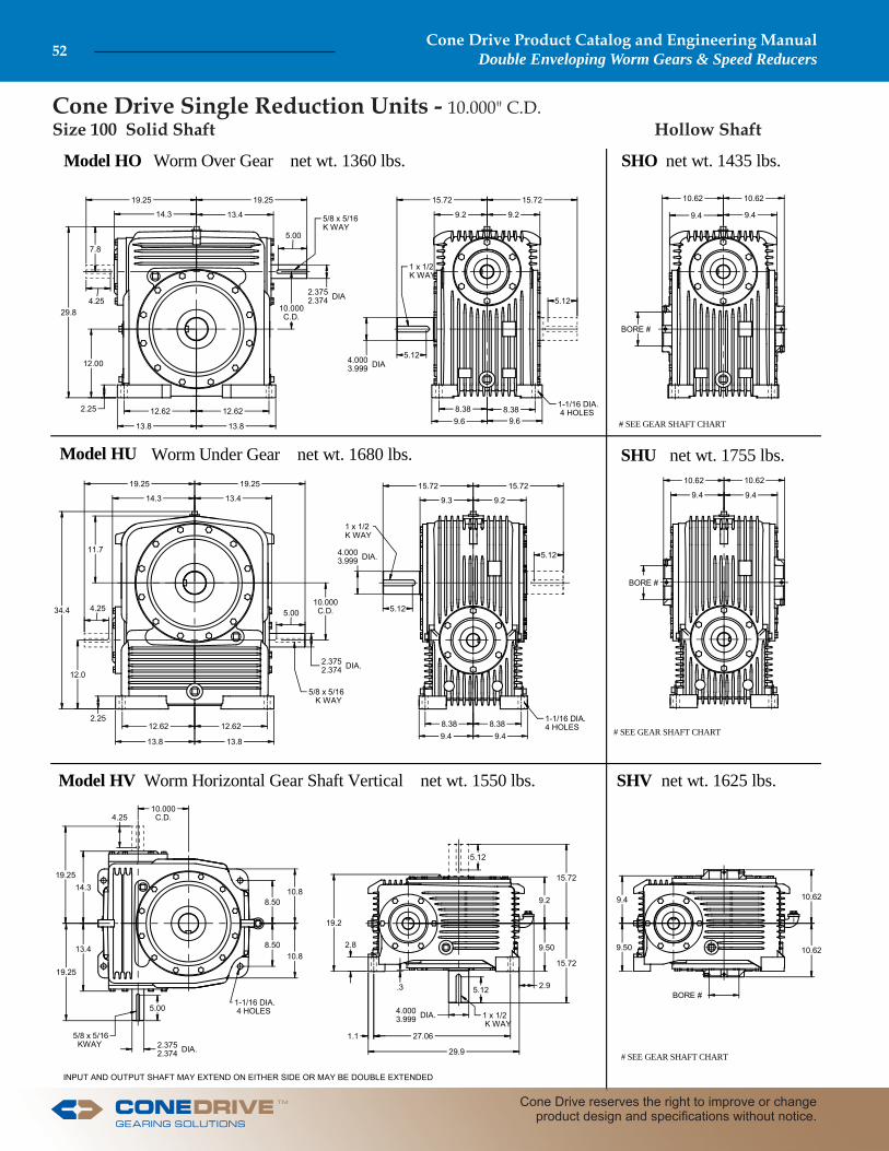
INPUT AND OUTPUT SHAFT MAY EXTEND ON EITHER SIDE OR MAY BE DOUBLE EXTENDED
Model HO SHOWorm Over Gear net wt. 1360 lbs. net wt. 1435 lbs.
Model HU SHUWorm Under Gear net wt. 1680 lbs. net wt. 1755 lbs.
Model HV SHVWorm Horizontal Gear Shaft Vertical net wt. 1550 lbs. net wt. 1625 lbs.
# SEE GEAR SHAFT CHART
# SEE GEAR SHAFT CHART
# SEE GEAR SHAFT CHART
12.62
13.8 13.8
12.622.25
29.8
14.3
19.25
12.00
10.000C.D.
2.3752.374 DIA
19.25
13.4
5.00
7.8
5/8 x 5/16K WAY
15.72
9.2 9.2
15.72
5.12
5.12
9.68.38 8.38
9.6
4.0003.999 DIA
1 x 1/2K WAY
10.62
9.4
BORE #
19.25
14.3 13.4
5.0010.000C.D.
19.25
34.4
12.0
2.25
15.72 15.72
9.3 9.2
4.0003.999 DIA.
8.388.389.49.4
1-1/16 DIA.4 HOLES
9.4
10.6210.62
9.4
BORE #
12.62 12.62
13.8 13.8
10.62
10.62
BORE #
9.4
15.72
15.72
9.2
19.2
.3
19.25
19.25
14.3
13.4
5.00
2.3752.374 DIA.
1-1/16 DIA. 4 HOLES
1.1
2.8
29.9
27.06
4.0003.999 DIA.
5.12
5.12
8.50
8.50
10.8
10.8
5.12
9.50
5/8 x 5/16 K WAY
5/8 x 5/16 KWAY
1 x 1/2K WAY
1 x 1/2 K WAY
10.000C.D.
2.3752.374 DIA.
4.25
10.62
4.25
5.12
4.25
11.7
2.9
1-1/16 DIA. 4 HOLES
9.4
9.50
Cone Drive Single Reduction Units - 10.000" C.D.Size 100 Solid Shaft Hollow Shaft
Cone Drive Product Catalog and Engineering ManualDouble Enveloping Worm Gears & Speed Reducers52
Cone Drive reserves the right to improve or change product design and specifi cations without notice.
TM
Cone Drive Single Reduction Units - 10.000" C.D.Size 100
TOP VIEW
INPUT(DRIVE END)
Notes: Reducers may be used in fl oor, ceiling, or wall mounted positions, however they must be ordered for the position required so that suitable oil level, fi ller, and drains are provided.For cap and carrier dimensions not shown, see mounting section.Steeple bearing arrangements follow in this section.Fan cooling can be supplied with water cooling coils in oil sump. Units can be supplied with water cooling coils in oil sump. All standard units are supplied with right-hand helix gear sets. Units are designed for shaft rotation in either direction. For additional available ratios and left-hand helix gearing Contact Cone Drive.Refer to page 26 for lubrication information.
Important: In any applications of Cone Drive products where breakage, damage, disconnection, any other malfunction of any drive train component, or excessive wear could result in personal injury or property damage, a fail-safe device capable of stopping and holding the load in the event of such an occurrence must be incorporated after the drive train.
STANDARD HOLLOW GEAR SHAFT BORES
CAUTION: It is the purchaser’s or user’s responsibility to guard all shafting in accordance with current local, state or federal requirements.
BOREINCHES
GEARSHAFTNUMBER
KEYWAYSIZE
5.9375 100-S61-515 1 1/4 X 7/16
Special hollow gear shaft bore sizes are available at additional cost.*AGMA StandardBore Tolerance: +.003, -.0002 set screws at long end of shaft.
1 2 3 4 5 6
Hand of Assembly Floor Mounted UnitsWhen ordering, specify the assembly number required, selected from diagrams. Ceiling and wall mounted units follow in this section. The hand of assembly is always determined as a fl oor mounted unit.
AGMA HORSEPOWER & OUTPUT TORQUE RATINGS FOR 1.0 SERVICE FACTORWorm RPM
Ratio to 1 100 200 300 580 720 870 1150 1750
5
Me.HP 58.05 98.65 125.54 177.07 196.63 213.20 231.67 272.58Th.HP 23.59 36.51 48.34 68.86 77.07 86.19 93.10 102.42Th.HP Fan 47.17 73.02 96.68 137.72 154.14 172.38 186.21 204.83Effi ciency 94 95 96 96 97 97 97 97O.T. 171,875 147,605 126,550 92,320 83,450 74,880 61,555 47,595
10
Me.HP 40.93 72.26 95.47 136.70 152.42 166.98 188.26 216.10Th.HP 19.47 28.48 36.98 51.36 58.17 62.07 68.23 72.82Th.HP Fan 38.94 56.97 73.95 102.73 116.34 124.14 136.46 145.64Effi ciency 88 90 91 92 94 94 95 95O.T. 226,900 204,850 182,450 136,605 125,365 113,665 97,980 73,910
15
Me.HP 33.10 58.81 77.98 112.16 125.72 137.56 155.67 179.16Th.HP 16.13 24.04 29.93 41.50 44.96 48.17 51.71 55.22Th.HP Fan 32.26 48.07 59.85 83.00 89.91 96.35 103.43 110.45Effi ciency 84 86 87 90 92 92 93 93O.T. 262,765 238,975 213,695 164,470 151,805 137,465 118,965 89,975
20
Me.HP 25.35 45.14 60.01 86.25 96.74 106.30 119.51 138.49Th.HP 12.77 20.90 25.86 36.18 38.31 40.22 42.18 44.44Th.HP Fan 25.35 41.80 51.71 72.36 76.61 80.44 84.36 88.89Effi ciency 80 82 83 88 88 88 89 90O.T. 255,535 233,170 209,185 164,895 148,985 135,485 116,545 89,745
25
Me.HP 20.45 36.42 48.44 69.88 77.92 85.62 97.06 111.55Th.HP 10.17 17.63 22.19 30.98 32.30 33.84 35.11 36.48Th.HP Fan 20.34 35.25 44.39 61.97 64.59 67.67 70.23 72.96Effi ciency 76 80 82 86 88 88 89 89O.T. 244,825 229,470 208,520 163,190 149,995 136,400 118,315 89,350
30
Me.HP 17.14 30.52 40.58 58.54 65.28 71.73 81.32 93.46Th.HP 11.12 14.48 18.91 25.95 27.69 28.90 29.79 30.68Th.HP Fan 17.14 28.96 37.81 51.91 55.38 57.79 59.59 61.36Effi ciency 73 75 77 80 84 84 85 85O.T. 236,430 216,285 196,860 152,620 143,950 130,905 113,605 85,795
40
Me.HP 12.89 22.95 30.52 44.03 49.09 53.94 61.16 70.28Th.HP 6.25 11.49 15.55 28.98 23.32 24.43 25.39 26.26Th.HP Fan 12.51 22.95 30.52 44.03 46.63 48.85 50.78 52.53Effi ciency 66 68 72 77 80 80 81 81O.T. 214,330 196,625 184,570 147,290 137,460 125,005 108,550 81,975
50
Me.HP 10.34 18.44 24.59 35.52 39.63 43.42 49.46 56.68Th.HP 4.97 9.16 12.67 18.01 19.15 20.14 21.58 23.11Th.HP Fan 9.94 18.31 24.59 35.52 38.31 40.27 43.16 46.22Effi ciency 59 65 69 75 77 77 78 78O.T. 192,110 188,815 178,120 144,685 133,520 121,070 105,680 79,585
60
Me.HP 8.63 15.39 20.51 29.64 33.07 36.24 41.27 47.30Th.HP 4.15 7.61 10.65 15.76 16.71 17.72 19.38 20.64Th.HP Fan 8.30 15.22 20.51 29.64 33.07 35.44 38.76 41.27Effi ciency 58 64 66 71 74 74 75 75O.T. 189,105 186,160 170,605 137,150 128,485 116,505 101,750 76,630
70
Me.HP 7.40 13.21 17.61 25.44 28.39 31.10 35.42 40.60Th.HP 3.54 6.54 9.07 14.03 15.65 16.39 17.83 18.27Th.HP Fan 7.08 13.09 17.61 25.44 28.39 31.10 35.42 36.54Effi ciency 57 63 65 70 73 73 74 74O.T. 186,095 183,495 168,245 135,400 126,920 115,085 100,530 75,705
INPUT(DRIVE END)
TOP VIEW
GEARSHAFTEXTENDEDOpposite Feet .............7A ............8A ............9A ............0AThru Feet ....................7B .............8B .............9B .............0BBoth Sides ...................7C .............8C .............9C .............0C
HO Worm Over SHOHU Worm Under SHU
#3 Shown at right#1 Shown at left
HV Vertical SHV#7A Shown at left
#7C Shown at right
INPUT
OUTPUT
INPUT
OUTPUT
INPUT
OUTPUT
INPUT
OUTPUT
Key: Me.HP = Mech. Input Power (HP) Th.HP = Thermal Input Power - No Fan O.T. = Output Torque (In. Lb.) Th.HP Fan = Thermal Input Power - Fan
TM
Cone Drive Product Catalog and Engineering ManualDouble Enveloping Worm Gears & Speed Reducers 53
Sales: 1-888-994-2663Sales Fax: 1-888-907-2663Traverse City, MI. 49685

INPUT AND OUTPUT SHAFT MAY EXTEND ON EITHER SIDE OR MAY BE DOUBLE EXTENDED
Model HO SHOWorm Over Gear net wt. 2635 lbs. net wt. 2635 lbs.
Model HU SHUWorm Under Gear net wt. 2775 lbs. net wt. 2775 lbs.
Model HV SHVWorm Horizontal Gear Shaft Vertical net wt. 2995 lbs. net wt. 2995 lbs.
# SEE GEAR SHAFT CHART
# SEE GEAR SHAFT CHART
# SEE GEAR SHAFT CHART
16.00
17.4 17.4
16.003.0
36.3
17.3 15.8
14.50
12.000C.D.
3.0002.999 DIA
23.25 22.50
5.88
8.8
3/4 x 3/8K WAY
24.00
12.4 12.6
24.00
7.627.62
10.88
12.25 12.25
10.88
5.4975.496 DIA
1 1/4 x 5/8 K WAY
1-5/16 DIA6 HOLES
14.00 14.00
12.3
BORE #
23.25
17.3 15.8
5.88
12.000C.D.
22.50
41.2
14.503.0
24.00 24.00
12.4 12.6
5.4975.496 DIA.
10.8810.88
12.2512.25
1-5/16 DIA.6 HOLES
14.00 14.00
12.3 12.3
BORE #
16.00 16.00
17.4 17.4
14.00
14.00
1.7BORE #
12.324.00
24.00
12.611.2
14.00
23.25
22.50
17.3
15.8
5.88
3.0002.999 DIA.
1-5/16 DIA.5 HOLES
10.251.85
38.8
34.75
5.4975.496 DIA.7.62
7.62
10.00
10.00
14.2
14.2
7.62
3.0
3/4 x 3/8K WAY
3/4 x 3/8 KWAY
1-1/4 x 5/8K WAY
1-1/4 x 5/8 K WAY
12.000C.D.
3.0002.999 DIA.
4.50
12.3
4.50
7.624.50
13.8
1.6
Cone Drive Single Reduction Units - 12.000" C.D.Size 120 Solid Shaft Hollow Shaft
Cone Drive Product Catalog and Engineering ManualDouble Enveloping Worm Gears & Speed Reducers54
Cone Drive reserves the right to improve or change product design and specifi cations without notice.
TM

Cone Drive Single Reduction Units - 12.000" C.D.Size 120
CAUTION: It is the purchaser’s or user’s responsibility to guard all shafting in accordance with current local, state or federal requirements.
STANDARD HOLLOW GEAR SHAFT BORES
Notes: Reducers may be used in fl oor, ceiling, or wall mounted positions, however they must be ordered for the position required so that suitable oil level, grease fi ttings, fi ller, and drains are provided.For cap and carrier dimensions not shown, see mounting section.Units can be supplied with water cooling coils.All units can be motorized. Motor adapter to be located at extension end of input shaft.All standard units are supplied with right-hand helix gear sets. Units are designed for shaft rotation in either direction. For additional available ratios and left-hand helix gearing Contact Cone Drive.Refer to page 26 for lubrication information.
Important: In any applications of Cone Drive products where breakage, damage, disconnection, any other malfunction of any drive train component, or excessive wear could result in personal injury or property damage, a fail-safe device capable of stopping and holding the load in the event of such an occurrence must be incorporated after the drive train.
BOREINCHES
GEARSHAFTNUMBER
KEYWAYSIZE
7.9375 120-S61-715 1 1/2 X 1/2
Special hollow gear shaft bore sizes are avail-able at additional cost.Bore Tolerance: +.004, -.0002 set screws at long end of shaft.
AGMA HORSEPOWER & OUTPUT TORQUE RATINGS FOR 1.0 SERVICE FACTORWorm RPM
Ratio to 1 100 200 300 580 720 870 1150
5
Me.HP 97.66 160.36 199.46 279.03 307.46 322.92 360.54Th.HP 32.97 51.04 67.58 96.27 107.74 120.49 130.16Th.HP Fan 65.95 102.09 135.16 192.54 215.49 240.99 260.33Effi ciency 94 95 96 96 97 97 97O.T. 289,165 239,940 201,055 145,480 130,480 113,415 95,795
10
Me.HP 69.42 119.50 153.17 218.02 240.67 263.11 287.25Th.HP 27.22 39.82 51.69 71.81 81.32 86.78 95.39Th.HP Fan 54.45 79.64 103.39 143.62 162.64 173.55 190.78Effi ciency 88 90 91 92 94 94 95O.T. 384,890 338,790 292,715 217,870 197,955 179,100 149,495
15
Me.HP 56.15 97.31 125.83 179.16 198.25 217.23 237.20Th.HP 22.55 33.60 41.84 58.02 62.85 67.35 72.30Th.HP Fan 45.10 67.20 83.68 116.03 125.70 134.69 144.59Effi ciency 84 86 87 90 92 92 93O.T. 445,755 395,415 344,835 262,720 239,385 217,080 181,275
20
Me.HP 43.08 74.85 96.65 137.85 152.65 167.39 183.95Th.HP 17.85 29.22 36.15 50.58 53.55 56.23 58.97Th.HP Fan 35.70 58.44 72.30 101.16 107.11 112.46 117.94Effi ciency 80 82 83 88 88 88 89O.T. 434,270 386,660 336,930 263,530 235,085 213,335 179,375
25
Me.HP 34.70 60.41 78.21 111.03 123.39 135.35 148.86Th.HP 14.21 24.64 31.03 43.31 45.15 47.31 49.09Th.HP Fan 28.43 49.28 62.05 86.63 90.30 94.61 98.18Effi ciency 76 80 82 86 88 88 89O.T. 415,355 380,555 336,700 259,285 237,520 215,625 181,445
30
Me.HP 29.07 50.61 65.68 93.02 103.38 113.40 125.30Th.HP 15.55 20.24 26.43 36.28 38.71 40.40 41.65Th.HP Fan 29.07 40.48 52.87 72.57 77.43 80.80 83.30Effi ciency 73 75 77 80 84 84 85O.T. 401,110 358,695 318,615 242,500 227,950 206,930 175,040
40
Me.HP 21.90 38.06 49.39 70.40 78.29 85.61 94.23Th.HP 8.74 16.07 21.74 40.52 32.60 34.15 35.50Th.HP Fan 17.49 32.13 43.48 70.40 65.19 68.30 71.00Effi ciency 66 68 72 77 80 80 81O.T. 364,260 326,090 298,725 235,515 219,220 198,380 167,250
50
Me.HP 17.57 30.59 39.71 56.47 62.80 68.67 75.58Th.HP 6.95 12.80 17.72 25.18 26.78 28.15 30.17Th.HP Fan 13.90 25.60 35.44 50.37 53.55 56.30 60.34Effi ciency 59 65 69 75 77 77 78O.T. 326,495 313,165 287,710 230,010 211,565 191,450 161,490
60
Me.HP 14.66 25.53 33.14 47.12 52.40 57.30 63.07Th.HP 5.80 10.64 14.90 22.03 23.36 24.78 27.10Th.HP Fan 11.60 21.28 29.79 44.07 46.71 49.55 54.19Effi ciency 58 64 66 71 74 74 75O.T. 321,390 308,755 275,570 218,035 203,590 184,235 155,485
70
Me.HP 12.58 21.91 28.44 40.44 44.98 49.18 54.13Th.HP 4.95 9.15 12.68 19.61 21.88 22.91 24.93Th.HP Fan 9.90 18.30 25.37 39.22 43.76 45.82 49.86Effi ciency 57 63 65 70 73 73 74O.T. 316,270 304,340 271,755 215,250 201,110 181,990 153,615
1 2 3 4 5 6
GEARSHAFTEXTENDEDOpposite Feet .............7A ............8A ............9A ............0AThru Feet ....................7B .............8B .............9B .............0BBoth Sides ...................7C .............8C .............9C .............0C
Hand of Assembly Floor Mounted UnitsWhen ordering, specify the assembly number required, selected from diagrams. Ceiling and wall mounted units follow in this section.The hand of assembly is alwaysdetermined as a fl oor mounted unit.
HO Worm Over SHOHU Worm Under SHU
#3 Shown at right#1 Shown at left
HV Vertical SHV#7A Shown at left
#7C Shown at right
INPUT
OUTPUT
INPUT
OUTPUT
TOP VIEW
INPUT(DRIVE END)
INPUT(DRIVE END)
TOP VIEW
INPUT
OUTPUT
INPUT
OUTPUT
Key: Me.HP = Mech. Input Power (HP) Th.HP = Thermal Input Power - No Fan O.T. = Output Torque (In. Lb.) Th.HP Fan = Thermal Input Power - Fan
TM
Cone Drive Product Catalog and Engineering ManualDouble Enveloping Worm Gears & Speed Reducers 55
Sales: 1-888-994-2663Sales Fax: 1-888-907-2663Traverse City, MI. 49685

INPUT AND OUTPUT SHAFT MAY EXTEND ON EITHER SIDE OR MAY BE DOUBLE EXTENDED
Model HO Worm Over Gear net wt. 4000 lbs
Model HU Worm Under Gear net wt. 4000 lbs
Model HV Worm Horizontal Gear Shaft Vertical net wt. 4000 lbs
26.25
WELDED STEEL HOUSING ONLY
LUBRICATION REQUIREMENTSMUST BE REVIEWED FOREACH APPLICATION.
WELDED STEEL HOUSING ONLY
WELDED STEEL HOUSING ONLY
CONTACT CONE DRIVE.
42.0
16.00
2.25
20.6 18.3
8.50
18.25 18.2519.8 19.8
27.88
5.5
6 BOLTS INPUT END12 BOLTS OPPOSITE END
1-1/2 x 1/2 2 KWYS180 APART
6 BOLTS INPUT END12 BOLTS OPPOSITE END
6 BOLTS INPUT END12 BOLTS OPPOSITE END
7/8 x 7/16 KWY
1-1/2 x 1/2 2 KWYS180 APART
1-1/2 x 1/2 2 KWYS180 APART
1-5/16 DIA.8 HOLES
1-5/16 DIA.8 HOLES
1-5/16 DIA.7 HOLES
7/8 x 7/16 KWY
7/8 x 7/16 KWY
3.5003.499 DIA.
15.000C.D.
4.12 4.1212.25 12.2513.8 13.8
25.00
15.5 14.6
9.50
4.12 4.1212.25 12.2513.8 13.8
18.25 18.25
19.8 19.8
27.88 26.25
18.320.6
5.5
16.0
47.3 15.000C.D.
3.5003.499 DIA.
6.5006.499 DIA.
25.00 25.00
14.615.5
9.50 9.50
25.00
9.50
2.25
12.00
12.00
20.6
18.3
26.25
1.50 13.00
41.12 4.00
5.5
4.50
4.50
12.00
12.00
15.5
15.5
48.8
15.000C.D.
8.50
30.00
25.00
15.4
1.3
6.5006.499 DIA.
9.50
20.0
2.25
27.88
8.50
3.5003.499 DIA.
6.5006.499 DIA.
9.50
Cone Drive Single Reduction Units - 15.000" C.D. Size 150 Solid Shaft
Cone Drive Product Catalog and Engineering ManualDouble Enveloping Worm Gears & Speed Reducers56
Cone Drive reserves the right to improve or change product design and specifi cations without notice.
TM

Cone Drive Single Reduction Units - 15.000" C.D. Size 150
AGMA HORSEPOWER & OUTPUT TORQUE RATINGS FOR 1.0 SERVICE FACTORWorm RPM
Ratio to 1 100 200 300 580 720 870 1750
5
Me.HP 149.00 223.00 290.00 396.00 423.00 453.00 501.00Th.HP 23.60 35.50 45.60 65.50 73.00 78.50 85.40O.T. 442000 349000 291000 207000 178000 159000 133000C.P. 7351 9998 12333 15977 17778 18583 19323
10
Me.HP 99.30 166.00 208.00 293.00 322.00 343.00 378.00Th.HP 21.00 30.00 38.20 53.10 58.00 61.30 66.60O.T. 550000 469000 396000 294000 262000 232000 195000C.P. 41201 31629 30724 29523 29263 29572 29571
15
Me.HP 70.10 118.00 149.00 210.00 232.00 250.00 272.00Th.HP 18.30 26.20 32.50 43.80 47.20 49.50 52.40O.T. 557000 480000 407000 308000 277000 249000 208000C.P. 52000 52000 52000 46313 44395 43259 41720
20
Me.HP 53.70 90.50 114.00 161.00 178.00 191.00 210.00Th.HP 16.50 23.20 28.80 38.60 41.20 43.00 45.00O.T. 541000 467000 398000 307000 275000 245000 205000C.P. 52000 52000 52000 52000 52000 52000 50186
25
Me.HP 43.30 73.10 92.40 131.00 144.00 155.00 170.00Th.HP 13.85 19.80 24.70 33.70 35.20 36.30 37.40O.T. 522000 460000 400000 303000 274000 246000 207000C.P. 52000 52000 52000 52000 52000 52000 52000
30
Me.HP 36.30 61.30 77.50 110.00 121.00 130.00 143.00Th.HP 10.50 16.40 21.30 29.20 30.60 31.80 32.50O.T. 501000 436000 376000 286000 261000 238000 199000C.P. 52000 52000 52000 52000 52000 52000 52000
40
Me.HP 27.30 46.20 58.40 82.50 91.30 98.20 108.00Th.HP 8.60 13.80 17.90 24.70 26.20 27.30 28.40O.T. 455000 396000 354000 276000 251000 227000 191000C.P. 52000 52000 52000 52000 52000 52000 52000
50
Me.HP 21.90 37.10 46.90 66.30 73.40 78.90 86.40Th.HP 7.50 12.00 15.40 20.60 21.70 22.80 24.30O.T. 408000 380000 339000 271000 244000 219000 185000C.P. 52000 52000 52000 52000 52000 52000 52000
60
Me.HP 18.30 30.90 39.20 55.40 61.30 65.90 72.20Th.HP 6.00 10.50 13.10 18.00 19.10 20.20 22.10O.T. 401000 374000 327000 256000 233000 212000 178000C.P. 52000 52000 52000 52000 52000 52000 52000
Hollow Gear ShaftHollow shaft units are not standard but can be manufactured to suit your requirements. Contact Cone Drive. Notes: Reducers may be used in fl oor, ceiling, or wall mounted positions, however they must be ordered for the position required so that suitable oil level, grease fi ttings, fi ller, and drains are provided.For cap and carrier dimensions not shown, see mounting section.Units can be supplied with water cooling coils in oil sump. All standard units are supplied with right-hand helix gear sets. Units are designed for shaft rotation in either direction. For additional available ratios and left-hand helix gearing Contact Cone Drive.Refer to page 26 for lubrication information.
Important: In any applications of Cone Drive products where breakage, damage, disconnection, any other malfunction of any drive train component, or excessive wear could result in personal injury or property damage, a fail-safe device capable of stopping and holding the load in the event of such an occurrence must be incorporated after the drive train.
CAUTION: It is the purchaser’s or user’s responsibility to guard all shafting in accordance with current local, state or federal requirements.
Key: Me.HP - Mechanical horsepower O.T. - Output torque in Lb. in. Th.HP -Thermal horsepower C.P. - Chain-pull in pounds.Ratings to the right of heavy line require pressure lubrication.Contact Cone Drive.
Hand of Assembly Floor Mounted UnitsWhen ordering, specify the assembly number required, selected from diagrams. Ceiling and wall mounted units follow in this section.The hand of assembly is always determined as a fl oor mounted unit.
GEARSHAFTEXTENDEDOpposite Feet .............7A ............8A ............9A ............0AThru Feet ....................7B .............8B .............9B .............0BBoth Sides ...................7C .............8C .............9C .............0C
1 2 3 4 5 6
HO Worm OverHU Worm Under
#1 ShownTOP VIEW
INPUT(DRIVE END)
INPUT(DRIVE END)
TOP VIEW
INPUT
OUTPUT
INPUT
OUTPUT
HV Vertical #7A Shown
TM
Cone Drive Product Catalog and Engineering ManualDouble Enveloping Worm Gears & Speed Reducers 57
Sales: 1-888-994-2663Sales Fax: 1-888-907-2663Traverse City, MI. 49685

INPUT AND OUTPUT SHAFT MAY EXTEND ON EITHER SIDE OR MAY BE DOUBLE EXTENDED
Model HO Worm Over Gear net wt. 5500 lbs
Model HU Worm Under Gear net wt. 5500 lbs
Model HV Worm Horizontal Gear Shaft Vertical net wt. 5500 lbs
30.12
WELDED STEEL HOUSING ONLY
LUBRICATION REQUIREMENTSMUST BE REVIEWED FOREACH APPLICATION.
WELDED STEEL HOUSING ONLY
WELDED STEEL HOUSING ONLY
CONTACT CONE DRIVE.
20.00
49.8
21.00 21.0022.5 22.5
21.9
4.88 4.8814.50 14.5016.0 16.0
2.25
28.75
17.80 16.9
16.016.022.522.5
20.0010.00
28.75
16.917.8
10.75
7.5007.499 DIA.
18.000C.D.
4.0003.999 DIA.
10.00
20.3
5.5
5.5
15.00
15.0020.3
21.9
30.42
54.2
12.001.5044.50 5.75
5.5
5.5
15.00
15.00
18.0
18.0
10.0018.000C.D.
4.0003.999 DIA.
28.75
10.75
57.9
30.12
21.90 20.3
4.0003.999 DIA.
2.25
23.0
10.75
34.75
17.8
7.5007.499 DIA.
2.25
28.75
6 BOLTS INPUT END12 BOLTS OPPOSITE END
1-3/4 x 5/8 2 KWYS180 APART
1.0
28.75
10.75
21.00 21.00 4.88 4.8814.50 14.50
6 BOLTS INPUT END12 BOLTS OPPOSITE END
6 BOLTS INPUT END12 BOLTS OPPOSITE END
31.50
31.50
10.75
1 x 1/2 KWY
1-3/4 x 5/8 2 KWYS180 APART
1-3/4 x 5/8 2 KWYS180 APART
1-5/16 DIA.8 HOLES
1-5/16 DIA.8 HOLES
1-5/16 DIA.8 HOLES
18.000C.D.
1 x 1/2 KWY
7.5007.499 DIA.
7.5
31.50
7.50
10.75
1 x 1/2 KWY
Cone Drive Single Reduction Units - 18.000" C.D.Size 180 Solid Shaft
Cone Drive Product Catalog and Engineering ManualDouble Enveloping Worm Gears & Speed Reducers58
Cone Drive reserves the right to improve or change product design and specifi cations without notice.
TM

Cone Drive Single Reduction Units - 18.000" C.D.Size 180
AGMA HORSEPOWER & OUTPUT TORQUE RATINGS FOR 1.0 SERVICE FACTORWorm RPM
Ratio to 1 100 200 300 580 720 870 1150
5
Me.HP 236.00 356.00 440.00 577.00 624.00 669.00 733.00Th.HP 33.00 49.80 64.00 92.00 105.00 110.00 119.50O.T. 700000 532000 441000 301000 263000 234000 195000C.P. 7418 10371 12117 16716 17904 18532 19474
8
Me.HP 193.00 309.00 385.00 535.00 577.00 615.00 681.00Th.HP 30.84 45.30 57.75 81.50 92.10 96.20 103.85O.T. 878000 716000 600000 437000 381000 338000 285000C.P. 13893 11705 13958 17012 18558 20001 20804
10
Me.HP 161.00 261.00 326.00 455.00 493.00 524.00 581.00Th.HP 29.40 42.20 53.60 74.50 83.50 87.00 93.40O.T. 894000 738000 621000 457000 402000 355000 300000C.P. 32023 25614 26034 25941 26144 26926 26891
15
Me.HP 114.00 187.00 234.00 328.00 358.00 379.00 419.00Th.HP 25.70 36.70 46.00 61.50 67.90 69.50 73.00O.T. 904000 760000 639000 481000 428000 380000 320000C.P. 63254 50106 46800 41592 40312 39778 38237
20
Me.HP 87.30 144.00 180.00 253.00 277.00 292.00 324.00Th.HP 23.10 32.60 40.40 54.30 58.80 60.40 63.30O.T. 880000 742000 627000 481000 427000 375000 316000C.P. 72250 66257 60595 51989 49948 48805 46244
25
Me.HP 70.50 116.00 145.00 205.00 224.00 237.00 262.00Th.HP 19.40 27.90 34.60 47.40 50.50 50.60 52.50O.T. 849000 733000 629000 476000 424000 375000 319000C.P. 72250 72250 70287 59370 57078 55070 51917
30
Me.HP 59.10 97.60 122.00 172.00 188.00 199.00 220.00Th.HP 14.70 23.20 29.80 41.00 44.10 44.60 45.60O.T. 815000 694000 591000 448000 405000 363000 308000C.P. 72250 72250 72250 67162 63548 61154 57346
40
Me.HP 44.50 73.50 92.00 129.00 142.00 150.00 166.00Th.HP 12.00 19.40 25.20 35.00 37.80 38.30 40.00O.T. 739000 630000 558000 432000 390000 347000 295000C.P. 72250 72250 72250 72250 72250 69938 65338
50
Me.HP 35.70 59.10 73.90 104.00 114.00 121.00 133.00Th.HP 10.50 16.80 21.60 29.00 31.20 31.90 34.10O.T. 663000 605000 533000 424000 379000 335000 285000C.P. 72250 72250 72250 72250 72250 72250 71671
60
Me.HP 29.80 49.30 61.70 86.80 95.10 101.00 111.00Th.HP 8.40 14.70 18.40 25.30 27.30 28.40 31.10O.T. 653000 597000 515000 401000 362000 324000 275000C.P. 72250 72250 72250 72250 72250 72250 72250
Key: Me.HP - Mechanical horsepower O.T. - Output torque in Lb. in. Th.HP -Thermal horsepower C.P. - Chain-pull in pounds.Ratings to the right of heavy line require pressure lubrication. Contact Cone Drive.
Hollow Gear ShaftHollow shaft units are not standard but can be manufactured to suit your requirements. Contact Cone Drive. Notes: Reducers may be used in fl oor, ceiling, or wall mounted positions, however they must be ordered for the position required so that suitable oil level, fi ller, and drains are provided.For cap and carrier dimensions not shown, see mounting section.Units can be supplied with water cooling coils in oil sump. All standard units are supplied with right-hand helix gear sets. Units are designed for shaft rotation in either direction. For additional available ratios and left-hand helix gearing Contact Cone Drive.Refer to page 26 for lubrication information.
Important: In any applications of Cone Drive products where breakage, damage, disconnection, any other malfunction of any drive train component, or excessive wear could result in personal injury or property damage, a fail-safe device capable of stopping and holding the load in the event of such an occurrence must be incorporated after the drive train.
CAUTION: It is the purchaser’s or user’s responsibility to guard all shafting in accordance with current local, state or federal requirements.
Hand of Assembly Floor Mounted UnitsWhen ordering, specify the assembly number required, selected from diagrams. Ceiling and wall mounted units follow in this section.The hand of assembly is always determined as a fl oor mounted unit.
GEARSHAFTEXTENDEDOpposite Feet .............7A ............8A ............9A ............0AThru Feet ....................7B .............8B .............9B .............0BBoth Sides ...................7C .............8C .............9C .............0C
1 2 3 4 5 6
TOP VIEW
INPUT(DRIVE END)
INPUT(DRIVE END)
TOP VIEW
HO Worm OverHU Worm Under
#1 ShownINPUT
OUTPUT
INPUT
OUTPUT
HV Vertical #7A Shown
TM
Cone Drive Product Catalog and Engineering ManualDouble Enveloping Worm Gears & Speed Reducers 59
Sales: 1-888-994-2663Sales Fax: 1-888-907-2663Traverse City, MI. 49685

INPUT AND OUTPUT SHAFT MAY EXTEND ON EITHER SIDE OR MAY BE DOUBLE EXTENDED
Model HO Worm Over Gear net wt. 8700 lbs
Model HU Worm Under Gear net wt. 8700 lbs
Model HV Worm Horizontal Gear Shaft Vertical net wt. 8700 lbs
34.50
WELDED STEEL HOUSING ONLY
LUBRICATION REQUIREMENTSMUST BE REVIEWED FOREACH APPLICATION.
WELDED STEEL HOUSING ONLY
WELDED STEEL HOUSING ONLY
CONTACT CONE DRIVE.
23.00
58.4
25.50 25.5027.0 27.0
25.0 23.5
34.50
25.0
36.00
21.9
27.027.0
69.321.837C.D.
21.837C.D.
23.5
6.25 6.2518.25 18.2519.8 19.8
36.00
21.922.6
2.75
23.00
42.5034.50
6.50
6.50
18.00
18.0025.0
23.5
4.5004.499 DIA.
2-1/2 x 7/8 2 KWYS180 APART
1-9/16 DIA.8 HOLES
1-9/16 DIA.8 HOLES
1 x 1/2 KWY
66.6
28.00
2.75
4.5004.499 DIA.
37.00
2.25 15.50
55.12 6.75
22.00
22.00
6.50
6.50
18.00
18.00
10.021.837 C.D.
2.75
4.5004.499 DIA.
10.0
37.00
12.75
36.00
10.00
6.25 6.2518.25 18.25
19.819.8
12.75
36.00
12.75
1 x 1/2 KWY
25.50 25.50
22.6
37.00
1 x 1/2 KWY
2-1/2 x 7/8 2 KWYS180 APART
9.0008.999 DIA.
2-1/2 x 7/8 2 KWYS180 APART
9.0008.999 DIA.
36.00
12.75
22.7
2.20
9.0008.999 DIA.
9.5
9.5
12.75
1-9/16 DIA.8 HOLES
12.75
9.5
Cone Drive Single Reduction Units - 21.837" C.D.Size 220 Solid Shaft
Cone Drive Product Catalog and Engineering ManualDouble Enveloping Worm Gears & Speed Reducers60
Cone Drive reserves the right to improve or change product design and specifi cations without notice.
TM

Cone Drive Single Reduction Units - 21.837" C.D.Size 220
AGMA HORSEPOWER & OUTPUT TORQUE RATINGS FOR 1.0 SERVICE FACTORWorm RPM
Ratio to 1 100 200 300 580 720 870 1150
4
Me.HP 439.00 642.00 789.00 1010.00 1090.00 1160.00 1230.00Th.HP 52.14 79.45 101.95 147.40 164.50 177.30 193.00O.T. 105000 777000 639000 425000 372000 328000 265000C.P. 50991 44613 41397 32050 19461 18856 13363
5.625
Me.HP 394.00 589.00 732.00 955.00 1033.00 1106.00 1212.00Th.HP 50.28 75.45 96.75 138.40 153.90 165.20 179.80O.T. 1301000 985000 825000 557000 487000 435000 361000C.P. 52572 45115 42919 16490 15537 14022 11792
7
Me.HP 254.00 541.00 673.00 896.00 965.00 1030.00 1140.00Th.HP 48.72 72.10 92.20 131.20 145.00 155.40 168.50O.T. 1430000 1110000 926000 646000 562000 501000 419000C.P. 69239 56238 51189 23643 20001 18543 22144
10
Me.HP 281.00 445.00 554.00 764.00 819.00 875.00 970.00Th.HP 45.30 64.75 82.60 115.00 125.50 133.50 144.00O.T. 1559000 1262000 1059000 764000 673000 596000 505000C.P. 28915 25625 26485 28068 29723 30532 30855
14
Me.HP 212.00 339.00 422.00 585.00 631.00 673.00 745.00Th.HP 40.74 58.23 72.84 98.80 106.70 112.30 119.50O.T. 1580000 1350000 1130000 818000 713000 631000 532000C.P. 63447 50465 47842 43995 43116 43112 41994
20
Me.HP 150.00 238.00 296.00 408.00 436.00 467.00 518.00Th.HP 35.50 49.70 62.00 83.60 89.00 92.90 97.10O.T. 1510000 1230000 1030000 776000 673000 599000 505000C.P. 87350 74220 66150 59655 58180 56630 53710
25
Me.HP 121.00 192.00 239.00 330.00 354.00 378.00 419.00Th.HP 30.00 42.90 53.50 72.80 76.00 78.50 81.00O.T. 1460000 1210000 1040000 767000 670000 600000 511000C.P. 100609 90078 80874 69478 67469 65178 61377
30
Me.HP 102.00 162.00 201.00 277.00 297.00 318.00 353.00Th.HP 22.60 35.60 46.10 63.20 66.40 68.80 70.50O.T. 1400000 1150000 974000 723000 641000 581000 493000C.P. 103800 103424 92645 79134 75116 72503 68070
40
Me.HP 76.50 122.00 152.00 209.00 225.00 240.00 266.00Th.HP 18.60 30.00 38.80 53.40 56.70 59.10 61.50O.T. 1270000 1040000 919000 700000 618000 556000 472000C.P. 103800 103800 103800 91362 86720 83107 77762
45
Me.HP 68.10 109.00 135.00 187.00 200.00 214.00 237.00Th.HP 17.40 27.95 36.00 48.95 51.75 54.15 57.05O.T. 1210000 1020000 900000 693000 610000 547000 465000C.P. 103800 103800 103800 99407 91711 87052 81795
50
Me.HP 61.40 97.90 122.00 168.00 181.00 193.00 214.00Th.HP 16.20 25.90 33.20 44.50 47.00 49.40 52.60O.T. 1140000 1000000 879000 687000 601000 537000 457000C.P. 103800 103800 103800 101220 96200 92068 85458
Hollow Gear ShaftHollow shaft units are not standard but can be manufactured to suit your requirements. Contact Cone Drive. Notes: Reducers may be used in fl oor, ceiling, or wall mounted positions, however they must be ordered for the position required so that suitable oil level, grease fi ttings, fi ller, and drains are provided.For cap and carrier dimensions not shown, see mounting section.Units can be supplied with water cooling coils in oil sump. All standard units are supplied with right-hand helix gear sets. Units are designed for shaft rotation in either direction. For additional available ratios and left-hand helix gearing Contact Cone Drive.Refer to page 26 for lubrication information.
Important: In any applications of Cone Drive products where breakage, damage, disconnection, any other malfunction of any drive train component, or excessive wear could result in personal injury or property damage, a fail-safe device capable of stopping and holding the load in the event of such an occurrence must be incorporated after the drive train.
Key: Me.HP - Mechanical horsepower O.T. - Output torque in Lb. in. Th.HP -Thermal horsepower C.P. - Chain-pull in pounds.
Ratings to the right of heavy line require pressure lubrication. Contact Cone Drive.
CAUTION: It is the purchaser’s or user’s responsibility to guard all shafting in accordance with current local, state or federal requirements.
Hand of Assembly Floor Mounted UnitsWhen ordering, specify the assembly number required, selected from diagrams. Ceiling and wall mounted units follow in this section.The hand of assembly is always determined as a fl oor mounted unit.
GEARSHAFTEXTENDEDOpposite Feet .............7A ............8A ............9A ............0AThru Feet ....................7B .............8B .............9B .............0BBoth Sides ...................7C .............8C .............9C .............0C
1 2 3 4 5 6
TOP VIEW
INPUT(DRIVE END)
INPUT(DRIVE END)
TOP VIEW
HO Worm OverHU Worm Under
#1 ShownINPUT
OUTPUT
INPUT
OUTPUT
HV Vertical #7A Shown
TM
Cone Drive Product Catalog and Engineering ManualDouble Enveloping Worm Gears & Speed Reducers 61
Sales: 1-888-994-2663Sales Fax: 1-888-907-2663Traverse City, MI. 49685

INPUT AND OUTPUT SHAFT MAY EXTEND ON EITHER SIDE OR MAY BE DOUBLE EXTENDED
Model HO Worm Over Gear net wt. 11,000 lbs
Model HU Worm Under Gear net wt. 11,000 lbs
Model HV Worm Horizontal Gear Shaft Vertical net wt. 11,000 lbs
40.00
WELDED STEEL HOUSING ONLY
LUBRICATION REQUIREMENTSMUST BE REVIEWED FOREACH APPLICATION.
WELDED STEEL HOUSING ONLY
WELDED STEEL HOUSING ONLY
CONTACT CONE DRIVE.
26.00
65.0
27.00 27.0028.8 28.8
28.2 26.7
40.00
28.2
38.00
22.6
28.828.8
73.8 24.000C.D.
24.000C.D.
26.7
6.25 6.2518.25 18.2520.0 20.0
38.00
22.623.2
2.75
23.875
46.0040.00
8.0
8.0
20.00
20.0028.2
26.7
5.000 DIA.4.999 2-1/2 x 7/8
2 KWYS180 APART
1-9/16 DIA.8 HOLES
1-9/16 DIA.8 HOLES
1-1/4 x 7/16 KWY
71.8
30.00
2.75
5.000 DIA.4.999
40.00
2.0 16.25
60.50 7.12
24.0
24.0
8.0
8.0
20.00
20.00
10.024.000 C.D.
2.75
5.000 DIA.4.99910.00
40.00
14.0
38.00
10.0
6.25 6.2518.25 18.25
20.020.0
14.0
38.00
14.0
1-1/4 x 7/16 KWY
27.00 27.00
23.2
40.00
1-1/4 x 7/16 KWY
2-1/2 x 7/8 2 KWYS180 APART
10.000 DIA. 9.999
2-1/2 x 7/8 2 KWYS180 APART
10.000 DIA. 9.999
38.00
14.00
23.2
3.0
10.000 DIA. 9.999
9.7
9.7
14.00
1-9/16 DIA.8 HOLES
14.0
9.7
Cone Drive Single Reduction Units - 24.000" C.D. Size 240 Solid Shaft
Cone Drive Product Catalog and Engineering ManualDouble Enveloping Worm Gears & Speed Reducers62
Cone Drive reserves the right to improve or change product design and specifi cations without notice.
TM

Cone Drive Single Reduction Units - 24.000" C.D. Size 240
Key: Me.HP - Mechanical horsepower O.T. - Output torque in Lb. in. Th.HP -Thermal horsepower C.P. - Chain-pull in pounds.Ratings to the right of heavy line require pressure lubrication. Contact Cone Drive.
AGMA HORSEPOWER & OUTPUT TORQUE RATINGS FOR 1.0 SERVICE FACTOR
Worm RPM
Ratio to 1 100 200 300 580 720 870 1150
5
Me.HP 495.00 720.00 883.00 1117.00 1209.00 1282.00 1348.00Th.HP 59.50 89.60 115.20 165.00 184.20 198.40 215.50O.T. 1465000 1078000 890000 583000 508000 450000 358000C.P. 61913 53807 49379 13341 10115 9446 14866
8
Me.HP 412.00 617.00 770.00 1007.00 1090.00 1165.00 1280.00Th.HP 55.54 81.14 103.90 146.40 161.50 172.90 187.10O.T. 1876000 1431000 120200 819000 723000 643000 537000C.P. 73116 62369 56980 16348 9347 12247 15874
15
Me.HP 245.00 374.00 466.00 623.00 667.00 716.00 785.00Th.HP 46.25 66.00 82.20 110.50 119.00 124.70 132.20O.T. 1944000 1520000 1276000 914000 797000 716000 600000C.P. 41267 39080 39023 39876 40656 40508 40416
20
Me.HP 188.00 288.00 358.00 481.00 515.00 552.00 607.00Th.HP 41.50 58.50 72.60 97.30 104.00 108.80 113.20O.T. 1895000 1487000 1249000 920000 793000 704000 592000C.P. 73478 61173 58719 53694 53686 52899 51261
25
Me.HP 152.00 233.00 290.00 390.00 417.00 447.00 492.00Th.HP 34.90 50.00 62.30 85.00 88.75 91.60 94.40O.T. 1815000 1467000 1247000 911000 784000 713000 600000C.P. 85407 82151 74443 67883 64751 62631 60079
30
Me.HP 127.00 196.00 243.00 328.00 351.00 376.00 414.00Th.HP 26.40 41.50 53.80 73.60 77.40 80.30 82.20O.T. 1756000 1387000 1180000 855000 764000 686000 578000C.P. 97709 96270 88827 76726 73941 70945 67598
40
Me.HP 96.00 147.00 183.00 247.00 264.00 283.00 312.00Th.HP 21.70 34.90 45.30 62.40 66.10 68.90 71.80O.T. 1594000 1263000 1108000 827000 740000 657000 554000C.P. 104971 118076 106122 90866 86350 82843 77817
50
Me.HP 77.00 118.00 147.00 198.00 212.00 227.00 251.00Th.HP 18.90 30.20 38.80 51.90 54.80 57.60 61.30O.T. 1429000 1211000 1065000 808000 715000 634000 535000C.P. 118934 124683 122758 102154 96493 92744 86833
Hollow Gear ShaftHollow shaft units are not standard but can be manufactured to suit your requirements. Contact Cone Drive. Notes: Reducers may be used in fl oor, ceiling, or wall mounted positions, however they must be ordered for the position required so that suitable oil level, fi ller, and drains are provided.For cap and carrier dimensions not shown, see mounting section.Units can be supplied with water cooling coils in oil sump.All standard units are supplied with right-hand helix gear sets. Units are designed for shaft rotation in either direction. For additional available ratios and left-hand helix gearing Contact Cone Drive.Refer to page 26 for lubrication information.
Important: In any applications of Cone Drive products where breakage, damage, disconnection, any other malfunction of any drive train component, or excessive wear could result in personal injury or property damage, a fail-safe device capable of stopping and holding the load in the event of such an occurrence must be incorporated after the drive train.
CAUTION: It is the purchaser’s or user’s responsibility to guard all shafting in accordance with current local, state or federal requirements.
Hand of Assembly Floor Mounted UnitsWhen ordering, specify the assembly number required, selected from diagrams. Ceiling and wall mounted units follow in this section.The hand of assembly is always determined as a fl oor mounted unit.
GEARSHAFTEXTENDEDOpposite Feet .............7A ............8A ............9A ............0AThru Feet ....................7B .............8B .............9B .............0BBoth Sides ...................7C .............8C .............9C .............0C
1 2 3 4 5 6
TOP VIEW
INPUT(DRIVE END)
INPUT(DRIVE END)
TOP VIEW
HO Worm OverHU Worm Under
#1 ShownINPUT
OUTPUT
INPUT
OUTPUT
HV Vertical #7A Shown
TM
Cone Drive Product Catalog and Engineering ManualDouble Enveloping Worm Gears & Speed Reducers 63
Sales: 1-888-994-2663Sales Fax: 1-888-907-2663Traverse City, MI. 49685

INPUT AND OUTPUT SHAFT MAY EXTEND ON EITHER SIDE OR MAY BE DOUBLE EXTENDED
Model HO Worm Over Gear net wt. 18,500 lbs
Model HU Worm Under Gear net wt. 18,500 lbs
Model HV Worm Horizontal Gear Shaft Vertical net wt. 18,500 lbs
46.00
WELDED STEEL HOUSING ONLY
LUBRICATION REQUIREMENTSMUST BE REVIEWED FOREACH APPLICATION.
WELDED STEEL HOUSING ONLY
WELDED STEEL HOUSING ONLY
CONTACT CONE DRIVE.
31.00
76.5
32.00 32.0034.2 34.2
35.0 33.0
46.00
35.0
48.00
29.0
34.234.2
87.0 28.000C.D.
28.000C.D.
33.0
10.0 10.022.00 22.0024.2 24.2
48.00
29.029.0
3.25
28.00
55.0046.00
10.00
10.00
24.00
24.0035.0
33.0
6.000 DIA.5.999 3 x 1
2 KWYS180 APART
2-1/8 DIA.8 HOLES
2-1/8 DIA.8 HOLES
1-1/2 x 1/2 KWY
84.3
36.00
3.25
6.000 DIA.5.999
46.00
2.3 20.00
70.50 8.87
29.5
29.5
10.00
10.00
24.00
24.00
12.028.000 C.D.
3.25
6.000 DIA.5.99912.00
46.00
17.0
48.00
12.0
10.0 10.022.00 22.00
24.224.2
17.0
48.00
17.0
1-1/2 x 1/2 KWY
32.00 32.00
29.0
46.00
1-1/2 x 1/2 KWY
3 x 12 KWYS180 APART
12.000 DIA.11.999
3 x 12 KWYS180 APART
12.000 DIA.11.999
48.00
17.00
29.5
2.5
12.000 DIA.11.999
9.0
9.0
17.00
2-1/8 DIA.8 HOLES
17.0
9.0
Cone Drive Single Reduction Units - 28.000" C.D. Size 280 Solid Shaft
Cone Drive Product Catalog and Engineering ManualDouble Enveloping Worm Gears & Speed Reducers64
Cone Drive reserves the right to improve or change product design and specifi cations without notice.
TM
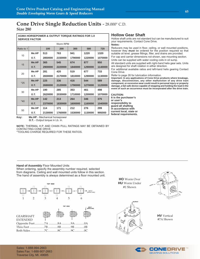
Cone Drive Single Reduction Units - 28.000" C.D. Size 280
Key: Me.HP - Mechanical horsepower O.T. - Output torque in Lb. in.
NOTE: THERMAL H.P. AND CHAIN PULL RATINGS MAY BE OBTAINED BY CONTACTING CONE DRIVE.*TOOLING CHARGE REQUIRED FOR THESE RATIOS.
Hollow Gear ShaftHollow shaft units are not standard but can be manufactured to suit your requirements. Contact Cone Drive. Notes: Reducers may be used in fl oor, ceiling, or wall mounted positions, however they must be ordered for the position required so that suitable oil level, grease fi ttings, fi ller, and drains are provided.For cap and carrier dimensions not shown, see mounting section.Units can be supplied with water cooling coils in oil sump. All standard units are supplied with right-hand helix gear sets. Units are designed for shaft rotation in either direction. For additional available ratios and left-hand helix gearing Contact Cone Drive.Refer to page 26 for lubrication information.Important: In any applications of Cone Drive products where breakage, damage, disconnection, any other malfunction of any drive train component, or excessive wear could result in personal injury or property damage, a fail-safe device capable of stopping and holding the load in the event of such an occurrence must be incorporated after the drive train.
CAUTION: It is the purchaser’s or user’s responsibility to guard all shafting in accordance with current local, state or federal requirements.
AGMA HORSEPOWER & OUTPUT TORQUE RATINGS FOR 1.0 SERVICE FACTOR
Worm RPM
Ratio to 1 100 200 300 580 720
10Me.HP 513 763 941 1220 1320O.T. 2850000 2150000 1790000 1220000 1070000
15Me.HP 365 545 674 877 950O.T. 2900000 2220000 1840000 1290000 1140000
20Me.HP 281 420 519 677 733O.T. 2830000 2170000 1810000 1290000 1130000
*25Me.HP 225 336 416 544 589O.T. 2690000 2120000 1790000 1270000 1120000
30Me.HP 190 285 353 461 498O.T. 2620000 2030000 1710000 1200000 1070000
*40Me.HP 142 213 264 346 375O.T. 2370000 1830000 1600000 1160000 1040000
50Me.HP 114 171 212 276 299O.T. 2130000 1760000 1530000 1130000 995000
Hand of Assembly Floor Mounted UnitsWhen ordering, specify the assembly number required, selected from diagrams. Ceiling and wall mounted units follow in this section.The hand of assembly is always determined as a fl oor mounted unit.
GEARSHAFTEXTENDEDOpposite Feet .............7A ............8A ............9A ............0AThru Feet ....................7B .............8B .............9B .............0BBoth Sides ...................7C .............8C .............9C .............0C
1 2 3 4 5 6
TOP VIEW
INPUT(DRIVE END)
INPUT(DRIVE END)
TOP VIEW
HO Worm OverHU Worm Under
#1 ShownINPUT
OUTPUT
INPUT
OUTPUT
HV Vertical #7A Shown
TM
Cone Drive Product Catalog and Engineering ManualDouble Enveloping Worm Gears & Speed Reducers 65
Sales: 1-888-994-2663Sales Fax: 1-888-907-2663Traverse City, MI. 49685
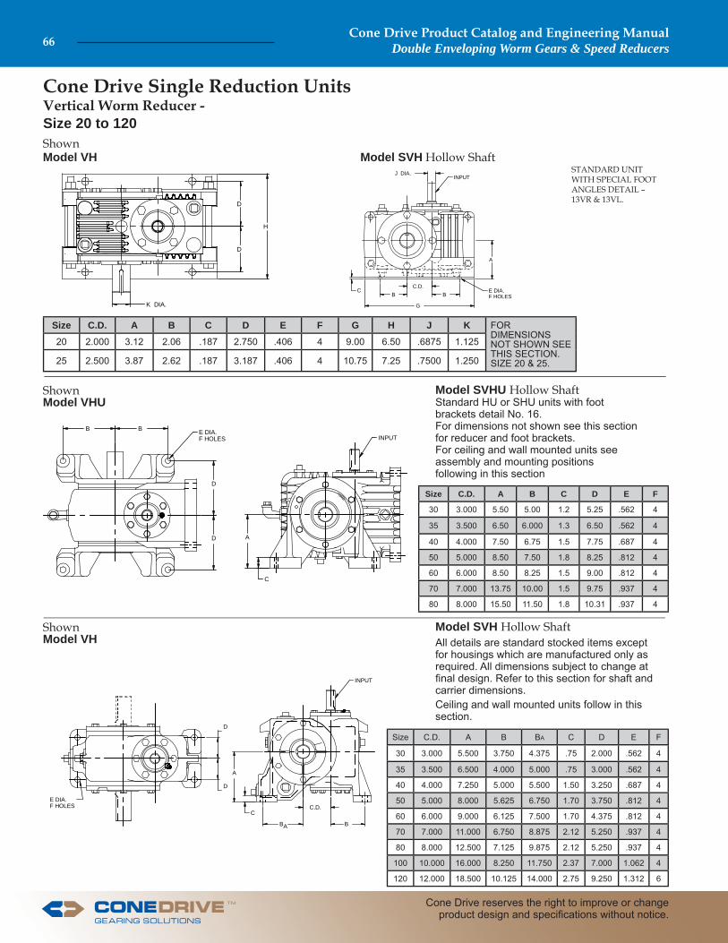
ShownModel VH
ShownModel VHU
Model SVHU Hollow Shaft Standard HU or SHU units with foot brackets detail No. 16. For dimensions not shown see this sectionfor reducer and foot brackets. For ceiling and wall mounted units see assembly and mounting positions following in this section
Cone Drive Single Reduction Units Vertical Worm Reducer - Size 20 to 120
Model SVH Hollow Shaft All details are standard stocked items except for housings which are manufactured only as required. All dimensions subject to change at fi nal design. Refer to this section for shaft and carrier dimensions. Ceiling and wall mounted units follow in this section.
ShownModel VH Model SVH Hollow Shaft
STANDARD UNIT WITH SPECIAL FOOT ANGLES DETAIL – 13VR & 13VL.
Size C.D. A B C D E F G H J K FOR DIMENSIONS NOT SHOWN SEE THIS SECTION.SIZE 20 & 25.
20 2.000 3.12 2.06 .187 2.750 .406 4 9.00 6.50 .6875 1.125
25 2.500 3.87 2.62 .187 3.187 .406 4 10.75 7.25 .7500 1.250
Size C.D. A B C D E F
30 3.000 5.50 5.00 1.2 5.25 .562 4
35 3.500 6.50 6.000 1.3 6.50 .562 4
40 4.000 7.50 6.75 1.5 7.75 .687 4
50 5.000 8.50 7.50 1.8 8.25 .812 4
60 6.000 8.50 8.25 1.5 9.00 .812 4
70 7.000 13.75 10.00 1.5 9.75 .937 4
80 8.000 15.50 11.50 1.8 10.31 .937 4
Size C.D. A B BA C D E F
30 3.000 5.500 3.750 4.375 .75 2.000 .562 4
35 3.500 6.500 4.000 5.000 .75 3.000 .562 4
40 4.000 7.250 5.000 5.500 1.50 3.250 .687 4
50 5.000 8.000 5.625 6.750 1.70 3.750 .812 4
60 6.000 9.000 6.125 7.500 1.70 4.375 .812 4
70 7.000 11.000 6.750 8.875 2.12 5.250 .937 4
80 8.000 12.500 7.125 9.875 2.12 5.250 .937 4
100 10.000 16.000 8.250 11.750 2.37 7.000 1.062 4
120 12.000 18.500 10.125 14.000 2.75 9.250 1.312 6
H
D
D
K DIA.
C
G
B BC.D.
J DIA.INPUT
A
E DIA.F HOLES
B B
D
D
C
A
E DIA.F HOLES INPUT
D
D
B
C.D.
BA
C
A
INPUT
E DIA.F HOLES
Cone Drive Product Catalog and Engineering ManualDouble Enveloping Worm Gears & Speed Reducers66
Cone Drive reserves the right to improve or change product design and specifi cations without notice.
TM

Cone Drive Fan Cooling for Single Reduction Units Ratings follow in this section.
Note: State on order when double extended worm is through fan cover or cut fl ush.
For dimensions not shown see Models HO & SHO.Fan and cover can be mounted at either end of reducer.Important Do not restrict air intake fl ow to fan when attaching coupling, clutch or sheaves to input shaft.
Size A B C D E
40 1.69 7.62 4.68 4.87 4.75
50 1.88 8.62 4.87 5.75 4.75
60 2.30 9.46 6.00 6.50 6.50
70 3.00 11.50 7.00 7.31 6.50
80 2.62 12.87 7.43 7.87 10.5
100 3.62 15.62 8.43 9.50 10.5
For dimensions not shown see Models HU & SHU.Fan and cover can be mounted at either end of reducer.Important Do not restrict air intake fl ow to fan when attaching coupling, clutch or sheaves to input shaft.
Size A B D E
35 1.50 6.25 4.38 4.50
40 1.69 7.62 5.25 4.75
50 1.88 8.62 6.00 4.75
60 2.30 9.46 6.75 6.50
70 3.00 11.50 7.75 6.50
80 2.37 13.12 8.50 10.5
100 3.37 15.87 9.00 10.5
For dimensions not shown see Models HV & SHV.Fan and cover can be mounted at either end of reducer.Important Do not restrict air intake fl ow to fan when attaching coupling, clutch or sheaves to input shaft.
Size A B C D E
35 1.00 6.75 4.25 4.25 4.25
40 1.69 7.62 4.68 4.87 4.75
50 1.88 8.62 4.87 5.75 4.75
60 2.30 9.46 6.00 6.50 6.50
70 3.00 11.50 7.00 7.31 6.50
80 2.62 13.2 7.43 7.87 10.5
100 3.62 15.62 8.43 9.50 10.5
For dimensions not shown see Models FHU, FSHU, HU, & SHU.Fan and cover can be mounted at either end of reducer.This style reducer is considered a vertical unit.Important Do not restrict air intake fl ow to fan when attaching coupling, clutch or sheaves to input shaft.
Size D E F G H K L
35 .44 10.25 7.25 6.25 11.75 .562 10.50
40 .50 11.25 7.50 6.62 12.75 .687 11.50
50 .62 13.62 9.62 8.62 17.00 .812 15.50
60 1.00 15.38 10.50 9.62 18.00 .812 16.50
70 1.25 19.38 14.00 12.50 22.00 .937 20.25
80 1.25 19.38 14.00 12.87 24.00 .937 22.25
100 1.50 24.00 17.50 16.50 29.25 1.062 27.00
Models FHO, FSHO
B A
EDIA.
D D
C
Models FHUV, FSHUV
E
G
K DIA. 4 HOLES 45�OFF C.L. ON 'L' DIA.
H DIA.
F
D
ModelsFHU, FSHU
B A
EDIA.
D D
ModelsFHV, FSHV
B A
EDIA.
D D
C
TM
Cone Drive Product Catalog and Engineering ManualDouble Enveloping Worm Gears & Speed Reducers 67
Sales: 1-888-994-2663Sales Fax: 1-888-907-2663Traverse City, MI. 49685

Cone Drive Water Cooling for Single Reduction Units Inlet and Outlet Locations
COOLING COILS MAY BE SUPPLIED IN EITHER PLAN OR FINNED O.D. TUBING.FOR THERMAL RATING OF REDUCERS EQUIPPED WITH COOLING COILS, CONTACT CONE DRIVE.
CAUTION: Before connecting water lines to reducer read caution tag attached to reducer.
WHV and WSHV
COOLING COIL INLET & OUTLET ARE LOCATED AT END OF HOUSING OPPOSIT INPUT SHAFT. SEE CAUTION NOTE BELOW
COOLING COIL INLET & OUTLET ARE LOCATED AT END OF HOUSING OPPOSIT INPUT SHAFT. SEE CAUTION NOTE BELOW
WHO and WSHO WHU and WSHU
APPROX DIM.
Size 40 Size 50 Size 60 size 70 size 80 size 100 size 120 size 150 size 180 size 220 size 240 size 280HO HU HV HO HU HV HO HU HV HO HU HV HO HU HV HO HU HV HO HU HV HO HU HV HO HU HV HO HU HV HO HU HV HO HU HV
H 2.1 2.2 3.0 2.4 2.2 3.0 2.5 2.8 3.8 2.5 3.7 3.9 3.5 4.2 4.8 4.0 4.0 5.0 6.2 6.2 10.5 9.0 6.0 11.5 7.5 7.5 13.5 10.5 8.2 15.2 12.0 10.0 17.7 12.0 12.0 18.0W 1.7 2.1 2.2 2.0 2.4 2.2 2.5 2.5 2.8 – 3.0 4.0 2.5 2.5 4.5 3.8 4.2 6.0 4.2 4.0 6.5 4.0 7.1 8.5 5.5 7.7 8.5 6 7.4 11.0 8.0 9.5 11.0 10.0 10.0 12.0X 5.6
Y 1.2
Z 2.8
T 3/8 - 18 NPT 1 - 11 1/2 NPT
X
H
W W
Y
Z
FEMALE PIPE THREAD T
W W
H
FEMALE PIPE THREAD T
H
W
W
FEMALE PIPE THREAD T
Cone Drive Product Catalog and Engineering ManualDouble Enveloping Worm Gears & Speed Reducers68
Cone Drive reserves the right to improve or change product design and specifi cations without notice.
TM

TM
Cone Drive Product Catalog and Engineering ManualDouble Enveloping Worm Gears & Speed Reducers 69
Sales: 1-888-994-2663Sales Fax: 1-888-907-2663Traverse City, MI. 49685
Cone Drive Water Cooled Thermal Horsepower RatingsSize 40 through 120
IMPORTANT: Water cooled thermal horsepower ratings listed have ratings less than the mechanical horsepower ratings. All other models or models not shown are equal to or exceed the mechanical horsepower ratings.
*These ratings are based on the use of plain (non-fi nned) cooling coils.
Contact Cone Drive for water cooled thermal horsepower ratings on Unit Size 150 and up.
Size 40 to 60 - Water CoolingTRU-FIN Th HP Rating
Model Ratio to 1
RPM 580 720 870 1150 1750
WHO 40 5 - - - - 26
WHV 40* 5 - - - 20.5 21.810 - - - - 16.2
WHO 50
5 - 29 33 34 3610 - - 23 25 2615 - - - - 2120 - - - - 1625 - - - - 1430 - - - - 12
WHO 60
5 - 43 50 51 5410 - - - 38 3915 - - - - 3120 - - - - 24
WHU 60 25 - - - 57 5910 - - - - 44
WHV 60
5 - - - 53 5510 - - - - 4015 - - - - 3220 - - - - 25
Size 120 - Water CoolingTRU-FIN Th HP Rating
Model Ratio to 1
RPM 100 200 300 580 720 870 1150 1750
WHO 120
5 68 91 116 144 157 179 189 18910 47 63 77 100 118 122 135 13515 – 52 62 82 91 95 103 10320 – 44 53 72 76 78 82 8425 – 38 46 62 67 68 71 7130 – 32 39 51 56 58 59 5940 – – 33 44 48 49 51 5150 – – – 37 40 41 44 4460 – – – – – 36 39 3970 – – – – – – – 37
WHV 120
10 – – – 144 183 185 216 –15 – – – 116 129 141 158 –20 – – – – 101 102 110 –
WD120
5 – 173.96 218.49 235.29 243.09 306.13 311.83 312.1310 77.67 97.36 112.2 134.75 170.16 172.26 200.12 200.1215 – 73.48 83.01 108.94 120.78 131.75 146.71 146.7120 – 59.58 66.62 92.61 95.31 96.27 103.47 110.0225 – 52.76 60.78 79.9 85.71 90.39 96.99 96.9930 – 42.74 49.2 60.62 68.84 71.78 75.39 75.3940 – 34.15 40.85 52.32 58.7 59 61.91 61.9150 – 30.6 36.2 46.22 50.04 50.46 53.2 53.260 – – 32.23 40.02 43.06 44.75 47.48 47.4870 – – – 36.17 39.49 41.45 43.9 44.93
Size 70 to 100 - Water CoolingTRU-FIN Th HP Rating
Model Ratio to 1
INPUT RPM
100 200 300 580 720 870 1150 1750
WHO 70 5 – – – – – – – 8810 – – – – – – – 65
WHU 705 – – – – – – 78 8110 – – – – – – 58 5915 – – – – – – – 4620 – – – – – – – 37
WD 70
5 69 82 98 105 108 126 128 13110 42 51 58 68 82 83 94 9515 34 40 44 57 61 67 73 7420 28 33 36 49 50 50 54 5825 24 29 33 43 45 48 51 5230 21 24 27 32 36 38 40 4135 17 19 23 28 32 32 34 3440 14 18 20 26 27 28 29 3050 13 17 18 22 24 25 26 2760 13 16 18 20 22 23 24 25
WHO 805 – – – – – – 115 12010 – – – – – – – 8815 – – – – – – – 70
WD 80
5 – – – – – – – –10 64 76 86 – – – – –15 50 59 65 82 89 – – –20 – – 52 71 72 72 78 8525 – – – 62 66 69 – 7530 – – – – 53 55 – 5935 – – – – – – – –40 – – – – – – – –50 – – – – – – – –
WD 100
5 – – – – – – – –10 – – – 140 – 180 212 21515 – – – – 124 – 155 15720 – – – – – 98 106 11425 – – – – – – – 10230 – – – – – – 77 7835 – – – – – – – 6340 – – – – – – – 5550 – – – – – – – -

Cone Drive Steeple Bearings for Single Reduction Units
When ordering, specify model size, hand of assembly, and steeple bearings using the letter designation R, S, or T for the mounting confi guration required.For R and T mountings, use the standard hand of assembly designation shown throughout the catalog for various sizes of reducers and mounting positions.
For double-extended S mountings on worm over and worm under units, specify steeple bearing on left (L) or right (R) of unit as viewed from the input end.For S mounting on vertical gear shaft unit, specify steeple bearing op-posite feet (U) or through feet (D).
REDUCER SIZE
CENTER DISTANCE A B C D E F G H DIA.
25 2.500 7.88 4.9 4.50 2.6 2.6 1.38 1/4 x 1/8 1.2501.249
30 3.000 8.62 5.9 5.94 3.4 3.4 2.00 3/8 x 3/16 1.5001.499
35 3.500 10.25 6.3 7.88 4.2 4.2 2.68 1/2 x 1/4 1.8751.874
40 4.000 11.25 6.6 9.25 4.9 4.9 3.31 1/2 x 1/4 2.2502.249
50 5.000 13.62 8.6 10.31 5.6 5.6 3.62 5/8 x 5/16 2.7502.749
60 6.000 15.38 9.6 12.00 6.3 6.4 4.62 3/4 x 3/8 3.2503.249
70 7.000 19.38 12.5 13.00 7.4 7.4 4.88 7/8 x 7/16 3.3753.374
80 8.000 19.38 12.9 14.00 7.8 7.8 4.88 7/8 x 7/16 3.5003.499
100 10.000 24.00 16.5 15.72 9.4 9.4 5.12 1 x 1/2 4.0003.999
120 12.000 36.00 22.6 24.00 12.6 12.4 9.62 1 1/4 x 5/8 5.4975.496
" S " MOUNTING
A
G Keyway
BDC
HG
F
H
" R " MOUNTING
" T " MOUNTING
B BA A
F F
HH
GG Keyway
E AB
F
H
G Keyway
Cone Drive Product Catalog and Engineering ManualDouble Enveloping Worm Gears & Speed Reducers70
Cone Drive reserves the right to improve or change product design and specifi cations without notice.
TM

Adapters are available or can be custom designed for motors not matching the NEMA “C” Face dimensions shown above: DC Motors, Servo Motors, Stepper Motors, Hydraulic Motors, Air Motors and others. Couplings other than the standard
fl exible elastomeric jaw type shown above are available for requirements such as low backlash and high stiffness. Please consult our Application Engineers or Sales Representatives for assistance.
For Cone Drive Standard Speed Reducer Sizes 20 25 30 35NEMA “C” Face Motors Adapters add letter “M” before model designationWhen motor is mounted vertically above worm, Add-1 to motor adapter number. Which indicates grease packing of upper worm bearing. (Sizes 30 and 35 Only.) When motor is mounted vertically, a collar is provided for assembly on the worm or motor shaft to prevent the lower coupling half from sliding down the shaft.
Motor Adapters
DimensionsMOTOR B F GAP
FRAME SIZE PILOTDIA.
SHAFT REDUCER SIZE REDUCER SIZE REDUCER SIZE
Lgth. Dia. Kwy. 20 25 30 35 20 25 30 35 20 25 30 35
56 C 4.50 2.06 .625 3/16 7.31 8.00 9.56 10.56 4.59 5.25 6.69 7.75 .06 .06 .06 0
143TC - 145TC 4.50 2.12 .875 3/16 7.31 8.00 9.56 10.56 4.59 5.25 6.69 7.75 0 0 0 † .06
182TC - 184TC 8.50 2.62 1.125 1/4 8.06 8.75 10.18 11.25 4.59 5.25 6.69 7.75 .12 .12 .12 .12
213TC - 215TC 8.50 3.12 1.375 5/16 – 8.75 10.18 11.25 – 4.88 6.31 7.12 – .12 0 0
For double-extended worms, change part number from -200 to -250. † Recess coupling on motor shaft.
MOTOR FRAME SIZE
COUPLING NUMBER WORM PART NUMBER
REDUCER SIZE REDUCER SIZE
20 25 30 35 20 25 30 35
56 C 720001 720005 720105 720110 20-200 25-200 7300C-200 73500C-200
143TC - 145TC 720004 720007 720107 720112 20-200 25-200 7300C-200 73500C-200
182TC - 184TC 720102 720104 720109 720113 20-200 25-200 7300C-200 73500C-200
213TC - 215TC – 720152 720154 720203 – 25-200-1 7300C-200-1 73500C-200-2
F MOTOR SHAFT LENGTH
4-13/32 DIA. HOLESON 5.875 B.C.
B
.62
PILOT DIA.8.500
4-17/32 DIA. HOLESON 7.250 B.C.
CONE WORM
COUPLING
GAP
MOTOR SHAFT DIA.
PILOT DIA.4.500
MOTOR ADAPTER
SIZE PART NUMBER
20 20-M21
25 25-M21
30 30-M21
35 35-M21
MOTOR ADAPTER
SIZE PART NUMBER
20 20-M20
25 25-M20
30 30-M20
35 35-M20
TM
Cone Drive Product Catalog and Engineering ManualDouble Enveloping Worm Gears & Speed Reducers 71
Sales: 1-888-994-2663Sales Fax: 1-888-907-2663Traverse City, MI. 49685

Motor Adapters
requirements such as low backlash and high stiffness. Please consult our Application Engineers or Sales Representatives for assistance.
For Cone Drive Standard Speed Reducer Sizes 40 50 60 NEMA “C” Face Motors Adapters add letter “M” before model designationWhen motor is mounted vertically above worm, add-1 to motor adapter number, which indicates grease packing of upper worm bearing. When motor is mounted vertically, a collar is provided for assembly on the worm or motor shaft to prevent the lower coupling half from sliding down the shaft.
Adapters are available or can be custom designed for motors not matching the NEMA “C” Face dimensions shown above: DC Motors, Servo Motors, Stepper Motors, Hydraulic Motors, Air Motors and others. Couplings other than the standard fl exible elastomeric jaw type shown above are available for
For double-extended worms, change part number from -200 to -250.
DimensionsMOTOR B
C
F
GFRAME SIZE PILOT
DIA.SHAFT REDUCER SIZE REDUCER SIZE
Lgth. Dia. Kwy. 40 50 60 40 50 60
143TC - 145TC 4.50 2.12 .875 3/16 10.937 12.062 13.125 .62 7.875 9.000 10.062 .937
182TC - 184TC 8.50 2.62 1.125 1/4 12.562 13.687 14.750 .75 9.000 10.125 11.187 .937
213TC - 215TC 8.50 3.12 1.375 5/16 12.562 13.687 14.750 .75 8.500 9.625 10.687 .937
254TC - 256TC 8.50 3.75 1.625 3/8 12.562 13.687 14.750 .75 7.687 8.812 9.875 1.125
MOTOR FRAME SIZE
COUPLING NUMBER WORM PART NUMBER
REDUCER SIZE REDUCER SIZE
40 50 60 40 50 60
143TC - 145TC 720207 720207 720212 40-200-3 50-200-3 60-200-3
182TC - 184TC 720208 720208 720213 40-200-1 50-200-1 60-200-1
213TC - 215TC 720209 720209 720214 40-200-2 50-200-2 60-200-2
254TC - 256TC 720258 720258 720260 40-200-4 50-200-4 60-200-4
4-13/32 DIA. HOLESON 5.875 B.C.
4-17/32 DIA. HOLESON 7.250 B.C.
CONE WORM
COUPLING
B
F
C
MOTOR SHAFT LENGTH
GAP
PILOT DIA.8.500
MOTOR SHAFT DIA.
PILOT DIA.4.500
MOTOR ADAPTER
SIZE PART NUMBER
40 40-M20
50 50-M20
60 60-M20
MOTOR ADAPTER
SIZE PART NUMBER
40 40-M21
50 50-M21
60 60-M21
Cone Drive Product Catalog and Engineering ManualDouble Enveloping Worm Gears & Speed Reducers72
Cone Drive reserves the right to improve or change product design and specifi cations without notice.
TM
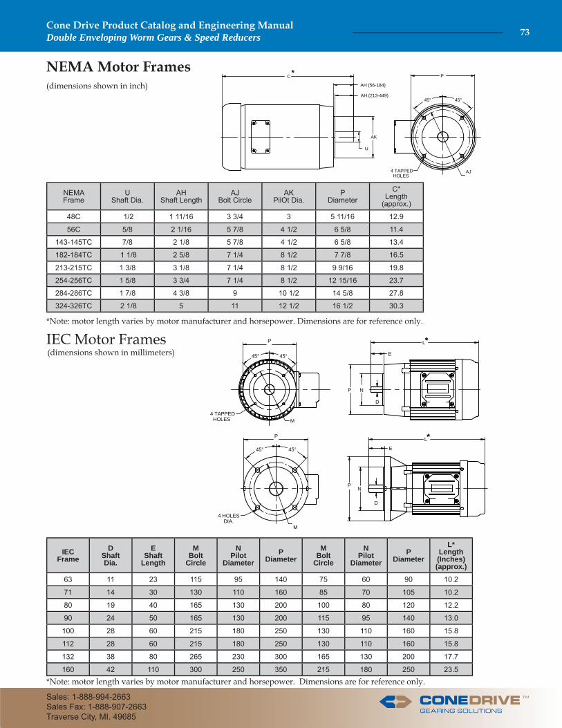
4 TAPPED HOLES M
45° 45°
L
E
NP
D
P
P
45° 45°
4 HOLES DIA.
M
E
L
PN
D
*
*
NEMA Motor Frames (dimensions shown in inch)
*Note: motor length varies by motor manufacturer and horsepower. Dimensions are for reference only.
IEC Motor Frames(dimensions shown in millimeters)
NEMAFrame
UShaft Dia.
AHShaft Length
AJBolt Circle
AKPilOt Dia.
PDiameter
C*Length
(approx.)
48C 1/2 1 11/16 3 3/4 3 5 11/16 12.9
56C 5/8 2 1/16 5 7/8 4 1/2 6 5/8 11.4
143-145TC 7/8 2 1/8 5 7/8 4 1/2 6 5/8 13.4
182-184TC 1 1/8 2 5/8 7 1/4 8 1/2 7 7/8 16.5
213-215TC 1 3/8 3 1/8 7 1/4 8 1/2 9 9/16 19.8
254-256TC 1 5/8 3 3/4 7 1/4 8 1/2 12 15/16 23.7
284-286TC 1 7/8 4 3/8 9 10 1/2 14 5/8 27.8
324-326TC 2 1/8 5 11 12 1/2 16 1/2 30.3
*Note: motor length varies by motor manufacturer and horsepower. Dimensions are for reference only.
IECFrame
DShaftDia.
EShaft
Length
MBolt
Circle
NPilot
DiameterP
DiameterM
BoltCircle
NPilot
DiameterP
Diameter
L*Length(Inches)(approx.)
63 11 23 115 95 140 75 60 90 10.2
71 14 30 130 110 160 85 70 105 10.2
80 19 40 165 130 200 100 80 120 12.2
90 24 50 165 130 200 115 95 140 13.0
100 28 60 215 180 250 130 110 160 15.8
112 28 60 215 180 250 130 110 160 15.8
132 38 80 265 230 300 165 130 200 17.7
160 42 110 300 250 350 215 180 250 23.5
C
AH (56-184)
AH (213-449)
AK
U
P
45° 45°
AJ4 TAPPED HOLES
*
TM
Cone Drive Product Catalog and Engineering ManualDouble Enveloping Worm Gears & Speed Reducers 73
Sales: 1-888-994-2663Sales Fax: 1-888-907-2663Traverse City, MI. 49685

TECHNICAL DATA SHEET
Unit Size Servo Motor Dimensions (mm)1 Interface Dimensions (mm)
Flange Square2 Pilot Dia. Bolt Circle Dia. Shaft Length Plate Thickness Options Dim. "B" Dim. "F"
30
160 80-130 100-165 14.-95 30 & 69
176 151190 114.3-180 200-228.6 29-105 49 & 79
240 230 265 43-116 63 & 90
260 180-250 215-300 65-111 85
35
160 80-130 100-165 14-95 30 & 69
206 182190 114.3-180 200-228.6 29-105 49 & 79
240 230 265 43-116 63 & 90
260 180-250 215-300 65-111 85
40
160 80-130 100-165 14-95 30 & 69
227 196190 114.3-180 200-228.6 29-105 49 & 79
240 230 265 43-116 63 & 90
260 180-250 215-300 65-111 85
Interface Dimensions (inch)
Dimension "H" Keyway "E" G Keyway Dimension “AK”3 Part Number Screw Tighten Torque (Nm)
30 1.000/0.999 1.000 .250 x .125 4.73 57128-140 18
57129-140 40
35 1.1875/1.1865 2.000 .250 x .125 4.9157128-140 18
57129-140 40
57130-140 80
40 1.500/1.499 1.380 .375 x .19 4.73 57129-140 40
57130-140 80
F
SECTION A-A
P T
A
A
F S
P D
C D
SECTION A-A
O H
E
G
O A
BF
SECTION A-A
Plate Thickness
Flange SquareA
A
Pilot Diameter
Bolt CircleDiameter
SECTION A-A
E
G-Keyway
Ø AK
Ø H
1) The pilot, bolt circle, and shaft lengths represent an upper and lower range.2) The actual motor flange square may be smaller or larger than the adapter plate square.
Plate Thickness Options
Unit Size Coupling
3) If coupling is not supplied by Cone Drive, care must be taken that the coupling does not interfere with this diameter or the plate diameter.
Servo Motor Adapter for Cone Drive Single Reduction UnitsSize 30 35 40
Cone Drive Product Catalog and Engineering ManualDouble Enveloping Worm Gears & Speed Reducers74
Cone Drive reserves the right to improve or change product design and specifi cations without notice.
TM

Assembly & Mounting Position Numbers for Cone Drive Single Reduction Units Models HU, SHU, HO, SHOALL DIAGRAMS SHOW REDUCER WITH FEET ON FAR SIDE.Model Prefi xes: F = Fan cooled W = Water cooled M = Motorized P = Pressure lube
1...............2..............3................4................5...............6
Ceiling Mounted
Top View, Floor Mounted
C1.............C2..............C3...........C4...........C5............C6
1 Shown
C1 Shown
Wall Mounted, Worm Vertical Up
W1.............W2.............W3...........W4...........W5..........W6Wall Mounted, Worm Vertical Down
X1.............X2..............X3...........X4............X5.............X6Wall Mounted, Worm Horizontal to the Left
Y1.............Y2..............Y3...........Y4...........Y5.............Y6
Wall Mounted, Worm Horizontal to the Right
Z1.............Z2.............Z3............Z4............Z5.............Z6
W2 Shown
X1 Shown
Y2 Shown
Z1 Shown
TM
Cone Drive Product Catalog and Engineering ManualDouble Enveloping Worm Gears & Speed Reducers 75
Sales: 1-888-994-2663Sales Fax: 1-888-907-2663Traverse City, MI. 49685

A Gearshaft Extended Opposite FeetB Gearshaft Extended Through FeetC Gearshaft Double Extended
Assembly & Mounting Position Numbers for Cone Drive Single Reduction Units Models HV, SHVModel Prefi xes: F = Fan cooled W = Water cooled M = Motorized P = Pressure lubeALL DIAGRAMS SHOW REDUCER WITH FEET ON FAR SIDE.
7A.....................8A.....................9A......................0A7B.....................8B.....................9B......................0B7C.....................8C.....................9C......................0C
Ceiling Mounted
Top View, Floor Mounted
Wall Mounted, Worm Vertical Up
Wall Mounted, Worm Vertical Down
Wall Mounted, Worm Horizontal Under Gear
Wall Mounted, Worm Horizontal Over Gear
C7A..................C8A..................C9A................C0AC7B..................C8B..................C9B................C0BC7C..................C8C..................C9C................C0C
W7A..................W8A................W9A...............W0AW7B..................W8B................W9B...............W0BW7C..................W8C................W9C...............W0C
X7A..................X8A..................X9A.................X0AX7B..................X8B..................X9B.................X0BX7C..................X8C..................X9C.................X0C
Y7A...................Y8A.....................Y9A....................Y0AY7B...................Y8B.....................Y9B....................Y0BY7C...................Y8C.....................Y9C....................Y0C
Z7A...................Z8A....................Z9A...................Z0AZ7B...................Z8B....................Z9B...................Z0BZ7C...................Z8C....................Z9C...................Z0C
7A Shown
C7A Shown
W8A Shown
X7A Shown
Y8A Shown
Z7A Shown
Size 100 and larger - Contact Cone Drive Regarding Lubrication of Upper Worm Bearing
Cone Drive Product Catalog and Engineering ManualDouble Enveloping Worm Gears & Speed Reducers76
Cone Drive reserves the right to improve or change product design and specifi cations without notice.
TM

Assembly & Mounting Position Numbers for Cone Drive Single Reduction Units Models VH, VHU, SVH, SVHUModel Prefi xes: F = Fan cooled W = Water cooled M = Motorized P = Pressure lubeALL DIAGRAMS SHOW REDUCER WITH FEET ON FAR SIDE.
DIAGRAMS 1 THRU 3 HAVE SINGLE EXTENDED INPUT SHAFTS, THE INPUT END EXTENDS UP. DIAGRAMS 4 THRU 6 HAVE DOUBLE EXTENDED INPUT SHAFTSFOR INPUT END EXTENDING DOWN SPECIFY SAME WHEN ORDERING AND ADD LETTER “D” AFTER UNIT SIZE VH50D-1
1.......................2.......................3......................4.......................5....................6
Ceiling Mounted
Top View, Floor Mounted
C1.....................C2..................C3....................C4.....................C5.................C6
Wall Mounted, Worm Under Gear
W1..................W2..................W3..................W4.....................W5.................W6Wall Mounted, Worm Over Gear
X1....................X2....................X3....................X4....................X5...................X6Wall Mounted, Worm to the Left of Gear
Y1....................Y2.....................Y3..................Y4....................Y5...................Y6
Wall Mounted, Worm to Right of Gear
Z1.....................Z2.....................Z3...................Z4....................Z5...................Z6TM
Cone Drive Product Catalog and Engineering ManualDouble Enveloping Worm Gears & Speed Reducers 77
Sales: 1-888-994-2663Sales Fax: 1-888-907-2663Traverse City, MI. 49685