configuration manual simatic net
TRANSCRIPT
Edition 01/2021
Configuration Manual
SIMATIC NETRugged Ethernet SwitchesRUGGEDCOM ROS v5.5
For RSG2488
https://www.siemens.com

SIMATIC NET
Rugged Ethernet SwitchesRUGGEDCOM ROS v5.5
Configuration Manual
For RSG2488
Preface
Introduction 1
Using ROS 2
Getting Started 3
Device Management 4
System Administration 5
Security 6
Layer 2 7
Layer 3 8
Network Redundancy 9Traffic Control andClassification 10
Time Services 11Network Discovery andManagement 12
IP Address Assignment 13
Troubleshooting 14
01/2021C79000-G8976-1472-02

Legal InformationWarning Notice System
This manual contains notices you have to observe in order to ensure your personal safety, as well as to preventdamage to property. The notices referring to your personal safety are highlighted in the manual by a safetyalert symbol, notices referring only to property damage have no safety alert symbol. These notices shownbelow are graded according to the degree of danger.
DANGERindicates that death or severe personal injury will result if proper precautions are not taken.
WARNINGindicates that death or severe personal injury may result if proper precautions are not taken.
CAUTIONindicates that minor personal injury can result if proper precautions are not taken.
NOTICEindicates that property damage can result if proper precautions are not taken.
If more than one degree of danger is present, the warning notice representing the highest degree of dangerwill be used. A notice warning of injury to persons with a safety alert symbol may also include a warningrelating to property damage.
Qualified PersonnelThe product/system described in this documentation may be operated only by personnel qualified for thespecific task in accordance with the relevant documentation, in particular its warning notices and safetyinstructions. Qualified personnel are those who, based on their training and experience, are capable ofidentifying risks and avoiding potential hazards when working with these products/systems.
Proper Use of Siemens ProductsNote the following:
WARNINGSiemens products may only be used for the applications described in the catalog and in the relevanttechnical documentation. If products and components from other manufacturers are used, these must berecommended or approved by Siemens. Proper transport, storage, installation, assembly, commissioning,operation and maintenance are required to ensure that the products operate safely and without anyproblems. The permissible ambient conditions must be complied with. The information in the relevantdocumentation must be observed.
TrademarksAll names identified by ® are registered trademarks of Siemens AG. The remaining trademarks in thispublication may be trademarks whose use by third parties for their own purposes could violate the rights ofthe owner.
Disclaimer of LiabilityWe have reviewed the contents of this publication to ensure consistency with the hardware and softwaredescribed. Since variance cannot be precluded entirely, we cannot guarantee full consistency. However, theinformation in this publication is reviewed regularly and any necessary corrections are included in subsequenteditions.
Siemens AGDigital IndustryProcess AutomationPostfach 48 4890026 NÜRNBERGGERMANY
© 01/2021 Subject to Change Copyright © Siemens 2021All rights reserved

Table of Contents
Preface ......................................................................................................................................... xiiiCLI Command Syntax ............................................................................................................ xiiiRelated Documents ............................................................................................................... xivSystem Requirements ........................................................................................................... xviAccessing Documentation ..................................................................................................... xviTraining ................................................................................................................................ xviCustomer Support ................................................................................................................. xvi
1 Introduction ........................................................................................................................... 1
1.1 Features and Benefits ............................................................................................ 1
1.2 Security Recommendations ................................................................................... 4
1.3 Logged Security Events ......................................................................................... 7
1.4 Controlled vs. Non-Controlled .............................................................................. 10
1.5 Supported Networking Standards ........................................................................ 10
1.6 Internet Protocol Support .................................................................................... 111.6.1 Features Supported by IPv4 and/or IPv6 ............................................................... 111.6.2 IPv4 Address ....................................................................................................... 111.6.3 IPv6 Address ....................................................................................................... 12
1.7 Port Numbering Scheme ..................................................................................... 12
1.8 Available Services by Port .................................................................................... 13
1.9 Removable Memory ............................................................................................ 14
2 Using ROS ............................................................................................................................ 17
2.1 Logging In .......................................................................................................... 18
2.2 Logging Out ........................................................................................................ 19
2.3 Using the Web Interface ...................................................................................... 20
2.4 Using the Console Interface ................................................................................ 21
2.5 Using the Command Line Interface ...................................................................... 232.5.1 Available CLI Commands ..................................................................................... 232.5.2 Tracing Events ..................................................................................................... 302.5.3 Executing Commands Remotely via RSH .............................................................. 312.5.4 Using SQL Commands ......................................................................................... 322.5.4.1 Finding the Correct Table .................................................................................... 322.5.4.2 Retrieving Information ......................................................................................... 332.5.4.3 Changing Values in a Table ................................................................................. 352.5.4.4 Resetting a Table ................................................................................................ 352.5.4.5 Using RSH and SQL ............................................................................................. 35
2.6 Selecting Ports in RUGGEDCOM ROS .................................................................... 36
2.7 Managing the Flash File System .......................................................................... 36
RUGGEDCOM ROS v5.5Configuration Manual, 01/2021, C79000-G8976-1472-02 iii

Table of Contents
2.7.1 Viewing a List of Flash Files ................................................................................ 362.7.2 Viewing Flash File Details .................................................................................... 372.7.3 Defragmenting the Flash File System ................................................................... 37
2.8 Accessing BIST Mode ........................................................................................... 38
2.9 Managing Access to the Boot Loader Interface ..................................................... 392.9.1 Enabling/Disabling Access to the Boot Loader Interface ........................................ 392.9.2 Accessing the Boot Loader Interface .................................................................... 402.9.3 Setting the Boot Source ...................................................................................... 41
2.10 Enabling/Disabling Automatic Access to Removable Memory ................................ 41
2.11 Enabling/Disabling the Console Service ................................................................ 42
3 Getting Started .................................................................................................................... 43
3.1 Connecting to ROS .............................................................................................. 433.1.1 Default IP Address ............................................................................................... 433.1.2 Connecting Directly ............................................................................................. 433.1.3 Connecting Remotely .......................................................................................... 45
3.2 Configuring a Basic Network ............................................................................... 46
4 Device Management ........................................................................................................... 47
4.1 Viewing Product Information ............................................................................... 47
4.2 Viewing CPU Diagnostics ..................................................................................... 48
4.3 Viewing the Status of the Power Supplies ............................................................ 48
4.4 Restoring Factory Defaults ................................................................................... 49
4.5 Uploading/Downloading Files .............................................................................. 504.5.1 Uploading/Downloading Files Using XMODEM ..................................................... 514.5.2 Uploading/Downloading Files Using a TFTP Client ................................................ 524.5.3 Uploading/Downloading Files Using a TFTP Server ............................................... 534.5.4 Uploading/Downloading Files Using an SFTP Server ............................................. 544.5.5 Uploading/Downloading Files Using the microSD/microSDHC Card ........................ 54
4.6 Managing Logs ................................................................................................... 554.6.1 Viewing Local and System Logs ........................................................................... 564.6.2 Clearing Local and System Logs ........................................................................... 564.6.3 Configuring the Local System Log ....................................................................... 564.6.4 Managing Remote Logging .................................................................................. 574.6.4.1 Syslog Format ..................................................................................................... 574.6.4.2 Configuring the Remote Syslog Client .................................................................. 584.6.4.3 Viewing a List of Remote Syslog Servers .............................................................. 594.6.4.4 Adding a Remote Syslog Server ........................................................................... 594.6.4.5 Deleting a Remote Syslog Server ......................................................................... 60
4.7 Managing Ethernet Ports ..................................................................................... 604.7.1 Controller Protection Through Link Fault Indication (LFI) ...................................... 604.7.2 Viewing the Status of Ethernet Ports ................................................................... 624.7.3 Viewing Statistics for All Ethernet Ports ............................................................... 624.7.4 Viewing Statistics for Specific Ethernet Ports ........................................................ 63
iv RUGGEDCOM ROS v5.5Configuration Manual, 01/2021, C79000-G8976-1472-02

Table of Contents
4.7.5 Clearing Statistics for Specific Ethernet Ports ....................................................... 664.7.6 Configuring an Ethernet Port ............................................................................... 664.7.7 Configuring Port Rate Limiting ............................................................................. 684.7.8 Configuring Port Mirroring .................................................................................. 694.7.9 Configuring Link Detection .................................................................................. 714.7.10 Managing SFP Transceivers ................................................................................. 724.7.10.1 SFP Transceiver Requirements ............................................................................. 734.7.10.2 Monitoring an SFP Port ....................................................................................... 734.7.10.3 Displaying Information for an SFP Port ................................................................ 744.7.11 Detecting Cable Faults ......................................................................................... 754.7.11.1 Viewing Cable Diagnostics Results ....................................................................... 754.7.11.2 Performing Cable Diagnostics .............................................................................. 764.7.11.3 Clearing Cable Diagnostics .................................................................................. 774.7.11.4 Determining the Estimated Distance To Fault (DTF) ............................................. 774.7.12 Resetting Ethernet Ports ...................................................................................... 78
4.8 Managing IP Interfaces ........................................................................................ 784.8.1 Configuring the Management IP Interface ........................................................... 794.8.2 Managing Switch IP Interfaces ............................................................................. 804.8.2.1 Viewing a List of Switch IP Interfaces .................................................................. 804.8.2.2 Adding a Switch IP Interface ................................................................................ 804.8.2.3 Deleting a Switch IP Interface .............................................................................. 82
4.9 Managing IP Gateways ........................................................................................ 824.9.1 Viewing a List of IP Gateways .............................................................................. 834.9.2 Adding an IP Gateway ......................................................................................... 834.9.3 Deleting an IP Gateway ....................................................................................... 83
4.10 Configuring IP Services ........................................................................................ 84
4.11 Managing Remote Monitoring ............................................................................. 854.11.1 Managing RMON History Controls ....................................................................... 864.11.1.1 Viewing a List of RMON History Controls ............................................................. 864.11.1.2 Adding an RMON History Control ........................................................................ 864.11.1.3 Deleting an RMON History Control ....................................................................... 874.11.2 Managing RMON Alarms ..................................................................................... 874.11.2.1 Viewing a List of RMON Alarms ........................................................................... 884.11.2.2 Adding an RMON Alarm ...................................................................................... 884.11.2.3 Deleting an RMON Alarm .................................................................................... 904.11.3 Managing RMON Events ...................................................................................... 904.11.3.1 Viewing a List of RMON Events ........................................................................... 914.11.3.2 Adding an RMON Event ....................................................................................... 914.11.3.3 Deleting an RMON Event ..................................................................................... 92
4.12 Upgrading/Downgrading Firmware ...................................................................... 924.12.1 Verifying the Hash Checksum .............................................................................. 924.12.2 Upgrading Firmware ........................................................................................... 924.12.3 Downgrading Firmware ....................................................................................... 94
4.13 Resetting the Device ........................................................................................... 95
4.14 Decommissioning the Device ............................................................................... 95
RUGGEDCOM ROS v5.5Configuration Manual, 01/2021, C79000-G8976-1472-02 v

Table of Contents
5 System Administration ........................................................................................................ 97
5.1 Configuring the System Information .................................................................... 97
5.2 Customizing the Login Screen ............................................................................. 97
5.3 Enabling/Disabling the Web Interface .................................................................. 98
5.4 Managing Alarms ................................................................................................ 985.4.1 Viewing a List of Pre-Configured Alarms .............................................................. 995.4.2 Viewing and Clearing Latched Alarms .................................................................. 995.4.3 Configuring an Alarm .......................................................................................... 995.4.4 Security Alarms for Login Authentication ........................................................... 1015.4.5 List of Alarms .................................................................................................... 103
5.5 Managing the Configuration File ....................................................................... 1065.5.1 Configuring Data Encryption .............................................................................. 1075.5.2 Updating the Configuration File ........................................................................ 108
5.6 Managing MMS ................................................................................................. 1085.6.1 Understanding MMS .......................................................................................... 1085.6.1.1 MMS Reporting ................................................................................................. 1095.6.1.2 Reports/Data Sets .............................................................................................. 1095.6.1.3 Supported Logical Nodes ................................................................................... 1105.6.2 Viewing a List of Preconfigured MMS Reports .................................................... 1105.6.3 Configuring an MMS Report .............................................................................. 1115.6.4 Example: Configuring MMS Reports ................................................................... 111
6 Security .............................................................................................................................. 115
6.1 Configuring Passwords ...................................................................................... 115
6.2 Clearing Private Data ......................................................................................... 117
6.3 Managing User Authentication .......................................................................... 1176.3.1 Authentication Methods .................................................................................... 1186.3.2 Configuring User Name Extensions .................................................................... 1196.3.3 Managing RADIUS Authentication ...................................................................... 1206.3.3.1 Configuring the RADIUS Server .......................................................................... 1216.3.3.2 Configuring the RADIUS Client on the Device ..................................................... 1216.3.4 Managing TACACS+ Authentication ................................................................... 1226.3.4.1 Configuring TACACS+ ........................................................................................ 1226.3.4.2 Configuring User Privileges ................................................................................ 124
6.4 Managing Port Security ..................................................................................... 1246.4.1 Port Security Concepts ...................................................................................... 1256.4.1.1 Static MAC Address-Based Authentication .......................................................... 1256.4.1.2 Static MAC Address-Based Authentication in an MRP Ring .................................. 1256.4.1.3 IEEE 802.1x Authentication ............................................................................... 1256.4.1.4 IEEE 802.1X Authentication with MAC Address-Based Authentication ................. 1266.4.1.5 Restricted VLANs ............................................................................................... 1276.4.1.6 Assigning VLANS with Tunnel Attributes ............................................................ 1286.4.2 Viewing a List of Authorized MAC Addresses ...................................................... 1286.4.3 Configuring Port Security .................................................................................. 1296.4.4 Configuring IEEE 802.1X ................................................................................... 131
vi RUGGEDCOM ROS v5.5Configuration Manual, 01/2021, C79000-G8976-1472-02

Table of Contents
6.5 Managing SSH/SSL Keys and Certificates ............................................................ 1326.5.1 SSL Certificates .................................................................................................. 1346.5.2 SSH Host Key .................................................................................................... 1346.5.3 Managing SSH Public Keys ................................................................................ 1356.5.3.1 Public Key Requirements ................................................................................... 1356.5.3.2 Adding a Public Key .......................................................................................... 1366.5.3.3 Viewing a List of Public Keys ............................................................................. 1376.5.3.4 Updating a Public Key ....................................................................................... 1376.5.3.5 Deleting a Public Key ........................................................................................ 1386.5.4 Certificate and Key Examples ............................................................................. 138
7 Layer 2 ............................................................................................................................... 141
7.1 Managing Virtual LANs ...................................................................................... 1417.1.1 VLAN Concepts .................................................................................................. 1417.1.1.1 Tagged vs. Untagged Frames ............................................................................ 1417.1.1.2 Native VLAN ...................................................................................................... 1427.1.1.3 The Management VLAN ..................................................................................... 1427.1.1.4 Auxiliary Management VLANs ............................................................................ 1427.1.1.5 Edge and Trunk Port Types ................................................................................ 1437.1.1.6 Ingress and Egress Rules ................................................................................... 1447.1.1.7 Forbidden Ports List .......................................................................................... 1447.1.1.8 VLAN-Aware and VLAN-Unaware Modes ............................................................ 1447.1.1.9 GARP VLAN Registration Protocol (GVRP) ........................................................... 1457.1.1.10 PVLAN Edge ...................................................................................................... 1477.1.1.11 QinQ ................................................................................................................. 1477.1.1.12 VLAN Advantages .............................................................................................. 1497.1.2 Viewing a List of VLANs .................................................................................... 1507.1.3 Configuring VLANs Globally ............................................................................... 1517.1.4 Configuring VLANs for Specific Ethernet Ports .................................................... 1517.1.5 Managing Static VLANs ..................................................................................... 1537.1.5.1 Viewing a List of Static VLANs ........................................................................... 1537.1.5.2 Adding a Static VLAN ........................................................................................ 1537.1.5.3 Deleting a Static VLAN ...................................................................................... 1547.1.6 Example: Configuring Management Support on Multiple VLANs ......................... 155
7.2 Managing MAC Addresses ................................................................................. 1577.2.1 Viewing a List of MAC Addresses ....................................................................... 1577.2.2 Configuring MAC Address Learning Options ....................................................... 1577.2.3 Configuring MAC Address Flooding Options ....................................................... 1587.2.4 Managing Static MAC Addresses ........................................................................ 1587.2.4.1 Viewing a List of Static MAC Addresses .............................................................. 1587.2.4.2 Adding a Static MAC Address ............................................................................ 1597.2.4.3 Deleting a Static MAC Address ........................................................................... 1607.2.5 Purging All Dynamic MAC Addresses .................................................................. 160
7.3 Managing Multicast Filtering ............................................................................. 1607.3.1 Managing IGMP ................................................................................................. 1607.3.1.1 IGMP Concepts .................................................................................................. 1617.3.1.2 Viewing a List of Multicast Group Memberships ................................................. 1657.3.1.3 Viewing Forwarding Information for Multicast Groups ....................................... 166
RUGGEDCOM ROS v5.5Configuration Manual, 01/2021, C79000-G8976-1472-02 vii

Table of Contents
7.3.1.4 Configuring IGMP .............................................................................................. 1667.3.2 Managing GMRP ................................................................................................ 1687.3.2.1 GMRP Concepts ................................................................................................. 1687.3.2.2 Viewing a Summary of Multicast Groups ........................................................... 1707.3.2.3 Configuring GMRP Globally ................................................................................ 1717.3.2.4 Configuring GMRP for Specific Ethernet Ports .................................................... 1727.3.2.5 Viewing a List of Static Multicast Groups ........................................................... 1727.3.2.6 Adding a Static Multicast Group ........................................................................ 1727.3.2.7 Deleting a Static Multicast Group ...................................................................... 173
8 Layer 3 ............................................................................................................................... 175
8.1 Managing Layer 3 Switching ............................................................................. 1758.1.1 Understanding Layer 3 Switching ...................................................................... 1758.1.1.1 Layer 3 Switch Forwarding Table ....................................................................... 1758.1.1.2 Static Layer 3 Switching Rules ........................................................................... 1768.1.1.3 Dynamic Learning of Layer 3 Switching Rules .................................................... 1768.1.1.4 Interaction Between IP Forwarding and Layer 3 Switching .................................. 1778.1.1.5 Layer 3 Switch ARP Table .................................................................................. 1778.1.1.6 Layer 3 Switch Routable Interfaces .................................................................... 1798.1.2 Configuring Layer 3 Switching ........................................................................... 1808.1.3 Configuring Layer 3 Switching Options .............................................................. 1808.1.4 Managing Static Unicast Rules ........................................................................... 1818.1.4.1 Viewing Static Unicast Rules .............................................................................. 1818.1.4.2 Adding a Static Unicast Rule .............................................................................. 1818.1.4.3 Deleting a Static Unicast Rule ............................................................................ 1828.1.5 Managing Static ARP Table Entries ..................................................................... 1828.1.5.1 Viewing a List of ARP Table Entries .................................................................... 1828.1.5.2 Adding a Static ARP Table Entry ......................................................................... 1838.1.5.3 Deleting a Static ARP Table Entry ....................................................................... 1838.1.6 Viewing Routing Rules ....................................................................................... 1848.1.7 Flushing Dynamic Hardware Routing Rules ........................................................ 1848.1.8 Example: Configuring Layer 3 Switching ............................................................ 1858.1.9 Example: Configuring Layer 3 Switching Using Multiple Switches ....................... 186
9 Network Redundancy ........................................................................................................ 189
9.1 Managing Spanning Tree Protocol ..................................................................... 1899.1.1 RSTP Operation ................................................................................................. 1899.1.1.1 RSTP States and Roles ....................................................................................... 1909.1.1.2 Edge Ports ......................................................................................................... 1929.1.1.3 Point-to-Point and Multipoint Links .................................................................... 1929.1.1.4 Path and Port Costs ........................................................................................... 1929.1.1.5 Bridge Diameter ................................................................................................ 1939.1.1.6 eRSTP ................................................................................................................ 1949.1.1.7 Fast Root Failover .............................................................................................. 1949.1.2 RSTP Applications .............................................................................................. 1959.1.2.1 RSTP in Structured Wiring Configurations ........................................................... 1959.1.2.2 RSTP in Ring Backbone Configurations ............................................................... 1979.1.2.3 RSTP Port Redundancy ....................................................................................... 1999.1.3 MSTP Operation ................................................................................................ 200
viii RUGGEDCOM ROS v5.5Configuration Manual, 01/2021, C79000-G8976-1472-02
Table of Contents
9.1.3.1 MSTP Regions and Interoperability ..................................................................... 2009.1.3.2 MSTP Bridge and Port Roles ............................................................................... 2019.1.3.3 Benefits of MSTP ............................................................................................... 2039.1.3.4 Implementing MSTP on a Bridged Network ........................................................ 2049.1.4 Configuring STP Globally ................................................................................... 2059.1.5 Configuring STP for Specific Ethernet Ports ........................................................ 2069.1.6 Configuring eRSTP ............................................................................................. 2089.1.7 Viewing Global Statistics for STP ........................................................................ 2109.1.8 Viewing STP Statistics for Ethernet Ports ............................................................ 2129.1.9 Managing Multiple Spanning Tree Instances ...................................................... 2139.1.9.1 Viewing Statistics for Global MSTIs .................................................................... 2149.1.9.2 Viewing Statistics for Port MSTIs ........................................................................ 2149.1.9.3 Configuring the MST Region Identifier ............................................................... 2169.1.9.4 Configuring a Global MSTI ................................................................................. 2169.1.9.5 Configuring an MSTI for an Ethernet Port .......................................................... 2179.1.10 Clearing Spanning Tree Protocol Statistics .......................................................... 218
9.2 Managing the Media Redundancy Protocol (MRP) .............................................. 2189.2.1 Understanding MRP ........................................................................................... 2189.2.1.1 MRM vs MRC Devices ........................................................................................ 2199.2.1.2 MRA Devices ..................................................................................................... 2199.2.1.3 Ring Port States ................................................................................................. 2199.2.1.4 Ring-Closed vs Ring-Open .................................................................................. 2199.2.2 Configuring MRP Globally .................................................................................. 2219.2.3 Viewing the Status of MRP Instances ................................................................. 2219.2.4 Adding an MRP Instance .................................................................................... 2229.2.5 Deleting an MRP Instance .................................................................................. 2259.2.6 Example: Configuring an MRP Ring .................................................................... 225
9.3 Managing Link Aggregation .............................................................................. 2279.3.1 Link Aggregation Concepts ................................................................................ 2289.3.1.1 Static vs. Dynamic Link Aggregation .................................................................. 2289.3.1.2 Rules and Limitations ........................................................................................ 2299.3.1.3 Link Aggregation and Layer 2 Features .............................................................. 2309.3.1.4 Link Aggregation and Physical Layer Features .................................................... 2309.3.2 Configuring Link Aggregation ............................................................................ 2309.3.3 Managing Link Aggregation Groups ................................................................... 2319.3.3.1 Viewing a List of Link Aggregation Groups ......................................................... 2319.3.3.2 Adding a Link Aggregation Group ...................................................................... 2319.3.3.3 Deleting a Link Aggregation Group .................................................................... 2339.3.3.4 Viewing the Status of Link Aggregation Groups ................................................. 2339.3.4 Managing the Link Aggregation Control Protocol ............................................... 2339.3.4.1 Viewing Information About the LACP Partner ..................................................... 2349.3.4.2 Configuring Global LACP Settings ...................................................................... 2359.3.4.3 Configuring LACP Per Port ................................................................................. 2359.3.4.4 Viewing LACP Statistics ..................................................................................... 2369.3.5 Clearing Link Aggregation Statistics ................................................................... 237
10 Traffic Control and Classification ...................................................................................... 239
10.1 Managing Classes of Service .............................................................................. 239
RUGGEDCOM ROS v5.5Configuration Manual, 01/2021, C79000-G8976-1472-02 ix

Table of Contents
10.1.1 Configuring Classes of Service Globally .............................................................. 24010.1.2 Configuring Classes of Service for Specific Ethernet Ports ................................... 24110.1.3 Configuring Priority to CoS Mapping .................................................................. 24210.1.4 Configuring DSCP to CoS Mapping ..................................................................... 242
11 Time Services .................................................................................................................... 245
11.1 Configuring the Time and Date ......................................................................... 245
11.2 Configuring IRIG-B ............................................................................................. 246
11.3 Managing the Precision Time Protocol (PTP) ...................................................... 24811.3.1 Configuring PTP Globally ................................................................................... 24911.3.2 Configuring an Ordinary or Transparent Clock .................................................... 25211.3.3 Configuring a Boundary Clock Slave .................................................................. 25311.3.4 Configuring the PTP Delay Request Interval ........................................................ 25511.3.5 Configuring a VLAN for PTP Traffic .................................................................... 25611.3.6 Viewing PTP Clock Statistics ............................................................................... 25611.3.7 Viewing Boundary Clock Slave Statistics ............................................................. 25711.3.8 Viewing Peer Delay Statistics ............................................................................. 257
11.4 Configuring the Time Source ............................................................................. 258
11.5 Managing NTP ................................................................................................... 25911.5.1 Enabling/Disabling NTP Service .......................................................................... 25911.5.2 Configuring NTP Servers .................................................................................... 259
11.6 Viewing the Status of Time Synchronization Subsystems .................................... 260
12 Network Discovery and Management .............................................................................. 263
12.1 Enabling/Disabling RCDP .................................................................................... 263
12.2 Managing LLDP ................................................................................................. 26412.2.1 Configuring LLDP Globally ................................................................................. 26512.2.2 Configuring LLDP for an Ethernet Port ............................................................... 26612.2.3 Viewing Global Statistics and Advertised System Information ............................. 26712.2.4 Viewing Statistics for LLDP Neighbors ................................................................ 26712.2.5 Viewing Statistics for LLDP Ports ........................................................................ 268
12.3 Managing SNMP ................................................................................................ 26812.3.1 SNMP Management Interface Base (MIB) Support .............................................. 26912.3.1.1 Supported Standard MIBs .................................................................................. 26912.3.1.2 Supported Proprietary RUGGEDCOM MIBs .......................................................... 35612.3.1.3 Supported Agent Capabilities ............................................................................. 38812.3.2 SNMP Traps ....................................................................................................... 38912.3.3 Managing SNMP Users ...................................................................................... 39512.3.3.1 Viewing a List of SNMP Users ............................................................................ 39512.3.3.2 Adding an SNMP User ....................................................................................... 39512.3.3.3 Deleting an SNMP User ..................................................................................... 39712.3.4 Managing Security-to-Group Mapping ............................................................... 39712.3.4.1 Viewing a List of Security-to-Group Maps ........................................................... 39812.3.4.2 Adding a Security-to-Group Map ........................................................................ 39812.3.4.3 Deleting a Security-to-Group Map ...................................................................... 39812.3.5 Managing SNMP Groups .................................................................................... 399
x RUGGEDCOM ROS v5.5Configuration Manual, 01/2021, C79000-G8976-1472-02

Table of Contents
12.3.5.1 Viewing a List of SNMP Groups ......................................................................... 39912.3.5.2 Adding an SNMP Group ..................................................................................... 39912.3.5.3 Deleting an SNMP Group ................................................................................... 400
12.4 ModBus Management Support .......................................................................... 40012.4.1 ModBus Function Codes .................................................................................... 40112.4.2 ModBus Memory Map ....................................................................................... 40212.4.3 Modbus Memory Formats .................................................................................. 40712.4.3.1 Text .................................................................................................................. 40712.4.3.2 Cmd .................................................................................................................. 40812.4.3.3 Uint16 ............................................................................................................... 40812.4.3.4 Uint32 ............................................................................................................... 40812.4.3.5 PortCmd ............................................................................................................ 40912.4.3.6 Alarm ................................................................................................................ 41012.4.3.7 PSStatusCmd ..................................................................................................... 41012.4.3.8 TruthValues ....................................................................................................... 410
13 IP Address Assignment ...................................................................................................... 413
13.1 Managing DHCP ................................................................................................ 41313.1.1 DHCP Concepts ................................................................................................. 41313.1.1.1 DHCP Snooping ................................................................................................. 41313.1.1.2 Trusted and Untrusted Ports .............................................................................. 41313.1.1.3 DHCP Relay Agent (Option 82) .......................................................................... 41413.1.1.4 Dynamic ARP Inspection .................................................................................... 41413.1.1.5 DHCP Binding Table ........................................................................................... 41513.1.1.6 Preventable Network Attacks ............................................................................. 41513.1.2 Configuring the DHCP Relay Agent .................................................................... 41813.1.3 Enabling DHCP Relay Agent Information (Option 82) for Specific Ports ................ 41813.1.4 Configuring DHCP Snooping .............................................................................. 41913.1.5 Configuring Trusted/Untrusted Ports .................................................................. 42013.1.6 Managing Dynamic ARP Inspection .................................................................... 42013.1.6.1 Enabling/Disabling Dynamic ARP Inspection ....................................................... 42113.1.6.2 Viewing ARP Inspection Statistics ....................................................................... 42113.1.6.3 Clearing ARP Inspection Statistics ...................................................................... 42113.1.7 Managing the DHCP Binding Table .................................................................... 42213.1.7.1 Adding Entries to the DHCP Binding Table ......................................................... 42213.1.7.2 Viewing the DHCP Binding Table ....................................................................... 42213.1.7.3 Saving the DHCP Binding Table ......................................................................... 42313.1.7.4 Example: Configuring the Device as a Relay Agent ............................................. 423
14 Troubleshooting ................................................................................................................ 427
14.1 General ............................................................................................................. 427
14.2 Ethernet Ports ................................................................................................... 428
14.3 Spanning Tree ................................................................................................... 428
14.4 VLANs ............................................................................................................... 430
RUGGEDCOM ROS v5.5Configuration Manual, 01/2021, C79000-G8976-1472-02 xi

Table of Contents
xii RUGGEDCOM ROS v5.5Configuration Manual, 01/2021, C79000-G8976-1472-02

Preface
This manual describes v5.5 of ROS (Rugged Operating System) running on theRUGGEDCOM RSG2488. It contains instructions and guidelines on how to use thesoftware, as well as some general theory.It is intended for use by network technical support personnel who are familiar withthe operation of networks. It is also recommended for use by network and systemplanners, system programmers, and line technicians.
NOTICESome of the parameters and options described may not be available dependingon variations in the device hardware. While every attempt is made to accuratelydescribe the specific parameters and options available, this manual should be usedas a companion to the Help text included in the software.
CLI Command SyntaxThis document details CLI commands. A CLI command consists of a key command,parameters, options and/or user variables.
Elements of a CLI CommandIn the following CLI command, interface is the key command, { name } is a user-defined value, vlan and type are parameters, and access and trunk are fixedoptions.
interface { name } vlan type [ access | trunk ]
Command FormattingCLI commands are displayed in this document according to the following syntaxrules:
Convention Description ExampleFont All commands, parameters, and options
are displayed in a monospace font.command parameter
User-DefinedValues
Some parameters require a user-defined value. Values that need to bedefined by you are wrapped in braces(curly brackets).The value can be a string, such as aname or description.The value may be a system component,such as an ID or interface.
command parameter { value }
RUGGEDCOM ROS v5.5Configuration Manual, 01/2021, C79000-G8976-1472-02 xiii

PrefaceRelated Documents
Convention Description ExampleIn all cases, the key word between thebraces indicates the type of value toenter.
Number Ranges When the value of a parameter is anumber within a specific range, therange is enclosed in braces (curlybrackets).
command parameter { 0 - 10 }
Options When multiple choices are available forthe value of a parameter, all choices arewrapped in square brackets.Choices are often comprised of fixedvalues, but may also include user-defined values and/or number ranges.
command parameter [ option1 |option2 | { value } | { 0 -10 } ]
Related DocumentsThe following are other documents related to this product that may be of interest.Unless indicated otherwise, each document is available on the Siemens IndustryOnline Support (SIOS) [https://support.industry.siemens.com] website.Documents listed are those available at the time of publication. Newer versionsof these documents or their associated products may be available. For moreinformation, visit SIOS or consult a Siemens Customer Support representative.
Product NotesProduct notes are available online via SIOS [https://support.industry.siemens.com/cs/ca/en/ps/16008/pm].
Configuration Manuals
Document Title LinkRUGGEDCOM NMS v2.1 User Guide for Windows https://support.industry.siemens.com/cs/ww/en/
view/109737564RUGGEDCOM NMS v2.1 User Guide for Linux https://support.industry.siemens.com/cs/ww/en/
view/109737563RUGGEDCOM DIRECTOR v1.5 ConfigurationManual
https://support.industry.siemens.com/cs/ww/en/view/97691648
RUGGEDCOM EXPLORER v1.5 User Guide https://support.industry.siemens.com/cs/ww/en/view/109480804
RUGGEDCOM PING v1.2 User Guide https://support.industry.siemens.com/cs/ww/en/view/97674073
xiv RUGGEDCOM ROS v5.5Configuration Manual, 01/2021, C79000-G8976-1472-02

PrefaceRelated Documents
Catalogs
Document Title LinkRUGGEDCOM Modules Catalog for theRUGGEDCOM RSG2488
https://support.industry.siemens.com/cs/ww/en/view/109757282
RUGGEDCOM SFP Transceivers Catalog https://support.industry.siemens.com/cs/ww/en/view/109482309
FAQs
Document Title LinkHow Do You Configure the SMP Function in aRUGGEDCOM Switch with RUGGEDCOM ROS?
https://support.industry.siemens.com/cs/ww/en/view/109474615
How to Secure RUGGEDCOM ROS Devices Beforeand After Field Deployment
https://support.industry.siemens.com/cs/ww/en/view/99858806
How to Implement Robust Ring Networks UsingRSTP and eRSTP
https://support.industry.siemens.com/cs/ww/en/view/109738240
How to Implement Secure, Unattended Logging inROS
https://support.industry.siemens.com/cs/ww/en/view/109756843
How to Control Bidirectional Traffic when UsingPort Mirroring
https://support.industry.siemens.com/cs/ww/en/view/109759351
RUGGEDCOM ROS Hash Checksums https://support.industry.siemens.com/cs/ww/en/view/109779935
White Papers
Document Title LinkPerformance of the Rapid Spanning Tree Protocolin Ring Network Topology
https://assets.new.siemens.com/siemens/assets/api/uuid:d4af5d17-728c-493f-b00a-9c4db67b23ed/RSTP-whitepaper-EN-09-2020.pdf
Reference Manuals
Document Title LinkTime Synchronization Capabilities ReferenceManual
https://support.industry.siemens.com/cs/us/en/view/109780448
Installation Manuals
Document Title LinkRUGGEDCOM RSG2488 Installation Guide https://support.industry.siemens.com/cs/ww/en/
view/82169156
RUGGEDCOM ROS v5.5Configuration Manual, 01/2021, C79000-G8976-1472-02 xv

PrefaceSystem Requirements
System RequirementsEach workstation used to connect to the RUGGEDCOM ROS interface must meet thefollowing system requirements:• Must have a working Ethernet interface compatible with at least one of the port
types on the RUGGEDCOM device• The ability to configure an IP address and netmask on the computer’s Ethernet
interface
Accessing DocumentationThe latest user documentation for RUGGEDCOM ROS v5.5 is available online athttps://support.industry.siemens.com . To request or inquire about a user document,contact Siemens Customer Support.
TrainingSiemens offers a wide range of educational services ranging from in-house trainingof standard courses on networking, Ethernet switches and routers, to on-sitecustomized courses tailored to the customer's needs, experience and application.Siemens' Educational Services team thrives on providing our customers with theessential practical skills to make sure users have the right knowledge and expertiseto understand the various technologies associated with critical communicationsnetwork infrastructure technologies.Siemens ' unique mix of IT/Telecommunications expertise combined with domainknowledge in the utility, transportation and industrial markets, allows Siemens toprovide training specific to the customer's application.For more information about training services and course availability, visit https://www.siemens.com or contact a Siemens Sales representative.
Customer SupportCustomer support is available 24 hours, 7 days a week for all Siemens customers.For technical support or general information, contact Siemens Customer Supportthrough any of the following methods:
OnlineVisit http://www.siemens.com/automation/support-request to submit aSupport Request (SR) or check on the status of an existing SR.TelephoneCall a local hotline center to submit a Support Request (SR). To locate alocal hotline center, visit https://w3.siemens.com/aspa_app/?lang=en.
xvi RUGGEDCOM ROS v5.5Configuration Manual, 01/2021, C79000-G8976-1472-02

PrefaceCustomer Support
Mobile AppInstall the Industry Online Support app by Siemens AG on any Android,Apple iOS or Windows mobile device and be able to:• Access Siemens' extensive library of support documentation,
including FAQs and manuals• Submit SRs or check on the status of an existing SR• Contact a local Siemens representative from Sales, Technical Support,
Training, etc.• Ask questions or share knowledge with fellow Siemens customers
and the support community
RUGGEDCOM ROS v5.5Configuration Manual, 01/2021, C79000-G8976-1472-02 xvii

PrefaceCustomer Support
xviii RUGGEDCOM ROS v5.5Configuration Manual, 01/2021, C79000-G8976-1472-02

Introduction 1Welcome to the RUGGEDCOM ROS v5.5 Software Configuration Manual for theRUGGEDCOM RSG2488 devices. This manual describes the wide array of carrier gradefeatures made available by RUGGEDCOM ROS (Rugged Operating System).This chapter provides a basic overview of the RUGGEDCOM ROS software.
1.1 Features and BenefitsThe following describes the many features available in RUGGEDCOM ROS and theirbenefits:• Cyber Security Features
Cyber security is an urgent issue in many industries where advanced automationand communications networks play a crucial role in mission critical applicationsand where high reliability is of paramount importance. Key RUGGEDCOM ROSfeatures that address security issues at the local area network level include:
Passwords Multi-level user passwords secures against unauthorizedconfiguration
SSH/SSL Extends capability of password protection to add encryption ofpasswords and data as they cross the network
Enable/Disable Ports Capability to disable ports so that traffic cannot pass802.1Q VLAN Provides the ability to logically segregate traffic between
predefined ports on switchesSNMPv3 Encrypted authentication and access securityHTTPS For secure access to the Web interface
• Enhanced Rapid Spanning Tree Protocol (eRSTP)™Siemens's eRSTP allows the creation of fault-tolerant ring and mesh Ethernetnetworks that incorporate redundant links that are pruned to prevent loops.eRSTP implements both STP and RSTP to promote interoperability withcommercial switches, unlike other proprietary ring solutions. The fast rootfailover feature of eRSTP provides quick network convergence in case of an RSTProot bridge failure in a mesh topology.
• Quality of Service (IEEE 802.1p)Some networking applications such as real-time control or VoIP (Voice over IP)require predictable arrival times for Ethernet frames. Switches can introducelatency in times of heavy network traffic due to the internal queues that bufferframes and then transmit on a first come first serve basis. RUGGEDCOM ROSsupports Class of Service, which allows time critical traffic to jump to the front of
RUGGEDCOM ROS v5.5Configuration Manual, 01/2021, C79000-G8976-1472-02 1

Introduction1.1 Features and Benefits
the queue, thus minimizing latency and reducing jitter to allow such demandingapplications to operate correctly. RUGGEDCOM ROS allows priority classificationby port, tags, MAC address, and IP Type of Service (ToS). A configurableweighted fair queuing algorithm controls how frames are emptied from thequeues.
• VLAN (IEEE 802.1Q)Virtual Local Area Networks (VLAN) allow the segregation of a physical networkinto separate logical networks with independent broadcast domains. A measureof security is provided since hosts can only access other hosts on the sameVLAN and traffic storms are isolated. RUGGEDCOM ROS supports 802.1Q taggedEthernet frames and VLAN trunks. Port based classification allows legacy devicesto be assigned to the correct VLAN. GVRP support is also provided to simplify theconfiguration of the switches on the VLAN.
• Remote Monitoring and Configuration with SINEC NMSSINEC NMS is Siemens 's Network Management System software for thediscovery, monitoring and management of RUGGEDCOM products and other IPenabled devices on a network. This highly configurable, full-featured productrecords and reports on the availability and performance of network componentsand services. Device, network and service failures are quickly detected andreported to reduce downtime.SINEC NMS is especially suited for remotely monitoring and configuring Siemensrouters, switches, serial servers and WiMAX wireless network equipment. Formore information, visit https://www.siemens.com/sinec.
• Simple Network Management Protocol (SNMP)SNMP provides a standardized method, for network management stations,to interrogate devices from different vendors. Supported SNMP versionsinclude v1, v2c and v3. SNMPv3 in particular provides security features (suchas authentication, privacy, and access control) not present in earlier SNMPversions. Numerous standard MIBs (Management Information Base) allow foreasy integration with any Network Management System (NMS). A feature ofSNMP supported by RUGGEDCOM ROS is the ability to generate traps uponsystem events. SINEC NMS, the Siemens management solution, can record trapsfrom multiple devices providing a powerful network troubleshooting tool. It alsoprovides a graphical visualization of the network and is fully integrated with allSiemens products.
• NTP (Network Time Protocol)NTP automatically synchronizes the internal clock of all RUGGEDCOM ROSdevices on the network. This allows for correlation of time stamped events fortroubleshooting.
• Port Rate LimitingRUGGEDCOM ROS supports configurable rate limiting per port to limit unicastand multicast traffic. This can be essential to managing precious networkbandwidth for service providers. It also provides edge security for Denial ofService (DoS) attacks.
2 RUGGEDCOM ROS v5.5Configuration Manual, 01/2021, C79000-G8976-1472-02
Introduction1.1 Features and Benefits
• Broadcast Storm FilteringBroadcast storms wreak havoc on a network and can cause attached devicesto malfunction. This could be disastrous on a network with mission criticalequipment. RUGGEDCOM ROS limits this by filtering broadcast frames with auser-defined threshold.
• Link AggregationEthernet ports can be aggregated into a single logical link either statically ordynamically to increase bandwidth and balance the traffic load.
• Port MirroringRUGGEDCOM ROS can be configured to duplicate all traffic on one port to adesignated mirror port. When combined with a network analyzer, this can be apowerful troubleshooting tool.
• Port Configuration and StatusRUGGEDCOM ROS allows individual ports to be hard configured for speed,duplex, auto-negotiation, flow control and more. This allows proper connectionwith devices that do not negotiate or have unusual settings. Detailed statusof ports with alarm and SNMP trap on link problems aid greatly in systemtroubleshooting.
• Port Statistics and RMON (Remote Monitoring)RUGGEDCOM ROS provides continuously updating statistics per port that provideboth ingress and egress packet and byte counters, as well as detailed errorfigures.Also provided is full support for RMON statistics. RMON allows for verysophisticated data collection, analysis and detection of traffic patterns.
• Multicast FilteringRUGGEDCOM ROS supports static multicast groups and the ability to join or leavemulticast groups dynamically using IGMP (Internet Group Management Protocol)or GMRP (GARP Multicast Registration Protocol).
• Event Logging and AlarmsRUGGEDCOM ROS records all significant events to a non-volatile system logallowing forensic troubleshooting. Events include link failure and recovery,unauthorized access, broadcast storm detection, and self-test diagnosticsamong others. Alarms provide a snapshot of recent events that have yet to beacknowledged by the network administrator. An external hardware relay is de-energized during the presence of critical alarms, allowing an external controllerto react if desired.
• HTML Web Browser User InterfaceRUGGEDCOM ROS provides a simple, intuitive user interface for configurationand monitoring via a standard graphical Web browser or via a standard telcomuser interface. All system parameters include detailed online help to facilitatesetup and configuration. RUGGEDCOM ROS presents a common look and feel
RUGGEDCOM ROS v5.5Configuration Manual, 01/2021, C79000-G8976-1472-02 3
Introduction1.2 Security Recommendations
and standardized configuration process, allowing easy migration to othermanaged RUGGEDCOM products.
• Brute Force Attack PreventionProtection against Brute Force Attacks (BFAs) is standard in RUGGEDCOM ROS.If an external host fails to log in to the Terminal or Web interfaces after a fixednumber of attempts, the service will be blocked for one hour.
• IPv4/IPv6 SupportRUGGEDCOM ROS supports both IPv4 and IPv6 addresses (for select features).For more information about support per protocol refer to "Internet ProtocolSupport (Page 11)".
• Layer 3 SwitchingThe device can function as a Layer 3 switch. For information about how toconfigure Layer 3 switching rules in RUGGEDCOM ROS, refer to "Layer 3 (Page175)".
1.2 Security RecommendationsTo prevent unauthorized access to the device, note the following securityrecommendations:
NoteBe aware that GPS signals have the potential to be either spoofed or jammed by amalicious third party.
Authentication• Replace the default passwords for all user accounts and processes (where
applicable) before the device is deployed.• Use strong passwords with high randomization (i.e. entropy), without repetition
of characters. Avoid weak passwords such as password1, 123456789,abcdefgh, and any dictionary words or proper names in any combination. Formore information about creating strong passwords, refer to the passwordrequirements in "Configuring Passwords (Page 115)".
• Make sure passwords are protected and not shared with unauthorized personnel.• Passwords should not be re-used across different user names and systems, or
after they expire.• If RADIUS authentication is done remotely, make sure all communications are
within the security perimeter or on a secure channel.• Generate and provision a custom SSL certificate and SSH host key pair before
commissioning the device. For more information, refer to "Managing SSH/SSLKeys and Certificates (Page 132)".
4 RUGGEDCOM ROS v5.5Configuration Manual, 01/2021, C79000-G8976-1472-02

Introduction1.2 Security Recommendations
• Use SSH public key authentication. For more information, refer to "Managing SSHPublic Keys (Page 135)".
• PAP (Password Authentication Protocol) is not considered a secure protocol and,where possible, should be used in a protected network environment.
• Be aware of any link layer protocols that do not provide any inherentauthentication between endpoints, such as ARP in IPv4, neighbor discovery/DAD in IPv6 and Wi-Fi in wireless networks. A malicious entity could exerciseweaknesses in these protocols to attack hosts, switches, and routers connectedto your Layer 2 network, for example, by poisoning the ARP caches of systemswithin the subnet and subsequently intercepting traffic. Appropriate safeguardsagainst non-secure L2 protocols, such as securing physical access to the localnetwork and using secure higher layer protocols, should be taken to preventunauthorized access to the network.
Physical/Remote Access• Do not connect the device to the Internet. Deploy the device only within a secure
network perimeter.• Restrict physical access to the device to only authorized personnel. A person with
malicious intent could extract critical information, such as certificates, keys, etc.(user passwords are protected by hash codes), or reprogram the device.
• Unless required, automatic access to removable memory should be disabled toprevent unauthorized access. For more information about disabling access toremovable memory, refer to "Enabling/Disabling Automatic Access to RemovableMemory (Page 41)".
• Control access to the serial console to the same degree as any physical access tothe device. Access to the serial console allows for potential unauthorized accessto the RUGGEDCOM ROS boot loader, which includes tools that may be usedto gain complete access to the device. For more information about restrictingaccess to the boot loader interface, refer to "Managing Access to the Boot LoaderInterface (Page 39)".
• Only enable services that will be used on the device, including physical ports.Unused physical ports could potentially be used to gain access to the networkbehind the device.
• Mirror ports allow bidirectional traffic (i.e. the device will not block incomingtraffic to the mirror port or ports). For increased security, configure ingressfiltering to control traffic flow when port mirroring is enabled. For moreinformation about enabling port mirroring, refer to "Configuring Port Mirroring(Page 69)". For more information about enabling ingress filtering, refer to"Configuring VLANs Globally (Page 151)".
• For increased security, enable ingress filtering on all ports by default. For moreinformation about enabling ingress filtering, refer to "Configuring VLANs Globally(Page 151)".
• If SNMP is enabled, limit the number of IP addresses that can connect to thedevice and change the community names. Also configure SNMP to raise a trap
RUGGEDCOM ROS v5.5Configuration Manual, 01/2021, C79000-G8976-1472-02 5

Introduction1.2 Security Recommendations
upon authentication failures. For more information, refer to "Managing SNMP(Page 268)".
• Avoid using insecure services such as Telnet and TFTP, or disable themcompletely if possible. These services are available for historical reasons and aredisabled by default.
• Disable RCDP if it is not intended for use.• Limit the number of simultaneous Web Server, Telnet and SSH sessions allowed.• Configure remote system logging to forward all logs to a central location.
For more information, refer to "Managing Logs (Page 55)" and theFAQ How to Implement Secure, Unattended Logging in ROS (https://support.industry.siemens.com/cs/ww/en/view/109756843).
• Configuration files are provided in the CSV (comma separated values) formatfor ease of use. Make sure configuration files are properly protected when theyexist outside of the device. For instance, encrypt the files, store them in a secureplace, and do not transfer them via insecure communication channels.
• Management of the configuration file, certificates and keys is the responsibilityof the device owner. Consider using RSA key sizes of at least 2048 bits in lengthand certificates signed with SHA256 for increased cryptographic strength. Beforereturning the device to Siemens for repair, make sure encryption is disabled(to create a cleartext version of the configuration file) and replace the currentcertificates and keys with temporary throwaway certificates and keys that can bedestroyed upon the device's return.
• Be aware of any non-secure protocols enabled on the device. While someprotocols such as HTTPS and SSH are secure, others such as HTTP, MMS, Telnet,and RSH were not designed for this purpose. Appropriate safeguards againstnon-secure protocols should be taken to prevent unauthorized access to thedevice/network.
• Configure port security features on access ports to prevent an unauthorizedthird-party from physically connecting to the device. For more information, referto "Managing Port Security (Page 124)".
Hardware/Software• Make sure the latest firmware version is installed, including all security-related
patches. For the latest information on security patches for Siemens products,visit the Industrial Security website [https://www.siemens.com/global/en/home/company/topic-areas/future-of-manufacturing/industrial-security.html] or theProductCERT Security Advisories website [http://www.siemens.com/innovation/en/technology-focus/siemens-cert/cert-security-advisories.htm]. Updates toSiemens Product Security Advisories can be obtained by subscribing to the RSSfeed on the Siemens ProductCERT Security Advisories website, or by following@ProductCert on Twitter.
• Enable BPDU Guard on ports where RSTP BPDUs are not expected.
6 RUGGEDCOM ROS v5.5Configuration Manual, 01/2021, C79000-G8976-1472-02

Introduction1.3 Logged Security Events
• Use the latest Web browser version compatible with RUGGEDCOM ROS tomake sure the most secure Transport Layer Security (TLS) versions and ciphersavailable are employed.
• Modbus can be deactivated if not required by the user. If Modbus activationis required, then it is recommended to follow the security recommendationsoutlined in this manual and to configure the environment according to defense-in-depth best practices.
• Prevent access to external, untrusted Web pages while accessing the device viaa Web browser. This can assist in preventing potential security threats, such assession hijacking.
• For optimal security, use SNMPv3 whenever possible. Use strong authenticationkeys and private keys without repetitive strings ( e.g. abc or abcabc) with thisfeature. For more information about creating strong passwords, refer to thepassword requirements in "Configuring Passwords (Page 115)".
• Unless required for a particular network topology, the IP Forward setting shouldbe set to Disabled to prevent the routing of packets.
Policy• Periodically audit the device to make sure it complies with these
recommendations and/or any internal security policies.• Review the user documentation for other Siemens products used in coordination
with device for further security recommendations.
1.3 Logged Security EventsThe following are security-related event messages that may be generated byRUGGEDCOM ROS.
Category Event Message Facility Severity ConditionSE_LOCAL_SUCCESSFUL_LOGON {date} {time} INFO
{temperature} Console user'{username}' logged in withadmin level
local0 Info A user logged insuccessfully via a localinterface to the device.
SE_LOCAL_UNSUCCESSFUL_LOGON {date} {time} INFO{temperature} Failed Consoleuser '{username}' login attempt
local0 Info Unsuccessful loginattempt via a localinterface to the device.
SE_NETWORK_SUCCESSFUL_LOGON {date} {time} INFO{temperature} {protocol} user'{username}' logged in withadmin level {ip address}
local0 Info A user logged insuccessful via anetwork interface tothe device.
SE_NETWORK_UNSUCCESSFUL_LOGON {date} {time} INFO{temperature} Failed {protocol}user '{username}' login attempt{ip address}
local0 Info Unsuccessful loginattempt via a networkinterface to the device.
RUGGEDCOM ROS v5.5Configuration Manual, 01/2021, C79000-G8976-1472-02 7

Introduction1.3 Logged Security Events
Category Event Message Facility Severity Condition{date} {time} INFO{temperature} console user'{username}, cmd: Logged out
local0 Info A user logged outeither manually orautomatically due toa timeout via a localinterface.
SE_LOGOFF
{date} {time} INFO{temperature} {protocol} user'{username}' ({ip address}),cmd: Logged out
local0 Info A user logged outeither manually orautomatically due to atimeout via a networkinterface.
SE_USER_AUTH_RADIUS_SERVER_NOT_AVAILABLE
{date} {time} INFO{temperature} RADIUS Primaryserver is unreachable
local0 Info Unsuccessful RADIUSserver access or noRADIUS response.
{date} {time} INFO{temperature} 'admin' levelpassword changed {date}{time} INFO {temperature}{protocol} user {'username'}{(ip address)} Passwords AdminPassword - MODIFIED.
local0 Info An authenticateduser changed its ownpassword.
SE_ACCESS_PWD_CHANGED
{date} {time} INFO{temperature} 'guest' levelpassword changed {date}{time} INFO {temperature}{protocol} user {'username'}{(ip address)} Passwords GuestPassword - MODIFIED.
local0 Info An authenticated userchanged the passwordof another user.
SE_USER_ACCOUNT_CHANGED {date> {time} INFO{temperature} {protocol}user {username} {ip address},Passwords Guest Username,old: {guest}, new: {newusername} - MODIFIED.
local0 Info User account modifiedor assigned to anotherrole.
SE_USER_ACCOUNT_DELETED date> {time} INFO{temperature} {protocol}user {username} {ip address},Passwords Guest Username,old: {username}, new:-MODIFIED.
local0 Info User account deleted.
SE_ACCOUNT_LOCKED_TEMP {date} {time} WARN{temperature} Excessivefailed {protocol} access/loginattempts, service locked.
local0 Warning Brute force preventionvia temporary lockeduser account.
SE_SESSION_LOCKED_INACTIVITY {date} {time} INFO 37C Consoleuser 'admin' , cmd: Logged out
local0 Info Session was lockedafter some time ofinactivity.
SE_RAS_SESSION_TERMINATED_INACTIVITY
{date} {time} INFO 37C HTTPSuser 'admin' logged out(IP:192.168.0.200).
local0 Info Remote session closedafter some time ofinactivity.
SE_UNSUCCESSFUL_RAS_LOGON {date} {time} INFO{temperature} Failed {protocol}user '{username}' login attempt{ip address}
local0 Info Remote access userfailed to log in theremote access device.
8 RUGGEDCOM ROS v5.5Configuration Manual, 01/2021, C79000-G8976-1472-02

Introduction1.3 Logged Security Events
Category Event Message Facility Severity ConditionSE_RAS_LOGOFF {date} {time} INFO
{temperature} {protocol} user'{username}' {ip address}, cmd:loggd out
local0 Info Remote access userlogged out from theremote access device.
SE_RAS_CONNECTION_CLOSED {date} {time} INFO {protocol}user {'username'} closingconnection {(ip address)}
local0 Info Remote accessconnection closed.
SE_SUCCESSFUL_DEVICE_IDENTIFICATION
{date} {time} INFO{temperature} {protocol}port 1 authorized addr {MACaddress}, {VLAN ID} {date}{time} INFO{temperature}Secure port 1 learned addr{MAC address}, {VLAN ID}
local0 Info Device accessgranted because ofsuccessful 802.1X Portauthentication.
SE_UNSUCCESSFUL_DEVICE_IDENTIFICATION
{date} {time}WARN 43C 802.1Xport 1 auth failed, addr {MACaddress}, {VLAN ID}
local0 Warning Device accessdenied because ofunsuccessful 802.1XPort authentication.
SE_SUCCESSFUL_DEVICE_AUTHENTICATION
{date} {time} INFO{temperature}{protocol}user {username} (pub id 1fingerprint:{value}) logged inwith {role} access {ip address}
local0 Info Device authenticatedsuccessful viacertificate-basedauthentication.
SE_AUDIT_LOG_CLEARED {date} {time}INFO{temperature} Console user'admin' , cmd: clearlogs {date}{time} INFO {temperature}clearlogs
local0 Info The user deleted thedevice local loggingbuffer.
{date} {time} INFO{temperature} Console user'{username}', IP ServicesInactivity Timeout, old: 5 min,new: Disable - MODIFIED {date}{time} INFO {temperature}Configuration changed
local0 Info The user changeddefined configurationdetails.
SE_CONFIG_CHANGE
{date} {time} INFO{temperature} Console user'{username}', Load FactoryDefaults Defaults Choice, old:None, new: All - MODIFIED.
local0 Info The user initiateda reset to factorydefaults.
SE_SOFTWARE_INTEGRITY_CHECK_FAILED
{date} {time} NOTE{temperature} SFTP put filemain.bin from {ip address}by user {date} {time} INFOConsole user ‘{username}’,cmd: xmodem receivemain.bin {date} {time} ERRODownloaded file main.bin isinvalid: Bad signature {date}{time} NOTE Downloaded filewith invalid signature (-7711){date} {time} Downloaded filemain.bin is invalid: Body CRCinvalid
local0 Error Firmware/Softwareintegrity verificationidentified an integrityerror.
RUGGEDCOM ROS v5.5Configuration Manual, 01/2021, C79000-G8976-1472-02 9

Introduction1.4 Controlled vs. Non-Controlled
Category Event Message Facility Severity ConditionSE_BACKUP_SUCCESSFULLY_DONE {date} {time} NOTE
{temperature} config.csvcopied to A:\config.csv
local0 Notice The systemsuccessfully createda backup when anexternal memory ismounted.
1.4 Controlled vs. Non-ControlledRUGGEDCOM ROS devices are available as either Controlled (C) or Non-Controlled(NC).• Controlled switches feature a variety of encryption capabilities.• Non-controlled switches have limited encryption capabilities.To determine if a device is classified as controlled or non-controlled, navigate toDiagnostics » View Product Information. The Classification parameter on theProduct Information form indicates if the device is controlled or non-controlled.
1
1 Classification Box
Figure 1.1 Product Information Form (Example)
1.5 Supported Networking StandardsThe following networking standards are supported by RUGGEDCOM ROS:
Standard 10 MbpsPorts
100 MbpsPorts
1000 Mbps Ports Notes
IEEE 802.3x • • • Full Duplex OperationIEEE 802.3z • 1000Base-LX
IEEE 802.3ab • 1000Base-Tx
10 RUGGEDCOM ROS v5.5Configuration Manual, 01/2021, C79000-G8976-1472-02

Introduction1.6 Internet Protocol Support
Standard 10 MbpsPorts
100 MbpsPorts
1000 Mbps Ports Notes
IEEE 802.1D • • • MAC BridgesIEEE 802.1Q • • • VLAN (Virtual LAN)IEEE 802.1p • • • Priority Levels
1.6 Internet Protocol SupportRUGGEDCOM ROS supports both IPv4 addresses and IPv6 global unicast addressesfor select features. For more information, refer to "Features Supported by IPv4 and/orIPv6 (Page 11)".
1.6.1 Features Supported by IPv4 and/or IPv6The following table lists the features supported by IPv4 and/or IPv6 addresses.
Feature IPv4 IPv6Ping • •Telnet Server • •SSH Server • •SFTP Server • •Web Server Access • •SNMP Client (v1, v2c, v3) • •Radius Client • •TACACS+ Client • •TFTP • •NTP Server/Client • •DHCP Client • Remote Syslog Server • •RSH • •Serial Protocol • ARP • Network Discovery Messagesa •
a Supports network solicitation and network advertisement.
1.6.2 IPv4 AddressAn IPv4 address is 32 bits in length and is written in dot-decimal notation consistingof four octets separated by periods. Each number can be zero to 255.Example: 192.168.0.1
RUGGEDCOM ROS v5.5Configuration Manual, 01/2021, C79000-G8976-1472-02 11

Introduction1.6.3 IPv6 Address
1.6.3 IPv6 AddressRUGGEDCOM ROS supports IPv6 global unicast addresses for management.An IPv6 address is 128 bits in length and consists of eight 16-bit octets separated bya colons.IPv6 addresses often contain consecutive hexadecimal fields of zeros. The doublecolon (::) can be used to compress zeros in an address. For example, IPv6 addressFF00:5402:0:0:0:0:0:32 can be represented as FF00:5402::32.An IPv6 address is formatted as follows:• The leftmost three fields (48 bits) contain the site prefix. The prefix describes
the public topology typically allocated to a site by an ISP.• The center field is the 16-bit subnet ID, which is allocated to a specific site. The
subnet ID describes the private topology, also known as the site topology, as it isinternal to the site.
• The rightmost four fields (64 bits) contain the interface ID.
2001:0db8:3c4d:0015:0000:0000:1a2f:1a2b
1 2 3
1 Site Prefix 2 Subnet ID 3 Interface ID
Figure 1.2 IPv6 Global Unicast Address Example
1.7 Port Numbering SchemeFor quick identification, each port on a RUGGEDCOM RSG2488 device is assigneda number in the form of [slot]/[number]. Slots and ports along the top row arenumbered from left to right. Slots and ports along the bottom row are numberedfrom right to left. Therefore, the third port in the first slot would be labeled 1/3,where 1 represents the slot and 3 represents the port number. All port numbers aresilk-screened on the device.
1 4 1 4 1 4 1 2
4 1 4 1 4 1 2 1
Figure 1.3 RUGGEDCOM RSG2488 Port Numbering (Typical)
Use these numbers to configure applicable features on select ports.
12 RUGGEDCOM ROS v5.5Configuration Manual, 01/2021, C79000-G8976-1472-02

Introduction1.8 Available Services by Port
1.8 Available Services by PortThe following table lists the services available under RUGGEDCOM ROS. This tableincludes the following information:• Services
The service supported by the device.• Port Number
The port number associated with the service.• Port Open
The port state, whether it is always open and cannot be closed, or open only, butcan be configured.
NoteIn certain cases, the service might be disabled, but the port can still be open (e.g.TFTP).
• Port DefaultThe default state of the port (i.e. open or closed).
• Access AuthorizedDenotes whether the ports/services are authenticated during access.
Services Port Number Service Enabled/Disabled
Access Authorized Note
Telnet TCP/23 Disabled Yes Only availablethrough managementinterfaces.
HTTP TCP/80 Enabled, redirects to443
— Only redirects to 443on Controlled versions
HTTPS TCP/443 Enabled (configurable) Yes Only applicable toControlled versions
RSH TCP/514 Disabled (configurable) Yes Only availablethrough managementinterfaces.
TFTP UDP/69 Disabled (configurable) No Only availablethrough managementinterfaces.
SFTP TCP/22 Enabled Yes Only availablethrough managementinterfaces.
SNMP UDP/161 Disabled (configurable) Yes Only availablethrough managementinterfaces.
SNTP UDP/123 Enabled (configurable) No Only availablethrough managementinterfaces.
SSH TCP/22 Enabled Yes Only availablethrough managementinterfaces.
RUGGEDCOM ROS v5.5Configuration Manual, 01/2021, C79000-G8976-1472-02 13

Introduction1.9 Removable Memory
Services Port Number Service Enabled/Disabled
Access Authorized Note
ICMP — Enabled No TACACS+ TCP/49 (configurable) Disabled (configurable) Yes RADIUS UDP/1812 to send
(configurable), opensrandom port to listento
Disabled (configurable) Yes Only availablethrough managementinterfaces.
Remote Syslog UDP/514(configurable)
Disabled (configurable) No Only availablethrough managementinterfaces.
TCP Modbus (Server) TCP/502 Disabled (configurable) No Only availablethrough managementinterfaces.
TCP Modbus (Switch) TCP/502 Disabled (configurable) No DHCP, DHCP Agent UDP/67, 68 sending
msg if enabled - ifreceived, always cometo CPU, dropped ifservice not configured
Disabled (configurable) No
RCDP — Enabled (configurable) Yes PTP (IEEE 1588) UDP/319
UDP/320Disabled (configurable) No
1.9 Removable MemoryThe RSG2488 features a user-accessible memory slot that supports a standard ISO/IEC9293-compatible FAT16 or FAT32 (File Allocation Table) file system on a microSD/microSDHC Flash card.An important advantage of using a FAT-based file system for the removable memoryis that its contents may be modified on any general purpose computer that has amicroSD/microSDHC interface.
NoteThe microSD/microSDHC card will be automatically formatted to the FAT16 or FAT32file system if any file system other than FAT16 or FAT32 is loaded on the card.
2
1
1 Access Plate
14 RUGGEDCOM ROS v5.5Configuration Manual, 01/2021, C79000-G8976-1472-02

Introduction1.9 Removable Memory
2 microSD/microSDHC Flash Card
Figure 1.4 Memory Slot
The primary purpose of the removable microSD/microSDHC card is to provide aplace to automatically backup the main firmware image and device configurationdatabase, along with the ability to automatically restore the firmware image and/orthe configuration from the backup. It can also be used to regain access to the deviceif data in the internal Flash memory is corrupted.During normal operation, the device will automatically synchronize the filesmain.bin and config.csv on the device and the microSD/microSDHC card. If avalid firmware file (main.bin) exists on the microSD/microSDHC card, RUGGEDCOMROS will load and run the firmware from the microSD/microSDHC card.When the device is rebooted, it will compare the files main.bin and config.csvon the device and the microSD/microSDHC card. If the files on the device differ fromthose on the card, the device will upload the files from the card into its file systemand apply them.Other applications for the removable microSD/microSDHC card include:• Quickly recover from a hardware failure in the field• Backup and restore firmware and configuration data• Copy the firmware and configuration from one device to another• Perform an automatic firmware upgrade• Recover from a failed firmware upgrade or reconfiguration• Automatically backup system logsIn addition to being able to automatically backup and restore firmware andconfiguration using the removable memory, RUGGEDCOM ROS supports an extendedset of command line utilities for manipulating files on the system. The removablememory presents a disk paradigm, familiar to users of FAT-based file systems,complete with CLI (Command Line Interface) commands like dir, copy, and move.For a complete list of available CLI commands, refer to "Available CLI Commands(Page 23)".
NoteFor instructions on how to disable automatic access to the microSD/microSDHC card,refer to "Enabling/Disabling Automatic Access to Removable Memory (Page 41)".
RUGGEDCOM ROS v5.5Configuration Manual, 01/2021, C79000-G8976-1472-02 15

Introduction1.9 Removable Memory
16 RUGGEDCOM ROS v5.5Configuration Manual, 01/2021, C79000-G8976-1472-02

Using ROS 2This chapter describes how to use RUGGEDCOM ROS.
RUGGEDCOM ROS v5.5Configuration Manual, 01/2021, C79000-G8976-1472-02 17

Using ROS2.1 Logging In
2.1 Logging InTo log in to the device, do the following:1. Connect to the device either directly or through a Web browser. For more
information about how to connect to the device, refer to "Connecting to ROS(Page 43)".Once the connection is established, the login form appears.
1
2
1 User Name Box 2 Password Box
Figure 2.1 SSH Login Screen (Console Interface)
1
3
2
1 Username Box 2 Password Box 3 Submit Button
Figure 2.2 Login Screen (Web Interface)
NoteThe following default user name and password is set on the device:
User Name Passwordadmin admin
18 RUGGEDCOM ROS v5.5Configuration Manual, 01/2021, C79000-G8976-1472-02
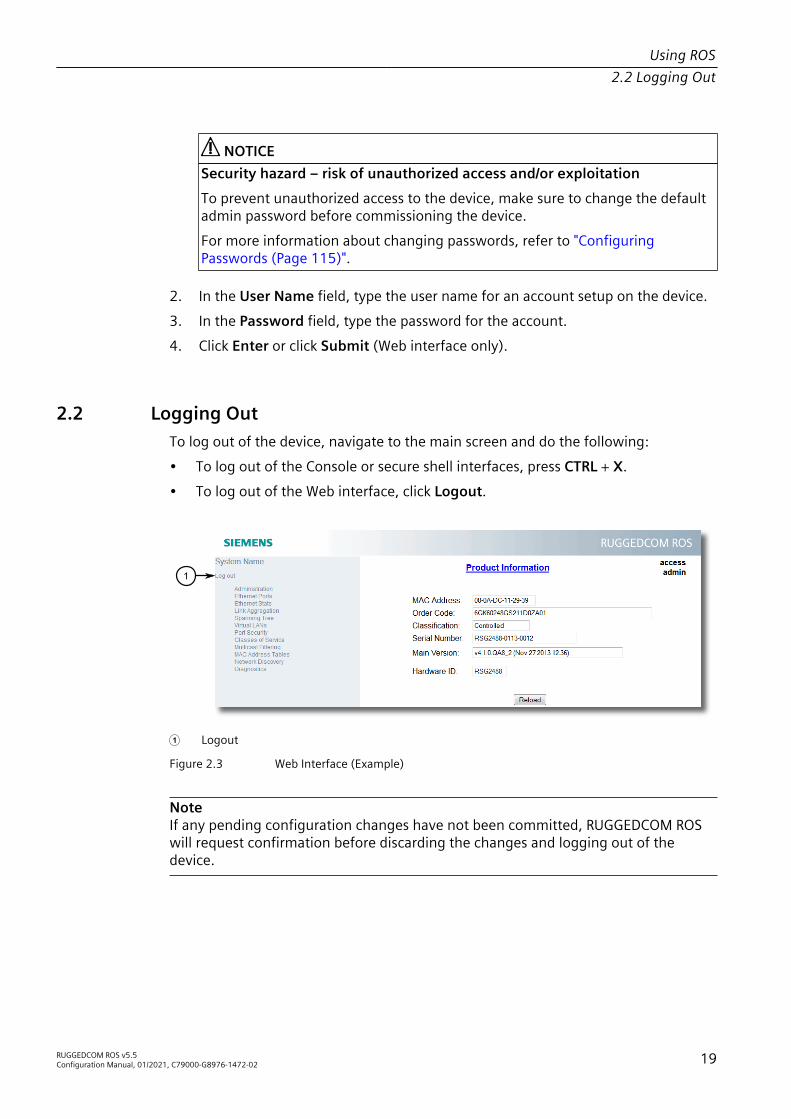
Using ROS2.2 Logging Out
NOTICESecurity hazard – risk of unauthorized access and/or exploitationTo prevent unauthorized access to the device, make sure to change the defaultadmin password before commissioning the device.For more information about changing passwords, refer to "ConfiguringPasswords (Page 115)".
2. In the User Name field, type the user name for an account setup on the device.3. In the Password field, type the password for the account.4. Click Enter or click Submit (Web interface only).
2.2 Logging OutTo log out of the device, navigate to the main screen and do the following:• To log out of the Console or secure shell interfaces, press CTRL + X.• To log out of the Web interface, click Logout.
1
1 Logout
Figure 2.3 Web Interface (Example)
NoteIf any pending configuration changes have not been committed, RUGGEDCOM ROSwill request confirmation before discarding the changes and logging out of thedevice.
RUGGEDCOM ROS v5.5Configuration Manual, 01/2021, C79000-G8976-1472-02 19

Using ROS2.3 Using the Web Interface
2.3 Using the Web InterfaceThe Web interface is a Web-based Graphical User Interface (GUI) for displayingimportant information and controls in a Web browser. The interface is divided intothree frames: the banner, the menu and the main frame.
2
1
3
1 Top Frame 2 Side Frame 3 Main Frame
Figure 2.4 Web Interface Layout (Example)
Frame DescriptionTop The top frame displays the system name for the device.Side The side frame contains a logout option and a collapsible list of
links that open various screens in the main frame. For informationabout logging out of RUGGEDCOM ROS, refer to "Logging Out (Page19)".
Main The main frame displays the parameters and/or data related to theselected feature.
Each screen consists of a title, the current user's access level, parameters and/ordata (in form or table format), and controls (e.g. add, delete, refresh, etc.). Thetitle provides access to context-specific Help for the screen that provides importantinformation about the available parameters and/or data. Click on the link to open theHelp information in a new window.When an alarm is generated, an alarm notification replaces the current user's accesslevel on each screen until the alarm is cleared. The notification indicates how manyalarms are currently active. For more information about alarms, refer to "ManagingAlarms (Page 98)".
20 RUGGEDCOM ROS v5.5Configuration Manual, 01/2021, C79000-G8976-1472-02

Using ROS2.4 Using the Console Interface
31
2
4
1 Title 2 Parameters and/or Data 3 Access Level or Alarm Notification 4 Reload Button
Figure 2.5 Elements of a Typical Screen (Example)
NoteIf desired, the web interface can be disabled. For more information, refer to"Enabling/Disabling the Web Interface (Page 98)".
2.4 Using the Console InterfaceThe Console interface is a Graphical User Interface (GUI) organized as a series ofmenus. It is primarily accessible through a serial console connection, but can alsobe accessed through IP services, such as a Telnet, RSH (Remote Shell), SSH (SecureShell) session, or SSH remote command execution.
NoteIP services can be restricted to control access to the device. For more information,refer to "Configuring IP Services (Page 84)".
Each screen consists of a system identifier, the name of the current menu, and acommand bar. Alarms are also indicated on each screen in the upper right corner.
RUGGEDCOM ROS v5.5Configuration Manual, 01/2021, C79000-G8976-1472-02 21

Using ROS2.4 Using the Console Interface
5
4
1
2
3
1 System Identification 2 Menus 3 Command Bar 4 Menu Name 5 Alarms Indicator
Figure 2.6 Console Interface (Example)
NoteThe system identifier is user configurable. For more information about setting thesystem name, refer to "Configuring the System Information (Page 97)".
Navigating the InterfaceUse the following controls to navigate between screens in the Console interface:
Enter Select a menu item and press this Enter to enter the sub-menu or screenbeneath.
Esc Press Esc to return to the previous screen.
Configuring ParametersUse the following controls to select and configure parameters in the Consoleinterface:
Up/Down ArrowKeys
Use the up and down arrow keys to select parameters.
Enter Select a parameter and press Enter to start editing a parameter. Press Enter againto commit the change.
22 RUGGEDCOM ROS v5.5Configuration Manual, 01/2021, C79000-G8976-1472-02

Using ROS2.5 Using the Command Line Interface
Esc When editing a parameter, press Esc to abort all changes.
CommandsThe command bar lists the various commands that can be issued in the Consoleinterface. Some commands are specific to select screens. The standard commandsinclude the following:
Ctrl + A Commits configuration changes made on the current screen.
NoteBefore exiting a screen, RUGGEDCOM ROS will automatically prompt the user tosave any changes that have not been committed.
NoteIf removable memory (i.e. microSD/microSDHC card) is present, configurationchanges will update both config.csv on the flash and on the removablememory.
Ctrl + I Inserts a new record.Ctrl + L Deletes a record.Ctrl + S Opens the CLI interface.Ctrl + X Terminates the current session. This command is only available from the main
menu.Ctrl + Z Displays important information about the current screen or selected parameter.
2.5 Using the Command Line InterfaceThe Command Line Interface (CLI) offers a series of powerful commands for updatingRUGGEDCOM ROS, generating certificates/keys, tracing events, troubleshooting andmuch more. It is accessed via the Console interface by pressing Ctrl-S.
2.5.1 Available CLI CommandsThe following commands are available at the command line:
Command Description Authorized Usersalarms all Displays a list of available alarms.
Optional and/or required parameters include:• all displays all available alarms
Guest, Operator, Admin
arp Displays the IP to MAC address resolution table. Adminattrib { filename }[ + | - ] [ W | H ]
Sets and removes file attributes. Admin
banner { -? } { -c } { -l } { -f }{ -s <enter>{ text } | -s { text } } -e
Modifies the banner file banner.txt.Optional and/or required parameters include:• { -? } Displays the command options help.• { -c } Clears the content of the banner file.
Admin
RUGGEDCOM ROS v5.5Configuration Manual, 01/2021, C79000-G8976-1472-02 23

Using ROS2.5.1 Available CLI Commands
Command Description Authorized Users{ line_number } -d{ line_number }
• { -l } Displays the banner file with line numbersindexed.
• { -f } Restores the factory default banner.• -s <enter> { text } Inputs text into the banner
file. The existing banner text is erased and replacedby the new text. Accepts up to 8190 characters andsupports sets of control characters for editing text.
• -s { text } Inputs text into the banner file. Can beused to modify the file via terminal. The existing bannertext is erased and replaced by the new text. Accepts upto 500 characters, maximum 250 words.
• -e { line_number } Edits the selected line of thebanner file.
• -d { line_number } Deletes the selected line ofthe banner file.
chkdsk Checks the file system for disk errors. Adminclearalarms Clears all alarms. Operator, Adminclearethstats [ all |{ port } ]
Clears Ethernet statistics for one or more ports.Optional and/or required parameters include:• all clears statistics for all ports• { port }is a comma separated list of port numbers (e.g.
1,3-5,7)
Operator, Admin
clearlogs Clears the system and crash logs. Adminclrcblstats [ all |{ port } ]
Clears cable diagnostics statistics for one or more ports.Optional and/or required parameters include:• all clears statistics for all ports• { port }is a comma separated list of port numbers (e.g.
1,3-5,7)
Admin
clrstpstats Clears all spanning tree statistics. Operator, Admincls Clears the screen. Guest, Operator, Admincopy Copies a target file to the internal or removable memory.
Examples:• Copying a file from the removable memory to the
internal memory
copy a:\config.csv config.csv
• Copying a file from the internal memory to theremovable memory
copy config.csv a:\config.csv
Admin
delete { filename } Deletes the specified file on the removable memory card. Admin
dir Prints the directory listing of the internal memory. Guest, Operator, Admindir { A: } Prints the directory listing of the removable memory card, if
equipped.Guest, Operator, Admin
exit Terminates the session. Guest, Operator, Adminfactory Enables factory mode, which includes several factory-level
commands used for testing and troubleshooting. Onlyavailable to admin users.
Admin
24 RUGGEDCOM ROS v5.5Configuration Manual, 01/2021, C79000-G8976-1472-02

Using ROS2.5.1 Available CLI Commands
Command Description Authorized Users
NOTICEConfiguration hazard – risk of firmware corruptionMisuse of the factory commands may corrupt theoperational state of device and/or may permanently damagethe ability to recover the device without manufacturerintervention.
flashfiles { info{ filename } | de frag }
A set of diagnostic commands to display information aboutthe Flash filesystem and to defragment Flash memory.Optional and/or required parameters include:• info { filename } displays information about the
specified file in the Flash file system• defrag defragments files in the Flash file systemFor more information about the flashfiles command,refer to "Managing the Flash File System (Page 36)".
Admin
flashleds { timeout } Flashes the LED indicators on the device for a specifiednumber of seconds.Optional and/or required parameters include:• { timeout }is the number of seconds to flash the LED
indicators. To stop the LEDs from flashing, set thetimeout period to 0 (zero).
Admin
format { disk } Formats the specified disk (e.g. A:). Adminfpgacmd Provides access to the FPGA management tool for
troubleshooting time synchronization.Admin
help { command } Displays a brief description of the specified command. Ifno command is specified, it displays a list of all availablecommands, including a description for each.Optional and/or required parameters include:• { command }is the command name.
Guest, Operator, Admin
ipconfig Displays the current IP address, subnet mask and defaultgateway.
Guest, Operator, Admin
label { disk }{ string }
Applies a label to the specified disk (e.g. A:). Admin
loaddflts Loads the factory default configuration. Adminlogout Logs out of the shell. Guest, Operator, Adminlogs Displays syslog entries in CLI shell. Adminpasswd { user_name }{ new_password }
Changes the selected user's password.Optional and/or required parameters include:• { user_name } is an existing user_name in RUGGEDCOM
ROS.• { new_password } is the new password that will replace
the existing password of the selected user.This command is unavailable in Telnet sessions.
Admin
ping { address }{ { count } | { time out } }
Sends an ICMP echo request to a remotely connected device.For each reply received, the round trip time is displayed. Usethis command to verify connectivity to the next connecteddevice. It is a useful tool for testing commissioned links.
Guest, Operator, Admin
RUGGEDCOM ROS v5.5Configuration Manual, 01/2021, C79000-G8976-1472-02 25

Using ROS2.5.1 Available CLI Commands
Command Description Authorized UsersThis command also includes the ability to send a specificnumber of pings with a specified time for which to wait for aresponse.Optional and/or required parameters include:• { address }is the target IP address.• { count }is the number of echo requests to send. The
default is 4.• { timeout }is the time in milliseconds to wait for each
reply. The range is 2 to 5000 seconds. The default is 300milliseconds.
NoteThe device to be pinged must support ICMP echo. Uponcommencing the ping, an ARP request for the MAC addressof the device is issued. If the device to be pinged is not onthe same network as the device pinging the other device, thedefault gateway must be programmed.
purgemac Purges the MAC Address table. Operator, Adminrandom Display seeds or random numbers. Adminrename { source }{ destination }
Renames the specified file. Add a path to new filename tomove the file at the same time.
Admin
reset Perform a hard reset of the switch. Operator, Adminresetport { all |{ ports } }
Resets one or more Ethernet ports, which may be useful forforcing re-negotiation of speed and duplex, or in situationswhere the link partner has latched into an inappropriatestate.Optional and/or required parameters include:• all resets all ports• { ports }is a comma separated list of port numbers (e.g.
1,3-5,7)
Operator, Admin
rmon Displays the names of all RMON alarm eligible objects. Guest, Operator, Adminroute Displays the gateway configuration. Guest, Operator, Adminsfp { port } { base |alarms | diag | cal ibr | thr | all | noparameter specified }
Displays SFP (Small Form Factor Pluggable) deviceinformation and diagnostics. If optional or requiredparameters are not used, this command displays the baseand extended information.Optional and/or required parameters include:• { port }is the port number for which the data are
required• base displays the base information• alarms displays alarms and warning flags• diag displays measured data• calibr displays calibration data for external calibration• thr displays thresholds data• all displays all diagnostic data
Admin
sql { default |delete | help | info| insert | save | se lect | update }
Provides an SQL-like interface for manipulating all systemconfiguration and status parameters. All commands, clauses,table, and column names are case insensitive.
Admin
26 RUGGEDCOM ROS v5.5Configuration Manual, 01/2021, C79000-G8976-1472-02

Using ROS2.5.1 Available CLI Commands
Command Description Authorized UsersOptional and/or required parameters include:• default sets all records in a table(s) to factory defaults• delete allows for records to be deleted from a table• help provides a brief description for any SQL command
or clause• info displays a variety of information about the tables
in the database• insert enables new records to be inserted into a table• save saves the database to non-volatile memory storage• select queries the database and displays selected
records• update enable existing records in a table to be updatedFor more information about the sql command, refer to"Using SQL Commands (Page 32)".
sshdigest Displays the host key fingerprints of the device. Adminsshkeygen [ rsa |dsa ] [ 1024 | 2048 |3072 ] { N }
Generates new RSA or DSA keys in ssh.keys. Keys can beeither 1024, 2048 or 3072 bits long.
Admin
sshpubkey List, remove and update key entries in sshpub.keys file. Adminsslkeygen { keytype }{ N }
Generates a new SSL certificate in ssl.crt.Optional and/or required parameters include:• { keytype } is the type of key, either rsa or ecc• { N } is the number of bits in length. For RSA keys, the
allowable sizes are 1024, 2048 or 3072. For ECC keys,the allowable sizes are 256, 384, or 521.
Admin
svcmod -s { snmpac cess } { -i { Group Name } | -d { Group Name } } -sm { Se curityModel } -sl{ SecurityLevel } -rv { ReadViewName } -wv { WriteViewName }-nv { NotifyView Name }
Modifies SNMP access groups.Optional and/or required parameters include:• -i { GroupName } creates a new access group with a
specified group name or modifies parameters associatedwith a specified access group, if it already exists
• -d { GroupName } deletes a specified access group• -sm { SecurityModel } specifies the security model
to be used• -sl { SecurityLevel } specifies the SNMP security
level to be granted to the specified access group.Allowable values are 'authPriv' (i.e. communicationwith authentication and privacy), 'authNoPriv' (i.e.communication with authentication and withoutprivacy), or 'noAuthnoPriv' (i.e. communication withneither authentication nor privacy).
• -rv { ReadViewName } identifies the MIB tree(s) towhich this entry authorizes read access. Allowable valuesare 'noView', 'V1Mib', or 'allOfMib'.
• -wv { WriteViewName } identifies the MIB tree(s)to which this entry authorizes write access. Allowablevalues are 'noView', 'V1Mib', or 'allOfMib'.
• -nv { NotifyViewName } identifies the MIB tree(s)to which this entry authorizes access for notifications.Allowable values are 'noView', 'V1Mib', or 'allOfMib'.
Admin
RUGGEDCOM ROS v5.5Configuration Manual, 01/2021, C79000-G8976-1472-02 27

Using ROS2.5.1 Available CLI Commands
Command Description Authorized Userssvcmod -s { snmp group } { -i { User Name } | -d { User Name } } -sm { Se curityModel } -g{ group }
Modifies SNMP security-to-group maps.Optional and/or required parameters include:• -i { UserName } -sm { SecurityModel }
creates a new user name and security profile as specifiedor modifies parameters associated with a specified username and security profile, if they already exist
• -d { UserName } -sm { SecurityModel }deletes a specified user name and security profile
• -g { group } specifies the group to which the username and secuirty profile belong
Admin
svcmod -s { snm puser } { -i { User Name } | -d { User Name } } -c { Commu nity } -ip { IP } -ap { protocol } -ak{ key } -pp { proto col } -pk { key }
Modifies SNMP users.Optional and/or required parameters include:• -i { UserName } creates a new user name as
specified or modifies parameters associated with aspecified user name, if it already exists
• -d { UserName } deletes a specified user name• -c { Community } specifies the SNMP community
string (for SNMPv1 or SNMPv2c).• -ip { IP } configures a specified IP address to be
used for SNMP authentication• -ap { protocol } configures SNMP authetication via
a specified authentication protocol. Allowable values are'noAuth', 'HMACMD5', or 'HMACSHA'.
• -ak { key } sets a secret key (of 0 or 6+ characters)to be used for SNMP authentication
• -pp { protocol } configures data encryption via aspecified privacy protocol. Allowable values are 'noPriv'or 'CBC-DES.'
• -ak { key } sets a secret key (of 0 or 6+ characters)to be used for data encyrption
Admin
svcmod -s { radius } { -ip { 1 } | -ip{ 2 } } -ip { IP } -ak { AuthKey } -pt{ Port } -ux { User nameExtension } -mr{ MaxRetries } -to{ timeout }
Modifies RADIUS security server.Optional and/or required parameters include:• -ip { 1 } sets the specified server as the primary
RADIUS server• -ip { 2 } sets the specified server as the backup
RADIUS server• -ip { 2 } -ip deletes the primary RADIUS server• -ip { 1 } -ip deletes the backup RADIUS server• -ip { IP } specifies the IP address of the RADIUS
server• -ak { AuthKey } specifies an authentication key to
be shared with the RADIUS server• -pt { Port } specifies the port number of the IP port
on the RADIUS server• -ux { UsernameExtension } defines an affix to be
added when a user name is sent to the RADIUS serverfor authentication. Values may include predefinedkeywords (wrapped in % delimiters) or user-definedstrings. Predefined keywords are '%Username%' (i.e. thename associated with the user profile), '%IPaddr%' (i.e.the management IP address of the Network Access
Admin
28 RUGGEDCOM ROS v5.5Configuration Manual, 01/2021, C79000-G8976-1472-02

Using ROS2.5.1 Available CLI Commands
Command Description Authorized UsersServer), '%SysName%' (i.e. the system name given to thedevice), and '%SysLocation%' (i.e. the phyiscal location ofthe device).
• -mr { MaxRetries } specifies the maximum numberof times the authenticator will attempt to authenticate auser in the case of any failure. After the specified value isexceeded, authentication fails.
• -to { timeout } specifies the number ofmilliseconds (ms) the authenticator will wait for aresponse from the RADUS server before reattemptingauthentication.
svcmod -s { tacac splus } { -ip { 1 }| -ip { 2 } } -ip{ IP } -ak { Au thKey } -pt { Port }-ux { UsernameExten sion } -mr { MaxRe tries } -to { time out } -apl { Admin Privilege } -opl{ OperPrivilege } -gpl { GuestPrivi lege }
Modifies TACACS+ security server.Optional and/or required parameters include:• -ip { 1 } sets the specified server as the primary
TACACS+ server• -ip { 2 } sets the specified server as the backup
TACACS+ server• -ip { 2 } -ip deletes the primary TACACS+ server• -ip { 1 } -ip deletes the backup TACACS+ server• -ip { IP } specifies the IP address of the TACACS+
server• -ak { AuthKey } specifies an authentication key to
be shared with the TACACS+ server• -pt { Port } specifies the port number of the IP port
on the TACACS+ server• -ux { UsernameExtension } defines an affix to
be added when a user name is sent to the TACACS+server for authentication. Values may include predefinedkeywords (wrapped in % delimiters) or user-definedstrings. Predefined keywords are '%Username%' (i.e. thename associated with the user profile), '%IPaddr%' (i.e.the management IP address of the Network AccessServer), '%SysName%' (i.e. the system name given to thedevice), and '%SysLocation%' (i.e. the phyiscal location ofthe device).
• -mr { MaxRetries } specifies the maximum numberof times the authenticator will attempt to authenticate auser in the case of any failure. After the specified value isexceeded, authentication fails.
• -to { timeout } specifies the number ofmilliseconds (ms) the authenticator will wait for aresponse from the TACACS+ server before reattemptingauthentication.
• -apl { AdminPrivilege } specifies the level towhich administrator users are able to configure theTACACS+ server. Values must correspond with one ormore option(s) defined numerically (between 0 and 15)in the TACACS+ configuration file.
• -opl { OperPrivilege } specifies the level towhich operator users are able to configure the TACACS+ server. Values must correspond with one or moreoption(s) defined numerically (between 0 and 15) in theTACACS+ configuration file.
Admin
RUGGEDCOM ROS v5.5Configuration Manual, 01/2021, C79000-G8976-1472-02 29

Using ROS2.5.2 Tracing Events
Command Description Authorized Users• -gpl { GuestPrivilege } specifies the level to
which guest users are able to configure the TACACS+ server. Values must correspond with one or moreoption(s) defined numerically (between 0 and 15) in theTACACS+ configuration file.
telnet { dest } Opens a telnet session. Press Ctrl-C to close the session.Optional and/or required parameters include:• { dest }is the server's IP address
Guest, Operator, Admin
tftp { address }[ put | get ]{ source } { target }
Opens a TFTP session. Press Ctrl-C to close the session.Optional and/or required parameters include:• { address }is the IP address of the remote TFTP server• put indicates TFTP will be uploading the source file to
replace the destination file• get indicates TFTP will be downloading the source file to
replace the destination file• { source }is the name of the source file• { target }is the name of the file that will be replaced
Admin
trace Starts event tracing. Run trace ? for more help. Operator, Admintype { filename } Displays the contents of a text file.
Optional and/or required parameters include:• { filename }is the name of the file to be read
Guest, Operator, Admin
usermod { -b | -r { username } |{ old_user_name }{ new_user_name } }
A set of commands to display, remove and change existingusernames.Optional and/or required parameters include:• -b browses through the existing user names in
RUGGEDCOM ROS.• -r { username } removes a specified user name to
disable the account• { old_user_name } and { new_user_name } define the
user name to be changedThis command is unavailable in Telnet sessions.
Admin
version Prints the software version. Guest, Operator, Adminxmodem { send | re ceive } { filename }
Opens an XModem session.Optional and/or required parameters include:• send sends the file to the client.• receive receives the file from the client.• { filename }is the name of the file to be read.
Operator, Admin
2.5.2 Tracing EventsThe CLI trace command provides a means to trace the operation of various protocolssupported by the device. Trace provides detailed information, including STP packetdecodes, IGMP activity and MAC address displays.
30 RUGGEDCOM ROS v5.5Configuration Manual, 01/2021, C79000-G8976-1472-02

Using ROS2.5.3 Executing Commands Remotely via RSH
NoteTracing has been designed to provide detailed information to expert users. Note thatall tracing is disabled upon device startup.
To trace an event, do the following:1. Log in to the device as an admin user and access the CLI shell. For more
information about accessing the CLI shell, refer to "Using the Command LineInterface (Page 23)".
2. Determine the protocols and associated options available by typing:
trace ?
If an option such as allon or alloff is required, determine which options areavailable for the desired protocol by typing:
trace { protocol } ?
NoteIf required, expand the trace scope by stringing protocols and their associatedoptions together using a vertical bar (|).
3. Select the type of trace to run by typing:
trace { protocol } { option }
Where:• { protocol } is the protocol to trace• { option } is the option to use during the traceExample:>trace transport allon TRANSPORT: Logging is enabled
4. Start the trace by typing:
trace
2.5.3 Executing Commands Remotely via RSHThe Remote Shell (RSH) facility can be used from a workstation to cause the productto act upon commands as if they were entered at the CLI prompt. The syntax of theRSH command is usually of the form:
rsh { ipaddr } –l { auth_token } { command_string }
Where:• { ipaddr } is the address or resolved name of the device.
RUGGEDCOM ROS v5.5Configuration Manual, 01/2021, C79000-G8976-1472-02 31

Using ROS2.5.4 Using SQL Commands
• { auth_token } is the user name (i.e. guest, operator or admin) andcorresponding password separated by a comma. For example, admin,secret.
• { command_string } is the RUGGEDCOM ROS CLI command to execute.
NoteThe access level (corresponding to the user name) selected must support the givencommand.
NoteAny output from the command will be returned to the workstation submitting thecommand. Commands that start interactive dialogs (such as trace) cannot be used.
2.5.4 Using SQL CommandsRUGGEDCOM ROS provides an SQL-like command facility that allows expert users toperform several operations not possible under the traditional Web or CLI interface.For instance:• Restoring the contents of a specific table, but not the whole configuration, to
their factory defaults.• Search tables in the database for specific configurations.• Make changes to tables predicated upon existing configurations.When combined with RSH, SQL commands provide a means to query and configurelarge numbers of devices from a central location.
NoteFor a list of parameters available under the sql command, refer to "Available CLICommands (Page 23)".
NoteRead/write access to tables containing passwords or shared secrets is unavailableusing SQL commands.
2.5.4.1 Finding the Correct Table
Many SQL commands operate upon specific tables in the database, and require thetable name to be specified. Navigating the menu system in the console interfaceto the desired menu and pressing Ctrl-Z displays the name of the table. The menuname and the corresponding database table name will be cited.Another way to find a table name is to type the following in the CLI:
sql info tables
32 RUGGEDCOM ROS v5.5Configuration Manual, 01/2021, C79000-G8976-1472-02
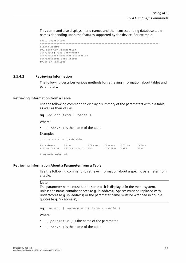
Using ROS2.5.4 Using SQL Commands
This command also displays menu names and their corresponding database tablenames depending upon the features supported by the device. For example:Table Description-------------------------------------------------------------------------------alarms AlarmscpuDiags CPU DiagnosticsethPortCfg Port ParametersethPortStats Ethernet StatisticsethPortStatus Port StatusipCfg IP Services
2.5.4.2 Retrieving Information
The following describes various methods for retrieving information about tables andparameters.
Retrieving Information from a TableUse the following command to display a summary of the parameters within a table,as well as their values:
sql select from { table }
Where:• { table } is the name of the tableExample:>sql select from ipAddrtable
IP Address Subnet IfIndex IfStats IfTime IfName 172.30.146.88 255.255.224.0 1001 17007888 2994 vlan1
1 records selected
Retrieving Information About a Parameter from a TableUse the following command to retrieve information about a specific parameter froma table:
NoteThe parameter name must be the same as it is displayed in the menu system,unless the name contains spaces (e.g. ip address). Spaces must be replaced withunderscores (e.g. ip_address) or the parameter name must be wrapped in doublequotes (e.g. "ip address").
sql select { parameter } from { table }
Where:• { parameter } is the name of the parameter• { table } is the name of the table
RUGGEDCOM ROS v5.5Configuration Manual, 01/2021, C79000-G8976-1472-02 33

Using ROS2.5.4 Using SQL Commands
Example:>sql select "ip address" from ipSwitchIfCfg
IP Address192.168.0.1
1 records selected
Retrieving Information from a Table Using the Where ClauseUse the following command to display specific parameters from a table that have aspecific value:
sql select from { table } where { parameter } = { value }
Where:• { table } is the name of the table• { parameter } is the name of the parameter• { value } is the value of the parameterExample:>sql select from ethportcfg where media = 1000T
Port Name ifName Media State AutoN Speed Dupx FlowCtrl LFI Alarm 1/1 Port 1 1/1 1000T Enabled On Auto Auto Off Off On 1/2 Port 2 1/2 1000T Enabled On Auto Auto Off Off On 1/3 Port 3 1/3 1000T Enabled On Auto Auto Off Off On 1/4 Port 4 1/4 1000T Enabled On Auto Auto Off Off On
4 records selected
Further refine the results by using and or or operators:
sql select from { table } where { parameter } = { value }{ and | or } { parameter } = { value }
Where:• { table } is the name of the table• { parameter } is the name of the parameter• { value } is the value of the parameterExample:>sql select from ethportcfg where media = 1000T and State = enabled
Port Name ifName Media State AutoN Speed Dupx FlowCtrl LFI Alarm 1/1 Port 1 1/1 1000T Enabled On Auto Auto Off Off on 1/2 Port 2 1/2 1000T Enabled On Auto Auto Off Off On
34 RUGGEDCOM ROS v5.5Configuration Manual, 01/2021, C79000-G8976-1472-02

Using ROS2.5.4 Using SQL Commands
1/3 Port 3 1/3 1000T Enabled On Auto Auto Off Off On 1/4 Port 4 1/4 1000T Enabled On Auto Auto Off Off On
4 records selected
2.5.4.3 Changing Values in a Table
Use the following command to change the value of parameters in a table:
sql update { table } set { parameter } = { value }
Where:• { table } is the name of the table• { parameter } is the name of the parameter• { value } is the value of the parameterExample:>sql update iplcfg set IP_Address_Type = static1 records updated
Conditions can also be included in the command to apply changes only toparameters that meet specific criteria. In the following example, flow control isenabled on ports that are operating in 100 Mbps full-duplex mode with flow controldisabled:>sql update ethportcfg set FlowCtrl = Off where ( Media = 100TX and FlowCtrl = On )2 records updated
2.5.4.4 Resetting a Table
Use the following command to reset a table back to its factory defaults:
sql default into { table }
Where:• { table } is the name of the table
2.5.4.5 Using RSH and SQL
The combination of remote shell scripting and SQL commands offers a means tointerrogate and maintain a large number of devices. Consistency of configurationacross sites may be verified by this method. The following presents a simple examplewhere the devices to interrogate are drawn from the file Devices:C:> type Devices10.0.1.110.0.1.2
C:\> for /F %i in (devices) do rsh %i -l admin,admin sql select from ipAddrtable
RUGGEDCOM ROS v5.5Configuration Manual, 01/2021, C79000-G8976-1472-02 35
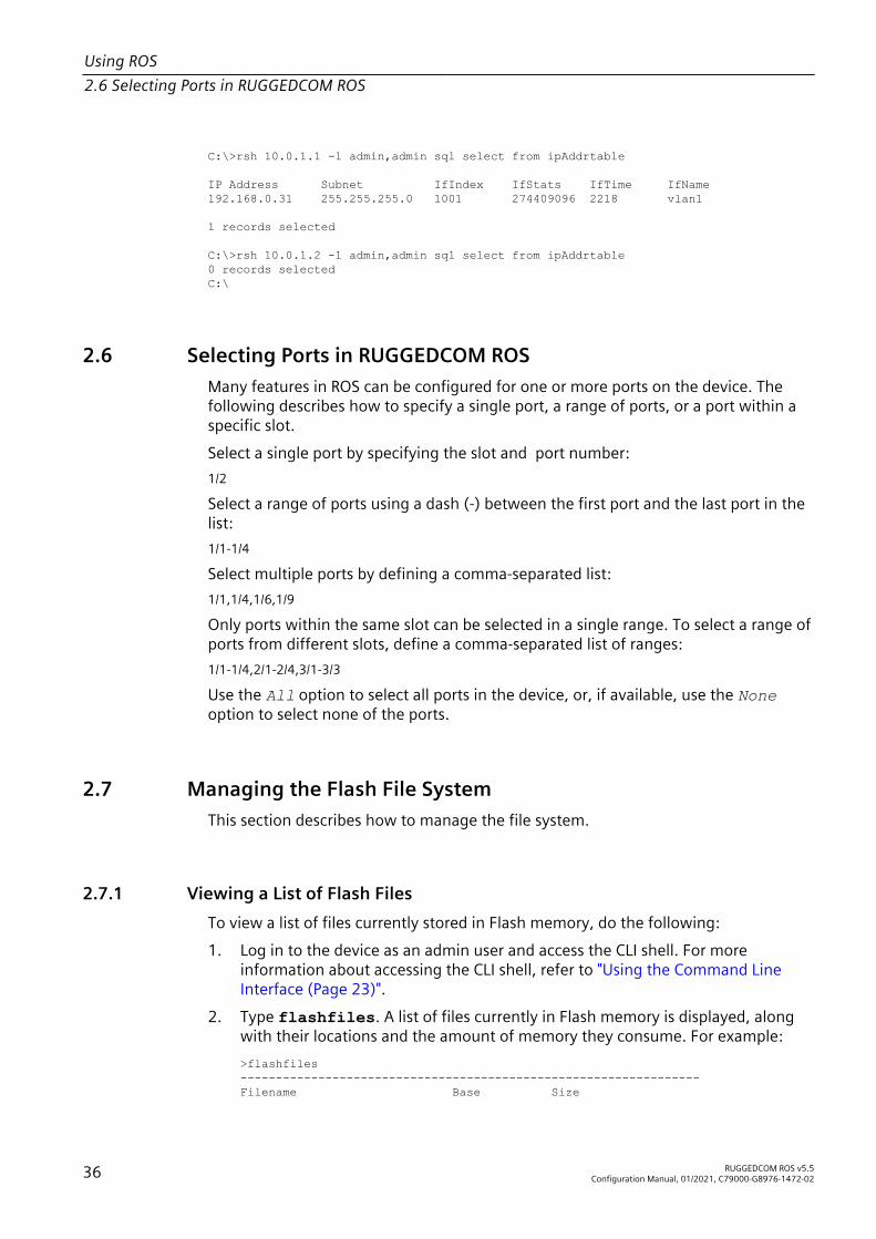
Using ROS2.6 Selecting Ports in RUGGEDCOM ROS
C:\>rsh 10.0.1.1 -l admin,admin sql select from ipAddrtable
IP Address Subnet IfIndex IfStats IfTime IfName192.168.0.31 255.255.255.0 1001 274409096 2218 vlan1
1 records selected
C:\>rsh 10.0.1.2 -l admin,admin sql select from ipAddrtable0 records selectedC:\
2.6 Selecting Ports in RUGGEDCOM ROSMany features in ROS can be configured for one or more ports on the device. Thefollowing describes how to specify a single port, a range of ports, or a port within aspecific slot.Select a single port by specifying the slot and port number:1/2
Select a range of ports using a dash (-) between the first port and the last port in thelist:1/1-1/4
Select multiple ports by defining a comma-separated list:1/1,1/4,1/6,1/9
Only ports within the same slot can be selected in a single range. To select a range ofports from different slots, define a comma-separated list of ranges:1/1-1/4,2/1-2/4,3/1-3/3
Use the All option to select all ports in the device, or, if available, use the Noneoption to select none of the ports.
2.7 Managing the Flash File SystemThis section describes how to manage the file system.
2.7.1 Viewing a List of Flash FilesTo view a list of files currently stored in Flash memory, do the following:1. Log in to the device as an admin user and access the CLI shell. For more
information about accessing the CLI shell, refer to "Using the Command LineInterface (Page 23)".
2. Type flashfiles. A list of files currently in Flash memory is displayed, alongwith their locations and the amount of memory they consume. For example:>flashfiles-----------------------------------------------------------------Filename Base Size
36 RUGGEDCOM ROS v5.5Configuration Manual, 01/2021, C79000-G8976-1472-02

Using ROS2.7.2 Viewing Flash File Details
-----------------------------------------------------------------main.bin 0xFE959AE0 0x002C5493 (2905235)syslog.txt 0xFE100080 0x001BFF80 (1834880)...
Free Space: 19792360Used Space: 11664720Fragmented Space: 5830423-----------------------------------------------------------------
2.7.2 Viewing Flash File DetailsTo view the details of a file currently stored in Flash memory, do the following:1. Log in to the device as an admin user and access the CLI shell. For more
information about accessing the CLI shell, refer to "Using the Command LineInterface (Page 23)".
2. Display information about a file by typing:
flashfiles info { filename }
Where:• { filename } is the name of the file stored in Flash memoryDetails, similar to the following, are displayed.>flashfiles info main.bin
Flash file information for main.bin:Header version : 4Platform : ROS-MPC83File name : main.binFirmware version : v5.5.0Build date : Sep 27 2014 15:50File length : 2624659Board IDs : 3dHeader CRC : 73b4Header CRC Calc : 73b4Body CRC : b441Body CRC Calc : b441
2.7.3 Defragmenting the Flash File SystemThe flash memory is defragmented automatically whenever there is not enoughmemory available for a binary upgrade. However, fragmentation can occur whenevera new file is uploaded to the unit. Fragmentation causes sectors of available memoryto become separated by ones allocated to files. In some cases, the total availablememory might be sufficient for a binary upgrade, but that memory may not beavailable in one contiguous region.
RUGGEDCOM ROS v5.5Configuration Manual, 01/2021, C79000-G8976-1472-02 37

Using ROS2.8 Accessing BIST Mode
To defragment the flash memory, do the following:1. Log in to the device as an admin user and access the CLI shell. For more
information about accessing the CLI shell, refer to "Using the Command LineInterface (Page 23)".
2. Defragment the flash memory by typing:
flashfiles defrag
2.8 Accessing BIST ModeBIST (Built-In-Self-Test) mode is used by service technicians to test and configureinternal functions of the device. It should only be accessed for troubleshootingpurposes.
NOTICEMechanical hazard – risk of damage to the deviceExcessive use of BIST functions may cause increased wear on the device, whichmay void the warranty. Avoid using BIST functions unless instructed by a SiemensCustomer Support representative.
NoteAccess to BIST mode is disabled at the factory by default. All console inputs areignored and users are directed automatically to the RUGGEDCOM ROS user interface.
To first enable access to BIST mode, do the following:1. Using a PC/laptop, create a file named bootoption.txt and include the
following line in the file:Security=no
2. Upload the file to the device and reboot the device.
NoteAccess to BIST and the boot loader can be later revoked by changing no to yes.
To access BIST mode, do the following:
NOTICEConfiguration hazard – risk of communication disruptionDo not connect the device to the network when it is in BIST mode. The device willgenerate excess multicast traffic in this mode.
1. Disconnect the device from the network.2. Connect to RUGGEDCOM ROS through the RS-232 console connection and a
terminal application. For more information, refer to "Connecting Directly (Page43)".
38 RUGGEDCOM ROS v5.5Configuration Manual, 01/2021, C79000-G8976-1472-02

Using ROS2.9 Managing Access to the Boot Loader Interface
3. Reset the device. For more information, refer to "Resetting the Device (Page95)".
4. During the boot up sequence, press Ctrl-C when prompted. The commandprompt for BIST appears.>
5. Type help to view a list of all available options under BIST.Alternatively, BIST functions can be accessed via factory mode. For more informationabout factory mode, refer to "Available CLI Commands (Page 23)".
2.9 Managing Access to the Boot Loader InterfaceThe following sections describe how to enable, disable, and access the boot loaderinterface in RUGGEDCOM ROS.
NoteAccess to the boot loader interface is disabled at the factory by default on all devicesrunning RUGGEDCOM ROS v5.5 . All console inputs are ignored and users aredirected automatically to the RUGGEDCOM ROS user interface.
NoteSiemens recommends disabling access to the boot loader interface following anupgrade from an earlier version of RUGGEDCOM ROS to RUGGEDCOM ROS v5.5. Formore information about disabling the boot loader, refer to "Enabling/Disabling Accessto the Boot Loader Interface (Page 39)".
2.9.1 Enabling/Disabling Access to the Boot Loader InterfaceTo enable or disable access to the boot loader interface, do the following:
Create File bootoption.txtTo enable or disable access to the boot loader, the file bootoption.txt must beavailable on the device.If the file is not available, do the following:1. Using a PC/laptop, create a file named bootoption.txt.
NOTICEIf the Security parameter is either commented out using the hash (#) characteror does not exist in the file, it will be created by RUGGEDCOM ROS with itsdefault value following reboot.
RUGGEDCOM ROS v5.5Configuration Manual, 01/2021, C79000-G8976-1472-02 39
Using ROS2.9.2 Accessing the Boot Loader Interface
2. Include the following line in the file:Security = [No | Yes]
• Security = No enables access to the boot loader.• Security = Yes disables access to the boot loader. This is the default value.
3. Upload the file to the device and reboot the device.
Enabling the Boot LoaderTo enable access to the boot loader, do the following:1. Using a PC/laptop, navigate to the file bootoption.txt.2. Locate the following line and change from
Security = Yes
toSecurity = No
3. Upload the file to the device and reboot the device.
Disabling the Boot LoaderTo disable access to the boot loader, do the following:1. Using a PC/laptop, navigate to the file bootoption.txt.2. Locate the following line and change from
Security = No
toSecurity = Yes
3. Upload the file to the device and reboot the device.
2.9.2 Accessing the Boot Loader InterfaceTo access the boot loader interface, do the following:1. Connect to RUGGEDCOM ROS through the RS-232 console connection and a
terminal application. For more information, refer to "Connecting Directly (Page43)".
2. Reset the device. For more information, refer to "Resetting the Device (Page95)".
3. As soon as the device starts to boot up, press Ctrl-Z. The command prompt forUboot appears.=>
4. Type help to view a list of all available options under Uboot.
40 RUGGEDCOM ROS v5.5Configuration Manual, 01/2021, C79000-G8976-1472-02

Using ROS2.9.3 Setting the Boot Source
2.9.3 Setting the Boot SourceBy default, the device boots up from its internal flash memory. However,RUGGEDCOM ROS supports booting up from the inserted microSD/microSDHC card ifdesired.To set the boot source, do the following:
NOTICETo allow boot up from the microSD/microSDHC card, automatic access to theremovable memory must be enabled. For more information, refer to "Enabling/Disabling Automatic Access to Removable Memory (Page 41)".
1. Using a PC/laptop, create a file named bootoption.txt.
NOTICEIf the BootOrderFirstRemovable parameter is either commented out using thehash (#) character or does not exist in the file, it will be created by RUGGEDCOMROS with its default value following reboot.
2. Include the following line in the file:BootOrderFirstRemovable = [No | Yes]
• BootOrderFirstRemovable = No boots from internal flash. This is the defaultvalue.
• BootOrderFirstRemovable = Yes boots from the microSD/microSDHC card.3. Upload the file to the device and reboot the device.
2.10 Enabling/Disabling Automatic Access to Removable MemoryRUGGEDCOM ROS can automatically synchronize firmware, configuration, and logfiles between a device and its RUGGEDCOM ROS microSD/microSDHC card.
NOTICESecurity hazard – risk of unauthorized access and/or exploitationUnless required, automatic access to removable memory should be disabled.
To configure automatic access to removable memory, do the following:1. Using a PC/laptop, create a file named bootoption.txt.
NOTICEIf the DisableAutoAccessRemovable parameter is either commented outusing the hash (#) character or does not exist in the file, it will be created byRUGGEDCOM ROS with its default value following reboot.
RUGGEDCOM ROS v5.5Configuration Manual, 01/2021, C79000-G8976-1472-02 41

Using ROS2.11 Enabling/Disabling the Console Service
2. To disable automatic access to removable memory, add the following line to thefile:DisableAutoAccessRemovable = Yes
NoteThe DisableAutoAccessRemovable command only affects automaticactions. Even when automatic access to removable memory is disabled, userscan manually copy files between a device and its microSD/microSDHC card.
3. To re-enable automatic access to removable memory after having disabled it,add the following line to the file:DisableAutoAccessRemovable = No.
No is the default value.4. Upload the file to the device.5. Reboot the device.
2.11 Enabling/Disabling the Console ServiceThe local console service is enabled by default in RUGGEDCOM ROS. For addedsecurity, an admin user can disable and re-enable access to the RS-232 Serial consoleas desired.
NoteEnabling/disabling the console service is only available using SQL commands. Formore information, refer to "Using SQL Commands (Page 32)".
To enable/disable access to the console service, do the following:1. Log in to the device as an admin user and access the CLI shell. For more
information about accessing the CLI shell, refer to "Using the Command LineInterface (Page 23)".
2. Enable or disable the console service by typing either:Enabling
sql update consoleServices SET Local Console Service = En abled
Disabling
sql update consoleServices SET Local Console Service = Dis abled
The changes will take effect immediately on the next local console login.
42 RUGGEDCOM ROS v5.5Configuration Manual, 01/2021, C79000-G8976-1472-02

Getting Started 3This section describes startup tasks to be performed during the initial commissioningof the device. Tasks include connecting to the device and accessing the RUGGEDCOMROS , as well as configuring a basic network.
NOTICESecurity hazard – risk of unauthorized access and/or exploitationSiemens recommends the following actions before commissioning the device:• Replace the factory-provisioned, self-signed SSL certificate with one signed by a
trusted Certificate Authority (CA)• Configure the SSH client to use diffie-hellman-group14-sha1 or better
3.1 Connecting to ROSThis section describes the various methods for connecting to the device.
3.1.1 Default IP AddressThe default IP address for the device is as follows:
Port IP Address/MaskMGMT 10.0.0.1/8All other Ethernet ports 192.168.0.1/24
3.1.2 Connecting DirectlyRUGGEDCOM ROS can be accessed through a direct RS-232 Serial console or Ethernetconnection for management and troubleshooting purposes. A console connectionprovides access to the console interface and CLI. An Ethernet connection providesaccess to the Web interface.For added security, the console service can be disabled if desired. For moreinformation about disabling the console service, refer to "Enabling/Disabling theConsole Service (Page 42)".
RUGGEDCOM ROS v5.5Configuration Manual, 01/2021, C79000-G8976-1472-02 43

Getting Started3.1.2 Connecting Directly
Using the RS-232 Serial Console PortTo establish a console connection to the device, do the following:1. Connect a workstation (either a terminal or computer running terminal
emulation software) to the RS-232 Serial console port on the device. Formore information about the RS-232 Serial console port, refer to the RSG2488Installation Manual.
2. Configure the workstation as follows:• Speed (baud): 57600• Data Bits: 8• Parity: None• Flow Control: Off• Terminal ID: VT100• Stop Bit: 1
3. Connect to the device. Once the connection is established, the login formappears. For more information about logging in to the device, refer to "LoggingIn (Page 18)".
Using an Ethernet PortTo establish a direct Ethernet connection to the device, do the following:1. On the workstation being used to access the device, configure an Ethernet port
to use an IP address falling within the subnet of the device.By default, the device has a different IP address and subnet configured for twotypes of IP interfaces, both of which are mapped to one or more physical ports:
Port IP Address/MaskMGMT 10.0.0.1/8All other Ethernet ports 192.168.0.1/24
For example, to configure the device to connect to one of the available Ethernetports, assign an IP address to the Ethernet port on the workstation in the rangeof 192.168.0.3 to 192.168.0.254.
2. Launch the SSH client on the workstation and connect to admin@{ipaddress},where {ipaddress} is the IP address for the port that is connected to the network.The login prompt appears:Using username "admin"[email protected]'s password:
3. Log in to RUGGEDCOM ROS . For more information about logging in toRUGGEDCOM ROS, refer to "Logging In (Page 18)".
44 RUGGEDCOM ROS v5.5Configuration Manual, 01/2021, C79000-G8976-1472-02
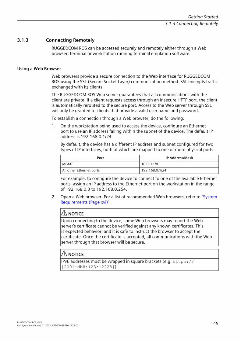
Getting Started3.1.3 Connecting Remotely
3.1.3 Connecting RemotelyRUGGEDCOM ROS can be accessed securely and remotely either through a Webbrowser, terminal or workstation running terminal emulation software.
Using a Web BrowserWeb browsers provide a secure connection to the Web interface for RUGGEDCOMROS using the SSL (Secure Socket Layer) communication method. SSL encrypts trafficexchanged with its clients.The RUGGEDCOM ROS Web server guarantees that all communications with theclient are private. If a client requests access through an insecure HTTP port, the clientis automatically rerouted to the secure port. Access to the Web server through SSLwill only be granted to clients that provide a valid user name and password.To establish a connection through a Web browser, do the following:1. On the workstation being used to access the device, configure an Ethernet
port to use an IP address falling within the subnet of the device. The default IPaddress is 192.168.0.1/24.By default, the device has a different IP address and subnet configured for twotypes of IP interfaces, both of which are mapped to one or more physical ports:
Port IP Address/MaskMGMT 10.0.0.1/8All other Ethernet ports 192.168.0.1/24
For example, to configure the device to connect to one of the available Ethernetports, assign an IP address to the Ethernet port on the workstation in the rangeof 192.168.0.3 to 192.168.0.254.
2. Open a Web browser. For a list of recommended Web browsers, refer to "SystemRequirements (Page xvi)".
NOTICEUpon connecting to the device, some Web browsers may report the Webserver's certificate cannot be verified against any known certificates. Thisis expected behavior, and it is safe to instruct the browser to accept thecertificate. Once the certificate is accepted, all communications with the Webserver through that browser will be secure.
NOTICEIPv6 addresses must be wrapped in square brackets (e.g. https://[2001:db8:123::2228]).
RUGGEDCOM ROS v5.5Configuration Manual, 01/2021, C79000-G8976-1472-02 45

Getting Started3.2 Configuring a Basic Network
3. In the address bar, type the IP address for the port that is connected to thenetwork. Once the connection is established, the login screen for the Webinterface appears.For more information about logging in to the device, refer to "Logging In (Page18)". For more information about the Web interface, refer to "Using the WebInterface (Page 20)".
Using a Terminal or Terminal Emulation SoftwareA terminal or computer running terminal emulation software provides access to theconsole interface for RUGGEDCOM ROS through a Telnet, RSH (Remote Shell) or SSH(Secure Shell) service.
NoteIP services can be restricted to control access to the device. For more information,refer to "Configuring IP Services (Page 84)".
To establish a connection through a terminal or terminal emulation software, do thefollowing:1. Select the service (i.e. Telnet, RSH or SSH).2. Enter the IP address for the port that is connected to the network.3. Connect to the device. Once the connection is established, the login form
appears. For more information about logging in to the device, refer to "LoggingIn (Page 18)".
3.2 Configuring a Basic NetworkTo configure a basic network, do the following:1. Connect a computer to the management interface of the device and configure
the computer to be on the same subnet as the port.2. Configure the computer to use the address of the MGMT port as the default
gateway.3. Connect one of the switched ports from any available module to a switch that is
connected to a LAN.4. Make sure the computer connected to the switch is on the same subnet as the
switch.5. Configure the switch and all the computers behind it to use VLAN1's IP address
as the default gateway. The default IP address is 192.168.0.1.6. Make sure all computers connected to the device can ping one another.
46 RUGGEDCOM ROS v5.5Configuration Manual, 01/2021, C79000-G8976-1472-02

Device Management 4This chapter describes how to configure and manage the device and its components,such as module interfaces, logs and files.
4.1 Viewing Product InformationDuring troubleshooting or when ordering new devices, Siemens personnel mayrequest specific information about the device, such as the model, order code or serialnumber.To view information about the device, navigate to Diagnostics » View ProductInformation. The Product Information form appears.This screen displays the following information:
Parameter Description
MAC Address Synopsis: ##-##-##-##-##-## where ## ranges 0 to FFShows the unique MAC address of the device.
Order Code Synopsis: A string 57 characters longShows the order code of the device.
Classification Synopsis: A string 15 characters longProvides system classification.The value Controlled indicates the main firmware is a Controlledrelease. The value Non-Controlled indicates the main firmwareis a Non-Controlled release. The Controlled main firmware canrun on Controlled units, but it can not run on Non-Controlled units.The Non-Controlled main firmware can run on both Controlledand Non-Controlled units.
Serial Number Synopsis: A string 31 characters longShows the serial number of the device.
Main Version Synopsis: A string 47 characters longShows the version and build date of the main operating systemsoftware.
Hardware ID Shows the type, part number, and revision level of the hardware.Example: RSG2488 , RSG2488v2
Descr Synopsis: A string 57 characters longThe description of product based on Hardware ID, order code andclassification.
RUGGEDCOM ROS v5.5Configuration Manual, 01/2021, C79000-G8976-1472-02 47

Device Management4.2 Viewing CPU Diagnostics
4.2 Viewing CPU DiagnosticsTo view CPU diagnostic information useful for troubleshooting hardware andsoftware performance, navigate to Diagnostics » View CPU Diagnostics. The CPUDiagnostics form appears.This screen displays the following information:
Parameter Description
Running Time Synopsis: DDDD days, HH:MM:SSThe amount of time since the device was last powered on.
CPU Usage Synopsis: An integer between 0.0 and 100.0The percentage of available CPU cycles used for device operation asmeasured over the last second.
RAM Total Synopsis: An integer between 0 and 4294967295The total size of RAM in the system.
RAM Free Synopsis: An integer between 0 and 4294967295The total size of RAM still available.
RAM Low Watermark Synopsis: An integer between 0 and 4294967295The size of RAM that have never been used during the systemruntime.
DMA RAM Free Synopsis: An integer between 0 and 4294967295The total size of DMA RAM still available.
DMA RAM Low Watermark Synopsis: An integer between 0 and 4294967295The size of DMA RAM that have never been used during the systemruntime.
Temperature Synopsis: An integer between -32768 and 32767The temperature on CPU board.
Free Rx Bufs Synopsis: An integer between 0 and 4294967295Free Rx Buffers.
Free Tx Bufs Synopsis: An integer between 0 and 4294967295Free Tx Buffers.
4.3 Viewing the Status of the Power SuppliesTo view the current status of the power supplies, navigate to Diagnostics » PowerSupply Status. The Power Supply Status table appears.This table displays the following information:
Parameter Description
ID Synopsis: An integer between 1 and 2The ID of the power supply.
48 RUGGEDCOM ROS v5.5Configuration Manual, 01/2021, C79000-G8976-1472-02

Device Management4.4 Restoring Factory Defaults
Parameter Description
Voltage Synopsis: An integer between 0 and 4294967295The millivolt output voltage.
Current Synopsis: An integer between 0 and 4294967295The milliampere output current.
Temperature Synopsis: An integer between -32768 and 32767The temperature of the power supply.
InStatus Synopsis: [ ---- | Out of range | Good ]Specifies whether or not the power supply input voltage is in range.For dual DC/DC power supplies, the input voltage range is between36 and 72 V.For dual AC/DC power supplies, the input voltage range for AC isbetween 85 and 264 VAC and, for DC, 95 and 300 VDC.
OutStatus Synopsis: [ ---- | Out of range | Good ]Specifies whether or not the power supply output voltage is inrange. The output voltage range is 12 V +/- 1%.
Calibration Synopsis: [ ---- | Bad | Good ]Indicates whether or not the power supply is calibrated correctly.
4.4 Restoring Factory DefaultsThe device can be completely or partially restored to its original factory defaultsettings. Excluding groups of parameters from the factory reset, such as those thataffect basic connectivity and SNMP management, is useful when communicationwith the device is still required during the reset.The following categories are not affected by a selective configuration reset:• IP Interfaces• IP Gateways• SNMP Users• SNMP Security to Group Maps• SNMP AccessIn addition, the following categories are not affected by a full or selectiveconfiguration reset:• Time Zone• DST Offset• DST Rule
RUGGEDCOM ROS v5.5Configuration Manual, 01/2021, C79000-G8976-1472-02 49

Device Management4.5 Uploading/Downloading Files
NoteMRMs or MRAs acting as Manager must be either physically disconnected or have thering port disabled (i.e. MRP ring open) before restoring factory defaults, otherwisedefault configurations may not be restored for the following parameters:• Port RSTP Parameters• Global MRP Parameters• MRP InstancesFor more information about MRP rings, refer to "Managing the Media RedundancyProtocol (MRP) (Page 218)".For more information about configuring port parameters, refer to "Configuring anEthernet Port (Page 66)".
To restore factory defaults, do the following:1. Navigate to Diagnostics » Load Factory Defaults. The Load Factory Defaults
form appears.2. Configure the following parameter(s) as required:
NoteIf the VLAN ID for the Management IP interface is not 1, setting Defaults Choiceto Selected will automatically set it to 1.
Parameter Description
Defaults Choice Synopsis: [ None | Selected | All ]Setting some records like IP Interfaces management interface,default gateway, SNMP settings to default value would causeswitch not to be accessible with management applications. Thisparameter allows user to choose to load defaults to Selectedtables, which would preserve configuration for tables that arecritical for switch management applications, or to force Alltables to default settings.
3. Click Apply.
4.5 Uploading/Downloading FilesFiles can be transferred between the device and a host computer using any of thefollowing methods:• Xmodem using the CLI shell over a Telnet, SSH or RS-232 console session• TFTP client using the CLI shell in a console session and a remote TFTP server• TFTP server from a remote TFTP client• SFTP (secure FTP over SSH) from a remote SFTP client• microSD/microSDHC card
50 RUGGEDCOM ROS v5.5Configuration Manual, 01/2021, C79000-G8976-1472-02
Device Management4.5.1 Uploading/Downloading Files Using XMODEM
NoteScripts can be used to automate the management of files on the device. However,depending on the size of the target file(s), a delay between any concurrent writeand read commands may be required, as the file may not have been fully savedbefore the read command is issued. A general delay of five seconds is recommended,but testing is encouraged to optimize the delay for the target file(s) and operatingenvironment.
NoteThe contents of the internal file system are fixed. New files and directories cannot becreated, and existing files cannot be deleted. Only the files that can be uploaded tothe device can be overwritten.
RUGGEDCOM ROS will generate an SNMP trap and log a message in the syslog toindicate the transfer details and status when files are transferred to or from a remotecomputer or external media.Files that may need to be uploaded or downloaded include:• main.bin – the main RUGGEDCOM ROS application firmware image• fpga2488.bin – the FPGA firmware binary image• config.csv – the complete configuration database, in the form of a comma-
delimited ASCII text file• factory.txt – contains the MAC address, order code and serial number.
Factory data must be signed.• banner.txt – contains text that appears on the login screen• ssl.crt – the SSL certificate. Contains both the SSL certificate and the
corresponding RSA private key file.• ssh.keys – the SSH keys for the device
NoteMultiple versions of the standard files can be saved on the microSD/microSDHC card.However, if any file resides in the root directory of the microSD/microSDHC cardand has the same filename as a file in the internal memory, RUGGEDCOM ROS willautomatically load the file during the next boot up.
4.5.1 Uploading/Downloading Files Using XMODEMTo upload or download a file using XMODEM, do the following:
NoteThis method requires a host computer that has terminal emulation or Telnet softwareinstalled, and the ability to perform XMODEM transfers.
1. Establish a connection between the device and the host computer. For moreinformation, refer to "Connecting to ROS (Page 43)".
RUGGEDCOM ROS v5.5Configuration Manual, 01/2021, C79000-G8976-1472-02 51

Device Management4.5.2 Uploading/Downloading Files Using a TFTP Client
2. Log in to the device as an admin user and access the CLI shell. For moreinformation about accessing the CLI shell, refer to "Using the Command LineInterface (Page 23)".
3. At the CLI prompt, type:
xmodem [ send | receive ] { filename }
Where:• send sends the file to the host computer• receive pulls the file from the host computer• { filename } is the name of the file (i.e. main.bin)
NoteIf available in the terminal emulation or Telnet software, select the XModem 1Kprotocol for transmission over the standard XModem option.
4. When the device responds with Press Ctrl-X to cancel, launch theXMODEM transfer from the host computer. The device will indicate when thetransfer is complete.
NoteWhen SSH is used to establish a connection between the RSG2488 device andthe host computer, XMODEM can take a long time to download an image.
The following is an example from the CLI shell of a successful XMODEM filetransfer:>xmodem receive main.binPress Ctrl-X to cancelReceiving data now ...CReceived 1428480 bytes. Closing file main.bin ...main.bin transferred successfully
5. If the file has been uploaded, reset the device. For more information, refer to"Resetting the Device (Page 95)"
4.5.2 Uploading/Downloading Files Using a TFTP ClientTo upload or download a file using a TFTP client, do the following:
NOTICESecurity hazard – risk of unauthorized access and/or exploitationTFTP does not define an authentication scheme. Any use of the TFTP client or serveris considered highly insecure.
NoteThis method requires a TFTP server that is accessible over the network.
1. Identify the IP address of the computer running the TFTP server.
52 RUGGEDCOM ROS v5.5Configuration Manual, 01/2021, C79000-G8976-1472-02

Device Management4.5.3 Uploading/Downloading Files Using a TFTP Server
2. Establish a connection between the device and the host computer. For moreinformation, refer to "Connecting to ROS (Page 43)".
3. Log in to the device as an admin user and access the CLI shell. For moreinformation about accessing the CLI shell, refer to "Using the Command LineInterface (Page 23)".
4. At the CLI prompt, type:
tftp { address } [ get | put ] { source-filename } { destination-filename }
Where:• get copies files from the host computer to the device• put copies files from the device to the host computer• { address } is the IP address of the computer running the TFTP server• { source-filename } is the name of the file to be transferred• { destination-filename } is the name of the file (on the device or the
TFTP server) that will be replaced during the transferThe following is an example of a successful TFTP client file transfer:>tftp 10.0.0.1 get ROS-MPC83_Main_v5.5.0.bin main.binTFTP CMD: main.bin transfer ok. Please wait, closing file ...TFTP CMD: main.bin loading successful.
5. If the file has been uploaded, reset the device. For more information, refer to"Resetting the Device (Page 95)"
4.5.3 Uploading/Downloading Files Using a TFTP ServerTo upload or download a file using a TFTP server, do the following:
NOTICESecurity hazard – risk of unauthorized access and/or exploitationTFTP does not define an authentication scheme. Any use of the TFTP client or serveris considered highly insecure.
1. Establish a connection between the device and the host computer. For moreinformation, refer to "Connecting to ROS (Page 43)".
2. Initialize the TFTP server on the device and launch the TFTP transfer. The serverwill indicate when the transfer is complete.The following is an example of a successful TFTP server exchange:C:\>tftp -i 10.1.0.1 put C:\files\ROS-MPC83_Main_v5.5.0.bin main.bin Transfer successful: 1428480 bytes in 4 seconds, 375617 bytes/s
3. If the file has been uploaded, reset the device. For more information, refer to"Resetting the Device (Page 95)".
RUGGEDCOM ROS v5.5Configuration Manual, 01/2021, C79000-G8976-1472-02 53

Device Management4.5.4 Uploading/Downloading Files Using an SFTP Server
4.5.4 Uploading/Downloading Files Using an SFTP ServerSFTP (Secure File Transfer Protocol) is a file transfer mechanism that uses SSH toencrypt every aspect of file transfer between a networked client and server.
NoteThe device does not have an SFTP client and, therefore, can only receive SFTP filesfrom an external source. SFTP requires authentication for the file transfer.
To upload or download a file using an SFTP server, do the following:
NoteThis method requires a host computer that has SFTP client software installed.
1. Establish an SFTP connection between the device and the host computer.2. Launch the SFTP transfer. The client will indicate when the transfer is complete.
The following is an example of a successful SFTP server exchange:user@host$ sftp admin@ros_ipConnecting to ros_ip...admin@ros_ip's password:
sftp>
3. If the file has been uploaded, reset the device. For more information, refer to"Resetting the Device (Page 95)"
4.5.5 Uploading/Downloading Files Using the microSD/microSDHC CardThe removable microSD/microSDHC card can be used to transfer files between thedevice, a host computer, and/or another device for a variety of purposes. For moreinformation about the removable microSD/microSDHC card and its uses, refer to"Removable Memory (Page 14)".
NOTICEConfiguration hazard – risk of communication disruptionBefore sharing an encrypted configuration file with another device, make sureboth devices share the same password/passphrase for deciphering encryptedconfiguration files. For more information on how to enable data encryption, refer to"Configuring Data Encryption (Page 107)".
NOTICEConfiguration hazard - risk of data loss.After uploading or downloading a file, allow at least twenty seconds beforeremoving the microSD/microSDHC card to ensure the data has been fullytransferred.
54 RUGGEDCOM ROS v5.5Configuration Manual, 01/2021, C79000-G8976-1472-02
Device Management4.6 Managing Logs
NoteThe files on the microSD/microSDHC card and the device can be renamed duringthe transfer. This is useful, for instance, when multiple versions of the firmwarebinary file are available on the microSD/microSDHC card. The correct version can betransferred to the device and renamed main.bin to replace the version currently onthe device.
NoteThe file bootoption.txt cannot be uploaded/downloaded using the microSD/microSDHC card.
To upload a file to the device or download a file from the device, do the following:1. Insert the microSD/microSDHC card in the device. For more information, refer to
the Installation Manual for the device.2. Log in to the device as an admin user and access the CLI shell. For more
information about accessing the CLI shell, refer to "Using the Command LineInterface (Page 23)".
3. At the CLI prompt, type:• Uploading
copy a:\{ sourceFile } { destinationFile }
• Downloading
copy { sourceFile } a:\{ destinationFile }
4. If the file has been uploaded, reset the device. For more information, refer to"Resetting the Device (Page 95)"
4.6 Managing LogsThe crash (crashlog.txt) and system (syslog.txt) log files contain historicalinformation about events that have occurred during the operation of the device.The crash log contains debugging information related to problems that might haveresulted in unplanned restarts of the device or which may effect the operation of thedevice. A file size of 0 bytes indicates that no unexpected events have occurred.The system log contains a record of significant events including startups,configuration changes, firmware upgrades and database re-initializations due tofeature additions. The system log will accumulate information until it is full, holdingapproximately 2 MB of data.
NoteSyslog files backed up to the microSD/microSDHC card are timestamped in the formatof year, month and date (e.g. syslog.txt.20140101). This allows for multiple syslogfiles to be saved on the same card.
RUGGEDCOM ROS v5.5Configuration Manual, 01/2021, C79000-G8976-1472-02 55

Device Management4.6.1 Viewing Local and System Logs
4.6.1 Viewing Local and System LogsThe local crash and system logs can both be downloaded from the device andviewed in a text editor. For more information about downloading log files, refer to"Uploading/Downloading Files (Page 50)".To view the system log through the Web interface, navigate to Diagnostics » ViewSystem Log. The syslog.txt form appears.
4.6.2 Clearing Local and System LogsTo clear both the local crash and system logs, log in to the CLI shell and type:
clearlogs
To clear only the local system log, log in to the Web interface and do the following:1. Navigate to Diagnostics » Clear System Log. The Clear System Log form
appears.2. Click Confirm.
4.6.3 Configuring the Local System LogTo configure the severity level for the local system log, do the following:
NoteFor maximum reliability, use remote logging. For more information, refer to"Managing Remote Logging (Page 57)".
1. Navigate to Administration » Configure Syslog » Configure Local Syslog. TheLocal Syslog form appears.
2. Configure the following parameter(s) as required:
Parameter Description
Local Syslog Level Synopsis: [ EMERGENCY | ALERT | CRITICAL | ERROR | WARNING| NOTICE | INFORMATIONAL | DEBUGGING ]Default: INFORMATIONALThe severity of the message that has been generated. Note thatthe severity level selected is considered the minimum severitylevel for the system. For example, if ERROR is selected, thesystem sends any syslog messages generated by Error, Critical,Alert and Emergency.
3. Click Apply.
56 RUGGEDCOM ROS v5.5Configuration Manual, 01/2021, C79000-G8976-1472-02

Device Management4.6.4 Managing Remote Logging
4.6.4 Managing Remote LoggingIn addition to the local system log maintained on the device, a remote system log canbe configured as well to collect important event messages. The syslog client resideson the device and supports up to 5 collectors (or syslog servers).The remote syslog protocol is a UDP/IP-based transport that enables the device tosend event notification messages across IP networks to event message collectors,also known as syslog servers. The protocol is designed to simply transport theseevent messages from the generating device to the collector(s).
4.6.4.1 Syslog Format
RUGGEDCOM ROS supports both the RFC 3164 and RFC 5424 syslog formats, used toconvey event notification messages.As RFC 3164 has been obsoleted by RFC 5424, this section focuses on the RFC 5424format.Each RFC 5424 compliant remote syslog message is divided into three parts, asfollows:• Header• Structured-Element• Message
HeaderThe message header includes the following fields:
VERSION SP TS SP HN SP AN SP PID SP MIDPRI
Figure 4.1 Message Header Fields
Field DescriptionPRI The Priority value (PRIVAL) represents both the Facility and Severity.
PRIVAL = (Facility * 8) + Severity.VERSION The version of the RFC 5424 syslog protocol (e.g. "1").SP This field is used to represent an ASCII Space.TS The timestamp, in format YYYY-MM-DDTHH-MM-SSuZ. Example:
"2020-10-06T20:14:47.476406-5:00” represents 6th October 2020at 08:14:47pm, 476406 microseconds into the next second. Thetimestamp indicates that its local time is -5 hours from UTC.
HN The host name. It is set to either the static or dynamic IP Addressof the device (depending on the IP address type selected by theuser during interface configuration). When no dynamic address isassigned to the device, a NILVALUE (i.e. “-”) is used to denote thefield.
RUGGEDCOM ROS v5.5Configuration Manual, 01/2021, C79000-G8976-1472-02 57

Device Management4.6.4 Managing Remote Logging
Field DescriptionAN The APP-NAME. The device chassis type is used for this field. For
example, “RSG2488”.PID The process ID.MID The message ID.
Structured-ElementA Structured-Element consists of name and parameter-value pairs in format "["SD-ID SP SD-PARAM) "]". The name is referred to as SD-ID. The parameter-value pairs arereferred to as "SD-PARAM".In RUGGEDCOM ROS, Time Quality information is being sent using “timeQuality” SD-ID and 2 parameter-value pairs:• tzKnown: Indicates whether or not the originator knows its time zone. As
RUGGEDCOM ROS is time zone aware, tzKnown is always set as “1”.• isSynced: Indicates whether or not the originator is synchronized to a reliable
external time source. A value of "1" indicates that an external clock master hasbeen selected as the time source and synchronization between the masterand the slave has been achieved. A value of "0" indicates that the local clock isselected as the time source.
MessageThe message contains a free-form message that provides information about theevent.
ExamplesThe following message indicates the time source is configured to the local clock:<190>1 2020-10-08T23:48:57.582209-5:00 192.168.2.102 RSG2488 - - [timeQuality tzKnown="1" isSynced="0"] RemoteSyslog update collector 192.168.2.101
The following message indicates the time source is configured to an external clock:<190>1 2020-10-08T23:40:31.534206-5:00 192.168.2.102 RSG2488R - - [timeQuality tzKnown="1" isSynced="1"] RemoteSyslog update collector 192.168.2.101
For more information about configuring the syslog format, refer to "Adding a RemoteSyslog Server (Page 59)".
4.6.4.2 Configuring the Remote Syslog Client
To configure the remote syslog client, do the following:1. Navigate to Administration » Configure Syslog » Configure Remote Syslog
Client. The Remote Syslog Client form appears.
58 RUGGEDCOM ROS v5.5Configuration Manual, 01/2021, C79000-G8976-1472-02

Device Management4.6.4 Managing Remote Logging
2. Configure the following parameter(s) as required:
Parameter Description
UDP Port Synopsis: An integer between 1025 and 65535 or [ 514 ]Default: 514The local UDP port through which the client sends informationto the server(s).
3. Click Apply.
4.6.4.3 Viewing a List of Remote Syslog Servers
To view a list of known remote syslog servers, navigate to Administration »Configure Syslog » Configure Remote Syslog Server. The Remote Syslog Servertable appears.If remote syslog servers have not been configured, add the servers as needed. Formore information, refer to "Adding a Remote Syslog Server (Page 59)".
4.6.4.4 Adding a Remote Syslog Server
RUGGEDCOM ROS supports up to 5 remote syslog servers (or collectors). Similar tothe local system log, a remote system log server can be configured to log informationat a specific severity level. Only messages of a severity level equal to or greater thanthe specified severity level are written to the log.To add a remote syslog server to the list of known servers, do the following:1. Navigate to Administration » Configure Syslog » Configure Remote Syslog
Server. The Remote Syslog Server table appears.2. Click InsertRecord. The Remote Syslog Server form appears.3. Configure the following parameter(s) as required:
Parameter Description
IP Address Synopsis: Any valid IP addressSyslog server IP Address.
UDP Port Synopsis: An integer between 1025 and 65535 or [ 514 ]Default: 514The UDP port number on which the remote server listens.
Facility Synopsis: [ USER | LOCAL0 | LOCAL1 | LOCAL2 | LOCAL3 |LOCAL4 | LOCAL5 | LOCAL6 | LOCAL7 ]Default: LOCAL7The application or operating system component that generatesa log message. RUGGEDCOM ROS maps all syslog logginginformation to a single facility, configurable by the user.
RUGGEDCOM ROS v5.5Configuration Manual, 01/2021, C79000-G8976-1472-02 59
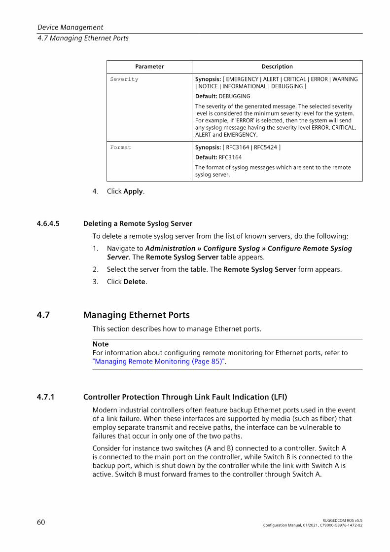
Device Management4.7 Managing Ethernet Ports
Parameter Description
Severity Synopsis: [ EMERGENCY | ALERT | CRITICAL | ERROR | WARNING| NOTICE | INFORMATIONAL | DEBUGGING ]Default: DEBUGGINGThe severity of the generated message. The selected severitylevel is considered the minimum severity level for the system.For example, if 'ERROR' is selected, then the system will sendany syslog message having the severity level ERROR, CRITICAL,ALERT and EMERGENCY.
Format Synopsis: [ RFC3164 | RFC5424 ]Default: RFC3164The format of syslog messages which are sent to the remotesyslog server.
4. Click Apply.
4.6.4.5 Deleting a Remote Syslog Server
To delete a remote syslog server from the list of known servers, do the following:1. Navigate to Administration » Configure Syslog » Configure Remote Syslog
Server. The Remote Syslog Server table appears.2. Select the server from the table. The Remote Syslog Server form appears.3. Click Delete.
4.7 Managing Ethernet PortsThis section describes how to manage Ethernet ports.
NoteFor information about configuring remote monitoring for Ethernet ports, refer to"Managing Remote Monitoring (Page 85)".
4.7.1 Controller Protection Through Link Fault Indication (LFI)Modern industrial controllers often feature backup Ethernet ports used in the eventof a link failure. When these interfaces are supported by media (such as fiber) thatemploy separate transmit and receive paths, the interface can be vulnerable tofailures that occur in only one of the two paths.Consider for instance two switches (A and B) connected to a controller. Switch Ais connected to the main port on the controller, while Switch B is connected to thebackup port, which is shut down by the controller while the link with Switch A isactive. Switch B must forward frames to the controller through Switch A.
60 RUGGEDCOM ROS v5.5Configuration Manual, 01/2021, C79000-G8976-1472-02

Device Management4.7.1 Controller Protection Through Link Fault Indication (LFI)
21
43
5
1 Switch A 2 Switch B 3 Main Transmit Path 4 Backup Transmit Path 5 Controller
Figure 4.2 Example
If the transmit path from the controller to Switch A fails, Switch A still generates alink signal to the controller through the receive path. The controller still detects thelink with Switch A and does not failover to the backup port.This situation illustrates the need for a notification method that tells a link partnerwhen the link integrity signal has stopped. Such a method natively exists in some linkmedia, but not all.
100Base-TX, 1000Base-T,1000Base-X
Includes a built-in auto-negotiation feature (i.e. a special flag calledRemote Fault Indication is set in the transmitted auto-negotiationsignal).
100Base-FX Links Includes a standard Far-End-Fault-Indication (FEFI) feature definedby the IEEE 802.3 standard for this link type. This feature includes:• Transmitting FEFI
Transmits a modified link integrity signal in case a link failure isdetected (i.e. no link signal is received from the link partner)
• Detecting FEFIIndicates link loss in case an FEFI signal is received from the linkpartner
10Base-FL LInks No standard support.
10Base-FL links do not have a native link partner notification mechanism and FEFIsupport in 100Base-FX links is optional according to the IEEE 802.3 standard, whichmeans that some links partners may not support it.Siemens offers an advanced Link-Fault-Indication (LFI) feature for the links that donot have a native link partner notification mechanism. With LFI enabled, the devicebases the generation of a link integrity signal upon its reception of a link signal. Inthe example described previously, if switch A fails to receive a link signal from thecontroller, it will stop generating a link signal. The controller will detect the linkfailure and failover to the backkup port.
RUGGEDCOM ROS v5.5Configuration Manual, 01/2021, C79000-G8976-1472-02 61

Device Management4.7.2 Viewing the Status of Ethernet Ports
NOTICEConfiguration hazard – risk of communication disruptionIf both link partners have the LFI feature, it must not be enabled on both sides ofthe link. If it is enabled on both sides, the link will never be established, as each linkpartner will be waiting for the other to transmit a link signal.
The switch can also be configured to flush the MAC address table for the controllerport. Frames destined for the controller will be flooded to Switch B where they willbe forwarded to the controller (after the controller transmits its first frame).
4.7.2 Viewing the Status of Ethernet PortsTo view the current status of each Ethernet port, navigate to Ethernet Ports » ViewPort Status. The Port Status table appears.This table displays the following information:
Parameter Description
Port Synopsis: 1/1 to maximum port numberThe port number as seen on the front plate silkscreen of the device.
Name Synopsis: A string 15 characters longA descriptive name that may be used to identify the deviceconnected on that port.
Link Synopsis: [ ---- | Down | Up ]The port's link status.
Speed Synopsis: [ --- | 10M | 100M | 1G | 10G ]The port's current speed.
Duplex Synopsis: [ ---- | Half | Full ]The port's current duplex status.
4.7.3 Viewing Statistics for All Ethernet PortsTo view statistics collected for all Ethernet ports, navigate to Ethernet Stats » ViewEthernet Statistics. The Ethernet Statistics table appears.This table displays the following information:
Parameter Description
Port Synopsis: 1/1 to maximum port numberThe port number as seen on the front plate silkscreen of the device.
State Synopsis: [ ---- | Down | Up ]The link status of the port.
62 RUGGEDCOM ROS v5.5Configuration Manual, 01/2021, C79000-G8976-1472-02

Device Management4.7.4 Viewing Statistics for Specific Ethernet Ports
Parameter Description
InOctets Synopsis: An integer between 0 and 4294967295The number of octets in received good packets (Unicast+Multicast+Broadcast) and dropped packets.
OutOctets Synopsis: An integer between 0 and 4294967295The number of octets in transmitted good packets.
InPkts Synopsis: An integer between 0 and 4294967295The number of received good packets (Unicast+Multicast+Broadcast) and dropped packets.
OutPkts Synopsis: An integer between 0 and 4294967295The number of transmitted good packets.
ErrorPkts Synopsis: An integer between 0 and 4294967295The number of any type of erroneous packet.
4.7.4 Viewing Statistics for Specific Ethernet PortsTo view statistics collected for specific Ethernet ports, navigate to Ethernet Stats »View Ethernet Port Statistics. The Ethernet Port Statistics table appears.This table displays the following information:
Parameter Description
Port Synopsis: 1/1 to maximum port numberThe port number as seen on the front plate silkscreen of the device.
InOctets Synopsis: An integer between 0 and 18446744073709551615The number of octets in received good packets (Unicast+Multicast+Broadcast) and dropped packets.
OutOctets Synopsis: An integer between 0 and 18446744073709551615The number of octets in transmitted good packets.
InPkts Synopsis: An integer between 0 and 18446744073709551615The number of received good packets (Unicast+Multicast+Broadcast) and dropped packets.
OutPkts Synopsis: An integer between 0 and 18446744073709551615The number of transmitted good packets.
TotalInOctets Synopsis: An integer between 0 and 18446744073709551615The total number of octets of all received packets. This includesdata octets of rejected and local packets which are not forwardedto the switching core for transmission. It should reflect all the dataoctets received on the line.
RUGGEDCOM ROS v5.5Configuration Manual, 01/2021, C79000-G8976-1472-02 63

Device Management4.7.4 Viewing Statistics for Specific Ethernet Ports
Parameter Description
TotalInPkts Synopsis: An integer between 0 and 18446744073709551615The number of received packets. This includes rejected, droppedlocal, and packets which are not forwarded to the switching corefor transmission. It should reflect all packets received ont the line.
InBroadcasts Synopsis: An integer between 0 and 18446744073709551615The number of good Broadcast packets received.
InMulticasts Synopsis: An integer between 0 and 18446744073709551615The number of good Multicast packets received.
CRCAlignErrors Synopsis: An integer between 0 and 4294967295The number of packets received which meet all the followingconditions:• Packet data length is between 64 and 1536 octets inclusive• Packet has invalid CRC• Collision Event has not been detected• Late Collision Event has not been detected
OversizePkts Synopsis: An integer between 0 and 4294967295The number of packets received with data length greater than 1536octets and valid CRC.
Fragments Synopsis: An integer between 0 and 4294967295The number of packets received which meet all the followingconditions:• Packet data length is less than 64 octets, or packet without SFD
and is less than 64 octets in length• Collision Event has not been detected• Late Collision Event has not been detected• Packet has invalid CRC
Jabbers Synopsis: An integer between 0 and 4294967295The number of packets which meet all the following conditions:• Packet data length is greater that 1536 octets• Packet has invalid CRC
Collisions Synopsis: An integer between 0 and 4294967295The number of received packets for which Collision Event has beendetected.
LateCollisions Synopsis: An integer between 0 and 4294967295The number of received packets for which Late Collision Event hasbeen detected.
Pkt64Octets Synopsis: An integer between 0 and 4294967295The number of received and transmitted packets with size of 64octets. This includes received and transmitted packets as well asdropped and local received packets. This does not include rejectedreceived packets.
64 RUGGEDCOM ROS v5.5Configuration Manual, 01/2021, C79000-G8976-1472-02

Device Management4.7.4 Viewing Statistics for Specific Ethernet Ports
Parameter Description
Pkt65to127Octets Synopsis: An integer between 0 and 4294967295The number of received and transmitted packets with size of 65to 127 octets. This includes received and transmitted packets aswell as dropped and local received packets. This does not includerejected received packets.
Pkt128to255Octets Synopsis: An integer between 0 and 4294967295The number of received and transmitted packets with size of 128to 257 octets. This includes received and transmitted packets aswell as dropped and local received packets. This does not includerejected received packets.
Pkt256to511Octets Synopsis: An integer between 0 and 4294967295The number of received and transmitted packets with size of 256to 511 octets. This includes received and transmitted packets aswell as dropped and local received packets. This does not includerejected received packets.
Pkt512to1023Octets Synopsis: An integer between 0 and 4294967295The number of received and transmitted packets with size of 512to 1023 octets. This includes received and transmitted packets aswell as dropped and local received packets. This does not includerejected received packets.
Pkt1024to1536Octets Synopsis: An integer between 0 and 4294967295The number of received and transmitted packets with size of 1024to 1536 octets. This includes received and transmitted packets aswell as dropped and local received packets. This does not includerejected received packets.
DropEvents Synopsis: An integer between 0 and 4294967295The number of received packets that are droped due to lack ofreceive buffers.
OutMulticasts Synopsis: An integer between 0 and 18446744073709551615The number of transmitted Multicast packets. This does not includeBroadcast packets.
OutBroadcasts Synopsis: An integer between 0 and 18446744073709551615The number of transmitted Broadcast packets.
UndersizePkts Synopsis: An integer between 0 and 4294967295The number of received packets which meet all the followingconditions:• Packet data length is less than 64 octets• Collision Event has not been detected• Late Collision Event has not been detected• Packet has valid CRC
RUGGEDCOM ROS v5.5Configuration Manual, 01/2021, C79000-G8976-1472-02 65

Device Management4.7.5 Clearing Statistics for Specific Ethernet Ports
4.7.5 Clearing Statistics for Specific Ethernet PortsTo clear the statistics collected for one or more Ethernet ports, do the following:1. Navigate to Ethernet Stats » Clear Ethernet Port Statistics. The Clear Ethernet
Port Statistics form appears.2. Select one or more Ethernet ports.3. Click Apply.
4.7.6 Configuring an Ethernet PortTo configure an Ethernet port, do the following:
NoteDepending on the required link media type, an SFP port may require some explicitconfiguration. Before configuring an SFP port, refer to "SFP Transceiver Requirements(Page 73)".
1. Navigate to Ethernet Ports » Configure Port Parameters. The Port Parameterstable appears.
2. Select an Ethernet port. The Port Parameters form appears.3. Configure the following parameter(s) as required:
Parameter Description
Port Synopsis: 1/1 to maximum port numberDefault: 1/1The port number as seen on the front plate silkscreen of thedevice.
Name Synopsis: A string 15 characters longDefault: Port xA descriptive name that may be used to identify the deviceconnected on that port.
Media Synopsis: [ 100TX | 10FL | 100FX | 1000X | 1000T | 802.11g |EoVDSL | 100TX Only | 10FL/100SX | 10GX ]Default: 100TXThe type of the port media.
State Synopsis: [ Disabled | Enabled ]Default: EnabledDisabling a port will prevent all frames from being sent andreceived on that port. Also, when disabled link integrity signalis not sent so that the link/activity LED will never be lit. You maywant to disable a port for troubleshooting or to secure it fromunauthorized connections.
66 RUGGEDCOM ROS v5.5Configuration Manual, 01/2021, C79000-G8976-1472-02

Device Management4.7.6 Configuring an Ethernet Port
Parameter Description
NoteDisabling a port whose media type is set to 802.11g disablesthe corresponding wireless module.
AutoN Synopsis: [ Off | On ]Default: OnEnable or disable IEEE 802.3 auto-negotiation. Enabling auto-negotiation results in speed and duplex being negotiated uponlink detection; both end devices must be auto-negotiationcompliant for the best possible results. 10Mbps and 100Mbpsfiber optic media do not support auto-negotiation so thesemedia must be explicitly configured to either half or full duplex.Full duplex operation requires that both ends are configured assuch or else severe frame loss will occur during heavy networktraffic.
Speed Synopsis: [ Auto | 10M | 100M | 1G ]Default: AutoSpeed (in Megabit-per-second or Gigabit-per-second). If auto-negotiation is enabled, this is the speed capability advertisedby the auto-negotiation process. If auto-negotiation is disabled,the port is explicitly forced to this speed mode.AUTO means advertise all supported speed modes.
Dupx Synopsis: [ Auto | Half | Full ]Default: AutoDuplex mode. If auto-negotiation is enabled, this is the duplexcapability advertised by the auto-negotiation process. If auto-negotiation is disabled, the port is explicitly forced to thisduplex mode.AUTO means advertise all supported duplex modes.
LFI Synopsis: [ Off | On ]Default: OffEnabling Link-Fault-Indication (LFI) inhibits transmitting linkintegrity signal when the receive link has failed. This allows thedevice at far end to detect link failure under all circumstances.
NoteThis feature must not be enabled at both ends of a fiber link.
Alarm Synopsis: [ On | Off ]Default: OnDisabling link state alarms will prevent alarms and LinkUp andLinkDown SNMP traps from being sent for that port.
RUGGEDCOM ROS v5.5Configuration Manual, 01/2021, C79000-G8976-1472-02 67

Device Management4.7.7 Configuring Port Rate Limiting
Parameter Description
Act on LinkDown Synopsis: [ Do nothing | Admin Disable ]Default: Do nothingThe action to be taken upon a port LinkDown event. Optionsinclude:• Do nothing – No action is taken.• Admin Disable – The port state is disabled. The State pa-
rameter must be set to Enabled before the link can be re-stored.
Downshift Synopsis: [ Disabled | Enabled ]Default: EnabledEnable or disable auto-negotiation on a gigabit (1000BASE-T)port with a two-pair twisted cable. If this option is enabled, thedevice is able to auto-negoatiate with another 1000BASE-T linkpartner using a two-pair cable and establish a link at 100Mbpsor 10Mbps.
NoteIf one end of the link is fixed to a specific speed and duplex type and the peerauto-negotiates, there is a strong possibility the link will either fail to raise, orraise with the wrong settings on the auto-negotiating side. The auto-negotiatingpeer will fall back to half-duplex operation, even when the fixed side is fullduplex. Full-duplex operation requires that both ends are configured as such orelse severe frame loss will occur during heavy network traffic. At lower trafficvolumes the link may display few, if any, errors. As the traffic volume rises, thefixed negotiation side will begin to experience dropped packets, while the auto-negotiating side will experience excessive collisions. Ultimately, as traffic loadapproaches 100%, the link will become entirely unusable. These problems canbe avoided by always configuring ports to the appropriate fixed values.
4. Click Apply.
4.7.7 Configuring Port Rate LimitingTo configure port rate limiting, do the following:1. Navigate to Ethernet Ports » Configure Port Rate Limiting. The Port Rate
Limiting table appears.2. Select an Ethernet port. The Port Rate Limiting form appears.3. Configure the following parameter(s) as required:
Parameter Description
Port Synopsis: 1/1 to maximum port numberDefault: 1/1The port number as seen on the front plate silkscreen of thedevice.
68 RUGGEDCOM ROS v5.5Configuration Manual, 01/2021, C79000-G8976-1472-02

Device Management4.7.8 Configuring Port Mirroring
Parameter Description
Ingress Limit Synopsis: An integer between 64 and 1000000 or [ Disabled ]Default: 1000The rate after which received frames (of the type described bythe ingress frames parameter) will be discarded by the switch.
Ingress Frames Synopsis: [ Broadcast | Multicast | Mcast&FloodUcast| Bcast&FloodUcast | FloodUcast | Bcast&Mcast |Bcast&Mcast&FloodUcast | All ]Default: BroadcastThis parameter specifies the types of frames to be rate-limitedon this port. It applies only to received frames:• Broadcast – Only broadcast frames are limited• Multicast – Only multicast frames are limited• Bcast&Mcast – Broadcast and multicast frames are limit-
ed• Bcast&FloodUcast – Broadcast and flooded unicast
frames are limited• Mcast&FloodUcast – Multicast and flooded unicast
frames are limited• FloodUcast – Only flooded unicast frames are limited
Egress Limit Synopsis: An integer between 64 and 1000000 or [ Disabled ]Default: DisabledThe maximum rate at which the switch will transmit (multicast,broadcast and unicast) frames on this port. The switch willdiscard frames in order to meet this rate if required.
4. Click Apply.
4.7.8 Configuring Port MirroringPort mirroring is a troubleshooting tool that copies, or mirrors, all traffic received ortransmitted on a designated port to a specified mirror port. If a protocol analyzer isattached to the target port, the traffic stream of valid frames on any source port ismade available for analysis.
NOTICEConfiguration hazard – risk of communication disruptionSelect a target port that has a higher speed than the source port. Mirroring a 100Mbps port onto a 10 Mbps port may result in an improperly mirrored stream.
NOTICEConfiguration hazard – risk of communication disruptionFrames will be dropped if the full-duplex rate of frames on the source port exceedsthe transmission speed of the target port. Since both transmitted and received
RUGGEDCOM ROS v5.5Configuration Manual, 01/2021, C79000-G8976-1472-02 69

Device Management4.7.8 Configuring Port Mirroring
frames on the source port are mirrored to the target port, frames will be discarded ifthe sum traffic exceeds the target port’s transmission rate. This problem reaches itsextreme in the case where traffic on a 100 Mbps full-duplex port is mirrored onto a10 Mbps half-duplex port.
NOTICEBefore configuring port mirroring, note the following:• Mirror ports allow bidirectional traffic, i.e. the device will not block incoming
traffic to the mirror port(s). For increased security, configure ingress filtering tocontrol traffic flow when port mirroring is enabled. For more information aboutenabling ingress filtering, refer to "Configuring VLANs Globally (Page 151)".
• Traffic will be mirrored onto the target port irrespective of its VLANmembership. It could be the same as or different from the source port'smembership.
• Network management frames (such as RSTP, GVRP etc.) cannot be mirrored.• Switch management frames generated by the switch (such as Telnet, HTTP,
SNMP, etc.) cannot be mirrored.
NoteInvalid frames received on the source port will not be mirrored. These include CRCerrors, oversize and undersize packets, fragments, jabbers, collisions, late collisionsand dropped events.
To configure port mirroring, do the following:1. Navigate to Ethernet Ports » Configure Port Mirroring. The Port Mirroring
form appears.2. Configure the following parameter(s) as required:
Parameter Description
Port Mirroring Synopsis: [ Disabled | Enabled ]Default: DisabledEnabling port mirroring causes all frames received andtransmitted by the source port(s) to be transmitted out of thetarget port.
Source Ports Egr Synopsis: Comma-separated list of portsThe port(s) being monitored.
Source Ports Ingr Synopsis: Comma-separated list of portsThe port(s) being monitored.
Target Port Synopsis: 1/1 to maximum port numberDefault: 1/1The port where a monitoring device should be connected.
3. Click Apply.
70 RUGGEDCOM ROS v5.5Configuration Manual, 01/2021, C79000-G8976-1472-02

Device Management4.7.9 Configuring Link Detection
4.7.9 Configuring Link DetectionTo configure link detection, do the following:1. Navigate to Ethernet Ports » Configure Link Detection. The Link Detection
form appears.2. Configure the following parameter(s) as required:
NoteWhen Fast Link Detection is enabled, the system prevents link state changeprocessing from consuming all available CPU resources. However, if Port Guardis not used, it is possible for almost all available CPU time to be consumed byfrequent link state changes, which could have a negative impact on overallsystem responsiveness.
Parameter Description
Fast Link Detection Synopsis: [ Off | On | On_withPortGuard ]Default: On_withPortGuardThis parameter provides protection against faulty end devicesgenerating an improper link integrity signal. When a faultyend device or a mis-matching fiber port is connected to theunit, a large number of continuous link state changes could bereported in a short period of time. These large number of boguslink state changes could render the system unresponsive asmost, if not all, of the system resources are used to process thelink state changes. This could in turn cause a serious networkproblem as the unit's RSTP process may not be able to run, thusallowing network loop to form.Three different settings are available for this parameter:• Off – Turning this parameter OFF will disable FAST LINK
DETECTION completely. The switch will need a longer timeto detect a link failure. This will result in a longer networkrecovery time of up to 2s.
• On – In certain special cases where a prolonged excessivelink state changes constitute a legitimate link operation, us-ing this setting can prevent Port Guard from disabling FASTLINK DETECTION on the port in question. If excessive linkstate changes persist for more than 2 minutes, an alarmwill be generated to warn user about the observed bounc-ing link. If the excessive link state changes condition is re-solved later on, the alarm will be cleared automatically.Since this option does not disable FAST LINK DETECTION, apersistent bouncing link could continue affect the systemin terms of response time. This setting should be used withcaution.
• On_withPortGuard – This is the recommended setting.With this setting, an extended period (~2 minutes) of exces-sive link state changes reported by a port will prompt PortGuard feature to disable FAST LINK DETECTION on that portand raise an alarm. By disabling FAST LINK DETECTION onthe problematic port, excessive link state changes can nolonger consume substantial amount of system resources.However if FAST LINK DETECTION is disabled, the port willneed a longer time to detect a link failure. This may result
RUGGEDCOM ROS v5.5Configuration Manual, 01/2021, C79000-G8976-1472-02 71

Device Management4.7.10 Managing SFP Transceivers
Parameter Descriptionin a longer network recovery time of up to 2s. Once PortGuard disables FAST LINK DETECTION of a particular port,user can re-enable FAST LINK DETECTION on the port byclearing the alarm.
Link Detection Time Synopsis: An integer between 100 and 1000Default: 100The time that the link has to continuously stay up before the"link up" decision is made by the device.(The device performs de-bouncing of Ethernet link detectionto avoid multiple responses to an occasional link bouncingevent, e.g. when a cable is shaking while being plugged-in orunplugged).
3. Click Apply.
4.7.10 Managing SFP TransceiversRUGGEDCOM ROS supports Small Form-factor Pluggable (SFP) transceivers to providea 1000Base-X, 100Base-FX, 1000Base-T or 100Base-TX link.
NoteSince 1000Base-X fiber SFP transceivers are standardized, RUGGEDCOM ROSsupports most models of this type. For more information, refer to the RUGGEDCOMSFP Transceivers Catalog [https://support.industry.siemens.com/cs/ww/en/view/109482309].It is strongly recommended to use SFP transceiver models approved by Siemensonly. Siemens performs extensive testing on these transceivers to make sure theycan withstand harsh conditions. If a different SFP transceiver model is used, it is theuser’s responsibility to verify it meets environmental and usage requirements.1000Base-T copper SFP transceivers are not standardized. RUGGEDCOM ROSsupports only selected models of this type.
NoteSFP transceivers are hot swappable.When an SFP transceiver is inserted in to the SFP cage, the speed and auto-negotiation settings for the port are automatically adjusted to the appropriatevalues. For example, if a 1 G SFP transceiver is installed, the speed of the port isautomatically changed to 1 G and auto-negotiation is set to On.
NoteDue to the uncertain latency introduced by the built-in PHY, the time accuracy of IEEE1588 may be significantly degraded on a copper SFP port.
72 RUGGEDCOM ROS v5.5Configuration Manual, 01/2021, C79000-G8976-1472-02

Device Management4.7.10 Managing SFP Transceivers
4.7.10.1 SFP Transceiver Requirements
Depending on the required link media type, an SFP port may require some explicitconfiguration:• For 100Base-FX or 100Base-TX links, the speed must be set to 100 Mbps.• For 1000Base-X or 1000Base-T links, the speed of the SFP port must be set to 1
Gbps.• Auto-negotiation can be configured to On when the port speed is set to 1 Gbps,
or to Off when the port speed is set to 100 Mbps.• Duplex mode cannot be configured on an SFP port and is always forced to full
duplex.For more information about configuring SFP transceiver ports and other Ethernetports on the device, refer to "Configuring an Ethernet Port (Page 66)".
4.7.10.2 Monitoring an SFP Port
RUGGEDCOM ROS supports hot-swapping of SFP transceivers on SFP ports and willautomatically detect when an SFP transceiver is removed or installed.When RUGGEDCOM ROS detects that an SFP transceiver is plugged into an SFPport, it reads the transceiver information and determines the transceiver type. Thisdecision results in RUGGEDCOM ROS either accepting, accepting and reconfiguring,or rejecting the SFP port.The following table shows in which cases an SFP transceiver is accepted or acceptedand reconfigured.
Configured Speed Detected SFPType: 1000Base-X
Detected SFPType: 100Base-FX
Detected SFPType: 1000Base-T
1 Gbps Accept
Accept andautomatically setthe speed to 100
Mbps and set auto-negotiation to Off
Accept
100 Mbps
Accept andautomatically set the
speed to 1 Gbps and setauto-negotiation to On
Accept
Compare thetransceiver model
against a list ofsupported models.
Accept if it is inthe list. Otherwise,
automatically set thespeed to 1 Gbps and setauto-negotiation to On.
If the transceiver is accepted, the Media parameter under Ethernet Ports »Configure Port Parameters shows detailed information about the SFP transceiver,including Gigabit Ethernet Compliance Code, transmission media, connector type,and link length. For example:SFP 1000LX SM LC 10 kmSFP 1000T 100 m
RUGGEDCOM ROS v5.5Configuration Manual, 01/2021, C79000-G8976-1472-02 73

Device Management4.7.10 Managing SFP Transceivers
If the transceiver is not recognized, it is rejected. An alarm is also generated and theport is blocked so that no link can be established until the transceiver is replaced. TheMedia parameter shows the rejected SFP transceiver is unidentified. For example:SFP Unidentified
If no transceiver is installed on an SFP port, the Media parameter shows the SFPtransceiver is unplugged:SFP Unplugged
4.7.10.3 Displaying Information for an SFP Port
To display detailed information about an SFP port, do the following:1. Log in to the device and access the CLI shell. For more information about
accessing the CLI shell, refer to "Using the Command Line Interface (Page 23)".2. Type the following command:
sfp { port }
Where:• { port } is the port numberInformation about the SFP port is displayed. For example:>sfp 1/1ID: SFPExtended ID: GBIC/SFP function is defined by serial ID onlyConnector: LCTransceiver:Gigabit Ethernet Compliance Codes:1000LXFibre Channel link length:Long Distance (L)Fibre Channel transmitter technology:Longwave laser (LC)Fibre Channel transmission media:Single Mode (SM)Fibre Channel speed:100 MBytes/SecBaud Rate, nominal: 1300 MBits/secEncoding type: 8B10BLength(9um): 10 kmLength(9um): 10000 mLength(50um): 550 mLength(62.5um): 550 mLength(Copper): Not specifiedVendor: xxxxxxxIEEE company ID: xxxxxxxPart number: xxxxxxxxxxRevision: 0000Laser wavelength: 1310 nm>
74 RUGGEDCOM ROS v5.5Configuration Manual, 01/2021, C79000-G8976-1472-02

Device Management4.7.11 Detecting Cable Faults
4.7.11 Detecting Cable FaultsConnectivity issues can sometimes be attributed to faults in Ethernet cables. Tohelp detect cable faults, short circuits, open cables or cables that are too long,RUGGEDCOM ROS includes a built-in cable diagnostics utility.
4.7.11.1 Viewing Cable Diagnostics Results
To view the results of previous diagnostic tests, navigate to Ethernet Ports »Configure/View Cable Diagnostics Parameters. The Cable DiagnosticsParameters table appears.
NoteFor information about how to start a diagnostic test, refer to "Performing CableDiagnostics (Page 76)".
This table displays the following information:
Parameter Description
Port Synopsis: 1/1 to maximum port numberThe port number as seen on the front plate silkscreen of the device.
State Synopsis: [ Stopped | Started ]Control the start/stop of the cable diagnostics on the selected port.If a port does not support cable diagnostics, State will be reportedas N/A.
Runs Synopsis: An integer between 0 and 65535The total number of times cable diagnostics to be performed on theselected port. If this number is set to 0, cable diagnostics will beperformed forever on the selected port.
Calib. Synopsis: An integer between -100.0 and 100.0This calibration value can be used to adjust or calibrate theestimated distance to fault. User can take following steps tocalibrate the cable diagnostics estimated distance to fault:1. Pick a particular port which calibration is needed.2. Connect an Ethernet cable with a known length (e.g. 50m) to
the port.3. DO NOT connect the other end of the cable to any link partner.4. Run cable diagnostics a few times on the port. OPEN fault
should be detected.5. Find the average distance to the OPEN fault recorded in the log
and compare it to the known length of the cable. The differ-ence can be used as the calibration value.
6. Enter the calibration value and run cable diagnostics a fewmore times.
7. The distance to OPEN fault should now be at similar distance asthe cable length.
8. Distance to fault for the selected port is now calibrated.
RUGGEDCOM ROS v5.5Configuration Manual, 01/2021, C79000-G8976-1472-02 75

Device Management4.7.11 Detecting Cable Faults
Parameter Description
Good Synopsis: An integer between 0 and 65535The number of times GOOD TERMINATION (no fault) is detected onthe cable pairs of the selected port.
Open Synopsis: An integer between 0 and 65535The number of times OPEN is detected on the cable pairs of theselected port.
Short Synopsis: An integer between 0 and 65535The number of times SHORT is detected on the cable pairs of theselected port.
Imped Synopsis: An integer between 0 and 65535The number of times IMPEDANCE MISMATCH is detected on thecable pairs of the selected port.
Pass /Fail /Total Synopsis: A string 19 characters longThis field summarizes the results of the cable diagnosticsperformed so far.• Pass – number of times cable diagnostics successfully com-
pleted on the selected port.• Fail – number of times cable diagnostics failed to complete
on the selected port.• Total – total number of times cable diagnostics have been at-
tempted on the selected port.
NoteFor each successful diagnostic test, the values for Good, Open, Short or Imped willincrement based on the number of cable pairs connected to the port. For a 100Base-T port, which has two cable pairs, the number will increase by two. For a 1000Base-Tport, which has four cable pairs, the number will increase by four.
NoteWhen a cable fault is detected, an estimated distance-to-fault is calculated andrecorded in the system log. The log lists the cable pair, the fault that was detected,and the distance-to-fault value. For more information about the system log, refer to"Viewing Local and System Logs (Page 56)".
4.7.11.2 Performing Cable Diagnostics
To perform a cable diagnostic test on one or more Ethernet ports, do the following:1. Connect a CAT-5 (or better quality) Ethernet cable to the selected Ethernet port.
NOTICEBoth the selected Ethernet port and its partner port can be configured to runin Enabled mode with auto-negotiation, or in Disabled mode. Other modes arenot recommended, as they may interfere with the cable diagnostics procedure.
76 RUGGEDCOM ROS v5.5Configuration Manual, 01/2021, C79000-G8976-1472-02

Device Management4.7.11 Detecting Cable Faults
2. Connect the other end of the cable to a similar network port. For example,connect a 100Base-T port to a 100Base-T port, or a 1000Base-T port to a1000Base-T port.
3. In RUGGEDCOM ROS, navigate to Ethernet Ports » Configure/View CableDiagnostics Parameters. The Cable Diagnostics Parameters table appears.
4. Select an Ethernet port. The Cable Diagnostics Parameters form appears.5. Under Runs, enter the number of consecutive diagnostic tests to perform. A
value of 0 indicates the test will run continuously until stopped by the user.6. Under Calib., enter the estimated Distance To Fault (DTF) value. For information
about how to determine the DTF value, refer to "Determining the EstimatedDistance To Fault (DTF) (Page 77)".
7. Select Started.
NOTICEA diagnostic test can be stopped by selecting Stopped and clicking Apply.However, if the test is stopped in the middle of a diagnostic run, the test willrun to completion.
8. Click Apply. The state of the Ethernet port will automatically change toStopped when the test is complete. For information about how to monitorthe test and view the results, refer to "Viewing Cable Diagnostics Results (Page75)".
4.7.11.3 Clearing Cable Diagnostics
To clear the cable diagnostic results, do the following:1. Navigate to Ethernet Ports » Clear Cable Diagnostics Statistics. The Clear
Cable Diagnostics Statistics form appears.2. Select one or more Ethernet ports.3. Click Apply.
4.7.11.4 Determining the Estimated Distance To Fault (DTF)
To determine the estimate Distance To Fault (DTF), do the following:1. Connect a CAT-5 (or better quality) Ethernet cable with a known length to the
device. Do not connect the other end of the cable to another port.2. Configure the cable diagnostic utility to run a few times on the selected Ethernet
port and start the test. For more information, refer to "Performing CableDiagnostics (Page 76)". Open faults should be detected and recorded in thesystem log.
RUGGEDCOM ROS v5.5Configuration Manual, 01/2021, C79000-G8976-1472-02 77

Device Management4.7.12 Resetting Ethernet Ports
3. Review the errors recorded in the system log and determine the averagedistance of the open faults. For more information about the system log, refer to"Viewing Local and System Logs (Page 56)".
4. Subtract the average distance from the cable length to determine the calibrationvalue.
5. Configure the cable diagnostic utility to run a few times with the new calibrationvalue. The distance to the open fault should now be the same as the actuallength of the cable. The Distance To Fault (DTF) is now calibrated for theselected Ethernet port.
4.7.12 Resetting Ethernet PortsAt times, it may be necessary to reset a specific Ethernet port, such as when the linkpartner has latched into an inappropriate state. This is also useful for forcing a re-negotiation of the speed and duplex modes.To reset a specific Ethernet port(s), do the following:1. Navigate to Ethernet Ports » Reset Port(s). The Reset Port(s) form appears.2. Select one or more Ethernet ports to reset.3. Click Apply. The selected Ethernet ports are reset.
4.8 Managing IP InterfacesTwo types of IP interfaces can be configured in RUGGEDCOM ROS:• Management IP interfaces• Switch IP interfacesThe management IP interface represents the management port on the device. Onlyone management IP interface can be configured.Switch IP interfaces represent the VLAN interfaces where each interface must beassigned an IP address with a unique subnet. One VLAN interface must be markedas the management interface. By default,the management interface is the onlyinterface that is able to run IP services such as DHCP, IEEE1588, Serial Server, andLLDP that affect the RUGGEDCOM ROS device. However, RUGGEDCOM ROS can beconfigured to allow auxiliary management interfaces to run the following services:
• MMS• Modbus• Radius/TacPlus• Remote Shell• Remote Syslog• SNMP
78 RUGGEDCOM ROS v5.5Configuration Manual, 01/2021, C79000-G8976-1472-02

Device Management4.8.1 Configuring the Management IP Interface
• SNTP
• SSH• TFTP• Telnet• Web Server
For more information, refer to "Configuring IP Services (Page 84)".
4.8.1 Configuring the Management IP InterfaceTo configure the management IP interface, do the following:1. Navigate to Administration » Configure IP Interfaces » Configure Mgmt IP
Interfaces. The Mgmt IP Interfaces form appears.2. Configure the following parameter(s) as required:
NoteThe IP address and mask configured for the management VLAN are not changedwhen resetting all configuration parameters to defaults and will be assigned adefault VLAN ID of 1. Changes to the IP address take effect immediately. All IPconnections in place at the time of an IP address change will be lost.
Parameter Description
IP Address Type Synopsis: [ Static | Dynamic | DHCP | BOOTP ]Default: StaticSpecifies whether the IP address is static or dynamicallyassigned via DHCP or BOOTP. Option DYNAMIC is a commoncase of dynamically assigned IP address. It switches betweenBOOTP and DHCP until it gets the response from the relevantserver. Must be static for non management interfaces.
IP Address Synopsis: Any valid IP addressDefault: 192.168.0.1Specifies the Internet Protocol address of this interface. AnIP address is a 128-bit number that is notated by using eightfields of four hexadecimal digits, for which leading zeros canbe omitted, delimited by colons. Consult offline documentationfor more information. A version 4 address can be encodedby four decimal numbers from 0 through 255, separated byperiods. Only a unicast IP addresses is allowed, which does notbegin with "FF", or ranges from 1.0.0.0 to 233.255.255.255 forversion 4.
Subnet Synopsis: An integer between 0 and 128Default: 24Specifies the IP subnet mask of this device. An IP subnet maskis a 32-bit number that is notated by using four numbers from0 through 255, separated by periods. Typically, subnet masknumbers use either 0 or 255 as values (e.g. 255.255.255.0) butother numbers can appear.
RUGGEDCOM ROS v5.5Configuration Manual, 01/2021, C79000-G8976-1472-02 79

Device Management4.8.2 Managing Switch IP Interfaces
Parameter Description
NOTICEEach IP interface must have a unique network address.
3. Click Apply.
4.8.2 Managing Switch IP InterfacesSwitch IP interfaces represent the VLAN interfaces where each interface must beassigned an IP address with a unique subnet. The following subsections describehow to view a list of switch IP interfaces, as well as how to add and delete switch IPinterfaces.
4.8.2.1 Viewing a List of Switch IP Interfaces
To view a list of switch IP interfaces configured on the device, navigate toAdministration » Configure IP Interfaces » Configure Switch IP Interfaces. TheSwitch IP Interfaces table appears.If switch IP interfaces have not been configured, add IP interfaces as needed. Formore information, refer to "Adding a Switch IP Interface (Page 80)".
4.8.2.2 Adding a Switch IP Interface
To add a switch IP interface, do the following:1. Navigate to Administration » Configure IP Interfaces » Configure Switch IP
Interfaces. The Switch IP Interfaces Table appears.2. Click InsertRecord. The Switch IP Interfaces form appears.
80 RUGGEDCOM ROS v5.5Configuration Manual, 01/2021, C79000-G8976-1472-02
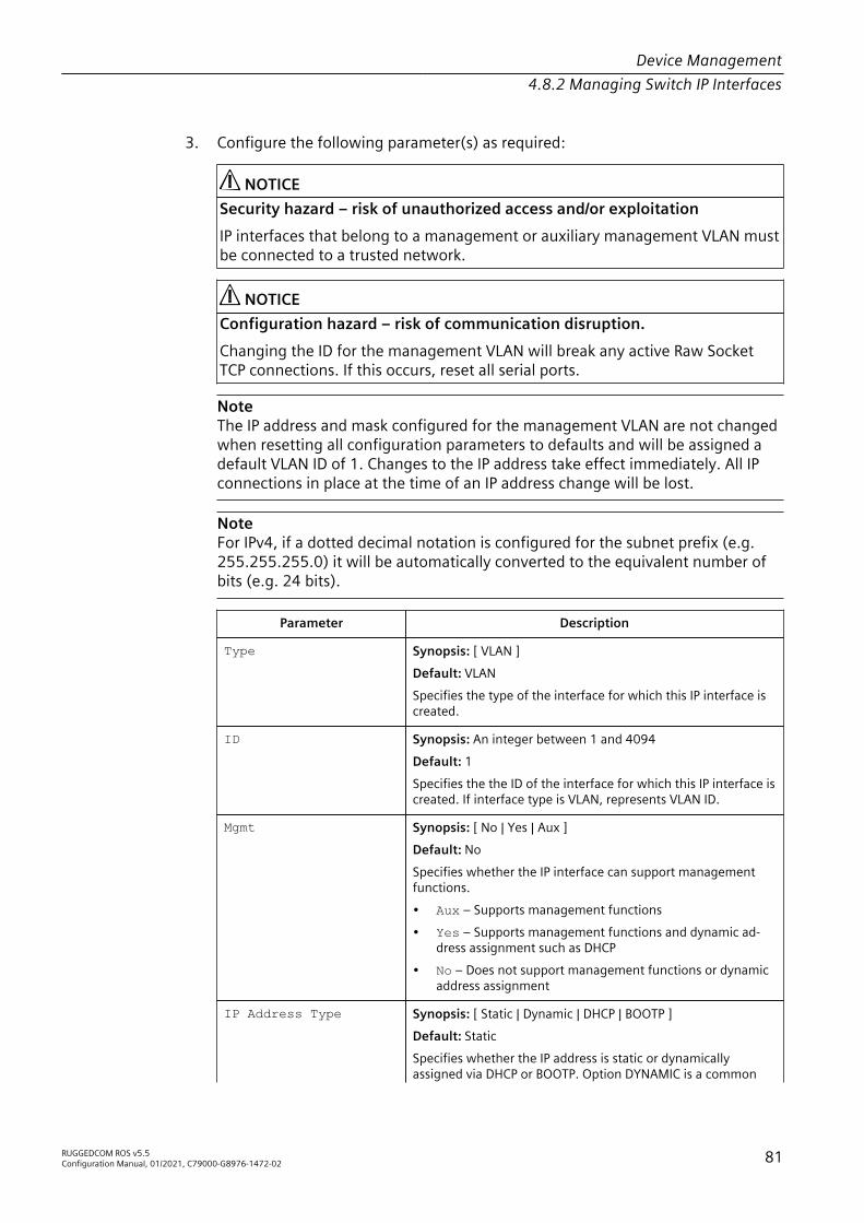
Device Management4.8.2 Managing Switch IP Interfaces
3. Configure the following parameter(s) as required:
NOTICESecurity hazard – risk of unauthorized access and/or exploitationIP interfaces that belong to a management or auxiliary management VLAN mustbe connected to a trusted network.
NOTICEConfiguration hazard – risk of communication disruption.Changing the ID for the management VLAN will break any active Raw SocketTCP connections. If this occurs, reset all serial ports.
NoteThe IP address and mask configured for the management VLAN are not changedwhen resetting all configuration parameters to defaults and will be assigned adefault VLAN ID of 1. Changes to the IP address take effect immediately. All IPconnections in place at the time of an IP address change will be lost.
NoteFor IPv4, if a dotted decimal notation is configured for the subnet prefix (e.g.255.255.255.0) it will be automatically converted to the equivalent number ofbits (e.g. 24 bits).
Parameter Description
Type Synopsis: [ VLAN ]Default: VLANSpecifies the type of the interface for which this IP interface iscreated.
ID Synopsis: An integer between 1 and 4094Default: 1Specifies the the ID of the interface for which this IP interface iscreated. If interface type is VLAN, represents VLAN ID.
Mgmt Synopsis: [ No | Yes | Aux ]Default: NoSpecifies whether the IP interface can support managementfunctions.• Aux – Supports management functions• Yes – Supports management functions and dynamic ad-
dress assignment such as DHCP• No – Does not support management functions or dynamic
address assignment
IP Address Type Synopsis: [ Static | Dynamic | DHCP | BOOTP ]Default: StaticSpecifies whether the IP address is static or dynamicallyassigned via DHCP or BOOTP. Option DYNAMIC is a common
RUGGEDCOM ROS v5.5Configuration Manual, 01/2021, C79000-G8976-1472-02 81
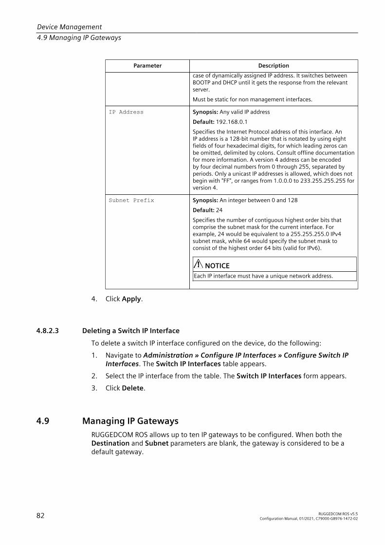
Device Management4.9 Managing IP Gateways
Parameter Descriptioncase of dynamically assigned IP address. It switches betweenBOOTP and DHCP until it gets the response from the relevantserver.Must be static for non management interfaces.
IP Address Synopsis: Any valid IP addressDefault: 192.168.0.1Specifies the Internet Protocol address of this interface. AnIP address is a 128-bit number that is notated by using eightfields of four hexadecimal digits, for which leading zeros canbe omitted, delimited by colons. Consult offline documentationfor more information. A version 4 address can be encodedby four decimal numbers from 0 through 255, separated byperiods. Only a unicast IP addresses is allowed, which does notbegin with "FF", or ranges from 1.0.0.0 to 233.255.255.255 forversion 4.
Subnet Prefix Synopsis: An integer between 0 and 128Default: 24Specifies the number of contiguous highest order bits thatcomprise the subnet mask for the current interface. Forexample, 24 would be equivalent to a 255.255.255.0 IPv4subnet mask, while 64 would specify the subnet mask toconsist of the highest order 64 bits (valid for IPv6).
NOTICEEach IP interface must have a unique network address.
4. Click Apply.
4.8.2.3 Deleting a Switch IP Interface
To delete a switch IP interface configured on the device, do the following:1. Navigate to Administration » Configure IP Interfaces » Configure Switch IP
Interfaces. The Switch IP Interfaces table appears.2. Select the IP interface from the table. The Switch IP Interfaces form appears.3. Click Delete.
4.9 Managing IP GatewaysRUGGEDCOM ROS allows up to ten IP gateways to be configured. When both theDestination and Subnet parameters are blank, the gateway is considered to be adefault gateway.
82 RUGGEDCOM ROS v5.5Configuration Manual, 01/2021, C79000-G8976-1472-02

Device Management4.9.1 Viewing a List of IP Gateways
NoteThe default gateway will not be changed if the selected factory default configurationis reloaded.
4.9.1 Viewing a List of IP GatewaysTo view a list of IP gateways configured on the device, navigate to Administration »Configure IP Gateways. The IP Gateways table appears.If IP gateways have not been configured, add IP gateways as needed. For moreinformation, refer to "Adding an IP Gateway (Page 83)".
4.9.2 Adding an IP Gateway
NoteDHCP-provided IP gateway addresses will override manually configured values.
To add an IP gateway, do the following:1. Navigate to Administration » Configure IP Gateways. The IP Gateways table
appears.2. Click InsertRecord. The IP Gateways form appears.3. Configure the following parameter(s) as required:
Parameter Description
Destination Synopsis: Any valid IP addressSpecifies the IP address of destination network or host. Fordefault gateway, both the destination and subnet are 0.
Subnet Synopsis: An integer between 0 and 128Default: 0Specifies the destination IP subnet mask. For default gateway,both the destination and subnet are 0.
Gateway Synopsis: Any valid IP addressSpecifies the gateway to be used to reach the destination.
4. Click Apply.
4.9.3 Deleting an IP GatewayTo delete an IP gateway configured on the device, do the following:1. Navigate to Administration » Configure IP Gateways. The IP Gateways table
appears.
RUGGEDCOM ROS v5.5Configuration Manual, 01/2021, C79000-G8976-1472-02 83

Device Management4.10 Configuring IP Services
2. Select the IP gateway from the table. The IP Gateways form appears.3. Click Delete.
4.10 Configuring IP ServicesTo configure the IP services provided by the device, do the following:1. Navigate to Administration » Configure IP Services. The IP Services form
appears.2. Configure the following parameter(s) as required:
Parameter Description
Inactivity Timeout Synopsis: An integer between 1 and 60 or [ Disabled ]Default: 5Specifies when the console will timeout and display the loginscreen if there is no user activity. A value of zero disablestimeouts. For Web Server users maximum timeout value islimited to 30 minutes.
Telnet Sessions Al lowed
Synopsis: An integer between 1 and 4 or [ Disabled ]Default: DisabledLimits the number of Telnet sessions. A value of zero preventsany Telnet access.
Web Server Users Al lowed
Synopsis: An integer between 1 and 4 or [ Disabled ]Default: 4Limits the number of simultaneous web server users.
TFTP Server Synopsis: [ Disabled | Get Only | Enabled ]Default: DisabledAs this is an insecure protocol, this parameter allows user tolimit or disable the service.Disabled – disables read and write access through this serviceGet Only – only allows to read files through this serviceEnabled – allows to read and write files through this service
ModBus Address Synopsis: An integer between 1 and 255 or [ Disabled ]Default: DisabledDetermines the Modbus address to be used for Managementthrough Modbus.
SSH Sessions Allowed(Controlled VersionOnly)
Synopsis: An integer between 1 and 4Default: 4Limits the number of SSH sessions.
MMS Sessions Allowed Synopsis: An integer between 1 and 4Default: DisabledLimits the number of MMS sessions. "Disabled" prevents anyMMS access.
84 RUGGEDCOM ROS v5.5Configuration Manual, 01/2021, C79000-G8976-1472-02

Device Management4.11 Managing Remote Monitoring
Parameter Description
RSH Server Synopsis: [ Disabled | Enabled ]Default: DisabledDisables/enables Remote Shell access.
IP Forward Synopsis: [ Disabled | Enabled ]Default: DisabledControls the ability of IP forwarding between VLANs in SerialServer or IP segments.
NoteWhen Layer 3 switching is enabled and Unicast Mode is set to"Auto", IP forwarding must be enabled.
Max Failed Attempts Synopsis: An integer between 1 and 20Default: 10Maximum number of failed access attempts per service withinthe Failed Attempts Window before blocking the service. Eachservice is allowed the maximum number of attempts beforebeing blocked. This parameter resets to the default value whenthe factory default configuration is reloaded, however thecounter for failed attempts on a particular service will not bereset.
Failed Attempts Window Synopsis: An integer between 1 and 30Default: 5The time in minutes (min) in which the maximum numberof failed login attempts must be exceeded before a service isblocked. The counter of failed attempts resets to 0 when thetimer expires. This parameter resets to the default value whenthe factory default configuration is reloaded.
Lockout Time Synopsis: An integer between 1 and 120Default: 60The time in minutes (min) the service remains locked outafter the maximum number of failed access attempts hasbeen reached. With the exception of the device managementinterface, this parameter resets to the default value when thefactory default configuration is reloaded.
3. Click Apply.
4.11 Managing Remote MonitoringRemote Monitoring (RMON) is used to collect and view historical statistics related tothe performance and operation of Ethernet ports. It can also record a log entry and/orgenerate an SNMP trap when the rate of occurrence of a specified event is exceeded.
RUGGEDCOM ROS v5.5Configuration Manual, 01/2021, C79000-G8976-1472-02 85

Device Management4.11.1 Managing RMON History Controls
4.11.1 Managing RMON History ControlsThe history controls for Remote Monitoring take samples of the RMON-MIB historystatistics of an Ethernet port at regular intervals.
4.11.1.1 Viewing a List of RMON History Controls
To view a list of RMON history controls, navigate to Ethernet Stats » ConfigureRMON History Controls. The RMON History Controls table appears.If history controls have not been configured, add controls as needed. For moreinformation, refer to "Adding an RMON History Control (Page 86)".
4.11.1.2 Adding an RMON History Control
To add an RMON history control, do the following:1. Navigate to Ethernet Stats » Configure RMON History Controls. The RMON
History Controls table appears.2. Click InsertRecord. The RMON History Controls form appears.3. Configure the following parameter(s) as required:
Parameter Description
Index Synopsis: An integer between 1 and 65535Default: 1The index of this RMON History Contol record.
Port Synopsis: 1/1 to maximum port numberDefault: 1/1The port number as seen on the front plate silkscreen of thedevice.
Requested Buckets Synopsis: An integer between 1 and 5000Default: 50The maximum number of buckets requested for this RMONcollection history group of statistics. The range is 1 to 4000. Thedefault is 50.
Granted Buckets Synopsis: An integer between 0 and 65535The number of buckets granted for this RMON collectionhistory. This field is not editable.
Interval Synopsis: An integer between 1 and 3600Default: 1800The number of seconds in over which the data is sampled foreach bucket. The range is 1 to 3600. The default is 1800.
86 RUGGEDCOM ROS v5.5Configuration Manual, 01/2021, C79000-G8976-1472-02

Device Management4.11.2 Managing RMON Alarms
Parameter Description
Owner Synopsis: A string 127 characters longDefault: MonitorThe owner of this record. It is suggested to start this stringwithword 'monitor'.
4. Click Apply.
4.11.1.3 Deleting an RMON History Control
To delete an RMON history control, do the following:1. Navigate to Ethernet Stats » Configure RMON History Controls. The RMON
History Controls table appears.2. Select the history control from the table. The RMON History Controls form
appears.3. Click Delete.
4.11.2 Managing RMON AlarmsWhen Remote Monitoring (RMON) alarms are configured, RUGGEDCOM ROSexamines the state of a specific statistical variable.Remote Monitoring (RMON) alarms define upper and lower thresholds for legalvalues of specific statistical variables in a given interval. This allows RUGGEDCOMROS to detect events as they occur more quickly than a specified maximum rate orless quckly than a minimum rate.When the rate of change for a statistics value exceeds its limits, an internal INFOalarm is always generated. For information about viewing alarms, refer to "Viewingand Clearing Latched Alarms (Page 99)".Additionally, a statistic threshold crossing can result in further activity. An RMONalarm can be configured to point to a particular RMON event, which can generate anSNMP trap, an entry in the event log, or both. The RMON event can also direct alarmstowards different users defined for SNMP.The alarm can point to a different event for each of the thresholds. Therefore,combinations such as trap on rising threshold or trap on rising threshold, log andtrap on falling threshold are possible.Each RMON alarm may be configured such that its first instance occurs only forrising, falling, or all thresholds that exceed their limits.The ability to configure upper and lower thresholds on the value of a measuredstatistic provides for the ability to add hysteresis to the alarm generation process.If the value of the measured statistic over time is compared to a single threshold,alarms will be generated each time the statistic crosses the threshold. If thestatistic’s value fluctuates around the threshold, an alarm can be generated every
RUGGEDCOM ROS v5.5Configuration Manual, 01/2021, C79000-G8976-1472-02 87

Device Management4.11.2 Managing RMON Alarms
measurement period. Programming different upper and lower thresholds eliminatesspurious alarms. The statistic value must travel between the thresholds before alarmscan be generated. The following illustrates the very different patterns of alarmgeneration resulting from a statistic sample and the same sample with hysteresisapplied.
Figure 4.3 The Alarm Process
There are two methods to evaluate a statistic to determine when to generate anevent: delta and absolute.For most statistics, such as line errors, it is appropriate to generate an alarm whena rate is exceeded. The alarm defaults to the delta measurement method, whichexamines changes in a statistic at the end of each measurement period.It may be desirable to alarm when the total, or absolute, number of events crosses athreshold. In this case, set the measurement period type to absolute.
4.11.2.1 Viewing a List of RMON Alarms
To view a list of RMON alarms, navigate to Ethernet Stats » Configure RMONAlarms. The RMON Alarms table appears.If alarms have not been configured, add alarms as needed. For more information,refer to "Adding an RMON Alarm (Page 88)".
4.11.2.2 Adding an RMON Alarm
To add an RMON alarm, do the following:1. Navigate to Ethernet Stats » Configure RMON Alarms. The RMON Alarms
table appears.2. Click InsertRecord. The RMON Alarms form appears.
88 RUGGEDCOM ROS v5.5Configuration Manual, 01/2021, C79000-G8976-1472-02

Device Management4.11.2 Managing RMON Alarms
3. Configure the following parameter(s) as required:
Parameter Description
Index Synopsis: An integer between 1 and 65535Default: 1The index of this RMON Alarm record.
Variable Synopsis: An integerThe SNMP object identifier (OID) of the particular variable tobe sampled. Only variables that resolve to an ASN.1 primitivetype INTEGER (INTEGER, Integer32,Counter32, Counter64,Gauge, or TimeTicks) may be sampled. A list of objects canbe printed using shell command 'rmon'. The OID format:objectName.index1.index2... where index format depends onindex object type.
Rising Thr Synopsis: An integer between -2147483647 and 2147483647Default: 0A threshold for the sampled variable. When the current sampledvariable value is greater than or equal to this threshold, and thevalue at the last sampling interval was less than this threshold,a single event will be generated. A single event will also begenerated if the first sample after this record is created isgreater than or equal to this threshold and the associatedstartup alarm ils equal to 'rising'.After rising alarm is generated,another such event will not be generated until the sampledvalue falls below this threshold and reaches the value ofFallingThreshold.
Falling Thr Synopsis: An integer between -2147483647 and 2147483647Default: 0A threshold for the sampled variable. When the current sampledvariable value is less than or equal to this threshold, andthe value at the last sampling interval was greater than thisthreshold, a single event will be generated. A single event willalso be generated if the first sample after this record is createdis less than or equal to this threshold and the associated startupalarm ils equal to 'falling'.After falling alarm is generated,another such event will not be generated until the sampledvalue rises above this threshold and reaches the value ofRisingThreshold.
Value Synopsis: An integer between -2147483647 and 2147483647The value of monitoring object during the last sampling period.The presentation of value depends of sample type ('absolute' or'delta').
Type Synopsis: [ absolute | delta ]Default: deltaThe method of sampling the selected variable and calculatingthe value to be compared against the thresholds. The value ofsample type can be 'absolute' or 'delta'.
RUGGEDCOM ROS v5.5Configuration Manual, 01/2021, C79000-G8976-1472-02 89

Device Management4.11.3 Managing RMON Events
Parameter Description
Interval Synopsis: An integer between 0 and 2147483647Default: 60The number of seconds in over which the data is sampled andcompared with the rising and falling thresholds.
Startup Alarm Synopsis: [ rising | falling | risingOrFalling ]Default: risingOrFallingThe alarm that may be sent when this record is first created ifcondition for raising alarm is met. The value of startup alarmcan be 'rising', 'falling' or 'risingOrFalling'.
Rising Event Synopsis: An integer between 0 and 65535Default: 0The index of the event that is used when a falling threshold iscrossed. If there is no corresponding entryl in the Event Table,then no association exists. In particular, if this value is zero, noassociated event will be generated.
Falling Event Synopsis: An integer between 0 and 65535Default: 0The index of the event that is used when a rising threshold iscrossed. If there is no corresponding entryl in the Event Table,then no association exists. In particular, if this value is zero, noassociated event will be generated.
Owner Synopsis: A string 127 characters longDefault: MonitorThe owner of this record. It is suggested to start this stringwithword 'monitor'.
4. Click Apply.
4.11.2.3 Deleting an RMON Alarm
To delete an RMON alarm, do the following:1. Navigate to Ethernet Stats » Configure RMON Alarms. The RMON Alarms
table appears.2. Select the alarm from the table. The RMON Alarms form appears.3. Click Delete.
4.11.3 Managing RMON EventsRemote Monitoring (RMON) events define behavior profiles used in event logging.These profiles are used by RMON alarms to send traps and log events.Each alarm may specify that a log entry be created on its behalf whenever theevent occurs. Each entry may also specify that a notification should occur by way of
90 RUGGEDCOM ROS v5.5Configuration Manual, 01/2021, C79000-G8976-1472-02

Device Management4.11.3 Managing RMON Events
SNMP trap messages. In this case, the user for the trap message is specified as theCommunity.Two traps are defined: risingAlarm and fallingAlarm.
4.11.3.1 Viewing a List of RMON Events
To view a list of RMON events, navigate to Ethernet Stats » Configure RMONEvents. The RMON Events table appears.If events have not been configured, add events as needed. For more information,refer to "Adding an RMON Event (Page 91)".
4.11.3.2 Adding an RMON Event
To add an RMON alarm, do the following:1. Navigate to Ethernet Stats » Configure RMON Events. The RMON Events table
appears.2. Click InsertRecord. The RMON Events form appears.3. Configure the following parameter(s) as required:
Parameter Description
Index Synopsis: An integer between 1 and 65535Default: 3The index of this RMON Event record.
Type Synopsis: [ none | log | snmpTrap | logAndTrap ]Default: logAndTrapThe type of notification that the probe will make about thisevent. In the case of 'log', an entry is made in the RMON Logtable for each event. In the case of snmp_trap, an SNMP trap issent to one or more management stations.
Community Synopsis: A string 31 characters longDefault: publicIf the SNMP trap is to be sent, it will be sent to the SNMPcommunity specified by this string.
Last Time Sent Synopsis: DDDD days, HH:MM:SSThe time from last reboot at the time this event entry lastgenerated an event. If this entry has not generated any events,this value will be 0.
Description Synopsis: A string 127 characters longDefault: EV2-RiseA comment describing this event.
RUGGEDCOM ROS v5.5Configuration Manual, 01/2021, C79000-G8976-1472-02 91

Device Management4.12 Upgrading/Downgrading Firmware
Parameter Description
Owner Synopsis: A string 127 characters longDefault: MonitorThe owner of this event record. It is suggested to start thisstring withword 'monitor'.
4. Click Apply.
4.11.3.3 Deleting an RMON Event
To delete an RMON event, do the following:1. Navigate to Ethernet Stats » Configure RMON Events. The RMON Events table
appears.2. Select the event from the table. The RMON Events form appears.3. Click Delete.
4.12 Upgrading/Downgrading FirmwareThis section describes how to upgrade and downgrade the firmware forRUGGEDCOM ROS.
4.12.1 Verifying the Hash ChecksumBefore installing new firmware for RUGGEDCOM ROS, it is recommended to verify thehash checksum to ensure the firmware is authentic and error-free.For instructions on how to verify the hash checksum, including a list of hashchecksums for all RUGGEDCOM ROS devices and releases, refer to FAQ RUGGEDCOMROS Hash Checksums (https://support.industry.siemens.com/cs/ww/en/view/109779935).
4.12.2 Upgrading FirmwareUpgrading RUGGEDCOM ROS firmware, including the main, bootloader andFPGA firmware, may be necessary to take advantage of new features orbug fixes. Binary firmware releases, including updates, can be obtained bysubmitting a Support Request via the Siemens Industry Online Support [https://support.industry.siemens.com] website. For more information, refer to https://support.industry.siemens.com/My/ww/en/requests.Binary firmware images transferred to the device are stored in non-volatile Flashmemory and require a device reset to take effect.
92 RUGGEDCOM ROS v5.5Configuration Manual, 01/2021, C79000-G8976-1472-02

Device Management4.12.2 Upgrading Firmware
NOTICEIf a microSD/microSDHC card is installed during the upgrade, the new firmware willbe stored to both the internal Flash and the microSD/microSDHC card.
NoteIn the event the upgrade process is interrupted, possibly due to a power disruption,RUGGEDCOM ROS is able to recover if a microSD/microSDHC card with a validfirmware image (main.bin) is installed before the next reboot. RUGGEDCOM ROSwill copy the firmware image to the internal memory and boot up from it.
NoteThe IP address set for the device will not be changed following a firmware upgrade.
NoteIt is recommended to enable access to the bootloader interface during this procedurein case emergency recovery is needed (e.g. power interruption during the upgrade).For increased security, Siemens recommends disabling bootloader access followingthe upgrade. For more information about managing bootloader access, refer to"Enabling/Disabling Access to the Boot Loader Interface (Page 39)".
To upgrade the RUGGEDCOM ROS firmware, do the following:1. Enable access to the bootloader interface. For more information, refer to
"Enabling/Disabling Access to the Boot Loader Interface (Page 39)".2. Upload a different version of the binary firmware image to the device or insert a
microSD/microSDHC card that contains the image. For more information aboutuploading files, refer to "Uploading/Downloading Files (Page 50)".
3. Reset the device to complete the installation. For more information, refer to"Resetting the Device (Page 95)".
4. Access the CLI shell and verify the new software version has been installed bytyping version. The currently installed versions of the main and boot firmwareare displayed.>versionCurrent ROS-MPC83 Main Software v5.5 .0 (Jan 01 5.5 00:01)
5. Disable access to the bootloader interface. For more information, refer to"Enabling/Disabling Access to the Boot Loader Interface (Page 39)".
RUGGEDCOM ROS v5.5Configuration Manual, 01/2021, C79000-G8976-1472-02 93

Device Management4.12.3 Downgrading Firmware
4.12.3 Downgrading FirmwareDowngrading the RUGGEDCOM ROS firmware is generally not recommended, asit may have unpredictable effects. However, if a downgrade is required, do thefollowing:
NoteBefore downgrading the firmware, make sure the hardware and FPGA code typesinstalled in the device are supported by the older firmware version. Refer to theRelease Notes for the older firmware version to confirm.
NoteDo not downgrade the RUGGEDCOM ROS boot version.
1. Disconnect the device from the network.2. Log in to the device as an admin user. For more information, refer to "Logging In
(Page 18)".3. Make a local copy of the current configuration file. For more information, refer
to "Uploading/Downloading Files (Page 50)".
NOTICEConfiguration hazard – risk of communication disruptionNever downgrade the firmware with encryption enabled to a version that doesnot support encryption.
4. Restore the device to its factory defaults. For more information, refer to"Restoring Factory Defaults (Page 49)".
5. Upload and apply the older firmware version and its associated FPGA filesusing the same methods used to install newer firmware versions. For moreinformation , refer to "Upgrading Firmware (Page 92)".
6. Press Ctrl-S to access the CLI.7. Clear all logs by typing:
clearlogs
8. Clear all alarms by typing:
clearalarms
NOTICESecurity hazard – risk of unauthorized access and/or exploitationAfter downgrading the firmware and FPGA files, be aware that some settingsfrom the previous configuration may be lost or reverted back to the factorydefaults (including user passwords if downgrading from a security relatedversion), as those particular tables or fields may not exist in the older firmwareversion. Because of this, the unit must be configured after the downgrade.
94 RUGGEDCOM ROS v5.5Configuration Manual, 01/2021, C79000-G8976-1472-02

Device Management4.13 Resetting the Device
9. Configure the device as required.
4.13 Resetting the DeviceTo reset the device, do the following:1. Navigate to Diagnostics » Reset Device. The Reset Device form appears.2. Click Confirm.
4.14 Decommissioning the DeviceBefore taking the device out of service, either permanently or for maintenance bya third-party, make sure the device has been fully decommissioned. This includesremoving any sensitive, proprietary information.To decommission the device, do the following:1. Disconnect all network cables from the device.2. Connect to the device via the RS-232 serial console port. For more information,
refer to "Connecting Directly (Page 43)".3. Restore all factory default settings for the device. For more information, refer to
"Restoring Factory Defaults (Page 49)".4. Access the CLI. For more information, refer to "Using the Command Line
Interface (Page 23)".5. Upload a blank version of the banner.txt file to the device to replace the
existing file. For more information about uploading a file, refer to "Uploading/Downloading Files (Page 50)".
6. Confirm the upload was successful by typing:
type banner.txt
7. Clear the system and crash logs by typing:
clearlog
8. Generate a random SSL certificate by typing:
sslkeygen
This may take several minutes to complete. To verify the certificate has beengenerated, type:
type syslog.txt
When the phrase Generated ssl.crt was saved appears in the log, theSSL certificate has been generated.
RUGGEDCOM ROS v5.5Configuration Manual, 01/2021, C79000-G8976-1472-02 95

Device Management4.14 Decommissioning the Device
9. Generate random SSH keys by typing:
sshkeygen
This may take several minutes to complete. To verify the keys have beengenerated, type:
type syslog.txt
When the phrase Generated ssh.keys was saved appears in the log, theSSH keys have been generated.
10. De-fragment and erase all free flash memory by typing:
flashfile defrag
This may take several minutes to complete.
96 RUGGEDCOM ROS v5.5Configuration Manual, 01/2021, C79000-G8976-1472-02

System Administration 5This chapter describes how to perform various administrative tasks related to deviceidentification, user permissions, alarm configuration, certificates and keys, and more.
5.1 Configuring the System InformationTo configure basic information that can be used to identify the device, its location,and/or its owner, do the following:1. Navigate to Administration » Configure System Identification. The System
Identification form appears.2. Configure the following parameter(s) as required:
Parameter Description
System Name Synopsis: A string 24 characters longThe system name is displayed in all RUGGEDCOM ROS menuscreens. This can make it easier to identify the switches withinyour network provided that all switches are given a uniquename.
Location Synopsis: A string 49 characters longThe location can be used to indicate the physical location of theswitch. It is displayed in the login screen as another means toensure you are dealing with the desired switch.
Contact Synopsis: A string 49 characters longThe contact can be used to help identify the person responsiblefor managing the switch. You can enter name, phone number,email, etc. It is displayed in the login screen so that this personmay be contacted should help be required.
3. Click Apply.
5.2 Customizing the Login ScreenTo display a custom welcome message, device information or any other informationon the login screen for the Web and console interfaces, add text to the banner.txtfile stored on the device.If the banner.txt file is empty, only the Username and Password fields appear onthe login screen.
RUGGEDCOM ROS v5.5Configuration Manual, 01/2021, C79000-G8976-1472-02 97

System Administration5.3 Enabling/Disabling the Web Interface
To update the banner.txt file, download the file from the device, modify it andthen load it back on to the device. For information about uploading and downloadingfiles, refer to "Uploading/Downloading Files (Page 50)".Alternatively, the banner.txt file can be updated using the banner CLI command.For more information, refer to "Available CLI Commands (Page 23)".
5.3 Enabling/Disabling the Web InterfaceIn some cases, users may want to disable the Web interface to increase cybersecurity.To disable or enable the Web interface, do the following:
NoteThe Web interface can be disabled via the Web UI by configuring the Web ServerUsers Allowed parameter in the IP Services form. For more information, refer to"Configuring IP Services (Page 84)".
1. Log in to the device as an admin user and access the CLI shell. For moreinformation about accessing the CLI shell, refer to "Using the Command LineInterface (Page 23)".
2. Navigate to Administration » Configure IP Services » Web Server UsersAllowed.
3. Select Disabled to disable the Web interface, or select the desired number ofWeb server users allowed to enable the interface.
5.4 Managing AlarmsAlarms indicate the occurrence of events of either importance or interest that arelogged by the device.There are two types of alarms:• Active alarms signify states of operation that are not in accordance with normal
operation. Examples include links that should be up, but are not, or error ratesthat repeatedly exceed a certain threshold. These alarms are continuously activeand are only cleared when the problem that triggered the alarms is resolved.
• Passive alarms are a record of abnormal conditions that occurred in the pastand do not affect the current operation state of the device. Examples includeauthentication failures, Remote Network MONitoring (RMON) MIB generatedalarms, or error states that temporarily exceeded a certain threshold . Thesealarms can be cleared from the list of alarms.
NoteFor more information about RMON alarms, refer to "Managing RMON Alarms (Page87)".
98 RUGGEDCOM ROS v5.5Configuration Manual, 01/2021, C79000-G8976-1472-02

System Administration5.4.1 Viewing a List of Pre-Configured Alarms
When either type of alarm occurs, a message appears in the top right corner of theuser interface. If more than one alarm has occurred, the message will indicate thenumber of alarms. Active alarms also trip the Critical Failure Relay LED on the device.The message and the LED will remain active until the alarm is cleared.
NoteAlarms are volatile in nature. All alarms (active and passive) are cleared at startup.
5.4.1 Viewing a List of Pre-Configured AlarmsTo view a list of alarms pre-configured for the device, navigate to Diagnostic »Configure Alarms. The Alarms table appears.
NoteThis list of alarms (configurable and non-configurable) is accessible through theCommand Line Interface (CLI) using the alarms command. For more information,refer to "Available CLI Commands (Page 23)".
For information about modifying a pre-configured alarm, refer to "Configuring anAlarm (Page 99)".
5.4.2 Viewing and Clearing Latched AlarmsTo view a list of alarms that are configured to latch, navigate to Diagnostics » ViewLatched Alarms. The Latched Alarms table appears.To clear the passive alarms from the list, do the following:1. Navigate to Diagnostics » Clear Latched Alarms. The Clear Latched Alarms
form appears.2. Click Confirm.
5.4.3 Configuring an AlarmWhile all alarms are pre-configured on the device, some alarms can be modified tosuit the application. This includes enabling/disabling certain features and changingthe refresh time.To configuring an alarm, do the following:
NOTICECritical and Alert level alarms are not configurable and cannot be disabled.
1. Navigate to Diagnostic » Configure Alarms. The Alarms table appears.2. Select an alarm. The Alarms form appears.
RUGGEDCOM ROS v5.5Configuration Manual, 01/2021, C79000-G8976-1472-02 99

System Administration5.4.3 Configuring an Alarm
3. Configure the following parameter(s) as required:
Parameter Description
Name Synopsis: A string 34 characters long or [ sys_alarm ]Default: sys_alarmThe alarm name, as obtained through the alarms CLIcommand.
Level Synopsis: [ EMRG | ALRT | CRIT | ERRO | WARN | NOTE | INFO |DEBG ]Severity level of the alarm:• EMRG – The device has had a serious failure that caused a
system reboot.• ALRT – The device has had a serious failure that did not
cause a system reboot.• CRIT – The device has a serious unrecoverable problem.• ERRO – The device has a recoverable problem that does not
seriously affect operation.• WARN – Possibly serious problem affecting overall system
operation.• NOTE – Condition detected that is not expected or not al-
lowed.• INFO – Event which is a part of normal operation, e.g. cold
start, user login etc.• DEBG – Intended for factory troubleshooting only.This parameter is not configurable.
Latch Synopsis: [ On | Off ]Default: OffEnables latching occurrence of this alarm in the Alarms Table.
Trap Synopsis: [ On | Off ]Default: OffEnables sending an SNMP trap for this alarm.
Log Synopsis: [ On | Off ]Default: OffEnables logging the occurrence of this alarm in syslog.txt.
LED & Relay Synopsis: [ On | Off ]Default: OffEnables LED and fail-safe relay control for this alarm. If latchingis not enabled, this field will remain disabled.
Refresh Time Synopsis: An integer between 0 and 60Default: 60Refreshing time for this alarm.
4. Click Apply.
100 RUGGEDCOM ROS v5.5Configuration Manual, 01/2021, C79000-G8976-1472-02

System Administration5.4.4 Security Alarms for Login Authentication
5.4.4 Security Alarms for Login AuthenticationRUGGEDCOM ROS provides various logging options related to login authentication.A user can log into a RUGGEDCOM ROS device via four different methods: Web,console, SSH or Telnet. RUGGEDCOM ROS can log messages in the syslog, senda trap to notify an SNMP manager, and/or raise an alarm when a successful andunsuccessful login event occurs. In addition, when a weak password is configuredon a unit or when the primary authentication server for TACACS+ or RADIUS is notreachable, RUGGEDCOM ROS will raise alarms, send SNMP traps and log messages inthe syslog.The following is a list of log and alarm messages related to user authentication:• Weak Password Configured• Login and Logout Information• Excessive Failed Login Attempts• RADIUS Server Unreachable• TACACS Server Unreachable• TACACS Response Invalid• SNMP Authentication Failure
NoteAll alarms and log messages related to login authentication are configurable. Formore information about configuring alarms, refer to "Configuring an Alarm (Page99)".
Weak Password ConfiguredRUGGEDCOM ROS generates this alarm and logs a message in the syslog when aweak password is configured in the Passwords table.
Message Name Alarm SNMP Trap SyslogWeak PasswordConfigured
Yes Yes Yes
Default Keys In UseRUGGEDCOM ROS generates this alarm and logs a message in the syslog whendefault keys are in use. For more information about default keys, refer to "ManagingSSH/SSL Keys and Certificates (Page 132)".
NoteFor Non-Controlled (NC) versions of RUGGEDCOM ROS, this alarm is only generatedwhen default SSL keys are in use.
Message Name Alarm SNMP Trap SyslogDefault Keys In Use Yes Yes Yes
RUGGEDCOM ROS v5.5Configuration Manual, 01/2021, C79000-G8976-1472-02 101

System Administration5.4.4 Security Alarms for Login Authentication
Login and Logout InformationRUGGEDCOM ROS generates this alarm and logs a message in the syslog when asuccessful and unsuccessful login attempt occurs. A message is also logged in thesyslog when a user with a certain privilege level is logged out from the device.Login attempts are logged regardless of how the user accesses the device (i.e. SSH,Web, Console, Telnet or RSH). However, when a user logs out, a message is onlylogged when the user is accessing the device through SSH, Telnet or Console.
Message Name Alarm SNMP Trap SyslogSuccessful Login Yes Yes YesFailed Login Yes Yes YesUser Logout No No Yes
Excessive Failed Login AttemptsRUGGEDCOM ROS generates this alarm and logs a message in the syslog after 10failed login attempts by a user occur within a span of five minutes. Furthermore, theservice the user attempted to access will be blocked for one hour to prevent furtherattempts.
Message Name Alarm SNMP Trap SyslogExcessive Failed LoginAttempts
Yes Yes Yes
RADIUS Server UnreachableRUGGEDCOM ROS generates this alarm and logs a message in the syslog when theprimary RADIUS server is unreachable.
Message Name Alarm SNMP Trap SyslogPrimary RADIUS ServerUnreachable
Yes Yes Yes
TACACS+ Server UnreachableRUGGEDCOM ROS generates this alarm and logs a message in the syslog when theprimary TACACS+ server is unreachable.
Message Name Alarm SNMP Trap SyslogPrimary TACACS ServerUnreachable
Yes Yes Yes
TACACS+ Response InvalidRUGGEDCOM ROS generate this alarm and logs a message in the syslog when theresponse from the TACACS+ server is received with an invalid CRC.
102 RUGGEDCOM ROS v5.5Configuration Manual, 01/2021, C79000-G8976-1472-02

System Administration5.4.5 List of Alarms
Message Name Alarm SNMP Trap SyslogTACACS ResponseInvalid
Yes Yes Yes
SNMP Authentication FailureRUGGEDCOM ROS generates this alarm, sends an authentication failure trap, andlogs a message in the syslog when an SNMP manager with incorrect credentialscommunicates with the SNMP agent in RUGGEDCOM ROS.
Message Name Alarm SNMP Trap SyslogSNMP AuthenticationFailure
Yes Yes Yes
5.4.5 List of AlarmsThe following table lists all possible alarms in RUGGEDCOM ROS and identifies if thealarm is user configurable.For more information about configuring alarms, refer to "Configuring an Alarm (Page99)".
Name Level Latch Trap Log LED &Relay
User Configurable
Admin Level PasswordChanged
Note Off On On Off Y
ARP security notification Warn On On On On YBootp - cfg transfer failed Error On On On On NBootup error Critical On Off On On NBouncing link Critical On On On On NBPDU Guard activated Error On On On On YBundle port inconsistentspeed
Error On On On On N
ClkMgr Out of Resources Warn On No On On NClkMgr PrimarySource Failed Warn On Off On On NConfiguration changed Info Off On On Off YCrashlog created Critical On Off No On NData Storage passphrasechanged
Note Off On On Off Y
Daughter card reading failed Critical On On On On NDevice Error Critical On On Off On NDHCP security notification Warn On On On On YExcessive failed loginattempts
Warn On On On On Y
Fast link detection disabled Critical On On On On NFile Transfer Happened Note Off On On Off N
RUGGEDCOM ROS v5.5Configuration Manual, 01/2021, C79000-G8976-1472-02 103

System Administration5.4.5 List of Alarms
Name Level Latch Trap Log LED &Relay
User Configurable
GMRP cannot learn moreaddresses
Warn On On On On Y
GPS/IRIGB error Error On On On Off YGPS/IRIGB status Note On On On Off YGuest Level PasswordChanged
Note Off On On Off Y
GVRP cannot learn moreVLANs
Warn On On On On Y
Heap error Alert On Off On On NIEEE1588 BMC Error Warn On On Off Off YIEEE1588 Holdover State Warn On On Off Off YIGMP Group Membershiptable full
Warn On On On On Y
IGMP Mcast Forwarding tablefull
Warn On On On On Y
Inconsistent speed/dpx intrunk
Error On On On On Y
Intermittent link Error On On On On NInvalid configuration Critical On Off Off On NLink up/down Warn On On On On YLLDP remote table changed Info Off On On Off NLocal Console Disabled Note Off On On Off NLocal Console Enabled Note Off On On Off NLogin failed Info On On On Off YLogin information Info On On On Off YMAC address authorizationfailed
Error On Off On On Y
MAC address not learned Warn On On On On YMcast CPU filtering table full Warn On On On On YMRP Inst 1 ring multiple MRMerror
Warn On On On On Y
MRP Inst 1 ring One Side Rxerror
Warn On On On On Y
MRP Inst 1 ring open Warn On On On On YMRP Inst 1 ring port down Warn On On On On YMRP Inst 2 ring multiple MRMerror
Warn On On On On Y
MRP Inst 2 ring One Side Rxerror
Warn On On On On Y
MRP Inst 2 ring open Warn On On On On YMRP Inst 2 ring port down Warn On On On On YMRP Inst 3 ring multiple MRMerror
Warn On On On On Y
104 RUGGEDCOM ROS v5.5Configuration Manual, 01/2021, C79000-G8976-1472-02

System Administration5.4.5 List of Alarms
Name Level Latch Trap Log LED &Relay
User Configurable
MRP Inst 3 ring One Side Rxerror
Warn On On On On Y
MRP Inst 3 ring open Warn On On On On YMRP Inst 3 ring port down Warn On On On On YMRP Inst 4 ring multiple MRMerror
Warn On On On On Y
MRP Inst 4 ring One Side Rxerror
Warn On On On On Y
MRP Inst 4 ring open Warn On On On On YMRP Inst 4 ring port down Warn On On On On YNew active STP topology Info Off On Off Off NNew STP root INFO Off Off Off Off YNTP service status changed Info On On On Off YOperator Level PasswordChanged
Note Off On On Off Y
Port placed in QuarantinedVLAN
Note On Off On On Y
Port security violated Warn On On On On YPower supply failed Warn On On On On YPTP clock offset exceeds limit Info Off On On Off NPTP grandmaster changed Info Off On On Off NPTP master time stepchanged
Info Off On On Off N
PTP service started Info Off On On Off NPTP service stopped Info Off On On Off NRADIUS authenticate keychanged
Note Off On On Off Y
RADIUS service statuschanged
Info On On On Off Y
Real Time Clock failed Error On Off On On NReceived looped back BPDU Error On On On On YRMON alarm Info On Off On On NROS FPGA compatibilityalarm
Warn On Off On Off N
Rx Buffer Low Note On Off On On NSFP Alarm Error On On On On NSNMP authenticate keychanged
Note Off On On Off Y
SNMP authentication failed Warn On On On Off YSNMP community changed Note Off On On Off YSNMP private Key changed Note Off On On Off YSSH user pub key add failed Warn On On On On YStack overflow Alert On Off On On NSTP events Info Off Off On Off Y
RUGGEDCOM ROS v5.5Configuration Manual, 01/2021, C79000-G8976-1472-02 105

System Administration5.5 Managing the Configuration File
Name Level Latch Trap Log LED &Relay
User Configurable
STP topology change Info Off Off Off Off YTacacs+ authenticate keychanged
Note Off On On Off Y
TACACS+ response invalid Warn On On On On YTACACS+ service statuschanged
Info On On On Off Y
Unable to obtain IP address Critical On On On On NUnknown privKey fromSNMPv3 user
Warn On On On Off Y
Unresolved speed Error On On On On NWatchdog reset Alert On Off On On NWeakPswdAdmin Warn On On On Off YWeakPswdGuest Warn On On On Off YWeakPswdOper Warn On On On Off YWeakRadiusBackupKey Warn On On On Off YWeakRadiusPrimaryKey Warn On On On Off YWeakSnmpAuthKey Warn On On On Off YWeakSnmpPrivKey Warn On On On Off YWeakSSHKey Warn On On On Off YWeakSSLKey Warn On On On Off YWeakTacacsBackupKey Warn On On On Off YWeakTacacsPrimaryKey Warn On On On Off Y
5.5 Managing the Configuration FileThe device configuration file for RUGGEDCOM ROS is a single CSV (Comma-SeparateValue) formatted ASCII text file, named config.csv. It can be downloaded fromthe device to view, compare against other configuration files, or store for backuppurposes. It can also be overwritten by a complete or partial configuration fileuploaded to the device.If a microSD/microSDHC card containing a complete or partial configuration file isloaded in the removable memory card slot, these files will take precedence over thecomplete or partial configuration files stored in the internal memory.To prevent unauthorized access to the contents of the configuration file, the file canbe encrypted and given a password/passphrase key.
106 RUGGEDCOM ROS v5.5Configuration Manual, 01/2021, C79000-G8976-1472-02

System Administration5.5.1 Configuring Data Encryption
5.5.1 Configuring Data EncryptionTo encrypt the configuration file and protect it with a password/passphrase, do thefollowing:
NoteData encryption is not available in Non-Controlled (NC) versions of RUGGEDCOMROS . When switching between Controlled and Non-Controlled (NC) versions ofRUGGEDCOM ROS , make sure data encryption is disabled. Otherwise, the NC versionof RUGGEDCOM ROS will ignore the encrypted configuration file and load the factorydefaults.
NoteOnly configuration data is encrypted. All comments and table names in theconfiguration file are saved as clear text.
NoteWhen sharing a configuration file between devices, make sure both devices have thesame passphrase configured. Otherwise, the configuration file will be rejected.
NoteEncryption must be disabled before the device is returned to Siemens or theconfiguration file is shared with Customer Support.
NOTICEConfiguration hazard – risk of communication disruptionNever downgrade the RUGGEDCOM ROS software version beyond RUGGEDCOM ROSv5.5 when encryption is enabled. Make sure the device has been restored to factorydefaults before downgrading.
1. Navigate to Administration » Configure Data Storage. The Data Storage formappears.
2. Configure the following parameter(s) as required:
Parameter Description
Encryption Synopsis: [ On | Off ]Enable/disable encryption of data in configuration file.
Passphrase Synopsis: A string 31 characters longThis passphrase is used as a secret key to encrypt theconfiguration data.Encrypted data can be decrypted by any device configured withthe same passphrase.
Confirm Passphrase Synopsis: A string 31 characters longThis passphrase is used as a secret key to encrypt theconfiguration data.Encrypted data can be decrypted by any device configured withthe same passphrase.
RUGGEDCOM ROS v5.5Configuration Manual, 01/2021, C79000-G8976-1472-02 107
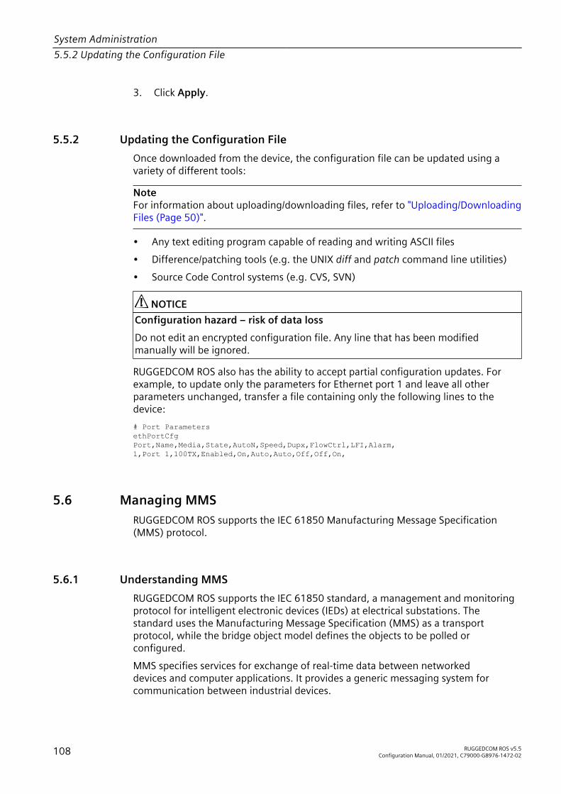
System Administration5.5.2 Updating the Configuration File
3. Click Apply.
5.5.2 Updating the Configuration FileOnce downloaded from the device, the configuration file can be updated using avariety of different tools:
NoteFor information about uploading/downloading files, refer to "Uploading/DownloadingFiles (Page 50)".
• Any text editing program capable of reading and writing ASCII files• Difference/patching tools (e.g. the UNIX diff and patch command line utilities)• Source Code Control systems (e.g. CVS, SVN)
NOTICEConfiguration hazard – risk of data lossDo not edit an encrypted configuration file. Any line that has been modifiedmanually will be ignored.
RUGGEDCOM ROS also has the ability to accept partial configuration updates. Forexample, to update only the parameters for Ethernet port 1 and leave all otherparameters unchanged, transfer a file containing only the following lines to thedevice:# Port ParametersethPortCfgPort,Name,Media,State,AutoN,Speed,Dupx,FlowCtrl,LFI,Alarm,1,Port 1,100TX,Enabled,On,Auto,Auto,Off,Off,On,
5.6 Managing MMSRUGGEDCOM ROS supports the IEC 61850 Manufacturing Message Specification(MMS) protocol.
5.6.1 Understanding MMSRUGGEDCOM ROS supports the IEC 61850 standard, a management and monitoringprotocol for intelligent electronic devices (IEDs) at electrical substations. Thestandard uses the Manufacturing Message Specification (MMS) as a transportprotocol, while the bridge object model defines the objects to be polled orconfigured.MMS specifies services for exchange of real-time data between networkeddevices and computer applications. It provides a generic messaging system forcommunication between industrial devices.
108 RUGGEDCOM ROS v5.5Configuration Manual, 01/2021, C79000-G8976-1472-02

System Administration5.6.1 Understanding MMS
The data model used by MMS is based on logical nodes containing a set of dataobjects. These data objects contain a set of data attributes.
5.6.1.1 MMS Reporting
The IEC 61850 report functionality is used to aggregate a group of data objects fromlogical nodes. These data objects can be sent to the client either as an unsolicitedevent-driven report or a time-based report initiated by the client.The MMS Report is based on the MMS Sessions Allowed parameter, which controlshow many clients can build MMS connections simultaneously to the RUGGEDCOMROS bridge device. For more information about configuring MMS reporting, refer to"Configuring IP Services (Page 84)".
5.6.1.2 Reports/Data Sets
RUGGEDCOM ROS supports the following types of reports/data sets:• LLDPStatus
A time-based report belonging to the logical node LPLD, indicating the LLDPstatus of the device. It includes three data objects: LPLD.RemPortId (remote portidentifier), LPLD.RemChsId (remote port chassis identifier) and LPLD.RemAddr(remote system management address).
• PortLinkStatusAn event-driven report belonging to the logical node LPCP, indicating thedevice's physical port MAU status. It includes the data object LPCP.Mau (mediumattachment unit link status).
• PortStatisticsA time-based report belonging to the logical node LPCP, indicating the device'sphysical port working status. It includes four data objects: LPCP.AutoNgt (Iftrue, the port is auto-negotiation), LPCP.RxCnt (Number of messages receivedsince last reset), LPCP.TxCnt (number of messages sent since last reset) andLPCP.FerPort (frame error rate on the port).
• RSTPStatusAn event-driven report belonging to the logical node LBRI, indicating the RSTPstatus of the device. It includes three data objects: LBRI.RstpRoot (device is RSTProot or not), LBRI.RstpTopoCnt (RSTP topology change count) and LBSP.RstpSt(RSTP port state).
• SystemStatusAn event-driven report belonging to the logical node LPHD, indicating thedevice's working status. It includes two data objects: LPHD.PhyHealth (devicehealth status) and LPHD.PwrSupAlm (device power supply alarm status).
RUGGEDCOM ROS v5.5Configuration Manual, 01/2021, C79000-G8976-1472-02 109

System Administration5.6.2 Viewing a List of Preconfigured MMS Reports
NoteThe files ruggedcom.icd (IEC61850 IED Capability Description of the device) andruggedcom.iid (IEC61850 Instantiated IED Description of the device) list thelogical nodes supported by RUGGEDCOM ROS. For information about downloadingthese files, refer to "Uploading/Downloading Files (Page 50)".
5.6.1.3 Supported Logical Nodes
RUGGEDCOM ROS supports the following logical nodes:
Logical Node DescriptionLLN0 A common logical node providing generic information about the
device as a whole, such as the vendor name and software version.LPHD (Physical Device) A logical node bearing system level information about the physical
device, such as the system name and system description.LBRI (Bridge) A logical node providing spanning tree related information when
the device functions as a bridge, such as RSTP priority and RSTPhello time.
LPCP (Physical CommunicationPort)
A logical node providing port specific information for each physicalinterface on the device, such as port admin status and port autonegotiation status.
LPLD (Port Link Discovery) A logical node providing port specific information related to LLDP(Link Layer Discovery Protocol) for each physical interface on thedevice, such as local port ID and remote port ID.
LBSP (Bridge Spanning tree Port) A logical node providing port specific information related tospanning tree for each physical interface on the device, such asRSTP port state and RSTP edge port status.
LCMF (Communication channelMAC Filtering)
A logical node bearing filtering information related to MulticastMAC addresses, such as the white list of multicast MAC addressesand related VLAN IDs.
LCVF (Communication channelVLAN Filtering)
A logical node providing port specific information related to VLANconfiguration, such as port VLAN ID and CoS priority.
5.6.2 Viewing a List of Preconfigured MMS ReportsTo view a list of MMS Reports pre-configured for the device, navigate toAdministration » Configure MMS. The MMS Report Configuration table appears.This table displays the following information:
Parameter Description
Name Synopsis: A string 32 characters long or [ SysStatus ]Default: SysStatusThe MMS report name (i.e.the name of the data set).
110 RUGGEDCOM ROS v5.5Configuration Manual, 01/2021, C79000-G8976-1472-02

System Administration5.6.3 Configuring an MMS Report
Parameter Description
Status Synopsis: [ Disabled | Enabled ]Default: DisabledThe MMS reporting status initiated or changed by the clientapplication. If any client application enables a data set's reportfunctionality, the status of this data set is 'Enabled'. If no clientapplication enables the data set's report functionality, the status ofthis data set is 'Disabled'.
EventDriven Synopsis: [ False | True ]Default: TrueThe reporting criteria:• True – Reporting is event-driven• False – Reporting is time-based
Period Synopsis: An integer between 30 and 1080 or [ Disabled ]Default: 300The reporting interval, in seconds, for time-based reports. Thisparameter is 'Disabled' for event-driven reports.
For information about modifying an MMS report, refer to "Configuring an MMSReport (Page 111)".
5.6.3 Configuring an MMS ReportWhile all MMS reports are pre-configured on the device, some reports can bemodified to suit the application. This includes enabling/disabling certain reports andchanging the reporting interval.To configuring an MMS report, do the following:1. Navigate to Administration » Configure MMS. The MMS Report Configuration
table appears.2. Select a report. The MMS Report Configuration form appears.3. Configure the following parameter(s) as required:
Parameter Description
Period Synopsis: An integer between 30 and 1080 or [ Disabled ]Default: 300The reporting interval, in seconds, for time-based reports. Thisparameter is 'Disabled' for event-driven reports.
4. Click Apply.
5.6.4 Example: Configuring MMS ReportsThis example demonstrates how to configure the device to generate MMS reports.
RUGGEDCOM ROS v5.5Configuration Manual, 01/2021, C79000-G8976-1472-02 111

System Administration5.6.4 Example: Configuring MMS Reports
The following topology depicts a scenario where four clients on a LAN are being sentMMS reports from RUGGEDCOM ROS:
1
MMS
2
4
4
4
4
3
1 RUGGEDCOM ROS 2 MMS Report 3 LAN 4 Client
Figure 5.1 Topology – MMS
To configure the device to receive MMS reports, do the following:1. On the client side, do the following:
NoteClient configuartion is dependent on the MMS client being used. Refer to theOEM's operating instructions for specific configuration details.
a. Enable or disable specific MMS reports, as desired. For a list of availablereports in RUGGEDCOM ROS, refer to "Reports/Data Sets (Page 109)".
b. Configure the device to provide either event-based or time-based reports, asdesired.
2. In RUGGEDCOM ROS, do the following:a. Configure the number of MMS sessions allowed, to specify how many
clients will be receiving reports. Per the topology, 4 sessions areallowed. For more information about configuring MMS sessions, refer to"Configuring IP Services (Page 84)".
b. If time-based reports are selected on the client side, configure the reporingtime interval as desired. For more information, refer to "Configuring anMMS Report (Page 111)".
112 RUGGEDCOM ROS v5.5Configuration Manual, 01/2021, C79000-G8976-1472-02

System Administration5.6.4 Example: Configuring MMS Reports
3. To verify the configuration, make sure each client receives MMS reports from thedevice per the configuration.
RUGGEDCOM ROS v5.5Configuration Manual, 01/2021, C79000-G8976-1472-02 113

System Administration5.6.4 Example: Configuring MMS Reports
114 RUGGEDCOM ROS v5.5Configuration Manual, 01/2021, C79000-G8976-1472-02
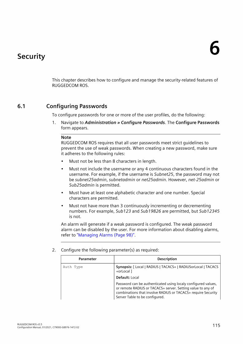
Security 6This chapter describes how to configure and manage the security-related features ofRUGGEDCOM ROS.
6.1 Configuring PasswordsTo configure passwords for one or more of the user profiles, do the following:1. Navigate to Administration » Configure Passwords. The Configure Passwords
form appears.
NoteRUGGEDCOM ROS requires that all user passwords meet strict guidelines toprevent the use of weak passwords. When creating a new password, make sureit adheres to the following rules:• Must not be less than 8 characters in length.• Must not include the username or any 4 continuous characters found in the
username. For example, if the username is Subnet25, the password may notbe subnet25admin, subnetadmin or net25admin. However, net-25admin orSub25admin is permitted.
• Must have at least one alphabetic character and one number. Specialcharacters are permitted.
• Must not have more than 3 continuously incrementing or decrementingnumbers. For example, Sub123 and Sub19826 are permitted, but Sub12345is not.
An alarm will generate if a weak password is configured. The weak passwordalarm can be disabled by the user. For more information about disabling alarms,refer to "Managing Alarms (Page 98)".
2. Configure the following parameter(s) as required:
Parameter Description
Auth Type Synopsis: [ Local | RADIUS | TACACS+ | RADIUSorLocal | TACACS+orLocal ]Default: LocalPassword can be authenticated using localy configured values,or remote RADIUS or TACACS+ server. Setting value to any ofcombinations that involve RADIUS or TACACS+ require SecurityServer Table to be configured.
RUGGEDCOM ROS v5.5Configuration Manual, 01/2021, C79000-G8976-1472-02 115

Security6.1 Configuring Passwords
Parameter DescriptionSettings:• Local – Authentication from the local Password Table.• RADIUS – Authentication using a RADIUS server for net-
work access only (HTTP/HTTPS, SSH, RSH, Telnet). For con-sole access, authenticate from the local Password Table. Iflocal authentication fails, then authenticate using RADIUSserver.
• TACACS+ – Authentication using a TACACS+ server for net-work access only (HTTP/HTTPS, SSH, RSH, Telnet). For con-sole access, authenticate from the local Password Table. Iflocal authentication fails, then authenticate using TACACS+server.
• RADIUSOrLocal – Authentication using RADIUS. If theserver cannot be reached, authenticate from the local Pass-word Table.
• TACACS+OrLocal – Authentication using TACACS+. If theserver cannot be reached, authenticate from the local Pass-word Table.
Guest Username Synopsis: A string 15 characters longDefault: guestRelated password is in field Guest Password; view only, cannotchange settings or run any commands.
Guest Password Synopsis: A string 19 characters longRelated username is in field Guest Username; view only, cannotchange settings or run any commands.
Confirm Guest Password Synopsis: A string 19 characters longRelated username is in field Guest Username; view only, cannotchange settings or run any commands.
Operator Username Synopsis: A string 15 characters longDefault: operatorRelated password is in field Oper Password; cannot changesettings; can reset alarms, statistics, logs, etc.
Operator Password Synopsis: A string 19 characters longRelated username is in field Oper Username; cannot changesettings; can reset alarms, statistics, logs, etc
Confirm Operator Pass word
Synopsis: A string 19 characters longRelated username is in field Oper Username; cannot changesettings; can reset alarms, statistics, logs, etc.
Admin Username Synopsis: A string 15 characters longDefault: adminRelated password is in field Admin Password; full read/writeaccess to all settings and commands.
Admin Password Synopsis: A string 19 characters longRelated username is in field Admin Username; full read/writeaccess to all settings and commands.
116 RUGGEDCOM ROS v5.5Configuration Manual, 01/2021, C79000-G8976-1472-02

Security6.2 Clearing Private Data
Parameter Description
Confirm Admin Password Synopsis: A string 19 characters longRelated username is in field Admin Username; full read/writeaccess to all settings and commands.
Password MinimumLength
Synopsis: An integer between 1 and 17Default: 1Configure the password string minimum length. The newpassword shorter than the minimum length will be rejected.
3. Click Apply.
6.2 Clearing Private DataWhen enabled, during system boot up, a user with serial console access can clearall configuration data and keys stored on the device, and restore all user names andpasswords to factory default settings.To clear private data, do the following:
NoteThe commands used in the following procedure are time-sensitive. If the specifiedtime limits are exceeded before providing the appropriate response, the device willcontinue normal boot up.
1. Connect to the device via the RS-232 serial console port. For more information,refer to "Connecting Directly (Page 43)".
2. Cycle power to the device. As the device is booting up, the following prompt willappear:Press any key to start
3. Within four seconds, press CTRL + r. The access banner will appear, followed bythe command prompt:>
4. Type the following command, then press Enter within 30 seconds:
clear private data
5. When prompted "Do you want to clear private data (Yes/No)?", answer yesand press Enter within five seconds. All configuration and keys in flash will bezeroized. An entry in the event log will be created. Crashlog.txt files (if existing)and syslog.txt files will be preserved. The device will reboot automatically.
6.3 Managing User AuthenticationThis section describes the various methods for authenticating users.
RUGGEDCOM ROS v5.5Configuration Manual, 01/2021, C79000-G8976-1472-02 117

Security6.3.1 Authentication Methods
6.3.1 Authentication MethodsRUGGEDCOM ROS supports Local, RADIUS, TACACS+, RADIUS or Local, and TACAS+or Local server authentication. The chosen method is configurable using the AuthType parameter.For more information about configuring the Auth Type parameter, refer to"Configuring Passwords (Page 115)".The following table shows user access capabilities in different scenarios using thesupported authentication methods.
Access MethodAuth Type AuthenticationMethod/Scenario
Login AccessCredentials Local Console Network (SSH/
Telnet/WebUI)Localauthentication
Local ü üLocal
RADIUS serverauthentication
RADIUS û û
RADIUS serverauthentication
RADIUS ü ü
Localauthentication
Local ü ü
Local ü ûServerunreachable RADIUS û û
Local ü ûWrong Shared KeyRADIUS û û
Local ü û
RADIUS
Wrong DestinationPort RADIUS û û
TACACS+ serverauthentication
TACACS+ ü ü
Localauthentication
Local ü ü
Local ü ûServerunreachable TACACS+ û û
Local ü ûWrong Shared KeyTACACS+ û û
Local ü û
TACACS+
Wrong DestinationPort TACACS+ û û
RADIUS serverauthentication
RADIUS ü ü
Localauthentication
Local û û
Local ü üServerunreachable RADIUS û û
Local û ûWrong Shared KeyRADIUS û û
RADIUSorLocal
Wrong DestinationPort
Local ü ü
118 RUGGEDCOM ROS v5.5Configuration Manual, 01/2021, C79000-G8976-1472-02

Security6.3.2 Configuring User Name Extensions
Access MethodAuth Type AuthenticationMethod/Scenario
Login AccessCredentials Local Console Network (SSH/
Telnet/WebUI)RADIUS û û
TACACS+ serverauthentication
TACACS+ ü ü
Localauthentication
Local û û
Local ü üServerunreachable TACACS+ û û
Local û ûWrong Shared KeyTACACS+ û û
Local ü ü
TACACS+orLocal
Wrong DestinationPort TACACS+ û û
6.3.2 Configuring User Name ExtensionsWhen configured to authenticate users using RADIUS or TACACS+, RUGGEDCOMROS can be configured to add information to each user name important to theauthentication server. This can include the NAS IP address, system name, systemlocation, or any other user-defined text.If the Username Extension parameter is left blank, only the user name will be sentto the authentication server.
NoteExtensions are ignored when IEEE 802.1x port-based authentication is enabled.RUGGEDCOM ROS will remain transparent and not make any changes to theusername. For more information about IEEE 802.1x authentication, refer to "PortSecurity Concepts (Page 125)".
To configure a username extension, do the following:1. Navigate to Administration » Configure Security Server » Configure Common
Security Parameters. The Common Security Parameters form appears.2. Configure the following parameter(s) as required:
Parameter Description
Username Extension Synopsis: A string 127 characters longDefines the format of all user names sent to a RADIUS orTACACS+ server for authentication. A prefix or suffix can beadded to the user name using predefined keywords (wrapped in% delimiters) or user-defined strings.Delimited values include:%Username%: The name associated with the user profile (e.g.admin, oper, etc.)%IPaddr%: The management IP address of the switch that actsas a Network Access Server (NAS).
RUGGEDCOM ROS v5.5Configuration Manual, 01/2021, C79000-G8976-1472-02 119

Security6.3.3 Managing RADIUS Authentication
Parameter Description%SysName%: The system name given to the device.%SysLocation%: The system location given to the device.All pre-defined keywords are case-insensitive.Examples:%Username%@ABC.com%Username%_%SysLocation%If an extension is not defined, only the user name is sent to theauthentication server.
3. Click Apply.
6.3.3 Managing RADIUS AuthenticationRUGGEDCOM ROS can be configured to act as a RADIUS client and forward usercredentials to a RADIUS (Remote Authentication Dial In User Service) server forremote authentication and authorization.RADIUS is a UDP-based protocol used for carrying authentication, authorization andconfiguration information between a Network Access Server (NAS) that desires toauthenticate its links and a shared authentication server. It provides centralizedauthentication and authorization for network access.RADIUS is also widely used in conjunction with the IEEE 802.1X standard for portsecurity using the Extensible Authentication Protocol (EAP).
NoteRADIUS messages are sent as UDP messages. The switch and the RADIUS server mustuse the same authentication and encryption key.
NoteRUGGEDCOM ROS supports both Protected Extensible Authentication Protocol(PEAP) and EAP-MD5. PEAP is more secure and is recommended if available in thesupplicant.
NoteFor more information about the RADIUS protocol, refer to RFC 2865 [http://tools.ietf.org/html/rfc2865].For more information about the Extensible Authentication Protocol (EAP), refer toRFC 3748 [http://tools.ietf.org/html/rfc3748].
120 RUGGEDCOM ROS v5.5Configuration Manual, 01/2021, C79000-G8976-1472-02

Security6.3.3 Managing RADIUS Authentication
6.3.3.1 Configuring the RADIUS Server
NoteFor information about configuring the RADIUS server, refer to the manufacturer'sinstructions of the server being configured.
The Vendor-Specific attribute (or VSA) sent to the RADIUS server as part of theRADIUS request is used to determine the access level from the RADIUS server.This attribute may be configured within the RADIUS server with the followinginformation:
Attribute ValueVendor-Specific Vendor-ID: 15004
Format: StringNumber: 2Attribute: { Guest, Operator, Admin }
NoteIf no access level is received in the response packet from the RADIUS server, access isdenied.
6.3.3.2 Configuring the RADIUS Client on the Device
The RADIUS client can be configured to use two RADIUS servers: a primary server anda backup server. If the primary server is unavailable, the device will automaticallyattempt to connect with the backup server.
NOTICEThe RADIUS client uses only the Password Authentication Protocol (PAP) protocol toverify access. No other authentication protocol is supported.
For CLI commands related to configuring the RADIUS client on the device, refer to"Available CLI Commands (Page 23)".To configure access to either the primary or backup RADIUS servers, do the following:1. Navigate to Administration » Configure Security Server » Configure RADIUS
Server. The RADIUS Server Table appears.2. Select either Primary or Backup from the table. The RADIUS Server form
appears.3. Configure the following parameter(s) as required:
Parameter Description
Server Synopsis: A string 8 characters long or [ Primary ]Default: PrimaryThis field tells whether this configuration is for a Primary or aBackup Server.
RUGGEDCOM ROS v5.5Configuration Manual, 01/2021, C79000-G8976-1472-02 121

Security6.3.4 Managing TACACS+ Authentication
Parameter Description
IP Address Synopsis: Any valid IP addressThe Server IP Address.
Auth UDP Port Synopsis: An integer between 1 and 65535Default: 1812The IP Port on server.
Max Retry Synopsis: An integer between 1 and 10Default: 2The maximum number of times the Authenticator will attemptto contact the authentication server to authenticate the user incase of any failure.
Timeout Synopsis: An integer between 1000 and 120000Default: 10000The amount of time in milliseconds the Authenticator will waitfor a response from the authentication server.
Reachable Synopsis: [ No | Yes ]The status of the server.
Auth Key Synopsis: A string 31 characters longThe authentication key to be shared with server.
Confirm Auth Key Synopsis: A string 31 characters longThe authentication key to be shared with server.
4. Click Apply.
6.3.4 Managing TACACS+ AuthenticationTACACS+ (Terminal Access Controller Access-Control System Plus) is a TCP-basedaccess control protocol that provides authentication, authorization and accountingservices to routers, Network Access Servers (NAS) and other networked computingdevices via one or more centralized servers.
6.3.4.1 Configuring TACACS+
RUGGEDCOM ROS can be configured to use two TACACS+ servers: a primary serverand a backup server. If the primary server is unavailable, the device will automaticallyattempt to connect with the backup server.For CLI commands related to configuring TACACS+, refer to "Available CLI Commands(Page 23)".
122 RUGGEDCOM ROS v5.5Configuration Manual, 01/2021, C79000-G8976-1472-02

Security6.3.4 Managing TACACS+ Authentication
To configure access to either the primary or backup TACACS+ servers, do thefollowing:1. Navigate to Administration » Configure Security Server » Configure TacPlus
Server » Configure TACACS Plus Server. The TACACS Plus Server Tableappears.
2. Select either Primary or Backup from the table. The TACACS Plus Server formappears.
3. Configure the following parameter(s) as required:
Parameter Description
Server Synopsis: A string 8 characters long or [ Primary ]Default: PrimaryThis field tells whether this configuration is for a Primary or aBackup Server.
IP Address Synopsis: Any valid IP addressThe Server IP Address.
Auth TCP Port Synopsis: An integer between 1 and 65535Default: 49The IP Port on server.
Max Retry Synopsis: An integer between 1 and 10Default: 3The maximum number of times the Authenticator will attemptto contact the authentication server to authenticate the user incase of any failure.
Timeout Synopsis: An integer between 1000 and 120000Default: 10000The amount of time in milliseconds the Authenticator will waitfor a response from the authentication server.
Reachable Synopsis: [ No | Yes ]The status of the server.
Auth Key Synopsis: A string 31 characters long or [ mySecret ]Default: mySecretThe authentication key to be shared with server.
Confirm Auth Key Synopsis: A string 31 characters longThe authentication key to be shared with server.
4. Set the privilege levels for each user type (i.e. admin, operator and guest). Formore information, refer to "Configuring User Privileges (Page 124)".
5. Click Apply.
RUGGEDCOM ROS v5.5Configuration Manual, 01/2021, C79000-G8976-1472-02 123

Security6.4 Managing Port Security
6.3.4.2 Configuring User Privileges
Each TACACS+ authentication request includes a priv_lvl attribute that is used togrant access to the device. By default, the attribute uses the following ranges asdefined in the TACACS+ configuration file:• 15 represents the admin access level• 2-14 represents the operator access level• 1 represents the guest access levelThe svcmod CLI command is used to configure user privileges. The values enteredmust correspond with one or more option(s) defined numerically (between 0 and 15)in the TACACS+ configuration file located on the TACACS+ server.For more information about the svcmod CLI command, refer to "Available CLICommands (Page 23)".To configure the privilege levels for each user type, do the following:1. Navigate to Administration » Configure Security Server » Configure TacPlus
Server » Configure TACPLUS Serv Privilege Config. The TACPLUS ServPrivilege Config form appears.
2. Configure the following parameter(s) as required:
Parameter Description
Admin Priv Synopsis: An integer between 0 and 15 or a range (e.g. 2-14)Default: 15Privilege level to be assigned to the user.
Oper Priv Synopsis: An integer between 0 and 15 or a range (e.g. 2-14)Default: 2-14Privilege level to be assigned to the user.
Guest Priv Synopsis: An integer between 0 and 15 or a range (e.g. 2-14)Default: 1Privilege level to be assigned to the user.
3. Click Apply.
6.4 Managing Port SecurityPort security, or port access control, provides the ability to filter or accept traffic fromspecific MAC addresses.Port security works by inspecting the source MAC addresses of received framesand validating them against the list of MAC addresses authorized by the port.Unauthorized frames are filtered and, optionally, the part that received the frame canbe shut down permanently or for a specified period of time. An alarm will be raisedindicating the detected unauthorized MAC address.Frames to unknown destination addresses are flooded through secure ports.
124 RUGGEDCOM ROS v5.5Configuration Manual, 01/2021, C79000-G8976-1472-02

Security6.4.1 Port Security Concepts
6.4.1 Port Security ConceptsThis section describes some of the concepts important to the implementation of portsecurity in RUGGEDCOM ROS.
6.4.1.1 Static MAC Address-Based Authentication
With this method, the switch validates the source MAC addresses of received framesagainst the contents in the Static MAC Address Table.RUGGEDCOM ROS also supports a highly flexible Port Security configuration whichprovides a convenient means for network administrators to use the feature in variousnetwork scenarios.A Static MAC address can be configured without a port number being explicitlyspecified. In this case, the configured MAC address will be automatically authorizedon the port where it is detected. This allows devices to be connected to any secureport on the switch without requiring any reconfiguration.The switch can also be programmed to learn (and, thus, authorize) a pre-configurednumber of the first source MAC addresses encountered on a secure port. This enablesthe capture of the appropriate secure addresses when first configuring MAC address-based authorization on a port. Those MAC addresses are automatically inserted intothe Static MAC Address Table and remain there until explicitly removed by the user.
6.4.1.2 Static MAC Address-Based Authentication in an MRP Ring
When port security is configured on an MRC, the MAC address of the MRM's ringports must be configured in the Static MAC Addresses table for the ring to remainclosed.To allow communication (i.e. ping) between MRP devices in a ring, each device withport security enabled on its MRP ports must contain the MAC addresses of all devicesin the ring in its Static MAC Addresses table.For information about configuring MRP, refer to "Managing the Media RedundancyProtocol (MRP) (Page 218)".For information about configuring a static MAC address, refer to "Adding a StaticMAC Address (Page 159)".
6.4.1.3 IEEE 802.1x Authentication
The IEEE 802.1x standard defines a mechanism for port-based network accesscontrol and provides a means of authenticating and authorizing devices attached toLAN ports.Although IEEE 802.1x is mostly used in wireless networks, this method is alsoimplemented in wired switches.
RUGGEDCOM ROS v5.5Configuration Manual, 01/2021, C79000-G8976-1472-02 125

Security6.4.1 Port Security Concepts
The IEEE 802.1x standard defines three major components of the authenticationmethod: Supplicant, Authenticator and Authentication server. RUGGEDCOM ROSsupports the Authenticator component.
4321
1 Supplicant 2 Authenticator Switch 3 LAN 4 Authentication Server
Figure 6.1 IEEE 802.1x General Topology
NOTICERUGGEDCOM ROS supports Protected Extensible Authentication Protocol (PEAP), EAPTransport Layer Security (EAP-TLS) and EAP-MD5. PEAP and EAP-TLS are more secureand are recommended if available in the supplicant.
IEEE 802.1x makes use of the Extensible Authentication Protocol (EAP), which is ageneric PPP authentication protocol that supports various authentication methods.IEEE 802.1x defines a protocol for communication between the Supplicant and theAuthenticator, referred to as EAP over LAN (EAPOL).RUGGEDCOM ROS communicates with the Authentication Server using EAP overRADIUS.
NoteThe switch supports authentication of one host per port.
NoteIf the host’s MAC address is configured in the Static MAC Address Table, it will beauthorized, even if the host authentication is rejected by the authentication server.
6.4.1.4 IEEE 802.1X Authentication with MAC Address-Based Authentication
This method, also referred to as MAB (MAC-Authentication Bypass), is commonlyused for devices, such as VoIP phones and Ethernet printers, that do not supportthe 802.1x protocol. This method allows such devices to be authenticated using thesame database infrastructure as that used in 802.1x.IEEE 802.1x with MAC-Authentication Bypass works as follows:1. The device connects to a switch port.
126 RUGGEDCOM ROS v5.5Configuration Manual, 01/2021, C79000-G8976-1472-02

Security6.4.1 Port Security Concepts
2. The switch learns the device MAC address upon receiving the first frame fromthe device (the device usually sends out a DHCP request message when firstconnected).
3. The switch sends an EAP Request message to the device, attempting to start802.1X authentication.
4. The switch times out while waiting for the EAP reply, because the device doesnot support 802.1x.
5. The switch sends an authentication message to the authentication server, usingthe device MAC address as the username and password.
6. The switch authenticates or rejects the device according to the reply from theauthentication server.
6.4.1.5 Restricted VLANs
RUGGEDCOM ROS allows users to configure 802.1X ports in Guest VLAN orQuarantine VLAN mode, to limit services to clients when IEEE 802.1x or 802.1x/MAC-Auth authentication fails. For example, an administrator may choose to restrictaccess to only printers, internet or specific dowloads for unauthenticated users.When a client fails to authenticate after a specified number of attempts, theconfigured port will switch automatically to either the Quarantine VLAN or the GuestVLAN, depending on the port security mode and the client’s security setup:• If a connected device supports 802.1x security but has failed authentication, the
port will switch to the Quarantine VID.• If a connected device is 802.1X incompatible and port security is set to 802.1X,
the port will become a member of the Guest VLAN after the authentication timesout.
An SNMP trap will be generated when a client device is placed in the Quarantine orGuest VLAN. An alarm will warn the user about the change in port status.When a port is a member of the Quarantine VLAN, ROS will attempt to re-authenticate the client at configured intervals. Clients who fail to authenticateremain in the Quarantine VLAN until successfully re-authenticated, or until thephysical link goes down. If re-authentication fails, the port remains a member of theQuarantine VLAN.There are no re-authentication attempts for clients in Guest VLANs. When an EAPOLStart frame is received from the client, the port will revert to the unauthenticatedstate, removing the client’s access from the Guest VLAN to continue with theauthentication process.The following table outlines Quarantine vs Guest port placement behavior followingauthentication failure:
Port Security Mode Client Security Placement FollowingAuthentication Failure
802.1x Capable Quarantine VLAN802.1x802.1x Not Capable Guest VLAN
RUGGEDCOM ROS v5.5Configuration Manual, 01/2021, C79000-G8976-1472-02 127

Security6.4.2 Viewing a List of Authorized MAC Addresses
Port Security Mode Client Security Placement FollowingAuthentication Failure
802.1x Capable Quarantine VLAN802.1x/MAC-Auth802.1x Not Capable Quarantine VLAN
For more information about configuring a Guest/Quarantine VLAN, refer to"Configuring Port Security (Page 129)".
6.4.1.6 Assigning VLANS with Tunnel Attributes
RUGGEDCOM ROS supports assigning a VLAN to the authorized port using tunnelattributes, as defined in RFC 3580 [http://tools.ietf.org/html/rfc3580], when the PortSecurity mode is set to 802.1x or 802.1x/MAC-Auth.In some cases, it may be desirable to allow a port to be placed into a particular VLAN,based on the authentication result. For example:• To allow a particular device, based on its MAC address, to remain on the same
VLAN as it moves within a network, configure the switches for 802.1X/MAC-Authmode
• To allow a particular user, based on the user’s login credentials, to remain onthe same VLAN when the user logs in from different locations, configure theswitches for 802.1X mode
If the RADIUS server wants to use this feature, it indicates the desired VLAN byincluding tunnel attributes in the Access-Accept message. The RADIUS server usesthe following tunnel attributes for VLAN assignment:• Tunnel-Type=VLAN (13)• Tunnel-Medium-Type=802• Tunnel-Private-Group-ID=VLANIDNote that VLANID is 12-bits and takes a value between 1 and 4094, inclusive. TheTunnel-Private-Group-ID is a string as defined in RFC 2868 [http://tools.ietf.org/html/rfc2868], so the VLANID integer value is encoded as a string.If the tunnel attributes are not returned by the authentication server, the VLANassigned to the switch port remains unchanged.
6.4.2 Viewing a List of Authorized MAC AddressesTo view a list of static MAC addresses learned from secure ports, navigate toNetwork Access Control » Port Security » View Authorized MAC Addresses. TheAuthorized MAC Addresses table appears.
NoteOnly MAC addresses authorized on a static MAC port(s) are shown. MAC addressesauthorized with IEEE 802.1X are not shown.
128 RUGGEDCOM ROS v5.5Configuration Manual, 01/2021, C79000-G8976-1472-02

Security6.4.3 Configuring Port Security
This table displays the following information:
Parameter Description
Port Synopsis: 1/1 to maximum port numberPort on which MAC address has been learned.
MAC Address Synopsis: ##-##-##-##-##-## where ## ranges 0 to FFAuthorized MAC address learned by the switch.
VID Synopsis: An integer between 0 and 65535VLAN Identifier of the VLAN upon which the MAC address operates.
Sticky Synopsis: [ No | Yes ]This describes whether the authorized MAC address/Device canmove to another port or not:• Yes – authorized MAC address/Device cannot move to a differ-
ent switch port• No – authorized MAC address/Device may move to another
switch port
If a MAC address is not listed, do the following:• Configure port security. For more information, refer to "Configuring Port Security
(Page 129)".• Configure IEEE 802.1X. For more information, refer to "Configuring IEEE 802.1X
(Page 131)".
6.4.3 Configuring Port SecurityTo configure port security, do the following:1. Navigate to Network Access Control » Port Security » Configure Ports
Security. The Ports Security table appears.2. Select an Ethernet port. The Ports Security form appears.3. Configure the following parameter(s) as required:
Parameter Description
Port Synopsis: 1/1 to maximum port numberDefault: 1The port number as seen on the front plate silkscreen of thedevice.
Security Synopsis: [ Off | Static MAC | 802.1X | 802.1x/MAC-Auth ]Default: OffEnables or disables the port's security feature. Two types of portaccess control are available:• Static MAC address-based. With this method, authorized
MAC address(es) should be configured in the Static MACAddress Table. If some MAC addresses are not known inadvance (or it is not known to which port they will be con-
RUGGEDCOM ROS v5.5Configuration Manual, 01/2021, C79000-G8976-1472-02 129
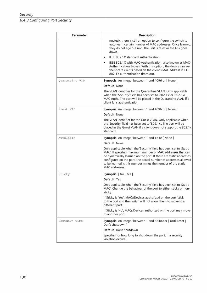
Security6.4.3 Configuring Port Security
Parameter Descriptionnected), there is still an option to configure the switch toauto-learn certain number of MAC addresses. Once learned,they do not age out until the unit is reset or the link goesdown.
• IEEE 802.1X standard authentication.• IEEE 802.1X with MAC-Authentication, also known as MAC-
Authentication Bypass. With this option, the device can au-thenticate clients based on the client’s MAC address if IEEE802.1X authentication times out.
Quarantine VID Synopsis: An integer between 1 and 4096 or [ None ]Default: NoneThe VLAN identifier for the Quarantine VLAN. Only applicablewhen the 'Security' field has been set to '802.1x' or ‘802.1x/MAC-Auth’. The port will be placed in the Quarantine VLAN if aclient fails authentication.
Guest VID Synopsis: An integer between 1 and 4096 or [ None ]Default: NoneThe VLAN identifier for the Guest VLAN. Only applicable whenthe 'Security' field has been set to '802.1x'. The port will beplaced in the Guest VLAN if a client does not support the 802.1xstandard.
Autolearn Synopsis: An integer between 1 and 16 or [ None ]Default: NoneOnly applicable when the 'Security' field has been set to 'StaticMAC'. It specifies maximum number of MAC addresses that canbe dynamically learned on the port. If there are static addressesconfigured on the port, the actual number of addresses allowedto be learned is this number minus the number of the staticMAC addresses.
Sticky Synopsis: [ No | Yes ]Default: YesOnly applicable when the 'Security' field has been set to 'StaticMAC'. Change the behaviour of the port to either sticky or non-sticky.If Sticky is 'Yes', MACs/Devices authorized on the port 'stick'to the port and the switch will not allow them to move to adifferent port.If Sticky is 'No', MACs/Devices authorized on the port may moveto another port.
Shutdown Time Synopsis: An integer between 1 and 86400 or [ Until reset |Don't shutdown ]Default: Don't shutdownSpecifies for how long to shut down the port, if a securityviolation occurs.
130 RUGGEDCOM ROS v5.5Configuration Manual, 01/2021, C79000-G8976-1472-02

Security6.4.4 Configuring IEEE 802.1X
Parameter Description
Status Synopsis: A string 31 characters longDescribes the security status of the port.
NoteThere are a few scenarios in which static MAC addresses can move:• When the link is up/down on a non-sticky secured port• When traffic switches from or to a non-sticky secured port
NoteTraffic is lost until the source MAC Address of the incoming traffic is authorizedagainst the static MAC address table.
4. Click Apply.
6.4.4 Configuring IEEE 802.1XTo configure IEEE 802.1X port-based authentication, do the following:1. Navigate to Network Access Control » Port Security » Configure 802.1X. The
802.1X Parameters table appears.2. Select an Ethernet port. The 802.1X Parameters form appears.3. Configure the following parameter(s) as required:
Parameter Description
Port Synopsis: 1/1 to maximum port numberDefault: 1The port number as seen on the front plate silkscreen of thedevice.
txPeriod Synopsis: An integer between 1 and 65535Default: 30The time to wait for the Supplicant's EAP Response/Identitypacket before retransmitting an EAP Request/Identity packet.
quietPeriod Synopsis: An integer between 0 and 65535Default: 60The period of time not to attempt to acquire a Supplicant afterthe authorization session failed.
reAuthEnabled Synopsis: [ No | Yes ]Default: NoEnables or disables periodic re-authentication.
RUGGEDCOM ROS v5.5Configuration Manual, 01/2021, C79000-G8976-1472-02 131

Security6.5 Managing SSH/SSL Keys and Certificates
Parameter Description
reAuthPeriod Synopsis: An integer between 60 and 86400Default: 3600The time between periodic re-authentication of the Supplicant.
reAuthMax Synopsis: An integer between 1 and 10Default: 2The number of re-authentication attempts that are permittedbefore the port becomes unauthorized.
suppTimeout Synopsis: An integer between 1 and 300Default: 30The time to wait for the Supplicant's response to theauthentication server's EAP packet.
serverTimeout Synopsis: An integer between 1 and 300Default: 30The time to wait for the authentication server's response to theSupplicant's EAP packet.
maxReq Synopsis: An integer between 1 and 10Default: 2The maximum number of times to retransmit theauthentication server's EAP Request packet to the Supplicantbefore the authentication session times out.
4. Click Apply.
6.5 Managing SSH/SSL Keys and CertificatesRUGGEDCOM ROS uses X.509v3 certificates and keys to establish secure connectionsfor remote logins (SSH) and Web access (SSL).
NOTICESecurity hazard – risk of unauthorized access and/or exploitationSiemens recommends the following actions before commissioning the device:• Replace the factory-provisioned, self-signed SSL certificate with one signed by a
trusted Certificate Authority (CA)• Configure the SSH client to use diffie-hellman-group14-sha1 or better
NoteOnly admin users can write certificates and keys to the device.
Each RUGGEDCOM ROS device is shipped with a unique ECC 256 self-signedSSL certificate and an RSA 2048 SSH host key pair that are generated at andprovisioned by the factory. The administrator may upload a new certificate and keysto the system at any time, which will overwrite the existing ones. In addition, CLI
132 RUGGEDCOM ROS v5.5Configuration Manual, 01/2021, C79000-G8976-1472-02
Security6.5 Managing SSH/SSL Keys and Certificates
commands are available to regenerate SSL certificate and key pair as well as the SSHhost key pair.There are three types of certificates and keys used in RUGGEDCOM ROS:
NoteNetwork exposure to a ROS unit operating with the default keys, although alwaysonly temporary by design, should be avoided. The best way to reduce or eliminatethis exposure is to provision user-created certificate and keys as quickly as possible,and preferably before the unit is placed in network service.
NoteThe default certificate and keys are common to all RUGGEDCOM ROS versionswithout a certificate or key files. That is why it is important to either allow the keyauto-generation to complete or to provision custom keys. In this way, one has atleast unique, and at best, traceable and verifiable keys installed when establishingsecure communication with the unit.
• DefaultA default certificate and SSL/SSH keys are built in to RUGGEDCOM ROS and arecommon across all RUGGEDCOM ROS units sharing the same firmware image. Inthe event that valid SSL certificate or SSL/SSH key files are not available on thedevice (as is usually only the case when upgrading from an old ROS version thatdoes not support user-configurable keys and therefore does was not shippedwith unique, factory-generated keys), the default certificate and keys are putinto service temporarily so that SSH and SSL (HTTPS) sessions can be served untilgenerated or provisioned keys are available.
• Auto-GeneratedIf a default SSL certificate and SSL/SSH keys are in use, RUGGEDCOM ROSimmediately begins to generate a unique certificate and SSL/SSH keys for thedevice in the background. If a custom certificate and keys are loaded while auto-generated certificates and keys are being generated, the generator will abort andthe custom certificate and keys and will be used.
• Custom (Recommended)Custom certificates and keys are the most secure option. They give the usercomplete control over certificate and key management, allow for the provisionof certificates signed by a public or local certificate authority, enable strictlycontrolled access to private keys, and allow authoritative distribution of SSLcertificates, any CA certificates, and public SSH keys.
NoteThe RSA or EC private key corresponding to the SSL certificate must be appended tothe certificate in the ssl.crt file.
RUGGEDCOM ROS v5.5Configuration Manual, 01/2021, C79000-G8976-1472-02 133

Security6.5.1 SSL Certificates
6.5.1 SSL CertificatesRUGGEDCOM ROS supports SSL certificates that conform to the followingspecifications:• X.509 v3 digital certificate format• PEM format• For RUGGEDCOM ROS Controlled verions: RSA key pair, 1024, 2048 or 3072 bits;
or NIST P-256, P-384 or P-521• For RUGGEDCOM ROS Non-Controlled (NC) verions: RSA key pair, 512 to 2048
bits
NoteElliptic curve keys smaller than P-256 bits in length are not supported.
NoteRSA keys smaller than 2048 bits in length are not recommended.
Two standard PEM files are required: the SSL certificate and the corresponding RSAprivate key file. These are concatenated into the resulting ssl.crt file, which maythen be uploaded to RUGGEDCOM ROS. For more information about transferringfiles between the device and a host computer, refer to "Uploading/Downloading Files(Page 50)".While RUGGEDCOM ROS is capable of using self-signed certificates created using thesslkeygen command, Siemens recommends using an X.509 certificate issued by anorganization's own Certificate Authority (CA).
6.5.2 SSH Host Key
NoteSSH is not supported in Non-Controlled (NC) versions of RUGGEDCOM ROS.
Controlled versions of RUGGEDCOM ROS support SSH public/private key pairs thatconform to the following specifications:• PEM format• DSA key pair, 1024, 2048 or 3072 bits in length• RSA key pair, 1024, 2048 or 3072 bits in length
NoteDSA or RSA key generation times increase depending on the key length. 1024 bitRSA keys take less than 5 minutes to generate on a lightly loaded unit, whereas 2048bit keys may take significantly longer. A typical modern PC system, however, cangenerate these keys in seconds.
134 RUGGEDCOM ROS v5.5Configuration Manual, 01/2021, C79000-G8976-1472-02

Security6.5.3 Managing SSH Public Keys
The following (bash) shell script fragment uses the ssh-keygen command lineutility to generate a 2048 bit RSA key suitable for use in RUGGEDCOM ROS . Theresulting ssh.keys file may then be uploaded to RUGGEDCOM ROS:# RSA key size:BITS=2048
# Make an SSH key pair:ssh-keygen -t RSA -b $BITS -N '' -f ssh.keys
For an example of an SSH key generated by RUGGEDCOM ROS, refer to "Certificateand Key Examples (Page 138)".
6.5.3 Managing SSH Public KeysRUGGEDCOM ROS allows admin users to list, add and delete SSH public keys. Publickeys are added as non-volatile storage (i.e. flash) files on RUGGEDCOM ROS devices,and are retrieved at the time of SSH client authentication.
6.5.3.1 Public Key Requirements
Public keys are stored in a flash file, called sshpub.keys. The sshpub.keys file consistsof ssh user public key entries. Similar to the config.csv file, each entry must beseparated by an empty line. An entry has two components. They are, in sequence:• Header• KeyThe header contains the parameters of the entry, separated by comma. Theparameters are, in sequence:• ID: A number between 0 and 9999• Entry type: UserKey• Access Level: (Admin, Operator or Guest)• Revocation Status: active/inactive (always active for keys)• User Name: This is the client's user name (not the RUGGEDCOM ROS user name).
This will be used by clients to later SSH into the RUGGEDCOM ROS device.The key must be in RFC4716 format, or in PEM format with any of the followingheader and footer lines:-----BEGIN PUBLIC KEY----------END PUBLIC KEY-----
-----BEGIN SSH2 PUBLIC KEY----------END SSH2 PUBLIC KEY-----
-----BEGIN RSA PUBLIC KEY----------END RSA PUBLIC KEY-----
The following is an example of a valid entry in the sshpub.keys file in PEM format:1,userkey,admin,active,alice
RUGGEDCOM ROS v5.5Configuration Manual, 01/2021, C79000-G8976-1472-02 135
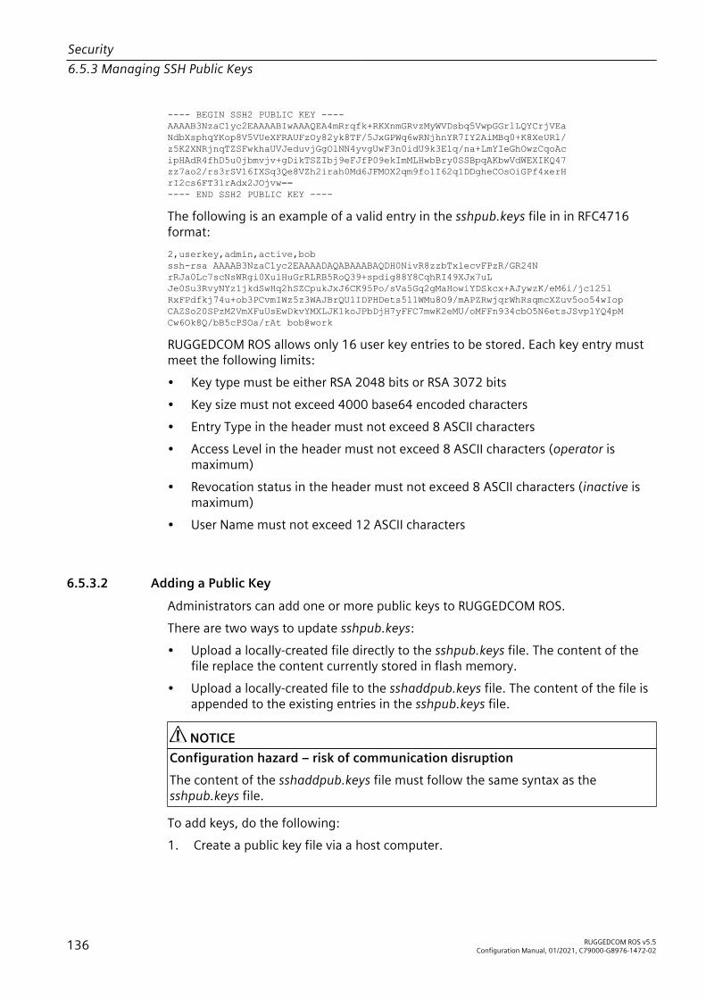
Security6.5.3 Managing SSH Public Keys
---- BEGIN SSH2 PUBLIC KEY ----AAAAB3NzaC1yc2EAAAABIwAAAQEA4mRrqfk+RKXnmGRvzMyWVDsbq5VwpGGrlLQYCrjVEaNdbXsphqYKop8V5VUeXFRAUFzOy82yk8TF/5JxGPWq6wRNjhnYR7IY2AiMBq0+K8XeURl/z5K2XNRjnqTZSFwkhaUVJeduvjGgOlNN4yvgUwF3n0idU9k3E1q/na+LmYIeGhOwzCqoAcipHAdR4fhD5u0jbmvjv+gDikTSZIbj9eFJfP09ekImMLHwbBry0SSBpqAKbwVdWEXIKQ47zz7ao2/rs3rSV16IXSq3Qe8VZh2irah0Md6JFMOX2qm9fo1I62q1DDgheCOsOiGPf4xerHrI2cs6FT31rAdx2JOjvw==---- END SSH2 PUBLIC KEY ----
The following is an example of a valid entry in the sshpub.keys file in in RFC4716format:2,userkey,admin,active,bobssh-rsa AAAAB3NzaC1yc2EAAAADAQABAAABAQDH0NivR8zzbTxlecvFPzR/GR24N rRJa0Lc7scNsWRgi0XulHuGrRLRB5RoQ39+spdig88Y8CqhRI49XJx7uL Je0Su3RvyNYz1jkdSwHq2hSZCpukJxJ6CK95Po/sVa5Gq2gMaHowiYDSkcx+AJywzK/eM6i/jc125l RxFPdfkj74u+ob3PCvmIWz5z3WAJBrQU1IDPHDets511WMu8O9/mAPZRwjqrWhRsqmcXZuv5oo54wIop CAZSo20SPzM2VmXFuUsEwDkvYMXLJK1koJPbDjH7yFFC7mwK2eMU/oMFFn934cbO5N6etsJSvplYQ4pM Cw6Ok8Q/bB5cPSOa/rAt bob@work
RUGGEDCOM ROS allows only 16 user key entries to be stored. Each key entry mustmeet the following limits:• Key type must be either RSA 2048 bits or RSA 3072 bits• Key size must not exceed 4000 base64 encoded characters• Entry Type in the header must not exceed 8 ASCII characters• Access Level in the header must not exceed 8 ASCII characters (operator is
maximum)• Revocation status in the header must not exceed 8 ASCII characters (inactive is
maximum)• User Name must not exceed 12 ASCII characters
6.5.3.2 Adding a Public Key
Administrators can add one or more public keys to RUGGEDCOM ROS.There are two ways to update sshpub.keys:• Upload a locally-created file directly to the sshpub.keys file. The content of the
file replace the content currently stored in flash memory.• Upload a locally-created file to the sshaddpub.keys file. The content of the file is
appended to the existing entries in the sshpub.keys file.
NOTICEConfiguration hazard – risk of communication disruptionThe content of the sshaddpub.keys file must follow the same syntax as thesshpub.keys file.
To add keys, do the following:1. Create a public key file via a host computer.
136 RUGGEDCOM ROS v5.5Configuration Manual, 01/2021, C79000-G8976-1472-02

Security6.5.3 Managing SSH Public Keys
2. Transfer the public key file to the device using SFTP or Xmodem. For moreinformation about transferring files, refer to "Uploading/Downloading Files (Page50)".
3. Log in to the device as an admin user and access the CLI shell. For moreinformation about accessing the CLI shell, refer to "Using the Command LineInterface (Page 23)".
4. Check the system log to make sure the files were properly transferred. For moreinformation about viewing the system log, refer to "Viewing Local and SystemLogs (Page 56)".
6.5.3.3 Viewing a List of Public Keys
Admin users can view a list of existing public keys on the device.To view public keys, do the following:1. Log in to the device as an admin user and access the CLI shell. For more
information about accessing the CLI shell, refer to "Using the Command LineInterface (Page 23)".
2. At the CLI prompt, type:
sshpubkey list
A list of public keys will appear, including their key ID, access level, revocationstatus, user name and key fingerprint.
6.5.3.4 Updating a Public Key
Admin users can update public keys.To update public keys, do the following:1. Log in to the device as an admin user and access the CLI shell. For more
information about accessing the CLI shell, refer to "Using the Command LineInterface (Page 23)".
2. At the CLI prompt, type:
sshpubkey list
A list of public keys will appear, including their key ID, access level, revocationstatus, user name and key fingerprint.
3. Type the following commands to update the public keys:
Command Descriptionsshpubkey update_id{ current_ID }{ new_ID }
Updates the ID of user public key.
NoteThe user public key ID must be a number between 0 and 9999.
RUGGEDCOM ROS v5.5Configuration Manual, 01/2021, C79000-G8976-1472-02 137

Security6.5.4 Certificate and Key Examples
Command Description• { current_ID } is the ID currently assigned to the public
key• { new_ID } is the ID that will be used to identify the
public key going forwardsshpubkey update_al{ AL }
Updates the access level of a user public key.• { AL } is the access level (admin, operator or guest) of the
public key to be updatedsshpubkey update_rs{ RS }
Updates the revocation status (active, inactive) of a user publickey.• { RS } is the revocation status of the public key to be
updatedsshpubkey update_un{ UN }
Updates the user name of a user public key.• { UN } is the user name of the public key to be updated
6.5.3.5 Deleting a Public Key
Admin users can delete one or more public keys.To delete a public key, do the following:1. Log in to the device as an admin user and access the CLI shell. For more
information about accessing the CLI shell, refer to "Using the Command LineInterface (Page 23)".
2. At the CLI prompt, type:
sshpubkey list
A list of public keys will appear, including access level, revocation status, username and key fingerprint.
3. Type the following commands to delete the public key(s):
Command Descriptionsshpubkey remove{ ID }
Removes a key from the non-volatile storage.• { ID } is the ID of the public key to be removed
6.5.4 Certificate and Key ExamplesFor SSL, certificates must meet the requirements outlined in "SSL Certificates (Page134)".The certificate and keys must be combined in a single ssl.crt file and uploaded tothe device.The following is an example of a combined SSL certificate and key:-----BEGIN CERTIFICATE-----MIIC9jCCAl+gAwIBAgIJAJh6rrehMt3iMA0GCSqGSIb3DQEBBQUAMIGuMQswCQYDVQQGEwJDQTEQMA4GA1UECBMHT250YXJpbzEQMA4GA1UEBxMHQ29uY29yZDESMBAGA1UEChMJUnVnZ2VkY29tMRkwFwYDVQQLExBDdXN0b21lciBTdXBwb3J0MSYwJAYD
138 RUGGEDCOM ROS v5.5Configuration Manual, 01/2021, C79000-G8976-1472-02

Security6.5.4 Certificate and Key Examples
VQQDEx1XUy1NSUxBTkdPVkFOLlJVR0dFRENPTS5MT0NBTDEkMCIGCSqGSIb3DQEJARYVc3VwcG9ydEBydWdnZWRjb20uY29tMB4XDTEyMTAyMzIxMTA1M1oXDTE3MTAyMjIxMTA1M1owgZwxCzAJBgNVBAYTAlVTMRAwDgYDVQQIEwdPbnRhcmlvMRAwDgYDVQQHEwdDb25jb3JkMRIwEAYDVQQKEwlSdWdnZWRDb20xGTAXBgNVBAsTEEN1c3RvbWVyIFN1cHBvcnQxFDASBgNVBAMTCzE5Mi4xNjguMS4yMSQwIgYJKoZIhvcNAQkBFhVTdXBwb3J0QHJ1Z2dlZGNvbS5jb20wgZ8wDQYJKoZIhvcNAQEBBQADgY0AMIGJAoGBALfE4eh2aY+CE3W5a4Wz1Z1RGRP02COHt153wFFrU8/fFQXNhKlQirlAHbNTRSwcTR8ZFapivwYDivn0ogOGFXknYP90gv2oIaSVY08FqZkJW77g3kzkv/8Zrw3mW/cBsZJ8SyKLIDfy401HkHpDOle5NsQFSrziGUPjAOIvvx4rAgMBAAGjLDAqMAkGA1UdEwQCMAAwHQYDVR0OBBYEFER0utgQOifnrflnDtsqNcnvRB0XMA0GCSqGSIb3DQEBBQUAA4GBAHtBsNZuh8tB3kdqR7Pn+XidCsD70YnI7w0tiy9yiRRhARmVXH8h5Q1rOeHceri3JFFIOxIxQt4KgCUYJLu+c9Esk/nXQQar3zR7IQCt0qOABPkviiY8c3ibVbhJjLpR2vNW4xRAJ+HkNNtBOg1xUlp4vOmJ2syYZR+7XAy/OP/S-----END CERTIFICATE----------BEGIN RSA PRIVATE KEY-----MIIEpQIBAAKCAQEAn3UT94ZjlmBjygLXaA21ULum7EDmgsvFvg2tKYyaMj1en5UWx172GvlDLUm5EwGmcG9u6DyuO3wOyv/taD1OUFkZA1W7cPu9NjeTtZjIQCx33xSU1d6INMi2oOzwJmWzqwqIkIgy0uMdw78be4n7359U0UOOEtCStOmUfdw34jv6c38J8sb+lC/FktX8Eilka4mDr07tf/ivC2kdwpPlGZIKt/xjcwjOsNHIBSfqbEbg5mO39OAPqsPRWKhBQZ6rM8aqEQjGPlrSTTNHrxO/CYVxAh0gtz+6qUytL3zi7Z9P7EzDH8V8qNdXRNN0w5hsh2A5ZJj6+cbQJm0JHQeOowIDAQABAoIBAH2zXqUfBLyTibbC3KoDPG7DLwhI9S4gkuaKg3ogg6GdLU2hys4p9to2qxU1a7cm8tzpi0V6KGNuHX87lxw4T9cZFZXCbLvZR0RJNaDPKvUj2O87m0SpYzgxDX74qSuruqHX8OX26BHExj78FR8jHDIhuUwp9AKy9yO0isFY65jkLov6tdRpNy5A+QrGyRVBilCIT6YFYKSzEEI86+29FkLtX+ERjqxJs+aGHyEPDWE4Zy7dBsuTk1Fwz8F6/rOz4PS2pNQXc2sWmomnmuQXv0hwKY5gMcovCkC3y/op3kNuc/3qeBHjeCBYEMLR0o25hZHGrKOrQahFsy+RV48sgIECgYEA0H66Ijfcc7NpgKOQwyvCt9/uhRZ3RkeABoSBLb/wYfQjw4pMadqrRMMzVPzOLC459Giv4m8GeikNPl53rYdTCRmd/t1nZClU/UQKhgj+RRt4xY2cJNsgj2CTZDr5SJO8H957K1IbvN5mxdsWZuDc5dtf0wBMIaCJoXR/iDMcf2MCgYEAw8oKDkpz9PdhGkbTE0ARLeUv7okelBkfDIGgucXBFHUElHAGe+XLF5dMppmzRDHXi2NGgSNPJsDOlgSyLJjKX7HapYeAJWm91w5kJEX+oERr1EnEPWPvOHI+OW5DjM6eR1s9xRJ87e3ymgLIF7G5rmf0p3OlnVvCaQvIVYTB98ECgYEAl+sPI2nCp0eeY05LZ/rV6fcwLCdfh4UHwzf/jF9j/2vON2fpH+RmkTcOiymd7NFOB0nUhtBRTufkr4JT/8wv89yHpDKdaH05YUWXyWx6Ic7PpFr34F8OjYpYO1tBUuHa3PnWk41Dis4e4qIt446LRq0fWHbKAmKghlWFq69aX3MCgYEArKU2JM/mXHbfe0pEyk7OV0gn8hGbk0Brrp2H2wjUb3OYbEQ0k4BYjB7wimAyQcoppVIPU8SNAUE3afYOH2FD4wp0IU7Q4yzRKBgamhnWpABxjSrXDsNWqNGkqQPgMQPpcka0u1jILQ6LxN77Dlm7wF0O0bIash292t928mI0oIECgYEAql8/uRHGtwSk64rXWXI+uq+x4ewwZkVc+mMmJ0yCMuQsOzbQTxhxv9GEi3xsFbNazGCx4b56+/6Bi6gf7aH+NeK2+7C4ddlpHGEawoEcW1CW8hRQ2brpvWgC+m5nmQ2SaYGzlilzZVK3JE6qOZ/AG8k+ZEG9tsvakMliG1SoJXk=-----END RSA PRIVATE KEY-----
For SSH, DSA or RSA host key pairs must meet the requirements outlined in "SSH HostKey (Page 134)".The following is an example of a PEM formatted SSH key:-----BEGIN DSA PRIVATE KEY-----MIIBuwIBAAKBgQD0gcGbXx/rrEMu2913UW4cYo1OlcbnuUz7OZyd2mBLDx/GYbD8X5TnRcMraJ0RuuGK+chqQJW5k3zQmZa/BS6q9U7wYwIAx8JSxxpwfPfl/t09VwKGrtSJIMpLRoDq3qEwEVyR4kDUo4LFQDsljtiyhcz1n6kd6gqsd5Xu1vdh4wIVANXbSBi97GmZ6/9f4UCvIIBtXLEjAoGAAfmhkcCCEnRJitUTiCE+MurxdFUr3mFs/d314cUDaLStQEhYYmx5dbFdQuapl4Y32B7lZQkohi5q1T1iUAa40/nUnJx1hFvblkYT8DLwxcuDAaiu0VqsaPtJ+baL2dYNp96tFisj/475PEEWBGbP6GSe5kKa1Zdgwuie9LyPb+ACgYBv856v5tb9UVG5+tX5Crfv/Nd8FFlSSFKmVWW3yzguhHajg2LQg8UUsm1/zPSwYQ0SbQ9aOAJnpLc2HUkK0lji/0oKVI7y9MMc4B+bGu4W4OnryP7oFpnpYYHt5PJY+zvLw/Wa+u3NOVFHkF1tGyfVBMXeV36nowPo+wrVMolAEgIVALLTnfpWmaV6uh6RxeE1d4XoxSg2-----END DSA PRIVATE KEY-----
RUGGEDCOM ROS v5.5Configuration Manual, 01/2021, C79000-G8976-1472-02 139

Security6.5.4 Certificate and Key Examples
140 RUGGEDCOM ROS v5.5Configuration Manual, 01/2021, C79000-G8976-1472-02
Layer 2 7This chapter describes the Layer 2, or Data Link Layer (DLL), features of RUGGEDCOMROS.
7.1 Managing Virtual LANsA Virtual Local Area Network (VLAN) is a group of devices on one or more LANsegments that communicate as if they were attached to the same physicalLAN segment. VLANs are extremely flexible because they are based on logicalconnections, rather than physical connections.When VLANs are introduced, all traffic in the network must belong to one VLANor another. Traffic on one VLAN cannot pass to another, except through an inter-network router or Layer 3 switch.VLANs are created in two ways:• Explicitly
Static VLANs can be created in the switch. For more information about staticVLANs, refer to "Managing Static VLANs (Page 153)".
• ImplicitlyWhen a VLAN ID (VID) is set for a port-based VLAN, static MAC address or IPinterface, an appropriate VLAN is automatically created if it does not yet exist.
For more information about VLANs, refer to "VLAN Concepts (Page 141)".
7.1.1 VLAN ConceptsThis section describes some of the concepts important to the implementation ofVLANs in RUGGEDCOM ROS.
7.1.1.1 Tagged vs. Untagged Frames
VLAN tags identify frames as part of a VLAN network. When a switch receives a framewith a VLAN (or 802.1Q) tag, the VLAN identifier (VID) is extracted and the frame isforwarded to other ports on the same VLAN.When a frame does not contain a VLAN tag, or contains an 802.1p (prioritization) tagthat only has prioritization information and a VID of 0, it is considered an untaggedframe.
RUGGEDCOM ROS v5.5Configuration Manual, 01/2021, C79000-G8976-1472-02 141
Layer 27.1.1 VLAN Concepts
7.1.1.2 Native VLAN
Each port is assigned a native VLAN number, the Port VLAN ID (PVID). When anuntagged frame ingresses a port, it is associated with the port's native VLAN.By default, when a switch transmits a frame on the native VLAN, it sends the frameuntagged. The switch can be configured to transmit tagged frames on the nativeVLAN.
7.1.1.3 The Management VLAN
By default, all management traffic belongs to the management VLAN. Auxiliarymanagement VLANs can be configured to move management traffic; however,BOOTP, DHCP, and LLDP traffic can only belong to the management VLAN.The management VLAN is configurable and always defaults to VLAN 1. This VLAN isalso the default native VLAN for all ports. Changing the management VLAN can beused to restrict management access to a specific set of users.
NOTICESecurity hazard – risk of unauthorized access and/or exploitationIP interfaces that belong to the management VLAN must be connected to a trustednetwork.
7.1.1.4 Auxiliary Management VLANs
In addition to the management VLAN, auxiliary management VLANs can forwardmanagement traffic associated with the following services:• MMS• Modbus• Radius/TacPlus• Remote Shell• Remote Syslog• SNMP• SNTP• SSH• TFTP• Telnet• Web ServerHowever, unlike the management VLAN, auxiliary management VLANs cannotforward BOOTP, DHCP, or LLDP traffic.
142 RUGGEDCOM ROS v5.5Configuration Manual, 01/2021, C79000-G8976-1472-02

Layer 27.1.1 VLAN Concepts
No auxiliary management VLANs are configured by default. Up to 254 auxiliarymanagement VLANs can be configured. Configuring auxiliary management VLANscan be used to restrict or expand management access across a set of users.
NOTICESecurity hazard – risk of unauthorized access and/or exploitationIP interfaces that belong to an auxiliary management VLAN must be connected to atrusted network.
7.1.1.5 Edge and Trunk Port Types
Each port can be configured as an edge or trunk port.An edge port attaches to a single end device, such as a PC or Intelligent ElectronicDevice (IED). An edge port carries traffic on the native VLAN.Trunk ports are part of the network and carry traffic for all VLANs between switches.Trunk ports are automatically members of all VLANs configured in the switch.The switch can 'pass through' traffic, forwarding frames received on one trunk portout of another trunk port. The trunk ports must be members of all VLANs that the'pass through' traffic is part of, even if none of those VLANs are used on edge ports.Frames transmitted out of the port on all VLANs other than the port's native VLAN arealways sent tagged.
NoteIt may be desirable to manually restrict the traffic on the trunk to a specific group ofVLANs. For example, when the trunk connects to a device, such as a Layer 3 router,that supports a subset of the available LANs. To prevent the trunk port from being amember of the VLAN, include it in the VLAN's Forbidden Ports list.For more information about the Forbidden Ports list, refer to "Forbidden Ports List(Page 144)".
Port Type VLANs Supported PVID Format UsageUntagged VLAN Unaware Networks: All frames are sent and received
without the need for VLAN tags.Edge 1 (Native)
ConfiguredTagged VLAN Aware Networks: VLAN traffic domains are enforced on
a single VLAN.Trunk All Configured Tagged or
UntaggedSwitch-to-Switch Connections: VLANs must be manuallycreated and administered, or can be dynamically learnedthrough GVRP.Multiple-VLAN End Devices: Implement connections to enddevices that support multiple VLANs at the same time.
RUGGEDCOM ROS v5.5Configuration Manual, 01/2021, C79000-G8976-1472-02 143

Layer 27.1.1 VLAN Concepts
7.1.1.6 Ingress and Egress Rules
Ingress and egress rules determine how traffic is received and transmitted by theswitch.Ingress rules are applied as follows to all frame when they are received by the switch:• If an incoming frame is untagged or has a VID of 0 (priority tagged), the frame is
associated with the ingress port's PVID• If an incoming frame is tagged, the frame is allowed to pass, while keeping its
VID• Incoming frames are only dropped if ingress filtering is enabled and the frame is
tagged with a VID that does not match any VLAN to which the ingress port is amember
Egress rules are applied as follows to all frames when they are transmitted by theswitch.• If PVID tagging is enabled, outgoing frames are tagged if they are associated with
the egress port's native VLAN, regardless of the egress port's membership type(edge or trunk)
• Frames egressing on an edge interface are dropped if they are associated with aVLAN other than the egress port's native VLAN
• Frames egressing on a trunk interface are tagged if they are associated with aVLAN to which the egress port is a member
7.1.1.7 Forbidden Ports List
Each VLAN can be configured to exclude ports from membership in the VLAN usingthe forbidden ports list. For more information, refer to "Adding a Static VLAN (Page153)".
7.1.1.8 VLAN-Aware and VLAN-Unaware Modes
The native operation mode for an IEEE 802.1Q compliant switch is VLAN-aware.Even if a specific network architecture does not use VLANs, RUGGEDCOM ROS'sdefault VLAN settings allow the switch to still operate in a VLAN-aware mode, whileproviding functionality required for almost any network application. However, theIEEE 802.1Q standard defines a set of rules that must be followed by all VLAN-awareswitches:• Valid VIDs are within the range of 1 to 4094. VIDs equal to 0 or 4095 are invalid.• Each frame ingressing a VLAN-aware switch is associated with a valid VID.• Each frame egressing a VLAN-aware switch is either untagged or tagged with
a valid VID. Priority-tagged frames with an invalid VID will never sent out by aVLAN-aware switch.
144 RUGGEDCOM ROS v5.5Configuration Manual, 01/2021, C79000-G8976-1472-02

Layer 27.1.1 VLAN Concepts
NoteSome applications have requirements conflicting with IEEE 802.Q1 native mode ofoperation. For example, some applications explicitly require priority-tagged frames tobe received by end devices.To avoid conflicts and provide full compatibility with legacy (VLAN-unaware) devices,RUGGEDCOM ROS can be configured to work in VLAN-unaware mode.In that mode:• Frames ingressing a VLAN-unaware device are not associated with any VLAN• Frames egressing a VLAN-unaware device are sent out unmodified (i.e. in the
same untagged, 802.1Q-tagged or priority-tagged format as they were received)
7.1.1.9 GARP VLAN Registration Protocol (GVRP)
GARP VLAN Registration Protocol (GVRP) is a standard protocol built on GARP(Generic Attribute Registration Protocol) to automatically distribute VLANconfiguration information in a network. Each switch in a network needs only tobe configured with VLANs it requires locally. VLANs configured elsewhere in thenetwork are learned through GVRP. A GVRP-aware end station (i.e. PC or IntelligentElectronic Device) configured for a particular VID can be connected to a trunk on aGVRP-aware switch and automatically become part of the desired VLAN.When a switch sends GVRP bridge protocol data units (BPDUs) out of all GVRP-enabled ports, GVRP BPDUs advertise all the VLANs known to that switch (configuredmanually or learned dynamically through GVRP) to the rest of the network.When a GVRP-enabled switch receives a GVRP BPDU advertising a set of VLANs, thereceiving port becomes a member of those advertised VLANs and the switch beginsadvertising those VLANs through all the GVRP-enabled ports (other than the port onwhich the VLANs were learned).To improve network security using VLANs, GVRP-enabled ports may be configured toprohibit the learning of any new dynamic VLANs but at the same time be allowed toadvertise the VLANs configured on the switch.
RUGGEDCOM ROS v5.5Configuration Manual, 01/2021, C79000-G8976-1472-02 145

Layer 27.1.1 VLAN Concepts
The following is an example of how to use GVRP:
A
A2
A1
D
D1
D2
B
B4
B3
B1B2
C
C2
C1E
E2
E1
D
EA C
1
2
1 Switch 2 End Node
Figure 7.1 Using GVRP
• Switch B is the core switch, all others are edge switches• Ports A1, B1 to B4, C1, D1, D2 and E1 are GVRP aware• Ports B1 to B4, D1 and D2 are set to advertise and learn• Ports A1, C1 and E1 are set to advertise only• Ports A2, C2 and E2 are edge ports• End node D is GVRP aware• End nodes A, E and C are GVRP unaware• Ports A2 and C2 are configured with PVID 7• Port E2 is configured with PVID 20• End node D is interested in VLAN 20, hence VLAN 20 is advertised by it towards
switch D• D2 becomes a member of VLAN 20• Ports A1 and C1 advertise VID 7
146 RUGGEDCOM ROS v5.5Configuration Manual, 01/2021, C79000-G8976-1472-02

Layer 27.1.1 VLAN Concepts
• Ports B1 and B2 become members of VLAN 7• Ports B1, B2 and D1 advertise VID 20• Ports B3, B4 and D1 become members of VLAN 20For more information about how to configure GVRP, refer to "Configuring VLANs forSpecific Ethernet Ports (Page 151)".
7.1.1.10 PVLAN Edge
Private VLAN (PVLAN) Edge isolates multiple VLAN Edge ports from each otheron a single device. When VLAN Edge ports are configured as protected, they areprohibited from sending frames to one another, but are still permitted to sendframes to other, non-protected ports within the same VLAN. This protection extendsto all traffic on the VLAN, including unicast, multicast and broadcast traffic.For more information about how to configure a port as protected, refer to"Configuring VLANs for Specific Ethernet Ports (Page 151)".
NoteThis feature is strictly local to the switch. PVLAN Edge ports are not prevented fromcommunicating with ports outside of the switch, whether protected (remotely) ornot.
7.1.1.11 QinQ
QinQ, also referred to as Stacked VLANs, port bridging, double VLAN-tagging andNested VLANs, is used to overlay a private Layer 2 network over a public Layer 2network.A large network service provider, for example, might have several clients whosenetworks each use multiple VLANs. It is likely the VLAN IDs used by these differentclient networks would conflict with one another, were they mixed together in theprovider's network. Using double QinQ, each client network could be further taggedusing a client-specific VID at the edges where the clients' networks are connected tothe network service provider's infrastructure.Any tagged frames ingressing an edge port of the service provider's switch aretagged with VIDs of the customer’s private network. When those frames egress theswitch's QinQ-enabled port into the service provider network, the switch always addsan extra tag (called an outer tag) on top of the frame's original VLAN tag (called aninner tag). The outer tag VID is the PVID of the frame's ingress edge port. This meansthat traffic from an individual customer is tagged with their unique VID and is thussegregated from other customers' traffic. For untagged ingress frames, the switchwill only add the outer VLAN tag.Within the service provider network, switching is based on the VID in the outer tag.
RUGGEDCOM ROS v5.5Configuration Manual, 01/2021, C79000-G8976-1472-02 147

Layer 27.1.1 VLAN Concepts
The service provider strips the outer VID from the frame on egress, leaving the framewith its original VLAN ID tag. Those frames are then forwarded on the appropriateVLANs.The following figure shows an example of traffic flow using QinQ.For tagged frames:• Frames received from customer 1 with VID 100 would carry an inner tag of 100
and an outer tag of VID X (i.e. VLAN 110) which is configured on the edge portconnected to customer 1.
• Next, the frames from customer 1 are forwarded through the QinQ port carryingan inner and an outer tag.
• Finally, upon arrival of the frames in the peer switch, the outer VLAN tag isremoved and the frames are forwarded with the inner VLAN tag towardscustomer 1.
For untagged frames:• Frames received from customer 2 would carry an outer tag of VID Y(i.e VLAN
220) which is configured on the edge port connected to customer 2.• Next, the frames from customer 2 are forwarded through the QinQ port carrying
the outer tag.• Finally, upon arrival of the frames in the peer switch, the outer VLAN tag is
removed before the frames are forwarded to customer 2.
1
5
2
3
5
1
4
2
4
1 Customer 1 (PVID is X) 2 Customer 2 (PVID is Y) 3 Network Service Provider Infrastructure 4 Switch 5 QinQ
Figure 7.2 Using QinQ
148 RUGGEDCOM ROS v5.5Configuration Manual, 01/2021, C79000-G8976-1472-02

Layer 27.1.1 VLAN Concepts
NoteDepending on the hardware installed, some switch models allow only one switchport be configured to QinQ mode at a time.
NoteWhen QinQ is enabled, all non-QinQ ports will be untagged and cannot be changed,and all QinQ ports will be tagged, and cannot be changed.
7.1.1.12 VLAN Advantages
The following are a few of the advantages offered by VLANs.
Traffic Domain IsolationVLANs are most often used for their ability to restrict traffic flows between groups ofdevices.Unnecessary broadcast traffic can be restricted to the VLAN that requires it. Broadcaststorms in one VLAN need not affect users in other VLANs.Hosts on one VLAN can be prevented from accidentally or deliberately assuming theIP address of a host on another VLAN.The use of creative bridge filtering and multiple VLANs can carve seemingly unified IPsubnets into multiple regions policed by different security/access policies.Multi-VLAN hosts can assign different traffic types to different VLANs.
2
3
54
2
1
1 VLAN 2 Switch
Figure 7.3 Multiple Overlapping VLANs
RUGGEDCOM ROS v5.5Configuration Manual, 01/2021, C79000-G8976-1472-02 149

Layer 27.1.2 Viewing a List of VLANs
Administrative ConvenienceVLANs enable equipment moves to be handled by software reconfiguration insteadof by physical cable management. When a host's physical location is changed, itsconnection point is often changed as well. With VLANs, the host's VLAN membershipand priority are simply copied to the new port.
Reduced HardwareWithout VLANs, traffic domain isolation requires the use of separate bridges forseparate networks. VLANs eliminate the need for separate bridges.The number of network hosts may often be reduced. Often, a server is assigned toprovide services for independent networks. These hosts may be replaced by a single,multi-horned host supporting each network on its own VLAN. This host can performrouting between VLANs.Multi-VLAN hosts can assign different traffic types to different VLANs.
199.85.245.192/26
199.85.245.128/26
199.85.245.1/25
1 4
2
3
5
1 Server, Router or Layer 3 Switch 2 Switch 3 VLAN 2 4 VLAN 3 5 VLAN 4
Figure 7.4 Inter-VLAN Communications
7.1.2 Viewing a List of VLANsTo view a list of all VLANs, whether they were created statically or implicitly, navigateto Virtual LANs » View VLAN Summary. The VLAN Summary table appears.If a VLANs are not listed, add static VLANs as needed. For more information, refer to"Adding a Static VLAN (Page 153)".
150 RUGGEDCOM ROS v5.5Configuration Manual, 01/2021, C79000-G8976-1472-02

Layer 27.1.3 Configuring VLANs Globally
7.1.3 Configuring VLANs GloballyTo configure global settings for all VLANs, do the following:1. Navigate to Virtual LANs » Configure Global VLAN Parameters. The Global
VLAN Parameters form appears.2. Configure the following parameter(s) as required:
Parameter Description
VLAN-aware Synopsis: [ No | Yes ]Default: YesSet either VLAN-aware or VLAN-unaware mode of operation.
Ingress Filtering Synopsis: [ Disabled | Enabled ]Default: DisabledEnables or disables VLAN ingress filtering on all ports. Whenenabled, any tagged packet arriving at a port, which is nota member of a VLAN with which that packet is associated, isdropped. When disabled, packets are not dropped.
NoteIngress filtering has no effect when ports are in either VLAN-un-aware mode or Q-in-Q mode.
QinQ Outer TPID Synopsis: [ 0x8100 | 0x88A8 ]Default: 0x8100Selects an Ethertype to be used as the Tag Protocol Identifier(TPID) on VLAN QinQ ports when QinQ is enabled. Framesthat ingress a VLAN QinQ port will be identified as outer VLANtagged if the first Ethertype matches this value; an outer VLANtag with the TPID field assigned to this value will be inserted toframes that egress a VLAN QinQ port.
NoteWhen QinQ is enabled, all non-QinQ ports will be untagged andcannot be changed, and all QinQ ports will be tagged, and can-not be changed.
3. Click Apply.
7.1.4 Configuring VLANs for Specific Ethernet PortsWhen a VLAN ID is assigned to an Ethernet port, the VLAN appears in the VLANSummary table where it can be further configured.To configure a VLAN for a specific Ethernet port, do the following:1. Navigate to Virtual LANs » Configure Port VLAN Parameters. The Port VLAN
Parameters table appears.2. Select a port. The Port VLAN Parameters form appears.
RUGGEDCOM ROS v5.5Configuration Manual, 01/2021, C79000-G8976-1472-02 151

Layer 27.1.4 Configuring VLANs for Specific Ethernet Ports
3. Configure the following parameter(s) as required:
Parameter Description
Port(s) Synopsis: Any combination of numbers valid for this parameterThe port number as seen on the front plate silkscreen of theswitch (or a list of ports, if aggregated in a port trunk).
Type Synopsis: [ Edge | Trunk | PVLANEdge | QinQ ]Default: EdgeThis parameter specifies how the port determines itsmembership in VLANs. There are few types of ports:• Edge – the port is only a member of one VLAN (its native
VLAN specified by the PVID parameter).• Trunk – the port is automatically a member of all con-
figured VLANs. Frames transmitted out of the port on allVLANs except the port's native VLAN will be always tagged.It can also be configured to use GVRP for automatic VLANconfiguration.
• PVLANEdge – the port is only a member of one VLAN (itsnative VLAN specified by the PVID parameter), and does notforward traffic to other PVLANedge ports within the sameVLAN.
• QinQ – the port is a trunk port using double-VLAN tagging,or nested VLANs. An extra VLAN tag is always added to allframes egressing this port. VID in the added extra tag isthe PVID of the frame's ingress port. VLAN tag is alwaysstripped from frames ingressing this port.
NoteDepending on the hardware installed, some switch modelsallow only one switch port be configured to QinQ mode at atime.
PVID Synopsis: An integer between 1 and 4094Default: 1The Port VLAN Identifier specifies the VLAN ID associated withuntagged (and 802.1p priority tagged) frames received on thisport.Frames tagged with a non-zero VLAN ID will always beassociated with the VLAN ID retrieved from the frame tag.Modify this parameter with care! By default, the switch isprogrammed to use VLAN 1 for management and every port onthe switch is programmed to use VLAN 1. If you modify a switchport to use a VLAN other than the management VLAN, deviceson that port will not be able to manage the switch.
PVID Format Synopsis: [ Untagged | Tagged ]Default: UntaggedSpecifies whether frames transmitted out of the port on itsnative VLAN (specified by the PVID parameter) will be taggedor untagged.
152 RUGGEDCOM ROS v5.5Configuration Manual, 01/2021, C79000-G8976-1472-02

Layer 27.1.5 Managing Static VLANs
Parameter Description
NoteWhen QinQ is enabled, all non-QinQ ports will be untagged andcannot be changed, and all QinQ ports will be tagged, and can-not be changed.
GVRP Synopsis: [ Adv&Learn | Adv Only | Disabled ]Default: DisabledConfigures GVRP (Generic VLAN Registration Protocol)operation on the port. There are several GVRP operation modes:• Adv&Learn – the port will declare all VLANs existing in the
switch (configured or learned) and can dynamically learnVLANs.
• Adv Only – the port will declare all VLANs existing in theswitch (configured or learned) but will not learn any VLANs.
• Disabled – the port is not capable of any GVRP process-ing.
Only Trunk ports are GVRP-capable.
4. Click Apply.
7.1.5 Managing Static VLANsThis section describes how to configure and manage static VLANs.
7.1.5.1 Viewing a List of Static VLANs
To view a list of static VLANs, navigate to Virtual LANs » Configure Static VLANs.The Static VLANs table appears.If a static VLAN is not listed, add the VLAN. For more information, refer to "Adding aStatic VLAN (Page 153)".
7.1.5.2 Adding a Static VLAN
To add a static VLAN, do the following:1. Navigate to Virtual LANs » Configure Static VLANs. The Static VLANs table
appears.2. Click InsertRecord. The Static VLANs form appears.3. Configure the following parameter(s) as required:
NoteIf IGMP Options is not enabled for the VLAN, both IGMP messages and multicaststreams will be forwarded directly to all members of the VLAN. If any one
RUGGEDCOM ROS v5.5Configuration Manual, 01/2021, C79000-G8976-1472-02 153

Layer 27.1.5 Managing Static VLANs
member of the VLAN joins a multicast group, then all members of the VLAN willreceive the multicast traffic.
Parameter Description
VID Synopsis: An integer between 1 and 4094Default: 1The VLAN Identifier is used to identify the VLAN in taggedEthernet frames according to IEEE 802.1Q.
VLAN Name Synopsis: A string 19 characters longThe VLAN name provides a description of the VLAN purpose (forexample, Engineering VLAN).
Forbidden Ports Synopsis: Any combination of numbers valid for this parameteror [ None ]These are ports that are not allowed to be members of theVLAN.Examples:• None – All ports of the switch are allowed to be members
of the VLAN• 2,4-6,8 – All ports except ports 2, 4, 6, 7 and 8 are al-
lowed to be members of the VLAN
IGMP Synopsis: [ Off | On ]Default: OffThis parameter enables or disables IGMP Snooping on theVLAN.
DHCP Synopsis: [ Off | On ]Default: OffThis parameter enables or disables DHCP Snooping on theVLAN.
MSTI Synopsis: An integer between 0 and 16Default: 0This parameter is only valid for Multiple Spanning Tree Protocol(MSTP) and has no effect if MSTP is not used. The parameterspecifies the Multiple Spanning Tree Instance (MSTI) to whichthe VLAN should be mapped.
4. Click Apply.
7.1.5.3 Deleting a Static VLAN
To delete a static VLAN, do the following:1. Navigate to Virtual LANs » Configure Static VLANs. The Static VLANs table
appears.2. Select the static VLAN from the table. The Static VLANs form appears.3. Click Delete.
154 RUGGEDCOM ROS v5.5Configuration Manual, 01/2021, C79000-G8976-1472-02

Layer 27.1.6 Example: Configuring Management Support on Multiple VLANs
7.1.6 Example: Configuring Management Support on Multiple VLANsThis example demonstrates how to move management traffic across multiple VLANs.The following topology depicts a scenario where system time is synchronized acrossthree RUGGEDCOM ROS devices over two VLANs. SNTP packets are sent back andforth between RUGGEDCOM ROS devices in a client-server model.
NOTICEThe values shown are specific to the provided topology. Actual values can varybased on the user's configuration.
S3S1 S2
2001:db8::2/64
VLAN2
192.168.0.1/24
VLAN1P1 P3
NTP Client A NTP Client B NTP Server A192.168.0.2/24
P2
NTP Server B2001:db8::3/65
P4
21 22 23
1 Switch S1 2 Switch S2 3 Switch S3
Figure 7.5 Topology – Management Support on Multiple VLANs
To replicate the topology, do the following:1. Configure switch S1 as follows:
a. Connect port P1 to port P2 on switch S2.b. Assign IP address 192.168.0.1/24 to port P1.c. Configure port P1 as the management interface. For more information,
refer to "Adding a Switch IP Interface (Page 80)".d. Assign port P1 to VLAN 1. For more information, refer to Section
"Configuring VLANs for Specific Ethernet Ports (Page 151)".e. Set the time source of switch S1 to NTP SERVER. For more information, refer
to "Configuring the Time Source (Page 258)".f. Configure the NTP server on switch S1 as follows:
Server PrimaryIP Address 192.168.0.2Update Period 1 min
For more information, refer to "Configuring NTP Servers (Page 259)".
RUGGEDCOM ROS v5.5Configuration Manual, 01/2021, C79000-G8976-1472-02 155

Layer 27.1.6 Example: Configuring Management Support on Multiple VLANs
2. Configure switch S2 as follows:a. Connect port P3 to port P4 on switch S3.b. Assign IP address 192.168.0.2/24 to port P2.c. Assign IP address 2001:db8::2/64 to port P3.d. Configure port P2 as an auxiliary management interface. For more
information, refer to "Adding a Switch IP Interface (Page 80)".e. Configure port P3 as a non-management interface. For more information,
refer to "Adding a Switch IP Interface (Page 80)".f. Assign port P2 to VLAN 1. For more information, refer to Section
"Configuring VLANs for Specific Ethernet Ports (Page 151)".g. Assign port P3 to VLAN 2. For more information, refer to Section
"Configuring VLANs for Specific Ethernet Ports (Page 151)".h. Set the time source of switch S2 to NTP SERVER. For more information, refer
to "Configuring the Time Source (Page 258)".i. Configure the NTP server on switch S2 as follows:
Server PrimaryIP Address 2001:db8::3Update Period 1 min
For more information, refer to "Configuring NTP Servers (Page 259)".3. Configure switch S3 as follows:
a. Assign IP address 2001:db8::3/64 to port P4.b. Configure port P4 as a non-management interface. For more information,
refer to "Adding a Switch IP Interface (Page 80)".c. Assign port P4 to VLAN 2. For more information, refer to Section
"Configuring VLANs for Specific Ethernet Ports (Page 151)".d. Set the time source of switch S3 to LOCAL CLK. For more information, refer
to "Configuring the Time Source (Page 258)".e. Enable SNTP on switch S3. For more information, refer to Section "Enabling/
Disabling NTP Service (Page 259)".4. Verify the following:
a. The local clock of switch S1 is synchronized with the local clock of switchS2. For more information, refer to "Managing NTP (Page 259)".
b. The local clock of switch S2 is not synchronized with the local clock ofswitch S3. For more information, refer to "Managing NTP (Page 259)".
c. The SNTP server on switch S2 is unreachable from the primary NTP server(because VLAN 2 is a non-management VLAN). For more information, referto "Managing NTP (Page 259)".
156 RUGGEDCOM ROS v5.5Configuration Manual, 01/2021, C79000-G8976-1472-02

Layer 27.2 Managing MAC Addresses
7.2 Managing MAC AddressesThis section describes how to manage MAC addresses.
7.2.1 Viewing a List of MAC AddressesTo view a list of all static and dynamically learned MAC addresses, navigate to MACAddress Tables » View MAC Addresses. The MAC Addresses table appears.If a MAC address is not listed, do the following:1. Configure the MAC address learning options to control the aging time of
dynamically learned MAC addresses of other devices on the network. For moreinformation, refer to "Configuring MAC Address Learning Options (Page 157)".
2. Configure the address on the device as a static MAC address. For moreinformation, refer to "Adding a Static MAC Address (Page 159)".
7.2.2 Configuring MAC Address Learning OptionsThe MAC address learning options control how and when MAC addresses areremoved automatically from the MAC address table. Individual addresses areremoved when the aging timer is exceeded. Addresses can also be removed when alink failure or topology change occurs.To configure the MAC address learning options, do the following:1. Navigate to MAC Address Tables » Configure MAC Address Learning Options.
The MAC Address Learning Options form appears.2. Configure the following parameter(s) as required:
Parameter Description
Aging Time Synopsis: An integer between 15 and 800Default: 300This parameter configures the time that a learned MAC addressis held before being aged out.
Age Upon Link Loss Synopsis: [ No | Yes ]Default: YesWhen set to Yes, all MAC addresses learned on a failed port willbe aged-out immediately upon link failure detection.When link failure occurs the switch may have some MACaddresses previously learned on the failed port. As long as thoseaddresses are not aged-out the switch will still be forwardingtraffic to that port, thus preventing that traffic from reaching itsdestination via the new network topology.Note that when a network redundancy protocol, e.g. RSTP/MSTP, is enabled on the switch, that redundancy protocol may,upon a link failure, flush MAC addresses learned on the failedport regardless of the setting of this parameter.
RUGGEDCOM ROS v5.5Configuration Manual, 01/2021, C79000-G8976-1472-02 157
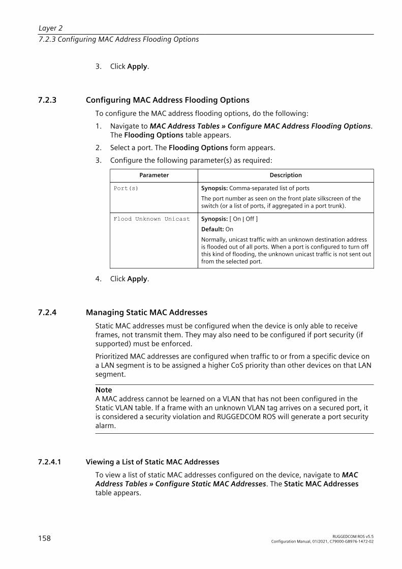
Layer 27.2.3 Configuring MAC Address Flooding Options
3. Click Apply.
7.2.3 Configuring MAC Address Flooding OptionsTo configure the MAC address flooding options, do the following:1. Navigate to MAC Address Tables » Configure MAC Address Flooding Options.
The Flooding Options table appears.2. Select a port. The Flooding Options form appears.3. Configure the following parameter(s) as required:
Parameter Description
Port(s) Synopsis: Comma-separated list of portsThe port number as seen on the front plate silkscreen of theswitch (or a list of ports, if aggregated in a port trunk).
Flood Unknown Unicast Synopsis: [ On | Off ]Default: OnNormally, unicast traffic with an unknown destination addressis flooded out of all ports. When a port is configured to turn offthis kind of flooding, the unknown unicast traffic is not sent outfrom the selected port.
4. Click Apply.
7.2.4 Managing Static MAC AddressesStatic MAC addresses must be configured when the device is only able to receiveframes, not transmit them. They may also need to be configured if port security (ifsupported) must be enforced.Prioritized MAC addresses are configured when traffic to or from a specific device ona LAN segment is to be assigned a higher CoS priority than other devices on that LANsegment.
NoteA MAC address cannot be learned on a VLAN that has not been configured in theStatic VLAN table. If a frame with an unknown VLAN tag arrives on a secured port, itis considered a security violation and RUGGEDCOM ROS will generate a port securityalarm.
7.2.4.1 Viewing a List of Static MAC Addresses
To view a list of static MAC addresses configured on the device, navigate to MACAddress Tables » Configure Static MAC Addresses. The Static MAC Addressestable appears.
158 RUGGEDCOM ROS v5.5Configuration Manual, 01/2021, C79000-G8976-1472-02
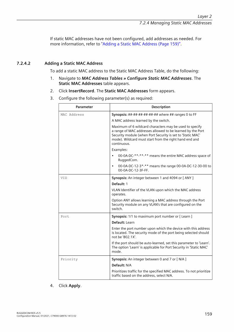
Layer 27.2.4 Managing Static MAC Addresses
If static MAC addresses have not been configured, add addresses as needed. Formore information, refer to "Adding a Static MAC Address (Page 159)".
7.2.4.2 Adding a Static MAC Address
To add a static MAC address to the Static MAC Address Table, do the following:1. Navigate to MAC Address Tables » Configure Static MAC Addresses. The
Static MAC Addresses table appears.2. Click InsertRecord. The Static MAC Addresses form appears.3. Configure the following parameter(s) as required:
Parameter Description
MAC Address Synopsis: ##-##-##-##-##-## where ## ranges 0 to FFA MAC address learned by the switch.Maximum of 6 wildcard characters may be used to specifya range of MAC addresses allowed to be learned by the PortSecurity module (when Port Security is set to 'Static MAC'mode). Wildcard must start from the right hand end andcontinuous.Examples:• 00-0A-DC-**-**-** means the entire MAC address space of
RuggedCom.• 00-0A-DC-12-3*-** means the range 00-0A-DC-12-30-00 to
00-0A-DC-12-3F-FF.
VID Synopsis: An integer between 1 and 4094 or [ ANY ]Default: 1VLAN Identifier of the VLAN upon which the MAC addressoperates.Option ANY allows learning a MAC address through the PortSecurity module on any VLAN's that are configured on theswitch.
Port Synopsis: 1/1 to maximum port number or [ Learn ]Default: LearnEnter the port number upon which the device with this addressis located. The security mode of the port being selected shouldnot be '802.1X'.If the port should be auto-learned, set this parameter to 'Learn'.The option 'Learn' is applicable for Port Security in 'Static MAC'mode.
Priority Synopsis: An integer between 0 and 7 or [ N/A ]Default: N/APrioritizes traffic for the specified MAC address. To not prioritizetraffic based on the address, select N/A.
4. Click Apply.
RUGGEDCOM ROS v5.5Configuration Manual, 01/2021, C79000-G8976-1472-02 159

Layer 27.2.5 Purging All Dynamic MAC Addresses
7.2.4.3 Deleting a Static MAC Address
To delete a static MAC address from the Static MAC Address Table, do the following:1. Navigate to MAC Address Tables » Configure Static MAC Addresses. The
Static MAC Addresses table appears.2. Select the MAC address from the table. The Static MAC Addresses form
appears.3. Click Delete.
7.2.5 Purging All Dynamic MAC AddressesTo purge the dynamic MAC address list of all entries, do the following:1. Navigate to MAC Address Tables » Purge MAC Address Table. The Purge MAC
Address Table form appears.2. Click Confirm.
7.3 Managing Multicast FilteringMulticast traffic can be filtered using IGMP (Internet Group Management Protocol)snooping or GMRP (GARP Multicast Registration Protocol).
7.3.1 Managing IGMPIGMP is used by IP hosts to report their host group memberships with multicastrouters. As hosts join and leave specific multicast groups, streams of traffic aredirected to or withheld from that host.The IGMP protocol operates between multicast routers and IP hosts. When anunmanaged switch is placed between multicast routers and their hosts, the multicaststreams will be distributed to all ports.This may introduce significant traffic ontoports that do not require it and receive no benefit from it.IGMP Snooping, when enabled, will act on IGMP messages sent from the router andthe host, restricting traffic streams to the appropriate LAN segments.
NOTICERUGGEDCOM ROS restricts IGMP hosts from subscribing to the following specialmulticast addresses:• 224.0.0.0 to 224.0.0.255• 224.0.1.129
160 RUGGEDCOM ROS v5.5Configuration Manual, 01/2021, C79000-G8976-1472-02
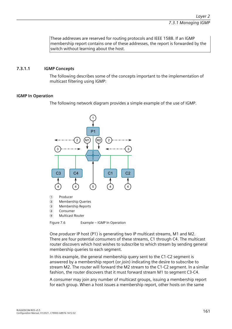
Layer 27.3.1 Managing IGMP
These addresses are reserved for routing protocols and IEEE 1588. If an IGMPmembership report contains one of these addresses, the report is forwarded by theswitch without learning about the host.
7.3.1.1 IGMP Concepts
The following describes some of the concepts important to the implementation ofmulticast filtering using IGMP:
IGMP In OperationThe following network diagram provides a simple example of the use of IGMP.
P1
C3 C4 C1 C2
3
2
3
2
1
4
M2M1
4544
1 Producer 2 Membership Queries 3 Membership Reports 4 Consumer 5 Multicast Router
Figure 7.6 Example – IGMP In Operation
One producer IP host (P1) is generating two IP multicast streams, M1 and M2.There are four potential consumers of these streams, C1 through C4. The multicastrouter discovers which host wishes to subscribe to which stream by sending generalmembership queries to each segment.In this example, the general membership query sent to the C1-C2 segment isanswered by a membership report (or join) indicating the desire to subscribe tostream M2. The router will forward the M2 stream to the C1-C2 segment. In a similarfashion, the router discovers that it must forward stream M1 to segment C3-C4.A consumer may join any number of multicast groups, issuing a membership reportfor each group. When a host issues a membership report, other hosts on the same
RUGGEDCOM ROS v5.5Configuration Manual, 01/2021, C79000-G8976-1472-02 161

Layer 27.3.1 Managing IGMP
network segment that also require membership to the same group suppress theirown requests, since they would be redundant. In this way, the IGMP protocolguarantees the segment will issue only one membership report for each group.The router periodically queries each of its segments in order to determine whetherat least one consumer still subscribes to a given stream. If it receives no responseswithin a given time period (usually two query intervals), the router will prune themulticast stream from the given segment.A more common method of pruning occurs when consumers wishing to unsubscribeissue an IGMP leave group message. The router will immediately issue a group-specific membership query to determine whether there are any remainingsubscribers of that group on the segment. After the last consumer of a group hasunsubscribed, the router will prune the multicast stream from the given segment.
Switch IGMP OperationThe IGMP Snooping feature provides a means for switches to snoop (i.e. watch) theoperation of routers, respond with joins/leaves on the behalf of consumer ports, andprune multicast streams accordingly. There are two modes of IGMP the switch can beconfigured to assume: active and passive.• Active Mode
IGMP supports a routerless mode of operation.When such a switch is used without a multicast router, it is able to function as ifit is a multicast router sending IGMP general queries.
• Passive ModeWhen such a switch is used in a network with a multicast router, it can beconfigured to run Passive IGMP. This mode prevents the switch from sending thequeries that can confuse the router causing it to stop issuing IGMP queries.
NoteA switch running in passive mode requires the presence of a multicast router or it willbe unable to forward multicast streams at all if no multicast routers are present.
NoteAt least one IGMP Snooping switch must be in active mode to make IGMP functional.
IGMP Snooping RulesIGMP Snooping adheres to the following rules:• When a multicast source starts multicasting, the traffic stream will be
immediately blocked on segments from which joins have not been received.• Unless configured otherwise, the switch will forward all multicast traffic to the
ports where multicast routers are attached.• Packets with a destination IP multicast address in the 224.0.0.X range that are
not IGMP are always forwarded to all ports. This behavior is based on the fact
162 RUGGEDCOM ROS v5.5Configuration Manual, 01/2021, C79000-G8976-1472-02
Layer 27.3.1 Managing IGMP
that many systems do not send membership reports for IP multicast addresses inthis range while still listening to such packets.
• The switch implements IGMPv2 proxy-reporting (i.e. membership reportsreceived from downstream are summarized and used by the switch to issue itsown reports).
• The switch will only send IGMP membership reports out of those ports wheremulticast routers are attached, as sending membership reports to hosts couldresult in unintentionally preventing a host from joining a specific group.
• Multicast routers use IGMP to elect a master router known as the querier. Thequerier is the router with the lowest IP address. All other routers become non-queriers, participating only in forwarding multicast traffic. Switches running inactive mode participate in the querier election the same as multicast routers.
• When the querier election process is complete, the switch simply relays IGMPqueries received from the querier.
• When sending IGMP packets, the switch uses its own IP address, if it has one, forthe VLAN on which packets are sent, or an address of 0.0.0.0, if it does not havean assigned IP address.
NoteIGMP Snooping switches perform multicast pruning using a multicast frames’destination MAC multicast address, which depends on the group IP multicastaddress. IP address W.X.Y.Z corresponds to MAC address 01-00-5E-XX-YY-ZZ whereXX is the lower 7 bits of X, and YY and ZZ are simply Y and Z coded in hexadecimal.One can note that IP multicast addresses, such as 224.1.1.1 and 225.1.1.1, will bothmap onto the same MAC address 01-00-5E-01-01-01. This is a problem for which theIETF Network Working Group currently has offered no solution. Users are advised tobe aware of and avoid this problem.
IGMP and RSTPAn RSTP change of topology can render the routes selected to carry multicast trafficas incorrect. This results in lost multicast traffic.If RSTP detects a change in the network topology, IGMP will take some actions toavoid the loss of multicast connectivity and reduce network convergence time:• The switch will immediately issue IGMP queries (if in IGMP Active mode) to
obtain potential new group membership information.• The switch can be configured to flood multicast streams temporarily out of all
ports that are not configured as RSTP Edge Ports.
Combined Router and Switch IGMP OperationThe following example illustrates the challenges faced with multiple routers, VLANsupport and switching.
RUGGEDCOM ROS v5.5Configuration Manual, 01/2021, C79000-G8976-1472-02 163

Layer 27.3.1 Managing IGMP
Producer P1 resides on VLAN 2 while P2 resides on VLAN 3. Consumer C1 resideson both VLANs whereas C2 and C3 reside on VLANs 3 and 2, respectively. Router 2resides on VLAN 2, presumably to forward multicast traffic to a remote network oract as a source of multicast traffic itself.
C1 C3C2
P1
P2
2
1
5
3
4
1 Producer 2 Multicast Router 1 3 Multicast Router 2 4 Switch 5 Host
Figure 7.7 Example – Combined Router and Switch IGMP In Operation
In this example:• P1, Router 1, Router 2 and C3 are on VLAN 2• P2 and C2 are on VLAN 3• C1 is on both VLAN 2 and 3Assuming that router 1 is the querier for VLAN 2 and router 2 is simply a non-querier, the switch will periodically receive queries from router 1 and maintain theinformation concerning which port links to the multicast router. However, the switchport that links to router 2 must be manually configured as a router port. Otherwise,the switch will send neither multicast streams nor joins/leaves to router 2.Note that VLAN 3 does not have an external multicast router. The switch should beconfigured to operate in its routerless mode and issue general membership queriesas if it is the router.• Processing Joins
If host C1 wants to subscribe to the multicast streams for both P1 and P2, it willgenerate two membership reports. The membership report from C1 on VLAN2 will cause the switch to immediately initiate its own membership report to
164 RUGGEDCOM ROS v5.5Configuration Manual, 01/2021, C79000-G8976-1472-02
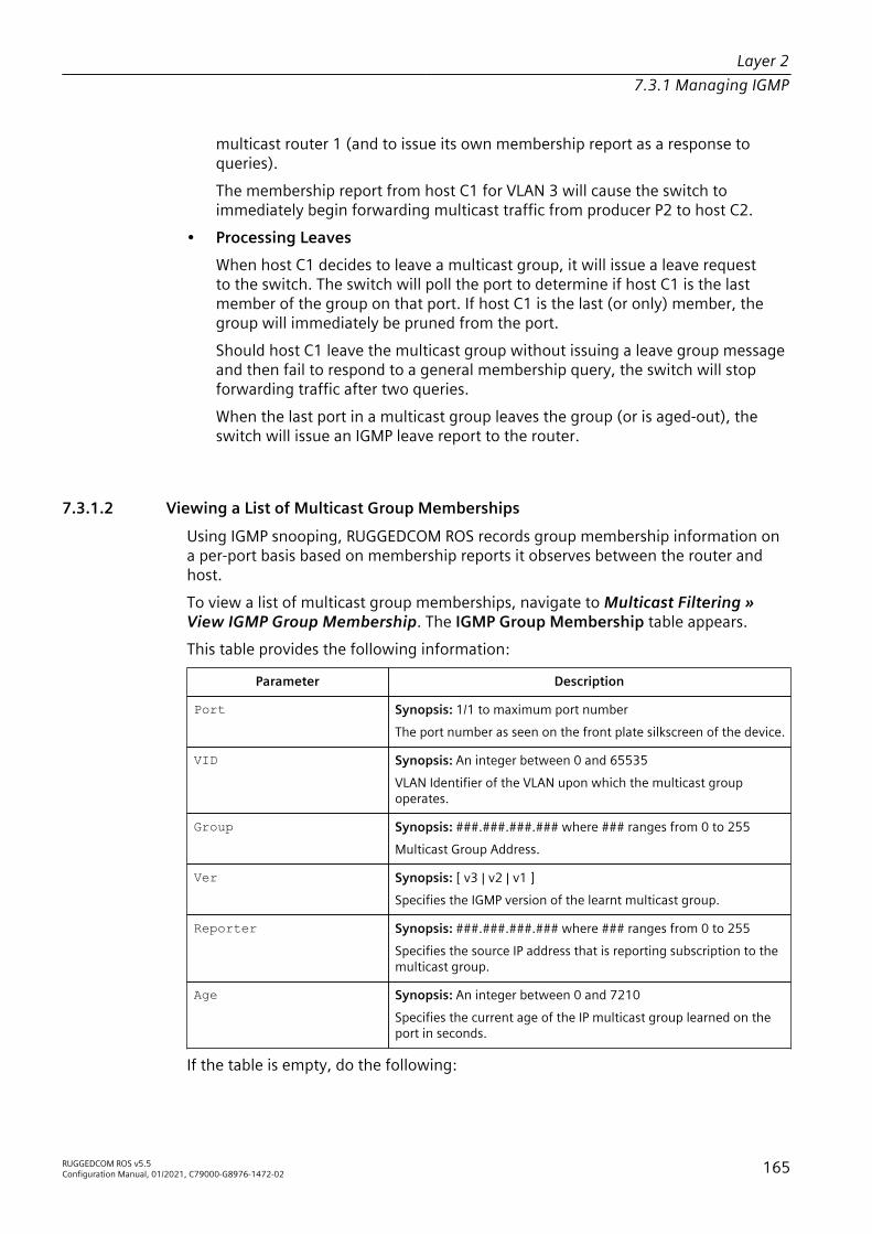
Layer 27.3.1 Managing IGMP
multicast router 1 (and to issue its own membership report as a response toqueries).The membership report from host C1 for VLAN 3 will cause the switch toimmediately begin forwarding multicast traffic from producer P2 to host C2.
• Processing LeavesWhen host C1 decides to leave a multicast group, it will issue a leave requestto the switch. The switch will poll the port to determine if host C1 is the lastmember of the group on that port. If host C1 is the last (or only) member, thegroup will immediately be pruned from the port.Should host C1 leave the multicast group without issuing a leave group messageand then fail to respond to a general membership query, the switch will stopforwarding traffic after two queries.When the last port in a multicast group leaves the group (or is aged-out), theswitch will issue an IGMP leave report to the router.
7.3.1.2 Viewing a List of Multicast Group Memberships
Using IGMP snooping, RUGGEDCOM ROS records group membership information ona per-port basis based on membership reports it observes between the router andhost.To view a list of multicast group memberships, navigate to Multicast Filtering »View IGMP Group Membership. The IGMP Group Membership table appears.This table provides the following information:
Parameter Description
Port Synopsis: 1/1 to maximum port numberThe port number as seen on the front plate silkscreen of the device.
VID Synopsis: An integer between 0 and 65535VLAN Identifier of the VLAN upon which the multicast groupoperates.
Group Synopsis: ###.###.###.### where ### ranges from 0 to 255Multicast Group Address.
Ver Synopsis: [ v3 | v2 | v1 ]Specifies the IGMP version of the learnt multicast group.
Reporter Synopsis: ###.###.###.### where ### ranges from 0 to 255Specifies the source IP address that is reporting subscription to themulticast group.
Age Synopsis: An integer between 0 and 7210Specifies the current age of the IP multicast group learned on theport in seconds.
If the table is empty, do the following:
RUGGEDCOM ROS v5.5Configuration Manual, 01/2021, C79000-G8976-1472-02 165

Layer 27.3.1 Managing IGMP
• Make sure traffic is being sent to the device.• Make sure IGMP is properly configured on the device. For more information,
refer to "Configuring IGMP (Page 166)".
7.3.1.3 Viewing Forwarding Information for Multicast Groups
Multicast forwarding information for every source, group and VLAN combinationlearned by RUGGEDCOM ROS is recorded in the IGMP Multicast Forwarding table.To view the IGMP Multicast Forwarding table, navigate to Multicast Filtering » ViewIGMP Multicast Forwarding. The IGMP Multicast Forwarding table appears.This table provides the following information:
Parameter Description
VID Synopsis: An integer between 0 and 65535VLAN Identifier of the VLAN upon which the multicast groupoperates.
Group Synopsis: ###.###.###.### where ### ranges from 0 to 255Multicast Group Address.
Source Synopsis: ###.###.###.### where ### ranges from 0 to 255 or[ * ]Source Address. * means all possible source addresses.
Joined Ports Synopsis: Comma-separated list of portsAll ports that currently receive multicast traffic for the specifiedmulticast group.
Router Ports Synopsis: Comma-separated list of portsAll ports that have been manually configured or dynamicallydiscovered (by observing router specific traffic) as ports that link tomulticast routers.
If the table is empty, do the following:• Make sure traffic is being sent to the device.• Make sure IGMP is properly configured on the device. For more information,
refer to "Configuring IGMP (Page 166)".
7.3.1.4 Configuring IGMP
To configure the IGMP, do the following:1. Make sure one or more static VLANs exist with IGMP enabled. For more
information, refer to "Managing Static VLANs (Page 153)".2. Navigate to Multicast Filtering » Configure IGMP Parameters. The IGMP
Parameters form appears.
166 RUGGEDCOM ROS v5.5Configuration Manual, 01/2021, C79000-G8976-1472-02

Layer 27.3.1 Managing IGMP
3. Configure the following parameter(s) as required:
Parameter Description
Mode Synopsis: [ Passive | Active ]Default: PassiveSpecifies the IGMP mode. Options include:• Passive – the switch passively snoops IGMP traffic and
never sends IGMP queries• Active – the switch generates IGMP queries, if no queries
from a better candidate for being the querier are detectedfor a while.
IGMP Version Synopsis: [ v2 | v3 ]Default: v2Specifies the configured IGMP version on the switch. Optionsinclude:• v2 – Sets the IGMP version to version 2. When selected for
a snooping switch, all IGMP reports and queries greaterthan v2 are forwarded, but not added to the IGMP MulticastForwarding Table.
• v3 – Sets the IGMP version to version 3. General queries aregenerated in IGMPv3 format, all versions of IGMP messagesare processed by the switch, and traffic is pruned based onmulticast group address only.
Query Interval Synopsis: An integer between 10 and 3600Default: 60The time interval between IGMP queries generated by theswitch.
NoteThis parameter also affects the Group Membership Interval (i.e.the group subscriber aging time), therefore, it takes effect evenin PASSIVE mode.
Router Ports Synopsis: Comma-separated list of portsDefault: NoneThis parameter specifies ports that connect to multicast routers.If you do not configure known router ports, the switch may beable to detect them, however it is advisable to pre-configurethem.
Router Forwarding Synopsis: [ Off | On ]Default: OnThis parameter specifies whether multicast streams will bealways forwarded to multicast routers.
RSTP Flooding Synopsis: [ Off | On ]Default: OffThis parameter specifies whether multicast streams will beflooded out of all RSTP non-edge ports upon topology change
RUGGEDCOM ROS v5.5Configuration Manual, 01/2021, C79000-G8976-1472-02 167
Layer 27.3.2 Managing GMRP
Parameter Descriptiondetection. Such flooding is desirable, if guaranteed multicaststream delivery after topology change is most important.
4. Click Apply.
7.3.2 Managing GMRPThe GMRP is an application of the Generic Attribute Registration Protocol (GARP)that provides a Layer 2 mechanism for managing multicast group memberships in abridged Layer 2 network. It allows Ethernet switches and end stations to register andunregister membership in multicast groups with other switches on a LAN, and forthat information to be disseminated to all switches in the LAN that support ExtendedFiltering Services.GMRP is an industry-standard protocol first defined in IEEE 802.1D-1998 andextended in IEEE 802.1Q-2005. GARP was defined in IEEE 802.1D-1998 and updatedin 802.1D-2004.
7.3.2.1 GMRP Concepts
The following describes some of the concepts important to the implementation ofmulticast filtering using GMRP:
Joining a Multicast GroupTo join a multicast group, an end station transmits a GMRP join message. The switchthat receives the join message adds the port through which the message wasreceived to the multicast group specified in the message. It then propagates the joinmessage to all other hosts in the VLAN, one of which is expected to be the multicastsource.When a switch transmits GMRP updates (from GMRP-enabled ports), all of themulticast groups known to the switch, whether configured manually or learneddynamically through GMRP, are advertised to the rest of network.As long as one host on the Layer 2 network has registered for a given multicastgroup, traffic from the corresponding multicast source will be carried on thenetwork. Traffic multicast by the source is only forwarded by each switch in thenetwork to those ports from which it has received join messages for the multicastgroup.
Leaving a Multicast GroupPeriodically, the switch sends GMRP queries in the form of a leave all message. Ifa host (either a switch or an end station) wishes to remain in a multicast group, itreasserts its group membership by responding with an appropriate join request.Otherwise, it can either respond with a leave message or simply not respond at all.
168 RUGGEDCOM ROS v5.5Configuration Manual, 01/2021, C79000-G8976-1472-02

Layer 27.3.2 Managing GMRP
If the switch receives a leave message or receives no response from the host for atimeout period, the switch removes the host from the multicast group.
Notes About GMRPSince GMRP is an application of GARP, transactions take place using the GARPprotocol. GMRP defines the following two Attribute Types:• The Group Attribute Type, used to identify the values of group MAC addresses• The Service Requirement Attribute Type, used to identify service requirements
for the groupService Requirement Attributes are used to change the receiving port's multicastfiltering behavior to one of the following:• Forward All Multicast group traffic in the VLAN, or• Forward All Unknown Traffic (Multicast Groups) for which there are no members
registered in the device in a VLANIf GMRP is disabled, GMRP packets received will be forwarded like any other traffic.Otherwise, GMRP packets will be processed and not forwarded.
Establishing Membership with GMRPThe following example illustrates how a network of hosts and switches candynamically join two multicast groups using GMRP.In this scenario, there are two multicast sources, S1 and S2, multicasting to MulticastGroups 1 and 2, respectively. A network of five switches, including one core switch(B), connects the sources to two hosts, H1 and H2, which receive the multicaststreams from S1 and S2, respectively.
A1
A2A E C
D
S1
E1
E2
C1
C2
B3
B4
B1B2B
D1
D2
S2H2H1
1
1
2
3
1 Multicast Source
RUGGEDCOM ROS v5.5Configuration Manual, 01/2021, C79000-G8976-1472-02 169

Layer 27.3.2 Managing GMRP
2 Switch 3 Multicast Host
Figure 7.8 Example – Establishing Membership with GMRP
The hosts and switches establish membership with the Multicast Group 1 and 2 asfollows:1. Host H1 is GMRP unaware, but needs to see traffic for Multicast Group 1.
Therefore, Port E2 on Switch E is statically configured to forward traffic forMulticast Group 1.
2. Switch E advertises membership in Multicast Group 1 to the network throughPort E1, making Port B4 on Switch B a member of Multicast Group 1.
3. Switch B propagates the join message, causing Ports A1, C1 and D1 to becomemembers of Multicast Group 1.
4. Host H2 is GMRP-aware and sends a join request for Multicast Group 2 to Port C2,which thereby becomes a member of Multicast Group 2.
5. Switch C propagates the join message, causing Ports A1, B2, D1 and E1 tobecome members of Multicast Group 2.
Once GMRP-based registration has propagated through the network, multicast trafficfrom S1 and S2 can reach its destination as follows:• Source S1 transmits multicast traffic to Port D2 which is forwarded via Port D1,
which has previously become a member of Multicast Group 1.• Switch B forwards the Group 1 multicast via Port B4 towards Switch E.• Switch E forwards the Group 1 multicast via Port E2, which has been statically
configured for membership in Multicast Group 1.• Host H1, connected to Port E2, thus receives the Group 1 multicast.• Source S2 transmits multicast traffic to Port A2, which is then forwarded via port
A1, which has previously become a member of Multicast Group 2.• Switch B forwards the Group 2 multicast via Port B2 towards Switch C.• Switch C forwards the Group 2 multicast via Port C2, which has previously
become a member of Group 2.• Ultimately, Host H2, connected to Port C2, receives the Group 2 multicast.
7.3.2.2 Viewing a Summary of Multicast Groups
To view a summary of all multicast groups, navigate to Multicast Filtering » ViewMulticast Group Summary. The Multicast Group Summary table appears.
170 RUGGEDCOM ROS v5.5Configuration Manual, 01/2021, C79000-G8976-1472-02

Layer 27.3.2 Managing GMRP
This table provides the following information:
Parameter Description
VID Synopsis: An integer between 0 and 65535VLAN Identifier of the VLAN upon which the multicast groupoperates.
MAC Address Synopsis: ##-##-##-##-##-## where ## ranges 0 to FFMulticast group MAC address.
Static Ports Synopsis: Any combination of numbers valid for this parameterPorts that joined this group statically through static configurationin Static MAC Table and to which the multicast group traffic isforwarded.
GMRP Dynamic Ports Synopsis: Any combination of numbers valid for this parameterPorts that joined this group dynamically through GMRP Applicationand to which the multicast group traffic is forwarded.
7.3.2.3 Configuring GMRP Globally
To configure global settings for GMRP, do the following:1. Navigate to Multicast Filtering » Configure Global GMRP Parameters. The
Global GMRP Parameters form appears.2. Configure the following parameter(s) as required:
Parameter Description
GMRP Enable Synopsis: [ No | Yes ]Default: NoGlobally enable or disable GMRP.When GMRP is globally disabled, GMRP configurations onindividual ports are ignored. When GMRP is globally enabled,each port can be individually configured.
RSTP Flooding Synopsis: [ On | Off ]Default: OffThis parameter specifies whether multicast streams will beflooded out of all RSTP non-edge ports upon topology changedetection. Such flooding is desirable, if guaranteed multicaststream delivery after topology change is most important.
Leave Timer Synopsis: An integer between 600 and 300000Default: 4000Time (milliseconds) to wait after issuing Leave or LeaveAllbefore removing registered multicast groups. If Join messagesfor specific addresses are received before this timer expires, theaddresses will be kept registered.
3. Click Apply.
RUGGEDCOM ROS v5.5Configuration Manual, 01/2021, C79000-G8976-1472-02 171

Layer 27.3.2 Managing GMRP
7.3.2.4 Configuring GMRP for Specific Ethernet Ports
To configure GMRP for a specific Ethernet port, do the following:1. Make sure the global settings for GMRP have been configured. For more
information, refer to "Configuring GMRP Globally (Page 171)".2. Navigate to Multicast Filtering » Configure Port GMRP Parameters. The Port
GMRP Parameters table appears.3. Select an Ethernet port. The Port GMRP Parameters form appears.4. Configure the following parameter(s) as required:
Parameter Description
Port(s) Synopsis: Any combination of numbers valid for this parameterThe port number as seen on the front plate silkscreen of theswitch (or a list of ports, if aggregated in a port trunk).
GMRP Synopsis: [ Disabled | Adv Only | Adv&Learn ]Default: DisabledConfigures GMRP (GARP Multicast Registration Protocol)operation on the port. There are several GMRP operationmodes:• Disabled – the port is not capable of any GMRP process-
ing.• Adv Only – the port will declare all MCAST addresses ex-
isting in the switch (configured or learned) but will notlearn any MCAST addresses.
• Adv&Learn – the port will declare all MCAST Addresses ex-isting in the switch (configured or learned) and can dynami-cally learn MCAST addresses.
5. Click Apply.
7.3.2.5 Viewing a List of Static Multicast Groups
To view a list of static multicast groups, navigate to Multicast Filtering » ConfigureStatic Multicast Groups. The Static Multicast Groups table appears.If a static multicast group is not listed, add the group. For more information, refer to"Adding a Static Multicast Group (Page 172)".
7.3.2.6 Adding a Static Multicast Group
To add a static multicast group from another device, do the following:1. Navigate to Multicast Filtering » Configure Static Multicast Groups. The
Static Multicast Groups table appears.2. Click InsertRecord. The Static Multicast Groups form appears.
172 RUGGEDCOM ROS v5.5Configuration Manual, 01/2021, C79000-G8976-1472-02

Layer 27.3.2 Managing GMRP
3. Configure the following parameter(s) as required:
Parameter Description
MAC Address Synopsis: ##-##-##-##-##-## where ## ranges 0 to FFDefault: 00-00-00-00-00-00Multicast group MAC address.
VID Synopsis: An integer between 1 and 4094Default: 1VLAN Identifier of the VLAN upon which the multicast groupoperates.
Priority Synopsis: An integer between 0 and 7 or [ N/A ]Default: N/APrioritizes traffic for the specified MAC address. To not prioritizetraffic based on the address, select N/A.
Ports Synopsis: Any combination of numbers valid for this parameterDefault: NoneA comma-separated list of ports to which the multicast grouptraffic is forwarded. If a port is part of a Link Aggregation Group(LAG), or port trunk, specify all ports in the LAG.
4. Click Apply.
7.3.2.7 Deleting a Static Multicast Group
To delete a static multicast group, do the following:1. Navigate to Multicast Filtering » Configure Static Multicast Groups. The
Static Multicast Groups table appears.2. Select the group from the table. The Static Multicast Groups form appears.3. Click Delete.
RUGGEDCOM ROS v5.5Configuration Manual, 01/2021, C79000-G8976-1472-02 173

Layer 27.3.2 Managing GMRP
174 RUGGEDCOM ROS v5.5Configuration Manual, 01/2021, C79000-G8976-1472-02

Layer 3 8This chapter describes the Layer 3, or network layer, features of RUGGEDCOM ROS.
8.1 Managing Layer 3 SwitchingThis section describes how to manage Layer 3 switching.
NoteLayer 3 switching only supports IPv4 addresses (not IPv6 addresses).
NoteLayer 3 switching only supports unicast traffic. Layer 3 switching for multicast andbroadcast traffic is not supported.
8.1.1 Understanding Layer 3 SwitchingTraditional switching operates at Layer 2 of the OSI model, where packets are sentto a specific switch port based on destination MAC addresses and VLANs. Routingoperates at Layer 3, where packets are sent to a specific next-hop IP address, basedon the destination IP address.RUGGEDCOM ROS supports configuration of Layer 3 switching rules, allowing IPtraffic to be switched between two existing VLANs via device hardware.This section describes some of the concepts important to the implementation ofLayer 3 switching in RUGGEDCOM ROS.
8.1.1.1 Layer 3 Switch Forwarding Table
To route a packet with a specific destination IP address, a device needs the followinginformation:• Egress interface (subnet)
This information is stored in the device's routing table.
NoteIn a Layer 2 switched network segment, a VLAN constitutes an IP subnet.
RUGGEDCOM ROS v5.5Configuration Manual, 01/2021, C79000-G8976-1472-02 175

Layer 38.1.1 Understanding Layer 3 Switching
• Next-hop or Gateway Media Access Control (MAC) addressThis information is stored in an ARP table specific to Layer 3 switching.
NoteIf the next hop is the destination subnet itself, then the destination host MACaddress is required.
Layer 3 switching translates this routing information into Layer 3 switching rules.These rules are known as the Layer 3 Switch Forwarding Information Base (FIB) orthe Layer 3 Switch Forwarding Table. A Layer 3 switching rule defines how to switcha specific traffic flow.Layer 3 switching Application-Specific Integrated Circuits (ASICs) store Layer 3switching rules in seperate Ternary Content Addressable Memory (TCAM) tables forhosts and subnets. Layer 3 switching rules can be statically configured or dynamicallylearned (or auto-learned).
NoteLayer 3 switching rules can only be dynamically learned for neighbor hosts. Rulesmust be statically configured for remote hosts and subnets.
NoteThe maximum number of Layer 3 switching rules is 288, including 256 for hosts and32 for subnets.
8.1.1.2 Static Layer 3 Switching Rules
When creating a static route through switch management, hardware accelerationcan be explicitly configured. If hardware acceleration is selected, an appropriateLayer 3 switching rule is installed in the ASIC's TCAM and never ages out.
NoteOnly ICMP, TCP, and UDP traffic flows will be accelerated by the IP/Layer 3 switchingASIC.
NoteWhen using statically configured Layer 3 switching rules, IP forwarding may beenabled or disabled. For information on how to configure IP forwarding, refer to"Configuring IP Services (Page 84)".
8.1.1.3 Dynamic Learning of Layer 3 Switching Rules
For static routes without hardware acceleration or for dynamic routes, Layer3 switching rules can be dynamically learned based on software-based routerdecisions.
176 RUGGEDCOM ROS v5.5Configuration Manual, 01/2021, C79000-G8976-1472-02

Layer 38.1.1 Understanding Layer 3 Switching
After a certain amount of traffic for the same flow is successfully routed, the Layer3 switching ASIC begins switching the rest of the packets belonging to the sameflow. A flow is unidirectional traffic between two hosts. For example, traffic flowingbetween ports from one host to another is considered a flow. Traffic flowing in theopposite direction between the same ports is considered a different flow.RUGGEDCOM ROS supports the host-oriented auto-learning method, where thedevice uses the source and destination IP addresses to identify a traffic flow.Each flow constitutes one rule.The Layer 3 switch continuously monitors activity (this is, the presence of traffic)for dynamically learned rules. Because of this, dynamically learned rules may beremoved after a configurable time due to inactivity.
8.1.1.4 Interaction Between IP Forwarding and Layer 3 Switching
To use static Layer 3 switching rules, IP forwarding can be enabled or disabled.However, to use dynamically learned Layer 3 switching rules, IP forwarding must beenabled. For information about configuring IP forwarding, refer to "Configuring IPServices (Page 84)".The following shows how IP forwarding interacts with Layer 3 switching inRUGGEDCOM ROS.
IP Forwarding L3 Switching Disabled L3 Switching Static L3 Switching DynamicDisabled Both features disabled Static Layer 3 switching Not possible
Enabled No hardwareacceleration Static Layer 3 switching Static and Dynamic
Layer 3 switching
8.1.1.5 Layer 3 Switch ARP Table
A router needs to know the destination host or next-hop gateway MAC address forit to forward a packet on another subnet. Therefore, software maintains an AddressResolution Protocol (ARP) table that maps IP addresses to MAC addresses. The sameinformation is also needed by the Layer 3 switching ASIC when it switches IP packetsbetween subnets.
NoteARP entries can be statically configured and resolved if the static MAC addresses towhich they correspond are configured in the Static MAC Address Table. Otherwise,ARP entries will be dynamically resolved every 60 seconds (s).
The destination or gateway MAC address is usually obtained through ARP. However,ARP entries can also be statically configured in the Layer 3 Switch so they do nottime out. When configuring a static ARP entry, if no value is entered for the MACAddress parameter, the address is automatically resolved through ARP and thensaved statically. This is preserved across reboots of the device.
RUGGEDCOM ROS v5.5Configuration Manual, 01/2021, C79000-G8976-1472-02 177

Layer 38.1.1 Understanding Layer 3 Switching
If no static ARP entry is configured for a specific destination, a dynamic ARP entry willbe created and the destination MAC address will be resolved automatically.
Layer 3 ARP Resolution BehaviorThe following flowchart shows how ARP entries are resolved in RUGGEDCOM ROS.
Is the ARP entry static?
Search for the MAC addressin the Static MAC Address Table.
Is the static MACaddress configured?
ARP entry is statically resolved. Send ARP requests periodically.
Is the ARP replyreceived?
ARP entry is unresolved.ARP entry is
dynamically resolved.
For each Layer 3 entryin the ARP table:
YESYES
YESYES
YESYES
NO
NO
NO
178 RUGGEDCOM ROS v5.5Configuration Manual, 01/2021, C79000-G8976-1472-02

Layer 38.1.1 Understanding Layer 3 Switching
Layer 3 Switching Rule Resolution BehaviorThe following flowchart shows how Layer 3 switching rules are resolved inRUGGEDCOM ROS.
Does a Layer 3 ARP entryexist for that host/gateway?
Create a dynamic ARP entryin the Layer 3 ARP Table.
Is the ARP entry resolved?
Layer 3 rule is resolving.Layer 3 rule is active.
Layer 3 switching is working.
For each Layer 3 rulein the Rule Summary Table:
YESYES
NO
NO
YESYES
8.1.1.6 Layer 3 Switch Routable Interfaces
RUGGEDCOM ROS allows up to 255 interfaces (VLANs) to be configured. To makean interface routable for unicast IPv4 traffic, an IPv4 address must be configuredstatically or assigned via DHCP to the interface. For more information, refer to"Managing IP Interfaces (Page 78)".
RUGGEDCOM ROS v5.5Configuration Manual, 01/2021, C79000-G8976-1472-02 179

Layer 38.1.2 Configuring Layer 3 Switching
8.1.2 Configuring Layer 3 SwitchingTo configure Layer 3 switching, do the following:
NoteAvoid configuring Link Aggregation Groups (LAGs) when Layer 3 switching isenabled. For more information, refer to "Managing Link Aggregation Groups (Page231)".
1. Add VLANs as required. For more information, refer to "Adding a Static VLAN(Page 153)".
2. Assign IP addresses to the configured VLANs. For more information, refer to"Adding a Switch IP Interface (Page 80)".
3. Assign desired ports to the configured VLANs. For more information, refer to"Configuring VLANs for Specific Ethernet Ports (Page 151)".
4. Configure the unicast mode and aging time. For more information, refer to"Configuring Layer 3 Switching Options (Page 180)".
5. If static unicast mode is selected, add destination IP addresses and next hopgateways as needed. For more information, refer to "Managing Static UnicastRules (Page 181)".
6. If static unicast mode is selected, add static ARP table entries as needed. Formore information, refer to "Managing Static ARP Table Entries (Page 182)".
7. Test the configuration by sending traffic and verifying the following:a. ARP entries are resolved in the ARP Table. For more information, refer to
"Viewing a List of ARP Table Entries (Page 182)".b. Rules are active in the Rule Summary Table. For more information, refer to
"Viewing Routing Rules (Page 184)".c. Traffic is being sent and received. For more information, refer to "Viewing
Statistics for Specific Ethernet Ports (Page 63)".For configuration examples, refer to "Example: Configuring Layer 3 Switching (Page185)" and "Example: Configuring Layer 3 Switching Using Multiple Switches (Page186)".
8.1.3 Configuring Layer 3 Switching OptionsTo configure Layer 3 switching options, do the following:1. Navigate to Layer 3 Switching » Configure Switch Options. The Switch
Options form appears.
180 RUGGEDCOM ROS v5.5Configuration Manual, 01/2021, C79000-G8976-1472-02

Layer 38.1.4 Managing Static Unicast Rules
2. Configure the following parameter(s) as required:
Parameter Description
Unicast Mode Synopsis: [ Disabled | Static | Auto ]Default: DisabledDisabled – Layer 3 switching is disabled.Static – Only statically configured Layer 3 switching rules will beused.Auto – Both statically configured and dynamically learned Layer3 switching rules will be used. In this mode, maximum routinghardware acceleration is utilized.
Aging Time Synopsis: An integer between 16 and 600Default: 32This parameter configures the time a dynamically learned rulefor a traffic flow, which has become inactive, is held beforebeing removed from the Layer 3 Switch forwarding table.
3. Click Apply.
8.1.4 Managing Static Unicast RulesThis section describes how to manage static unicast rules.
8.1.4.1 Viewing Static Unicast Rules
To view a list of static unicast rule entries, navigate to Layer 3 Switching »Configure Static Unicast Rules. If table entries have been configured, the StaticUnicast Rules table appears.Static unicast rules can be configured as required. For more information aboutadding static unicast rules, refer to "Adding a Static Unicast Rule (Page 181)".
8.1.4.2 Adding a Static Unicast Rule
To add a static unicast rule, do the following:1. Navigate to Layer 3 Switching » Configure Static Unicast Rules. The Static
Unicast Rules Table appears.2. Click InsertRecord. The Static Unicast Rules form appears.
RUGGEDCOM ROS v5.5Configuration Manual, 01/2021, C79000-G8976-1472-02 181

Layer 38.1.5 Managing Static ARP Table Entries
3. Configure the following parameter(s) as required:
Parameter Description
Destination Synopsis: ###.###.###.###/## where ### ranges from 0 to255 and ## ranges from 0 to 32Default: ANYDestination IP address or subnet. To match the rule, theincoming packet's destination IP address should belong to thesubnet.
Gateway Synopsis: ###.###.###.### where ### ranges from 0 to 255IP address of the next hop to which matching unicast packetswill be forwarded
NoteIf the Destination is a directly connected neighbor, no valueshould be supplied for the Gateway parameter.
4. Click Apply.
8.1.4.3 Deleting a Static Unicast Rule
To delete a static unicast rule, do the following:1. Navigate to Layer 3 Switching » Configure Static Unicast Rules. The Static
Unicast Rules table appears.2. Select the record to be deleted. The Static Unicast Rules form appears.3. Click Delete.
8.1.5 Managing Static ARP Table EntriesThis section describes how to manage static ARP Table entries.
8.1.5.1 Viewing a List of ARP Table Entries
To view a list of Layer 3 switching ARP table entries, navigate to Layer 3 Switching »Configure/View ARP Table. If table entries have been configured, the ARP Tableappears.When unicast rules are configured, the Layer 3 switching ARP table will populate asARP entries are dynamically learned. Static ARP table entries can also be added asneeded. For more information about adding static ARP table entries, refer to "Addinga Static ARP Table Entry (Page 183)".
182 RUGGEDCOM ROS v5.5Configuration Manual, 01/2021, C79000-G8976-1472-02

Layer 38.1.5 Managing Static ARP Table Entries
8.1.5.2 Adding a Static ARP Table Entry
To add a static ARP table entry, do the following:1. Navigate to Layer 3 Switching » Configure/View ARP Table. The ARP Table
form appears.2. Click InsertRecord. The ARP Table form appears.3. Configure the following parameter(s) as required:
Parameter Description
IP Address Synopsis: ###.###.###.### where ### ranges from 0 to 255IP address of the network device the entry describes.
VID Synopsis: An integer between 0 and 65535Default: N/AVLAN Identifier of the VLAN upon which the MAC addressoperates.
MAC Address Synopsis: ##-##-##-##-##-## where ## ranges 0 to FFDefault: 00-00-00-00-00-00MAC address of the network device specified by the IP address.
Static Synopsis: [ True | False ]Default: TrueWhether the entry is static or dynamic. Static entries areconfigured as a result of management activity. Dynamic entriesare automatically learned by the device and can be unlearned.
Status Synopsis: [ Unresolved | Resolved ]ARP entry resolution status:Resolved – MAC-IP address pair is resolved and operational.Unresolved – the device hasn't resolved the MAC-IP address pairand keeps sending ARP requests periodically.
4. Click Apply.
8.1.5.3 Deleting a Static ARP Table Entry
To delete a static ARP table entry, do the following:1. Navigate to Layer 3 Switching » Configure/View ARP Table. The ARP Table
form appears.2. Select the record to be deleted. The ARP Table form appears.3. Click Delete.
RUGGEDCOM ROS v5.5Configuration Manual, 01/2021, C79000-G8976-1472-02 183

Layer 38.1.6 Viewing Routing Rules
8.1.6 Viewing Routing RulesTo view a list of routing rules, navigate to Layer 3 Switching » View Rule Summary.If any static or dynamic unicast rules are configured, the Rule Summary Tableappears.This table provides the following information:
Parameter Description
Destination Synopsis: A string 20 characters longDestination IP address or subnet.To match the rule, the incoming packet's destination IP addressshould belong to the subnet.
Out-VLAN(s) Synopsis: Comma separated list of up to 2 numbers ranging from 1to 4095Egress VLAN(s).Matching unicast or multicast packets will be sent to this one ormore VLAN(s).
Gateway Synopsis: ###.###.###.### where ### ranges from 0 to 255IP address of the next hop to which matching unicast packets willbe forwarded.
Static Synopsis: [ True | False ]Whether the rule is static or dynamic.Static rules are configured as a result of management activity.Dynamic rules are automatically learned by the device and can beunlearned subject to Aging Time.
Status Synopsis: [ Active | Resolving ]Whether the rule is currently operational or not:Active – rule is fully operational and can be applied, so hardwareacceleration is performed.Resolving – rule is not operational yet due to some unresolvedinformation, like ARP or gateway's MAC address in the MAC AddressTable. Hardware acceleration is not performed.
8.1.7 Flushing Dynamic Hardware Routing RulesFlushing dynamic hardware routing rules removes all dynamically learned rules fromthe Layer 3 Switch Forwarding Table.
NoteOnly dynamic rules can be flushed. Static rules, configured in the Layer 3 SwitchForwarding Table, never age out. For more information about enabling hardwareacceleration, refer to "Understanding Layer 3 Switching (Page 175)".
184 RUGGEDCOM ROS v5.5Configuration Manual, 01/2021, C79000-G8976-1472-02
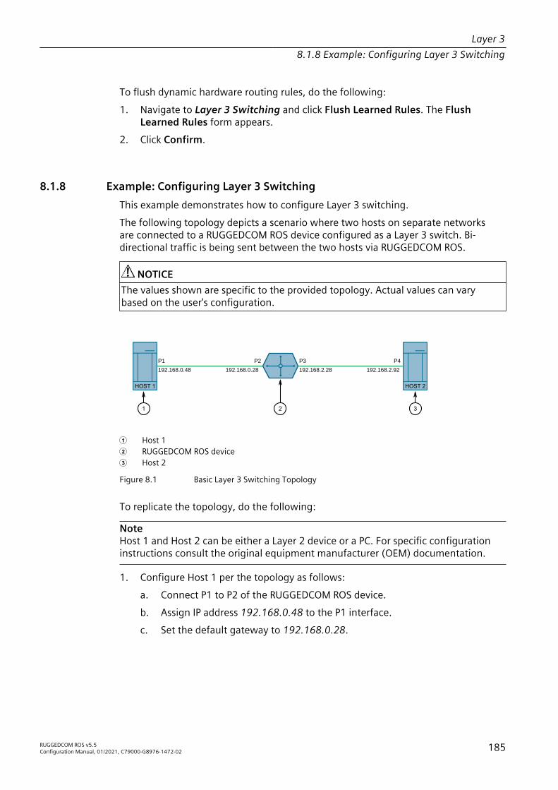
Layer 38.1.8 Example: Configuring Layer 3 Switching
To flush dynamic hardware routing rules, do the following:1. Navigate to Layer 3 Switching and click Flush Learned Rules. The Flush
Learned Rules form appears.2. Click Confirm.
8.1.8 Example: Configuring Layer 3 SwitchingThis example demonstrates how to configure Layer 3 switching.The following topology depicts a scenario where two hosts on separate networksare connected to a RUGGEDCOM ROS device configured as a Layer 3 switch. Bi-directional traffic is being sent between the two hosts via RUGGEDCOM ROS.
NOTICEThe values shown are specific to the provided topology. Actual values can varybased on the user's configuration.
192.168.0.28 192.168.2.28192.168.0.48 192.168.2.92
HOST 2 HOST 1
1 2 3
P1 P2 P4P3
1 Host 1 2 RUGGEDCOM ROS device 3 Host 2
Figure 8.1 Basic Layer 3 Switching Topology
To replicate the topology, do the following:
NoteHost 1 and Host 2 can be either a Layer 2 device or a PC. For specific configurationinstructions consult the original equipment manufacturer (OEM) documentation.
1. Configure Host 1 per the topology as follows:a. Connect P1 to P2 of the RUGGEDCOM ROS device.b. Assign IP address 192.168.0.48 to the P1 interface.c. Set the default gateway to 192.168.0.28.
RUGGEDCOM ROS v5.5Configuration Manual, 01/2021, C79000-G8976-1472-02 185

Layer 38.1.9 Example: Configuring Layer 3 Switching Using Multiple Switches
2. Configure Host 2 per the topology as follows:a. Connect P4 to P3 of the RUGGEDCOM ROS device.b. Assign IP address 192.168.2.92 to the P4 interface.c. Set the default gateway to 192.168.2.28.
3. Configure the RUGGEDCOM ROS device as a Layer 3 switch:a. Add VLAN 1 and VLAN 2. For more information, refer to "Adding a Static
VLAN (Page 153)".b. Assign IP address 192.168.0.28 to VLAN 1, and IP address 192.168.2.28 to
VLAN 2. For more information, refer to "Adding a Switch IP Interface (Page80)".
c. Assign P2 to VLAN1 and P3 to VLAN2. Refer to "Configuring VLANs forSpecific Ethernet Ports (Page 151)" for more information.
d. Enable unicast mode. For more information, refer to "Configuring Layer 3Switching Options (Page 180)".
e. If Auto is selected as the unicast mode, proceed to step Step 4. Otherwise,configure destination and default gateway static unicast rules as follows:
Destination Gateway192.168.0.48 0.0.0.0192.168.2.92 0.0.0.0
For more information about configuring static unicast rules, refer to "Addinga Static Unicast Rule (Page 181)".
f. Send multiple ARP requests/replies from Host 1 and Host 2 to theRUGGEDCOM ROS device.
4. Send bidirectional traffic (i.e. UDP, TCP, ICMP) between Host 1 and Host 2, andverify the following:a. ARP entries are resolved in the ARP Table. For more information, refer to
"Viewing a List of ARP Table Entries (Page 182)".b. Rules are active in the Rule Summary Table. For more information, refer to
"Viewing Routing Rules (Page 184)".c. Traffic is being sent and received between the two end hosts. For more
information, refer to "Viewing Statistics for Specific Ethernet Ports (Page63)".
8.1.9 Example: Configuring Layer 3 Switching Using Multiple SwitchesThis example demonstrates how to configure Layer 3 switching using multipleswitches.The following topology depicts a scenario where two hosts on separate networksare connected to two RUGGEDCOM ROS devices configured as a Layer 3 switches.
186 RUGGEDCOM ROS v5.5Configuration Manual, 01/2021, C79000-G8976-1472-02

Layer 38.1.9 Example: Configuring Layer 3 Switching Using Multiple Switches
Bi-directional traffic is being sent between the two hosts via the RUGGEDCOM ROSdevices.
NOTICEThe values shown are specific to the provided topology. Actual values can varybased on the user's configuration.
192.168.0.28 192.168.3.28192.168.0.48 192.168.2.29
HOST 2 HOST 1
P1 P2 P6P3
192.168.3.92 192.168.2.92
P4 P5VLAN1 VLAN3 VLAN2
2 3
S1 S2
1 4
1 Host 1 2 S1 3 S2 4 Host 2
Figure 8.2 Topology – Layer 3 Switching Using Two Switches
To replicate the topology, do the following:
NoteHost 1 and Host 2 can be either a Layer 2 device or a PC. For specific configurationinstructions, consult the OEM documentation.
1. Configure Host 1 per the topology as follows:a. Connect P1 to P2 of RUGGEDCOM ROS device 1.b. Assign IP address 192.168.0.48 to the P1 interface.c. Set the default gateway to 192.168.0.28.
2. Configure Host 2 per the topology as follows:a. Connect P6 to P5 of S2.b. Assign IP address 192.168.2.29 to the P6 interface.c. Set the default gateway to 192.168.2.92.
RUGGEDCOM ROS v5.5Configuration Manual, 01/2021, C79000-G8976-1472-02 187

Layer 38.1.9 Example: Configuring Layer 3 Switching Using Multiple Switches
3. Configure S1 as a Layer 3 switch:a. Connect P3 to P4 of S2.b. Add VLAN 1 and VLAN 3. For more information, refer to "Adding a Static
VLAN (Page 153)".c. Assign IP address 192.168.0.28 to VLAN 1, and IP address 192.168.3.28 to
VLAN 3. For more information, refer to "Adding a Switch IP Interface (Page80)".
d. Assign P2 to VLAN1 and P3 to VLAN3. Refer to "Configuring VLANs forSpecific Ethernet Ports (Page 151)" for more information.
e. Set the unicast mode to Auto. For more information, refer to "ConfiguringLayer 3 Switching Options (Page 180)".
f. Configure destination and default gateway static unicast rules as follows:
Destination Gateway192.168.2.0/24 192.168.3.92
For more information about configuring static unicast rules, refer to "Addinga Static Unicast Rule (Page 181)".
4. Configure S2 as a Layer 3 switch:a. Add VLAN 3 and VLAN 2. For more information, refer to "Adding a Static
VLAN (Page 153)".b. Assign IP address 192.168.3.92 to VLAN 3, and IP address 192.168.2.92 to
VLAN 2. For more information, refer to "Adding a Switch IP Interface (Page80)".
c. Set the unicast mode to Auto. For more information, refer to "ConfiguringLayer 3 Switching Options (Page 180)".
d. Configure destination and default gateway static unicast rules as follows:
Destination Gateway192.168.0.0/24 192.168.3.28
For more information about configuring static unicast rules, refer to "Addinga Static Unicast Rule (Page 181)".
5. Send multiple ARP requests/replies from Host 1 to S1, and from Host 2 to S2.6. Send bidirectional traffic (i.e. UDP, TCP, ICMP) between Host 1 and Host 2, and
verify the following:a. ARP entries are resolved in the ARP Table. For more information, refer to
"Viewing a List of ARP Table Entries (Page 182)".b. Rules are active in the Rule Summary Table. For more information, refer to
"Viewing Routing Rules (Page 184)".c. Traffic is being sent and received between the two end hosts. For more
information, refer to "Viewing Statistics for Specific Ethernet Ports (Page63)".
188 RUGGEDCOM ROS v5.5Configuration Manual, 01/2021, C79000-G8976-1472-02
Network Redundancy 9This chapter describes how to configure and manage the redundancy-relatedfeatures of RUGGEDCOM ROS.
9.1 Managing Spanning Tree ProtocolThis section describes how to manage the spanning tree protocol.
9.1.1 RSTP OperationThe 802.1D Spanning Tree Protocol (STP) was developed to enable the constructionof robust networks that incorporate redundancy while pruning the active topologyof the network to prevent loops. While STP is effective, it requires that frame transferhalt after a link outage until all bridges in the network are guaranteed to be awareof the new topology. Using the values recommended by 802.1D, this period lasts 30seconds.The Rapid Spanning Tree Protocol (RSTP, IEEE 802.1w) was a further evolution ofthe 802.1D Spanning Tree Protocol. It replaced the settling period with an activehandshake between bridges that guarantees the rapid propagation of topologyinformation throughout the network. RSTP also offers a number of other significantinnovations, including:• Topology changes in RSTP can originate from and be acted upon by any
designated bridges, leading to more rapid propagation of address information,unlike topology changes in STP, which must be passed to the root bridge beforethey can be propagated to the network.
• RSTP explicitly recognizes two blocking roles - Alternate and Backup Port - whichare included in computations of when to learn and forward. STP, however,recognizes only one state - Blocking - for ports that should not forward.
• RSTP bridges generate their own configuration messages, even if they fail toreceive any from the root bridge. This leads to quicker failure detection. STP, bycontrast, must relay configuration messages received on the root port out itsdesignated ports. If an STP bridge fails to receive a message from its neighbor, itcannot be sure where along the path to the root a failure occurred.
• RSTP offers edge port recognition, allowing ports at the edge of the network toforward frames immediately after activation, while at the same time protectingthem against loops.
RUGGEDCOM ROS v5.5Configuration Manual, 01/2021, C79000-G8976-1472-02 189

Network Redundancy9.1.1 RSTP Operation
While providing much better performance than STP, IEEE 802.1w RSTP still requiredup to several seconds to restore network connectivity when a topology changeoccurred.A revised and highly optimized RSTP version was defined in the IEEE standard802.1D-2004 edition. IEEE 802.1D-2004 RSTP reduces network recovery times to justmilliseconds and optimizes RSTP operation for various scenarios.RUGGEDCOM ROS supports IEEE 802.1D-2004 RSTP.
9.1.1.1 RSTP States and Roles
RSTP bridges have roles to play, either root or designated. One bridge - the RootBridge - is the logical center of the network. All other bridges in the network areDesignated bridges. RSTP also assigns each port of the bridge a state and a role. TheRSTP state describes what is happening at the port in relation to address learning andframe forwarding. The RSTP role basically describes whether the port is facing thecenter or the edges of the network and whether it can currently be used.
StateThere are three RSTP states: Discarding, Learning and Forwarding.The discarding state is entered when the port is first put into service. The port doesnot learn addresses in this state and does not participate in frame transfer. The portlooks for RSTP traffic to determine its role in the network. When it is determined thatthe port will play an active part in the network, the state will change to learning.The learning state is entered when the port is preparing to play an active part in thenetwork. The port learns addresses in this state but does not participate in frametransfer. In a network of RSTP bridges, the time spent in this state is usually quiteshort. RSTP bridges operating in STP compatibility mode will spend six to 40 secondsin this state.After learning, the bridge will place the port in the forwarding state. The port bothlearns addresses and participates in frame transfer while in this state.
NOTICERUGGEDCOM ROS introduces two additional states: Disabled and Link Down. Thesestates are useful for network monitoring and troubleshooting.The Disabled state refers to links for which RSTP has been disabled. In the Disabledstate, the port is always “Forwarding”.The Link Down state refers to links for which RSTP is enabled but are currently down.
RoleThere are four RSTP port roles: Root, Designated, Alternate and Backup. If the bridgeis not the root bridge, it must have a single Root Port. The Root Port is the "best” (i.e.quickest) way to send traffic to the root bridge.
190 RUGGEDCOM ROS v5.5Configuration Manual, 01/2021, C79000-G8976-1472-02

Network Redundancy9.1.1 RSTP Operation
A port is marked as Designated if it is the best port to serve the LAN segment towhich it is connected. All bridges on the same LAN segment listen to each others’messages and agree on which bridge is the Root Bridge. The ports of other bridgeson the segment must become either Root, Alternate or Backup ports.
C
3
21
1
2
1
23
3
D
4
2 2
1
3
4
5 6 3
1 Root Bridge 2 Designated Bridge 3 Designated Port 4 Root Port 5 Alternate Port 6 Backup Port
Figure 9.1 Bridge and Port Roles
A port is alternate when it receives a better message from another bridge on the LANsegment it is connected to. The message that an Alternate Port receives is better thanthe port itself would generate, but not good enough to convince it to become theRoot Port. The port becomes the alternate to the current Root Port and will becomethe new Root Port should the current Root Port fail. The Alternate Port does notparticipate in the network.A port is a Backup Port when it receives a better message from the LAN segment it isconnected to, originating from another port on the same bridge. The port is a backupfor another port on the bridge and will become active if that port fails. The BackupPort does not participate in the network.
RUGGEDCOM ROS v5.5Configuration Manual, 01/2021, C79000-G8976-1472-02 191

Network Redundancy9.1.1 RSTP Operation
9.1.1.2 Edge Ports
A port may be designated as an Edge Port if it is directly connected to an endstation. As such, it cannot create bridging loops in the network and can thus directlytransition to forwarding, skipping the listening and learning stages.Edge ports that receive configuration messages immediately lose their Edge Portstatus and become normal spanning tree ports. A loop created on an improperlyconnected edge port is thus quickly repaired.Because an Edge Port services only end stations, topology change messages are notgenerated when its link toggles.
9.1.1.3 Point-to-Point and Multipoint Links
RSTP uses a peer-peer protocol called Proposing-Agreeing to ensure transitioningin the event of a link failure. This protocol is point-to-point and breaks down inmultipoint situations, i.e. when more than two bridges operate on a shared medialink.If RSTP detects this circumstance (based upon the port’s half duplex state after linkup) it will switch off Proposing-Agreeing. The port must transition through thelearning and forwarding states, spending one forward delay in each state.There are circumstances in which RSTP will make an incorrect decision about thepoint-to-point state of the link simply by examining the half-duplex status, namely:• The port attaches only to a single partner, but through a half-duplex link.• The port attaches to a shared media hub through a full-duplex link. The shared
media link attaches to more than one RSTP enabled bridge.In such cases, the user may configure the bridge to override the half-duplexdetermination mechanism and force the link to be treated in the proper fashion.
9.1.1.4 Path and Port Costs
The STP path cost is the main metric by which root and designated ports are chosen.The path cost for a designated bridge is the sum of the individual port costs of thelinks between the root bridge and that designated bridge. The port with the lowestpath cost is the best route to the root bridge and is chosen as the root port.
NoteIn actuality the primary determinant for root port selection is the root bridge ID.Bridge ID is important mainly at network startup when the bridge with the lowestID is elected as the root bridge. After startup (when all bridges agree on the rootbridge’s ID) the path cost is used to select root ports. If the path costs of candidatesfor the root port are the same, the ID of the peer bridge is used to select the port.Finally, if candidate root ports have the same path cost and peer bridge ID, the portID of the peer bridge is used to select the root port. In all cases the lower ID, pathcost or port ID is selected as the best.
192 RUGGEDCOM ROS v5.5Configuration Manual, 01/2021, C79000-G8976-1472-02

Network Redundancy9.1.1 RSTP Operation
How Port Costs Are GeneratedPort costs can be generated either as a result of link auto-negotiation or manualconfiguration. When the link auto-negotiation method is used, the port cost isderived from the speed of the link. This method is useful when a well-connectednetwork has been established. It can be used when the designer is not too concernedwith the resultant topology as long as connectivity is assured.Manual configuration is useful when the exact topology of the network must bepredictable under all circumstances. The path cost can be used to establish thetopology of the network exactly as the designer intends.
STP vs. RSTP CostsThe IEEE 802.1D-1998 specification limits port costs to values of 1 to 65536.Designed at a time when 9600 bps links were state of the art, this method breaksdown in modern use, as the method cannot represent a link speed higher than 10gigabits per second.To remedy this problem in future applications, the IEEE 802.1w specification limitsport costs to values of 1 to 20000000, and a link speed up to 10 Tb per second canbe represented with a value of 2.RUGGEDCOM bridges support interoperability with legacy STP bridges by selectingthe style to use. In practice, it makes no difference which style is used as long as it isapplied consistently across the network, or if costs are manually assigned.
9.1.1.5 Bridge Diameter
The bridge diameter is the maximum number of bridges between any two possiblepoints of attachment of end stations to the network.The bridge diameter reflects the realization that topology information requires timeto propagate hop by hop through a network. If configuration messages take too longto propagate end to end through the network, the result will be an unstable network.There is a relationship between the bridge diameter and the maximum ageparameter. To achieve extended ring sizes, Siemens eRSTP™ uses an age incrementof ¼ of a second. The value of the maximum bridge diameter is thus four times theconfigured maximum age parameter.
NoteThe RSTP algorithm is as follows:• STP configuration messages contain age information.• Messages transmitted by the root bridge have an age of 0. As each subsequent
designated bridge transmits the configuration message it must increase the ageby at least 1 second.
• When the age exceeds the value of the maximum age parameter the next bridgeto receive the message immediately discards it.
RUGGEDCOM ROS v5.5Configuration Manual, 01/2021, C79000-G8976-1472-02 193

Network Redundancy9.1.1 RSTP Operation
NOTICERaise the value of the maximum age parameter if implementing very large bridgednetworks or rings.
9.1.1.6 eRSTP
Siemens's enhanced Rapid Spanning Tree Protocol (eRSTP) improves the performanceof RSTP in two ways:• Improves the fault recovery time performance (< 5 ms per hop)• Improves performance for large ring network topologies (up to 160 switches)eRSTP is also compatible with standard RSTP for interoperability with commercialswitches.
9.1.1.7 Fast Root Failover
Siemens’s Fast Root Failover feature is an enhancement to RSTP that may be enabledor disabled. Fast Root Failover improves upon RSTP’s handling of root bridge failuresin mesh-connected networks.
NOTICEConfiguration hazard – risk of communication disruptionIn networks mixing RUGGEDCOM and non-RUGGEDCOM switches, or in thosemixing Fast Root Failover algorithms, RSTP Fast Root Failover will not functionproperly and root bridge failure will result in an unpredictable failover time. To avoidpotential issues, note the following:• When using the Robust algorithm, all switches must be RUGGEDCOM switches• When using the Relaxed algorithm, all switches must be RUGGEDCOM switches,
with the exception of the root switch• All RUGGEDCOM switches in the network must use the same Fast Root Failover
algorithm
Two Fast Root Failover algorithms are available:• Robust – Guarantees a deterministic root failover time, but requires support
from all switches in the network, including the root switch• Relaxed – Ensures a deterministic root failover time in most network
configurations, but allows the use of a standard bridge in the root role
NoteThe minimum interval for root failures is one second. Multiple, near simultaneousroot failures (within less than one second of each other) are not supported by FastRoot Failover.
194 RUGGEDCOM ROS v5.5Configuration Manual, 01/2021, C79000-G8976-1472-02
Network Redundancy9.1.2 RSTP Applications
Fast Root Failover and RSTP Performance• Running RSTP with Fast Root Failover disabled has no impact on RSTP
performance in ring-connected networks.• Fast Root Failover has no effect on RSTP performance in the case of failures that
do not involve the root bridge or one of its links.• The extra processing introduced by Fast Root Failover significantly decreases the
worst-case failover time due to root bridge failure in mesh networks.
Recommendations On the Use of Fast Root Failover• It is not recommended to enable Fast Root Failover in single ring network
topologies.• It is strongly recommended to always connect the root bridge to each of its
neighbor bridges using more than one link when enabled in ring-connectednetworks.
9.1.2 RSTP ApplicationsThis section describes various applications of RSTP.
9.1.2.1 RSTP in Structured Wiring Configurations
RSTP may be used to construct structured wiring systems where connectivity ismaintained in the event of link failures. For example, a single link failure of any linkbetween A and N in Figure 9.2, “Example - Structured Wiring Configuration” wouldleave all the ports of bridges 555 through 888 connected to the network.
RUGGEDCOM ROS v5.5Configuration Manual, 01/2021, C79000-G8976-1472-02 195

Network Redundancy9.1.2 RSTP Applications
B
A
D
2
1
4 3
F
4
1
777
3
2
4
1
888
3
2
4
1
999
3
2
4
1
666
3
2
C
KH
E
32
1
4
1
444
2
43
56
1
555
2
56
43
IG MJ NL
111 222
Figure 9.2 Example - Structured Wiring Configuration
To design a structured wiring configuration, do the following:1. Select the design parameters for the network.
What are the requirements for robustness and network failover/recoverytimes? Are there any special requirements for diverse routing to a central hostcomputer? Are there any special port redundancy requirements?
2. Identify required legacy support.Are STP bridges used in the network? These bridges do not support rapidtransitioning to forwarding. If these bridges are present, can they be re-deployedcloser to the network edge?
3. Identify edge ports and ports with half-duplex/shared media restrictions.Ports that connect to host computers, Intelligent Electronic Devices (IEDs)and controllers may be set to edge ports to guarantee rapid transitioning toforwarding as well as to reduce the number of topology change notifications
196 RUGGEDCOM ROS v5.5Configuration Manual, 01/2021, C79000-G8976-1472-02

Network Redundancy9.1.2 RSTP Applications
in the network. Ports with half-duplex/shared media restrictions require specialattention to guarantee that they do not cause extended fail-over/recovery times.
4. Choose the root bridge and backup root bridge carefully.The root bridge should be selected to be at the concentration point of networktraffic. Locate the backup root bridge adjacent to the root bridge. One strategythat may be used is to tune the bridge priority to establish the root bridge andthen tune each bridge’s priority to correspond to its distance from the rootbridge.
5. Identify desired steady state topology.Identify the desired steady state topology taking into account link speeds,offered traffic and QOS. Examine of the effects of breaking selected links, takinginto account network loading and the quality of alternate links.
6. Decide upon a port cost calculation strategy.Select whether fixed or auto-negotiated costs should be used? It isrecommended to use the auto-negotiated cost style, unless it is necessary forthe network design to change the auto-negotiated cost style. Select whetherthe STP or RSTP cost style should be used. Make sure to configure the same coststyle on all devices on the network.
7. Enable RSTP Fast Root Failover option.This is a proprietary feature of Siemens . In a mesh network with onlyRUGGEDCOM devices in the core of the network, it is recommended to enablethe RSTP Fast Root Failover option to minimize the network downtime in theevent of a Root bridge failure.
8. Calculate and configure priorities and costs.9. Implement the network and test under load.
9.1.2.2 RSTP in Ring Backbone Configurations
RSTP may be used in ring backbone configurations where rapid recovery from linkfailure is required. In normal operation, RSTP will block traffic on one of the links,for example, as indicated by the double bars through link H in Figure 9.3, “Example- Ring Backbone Configuration”. In the event of a failure on link D, bridge 444 willunblock link H. Bridge 333 will communicate with the network through link F.
RUGGEDCOM ROS v5.5Configuration Manual, 01/2021, C79000-G8976-1472-02 197
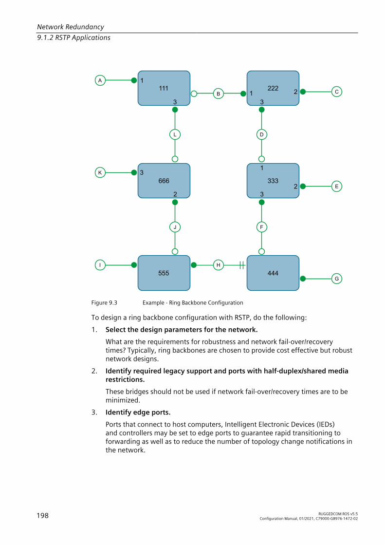
Network Redundancy9.1.2 RSTP Applications
E
1
3
31
C
G
A
K
I1
32
2
2 32
1
3321B
J
555
666 333
444
F
L D
H
111 222
Figure 9.3 Example - Ring Backbone Configuration
To design a ring backbone configuration with RSTP, do the following:1. Select the design parameters for the network.
What are the requirements for robustness and network fail-over/recoverytimes? Typically, ring backbones are chosen to provide cost effective but robustnetwork designs.
2. Identify required legacy support and ports with half-duplex/shared mediarestrictions.These bridges should not be used if network fail-over/recovery times are to beminimized.
3. Identify edge ports.Ports that connect to host computers, Intelligent Electronic Devices (IEDs)and controllers may be set to edge ports to guarantee rapid transitioning toforwarding as well as to reduce the number of topology change notifications inthe network.
198 RUGGEDCOM ROS v5.5Configuration Manual, 01/2021, C79000-G8976-1472-02
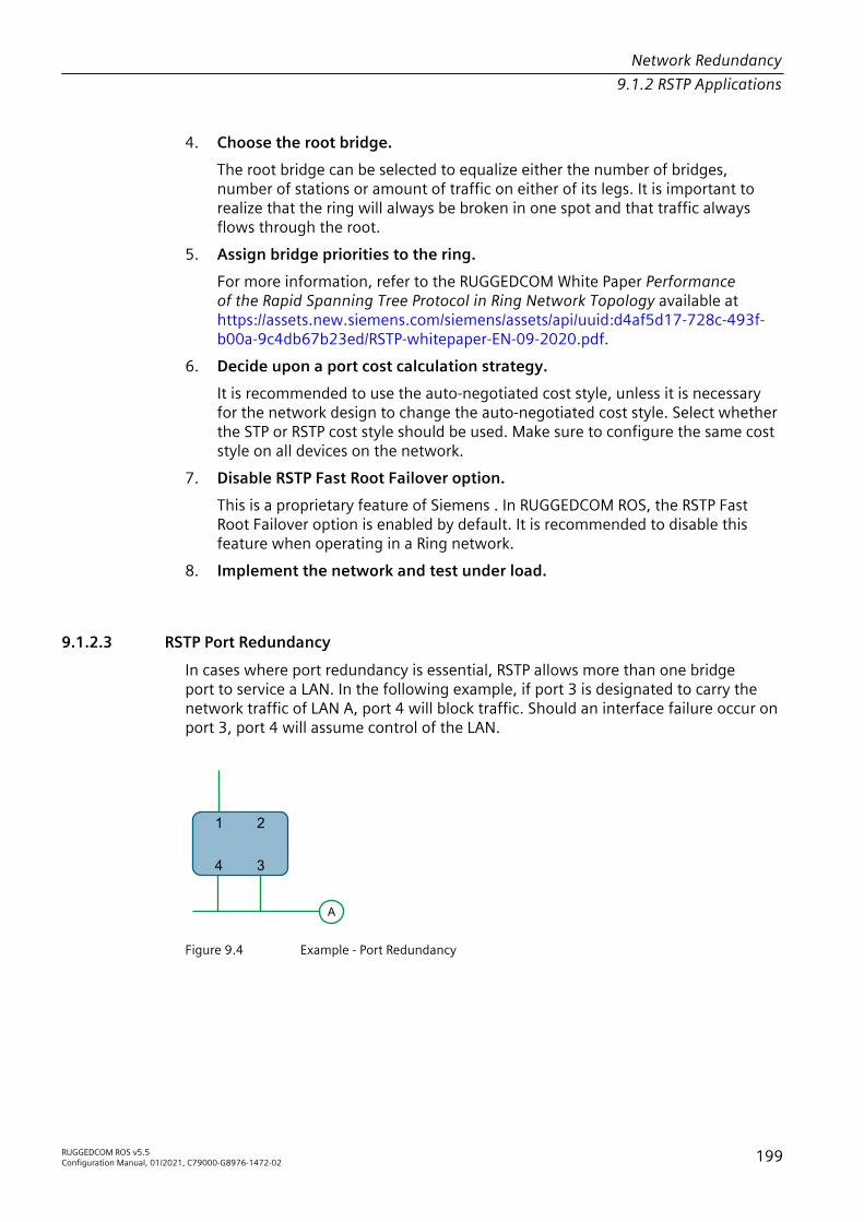
Network Redundancy9.1.2 RSTP Applications
4. Choose the root bridge.The root bridge can be selected to equalize either the number of bridges,number of stations or amount of traffic on either of its legs. It is important torealize that the ring will always be broken in one spot and that traffic alwaysflows through the root.
5. Assign bridge priorities to the ring.For more information, refer to the RUGGEDCOM White Paper Performanceof the Rapid Spanning Tree Protocol in Ring Network Topology available athttps://assets.new.siemens.com/siemens/assets/api/uuid:d4af5d17-728c-493f-b00a-9c4db67b23ed/RSTP-whitepaper-EN-09-2020.pdf.
6. Decide upon a port cost calculation strategy.It is recommended to use the auto-negotiated cost style, unless it is necessaryfor the network design to change the auto-negotiated cost style. Select whetherthe STP or RSTP cost style should be used. Make sure to configure the same coststyle on all devices on the network.
7. Disable RSTP Fast Root Failover option.This is a proprietary feature of Siemens . In RUGGEDCOM ROS, the RSTP FastRoot Failover option is enabled by default. It is recommended to disable thisfeature when operating in a Ring network.
8. Implement the network and test under load.
9.1.2.3 RSTP Port Redundancy
In cases where port redundancy is essential, RSTP allows more than one bridgeport to service a LAN. In the following example, if port 3 is designated to carry thenetwork traffic of LAN A, port 4 will block traffic. Should an interface failure occur onport 3, port 4 will assume control of the LAN.
A
1 2
34
Figure 9.4 Example - Port Redundancy
RUGGEDCOM ROS v5.5Configuration Manual, 01/2021, C79000-G8976-1472-02 199

Network Redundancy9.1.3 MSTP Operation
9.1.3 MSTP OperationThe Multiple Spanning Tree (MST) algorithm and protocol provide greater controland flexibility than RSTP and legacy STP. MSTP (Multiple Spanning Tree Protocol) isan extension of RSTP, whereby multiple spanning trees may be maintained on thesame bridged network. Data traffic is allocated to one or another of several spanningtrees by mapping one or more VLANs onto the network.The sophistication and utility of the Multiple Spanning Tree implementation on agiven bridged network is proportional to the amount of planning and design investedin configuring MSTP.If MSTP is activated on some or all of the bridges in a network with no additionalconfiguration, the result will be a fully and simply connected network, but at best,the result will be the same as a network using only RSTP. Taking full advantage ofthe features offered by MSTP requires a potentially large number of configurationvariables to be derived from an analysis of data traffic on the bridged network, andfrom requirements for load sharing, redundancy, and path optimization. Once theseparameters have all been derived, it is also critical that they are consistently appliedand managed across all bridges in an MST region.By design, MSTP processing time is proportional to the number of active STPinstances. This means that MSTP will likely be significantly slower than RSTP.Therefore, for mission critical applications, RSTP should be considered a betternetwork redundancy solution than MSTP.
9.1.3.1 MSTP Regions and Interoperability
In addition to supporting multiple spanning trees in a network of MSTP-capablebridges, MSTP is capable of inter-operating with bridges that support only RSTP orlegacy STP, without requiring any special configuration.An MST region may be defined as the set of interconnected bridges whose MSTRegion Identification is identical. The interface between MSTP bridges and non-MSTP bridges, or between MSTP bridges with different MST Region Identificationinformation, becomes part of an MST Region boundary.Bridges outside an MST region will see the entire region as though it were a single(R)STP bridge; the internal detail of the MST region is hidden from the rest of thebridged network. In support of this, MSTP maintains separate hop counters forspanning tree information exchanged at the MST region boundary versus thatpropagated inside the region. For information received at the MST region boundary,the (R)STP Message Age is incremented only once. Inside the region, a separateRemaining Hop Count is maintained, one for each spanning tree instance. Theexternal Message Age parameter is referred to the (R)STP Maximum Age Time,whereas the internal Remaining Hop Counts are compared to an MST region-wideMaximum Hops parameter.
200 RUGGEDCOM ROS v5.5Configuration Manual, 01/2021, C79000-G8976-1472-02

Network Redundancy9.1.3 MSTP Operation
MSTIAn MSTI (Multiple Spanning Tree Instance) is one of sixteen independent spanningtree instances that may be defined in an MST region (not including the IST – seebelow). An MSTI is created by mapping a set of VLANs (in RUGGEDCOM ROS, viathe VLAN configuration) to a given MSTI ID. The same mapping must be configuredon all bridges that are intended to be part of the MSTI. Moreover, all VLAN to MSTImappings must be identical for all bridges in an MST region.RUGGEDCOM ROS supports 16 MSTIs in addition to the IST.Each MSTI has a topology that is independent of every other. Data traffic originatingfrom the same source and bound to the same destination but on different VLANs ondifferent MSTIs may therefore travel a different path across the network.
ISTAn MST region always defines an IST (Internal Spanning Tree). The IST spans theentire MST region, and carries all data traffic that is not specifically allocated (byVLAN) to a specific MSTI. The IST is always computed and is defined to be MSTI zero.The IST is also the extension inside the MST region of the CIST (see below), whichspans the entire bridged network, inside and outside of the MST region and all otherRSTP and STP bridges, as well as any other MST regions.
CSTThe CST (Common Spanning Tree) spans the entire bridged network, including MSTregions and any connected STP or RSTP bridges. An MST region is seen by the CST asan individual bridge, with a single cost associated with its traversal.
CISTThe CIST (Common and Internal Spanning Tree) is the union of the CST and the ISTsin all MST regions. The CIST therefore spans the entire bridged network, reachinginto each MST region via the latter’s IST to reach every bridge on the network.
9.1.3.2 MSTP Bridge and Port Roles
MSTP supports the following bridge and port roles:
Bridge Roles
Role DescriptionCIST Root The CIST Root is the elected root bridge of the
CIST (Common and Internal Spanning Tree),which spans all connected STP and RSTP bridgesand MSTP regions.
CIST Regional Root The root bridge of the IST within an MSTP region.The CIST Regional Root is the bridge within an
RUGGEDCOM ROS v5.5Configuration Manual, 01/2021, C79000-G8976-1472-02 201

Network Redundancy9.1.3 MSTP Operation
Role DescriptionMSTP region with the lowest cost path to the CISTRoot. Note that the CIST Regional Root will be atthe boundary of an MSTP region. Note also thatit is possible for the CIST Regional Root to be theCIST Root.
MSTI Regional Root The root bridge for an MSTI within an MSTPregion. A root bridge is independently elected foreach MSTI in an MSTP region.
Port RolesEach port on an MSTP bridge may have more than one CIST role depending on thenumber and topology of spanning tree instances defined on the port.
Role DescriptionCIST Port Roles • The Root Port provides the minimum cost
path from the bridge to the CIST Root viathe CIST Regional Root. If the bridge itselfhappens to be the CIST Regional Root, theRoot Port is also the Master Port for all MSTIs,and provides the minimum cost path to a CISTRoot located outside the region.
• A Designated Port provides the minimum costpath from an attached LAN, via the bridge tothe CIST Regional Root.
• Alternate and Backup Ports function the sameas they do in RSTP, but relative to the CISTRegional Root.
MSTI Port Roles For each MSTI on a bridge:• The Root Port provides the minimum cost
path from the bridge to the MSTI RegionalRoot, if the bridge itself is not the MSTIRegional Root.
• A Designated Port provides the minimum costpath from an attached LAN, via the bridge tothe MSTI Regional Root.
• Alternate and Backup Ports function the sameas they do in RSTP, but relative to the MSTIRegional Root.
The Master Port, which is unique in an MSTPregion, is the CIST Root Port of the CIST RegionalRoot, and provides the minimum cost path to theCIST Root for all MSTIs.
Boundary Ports A Boundary Port is a port on a bridge in an MSTPregion that connects to either: a bridge belongingto a different MSTP region, or a bridge supportingonly RSTP or legacy STP. A Boundary Port blocksor forwards all VLANs from all MSTIs and the CISTalike.A Boundary Port may be:• The CIST Root Port of the CIST Regional Root
(and therefore also the MSTI Master Port).
202 RUGGEDCOM ROS v5.5Configuration Manual, 01/2021, C79000-G8976-1472-02

Network Redundancy9.1.3 MSTP Operation
Role Description• A CIST Designated Port, CIST Alternate/
Backup Port, or Disabled. At the MSTP regionboundary, the MSTI Port Role is the same asthe CIST Port Role.
A Boundary Port connected to an STP bridgewill send only STP BPDUs. One connected to anRSTP bridge need not refrain from sending MSTPBPDUs. This is made possible by the fact that theMSTP carries the CIST Regional Root Identifier inthe field that RSTP parses as the Designated BridgeIdentifier.
9.1.3.3 Benefits of MSTP
Despite the fact that MSTP is configured by default to arrive automatically at aspanning tree solution for each configured MSTI, advantages may be gained frominfluencing the topology of MSTIs in an MST region. The fact that the Bridge Priorityand each port cost are configurable per MST makes it possible to control the topologyof each MSTI within a region.
Load BalancingMSTP can be used to balance data traffic load among sets of VLANs, enabling morecomplete utilization of a multiply interconnected bridged network.A bridged network controlled by a single spanning tree will block redundant linksby design, to avoid harmful loops. Using MSTP, however, any given link may have adifferent blocking state for MSTI, as maintained by MSTP. Any given link, therefore,might be in blocking state for some VLANs, and in forwarding state for other VLANs,depending on the mapping of VLANs to MSTIs.It is possible to control the spanning tree solution for each MSTI, especially the setof active links for each tree, by manipulating, per MSTI, the bridge priority and theport costs of links in the network. If traffic is allocated judiciously to multiple VLANs,redundant interconnections in a bridged network which, using a single spanningtree, would have gone unused, can now be made to carry traffic.
Isolation of Spanning Tree Reconfiguration.A link failure in an MSTP region that does not affect the roles of Boundary portswill not cause the CST to be reconfigured, nor will the change affect other MSTPregions. This is due to the fact that MSTP information does not propagate past aregion boundary.
MSTP vs. PVSTAn advantage of MSTP over the Cisco Systems Inc. proprietary Per-VLAN SpanningTree (PVST) protocol is the ability to map multiple VLANs onto a single MSTI. Since
RUGGEDCOM ROS v5.5Configuration Manual, 01/2021, C79000-G8976-1472-02 203

Network Redundancy9.1.3 MSTP Operation
each spanning tree requires processing and memory, the expense of keeping track ofan increasing number of VLANs increases much more rapidly for PVST than for MSTP.
Compatibility with STP and RSTPNo special configuration is required for the bridges of an MST region to connect fullyand simply to non-MST bridges on the same bridged network. Careful planning andconfiguration is, however, recommended to arrive at an optimal network.
9.1.3.4 Implementing MSTP on a Bridged Network
It is recommended the configuration of MSTP on a network proceed in the sequenceoutlined below.Naturally, it is also recommended that network analysis and planning inform thesteps of configuring the VLAN and MSTP parameters in particular.Begin with a set of MSTP-capable Ethernet bridges and MSTP disabled. For eachbridge in the network:
NoteMSTP does not need to be enabled to map a VLAN to an MSTI. However, the mappingmust be identical for each bridge that belongs to the MSTP region.
1. Configure and enable STP globally and/or for specific Ethernet ports. For moreinformation, refer to "Configuring STP Globally (Page 205)" or "Configuring STPfor Specific Ethernet Ports (Page 206)".
NoteStatic VLANs must be used in an MSTP configuration. GVRP is not supported.
2. Add static VLANs and map them to MSTIs. For more information, refer to"Adding a Static VLAN (Page 153)".
NoteThe Region Identifier and Revision Level must be the same for each bridge in theMST region.
3. Configure the revision level for the MST Region Identifier. For more information,refer to "Configuring the MST Region Identifier (Page 216)".
4. Make sure the read-only digest for the MST Region Identifier is identical for eachbridge in the MST region. If the digest is different, the set of mappings fromVLANs to MSTIs differs.
5. Configure the Bridge Priority for the global MSTI. For more information, refer to"Configuring a Global MSTI (Page 216)".
6. Configure the Port Cost and Priority per Port for each MSTI. For moreinformation, refer to "Configuring an MSTI for an Ethernet Port (Page 217)".
204 RUGGEDCOM ROS v5.5Configuration Manual, 01/2021, C79000-G8976-1472-02
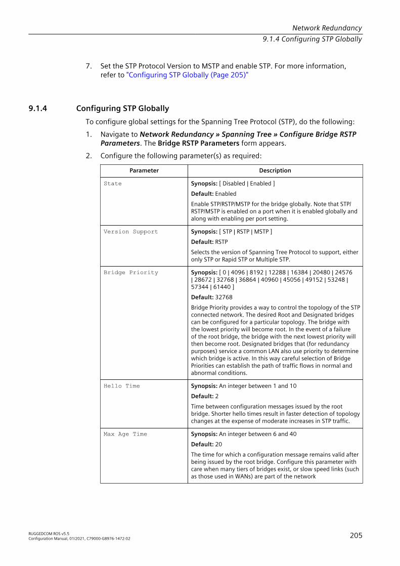
Network Redundancy9.1.4 Configuring STP Globally
7. Set the STP Protocol Version to MSTP and enable STP. For more information,refer to "Configuring STP Globally (Page 205)"
9.1.4 Configuring STP GloballyTo configure global settings for the Spanning Tree Protocol (STP), do the following:1. Navigate to Network Redundancy » Spanning Tree » Configure Bridge RSTP
Parameters. The Bridge RSTP Parameters form appears.2. Configure the following parameter(s) as required:
Parameter Description
State Synopsis: [ Disabled | Enabled ]Default: EnabledEnable STP/RSTP/MSTP for the bridge globally. Note that STP/RSTP/MSTP is enabled on a port when it is enabled globally andalong with enabling per port setting.
Version Support Synopsis: [ STP | RSTP | MSTP ]Default: RSTPSelects the version of Spanning Tree Protocol to support, eitheronly STP or Rapid STP or Multiple STP.
Bridge Priority Synopsis: [ 0 | 4096 | 8192 | 12288 | 16384 | 20480 | 24576| 28672 | 32768 | 36864 | 40960 | 45056 | 49152 | 53248 |57344 | 61440 ]Default: 32768Bridge Priority provides a way to control the topology of the STPconnected network. The desired Root and Designated bridgescan be configured for a particular topology. The bridge withthe lowest priority will become root. In the event of a failureof the root bridge, the bridge with the next lowest priority willthen become root. Designated bridges that (for redundancypurposes) service a common LAN also use priority to determinewhich bridge is active. In this way careful selection of BridgePriorities can establish the path of traffic flows in normal andabnormal conditions.
Hello Time Synopsis: An integer between 1 and 10Default: 2Time between configuration messages issued by the rootbridge. Shorter hello times result in faster detection of topologychanges at the expense of moderate increases in STP traffic.
Max Age Time Synopsis: An integer between 6 and 40Default: 20The time for which a configuration message remains valid afterbeing issued by the root bridge. Configure this parameter withcare when many tiers of bridges exist, or slow speed links (suchas those used in WANs) are part of the network
RUGGEDCOM ROS v5.5Configuration Manual, 01/2021, C79000-G8976-1472-02 205

Network Redundancy9.1.5 Configuring STP for Specific Ethernet Ports
Parameter Description
Transmit Count Synopsis: An integer between 3 and 100 or [ Unlimited ]Default: UnlimitedMaximum number of BPDUs on each port that may be sent inone second. Larger values allow the network to recover fromfailed links/bridges more quickly.
Forward Delay Synopsis: An integer between 4 and 30Default: 15The amount of time a bridge spends learning MAC addresses ona rising port before beginning to forward traffic. Lower valuesallow the port to reach the forwarding state more quickly, butat the expense of flooding unlearned addresses to all ports.
Max Hops Synopsis: An integer between 6 and 40Default: 20Only applicable to MSTP. The maximum possible bridgediameter inside an MST region.MSTP BPDUs propagating inside an MST region specify a time-to-live that is decremented by every switch that propagatesthe BPDU. If the maximum number of hops inside the regionexceeds the configured maximum, BPDUs may be discarded dueto their time-to-live setting.
3. Click Apply.
9.1.5 Configuring STP for Specific Ethernet PortsTo configure the Spanning Tree Protocol (STP) for a specific Ethernet port, do thefollowing:1. Navigate to Network Redundancy » Spanning Tree » Configure Port RSTP
Parameters. The Port RSTP Parameters table appears.2. Select an Ethernet port. The Port RSTP Parameters form appears.3. Configure the following parameter(s) as required:
Parameter Description
Port(s) Synopsis: Comma-separated list of portsThe port number as seen on the front plate silkscreen of theswitch (or a list of ports, if aggregated in a port trunk).
Enabled Synopsis: [ Disabled | Enabled ]Default: EnabledEnabling STP activates the STP or RSTP protocol for this port perthe configuration in the STP Configuration menu. STP may bedisabled for the port ONLY if the port does not attach to an STPenabled bridge in any way. Failure to meet this requirementWILL result in an undetectable traffic loop in the network. Abetter alternative to disabling the port is to leave STP enabledbut to configure the port as an edge port. A good candidate for
206 RUGGEDCOM ROS v5.5Configuration Manual, 01/2021, C79000-G8976-1472-02

Network Redundancy9.1.5 Configuring STP for Specific Ethernet Ports
Parameter Descriptiondisabling STP would be a port that services only a single hostcomputer.
Priority Synopsis: [ 0 | 16 | 32 | 48 | 64 | 80 | 96 | 112 | 128 | 144 | 160 |176 | 194 | 208 | 224 | 240 ]Default: 128Selects the STP port priority. Ports of the same cost that attachto a common LAN will select the port to be used based upon theport priority.
STP Cost Synopsis: An integer between 0 and 65535 or [ Auto ]Default: AutoSelects the cost to use in cost calculations, when the CostStyle parameter is set to STP in the Bridge RSTP Parametersconfiguration. Setting the cost manually provides the ability topreferentially select specific ports to carry traffic over others.Leave this field set to "auto" to use the standard STP port costsas negotiated (4 for 1Gbps, 19 for 100 Mbps links and 100 for10 Mbps links).For MSTP, this parameter applies to both external and internalpath cost.
RSTP Cost Synopsis: An integer between 0 and 2147483647 or [ Auto ]Default: AutoSelects the cost to use in cost calculations, when the CostStyle parameter is set to RSTP in the Bridge RSTP Parametersconfiguration. Setting the cost manually provides the ability topreferentially select specific ports to carry traffic over others.Leave this field set to "auto" to use the standard RSTP port costsas negotiated (20,000 for 1Gbps, 200,000 for 100 Mbps linksand 2,000,000 for 10 Mbps links).For MSTP, this parameter applies to both external and internalpath cost.
Edge Port Synopsis: [ False | True | Auto ]Default: AutoEdge ports are ports that do not participate in the SpanningTree, but still send configuration messages. Edge portstransition directly to frame forwarding without any listeningand learning delays. The MAC tables of Edge ports do notneed to be flushed when topology changes occur in the STPnetwork. Unlike an STP disabled port, accidentally connectingan edge port to another port in the spanning tree will result ina detectable loop. The "Edgeness" of the port will be switchedoff and the standard RSTP rules will apply (until the next linkoutage).
Point to Point Synopsis: [ False | True | Auto ]Default: AutoRSTP uses a peer-to-peer protocol that provides rapidtransitioning on point-to-point links. This protocol isautomatically turned off in situations where multiple STPbridges communicate over a shared (non point-to-point) LAN.The bridge will automatically take point-to-point to be true
RUGGEDCOM ROS v5.5Configuration Manual, 01/2021, C79000-G8976-1472-02 207

Network Redundancy9.1.6 Configuring eRSTP
Parameter Descriptionwhen the link is found to be operating in full-duplex mode. Thepoint-to-point parameter allows this behavior or overrides it,forcing point-to-point to be true or false. Force the parametertrue when the port operates a point-to-point link but cannot runthe link in full-duplex mode. Force the parameter false whenthe port operates the link in full-duplex mode, but is still notpoint-to-point (e.g. a full-duplex link to an unmanaged bridgethat concentrates two other STP bridges).
Restricted Role Synopsis: [ True | False ]Default: FalseA boolean value set by management. If TRUE, causes the Portnot to be selected as the Root Port for the CIST or any MSTI,even if it has the best spanning tree priority vector. Such a Portwill be selected as an Alternate Port after the Root Port has beenselected. This parameter should be FALSE by default. If set,it can cause a lack of spanning tree connectivity. It is set by anetwork administrator to prevent bridges that are external to acore region of the network from influencing the spanning treeactive topology. This may be necessary, for example, if thosebridges are not under the full control of the administrator.
Restricted TCN Synopsis: [ True | False ]Default: FalseA boolean value set by management. If TRUE, it causes the Portnot to propagate received topology change notifications andtopology changes to other Ports. If set, it can cause temporaryloss of connectivity after changes in a spanning tree’s activetopology as a result of persistent, incorrectly learned, stationlocation information. It is set by a network administratorto prevent bridges that are external to a core region of thenetwork from causing address flushing in that region. Thismay be necessary, for example, if those bridges are not underthe full control of the administrator or if the MAC_Operationalstatus parameter for the attached LANs transitions frequently.
4. Click Apply.
9.1.6 Configuring eRSTPTo configure eRSTP, do the following:1. Navigate to Network Redundancy » Spanning Tree » Configure eRSTP
Parameters. The eRSTP Parameters form appears.2. Configure the following parameter(s) as required:
Parameter Description
Max Network Diameter Synopsis: [ MaxAgeTime | 4*MaxAgeTime ]Default: 4*MaxAgeTimeThe RSTP standard puts a limit on the maximum network sizethat can be controlled by the RSTP protocol. The network sizeis described by the term 'maximum network diameter', which
208 RUGGEDCOM ROS v5.5Configuration Manual, 01/2021, C79000-G8976-1472-02

Network Redundancy9.1.6 Configuring eRSTP
Parameter Descriptionis the number of switches that comprise the longest path thatRSTP BPDUs have to traverse. The standard supported maximumnetwork diameter is equal to the value of the 'MaxAgeTime'RSTP configuration parameter.eRSTP offers an enhancement to RSTP which allows it to covernetworks larger than ones defined by the standard.This configuration parameter selects the maximum supportednetwork size.
BPDU Guard Timeout Synopsis: An integer between 1 and 86400 or [ Until reset |Don't shutdown ]Default: Don't shutdownThe RSTP standard does not address network security. RSTPmust process every received BPDU and take an appropriateaction. This opens a way for an attacker to influence RSTPtopology by injecting RSTP BPDUs into the network.BPDU Guard is a feature that protects the network from BPDUsreceived by a port where RSTP capable devices are not expectedto be attached. If a BPDU is received by a port for which 'Edge'parameter is set to 'TRUE' or RSTP is disabled, the port will beshutdown for the time period specified by this parameter.• Don't shutdown – BPDU Guard is disabled• Until reset – port will remain shutdown until the port
reset command is issued by the user
Fast Root Failover Synopsis: [ On | On with standard root | Off ]Default: OnIn mesh network topologies, the standard RSTP algorithm doesnot guarantee deterministic network recovery time in the caseof a root switch failure. Such a recovery time is hard to calculateand it can be different (and may be relatively long) for anygiven mesh topology.This configuration parameter enables Siemens's enhancementto RSTP which detects a failure of the root switch and performssome extra RSTP processing steps, significantly reducing thenetwork recovery time and making it deterministic.
Note• This feature is only available in RSTP mode. In MSTP mode,
the configuration parameter is ignored.• In a single ring topology, this feature is not needed and
should be disabled to avoid longer network recovery timesdue to extra RSTP processing.
The Fast Root Failover algorithm must be supported by allswitches in the network, including the root, to guaranteeoptimal performance. However, it is not uncommon to assignthe root role to a switch from a vendor different from the restof the switches in the network. In other words, it is possiblethat the root might not suport the Fast Root Failover algorithm.In such a scenario, a "relaxed" algorithm should be used, whichtolerates the lack of support in the root switch.
RUGGEDCOM ROS v5.5Configuration Manual, 01/2021, C79000-G8976-1472-02 209

Network Redundancy9.1.7 Viewing Global Statistics for STP
Parameter DescriptionThese are the supported configuration options:• Off – Fast Root Failover algorithm is disabled and hence a
root switch failure may result in excessive connectivity re-covery time.
• On – Fast Root Failover is enabled and the most robust algo-rithm is used, which requires the appropriate support in theroot switch.
• On with standard root – Fast Root Failover is enabledbut a "relaxed" algorithm is used, allowing the use of a stan-dard switch in the root role.
IEEE802.1w Interoper ability
Synopsis: [ On | Off ]Default: OnThe original RSTP protocol defined in the IEEE 802.1wstandard has minor differences from more recent, enhanced,standard(s). Those differences cause interoperability issueswhich, although they do not completely break RSTP operation,can lead to a longer recovery time from failures in the network.eRSTP offers some enhancements to the protocol which makethe switch fully interoperable with other vendors' switches,which may be running IEEE 802.2w RSTP. The enhancementsdo not affect interoperability with more recent RSTP editions.This configuration parameter enables the aforementionedinteroperability mode.
Cost Style Synopsis: [ STP (16 bit) | RSTP (32 bit) ]Default: STP (16 bit)The RSTP standard defines two styles of a path cost value. STPuses 16-bit path costs based upon 1x10E9/link speed (4 for1Gbps, 19 for 100 Mbps and 100 for 10 Mbps) whereas RSTPuses 32-bit costs based upon 2x10E13/link speed (20,000 for1Gbps, 200,000 for 100 Mbps and 2,000,000 for 10 Mbps).However, switches from some vendors keep using the STP pathcost style even in RSTP mode, which can cause confusion andinteroperability problems.This configuration parameter selects the style of link costs toemploy.Note that RSTP link costs are used only when the bridge versionsupport is set to allow RSTP and the port does not migrate toSTP.
3. Click Apply.
9.1.7 Viewing Global Statistics for STPTo view global statistics for STP, Navigate to Network Redundancy » SpanningTree » View Bridge RSTP Statistics. The Bridge RSTP Statistics form appears.
210 RUGGEDCOM ROS v5.5Configuration Manual, 01/2021, C79000-G8976-1472-02

Network Redundancy9.1.7 Viewing Global Statistics for STP
This table displays the following information:
Parameter Description
Bridge Status Synopsis: [ Designated Bridge | Not Designated For Any LAN | RootBridge ]Spanning Tree status of the bridge. The status may be root ordesignated. This field may show text saying not designated for anyLAN if the bridge is not designated for any of its ports.
Bridge ID Synopsis: $$ / ##-##-##-##-##-## where $$ is 0 to 65535, ## is 0to FFBridge Identifier of this bridge.
Root ID Synopsis: $$ / ##-##-##-##-##-## where $$ is 0 to 65535, ## is 0to FFBridge Identifier of the root bridge.
Root Port Synopsis: 1/1 to maximum port number or [ <empty string> ]If the bridge is designated, this is the port that providesconnectivity towards the root bridge of the network.
Root Path Cost Synopsis: An integer between 0 and 4294967295Total cost of the path to the root bridge composed of the sum ofthe costs of each link in the path. If custom costs have not beenconfigured. 1Gbps ports will contribute 4, 100 Mbps ports willcontribute 19 and 10 Mbps ports will contribute a cost of 100 tothis figure.For the CIST instance of MSTP, this is an external root path cost,which is the cost of the path from the IST root (i.e. regional root)bridge to the CST root (i.e. network "global" root) bridge.
Configured Hello Time Synopsis: An integer between 0 and 65535The configured Hello time from the Bridge RSTP Parameters menu.
Learned Hello Time Synopsis: An integer between 0 and 65535The actual Hello time provided by the root bridge as learned inconfiguration messages. This time is used in designated bridges.
Configured Forward Delay Synopsis: An integer between 0 and 65535The configured Forward Delay time from the Bridge RSTPParameters menu.
Learned Forward Delay Synopsis: An integer between 0 and 65535The actual Forward Delay time provided by the root bridge aslearned in configuration messages. This time is used in designatedbridges.
Configured Max Age Synopsis: An integer between 0 and 65535The configured Maximum Age time from the Bridge RSTPParameters menu.
Learned Max Age Synopsis: An integer between 0 and 65535The actual Maximum Age time provided by the root bridge aslearned in configuration messages. This time is used in designatedbridges.
RUGGEDCOM ROS v5.5Configuration Manual, 01/2021, C79000-G8976-1472-02 211

Network Redundancy9.1.8 Viewing STP Statistics for Ethernet Ports
Parameter Description
Total Topology Changes Synopsis: An integer between 0 and 65535A count of topology changes in the network, as detected on thisbridge through link failures or as signaled from other bridges.Excessively high or rapidly increasing counts signal networkproblems.
Time since Last TC Synopsis: DDDD days, HH:MM:SSThe time since the last time a topology change was detected by thebridge.
9.1.8 Viewing STP Statistics for Ethernet PortsTo view STP statistics for Ethernet ports, Navigate to Network Redundancy »Spanning Tree » View Port RSTP Statistics. The Port RSTP Statistics table appears.This table displays the following information:
Parameter Description
Port(s) Synopsis: Comma-separated list of portsThe port number as seen on the front plate silkscreen of the switch(or a list of ports, if aggregated in a port trunk).
Status Synopsis: [ Disabled | Listening | Learning | Forwarding | Blocking |Link Down | Discarding ]Status of this port in Spanning Tree. This may be one of thefollowing:• Disabled – STP is disabled on this port.• Listening – This state is not used by .• Learning – The port is learning MAC addresses to prevent
flooding when it begins forwarding traffic.• Forwarding – The port is forwarding traffic.• Blocking – The port is blocking traffic.• Link Down – STP is enabled on this port but the link is down.• Discarding – The link is not used in the STP topology but is
standing by.
Role Synopsis: [ Root | Designated | Alternate | Backup | Master ]Role of this port in Spanning Tree. This may be one of thefollowing:• Designated – The port is designated for (i.e. carries traffic to-
wards the root for) the LAN it is connected to.• Root – The single port on the bridge, which provides connec-
tivity towards the root bridge.• Backup – The port is attached to a LAN that is serviced by an-
other port on the bridge. It is not used but is standing by.• Alternate – The port is attached to a bridge that provides
connectivity to the root bridge. It is not used but is standing by.
212 RUGGEDCOM ROS v5.5Configuration Manual, 01/2021, C79000-G8976-1472-02

Network Redundancy9.1.9 Managing Multiple Spanning Tree Instances
Parameter Description• Master – Only exists in MSTP. The port is an MST region
boundary port and the single port on the bridge, which pro-vides connectivity for the Multiple Spanning Tree Instance to-wards the Common Spanning Tree root bridge (i.e. this port isthe root port for the Common Spanning Tree Instance).
Cost Synopsis: An integer between 0 and 4294967295Cost offered by this port. If the Bridge RSTP Parameters Cost Styleis set to STP, 1Gbps ports will contribute 4, 100 Mbps ports willcontribute 19 and 10 Mbps ports contribute a cost of 100. Ifthe Cost Style is set to RSTP, 1Gbps will contribute 20,000, 100Mbps ports will contribute a cost of 200,000 and 10 Mbps portscontribute a cost of 2,000,000. Note that even if the Cost style isset to RSTP, a port that migrates to STP will have its cost limited to amaximum of 65535.
RX RSTs Synopsis: An integer between 0 and 4294967295The count of RSTP configuration messages received on this port.
TX RSTs Synopsis: An integer between 0 and 4294967295The count of RSTP configuration messages transmitted on this port.
RX Configs Synopsis: An integer between 0 and 4294967295The count of STP configuration messages received on this port.
TX Configs Synopsis: An integer between 0 and 4294967295The count of STP configuration messages transmitted on this port.
RX Tcns Synopsis: An integer between 0 and 4294967295The count of STP topology change notification messages receivedon this port. Excessively high or rapidly increasing counts signalnetwork problems.
TX Tcns Synopsis: An integer between 0 and 4294967295The count of STP topology change notification messagestransmitted on this port.
Desig Bridge ID Synopsis: $$ / ##-##-##-##-##-## where $$ is 0 to 65535, ## is 0to FFProvided on the root ports of designated bridges, the BridgeIdentifier of the bridge this port is connected to.
operEdge Synopsis: [ True | False ]The port is operating as an edge port or not.
9.1.9 Managing Multiple Spanning Tree InstancesThis section describes how to configure and manage Multiple Spanning TreeInstances (MSTIs).
RUGGEDCOM ROS v5.5Configuration Manual, 01/2021, C79000-G8976-1472-02 213

Network Redundancy9.1.9 Managing Multiple Spanning Tree Instances
9.1.9.1 Viewing Statistics for Global MSTIs
To view statistics for global MSTIs, Navigate to Network Redundancy » SpanningTree » View Bridge MSTI Statistics. The Bridge MSTI Statistics form appears.To view statistics for global MSTIs, Navigate to Spanning Tree » View Bridge MSTIStatistics. The Bridge MSTI Statistics form appears.This table displays the following information:
Parameter Description
Bridge Status Synopsis: [ Designated Bridge | Not Designated For Any LAN | RootBridge ]Spanning Tree status of the bridge. The status may be root ordesignated. This field may show text saying not designated for anyLAN if the bridge is not designated for any of its ports.
Bridge ID Synopsis: $$ / ##-##-##-##-##-## where $$ is 0 to 65535, ## is 0to FFBridge Identifier of this bridge.
Root ID Synopsis: $$ / ##-##-##-##-##-## where $$ is 0 to 65535, ## is 0to FFBridge Identifier of the root bridge.
Root Port Synopsis: 1/1 to maximum port number or [ <empty string> ]If the bridge is designated, this is the port that providesconnectivity towards the root bridge of the network.
Root Path Cost Synopsis: An integer between 0 and 4294967295Total cost of the path to the root bridge composed of the sum ofthe costs of each link in the path. If custom costs have not beenconfigured. 1Gbps ports will contribute 4, 100 Mbps ports willcontribute 19 and 10 Mbps ports will contribute a cost of 100 tothis figure.For the CIST instance of MSTP, this is an external root path cost,which is the cost of the path from the IST root (i.e. regional root)bridge to the CST root (i.e. network "global" root) bridge.
Total Topology Changes Synopsis: An integer between 0 and 65535A count of topology changes in the network, as detected on thisbridge through link failures or as signaled from other bridges.Excessively high or rapidly increasing counts signal networkproblems.
9.1.9.2 Viewing Statistics for Port MSTIs
To view statistics for port MSTIs, Navigate to Network Redundancy » SpanningTree » View Port MSTI Statistics. The Port MSTI Statistics form appears.
214 RUGGEDCOM ROS v5.5Configuration Manual, 01/2021, C79000-G8976-1472-02

Network Redundancy9.1.9 Managing Multiple Spanning Tree Instances
This table displays the following information:
Parameter Description
Port(s) Synopsis: Comma-separated list of portsThe port number as seen on the front plate silkscreen of the switch(or a list of ports, if aggregated in a port trunk).
Status Synopsis: [ Disabled | Listening | Learning | Forwarding | Blocking |Link Down | Discarding ]Status of this port in Spanning Tree. This may be one of thefollowing:• Disabled – STP is disabled on this port.• Listening – This state is not used by .• Learning – The port is learning MAC addresses in order to
prevent flooding when it begins forwarding traffic.• Forwarding – The port is forwarding traffic.• Blocking – The port is blocking traffic.• Link Down – STP is enabled on this port but the link is down.• Discarding – The link is not used in the STP topology but is
standing by.
Role Synopsis: [ Root | Designated | Alternate | Backup | Master ]Role of this port in Spanning Tree. This may be one of thefollowing:• Designated – The port is designated for (i.e. carries traffic to-
wards the root for) the LAN it is connected to.• Root – The single port on the bridge, which provides connec-
tivity towards the root bridge.• Backup – The port is attached to a LAN that is serviced by an-
other port on the bridge. It is not used but is standing by.• Alternate – The port is attached to a bridge that provides
connectivity to the root bridge. It is not used but is standing by.• Master – Only exists in MSTP. The port is an MST region
boundary port and the single port on the bridge, which pro-vides connectivity for the Multiple Spanning Tree Instance to-wards the Common Spanning Tree root bridge (i.e. this port isthe root port for the Common Spanning Tree Instance).
Cost Synopsis: An integer between 0 and 4294967295Cost offered by this port. If the Bridge RSTP Parameters Cost Styleis set to STP, 1Gbps ports will contribute 4, 100 Mbps ports willcontribute 19 and 10 Mbps ports contribute a cost of 100. Ifthe Cost Style is set to RSTP, 1Gbps will contribute 20,000, 100Mbps ports will contribute a cost of 200,000 and 10 Mbps portscontribute a cost of 2,000,000. Note that even if the Cost style isset to RSTP, a port that migrates to STP will have its cost limited to amaximum of 65535.
Desig Bridge ID Synopsis: $$ / ##-##-##-##-##-## where $$ is 0 to 65535, ## is 0to FFProvided on the root ports of designated bridges, the BridgeIdentifier of the bridge this port is connected to.
RUGGEDCOM ROS v5.5Configuration Manual, 01/2021, C79000-G8976-1472-02 215
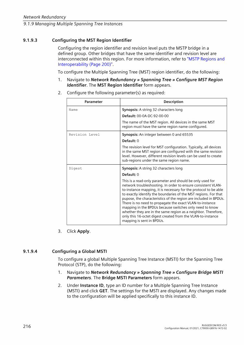
Network Redundancy9.1.9 Managing Multiple Spanning Tree Instances
9.1.9.3 Configuring the MST Region Identifier
Configuring the region identifier and revision level puts the MSTP bridge in adefined group. Other bridges that have the same identifier and revision level areinterconnected within this region. For more information, refer to "MSTP Regions andInteroperability (Page 200)".To configure the Multiple Spanning Tree (MST) region identifier, do the following:1. Navigate to Network Redundancy » Spanning Tree » Configure MST Region
Identifier. The MST Region Identifier form appears.2. Configure the following parameter(s) as required:
Parameter Description
Name Synopsis: A string 32 characters longDefault: 00-0A-DC-92-00-00The name of the MST region. All devices in the same MSTregion must have the same region name configured.
Revision Level Synopsis: An integer between 0 and 65535Default: 0The revision level for MST configuration. Typically, all devicesin the same MST region are configured with the same revisionlevel. However, different revision levels can be used to createsub-regions under the same region name.
Digest Synopsis: A string 32 characters longDefault: 0This is a read-only parameter and should be only used fornetwork troubleshooting. In order to ensure consistent VLAN-to-instance mapping, it is necessary for the protocol to be ableto exactly identify the boundaries of the MST regions. For thatpupose, the characteristics of the region are included in BPDUs.There is no need to propagate the exact VLAN-to-instancemapping in the BPDUs because switches only need to knowwhether they are in the same region as a neighbor. Therefore,only this 16-octet digest created from the VLAN-to-instancemapping is sent in BPDUs.
3. Click Apply.
9.1.9.4 Configuring a Global MSTI
To configure a global Multiple Spanning Tree Instance (MSTI) for the Spanning TreeProtocol (STP), do the following:1. Navigate to Network Redundancy » Spanning Tree » Configure Bridge MSTI
Parameters. The Bridge MSTI Parameters form appears.2. Under Instance ID, type an ID number for a Multiple Spanning Tree Instance
(MSTI) and click GET. The settings for the MSTI are displayed. Any changes madeto the configuration will be applied specifically to this instance ID.
216 RUGGEDCOM ROS v5.5Configuration Manual, 01/2021, C79000-G8976-1472-02

Network Redundancy9.1.9 Managing Multiple Spanning Tree Instances
3. Configure the following parameter(s) as required:
Parameter Description
Bridge Priority Synopsis: [ 0 | 4096 | 8192 | 12288 | 16384 | 20480 | 24576| 28672 | 32768 | 36864 | 40960 | 45056 | 49152 | 53248 |57344 | 61440 ]Default: 32768Bridge Priority provides a way to control the topology of the STPconnected network. The desired Root and Designated bridgescan be configured for a particular topology. The bridge withthe lowest priority will become root. In the event of a failureof the root bridge, the bridge with the next lowest priority willthen become root. Designated bridges that (for redundancypurposes) service a common LAN also use priority to determinewhich bridge is active. In this way careful selection of BridgePriorities can establish the path of traffic flows in normal andabnormal conditions.
4. Click Apply.
9.1.9.5 Configuring an MSTI for an Ethernet Port
To configure a Multiple Spanning Tree Instance (MSTI) for an Ethernet port, do thefollowing1. Navigate to Network Redundancy » Spanning Tree » Configure Port MSTI
Parameters. The Port MSTI Parameters table appears.2. Select an Ethernet port. The Port MSTI Parameters form appears.3. Under Instance ID, type an ID number for a Multiple Spanning Tree Instance
(MSTI) and click GET. The settings for the MSTI are displayed. Any changes madeto the configuration will be applied specifically to this instance ID.
4. Configure the following parameter(s) as required:
Parameter Description
Port(s) Synopsis: Comma-separated list of portsThe port number as seen on the front plate silkscreen of theswitch (or a list of ports, if aggregated in a port trunk).
Priority Synopsis: [ 0 | 16 | 32 | 48 | 64 | 80 | 96 | 112 | 128 | 144 | 160 |176 | 192 | 208 | 224 | 240 ]Default: 128Selects the STP port priority. Ports of the same cost that attachto a common LAN will select the port to be used based upon theport priority.
STP Cost Synopsis: An integer between 0 and 65535 or [ Auto ]Default: AutoSelects the cost to use in cost calculations, when the CostStyle parameter is set to STP in the Bridge RSTP Parametersconfiguration. Setting the cost manually provides the ability to
RUGGEDCOM ROS v5.5Configuration Manual, 01/2021, C79000-G8976-1472-02 217

Network Redundancy9.1.10 Clearing Spanning Tree Protocol Statistics
Parameter Descriptionpreferentially select specific ports to carry traffic over others.Leave this field set to "auto" to use the standard STP port costsas negotiated (4 for 1Gbps, 19 for 100 Mbps links and 100 for10 Mbps links).For MSTP, this parameter applies to both external and internalpath cost.
RSTP Cost Synopsis: An integer between 0 and 2147483647 or [ Auto ]Default: AutoSelects the cost to use in cost calculations, when the CostStyle parameter is set to RSTP in the Bridge RSTP Parametersconfiguration. Setting the cost manually provides the ability topreferentially select specific ports to carry traffic over others.Leave this field set to "auto" to use the standard RSTP port costsas negotiated (20,000 for 1Gbps, 200,000 for 100 Mbps linksand 2,000,000 for 10 Mbps links).For MSTP, this parameter applies to both external and internalpath cost.
5. Click Apply.
9.1.10 Clearing Spanning Tree Protocol StatisticsTo clear all spanning tree protocol statistics, do the following:1. Navigate to Network Redundancy » Spanning Tree » Clear Spanning Tree
Statistics. The Clear Spanning Tree Statistics form appears.2. Click Confirm.
9.2 Managing the Media Redundancy Protocol (MRP)RUGGEDCOM ROS supports the Media Redundancy Protocol (MRP).
9.2.1 Understanding MRPThe Media Redundancy Protocol (MRP) is a networking protocol designed toimplement redundancy and recovery in a ring topology of up to 50 devices. It allowsrings of Ethernet switches to quickly overcome any single failure of an inter-switchlink or switch in the MRP ring or interconnection topology.MRP operates between Layer 2 and the application layer and uses the functions ofISO/IEC/IEEE 8802-3 (IEEE 802.3) and IEEE 802.1Q, including the Filtering Database(FDB).MRP is standardized by the International Electrotechnical Commission as IEC62439-2.
218 RUGGEDCOM ROS v5.5Configuration Manual, 01/2021, C79000-G8976-1472-02
Network Redundancy9.2.1 Understanding MRP
9.2.1.1 MRM vs MRC Devices
In an MRP ring, the Media Redundancy Manager (MRM) acts as the ring manager,while Media Redundancy Clients (MRCs) act as member nodes of the ring.The MRM periodically sends out MRP Test messages through both of its ring ports.These messages are forwarded by the MRCs between their ring ports. As the switchesare connected in a ring, the MRP test messages circulate through the ring and returnto the MRM. This allows the MRM to determine the state of the ring.When the MRP test messages are returned to the MRM, redundancy is present andthe ring is declared closed. If the MRP test messages fail to return, redundancy is lostand the ring is declared open.When the ring is closed, the MRM drops (blocks) all packets on one of its twodesignated ring ports, while the other port forwards packets. When a link failureoccurs, the MRCs sends a link failure notification to the MRM, which will thenunblock its blocked port, enabling communication between all of the devices.
9.2.1.2 MRA Devices
Media Redundancy Manager Auto (MRA) devices automatically decide which devicewill take on the role of manager in the ring. This is done through an election processbetween all MRAs in the ring. Once the manager is elected, the rest of the MRAs actas clients.When an MRA is present in a ring, all other devices in the ring must be either MRA orMRC (not MRM).
9.2.1.3 Ring Port States
MRM and MRC ring ports support three states: disabled, blocked, and forwarding:• Disabled ring ports drop all received packets.• Blocked ring ports drop all received packets except the MRP control packets.• Forwarding ring ports forward all received packets.
9.2.1.4 Ring-Closed vs Ring-Open
During normal operation, the network works in the ring-closed state. In this state,one of the MRM ring ports is blocked, while the other is forwarding. Both ring portsof all MRCs are forwarding.
RUGGEDCOM ROS v5.5Configuration Manual, 01/2021, C79000-G8976-1472-02 219

Network Redundancy9.2.1 Understanding MRP
5
2
1
4
8
7
3
4
1
3
2
6
1 MRM or MRA acting as Manager 2 MRP Client 1 3 MRP Client 2 4 MRP Client 3
Figure 9.5 MRP Ring-Closed State
In case of failure, the network works in the ring-open state. In this state, when a linkconnecting two devices fails, both ring ports of the MRM are now forwarding. TheMRCs adjacent to the failure have a blocked and a forwarding ring port and the otherMRCs have both ring ports forwarding.
5
2
1
8
74
1
3
2
6
4
3
1 MRM or MRA acting as Manager 2 MRP Client 1 3 MRP Client 2 4 MRP Client 3
Figure 9.6 MRP Ring-Open State
220 RUGGEDCOM ROS v5.5Configuration Manual, 01/2021, C79000-G8976-1472-02

Network Redundancy9.2.2 Configuring MRP Globally
9.2.2 Configuring MRP GloballyTo configure the Media Redundancy Protocol globally, do the following:1. Navigate to Network Redundancy » Ring Redundancy » Configure Global
MRP Parameters. The Global MRP Parameters form appears.2. Configure the following parameter(s) as required:
Parameter Description
State Synopsis: [ Disabled | Enabled ]Default: DisabledEnables/disables MRP globally. Note that MRP can be disabledon a per port basis.
Auto Generate UUID Synopsis: [ Disabled | Enabled ]Default: EnabledEnables/disables the automatic generation of the MRPUUID (Universal Unique Identifier). If enabled, any existinguser-configured domain ID will be overwritten by the UUIDgenerated. The generated UUID is the MD5 hash of the domainname.
3. Click Apply.
9.2.3 Viewing the Status of MRP InstancesTo view the status of MRP instances, navigate to Network Redundancy » RingRedundancy » View MRP Instance Status. The MRP Instance Status table appears.This table displays the following information:
Parameter Description
Index The MRP instance number.
Name Synopsis: A string 24 characters long or [ default-mrpdomain ]Default: default-mrpdomainThe name of the MRP domain/ring. All MRP instances belonging tothe same ring must have the same domain name.
Role The role assigned to the MRP instance:• Disabled – No role is assigned. The MRP instance is disabled.• Client – MRP Client.• Manager – MRP Manager.• ManagerAuto – MRP instance automatically determines the
role.
Ring Status The status of the MRP ring. Possible values include:• N/A – The status of the ring is unknown. This is displayed when
the device is an MRC.• Open – The MRP ring is open. Both ring ports are forwarding
packets.
RUGGEDCOM ROS v5.5Configuration Manual, 01/2021, C79000-G8976-1472-02 221

Network Redundancy9.2.4 Adding an MRP Instance
Parameter Description• Closed – The MRP ring is closed. One ring port is forwarding
packets, while the other is blocking packets.
PRM Port The port number and state of the MRP ring port. Possible valuesinclude:• { port }-OFF – MRP not running.• { port }-DWN – The ring port is down.• { port }-BLK – The ring port is blocking packets.• { port }-FWD – The ring port is forwarding packets.
SEC Port The port number and state of the MRP ring port. Possible valuesinclude:• { port }-OFF – MRP not running.• { port }-DWN – The ring port is down.• { port }-BLK – The ring port is blocking packets.• { port }-FWD – The ring port is forwarding packets.
Multi-MRM Err Error indicated by an MRM when more than one MRM are active inthe MRP ring. Possible values include:• false – No Multi-MRM error.• true – More than one MRM present in the ring.
One Side Rx Err Error indicated by an MRM when the test frames of an MRM havebeen seen, but only on one ring port. Possible values include:• false – No One Side Rx error.• true – Test frame received only on one ring port.
9.2.4 Adding an MRP InstanceTo configure an MRP instance, do the following:1. Navigate to Network Redundancy » Ring Redundancy » Configure MRP
Instances. The MRP Instances table appears.
222 RUGGEDCOM ROS v5.5Configuration Manual, 01/2021, C79000-G8976-1472-02

Network Redundancy9.2.4 Adding an MRP Instance
2. Click InsertRecord. The MRP Instances form appears.
NoteRUGGEDCOM ROS only allows multiple MRP instances if all instances areManagers. A device can have up to four Manager instances.
NOTICEConfiguration hazard – risk of communication disruptionRUGGEDCOM ROS only allows multiple MRP instances if the device is the ringmanager in each instance. A device can have up to four ring manager instances.
NOTICEConfiguration hazard – risk of communication disruptionMRMs or MRAs acting as Manager must be either physically disconnected orhave their primary ring port disabled (i.e. MRP ring open) before the MRMinstance configuration can be changed.For more information about configuring port parameters, refer to "Configuringan Ethernet Port (Page 66)".For more information about open and closed MRP rings, refer to "Managing theMedia Redundancy Protocol (MRP) (Page 218)".
NoteTo avoid potential misconfiguration issues which can result in loss of networkaccess, Siemens recommends disabling the ring port of an MRC beforeconfiguring it. For more information about configuring port parameters, refer to"Configuring an Ethernet Port (Page 66)".
NoteWhen using port security in an MRP ring, the MAC addresses of devices in thering must be configured to allow communication between them. Also, theMRM's ring port must be configured in the Static MAC Addresses table forthe ring to remain in a closed state. For more information, refer to "Static MACAddress-Based Authentication in an MRP Ring (Page 125)".
3. Configure the following parameters:
Parameter Description
Index Synopsis: An integer between 1 and 4Default: 1The MRP instance number.
Name Synopsis: A string 24 characters longDefault: default-mrpdomainThe name of the MRP domain/ring. All MRP instances belongingto the same ring must have the same domain name.
RUGGEDCOM ROS v5.5Configuration Manual, 01/2021, C79000-G8976-1472-02 223

Network Redundancy9.2.4 Adding an MRP Instance
Parameter Description
Role Synopsis: [ Disabled | Client | Manager | ManagerAuto ]Default: ClientThe role assigned to the MRP instance:• Disabled – No role is assigned. The MRP instance is dis-
abled.• Client – MRP Client.• Manager – MRP Manager.• ManagerAuto – MRP instance automatically determines
the role.
PRM Port Synopsis: 1 to maximum port numberDefault: 1MRP ring port number. The port number as seen on thesilkscreen of the switch.
SEC Port Synopsis: 1 to maximum port numberDefault: 1MRP ring port number. The port number as seen on thesilkscreen of the switch.
Priority Synopsis: A string 4 characters longDefault: 8000The priority assigned to the MRP instance. This is used whennegotiating with other MRP devices to determine which is theMRP Manager. Possible values include:• 0000 – Highest priority (Manager)• 1000 – 7000 – High priority (Manager)• 8000 – Default priority (Manager)• 9000 - E000 – Low priority (ManagerAuto)• F000 – Lowest priority (ManagerAuto)The priority only applies when Role is set to Manager orManagerAuto.
ID Synopsis: A string 32 characters longDefault: FFFFFFFFFFFFFFFFFFFFFFFFFFFFFFFF128-bit domain UUID unique to a domain/ring. All MRPinstances belonging to the same ring must have the samedomain ID. If the Auto Generate UUID parameter is enabled,ROS automatically generates the domain ID as an MD5 hashof the domain name. In this case, any attempt to modifythe domain ID will be rejected. If the Auto Generate UUIDparameter is disabled, the domain ID can be modified by theuser.
4. Click Apply.
224 RUGGEDCOM ROS v5.5Configuration Manual, 01/2021, C79000-G8976-1472-02
Network Redundancy9.2.5 Deleting an MRP Instance
9.2.5 Deleting an MRP InstanceTo delete an MRP instance, do the following:1. Navigate to Network Redundancy » Ring Redundancy » Configure MRP
Instances. The MRP Instances table appears.2. Click the desired record. The MRP Instances form appears.
NOTICEMRMs or MRAs acting as Manager must be either physically disconnectedor have the ring port disabled (i.e. MRP ring open) before the MRM instanceconfiguration can be changed.For more information about configuring port parameters, refer to "Configuringan Ethernet Port (Page 66)".For more information about open and closed MRP rings, refer to "Managing theMedia Redundancy Protocol (MRP) (Page 218)".
NoteTo avoid potential misconfiguration issues which can result in loss of networkaccess, Siemens recommends disabling the ring port of an MRC beforeconfiguring it. For more information about configuring port parameters, refer to"Configuring an Ethernet Port (Page 66)".
3. Click Delete.
9.2.6 Example: Configuring an MRP RingThis example demonstrates how to configure an MRP ring using four RUGGEDCOMROS devices.In the following topology, the MRP ring is operating in the ring-closed state. TheMRP Manager (MRM) device serves as the ring manager, while the MRP Client (MRC)devices act as member nodes of the ring. Each MRM or MRC node has two portsparticipating in the ring.The MRM blocks all packets forwarding on one of its two designated ring ports. If oneof two links on any other ring nodes detects a failure, the MRP ring will change tothe ring-open state. In this state, the MRC sends a message to the MRM which thenunblocks its blocked port, enabling communication between all of the switches.For more information about ring-closed and ring-open states, refer to "Managing theMedia Redundancy Protocol (MRP) (Page 218)".
NOTICEThe values shown are specific to the provided topology. Actual values can varybased on the user's configuration.
RUGGEDCOM ROS v5.5Configuration Manual, 01/2021, C79000-G8976-1472-02 225

Network Redundancy9.2.6 Example: Configuring an MRP Ring
5
2
1
4
8
7
3
4
1
3
2
6
1 MRP Manager 2 MRP Client 1 3 MRP Client 2 4 MRP Client 3
Figure 9.7 Topology – MRP Ring
To configure an MRP ring per the topology, do the following:1. Make sure RSTP is disabled on ports acting as PRM and SEC ports in the ring. For
more information, refer to "Configuring an Ethernet Port (Page 66)".2. Enable MRP on the MRP Manager and all MRP Client devices. For more
information, refer to "Configuring MRP Globally (Page 221)".3. Configure an MRP instance for the MRP Manager device as follows:
Parameter ValueName { name }Role Manager
PRM Port 5SEC Port 1Priority 1000
For more information about configuring MRP instances, refer to "Adding an MRPInstance (Page 222)".
4. Configure an MRP instance for each MRP Client device as follows:
NoteIn this example, three devices are being used. MRP is supported in ringtopologies with up to 50 devices.
Device Parameter ValueName { name }Role Client
PRM Port 2
MRP Client 1
SEC Port 3
226 RUGGEDCOM ROS v5.5Configuration Manual, 01/2021, C79000-G8976-1472-02
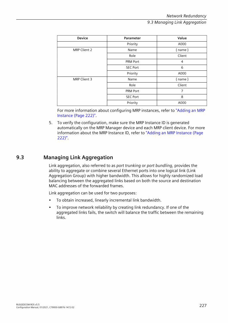
Network Redundancy9.3 Managing Link Aggregation
Device Parameter ValuePriority A000Name { name }Role Client
PRM Port 4SEC Port 6
MRP Client 2
Priority A000Name { name }Role Client
PRM Port 7SEC Port 8
MRP Client 3
Priority A000
For more information about configuring MRP instances, refer to "Adding an MRPInstance (Page 222)".
5. To verify the configuration, make sure the MRP Instance ID is generatedautomatically on the MRP Manager device and each MRP client device. For moreinformation about the MRP Instance ID, refer to "Adding an MRP Instance (Page222)".
9.3 Managing Link AggregationLink aggregation, also referred to as port trunking or port bundling, provides theability to aggregate or combine several Ethernet ports into one logical link (LinkAggregation Group) with higher bandwidth. This allows for highly randomized loadbalancing between the aggregated links based on both the source and destinationMAC addresses of the forwarded frames.Link aggregation can be used for two purposes:• To obtain increased, linearly incremental link bandwidth.• To improve network reliability by creating link redundancy. If one of the
aggregated links fails, the switch will balance the traffic between the remaininglinks.
RUGGEDCOM ROS v5.5Configuration Manual, 01/2021, C79000-G8976-1472-02 227

Network Redundancy9.3.1 Link Aggregation Concepts
11
2
1 Device 2 Link Aggregation Group (LAG)
Figure 9.8 Basic Link Aggregation Topography
9.3.1 Link Aggregation ConceptsThis section describes some of the concepts important to the implementation of linkaggregation in RUGGEDCOM ROS.
9.3.1.1 Static vs. Dynamic Link Aggregation
RUGGEDCOM ROS supports either static or dynamic link aggregation. In static linkaggregation, a device is paired with a specific partner device that shares the samecapabilities and configuration. The same is required for dynamic link aggregation,but with less involvement by the user. In dynamic link aggregation, the LinkAggregation Control Protocol (LACP) seeks a suitable partner on its own afternegotiating with its peers to determine the best match.Static link aggregation is ideal for switch-to-switch configurations, but lacks thefollowing key features offered by dynamic link aggregation:• Failover
In static link aggregation, devices are unable to communicate the status of theirLAGs. Should all ports in a LAG go down and there is a media converter betweenboth devices, the device at the other end will not know and continue to sendtraffic to its partner. Dynamic link aggregation, however, will detect the failedlink and stop sending traffic to the other device.
• RenegotiationShould all ports on the partner device go down and/or the Signal-to-Noise Ratio(SNR) be too high, LACP will automatically seek another LACP-enabled device onthe network with which to form a new port channel.
228 RUGGEDCOM ROS v5.5Configuration Manual, 01/2021, C79000-G8976-1472-02

Network Redundancy9.3.1 Link Aggregation Concepts
• StandbyIf more ports are added to a LAG than the device supports, LACP willautomatically put the excess ports on standby. It determines which ports to puton standby based on criteria defined by the user. These standby ports will waituntil an active port fails and then take its place.
• Link VerificationIn dynamic link aggregation, both partners can mutually verify the port channelbetween them, making it easy for users to confirm the configuration. Static linkaggregation offers no such verification.
Choosing between static or dynamic link aggregation is dependent on thecapabilities of the devices available on the network.
9.3.1.2 Rules and Limitations
The implementation of link aggregation must adhere to the following rules andlimitations:• A port can only belong to one Link Aggregation Group (LAG) or port trunk at a
time.• A port that is being mirrored (the target port) cannot belong to a LAG. However,
any port that receives the mirrored traffic (the source port) can belong to a LAG.• If only one QinQ port is supported by the device, the port working in QinQ mode
cannot be a secondary member of a LAG.• A DHCP relay agent client port cannot be a member of a LAG.• Load balancing between the links of a bundle is randomized and may not
be ideal. For instance, if three 100 Mbps links are aggregated, the resultingbandwidth of the LAG may not be precisely 300 Mbps.
• A static MAC address should not be configured to reside on an aggregated port –it may cause some frames destined for that address to be dropped.
• A secure port cannot be a member of a LAG.• The IEEE 802.1AX (formerly IEEE 802.3ad) Link Aggregation standard requires all
physical links in the LAG to run at the same speed and in full-duplex mode. If thisrequirement is violated, the performance of the LAG will drop.The switch will raise an appropriate alarm, if such a speed/duplex mismatch isdetected.
• The Spanning Tree Protocol (STP) dynamically calculates the path cost of theLAG based on its aggregated bandwidth. However, if the aggregated ports arerunning at different speeds, the path cost may not be calculated correctly.
• Enabling STP is the best way for handling link redundancy in switch-to-switchconnections composed of more than one physical link. If STP is enabled andincreased bandwidth is not required, link aggregation should not be used, as itmay lead to a longer fail-over time.
RUGGEDCOM ROS v5.5Configuration Manual, 01/2021, C79000-G8976-1472-02 229

Network Redundancy9.3.2 Configuring Link Aggregation
9.3.1.3 Link Aggregation and Layer 2 Features
Layer 2 features (e.g. STP, VLAN, CoS, Multicast Filtering) treat a Link AggregationGroup (LAG) as a single link.• If the Spanning Tree Protocol (STP) sets the status of an aggregated port to
Blocking or Forwarding, it does it for the whole LAG.• If one of the aggregated ports joins or leaves a multicast group (e.g. via GMRP),
all other ports in the LAG will join or leave too.• Any port configuration parameter (e.g. VLAN, CoS) change will be automatically
applied to all ports in the LAG.• Configuration/status parameters of the secondary ports will not be shown and
their port numbers will be simply listed next to the primary port number in theappropriate configuration/status user interface sessions.
• When a secondary port is added to a LAG, it inherits all the configuration settingsof the primary port. When this secondary port is removed from the LAG, thesettings it had previous to the aggregation are restored.
9.3.1.4 Link Aggregation and Physical Layer Features
Physical layer features (e.g. physical link configuration, link status, rate limiting,Ethernet statistics) will still treat each aggregated port separately.• Physical configuration/status parameters will NOT be automatically applied to
other ports in the Link Aggregation Group (LAG) and will be displayed for eachport as usual.
• Make sure only ports with the same speed and duplex settings are aggregated. Ifauto-negotiation is used, make sure it is resolved to the same speed for all portsin the LAG.
• To get a value of an Ethernet statistics counter for the LAG, add the values of thecounters for all ports in the LAG.
9.3.2 Configuring Link AggregationTo configure static or dynamic link aggregation, do the following:1. Disconnect or disable each port to be aggregated. For information about
disabling a port, refer to "Configuring an Ethernet Port (Page 66)".2. Create one or more Link Aggregation Groups (LAGs) consisting of two or more
ports. For more information, refer to "Adding a Link Aggregation Group (Page231)".
3. Connect or enable each port in the LAG. For information about enabling a port,refer to "Configuring an Ethernet Port (Page 66)".
230 RUGGEDCOM ROS v5.5Configuration Manual, 01/2021, C79000-G8976-1472-02

Network Redundancy9.3.3 Managing Link Aggregation Groups
4. If dynamic link aggregation is required, configure the global and per port LACPsettings. For more information, refer to "Configuring Global LACP Settings (Page235)" and "Configuring LACP Per Port (Page 235)".
5. Repeat Step 1 to Step 4 for a neighboring device that has the same capabilities(i.e. port speed, media type, etc.), making sure to refer to the device's userdocumentation for details.
9.3.3 Managing Link Aggregation GroupsRUGGEDCOM ROS allows up to 15 Link Aggregation Groups (LAGs), or port trunks, tobe configured on a single device, with each consisting of up to eight ports.
NoteAvoid configuring LAGs when Layer 3 switching is enabled. For more information onenabling or disabling Layer 3 switching, refer to "Layer 3 (Page 175)".
NoteThe maximum number of LAGs for each device depends on the number of portsavailable. At least two ports are required to configure a LAG.
NoteThe aggregated port with the lowest port number is called the Primary port. Otherports in the LAG are called Secondary ports.
9.3.3.1 Viewing a List of Link Aggregation Groups
To view a list of Link Aggregation Groups (LAGs), or port trunks, configured on thedevice, navigate to Link Aggregation » Configure Port Trunks. The Port Trunkstable appears.If LAGs have not been configured, add LAGs as needed. For more information, referto "Adding a Link Aggregation Group (Page 231)".
9.3.3.2 Adding a Link Aggregation Group
To add a LInk Aggregation Group (LAG), or port trunk, do the following:
NOTICEConfiguration hazard – risk of communication disruptionThe LAG must be properly configured on both sides of the port channel. In switch-to-switch connections, if the configuration of both sides does not match (i.e.
RUGGEDCOM ROS v5.5Configuration Manual, 01/2021, C79000-G8976-1472-02 231
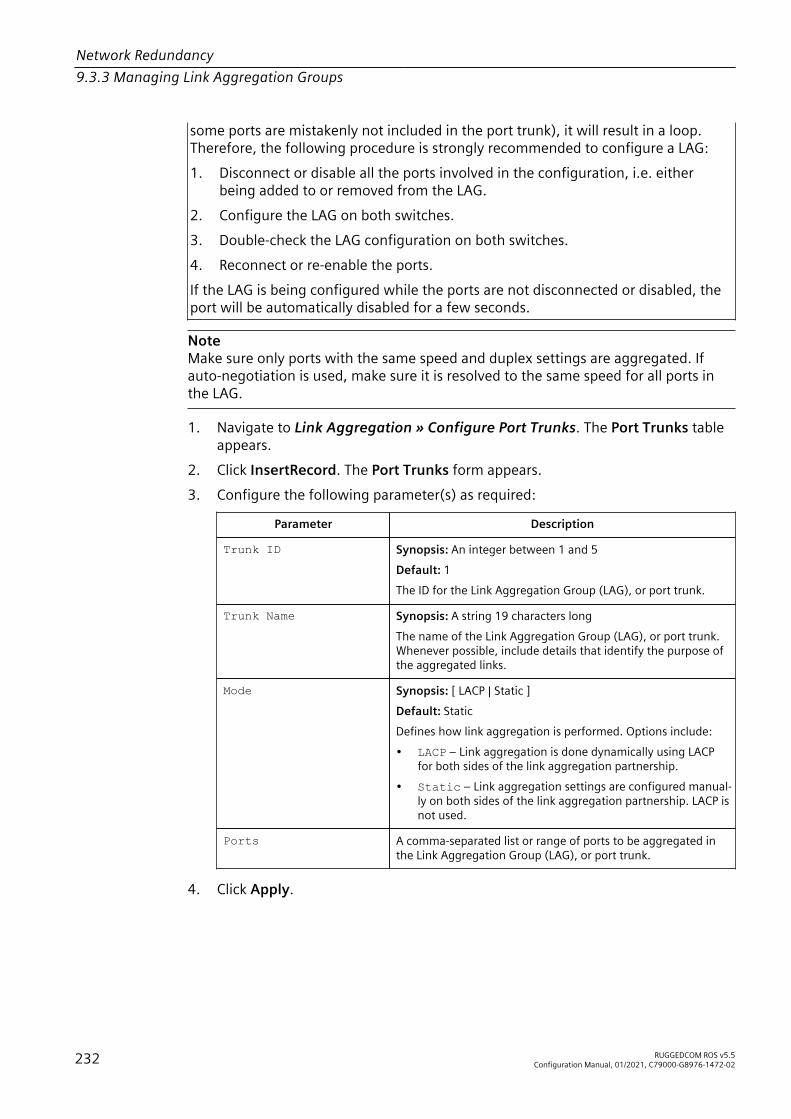
Network Redundancy9.3.3 Managing Link Aggregation Groups
some ports are mistakenly not included in the port trunk), it will result in a loop.Therefore, the following procedure is strongly recommended to configure a LAG:1. Disconnect or disable all the ports involved in the configuration, i.e. either
being added to or removed from the LAG.2. Configure the LAG on both switches.3. Double-check the LAG configuration on both switches.4. Reconnect or re-enable the ports.If the LAG is being configured while the ports are not disconnected or disabled, theport will be automatically disabled for a few seconds.
NoteMake sure only ports with the same speed and duplex settings are aggregated. Ifauto-negotiation is used, make sure it is resolved to the same speed for all ports inthe LAG.
1. Navigate to Link Aggregation » Configure Port Trunks. The Port Trunks tableappears.
2. Click InsertRecord. The Port Trunks form appears.3. Configure the following parameter(s) as required:
Parameter Description
Trunk ID Synopsis: An integer between 1 and 5Default: 1The ID for the Link Aggregation Group (LAG), or port trunk.
Trunk Name Synopsis: A string 19 characters longThe name of the Link Aggregation Group (LAG), or port trunk.Whenever possible, include details that identify the purpose ofthe aggregated links.
Mode Synopsis: [ LACP | Static ]Default: StaticDefines how link aggregation is performed. Options include:• LACP – Link aggregation is done dynamically using LACP
for both sides of the link aggregation partnership.• Static – Link aggregation settings are configured manual-
ly on both sides of the link aggregation partnership. LACP isnot used.
Ports A comma-separated list or range of ports to be aggregated inthe Link Aggregation Group (LAG), or port trunk.
4. Click Apply.
232 RUGGEDCOM ROS v5.5Configuration Manual, 01/2021, C79000-G8976-1472-02

Network Redundancy9.3.4 Managing the Link Aggregation Control Protocol
9.3.3.3 Deleting a Link Aggregation Group
To delete a Link Aggregation Group (LAG), or port trunk, do the following:1. Navigate to Link Aggregation » Configure Port Trunks. The Port Trunks table
appears.2. Select the desired LAG from the table. The Port Trunks form appears.3. Click Delete.
9.3.3.4 Viewing the Status of Link Aggregation Groups
To view the status of each Link Aggregation Group (LAG), or port trunk, configuredon the device, navigate to Link Aggregation » View Port Trunk Statistics. The PortTrunk Statistics table appears.This table displays the following information about each LAG:
Parameter Description
Trunk ID The ID for the Link Aggregation Group (LAG), or port trunk.
Mode The link aggregation mode. Options include:• LACP – Link aggregation is done dynamically using LACP for
both sides of the link aggregation partnership.• Static – Link aggregation settings are configured manually
on both sides of the link aggregation partnership. LACP is notused.
State The operational state of the Link Aggregation Group (LAG), or porttrunk..
Ports Aggregated A comma-separated list or range of ports that are aggregated andoperational in the Link Aggregation Group (LAG), or port trunk.
9.3.4 Managing the Link Aggregation Control ProtocolThe Link Aggregation Control Protocol (LACP) allows LACP-enabled devices todynamically learn about each other's capabilities and automatically create portchannels based on the maximum port speed and trunking state. The capabilities andconfiguration of each device do not need to be expressly controlled, as it would bewith static link aggregation.The capabilities of LACP-enabled devices are learned through the exchange of LACPData Units (LACPDU). LACPDUs are distributed initially by ports configured to runLACP in Active mode. When these LAPDUs are received by a neighboring LACP-enabled device, an LACPDU is returned and both devices negotiate the creation ofthe port channel. The channel is created only if the capabilities of each device align.
RUGGEDCOM ROS v5.5Configuration Manual, 01/2021, C79000-G8976-1472-02 233

Network Redundancy9.3.4 Managing the Link Aggregation Control Protocol
NoteAvoid configuring LACP when Layer 3 switching is enabled. For more information onenabling or disabling Layer 3 switching, refer to "Layer 3 (Page 175)".
NOTICEAt least one LACP-enabled device must have a port configured to run LACP inActive mode. Ports configured to run in Passive mode participate in thenegotiation process, but will not initiate it.
Configure LACP when the Mode parameter for any port trunk is set to LACP.
9.3.4.1 Viewing Information About the LACP Partner
To view details about the LACP partner system, navigate to Link Aggregation » ViewPartner LACP Information. The Partner LACP Information table appears.This table displays the following information:
Parameter Description
Port The port number as seen on the front plate silkscreen of the device.
System Priority The LACP system priority of the partner system.
System ID The MAC address of the partner system.
Port Priority The LACP port priority of the partner port.
Port Number The LACP port number of the partner port.
Key The LACP key assigned to the partner port by the partner system.
State The LACP operational state of the partner port. The state isexpressed as an eight character string. For example:
ASAO----
From left to right, each character in the string has the followingmeaning:1. LACP Activity: A=Active LACP, P=Passive LACP2. LACP Timeout: S=Short Timeout, L=Long Timeout3. Aggregation: A=Aggregateable, I=Individual4. Synchronization: S=In Sync, O=Out Of Sync5. Collecting: C=Collecting, -=Not Collecting6. Distributing: D=Distributing, -=Not Distributing7. Defaulted: D=Defaulted Info, -=Received Info8. Expired: E=Expired, -=Not Expired
Version Synopsis: An integer between 0 and 255The version number of LACP packets sent by the partner system.
234 RUGGEDCOM ROS v5.5Configuration Manual, 01/2021, C79000-G8976-1472-02

Network Redundancy9.3.4 Managing the Link Aggregation Control Protocol
9.3.4.2 Configuring Global LACP Settings
To configure the global settings for the Link Aggregation Control Protocol (LACP), dothe following:1. Navigate to Link Aggregation » Configure Global LACP Parameters. The
Global LACP Parameters form appears.2. Configure the following parameter(s) as required:
Parameter Description
Bridge LACP Priority Synopsis: An integer between 0 and 65535Default: 32768The LACP system priority. This is combined with the device'sMAC address to form the LACP system ID, which is used innegotiations with other LACP-enabled devices.
LAG Ports SelectionRule
Synopsis: [ ActivePartner | LinkSpeed | LinkPriority ]Default: ActivePartnerDefines the order in which ports in the Link Aggregation Group(LAG), or port trunk, are selected by LACP for aggregation. Thisparameter applies when ports in the LAG are connected to twoor more other LAGs.Options include:• ActivePartner – Select ports based on when partner
ports become active.• LinkSpeed – Select ports based on link speed. The port
with the higher link speed has precedence.• LinkPriority – Select ports based on LACP link priority.
The port with the higher LACP link priority has precedence.
3. Click Apply.
9.3.4.3 Configuring LACP Per Port
To configure the Link Aggregation Control Protocol (LACP) settings for a specific port,do the following:1. Navigate to Link Aggregation » Configure Port LACP Parameters. The Port
LACP Parameters table appears.2. Select the desired port. The Port LACP Parameters form appears.3. Configure the following parameter(s) as required:
Parameter Description
Port Synopsis: 1/1 to maximum port numberThe port number as seen on the front plate silkscreen of thedevice.
RUGGEDCOM ROS v5.5Configuration Manual, 01/2021, C79000-G8976-1472-02 235
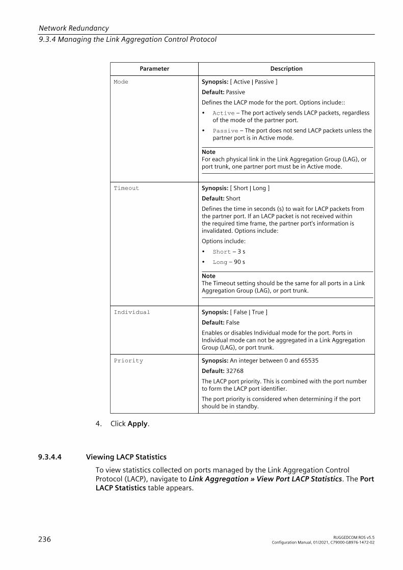
Network Redundancy9.3.4 Managing the Link Aggregation Control Protocol
Parameter Description
Mode Synopsis: [ Active | Passive ]Default: PassiveDefines the LACP mode for the port. Options include::• Active – The port actively sends LACP packets, regardless
of the mode of the partner port.• Passive – The port does not send LACP packets unless the
partner port is in Active mode.
NoteFor each physical link in the Link Aggregation Group (LAG), orport trunk, one partner port must be in Active mode.
Timeout Synopsis: [ Short | Long ]Default: ShortDefines the time in seconds (s) to wait for LACP packets fromthe partner port. If an LACP packet is not received withinthe required time frame, the partner port's information isinvalidated. Options include:Options include:• Short – 3 s• Long – 90 s
NoteThe Timeout setting should be the same for all ports in a LinkAggregation Group (LAG), or port trunk.
Individual Synopsis: [ False | True ]Default: FalseEnables or disables Individual mode for the port. Ports inIndividual mode can not be aggregated in a Link AggregationGroup (LAG), or port trunk.
Priority Synopsis: An integer between 0 and 65535Default: 32768The LACP port priority. This is combined with the port numberto form the LACP port identifier.The port priority is considered when determining if the portshould be in standby.
4. Click Apply.
9.3.4.4 Viewing LACP Statistics
To view statistics collected on ports managed by the Link Aggregation ControlProtocol (LACP), navigate to Link Aggregation » View Port LACP Statistics. The PortLACP Statistics table appears.
236 RUGGEDCOM ROS v5.5Configuration Manual, 01/2021, C79000-G8976-1472-02

Network Redundancy9.3.5 Clearing Link Aggregation Statistics
This table displays the following information:
Parameter Description
Port The port number as seen on the front plate silkscreen of the device.
Link The link status of the port.
State Synopsis: An integer between 0 and 255The LACP operational state of the port. The state is expressed as aneight character string. For example:
ASAO----
From left to right, each character in the string has the followingmeaning:1. LACP Activity: A=Active LACP, P=Passive LACP2. LACP Timeout: S=Short Timeout, L=Long Timeout3. Aggregation: A=Aggregateable, I=Individual4. Synchronization: S=In Sync, O=Out Of Sync5. Collecting: C=Collecting, -=Not Collecting6. Distributing: D=Distributing, -=Not Distributing7. Defaulted: D=Defaulted Info, -=Received Info8. Expired: E=Expired, -=Not Expired
Tx The number of LACP packets transmitted by the port.
Rx The number of good LACP packets received by the port.
RxUnknown The number of unknown LACP packets received by the port.
RxIllegal The number of illegal LACP packets received by the port.
9.3.5 Clearing Link Aggregation StatisticsTo clear all link aggregation statistics from the device, do the following:1. Navigate to Link Aggregation » Clear Link Aggregation Statistics. The Clear
Link Aggregation Statistics form appears.2. Click Confirm.
RUGGEDCOM ROS v5.5Configuration Manual, 01/2021, C79000-G8976-1472-02 237

Network Redundancy9.3.5 Clearing Link Aggregation Statistics
238 RUGGEDCOM ROS v5.5Configuration Manual, 01/2021, C79000-G8976-1472-02
Traffic Control and Classification 10Use the traffic control and classification subsystems to control the flow of datapackets to connected network interfaces.
10.1 Managing Classes of ServiceClasses of Service (CoS) provides the ability to expedite the transmission of certainframes and port traffic over others. The CoS of a frame can be set to Normal,Medium, High, or Critical. By default, other than the control frames, RUGGEDCOMROS enforces Normal CoS for all incoming traffic received without a priority tag.
NOTICEUse the highest supported CoS with caution, as it is always used by the switch forhandling network management traffic, such as RSTP BPDUs.If this CoS is used for regular network traffic, upon traffic bursts, it may result in theloss of some network management frames, which in turn may result in the loss ofconnectivity over the network.
RUGGEDCOM ROS v5.5Configuration Manual, 01/2021, C79000-G8976-1472-02 239

Traffic Control and Classification10.1.1 Configuring Classes of Service Globally
The process of controlling traffic based on CoS occurs over two phases:1. Inspection Phase
In the inspection phase, the CoS priority of a received frame is determined fromeither:• A specific CoS based upon the source and destination MAC address (as set in
the Static MAC Address Table)• The priority field in the IEEE 802.1Q tags• The Differentiated Services Code Point (DSCP) component of the Type Of
Service (TOS) field in the IP header, if the frame is IP• The default CoS for the portEach frame’s CoS will be determined once the first examined parameter is foundin the frame.
NoteFor information on how to configure the Inspect TOS parameter, refer to"Configuring Classes of Service for Specific Ethernet Ports (Page 241)".
The header of each received frame is first examined to determine if the frameis an IP packet and if Inspect TOS is enabled in RUGGEDCOM ROS. The CoS isdetermined from the DSCP field.If the frame is not an IP packet or if Inspect TOS is disabled, the frame isexamined to determine if its destination or source MAC address is found in theStatic MAC address table. If it is, the CoS configured for the static Mac address isused. If neither destination or source MAC address is in the Static MAC Addresstable, the frame is then examined for 802.1Q tags and the priority field ismapped to a CoS. If a tag is not present, the default CoS for the port is used.After inspection, the frame is forwarded to the egress port for transmission.
2. Forwarding PhaseOnce the CoS of the frame is determined, the frame is forwarded to the egressport, where it is collected into one of the priority queues according to theassigned CoS.CoS weighting selects the degree of preferential treatment that is attachedto different priority queues. The ratio of the number of higher CoS to lowerCoS frames transmitted can be configured. If desired, lower CoS frames can betransmitted only after all higher CoS frames have been serviced.
10.1.1 Configuring Classes of Service GloballyTo configure global settings for Classes of Service (CoS), do the following:1. Navigate to Classes of Service » Configure Global CoS Parameters. The
Global CoS Parameters form appears.
240 RUGGEDCOM ROS v5.5Configuration Manual, 01/2021, C79000-G8976-1472-02

Traffic Control and Classification10.1.2 Configuring Classes of Service for Specific Ethernet Ports
2. Configure the following parameter(s) as required:
Parameter Description
CoS Weighting Synopsis: [ 8:4:2:1 | Strict ]Default: 8:4:2:1During traffic bursts, frames queued in the switch pendingtransmission on a port may have different CoS priorities. Thisparameter specifies weighting algorithm for transmittingdifferent priority CoS frames.Examples:• 8:4:2:1 – 8 Critical, 4 High, 2 Medium and 1 Normal pri-
ority CoS frame• Strict – lower priority CoS frames will be only transmit-
ted after all higher priority CoS frames have been transmit-ted
3. Click Apply.4. If necessary, configure CoS mapping based on either the IEEE 802.1p priority
or Differentiated Services (DS) field set in the IP header for each packet. Formore information, refer to "Configuring Priority to CoS Mapping (Page 242)" or"Configuring DSCP to CoS Mapping (Page 242)".
10.1.2 Configuring Classes of Service for Specific Ethernet PortsTo configure Classes of Service (CoS) for one or more Ethernet ports, do thefollowing:1. Navigate to Classes of Service » Configure Port CoS Parameters. The Port CoS
Parameters table appears.2. Select an Ethernet port. The Port CoS Parameters form appears.3. Configure the following parameter(s) as required:
Parameter Description
Port(s) Synopsis: Any combination of numbers valid for this parameterThe port number as seen on the front plate silkscreen of theswitch (or a list of ports, if aggregated in a port trunk).
Default Pri Synopsis: An integer between 0 and 7Default: 0This parameter allows to prioritize frames received on this portthat are not prioritized based on the frames contents (e.g.priority field in the VLAN tag, DiffServ field in the IP header,prioritized MAC address).
Inspect TOS Synopsis: [ No | Yes ]Default: NoThis parameters enables or disables parsing of the Type-Of-Service (TOS) field in the IP header of the received frames todetermine what Class of Service they should be assigned. When
RUGGEDCOM ROS v5.5Configuration Manual, 01/2021, C79000-G8976-1472-02 241

Traffic Control and Classification10.1.3 Configuring Priority to CoS Mapping
Parameter DescriptionTOS parsing is enabled the switch will use the DifferentiatedServices bits in the TOS field.
4. Click Apply.
10.1.3 Configuring Priority to CoS MappingFrames received untagged can be automatically assigned a CoS based on theirpriority level.To map a priority level to a CoS, do the following:1. Navigate to Classes of Service » Configure Priority to CoS Mapping. The
Priority to CoS Mapping table appears.2. Select a priority level. The Priority to CoS Mapping form appears.3. Configure the following parameter(s) as required:
Parameter Description
Priority Synopsis: An integer between 0 and 7Default: 0Value of the IEEE 802.1p priority.
CoS Synopsis: [ Normal | Medium | High | Crit ]Default: NormalCoS assigned to received tagged frames with the specified IEEE802.1p priority value.
4. Click Apply.
10.1.4 Configuring DSCP to CoS MappingMapping CoS to the Differentiated Services (DS) field set in the IP header for eachpacket is done by defining Differentiated Services Code Points (DSCPs) in the CoSconfiguration.To map a DSCP to a Class of Service, do the following:1. Navigate to Classes of Service » Configure DSCP to CoS Mapping. The DSCP
to CoS Mapping table appears.2. Select a DSCP level. The DSCP to CoS Mapping form appears.
242 RUGGEDCOM ROS v5.5Configuration Manual, 01/2021, C79000-G8976-1472-02

Traffic Control and Classification10.1.4 Configuring DSCP to CoS Mapping
3. Configure the following parameter(s) as required:
Parameter Description
DSCP Synopsis: An integer between 0 and 63Default: 0Differentiated Services Code Point (DSCP) – a value of the 6 bitDiffServ field in the Type-Of-Service (TOS) field of the IP header.
Priority Synopsis: An integer between 0 and 7Default: 0Priority assigned to received frames with the specified DSCP.
4. Click Apply.5. Configure the CoS parameters on select switched Ethernet ports as needed. For
more information, refer to "Configuring Classes of Service for Specific EthernetPorts (Page 241)".
RUGGEDCOM ROS v5.5Configuration Manual, 01/2021, C79000-G8976-1472-02 243

Traffic Control and Classification10.1.4 Configuring DSCP to CoS Mapping
244 RUGGEDCOM ROS v5.5Configuration Manual, 01/2021, C79000-G8976-1472-02

Time Services 11This chapter describes the time-keeping and time synchronization features inRUGGEDCOM ROS.
11.1 Configuring the Time and DateTo set the time, date and other time-keeping related parameters, do the following:1. Navigate to Administration » System Time Manager » Configure Time and
Date. The Time and Date form appears.2. Configure the following parameter(s) as required:
Parameter Description
Time Synopsis: HH:MM:SSThis parameter allows for both the viewing and setting of thelocal time.
Date Synopsis: MMM DD, YYYYThis parameter allows for both the viewing and setting of thelocal date.
Time Zone Synopsis: [ UTC-12:00 (Eniwetok, Kwajalein) | UTC-11:00(Midway Island, Samoa) | UTC-10:00 (Hawaii) | UTC-9:00(Alaska) | UTC-8:00 (Los Angeles, Vancouver) | UTC-7:00(Calgary, Denver) | UTC-6:00 (Chicago, Mexico City) | UTC-5:00(New York, Toronto) | UTC-4:30 (Caracas) | UTC-4:00 (Santiago)| UTC-3:30 (Newfoundland) | UTC-3:00 (Brasilia, Buenos Aires) |UTC-2:00 (Mid Atlantic) | UTC-1:00 (Azores) | UTC-0:00 (Lisbon,London) | UTC+1:00 (Berlin, Paris, Rome) | UTC+2:00 (Athens,Cairo, Helsinki) | ... ]Default: UTC-5:00 (New York, Toronto)This setting allows for the conversion of UTC (UniversalCoordinated Time) to local time.
DST Offset Synopsis: HH:MM:SSDefault: 00:00:00This parameter specifies the amount of time to be shiftedforward/backward when DST begins and ends. For examplefor most part of USA and Canada, DST time shift is 1 hour(01:00:00) forward when DST begins and 1 hour backwardwhen DST ends.
DST Rule Synopsis: mm.n.d/HH:MM:SS mm.n.d/HH:MM:SSThis parameter specifies a rule for time and date when thetransition between Standard and Daylight Saving Time occurs.
RUGGEDCOM ROS v5.5Configuration Manual, 01/2021, C79000-G8976-1472-02 245

Time Services11.2 Configuring IRIG-B
Parameter Description• mm – Month of the year (01 = January, 12 = December)• n – nth d-day in the month (1 = 1st d-day, 5 = 5th/last d-
day)• d – day of the week (0 = Sunday, 6 = Saturday)• HH – hour of the day (0 - 24)• MM – minute of the hour (0- 59)• SS – second of the minute (0 - 59)Example: The following rule applies in most part of USA andCanada:
03.2.0/02:00:00 11.1.0/02:00:00
DST begins on March's 2nd Sunday at 2:00am.DST ends on November's 1st Sunday at 2:00am.
Current UTC Offset Synopsis: An integer between 0 and 1000Default: 36Coordinated Universal Time (UTC) is a time standard basedon International Atomic Time (TAI) with leap seconds addedat irregular intervals to compensate for the Earth's slowingrotation. Current UTC offset parameter allows user to adjustthe difference between UTC and TAI. The International EarthRotation and Reference System Service (IERS) observes theEarth's rotation and nearly six months in advance (January andJuly) a Bulletin-C message is sent out, which reports whether ornot to add a leap second in the end of June and December.Please note that change in current UTC offset parameter willresult in temporally disruption in the timing network.
Leap Second Pending Synopsis: [ No | Yes ]Default: NoThis parameter allows user to manage the leap second event.A leap second is a second added to Coordinated Universal Time(UTC) in order to keep it synchronized with astronomical time.The International Earth Rotation and Reference System Service(IERS) observes the Earth's rotation and nearly six months inadvance (January and July) a Bulletin-C message is sent out,which reports whether or not to add a leap second in the end ofJune and December. This parameter must set at least 5 minutesin advance before the occurrence of leap second event.
11.2 Configuring IRIG-BThe TTL Output can perform different functions, such as transmitting the IRIG-Breference time signal or a utility Pulse Per Second (PPS) or Pulse per x Seconds (PPx)reference signal.To configure IRIG-B, do the following:1. Navigate to Administration » System Time Manager » Configure IRIGB. The
IRIGB form appears.
246 RUGGEDCOM ROS v5.5Configuration Manual, 01/2021, C79000-G8976-1472-02

Time Services11.2 Configuring IRIG-B
2. Configure the following parameter(s) as required:
Parameter Description
TTL Output Synopsis: [ Off | PWM | PPS | PPx ]Default: PWMSelects Operational mode of TTL output port. PWM modecomplies with IRIG Standard 200-04. PPx provides generic pulseper x second interface to synchronize external devices.
PPx Pulse Interval Synopsis: An integer between 1 and 86400Default: 1Selects Pulse Interval for TTL output port. This parameter is usedin conjunction with PPx in order to provides generic pulse per xsecond interface to synchronize external devices.
PPx Pulse Width Synopsis: An integer between 1 and 200Default: 1Selects Pulse Width in milliseconds for TTL output port. Thisparameter is used in conjunction with PPx to control the widthof the pulse.
PPx Start Time Synopsis: YYYY/MM/DD HH:MM:SSDefault: 1970/01/01 00:00:00This parameter is used in conjunction with PPx to set thestarting time of first PPx event. Note that this parameter mustbe set at least 15 seconds before the start of desired PPxotherwise first PPx event might be lost.
AM Output Synopsis: [ Off | AM ]Default: AMSelects AM (Amplitude Modulation) mode of IRIGB port. AMmode complies with IRIG Standard 200-04.
Time Code Synopsis: [ Bxx0 | Bxx1 | Bxx2 | Bxx3 | Bxx4 | Bxx5 | Bxx6 |Bxx7 ]Default: Bxx4This device uses the following convention to decode the IRIGBtime code: letter [B] represents IRIG-B format, [xx] represents[00] for PWM/TTL mode of operation and [12] for AM operation.For example, Bxx7 represents B007 for PWM/TTL operation andB127 for AM operation. Please note that only Bxx0, Bxx1, Bxx4and Bxx5 time codes support IRIGB extensions.
IRIGB Ext Synopsis: [ Off | IEEE1344 | C37.118-2005 | C37.118-2011 ]Default: OffIRIGB extensions use extra bits of the Control Functions (CF)portion of the IRIGB time code. Within this portion of the timecode, bits are designated for additional features, including:Calendar Year, Leap seconds, leap seconds pending, DaylightSaving Time (DST), DST pending, local time offset and timequality. Please note that only Bxx0, Bxx1, Bxx4 and Bxx5 timecodes support IRIGB extensions.
RUGGEDCOM ROS v5.5Configuration Manual, 01/2021, C79000-G8976-1472-02 247

Time Services11.3 Managing the Precision Time Protocol (PTP)
Parameter Description
IRIGB Input Synopsis: [ Off | PWM | AM ]Default: PWMSelects operational mode of IRIGB input port. IRIGB module iscapable of interpreting IRIGB extensions such as C37.118-2011,C37.118-2005 and IEEE1344.
3. Click Apply.4. If IRIGB Ext was modified, reset the device. For more information, refer to
"Resetting the Device (Page 95)".
11.3 Managing the Precision Time Protocol (PTP)The Precision Time Protocol (PTP) is a standard method of synchronizing networkclocks over Ethernet. RUGGEDCOM ROS supports PTP v2, which is defined by the IEEE1588 working group in the IEEE 1588-2008 standard.PTP is a distributed protocol that allows multiple clocks in a network to synchronizewith one another. These clocks are organized into a master-slave synchronizationhierarchy with a grandmaster clock at the top of the hierarchy, which determines thereference time for the entire system. Synchronization is achieved via the exchangeof PTP timing messages. Slave clocks use the timing information in PTP messages toadjust their time to that of the master in their part of the hierarchy.The PTP protocol executes within a logical scope called a domain. The timeestablished via the protocol within one domain is independent of the time in otherdomains.A PTP v2 system may consist of a combination of both PTP-aware and PTP-unawaredevices. There are five basic PTP device types defined in the IEEE 1588-2008standard:• Ordinary Clocks• Boundary Clocks• End-to-End Transparent Clocks• Peer-to-Peer Transparent Clocks• Management NodesRUGGEDCOM ROS supports Ordinary Clock, Peer-to-Peer Transparent Clock,Boundary Clock and End-to-End Transparent Clock modes:• The Ordinary Clock can be either the grandmaster clock in a system or a slave
clock in the master-slave hierarchy. The selection of grandmaster and slaveclocks is based on the Best Master Clock (BMC) algorithm defined in the IEEE1588-2008 standard.
• A Peer-to-Peer Transparent Clock forwards all messages just as a normal bridge,router, or repeater does. The difference is that a Peer-to-Peer Transparent Clockalso computes the residence time (message departure time - message arrival
248 RUGGEDCOM ROS v5.5Configuration Manual, 01/2021, C79000-G8976-1472-02

Time Services11.3.1 Configuring PTP Globally
time) and link delay (packet propagation delay between peer ports) and adds thisinformation in PTP event messages (which carry timestamps). Ethernet ports ona Peer-to-Peer Transparent Clock use the peer delay mechanism to compute thepacket propagation delay between peer ports.
• A Boundary Clock can be considered an IEEE 1588 gateway. A Boundary Clocktranslates the PTP messages between PTP regions implementing differenttransport and messaging protocols, or different PTP profiles. For example, adevice in Boundary Clock mode can act as a timing sync (PTP Slave) from theTelecom network and as a timing distribution source (PTP master) in a powersubstation environment.
• The End-to-End Transparent Clock supports the use of the end-to-end delaymeasurement mechanism between slave clocks and the master clock. It forwardsall messages just as a normal bridge, router or repeater does. The difference isthat an End-to-End Transparent Clock computes the residence time (messagedeparture time - message arrival time) and adds this information to PTP eventmessages (messages that carry a time-stamp).
For more information about PTP capabilities, refer to the Time SynchronizationCapabilities of RUGGEDCOM Devices Reference Manual available at https://support.industry.siemens.com/cs/us/en/view/109780448.
11.3.1 Configuring PTP GloballyTo configure the global settings for PTP, do the following:1. Navigate to Administration » System Time Manager » Precision Time
Protocol » Configure Global Parameters. The Global Parameters formappears.
NOTICEBefore performing SNMP get or SNMP set operations for MIBs IEEEC37.238-2011 and RUGGEDCOM-PTP1588-MIB.mib, make sure the PTP Enableparameter is set to Yes. For more information about supported MIBs, refer to"SNMP Management Interface Base (MIB) Support (Page 269)".
2. Configure the following parameter(s) as required:
Parameter Description
PTP Enable Synopsis: [ No | Yes ]Default: NoEnables PTP (Precision Time Protocol) protocol.
Clock Type Synopsis: [ Ordinary Clock | Boundary Clock | OC and P2PTClock | P2P TClock | E2E TClock ]Default: P2P TClockSelects the PTP (Precision Time Protocol) clock type. Note thatthe Ordinary Clock will become a Master Clock (MC) or SlaveClock (SC) subject to network negotiation. If, however, IRIGB
RUGGEDCOM ROS v5.5Configuration Manual, 01/2021, C79000-G8976-1472-02 249

Time Services11.3.1 Configuring PTP Globally
Parameter Descriptionor GPS is selected as the Time Source, the device will eithernegotiate Mastership and act as a Grandmaster Clock (GMC) orremain in a passive PTP state.Note that only P2P (Peer-to-Peer) Transparent Clock (TClock),E2E (End-to-End) Transparent Clock and P2P Grandmaster Clockmodes are supported on ports 2/4, 4/4, 6/4 and 7/2.
PTP Profile Synopsis: [ Power Profile | Default P2P Profile | Utility ProfileLevel 1 | Default E2E Profile | Custom Profile | Power Profile v2 ]Default: Power ProfileSelects the PTP (Precision Time Protocol) clock profile. PTPprofile represents a set of allowed PTP features applicable tospecific industry.
NotePower Profile represents C37.238.2011.
NotePower Profile v2 represents C37.238.2017.
NoteUtility Profile Level 1 represents IEC/IEEE 61850-9-3Ed.1.
Ethernet Ports Synopsis: Comma-separated list of ports or [ All ]Default: AllSelects Ethernet port(s) which take part in PTP (Precision TimeProtocol) message exchanges.Note that only P2P (Peer-to-Peer) Transparent Clock (TClock),E2E (End-to-End) Transparent Clock and P2P Grandmaster Clockmodes are supported on ports 2/4, 4/4, 6/4 and 7/2.
VLAN ID Synopsis: An integer between 1 and 4094 or [ Disable ]Default: 1The VLAN ID associated with untagged (and 802.1p prioritytagged) frames received on this port. Frames tagged with anon-zero VLAN ID will always be associated with the VLAN IDretrieved from the frame tag. Frames tagged with a zero VLANID will always be associated with the VLAN ID 1 unless thisparameter is configured.
Class Of Service Synopsis: An integer between 1 and 7 or [ Disable ]Default: 4Selects the PTP (Precision Time Protocol) message priority basedon the IEEE 802.1p specification. IEEE 802.1p defines eightdifferent classes of service, usually expressed using the 3-bitpriority field in an IEEE 802.1Q header added to the Ethernetframe. If the VLAN option is enabled and the Class Of Serviceoption is set to 'Disable' then it represents priority '0' in terms ofthe IEEE 802.1p specification.
250 RUGGEDCOM ROS v5.5Configuration Manual, 01/2021, C79000-G8976-1472-02

Time Services11.3.1 Configuring PTP Globally
Parameter Description
Transport Protocol Synopsis: [ Layer 2 Multicast | Layer 3 Multicast ]Default: Layer 2 MulticastSelects network transport protocol for PTP (Precision TimeProtocol) messages.
Grandmaster ID Synopsis: An integer between 3 and 255Default: 255This parameter is specific to the Power Profile (IEEEC37.238-2011) or Power Profile v2 (IEEE C37.238-2017), asselected. All PTP master capable devices must configure anetwork-wide, unique instance of this parameter in the rangeof 3 to 254 for proper operation.
Startup Wait Synopsis: An integer between 0 and 3600Default: 10Normally the start-up time of a non-GPS master clock is lessthan that of a GPS-enabled master (i.e. by the time it takesto acquire GPS lock). This parameter provides the ability tobootstrap the PTP network in an orderly fashion.
Desired Clock Accuracy Synopsis: [ 50 ns | 100 ns | 250 ns | 1 us | 2.5 us | 10 us | 25 us| 100 us | 250 us | 1 ms | 2.5 ms | 10 ms | 25 ms | 100 ms | 250ms ]Default: 1This parameter allows the user to configure the desired clockaccuracy. This represents the instantaneous value of thetime offset between master and slave clocks. The system willgenerate an alarm if the time offset from the master exceedsthe desired accuracy.
Network Class Synopsis: [ IEEE1588 network | Non-IEEE1588 network ]Default: IEEE1588 networkClock servo stability is highly dependent on networkpersonality. This parameter allows the user to configurea network personality to reflect a particular networkenvironment. This might mean, for example, whether alldevices in the timing plane are IEEE1588 aware (IEEE1588network) or whether the timing plane includes non-IEEE1588devices as well (non-IEEE1588 network). Note that a IEEE1588network is independent of traffic load. Only the E2E mechanismis applicable to non-IEEE1588 networks.
1 Step Master Clock Synopsis: [ No | Yes ]Default: YesThis parameter allows the user to configure 1-step or 2-stepmaster clock functionality.
3. Click Apply.4. Reset the device. For more information, refer to "Resetting the Device (Page
95)".
RUGGEDCOM ROS v5.5Configuration Manual, 01/2021, C79000-G8976-1472-02 251

Time Services11.3.2 Configuring an Ordinary or Transparent Clock
11.3.2 Configuring an Ordinary or Transparent ClockTo configure settings for a PTP ordinary or transparent clock, do the following:1. Navigate to Administration » System Time Manager » Precision Time
Protocol » Configure Clock Parameters. The Clock Parameters form appears.2. Configure the following parameter(s) as required:
Parameter Description
Domain Number Synopsis: An integer between 0 and 127Default: 0Selects the PTP (Precision Time Protocol) domain number. A PTPdomain is a logical grouping of PTP clocks that synchronize toeach other using the PTP protocol.
Sync Interval Synopsis: [ 125 ms | 250 ms | 500 ms | 1 s | 2 s ]Default: 1 sSelects the PTP (Precision Time Protocol) Sync interval (meantime interval between successive Sync messages) in seconds.Sync messages are sent periodically by the Master Clock whichprovide time of day information to PTP Slave Clocks.
Announce Interval Synopsis: [ 1 s | 2 s | 4 s | 8 s | 16 s | 32 s ]Default: 1Selects the PTP (Precision Time Protocol) Announce interval(mean time interval between successive Announce messages)in seconds. Announce messages are sent periodically bythe Master Clock to provide its status and characteristicinformation. Announce messages are used to establish thesynchronization hierarchy, i.e., using the BMC (Best MasterClock) algorithm.
Announce Receipt Time out
Synopsis: An integer between 2 and 10Default: 3Selects the PTP (Precision Time Protocol) Announce receipttimeout. This parameter specifies the number of intervalsthat may pass without receipt of an Announce message. Thisparameter is part of BMC (Best Master Clock) algorithm.Please note that a change in this parameter may be disruptive.
Priority1 Synopsis: An integer between 0 and 255Default: 128Selects the PTP (Precision Time Protocol) clock priority1 duringthe execution of the BMC (Best Master Clock) algorithm. Alower value corresponds to a higher precedence. The BMCalgorithm selects clocks from a set with a lower value ofpriority1 over clocks from a set with a greater value
Priority2 Synopsis: An integer between 0 and 255Default: 128Selects the PTP (Precision Time Protocol) clock priority2 duringthe execution of the BMC (Best Master Clock) algorithm. Alower value corresponds to a higher precedence. In the eventthat the operation of the BMC algorithm fails to order the clocks
252 RUGGEDCOM ROS v5.5Configuration Manual, 01/2021, C79000-G8976-1472-02

Time Services11.3.3 Configuring a Boundary Clock Slave
Parameter Descriptionbased on the values of priority1, clockClass, clockAccuracy andscaledOffsetLogVariance, the priority2 attribute allows thecreation of up to 256 priorities to be evaluated before the tie-breaker. The tie-breaker is based on the clock identity.
Path Delay Mechanism Synopsis: [ Disabled | Peer-to-Peer | End-to-End ]Default: Peer-to-PeerSelects the PTP (Precision Time Protocol) delay mechanism.There are two mechanisms used in PTP to measure thepropagation delay between PTP ports: The P2P (Peer-to-Peer)delay mechanism measures the port to port propagationtime such as link delay and frame residence time. The P2Pmechanism is independent of whether the PTP port is acting asMaster or Slave.The E2E (End-to-End) delay mechanism measures the messagepropagation time between Master and Slave clocks across thewhole intervening network.Note that the P2P mechanism does not inter-operate with pathdelay measurements based on the E2E (also called request-response) delay mechanism.
Slave Only Synopsis: [ No | Yes ]Default: NoThis option may be used to force an Ordinary Clock be a Slaveonly clock. A slave only clock never enters the master state.Slave only and Transparent Clock functionality may be used incombination. Please note that a Boundary Clock must not beconfigured as a slave only clock.
3. Click Apply.4. Reset the device. For more information, refer to "Resetting the Device (Page
95)".
11.3.3 Configuring a Boundary Clock SlaveTo configure settings for a PTP boundary clock slave, do the following:1. Navigate to Administration » System Time Manager » Precision Time
Protocol » Configure BClock Slave. The BClock Slave form appears.2. Configure the following parameter(s) as required:
Parameter Description
PTP Profile Synopsis: [ Power Profile | Default P2P Profile | Utility ProfileLevel 1 | Default E2E Profile | Telecom Profile | Custom Profile |Power Profile v2 ]Default: Telecom ProfileSelects the PTP (Precision Time Protocol) clock profile. Eachprofile is a set of allowed PTP features applicable to the device.Supported profiles are:• Power Profile (IEEE C37.238.2011 version)
RUGGEDCOM ROS v5.5Configuration Manual, 01/2021, C79000-G8976-1472-02 253

Time Services11.3.3 Configuring a Boundary Clock Slave
Parameter Description• Power Profile v2 (IEEE C37.238.2017 version)• Default P2P (Peer-to-Peer) Profile as defined in
IEEE1588-2008 standard with layer 2 transport• Default E2E (End-to-End) Profile as defined in
IEEE1588-2008 standard with layer 2 transport• Telecom Profile is a subset of the ITU-T G.8265.1 telecom
profile• Custom Profile is a user-defined custom profile
Ethernet Port Synopsis: Comma-separated list of portsDefault: NoneSelects the Ethernet port which will act as the Slave port whenthe device is configured as a Boundary Clock.Note that Boundary Clock slave mode is not supported on ports2/4, 4/4, 6/4 and 7/2.
Domain Number Synopsis: An integer between 0 and 127Default: 0Selects the PTP (Precision Time Protocol) domain number forthe Slave Clock. A PTP domain is a logical grouping of PTP clocksthat synchronize to each other using the PTP protocol.
Sync Interval Synopsis: [ 125 ms | 250 ms | 500 ms | 1 s | 2 s ]Default: 1This parameter is specific to unicast transport and represents arequested Sync interval (mean time interval between successiveSync messages) in seconds. It is transmitted in the request forunicast transmissions.
Announce Interval Synopsis: [ 1 s | 2 s | 4 s | 8 s | 16 s | 32 s ]Default: 2Selects the PTP (Precision Time Protocol) Announce interval(mean time interval between successive Announce messages)in seconds. Announce messages are sent periodically bythe Master Clock to provide its status and characteristicinformation. Announce messages are used to establish thesynchronization hierarchy, i.e., using the BMC (Best MasterClock) algorithm.
Transport Protocol Synopsis: [ Layer 2 Multicast | Layer 3 Multicast | Layer 3Unicast ]Default: Layer 3 UnicastSelects layer 2 (Ethernet) multicast transport, layer 3 (UDP/IP)multicast transport or layer 3 (UDP/IP) unicast transport for PTP(Precision Time Protocol) messages.
Path Delay Mechanism Synopsis: [ Disabled | Peer-to-Peer | End-to-End ]Default: End-to-EndSelects the PTP (Precision Time Protocol) delay mechanism.There are two mechanisms used in PTP to measure thepropagation delay between PTP ports: The P2P (Peer-to-Peer)
254 RUGGEDCOM ROS v5.5Configuration Manual, 01/2021, C79000-G8976-1472-02

Time Services11.3.4 Configuring the PTP Delay Request Interval
Parameter Descriptiondelay mechanism measures the port-to-port propagation timesuch as link delay and frame residence time.The E2E (End-to-End) delay mechanism measures the messagepropagation time between Master and Slave clocks across thewhole intervening network.Note that the P2P mechanism does not inter-operate with pathdelay measurements based on the E2E (also called request-response) delay mechanism.
Auto Registration Synopsis: [ No | Yes ]Default: YesThis parameter is specific to unicast transport. This parameterallows user to auto register the slave clock to unicast master asspecified by the 'Master IP Address' attribute.
Master IP Address Synopsis: ###.###.###.### where ### ranges from 0 to 255This parameter is specific to unicast transport and representsthe IP address of the unicast PTP (Precision Time Protocol)master clock.
Backup Master IP Ad dress
Synopsis: ###.###.###.### where ### ranges from 0 to 255This parameter is specific to unicast transport and representsthe IP address of the unicast backup PTP (Precision TimeProtocol) master clock.
3. Click Apply.4. Reset the device. For more information, refer to "Resetting the Device (Page
95)".
11.3.4 Configuring the PTP Delay Request IntervalTo configure the PTP delay request interval, do the following:1. Navigate to Administration » System Time Manager » Precision Time
Protocol » Configure Path Delay. The Path Delay form appears.2. Configure the following parameter(s) as required:
Parameter Description
P2P Request Interval Synopsis: [ 1 s | 2 s | 4 s | 8 s | 16 s | 32 s ]Default: 1 sSelects PTP delay request interval (mean time interval betweensuccessive delay request messages) in seconds. The peer delaymechanism measures the port-to-port propagation time, suchas the link delay, between two communicating ports supportingthe peer delay mechanism.
E2E Request Interval Synopsis: [ 1 s | 2 s | 4 s | 8 s | 16 s | 32 s ]Default: 1 sSelects PTP delay request interval (mean time interval betweensuccessive delay request messages) in seconds. The E2E (also
RUGGEDCOM ROS v5.5Configuration Manual, 01/2021, C79000-G8976-1472-02 255
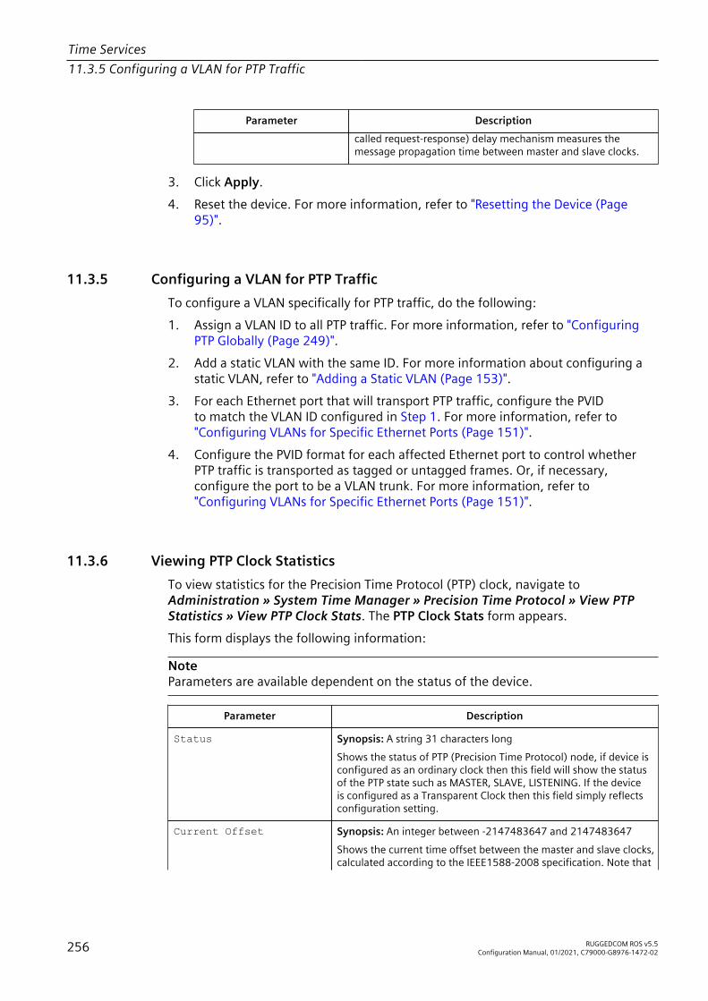
Time Services11.3.5 Configuring a VLAN for PTP Traffic
Parameter Descriptioncalled request-response) delay mechanism measures themessage propagation time between master and slave clocks.
3. Click Apply.4. Reset the device. For more information, refer to "Resetting the Device (Page
95)".
11.3.5 Configuring a VLAN for PTP TrafficTo configure a VLAN specifically for PTP traffic, do the following:1. Assign a VLAN ID to all PTP traffic. For more information, refer to "Configuring
PTP Globally (Page 249)".2. Add a static VLAN with the same ID. For more information about configuring a
static VLAN, refer to "Adding a Static VLAN (Page 153)".3. For each Ethernet port that will transport PTP traffic, configure the PVID
to match the VLAN ID configured in Step 1. For more information, refer to"Configuring VLANs for Specific Ethernet Ports (Page 151)".
4. Configure the PVID format for each affected Ethernet port to control whetherPTP traffic is transported as tagged or untagged frames. Or, if necessary,configure the port to be a VLAN trunk. For more information, refer to"Configuring VLANs for Specific Ethernet Ports (Page 151)".
11.3.6 Viewing PTP Clock StatisticsTo view statistics for the Precision Time Protocol (PTP) clock, navigate toAdministration » System Time Manager » Precision Time Protocol » View PTPStatistics » View PTP Clock Stats. The PTP Clock Stats form appears.This form displays the following information:
NoteParameters are available dependent on the status of the device.
Parameter Description
Status Synopsis: A string 31 characters longShows the status of PTP (Precision Time Protocol) node, if device isconfigured as an ordinary clock then this field will show the statusof the PTP state such as MASTER, SLAVE, LISTENING. If the deviceis configured as a Transparent Clock then this field simply reflectsconfiguration setting.
Current Offset Synopsis: An integer between -2147483647 and 2147483647Shows the current time offset between the master and slave clocks,calculated according to the IEEE1588-2008 specification. Note that
256 RUGGEDCOM ROS v5.5Configuration Manual, 01/2021, C79000-G8976-1472-02

Time Services11.3.7 Viewing Boundary Clock Slave Statistics
Parameter Descriptionthis parameter reflects the approximate value and may ignore linkasymmetry.
Servo Status Synopsis: A string 15 characters longShows the status of the clock servo. The clock servo mechanismdisciplines the system clock. If the clock accuracy is within thedesired limits, the status is set to lock. Note that an alarm mightoccur convergence of the clock servo.
GM ID Synopsis: A string 31 characters longShows the identity of PTP (Precision Time Protocol) grandmasterID. Please note that master clock may be the same as grandmasterclock.
Master ID Synopsis: A string 31 characters longShows the identity of PTP (Precision Time Protocol) master clock.Please note that master clock may be the same as grandmasterclock.
11.3.7 Viewing Boundary Clock Slave StatisticsTo view statistics for the Precision Time Protocol (PTP) boundary clock slave, navigateto Administration » System Time Manager » Precision Time Protocol » View PTPStatistics » Viewing BClock Slave Stats. The BClock Slave Stats form appears.This form displays the following information:
Parameter Description
Status Synopsis: A string 31 characters longShows the status of PTP (Precision Time Protocol) boundary clockslave such as SLAVE, LISTENING.
GM ID Synopsis: A string 31 characters longShows the identity of PTP (Precision Time Protocol) grandmasterID. Please note that master clock may be the same as grandmasterclock.
Master ID Synopsis: A string 31 characters longShows the identity of PTP (Precision Time Protocol) master clock.Please note that master clock may be the same as grandmasterclock.
11.3.8 Viewing Peer Delay StatisticsTo view statistics for the Precision Time Protocol (PTP) peer delay, do the following:1. Navigate to Administration » System Time Manager » Precision Time
Protocol » View PTP Statistics » View Peer Delay Stats. The PTP Delay Statstable appears.
RUGGEDCOM ROS v5.5Configuration Manual, 01/2021, C79000-G8976-1472-02 257
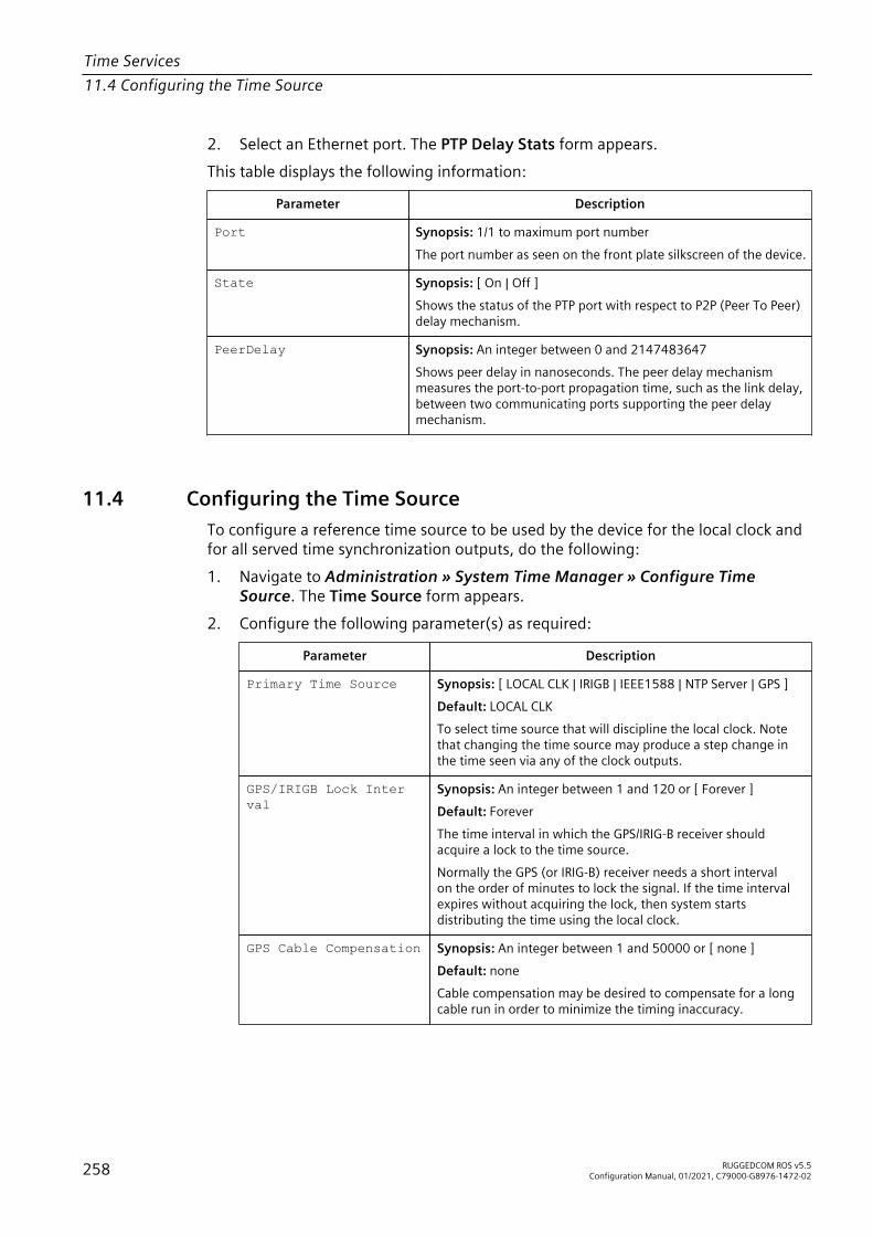
Time Services11.4 Configuring the Time Source
2. Select an Ethernet port. The PTP Delay Stats form appears.This table displays the following information:
Parameter Description
Port Synopsis: 1/1 to maximum port numberThe port number as seen on the front plate silkscreen of the device.
State Synopsis: [ On | Off ]Shows the status of the PTP port with respect to P2P (Peer To Peer)delay mechanism.
PeerDelay Synopsis: An integer between 0 and 2147483647Shows peer delay in nanoseconds. The peer delay mechanismmeasures the port-to-port propagation time, such as the link delay,between two communicating ports supporting the peer delaymechanism.
11.4 Configuring the Time SourceTo configure a reference time source to be used by the device for the local clock andfor all served time synchronization outputs, do the following:1. Navigate to Administration » System Time Manager » Configure Time
Source. The Time Source form appears.2. Configure the following parameter(s) as required:
Parameter Description
Primary Time Source Synopsis: [ LOCAL CLK | IRIGB | IEEE1588 | NTP Server | GPS ]Default: LOCAL CLKTo select time source that will discipline the local clock. Notethat changing the time source may produce a step change inthe time seen via any of the clock outputs.
GPS/IRIGB Lock Inter val
Synopsis: An integer between 1 and 120 or [ Forever ]Default: ForeverThe time interval in which the GPS/IRIG-B receiver shouldacquire a lock to the time source.Normally the GPS (or IRIG-B) receiver needs a short intervalon the order of minutes to lock the signal. If the time intervalexpires without acquiring the lock, then system startsdistributing the time using the local clock.
GPS Cable Compensation Synopsis: An integer between 1 and 50000 or [ none ]Default: noneCable compensation may be desired to compensate for a longcable run in order to minimize the timing inaccuracy.
258 RUGGEDCOM ROS v5.5Configuration Manual, 01/2021, C79000-G8976-1472-02
Time Services11.5 Managing NTP
Parameter Description
IRIGB Cable Compensa tion
Synopsis: An integer between 1 and 50000 or [ none ]Default: noneCable compensation may be desired to compensate for a longcable run in order to minimize the timing inaccuracy.
GPS Antenna Power Synopsis: [ On | Off ]Default: OnGPS receiver requires an active antenna. An active antennaincludes preamplifier that filters and amplifies the GPS signalsbefore delivery to the receiver. This option allows user toactivate or deactivate the power of GPS antenna. If GPS antennais share among multiple devices than all but one device shouldpower the GPS antenna.
3. Click Apply.
11.5 Managing NTPRUGGEDCOM ROS may be configured to refer periodically to a specified NTP server tocorrect any accumulated drift in the on-board clock. RUGGEDCOM ROS will also servetime via the Simple Network Time Protocol (SNTP) to hosts that request it.Two NTP servers (primary and backup) may be configured for the device. The primaryserver is contacted first for each attempt to update the system time. If the primaryserver fails to respond, the backup server is contacted. If either the primary or backupserver fails to respond, an alarm is raised.
11.5.1 Enabling/Disabling NTP ServiceTo enable or disable NTP Service, do the following:
NoteIf the device is running as an NTP server, NTP service must be enabled.
1. Navigate to Administration » System Time Manager » Configure NTP »Configure NTP Service. The SNTP Parameters form appears.
2. Select Enabled to enable SNTP, or select Disabled to disable SNTP.3. Click Apply.
11.5.2 Configuring NTP ServersTo configure either the primary or backup NTP server, do the following:1. Navigate to Administration » System Time Manager » Configure NTP »
Configure NTP Servers. The NTP Servers table appears.
RUGGEDCOM ROS v5.5Configuration Manual, 01/2021, C79000-G8976-1472-02 259

Time Services11.6 Viewing the Status of Time Synchronization Subsystems
2. Select either Primary or Backup. The NTP Servers form appears.3. Configure the following parameter(s) as required:
Parameter Description
Server Synopsis: A string 8 characters longDefault: PrimaryThis field tells whether this configuration is for a Primary or aBackup Server.
IP Address Synopsis: Any valid IP addressThe Server IP Address.
Reachable Synopsis: [ No | Yes ]The status of the server.
Update Period Synopsis: An integer between 1 and 1440Default: 60Determines how frequently the (S)NTP server is polled for atime update.If the server cannot be reached in three attemptsthat are made at one minute intervals an alarm is generated.
4. Click Apply.
11.6 Viewing the Status of Time Synchronization SubsystemsTo view the current status of each time synchronization subsystem, navigate toAdministration » System Time Manager » View Time Sync Status. The Time SyncStatus form appears. This form varies based on the time source configured.
Figure 11.1 Time Sync Status Form (IRIG-B Time Source)
260 RUGGEDCOM ROS v5.5Configuration Manual, 01/2021, C79000-G8976-1472-02
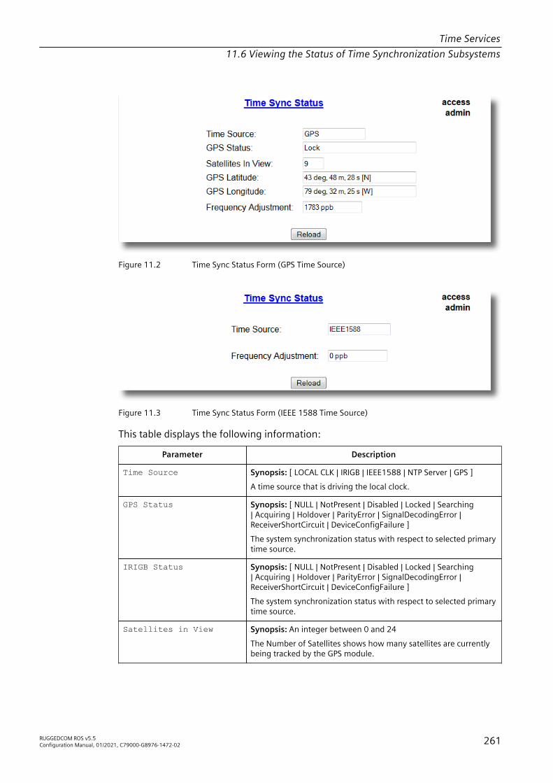
Time Services11.6 Viewing the Status of Time Synchronization Subsystems
Figure 11.2 Time Sync Status Form (GPS Time Source)
Figure 11.3 Time Sync Status Form (IEEE 1588 Time Source)
This table displays the following information:
Parameter Description
Time Source Synopsis: [ LOCAL CLK | IRIGB | IEEE1588 | NTP Server | GPS ]A time source that is driving the local clock.
GPS Status Synopsis: [ NULL | NotPresent | Disabled | Locked | Searching| Acquiring | Holdover | ParityError | SignalDecodingError |ReceiverShortCircuit | DeviceConfigFailure ]The system synchronization status with respect to selected primarytime source.
IRIGB Status Synopsis: [ NULL | NotPresent | Disabled | Locked | Searching| Acquiring | Holdover | ParityError | SignalDecodingError |ReceiverShortCircuit | DeviceConfigFailure ]The system synchronization status with respect to selected primarytime source.
Satellites in View Synopsis: An integer between 0 and 24The Number of Satellites shows how many satellites are currentlybeing tracked by the GPS module.
RUGGEDCOM ROS v5.5Configuration Manual, 01/2021, C79000-G8976-1472-02 261

Time Services11.6 Viewing the Status of Time Synchronization Subsystems
Parameter Description
GPS Latitude Synopsis: A string 31 characters longThe Latitude and Longitude fields show the current position of theGPS antenna. A position's distance north or south of the equator,measured by degrees from zero to 90. One minute of latitudeequals one nautical mile. Latitude is often measured in degrees,with minutes and seconds for finer measurements. A degree isdivided into 60 minutes. One minute can be further divided into 60seconds.
GPS Longitude Synopsis: A string 31 characters longThe Latitude and Longitude fields show the current position ofthe GPS antenna. The distance east or west of the prime meridian(measured in degrees). The prime meridian runs from the northto south pole through Greenwich, England. It is an angularmeasurement, expressed in degrees, minutes and seconds.
SNTP Offset Synopsis: An integer between -2147483647 and 2147483646 or[ Acquiring | Holdover ]Shows the current time offset between (S)NTP server and clientclocks and is calculated as "–" .
Frequency Adjustment Synopsis: An integer between -2147483647 and 2147483646Shows the current amount of discipline applied to the localfrequency reference (TCXO); i.e. the amount of correction on thissystem required to synchronize to the current reference.
262 RUGGEDCOM ROS v5.5Configuration Manual, 01/2021, C79000-G8976-1472-02

Network Discovery and Management 12RUGGEDCOM ROS supports the following protocols for automatic network discovery,monitoring and device management:• RUGGEDCOM Discovery Protocol (RCDP)
Use RCDP to discover RUGGEDCOM ROS-based devices over a Layer 2 network.• Link Layer Device Protocol (LLDP)
Use LLDP to broadcast the device's network capabilities and configuration toother devices on the network, as well as receive broadcasts from other devices.
• Simple Network Management Protocol (SNMP)Use SNMP to notify select users or groups of certain events that happen duringthe operation of the device, such as changes to network topology, link state,spanning tree root, etc.
12.1 Enabling/Disabling RCDPRUGGEDCOM ROS supports the RUGGEDCOM Discovery Protocol (RCDP). RCDPsupports the deployment of RUGGEDCOM ROS -based devices that have not beenconfigured since leaving the factory. RUGGEDCOM ROS devices that have notbeen configured all have the default IP (Layer 3) address. Connecting more thanone of them on a Layer 2 network means that one cannot use standard IP-basedconfiguration tools to configure them. The behavior of IP-based mechanisms such asthe web interface, SSH, telnet, or SNMP will all be undefined.Since RCDP operates at Layer 2, it can be used to reliably and unambiguously addressmultiple devices even though they may share the same IP configuration.Siemens 's RUGGEDCOM EXPLORER is a lightweight, standalone Windows applicationthat supports RCDP. It is capable of discovering, identifying and performing basicconfiguration of RUGGEDCOM ROS-based devices via RCDP. The features supportedby RCDP include:• Discovery of RUGGEDCOM ROS-based devices over a Layer 2 network.• Retrieval of basic network configuration, RUGGEDCOM ROS version, order code,
and serial number.• Control of device LEDs for easy physical identification.• Configuration of basic identification, networking, and authentication
parameters.For security reasons, RUGGEDCOM EXPLORER will attempt to disable RCDP or set alldevices to Get Only mode when EXPLORER is shut down.
RUGGEDCOM ROS v5.5Configuration Manual, 01/2021, C79000-G8976-1472-02 263

Network Discovery and Management12.2 Managing LLDP
Additionally, RUGGEDCOM EXPLORER will set all devices to Get Only mode in thefollowing conditions:• 60 minutes after the last RCDP frame has been received.• The IP address, subnet, gateway or any passwords are changed for the device via
SSH, RSH, Telnet, serial console or SNMP.
NOTICEFor increased security, Siemens recommends disabling RCDP if it is not intended foruse.
NoteRCDP is not compatible with VLAN-based network configurations. For correctoperation of RUGGEDCOM EXPLORER, no VLANs (tagged or untagged) must beconfigured. All VLAN configuration items must be at their default settings.
NoteRUGGEDCOM ROS responds to RCDP requests only. It does not under anycircumstances initiate any RCDP-based communication.
To enable or disable RCDP, do the following:1. Navigate to Network Discovery » RuggedCom Discovery Protocol » Configure
RCDP Parameters. The RCDP Parameters form appears.2. Under RCDP Discovery, select one of the following options:
NOTICEThe Enabled option is only available for devices loaded with factory defaultsettings. This option will not be selectable once a device has been configured.
• Disabled – Disables read and write access• Get Only – Enables only read access• Enabled – Enables read and write access
3. Click Apply.
12.2 Managing LLDPThe Link Layer Discovery Protocol (LLDP) defined by IEEE 802.11AB allowsa networked device to advertise its own basic networking capabilities andconfiguration.LLDP allows a networked device to discover its neighbors across connectednetwork links using a standard mechanism. Devices that support LLDP are able toadvertise information about themselves, including their capabilities, configuration,interconnections, and identifying information.
264 RUGGEDCOM ROS v5.5Configuration Manual, 01/2021, C79000-G8976-1472-02

Network Discovery and Management12.2.1 Configuring LLDP Globally
LLDP agent operation is typically implemented as two modules: the LLDP transmitmodule and LLDP receive module. The LLDP transmit module, when enabled, sendsthe local device’s information at regular intervals, in IEEE 802.1AB standard format.Whenever the transmit module is disabled, it transmits an LLDPDU (LLDP data unit)with a time-to-live (TTL) type-length-value (TLV) containing 0 in the informationfield. This enables remote devices to remove the information associated with thelocal device in their databases. The LLDP receive module, when enabled, receivesremote devices’ information and updates its LLDP database of remote systems. Whennew or updated information is received, the receive module initiates a timer for thevalid duration indicated by the TTL TLV in the received LLDPDU. A remote system’sinformation is removed from the database when an LLDPDU is received from it withTTL TLV containing 0 in its information field.
NoteLLDP is implemented to keep a record of only one device per Ethernet port.Therefore, if there are multiple devices sending LLDP information to a switch porton which LLDP is enabled, information about the neighbor on that port will changeconstantly.
12.2.1 Configuring LLDP GloballyTo configure the global settings for LLDP, do the following:1. Navigate to Network Discovery » Link Layer Discovery Protocol » Configure
Global LLDP Parameters. The Global LLDP Parameters form appears.2. Configure the following parameter(s) as required:
Parameter Description
State Synopsis: [ Disabled | Enabled ]Default: EnabledEnables LLDP protocol. Note that LLDP is enabled on a portwhen LLDP is enabled globally and along with enabling per portsetting in Port LLDP Parameters menu.
Tx Interval Synopsis: An integer between 5 and 32768Default: 30The interval at which LLDP frames are transmitted on behalf ofthis LLDP agent.
Tx Hold Synopsis: An integer between 2 and 10Default: 4The multiplier of the Tx Interval parameter that determines theactual time-to-live (TTL) value used in a LLDPDU. The actual TTLvalue can be expressed by the following formula:
TTL = MIN(65535, (Tx Interval * Tx Hold)
RUGGEDCOM ROS v5.5Configuration Manual, 01/2021, C79000-G8976-1472-02 265

Network Discovery and Management12.2.2 Configuring LLDP for an Ethernet Port
Parameter Description
Reinit Delay Synopsis: An integer between 1 and 10Default: 2The delay in seconds from when the value of Admin Statusparameter of a particular port becomes 'Disbled' until re-initialization will be attempted.
Tx Delay Synopsis: An integer between 1 and 8192Default: 2The delay in seconds between successive LLDP frametransmissions initiated by value or status changed. Therecommended value is set by the following formula:
1 <= txDelay <= (0.25 * Tx Interval)
3. Click Apply.
12.2.2 Configuring LLDP for an Ethernet PortTo configure LLDP for a specific Ethernet Port, do the following:1. Navigate to Network Discovery » Link Layer Discovery Protocol » Configure
Port LLDP Parameters. The Port LLDP Parameters table appears.2. Select a port. The Port LLDP Parameters form appears.3. Configure the following parameter(s) as required:
Parameter Description
Port Synopsis: 1/1 to maximum port numberDefault: 1/1The port number as seen on the front plate silkscreen of thedevice.
Admin Status Synopsis: [ rxTx | txOnly | rxOnly | Disabled ]Default: rxTxrxTx: the local LLDP agent can both transmit and receive LLDPframes through the port.txOnly: the local LLDP agent can only transmit LLDP frames.rxOnly: the local LLDP agent can only receive LLDP frames.disabled: the local LLDP agent can neither transmit or receiveLLDP frames.
Notifications Synopsis: [ Disabled | Enabled ]Default: DisabledDisabling notifications will prevent sending notifications andgenerating alarms for particular port from the LLDP agent.
4. Click Apply.
266 RUGGEDCOM ROS v5.5Configuration Manual, 01/2021, C79000-G8976-1472-02

Network Discovery and Management12.2.3 Viewing Global Statistics and Advertised System Information
12.2.3 Viewing Global Statistics and Advertised System InformationTo view global statistics for LLDP and the system information that is advertised toneighbors, navigate to Network Discovery » Link Layer Discovery Protocol » ViewLLDP Global Remote Statistics. The LLDP Global Remote Statistics form appears.This form displays the following information:
Parameter Description
Inserts Synopsis: An integer between 0 and 4294967295A number of times the entry in LLDP Neighbor Information Tablewas inserted.
Deletes Synopsis: An integer between 0 and 4294967295A number of times the entry in LLDP Neighbor Information Tablewas deleted.
Drops Synopsis: An integer between 0 and 4294967295A number of times an entry was deleted from LLDP NeighborInformation Table because the information timeliness interval hasexpired.
Ageouts Synopsis: An integer between 0 and 4294967295A counter of all TLVs discarded.
12.2.4 Viewing Statistics for LLDP NeighborsTo view statistics for LLDP neighbors, navigate to Network Discovery » Link LayerDiscovery Protocol » View LLDP Neighbor Information. The LLDP NeighborInformation table appears.This form displays the following information:
Parameter Description
Port Synopsis: 1/1 to maximum port numberThe local port associated with this entry.
ChassisId Synopsis: A string 45 characters longChassis Id information received from remote LLDP agent.
PortId Synopsis: A string 45 characters longPort Id information received from remote LLDP agent.
SysName Synopsis: A string 45 characters longSystem Name information received from remote LLDP agent.
SysDesc Synopsis: A string 45 characters longSystem Descriptor information received from remote LLDP agent.
RUGGEDCOM ROS v5.5Configuration Manual, 01/2021, C79000-G8976-1472-02 267

Network Discovery and Management12.2.5 Viewing Statistics for LLDP Ports
12.2.5 Viewing Statistics for LLDP PortsTo view statistics for LLDP ports, navigate to Network Discovery » Link LayerDiscovery Protocol » View LLDP Statistics. The LLDP Statistics table appears.This table displays the following information:
Parameter Description
Port Synopsis: 1/1 to maximum port numberThe port number as seen on the front plate silkscreen of the device.
FrmDrop Synopsis: An integer between 0 and 4294967295A counter of all LLDP frames discarded.
ErrFrm Synopsis: An integer between 0 and 4294967295A counter of all LLDPDUs received with detectable errors.
FrmIn Synopsis: An integer between 0 and 4294967295A counter of all LLDPDUs received.
FrmOut Synopsis: An integer between 0 and 4294967295A counter of all LLDPDUs transmitted.
Ageouts Synopsis: An integer between 0 and 4294967295A counter of the times that a neighbor's information has beendeleted from the LLDP remote system MIB because the txinfoTTLtimer has expired.
TLVsDrop Synopsis: An integer between 0 and 4294967295A counter of all TLVs discarded.
TLVsUnknown Synopsis: An integer between 0 and 4294967295A counter of all TLVs received on the port that are not recognizedby the LLDP local agent.
12.3 Managing SNMPRUGGEDCOM ROS supports versions 1, 2 and 3 of the Simple Network ManagementProtocol (SNMP), otherwise referred to as SNMPv1, SNMPv2c and SNMPv3respectively. SNMPv3 provides secure access to the devices through a combinationof authentication and packet encryption over the network. Security features for thisprotocol include:
Feature DescriptionMessage Integrity Makes sure that a packet has not been tampered with in-transit.Authentication Determines if the message is from a valid source.Encryption Encrypts the contents of a packet to prevent it from being seen by an
unauthorized source.
SNMPv3 provides security models and security levels. A security model is anauthentication strategy setup for a user and the group in which the user resides. Asecurity level is a permitted level of security within a security model. A combination
268 RUGGEDCOM ROS v5.5Configuration Manual, 01/2021, C79000-G8976-1472-02

Network Discovery and Management12.3.1 SNMP Management Interface Base (MIB) Support
of a security model and level will determine which security mechanism is employedwhen handling an SNMP packet.Before configuring SNMPv3, note the following:• Each user belongs to a group• A group defines the access policy for a set of users• An access policy defines what SNMP objects can be accessed for (i.e. reading,
writing and creating notifications)• A group determines the list of notifications its users can receive• A group also defines the security model and security level for its usersFor SNMPv1 and SNMPv2c, a community string can be configured. The string ismapped to the group and access level with a security name, which is configured asUser Name.
12.3.1 SNMP Management Interface Base (MIB) SupportRUGGEDCOM ROS supports a variety of standard MIBs, proprietary RUGGEDCOM MIBsand Agent Capabilities MIBs, all for SNMP (Simple Network Management Protocol).
12.3.1.1 Supported Standard MIBs
RUGGEDCOM ROS supports the following standard MIBs:
NOTICEThis section lists all MIBs supported by RUGGEDCOM ROS, and is intended forreference purposes only. Individual device support may vary.
• BRIDGE-MIBFor more information, refer to "BRIDGE-MIB".
• IEC-62439-3-MIBFor more information, refer to "IEC-62439-3-MIB".
• IEEEC37-238-MIBFor more information, refer to "IEEEC37-238-MIB".
• IF-MIBFor more information, refer to "IF-MIB".
• IP-MIBFor more information, refer to "IP-MIB".
• LLDP-MIBFor more information, refer to "LLDP-MIB".
RUGGEDCOM ROS v5.5Configuration Manual, 01/2021, C79000-G8976-1472-02 269

Network Discovery and Management12.3.1 SNMP Management Interface Base (MIB) Support
• Q-BRIDGE-MIBFor more information, refer to "Q-BRIDGE-MIB".
• RMON-MIBFor more information, refer to "RMON-MIB".
• RS-232-MIBFor more information, refer to "RS-232-MIB".
• RSTP-MIBFor more information, refer to "RSTP-MIB".
• SNMP-FRAMEWORK-MIBFor more information, refer to "SNMP-FRAMEWORK-MIB".
• SNMP-USER-BASED-SM-MIBFor more information, refer to "SNMP-USER-BASED-SM-MIB".
• SNMPv2-MIBFor more information, refer to "SNMPv2-MIB".
• SNMP-VIEW-BASED-ACM-MIBFor more information, refer to "SNMP-VIEW-BASED-ACM-MIB".
• TCP-MIBFor more information, refer to "TCP-MIB".
• UDP-MIBFor more information, refer to "UDP-MIB".
BRIDGE-MIB
Group/Object DescriptionGroup: dot1dBaseBridgeGroupObject: dot1dBaseBridgeAddress
Access: Read-OnlySyntax: Hex-StringOID: .1.3.6.1.2.1.17.1.1.0Definition: The MAC address used by this bridge when it must be referred toin a unique fashion. It is recommended that this be the numerically smallestMAC address of all ports that belong to this bridge. However, it is onlyrequired to be unique. When concatenated with dot1dStpPriority, a uniqueBridgeIdentifier is formed, which is used in the Spanning Tree Protocol.
Group: dot1dBaseBridgeGroupTrap: dot1dBaseNumPorts
Access: Read-OnlySyntax: IntegerOID: .1.3.6.1.2.1.17.1.2.0Definition: The number of ports controlled by this bridging entity.
Group: dot1dBasePortGroupTrap: dot1dBasePort
Access: Read-OnlySyntax: IntegerOID: .1.3.6.1.2.1.17.1.4.1.1.1
270 RUGGEDCOM ROS v5.5Configuration Manual, 01/2021, C79000-G8976-1472-02

Network Discovery and Management12.3.1 SNMP Management Interface Base (MIB) Support
Group/Object DescriptionDefinition: The port number of the port for which this entry contains bridgemanagement information.
Group: dot1dBasePortGroupTrap: dot1dBasePortCircuit
Access: Read-OnlySyntax: OIDOID: .1.3.6.1.2.1.17.1.3.1Definition: For a port that (potentially) has the same value ofdot1dBasePortIfIndex as another port on the same bridge. This objectcontains the name of an object instance unique to this port. For example,in the case where multiple ports correspond one-to-one with multiple X.25virtual circuits, this value might identify an (e.g., the first) object instanceassociated with the X.25 virtual circuit corresponding to this port. For a portthat has a unique value of dot1dBasePortIfIndex, this object can have thevalue { 0 0 }.
Group: dot1dBasePortGroupTrap: dot1dBasePortDelayExceededDiscards
Agent Capability: RC-BRIDGE-MIB-ACAccess: Read-OnlySyntax: Counter32OID: .1.3.6.1.2.1.17.1.4.1.4.1Definition: The number of frames discarded by this port due to excessivetransit delay through the bridge. It is incremented by both transparent andsource route bridges.
NoteThe switch does not have a knowledge of the value of this object. In aresponse to a get request a zero value will be returned.
Group: dot1dBasePortGroupTrap: dot1dBasePortIfIndex
Access: Read-OnlySyntax: IntegerOID: .1.3.6.1.2.1.17.1.4.1.2.1Definition: The value of the instance of the ifIndex object, defined in IF-MIB,for the interface corresponding to this port.
Group: dot1dBasePortGroupTrap: dot1dBasePortMtuExceededDiscards
Access: Read-OnlySyntax: Counter32OID: .1.3.6.1.2.1.17.1.4.1.5.1Definition: The number of frames discarded by this port due to an excessivesize. It is incremented by both transparent and source route bridges.
Group: dot1dBaseBridgeGroupTrap: dot1dBaseType
Access: Read-OnlySyntax: IntegerOID: .1.3.6.1.2.1.17.1.3.0Definition: Indicates what type of bridging this bridge can perform. If abridge is actually performing a certain type of bridging, this will be indicatedby entries in the port table for the given type.
Group: dot1dStpBridgeGroupTrap: dot1dStpBridgeForwardDelay
Agent Capability: RC-BRIDGE-MIB-ACAccess: Read-WriteSyntax: IntegerOID: .1.3.6.1.2.1.17.2.14.0Definition: The value that all bridges use for ForwardDelay when this bridgeis acting as the root. Note that 802.1D-1998 specifies that the range for thisparameter is related to the value of dot1dStpBridgeMaxAge. The granularity
RUGGEDCOM ROS v5.5Configuration Manual, 01/2021, C79000-G8976-1472-02 271

Network Discovery and Management12.3.1 SNMP Management Interface Base (MIB) Support
Group/Object Descriptionof this timer is specified by 802.1D-1998 to be 1 second. An agent mayreturn a badValue error if a set is attempted to a value that is not a wholenumber of seconds.
NoteThe value of this object will be rounded to the closest number of tenths of asecond.
Group: dot1dStpBridgeGroupTrap: dot1dStpBridgeHelloTime
Agent Capability: RC-BRIDGE-MIB-ACAccess: Read-WriteSyntax: IntegerOID: .1.3.6.1.2.1.17.2.13.0Definition: The value that all bridges use for HelloTime when this bridge isacting as the root. The granularity of this timer is specified by 802.1D-1998to be 1 second. An agent may return a badValue error if a set is attempted toa value that is not a whole number of seconds.
NoteThe value of this object will be rounded to the closest number of tenths of asecond.
Group: dot1dStpBridgeGroupTrap: dot1dStpBridgeMaxAge
Agent Capability: RC-BRIDGE-MIB-ACAccess: Read-WriteSyntax: IntegerOID: .1.3.6.1.2.1.17.2.12.0Definition: The value that all bridges use for MaxAge when this bridgeis acting as the root. Note that 802.1D-1998 specifies that the range forthis parameter is related to the value of dot1dStpBridgeHelloTime. Thegranularity of this timer is specified by 802.1D-1998 to be 1 second. Anagent may return a badValue error if a set is attempted to a value that is nota whole number of seconds.
NoteThe value of this object will be rounded to the closest number of tenths of asecond.
Group: dot1dStpBridgeGroupTrap: dot1dStpDesignatedRoot
Access: Read-OnlySyntax: Hex-StringOID: .1.3.6.1.2.1.17.2.5.0Definition: The bridge identifier of the root of the spanning tree, asdetermined by the Spanning Tree Protocol, as executed by this node. Thisvalue is used as the Root Identifier parameter in all Configuration BridgePDUs originated by this node.
Group: dot1dStpBridgeGroupTrap: dot1dStpForwardDelay
Access: Read-OnlySyntax: IntegerOID: .1.3.6.1.2.1.17.2.11.0Definition: This time value, measured in units of hundredths of a second,controls how fast a port changes its spanning state when moving towardsthe Forwarding state. The value determines how long the port stays in eachof the Listening and Learning states, which precede the Forwarding state.This value is also used when a topology change has been detected and is
272 RUGGEDCOM ROS v5.5Configuration Manual, 01/2021, C79000-G8976-1472-02

Network Discovery and Management12.3.1 SNMP Management Interface Base (MIB) Support
Group/Object Descriptionunderway, to age all dynamic entries in the Forwarding Database. [Notethat this value is the one that this bridge is currently using, in contrast todot1dStpBridgeForwardDelay, which is the value that this bridge and allothers would start using if/when this bridge were to become the root.]
Group: dot1dStpBridgeGroupTrap: dot1dStpHelloTime
Access: Read-OnlySyntax: IntegerOID: .1.3.6.1.2.1.17.2.9.0Definition: The amount of time between the transmission of Configurationbridge PDUs by this node on any port when it is the root of the spanningtree, or trying to become so, in units of hundredths of a second. This is theactual value that this bridge is currently using.
Group: dot1dStpBridgeGroupTrap: dot1dStpHoldTime
Access: Read-OnlySyntax: IntegerOID: .1.3.6.1.2.1.17.2.10.0Definition: This time value determines the interval length during which nomore than two Configuration bridge PDUs shall be transmitted by this node,in units of hundredths of a second.
Group: dot1dStpBridgeGroupTrap: dot1dStpMaxAge
Access: Read-OnlySyntax: IntegerOID: .1.3.6.1.2.1.17.2.8.0Definition: The maximum age of Spanning Tree Protocol informationlearned from the network on any port before it is discarded, in units ofhundredths of a second. This is the actual value that this bridge is currentlyusing.
Group: dot1dStpPortGroupTrap: dot1dStpPort
Access: Read-OnlySyntax: IntegerOID: .1.3.6.1.2.1.17.2.15.1.1.1Definition: The port number of the port for which this entry containsSpanning Tree Protocol management information.
Group: dot1dStpPortGroupTrap: dot1dStpPortDesignatedBridge
Access: Read-OnlySyntax: Hex-StringOID: .1.3.6.1.2.1.17.2.15.1.8.1Definition: The Bridge Identifier of the bridge that this port considers to bethe Designated Bridge for this port's segment.
Group: dot1dStpPortGroupTrap: dot1dStpPortDesignatedCost
Access: Read-OnlySyntax: IntegerOID: .1.3.6.1.2.1.17.2.15.1.7.1Definition: The path cost of the Designated Port of the segment connectedto this port. This value is compared to the Root Path Cost field in receivedbridge PDUs.
Group: dot1dStpPortGroupTrap: dot1dStpPortDesignatedPort
Access: Read-OnlySyntax: Hex-StringOID: .1.3.6.1.2.1.17.2.15.1.9.1Definition: The Port Identifier of the port on the Designated Bridge for thisport's segment.
Group: dot1dStpPortGroup Access: Read-Only
RUGGEDCOM ROS v5.5Configuration Manual, 01/2021, C79000-G8976-1472-02 273
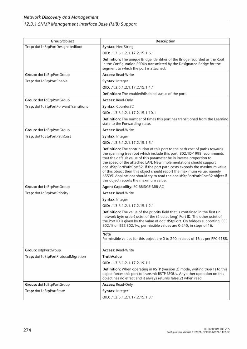
Network Discovery and Management12.3.1 SNMP Management Interface Base (MIB) Support
Group/Object DescriptionTrap: dot1dStpPortDesignatedRoot Syntax: Hex-String
OID: .1.3.6.1.2.1.17.2.15.1.6.1Definition: The unique Bridge Identifier of the Bridge recorded as the Rootin the Configuration BPDUs transmitted by the Designated Bridge for thesegment to which the port is attached.
Group: dot1dStpPortGroupTrap: dot1dStpPortEnable
Access: Read-WriteSyntax: IntegerOID: .1.3.6.1.2.1.17.2.15.1.4.1Definition: The enabled/disabled status of the port.
Group: dot1dStpPortGroupTrap: dot1dStpPortForwardTransitions
Access: Read-OnlySyntax: Counter32OID: .1.3.6.1.2.1.17.2.15.1.10.1Definition: The number of times this port has transitioned from the Learningstate to the Forwarding state.
Group: dot1dStpPortGroupTrap: dot1dStpPortPathCost
Access: Read-WriteSyntax: IntegerOID: .1.3.6.1.2.1.17.2.15.1.5.1Definition: The contribution of this port to the path cost of paths towardsthe spanning tree root which include this port. 802.1D-1998 recommendsthat the default value of this parameter be in inverse proportion tothe speed of the attached LAN. New implementations should supportdot1dStpPortPathCost32. If the port path costs exceeds the maximum valueof this object then this object should report the maximum value, namely65535. Applications should try to read the dot1dStpPortPathCost32 object ifthis object reports the maximum value.
Group: dot1dStpPortGroupTrap: dot1dStpPortPriority
Agent Capability: RC-BRIDGE-MIB-ACAccess: Read-WriteSyntax: IntegerOID: .1.3.6.1.2.1.17.2.15.1.2.1Definition: The value of the priority field that is contained in the first (innetwork byte order) octet of the (2 octet long) Port ID. The other octet ofthe Port ID is given by the value of dot1dStpPort. On bridges supporting IEEE802.1t or IEEE 802.1w, permissible values are 0-240, in steps of 16.
NotePermissible values for this object are 0 to 240 in steps of 16 as per RFC 4188.
Group: rstpPortGroupTrap: dot1dStpPortProtocolMigration
Access: Read-WriteTruthValueOID: .1.3.6.1.2.1.17.2.19.1.1Definition: When operating in RSTP (version 2) mode, writing true(1) to thisobject forces this port to transmit RSTP BPDUs. Any other operation on thisobject has no effect and it always returns false(2) when read.
Group: dot1dStpPortGroupTrap: dot1dStpPortState
Access: Read-OnlySyntax: IntegerOID: .1.3.6.1.2.1.17.2.15.1.3.1
274 RUGGEDCOM ROS v5.5Configuration Manual, 01/2021, C79000-G8976-1472-02
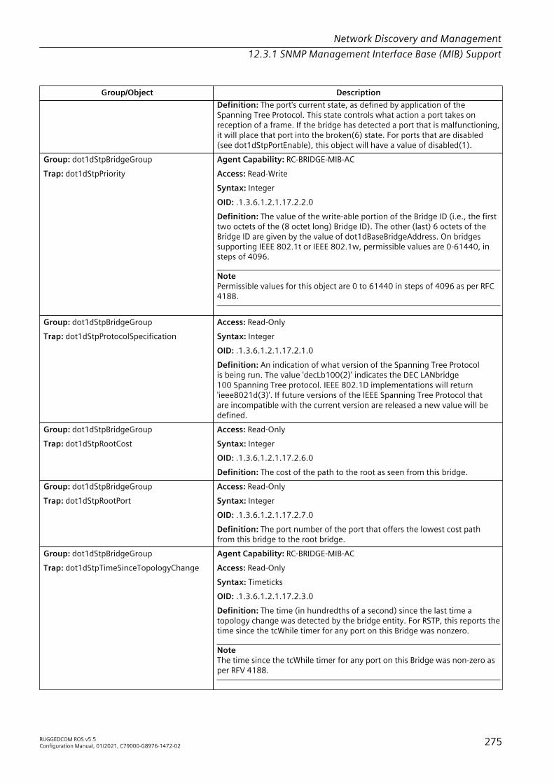
Network Discovery and Management12.3.1 SNMP Management Interface Base (MIB) Support
Group/Object DescriptionDefinition: The port's current state, as defined by application of theSpanning Tree Protocol. This state controls what action a port takes onreception of a frame. If the bridge has detected a port that is malfunctioning,it will place that port into the broken(6) state. For ports that are disabled(see dot1dStpPortEnable), this object will have a value of disabled(1).
Group: dot1dStpBridgeGroupTrap: dot1dStpPriority
Agent Capability: RC-BRIDGE-MIB-ACAccess: Read-WriteSyntax: IntegerOID: .1.3.6.1.2.1.17.2.2.0Definition: The value of the write-able portion of the Bridge ID (i.e., the firsttwo octets of the (8 octet long) Bridge ID). The other (last) 6 octets of theBridge ID are given by the value of dot1dBaseBridgeAddress. On bridgessupporting IEEE 802.1t or IEEE 802.1w, permissible values are 0-61440, insteps of 4096.
NotePermissible values for this object are 0 to 61440 in steps of 4096 as per RFC4188.
Group: dot1dStpBridgeGroupTrap: dot1dStpProtocolSpecification
Access: Read-OnlySyntax: IntegerOID: .1.3.6.1.2.1.17.2.1.0Definition: An indication of what version of the Spanning Tree Protocolis being run. The value 'decLb100(2)' indicates the DEC LANbridge100 Spanning Tree protocol. IEEE 802.1D implementations will return'ieee8021d(3)'. If future versions of the IEEE Spanning Tree Protocol thatare incompatible with the current version are released a new value will bedefined.
Group: dot1dStpBridgeGroupTrap: dot1dStpRootCost
Access: Read-OnlySyntax: IntegerOID: .1.3.6.1.2.1.17.2.6.0Definition: The cost of the path to the root as seen from this bridge.
Group: dot1dStpBridgeGroupTrap: dot1dStpRootPort
Access: Read-OnlySyntax: IntegerOID: .1.3.6.1.2.1.17.2.7.0Definition: The port number of the port that offers the lowest cost pathfrom this bridge to the root bridge.
Group: dot1dStpBridgeGroupTrap: dot1dStpTimeSinceTopologyChange
Agent Capability: RC-BRIDGE-MIB-ACAccess: Read-OnlySyntax: TimeticksOID: .1.3.6.1.2.1.17.2.3.0Definition: The time (in hundredths of a second) since the last time atopology change was detected by the bridge entity. For RSTP, this reports thetime since the tcWhile timer for any port on this Bridge was nonzero.
NoteThe time since the tcWhile timer for any port on this Bridge was non-zero asper RFV 4188.
RUGGEDCOM ROS v5.5Configuration Manual, 01/2021, C79000-G8976-1472-02 275

Network Discovery and Management12.3.1 SNMP Management Interface Base (MIB) Support
Group/Object DescriptionGroup: dot1dStpBridgeGroupTrap: dot1dStpTopChanges
Access: Read-OnlySyntax: Counter32OID: .1.3.6.1.2.1.17.2.4.0Definition: The total number of topology changes detected by this bridgesince the management entity was last reset or initialized.
Group: dot1dTpBridgeGroupTrap: dot1dTpAgingTime
Access: Read-WriteSyntax: IntegerOID: .1.3.6.1.2.1.17.4.2.0Definition: The timeout period in seconds for aging out dynamically-learned forwarding information. 802.1D-1998 recommends a default of 300seconds.
NoteThe range of valid values is restricted to 15 to 800 seconds. Lower limit of 15seconds is a hardware limitation.
Group: dot1dTpFdbGroupTrap: dot1dTpFdbAddress
Access: Read-OnlySyntax: Hex-StringOID: .1.3.6.1.2.1.17.4.3.1.1.148.184.197.5.176.0Definition: A unicast MAC address for which the bridge has forwarding and/or filtering information.
Group: dot1dTpFdbGroupTrap: dot1dTpFdbPort
Access: Read-OnlySyntax: IntegerOID: .1.3.6.1.2.1.17.4.3.1.2.148.184.197.5.176.0Definition: Either the value '0', or the port number of the port on whicha frame having a source address equal to the value of the correspondinginstance of dot1dTpFdbAddress has been seen. A value of '0' indicatesthat the port number has not been learned, but that the bridge does havesome forwarding/filtering information about this address (e.g., in thedot1dStaticTable). Implementors are encouraged to assign the port valueto this object whenever it is learned, even for addresses for which thecorresponding value of dot1dTpFdbStatus is not learned(3).
Group: dot1dTpFdbGroupTrap: dot1dTpFdbStatus
Access: Read-OnlySyntax: IntegerOID: .1.3.6.1.2.1.17.4.3.1.3.148.184.197.5.176.0Definition: The status of this entry. The meanings of the values are:• other(1) - none of the following. This would include the case
where some other MIB object (not the corresponding instance ofdot1dTpFdbPort, nor an entry in the dot1dStaticTable) is beingused to determine if and how frames addressed to the value of thecorresponding instance of dot1dTpFdbAddress are being forwarded.
• invalid(2) - this entry is no longer valid (e.g., it was learned but has sinceaged out), but has not yet been flushed from the table.
• learned(3) - the value of the corresponding instance of dot1dTpFdbPortwas learned, and is being used.
• self(4) - the value of the corresponding instance of dot1dTpFdbAddressrepresents one of the bridge's addresses. The corresponding instance ofdot1dTpFdbPort indicates which of the bridge's ports has this address.
276 RUGGEDCOM ROS v5.5Configuration Manual, 01/2021, C79000-G8976-1472-02
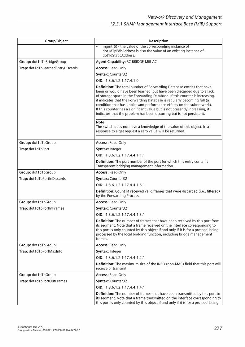
Network Discovery and Management12.3.1 SNMP Management Interface Base (MIB) Support
Group/Object Description• mgmt(5) - the value of the corresponding instance of
dot1dTpFdbAddress is also the value of an existing instance ofdot1dStaticAddress.
Group: dot1dTpBridgeGroupTrap: dot1dTpLearnedEntryDiscards
Agent Capability: RC-BRIDGE-MIB-ACAccess: Read-OnlySyntax: Counter32OID: .1.3.6.1.2.1.17.4.1.0Definition: The total number of Forwarding Database entries that havebeen or would have been learned, but have been discarded due to a lackof storage space in the Forwarding Database. If this counter is increasing,it indicates that the Forwarding Database is regularly becoming full (acondition that has unpleasant performance effects on the subnetwork).If this counter has a significant value but is not presently increasing, itindicates that the problem has been occurring but is not persistent.
NoteThe switch does not have a knowledge of the value of this object. In aresponse to a get request a zero value will be returned.
Group: dot1dTpGroupTrap: dot1dTpPort
Access: Read-OnlySyntax: IntegerOID: .1.3.6.1.2.1.17.4.4.1.1.1Definition: The port number of the port for which this entry containsTransparent bridging management information.
Group: dot1dTpGroupTrap: dot1dTpPortInDiscards
Access: Read-OnlySyntax: Counter32OID: .1.3.6.1.2.1.17.4.4.1.5.1Definition: Count of received valid frames that were discarded (i.e., filtered)by the Forwarding Process.
Group: dot1dTpGroupTrap: dot1dTpPortInFrames
Access: Read-OnlySyntax: Counter32OID: .1.3.6.1.2.1.17.4.4.1.3.1Definition: The number of frames that have been received by this port fromits segment. Note that a frame received on the interface corresponding tothis port is only counted by this object if and only if it is for a protocol beingprocessed by the local bridging function, including bridge managementframes.
Group: dot1dTpGroupTrap: dot1dTpPortMaxInfo
Access: Read-OnlySyntax: IntegerOID: .1.3.6.1.2.1.17.4.4.1.2.1Definition: The maximum size of the INFO (non-MAC) field that this port willreceive or transmit.
Group: dot1dTpGroupTrap: dot1dTpPortOutFrames
Access: Read-OnlySyntax: Counter32OID: .1.3.6.1.2.1.17.4.4.1.4.1Definition: The number of frames that have been transmitted by this port toits segment. Note that a frame transmitted on the interface corresponding tothis port is only counted by this object if and only if it is for a protocol being
RUGGEDCOM ROS v5.5Configuration Manual, 01/2021, C79000-G8976-1472-02 277

Network Discovery and Management12.3.1 SNMP Management Interface Base (MIB) Support
Group/Object Descriptionprocessed by the local bridging function, including bridge managementframes.
IEC-62439-3-MIB
Group/Object DescriptionGroup: lreStatisticsInterfaceGroupTrap: lreCntDuplicateA
Access: Read-OnlySyntax: Counter32OID: 1.0.62439.2.21.1.1.0.1.1.19.1Definition: Number of entries in the duplicate detection mechanism on portA for which one single duplicate was received.
Group: lreStatisticsInterfaceGroupTrap: lreCntDuplicateB
Access: Read-OnlySyntax: Counter32OID: 1.0.62439.2.21.1.1.0.1.1.20.1Definition: Number of entries in the duplicate detection mechanism on portB for which one single duplicate was received.
Group: lreStatisticsInterfaceGroupTrap: lreCntDuplicateC
Access: Read-OnlySyntax: Counter32OID: 1.0.62439.2.21.1.1.0.1.1.21.1Definition: Number of entries in the duplicate detection mechanism on portC for which one single duplicate was received.
Group: lreStatisticsInterfaceGroupTrap: lreCntErrorsA
Access: Read-OnlySyntax: Counter32OID: 1.0.62439.2.21.1.1.0.1.1.11.1Definition: Number of frames with errors received on this LRE port A. Initialvalue = 0.
Group: lreStatisticsInterfaceGroupTrap: lreCntErrorsB
Access: Read-OnlySyntax: Counter32OID: 1.0.62439.2.21.1.1.0.1.1.12.1Definition: Number of frames with errors received on this LRE port B. Initialvalue = 0.
Group: lreStatisticsInterfaceGroupTrap: lreCntErrorsC
Access: Read-OnlySyntax: Counter32OID: 1.0.62439.2.21.1.1.0.1.1.13.1Definition: Number of frames with errors received on the applicationinterface of a DANP or DANH or on the interlink of a RedBox. Initial value = 0.
Group: lreStatisticsInterfaceGroupTrap: lreCntErrWrongLanA
Access: Read-OnlySyntax: Counter32OID: 1.0.62439.2.21.1.1.0.1.1.5.1Definition: Number of frames with the wrong LAN identifier received on LREport A. Initial value = 0. Only applicable to PRP ports.
Group: lreStatisticsInterfaceGroupTrap: lreCntErrWrongLanB
Access: Read-OnlySyntax: Counter32OID: 1.0.62439.2.21.1.1.0.1.1.6.1
278 RUGGEDCOM ROS v5.5Configuration Manual, 01/2021, C79000-G8976-1472-02

Network Discovery and Management12.3.1 SNMP Management Interface Base (MIB) Support
Group/Object DescriptionDefinition: Number of frames with the wrong LAN identifier received on LREport B. Initial value = 0. Only applicable to PRP ports.
Group: lreStatisticsInterfaceGroupTrap: lreCntErrWrongLanC
Agent Capability: RC-IEC-62439-3-MIB-ACAccess: not-implementedSyntax: Counter32OID: 1.0.62439.2.21.1.1.0.1.1.7.1Definition: Number of frames with the wrong LAN identifier received onthe interlink of a RedBox. Only applicable to HSR RedBoxes in HSR-PRPconfiguration.
Group: lreStatisticsInterfaceGroupTrap: lreCntMultiA
Agent Capability: RC-IEC-62439-3-MIB-ACAccess: not-implementedSyntax: Counter32OID: 1.0.62439.2.21.1.1.0.1.1.22.1Definition: Number of entries in the duplicate detection mechanism on portA for which more than one duplicate was received.
Group: lreStatisticsInterfaceGroupTrap: lreCntMultiB
Agent Capability: RC-IEC-62439-3-MIB-ACAccess: not-implementedSyntax: Counter32OID: 1.0.62439.2.21.1.1.0.1.1.23.1Definition: Number of entries in the duplicate detection mechanism on portB for which more than one duplicate was received.
Group: lreStatisticsInterfaceGroupTrap: lreCntMultiC
Agent Capability: RC-IEC-62439-3-MIB-ACAccess: not-implementedSyntax: Counter32OID: 1.0.62439.2.21.1.1.0.1.1.24.1Definition: Number of entries in the duplicate detection mechanism on theapplication interface of the DAN or the interlink of the RedBox for whichmore than one duplicate was received.
Group: lreStatisticsInterfaceGroupTrap: lreCntNodes
Access: Read-OnlySyntax: IntegerOID: 1.0.62439.2.21.1.1.0.1.1.14.1Definition: Number of nodes in the Nodes Table.
Group: lreStatisticsInterfaceGroupTrap: lreCntOwnRxA
Access: Read-OnlySyntax: Counter32OID: 1.0.62439.2.21.1.1.0.1.1.25.1Definition: Number of HSR tagged frames received on Port A that originatedfrom this device. Frames originate from this device if the source MACmatches the MAC of the LRE, or if the source MAC appears in the proxy nodetable (if implemented). Applicable only to HSR. Initial value = 0.
Group: lreStatisticsInterfaceGroupTrap: lreCntOwnRxB
Access: Read-OnlySyntax: Counter32OID: 1.0.62439.2.21.1.1.0.1.1.26.1Definition: Number of HSR tagged frames received on Port B that originatedfrom this device. Frames originate from this device if the source MAC
RUGGEDCOM ROS v5.5Configuration Manual, 01/2021, C79000-G8976-1472-02 279

Network Discovery and Management12.3.1 SNMP Management Interface Base (MIB) Support
Group/Object Descriptionmatches the MAC of the LRE, or if the source MAC appears in the proxy nodetable (if implemented). Applicable only to HSR. Initial value = 0.
Group: lreStatisticsInterfaceGroupTrap: lreCntProxyNodes
Access: Read-OnlySyntax: IntegerOID: 1.0.62439.2.21.1.1.0.1.1.15.1Definition: Number of nodes in the Proxy Node Table. Only applicable toRedBox. Initial value = 0.
Group: lreStatisticsInterfaceGroupTrap: lreCntRxA
Access: Read-OnlySyntax: Counter32OID: 1.0.62439.2.21.1.1.0.1.1.8.1Definition: Number of frames received on a LRE port A. Only frames thatare HSR tagged or fitted with a PRP Redundancy Control Trailer are counted.Frames that are not forwarded anywhere (e.g. because the sender of theframe is in the proxy node table) are counted, too. Only frames receivedcompletely and without error are counted. Initial value = 0.
Group: lreStatisticsInterfaceGroupTrap: lreCntRxB
Access: Read-OnlySyntax: Counter32OID: 1.0.62439.2.21.1.1.0.1.1.9.1Definition: Number of frames received on a LRE port B. Only frames thatare HSR tagged or fitted with a PRP Redundancy Control Trailer are counted.Frames that are not forwarded anywhere (e.g. because the sender of theframe is in the proxy node table) are counted, too. Only frames receivedcompletely and without error are counted. Initial value = 0.
Group: lreStatisticsInterfaceGroupTrap: lreCntRxC
Agent Capability: RC-IEC-62439-3-MIB-ACAccess: Read-OnlySyntax: Counter32OID: 1.0.62439.2.21.1.1.0.1.1.10.1Definition: Number of frames received from the application interface of aDANP or DANH or the number of number of frames received on the interlinkof a RedBox. Frames with and without PRP RCT or HSR tag are counted, butnot linklocal frames. Only frames received completely and without error arecounted. Initial value = 0.
NoteOnly frames received on the local port are counted.
Group: lreStatisticsInterfaceGroupTrap: lreCntTxA
Access: Read-OnlySyntax: Counter32OID: 1.0.62439.2.21.1.1.0.1.1.2.1Definition: Number of frames sent over port A that are HSR tagged or fittedwith a PRP Redundancy Control Trailer. Only frames that are HSR tagged ordo have a PRP RCT are counted. A frame aborted during the transmission isnot counted. Initial value = 0.
Group: lreStatisticsInterfaceGroupTrap: lreCntTxB
Access: Read-OnlySyntax: Counter32OID: 1.0.62439.2.21.1.1.0.1.1.3.1Definition: Number of frames sent over port B that are HSR tagged or fittedwith a PRP Redundancy Control Trailer. Only frames that are HSR tagged or
280 RUGGEDCOM ROS v5.5Configuration Manual, 01/2021, C79000-G8976-1472-02

Network Discovery and Management12.3.1 SNMP Management Interface Base (MIB) Support
Group/Object Descriptiondo have a PRP RCT are counted. A frame aborted during the transmission isnot counted. Initial value = 0.
Group: lreStatisticsInterfaceGroupTrap: lreCntTxC
Agent Capability: RC-IEC-62439-3-MIB-ACAccess: Read-OnlySyntax: Counter32OID: 1.0.62439.2.21.1.1.0.1.1.4.1Definition: Number of frames sent towards the application interface of theDANP or DANH or over the interlink of the RedBox. Frames with and withoutPRP RCT or HSR tag are counted, but not link-local frames. A frame abortedduring the transmission is not counted. Initial value = 0.
NoteOnly frames sent out the local port are counted.
Group: lreStatisticsInterfaceGroupTrap: lreCntUniqueA
Agent Capability: RC-IEC-62439-3-MIB-ACAccess: not-implementedSyntax: Counter32OID: 1.0.62439.2.21.1.1.0.1.1.16.1Definition: Number of entries in the duplicate detection mechanism on portA for which no duplicate was received.
Group: lreStatisticsInterfaceGroupTrap: lreCntUniqueB
Agent Capability: RC-IEC-62439-3-MIB-ACAccess: not-implementedSyntax: Counter32OID: 1.0.62439.2.21.1.1.0.1.1.17.1Definition: Number of entries in the duplicate detection mechanism on portB for which no duplicate was received.
Group: lreStatisticsInterfaceGroupTrap: lreCntUniqueC
Agent Capability: RC-IEC-62439-3-MIB-ACAccess: not-implementedSyntax: Counter32OID: 1.0.62439.2.21.1.1.0.1.1.18.1Definition: Number of entries in the duplicate detection mechanism on portC for which no duplicate was received.
Group: lreConfigurationInterfaceGroupTrap: lreDuplicateDiscard
Agent Capability: RC-IEC-62439-3-MIB-ACAccess: Read-OnlySyntax: IntegerOID: 1.0.62439.2.21.0.1.0.1.1.11.1Definition: Specifies whether a duplicate discard algorithm is used atreception. Default: discard.
Group: lreConfigurationInterfaceGroupTrap: lreEvaluateSupervision
Agent Capability: RC-IEC-62439-3-MIB-ACAccess: Read-OnlySyntax: IntegerOID: 1.0.62439.2.21.0.1.0.1.1.16.1Definition: True if the LRE evaluates received supervision frames. False if itdrops the supervision frames without evaluating. Note: LREs are requiredto send supervision frames, but reception is optional. Default value isdependent on implementation.
RUGGEDCOM ROS v5.5Configuration Manual, 01/2021, C79000-G8976-1472-02 281

Network Discovery and Management12.3.1 SNMP Management Interface Base (MIB) Support
Group/Object DescriptionGroup: lreConfigurationInterfaceGroupTrap: lreHsrLREMode
Agent Capability: RC-IEC-62439-3-MIB-ACAccess: Read-OnlySyntax: IntegerOID: 1.0.62439.2.21.0.1.0.1.1.13.1Definition: This enumeration is only applicable if the LRE is an HSR bridgingnode or RedBox. It shows the mode of the HSR LRE:• (1): Default mode: The HSR LRE is in mode h and bridges tagged HSR
traffic.• (2): Optional mode: The HSR LRE is in mode n and bridging between its
HSR ports Is disabled. Traffic is HSR tagged.• (3): Optional mode: The HSR LRE is in mode t and bridges nontagged
HSR traffic between its HSR ports.• (4): Optional mode: The HSR LRE is in mode u and behaves like in mode
h, except it does not remove unicast messages.• (5): Optional mode: The HSR LRE is configured in mixed mode. HSR
frames are handled according to mode h. Non-HSR frames are handledaccording to 802.1D ridging rules.
When the switch is in HSR mode, this configuration setting is accessible butis Read-Only. Value: modeh(1). When the switch is in PRP mode, this settingis not accessible because it does not apply.
Group: lreConfigurationInterfaceGroupTrap: lreInterfaceConfigEntry
Access: not-implementedSyntax: IntegerOID: 1.0.62439.2.21.0.1.0.1.1Definition: Each entry contains management information applicable to aparticular LRE.
Group: lreConfigurationInterfaceGroupTrap: lreInterfaceConfigIndex
Access: not-implementedSyntax: IntegerOID: 1.0.62439.2.21.0.1.0.1.1.1Definition: A unique value for each LRE.
Group: lreConfigurationInterfaceGroupTrap: lreInterfaceConfigTable
Access: not-implementedSyntax: IntegerOID: 1.0.62439.2.21.0.1.0.1Definition: List of PRP/HSR LREs. Each entry corresponds to one PRP/HSRLink Redundancy Entity (LRE), each representing a pair of LAN ports A andB. Basic devices supporting PRP/HSR may have only one LRE and thus oneentry in the table, while more complex devices may have several entries formultiple LREs.
Group: lreConfigurationGeneralGroupTrap: lreInterfaceCount
Access: Read-OnlySyntax: IntegerOID: 1.0.62439.2.21.0.0.2.0Definition: Total number of LREs present in this system.
Group: lreStatisticsInterfaceGroupTrap: lreInterfaceStatsEntry
Access: not-implementedSyntax: IntegerOID: 1.0.62439.2.21.1.1.0.1.1Definition: An entry containing management information applicable to aparticular LRE.
282 RUGGEDCOM ROS v5.5Configuration Manual, 01/2021, C79000-G8976-1472-02
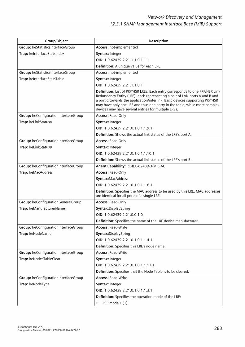
Network Discovery and Management12.3.1 SNMP Management Interface Base (MIB) Support
Group/Object DescriptionGroup: lreStatisticsInterfaceGroupTrap: lreInterfaceStatsIndex
Access: not-implementedSyntax: IntegerOID: 1.0.62439.2.21.1.1.0.1.1.1Definition: A unique value for each LRE.
Group: lreStatisticsInterfaceGroupTrap: lreInterfaceStatsTable
Access: not-implementedSyntax: IntegerOID: 1.0.62439.2.21.1.1.0.1Definition: List of PRP/HSR LREs. Each entry corresponds to one PRP/HSR LinkRedundancy Entity (LRE), each representing a pair of LAN ports A and B anda port C towards the application/interlink. Basic devices supporting PRP/HSRmay have only one LRE and thus one entry in the table, while more complexdevices may have several entries for multiple LREs.
Group: lreConfigurationInterfaceGroupTrap: lreLinkStatusA
Access: Read-OnlySyntax: IntegerOID: 1.0.62439.2.21.0.1.0.1.1.9.1Definition: Shows the actual link status of the LRE's port A.
Group: lreConfigurationInterfaceGroupTrap: lreLinkStatusB
Access: Read-OnlySyntax: IntegerOID: 1.0.62439.2.21.0.1.0.1.1.10.1Definition: Shows the actual link status of the LRE's port B.
Group: lreConfigurationInterfaceGroupTrap: lreMacAddress
Agent Capability: RC-IEC-62439-3-MIB-ACAccess: Read-OnlySyntax:MacAddressOID: 1.0.62439.2.21.0.1.0.1.1.6.1Definition: Specifies the MAC address to be used by this LRE. MAC addressesare identical for all ports of a single LRE.
Group: lreConfigurationGeneralGroupTrap: lreManufacturerName
Access: Read-OnlySyntax:DisplayStringOID: 1.0.62439.2.21.0.0.1.0Definition: Specifies the name of the LRE device manufacturer.
Group: lreConfigurationInterfaceGroupTrap: lreNodeName
Access: Read-WriteSyntax:DisplayStringOID: 1.0.62439.2.21.0.1.0.1.1.4.1Definition: Specifies this LRE's node name.
Group: lreConfigurationInterfaceGroupTrap: lreNodesTableClear
Access: Read-WriteSyntax: IntegerOID: 1.0.62439.2.21.0.1.0.1.1.17.1Definition: Specifies that the Node Table is to be cleared.
Group: lreConfigurationInterfaceGroupTrap: lreNodeType
Access: Read-WriteSyntax: IntegerOID: 1.0.62439.2.21.0.1.0.1.1.3.1Definition: Specifies the operation mode of the LRE:• PRP mode 1 (1)
RUGGEDCOM ROS v5.5Configuration Manual, 01/2021, C79000-G8976-1472-02 283
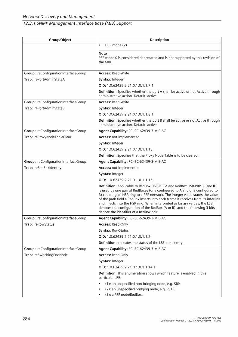
Network Discovery and Management12.3.1 SNMP Management Interface Base (MIB) Support
Group/Object Description• HSR mode (2)
NotePRP mode 0 is considered deprecated and is not supported by this revision ofthe MIB.
Group: lreConfigurationInterfaceGroupTrap: lrePortAdminStateA
Access: Read-WriteSyntax: IntegerOID: 1.0.62439.2.21.0.1.0.1.1.7.1Definition: Specifies whether the port A shall be active or not Active throughadministrative action. Default: active
Group: lreConfigurationInterfaceGroupTrap: lrePortAdminStateB
Access: Read-WriteSyntax: IntegerOID: 1.0.62439.2.21.0.1.0.1.1.8.1Definition: Specifies whether the port B shall be active or not Active throughadministrative action. Default: active
Group: lreConfigurationInterfaceGroupTrap: lreProxyNodeTableClear
Agent Capability: RC-IEC-62439-3-MIB-ACAccess: not-implementedSyntax: IntegerOID: 1.0.62439.2.21.0.1.0.1.1.18Definition: Specifies that the Proxy Node Table is to be cleared.
Group: lreConfigurationInterfaceGroupTrap: lreRedBoxIdentity
Agent Capability: RC-IEC-62439-3-MIB-ACAccess: not-implementedSyntax: IntegerOID: 1.0.62439.2.21.0.1.0.1.1.15Definition: Applicable to RedBox HSR-PRP A and RedBox HSR-PRP B. One IDis used by one pair of RedBoxes (one configured to A and one configured toB) coupling an HSR ring to a PRP network. The integer value states the valueof the path field a RedBox inserts into each frame it receives from its interlinkand injects into the HSR ring. When interpreted as binary values, the LSBdenotes the configuration of the RedBox (A or B), and the following 3 bitsdenote the identifier of a RedBox pair.
Group: lreConfigurationInterfaceGroupTrap: lreRowStatus
Agent Capability: RC-IEC-62439-3-MIB-ACAccess: Read-OnlySyntax: RowStatusOID: 1.0.62439.2.21.0.1.0.1.1.2Definition: Indicates the status of the LRE table entry.
Group: lreConfigurationInterfaceGroupTrap: lreSwitchingEndNode
Agent Capability: RC-IEC-62439-3-MIB-ACAccess: Read-OnlySyntax: IntegerOID: 1.0.62439.2.21.0.1.0.1.1.14.1Definition: This enumeration shows which feature is enabled in thisparticular LRE:• (1): an unspecified non-bridging node, e.g. SRP.• (2): an unspecified bridging node, e.g. RSTP.• (3): a PRP node/RedBox.
284 RUGGEDCOM ROS v5.5Configuration Manual, 01/2021, C79000-G8976-1472-02

Network Discovery and Management12.3.1 SNMP Management Interface Base (MIB) Support
Group/Object Description• (4): an HSR RedBox with regular Ethernet traffic on its interlink.• (5): an HSR switching node.• (6): an HSR RedBox with HSR tagged traffic on its interlink.• (7): an HSR RedBox with PRP traffic for LAN A on its interlink.• (8): an HSR RedBox with PRP traffic for LAN B on its interlink.
Group: lreConfigurationInterfaceGroupTrap: lreTransparentReception
Access: Read-OnlySyntax: IntegerOID: 1.0.62439.2.21.0.1.0.1.1.12.1Definition: If removeRCT is configured, the RCT is removed when forwardingto the upper layers, only applicable for PRP LRE (Default: removeRCT).
Group: lreConfigurationInterfaceGroupTrap: lreVersionName
Access: Read-OnlySyntax: StringOID: 1.0.62439.2.21.0.1.0.1.1.5.1Definition: Specifies the version of this LRE's software.
IEEEC37-238-MIB
Group/Object DescriptionGroup: ieeeC37238SystemCurrentGroupTrap: ieeeC37238CurrentDSLocTimeInacc
Access: Read-OnlySyntax: Gauge32OID: 1.3.111.3.37.238.9999.1.2.3Definition: TimeInaccuracy contribution of the device in nanoseconds.
Group: ieeeC37238SystemCurrentGroupTrap: ieeeC37238CurrentDSOfstFrMaster
Access: Read-OnlySyntax: IEEEC37238TimeIntervalOID: 1.3.111.3.37.238.9999.1.2.2Implementation-specific representation of the current value of the timedifference between a master and a slave as computed by the slave; i.e.,<offsetFromMaster> = <Time on the slave clock> ? <Time on the masterclock>. The most significant 4 bytes. The data type should be TimeInterval.
Group: ieeeC37238SystemCurrentGroupTrap: ieeeC37238CurrentDSStepsRemoved
Access: Read-OnlySyntax: IntegerOID: 1.3.111.3.37.238.9999.1.2.1Definition: The number of communication paths traversed between thelocal clock and the grandmaster clock. The initialization value shall be 0.
Group:ieeeC37238SystemDefaultReqdGroupTrap: ieeeC37238DefaultDSClkAccuracy
Access: Read-OnlySyntax: IEEEC37238ClockAccuracyValueOID: 1.3.111.3.37.238.9999.1.1.5Definition:ClockAccuracy of the local clock.
Group:ieeeC37238SystemDefaultReqdGroupTrap: ieeeC37238DefaultDSClkClass
Access: Read-OnlySyntax: IEEEC37238ClockAccuracyValueOID: 1.3.111.3.37.238.9999.1.1.4Definition:ClockClass of the local clock.
Group:ieeeC37238SystemDefaultReqdGroup
Access: Read-OnlySyntax: ClockIdentity
RUGGEDCOM ROS v5.5Configuration Manual, 01/2021, C79000-G8976-1472-02 285
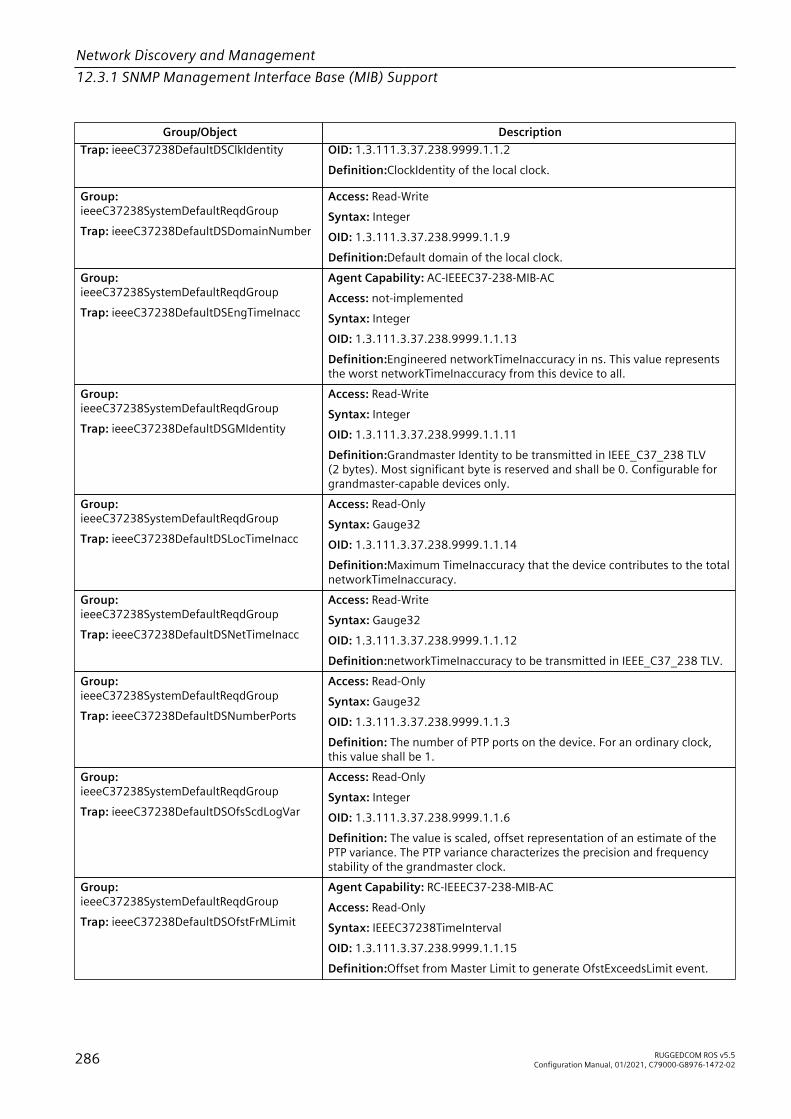
Network Discovery and Management12.3.1 SNMP Management Interface Base (MIB) Support
Group/Object DescriptionTrap: ieeeC37238DefaultDSClkIdentity OID: 1.3.111.3.37.238.9999.1.1.2
Definition:ClockIdentity of the local clock.
Group:ieeeC37238SystemDefaultReqdGroupTrap: ieeeC37238DefaultDSDomainNumber
Access: Read-WriteSyntax: IntegerOID: 1.3.111.3.37.238.9999.1.1.9Definition:Default domain of the local clock.
Group:ieeeC37238SystemDefaultReqdGroupTrap: ieeeC37238DefaultDSEngTimeInacc
Agent Capability: AC-IEEEC37-238-MIB-ACAccess: not-implementedSyntax: IntegerOID: 1.3.111.3.37.238.9999.1.1.13Definition:Engineered networkTimeInaccuracy in ns. This value representsthe worst networkTimeInaccuracy from this device to all.
Group:ieeeC37238SystemDefaultReqdGroupTrap: ieeeC37238DefaultDSGMIdentity
Access: Read-WriteSyntax: IntegerOID: 1.3.111.3.37.238.9999.1.1.11Definition:Grandmaster Identity to be transmitted in IEEE_C37_238 TLV(2 bytes). Most significant byte is reserved and shall be 0. Configurable forgrandmaster-capable devices only.
Group:ieeeC37238SystemDefaultReqdGroupTrap: ieeeC37238DefaultDSLocTimeInacc
Access: Read-OnlySyntax: Gauge32OID: 1.3.111.3.37.238.9999.1.1.14Definition:Maximum TimeInaccuracy that the device contributes to the totalnetworkTimeInaccuracy.
Group:ieeeC37238SystemDefaultReqdGroupTrap: ieeeC37238DefaultDSNetTimeInacc
Access: Read-WriteSyntax: Gauge32OID: 1.3.111.3.37.238.9999.1.1.12Definition:networkTimeInaccuracy to be transmitted in IEEE_C37_238 TLV.
Group:ieeeC37238SystemDefaultReqdGroupTrap: ieeeC37238DefaultDSNumberPorts
Access: Read-OnlySyntax: Gauge32OID: 1.3.111.3.37.238.9999.1.1.3Definition: The number of PTP ports on the device. For an ordinary clock,this value shall be 1.
Group:ieeeC37238SystemDefaultReqdGroupTrap: ieeeC37238DefaultDSOfsScdLogVar
Access: Read-OnlySyntax: IntegerOID: 1.3.111.3.37.238.9999.1.1.6Definition: The value is scaled, offset representation of an estimate of thePTP variance. The PTP variance characterizes the precision and frequencystability of the grandmaster clock.
Group:ieeeC37238SystemDefaultReqdGroupTrap: ieeeC37238DefaultDSOfstFrMLimit
Agent Capability: RC-IEEEC37-238-MIB-ACAccess: Read-OnlySyntax: IEEEC37238TimeIntervalOID: 1.3.111.3.37.238.9999.1.1.15Definition:Offset from Master Limit to generate OfstExceedsLimit event.
286 RUGGEDCOM ROS v5.5Configuration Manual, 01/2021, C79000-G8976-1472-02

Network Discovery and Management12.3.1 SNMP Management Interface Base (MIB) Support
Group/Object DescriptionGroup:ieeeC37238SystemDefaultReqdGroupTrap: ieeeC37238DefaultDSPriority1
Access: Read-WriteSyntax: Gauge32OID: 1.3.111.3.37.238.9999.1.1.7Definition:Priority1 attribute of the local clock.
Group:ieeeC37238SystemDefaultReqdGroupTrap: ieeeC37238DefaultDSPriority2
Access: Read-WriteSyntax: Gauge32OID: 1.3.111.3.37.238.9999.1.1.8Definition:Priority2 attribute of the local clock.
Group:ieeeC37238SystemDefaultReqdGroupTrap: ieeeC37238DefaultDSSlaveOnly
Access: Read-WriteSyntax: IntegerOID: 1.3.111.3.37.238.9999.1.1.10Definition: True if the local clock is a slave-only clock, False otherwise.
Group:ieeeC37238SystemDefaultReqdGroupTrap: ieeeC37238DefaultDSTwoStepFlag
Access: Read-WriteSyntax: IntegerOID: 1.3.111.3.37.238.9999.1.1.1Definition: True if the clock is a two-step clock, False otherwise.
Group: ieeeC37238EventsPropertiesGroupTrap: ieeeC37238EventFaultyState
Agent Capability: RC-IEEEC37-238-MIB-ACOID: 1.3.111.3.37.238.9999.0.0.3.0Definition: Indicates that a clock has entered faulty state.
NoteThis notification is not supported.
Group: ieeeC37238EventsPropertiesGroupTrap: ieeeC37238EventLeapSecAnnounced
Agent Capability: RC-IEEEC37-238-MIB-ACOID: 1.3.111.3.37.238.9999.0.0.7.0Definition: Indicates that a leap second has been announced.
NoteThis notification is not supported.
Group: ieeeC37238EventsPropertiesGroupTrap: ieeeC37238EventOtherProfileDetect
Agent Capability: RC-IEEEC37-238-MIB-ACOID: 1.3.111.3.37.238.9999.0.0.6.0Definition: Indicates that other then C37.238 PTP profile has been detected.
NoteThis notification is not supported.
Group: ieeeC37238EventsPropertiesGroupTrap: ieeeC37238EventPortStateChange
Agent Capability: RC-IEEEC37-238-MIB-ACOID: 1.3.111.3.37.238.9999.0.0.4.0Definition: Indicates that port state has changed.
NoteThis notification is not supported.
Group: ieeeC37238SystemClockParentGroupTrap: ieeeC37238ParentDSClkIdentity
Access: Read-OnlySyntax: ClockIdentity
RUGGEDCOM ROS v5.5Configuration Manual, 01/2021, C79000-G8976-1472-02 287

Network Discovery and Management12.3.1 SNMP Management Interface Base (MIB) Support
Group/Object DescriptionOID: 1.3.111.3.37.238.9999.1.3.1.0Definition: Clock Identity of the master that synchronizes this clock.
Group: ieeeC37238SystemClockParentGroupTrap: ieeeC37238ParentDSGMClkAccuracy
Access: Read-OnlySyntax: IEEEC37238ClockAccuracyValueOID: 1.3.111.3.37.238.9999.1.3.8.0Definition: ClockAccuracy of the grandmaster clock.
Group: ieeeC37238SystemClockParentGroupTrap: ieeeC37238ParentDSGMClkClass
Access: Read-OnlySyntax: IEEEC37238ClockClassValueOID: 1.3.111.3.37.238.9999.1.3.7.0Definition: ClockClass of the grandmaster clock.
Group: ieeeC37238SystemClockParentGroupTrap: ieeeC37238ParentDSGMClkIdentity
Access: Read-OnlySyntax: ClockIdentityOID: 1.3.111.3.37.238.9999.1.3.6.0Definition: ClockIdentity of the grandmaster clock.
Group: ieeeC37238SystemClockParentGroupTrap: ieeeC37238ParentDSGMIdentity
Access: Read-OnlySyntax: IntegerOID: 1.3.111.3.37.238.9999.1.3.12.0Definition: Grandmaster Identity received in IEEE_C37_238 TLV.
Group: ieeeC37238SystemClockParentGroupTrap: ieeeC37238ParentDSGMOfstScdLVar
Agent Capability: RC-IEEEC37-238-MIB-ACAccess: Read-OnlySyntax: IntegerOID: 1.3.111.3.37.238.9999.1.3.4.0Definition: OffsetScaledLog Variance of the grandmaster clock.
NoteFurther Support will be provided. Current Value: 65535.
Group: ieeeC37238SystemClockParentGroupTrap: ieeeC37238ParentDSGMPriority1
Access: Read-OnlySyntax: Gauge32OID: 1.3.111.3.37.238.9999.1.3.10.0Definition: Priority1 attribute of the grandmaster clock.
Group: ieeeC37238SystemClockParentGroupTrap: ieeeC37238ParentDSGMPriority2
Access: Read-OnlySyntax: Gauge32OID: 1.3.111.3.37.238.9999.1.3.11.0Definition: Priority2 attribute of the grandmaster clock.
Group: ieeeC37238SystemClockParentGroupTrap: ieeeC37238ParentDSGMTimeInacc
Agent Capability: RC-IEEEC37-238-MIB-ACAccess: Read-OnlySyntax: Gauge32OID: 1.3.111.3.37.238.9999.1.3.13.0Definition: NetworkTimeInaccuracy received in IEEE_C37_238 TLV innanoseconds.
288 RUGGEDCOM ROS v5.5Configuration Manual, 01/2021, C79000-G8976-1472-02

Network Discovery and Management12.3.1 SNMP Management Interface Base (MIB) Support
Group/Object Description
NoteFurther Support will be provided. Current Value: 0.
Group: ieeeC37238SystemClockParentGroupTrap: ieeeC37238ParentDSNetTimeInacc
Agent Capability: RC-IEEEC37-238-MIB-ACAccess: Read-OnlySyntax: Gauge32OID: 1.3.111.3.37.238.9999.1.3.14.0Definition: NetworkTimeInaccuracy received in IEEE_C37_238 TLV innanoseconds.
NoteFurther Support will be provided. Current Value: 0.
Group: ieeeC37238SystemClockParentGroupTrap: ieeeC37238ParentDSObsOfstScdLVar
Agent Capability: RC-IEEEC37-238-MIB-ACAccess: Read-OnlySyntax: Gauge32OID: 1.3.111.3.37.238.9999.1.3.4.0Definition: An estimate of the parent clock PTP variance as observed by theslave clock, computed and represented as described in IEEE Std 1588-20087.6.3.5. The initialization value shall be FFFF.
NoteFurther Support will be provided. Current Value: 65535.
Group: ieeeC37238SystemClockParentGroupTrap: ieeeC37238ParentDSObsPhChgRate
Agent Capability: RC-IEEEC37-238-MIB-ACAccess: Read-OnlySyntax: Gauge32OID: 1.3.111.3.37.238.9999.1.3.5.0Definition: An estimate of the parent clock phase change rate as observedby the slave clock as defined in IEEE Std 1588-2008 7.6.4.4. If the estimateexceeds the capacity of its data type, this value shall be set to 7FFF FFFFor 8000 0000, as appropriate. A positive sign indicates that the parentclock phase change rate is greater than the rate of the slave clock. Theinitialization value shall be 7FFF FFFF.
NoteFurther Support will be provided. Current Value: 0x7FFF FFFF.
Group: ieeeC37238SystemClockParentGroupTrap: ieeeC37238ParentDSPortNumber
Access: Read-OnlySyntax: Gauge32OID: 1.3.111.3.37.238.9999.1.3.2.0Definition: Port Number of the port on the master that issues the Syncmessages used in synchronizing this clock.
Group: ieeeC37238SystemClockParentGroupTrap: ieeeC37238ParentDSStats
Agent Capability: RC-IEEEC37-238-MIB-ACAccess: Read-OnlySyntax: IntegerOID: 1.3.111.3.37.238.9999.1.3.3.0
RUGGEDCOM ROS v5.5Configuration Manual, 01/2021, C79000-G8976-1472-02 289
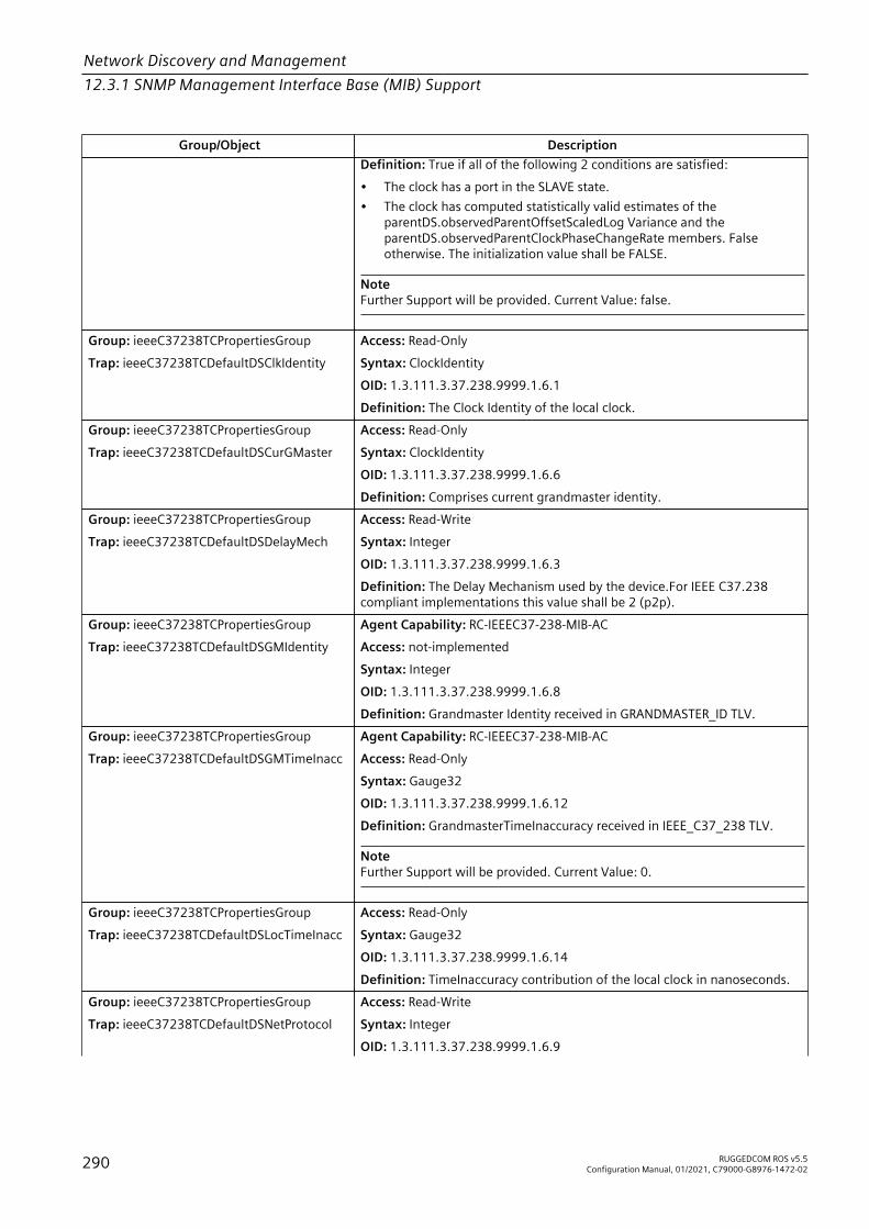
Network Discovery and Management12.3.1 SNMP Management Interface Base (MIB) Support
Group/Object DescriptionDefinition: True if all of the following 2 conditions are satisfied:• The clock has a port in the SLAVE state.• The clock has computed statistically valid estimates of the
parentDS.observedParentOffsetScaledLog Variance and theparentDS.observedParentClockPhaseChangeRate members. Falseotherwise. The initialization value shall be FALSE.
NoteFurther Support will be provided. Current Value: false.
Group: ieeeC37238TCPropertiesGroupTrap: ieeeC37238TCDefaultDSClkIdentity
Access: Read-OnlySyntax: ClockIdentityOID: 1.3.111.3.37.238.9999.1.6.1Definition: The Clock Identity of the local clock.
Group: ieeeC37238TCPropertiesGroupTrap: ieeeC37238TCDefaultDSCurGMaster
Access: Read-OnlySyntax: ClockIdentityOID: 1.3.111.3.37.238.9999.1.6.6Definition: Comprises current grandmaster identity.
Group: ieeeC37238TCPropertiesGroupTrap: ieeeC37238TCDefaultDSDelayMech
Access: Read-WriteSyntax: IntegerOID: 1.3.111.3.37.238.9999.1.6.3Definition: The Delay Mechanism used by the device.For IEEE C37.238compliant implementations this value shall be 2 (p2p).
Group: ieeeC37238TCPropertiesGroupTrap: ieeeC37238TCDefaultDSGMIdentity
Agent Capability: RC-IEEEC37-238-MIB-ACAccess: not-implementedSyntax: IntegerOID: 1.3.111.3.37.238.9999.1.6.8Definition: Grandmaster Identity received in GRANDMASTER_ID TLV.
Group: ieeeC37238TCPropertiesGroupTrap: ieeeC37238TCDefaultDSGMTimeInacc
Agent Capability: RC-IEEEC37-238-MIB-ACAccess: Read-OnlySyntax: Gauge32OID: 1.3.111.3.37.238.9999.1.6.12Definition: GrandmasterTimeInaccuracy received in IEEE_C37_238 TLV.
NoteFurther Support will be provided. Current Value: 0.
Group: ieeeC37238TCPropertiesGroupTrap: ieeeC37238TCDefaultDSLocTimeInacc
Access: Read-OnlySyntax: Gauge32OID: 1.3.111.3.37.238.9999.1.6.14Definition: TimeInaccuracy contribution of the local clock in nanoseconds.
Group: ieeeC37238TCPropertiesGroupTrap: ieeeC37238TCDefaultDSNetProtocol
Access: Read-WriteSyntax: IntegerOID: 1.3.111.3.37.238.9999.1.6.9
290 RUGGEDCOM ROS v5.5Configuration Manual, 01/2021, C79000-G8976-1472-02

Network Discovery and Management12.3.1 SNMP Management Interface Base (MIB) Support
Group/Object DescriptionDefinition: Indicates Network Protocol in use. For IEEE C37.238 compliantimplementations this value shall be 1 (ieee8023).
Group: ieeeC37238TCPropertiesGroupTrap: ieeeC37238TCDefaultDSNetTimeInacc
Agent Capability: RC-IEEEC37-238-MIB-ACAccess: Read-OnlySyntax: Gauge32OID: 1.3.111.3.37.238.9999.1.6.13Definition: NetworkTimeInaccuracy received in IEEE_C37_238 TLV.
NoteFurther Support will be provided. Current Value: 0.
Group: ieeeC37238TCPropertiesGroupTrap: ieeeC37238TCDefaultDSNumberPorts
Access: Read-OnlySyntax: Gauge32OID: 1.3.111.3.37.238.9999.1.6.2Definition: The number of PTP ports of the device.
Group: ieeeC37238TCPropertiesGroupTrap: ieeeC37238TCDefaultDSPriDomain
Access: Read-WriteSyntax: IntegerOID: 1.3.111.3.37.238.9999.1.6.4Definition: Domain number of the primary syntonization domain. Theinitialization value shall be 0.
Group: ieeeC37238TCPropertiesGroupTrap: ieeeC37238TCDefaultDSPriority
Access: Read-WriteSyntax: Gauge32OID: 1.3.111.3.37.238.9999.1.6.11Definition: Indicates VLAN tag Priority in use.
Group: ieeeC37238TCPropertiesGroupTrap: ieeeC37238TCDefaultDSSyntonize
Access: Read-WriteSyntax: IntegerOID: 1.3.111.3.37.238.9999.1.6.5Definition: True if syntonization enabled.
Group: ieeeC37238TCPropertiesGroupTrap: ieeeC37238TCDefaultDSTwoStepFlag
Access: Read-WriteSyntax: IntegerOID: 1.3.111.3.37.238.9999.1.6.7Definition: True if the clock is a two-step clock.
Group: ieeeC37238TCPropertiesGroupTrap: ieeeC37238TCDefaultDSVlanId
Access: Read-WriteSyntax: Gauge32OID: 1.3.111.3.37.238.9999.1.6.10Definition: Indicates VLAN ID in use.
Group: ieeeC37238SystemTimePropGroupTrap: ieeeC37238TimePropDSCurUTCOfst
Access: Read-OnlySyntax: IntegerOID: 1.3.111.3.37.238.9999.1.4.1Definition: The current offset between TAI and UTC in units of seconds.
Group: ieeeC37238SystemTimePropGroupTrap: ieeeC37238TimePropDSCurUTCOfstVd
Access: Read-OnlySyntax: IntegerOID: 1.3.111.3.37.238.9999.1.4.2
RUGGEDCOM ROS v5.5Configuration Manual, 01/2021, C79000-G8976-1472-02 291

Network Discovery and Management12.3.1 SNMP Management Interface Base (MIB) Support
Group/Object DescriptionDefinition: True if the the currentUtcOffset is known to be correct.
Group: ieeeC37238SystemTimePropGroupTrap: ieeeC37238TimePropDSFrqTraceable
Access: Read-OnlySyntax: IntegerOID: 1.3.111.3.37.238.9999.1.4.6Definition: True if the frequency determining the timescale is traceable to aprimary reference, False otherwise.
Group: ieeeC37238SystemTimePropGroupTrap: ieeeC37238TimePropDSLeap59
Agent Capability: RC-IEEEC37-238-MIB-ACAccess: Read-OnlySyntax: IntegerOID: 1.3.111.3.37.238.9999.1.4.3Definition: True value indicates that the last minute of the current UTC daycontains 59 seconds.
NoteFurther Support will be provided. Current Value: false.
Group: ieeeC37238SystemTimePropGroupTrap: ieeeC37238TimePropDSLeap61
Access: Read-OnlySyntax: IntegerOID: 1.3.111.3.37.238.9999.1.4.4Definition: True value indicates that the last minute of the current UTC daycontains 61 seconds.
Group: ieeeC37238SystemTimePropGroupTrap: ieeeC37238TimePropDSLeapEvExpiry
Agent Capability: RC-IEEEC37-238-MIB-ACAccess: not-implementedSyntax: IntegerOID: 1.3.111.3.37.238.9999.1.4.15Definition: The seconds portion of PTP time for the expiry of the latest IERS-announced leap-second event. If PTP time > LeapEvExpiry, devices shall setCurUTCOfstVd to False.
Group: ieeeC37238SystemTimePropGroupTrap: ieeeC37238TimePropDSLeapEvLatest
Agent Capability: RC-IEEEC37-238-MIB-ACAccess: not-implementedSyntax: IntegerOID: 1.3.111.3.37.238.9999.1.4.13Definition: The seconds portion of PTP time for the second prior to the latestIERS-announced leap-second event (may be past or future).
Group: ieeeC37238SystemTimePropGroupTrap: ieeeC37238TimePropDSLocalTCurOfs
Agent Capability: RC-IEEEC37-238-MIB-ACAccess: not-implementedSyntax: IntegerOID: 1.3.111.3.37.238.9999.1.4.9Definition: The offset of the alternate time, in seconds, from the node time.The alternate time is the sum of this value and the node time.
Group: ieeeC37238SystemTimePropGroupTrap: ieeeC37238TimePropDSLocalTJumpS
Agent Capability: RC-IEEEC37-238-MIB-ACAccess: not-implementedSyntax: IntegerOID: 1.3.111.3.37.238.9999.1.4.10
292 RUGGEDCOM ROS v5.5Configuration Manual, 01/2021, C79000-G8976-1472-02
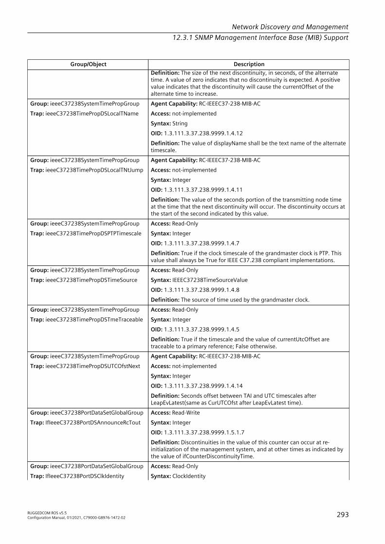
Network Discovery and Management12.3.1 SNMP Management Interface Base (MIB) Support
Group/Object DescriptionDefinition: The size of the next discontinuity, in seconds, of the alternatetime. A value of zero indicates that no discontinuity is expected. A positivevalue indicates that the discontinuity will cause the currentOffset of thealternate time to increase.
Group: ieeeC37238SystemTimePropGroupTrap: ieeeC37238TimePropDSLocalTName
Agent Capability: RC-IEEEC37-238-MIB-ACAccess: not-implementedSyntax: StringOID: 1.3.111.3.37.238.9999.1.4.12Definition: The value of displayName shall be the text name of the alternatetimescale.
Group: ieeeC37238SystemTimePropGroupTrap: ieeeC37238TimePropDSLocalTNtJump
Agent Capability: RC-IEEEC37-238-MIB-ACAccess: not-implementedSyntax: IntegerOID: 1.3.111.3.37.238.9999.1.4.11Definition: The value of the seconds portion of the transmitting node timeat the time that the next discontinuity will occur. The discontinuity occurs atthe start of the second indicated by this value.
Group: ieeeC37238SystemTimePropGroupTrap: ieeeC37238TimePropDSPTPTimescale
Access: Read-OnlySyntax: IntegerOID: 1.3.111.3.37.238.9999.1.4.7Definition: True if the clock timescale of the grandmaster clock is PTP. Thisvalue shall always be True for IEEE C37.238 compliant implementations.
Group: ieeeC37238SystemTimePropGroupTrap: ieeeC37238TimePropDSTimeSource
Access: Read-OnlySyntax: IEEEC37238TimeSourceValueOID: 1.3.111.3.37.238.9999.1.4.8Definition: The source of time used by the grandmaster clock.
Group: ieeeC37238SystemTimePropGroupTrap: ieeeC37238TimePropDSTmeTraceable
Access: Read-OnlySyntax: IntegerOID: 1.3.111.3.37.238.9999.1.4.5Definition: True if the timescale and the value of currentUtcOffset aretraceable to a primary reference; False otherwise.
Group: ieeeC37238SystemTimePropGroupTrap: ieeeC37238TimePropDSUTCOfstNext
Agent Capability: RC-IEEEC37-238-MIB-ACAccess: not-implementedSyntax: IntegerOID: 1.3.111.3.37.238.9999.1.4.14Definition: Seconds offset between TAI and UTC timescales afterLeapEvLatest(same as CurUTCOfst after LeapEvLatest time).
Group: ieeeC37238PortDataSetGlobalGroupTrap: IfIeeeC37238PortDSAnnounceRcTout
Access: Read-WriteSyntax: IntegerOID: 1.3.111.3.37.238.9999.1.5.1.7Definition: Discontinuities in the value of this counter can occur at re-initialization of the management system, and at other times as indicated bythe value of ifCounterDiscontinuityTime.
Group: ieeeC37238PortDataSetGlobalGroupTrap: IfIeeeC37238PortDSClkIdentity
Access: Read-OnlySyntax: ClockIdentity
RUGGEDCOM ROS v5.5Configuration Manual, 01/2021, C79000-G8976-1472-02 293
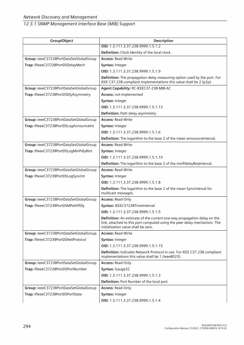
Network Discovery and Management12.3.1 SNMP Management Interface Base (MIB) Support
Group/Object DescriptionOID: 1.3.111.3.37.238.9999.1.5.1.2Definition: Clock Identity of the local clock.
Group: ieeeC37238PortDataSetGlobalGroupTrap: IfIeeeC37238PortDSDelayMech
Access: Read-WriteSyntax: IntegerOID: 1.3.111.3.37.238.9999.1.5.1.9Definition: The propagation delay measuring option used by the port. ForIEEE C37.238 compliant implementations this value shall be 2 (p2p).
Group: ieeeC37238PortDataSetGlobalGroupTrap: IfIeeeC37238PortDSDlyAsymmetry
Agent Capability: RC-IEEEC37-238-MIB-ACAccess: not-implementedSyntax: IntegerOID: 1.3.111.3.37.238.9999.1.5.1.13Definition: Path delay asymmetry.
Group: ieeeC37238PortDataSetGlobalGroupTrap: IfIeeeC37238PortDSLogAnnounceInt
Access: Read-WriteSyntax: IntegerOID: 1.3.111.3.37.238.9999.1.5.1.6Definition: The logarithm to the base 2 of the mean announceInterval.
Group: ieeeC37238PortDataSetGlobalGroupTrap: IfIeeeC37238PortDSLogMinPdlyRInt
Access: Read-WriteSyntax: IntegerOID: 1.3.111.3.37.238.9999.1.5.1.10Definition: The logarithm to the base 2 of the minPdelayReqInterval.
Group: ieeeC37238PortDataSetGlobalGroupTrap: IfIeeeC37238PortDSLogSyncInt
Access: Read-WriteSyntax: IntegerOID: 1.3.111.3.37.238.9999.1.5.1.8Definition: The logarithm to the base 2 of the mean SyncInterval formulticast messages.
Group: ieeeC37238PortDataSetGlobalGroupTrap: IfIeeeC37238PortDSMPathPDly
Access: Read-OnlySyntax: IEEEC37238TimeIntervalOID: 1.3.111.3.37.238.9999.1.5.1.5Definition: An estimate of the current one-way propagation delay on thelink, attached to this port computed using the peer delay mechanism. Theinitialization value shall be zero.
Group: ieeeC37238PortDataSetGlobalGroupTrap: IfIeeeC37238PortDSNetProtocol
Access: Read-WriteSyntax: IntegerOID: 1.3.111.3.37.238.9999.1.5.1.15Definition: Indicates Network Protocol in use. For IEEE C37.238 compliantimplementations this value shall be 1 (ieee8023).
Group: ieeeC37238PortDataSetGlobalGroupTrap: IfIeeeC37238PortDSPortNumber
Access: Read-OnlySyntax: Gauge32OID: 1.3.111.3.37.238.9999.1.5.1.3Definition: Port Number of the local port.
Group: ieeeC37238PortDataSetGlobalGroupTrap: IfIeeeC37238PortDSPortState
Access: Read-OnlySyntax: IntegerOID: 1.3.111.3.37.238.9999.1.5.1.4
294 RUGGEDCOM ROS v5.5Configuration Manual, 01/2021, C79000-G8976-1472-02
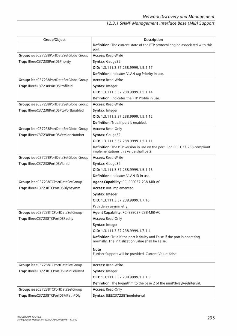
Network Discovery and Management12.3.1 SNMP Management Interface Base (MIB) Support
Group/Object DescriptionDefinition: The current state of the PTP protocol engine associated with thisport.
Group: ieeeC37238PortDataSetGlobalGroupTrap: IfIeeeC37238PortDSPriority
Access: Read-WriteSyntax: Gauge32OID: 1.3.111.3.37.238.9999.1.5.1.17Definition: Indicates VLAN tag Priority in use.
Group: ieeeC37238PortDataSetGlobalGroupTrap: IfIeeeC37238PortDSProfileId
Access: Read-WriteSyntax: IntegerOID: 1.3.111.3.37.238.9999.1.5.1.14Definition: Indicates the PTP Profile in use.
Group: ieeeC37238PortDataSetGlobalGroupTrap: IfIeeeC37238PortDSPtpPortEnabled
Access: Read-WriteSyntax: IntegerOID: 1.3.111.3.37.238.9999.1.5.1.12Definition: True if port is enabled.
Group: ieeeC37238PortDataSetGlobalGroupTrap: IfIeeeC37238PortDSVersionNumber
Access: Read-OnlySyntax: Gauge32OID: 1.3.111.3.37.238.9999.1.5.1.11Definition: The PTP version in use on the port. For IEEE C37.238 compliantimplementations this value shall be 2.
Group: ieeeC37238PortDataSetGlobalGroupTrap: IfIeeeC37238PortDSVlanId
Access: Read-WriteSyntax: Gauge32OID: 1.3.111.3.37.238.9999.1.5.1.16Definition: Indicates VLAN ID in use.
Group: ieeeC37238TCPortDataSetGroupTrap: IfIeeeC37238TCPortDSDlyAsymm
Agent Capability: RC-IEEEC37-238-MIB-ACAccess: not-implementedSyntax: IntegerOID: 1.3.111.3.37.238.9999.1.7.16Path delay asymmetry.
Group: ieeeC37238TCPortDataSetGroupTrap: IfIeeeC37238TCPortDSFaulty
Agent Capability: RC-IEEEC37-238-MIB-ACAccess: Read-OnlySyntax: IntegerOID: 1.3.111.3.37.238.9999.1.7.1.4Definition: True if the port is faulty and False if the port is operatingnormally. The initialization value shall be False.
NoteFurther Support will be provided. Current Value: false.
Group: ieeeC37238TCPortDataSetGroupTrap: IfIeeeC37238TCPortDSLMinPdlyRInt
Access: Read-WriteSyntax: IntegerOID: 1.3.111.3.37.238.9999.1.7.1.3Definition: The logarithm to the base 2 of the minPdelayReqInterval.
Group: ieeeC37238TCPortDataSetGroupTrap: IfIeeeC37238TCPortDSMPathPDly
Access: Read-OnlySyntax: IEEEC37238TimeInterval
RUGGEDCOM ROS v5.5Configuration Manual, 01/2021, C79000-G8976-1472-02 295

Network Discovery and Management12.3.1 SNMP Management Interface Base (MIB) Support
Group/Object DescriptionOID: 1.3.111.3.37.238.9999.1.7.1.5Definition: The estimate of the current one-way propagation delay.
Group: ieeeC37238TCPortDataSetGroupTrap: IfIeeeC37238TCPortDSPortNumber
Access: Read-OnlySyntax: Gauge32OID: 1.3.111.3.37.238.9999.1.7.1.2Definition: Port number of the local port.
IF-MIB
Group/Object DescriptionGroup: IfGeneralInformationGroupTrap: IfAdminStatus
Agent Capability: RC-IEEEC37-238-MIB-ACAccess: Read-WriteSyntax: IntegerOID: .1.3.6.1.2.1.2.2.1.7.1Definition: The desired state of the interface. The testing(3) state indicatesthat no operational packets can be passed. When a managed systeminitializes, all interfaces start with ifAdminStatus in the down(2) state. As aresult of either explicit management action or per configuration informationretained by the managed system, ifAdminStatus is then changed to eitherthe up(1) or testing(3) states (or remains in the down(2) state).
NoteSupport for the value 'testing(3)' is not implemented per RFC 2863compliance statement.
Group: IfGeneralInformationGroupTrap: IfAlias
Agent Capability: RC-IF-MIB-ACSyntax: StringOID: .1.3.6.1.2.1.31.1.1.1.18.1Definition: This object is an 'alias' name for the interface as specified by anetwork manager, and provides a non-volatile 'handle' for the interface. Onthe first instantiation of an interface, the value of ifAlias associated withthat interface is the zero-length string. As and when a value is written intoan instance of ifAlias through a network management set operation, thenthe agent must retain the supplied value in the ifAlias instance associatedwith the same interface for as long as that interface remains instantiated,including across all re- initializations/reboots of the network managementsystem, including those which result in a change of the interface's ifIndexvalue. An example of the value which a network manager might store inthis object for a WAN interface is the (Telco's) circuit number/identifier ofthe interface. Some agents may support write-access only for interfaceshaving particular values of ifType. An agent which supports write access tothis object is required to keep the value in non-volatile storage, but it maylimit the length of new values depending on how much storage is alreadyoccupied by the current values for other interfaces.
NoteString length is limited to 15 characters.
Group: IfGeneralInformationGroupTrap: IfConnectorPresent
Agent Capability: RC-IF-MIB-ACAccess: Read-Only
296 RUGGEDCOM ROS v5.5Configuration Manual, 01/2021, C79000-G8976-1472-02

Network Discovery and Management12.3.1 SNMP Management Interface Base (MIB) Support
Group/Object DescriptionSyntax: IntegerOID: .1.3.6.1.2.1.31.1.1.1.17.1Definition: This object has the value 'true(1)' if the interface sublayer has aphysical connector and the value 'false(2)' otherwise.
Group: IfCounterDiscontinuityGroupTrap: IfCounterDiscontinuityTime
Access: Read-OnlySyntax: TimeticksOID: .1.3.6.1.2.1.31.1.1.1.19.1Definition: The value of sysUpTime on the most recent occasion at whichany one or more of this interface's counters suffered a discontinuity. Therelevant counters are the specific instances associated with this interface ofany Counter32 or
Group: IfGeneralInformationGroupTrap: IfDescr
Access: Read-OnlySyntax: StringOID: .1.3.6.1.2.1.2.2.1.2.1Definition: A textual string containing information about the interface Thisstring should include the name of the manufacturer, the product name andthe version of the interface hardware/software.
Group: IfVHCPacketGroupTrap: IfHCInBroadcastPkts
Access: Read-OnlyDefinition: Counter64OID: .1.3.6.1.2.1.31.1.1.1.9.1Definition: Counter64 object contained in the ifTable or ifXTable. If no suchdiscontinuities have occurred since the last re- initialization of the localmanagement subsystem, then this object contains a zero value.
Group: IfVHCPacketGroupTrap: IfHCInMulticastPkts
Access: Read-OnlyDefinition: Counter64OID: .1.3.6.1.2.1.31.1.1.1.8.1Definition: The number of packets, delivered by this sub-layer to a higher(sub-)layer, which were addressed to a multicast address at this sub-layer.For a MAC layer protocol, this includes both Group and Functional addresses.This object is a 64-bit version of ifInMulticastPkts. Discontinuities in the valueof this counter can occur at re-initialization of the management system, andat other times as indicated by the value of ifCounterDiscontinuityTime.
Group: IfVHCPacketGroupTrap: IfHCInOctets
Access: Read-OnlyDefinition: Counter64OID: .1.3.6.1.2.1.31.1.1.1.6.1Definition: The total number of octets received on the interface,including framing characters. This object is a 64-bit version of ifInOctets.Discontinuities in the value of this counter can occur at re-initialization ofthe management system, and at other times as indicated by the value ofifCounterDiscontinuityTime.
Group: IfVHCPacketGroupTrap: IfHCInUcastPkts
Access: Read-OnlyDefinition: Counter64OID: .1.3.6.1.2.1.31.1.1.1.7.1Definition: The number of packets, delivered by this sub-layer to ahigher (sub-)layer, which were not addressed to a multicast or broadcastaddress at this sub-layer. This object is a 64-bit version of ifInUcastPkts.Discontinuities in the value of this counter can occur at re-initialization of
RUGGEDCOM ROS v5.5Configuration Manual, 01/2021, C79000-G8976-1472-02 297
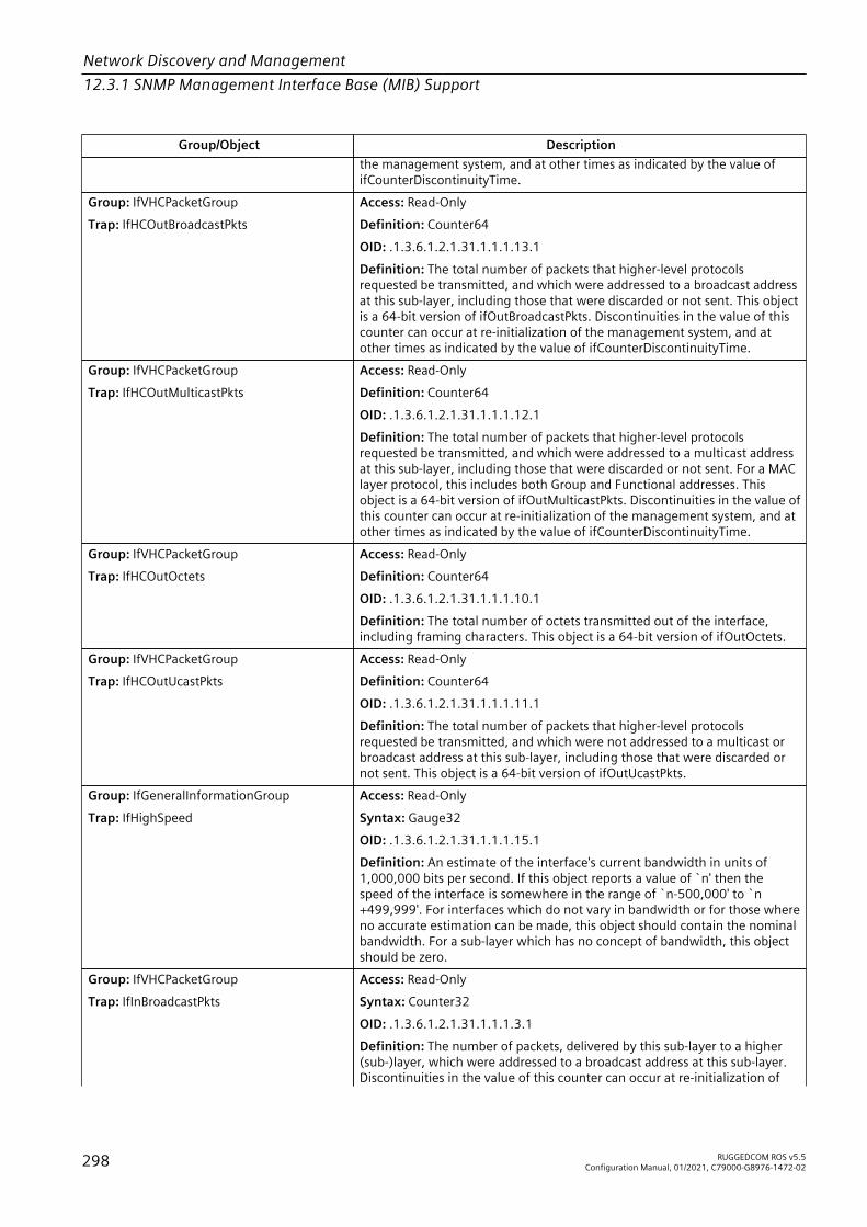
Network Discovery and Management12.3.1 SNMP Management Interface Base (MIB) Support
Group/Object Descriptionthe management system, and at other times as indicated by the value ofifCounterDiscontinuityTime.
Group: IfVHCPacketGroupTrap: IfHCOutBroadcastPkts
Access: Read-OnlyDefinition: Counter64OID: .1.3.6.1.2.1.31.1.1.1.13.1Definition: The total number of packets that higher-level protocolsrequested be transmitted, and which were addressed to a broadcast addressat this sub-layer, including those that were discarded or not sent. This objectis a 64-bit version of ifOutBroadcastPkts. Discontinuities in the value of thiscounter can occur at re-initialization of the management system, and atother times as indicated by the value of ifCounterDiscontinuityTime.
Group: IfVHCPacketGroupTrap: IfHCOutMulticastPkts
Access: Read-OnlyDefinition: Counter64OID: .1.3.6.1.2.1.31.1.1.1.12.1Definition: The total number of packets that higher-level protocolsrequested be transmitted, and which were addressed to a multicast addressat this sub-layer, including those that were discarded or not sent. For a MAClayer protocol, this includes both Group and Functional addresses. Thisobject is a 64-bit version of ifOutMulticastPkts. Discontinuities in the value ofthis counter can occur at re-initialization of the management system, and atother times as indicated by the value of ifCounterDiscontinuityTime.
Group: IfVHCPacketGroupTrap: IfHCOutOctets
Access: Read-OnlyDefinition: Counter64OID: .1.3.6.1.2.1.31.1.1.1.10.1Definition: The total number of octets transmitted out of the interface,including framing characters. This object is a 64-bit version of ifOutOctets.
Group: IfVHCPacketGroupTrap: IfHCOutUcastPkts
Access: Read-OnlyDefinition: Counter64OID: .1.3.6.1.2.1.31.1.1.1.11.1Definition: The total number of packets that higher-level protocolsrequested be transmitted, and which were not addressed to a multicast orbroadcast address at this sub-layer, including those that were discarded ornot sent. This object is a 64-bit version of ifOutUcastPkts.
Group: IfGeneralInformationGroupTrap: IfHighSpeed
Access: Read-OnlySyntax: Gauge32OID: .1.3.6.1.2.1.31.1.1.1.15.1Definition: An estimate of the interface's current bandwidth in units of1,000,000 bits per second. If this object reports a value of `n' then thespeed of the interface is somewhere in the range of `n-500,000' to `n+499,999'. For interfaces which do not vary in bandwidth or for those whereno accurate estimation can be made, this object should contain the nominalbandwidth. For a sub-layer which has no concept of bandwidth, this objectshould be zero.
Group: IfVHCPacketGroupTrap: IfInBroadcastPkts
Access: Read-OnlySyntax: Counter32OID: .1.3.6.1.2.1.31.1.1.1.3.1Definition: The number of packets, delivered by this sub-layer to a higher(sub-)layer, which were addressed to a broadcast address at this sub-layer.Discontinuities in the value of this counter can occur at re-initialization of
298 RUGGEDCOM ROS v5.5Configuration Manual, 01/2021, C79000-G8976-1472-02

Network Discovery and Management12.3.1 SNMP Management Interface Base (MIB) Support
Group/Object Descriptionthe management system, and at other times as indicated by the value ofifCounterDiscontinuityTime.
Group: IfGeneralInformationGroupTrap: IfIndex
Agent Capability: RC-IEEEC37-238-MIB-ACAccess: Read-OnlySyntax: IntegerOID: .1.3.6.1.2.1.2.2.1.1.1Definition: A unique value, greater than zero, for each interface. It isrecommended that values are assigned contiguously starting from 1. Thevalue for each interface sub-layer must remain constant at least from onere-initialization of the entity's network management system to the next re-initialization.
NoteCreation and deletion of an entry in ifTable is not supported.
Group: IfVHCPacketGroupTrap: IfInDiscards
Access: Read-OnlySyntax: Counter32OID: .1.3.6.1.2.1.2.2.1.13.1Definition: The number of inbound packets which were chosen to bediscarded even though no errors had been detected to prevent their beingdeliverable to a higher-layer protocol. One possible reason for discardingsuch a packet could be to free up buffer space. Discontinuities in the value ofthis counter can occur at re-initialization of the management system, and atother times as indicated by the value of ifCounterDiscontinuityTime.
Group: IfVHCPacketGroupTrap: IfInErrors
Access: Read-OnlySyntax: Counter32OID: .1.3.6.1.2.1.2.2.1.14.1Definition: For packet-oriented interfaces, the number of inbound packetsthat contained errors preventing them from being deliverable to a higher-layer protocol. For character- oriented or fixed-length interfaces, the numberof inbound transmission units that contained errors preventing them frombeing deliverable to a higher-layer protocol. Discontinuities in the value ofthis counter can occur at re-initialization of the management system, and atother times as indicated by the value of ifCounterDiscontinuityTime.
Group: IfVHCPacketGroupTrap: IfInMulticastPkts
Access: Read-OnlySyntax: Counter32OID: .1.3.6.1.2.1.31.1.1.1.2.1Definition: The number of packets, delivered by this sub-layer to a higher(sub-)layer, which were addressed to a multicast address at this sub-layer.For a MAC layer protocol, this includes both Group and Functional addresses.Discontinuities in the value of this counter can occur at re-initialization ofthe management system, and at other times as indicated by the value ofifCounterDiscontinuityTime.
Group: IfVHCPacketGroupTrap: IfInOctets
Access: Read-OnlySyntax: Counter32OID: .1.3.6.1.2.1.2.2.1.10.1Definition: The total number of octets received on the interface, includingframing characters. Discontinuities in the value of this counter can occur atre-initialization of the management system, and at other times as indicatedby the value of ifCounterDiscontinuityTime.
RUGGEDCOM ROS v5.5Configuration Manual, 01/2021, C79000-G8976-1472-02 299

Network Discovery and Management12.3.1 SNMP Management Interface Base (MIB) Support
Group/Object DescriptionGroup: IfVHCPacketGroupTrap: IfInUcastPkts
Access: Read-OnlySyntax: Counter32OID: .1.3.6.1.2.1.2.2.1.11.1Definition: The number of packets, delivered by this sub-layer to a higher(sub-)layer, which were not addressed to a multicast or broadcast addressat this sub-layer. Discontinuities in the value of this counter can occur at re-initialization of the management system, and at other times as indicated bythe value of ifCounterDiscontinuityTime.
Group: IfVHCPacketGroupTrap: IfInUnknownProtos
Access: Read-OnlySyntax: Counter32OID: .1.3.6.1.2.1.2.2.1.15.1Definition: For packet-oriented interfaces, the number of packets receivedvia the interface which were discarded because of an unknown orunsupported protocol. For character-oriented or fixed-length interfaces thatsupport protocol multiplexing the number of transmission units received viathe interface which were discarded because of an unknown or unsupportedprotocol. For any interface that does not support protocol multiplexing, thiscounter will always be 0. Discontinuities in the value of this counter canoccur at re-initialization of the management system, and at other times asindicated by the value of ifCounterDiscontinuityTime.
Group: IfGeneralInformationGroupTrap: IfLastChange
Access: Read-OnlySyntax: TimeticksOID: .1.3.6.1.2.1.2.2.1.9.1Definition: The value of sysUpTime at the time the interface entered itscurrent operational state. If the current state was entered prior to the last re-initialization of the local network management subsystem, then this objectcontains a zero value.
Group: IfGeneralInformationGroupTrap: IfLinkUpDownTrapEnable
Access: Read-WriteSyntax: IntegerOID: .1.3.6.1.2.1.31.1.1.1.14.1Definition: Indicates whether linkUp/linkDown traps should be generatedfor this interface. By default, this object should have the value enabled(1) forinterfaces which do not operate on 'top' of any other interface (as defined inthe ifStackTable), and disabled(2) otherwise.
Group: IfVHCPacketGroupTrap: IfMtu
Access: Read-OnlySyntax: IntegerOID: .1.3.6.1.2.1.2.2.1.4.1Definition: The size of the largest packet which can be sent/received on theinterface, specified in octets. For interfaces that are used for transmittingnetwork datagrams, this is the size of the largest network datagram that canbe sent on the interface.
Group: IfGeneralInformationGroupTrap: IfName
Access: Read-OnlySyntax: StringOID: .1.3.6.1.2.1.31.1.1.1.1.1Definition: The textual name of the interface. The value of this object shouldbe the name of the interface as assigned by the local device and shouldbe suitable for use in commands entered at the device's `console'. Thismight be a text name, such as `le0' or a simple port number, such as `1',depending on the interface naming syntax of the device. If several entries
300 RUGGEDCOM ROS v5.5Configuration Manual, 01/2021, C79000-G8976-1472-02

Network Discovery and Management12.3.1 SNMP Management Interface Base (MIB) Support
Group/Object Descriptionin the ifTable together represent a single interface as named by the device,then each will have the same value of ifName. Note that for an agent whichresponds to SNMP queries concerning an interface on some other (proxied)device, then the value of ifName for such an interface is the proxied device'slocal name for it. If there is no local name, or this object is otherwise notapplicable, then this object contains a zero-length string.
Group: IfGeneralInformationGroupTrap: IfNumber
Access: Read-OnlySyntax: IntegerOID: .1.3.6.1.2.1.2.1.0Definition: The number of network interfaces (regardless of their currentstate) present on this system.
Group: IfGeneralInformationGroupTrap: IfOperStatus
Agent Capability: RC-IF-MIB-ACAccess: Read-OnlySyntax: IntegerOID: .1.3.6.1.2.1.2.2.1.8.1Definition: The current operational state of the interface. The testing(3)state indicates that no operational packets can be passed. If ifAdminStatus isdown(2) then ifOperStatus should be down(2). If ifAdminStatus is changedto up(1) then ifOperStatus should change to up(1) if the interface is readyto transmit and receive network traffic; it should change to dormant(5) ifthe interface is waiting for external actions (such as a serial line waiting foran incoming connection); it should remain in the down(2) state if and onlyif there is a fault that prevents it from going to the up(1) state; it shouldremain in the notPresent(6) state if the interface has missing (typically,hardware) components.
NoteInformation limited by Rugged Switch Agent for Read-Only object.
Group: IfVHCPacketGroupTrap: IfOutBroadcastPkts
Access: Read-OnlySyntax: Counter32OID: .1.3.6.1.2.1.31.1.1.1.5.1Definition: The total number of packets that higher-level protocolsrequested be transmitted, and which were addressed to a broadcastaddress at this sub-layer, including those that were discarded or not sent.Discontinuities in the value of this counter can occur at re-initialization ofthe management system, and at other times as indicated by the value ofifCounterDiscontinuityTime.
Group: IfVHCPacketGroupTrap: IfOutDiscards
Access: Read-OnlySyntax: Counter32OID: .1.3.6.1.2.1.2.2.1.19.1Definition: The number of outbound packets which were chosen to bediscarded even though no errors had been detected to prevent their beingtransmitted. One possible reason for discarding such a packet could be tofree up buffer space. Discontinuities in the value of this counter can occur atre-initialization of the management system, and at other times as indicatedby the value of ifCounterDiscontinuityTime.
Group: IfVHCPacketGroupTrap: IfOutErrors
Access: Read-OnlySyntax: Counter32OID: .1.3.6.1.2.1.2.2.1.20.1
RUGGEDCOM ROS v5.5Configuration Manual, 01/2021, C79000-G8976-1472-02 301

Network Discovery and Management12.3.1 SNMP Management Interface Base (MIB) Support
Group/Object DescriptionDefinition: For packet-oriented interfaces, the number of outbound packetsthat could not be transmitted because of errors. For character-oriented orfixed-length interfaces, the number of outbound transmission units thatcould not be transmitted because of errors. Discontinuities in the value ofthis counter can occur at re-initialization of the management system, and atother times as indicated by the value of ifCounterDiscontinuityTime.
Group: IfVHCPacketGroupTrap: IfOutMulticastPkts
Access: Read-OnlySyntax: Counter32OID: .1.3.6.1.2.1.31.1.1.1.4.1Definition: The total number of packets that higher-level protocolsrequested be transmitted, and which were addressed to a multicast addressat this sub-layer, including those that were discarded or not sent. For aMAC layer protocol, this includes both Group and Functional addresses.Discontinuities in the value of this counter can occur at re-initialization ofthe management system, and at other times as indicated by the value ofifCounterDiscontinuityTime.
Group: IfVHCPacketGroupTrap: IfOutOctets
Access: Read-OnlySyntax: Counter32OID: .1.3.6.1.2.1.2.2.1.16.1Definition: The total number of octets transmitted out of the interface,including framing characters. Discontinuities in the value of this counter canoccur at re-initialization of the management system, and at other times asindicated by the value of ifCounterDiscontinuityTime.
Group: IfVHCPacketGroupTrap: IfOutUcastPkts
Access: Read-OnlySyntax: Counter32OID: .1.3.6.1.2.1.2.2.1.17.1Definition: The total number of packets that higher-level protocolsrequested be transmitted, and which were not addressed to a multicast orbroadcast address at this sub-layer, including those that were discardedor not sent. Discontinuities in the value of this counter can occur at re-initialization of the management system, and at other times as indicated bythe value of ifCounterDiscontinuityTime.
Group: IfGeneralInformationGroupTrap: IfPhysAddress
Access: Read-OnlySyntax: PhysAddressOID: .1.3.6.1.2.1.2.2.1.6.1Definition: The interface's address at its protocol sub-layer. For example,for an 802.x interface, this object normally contains a MAC address. Theinterface's media-specific MIB must define the bit and byte ordering and theformat of the value of this object. For interfaces which do not have such anaddress (e.g., a serial line), this object should contain an octet string of zerolength.
Group: IfVHCPacketGroupTrap: IfPromiscuousMode
Agent Capability: RC-IF-MIB-ACAccess: Read-OnlySyntax: IntegerOID: .1.3.6.1.2.1.31.1.1.1.16.1Definition: This object has a value of false(2) if this interface only acceptspackets/frames that are addressed to this station. This object has a valueof true(1) when the station accepts all packets/frames transmitted on themedia. The value true(1) is only legal on certain types of media. If legal,setting this object to a value of true(1) may require the interface to be reset
302 RUGGEDCOM ROS v5.5Configuration Manual, 01/2021, C79000-G8976-1472-02

Network Discovery and Management12.3.1 SNMP Management Interface Base (MIB) Support
Group/Object Descriptionbefore becoming effective. The value of ifPromiscuousMode does not affectthe reception of broadcast and multicast packets/frames by the interface.
NoteWrite access is not implemented per RFC 2863 compliance statement. Thismode is always 'false(1)'.
Group: IfGeneralInformationGroupTrap: IfSpeed
Agent Capability: RC-IF-MIB-ACAccess: Read-OnlySyntax: IntegerOID: .1.3.6.1.2.1.2.2.1.5.1Definition: An estimate of the interface's current bandwidth in bits persecond. For interfaces which do not vary in bandwidth or for those whereno accurate estimation can be made, this object should contain thenominal bandwidth. If the bandwidth of the interface is greater than themaximum value reportable by this object then this object should report itsmaximum value (4,294,967,295) and ifHighSpeed must be used to reportthe interace's speed. For a sub-layer which has no concept of bandwidth, thisobject should be zero.
Group: IfGeneralInformationGroupTrap: IfTableLastChange
Agent Capability: RC-IF-MIB-ACAccess: Read-OnlySyntax: TimeticksOID: .1.3.6.1.2.1.31.1.5.0Definition: The value of sysUpTime at the time of the last creation ordeletion of an entry in the ifTable. If the number of entries has beenunchanged since the last re-initialization of the local network managementsubsystem, then this object contains a zero value.
Group: IfGeneralInformationGroupTrap: IfType
Agent Capability: RC-IP-MIB-ACAccess: Read-OnlySyntax: IntegerOID: .1.3.6.1.2.1.2.2.1.3.1Definition: The type of interface. Additional values for ifType are assignedby the Internet Assigned Numbers Authority (IANA), through updating thesyntax of the IANAifType textual convention.
IP-MIB
Group/Object DescriptionGroup: icmpGroupTrap: icmpInAddrMaskReps
Access: Read-OnlySyntax: Counter32OID: .1.3.6.1.2.1.5.13Definition: The number of ICMP Address Mask Reply messages received.
Group: icmpGroupTrap: icmpInAddrMasks
Access: Read-OnlySyntax: Counter32OID: .1.3.6.1.2.1.5.12Definition: The number of ICMP Address Mask Request messages received.
Group: icmpGroup Access: Read-Only
RUGGEDCOM ROS v5.5Configuration Manual, 01/2021, C79000-G8976-1472-02 303

Network Discovery and Management12.3.1 SNMP Management Interface Base (MIB) Support
Group/Object DescriptionTrap: icmpInDestUnreachs Syntax: Counter32
OID: .1.3.6.1.2.1.5.3Definition: The number of ICMP Destination Unreachable messagesreceived.
Group: icmpGroupTrap: icmpInEchoReps
Access: Read-OnlySyntax: Counter32OID: .1.3.6.1.2.1.5.9Definition: The number of ICMP Echo Reply messages received.
Group: icmpGroupTrap: icmpInEchos
Access: Read-OnlySyntax: Counter32OID: .1.3.6.1.2.1.5.8Definition: The number of ICMP Echo (request) messages received.
Group: icmpGroupTrap: icmpInErrors
Access: Read-OnlySyntax: Counter32OID: .1.3.6.1.2.1.5.2Definition: The number of ICMP messages which the entity received butdetermined as having ICMP-specific errors (bad ICMP checksums, bad length,etc.).
Group: icmpGroupTrap: icmpInMsgs
Access: Read-OnlySyntax: Counter32OID: .1.3.6.1.2.1.5.1Definition: The total number of ICMP messages which the entity received.Note that this counter includes all those counted by icmpInErrors.
Group: icmpGroupTrap: icmpInParmProbs
Access: Read-OnlySyntax: Counter32OID: .1.3.6.1.2.1.5.5Definition: The number of ICMP Parameter Problem messages received.
Group: icmpGroupTrap: icmpInRedirects
Access: Read-OnlySyntax: Counter32OID: .1.3.6.1.2.1.5.7Definition: The number of ICMP Redirect messages received.
Group: icmpGroupTrap: icmpInSrcQuenchs
Access: Read-OnlySyntax: Counter32OID: .1.3.6.1.2.1.5.6Definition: The number of ICMP Time Exceeded messages received.
Group: icmpGroupTrap: icmpInTimeExcds
Access: Read-OnlySyntax: Counter32OID: .1.3.6.1.2.1.5.4Definition: The number of ICMP Timestamp Reply messages received.
Group: icmpGroupTrap: icmpInTimestampReps
Access: Read-OnlySyntax: Counter32OID: .1.3.6.1.2.1.5.11Definition: The number of ICMP Timestamp Reply messages received.
304 RUGGEDCOM ROS v5.5Configuration Manual, 01/2021, C79000-G8976-1472-02
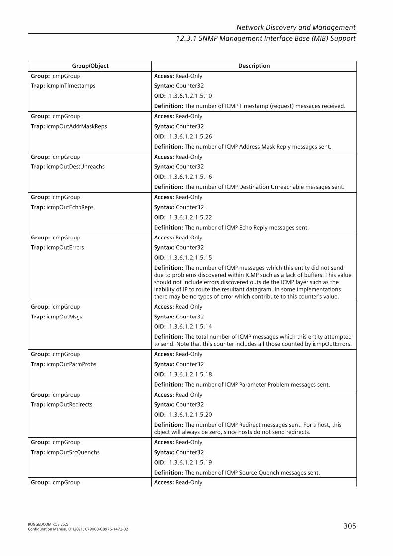
Network Discovery and Management12.3.1 SNMP Management Interface Base (MIB) Support
Group/Object DescriptionGroup: icmpGroupTrap: icmpInTimestamps
Access: Read-OnlySyntax: Counter32OID: .1.3.6.1.2.1.5.10Definition: The number of ICMP Timestamp (request) messages received.
Group: icmpGroupTrap: icmpOutAddrMaskReps
Access: Read-OnlySyntax: Counter32OID: .1.3.6.1.2.1.5.26Definition: The number of ICMP Address Mask Reply messages sent.
Group: icmpGroupTrap: icmpOutDestUnreachs
Access: Read-OnlySyntax: Counter32OID: .1.3.6.1.2.1.5.16Definition: The number of ICMP Destination Unreachable messages sent.
Group: icmpGroupTrap: icmpOutEchoReps
Access: Read-OnlySyntax: Counter32OID: .1.3.6.1.2.1.5.22Definition: The number of ICMP Echo Reply messages sent.
Group: icmpGroupTrap: icmpOutErrors
Access: Read-OnlySyntax: Counter32OID: .1.3.6.1.2.1.5.15Definition: The number of ICMP messages which this entity did not senddue to problems discovered within ICMP such as a lack of buffers. This valueshould not include errors discovered outside the ICMP layer such as theinability of IP to route the resultant datagram. In some implementationsthere may be no types of error which contribute to this counter's value.
Group: icmpGroupTrap: icmpOutMsgs
Access: Read-OnlySyntax: Counter32OID: .1.3.6.1.2.1.5.14Definition: The total number of ICMP messages which this entity attemptedto send. Note that this counter includes all those counted by icmpOutErrors.
Group: icmpGroupTrap: icmpOutParmProbs
Access: Read-OnlySyntax: Counter32OID: .1.3.6.1.2.1.5.18Definition: The number of ICMP Parameter Problem messages sent.
Group: icmpGroupTrap: icmpOutRedirects
Access: Read-OnlySyntax: Counter32OID: .1.3.6.1.2.1.5.20Definition: The number of ICMP Redirect messages sent. For a host, thisobject will always be zero, since hosts do not send redirects.
Group: icmpGroupTrap: icmpOutSrcQuenchs
Access: Read-OnlySyntax: Counter32OID: .1.3.6.1.2.1.5.19Definition: The number of ICMP Source Quench messages sent.
Group: icmpGroup Access: Read-Only
RUGGEDCOM ROS v5.5Configuration Manual, 01/2021, C79000-G8976-1472-02 305
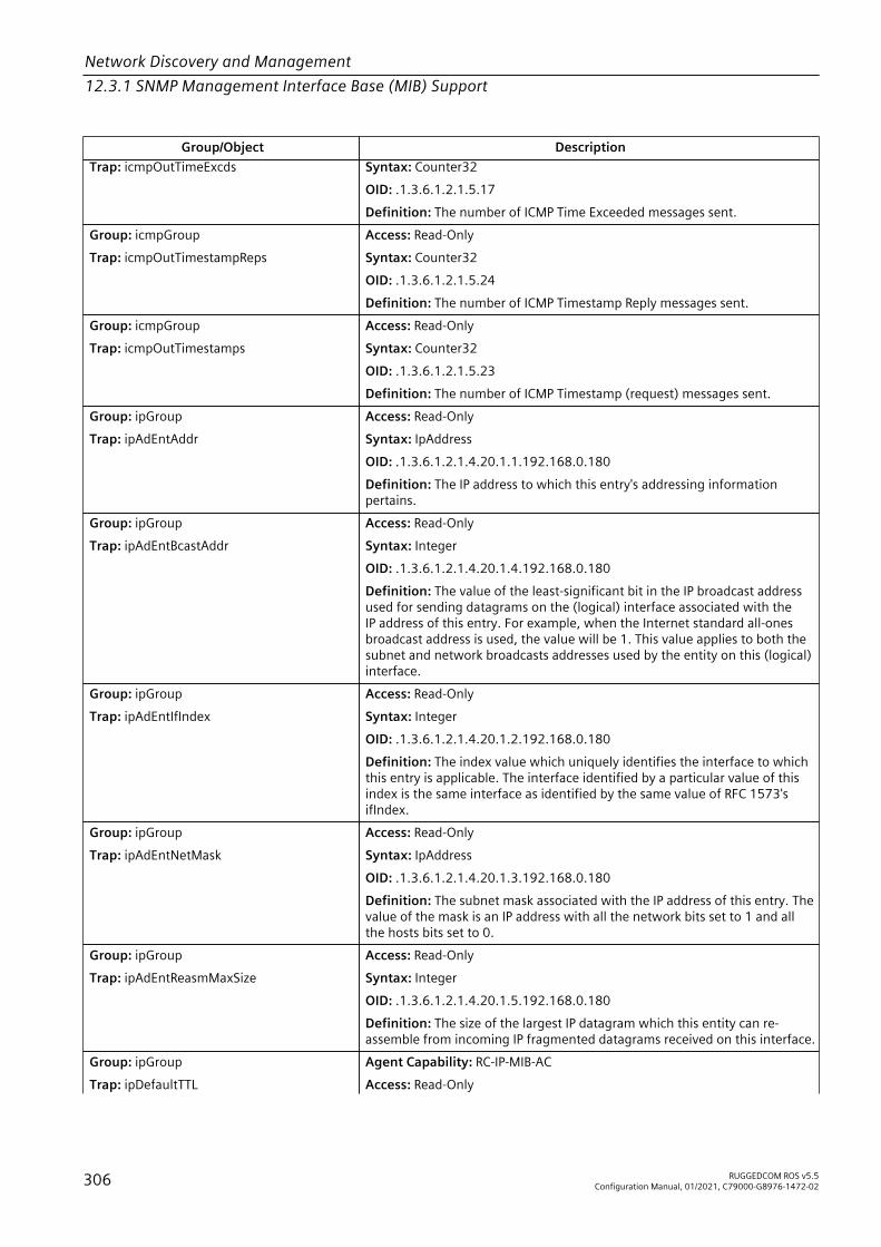
Network Discovery and Management12.3.1 SNMP Management Interface Base (MIB) Support
Group/Object DescriptionTrap: icmpOutTimeExcds Syntax: Counter32
OID: .1.3.6.1.2.1.5.17Definition: The number of ICMP Time Exceeded messages sent.
Group: icmpGroupTrap: icmpOutTimestampReps
Access: Read-OnlySyntax: Counter32OID: .1.3.6.1.2.1.5.24Definition: The number of ICMP Timestamp Reply messages sent.
Group: icmpGroupTrap: icmpOutTimestamps
Access: Read-OnlySyntax: Counter32OID: .1.3.6.1.2.1.5.23Definition: The number of ICMP Timestamp (request) messages sent.
Group: ipGroupTrap: ipAdEntAddr
Access: Read-OnlySyntax: IpAddressOID: .1.3.6.1.2.1.4.20.1.1.192.168.0.180Definition: The IP address to which this entry's addressing informationpertains.
Group: ipGroupTrap: ipAdEntBcastAddr
Access: Read-OnlySyntax: IntegerOID: .1.3.6.1.2.1.4.20.1.4.192.168.0.180Definition: The value of the least-significant bit in the IP broadcast addressused for sending datagrams on the (logical) interface associated with theIP address of this entry. For example, when the Internet standard all-onesbroadcast address is used, the value will be 1. This value applies to both thesubnet and network broadcasts addresses used by the entity on this (logical)interface.
Group: ipGroupTrap: ipAdEntIfIndex
Access: Read-OnlySyntax: IntegerOID: .1.3.6.1.2.1.4.20.1.2.192.168.0.180Definition: The index value which uniquely identifies the interface to whichthis entry is applicable. The interface identified by a particular value of thisindex is the same interface as identified by the same value of RFC 1573'sifIndex.
Group: ipGroupTrap: ipAdEntNetMask
Access: Read-OnlySyntax: IpAddressOID: .1.3.6.1.2.1.4.20.1.3.192.168.0.180Definition: The subnet mask associated with the IP address of this entry. Thevalue of the mask is an IP address with all the network bits set to 1 and allthe hosts bits set to 0.
Group: ipGroupTrap: ipAdEntReasmMaxSize
Access: Read-OnlySyntax: IntegerOID: .1.3.6.1.2.1.4.20.1.5.192.168.0.180Definition: The size of the largest IP datagram which this entity can re-assemble from incoming IP fragmented datagrams received on this interface.
Group: ipGroupTrap: ipDefaultTTL
Agent Capability: RC-IP-MIB-ACAccess: Read-Only
306 RUGGEDCOM ROS v5.5Configuration Manual, 01/2021, C79000-G8976-1472-02

Network Discovery and Management12.3.1 SNMP Management Interface Base (MIB) Support
Group/Object DescriptionSyntax: IntegerOID: .1.3.6.1.2.1.4.2.0Definition: The default value inserted into the Time-To-Live field of the IPheader of datagrams originated at this entity, whenever a TTL value is notsupplied by the transport layer protocol.
NoteWrite access is not supported.
Group: ipGroupTrap: ipForwarding
Agent Capability: RC-IP-MIB-ACAccess: Read-WriteSyntax: IntegerOID: .1.3.6.1.2.1.4.1.0Definition: The indication of whether this entity is acting as an IP routerin respect to the forwarding of datagrams received by, but not addressedto, this entity. IP routers forward datagrams. IP hosts do not (except thosesource-routed via the host).
NoteSupport for the value 'forwarding(1)' is not implemented per RFC 2011.
Group: ipGroupTrap: ipForwDatagrams
Access: Read-OnlySyntax: Counter32OID: .1.3.6.1.2.1.4.6.0Definition: The number of input datagrams for which this entity was nottheir final IP destination, as a result of which an attempt was made to finda route to forward them to that final destination. In entities which do notact as IP routers, this counter will include only those packets which wereSource-Routed via this entity, and the Source-Route option processing wassuccessful.
Group: ipGroupTrap: ipFragCreates
Access: Read-OnlySyntax: Counter32OID: .1.3.6.1.2.1.4.19.0Definition: The number of IP datagram fragments that have been generatedas a result of fragmentation at this entity.
Group: ipGroupTrap: ipFragFails
Access: Read-OnlySyntax: Counter32OID: .1.3.6.1.2.1.4.18.0Definition: The number of IP datagrams that have been discarded becausethey needed to be fragmented at this entity but could not be, e.g., becausetheir Don't Fragment flag was set.
Group: ipGroupTrap: ipFragOKs
Access: Read-OnlySyntax: Counter32OID: .1.3.6.1.2.1.4.17.0Definition: The number of IP datagrams that have been successfullyfragmented at this entity.
Group: ipGroupTrap: ipInAddrErrors
Agent Capability: RC-LLDP-MIB-ACAccess: Read-Only
RUGGEDCOM ROS v5.5Configuration Manual, 01/2021, C79000-G8976-1472-02 307

Network Discovery and Management12.3.1 SNMP Management Interface Base (MIB) Support
Group/Object DescriptionSyntax: Counter32OID: .1.3.6.1.2.1.4.5.0Definition: The number of input datagrams discarded because the IPaddress in their IP header's destination field was not a valid address to bereceived at this entity. This count includes invalid addresses (e.g., 0.0.0.0)and addresses of unsupported Classes (e.g., Class E). For entities whichare not IP routers and therefore do not forward datagrams, this counterincludes datagrams discarded because the destination address was not alocal address.
Group: ipGroupTrap: ipInDelivers
Access: Read-OnlySyntax: Counter32OID: .1.3.6.1.2.1.4.9.0Definition: The total number of input datagrams successfully delivered to IPuser-protocols (including ICMP).
Group: ipGroupTrap: ipInDiscards
Access: Read-OnlySyntax: Counter32OID: .1.3.6.1.2.1.4.8.0Definition: The number of input IP datagrams for which no problemswere encountered to prevent their continued processing, but which werediscarded (e.g., for lack of buffer space). Note that this counter does notinclude any datagrams discarded while awaiting re-assembly.
Group: ipGroupTrap: ipInHdrErrors
Access: Read-OnlySyntax: Counter32OID: .1.3.6.1.2.1.4.4.0Definition: The number of input datagrams discarded due to errors in theirIP headers, including bad checksums, version number mismatch, otherformat errors, time-to-live exceeded, errors discovered in processing their IPoptions, etc.
Group: ipGroupTrap: ipInReceives
Access: Read-OnlySyntax: Counter32OID: .1.3.6.1.2.1.4.3.0Definition: The total number of input datagrams received from interfaces,including those received in error.
Group: ipGroupTrap: ipInUnknownProtos
Access: Read-OnlySyntax: Counter32OID: .1.3.6.1.2.1.4.7.0Definition: The number of locally-addressed datagrams received successfullybut discarded because of an unknown or unsupported protocol.
Group: ipGroupTrap: ipNetToMediaIfIndex
Access: Read-CreateSyntax: IntegerOID: .1.3.6.1.2.1.4.22.1.1.1002.192.168.0.254Definition: The interface on which this entry's equivalence is effective. Theinterface identified by a particular value of this index is the same interface asidentified by the same value of RFC 1573's ifIndex.
Group: ipGroupTrap: ipNetToMediaNetAddress
Access: Read-CreateSyntax: IpAddressOID: .1.3.6.1.2.1.4.22.1.3.1002.192.168.0.254
308 RUGGEDCOM ROS v5.5Configuration Manual, 01/2021, C79000-G8976-1472-02

Network Discovery and Management12.3.1 SNMP Management Interface Base (MIB) Support
Group/Object DescriptionDefinition: The IpAddress corresponding to the media-dependent 'physical'address.
Group: ipGroupTrap: ipNetToMediaPhysAddress
Access: Read-CreateSyntax: StringOID: .1.3.6.1.2.1.4.22.1.2.1002.192.168.0.254Definition: The media-dependent `physical' address.
Group: ipGroupTrap: ipNetToMediaType
Access: Read-CreateSyntax: IntegerOID: .1.3.6.1.2.1.4.22.1.4.1002.192.168.0.254Definition: The type of mapping. Setting this object to the valueinvalid(2) has the effect of invalidating the corresponding entry in theipNetToMediaTable. That is, it effectively disassociates the interfaceidentified with said entry from the mapping identified with said entry. It isan implementation- specific matter as to whether the agent removes aninvalidated entry from the table. Accordingly, management stations mustbe prepared to receive tabular information from agents that corresponds toentries not currently in use. Proper interpretation of such entries requiresexamination of the relevant ipNetToMediaType object.
Group: ipGroupTrap: ipOutDiscards
Access: Read-OnlySyntax: Counter32OID: .1.3.6.1.2.1.4.11.0Definition: The number of output IP datagrams for which no problem wasencountered to prevent their transmission to their destination, but whichwere discarded (e.g., for lack of buffer space). Note that this counter wouldinclude datagrams counted in ipForwDatagrams if any such packets met this(discretionary) discard criterion.
Group: ipGroupTrap: ipOutNoRoutes
Access: Read-OnlySyntax: Counter32OID: .1.3.6.1.2.1.4.12.0Definition: The number of IP datagrams discarded because no route couldbe found to transmit them to their destination. Note that this counterincludes any packets counted in ipForwDatagrams which meet this `no-route' criterion. Note that this includes any datagrams which a host cannotroute because all of its default routers are down.
Group: ipGroupTrap: ipOutRequests
Access: Read-OnlySyntax: Counter32OID: .1.3.6.1.2.1.4.10.0Definition: The total number of IP datagrams which local IP user-protocols(including ICMP) supplied to IP in requests for transmission. Note that thiscounter does not include any datagrams counted in ipForwDatagrams.
Group: ipGroupTrap: ipReasmFails
Access: Read-OnlySyntax: Counter32OID: .1.3.6.1.2.1.4.16.0Definition: The number of failures detected by the IP re-assembly algorithm(for whatever reason: timed out, errors, etc). Note that this is not necessarilya count of discarded IP fragments since some algorithms (notably thealgorithm in RFC 815) can lose track of the number of fragments bycombining them as they are received.
RUGGEDCOM ROS v5.5Configuration Manual, 01/2021, C79000-G8976-1472-02 309

Network Discovery and Management12.3.1 SNMP Management Interface Base (MIB) Support
Group/Object DescriptionGroup: ipGroupTrap: ipReasmOKs
Access: Read-OnlySyntax: Counter32OID: .1.3.6.1.2.1.4.15.0Definition: The number of IP datagrams successfully re-assembled.
Group: ipGroupTrap: ipReasmReqds
Access: Read-OnlySyntax: Counter32OID: .1.3.6.1.2.1.4.14.0Definition: The number of IP fragments received which needed to bereassembled at this entity.
Group: ipGroupTrap: ipReasmTimeout
Access: Read-OnlySyntax: IntegerOID: .1.3.6.1.2.1.4.13.0Definition: The maximum number of seconds which received fragments areheld while they are awaiting reassembly at this entity.
Group: ipGroupTrap: ipRoutingDiscards
Access: Read-OnlySyntax: Counter32OID: .1.3.6.1.2.1.4.23Definition: The number of routing entries which were chosen to bediscarded even though they are valid. One possible reason for discardingsuch an entry could be to free-up buffer space for other routing entries.
LLDP-MIB
Group/Object DescriptionGroup: lldpConfigTxGroupTrap: lldpConfigManAddrPortsTxEnable
Agent Capability: RC-LLDP-MIB-ACAccess: Read-WriteSyntax: Hex-StringOID: .1.0.8802.1.1.2.1.1.7.1.1.4Definition: A set of ports that are identified by a PortList, in whicheach port is represented as a bit. The corresponding local systemmanagement address instance will be transmitted on the memberports of the lldpManAddrPortsTxEnable. The default value forlldpConfigManAddrPortsTxEnable object is empty binary string, whichmeans no ports are specified for advertising indicated management addressinstance.Write access is not implemented.
Group: lldpLocSysGroupTrap: lldpLocChassisId
Access: Read-OnlySyntax: Hex-StringOID: .1.0.8802.1.1.2.1.3.2.0Definition: The type of encoding used to identify the chassis associated withthe local system.
Group: lldpLocSysGroupTrap: lldpLocChassisIdSubtype
Access: Read-OnlySyntax: IntegerOID: .1.0.8802.1.1.2.1.3.1.0
310 RUGGEDCOM ROS v5.5Configuration Manual, 01/2021, C79000-G8976-1472-02
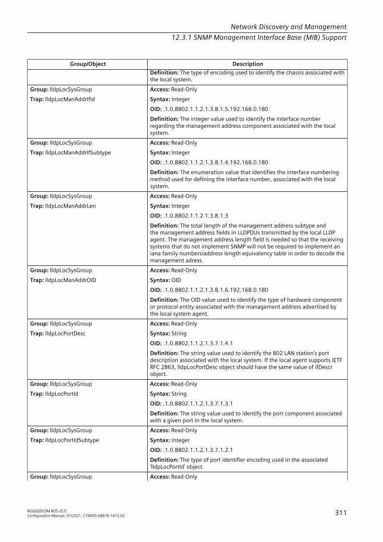
Network Discovery and Management12.3.1 SNMP Management Interface Base (MIB) Support
Group/Object DescriptionDefinition: The type of encoding used to identify the chassis associated withthe local system.
Group: lldpLocSysGroupTrap: lldpLocManAddrIfId
Access: Read-OnlySyntax: IntegerOID: .1.0.8802.1.1.2.1.3.8.1.5.192.168.0.180Definition: The integer value used to identify the interface numberregarding the management address component associated with the localsystem.
Group: lldpLocSysGroupTrap: lldpLocManAddrIfSubtype
Access: Read-OnlySyntax: IntegerOID: .1.0.8802.1.1.2.1.3.8.1.4.192.168.0.180Definition: The enumeration value that identifies the interface numberingmethod used for defining the interface number, associated with the localsystem.
Group: lldpLocSysGroupTrap: lldpLocManAddrLen
Access: Read-OnlySyntax: IntegerOID: .1.0.8802.1.1.2.1.3.8.1.3Definition: The total length of the management address subtype andthe management address fields in LLDPDUs transmitted by the local LLDPagent. The management address length field is needed so that the receivingsystems that do not implement SNMP will not be required to implement aniana family numbers/address length equivalency table in order to decode themanagement adress.
Group: lldpLocSysGroupTrap: lldpLocManAddrOID
Access: Read-OnlySyntax: OIDOID: .1.0.8802.1.1.2.1.3.8.1.6.192.168.0.180Definition: The OID value used to identify the type of hardware componentor protocol entity associated with the management address advertised bythe local system agent.
Group: lldpLocSysGroupTrap: lldpLocPortDesc
Access: Read-OnlySyntax: StringOID: .1.0.8802.1.1.2.1.3.7.1.4.1Definition: The string value used to identify the 802 LAN station's portdescription associated with the local system. If the local agent supports IETFRFC 2863, lldpLocPortDesc object should have the same value of ifDescrobject.
Group: lldpLocSysGroupTrap: lldpLocPortId
Access: Read-OnlySyntax: StringOID: .1.0.8802.1.1.2.1.3.7.1.3.1Definition: The string value used to identify the port component associatedwith a given port in the local system.
Group: lldpLocSysGroupTrap: lldpLocPortIdSubtype
Access: Read-OnlySyntax: IntegerOID: .1.0.8802.1.1.2.1.3.7.1.2.1Definition: The type of port identifier encoding used in the associated'lldpLocPortId' object.
Group: lldpLocSysGroup Access: Read-Only
RUGGEDCOM ROS v5.5Configuration Manual, 01/2021, C79000-G8976-1472-02 311
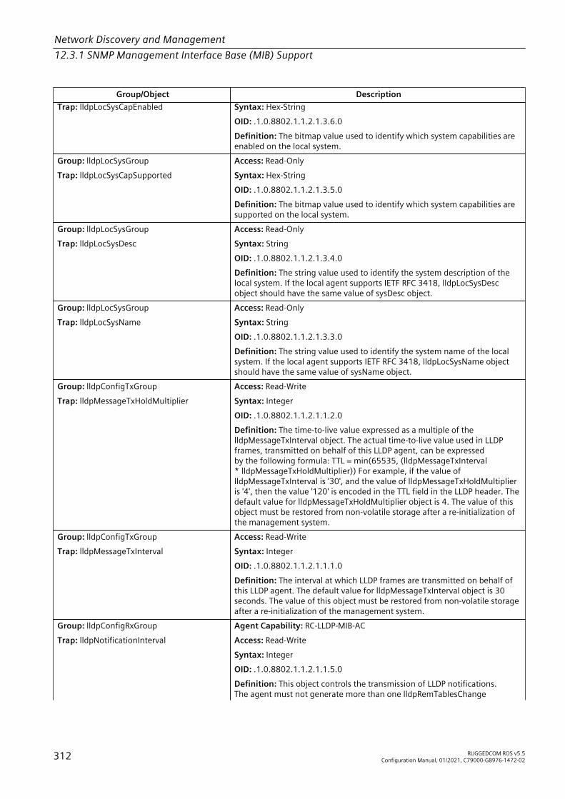
Network Discovery and Management12.3.1 SNMP Management Interface Base (MIB) Support
Group/Object DescriptionTrap: lldpLocSysCapEnabled Syntax: Hex-String
OID: .1.0.8802.1.1.2.1.3.6.0Definition: The bitmap value used to identify which system capabilities areenabled on the local system.
Group: lldpLocSysGroupTrap: lldpLocSysCapSupported
Access: Read-OnlySyntax: Hex-StringOID: .1.0.8802.1.1.2.1.3.5.0Definition: The bitmap value used to identify which system capabilities aresupported on the local system.
Group: lldpLocSysGroupTrap: lldpLocSysDesc
Access: Read-OnlySyntax: StringOID: .1.0.8802.1.1.2.1.3.4.0Definition: The string value used to identify the system description of thelocal system. If the local agent supports IETF RFC 3418, lldpLocSysDescobject should have the same value of sysDesc object.
Group: lldpLocSysGroupTrap: lldpLocSysName
Access: Read-OnlySyntax: StringOID: .1.0.8802.1.1.2.1.3.3.0Definition: The string value used to identify the system name of the localsystem. If the local agent supports IETF RFC 3418, lldpLocSysName objectshould have the same value of sysName object.
Group: lldpConfigTxGroupTrap: lldpMessageTxHoldMultiplier
Access: Read-WriteSyntax: IntegerOID: .1.0.8802.1.1.2.1.1.2.0Definition: The time-to-live value expressed as a multiple of thelldpMessageTxInterval object. The actual time-to-live value used in LLDPframes, transmitted on behalf of this LLDP agent, can be expressedby the following formula: TTL = min(65535, (lldpMessageTxInterval* lldpMessageTxHoldMultiplier)) For example, if the value oflldpMessageTxInterval is '30', and the value of lldpMessageTxHoldMultiplieris '4', then the value '120' is encoded in the TTL field in the LLDP header. Thedefault value for lldpMessageTxHoldMultiplier object is 4. The value of thisobject must be restored from non-volatile storage after a re-initialization ofthe management system.
Group: lldpConfigTxGroupTrap: lldpMessageTxInterval
Access: Read-WriteSyntax: IntegerOID: .1.0.8802.1.1.2.1.1.1.0Definition: The interval at which LLDP frames are transmitted on behalf ofthis LLDP agent. The default value for lldpMessageTxInterval object is 30seconds. The value of this object must be restored from non-volatile storageafter a re-initialization of the management system.
Group: lldpConfigRxGroupTrap: lldpNotificationInterval
Agent Capability: RC-LLDP-MIB-ACAccess: Read-WriteSyntax: IntegerOID: .1.0.8802.1.1.2.1.1.5.0Definition: This object controls the transmission of LLDP notifications.The agent must not generate more than one lldpRemTablesChange
312 RUGGEDCOM ROS v5.5Configuration Manual, 01/2021, C79000-G8976-1472-02

Network Discovery and Management12.3.1 SNMP Management Interface Base (MIB) Support
Group/Object Descriptionnotification-event in the indicated period, where a 'notification-event' isthe transmission of a single notification PDU type to a list of notificationdestinations. If additional changes in lldpRemoteSystemsData objectgroups occur within the indicated throttling period, then these trap-events must be suppressed by the agent. An NMS should periodicallycheck the value of lldpStatsRemTableLastChangeTime to detect anymissed lldpRemTablesChange notification-events, e.g. due to throttling ortransmission loss. If notification transmission is enabled for particular ports,the suggested default throttling period is 5 seconds. The value of this objectmust be restored from non-volatile storage after a re-initialization of themanagement system.
NoteWrite access is not implemented.
Group: lldpConfigGroupTrap: lldpPortConfigAdminStatus
Access: Read-WriteSyntax: IntegerOID: .1.0.8802.1.1.2.1.1.6.1.2.1Definition: The administratively desired status of the local LLDP agent. Ifthe associated lldpPortConfigAdminStatus object has a value of 'txOnly(1)',then LLDP agent will transmit LLDP frames on this port and it will not storeany information about the remote systems connected. If the associatedlldpPortConfigAdminStatus object has a value of 'rxOnly(2)', then the LLDPagent will receive, but it will not transmit LLDP frames on this port. If theassociated lldpPortConfigAdminStatus object has a value of 'txAndRx(3)',then the LLDP agent will transmit and receive LLDP frames on this port. Ifthe associated lldpPortConfigAdminStatus object has a value of 'disabled(4)',then LLDP agent will not transmit or receive LLDP frames on this port. Ifthere is remote systems information which is received on this port andstored in other tables, before the port's lldpPortConfigAdminStatus becomesdisabled, then the information will naturally age out.
Group: lldpConfigRxGroupTrap: lldpPortConfigNotificationEnable
Access: Read-WriteSyntax: IntegerOID: .1.0.8802.1.1.2.1.1.6.1.3.1Definition: The lldpPortConfigNotificationEnable controls, on a per portbasis, whether or not notifications from the agent are enabled. The valuetrue(1) means that notifications are enabled; the value false(2) means thatthey are not.
Group: lldpConfigTxGroupTrap: lldpPortConfigTLVsTxEnable
Agent Capability: RC-LLDP-MIB-ACAccess: Read-WriteSyntax: Hex-StringOID: .1.0.8802.1.1.2.1.1.6.1.4.1Definition: The lldpPortConfigTLVsTxEnable, defined as a bitmap, includesthe basic set of LLDP TLVs whose transmission is allowed on the local LLDPagent by the network management. Each bit in the bitmap corresponds toa TLV type associated with a specific optional TLV. It should be noted thatthe organizationally-specific TLVs are excluded from the lldpTLVsTxEnablebitmap. LLDP Organization Specific Information Extension MIBs should havesimilar configuration object to control transmission of their organizationallydefined TLVs. The bit 'portDesc(0)' indicates that LLDP agent should transmit'Port Description TLV'. The bit 'sysName(1)' indicates that LLDP agent shouldtransmit 'System Name TLV'. The bit 'sysDesc(2)' indicates that LLDP agentshould transmit 'System Description TLV'. The bit 'sysCap(3)' indicates that
RUGGEDCOM ROS v5.5Configuration Manual, 01/2021, C79000-G8976-1472-02 313

Network Discovery and Management12.3.1 SNMP Management Interface Base (MIB) Support
Group/Object DescriptionLLDP agent should transmit 'System Capabilities TLV'. There is no bit reservedfor the management address TLV type since transmission of managementaddress TLVs are controlled by another object, lldpConfigManAddrTable.The default value for lldpPortConfigTLVsTxEnable object is empty set,which means no enumerated values are set. The value of this objectmust be restored from non-volatile storage after a re-initialization of themanagement system.Write access is not implemented.
Group: lldpConfigTxGroupTrap: lldpReinitDelay
Access: Read-WriteSyntax: IntegerOID: .1.0.8802.1.1.2.1.1.3.0Definition: The lldpReinitDelay indicates the delay (in units of seconds)from when lldpPortConfigAdminStatus object of a particular port becomes'disabled' until re-initialization will be attempted. The default valuefor lldpReintDelay object is two seconds. The value of this object mustbe restored from non-volatile storage after a re-initialization of themanagement system.
Group: lldpRemSysGroupTrap: lldpRemChassisId
Access: Read-OnlySyntax: Hex-StringOID: .1.0.8802.1.1.2.1.4.1.1.5.3496.7.1Definition: The string value used to identify the chassis componentassociated with the remote system.
Group: lldpRemSysGroupTrap: lldpRemChassisIdSubtype
Access: Read-OnlySyntax: IntegerOID: .1.0.8802.1.1.2.1.4.1.1.4.3496.7.1Definition: The type of encoding used to identify the chassis associated withthe remote system.
Group: lldpRemSysGroupTrap: lldpRemManAddrIfId
Access: Read-OnlySyntax: IntegerOID: .1.0.8802.1.1.2.1.4.2.1.4.3496.7.1.1.4.192.168.0.20Definition: The integer value used to identify the interface numberregarding the management address component associated with the remotesystem.
Group: lldpRemSysGroupTrap: lldpRemManAddrIfSubtype
Access: Read-OnlySyntax: IntegerOID: .1.0.8802.1.1.2.1.4.2.1.3.3496.7.1.1.4.192.168.0.20Definition: The enumeration value that identifies the interface numberingmethod used for defining the interface number, associated with the remotesystem.
Group: lldpRemSysGroupTrap: lldpRemManAddrOID
Access: Read-OnlySyntax: OIDOID: .1.0.8802.1.1.2.1.4.2.1.5.6036.6.1.1.4.192.168.0.33Definition: The OID value used to identify the type of hardware componentor protocol entity associated with the management address advertised bythe remote system agent.
Group: lldpRemSysGroupTrap: lldpRemOrgDefInfo
Access: Read-OnlySyntax: String
314 RUGGEDCOM ROS v5.5Configuration Manual, 01/2021, C79000-G8976-1472-02

Network Discovery and Management12.3.1 SNMP Management Interface Base (MIB) Support
Group/Object DescriptionOID: .1.0.8802.1.1.2.1.4.4.1.4Definition: This table contains one or more rows per physical networkconnection which advertises the organizationally defined information.Note that this table contains one or more rows of organizationally definedinformation that is not recognized by the local agent. If the local system iscapable of recognizing any organizationally defined information, appropriateextension MIBs from the organization should be used for informationretrieval.
Group: lldpRemSysGroupTrap: lldpRemPortDesc
Access: Read-OnlySyntax: StringOID: .1.0.8802.1.1.2.1.4.1.1.8Definition: The string value used to identify the description of the given portassociated with the remote system.
Group: lldpRemSysGroupTrap: lldpRemPortId
Access: Read-OnlySyntax: StringOID: .1.0.8802.1.1.2.1.4.1.1.7.3496.7.1Definition: The string value used to identify the port component associatedwith the remote system.
Group: lldpRemSysGroupTrap: lldpRemPortIdSubtype
Access: Read-OnlySyntax: IntegerOID: .1.0.8802.1.1.2.1.4.1.1.6.3496.7.1Definition: The type of port identifier encoding used in the associated'lldpRemPortId' object.
Group: lldpRemSysGroupTrap: lldpRemSysCapEnabled
Access: Read-OnlySyntax: Hex-StringOID: .1.0.8802.1.1.2.1.4.1.1.12.3496.7.1Definition: The bitmap value used to identify which system capabilities areenabled on the remote system.
Group: lldpRemSysGroupTrap: lldpRemSysCapSupported
Access: Read-OnlySyntax: Hex-StringOID: .1.0.8802.1.1.2.1.4.1.1.11.3496.7.1Definition: The bitmap value used to identify which system capabilities aresupported on the remote system.
Group: lldpRemSysGroupTrap: lldpRemSysDesc
Access: Read-OnlySyntax: StringOID: .1.0.8802.1.1.2.1.4.1.1.10.3496.7.1Definition: The string value used to identify the system description of theremote system.
Group: lldpRemSysGroupTrap: lldpRemSysName
Access: Read-OnlySyntax: StringOID: .1.0.8802.1.1.2.1.4.1.1.9.3496.7.1Definition: The string value used to identify the system name of the remotesystem.
Group: lldpNotificationsGroupTrap: lldpRemTablesChange
Syntax: StringOID: 1.0.8802.1.1.2.0.0.1.0
RUGGEDCOM ROS v5.5Configuration Manual, 01/2021, C79000-G8976-1472-02 315
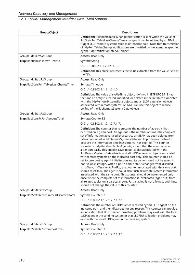
Network Discovery and Management12.3.1 SNMP Management Interface Base (MIB) Support
Group/Object DescriptionDefinition: A lldpRemTablesChange notification is sent when the value oflldpStatsRemTableLastChangeTime changes. It can be utilized by an NMS totrigger LLDP remote systems table maintenance polls. Note that transmissionof lldpRemTablesChange notifications are throttled by the agent, as specifiedby the 'lldpNotificationInterval' object.
Group: lldpRemSysGroupTrap: lldpRemUnknownTLVInfo
Access: Read-OnlySyntax: StringOID: 1.0.8802.1.1.2.1.4.3.1.2Definition: This object represents the value extracted from the value field ofthe TLV.
Group: lldpStatsRxGroupTrap: lldpStatsRemTablesLastChangeTime
Access: Read-OnlySyntax: TimeticksOID: .1.0.8802.1.1.2.1.2.1.0Definition: The value of sysUpTime object (defined in IETF RFC 3418) atthe time an entry is created, modified, or deleted in the in tables associatedwith the lldpRemoteSystemsData objects and all LLDP extension objectsassociated with remote systems. An NMS can use this object to reducepolling of the lldpRemoteSystemsData objects.
Group: lldpStatsRxGroupTrap: lldpStatsRxPortAgeoutsTotal
Access: Read-OnlySyntax: Counter32OID: .1.0.8802.1.1.2.1.2.7.1.7.1Definition: The counter that represents the number of age-outs thatoccurred on a given port. An age-out is the number of times the completeset of information advertised by a particular MSAP has been deleted fromtables contained in lldpRemoteSystemsData and lldpExtensions objectsbecause the information timeliness interval has expired. This counteris similar to lldpStatsRemTablesAgeouts, except that the counter is ona per port basis. This enables NMS to poll tables associated with thelldpRemoteSystemsData objects and all LLDP extension objects associatedwith remote systems on the indicated port only. This counter should beset to zero during agent initialization and its value should not be saved innon-volatile storage. When a port's admin status changes from 'disabled'to 'rxOnly', 'txOnly' or 'txAndRx', the counter associated with the same portshould reset to 0. The agent should also flush all remote system informationassociated with the same port. This counter should be incremented onlyonce when the complete set of information is invalidated (aged out) fromall related tables on a particular port. Partial aging is not allowed, and thus,should not change the value of this counter.
Group: lldpStatsRxGroupTrap: lldpStatsRxPortFramesDiscardedTotal
Access: Read-OnlySyntax: Counter32OID: .1.0.8802.1.1.2.1.2.7.1.2.1Definition: The number of LLDP frames received by this LLDP agent on theindicated port, and then discarded for any reason. This counter can providean indication that LLDP header formating problems may exist with the localLLDP agent in the sending system or that LLDPDU validation problems mayexist with the local LLDP agent in the receiving system.
Group: lldpStatsRxGroupTrap: lldpStatsRxPortFramesErrors
Access: Read-OnlySyntax: Counter32OID: .1.0.8802.1.1.2.1.2.7.1.3.1
316 RUGGEDCOM ROS v5.5Configuration Manual, 01/2021, C79000-G8976-1472-02

Network Discovery and Management12.3.1 SNMP Management Interface Base (MIB) Support
Group/Object DescriptionDefinition: The number of invalid LLDP frames received by this LLDP agenton the indicated port, while this LLDP agent is enabled.
Group: lldpStatsRxGroupTrap: lldpStatsRxPortFramesTotal
Access: Read-OnlySyntax: Counter32OID: .1.0.8802.1.1.2.1.2.7.1.4.1Definition: The number of valid LLDP frames received by this LLDP agent onthe indicated port, while this LLDP agent is enabled.
Group: lldpStatsRxGroupTrap: lldpStatsRxPortTLVsDiscardedTotal
Access: Read-OnlySyntax: Counter32OID: .1.0.8802.1.1.2.1.2.7.1.5.1Definition: The number of LLDP TLVs discarded for any reason by this LLDPagent on the indicated port.
Group: lldpStatsRxGroupTrap: lldpStatsRxPortTLVsUnrecognizedTotal
Access: Read-OnlySyntax: Counter32OID: .1.0.8802.1.1.2.1.2.7.1.6.1Definition: The number of LLDP TLVs received on the given port that arenot recognized by this LLDP agent on the indicated port. An unrecognizedTLV is referred to as the TLV whose type value is in the range of reservedTLV types (000 1001 - 111 1110) in Table 9.1 of IEEE Std 802.1AB-2005.An unrecognized TLV may be a basic management TLV from a later LLDPversion.
Group: lldpStatsTxGroupTrap: lldpStatsTxPortFramesTotal
Access: Read-OnlySyntax: Counter32OID: .1.0.8802.1.1.2.1.2.6.1.2.1Definition: The number of LLDP frames transmitted by this LLDP agent onthe indicated port.
Group: lldpConfigTxGroupTrap: lldpTxDelay
Access: Read-WriteSyntax: IntegerOID: .1.0.8802.1.1.2.1.1.4.0Definition: The lldpTxDelay indicates the delay (in units of seconds)between successive LLDP frame transmissions initiated by value/statuschanges in the LLDP local systems MIB. The recommended value for thelldpTxDelay is set by the following formula:1 <= lldpTxDelay <= (0.25 * lldpMessageTxInterval)The default value for lldpTxDelay object is two seconds. The value of thisobject must be restored from non-volatile storage after a re-initialization ofthe management system.
Q-BRIDGE-MIB
Group/Object DescriptionGroup: qBridgeFdbUnicastGroupTrap: dot1qFdbDynamicCount
Access: Read-OnlySyntax: Counter32OID: .1.3.6.1.2.1.17.7.1.2.1.1.2.255.148.184.197.5.176.0Definition: The current number of dynamic entries in this Filtering Database.
Group: qBridgeServiceRequirementsGroup Agent Capability: RC-Q-BRIDGE-MIB-AC
RUGGEDCOM ROS v5.5Configuration Manual, 01/2021, C79000-G8976-1472-02 317

Network Discovery and Management12.3.1 SNMP Management Interface Base (MIB) Support
Group/Object DescriptionTrap: dot1qForwardAllForbiddenPorts Access: Read-Only
Syntax: Hex-StringOID: .1.3.6.1.2.1.17.7.1.2.4.1.3.22Definition: The set of ports configured by management in this VLAN forwhich the Service Requirement attribute Forward All Multicast Groups maynot be dynamically registered by GMRP. This value will be restored after thedevice is reset. A port may not be added in this set if it is already a memberof the set of ports in dot1qForwardAllStaticPorts. The default value is a stringof zeros of appropriate length. The value of this object MUST be retainedacross reinitializations of the management system.
Group: qBridgeServiceRequirementsGroupTrap: dot1qForwardAllPorts
Access: Read-OnlySyntax: Hex-StringOID: .1.3.6.1.2.1.17.7.1.2.4.1.1.22Definition: The complete set of ports in this VLAN to which all multicastgroup-addressed frames are to be forwarded. This includes ports for whichthis need has been determined dynamically by GMRP, or configured staticallyby management.
Group: qBridgeServiceRequirementsGroupTrap: dot1qForwardAllStaticPorts
Agent Capability: RC-Q-BRIDGE-MIB-ACAccess: Read-OnlySyntax: Hex-StringOID: .1.3.6.1.2.1.17.7.1.2.4.1.2.22Definition: The set of ports configured by management in this VLANto which all multicast group-addressed frames are to be forwarded.Ports entered in this list will also appear in the complete set shown bydot1qForwardAllPorts. This value will be restored after the device is reset.This only applies to ports that are members of the VLAN, defined bydot1qVlanCurrentEgressPorts. A port may not be added in this set if it isalready a member of the set of ports in dot1qForwardAllForbiddenPorts.The default value is a string of ones of appropriate length, to indicatethe standard behaviour of using basic filtering services, i.e., forward allmulticasts to all ports. The value of this object MUST be retained acrossreinitializations of the management system.
Group: qBridgeServiceRequirementsGroupTrap:dot1qForwardUnregisteredForbiddenPorts
Access: Read-WriteSyntax: Hex-StringOID: .1.3.6.1.2.1.17.7.1.2.5.1.3.22Definition: The set of ports configured by management in this VLANfor which the Service Requirement attribute Forward UnregisteredMulticast Groups may not be dynamically registered by GMRP.This value will be restored after the device is reset. A port may notbe added in this set if it is already a member of the set of ports indot1qForwardUnregisteredStaticPorts. The default value is a string of zerosof appropriate length. The value of this object MUST be retained acrossreinitializations of the management system.
Group: qBridgeServiceRequirementsGroupTrap: dot1qForwardUnregisteredPorts
Access: Read-OnlySyntax: Hex-StringOID: .1.3.6.1.2.1.17.7.1.2.5.1.1.22Definition: The complete set of ports in this VLAN to which multicastgroup-addressed frames for which there is no more specific forwardinginformation will be forwarded. This includes ports for which this need
318 RUGGEDCOM ROS v5.5Configuration Manual, 01/2021, C79000-G8976-1472-02

Network Discovery and Management12.3.1 SNMP Management Interface Base (MIB) Support
Group/Object Descriptionhas been determined dynamically by GMRP, or configured statically bymanagement.
Group: qBridgeServiceRequirementsGroupTrap: dot1qForwardUnregisteredStaticPorts
Access: Read-WriteSyntax: Hex-StringOID: .1.3.6.1.2.1.17.7.1.2.5.1.2.22Definition: The set of ports configured by management, in this VLAN, towhich multicast group-addressed frames for which there is no more specificforwarding information are to be forwarded. Ports entered in this list willalso appear in the complete set shown by dot1qForwardUnregisteredPorts.This value will be restored after the device is reset. A port may notbe added in this set if it is already a member of the set of ports indot1qForwardUnregisteredForbiddenPorts. The default value is a string ofzeros of appropriate length, although this has no effect with the defaultvalue of dot1qForwardAllStaticPorts. The value of this object MUST beretained across reinitializations of the management system.
Group: qBridgeBaseGroupTrap: dot1qGvrpStatus
Access: Read-WriteSyntax: IntegerOID: .1.3.6.1.2.1.17.7.1.1.5.0Definition: The administrative status requested by management for GVRP.The value enabled(1) indicates that GVRP should be enabled on this device,on all ports for which it has not been specifically disabled. When disabled(2),GVRP is disabled on all ports, and all GVRP packets will be forwardedtransparently. This object affects all GVRP Applicant and Registrar statemachines. A transition from disabled(2) to enabled(1) will cause a reset of allGVRP state machines on all ports. The value of this object MUST be retainedacross reinitializations of the management system.
Group: qBridgeBaseGroupTrap: dot1qMaxSupportedVlans
Access: Read-OnlySyntax: Gauge32OID: .1.3.6.1.2.1.17.7.1.1.3.0Definition: The maximum number of IEEE 802.1Q VLANs that this devicesupports.
Group: qBridgeBaseGroupTrap: dot1qMaxVlanId
Access: Read-OnlySyntax: IntegerOID: .1.3.6.1.2.1.17.7.1.1.2.0Definition: The maximum IEEE 802.1Q VLAN-ID that this device supports.
Group: qBridgeVlanStaticGroupTrap: dot1qNextFreeLocalVlanIndex
Access: Read-OnlySyntax: IntegerOID: .1.3.6.1.2.1.17.7.1.4.4.0Definition: The next available value for dot1qVlanIndex of a local VLANentry in dot1qVlanStaticTable. This will report values >=4096 if a newLocal VLAN may be created or else the value 0 if this is not possible. Arow creation operation in this table for an entry with a local VlanIndexvalue may fail if the current value of this object is not used as the index.Even if the value read is used, there is no guarantee that it will still be thevalid index when the create operation is attempted; another managermay have already got in during the intervening time interval. In this case,dot1qNextFreeLocalVlanIndex should be re-read and the creation re-triedwith the new value. This value will automatically change when the currentvalue is used to create a new row.
Group: qBridgeBaseGroup Access: Read-Only
RUGGEDCOM ROS v5.5Configuration Manual, 01/2021, C79000-G8976-1472-02 319

Network Discovery and Management12.3.1 SNMP Management Interface Base (MIB) Support
Group/Object DescriptionTrap: dot1qNumVlans Syntax: Gauge32
OID: .1.3.6.1.2.1.17.7.1.1.4.0Definition: The current number of IEEE 802.1Q VLANs that are configured inthis device.
Group: qBridgePortGroup2Trap: dot1qPortAcceptableFrameTypes
Agent Capability: RC-Q-BRIDGE-MIB-ACAccess: Read-WriteSyntax: IntegerOID: .1.3.6.1.2.1.17.7.1.4.5.1.2.1Definition: When this is admitOnlyVlanTagged(2), the device will discarduntagged frames or Priority-Tagged frames received on this port. WhenadmitAll(1), untagged frames or Priority-Tagged frames received on this portwill be accepted and assigned to a VID based on the PVID and VID Set for thisport. This control does not affect VLAN-independent Bridge Protocol DataUnit (BPDU) frames, such as GVRP and Spanning Tree Protocol (STP). It doesaffect VLAN- dependent BPDU frames, such as GMRP. The value of this objectMUST be retained across reinitializations of the management system.
NoteThe value of 'admitOnlyVlanTagged(2)' is not supported.
Group: qBridgePortGroup2Trap: dot1qPortGvrpStatus
Agent Capability: RC-Q-BRIDGE-MIB-ACAccess: Read-WriteSyntax: IntegerOID: .1.3.6.1.2.1.17.7.1.4.5.1.4.1Definition: The state of GVRP operation on this port. The value enabled(1)indicates that GVRP is enabled on this port, as long as dot1qGvrpStatusis also enabled for this device. When disabled(2) but dot1qGvrpStatusis still enabled for the device, GVRP is disabled on this port: any GVRPpackets received will be silently discarded, and no GVRP registrations willbe propagated from other ports. This object affects all GVRP Applicantand Registrar state machines on this port. A transition from disabled(2)to enabled(1) will cause a reset of all GVRP state machines on this port.The value of this object MUST be retained across reinitializations of themanagement system.
NoteThe default value is 'disabled(2)'.
Group: qBridgePortGroup2Trap: dot1qPortIngressFiltering
Agent Capability: RC-Q-BRIDGE-MIB-ACAccess: Read-WriteSyntax: IntegerOID: .1.3.6.1.2.1.17.7.1.4.5.1.3.1Definition: When this is true(1), the device will discard incoming framesfor VLANs that do not include this Port in its Member set. When false(2),the port will accept all incoming frames. This control does not affect VLAN-independent BPDU frames, such as GVRP and STP. It does affect VLAN-dependent BPDU frames, such as GMRP. The value of this object MUST beretained across reinitializations of the management system.
320 RUGGEDCOM ROS v5.5Configuration Manual, 01/2021, C79000-G8976-1472-02
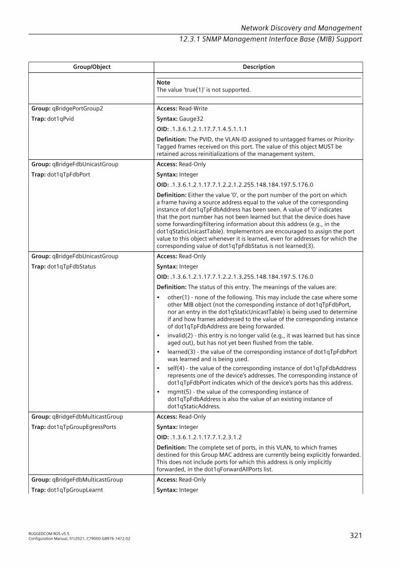
Network Discovery and Management12.3.1 SNMP Management Interface Base (MIB) Support
Group/Object Description
NoteThe value 'true(1)' is not supported.
Group: qBridgePortGroup2Trap: dot1qPvid
Access: Read-WriteSyntax: Gauge32OID: .1.3.6.1.2.1.17.7.1.4.5.1.1.1Definition: The PVID, the VLAN-ID assigned to untagged frames or Priority-Tagged frames received on this port. The value of this object MUST beretained across reinitializations of the management system.
Group: qBridgeFdbUnicastGroupTrap: dot1qTpFdbPort
Access: Read-OnlySyntax: IntegerOID: .1.3.6.1.2.1.17.7.1.2.2.1.2.255.148.184.197.5.176.0Definition: Either the value '0', or the port number of the port on whicha frame having a source address equal to the value of the correspondinginstance of dot1qTpFdbAddress has been seen. A value of '0' indicatesthat the port number has not been learned but that the device does havesome forwarding/filtering information about this address (e.g., in thedot1qStaticUnicastTable). Implementors are encouraged to assign the portvalue to this object whenever it is learned, even for addresses for which thecorresponding value of dot1qTpFdbStatus is not learned(3).
Group: qBridgeFdbUnicastGroupTrap: dot1qTpFdbStatus
Access: Read-OnlySyntax: IntegerOID: .1.3.6.1.2.1.17.7.1.2.2.1.3.255.148.184.197.5.176.0Definition: The status of this entry. The meanings of the values are:• other(1) - none of the following. This may include the case where some
other MIB object (not the corresponding instance of dot1qTpFdbPort,nor an entry in the dot1qStaticUnicastTable) is being used to determineif and how frames addressed to the value of the corresponding instanceof dot1qTpFdbAddress are being forwarded.
• invalid(2) - this entry is no longer valid (e.g., it was learned but has sinceaged out), but has not yet been flushed from the table.
• learned(3) - the value of the corresponding instance of dot1qTpFdbPortwas learned and is being used.
• self(4) - the value of the corresponding instance of dot1qTpFdbAddressrepresents one of the device's addresses. The corresponding instance ofdot1qTpFdbPort indicates which of the device's ports has this address.
• mgmt(5) - the value of the corresponding instance ofdot1qTpFdbAddress is also the value of an existing instance ofdot1qStaticAddress.
Group: qBridgeFdbMulticastGroupTrap: dot1qTpGroupEgressPorts
Access: Read-OnlySyntax: IntegerOID: .1.3.6.1.2.1.17.7.1.2.3.1.2Definition: The complete set of ports, in this VLAN, to which framesdestined for this Group MAC address are currently being explicitly forwarded.This does not include ports for which this address is only implicitlyforwarded, in the dot1qForwardAllPorts list.
Group: qBridgeFdbMulticastGroupTrap: dot1qTpGroupLearnt
Access: Read-OnlySyntax: Integer
RUGGEDCOM ROS v5.5Configuration Manual, 01/2021, C79000-G8976-1472-02 321
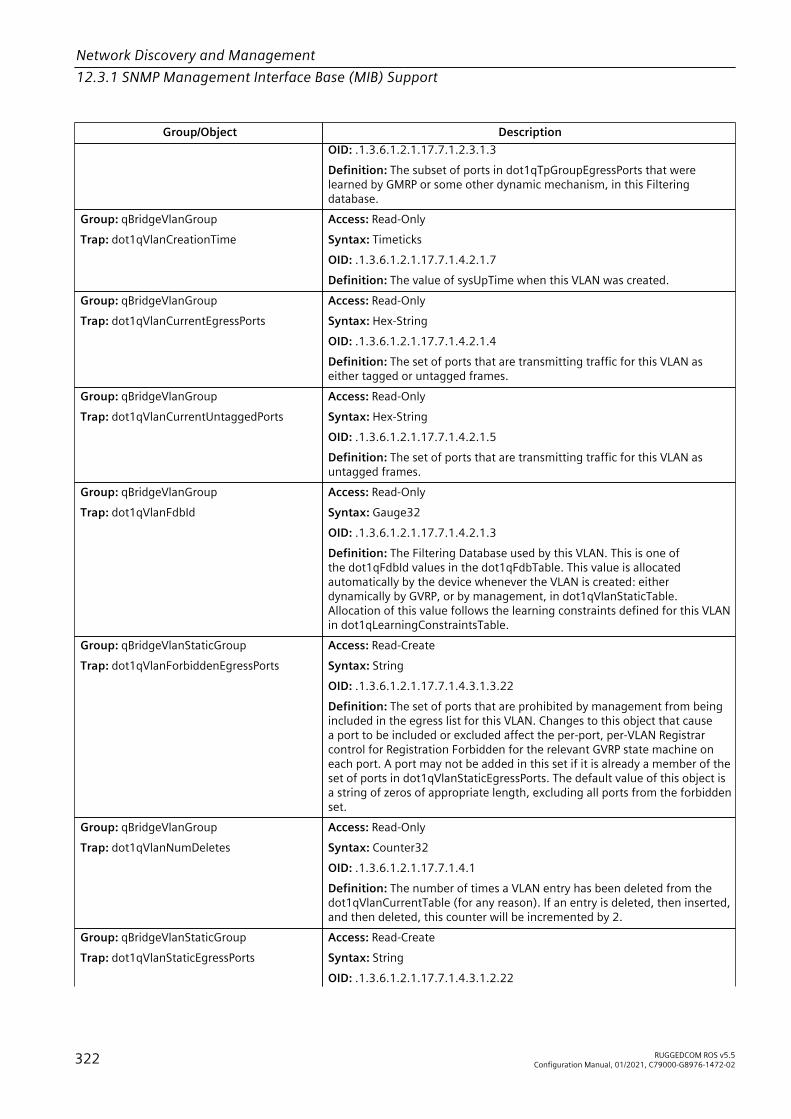
Network Discovery and Management12.3.1 SNMP Management Interface Base (MIB) Support
Group/Object DescriptionOID: .1.3.6.1.2.1.17.7.1.2.3.1.3Definition: The subset of ports in dot1qTpGroupEgressPorts that werelearned by GMRP or some other dynamic mechanism, in this Filteringdatabase.
Group: qBridgeVlanGroupTrap: dot1qVlanCreationTime
Access: Read-OnlySyntax: TimeticksOID: .1.3.6.1.2.1.17.7.1.4.2.1.7Definition: The value of sysUpTime when this VLAN was created.
Group: qBridgeVlanGroupTrap: dot1qVlanCurrentEgressPorts
Access: Read-OnlySyntax: Hex-StringOID: .1.3.6.1.2.1.17.7.1.4.2.1.4Definition: The set of ports that are transmitting traffic for this VLAN aseither tagged or untagged frames.
Group: qBridgeVlanGroupTrap: dot1qVlanCurrentUntaggedPorts
Access: Read-OnlySyntax: Hex-StringOID: .1.3.6.1.2.1.17.7.1.4.2.1.5Definition: The set of ports that are transmitting traffic for this VLAN asuntagged frames.
Group: qBridgeVlanGroupTrap: dot1qVlanFdbId
Access: Read-OnlySyntax: Gauge32OID: .1.3.6.1.2.1.17.7.1.4.2.1.3Definition: The Filtering Database used by this VLAN. This is one ofthe dot1qFdbId values in the dot1qFdbTable. This value is allocatedautomatically by the device whenever the VLAN is created: eitherdynamically by GVRP, or by management, in dot1qVlanStaticTable.Allocation of this value follows the learning constraints defined for this VLANin dot1qLearningConstraintsTable.
Group: qBridgeVlanStaticGroupTrap: dot1qVlanForbiddenEgressPorts
Access: Read-CreateSyntax: StringOID: .1.3.6.1.2.1.17.7.1.4.3.1.3.22Definition: The set of ports that are prohibited by management from beingincluded in the egress list for this VLAN. Changes to this object that causea port to be included or excluded affect the per-port, per-VLAN Registrarcontrol for Registration Forbidden for the relevant GVRP state machine oneach port. A port may not be added in this set if it is already a member of theset of ports in dot1qVlanStaticEgressPorts. The default value of this object isa string of zeros of appropriate length, excluding all ports from the forbiddenset.
Group: qBridgeVlanGroupTrap: dot1qVlanNumDeletes
Access: Read-OnlySyntax: Counter32OID: .1.3.6.1.2.1.17.7.1.4.1Definition: The number of times a VLAN entry has been deleted from thedot1qVlanCurrentTable (for any reason). If an entry is deleted, then inserted,and then deleted, this counter will be incremented by 2.
Group: qBridgeVlanStaticGroupTrap: dot1qVlanStaticEgressPorts
Access: Read-CreateSyntax: StringOID: .1.3.6.1.2.1.17.7.1.4.3.1.2.22
322 RUGGEDCOM ROS v5.5Configuration Manual, 01/2021, C79000-G8976-1472-02

Network Discovery and Management12.3.1 SNMP Management Interface Base (MIB) Support
Group/Object DescriptionDefinition: The set of ports that are permanently assigned to the egresslist for this VLAN by management. Changes to a bit in this object affect theper-port, per-VLAN Registrar control for Registration Fixed for the relevantGVRP state machine on each port. A port may not be added in this set if itis already a member of the set of ports in dot1qVlanForbiddenEgressPorts.The default value of this object is a string of zeros of appropriate length,indicating not fixed.
Group: qBridgeVlanStaticGroupTrap: dot1qVlanStaticName
Access: Read-CreateSyntax: StringOID: .1.3.6.1.2.1.17.7.1.4.3.1.1.22Definition: An administratively assigned string, which may be used toidentify the VLAN.
Group: qBridgeVlanStaticGroupTrap: dot1qVlanStaticRowStatus
Access: Read-CreateSyntax: IntegerOID: .1.3.6.1.2.1.17.7.1.4.3.1.5.22Definition: This object indicates the status of this entry.
Group: qBridgeVlanStaticGroupTrap: dot1qVlanStaticUntaggedPorts
Access: Read-CreateSyntax: StringOID: .1.3.6.1.2.1.17.7.1.4.3.1.4.22Definition: The set of ports that should transmit egress packets for thisVLAN as untagged. The default value of this object for the default VLAN(dot1qVlanIndex = 1) is a string of appropriate length including all ports.There is no specified default for other VLANs. If a device agent cannotsupport the set of ports being set, then it will reject the set operation with anerror. For example, a manager might attempt to set more than one VLAN tobe untagged on egress where the device does not support this IEEE 802.1Qoption.
Group: qBridgeVlanGroupTrap: dot1qVlanStatus
Access: Read-OnlySyntax: IntegerOID: .1.3.6.1.2.1.17.7.1.4.2.1.6Definition: This object indicates the status of this entry.• other(1) - this entry is currently in use, but the conditions under which it
will remain so differ from the following values.• permanent(2) - this entry, corresponding to an entry in
dot1qVlanStaticTable, is currently in use and will remain so after thenext reset of the device. The port lists for this entry include portsfrom the equivalent dot1qVlanStaticTable entry and ports learneddynamically.
• dynamicGvrp(3) - this entry is currently in use and will remain so untilremoved by GVRP. There is no static entry for this VLAN, and it will beremoved when the last port leaves the VLAN.
Group: qBridgeBaseGroupTrap: dot1qVlanVersionNumber
Access: Read-OnlySyntax: IntegerOID: .1.3.6.1.2.1.17.7.1.1.1.0Definition: The version number of IEEE 802.1Q that this device supports.
RUGGEDCOM ROS v5.5Configuration Manual, 01/2021, C79000-G8976-1472-02 323
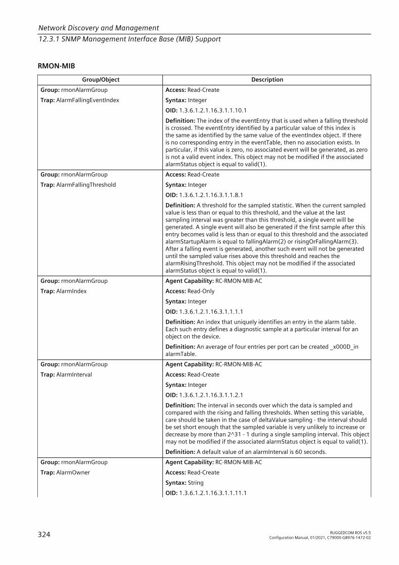
Network Discovery and Management12.3.1 SNMP Management Interface Base (MIB) Support
RMON-MIB
Group/Object DescriptionGroup: rmonAlarmGroupTrap: AlarmFallingEventIndex
Access: Read-CreateSyntax: IntegerOID: 1.3.6.1.2.1.16.3.1.1.10.1Definition: The index of the eventEntry that is used when a falling thresholdis crossed. The eventEntry identified by a particular value of this index isthe same as identified by the same value of the eventIndex object. If thereis no corresponding entry in the eventTable, then no association exists. Inparticular, if this value is zero, no associated event will be generated, as zerois not a valid event index. This object may not be modified if the associatedalarmStatus object is equal to valid(1).
Group: rmonAlarmGroupTrap: AlarmFallingThreshold
Access: Read-CreateSyntax: IntegerOID: 1.3.6.1.2.1.16.3.1.1.8.1Definition: A threshold for the sampled statistic. When the current sampledvalue is less than or equal to this threshold, and the value at the lastsampling interval was greater than this threshold, a single event will begenerated. A single event will also be generated if the first sample after thisentry becomes valid is less than or equal to this threshold and the associatedalarmStartupAlarm is equal to fallingAlarm(2) or risingOrFallingAlarm(3).After a falling event is generated, another such event will not be generateduntil the sampled value rises above this threshold and reaches thealarmRisingThreshold. This object may not be modified if the associatedalarmStatus object is equal to valid(1).
Group: rmonAlarmGroupTrap: AlarmIndex
Agent Capability: RC-RMON-MIB-ACAccess: Read-OnlySyntax: IntegerOID: 1.3.6.1.2.1.16.3.1.1.1.1Definition: An index that uniquely identifies an entry in the alarm table.Each such entry defines a diagnostic sample at a particular interval for anobject on the device.Definition: An average of four entries per port can be created _x000D_inalarmTable.
Group: rmonAlarmGroupTrap: AlarmInterval
Agent Capability: RC-RMON-MIB-ACAccess: Read-CreateSyntax: IntegerOID: 1.3.6.1.2.1.16.3.1.1.2.1Definition: The interval in seconds over which the data is sampled andcompared with the rising and falling thresholds. When setting this variable,care should be taken in the case of deltaValue sampling - the interval shouldbe set short enough that the sampled variable is very unlikely to increase ordecrease by more than 2^31 - 1 during a single sampling interval. This objectmay not be modified if the associated alarmStatus object is equal to valid(1).Definition: A default value of an alarmInterval is 60 seconds.
Group: rmonAlarmGroupTrap: AlarmOwner
Agent Capability: RC-RMON-MIB-ACAccess: Read-CreateSyntax: StringOID: 1.3.6.1.2.1.16.3.1.1.11.1
324 RUGGEDCOM ROS v5.5Configuration Manual, 01/2021, C79000-G8976-1472-02

Network Discovery and Management12.3.1 SNMP Management Interface Base (MIB) Support
Group/Object DescriptionDefinition: The entity that configured this entry and is therefore using theresources assigned to it.Definition: A default value of an alarmOwner is a 'Monitor'_x000D_ string.
Group: rmonAlarmGroupTrap: AlarmRisingEventIndex
Access: Read-CreateSyntax: IntegerOID: 1.3.6.1.2.1.16.3.1.1.9.1Definition: The index of the eventEntry that is used when a rising thresholdis crossed. The eventEntry identified by a particular value of this index isthe same as identified by the same value of the eventIndex object. If thereis no corresponding entry in the eventTable, then no association exists. Inparticular, if this value is zero, no associated event will be generated, as zerois not a valid event index. This object may not be modified if the associatedalarmStatus object is equal to valid(1).
Group: rmonAlarmGroupTrap: AlarmRisingThreshold
Access: Read-CreateSyntax: IntegerOID: 1.3.6.1.2.1.16.3.1.1.7.1Definition: A threshold for the sampled statistic. When the current sampledvalue is greater than or equal to this threshold, and the value at thelast sampling interval was less than this threshold, a single event willbe generated. A single event will also be generated if the first sampleafter this entry becomes valid is greater than or equal to this thresholdand the associated alarmStartupAlarm is equal to risingAlarm(1) orrisingOrFallingAlarm(3). After a rising event is generated, another suchevent will not be generated until the sampled value falls below thisthreshold and reaches the alarmFallingThreshold. This object may not bemodified if the associated alarmStatus object is equal to valid(1).
Group: rmonAlarmGroupTrap: AlarmSampleType
Agent Capability: RC-RMON-MIB-ACAccess: Read-CreateSyntax: IntegerOID: 1.3.6.1.2.1.16.3.1.1.4.1Definition: The method of sampling the selected variable and calculatingthe value to be compared against the thresholds. If the value of this object isabsoluteValue(1), the value of the selected variable will be compared directlywith the thresholds at the end of the sampling interval. If the value of thisobject is deltaValue(2), the value of the selected variable at the last samplewill be subtracted from the current value, and the difference compared withthe thresholds. This object may not be modified if the associated alarmStatusobject is equal to valid(1).Definition: A default value of an alarmSampleType is 'deltaValue(2)'.
Group: rmonAlarmGroupTrap: AlarmStartupAlarm
Agent Capability: RC-RMON-MIB-ACAccess: Read-CreateSyntax: IntegerOID: 1.3.6.1.2.1.16.3.1.1.6.1Definition: The alarm that may be sent when this entry is first set to valid.If the first sample after this entry becomes valid is greater than or equalto the risingThreshold and alarmStartupAlarm is equal to risingAlarm(1)or risingOrFallingAlarm(3), then a single rising alarm will be generated.If the first sample after this entry becomes valid is less than or equal tothe fallingThreshold and alarmStartupAlarm is equal to fallingAlarm(2) orrisingOrFallingAlarm(3), then a single falling alarm will be generated. This
RUGGEDCOM ROS v5.5Configuration Manual, 01/2021, C79000-G8976-1472-02 325
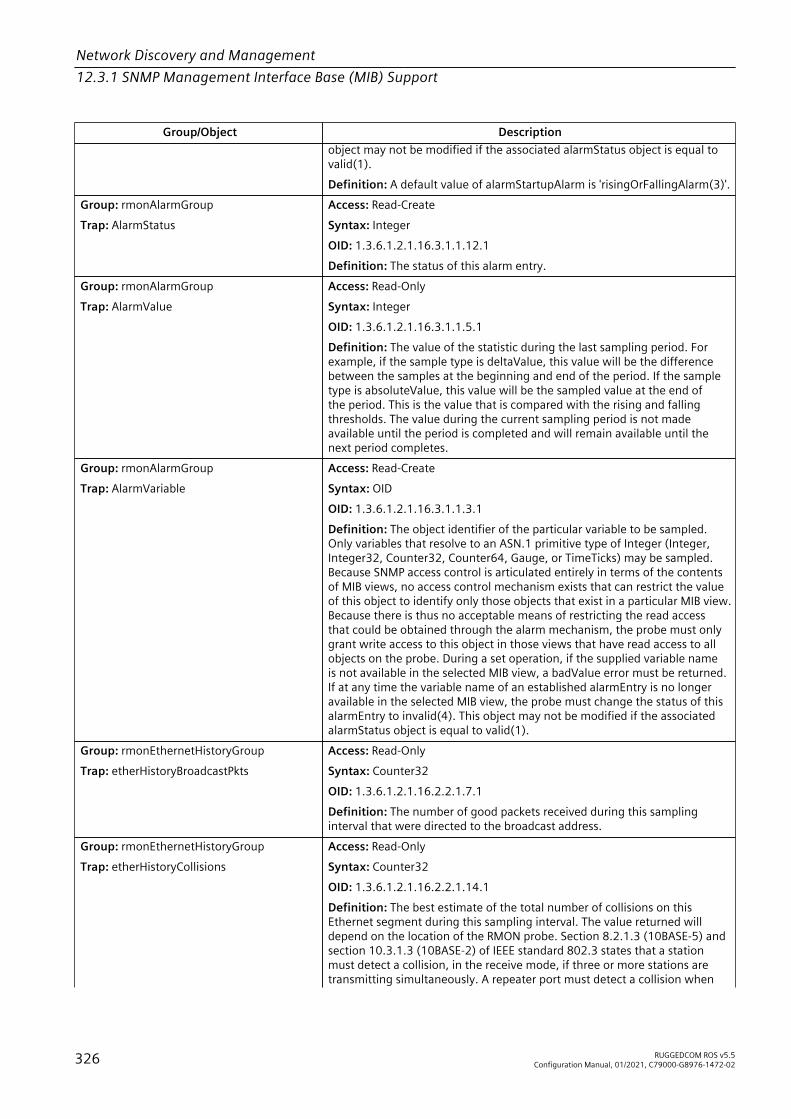
Network Discovery and Management12.3.1 SNMP Management Interface Base (MIB) Support
Group/Object Descriptionobject may not be modified if the associated alarmStatus object is equal tovalid(1).Definition: A default value of alarmStartupAlarm is 'risingOrFallingAlarm(3)'.
Group: rmonAlarmGroupTrap: AlarmStatus
Access: Read-CreateSyntax: IntegerOID: 1.3.6.1.2.1.16.3.1.1.12.1Definition: The status of this alarm entry.
Group: rmonAlarmGroupTrap: AlarmValue
Access: Read-OnlySyntax: IntegerOID: 1.3.6.1.2.1.16.3.1.1.5.1Definition: The value of the statistic during the last sampling period. Forexample, if the sample type is deltaValue, this value will be the differencebetween the samples at the beginning and end of the period. If the sampletype is absoluteValue, this value will be the sampled value at the end ofthe period. This is the value that is compared with the rising and fallingthresholds. The value during the current sampling period is not madeavailable until the period is completed and will remain available until thenext period completes.
Group: rmonAlarmGroupTrap: AlarmVariable
Access: Read-CreateSyntax: OIDOID: 1.3.6.1.2.1.16.3.1.1.3.1Definition: The object identifier of the particular variable to be sampled.Only variables that resolve to an ASN.1 primitive type of Integer (Integer,Integer32, Counter32, Counter64, Gauge, or TimeTicks) may be sampled.Because SNMP access control is articulated entirely in terms of the contentsof MIB views, no access control mechanism exists that can restrict the valueof this object to identify only those objects that exist in a particular MIB view.Because there is thus no acceptable means of restricting the read accessthat could be obtained through the alarm mechanism, the probe must onlygrant write access to this object in those views that have read access to allobjects on the probe. During a set operation, if the supplied variable nameis not available in the selected MIB view, a badValue error must be returned.If at any time the variable name of an established alarmEntry is no longeravailable in the selected MIB view, the probe must change the status of thisalarmEntry to invalid(4). This object may not be modified if the associatedalarmStatus object is equal to valid(1).
Group: rmonEthernetHistoryGroupTrap: etherHistoryBroadcastPkts
Access: Read-OnlySyntax: Counter32OID: 1.3.6.1.2.1.16.2.2.1.7.1Definition: The number of good packets received during this samplinginterval that were directed to the broadcast address.
Group: rmonEthernetHistoryGroupTrap: etherHistoryCollisions
Access: Read-OnlySyntax: Counter32OID: 1.3.6.1.2.1.16.2.2.1.14.1Definition: The best estimate of the total number of collisions on thisEthernet segment during this sampling interval. The value returned willdepend on the location of the RMON probe. Section 8.2.1.3 (10BASE-5) andsection 10.3.1.3 (10BASE-2) of IEEE standard 802.3 states that a stationmust detect a collision, in the receive mode, if three or more stations aretransmitting simultaneously. A repeater port must detect a collision when
326 RUGGEDCOM ROS v5.5Configuration Manual, 01/2021, C79000-G8976-1472-02
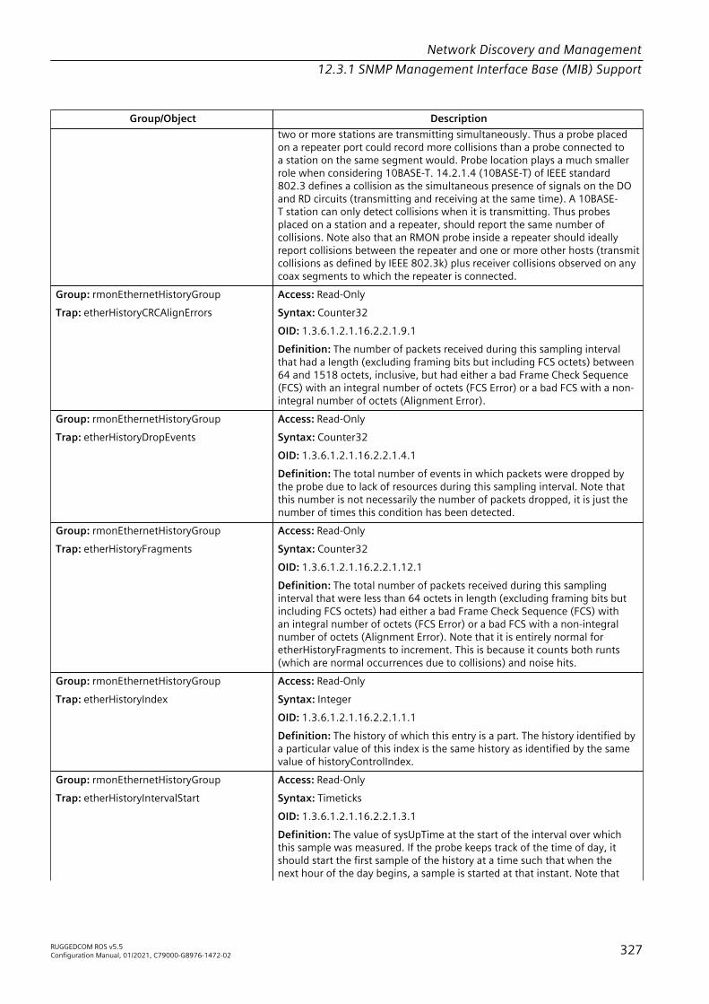
Network Discovery and Management12.3.1 SNMP Management Interface Base (MIB) Support
Group/Object Descriptiontwo or more stations are transmitting simultaneously. Thus a probe placedon a repeater port could record more collisions than a probe connected toa station on the same segment would. Probe location plays a much smallerrole when considering 10BASE-T. 14.2.1.4 (10BASE-T) of IEEE standard802.3 defines a collision as the simultaneous presence of signals on the DOand RD circuits (transmitting and receiving at the same time). A 10BASE-T station can only detect collisions when it is transmitting. Thus probesplaced on a station and a repeater, should report the same number ofcollisions. Note also that an RMON probe inside a repeater should ideallyreport collisions between the repeater and one or more other hosts (transmitcollisions as defined by IEEE 802.3k) plus receiver collisions observed on anycoax segments to which the repeater is connected.
Group: rmonEthernetHistoryGroupTrap: etherHistoryCRCAlignErrors
Access: Read-OnlySyntax: Counter32OID: 1.3.6.1.2.1.16.2.2.1.9.1Definition: The number of packets received during this sampling intervalthat had a length (excluding framing bits but including FCS octets) between64 and 1518 octets, inclusive, but had either a bad Frame Check Sequence(FCS) with an integral number of octets (FCS Error) or a bad FCS with a non-integral number of octets (Alignment Error).
Group: rmonEthernetHistoryGroupTrap: etherHistoryDropEvents
Access: Read-OnlySyntax: Counter32OID: 1.3.6.1.2.1.16.2.2.1.4.1Definition: The total number of events in which packets were dropped bythe probe due to lack of resources during this sampling interval. Note thatthis number is not necessarily the number of packets dropped, it is just thenumber of times this condition has been detected.
Group: rmonEthernetHistoryGroupTrap: etherHistoryFragments
Access: Read-OnlySyntax: Counter32OID: 1.3.6.1.2.1.16.2.2.1.12.1Definition: The total number of packets received during this samplinginterval that were less than 64 octets in length (excluding framing bits butincluding FCS octets) had either a bad Frame Check Sequence (FCS) withan integral number of octets (FCS Error) or a bad FCS with a non-integralnumber of octets (Alignment Error). Note that it is entirely normal foretherHistoryFragments to increment. This is because it counts both runts(which are normal occurrences due to collisions) and noise hits.
Group: rmonEthernetHistoryGroupTrap: etherHistoryIndex
Access: Read-OnlySyntax: IntegerOID: 1.3.6.1.2.1.16.2.2.1.1.1Definition: The history of which this entry is a part. The history identified bya particular value of this index is the same history as identified by the samevalue of historyControlIndex.
Group: rmonEthernetHistoryGroupTrap: etherHistoryIntervalStart
Access: Read-OnlySyntax: TimeticksOID: 1.3.6.1.2.1.16.2.2.1.3.1Definition: The value of sysUpTime at the start of the interval over whichthis sample was measured. If the probe keeps track of the time of day, itshould start the first sample of the history at a time such that when thenext hour of the day begins, a sample is started at that instant. Note that
RUGGEDCOM ROS v5.5Configuration Manual, 01/2021, C79000-G8976-1472-02 327
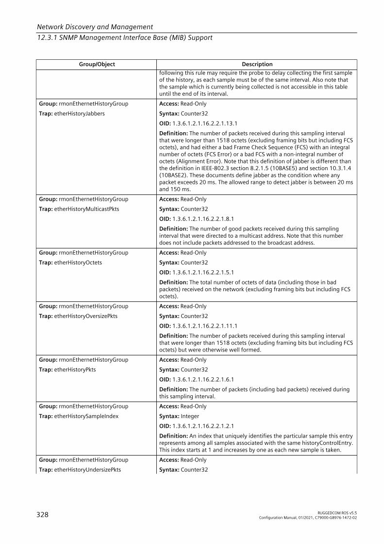
Network Discovery and Management12.3.1 SNMP Management Interface Base (MIB) Support
Group/Object Descriptionfollowing this rule may require the probe to delay collecting the first sampleof the history, as each sample must be of the same interval. Also note thatthe sample which is currently being collected is not accessible in this tableuntil the end of its interval.
Group: rmonEthernetHistoryGroupTrap: etherHistoryJabbers
Access: Read-OnlySyntax: Counter32OID: 1.3.6.1.2.1.16.2.2.1.13.1Definition: The number of packets received during this sampling intervalthat were longer than 1518 octets (excluding framing bits but including FCSoctets), and had either a bad Frame Check Sequence (FCS) with an integralnumber of octets (FCS Error) or a bad FCS with a non-integral number ofoctets (Alignment Error). Note that this definition of jabber is different thanthe definition in IEEE-802.3 section 8.2.1.5 (10BASE5) and section 10.3.1.4(10BASE2). These documents define jabber as the condition where anypacket exceeds 20 ms. The allowed range to detect jabber is between 20 msand 150 ms.
Group: rmonEthernetHistoryGroupTrap: etherHistoryMulticastPkts
Access: Read-OnlySyntax: Counter32OID: 1.3.6.1.2.1.16.2.2.1.8.1Definition: The number of good packets received during this samplinginterval that were directed to a multicast address. Note that this numberdoes not include packets addressed to the broadcast address.
Group: rmonEthernetHistoryGroupTrap: etherHistoryOctets
Access: Read-OnlySyntax: Counter32OID: 1.3.6.1.2.1.16.2.2.1.5.1Definition: The total number of octets of data (including those in badpackets) received on the network (excluding framing bits but including FCSoctets).
Group: rmonEthernetHistoryGroupTrap: etherHistoryOversizePkts
Access: Read-OnlySyntax: Counter32OID: 1.3.6.1.2.1.16.2.2.1.11.1Definition: The number of packets received during this sampling intervalthat were longer than 1518 octets (excluding framing bits but including FCSoctets) but were otherwise well formed.
Group: rmonEthernetHistoryGroupTrap: etherHistoryPkts
Access: Read-OnlySyntax: Counter32OID: 1.3.6.1.2.1.16.2.2.1.6.1Definition: The number of packets (including bad packets) received duringthis sampling interval.
Group: rmonEthernetHistoryGroupTrap: etherHistorySampleIndex
Access: Read-OnlySyntax: IntegerOID: 1.3.6.1.2.1.16.2.2.1.2.1Definition: An index that uniquely identifies the particular sample this entryrepresents among all samples associated with the same historyControlEntry.This index starts at 1 and increases by one as each new sample is taken.
Group: rmonEthernetHistoryGroupTrap: etherHistoryUndersizePkts
Access: Read-OnlySyntax: Counter32
328 RUGGEDCOM ROS v5.5Configuration Manual, 01/2021, C79000-G8976-1472-02
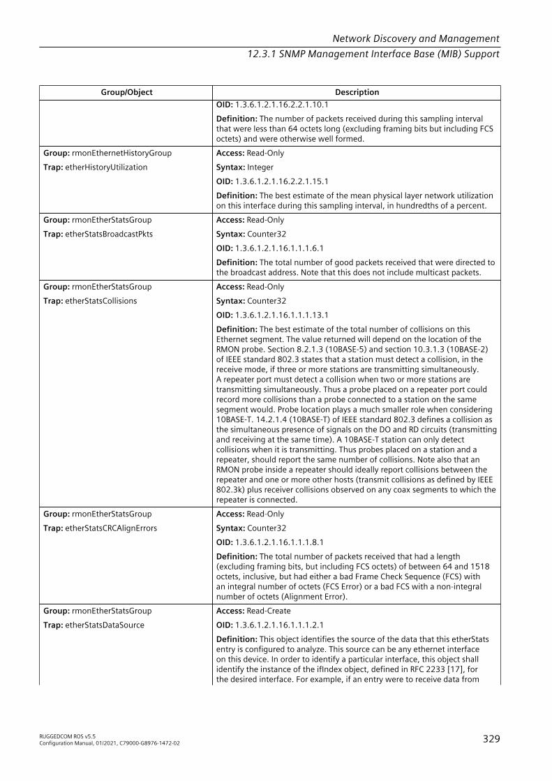
Network Discovery and Management12.3.1 SNMP Management Interface Base (MIB) Support
Group/Object DescriptionOID: 1.3.6.1.2.1.16.2.2.1.10.1Definition: The number of packets received during this sampling intervalthat were less than 64 octets long (excluding framing bits but including FCSoctets) and were otherwise well formed.
Group: rmonEthernetHistoryGroupTrap: etherHistoryUtilization
Access: Read-OnlySyntax: IntegerOID: 1.3.6.1.2.1.16.2.2.1.15.1Definition: The best estimate of the mean physical layer network utilizationon this interface during this sampling interval, in hundredths of a percent.
Group: rmonEtherStatsGroupTrap: etherStatsBroadcastPkts
Access: Read-OnlySyntax: Counter32OID: 1.3.6.1.2.1.16.1.1.1.6.1Definition: The total number of good packets received that were directed tothe broadcast address. Note that this does not include multicast packets.
Group: rmonEtherStatsGroupTrap: etherStatsCollisions
Access: Read-OnlySyntax: Counter32OID: 1.3.6.1.2.1.16.1.1.1.13.1Definition: The best estimate of the total number of collisions on thisEthernet segment. The value returned will depend on the location of theRMON probe. Section 8.2.1.3 (10BASE-5) and section 10.3.1.3 (10BASE-2)of IEEE standard 802.3 states that a station must detect a collision, in thereceive mode, if three or more stations are transmitting simultaneously.A repeater port must detect a collision when two or more stations aretransmitting simultaneously. Thus a probe placed on a repeater port couldrecord more collisions than a probe connected to a station on the samesegment would. Probe location plays a much smaller role when considering10BASE-T. 14.2.1.4 (10BASE-T) of IEEE standard 802.3 defines a collision asthe simultaneous presence of signals on the DO and RD circuits (transmittingand receiving at the same time). A 10BASE-T station can only detectcollisions when it is transmitting. Thus probes placed on a station and arepeater, should report the same number of collisions. Note also that anRMON probe inside a repeater should ideally report collisions between therepeater and one or more other hosts (transmit collisions as defined by IEEE802.3k) plus receiver collisions observed on any coax segments to which therepeater is connected.
Group: rmonEtherStatsGroupTrap: etherStatsCRCAlignErrors
Access: Read-OnlySyntax: Counter32OID: 1.3.6.1.2.1.16.1.1.1.8.1Definition: The total number of packets received that had a length(excluding framing bits, but including FCS octets) of between 64 and 1518octets, inclusive, but had either a bad Frame Check Sequence (FCS) withan integral number of octets (FCS Error) or a bad FCS with a non-integralnumber of octets (Alignment Error).
Group: rmonEtherStatsGroupTrap: etherStatsDataSource
Access: Read-CreateOID: 1.3.6.1.2.1.16.1.1.1.2.1Definition: This object identifies the source of the data that this etherStatsentry is configured to analyze. This source can be any ethernet interfaceon this device. In order to identify a particular interface, this object shallidentify the instance of the ifIndex object, defined in RFC 2233 [17], forthe desired interface. For example, if an entry were to receive data from
RUGGEDCOM ROS v5.5Configuration Manual, 01/2021, C79000-G8976-1472-02 329
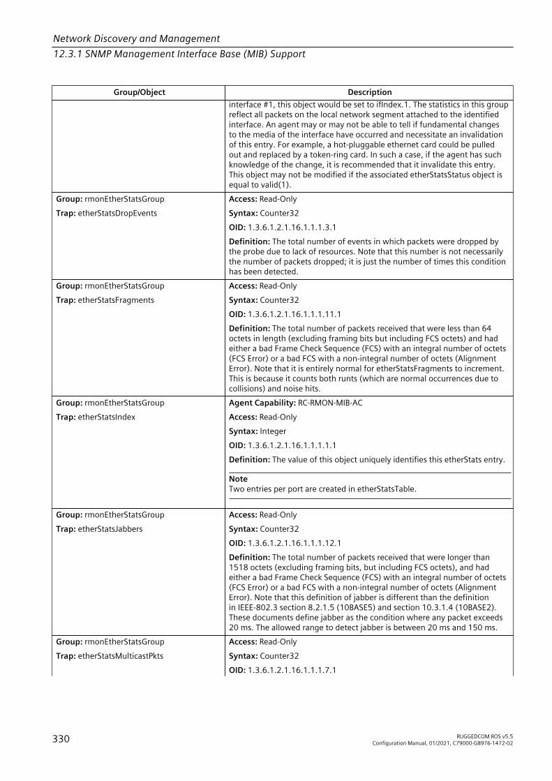
Network Discovery and Management12.3.1 SNMP Management Interface Base (MIB) Support
Group/Object Descriptioninterface #1, this object would be set to ifIndex.1. The statistics in this groupreflect all packets on the local network segment attached to the identifiedinterface. An agent may or may not be able to tell if fundamental changesto the media of the interface have occurred and necessitate an invalidationof this entry. For example, a hot-pluggable ethernet card could be pulledout and replaced by a token-ring card. In such a case, if the agent has suchknowledge of the change, it is recommended that it invalidate this entry.This object may not be modified if the associated etherStatsStatus object isequal to valid(1).
Group: rmonEtherStatsGroupTrap: etherStatsDropEvents
Access: Read-OnlySyntax: Counter32OID: 1.3.6.1.2.1.16.1.1.1.3.1Definition: The total number of events in which packets were dropped bythe probe due to lack of resources. Note that this number is not necessarilythe number of packets dropped; it is just the number of times this conditionhas been detected.
Group: rmonEtherStatsGroupTrap: etherStatsFragments
Access: Read-OnlySyntax: Counter32OID: 1.3.6.1.2.1.16.1.1.1.11.1Definition: The total number of packets received that were less than 64octets in length (excluding framing bits but including FCS octets) and hadeither a bad Frame Check Sequence (FCS) with an integral number of octets(FCS Error) or a bad FCS with a non-integral number of octets (AlignmentError). Note that it is entirely normal for etherStatsFragments to increment.This is because it counts both runts (which are normal occurrences due tocollisions) and noise hits.
Group: rmonEtherStatsGroupTrap: etherStatsIndex
Agent Capability: RC-RMON-MIB-ACAccess: Read-OnlySyntax: IntegerOID: 1.3.6.1.2.1.16.1.1.1.1.1Definition: The value of this object uniquely identifies this etherStats entry.
NoteTwo entries per port are created in etherStatsTable.
Group: rmonEtherStatsGroupTrap: etherStatsJabbers
Access: Read-OnlySyntax: Counter32OID: 1.3.6.1.2.1.16.1.1.1.12.1Definition: The total number of packets received that were longer than1518 octets (excluding framing bits, but including FCS octets), and hadeither a bad Frame Check Sequence (FCS) with an integral number of octets(FCS Error) or a bad FCS with a non-integral number of octets (AlignmentError). Note that this definition of jabber is different than the definitionin IEEE-802.3 section 8.2.1.5 (10BASE5) and section 10.3.1.4 (10BASE2).These documents define jabber as the condition where any packet exceeds20 ms. The allowed range to detect jabber is between 20 ms and 150 ms.
Group: rmonEtherStatsGroupTrap: etherStatsMulticastPkts
Access: Read-OnlySyntax: Counter32OID: 1.3.6.1.2.1.16.1.1.1.7.1
330 RUGGEDCOM ROS v5.5Configuration Manual, 01/2021, C79000-G8976-1472-02

Network Discovery and Management12.3.1 SNMP Management Interface Base (MIB) Support
Group/Object DescriptionDefinition: The total number of good packets received that were directed toa multicast address. Note that this number does not include packets directedto the broadcast address.
Group: rmonEtherStatsGroupTrap: etherStatsOctets
Access: Read-OnlySyntax: Counter32OID: 1.3.6.1.2.1.16.1.1.1.4.1Definition: The total number of octets of data (including those in badpackets) received on the network (excluding framing bits but including FCSoctets). This object can be used as a reasonable estimate of 10-Megabitethernet utilization. If greater precision is desired, the etherStatsPkts andetherStatsOctets objects should be sampled before and after a commoninterval. The differences in the sampled values are Pkts and Octets,respectively, and the number of seconds in the interval is Interval. Thesevalues are used to calculate the Utilization as follows:
Pkts * (9.6 + 6.4) + (Octets * .8)Utilization = -------------------------------------Interval * 10,000
The result of this equation is the value Utilization which is the percentutilization of the ethernet segment on a scale of 0 to 100 percent.
Group: rmonEtherStatsGroupTrap: etherStatsOversizePkts
Access: Read-OnlySyntax: Counter32OID: 1.3.6.1.2.1.16.1.1.1.10.1Definition: The total number of packets received that were longer than1518 octets (excluding framing bits, but including FCS octets) and wereotherwise well formed.
Group: rmonEtherStatsGroupTrap: etherStatsOwner
Agent Capability: RC-RMON-MIB-ACAccess: Read-CreateSyntax: StringOID: 1.3.6.1.2.1.16.1.1.1.20.1Definition: The entity that configured this entry and is therefore using theresources assigned to it.Definition: The value of this entry is always set to 'Monitor' and_x000D_may not be modified.
Group: rmonEtherStatsGroupTrap: etherStatsPkts
Access: Read-OnlySyntax: Counter32OID: 1.3.6.1.2.1.16.1.1.1.5.1Definition: The total number of packets (including bad packets, broadcastpackets, and multicast packets) received.
Group: rmonEtherStatsGroupTrap: etherStatsPkts1024to1518Octets
Access: Read-OnlySyntax: Counter32OID: 1.3.6.1.2.1.16.1.1.1.19.1Definition: The total number of packets (including bad packets) receivedthat were between 1024 and 1518 octets in length inclusive (excludingframing bits but including FCS octets).
Group: rmonEtherStatsGroupTrap: etherStatsPkts128to255Octets
Access: Read-OnlySyntax: Counter32
RUGGEDCOM ROS v5.5Configuration Manual, 01/2021, C79000-G8976-1472-02 331

Network Discovery and Management12.3.1 SNMP Management Interface Base (MIB) Support
Group/Object DescriptionOID: 1.3.6.1.2.1.16.1.1.1.16.1Definition: The total number of packets (including bad packets) receivedthat were between 128 and 255 octets in length inclusive (excludingframing bits but including FCS octets).
Group: rmonEtherStatsGroupTrap: etherStatsPkts256to511Octets
Access: Read-OnlySyntax: Counter32OID: 1.3.6.1.2.1.16.1.1.1.17.1Definition: The total number of packets (including bad packets) receivedthat were between 256 and 511 octets in length inclusive (excludingframing bits but including FCS octets).
Group: rmonEtherStatsGroupTrap: etherStatsPkts512to1023Octets
Access: Read-OnlySyntax: Counter32OID: 1.3.6.1.2.1.16.1.1.1.18.1Definition: The total number of packets (including bad packets) receivedthat were between 512 and 1023 octets in length inclusive (excludingframing bits but including FCS octets).
Group: rmonEtherStatsGroupTrap: etherStatsPkts64Octets
Access: Read-OnlySyntax: Counter32OID: 1.3.6.1.2.1.16.1.1.1.14.1Definition: The total number of packets (including bad packets) receivedthat were 64 octets in length (excluding framing bits but including FCSoctets).
Group: rmonEtherStatsGroupTrap: etherStatsPkts65to127Octets
Access: Read-OnlySyntax: Counter32OID: 1.3.6.1.2.1.16.1.1.1.15.1Definition: The total number of packets (including bad packets) receivedthat were between 65 and 127 octets in length inclusive (excluding framingbits but including FCS octets).
Group: rmonEtherStatsGroupTrap: etherStatsStatus
Agent Capability: RC-RMON-MIB-ACAccess: Read-CreateSyntax: IntegerOID: 1.3.6.1.2.1.16.1.1.1.21.1Definition: The status of this etherStats entry.
NoteOne entry per port is created in etherStatsTable upon initialization up. Theseentries may not be modified or deleted. No new entries can be created.Therefore, historyControlStatus is always set to 'valid(1)'.
Group: rmonEtherStatsGroupTrap: etherStatsUndersizePkts
Access: Read-OnlySyntax: Counter32OID: 1.3.6.1.2.1.16.1.1.1.9.1Definition: The total number of packets received that were less than 64octets long (excluding framing bits, but including FCS octets) and wereotherwise well formed.
Group: rmonEventGroupTrap: eventCommunity
Agent Capability: RC-RMON-MIB-ACAccess: Read-Create
332 RUGGEDCOM ROS v5.5Configuration Manual, 01/2021, C79000-G8976-1472-02

Network Discovery and Management12.3.1 SNMP Management Interface Base (MIB) Support
Group/Object DescriptionSyntax: StringOID: 1.3.6.1.2.1.16.9.1.1.4.1Definition: If an SNMP trap is to be sent, it will be sent to the SNMPcommunity specified by this octet string.Definition: The string of up to 30 characters is supported for this_x000D_object.
Group: rmonEventGroupTrap: eventDescription
Agent Capability: RC-RMON-MIB-ACAccess: Read-CreateSyntax: StringOID: 1.3.6.1.2.1.16.9.1.1.2.1Definition: A comment describing this event entry.
Group: rmonEventGroupTrap: eventIndex
Agent Capability: RC-RMON-MIB-ACAccess: Read-OnlySyntax: IntegerOID: 1.3.6.1.2.1.16.9.1.1.1.1Definition: An index that uniquely identifies an entry in the event table.Each such entry defines one event that is to be generated when theappropriate conditions occur.Definition: An average of one entry per alarmEntry may be created_x000D_in eventTable.
Group: rmonEventGroupTrap: eventLastTimeSent
Agent Capability: RC-RMON-MIB-ACAccess: Read-OnlySyntax: TimeticksOID: 1.3.6.1.2.1.16.9.1.1.5.1Definition: The value of sysUpTime at the time this event entry lastgenerated an event. If this entry has not generated any events, this valuewill be zero.
Group: rmonEventGroupTrap: eventOwner
Agent Capability: RC-RMON-MIB-ACAccess: Read-CreateSyntax: StringOID: 1.3.6.1.2.1.16.9.1.1.6.1Definition: The entity that configured this entry and is therefore using theresources assigned to it. If this object contains a string starting with 'monitor'and has associated entries in the log table, all connected managementstations should retrieve those log entries, as they may have significance toall management stations connected to this device.Definition: A default value of an eventOwner is a 'Monitor' string.
Group: rmonEventGroupTrap: eventStatus
Access: Read-CreateSyntax: IntegerOID: 1.3.6.1.2.1.16.9.1.1.7.1Definition: The status of this event entry. If this object is not equal tovalid(1), all associated log entries shall be deleted by the agent.
Group: rmonEventGroupTrap: eventType
Agent Capability: RC-RMON-MIB-ACAccess: Read-CreateSyntax: Integer
RUGGEDCOM ROS v5.5Configuration Manual, 01/2021, C79000-G8976-1472-02 333

Network Discovery and Management12.3.1 SNMP Management Interface Base (MIB) Support
Group/Object DescriptionOID: 1.3.6.1.2.1.16.9.1.1.3.1Definition: The type of notification that the probe will make about thisevent. In the case of log, an entry is made in the log table for each event.In the case of snmp-trap, an SNMP trap is sent to one or more managementstations.Definition: A default value of an eventType is 'logandtrap(4)'.
Group: rmonHistoryControlGroupTrap: historyControlBucketsGranted
Access: Read-OnlySyntax: IntegerOID: 1.3.6.1.2.1.16.2.1.1.4.1Definition: The number of discrete sampling intervals over which datashall be saved in the part of the media-specific table associated with thishistoryControlEntry. When the associated historyControlBucketsRequestedobject is created or modified, the probe should set this object as closely tothe requested value as is possible for the particular probe implementationand available resources. The probe must not lower this value except as aresult of a modification to the associated historyControlBucketsRequestedobject. There will be times when the actual number of buckets associatedwith this entry is less than the value of this object. In this case, at the endof each sampling interval, a new bucket will be added to the media-specifictable. When the number of buckets reaches the value of this object and anew bucket is to be added to the media-specific table, the oldest bucketassociated with this historyControlEntry shall be deleted by the agent sothat the new bucket can be added. When the value of this object changesto a value less than the current value, entries are deleted from the media-specific table associated with this historyControlEntry. Enough of the oldestof these entries shall be deleted by the agent so that their number remainsless than or equal to the new value of this object. When the value of thisobject changes to a value greater than the current value, the number ofassociated media- specific entries may be allowed to grow.
Group: rmonHistoryControlGroupTrap: historyControlBucketsRequested
Agent Capability: RC-RMON-MIB-ACAccess: Read-CreateSyntax: IntegerOID: 1.3.6.1.2.1.16.2.1.1.3.1Definition: The requested number of discrete time intervals over whichdata is to be saved in the part of the media-specific table associated withthis historyControlEntry. When this object is created or modified, the probeshould set historyControlBucketsGranted as closely to this object as ispossible for the particular probe implementation and available resources.Definition: The value of historyControBucketRequested is restricted_x000D_to 4000.
Group: rmonHistoryControlGroupTrap: historyControlDataSource
Access: Read-CreateSyntax: OIDOID: 1.3.6.1.2.1.16.2.1.1.2.1Definition: This object identifies the source of the data for which historicaldata was collected and placed in a media-specific table on behalf of thishistoryControlEntry. This source can be any interface on this device. In orderto identify a particular interface, this object shall identify the instance ofthe ifIndex object, defined in RFC 2233 [17], for the desired interface. Forexample, if an entry were to receive data from interface #1, this objectwould be set to ifIndex.1. The statistics in this group reflect all packets onthe local network segment attached to the identified interface. An agentmay or may not be able to tell if fundamental changes to the media of the
334 RUGGEDCOM ROS v5.5Configuration Manual, 01/2021, C79000-G8976-1472-02

Network Discovery and Management12.3.1 SNMP Management Interface Base (MIB) Support
Group/Object Descriptioninterface have occurred and necessitate an invalidation of this entry. Forexample, a hot-pluggable ethernet card could be pulled out and replacedby a token-ring card. In such a case, if the agent has such knowledge of thechange, it is recommended that it invalidate this entry. This object may notbe modified if the associated historyControlStatus object is equal to valid(1).
Group: rmonHistoryControlGroupTrap: historyControlIndex
Agent Capability: RC-RMON-MIB-ACAccess: Read-OnlySyntax: IntegerOID: 1.3.6.1.2.1.16.2.1.1.1.1Definition: An index that uniquely identifies an entry in the historyControltable. Each such entry defines a set of samples at a particular interval for aninterface on the device.Definition: An average of four entries per ethernet port can be created_x000D_ in historyControlTable.
Group: rmonHistoryControlGroupTrap: historyControlInterval
Access: Read-CreateSyntax: IntegerOID: 1.3.6.1.2.1.16.2.1.1.5.1Definition: The interval in seconds over which the data is sampled foreach bucket in the part of the media-specific table associated with thishistoryControlEntry. This interval can be set to any number of secondsbetween 1 and 3600 (1 hour). Because the counters in a bucket mayoverflow at their maximum value with no indication, a prudent managerwill take into account the possibility of overflow in any of the associatedcounters. It is important to consider the minimum time in which any countercould overflow on a particular media type and set the historyControlIntervalobject to a value less than this interval. This is typically most important forthe 'octets' counter in any media-specific table. For example, on an Ethernetnetwork, the etherHistoryOctets counter could overflow in about one hourat the Ethernet's maximum utilization. This object may not be modified if theassociated historyControlStatus object is equal to valid(1).
Group: rmonHistoryControlGroupTrap: historyControlOwner
Agent Capability: RC-RMON-MIB-ACAccess: Read-CreateSyntax: StringOID: 1.3.6.1.2.1.16.2.1.1.6.1Definition: The entity that configured this entry and is therefore using theresources assigned to it.Definition: A default value of a historyControlOwner is a _x000D_'Monitor'string.
Group: rmonHistoryControlGroupTrap: historyControlStatus
Access: Read-CreateSyntax: IntegerOID: 1.3.6.1.2.1.16.2.1.1.7.1Definition: The status of this historyControl entry. Each instance of themedia-specific table associated with this historyControlEntry will be deletedby the agent if this historyControlEntry is not equal to valid(1).
Group: rmonEventGroupTrap: logDescription
Access: Read-OnlySyntax: StringOID: 1.3.6.1.2.1.16.9.2.1.4.1
RUGGEDCOM ROS v5.5Configuration Manual, 01/2021, C79000-G8976-1472-02 335

Network Discovery and Management12.3.1 SNMP Management Interface Base (MIB) Support
Group/Object DescriptionDefinition: An implementation dependent description of the event thatactivated this log entry.
Group: rmonEventGroupTrap: logEventIndex
Access: Read-OnlySyntax: IntegerOID: 1.3.6.1.2.1.16.9.2.1.1.1Definition: The event entry that generated this log entry. The log identifiedby a particular value of this index is associated with the same eventEntry asidentified by the same value of eventIndex.
Group: rmonEventGroupTrap: logIndex
Agent Capability: RC-RMON-MIB-ACAccess: Read-OnlySyntax: IntegerOID: 1.3.6.1.2.1.16.9.2.1.2.1Definition: An index that uniquely identifies an entry in the log tableamongst those generated by the same eventEntries. These indexes areassigned beginning with 1 and increase by one with each new log entry.The association between values of logIndex and logEntries is fixed forthe lifetime of each logEntry. The agent may choose to delete the oldestinstances of logEntry as required because of lack of memory. It is animplementation-specific matter as to when this deletion may occur.
NoteFor each eventEntry a hundred of entries in logTable may_x000D_ becreated. The value of thi object will increase for each_x000D_ new loggenerated for coresponding event. When value of_x000D_ this objectbecomes greater than 100, oldest entries will _x000D_be deleted.
Group: rmonEventGroupTrap: logTime
Access: Read-OnlySyntax: TimeticksOID: 1.3.6.1.2.1.16.9.2.1.3.1Definition: The value of sysUpTime when this log entry was created.
RS-232-MIB
Group/Object DescriptionGroup: rs232AsyncGroupTrap: rs232AsyncPortAutobaud
Access: Read-WriteSyntax: IntegerOID: 1.3.6.1.2.1.10.33.3.1.3.101Definition: A control for the port's ability to automatically sense inputspeed. When rs232PortAutoBaud is 'enabled', a port may autobaud to valuesdifferent from the set values for speed, parity, and character size. As a resulta network management system may temporarily observe values differentfrom what was previously set.
Group: rs232AsyncGroupTrap: rs232AsyncPortBits
Access: Read-WriteSyntax: IntegerOID: 1.3.6.1.2.1.10.33.2.1.5.1.4Definition: The port's number of bits in a character.
Group: rs232AsyncGroupTrap: rs232AsyncPortFramingErrs
Access: Read-OnlySyntax: Counter32
336 RUGGEDCOM ROS v5.5Configuration Manual, 01/2021, C79000-G8976-1472-02

Network Discovery and Management12.3.1 SNMP Management Interface Base (MIB) Support
Group/Object DescriptionOID: 1.3.6.1.2.1.10.33.2.1.5.1.2Definition: Total number of characters with a framing error, input from theport since system re-initialization and while the port state was 'up' or 'test'.
Group: rs232AsyncGroupTrap: rs232AsyncPortIndex
Access: Read-OnlySyntax: IntegerOID: 1.3.6.1.2.1.10.33.2.1.5.1.1Definition: A unique value for each port. Its value is the same asrs232PortIndex for the port.
Group: rs232AsyncGroupTrap: rs232AsyncPortOverrunErrs
Access: Read-OnlySyntax: Counter32OID: 1.3.6.1.2.1.10.33.2.1.5.1.3Definition: Total number of characters with an overrun error, input from theport since system re-initialization and while the port state was 'up' or 'test'.
Group: rs232AsyncGroupTrap: rs232AsyncPortParity
Access: Read-WriteSyntax: IntegerOID: 1.3.6.1.2.1.10.33.1.0Definition: The port's sense of a character parity bit.
Group: rs232AsyncGroupTrap: rs232AsyncPortParityErrs
Access: Read-OnlySyntax: Counter32OID: 1.3.6.1.2.1.10.33.2.1.6.1.4Definition: Total number of characters with a parity error, input from theport since system re-initialization and while the port state was 'up' or 'test'.
Group: rs232AsyncGroupTrap: rs232AsyncPortStopBits
Access: Read-WriteSyntax: IntegerOID: 1.3.6.1.2.1.10.33.2.1.6.1.2Definition: The port's number of stop bits.
Group: rs232GroupTrap: rs232InSigChanges
Access: Read-OnlySyntax: Counter32OID: 1.3.6.1.2.1.10.33.2.1.6.1.1Definition: The number of times the signal has changed from 'on' to 'off' orfrom 'off' to 'on'.
Group: rs232GroupTrap: rs232InSigName
Access: Read-OnlySyntax: IntegerOID: 1.3.6.1.2.1.10.33.2.1.6.1.3Definition:>Identification of a hardware signal, as follows:• rts: Request to Send• cts: Clear to Send• dsr: Data Set Ready• dtr: Data Terminal Ready• ri: Ring Indicator• dcd: Received Line Signal Detector• sq: Signal Quality Detector• srs: Data Signaling Rate Selector• srts: Secondary Request to Send
RUGGEDCOM ROS v5.5Configuration Manual, 01/2021, C79000-G8976-1472-02 337

Network Discovery and Management12.3.1 SNMP Management Interface Base (MIB) Support
Group/Object Description• scts: Secondary Clear to Send• sdcd: Secondary Received Line Signal Detector
Group: rs232GroupTrap: rs232InSigPortIndex
Access: Read-OnlySyntax: IntegerOID: 1.3.6.1.2.1.10.33.2.1.1.101Definition: The value of rs232PortIndex for the port to which this entrybelongs.
Group: rs232GroupTrap: rs232InSigState
Access: Read-OnlySyntax: IntegerOID: 1.3.6.1.2.1.10.33.2.1.7.101Definition: The current signal state.
Group: rs232GroupTrap: rs232Number
Access: Read-OnlySyntax: IntegerOID: 1.3.6.1.2.1.10.33.2.1.3.101Definition: The number of ports (regardless of their current state) in theRS-232-like general port table.
Group: rs232GroupTrap: rs232OutSigChanges
Access: Read-OnlySyntax: IntegerOID: 1.3.6.1.2.1.10.33.2.1.5.101Definition: The number of times the signal has changed from 'on' to 'off' orfrom 'off' to 'on'.
Group: rs232GroupTrap: rs232OutSigName
Access: Read-OnlySyntax: IntegerOID: 1.3.6.1.2.1.10.33.2.1.7.101Definition: Identification of a hardware signal, as follows:• rts: Request to Send• cts: Clear to Send• dsr: Data Set Ready• dtr: Data Terminal Ready• ri: Ring Indicator• dcd: Received Line Signal Detector• sq: Signal Quality Detector• srs: Data Signaling Rate Selector• srts: Secondary Request to Send• scts: Secondary Clear to Send• sdcd: Secondary Received Line Signal Detector
Group: rs232GroupTrap: rs232OutSigPortIndex
Access: Read-OnlySyntax: IntegerOID: 1.3.6.1.2.1.10.33.2.1.4.101Definition: The value of rs232PortIndex for the port to which this entrybelongs.
Group: rs232GroupTrap: rs232OutSigState
Access: Read-OnlySyntax: IntegerOID: 1.3.6.1.2.1.10.33.2.1.5.101
338 RUGGEDCOM ROS v5.5Configuration Manual, 01/2021, C79000-G8976-1472-02
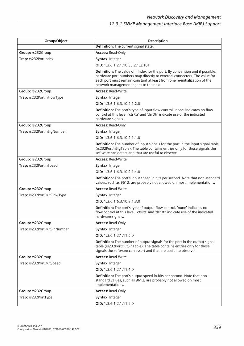
Network Discovery and Management12.3.1 SNMP Management Interface Base (MIB) Support
Group/Object DescriptionDefinition: The current signal state.
Group: rs232GroupTrap: rs232PortIndex
Access: Read-OnlySyntax: IntegerOID: 1.3.6.1.2.1.10.33.2.1.2.101Definition: The value of ifIndex for the port. By convention and if possible,hardware port numbers map directly to external connectors. The value foreach port must remain constant at least from one re-initialization of thenetwork management agent to the next.
Group: rs232GroupTrap: rs232PortInFlowType
Access: Read-WriteSyntax: IntegerOID: 1.3.6.1.6.3.10.2.1.2.0Definition: The port's type of input flow control. 'none' indicates no flowcontrol at this level. 'ctsRts' and 'dsrDtr' indicate use of the indicatedhardware signals.
Group: rs232GroupTrap: rs232PortInSigNumber
Access: Read-OnlySyntax: IntegerOID: 1.3.6.1.6.3.10.2.1.1.0Definition: The number of input signals for the port in the input signal table(rs232PortInSigTable). The table contains entries only for those signals thesoftware can detect and that are useful to observe.
Group: rs232GroupTrap: rs232PortInSpeed
Access: Read-WriteSyntax: IntegerOID: 1.3.6.1.6.3.10.2.1.4.0Definition: The port's input speed in bits per second. Note that non-standardvalues, such as 9612, are probably not allowed on most implementations.
Group: rs232GroupTrap: rs232PortOutFlowType
Access: Read-WriteSyntax: IntegerOID: 1.3.6.1.6.3.10.2.1.3.0Definition: The port's type of output flow control. 'none' indicates noflow control at this level. 'ctsRts' and 'dsrDtr' indicate use of the indicatedhardware signals.
Group: rs232GroupTrap: rs232PortOutSigNumber
Access: Read-OnlySyntax: IntegerOID: 1.3.6.1.2.1.11.6.0Definition: The number of output signals for the port in the output signaltable (rs232PortOutSigTable). The table contains entries only for thosesignals the software can assert and that are useful to observe.
Group: rs232GroupTrap: rs232PortOutSpeed
Access: Read-WriteSyntax: IntegerOID: 1.3.6.1.2.1.11.4.0Definition: The port's output speed in bits per second. Note that non-standard values, such as 9612, are probably not allowed on mostimplementations.
Group: rs232GroupTrap: rs232PortType
Access: Read-OnlySyntax: IntegerOID: 1.3.6.1.2.1.11.5.0
RUGGEDCOM ROS v5.5Configuration Manual, 01/2021, C79000-G8976-1472-02 339

Network Discovery and Management12.3.1 SNMP Management Interface Base (MIB) Support
Group/Object DescriptionDefinition: The port's hardware type.
RSTP-MIB
Group/Object DescriptionGroup: rstpPortGroupTrap: dot1dStpPortAdminEdgePort
Access: Read-WriteTruthValueOID: .1.3.6.1.2.1.17.2.19.1.2Definition: The administrative value of the Edge Port parameter. A valueof true(1) indicates that this port should be assumed as an edge-port, anda value of false(2) indicates that this port should be assumed as a non-edge-port. Setting this object will also cause the corresponding instance ofdot1dStpPortOperEdgePort to change to the same value. Note that evenwhen this object's value is true, the value of the corresponding instanceof dot1dStpPortOperEdgePort can be false if a BPDU has been received.The value of this object MUST be retained across reinitializations of themanagement system.
Group: rstpPortGroupTrap: dot1dStpPortAdminPathCost
Access: Read-WriteSyntax: IntegerOID: .1.3.6.1.2.1.17.2.19.1.6Definition: The administratively assigned value for the contribution of thisport to the path cost of paths toward the spanning tree root. Writing a valueof '0' assigns the automatically calculated default Path Cost value to the port.If the default Path Cost is being used, this object returns '0' when read. Thiscomplements the object dot1dStpPortPathCost or dot1dStpPortPathCost32,which returns the operational value of the path cost. The value of this objectMUST be retained across reinitializations of the management system.
Group: rstpPortGroupTrap: dot1dStpPortAdminPointToPoint
Access: Read-WriteSyntax: IntegerOID: .1.3.6.1.2.1.17.2.19.1.4Definition: The administrative point-to-point status of the LAN segmentattached to this port, using the enumeration values of the IEEE 802.1wclause. A value of forceTrue(0) indicates that this port should always betreated as if it is connected to a point-to-point link. A value of forceFalse(1)indicates that this port should be treated as having a shared mediaconnection. A value of auto(2) indicates that this port is considered tohave a point-to-point link if it is an Aggregator and all of its members areaggregatable, or if the MAC entity is configured for full duplex operation,either through auto-negotiation or by management means. Manipulatingthis object changes the underlying adminPortToPortMAC. The value of thisobject MUST be retained across reinitializations of the management system.
Group: rstpPortGroupTrap: dot1dStpPortOperEdgePort
Access: Read-OnlyTruthValueOID: .1.3.6.1.2.1.17.2.19.1.3Definition: The operational value of the Edge Port parameter. Theobject is initialized to the value of the corresponding instance ofdot1dStpPortAdminEdgePort. When the corresponding instance ofdot1dStpPortAdminEdgePort is set, this object will be changed as well. Thisobject will also be changed to false on reception of a BPDU.
Group: rstpPortGroup Access: Read-Only
340 RUGGEDCOM ROS v5.5Configuration Manual, 01/2021, C79000-G8976-1472-02

Network Discovery and Management12.3.1 SNMP Management Interface Base (MIB) Support
Group/Object DescriptionTrap: dot1dStpPortOperPointToPoint TruthValue
OID: .1.3.6.1.2.1.17.2.19.1.5Definition: The operational point-to-point status of the LAN segmentattached to this port. It indicates whether a port is considered to have apoint-to-point connection. If adminPointToPointMAC is set to auto(2), thenthe value of operPointToPointMAC is determined in accordance with thespecific procedures defined for the MAC entity concerned, as defined inIEEE 802.1w, clause 6.5. The value is determined dynamically; that is, it isre-evaluated whenever the value of adminPointToPointMAC changes, andwhenever the specific procedures defined for the MAC entity evaluate achange in its point-to-point status.
Group: rstpBridgeGroupTrap: dot1dStpTxHoldCount
Agent Capability: RC-RSTP-MIB-ACAccess: Read-WriteSyntax: IntegerOID: .1.3.6.1.2.1.17.2.17.0Definition: The value used by the Port Transmit state machine to limit themaximum transmission rate. The value of this object MUST be retainedacross reinitializations of the management system.
NoteRFC specified range is 1..10. Implementation uses 0...100. The value 0 isused for Unlimited and ROS range is actually 3..100.
Group: rstpBridgeGroupTrap: dot1dStpVersion
Access: Read-WriteSyntax: IntegerOID: .1.3.6.1.2.1.17.2.16.0Definition: The version of Spanning Tree Protocol the bridge is currentlyrunning. The value 'stpCompatible(0)' indicates the Spanning Tree Protocolspecified in IEEE 802.1D-1998 and 'rstp(2)' indicates the Rapid Spanning TreeProtocol specified in IEEE 802.1w and clause 17 of 802.1D-2004. The valuesare directly from the IEEE standard. New values may be defined as futureversions of the protocol become available. The value of this object MUST beretained across reinitializations of the management system.
SNMP-FRAMEWORK-MIB
Group/Object DescriptionGroup: snmpEngineGroupTrap: snmpEngineBoots
Access: Read-OnlySyntax: IntegerOID: 1.3.6.1.2.1.11.31.0Definition: The number of times that the SNMP engine has (re-)initializeditself since snmpEngineID was last configured.
Group: snmpEngineGroupTrap: snmpEngineID
Access: Read-OnlySyntax: Hex-StringOID: 1.3.6.1.2.1.1.4.0Definition: An SNMP engine's administratively-unique identifier. Thisinformation SHOULD be stored in non-volatile storage so that it remainsconstant across re-initializations of the SNMP engine.
Group: snmpEngineGroup Access: Read-Only
RUGGEDCOM ROS v5.5Configuration Manual, 01/2021, C79000-G8976-1472-02 341

Network Discovery and Management12.3.1 SNMP Management Interface Base (MIB) Support
Group/Object DescriptionTrap: snmpEngineMaxMessageSize Syntax: Integer
OID: 1.3.6.1.2.1.1.1.0Definition: The maximum length in octets of an SNMP message which thisSNMP engine can send or receive and process, determined as the minimumof the maximum message size values supported among all of the transportsavailable to and supported by the engine.
Group: snmpEngineGroupTrap: snmpEngineTime
Access: Read-OnlySyntax: IntegerOID: 1.3.6.1.2.1.1.6.0Definition: The number of seconds since the value of the snmpEngineBootsobject last changed. When incrementing this object's value would causeit to exceed its maximum, snmpEngineBoots is incremented as if a re-initialization had occurred, and this object's value consequently reverts tozero.
SNMP-USER-BASED-SM-MIB
Group/Object DescriptionGroup: usmMIBBasicGroupTrap: usmStatsDecryptionErrors
Access: Read-OnlySyntax: Counter32OID: 1.3.6.1.6.3.15.1.2.2.1.9Definition: The total number of packets received by the SNMP engine whichwere dropped because they could not be decrypted.
Group: usmMIBBasicGroupTrap: usmStatsNotInTimeWindows
Access: Read-OnlySyntax: Counter32OID:1.3.6.1.6.3.15.1.2.2.1.8.11.128.0.58.156.3.0.10.220.0.128.72.4.97.112.118.51Definition: The total number of packets received by the SNMP engine whichwere dropped because they appeared outside of the authoritative SNMPengine's window.
Group: usmMIBBasicGroupTrap: usmStatsUnknownEngineIDs
Access: Read-OnlySyntax: Counter32OID: 1.3.6.1.6.3.15.1.2.2.1.11Definition: The total number of packets received by the SNMP engine whichwere dropped because they referenced an snmpEngineID that was notknown to the SNMP engine.
Group: usmMIBBasicGroupTrap: usmStatsUnknownUserNames
Access: Read-OnlySyntax: Counter32OID: 1.3.6.1.6.3.15.1.2.2.1.3Definition: The total number of packets received by the SNMP engine whichwere dropped because they referenced a user that was not known to theSNMP engine.
Group: usmMIBBasicGroupTrap: usmStatsUnsupportedSecLevels
Access: Read-OnlySyntax: Counter32OID: 1.3.6.1.6.3.15.1.2.1.0
342 RUGGEDCOM ROS v5.5Configuration Manual, 01/2021, C79000-G8976-1472-02

Network Discovery and Management12.3.1 SNMP Management Interface Base (MIB) Support
Group/Object DescriptionDefinition: The total number of packets received by the SNMP engine whichwere dropped because they requested a securityLevel that was unknown tothe SNMP engine or otherwise unavailable.
Group: usmMIBBasicGroupTrap: usmStatsWrongDigests
Access: Read-OnlySyntax: Counter32OID: 1.3.6.1.6.3.15.1.2.2.1.13Definition: The total number of packets received by the SNMP engine whichwere dropped because they didn't contain the expected digest value.
Group: usmMIBBasicGroupTrap: usmUserAuthKeyChange
Access: Read-CreateSyntax: StringOID: 1.3.6.1.6.3.15.1.2.2.1.12Definition: An object, which when modified, causes the secretauthentication key used for messages sent on behalf of this user to/fromthe SNMP engine identified by usmUserEngineID, to be modified via a one-way function. The associated protocol is the usmUserAuthProtocol. Theassociated secret key is the user's secret authentication key (authKey).The associated hash algorithm is the algorithm used by the user'susmUserAuthProtocol. When creating a new user, it is an 'inconsistentName'error for a set operation to refer to this object unless it is previously orconcurrently initialized through a set operation on the correspondinginstance of usmUserCloneFrom. When the value of the correspondingusmUserAuthProtocol is usmNoAuthProtocol, then a set is successful, buteffectively is a no-op. When this object is read, the zero-length (empty)string is returned. The recommended way to do a key change is as follows:• 1) GET(usmUserSpinLock.0) and save in sValue.• 2) generate the keyChange value based on the old (existing) secret key
and the new secret key, let us call this kcValue.If you do the key change on behalf of another user:• 3) SET(usmUserSpinLock.0=sValue, usmUserAuthKeyChange=kcValue
usmUserPublic=randomValue)If you do the key change for yourself:• 4) SET(usmUserSpinLock.0=sValue,
usmUserOwnAuthKeyChange=kcValue usmUserPublic=randomValue)If you get a response with error-status of noError, then the SET succeededand the new key is active. If you do not get a response, then you can issue aGET(usmUserPublic) and check if the value is equal to the randomValue youdid send in the SET. If so, then the key change succeeded and the new key isactive (probably the response got lost). If not, then the SET request probablynever reached the target and so you can start over with the procedureabove.
Group: usmMIBBasicGroupTrap: usmUserAuthProtocol
Access: Read-CreateSyntax: OIDOID: 1.3.6.1.6.3.16.1.4.1.4.8.71.112.114.105.118.97.116.101.0.2.1Definition: An indication of whether messages sent on behalf of this user to/from the SNMP engine identified by usmUserEngineID, can be authenticated,and if so, the type of authentication protocol which is used. An instanceof this object is created concurrently with the creation of any other objectinstance for the same user (i.e., as part of the processing of the set operationwhich creates the first object instance in the same conceptual row). Ifan initial set operation (i.e. at row creation time) tries to set a value foran unknown or unsupported protocol, then a 'wrongValue' error must
RUGGEDCOM ROS v5.5Configuration Manual, 01/2021, C79000-G8976-1472-02 343

Network Discovery and Management12.3.1 SNMP Management Interface Base (MIB) Support
Group/Object Descriptionbe returned. The value will be overwritten/set when a set operation isperformed on the corresponding instance of usmUserCloneFrom. Onceinstantiated, the value of such an instance of this object can only bechanged via a set operation to the value of the usmNoAuthProtocol. If aset operation tries to change the value of an existing instance of this objectto any value other than usmNoAuthProtocol, then an 'inconsistentValue'error must be returned. If a set operation tries to set the value to theusmNoAuthProtocol while the usmUserPrivProtocol value in the samerow is not equal to usmNoPrivProtocol, then an 'inconsistentValue'error must be returned. That means that an SNMP command generatorapplication must first ensure that the usmUserPrivProtocol is set to theusmNoPrivProtocol value before it can set the usmUserAuthProtocol value tousmNoAuthProtocol.
Group: usmMIBBasicGroupTrap: usmUserCloneFrom
Access: Read-CreateSyntax: OIDOID: 1.3.6.1.6.3.16.1.4.1.7.8.71.112.114.105.118.97.116.101.0.2.1Definition: A pointer to another conceptual row in this usmUserTable. Theuser in this other conceptual row is called the clone-from user. When a newuser is created (i.e., a new conceptual row is instantiated in this table), theprivacy and authentication parameters of the new user must be cloned fromits clone-from user. These parameters are:• - authentication protocol (usmUserAuthProtocol)• - privacy protocol (usmUserPrivProtocol)They will be copied regardless of what the current value is. Cloning alsocauses the initial values of the secret authentication key (authKey) andthe secret encryption key (privKey) of the new user to be set to the samevalues as the corresponding secrets of the clone-from user to allow theKeyChange process to occur as required during user creation. The firsttime an instance of this object is set by a management operation (eitherat or after its instantiation), the cloning process is invoked. Subsequentwrites are successful but invoke no action to be taken by the receiver. Thecloning process fails with an 'inconsistentName' error if the conceptualrow representing the clone-from user does not exist or is not in an activestate when the cloning process is invoked. When this object is read, theZeroDotZero OID is returned.
Group: usmMIBBasicGroupTrap: usmUserOwnAuthKeyChange
Access: Read-CreateSyntax: StringOID: 1.3.6.1.6.3.16.1.4.1.5.8.71.112.114.105.118.97.116.101.0.2.1Definition:Behaves exactly as usmUserAuthKeyChange, with one notabledifference: in order for the set operation to succeed, the usmUserNameof the operation requester must match the usmUserName that indexesthe row which is targeted by this operation. In addition, the USM securitymodel must be used for this operation. The idea here is that access to thiscolumn can be public, since it will only allow a user to change his own secretauthentication key (authKey). Note that this can only be done once the rowis active. When a set is received and the usmUserName of the requester isnot the same as the umsUserName that indexes the row which is targetedby this operation, then a 'noAccess' error must be returned. When a set isreceived and the security model in use is not USM, then a 'noAccess' errormust be returned.
Group: usmMIBBasicGroupTrap: usmUserOwnPrivKeyChange
Access: Read-CreateSyntax: StringOID: 1.3.6.1.6.3.16.1.4.1.9.8.71.112.114.105.118.97.116.101.0.2.1
344 RUGGEDCOM ROS v5.5Configuration Manual, 01/2021, C79000-G8976-1472-02

Network Discovery and Management12.3.1 SNMP Management Interface Base (MIB) Support
Group/Object DescriptionDefinition:Behaves exactly as usmUserPrivKeyChange, with one notabledifference: in order for the Set operation to succeed, the usmUserName ofthe operation requester must match the usmUserName that indexes therow which is targeted by this operation. In addition, the USM security modelmust be used for this operation. The idea here is that access to this columncan be public, since it will only allow a user to change his own secret privacykey (privKey). Note that this can only be done once the row is active. When aset is received and the usmUserName of the requester is not the same as theumsUserName that indexes the row which is targeted by this operation, thena 'noAccess' error must be returned. When a set is received and the securitymodel in use is not USM, then a 'noAccess' error must be returned.
Group: usmMIBBasicGroupTrap: usmUserPrivKeyChange
Access: Read-CreateSyntax: StringOID: 1.3.6.1.6.3.16.1.4.1.8.8.71.112.114.105.118.97.116.101.0.2.1Definition: An object, which when modified, causes the secret encryptionkey used for messages sent on behalf of this user to/from the SNMP engineidentified by usmUserEngineID, to be modified via a one-way function. Theassociated protocol is the usmUserPrivProtocol. The associated secret keyis the user's secret privacy key (privKey). The associated hash algorithm isthe algorithm used by the user's usmUserAuthProtocol. When creating anew user, it is an 'inconsistentName' error for a set operation to refer tothis object unless it is previously or concurrently initialized through a setoperation on the corresponding instance of usmUserCloneFrom. Whenthe value of the corresponding usmUserPrivProtocol is usmNoPrivProtocol,then a set is successful, but effectively is a no-op. When this object is read,the zero-length (empty) string is returned. See the description clause ofusmUserAuthKeyChange for a recommended procedure to do a key change.
Group: usmMIBBasicGroupTrap: usmUserPrivProtocol
Access: Read-CreateSyntax: OIDOID: 1.3.6.1.6.3.16.1.4.1.6.8.71.112.114.105.118.97.116.101.0.2.1Definition: An indication of whether messages sent on behalf of this userto/from the SNMP engine identified by usmUserEngineID, can be protectedfrom disclosure, and if so, the type of privacy protocol which is used. Aninstance of this object is created concurrently with the creation of anyother object instance for the same user (i.e., as part of the processingof the set operation which creates the first object instance in the sameconceptual row). If an initial set operation (i.e. at row creation time)tries to set a value for an unknown or unsupported protocol, then a'wrongValue' error must be returned. The value will be overwritten/setwhen a set operation is performed on the corresponding instance ofusmUserCloneFrom. Once instantiated, the value of such an instance ofthis object can only be changed via a set operation to the value of theusmNoPrivProtocol. If a set operation tries to change the value of an existinginstance of this object to any value other than usmNoPrivProtocol, then an'inconsistentValue' error must be returned. Note that if any privacy protocolis used, then you must also use an authentication protocol. In other words,if usmUserPrivProtocol is set to anything else than usmNoPrivProtocol, thenthe corresponding instance of usmUserAuthProtocol cannot have a valueof usmNoAuthProtocol. If it does, then an 'inconsistentValue' error must bereturned.
Group: usmMIBBasicGroupTrap: usmUserPublic
Access: Read-CreateSyntax: StringOID: 1.3.6.1.6.3.16.1.1.1.1
RUGGEDCOM ROS v5.5Configuration Manual, 01/2021, C79000-G8976-1472-02 345

Network Discovery and Management12.3.1 SNMP Management Interface Base (MIB) Support
Group/Object DescriptionDefinition: A publicly-readable value which can be written as part of theprocedure for changing a user's secret authentication and/or privacy key, andlater read to determine whether the change of the secret was effected.
Group: usmMIBBasicGroupTrap: usmUserSecurityName
Access: Read-OnlySyntax: StringOID: 1.3.6.1.6.3.16.1.2.1.3.2.7.112.114.105.118.97.116.101Definition: A human readable string representing the user in Security Modelindependent format. The default transformation of the User-based SecurityModel dependent security ID to the securityName and vice versa is theidentity function so that the securityName is the same as the userName.
Group: usmMIBBasicGroupTrap: usmUserSpinLock
Access: Read-WriteSyntax: IntegerOID: 1.3.6.1.6.3.16.1.2.1.5.2.7.112.114.105.118.97.116.101Definition: An advisory lock used to allow several cooperating CommandGenerator Applications to coordinate their use of facilities to alter secrets inthe usmUserTable.
Group: usmMIBBasicGroupTrap: usmUserStatus
Access: Read-CreateSyntax: IntegerOID: 1.3.6.1.6.3.16.1.2.1.4.2.7.112.114.105.118.97.116.101Definition: The status of this conceptual row. Until instances of allcorresponding columns are appropriately configured, the value of thecorresponding instance of the usmUserStatus column is 'notReady'. Inparticular, a newly created row for a user who employs authentication,cannot be made active until the corresponding usmUserCloneFromand usmUserAuthKeyChange have been set. Further, a newly createdrow for a user who also employs privacy, cannot be made active untilthe usmUserPrivKeyChange has been set. The RowStatus TC [RFC2579<rfc2579.html>] requires that this DESCRIPTION clause states underwhich circumstances other objects in this row can be modified: Thevalue of this object has no effect on whether other objects in thisconceptual row can be modified, except for usmUserOwnAuthKeyChangeand usmUserOwnPrivKeyChange. For these 2 objects, the value ofusmUserStatus MUST be active.
Group: usmMIBBasicGroupTrap: usmUserStorageType
Access: Read-CreateSyntax: IntegerOID: 1.3.6.1.6.3.16.1.5.1.0Definition: The storage type for this conceptual row. Conceptual rowshaving the value 'permanent' must allow write-access at a minimum to:• - usmUserAuthKeyChange, usmUserOwnAuthKeyChange and
usmUserPublic for a user who employs authentication, and• - usmUserPrivKeyChange, usmUserOwnPrivKeyChange and
usmUserPublic for a user who employs privacy.Note that any user who employs authentication or privacy must allowits secret(s) to be updated and thus cannot be 'readOnly'. If an initialset operation tries to set the value to 'readOnly' for a user who employsauthentication or privacy, then an 'inconsistentValue' error must bereturned. Note that if the value has been previously set (implicit orexplicit) to any value, then the rules as defined in the StorageType TextualConvention apply. It is an implementation issue to decide if a SET for areadOnly or permanent row is accepted at all. In some contexts this may
346 RUGGEDCOM ROS v5.5Configuration Manual, 01/2021, C79000-G8976-1472-02

Network Discovery and Management12.3.1 SNMP Management Interface Base (MIB) Support
Group/Object Descriptionmake sense, in others it may not. If a SET for a readOnly or permanent row isnot accepted at all, then a 'wrongValue' error must be returned.
SNMPv2-MIB
Group/Object DescriptionGroup: snmpBasicNotificationsGroupTrap: AuthenticationFailure
Access: 0Syntax: —OID: 1.3.6.1.6.3.1.1.5.5Definition: An authenticationFailure trap signifies that the SNMPv2 entity,acting in an agent role, has received a protocol message that is not properlyauthenticated. While all implementations of the SNMPv2 must be capable ofgenerating this trap, the snmpEnableAuthenTraps object indicates whetherthis trap will be generated.
Group: snmpGroupTrap: snmpInASNParseErrs
Access: Read-OnlySyntax: Counter32OID: 1.3.6.1.2.1.1.5.0Definition: The total number of ASN.1 or BER errors encountered by theSNMP entity when decoding received SNMP messages.
Group: snmpCommunityGroupTrap: snmpInBadCommunityNames
Access: Read-OnlySyntax: Counter32OID: 1.3.6.1.2.1.1.2.0Definition: The total number of SNMP messages delivered to the SNMPentity which used a SNMP community name not known to said entity.
Group: snmpCommunityGroupTrap: snmpInBadCommunityUses
Access: Read-OnlySyntax: Counter32OID: 1.3.6.1.2.1.1.9.1.3.0Definition: The total number of SNMP messages delivered to the SNMPentity which represented an SNMP operation which was not allowed by theSNMP community named in the message.
Group: snmpGroupTrap: snmpInBadVersions
Access: Read-OnlySyntax: Counter32OID: 1.3.6.1.2.1.1.9.1.2.0Definition: The total number of SNMP messages which were delivered to theSNMP entity and were for an unsupported SNMP version.
Group: snmpGroupTrap: snmpInPkts
Access: Read-OnlySyntax: Counter32OID: 1.3.6.1.2.1.1.8.0Definition: The total number of messages delivered to the SNMP entity fromthe transport service.
Group: snmpGroupTrap: snmpProxyDrops
Access: Read-OnlySyntax: Counter32OID: 1.3.6.1.2.1.1.9.1.4.0Definition: The total number of GetRequest-PDUs, GetNextRequest-PDUs,GetBulkRequest-PDUs, SetRequest-PDUs, and InformRequest-PDUs deliveredto the SNMP entity which were silently dropped because the transmission of
RUGGEDCOM ROS v5.5Configuration Manual, 01/2021, C79000-G8976-1472-02 347

Network Discovery and Management12.3.1 SNMP Management Interface Base (MIB) Support
Group/Object Descriptionthe (possibly translated) message to a proxy target failed in a manner (otherthan a time-out) such that no Response-PDU could be returned.
Group: snmpSetGroupTrap: snmpSetSerialNo
Access: Read-WriteSyntax: IntegerOID: 1.3.6.1.2.1.1.7.0Definition: An advisory lock used to allow several cooperating SNMPv2entities, all acting in a manager role, to coordinate their use of the SNMPv2set operation. This object is used for coarse-grain coordination. To achievefine-grain coordination, one or more similar objects might be defined withineach MIB group, as appropriate.
Group: snmpGroupTrap: snmpSilentDrops
Access: Read-OnlySyntax: Counter32OID: 1.3.6.1.2.1.1.3.0Definition: The total number of GetRequest-PDUs, GetNextRequest-PDUs,GetBulkRequest-PDUs, SetRequest-PDUs, and InformRequest-PDUs deliveredto the SNMP entity which were silently dropped because the size of a replycontaining an alternate Response-PDU with an empty variable-bindings fieldwas greater than either a local constraint or the maximum message sizeassociated with the originator of the request.
Group: systemGroupTrap: sysContact
Agent Capability: RC-SNMPv2-MIB-ACAccess: Read-WriteSyntax: StringOID: .1.3.6.1.2.1.6.5.0Definition: The textual identification of the contact person for this managednode, together with information on how to contact this person. If no contactinformation is known, the value is the zero-length string.Definition: The string of up to 49 characters is supported for this object.
Group: systemGroupTrap: sysDescr
Access: Read-OnlySyntax: StringOID: .1.3.6.1.2.1.6.7.0Definition: A textual description of the entity. This value should include thefull name and version identification of the system's hardware type, softwareoperating-system, and networking software.
Group: systemGroupTrap: sysLocation
Agent Capability: RC-SNMPv2-MIB-ACAccess: Read-WriteSyntax: StringOID: .1.3.6.1.2.1.6.13.1.2.0.0.0.0.22.0.0.0.0.0Definition: The physical location of this node (e.g., `telephone closet, 3rdfloor'). If the location is unknown, the value is the zero-length string.Definition: The string of up to 49 characters is supported for this object.
Group: systemGroupTrap: sysName
Agent Capability: RC-SNMPv2-MIB-ACAccess: Read-WriteSyntax: StringOID: .1.3.6.1.2.1.6.13.1.3.0.0.0.0.22.0.0.0.0.0Definition: An administratively-assigned name for this managed node. Byconvention, this is the node's fully-qualified domain name. If the name isunknown, the value is the zero-length string.
348 RUGGEDCOM ROS v5.5Configuration Manual, 01/2021, C79000-G8976-1472-02

Network Discovery and Management12.3.1 SNMP Management Interface Base (MIB) Support
Group/Object DescriptionDefinition: The string of up to 24 characters is supported for this object.
Group: systemGroupTrap: sysObjectID
Access: Read-OnlySyntax: StringOID: .1.3.6.1.2.1.6.13.1.4.0.0.0.0.22.0.0.0.0.0Definition: The vendor's authoritative identification of the networkmanagement subsystem contained in the entity. This value is allocatedwithin the SMI enterprises subtree (1.3.6.1.4.1) and provides an easyand unambiguous means for determining `what kind of box' is beingmanaged. For example, if vendor `Flintstones, Inc.' was assigned the subtree1.3.6.1.4.1.4242, it could assign the identifier 1.3.6.1.4.1.4242.1.1 to its`Fred Router'.
Group: systemGroupTrap: sysORDescr
Access: Read-OnlySyntax: StringOID: .1.3.6.1.2.1.6.13.1.5.0.0.0.0.22.0.0.0.0.0Definition: A textual description of the capabilities identified by thecorresponding instance of sysORID.
Group: systemGroupTrap: sysORID
Access: Read-OnlySyntax: IntegerOID: .1.3.6.1.2.1.6.13.1.1.0.0.0.0.22.0.0.0.0.0Definition: An authoritative identification of a capabilities statement withrespect to various MIB modules supported by the local SNMPv2 entity actingin an agent role.
Group: systemGroupTrap: sysORLastChange
Access: Read-OnlySyntax: TimeticksOID: .1.3.6.1.2.1.6.9.0Definition: The value of sysUpTime at the time of the most recent change instate or value of any instance of sysORID.
Group: systemGroupTrap: sysORUpTime
Access: Read-OnlySyntax: TimeStampOID: .1.3.6.1.2.1.6.8.0Definition: The value of sysUpTime at the time this conceptual row was lastinstanciated.
Group: systemGroupTrap: sysServices
Access: Read-OnlySyntax: IntegerOID: .1.3.6.1.2.1.6.14.0Definition: A value which indicates the set of services that this entity maypotentially offers. The value is a sum. This sum initially takes the value zero,Then, for each layer, L, in the range 1 through 7, that this node performstransactions for, 2 raised to (L - 1) is added to the sum. For example, a nodewhich performs only routing functions would have a value of 4 (2^(3-1)). Incontrast, a node which is a host offering application services would have avalue of 72 (2^(4-1) + 2^(7-1)). Note that in the context of the Internet suiteof protocols, values should be calculated accordingly:• Layer 1: physical (e.g., repeaters)• Layer 2: datalink/subnetwork (e.g., bridges)• Layer 3: internet (e.g., supports the IP)• Layer 4: end-to-end (e.g., supports the TCP)
RUGGEDCOM ROS v5.5Configuration Manual, 01/2021, C79000-G8976-1472-02 349

Network Discovery and Management12.3.1 SNMP Management Interface Base (MIB) Support
Group/Object Description• Layer 7: applications (e.g., supports the SMTP)For systems including OSI protocols, layers 5 and 6 may also be counted.
Group: systemGroupTrap: sysUpTime
Access: Read-OnlySyntax: TimeticksOID: .1.3.6.1.2.1.6.17.0Definition: The time (in hundredths of a second) since the networkmanagement portion of the system was last re-initialized.
SNMP-VIEW-BASED-ACM-MIB
Group/Object DescriptionGroup: vacmBasicGroupTrap: vacmAccessContextMatch
Agent Capability: RC-SNMP-VIEW-BASED-ACM-MIB-ACAccess: Read-OnlySyntax: IntegerOID: 1.3.6.1.6.3.16.1.5.2.1.3.5.86.49.77.105.98.1.1Definition: If the value of this object is exact(1), then all rows where thecontextName exactly matches vacmAccessContextPrefix are selected. If thevalue of this object is prefix(2), then all rows where the contextName whosestarting octets exactly match vacmAccessContextPrefix are selected. Thisallows for a simple form of wildcarding.
Group: vacmBasicGroupTrap: vacmAccessNotifyViewName
Access: Read-CreateSyntax: StringOID: 1.3.6.1.6.3.16.1.5.2.1.6.5.86.49.77.105.98.1.1Definition: The value of an instance of this object identifies the MIBview of the SNMP context to which this conceptual row authorizesaccess for notifications. The identified MIB view is that one for which thevacmViewTreeFamilyViewName has the same value as the instance of thisobject; if the value is the empty string or if there is no active MIB view havingthis value of vacmViewTreeFamilyViewName, then no access is granted.
Group: vacmBasicGroupTrap: vacmAccessReadViewName
Access: Read-CreateSyntax: StringOID: 1.3.6.1.6.3.16.1.5.2.1.5.5.86.49.77.105.98.1.1Definition: The value of an instance of this object identifies the MIB view ofthe SNMP context to which this conceptual row authorizes read access. Theidentified MIB view is that one for which the vacmViewTreeFamilyViewNamehas the same value as the instance of this object; if the value is theempty string or if there is no active MIB view having this value ofvacmViewTreeFamilyViewName, then no access is granted.
Group: vacmBasicGroupTrap: vacmAccessStatus
Access: Read-OnlySyntax: IntegerOID: 1.3.6.1.6.3.16.1.5.2.1.4.5.86.49.77.105.98.1.1Definition: The status of this conceptual row. The RowStatus TC [RFC2579<rfc2579.html>] requires that this DESCRIPTION clause states under whichcircumstances other objects in this row can be modified: The value of thisobject has no effect on whether other objects in this conceptual row can bemodified.
Group: vacmBasicGroup Access: Read-Only
350 RUGGEDCOM ROS v5.5Configuration Manual, 01/2021, C79000-G8976-1472-02

Network Discovery and Management12.3.1 SNMP Management Interface Base (MIB) Support
Group/Object DescriptionTrap: vacmAccessStorageType Syntax: Integer
Definition: The storage type for this conceptual row. Conceptual rowshaving the value 'permanent' need not allow write-access to any columnarobjects in the row.
Group: vacmBasicGroupTrap: vacmAccessWriteViewName
Access: Read-CreateSyntax: StringDefinition: The value of an instance of this object identifies the MIB view ofthe SNMP context to which this conceptual row authorizes write access. Theidentified MIB view is that one for which the vacmViewTreeFamilyViewNamehas the same value as the instance of this object; if the value is theempty string or if there is no active MIB view having this value ofvacmViewTreeFamilyViewName, then no access is granted.
Group: vacmBasicGroupTrap: vacmContextName
Access: Read-OnlySyntax: StringDefinition: A human readable name identifying a particular context at aparticular SNMP entity. The empty contextName (zero length) represents thedefault context.
Group: vacmBasicGroupTrap: vacmGroupName
Access: Read-CreateSyntax: StringDefinition: The name of the group to which this entry (e.g., the combinationof securityModel and securityName) belongs. This groupName is used asindex into the vacmAccessTable to select an access control policy. However,a value in this table does not imply that an instance with the value exists intable vacmAccesTable.
Group: vacmBasicGroupTrap: vacmSecurityToGroupStatus
Access: Read-CreateSyntax: IntegerDefinition: The status of this conceptual row. Until instances of allcorresponding columns are appropriately configured, the value of thecorresponding instance of the vacmSecurityToGroupStatus column is'notReady'. In particular, a newly created row cannot be made active untila value has been set for vacmGroupName. The RowStatus TC [RFC2579<rfc2579.html>] requires that this DESCRIPTION clause states under whichcircumstances other objects in this row can be modified: The value of thisobject has no effect on whether other objects in this conceptual row can bemodified.
Group: vacmBasicGroupTrap: vacmSecurityToGroupStorageType
Access: Read-CreateSyntax: IntegerDefinition: The storage type for this conceptual row. Conceptual rowshaving the value 'permanent' need not allow write-access to any columnarobjects in the row.
Group: vacmBasicGroupTrap: vacmViewSpinLock
Access: Read-WriteSyntax: IntegerDefinition: An advisory lock used to allow cooperating SNMP CommandGenerator applications to coordinate their use of the Set operation increating or modifying views. When creating a new view or altering anexisting view, it is important to understand the potential interactionswith other uses of the view. The vacmViewSpinLock should be retrieved.The name of the view to be created should be determined to be uniqueby the SNMP Command Generator application by consulting thevacmViewTreeFamilyTable. Finally, the named view may be created(Set), including the advisory lock. If another SNMP Command Generator
RUGGEDCOM ROS v5.5Configuration Manual, 01/2021, C79000-G8976-1472-02 351

Network Discovery and Management12.3.1 SNMP Management Interface Base (MIB) Support
Group/Object Descriptionapplication has altered the views in the meantime, then the spin lock's valuewill have changed, and so this creation will fail because it will specify thewrong value for the spin lock. Since this is an advisory lock, the use of thislock is not enforced.
Group: vacmBasicGroupTrap: vacmViewTreeFamilyMask
Access: Read-OnlySyntax: StringDefinition: The bit mask which, in combination with the correspondinginstance of vacmViewTreeFamilySubtree, defines a family of viewsubtrees. Each bit of this bit mask corresponds to a sub-identifier ofvacmViewTreeFamilySubtree, with the most significant bit of the i-th octetof this octet string value (extended if necessary, see below) correspondingto the (8*i - 7)-th sub-identifier, and the least significant bit of the i-th octetof this octet string corresponding to the (8*i)-th sub-identifier, where i isin the range 1 through 16. Each bit of this bit mask specifies whether ornot the corresponding sub-identifiers must match when determining if anOBJECT IDENTIFIER is in this family of view subtrees: a '1' indicates that anexact match must occur: a '0' indicates 'wild card', i.e., any sub-identifiervalue matches.Thus, the OBJECT IDENTIFIER X of an object instance iscontained in a family of view subtrees if, for each sub-identifier of the valueof vacmViewTreeFamilySubtree, either:• - the i-th bit of vacmViewTreeFamilyMask is 0, or• - the i-th sub-identifier of X is equal to the i-th sub-identifier of the value
of vacmViewTreeFamilySubtree.>If the value of this bit mask is M bits long and there are more than M sub-identifiers in the corresponding instance of vacmViewTreeFamilySubtree,then the bit mask is extended with 1's to be the required length. Notethat when the value of this object is the zero-length string, this extensionrule results in a mask of all-1's being used (i.e., no 'wild card'), and thefamily of view subtrees is the one view subtree uniquely identified by thecorresponding instance of vacmViewTreeFamilySubtree. Note that masks oflength greater than zero length do not need to be supported. In this case thisobject is made Read-Only.
Group: vacmBasicGroupTrap: vacmViewTreeFamilyStatus
Access: Read-OnlySyntax: IntegerDefinition: The status of this conceptual row. The RowStatus TC [RFC2579<rfc2579.html>] requires that this DESCRIPTION clause states under whichcircumstances other objects in this row can be modified: The value of thisobject has no effect on whether other objects in this conceptual row can bemodified.
Group: vacmBasicGroupTrap: vacmViewTreeFamilyStorageType
Access: Read-OnlySyntax: IntegerDefinition: The storage type for this conceptual row. Conceptual rowshaving the value 'permanent' need not allow write-access to any columnarobjects in the row.
Group: vacmBasicGroupTrap: vacmViewTreeFamilyType
Access: Read-OnlySyntax: IntegerDefinition: Indicates whether the corresponding instances ofvacmViewTreeFamilySubtree and vacmViewTreeFamilyMask define a familyof view subtrees which is included in or excluded from the MIB view.
352 RUGGEDCOM ROS v5.5Configuration Manual, 01/2021, C79000-G8976-1472-02

Network Discovery and Management12.3.1 SNMP Management Interface Base (MIB) Support
TCP-MIB
Group/Object DescriptionGroup: tcpGroupTrap: tcpActiveOpens
Access: Read-OnlySyntax: Counter32OID: .1.3.6.1.2.1.6.4.0Definition: The number of times TCP connections have made a directtransition to the SYN-SENT state from the CLOSED state.
Group: tcpGroupTrap: tcpAttemptFails
Access: Read-OnlySyntax: Counter32OID: .1.3.6.1.2.1.6.15.0Definition: The number of times TCP connections have made a directtransition to the CLOSED state from either the SYN-SENT state or the SYN-RCVD state, plus the number of times TCP connections have made a directtransition to the LISTEN state from the SYN-RCVD state.
Group: tcpGroupTrap: tcpConnLocalAddress
Access: Read-OnlySyntax: IpAddressOID: .1.3.6.1.2.1.6.11.0Definition: The local IP address for this TCP connection. In the case of aconnection in the listen state which is willing to accept connections for anyIP interface associated with the node, the value 0.0.0.0 is used.
Group: tcpGroupTrap: tcpConnLocalPort
Access: Read-OnlySyntax: IntegerOID: .1.3.6.1.2.1.6.6.0Definition: The local port number for this TCP connection.
Group: tcpGroupTrap: tcpConnRemAddress
Access: Read-OnlySyntax: IpAddressOID: .1.3.6.1.2.1.6.12.0Definition: The remote IP address for this TCP connection.
Group: tcpGroupTrap: tcpConnRemPort
Access: Read-OnlySyntax: IntegerOID: .1.3.6.1.2.1.6.1.0Definition: The remote port number for this TCP connection.
Group: tcpGroupTrap: tcpConnState
Access: Read-WriteSyntax: IntegerOID: .1.3.6.1.2.1.6.3.0Definition: The state of this TCP connection. The only value which may beset by a management station is deleteTCB(12). Accordingly, it is appropriatefor an agent to return a `badValue' response if a management stationattempts to set this object to any other value. If a management station setsthis object to the value deleteTCB(12), then this has the effect of deletingthe TCB (as defined in RFC 793) of the corresponding connection on themanaged node, resulting in immediate termination of the connection. Asan implementation-specific option, a RST segment may be sent from themanaged node to the other TCP endpoint (note however that RST segmentsare not sent reliably).
Group: tcpGroupTrap: tcpCurrEstab
Access: Read-OnlySyntax: Gauge32
RUGGEDCOM ROS v5.5Configuration Manual, 01/2021, C79000-G8976-1472-02 353

Network Discovery and Management12.3.1 SNMP Management Interface Base (MIB) Support
Group/Object DescriptionOID: .1.3.6.1.2.1.6.2.0Definition: The number of TCP connections for which the current state iseither ESTABLISHED or CLOSE- WAIT.
Group: tcpGroupTrap: tcpEstabResets
Access: Read-OnlySyntax: Counter32OID: .1.3.6.1.2.1.7.1.0Definition: The number of times TCP connections have made a directtransition to the CLOSED state from either the ESTABLISHED state or theCLOSE-WAIT state.
Group: tcpGroupTrap: tcpInErrs
Access: Read-OnlySyntax: Counter32OID: .1.3.6.1.2.1.7.3.0Definition: The total number of segments received in error (e.g., bad TCPchecksums).
Group: tcpGroupTrap: tcpInSegs
Access: Read-OnlySyntax: Counter32OID: .1.3.6.1.2.1.7.5.1.1.0.0.0.0.69Definition: The total number of segments received, including those receivedin error. This count includes segments received on currently establishedconnections.
Group: tcpGroupTrap: tcpMaxConn
Access: Read-OnlySyntax: IntegerOID: .1.3.6.1.2.1.7.5.1.2.0.0.0.0.69Definition: The limit on the total number of TCP connections the entity cansupport. In entities where the maximum number of connections is dynamic,this object should contain the value -1.
Group: tcpGroupTrap: tcpOutRsts
Access: Read-OnlySyntax: Counter32OID: .1.3.6.1.2.1.7.2.0Definition: The number of TCP segments sent containing the RST flag.
Group: tcpGroupTrap: tcpOutSegs
Access: Read-OnlySyntax: Counter32OID: .1.3.6.1.2.1.7.4.0Definition: The total number of segments sent, including those on currentconnections but excluding those containing only retransmitted octets.
Group: tcpGroupTrap: tcpPassiveOpens
Access: Read-OnlySyntax: Counter32OID: 1.3.6.1.6.3.15.1.1.6.0Definition: The number of times TCP connections have made a directtransition to the SYN-RCVD state from the LISTEN state.
Group: tcpGroupTrap: tcpRetransSegs
Access: Read-OnlySyntax: Counter32OID: 1.3.6.1.6.3.15.1.1.2.0Definition: The number of times TCP connections have made a directtransition to the SYN-RCVD state from the LISTEN state.
354 RUGGEDCOM ROS v5.5Configuration Manual, 01/2021, C79000-G8976-1472-02

Network Discovery and Management12.3.1 SNMP Management Interface Base (MIB) Support
Group/Object DescriptionGroup: tcpGroupTrap: tcpRtoAlgorithm
Access: Read-OnlySyntax: IntegerOID: 1.3.6.1.6.3.15.1.1.4.0Definition: The algorithm used to determine the timeout value used forretransmitting unacknowledged octets.
Group: tcpGroupTrap: tcpRtoMax
Access: Read-OnlySyntax: IntegerOID: 1.3.6.1.6.3.15.1.1.3.0Definition: The maximum value permitted by a TCP implementation for theretransmission timeout, measured in milliseconds. More refined semanticsfor objects of this type depend upon the algorithm used to determine theretransmission timeout. In particular, when the timeout algorithm is rsre(3),an object of this type has the semantics of the UBOUND quantity describedin RFC 793.
Group: tcpGroupTrap: tcpRtoMin
Access: Read-OnlySyntax: IntegerOID: 1.3.6.1.6.3.15.1.1.1.0Definition: The minimum value permitted by a TCP implementation for theretransmission timeout, measured in milliseconds. More refined semanticsfor objects of this type depend upon the algorithm used to determine theretransmission timeout. In particular, when the timeout algorithm is rsre(3),an object of this type has the semantics of the LBOUND quantity described inRFC 793.
UDP-MIB
Group/Object DescriptionGroup: udpGroupTrap: udpInDatagrams
Access: Read-OnlySyntax: Counter32OID: 1.3.6.1.6.3.15.1.1.5.0Definition: The total number of UDP datagrams delivered to UDP users.
Group: udpGroupTrap: udpInErrors
Access: Read-OnlySyntax: Counter32OID: 1.3.6.1.6.3.15.1.2.2.1.6Definition: The number of received UDP datagrams that could not be delivered for reasonsother than the lack of an application at the destination port.
Group: udpGroupTrap: udpLocalAddress
Access: Read-OnlySyntax: IpAddressOID: 1.3.6.1.6.3.15.1.2.2.1.5.11.128.0.58.156.3.0.10.220.0.128.72.4.97.112.118.51Definition: The local IP address for this UDP listener. In the case of a UDP listener which iswilling to accept datagrams for any IP interface associated with the node, the value 0.0.0.0is used.
Group: udpGroupTrap: udpLocalPort
Access: Read-OnlySyntax: IntegerOID: 1.3.6.1.6.3.15.1.2.2.1.4.11.128.0.58.156.3.0.10.220.0.128.72.4.97.112.118.51Definition: The local port number for this UDP listener.
RUGGEDCOM ROS v5.5Configuration Manual, 01/2021, C79000-G8976-1472-02 355

Network Discovery and Management12.3.1 SNMP Management Interface Base (MIB) Support
Group/Object DescriptionGroup: udpGroupTrap: udpNoPorts
Access: Read-OnlySyntax: Counter32OID: 1.3.6.1.6.3.15.1.2.2.1.7Definition: The total number of received UDP datagrams for which there was no applicationat the destination port.
Group: udpGroupTrap: udpOutDatagrams
Access: Read-OnlySyntax: Counter32OID: 1.3.6.1.6.3.15.1.2.2.1.10Definition: The total number of UDP datagrams sent from this entity.
12.3.1.2 Supported Proprietary RUGGEDCOM MIBs
RUGGEDCOM ROS supports the following proprietary RUGGEDCOM MIBs:
NOTICEThis section lists all MIBs supported by RUGGEDCOM ROS, and is intended forreference purposes only. Individual device support may vary.
• RUGGEDCOM-AAA-SERVER-MIBFor more information, refer to "RUGGEDCOM-AAA-SERVER-MIB".
• RUGGEDCOM-DIGITAL-INPUTS-MIBFor more information, refer to "RUGGEDCOM-DIGITAL-INPUTS-MIB".
• RUGGEDCOM-GPS-MIBFor more information, refer to "RUGGEDCOM-GPS-MIB".
• RUGGEDCOM-IP-MIBFor more information, refer to "RUGGEDCOM-IP-MIB".
• RUGGEDCOM-IRIGB-MIBFor more information, refer to "RUGGEDCOM-IRIGB-MIB".
• RUGGEDCOM-MC30-MIBFor more information, refer to "RUGGEDCOM-MC30-MIB".
• RUGGEDCOM-NTP-MIBFor more information, refer to "RUGGEDCOM-NTP-MIB".
• RUGGEDCOM-POE-MIBFor more information, refer to "RUGGEDCOM-POE-MIB".
• RUGGEDCOM-PTP1588-MIBFor more information, refer to "RUGGEDCOM-PTP1588-MIB".
• RUGGEDCOM-SERIAL-MIBFor more information, refer to "RUGGEDCOM-SERIAL-MIB".
356 RUGGEDCOM ROS v5.5Configuration Manual, 01/2021, C79000-G8976-1472-02

Network Discovery and Management12.3.1 SNMP Management Interface Base (MIB) Support
• RUGGEDCOM-STP-MIBFor more information, refer to "RUGGEDCOM-STP-MIB".
• RUGGEDCOM-SYS-INFO-MIBFor more information, refer to "RUGGEDCOM-SYS-INFO-MIB".
• RUGGEDCOM-TIMECONFIG-MIBFor more information, refer to "RUGGEDCOM-TIMECONFIG-MIB".
RUGGEDCOM-AAA-SERVER-MIB
Group(s) Object DescriptionrcRadiusNotifyGroup radiusServiceAvailableChange OID: 1.3.6.1.4.1.15004.4.14.1.2.1.3
Definition: Notification generated when the status ofRADIUS Service changes.
rcRadiusBaseGroup rcRadiusServerAutUdpPort Access: Read-WriteSyntax: Integer32OID: 1.3.6.1.4.1.15004.4.14.1.1.1.1.3Definition: The RADIUS server UDP port.
rcRadiusBaseGroup rcRadiusServerId Access: Read-OnlySyntax: Integer32OID: 1.3.6.1.4.1.15004.4.14.1.1.1.1.1Definition: The index value used to identify the RADIUSserver.1. Primary Server2. Backup Server
rcRadiusBaseGroup rcRadiusServerIP Access: Read-WriteSyntax: IpAddressOID: 1.3.6.1.4.1.15004.4.14.1.1.1.1.2Definition: The RADIUS server IP address.
rcRadiusBaseGroup rcRadiusServerMaxRetry Access: Read-WriteSyntax: Integer32OID: 1.3.6.1.4.1.15004.4.14.1.1.1.1.4Definition: The maximum number of times theauthenticator will attempt to contact the RADIUS server toauthenticate the user in case of any failure.
rcRadiusBaseGrouprcRadiusServiceStatusGroup
rcRadiusServerReachable Access: Read-OnlySyntax: TruthValueOID: 1.3.6.1.4.1.15004.4.14.1.1.1.1.6Definition: The status of the primary RADIUS server.
rcRadiusBaseGroup rcRadiusServerTimeOut Access: Read-WriteSyntax: Integer32OID: 1.3.6.1.4.1.15004.4.14.1.1.1.1.5
RUGGEDCOM ROS v5.5Configuration Manual, 01/2021, C79000-G8976-1472-02 357

Network Discovery and Management12.3.1 SNMP Management Interface Base (MIB) Support
Group(s) Object DescriptionDefinition: The amount of time in milliseconds theauthenticator will wait for a response from the RADIUSserver.
rcRadiusBaseGroup rcTacacsServerAutTcpPort Access: Read-WriteSyntax: Integer32OID: 1.3.6.1.4.1.15004.4.14.2.1.1.1.3Definition: The TACACS server TCP port.
rcRadiusBaseGroup rcTacacsServerId Access: Read-OnlySyntax: Integer32OID: 1.3.6.1.4.1.15004.4.14.2.1.1.1.1Definition: The index value used to identify the TACACSServer.1. Primary Server2. Backup Server
rcRadiusBaseGroup rcTacacsServerIP Access: Read-WriteSyntax: IpAddressOID: 1.3.6.1.4.1.15004.4.14.2.1.1.1.2Definition: The TACACS server IP address.
rcRadiusBaseGroup rcTacacsServerMaxRetry Access: Read-WriteSyntax: Integer32OID: 1.3.6.1.4.1.15004.4.14.2.1.1.1.4Definition: The maximum number of times theauthenticator will attempt to contact the TACACS server toauthenticate the user in case of any failure.
rcTacacsBaseGrouprcTacacsServiceStatusGroup
rcTacacsServerReachable Access: Read-OnlySyntax: TruthValueOID: 1.3.6.1.4.1.15004.4.14.2.1.1.1.6Definition: The status of the TACACS server.
rcTacacsBaseGroup rcTacacsServerTimeOut Access: Read-WriteSyntax: Integer32OID: 1.3.6.1.4.1.15004.4.14.2.1.1.1.5Definition: The amount of time in milliseconds theauthenticator will wait for a response from the TACACSserver.
rcTacacsNotifyGroup tacacsServiceAvailableChange OID: 1.3.6.1.4.1.15004.5.23Definition: Notification generated when the status ofTACACS Service changes.
RUGGEDCOM-DIGITAL-INPUTS-MIB
Group(s) Object DescriptionrcDigitalInputsTableGroup rcDiActiveState Access: Read-Write
Syntax: RcLowOrHighOID: 1.3.6.1.4.1.15004.4.8.1.1.1.3.1
358 RUGGEDCOM ROS v5.5Configuration Manual, 01/2021, C79000-G8976-1472-02

Network Discovery and Management12.3.1 SNMP Management Interface Base (MIB) Support
Group(s) Object DescriptionDefinition: A state that would activate an alarm for thisdigital input.
rcDigitalInputsTableGroup rcDiAlarm Access: Read-WriteSyntax: EnabledStatusOID: 1.3.6.1.4.1.15004.4.8.1.1.1.2.1Definition: The current alarm status for this digital input.A change of the value of this object will result in sendingnotification (trap) digitalInputTrap.
rcDigitalInputsTableGroup rcDiAlarmStatus Access: Read-OnlySyntax: RcActiveOrInactiveOID: 1.3.6.1.4.1.15004.4.8.1.1.1.8.1Definition: The current alarm status for this digital input.A change of the value of this object will result in sendingnotification (trap) digitalInputTrap.
rcDigitalInputsTableGroup rcDiDelayOff Access: Read-WriteSyntax: Integer32OID: 1.3.6.1.4.1.15004.4.8.1.1.1.5.1Definition: A time for which the input must be inactivebefore the alarm is deactivated.
rcDigitalInputsTableGroup rcDiDelayOn Access: Read-WriteSyntax: Integer32OID: 1.3.6.1.4.1.15004.4.8.1.1.1.4.1Definition: A time for which the input must be active beforethe alarm is activated.
rcDigitalInputsTableGroup rcDiDescription Access: Read-WriteSyntax: DisplayStringOID: 1.3.6.1.4.1.15004.4.8.1.1.1.6.1Definition: The current digital input state read fromhardware.
rcDigitalInputsTableGroup rcDiID Access: Not-AccessibleSyntax: Integer32OID: 1.3.6.1.4.1.15004.4.8.1.1.1.1Definition: The physical digital input ID of the device forwhich this Entry contains configuration settings.
rcDigitalInputsTableGroup rcDiInputState Access: Read-OnlySyntax: RcLowOrHighOID: 1.3.6.1.4.1.15004.4.8.1.1.1.7.1Definition: Current digital input state read from hardware.
RUGGEDCOM-GPS-MIB
Group(s) Object DescriptionrcGpsBaseGroup01 rcFreqAdj Access: Read-Only
Syntax: Integer32
RUGGEDCOM ROS v5.5Configuration Manual, 01/2021, C79000-G8976-1472-02 359

Network Discovery and Management12.3.1 SNMP Management Interface Base (MIB) Support
Group(s) Object DescriptionOID: 1.3.6.1.4.1.15004.4.9.1.9.0Definition: The current amount of discipline applied to thelocal frequency reference (TCXO).
rcGpsBaseGroup01 rcGpsAntPower Access: Read-WriteSyntax: TruthValueOID: 1.3.6.1.4.1.15004.4.9.1.4.0Definition: The GPS receiver requires an active antenna.An active antenna includes a preamplifier that filters andamplifies the GPS signals before delivery to the receiver. Thisoption allows the user to activate or deactivate the powerof the GPS antenna. If the GPS antenna is shared amongmultiple devices then all but one device should power theGPS antenna.
rcGpsBaseGroup01 rcGpsCableCompensate Access: Read-WriteSyntax: Integer32OID: 1.3.6.1.4.1.15004.4.9.1.3.0Definition: Cable compensation in nanoseconds may bedesired to compensate for a long cable run to minimize thetiming inaccuracy.
rcGpsBaseGroup01 rcGpsLatitude Access: Read-OnlySyntax: DisplayStringOID: 1.3.6.1.4.1.15004.4.9.1.6.0Definition: The GPS Latitude.
rcGpsBaseGroup01 rcGpsLocInt Access: Read-WriteSyntax: Integer32OID: 1.3.6.1.4.1.15004.4.9.1.2.0Definition: The time interval in minutes within whichthe GPS receiver should acquire a lock to the time source.Normally the GPS receiver needs a couple of minutes to lockthe signal. The user should set reasonable time interval. Ifthe time interval expires without acquiring the lock thensystem will distribute time using the local clock.
rcGpsBaseGroup01 rcGpsLongtitude Access: Read-OnlySyntax: DisplayStringOID: 1.3.6.1.4.1.15004.4.9.1.7.0Definition: The GPS Longtitude.
rcGpsNotifyGrouprcGpsBaseGrouprcGpsBaseGroup01
rcGpsStatus Access: Read-OnlySyntax: RcTimeSyncStatusOID: 1.3.6.1.4.1.15004.4.9.1.1.0Definition: The system synchronization status when GPS is aprimary time source. If the value of this object is changed, anrcGpsStatusChange notification will be generated.
rcGpsNotifyGroup rcGpsStatusChange OID: 1.3.6.1.4.1.15004.5.19Definition: A notification generated if the status of the GPSmodule is changed.
rcGpsBaseGroup01 rcOFM Access: Read-OnlySyntax: Integer32
360 RUGGEDCOM ROS v5.5Configuration Manual, 01/2021, C79000-G8976-1472-02

Network Discovery and Management12.3.1 SNMP Management Interface Base (MIB) Support
Group(s) Object DescriptionOID: 1.3.6.1.4.1.15004.4.9.1.8.0Definition: The current time offset between system andreference clocks.
rcGpsBaseGroup01 rcSatelliteInView Access: Read-OnlySyntax: Integer32OID: 1.3.6.1.4.1.15004.4.9.1.5.0Definition: The number of satellites currently being trackedby the GPS module.
RUGGEDCOM-IP-MIB
Group(s) Object DescriptionrcIpObjectsGroup rcIpConfigDefaultGateway Access: Read-Write
Syntax: IpAddressOID: 1.3.6.1.4.1.15004.4.3.1.3.0Definition: The default IP Gateway for the device.
rcIpObjectsGroupDflt rcIpConfigDfltMgmtIpAddress Access: Read-WriteSyntax: IpAddressOID: 1.3.6.1.4.1.15004.4.3.1.4.0Definition: The management IP address of the device.
rcIpObjectsGroupDflt rcIpConfigDfltMgmtIpSubnet Access: Read-WriteSyntax: IpAddressOID: 1.3.6.1.4.1.15004.4.3.1.5.0Definition: The subnet mask associated with themanagement IP address entry. The value of the mask is anIP address with all the network bits set to 1 and all the hostsbits set to 0.
rcIpObjectsGroup rcIpConfigMgmtIpAddress Access: Read-WriteSyntax: IpAddressOID: 1.3.6.1.4.1.15004.4.3.1.1.0Definition: The management IP address of the device.
rcIpObjectsGroup rcIpConfigMgmtIpSubnet Access: Read-WriteSyntax: IpAddressOID: 1.3.6.1.4.1.15004.4.3.1.2.0Definition: The subnet mask associated with themanagement IP address entry. The value of the mask is anIP address with all the network bits set to 1 and all the hostsbits set to 0.
RUGGEDCOM-IRIGB-MIB
Group(s) Object DescriptionrcIrigbAMOutGroup rcIrigbAMOutput Access: Read-Write
Syntax: Integer
RUGGEDCOM ROS v5.5Configuration Manual, 01/2021, C79000-G8976-1472-02 361
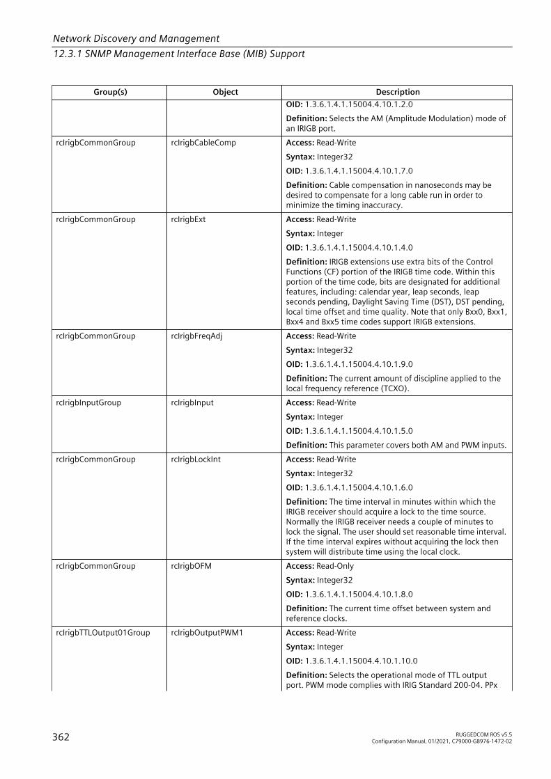
Network Discovery and Management12.3.1 SNMP Management Interface Base (MIB) Support
Group(s) Object DescriptionOID: 1.3.6.1.4.1.15004.4.10.1.2.0Definition: Selects the AM (Amplitude Modulation) mode ofan IRIGB port.
rcIrigbCommonGroup rcIrigbCableComp Access: Read-WriteSyntax: Integer32OID: 1.3.6.1.4.1.15004.4.10.1.7.0Definition: Cable compensation in nanoseconds may bedesired to compensate for a long cable run in order tominimize the timing inaccuracy.
rcIrigbCommonGroup rcIrigbExt Access: Read-WriteSyntax: IntegerOID: 1.3.6.1.4.1.15004.4.10.1.4.0Definition: IRIGB extensions use extra bits of the ControlFunctions (CF) portion of the IRIGB time code. Within thisportion of the time code, bits are designated for additionalfeatures, including: calendar year, leap seconds, leapseconds pending, Daylight Saving Time (DST), DST pending,local time offset and time quality. Note that only Bxx0, Bxx1,Bxx4 and Bxx5 time codes support IRIGB extensions.
rcIrigbCommonGroup rcIrigbFreqAdj Access: Read-WriteSyntax: Integer32OID: 1.3.6.1.4.1.15004.4.10.1.9.0Definition: The current amount of discipline applied to thelocal frequency reference (TCXO).
rcIrigbInputGroup rcIrigbInput Access: Read-WriteSyntax: IntegerOID: 1.3.6.1.4.1.15004.4.10.1.5.0Definition: This parameter covers both AM and PWM inputs.
rcIrigbCommonGroup rcIrigbLockInt Access: Read-WriteSyntax: Integer32OID: 1.3.6.1.4.1.15004.4.10.1.6.0Definition: The time interval in minutes within which theIRIGB receiver should acquire a lock to the time source.Normally the IRIGB receiver needs a couple of minutes tolock the signal. The user should set reasonable time interval.If the time interval expires without acquiring the lock thensystem will distribute time using the local clock.
rcIrigbCommonGroup rcIrigbOFM Access: Read-OnlySyntax: Integer32OID: 1.3.6.1.4.1.15004.4.10.1.8.0Definition: The current time offset between system andreference clocks.
rcIrigbTTLOutput01Group rcIrigbOutputPWM1 Access: Read-WriteSyntax: IntegerOID: 1.3.6.1.4.1.15004.4.10.1.10.0Definition: Selects the operational mode of TTL outputport. PWM mode complies with IRIG Standard 200-04. PPx
362 RUGGEDCOM ROS v5.5Configuration Manual, 01/2021, C79000-G8976-1472-02
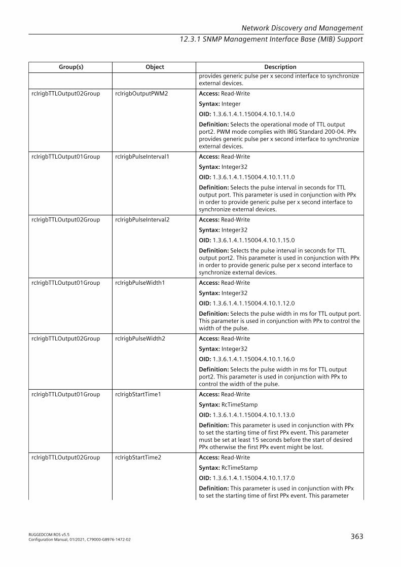
Network Discovery and Management12.3.1 SNMP Management Interface Base (MIB) Support
Group(s) Object Descriptionprovides generic pulse per x second interface to synchronizeexternal devices.
rcIrigbTTLOutput02Group rcIrigbOutputPWM2 Access: Read-WriteSyntax: IntegerOID: 1.3.6.1.4.1.15004.4.10.1.14.0Definition: Selects the operational mode of TTL outputport2. PWM mode complies with IRIG Standard 200-04. PPxprovides generic pulse per x second interface to synchronizeexternal devices.
rcIrigbTTLOutput01Group rcIrigbPulseInterval1 Access: Read-WriteSyntax: Integer32OID: 1.3.6.1.4.1.15004.4.10.1.11.0Definition: Selects the pulse interval in seconds for TTLoutput port. This parameter is used in conjunction with PPxin order to provide generic pulse per x second interface tosynchronize external devices.
rcIrigbTTLOutput02Group rcIrigbPulseInterval2 Access: Read-WriteSyntax: Integer32OID: 1.3.6.1.4.1.15004.4.10.1.15.0Definition: Selects the pulse interval in seconds for TTLoutput port2. This parameter is used in conjunction with PPxin order to provide generic pulse per x second interface tosynchronize external devices.
rcIrigbTTLOutput01Group rcIrigbPulseWidth1 Access: Read-WriteSyntax: Integer32OID: 1.3.6.1.4.1.15004.4.10.1.12.0Definition: Selects the pulse width in ms for TTL output port.This parameter is used in conjunction with PPx to control thewidth of the pulse.
rcIrigbTTLOutput02Group rcIrigbPulseWidth2 Access: Read-WriteSyntax: Integer32OID: 1.3.6.1.4.1.15004.4.10.1.16.0Definition: Selects the pulse width in ms for TTL outputport2. This parameter is used in conjunction with PPx tocontrol the width of the pulse.
rcIrigbTTLOutput01Group rcIrigbStartTime1 Access: Read-WriteSyntax: RcTimeStampOID: 1.3.6.1.4.1.15004.4.10.1.13.0Definition: This parameter is used in conjunction with PPxto set the starting time of first PPx event. This parametermust be set at least 15 seconds before the start of desiredPPx otherwise the first PPx event might be lost.
rcIrigbTTLOutput02Group rcIrigbStartTime2 Access: Read-WriteSyntax: RcTimeStampOID: 1.3.6.1.4.1.15004.4.10.1.17.0Definition: This parameter is used in conjunction with PPxto set the starting time of first PPx event. This parameter
RUGGEDCOM ROS v5.5Configuration Manual, 01/2021, C79000-G8976-1472-02 363

Network Discovery and Management12.3.1 SNMP Management Interface Base (MIB) Support
Group(s) Object Descriptionmust be set at least 15 seconds before the start of desiredPPx otherwise the first PPx event might be lost.
rcIrigbCommonGrouprcIrigbBaseGroup
rcIrigbStatus Access: Read-OnlySyntax: RcTimeSyncStatusOID: 1.3.6.1.4.1.15004.4.10.1.1.0Definition: The system synchronization status when IRIGB isa primary time source. If the value of this object is changed,an rcIrigbStatusChange notification will be sent.
rcIrigbNotifyGroup rcIrigbStatusChange OID: 1.3.6.1.4.1.15004.5.20Definition: Notification generated if the status of the IRIGBmodule is changed.
rcIrigbCommonGroup rcIrigbTimeCode Access: Read-WriteSyntax: IntegerOID: 1.3.6.1.4.1.15004.4.10.1.3.0Definition: This device uses the following convention todecode the IRIGB time code: letter [B] represents IRIG-Bformat, [xx] represents [00] for PWM/TTL mode of operationand [12] for AM operation. For example, Bxx7 representsB007 for PWM/TTL operation and B127 for AM operation.Only Bxx0, Bxx1, Bxx4 and Bxx5 time codes support IRIGBextensions.
RUGGEDCOM-MC30-MIB
Group(s) Object DescriptionrcPoeNotifyGroup rcPoeOverheat Access: Read-Only
Syntax: IntegerOID: 1.3.6.1.4.1.15004.5.12.1Definition: The value of this object will be set to 'true(1)'if PoE is overheated. Whenever the value of this objectchanges from false(2) to true(1), the device will generate anrcPoeOverheat notification.
RUGGEDCOM-NTP-MIB
Group(s) Object DescriptionrcNTPNotifyGroup ntpServiceAvailableChange OID: 1.3.6.1.4.1.15004.5.21
Definition: A notification generated when thestatus of NTP service changes.
rcNTPBaseGroup rcNTPBackUpServerIP Access: Read-WriteSyntax: IpAddressOID: 1.3.6.1.4.1.15004.4.13.1.4.0Definition: The backup server IP address.
rcNTPServiceStatusGroup rcNTPBackUpServerReachable Access: Read-OnlySyntax: TruthValueOID: 1.3.6.1.4.1.15004.4.13.1.9.0
364 RUGGEDCOM ROS v5.5Configuration Manual, 01/2021, C79000-G8976-1472-02

Network Discovery and Management12.3.1 SNMP Management Interface Base (MIB) Support
Group(s) Object DescriptionDefinition: The status of the backup NTP server.
rcNTPBaseGroup rcNTPBackUpServerUpdatePeriod Access: Read-WriteSyntax: Integer32OID: 1.3.6.1.4.1.15004.4.13.1.5.0Definition: The frequency in minutes the (S)NTPserver is polled for a time update.
rcNTPBaseGroup rcNTPFRQADJ Access: Read-OnlySyntax: Integer32OID: 1.3.6.1.4.1.15004.4.13.1.7.0Definition: The current amount of disciplineapplied to the local frequency reference (TCXO);i.e. the amount of correction on this systemrequired to syntonize to the current reference.
rcNTPBaseGroup rcNTPOFM Access: Read-OnlySyntax: Integer32OID: 1.3.6.1.4.1.15004.4.13.1.6.0Definition: The current time offset between(S)NTP server and client clocks and is calculatedas <time on the client clock> - <time on theserver clock>.
rcNTPBaseGroup rcNTPPriServerIP Access: Read-WriteSyntax: IpAddressOID: 1.3.6.1.4.1.15004.4.13.1.2.0Definition: The primary server IP Address.
rcNTPServiceStatusGroup rcNTPPriServerReachable Access: Read-OnlySyntax: TruthValueOID: 1.3.6.1.4.1.15004.4.13.1.8.0Definition: The status of the primary NTP server.
rcNTPBaseGroup rcNTPPriServerUpdatePeriod Access: Read-WriteSyntax: Integer32OID: 1.3.6.1.4.1.15004.4.13.1.3.0Definition: The frequency in minutes the (S)NTPserver is polled for a time update.
rcNTPBaseGroup rcSNTPEnabled Access: Read-WriteSyntax: TruthValueOID: 1.3.6.1.4.1.15004.4.13.1.1.0Definition: Enable/disable SNTP serverfunctionality.
RUGGEDCOM-POE-MIB
Group(s) Object DescriptionrcBasePoeGroup rcPoeCapacity Access: Read-Write
Syntax: Integer32
RUGGEDCOM ROS v5.5Configuration Manual, 01/2021, C79000-G8976-1472-02 365

Network Discovery and Management12.3.1 SNMP Management Interface Base (MIB) Support
Group(s) Object DescriptionOID: 1.3.6.1.4.1.15004.4.7.1.1.0Definition: The maximum total output power that can beprovided by PoE ports. If the value of this object is set to '0',the capacity is unlimited. When total power consumptionreaches this limit, low priority PoE ports will be shut down.
rcBasePoeGroup rcPoeConsumption Access: Read-OnlySyntax: Integer32OID: 1.3.6.1.4.1.15004.4.7.1.4.0Definition: The current total power consumption by all PoEdevices.
rcBasePoeGroup rcPoeMinimumVoltage Access: Read-WriteSyntax: Integer32OID: 1.3.6.1.4.1.15004.4.7.1.2.0Definition: The minimum required voltage to be providedby PoE ports. The minimum required voltage for PoE ports.When PoE voltage drops below this threshold, low priorityPoE ports will be shut down.
rcBasePoeStatusGroup rcPoeOverheatStatus Access: Read-OnlySyntax: TruthValueOID: 1.3.6.1.4.1.15004.4.7.1.5.0Definition: The value of this object will be set to true(1)if PoE is overheated. Whenever the value of this objectchanges from false(2) to true(1), the device will generate anrcPoeOverheat notification.
rcPoeNotifyGroup rcPoeOverload Access: Read-OnlySyntax: IntegerOID: 1.3.6.1.4.1.15004.5.12.2Definition: The value of this object will be set to true(1)if PoE is overloaded. Whenever the value of this objectchanges from false(2) to true(1), the device will generate anrcPoeOverload notification.
rcBasePoeStatusGroup rcPoeOverloadStatus Access: Read-OnlySyntax: TruthValueOID: 1.3.6.1.4.1.15004.4.7.1.6.0Definition: The value of this object will be set to true(1)if PoE is overloaded. Whenever the value of this objectchanges from false(2) to true(1), the device will generate anrcPoeOverload notification.
rcPoeTableGroup rcPoePort Access: Not-AccessibleSyntax: Integer32OID: 1.3.6.1.4.1.15004.4.7.2.1.1.1Definition: The PoE port for which this entry containsinformation. The value is limited by number of ports in thedevice.
rcPoeTableGroup rcPoePortAdmin Access: Read-WriteSyntax: TruthValueOID: 1.3.6.1.4.1.15004.4.7.2.1.1.2.13
366 RUGGEDCOM ROS v5.5Configuration Manual, 01/2021, C79000-G8976-1472-02

Network Discovery and Management12.3.1 SNMP Management Interface Base (MIB) Support
Group(s) Object DescriptionDefinition: The PoE port for which this entry containsinformation. The value is limited by number of ports in thedevice.
rcPoeTableGroup rcPoePortClass Access: Read-OnlySyntax: Integer32OID: 1.3.6.1.4.1.15004.4.7.2.1.1.5.13Definition: The PoE class value that defines the power level.
rcPoeTableGroup rcPoePortCurrent Access: Read-OnlySyntax: Integer32OID: 1.3.6.1.4.1.15004.4.7.2.1.1.7.13Definition: The PoE class value that defines the power level.
rcPoeTableGroup rcPoePortPowered Access: Read-OnlySyntax: TruthValueOID: 1.3.6.1.4.1.15004.4.7.2.1.1.4.13Definition: Whether or not power is currently supplied bythe port.
rcPoeTablePriorityGroup rcPoePortPriority Access: Read-WriteSyntax: IntegerOID: 1.3.6.1.4.1.15004.4.7.2.1.1.3.13Definition: The priority of the port. Low priority ports will beshut down first if the power supply is overloaded.
rcPoeTableGroup rcPoePortVoltage Access: Read-OnlySyntax: Integer32OID: 1.3.6.1.4.1.15004.4.7.2.1.1.6.13Definition: The PoE Class value that defines the power level.
rcBasePoeGroup rcPoeReenableTime Access: Read-WriteSyntax: Unsigned32OID: 1.3.6.1.4.1.15004.4.7.1.3.0Definition: The time to wait to turn on low priority PoE portsagain after they were shut down due to overload condition.
rcPoeNotifyGroup rcPoeUndervoltage OID: 1.3.6.1.4.1.15004.5.12.3Definition: PoE voltage low.
rcBasePoeStatusGroup rcPoeUndervoltageStatus Access: Read-OnlySyntax: TruthValueOID: 1.3.6.1.4.1.15004.4.7.1.7.0Definition: The character that can be used to forceforwarding of accumulated data to the network forconnection to the dynamic master. If a packetizationcharacter is not configured, accumulated data will beforwarded based upon the packetization timeout parameterrcPreemptRSDynPackTimer.
RUGGEDCOM ROS v5.5Configuration Manual, 01/2021, C79000-G8976-1472-02 367

Network Discovery and Management12.3.1 SNMP Management Interface Base (MIB) Support
RUGGEDCOM-PTP1588-MIB
Group(s) Object DescriptionrcPTP1588BaseGroup rcPTP1588ClkType Access: Read-Write
Syntax: IntegerOID: 1.3.6.1.4.1.15004.4.12.1.1.0Definition: The PTP1588 clock type.
rcPTP1588BaseGroup rcPTP1588E2EDelay Access: Read-OnlySyntax: Integer32OID: 1.3.6.1.4.1.15004.4.12.1.12.0Definition: The measured E2E (i.e. request-response) delaybetween master and slave clocks.
rcPTP1588BaseGroup rcPTP1588EthPorts Access: Read-WriteSyntax: PortListOID: 1.3.6.1.4.1.15004.4.12.1.2.0Definition: Selects which Ethernet ports will take part in PTP(Precision Time Protocol) message exchanges.
rcPTP1588BaseGroup rcPTP1588NetClass Access: Read-WriteSyntax: IntegerOID: 1.3.6.1.4.1.15004.4.12.1.4.0Definition: Indicates if all devices in the timing plane areIEEE1588 aware (IEEE1588 network) or if non-IEEE1588devices are included as well (non-IEEE1588 network).
rcPTP1588BaseGroup rcPTP1588ServoStatus Access: Read-OnlySyntax: DisplayStringOID: 1.3.6.1.4.1.15004.4.12.1.10.0Definition: Shows the status of the clock servo. The clockservo mechanism is used to regulate the system clock. Theclock status represents clock accuracy is with in the desiredlimits.
rcPTP1588BaseGroup rcPTP1588SlaveAutoReg Access: Read-WriteSyntax: TruthValueOID: 1.3.6.1.4.1.15004.4.12.1.7.0Definition: This parameter is specific to unicast transport. Itallows user to auto register the slave clock to unicast masteras specified by the 'Master IP Address' attribute.
rcPTP1588BaseGroup rcPTP1588SlaveBackUpIP Access: Read-WriteSyntax: IpAddressOID: 1.3.6.1.4.1.15004.4.12.1.9.0Definition: This parameter is specific to unicast transportand represents the IP address of the unicast backup PTP(Precision Time Protocol) master clock.
rcPTP1588BaseGroup rcPTP1588SlaveDomain Access: Read-WriteSyntax: Integer32OID: 1.3.6.1.4.1.15004.4.12.1.6.0Definition: Selects the PTP (Precision Time Protocol) domainnumber for the slave clock. A PTP domain is a logical
368 RUGGEDCOM ROS v5.5Configuration Manual, 01/2021, C79000-G8976-1472-02

Network Discovery and Management12.3.1 SNMP Management Interface Base (MIB) Support
Group(s) Object Descriptiongrouping of PTP clocks that synchronize to each other usingthe PTP protocol.
rcPTP1588BaseGroup rcPTP1588SlaveEthPort Access: Read-WriteSyntax: PortListOID: 1.3.6.1.4.1.15004.4.12.1.5.0Definition: Selects the Ethernet port which will act as theslave port when the device is configured as a boundary clock.
rcPTP1588BaseGroup rcPTP1588SlaveFeqAdj Access: Read-OnlySyntax: Integer32OID: 1.3.6.1.4.1.15004.4.12.1.11.0Definition: This parameter shows the current amount ofdiscipline applied to the local frequency reference (TCXO),i.e. the amount of correction on this system required tosyntonize to the current reference.
rcPTP1588BaseGroup rcPTP1588SlaveMasteIP Access: Read-WriteSyntax: IpAddressOID: 1.3.6.1.4.1.15004.4.12.1.8.0Definition: This parameter is specific to unicast transportand represents the IP address of the unicast PTP (PrecisionTime Protocol) master clock.
rcPTP1588BaseGroup rcPTP1588StartUpWait Access: Read-WriteSyntax: Integer32OID: 1.3.6.1.4.1.15004.4.12.1.3.0Definition: The time in seconds to bootstrap the PTPnetwork in an orderly fashion.
RUGGEDCOM-SERIAL-MIB
Group(s) Object DescriptionrcSerialConnStatsGroup rcConnStatsRxPkts Access: Read-Only
Syntax: Integer32OID: 1.3.6.1.4.1.15004.4.6.15.1.1.4Definition: The number of received packets.
rcSerialConnStatsGroup rcConnStatsTxPkts Access: Read-OnlySyntax: Integer32OID: 1.3.6.1.4.1.15004.4.6.15.1.1.5Definition: The number of transmitted packets
rcSerialDnpGroup rcDnpAgingTimer Access: Read-WriteSyntax: Integer32OID: 1.3.6.1.4.1.15004.4.6.8.4.0Definition: The time of communication inactivity afterwhich a learned DNP address is removed from the deviceaddress table. Entries in the Link Statistics table with theaged address will be kept until statistics are cleared.
rcSerialDnpGroup rcDnpDscp Access: Read-Write
RUGGEDCOM ROS v5.5Configuration Manual, 01/2021, C79000-G8976-1472-02 369
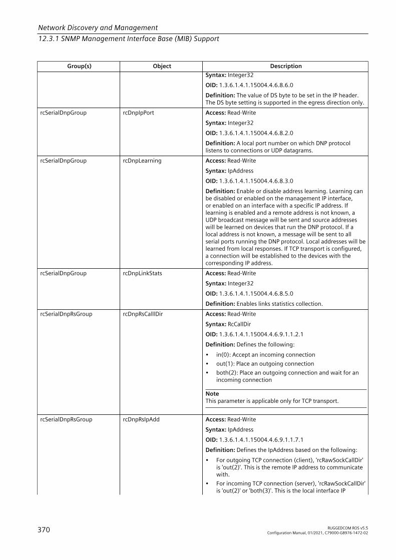
Network Discovery and Management12.3.1 SNMP Management Interface Base (MIB) Support
Group(s) Object DescriptionSyntax: Integer32OID: 1.3.6.1.4.1.15004.4.6.8.6.0Definition: The value of DS byte to be set in the IP header.The DS byte setting is supported in the egress direction only.
rcSerialDnpGroup rcDnpIpPort Access: Read-WriteSyntax: Integer32OID: 1.3.6.1.4.1.15004.4.6.8.2.0Definition: A local port number on which DNP protocollistens to connections or UDP datagrams.
rcSerialDnpGroup rcDnpLearning Access: Read-WriteSyntax: IpAddressOID: 1.3.6.1.4.1.15004.4.6.8.3.0Definition: Enable or disable address learning. Learning canbe disabled or enabled on the management IP interface,or enabled on an interface with a specific IP address. Iflearning is enabled and a remote address is not known, aUDP broadcast message will be sent and source addresseswill be learned on devices that run the DNP protocol. If alocal address is not known, a message will be sent to allserial ports running the DNP protocol. Local addresses will belearned from local responses. If TCP transport is configured,a connection will be established to the devices with thecorresponding IP address.
rcSerialDnpGroup rcDnpLinkStats Access: Read-WriteSyntax: Integer32OID: 1.3.6.1.4.1.15004.4.6.8.5.0Definition: Enables links statistics collection.
rcSerialDnpRsGroup rcDnpRsCalllDir Access: Read-WriteSyntax: RcCallDirOID: 1.3.6.1.4.1.15004.4.6.9.1.1.2.1Definition: Defines the following:• in(0): Accept an incoming connection• out(1): Place an outgoing connection• both(2): Place an outgoing connection and wait for an
incoming connection
NoteThis parameter is applicable only for TCP transport.
rcSerialDnpRsGroup rcDnpRsIpAdd Access: Read-WriteSyntax: IpAddressOID: 1.3.6.1.4.1.15004.4.6.9.1.1.7.1Definition: Defines the IpAddress based on the following:• For outgoing TCP connection (client), 'rcRawSockCallDir'
is 'out(2)'. This is the remote IP address to communicatewith.
• For incoming TCP connection (server), 'rcRawSockCallDir'is 'out(2)' or 'both(3)'. This is the local interface IP
370 RUGGEDCOM ROS v5.5Configuration Manual, 01/2021, C79000-G8976-1472-02
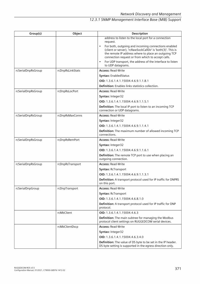
Network Discovery and Management12.3.1 SNMP Management Interface Base (MIB) Support
Group(s) Object Descriptionaddress to listen to the local port for a connectionrequest.
• For both, outgoing and incoming connections enabled(client or server), 'rcRawSockCallDir' is 'both(3)'. This isthe remote IP address where to place an outgoing TCPconnection request or from which to accept calls.
• For UDP transport, the address of the interface to listento UDP datagrams.
rcSerialDnpRsGroup rcDnpRsLinkStats Access: Read-WriteSyntax: EnabledStatusOID: 1.3.6.1.4.1.15004.4.6.9.1.1.8.1Definition: Enables links statistics collection.
rcSerialDnpRsGroup rcDnpRsLocPort Access: Read-WriteSyntax: Integer32OID: 1.3.6.1.4.1.15004.4.6.9.1.1.5.1Definition: The local IP port to listen to an incoming TCPconnection or UDP datagrams.
rcSerialDnpRsGroup rcDnpRsMaxConns Access: Read-WriteSyntax: Integer32OID: 1.3.6.1.4.1.15004.4.6.9.1.1.4.1Definition: The maximum number of allowed incoming TCPconnections.
rcSerialDnpRsGroup rcDnpRsRemPort Access: Read-WriteSyntax: Integer32OID: 1.3.6.1.4.1.15004.4.6.9.1.1.6.1Definition: The remote TCP port to use when placing anoutgoing connection.
rcSerialDnpRsGroup rcDnpRsTransport Access: Read-WriteSyntax: RcTransportOID: 1.3.6.1.4.1.15004.4.6.9.1.1.3.1Definition: A transport protocol used for IP traffic for DNPRSon this port.
rcSerialDnpGroup rcDnpTransport Access: Read-WriteSyntax: RcTransportOID: 1.3.6.1.4.1.15004.4.6.8.1.0Definition: A transport protocol used for IP traffic for DNPprotocol.
rcMbClient OID: 1.3.6.1.4.1.15004.4.6.3Definition: The main subtree for managing the Modbusprotocol client settings on RUGGEDCOM serial devices.
rcMbClientDscp Access: Read-WriteSyntax: Integer32OID: 1.3.6.1.4.1.15004.4.6.3.4.0Definition: The value of DS byte to be set in the IP header.DS byte setting is supported in the egress direction only.
RUGGEDCOM ROS v5.5Configuration Manual, 01/2021, C79000-G8976-1472-02 371

Network Discovery and Management12.3.1 SNMP Management Interface Base (MIB) Support
Group(s) Object Description rcMbClientFwdExcp Access: Read-Write
Syntax: Integer32OID: 1.3.6.1.4.1.15004.4.6.3.2.0Definition: Enables forwarding exception messages to theMaster as exception codes 10 (no path) or 11 (no response).When the Master polls for an unconfigured RTU or theremote Modbus server receives a poll for an RTU which is notconfigured or is timing out, it returns an exception message.This object should be set to 'disabled(2)' if the Master doesnot support exceptions but recognizes failure by time-outwhen waiting for response.
rcMbClientIPPort Access: Read-WriteSyntax: Integer32OID: 1.3.6.1.4.1.15004.4.6.3.1.0Definition: A remote port number to which the protocolconnection manager sends TCP connection requests.
rcMbClientLinkStats Access: Read-WriteSyntax: Integer32OID: 1.3.6.1.4.1.15004.4.6.3.3.0Definition: Enables link statistics collection.
rcSerialMbServerGroup rcMbServerAuxTcpPort Access: Read-WriteSyntax: Integer32OID: 1.3.6.1.4.1.15004.4.6.2.1.1.3.1Definition: The alternative TCP port number where an'rcMbServerPort' may listen to incoming TCP connections. Asthe TCP Modbus server always listens on TCP port 502, thisparameter allows the RUGGEDCOM serial device to acceptTCP Modbus Protocol connections request on both TCP ports.
rcSerialMbServerGroup rcMbServerLinkStats Access: Read-WriteSyntax: EnabledStatusOID: 1.3.6.1.4.1.15004.4.6.2.1.1.5.1Definition: Enables links statistics collection.
rcMbServerPort Access: Not-AccessibleSyntax: IntegerOID: 1.3.6.1.4.1.15004.4.6.2.1.1.1Definition: The physical serial port number for which thisentry contains the Modbus server protocol configurationsettings.
rcSerialMbServerGroup rcMbServerRespTimer Access: Read-WriteSyntax: Integer32OID: 1.3.6.1.4.1.15004.4.6.2.1.1.2.1Definition: The allowable time to wait for the RTU to start torespond.
rcSerialMbServerGroup rcMbServerSendExcep Access: Read-WriteSyntax: EnabledStatusOID: 1.3.6.1.4.1.15004.4.6.2.1.1.4.1
372 RUGGEDCOM ROS v5.5Configuration Manual, 01/2021, C79000-G8976-1472-02

Network Discovery and Management12.3.1 SNMP Management Interface Base (MIB) Support
Group(s) Object DescriptionDefinition: Allows the RUGGEDCOM serial devices to enableor disable sending TCP Modbus exception back to the masterif no response has been received from the RTU within theexpected time.
rcSerialMicrolokGroup rcMicrolokDscp Access: Read-WriteSyntax: Integer32OID: 1.3.6.1.4.1.15004.4.6.7.4.0Definition: The value of DS byte to be set in the IP header.The DS byte setting is supported in the egress direction only.
rcSerialMicrolokGroup rcMicrolokIpPort Access: Read-WriteSyntax: Integer32OID: 1.3.6.1.4.1.15004.4.6.7.2.0Definition: A local port number on which the Microlokprotocol listens to connections or UDP datagrams.
rcSerialMicrolokGroup rcMicrolokLinkStats Access: Read-WriteSyntax: EnabledStatusOID: 1.3.6.1.4.1.15004.4.6.7.3.0Definition: Enables links statistics collection.
rcSerialMicrolokGroup rcMicrolokTransport Access: Read-WriteSyntax: RcTransportOID: 1.3.6.1.4.1.15004.4.6.7.1.0Definition: A transport protocol used for IP traffic for theMicrolok protocol.
rcSerialMirrBitsGroup rcMirrBitsIpAdd Access: Read-WriteSyntax: IpAddressOID: 1.3.6.1.4.1.15004.4.6.10.1.1.5.1Definition: The IP Address of the interface to listen to UDPdatagrams.
rcSerialMirrBitsGroup rcMirrBitsLinkStats Access: Read-WriteSyntax: EnabledStatusOID: 1.3.6.1.4.1.15004.4.6.10.1.1.6.1Definition: Enables links statistics collection.
rcSerialMirrBitsGroup rcMirrBitsLocPort Access: Read-WriteSyntax: Integer32OID: 1.3.6.1.4.1.15004.4.6.10.1.1.3.1Definition: The local IP port to listen to UDP datagrams.
rcSerialMirrBitsGroup rcMirrBitsRemPort Access: Read-WriteSyntax: Integer32OID: 1.3.6.1.4.1.15004.4.6.10.1.1.4.1Definition: The remote port to which protocols on this portcan exchange UDP datagrams.
rcSerialMirrBitsGroup rcMirrBitsTransport Access: Read-WriteSyntax: RcTransportOID: 1.3.6.1.4.1.15004.4.6.10.1.1.2.1
RUGGEDCOM ROS v5.5Configuration Manual, 01/2021, C79000-G8976-1472-02 373

Network Discovery and Management12.3.1 SNMP Management Interface Base (MIB) Support
Group(s) Object DescriptionDefinition: A transport protocol used for IP traffic formirrored bits on this port. This object is always set to value'udp(2)'.
rcSerialPreEmpRawSockGroup rcPreemptRSDynPackChar Access: Read-WriteSyntax: Integer32OID: 1.3.6.1.4.1.15004.4.6.5.1.1.10.1Definition: The character that can be used to forceforwarding of accumulated data to the network forconnection to the dynamic master. If a packetizationcharacter is not configured, accumulated data will beforwarded based upon the packetization timeout parameterrcPreemptRSDynPackTimer.
rcSerialPreEmpRawSockGroup rcPreemptRSDynPackTimer Access: Read-WriteSyntax: Integer32OID: 1.3.6.1.4.1.15004.4.6.5.1.1.11.1Definition: The delay in milliseconds from the last receivedcharacter until when data is forwarded to the dynamicmaster.
rcSerialPreEmpRawSockGroup rcPreemptRSDynTimeout Access: Read-WriteSyntax: Integer32OID: 1.3.6.1.4.1.15004.4.6.5.1.1.12.1Definition: The time in seconds allowed for the dynamicmaster to be idle before its connection is closed. Theprotocol listens to the socket open to the dynamic master,and if no data is received within this time, the connectionwill be closed.
rcSerialPreEmpRawSockGroup rcPreemptRSFlowControl Access: Read-WriteSyntax: RcFlowControlOID: 1.3.6.1.4.1.15004.4.6.5.1.1.5.1Definition: The type of FlowControl to be used on the port.
rcSerialPreEmpRawSockGroup rcPreemptRSIpAdd Access: Read-WriteSyntax: IpAddressOID: 1.3.6.1.4.1.15004.4.6.5.1.1.8.1Definition: Defines the IpAddress based on the following:• For outgoing TCP connections (client), 'rcRawSockCallDir'
is 'out(2)' is the remote IP address to communicate with.• For incoming TCP connections (server),
'rcRawSockCallDir' is 'out(2)' or 'both(3)' is the localinterface IP address to listen to the local port for aconnection request.
• For both outgoing and incoming connections enabled(client or server), 'rcRawSockCallDir' is 'both(3)' is theremote IP address to place an outgoing TCP connectionrequest or from which to accept calls.
rcSerialPreEmpRawSockGroup rcPreemptRSLinkStats Access: Read-WriteSyntax: EnabledStatusOID: 1.3.6.1.4.1.15004.4.6.5.1.1.9.1Definition: Enables links statistics collection.
374 RUGGEDCOM ROS v5.5Configuration Manual, 01/2021, C79000-G8976-1472-02

Network Discovery and Management12.3.1 SNMP Management Interface Base (MIB) Support
Group(s) Object DescriptionrcSerialPreEmpRawSockGroup rcPreemptRSLocPort Access: Read-Write
Syntax: Integer32OID: 1.3.6.1.4.1.15004.4.6.5.1.1.6.1Definition: The local IP port to listen to an incoming TCPconnection or UDP datagram.
rcSerialPreEmpRawSockGroup rcPreemptRSPackChar Access: Read-WriteSyntax: Integer32OID: 1.3.6.1.4.1.15004.4.6.5.1.1.2.1Definition: The character that can be used to forceforwarding of accumulated data to the network. If apacketization character is not configured, the object is set tothe value of '256' and accumulated data will be forwardedbased on the packetization timeout parameter which is thevalue set for object rcPreemptRSPackTimer.
rcSerialPreEmpRawSockGroup rcPreemptRSPackSize Access: Read-WriteSyntax: Integer32OID: 1.3.6.1.4.1.15004.4.6.5.1.1.4.1Definition: The Maximum number of bytes received fromthe serial port to be packed in one IP packet.
rcSerialPreEmpRawSockGroup rcPreemptRSPackTimer Access: Read-WriteSyntax: Integer32OID: 1.3.6.1.4.1.15004.4.6.5.1.1.3.1Definition: The delay in milliseconds from the last receivedcharacter until when data is forwarded.
rcSerialPreEmpRawSockGroup rcPreemptRSRemPort Access: Read-WriteSyntax: Integer32OID: 1.3.6.1.4.1.15004.4.6.5.1.1.7.1Definition: The remote TCP port to use when placing anoutgoing connection.
rcSerialRawSocketGroup rcRawSockCallDir Access: Read-WriteSyntax: RcCallDirOID: 1.3.6.1.4.1.15004.4.6.4.1.1.7.1Definition: Defines following:
NoteThis parameter is applicable only for TCP transport.
• in(0): Accept an incoming connection• out(1): Place an outgoing connection• both(2): Place an outgoing connection and wait for an
incoming connectionrcSerialRawSocketGroup rcRawSockFlowControl Access: Read-Write
Syntax: RcFlowControlOID: 1.3.6.1.4.1.15004.4.6.4.1.1.5.1Definition: The type of FlowControl to be used on the port.
rcSerialRawSocketGroup rcRawSockIpAdd Access: Read-Write
RUGGEDCOM ROS v5.5Configuration Manual, 01/2021, C79000-G8976-1472-02 375

Network Discovery and Management12.3.1 SNMP Management Interface Base (MIB) Support
Group(s) Object DescriptionSyntax: IpAddressOID: 1.3.6.1.4.1.15004.4.6.4.1.1.11.1Definition: >Defines the IpAddress based on the following:• For outgoing TCP connections (client), 'rcRawSockCallDir'
is 'out(2)' is the remote IP address to communicate with.• For incoming TCP connections (server),
'rcRawSockCallDir' is 'out(2)' or 'both(3)' is the localinterface IP address to listen to the local port for aconnection request.
• For both outgoing and incoming connections enabled(client or server), 'rcRawSockCallDir' is 'both(3)' is theremote IP address to place an outgoing TCP connectionrequest or from which to accept calls.
• For UDP transport, the address of the interface to listento UDP datagrams.
rcSerialRawSocketGroup rcRawSockLinkStats Access: Read-WriteSyntax: EnabledStatusOID: 1.3.6.1.4.1.15004.4.6.4.1.1.12.1Definition: Enables links statistics collection for RawSocketon this port.
rcSerialRawSocketGroup rcRawSockLocPort Access: Read-WriteSyntax: Integer32OID: 1.3.6.1.4.1.15004.4.6.4.1.1.9.1Definition: The local IP port to listen to an incoming TCPconnection or UDP datagrams.
rcSerialRawSocketGroup rcRawSockMaxConn Access: Read-WriteSyntax: Integer32OID: 1.3.6.1.4.1.15004.4.6.4.1.1.8.1Definition: The maximum number of allowed incoming TCPconnections.
rcSerialMbClientGroup rcRawSockPackChar Access: Read-WriteSyntax: Integer32OID: 1.3.6.1.4.1.15004.4.6.4.1.1.2.1Definition: The character that can be used to forceforwarding of accumulated data to the network. If apacketization character is not configured, the object is set tothe value of '256', and accumulated data will be forwardedbased upon the packetization timeout parameter which isthe value set for object rcRawSockPackTimer.
rcSerialRawSocketGroup rcRawSockPackSize Access: Read-WriteSyntax: Integer32OID: 1.3.6.1.4.1.15004.4.6.4.1.1.4.1Definition: The maximum number of bytes received fromserial port to be forwarded.
rcSerialRawSocketGroup rcRawSockPackTimer Access: Read-WriteSyntax: Integer32OID: 1.3.6.1.4.1.15004.4.6.4.1.1.3.1
376 RUGGEDCOM ROS v5.5Configuration Manual, 01/2021, C79000-G8976-1472-02
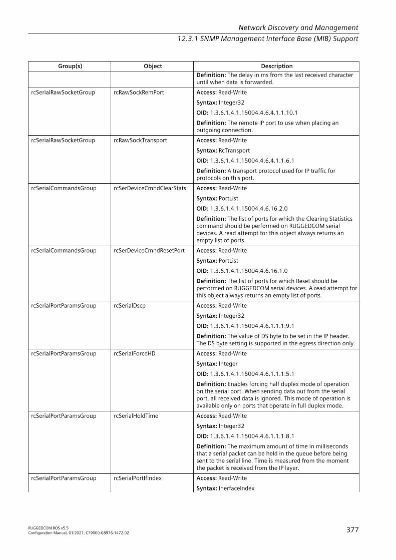
Network Discovery and Management12.3.1 SNMP Management Interface Base (MIB) Support
Group(s) Object DescriptionDefinition: The delay in ms from the last received characteruntil when data is forwarded.
rcSerialRawSocketGroup rcRawSockRemPort Access: Read-WriteSyntax: Integer32OID: 1.3.6.1.4.1.15004.4.6.4.1.1.10.1Definition: The remote IP port to use when placing anoutgoing connection.
rcSerialRawSocketGroup rcRawSockTransport Access: Read-WriteSyntax: RcTransportOID: 1.3.6.1.4.1.15004.4.6.4.1.1.6.1Definition: A transport protocol used for IP traffic forprotocols on this port.
rcSerialCommandsGroup rcSerDeviceCmndClearStats Access: Read-WriteSyntax: PortListOID: 1.3.6.1.4.1.15004.4.6.16.2.0Definition: The list of ports for which the Clearing Statisticscommand should be performed on RUGGEDCOM serialdevices. A read attempt for this object always returns anempty list of ports.
rcSerialCommandsGroup rcSerDeviceCmndResetPort Access: Read-WriteSyntax: PortListOID: 1.3.6.1.4.1.15004.4.6.16.1.0Definition: The list of ports for which Reset should beperformed on RUGGEDCOM serial devices. A read attempt forthis object always returns an empty list of ports.
rcSerialPortParamsGroup rcSerialDscp Access: Read-WriteSyntax: Integer32OID: 1.3.6.1.4.1.15004.4.6.1.1.1.9.1Definition: The value of DS byte to be set in the IP header.The DS byte setting is supported in the egress direction only.
rcSerialPortParamsGroup rcSerialForceHD Access: Read-WriteSyntax: IntegerOID: 1.3.6.1.4.1.15004.4.6.1.1.1.5.1Definition: Enables forcing half duplex mode of operationon the serial port. When sending data out from the serialport, all received data is ignored. This mode of operation isavailable only on ports that operate in full duplex mode.
rcSerialPortParamsGroup rcSerialHoldTime Access: Read-WriteSyntax: Integer32OID: 1.3.6.1.4.1.15004.4.6.1.1.1.8.1Definition: The maximum amount of time in millisecondsthat a serial packet can be held in the queue before beingsent to the serial line. Time is measured from the momentthe packet is received from the IP layer.
rcSerialPortParamsGroup rcSerialPortIfIndex Access: Read-WriteSyntax: InerfaceIndex
RUGGEDCOM ROS v5.5Configuration Manual, 01/2021, C79000-G8976-1472-02 377

Network Discovery and Management12.3.1 SNMP Management Interface Base (MIB) Support
Group(s) Object DescriptionOID: 1.3.6.1.4.1.15004.4.6.1.1.1.2.1Definition: The value of ifIndex for the port. This valueis same as 'rs232PortIndex' which is the index used for'rs232PortTable' in RS-232-MIB.
rcSerialPortParamsGroup rcSerialPortType Access: Read-WriteSyntax: RcSerPortTypeOID: 1.3.6.1.4.1.15004.4.6.1.1.1.4.1Definition: A serial port type supported on the serial portrepresented by this entry.
rcSerialPortParamsGroup rcSerialPostTxDelay Access: Read-WriteSyntax: Integer32OID: 1.3.6.1.4.1.15004.4.6.1.1.1.7.1Definition: The number of bits needed to generatethe required delay with the configured baudrate('rs232PortOutSpeed') after the last bit of the packetwas sent out before serial UART starts listening to the RXline. This value is relevant for RS485 interface only with'rs232PortType' equals other(1).
rcSerialPortParamsGroup rcSerialProtocol Access: Read-WriteSyntax: RcSerProtocolOID: 1.3.6.1.4.1.15004.4.6.1.1.1.3.1Definition: A serial protocol supported on the serial portrepresented by this entry.
rcSerialPortParamsGroup rcSerialRxtoTxDelay Access: Read-WriteSyntax: Integer32OID: 1.3.6.1.4.1.15004.4.6.1.1.1.10.1Definition: The minimum amount of time in millisecondsthe transmission of a new message should delay after thelast message is received through the Al port. This parameteris useful, especially for the half duplex transmission mode,such as two-wire RS485 serial protocol. It ensures theconnected device has enough time to turn off its transmitterand to turn on its receiver, so it can receive the next messagewithout a single bit loss.
rcSerialPortParamsGroup rcSerialTurnAround Access: Read-WriteSyntax: Integer32OID: 1.3.6.1.4.1.15004.4.6.1.1.1.6.1Definition: The amount of delay between the transmissionof individual messages from the serial port. For'rcSerialProtocol' object value modbusServer(3), this valuemust be non-zero. It represents the delay between sendinga broadcast message and the next pollout of the serial port.As RTUs do not reply to a broadcast, sufficient time must beensured to process them.
rcSerialTelnetComportGroup rcTelnetComportCallDir Access: Read-WriteSyntax: RcCallDirOID: 1.3.6.1.4.1.15004.4.6.11.1.1.6.1
378 RUGGEDCOM ROS v5.5Configuration Manual, 01/2021, C79000-G8976-1472-02
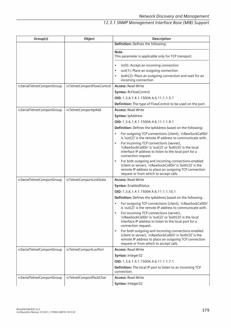
Network Discovery and Management12.3.1 SNMP Management Interface Base (MIB) Support
Group(s) Object DescriptionDefinition: Defines the following:
NoteThis parameter is applicable only for TCP transport.
• in(0): Accept an incoming connection• out(1): Place an outgoing connection• both(2): Place an outgoing connection and wait for an
incoming connectionrcSerialTelnetComportGroup rcTelnetComportFlowControl Access: Read-Write
Syntax: RcFlowControlOID: 1.3.6.1.4.1.15004.4.6.11.1.1.5.1Definition: The type of FlowControl to be used on the port.
rcSerialTelnetComportGroup rcTelnetComportIpAdd Access: Read-WriteSyntax: IpAddressOID: 1.3.6.1.4.1.15004.4.6.11.1.1.9.1Definition: Defines the IpAddress based on the following:• For outgoing TCP connections (client), 'rcRawSockCallDir'
is 'out(2)' is the remote IP address to communicate with.• For incoming TCP connections (server),
'rcRawSockCallDir' is 'out(2)' or 'both(3)' is the localinterface IP address to listen to the local port for aconnection request.
• For both outgoing and incoming connections enabled(client or server), 'rcRawSockCallDir' is 'both(3)' is theremote IP address to place an outgoing TCP connectionrequest or from which to accept calls.
rcSerialTelnetComportGroup rcTelnetComportLinkStats Access: Read-WriteSyntax: EnabledStatusOID: 1.3.6.1.4.1.15004.4.6.11.1.1.10.1Definition: Defines the IpAddress based on the following:• For outgoing TCP connections (client), 'rcRawSockCallDir'
is 'out(2)' is the remote IP address to communicate with.• For incoming TCP connections (server),
'rcRawSockCallDir' is 'out(2)' or 'both(3)' is the localinterface IP address to listen to the local port for aconnection request.
• For both outgoing and incoming connections enabled(client or server), 'rcRawSockCallDir' is 'both(3)' is theremote IP address to place an outgoing TCP connectionrequest or from which to accept calls.
rcSerialTelnetComportGroup rcTelnetComportLocPort Access: Read-WriteSyntax: Integer32OID: 1.3.6.1.4.1.15004.4.6.11.1.1.7.1Definition: The local IP port to listen to an incoming TCPconnection.
rcSerialTelnetComportGroup rcTelnetComportPackChar Access: Read-WriteSyntax: Integer32
RUGGEDCOM ROS v5.5Configuration Manual, 01/2021, C79000-G8976-1472-02 379

Network Discovery and Management12.3.1 SNMP Management Interface Base (MIB) Support
Group(s) Object DescriptionOID: 1.3.6.1.4.1.15004.4.6.11.1.1.2.1Definition: The character that can be used to forceforwarding of accumulated data to the network. If apacketization character is not configured, the object is setto the value '256', and accumulated data will be forwardedbased upon the packetization timeout parameter which isthe value set for object rcTelnetComportPackTimer.
rcSerialTelnetComportGroup rcTelnetComportPackSize Access: Read-WriteSyntax: Integer32OID: 1.3.6.1.4.1.15004.4.6.11.1.1.4.1Definition: The maximum number of bytes received fromthe serial port to be packed in one IP packet.
rcSerialTelnetComportGroup rcTelnetComportPackTimer Access: Read-WriteSyntax: Integer32OID: 1.3.6.1.4.1.15004.4.6.11.1.1.3.1Definition: The delay from the last received character untilwhen data is forwarded.
rcSerialTelnetComportGroup rcTelnetComportRemPort Access: Read-WriteSyntax: Integer32OID: 1.3.6.1.4.1.15004.4.6.11.1.1.8.1Definition: The remote TCP port to use when placing anoutgoing connection.
rcTimeConfigBaseGroup rcTimeAndDate Access: Read-WriteSyntax: DateandTimeOID: 1.3.6.1.4.1.15004.4.11.1.2.0Definition: This parameter allows for both the viewing andsetting of the local time and date in DateAndTime format.DateAndTime is a standard textual convention defined in theSNMPv2-TC.
RUGGEDCOM-STP-MIB
Group(s) Object DescriptionrcRstpBaseGroup rcRstpDot1dRstpAlternatePorts Access: Read-Only
Syntax: PortListOID: 1.3.6.1.4.1.15004.4.5.1.5.0Definition: The subset of ports with anAlternate role.
rcRstpBaseGroup rcRstpDot1dRstpBackupPorts Access: Read-OnlySyntax: PortListOID: 1.3.6.1.4.1.15004.4.5.1.6.0Definition: The subset of ports with a Backuprole.
rcRstpBaseGroup rcRstpDot1dStpBlockedPorts Access: Read-OnlySyntax: PortListOID: 1.3.6.1.4.1.15004.4.5.1.3.0
380 RUGGEDCOM ROS v5.5Configuration Manual, 01/2021, C79000-G8976-1472-02
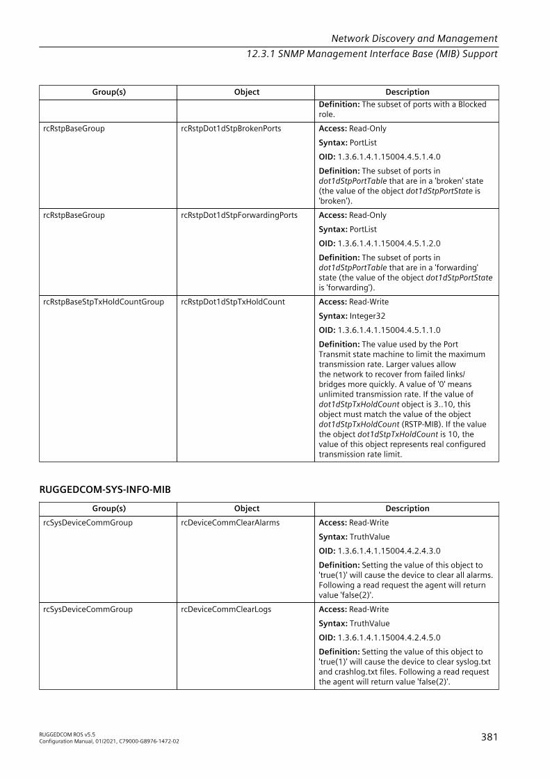
Network Discovery and Management12.3.1 SNMP Management Interface Base (MIB) Support
Group(s) Object DescriptionDefinition: The subset of ports with a Blockedrole.
rcRstpBaseGroup rcRstpDot1dStpBrokenPorts Access: Read-OnlySyntax: PortListOID: 1.3.6.1.4.1.15004.4.5.1.4.0Definition: The subset of ports indot1dStpPortTable that are in a 'broken' state(the value of the object dot1dStpPortState is'broken').
rcRstpBaseGroup rcRstpDot1dStpForwardingPorts Access: Read-OnlySyntax: PortListOID: 1.3.6.1.4.1.15004.4.5.1.2.0Definition: The subset of ports indot1dStpPortTable that are in a 'forwarding'state (the value of the object dot1dStpPortStateis 'forwarding').
rcRstpBaseStpTxHoldCountGroup rcRstpDot1dStpTxHoldCount Access: Read-WriteSyntax: Integer32OID: 1.3.6.1.4.1.15004.4.5.1.1.0Definition: The value used by the PortTransmit state machine to limit the maximumtransmission rate. Larger values allowthe network to recover from failed links/bridges more quickly. A value of '0' meansunlimited transmission rate. If the value ofdot1dStpTxHoldCount object is 3..10, thisobject must match the value of the objectdot1dStpTxHoldCount (RSTP-MIB). If the valuethe object dot1dStpTxHoldCount is 10, thevalue of this object represents real configuredtransmission rate limit.
RUGGEDCOM-SYS-INFO-MIB
Group(s) Object DescriptionrcSysDeviceCommGroup rcDeviceCommClearAlarms Access: Read-Write
Syntax: TruthValueOID: 1.3.6.1.4.1.15004.4.2.4.3.0Definition: Setting the value of this object to'true(1)' will cause the device to clear all alarms.Following a read request the agent will returnvalue 'false(2)'.
rcSysDeviceCommGroup rcDeviceCommClearLogs Access: Read-WriteSyntax: TruthValueOID: 1.3.6.1.4.1.15004.4.2.4.5.0Definition: Setting the value of this object to'true(1)' will cause the device to clear syslog.txtand crashlog.txt files. Following a read requestthe agent will return value 'false(2)'.
RUGGEDCOM ROS v5.5Configuration Manual, 01/2021, C79000-G8976-1472-02 381

Network Discovery and Management12.3.1 SNMP Management Interface Base (MIB) Support
Group(s) Object DescriptionrcSysDeviceCommGroup rcDeviceCommClearSyslog Access: Read-Write
Syntax: TruthValueOID: 1.3.6.1.4.1.15004.4.2.4.4.0Definition: Setting the value of this objectto 'true(1)' will cause the device to clear thesyslog.txt file. Following a read request theagent will return value 'false(2)'.
rcSysDeviceCommGroup rcDeviceCommLoadDefaultCfg Access: Read-WriteSyntax: TruthValueOID: 1.3.6.1.4.1.15004.4.2.4.2.0Definition: Setting the value of this object to'true(1)' will force the device to load the defaultconfiguration to all tables. Following a readrequest the agent will return value 'false(2)'.
rcSysDeviceCommGroup rcDeviceCommReset Access: Read-WriteSyntax: TruthValueOID: 1.3.6.1.4.1.15004.4.2.4.1.0Definition: Setting the value of this objectto 'true(1)' will cause the device to reboot.Following a read request the agent will returnvalue 'false(2)'.
rcSysErrObjectsGroup rcDeviceErrBootPTftpTrFailed Access: Read-OnlySyntax: TruthValueOID: 1.3.6.1.4.1.15004.4.2.1.9.0Definition: Indicates whether the file wastransferred properly after obtaining an IPaddress from the BootP server. Whenever thevalue of this object changes from false(2) totrue(1), the device will generate a genericTrapnotification.
rcSysErrObjectsGroup rcDeviceErrBootupError Access: Read-OnlySyntax: DisplayStringOID: 1.3.6.1.4.1.15004.4.2.1.1.0Definition: The error discovered during thebootup process. If there was no error duringdevice bootup, zero length DisplayString will beretrieved.
rcSysErrObjectsGroup rcDeviceErrConfigurationFailure Access: Read-OnlySyntax: TruthValueOID: 1.3.6.1.4.1.15004.4.2.1.3.0Definition: Indicates whether errors weredetected while applying configuration settingsfrom the configuration file. The configuration isupdated from the configuration file at bootuptime when a file is loaded from non-volatilememory, or when a new file is downloaded tothe device. Whenever the value of this objectchanges from false(2) to true(1), the device willgenerate a genericTrap notification.
382 RUGGEDCOM ROS v5.5Configuration Manual, 01/2021, C79000-G8976-1472-02

Network Discovery and Management12.3.1 SNMP Management Interface Base (MIB) Support
Group(s) Object DescriptionrcSysErrObjectsGroup rcDeviceErrCrashLogCreated Access: Read-Only
Syntax: TruthValueOID: 1.3.6.1.4.1.15004.4.2.1.4.0Definition: Indicates whether the device errorthat caused creation of an entry in crashlog.txtfile was detected. Whenever the value of thisobject changes from false(2) to true(1), thedevice will generate a genericTrap notification.
rcSysErrObjectsGroup rcDeviceErrDateAndTimeSetFailed Access: Read-OnlySyntax: TruthValueOID: 1.3.6.1.4.1.15004.4.2.1.7.0Definition: Indicates whether the date andtime setting in the device failed. Whenever thevalue of this object changes from false(2) totrue(1), the device will generate a genericTrapnotification.
rcSysErrObjectsGroup rcDeviceErrHeapError Access: Read-OnlySyntax: TruthValueOID: 1.3.6.1.4.1.15004.4.2.1.6.0Definition: Indicates whether the systemmemory corruption was detected. Wheneverthe value of this object changes from false(2) totrue(1), the device will generate a genericTrapnotification.
rcSysErrObjectsGroup rcDeviceErrNtpServerUnreachable Access: Read-OnlySyntax: TruthValueOID: 1.3.6.1.4.1.15004.4.2.1.8.0Definition: Indicates whether any of the NTPservers (if required) can be reached. The valueof this object is 'false' if both servers becomeunreachable. Whenever the value of thisobject changes, the device will generate thentpServiceAvailableChange notification.
rcSysErrObjectsGroup rcDeviceErrRadiusServerUnreachable Access: Read-OnlySyntax: TruthValueOID: 1.3.6.1.4.1.15004.4.2.1.10.0Definition: Indicates whether the RADIUS server(if required) can be reached. Whenever thevalue of this object changes, the device willgenerate the radiusServiceAvailableChangenotification.
rcSysErrObjectsGroup rcDeviceErrStackOverflow Access: Read-OnlySyntax: TruthValueOID: 1.3.6.1.4.1.15004.4.2.1.5.0Definition: Indicates whether the stack of anyof the system tasks is used over the systemthreshold. Whenever the value of this objectchanges from false(2) to true(1), the device willgenerate a genericTrap notification.
RUGGEDCOM ROS v5.5Configuration Manual, 01/2021, C79000-G8976-1472-02 383

Network Discovery and Management12.3.1 SNMP Management Interface Base (MIB) Support
Group(s) Object DescriptionrcSysErrObjectsGroup rcDeviceErrTacacsServerUnreachable Access: Read-Only
Syntax: TruthValueOID: 1.3.6.1.4.1.15004.4.2.1.11.0Definition: Indicates whether the TACACS+server (if required) can be reached. Wheneverthe value of this object changes, the device willgenerate the tacacsServiceAvailableChangenotification.
rcSysErrObjectsGroup rcDeviceErrWatchdogReset Access: Read-OnlySyntax: TruthValueOID: 1.3.6.1.4.1.15004.4.2.1.2.0Definition: Indicates whether the last devicereboot was caused by watchdog.
rcSysInfoDeviceInfoGroup rcDeviceInfoBootSwVersion Access: Read-OnlySyntax: DisplayStringOID: 1.3.6.1.4.1.15004.4.2.3.2.0Definition: The version and the build date of theboot loader software.
rcSysInfoDeviceInfoGroup rcDeviceInfoCfgRevision Access: Read-OnlySyntax: Integer32OID: 1.3.6.1.4.1.15004.4.2.3.8.0Definition: The configuration file revision. Therevision number will be updated whenever afile is saved to the flash memory. This numberis recorded in config.csv at the time file isuploaded from the device. Whenever the valueof this object changes the device will generate acfgChangeTrap notification.
rcSysInfoDeviceInfoGroup rcDeviceInfoMainBoardType Access: Read-OnlySyntax: RcMainBoardOID: 1.3.6.1.4.1.15004.4.2.3.4.0Definition: The identification code of the devicemain board.
rcSysInfoDeviceInfoGroup rcDeviceInfoMainSwVersion Access: Read-OnlySyntax: DisplayStringOID: 1.3.6.1.4.1.15004.4.2.3.3.0Definition: The version and build date of themain operating system software.
rcSysInfoDeviceInfoGroup rcDeviceInfoPendingBootSwVersion Access: Read-OnlySyntax: DisplayStringOID: 1.3.6.1.4.1.15004.4.2.3.6.0Definition: The version and build date of theboot loader software that has been loaded tothe device and is pending reboot. Whenever thevalue of this object changes from zero-lengthDisplayString to any DisplayString of non-zero
384 RUGGEDCOM ROS v5.5Configuration Manual, 01/2021, C79000-G8976-1472-02

Network Discovery and Management12.3.1 SNMP Management Interface Base (MIB) Support
Group(s) Object Descriptionlength, the device will generate swUpgradeTrapnotification.
rcSysInfoDeviceInfoGroup rcDeviceInfoPendingMainSwVersion Access: Read-OnlySyntax: DisplayStringOID: 1.3.6.1.4.1.15004.4.2.3.7.0Definition: The version and the build date of themain operating system software that has beenloaded to the device and is pending reboot.Whenever the value of this object changes fromzero-length DisplayString to any DisplayStringof non-zero length, the device will generateswUpgradeTrap notification.
rcSysInfoDeviceInfoGroup rcDeviceInfoSerialNumber Access: Read-OnlySyntax: DisplayStringOID: 1.3.6.1.4.1.15004.4.2.3.1.0Definition: The manufacturing serial number ofthe device.
rcSysInfoDeviceInfoGroup rcDeviceInfoTotalRam Access: Read-OnlySyntax: Integer32OID: 1.3.6.1.4.1.15004.4.2.3.5.0Definition: The total number of bytes of RAM inthe system control CPU.
rcSysStsPowerSupplyGroup rcDeviceStsPowerSupply1 Access: Read-OnlySyntax: RcHardwareStatusOID: 1.3.6.1.4.1.15004.4.2.2.4.0Definition: Indicates the status of Power SupplyModule 1. Whenever the value of this objectchanges from functional(2) to notFunctional(3),or from notFunctionl(3) to functional(2),the device will generate a powerSupplyTrapnotification.
rcSysStsPowerSupplyGroup rcDeviceStsPowerSupply2 Access: Read-OnlySyntax: RcHardwareStatusOID: 1.3.6.1.4.1.15004.4.2.2.5.0Definition: Indicates the status of Power SupplyModule 2. Whenever the value of this objectchanges from functional(2) to notFunctional(3),or from notFunctionl(3) to functional(2),the device will generate a powerSupplyTrapnotification.
rcSysStsObjectsTemperatureGroup rcDeviceStsTemperature Access: Read-OnlySyntax: Integer32OID: 1.3.6.1.4.1.15004.4.2.2.3.0Definition: The temperature measured in thedevice.
RUGGEDCOM ROS v5.5Configuration Manual, 01/2021, C79000-G8976-1472-02 385
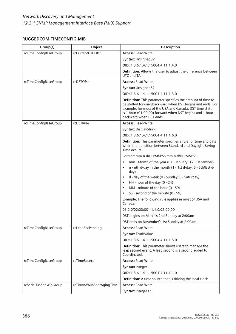
Network Discovery and Management12.3.1 SNMP Management Interface Base (MIB) Support
RUGGEDCOM-TIMECONFIG-MIB
Group(s) Object DescriptionrcTimeConfigBaseGroup rcCurrentUTCOfst Access: Read-Write
Syntax: Unsigned32OID: 1.3.6.1.4.1.15004.4.11.1.4.0Definition: Allows the user to adjust the difference betweenUTC and TAI.
rcTimeConfigBaseGroup rcDSTOfst Access: Read-WriteSyntax: Unsigned32OID: 1.3.6.1.4.1.15004.4.11.1.3.0Definition: This parameter specifies the amount of time tobe shifted forward/backward when DST begins and ends. Forexample, for most of the USA and Canada, DST time shiftis 1 hour (01:00:00) forward when DST begins and 1 hourbackward when DST ends.
rcTimeConfigBaseGroup rcDSTRule Access: Read-WriteSyntax: DisplayStringOID: 1.3.6.1.4.1.15004.4.11.1.6.0Definition: This parameter specifies a rule for time and datewhen the transition between Standard and Daylight SavingTime occurs.Format: mm.n.d/HH:MM:SS mm.n.d/HH:MM:SS• mm - Month of the year (01 - January, 12 - December)• n - nth d-day in the month (1 - 1st d-day, 5 - 5th/last d-
day)• d - day of the week (0 - Sunday, 6 - Saturday)• HH - hour of the day (0 - 24)• MM - minute of the hour (0 - 59)• SS - second of the minute (0 - 59)Example: The following rule applies in most of USA andCanada:03.2.0/02:00:00 11.1.0/02:00:00DST begins on March's 2nd Sunday at 2:00amDST ends on November's 1st Sunday at 2:00am.
rcTimeConfigBaseGroup rcLeapSecPending Access: Read-WriteSyntax: TruthValueOID: 1.3.6.1.4.1.15004.4.11.1.5.0Definition: This parameter allows users to manage theleap second event. A leap second is a second added toCoordinated.
rcTimeConfigBaseGroup rcTimeSource Access: Read-WriteSyntax: IntegerOID: 1.3.6.1.4.1.15004.4.11.1.1.0Definition: A time source that is driving the local clock.
rcSerialTinAndWinGroup rcTinAndWinAddrAgingTime Access: Read-WriteSyntax: Integer32
386 RUGGEDCOM ROS v5.5Configuration Manual, 01/2021, C79000-G8976-1472-02

Network Discovery and Management12.3.1 SNMP Management Interface Base (MIB) Support
Group(s) Object DescriptionOID: 1.3.6.1.4.1.15004.4.6.6.7.0Definition: The time of communication inactivity inmilliseconds after which a learned TIN address is removedfrom the dynamic device address table. Entries in LinkStatistics table with the aged address will be kept untilstatistics are cleared.
rcSerialTinAndWinGroup rcTinAndWinBroadCastAddr Access: Read-WriteSyntax: IntegerOID: 1.3.6.1.4.1.15004.4.6.6.8.0Definition: The device address table in which addresses willbe found for broadcast messages.
rcSerialTinAndWinGroup rcTinAndWinLinkStats Access: Read-WriteSyntax: EnabledStatusOID: 1.3.6.1.4.1.15004.4.6.6.10.0Definition: Enables links statistics collection for TIN and WINprotocols.
rcSerialTinAndWinGroup rcTinAndWinMsgAgingTime Access: Read-WriteSyntax: Integer32OID: 1.3.6.1.4.1.15004.4.6.6.6.0Definition: Aging time for TIN mode2 messages. The featureis disabled if the value of this object is '0'. When the featureis enabled, any TIN mode2 message received will be stored inan internal table. If the same message is received within thetime window specified by this parameter, the new messageis considered duplicate, and thus discarded.
rcSerialTinAndWinGroup rcTinAndWinTinDscp Access: Read-WriteSyntax: Integer32OID: 1.3.6.1.4.1.15004.4.6.6.12.0Definition: The value of DS byte to be set in the IP header.The DS byte setting is supported in the egress direction only.
rcSerialTinAndWinGroup rcTinAndWinTinIpPort Access: Read-WriteSyntax: Integer32OID: 1.3.6.1.4.1.15004.4.6.6.4.0Definition: A local port number on which the TIN protocollistens to connections or UDP datagrams.
rcSerialTinAndWinGroup rcTinAndWinTinMode Access: Read-WriteSyntax: IntegerOID: 1.3.6.1.4.1.15004.4.6.6.1.0Definition: The TIN protocol running mode.
rcSerialTinAndWinGroup rcTinAndWinTinTrans Access: Read-WriteSyntax: RcTransportOID: 1.3.6.1.4.1.15004.4.6.6.2.0Definition: A transport protocol used for IP traffic for TINprotocol.
rcSerialTinAndWinGroup rcTinAndWinUniAddr Access: Read-WriteSyntax: Integer
RUGGEDCOM ROS v5.5Configuration Manual, 01/2021, C79000-G8976-1472-02 387

Network Discovery and Management12.3.1 SNMP Management Interface Base (MIB) Support
Group(s) Object DescriptionOID: 1.3.6.1.4.1.15004.4.6.6.9.0Definition: The device address table in which addresses willbe found for unicast messages.
rcSerialTinAndWinGroup rcTinAndWinWinDscp Access: Read-WriteSyntax: Integer32OID: 1.3.6.1.4.1.15004.4.6.6.11.0Definition: The value of DS byte to be set in the IP header.The DS byte setting is supported in the egress direction only.
rcSerialTinAndWinGroup rcTinAndWinWinIpPort Access: Read-WriteSyntax: Integer32OID: 1.3.6.1.4.1.15004.4.6.6.5.0Definition: A local port number on which the WIN protocollistens to connections or UDP datagrams.
rcSerialTinAndWinGroup rcTinAndWinWinTrans Access: Read-WriteSyntax: RcTransportOID: 1.3.6.1.4.1.15004.4.6.6.3.0Definition: A transport protocol used for IP traffic for theWIN protocol.
12.3.1.3 Supported Agent Capabilities
RUGGEDCOM ROS supports the following agent capabilities for the SNMP agent:
NOTICEThis section lists all MIBs supported by RUGGEDCOM ROS, and is intended forreference purposes only. Individual device support may vary.
NoteFor information about agent capabilities for SNMPv2, refer to RFC 2580 [http://tools.ietf.org/html/rfc2580].
File Name Agent Capability Supported MIBRC-SNMPv2-MIB-AC.mib RC-SNMPv2-MIB-AC SNMPv2-MIBRC-UDP-MIB-AC.mib RC-UDP-MIB-AC UDP-MIBRC-TCP-MIB-AC.mib RC-TCP-MIB-AC TCP-MIBRC-SNMP-USER-BASED-SM-MIB-AC.mib RC-SNMP-USER-BASED-SM-MIB-AC SNMP-USER-BASED-SM-MIB-ACRC-SNMP-VIEW-BASED-ACM-MIB-AC.mib RC-SNMP-VIEW-BASED-ACM-MIB-AC SNMP-VIEW-BASED-ACM-MIB-ACRC-IF-MIB-AC.mib RC-IF-MIB-AC IF-MIBRC-BRIDGE-MIB-AC.mib RC-BRIDGE-MIB-AC BRIDGE-MIBRC-RMON-MIB-AC.mib RC-RMON-MIB-AC RMON-MIBRC-Q-BRIDGE-MIB-AC.mib RC-Q-BRIDGE-MIB-AC Q-BRIDGE-MIBRC-IP-MIB-AC.mib RC-IP-MIB-AC IP-MIBRC-LLDP-MIB-AC.mib RC-LLDP-MIB-AC LLDP-MIB
388 RUGGEDCOM ROS v5.5Configuration Manual, 01/2021, C79000-G8976-1472-02

Network Discovery and Management12.3.2 SNMP Traps
File Name Agent Capability Supported MIBRC-LAG-MIB-AC.mib RC-LAG-MIB-AC IEEE8023-LAG-MIBRC_RSTP-MIB-AC.mib RC_RSTP-MIB-AC RSTP-MIBRC-RUGGEDCOM-DOT11-MIB-AC.mib RC-RUGGEDCOM-DOT11-MIB-AC RUGGEDCOM-DOT11- MIBRC-RUGGEDCOM-POE-MIB-AC.mib RC-RUGGEDCOM-POE-MIB-AC RUGGEDCOM-POE-MIBRC-RUGGEDCOM-STP-AC-MIB.mib RC-RUGGEDCOM-STP-AC-MIB RUGGEDCOM-STP-MIBRC-RUGGEDCOM-SYS-INFO-MIB-AC.mib RC-RUGGEDCOM-SYS-INFO-MIB-AC RUGGEDCOM-SYS-INFO-MIBRC-RUGGEDCOM-TRAPS-MIB-AC.mib RC-RUGGEDCOM-TRAPS-MIB-AC RUGGEDCOM-TRAPS-MIBRUGGEDCOM_RS-232-MIB-AC.mib RUGGEDCOM_RS-232-MIB-AC RS-232-MIBRC-RUGGEDCOM-SERIAL-MIB-AC.mib RC-RUGGEDCOM-SERIAL-MIB-AC RUGGEDCOM-SERIAL-MIBRC-GPS-MIB-AC.mib RC-GPS-MIB-AC GPS-MIBRC-IRIGB-MIB-AC.mib RC-IRIGB-MIB-AC IRIGB-MIBRC-NTP-MIB-AC.mib RC-NTP-MIB-AC NTP-MIBRC-PTP1588-MIB-AC.mib RC-PTP1588-MIB-AC PTP1588-MIBRC-TIMECONFIG-MIB-AC.mib RC-TIMECONFIG-MIB-AC TIMECONFIG-MIBRC-SNMP-FRAMEWORK-MIB-AC.MIB RC-SNMP-FRAMEWORK-MIB-AC SNMP-FRAMEWORK-MIB.MIBRC-RUGGEDCOM-AAA-SERVER-MIB-AC.MIB
RC-RUGGEDCOM-AAA-SERVER-MIB-AC RUGGEDCOM-AAA-SERVER-MIB.MIB
12.3.2 SNMP TrapsThe device generates the following traps:
Standard Traps
Variable DescriptioncoldStart Object Group: snmpBasicNotificationsGroup
MIB: SNMPv2-MIBAccess: read-onlyOID: 1.3.6.1.6.3.1.1.5.1.0Standard: RFC-1907Definition: A coldStart trap signifies that the SNMPv2 entity,acting in an agent role, is reinitializing itself and that itsconfiguration may have been altered.
ieeeC37238EventChangeOfMaster Object Group: ieeeC37238EventsPropertiesGroupMIB: IEEEC37-238-MIBAccess: read-onlyOID: 1.3.111.3.37.238.9999.0.0.1.0Standard: PC37.238/D5.5Definition: Indicates that new grandmaster has been selected.
ieeeC37238EventMasterStepChange Object Group: ieeeC37238EventsPropertiesGroupMIB: IEEEC37-238-MIBAccess: read-only
RUGGEDCOM ROS v5.5Configuration Manual, 01/2021, C79000-G8976-1472-02 389

Network Discovery and Management12.3.2 SNMP Traps
Variable DescriptionOID: 1.3.111.3.37.238.9999.0.0.2.0Standard: Indicates that a step change occurred in currentgrandmaster time.Definition: PC37.238/D5.5
ieeeC37238EventOfstExceedsLimit Object Group: ieeeC37238EventsPropertiesGroupMIB: IEEEC37-238-MIBAccess: read-onlyOID: 1.3.111.3.37.238.9999.0.0.5.0Standard: PC37.238/D5.5Definition: Indicates that for a clock in a slave state Offset fromMaster exceeds configurable limit.
ieeeC37238EventPTPServiceStarted Object Group: ieeeC37238EventsPropertiesGroupMIB: IEEEC37-238-MIBAccess: read-onlyOID: 1.3.111.3.37.238.9999.0.0.8.0Standard: PC37.238/D5.5Definition: Indicates that PTP service has started.
ieeeC37238EventPTPServiceStopped Object Group: ieeeC37238EventsPropertiesGroupMIB: IEEEC37-238-MIBAccess: read-onlyOID: 1.3.111.3.37.238.9999.0.0.9.0Standard: PC37.238/D5.5Definition: Indicates that PTP service has started.
linkDown Object Group: linkUpDownNotificationsGroupMIB: IF-MIBAccess: read-onlySyntax: Counter32OID: .1.3.6.1.6.3.1.1.5.3Standard: RFC-2863Definition: A linkDown trap signifies that the SNMP entity,acting in an agent role, has detected that the ifOperStatusobject for one of its communication links is about to enter thedown state from some other state (but not from the notPresentstate). This other state is indicated by the included value ofifOperStatus.
linkUp Object Group: linkUpDownNotificationsGroupMIB: IF-MIBAgent Capability: RC-IF-MIB-ACAccess: read-onlyOID: .1.3.6.1.6.3.1.1.5.4Definition: A linkUp trap signifies that the SNMP entity, actingin an agent role, has detected that the ifOperStatus objectfor one of its communication links left the down state andtransitioned into some other state (but not into the notPresent
390 RUGGEDCOM ROS v5.5Configuration Manual, 01/2021, C79000-G8976-1472-02
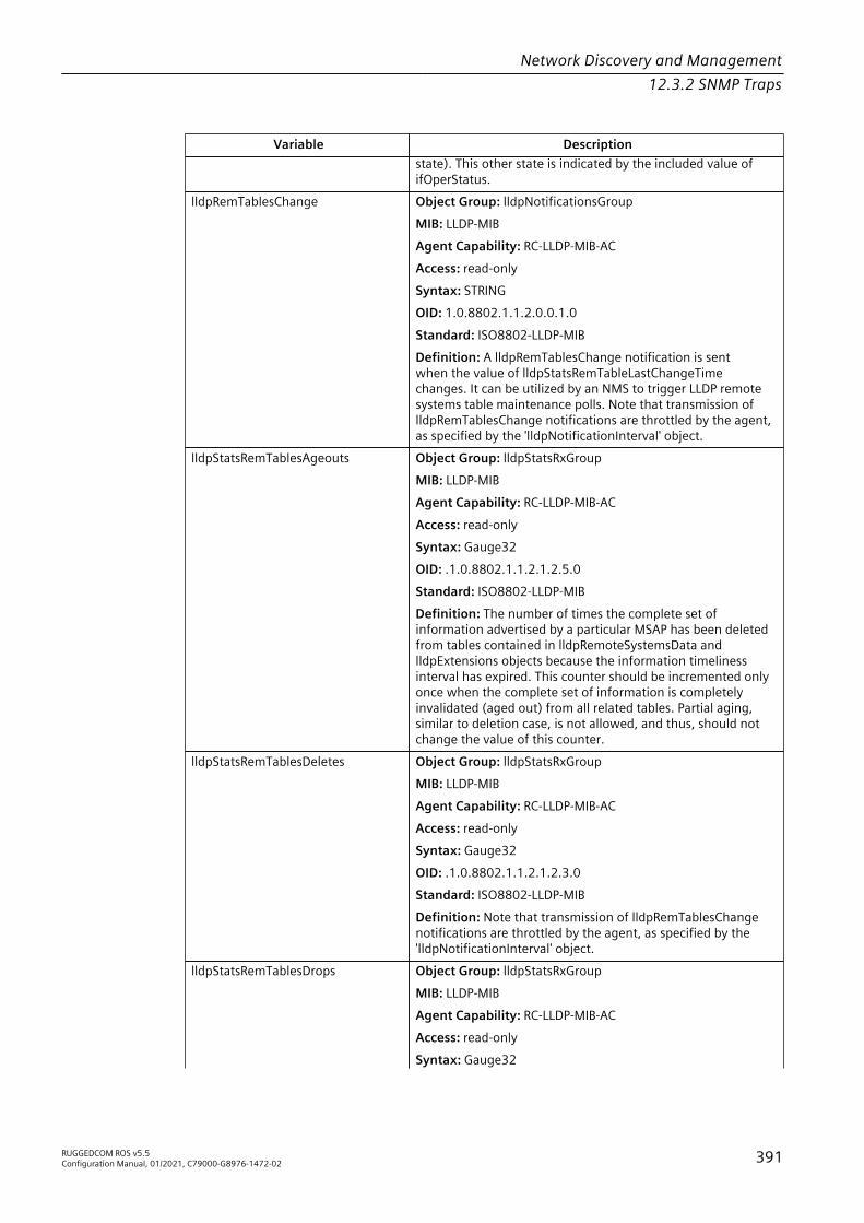
Network Discovery and Management12.3.2 SNMP Traps
Variable Descriptionstate). This other state is indicated by the included value ofifOperStatus.
lldpRemTablesChange Object Group: lldpNotificationsGroupMIB: LLDP-MIBAgent Capability: RC-LLDP-MIB-ACAccess: read-onlySyntax: STRINGOID: 1.0.8802.1.1.2.0.0.1.0Standard: ISO8802-LLDP-MIBDefinition: A lldpRemTablesChange notification is sentwhen the value of lldpStatsRemTableLastChangeTimechanges. It can be utilized by an NMS to trigger LLDP remotesystems table maintenance polls. Note that transmission oflldpRemTablesChange notifications are throttled by the agent,as specified by the 'lldpNotificationInterval' object.
lldpStatsRemTablesAgeouts Object Group: lldpStatsRxGroupMIB: LLDP-MIBAgent Capability: RC-LLDP-MIB-ACAccess: read-onlySyntax: Gauge32OID: .1.0.8802.1.1.2.1.2.5.0Standard: ISO8802-LLDP-MIBDefinition: The number of times the complete set ofinformation advertised by a particular MSAP has been deletedfrom tables contained in lldpRemoteSystemsData andlldpExtensions objects because the information timelinessinterval has expired. This counter should be incremented onlyonce when the complete set of information is completelyinvalidated (aged out) from all related tables. Partial aging,similar to deletion case, is not allowed, and thus, should notchange the value of this counter.
lldpStatsRemTablesDeletes Object Group: lldpStatsRxGroupMIB: LLDP-MIBAgent Capability: RC-LLDP-MIB-ACAccess: read-onlySyntax: Gauge32OID: .1.0.8802.1.1.2.1.2.3.0Standard: ISO8802-LLDP-MIBDefinition: Note that transmission of lldpRemTablesChangenotifications are throttled by the agent, as specified by the'lldpNotificationInterval' object.
lldpStatsRemTablesDrops Object Group: lldpStatsRxGroupMIB: LLDP-MIBAgent Capability: RC-LLDP-MIB-ACAccess: read-onlySyntax: Gauge32
RUGGEDCOM ROS v5.5Configuration Manual, 01/2021, C79000-G8976-1472-02 391

Network Discovery and Management12.3.2 SNMP Traps
Variable DescriptionOID: .1.0.8802.1.1.2.1.2.4.0Standard: The number of times the complete set ofinformation advertised by a particular MSAP could not beentered into tables contained in lldpRemoteSystemsData andlldpExtensions objects because of insufficient resources.Definition: ISO8802-LLDP-MIB
lldpStatsRemTablesInserts Object Group: lldpStatsRxGroupMIB: LLDP-MIBAgent Capability: RC-LLDP-MIB-ACAccess: read-onlySyntax: Gauge32OID: .1.0.8802.1.1.2.1.2.2.0Standard: ISO8802-LLDP-MIBDefinition: The number of times the complete set ofinformation advertised by a particular MSAP has beeninserted into tables contained in lldpRemoteSystemsDataand lldpExtensions objects. The complete set of informationreceived from a particular MSAP should be inserted intorelated tables. If partial information cannot be inserted fora reason such as lack of resources, all of the complete setof information should be removed. This counter should beincremented only once after the complete set of informationis successfully recorded in all related tables. Any failuresduring inserting information set which result in deletion ofpreviously inserted information should not trigger any changesin lldpStatsRemTablesInserts since the insert is not completedyet or or in lldpStatsRemTablesDeletes, since the deletionwould only be a partial deletion. If the failure was the result oflack of resources, the lldpStatsRemTablesDrops counter shouldbe incremented once.
RMON_alarmIndex Access: read-onlySyntax: 1.3.6.1.2.1.16.3.1.1.1.0OID: 1.3.6.1.2.1.16.3.1.1.1.0Standard: RFC-2819
RMON_alarmSampleType Access: read-onlySyntax: 1.3.6.1.2.1.16.3.1.1.4.0OID: 1.3.6.1.2.1.16.3.1.1.4.0Standard: RFC-2819
RMON_alarmThreshold Access: read-onlySyntax: 1.3.6.1.2.1.16.3.1.1.0.0OID: 1.3.6.1.2.1.16.3.1.1.0.0Standard: RFC-2819
RMON_alarmValue Access: read-onlySyntax: 1.3.6.1.2.1.16.3.1.1.5.0OID: 1.3.6.1.2.1.16.3.1.1.5.0Standard: RFC-2819
RMON_alarmVariable Access: read-only
392 RUGGEDCOM ROS v5.5Configuration Manual, 01/2021, C79000-G8976-1472-02

Network Discovery and Management12.3.2 SNMP Traps
Variable DescriptionSyntax: 1.3.6.1.2.1.16.3.1.1.3.0OID: 1.3.6.1.2.1.16.3.1.1.3.0Standard: RFC-2819
RMON_fallingAlarm Access: read-onlySyntax: 1.3.6.1.2.1.16.0.2.0OID: 1.3.6.1.2.1.16.0.2.0Standard: RFC-2819
RMON_risingAlarm Access: read-onlySyntax: 1.3.6.1.2.1.16.0.1.0OID: 1.3.6.1.2.1.16.0.1.0Standard: RFC-2819
RstpNewRoot Access: read-onlySyntax: 1.3.6.1.2.1.17.0.1.0OID: 1.3.6.1.2.1.17.0.1.0Standard: RFC-4188
RstpTopolgyChange Access: read-onlySyntax: 1.3.6.1.2.1.17.0.2.0OID: 1.3.6.1.2.1.17.0.2.0Standard: RFC-4188
SnmpAuthenticationFailure Access: read-onlySyntax: 1.3.6.1.6.3.1.1.5.5.0OID: 1.3.6.1.6.3.1.1.5.5.0Standard: RFC-1907
snmpEnableAuthenTraps Object Group: snmpGroupMIB: SNMPv2-MIBAccess: read-writeSyntax: INTEGEROID: 1.3.6.1.2.1.11.30.0Definition: Indicates whether the SNMP entity is permittedto generate authenticationFailure traps. The value of thisobject overrides any configuration information; as such, itprovides a means whereby all authenticationFailure traps maybe disabled. Note that it is strongly recommended that thisobject be stored in non-volatile memory so that it remainsconstant across re-initializations of the network managementsystem.
warmStart Object Group: ROS-Standard-TrapMIB: SNMPv2-MIBAccess: read-onlySyntax: 1.3.6.1.6.3.1.1.5.2.0OID: 1.3.6.1.6.3.1.1.5.2.0Definition: A warmStart trap signifies that the SNMPv2 entity,acting in an agent role, is reinitializing itself such that itsconfiguration is unaltered.
RUGGEDCOM ROS v5.5Configuration Manual, 01/2021, C79000-G8976-1472-02 393

Network Discovery and Management12.3.2 SNMP Traps
Specific Proprietary Traps
Variable DescriptionbootVersionMismatchTrap Object Group: ruggedcomSecurityGroup01
MIB: RUGGEDCOM-TRAPS-MIBOID: 1.3.6.1.4.1.15004.5.14Definition: A boot software version indication trap generatedby RUGGEDCOM devices.
cfgChangeTrap Object Group: ruggedcomNotificationsGroupMIB: RUGGEDCOM-TRAPS-MIBOID: 1.3.6.1.4.1.15004.5.4Definition: A generic trap generated upon configurationchange. The rate at which this notification can be provided is60 seconds.
defaultKeysTrap Object Group: ruggedcomSecurityGroup01MIB: RUGGEDCOM-TRAPS-MIBOID: 1.3.6.1.4.1.15004.5.13Definition: A use of default keys for secure services (SSH andSSL) indication trap generated by RUGGEDCOM devices.
genericTrap Object Group: ruggedcomNotificationsGroupMIB: RUGGEDCOM-TRAPS-MIBOID: 1.3.6.1.4.1.15004.5.1Definition: A use of default keys for secure services (SSH andSSL) indication trap generated by RUGGEDCOM devices.
genericTrapDescription Object Group: ruggedcomGenericTrapGroupMIB: RUGGEDCOM-TRAPS-MIBOID: 1.3.6.1.4.1.15004.4.1.1.1.2Definition: A description of a generic trap.
genericTrapSeverity Object Group: ruggedcomGenericTrapGroupMIB: RUGGEDCOM-TRAPS-MIBOID: 1.3.6.1.4.1.15004.4.1.1.1.1Definition: The severity level of the generic trap.
powerSupplyDescription Object Group: ruggedcomPowerSupplyGroupMIB: RUGGEDCOM-TRAPS-MIBOID: 1.3.6.1.4.1.15004.4.1.1.2.1Definition: A description of power supply that fails.
powerSupplyTrap Object Group: ruggedcomNotificationsGroupMIB: RUGGEDCOM-TRAPS-MIBOID: 1.3.6.1.4.1.15004.5.2Definition: A trap generated when a power supply fails orcomes up The first trap would be generated on first powersupply failure The state of power supply (failed or restored)is retrieved via object powerSupplyDescription at the timewhen trap is generated. The status of power supply units indevice can be retrieved via objects rcDeviceStsPowerSupply1and rcDeviceStsPowerSupply2 powerSupplyIdentifier object is
394 RUGGEDCOM ROS v5.5Configuration Manual, 01/2021, C79000-G8976-1472-02

Network Discovery and Management12.3.3 Managing SNMP Users
Variable Descriptionrecommended to be added as an optional parameter to the listof objects.
rcRstpNewTopology Object Groups: rcRstpNotifyGroup, rcDigitalInputsNotifyGroupMIB: RUGGEDCOM-STP-MIBOID: 1.3.6.1.4.1.15004.5.11.1Definition: A rcRstpNewTopology trap is sent by a bridgeafter topoogy change trap occures on one or more ports( topologyChange traps are sent), and topology becomesstable. Topology is stable when the tcWhile timer for all portson this Bridge is zero. This trap is disabled if topologyChangetrap is disabled by device configuration.
swUpgradeTrap Object Group: ruggedcomNotificationsGroupMIB: RUGGEDCOM-SYS-INFO-MIBOID: 1.3.6.1.4.1.15004.5.3Definition: A generic trap generated upon software upgrade.The rate at which this notification can be provided is 60seconds.
weakPasswordTrap Object Group: ruggedcomSecurityGroup01MIB: RUGGEDCOM-SYS-INFO-MIBOID: 1.3.6.1.4.1.15004.5.8Definition: A weak password indication trap generated byRUGGEDCOM devices.
12.3.3 Managing SNMP UsersThis section describes how to manage SNMP users.
12.3.3.1 Viewing a List of SNMP Users
To view a list of SNMP users configured on the device, navigate to Administration »Configure SNMP » Configure SNMP Users. The SNMP Users table appears.If users have not been configured, add users as needed. For more information, referto "Adding an SNMP User (Page 395)".
12.3.3.2 Adding an SNMP User
Multiple users (up to a maximum of 32) can be configured for the local SNMPv3engine, as well as SNMPv1 and SNMPv2c communities.
NoteWhen employing the SNMPv1 or SNMPv2c security level, the User Name parametermaps the community name with the security group and access level.
RUGGEDCOM ROS v5.5Configuration Manual, 01/2021, C79000-G8976-1472-02 395

Network Discovery and Management12.3.3 Managing SNMP Users
For CLI commands related to adding an SNMP user, refer to "Available CLI Commands(Page 23)".To add a new SNMP user, do the following:1. Navigate to Administration » Configure SNMP » Configure SNMP Users. The
SNMP Users Table appears.2. Click InsertRecord. The SNMP Users form appears.
NoteRUGGEDCOM ROS requires that all user passwords meet strict guidelines toprevent the use of weak passwords. When creating a new password, make sureit adheres to the following rules:• Must not be less than 6 characters in length.• Must not include the username or any 4 continuous alphanumeric
characters found in the username. For example, if the username isSubnet25, the password may not be subnet25admin or subnetadmin.However, net25admin or Sub25admin is permitted.
• Must have at least one alphabetic character and one number. Specialcharacters are permitted.
• Must not have more than 3 continuously incrementing or decrementingnumbers. For example, Sub123 and Sub19826 are permitted, but Sub12345is not.
An alarm will generate if a weak password is configured. The weak passwordalarm can be disabled by the user. For more information about disabling alarms,refer to "Managing Alarms (Page 98)".
3. Configure the following parameter(s) as required:
Parameter Description
Name Synopsis: A string 32 characters longDefault: initialThe name of the user. This user name also represents thesecurity name that maps this user to the security group.
IP Address Synopsis: Any valid IP addressThe IP address of the user's SNMP management station. If IPaddress is configured, SNMP requests from that user will beverified by IP address as well. SNMP Authentication trap will begenerated to trap receivers if request was received from thisuser, but from any other IP address.If IP address is empty, trapscan not be generated to this user, but SNMP requests will beserved for this user from any IP address.
v1/v2c Community Synopsis: A string 32 characters longThe community string which is mapped by this user/securityname to the security group if security model is SNMPv1 orSNMPv2c. If this string is left empty, it will be assumed to beequal to the same as user name.
396 RUGGEDCOM ROS v5.5Configuration Manual, 01/2021, C79000-G8976-1472-02
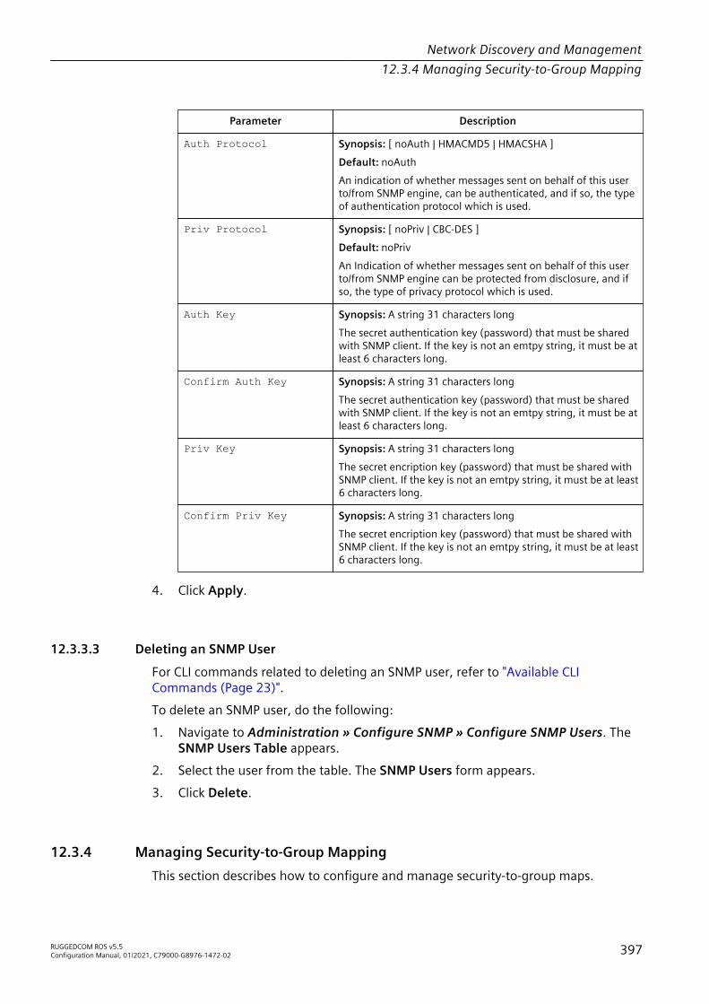
Network Discovery and Management12.3.4 Managing Security-to-Group Mapping
Parameter Description
Auth Protocol Synopsis: [ noAuth | HMACMD5 | HMACSHA ]Default: noAuthAn indication of whether messages sent on behalf of this userto/from SNMP engine, can be authenticated, and if so, the typeof authentication protocol which is used.
Priv Protocol Synopsis: [ noPriv | CBC-DES ]Default: noPrivAn Indication of whether messages sent on behalf of this userto/from SNMP engine can be protected from disclosure, and ifso, the type of privacy protocol which is used.
Auth Key Synopsis: A string 31 characters longThe secret authentication key (password) that must be sharedwith SNMP client. If the key is not an emtpy string, it must be atleast 6 characters long.
Confirm Auth Key Synopsis: A string 31 characters longThe secret authentication key (password) that must be sharedwith SNMP client. If the key is not an emtpy string, it must be atleast 6 characters long.
Priv Key Synopsis: A string 31 characters longThe secret encription key (password) that must be shared withSNMP client. If the key is not an emtpy string, it must be at least6 characters long.
Confirm Priv Key Synopsis: A string 31 characters longThe secret encription key (password) that must be shared withSNMP client. If the key is not an emtpy string, it must be at least6 characters long.
4. Click Apply.
12.3.3.3 Deleting an SNMP User
For CLI commands related to deleting an SNMP user, refer to "Available CLICommands (Page 23)".To delete an SNMP user, do the following:1. Navigate to Administration » Configure SNMP » Configure SNMP Users. The
SNMP Users Table appears.2. Select the user from the table. The SNMP Users form appears.3. Click Delete.
12.3.4 Managing Security-to-Group MappingThis section describes how to configure and manage security-to-group maps.
RUGGEDCOM ROS v5.5Configuration Manual, 01/2021, C79000-G8976-1472-02 397

Network Discovery and Management12.3.4 Managing Security-to-Group Mapping
12.3.4.1 Viewing a List of Security-to-Group Maps
To view a list of security-to-group maps configured on the device, navigate toAdministration » Configure SNMP » Configure SNMP Security to Group Maps.The SNMP Security to Group Maps table appears.If security-to-group maps have not been configured, add maps as needed. For moreinformation, refer to "Adding a Security-to-Group Map (Page 398)".
12.3.4.2 Adding a Security-to-Group Map
Multiple combinations of security models and groups can be mapped (up to amaximum of 32) for SNMP.For CLI commands related to adding an SNMP security-to-group map, refer to"Available CLI Commands (Page 23)".To add a security-to-group map, do the following:1. Navigate to Administration » Configure SNMP » Configure SNMP Security to
Group Maps. The SNMP Security to Group Maps Table appears.2. Click InsertRecord. The SNMP Security to Group Maps form appears.3. Configure the following parameter(s) as required:
Parameter Description
SecurityModel Synopsis: [ snmpV1 | snmpV2c | snmpV3 ]Default: snmpV3The Security Model that provides the name referenced in thistable.
Name Synopsis: A string 32 characters longThe user name which is mapped by this entry to the specifiedgroup name.
Group Synopsis: A string 32 characters longThe group name to which the security model and name belong.This name is used as an index to the SNMPv3 VACM AccessTable.
4. Click Apply.
12.3.4.3 Deleting a Security-to-Group Map
For CLI commands related to deleting an SNMP security-to-group map, refer to"Available CLI Commands (Page 23)".To delete a security-to-group map, do the following:1. Navigate to Administration » Configure SNMP » Configure SNMP Security to
Group Maps. The SNMP Security to Group Maps Table appears.
398 RUGGEDCOM ROS v5.5Configuration Manual, 01/2021, C79000-G8976-1472-02
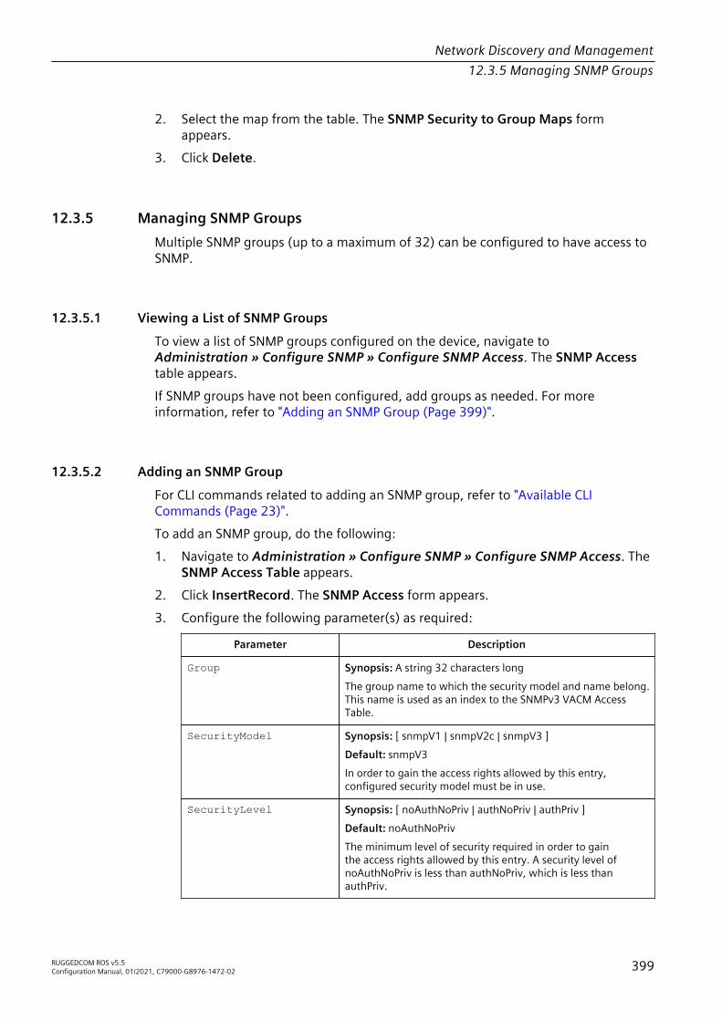
Network Discovery and Management12.3.5 Managing SNMP Groups
2. Select the map from the table. The SNMP Security to Group Maps formappears.
3. Click Delete.
12.3.5 Managing SNMP GroupsMultiple SNMP groups (up to a maximum of 32) can be configured to have access toSNMP.
12.3.5.1 Viewing a List of SNMP Groups
To view a list of SNMP groups configured on the device, navigate toAdministration » Configure SNMP » Configure SNMP Access. The SNMP Accesstable appears.If SNMP groups have not been configured, add groups as needed. For moreinformation, refer to "Adding an SNMP Group (Page 399)".
12.3.5.2 Adding an SNMP Group
For CLI commands related to adding an SNMP group, refer to "Available CLICommands (Page 23)".To add an SNMP group, do the following:1. Navigate to Administration » Configure SNMP » Configure SNMP Access. The
SNMP Access Table appears.2. Click InsertRecord. The SNMP Access form appears.3. Configure the following parameter(s) as required:
Parameter Description
Group Synopsis: A string 32 characters longThe group name to which the security model and name belong.This name is used as an index to the SNMPv3 VACM AccessTable.
SecurityModel Synopsis: [ snmpV1 | snmpV2c | snmpV3 ]Default: snmpV3In order to gain the access rights allowed by this entry,configured security model must be in use.
SecurityLevel Synopsis: [ noAuthNoPriv | authNoPriv | authPriv ]Default: noAuthNoPrivThe minimum level of security required in order to gainthe access rights allowed by this entry. A security level ofnoAuthNoPriv is less than authNoPriv, which is less thanauthPriv.
RUGGEDCOM ROS v5.5Configuration Manual, 01/2021, C79000-G8976-1472-02 399
Network Discovery and Management12.4 ModBus Management Support
Parameter Description
ReadViewName Synopsis: [ noView | V1Mib | allOfMib ]Default: noViewThis parameter identifies the MIB tree(s) to which this entryauthorizes read access. If the value is noView, then no readaccess is granted.
WriteViewName Synopsis: [ noView | V1Mib | allOfMib ]Default: noViewThis parameter identifies the MIB tree(s) to which this entryauthorizes write access. If the value is noView, then no writeaccess is granted.
NotifyViewName Synopsis: [ noView | V1Mib | allOfMib ]Default: noViewThis parameter identifies the MIB tree(s) to which this entryauthorizes access for notifications. If the value is noView, thenno access for notifications is granted.
4. Click Apply.
12.3.5.3 Deleting an SNMP Group
For CLI commands related to deleting an SNMP group, refer to "Available CLICommands (Page 23)".To delete an SNMP group, do the following:1. Navigate to Administration » Configure SNMP » Configure SNMP Access. The
SNMP Access Table appears.2. Select the group from the table. The SNMP Access form appears.3. Click Delete.
12.4 ModBus Management SupportModbus management support in RUGGEDCOM devices provides a simple interfacefor retrieving basic status information. ModBus support simplifies the job of SCADA(Supervisory Control and Data Acquisition) system integrators by providing familiarprotocols for retrieving RUGGEDCOM device information. ModBus provides mostlyread-only status information, but there are some writeable registers for operatorcommands.The ModBus protocol PDU (Protocol Data Unit) format is as follows:
Function Code Data
400 RUGGEDCOM ROS v5.5Configuration Manual, 01/2021, C79000-G8976-1472-02

Network Discovery and Management12.4.1 ModBus Function Codes
12.4.1 ModBus Function CodesRUGGEDCOM devices support the following ModBus function codes for devicemanagement through ModBus:
NoteWhile RUGGEDCOM devices have a variable number of ports, not all registers and bitsapply to all products.Registers that are not applicable to a particular device return a zero (0) value. Forexample, registers referring to serial ports are not applicable to RUGGEDCOM switchdevices.
Read Input Registers or Read Holding Registers – 0x04 or 0x03Example PDU Request
Function Code 1 Byte 0x04(0x03)Starting Address 2 Bytes 0x0000 to 0xFFFF (Hexadecimal)
128 to 65535 (Decimal)Number of Input Registers 2 Bytes Bytes 0x0001 to 0x007D
Example PDU Response
Function Code 1 Byte 0x04(0x03)Byte Count 1 Byte 2 x N a
Number of Input Registers Na x 2 Bytes a The number of input registers
Write Multiple Registers – 0x10Example PDU Request
Function Code 1 Byte 0x10Starting Address 2 Bytes 0x0000 to 0xFFFFNumber of Input Registers 2 Bytes Bytes 0x0001 to 0x0079Byte Count 1 Byte 2 x N a
Registers Value Na x 2 Bytes Value of the registera The number of input registers
Example PDU Response
Function Code 1 Byte 0x10Starting Address 2 Bytes 0x0000 to 0xFFFFNumber of Registers 2 Bytes 1 to 121 (0x79)
RUGGEDCOM ROS v5.5Configuration Manual, 01/2021, C79000-G8976-1472-02 401

Network Discovery and Management12.4.2 ModBus Memory Map
12.4.2 ModBus Memory MapThe following details how ModBus process variable data is mapped.
Product InfoThe following data is mapped to the Productinfo table:
Address #Registers Description (Reference Table in UI) R/W Format0000 16 Product Identification R Text0010 32 Firmware Identification R Text0040 1 Number of Ethernet Ports R Uint160042 1 Number of Alarms R Uint160043 1 Power Supply Status R PSStatusCmd0044 1 FailSafe Relay Status R TruthValue0045 1 ErrorAlarm Status R TruthValue
Product Write RegisterThe following data is mapped to various tables:
Address #Registers Description (Reference Table in UI) R/W Format0080 1 Clear Alarms W Cmd0081 2 Reset Ethernet Ports W PortCmd0083 2 Clear Ethernet Statistics W PortCmd
AlarmsThe following data is mapped to the alarms table:
Address #Registers Description (Reference Table in UI) R/W Format0100 64 Alarm 1 R Alarm0140 64 Alarm 2 R Alarm0180 64 Alarm 3 R Alarm01C0 64 Alarm 4 R Alarm0200 64 Alarm 5 R Alarm0240 64 Alarm 6 R Alarm0280 64 Alarm 7 R Alarm02C0 64 Alarm 8 R Alarm
Ethernet Port StatusThe following data is mapped to the ethPortStats table:
Address #Registers Description (Reference Table in UI) R/W Format03FE 2 Port Link Status R PortCmd
402 RUGGEDCOM ROS v5.5Configuration Manual, 01/2021, C79000-G8976-1472-02
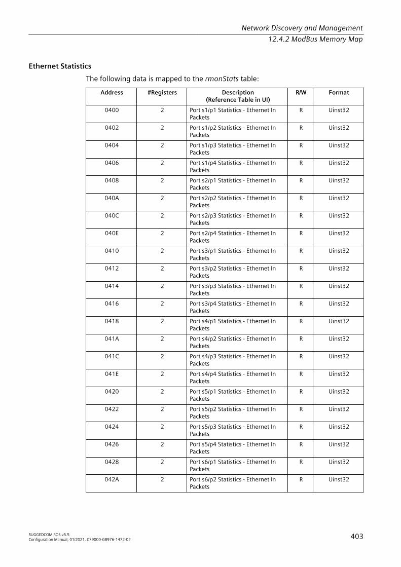
Network Discovery and Management12.4.2 ModBus Memory Map
Ethernet StatisticsThe following data is mapped to the rmonStats table:
Address #Registers Description(Reference Table in UI)
R/W Format
0400 2 Port s1/p1 Statistics - Ethernet InPackets
R Uinst32
0402 2 Port s1/p2 Statistics - Ethernet InPackets
R Uinst32
0404 2 Port s1/p3 Statistics - Ethernet InPackets
R Uinst32
0406 2 Port s1/p4 Statistics - Ethernet InPackets
R Uinst32
0408 2 Port s2/p1 Statistics - Ethernet InPackets
R Uinst32
040A 2 Port s2/p2 Statistics - Ethernet InPackets
R Uinst32
040C 2 Port s2/p3 Statistics - Ethernet InPackets
R Uinst32
040E 2 Port s2/p4 Statistics - Ethernet InPackets
R Uinst32
0410 2 Port s3/p1 Statistics - Ethernet InPackets
R Uinst32
0412 2 Port s3/p2 Statistics - Ethernet InPackets
R Uinst32
0414 2 Port s3/p3 Statistics - Ethernet InPackets
R Uinst32
0416 2 Port s3/p4 Statistics - Ethernet InPackets
R Uinst32
0418 2 Port s4/p1 Statistics - Ethernet InPackets
R Uinst32
041A 2 Port s4/p2 Statistics - Ethernet InPackets
R Uinst32
041C 2 Port s4/p3 Statistics - Ethernet InPackets
R Uinst32
041E 2 Port s4/p4 Statistics - Ethernet InPackets
R Uinst32
0420 2 Port s5/p1 Statistics - Ethernet InPackets
R Uinst32
0422 2 Port s5/p2 Statistics - Ethernet InPackets
R Uinst32
0424 2 Port s5/p3 Statistics - Ethernet InPackets
R Uinst32
0426 2 Port s5/p4 Statistics - Ethernet InPackets
R Uinst32
0428 2 Port s6/p1 Statistics - Ethernet InPackets
R Uinst32
042A 2 Port s6/p2 Statistics - Ethernet InPackets
R Uinst32
RUGGEDCOM ROS v5.5Configuration Manual, 01/2021, C79000-G8976-1472-02 403

Network Discovery and Management12.4.2 ModBus Memory Map
Address #Registers Description(Reference Table in UI)
R/W Format
042C 2 Port s6/p3 Statistics - Ethernet InPackets
R Uinst32
042E 2 Port s6/p4 Statistics - Ethernet InPackets
R Uinst32
0430 2 Port s7/p1 Statistics - Ethernet InPackets
R Uinst32
0432 2 Port s7/p2 Statistics - Ethernet InPackets
R Uinst32
0434 2 Port s8/p1 Statistics - Ethernet InPackets
R Uinst32
0436 2 Port s8/p2 Statistics - Ethernet InPackets
R Uinst32
0440 2 Port s1/p1 Statistics - Ethernet OutPackets
R Uinst32
0442 2 Port s1/p2 Statistics - Ethernet OutPackets
R Uinst32
0444 2 Port s1/p3 Statistics - Ethernet OutPackets
R Uinst32
0446 2 Port s1/p4 Statistics - Ethernet OutPackets
R Uinst32
0448 2 Port s2/p1 Statistics - Ethernet OutPackets
R Uinst32
044A 2 Port s2/p2 Statistics - Ethernet OutPackets
R Uinst32
044C 2 Port s2/p3 Statistics - Ethernet OutPackets
R Uinst32
044E 2 Port s2/p4 Statistics - Ethernet OutPackets
R Uinst32
0450 2 Port s3/p1 Statistics - Ethernet OutPackets
R Uinst32
0452 2 Port s3/p2 Statistics - Ethernet OutPackets
R Uinst32
0454 2 Port s3/p3 Statistics - Ethernet OutPackets
R Uinst32
0456 2 Port s3/p4 Statistics - Ethernet OutPackets
R Uinst32
0458 2 Port s4/p1 Statistics - Ethernet OutPackets
R Uinst32
045A 2 Port s4/p2 Statistics - Ethernet OutPackets
R Uinst32
045C 2 Port s4/p3 Statistics - Ethernet OutPackets
R Uinst32
045E 2 Port s4/p4 Statistics - Ethernet OutPackets
R Uinst32
0460 2 Port s5/p1 Statistics - Ethernet OutPackets
R Uinst32
0462 2 Port s5/p2 Statistics - Ethernet OutPackets
R Uinst32
404 RUGGEDCOM ROS v5.5Configuration Manual, 01/2021, C79000-G8976-1472-02

Network Discovery and Management12.4.2 ModBus Memory Map
Address #Registers Description(Reference Table in UI)
R/W Format
0464 2 Port s5/p3 Statistics - Ethernet OutPackets
R Uinst32
0466 2 Port s5/p4 Statistics - Ethernet OutPackets
R Uinst32
0468 2 Port s6/p1 Statistics - Ethernet OutPackets
R Uinst32
046A 2 Port s6/p2 Statistics - Ethernet OutPackets
R Uinst32
046C 2 Port s6/p3 Statistics - Ethernet OutPackets
R Uinst32
046E 2 Port s6/p4 Statistics - Ethernet OutPackets
R Uinst32
0470 2 Port s7/p1 Statistics - Ethernet OutPackets
R Uinst32
0472 2 Port s7/p2 Statistics - Ethernet OutPackets
R Uinst32
0474 2 Port s8/p1 Statistics - Ethernet OutPackets
R Uinst32
0476 2 Port s8/p2 Statistics - Ethernet OutPackets
R Uinst32
0480 2 Port s1/p1 Statistics - Ethernet InPackets
R Uinst32
0482 2 Port s1/p2 Statistics - Ethernet InPackets
R Uinst32
0484 2 Port s1/p3 Statistics - Ethernet InPackets
R Uinst32
0486 2 Port s1/p4 Statistics - Ethernet InPackets
R Uinst32
0488 2 Port s2/p1 Statistics - Ethernet InPackets
R Uinst32
048A 2 Port s2/p2 Statistics - Ethernet InPackets
R Uinst32
048C 2 Port s2/p3 Statistics - Ethernet InPackets
R Uinst32
048E 2 Port s2/p4 Statistics - Ethernet InPackets
R Uinst32
0490 2 Port s3/p1 Statistics - Ethernet InPackets
R Uinst32
0492 2 Port s3/p2 Statistics - Ethernet InPackets
R Uinst32
0494 2 Port s3/p3 Statistics - Ethernet InPackets
R Uinst32
0496 2 Port s3/p4 Statistics - Ethernet InPackets
R Uinst32
0498 2 Port s4/p1 Statistics - Ethernet InPackets
R Uinst32
049A 2 Port s4/p2 Statistics - Ethernet InPackets
R Uinst32
RUGGEDCOM ROS v5.5Configuration Manual, 01/2021, C79000-G8976-1472-02 405
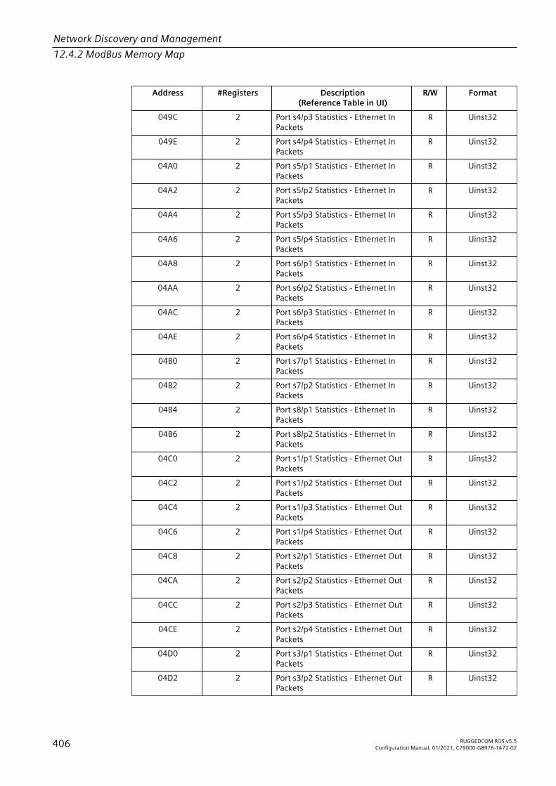
Network Discovery and Management12.4.2 ModBus Memory Map
Address #Registers Description(Reference Table in UI)
R/W Format
049C 2 Port s4/p3 Statistics - Ethernet InPackets
R Uinst32
049E 2 Port s4/p4 Statistics - Ethernet InPackets
R Uinst32
04A0 2 Port s5/p1 Statistics - Ethernet InPackets
R Uinst32
04A2 2 Port s5/p2 Statistics - Ethernet InPackets
R Uinst32
04A4 2 Port s5/p3 Statistics - Ethernet InPackets
R Uinst32
04A6 2 Port s5/p4 Statistics - Ethernet InPackets
R Uinst32
04A8 2 Port s6/p1 Statistics - Ethernet InPackets
R Uinst32
04AA 2 Port s6/p2 Statistics - Ethernet InPackets
R Uinst32
04AC 2 Port s6/p3 Statistics - Ethernet InPackets
R Uinst32
04AE 2 Port s6/p4 Statistics - Ethernet InPackets
R Uinst32
04B0 2 Port s7/p1 Statistics - Ethernet InPackets
R Uinst32
04B2 2 Port s7/p2 Statistics - Ethernet InPackets
R Uinst32
04B4 2 Port s8/p1 Statistics - Ethernet InPackets
R Uinst32
04B6 2 Port s8/p2 Statistics - Ethernet InPackets
R Uinst32
04C0 2 Port s1/p1 Statistics - Ethernet OutPackets
R Uinst32
04C2 2 Port s1/p2 Statistics - Ethernet OutPackets
R Uinst32
04C4 2 Port s1/p3 Statistics - Ethernet OutPackets
R Uinst32
04C6 2 Port s1/p4 Statistics - Ethernet OutPackets
R Uinst32
04C8 2 Port s2/p1 Statistics - Ethernet OutPackets
R Uinst32
04CA 2 Port s2/p2 Statistics - Ethernet OutPackets
R Uinst32
04CC 2 Port s2/p3 Statistics - Ethernet OutPackets
R Uinst32
04CE 2 Port s2/p4 Statistics - Ethernet OutPackets
R Uinst32
04D0 2 Port s3/p1 Statistics - Ethernet OutPackets
R Uinst32
04D2 2 Port s3/p2 Statistics - Ethernet OutPackets
R Uinst32
406 RUGGEDCOM ROS v5.5Configuration Manual, 01/2021, C79000-G8976-1472-02

Network Discovery and Management12.4.3 Modbus Memory Formats
Address #Registers Description(Reference Table in UI)
R/W Format
04D4 2 Port s3/p3 Statistics - Ethernet OutPackets
R Uinst32
04D6 2 Port s3/p4 Statistics - Ethernet OutPackets
R Uinst32
04D8 2 Port s4/p1 Statistics - Ethernet OutPackets
R Uinst32
04DA 2 Port s4/p2 Statistics - Ethernet OutPackets
R Uinst32
04DC 2 Port s4/p3 Statistics - Ethernet OutPackets
R Uinst32
04DE 2 Port s4/p4 Statistics - Ethernet OutPackets
R Uinst32
04E0 2 Port s5/p1 Statistics - Ethernet OutPackets
R Uinst32
04E2 2 Port s5/p2 Statistics - Ethernet OutPackets
R Uinst32
04E4 2 Port s5/p3 Statistics - Ethernet OutPackets
R Uinst32
04E6 2 Port s5/p4 Statistics - Ethernet OutPackets
R Uinst32
04E8 2 Port s6/p1 Statistics - Ethernet OutPackets
R Uinst32
04EA 2 Port s6/p2 Statistics - Ethernet OutPackets
R Uinst32
04EC 2 Port s6/p3 Statistics - Ethernet OutPackets
R Uinst32
04EE 2 Port s6/p4 Statistics - Ethernet OutPackets
R Uinst32
04F0 2 Port s7/p1 Statistics - Ethernet OutPackets
R Uinst32
04F2 2 Port s7/p2 Statistics - Ethernet OutPackets
R Uinst32
04F4 2 Port s8/p1 Statistics - Ethernet OutPackets
R Uinst32
04F6 2 Port s8/p2 Statistics - Ethernet OutPackets
R Uinst32
12.4.3 Modbus Memory FormatsThis section defines the Modbus memory formats supported by RUGGEDCOM ROS.
12.4.3.1 Text
The Text format provides a simple ASCII representation of the information related tothe product. The most significant register byte of an ASCII characters comes first.
RUGGEDCOM ROS v5.5Configuration Manual, 01/2021, C79000-G8976-1472-02 407

Network Discovery and Management12.4.3 Modbus Memory Formats
For example, consider a Read Multiple Registers request to read ProductIdentification from location 0x0000.
0x04 0x00 0x00 0x00 0x08
The response may look like:
0x04 0x10 0x53 0x59 0x53 0x54 0x45 0x4D 0x20 0x4E 0x41 0x4D 0x450x00 0x00 0x00 0x00 0x00
In this example, starting from byte 3 until the end, the response presents an ASCIIrepresentation of the characters for the product identification, which reads asSYSTEM NAME. Since the length of this field is smaller than eight registers, the rest ofthe field is filled with zeros (0).
12.4.3.2 Cmd
The Cmd format instructs the device to set the output to either true or false. Themost significant byte comes first.• FF 00 hex requests output to be True• 00 00 hex requests output to be False• Any value other than the suggested values does not affect the requested
operationFor example, consider a Write Multiple Registers request to clear alarms in the device.
0x10 0x00 0x80 0x00 0x01 2 0xFF 0x00
• FF 00 for register 00 80 clears the system alarms• 00 00 does not clear any alarmsThe response may look like:
0x10 0x00 0x80 0x00 0x01
12.4.3.3 Uint16
The Uint16 format describes a Standard ModBus 16 bit register.
12.4.3.4 Uint32
The Uint32 format describes Standard 2 ModBus 16 bit registers. The first registerholds the most significant 16 bits of a 32 bit value. The second register holds theleast significant 16 bits of a 32 bit value.
408 RUGGEDCOM ROS v5.5Configuration Manual, 01/2021, C79000-G8976-1472-02
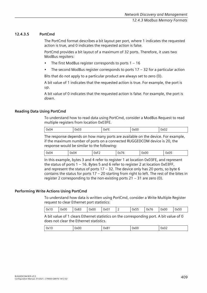
Network Discovery and Management12.4.3 Modbus Memory Formats
12.4.3.5 PortCmd
The PortCmd format describes a bit layout per port, where 1 indicates the requestedaction is true, and 0 indicates the requested action is false.PortCmd provides a bit layout of a maximum of 32 ports. Therefore, it uses twoModBus regsiters:• The first ModBus register corresponds to ports 1 – 16• The second ModBus register corresponds to ports 17 – 32 for a particular actionBits that do not apply to a particular product are always set to zero (0).A bit value of 1 indicates that the requested action is true. For example, the port isup.A bit value of 0 indicates that the requested action is false. For example, the port isdown.
Reading Data Using PortCmdTo understand how to read data using PortCmd, consider a ModBus Request to readmultiple registers from location 0x03FE.
0x04 0x03 0xFE 0x00 0x02
The response depends on how many ports are available on the device. For example,if the maximum number of ports on a connected RUGGEDCOM device is 20, theresponse would be similar to the following:
0x04 0x04 0xF2 0x76 0x00 0x05
In this example, bytes 3 and 4 refer to register 1 at location 0x03FE, and representthe status of ports 1 – 16. Bytes 5 and 6 refer to register 2 at location 0x03FF,and represent the status of ports 17 – 32. The device only has 20 ports, so byte 6contains the status for ports 17 – 20 starting from right to left. The rest of the bites inregister 2 corresponding to the non-existing ports 21 – 31 are zero (0).
Performing Write Actions Using PortCmdTo understand how data is written using PortCmd, consider a Write Multiple Registerrequest to clear Ethernet port statistics:
0x10 0x00 0x83 0x00 0x01 2 0x55 0x76 0x00 0x50
A bit value of 1 clears Ethernet statistics on the corresponding port. A bit value of 0does not clear the Ethernet statistics.
0x10 0x00 0x81 0x00 0x02
RUGGEDCOM ROS v5.5Configuration Manual, 01/2021, C79000-G8976-1472-02 409
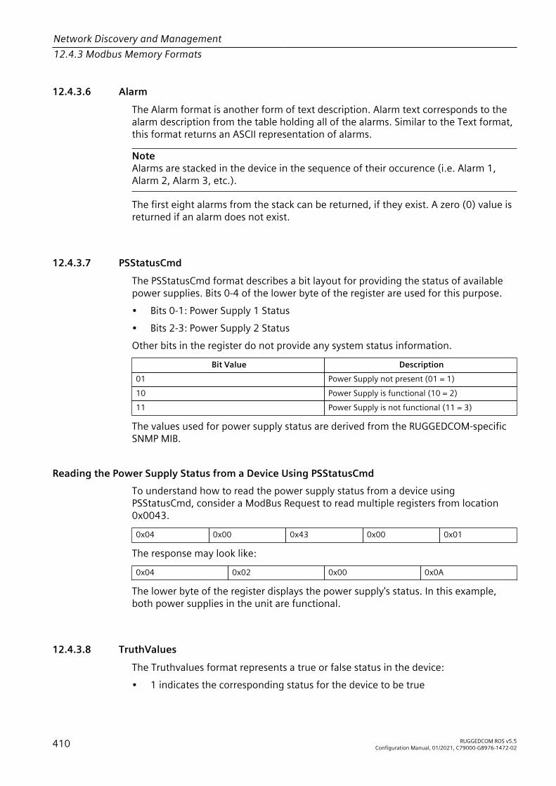
Network Discovery and Management12.4.3 Modbus Memory Formats
12.4.3.6 Alarm
The Alarm format is another form of text description. Alarm text corresponds to thealarm description from the table holding all of the alarms. Similar to the Text format,this format returns an ASCII representation of alarms.
NoteAlarms are stacked in the device in the sequence of their occurence (i.e. Alarm 1,Alarm 2, Alarm 3, etc.).
The first eight alarms from the stack can be returned, if they exist. A zero (0) value isreturned if an alarm does not exist.
12.4.3.7 PSStatusCmd
The PSStatusCmd format describes a bit layout for providing the status of availablepower supplies. Bits 0-4 of the lower byte of the register are used for this purpose.• Bits 0-1: Power Supply 1 Status• Bits 2-3: Power Supply 2 StatusOther bits in the register do not provide any system status information.
Bit Value Description01 Power Supply not present (01 = 1)10 Power Supply is functional (10 = 2)11 Power Supply is not functional (11 = 3)
The values used for power supply status are derived from the RUGGEDCOM-specificSNMP MIB.
Reading the Power Supply Status from a Device Using PSStatusCmdTo understand how to read the power supply status from a device usingPSStatusCmd, consider a ModBus Request to read multiple registers from location0x0043.
0x04 0x00 0x43 0x00 0x01
The response may look like:
0x04 0x02 0x00 0x0A
The lower byte of the register displays the power supply's status. In this example,both power supplies in the unit are functional.
12.4.3.8 TruthValues
The Truthvalues format represents a true or false status in the device:• 1 indicates the corresponding status for the device to be true
410 RUGGEDCOM ROS v5.5Configuration Manual, 01/2021, C79000-G8976-1472-02

Network Discovery and Management12.4.3 Modbus Memory Formats
• 2 indicates the corresponding status for the device to be false
Reading the FailSafe Relay Status From a Device Using TruthValueTo understand how to use the TruthValue format to read the FailSafe Relay statusfrom a device, consider a ModBus request to read multiple registers from location0x0044.
0x04 0x00 0x44 0x00 0x01
The response may look like:
0x04 0x02 0x00 0x01
The register's lower byte shows the FailSafe Relay status. In this example, the FailSafeRelay is energized.
Reading the ErrorAlarm Status From a Device Using TruthValueTo understand how to use the TruthValue format to read the ErrorAlarm status froma device, conside a ModBus request to read mulitple registers from location 0x0045.
0x04 0x00 0x45 0x00 0x01
The response may look like:
0x04 0x02 0x00 0x01
The register's lower byte shows the ErrorAlarm status. In this example, there is noactive ERROR, ALERT or CRITICAL alarm in the device.
RUGGEDCOM ROS v5.5Configuration Manual, 01/2021, C79000-G8976-1472-02 411

Network Discovery and Management12.4.3 Modbus Memory Formats
412 RUGGEDCOM ROS v5.5Configuration Manual, 01/2021, C79000-G8976-1472-02

IP Address Assignment 13This chapter describes features related to the assignment of IP addresses.
13.1 Managing DHCPDynamic Host Configuration Protocol (DHCP) is a communications protocol thatallows network administrators to centrally manage and automate the networkconfiguration of devices attached to an Internet Protocol (IP) network.
13.1.1 DHCP ConceptsThe following section describes concepts important to the configuration andapplication of DHCP.
13.1.1.1 DHCP Snooping
DHCP snooping is a network security feature that protects the network fromuntrusted DHCP servers and untrusted clients by keeping track of ports where DHCPclients and servers reside. This information is tracked by building a DHCP bindingtable that contains all MAC-IP associations the switch has learned by snooping clientand server DHCP communications. The binding table contains MAC-IP informationwhich can be further utilized by DHCP snooping applications. RUGGEDCOM ROS willlog messages in the syslog and/or raise an alarm when DHCP violations are detected.
NoteDHCP Snooping is enabled on the device on a per-VLAN basis. For more informationabout enabling DHCP snooping on individual VLANs, refer to "Managing Static VLANs(Page 153)".
13.1.1.2 Trusted and Untrusted Ports
DHCP Snooping classifies ports as trusted and untrusted. This port classificationdetermines how a DHCP message is handled by the switch. DHCP messages receivedon trusted ports are forwarded without any further checking, while messagesreceived from untrusted ports are verified to determine if the message is legitimate.The user is expected to configure the ports as trusted or untrusted.
RUGGEDCOM ROS v5.5Configuration Manual, 01/2021, C79000-G8976-1472-02 413

IP Address Assignment13.1.1 DHCP Concepts
From a deployment perspective, it is also expected the user configures network portsas trusted. Network ports typically connect to another switch or a router. This isnecessary because a DHCP server may not be directly connected to a switch port.For more information about configuring ports as trusted or untrusted, refer to"Configuring Trusted/Untrusted Ports (Page 420)".
13.1.1.3 DHCP Relay Agent (Option 82)
A DHCP Relay Agent is a device that forwards DHCP packets between clients andservers when they are not on the same physical LAN segment or IP subnet. Thefeature is enabled if the DHCP server IP address and a set of ethernet ports areconfigured.DHCP Option 82 provides a mechanism for assigning an IP Address based on thelocation of the client device in the network. Information about the client’s locationcan be sent along with the DHCP request to the server. Based on this information, theDHCP server makes a decision about an IP Address to be assigned.The DHCP Relay Agent takes the broadcast DHCP requests from clients received onthe configured port and inserts the relay agent information option (Option 82) intothe packet. Option 82 contains the VLAN ID (2 bytes) and the port number of theclient port (2 bytes: the circuit ID sub-option) and the relay agent’s MAC address (theremote ID sub-option). This information uniquely defines the client’s position in thenetwork.For example, using the following formula, the Circuit ID for a client which isconnected to VLAN 1 on port 3/1 is 00:01:00:09.({slot} - 1)*4 + {port}
The DHCP Server supporting DHCP Option 82 sends a unicast reply and echoesOption 82. The DHCP Relay Agent removes the Option 82 field and forwards thepacket to the port from which the original request was received.These parameters provide the ability to configure the information based DHCP relayagent (Option 82).For more information about configuring the DHCP Relay Agent, refer to "Configuringthe DHCP Relay Agent (Page 418)".
13.1.1.4 Dynamic ARP Inspection
Dynamic ARP Inspection (DAI) is a DHCP snooping application that validates AddressResolution Protocol (ARP) packets in a network. DAI filters ARP packets with invalid IP-to-MAC address bindings. This protects the network from some man-in-the-middleattacks. Dynamic ARP inspection makes sure only valid ARP requests and responsesare relayed.
414 RUGGEDCOM ROS v5.5Configuration Manual, 01/2021, C79000-G8976-1472-02

IP Address Assignment13.1.1 DHCP Concepts
NoteDynamic ARP Inspection can only be enabled if DHCP snooping is enabled on thedevice.
ARP request and reply packets ingressing on untrusted ports are intercepted by thedevice and subject to validation. ARP packets are not intercepted on ports that areconfigured as trusted. The user is expected to configure the network ports as trusted,so that ARP traffic between devices is not subject to inspection.The sender MAC and sender IP address fields in an ARP request/reply packets arevalidated against the MAC-IP binding entry present in the DHCP snooping bindingtable. If a binding entry is not present in the table, or if the information in the entrydoes not match, the ARP request/reply packet is dropped.For more information about ARP inspection statistics, refer to "Viewing ARPInspection Statistics (Page 421)".
13.1.1.5 DHCP Binding Table
DHCP snooping dynamically builds and maintains a binding table using informationextracted from intercepted DHCP messages. The table contains an entry for eachuntrusted host with a leased IP address from the DHCP server. The table does notcontain entries for hosts connected through trusted interfaces. The DHCP snoopingfeature updates the table when the switch receives specific DHCP messages.When the device is reset, all the MAC-IP binding information learned by the switchwill be lost, unless the learned bindings are saved in the switch configuration file.If a switch port link goes down, all the dynamically-learned binding table entries onthat particular port are removed from the table.Manually-entered records can also be configured using a static binding table. Formore information about configuring the static DHCP binding table, refer to "AddingEntries to the DHCP Binding Table (Page 422)".
13.1.1.6 Preventable Network Attacks
The following network attacks can be prevented by enabling DHCP snooping andDynamic ARP Inspection on the switch. For more information, refer to "ConfiguringDHCP Snooping (Page 419)".• Host Misconfiguration by a Rogue DHCP Server
A rogue DHCP server can assign an incorrect IP address, default gateway and/or DNS server parameters to the client. A misconfigured client is susceptible toa potential network attack. Switches that support DHCP snooping can identify
RUGGEDCOM ROS v5.5Configuration Manual, 01/2021, C79000-G8976-1472-02 415

IP Address Assignment13.1.1 DHCP Concepts
DHCP messages from a rogue DHCP server and block these messages in theswitch itself.
3
2
1
4
1 DHCP Client 2 Switch 3 DHCP Server 4 Rogue DHCP Server
Figure 13.1 Misconfiguration by a Rogue DHCP Server
• DHCP Client AttackA roque DHCP client, or attacker host, can cancel the lease for an IP addressassigned to another client by sending a DHCPRELEASE message to the DHCPserver. It can also decline the IP address for another client by sending aDHCPDECLINE message.DHCP snooping builds a DHCP binding table to validate the legitimacy ofDHCPRELEASE and DHCPDECLINE messages. If validation of these messages fail,they are dropped by the device.
4
3
1
2
1 DHCP Client 2 Attacker Host 3 Switch 4 DHCP Server
Figure 13.2 DHCP Client Attack
416 RUGGEDCOM ROS v5.5Configuration Manual, 01/2021, C79000-G8976-1472-02

IP Address Assignment13.1.1 DHCP Concepts
• DHCP Starvation AttackDHCP starvation occurs when a DHCP server is flooded with DHCP requests froma single rogue DHCP client that has spoofed the client hardware addresses ofother clients. This exhausts the DHCP server's IP address pool, after which theserver is unable to respond and provide new leases to legitimate DHCP clients.DHCP snooping provides users an option to verify the client hardware address inthe DHCP-REQUEST message, thus preventing a starvation attack.
4
3
1
2
1
1 DHCP Client 2 Attacker 3 Switch 4 DHCP Server
Figure 13.3 DHCP Starvation/Consumption Attack
• ARP Spoofing Attack/Cache PoisoningARP spoofing attacks and cache poisoning can occur because ARP allows agratuitous reply from a host even if an ARP request was not received. After theattack, all traffic from the device under attack flows to the attacker's computer.An ARP spoofing attack can target hosts, switches, and routers connected to a
RUGGEDCOM ROS v5.5Configuration Manual, 01/2021, C79000-G8976-1472-02 417

IP Address Assignment13.1.2 Configuring the DHCP Relay Agent
Layer 2 network by poisoning the ARP caches of systems connected to the subnetand by intercepting traffic intended for other hosts on the subnet.An ARP spoofing attack can be prevented by enabling Dynamic ARP Inspection onthe switch. For more information about enabling Dynamic ARP Inspection, referto "Configuring DHCP Snooping (Page 419)".
3
1
2
1
1 Host 2 Attacker 3 Switch
Figure 13.4 ARP Cache Poisoning
13.1.2 Configuring the DHCP Relay AgentTo configure the device as a DHCP Relay Agent (Option 82), do the following:1. Navigate to Network Access Control » DHCP Snooping » Configure DHCP
Parameters. The DHCP Parameters form appears.2. Configure the following parameter(s) as required:
Parameter Description
DHCP Server Address Synopsis: Any valid IP addressIP address of the DHCP server to which DHCP requests will beforwarded. DHCP server IP must be configured for Relay Agentto work.
3. Click Apply.4. Enable DHCP Relay Agent (Option 82) on ports connected to a DHCP client. For
more information, refer to "Enabling DHCP Relay Agent Information (Option 82)for Specific Ports (Page 418)".
13.1.3 Enabling DHCP Relay Agent Information (Option 82) for Specific PortsDHCP Relay Agent (Option 82) can be enabled for any Ethernet port connected to aDHCP client.
418 RUGGEDCOM ROS v5.5Configuration Manual, 01/2021, C79000-G8976-1472-02

IP Address Assignment13.1.4 Configuring DHCP Snooping
To enable DHCP Relay Agent (Option 82) for a specific port, do the following:1. Navigate to Network Access Control » DHCP Snooping » Configure DHCP Port
Parameters. The DHCP Port Parameters table appears.2. Select a port. The DHCP Port Parameters form appears.
NoteThe Trusted parameter is configured as part of the DHCP snooping feature. Formore information, refer to "Configuring Trusted/Untrusted Ports (Page 420)".
3. Configure the following parameter(s) as required:
Parameter Description
Port Synopsis: 1/1 to maximum port numberThe port number as seen on the front plate silkscreen of thedevice.
Option-82 Synopsis: [ Disabled | Enabled ]Default: DisabledInsert DHCP Option 82.
4. Click Apply.
13.1.4 Configuring DHCP SnoopingTo configure DHCP snooping, do the following:
NoteDHCP Snooping is enabled on the device on a per-VLAN basis. For more informationabout enabling DHCP snooping on individual VLANs, refer to "Managing Static VLANs(Page 153)".
1. Navigate to Network Access Control » DHCP Snooping » Configure DHCPParameters. The DHCP Parameters form appears.
NoteFor information about the ARP Inspection parameter, refer to "Enabling/Disabling Dynamic ARP Inspection (Page 421)"
2. Configure the following parameter(s) as required:
Parameter Description
DHCP Server Address Synopsis: Any valid IP addressIP address of the DHCP server to which DHCP requests will beforwarded. DHCP server IP must be configured for Relay Agentto work.
RUGGEDCOM ROS v5.5Configuration Manual, 01/2021, C79000-G8976-1472-02 419
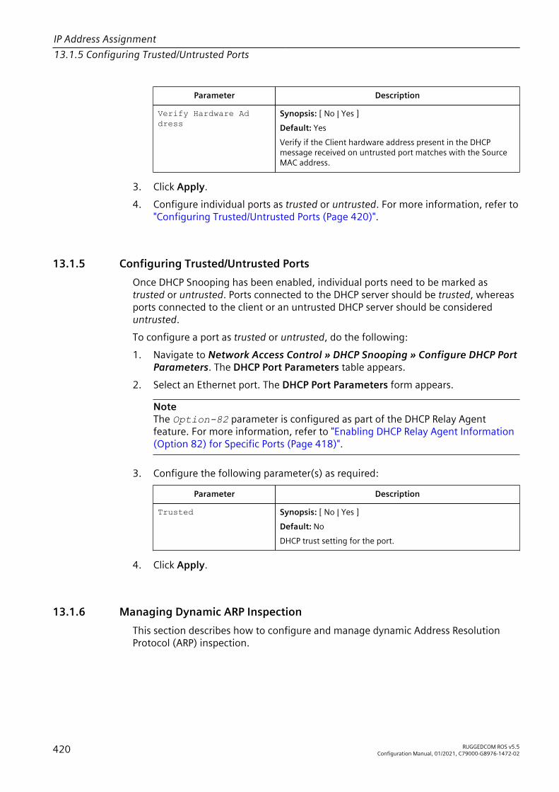
IP Address Assignment13.1.5 Configuring Trusted/Untrusted Ports
Parameter Description
Verify Hardware Ad dress
Synopsis: [ No | Yes ]Default: YesVerify if the Client hardware address present in the DHCPmessage received on untrusted port matches with the SourceMAC address.
3. Click Apply.4. Configure individual ports as trusted or untrusted. For more information, refer to
"Configuring Trusted/Untrusted Ports (Page 420)".
13.1.5 Configuring Trusted/Untrusted PortsOnce DHCP Snooping has been enabled, individual ports need to be marked astrusted or untrusted. Ports connected to the DHCP server should be trusted, whereasports connected to the client or an untrusted DHCP server should be considereduntrusted.To configure a port as trusted or untrusted, do the following:1. Navigate to Network Access Control » DHCP Snooping » Configure DHCP Port
Parameters. The DHCP Port Parameters table appears.2. Select an Ethernet port. The DHCP Port Parameters form appears.
NoteThe Option-82 parameter is configured as part of the DHCP Relay Agentfeature. For more information, refer to "Enabling DHCP Relay Agent Information(Option 82) for Specific Ports (Page 418)".
3. Configure the following parameter(s) as required:
Parameter Description
Trusted Synopsis: [ No | Yes ]Default: NoDHCP trust setting for the port.
4. Click Apply.
13.1.6 Managing Dynamic ARP InspectionThis section describes how to configure and manage dynamic Address ResolutionProtocol (ARP) inspection.
420 RUGGEDCOM ROS v5.5Configuration Manual, 01/2021, C79000-G8976-1472-02

IP Address Assignment13.1.6 Managing Dynamic ARP Inspection
13.1.6.1 Enabling/Disabling Dynamic ARP Inspection
To enable or disable Dynamic ARP Inspection, do the following:1. Navigate to Network Access Control » DHCP Snooping » Configure DHCP
Parameters. The DHCP Parameters form appears.2. Configure the following parameter(s) as required:
Parameter Description
ARP Inspection Synopsis: [ Disabled | Enabled ]Default: DisabledEnable or Disable Dynamic ARP Inspection.
3. Click Apply.
13.1.6.2 Viewing ARP Inspection Statistics
To view ARP Inspection Statistics, do the following:1. Navigate to Network Access Control » DHCP Snooping » View ARP Inspection
Statistics. The ARP Inspection Statistics table appears.2. Select an Ethernet port. The ARP Inspection Statistics form appears.3. Configure the following parameter(s) as required:
Parameter Description
Port Synopsis: 1/1 to maximum port numberThe port number as seen on the front plate silkscreen of thedevice.
In Packets Synopsis: An integer between 0 and 4294967295Total number of incoming ARP packets that were processed byDynamic ARP Inspection on this port.
Dropped Packets Synopsis: An integer between 0 and 4294967295Total number of incoming ARP packets that were dropped byDynamic ARP Inspection on this port.
4. Click Apply.
13.1.6.3 Clearing ARP Inspection Statistics
To clear ARP Inspection Statistics, do the following:1. Navigate to Network Access Control » DHCP Snooping » Clear ARP Inspection
Statistics. The Clear ARP Inspection Statistics form appears.2. Click Confirm.
RUGGEDCOM ROS v5.5Configuration Manual, 01/2021, C79000-G8976-1472-02 421

IP Address Assignment13.1.7 Managing the DHCP Binding Table
13.1.7 Managing the DHCP Binding TableThis section describes how to configure and manage the DHCP binding table.
13.1.7.1 Adding Entries to the DHCP Binding Table
The DHCP binding table is populated automatically with information RUGGEDCOMROS learns about untrusted hosts. Specific hosts can also be added to the table.Static entries do not expire and will not be removed when DHCP snooping is disabledor the device is reset.To add a static entry to the DHCP binding table, do the following:1. Navigate to Network Access Control » DHCP Snooping » Configure Static
DHCP Binding Table. The Configure Static DHCP Binding Table appears.2. Click InsertRecord. The Static DHCP Binding Table form appears.3. Configure the following parameter(s) as required:
Parameter Description
MAC Address Synopsis: ##-##-##-##-##-## where ## ranges 0 to FFDefault: 00-00-00-00-00-00MAC Address of the DHCP Host.
IP Address Synopsis: ##-##-##-##-##-## where ## ranges 0 to 255IP Address assigned to the DHCP Host.
VID Synopsis: An integer between 0 and 65535Default: 1VLAN where in the IP-MAC binding entry was registered.
Port Synopsis: 1/1 to maximum port numberDefault: 1/1Port on which IP-MAC binding entry was regsitered.
4. Click Apply.
13.1.7.2 Viewing the DHCP Binding Table
To view the DHCP binding table, do the following:1. Navigate to Network Access Control » DHCP Snooping » View DHCP Binding
Table. The View DHCP Binding Table appears.2. Select an Ethernet port. The DHCP Binding Table form appears.
422 RUGGEDCOM ROS v5.5Configuration Manual, 01/2021, C79000-G8976-1472-02

IP Address Assignment13.1.7 Managing the DHCP Binding Table
The DHCP binding table displays the following information:
Parameter Description
MAC Address Synopsis: ##-##-##-##-##-## where ## ranges 0 to FFMAC Address of the DHCP Host.
IP Address Synopsis: ##-##-##-##-##-## where ## ranges 0 to 255IP Address assigned to the DHCP Host.
VID Synopsis: An integer between 0 and 65535VLAN where in the IP-MAC binding entry was registered.
Port Synopsis: 1/1 to maximum port numberDefault: 1/1Port on which IP-MAC binding entry was regsitered.
Type Synopsis: [ Static | Dynamic ]Dynamic DHCP IP-MAC Binding Entries.
Lease (secs) Synopsis: An integer between 0 and 4294967295 or [ – ]Lease time assigned to a Dynamic binding entry in seconds.If theentry is Static then the lease time is infinite denoted as "– ".
To refresh the table, click Reload.
13.1.7.3 Saving the DHCP Binding Table
Information learned dynamically and added to the DHCP binding table is removedautomatically when the following occurs:• The lease expires• DHCP snooping is disabled• The device is resetHowever, this information can be saved to the configuration file for future reference/use.To save the DHCP binding table, do the following:1. Navigate to Network Access Control » DHCP Snooping » Save DHCP Binding
Table. The Save DHCP Binding Table table appears.2. Click Confirm.
13.1.7.4 Example: Configuring the Device as a Relay Agent
This example demonstrates how to configure the device as a DHCP relay agent.The following topology depicts a scenario where two clients on separate LANsrequire IP addresses on different subnets from a DHCP server. Each client connects
RUGGEDCOM ROS v5.5Configuration Manual, 01/2021, C79000-G8976-1472-02 423

IP Address Assignment13.1.7 Managing the DHCP Binding Table
to the DHCP relay agent using different VLANs. The DHCP relay agent manages therequests and responses between the clients and the DHCP server.
NOTICEThe values shown are specific to the provided topology. Actual values can varybased on the user's configuration.
4 6 73
192.168.0.52P2, switch.0001
192.168.0.8P4, PVID=1
10.10.10.1/24P2, PVID=3
172.16.10.1/24P1, PVID=2
11
2
5
1 DHCP Server 2 LAN A 3 Client 2 4 LAN B 5 DHCP Relay Agent (RUGGEDCOM ROS Device) 6 LAN C 7 Client 1
Figure 13.5 Topology – Device as a Relay Agent
To configure the device as a DHCP relay agent per the topology, do the following:1. Configure a separate device as the DHCP Server. If the DHCP server being used is
a RUGGEDCOM ROX II device, refer to the device-specific Configuration Manualfor more information.
424 RUGGEDCOM ROS v5.5Configuration Manual, 01/2021, C79000-G8976-1472-02
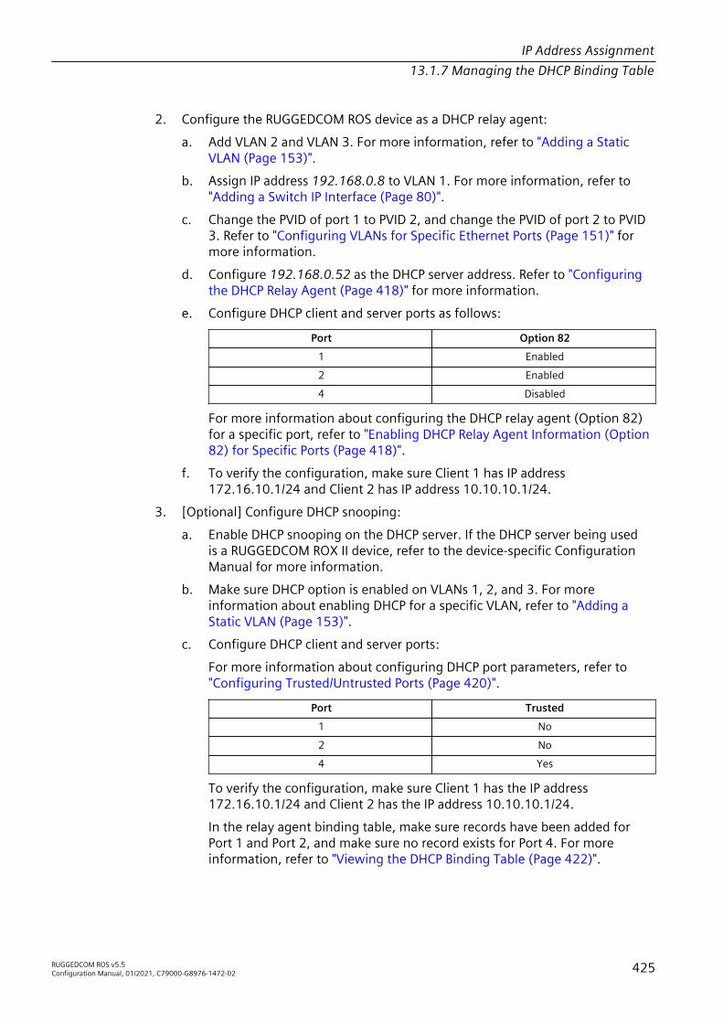
IP Address Assignment13.1.7 Managing the DHCP Binding Table
2. Configure the RUGGEDCOM ROS device as a DHCP relay agent:a. Add VLAN 2 and VLAN 3. For more information, refer to "Adding a Static
VLAN (Page 153)".b. Assign IP address 192.168.0.8 to VLAN 1. For more information, refer to
"Adding a Switch IP Interface (Page 80)".c. Change the PVID of port 1 to PVID 2, and change the PVID of port 2 to PVID
3. Refer to "Configuring VLANs for Specific Ethernet Ports (Page 151)" formore information.
d. Configure 192.168.0.52 as the DHCP server address. Refer to "Configuringthe DHCP Relay Agent (Page 418)" for more information.
e. Configure DHCP client and server ports as follows:
Port Option 821 Enabled2 Enabled4 Disabled
For more information about configuring the DHCP relay agent (Option 82)for a specific port, refer to "Enabling DHCP Relay Agent Information (Option82) for Specific Ports (Page 418)".
f. To verify the configuration, make sure Client 1 has IP address172.16.10.1/24 and Client 2 has IP address 10.10.10.1/24.
3. [Optional] Configure DHCP snooping:a. Enable DHCP snooping on the DHCP server. If the DHCP server being used
is a RUGGEDCOM ROX II device, refer to the device-specific ConfigurationManual for more information.
b. Make sure DHCP option is enabled on VLANs 1, 2, and 3. For moreinformation about enabling DHCP for a specific VLAN, refer to "Adding aStatic VLAN (Page 153)".
c. Configure DHCP client and server ports:For more information about configuring DHCP port parameters, refer to"Configuring Trusted/Untrusted Ports (Page 420)".
Port Trusted1 No2 No4 Yes
To verify the configuration, make sure Client 1 has the IP address172.16.10.1/24 and Client 2 has the IP address 10.10.10.1/24.In the relay agent binding table, make sure records have been added forPort 1 and Port 2, and make sure no record exists for Port 4. For moreinformation, refer to "Viewing the DHCP Binding Table (Page 422)".
RUGGEDCOM ROS v5.5Configuration Manual, 01/2021, C79000-G8976-1472-02 425

IP Address Assignment13.1.7 Managing the DHCP Binding Table
426 RUGGEDCOM ROS v5.5Configuration Manual, 01/2021, C79000-G8976-1472-02

Troubleshooting 14This chapter describes troubleshooting steps for common issues that may beencountered when using RUGGEDCOM ROS or designing a network.
NOTICEFor further assistance, contact a Customer Service representative.
14.1 GeneralThe following describes common problems.
Problem SolutionThe switch is not responding toping attempts, even though theIP address and gateway havebeen configured. The switch isreceiving the ping because theLEDs are flashing and the devicestatistics are logging the pings.What is going on?
Is the switch being pinged through a router? If so, the switchgateway address must be configured as well. The following figureillustrates the problem.
192.168.0.2
192.168.0.1
10.10.0.1
10.10.0.2
1 2 3
1 Work Station 2 Router 3 Switch
Figure 14.1 Using a Router As a Gateway
The router is configured with the appropriate IP subnets and willforward the ping from the workstation to the switch. When theswitch responds, however, it will not know which of its interfacesto use to reach the workstation and will drop the response.Programming a gateway of 10.0.0.1 will cause the switch toforward unresolvable frames to the router.This problem will also occur if the gateway address is notconfigured and the switch tries to raise an SNMP trap to a host thatis not on the local subnet.
RUGGEDCOM ROS v5.5Configuration Manual, 01/2021, C79000-G8976-1472-02 427

Troubleshooting14.2 Ethernet Ports
14.2 Ethernet PortsThe following describes common problems related to Ethernet ports.
Problem SolutionA link seems fine when trafficlevels are low, but fails as trafficrates increase OR a link can bepinged but has problems withFTP/SQL/HTTP/etc.
A possible cause of intermittent operation with auto-negotiation offis that of a ‘duplex mismatch’. If one end of the link is fixed to full-duplex and the peer auto-negotiates, the auto-negotiating end fallsback to half-duplex operation.At lower traffic volumes, the link may display few if any errors. Asthe traffic volume rises, the fixed negotiation side will begin toexperience dropped packets while the auto-negotiating side willexperience collisions. Ultimately, as traffic loads approach 100%,the link will become entirely unusable.The ping command with flood options is a useful tool for testingcommissioned links. The command ping {destination}{count} {timeout} can be used to ping the next switch bya specified number of echo requests, separated by the definednumber of milliseconds. For example, ping 192.168.0.1 5002 issues 500 pings each separated by two milliseconds to the nextswitch. If the link used is of high quality, then no pings should belost and the average round trip time should be small.
Links are inaccessible, evenwhen using the Link FaultIndication (LFI) protectionfeature.
Make sure LFI is not enabled on the peer as well. If both sides ofthe link have LFI enabled, then both sides will withhold link signalgeneration from each other.
Previously stable port linksexperience up/down eventswhen new media is introduced.
This is normal behavior when fiber optic devices are introduced.When a newly inserted fiber optic device is booting up, the fiberports are in a transitional state and therefore adjacent systems thatare live (i.e. functional and stable) will observe port up/down eventsuntil the device has completed the boot up sequence. This is due tothe fact that fiber transceiver power levels are changing during theboot up transition, thereby toggling the connected link up or down.Installing fiber optic cables in a live network will also cause theseeffects, especially for connectors that are designed to be keyed andlocked, such as ST connectors.
The remote syslog appears toskip events or log them out ofsequence.
This is normal behavior when a new Ethernet switch is introducedinto a network.In RUGGEDCOM ROS, system and network stability is thehighest priority. When a new Ethernet switch is introduced intoa network, network reconfiguration occurs so as to preventloops from occurring and causing broadcast storms. When suchreconfiguration takes place, a higher priority is given to RSTPmessages and reconfiguration activities than to event loggingactivities.
14.3 Spanning TreeThe following describes common problems related to the Spanning Tree Protocol(STP).
428 RUGGEDCOM ROS v5.5Configuration Manual, 01/2021, C79000-G8976-1472-02
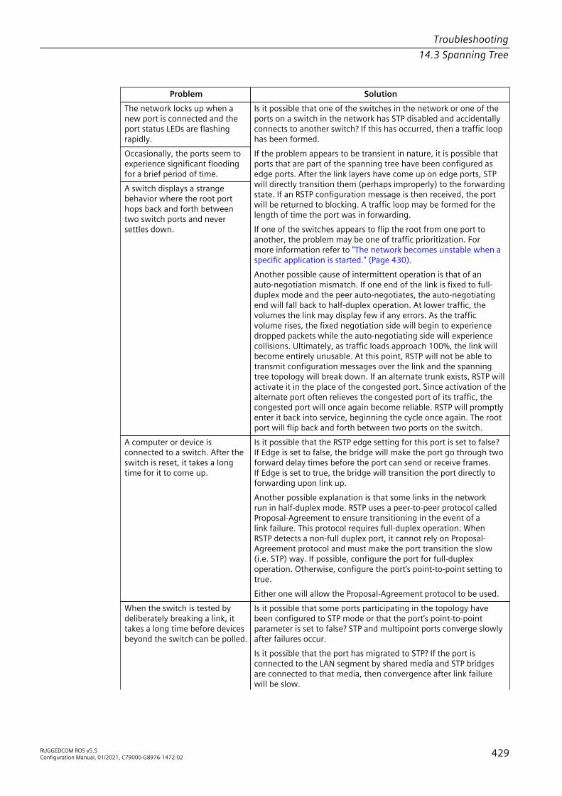
Troubleshooting14.3 Spanning Tree
Problem SolutionThe network locks up when anew port is connected and theport status LEDs are flashingrapidly.Occasionally, the ports seem toexperience significant floodingfor a brief period of time.A switch displays a strangebehavior where the root porthops back and forth betweentwo switch ports and neversettles down.
Is it possible that one of the switches in the network or one of theports on a switch in the network has STP disabled and accidentallyconnects to another switch? If this has occurred, then a traffic loophas been formed.If the problem appears to be transient in nature, it is possible thatports that are part of the spanning tree have been configured asedge ports. After the link layers have come up on edge ports, STPwill directly transition them (perhaps improperly) to the forwardingstate. If an RSTP configuration message is then received, the portwill be returned to blocking. A traffic loop may be formed for thelength of time the port was in forwarding.If one of the switches appears to flip the root from one port toanother, the problem may be one of traffic prioritization. Formore information refer to "The network becomes unstable when aspecific application is started." (Page 430).Another possible cause of intermittent operation is that of anauto-negotiation mismatch. If one end of the link is fixed to full-duplex mode and the peer auto-negotiates, the auto-negotiatingend will fall back to half-duplex operation. At lower traffic, thevolumes the link may display few if any errors. As the trafficvolume rises, the fixed negotiation side will begin to experiencedropped packets while the auto-negotiating side will experiencecollisions. Ultimately, as traffic loads approach 100%, the link willbecome entirely unusable. At this point, RSTP will not be able totransmit configuration messages over the link and the spanningtree topology will break down. If an alternate trunk exists, RSTP willactivate it in the place of the congested port. Since activation of thealternate port often relieves the congested port of its traffic, thecongested port will once again become reliable. RSTP will promptlyenter it back into service, beginning the cycle once again. The rootport will flip back and forth between two ports on the switch.
A computer or device isconnected to a switch. After theswitch is reset, it takes a longtime for it to come up.
Is it possible that the RSTP edge setting for this port is set to false?If Edge is set to false, the bridge will make the port go through twoforward delay times before the port can send or receive frames.If Edge is set to true, the bridge will transition the port directly toforwarding upon link up.Another possible explanation is that some links in the networkrun in half-duplex mode. RSTP uses a peer-to-peer protocol calledProposal-Agreement to ensure transitioning in the event of alink failure. This protocol requires full-duplex operation. WhenRSTP detects a non-full duplex port, it cannot rely on Proposal-Agreement protocol and must make the port transition the slow(i.e. STP) way. If possible, configure the port for full-duplexoperation. Otherwise, configure the port’s point-to-point setting totrue.Either one will allow the Proposal-Agreement protocol to be used.
When the switch is tested bydeliberately breaking a link, ittakes a long time before devicesbeyond the switch can be polled.
Is it possible that some ports participating in the topology havebeen configured to STP mode or that the port’s point-to-pointparameter is set to false? STP and multipoint ports converge slowlyafter failures occur.Is it possible that the port has migrated to STP? If the port isconnected to the LAN segment by shared media and STP bridgesare connected to that media, then convergence after link failurewill be slow.
RUGGEDCOM ROS v5.5Configuration Manual, 01/2021, C79000-G8976-1472-02 429

Troubleshooting14.4 VLANs
Problem SolutionDelays on the order of tens or hundreds of milliseconds can resultin circumstances where the link broken is the sole link to the rootbridge and the secondary root bridge is poorly chosen. The worstof all possible designs occurs when the secondary root bridge islocated at the farthest edge of the network from the root. In thiscase, a configuration message will have to propagate out to theedge and then back to reestablish the topology.
The network is composed ofa ring of bridges, of whichtwo (connected to each other)are managed and the rest areunmanaged. Why does the RSTPprotocol work quickly whena link is broken between themanaged bridges, but not in theunmanaged bridge part of thering?
A properly operating unmanaged bridge is transparent to STPconfiguration messages. The managed bridges will exchangeconfiguration messages through the unmanaged bridge part ofthe ring as if it is non-existent. When a link in the unmanaged partof the ring fails however, the managed bridges will only be ableto detect the failure through timing out of hello messages. Fullconnectivity will require three hello times plus two forwardingtimes to be restored.
The network becomes unstablewhen a specific application isstarted. The network returns tonormal when the application isstopped.
RSTP sends its configuration messages using the highest possiblepriority level. If CoS is configured to allow traffic flows at thehighest priority level and these traffic flows burst continuously to100% of the line bandwidth, STP may be disrupted. It is thereforeadvised not to use the highest CoS.
When a new port is broughtup, the root moves on to thatport instead of the port it shouldmove to or stay on.
Is it possible that the port cost is incorrectly programmed or thatauto-negotiation derives an undesired value? Inspect the port andpath costs with each port active as root.
An Intelligent Electronic Device(IED) or controller does not workwith the device.
Certain low CPU bandwidth controllers have been found to behaveless than perfectly when they receive unexpected traffic. Trydisabling STP for the port.If the controller fails around the time of a link outage, there is theremote possibility that frame disordering or duplication may bethe cause of the problem. Try setting the root port of the failingcontroller’s bridge to STP.
Polls to other devices areoccasionally lost.
Review the network statistics to determine whether the root bridgeis receiving Topology Change Notifications (TCNs) around the timeof observed frame loss. It may be possible there are problems withintermittent links in the network.
The root is receiving a numberof TCNs. Where are they comingfrom?
Examine the RSTP port statistics to determine the port from whichthe TCNs are arriving. Sign-on to the switch at the other end ofthe link attached to that port. Repeat this step until the switchgenerating the TCNs is found (i.e. the switch that is itself notreceiving a large number of TCNs). Determine the problem at thatswitch.
14.4 VLANsThe following describes common problems related to the VLANs.
Problem SolutionVLANs are not needed on thenetwork. Can they be turned off?
Yes. Simply leave all ports set to type edge and leave the nativeVLAN set to 1. This is the default configuration for the switch.
430 RUGGEDCOM ROS v5.5Configuration Manual, 01/2021, C79000-G8976-1472-02

Troubleshooting14.4 VLANs
Problem SolutionTwo VLANs were created anda number of ports were mademembers of them. Now some ofthe devices in one VLAN need tosend messages to devices in theother VLAN.
If the devices need to communicate at the physical address layer,they must be members of the same VLAN. If they can communicatein a Layer 3 fashion (i.e. using a protocol such as IP or IPX), usea router. The router will treat each VLAN as a separate interface,which will have its own associated IP address space.
On a network of 30 switches,management traffic needs to berestricted to a separate domain.What is the best method fordoing this while staying incontact with these switches?
At the switch where the management station is located, configurea port to use the new management VLAN as its native VLAN.Configure a host computer to act as a temporary managementstation.At each switch, configure the management VLAN to the new value.Contact with each individual switch will be lost immediately asthey are being configured, but it should be possible re-establishcommunication from the temporary management station. Afterall switches have been taken to the new management VLAN,configure the ports of all attached management devices to use thenew VLAN.
NoteEstablishing a management domain is often accompanied with theestablishment of an IP subnet specifically for the managed devices.
RUGGEDCOM ROS v5.5Configuration Manual, 01/2021, C79000-G8976-1472-02 431

Troubleshooting14.4 VLANs
432 RUGGEDCOM ROS v5.5Configuration Manual, 01/2021, C79000-G8976-1472-02

Further Information
Siemens RUGGEDCOMhttps://www.siemens.com/ruggedcom
Industry Online Support (service and support)https://support.industry.siemens.com
Industry Mallhttps://mall.industry.siemens.com
Siemens AGDigital IndustryProcess AutomationPostfach 48 4890026 NÜRNBERGGERMANY