configuration — vlans, spanning tree, and multi-link
TRANSCRIPT
Configuration — VLANs, Spanning Tree,and Multi-Link TrunkingAvaya Ethernet Routing Switch 4500Series
5.4NN47205-501, 06.02
November 2010

© 2010 Avaya Inc.
All Rights Reserved.
Notice
While reasonable efforts have been made to ensure that theinformation in this document is complete and accurate at the time ofprinting, Avaya assumes no liability for any errors. Avaya reserves theright to make changes and corrections to the information in thisdocument without the obligation to notify any person or organization ofsuch changes.
Documentation disclaimer
“Documentation” means information published by Avaya in varyingmediums which may include product information, operating instructionsand performance specifications that Avaya generally makes availableto users of its products. Documentation does not include marketingmaterials. Avaya shall not be responsible for any modifications,additions, or deletions to the original published version ofdocumentation unless such modifications, additions, or deletions wereperformed by Avaya. End User agrees to indemnify and hold harmlessAvaya, Avaya's agents, servants and employees against all claims,lawsuits, demands and judgments arising out of, or in connection with,subsequent modifications, additions or deletions to this documentation,to the extent made by End User.
Link disclaimer
Avaya is not responsible for the contents or reliability of any linked Websites referenced within this site or documentation provided by Avaya.Avaya is not responsible for the accuracy of any information, statementor content provided on these sites and does not necessarily endorsethe products, services, or information described or offered within them.Avaya does not guarantee that these links will work all the time and hasno control over the availability of the linked pages.
Warranty
Avaya provides a limited warranty on its Hardware and Software(“Product(s)”). Refer to your sales agreement to establish the terms ofthe limited warranty. In addition, Avaya’s standard warranty language,as well as information regarding support for this Product while underwarranty is available to Avaya customers and other parties through theAvaya Support Web site: http://support.avaya.com. Please note that ifyou acquired the Product(s) from an authorized Avaya reseller outsideof the United States and Canada, the warranty is provided to you bysaid Avaya reseller and not by Avaya.
Licenses
THE SOFTWARE LICENSE TERMS AVAILABLE ON THE AVAYAWEBSITE, HTTP://SUPPORT.AVAYA.COM/LICENSEINFO/ AREAPPLICABLE TO ANYONE WHO DOWNLOADS, USES AND/ORINSTALLS AVAYA SOFTWARE, PURCHASED FROM AVAYA INC.,ANY AVAYA AFFILIATE, OR AN AUTHORIZED AVAYA RESELLER(AS APPLICABLE) UNDER A COMMERCIAL AGREEMENT WITHAVAYA OR AN AUTHORIZED AVAYA RESELLER. UNLESSOTHERWISE AGREED TO BY AVAYA IN WRITING, AVAYA DOESNOT EXTEND THIS LICENSE IF THE SOFTWARE WAS OBTAINEDFROM ANYONE OTHER THAN AVAYA, AN AVAYA AFFILIATE OR ANAVAYA AUTHORIZED RESELLER; AVAYA RESERVES THE RIGHTTO TAKE LEGAL ACTION AGAINST YOU AND ANYONE ELSEUSING OR SELLING THE SOFTWARE WITHOUT A LICENSE. BYINSTALLING, DOWNLOADING OR USING THE SOFTWARE, ORAUTHORIZING OTHERS TO DO SO, YOU, ON BEHALF OFYOURSELF AND THE ENTITY FOR WHOM YOU ARE INSTALLING,DOWNLOADING OR USING THE SOFTWARE (HEREINAFTERREFERRED TO INTERCHANGEABLY AS “YOU” AND “END USER”),AGREE TO THESE TERMS AND CONDITIONS AND CREATE ABINDING CONTRACT BETWEEN YOU AND AVAYA INC. OR THEAPPLICABLE AVAYA AFFILIATE (“AVAYA”).
Copyright
Except where expressly stated otherwise, no use should be made ofmaterials on this site, the Documentation, Software, or Hardwareprovided by Avaya. All content on this site, the documentation and theProduct provided by Avaya including the selection, arrangement anddesign of the content is owned either by Avaya or its licensors and isprotected by copyright and other intellectual property laws including thesui generis rights relating to the protection of databases. You may notmodify, copy, reproduce, republish, upload, post, transmit or distributein any way any content, in whole or in part, including any code andsoftware unless expressly authorized by Avaya. Unauthorizedreproduction, transmission, dissemination, storage, and or use withoutthe express written consent of Avaya can be a criminal, as well as acivil offense under the applicable law.
Third-party components
Certain software programs or portions thereof included in the Productmay contain software distributed under third party agreements (“ThirdParty Components”), which may contain terms that expand or limitrights to use certain portions of the Product (“Third Party Terms”).Information regarding distributed Linux OS source code (for thoseProducts that have distributed the Linux OS source code), andidentifying the copyright holders of the Third Party Components and theThird Party Terms that apply to them is available on the Avaya SupportWeb site: http://support.avaya.com/Copyright.
Trademarks
The trademarks, logos and service marks (“Marks”) displayed in thissite, the Documentation and Product(s) provided by Avaya are theregistered or unregistered Marks of Avaya, its affiliates, or other thirdparties. Users are not permitted to use such Marks without prior writtenconsent from Avaya or such third party which may own the Mark.Nothing contained in this site, the Documentation and Product(s)should be construed as granting, by implication, estoppel, or otherwise,any license or right in and to the Marks without the express writtenpermission of Avaya or the applicable third party.
Avaya is a registered trademark of Avaya Inc.
All non-Avaya trademarks are the property of their respective owners,and “Linux” is a registered trademark of Linus Torvalds.
Downloading Documentation
For the most current versions of Documentation, see the AvayaSupport Web site: http://support.avaya.com.
Contact Avaya Support
Avaya provides a telephone number for you to use to report problemsor to ask questions about your Product. The support telephone numberis 1-800-242-2121 in the United States. For additional supporttelephone numbers, see the Avaya Web site: http://support.avaya.com.
2 Configuration — VLANs, Spanning Tree, and Multi-Link Trunking November 2010
Contents
Chapter 1: New in this release................................................................................................11Features..........................................................................................................................................................11
Enterprise Device Manager....................................................................................................................11ADAC Enhancements.............................................................................................................................11MLT and LAG Scaling.............................................................................................................................12802.1D compliancy support....................................................................................................................12
Other changes.................................................................................................................................................12Multiple Port Configuration.....................................................................................................................12
Chapter 2: Introduction...........................................................................................................13ACLI command modes....................................................................................................................................13Navigation.......................................................................................................................................................14
Chapter 3: VLAN Fundamentals.............................................................................................15Virtual Local Area Networks............................................................................................................................15
IEEE 802.1Q Tagging.............................................................................................................................16VLANs Spanning Multiple Switches.......................................................................................................21VLAN Summary......................................................................................................................................24VLAN Configuration Rules......................................................................................................................25
VLAN Configuration Control............................................................................................................................26MAC Flush......................................................................................................................................................27
Chapter 4: MLT Fundamentals...............................................................................................29MultiLink trunks...............................................................................................................................................29
Client-server configuration using MultiLink trunks..................................................................................29Before Trunks are Configured................................................................................................................30MultiLink Trunking Configuration Rules..................................................................................................31MLT load-balancing................................................................................................................................32MLT Enable or Disable Whole Trunk......................................................................................................33Removal of MLT restrictions...................................................................................................................34Add and delete links from existing MultiLink trunks................................................................................34How a MultiLink trunk reacts to losing distributed trunk members.........................................................34Spanning Tree Considerations for MultiLink trunks................................................................................35Additional Tips About the MultiLink Trunking Feature............................................................................38
Chapter 5: STP Fundamentals...............................................................................................41Spanning Tree Protocol groups.......................................................................................................................41
STG Configuration Guidelines................................................................................................................42Spanning Tree Fast Learning.................................................................................................................43STG port membership mode..................................................................................................................44802.1t path cost calculation....................................................................................................................44802.1D compliancy support....................................................................................................................44
Rapid Spanning Tree Protocol........................................................................................................................44Multiple Spanning Tree Protocol.....................................................................................................................45
Interoperability with legacy STP.............................................................................................................45Differences in STP and RSTP port roles................................................................................................46Rapid convergent...................................................................................................................................47
BPDU-Filtering................................................................................................................................................48
Configuration — VLANs, Spanning Tree, and Multi-Link Trunking November 2010 3
Chapter 6: ADAC Fundamentals............................................................................................51Autodetection and Autoconfiguration of IP Phones.........................................................................................51ADAC operation..............................................................................................................................................51
Auto-detection of IP Phones...................................................................................................................52Auto-Detection by MAC address............................................................................................................52Auto-Detection by LLDP (IEEE 802.1ab)...............................................................................................54Auto-Configuration of IP Phones............................................................................................................55Initial user settings..................................................................................................................................56Port Restrictions.....................................................................................................................................56Operating modes....................................................................................................................................57Dynamic VLAN Autoconfiguration..........................................................................................................61ADAC and stacking................................................................................................................................62ADAC Uplink port as part of trunk..........................................................................................................62ADAC and EAP configuration.................................................................................................................63ADAC User Restrictions.........................................................................................................................64ADAC management................................................................................................................................65
Chapter 7: LACP and VLACP Fundamentals........................................................................67IEEE 802.3ad Link Aggregation......................................................................................................................67
Link aggregation rules............................................................................................................................68VLACP............................................................................................................................................................69
Virtual LACP (VLACP) overview.............................................................................................................69VLACP features......................................................................................................................................71
Chapter 8: Configuring VLANs using ACLI...........................................................................73Displaying VLAN information..........................................................................................................................73Displaying VLAN interface information............................................................................................................74Displaying port membership in VLANs............................................................................................................74Displaying the management VLAN.................................................................................................................75Configuring the management VLAN...............................................................................................................75Deleting the management VLAN IP address..................................................................................................75Resetting the management VLAN...................................................................................................................76Creating VLANs..............................................................................................................................................76Deleting a VLAN..............................................................................................................................................77Removing a MAC address from allowed flooding...........................................................................................78Configuring VLAN name.................................................................................................................................78Configuring automatic PVID............................................................................................................................79Configuring port VLAN settings.......................................................................................................................79Configuring VLAN member ports....................................................................................................................80Configuring VLAN Configuration Control........................................................................................................81
Displaying VLAN Configuration Control settings....................................................................................82Modifying VLAN Configuration Control...................................................................................................82
Managing MAC address forwarding database table.......................................................................................83Displaying the MAC address forwarding table........................................................................................83Configuring aging time for unseen MAC addresses...............................................................................84Setting aging time for unseen MAC addresses to default......................................................................84Clearing the MAC address table.............................................................................................................85Clearing the MAC address table on a VLAN..........................................................................................85Clearing the MAC address table on a FastEthernet interface................................................................86Clearing the MAC address table on a trunk............................................................................................86Removing a single address from the MAC address table......................................................................87
4 Configuration — VLANs, Spanning Tree, and Multi-Link Trunking November 2010
Chapter 9: Configuring MultiLink Trunking using ACLI......................................................89Configuring a Multi Link Trunk using ACLI......................................................................................................89Displaying MLT configuration using ACLI........................................................................................................90Viewing IP address-based MLT hashing information using ACLI....................................................................90Viewing MAC address-based MLT hashing using ACLI..................................................................................92Displaying STG MLT properties using ACLI....................................................................................................93Configuring STP participation for MLTs using ACLI........................................................................................94Enabling all ports shutdown in the MLT using ACLI........................................................................................94Disabling MLT Enable or Disable Whole Trunk feature using ACLI................................................................95Displaying the current MLT Enable or Disable Whole Trunk mode of operation using ACLI..........................95
Chapter 10: Configuring Spanning Tree Protocol using ACLI............................................97Configuring STP operation mode using ACLI.................................................................................................97Configuring STP BPDU Filtering using ACLI..................................................................................................97Creating and Managing STGs using ACLI......................................................................................................98
Configuring path cost calculation using ACLI.........................................................................................98Configuring STG port membership using ACLI......................................................................................99Displaying spanning tree configuration information using ACLI.............................................................99Creating a spanning tree group using ACLI.........................................................................................100Deleting a spanning tree group using ACLI..........................................................................................100Enabling a spanning tree group using ACLI.........................................................................................100Disabling a spanning tree group using ACLI........................................................................................101Configuring STP values by STG using ACLI........................................................................................101Restoring default spanning tree value for a STG using ACLI...............................................................102Setting STP and STG participation using ACLI....................................................................................103Setting default spanning tree values for ports using ACLI....................................................................104Disable spanning tree for a port using ACLI.........................................................................................104
STP 802.1D compliancy support configuration using ACLI..........................................................................105Enabling STP 802.1D compliancy support using ACLI........................................................................105Disabling STP 802.1D compliancy support using ACLI........................................................................106Viewing STP 802.1D compliancy support status using ACLI...............................................................106
STP 802.1t cost calculation support configuration using ACLI.....................................................................107Enabling STP 802.1t cost calculation support using ACLI...................................................................107Disabling STP 802.1t cost calculation support using ACLI...................................................................107Viewing STP 802.1t cost calculation status using ACLI.......................................................................108
Managing RSTP using ACLI.........................................................................................................................109Configuring RSTP parameters using ACLI...........................................................................................109Configuring RSTP parameters per port using ACLI..............................................................................110Displaying RSTP bridge-level configuration details using ACLI............................................................111Displaying RSTP port-level configuration details using ACLI................................................................111
Configuring RSTP SNMP traps using ACLI...................................................................................................112Enable RSTP SNMP traps using ACLI.................................................................................................112Reset RSTP SNMP traps settings to default using ACLI......................................................................113Verifying RSTP SNMP traps settings using ACLI.................................................................................113
Managing MSTP using ACLI.........................................................................................................................114Configuring MSTP parameters for CIST Bridge using ACLI.................................................................114Configuring MSTP parameters for Common Spanning Tree using ACLI.............................................115Configuring MSTP region parameters using ACLI................................................................................116Configuring MSTP parameters for bridge instance using ACLI............................................................116Disabling a MSTP bridge instance using ACLI.....................................................................................117Deleting a MSTP bridge instance using ACLI.......................................................................................117
Configuration — VLANs, Spanning Tree, and Multi-Link Trunking November 2010 5
Displaying MSTP status by selected bridge using ACLI.......................................................................118Displaying MSTP CIST port information using ACLI............................................................................118Displaying MSTP MSTI settings using ACLI.........................................................................................119
Chapter 11: Configuring ADAC using ACLI........................................................................121Configuring ADAC globally using ACLI.........................................................................................................121Disabling ADAC globally using ACLI.............................................................................................................122Restoring default ADAC settings using ACLI................................................................................................123Configuring per port ADAC settings using ACLI...........................................................................................124Disable ADAC settings per port using ACLI..................................................................................................125Configuring per port ADAC defaults for a specified port using ACLI.............................................................125Configuring the autodetection method using ACLI........................................................................................126Disabling autodetection using ACLI..............................................................................................................127Setting autodetection method to default using ACLI.....................................................................................127Configuring autodetection for a specified port using ACLI............................................................................128Disabling autodetection on specified ports using ACLI.................................................................................128Restoring default ADAC setting for ports using ACLI....................................................................................129Adding a range of MAC addresses for autodetection using ACLI.................................................................129Deleting a range of MAC addresses used by autodetection using ACLI......................................................130Resetting supported MAC address ranges using ACLI.................................................................................130Displaying global ADAC settings for a device using ACLI............................................................................130Displaying ADAC settings per port using ACLI.............................................................................................131Displaying configured ADAC MAC ranges using ACLI.................................................................................131Displaying detection mechanism configured per port using ACLI.................................................................131ADAC UFA configuration example................................................................................................................132ADAC ACLI configuration commands...........................................................................................................134Verifying new ADAC settings........................................................................................................................134
Chapter 12: LACP and VLACP configuration using ACLI.................................................137Configuring LACP using ACLI.......................................................................................................................137
Displaying LACP settings using ACLI...................................................................................................137Displaying per port LACP configuration information using ACLI..........................................................137Displaying LACP port statistics using ACLI..........................................................................................138Clearing LACP port statistics using ACLI.............................................................................................138Displaying port debug information using ACLI.....................................................................................139Displaying LACP aggregators or LACP trunks using ACLI..................................................................139Configuring LACP system priority using ACLI......................................................................................139Enabling port aggregation mode using ACLI........................................................................................140Disabling port aggregation mode using ACLI.......................................................................................140Configuring administrative LACP key using ACLI................................................................................140Configuring LACP mode of operation using ACLI................................................................................141Configuring per port LACP priority using ACLI.....................................................................................142Configuring LACP periodic transmission timeout interval using ACLI..................................................142
Configuring VLACP using ACLI....................................................................................................................143Enabling VLACP using ACLI................................................................................................................143Configuring multicast MAC address for VLACP using ACLI.................................................................143Configuring VLACP parameters per port using ACLI...........................................................................144Disabling VLACP using ACLI...............................................................................................................146Resetting multicast MAC address for VLACP to default using ACLI....................................................146Disabling VLACP on a port using ACLI................................................................................................146Displaying VLACP status using ACLI...................................................................................................147Displaying VLACP configuration details for ports using ACLI..............................................................147
6 Configuration — VLANs, Spanning Tree, and Multi-Link Trunking November 2010
Chapter 13: Configuring VLANs using Enterprise Device Manager.................................149VLAN management using EDM....................................................................................................................149
Viewing VLAN information using EDM.................................................................................................149Modifying an existing VLAN in STG mode using EDM.........................................................................152Modifying an existing VLAN in RSTP mode using EDM.......................................................................154Modifying an existing VLAN in MSTP mode using EDM......................................................................157Creating a VLAN in STP mode using EDM..........................................................................................159Creating a VLAN in RSTP mode using EDM........................................................................................162Creating a VLAN in MSTP mode using EDM.......................................................................................164Deleting a VLAN using EDM................................................................................................................167
VLAN IPv4 address management using EDM..............................................................................................168Viewing VLAN IPv4 address information using EDM...........................................................................168Assigning an IPv4 address to a using EDM.........................................................................................169Deleting an IPv4 address from a VLAN using EDM.............................................................................170
Configuring DHCP for a VLAN using EDM...................................................................................................170Configuring RIP for a VLAN using EDM........................................................................................................172Graphing OSPF statistics for a VLAN using EDM.........................................................................................173VLAN IPv6 interface management using EDM.............................................................................................174
Viewing IPv6 interface information for a VLAN using EDM..................................................................174Adding an IPv6 interface to a VLAN using EDM..................................................................................176Deleting an IPv6 interface from a VLAN using EDM............................................................................177
VLAN IPv6 address management using EDM..............................................................................................178Viewing IPv6 address information for a VLAN using EDM...................................................................178Adding an IPv6 address to a VLAN using EDM...................................................................................179Deleting an IPv6 address from a VLAN using EDM.............................................................................180
VLAN configuration for ports using EDM......................................................................................................181Viewing VLAN membership port information using EDM.....................................................................181Configuring VLAN membership ports using EDM................................................................................182
Selecting VLAN configuration control using EDM.........................................................................................184Enabling AutoPVID using EDM.....................................................................................................................185Port configuration for VLANs using EDM......................................................................................................186
Viewing port VLAN membership information using EDM.....................................................................186Configuring ports for VLAN membership using EDM...........................................................................187
MAC address table management using EDM...............................................................................................189Flushing the MAC address table using EDM........................................................................................190Flushing FastEthernet interface-based MAC addresses from the MAC address table using EDM......190Flushing VLAN-based MAC addresses from the MAC address table using EDM................................191Flushing trunk-based MAC addresses from the MAC address table using EDM.................................191Flushing a specific MAC address from the MAC address table using EDM.........................................192
Chapter 14: Configuring MultiLink Trunking using Enterprise Device Manager.............193MLT configuration using EDM.......................................................................................................................193
Viewing MLT configurations using EDM...............................................................................................193Creating an MLT using EDM................................................................................................................194Modifying MLT port memberships using EDM......................................................................................196
Graphing MLT statistics using EDM..............................................................................................................197Graphing MLT Ethernet error statistics using EDM.......................................................................................199
Chapter 15: Configuring Spanning Tree Protocol using Enterprise Device Manager....203Configuring the STP mode using EDM.........................................................................................................203
Resetting the switch using EDM...........................................................................................................204
Configuration — VLANs, Spanning Tree, and Multi-Link Trunking November 2010 7
Configuring STP BPDU filtering for specific ports using EDM......................................................................204Configuring STG globally using EDM............................................................................................................205STG configuration using EDM.......................................................................................................................207
Viewing an STG using EDM.................................................................................................................207Modifying an STG using EDM..............................................................................................................209Creating an STG using EDM................................................................................................................211Deleting an STG using EDM................................................................................................................212
Moving a VLAN between STGs using EDM..................................................................................................212Viewing STG Status using EDM....................................................................................................................212STG port membership management using EDM..........................................................................................214
Viewing STG port information using EDM............................................................................................214Configuring STG for port using EDM....................................................................................................216
Port STG membership configuration using EDM..........................................................................................217Viewing STG port membership information using EDM.......................................................................217Configuring STG port membership using EDM....................................................................................219
Chapter 16: RSTP configuration using Enterprise Device Manager................................221Viewing global RSTP information using EDM...............................................................................................221Viewing RSTP port information using EDM...................................................................................................224Viewing RSTP statistics using EDM..............................................................................................................226Graphing RSTP port statistics using EDM....................................................................................................227
Chapter 17: MSTP configuration using Enterprise Device Manager................................229Viewing global MSTP using EDM..................................................................................................................230Viewing CIST port information using EDM....................................................................................................233Graphing CIST port statistics using EDM......................................................................................................235Viewing MSTI bridge information using EDM................................................................................................237Inserting MSTI Bridges using EDM...............................................................................................................238Deleting MSTI Bridges using EDM................................................................................................................239Viewing MSTI port information using EDM....................................................................................................239Graphing MSTI port statistics using EDM.....................................................................................................241
Chapter 18: Configuring ADAC using Enterprise Device Manager..................................243Configuring ADAC globally using EDM.........................................................................................................243ADAC MAC address range configuration using EDM...................................................................................245
Creating a ADAC MAC address range using EDM..............................................................................245Deleting MAC address ranges using EDM...........................................................................................246
ADAC port configuration using EDM.............................................................................................................246Viewing the ADAC configuration for ports using EDM..........................................................................246Configuring ADAC for specific ports using EDM..................................................................................248
Chapter 19: Configuring LACP and VLACP using Enterprise Device Manager..............253Viewing LAG information using EDM............................................................................................................253Link Aggregation Group configuration using EDM........................................................................................255
Viewing LACP for LAG members using EDM.......................................................................................255Configuring LACP for specific LAG members using EDM....................................................................256
LACP configuration for ports using EDM......................................................................................................259Viewing the LACP configuration for ports using EDM..........................................................................259Configuring LACP for ports using EDM................................................................................................261
Graphing port LACP statistics using EDM....................................................................................................264Global VLACP configuration using EDM.......................................................................................................265
Enabling global VLACP using EDM......................................................................................................265
8 Configuration — VLANs, Spanning Tree, and Multi-Link Trunking November 2010

Disabling global VLACP using EDM.....................................................................................................266VLACP configuration for ports using EDM....................................................................................................266
Viewing the VLACP configuration for ports using EDM........................................................................266Configuring VLACP for specific ports using EDM.................................................................................268
Configuration — VLANs, Spanning Tree, and Multi-Link Trunking November 2010 9

10 Configuration — VLANs, Spanning Tree, and Multi-Link Trunking November 2010
Chapter 1: New in this release
The following section details what is new in Avaya Ethernet Routing Switch 4500 Configuration — VLANs,Spanning Tree, and MultiLink Trunking (NN47205-501) for Release 5.4.
• Features on page 11• Other changes on page 12
FeaturesSee the following section for information about feature changes:
• Enterprise Device Manager on page 11• ADAC Enhancements on page 11• MLT and LAG Scaling on page 12• 802.1D compliancy support on page 12
Enterprise Device ManagerEnterprise Device Manager (EDM) replaces both the Java-based Device Manager and Web-based management user interfaces. EDM is an embedded element management andconfiguration application for Avaya Ethernet Routing Switch 4500 Series switches. EDMprovides a Web-based graphical user interface through a standard web browser for theconvenience of full configuration and management on the switch, and retains the look and feelof Device Manager.
ADAC EnhancementsADAC Enhancements provide increased flexibility in deployments that use Auto-Detect Auto-Configuration (ADAC) as follows:
• expanded support for up to 8 ADAC uplinks and 8 call-server links - individual ports orany combination of MLT, DMLT or LAG - per switch or stack
• the ability to change the non-ADAC VLANs on a port without disabling ADAC
Configuration — VLANs, Spanning Tree, and Multi-Link Trunking November 2010 11
For more information, see:
• Configuring ADAC globally using ACLI on page 121
• Configuring ADAC globally using EDM on page 243
MLT and LAG ScalingMultiLink Trunking (MLT) and Link Aggregation Groups (LAG) scaling supports up to 32 trunkgroups with up to 8 links per trunk for MLT, Distributed MultiLink Trunking (DMLT) and 802.3adLAG. For more information, see:
• MultiLink trunks on page 29
• Link aggregation rules on page 68
802.1D compliancy supportTo prevent broadcast storms in a complex network, when a port drops and comes back upfrequently you can use 802.1D compliancy support. When you configure 802.1D compliancemode, the system sets the Spanning Tree Protocol (STP) state of the port to disabled whenthe port link is down. For more information, see:
• 802.1D compliancy support on page 44
• STP 802.1D compliancy support configuration using ACLI on page 105
• Configuring STG globally using EDM on page 205
Other changesSee the following sections for information about changes that are not feature-related:
Multiple Port ConfigurationAmong the many functions available in EDM, you can configure port-specific features for asingle port, a group of ports, or all ports. Multiple Port Configuration appears as a pane in thework area wherever this function is available. By default the pane appears and you can closeand open it with a click of the task bar.
For more information about EDM, see Avaya Ethernet Routing Switch 4500 SeriesFundamentals (NN47205-102).
New in this release
12 Configuration — VLANs, Spanning Tree, and Multi-Link Trunking November 2010
Chapter 2: Introduction
This document provides information you need to configure VLANs, Spanning Tree and MultiLink Trunkingfor the Avaya Ethernet Routing Switch 4500 Series.
ACLI command modesACLI provides the following command modes:
• User EXEC
• Privileged EXEC
• Global Configuration
• Interface Configuration
Mode access is determined by access permission levels and password protection.
If no password is set, you can enter ACLI in User EXEC mode and use the enable command tomove to the next level (Privileged EXEC mode). However, if you have read-only access, youcannot progress beyond User EXEC mode, the default mode. If you have read-write accessyou can progress from the default mode through all of the available modes.
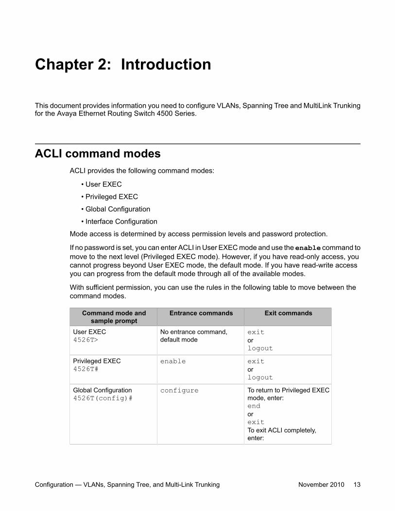
With sufficient permission, you can use the rules in the following table to move between thecommand modes.
Command mode andsample prompt
Entrance commands Exit commands
User EXEC4526T>
No entrance command,default mode
exitorlogout
Privileged EXEC4526T#
enable exitorlogout
Global Configuration4526T(config)#
configure To return to Privileged EXECmode, enter:endorexitTo exit ACLI completely,enter:
Configuration — VLANs, Spanning Tree, and Multi-Link Trunking November 2010 13
Command mode andsample prompt
Entrance commands Exit commands
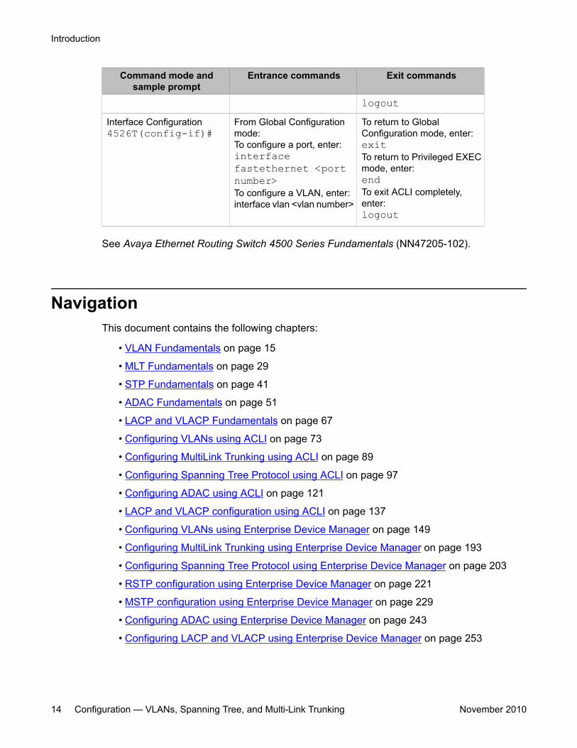
logoutInterface Configuration4526T(config-if)#
From Global Configurationmode:To configure a port, enter:interfacefastethernet <portnumber>To configure a VLAN, enter:interface vlan <vlan number>
To return to GlobalConfiguration mode, enter:exitTo return to Privileged EXECmode, enter:endTo exit ACLI completely,enter:logout
See Avaya Ethernet Routing Switch 4500 Series Fundamentals (NN47205-102).
NavigationThis document contains the following chapters:
• VLAN Fundamentals on page 15
• MLT Fundamentals on page 29
• STP Fundamentals on page 41
• ADAC Fundamentals on page 51
• LACP and VLACP Fundamentals on page 67
• Configuring VLANs using ACLI on page 73
• Configuring MultiLink Trunking using ACLI on page 89
• Configuring Spanning Tree Protocol using ACLI on page 97
• Configuring ADAC using ACLI on page 121
• LACP and VLACP configuration using ACLI on page 137
• Configuring VLANs using Enterprise Device Manager on page 149
• Configuring MultiLink Trunking using Enterprise Device Manager on page 193
• Configuring Spanning Tree Protocol using Enterprise Device Manager on page 203
• RSTP configuration using Enterprise Device Manager on page 221
• MSTP configuration using Enterprise Device Manager on page 229
• Configuring ADAC using Enterprise Device Manager on page 243
• Configuring LACP and VLACP using Enterprise Device Manager on page 253
Introduction
14 Configuration — VLANs, Spanning Tree, and Multi-Link Trunking November 2010
Chapter 3: VLAN Fundamentals
This chapter provides conceptual information relating VLANs, Spanning Tree, MultiLink Trunks, andassociated features and capabilities.
Virtual Local Area NetworksThe Avaya Ethernet Routing Switch 4500 Series supports up to 25 concurrent VLANs.
You can group ports into broadcast domains by assigning them to the same VLAN. Framesreceived in one VLAN can be forwarded only within that VLAN, and multicast frames andunknown unicast frames are flooded only to ports in the same VLAN.
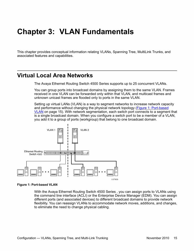
Setting up virtual LANs (VLAN) is a way to segment networks to increase network capacityand performance without changing the physical network topology (Figure 1: Port-basedVLAN on page 15). With network segmentation, each switch port connects to a segment thatis a single broadcast domain. When you configure a switch port to be a member of a VLAN,you add it to a group of ports (workgroup) that belong to one broadcast domain.
Figure 1: Port-based VLAN
With the Avaya Ethernet Routing Switch 4500 Series , you can assign ports to VLANs usingthe command line interface (ACLI) or the Enterprise Device Manager (EDM). You can assigndifferent ports (and associated devices) to different broadcast domains to provide networkflexibility. You can reassign VLANs to accommodate network moves, additions, and changes,to eliminate the need to change physical cabling.
Configuration — VLANs, Spanning Tree, and Multi-Link Trunking November 2010 15
IEEE 802.1Q TaggingThe Avaya Ethernet Routing Switch 4500 Series operates in accordance with the IEEE 802.1Qtagging rules. Important terms used with the 32-bit 802.1Q tagging feature are
• VLAN identifier (VID): the 12-bit portion of the VLAN tag in the frame header that identifiesan explicit VLAN. When other types of VLANs are enabled, the values enabled in themanagement interfaces can override this default value.
• Port VLAN identifier (PVID): a classification mechanism that associates a port with aspecific VLAN. For example, a port with a PVID of 3 (PVID =3) assigns all untaggedframes received on this port to VLAN 3.
• Tagged frame: a frame that contains the 32-bit 802.1q field (VLAN tag) and identifies theframe as belonging to a specific VLAN.
• Untagged frame: a frame that carries no VLAN tagging information in the frame header.
• VLAN port members: a group of ports that are all members of a particular VLAN. A portcan be a member of one or more VLANs.
• Untagged member: a port configured as an untagged member of a specific VLAN. Whenan untagged frame exits the switch through an untagged member port, the frame headerremains unchanged. When a tagged frame exits the switch through an untagged memberport, the tag is stripped and the tagged frame is changed to an untagged frame.
• Tagged member: a port configured as a tagged member of a specific VLAN. When anuntagged frame exits the switch through a tagged member port, the frame headerchanges to include the 32-bit tag associated with the ingress port PVID. When a taggedframe exits the switch through a tagged member port, the frame header remainsunchanged (original VID remains).
• User priority: a three-bit field in the header of a tagged frame. The field is interpreted asa binary number, therefore has a value of 0 to 7. The tagged frame uses this field to carrythe user-priority across bridged LANs where the individual LAN segments may be unableto signal priority information.
• Port priority: the priority level assigned to untagged frames received on a port. This valuebecomes the user priority for the frame. Tagged packets obtain their user priority from thevalue in the 32-bit 802.1Q frame header.
• Unregistered packet: a tagged frame that contains a VID if the receiving port is not amember of that VLAN.
• Filtering database identifier (FID): the specific filtering and forwarding database within theAvaya Ethernet Routing Switch 4500 Series switch that is assigned to each VLAN. EachVLAN has a filtering database, which is called independent VLAN learning (IVL). IVLs canhave duplicate MAC addresses in different VLANs.
The default configuration settings for the Avaya Ethernet Routing Switch 4500 Series have allports set as untagged members of VLAN 1 with all ports configured as PVID = 1. Every VLAN isassigned a unique VLAN identifier (VID) that distinguishes it from all other VLANs. In the default
VLAN Fundamentals
16 Configuration — VLANs, Spanning Tree, and Multi-Link Trunking November 2010
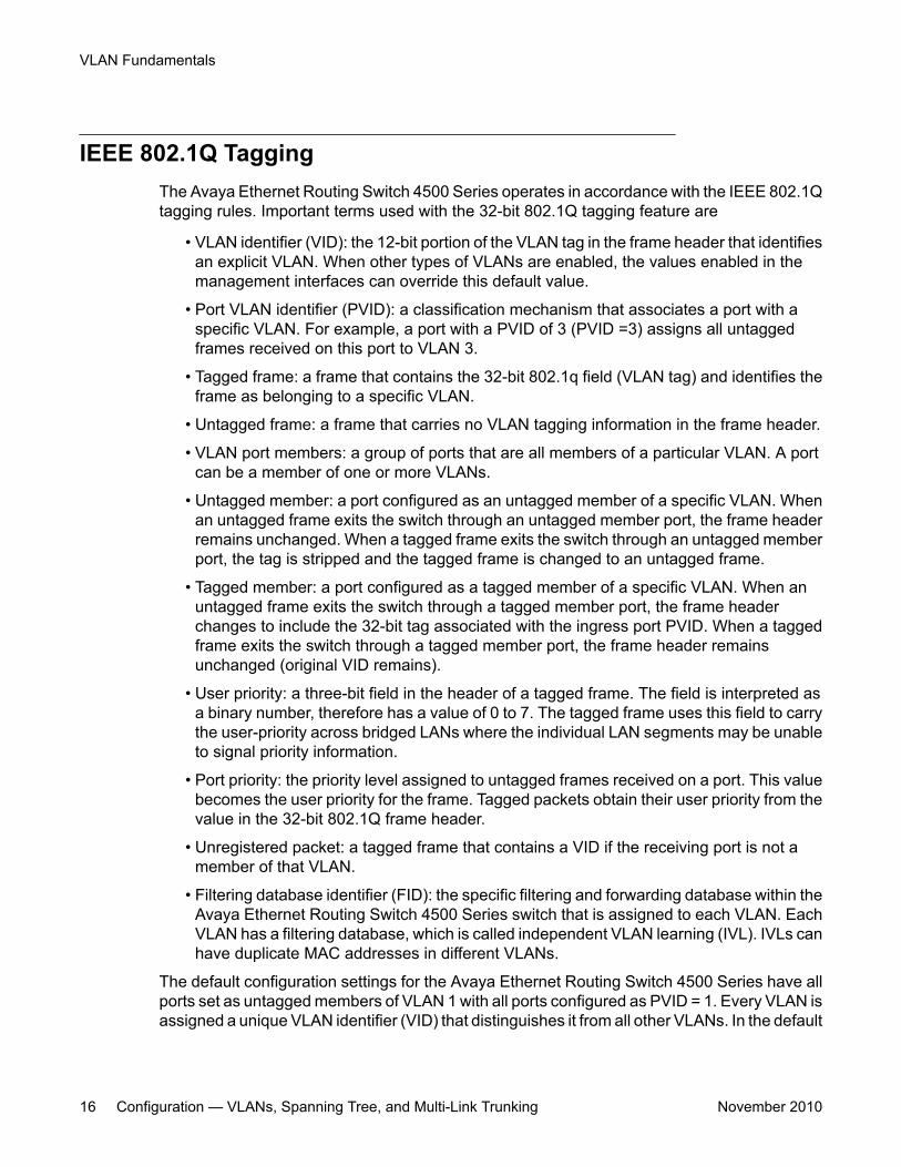
configuration example shown in Figure 2: Default VLAN Settings on page 17, all incomingpackets are assigned to VLAN 1 by the default port VLAN identifier (PVID =1). Untaggedpackets enter and leave the switch unchanged.
Figure 2: Default VLAN Settings
You can configure switch ports to transmit frames tagged on some VLANs and untagged onother VLANs.
When you configure VLANs, you can configure the egress tagging of each switch port as UntagAll, Untag PVID Only, Tag All or Tag PVID Only.
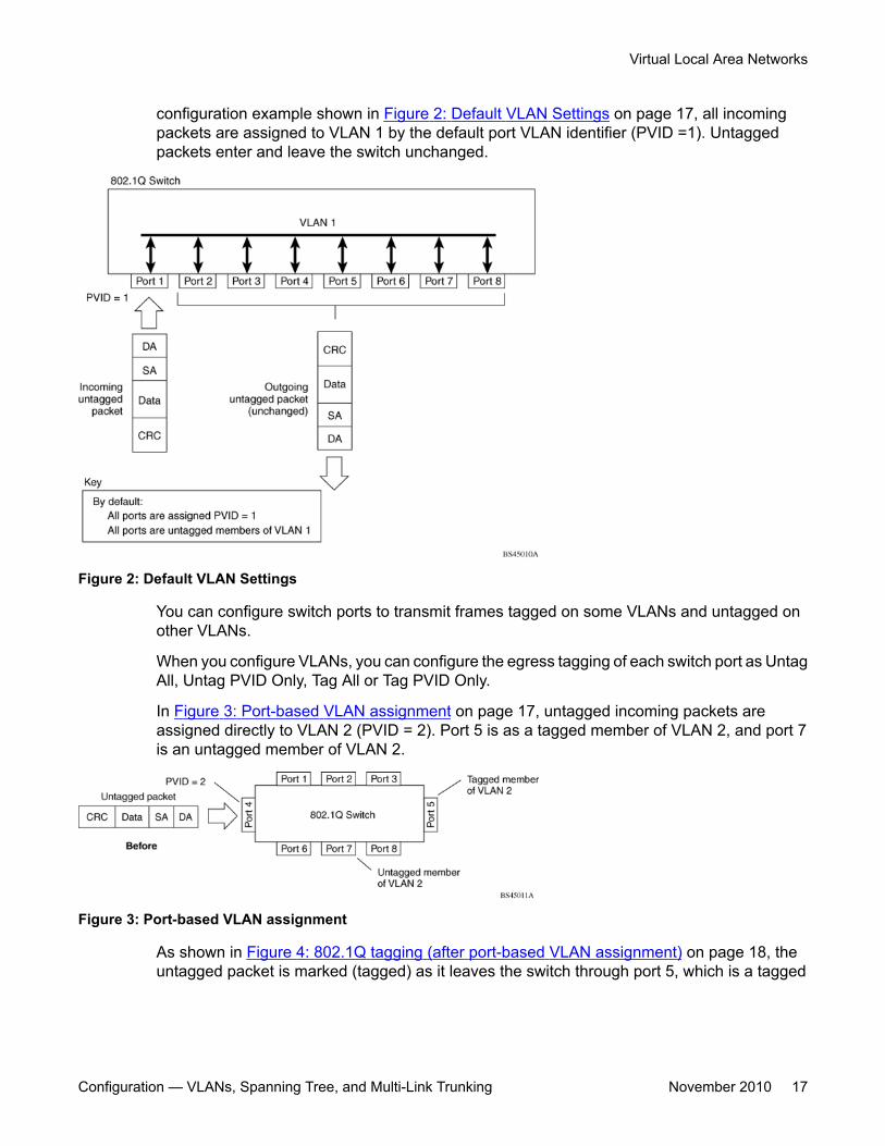
In Figure 3: Port-based VLAN assignment on page 17, untagged incoming packets areassigned directly to VLAN 2 (PVID = 2). Port 5 is as a tagged member of VLAN 2, and port 7is an untagged member of VLAN 2.
Figure 3: Port-based VLAN assignment
As shown in Figure 4: 802.1Q tagging (after port-based VLAN assignment) on page 18, theuntagged packet is marked (tagged) as it leaves the switch through port 5, which is a tagged
Virtual Local Area Networks
Configuration — VLANs, Spanning Tree, and Multi-Link Trunking November 2010 17
member of VLAN 2. The untagged packet remains unchanged as it leaves the switch throughport 7, which is an untagged member of VLAN 2.
Figure 4: 802.1Q tagging (after port-based VLAN assignment)
In Figure 5: Policy-based VLAN assignment on page 18, untagged incoming packets areassigned to VLAN 3 (policy VLAN = 3, PVID = 2). Port 5 is a tagged member of VLAN 3,and port 7 is an untagged member of VLAN 3.
Figure 5: Policy-based VLAN assignment
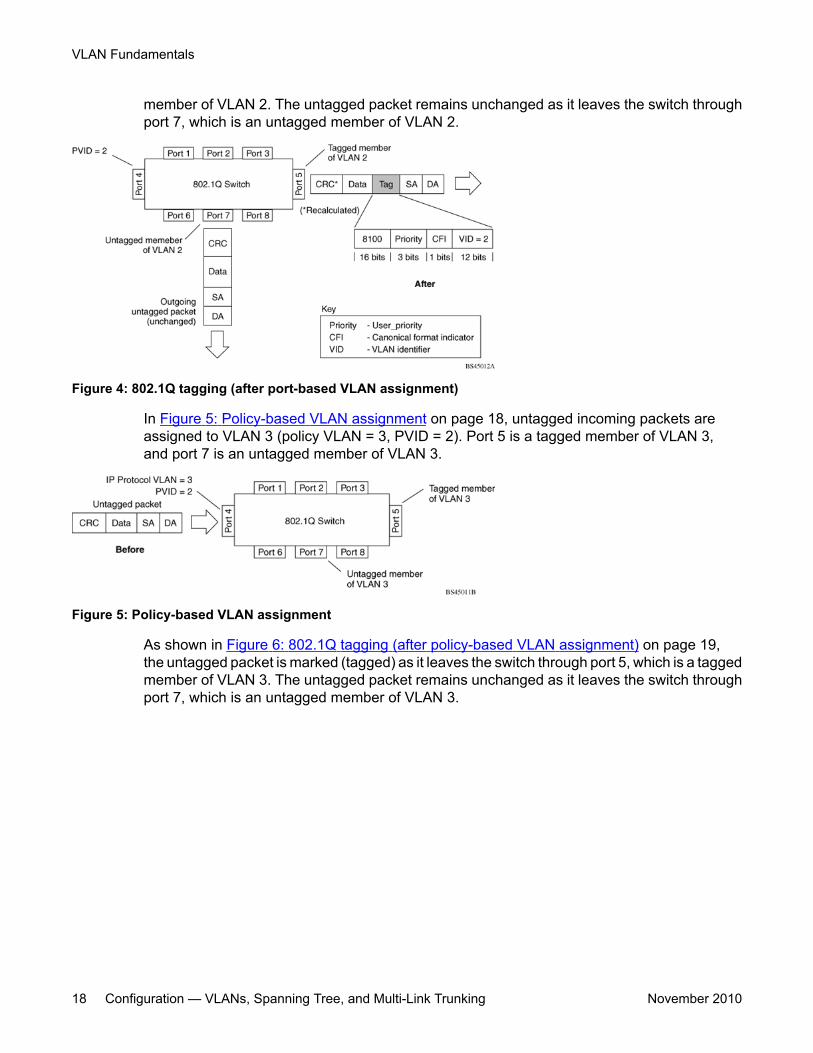
As shown in Figure 6: 802.1Q tagging (after policy-based VLAN assignment) on page 19,the untagged packet is marked (tagged) as it leaves the switch through port 5, which is a taggedmember of VLAN 3. The untagged packet remains unchanged as it leaves the switch throughport 7, which is an untagged member of VLAN 3.
VLAN Fundamentals
18 Configuration — VLANs, Spanning Tree, and Multi-Link Trunking November 2010
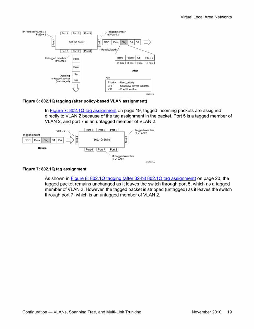
Figure 6: 802.1Q tagging (after policy-based VLAN assignment)
In Figure 7: 802.1Q tag assignment on page 19, tagged incoming packets are assigneddirectly to VLAN 2 because of the tag assignment in the packet. Port 5 is a tagged member ofVLAN 2, and port 7 is an untagged member of VLAN 2.
Figure 7: 802.1Q tag assignment
As shown in Figure 8: 802.1Q tagging (after 32-bit 802.1Q tag assignment) on page 20, thetagged packet remains unchanged as it leaves the switch through port 5, which as a taggedmember of VLAN 2. However, the tagged packet is stripped (untagged) as it leaves the switchthrough port 7, which is an untagged member of VLAN 2.
Virtual Local Area Networks
Configuration — VLANs, Spanning Tree, and Multi-Link Trunking November 2010 19
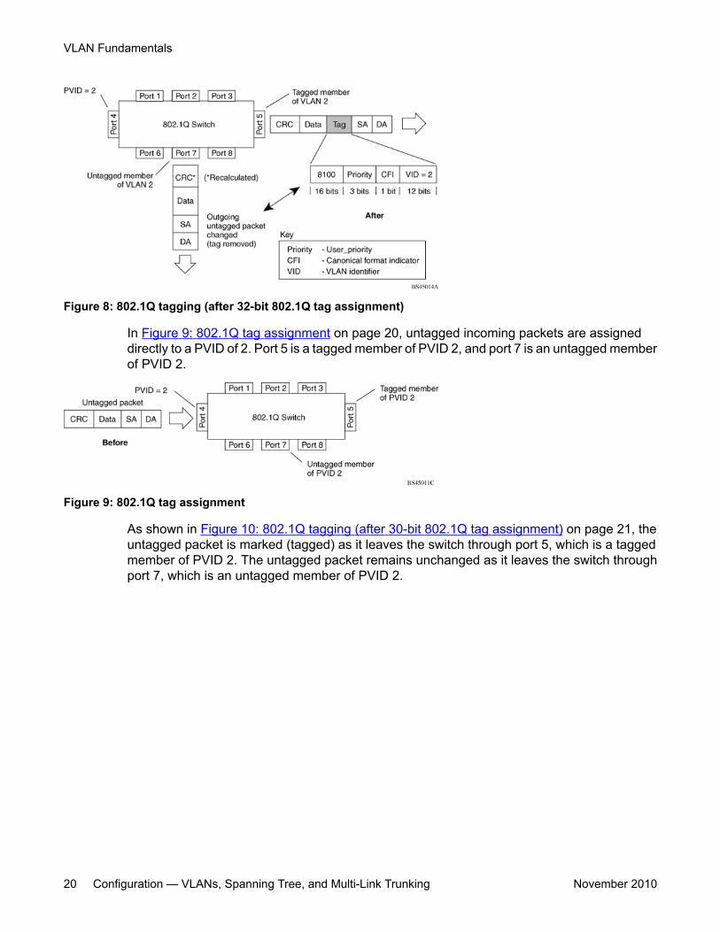
Figure 8: 802.1Q tagging (after 32-bit 802.1Q tag assignment)
In Figure 9: 802.1Q tag assignment on page 20, untagged incoming packets are assigneddirectly to a PVID of 2. Port 5 is a tagged member of PVID 2, and port 7 is an untagged memberof PVID 2.
Figure 9: 802.1Q tag assignment
As shown in Figure 10: 802.1Q tagging (after 30-bit 802.1Q tag assignment) on page 21, theuntagged packet is marked (tagged) as it leaves the switch through port 5, which is a taggedmember of PVID 2. The untagged packet remains unchanged as it leaves the switch throughport 7, which is an untagged member of PVID 2.
VLAN Fundamentals
20 Configuration — VLANs, Spanning Tree, and Multi-Link Trunking November 2010
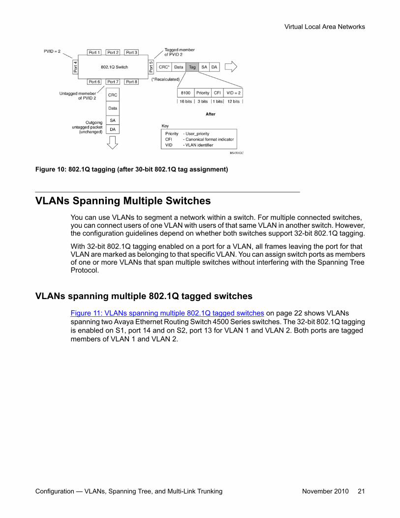
Figure 10: 802.1Q tagging (after 30-bit 802.1Q tag assignment)
VLANs Spanning Multiple SwitchesYou can use VLANs to segment a network within a switch. For multiple connected switches,you can connect users of one VLAN with users of that same VLAN in another switch. However,the configuration guidelines depend on whether both switches support 32-bit 802.1Q tagging.
With 32-bit 802.1Q tagging enabled on a port for a VLAN, all frames leaving the port for thatVLAN are marked as belonging to that specific VLAN. You can assign switch ports as membersof one or more VLANs that span multiple switches without interfering with the Spanning TreeProtocol.
VLANs spanning multiple 802.1Q tagged switches
Figure 11: VLANs spanning multiple 802.1Q tagged switches on page 22 shows VLANsspanning two Avaya Ethernet Routing Switch 4500 Series switches. The 32-bit 802.1Q taggingis enabled on S1, port 14 and on S2, port 13 for VLAN 1 and VLAN 2. Both ports are taggedmembers of VLAN 1 and VLAN 2.
Virtual Local Area Networks
Configuration — VLANs, Spanning Tree, and Multi-Link Trunking November 2010 21
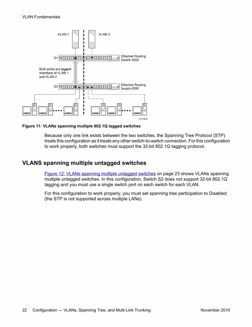
Figure 11: VLANs spanning multiple 802.1Q tagged switches
Because only one link exists between the two switches, the Spanning Tree Protocol (STP)treats this configuration as it treats any other switch-to-switch connection. For this configurationto work properly, both switches must support the 32-bit 802.1Q tagging protocol.
VLANS spanning multiple untagged switches
Figure 12: VLANs spanning multiple untagged switches on page 23 shows VLANs spanningmultiple untagged switches. In this configuration, Switch S2 does not support 32-bit 802.1Qtagging and you must use a single switch port on each switch for each VLAN.
For this configuration to work properly, you must set spanning tree participation to Disabled(the STP is not supported across multiple LANs).
VLAN Fundamentals
22 Configuration — VLANs, Spanning Tree, and Multi-Link Trunking November 2010
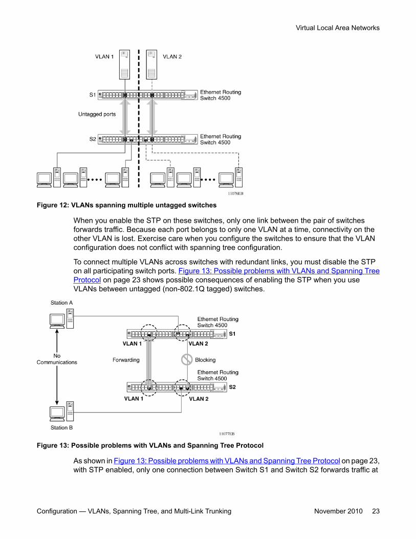
Figure 12: VLANs spanning multiple untagged switches
When you enable the STP on these switches, only one link between the pair of switchesforwards traffic. Because each port belongs to only one VLAN at a time, connectivity on theother VLAN is lost. Exercise care when you configure the switches to ensure that the VLANconfiguration does not conflict with spanning tree configuration.
To connect multiple VLANs across switches with redundant links, you must disable the STPon all participating switch ports. Figure 13: Possible problems with VLANs and Spanning TreeProtocol on page 23 shows possible consequences of enabling the STP when you useVLANs between untagged (non-802.1Q tagged) switches.
Figure 13: Possible problems with VLANs and Spanning Tree Protocol
As shown in Figure 13: Possible problems with VLANs and Spanning Tree Protocol on page 23,with STP enabled, only one connection between Switch S1 and Switch S2 forwards traffic at
Virtual Local Area Networks
Configuration — VLANs, Spanning Tree, and Multi-Link Trunking November 2010 23
any time. Communication fails between VLAN 2 of S1 and VLAN 2 of S2, blockingcommunications between Stations A and B.
The STP selects the link that connects VLAN 1 on Switches S1 and S2 as the forwarding linkbased on port speed, duplex-mode, and port priority. Because the other link that connectsVLAN 2 is in Blocking mode, stations on VLAN 2 in Switch S1 cannot communicate withstations in VLAN 2 on Switch S2. With multiple links only one link forwards traffic.
VLAN SummaryThis section summarizes the VLAN examples discussed in the previous sections.
As shown in Figure 14: VLAN configuration spanning multiple switches on page 25, SwitchS1 is configured with multiple VLANs:
• Ports 17, 20, 25, and 26 are in VLAN 1.
• Ports 16, 18, 19, 21, and 24 are in VLAN 2.
• Port 22 is in VLAN 3.
Because S4 does not support 32-bit 802.1Q tagging, you must use a single switch port oneach switch for each VLAN (see Figure 12: VLANs spanning multiple untagged switches onpage 23).
The connection to S2 requires only one link between the switches because S1 and S2 are bothAvaya Ethernet Routing Switch 4500 Series switches that support 32-bit 802.1Q tagging (see VLANs spanning multiple 802.1Q tagged switches on page 21).
VLAN Fundamentals
24 Configuration — VLANs, Spanning Tree, and Multi-Link Trunking November 2010
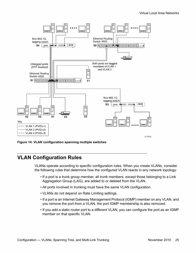
Figure 14: VLAN configuration spanning multiple switches
VLAN Configuration RulesVLANs operate according to specific configuration rules. When you create VLANs, considerthe following rules that determine how the configured VLAN reacts in any network topology:
• If a port is a trunk group member, all trunk members, except those belonging to a LinkAggregation Group (LAG), are added to or deleted from the VLAN.
• All ports involved in trunking must have the same VLAN configuration.
• VLANs do not depend on Rate Limiting settings.
• If a port is an Internet Gateway Management Protocol (IGMP) member on any VLAN, andyou remove the port from a VLAN, the port IGMP membership is also removed.
• If you add a static router port to a different VLAN, you can configure the port as an IGMPmember on that specific VLAN.
Virtual Local Area Networks
Configuration — VLANs, Spanning Tree, and Multi-Link Trunking November 2010 25
Important:If you tag protocol VLAN client ports, the system cannot assign frames to the protocol VLAN,regardless of the defined ethertype. Frames are not assigned to the protocol VLAN becauseuntagged packets will be assigned to the VLAN identified by the port PVID.
VLAN Configuration ControlA switch administrator uses VLAN Configuration Control (VCC) to control modifications toVLANs. VCC is a superset of the existing AutoPVID functionality and incorporates thisfunctionality for backwards compatibility. VCC is globally applied to all VLANs on the switch.
VLAN Configuration Control offers four options to control VLAN modification:
• Strict: Restrict the addition of an untagged port to a VLAN if it is already a member ofanother VLAN. To add an untagged port to a new VLAN, the switch administrator mustremove the port from all other VLANs of which it is a member before adding it to the newVLAN. The PVID of the port is changed to the new VID to which it was added.
Important:Strict is the factory default setting.
• Automatic: Automatically add an untagged port to a new VLAN and automatically removeit from any previous VLAN membership. The PVID of the port automatically changes tothe VID of the VLAN it joins. Because you first add the port to the new VLAN and thenremove it from any previous membership, the Spanning Tree Group participation of theport remains enabled as long as the VLANs involved are in the same Spanning TreeGroup.
• AutoPVID: This option functions in the same manner as previous AutoPVID functionality.When you add an untagged port to a new VLAN, you add the port to the new VLAN and thePVID assigned to the new VID without removing it from previous VLAN memberships.Using this option, an untagged port can have membership in multiple VLANs.
• Flexible: This option functions in a similar manner to disabling AutoPVID functionality.When you use this option, an untagged port can belong to an unlimited number of VLANs.Any new additions of an untagged port to a new VLAN does not change the PVID of thatport.
VLAN Configuration Control applies only to ports with the tagging modes of Untag All and TagPVID Only. VCC does not govern ports with the tagging modes of Tag All and Untag PVIDOnly. Ports with the tagging modes of Tag All and Untag PVID Only can belong to multipleVLANs regardless of VLAN Configuration Control settings and you must manually change theirPVID.
VLAN Fundamentals
26 Configuration — VLANs, Spanning Tree, and Multi-Link Trunking November 2010
MAC FlushYou can use the MAC Flush feature to clear MAC Address entries directly from the MACAddress Table (or Forwarding Data Base). If you do not use the MAC Flush feature, you canuse the following indirect methods:
• power cycling the switch
• deleting, and then recreating the VLAN
• unplugging, and then replugging the port to flush out all addresses learned on the port
MAC Flush provides the following options to flush out MAC Address entries:
• clear a single MAC Address
• clear all MAC addresses from a port (or list of ports)
• clear all MAC addresses from a trunk (MLT or LAG)
• clear all MAC addresses from a particular VLAN or all MAC addresses
MAC Flush clears only dynamically learned MAC Addresses. MAC Flush does not delete MACAddresses created by MAC Security or Port Mirroring because deletion of these MACAddresses can affect the MAC Security or Port Mirroring function.
MAC Addresses for MAC Security or Port Mirroring have one of the following identifiers:
• AGELOCK
• SECRET
• STATIC
Higher priority tasks can delay MAC Address clearing.
You can configure MAC Flush in ACLI, SNMP, and Enterprise Device Manager.
MAC Flush
Configuration — VLANs, Spanning Tree, and Multi-Link Trunking November 2010 27

VLAN Fundamentals
28 Configuration — VLANs, Spanning Tree, and Multi-Link Trunking November 2010
Chapter 4: MLT Fundamentals
MultiLink trunksWith MultiLink trunks, you can group a maximum of 8 switch ports to form a link to anotherswitch or server, thus increasing aggregate throughput of the interconnection between thedevices (up to 8 Gigabits if using Gigabit ports or 80 Gigabits if using 10 Gigabit ports). Youcan configure a maximum of 32 MultiLink trunks. The trunk members can reside on a singleunit or on multiple units within the same stack configuration as a distributed trunk. MultiLinkTrunking software detects misconfigured (or broken) trunk links and redirects traffic on themisconfigured or broken trunk link to other trunk members within that trunk.
You can use the Command Line Interface (ACLI) or Enterprise Device Manager (EDM) tocreate switch-to-switch and switch-to-server MultiLink trunk links.
Client-server configuration using MultiLink trunksFigure 15: Client/server configuration example on page 30 shows an example of how youcan use MultiLink Trunking in a client/server configuration. In this example, both serversconnect directly to Switch S1. FS2 is connected through a trunk configuration. The switch-to-switch connections are through trunks.
Configuration — VLANs, Spanning Tree, and Multi-Link Trunking November 2010 29
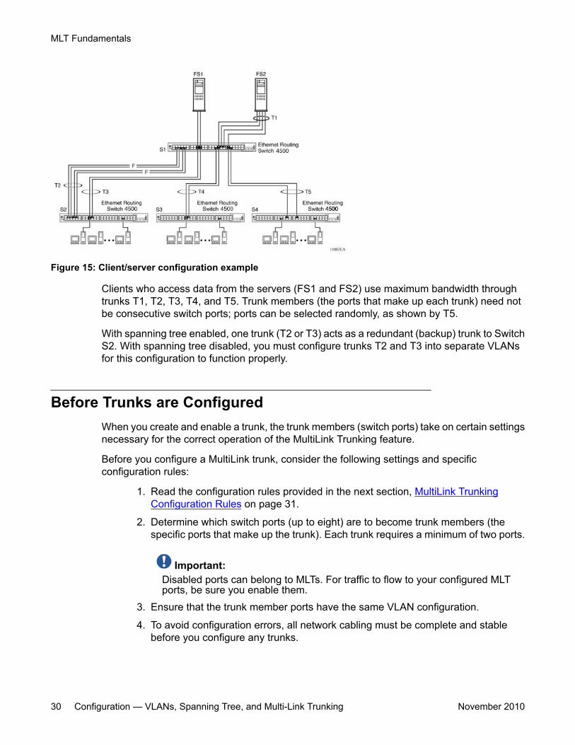
Figure 15: Client/server configuration example
Clients who access data from the servers (FS1 and FS2) use maximum bandwidth throughtrunks T1, T2, T3, T4, and T5. Trunk members (the ports that make up each trunk) need notbe consecutive switch ports; ports can be selected randomly, as shown by T5.
With spanning tree enabled, one trunk (T2 or T3) acts as a redundant (backup) trunk to SwitchS2. With spanning tree disabled, you must configure trunks T2 and T3 into separate VLANsfor this configuration to function properly.
Before Trunks are ConfiguredWhen you create and enable a trunk, the trunk members (switch ports) take on certain settingsnecessary for the correct operation of the MultiLink Trunking feature.
Before you configure a MultiLink trunk, consider the following settings and specificconfiguration rules:
1. Read the configuration rules provided in the next section, MultiLink TrunkingConfiguration Rules on page 31.
2. Determine which switch ports (up to eight) are to become trunk members (thespecific ports that make up the trunk). Each trunk requires a minimum of two ports.
Important:Disabled ports can belong to MLTs. For traffic to flow to your configured MLTports, be sure you enable them.
3. Ensure that the trunk member ports have the same VLAN configuration.
4. To avoid configuration errors, all network cabling must be complete and stablebefore you configure any trunks.
MLT Fundamentals
30 Configuration — VLANs, Spanning Tree, and Multi-Link Trunking November 2010
Important:If trunk ports are STP-enabled, ensure that all potential trunk members areconnected to their corresponding members; otherwise, STP cannot convergecorrectly, and traffic loss can result.
5. Consider how the existing spanning tree reacts to the new trunk configuration.
Important:If potential trunk ports are connected and STP is disabled on these ports, a loop isformed; to avoid this situation, enable the trunk before you disable STP.
6. Consider how the addition of a trunk will affect existing VLANs.
MultiLink Trunking Configuration RulesThe MultiLink Trunking feature is deterministic; that is, it operates according to specificconfiguration rules. When you create trunks, consider the following rules that determine howthe MultiLink trunk reacts in any network topology:
• Disabled ports can belong to MLTs. For traffic to flow to your configured MLT ports, besure that you enable them (set to Enabled through the Port Configuration screen orthrough network management)..
• All trunk members must have the same VLAN configuration before you set the TrunkStatus field on the Trunk Configuration screen to Enabled using ACLI.
• When you configure an active port in a trunk, the port becomes a trunk member when theTrunk Status field is Enabled. The spanning tree parameters for the port then change toreflect the new trunk settings.
• If you change the spanning tree participation of any trunk member to Enabled or Disabled,the spanning tree participation of all members of that trunk changes similarly.
• If you change the VLAN settings of any trunk member, the VLAN settings of all members ofthat trunk change similarly.
• A MLT/DMLT/LAG member can not be configured as a monitor port.• A monitor port cannot monitor entire trunks; the monitor port can monitor trunk members.• All trunk members must have identical Internet Gateway Management Protocol (IGMP)
configurations.• If you change the IGMP snooping configuration for any trunk member, the IGMP snooping
settings for all trunk members change.• Avaya recommends that you do not enable MAC Address Security on trunk ports.
MultiLink trunks
Configuration — VLANs, Spanning Tree, and Multi-Link Trunking November 2010 31
• MLT ports can participate in different STGs. They must have the same spanning treelearning in every group but not necessarily the same learning between different groupsto consistently update their state in the port driver.
• Like normal ports, MLT ports can participate with different spanning tree learning fordifferent spanning tree groups. Trunk ports that are in multiple spanning tree groups mustbe tagged, and all MLT members must belong to the same spanning tree group.
MLT load-balancingThe Avaya Ethernet Routing Switch 4500 supports two modes of MLT load-balancing; Basicfor layer 2 operation and Advanced for Layer 3 operation. You can configure this option usingthe mlt <1-32> loadbalance ACLI command. You can also use the show mlt hash-calc ACLI command to display the MLT hashing for a particular source or destination address.
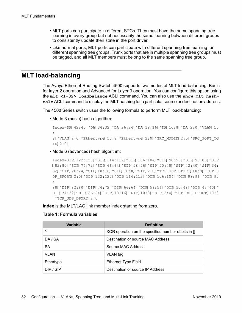
The 4500 Series switch uses the following formula to perform MLT load-balancing:
• Mode 3 (basic) hash algorithm:
Index=DA[42:40]^DA[34:32]^DA[26:24]^DA[18:16]^DA[10:8]^DA[2:0]^VLAN[10:8]^VLAN[2:0]^Ethertype[10:8]^Ethertype[2:0]^SRC_MODID[2:0]^SRC_PORT_TGID[2:0]
• Mode 6 (advanced) hash algorithm:
Index=SIP[122:120]^SIP[114:112]^SIP[106:104]^SIP[98:96]^SIP[90:88]^SIP[82:80]^SIP[74:72]^SIP[66:64]^SIP[58:56]^SIP[50:48]^SIP[42:40]^SIP[34:32]^SIP[26:24]^SIP[18:16]^SIP[10:8]^SIP[2:0]^TCP_UDP_SPORT[10:8]^TCP_UDP_SPORT[2:0]^DIP[122:120]^DIP[114:112]^DIP[106:104]^DIP[98:96]^DIP[90:88]^DIP[82:80]^DIP[74:72]^DIP[66:64]^DIP[58:56]^DIP[50:48]^DIP[42:40]^DIP[34:32]^DIP[26:24]^DIP[18:16]^DIP[10:8]^DIP[2:0]^TCP_UDP_DPORT[10:8]^TCP_UDP_DPORT[2:0]
Index is the MLT/LAG link member index starting from zero.
Table 1: Formula variables
Variable Definition^ XOR operation on the specified number of bits in []
DA / SA Destination or source MAC Address
SA Source MAC Address
VLAN VLAN tag
Ethertype Ethernet Type Field
DIP / SIP Destination or source IP Address
MLT Fundamentals
32 Configuration — VLANs, Spanning Tree, and Multi-Link Trunking November 2010
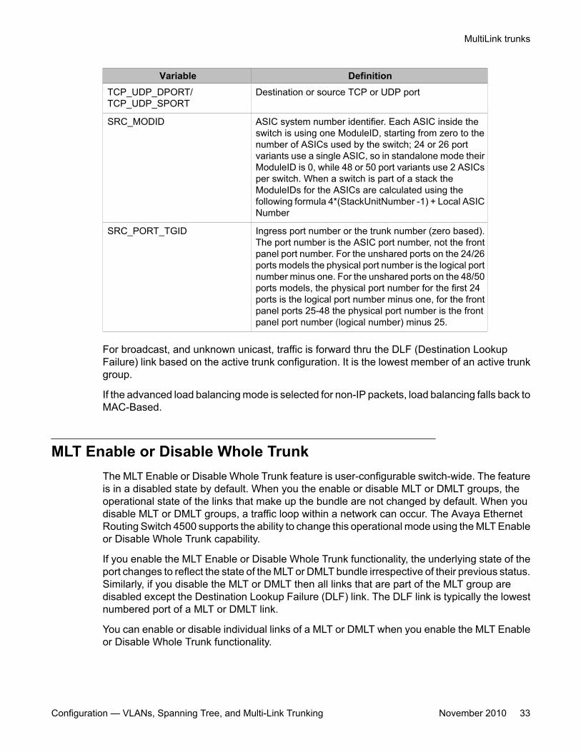
Variable DefinitionTCP_UDP_DPORT/TCP_UDP_SPORT
Destination or source TCP or UDP port
SRC_MODID ASIC system number identifier. Each ASIC inside theswitch is using one ModuleID, starting from zero to thenumber of ASICs used by the switch; 24 or 26 portvariants use a single ASIC, so in standalone mode theirModuleID is 0, while 48 or 50 port variants use 2 ASICsper switch. When a switch is part of a stack theModuleIDs for the ASICs are calculated using thefollowing formula 4*(StackUnitNumber -1) + Local ASICNumber
SRC_PORT_TGID Ingress port number or the trunk number (zero based).The port number is the ASIC port number, not the frontpanel port number. For the unshared ports on the 24/26ports models the physical port number is the logical portnumber minus one. For the unshared ports on the 48/50ports models, the physical port number for the first 24ports is the logical port number minus one, for the frontpanel ports 25-48 the physical port number is the frontpanel port number (logical number) minus 25.
For broadcast, and unknown unicast, traffic is forward thru the DLF (Destination LookupFailure) link based on the active trunk configuration. It is the lowest member of an active trunkgroup.
If the advanced load balancing mode is selected for non-IP packets, load balancing falls back toMAC-Based.
MLT Enable or Disable Whole TrunkThe MLT Enable or Disable Whole Trunk feature is user-configurable switch-wide. The featureis in a disabled state by default. When you the enable or disable MLT or DMLT groups, theoperational state of the links that make up the bundle are not changed by default. When youdisable MLT or DMLT groups, a traffic loop within a network can occur. The Avaya EthernetRouting Switch 4500 supports the ability to change this operational mode using the MLT Enableor Disable Whole Trunk capability.
If you enable the MLT Enable or Disable Whole Trunk functionality, the underlying state of theport changes to reflect the state of the MLT or DMLT bundle irrespective of their previous status.Similarly, if you disable the MLT or DMLT then all links that are part of the MLT group aredisabled except the Destination Lookup Failure (DLF) link. The DLF link is typically the lowestnumbered port of a MLT or DMLT link.
You can enable or disable individual links of a MLT or DMLT when you enable the MLT Enableor Disable Whole Trunk functionality.
MultiLink trunks
Configuration — VLANs, Spanning Tree, and Multi-Link Trunking November 2010 33
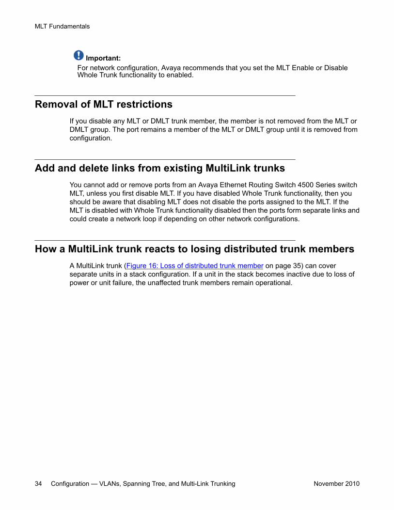
Important:For network configuration, Avaya recommends that you set the MLT Enable or DisableWhole Trunk functionality to enabled.
Removal of MLT restrictionsIf you disable any MLT or DMLT trunk member, the member is not removed from the MLT orDMLT group. The port remains a member of the MLT or DMLT group until it is removed fromconfiguration.
Add and delete links from existing MultiLink trunksYou cannot add or remove ports from an Avaya Ethernet Routing Switch 4500 Series switchMLT, unless you first disable MLT. If you have disabled Whole Trunk functionality, then youshould be aware that disabling MLT does not disable the ports assigned to the MLT. If theMLT is disabled with Whole Trunk functionality disabled then the ports form separate links andcould create a network loop if depending on other network configurations.
How a MultiLink trunk reacts to losing distributed trunk membersA MultiLink trunk (Figure 16: Loss of distributed trunk member on page 35) can coverseparate units in a stack configuration. If a unit in the stack becomes inactive due to loss ofpower or unit failure, the unaffected trunk members remain operational.
MLT Fundamentals
34 Configuration — VLANs, Spanning Tree, and Multi-Link Trunking November 2010
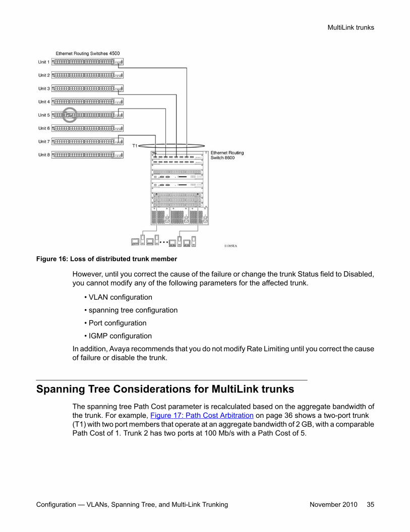
Figure 16: Loss of distributed trunk member
However, until you correct the cause of the failure or change the trunk Status field to Disabled,you cannot modify any of the following parameters for the affected trunk.
• VLAN configuration
• spanning tree configuration
• Port configuration
• IGMP configuration
In addition, Avaya recommends that you do not modify Rate Limiting until you correct the causeof failure or disable the trunk.
Spanning Tree Considerations for MultiLink trunksThe spanning tree Path Cost parameter is recalculated based on the aggregate bandwidth ofthe trunk. For example, Figure 17: Path Cost Arbitration on page 36 shows a two-port trunk(T1) with two port members that operate at an aggregate bandwidth of 2 GB, with a comparablePath Cost of 1. Trunk 2 has two ports at 100 Mb/s with a Path Cost of 5.
MultiLink trunks
Configuration — VLANs, Spanning Tree, and Multi-Link Trunking November 2010 35
Figure 17: Path Cost Arbitration
When the Path Cost calculations for both trunks are equal, the software chooses the trunk thatcontains the lowest numbered port as the forwarding path.
Important:The default spanning tree Path Cost for all gigabit ports is always equal to 1.
When configuring trunks, be aware that when adding a one-gigabit link in front of anothertrunk, the trunk becomes blocked because both the link and trunks have a Path Cost of 1.
The switch can detect trunk member ports that are physically misconfigured. For example, in Figure 18: Correctly Configured Trunk on page 37, trunk member ports 2, 4, and 6 of SwitchS1 are configured correctly to trunk member ports 7, 9, and 11 of Switch S2. The showspanning-tree port command output for each switch shows the port state field for eachport in the Forwarding state.
MLT Fundamentals
36 Configuration — VLANs, Spanning Tree, and Multi-Link Trunking November 2010
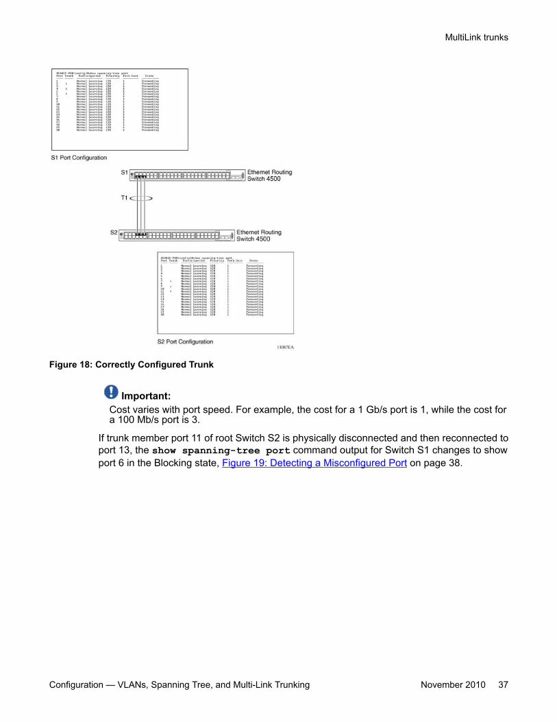
Figure 18: Correctly Configured Trunk
Important:Cost varies with port speed. For example, the cost for a 1 Gb/s port is 1, while the cost fora 100 Mb/s port is 3.
If trunk member port 11 of root Switch S2 is physically disconnected and then reconnected toport 13, the show spanning-tree port command output for Switch S1 changes to showport 6 in the Blocking state, Figure 19: Detecting a Misconfigured Port on page 38.
MultiLink trunks
Configuration — VLANs, Spanning Tree, and Multi-Link Trunking November 2010 37
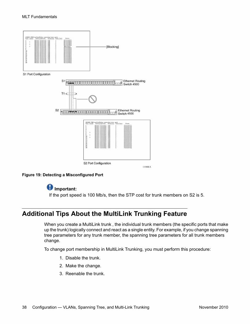
Figure 19: Detecting a Misconfigured Port
Important:If the port speed is 100 Mb/s, then the STP cost for trunk members on S2 is 5.
Additional Tips About the MultiLink Trunking FeatureWhen you create a MultiLink trunk , the individual trunk members (the specific ports that makeup the trunk) logically connect and react as a single entity. For example, if you change spanningtree parameters for any trunk member, the spanning tree parameters for all trunk memberschange.
To change port membership in MultiLink Trunking, you must perform this procedure:
1. Disable the trunk.
2. Make the change.
3. Reenable the trunk.
MLT Fundamentals
38 Configuration — VLANs, Spanning Tree, and Multi-Link Trunking November 2010
All configured trunks are indicated in the Spanning Tree Configuration screen. The Trunk fieldlists the active trunks that are adjacent to the port numbers that correspond to the specific trunkmember for that trunk.
When you change a Spanning Tree parameter for one trunk member, the modification affectsall trunk members.
Management stations view the trunk as a single spanning tree port. The spanning tree port isrepresented by the trunk member with the lowest port number. For example, if ports 13, 14,15, and 16 are trunk members of trunk T1, the management station views trunk T1 as spanningtree port 13.
MultiLink trunks
Configuration — VLANs, Spanning Tree, and Multi-Link Trunking November 2010 39

MLT Fundamentals
40 Configuration — VLANs, Spanning Tree, and Multi-Link Trunking November 2010
Chapter 5: STP Fundamentals
Spanning Tree Protocol groupsThe Avaya Ethernet Routing Switch 4500 Series supports the Spanning Tree Protocol (STP)as defined in IEEE 802.1D. The Spanning Tree Protocol detects and eliminates logical loopsin a bridged or switched network. When multiple paths exist, the spanning tree algorithmconfigures the network so that a bridge or switch uses only the most efficient path. If that pathfails, the protocol automatically reconfigures the network activate another path, thus sustainingnetwork operations.
The Avaya Ethernet Routing Switch 4500 Series supports multiple spanning tree groups(STG). The Avaya Ethernet Routing Switch 4500 Series supports a maximum of eight STGs,either all in one stand-alone switch or across a stack. Multiple STGs provide multiple datapaths, which can be used for load-sharing and redundancy. Enable load sharing between twoswitches using multiple STGs by configuring each path with a different VLAN and thenassigning each VLAN to a separate STG. Each STG is independent. Each STG sends its ownBridge Protocol Data Units (BPDU), and you must independently configure each STG.
The STG, or bridge group, forms a loop-free topology that includes one or more virtual LANs(VLAN). The Avaya Ethernet Routing Switch 4500 Series supports multiple instances (eight)of STGs that run simultaneously.
The Avaya Ethernet Routing Switch 4500 Series supports a maximum of 256 VLANs. With amaximum of 8 STGs, on average, each STG can have 32 VLANs.
In the default configuration of the Avaya Ethernet Routing Switch 4500 Series, a single STGwith the ID of 1 includes all ports on the switch. This STG is the default STG. Although you canadd ports or delete ports from the default STG, you cannot delete the default STG (STG1) itselffrom the system. Also you cannot delete the default VLAN (VLAN1) from STG1.
The tagging for the BPDUs from STG1, or the default STG, is user-configurable (as are taggingsettings for all STGs). However, by default STG1 sends only untagged BPDUs to operate withall devices that support only one instance of STP. (By default, STG2 through STG8 are tagged.)The tagging setting for each STG is user-configurable.
Important:If the STG tags a BPDU, the BPDU packet is tagged only on a tagged port. Also, ensurethat the Filter Unregistered Frames option is disabled on the tagged port for this to functionproperly.
You must create all other STGs, except the Default STG. To become active, you must enableeach STG after its creation. Each STG is assigned an ID number from 2 to 8 (the Default STG is
Configuration — VLANs, Spanning Tree, and Multi-Link Trunking November 2010 41
assigned the ID number 1). Ports or VLANs are assigned to an active STG. However, a portthat is not a member of a VLAN cannot join an STG.
When you create an STG, all ports that belong to any assigned VLAN are automatically addedto the STG.
Disable and delete an STG when you no longer need it. The procedure is to disable the STG,delete all VLAN and port memberships, and then delete the STG.
A unique multicast address can be configured for STGs 1 to 4.
Important:When configuring a unique multicast address for an STG, each device in that STG must beconfigured with the same spanning tree multicast address.
STG Configuration GuidelinesThis section provides important information about configuring STGs:
• You must create an STG must by preforming these steps:
- Create the STG.
- Add the existing VLAN and port memberships.
- Enable the STG.
• When you create a VLAN, that VLAN automatically belongs to STG 1, the default STG.If the VLAN is to be in another STG, move the VLAN by assigning it to another STG.
• You must move a newly created VLAN to an existing STG by performing these steps:
- Create the VLAN.
- Add the VLAN to an existing STG.
• You cannot move or delete VLAN1 from STG1.
• VLANs must be in a single STG; a VLAN cannot span multiple STGs. By confining VLANswithin a single STG, you avoid problems with spanning tree blocking ports and loss ofconnectivity within the VLAN. When a VLAN spans multiple switches, the VLAN must bewithin the same spanning tree group (have the same STG ID) across all the switches.
• You cannot add a port that is a member of no VLAN to any STG. You must add the portmust to a VLAN, and add that VLAN to the desired STG.
• Tagged ports can belong to more than one STG, but untagged ports can belong to onlyone STG.
• When a tagged port belongs to more than one STG, the egress BPDUs are tagged todistinguish the BPDUs of one STG from those of another STG.
STP Fundamentals
42 Configuration — VLANs, Spanning Tree, and Multi-Link Trunking November 2010
• Because some STP-compliant devices do not support tagging, you can configure whetherto send tagged or untagged BPDUs, even from tagged ports. The VLAN ID for the taggedBPDUs is 4000+STG ID.
• The default VLAN ID for tagged BPDUs is as follows:
- 4001--STG1
- 4002--STG2
- 4003--STG3
- 4004--STG4
- 4005--STG5
- 4006--STG6
- 4007--STG7
- 4008--STG8
• You can select a VLAN ID for tagged BPDUs for each STG. Valid VLAN IDs are 1 to 4094.
• Tagged BPDUs cannot use the same VID as an active VLAN.
• An untagged port cannot span multiple STGs.
• When you remove a port from a VLAN that belongs to an STG, that port is also removedfrom the STG. However, if that port belongs to another VLAN in the same STG, the portremains in the STG.
• As an example, assume that port 1 belongs to VLAN1, and that VLAN1 belongs to STG1.When you remove port 1 from VLAN1, port 1 is also removed from STG1. However, ifport 1 belongs to both VLAN1 and VLAN2 and both VLANs belong to STG1, removingport 1 from VLAN1 does not remove port 1 from STG1 because VLAN2 is still a member ofSTG1.
• You must disable an STG before you can delete it.
• You can configure a unique multicast address for STGs 1 to 4 only.
Spanning Tree Fast LearningSpanning Tree Fast Learning is an enhanced port mode supported by the Ethernet RoutingSwitch 4500 Series. If you enable Spanning Tree Fast Learning on a port with no other bridges,the port starts more quickly after a switch initialization or a spanning tree change. The portpasses through the normal blocking and learning states before the forwarding state, but thehold times for these states is the bridge hello timer (2 seconds by default) instead of the bridgeforward delay timer (15 seconds by default).
The port configured with Fast Learning can forward data immediately, as soon as the switchlearns that the port is enabled.
Spanning Tree Protocol groups
Configuration — VLANs, Spanning Tree, and Multi-Link Trunking November 2010 43
Fast Learning is intended for access ports in which only one device is connected to the switch(as in workstations with no other spanning tree devices). For these ports, it is not desirable towait the usual 30 to 35 seconds for spanning tree initialization and bridge learning.
Important:Use Spanning Tree Fast Learning with caution. This procedure is contrary to that specified inthe IEEE 802.1D standard for Spanning Tree Protocol (STP) in which a port enters theblocking state after the initialization of the bridging device or after a return from the disabledstate when you enable the port through configuration.
STG port membership modeThe Avaya Ethernet Routing Switch 4500 supports two different STP port membership modes:normal and automatic. In the normal mode, when you assign a port to VLAN X and VLAN Xis in STP group Y, the port does not automatically become a member of STP group Y. Inautomatic mode, when you assign a port to VLAN X and VLAN X is in STP group Y, the portautomatically becomes a member of STP group Y.
802.1t path cost calculationYou can configure the switch to calculate the STG path cost using either the IEEE 802.1Dstandard or the IEEE 802.1t standard. The 802.1t standard is a maintenance extension to the802.1D standard which provides more bits for spanning tree costs, thus provides a larger rangeof costs which can better support the higher speed links which can be supported on the AvayaEthernet Routing Switch 4500. It is recommended to use 802.1t mode if using 10 Gigabit linksand other switches in the network support 802.1t. The mode can be changed using the ACLIcommand, spanning-tree cost-calc-mode.
802.1D compliancy supportIn a complex network environment, STP can cause broadcast storms when a switch port failsand recovers frequently. When you enable 802.1D compliancy support, the system preventsbroadcast storms by setting the STP state of a port to disabled when the port link is down.
Rapid Spanning Tree ProtocolThe standard Spanning Tree implementation in 4500 Series switches is based on IEEE802.1D. This implementation results in a slow response to a topology change in the network(for example, a dysfunctional link in a network).
STP Fundamentals
44 Configuration — VLANs, Spanning Tree, and Multi-Link Trunking November 2010
The Rapid Spanning Tree Protocol (RSTP or IEEE 802.1w) reduces recovery time after anetwork breakdown. RSTP also maintains a backward compatibility with the IEEE 802.1D,which was the Spanning Tree implementation prior to RSTP. In certain configurations, you canreduce the recovery time of RSTP to less than 1 second. Maintain the backward compatibilityby configuring a port to be in STP-compatible mode. A port that operates in the STP-compatible mode transmits and receives only STP BPDUs and drops any RSTP BPDUs.
RSTP also reduces the amount of flooding in the network by enhancing the way the TopologyChange Notification (TCN) packet is generated.
Multiple Spanning Tree ProtocolYou can use the Multiple Spanning Tree Protocol (MSTP or IEEE 802.1s) to configure multipleinstances of RSTP on the same switch. Each RSTP instance can include one or more VLANs.The operation of the MSTP is similar to the current Avaya proprietary MSTP.
The 4500 switch uses RSTP and MSTP to achieve the following:
• Reduce converging time from 30 seconds to less than 2 seconds when a topology changeoccurs in the network (that is, the port goes up or down).
• Eliminate unnecessary flushing of the MAC database and flooding of traffic to the networkwith a new Topology Change mechanism.
• Obtain backward compatibility with other switches that run legacy 802.1D STP or AvayaMSTG (STP group 1 only).
• Under MSTP mode, simultaneously support eight instances of RSTP. Instance 0 or CISTis the default group, which includes default VLAN 1. Instances 1 to 7 are called MSTIs 1-7.
• Run Avaya MSTG, RSTP, or MSTP.
Interoperability with legacy STPRSTP provides a new parameter ForceVersion for backward compatibility with legacy STP.You can configure a port in either STP-compatible or RSTP mode.
• An STP-compatible port transmits and receives only STP BPDUs. Any RSTP BPDU thatthe port receives in this mode is discarded.
• An RSTP-compatible port transmits and receives only RSTP BPDUs. If an RSTP portreceives an STP BPDU, it becomes an STP port. User intervention is required to returnthis port to RSTP mode. This process is called Port Protocol Migration.
Multiple Spanning Tree Protocol
Configuration — VLANs, Spanning Tree, and Multi-Link Trunking November 2010 45
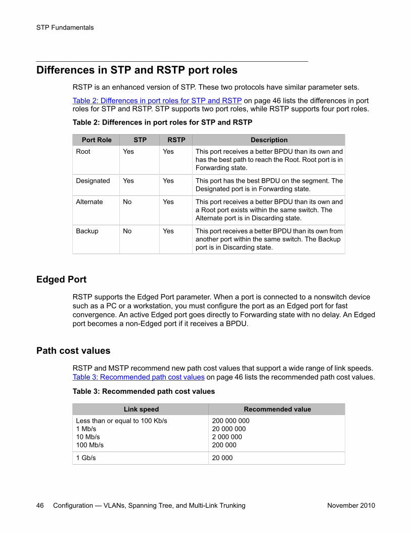
Differences in STP and RSTP port rolesRSTP is an enhanced version of STP. These two protocols have similar parameter sets.
Table 2: Differences in port roles for STP and RSTP on page 46 lists the differences in portroles for STP and RSTP. STP supports two port roles, while RSTP supports four port roles.
Table 2: Differences in port roles for STP and RSTP
Port Role STP RSTP DescriptionRoot Yes Yes This port receives a better BPDU than its own and
has the best path to reach the Root. Root port is inForwarding state.
Designated Yes Yes This port has the best BPDU on the segment. TheDesignated port is in Forwarding state.
Alternate No Yes This port receives a better BPDU than its own anda Root port exists within the same switch. TheAlternate port is in Discarding state.
Backup No Yes This port receives a better BPDU than its own fromanother port within the same switch. The Backupport is in Discarding state.
Edged Port
RSTP supports the Edged Port parameter. When a port is connected to a nonswitch devicesuch as a PC or a workstation, you must configure the port as an Edged port for fastconvergence. An active Edged port goes directly to Forwarding state with no delay. An Edgedport becomes a non-Edged port if it receives a BPDU.
Path cost values
RSTP and MSTP recommend new path cost values that support a wide range of link speeds. Table 3: Recommended path cost values on page 46 lists the recommended path cost values.
Table 3: Recommended path cost values
Link speed Recommended valueLess than or equal to 100 Kb/s1 Mb/s10 Mb/s100 Mb/s
200 000 00020 000 0002 000 000200 000
1 Gb/s 20 000
STP Fundamentals
46 Configuration — VLANs, Spanning Tree, and Multi-Link Trunking November 2010
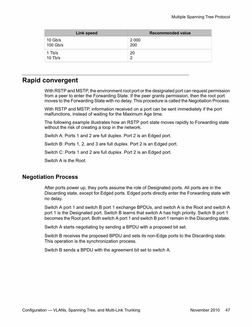
Link speed Recommended value10 Gb/s100 Gb/s
2 000200
1 Tb/s10 Tb/s
202
Rapid convergentWith RSTP and MSTP, the environment root port or the designated port can request permissionfrom a peer to enter the Forwarding State. If the peer grants permission, then the root portmoves to the Forwarding State with no delay. This procedure is called the Negotiation Process.
With RSTP and MSTP, information received on a port can be sent immediately if the portmalfunctions, instead of waiting for the Maximum Age time.
The following example illustrates how an RSTP port state moves rapidly to Forwarding statewithout the risk of creating a loop in the network.
Switch A: Ports 1 and 2 are full duplex. Port 2 is an Edged port.
Switch B: Ports 1, 2, and 3 are full duplex. Port 2 is an Edged port.
Switch C: Ports 1 and 2 are full duplex. Port 2 is an Edged port.
Switch A is the Root.
Negotiation Process
After ports power up, they ports assume the role of Designated ports. All ports are in theDiscarding state, except for Edged ports. Edged ports directly enter the Forwarding state withno delay.
Switch A port 1 and switch B port 1 exchange BPDUs, and switch A is the Root and switch Aport 1 is the Designated port. Switch B learns that switch A has high priority. Switch B port 1becomes the Root port. Both switch A port 1 and switch B port 1 remain in the Discarding state.
Switch A starts negotiating by sending a BPDU with a proposed bit set.
Switch B receives the proposed BPDU and sets its non-Edge ports to the Discarding state.This operation is the synchronization process.
Switch B sends a BPDU with the agreement bit set to switch A.
Multiple Spanning Tree Protocol
Configuration — VLANs, Spanning Tree, and Multi-Link Trunking November 2010 47
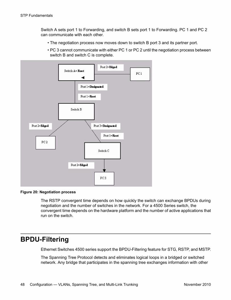
Switch A sets port 1 to Forwarding, and switch B sets port 1 to Forwarding. PC 1 and PC 2can communicate with each other.
• The negotiation process now moves down to switch B port 3 and its partner port.
• PC 3 cannot communicate with either PC 1 or PC 2 until the negotiation process betweenswitch B and switch C is complete.
Figure 20: Negotiation process
The RSTP convergent time depends on how quickly the switch can exchange BPDUs duringnegotiation and the number of switches in the network. For a 4500 Series switch, theconvergent time depends on the hardware platform and the number of active applications thatrun on the switch.
BPDU-FilteringEthernet Switches 4500 series support the BPDU-Filtering feature for STG, RSTP, and MSTP.
The Spanning Tree Protocol detects and eliminates logical loops in a bridged or switchednetwork. Any bridge that participates in the spanning tree exchanges information with other
STP Fundamentals
48 Configuration — VLANs, Spanning Tree, and Multi-Link Trunking November 2010
bridges using configuration messages known as Bridge Protocol Data Units (BPDU). Basedon the BPDU information exchange, the bridge with the lowest bridge ID becomes the root.This process is called the root selection process.
Typically, after a new bridge joins the spanning tree or an existing bridge leaves the spanningtree, the root selection process is repeated and a new root is selected.
The BPDU-Filtering feature allows the network administrator to achieve the following:
• Block an unwanted root selection process after an edge device, such as a laptop runningLinux and enabled with STP, is added to the network. This prevents unknown devicesfrom influencing an existing spanning tree topology.
• Block the flooding of BPDUs from an unknown device.
Important:The STP BPDU-Filtering feature is not supported on MultiLink Trunk (MLT) ports.
If a port has BPDU-Filtering enabled and it receives an STP BPDU, the following actions takeplace:
• The port is immediately put in the operational disabled state.
• A trap is generated and the following log message is written to the log:
BPDU received on port with BPDU-Filtering enabled. Port <x> hasbeen disabled.
• The port timer starts.
• The port stays in the operational disabled state until the port timer expires.
If the timer is disabled or the switch is reset before the timer expires, the port remains in thedisabled state. Similarly, if a user disables BPDU-Filtering while the timer is running, the timer isstopped and that port stays in the disabled state. In this case, you must then manually enablethe port to bring it back to the normal mode.
You can enable and disable the BPDU-Filtering feature on a per-port basis. The BPDU-Filtering timer is user-configurable for each port and has a valid range of between 10 and 65535 seconds. The port timer is disabled if it is configured as 0.
For details on configuring BPDU Filtering, see Configuring STP BPDU Filtering using ACLI onpage 97 and Configuring STP BPDU filtering for specific ports using EDM on page 204.
BPDU-Filtering
Configuration — VLANs, Spanning Tree, and Multi-Link Trunking November 2010 49

STP Fundamentals
50 Configuration — VLANs, Spanning Tree, and Multi-Link Trunking November 2010
Chapter 6: ADAC Fundamentals
Autodetection and Autoconfiguration of IP PhonesEthernet Switch software supports Autodetection and Autoconfiguration (ADAC) of IP Phones.With ADAC, you can automatically configure the switch to support and prioritize IP Phonetraffic.
When ADAC is enabled and an Avaya IP Phone is connected to the switch, the switchautomatically configures the VLAN, port, and Quality of Service (QoS) settings necessary forthe transmission of signal and voice between the Avaya IP Phone and the switch.
ADAC can configure the switch whether the switch is directly connected to the Call Server(through the Call Server ports) or is indirectly connected to the Call Server using a networkuplink (through the Uplink ports).
ADAC has three separate operating modes to meet the requirements of different networks:
• Untagged-Frames-Basic:
Use this mode when you want a basic configuration only and the IP Phones are sendinguntagged traffic.
• Untagged-Frames-Advanced:
Use this mode when you want an advanced configuration and the IP Phones are sendinguntagged traffic. In this mode, ADAC creates a Voice VLAN that includes the Call Server orUplink ports, as applicable, and all telephony ports. All tagging, PVID settings, and trafficprioritization are configured automatically.
• Tagged Frames:
Use this mode when you want an advanced configuration and the IP Phones are sendingtagged traffic. This mode provides the same configuration as the Untagged-Frames-Advanced mode, but with tagged frames. As with the Untagged-Frames-Advanced mode,ADAC creates a Voice VLAN that includes the Call Server or Uplink ports, as applicable,and all telephony ports. While Traffic prioritization is configured automatically, tagging andPVID settings are user configurable.
ADAC operationThe following sections provide detailed explanations of ADAC operation.
Configuration — VLANs, Spanning Tree, and Multi-Link Trunking November 2010 51
Auto-detection of IP PhonesWhen an Avaya IP Phone is connected to a switch and is powered on, the switch automaticallydetects the IP Phone, and then begins the auto-configuration of the IP Phone. An ADAC lookupis also performed each time a MAC address is learned, migrated, or aged-out and removed.
When you enable auto-detection on a port, the port also becomes operationally enabled.Similarly, when you disable auto-detection on a port, the port is operationally disabled. A portcan also be operationally disabled if the port maximum of 32 devices is reached. If the portlimit is reached, a trap will be sent (if ADAC traps are enabled) and autoconfiguration will alsobe removed. To put the port back into the operational state, disable and then reenable auto-detection on the affected port. ADAC supports a maximum of 32 devices (both IP phones andnon-phones) per port.
There are two ways to use ADAC to automatically detect IP Phones. You can enable one orthe other or both of these methods on a port-by-port basis, as long as at least one detectionmechanism remains enabled. The detection mechanism can be selected in the followinginstances:
• before enabling auto-detection on the port
• if ADAC is globally disabled
The two methods of auto-detection are by MAC address or using LLDP (IEEE 802.1ab). Auto-detection by MAC address is based on using predefined MAC addresses to determine that thespecified port is connected to an Avaya IP phone. For more information and the list of definedMAC address ranges, see Auto-Detection by MAC address on page 52.
Auto-detection by LLDP allows the system to detect IP phones with MAC addresses outsidethe list of default MAC address ranges as long as they can be identified as an IP phone byLLDP, regardless of their MAC addresses. For more information about auto-detection by LLDP,see Auto-Detection by LLDP (IEEE 802.1ab) on page 54.
You can enable either of these detection mechanisms or both on each individual port. At leastone of these detection methods must be enabled on each port.
Auto-Detection by MAC addressWhen this feature is enabled on a port, the switch checks all MAC addresses of packetsreceived on the port. If a received MAC address falls within the range of known Avaya IP PhoneMAC addresses, ADAC determines that the specified port is connected to an Avaya IP Phoneand initiates the required configuration. ADAC is supported for a maximum of 32 devices perport, but in most cases, there will be only one IP phone and one PC on each port. The ERS4500 Series has a default range of MAC addresses configured to be recognized as Avaya IPPhones by ADAC.
The following table shows a list of the default MAC address ranges.
ADAC Fundamentals
52 Configuration — VLANs, Spanning Tree, and Multi-Link Trunking November 2010
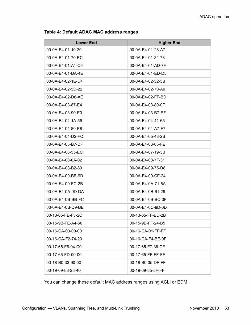
Table 4: Default ADAC MAC address ranges
Lower End Higher End00-0A-E4-01-10-20 00-0A-E4-01-23-A7
00-0A-E4-01-70-EC 00-0A-E4-01-84-73
00-0A-E4-01-A1-C8 00-0A-E4-01-AD-7F
00-0A-E4-01-DA-4E 00-0A-E4-01-ED-D5
00-0A-E4-02-1E-D4 00-0A-E4-02-32-5B
00-0A-E4-02-5D-22 00-0A-E4-02-70-A9
00-0A-E4-02-D8-AE 00-0A-E4-02-FF-BD
00-0A-E4-03-87-E4 00-0A-E4-03-89-0F
00-0A-E4-03-90-E0 00-0A-E4-03-B7-EF
00-0A-E4-04-1A-56 00-0A-E4-04-41-65
00-0A-E4-04-80-E8 00-0A-E4-04-A7-F7
00-0A-E4-04-D2-FC 00-0A-E4-05-48-2B
00-0A-E4-05-B7-DF 00-0A-E4-06-05-FE
00-0A-E4-06-55-EC 00-0A-E4-07-19-3B
00-0A-E4-08-0A-02 00-0A-E4-08-7F-31
00-0A-E4-08-B2-89 00-0A-E4-09-75-D8
00-0A-E4-09-BB-9D 00-0A-E4-09-CF-24
00-0A-E4-09-FC-2B 00-0A-E4-0A-71-5A
00-0A-E4-0A-9D-DA 00-0A-E4-0B-61-29
00-0A-E4-0B-BB-FC 00-0A-E4-0B-BC-0F
00-0A-E4-0B-D9-BE 00-0A-E4-0C-9D-0D
00-13-65-FE-F3-2C 00-13-65-FF-ED-2B
00-15-9B-FE-A4-66 00-15-9B-FF-24-B5
00-16-CA-00-00-00 00-16-CA-01-FF-FF
00-16-CA-F2-74-20 00-16-CA-F4-BE-0F
00-17-65-F6-94-C0 00-17-65-F7-38-CF
00-17-65-FD-00-00 00-17-65-FF-FF-FF
00-18-B0-33-90-00 00-18-B0-35-DF-FF
00-19-69-83-25-40 00-19-69-85-5F-FF
You can change these default MAC address ranges using ACLI or EDM.
ADAC operation
Configuration — VLANs, Spanning Tree, and Multi-Link Trunking November 2010 53
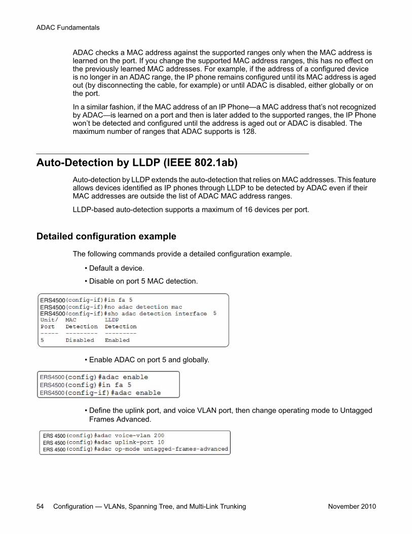
ADAC checks a MAC address against the supported ranges only when the MAC address islearned on the port. If you change the supported MAC address ranges, this has no effect onthe previously learned MAC addresses. For example, if the address of a configured deviceis no longer in an ADAC range, the IP phone remains configured until its MAC address is agedout (by disconnecting the cable, for example) or until ADAC is disabled, either globally or onthe port.
In a similar fashion, if the MAC address of an IP Phone—a MAC address that’s not recognizedby ADAC—is learned on a port and then is later added to the supported ranges, the IP Phonewon’t be detected and configured until the address is aged out or ADAC is disabled. Themaximum number of ranges that ADAC supports is 128.
Auto-Detection by LLDP (IEEE 802.1ab)Auto-detection by LLDP extends the auto-detection that relies on MAC addresses. This featureallows devices identified as IP phones through LLDP to be detected by ADAC even if theirMAC addresses are outside the list of ADAC MAC address ranges.
LLDP-based auto-detection supports a maximum of 16 devices per port.
Detailed configuration example
The following commands provide a detailed configuration example.
• Default a device.
• Disable on port 5 MAC detection.
• Enable ADAC on port 5 and globally.
• Define the uplink port, and voice VLAN port, then change operating mode to UntaggedFrames Advanced.
ADAC Fundamentals
54 Configuration — VLANs, Spanning Tree, and Multi-Link Trunking November 2010
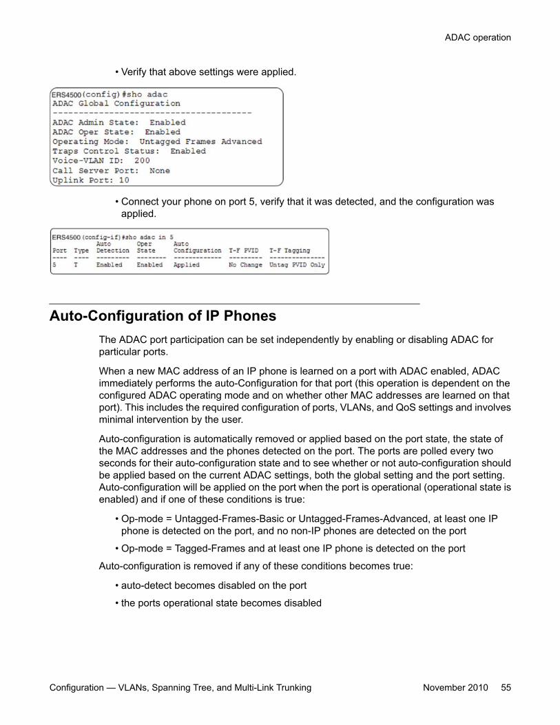
• Verify that above settings were applied.
• Connect your phone on port 5, verify that it was detected, and the configuration wasapplied.
Auto-Configuration of IP PhonesThe ADAC port participation can be set independently by enabling or disabling ADAC forparticular ports.
When a new MAC address of an IP phone is learned on a port with ADAC enabled, ADACimmediately performs the auto-Configuration for that port (this operation is dependent on theconfigured ADAC operating mode and on whether other MAC addresses are learned on thatport). This includes the required configuration of ports, VLANs, and QoS settings and involvesminimal intervention by the user.
Auto-configuration is automatically removed or applied based on the port state, the state ofthe MAC addresses and the phones detected on the port. The ports are polled every twoseconds for their auto-configuration state and to see whether or not auto-configuration shouldbe applied based on the current ADAC settings, both the global setting and the port setting.Auto-configuration will be applied on the port when the port is operational (operational state isenabled) and if one of these conditions is true:
• Op-mode = Untagged-Frames-Basic or Untagged-Frames-Advanced, at least one IPphone is detected on the port, and no non-IP phones are detected on the port
• Op-mode = Tagged-Frames and at least one IP phone is detected on the port
Auto-configuration is removed if any of these conditions becomes true:
• auto-detect becomes disabled on the port
• the ports operational state becomes disabled
ADAC operation
Configuration — VLANs, Spanning Tree, and Multi-Link Trunking November 2010 55
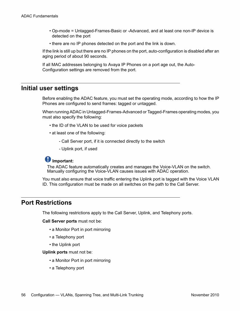
• Op-mode = Untagged-Frames-Basic or -Advanced, and at least one non-IP device isdetected on the port
• there are no IP phones detected on the port and the link is down.
If the link is still up but there are no IP phones on the port, auto-configuration is disabled after anaging period of about 90 seconds.
If all MAC addresses belonging to Avaya IP Phones on a port age out, the Auto-Configuration settings are removed from the port.
Initial user settingsBefore enabling the ADAC feature, you must set the operating mode, according to how the IPPhones are configured to send frames: tagged or untagged.
When running ADAC in Untagged-Frames-Advanced or Tagged-Frames operating modes, youmust also specify the following:
• the ID of the VLAN to be used for voice packets
• at least one of the following:
- Call Server port, if it is connected directly to the switch
- Uplink port, if used
Important:The ADAC feature automatically creates and manages the Voice-VLAN on the switch.Manually configuring the Voice-VLAN causes issues with ADAC operation.
You must also ensure that voice traffic entering the Uplink port is tagged with the Voice VLANID. This configuration must be made on all switches on the path to the Call Server.
Port RestrictionsThe following restrictions apply to the Call Server, Uplink, and Telephony ports.
Call Server ports must not be:
• a Monitor Port in port mirroring
• a Telephony port
• the Uplink port
Uplink ports must not be:
• a Monitor Port in port mirroring
• a Telephony port
ADAC Fundamentals
56 Configuration — VLANs, Spanning Tree, and Multi-Link Trunking November 2010
• an EAP port
• the Call Server port
Telephony ports must not be:
• part of a trunk (MLT, LAG)
• a Monitor Port in port mirroring
• an IGMP static router port
• a Call Server port
• a Uplink port
Operating modesADAC can be configured to apply settings depending on how the IP Phones are configured tosend traffic (tagged or untagged) and depending on the desired complexity level of theAutoconfiguration. The following sections provide detailed descriptions of the configurationsthat are applied in each ADAC operating mode.
• QoS Settings on page 57• Untagged-Frames-Basic operating mode on page 57• Untagged-Frames-Advanced operating mode on page 58• Tagged-Frames operating mode on page 60
QoS Settings
ADAC QoS configuration is applied to:
• traffic coming from the IP Phones
• traffic coming from Call Server ports
• traffic coming from Uplink ports
Untagged-Frames-Basic operating mode
In the Untagged-Frames-Basic operating mode, the Call Server and Uplink ports are not used,and therefore QoS settings are applied only for traffic coming from the IP Phones. The VLANconfiguration is minimal.
ADAC operation
Configuration — VLANs, Spanning Tree, and Multi-Link Trunking November 2010 57
To properly configure the Untagged-Frames-Basic mode, you must perform the following:
• Configure the IP Phones to send untagged frames.• Connect only IP Phones to a port. (You cannot connect a device that is not an Avaya IP
Phone to the same port.)• Ensure that the Filter Unregistered Frames option is set to disabled on the ADAC-
enabled ports (or that the ports belong to at least one VLAN).
Untagged-Frames-Basic QoS configurationIn this operating mode, QoS settings are applied only for traffic coming from the IP Phones.The Call Server and Uplink ports are not used.
Autoconfiguration performs the following:
• creates an Unrestricted Interface with all Telephony ports (each time a new Telephonyport is detected, it will be added to this interface)
• creates an IP Filter (all fields set to Ignore) and an IP Filter Group• uses Premium Service (transmit frame, update DSCP to 0x2E, Drop Precedence to Loss
Sensitive, Update Priority to 6)
DSCP to 0x2E is the default for ADAC. If you configure 802.1AB (LLDP) MED NetworkPolicy to use a different DSCP marking, this marking is used by ADAC.
• creates a policy containing the above
Untagged-Frames-Basic VLAN configurationIn the Untagged-Frames-Basic operating mode, Autoconfiguration also performs the followingVLAN configuration:
Tagging of Telephony ports is set to Untagged.
Untagged-Frames-Advanced operating mode
To properly configure the Untagged-Frames-Advanced operating mode, you must perform thefollowing:
• Configure the IP Phones to send untagged frames.• Connect only IP Phones to a port. (You cannot connect a device that is not an Avaya IP
Phone to the same port.)• Ensure that Filter Unregistered Frames option is set to disabled on the ADAC-enabled
ports (or that the ports belong to at least one VLAN).• Specify the Voice-VLAN ID and either the Call Server port or the Uplink port, as applicable.• If the switch is not directly connected to the Call Server, ensure that the telephony packets
coming from the Call Server through the Uplink port are tagged with the Voice-VLAN ID.
Untagged-Frames-Advanced QoS configuration
In the Untagged-Frames-Advanced mode, Autoconfiguration performs the following QoSconfiguration for each port:
ADAC Fundamentals
58 Configuration — VLANs, Spanning Tree, and Multi-Link Trunking November 2010
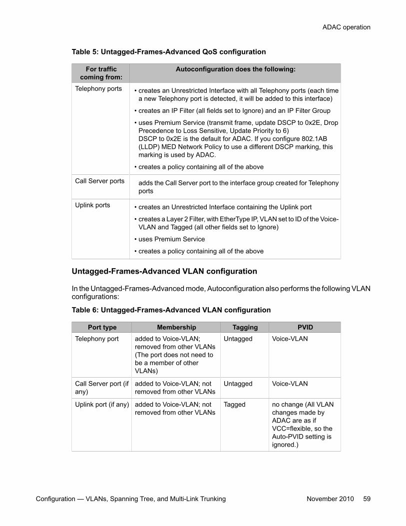
Table 5: Untagged-Frames-Advanced QoS configuration
For trafficcoming from:
Autoconfiguration does the following:
Telephony ports • creates an Unrestricted Interface with all Telephony ports (each timea new Telephony port is detected, it will be added to this interface)
• creates an IP Filter (all fields set to Ignore) and an IP Filter Group
• uses Premium Service (transmit frame, update DSCP to 0x2E, DropPrecedence to Loss Sensitive, Update Priority to 6)DSCP to 0x2E is the default for ADAC. If you configure 802.1AB(LLDP) MED Network Policy to use a different DSCP marking, thismarking is used by ADAC.
• creates a policy containing all of the above
Call Server ports adds the Call Server port to the interface group created for Telephonyports
Uplink ports • creates an Unrestricted Interface containing the Uplink port
• creates a Layer 2 Filter, with EtherType IP, VLAN set to ID of the Voice-VLAN and Tagged (all other fields set to Ignore)
• uses Premium Service
• creates a policy containing all of the above
Untagged-Frames-Advanced VLAN configuration
In the Untagged-Frames-Advanced mode, Autoconfiguration also performs the following VLANconfigurations:
Table 6: Untagged-Frames-Advanced VLAN configuration
Port type Membership Tagging PVIDTelephony port added to Voice-VLAN;
removed from other VLANs(The port does not need tobe a member of otherVLANs)
Untagged Voice-VLAN
Call Server port (ifany)
added to Voice-VLAN; notremoved from other VLANs
Untagged Voice-VLAN
Uplink port (if any) added to Voice-VLAN; notremoved from other VLANs
Tagged no change (All VLANchanges made byADAC are as ifVCC=flexible, so theAuto-PVID setting isignored.)
ADAC operation
Configuration — VLANs, Spanning Tree, and Multi-Link Trunking November 2010 59
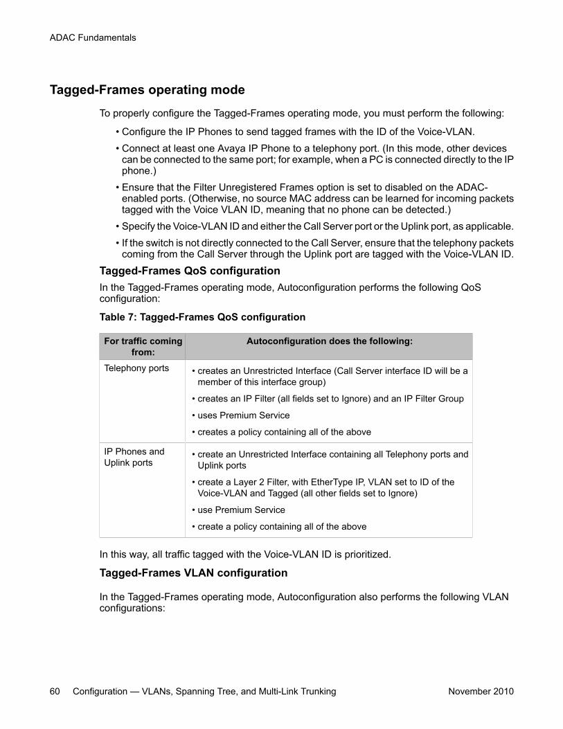
Tagged-Frames operating mode
To properly configure the Tagged-Frames operating mode, you must perform the following:
• Configure the IP Phones to send tagged frames with the ID of the Voice-VLAN.• Connect at least one Avaya IP Phone to a telephony port. (In this mode, other devices
can be connected to the same port; for example, when a PC is connected directly to the IPphone.)
• Ensure that the Filter Unregistered Frames option is set to disabled on the ADAC-enabled ports. (Otherwise, no source MAC address can be learned for incoming packetstagged with the Voice VLAN ID, meaning that no phone can be detected.)
• Specify the Voice-VLAN ID and either the Call Server port or the Uplink port, as applicable.• If the switch is not directly connected to the Call Server, ensure that the telephony packets
coming from the Call Server through the Uplink port are tagged with the Voice-VLAN ID.
Tagged-Frames QoS configurationIn the Tagged-Frames operating mode, Autoconfiguration performs the following QoSconfiguration:
Table 7: Tagged-Frames QoS configuration
For traffic comingfrom:
Autoconfiguration does the following:
Telephony ports • creates an Unrestricted Interface (Call Server interface ID will be amember of this interface group)
• creates an IP Filter (all fields set to Ignore) and an IP Filter Group
• uses Premium Service
• creates a policy containing all of the above
IP Phones andUplink ports
• create an Unrestricted Interface containing all Telephony ports andUplink ports
• create a Layer 2 Filter, with EtherType IP, VLAN set to ID of theVoice-VLAN and Tagged (all other fields set to Ignore)
• use Premium Service
• create a policy containing all of the above
In this way, all traffic tagged with the Voice-VLAN ID is prioritized.
Tagged-Frames VLAN configuration
In the Tagged-Frames operating mode, Autoconfiguration also performs the following VLANconfigurations:
ADAC Fundamentals
60 Configuration — VLANs, Spanning Tree, and Multi-Link Trunking November 2010
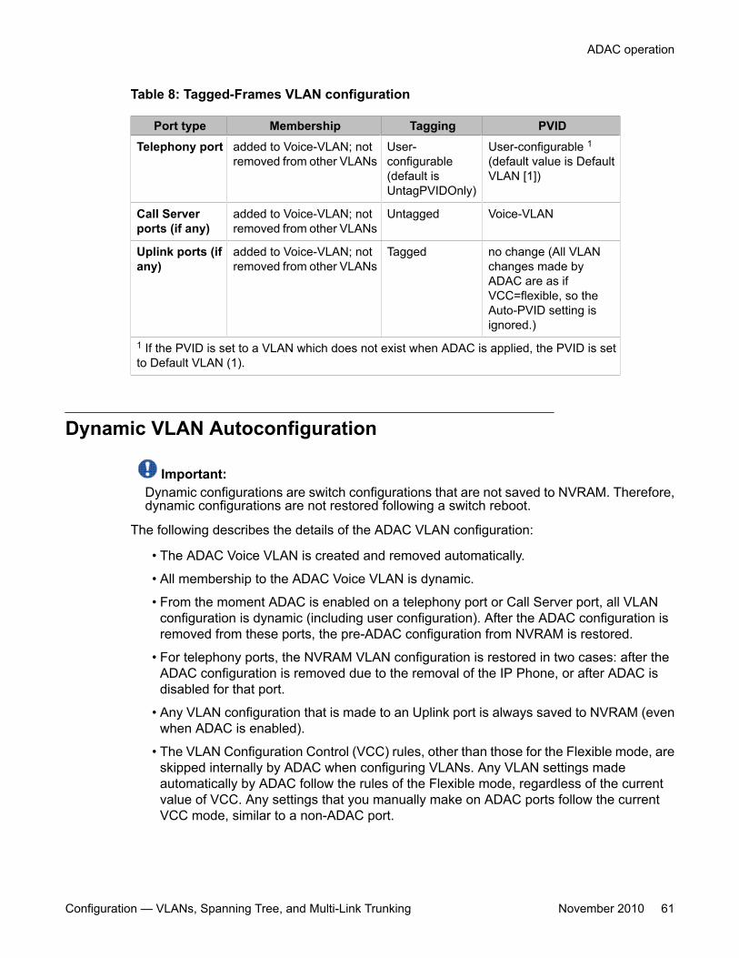
Table 8: Tagged-Frames VLAN configuration
Port type Membership Tagging PVIDTelephony port added to Voice-VLAN; not
removed from other VLANsUser-configurable(default isUntagPVIDOnly)
User-configurable 1(default value is DefaultVLAN [1])
Call Serverports (if any)
added to Voice-VLAN; notremoved from other VLANs
Untagged Voice-VLAN
Uplink ports (ifany)
added to Voice-VLAN; notremoved from other VLANs
Tagged no change (All VLANchanges made byADAC are as ifVCC=flexible, so theAuto-PVID setting isignored.)
1 If the PVID is set to a VLAN which does not exist when ADAC is applied, the PVID is setto Default VLAN (1).
Dynamic VLAN Autoconfiguration
Important:Dynamic configurations are switch configurations that are not saved to NVRAM. Therefore,dynamic configurations are not restored following a switch reboot.
The following describes the details of the ADAC VLAN configuration:
• The ADAC Voice VLAN is created and removed automatically.
• All membership to the ADAC Voice VLAN is dynamic.
• From the moment ADAC is enabled on a telephony port or Call Server port, all VLANconfiguration is dynamic (including user configuration). After the ADAC configuration isremoved from these ports, the pre-ADAC configuration from NVRAM is restored.
• For telephony ports, the NVRAM VLAN configuration is restored in two cases: after theADAC configuration is removed due to the removal of the IP Phone, or after ADAC isdisabled for that port.
• Any VLAN configuration that is made to an Uplink port is always saved to NVRAM (evenwhen ADAC is enabled).
• The VLAN Configuration Control (VCC) rules, other than those for the Flexible mode, areskipped internally by ADAC when configuring VLANs. Any VLAN settings madeautomatically by ADAC follow the rules of the Flexible mode, regardless of the currentvalue of VCC. Any settings that you manually make on ADAC ports follow the currentVCC mode, similar to a non-ADAC port.
ADAC operation
Configuration — VLANs, Spanning Tree, and Multi-Link Trunking November 2010 61
ADAC and stackingIn a stack, the global ADAC settings on the base unit are applied across the stack, except forport settings (for Call Server ports, Uplink ports and Telephony ports).
The ADAC port states are taken from each unit. Therefore, a unit's ports have the same ADACstatus in a stack as they do in stand-alone mode.
If two or more units each have a configured Call Server port in stand-alone mode and are thenjoined together in a stack, the Call Server port with the lowest interface number in the stack iselected the stack Call Server port.
This same scenario also occurs for the Uplink port.
Lost Call Server Port or Uplink Port
Beginning with release 5.4, the Avaya Ethernet Routing Switch 4500 maintains ADACoperation if the designated call server or uplink ports become unreachable. This allows theswitch to maintain any current communications between end devices located on the switch.
ADAC Uplink port as part of trunkWhen a port that is a member of an already active MLT, DMLT, or LAG is selected as the ADACUplink port, then the entire trunk is set as the Uplink connection. This means that the ADACconfiguration (VLAN and QoS) is applied for all the members of the trunk. ADAC does notinterfere in the way traffic is forwarded in the trunk.
Uplink port as part of MLT in a stack
The Uplink port can be part of an MLT. If the unit containing the Uplink port in a stack is removedfrom the stack, the lowest port from the same MLT becomes the new Uplink port.
After rebooting a stack, each unit that has a port member belonging to the Uplink MLT isconfigured as an Uplink port on the unit. After joining stack, the lowest Uplink port is electedas the stack's Uplink port.
ADAC and LACP enabled on an Uplink port
To set an Uplink port as LACP-enabled, you must first configure and enable Link AggregationControl Protocol (LACP) on the port, and then you can set the port as the Uplink port.
ADAC Fundamentals
62 Configuration — VLANs, Spanning Tree, and Multi-Link Trunking November 2010
Due to the dynamic configuration of VLANs, you are not allowed to:
• enable LACP on a preconfigured Uplink port• enable LACP on a port with the same admin key as the ADAC Uplink ports• change the admin key of any member of the ADAC Uplink ports• set the admin key for a LACP-enabled port to the same value as the Uplink port
When ADAC sets the configuration for the Uplink port, the VLAN and QoS configuration isapplied for all LACP-enabled (active or passive) ports belonging to the same Link AggregationGroup (LAG) as the Uplink port.
Any changes to the LAG mode, from active to passive or from passive to active, have no effecton ADAC.
Disabling LACP on an Uplink port
When you disable the LAG, the Uplink configuration is removed for all trunk members, exceptfor the original Uplink port.
After you remove the LAG, you cannot reenable the configuration for the Uplink port. You mustremove the Uplink, reconfigure the LAG, and then set the Uplink port again.
Uplink port as part of LACP in a stack
In a stack, LAGs containing the Uplink port operate similarly to MLTs containing the Uplink port.
If the unit containing the Uplink port in a stack is removed from the stack, the lowest port fromthe same LAG becomes the new Uplink port.
After rebooting a stack, each unit that has a port member belonging to the Uplink LAG isconfigured as an Uplink port on the unit. After joining the stack, the lowest Uplink port is electedas the stack Uplink port.
ADAC and EAP configurationADAC and Extensible Authentication Protocol (EAP) are mutually exclusive on the Call Serverport and the Uplink port.
However, on telephony ports, you can enable both ADAC and EAP, provided the followingconditions are met:
• The ports must be configured to allow non-EAP MAC addresses.
• Guest VLAN must not be allowed on the ports.
To enable ADAC on an EAP port, you must perform the following:
ADAC operation
Configuration — VLANs, Spanning Tree, and Multi-Link Trunking November 2010 63
1. On the switch, globally enable support for non-EAP MAC addresses. (In ACLI, usethe eap multihost allow-non-eap-enable command.)
2. On each telephony port, enable support for non-EAP MAC addresses. (In ACLI, usethe eap multihost port <port> allow-non-eap-enable command.)
3. On each telephony port, enable EAP Multihost. (In ACLI, use the eap multihostport <port> enable command.)
4. On the telephony ports, ensure that Guest VLAN is disabled. (In ACLI, use the showeap guest-vlan command.)
5. On the switch, enable EAP globally. (In ACLI, use the eap enable command.)
6. Configure and enable ADAC on the ports.
When you configure ADAC and EAP, the following restrictions apply:
1. EAP: While ADAC is enabled, cannot disable per-port EAP Multihost or EAP setting:
• Cannot disable Multihost on port if EAP is enabled per port and ADACDetection is enabled per port
• Cannot enable EAP per port if Multihost is disabled per port and ADACDetection is enabled per port
2. ADAC: The detection can be enabled (for example, set ADAC enable per port) onlyif:
• EAP is disabled per port
or
• EAP is enabled per port and Multihost is enabled per port
EAP does not change the VLAN configuration for ADAC-enabled ports. ADAC changes to theVLAN configuration take priority over EAP configurations.
ADAC User RestrictionsAfter ADAC is enabled, you cannot:
• erase the Voice-VLAN• remove auto-configured ports from Voice-VLAN• remove any QoS setting made by ADAC (auto-configured settings)• use the filter groups created by ADAC when setting policies• disable the policies created by ADAC• modify Call Server and Uplink port configuration
ADAC Fundamentals
64 Configuration — VLANs, Spanning Tree, and Multi-Link Trunking November 2010
You can:
• add ports to and remove ports from the Voice-VLAN (configuration is dynamic)• change the tagging and PVID of all ports in the Voice-VLAN (configuration is dynamic)• add interfaces to and remove interfaces from ADAC interface groups• use the filters created by ADAC when setting filter groups. (This means that when
disabling the feature or when changing operating mode, if the filter is used by filter groupsother than the ADAC filter group, the filter is not deleted.)
• use the interface groups created by ADAC when setting policies. (This means that whendisabling the feature or when changing operating mode, if the interface group is used by apolicy other than the ADAC policy, the interface group is not deleted.)
Adding the Voice-VLAN to another STG
In Untagged-Frames-Advanced or Tagged-Frames modes, ADAC sets tagging for the CallServer port to UntaggedAll. However, STP configuration rules do not allow an untagged portto span multiple STGs. As a result, you cannot add the Voice-VLAN to an STG as long as theCall Server is a member of another VLAN that belongs to another STG.
To successfully add the Voice-VLAN to a different STG using the same Call Server port, youmust first remove the Call Server port from all other VLANs.
Disabling ADAC
Disabling the ADAC feature means the deletion of all configurations (except as noted in ADACUser Restrictions on page 64), including the following:
• All ADAC-involved ports are removed from the Voice-VLAN and the Voice-VLAN isdeleted.
• PVID is set to the Management VLAN ID. The Uplink port is not changed if it has a valueother than the Voice-VLAN ID (that is, if you have explicitly changed it afterAutoconfiguration).
ADAC managementFor more details on network configurations required to support IP Phones, see DataNetworking for Voice over IP, (553-3001-160).
ADAC operation
Configuration — VLANs, Spanning Tree, and Multi-Link Trunking November 2010 65

ADAC Fundamentals
66 Configuration — VLANs, Spanning Tree, and Multi-Link Trunking November 2010
Chapter 7: LACP and VLACP Fundamentals
IEEE 802.3ad Link AggregationWith IEEE 802.3ad-based link aggregation, you can aggregate one or more links to form LinkAggregation Groups (LAG) so that a MAC client can treat the Link Aggregation Group as if itwere a single link. Link aggregation increases the aggregate throughput of the interconnectionbetween the devices while providing link redundancy.
Although IEEE 802.3ad-based link aggregation and MultiLink Trunking (MLT) features providesimilar services, MLT is statically defined, whereas IEEE 802.3ad-based link aggregation isdynamic and provides additional functionality.
With Link Aggregation Control Protocol (LACP), as defined by the IEEE 802.3ad standard, aswitch can learn the presence and capabilities of a remote switch by exchanging informationwith the remote switch before a trunk group is formed. Either switch can accept or reject theaggregation request with the far end for each port. A link that cannot join a trunk group operatesas an individual link.
The main purpose of LACP is to manage switch ports and their port memberships to linkaggregation trunk groups (LAGs). LACP can dynamically add or remove LAG ports, dependingon their availability and states. By default, Link Aggregation is disabled on all ports.
Link aggregation employs the following principles and concepts:
• A MAC client communicates with a set of ports through an Aggregator, which presents astandard IEEE 802.3 service interface to the MAC client. The Aggregator binds to one ormore ports within a system.
• The Aggregator distributes frame transmissions from the MAC client to the various ports.The Aggregator also collects received frames from the ports and transparently passesthem to the MAC client.
• A system can contain multiple Aggregators that serve multiple MAC clients. A given portbinds to (at most) a single Aggregator at any time. At any one time, only one Aggregatorserves a MAC client.
• The binding of ports to Aggregators within a system is managed by the Link AggregationControl feature. The Link Aggregation Control feature determines which links can beaggregated, aggregates them, binds the ports within the system to an appropriateAggregator, and monitors conditions to determine when a change in aggregation isneeded.
The network manager can control the determination and binding directly by manipulatingthe state variables of Link Aggregation (for example, Keys). In addition, automatic
Configuration — VLANs, Spanning Tree, and Multi-Link Trunking November 2010 67
determination, configuration, binding, and monitoring can occur by using a LinkAggregation Control Protocol (LACP).
The LACP uses peer exchanges across the links to determine, on an ongoing basis, theaggregation capability of the various links, and to continuously provide the maximum levelof aggregation between a pair of systems.
• Each port has a unique, globally administered MAC address.
The MAC address is the source address for frame exchanges that entities within the LinkAggregation sublayer itself (for example, LACP and Marker protocol exchanges) initiate.
• Each Aggregator has a unique, globally administered MAC address, which is used as theMAC address of the aggregation from the perspective of the MAC Client, both as a sourceaddress for transmitted frames and as the destination address for received frames.
The MAC address of the Aggregator can be one of the MAC addresses of a port in theassociated Link Aggregation Group.
Link aggregation rulesThe 4500 Series switch link aggregation groups operate under the following rules:
• Link aggregation groups are formed using LACP.
• All ports in a link aggregation group must connect to the same far-end system.
• All ports in a link aggregation group must operate in full-duplex mode.
• You must configure all ports in a link aggregation group to the same port speed.
• All ports in a link aggregation group must be in the same VLANs.
• In stack mode, ports in a link aggregation group can be on different units to form adistributed LAG (DLAG).
• LACPDUs are transmitted and received on all ports in the link aggregation group.
• Link aggregation is compatible with the Spanning Tree Protocol (STP).
• Link aggregation groups must be in the same STP groups.
• STP BPDUs are transmitted and received only on the first link in the group.
• A maximum of 32 link aggregation groups are supported.
• A maximum of 8 active links are supported per LAG.
• Unlimited standby links are supported for each LAG (for example, if a switch or stack hasone LAG, you can configure all non active LAG link ports as standby ports for that LAG).
• The MLT/LAG is a logical port. The STP protocol is computing the topology using thislogical port, not on individual MLT/LAG member ports. The logical port is represented bythe first MLT/LAG port. The STP events related to MLT/LAG are logged using the firstMLT/LAG port.
The maximum number of LAGs is 32, and the maximum number of active links for each group is8. With Link Aggregation, you can configure more than 8 links in one LAG. The first eight high-
LACP and VLACP Fundamentals
68 Configuration — VLANs, Spanning Tree, and Multi-Link Trunking November 2010
priority links are active links, and together, they form a trunk group. The fifth low-priority linkremains in standby mode. When an active links goes down, the standby link becomes activeand is added to the trunk group. For more information, see LACP and VLACP configurationusing ACLI on page 137 and Configuring LACP and VLACP using Enterprise DeviceManager on page 253.
The failover process is as follows:
• The down link is removed from the trunk group.
• The highest priority standby link is added to the trunk group.
A temporary delay in traffic flow can occur due to links switching. If the active link goes downand no standby link exists, the traffic is rerouted to the remaining active links with a minimaldelay in time.
VLACPMany enterprise networks require that trunk links provide subsecond failover to the redundantlink when a failure occurs at the local or remote endpoint. This requirement can be met whenboth ends of the link are informed of any loss of communication.
Virtual Link Aggregation Control Protocol (VLACP), an LACP extension, is a Layer 2handshaking protocol that provides end-to-end failure detection between two physical Ethernetinterfaces. It allows the switch to detect unidirectional or bidirectional link failures.
Virtual LACP (VLACP) overviewWhile Ethernet is extended to detect remote link failures through functions such as RemoteFault Indication and Far End Fault Indication mechanisms, a limitation of these functions isthat they terminate at the next Ethernet hop. Therefore, failures cannot be determined on anend-to-end basis.
Figure 21: Problem description (1 of 2) on page 70 provides an illustration of these limitations.While the Enterprise networks shown can connect their aggregated Ethernet trunk groupsthrough a service provider network connection (for example, through a VPN), far-end failurescannot be signaled with Ethernet-based functions that operate end-to-end through the serviceprovider cloud.
In Figure 21: Problem description (1 of 2) on page 70, the MLT (between Enterprise switchesS1 and S2) extends through the service provider (SP) network.
VLACP
Configuration — VLANs, Spanning Tree, and Multi-Link Trunking November 2010 69
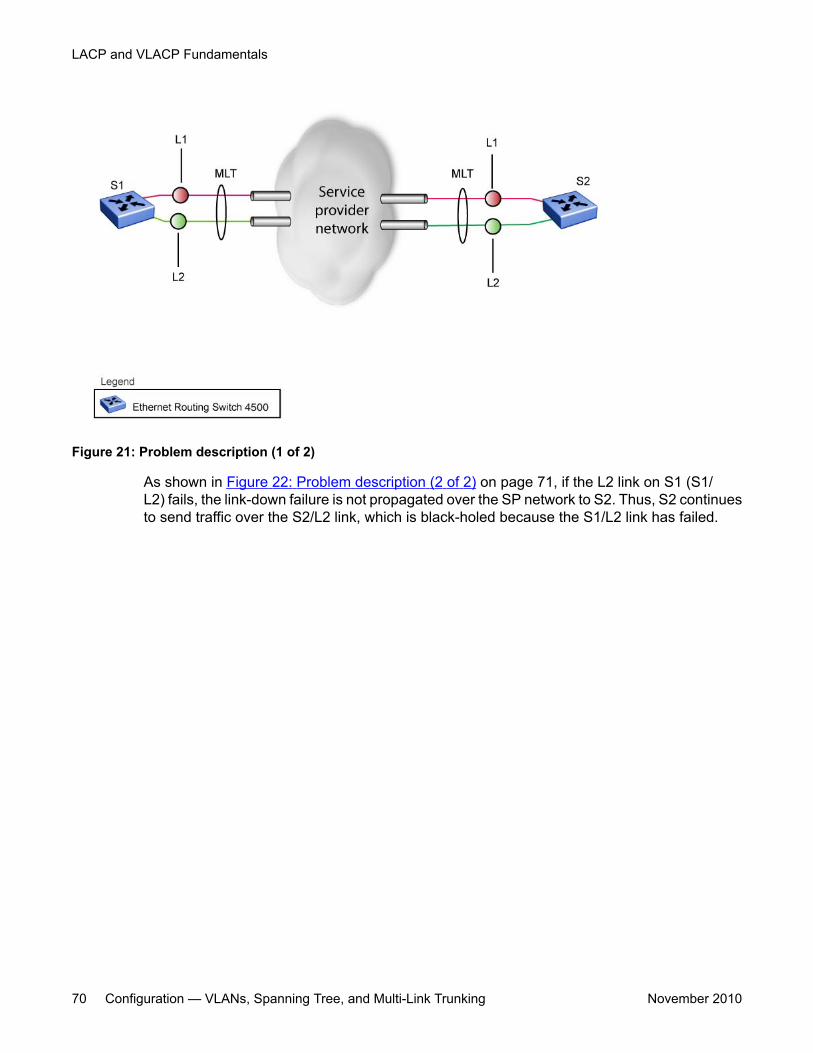
Figure 21: Problem description (1 of 2)
As shown in Figure 22: Problem description (2 of 2) on page 71, if the L2 link on S1 (S1/L2) fails, the link-down failure is not propagated over the SP network to S2. Thus, S2 continuesto send traffic over the S2/L2 link, which is black-holed because the S1/L2 link has failed.
LACP and VLACP Fundamentals
70 Configuration — VLANs, Spanning Tree, and Multi-Link Trunking November 2010
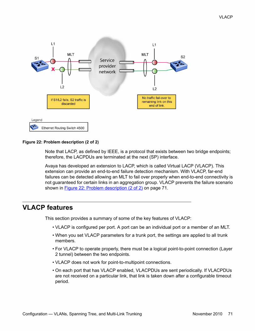
Figure 22: Problem description (2 of 2)
Note that LACP, as defined by IEEE, is a protocol that exists between two bridge endpoints;therefore, the LACPDUs are terminated at the next (SP) interface.
Avaya has developed an extension to LACP, which is called Virtual LACP (VLACP). Thisextension can provide an end-to-end failure detection mechanism. With VLACP, far-endfailures can be detected allowing an MLT to fail over properly when end-to-end connectivity isnot guaranteed for certain links in an aggregation group. VLACP prevents the failure scenarioshown in Figure 22: Problem description (2 of 2) on page 71.
VLACP featuresThis section provides a summary of some of the key features of VLACP:
• VLACP is configured per port. A port can be an individual port or a member of an MLT.
• When you set VLACP parameters for a trunk port, the settings are applied to all trunkmembers.
• For VLACP to operate properly, there must be a logical point-to-point connection (Layer2 tunnel) between the two endpoints.
• VLACP does not work for point-to-multipoint connections.
• On each port that has VLACP enabled, VLACPDUs are sent periodically. If VLACPDUsare not received on a particular link, that link is taken down after a configurable timeoutperiod.
VLACP
Configuration — VLANs, Spanning Tree, and Multi-Link Trunking November 2010 71
• For the current software release, VLACP is supported on Ethernet interfaces only.
• VLACP can run independently as a port-to-port protocol or on top of MLT or LACPprotocol.
• VLACP packets are untagged because they operate at the port level and not the VLANlevel.
• The Destination Mac Address used in VLACPDUs is configurable. The MAC Addressmust be a multicast MAC Address so that it is always flooded. This allows the exchange ofVLACPDUs from end to end.
Avaya recommends you to set VLACP enabled ports with the following values to provide ahigher resiliency.
• the timeout scale to five
• the timeout type to short
• the fast periodic time to 500ms
When you set the timeout scale to lower values in heavily loaded networks, it causes undesiredbehavior for VLACP enabled ports.
Troubleshooting
Error logs are created for the following failures and errors:
• An incorrect PDU, such as wrong destination MAC addresses received
• An inability to enable VLACP on a port due to unallowable Destination MAC addresses
• A port index that is out of range
• A port was blocked by VLACP (a log message is also generated when the port isunblocked)
LACP and VLACP Fundamentals
72 Configuration — VLANs, Spanning Tree, and Multi-Link Trunking November 2010
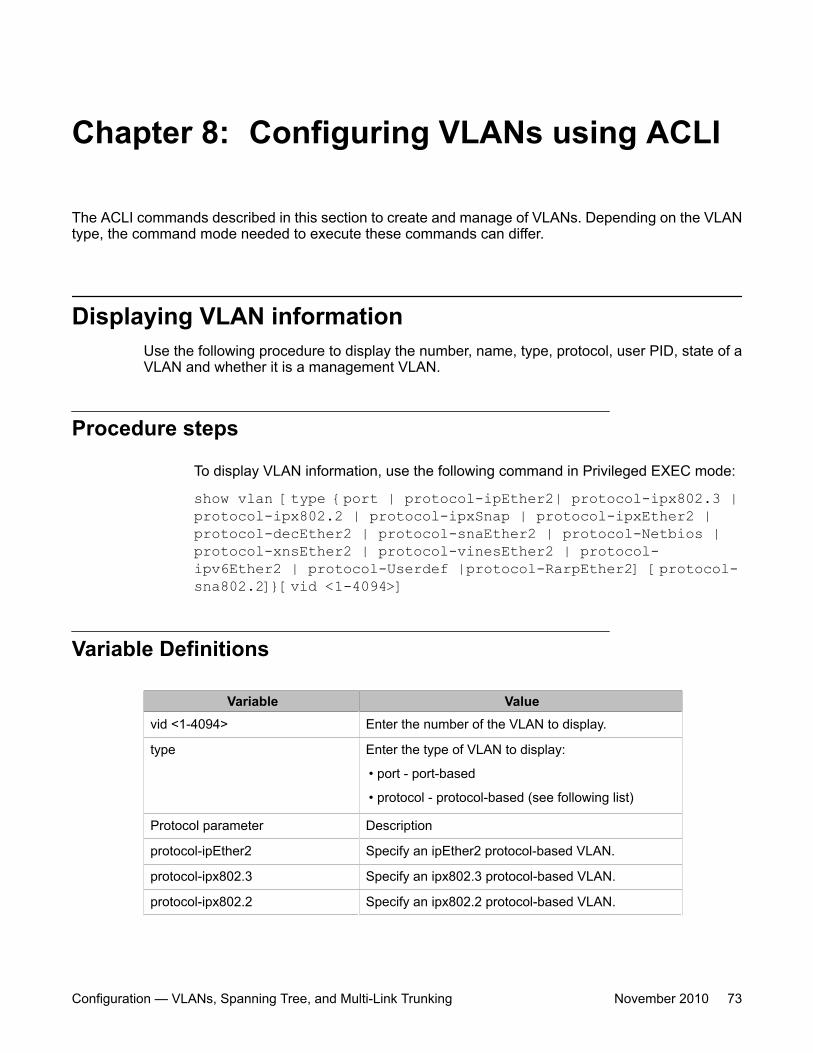
Chapter 8: Configuring VLANs using ACLI
The ACLI commands described in this section to create and manage of VLANs. Depending on the VLANtype, the command mode needed to execute these commands can differ.
Displaying VLAN informationUse the following procedure to display the number, name, type, protocol, user PID, state of aVLAN and whether it is a management VLAN.
Procedure steps
To display VLAN information, use the following command in Privileged EXEC mode:
show vlan [type {port | protocol-ipEther2| protocol-ipx802.3 |protocol-ipx802.2 | protocol-ipxSnap | protocol-ipxEther2 |protocol-decEther2 | protocol-snaEther2 | protocol-Netbios |protocol-xnsEther2 | protocol-vinesEther2 | protocol-ipv6Ether2 | protocol-Userdef |protocol-RarpEther2] [protocol-sna802.2]}[vid <1-4094>]
Variable Definitions
Variable Valuevid <1-4094> Enter the number of the VLAN to display.
type Enter the type of VLAN to display:
• port - port-based
• protocol - protocol-based (see following list)
Protocol parameter Description
protocol-ipEther2 Specify an ipEther2 protocol-based VLAN.
protocol-ipx802.3 Specify an ipx802.3 protocol-based VLAN.
protocol-ipx802.2 Specify an ipx802.2 protocol-based VLAN.
Configuration — VLANs, Spanning Tree, and Multi-Link Trunking November 2010 73
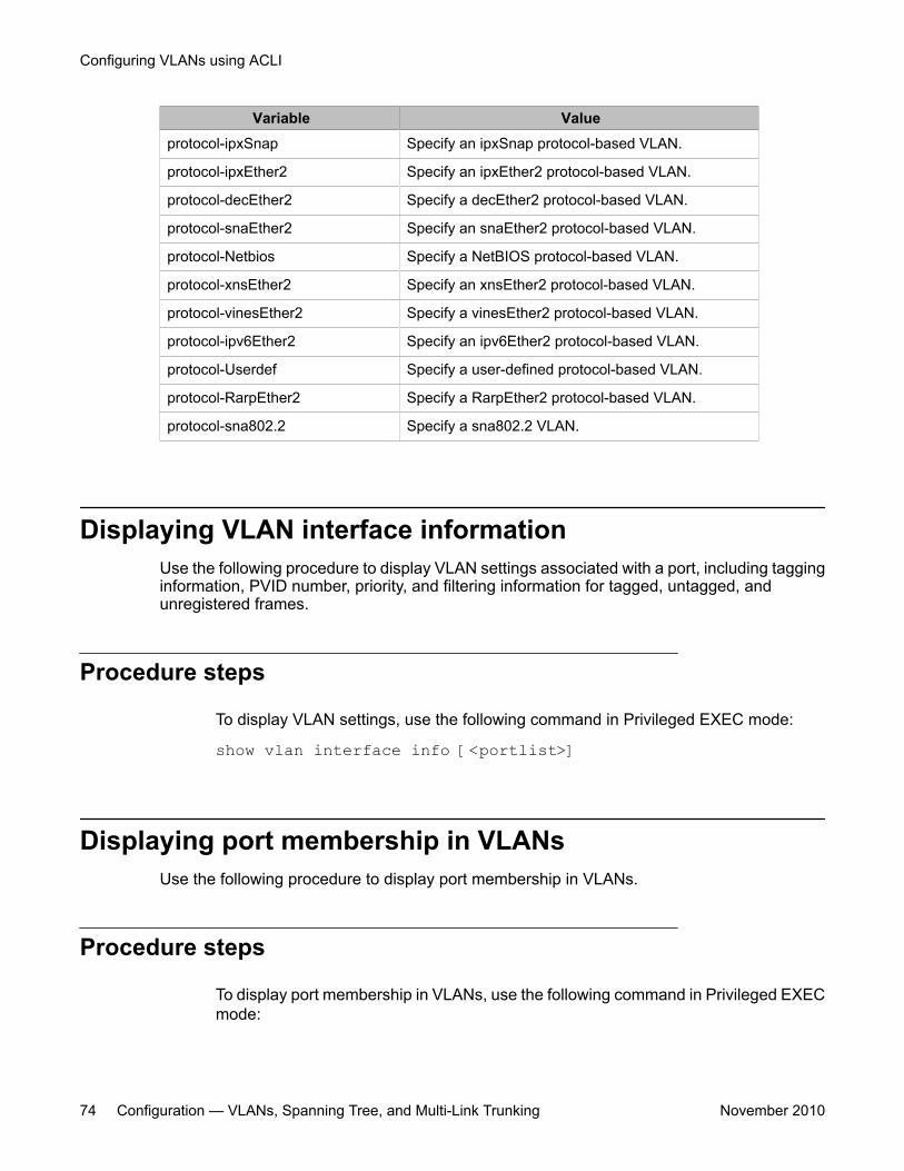
Variable Valueprotocol-ipxSnap Specify an ipxSnap protocol-based VLAN.
protocol-ipxEther2 Specify an ipxEther2 protocol-based VLAN.
protocol-decEther2 Specify a decEther2 protocol-based VLAN.
protocol-snaEther2 Specify an snaEther2 protocol-based VLAN.
protocol-Netbios Specify a NetBIOS protocol-based VLAN.
protocol-xnsEther2 Specify an xnsEther2 protocol-based VLAN.
protocol-vinesEther2 Specify a vinesEther2 protocol-based VLAN.
protocol-ipv6Ether2 Specify an ipv6Ether2 protocol-based VLAN.
protocol-Userdef Specify a user-defined protocol-based VLAN.
protocol-RarpEther2 Specify a RarpEther2 protocol-based VLAN.
protocol-sna802.2 Specify a sna802.2 VLAN.
Displaying VLAN interface informationUse the following procedure to display VLAN settings associated with a port, including tagginginformation, PVID number, priority, and filtering information for tagged, untagged, andunregistered frames.
Procedure steps
To display VLAN settings, use the following command in Privileged EXEC mode:
show vlan interface info [<portlist>]
Displaying port membership in VLANsUse the following procedure to display port membership in VLANs.
Procedure steps
To display port membership in VLANs, use the following command in Privileged EXECmode:
Configuring VLANs using ACLI
74 Configuration — VLANs, Spanning Tree, and Multi-Link Trunking November 2010
show vlan interface vids [<portlist>]
Displaying the management VLANUse the following procedure to display the management VLAN.
Procedure steps
To display the management VLAN, use the following command in Privileged EXECmode:
show vlan mgmt
Configuring the management VLANUse the following procedure to configure the management VLAN.
Procedure steps
To configure the management VLAN, use the following command from GlobalConfiguration mode:
vlan mgmt <1-4094>
Deleting the management VLAN IP addressUse the following procedure to delete the management VLAN IP address.
Procedure steps
To delete the management VLAN IP address, use the following command from GlobalConfiguration mode:
default ip address
Displaying the management VLAN
Configuration — VLANs, Spanning Tree, and Multi-Link Trunking November 2010 75
Note:This command will delete the management VLAN IP address from any mode.
Resetting the management VLANUse the following procedure to reset the management VLAN.
Procedure steps
To reset the management VLAN, use the following command in Global Configurationmode:
default vlan mgmt
Creating VLANsUse the following procedure to create an individual VLAN or a range of VLANs.
Procedure steps
To create a VLAN, use the following command from Global Configuration mode:
vlan create <1-4094> [name <line>] type {port | protocol-decEther2 | protocol-ipEther2 | protocol-ipv6Ether2 | protocol-ipx802.2 | protocol-ipx802.3 | protocol-ipxEther2 | protocol-ipxSnap | protocol-Netbios | protocol-RarpEther2 | protocol-sna802.2 | protocol-snaEther2 | protocol-vinesEther2 |protocol-xnsEther2 | protocol-Userdef <4096-65534> }
Important:If you tag protocol VLAN client ports, the system cannot assign frames to the protocol VLAN,regardless of the defined ethertype. Frames are not assigned to the protocol VLAN becauseuntagged packets will be assigned to the VLAN identified by the port PVID.
Configuring VLANs using ACLI
76 Configuration — VLANs, Spanning Tree, and Multi-Link Trunking November 2010
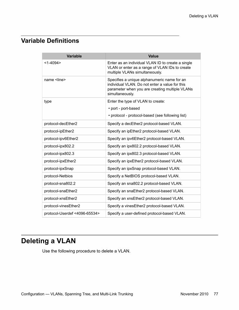
Variable Definitions
Variable Value<1-4094> Enter as an individual VLAN ID to create a single
VLAN or enter as a range of VLAN IDs to createmultiple VLANs simultaneously.
name <line> Specifies a unique alphanumeric name for anindividual VLAN. Do not enter a value for thisparameter when you are creating multiple VLANssimultaneously.
type Enter the type of VLAN to create:
• port - port-based
• protocol - protocol-based (see following list)
protocol-decEther2 Specify a decEther2 protocol-based VLAN.
protocol-ipEther2 Specify an ipEther2 protocol-based VLAN.
protocol-ipv6Ether2 Specify an ipv6Ether2 protocol-based VLAN.
protocol-ipx802.2 Specify an ipx802.2 protocol-based VLAN.
protocol-ipx802.3 Specify an ipx802.3 protocol-based VLAN.
protocol-ipxEther2 Specify an ipxEther2 protocol-based VLAN.
protocol-ipxSnap Specify an ipxSnap protocol-based VLAN.
protocol-Netbios Specify a NetBIOS protocol-based VLAN.
protocol-sna802.2 Specify an sna802.2 protocol-based VLAN.
protocol-snaEther2 Specify an snaEther2 protocol-based VLAN.
protocol-xnsEther2 Specify an xnsEther2 protocol-based VLAN.
protocol-vinesEther2 Specify a vinesEther2 protocol-based VLAN.
protocol-Userdef <4096-65534> Specify a user-defined protocol-based VLAN.
Deleting a VLANUse the following procedure to delete a VLAN.
Deleting a VLAN
Configuration — VLANs, Spanning Tree, and Multi-Link Trunking November 2010 77
Procedure steps
To delete a VLAN, use the following command from Global Configuration mode:
vlan delete <1-4094>
Important:VLAN 1 cannot be deleted.
Variable Definitions
Variable Value<1-4094> Enter as an individual VLAN ID to delete a single VLAN
or enter as a range of VLAN IDs to delete multipleVLANs simultaneously.
Removing a MAC address from allowed floodingUse the following procedure to remove a MAC address from the list of addresses for whichflooding is allowed.
Procedure steps
To remove a MAC address, use the following command from Global Configurationmode:
no vlan [igmp unknown-mcast-allow-flood <mac_address>]
Configuring VLAN nameUse the following procedure to configure or change a VLAN name.
Configuring VLANs using ACLI
78 Configuration — VLANs, Spanning Tree, and Multi-Link Trunking November 2010
Procedure steps
To change the VLAN name, use the following command from Global Configurationmode:
vlan name <1-4094> <name>
Configuring automatic PVIDUse the following procedure to enable automatic PVID.
Procedure steps
To enable automatic PVID, use the following command from Global Configurationmode:
auto-pvidUse the no form of this command to disable.
Configuring port VLAN settingsUse the following procedure to configure port VLAN settings.
Procedure steps
To configure VLAN port settings, use the following command from Global Configurationmode:
vlan ports [<portlist>] [tagging {enable | disable | tagAll |untagAll | tagPvidOnly | untagPvidOnly}] [pvid <1-4094>][filter-untagged-frame {enable | disable}] [filter-
Configuring automatic PVID
Configuration — VLANs, Spanning Tree, and Multi-Link Trunking November 2010 79
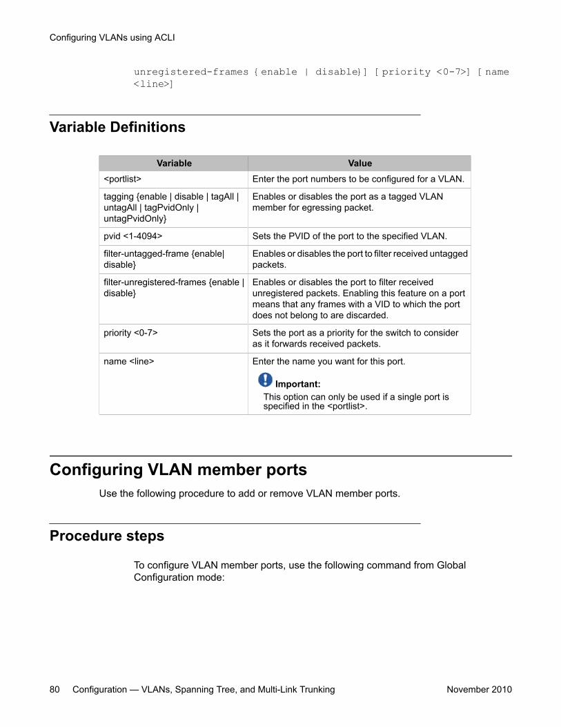
unregistered-frames {enable | disable}] [priority <0-7>] [name<line>]
Variable Definitions
Variable Value<portlist> Enter the port numbers to be configured for a VLAN.
tagging {enable | disable | tagAll |untagAll | tagPvidOnly |untagPvidOnly}
Enables or disables the port as a tagged VLANmember for egressing packet.
pvid <1-4094> Sets the PVID of the port to the specified VLAN.
filter-untagged-frame {enable|disable}
Enables or disables the port to filter received untaggedpackets.
filter-unregistered-frames {enable |disable}
Enables or disables the port to filter receivedunregistered packets. Enabling this feature on a portmeans that any frames with a VID to which the portdoes not belong to are discarded.
priority <0-7> Sets the port as a priority for the switch to consideras it forwards received packets.
name <line> Enter the name you want for this port.
Important:This option can only be used if a single port isspecified in the <portlist>.
Configuring VLAN member portsUse the following procedure to add or remove VLAN member ports.
Procedure steps
To configure VLAN member ports, use the following command from GlobalConfiguration mode:
Configuring VLANs using ACLI
80 Configuration — VLANs, Spanning Tree, and Multi-Link Trunking November 2010
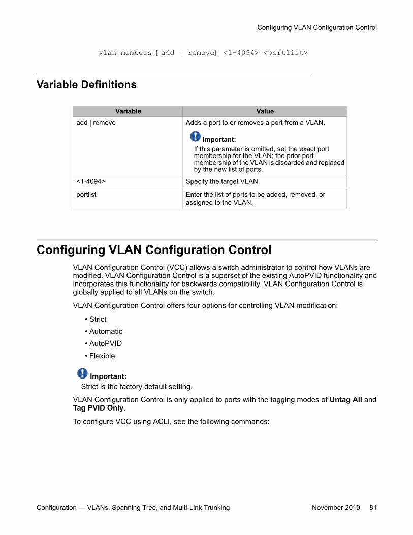
vlan members [add | remove] <1-4094> <portlist>
Variable Definitions
Variable Valueadd | remove Adds a port to or removes a port from a VLAN.
Important:If this parameter is omitted, set the exact portmembership for the VLAN; the prior portmembership of the VLAN is discarded and replacedby the new list of ports.
<1-4094> Specify the target VLAN.
portlist Enter the list of ports to be added, removed, orassigned to the VLAN.
Configuring VLAN Configuration ControlVLAN Configuration Control (VCC) allows a switch administrator to control how VLANs aremodified. VLAN Configuration Control is a superset of the existing AutoPVID functionality andincorporates this functionality for backwards compatibility. VLAN Configuration Control isglobally applied to all VLANs on the switch.
VLAN Configuration Control offers four options for controlling VLAN modification:
• Strict• Automatic• AutoPVID• Flexible
Important:Strict is the factory default setting.
VLAN Configuration Control is only applied to ports with the tagging modes of Untag All andTag PVID Only.
To configure VCC using ACLI, see the following commands:
Configuring VLAN Configuration Control
Configuration — VLANs, Spanning Tree, and Multi-Link Trunking November 2010 81
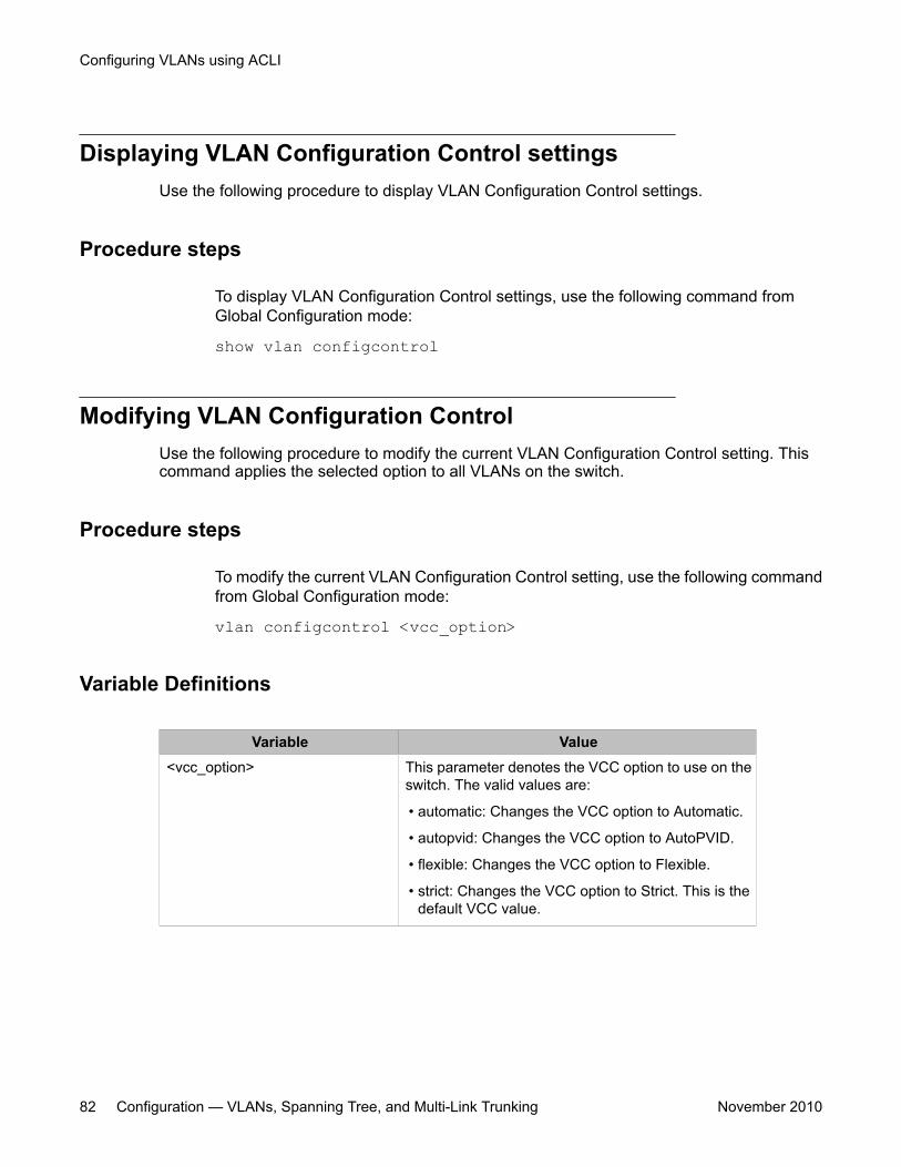
Displaying VLAN Configuration Control settingsUse the following procedure to display VLAN Configuration Control settings.
Procedure steps
To display VLAN Configuration Control settings, use the following command fromGlobal Configuration mode:
show vlan configcontrol
Modifying VLAN Configuration ControlUse the following procedure to modify the current VLAN Configuration Control setting. Thiscommand applies the selected option to all VLANs on the switch.
Procedure steps
To modify the current VLAN Configuration Control setting, use the following commandfrom Global Configuration mode:
vlan configcontrol <vcc_option>
Variable Definitions
Variable Value<vcc_option> This parameter denotes the VCC option to use on the
switch. The valid values are:
• automatic: Changes the VCC option to Automatic.
• autopvid: Changes the VCC option to AutoPVID.
• flexible: Changes the VCC option to Flexible.
• strict: Changes the VCC option to Strict. This is thedefault VCC value.
Configuring VLANs using ACLI
82 Configuration — VLANs, Spanning Tree, and Multi-Link Trunking November 2010
Managing MAC address forwarding database table
Note:In certain situations, due to the hash algorithm used by switch to store MAC addresses intomemory, some MAC addresses may not be learned.
This section shows you how to view the contents of the MAC address forwarding databasetable, setting the age-out time for the addresses, and clearing The MAC address table. Thefollowing topics are covered:
• Displaying the MAC address forwarding table on page 83• Configuring aging time for unseen MAC addresses on page 84• Setting aging time for unseen MAC addresses to default on page 84• Clearing the MAC address table on a VLAN on page 85• Clearing the MAC address table on page 85• Clearing the MAC address table on a FastEthernet interface on page 86• Clearing the MAC address table on a trunk on page 86• Removing a single address from the MAC address table on page 87
Displaying the MAC address forwarding tableUse the following procedure to display the current contents of the MAC address forwardingdatabase table. You can now filter the MAC Address table by port number. The MAC addresstable can store up to 16000 addresses.
Procedure steps
To display the MAC address forwarding table, use the following command fromPrivileged EXEC mode:
Managing MAC address forwarding database table
Configuration — VLANs, Spanning Tree, and Multi-Link Trunking November 2010 83
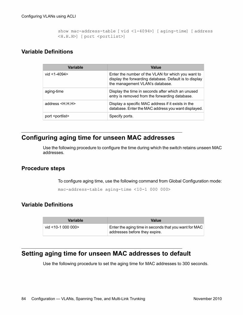
show mac-address-table [vid <1-4094>] [aging-time] [address<H.H.H>] [port <portlist>]
Variable Definitions
Variable Valuevid <1-4094> Enter the number of the VLAN for which you want to
display the forwarding database. Default is to displaythe management VLAN’s database.
aging-time Display the time in seconds after which an unusedentry is removed from the forwarding database.
address <H.H.H> Display a specific MAC address if it exists in thedatabase. Enter the MAC address you want displayed.
port <portlist> Specify ports.
Configuring aging time for unseen MAC addressesUse the following procedure to configure the time during which the switch retains unseen MACaddresses.
Procedure steps
To configure aging time, use the following command from Global Configuration mode:
mac-address-table aging-time <10-1 000 000>
Variable Definitions
Variable Valuevid <10-1 000 000> Enter the aging time in seconds that you want for MAC
addresses before they expire.
Setting aging time for unseen MAC addresses to defaultUse the following procedure to set the aging time for MAC addresses to 300 seconds.
Configuring VLANs using ACLI
84 Configuration — VLANs, Spanning Tree, and Multi-Link Trunking November 2010
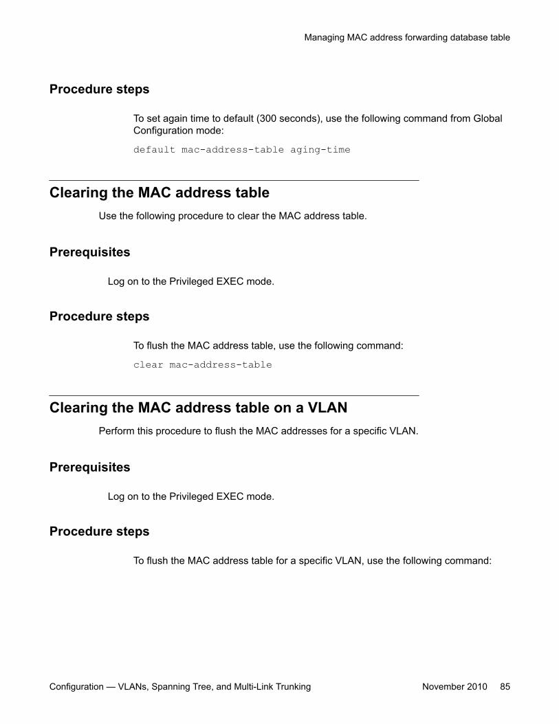
Procedure steps
To set again time to default (300 seconds), use the following command from GlobalConfiguration mode:
default mac-address-table aging-time
Clearing the MAC address tableUse the following procedure to clear the MAC address table.
Prerequisites
Log on to the Privileged EXEC mode.
Procedure steps
To flush the MAC address table, use the following command:
clear mac-address-table
Clearing the MAC address table on a VLANPerform this procedure to flush the MAC addresses for a specific VLAN.
Prerequisites
Log on to the Privileged EXEC mode.
Procedure steps
To flush the MAC address table for a specific VLAN, use the following command:
Managing MAC address forwarding database table
Configuration — VLANs, Spanning Tree, and Multi-Link Trunking November 2010 85
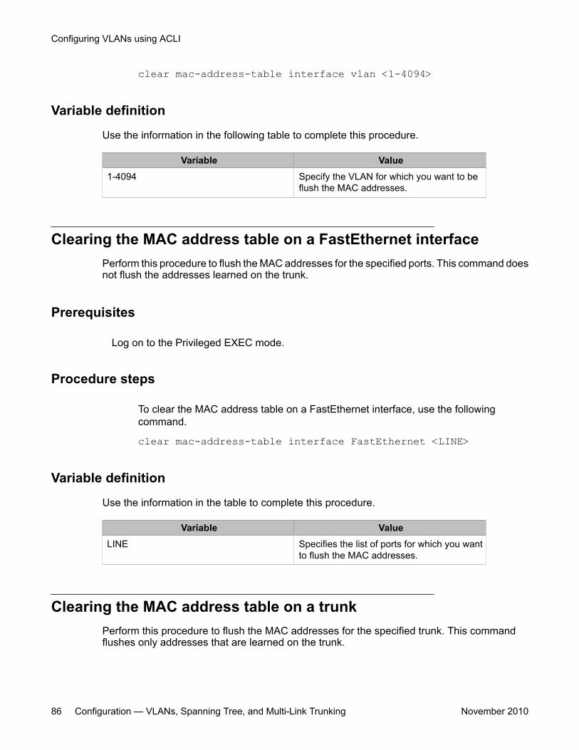
clear mac-address-table interface vlan <1-4094>
Variable definition
Use the information in the following table to complete this procedure.
Variable Value1-4094 Specify the VLAN for which you want to be
flush the MAC addresses.
Clearing the MAC address table on a FastEthernet interfacePerform this procedure to flush the MAC addresses for the specified ports. This command doesnot flush the addresses learned on the trunk.
Prerequisites
Log on to the Privileged EXEC mode.
Procedure steps
To clear the MAC address table on a FastEthernet interface, use the followingcommand.
clear mac-address-table interface FastEthernet <LINE>
Variable definition
Use the information in the table to complete this procedure.
Variable ValueLINE Specifies the list of ports for which you want
to flush the MAC addresses.
Clearing the MAC address table on a trunkPerform this procedure to flush the MAC addresses for the specified trunk. This commandflushes only addresses that are learned on the trunk.
Configuring VLANs using ACLI
86 Configuration — VLANs, Spanning Tree, and Multi-Link Trunking November 2010
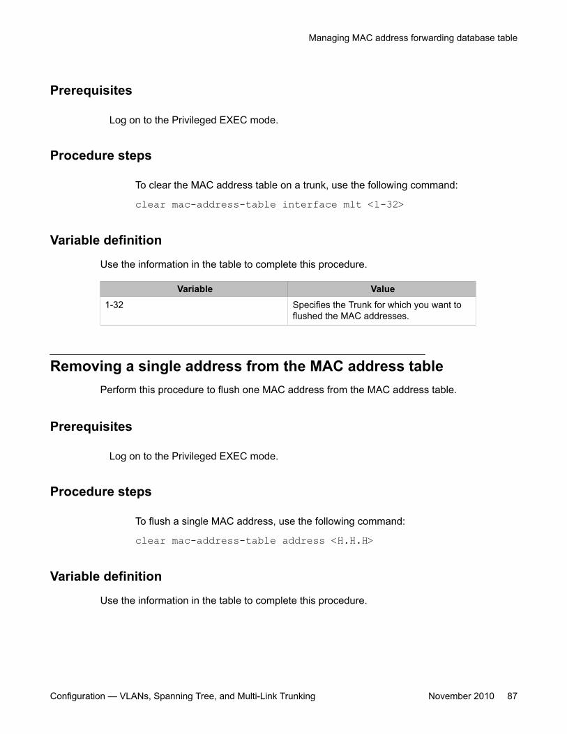
Prerequisites
Log on to the Privileged EXEC mode.
Procedure steps
To clear the MAC address table on a trunk, use the following command:
clear mac-address-table interface mlt <1-32>
Variable definition
Use the information in the table to complete this procedure.
Variable Value1-32 Specifies the Trunk for which you want to
flushed the MAC addresses.
Removing a single address from the MAC address tablePerform this procedure to flush one MAC address from the MAC address table.
Prerequisites
Log on to the Privileged EXEC mode.
Procedure steps
To flush a single MAC address, use the following command:
clear mac-address-table address <H.H.H>
Variable definition
Use the information in the table to complete this procedure.
Managing MAC address forwarding database table
Configuration — VLANs, Spanning Tree, and Multi-Link Trunking November 2010 87
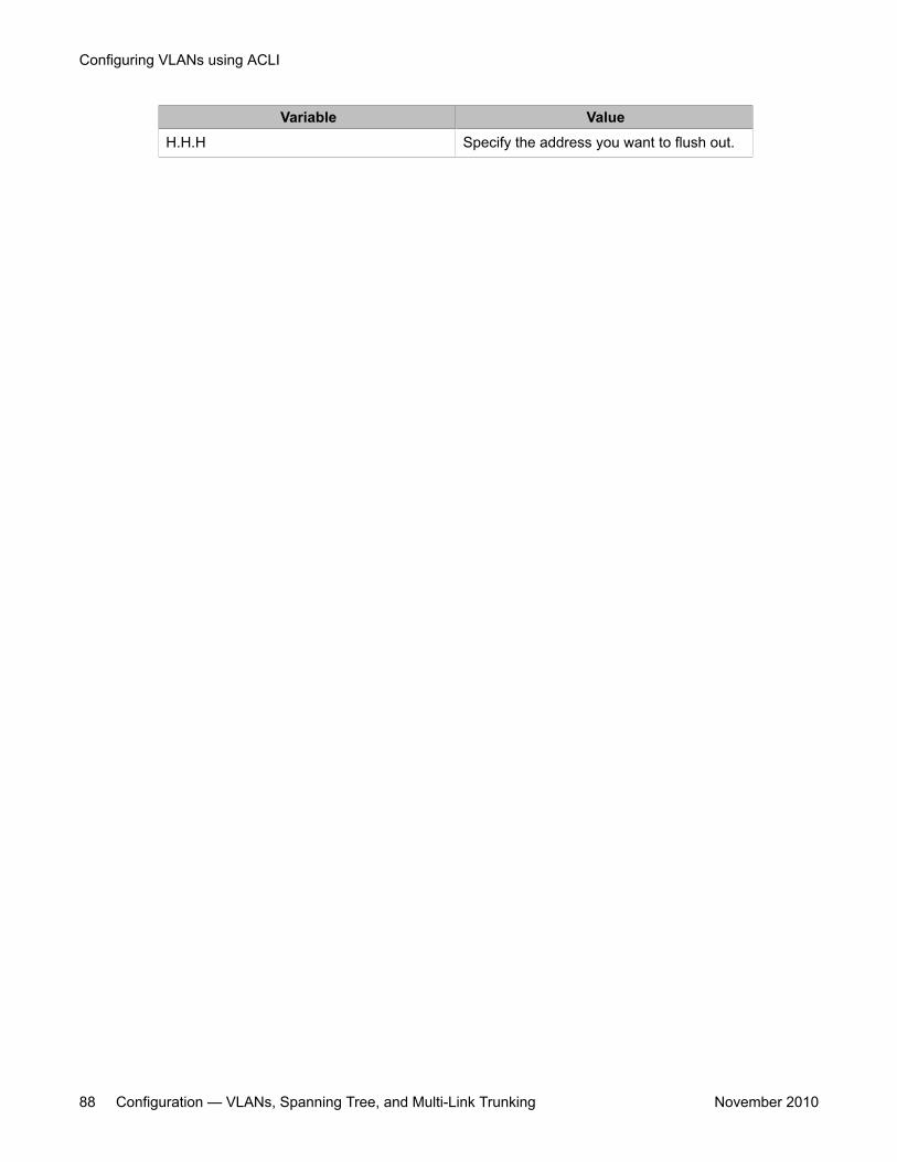
Variable ValueH.H.H Specify the address you want to flush out.
Configuring VLANs using ACLI
88 Configuration — VLANs, Spanning Tree, and Multi-Link Trunking November 2010
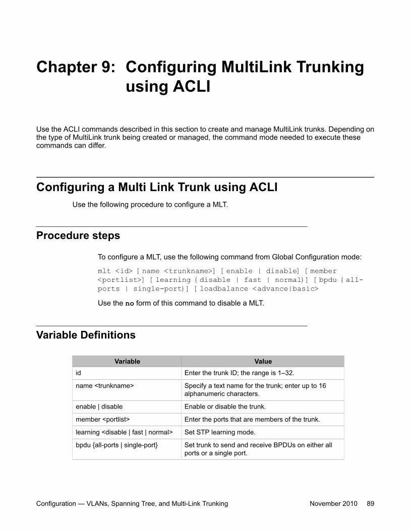
Chapter 9: Configuring MultiLink Trunkingusing ACLI
Use the ACLI commands described in this section to create and manage MultiLink trunks. Depending onthe type of MultiLink trunk being created or managed, the command mode needed to execute thesecommands can differ.
Configuring a Multi Link Trunk using ACLIUse the following procedure to configure a MLT.
Procedure steps
To configure a MLT, use the following command from Global Configuration mode:
mlt <id> [name <trunkname>] [enable | disable] [member<portlist>] [learning {disable | fast | normal}] [bpdu {all-ports | single-port}] [loadbalance <advance|basic>Use the no form of this command to disable a MLT.
Variable Definitions
Variable Valueid Enter the trunk ID; the range is 1–32.
name <trunkname> Specify a text name for the trunk; enter up to 16alphanumeric characters.
enable | disable Enable or disable the trunk.
member <portlist> Enter the ports that are members of the trunk.
learning <disable | fast | normal> Set STP learning mode.
bpdu {all-ports | single-port} Set trunk to send and receive BPDUs on either allports or a single port.
Configuration — VLANs, Spanning Tree, and Multi-Link Trunking November 2010 89
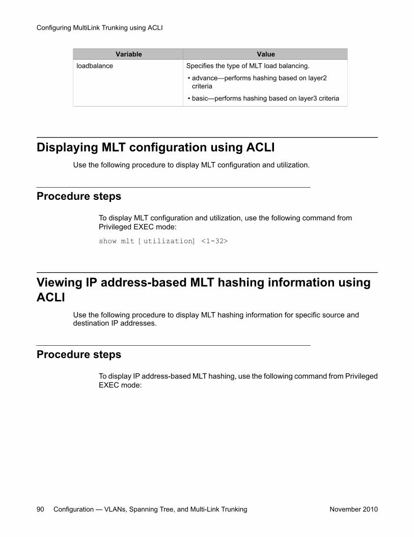
Variable Valueloadbalance Specifies the type of MLT load balancing.
• advance—performs hashing based on layer2criteria
• basic—performs hashing based on layer3 criteria
Displaying MLT configuration using ACLIUse the following procedure to display MLT configuration and utilization.
Procedure steps
To display MLT configuration and utilization, use the following command fromPrivileged EXEC mode:
show mlt [utilization] <1-32>
Viewing IP address-based MLT hashing information usingACLI
Use the following procedure to display MLT hashing information for specific source anddestination IP addresses.
Procedure steps
To display IP address-based MLT hashing, use the following command from PrivilegedEXEC mode:
Configuring MultiLink Trunking using ACLI
90 Configuration — VLANs, Spanning Tree, and Multi-Link Trunking November 2010
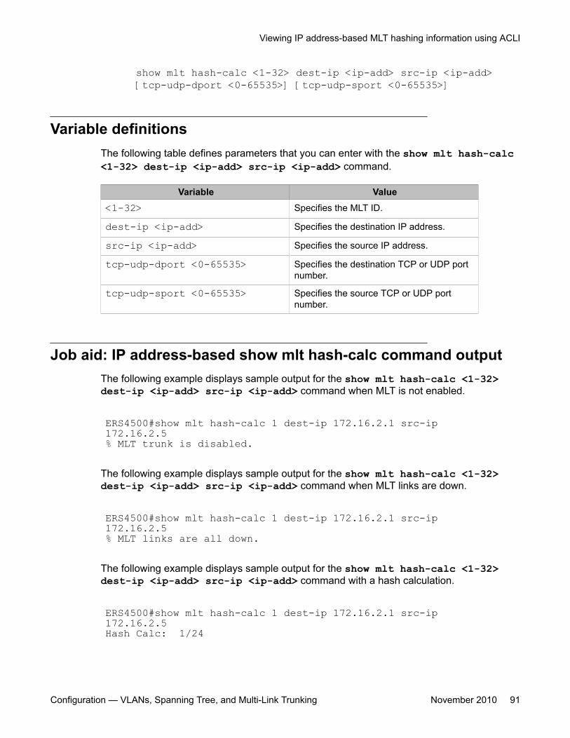
show mlt hash-calc <1-32> dest-ip <ip-add> src-ip <ip-add>[tcp-udp-dport <0-65535>] [tcp-udp-sport <0-65535>]
Variable definitionsThe following table defines parameters that you can enter with the show mlt hash-calc<1-32> dest-ip <ip-add> src-ip <ip-add> command.
Variable Value<1-32> Specifies the MLT ID.
dest-ip <ip-add> Specifies the destination IP address.
src-ip <ip-add> Specifies the source IP address.
tcp-udp-dport <0-65535> Specifies the destination TCP or UDP portnumber.
tcp-udp-sport <0-65535> Specifies the source TCP or UDP portnumber.
Job aid: IP address-based show mlt hash-calc command outputThe following example displays sample output for the show mlt hash-calc <1-32>dest-ip <ip-add> src-ip <ip-add> command when MLT is not enabled.
ERS4500#show mlt hash-calc 1 dest-ip 172.16.2.1 src-ip 172.16.2.5% MLT trunk is disabled.
The following example displays sample output for the show mlt hash-calc <1-32>dest-ip <ip-add> src-ip <ip-add> command when MLT links are down.
ERS4500#show mlt hash-calc 1 dest-ip 172.16.2.1 src-ip 172.16.2.5% MLT links are all down.
The following example displays sample output for the show mlt hash-calc <1-32>dest-ip <ip-add> src-ip <ip-add> command with a hash calculation.
ERS4500#show mlt hash-calc 1 dest-ip 172.16.2.1 src-ip 172.16.2.5Hash Calc: 1/24
Viewing IP address-based MLT hashing information using ACLI
Configuration — VLANs, Spanning Tree, and Multi-Link Trunking November 2010 91
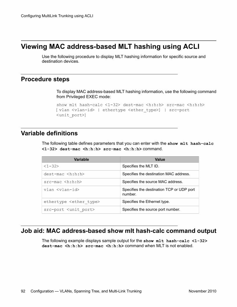
Viewing MAC address-based MLT hashing using ACLIUse the following procedure to display MLT hashing information for specific source anddestination devices.
Procedure steps
To display MAC address-based MLT hashing information, use the following commandfrom Privileged EXEC mode:
show mlt hash-calc <1-32> dest-mac <h:h:h> src-mac <h:h:h>[vlan <vlan-id> | ethertype <ether_type>] | src-port<unit_port>]
Variable definitionsThe following table defines parameters that you can enter with the show mlt hash-calc<1-32> dest-mac <h:h:h> src-mac <h:h:h> command.
Variable Value<1-32> Specifies the MLT ID.
dest-mac <h:h:h> Specifies the destination MAC address.
src-mac <h:h:h> Specifies the source MAC address.
vlan <vlan-id> Specifies the destination TCP or UDP portnumber.
ethertype <ether_type> Specifies the Ethernet type.
src-port <unit_port> Specifies the source port number.
Job aid: MAC address-based show mlt hash-calc command outputThe following example displays sample output for the show mlt hash-calc <1-32>dest-mac <h:h:h> src-mac <h:h:h> command when MLT is not enabled.
Configuring MultiLink Trunking using ACLI
92 Configuration — VLANs, Spanning Tree, and Multi-Link Trunking November 2010
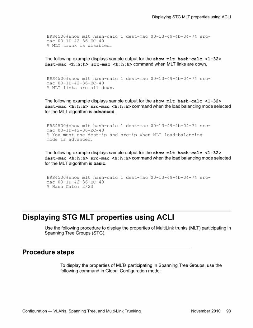
ERS4500#show mlt hash-calc 1 dest-mac 00-13-49-4b-04-74 src-mac 00-1D-42-36-EC-40% MLT trunk is disabled.
The following example displays sample output for the show mlt hash-calc <1-32>dest-mac <h:h:h> src-mac <h:h:h> command when MLT links are down.
ERS4500#show mlt hash-calc 1 dest-mac 00-13-49-4b-04-74 src-mac 00-1D-42-36-EC-40% MLT links are all down.
The following example displays sample output for the show mlt hash-calc <1-32>dest-mac <h:h:h> src-mac <h:h:h> command when the load balancing mode selectedfor the MLT algorithm is advanced.
ERS4500#show mlt hash-calc 1 dest-mac 00-13-49-4b-04-74 src-mac 00-1D-42-36-EC-40% You must use dest-ip and src-ip when MLT load-balancing mode is advanced.
The following example displays sample output for the show mlt hash-calc <1-32>dest-mac <h:h:h> src-mac <h:h:h> command when the load balancing mode selectedfor the MLT algorithm is basic.
ERS4500#show mlt hash-calc 1 dest-mac 00-13-49-4b-04-74 src-mac 00-1D-42-36-EC-40% Hash Calc: 2/23
Displaying STG MLT properties using ACLIUse the following procedure to display the properties of MultiLink trunks (MLT) participating inSpanning Tree Groups (STG).
Procedure steps
To display the properties of MLTs participating in Spanning Tree Groups, use thefollowing command in Global Configuration mode:
Displaying STG MLT properties using ACLI
Configuration — VLANs, Spanning Tree, and Multi-Link Trunking November 2010 93
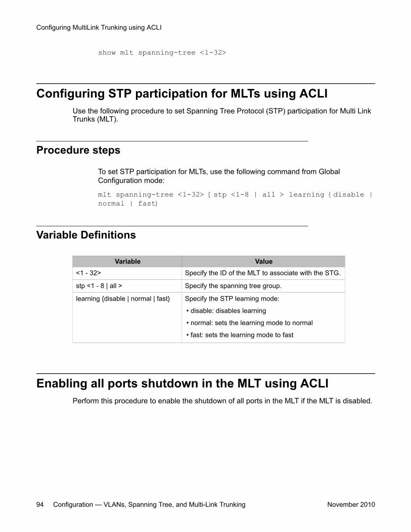
show mlt spanning-tree <1-32>
Configuring STP participation for MLTs using ACLIUse the following procedure to set Spanning Tree Protocol (STP) participation for Multi LinkTrunks (MLT).
Procedure steps
To set STP participation for MLTs, use the following command from GlobalConfiguration mode:
mlt spanning-tree <1-32> [stp <1-8 | all > learning {disable |normal | fast}
Variable Definitions
Variable Value<1 - 32> Specify the ID of the MLT to associate with the STG.
stp <1 - 8 | all > Specify the spanning tree group.
learning {disable | normal | fast} Specify the STP learning mode:
• disable: disables learning
• normal: sets the learning mode to normal
• fast: sets the learning mode to fast
Enabling all ports shutdown in the MLT using ACLIPerform this procedure to enable the shutdown of all ports in the MLT if the MLT is disabled.
Configuring MultiLink Trunking using ACLI
94 Configuration — VLANs, Spanning Tree, and Multi-Link Trunking November 2010
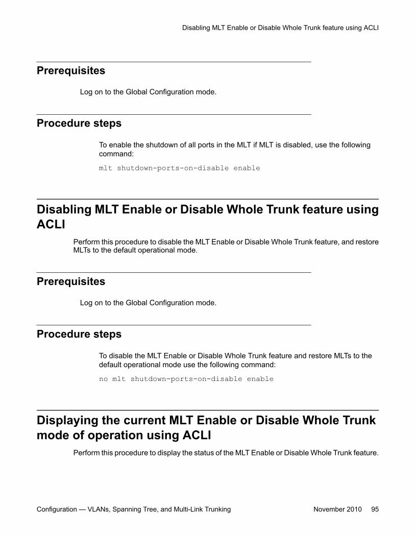
Prerequisites
Log on to the Global Configuration mode.
Procedure steps
To enable the shutdown of all ports in the MLT if MLT is disabled, use the followingcommand:
mlt shutdown-ports-on-disable enable
Disabling MLT Enable or Disable Whole Trunk feature usingACLI
Perform this procedure to disable the MLT Enable or Disable Whole Trunk feature, and restoreMLTs to the default operational mode.
Prerequisites
Log on to the Global Configuration mode.
Procedure steps
To disable the MLT Enable or Disable Whole Trunk feature and restore MLTs to thedefault operational mode use the following command:
no mlt shutdown-ports-on-disable enable
Displaying the current MLT Enable or Disable Whole Trunkmode of operation using ACLI
Perform this procedure to display the status of the MLT Enable or Disable Whole Trunk feature.
Disabling MLT Enable or Disable Whole Trunk feature using ACLI
Configuration — VLANs, Spanning Tree, and Multi-Link Trunking November 2010 95
Prerequisites
Log on to the Privileged EXEC mode.
Procedure steps
To see current MLT mode of operation use the following command:
show shutdown-ports-on-disable
Job aidThe following displays sample output for the show mlt shutdown-ports-on-disablecommand:
show mlt shutdown-ports-on-disable Trunk loop prevention is enabled.
Configuring MultiLink Trunking using ACLI
96 Configuration — VLANs, Spanning Tree, and Multi-Link Trunking November 2010
Chapter 10: Configuring Spanning TreeProtocol using ACLI
Configuring STP operation mode using ACLIUse the following procedure to set the STP operational mode to STG (Avaya Multiple SpanningTree Protocol), RSTP (802.1w Rapid Spanning Tree Protocol), or MSTP (802.1s MultipleSpanning Tree Protocol).
Procedure steps
To configure STP operation mode, use the following command from GlobalConfiguration mode:
spanning-tree op-mode {stpg | rstp | MSTP}
Configuring STP BPDU Filtering using ACLIUse the following procedure to configure STP BPDU Filtering on a port. This command isavailable in all STP modes (STG, RSTP, and MSTP).
Procedure steps
To configure STP BPDU filtering, use the following command in Interface Configurationmode:
Configuration — VLANs, Spanning Tree, and Multi-Link Trunking November 2010 97
spanning-tree bpdu-filtering [port <portlist>] [enable][timeout <10-65535 | 0> ]
Variable Definitions
Variable Valueport <portlist> Specifies the ports affected by the command.
enable Enables STP BPDU Filtering on the specifiedports. The default value is disabled.
timeout <10-65535 | 0 > When BPDU filtering is enabled, thisindicates the time (in seconds) during whichthe port remains disabled after it receives aBPDU. The port timer is disabled if this valueis set to 0. The default value is 120 seconds.
Creating and Managing STGs using ACLITo create and manage Spanning Tree Groups, you can refer to the Command Line Interfacecommands listed in this section. Depending on the type of Spanning Tree Group that you wantto create or manage, the command mode needed to execute these commands can differ.
In the following commands, the omission of any parameters that specify a Spanning TreeGroup results in the command operating against the default Spanning Tree Group (SpanningTree Group 1).
To configure STGs using ACLI, see the following:
Configuring path cost calculation using ACLIUse the following procedure to set the path cost calculation mode for all Spanning Tree Groupson the switch.
Procedure steps
1. To set path cost calculation, use the following command from Global Configurationmode:
spanning-tree cost-calc-mode {dot1d | dot1t}2. To set the cost-calc-mode to its default value (dot1d), use the following command:
Configuring Spanning Tree Protocol using ACLI
98 Configuration — VLANs, Spanning Tree, and Multi-Link Trunking November 2010
default spanning-tree cost-calc-mode
Configuring STG port membership using ACLIUse the following procedure to set the STG port membership mode for all Spanning TreeGroups on the switch.
Procedure steps
To set STG membership mode, use the following command from Global Configurationmode:
spanning-tree port-mode {auto | normal}
Displaying spanning tree configuration information using ACLIUse the following procedure to display sspanning tree configuration information that is specificto either the Spanning Tree Group or to the port.
Procedure steps
To display spanning tree configuration information, use the following command fromPrivileged EXEC mode:
show spanning-tree [stp <1-8>] {config | port| vlans} {cost-calc-mode | op-mode | port-mode}
Variable Definitions
Variable Valuestp <1-8> Display specified Spanning Tree Group configuration;
enter the number of the group to be displayed.
config | port | vlans Display spanning tree configuration for
• config: the specified (or default) Spanning TreeGroup
• port: the ports within the Spanning Tree Group
• vlans: the VLANs that are members of the specifiedSpanning Tree Group
Creating and Managing STGs using ACLI
Configuration — VLANs, Spanning Tree, and Multi-Link Trunking November 2010 99
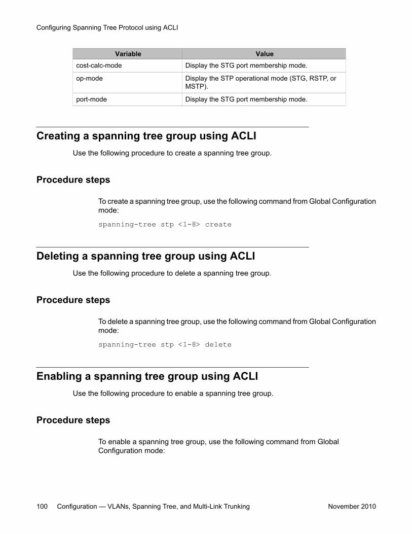
Variable Valuecost-calc-mode Display the STG port membership mode.
op-mode Display the STP operational mode (STG, RSTP, orMSTP).
port-mode Display the STG port membership mode.
Creating a spanning tree group using ACLIUse the following procedure to create a spanning tree group.
Procedure steps
To create a spanning tree group, use the following command from Global Configurationmode:
spanning-tree stp <1-8> create
Deleting a spanning tree group using ACLIUse the following procedure to delete a spanning tree group.
Procedure steps
To delete a spanning tree group, use the following command from Global Configurationmode:
spanning-tree stp <1-8> delete
Enabling a spanning tree group using ACLIUse the following procedure to enable a spanning tree group.
Procedure steps
To enable a spanning tree group, use the following command from GlobalConfiguration mode:
Configuring Spanning Tree Protocol using ACLI
100 Configuration — VLANs, Spanning Tree, and Multi-Link Trunking November 2010
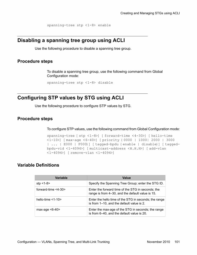
spanning-tree stp <1-8> enable
Disabling a spanning tree group using ACLIUse the following procedure to disable a spanning tree group.
Procedure steps
To disable a spanning tree group, use the following command from GlobalConfiguration mode:
spanning-tree stp <1-8> disable
Configuring STP values by STG using ACLIUse the following procedure to configure STP values by STG.
Procedure steps
To configure STP values, use the following command from Global Configuration mode:
spanning-tree [stp <1-8>] [forward-time <4-30>] [hello-time<1-10>] [max-age <6-40>] [priority {0000 | 1000| 2000 | 3000| ... | E000 | F000}] [tagged-bpdu {enable | disable}] [tagged-bpdu-vid <1-4094>] [multicast-address <H.H.H>] [add-vlan<1-4094>] [remove-vlan <1-4094>]
Variable Definitions
Variable Valuestp <1-8> Specify the Spanning Tree Group; enter the STG ID.
forward-time <4-30> Enter the forward time of the STG in seconds; therange is from 4–30, and the default value is 15.
hello-time <1-10> Enter the hello time of the STG in seconds; the rangeis from 1–10, and the default value is 2.
max-age <6-40> Enter the max-age of the STG in seconds; the rangeis from 6–40, and the default value is 20.
Creating and Managing STGs using ACLI
Configuration — VLANs, Spanning Tree, and Multi-Link Trunking November 2010 101
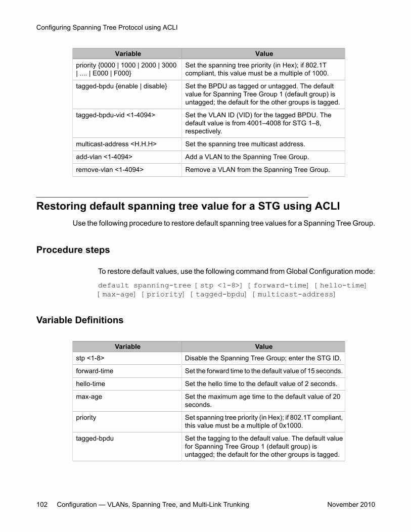
Variable Valuepriority {0000 | 1000 | 2000 | 3000| .... | E000 | F000}
Set the spanning tree priority (in Hex); if 802.1Tcompliant, this value must be a multiple of 1000.
tagged-bpdu {enable | disable} Set the BPDU as tagged or untagged. The defaultvalue for Spanning Tree Group 1 (default group) isuntagged; the default for the other groups is tagged.
tagged-bpdu-vid <1-4094> Set the VLAN ID (VID) for the tagged BPDU. Thedefault value is from 4001–4008 for STG 1–8,respectively.
multicast-address <H.H.H> Set the spanning tree multicast address.
add-vlan <1-4094> Add a VLAN to the Spanning Tree Group.
remove-vlan <1-4094> Remove a VLAN from the Spanning Tree Group.
Restoring default spanning tree value for a STG using ACLIUse the following procedure to restore default spanning tree values for a Spanning Tree Group.
Procedure steps
To restore default values, use the following command from Global Configuration mode:
default spanning-tree [stp <1-8>] [forward-time] [hello-time][max-age] [priority] [tagged-bpdu] [multicast-address]
Variable Definitions
Variable Valuestp <1-8> Disable the Spanning Tree Group; enter the STG ID.
forward-time Set the forward time to the default value of 15 seconds.
hello-time Set the hello time to the default value of 2 seconds.
max-age Set the maximum age time to the default value of 20seconds.
priority Set spanning tree priority (in Hex); if 802.1T compliant,this value must be a multiple of 0x1000.
tagged-bpdu Set the tagging to the default value. The default valuefor Spanning Tree Group 1 (default group) isuntagged; the default for the other groups is tagged.
Configuring Spanning Tree Protocol using ACLI
102 Configuration — VLANs, Spanning Tree, and Multi-Link Trunking November 2010
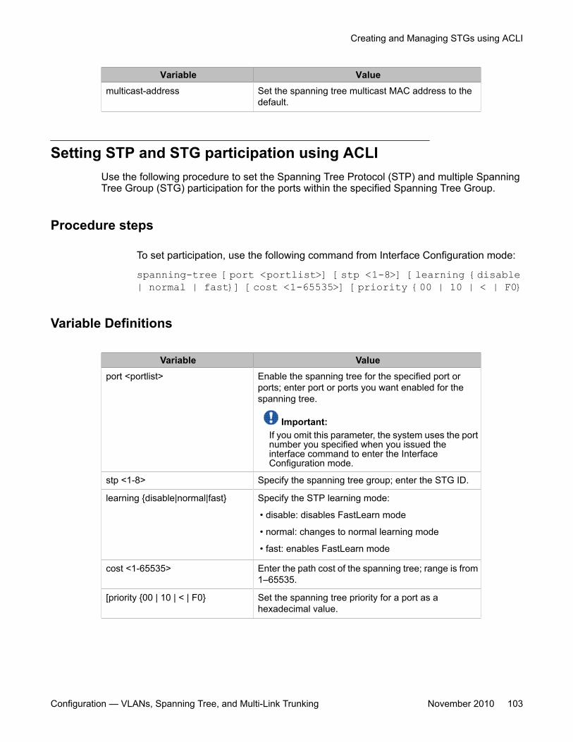
Variable Valuemulticast-address Set the spanning tree multicast MAC address to the
default.
Setting STP and STG participation using ACLIUse the following procedure to set the Spanning Tree Protocol (STP) and multiple SpanningTree Group (STG) participation for the ports within the specified Spanning Tree Group.
Procedure steps
To set participation, use the following command from Interface Configuration mode:
spanning-tree [port <portlist>] [stp <1-8>] [learning {disable| normal | fast}] [cost <1-65535>] [priority {00 | 10 | < | F0}
Variable Definitions
Variable Valueport <portlist> Enable the spanning tree for the specified port or
ports; enter port or ports you want enabled for thespanning tree.
Important:If you omit this parameter, the system uses the portnumber you specified when you issued theinterface command to enter the InterfaceConfiguration mode.
stp <1-8> Specify the spanning tree group; enter the STG ID.
learning {disable|normal|fast} Specify the STP learning mode:
• disable: disables FastLearn mode
• normal: changes to normal learning mode
• fast: enables FastLearn mode
cost <1-65535> Enter the path cost of the spanning tree; range is from1–65535.
[priority {00 | 10 | < | F0} Set the spanning tree priority for a port as ahexadecimal value.
Creating and Managing STGs using ACLI
Configuration — VLANs, Spanning Tree, and Multi-Link Trunking November 2010 103
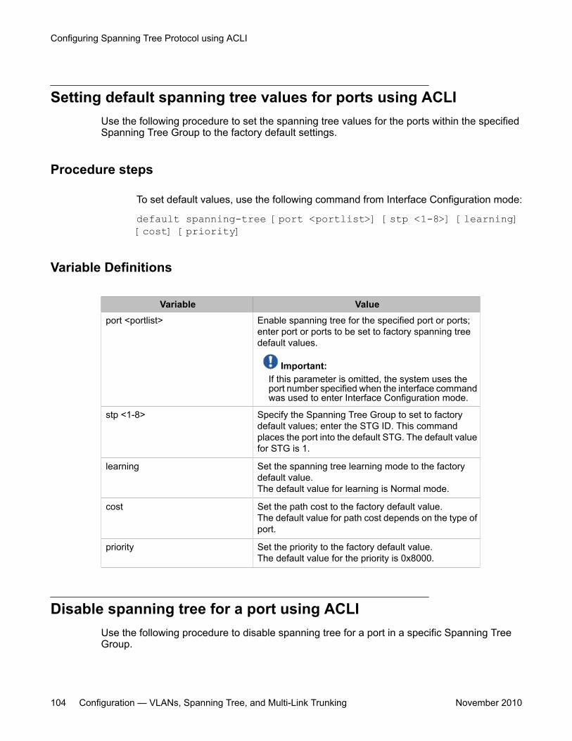
Setting default spanning tree values for ports using ACLIUse the following procedure to set the spanning tree values for the ports within the specifiedSpanning Tree Group to the factory default settings.
Procedure steps
To set default values, use the following command from Interface Configuration mode:
default spanning-tree [port <portlist>] [stp <1-8>] [learning][cost] [priority]
Variable Definitions
Variable Valueport <portlist> Enable spanning tree for the specified port or ports;
enter port or ports to be set to factory spanning treedefault values.
Important:If this parameter is omitted, the system uses theport number specified when the interface commandwas used to enter Interface Configuration mode.
stp <1-8> Specify the Spanning Tree Group to set to factorydefault values; enter the STG ID. This commandplaces the port into the default STG. The default valuefor STG is 1.
learning Set the spanning tree learning mode to the factorydefault value.The default value for learning is Normal mode.
cost Set the path cost to the factory default value.The default value for path cost depends on the type ofport.
priority Set the priority to the factory default value.The default value for the priority is 0x8000.
Disable spanning tree for a port using ACLIUse the following procedure to disable spanning tree for a port in a specific Spanning TreeGroup.
Configuring Spanning Tree Protocol using ACLI
104 Configuration — VLANs, Spanning Tree, and Multi-Link Trunking November 2010
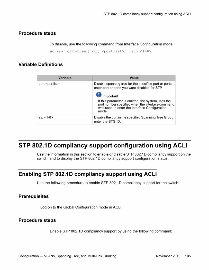
Procedure steps
To disable, use the following command from Interface Configuration mode:
no spanning-tree [port <portlist>] [stp <1-8>]
Variable Definitions
Variable Valueport <portlist> Disable spanning tree for the specified port or ports;
enter port or ports you want disabled for STP.
Important:If this parameter is omitted, the system uses theport number specified when the interface commandwas used to enter the Interface Configurationmode.
stp <1-8> Disable the port in the specified Spanning Tree Group;enter the STG ID.
STP 802.1D compliancy support configuration using ACLIUse the information in this section to enable or disable STP 802.1D compliancy support on theswitch, and to display the STP 802.1D compliancy support configuration status.
Enabling STP 802.1D compliancy support using ACLIUse the following procedure to enable STP 802.1D compliancy support for the switch.
Prerequisites
Log on to the Global Configuration mode in ACLI.
Procedure steps
Enable STP 802.1D compliancy support by using the following command:
STP 802.1D compliancy support configuration using ACLI
Configuration — VLANs, Spanning Tree, and Multi-Link Trunking November 2010 105
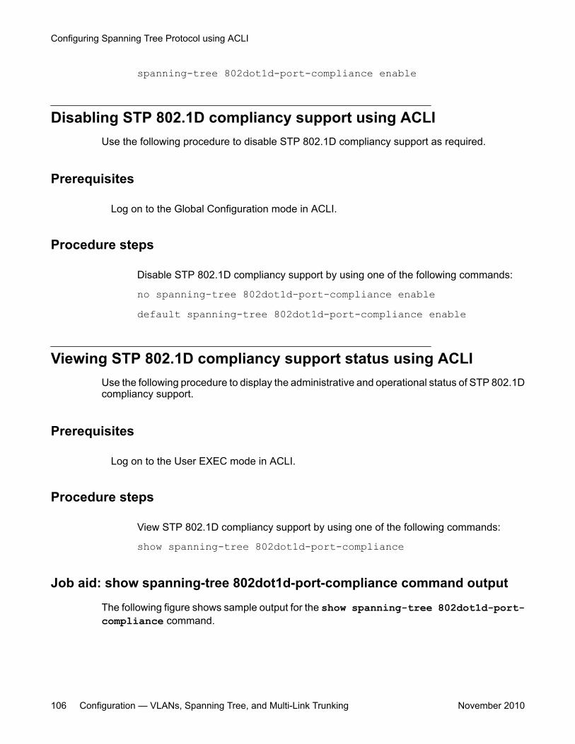
spanning-tree 802dot1d-port-compliance enable
Disabling STP 802.1D compliancy support using ACLIUse the following procedure to disable STP 802.1D compliancy support as required.
Prerequisites
Log on to the Global Configuration mode in ACLI.
Procedure steps
Disable STP 802.1D compliancy support by using one of the following commands:
no spanning-tree 802dot1d-port-compliance enabledefault spanning-tree 802dot1d-port-compliance enable
Viewing STP 802.1D compliancy support status using ACLIUse the following procedure to display the administrative and operational status of STP 802.1Dcompliancy support.
Prerequisites
Log on to the User EXEC mode in ACLI.
Procedure steps
View STP 802.1D compliancy support by using one of the following commands:
show spanning-tree 802dot1d-port-compliance
Job aid: show spanning-tree 802dot1d-port-compliance command output
The following figure shows sample output for the show spanning-tree 802dot1d-port-compliance command.
Configuring Spanning Tree Protocol using ACLI
106 Configuration — VLANs, Spanning Tree, and Multi-Link Trunking November 2010
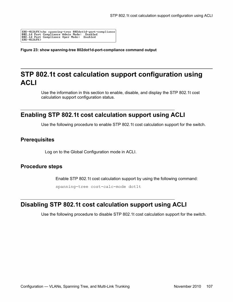
Figure 23: show spanning-tree 802dot1d-port-compliance command output
STP 802.1t cost calculation support configuration usingACLI
Use the information in this section to enable, disable, and display the STP 802.1t costcalculation support configuration status.
Enabling STP 802.1t cost calculation support using ACLIUse the following procedure to enable STP 802.1t cost calculation support for the switch.
Prerequisites
Log on to the Global Configuration mode in ACLI.
Procedure steps
Enable STP 802.1t cost calculation support by using the following command:
spanning-tree cost-calc-mode dot1t
Disabling STP 802.1t cost calculation support using ACLIUse the following procedure to disable STP 802.1t cost calculation support for the switch.
STP 802.1t cost calculation support configuration using ACLI
Configuration — VLANs, Spanning Tree, and Multi-Link Trunking November 2010 107
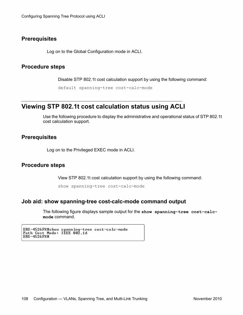
Prerequisites
Log on to the Global Configuration mode in ACLI.
Procedure steps
Disable STP 802.1t cost calculation support by using the following command:
default spanning-tree cost-calc-mode
Viewing STP 802.1t cost calculation status using ACLIUse the following procedure to display the administrative and operational status of STP 802.1tcost calculation support.
Prerequisites
Log on to the Privileged EXEC mode in ACLI.
Procedure steps
View STP 802.1t cost calculation support by using the following command:
show spanning-tree cost-calc-mode
Job aid: show spanning-tree cost-calc-mode command output
The following figure displays sample output for the show spanning-tree cost-calc-mode command.
Configuring Spanning Tree Protocol using ACLI
108 Configuration — VLANs, Spanning Tree, and Multi-Link Trunking November 2010
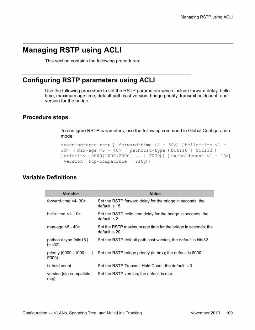
Managing RSTP using ACLIThis section contains the following procedures:
Configuring RSTP parameters using ACLIUse the following procedure to set the RSTP parameters which include forward delay, hellotime, maximum age time, default path cost version, bridge priority, transmit holdcount, andversion for the bridge.
Procedure steps
To configure RSTP parameters, use the following command in Global Configurationmode:
spanning-tree rstp [ forward-time <4 - 30>] [hello-time <1 -10>] [max-age <6 - 40>] [pathcost-type {bits16 | bits32}][priority {0000|1000|2000| ...| F000}] [tx-holdcount <1 - 10>][version {stp-compatible | rstp}]
Variable Definitions
Variable Valueforward-time <4- 30> Set the RSTP forward delay for the bridge in seconds; the
default is 15.
hello-time <1- 10> Set the RSTP hello time delay for the bridge in seconds; thedefault is 2.
max-age <6 - 40> Set the RSTP maximum age time for the bridge in seconds; thedefault is 20.
pathcost-type {bits16 |bits32}
Set the RSTP default path cost version; the default is bits32.
priority {0000 | 1000 | ... |F000}
Set the RSTP bridge priority (in hex); the default is 8000.
tx-hold count Set the RSTP Transmit Hold Count; the default is 3.
version {stp-compatible |rstp}
Set the RSTP version; the default is rstp.
Managing RSTP using ACLI
Configuration — VLANs, Spanning Tree, and Multi-Link Trunking November 2010 109
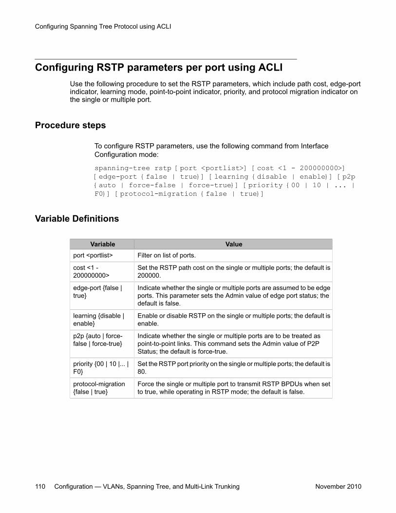
Configuring RSTP parameters per port using ACLIUse the following procedure to set the RSTP parameters, which include path cost, edge-portindicator, learning mode, point-to-point indicator, priority, and protocol migration indicator onthe single or multiple port.
Procedure steps
To configure RSTP parameters, use the following command from InterfaceConfiguration mode:
spanning-tree rstp [port <portlist>] [cost <1 - 200000000>][edge-port {false | true}] [learning {disable | enable}] [p2p{auto | force-false | force-true}] [priority {00 | 10 | ... |F0}] [protocol-migration {false | true}]
Variable Definitions
Variable Valueport <portlist> Filter on list of ports.
cost <1 -200000000>
Set the RSTP path cost on the single or multiple ports; the default is200000.
edge-port {false |true}
Indicate whether the single or multiple ports are assumed to be edgeports. This parameter sets the Admin value of edge port status; thedefault is false.
learning {disable |enable}
Enable or disable RSTP on the single or multiple ports; the default isenable.
p2p {auto | force-false | force-true}
Indicate whether the single or multiple ports are to be treated aspoint-to-point links. This command sets the Admin value of P2PStatus; the default is force-true.
priority {00 | 10 |... |F0}
Set the RSTP port priority on the single or multiple ports; the default is80.
protocol-migration{false | true}
Force the single or multiple port to transmit RSTP BPDUs when setto true, while operating in RSTP mode; the default is false.
Configuring Spanning Tree Protocol using ACLI
110 Configuration — VLANs, Spanning Tree, and Multi-Link Trunking November 2010
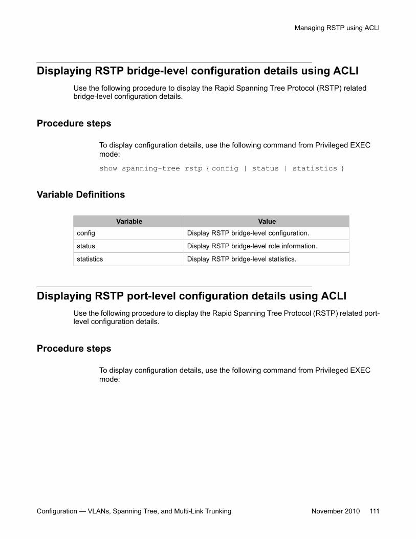
Displaying RSTP bridge-level configuration details using ACLIUse the following procedure to display the Rapid Spanning Tree Protocol (RSTP) relatedbridge-level configuration details.
Procedure steps
To display configuration details, use the following command from Privileged EXECmode:
show spanning-tree rstp {config | status | statistics }
Variable Definitions
Variable Valueconfig Display RSTP bridge-level configuration.
status Display RSTP bridge-level role information.
statistics Display RSTP bridge-level statistics.
Displaying RSTP port-level configuration details using ACLIUse the following procedure to display the Rapid Spanning Tree Protocol (RSTP) related port-level configuration details.
Procedure steps
To display configuration details, use the following command from Privileged EXECmode:
Managing RSTP using ACLI
Configuration — VLANs, Spanning Tree, and Multi-Link Trunking November 2010 111
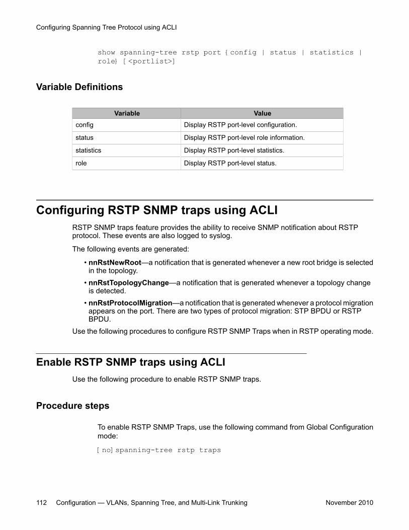
show spanning-tree rstp port {config | status | statistics |role} [<portlist>]
Variable Definitions
Variable Valueconfig Display RSTP port-level configuration.
status Display RSTP port-level role information.
statistics Display RSTP port-level statistics.
role Display RSTP port-level status.
Configuring RSTP SNMP traps using ACLIRSTP SNMP traps feature provides the ability to receive SNMP notification about RSTPprotocol. These events are also logged to syslog.
The following events are generated:
• nnRstNewRoot—a notification that is generated whenever a new root bridge is selectedin the topology.
• nnRstTopologyChange—a notification that is generated whenever a topology changeis detected.
• nnRstProtocolMigration—a notification that is generated whenever a protocol migrationappears on the port. There are two types of protocol migration: STP BPDU or RSTPBPDU.
Use the following procedures to configure RSTP SNMP Traps when in RSTP operating mode.
Enable RSTP SNMP traps using ACLIUse the following procedure to enable RSTP SNMP traps.
Procedure steps
To enable RSTP SNMP Traps, use the following command from Global Configurationmode:
[no]spanning-tree rstp traps
Configuring Spanning Tree Protocol using ACLI
112 Configuration — VLANs, Spanning Tree, and Multi-Link Trunking November 2010
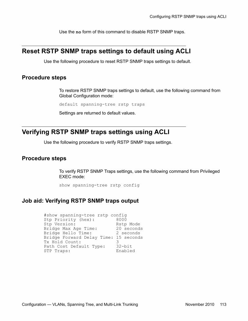
Use the no form of this command to disable RSTP SNMP traps.
Reset RSTP SNMP traps settings to default using ACLIUse the following procedure to reset RSTP SNMP traps settings to default.
Procedure steps
To restore RSTP SNMP traps settings to default, use the following command fromGlobal Configuration mode:
default spanning-tree rstp trapsSettings are returned to default values.
Verifying RSTP SNMP traps settings using ACLIUse the following procedure to verify RSTP SNMP traps settings.
Procedure steps
To verify RSTP SNMP Traps settings, use the following command from PrivilegedEXEC mode:
show spanning-tree rstp config
Job aid: Verifying RSTP SNMP traps output
#show spanning-tree rstp configStp Priority (hex): 8000 Stp Version: Rstp ModeBridge Max Age Time: 20 secondsBridge Hello Time: 2 secondsBridge Forward Delay Time: 15 secondsTx Hold Count: 3Path Cost Default Type: 32-bitSTP Traps: Enabled
Configuring RSTP SNMP traps using ACLI
Configuration — VLANs, Spanning Tree, and Multi-Link Trunking November 2010 113
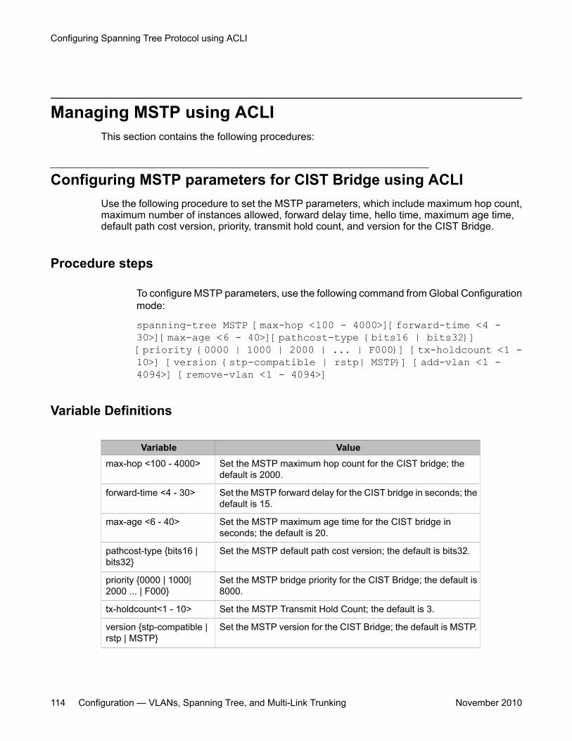
Managing MSTP using ACLIThis section contains the following procedures:
Configuring MSTP parameters for CIST Bridge using ACLIUse the following procedure to set the MSTP parameters, which include maximum hop count,maximum number of instances allowed, forward delay time, hello time, maximum age time,default path cost version, priority, transmit hold count, and version for the CIST Bridge.
Procedure steps
To configure MSTP parameters, use the following command from Global Configurationmode:
spanning-tree MSTP [max-hop <100 - 4000>][forward-time <4 -30>][max-age <6 - 40>][pathcost-type {bits16 | bits32}][priority {0000 | 1000 | 2000 | ... | F000}] [tx-holdcount <1 -10>] [version {stp-compatible | rstp| MSTP}] [add-vlan <1 -4094>] [remove-vlan <1 - 4094>]
Variable Definitions
Variable Valuemax-hop <100 - 4000> Set the MSTP maximum hop count for the CIST bridge; the
default is 2000.
forward-time <4 - 30> Set the MSTP forward delay for the CIST bridge in seconds; thedefault is 15.
max-age <6 - 40> Set the MSTP maximum age time for the CIST bridge inseconds; the default is 20.
pathcost-type {bits16 |bits32}
Set the MSTP default path cost version; the default is bits32.
priority {0000 | 1000|2000 ... | F000}
Set the MSTP bridge priority for the CIST Bridge; the default is8000.
tx-holdcount<1 - 10> Set the MSTP Transmit Hold Count; the default is 3.
version {stp-compatible |rstp | MSTP}
Set the MSTP version for the CIST Bridge; the default is MSTP.
Configuring Spanning Tree Protocol using ACLI
114 Configuration — VLANs, Spanning Tree, and Multi-Link Trunking November 2010
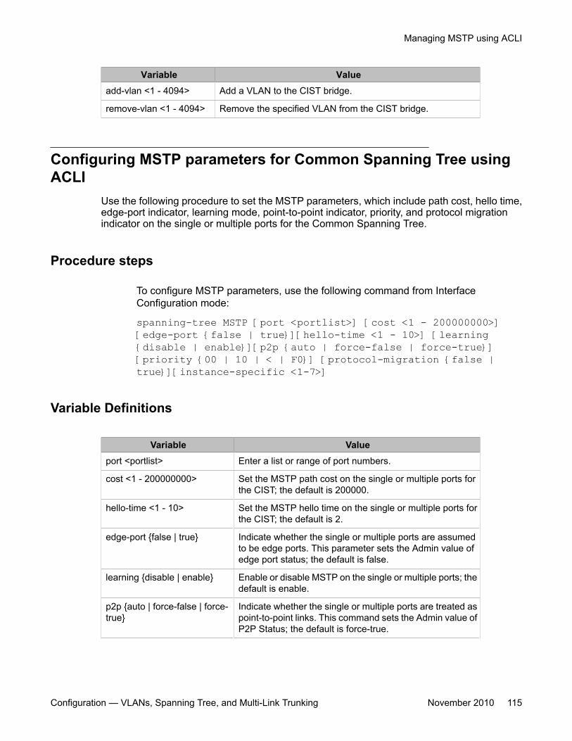
Variable Valueadd-vlan <1 - 4094> Add a VLAN to the CIST bridge.
remove-vlan <1 - 4094> Remove the specified VLAN from the CIST bridge.
Configuring MSTP parameters for Common Spanning Tree usingACLI
Use the following procedure to set the MSTP parameters, which include path cost, hello time,edge-port indicator, learning mode, point-to-point indicator, priority, and protocol migrationindicator on the single or multiple ports for the Common Spanning Tree.
Procedure steps
To configure MSTP parameters, use the following command from InterfaceConfiguration mode:
spanning-tree MSTP [port <portlist>] [cost <1 - 200000000>][edge-port {false | true}][hello-time <1 - 10>] [learning{disable | enable}][p2p {auto | force-false | force-true}][priority {00 | 10 | < | F0}] [protocol-migration {false |true}][instance-specific <1-7>]
Variable Definitions
Variable Valueport <portlist> Enter a list or range of port numbers.
cost <1 - 200000000> Set the MSTP path cost on the single or multiple ports forthe CIST; the default is 200000.
hello-time <1 - 10> Set the MSTP hello time on the single or multiple ports forthe CIST; the default is 2.
edge-port {false | true} Indicate whether the single or multiple ports are assumedto be edge ports. This parameter sets the Admin value ofedge port status; the default is false.
learning {disable | enable} Enable or disable MSTP on the single or multiple ports; thedefault is enable.
p2p {auto | force-false | force-true}
Indicate whether the single or multiple ports are treated aspoint-to-point links. This command sets the Admin value ofP2P Status; the default is force-true.
Managing MSTP using ACLI
Configuration — VLANs, Spanning Tree, and Multi-Link Trunking November 2010 115
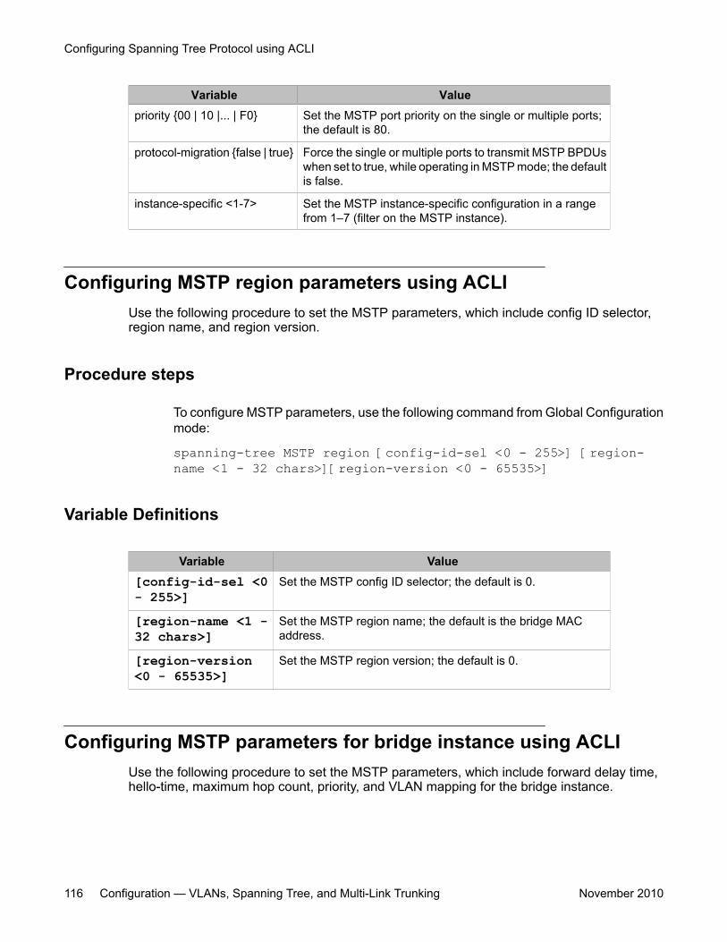
Variable Valuepriority {00 | 10 |... | F0} Set the MSTP port priority on the single or multiple ports;
the default is 80.
protocol-migration {false | true} Force the single or multiple ports to transmit MSTP BPDUswhen set to true, while operating in MSTP mode; the defaultis false.
instance-specific <1-7> Set the MSTP instance-specific configuration in a rangefrom 1–7 (filter on the MSTP instance).
Configuring MSTP region parameters using ACLIUse the following procedure to set the MSTP parameters, which include config ID selector,region name, and region version.
Procedure steps
To configure MSTP parameters, use the following command from Global Configurationmode:
spanning-tree MSTP region [config-id-sel <0 - 255>] [region-name <1 - 32 chars>][region-version <0 - 65535>]
Variable Definitions
Variable Value[config-id-sel <0- 255>]
Set the MSTP config ID selector; the default is 0.
[region-name <1 -32 chars>]
Set the MSTP region name; the default is the bridge MACaddress.
[region-version<0 - 65535>]
Set the MSTP region version; the default is 0.
Configuring MSTP parameters for bridge instance using ACLIUse the following procedure to set the MSTP parameters, which include forward delay time,hello-time, maximum hop count, priority, and VLAN mapping for the bridge instance.
Configuring Spanning Tree Protocol using ACLI
116 Configuration — VLANs, Spanning Tree, and Multi-Link Trunking November 2010
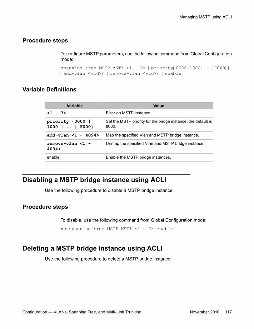
Procedure steps
To configure MSTP parameters, use the following command from Global Configurationmode:
spanning-tree MSTP MSTI <1 - 7> [priority{0000|1000|...|F000}][add-vlan <vid>] [remove-vlan <vid>] [enable]
Variable Definitions
Variable Value<1 - 7> Filter on MSTP instance.
priority {0000 |1000 |... | F000}
Set the MSTP priority for the bridge instance; the default is8000.
add-vlan <1 - 4094> Map the specified Vlan and MSTP bridge instance.
remove-vlan <1 -4094>
Unmap the specified Vlan and MSTP bridge instance.
enable Enable the MSTP bridge instances.
Disabling a MSTP bridge instance using ACLIUse the following procedure to disable a MSTP bridge instance.
Procedure steps
To disable, use the following command from Global Configuration mode:
no spanning-tree MSTP MSTI <1 - 7> enable
Deleting a MSTP bridge instance using ACLIUse the following procedure to delete a MSTP bridge instance.
Managing MSTP using ACLI
Configuration — VLANs, Spanning Tree, and Multi-Link Trunking November 2010 117
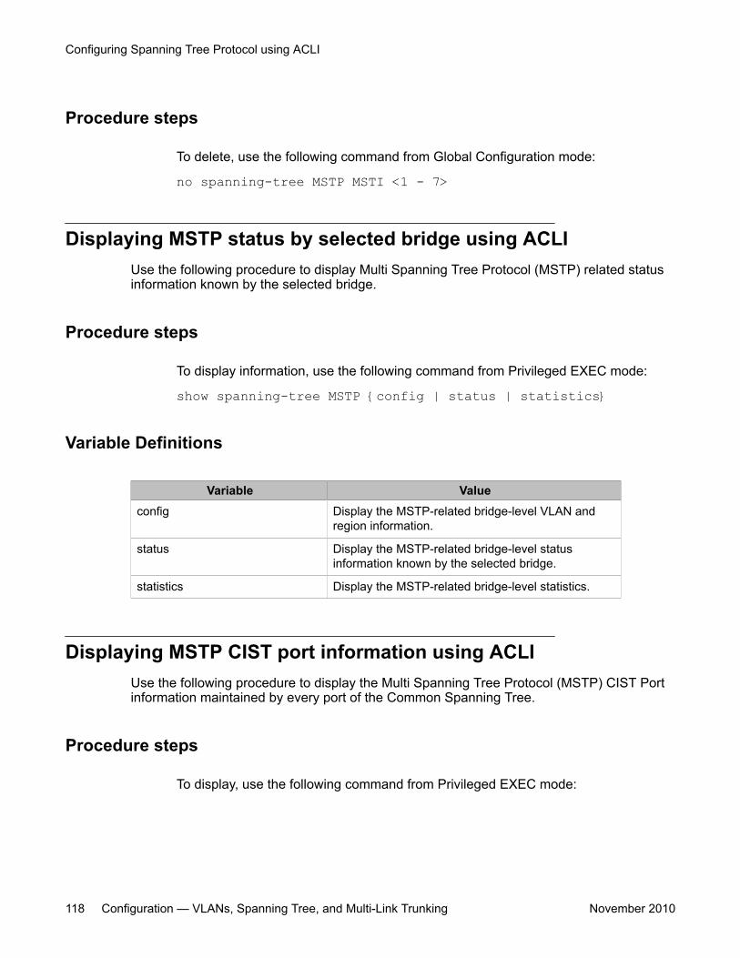
Procedure steps
To delete, use the following command from Global Configuration mode:
no spanning-tree MSTP MSTI <1 - 7>
Displaying MSTP status by selected bridge using ACLIUse the following procedure to display Multi Spanning Tree Protocol (MSTP) related statusinformation known by the selected bridge.
Procedure steps
To display information, use the following command from Privileged EXEC mode:
show spanning-tree MSTP {config | status | statistics}
Variable Definitions
Variable Valueconfig Display the MSTP-related bridge-level VLAN and
region information.
status Display the MSTP-related bridge-level statusinformation known by the selected bridge.
statistics Display the MSTP-related bridge-level statistics.
Displaying MSTP CIST port information using ACLIUse the following procedure to display the Multi Spanning Tree Protocol (MSTP) CIST Portinformation maintained by every port of the Common Spanning Tree.
Procedure steps
To display, use the following command from Privileged EXEC mode:
Configuring Spanning Tree Protocol using ACLI
118 Configuration — VLANs, Spanning Tree, and Multi-Link Trunking November 2010
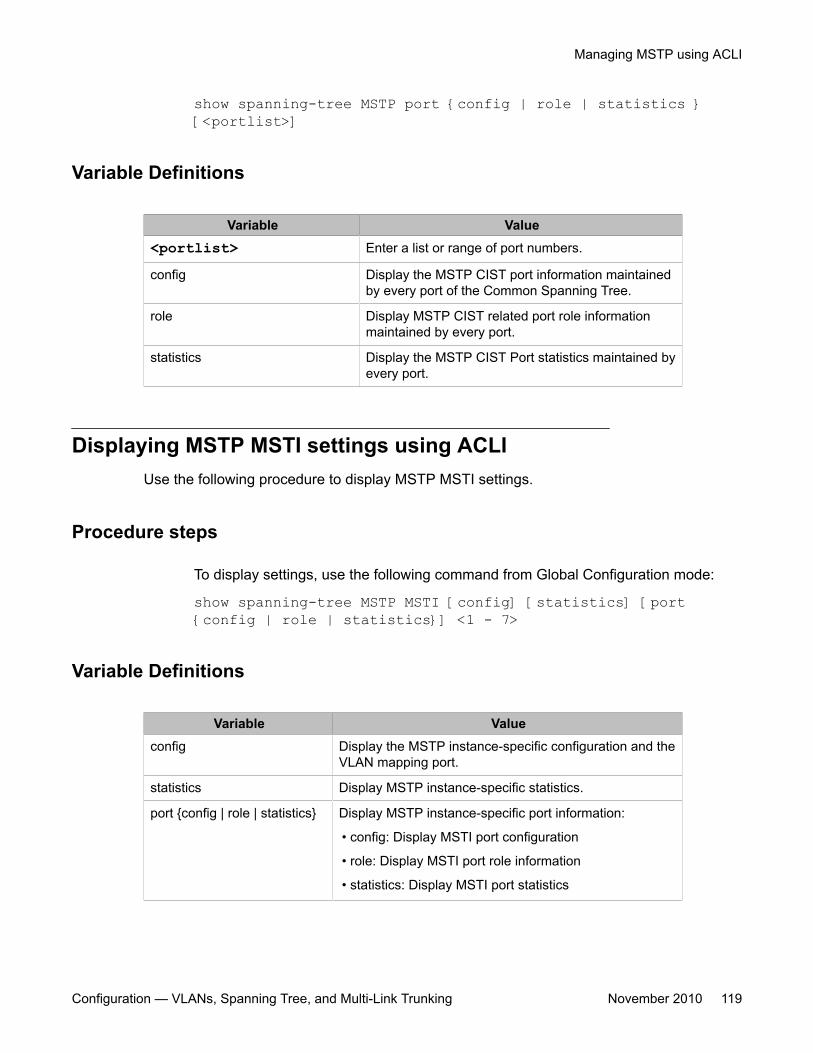
show spanning-tree MSTP port {config | role | statistics }[<portlist>]
Variable Definitions
Variable Value<portlist> Enter a list or range of port numbers.
config Display the MSTP CIST port information maintainedby every port of the Common Spanning Tree.
role Display MSTP CIST related port role informationmaintained by every port.
statistics Display the MSTP CIST Port statistics maintained byevery port.
Displaying MSTP MSTI settings using ACLIUse the following procedure to display MSTP MSTI settings.
Procedure steps
To display settings, use the following command from Global Configuration mode:
show spanning-tree MSTP MSTI [config] [statistics] [port{config | role | statistics}] <1 - 7>
Variable Definitions
Variable Valueconfig Display the MSTP instance-specific configuration and the
VLAN mapping port.
statistics Display MSTP instance-specific statistics.
port {config | role | statistics} Display MSTP instance-specific port information:
• config: Display MSTI port configuration
• role: Display MSTI port role information
• statistics: Display MSTI port statistics
Managing MSTP using ACLI
Configuration — VLANs, Spanning Tree, and Multi-Link Trunking November 2010 119
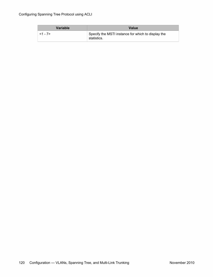
Variable Value<1 - 7> Specify the MSTI instance for which to display the
statistics.
Configuring Spanning Tree Protocol using ACLI
120 Configuration — VLANs, Spanning Tree, and Multi-Link Trunking November 2010
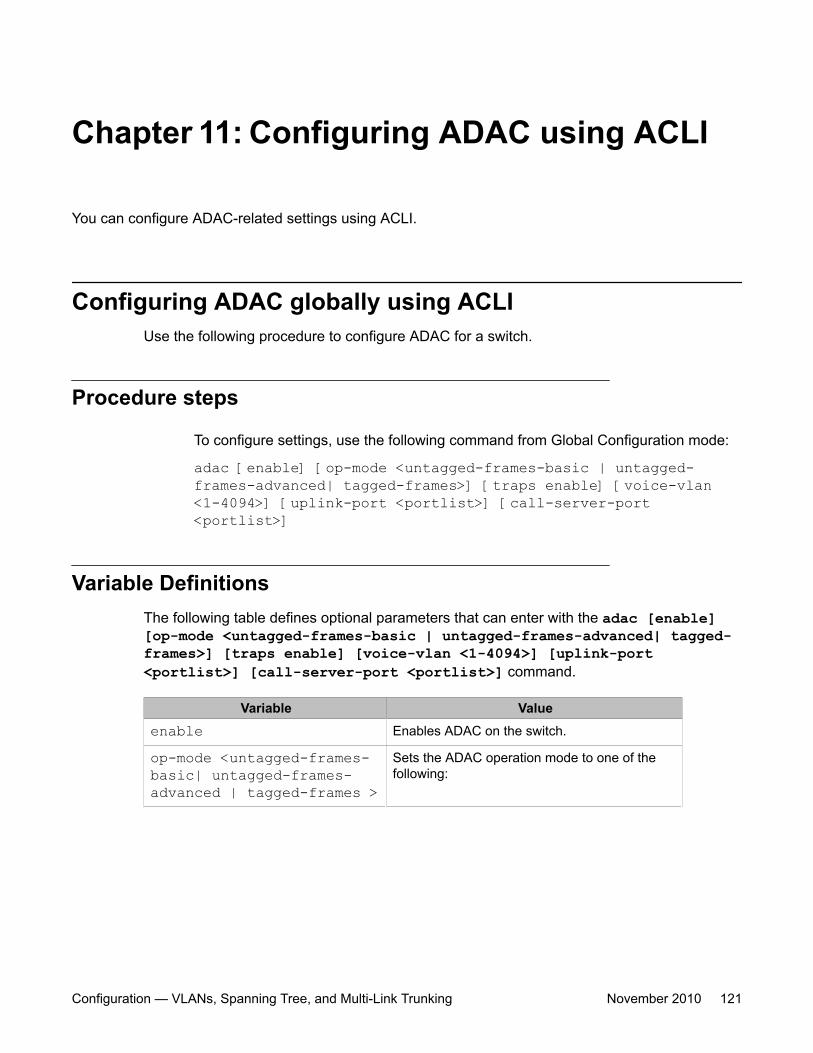
Chapter 11: Configuring ADAC using ACLI
You can configure ADAC-related settings using ACLI.
Configuring ADAC globally using ACLIUse the following procedure to configure ADAC for a switch.
Procedure steps
To configure settings, use the following command from Global Configuration mode:
adac [enable] [op-mode <untagged-frames-basic | untagged-frames-advanced| tagged-frames>] [traps enable] [voice-vlan<1-4094>] [uplink-port <portlist>] [call-server-port<portlist>]
Variable DefinitionsThe following table defines optional parameters that can enter with the adac [enable][op-mode <untagged-frames-basic | untagged-frames-advanced| tagged-frames>] [traps enable] [voice-vlan <1-4094>] [uplink-port<portlist>] [call-server-port <portlist>] command.
Variable Valueenable Enables ADAC on the switch.
op-mode <untagged-frames-basic| untagged-frames-advanced | tagged-frames >
Sets the ADAC operation mode to one of thefollowing:
Configuration — VLANs, Spanning Tree, and Multi-Link Trunking November 2010 121
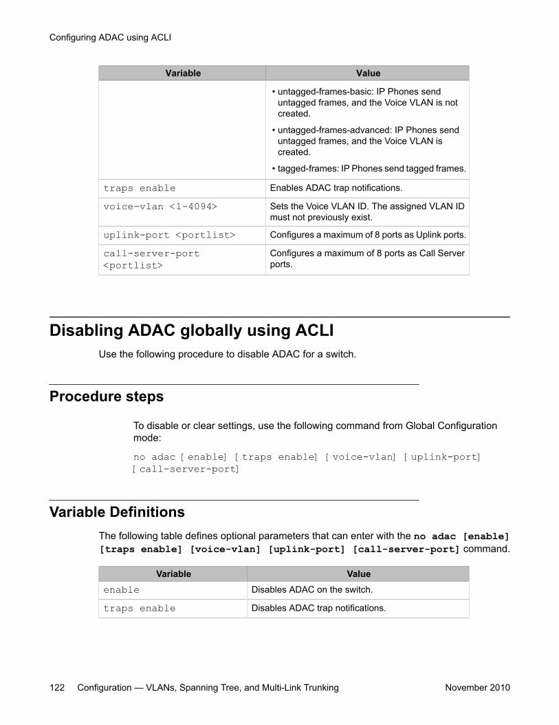
Variable Value
• untagged-frames-basic: IP Phones senduntagged frames, and the Voice VLAN is notcreated.
• untagged-frames-advanced: IP Phones senduntagged frames, and the Voice VLAN iscreated.
• tagged-frames: IP Phones send tagged frames.
traps enable Enables ADAC trap notifications.
voice-vlan <1-4094> Sets the Voice VLAN ID. The assigned VLAN IDmust not previously exist.
uplink-port <portlist> Configures a maximum of 8 ports as Uplink ports.
call-server-port<portlist>
Configures a maximum of 8 ports as Call Serverports.
Disabling ADAC globally using ACLIUse the following procedure to disable ADAC for a switch.
Procedure steps
To disable or clear settings, use the following command from Global Configurationmode:
no adac [enable] [traps enable] [voice-vlan] [uplink-port][call-server-port]
Variable DefinitionsThe following table defines optional parameters that can enter with the no adac [enable][traps enable] [voice-vlan] [uplink-port] [call-server-port] command.
Variable Valueenable Disables ADAC on the switch.
traps enable Disables ADAC trap notifications.
Configuring ADAC using ACLI
122 Configuration — VLANs, Spanning Tree, and Multi-Link Trunking November 2010
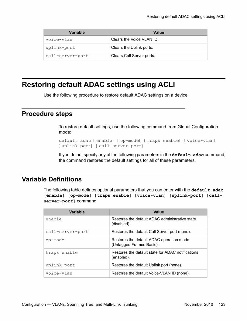
Variable Valuevoice-vlan Clears the Voice VLAN ID.
uplink-port Clears the Uplink ports.
call-server-port Clears Call Server ports.
Restoring default ADAC settings using ACLIUse the following procedure to restore default ADAC settings on a device.
Procedure steps
To restore default settings, use the following command from Global Configurationmode:
default adac [enable] [op-mode] [traps enable] [voice-vlan][uplink-port] [call-server-port]If you do not specify any of the following parameters in the default adac command,the command restores the default settings for all of these parameters.
Variable DefinitionsThe following table defines optional parameters that you can enter with the default adac[enable] [op-mode] [traps enable] [voice-vlan] [uplink-port] [call-server-port] command.
Variable Valueenable Restores the default ADAC administrative state
(disabled).
call-server-port Restores the default Call Server port (none).
op-mode Restores the default ADAC operation mode(Untagged Frames Basic).
traps enable Restores the default state for ADAC notifications(enabled).
uplink-port Restores the default Uplink port (none).
voice-vlan Restores the default Voice-VLAN ID (none).
Restoring default ADAC settings using ACLI
Configuration — VLANs, Spanning Tree, and Multi-Link Trunking November 2010 123
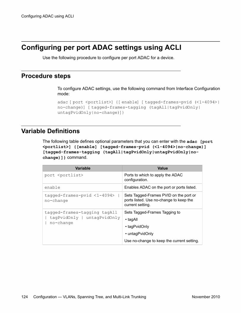
Configuring per port ADAC settings using ACLIUse the following procedure to configure per port ADAC for a device.
Procedure steps
To configure ADAC settings, use the following command from Interface Configurationmode:
adac [port <portlist>] {[enable] [tagged-frames-pvid (<1-4094>|no-change)] [tagged-frames-tagging (tagAll|tagPvidOnly|untagPvidOnly|no-change)]}
Variable DefinitionsThe following table defines optional parameters that you can enter with the adac [port<portlist>] {[enable] [tagged-frames-pvid (<1-4094>|no-change)][tagged-frames-tagging (tagAll|tagPvidOnly|untagPvidOnly|no-change)]} command.
Variable Valueport <portlist> Ports to which to apply the ADAC
configuration.
enable Enables ADAC on the port or ports listed.
tagged-frames-pvid <1-4094> |no-change
Sets Tagged-Frames PVID on the port orports listed. Use no-change to keep thecurrent setting.
tagged-frames-tagging tagAll| tagPvidOnly | untagPvidOnly| no-change
Sets Tagged-Frames Tagging to
• tagAll
• tagPvidOnly
• untagPvidOnly
Use no-change to keep the current setting.
Configuring ADAC using ACLI
124 Configuration — VLANs, Spanning Tree, and Multi-Link Trunking November 2010
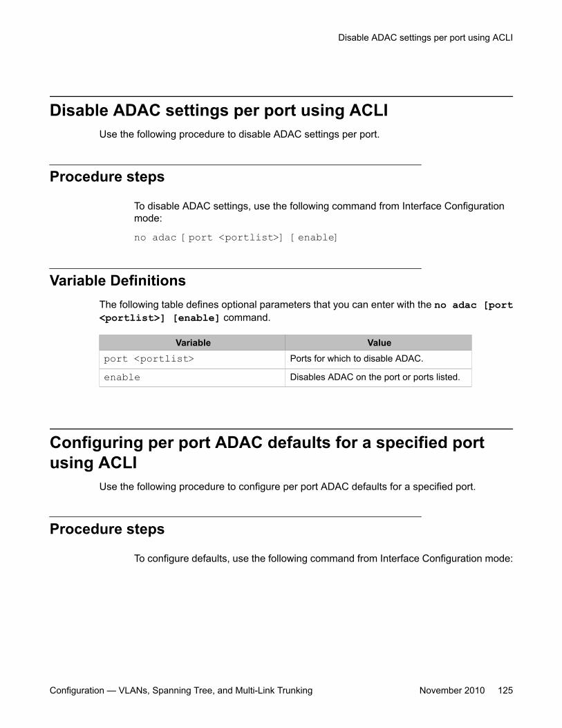
Disable ADAC settings per port using ACLIUse the following procedure to disable ADAC settings per port.
Procedure steps
To disable ADAC settings, use the following command from Interface Configurationmode:
no adac [port <portlist>] [enable]
Variable DefinitionsThe following table defines optional parameters that you can enter with the no adac [port<portlist>] [enable] command.
Variable Valueport <portlist> Ports for which to disable ADAC.
enable Disables ADAC on the port or ports listed.
Configuring per port ADAC defaults for a specified portusing ACLI
Use the following procedure to configure per port ADAC defaults for a specified port.
Procedure steps
To configure defaults, use the following command from Interface Configuration mode:
Disable ADAC settings per port using ACLI
Configuration — VLANs, Spanning Tree, and Multi-Link Trunking November 2010 125
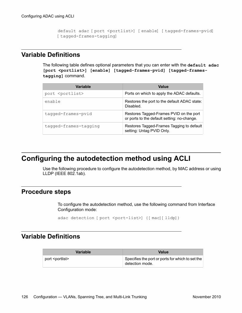
default adac [port <portlist>] [enable] [tagged-frames-pvid][tagged-frames-tagging]
Variable DefinitionsThe following table defines optional parameters that you can enter with the default adac[port <portlist>] [enable] [tagged-frames-pvid] [tagged-frames-tagging] command.
Variable Valueport <portlist> Ports on which to apply the ADAC defaults.
enable Restores the port to the default ADAC state:Disabled.
tagged-frames-pvid Restores Tagged-Frames PVID on the portor ports to the default setting: no-change.
tagged-frames-tagging Restores Tagged-Frames Tagging to defaultsetting: Untag PVID Only.
Configuring the autodetection method using ACLIUse the following procedure to configure the autodetection method, by MAC address or usingLLDP (IEEE 802.1ab).
Procedure steps
To configure the autodetection method, use the following command from InterfaceConfiguration mode:
adac detection [port <port-list>] {[mac][lldp]}
Variable Definitions
Variable Valueport <portlist> Specifies the port or ports for which to set the
detection mode.
Configuring ADAC using ACLI
126 Configuration — VLANs, Spanning Tree, and Multi-Link Trunking November 2010
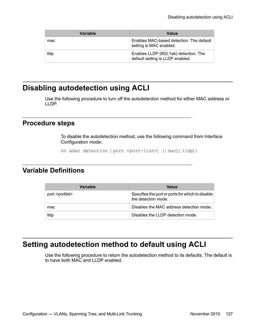
Variable Valuemac Enables MAC-based detection. The default
setting is MAC enabled.
lldp Enables LLDP (802.1ab) detection. Thedefault setting is LLDP enabled.
Disabling autodetection using ACLIUse the following procedure to turn off the autodetection method for either MAC address orLLDP.
Procedure steps
To disable the autodetection method, use the following command from InterfaceConfiguration mode:
no adac detection [port <port-list>] {[mac][lldp]}
Variable Definitions
Variable Valueport <portlist> Specifies the port or ports for which to disable
the detection mode.
mac Disables the MAC address detection mode.
lldp Disables the LLDP detection mode.
Setting autodetection method to default using ACLIUse the following procedure to return the autodetection method to its defaults. The default isto have both MAC and LLDP enabled.
Disabling autodetection using ACLI
Configuration — VLANs, Spanning Tree, and Multi-Link Trunking November 2010 127
Procedure steps
To return to default, use the following command from Interface Configuration mode:
default adac detection [port <port-list>] {[mac][lldp]}
Variable Definitions
Variable Valueport <portlist> Specifies the port or ports to be returned to
the default; both MAC and LLDP areenabled.
mac MAC is enabled by default.
lldp LLDP is enabled by default.
Configuring autodetection for a specified port using ACLIUse the following procedure to enable autodetection on specified ports.
Procedure steps
To enable autodetection, use the following command from Interface Configurationmode:
adac port <port-list> enable
Disabling autodetection on specified ports using ACLIUse the following procedure to disable autodetection on the specified port(s).
Configuring ADAC using ACLI
128 Configuration — VLANs, Spanning Tree, and Multi-Link Trunking November 2010
Procedure steps
To disable autodetection, use the following command from Interface Configurationmode:
no adac port <port-list> enable
Restoring default ADAC setting for ports using ACLIUse the following procedure to restore the default ADAC setting (disabled) for the specifiedports.
Procedure steps
To restore the default setting (disabled), use the following command from GlobalConfiguration mode:
default adac [port <port-list>] enable
Adding a range of MAC addresses for autodetection usingACLI
Use the following procedure to add a specified range to the table of MAC addresses recognizedas Avaya IP Phones by the autodetection process.
Procedure steps
To add a range of addresses, use the following command on Global Configurationmode:
Restoring default ADAC setting for ports using ACLI
Configuration — VLANs, Spanning Tree, and Multi-Link Trunking November 2010 129
adac mac-range-table low-end <MACaddress> high-end <MACaddress>
Deleting a range of MAC addresses used by autodetectionusing ACLI
Use the following procedure to delete an existing MAC address range used by theautodetection process. If the low-end and high-end MAC address values are not provided, theswitch deletes all existing MAC address ranges from the switch.
Procedure steps
To delete a range of addresses, use the following command from Global Configurationmode:
no adac mac-range-table low-end <MACaddress> high-end<MACaddress>
Resetting supported MAC address ranges using ACLIUse the following procedure to restore all supported MAC address ranges on the switch totheir default values.
Procedure steps
To reset to default values, use the following command from Global Configuration mode:
default adac mac-range-table
Displaying global ADAC settings for a device using ACLIUse the following procedure to display global ADAC settings for a device.
Configuring ADAC using ACLI
130 Configuration — VLANs, Spanning Tree, and Multi-Link Trunking November 2010
Procedure steps
To display settings, use the following command in Privileged EXEC mode:
show adac
Displaying ADAC settings per port using ACLIUse the following procedure to display ADAC settings per port.
Procedure steps
To display ADAC settings, use the following command from Privileged EXEC mode:
show adac interface <interface-type> <slot/port>
Displaying configured ADAC MAC ranges using ACLIUse the following procedure to display the ADAC MAC ranges configured on the switch.
Procedure steps
To display ranges, use the following command from Privileged EXEC mode:
show adac mac-range-table
Displaying detection mechanism configured per port usingACLI
Use the following procedure to display the detection mechanism configured per port.
Displaying ADAC settings per port using ACLI
Configuration — VLANs, Spanning Tree, and Multi-Link Trunking November 2010 131
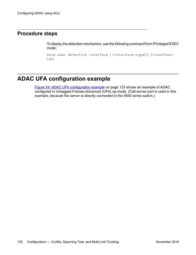
Procedure steps
To display the detection mechanism, use the following command from Privileged EXECmode:
show adac detection interface [<interface-type>][<interface-id>]
ADAC UFA configuration exampleFigure 24: ADAC UFA configuration example on page 133 shows an example of ADACconfigured in Untagged-Frames-Advanced (UFA) op-mode. (Call-server-port is used in thisexample, because the server is directly connected to the 4500 series switch.)
Configuring ADAC using ACLI
132 Configuration — VLANs, Spanning Tree, and Multi-Link Trunking November 2010
Figure 24: ADAC UFA configuration example
Auto-Configuration (AC) is applied for call-server-port and telephony ports. On telephony ports,AC is applied only when Avaya IP Phones are detected. (Autodetection is based on MACAddress.) VLAN configuration is made according to the selected op-mode (UFA):
• Telephony port:
- Membership = remove from all other VLANs, and add to Voice-VLAN (since there isno reason for the port to be member of more than the Voice VLAN)
- Tagging = Untagged
- PVID = Voice-VLAN
• Call Server port:
- Membership = add to Voice-VLAN
- Tagging = Untagged
- PVID = Voice-VLAN
To configure the example shown in Figure 24: ADAC UFA configuration example on page 133,you must perform the following tasks:
ADAC UFA configuration example
Configuration — VLANs, Spanning Tree, and Multi-Link Trunking November 2010 133
1. Configure the call-server port.
2. Configure voice-VLAN.
3. Configure Untagged-Frames-Advanced (UFA) op-mode.
4. Enable ADAC on all ports to which IP phones connect.
5. Configure IP phones to send untagged traffic.
ADAC ACLI configuration commandsThe following section describes the detailed ACLI commands required to carry out theconfiguration shown in Figure 24: ADAC UFA configuration example on page 133.
(config)#adac call-server-port 7(config)#adac voice-vlan 2(config)#adac enable op-mode untagged-frames-advanced(config)#interface fastEthernet all(config)#interface fastEthernet 16,24(config-if)#adac enable
Verifying new ADAC settingsThe following section includes commands used to view ADAC configuration settings and theexpected responses for each.
Auto configuration settings
(config)#show adac interface 7,16,24Port Auto-Detection Auto-Configuration---- -------------- ------------------7 Disabled Applied16 Enabled Applied24 Enabled Applied
VLAN settings
(config)#show vlanId Name Type Protocol User PID Active IVL/SVL Mgmt --- -------------------- -------- ---------------- -------- ------1 VLAN #1 Port None 0x0000 Yes IVL Yes Port Members: 1-15,17-232 Voice_VLAN Port None 0x0000 Yes IVL No Port Members: 7,16,24
(config)#show vlan interface info 7,16,24
Configuring ADAC using ACLI
134 Configuration — VLANs, Spanning Tree, and Multi-Link Trunking November 2010
Filter FilterUntagged Unregistered Port Frames Frames PVID PRI Tagging Name ---- -------- ------------ ---- --- ------------- ----------------7 No Yes 2 0 UntagAll Port 716 No Yes 2 0 UntagAll Port 1624 No Yes 2 0 UntagAll Port 24
ADAC settings
ERS4500#show running-config module adac! Embedded ASCII Configuration Generator Script! Base model = Ethernet Routing Switch 4524GT! Base Software version = v5.4.0.074! Stack info:!Unit# Switch Model Pluggable Pluggable Pluggable Pluggable SW Version! Port Port Port Port!----- ---------------- --------- --------- --------- --------- ----------!1 4524GT (21) None (22) None (23) None (24) None v5.4.0.074!2 4526GTX (21) None (22) None (23) None (24) None v5.4.0.074! (25) None (26) None!! Displaying only parameters different to default!================================================enableconfigure terminal!! *** ADAC ***!adac voice-vlan 101adac uplink-port 2/25,2/26adac op-mode tagged-framesadac enable
ERS4500#show running-config verbose module adac! Embedded ASCII Configuration Generator Script! Base model = Ethernet Routing Switch 4524GT! Base Software version = v5.4.0.074! Stack info:!Unit# Switch Model Pluggable Pluggable Pluggable Pluggable SW Version! Port Port Port Port!----- ---------------- --------- --------- --------- --------- ----------!1 4524GT (21) None (22) None (23) None (24) None v5.4.0.074!2 4526GTX (21) None (22) None (23) None (24) None v5.4.0.074! (25) None (26) None!! Displaying all switch parameters!================================================enableconfigure terminal!! *** ADAC ***!no adac enableno adac mac-range-tableinterface FastEthernet ALLadac detection port 1/1-24,2/1-26 macadac detection port 1/1-24,2/1-26 lldpexitadac mac-range-table low-end 00-0A-E4-01-10-20 high-end 00-0A-E4-01-23-A7adac mac-range-table low-end 00-0A-E4-01-70-EC high-end 00-0A-E4-01-84-73adac mac-range-table low-end 00-0A-E4-01-A1-C8 high-end 00-0A-E4-01-AD-7F
Verifying new ADAC settings
Configuration — VLANs, Spanning Tree, and Multi-Link Trunking November 2010 135
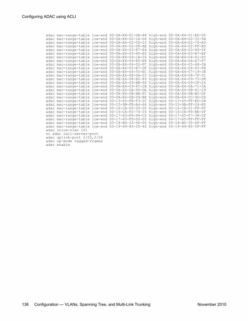
adac mac-range-table low-end 00-0A-E4-01-DA-4E high-end 00-0A-E4-01-ED-D5adac mac-range-table low-end 00-0A-E4-02-1E-D4 high-end 00-0A-E4-02-32-5Badac mac-range-table low-end 00-0A-E4-02-5D-22 high-end 00-0A-E4-02-70-A9adac mac-range-table low-end 00-0A-E4-02-D8-AE high-end 00-0A-E4-02-FF-BDadac mac-range-table low-end 00-0A-E4-03-87-E4 high-end 00-0A-E4-03-89-0Fadac mac-range-table low-end 00-0A-E4-03-90-E0 high-end 00-0A-E4-03-B7-EFadac mac-range-table low-end 00-0A-E4-04-1A-56 high-end 00-0A-E4-04-41-65adac mac-range-table low-end 00-0A-E4-04-80-E8 high-end 00-0A-E4-04-A7-F7adac mac-range-table low-end 00-0A-E4-04-D2-FC high-end 00-0A-E4-05-48-2Badac mac-range-table low-end 00-0A-E4-05-B7-DF high-end 00-0A-E4-06-05-FEadac mac-range-table low-end 00-0A-E4-06-55-EC high-end 00-0A-E4-07-19-3Badac mac-range-table low-end 00-0A-E4-08-0A-02 high-end 00-0A-E4-08-7F-31adac mac-range-table low-end 00-0A-E4-08-B2-89 high-end 00-0A-E4-09-75-D8adac mac-range-table low-end 00-0A-E4-09-BB-9D high-end 00-0A-E4-09-CF-24adac mac-range-table low-end 00-0A-E4-09-FC-2B high-end 00-0A-E4-0A-71-5Aadac mac-range-table low-end 00-0A-E4-0A-9D-DA high-end 00-0A-E4-0B-61-29adac mac-range-table low-end 00-0A-E4-0B-BB-FC high-end 00-0A-E4-0B-BC-0Fadac mac-range-table low-end 00-0A-E4-0B-D9-BE high-end 00-0A-E4-0C-9D-0Dadac mac-range-table low-end 00-13-65-FE-F3-2C high-end 00-13-65-FF-ED-2Badac mac-range-table low-end 00-15-9B-FE-A4-66 high-end 00-15-9B-FF-24-B5adac mac-range-table low-end 00-16-CA-00-00-00 high-end 00-16-CA-01-FF-FFadac mac-range-table low-end 00-16-CA-F2-74-20 high-end 00-16-CA-F4-BE-0Fadac mac-range-table low-end 00-17-65-F6-94-C0 high-end 00-17-65-F7-38-CFadac mac-range-table low-end 00-17-65-FD-00-00 high-end 00-17-65-FF-FF-FFadac mac-range-table low-end 00-18-B0-33-90-00 high-end 00-18-B0-35-DF-FFadac mac-range-table low-end 00-19-69-83-25-40 high-end 00-19-69-85-5F-FFadac voice-vlan 101no adac call-server-portadac uplink-port 2/25,2/26adac op-mode tagged-framesadac enable
Configuring ADAC using ACLI
136 Configuration — VLANs, Spanning Tree, and Multi-Link Trunking November 2010
Chapter 12: LACP and VLACP configurationusing ACLI
Configuring LACP using ACLIThis section describes the procedures necessary to configure and manage Link Aggregationusing the Command Line Interface (ACLI).
Displaying LACP settings using ACLIUse the following procedure to display system-wide LACP settings.
Procedure steps
To display settings, use the following command from Privileged EXEC mode:
show lacp system
Displaying per port LACP configuration information using ACLIUse the following procedure to display per port LACP configuration information.
Procedure steps
To display configuration information, use the following command from Privileged EXECmode:
Configuration — VLANs, Spanning Tree, and Multi-Link Trunking November 2010 137
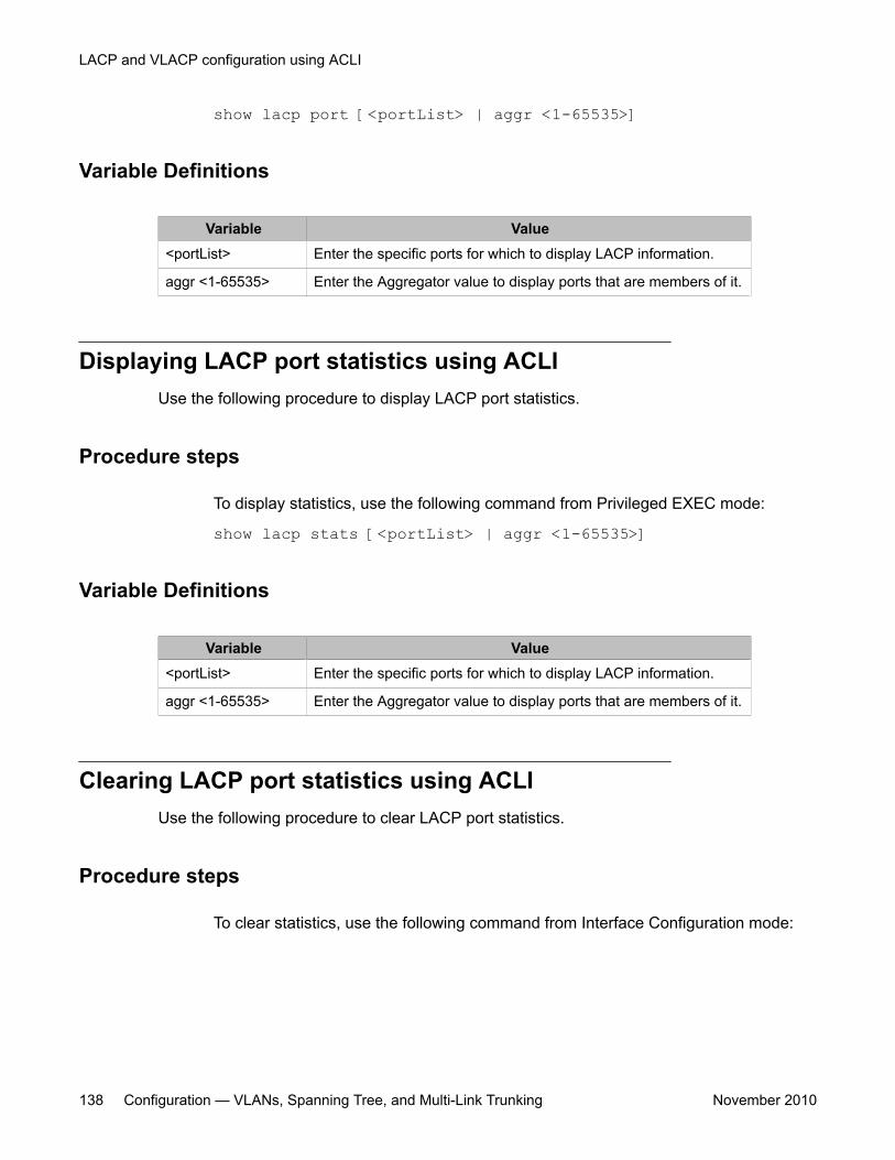
show lacp port [<portList> | aggr <1-65535>]
Variable Definitions
Variable Value<portList> Enter the specific ports for which to display LACP information.
aggr <1-65535> Enter the Aggregator value to display ports that are members of it.
Displaying LACP port statistics using ACLIUse the following procedure to display LACP port statistics.
Procedure steps
To display statistics, use the following command from Privileged EXEC mode:
show lacp stats [<portList> | aggr <1-65535>]
Variable Definitions
Variable Value<portList> Enter the specific ports for which to display LACP information.
aggr <1-65535> Enter the Aggregator value to display ports that are members of it.
Clearing LACP port statistics using ACLIUse the following procedure to clear LACP port statistics.
Procedure steps
To clear statistics, use the following command from Interface Configuration mode:
LACP and VLACP configuration using ACLI
138 Configuration — VLANs, Spanning Tree, and Multi-Link Trunking November 2010
lacp clear-stats <portList>
Displaying port debug information using ACLIUse the following procedure to display port debug information.
Procedure steps
To display information, use the following command from Privileged EXEC mode:
show lacp debug member [<portList>]
Displaying LACP aggregators or LACP trunks using ACLIUse the following procedure to display LACP aggregators or LACP trunks.
Procedure steps
To display LACP aggregators or trunks, use the following command from PrivilegedEXEC mode:
show lacp aggr <1-65535>
Configuring LACP system priority using ACLIUse the following procedure to set the system-wide LACP priority. The factory default priorityvalue is 32768.
Procedure steps
1. To set the priority, use the following command from Global Configuration mode:
lacp system-priority <0-65535>2. To reset the priority level to default, use the following command from Global
Configuration mode:
default lacp system-priority
Configuring LACP using ACLI
Configuration — VLANs, Spanning Tree, and Multi-Link Trunking November 2010 139
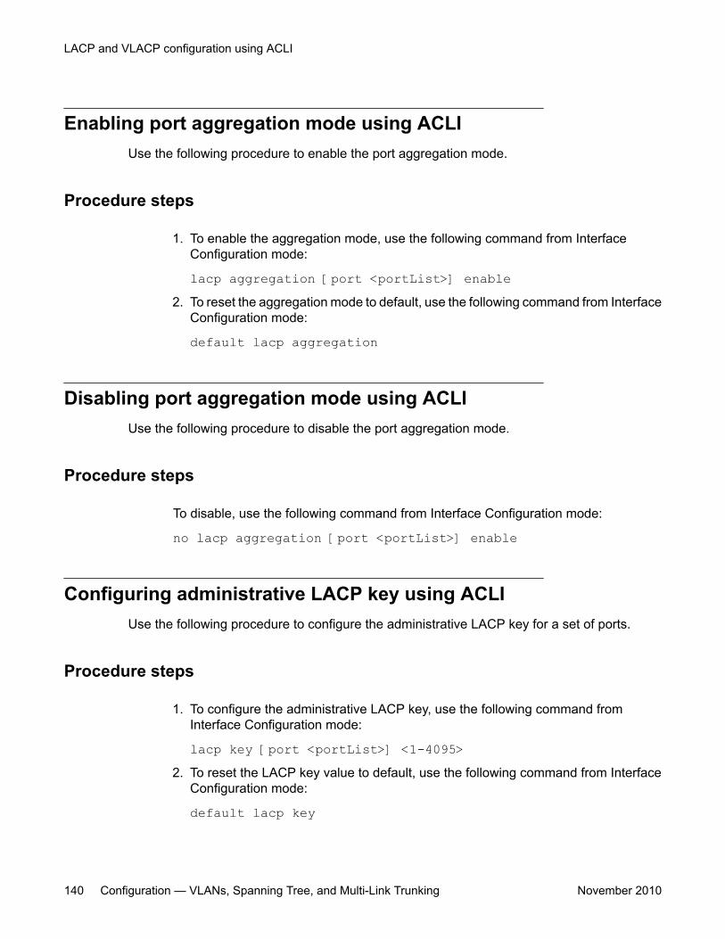
Enabling port aggregation mode using ACLIUse the following procedure to enable the port aggregation mode.
Procedure steps
1. To enable the aggregation mode, use the following command from InterfaceConfiguration mode:
lacp aggregation [port <portList>] enable2. To reset the aggregation mode to default, use the following command from Interface
Configuration mode:
default lacp aggregation
Disabling port aggregation mode using ACLIUse the following procedure to disable the port aggregation mode.
Procedure steps
To disable, use the following command from Interface Configuration mode:
no lacp aggregation [port <portList>] enable
Configuring administrative LACP key using ACLIUse the following procedure to configure the administrative LACP key for a set of ports.
Procedure steps
1. To configure the administrative LACP key, use the following command fromInterface Configuration mode:
lacp key [port <portList>] <1-4095>2. To reset the LACP key value to default, use the following command from Interface
Configuration mode:
default lacp key
LACP and VLACP configuration using ACLI
140 Configuration — VLANs, Spanning Tree, and Multi-Link Trunking November 2010
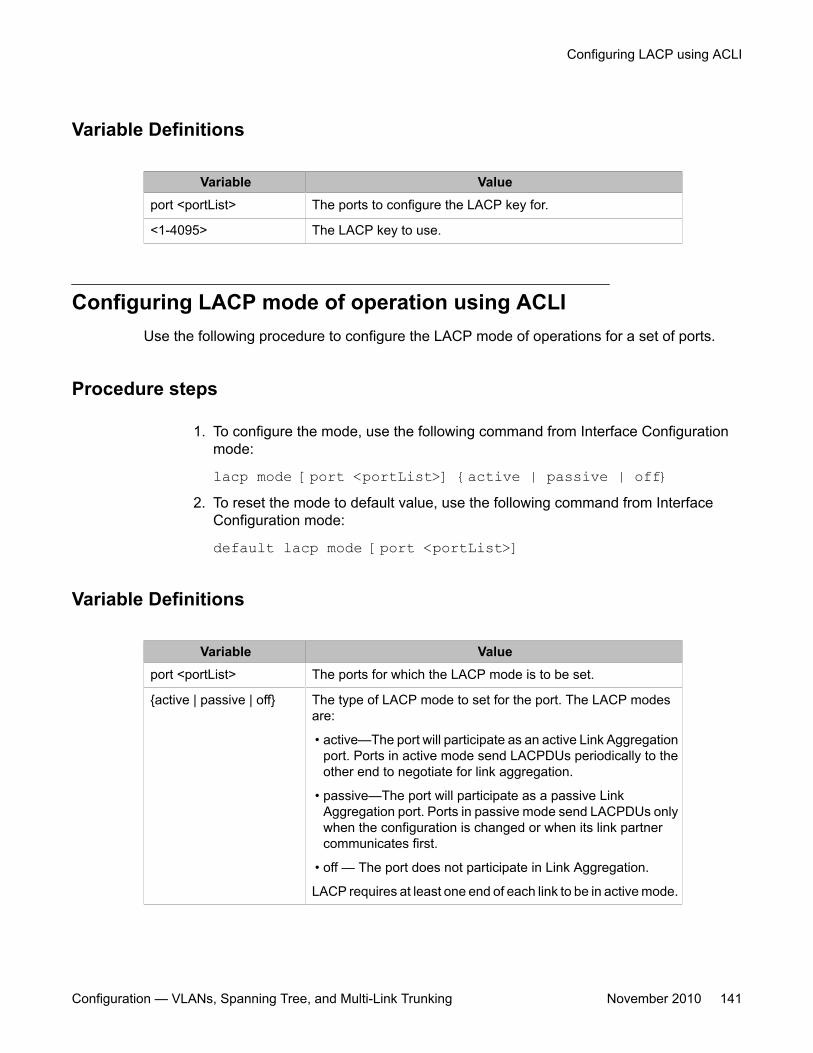
Variable Definitions
Variable Valueport <portList> The ports to configure the LACP key for.
<1-4095> The LACP key to use.
Configuring LACP mode of operation using ACLIUse the following procedure to configure the LACP mode of operations for a set of ports.
Procedure steps
1. To configure the mode, use the following command from Interface Configurationmode:
lacp mode [port <portList>] {active | passive | off}2. To reset the mode to default value, use the following command from Interface
Configuration mode:
default lacp mode [port <portList>]
Variable Definitions
Variable Valueport <portList> The ports for which the LACP mode is to be set.
{active | passive | off} The type of LACP mode to set for the port. The LACP modesare:
• active—The port will participate as an active Link Aggregationport. Ports in active mode send LACPDUs periodically to theother end to negotiate for link aggregation.
• passive—The port will participate as a passive LinkAggregation port. Ports in passive mode send LACPDUs onlywhen the configuration is changed or when its link partnercommunicates first.
• off — The port does not participate in Link Aggregation.
LACP requires at least one end of each link to be in active mode.
Configuring LACP using ACLI
Configuration — VLANs, Spanning Tree, and Multi-Link Trunking November 2010 141
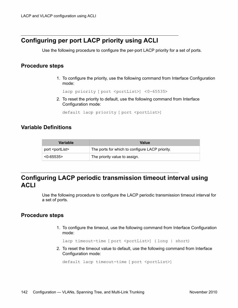
Configuring per port LACP priority using ACLIUse the following procedure to configure the per-port LACP priority for a set of ports.
Procedure steps
1. To configure the priority, use the following command from Interface Configurationmode:
lacp priority [port <portList>] <0-65535>2. To reset the priority to default, use the following command from Interface
Configuration mode:
default lacp priority [port <portList>]
Variable Definitions
Variable Valueport <portList> The ports for which to configure LACP priority.
<0-65535> The priority value to assign.
Configuring LACP periodic transmission timeout interval usingACLI
Use the following procedure to configure the LACP periodic transmission timeout interval fora set of ports.
Procedure steps
1. To configure the timeout, use the following command from Interface Configurationmode:
lacp timeout-time [port <portList>] {long | short}2. To reset the timeout value to default, use the following command from Interface
Configuration mode:
default lacp timeout-time [port <portList>]
LACP and VLACP configuration using ACLI
142 Configuration — VLANs, Spanning Tree, and Multi-Link Trunking November 2010
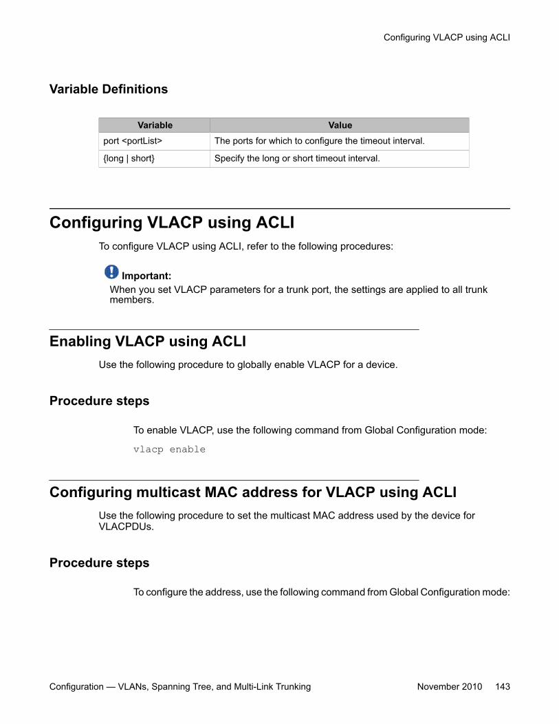
Variable Definitions
Variable Valueport <portList> The ports for which to configure the timeout interval.
{long | short} Specify the long or short timeout interval.
Configuring VLACP using ACLITo configure VLACP using ACLI, refer to the following procedures:
Important:When you set VLACP parameters for a trunk port, the settings are applied to all trunkmembers.
Enabling VLACP using ACLIUse the following procedure to globally enable VLACP for a device.
Procedure steps
To enable VLACP, use the following command from Global Configuration mode:
vlacp enable
Configuring multicast MAC address for VLACP using ACLIUse the following procedure to set the multicast MAC address used by the device forVLACPDUs.
Procedure steps
To configure the address, use the following command from Global Configuration mode:
Configuring VLACP using ACLI
Configuration — VLANs, Spanning Tree, and Multi-Link Trunking November 2010 143
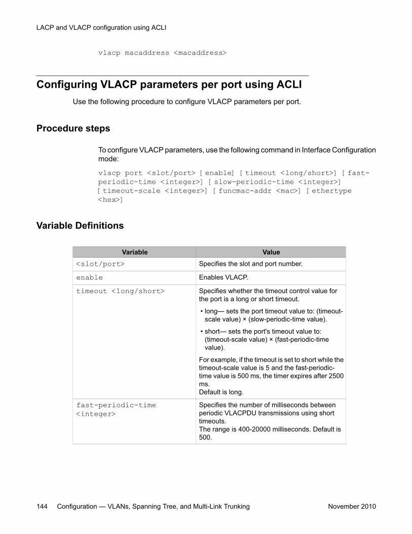
vlacp macaddress <macaddress>
Configuring VLACP parameters per port using ACLIUse the following procedure to configure VLACP parameters per port.
Procedure steps
To configure VLACP parameters, use the following command in Interface Configurationmode:
vlacp port <slot/port> [enable] [timeout <long/short>] [fast-periodic-time <integer>] [slow-periodic-time <integer>][timeout-scale <integer>] [funcmac-addr <mac>] [ethertype<hex>]
Variable Definitions
Variable Value<slot/port> Specifies the slot and port number.
enable Enables VLACP.
timeout <long/short> Specifies whether the timeout control value forthe port is a long or short timeout.
• long— sets the port timeout value to: (timeout-scale value) × (slow-periodic-time value).
• short— sets the port's timeout value to:(timeout-scale value) × (fast-periodic-timevalue).
For example, if the timeout is set to short while thetimeout-scale value is 5 and the fast-periodic-time value is 500 ms, the timer expires after 2500ms.Default is long.
fast-periodic-time<integer>
Specifies the number of milliseconds betweenperiodic VLACPDU transmissions using shorttimeouts.The range is 400-20000 milliseconds. Default is500.
LACP and VLACP configuration using ACLI
144 Configuration — VLANs, Spanning Tree, and Multi-Link Trunking November 2010
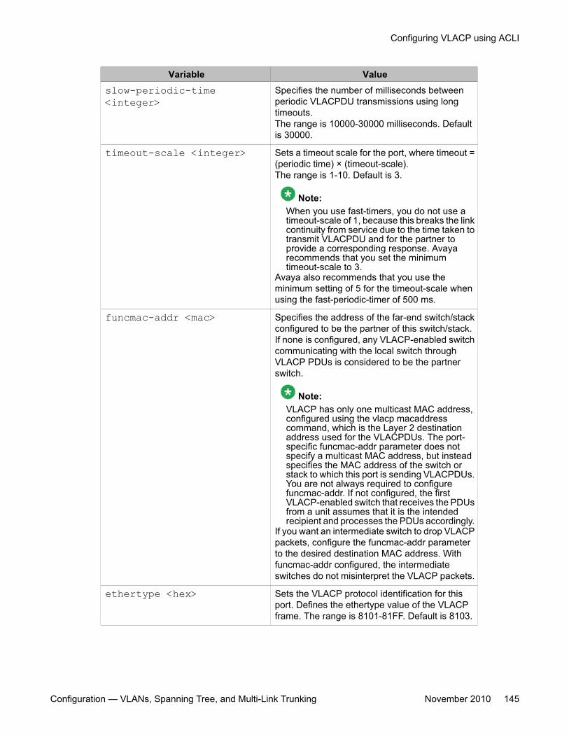
Variable Valueslow-periodic-time<integer>
Specifies the number of milliseconds betweenperiodic VLACPDU transmissions using longtimeouts.The range is 10000-30000 milliseconds. Defaultis 30000.
timeout-scale <integer> Sets a timeout scale for the port, where timeout =(periodic time) × (timeout-scale).The range is 1-10. Default is 3.
Note:When you use fast-timers, you do not use atimeout-scale of 1, because this breaks the linkcontinuity from service due to the time taken totransmit VLACPDU and for the partner toprovide a corresponding response. Avayarecommends that you set the minimumtimeout-scale to 3.
Avaya also recommends that you use theminimum setting of 5 for the timeout-scale whenusing the fast-periodic-timer of 500 ms.
funcmac-addr <mac> Specifies the address of the far-end switch/stackconfigured to be the partner of this switch/stack.If none is configured, any VLACP-enabled switchcommunicating with the local switch throughVLACP PDUs is considered to be the partnerswitch.
Note:VLACP has only one multicast MAC address,configured using the vlacp macaddresscommand, which is the Layer 2 destinationaddress used for the VLACPDUs. The port-specific funcmac-addr parameter does notspecify a multicast MAC address, but insteadspecifies the MAC address of the switch orstack to which this port is sending VLACPDUs.You are not always required to configurefuncmac-addr. If not configured, the firstVLACP-enabled switch that receives the PDUsfrom a unit assumes that it is the intendedrecipient and processes the PDUs accordingly.
If you want an intermediate switch to drop VLACPpackets, configure the funcmac-addr parameterto the desired destination MAC address. Withfuncmac-addr configured, the intermediateswitches do not misinterpret the VLACP packets.
ethertype <hex> Sets the VLACP protocol identification for thisport. Defines the ethertype value of the VLACPframe. The range is 8101-81FF. Default is 8103.
Configuring VLACP using ACLI
Configuration — VLANs, Spanning Tree, and Multi-Link Trunking November 2010 145
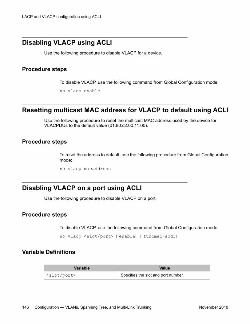
Disabling VLACP using ACLIUse the following procedure to disable VLACP for a device.
Procedure steps
To disable VLACP, use the following command from Global Configuration mode:
no vlacp enable
Resetting multicast MAC address for VLACP to default using ACLIUse the following procedure to reset the multicast MAC address used by the device forVLACPDUs to the default value (01:80:c2:00:11:00).
Procedure steps
To reset the address to default, use the following procedure from Global Configurationmode:
no vlacp macaddress
Disabling VLACP on a port using ACLIUse the following procedure to disable VLACP on a port.
Procedure steps
To disable VLACP, use the following command from Global Configuration mode:
no vlacp <slot/port> [enable] [funcmac-addr]
Variable Definitions
Variable Value<slot/port> Specifies the slot and port number.
LACP and VLACP configuration using ACLI
146 Configuration — VLANs, Spanning Tree, and Multi-Link Trunking November 2010
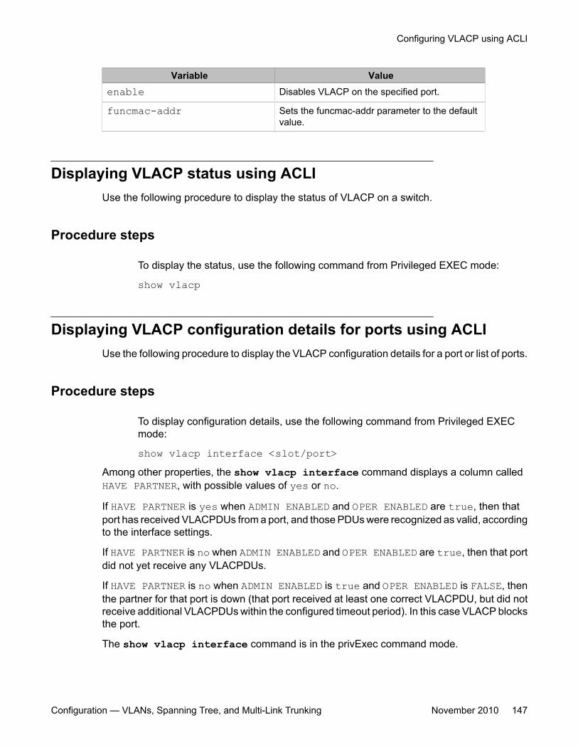
Variable Valueenable Disables VLACP on the specified port.
funcmac-addr Sets the funcmac-addr parameter to the defaultvalue.
Displaying VLACP status using ACLIUse the following procedure to display the status of VLACP on a switch.
Procedure steps
To display the status, use the following command from Privileged EXEC mode:
show vlacp
Displaying VLACP configuration details for ports using ACLIUse the following procedure to display the VLACP configuration details for a port or list of ports.
Procedure steps
To display configuration details, use the following command from Privileged EXECmode:
show vlacp interface <slot/port>Among other properties, the show vlacp interface command displays a column calledHAVE PARTNER, with possible values of yes or no.
If HAVE PARTNER is yes when ADMIN ENABLED and OPER ENABLED are true, then thatport has received VLACPDUs from a port, and those PDUs were recognized as valid, accordingto the interface settings.
If HAVE PARTNER is no when ADMIN ENABLED and OPER ENABLED are true, then that portdid not yet receive any VLACPDUs.
If HAVE PARTNER is no when ADMIN ENABLED is true and OPER ENABLED is FALSE, thenthe partner for that port is down (that port received at least one correct VLACPDU, but did notreceive additional VLACPDUs within the configured timeout period). In this case VLACP blocksthe port.
The show vlacp interface command is in the privExec command mode.
Configuring VLACP using ACLI
Configuration — VLANs, Spanning Tree, and Multi-Link Trunking November 2010 147
As long as the VLACP functional address for a specifc interface is not changed when usingthe (config-if)# vlacp port x funcmac-addr H.H.H command, the MAC addressis displayed as 00:00:00:00:00:00. The MAC address used for sending VLACP PDUs for aninterface is the global VLACP MAC address (01:80:c2:00:11:00). The VLACP globaldestination MAC can be specifed by the user. Setting a func-mac-addr on an interface displaysthat address in the show vlacp interface instead of 00:00:00:00:00:00.
LACP and VLACP configuration using ACLI
148 Configuration — VLANs, Spanning Tree, and Multi-Link Trunking November 2010
Chapter 13: Configuring VLANs usingEnterprise Device Manager
This chapter describes how to create and manage a VLAN using Enterprise Device Manager (EDM).
VLAN management using EDMUse the information in this section to view, create, and manage VLAN configurations for aswitch or stack.
VLAN management using EDM navigation
• Viewing VLAN information using EDM on page 149
• Modifying an existing VLAN in STG mode using EDM on page 152
• Modifying an existing VLAN in RSTP mode using EDM on page 154
• Modifying an existing VLAN in MSTP mode using EDM on page 157
• Creating a VLAN in STP mode using EDM on page 159
• Creating a VLAN in RSTP mode using EDM on page 162
• Creating a VLAN in MSTP mode using EDM on page 164
• Deleting a VLAN using EDM on page 167
Viewing VLAN information using EDMUse this procedure to display VLAN configuration information for a switch or stack.
Procedure steps
1. From the navigation tree, choose VLAN.
2. Double-click VLANs.
3. In the work area, click the Basic tab.
Configuration — VLANs, Spanning Tree, and Multi-Link Trunking November 2010 149
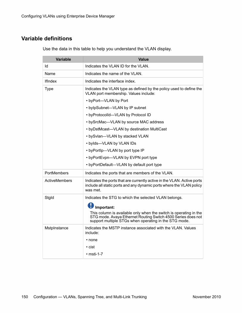
Variable definitions
Use the data in this table to help you understand the VLAN display.
Variable ValueId Indicates the VLAN ID for the VLAN.
Name Indicates the name of the VLAN.
IfIndex Indicates the interface index.
Type Indicates the VLAN type as defined by the policy used to define theVLAN port membership. Values include:
• byPort—VLAN by Port
• byIpSubnet—VLAN by IP subnet
• byProtocolId—VLAN by Protocol ID
• bySrcMac—VLAN by source MAC address
• byDstMcast—VLAN by destination MultiCast
• bySvlan—VLAN by stacked VLAN
• byIds—VLAN by VLAN IDs
• byPortIp—VLAN by port type IP
• byPortEvpn—VLAN by EVPN port type
• byPortDefault—VLAN by default port type
PortMembers Indicates the ports that are members of the VLAN.
ActiveMembers Indicates the ports that are currently active in the VLAN. Active portsinclude all static ports and any dynamic ports where the VLAN policywas met.
StgId Indicates the STG to which the selected VLAN belongs.
Important:This column is available only when the switch is operating in theSTG mode. Avaya Ethernet Routing Switch 4500 Series does notsupport multiple STGs when operating in the STG mode.
MstpInstance Indicates the MSTP instance associated with the VLAN. Valuesinclude:
• none
• cist
• msti-1-7
Configuring VLANs using Enterprise Device Manager
150 Configuration — VLANs, Spanning Tree, and Multi-Link Trunking November 2010
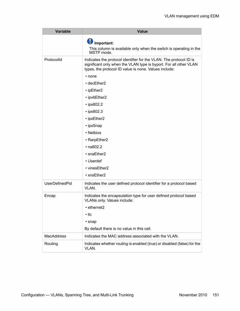
Variable Value
Important:This column is available only when the switch is operating in theMSTP mode.
ProtocolId Indicates the protocol identifier for the VLAN. The protocol ID issignificant only when the VLAN type is byport. For all other VLANtypes, the protocol ID value is none. Values include:
• none
• decEther2
• ipEther2
• ipv6Ether2
• ipx802.2
• ipx802.3
• ipxEther2
• ipxSnap
• Netbios
• RarpEther2
• na802.2
• snaEther2
• Userdef
• vinesEther2
• xnsEther2
UserDefinedPid Indicates the user defined protocol identifier for a protocol basedVLAN.
Encap Indicates the encapsulation type for user defined protocol basedVLANs only. Values include:
• ethernet2
• llc
• snap
By default there is no value in this cell.
MacAddress Indicates the MAC address associated with the VLAN.
Routing Indicates whether routing is enabled (true) or disabled (false) for theVLAN.
VLAN management using EDM
Configuration — VLANs, Spanning Tree, and Multi-Link Trunking November 2010 151
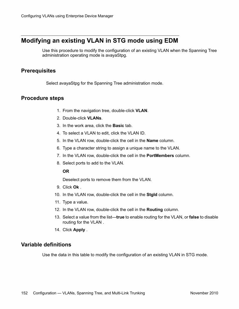
Modifying an existing VLAN in STG mode using EDMUse this procedure to modify the configuration of an existing VLAN when the Spanning Treeadministration operating mode is avayaStpg.
Prerequisites
Select avayaStpg for the Spanning Tree administration mode.
Procedure steps
1. From the navigation tree, double-click VLAN.
2. Double-click VLANs.
3. In the work area, click the Basic tab.
4. To select a VLAN to edit, click the VLAN ID.
5. In the VLAN row, double-click the cell in the Name column.
6. Type a character string to assign a unique name to the VLAN.
7. In the VLAN row, double-click the cell in the PortMembers column.
8. Select ports to add to the VLAN.
OR
Deselect ports to remove them from the VLAN.
9. Click Ok .
10. In the VLAN row, double-click the cell in the StgId column.
11. Type a value.
12. In the VLAN row, double-click the cell in the Routing column.
13. Select a value from the list—true to enable routing for the VLAN, or false to disablerouting for the VLAN .
14. Click Apply .
Variable definitions
Use the data in this table to modify the configuration of an existing VLAN in STG mode.
Configuring VLANs using Enterprise Device Manager
152 Configuration — VLANs, Spanning Tree, and Multi-Link Trunking November 2010
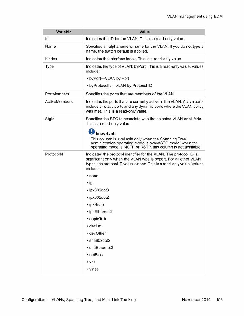
Variable ValueId Indicates the ID for the VLAN. This is a read-only value.
Name Specifies an alphanumeric name for the VLAN. If you do not type aname, the switch default is applied.
IfIndex Indicates the interface index. This is a read-only value.
Type Indicates the type of VLAN: byPort. This is a read-only value. Valuesinclude:
• byPort—VLAN by Port
• byProtocolId—VLAN by Protocol ID
PortMembers Specifies the ports that are members of the VLAN.
ActiveMembers Indicates the ports that are currently active in the VLAN. Active portsinclude all static ports and any dynamic ports where the VLAN policywas met. This is a read-only value.
StgId Specifies the STG to associate with the selected VLAN or VLANs.This is a read-only value.
Important:This column is available only when the Spanning Treeadministration operating mode is avayaSTG mode, when theoperating mode is MSTP or RSTP, this column is not available.
ProtocolId Indicates the protocol identifier for the VLAN. The protocol ID issignificant only when the VLAN type is byport. For all other VLANtypes, the protocol ID value is none. This is a read-only value. Valuesinclude:
• none
• ip
• ipx802dot3
• ipx802dot2
• ipxSnap
• ipxEthernet2
• appleTalk
• decLat
• decOther
• sna802dot2
• snaEthernet2
• netBios
• xns
• vines
VLAN management using EDM
Configuration — VLANs, Spanning Tree, and Multi-Link Trunking November 2010 153
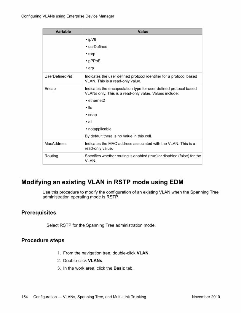
Variable Value
• ipV6
• usrDefined
• rarp
• pPPoE
• arp
UserDefinedPid Indicates the user defined protocol identifier for a protocol basedVLAN. This is a read-only value.
Encap Indicates the encapsulation type for user defined protocol basedVLANs only. This is a read-only value. Values include:
• ethernet2
• llc
• snap
• all
• notapplicable
By default there is no value in this cell.
MacAddress Indicates the MAC address associated with the VLAN. This is aread-only value.
Routing Specifies whether routing is enabled (true) or disabled (false) for theVLAN.
Modifying an existing VLAN in RSTP mode using EDMUse this procedure to modify the configuration of an existing VLAN when the Spanning Treeadministration operating mode is RSTP.
Prerequisites
Select RSTP for the Spanning Tree administration mode.
Procedure steps
1. From the navigation tree, double-click VLAN.
2. Double-click VLANs.
3. In the work area, click the Basic tab.
Configuring VLANs using Enterprise Device Manager
154 Configuration — VLANs, Spanning Tree, and Multi-Link Trunking November 2010
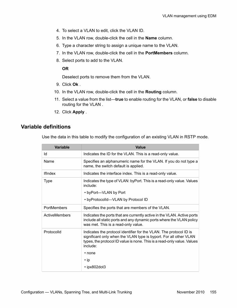
4. To select a VLAN to edit, click the VLAN ID.
5. In the VLAN row, double-click the cell in the Name column.
6. Type a character string to assign a unique name to the VLAN.
7. In the VLAN row, double-click the cell in the PortMembers column.
8. Select ports to add to the VLAN.
OR
Deselect ports to remove them from the VLAN.
9. Click Ok .
10. In the VLAN row, double-click the cell in the Routing column.
11. Select a value from the list—true to enable routing for the VLAN, or false to disablerouting for the VLAN .
12. Click Apply .
Variable definitions
Use the data in this table to modify the configuration of an existing VLAN in RSTP mode.
Variable ValueId Indicates the ID for the VLAN. This is a read-only value.
Name Specifies an alphanumeric name for the VLAN. If you do not type aname, the switch default is applied.
IfIndex Indicates the interface index. This is a read-only value.
Type Indicates the type of VLAN: byPort. This is a read-only value. Valuesinclude:
• byPort—VLAN by Port
• byProtocolId—VLAN by Protocol ID
PortMembers Specifies the ports that are members of the VLAN.
ActiveMembers Indicates the ports that are currently active in the VLAN. Active portsinclude all static ports and any dynamic ports where the VLAN policywas met. This is a read-only value.
ProtocolId Indicates the protocol identifier for the VLAN. The protocol ID issignificant only when the VLAN type is byport. For all other VLANtypes, the protocol ID value is none. This is a read-only value. Valuesinclude:
• none
• ip
• ipx802dot3
VLAN management using EDM
Configuration — VLANs, Spanning Tree, and Multi-Link Trunking November 2010 155
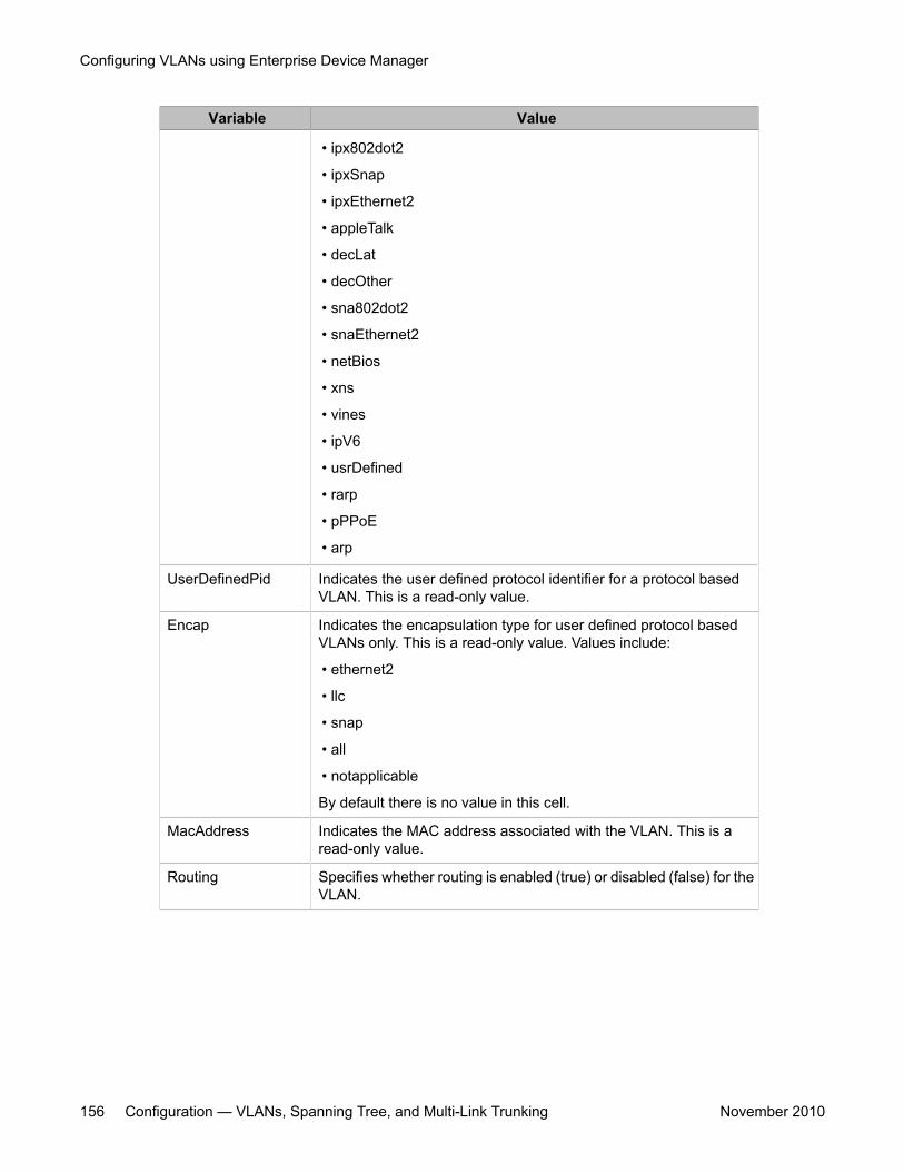
Variable Value
• ipx802dot2
• ipxSnap
• ipxEthernet2
• appleTalk
• decLat
• decOther
• sna802dot2
• snaEthernet2
• netBios
• xns
• vines
• ipV6
• usrDefined
• rarp
• pPPoE
• arp
UserDefinedPid Indicates the user defined protocol identifier for a protocol basedVLAN. This is a read-only value.
Encap Indicates the encapsulation type for user defined protocol basedVLANs only. This is a read-only value. Values include:
• ethernet2
• llc
• snap
• all
• notapplicable
By default there is no value in this cell.
MacAddress Indicates the MAC address associated with the VLAN. This is aread-only value.
Routing Specifies whether routing is enabled (true) or disabled (false) for theVLAN.
Configuring VLANs using Enterprise Device Manager
156 Configuration — VLANs, Spanning Tree, and Multi-Link Trunking November 2010
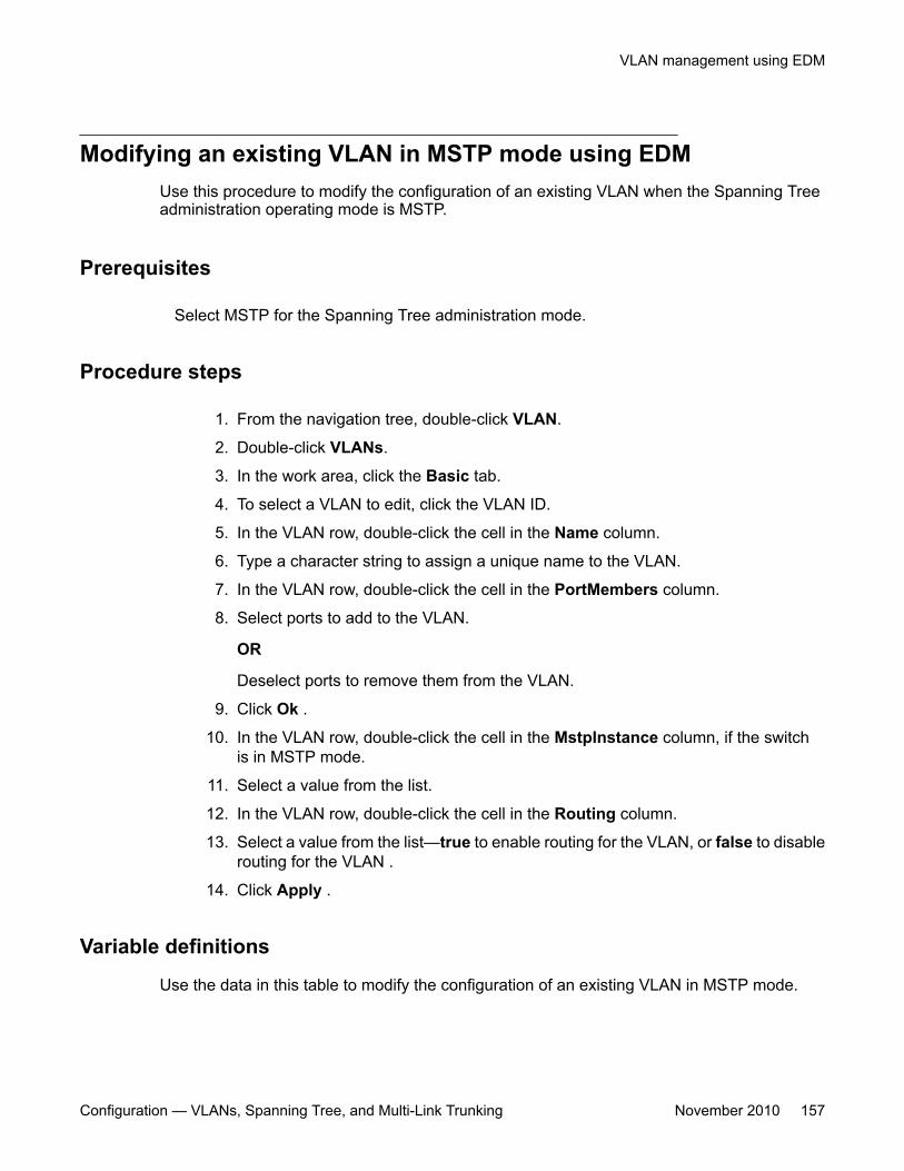
Modifying an existing VLAN in MSTP mode using EDMUse this procedure to modify the configuration of an existing VLAN when the Spanning Treeadministration operating mode is MSTP.
Prerequisites
Select MSTP for the Spanning Tree administration mode.
Procedure steps
1. From the navigation tree, double-click VLAN.
2. Double-click VLANs.
3. In the work area, click the Basic tab.
4. To select a VLAN to edit, click the VLAN ID.
5. In the VLAN row, double-click the cell in the Name column.
6. Type a character string to assign a unique name to the VLAN.
7. In the VLAN row, double-click the cell in the PortMembers column.
8. Select ports to add to the VLAN.
OR
Deselect ports to remove them from the VLAN.
9. Click Ok .
10. In the VLAN row, double-click the cell in the MstpInstance column, if the switchis in MSTP mode.
11. Select a value from the list.
12. In the VLAN row, double-click the cell in the Routing column.
13. Select a value from the list—true to enable routing for the VLAN, or false to disablerouting for the VLAN .
14. Click Apply .
Variable definitions
Use the data in this table to modify the configuration of an existing VLAN in MSTP mode.
VLAN management using EDM
Configuration — VLANs, Spanning Tree, and Multi-Link Trunking November 2010 157
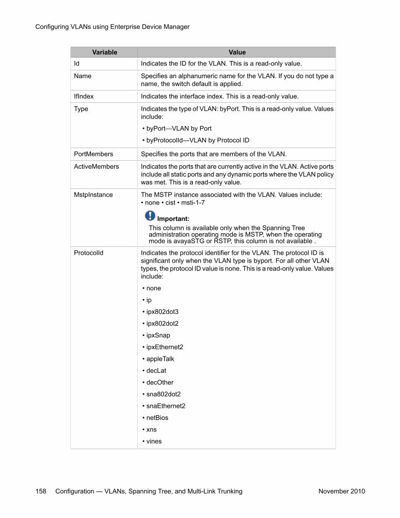
Variable ValueId Indicates the ID for the VLAN. This is a read-only value.
Name Specifies an alphanumeric name for the VLAN. If you do not type aname, the switch default is applied.
IfIndex Indicates the interface index. This is a read-only value.
Type Indicates the type of VLAN: byPort. This is a read-only value. Valuesinclude:
• byPort—VLAN by Port
• byProtocolId—VLAN by Protocol ID
PortMembers Specifies the ports that are members of the VLAN.
ActiveMembers Indicates the ports that are currently active in the VLAN. Active portsinclude all static ports and any dynamic ports where the VLAN policywas met. This is a read-only value.
MstpInstance The MSTP instance associated with the VLAN. Values include:• none • cist • msti-1-7
Important:This column is available only when the Spanning Treeadministration operating mode is MSTP, when the operatingmode is avayaSTG or RSTP, this column is not available .
ProtocolId Indicates the protocol identifier for the VLAN. The protocol ID issignificant only when the VLAN type is byport. For all other VLANtypes, the protocol ID value is none. This is a read-only value. Valuesinclude:
• none
• ip
• ipx802dot3
• ipx802dot2
• ipxSnap
• ipxEthernet2
• appleTalk
• decLat
• decOther
• sna802dot2
• snaEthernet2
• netBios
• xns
• vines
Configuring VLANs using Enterprise Device Manager
158 Configuration — VLANs, Spanning Tree, and Multi-Link Trunking November 2010
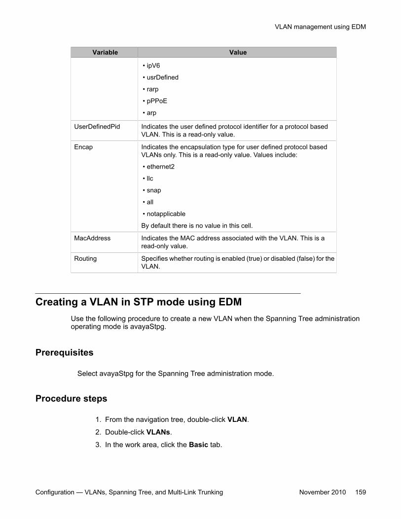
Variable Value
• ipV6
• usrDefined
• rarp
• pPPoE
• arp
UserDefinedPid Indicates the user defined protocol identifier for a protocol basedVLAN. This is a read-only value.
Encap Indicates the encapsulation type for user defined protocol basedVLANs only. This is a read-only value. Values include:
• ethernet2
• llc
• snap
• all
• notapplicable
By default there is no value in this cell.
MacAddress Indicates the MAC address associated with the VLAN. This is aread-only value.
Routing Specifies whether routing is enabled (true) or disabled (false) for theVLAN.
Creating a VLAN in STP mode using EDMUse the following procedure to create a new VLAN when the Spanning Tree administrationoperating mode is avayaStpg.
Prerequisites
Select avayaStpg for the Spanning Tree administration mode.
Procedure steps
1. From the navigation tree, double-click VLAN.
2. Double-click VLANs.
3. In the work area, click the Basic tab.
VLAN management using EDM
Configuration — VLANs, Spanning Tree, and Multi-Link Trunking November 2010 159
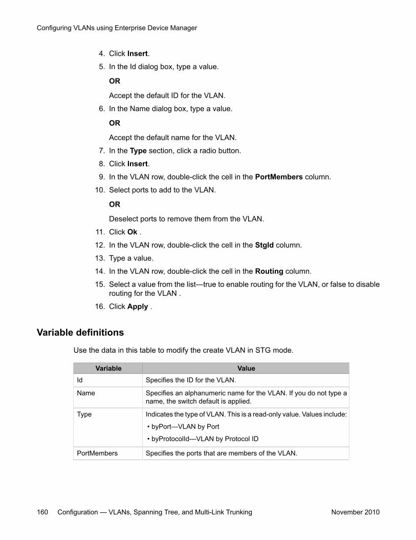
4. Click Insert.
5. In the Id dialog box, type a value.
OR
Accept the default ID for the VLAN.
6. In the Name dialog box, type a value.
OR
Accept the default name for the VLAN.
7. In the Type section, click a radio button.
8. Click Insert.
9. In the VLAN row, double-click the cell in the PortMembers column.
10. Select ports to add to the VLAN.
OR
Deselect ports to remove them from the VLAN.
11. Click Ok .
12. In the VLAN row, double-click the cell in the StgId column.
13. Type a value.
14. In the VLAN row, double-click the cell in the Routing column.
15. Select a value from the list—true to enable routing for the VLAN, or false to disablerouting for the VLAN .
16. Click Apply .
Variable definitions
Use the data in this table to modify the create VLAN in STG mode.
Variable ValueId Specifies the ID for the VLAN.
Name Specifies an alphanumeric name for the VLAN. If you do not type aname, the switch default is applied.
Type Indicates the type of VLAN. This is a read-only value. Values include:
• byPort—VLAN by Port
• byProtocolId—VLAN by Protocol ID
PortMembers Specifies the ports that are members of the VLAN.
Configuring VLANs using Enterprise Device Manager
160 Configuration — VLANs, Spanning Tree, and Multi-Link Trunking November 2010
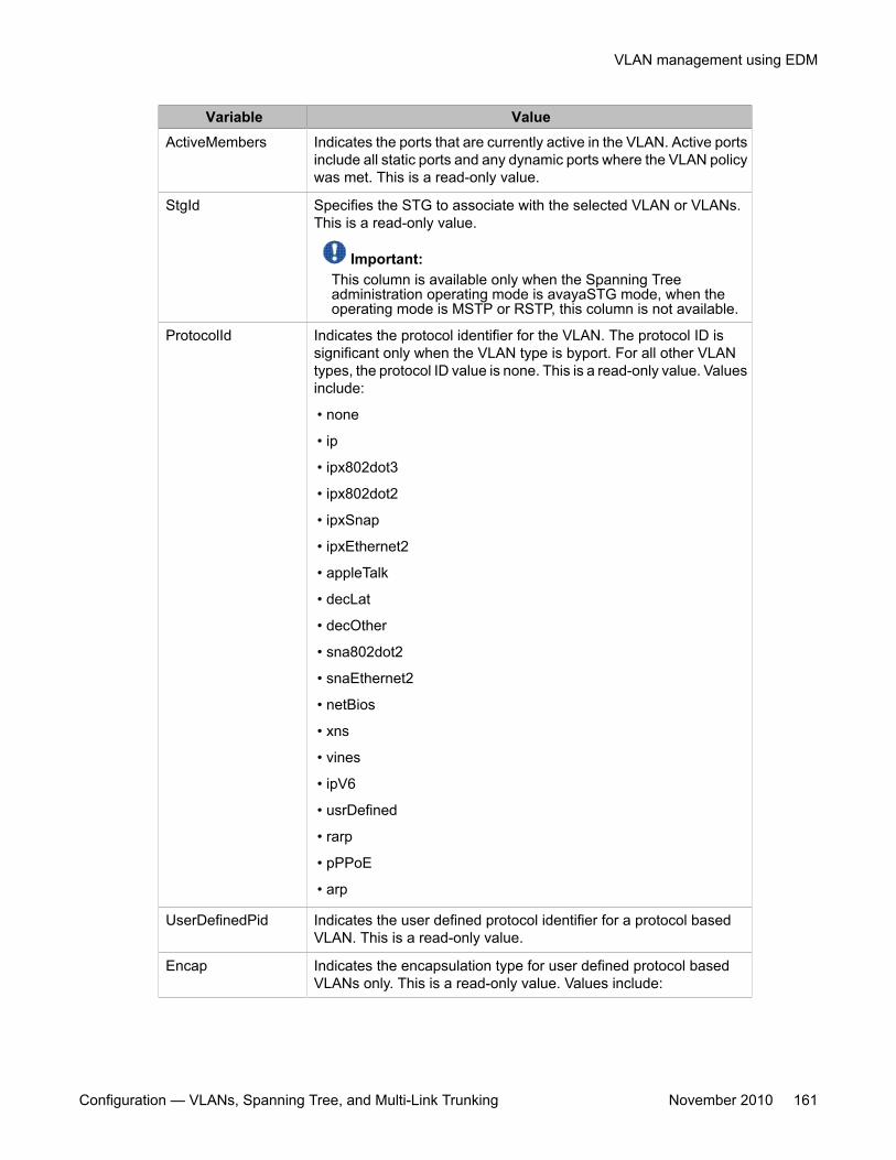
Variable ValueActiveMembers Indicates the ports that are currently active in the VLAN. Active ports
include all static ports and any dynamic ports where the VLAN policywas met. This is a read-only value.
StgId Specifies the STG to associate with the selected VLAN or VLANs.This is a read-only value.
Important:This column is available only when the Spanning Treeadministration operating mode is avayaSTG mode, when theoperating mode is MSTP or RSTP, this column is not available.
ProtocolId Indicates the protocol identifier for the VLAN. The protocol ID issignificant only when the VLAN type is byport. For all other VLANtypes, the protocol ID value is none. This is a read-only value. Valuesinclude:
• none
• ip
• ipx802dot3
• ipx802dot2
• ipxSnap
• ipxEthernet2
• appleTalk
• decLat
• decOther
• sna802dot2
• snaEthernet2
• netBios
• xns
• vines
• ipV6
• usrDefined
• rarp
• pPPoE
• arp
UserDefinedPid Indicates the user defined protocol identifier for a protocol basedVLAN. This is a read-only value.
Encap Indicates the encapsulation type for user defined protocol basedVLANs only. This is a read-only value. Values include:
VLAN management using EDM
Configuration — VLANs, Spanning Tree, and Multi-Link Trunking November 2010 161
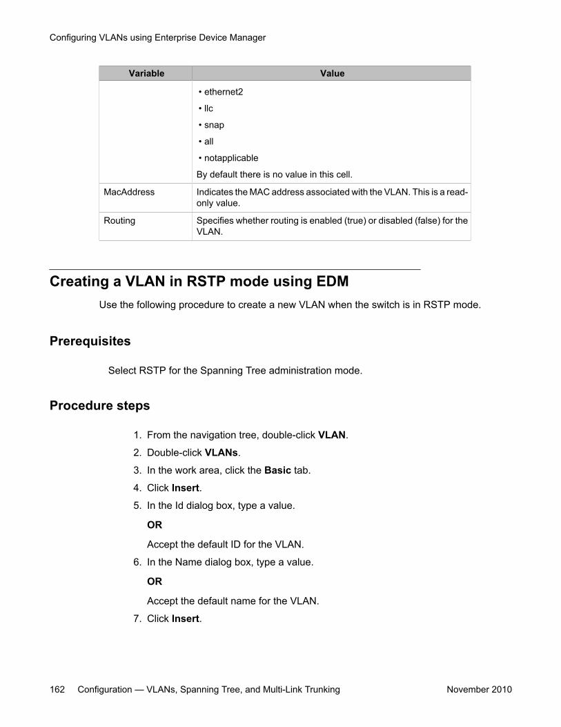
Variable Value
• ethernet2
• llc
• snap
• all
• notapplicable
By default there is no value in this cell.
MacAddress Indicates the MAC address associated with the VLAN. This is a read-only value.
Routing Specifies whether routing is enabled (true) or disabled (false) for theVLAN.
Creating a VLAN in RSTP mode using EDMUse the following procedure to create a new VLAN when the switch is in RSTP mode.
Prerequisites
Select RSTP for the Spanning Tree administration mode.
Procedure steps
1. From the navigation tree, double-click VLAN.
2. Double-click VLANs.
3. In the work area, click the Basic tab.
4. Click Insert.
5. In the Id dialog box, type a value.
OR
Accept the default ID for the VLAN.
6. In the Name dialog box, type a value.
OR
Accept the default name for the VLAN.
7. Click Insert.
Configuring VLANs using Enterprise Device Manager
162 Configuration — VLANs, Spanning Tree, and Multi-Link Trunking November 2010
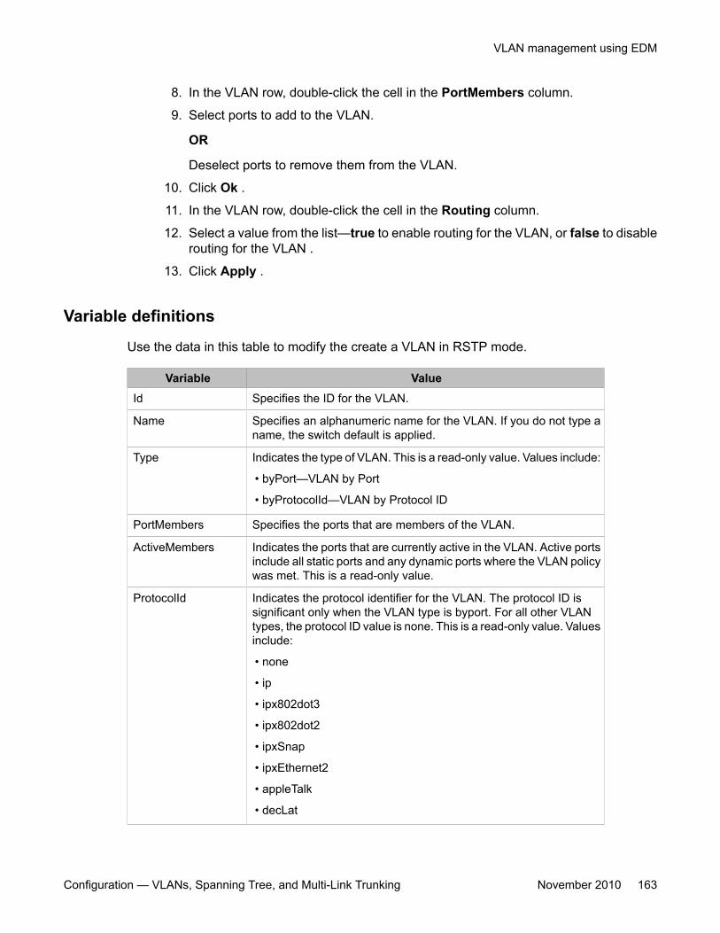
8. In the VLAN row, double-click the cell in the PortMembers column.
9. Select ports to add to the VLAN.
OR
Deselect ports to remove them from the VLAN.
10. Click Ok .
11. In the VLAN row, double-click the cell in the Routing column.
12. Select a value from the list—true to enable routing for the VLAN, or false to disablerouting for the VLAN .
13. Click Apply .
Variable definitions
Use the data in this table to modify the create a VLAN in RSTP mode.
Variable ValueId Specifies the ID for the VLAN.
Name Specifies an alphanumeric name for the VLAN. If you do not type aname, the switch default is applied.
Type Indicates the type of VLAN. This is a read-only value. Values include:
• byPort—VLAN by Port
• byProtocolId—VLAN by Protocol ID
PortMembers Specifies the ports that are members of the VLAN.
ActiveMembers Indicates the ports that are currently active in the VLAN. Active portsinclude all static ports and any dynamic ports where the VLAN policywas met. This is a read-only value.
ProtocolId Indicates the protocol identifier for the VLAN. The protocol ID issignificant only when the VLAN type is byport. For all other VLANtypes, the protocol ID value is none. This is a read-only value. Valuesinclude:
• none
• ip
• ipx802dot3
• ipx802dot2
• ipxSnap
• ipxEthernet2
• appleTalk
• decLat
VLAN management using EDM
Configuration — VLANs, Spanning Tree, and Multi-Link Trunking November 2010 163
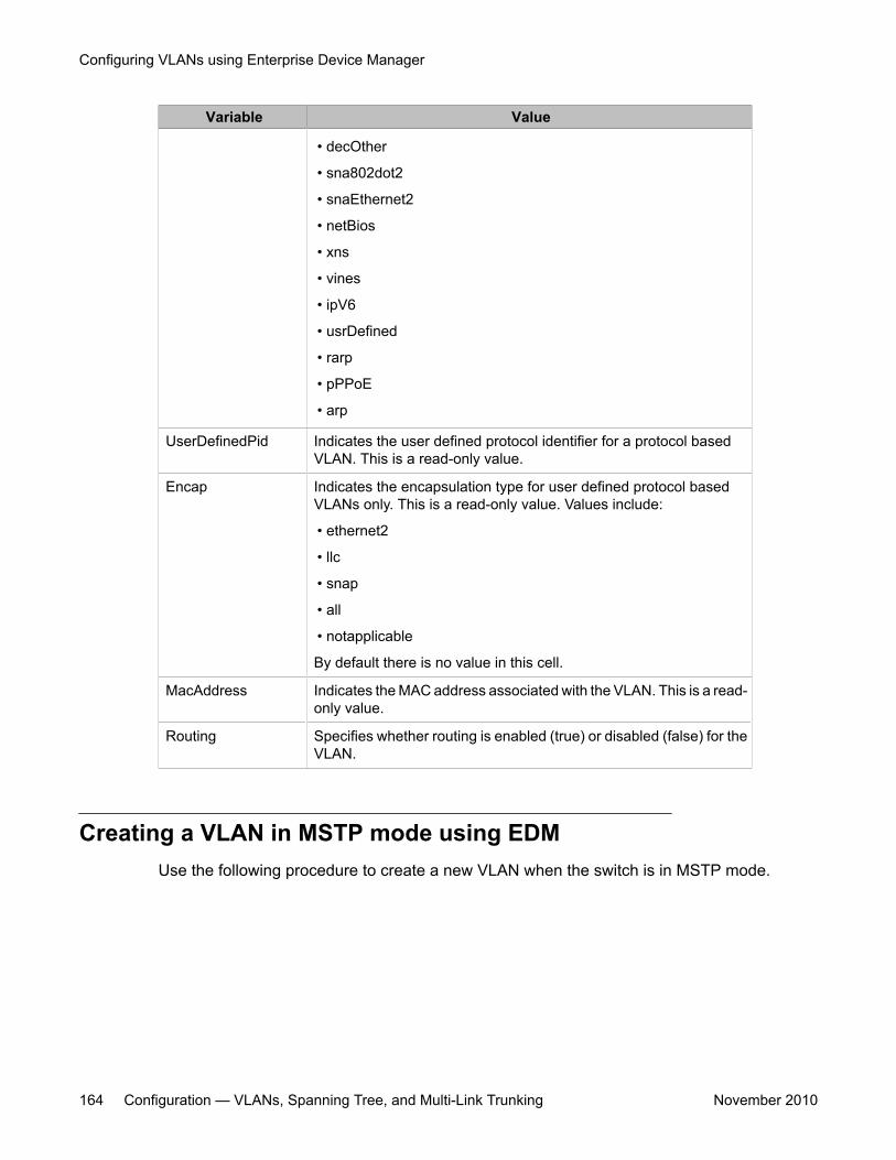
Variable Value
• decOther
• sna802dot2
• snaEthernet2
• netBios
• xns
• vines
• ipV6
• usrDefined
• rarp
• pPPoE
• arp
UserDefinedPid Indicates the user defined protocol identifier for a protocol basedVLAN. This is a read-only value.
Encap Indicates the encapsulation type for user defined protocol basedVLANs only. This is a read-only value. Values include:
• ethernet2
• llc
• snap
• all
• notapplicable
By default there is no value in this cell.
MacAddress Indicates the MAC address associated with the VLAN. This is a read-only value.
Routing Specifies whether routing is enabled (true) or disabled (false) for theVLAN.
Creating a VLAN in MSTP mode using EDMUse the following procedure to create a new VLAN when the switch is in MSTP mode.
Configuring VLANs using Enterprise Device Manager
164 Configuration — VLANs, Spanning Tree, and Multi-Link Trunking November 2010
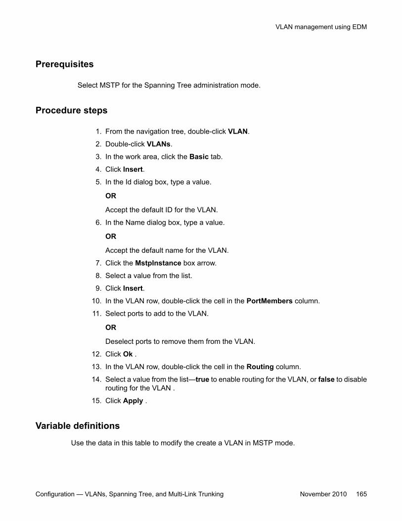
Prerequisites
Select MSTP for the Spanning Tree administration mode.
Procedure steps
1. From the navigation tree, double-click VLAN.
2. Double-click VLANs.
3. In the work area, click the Basic tab.
4. Click Insert.
5. In the Id dialog box, type a value.
OR
Accept the default ID for the VLAN.
6. In the Name dialog box, type a value.
OR
Accept the default name for the VLAN.
7. Click the MstpInstance box arrow.
8. Select a value from the list.
9. Click Insert.
10. In the VLAN row, double-click the cell in the PortMembers column.
11. Select ports to add to the VLAN.
OR
Deselect ports to remove them from the VLAN.
12. Click Ok .
13. In the VLAN row, double-click the cell in the Routing column.
14. Select a value from the list—true to enable routing for the VLAN, or false to disablerouting for the VLAN .
15. Click Apply .
Variable definitions
Use the data in this table to modify the create a VLAN in MSTP mode.
VLAN management using EDM
Configuration — VLANs, Spanning Tree, and Multi-Link Trunking November 2010 165
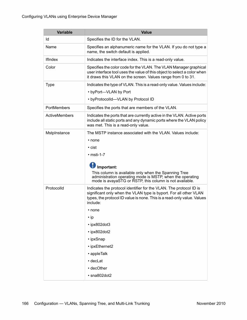
Variable ValueId Specifies the ID for the VLAN.
Name Specifies an alphanumeric name for the VLAN. If you do not type aname, the switch default is applied.
IfIndex Indicates the interface index. This is a read-only value.
Color Specifies the color code for the VLAN. The VLAN Manager graphicaluser interface tool uses the value of this object to select a color whenit draws this VLAN on the screen. Values range from 0 to 31.
Type Indicates the type of VLAN. This is a read-only value. Values include:
• byPort—VLAN by Port
• byProtocolId—VLAN by Protocol ID
PortMembers Specifies the ports that are members of the VLAN.
ActiveMembers Indicates the ports that are currently active in the VLAN. Active portsinclude all static ports and any dynamic ports where the VLAN policywas met. This is a read-only value.
MstpInstance The MSTP instance associated with the VLAN. Values include:
• none
• cist
• msti-1-7
Important:This column is available only when the Spanning Treeadministration operating mode is MSTP, when the operatingmode is avayaSTG or RSTP, this column is not available.
ProtocolId Indicates the protocol identifier for the VLAN. The protocol ID issignificant only when the VLAN type is byport. For all other VLANtypes, the protocol ID value is none. This is a read-only value. Valuesinclude:
• none
• ip
• ipx802dot3
• ipx802dot2
• ipxSnap
• ipxEthernet2
• appleTalk
• decLat
• decOther
• sna802dot2
Configuring VLANs using Enterprise Device Manager
166 Configuration — VLANs, Spanning Tree, and Multi-Link Trunking November 2010
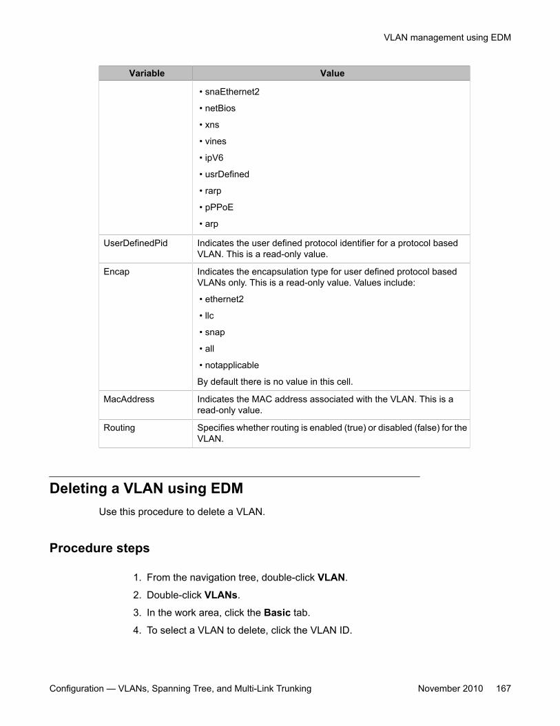
Variable Value
• snaEthernet2
• netBios
• xns
• vines
• ipV6
• usrDefined
• rarp
• pPPoE
• arp
UserDefinedPid Indicates the user defined protocol identifier for a protocol basedVLAN. This is a read-only value.
Encap Indicates the encapsulation type for user defined protocol basedVLANs only. This is a read-only value. Values include:
• ethernet2
• llc
• snap
• all
• notapplicable
By default there is no value in this cell.
MacAddress Indicates the MAC address associated with the VLAN. This is aread-only value.
Routing Specifies whether routing is enabled (true) or disabled (false) for theVLAN.
Deleting a VLAN using EDMUse this procedure to delete a VLAN.
Procedure steps
1. From the navigation tree, double-click VLAN.
2. Double-click VLANs.
3. In the work area, click the Basic tab.
4. To select a VLAN to delete, click the VLAN ID.
VLAN management using EDM
Configuration — VLANs, Spanning Tree, and Multi-Link Trunking November 2010 167
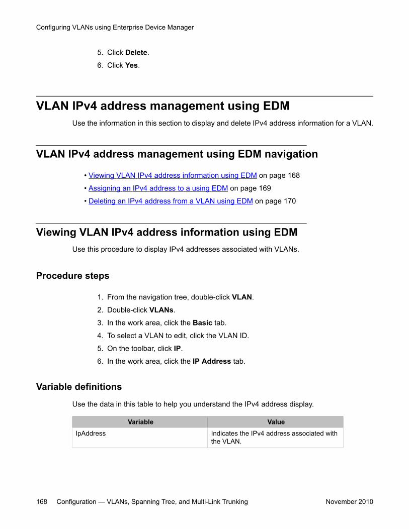
5. Click Delete.
6. Click Yes.
VLAN IPv4 address management using EDMUse the information in this section to display and delete IPv4 address information for a VLAN.
VLAN IPv4 address management using EDM navigation
• Viewing VLAN IPv4 address information using EDM on page 168
• Assigning an IPv4 address to a using EDM on page 169
• Deleting an IPv4 address from a VLAN using EDM on page 170
Viewing VLAN IPv4 address information using EDMUse this procedure to display IPv4 addresses associated with VLANs.
Procedure steps
1. From the navigation tree, double-click VLAN.
2. Double-click VLANs.
3. In the work area, click the Basic tab.
4. To select a VLAN to edit, click the VLAN ID.
5. On the toolbar, click IP.
6. In the work area, click the IP Address tab.
Variable definitions
Use the data in this table to help you understand the IPv4 address display.
Variable ValueIpAddress Indicates the IPv4 address associated with
the VLAN.
Configuring VLANs using Enterprise Device Manager
168 Configuration — VLANs, Spanning Tree, and Multi-Link Trunking November 2010
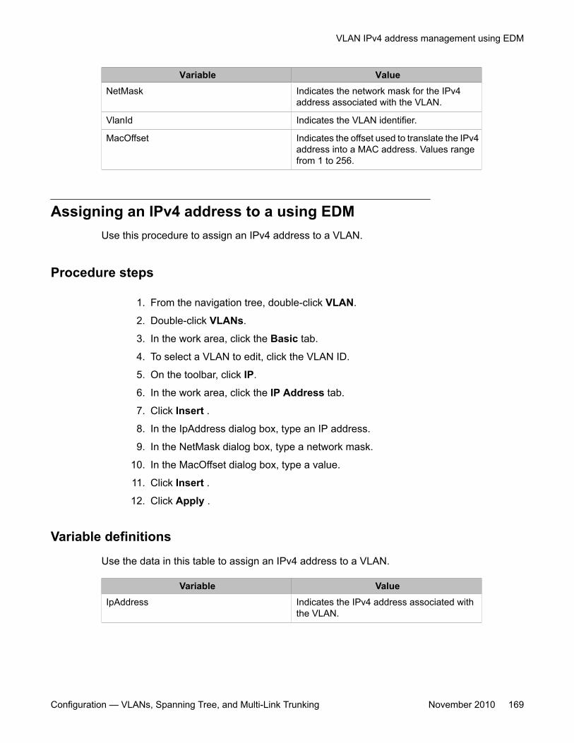
Variable ValueNetMask Indicates the network mask for the IPv4
address associated with the VLAN.
VlanId Indicates the VLAN identifier.
MacOffset Indicates the offset used to translate the IPv4address into a MAC address. Values rangefrom 1 to 256.
Assigning an IPv4 address to a using EDMUse this procedure to assign an IPv4 address to a VLAN.
Procedure steps
1. From the navigation tree, double-click VLAN.
2. Double-click VLANs.
3. In the work area, click the Basic tab.
4. To select a VLAN to edit, click the VLAN ID.
5. On the toolbar, click IP.
6. In the work area, click the IP Address tab.
7. Click Insert .
8. In the IpAddress dialog box, type an IP address.
9. In the NetMask dialog box, type a network mask.
10. In the MacOffset dialog box, type a value.
11. Click Insert .
12. Click Apply .
Variable definitions
Use the data in this table to assign an IPv4 address to a VLAN.
Variable ValueIpAddress Indicates the IPv4 address associated with
the VLAN.
VLAN IPv4 address management using EDM
Configuration — VLANs, Spanning Tree, and Multi-Link Trunking November 2010 169
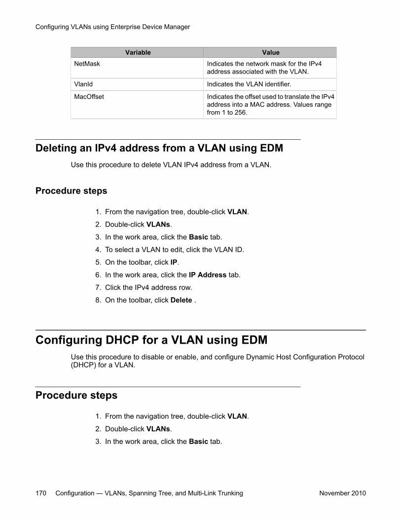
Variable ValueNetMask Indicates the network mask for the IPv4
address associated with the VLAN.
VlanId Indicates the VLAN identifier.
MacOffset Indicates the offset used to translate the IPv4address into a MAC address. Values rangefrom 1 to 256.
Deleting an IPv4 address from a VLAN using EDMUse this procedure to delete VLAN IPv4 address from a VLAN.
Procedure steps
1. From the navigation tree, double-click VLAN.
2. Double-click VLANs.
3. In the work area, click the Basic tab.
4. To select a VLAN to edit, click the VLAN ID.
5. On the toolbar, click IP.
6. In the work area, click the IP Address tab.
7. Click the IPv4 address row.
8. On the toolbar, click Delete .
Configuring DHCP for a VLAN using EDMUse this procedure to disable or enable, and configure Dynamic Host Configuration Protocol(DHCP) for a VLAN.
Procedure steps
1. From the navigation tree, double-click VLAN.
2. Double-click VLANs.
3. In the work area, click the Basic tab.
Configuring VLANs using Enterprise Device Manager
170 Configuration — VLANs, Spanning Tree, and Multi-Link Trunking November 2010
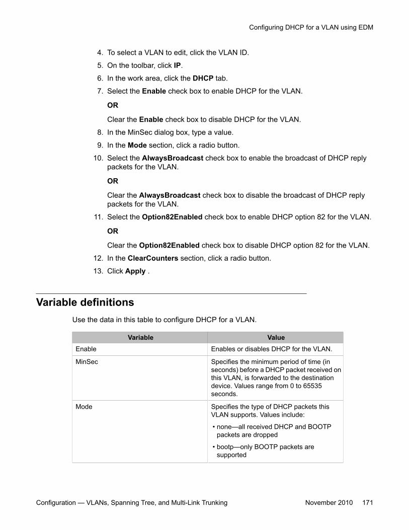
4. To select a VLAN to edit, click the VLAN ID.
5. On the toolbar, click IP.
6. In the work area, click the DHCP tab.
7. Select the Enable check box to enable DHCP for the VLAN.
OR
Clear the Enable check box to disable DHCP for the VLAN.
8. In the MinSec dialog box, type a value.
9. In the Mode section, click a radio button.
10. Select the AlwaysBroadcast check box to enable the broadcast of DHCP replypackets for the VLAN.
OR
Clear the AlwaysBroadcast check box to disable the broadcast of DHCP replypackets for the VLAN.
11. Select the Option82Enabled check box to enable DHCP option 82 for the VLAN.
OR
Clear the Option82Enabled check box to disable DHCP option 82 for the VLAN.
12. In the ClearCounters section, click a radio button.
13. Click Apply .
Variable definitionsUse the data in this table to configure DHCP for a VLAN.
Variable ValueEnable Enables or disables DHCP for the VLAN.
MinSec Specifies the minimum period of time (inseconds) before a DHCP packet received onthis VLAN, is forwarded to the destinationdevice. Values range from 0 to 65535seconds.
Mode Specifies the type of DHCP packets thisVLAN supports. Values include:
• none—all received DHCP and BOOTPpackets are dropped
• bootp—only BOOTP packets aresupported
Configuring DHCP for a VLAN using EDM
Configuration — VLANs, Spanning Tree, and Multi-Link Trunking November 2010 171
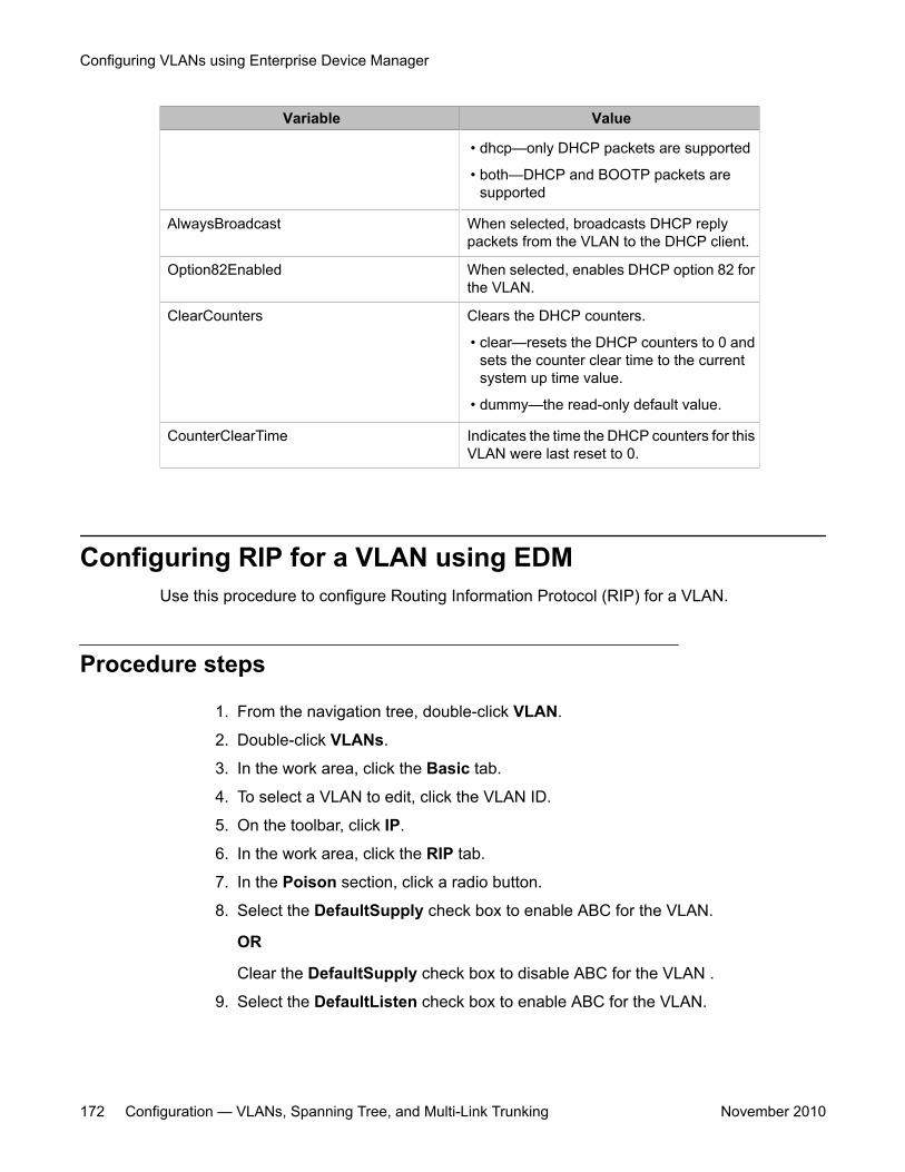
Variable Value
• dhcp—only DHCP packets are supported
• both—DHCP and BOOTP packets aresupported
AlwaysBroadcast When selected, broadcasts DHCP replypackets from the VLAN to the DHCP client.
Option82Enabled When selected, enables DHCP option 82 forthe VLAN.
ClearCounters Clears the DHCP counters.
• clear—resets the DHCP counters to 0 andsets the counter clear time to the currentsystem up time value.
• dummy—the read-only default value.
CounterClearTime Indicates the time the DHCP counters for thisVLAN were last reset to 0.
Configuring RIP for a VLAN using EDMUse this procedure to configure Routing Information Protocol (RIP) for a VLAN.
Procedure steps
1. From the navigation tree, double-click VLAN.
2. Double-click VLANs.
3. In the work area, click the Basic tab.
4. To select a VLAN to edit, click the VLAN ID.
5. On the toolbar, click IP.
6. In the work area, click the RIP tab.
7. In the Poison section, click a radio button.
8. Select the DefaultSupply check box to enable ABC for the VLAN.
OR
Clear the DefaultSupply check box to disable ABC for the VLAN .
9. Select the DefaultListen check box to enable ABC for the VLAN.
Configuring VLANs using Enterprise Device Manager
172 Configuration — VLANs, Spanning Tree, and Multi-Link Trunking November 2010
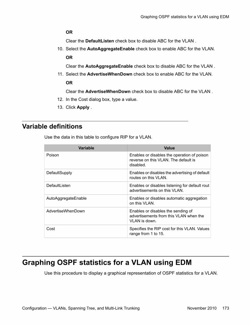
OR
Clear the DefaultListen check box to disable ABC for the VLAN .
10. Select the AutoAggregateEnable check box to enable ABC for the VLAN.
OR
Clear the AutoAggregateEnable check box to disable ABC for the VLAN .
11. Select the AdvertiseWhenDown check box to enable ABC for the VLAN.
OR
Clear the AdvertiseWhenDown check box to disable ABC for the VLAN .
12. In the Cost dialog box, type a value.
13. Click Apply .
Variable definitionsUse the data in this table to configure RIP for a VLAN.
Variable ValuePoison Enables or disables the operation of poison
reverse on this VLAN. The default isdisabled.
DefaultSupply Enables or disables the advertising of defaultroutes on this VLAN.
DefaultListen Enables or disables listening for default routadvertisements on this VLAN.
AutoAggregateEnable Enables or disables automatic aggregationon this VLAN.
AdvertiseWhenDown Enables or disables the sending ofadvertisements from this VLAN when theVLAN is down.
Cost Specifies the RIP cost for this VLAN. Valuesrange from 1 to 15.
Graphing OSPF statistics for a VLAN using EDMUse this procedure to display a graphical representation of OSPF statistics for a VLAN.
Graphing OSPF statistics for a VLAN using EDM
Configuration — VLANs, Spanning Tree, and Multi-Link Trunking November 2010 173
Procedure steps
1. From the navigation tree, double-click VLAN.
2. Double-click VLANs.
3. In the work area, click the Basic tab.
4. To select a VLAN, click the VLAN ID.
5. On the toolbar, click IP.
6. In the work area, click the OSPF Stats tab.
7. Select a Poll Interval from the list on the toolbar.
8. To select statistics to graph, click a statistic type row under one of the displayedcolumns.
9. Click Line Chart, Area Chart, Bar Chart, or Pie Chart.
VLAN IPv6 interface management using EDMUse the information in this section to configure and manage IPv6 interfaces for a VLAN.
VLAN IPv6 interface management using EDM navigation
• Viewing IPv6 interface information for a VLAN using EDM on page 174
• Adding an IPv6 interface to a VLAN using EDM on page 176
• Deleting an IPv6 interface from a VLAN using EDM on page 177
Viewing IPv6 interface information for a VLAN using EDMUse this procedure to display existing IPv6 interface information for a VLAN.
Procedure steps
1. From the navigation tree, double-click VLAN.
2. Double-click VLANs.
Configuring VLANs using Enterprise Device Manager
174 Configuration — VLANs, Spanning Tree, and Multi-Link Trunking November 2010
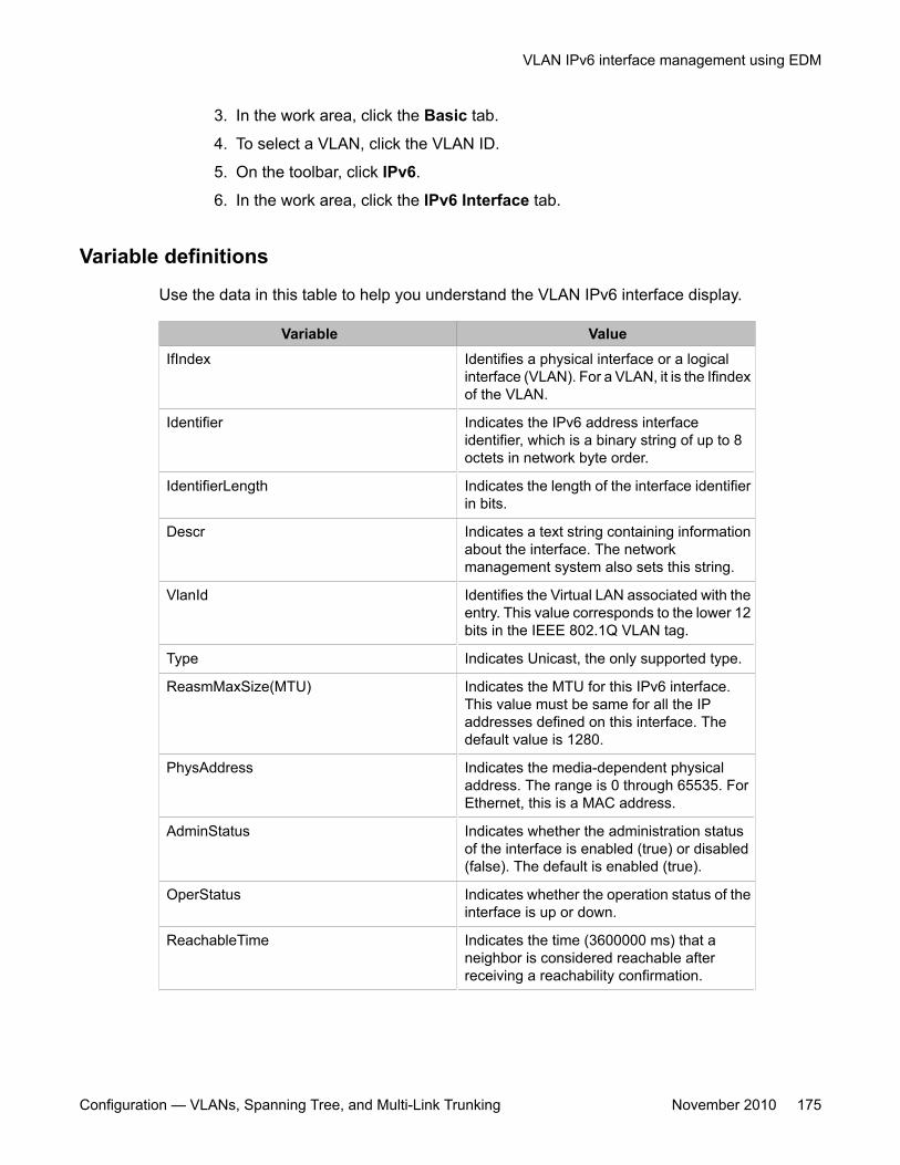
3. In the work area, click the Basic tab.
4. To select a VLAN, click the VLAN ID.
5. On the toolbar, click IPv6.
6. In the work area, click the IPv6 Interface tab.
Variable definitions
Use the data in this table to help you understand the VLAN IPv6 interface display.
Variable ValueIfIndex Identifies a physical interface or a logical
interface (VLAN). For a VLAN, it is the Ifindexof the VLAN.
Identifier Indicates the IPv6 address interfaceidentifier, which is a binary string of up to 8octets in network byte order.
IdentifierLength Indicates the length of the interface identifierin bits.
Descr Indicates a text string containing informationabout the interface. The networkmanagement system also sets this string.
VlanId Identifies the Virtual LAN associated with theentry. This value corresponds to the lower 12bits in the IEEE 802.1Q VLAN tag.
Type Indicates Unicast, the only supported type.
ReasmMaxSize(MTU) Indicates the MTU for this IPv6 interface.This value must be same for all the IPaddresses defined on this interface. Thedefault value is 1280.
PhysAddress Indicates the media-dependent physicaladdress. The range is 0 through 65535. ForEthernet, this is a MAC address.
AdminStatus Indicates whether the administration statusof the interface is enabled (true) or disabled(false). The default is enabled (true).
OperStatus Indicates whether the operation status of theinterface is up or down.
ReachableTime Indicates the time (3600000 ms) that aneighbor is considered reachable afterreceiving a reachability confirmation.
VLAN IPv6 interface management using EDM
Configuration — VLANs, Spanning Tree, and Multi-Link Trunking November 2010 175
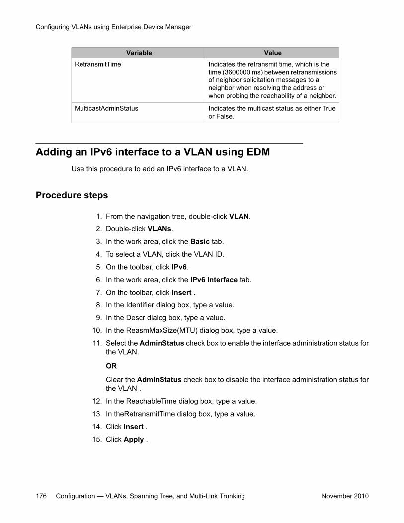
Variable ValueRetransmitTime Indicates the retransmit time, which is the
time (3600000 ms) between retransmissionsof neighbor solicitation messages to aneighbor when resolving the address orwhen probing the reachability of a neighbor.
MulticastAdminStatus Indicates the multicast status as either Trueor False.
Adding an IPv6 interface to a VLAN using EDMUse this procedure to add an IPv6 interface to a VLAN.
Procedure steps
1. From the navigation tree, double-click VLAN.
2. Double-click VLANs.
3. In the work area, click the Basic tab.
4. To select a VLAN, click the VLAN ID.
5. On the toolbar, click IPv6.
6. In the work area, click the IPv6 Interface tab.
7. On the toolbar, click Insert .
8. In the Identifier dialog box, type a value.
9. In the Descr dialog box, type a value.
10. In the ReasmMaxSize(MTU) dialog box, type a value.
11. Select the AdminStatus check box to enable the interface administration status forthe VLAN.
OR
Clear the AdminStatus check box to disable the interface administration status forthe VLAN .
12. In the ReachableTime dialog box, type a value.
13. In theRetransmitTime dialog box, type a value.
14. Click Insert .
15. Click Apply .
Configuring VLANs using Enterprise Device Manager
176 Configuration — VLANs, Spanning Tree, and Multi-Link Trunking November 2010
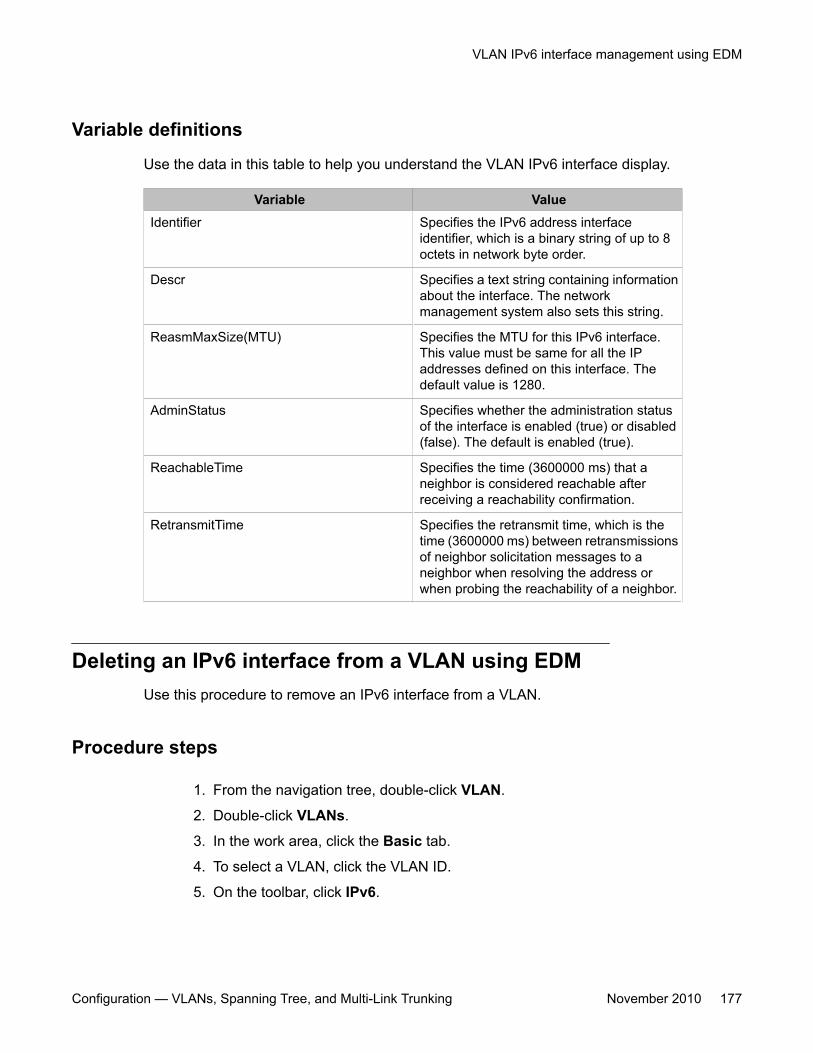
Variable definitions
Use the data in this table to help you understand the VLAN IPv6 interface display.
Variable ValueIdentifier Specifies the IPv6 address interface
identifier, which is a binary string of up to 8octets in network byte order.
Descr Specifies a text string containing informationabout the interface. The networkmanagement system also sets this string.
ReasmMaxSize(MTU) Specifies the MTU for this IPv6 interface.This value must be same for all the IPaddresses defined on this interface. Thedefault value is 1280.
AdminStatus Specifies whether the administration statusof the interface is enabled (true) or disabled(false). The default is enabled (true).
ReachableTime Specifies the time (3600000 ms) that aneighbor is considered reachable afterreceiving a reachability confirmation.
RetransmitTime Specifies the retransmit time, which is thetime (3600000 ms) between retransmissionsof neighbor solicitation messages to aneighbor when resolving the address orwhen probing the reachability of a neighbor.
Deleting an IPv6 interface from a VLAN using EDMUse this procedure to remove an IPv6 interface from a VLAN.
Procedure steps
1. From the navigation tree, double-click VLAN.
2. Double-click VLANs.
3. In the work area, click the Basic tab.
4. To select a VLAN, click the VLAN ID.
5. On the toolbar, click IPv6.
VLAN IPv6 interface management using EDM
Configuration — VLANs, Spanning Tree, and Multi-Link Trunking November 2010 177
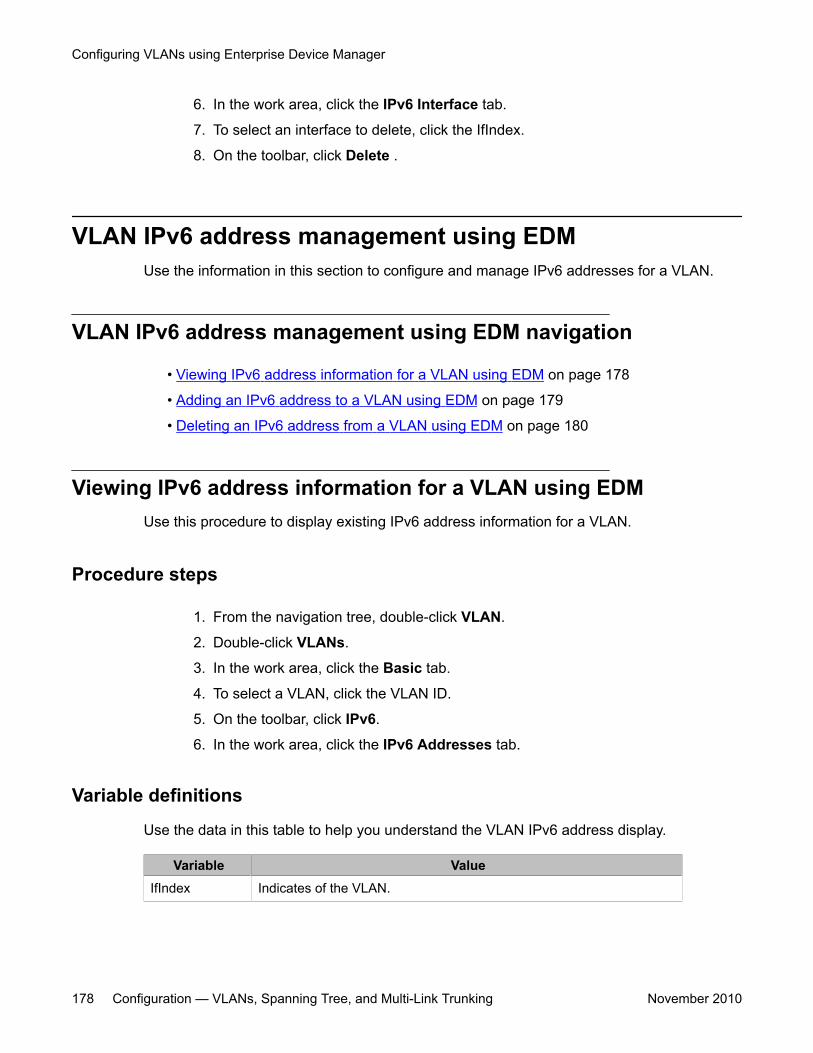
6. In the work area, click the IPv6 Interface tab.
7. To select an interface to delete, click the IfIndex.
8. On the toolbar, click Delete .
VLAN IPv6 address management using EDMUse the information in this section to configure and manage IPv6 addresses for a VLAN.
VLAN IPv6 address management using EDM navigation
• Viewing IPv6 address information for a VLAN using EDM on page 178
• Adding an IPv6 address to a VLAN using EDM on page 179
• Deleting an IPv6 address from a VLAN using EDM on page 180
Viewing IPv6 address information for a VLAN using EDMUse this procedure to display existing IPv6 address information for a VLAN.
Procedure steps
1. From the navigation tree, double-click VLAN.
2. Double-click VLANs.
3. In the work area, click the Basic tab.
4. To select a VLAN, click the VLAN ID.
5. On the toolbar, click IPv6.
6. In the work area, click the IPv6 Addresses tab.
Variable definitions
Use the data in this table to help you understand the VLAN IPv6 address display.
Variable ValueIfIndex Indicates of the VLAN.
Configuring VLANs using Enterprise Device Manager
178 Configuration — VLANs, Spanning Tree, and Multi-Link Trunking November 2010
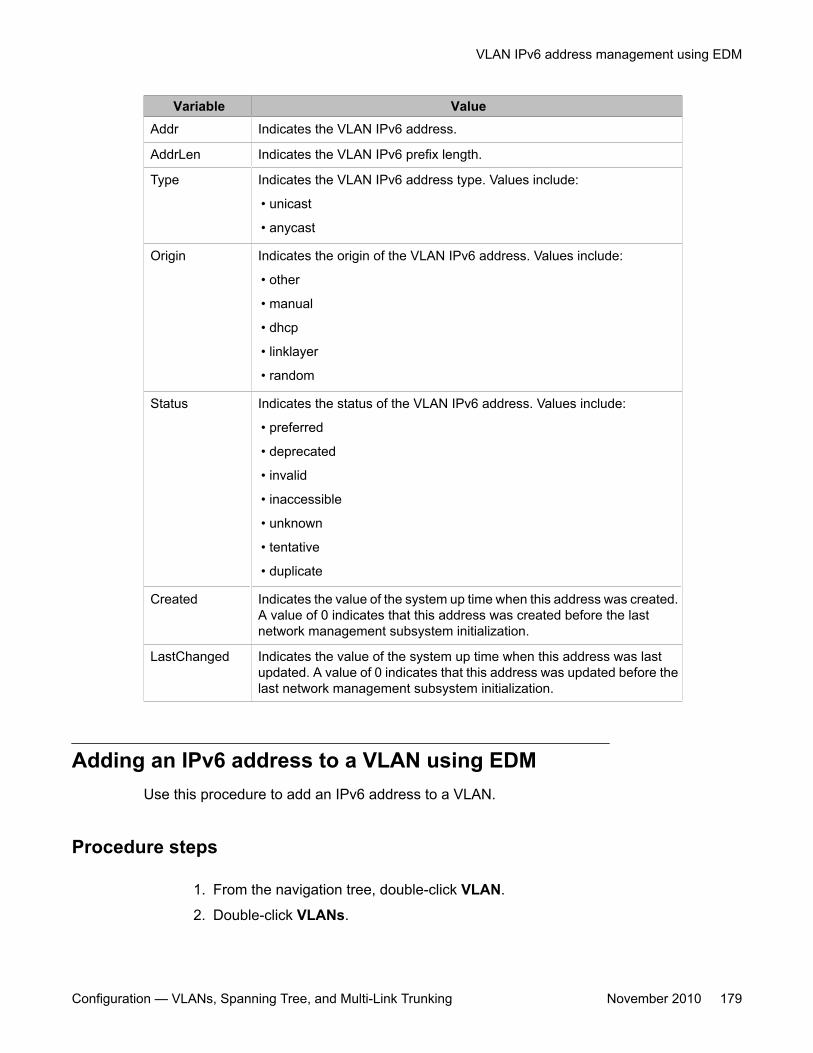
Variable ValueAddr Indicates the VLAN IPv6 address.
AddrLen Indicates the VLAN IPv6 prefix length.
Type Indicates the VLAN IPv6 address type. Values include:
• unicast
• anycast
Origin Indicates the origin of the VLAN IPv6 address. Values include:
• other
• manual
• dhcp
• linklayer
• random
Status Indicates the status of the VLAN IPv6 address. Values include:
• preferred
• deprecated
• invalid
• inaccessible
• unknown
• tentative
• duplicate
Created Indicates the value of the system up time when this address was created.A value of 0 indicates that this address was created before the lastnetwork management subsystem initialization.
LastChanged Indicates the value of the system up time when this address was lastupdated. A value of 0 indicates that this address was updated before thelast network management subsystem initialization.
Adding an IPv6 address to a VLAN using EDMUse this procedure to add an IPv6 address to a VLAN.
Procedure steps
1. From the navigation tree, double-click VLAN.
2. Double-click VLANs.
VLAN IPv6 address management using EDM
Configuration — VLANs, Spanning Tree, and Multi-Link Trunking November 2010 179
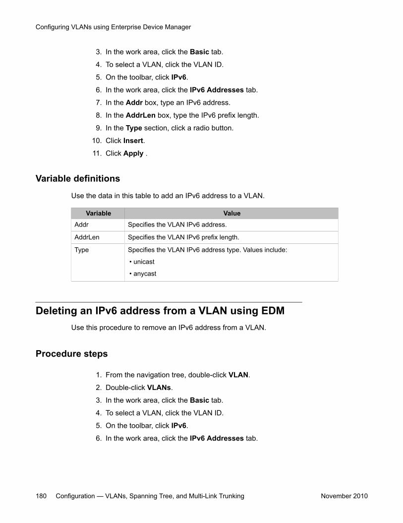
3. In the work area, click the Basic tab.
4. To select a VLAN, click the VLAN ID.
5. On the toolbar, click IPv6.
6. In the work area, click the IPv6 Addresses tab.
7. In the Addr box, type an IPv6 address.
8. In the AddrLen box, type the IPv6 prefix length.
9. In the Type section, click a radio button.
10. Click Insert.
11. Click Apply .
Variable definitions
Use the data in this table to add an IPv6 address to a VLAN.
Variable ValueAddr Specifies the VLAN IPv6 address.
AddrLen Specifies the VLAN IPv6 prefix length.
Type Specifies the VLAN IPv6 address type. Values include:
• unicast
• anycast
Deleting an IPv6 address from a VLAN using EDMUse this procedure to remove an IPv6 address from a VLAN.
Procedure steps
1. From the navigation tree, double-click VLAN.
2. Double-click VLANs.
3. In the work area, click the Basic tab.
4. To select a VLAN, click the VLAN ID.
5. On the toolbar, click IPv6.
6. In the work area, click the IPv6 Addresses tab.
Configuring VLANs using Enterprise Device Manager
180 Configuration — VLANs, Spanning Tree, and Multi-Link Trunking November 2010
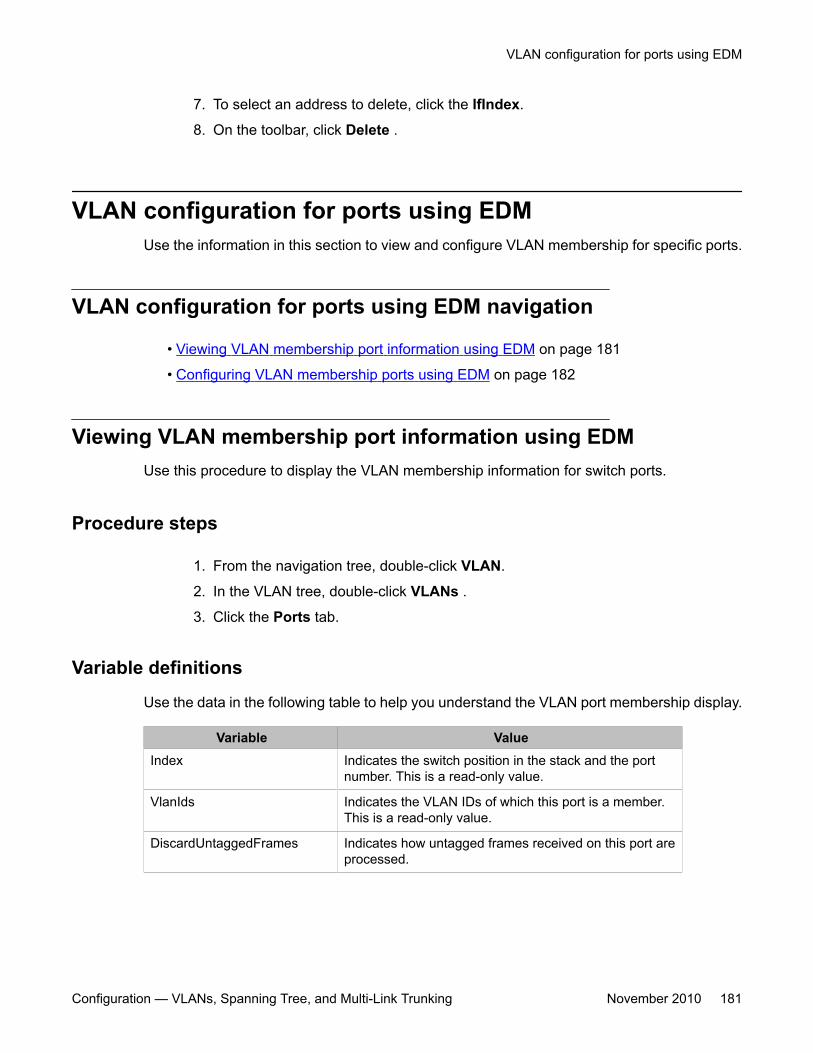
7. To select an address to delete, click the IfIndex.
8. On the toolbar, click Delete .
VLAN configuration for ports using EDMUse the information in this section to view and configure VLAN membership for specific ports.
VLAN configuration for ports using EDM navigation
• Viewing VLAN membership port information using EDM on page 181
• Configuring VLAN membership ports using EDM on page 182
Viewing VLAN membership port information using EDMUse this procedure to display the VLAN membership information for switch ports.
Procedure steps
1. From the navigation tree, double-click VLAN.
2. In the VLAN tree, double-click VLANs .
3. Click the Ports tab.
Variable definitions
Use the data in the following table to help you understand the VLAN port membership display.
Variable ValueIndex Indicates the switch position in the stack and the port
number. This is a read-only value.
VlanIds Indicates the VLAN IDs of which this port is a member.This is a read-only value.
DiscardUntaggedFrames Indicates how untagged frames received on this port areprocessed.
VLAN configuration for ports using EDM
Configuration — VLANs, Spanning Tree, and Multi-Link Trunking November 2010 181
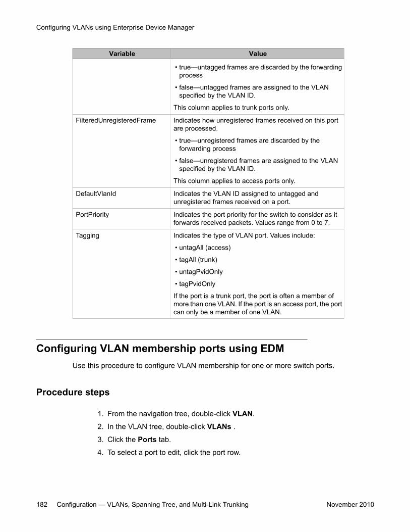
Variable Value
• true—untagged frames are discarded by the forwardingprocess
• false—untagged frames are assigned to the VLANspecified by the VLAN ID.
This column applies to trunk ports only.
FilteredUnregisteredFrame Indicates how unregistered frames received on this portare processed.
• true—unregistered frames are discarded by theforwarding process
• false—unregistered frames are assigned to the VLANspecified by the VLAN ID.
This column applies to access ports only.
DefaultVlanId Indicates the VLAN ID assigned to untagged andunregistered frames received on a port.
PortPriority Indicates the port priority for the switch to consider as itforwards received packets. Values range from 0 to 7.
Tagging Indicates the type of VLAN port. Values include:
• untagAll (access)
• tagAll (trunk)
• untagPvidOnly
• tagPvidOnly
If the port is a trunk port, the port is often a member ofmore than one VLAN. If the port is an access port, the portcan only be a member of one VLAN.
Configuring VLAN membership ports using EDMUse this procedure to configure VLAN membership for one or more switch ports.
Procedure steps
1. From the navigation tree, double-click VLAN.
2. In the VLAN tree, double-click VLANs .
3. Click the Ports tab.
4. To select a port to edit, click the port row.
Configuring VLANs using Enterprise Device Manager
182 Configuration — VLANs, Spanning Tree, and Multi-Link Trunking November 2010
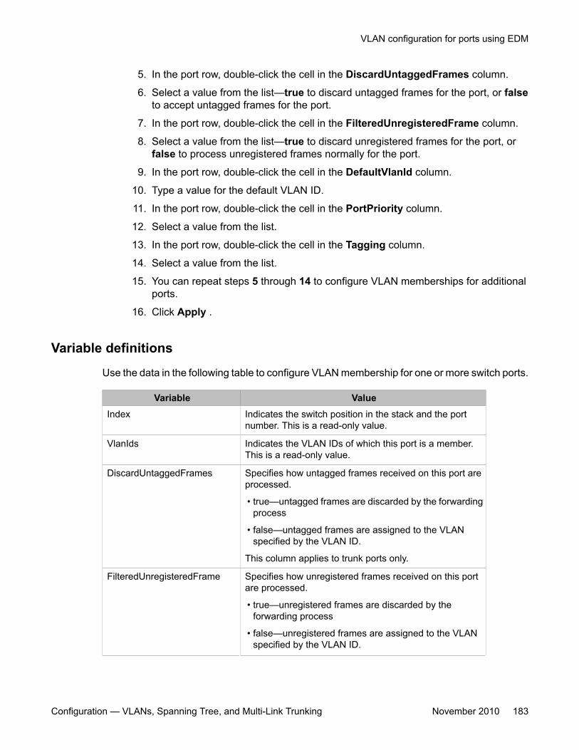
5. In the port row, double-click the cell in the DiscardUntaggedFrames column.
6. Select a value from the list—true to discard untagged frames for the port, or falseto accept untagged frames for the port.
7. In the port row, double-click the cell in the FilteredUnregisteredFrame column.
8. Select a value from the list—true to discard unregistered frames for the port, orfalse to process unregistered frames normally for the port.
9. In the port row, double-click the cell in the DefaultVlanId column.
10. Type a value for the default VLAN ID.
11. In the port row, double-click the cell in the PortPriority column.
12. Select a value from the list.
13. In the port row, double-click the cell in the Tagging column.
14. Select a value from the list.
15. You can repeat steps 5 through 14 to configure VLAN memberships for additionalports.
16. Click Apply .
Variable definitions
Use the data in the following table to configure VLAN membership for one or more switch ports.
Variable ValueIndex Indicates the switch position in the stack and the port
number. This is a read-only value.
VlanIds Indicates the VLAN IDs of which this port is a member.This is a read-only value.
DiscardUntaggedFrames Specifies how untagged frames received on this port areprocessed.
• true—untagged frames are discarded by the forwardingprocess
• false—untagged frames are assigned to the VLANspecified by the VLAN ID.
This column applies to trunk ports only.
FilteredUnregisteredFrame Specifies how unregistered frames received on this portare processed.
• true—unregistered frames are discarded by theforwarding process
• false—unregistered frames are assigned to the VLANspecified by the VLAN ID.
VLAN configuration for ports using EDM
Configuration — VLANs, Spanning Tree, and Multi-Link Trunking November 2010 183
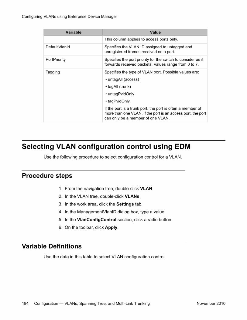
Variable ValueThis column applies to access ports only.
DefaultVlanId Specifies the VLAN ID assigned to untagged andunregistered frames received on a port.
PortPriority Specifies the port priority for the switch to consider as itforwards received packets. Values range from 0 to 7.
Tagging Specifies the type of VLAN port. Possible values are:
• untagAll (access)
• tagAll (trunk)
• untagPvidOnly
• tagPvidOnly
If the port is a trunk port, the port is often a member ofmore than one VLAN. If the port is an access port, the portcan only be a member of one VLAN.
Selecting VLAN configuration control using EDMUse the following procedure to select configuration control for a VLAN.
Procedure steps
1. From the navigation tree, double-click VLAN.
2. In the VLAN tree, double-click VLANs.
3. In the work area, click the Settings tab.
4. In the ManagementVlanID dialog box, type a value.
5. In the VlanConfigControl section, click a radio button.
6. On the toolbar, click Apply.
Variable DefinitionsUse the data in this table to select VLAN configuration control.
Configuring VLANs using Enterprise Device Manager
184 Configuration — VLANs, Spanning Tree, and Multi-Link Trunking November 2010
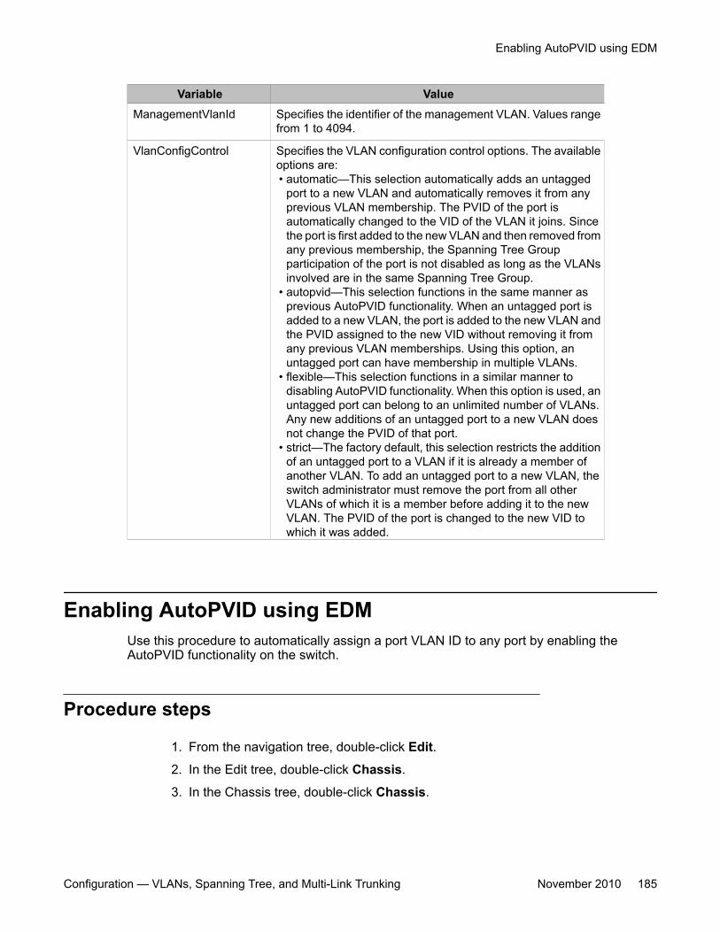
Variable ValueManagementVlanId Specifies the identifier of the management VLAN. Values range
from 1 to 4094.
VlanConfigControl Specifies the VLAN configuration control options. The availableoptions are:• automatic—This selection automatically adds an untagged
port to a new VLAN and automatically removes it from anyprevious VLAN membership. The PVID of the port isautomatically changed to the VID of the VLAN it joins. Sincethe port is first added to the new VLAN and then removed fromany previous membership, the Spanning Tree Groupparticipation of the port is not disabled as long as the VLANsinvolved are in the same Spanning Tree Group.
• autopvid—This selection functions in the same manner asprevious AutoPVID functionality. When an untagged port isadded to a new VLAN, the port is added to the new VLAN andthe PVID assigned to the new VID without removing it fromany previous VLAN memberships. Using this option, anuntagged port can have membership in multiple VLANs.
• flexible—This selection functions in a similar manner todisabling AutoPVID functionality. When this option is used, anuntagged port can belong to an unlimited number of VLANs.Any new additions of an untagged port to a new VLAN doesnot change the PVID of that port.
• strict—The factory default, this selection restricts the additionof an untagged port to a VLAN if it is already a member ofanother VLAN. To add an untagged port to a new VLAN, theswitch administrator must remove the port from all otherVLANs of which it is a member before adding it to the newVLAN. The PVID of the port is changed to the new VID towhich it was added.
Enabling AutoPVID using EDMUse this procedure to automatically assign a port VLAN ID to any port by enabling theAutoPVID functionality on the switch.
Procedure steps
1. From the navigation tree, double-click Edit.
2. In the Edit tree, double-click Chassis.
3. In the Chassis tree, double-click Chassis.
Enabling AutoPVID using EDM
Configuration — VLANs, Spanning Tree, and Multi-Link Trunking November 2010 185
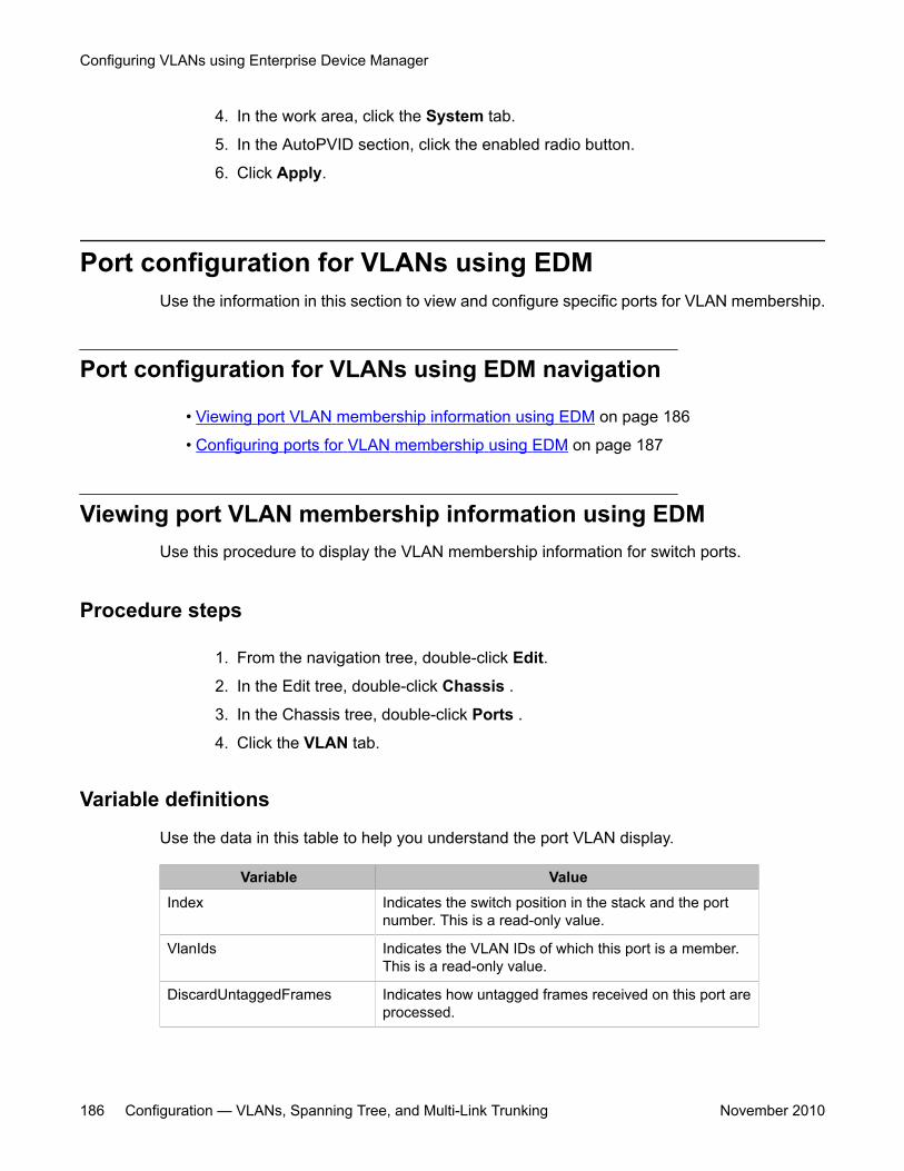
4. In the work area, click the System tab.
5. In the AutoPVID section, click the enabled radio button.
6. Click Apply.
Port configuration for VLANs using EDMUse the information in this section to view and configure specific ports for VLAN membership.
Port configuration for VLANs using EDM navigation
• Viewing port VLAN membership information using EDM on page 186
• Configuring ports for VLAN membership using EDM on page 187
Viewing port VLAN membership information using EDMUse this procedure to display the VLAN membership information for switch ports.
Procedure steps
1. From the navigation tree, double-click Edit.
2. In the Edit tree, double-click Chassis .
3. In the Chassis tree, double-click Ports .
4. Click the VLAN tab.
Variable definitions
Use the data in this table to help you understand the port VLAN display.
Variable ValueIndex Indicates the switch position in the stack and the port
number. This is a read-only value.
VlanIds Indicates the VLAN IDs of which this port is a member.This is a read-only value.
DiscardUntaggedFrames Indicates how untagged frames received on this port areprocessed.
Configuring VLANs using Enterprise Device Manager
186 Configuration — VLANs, Spanning Tree, and Multi-Link Trunking November 2010
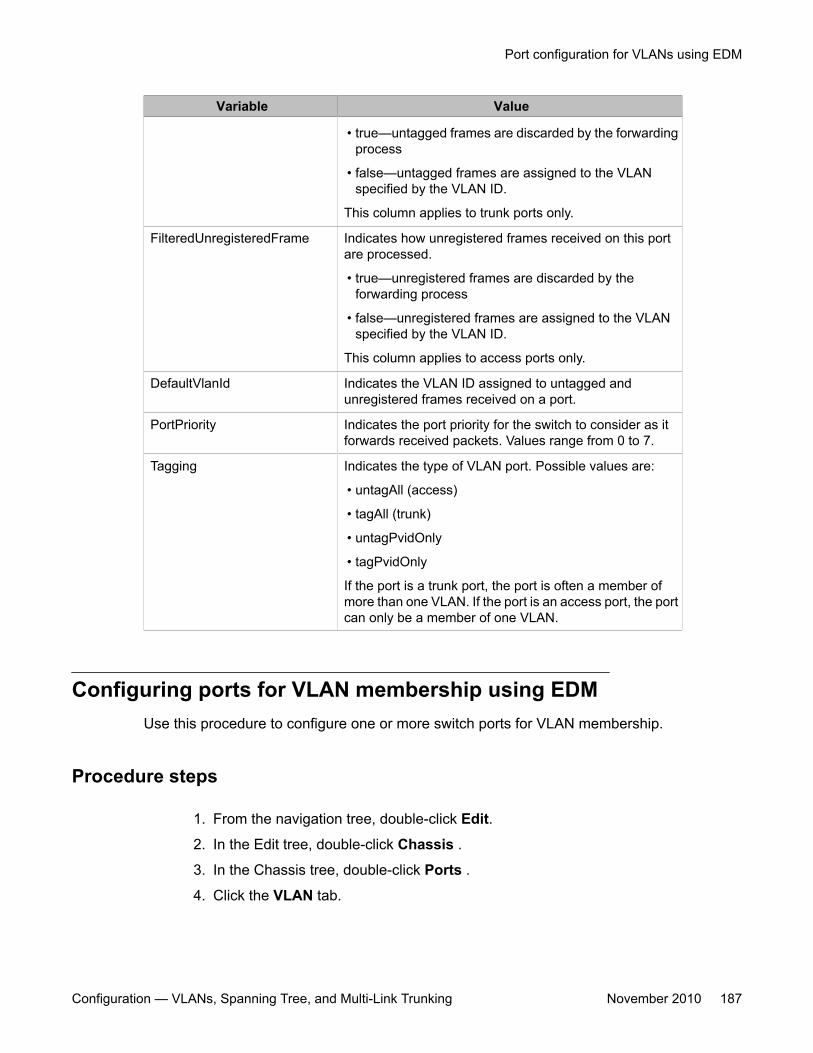
Variable Value
• true—untagged frames are discarded by the forwardingprocess
• false—untagged frames are assigned to the VLANspecified by the VLAN ID.
This column applies to trunk ports only.
FilteredUnregisteredFrame Indicates how unregistered frames received on this portare processed.
• true—unregistered frames are discarded by theforwarding process
• false—unregistered frames are assigned to the VLANspecified by the VLAN ID.
This column applies to access ports only.
DefaultVlanId Indicates the VLAN ID assigned to untagged andunregistered frames received on a port.
PortPriority Indicates the port priority for the switch to consider as itforwards received packets. Values range from 0 to 7.
Tagging Indicates the type of VLAN port. Possible values are:
• untagAll (access)
• tagAll (trunk)
• untagPvidOnly
• tagPvidOnly
If the port is a trunk port, the port is often a member ofmore than one VLAN. If the port is an access port, the portcan only be a member of one VLAN.
Configuring ports for VLAN membership using EDMUse this procedure to configure one or more switch ports for VLAN membership.
Procedure steps
1. From the navigation tree, double-click Edit.
2. In the Edit tree, double-click Chassis .
3. In the Chassis tree, double-click Ports .
4. Click the VLAN tab.
Port configuration for VLANs using EDM
Configuration — VLANs, Spanning Tree, and Multi-Link Trunking November 2010 187
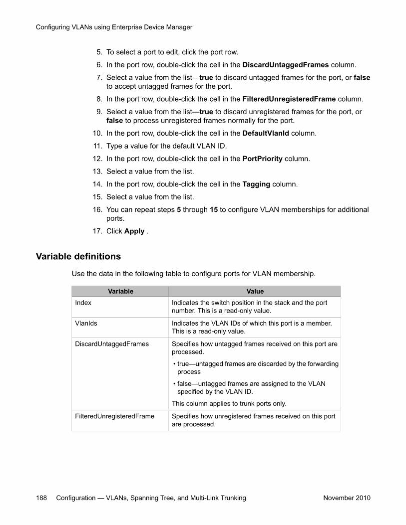
5. To select a port to edit, click the port row.
6. In the port row, double-click the cell in the DiscardUntaggedFrames column.
7. Select a value from the list—true to discard untagged frames for the port, or falseto accept untagged frames for the port.
8. In the port row, double-click the cell in the FilteredUnregisteredFrame column.
9. Select a value from the list—true to discard unregistered frames for the port, orfalse to process unregistered frames normally for the port.
10. In the port row, double-click the cell in the DefaultVlanId column.
11. Type a value for the default VLAN ID.
12. In the port row, double-click the cell in the PortPriority column.
13. Select a value from the list.
14. In the port row, double-click the cell in the Tagging column.
15. Select a value from the list.
16. You can repeat steps 5 through 15 to configure VLAN memberships for additionalports.
17. Click Apply .
Variable definitions
Use the data in the following table to configure ports for VLAN membership.
Variable ValueIndex Indicates the switch position in the stack and the port
number. This is a read-only value.
VlanIds Indicates the VLAN IDs of which this port is a member.This is a read-only value.
DiscardUntaggedFrames Specifies how untagged frames received on this port areprocessed.
• true—untagged frames are discarded by the forwardingprocess
• false—untagged frames are assigned to the VLANspecified by the VLAN ID.
This column applies to trunk ports only.
FilteredUnregisteredFrame Specifies how unregistered frames received on this portare processed.
Configuring VLANs using Enterprise Device Manager
188 Configuration — VLANs, Spanning Tree, and Multi-Link Trunking November 2010
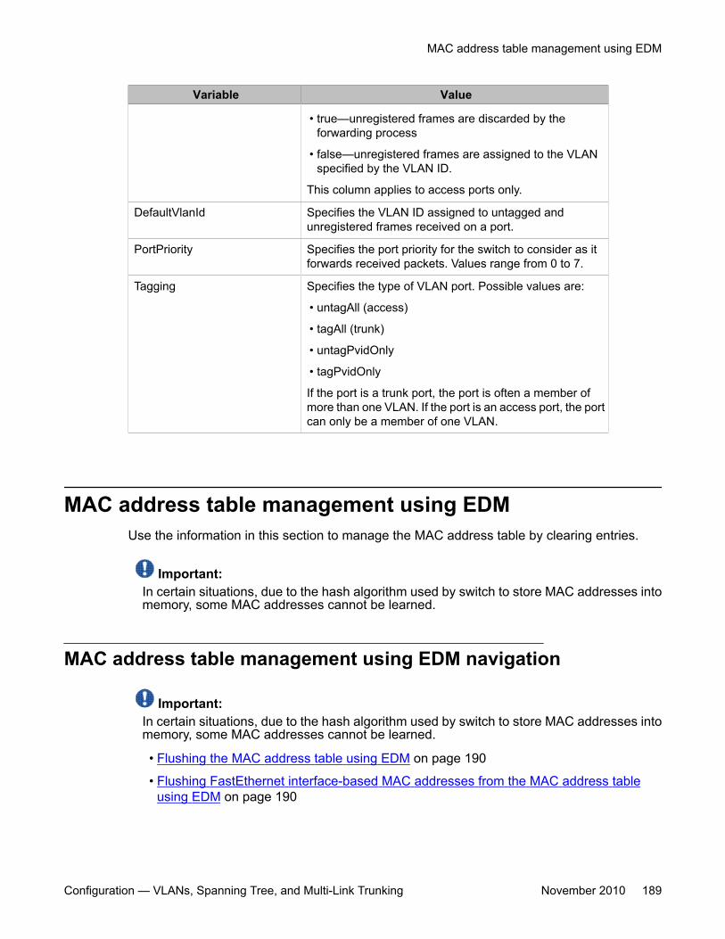
Variable Value
• true—unregistered frames are discarded by theforwarding process
• false—unregistered frames are assigned to the VLANspecified by the VLAN ID.
This column applies to access ports only.
DefaultVlanId Specifies the VLAN ID assigned to untagged andunregistered frames received on a port.
PortPriority Specifies the port priority for the switch to consider as itforwards received packets. Values range from 0 to 7.
Tagging Specifies the type of VLAN port. Possible values are:
• untagAll (access)
• tagAll (trunk)
• untagPvidOnly
• tagPvidOnly
If the port is a trunk port, the port is often a member ofmore than one VLAN. If the port is an access port, the portcan only be a member of one VLAN.
MAC address table management using EDMUse the information in this section to manage the MAC address table by clearing entries.
Important:In certain situations, due to the hash algorithm used by switch to store MAC addresses intomemory, some MAC addresses cannot be learned.
MAC address table management using EDM navigation
Important:In certain situations, due to the hash algorithm used by switch to store MAC addresses intomemory, some MAC addresses cannot be learned.
• Flushing the MAC address table using EDM on page 190
• Flushing FastEthernet interface-based MAC addresses from the MAC address tableusing EDM on page 190
MAC address table management using EDM
Configuration — VLANs, Spanning Tree, and Multi-Link Trunking November 2010 189
• Flushing VLAN-based MAC addresses from the MAC address table using EDM onpage 191
• Flushing trunk-based MAC addresses from the MAC address table using EDM onpage 191
• Flushing a specific MAC address from the MAC address table using EDM on page 192
Flushing the MAC address table using EDMUse the following procedure to clear all MAC addresses from the MAC address table.
Procedure steps
1. From the navigation tree, double-click Edit.
2. In the Edit tree, double-click Bridge.
3. In the work area, click the MAC Flush tab.
4. Select the FlushMacAddrTableAll check box.
5. On the toolbar, click Apply.
Flushing FastEthernet interface-based MAC addresses from theMAC address table using EDM
Use the following procedure to clear FastEthernet interface-based MAC addresses from theMAC address table.
Procedure steps
1. From the navigation tree, double-click Edit.
2. In the Edit tree, double-click Bridge.
3. On the work area, click the MAC Flush tab.
4. Click the FlushMacAddrTableByPortList elipsis (...).
5. Select one or more specific ports.
OR
Click ALL to select all the ports.
Configuring VLANs using Enterprise Device Manager
190 Configuration — VLANs, Spanning Tree, and Multi-Link Trunking November 2010
6. Click Ok.
7. On the toolbar, click Apply.
Flushing VLAN-based MAC addresses from the MAC address tableusing EDM
Use the following procedure to clear VLAN-based MAC addresses from the MAC addresstable.
Procedure steps
1. From the navigation tree, double-click Edit.
2. In the Edit tree, double-click Bridge.
3. On the work area, click the MAC Flush tab.
4. In the FlushMacAddrTableByVlan dialog box, type a VLAN ID ranging from 1 to4094.
5. On the toolbar, click Apply.
Flushing trunk-based MAC addresses from the MAC address tableusing EDM
Use the following procedure to clear trunk-based MAC addresses from the MAC address table.
Procedure steps
1. From the navigation tree, double-click Edit.
2. In the Edit tree, double-click Bridge.
3. On the work area, click the MAC Flush tab.
4. In the FlushMacAddrTableByTrunk dialog box, type a trunk value ranging from 1 to6.
5. On the toolbar, click Apply.
MAC address table management using EDM
Configuration — VLANs, Spanning Tree, and Multi-Link Trunking November 2010 191
Flushing a specific MAC address from the MAC address table usingEDM
Use the following procedure to remove a single specific MAC address from the MAC addresstable.
Procedure steps
1. From the navigation tree, double-click Edit.
2. In the Edit tree, double-click Bridge.
3. On the work area, click the MAC Flush tab.
4. In the FlushMacAddrTableByAddress dialog box, type a MAC address.
5. On the toolbar, click Apply.
Configuring VLANs using Enterprise Device Manager
192 Configuration — VLANs, Spanning Tree, and Multi-Link Trunking November 2010
Chapter 14: Configuring MultiLink Trunkingusing Enterprise DeviceManager
This chapter provides information you can use to create and manage Multi Link Trunks using EnterpriseDevice Manager (EDM).
Navigation• MLT configuration using EDM on page 193• Graphing MLT statistics using EDM on page 197• Graphing MLT Ethernet error statistics using EDM on page 199
MLT configuration using EDMUse the information in this section to create a MultiLink Trunk (MLT) and to modify existingMLT port memberships.
MLT configuration using EDM navigation
• Viewing MLT configurations using EDM on page 193
• Creating an MLT using EDM on page 194
• Modifying MLT port memberships using EDM on page 196
Viewing MLT configurations using EDMUse this procedure to display MLT configuration information.
Configuration — VLANs, Spanning Tree, and Multi-Link Trunking November 2010 193
Procedure steps
1. From the navigation tree, double-click VLAN.
2. In the VLAN tree, double-click MLT/LACP.
3. In the work area, click the Multi Link Trunks tab.
Variable Definitions
Variable ValueId Indicates the number of the MLT (assigned
consecutively). Displays the vlan based on portselected.
PortType Indicates the port type. Values include:
• access
• trunk
Name Indicates a unique alphanumeric identifier for the MLT.
PortMembers Indicates the switch or stack ports to assign to theMLT.
VlanIds Indicates the VLAN identifier. Displays the vlan basedon port selected.
Loadbalance (Mode) Indicates the mode of load balancing. Options arebasic and advanced.
Enable Indicates whether the MLT is enabled (true) ordisabled (false) .
Important:You cannot enable an MLT if trunk port membersare enabled for LACP.
Creating an MLT using EDMCreate an MLT to form a link from the switch to another switch or server.
Configuring MultiLink Trunking using Enterprise Device Manager
194 Configuration — VLANs, Spanning Tree, and Multi-Link Trunking November 2010
Procedure steps
1. From the navigation tree, double-click VLAN.
2. In the VLAN tree, double-click MLT/LACP.
3. In the work area, click the Multi Link Trunks tab.
4. To select a trunk to create, click the trunk Id.
5. In the trunk row, double-click the cell in the Name column.
6. In the box, type a name for the MLT.
OR
Accept the default MLT name.
7. In the trunk row, double-click the cell in the PortMembers column.
8. From the list , select ports to add to the trunk.
9. Click Ok.
10. In the trunk row, double-click the cell in the Loadbalance(Mode) column.
11. From the list, select a load balancing mode.
12. In the trunk row, double-click the cell in the Enable column.
13. From the list, select a value—true to enable the MLT, or false to disable the MLT.
14. You can repeat steps 4 through 13 to create additional MLTs.
15. Click Apply.
Variable Definitions
Variable ValueId Specifies the number of the MLT (assigned
consecutively). Displays the vlan based on portselected.
PortType Specifies the port type. Values include:
• access
• trunk
Name Specifies a unique alphanumeric identifier for the MLT.
PortMembers Specifies the switch or stack ports to assign to theMLT.
MLT configuration using EDM
Configuration — VLANs, Spanning Tree, and Multi-Link Trunking November 2010 195
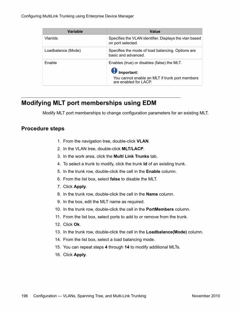
Variable ValueVlanIds Specifies the VLAN identifier. Displays the vlan based
on port selected.
Loadbalance (Mode) Specifies the mode of load balancing. Options arebasic and advanced.
Enable Enables (true) or disables (false) the MLT.
Important:You cannot enable an MLT if trunk port membersare enabled for LACP.
Modifying MLT port memberships using EDMModify MLT port memberships to change configuration parameters for an existing MLT.
Procedure steps
1. From the navigation tree, double-click VLAN.
2. In the VLAN tree, double-click MLT/LACP.
3. In the work area, click the Multi Link Trunks tab.
4. To select a trunk to modify, click the trunk Id of an existing trunk.
5. In the trunk row, double-click the cell in the Enable column.
6. From the list box, select false to disable the MLT.
7. Click Apply.
8. In the trunk row, double-click the cell in the Name column.
9. In the box, edit the MLT name as required.
10. In the trunk row, double-click the cell in the PortMembers column.
11. From the list box, select ports to add to or remove from the trunk.
12. Click Ok.
13. In the trunk row, double-click the cell in the Loadbalance(Mode) column.
14. From the list box, select a load balancing mode.
15. You can repeat steps 4 through 14 to modify additional MLTs.
16. Click Apply.
Configuring MultiLink Trunking using Enterprise Device Manager
196 Configuration — VLANs, Spanning Tree, and Multi-Link Trunking November 2010
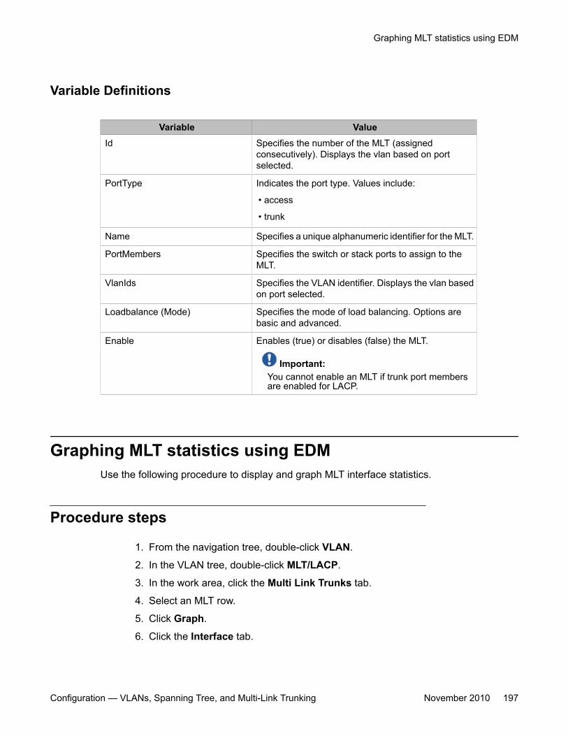
Variable Definitions
Variable ValueId Specifies the number of the MLT (assigned
consecutively). Displays the vlan based on portselected.
PortType Indicates the port type. Values include:
• access
• trunk
Name Specifies a unique alphanumeric identifier for the MLT.
PortMembers Specifies the switch or stack ports to assign to theMLT.
VlanIds Specifies the VLAN identifier. Displays the vlan basedon port selected.
Loadbalance (Mode) Specifies the mode of load balancing. Options arebasic and advanced.
Enable Enables (true) or disables (false) the MLT.
Important:You cannot enable an MLT if trunk port membersare enabled for LACP.
Graphing MLT statistics using EDMUse the following procedure to display and graph MLT interface statistics.
Procedure steps
1. From the navigation tree, double-click VLAN.
2. In the VLAN tree, double-click MLT/LACP.
3. In the work area, click the Multi Link Trunks tab.
4. Select an MLT row.
5. Click Graph.
6. Click the Interface tab.
Graphing MLT statistics using EDM
Configuration — VLANs, Spanning Tree, and Multi-Link Trunking November 2010 197
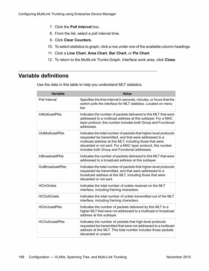
7. Click the Poll Interval box.
8. From the list, select a poll interval time.
9. Click Clear Counters.
10. To select statistics to graph, click a row under one of the available column headings.
11. Click a Line Chart, Area Chart, Bar Chart, or Pie Chart.
12. To return to the MultiLink Trunks-Graph, Interface work area, click Close.
Variable definitionsUse the data in this table to help you understand MLT statistics.
Variable ValuePoll Interval Specifies the time interval in seconds, minutes, or hours that the
switch polls the interface for MLT statistics. Located on menubar.
InMulticastPkts Indicates the number of packets delivered to this MLT that wereaddressed to a multicast address at this sublayer. For a MAClayer protocol, this number includes both Group and Functionaladdresses.
OutMulticastPkts Indicates the total number of packets that higher-level protocolsrequested be transmitted, and that were addressed to amulticast address at this MLT, including those that werediscarded or not sent. For a MAC layer protocol, this numberincludes both Group and Functional addresses.
InBroadcastPkts Indicates the number of packets delivered to this MLT that wereaddressed to a broadcast address at this sublayer.
OutBroadcastPkts Indicates the total number of packets that higher-level protocolsrequested be transmitted, and that were addressed to abroadcast address at this MLT, including those that werediscarded or not sent.
HCInOctets Indicates the total number of octets received on the MLTinterface, including framing characters.
HCOutOctets Indicates the total number of octets transmitted out of the MLTinterface, including framing characters.
HCInUcastPkts Indicates the number of packets delivered by this MLT to ahigher MLT that were not addressed to a multicast or broadcastaddress at this sublayer.
HCOutUcastPkts Indicates the number of packets that high-level protocolsrequested be transmitted that were not addressed to a multicastaddress at this MLT. This total number includes those packetsdiscarded or unsent.
Configuring MultiLink Trunking using Enterprise Device Manager
198 Configuration — VLANs, Spanning Tree, and Multi-Link Trunking November 2010
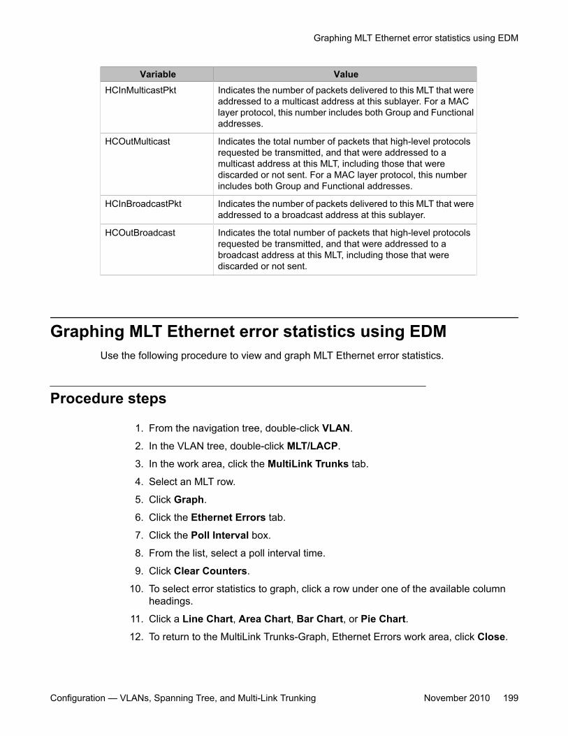
Variable ValueHCInMulticastPkt Indicates the number of packets delivered to this MLT that were
addressed to a multicast address at this sublayer. For a MAClayer protocol, this number includes both Group and Functionaladdresses.
HCOutMulticast Indicates the total number of packets that high-level protocolsrequested be transmitted, and that were addressed to amulticast address at this MLT, including those that werediscarded or not sent. For a MAC layer protocol, this numberincludes both Group and Functional addresses.
HCInBroadcastPkt Indicates the number of packets delivered to this MLT that wereaddressed to a broadcast address at this sublayer.
HCOutBroadcast Indicates the total number of packets that high-level protocolsrequested be transmitted, and that were addressed to abroadcast address at this MLT, including those that werediscarded or not sent.
Graphing MLT Ethernet error statistics using EDMUse the following procedure to view and graph MLT Ethernet error statistics.
Procedure steps
1. From the navigation tree, double-click VLAN.
2. In the VLAN tree, double-click MLT/LACP.
3. In the work area, click the MultiLink Trunks tab.
4. Select an MLT row.
5. Click Graph.
6. Click the Ethernet Errors tab.
7. Click the Poll Interval box.
8. From the list, select a poll interval time.
9. Click Clear Counters.
10. To select error statistics to graph, click a row under one of the available columnheadings.
11. Click a Line Chart, Area Chart, Bar Chart, or Pie Chart.
12. To return to the MultiLink Trunks-Graph, Ethernet Errors work area, click Close.
Graphing MLT Ethernet error statistics using EDM
Configuration — VLANs, Spanning Tree, and Multi-Link Trunking November 2010 199
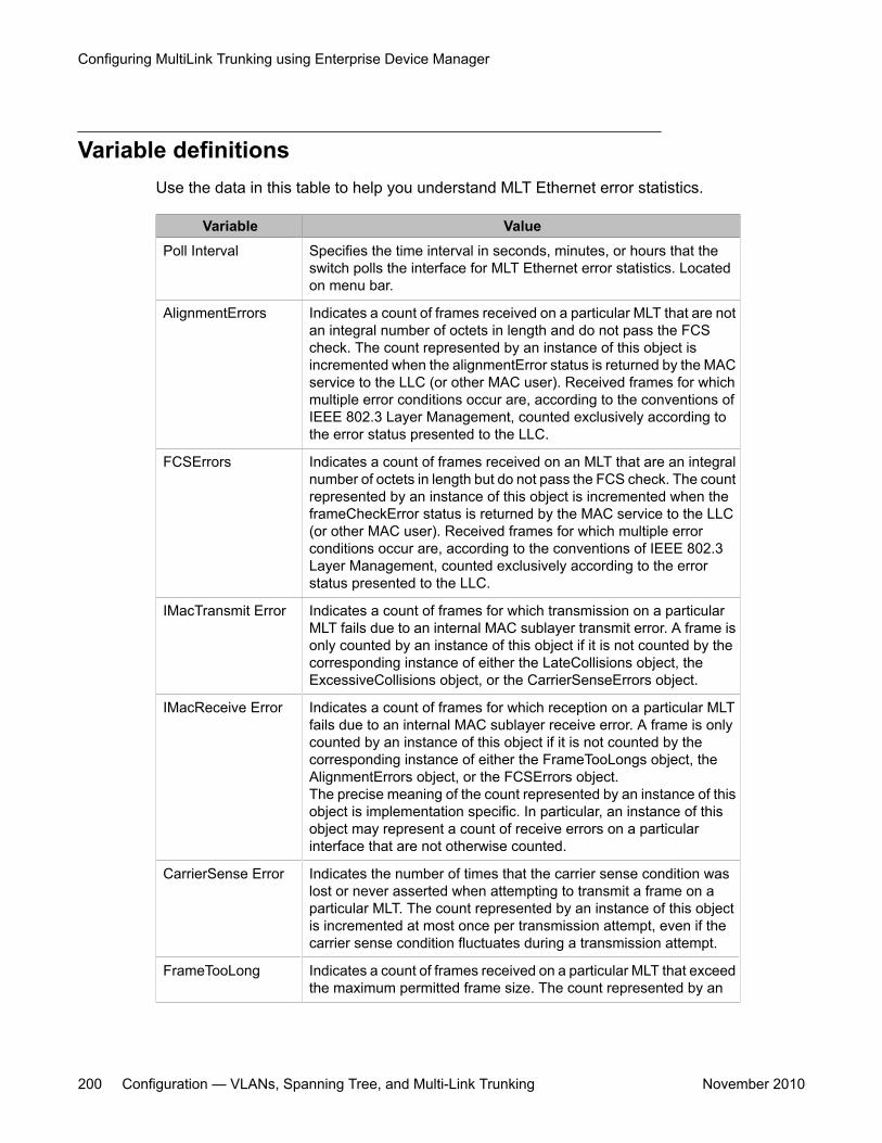
Variable definitionsUse the data in this table to help you understand MLT Ethernet error statistics.
Variable ValuePoll Interval Specifies the time interval in seconds, minutes, or hours that the
switch polls the interface for MLT Ethernet error statistics. Locatedon menu bar.
AlignmentErrors Indicates a count of frames received on a particular MLT that are notan integral number of octets in length and do not pass the FCScheck. The count represented by an instance of this object isincremented when the alignmentError status is returned by the MACservice to the LLC (or other MAC user). Received frames for whichmultiple error conditions occur are, according to the conventions ofIEEE 802.3 Layer Management, counted exclusively according tothe error status presented to the LLC.
FCSErrors Indicates a count of frames received on an MLT that are an integralnumber of octets in length but do not pass the FCS check. The countrepresented by an instance of this object is incremented when theframeCheckError status is returned by the MAC service to the LLC(or other MAC user). Received frames for which multiple errorconditions occur are, according to the conventions of IEEE 802.3Layer Management, counted exclusively according to the errorstatus presented to the LLC.
IMacTransmit Error Indicates a count of frames for which transmission on a particularMLT fails due to an internal MAC sublayer transmit error. A frame isonly counted by an instance of this object if it is not counted by thecorresponding instance of either the LateCollisions object, theExcessiveCollisions object, or the CarrierSenseErrors object.
IMacReceive Error Indicates a count of frames for which reception on a particular MLTfails due to an internal MAC sublayer receive error. A frame is onlycounted by an instance of this object if it is not counted by thecorresponding instance of either the FrameTooLongs object, theAlignmentErrors object, or the FCSErrors object.The precise meaning of the count represented by an instance of thisobject is implementation specific. In particular, an instance of thisobject may represent a count of receive errors on a particularinterface that are not otherwise counted.
CarrierSense Error Indicates the number of times that the carrier sense condition waslost or never asserted when attempting to transmit a frame on aparticular MLT. The count represented by an instance of this objectis incremented at most once per transmission attempt, even if thecarrier sense condition fluctuates during a transmission attempt.
FrameTooLong Indicates a count of frames received on a particular MLT that exceedthe maximum permitted frame size. The count represented by an
Configuring MultiLink Trunking using Enterprise Device Manager
200 Configuration — VLANs, Spanning Tree, and Multi-Link Trunking November 2010
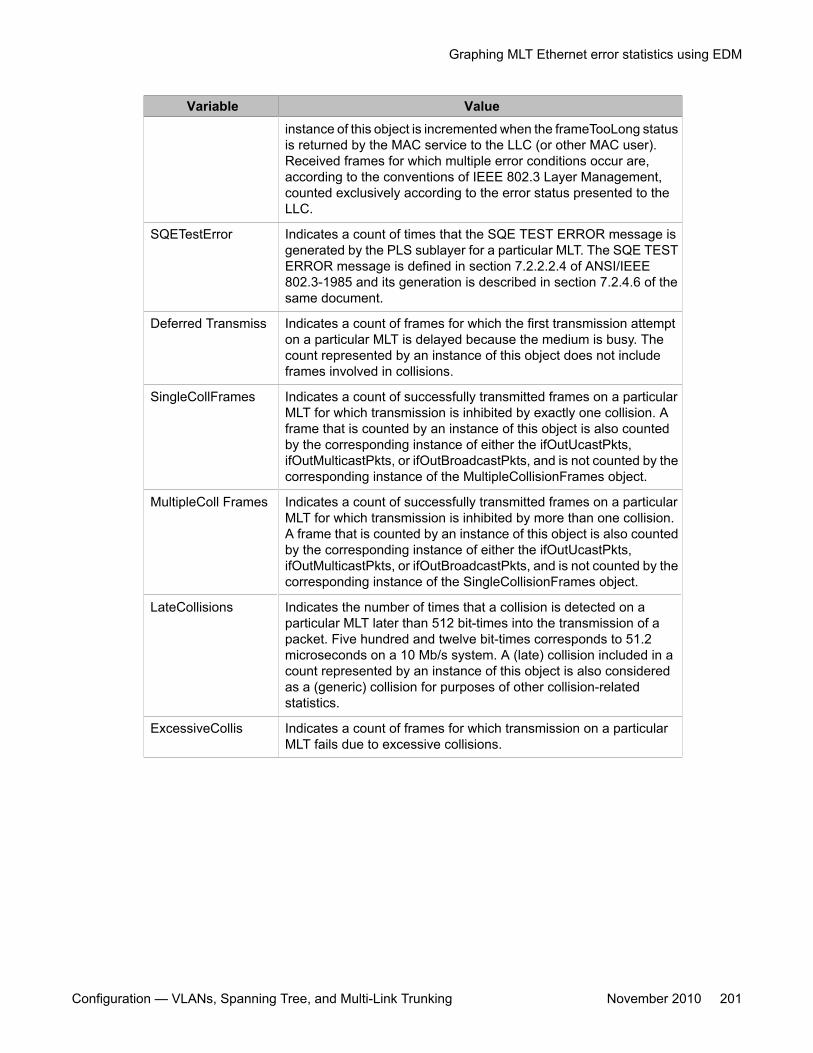
Variable Valueinstance of this object is incremented when the frameTooLong statusis returned by the MAC service to the LLC (or other MAC user).Received frames for which multiple error conditions occur are,according to the conventions of IEEE 802.3 Layer Management,counted exclusively according to the error status presented to theLLC.
SQETestError Indicates a count of times that the SQE TEST ERROR message isgenerated by the PLS sublayer for a particular MLT. The SQE TESTERROR message is defined in section 7.2.2.2.4 of ANSI/IEEE802.3-1985 and its generation is described in section 7.2.4.6 of thesame document.
Deferred Transmiss Indicates a count of frames for which the first transmission attempton a particular MLT is delayed because the medium is busy. Thecount represented by an instance of this object does not includeframes involved in collisions.
SingleCollFrames Indicates a count of successfully transmitted frames on a particularMLT for which transmission is inhibited by exactly one collision. Aframe that is counted by an instance of this object is also countedby the corresponding instance of either the ifOutUcastPkts,ifOutMulticastPkts, or ifOutBroadcastPkts, and is not counted by thecorresponding instance of the MultipleCollisionFrames object.
MultipleColl Frames Indicates a count of successfully transmitted frames on a particularMLT for which transmission is inhibited by more than one collision.A frame that is counted by an instance of this object is also countedby the corresponding instance of either the ifOutUcastPkts,ifOutMulticastPkts, or ifOutBroadcastPkts, and is not counted by thecorresponding instance of the SingleCollisionFrames object.
LateCollisions Indicates the number of times that a collision is detected on aparticular MLT later than 512 bit-times into the transmission of apacket. Five hundred and twelve bit-times corresponds to 51.2microseconds on a 10 Mb/s system. A (late) collision included in acount represented by an instance of this object is also consideredas a (generic) collision for purposes of other collision-relatedstatistics.
ExcessiveCollis Indicates a count of frames for which transmission on a particularMLT fails due to excessive collisions.
Graphing MLT Ethernet error statistics using EDM
Configuration — VLANs, Spanning Tree, and Multi-Link Trunking November 2010 201

Configuring MultiLink Trunking using Enterprise Device Manager
202 Configuration — VLANs, Spanning Tree, and Multi-Link Trunking November 2010
Chapter 15: Configuring Spanning TreeProtocol using Enterprise DeviceManager
This chapter describes how you can configure the Spanning Tree Protocol (STP) and Spanning TreeGroups (STGs) using Enterprise Device Manager (EDM).
Navigation• Configuring the STP mode using EDM on page 203• Configuring STP BPDU filtering for specific ports using EDM on page 204• Configuring STG globally using EDM on page 205• STG configuration using EDM on page 207• Moving a VLAN between STGs using EDM on page 212• Viewing STG Status using EDM on page 212• STG port membership management using EDM on page 214• Port STG membership configuration using EDM on page 217
Configuring the STP mode using EDMUse the following procedure to configure the STP operational mode.
Procedure steps
1. From the navigation tree, double-click VLAN.
2. In the VLAN tree, double-click Spanning Tree.
3. In the Spanning Tree tree, double-click Globals.
4. Choose the STP mode in the SpanningTreeAdminMode field.
Configuration — VLANs, Spanning Tree, and Multi-Link Trunking November 2010 203
5. On the toolbar, click Apply.
A warning message appears reminding you that you must reset the switch for thechange to take effect.
6. Click Yes.
7. Click Close.
For information about resetting the switch, see Resetting the switch using EDM on page 204.
Resetting the switch using EDMUse the following procedure to reset the switch.
Procedure steps
1. From the navigation tree, double-click Edit.
2. In the Edit tree, double-click Chassis.
3. In the Chassis tree, double-click Chassis.
4. On the work area, click the System tab.
5. In the ReBoot section, click the reboot radio button.
6. Click Apply.
Configuring STP BPDU filtering for specific ports using EDMUse this procedure to configure STP BPDU filtering for one or more ports.
You can configure STP BPDU filtering in either STG, RSTP, or MSTP operational mode.
Procedure steps
1. From the navigation tree, double-click Edit.
2. In the Edit tree, double-click Chassis.
3. In the Chassis tree, double-click Ports.
4. On the work area, click the STP BPDU-Filtering tab.
5. To select a port to edit, click the port index.
Configuring Spanning Tree Protocol using Enterprise Device Manager
204 Configuration — VLANs, Spanning Tree, and Multi-Link Trunking November 2010
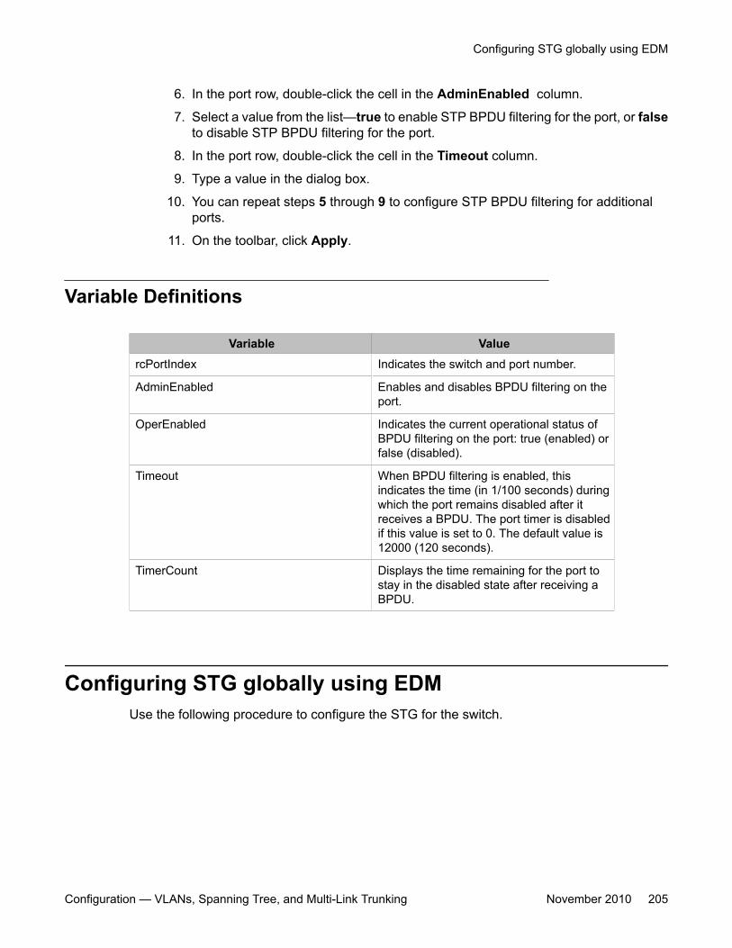
6. In the port row, double-click the cell in the AdminEnabled column.
7. Select a value from the list—true to enable STP BPDU filtering for the port, or falseto disable STP BPDU filtering for the port.
8. In the port row, double-click the cell in the Timeout column.
9. Type a value in the dialog box.
10. You can repeat steps 5 through 9 to configure STP BPDU filtering for additionalports.
11. On the toolbar, click Apply.
Variable Definitions
Variable ValuercPortIndex Indicates the switch and port number.
AdminEnabled Enables and disables BPDU filtering on theport.
OperEnabled Indicates the current operational status ofBPDU filtering on the port: true (enabled) orfalse (disabled).
Timeout When BPDU filtering is enabled, thisindicates the time (in 1/100 seconds) duringwhich the port remains disabled after itreceives a BPDU. The port timer is disabledif this value is set to 0. The default value is12000 (120 seconds).
TimerCount Displays the time remaining for the port tostay in the disabled state after receiving aBPDU.
Configuring STG globally using EDMUse the following procedure to configure the STG for the switch.
Configuring STG globally using EDM
Configuration — VLANs, Spanning Tree, and Multi-Link Trunking November 2010 205
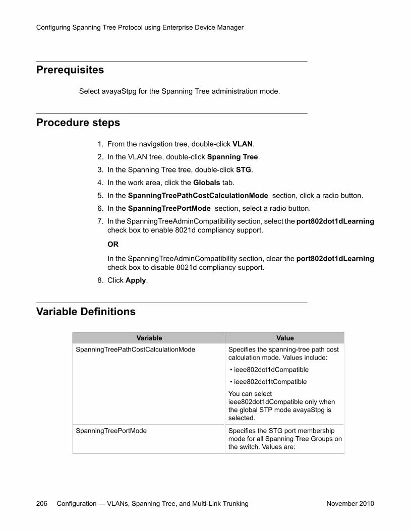
Prerequisites
Select avayaStpg for the Spanning Tree administration mode.
Procedure steps
1. From the navigation tree, double-click VLAN.
2. In the VLAN tree, double-click Spanning Tree.
3. In the Spanning Tree tree, double-click STG.
4. In the work area, click the Globals tab.
5. In the SpanningTreePathCostCalculationMode section, click a radio button.
6. In the SpanningTreePortMode section, select a radio button.
7. In the SpanningTreeAdminCompatibility section, select the port802dot1dLearningcheck box to enable 8021d compliancy support.
OR
In the SpanningTreeAdminCompatibility section, clear the port802dot1dLearningcheck box to disable 8021d compliancy support.
8. Click Apply.
Variable Definitions
Variable ValueSpanningTreePathCostCalculationMode Specifies the spanning-tree path cost
calculation mode. Values include:
• ieee802dot1dCompatible
• ieee802dot1tCompatible
You can selectieee802dot1dCompatible only whenthe global STP mode avayaStpg isselected.
SpanningTreePortMode Specifies the STG port membershipmode for all Spanning Tree Groups onthe switch. Values are:
Configuring Spanning Tree Protocol using Enterprise Device Manager
206 Configuration — VLANs, Spanning Tree, and Multi-Link Trunking November 2010
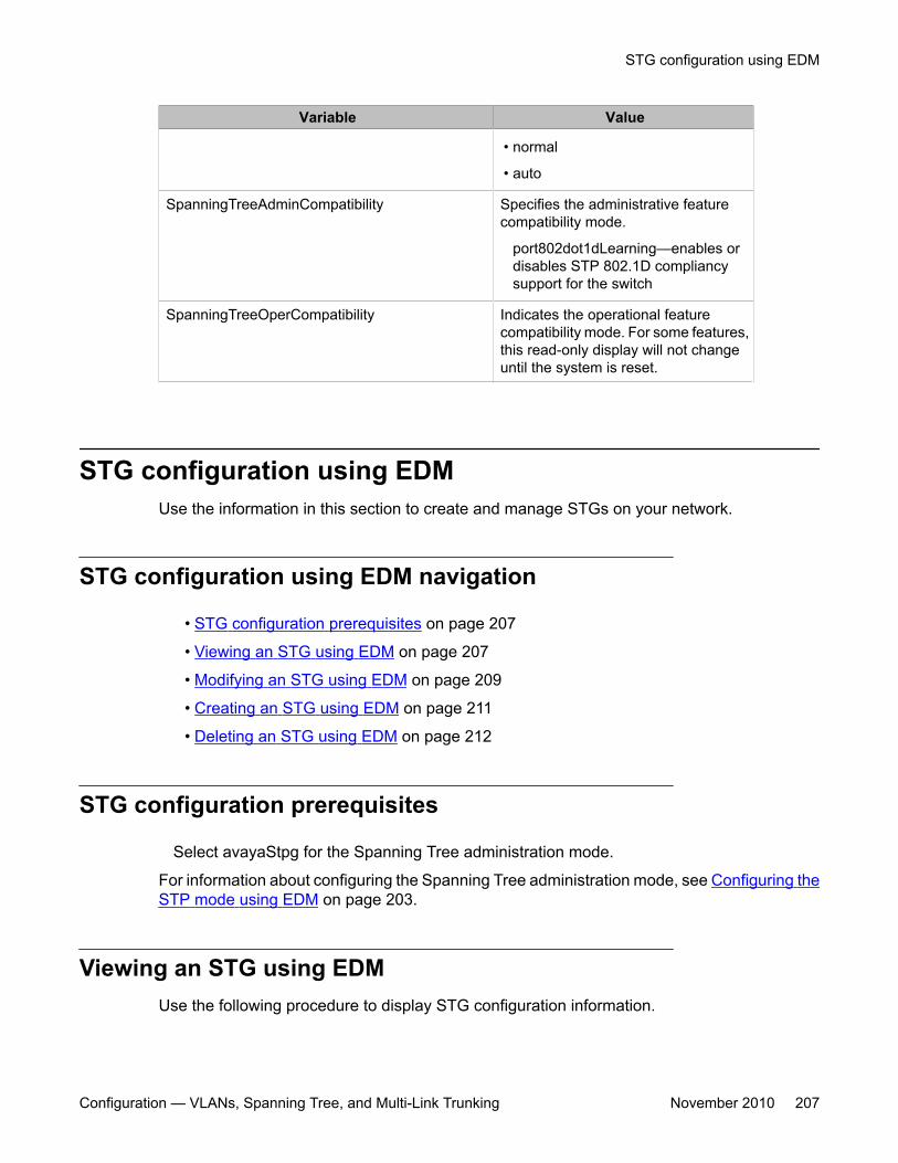
Variable Value
• normal
• auto
SpanningTreeAdminCompatibility Specifies the administrative featurecompatibility mode.
port802dot1dLearning—enables ordisables STP 802.1D compliancysupport for the switch
SpanningTreeOperCompatibility Indicates the operational featurecompatibility mode. For some features,this read-only display will not changeuntil the system is reset.
STG configuration using EDMUse the information in this section to create and manage STGs on your network.
STG configuration using EDM navigation
• STG configuration prerequisites on page 207
• Viewing an STG using EDM on page 207
• Modifying an STG using EDM on page 209
• Creating an STG using EDM on page 211
• Deleting an STG using EDM on page 212
STG configuration prerequisites
Select avayaStpg for the Spanning Tree administration mode.
For information about configuring the Spanning Tree administration mode, see Configuring theSTP mode using EDM on page 203.
Viewing an STG using EDMUse the following procedure to display STG configuration information.
STG configuration using EDM
Configuration — VLANs, Spanning Tree, and Multi-Link Trunking November 2010 207
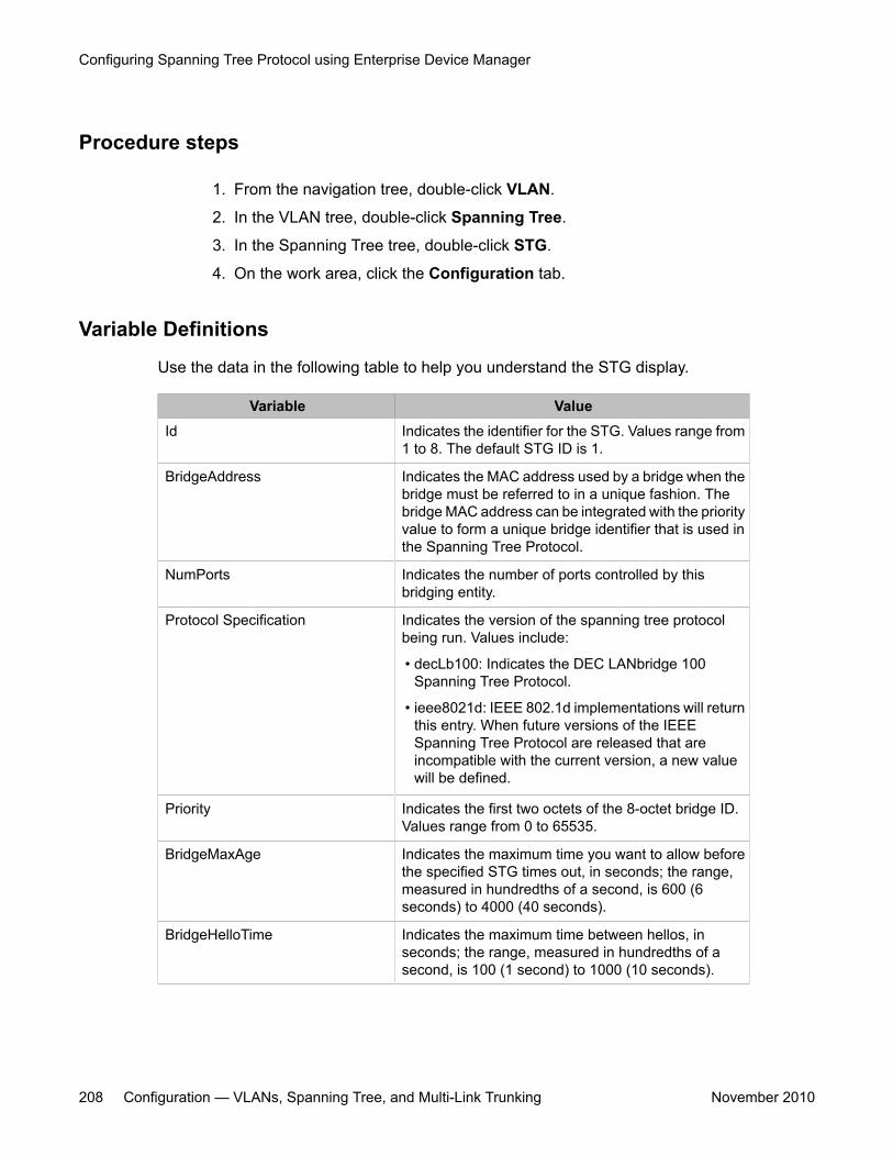
Procedure steps
1. From the navigation tree, double-click VLAN.
2. In the VLAN tree, double-click Spanning Tree.
3. In the Spanning Tree tree, double-click STG.
4. On the work area, click the Configuration tab.
Variable Definitions
Use the data in the following table to help you understand the STG display.
Variable ValueId Indicates the identifier for the STG. Values range from
1 to 8. The default STG ID is 1.
BridgeAddress Indicates the MAC address used by a bridge when thebridge must be referred to in a unique fashion. Thebridge MAC address can be integrated with the priorityvalue to form a unique bridge identifier that is used inthe Spanning Tree Protocol.
NumPorts Indicates the number of ports controlled by thisbridging entity.
Protocol Specification Indicates the version of the spanning tree protocolbeing run. Values include:
• decLb100: Indicates the DEC LANbridge 100Spanning Tree Protocol.
• ieee8021d: IEEE 802.1d implementations will returnthis entry. When future versions of the IEEESpanning Tree Protocol are released that areincompatible with the current version, a new valuewill be defined.
Priority Indicates the first two octets of the 8-octet bridge ID.Values range from 0 to 65535.
BridgeMaxAge Indicates the maximum time you want to allow beforethe specified STG times out, in seconds; the range,measured in hundredths of a second, is 600 (6seconds) to 4000 (40 seconds).
BridgeHelloTime Indicates the maximum time between hellos, inseconds; the range, measured in hundredths of asecond, is 100 (1 second) to 1000 (10 seconds).
Configuring Spanning Tree Protocol using Enterprise Device Manager
208 Configuration — VLANs, Spanning Tree, and Multi-Link Trunking November 2010
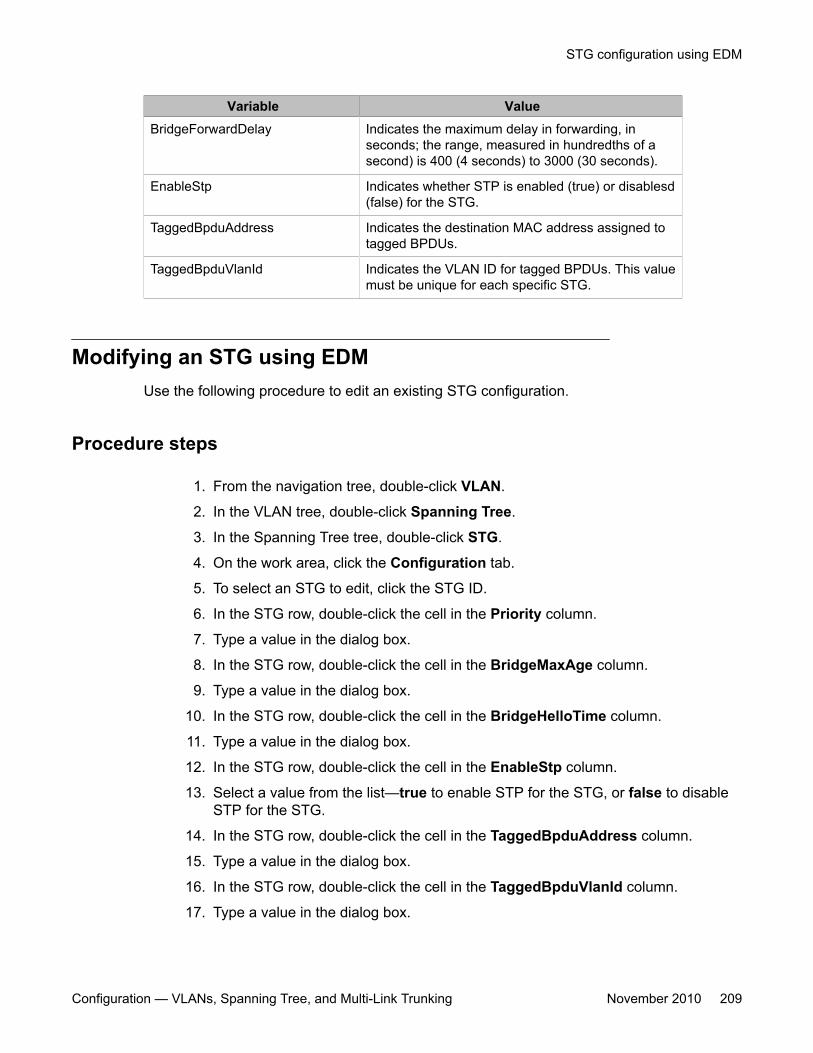
Variable ValueBridgeForwardDelay Indicates the maximum delay in forwarding, in
seconds; the range, measured in hundredths of asecond) is 400 (4 seconds) to 3000 (30 seconds).
EnableStp Indicates whether STP is enabled (true) or disablesd(false) for the STG.
TaggedBpduAddress Indicates the destination MAC address assigned totagged BPDUs.
TaggedBpduVlanId Indicates the VLAN ID for tagged BPDUs. This valuemust be unique for each specific STG.
Modifying an STG using EDMUse the following procedure to edit an existing STG configuration.
Procedure steps
1. From the navigation tree, double-click VLAN.
2. In the VLAN tree, double-click Spanning Tree.
3. In the Spanning Tree tree, double-click STG.
4. On the work area, click the Configuration tab.
5. To select an STG to edit, click the STG ID.
6. In the STG row, double-click the cell in the Priority column.
7. Type a value in the dialog box.
8. In the STG row, double-click the cell in the BridgeMaxAge column.
9. Type a value in the dialog box.
10. In the STG row, double-click the cell in the BridgeHelloTime column.
11. Type a value in the dialog box.
12. In the STG row, double-click the cell in the EnableStp column.
13. Select a value from the list—true to enable STP for the STG, or false to disableSTP for the STG.
14. In the STG row, double-click the cell in the TaggedBpduAddress column.
15. Type a value in the dialog box.
16. In the STG row, double-click the cell in the TaggedBpduVlanId column.
17. Type a value in the dialog box.
STG configuration using EDM
Configuration — VLANs, Spanning Tree, and Multi-Link Trunking November 2010 209
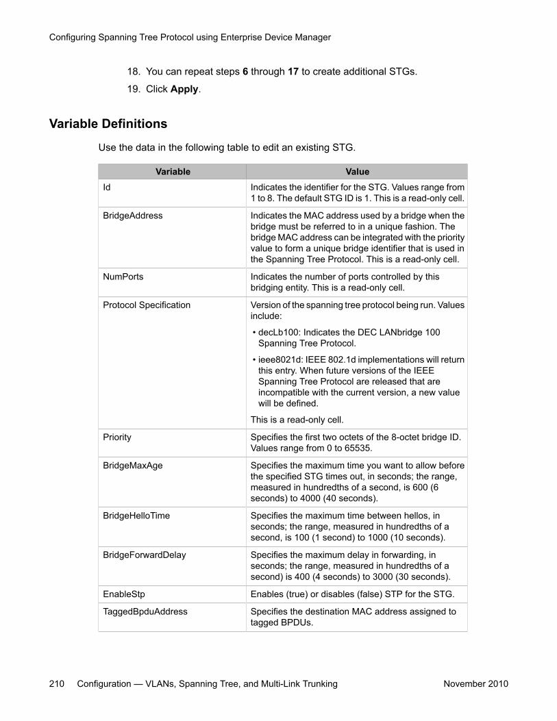
18. You can repeat steps 6 through 17 to create additional STGs.
19. Click Apply.
Variable Definitions
Use the data in the following table to edit an existing STG.
Variable ValueId Indicates the identifier for the STG. Values range from
1 to 8. The default STG ID is 1. This is a read-only cell.
BridgeAddress Indicates the MAC address used by a bridge when thebridge must be referred to in a unique fashion. Thebridge MAC address can be integrated with the priorityvalue to form a unique bridge identifier that is used inthe Spanning Tree Protocol. This is a read-only cell.
NumPorts Indicates the number of ports controlled by thisbridging entity. This is a read-only cell.
Protocol Specification Version of the spanning tree protocol being run. Valuesinclude:
• decLb100: Indicates the DEC LANbridge 100Spanning Tree Protocol.
• ieee8021d: IEEE 802.1d implementations will returnthis entry. When future versions of the IEEESpanning Tree Protocol are released that areincompatible with the current version, a new valuewill be defined.
This is a read-only cell.
Priority Specifies the first two octets of the 8-octet bridge ID.Values range from 0 to 65535.
BridgeMaxAge Specifies the maximum time you want to allow beforethe specified STG times out, in seconds; the range,measured in hundredths of a second, is 600 (6seconds) to 4000 (40 seconds).
BridgeHelloTime Specifies the maximum time between hellos, inseconds; the range, measured in hundredths of asecond, is 100 (1 second) to 1000 (10 seconds).
BridgeForwardDelay Specifies the maximum delay in forwarding, inseconds; the range, measured in hundredths of asecond) is 400 (4 seconds) to 3000 (30 seconds).
EnableStp Enables (true) or disables (false) STP for the STG.
TaggedBpduAddress Specifies the destination MAC address assigned totagged BPDUs.
Configuring Spanning Tree Protocol using Enterprise Device Manager
210 Configuration — VLANs, Spanning Tree, and Multi-Link Trunking November 2010
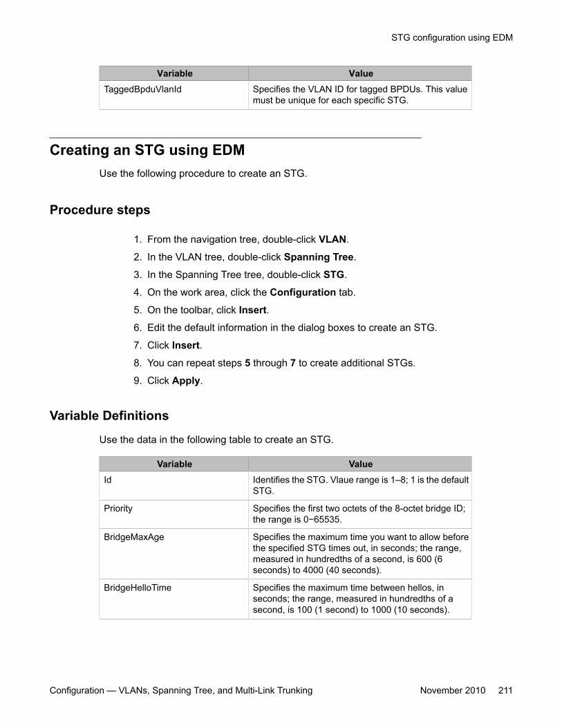
Variable ValueTaggedBpduVlanId Specifies the VLAN ID for tagged BPDUs. This value
must be unique for each specific STG.
Creating an STG using EDMUse the following procedure to create an STG.
Procedure steps
1. From the navigation tree, double-click VLAN.
2. In the VLAN tree, double-click Spanning Tree.
3. In the Spanning Tree tree, double-click STG.
4. On the work area, click the Configuration tab.
5. On the toolbar, click Insert.
6. Edit the default information in the dialog boxes to create an STG.
7. Click Insert.
8. You can repeat steps 5 through 7 to create additional STGs.
9. Click Apply.
Variable Definitions
Use the data in the following table to create an STG.
Variable ValueId Identifies the STG. Vlaue range is 1–8; 1 is the default
STG.
Priority Specifies the first two octets of the 8-octet bridge ID;the range is 0−65535.
BridgeMaxAge Specifies the maximum time you want to allow beforethe specified STG times out, in seconds; the range,measured in hundredths of a second, is 600 (6seconds) to 4000 (40 seconds).
BridgeHelloTime Specifies the maximum time between hellos, inseconds; the range, measured in hundredths of asecond, is 100 (1 second) to 1000 (10 seconds).
STG configuration using EDM
Configuration — VLANs, Spanning Tree, and Multi-Link Trunking November 2010 211
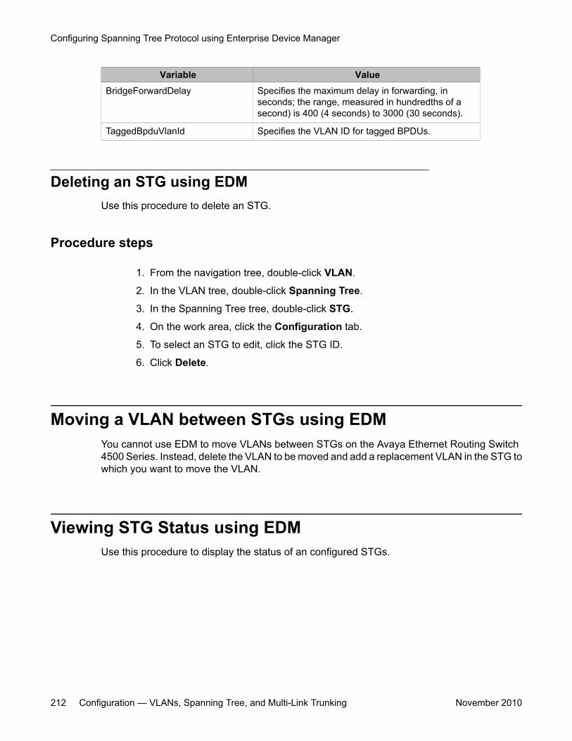
Variable ValueBridgeForwardDelay Specifies the maximum delay in forwarding, in
seconds; the range, measured in hundredths of asecond) is 400 (4 seconds) to 3000 (30 seconds).
TaggedBpduVlanId Specifies the VLAN ID for tagged BPDUs.
Deleting an STG using EDMUse this procedure to delete an STG.
Procedure steps
1. From the navigation tree, double-click VLAN.
2. In the VLAN tree, double-click Spanning Tree.
3. In the Spanning Tree tree, double-click STG.
4. On the work area, click the Configuration tab.
5. To select an STG to edit, click the STG ID.
6. Click Delete.
Moving a VLAN between STGs using EDMYou cannot use EDM to move VLANs between STGs on the Avaya Ethernet Routing Switch4500 Series. Instead, delete the VLAN to be moved and add a replacement VLAN in the STG towhich you want to move the VLAN.
Viewing STG Status using EDMUse this procedure to display the status of an configured STGs.
Configuring Spanning Tree Protocol using Enterprise Device Manager
212 Configuration — VLANs, Spanning Tree, and Multi-Link Trunking November 2010
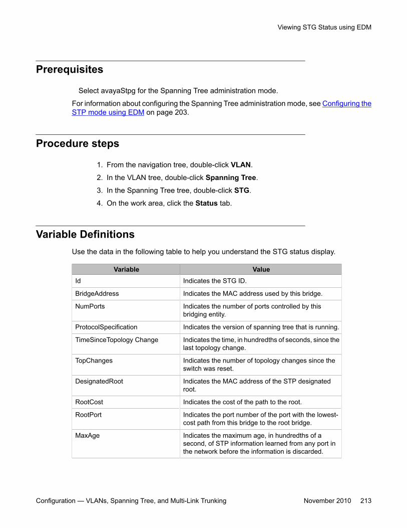
Prerequisites
Select avayaStpg for the Spanning Tree administration mode.
For information about configuring the Spanning Tree administration mode, see Configuring theSTP mode using EDM on page 203.
Procedure steps
1. From the navigation tree, double-click VLAN.
2. In the VLAN tree, double-click Spanning Tree.
3. In the Spanning Tree tree, double-click STG.
4. On the work area, click the Status tab.
Variable DefinitionsUse the data in the following table to help you understand the STG status display.
Variable ValueId Indicates the STG ID.
BridgeAddress Indicates the MAC address used by this bridge.
NumPorts Indicates the number of ports controlled by thisbridging entity.
ProtocolSpecification Indicates the version of spanning tree that is running.
TimeSinceTopology Change Indicates the time, in hundredths of seconds, since thelast topology change.
TopChanges Indicates the number of topology changes since theswitch was reset.
DesignatedRoot Indicates the MAC address of the STP designatedroot.
RootCost Indicates the cost of the path to the root.
RootPort Indicates the port number of the port with the lowest-cost path from this bridge to the root bridge.
MaxAge Indicates the maximum age, in hundredths of asecond, of STP information learned from any port inthe network before the information is discarded.
Viewing STG Status using EDM
Configuration — VLANs, Spanning Tree, and Multi-Link Trunking November 2010 213
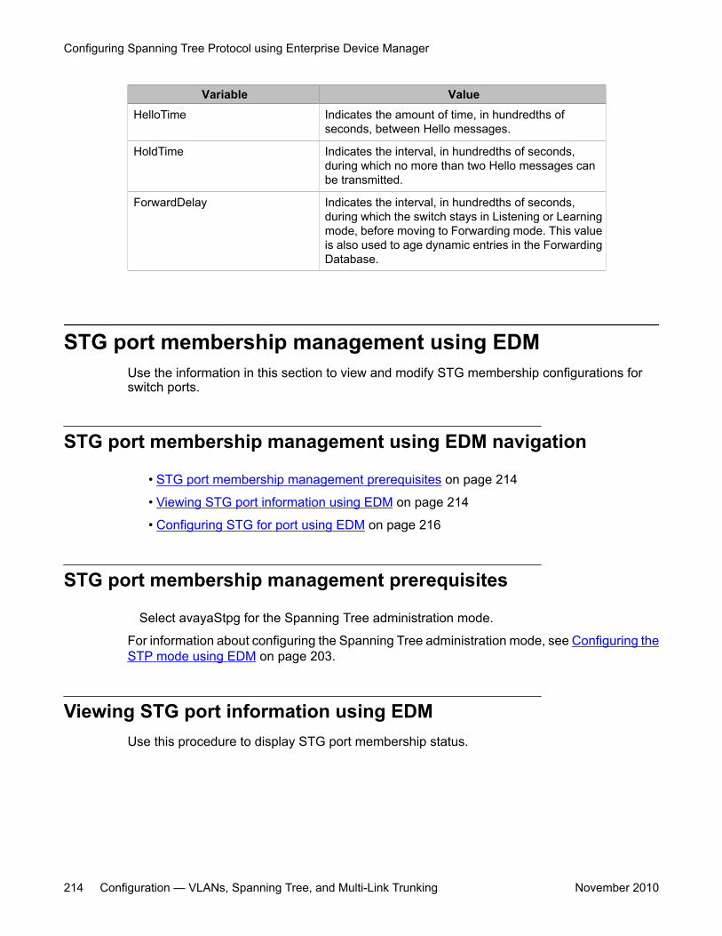
Variable ValueHelloTime Indicates the amount of time, in hundredths of
seconds, between Hello messages.
HoldTime Indicates the interval, in hundredths of seconds,during which no more than two Hello messages canbe transmitted.
ForwardDelay Indicates the interval, in hundredths of seconds,during which the switch stays in Listening or Learningmode, before moving to Forwarding mode. This valueis also used to age dynamic entries in the ForwardingDatabase.
STG port membership management using EDMUse the information in this section to view and modify STG membership configurations forswitch ports.
STG port membership management using EDM navigation
• STG port membership management prerequisites on page 214
• Viewing STG port information using EDM on page 214
• Configuring STG for port using EDM on page 216
STG port membership management prerequisites
Select avayaStpg for the Spanning Tree administration mode.
For information about configuring the Spanning Tree administration mode, see Configuring theSTP mode using EDM on page 203.
Viewing STG port information using EDMUse this procedure to display STG port membership status.
Configuring Spanning Tree Protocol using Enterprise Device Manager
214 Configuration — VLANs, Spanning Tree, and Multi-Link Trunking November 2010
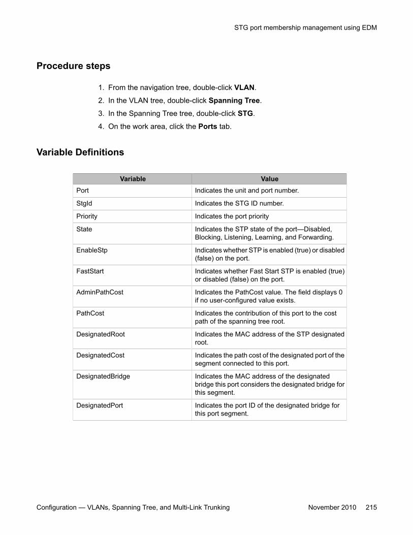
Procedure steps
1. From the navigation tree, double-click VLAN.
2. In the VLAN tree, double-click Spanning Tree.
3. In the Spanning Tree tree, double-click STG.
4. On the work area, click the Ports tab.
Variable Definitions
Variable ValuePort Indicates the unit and port number.
StgId Indicates the STG ID number.
Priority Indicates the port priority
State Indicates the STP state of the port—Disabled,Blocking, Listening, Learning, and Forwarding.
EnableStp Indicates whether STP is enabled (true) or disabled(false) on the port.
FastStart Indicates whether Fast Start STP is enabled (true)or disabled (false) on the port.
AdminPathCost Indicates the PathCost value. The field displays 0if no user-configured value exists.
PathCost Indicates the contribution of this port to the costpath of the spanning tree root.
DesignatedRoot Indicates the MAC address of the STP designatedroot.
DesignatedCost Indicates the path cost of the designated port of thesegment connected to this port.
DesignatedBridge Indicates the MAC address of the designatedbridge this port considers the designated bridge forthis segment.
DesignatedPort Indicates the port ID of the designated bridge forthis port segment.
STG port membership management using EDM
Configuration — VLANs, Spanning Tree, and Multi-Link Trunking November 2010 215
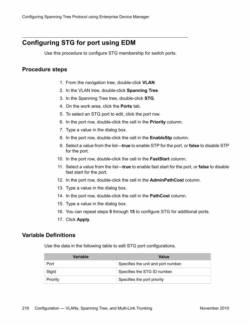
Configuring STG for port using EDMUse this procedure to configure STG membership for switch ports.
Procedure steps
1. From the navigation tree, double-click VLAN.
2. In the VLAN tree, double-click Spanning Tree.
3. In the Spanning Tree tree, double-click STG.
4. On the work area, click the Ports tab.
5. To select an STG port to edit, click the port row.
6. In the port row, double-click the cell in the Priority column.
7. Type a value in the dialog box.
8. In the port row, double-click the cell in the EnableStp column.
9. Select a value from the list—true to enable STP for the port, or false to disable STPfor the port.
10. In the port row, double-click the cell in the FastStart column.
11. Select a value from the list—true to enable fast start for the port, or false to disablefast start for the port.
12. In the port row, double-click the cell in the AdminPathCost column.
13. Type a value in the dialog box.
14. In the port row, double-click the cell in the PathCost column.
15. Type a value in the dialog box.
16. You can repeat steps 5 through 15 to configure STG for additional ports.
17. Click Apply.
Variable Definitions
Use the data in the following table to edit STG port configurations.
Variable ValuePort Specifies the unit and port number.
StgId Specifies the STG ID number.
Priority Specifies the port priority
Configuring Spanning Tree Protocol using Enterprise Device Manager
216 Configuration — VLANs, Spanning Tree, and Multi-Link Trunking November 2010
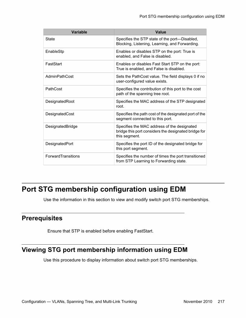
Variable ValueState Specifies the STP state of the port—Disabled,
Blocking, Listening, Learning, and Forwarding.
EnableStp Enables or disables STP on the port: True isenabled, and False is disabled.
FastStart Enables or disables Fast Start STP on the port:True is enabled, and False is disabled.
AdminPathCost Sets the PathCost value. The field displays 0 if nouser-configured value exists.
PathCost Specifies the contribution of this port to the costpath of the spanning tree root.
DesignatedRoot Specifies the MAC address of the STP designatedroot.
DesignatedCost Specifies the path cost of the designated port of thesegment connected to this port.
DesignatedBridge Specifies the MAC address of the designatedbridge this port considers the designated bridge forthis segment.
DesignatedPort Specifies the port ID of the designated bridge forthis port segment.
ForwardTransitions Specifies the number of times the port transitionedfrom STP Learning to Forwarding state.
Port STG membership configuration using EDMUse the information in this section to view and modify switch port STG memberships.
Prerequisites
Ensure that STP is enabled before enabling FastStart.
Viewing STG port membership information using EDMUse this procedure to display information about switch port STG memberships.
Port STG membership configuration using EDM
Configuration — VLANs, Spanning Tree, and Multi-Link Trunking November 2010 217
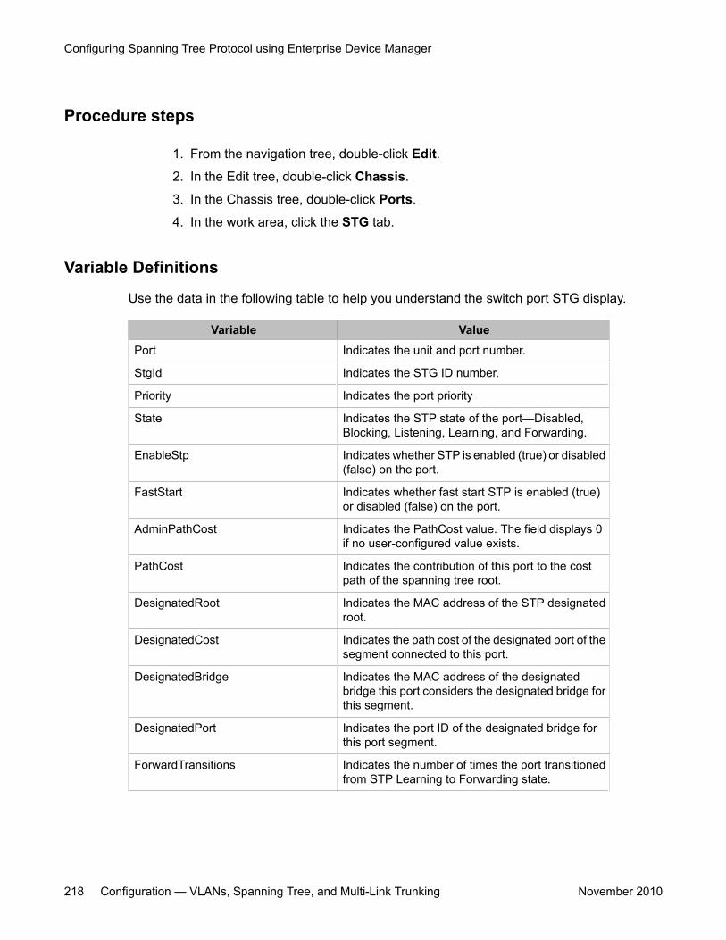
Procedure steps
1. From the navigation tree, double-click Edit.
2. In the Edit tree, double-click Chassis.
3. In the Chassis tree, double-click Ports.
4. In the work area, click the STG tab.
Variable Definitions
Use the data in the following table to help you understand the switch port STG display.
Variable ValuePort Indicates the unit and port number.
StgId Indicates the STG ID number.
Priority Indicates the port priority
State Indicates the STP state of the port—Disabled,Blocking, Listening, Learning, and Forwarding.
EnableStp Indicates whether STP is enabled (true) or disabled(false) on the port.
FastStart Indicates whether fast start STP is enabled (true)or disabled (false) on the port.
AdminPathCost Indicates the PathCost value. The field displays 0if no user-configured value exists.
PathCost Indicates the contribution of this port to the costpath of the spanning tree root.
DesignatedRoot Indicates the MAC address of the STP designatedroot.
DesignatedCost Indicates the path cost of the designated port of thesegment connected to this port.
DesignatedBridge Indicates the MAC address of the designatedbridge this port considers the designated bridge forthis segment.
DesignatedPort Indicates the port ID of the designated bridge forthis port segment.
ForwardTransitions Indicates the number of times the port transitionedfrom STP Learning to Forwarding state.
Configuring Spanning Tree Protocol using Enterprise Device Manager
218 Configuration — VLANs, Spanning Tree, and Multi-Link Trunking November 2010
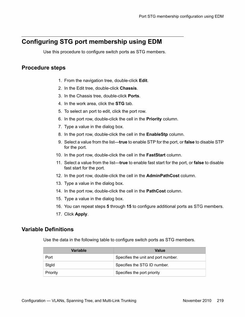
Configuring STG port membership using EDMUse this procedure to configure switch ports as STG members.
Procedure steps
1. From the navigation tree, double-click Edit.
2. In the Edit tree, double-click Chassis.
3. In the Chassis tree, double-click Ports.
4. In the work area, click the STG tab.
5. To select an port to edit, click the port row.
6. In the port row, double-click the cell in the Priority column.
7. Type a value in the dialog box.
8. In the port row, double-click the cell in the EnableStp column.
9. Select a value from the list—true to enable STP for the port, or false to disable STPfor the port.
10. In the port row, double-click the cell in the FastStart column.
11. Select a value from the list—true to enable fast start for the port, or false to disablefast start for the port.
12. In the port row, double-click the cell in the AdminPathCost column.
13. Type a value in the dialog box.
14. In the port row, double-click the cell in the PathCost column.
15. Type a value in the dialog box.
16. You can repeat steps 5 through 15 to configure additional ports as STG members.
17. Click Apply.
Variable Definitions
Use the data in the following table to configure switch ports as STG members.
Variable ValuePort Specifies the unit and port number.
StgId Specifies the STG ID number.
Priority Specifies the port priority
Port STG membership configuration using EDM
Configuration — VLANs, Spanning Tree, and Multi-Link Trunking November 2010 219
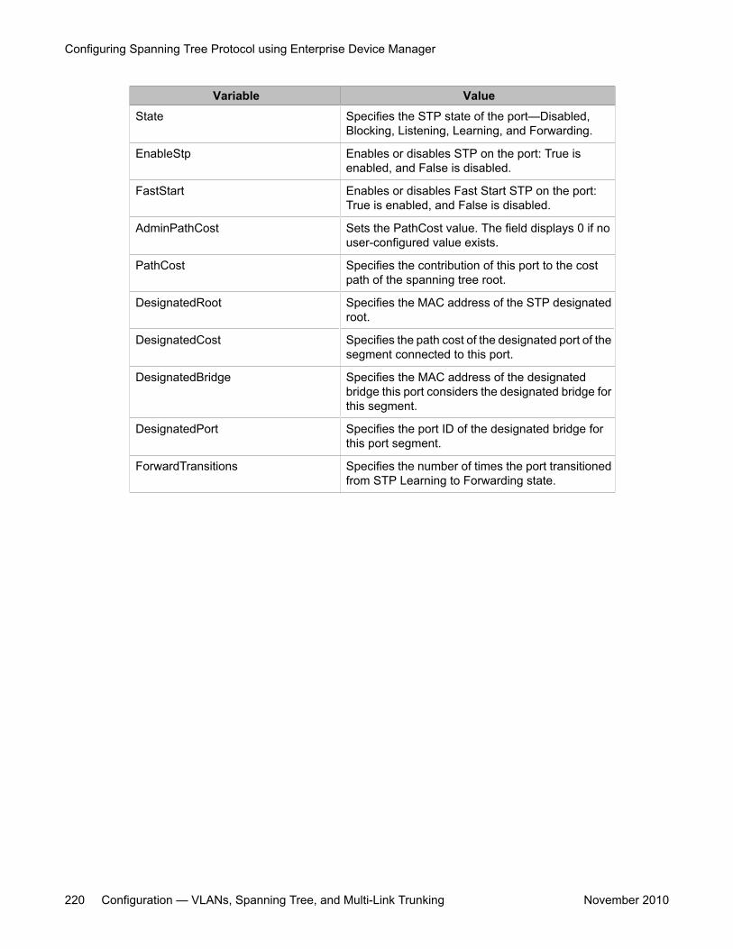
Variable ValueState Specifies the STP state of the port—Disabled,
Blocking, Listening, Learning, and Forwarding.
EnableStp Enables or disables STP on the port: True isenabled, and False is disabled.
FastStart Enables or disables Fast Start STP on the port:True is enabled, and False is disabled.
AdminPathCost Sets the PathCost value. The field displays 0 if nouser-configured value exists.
PathCost Specifies the contribution of this port to the costpath of the spanning tree root.
DesignatedRoot Specifies the MAC address of the STP designatedroot.
DesignatedCost Specifies the path cost of the designated port of thesegment connected to this port.
DesignatedBridge Specifies the MAC address of the designatedbridge this port considers the designated bridge forthis segment.
DesignatedPort Specifies the port ID of the designated bridge forthis port segment.
ForwardTransitions Specifies the number of times the port transitionedfrom STP Learning to Forwarding state.
Configuring Spanning Tree Protocol using Enterprise Device Manager
220 Configuration — VLANs, Spanning Tree, and Multi-Link Trunking November 2010
Chapter 16: RSTP configuration usingEnterprise Device Manager
This chapter describes how you can configure Rapid Spanning Tree protocol (RSTP) using EnterpriseDevice Manager (EDM).
RSTP (or IEEE 802.1w) reduces the recovery time after a network breakdown. It also maintains abackward compatibility with the IEEE 802.1D which was the Spanning Tree implementation prior to RSTP.In certain configurations, the recovery time of RSTP can be reduced to less than 1 second.
RSTP also reduces the amount of flooding in the network by enhancing the way the Topology ChangeNotification (TCN) packet is generated.
PrerequisitesSelect RSTP for the Spanning Tree administration mode.
For information about configuring the Spanning Tree administration mode, see Configuring theSTP mode using EDM on page 203.
Navigation• Viewing global RSTP information using EDM on page 221• Viewing RSTP port information using EDM on page 224• Viewing RSTP statistics using EDM on page 226• Graphing RSTP port statistics using EDM on page 227
Viewing global RSTP information using EDMUse this procedure to display global RSTP information .
Configuration — VLANs, Spanning Tree, and Multi-Link Trunking November 2010 221
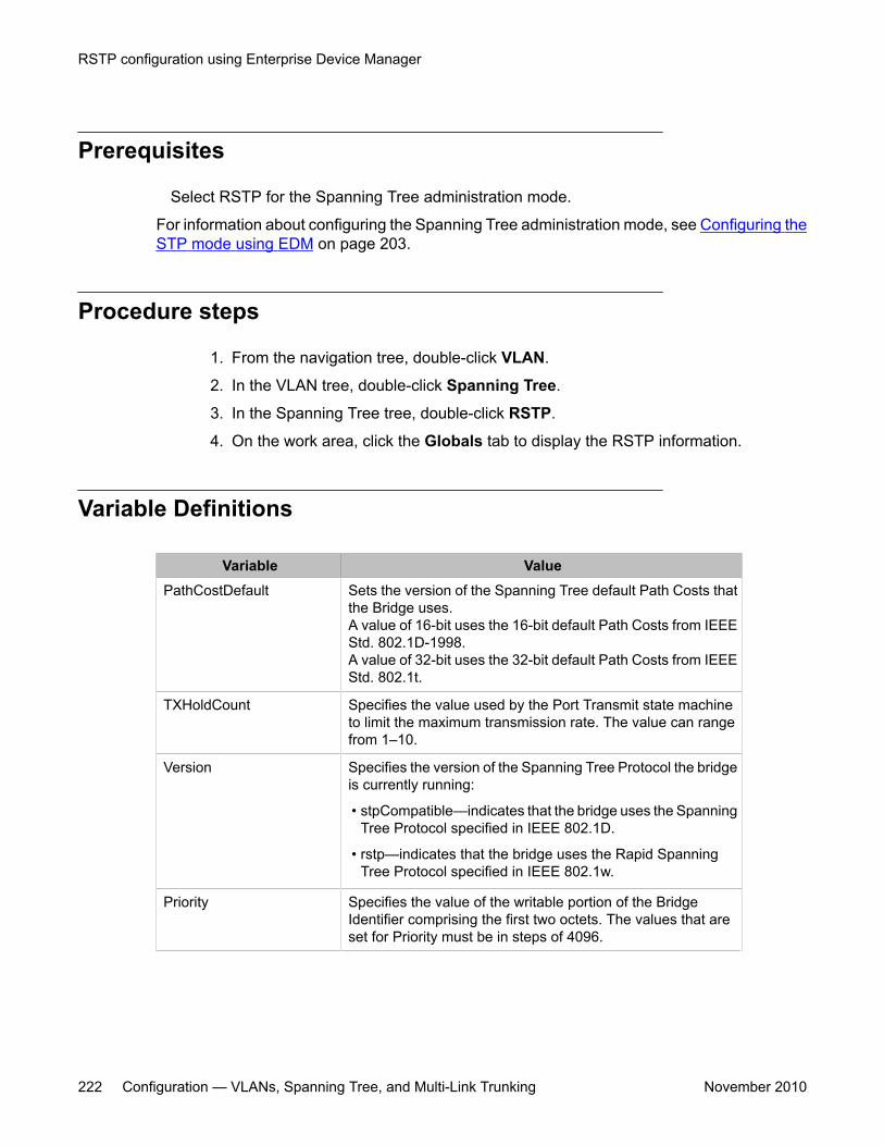
Prerequisites
Select RSTP for the Spanning Tree administration mode.
For information about configuring the Spanning Tree administration mode, see Configuring theSTP mode using EDM on page 203.
Procedure steps
1. From the navigation tree, double-click VLAN.
2. In the VLAN tree, double-click Spanning Tree.
3. In the Spanning Tree tree, double-click RSTP.
4. On the work area, click the Globals tab to display the RSTP information.
Variable Definitions
Variable ValuePathCostDefault Sets the version of the Spanning Tree default Path Costs that
the Bridge uses.A value of 16-bit uses the 16-bit default Path Costs from IEEEStd. 802.1D-1998.A value of 32-bit uses the 32-bit default Path Costs from IEEEStd. 802.1t.
TXHoldCount Specifies the value used by the Port Transmit state machineto limit the maximum transmission rate. The value can rangefrom 1–10.
Version Specifies the version of the Spanning Tree Protocol the bridgeis currently running:
• stpCompatible—indicates that the bridge uses the SpanningTree Protocol specified in IEEE 802.1D.
• rstp—indicates that the bridge uses the Rapid SpanningTree Protocol specified in IEEE 802.1w.
Priority Specifies the value of the writable portion of the BridgeIdentifier comprising the first two octets. The values that areset for Priority must be in steps of 4096.
RSTP configuration using Enterprise Device Manager
222 Configuration — VLANs, Spanning Tree, and Multi-Link Trunking November 2010
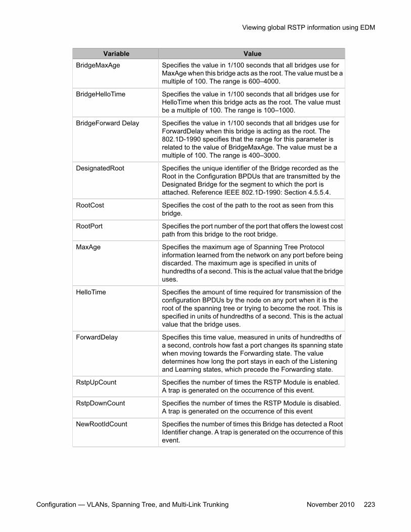
Variable ValueBridgeMaxAge Specifies the value in 1/100 seconds that all bridges use for
MaxAge when this bridge acts as the root. The value must be amultiple of 100. The range is 600–4000.
BridgeHelloTime Specifies the value in 1/100 seconds that all bridges use forHelloTime when this bridge acts as the root. The value mustbe a multiple of 100. The range is 100–1000.
BridgeForward Delay Specifies the value in 1/100 seconds that all bridges use forForwardDelay when this bridge is acting as the root. The802.1D-1990 specifies that the range for this parameter isrelated to the value of BridgeMaxAge. The value must be amultiple of 100. The range is 400–3000.
DesignatedRoot Specifies the unique identifier of the Bridge recorded as theRoot in the Configuration BPDUs that are transmitted by theDesignated Bridge for the segment to which the port isattached. Reference IEEE 802.1D-1990: Section 4.5.5.4.
RootCost Specifies the cost of the path to the root as seen from thisbridge.
RootPort Specifies the port number of the port that offers the lowest costpath from this bridge to the root bridge.
MaxAge Specifies the maximum age of Spanning Tree Protocolinformation learned from the network on any port before beingdiscarded. The maximum age is specified in units ofhundredths of a second. This is the actual value that the bridgeuses.
HelloTime Specifies the amount of time required for transmission of theconfiguration BPDUs by the node on any port when it is theroot of the spanning tree or trying to become the root. This isspecified in units of hundredths of a second. This is the actualvalue that the bridge uses.
ForwardDelay Specifies this time value, measured in units of hundredths ofa second, controls how fast a port changes its spanning statewhen moving towards the Forwarding state. The valuedetermines how long the port stays in each of the Listeningand Learning states, which precede the Forwarding state.
RstpUpCount Specifies the number of times the RSTP Module is enabled.A trap is generated on the occurrence of this event.
RstpDownCount Specifies the number of times the RSTP Module is disabled.A trap is generated on the occurrence of this event
NewRootIdCount Specifies the number of times this Bridge has detected a RootIdentifier change. A trap is generated on the occurrence of thisevent.
Viewing global RSTP information using EDM
Configuration — VLANs, Spanning Tree, and Multi-Link Trunking November 2010 223
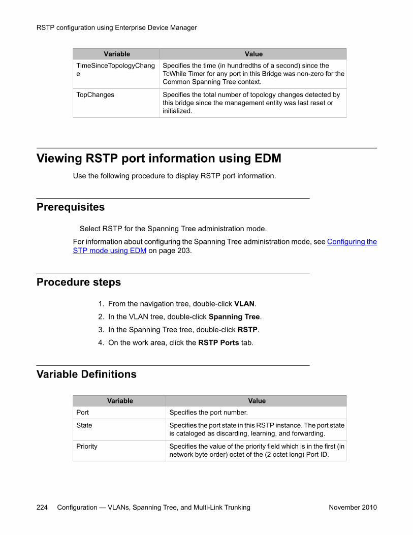
Variable ValueTimeSinceTopologyChange
Specifies the time (in hundredths of a second) since theTcWhile Timer for any port in this Bridge was non-zero for theCommon Spanning Tree context.
TopChanges Specifies the total number of topology changes detected bythis bridge since the management entity was last reset orinitialized.
Viewing RSTP port information using EDMUse the following procedure to display RSTP port information.
Prerequisites
Select RSTP for the Spanning Tree administration mode.
For information about configuring the Spanning Tree administration mode, see Configuring theSTP mode using EDM on page 203.
Procedure steps
1. From the navigation tree, double-click VLAN.
2. In the VLAN tree, double-click Spanning Tree.
3. In the Spanning Tree tree, double-click RSTP.
4. On the work area, click the RSTP Ports tab.
Variable Definitions
Variable ValuePort Specifies the port number.
State Specifies the port state in this RSTP instance. The port stateis cataloged as discarding, learning, and forwarding.
Priority Specifies the value of the priority field which is in the first (innetwork byte order) octet of the (2 octet long) Port ID.
RSTP configuration using Enterprise Device Manager
224 Configuration — VLANs, Spanning Tree, and Multi-Link Trunking November 2010
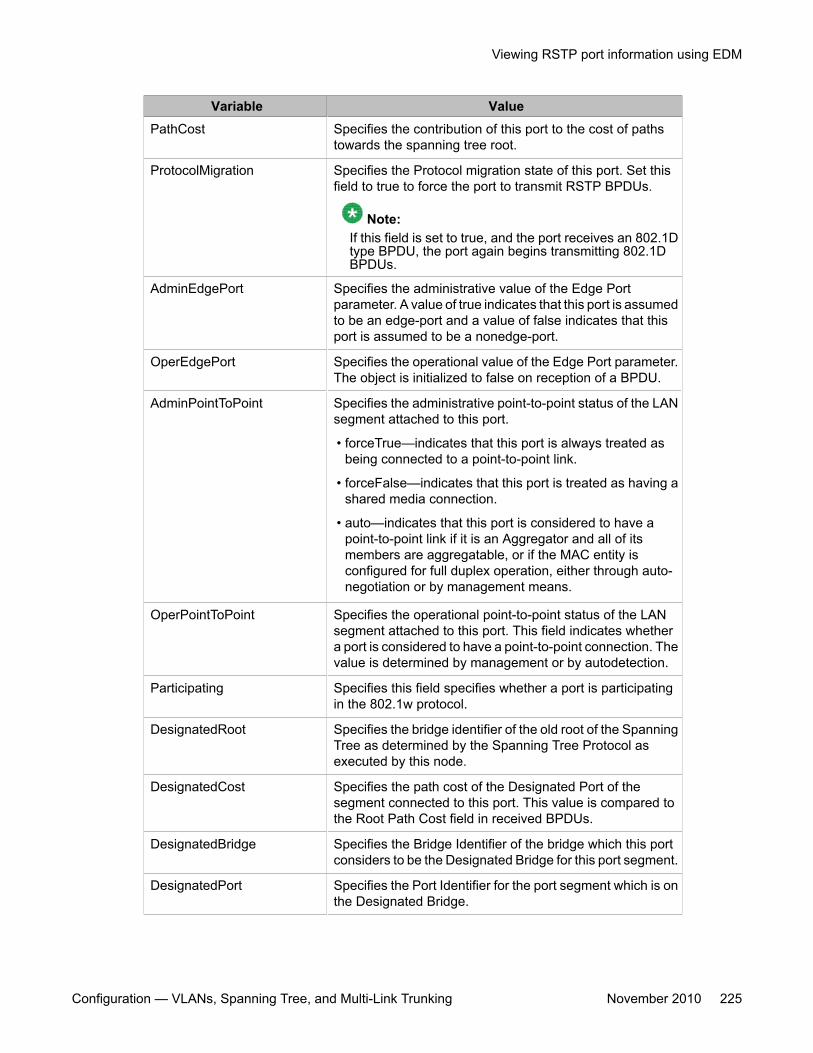
Variable ValuePathCost Specifies the contribution of this port to the cost of paths
towards the spanning tree root.
ProtocolMigration Specifies the Protocol migration state of this port. Set thisfield to true to force the port to transmit RSTP BPDUs.
Note:If this field is set to true, and the port receives an 802.1Dtype BPDU, the port again begins transmitting 802.1DBPDUs.
AdminEdgePort Specifies the administrative value of the Edge Portparameter. A value of true indicates that this port is assumedto be an edge-port and a value of false indicates that thisport is assumed to be a nonedge-port.
OperEdgePort Specifies the operational value of the Edge Port parameter.The object is initialized to false on reception of a BPDU.
AdminPointToPoint Specifies the administrative point-to-point status of the LANsegment attached to this port.
• forceTrue—indicates that this port is always treated asbeing connected to a point-to-point link.
• forceFalse—indicates that this port is treated as having ashared media connection.
• auto—indicates that this port is considered to have apoint-to-point link if it is an Aggregator and all of itsmembers are aggregatable, or if the MAC entity isconfigured for full duplex operation, either through auto-negotiation or by management means.
OperPointToPoint Specifies the operational point-to-point status of the LANsegment attached to this port. This field indicates whethera port is considered to have a point-to-point connection. Thevalue is determined by management or by autodetection.
Participating Specifies this field specifies whether a port is participatingin the 802.1w protocol.
DesignatedRoot Specifies the bridge identifier of the old root of the SpanningTree as determined by the Spanning Tree Protocol asexecuted by this node.
DesignatedCost Specifies the path cost of the Designated Port of thesegment connected to this port. This value is compared tothe Root Path Cost field in received BPDUs.
DesignatedBridge Specifies the Bridge Identifier of the bridge which this portconsiders to be the Designated Bridge for this port segment.
DesignatedPort Specifies the Port Identifier for the port segment which is onthe Designated Bridge.
Viewing RSTP port information using EDM
Configuration — VLANs, Spanning Tree, and Multi-Link Trunking November 2010 225
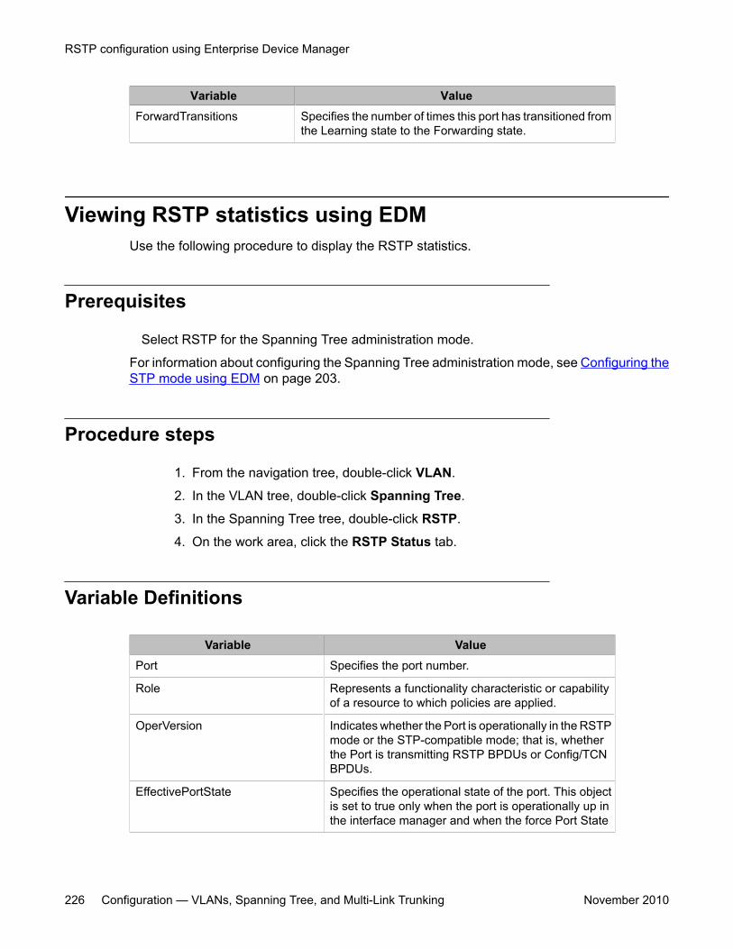
Variable ValueForwardTransitions Specifies the number of times this port has transitioned from
the Learning state to the Forwarding state.
Viewing RSTP statistics using EDMUse the following procedure to display the RSTP statistics.
Prerequisites
Select RSTP for the Spanning Tree administration mode.
For information about configuring the Spanning Tree administration mode, see Configuring theSTP mode using EDM on page 203.
Procedure steps
1. From the navigation tree, double-click VLAN.
2. In the VLAN tree, double-click Spanning Tree.
3. In the Spanning Tree tree, double-click RSTP.
4. On the work area, click the RSTP Status tab.
Variable Definitions
Variable ValuePort Specifies the port number.
Role Represents a functionality characteristic or capabilityof a resource to which policies are applied.
OperVersion Indicates whether the Port is operationally in the RSTPmode or the STP-compatible mode; that is, whetherthe Port is transmitting RSTP BPDUs or Config/TCNBPDUs.
EffectivePortState Specifies the operational state of the port. This objectis set to true only when the port is operationally up inthe interface manager and when the force Port State
RSTP configuration using Enterprise Device Manager
226 Configuration — VLANs, Spanning Tree, and Multi-Link Trunking November 2010
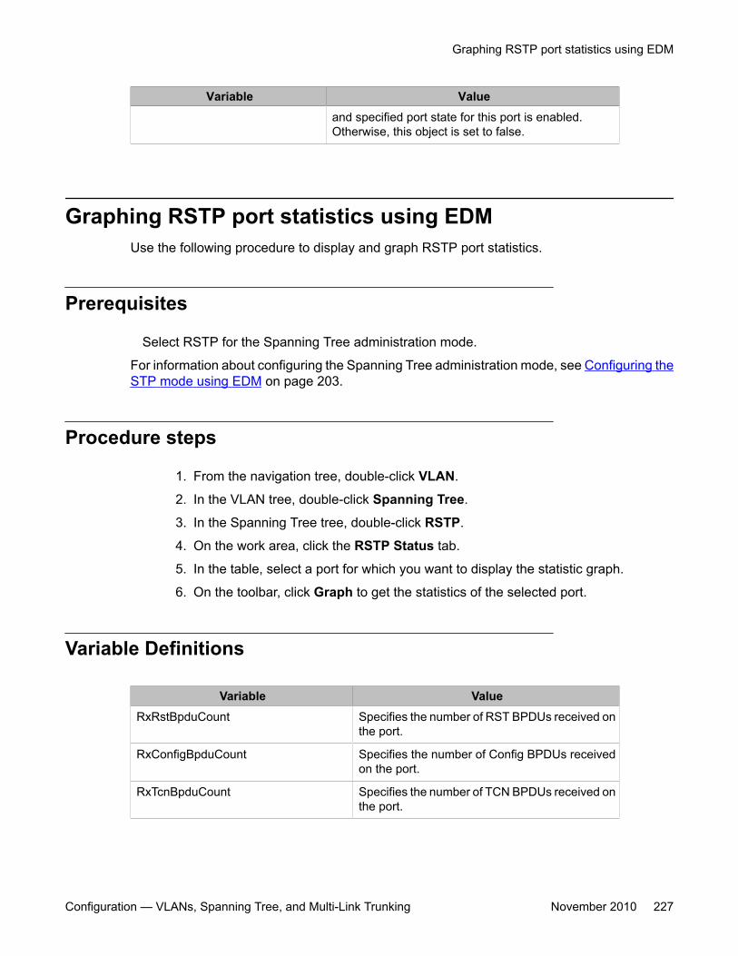
Variable Valueand specified port state for this port is enabled.Otherwise, this object is set to false.
Graphing RSTP port statistics using EDMUse the following procedure to display and graph RSTP port statistics.
Prerequisites
Select RSTP for the Spanning Tree administration mode.
For information about configuring the Spanning Tree administration mode, see Configuring theSTP mode using EDM on page 203.
Procedure steps
1. From the navigation tree, double-click VLAN.
2. In the VLAN tree, double-click Spanning Tree.
3. In the Spanning Tree tree, double-click RSTP.
4. On the work area, click the RSTP Status tab.
5. In the table, select a port for which you want to display the statistic graph.
6. On the toolbar, click Graph to get the statistics of the selected port.
Variable Definitions
Variable ValueRxRstBpduCount Specifies the number of RST BPDUs received on
the port.
RxConfigBpduCount Specifies the number of Config BPDUs receivedon the port.
RxTcnBpduCount Specifies the number of TCN BPDUs received onthe port.
Graphing RSTP port statistics using EDM
Configuration — VLANs, Spanning Tree, and Multi-Link Trunking November 2010 227
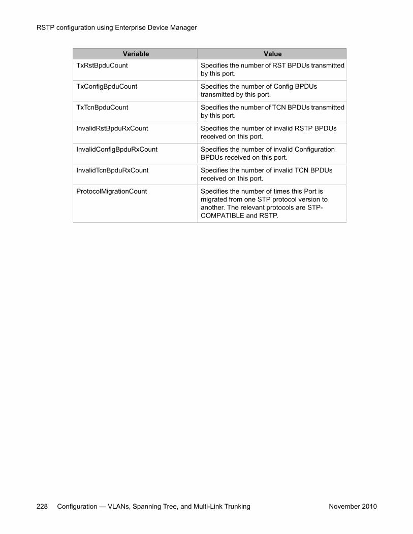
Variable ValueTxRstBpduCount Specifies the number of RST BPDUs transmitted
by this port.
TxConfigBpduCount Specifies the number of Config BPDUstransmitted by this port.
TxTcnBpduCount Specifies the number of TCN BPDUs transmittedby this port.
InvalidRstBpduRxCount Specifies the number of invalid RSTP BPDUsreceived on this port.
InvalidConfigBpduRxCount Specifies the number of invalid ConfigurationBPDUs received on this port.
InvalidTcnBpduRxCount Specifies the number of invalid TCN BPDUsreceived on this port.
ProtocolMigrationCount Specifies the number of times this Port ismigrated from one STP protocol version toanother. The relevant protocols are STP-COMPATIBLE and RSTP.
RSTP configuration using Enterprise Device Manager
228 Configuration — VLANs, Spanning Tree, and Multi-Link Trunking November 2010
Chapter 17: MSTP configuration usingEnterprise Device Manager
This chapter describes how you can configure Multiple Spanning Tree Protocol (MSTP) using EnterpriseDevice Manager (EDM).
With MSTP (or IEEE 802.1s), you can configure multiple instances of RSTP on the same switch. EachMSTP instance can include one or more VLANs. The operation of the MSTP is similar to the current Avayaproprietary STG.
In the MSTP mode, the 4500 Series switches support a maximum of one Common and Internal SpanningTree (CIST) and seven Multiple Spanning Tree Instances (MSTI).
Within the CIST, the Internal Spanning Tree component is used only by devices from the same region (forwhich a regional root is elected). The Common (External) Spanning Tree component of the CIST is used bydevices from different regions or between devices with different STP modes.
PrerequisitesSelect MSTP for the Spanning Tree administration mode.
For information about configuring the Spanning Tree administration mode, see Configuring theSTP mode using EDM on page 203.
Navigation• Viewing global MSTP using EDM on page 230• Viewing CIST port information using EDM on page 233• Graphing CIST port statistics using EDM on page 235• Viewing MSTI bridge information using EDM on page 237• Viewing MSTI port information using EDM on page 239• Graphing MSTI port statistics using EDM on page 241
Configuration — VLANs, Spanning Tree, and Multi-Link Trunking November 2010 229
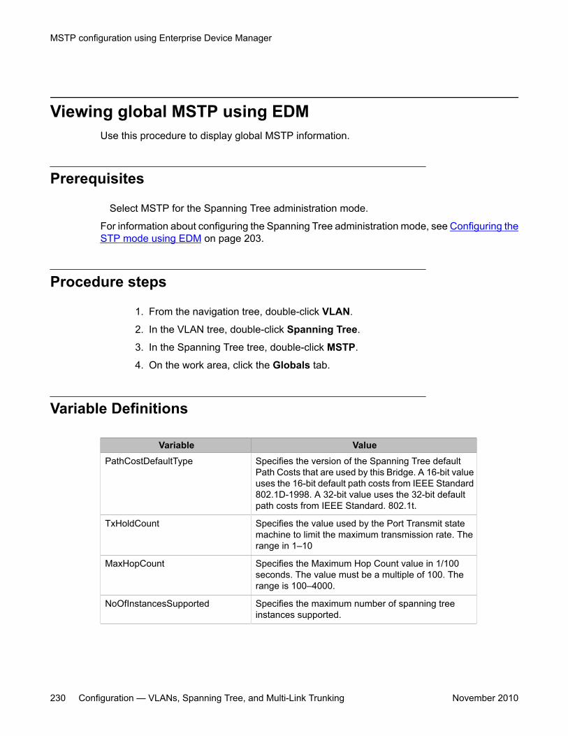
Viewing global MSTP using EDMUse this procedure to display global MSTP information.
Prerequisites
Select MSTP for the Spanning Tree administration mode.
For information about configuring the Spanning Tree administration mode, see Configuring theSTP mode using EDM on page 203.
Procedure steps
1. From the navigation tree, double-click VLAN.
2. In the VLAN tree, double-click Spanning Tree.
3. In the Spanning Tree tree, double-click MSTP.
4. On the work area, click the Globals tab.
Variable Definitions
Variable ValuePathCostDefaultType Specifies the version of the Spanning Tree default
Path Costs that are used by this Bridge. A 16-bit valueuses the 16-bit default path costs from IEEE Standard802.1D-1998. A 32-bit value uses the 32-bit defaultpath costs from IEEE Standard. 802.1t.
TxHoldCount Specifies the value used by the Port Transmit statemachine to limit the maximum transmission rate. Therange in 1–10
MaxHopCount Specifies the Maximum Hop Count value in 1/100seconds. The value must be a multiple of 100. Therange is 100–4000.
NoOfInstancesSupported Specifies the maximum number of spanning treeinstances supported.
MSTP configuration using Enterprise Device Manager
230 Configuration — VLANs, Spanning Tree, and Multi-Link Trunking November 2010
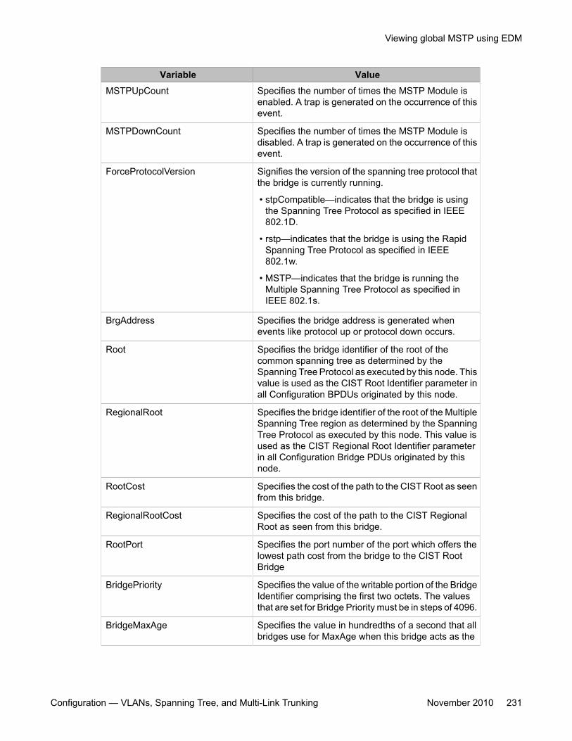
Variable ValueMSTPUpCount Specifies the number of times the MSTP Module is
enabled. A trap is generated on the occurrence of thisevent.
MSTPDownCount Specifies the number of times the MSTP Module isdisabled. A trap is generated on the occurrence of thisevent.
ForceProtocolVersion Signifies the version of the spanning tree protocol thatthe bridge is currently running.
• stpCompatible—indicates that the bridge is usingthe Spanning Tree Protocol as specified in IEEE802.1D.
• rstp—indicates that the bridge is using the RapidSpanning Tree Protocol as specified in IEEE802.1w.
• MSTP—indicates that the bridge is running theMultiple Spanning Tree Protocol as specified inIEEE 802.1s.
BrgAddress Specifies the bridge address is generated whenevents like protocol up or protocol down occurs.
Root Specifies the bridge identifier of the root of thecommon spanning tree as determined by theSpanning Tree Protocol as executed by this node. Thisvalue is used as the CIST Root Identifier parameter inall Configuration BPDUs originated by this node.
RegionalRoot Specifies the bridge identifier of the root of the MultipleSpanning Tree region as determined by the SpanningTree Protocol as executed by this node. This value isused as the CIST Regional Root Identifier parameterin all Configuration Bridge PDUs originated by thisnode.
RootCost Specifies the cost of the path to the CIST Root as seenfrom this bridge.
RegionalRootCost Specifies the cost of the path to the CIST RegionalRoot as seen from this bridge.
RootPort Specifies the port number of the port which offers thelowest path cost from the bridge to the CIST RootBridge
BridgePriority Specifies the value of the writable portion of the BridgeIdentifier comprising the first two octets. The valuesthat are set for Bridge Priority must be in steps of 4096.
BridgeMaxAge Specifies the value in hundredths of a second that allbridges use for MaxAge when this bridge acts as the
Viewing global MSTP using EDM
Configuration — VLANs, Spanning Tree, and Multi-Link Trunking November 2010 231
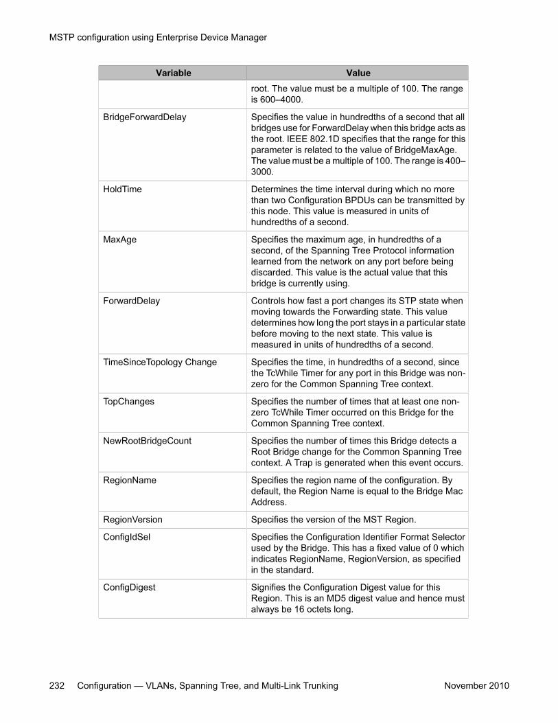
Variable Valueroot. The value must be a multiple of 100. The rangeis 600–4000.
BridgeForwardDelay Specifies the value in hundredths of a second that allbridges use for ForwardDelay when this bridge acts asthe root. IEEE 802.1D specifies that the range for thisparameter is related to the value of BridgeMaxAge.The value must be a multiple of 100. The range is 400–3000.
HoldTime Determines the time interval during which no morethan two Configuration BPDUs can be transmitted bythis node. This value is measured in units ofhundredths of a second.
MaxAge Specifies the maximum age, in hundredths of asecond, of the Spanning Tree Protocol informationlearned from the network on any port before beingdiscarded. This value is the actual value that thisbridge is currently using.
ForwardDelay Controls how fast a port changes its STP state whenmoving towards the Forwarding state. This valuedetermines how long the port stays in a particular statebefore moving to the next state. This value ismeasured in units of hundredths of a second.
TimeSinceTopology Change Specifies the time, in hundredths of a second, sincethe TcWhile Timer for any port in this Bridge was non-zero for the Common Spanning Tree context.
TopChanges Specifies the number of times that at least one non-zero TcWhile Timer occurred on this Bridge for theCommon Spanning Tree context.
NewRootBridgeCount Specifies the number of times this Bridge detects aRoot Bridge change for the Common Spanning Treecontext. A Trap is generated when this event occurs.
RegionName Specifies the region name of the configuration. Bydefault, the Region Name is equal to the Bridge MacAddress.
RegionVersion Specifies the version of the MST Region.
ConfigIdSel Specifies the Configuration Identifier Format Selectorused by the Bridge. This has a fixed value of 0 whichindicates RegionName, RegionVersion, as specifiedin the standard.
ConfigDigest Signifies the Configuration Digest value for thisRegion. This is an MD5 digest value and hence mustalways be 16 octets long.
MSTP configuration using Enterprise Device Manager
232 Configuration — VLANs, Spanning Tree, and Multi-Link Trunking November 2010
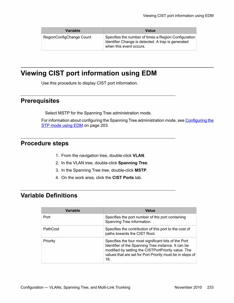
Variable ValueRegionConfigChange Count Specifies the number of times a Region Configuration
Identifier Change is detected. A trap is generatedwhen this event occurs.
Viewing CIST port information using EDMUse this procedure to display CIST port information.
Prerequisites
Select MSTP for the Spanning Tree administration mode.
For information about configuring the Spanning Tree administration mode, see Configuring theSTP mode using EDM on page 203.
Procedure steps
1. From the navigation tree, double-click VLAN.
2. In the VLAN tree, double-click Spanning Tree.
3. In the Spanning Tree tree, double-click MSTP.
4. On the work area, click the CIST Ports tab.
Variable Definitions
Variable ValuePort Specifies the port number of the port containing
Spanning Tree information.
PathCost Specifies the contribution of this port to the cost ofpaths towards the CIST Root.
Priority Specifies the four most significant bits of the PortIdentifier of the Spanning Tree instance. It can bemodified by setting the CISTPortPriority value. Thevalues that are set for Port Priority must be in steps of16.
Viewing CIST port information using EDM
Configuration — VLANs, Spanning Tree, and Multi-Link Trunking November 2010 233
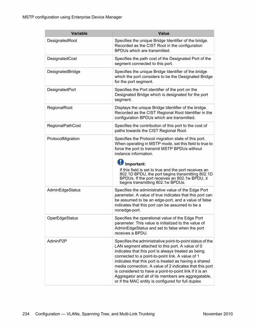
Variable ValueDesignatedRoot Specifies the unique Bridge Identifier of the bridge.
Recorded as the CIST Root in the configurationBPDUs which are transmitted.
DesignatedCost Specifies the path cost of the Designated Port of thesegment connected to this port.
DesignatedBridge Specifies the unique Bridge Identifier of the bridgewhich the port considers to be the Designated Bridgefor the port segment.
DesignatedPort Specifies the Port identifier of the port on theDesignated Bridge which is designated for the portsegment.
RegionalRoot Displays the unique Bridge Identifier of the bridge.Recorded as the CIST Regional Root Identifier in theconfiguration BPDUs which are transmitted.
RegionalPathCost Specifies the contribution of this port to the cost ofpaths towards the CIST Regional Root.
ProtocolMigration Specifies the Protocol migration state of this port.When operating in MSTP mode, set this field to true toforce the port to transmit MSTP BPDUs withoutinstance information.
Important:If this field is set to true and the port receives an802.1D BPDU, the port begins transmitting 802.1DBPDUs. If the port receives an 802.1w BPDU, itbegins transmitting 802.1w BPDUs.
AdminEdgeStatus Specifies the administrative value of the Edge Portparameter. A value of true indicates that this port canbe assumed to be an edge-port, and a value of falseindicates that this port can be assumed to be anonedge-port.
OperEdgeStatus Specifies the operational value of the Edge Portparameter. This value is initialized to the value ofAdminEdgeStatus and set to false when the portreceives a BPDU.
AdminP2P Specifies the administrative point-to-point status of theLAN segment attached to this port. A value of 0indicates that this port is always treated as beingconnected to a point-to-point link. A value of 1indicates that this port is treated as having a sharedmedia connection. A value of 2 indicates that this portis considered to have a point-to-point link if it is anAggregator and all of its members are aggregatable,or if the MAC entity is configured for full duplex
MSTP configuration using Enterprise Device Manager
234 Configuration — VLANs, Spanning Tree, and Multi-Link Trunking November 2010
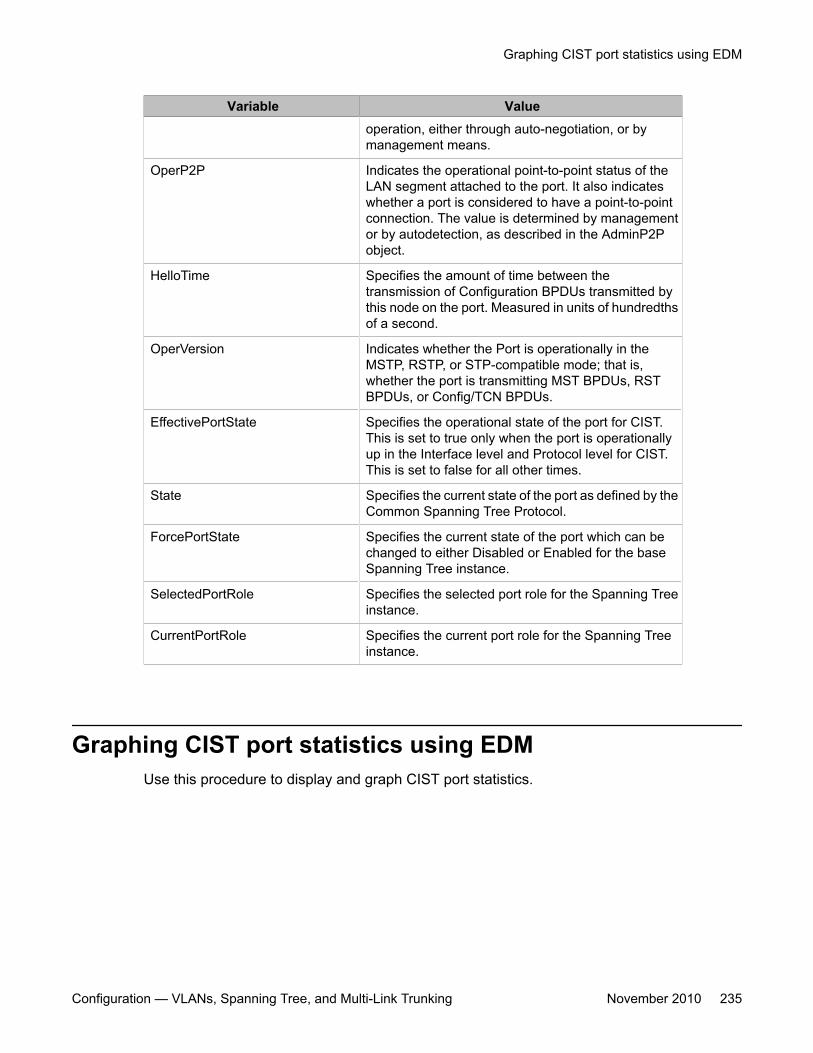
Variable Valueoperation, either through auto-negotiation, or bymanagement means.
OperP2P Indicates the operational point-to-point status of theLAN segment attached to the port. It also indicateswhether a port is considered to have a point-to-pointconnection. The value is determined by managementor by autodetection, as described in the AdminP2Pobject.
HelloTime Specifies the amount of time between thetransmission of Configuration BPDUs transmitted bythis node on the port. Measured in units of hundredthsof a second.
OperVersion Indicates whether the Port is operationally in theMSTP, RSTP, or STP-compatible mode; that is,whether the port is transmitting MST BPDUs, RSTBPDUs, or Config/TCN BPDUs.
EffectivePortState Specifies the operational state of the port for CIST.This is set to true only when the port is operationallyup in the Interface level and Protocol level for CIST.This is set to false for all other times.
State Specifies the current state of the port as defined by theCommon Spanning Tree Protocol.
ForcePortState Specifies the current state of the port which can bechanged to either Disabled or Enabled for the baseSpanning Tree instance.
SelectedPortRole Specifies the selected port role for the Spanning Treeinstance.
CurrentPortRole Specifies the current port role for the Spanning Treeinstance.
Graphing CIST port statistics using EDMUse this procedure to display and graph CIST port statistics.
Graphing CIST port statistics using EDM
Configuration — VLANs, Spanning Tree, and Multi-Link Trunking November 2010 235
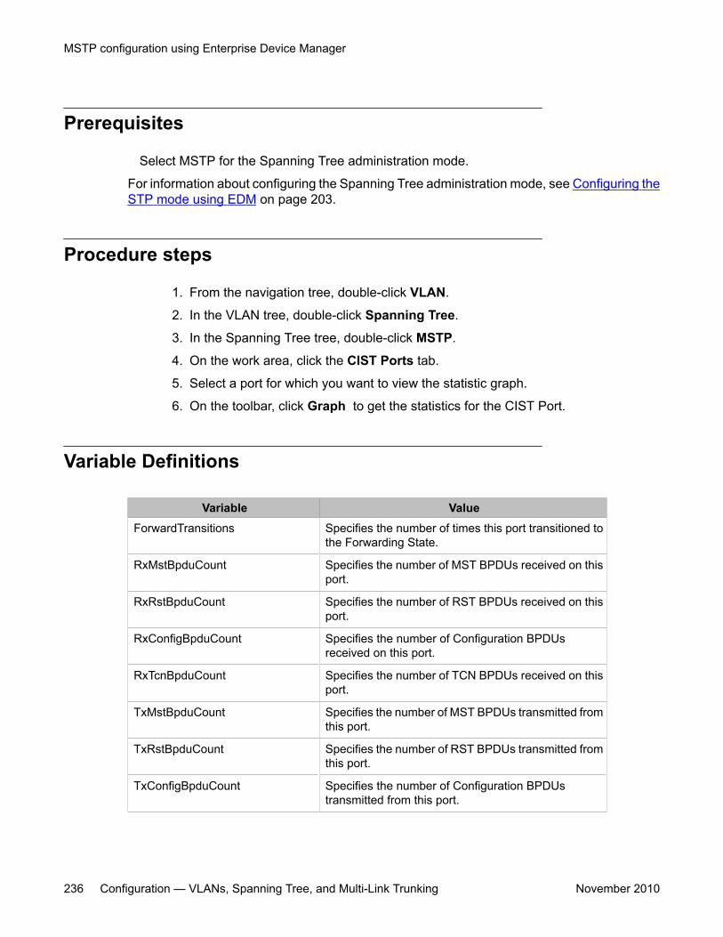
Prerequisites
Select MSTP for the Spanning Tree administration mode.
For information about configuring the Spanning Tree administration mode, see Configuring theSTP mode using EDM on page 203.
Procedure steps
1. From the navigation tree, double-click VLAN.
2. In the VLAN tree, double-click Spanning Tree.
3. In the Spanning Tree tree, double-click MSTP.
4. On the work area, click the CIST Ports tab.
5. Select a port for which you want to view the statistic graph.
6. On the toolbar, click Graph to get the statistics for the CIST Port.
Variable Definitions
Variable ValueForwardTransitions Specifies the number of times this port transitioned to
the Forwarding State.
RxMstBpduCount Specifies the number of MST BPDUs received on thisport.
RxRstBpduCount Specifies the number of RST BPDUs received on thisport.
RxConfigBpduCount Specifies the number of Configuration BPDUsreceived on this port.
RxTcnBpduCount Specifies the number of TCN BPDUs received on thisport.
TxMstBpduCount Specifies the number of MST BPDUs transmitted fromthis port.
TxRstBpduCount Specifies the number of RST BPDUs transmitted fromthis port.
TxConfigBpduCount Specifies the number of Configuration BPDUstransmitted from this port.
MSTP configuration using Enterprise Device Manager
236 Configuration — VLANs, Spanning Tree, and Multi-Link Trunking November 2010
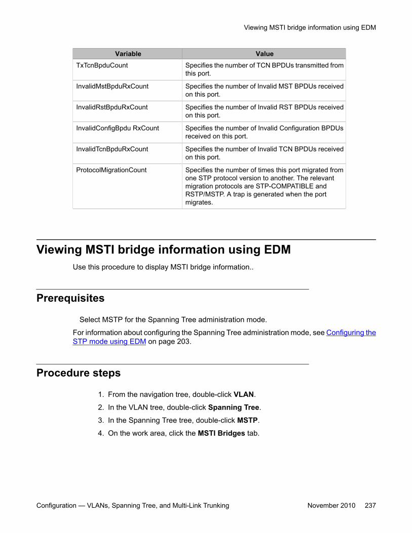
Variable ValueTxTcnBpduCount Specifies the number of TCN BPDUs transmitted from
this port.
InvalidMstBpduRxCount Specifies the number of Invalid MST BPDUs receivedon this port.
InvalidRstBpduRxCount Specifies the number of Invalid RST BPDUs receivedon this port.
InvalidConfigBpdu RxCount Specifies the number of Invalid Configuration BPDUsreceived on this port.
InvalidTcnBpduRxCount Specifies the number of Invalid TCN BPDUs receivedon this port.
ProtocolMigrationCount Specifies the number of times this port migrated fromone STP protocol version to another. The relevantmigration protocols are STP-COMPATIBLE andRSTP/MSTP. A trap is generated when the portmigrates.
Viewing MSTI bridge information using EDMUse this procedure to display MSTI bridge information..
Prerequisites
Select MSTP for the Spanning Tree administration mode.
For information about configuring the Spanning Tree administration mode, see Configuring theSTP mode using EDM on page 203.
Procedure steps
1. From the navigation tree, double-click VLAN.
2. In the VLAN tree, double-click Spanning Tree.
3. In the Spanning Tree tree, double-click MSTP.
4. On the work area, click the MSTI Bridges tab.
Viewing MSTI bridge information using EDM
Configuration — VLANs, Spanning Tree, and Multi-Link Trunking November 2010 237
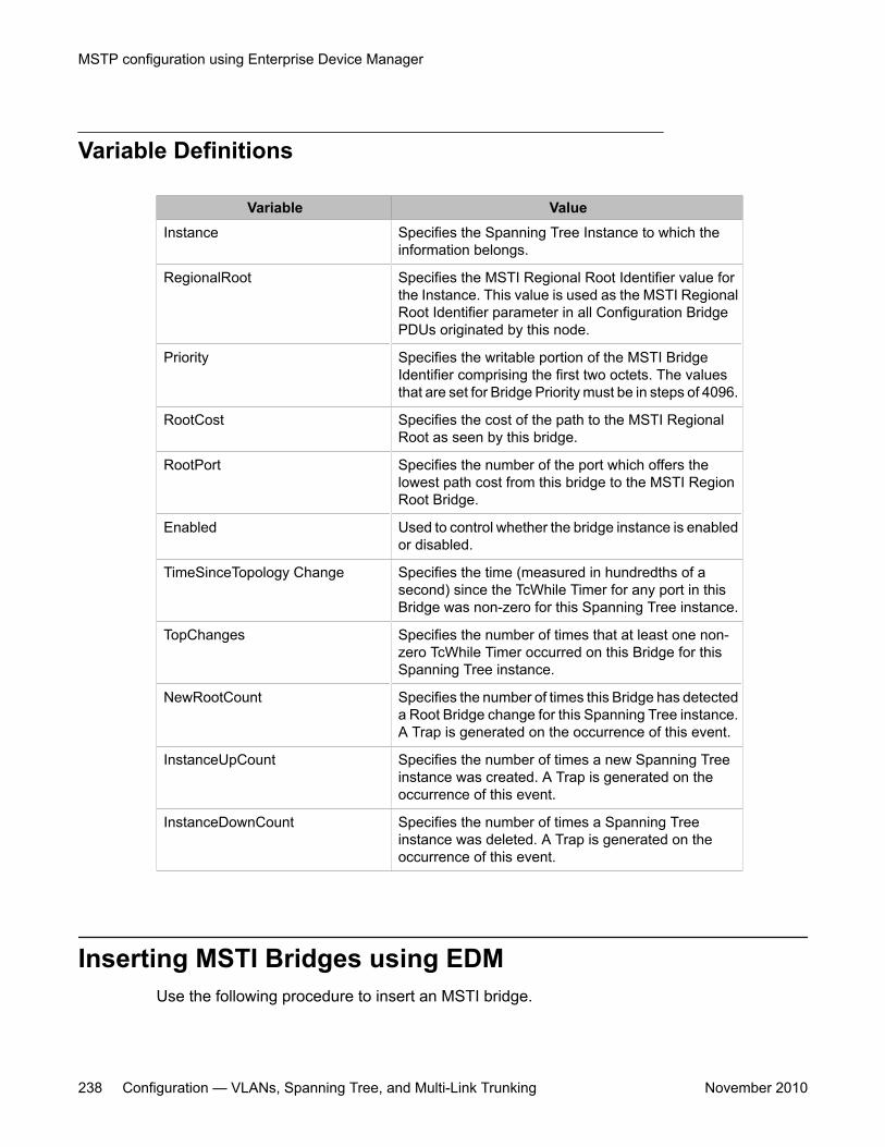
Variable Definitions
Variable ValueInstance Specifies the Spanning Tree Instance to which the
information belongs.
RegionalRoot Specifies the MSTI Regional Root Identifier value forthe Instance. This value is used as the MSTI RegionalRoot Identifier parameter in all Configuration BridgePDUs originated by this node.
Priority Specifies the writable portion of the MSTI BridgeIdentifier comprising the first two octets. The valuesthat are set for Bridge Priority must be in steps of 4096.
RootCost Specifies the cost of the path to the MSTI RegionalRoot as seen by this bridge.
RootPort Specifies the number of the port which offers thelowest path cost from this bridge to the MSTI RegionRoot Bridge.
Enabled Used to control whether the bridge instance is enabledor disabled.
TimeSinceTopology Change Specifies the time (measured in hundredths of asecond) since the TcWhile Timer for any port in thisBridge was non-zero for this Spanning Tree instance.
TopChanges Specifies the number of times that at least one non-zero TcWhile Timer occurred on this Bridge for thisSpanning Tree instance.
NewRootCount Specifies the number of times this Bridge has detecteda Root Bridge change for this Spanning Tree instance.A Trap is generated on the occurrence of this event.
InstanceUpCount Specifies the number of times a new Spanning Treeinstance was created. A Trap is generated on theoccurrence of this event.
InstanceDownCount Specifies the number of times a Spanning Treeinstance was deleted. A Trap is generated on theoccurrence of this event.
Inserting MSTI Bridges using EDMUse the following procedure to insert an MSTI bridge.
MSTP configuration using Enterprise Device Manager
238 Configuration — VLANs, Spanning Tree, and Multi-Link Trunking November 2010
Procedure steps
1. From the navigation tree, double-click VLAN.2. In the VLAN tree, double-click Spanning Tree.3. In the Spanning Tree tree, double-click MSTP.4. On the work area, click the MSTI Bridges tab.5. On the toolbar, click Insert.
The Insert MSTI Bridges dialog box appears with the next available instance shown.6. Click Insert.
Deleting MSTI Bridges using EDMUse the following procedure to delete an MSTI bridge.
Procedure steps
1. From the navigation tree, double-click VLAN.2. In the VLAN tree, double-click Spanning Tree.3. In the Spanning Tree tree, double-click MSTP.4. On the work area, click the MSTI Bridges tab.5. In the table, select the MSTI bridge instance that you want to delete.6. On the toolbar, click Delete.
The selected instance is deleted from the MSTI Bridges tab.
Viewing MSTI port information using EDMUse this procedure to display MSTI port information.
Prerequisites
Select MSTP for the Spanning Tree administration mode.
For information about configuring the Spanning Tree administration mode, see Configuring theSTP mode using EDM on page 203.
Deleting MSTI Bridges using EDM
Configuration — VLANs, Spanning Tree, and Multi-Link Trunking November 2010 239
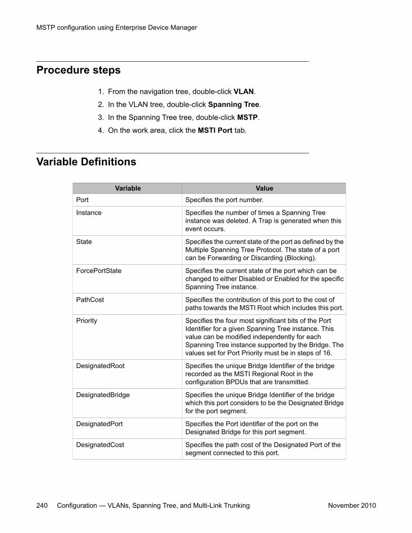
Procedure steps
1. From the navigation tree, double-click VLAN.
2. In the VLAN tree, double-click Spanning Tree.
3. In the Spanning Tree tree, double-click MSTP.
4. On the work area, click the MSTI Port tab.
Variable Definitions
Variable ValuePort Specifies the port number.
Instance Specifies the number of times a Spanning Treeinstance was deleted. A Trap is generated when thisevent occurs.
State Specifies the current state of the port as defined by theMultiple Spanning Tree Protocol. The state of a portcan be Forwarding or Discarding (Blocking).
ForcePortState Specifies the current state of the port which can bechanged to either Disabled or Enabled for the specificSpanning Tree instance.
PathCost Specifies the contribution of this port to the cost ofpaths towards the MSTI Root which includes this port.
Priority Specifies the four most significant bits of the PortIdentifier for a given Spanning Tree instance. Thisvalue can be modified independently for eachSpanning Tree instance supported by the Bridge. Thevalues set for Port Priority must be in steps of 16.
DesignatedRoot Specifies the unique Bridge Identifier of the bridgerecorded as the MSTI Regional Root in theconfiguration BPDUs that are transmitted.
DesignatedBridge Specifies the unique Bridge Identifier of the bridgewhich this port considers to be the Designated Bridgefor the port segment.
DesignatedPort Specifies the Port identifier of the port on theDesignated Bridge for this port segment.
DesignatedCost Specifies the path cost of the Designated Port of thesegment connected to this port.
MSTP configuration using Enterprise Device Manager
240 Configuration — VLANs, Spanning Tree, and Multi-Link Trunking November 2010
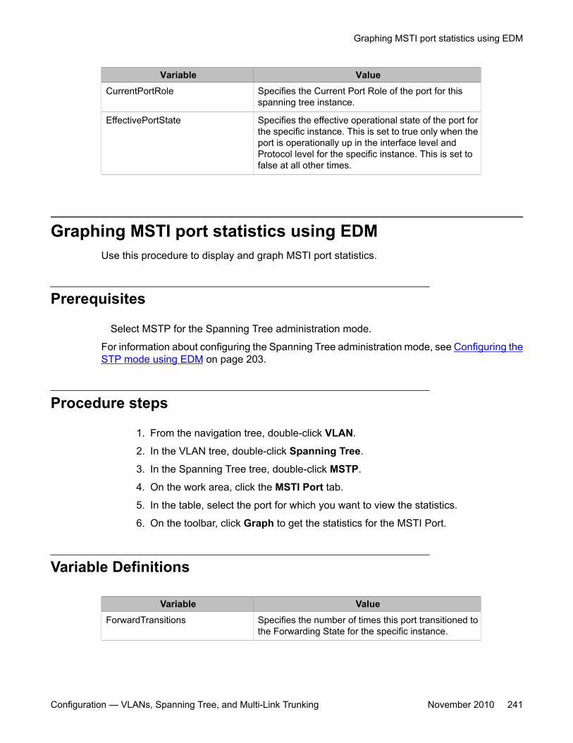
Variable ValueCurrentPortRole Specifies the Current Port Role of the port for this
spanning tree instance.
EffectivePortState Specifies the effective operational state of the port forthe specific instance. This is set to true only when theport is operationally up in the interface level andProtocol level for the specific instance. This is set tofalse at all other times.
Graphing MSTI port statistics using EDMUse this procedure to display and graph MSTI port statistics.
Prerequisites
Select MSTP for the Spanning Tree administration mode.
For information about configuring the Spanning Tree administration mode, see Configuring theSTP mode using EDM on page 203.
Procedure steps
1. From the navigation tree, double-click VLAN.
2. In the VLAN tree, double-click Spanning Tree.
3. In the Spanning Tree tree, double-click MSTP.
4. On the work area, click the MSTI Port tab.
5. In the table, select the port for which you want to view the statistics.
6. On the toolbar, click Graph to get the statistics for the MSTI Port.
Variable Definitions
Variable ValueForwardTransitions Specifies the number of times this port transitioned to
the Forwarding State for the specific instance.
Graphing MSTI port statistics using EDM
Configuration — VLANs, Spanning Tree, and Multi-Link Trunking November 2010 241
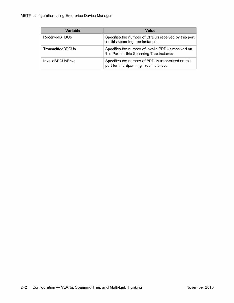
Variable ValueReceivedBPDUs Specifies the number of BPDUs received by this port
for this spanning tree instance.
TransmittedBPDUs Specifies the number of Invalid BPDUs received onthis Port for this Spanning Tree instance.
InvalidBPDUsRcvd Specifies the number of BPDUs transmitted on thisport for this Spanning Tree instance.
MSTP configuration using Enterprise Device Manager
242 Configuration — VLANs, Spanning Tree, and Multi-Link Trunking November 2010
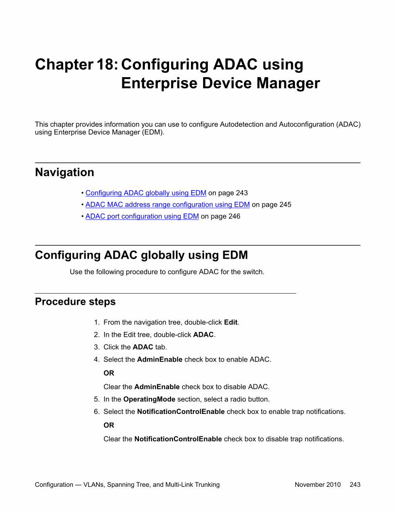
Chapter 18: Configuring ADAC usingEnterprise Device Manager
This chapter provides information you can use to configure Autodetection and Autoconfiguration (ADAC)using Enterprise Device Manager (EDM).
Navigation• Configuring ADAC globally using EDM on page 243• ADAC MAC address range configuration using EDM on page 245• ADAC port configuration using EDM on page 246
Configuring ADAC globally using EDMUse the following procedure to configure ADAC for the switch.
Procedure steps
1. From the navigation tree, double-click Edit.
2. In the Edit tree, double-click ADAC.
3. Click the ADAC tab.
4. Select the AdminEnable check box to enable ADAC.
OR
Clear the AdminEnable check box to disable ADAC.
5. In the OperatingMode section, select a radio button.
6. Select the NotificationControlEnable check box to enable trap notifications.
OR
Clear the NotificationControlEnable check box to disable trap notifications.
Configuration — VLANs, Spanning Tree, and Multi-Link Trunking November 2010 243
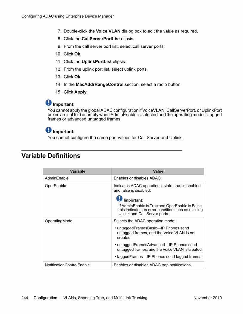
7. Double-click the Voice VLAN dialog box to edit the value as required.
8. Click the CallServerPortList elipsis.
9. From the call server port list, select call server ports.
10. Click Ok.
11. Click the UplinkPortList elipsis.
12. From the uplink port list, select uplink ports.
13. Click Ok.
14. In the MacAddrRangeControl section, select a radio button.
15. Click Apply.
Important:You cannot apply the global ADAC configuration if VoiceVLAN, CallServerPort, or UplinkPortboxes are set to 0 or empty when AdminEnable is selected and the operating mode is taggedframes or advanced untagged frames.
Important:You cannot configure the same port values for Call Server and Uplink.
Variable Definitions
Variable ValueAdminEnable Enables or disables ADAC.
OperEnable Indicates ADAC operational state: true is enabledand false is disabled.
Important:If AdminEnable is True and OperEnable is False,this indicates an error condition such as missingUplink and Call Server ports.
OperatingMode Selects the ADAC operation mode:
• untaggedFramesBasic—IP Phones senduntagged frames, and the Voice VLAN is notcreated.
• untaggedFramesAdvanced—IP Phones senduntagged frames, and the Voice VLAN is created.
• taggedFrames—IP Phones send tagged frames.
NotificationControlEnable Enables or disables ADAC trap notifications.
Configuring ADAC using Enterprise Device Manager
244 Configuration — VLANs, Spanning Tree, and Multi-Link Trunking November 2010
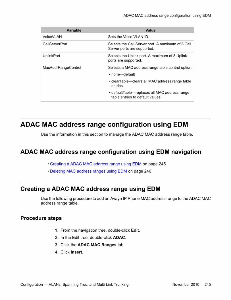
Variable ValueVoiceVLAN Sets the Voice VLAN ID.
CallServerPort Selects the Call Server port. A maximum of 8 CallServer ports are supported.
UplinkPort Selects the Uplink port. A maximum of 8 Uplinkports are supported.
MacAddrRangeControl Selects a MAC address range table control option.
• none—default
• clearTable—clears all MAC address range tableentries.
• defaultTable—replaces all MAC address rangetable entries to default values.
ADAC MAC address range configuration using EDMUse the information in this section to manage the ADAC MAC address range table.
ADAC MAC address range configuration using EDM navigation
• Creating a ADAC MAC address range using EDM on page 245
• Deleting MAC address ranges using EDM on page 246
Creating a ADAC MAC address range using EDMUse the following procedure to add an Avaya IP Phone MAC address range to the ADAC MACaddress range table.
Procedure steps
1. From the navigation tree, double-click Edit.
2. In the Edit tree, double-click ADAC.
3. Click the ADAC MAC Ranges tab.
4. Click Insert.
ADAC MAC address range configuration using EDM
Configuration — VLANs, Spanning Tree, and Multi-Link Trunking November 2010 245
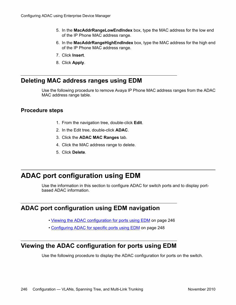
5. In the MacAddrRangeLowEndIndex box, type the MAC address for the low endof the IP Phone MAC address range.
6. In the MacAddrRangeHighEndIndex box, type the MAC address for the high endof the IP Phone MAC address range.
7. Click Insert.
8. Click Apply.
Deleting MAC address ranges using EDMUse the following procedure to remove Avaya IP Phone MAC address ranges from the ADACMAC address range table.
Procedure steps
1. From the navigation tree, double-click Edit.
2. In the Edit tree, double-click ADAC.
3. Click the ADAC MAC Ranges tab.
4. Click the MAC address range to delete.
5. Click Delete.
ADAC port configuration using EDMUse the information in this section to configure ADAC for switch ports and to display port-based ADAC information.
ADAC port configuration using EDM navigation
• Viewing the ADAC configuration for ports using EDM on page 246
• Configuring ADAC for specific ports using EDM on page 248
Viewing the ADAC configuration for ports using EDMUse the following procedure to display the ADAC configuration for ports on the switch.
Configuring ADAC using Enterprise Device Manager
246 Configuration — VLANs, Spanning Tree, and Multi-Link Trunking November 2010
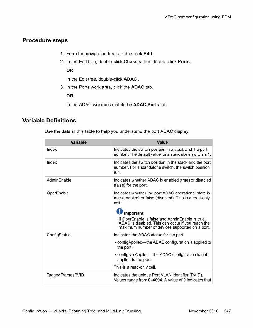
Procedure steps
1. From the navigation tree, double-click Edit.
2. In the Edit tree, double-click Chassis then double-click Ports.
OR
In the Edit tree, double-click ADAC .
3. In the Ports work area, click the ADAC tab.
OR
In the ADAC work area, click the ADAC Ports tab.
Variable Definitions
Use the data in this table to help you understand the port ADAC display.
Variable ValueIndex Indicates the switch position in a stack and the port
number. The default value for a standalone switch is 1.
Index Indicates the switch position in the stack and the portnumber. For a standalone switch, the switch positionis 1.
AdminEnable Indicates whether ADAC is enabled (true) or disabled(false) for the port.
OperEnable Indicates whether the port ADAC operational state istrue (enabled) or false (disabled). This is a read-onlycell.
Important:If OperEnable is false and AdminEnable is true,ADAC is disabled. This can occur if you reach themaximum number of devices supported on a port.
ConfigStatus Indicates the ADAC status for the port.
• configApplied—the ADAC configuration is applied tothe port.
• configNotApplied—the ADAC configuration is notapplied to the port.
This is a read-only cell.
TaggedFramesPVID Indicates the unique Port VLAN identifier (PVID).Values range from 0–4094. A value of 0 indicates that
ADAC port configuration using EDM
Configuration — VLANs, Spanning Tree, and Multi-Link Trunking November 2010 247
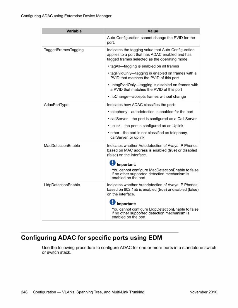
Variable ValueAuto-Configuration cannot change the PVID for theport.
TaggedFramesTagging Indicates the tagging value that Auto-Configurationapplies to a port that has ADAC enabled and hastagged frames selected as the operating mode.
• tagAll—tagging is enabled on all frames
• tagPvidOnly—tagging is enabled on frames with aPVID that matches the PVID of this port
• untagPvidOnly—tagging is disabled on frames witha PVID that matches the PVID of this port
• noChange—accepts frames without change
AdacPortType Indicates how ADAC classifies the port:
• telephony—autodetection is enabled for the port
• callServer—the port is configured as a Call Server
• uplink—the port is configured as an Uplink
• other—the port is not classified as telephony,callServer, or uplink
MacDetectionEnable Indicates whether Autodetection of Avaya IP Phones,based on MAC address is enabled (true) or disabled(false) on the interface.
Important:You cannot configure MacDetectionEnable to falseif no other supported detection mechanism isenabled on the port.
LldpDetectionEnable Indicates whether Autodetection of Avaya IP Phones,based on 802.1ab is enabled (true) or disabled (false)on the interface.
Important:You cannot configure LldpDetectionEnable to falseif no other supported detection mechanism isenabled on the port.
Configuring ADAC for specific ports using EDMUse the following procedure to configure ADAC for one or more ports in a standalone switchor switch stack.
Configuring ADAC using Enterprise Device Manager
248 Configuration — VLANs, Spanning Tree, and Multi-Link Trunking November 2010
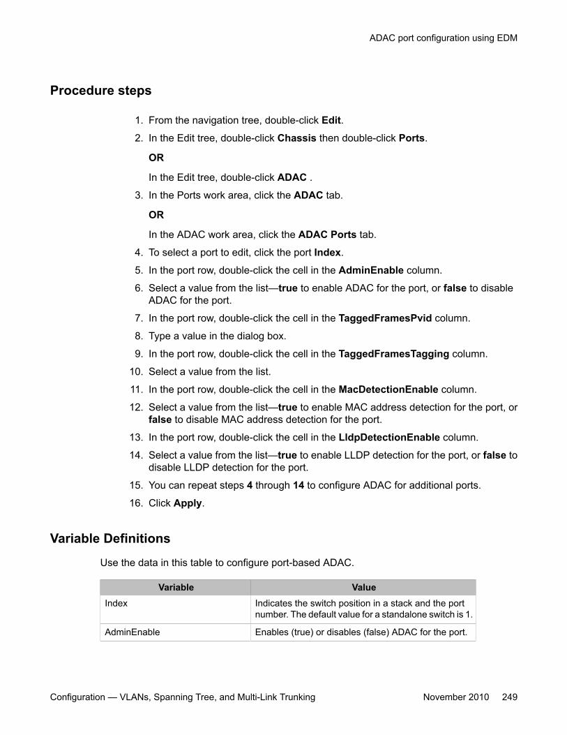
Procedure steps
1. From the navigation tree, double-click Edit.
2. In the Edit tree, double-click Chassis then double-click Ports.
OR
In the Edit tree, double-click ADAC .
3. In the Ports work area, click the ADAC tab.
OR
In the ADAC work area, click the ADAC Ports tab.
4. To select a port to edit, click the port Index.
5. In the port row, double-click the cell in the AdminEnable column.
6. Select a value from the list—true to enable ADAC for the port, or false to disableADAC for the port.
7. In the port row, double-click the cell in the TaggedFramesPvid column.
8. Type a value in the dialog box.
9. In the port row, double-click the cell in the TaggedFramesTagging column.
10. Select a value from the list.
11. In the port row, double-click the cell in the MacDetectionEnable column.
12. Select a value from the list—true to enable MAC address detection for the port, orfalse to disable MAC address detection for the port.
13. In the port row, double-click the cell in the LldpDetectionEnable column.
14. Select a value from the list—true to enable LLDP detection for the port, or false todisable LLDP detection for the port.
15. You can repeat steps 4 through 14 to configure ADAC for additional ports.
16. Click Apply.
Variable Definitions
Use the data in this table to configure port-based ADAC.
Variable ValueIndex Indicates the switch position in a stack and the port
number. The default value for a standalone switch is 1.
AdminEnable Enables (true) or disables (false) ADAC for the port.
ADAC port configuration using EDM
Configuration — VLANs, Spanning Tree, and Multi-Link Trunking November 2010 249
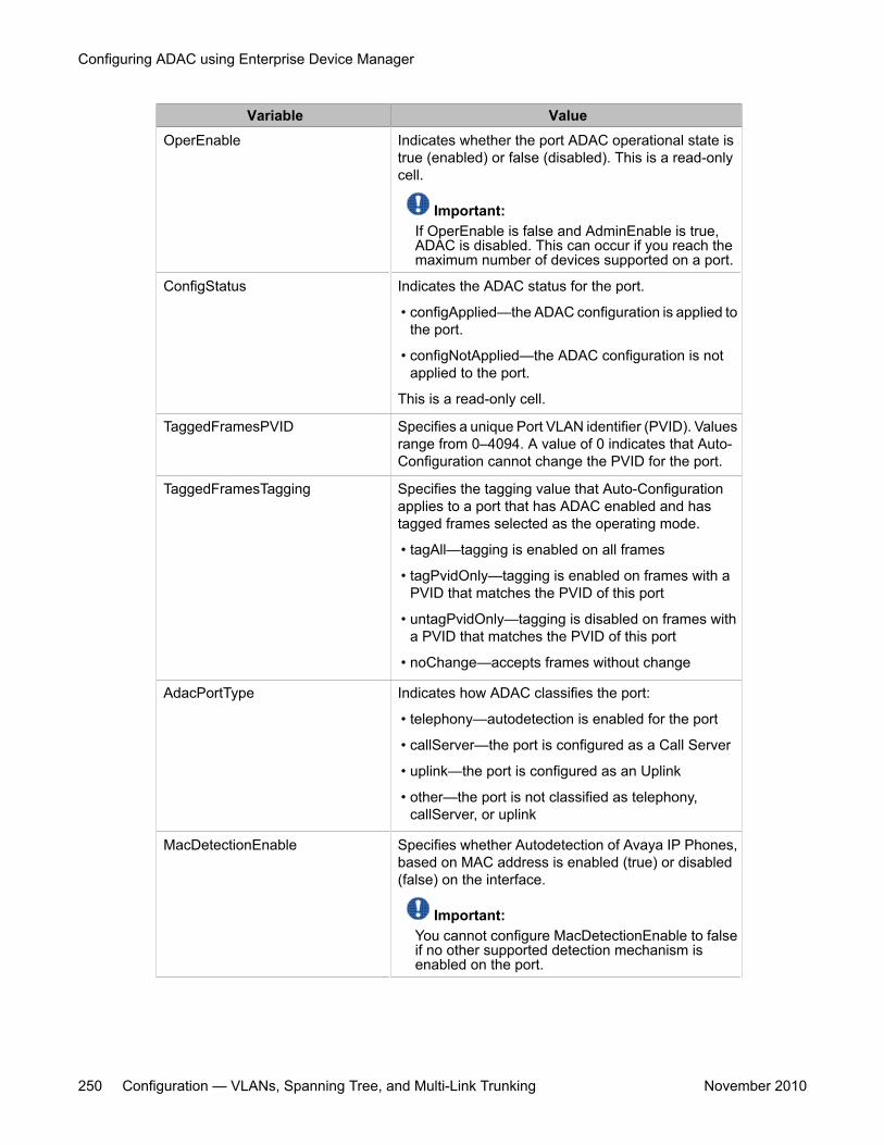
Variable ValueOperEnable Indicates whether the port ADAC operational state is
true (enabled) or false (disabled). This is a read-onlycell.
Important:If OperEnable is false and AdminEnable is true,ADAC is disabled. This can occur if you reach themaximum number of devices supported on a port.
ConfigStatus Indicates the ADAC status for the port.
• configApplied—the ADAC configuration is applied tothe port.
• configNotApplied—the ADAC configuration is notapplied to the port.
This is a read-only cell.
TaggedFramesPVID Specifies a unique Port VLAN identifier (PVID). Valuesrange from 0–4094. A value of 0 indicates that Auto-Configuration cannot change the PVID for the port.
TaggedFramesTagging Specifies the tagging value that Auto-Configurationapplies to a port that has ADAC enabled and hastagged frames selected as the operating mode.
• tagAll—tagging is enabled on all frames
• tagPvidOnly—tagging is enabled on frames with aPVID that matches the PVID of this port
• untagPvidOnly—tagging is disabled on frames witha PVID that matches the PVID of this port
• noChange—accepts frames without change
AdacPortType Indicates how ADAC classifies the port:
• telephony—autodetection is enabled for the port
• callServer—the port is configured as a Call Server
• uplink—the port is configured as an Uplink
• other—the port is not classified as telephony,callServer, or uplink
MacDetectionEnable Specifies whether Autodetection of Avaya IP Phones,based on MAC address is enabled (true) or disabled(false) on the interface.
Important:You cannot configure MacDetectionEnable to falseif no other supported detection mechanism isenabled on the port.
Configuring ADAC using Enterprise Device Manager
250 Configuration — VLANs, Spanning Tree, and Multi-Link Trunking November 2010
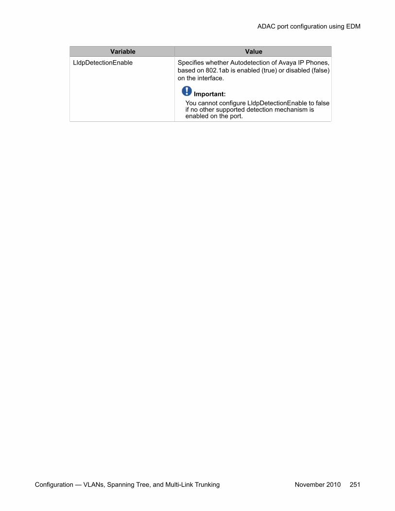
Variable ValueLldpDetectionEnable Specifies whether Autodetection of Avaya IP Phones,
based on 802.1ab is enabled (true) or disabled (false)on the interface.
Important:You cannot configure LldpDetectionEnable to falseif no other supported detection mechanism isenabled on the port.
ADAC port configuration using EDM
Configuration — VLANs, Spanning Tree, and Multi-Link Trunking November 2010 251

Configuring ADAC using Enterprise Device Manager
252 Configuration — VLANs, Spanning Tree, and Multi-Link Trunking November 2010
Chapter 19: Configuring LACP and VLACPusing Enterprise DeviceManager
This chapter provides information you can use to configure Link Aggregation Control Protocol (LACP) andVirtual LACP (VLACP) using Enterprise Device Manager (EDM).
Navigation• Viewing LAG information using EDM on page 253• Link Aggregation Group configuration using EDM on page 255• LACP configuration for ports using EDM on page 259• Graphing port LACP statistics using EDM on page 264• Global VLACP configuration using EDM on page 265• VLACP configuration for ports using EDM on page 266
Viewing LAG information using EDMUse the following procedure to display Link Aggregation Group (LAG) configurationinformation.
Procedure steps
1. From the navigation tree, double-click VLAN.
2. In the VLAN tree, double-click MLT/LACP.
3. In the work area, click the LACP tab.
Configuration — VLANs, Spanning Tree, and Multi-Link Trunking November 2010 253
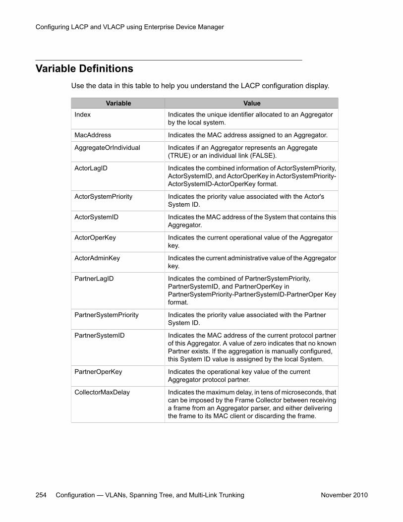
Variable DefinitionsUse the data in this table to help you understand the LACP configuration display.
Variable ValueIndex Indicates the unique identifier allocated to an Aggregator
by the local system.
MacAddress Indicates the MAC address assigned to an Aggregator.
AggregateOrIndividual Indicates if an Aggregator represents an Aggregate(TRUE) or an individual link (FALSE).
ActorLagID Indicates the combined information of ActorSystemPriority,ActorSystemID, and ActorOperKey in ActorSystemPriority-ActorSystemID-ActorOperKey format.
ActorSystemPriority Indicates the priority value associated with the Actor'sSystem ID.
ActorSystemID Indicates the MAC address of the System that contains thisAggregator.
ActorOperKey Indicates the current operational value of the Aggregatorkey.
ActorAdminKey Indicates the current administrative value of the Aggregatorkey.
PartnerLagID Indicates the combined of PartnerSystemPriority,PartnerSystemID, and PartnerOperKey inPartnerSystemPriority-PartnerSystemID-PartnerOper Keyformat.
PartnerSystemPriority Indicates the priority value associated with the PartnerSystem ID.
PartnerSystemID Indicates the MAC address of the current protocol partnerof this Aggregator. A value of zero indicates that no knownPartner exists. If the aggregation is manually configured,this System ID value is assigned by the local System.
PartnerOperKey Indicates the operational key value of the currentAggregator protocol partner.
CollectorMaxDelay Indicates the maximum delay, in tens of microseconds, thatcan be imposed by the Frame Collector between receivinga frame from an Aggregator parser, and either deliveringthe frame to its MAC client or discarding the frame.
Configuring LACP and VLACP using Enterprise Device Manager
254 Configuration — VLANs, Spanning Tree, and Multi-Link Trunking November 2010
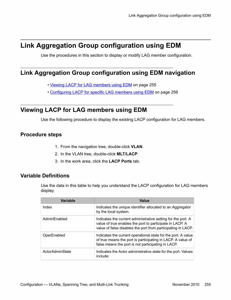
Link Aggregation Group configuration using EDMUse the procedures in this section to display or modify LAG member configuration.
Link Aggregation Group configuration using EDM navigation
• Viewing LACP for LAG members using EDM on page 255
• Configuring LACP for specific LAG members using EDM on page 256
Viewing LACP for LAG members using EDMUse the following procedure to display the existing LACP configuration for LAG members.
Procedure steps
1. From the navigation tree, double-click VLAN.
2. In the VLAN tree, double-click MLT/LACP.
3. In the work area, click the LACP Ports tab.
Variable Definitions
Use the data in this table to help you understand the LACP configuration for LAG membersdisplay.
Variable ValueIndex Indicates the unique identifier allocated to an Aggregator
by the local system.
AdminEnabled Indicates the current administrative setting for the port. Avalue of true enables the port to participate in LACP. Avalue of false disables the port from participating in LACP.
OperEnabled Indicates the current operational state for the port. A valueof true means the port is participating in LACP. A value offalse means the port is not participating in LACP.
ActorAdminState Indicates the Actor administrative state for the port. Valuesinclude:
Link Aggregation Group configuration using EDM
Configuration — VLANs, Spanning Tree, and Multi-Link Trunking November 2010 255
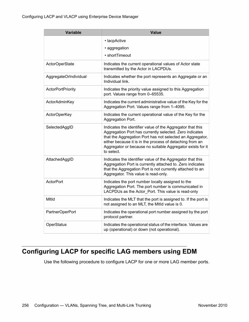
Variable Value
• lacpActive
• aggregation
• shortTimeout
ActorOperState Indicates the current operational values of Actor statetransmitted by the Actor in LACPDUs.
AggregateOrIndividual Indicates whether the port represents an Aggregate or anIndividual link.
ActorPortPriority Indicates the priority value assigned to this Aggregationport. Values range from 0–65535.
ActorAdminKey Indicates the current administrative value of the Key for theAggregation Port. Values range from 1–4095.
ActorOperKey Indicates the current operational value of the Key for theAggregation Port.
SelectedAggID Indicates the identifier value of the Aggregator that thisAggregation Port has currently selected. Zero indicatesthat the Aggregation Port has not selected an Aggregator,either because it is in the process of detaching from anAggregator or because no suitable Aggregator exists for itto select.
AttachedAggID Indicates the identifier value of the Aggregator that thisAggregation Port is currently attached to. Zero indicatesthat the Aggregation Port is not currently attached to anAggregator. This value is read-only.
ActorPort Indicates the port number locally assigned to theAggregation Port. The port number is communicated inLACPDUs as the Actor_Port. This value is read-only
MltId Indicates the MLT that the port is assigned to. If the port isnot assigned to an MLT, the MltId value is 0.
PartnerOperPort Indicates the operational port number assigned by the portprotocol partner.
OperStatus Indicates the operational status of the interface. Values areup (operational) or down (not operational).
Configuring LACP for specific LAG members using EDMUse the following procedure to configure LACP for one or more LAG member ports.
Configuring LACP and VLACP using Enterprise Device Manager
256 Configuration — VLANs, Spanning Tree, and Multi-Link Trunking November 2010
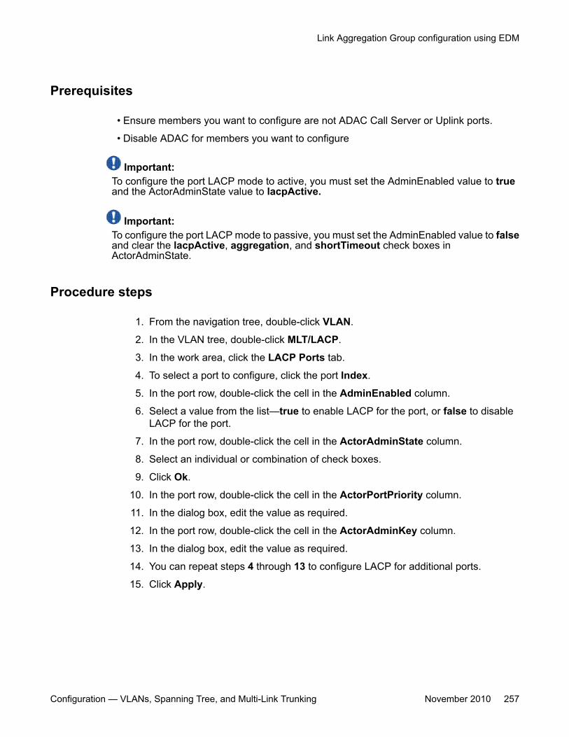
Prerequisites
• Ensure members you want to configure are not ADAC Call Server or Uplink ports.
• Disable ADAC for members you want to configure
Important:To configure the port LACP mode to active, you must set the AdminEnabled value to trueand the ActorAdminState value to lacpActive.
Important:To configure the port LACP mode to passive, you must set the AdminEnabled value to falseand clear the lacpActive, aggregation, and shortTimeout check boxes inActorAdminState.
Procedure steps
1. From the navigation tree, double-click VLAN.
2. In the VLAN tree, double-click MLT/LACP.
3. In the work area, click the LACP Ports tab.
4. To select a port to configure, click the port Index.
5. In the port row, double-click the cell in the AdminEnabled column.
6. Select a value from the list—true to enable LACP for the port, or false to disableLACP for the port.
7. In the port row, double-click the cell in the ActorAdminState column.
8. Select an individual or combination of check boxes.
9. Click Ok.
10. In the port row, double-click the cell in the ActorPortPriority column.
11. In the dialog box, edit the value as required.
12. In the port row, double-click the cell in the ActorAdminKey column.
13. In the dialog box, edit the value as required.
14. You can repeat steps 4 through 13 to configure LACP for additional ports.
15. Click Apply.
Link Aggregation Group configuration using EDM
Configuration — VLANs, Spanning Tree, and Multi-Link Trunking November 2010 257
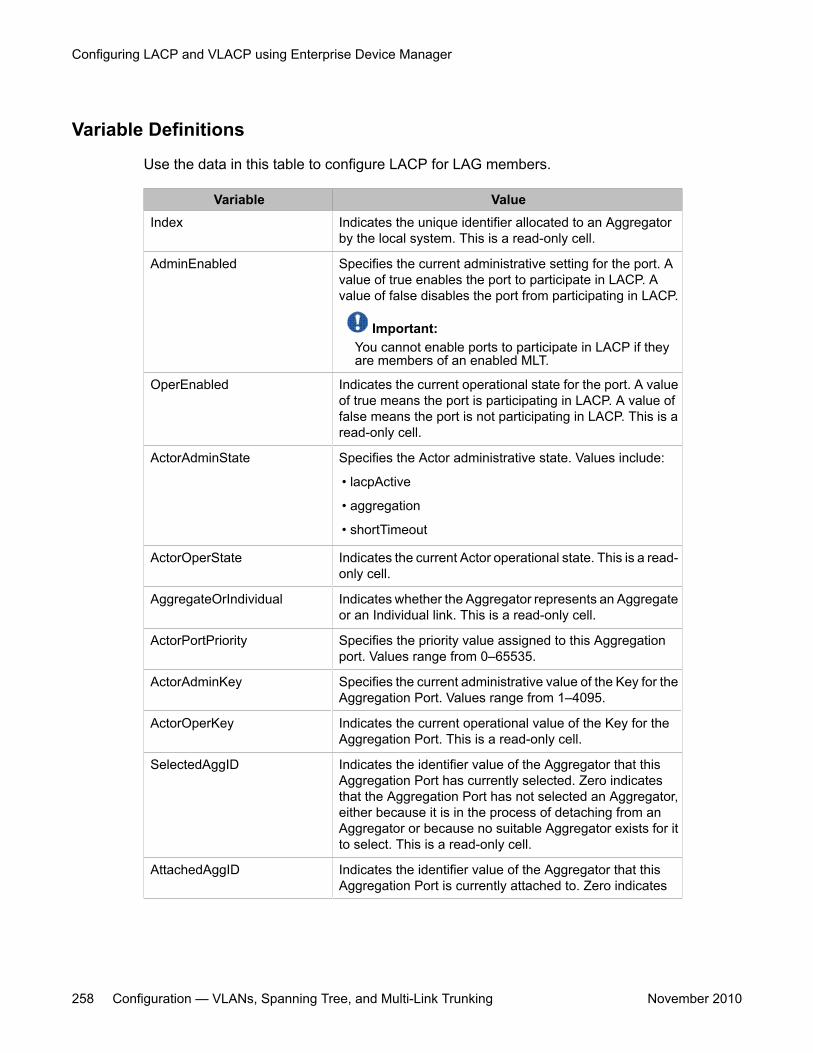
Variable Definitions
Use the data in this table to configure LACP for LAG members.
Variable ValueIndex Indicates the unique identifier allocated to an Aggregator
by the local system. This is a read-only cell.
AdminEnabled Specifies the current administrative setting for the port. Avalue of true enables the port to participate in LACP. Avalue of false disables the port from participating in LACP.
Important:You cannot enable ports to participate in LACP if theyare members of an enabled MLT.
OperEnabled Indicates the current operational state for the port. A valueof true means the port is participating in LACP. A value offalse means the port is not participating in LACP. This is aread-only cell.
ActorAdminState Specifies the Actor administrative state. Values include:
• lacpActive
• aggregation
• shortTimeout
ActorOperState Indicates the current Actor operational state. This is a read-only cell.
AggregateOrIndividual Indicates whether the Aggregator represents an Aggregateor an Individual link. This is a read-only cell.
ActorPortPriority Specifies the priority value assigned to this Aggregationport. Values range from 0–65535.
ActorAdminKey Specifies the current administrative value of the Key for theAggregation Port. Values range from 1–4095.
ActorOperKey Indicates the current operational value of the Key for theAggregation Port. This is a read-only cell.
SelectedAggID Indicates the identifier value of the Aggregator that thisAggregation Port has currently selected. Zero indicatesthat the Aggregation Port has not selected an Aggregator,either because it is in the process of detaching from anAggregator or because no suitable Aggregator exists for itto select. This is a read-only cell.
AttachedAggID Indicates the identifier value of the Aggregator that thisAggregation Port is currently attached to. Zero indicates
Configuring LACP and VLACP using Enterprise Device Manager
258 Configuration — VLANs, Spanning Tree, and Multi-Link Trunking November 2010
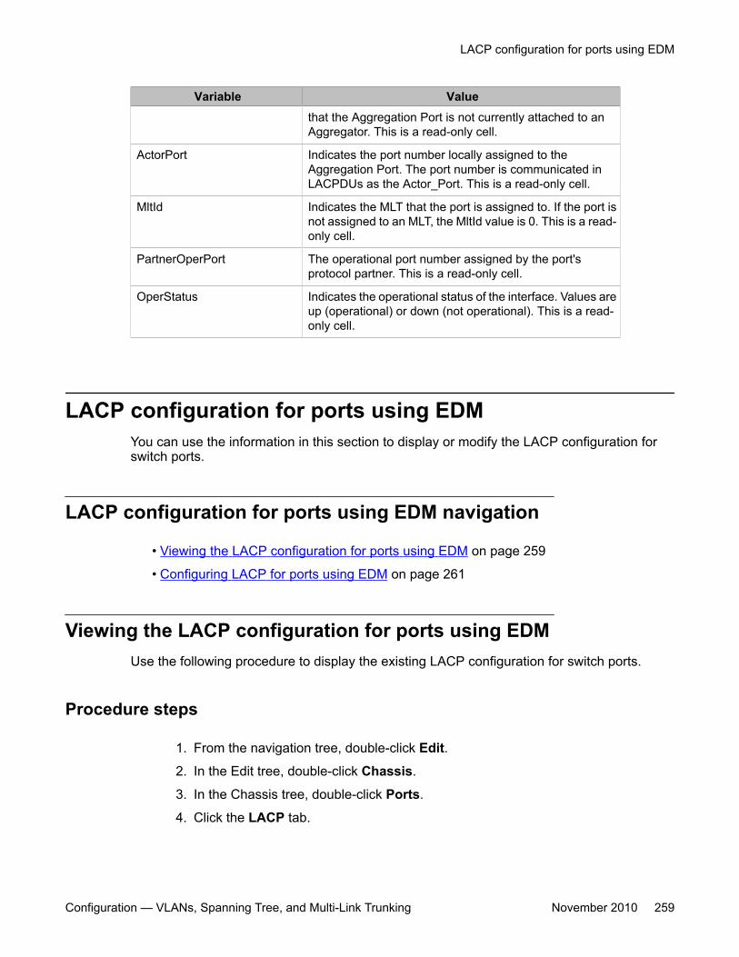
Variable Valuethat the Aggregation Port is not currently attached to anAggregator. This is a read-only cell.
ActorPort Indicates the port number locally assigned to theAggregation Port. The port number is communicated inLACPDUs as the Actor_Port. This is a read-only cell.
MltId Indicates the MLT that the port is assigned to. If the port isnot assigned to an MLT, the MltId value is 0. This is a read-only cell.
PartnerOperPort The operational port number assigned by the port'sprotocol partner. This is a read-only cell.
OperStatus Indicates the operational status of the interface. Values areup (operational) or down (not operational). This is a read-only cell.
LACP configuration for ports using EDMYou can use the information in this section to display or modify the LACP configuration forswitch ports.
LACP configuration for ports using EDM navigation
• Viewing the LACP configuration for ports using EDM on page 259
• Configuring LACP for ports using EDM on page 261
Viewing the LACP configuration for ports using EDMUse the following procedure to display the existing LACP configuration for switch ports.
Procedure steps
1. From the navigation tree, double-click Edit.
2. In the Edit tree, double-click Chassis.
3. In the Chassis tree, double-click Ports.
4. Click the LACP tab.
LACP configuration for ports using EDM
Configuration — VLANs, Spanning Tree, and Multi-Link Trunking November 2010 259
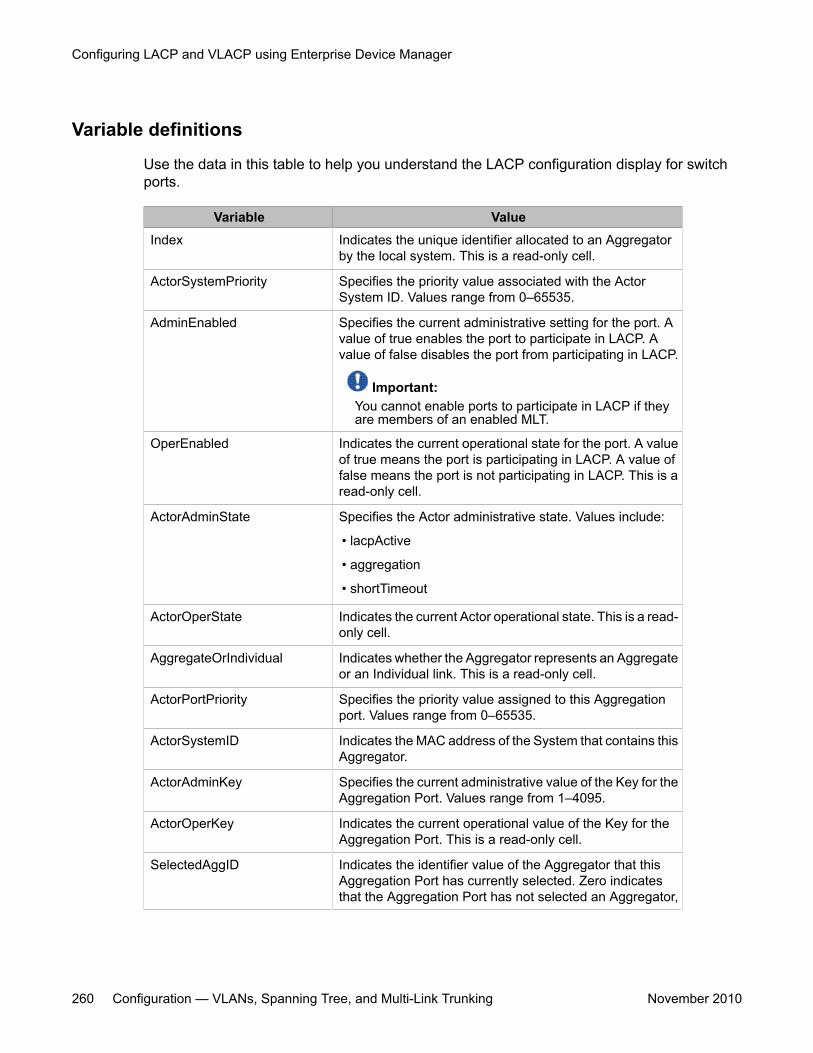
Variable definitions
Use the data in this table to help you understand the LACP configuration display for switchports.
Variable ValueIndex Indicates the unique identifier allocated to an Aggregator
by the local system. This is a read-only cell.
ActorSystemPriority Specifies the priority value associated with the ActorSystem ID. Values range from 0–65535.
AdminEnabled Specifies the current administrative setting for the port. Avalue of true enables the port to participate in LACP. Avalue of false disables the port from participating in LACP.
Important:You cannot enable ports to participate in LACP if theyare members of an enabled MLT.
OperEnabled Indicates the current operational state for the port. A valueof true means the port is participating in LACP. A value offalse means the port is not participating in LACP. This is aread-only cell.
ActorAdminState Specifies the Actor administrative state. Values include:
• lacpActive
• aggregation
• shortTimeout
ActorOperState Indicates the current Actor operational state. This is a read-only cell.
AggregateOrIndividual Indicates whether the Aggregator represents an Aggregateor an Individual link. This is a read-only cell.
ActorPortPriority Specifies the priority value assigned to this Aggregationport. Values range from 0–65535.
ActorSystemID Indicates the MAC address of the System that contains thisAggregator.
ActorAdminKey Specifies the current administrative value of the Key for theAggregation Port. Values range from 1–4095.
ActorOperKey Indicates the current operational value of the Key for theAggregation Port. This is a read-only cell.
SelectedAggID Indicates the identifier value of the Aggregator that thisAggregation Port has currently selected. Zero indicatesthat the Aggregation Port has not selected an Aggregator,
Configuring LACP and VLACP using Enterprise Device Manager
260 Configuration — VLANs, Spanning Tree, and Multi-Link Trunking November 2010
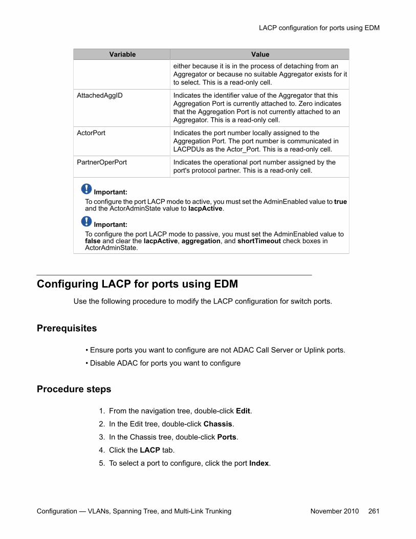
Variable Valueeither because it is in the process of detaching from anAggregator or because no suitable Aggregator exists for itto select. This is a read-only cell.
AttachedAggID Indicates the identifier value of the Aggregator that thisAggregation Port is currently attached to. Zero indicatesthat the Aggregation Port is not currently attached to anAggregator. This is a read-only cell.
ActorPort Indicates the port number locally assigned to theAggregation Port. The port number is communicated inLACPDUs as the Actor_Port. This is a read-only cell.
PartnerOperPort Indicates the operational port number assigned by theport's protocol partner. This is a read-only cell.
Important:To configure the port LACP mode to active, you must set the AdminEnabled value to trueand the ActorAdminState value to lacpActive.
Important:To configure the port LACP mode to passive, you must set the AdminEnabled value tofalse and clear the lacpActive, aggregation, and shortTimeout check boxes inActorAdminState.
Configuring LACP for ports using EDMUse the following procedure to modify the LACP configuration for switch ports.
Prerequisites
• Ensure ports you want to configure are not ADAC Call Server or Uplink ports.
• Disable ADAC for ports you want to configure
Procedure steps
1. From the navigation tree, double-click Edit.
2. In the Edit tree, double-click Chassis.
3. In the Chassis tree, double-click Ports.
4. Click the LACP tab.
5. To select a port to configure, click the port Index.
LACP configuration for ports using EDM
Configuration — VLANs, Spanning Tree, and Multi-Link Trunking November 2010 261
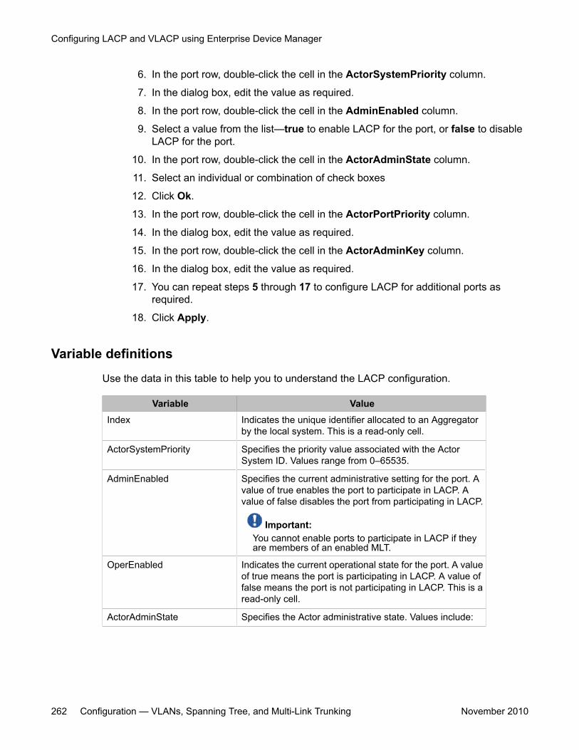
6. In the port row, double-click the cell in the ActorSystemPriority column.
7. In the dialog box, edit the value as required.
8. In the port row, double-click the cell in the AdminEnabled column.
9. Select a value from the list—true to enable LACP for the port, or false to disableLACP for the port.
10. In the port row, double-click the cell in the ActorAdminState column.
11. Select an individual or combination of check boxes
12. Click Ok.
13. In the port row, double-click the cell in the ActorPortPriority column.
14. In the dialog box, edit the value as required.
15. In the port row, double-click the cell in the ActorAdminKey column.
16. In the dialog box, edit the value as required.
17. You can repeat steps 5 through 17 to configure LACP for additional ports asrequired.
18. Click Apply.
Variable definitions
Use the data in this table to help you to understand the LACP configuration.
Variable ValueIndex Indicates the unique identifier allocated to an Aggregator
by the local system. This is a read-only cell.
ActorSystemPriority Specifies the priority value associated with the ActorSystem ID. Values range from 0–65535.
AdminEnabled Specifies the current administrative setting for the port. Avalue of true enables the port to participate in LACP. Avalue of false disables the port from participating in LACP.
Important:You cannot enable ports to participate in LACP if theyare members of an enabled MLT.
OperEnabled Indicates the current operational state for the port. A valueof true means the port is participating in LACP. A value offalse means the port is not participating in LACP. This is aread-only cell.
ActorAdminState Specifies the Actor administrative state. Values include:
Configuring LACP and VLACP using Enterprise Device Manager
262 Configuration — VLANs, Spanning Tree, and Multi-Link Trunking November 2010
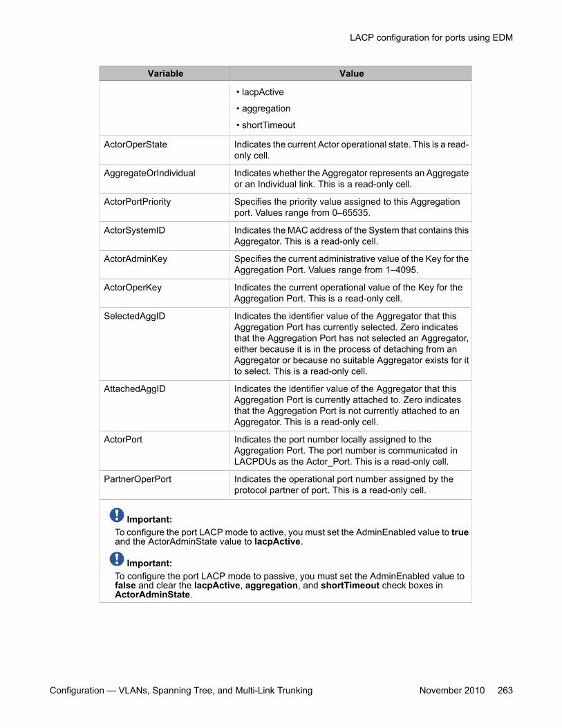
Variable Value
• lacpActive
• aggregation
• shortTimeout
ActorOperState Indicates the current Actor operational state. This is a read-only cell.
AggregateOrIndividual Indicates whether the Aggregator represents an Aggregateor an Individual link. This is a read-only cell.
ActorPortPriority Specifies the priority value assigned to this Aggregationport. Values range from 0–65535.
ActorSystemID Indicates the MAC address of the System that contains thisAggregator. This is a read-only cell.
ActorAdminKey Specifies the current administrative value of the Key for theAggregation Port. Values range from 1–4095.
ActorOperKey Indicates the current operational value of the Key for theAggregation Port. This is a read-only cell.
SelectedAggID Indicates the identifier value of the Aggregator that thisAggregation Port has currently selected. Zero indicatesthat the Aggregation Port has not selected an Aggregator,either because it is in the process of detaching from anAggregator or because no suitable Aggregator exists for itto select. This is a read-only cell.
AttachedAggID Indicates the identifier value of the Aggregator that thisAggregation Port is currently attached to. Zero indicatesthat the Aggregation Port is not currently attached to anAggregator. This is a read-only cell.
ActorPort Indicates the port number locally assigned to theAggregation Port. The port number is communicated inLACPDUs as the Actor_Port. This is a read-only cell.
PartnerOperPort Indicates the operational port number assigned by theprotocol partner of port. This is a read-only cell.
Important:To configure the port LACP mode to active, you must set the AdminEnabled value to trueand the ActorAdminState value to lacpActive.
Important:To configure the port LACP mode to passive, you must set the AdminEnabled value tofalse and clear the lacpActive, aggregation, and shortTimeout check boxes inActorAdminState.
LACP configuration for ports using EDM
Configuration — VLANs, Spanning Tree, and Multi-Link Trunking November 2010 263
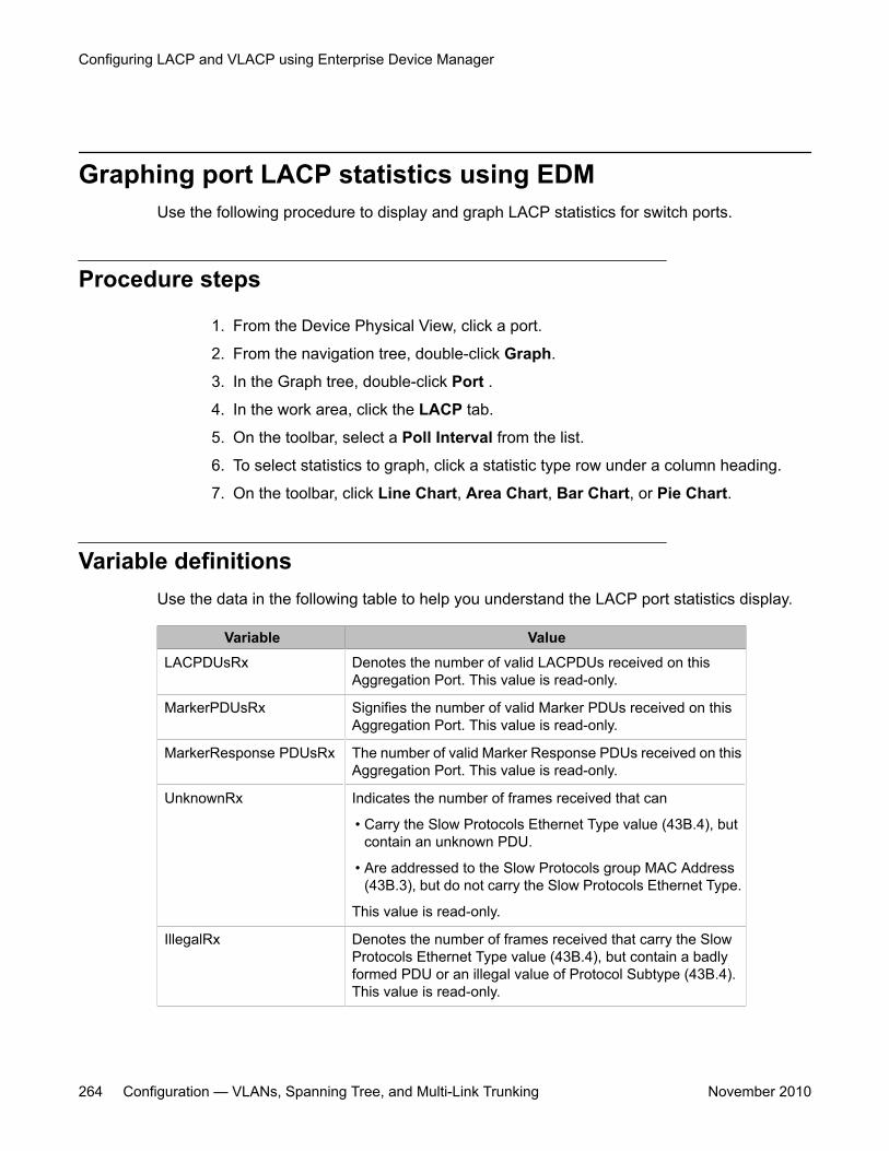
Graphing port LACP statistics using EDMUse the following procedure to display and graph LACP statistics for switch ports.
Procedure steps
1. From the Device Physical View, click a port.
2. From the navigation tree, double-click Graph.
3. In the Graph tree, double-click Port .
4. In the work area, click the LACP tab.
5. On the toolbar, select a Poll Interval from the list.
6. To select statistics to graph, click a statistic type row under a column heading.
7. On the toolbar, click Line Chart, Area Chart, Bar Chart, or Pie Chart.
Variable definitionsUse the data in the following table to help you understand the LACP port statistics display.
Variable ValueLACPDUsRx Denotes the number of valid LACPDUs received on this
Aggregation Port. This value is read-only.
MarkerPDUsRx Signifies the number of valid Marker PDUs received on thisAggregation Port. This value is read-only.
MarkerResponse PDUsRx The number of valid Marker Response PDUs received on thisAggregation Port. This value is read-only.
UnknownRx Indicates the number of frames received that can
• Carry the Slow Protocols Ethernet Type value (43B.4), butcontain an unknown PDU.
• Are addressed to the Slow Protocols group MAC Address(43B.3), but do not carry the Slow Protocols Ethernet Type.
This value is read-only.
IllegalRx Denotes the number of frames received that carry the SlowProtocols Ethernet Type value (43B.4), but contain a badlyformed PDU or an illegal value of Protocol Subtype (43B.4).This value is read-only.
Configuring LACP and VLACP using Enterprise Device Manager
264 Configuration — VLANs, Spanning Tree, and Multi-Link Trunking November 2010
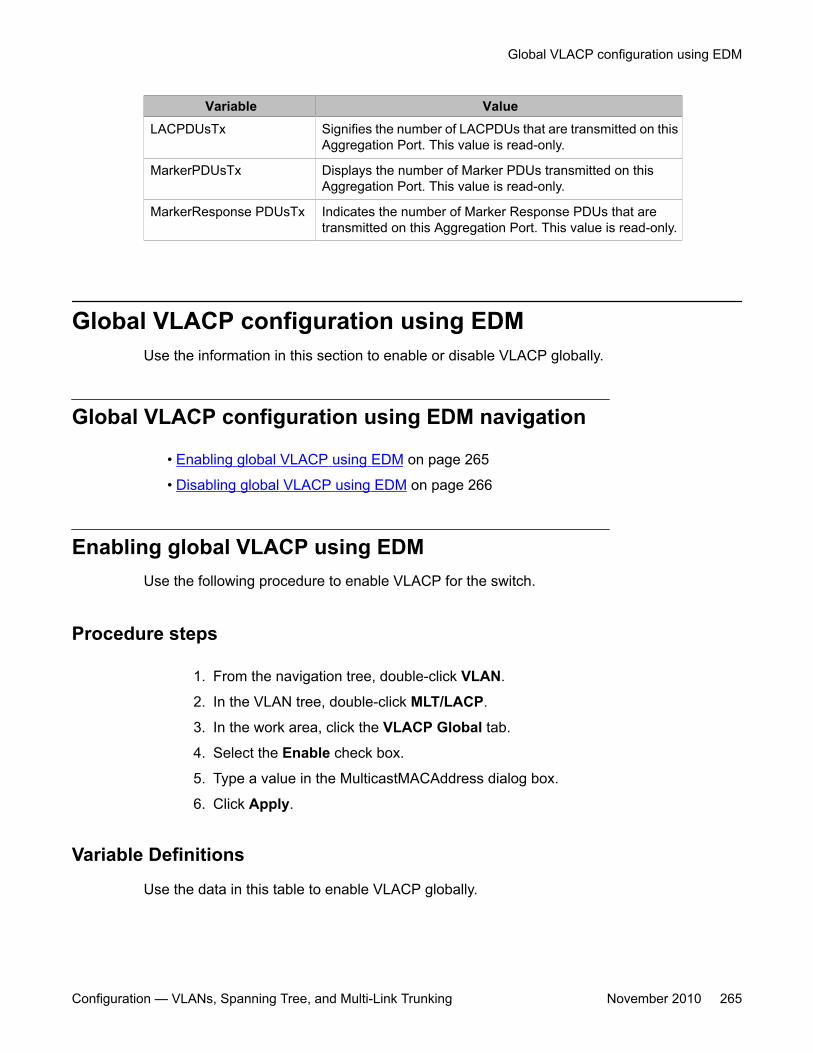
Variable ValueLACPDUsTx Signifies the number of LACPDUs that are transmitted on this
Aggregation Port. This value is read-only.
MarkerPDUsTx Displays the number of Marker PDUs transmitted on thisAggregation Port. This value is read-only.
MarkerResponse PDUsTx Indicates the number of Marker Response PDUs that aretransmitted on this Aggregation Port. This value is read-only.
Global VLACP configuration using EDMUse the information in this section to enable or disable VLACP globally.
Global VLACP configuration using EDM navigation
• Enabling global VLACP using EDM on page 265
• Disabling global VLACP using EDM on page 266
Enabling global VLACP using EDMUse the following procedure to enable VLACP for the switch.
Procedure steps
1. From the navigation tree, double-click VLAN.
2. In the VLAN tree, double-click MLT/LACP.
3. In the work area, click the VLACP Global tab.
4. Select the Enable check box.
5. Type a value in the MulticastMACAddress dialog box.
6. Click Apply.
Variable Definitions
Use the data in this table to enable VLACP globally.
Global VLACP configuration using EDM
Configuration — VLANs, Spanning Tree, and Multi-Link Trunking November 2010 265
Variable ValueMulticastMACAddress Specifies a multicast MAC address used exclusively for
VLACPDUs. The default is 01:80:c2:00:11:00.
Disabling global VLACP using EDMUse the following procedure to disable VLACP for the switch.
Procedure steps
1. From the navigation tree, double-click VLAN.
2. In the VLAN tree, double-click MLT/LACP.
3. In the work area, click the VLACP Global tab.
4. Clear the Enable check box.
5. Click Apply.
VLACP configuration for ports using EDMUse the procedures in this section to view and configure VLACP at the port level.
VLACP configuration for ports using EDM navigation
• Viewing the VLACP configuration for ports using EDM on page 266
• Configuring VLACP for specific ports using EDM on page 268
Viewing the VLACP configuration for ports using EDMUse the following procedure to display the VLACP configuration for all ports on a switch orstack.
Configuring LACP and VLACP using Enterprise Device Manager
266 Configuration — VLANs, Spanning Tree, and Multi-Link Trunking November 2010
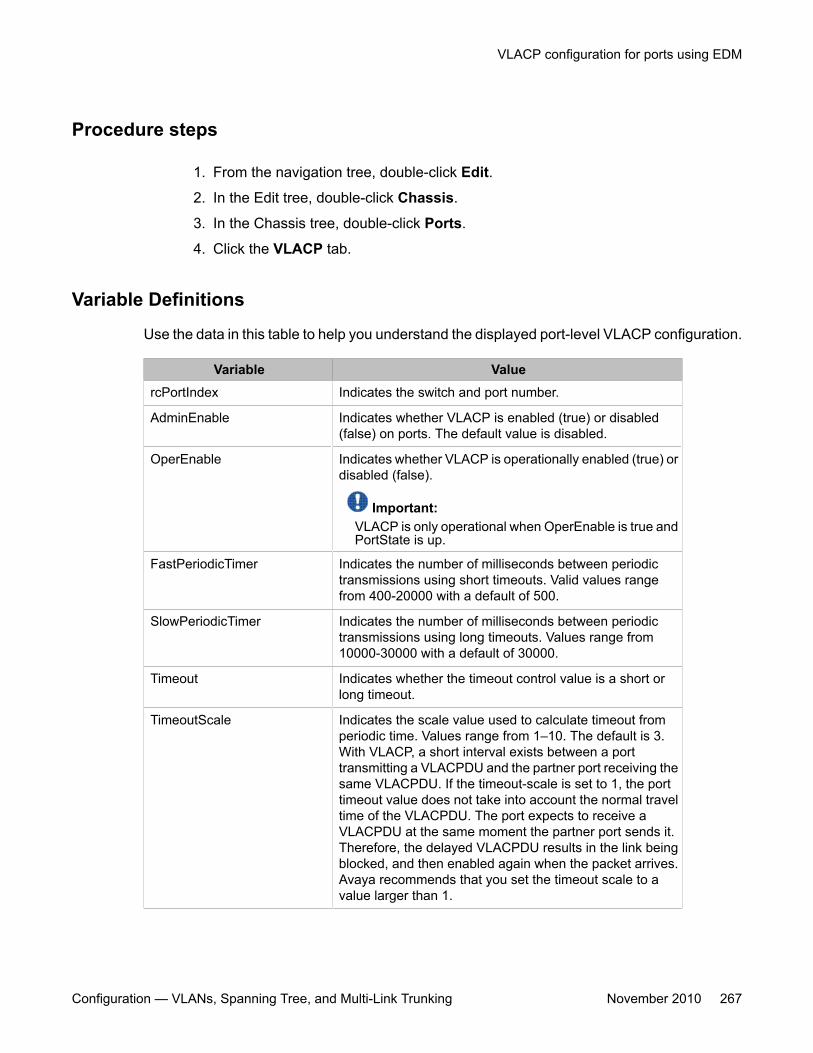
Procedure steps
1. From the navigation tree, double-click Edit.
2. In the Edit tree, double-click Chassis.
3. In the Chassis tree, double-click Ports.
4. Click the VLACP tab.
Variable Definitions
Use the data in this table to help you understand the displayed port-level VLACP configuration.
Variable ValuercPortIndex Indicates the switch and port number.
AdminEnable Indicates whether VLACP is enabled (true) or disabled(false) on ports. The default value is disabled.
OperEnable Indicates whether VLACP is operationally enabled (true) ordisabled (false).
Important:VLACP is only operational when OperEnable is true andPortState is up.
FastPeriodicTimer Indicates the number of milliseconds between periodictransmissions using short timeouts. Valid values rangefrom 400-20000 with a default of 500.
SlowPeriodicTimer Indicates the number of milliseconds between periodictransmissions using long timeouts. Values range from10000-30000 with a default of 30000.
Timeout Indicates whether the timeout control value is a short orlong timeout.
TimeoutScale Indicates the scale value used to calculate timeout fromperiodic time. Values range from 1–10. The default is 3.With VLACP, a short interval exists between a porttransmitting a VLACPDU and the partner port receiving thesame VLACPDU. If the timeout-scale is set to 1, the porttimeout value does not take into account the normal traveltime of the VLACPDU. The port expects to receive aVLACPDU at the same moment the partner port sends it.Therefore, the delayed VLACPDU results in the link beingblocked, and then enabled again when the packet arrives.Avaya recommends that you set the timeout scale to avalue larger than 1.
VLACP configuration for ports using EDM
Configuration — VLANs, Spanning Tree, and Multi-Link Trunking November 2010 267
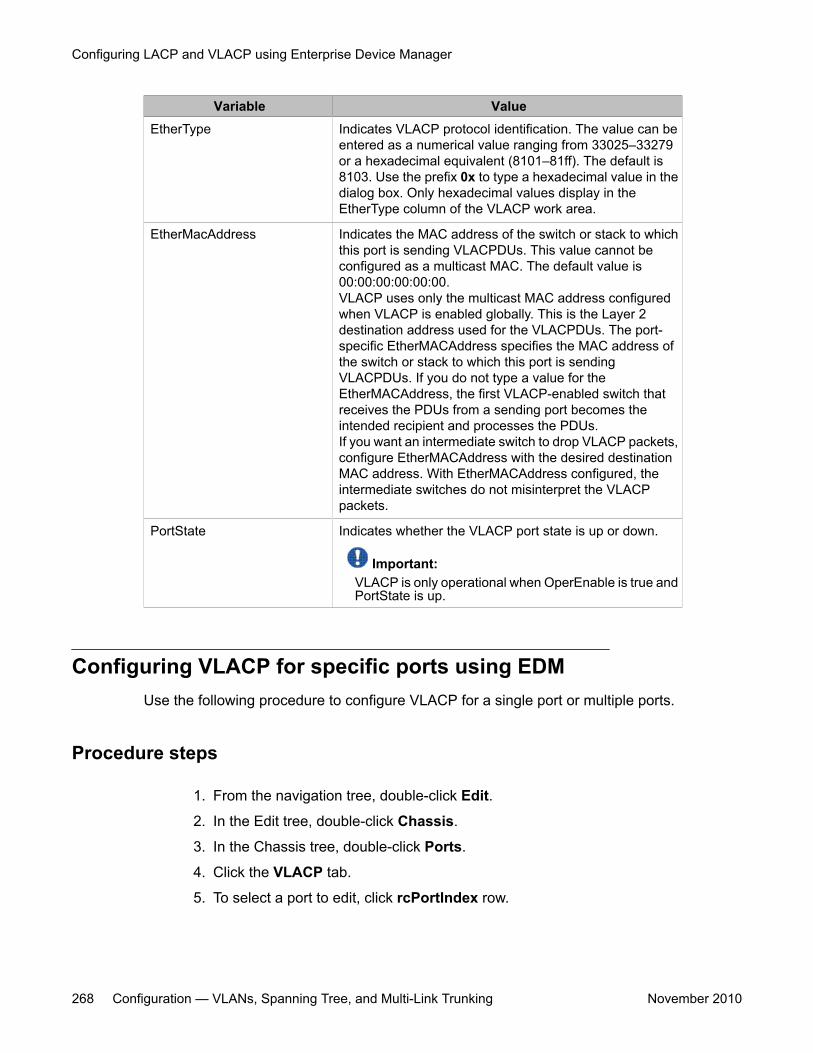
Variable ValueEtherType Indicates VLACP protocol identification. The value can be
entered as a numerical value ranging from 33025–33279or a hexadecimal equivalent (8101–81ff). The default is8103. Use the prefix 0x to type a hexadecimal value in thedialog box. Only hexadecimal values display in theEtherType column of the VLACP work area.
EtherMacAddress Indicates the MAC address of the switch or stack to whichthis port is sending VLACPDUs. This value cannot beconfigured as a multicast MAC. The default value is00:00:00:00:00:00.VLACP uses only the multicast MAC address configuredwhen VLACP is enabled globally. This is the Layer 2destination address used for the VLACPDUs. The port-specific EtherMACAddress specifies the MAC address ofthe switch or stack to which this port is sendingVLACPDUs. If you do not type a value for theEtherMACAddress, the first VLACP-enabled switch thatreceives the PDUs from a sending port becomes theintended recipient and processes the PDUs.If you want an intermediate switch to drop VLACP packets,configure EtherMACAddress with the desired destinationMAC address. With EtherMACAddress configured, theintermediate switches do not misinterpret the VLACPpackets.
PortState Indicates whether the VLACP port state is up or down.
Important:VLACP is only operational when OperEnable is true andPortState is up.
Configuring VLACP for specific ports using EDMUse the following procedure to configure VLACP for a single port or multiple ports.
Procedure steps
1. From the navigation tree, double-click Edit.
2. In the Edit tree, double-click Chassis.
3. In the Chassis tree, double-click Ports.
4. Click the VLACP tab.
5. To select a port to edit, click rcPortIndex row.
Configuring LACP and VLACP using Enterprise Device Manager
268 Configuration — VLANs, Spanning Tree, and Multi-Link Trunking November 2010
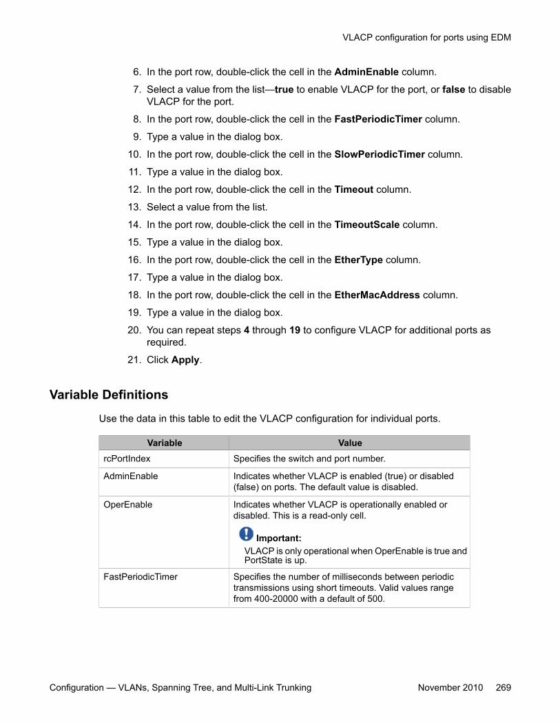
6. In the port row, double-click the cell in the AdminEnable column.
7. Select a value from the list—true to enable VLACP for the port, or false to disableVLACP for the port.
8. In the port row, double-click the cell in the FastPeriodicTimer column.
9. Type a value in the dialog box.
10. In the port row, double-click the cell in the SlowPeriodicTimer column.
11. Type a value in the dialog box.
12. In the port row, double-click the cell in the Timeout column.
13. Select a value from the list.
14. In the port row, double-click the cell in the TimeoutScale column.
15. Type a value in the dialog box.
16. In the port row, double-click the cell in the EtherType column.
17. Type a value in the dialog box.
18. In the port row, double-click the cell in the EtherMacAddress column.
19. Type a value in the dialog box.
20. You can repeat steps 4 through 19 to configure VLACP for additional ports asrequired.
21. Click Apply.
Variable Definitions
Use the data in this table to edit the VLACP configuration for individual ports.
Variable ValuercPortIndex Specifies the switch and port number.
AdminEnable Indicates whether VLACP is enabled (true) or disabled(false) on ports. The default value is disabled.
OperEnable Indicates whether VLACP is operationally enabled ordisabled. This is a read-only cell.
Important:VLACP is only operational when OperEnable is true andPortState is up.
FastPeriodicTimer Specifies the number of milliseconds between periodictransmissions using short timeouts. Valid values rangefrom 400-20000 with a default of 500.
VLACP configuration for ports using EDM
Configuration — VLANs, Spanning Tree, and Multi-Link Trunking November 2010 269
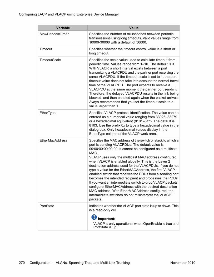
Variable ValueSlowPeriodicTimer Specifies the number of milliseconds between periodic
transmissions using long timeouts. Valid values range from10000-30000 with a default of 30000.
Timeout Specifies whether the timeout control value is a short orlong timeout.
TimeoutScale Specifies the scale value used to calculate timeout fromperiodic time. Values range from 1–10. The default is 3.With VLACP, a short interval exists between a porttransmitting a VLACPDU and the partner port receiving thesame VLACPDU. If the timeout-scale is set to 1, the porttimeout value does not take into account the normal traveltime of the VLACPDU. The port expects to receive aVLACPDU at the same moment the partner port sends it.Therefore, the delayed VLACPDU results in the link beingblocked, and then enabled again when the packet arrives.Avaya recommends that you set the timeout scale to avalue larger than 1.
EtherType Specifies VLACP protocol identification. The value can beentered as a numerical value ranging from 33025–33279or a hexadecimal equivalent (8101–81ff). The default is8103. Use the prefix 0x to type a hexadecimal value in thedialog box. Only hexadecimal values display in theEtherType column of the VLACP work area.
EtherMacAddress Specifies the MAC address of the switch or stack to which aport is sending VLACPDUs. The default value is00:00:00:00:00:00. It cannot be configured as a multicastMAC.VLACP uses only the multicast MAC address configuredwhen VLACP is enabled globally. This is the Layer 2destination address used for the VLACPDUs. If you do nottype a value for the EtherMACAddress, the first VLACP-enabled switch that receives the PDUs from a sending portbecomes the intended recipient and processes the PDUs.If you want an intermediate switch to drop VLACP packets,configure EtherMACAddress with the desired destinationMAC address. With EtherMACAddress configured, theintermediate switches do not misinterpret the VLACPpackets.
PortState Indicates whether the VLACP port state is up or down. Thisis a read-only cell.
Important:VLACP is only operational when OperEnable is true andPortState is up.
Configuring LACP and VLACP using Enterprise Device Manager
270 Configuration — VLANs, Spanning Tree, and Multi-Link Trunking November 2010