configuring a gsm (3g) modem on a gw series router€¦ · egsm (extended global system for mobile...
TRANSCRIPT

Service Managed GatewayTM
Configuring a GSM (3G) modem on a GW Series Router
Issue 1.4
Date 30 July 2013

Table of contents
1 About this document ............................................................................... 3 1.1 Scope ..................................................................................................... 3 1.2 Readership ............................................................................................. 3 1.3 More information .................................................................................... 3
1.3.1 Assigned interface number ...................................................................... 3 1.3.2 ISP provider details ................................................................................ 3 1.3.3 References to GSM (3G) .......................................................................... 3 1.3.4 SIM card ............................................................................................... 3 1.3.5 Terminology .......................................................................................... 4
2 Introduction ............................................................................................ 5 2.1 Typical uses of the GSM (3G) modem ..................................................... 5 2.2 Types of data bearers that the GSM (3G) modem supports .................... 5
2.2.1 GPRS .................................................................................................... 6 2.2.2 HSDPA .................................................................................................. 6 2.2.3 CSD in EGSM900/GSM1800 MHz .............................................................. 6
3 Configuring the SMG ................................................................................ 7 4 Setting up the GSM (3G) modem for a primary WAN link ........................ 8 4.1 Configuring the GW Series router to use the GSM (3G) modem interface
............................................................................................................... 8 4.1.1 Configure the IP default route .................................................................. 8 4.1.2 Configure the PPP interface ...................................................................... 9 4.1.3 Configure the IP interface .......................................................................10 4.1.4 Configure address translation ..................................................................13 4.1.5 Configure IPCP options ...........................................................................14 4.1.6 Select asynchronous PPP operation ..........................................................18 4.1.7 Configure authentication options .............................................................20 4.1.8 Set dialling options for GSM only .............................................................24 4.1.9 Configure the modem interface ...............................................................26 4.1.10 Configure the GSM (3G) modem ..............................................................28 4.1.11 Save the configuration ...........................................................................29 4.1.12 Reload the configuration .........................................................................30
5 Performing GSM (3G) monitoring and diagnostics ................................. 32 5.1 View the connection monitor ................................................................ 32
5.1.1 Call history ...........................................................................................32 5.1.2 Active data connections ..........................................................................34 5.1.3 Trace analyzer ......................................................................................34 5.1.4 Modem statistics ...................................................................................37
Copyright 2013 Virtual Access (Irl) Ltd. This material is protected by copyright. No part of this material may be reproduced, distributed, or altered without the written consent of Virtual Access. All rights reserved. Third party trademarks are the property of the third parties. Configuring a GSM (3G) modem on a GW Series Router © Virtual Access Ltd. Issue: 1.4 Page 2 of 38

1: About this document
1 About this document
1.1 Scope
This configuration guide explains how to set up and configure a primary link using the GSM (3G) modem on the following routers:
• GW6500 Series
• GW7000 Series
• GW8000 Series
• GW9000 Series
For information on configuring a GSM (3G) modem on a GW2040, read the guide ‘Configuring a GSM (3G) Modem on a GW2040’.
1.2 Readership
This document is for engineers who have previous experience configuring and managing GW Series routers.
1.3 More information
1.3.1 Assigned interface number
Throughout this guide we have used ppp-2 as the assigned interface number. You can configure any PPP interface number for connections.
1.3.2 ISP provider details
Please check with your provider for your number, username, and password for your access point.
1.3.3 References to GSM (3G)
The SMG web interface refers to GSM, so screen grabs of the web interface will vary.
1.3.4 SIM card
WARNING
The SIM card MUST be inserted into the SMG before the unit is powered on.
Do not insert or remove the SIM card after the unit has been powered on.
Configuring a GSM (3G) modem on a GW Series Router © Virtual Access Ltd. Issue: 1.4 Page 3 of 38

1: About this document
1.3.5 Terminology
Abbreviation Description GSM Global System for Mobile communications UMTS Universal Mobile Telecommunications System HSDPA High-Speed Downlink Packet Access
Configuring a GSM (3G) modem on a GW Series Router © Virtual Access Ltd. Issue: 1.4 Page 4 of 38

2: Introduction
2 Introduction The Service Managed Gateway (SMG) contains a GSM (Global System for Mobile communications) 3G wireless modem. The modem uses a SIM card to create a dial-up WAN connection to the Internet.
2.1 Typical uses of the GSM (3G) modem
You can use the GSM (3G) modem on the GW Series router in two ways.
• You can create a primary WAN link over the GSM (3G) modem.
Figure 1: A primary WAN link over the 3G modem
• You can use the GSM (3G) modem as a backup WAN link. If the primary interface link fails, the GW Series router uses its GSM (3G) modem to automatically route traffic across the Internet via its alternative interface. This set up is not covered in this document. For further information contact Virtual Access.
Figure 2: A primary link using the 3G modem on the GW SERIES ROUTER SMG
2.2 Types of data bearers that the GSM (3G) modem supports
Data bearers are frame protocols that transport data streams. The GSM (3G) modem supports GPRS, HSDPA, and CSD.
Configuring a GSM (3G) modem on a GW Series Router © Virtual Access Ltd. Issue: 1.4 Page 5 of 38

2: Introduction
2.2.1 GPRS
GPRS (General Packet Radio Service) uses packet-switched technology to transmit small bursts of data. The 3G modem on the GW Series router supports multi-slot class 6, which allows a maximum data rate of 384Kbps class 3. The maximum data rate available to the 3G modem depends on provisioning by the network operator.
2.2.2 HSDPA
HSDPA (High-Speed Downlink Packet Access) uses circuit-switched technology to transmit data at speeds of up to 1.8Mbps.
2.2.3 CSD in EGSM900/GSM1800 MHz
CSD (Circuit-Switched Data) mode enables the 3G modem to transmit data over the EGSM (Extended Global System for Mobile communications) frequency or the GSM frequency. The modem behaves as a dual-band mobile phone behaves.
Configuring a GSM (3G) modem on a GW Series Router © Virtual Access Ltd. Issue: 1.4 Page 6 of 38

3: Configuring the SMG
3 Configuring the SMG The Service Managed Gateway (SMG) contains an internal web server that is used to configure the SMG. Before you can access the internal web server and start the SMG configuration, you must ensure that your PC has the correct networking set up.
To enable and configure connections on your SMG, the gateway must be correctly installed, and a valid service must be configured on it.
When your Service Managed Gateway is correctly connected to your PC, type fast.start into the URL line of your browser to display the Start page.
Figure 3: The SMG start page
If a login page appears type in the login password you received from your administrator.
If you have not received a password, contact the Virtual Access Support team.
Access the Fast Start Wizard by clicking the Fast.Start icon on the Start page of the embedded web.
The Fast Start Wizard will guide you through a series of forms that you must complete to configure your SMG.
Configuring a GSM (3G) modem on a GW Series Router © Virtual Access Ltd. Issue: 1.4 Page 7 of 38

4: Setting up the GSM (3G) modem for a primary WAN link
4 Setting up the GSM (3G) modem for a primary WAN link You set up the GSM (3G) modem for a primary WAN link in the Expert View of the Advanced section of the web of the SMG.
On the SMG Start page, click Advanced.
In the Advanced menu, click Expert View.
4.1 Configuring the GW Series router to use the GSM (3G) modem interface
To configure the GW Series router to use the GSM (3G) modem interface, follow the steps in sections 4.1.1 to 4.1.10. You do not have to save each configuration until you have updated all your settings. When you have completed all your configuration changes, you must save the configuration as described in section 4.1.11.
4.1.1 Configure the IP default route
In the Expert View menu, select system -> ip -> default route. The IP Default Route page appears.
Figure 4: The IP default route page
Configuring a GSM (3G) modem on a GW Series Router © Virtual Access Ltd. Issue: 1.4 Page 8 of 38

4: Setting up the GSM (3G) modem for a primary WAN link
Field name Description Command line Configured Enables or disables the default route.
Set Configured to Yes
Set Ip Route Default Configured
Route Type Indicates whether the route type is over a numbered or unnumbered link. A numbered link is a link that has been assigned an IP address. Set Route Type to unnumbered.
Set Ip Route Default Numbered
Next Hop For Numbered Interfaces
When Route Type is set to numbered, enter the IP address in dotted-decimal notation, of an adjacent router. The local device sends traffic to this router when a route to a destination is not known. Set Next Hop For Numbered Interfaces fields to 0.0.0.0.
Set Ip Route Default Next Hop Ip
Next Hop For Unnumbered Interfaces
Selects the interface as the default route. Set Next Hop For Unnumbered Interfaces to ppp-2.
Set Ip Route Default Next Hop Interface
Table 1: The IP default route fields, their descriptions and command lines
Click Update. The Configuration Update Result page appears.
4.1.2 Configure the PPP interface
The GWM (3G) modem uses the modem-1 interface, so you must configure ppp-2 to send and receive data using the modem-1 interface.
In the Expert View menu, select interfaces -> ppp-2 -> wan interface. The WAN Interface page appears.
Configuring a GSM (3G) modem on a GW Series Router © Virtual Access Ltd. Issue: 1.4 Page 9 of 38

4: Setting up the GSM (3G) modem for a primary WAN link
Figure 5: The WAN interface page
On the PPP WAN Interface page, select Modem -1 from the Wan Interface drop-down list.
Field name Description Command line WAN Interface Defines the connection type on the
PPP WAN interface. Ppp Interface Wan Interface
Table 2: The PPP WAN interface field, its description and command line
Click Update. The Configuration Update Result page appears.
4.1.3 Configure the IP interface
To configure the IP interface, in the Expert View menu, select interfaces -> ppp-2 -> ip -> ip. The IP Interface page appears.
Configuring a GSM (3G) modem on a GW Series Router © Virtual Access Ltd. Issue: 1.4 Page 10 of 38

4: Setting up the GSM (3G) modem for a primary WAN link
Figure 6: The IP interface on ppp-2 page
Configuring a GSM (3G) modem on a GW Series Router © Virtual Access Ltd. Issue: 1.4 Page 11 of 38
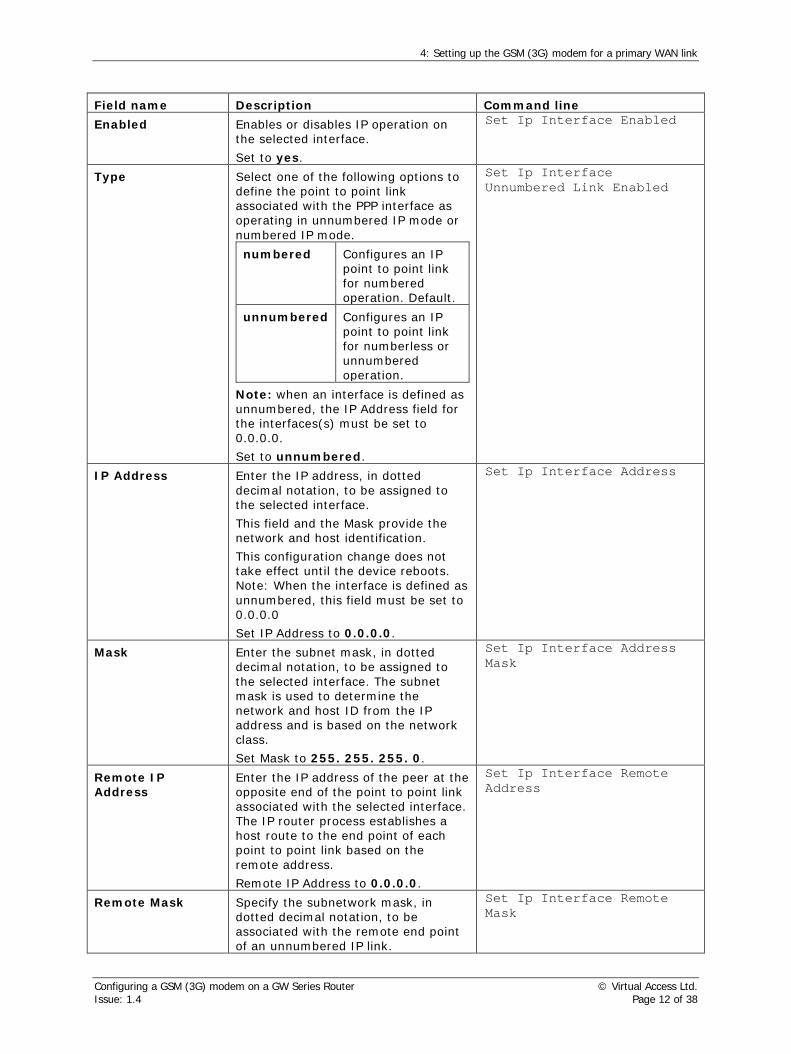
4: Setting up the GSM (3G) modem for a primary WAN link
Field name Description Command line Enabled Enables or disables IP operation on
the selected interface. Set to yes.
Set Ip Interface Enabled
Type Select one of the following options to define the point to point link associated with the PPP interface as operating in unnumbered IP mode or numbered IP mode. numbered Configures an IP
point to point link for numbered operation. Default.
unnumbered Configures an IP point to point link for numberless or unnumbered operation.
Note: when an interface is defined as unnumbered, the IP Address field for the interfaces(s) must be set to 0.0.0.0. Set to unnumbered.
Set Ip Interface Unnumbered Link Enabled
IP Address Enter the IP address, in dotted decimal notation, to be assigned to the selected interface. This field and the Mask provide the network and host identification. This configuration change does not take effect until the device reboots. Note: When the interface is defined as unnumbered, this field must be set to 0.0.0.0 Set IP Address to 0.0.0.0.
Set Ip Interface Address
Mask Enter the subnet mask, in dotted decimal notation, to be assigned to the selected interface. The subnet mask is used to determine the network and host ID from the IP address and is based on the network class. Set Mask to 255. 255. 255. 0.
Set Ip Interface Address Mask
Remote IP Address
Enter the IP address of the peer at the opposite end of the point to point link associated with the selected interface. The IP router process establishes a host route to the end point of each point to point link based on the remote address. Remote IP Address to 0.0.0.0.
Set Ip Interface Remote Address
Remote Mask Specify the subnetwork mask, in dotted decimal notation, to be associated with the remote end point of an unnumbered IP link.
Set Ip Interface Remote Mask
Configuring a GSM (3G) modem on a GW Series Router © Virtual Access Ltd. Issue: 1.4 Page 12 of 38

4: Setting up the GSM (3G) modem for a primary WAN link
Remote Mask to 255.255.255.0 MTU Enter the size, in bytes, of the largest
IP datagram that can be sent by the selected interface. The MTU value includes the data link header, IP header, and IP data field. Minimum Value
64
Default Value
1500
Maximum Value
1500
Units Bytes Set MTU to 1500
Set Ip Interface Mtu
BOOTP enabled This option is used to enable or disable BOOTP on the selected interface. yes Enables BOOTP no Disables BOOTP
Set BOOT enabled to no.
Set Ip Interface Bootp Enabled
Table 3: The IP interface on ppp-2 fields, their descriptions and command lines
Click Update. The Configuration Update Result page appears.
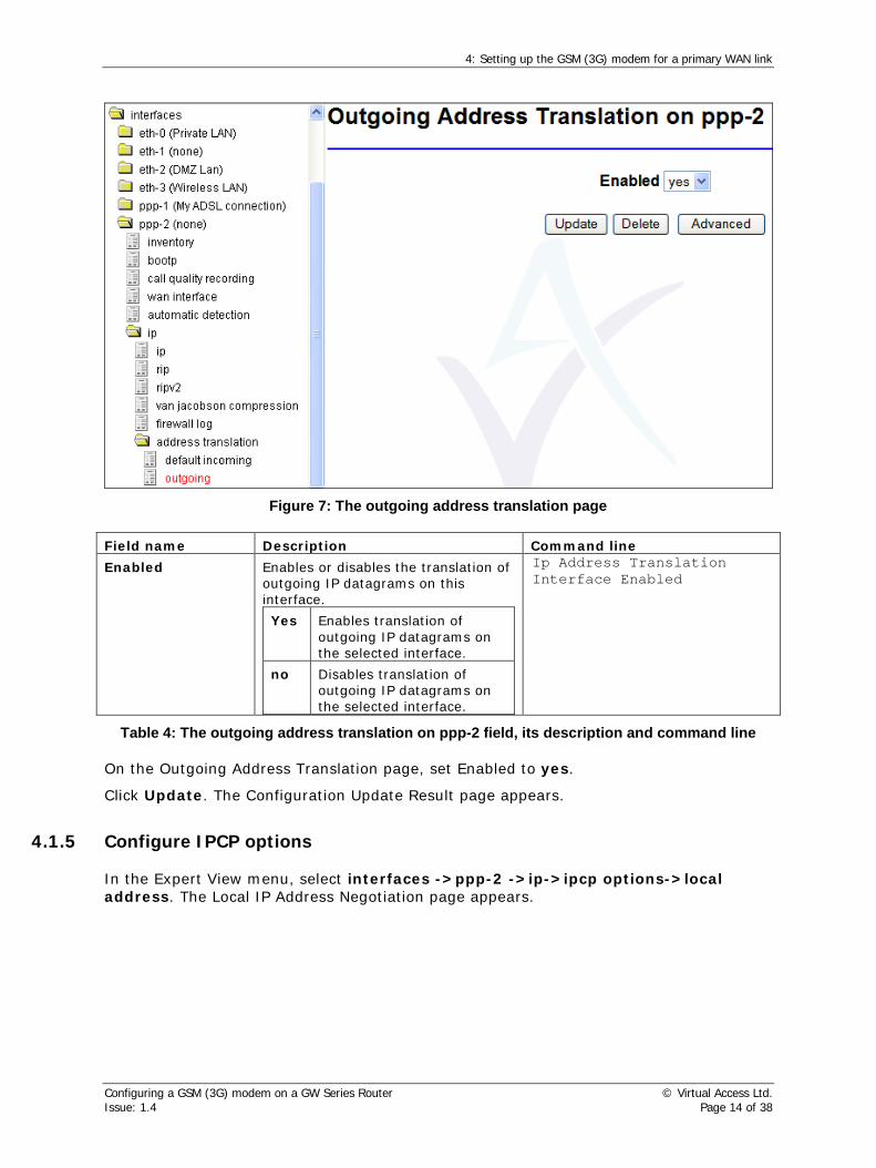
4.1.4 Configure address translation
In the Expert View menu, select interfaces -> ppp-2 -> ip -> address translation -> outgoing. The Outgoing Address Translation page appears.
Configuring a GSM (3G) modem on a GW Series Router © Virtual Access Ltd. Issue: 1.4 Page 13 of 38
4: Setting up the GSM (3G) modem for a primary WAN link
Figure 7: The outgoing address translation page
Field name Description Command line Enabled Enables or disables the translation of
outgoing IP datagrams on this interface. Yes Enables translation of
outgoing IP datagrams on the selected interface.
no Disables translation of outgoing IP datagrams on the selected interface.
Ip Address Translation Interface Enabled
Table 4: The outgoing address translation on ppp-2 field, its description and command line
On the Outgoing Address Translation page, set Enabled to yes.
Click Update. The Configuration Update Result page appears.
4.1.5 Configure IPCP options
In the Expert View menu, select interfaces ->ppp-2 ->ip->ipcp options->local address. The Local IP Address Negotiation page appears.
Configuring a GSM (3G) modem on a GW Series Router © Virtual Access Ltd. Issue: 1.4 Page 14 of 38

4: Setting up the GSM (3G) modem for a primary WAN link
Figure 8: The local IP address page
Field name Description Command line Enabled Enables or disables the IP address
negotiation on the local end of the link. Set Enabled to yes.
Set Ppp Interface Local Option Ipcp Address Enabled
Required Specifies whether or not negotiation of the local IP address is required. Set Required to no.
Set Ppp Interface Local Option Ipcp Address Negotiation Required Enabled
Negotiable Indicates whether the IP address is negotiable or not negotiable. Negotiable to yes.
Ppp Interface Local Option Ipcp Address Negotiable Enabled
IP Address If negotiation is enabled, enter the IP address to use for local IP address negotiation. Enter the IP address in dotted decimal notation. Set IP Address to 0.0.0.0
Ppp Interface Local Option Ipcp Address Value
Table 5: The local IP address fields, their descriptions and command lines
Click Update. The Configuration Update Result page appears.
In the Expert View menu, select interfaces ->ppp-2 ->ip->ipcp options-> local primary dns. The Local Primary DNS page appears.
Configuring a GSM (3G) modem on a GW Series Router © Virtual Access Ltd. Issue: 1.4 Page 15 of 38

4: Setting up the GSM (3G) modem for a primary WAN link
Figure 9: The local primary DNS negotiation on ppp-2 page
Field name Description Command line Enabled Enables or disables negotiation of the
primary DNS IP address on the local end of the link. Set Enabled to yes.
Set Ppp Interface Local Option Ipcp Primary Dns Address Enabled
Required Enables or disables primary DNS negotiation on the local end of the link. Set Required to no.
Set Ppp Interface Local Option Ipcp Primary Dns Address Negotiation Required Enabled
Negotiable Indicates whether primary DNS negotiation is negotiable or not negotiable by the local end of the link. Negotiable to yes.
Set Ppp Interface Local Option Ipcp Primary Dns Address Negotiable Enabled
IP Address Enter the IP address of the primary DNS server to be used by the local end of the link. Setting the IP address to 0.0.0.0 is an explicit request that the remote end provides the address information. Address to 0.0.0.0.
Set Ppp Interface Local Option Ipcp Primary Dns Address Value
Table 6: The local primary DNS fields, their descriptions and command lines
Click Update. The Configuration Update Result page appears.
In the Expert View menu, select interfaces ->ppp-2 ->ip->ipcp options->local secondary dns. The Local Secondary DNS Negotiation page appears.
Configuring a GSM (3G) modem on a GW Series Router © Virtual Access Ltd. Issue: 1.4 Page 16 of 38

4: Setting up the GSM (3G) modem for a primary WAN link
Figure 10: The local secondary DNS negotiation on ppp-2 page
Field name Description Command line Enabled Enables or disables negotiation of the
primary DNS IP address on the local end of the link. Set Enabled to yes
Set Ppp Interface Local Option Ipcp Secondary Dns Address Enabled
Required Enables or disables primary DNS negotiation on the local end of the link. Set Required to no.
Set Ppp Interface Local Option Ipcp Secondary Dns Address Negotiation Required Enabled
Negotiable Indicates whether primary DNS negotiation is negotiable or not negotiable by the local end of the link. Negotiable to yes.
Set Ppp Interface Local Option Ipcp Secondary Dns Address Negotiable Enabled
IP Address Enter the IP address of the primary DNS server to be used by the local end of the link. Setting the IP address to 0.0.0.0 is an explicit request that the remote end provides the address information. Set Address to 0.0.0.0
Set Ppp Interface Local Option Ipcp Secondary Dns Address Value
Figure 11: The secondary DNS fields, their descriptions and command lines
Click Update. The Configuration Update Result page appears.
Configuring a GSM (3G) modem on a GW Series Router © Virtual Access Ltd. Issue: 1.4 Page 17 of 38

4: Setting up the GSM (3G) modem for a primary WAN link
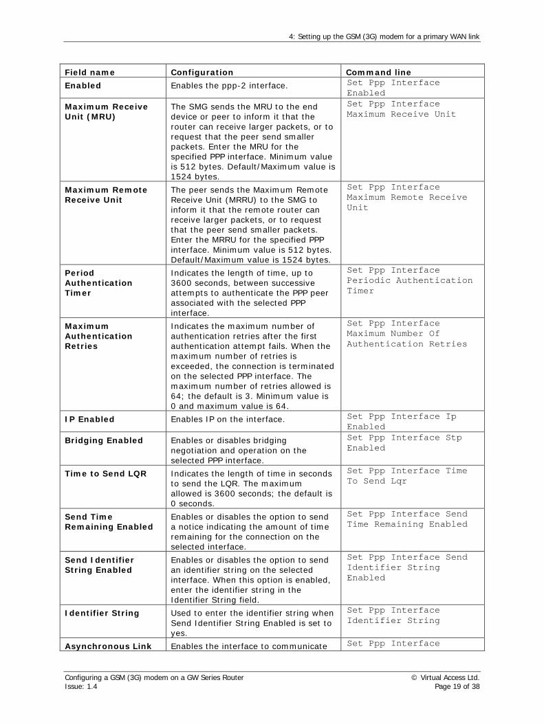
4.1.6 Select asynchronous PPP operation
All PPP interfaces by default are configured for synchronous data transfer. The GSM (3G) modem however, uses asynchronous data transfer so you must configure the PPP interface to operate asynchronously.
In the Expert View menu, select interfaces -> ppp-2 -> ppp -> ppp. The PPP Interface page appears. Click Advanced to view the advanced options.
Figure 12: The PPP interface page
Set Enabled to yes, and set Asychronous Link Enabled to yes. You can leave all other settings at their default values.
Configuring a GSM (3G) modem on a GW Series Router © Virtual Access Ltd. Issue: 1.4 Page 18 of 38
4: Setting up the GSM (3G) modem for a primary WAN link
Field name Configuration Command line Enabled Enables the ppp-2 interface. Set Ppp Interface
Enabled
Maximum Receive Unit (MRU)
The SMG sends the MRU to the end device or peer to inform it that the router can receive larger packets, or to request that the peer send smaller packets. Enter the MRU for the specified PPP interface. Minimum value is 512 bytes. Default/Maximum value is 1524 bytes.
Set Ppp Interface Maximum Receive Unit
Maximum Remote Receive Unit
The peer sends the Maximum Remote Receive Unit (MRRU) to the SMG to inform it that the remote router can receive larger packets, or to request that the peer send smaller packets. Enter the MRRU for the specified PPP interface. Minimum value is 512 bytes. Default/Maximum value is 1524 bytes.
Set Ppp Interface Maximum Remote Receive Unit
Period Authentication Timer
Indicates the length of time, up to 3600 seconds, between successive attempts to authenticate the PPP peer associated with the selected PPP interface.
Set Ppp Interface Periodic Authentication Timer
Maximum Authentication Retries
Indicates the maximum number of authentication retries after the first authentication attempt fails. When the maximum number of retries is exceeded, the connection is terminated on the selected PPP interface. The maximum number of retries allowed is 64; the default is 3. Minimum value is 0 and maximum value is 64.
Set Ppp Interface Maximum Number Of Authentication Retries
IP Enabled Enables IP on the interface. Set Ppp Interface Ip Enabled
Bridging Enabled Enables or disables bridging negotiation and operation on the selected PPP interface.
Set Ppp Interface Stp Enabled
Time to Send LQR Indicates the length of time in seconds to send the LQR. The maximum allowed is 3600 seconds; the default is 0 seconds.
Set Ppp Interface Time To Send Lqr
Send Time Remaining Enabled
Enables or disables the option to send a notice indicating the amount of time remaining for the connection on the selected interface.
Set Ppp Interface Send Time Remaining Enabled
Send Identifier String Enabled
Enables or disables the option to send an identifier string on the selected interface. When this option is enabled, enter the identifier string in the Identifier String field.
Set Ppp Interface Send Identifier String Enabled
Identifier String Used to enter the identifier string when Send Identifier String Enabled is set to yes.
Set Ppp Interface Identifier String
Asynchronous Link Enables the interface to communicate Set Ppp Interface
Configuring a GSM (3G) modem on a GW Series Router © Virtual Access Ltd. Issue: 1.4 Page 19 of 38

4: Setting up the GSM (3G) modem for a primary WAN link
Enabled in asynchronous mode. Asynchronous Link Enabled
Primary DNS IP Address
Address of the primary DNS server. Set Ppp Interface Dns Ip Address
Secondary DNS IP Address
Address of the secondary DNS server. Set Ppp Interface Secondary Dns Ip Address
Table 7: The PPP Interface on ppp-2 fields, their descriptions and command lines
Click Update. The Configuration Update Result page appears.
4.1.7 Configure authentication options
Access to each PPP interface can be restricted, based on a username and password. The username and password for the local interface are entered in the Local Username and Local Password fields. In some cases, the remote end of the connection may also require a username and password for authentication. The username and password for the remote end are entered in the Remote Username and Remote Password fields.
Note: Password validation does not require a minimum length or the use of numeric characters.
In the Expert View menu, select interfaces -> ppp-2 -> ppp->authentication->name and password. The Username and Password page appears.
Figure 13: The username and password page
On the name and password page, set the local username and password.
Configuring a GSM (3G) modem on a GW Series Router © Virtual Access Ltd. Issue: 1.4 Page 20 of 38

4: Setting up the GSM (3G) modem for a primary WAN link
Field name Description Command line Local Username Enter an ASCII string for the
authentication user name on the selected PPP interface. This username is used in PAP and CHAP security. Option Description Minimum length
0
Default Value Unspecified Maximum length
63
Units Unspecified
Set Ppp Interface User Name
Local Password Enter an ASCII string for the authentication user password on the selected PPP interface. To ensure security, the password is displayed with asterisks (*) replacing the actual characters. The password is used in PAP and CHAP security.
Set Ppp Interface User Encrypted Password
Local Password Confirm
Retype the ASCII string for the authentication user password on the selected PPP interface.
Remote Username Option Description Minimum length
0
Default Value Unspecified Maximum length
63
Units Unspecified
Set Ppp Interface Remote User Name
Remote Password Enter an ASCII string for the remote authentication user password.
Set Ppp Interface Remote User Encrypted Password
Remote Password Confirm
Re-type the ASCII string for the authentication user password on the selected PPP interface.
Table 8: The username and password fields, their descriptions and command lines
Click Update. The Configuration Update Result page appears.
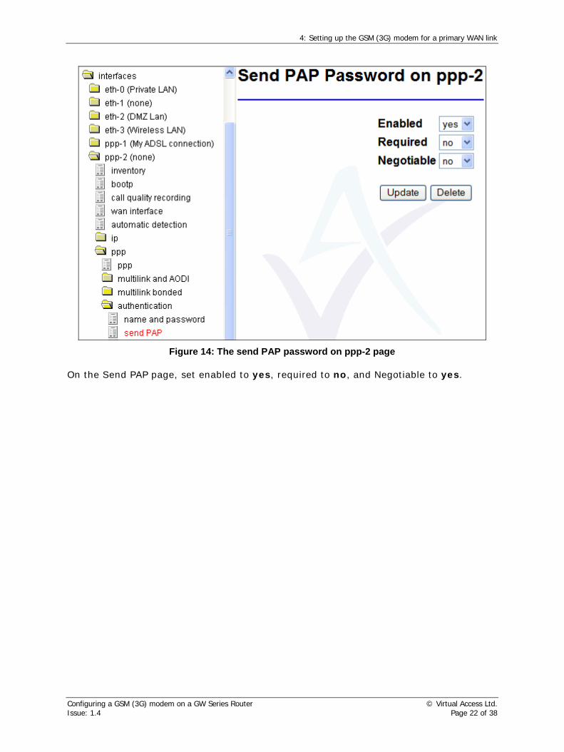
The Send PAP Password on ppp form is used to indicate whether or not to send the Password Authentication Protocol (PAP) password in response to a request.
In the Expert View menu, select interfaces -> ppp-2 -> ppp->authentication->send PAP. The Send PAP Password page appears.
Configuring a GSM (3G) modem on a GW Series Router © Virtual Access Ltd. Issue: 1.4 Page 21 of 38
4: Setting up the GSM (3G) modem for a primary WAN link
Figure 14: The send PAP password on ppp-2 page
On the Send PAP page, set enabled to yes, required to no, and Negotiable to yes.
Configuring a GSM (3G) modem on a GW Series Router © Virtual Access Ltd. Issue: 1.4 Page 22 of 38

4: Setting up the GSM (3G) modem for a primary WAN link
Field name Description Command line Enabled Enables or disables sending the PAP
password in response to a PAP password validation request on the interface. Option Description yes Enables sending PAP no Disables sending PAP
Ppp Interface Remote Option Pap Enabled
Required Specifies whether or not the PAP password should be sent in response to a request. Option Description yes Enables sending PAP in
response to a request. no Disables sending PAP in
response to a request.
Ppp Interface Remote Option Pap Negotiation Required Enabled
Negotiable Specifies whether or not sending the PAP password is negotiable. Option Description yes Enables sending PAP is
negotiable. no Disables sending PAP is
not negotiable.
Ppp Interface Remote Option Pap Negotiable Enabled
Table 9: The send PAP password on ppp fields, their descriptions and command lines
Click Update. The Configuration Update Result page appears.
In the Expert View menu, select interfaces -> ppp-2 -> ppp->authentication->Send CHAP. The Send CHAP Password page appears.
Configuring a GSM (3G) modem on a GW Series Router © Virtual Access Ltd. Issue: 1.4 Page 23 of 38

4: Setting up the GSM (3G) modem for a primary WAN link
Figure 15: The send CHAP password on ppp-2 page
On the Send CHAP page, set enabled to yes, required to no, and Negotiable to yes.
Click Update. The Configuration Update Result page appears.
4.1.8 Set dialling options for GSM only
In the Expert View menu, select interfaces -> ppp-2 -> call control -> call. The Call Details page appears.
Configuring a GSM (3G) modem on a GW Series Router © Virtual Access Ltd. Issue: 1.4 Page 24 of 38

4: Setting up the GSM (3G) modem for a primary WAN link
Figure 16: The call details on ppp-2 page
Configuring a GSM (3G) modem on a GW Series Router © Virtual Access Ltd. Issue: 1.4 Page 25 of 38

4: Setting up the GSM (3G) modem for a primary WAN link
Field name Configuration Command line Outgoing Call Destination Number
Enter the ISP number to call to establish a connection to the Internet. Normally,*99# string is valid. Check with your ISP to confirm.
Set Dial Neighbour Originate Address
Outgoing Call Destination Subaddress
Specifies the device’s subaddress, or extension, if the call destination device has a subaddress defined. No spaces are allowed.
Set Dial Neighbour Originate Subaddress
Incoming Call Remote Number
Specifies the number of one of the locations that is allowed to place calls on this interface. No spaces are allowed.
Set Dial Neighbour Answer Address
Incoming Call Local Number
Specifies the device’s local subaddress, or extension, if the call source has a subaddress defined. No spaces are allowed.
Set Dial Neighbour Received Called Address
ISDN Call Type If using ISDN, defines the call type. Set Dial Neighbour Call Type
Permissions Assigns the dial permissions to call, answer, call and answer, call back, or CLI auto answer.
Set Dial Neighbour Permission
Auto Connect Enabled
Allows the GSM (3G) modem to bring up the link automatically when the GW Series router is restarted.
Set Dial Neighbour Call Autoconnect
Inactivity Timer Period of inactivity elapsed before the call connection is disconnected.
Set Dial Neighbour Inactivity Timer
Minimum Duration Minimum connection time before the inactivity timer becomes active.
Set Dial Neighbour Minimum Duration
Maximum Duration Maximum time that the connection should be maintained.
Set Dial Neighbour Maximum Duration
Table 10: The call details on ppp-2 fields, their descriptions and command lines
On the Call Details on ppp-2 page, enter the number for the GSM (3G) modem to connect to. Normally, *99# is a valid string. Ensure that ‘Permissions’ are set to call.
Click Update. The Configuration Update Result page appears.
4.1.9 Configure the modem interface
In the Expert View menu, select interfaces -> modem-1 -> modem interface. The Modem Interface page appears.
The modem is set to US country code by default. To change the required country code, on the Modem Interface on modem-0 page, click Advanced.
Configuring a GSM (3G) modem on a GW Series Router © Virtual Access Ltd. Issue: 1.4 Page 26 of 38

4: Setting up the GSM (3G) modem for a primary WAN link
Figure 17: The modem interface page
Set Enabled to yes.
To set the appropriate country code, type in boot initialised string using the country code shown in Table 11.
Use ; (semi-colon) to separate multiple commands.
Configuring a GSM (3G) modem on a GW Series Router © Virtual Access Ltd. Issue: 1.4 Page 27 of 38

4: Setting up the GSM (3G) modem for a primary WAN link
Field name Description Command line Enabled Specifies if the modem interface is enabled.
Set Enabled to yes.
Set Modem Interface Enabled
Boot Initialisation String
Defines an initialisation string that is sent to the modem on boot. US value Default UK value at+gci=B4; Japan value
at+gci=00;
Multiple command example
at+gci=B4;+vcid=1;v0w2e0
Set Modem Interface Boot Initialization String
Full Duplex Enabled or disable full duplex on modem. Set Modem Interface Fullduplex Enabled
Tone Dial Enabled Enables or disable dial tone. Set Modem Interface Tone Dial Enabled
Table 11: The modem interface on modem-1 fields, their descriptions and command lines
Click Update. The Configuration Update Result page appears.
4.1.10 Configure the GSM (3G) modem
In the Expert View menu, select interfaces -> modem-1 -> gsm. The Modem Interface on GSM page appears.
Figure 18: The GSM on modem page
Configuring a GSM (3G) modem on a GW Series Router © Virtual Access Ltd. Issue: 1.4 Page 28 of 38

4: Setting up the GSM (3G) modem for a primary WAN link
Set Access Point Name, PIN, PIN2, PUK, and PUK2 according to your ISP settings.
Field name Description Command line Access Point Name
For GPRS operation only. An access point name is given by a network operator for connection into GPRS network.
Set Modem Interface Gsm Apn
PIN <SIM PIN number>. This may or may not be required, depending on SIM card type.
Set Modem Interface Gsm Pin
PIN2 <SIM PIN2 number>. This may or may not be required, depending on SIM card type.
Set Modem Interface Gsm Pin2
PUK <SIM personal unlock key>. This may or may not be required, depending on SIM card type.
Set Modem Interface Gsm Puk
PUK2 <SIM personal unlock key 2>. This may or may not be required, depending on SIM card type.
Set Modem Interface Gsm Puk2
Radio Access 2G=GSM, 3G=UTMS, Auto sets to 3G. If there is no 3G access, radio access automatically defaults to 2G. Set Radio Access to auto.
Set Modem Interface Gsm Rat
Connection Type Specifies the connection type: CSD (circuit switched data), HSDPA (high-speed circuit switched data), or GPRS (general packet radio service). Set Connection Type to gprs.
Set Modem Interface Gsm Connection Type
Signal Poll Time Poll time for a signal when the GSM (3G) modem is not connected. Default value is 10 secs.
Set Modem Interface Gsm Signal Poll Time
Table 12: GSM on modem-1 fields, their descriptions and command lines
Click Update. The Configuration Update Result page appears.
4.1.11 Save the configuration
In the Configuration Update Result page, click Save to flash.
Configuring a GSM (3G) modem on a GW Series Router © Virtual Access Ltd. Issue: 1.4 Page 29 of 38

4: Setting up the GSM (3G) modem for a primary WAN link
Figure 19: The configuration update results page
The Save Configuration to Flash page appears.
Figure 20: The save configuration to flash page
In the drop-down menu select the Config you want to save changes to and click Save.
There are 3 options to save to:
• Config 1
• Config 2
• Alternate Config
It is good practice to save to Alternate Config in case your committed configurations are unsuccessful.
If you select a different configuration option to the existing configuration, you will need to change the Boot Config to reload into the correct configuration.
4.1.12 Reload the configuration
In the Expert View menu, select set boot configuration.
In the drop-down menu, select the Config option you have chosen to save to.
Configuring a GSM (3G) modem on a GW Series Router © Virtual Access Ltd. Issue: 1.4 Page 30 of 38

4: Setting up the GSM (3G) modem for a primary WAN link
Click Select.
Figure 21: The next boot configuration page
Configuring a GSM (3G) modem on a GW Series Router © Virtual Access Ltd. Issue: 1.4 Page 31 of 38

5: Performing GSM (3G) monitoring and diagnostics
5 Performing GSM (3G) monitoring and diagnostics The GW Series router supports extensive remote diagnostics, status and SLA monitoring capabilities.
The status and diagnostics tools are provided as a series of Java applets.
5.1 View the connection monitor
To access Monitor, in the Advanced menu, click Connection Monitor.
The GSM (3G) modem interface is shown as MODEM on the Connection Monitor interface.
Figure 22: The connection monitor interface
5.1.1 Call history
The Call History page gives a history of GSM (3G) connectivity over a number of days. You can use the zoom facility to view detailed information for any hour during that period.
In the Status menu, click Call History. The Call History applet appears.
Configuring a GSM (3G) modem on a GW Series Router © Virtual Access Ltd. Issue: 1.4 Page 32 of 38

5: Performing GSM (3G) monitoring and diagnostics
Figure 23: The call history applet
Field name Configuration Interface PPP interface number. Title Descriptive name of the PPP interface. Duration Call duration. Connect Connect time. Disconnect Disconnect time.
Channel Physical channel name – modem-1 is used for GSM (3G) modem.
Called No Called ISP phone number (not shown in case of GPRS mode connection).
Source IP Source IP address of the packet that caused the router to bring up this call.
Destination Destination IP address of the packet that caused the router to bring up call.
Protocol Protocol carried by the IP packet that caused the router to bring up this call.
Data In Number of data bytes and packets received on this call. Data Out Number of data bytes and packets transmitted on this call.
Table 13: Outgoing data call box fields
Command line: show call history
Figure 24: Output from the command line show call history
Configuring a GSM (3G) modem on a GW Series Router © Virtual Access Ltd. Issue: 1.4 Page 33 of 38

5: Performing GSM (3G) monitoring and diagnostics
5.1.2 Active data connections
The Active Data Connection page shows the type of connection IP address and data uptime duration.
In the Status menu, click Active Data Connections. The Active Data Connections applet appears.
Figure 25: The active data connections applet
Command line: show active connections
Figure 26: Output from the command line show active connections
5.1.3 Trace analyzer
The Trace Analyzer provides a web interface to event tracing allowing you to quickly locate and analyze problems.
To view the Trace Analyzer, from the SMG Start page, click Advanced.
In the Advanced menu, click Diagnostics.
On the Diagnostics page, click Trace Analyzer. The Trace Analyzer pop-up window appears.
Configuring a GSM (3G) modem on a GW Series Router © Virtual Access Ltd. Issue: 1.4 Page 34 of 38

5: Performing GSM (3G) monitoring and diagnostics
Figure 27: The trace analyzer page
To trace modem events, check Custom Events and then click Select. The Select Events to Trace pop-up window appears.
In the Select Event Classes to Trace dialogue box, add Modem to the list of selected events.
Configuring a GSM (3G) modem on a GW Series Router © Virtual Access Ltd. Issue: 1.4 Page 35 of 38

5: Performing GSM (3G) monitoring and diagnostics
Figure 28: The select event class pop-up window
Click OK.
In the Trace Analyzer window, click Start Trace.
The modem call events display in the trace analyzer window.
Figure 28 shows the type of events that will display when the GSM (3G) modem establishes a link with the ISP.
For a full list of GSM modem events, see Table 11.
Figure 29: The trace analyzer event log
Configuring a GSM (3G) modem on a GW Series Router © Virtual Access Ltd. Issue: 1.4 Page 36 of 38

5: Performing GSM (3G) monitoring and diagnostics
Command Action performed by command ++modem Starts tracing modem events - (minus sign) Stops modem tracing.
Severity Text Description
INFO Modem: Dial (<called number>) Outgoing GSM (3G) modem call in progress to called number.
DEBUG Modem: error creating timer Debug messages logged if GSM driver failed to allocate memory for internal timer.
NOTICE Modem: Dial Failed (outgoing calls not allowed) Call permissions does not allow dial-out. NOTICE Modem: Dial Failed (no number configured) No destination number is configured. INFO Modem: Outgoing Call Connected (<speed>) Outgoing GSM connection established. INFO Modem: Disconnected GSM (3G) modem disconnected. INFO Modem: SIM READY SIM status is ready for operation, no PIN
is necessary. INFO Modem: SIM PIN2? SIM is present, but PIN2 is required. INFO Modem: SIM PIN? SIM is present, but PIN is required. INFO MODEM: SIM PUK2? SIM is present, but PUK2 is required. INFO MODEM: SIM PUK? SIM is present, but PUK is required. INFO MODEM: REGISTERED TO NTWK GSM (3G) modem registered to home
network. INFO MODEM: NETWORK NOT FOUND GSM (3G) modem could not find mobile
network. INFO MODEM: SEARCHING FOR NTWK GSM (3G) modem is searching for mobile
network. INFO MODEM: DENIED NTWK REGISTR. GSM (3G) modem has been denied
network registration. INFO MODEM: NTWK STATUS UNKNOWN The status of network registration is
unknown. INFO MODEM: REGISTERED ROAMING GSM (3G) modem registered and is
roaming on one of the networks. INFO MODEM: Code accepted PIN, PIN2, PUK or PUK2 code accepted. INFO MODEM: Code rejected PIN, PIN2, PUK or PUK2 code rejected. INFO MODEM: Attached to GPRS network GSM (3G) modem attached to GPRS
network. INFO MODEM: Connecting GPRS (<APN>) GSM (3G) modem is connecting to GPRS
network. INFO MODEM: Outgoing Call Local Disconnect GSM (3G) connection is terminated
Table 14: A list of GSM modem events
5.1.4 Modem statistics
To view modem statistics, from the Start page, click Advanced.
In the Advanced menu, click Expert View. In the top menu, click Operations.
In the Operations menu, click Performance ->Interface stats -> modem (1). The Statistics for interface modem page appears.
Configuring a GSM (3G) modem on a GW Series Router © Virtual Access Ltd. Issue: 1.4 Page 37 of 38

5: Performing GSM (3G) monitoring and diagnostics
Figure 25: The statistics for interface modem-1 page
Show modem interface type modem -1
Show modem interface gsm technology modem -1
Show modem interface gsm signal quality modem -1
Configuring a GSM (3G) modem on a GW Series Router © Virtual Access Ltd. Issue: 1.4 Page 38 of 38