configuring avaya communication manager with avaya g350 media
TRANSCRIPT
JZ; Reviewed: GAK 3/22/2006
Solution & Interoperability Test Lab Application Notes ©2006 Avaya Inc. All Rights Reserved.
1 of 22 MPLS-AVA-GW.doc
Avaya Solution & Interoperability Test Lab
Configuring Avaya Communication Manager with Avaya G350 Media Gateway in a Cisco MPLS Networks - Issue 1.0
Abstract These Application Notes present a sample configuration of an Avaya Voice over IP infrastructure in enterprise data networks. Under normal operation, a main and a branch office communicate over the primary corporate network. If the primary corporate network is out of service, the Multiprotocol Label Switching (MPLS) network will be used as a backup. An Avaya G350 Media Gateway is used in a remote office and communicates with all the other offices through the MPLS network. Quality of Service (QoS) and Fax over IP are also covered in these Application Notes. This was done to support a customer Proof of Concept.
JZ; Reviewed: GAK 3/22/2006
Solution & Interoperability Test Lab Application Notes ©2006 Avaya Inc. All Rights Reserved.
2 of 22 MPLS-AVA-GW.doc
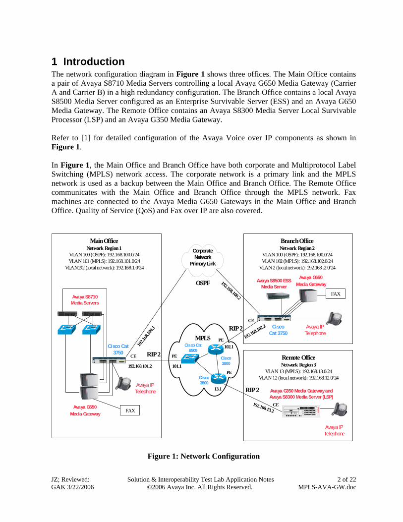
1 Introduction The network configuration diagram in Figure 1 shows three offices. The Main Office contains a pair of Avaya S8710 Media Servers controlling a local Avaya G650 Media Gateway (Carrier A and Carrier B) in a high redundancy configuration. The Branch Office contains a local Avaya S8500 Media Server configured as an Enterprise Survivable Server (ESS) and an Avaya G650 Media Gateway. The Remote Office contains an Avaya S8300 Media Server Local Survivable Processor (LSP) and an Avaya G350 Media Gateway. Refer to [1] for detailed configuration of the Avaya Voice over IP components as shown in Figure 1. In Figure 1, the Main Office and Branch Office have both corporate and Multiprotocol Label Switching (MPLS) network access. The corporate network is a primary link and the MPLS network is used as a backup between the Main Office and Branch Office. The Remote Office communicates with the Main Office and Branch Office through the MPLS network. Fax machines are connected to the Avaya Media G650 Gateways in the Main Office and Branch Office. Quality of Service (QoS) and Fax over IP are also covered.
Main OfficeNetwork Region 1
VLAN 100 (OSPF): 192.168.100.0/24VLAN 101 (MPLS): 192.168.101.0/24
VLAN192 (local network): 192.168.1.0/24
Branch OfficeNetwork Region 2
VLAN 100 (OSPF): 192.168.100.0/24VLAN 102 (MPLS): 192.168.102.0/24
VLAN 2 (local network): 192.168..2.0/24
MODE
STACKSPEEDDUPLXSTATMASTRRPSSYST
Catalyst 3750 SERIES
1 2 3 4 5 6 7 8 9 10 11 12
1X
2X
11X
12X
13 14 15 16 17 18 19 20 21 22 23 24
13X
14X
23X
24X
1 2 3 4
Cisco Cat 3750
Corporate Network
Primary Link
Remote OfficeNetwork Region 3
VLAN 13 (MPLS): 192.168.13.0/24VLAN 12 (local network): 192.168.12.0/24
Avaya G350 Media Gateway and Avaya S8300 Media Server (LSP)
Avaya G650 Media Gateway
Avaya G650 Media Gateway
COMPACT COMPACT
Avaya S8710 Media Servers
FAX
Avaya IP Telephone
Cisco Cat 3750
MODE
STACKSPEEDDUPLXSTATMASTRRPSSYST
Catalyst 3750 SERIES
1 2 3 4 5 6 7 8 9 10 11 12
1X
2X
11X
12X
13 14 15 16 17 18 19 20 21 22 23 24
13X
14X
23X
24X
1 2 3 4
FAX
Avaya IP Telephone
Cisco Cat 6509
Cisco 3800
Cisco 3800
Avaya S8500 ESS Media Server
RIP 2
RIP 2
RIP 2
OSPF
Avaya IP Telephone
MPLS
PE
PE
PE
CE
CE
CE
192.168.100.2
192.1
68.10
0.1
192.168.101.2 101.1
1
ALM
2 3 4 5 6 7 8 9 10 11 12
13 14 15 16 17 18 19 20 21 22 23 24
LNK COL Rx FDX FC LAG
SI
Tx
SI
1 2 3 4 5 6 7 8 9 10 11 12
13 14 15 16 17 18 19 20 21 22 23 24
H spd PoE
ALM
TSTACT
A V AY A
MM 722BRIV1
1 2
AL M
TSTACT
1 2 3 4 5 6 7 8
A VA Y A
ANALOGMO DULE
LINE T RUNK
AL MTSTACT
1 2 3 4 5 6 7 8
A VA Y AMM 712DCP
VH3ALMTSTACT
O K TOREMOVE
SE RVICE SUS B 1 US B 2
SHUT DOWN
A VA Y A
ICCMO DULE
AL M
TSTACT
A VA Y A
E1 /T1MODULESIG
SO EI SM EM SI EO
ETR
ALM
T ST
ACT
T RUNK LINE LINE CCA E TH W AN E TH LAN
1 2 3
MDM
A LM
CPU
P WR
SYS
TEM
CONSOLE
US B
RS T A SB
Remove before removing or inserting S8300 module
V6
V2
V1
V5
V4
V3
G350
V7
192.168.13.2
13.1
192.168.102.2
102.1
Figure 1: Network Configuration

JZ; Reviewed: GAK 3/22/2006
Solution & Interoperability Test Lab Application Notes ©2006 Avaya Inc. All Rights Reserved.
3 of 22 MPLS-AVA-GW.doc
2 Equipment and Software Validated Table 1 below shows the versions verified in these Application Notes.
Equipment Software Avaya Communication Manager Avaya S8710 Media Server Avaya S8500 Media Server (ESS) Avaya S8300 Media Server (LSP)
3.0.1 3.0.1 3.0.1
Avaya G650 Media Gateway IPSI (TN2312BP) C-LAN (TN799DP) MEDPRO (TN2302AP)
HW12 FW021 HW01 FW016 HW11 FW108
Avaya G350 Media Gateway 24.21.0 Cisco Catalyst 3750 Switch 12.1(19r)EA1b Cisco Catalyst 6509 12.2(18)SXD5 Cisco 3800 Integrated Access Router 12.3(11r)T1
Table 1: Equipment and Software Validated
JZ; Reviewed: GAK 3/22/2006
Solution & Interoperability Test Lab Application Notes ©2006 Avaya Inc. All Rights Reserved.
4 of 22 MPLS-AVA-GW.doc
3 Configurations The Open Shortest Path First (OSPF) routing protocol is used on the corporate network between the Main Office and Branch Office. The Routing Information Protocol (RIP) is used between the MPLS Customer Edge (CE) devices and the MPLS Provider Edge (PE) devices. When the corporate and MPLS networks are up, the Main Office and Branch Office will use OSPF entries for IP routing between them since the OSPF routing protocol has a lower default administration distance (distance 110) than the RIP routing protocol (distance 120). When the corporate network is out of service, the RIP routing entries will be used between the Main Office and Branch Office. Refer to Cisco Web site for details on MPLS configuration.
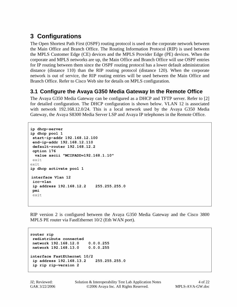
3.1 Configure the Avaya G350 Media Gateway In the Remote Office The Avaya G350 Media Gateway can be configured as a DHCP and TFTP server. Refer to [2] for detailed configuration. The DHCP configuration is shown below. VLAN 12 is associated with network 192.168.12.0/24. This is a local network used by the Avaya G350 Media Gateway, the Avaya S8300 Media Server LSP and Avaya IP telephones in the Remote Office. ip dhcp-server ip dhcp pool 1 start-ip-addr 192.168.12.100 end-ip-addr 192.168.12.110 default-router 192.168.12.2 option 176 value ascii "MCIPADD=192.168.1.10" exit exit ip dhcp activate pool 1 interface Vlan 12 icc-vlan ip address 192.168.12.2 255.255.255.0 pmi exit RIP version 2 is configured between the Avaya G350 Media Gateway and the Cisco 3800 MPLS PE router via FastEthernet 10/2 (Eth WAN port). router rip redistribute connected network 192.168.12.0 0.0.0.255 network 192.168.13.0 0.0.0.255 interface FastEthernet 10/2 ip address 192.168.13.2 255.255.255.0 ip rip rip-version 2
JZ; Reviewed: GAK 3/22/2006
Solution & Interoperability Test Lab Application Notes ©2006 Avaya Inc. All Rights Reserved.
5 of 22 MPLS-AVA-GW.doc
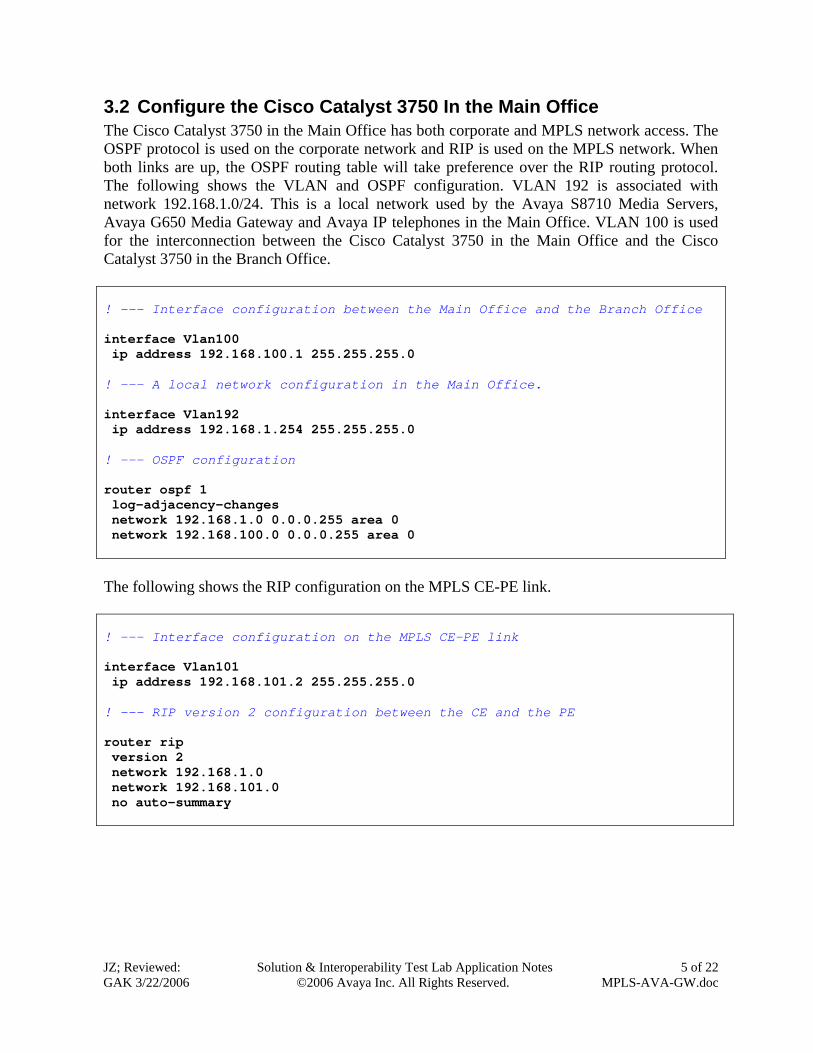
3.2 Configure the Cisco Catalyst 3750 In the Main Office The Cisco Catalyst 3750 in the Main Office has both corporate and MPLS network access. The OSPF protocol is used on the corporate network and RIP is used on the MPLS network. When both links are up, the OSPF routing table will take preference over the RIP routing protocol. The following shows the VLAN and OSPF configuration. VLAN 192 is associated with network 192.168.1.0/24. This is a local network used by the Avaya S8710 Media Servers, Avaya G650 Media Gateway and Avaya IP telephones in the Main Office. VLAN 100 is used for the interconnection between the Cisco Catalyst 3750 in the Main Office and the Cisco Catalyst 3750 in the Branch Office. ! --- Interface configuration between the Main Office and the Branch Office interface Vlan100 ip address 192.168.100.1 255.255.255.0 ! --- A local network configuration in the Main Office. interface Vlan192 ip address 192.168.1.254 255.255.255.0 ! --- OSPF configuration router ospf 1 log-adjacency-changes network 192.168.1.0 0.0.0.255 area 0 network 192.168.100.0 0.0.0.255 area 0 The following shows the RIP configuration on the MPLS CE-PE link. ! --- Interface configuration on the MPLS CE-PE link interface Vlan101 ip address 192.168.101.2 255.255.255.0 ! --- RIP version 2 configuration between the CE and the PE router rip version 2 network 192.168.1.0 network 192.168.101.0 no auto-summary

JZ; Reviewed: GAK 3/22/2006
Solution & Interoperability Test Lab Application Notes ©2006 Avaya Inc. All Rights Reserved.
6 of 22 MPLS-AVA-GW.doc
For the sample configuration, all Avaya components are configured with DSCP value 46 and 802.1p value 5. Auto QoS is enabled on the ports connected to the Avaya VoIP components including Avaya Media Servers, Avaya Media Gateways and Avaya IP telephones. Auto QoS is also enabled on the infrastructure ports (access to the corporate network and MPLS network). By default, the Auto QoS will prioritize the DSCP 46 or 802.1p 5. Refer to [1] for detailed QoS configuration on the Avaya VoIP components.
The following shows the configuration on interface FastEthernet 1/0/13 connected to an Avaya VoIP component. Trust DSCP is used in the sample configuration. interface FastEthernet1/0/13 switchport access vlan 192 duplex full srr-queue bandwidth share 10 10 60 20 srr-queue bandwidth shape 10 0 0 0 mls qos trust dscp auto qos voip trust spanning-tree portfast
3.3 Configure the Cisco Catalyst 3750 In the Branch Office The Cisco Catalyst 3750 in the Branch Office has both corporate and MPLS network access. The OSPF protocol is used on the corporate network and RIP is used on the MPLS network. When both links are up, the OSPF routing table will take preference over the RIP routing protocol. The following shows the VLAN and OSPF configuration. VLAN 2 is associated with network 192.168.2.0/24. This is a local network used by the Avaya S8500 Media Server configured as an ESS, Avaya G650 Media Gateway and Avaya IP telephones in the Branch Office. VLAN 100 is used for the interconnection between the Cisco Catalyst 3750 in the Main Office and the Cisco Catalyst 3750 in the Branch Office. ! --- Local network configuration in the Branch Office. interface Vlan2 ip address 192.168.2.254 255.255.255.0 ! --- Interface configuration between the Main Office and Branch Office interface Vlan100 ip address 192.168.100.2 255.255.255.0 ! --- OSPF configuration router ospf 1 log-adjacency-changes network 192.168.2.0 0.0.0.255 area 0 network 192.168.100.0 0.0.0.255 area 0
JZ; Reviewed: GAK 3/22/2006
Solution & Interoperability Test Lab Application Notes ©2006 Avaya Inc. All Rights Reserved.
7 of 22 MPLS-AVA-GW.doc
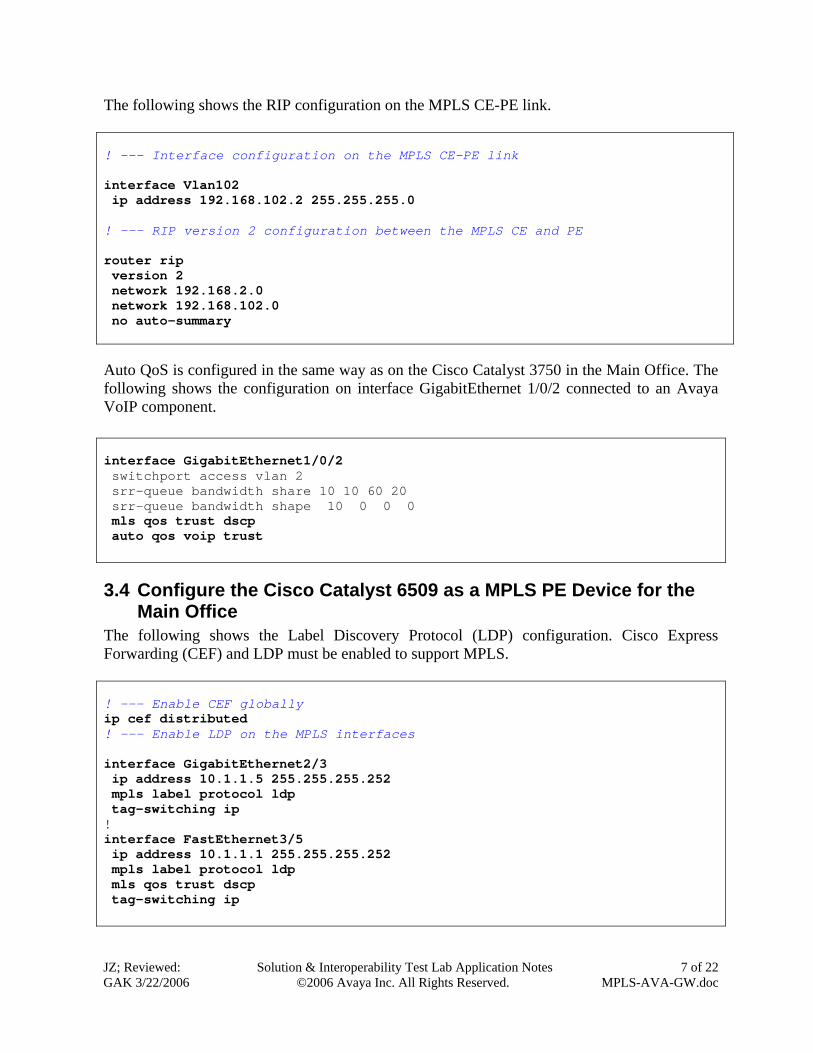
The following shows the RIP configuration on the MPLS CE-PE link. ! --- Interface configuration on the MPLS CE-PE link interface Vlan102 ip address 192.168.102.2 255.255.255.0 ! --- RIP version 2 configuration between the MPLS CE and PE router rip version 2 network 192.168.2.0 network 192.168.102.0 no auto-summary
Auto QoS is configured in the same way as on the Cisco Catalyst 3750 in the Main Office. The following shows the configuration on interface GigabitEthernet 1/0/2 connected to an Avaya VoIP component. interface GigabitEthernet1/0/2 switchport access vlan 2 srr-queue bandwidth share 10 10 60 20 srr-queue bandwidth shape 10 0 0 0 mls qos trust dscp auto qos voip trust
3.4 Configure the Cisco Catalyst 6509 as a MPLS PE Device for the Main Office
The following shows the Label Discovery Protocol (LDP) configuration. Cisco Express Forwarding (CEF) and LDP must be enabled to support MPLS. ! --- Enable CEF globally ip cef distributed ! --- Enable LDP on the MPLS interfaces interface GigabitEthernet2/3 ip address 10.1.1.5 255.255.255.252 mpls label protocol ldp tag-switching ip ! interface FastEthernet3/5 ip address 10.1.1.1 255.255.255.252 mpls label protocol ldp mls qos trust dscp tag-switching ip
JZ; Reviewed: GAK 3/22/2006
Solution & Interoperability Test Lab Application Notes ©2006 Avaya Inc. All Rights Reserved.
8 of 22 MPLS-AVA-GW.doc
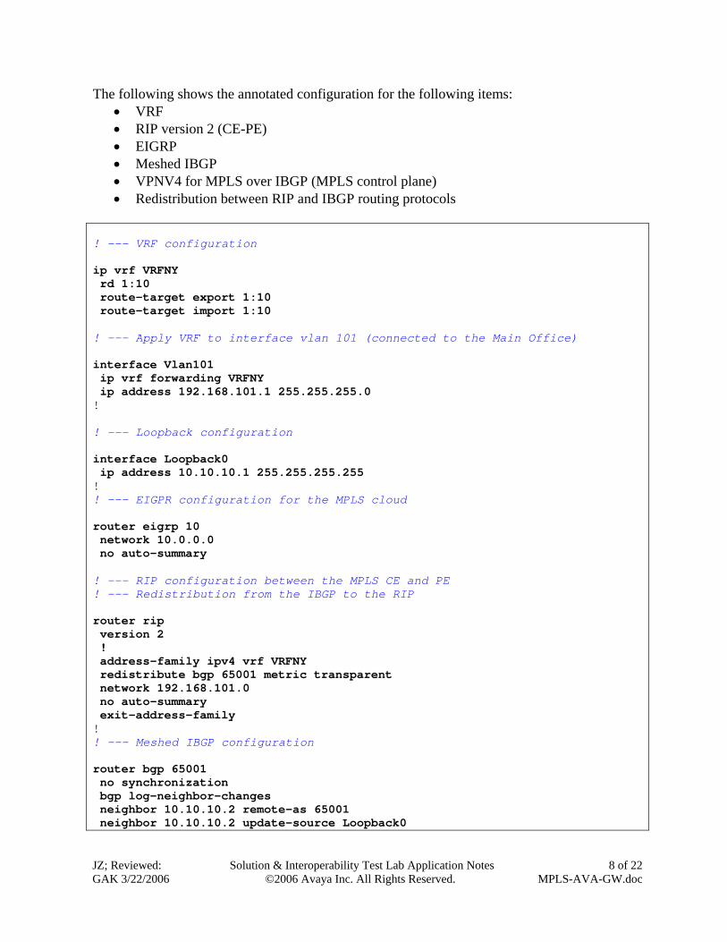
The following shows the annotated configuration for the following items: • VRF • RIP version 2 (CE-PE) • EIGRP • Meshed IBGP • VPNV4 for MPLS over IBGP (MPLS control plane) • Redistribution between RIP and IBGP routing protocols
! --- VRF configuration ip vrf VRFNY rd 1:10 route-target export 1:10 route-target import 1:10 ! --- Apply VRF to interface vlan 101 (connected to the Main Office) interface Vlan101 ip vrf forwarding VRFNY ip address 192.168.101.1 255.255.255.0 ! ! --- Loopback configuration interface Loopback0 ip address 10.10.10.1 255.255.255.255 ! ! --- EIGPR configuration for the MPLS cloud router eigrp 10 network 10.0.0.0 no auto-summary ! --- RIP configuration between the MPLS CE and PE ! --- Redistribution from the IBGP to the RIP router rip version 2 ! address-family ipv4 vrf VRFNY redistribute bgp 65001 metric transparent network 192.168.101.0 no auto-summary exit-address-family ! ! --- Meshed IBGP configuration router bgp 65001 no synchronization bgp log-neighbor-changes neighbor 10.10.10.2 remote-as 65001 neighbor 10.10.10.2 update-source Loopback0

JZ; Reviewed: GAK 3/22/2006
Solution & Interoperability Test Lab Application Notes ©2006 Avaya Inc. All Rights Reserved.
9 of 22 MPLS-AVA-GW.doc
neighbor 10.10.10.3 remote-as 65001 neighbor 10.10.10.3 update-source Loopback0 no auto-summary ! ! --- Enable VPNV4 with all IBGP peers address-family vpnv4 neighbor 10.10.10.2 activate neighbor 10.10.10.2 next-hop-self neighbor 10.10.10.2 send-community both neighbor 10.10.10.3 activate neighbor 10.10.10.3 next-hop-self neighbor 10.10.10.3 send-community both exit-address-family ! ! --- Redistribution from RIP to the IBGP address-family ipv4 vrf VRFNY redistribute rip no auto-summary no synchronization exit-address-family Assume that the MPLS network is part of an enterprise network; QoS can be enabled on the port connected to the Cisco Catalyst 3750 in the Main Office. The following shows that DSCP value will be trusted on that port. By default, DSCP value 46 will be prioritized on the Cisco Catalyst 6509. interface FastEthernet3/4 no ip address mls qos trust dscp switchport switchport access vlan 101
3.5 Configure Cisco 3800 Router as a MPLS PE Device for the Branch Office
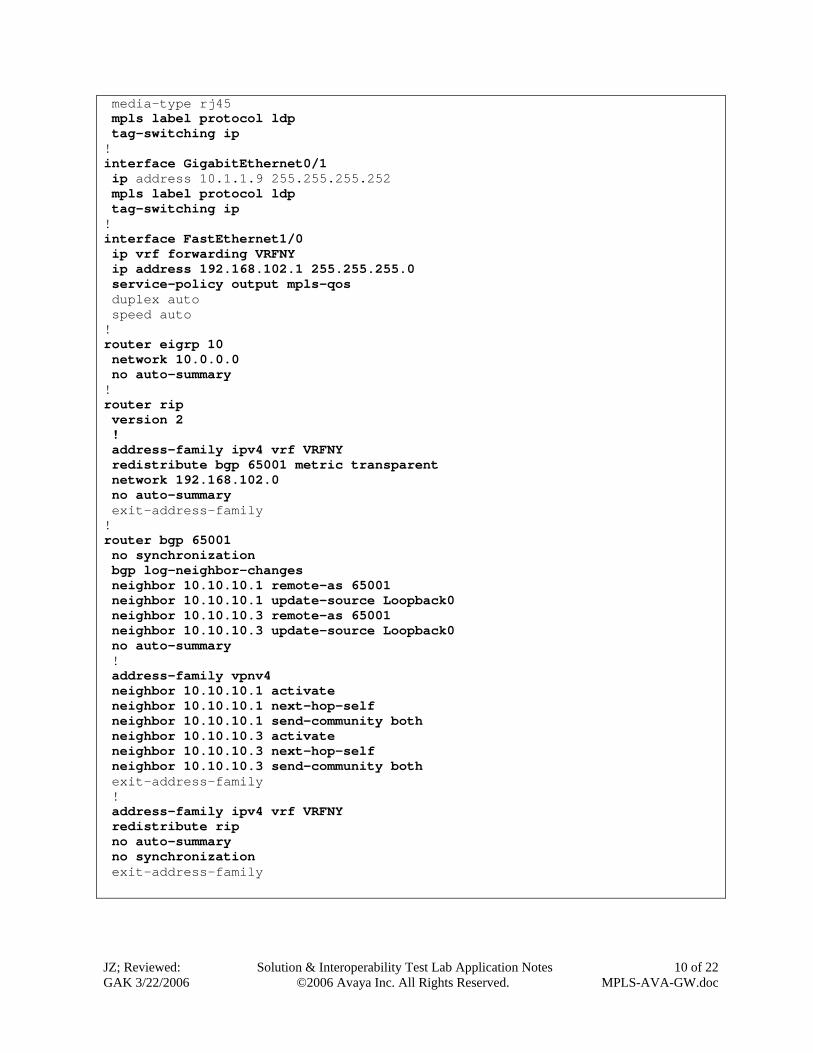
The MPLS configuration on the Cisco 3800 PE router for the Branch Office is similar to the configuration on the Cisco Catalyst 6509 PE router for the Main Office. The following shows the configuration. ip vrf VRFNY rd 1:10 route-target export 1:10 route-target import 1:10 ! interface Loopback0 ip address 10.10.10.2 255.255.255.255 ! interface GigabitEthernet0/0 ip address 10.1.1.2 255.255.255.252
JZ; Reviewed: GAK 3/22/2006
Solution & Interoperability Test Lab Application Notes ©2006 Avaya Inc. All Rights Reserved.
10 of 22 MPLS-AVA-GW.doc
media-type rj45 mpls label protocol ldp tag-switching ip ! interface GigabitEthernet0/1 ip address 10.1.1.9 255.255.255.252 mpls label protocol ldp tag-switching ip ! interface FastEthernet1/0 ip vrf forwarding VRFNY ip address 192.168.102.1 255.255.255.0 service-policy output mpls-qos duplex auto speed auto ! router eigrp 10 network 10.0.0.0 no auto-summary ! router rip version 2 ! address-family ipv4 vrf VRFNY redistribute bgp 65001 metric transparent network 192.168.102.0 no auto-summary exit-address-family ! router bgp 65001 no synchronization bgp log-neighbor-changes neighbor 10.10.10.1 remote-as 65001 neighbor 10.10.10.1 update-source Loopback0 neighbor 10.10.10.3 remote-as 65001 neighbor 10.10.10.3 update-source Loopback0 no auto-summary ! address-family vpnv4 neighbor 10.10.10.1 activate neighbor 10.10.10.1 next-hop-self neighbor 10.10.10.1 send-community both neighbor 10.10.10.3 activate neighbor 10.10.10.3 next-hop-self neighbor 10.10.10.3 send-community both exit-address-family ! address-family ipv4 vrf VRFNY redistribute rip no auto-summary no synchronization exit-address-family
JZ; Reviewed: GAK 3/22/2006
Solution & Interoperability Test Lab Application Notes ©2006 Avaya Inc. All Rights Reserved.
11 of 22 MPLS-AVA-GW.doc
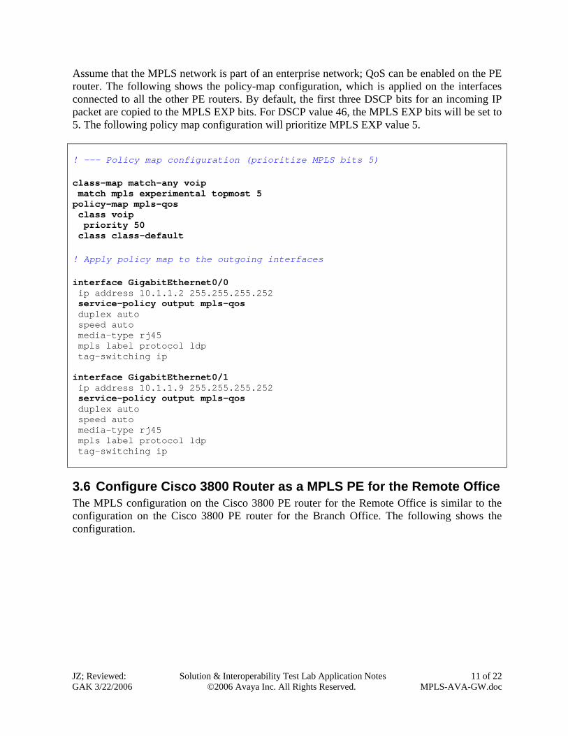
Assume that the MPLS network is part of an enterprise network; QoS can be enabled on the PE router. The following shows the policy-map configuration, which is applied on the interfaces connected to all the other PE routers. By default, the first three DSCP bits for an incoming IP packet are copied to the MPLS EXP bits. For DSCP value 46, the MPLS EXP bits will be set to 5. The following policy map configuration will prioritize MPLS EXP value 5. ! --- Policy map configuration (prioritize MPLS bits 5) class-map match-any voip match mpls experimental topmost 5 policy-map mpls-qos class voip priority 50 class class-default ! Apply policy map to the outgoing interfaces interface GigabitEthernet0/0 ip address 10.1.1.2 255.255.255.252 service-policy output mpls-qos duplex auto speed auto media-type rj45 mpls label protocol ldp tag-switching ip interface GigabitEthernet0/1 ip address 10.1.1.9 255.255.255.252 service-policy output mpls-qos duplex auto speed auto media-type rj45 mpls label protocol ldp tag-switching ip
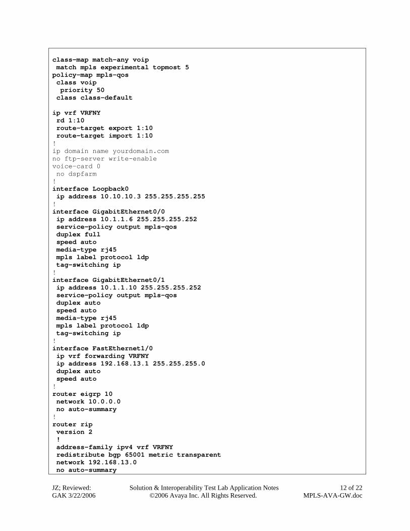
3.6 Configure Cisco 3800 Router as a MPLS PE for the Remote Office The MPLS configuration on the Cisco 3800 PE router for the Remote Office is similar to the configuration on the Cisco 3800 PE router for the Branch Office. The following shows the configuration.
JZ; Reviewed: GAK 3/22/2006
Solution & Interoperability Test Lab Application Notes ©2006 Avaya Inc. All Rights Reserved.
12 of 22 MPLS-AVA-GW.doc
class-map match-any voip match mpls experimental topmost 5 policy-map mpls-qos class voip priority 50 class class-default ip vrf VRFNY rd 1:10 route-target export 1:10 route-target import 1:10 ! ip domain name yourdomain.com no ftp-server write-enable voice-card 0 no dspfarm ! interface Loopback0 ip address 10.10.10.3 255.255.255.255 ! interface GigabitEthernet0/0 ip address 10.1.1.6 255.255.255.252 service-policy output mpls-qos duplex full speed auto media-type rj45 mpls label protocol ldp tag-switching ip ! interface GigabitEthernet0/1 ip address 10.1.1.10 255.255.255.252 service-policy output mpls-qos duplex auto speed auto media-type rj45 mpls label protocol ldp tag-switching ip ! interface FastEthernet1/0 ip vrf forwarding VRFNY ip address 192.168.13.1 255.255.255.0 duplex auto speed auto ! router eigrp 10 network 10.0.0.0 no auto-summary ! router rip version 2 ! address-family ipv4 vrf VRFNY redistribute bgp 65001 metric transparent network 192.168.13.0 no auto-summary

JZ; Reviewed: GAK 3/22/2006
Solution & Interoperability Test Lab Application Notes ©2006 Avaya Inc. All Rights Reserved.
13 of 22 MPLS-AVA-GW.doc
exit-address-family ! router bgp 65001 no synchronization bgp log-neighbor-changes neighbor 10.10.10.1 remote-as 65001 neighbor 10.10.10.1 update-source Loopback0 neighbor 10.10.10.2 remote-as 65001 neighbor 10.10.10.2 update-source Loopback0 no auto-summary ! address-family vpnv4 neighbor 10.10.10.1 activate neighbor 10.10.10.1 next-hop-self neighbor 10.10.10.1 send-community both neighbor 10.10.10.2 activate neighbor 10.10.10.2 next-hop-self neighbor 10.10.10.2 send-community both exit-address-family ! address-family ipv4 vrf VRFNY redistribute rip no auto-summary no synchronization exit-address-family !
JZ; Reviewed: GAK 3/22/2006
Solution & Interoperability Test Lab Application Notes ©2006 Avaya Inc. All Rights Reserved.
14 of 22 MPLS-AVA-GW.doc
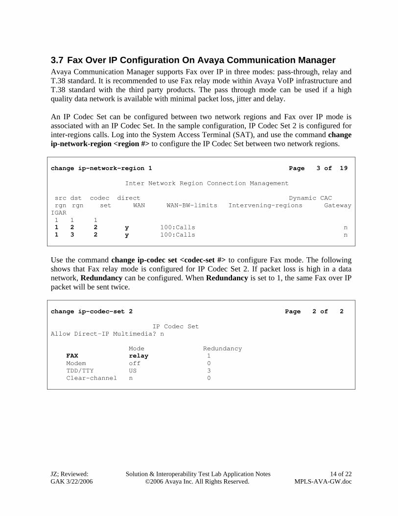
3.7 Fax Over IP Configuration On Avaya Communication Manager Avaya Communication Manager supports Fax over IP in three modes: pass-through, relay and T.38 standard. It is recommended to use Fax relay mode within Avaya VoIP infrastructure and T.38 standard with the third party products. The pass through mode can be used if a high quality data network is available with minimal packet loss, jitter and delay. An IP Codec Set can be configured between two network regions and Fax over IP mode is associated with an IP Codec Set. In the sample configuration, IP Codec Set 2 is configured for inter-regions calls. Log into the System Access Terminal (SAT), and use the command change ip-network-region <region #> to configure the IP Codec Set between two network regions. change ip-network-region 1 Page 3 of 19 Inter Network Region Connection Management src dst codec direct Dynamic CAC rgn rgn set WAN WAN-BW-limits Intervening-regions Gateway IGAR 1 1 1 1 2 2 y 100:Calls n 1 3 2 y 100:Calls n Use the command change ip-codec set <codec-set #> to configure Fax mode. The following shows that Fax relay mode is configured for IP Codec Set 2. If packet loss is high in a data network, Redundancy can be configured. When Redundancy is set to 1, the same Fax over IP packet will be sent twice. change ip-codec-set 2 Page 2 of 2 IP Codec Set Allow Direct-IP Multimedia? n Mode Redundancy FAX relay 1 Modem off 0 TDD/TTY US 3 Clear-channel n 0
JZ; Reviewed: GAK 3/22/2006
Solution & Interoperability Test Lab Application Notes ©2006 Avaya Inc. All Rights Reserved.
15 of 22 MPLS-AVA-GW.doc
4 Verification
4.1 Verify IP Routing Operation on the Cisco Catalyst 3750 In the Main Office
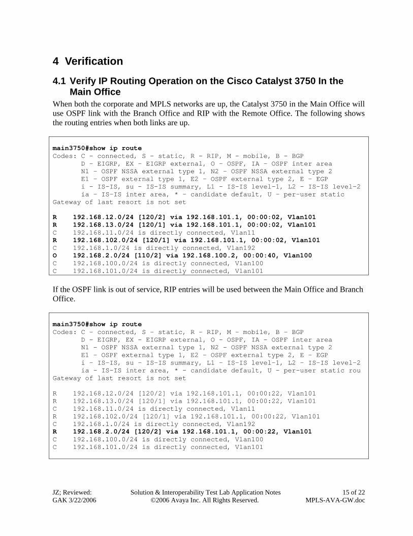
When both the corporate and MPLS networks are up, the Catalyst 3750 in the Main Office will use OSPF link with the Branch Office and RIP with the Remote Office. The following shows the routing entries when both links are up. main3750#show ip route Codes: C - connected, S - static, R - RIP, M - mobile, B - BGP D - EIGRP, EX - EIGRP external, O - OSPF, IA - OSPF inter area N1 - OSPF NSSA external type 1, N2 - OSPF NSSA external type 2 E1 - OSPF external type 1, E2 - OSPF external type 2, E - EGP i - IS-IS, su - IS-IS summary, L1 - IS-IS level-1, L2 - IS-IS level-2 ia - IS-IS inter area, * - candidate default, U - per-user static Gateway of last resort is not set R 192.168.12.0/24 [120/2] via 192.168.101.1, 00:00:02, Vlan101 R 192.168.13.0/24 [120/1] via 192.168.101.1, 00:00:02, Vlan101 C 192.168.11.0/24 is directly connected, Vlan11 R 192.168.102.0/24 [120/1] via 192.168.101.1, 00:00:02, Vlan101 C 192.168.1.0/24 is directly connected, Vlan192 O 192.168.2.0/24 [110/2] via 192.168.100.2, 00:00:40, Vlan100 C 192.168.100.0/24 is directly connected, Vlan100 C 192.168.101.0/24 is directly connected, Vlan101 If the OSPF link is out of service, RIP entries will be used between the Main Office and Branch Office. main3750#show ip route Codes: C - connected, S - static, R - RIP, M - mobile, B - BGP D - EIGRP, EX - EIGRP external, O - OSPF, IA - OSPF inter area N1 - OSPF NSSA external type 1, N2 - OSPF NSSA external type 2 E1 - OSPF external type 1, E2 - OSPF external type 2, E - EGP i - IS-IS, su - IS-IS summary, L1 - IS-IS level-1, L2 - IS-IS level-2 ia - IS-IS inter area, * - candidate default, U - per-user static rou Gateway of last resort is not set R 192.168.12.0/24 [120/2] via 192.168.101.1, 00:00:22, Vlan101 R 192.168.13.0/24 [120/1] via 192.168.101.1, 00:00:22, Vlan101 C 192.168.11.0/24 is directly connected, Vlan11 R 192.168.102.0/24 [120/1] via 192.168.101.1, 00:00:22, Vlan101 C 192.168.1.0/24 is directly connected, Vlan192 R 192.168.2.0/24 [120/2] via 192.168.101.1, 00:00:22, Vlan101 C 192.168.100.0/24 is directly connected, Vlan100 C 192.168.101.0/24 is directly connected, Vlan101
JZ; Reviewed: GAK 3/22/2006
Solution & Interoperability Test Lab Application Notes ©2006 Avaya Inc. All Rights Reserved.
16 of 22 MPLS-AVA-GW.doc
4.2 Verify IP Routing Operation on the Cisco Catalyst 3750 In the Branch Office
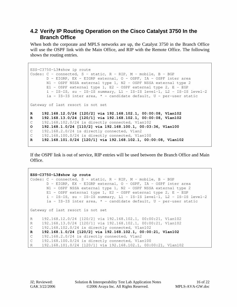
When both the corporate and MPLS networks are up, the Catalyst 3750 in the Branch Office will use the OSPF link with the Main Office, and RIP with the Remote Office. The following shows the routing entries. ESS-C3750-L3#show ip route Codes: C - connected, S - static, R - RIP, M - mobile, B - BGP D - EIGRP, EX - EIGRP external, O - OSPF, IA - OSPF inter area N1 - OSPF NSSA external type 1, N2 - OSPF NSSA external type 2 E1 - OSPF external type 1, E2 - OSPF external type 2, E - EGP i - IS-IS, su - IS-IS summary, L1 - IS-IS level-1, L2 - IS-IS level-2 ia - IS-IS inter area, * - candidate default, U - per-user static Gateway of last resort is not set R 192.168.12.0/24 [120/2] via 192.168.102.1, 00:00:08, Vlan102 R 192.168.13.0/24 [120/1] via 192.168.102.1, 00:00:08, Vlan102 C 192.168.102.0/24 is directly connected, Vlan102 O 192.168.1.0/24 [110/2] via 192.168.100.1, 00:03:36, Vlan100 C 192.168.2.0/24 is directly connected, Vlan2 C 192.168.100.0/24 is directly connected, Vlan100 R 192.168.101.0/24 [120/1] via 192.168.102.1, 00:00:08, Vlan102 If the OSPF link is out of service, RIP entries will be used between the Branch Office and Main Office. ESS-C3750-L3#show ip route Codes: C - connected, S - static, R - RIP, M - mobile, B - BGP D - EIGRP, EX - EIGRP external, O - OSPF, IA - OSPF inter area N1 - OSPF NSSA external type 1, N2 - OSPF NSSA external type 2 E1 - OSPF external type 1, E2 - OSPF external type 2, E - EGP i - IS-IS, su - IS-IS summary, L1 - IS-IS level-1, L2 - IS-IS level-2 ia - IS-IS inter area, * - candidate default, U - per-user static Gateway of last resort is not set R 192.168.12.0/24 [120/2] via 192.168.102.1, 00:00:21, Vlan102 R 192.168.13.0/24 [120/1] via 192.168.102.1, 00:00:21, Vlan102 C 192.168.102.0/24 is directly connected, Vlan102 R 192.168.1.0/24 [120/2] via 192.168.102.1, 00:00:21, Vlan102 C 192.168.2.0/24 is directly connected, Vlan2 C 192.168.100.0/24 is directly connected, Vlan100 R 192.168.101.0/24 [120/1] via 192.168.102.1, 00:00:21, Vlan102
JZ; Reviewed: GAK 3/22/2006
Solution & Interoperability Test Lab Application Notes ©2006 Avaya Inc. All Rights Reserved.
17 of 22 MPLS-AVA-GW.doc
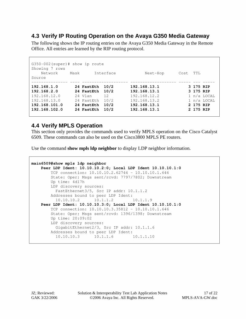
4.3 Verify IP Routing Operation on the Avaya G350 Media Gateway The following shows the IP routing entries on the Avaya G350 Media Gateway in the Remote Office. All entries are learned by the RIP routing protocol. G350-002(super)# show ip route Showing 7 rows Network Mask Interface Next-Hop Cost TTL Source --------------- ---- ------------------- ------------------- ----- --- ----- 192.168.1.0 24 FastEth 10/2 192.168.13.1 3 175 RIP 192.168.2.0 24 FastEth 10/2 192.168.13.1 3 175 RIP 192.168.12.0 24 Vlan 12 192.168.12.2 1 n/a LOCAL 192.168.13.0 24 FastEth 10/2 192.168.13.2 1 n/a LOCAL 192.168.101.0 24 FastEth 10/2 192.168.13.1 2 175 RIP 192.168.102.0 24 FastEth 10/2 192.168.13.1 2 175 RIP 4.4 Verify MPLS Operation This section only provides the commands used to verify MPLS operation on the Cisco Catalyst 6509. These commands can also be used on the Cisco3800 MPLS PE routers. Use the command show mpls ldp neighbor to display LDP neighbor information. main6509#show mpls ldp neighbor Peer LDP Ident: 10.10.10.2:0; Local LDP Ident 10.10.10.1:0 TCP connection: 10.10.10.2.62744 - 10.10.10.1.646 State: Oper; Msgs sent/rcvd: 7797/7802; Downstream Up time: 4d17h LDP discovery sources: FastEthernet3/5, Src IP addr: 10.1.1.2 Addresses bound to peer LDP Ident: 10.10.10.2 10.1.1.2 10.1.1.9 Peer LDP Ident: 10.10.10.3:0; Local LDP Ident 10.10.10.1:0 TCP connection: 10.10.10.3.35812 - 10.10.10.1.646 State: Oper; Msgs sent/rcvd: 1396/1398; Downstream Up time: 20:09:02 LDP discovery sources: GigabitEthernet2/3, Src IP addr: 10.1.1.6 Addresses bound to peer LDP Ident: 10.10.10.3 10.1.1.6 10.1.1.10
JZ; Reviewed: GAK 3/22/2006
Solution & Interoperability Test Lab Application Notes ©2006 Avaya Inc. All Rights Reserved.
18 of 22 MPLS-AVA-GW.doc
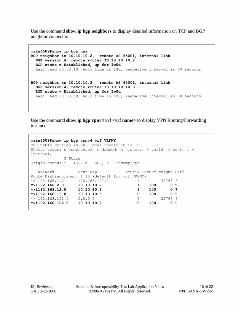
Use the command show ip bgp neighbors to display detailed information on TCP and BGP neighbor connections. main6509#show ip bgp nei BGP neighbor is 10.10.10.2, remote AS 65001, internal link BGP version 4, remote router ID 10.10.10.2 BGP state = Established, up for 1w0d Last read 00:00:10, hold time is 180, keepalive interval is 60 seconds … BGP neighbor is 10.10.10.3, remote AS 65001, internal link BGP version 4, remote router ID 10.10.10.3 BGP state = Established, up for 1w0d Last read 00:00:58, hold time is 180, keepalive interval is 60 seconds … Use the command show ip bgp vpnv4 vrf <vrf name> to display VPN Routing/Forwarding instance. main6509#show ip bgp vpnv4 vrf VRFNY BGP table version is 58, local router ID is 10.10.10.1 Status codes: s suppressed, d damped, h history, * valid, > best, i - internal, S Stale Origin codes: i - IGP, e - EGP, ? - incomplete Network Next Hop Metric LocPrf Weight Path Route Distinguisher: 1:10 (default for vrf VRFNY) *> 192.168.1.0 192.168.101.2 1 32768 ? *>i192.168.2.0 10.10.10.2 1 100 0 ? *>i192.168.12.0 10.10.10.3 1 100 0 ? *>i192.168.13.0 10.10.10.3 0 100 0 ? *> 192.168.101.0 0.0.0.0 0 32768 ? *>i192.168.102.0 10.10.10.2 0 100 0 ?
JZ; Reviewed: GAK 3/22/2006
Solution & Interoperability Test Lab Application Notes ©2006 Avaya Inc. All Rights Reserved.
19 of 22 MPLS-AVA-GW.doc
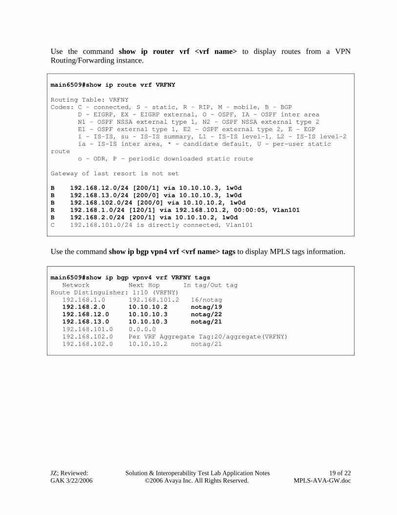
Use the command show ip router vrf <vrf name> to display routes from a VPN Routing/Forwarding instance. main6509#show ip route vrf VRFNY Routing Table: VRFNY Codes: C - connected, S - static, R - RIP, M - mobile, B - BGP D - EIGRP, EX - EIGRP external, O - OSPF, IA - OSPF inter area N1 - OSPF NSSA external type 1, N2 - OSPF NSSA external type 2 E1 - OSPF external type 1, E2 - OSPF external type 2, E - EGP i - IS-IS, su - IS-IS summary, L1 - IS-IS level-1, L2 - IS-IS level-2 ia - IS-IS inter area, * - candidate default, U - per-user static route o - ODR, P - periodic downloaded static route Gateway of last resort is not set B 192.168.12.0/24 [200/1] via 10.10.10.3, 1w0d B 192.168.13.0/24 [200/0] via 10.10.10.3, 1w0d B 192.168.102.0/24 [200/0] via 10.10.10.2, 1w0d R 192.168.1.0/24 [120/1] via 192.168.101.2, 00:00:05, Vlan101 B 192.168.2.0/24 [200/1] via 10.10.10.2, 1w0d C 192.168.101.0/24 is directly connected, Vlan101
Use the command show ip bgp vpn4 vrf <vrf name> tags to display MPLS tags information. main6509#show ip bgp vpnv4 vrf VRFNY tags Network Next Hop In tag/Out tag Route Distinguisher: 1:10 (VRFNY) 192.168.1.0 192.168.101.2 16/notag 192.168.2.0 10.10.10.2 notag/19 192.168.12.0 10.10.10.3 notag/22 192.168.13.0 10.10.10.3 notag/21
192.168.101.0 0.0.0.0 192.168.102.0 Per VRF Aggregate Tag:20/aggregate(VRFNY)
192.168.102.0 10.10.10.2 notag/21
JZ; Reviewed: GAK 3/22/2006
Solution & Interoperability Test Lab Application Notes ©2006 Avaya Inc. All Rights Reserved.
20 of 22 MPLS-AVA-GW.doc
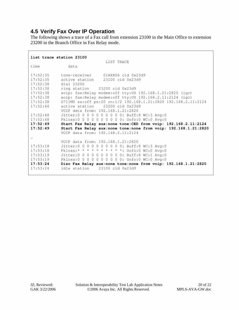
4.5 Verify Fax Over IP Operation The following shows a trace of a Fax call from extension 23100 in the Main Office to extension 23200 in the Branch Office in Fax Relay mode. list trace station 23100 LIST TRACE time data 17:52:35 tone-receiver 01AXX06 cid 0x23d9 17:52:35 active station 23100 cid 0x23d9 17:52:38 dial 23200 17:52:38 ring station 23200 cid 0x23d9 17:52:38 xoip: fax:Relay modem:off tty:US 192.168.1.21:2820 (igc) 17:52:38 xoip: fax:Relay modem:off tty:US 192.168.2.11:2124 (igc) 17:52:38 G711MU ss:off ps:20 rn:1/2 192.168.1.21:2820 192.168.2.11:2124 17:52:46 active station 23200 cid 0x23d9 VOIP data from: 192.168.1.21:2820 17:52:48 Jitter:0 0 0 0 0 0 0 0 0 0: Buff:8 WC:3 Avg:0 17:52:48 Pkloss:0 0 0 0 0 0 0 0 0 0: Oofo:0 WC:0 Avg:0 17:52:49 Start Fax Relay aux:none tone:CED from voip: 192.168.2.11:2124 17:52:49 Start Fax Relay aux:none tone:none from voip: 192.168.1.21:2820 VOIP data from: 192.168.2.11:2124 … VOIP data from: 192.168.1.21:2820 17:53:18 Jitter:0 0 0 0 0 0 0 0 0 0: Buff:8 WC:3 Avg:0 17:53:18 Pkloss:* * * * * * * * * *: Oofo:0 WC:0 Avg:0 17:53:19 Jitter:0 0 0 0 0 0 0 0 0 0: Buff:8 WC:1 Avg:0 17:53:19 Pkloss:0 0 0 0 0 0 0 0 0 0: Oofo:0 WC:0 Avg:0 17:53:24 Disc Fax Relay aux:none tone:none from voip: 192.168.1.21:2820 17:53:24 idle station 23100 cid 0x23d9
JZ; Reviewed: GAK 3/22/2006
Solution & Interoperability Test Lab Application Notes ©2006 Avaya Inc. All Rights Reserved.
21 of 22 MPLS-AVA-GW.doc
5 Conclusion As illustrated in these Application Notes, the MPLS network can be used to back up a primary corporate network. The Avaya G350 Media Gateway can be configured as a MPLS CE device to communicate with a Cisco MPLS PE device via the RIP routing protocol. The corporate and MPLS networks can be configured to prioritize Avaya VoIP traffic based on the DSCP value configured on the Avaya VoIP devices. Fax over IP works successfully between two Avaya Media Gateways.
6 Additional References The following Applications Notes can be found at http://www.avaya.com. [1] Configuring Avaya Communication Manager with Avaya Inter-Gateway Alternate
Routing (IGAR) Using Avaya Dynamic Call Admission Control (D-CAC) and Respond Time Report (RTR) Features
[2] Configuring DHCP and TFTP Servers on Avaya G350 and G250 Media Gateways for
Avaya IP 4600 Series Telephones 7. Glossary Technical Term Definition as it pertains to this document
MPLS Multiprotocol Label Switching CE Customer Edge PE Provider Edge VRF VPN Routing and Forwarding
JZ; Reviewed: GAK 3/22/2006
Solution & Interoperability Test Lab Application Notes ©2006 Avaya Inc. All Rights Reserved.
22 of 22 MPLS-AVA-GW.doc
©2006 Avaya Inc. All Rights Reserved. Avaya and the Avaya Logo are trademarks of Avaya Inc. All trademarks identified by ® and ™ are registered trademarks or trademarks, respectively, of Avaya Inc. All other trademarks are the property of their respective owners. The information provided in these Application Notes is subject to change without notice. The configurations, technical data, and recommendations provided in these Application Notes are believed to be accurate and dependable, but are presented without express or implied warranty. Users are responsible for their application of any products specified in these Application Notes. Please e-mail any questions or comments pertaining to these Application Notes along with the full title name and filename, located in the lower right corner, directly to the Avaya Solution & Interoperability Test Lab at [email protected]