configuring fault tolerance with a dell networking r1-2210 in a vrtx chassis (1)
DESCRIPTION
dellTRANSCRIPT

A Dell Deployment and Configuration Guide
Configuring Redundancy with a R1-2210 10GbE Switch module in a VRTX Chassis Deploying a Dell PowerEdge VRTX chassis with a Dell PowerEdge M820 blade server and a R1-2210 10GbE Switch Module in a redundant configuration. Dell Engineering December 2014

2 Configuring Redundancy with a R1-2210 10GbE Switch module in a VRTX Chassis | Version 1.0
Revisions
Date Description Authors
December 2014 Initial release Ed Blazek, Curtis Bunch, Mike Matthews
©2014 Dell Inc., All rights reserved.
Except as stated below, no part of this document may be reproduced, distributed or transmitted in any form or by any
means, without express permission of Dell.
You may distribute this document within your company or organization only, without alteration of its contents.
THIS DOCUMENT IS PROVIDED “AS-IS”, AND WITHOUT ANY WARRANTY, EXPRESS OR IMPLIED. IMPLIED
WARRANTIES OF MERCHANTABILITY AND FITNESS FOR A PARTICULAR PURPOSE ARE SPECIFICALLY DISCLAIMED.
PRODUCT WARRANTIES APPLICABLE TO THE DELL PRODUCTS DESCRIBED IN THIS DOCUMENT MAY BE FOUND
AT: http://www.dell.com/learn/us/en/19/terms-of-sale-commercial-and-public-sector Performance of network
reference architectures discussed in this document may vary with differing deployment conditions, network loads, and
the like. Third party products may be included in reference architectures for the convenience of the reader. Inclusion
of such third party products does not necessarily constitute Dell’s recommendation of those products. Please consult
your Dell representative for additional information.
Trademarks used in this text:
Dell™, the Dell logo, Dell Boomi™, Dell Precision™ ,OptiPlex™, Latitude™, PowerEdge™, PowerVault™,
PowerConnect™, OpenManage™, EqualLogic™, Compellent™, KACE™, FlexAddress™, Force10™ and Vostro™ are
trademarks of Dell Inc. Other Dell trademarks may be used in this document. Cisco Nexus®, Cisco MDS®, Cisco NX-
0S®, and other Cisco Catalyst® are registered trademarks of Cisco System Inc. EMC VNX®, and EMC Unisphere® are
registered trademarks of EMC Corporation. Intel®, Pentium®, Xeon®, Core® and Celeron® are registered trademarks
of Intel Corporation in the U.S. and other countries. AMD® is a registered trademark and AMD Opteron™, AMD
Phenom™ and AMD Sempron™ are trademarks of Advanced Micro Devices, Inc. Microsoft®, Windows®, Windows
Server®, Internet Explorer®, MS-DOS®, Windows Vista® and Active Directory® are either trademarks or registered
trademarks of Microsoft Corporation in the United States and/or other countries. Red Hat® and Red Hat® Enterprise
Linux® are registered trademarks of Red Hat, Inc. in the United States and/or other countries. Novell® and SUSE® are
registered trademarks of Novell Inc. in the United States and other countries. Oracle® is a registered trademark of
Oracle Corporation and/or its affiliates. Citrix®, Xen®, XenServer® and XenMotion® are either registered trademarks
or trademarks of Citrix Systems, Inc. in the United States and/or other countries. VMware®, Virtual SMP®, vMotion®,
vCenter® and vSphere® are registered trademarks or trademarks of VMware, Inc. in the United States or other
countries. IBM® is a registered trademark of International Business Machines Corporation. Broadcom® and
NetXtreme® are registered trademarks of Broadcom Corporation. Qlogic is a registered trademark of QLogic
Corporation. Other trademarks and trade names may be used in this document to refer to either the entities claiming
the marks and/or names or their products and are the property of their respective owners. Dell disclaims proprietary
interest in the marks and names of others.

3 Configuring Redundancy with a R1-2210 10GbE Switch module in a VRTX Chassis | Version 1.0
Table of contents Revisions ............................................................................................................................................................................................. 2
1 Introduction ................................................................................................................................................................................ 5
1.1 Audience ........................................................................................................................................................................... 5
1.2 Objectives ......................................................................................................................................................................... 5
2 Component Overview .............................................................................................................................................................. 7
2.1 Hardware Components ................................................................................................................................................. 7
2.2 Dell PowerEdge VRTX Chassis ...................................................................................................................................... 9
2.2.1 Dell PowerEdge VRTX 10GbE R1-2210 Switch Module ......................................................................................... 10
2.2.2 Dell PowerEdge M820 .................................................................................................................................................. 11
2.2.3 Broadcom NetXtreme II 57810 Dual-Port 10GbE Network Daughter Card ...................................................... 12
2.2.4 Broadcom NetXtreme II 57810 Dual-port 10GbE PCIe Adapter .......................................................................... 12
2.3 Dell Networking N3048 N-Series Switches ............................................................................................................. 13
2.3.1 Dell SFP+ Dual-Port 10GbE Module .......................................................................................................................... 13
2.4 Network Topology ........................................................................................................................................................ 14
3 Configuration One................................................................................................................................................................... 17
3.1 Server Roles and VLANS ............................................................................................................................................... 17
3.2 Dell Networking N3048 Configuration ..................................................................................................................... 18
3.2.1 Dell Networking N3048 Factory Defaults................................................................................................................. 18
3.2.2 Dell Networking N3048 Stacking ............................................................................................................................... 18
3.2.3 Dell Networking N3048 CLI Configuration .............................................................................................................. 20
3.2.4 Dell Networking N3048 Validation ............................................................................................................................ 22
3.3 R1-2210 Switch Module Configuration ..................................................................................................................... 22
3.3.1 R1-2210 Switch Module Management Settings ...................................................................................................... 22
3.3.2 R1-2210 Switch Module Resetting Factory Defaults .............................................................................................. 23
3.3.3 R1-2210 Switch Module CLI Configuration.............................................................................................................. 25
3.3.4 R1-2210 Switch Module Validation ............................................................................................................................ 27
3.4 Windows 2012 NIC Teaming Configuration using LACP ....................................................................................... 29
3.4.1 Enabling NIC Teaming ................................................................................................................................................. 29
4 Configuration Two .................................................................................................................................................................. 33
4.1 Server Roles and VLANs ............................................................................................................................................... 34
4.2 Dell Networking N3048 Configuration ..................................................................................................................... 34

4 Configuring Redundancy with a R1-2210 10GbE Switch module in a VRTX Chassis | Version 1.0
4.2.1 Dell Networking N3048 Factory Defaults................................................................................................................. 34
4.2.1 Dell Networking N3048 Stacking ............................................................................................................................... 35
4.2.2 Dell Networking N3048 CLI Configuration .............................................................................................................. 36
4.2.3 Dell Networking N3048 Validation ............................................................................................................................ 38
4.3 R1-2210 Switch Module Configuration ..................................................................................................................... 39
4.3.1 R1-2210 Switch Module Management Settings ...................................................................................................... 39
4.3.2 R1-2210 Switch Module Resetting Factory Defaults ............................................................................................. 40
4.3.3 R1-2210 Switch Module CLI Configuration.............................................................................................................. 41
4.3.4 R1-2210 Switch Module Validation ............................................................................................................................ 43
4.4 Broadcom PCIe Adapter Assignment ........................................................................................................................ 44
4.5 Windows 2012 NIC Teaming Configuration using Switch Independent Mode ................................................. 45
4.5.1 Enabling NIC Teaming ................................................................................................................................................. 45
A Terminology ............................................................................................................................................................................. 50
B Additional Resources............................................................................................................................................................... 51
Support and Feedback ................................................................................................................................................................... 51

5 Configuring Redundancy with a R1-2210 10GbE Switch module in a VRTX Chassis | Version 1.0
1 Introduction In today’s business environment, the need for high speed and reliable access to network resources is more
important than ever. Business can be lost and user productivity can plummet because of network
congestion or network downtime. If these issues become chronic, they can drastically affect the business’s
bottom line.
A 10GbE Switch Module (R1-2210) installed in a Dell PowerEdge VRTX chassis with dual Dell PowerEdge
M820 blade servers and configured with redundant networking paths can provide the speed and reliability
today's businesses demand. In addition to the redundancy, the R1-2210 switch module also provides a
10GB path from the PowerEdge VRTX to the LAN (Local Area Network).
This guide provides the details necessary to deploy redundant configurations using the Dell R1-2210
switch module. The first configuration deploys a VRTX chassis with dual Dell PowerEdge M820 blade
servers and a R1-2210 10GbE Switch Module in a redundant configuration with a pair of stacked Dell
Networking N3048 switches. The second configuration deploys a VRTX chassis with dual Dell PowerEdge
M820 blade servers and a R1-2210 10GbE Switch Module together with a Broadcom NetXtreme II 57810
Dual Port 10GbE PCIe adapter in a redundant configuration with a pair of stacked Dell Networking N3048
switches.
1.1 Audience The intended audiences for this guide are network administrators and/or network engineers who have a
thorough working knowledge of network connectivity, IP addressing and configuring switches via the
Command Line Interface (CLI). The audience should also understand and have experience using Link
Aggregation (LAG), port channels and Virtual LANs (VLANs). In addition, the audience must have the
appropriate permissions to configure the switches and change the server’s network settings.
1.2 Objectives In Scope
This deployment guide illustrates two configuration scenarios, which utilize one or more of the following
components:
Dell PowerEdge VRTX Chassis
Dell PowerEdge M820
Dell Networking N3048 switches
Dell Networking 10GbE R1-2210 switch module
Broadcom NetXtreme II 57810 Dual-port 10GbE Network Daughter Cards (NDC)
Broadcom NetXtreme II 57810 Dual-port 10GbE PCIe adapters
Refer to the Hardware Components section for details on these components. The objectives of each
configuration scenario are covered below.

6 Configuring Redundancy with a R1-2210 10GbE Switch module in a VRTX Chassis | Version 1.0
Configuration One: Redundancy using Dell PowerEdge M820s and the R1-2210 switch module The objective of Configuration One is to use the R1-2210 switch module to provide all I/O connectivity to the VRTX. Redundancy is provided to the VRTX by stacking Dell Networking N3048 switches. Configuration Two: Adding Additional Redundancy to the R1-2210 switch module The objective of Configuration Two is to add additional redundancy to Configuration One. This is accomplished by adding two Broadcom NetXtreme II 57810 dual-port 10GbE PCIe adapters to the VRTX. Each of these adapters are mapped to one of the M820 servers and a link is configured from the PCIe adapters to the second integrated SFP+ port on the front of the N3048 stack. Out of Scope This guide does not cover the initial VRTX setup or connecting the VRTX to the current environment. Advanced configuration of the operating system with the exception of NIC teaming is not covered; this includes configuring advanced fault tolerance or clustering from within the operating system.
7 Configuring Redundancy with a R1-2210 10GbE Switch module in a VRTX Chassis | Version 1.0
2 Component Overview
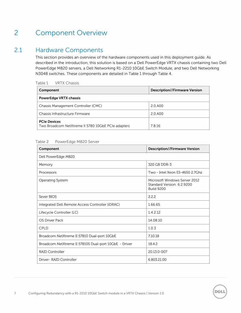
2.1 Hardware Components This section provides an overview of the hardware components used in this deployment guide. As
described in the introduction, this solution is based on a Dell PowerEdge VRTX chassis containing two Dell
PowerEdge M820 servers, a Dell Networking R1-2210 10GbE Switch Module, and two Dell Networking
N3048 switches. These components are detailed in Table 1 through Table 4.
Table 1 VRTX Chassis
Component Description//Firmware Version
PowerEdge VRTX chassis
Chassis Management Controller (CMC) 2.0.A00
Chassis Infrastructure Firmware 2.0.A00
PCIe Devices Two Broadcom NetXtreme II 5780 10GbE PCIe adapters
7.8.16
Table 2 PowerEdge M820 Server
Component Description//Firmware Version
Dell PowerEdge M820
Memory 320 GB DDR-3
Processors Two - Intel Xeon E5-4650 2.7Ghz
Operating System Microsoft Windows Server 2012 Standard Version: 6.2.9200 Build 9200
Sever BIOS 2.2.2
Integrated Dell Remote Access Controller (iDRAC) 1.66.65
Lifecycle Controller (LC) 1.4.2.12
OS Driver Pack 14.08.10
CPLD 1.0.3
Broadcom NetXtreme II 57810 Dual-port 10GbE 7.10.18
Broadcom NetXtreme II 57810S Dual-port 10GbE - Driver 18.4.2
RAID Controller 20.13.0-007
Driver- RAID Controller 6.803.21.00
8 Configuring Redundancy with a R1-2210 10GbE Switch module in a VRTX Chassis | Version 1.0
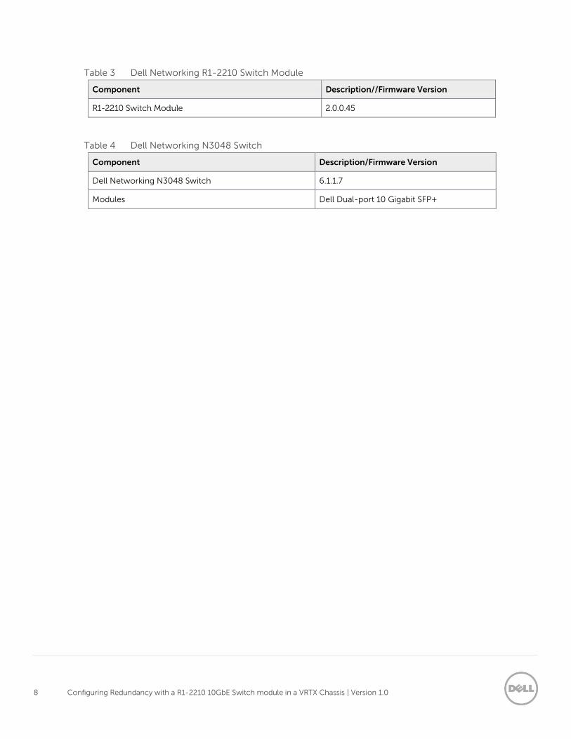
Table 3 Dell Networking R1-2210 Switch Module
Component Description//Firmware Version
R1-2210 Switch Module 2.0.0.45
Table 4 Dell Networking N3048 Switch
Component Description/Firmware Version
Dell Networking N3048 Switch 6.1.1.7
Modules Dell Dual-port 10 Gigabit SFP+

9 Configuring Redundancy with a R1-2210 10GbE Switch module in a VRTX Chassis | Version 1.0
2.2 Dell PowerEdge VRTX Chassis The Dell PowerEdge VRTX (Figure 1) is designed to reduce the complexity of deployments in remote and
branch offices by consolidating servers, storage, and networking in a 5U chassis. The VRTX chassis
supports a maximum of four half-height or two full-height blade servers and includes an internally shared
storage infrastructure using a SAS based PowerEdge RAID Controller (PERC) with 1GB cache. An internal
Ethernet switch provides external connectivity to the client network. The unique configuration of the VRTX
eliminates the need for external storage arrays and fabrics for connectivity to the computer nodes. For
more information about the Dell PowerEdge VRTX, visit http://www.dell.com/us/business/p/poweredge-
vrtx/pd
Figure 1 Dell PowerEdge VRTX Chassis

10 Configuring Redundancy with a R1-2210 10GbE Switch module in a VRTX Chassis | Version 1.0
2.2.1 Dell PowerEdge VRTX 10GbE R1-2210 Switch Module A single R1-2210 switch module (Figure 2) is implemented for all I/O; this allows a maximum signal
consolidation without forcing bifurcation of the Ethernet fabric. The R1-2210 accepts up to 16 lanes from
Fabric A and output of up to four lanes at the external ports. This switch is the only VRTX Fabric A device
that can support the full four-lane count from Fabric A. For more information on VRTX Fabrics, refer to the
VRTX Fabrics section. When equipped with two M820 servers and dual-port Network Daughter Cards
(NDCs), the PowerEdge VRTX can take advantage of eight internal ports (four ports per M820). For more
information about the PowerEdge VRTX 10GbE R1-2210 switch module, visit
http://www.dell.com/support/home/us/en/04/product-support/product/poweredge-vrtx/manuals
10GbE R1-2210 Switch Module
Figure 2 Dell PowerEdge VRTX 10GbE R1-2210 Switch Module

11 Configuring Redundancy with a R1-2210 10GbE Switch module in a VRTX Chassis | Version 1.0
2.2.2 Dell PowerEdge M820 The blade server selected for this solution is the best-in-class Dell PowerEdge M820 Server (Figure 3). This
full-height blade server is a feature-rich, quad-processor platform that offers a blend of density,
performance, efficiency and scalability. The M820 offers remarkable computational density, scaling up to
24 cores, four Intel Xeon processors and up to 3 TB of DDR3 memory, in an extremely compact full-
height blade form factor. For more information about Dell PowerEdge M820 server, visit
http://www.dell.com/us/business/p/poweredge-m820/pd
Figure 3 Dell PowerEdge M820 Blade Server

12 Configuring Redundancy with a R1-2210 10GbE Switch module in a VRTX Chassis | Version 1.0
2.2.3 Broadcom NetXtreme II 57810 Dual-Port 10GbE Network Daughter Card Each PowerEdge M820 supports two dual-port 10GbE NDCs (Figure 4). Currently Broadcom, Intel and
Qlogic each provide a NDC for the PowerEdge M820. In this deployment guide, each of the PowerEdge
M820 servers has two Broadcom NetXtreme II 57810 Dual Post 10GbE Network Daughter Cards (NDCs)
installed.
Figure 4 Broadcom NetXtreme II 57810 Dual-port 10GbE NDC
2.2.4 Broadcom NetXtreme II 57810 Dual-port 10GbE PCIe Adapter The PowerEdge VRTX chassis is capable of supporting up to three full-height, full-length PCIe cards and five half-height, low-profile PCIe cards. Install Network Adapters in these slots to provide network access through Fabric B or C. In this document, two Broadcom NetXtreme II 57810 full-height dual-port 10GbE PCIe adapter (Figure 5) are used.
Figure 5 Broadcom NetXtreme II 57810 Dual port 10GbE PCIe adapter

13 Configuring Redundancy with a R1-2210 10GbE Switch module in a VRTX Chassis | Version 1.0
2.3 Dell Networking N3048 N-Series Switches The Dell Networking N3048 1/10GbE switch (Figure 6) is optimized for lowering operational costs while
improving manageability at branch offices. The N3048 is recommended to compliment the Dell
PowerEdge VRTX because of the switch’s Layer 3 capabilities that help eliminate network bottlenecks
while reducing management devices at the remote office. The high-density N3048 design provides 48
1GbE access ports with two 10GbE uplinks. Four 10GbE uplinks are provided with the optional dual 10GbE
hot swappable module. Using the Dell Networking OS stacking technology and high-speed built-in
stacking ports, up to 12 N3048 switches can be stacked to create a single logical switch. The following
features and options are available on the N3048:
N3048 Features:
46 BaseT (10/100/1000)
Two SFP Ports
Two 10GbE SFP+ Ports
N3048 Options:
Redundant PSUs
One Slot for 10GbE uplink (1000BaseT or SFP+)
Two Built in Stacking ports
RedundantPower Supplies
10GbE Expansion Module
Mini-SAS Stacking Ports
48x 1 GbE Auto-sensing ports 2x 10GbE SFP+
Figure 6 Dell Networking N3048 Switch
Note: While the configurations outlined in this document use a pair of Dell Networking N3048 switches,
any pair of N3000 Series switches can be utilized. For more information about the Dell Networking N-
3000 series switches, visit: http://www.dell.com/us/business/p/networking-n3000-series/pd
2.3.1 Dell SFP+ Dual-Port 10GbE Module The Dell SFP+ (Small Form-factor Pluggable) Dual-Port 10GbE Module (Figure 7) can be installed in the
10GbE Expansion Module at the back of the N3048 switches. It is designed for high-speed uplink data
transmissions and provides two SFP+ ports that support 10GBase-LR and 10GBase-LRM optical
transceivers.
1 2
SFP+ MODULEACT
LNK
ACT
LNK
Figure 7 Dell SFP+ Dual-Port 10GbE Module
14 Configuring Redundancy with a R1-2210 10GbE Switch module in a VRTX Chassis | Version 1.0
2.4 Network Topology In the scenarios presented in this deployment guide, the VRTX chassis contains a R1-2210 switch module
and two PowerEdge M820 servers, each of the servers have two Broadcom NetXtreme II 57810 10GbE
NDCs installed. For Environment B, two Broadcom NetXtreme II 57810 10GbE PCIe adapters are added to
the VRTX chassis.
Dell PowerEdge VRTX Fabrics Port Mapping and Connectivity
Three separate fabrics (A, B and C) are available in the PowerEdge VRTX chassis. Fabric A refers to the
Ethernet connectivity provided to the M820 servers by the 10GbE R1-2210 switch module installed in the
VRTX chassis. Fabrics B and C refer to the PCIe connection between the Fabric B and C slots in the
PowerEdge M820 and the Broadcom NetXtreme II 57810 dual-port 10GbE PCIe adapter installed in the
PowerEdge VRTX chassis.
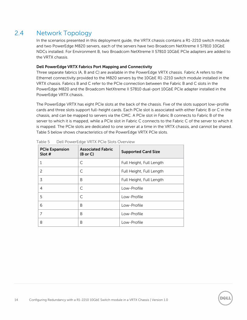
The PowerEdge VRTX has eight PCIe slots at the back of the chassis. Five of the slots support low-profile
cards and three slots support full-height cards. Each PCIe slot is associated with either Fabric B or C in the
chassis, and can be mapped to servers via the CMC. A PCIe slot in Fabric B connects to Fabric B of the
server to which it is mapped, while a PCIe slot in Fabric C connects to the Fabric C of the server to which it
is mapped. The PCIe slots are dedicated to one server at a time in the VRTX chassis, and cannot be shared.
Table 5 below shows characteristics of the PowerEdge VRTX PCIe slots.
Table 5 Dell PowerEdge VRTX PCIe Slots Overview
PCIe Expansion Slot #
Associated Fabric (B or C)
Supported Card Size
1 C Full Height, Full Length
2 C Full Height, Full Length
3 B Full Height, Full Length
4 C Low-Profile
5 C Low-Profile
6 B Low-Profile
7 B Low-Profile
8 B Low-Profile

15 Configuring Redundancy with a R1-2210 10GbE Switch module in a VRTX Chassis | Version 1.0
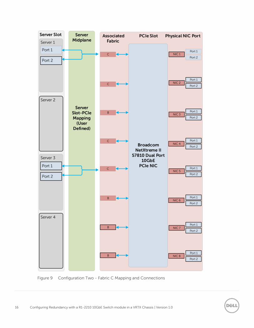
The Fabric A mapping and connections used in Configuration One are shown in Figure 8. The Fabric C
mapping and connections used in Configuration Two are shown in Figure 9.
Internal Ports
External Ports
Figure 8 Configuration One - Fabric A Mapping and Connections
16 Configuring Redundancy with a R1-2210 10GbE Switch module in a VRTX Chassis | Version 1.0
Server Midplane
Server Slot-PCIe Mapping
(User Defined)
Associated PCIe Slot Physical NIC Port Fabric
Server Slot
Server 1
Port 1
Server 3
Port 1
Broadcom NetXtreme II
57810 Dual Port 10GbE
PCIe NIC
Port 2C
C
B
C
C
B
Port 1
Port 2
Port 1
Port 2
Port 1
Port 2
Port 1
Port 1
Port 2
Port 2
Port 1
Port 2
Port 1
Port 2
B
B
NIC 1
NIC 2
NIC 3
NIC 4
NIC 5
NIC 6
NIC 7
NIC 8
Server 4
Server 2
Port 1
Port 2
Port 2
Figure 9 Configuration Two - Fabric C Mapping and Connections

17 Configuring Redundancy with a R1-2210 10GbE Switch module in a VRTX Chassis | Version 1.0
3 Configuration One The first solution utilizes the R1-2210 switch module to provide all I/O connectivity. The Dell Networking
N3048 switches are stacked to provide redundancy for the PowerEdge M820 server. Figure 10 presents
the physical topology of Configuration One.
Figure 10 Configuration One - Physical Topology
3.1 Server Roles and VLANS In this environment, each PowerEdge M820 is assigned a specific role and uses a separate network. As a
best practice, separate VLAN IDs are created to isolate these two distinct networks, VLAN 20 is used by the
employees at the branch office for communication with file server, mail server, etc., while VLAN 30 is used
to host data that is accessed from a less secure network, e.g. the internet. Table 6 summarizes these
VLANs. The network ranges and subnets in this table are provided as examples, the actual values will
depend on your network.
Table 6 VLANS
VLAN ID VLAN Name IP Network Subnet Purpose
20 Employee_Traffic 192.168.20.0 255.255.255.0 Internal Traffic
30 DMZ_Traffic 192.168.30.0 255.255.255.0 Public Traffic

18 Configuring Redundancy with a R1-2210 10GbE Switch module in a VRTX Chassis | Version 1.0
3.2 Dell Networking N3048 Configuration In this section, the N3048 switches are reset to their factory defaults, and then stacked. The time is set on
the switch, VLANs are created on the stacked units, and IP addresses are assigned to both VLANs. Finally, a
port channel consisting of two 10 Gigabit ports is created to connect the N3048 stack to the R1-2210
switch.
3.2.1 Dell Networking N3048 Factory Defaults The two N3048 switches must be cleared of all previous configurations before stacking. To clear the
switches, reset each of the switches to factory defaults.
To reset the Dell Networking N3048 switch to factory defaults, reload the switch and select Option 2 in
the Dell Networking Boot Options prompt during the switch startup. Then select Option 10 in the Boot
Main Menu prompt to restore the configuration to factory defaults. These steps are shown in Figure 11.
Console#reload
.
.
Dell Networking Boot Options
============================
Select a menu option within 3 seconds or the Operational Code will start
automatically...
1 - Start Operational Code
2 - Display Boot Menu
Select (1, 2)# 2
Boot Main Menu
==============
1 - Start Operational Code
2 - Select Baud Rate
3 - Retrieve Logs
4 - Load New Operational Code
5 - Display Operational Code Details
9 - Reboot
10 - Restore Configuration to Factory Defaults
11 - Activate Backup Image
12 - Start Password Recovery
Enter Choice# 10
Are sure you want to Erase Current Configuration? (Y/N): y
Erasing Current Configuration...done.
Figure 11 Resetting the Dell Networking N3048 to Factory Defaults
3.2.2 Dell Networking N3048 Stacking This environment utilizes a pair of N3048 stacked switches to provide redundancy at the top of the
distribution layer.

19 Configuring Redundancy with a R1-2210 10GbE Switch module in a VRTX Chassis | Version 1.0
To stack the switches, connect the switches as shown in figure 12 using the mini-SAS stacking cables.
To designate the master switch, allow the switch to boot up completely before powering up the second
switch. Once the switches have booted, the master switch will be the management point for the stacked
units. For additional information on stacking the N3048 switches, refer to the Dell Networking N2000,
N3000, and N4000 Series Switches User’s Configuration Guide.
Note: Only the master switch will be accessible and configurable in the stack. Other stack members will
be accessible, but not configurable.
2
1
Stacking
LNK
ACT
LNK
ACT
EST
1 2
2
1
Stacking
LNK
ACT
LNK
ACT
EST
1 2
Figure 12 Dell Networking N3048 Stacking
Once the switches are administratively accessible, the show switch and show switch stack-ports
commands can be issued to verify the stacking configuration. Figure 13 shows the output of the show
switch commands.
Console#show switch
Management Standby Preconfig Plugged-in Switch Code
SW Status Status Model ID Model ID Status Version
--- ---------- --------- ------------- ------------- ---------- -------
1 Mgmt Sw N3048 N3048 OK 6.0.1.3
2 Stack Mbr Oper Stby N3048 N3048 OK 6.0.1.3
console#show switch stack-ports
Configured Running Link Link Admin
Interface Stack Mode Stack Mode Status Speed (Gb/s) Status
--------- ---------- ---------- ------------ ------------ ------------
Tw1/0/1 Stack Stack Link Up 21 Enabled
Tw1/0/2 Stack Stack Link Up 21 Enabled
Tw2/0/1 Stack Stack Link Up 21 Enabled
Tw2/0/2 Stack Stack Link Up 21 Enabled
Figure 13 show switch and show switch stack-ports Commands
20 Configuring Redundancy with a R1-2210 10GbE Switch module in a VRTX Chassis | Version 1.0
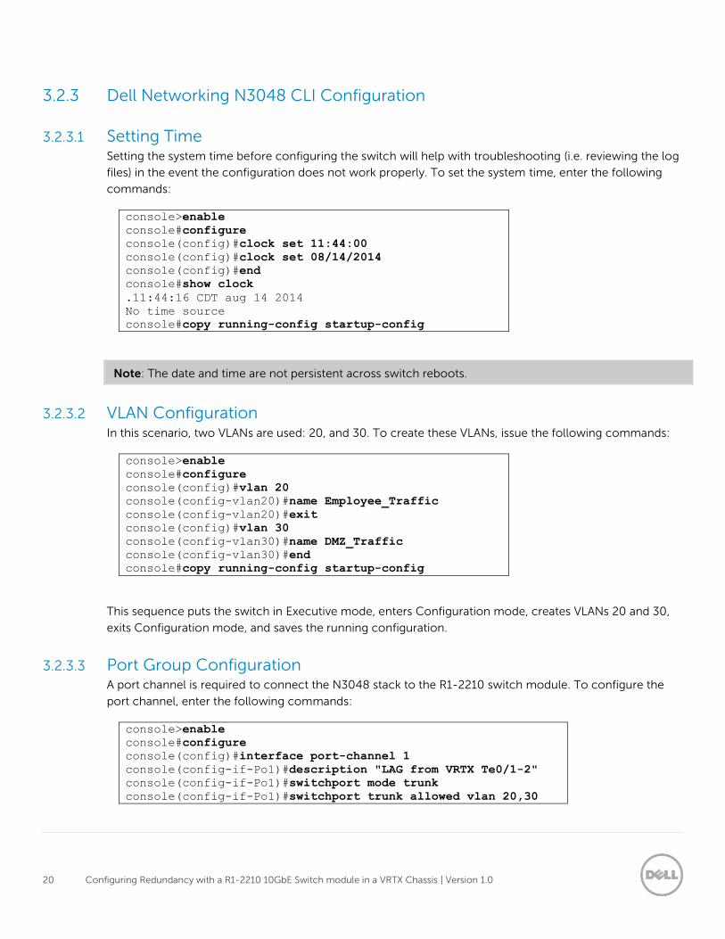
3.2.3 Dell Networking N3048 CLI Configuration
3.2.3.1 Setting Time Setting the system time before configuring the switch will help with troubleshooting (i.e. reviewing the log
files) in the event the configuration does not work properly. To set the system time, enter the following
commands:
console>enable
console#configure
console(config)#clock set 11:44:00
console(config)#clock set 08/14/2014
console(config)#end
console#show clock
.11:44:16 CDT aug 14 2014
No time source
console#copy running-config startup-config
Note: The date and time are not persistent across switch reboots.
3.2.3.2 VLAN Configuration In this scenario, two VLANs are used: 20, and 30. To create these VLANs, issue the following commands:
console>enable
console#configure
console(config)#vlan 20
console(config-vlan20)#name Employee_Traffic
console(config-vlan20)#exit
console(config)#vlan 30
console(config-vlan30)#name DMZ_Traffic
console(config-vlan30)#end
console#copy running-config startup-config
This sequence puts the switch in Executive mode, enters Configuration mode, creates VLANs 20 and 30,
exits Configuration mode, and saves the running configuration.
3.2.3.3 Port Group Configuration A port channel is required to connect the N3048 stack to the R1-2210 switch module. To configure the
port channel, enter the following commands:
console>enable
console#configure
console(config)#interface port-channel 1
console(config-if-Po1)#description "LAG from VRTX Te0/1-2"
console(config-if-Po1)#switchport mode trunk
console(config-if-Po1)#switchport trunk allowed vlan 20,30

21 Configuring Redundancy with a R1-2210 10GbE Switch module in a VRTX Chassis | Version 1.0
console(config-if-Po1)#end
console# copy running-config startup-config
This sequence puts the switch in Executive mode, enters Configuration mode, selects port channel 1 for
configuration, assigns a description and sets the port channel as a trunk. Then, the VLANs are limited to
the ones created earlier (20 and 30), Configuration mode is exited and the running configuration is saved.
Next, two 10GbE ports are assigned to the port channel group.
console>enable
console#configure
console(config)#interface tengigabitethernet1/0/1
console(config-if-Te1/0/1)#channel-group 1 mode active
console(config-if-Te1/0/1)#exit
console(config)#interface tengigabitethernet2/0/1
console(config-if-Te2/0/1)#channel-group 1 mode active
console(config-if-Te2/0/1)#end
console#copy running-config startup-config
This sequence puts the switch in Executive mode, enters Configuration mode, selects Ethernet
TenGigabitEthernet port 1/0/1, assigns it to port channel 1 and exits the port configuration. Then, Ethernet
TenGigabitEthernet port 2/0/1 is selected and assigned to port channel 1, Configuration mode is exited
and the running configuration is saved.

22 Configuring Redundancy with a R1-2210 10GbE Switch module in a VRTX Chassis | Version 1.0
3.2.4 Dell Networking N3048 Validation Verify the configuration by running the show interfaces port-channel and show vlan commands
(Figure 14).
console#show interfaces port-channel
Channel Ports Ch-Type Hash Type Min-links Local Prf
------- ------------------------- -------- --------- --------- ---------
Po1 Active: Te1/0/1, Te2/0/1 Dynamic 7 1 Disabled
Po2 No Configured Ports Static 7 1 Disabled
Po3 No Configured Ports Static 7 1 Disabled
Po4 No Configured Ports Static 7 1 Disabled
Po5 No Configured Ports Static 7 1 Disabled
console#show vlan
VLAN Name Ports Type
----- --------------- ------------- --------------
1 default Po2-128, Default
Gi1/0/1-48,
Te1/0/2,
Te1/1/1-2,
Gi2/0/1-48,
Te2/0/2,
Te2/1/1-2
20 Employee_Traffic Po1 Static
30 DMZ_Traffic Po1 Static
RSPAN Vlan
---------------------------------------------------------------------
None
console#
Figure 14 show interfaces port-channel and show vlan Commands
Note: Irrelevant information has been removed from the output of the show commands (Figure 14) to
highlight the configuration performed in this guide.
3.3 R1-2210 Switch Module Configuration
3.3.1 R1-2210 Switch Module Management Settings The R1-2210 switch module can be managed in multiple ways. In this document, the R1-2210 switch is
managed by accessing it through Telnet, and the configurations are validated using the Dell VRTX CMC
I/O Module GUI.
To launch the I/O module GUI perform the following steps in the Dell VRTX CMC.
Note: Figure 15 provides an overview of the following steps with each step labeled.
1. Expand the Chassis Overview.
2. Expand the I/O Module Overview.

23 Configuring Redundancy with a R1-2210 10GbE Switch module in a VRTX Chassis | Version 1.0
3. Click the switch module.
The I/O Module Status window opens.
4. Click Launch I/O Module GUI button.
The Login Screen for the I/O Module GUI opens.
1
2
3
4
Figure 15 Launching the I/O Module GUI
Note: This guide does not cover the configuration of the VRTX CMC, for CMC configuration information
refer to the Chassis Management Controller Version for Dell PowerEdge VRTX User’s Guide.
3.3.2 R1-2210 Switch Module Resetting Factory Defaults Before any configuration is done, the R1-2210 switch module must be reset to factory defaults. To reset
the module to factory defaults, perform the following steps (Figure 16) in the R1-2210 I/O Module GUI.
1. Expand System.
2. Expand File Management.
3. Click Copy Files.

24 Configuring Redundancy with a R1-2210 10GbE Switch module in a VRTX Chassis | Version 1.0
4. Select the Restore Configuration to Factory Defaults radio button.
5. Click the Activate button.
1
2
3
4
5
Figure 16 Resetting the R1-2210 to Factory Defaults

25 Configuring Redundancy with a R1-2210 10GbE Switch module in a VRTX Chassis | Version 1.0
3.3.3 R1-2210 Switch Module CLI Configuration
3.3.3.1 Setting Time Setting the system time before configuring the switch will help with troubleshooting (i.e. reviewing the log
files) in the event the configuration does not work properly. To set the system time, enter the following
commands:
console>enable
console#configure
console(config)#clock set 11:44:00 14 aug 2014
console(config)#end
console#show clock
.11:44:16 CDT aug 14 2014
No time source
3.3.3.2 VLAN Configuration Create VLAN 20 and 30 by entering the following commands:
console>enable
console#configure
console(config)#vlan 20
console(config-vlan20)#name Employee_Traffic
console(config-vlan20)#exit
console(config)#vlan 30
console(config-vlan30)#name DMZ_Traffic
console(config-vlan30)#end
console#copy running-config startup-config
This sequence puts the switch in Executive mode, enters into Configuration mode, creates VLANs 20 and
30, exits Configuration mode, and saves the running configuration.
3.3.3.3 External Facing Port Group Configuration Use the following commands to create and assign ports to port channel 1 (used between the R1-2210 and
the N3048 stack). Link Aggregation Control Protocol (LACP) is turned on by the use of mode auto option.
console>enable
console#configure
console(config)#interface port-channel 1
console(config-if)#description "LAG to N3048 stack"
console(config-if)#switchport mode trunk
console(config-if)#switchport trunk allowed vlan 20,30
console(config-if)#exit
console#interface range tengigabitethernet0/1-2
console(config-if-range)#channel-group 1 mode auto
console(config-if-range)#end
console#copy running-config startup-config

26 Configuring Redundancy with a R1-2210 10GbE Switch module in a VRTX Chassis | Version 1.0
3.3.3.4 Internal Facing Port Group Configuration Two additional port groups need to be created. These LAGs serve the M820 servers and allow redundancy
between the two NDCs installed in each M820. Table 7 summarizes the LAG and the internal ports used by
the R1-2210.
Table 7 R1-2210 – LAG and Internal Ports
LAG Members VLAN
M820 Slot-1 Slot 1 A1 Slot 3 A1 20
M820 Slot-2 Slot 2 A1 Slot 4 A1 30
3.3.3.5 Employee Traffic LAG This LAG will handle all internal, employee related traffic at the branch office and is assigned to the
PowerEdge M820 in Slot 1/3 of the VRTX chassis. Enter the following commands to create the LAG.
console>enable
console#configure
console(config)#interface Port-channel 2
console(config-if)#description Employee_VLAN
console(config-if)#switchport access vlan 20
console(config-if)#exit
console#interface range TengigabitEthernet1/1, te3/1
console(config-if-range)#channel-group 2 mode auto
console(config-if-range)#end
console#copy running-config startup-config
This sequence puts the switch in Executive mode, enters into Configuration mode, selects port channel 2
for configuration, sets a description, sets the port tag incoming packets with VLAN 20, and exits
configuration for port channel 2. Then an Ethernet range is selected for two internal ports on the R1-2210,
these two ports are assigned to port channel 2 using LACP, Configuration mode is exited, and the running
configuration is saved.
3.3.3.6 DMZ Traffic LAG This LAG will handle traffic coming from the Internet to the DMZ. This can be used for a web server, public
facing file server or any sever role that needs to be in a traditional DMZ.
console>enable
console#configure
console(config)#interface Port-channel 3
console(config-if)#description DMZ_VLAN
console(config-if)#switchport access vlan 30
console(config-if)#exit
console#interface range TengigabitEthernet2/1, te4/1
console(config-if-range)#channel-group 3 mode auto
console(config-if-range)#end
console#copy running-config startup-config

27 Configuring Redundancy with a R1-2210 10GbE Switch module in a VRTX Chassis | Version 1.0
This sequence puts the switch in Executive mode, enters into Configuration mode, selects port channel 3
for configuration, sets a description, sets the port tag incoming packets with VLAN 30 and exits
configuration for port channel 3. Then an Ethernet range is selected for two internal ports on the R1-2210,
these two ports are assigned to port channel 3 using LACP, Configuration mode is exited, and the running
configuration is saved.
3.3.4 R1-2210 Switch Module Validation Physical Port Status Verification
The physical port status can be verified by logging into the I/O Module GUI and selecting the Home tab
(Figure 17).
Figure 17 Physical Port Status Verification
VLAN Verification
Ensure that the created port groups have been added to the correct VLANs by performing the following
steps (Figure 18).
1. Click Home.
2. Expand Switching.
3. Expand VLAN.
4. Select VLAN Membership.
VLAN Membership page opens.
5. Select the VLAN ID from the drop-down box.
6. The LAGs will be shown.

28 Configuring Redundancy with a R1-2210 10GbE Switch module in a VRTX Chassis | Version 1.0
2
1
34
5
6
Figure 18 I/O Module GUI – VLAN Membership
LAG Membership Verification
Verify port membership by performing following steps (Figure 19).
1. Click Home.
2. Expand Switching.
3. Expand Link Aggregation
4. Select LAG Membership.
The LAG Membership: Summary page opens.
1
2
3
4
Figure 19 I/O Module GUI – LAG Membership

29 Configuring Redundancy with a R1-2210 10GbE Switch module in a VRTX Chassis | Version 1.0
3.4 Windows 2012 NIC Teaming Configuration using LACP This section covers NIC teaming in Windows 2012. Teaming allows multiple network interfaces on a
computer to be bound together to provide traffic failover, which prevents connectivity loss in the event of
a network component failure and to provide bandwidth aggregation. Support for NIC teaming is
supported natively in Windows 2012 and Windows 2012 R2.
In this environment, the NIC teaming mode LACP is explicitly used to match the configuration already
performed on the R1-2210 Switch module. For further details on other NIC teaming options, refer to the
NIC Teaming Overview page on Microsoft’s TechNet site.
Note: In the following steps, the NICs have been renamed to associate them with the R1-2210 switch
module ports.
3.4.1 Enabling NIC Teaming To enable NIC teaming in Windows 2012 and 2012 R2, click Disabled next to NIC Teaming in the Server
Manager window (Figure 20).
Figure 20 Server Manager Window – Enabling NIC Teaming

30 Configuring Redundancy with a R1-2210 10GbE Switch module in a VRTX Chassis | Version 1.0
To create a new NIC team, perform the following steps (Figure 21).
1. Ctrl+Click each adapter that needs to be added to the team.
2. Click TASKS.
3. Select Add to new Team.
1
2
3
1
Figure 21 Adding Adapters to New Team
4. Enter the new team’s name in the Team Name field (Figure 22).
5. Expand Additional properties.
6. Use the drop down box to change the Teaming Mode to LACP.
7. Click OK.

31 Configuring Redundancy with a R1-2210 10GbE Switch module in a VRTX Chassis | Version 1.0
4
56
7
Figure 22 Renaming and Setting the Teaming Mode to LACP
Once the team is created, it will be displayed in the TEAMS section of the NIC Teaming page (Figure 23).
This listing will also show the status of the LACP team (status should be OK). The adapters the team is
using can be identified by expanding the team in the ADAPTERS AND INTERFACES section.
Figure 23 NIC Teaming –Status and Team Members
At this point, the NIC team can be configured like any other network adapter. The IP address, subnet mask,
and default gateway can be assigned using the familiar Windows GUI as shown in Figure 24.

32 Configuring Redundancy with a R1-2210 10GbE Switch module in a VRTX Chassis | Version 1.0
Figure 24 Configuring the LACP Team’s Network Settings
Enable NIC Teaming on the Second Dell M820
To enable teaming on the second Dell M820, repeat the preceding section on the Dell M820 in Slot 2
using the information provided in Table 8.
Table 8 Teaming Information for the Dell M820 in Slot 2
Team Name Adapter #1 Adapter #2
DMZ_VLAN Slot2-A1 Slot4-A1

33 Configuring Redundancy with a R1-2210 10GbE Switch module in a VRTX Chassis | Version 1.0
4 Configuration Two In Configuration Two, additional redundancy is added between the servers and N3048 switches. This is
accomplished by adding PCIe NICs to the PowerEdge VRTX chassis. Building on Configuration One, two
Broadcom NetXtreme II 57810 dual-port 10GbE PCIe adapters are installed in the VRTX chassis. Each
adapter is mapped to one of the M820 servers and a link is configured from the PCIe adapters to the
second integrated SFP+ port on the front of the N3048 stack. Figure 25 shows the physical topology of
Configuration Two.
VRTX Chassis
Dell Networking N3048 Stacked Switches
Figure 25 Configuration Two - Physical Topology
Note: With the exception of the Broadcom NetXtreme II 57810 PCIe adapters, the hardware components
used for Configuration Two are identical to Configuration One.

34 Configuring Redundancy with a R1-2210 10GbE Switch module in a VRTX Chassis | Version 1.0
4.1 Server Roles and VLANs In this environment, each PowerEdge M820 is assigned a specific role and uses a separate network. As a
best practice, separate VLAN IDs are created to isolate these two distinct networks; VLAN 20 is used by the
employees at the branch office for communication with file server, mail server, etc. while VLAN 30 is used
to host data that is accessed from a less secure network, such as the internet. Table 9 summarizes these
VLANs. The network ranges and subnets in the following table are provided as examples; the actual values
will depend on your network.
Table 9 VLANs
VLAN ID VLAN Name IP Network Subnet Purpose
20 Employee_Traffic 192.168.20.0 255.255.255.0 Internal Traffic
30 DMZ_Traffic 192.168.30.0 255.255.255.0 Public Traffic
4.2 Dell Networking N3048 Configuration In this section, the N3048 switches are reset to their factory defaults, and then stacked. The time is set,
VLANs are created on the stacked units, and IP addresses are assigned to both VLANs. A port channel
consisting of two 10 Gigabit ports is created to connect the N3048 stack to the R1-2210 switch. Finally,
two links from two 10 Gigabit ports are connected to the Broadcom NetXtreme II 57810 Dual Port PCIe
adapters in the VRTX chassis.
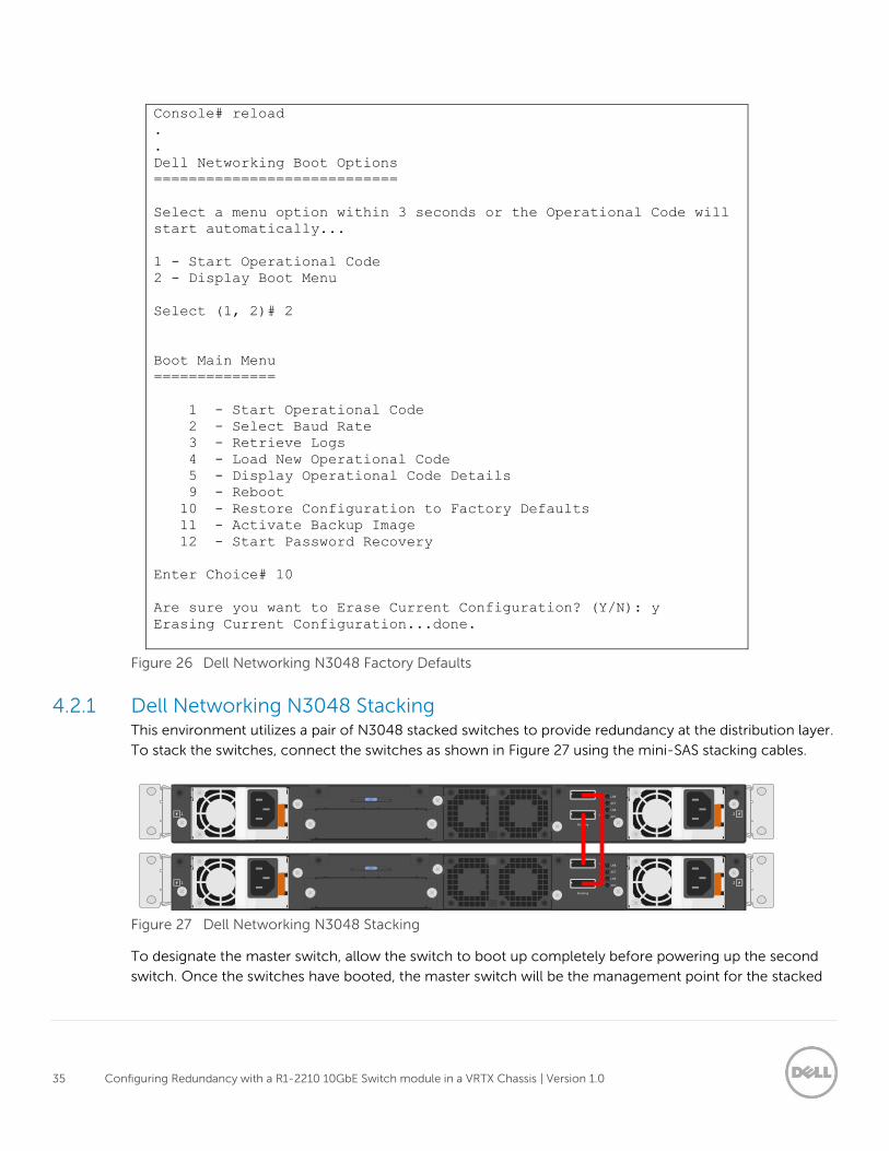
4.2.1 Dell Networking N3048 Factory Defaults The two N3048 switches must be cleared of all previous configurations before stacking. To clear the
switches, reset each of the switches to factory defaults.
To reset the Dell Networking N3048 switch to factory defaults, reload the switch and select Option 2 in
the Dell Networking Boot Options prompt during the switch startup. Then select Option 10 in the Boot
Main Menu prompt to restore the configuration to factory defaults. These steps are shown in Figure 26.
35 Configuring Redundancy with a R1-2210 10GbE Switch module in a VRTX Chassis | Version 1.0
Console# reload
.
.
Dell Networking Boot Options
============================
Select a menu option within 3 seconds or the Operational Code will
start automatically...
1 - Start Operational Code
2 - Display Boot Menu
Select (1, 2)# 2
Boot Main Menu
==============
1 - Start Operational Code
2 - Select Baud Rate
3 - Retrieve Logs
4 - Load New Operational Code
5 - Display Operational Code Details
9 - Reboot
10 - Restore Configuration to Factory Defaults
11 - Activate Backup Image
12 - Start Password Recovery
Enter Choice# 10
Are sure you want to Erase Current Configuration? (Y/N): y
Erasing Current Configuration...done.
Figure 26 Dell Networking N3048 Factory Defaults
4.2.1 Dell Networking N3048 Stacking This environment utilizes a pair of N3048 stacked switches to provide redundancy at the distribution layer.
To stack the switches, connect the switches as shown in Figure 27 using the mini-SAS stacking cables.
2
1
Stacking
LNK
ACT
LNK
ACT
EST
1 2
2
1
Stacking
LNK
ACT
LNK
ACT
EST
1 2
Figure 27 Dell Networking N3048 Stacking
To designate the master switch, allow the switch to boot up completely before powering up the second
switch. Once the switches have booted, the master switch will be the management point for the stacked

36 Configuring Redundancy with a R1-2210 10GbE Switch module in a VRTX Chassis | Version 1.0
units. For additional information on stacking the N3048 switches, refer to the Dell Networking N2000,
N3000, and N4000 Series Switches User’s Configuration Guide.
Note: Only the master switch will be accessible and configurable in the stack. Other stack members will
be accessible, but not configurable.
Once the switches are administratively accessible, the show switch and show switch stack-ports
commands can be issued to verify the stacking configuration. Figure 28 shows the output of the show
switch commands.
console#show switch
Management Standby Preconfig Plugged-in Switch Code
SW Status Status Model ID Model ID Status Version
--- ---------- --------- ------------- ------------- ------------- -----------
1 Mgmt Sw N3048 N3048 OK 6.0.1.3
2 Stack Mbr Oper Stby N3048 N3048 OK 6.0.1.3
console#show switch stack-ports
Configured Running Link Link Admin
Interface Stack Mode Stack Mode Status Speed (Gb/s) Status
--------- ---------- ---------- ------------ ------------ ------------
Tw1/0/1 Stack Stack Link Up 21 Enabled
Tw1/0/2 Stack Stack Link Up 21 Enabled
Tw2/0/1 Stack Stack Link Up 21 Enabled
Tw2/0/2 Stack Stack Link Up 21 Enabled
Figure 28 show switch and show switch stack-ports Commands
4.2.2 Dell Networking N3048 CLI Configuration
4.2.2.1 Setting Time Setting the system time before configuring the switch will help with troubleshooting (i.e. reviewing the log
files) in the event the configuration does not work properly. To set the system time, enter the following
commands:
console>enable
console#configure
console(config)#clock set 11:44:00
console(config)#clock set 08/14/2014
console(config)#end
console#show clock
.11:44:16 CDT aug 14 2014
No time source
console#copy running-config startup-config
Note: The date and time are not persistent across switch reboots.

37 Configuring Redundancy with a R1-2210 10GbE Switch module in a VRTX Chassis | Version 1.0
4.2.2.2 VLAN Configuration In this scenario, two VLANs are used: 20, and 30. To create these VLANs, issue the following commands:
console>enable
console#configure
console(config)#vlan 20
console(config-vlan20)#name Employee_Traffic
console(config-vlan20)#exit
console(config)#vlan 30
console(config-vlan30)#name DMZ_Traffic
console(config-vlan30)#end
console#copy running-config startup-config
This sequence puts the switch in Executive mode, enters into Configuration mode, creates VLAN 20 and
30, exits Configuration mode, and saves the running configuration.
4.2.2.3 Port Group Configuration A port channel is required to connect the N3048 stack to the R1-2210 switch module. To configure the
port channel, enter the following commands:
console>enable
console#configure
console(config)#interface port-channel 1
console(config-if-Po1)#description "LAG from VRTX Te0/1-2"
console(config-if-Po1)#switchport mode trunk
console(config-if-Po1)#switchport trunk allowed vlan 20,30
console(config-if-Po1)#end
console#copy running-config startup-config
This sequence puts the switch in Executive mode, enters Configuration mode, selects port channel 1 for
configuration, assigns a description and sets the port channel as a trunk. Then, the VLANs are limited to
the ones created earlier (20 and 30), Configuration mode is exited and the running configuration is saved.
Next, two 10GbE ports are assigned to the port channel group.
console>enable
console#configure
console(config)#interface tengigabitethernet1/0/1
console(config-if-Te1/0/1)#channel-group 1 mode active
console(config-if-Te1/0/1)#exit
console(config)#interface tengigabitethernet2/0/1
console(config-if-Te2/0/1)#channel-group 1 mode active
console(config-if-Te2/0/1)#end
console#copy running-config startup-config
This sequence puts the switch in Executive mode, enters Configuration mode, selects Ethernet
TenGigabitEthernet port 1/0/1, assigns it to port channel 1 and exits the port configuration. Then, Ethernet

38 Configuring Redundancy with a R1-2210 10GbE Switch module in a VRTX Chassis | Version 1.0
TenGigabitEthernet port 2/0/1 is selected and assigned to port channel 1, Configuration mode is exited
and the running configuration is saved.
4.2.2.4 PCIe NICs Connected Port Configuration To provide additional redundancy in this solution, the second integrated SFP+ ports on N3048 stack
members are set to switchport mode access and each is assigned to the respective VLAN used in the
M820. The configuration is then saved.
console>enable
console#configure
console(config)#interface te1/0/2
console(config-if-Te1/0/2)#switchport mode access
console(config-if-Te1/0/2)#switchport access vlan 20
console(config-if-Te1/0/2)#exit
console(config)#interface te2/0/2
console(config-if-Te2/0/2)#switchport mode access
console(config-if-Te2/0/2)#switchport access vlan 30
console(config-if-Te2/0/2)#end
console#copy running-config startup-config
4.2.3 Dell Networking N3048 Validation Verify the configuration by running the show interfaces port-channel and show vlan commands
(Figure 29).
console#show interfaces port-channel
Channel Ports Ch-Type Hash Type Min-links Local Prf
------- --------------------------- ------- --------- --------- ---------
Po1 Active: Te1/0/1, Te2/0/1 Dynamic 7 1 Disabled
console#show vlan
VLAN Name Ports Type
----- --------------- ------------- --------------
20 Employee_Traffic Po1,Te1/0/2 Static
30 DMZ_Traffic Po1,Te2/0/2 Static
Figure 29 show interfaces port-channel and show vlan Commands
Note: Irrelevant information has been removed from the output of the show commands (Figure 29) to
highlight the configuration performed in this guide.

39 Configuring Redundancy with a R1-2210 10GbE Switch module in a VRTX Chassis | Version 1.0
4.3 R1-2210 Switch Module Configuration
4.3.1 R1-2210 Switch Module Management Settings The R1-2210 switch module can be managed in multiple ways. In this document, the R1-2210 switch is
managed by accessing it through Telnet, and the configurations are validated using the Dell VRTX CMC
I/O Module GUI.
To launch the I/O module GUI perform the following steps in the Dell VRTX CMC.
Note: Figure 30 provides an overview of the following steps with each step labeled.
1. Expand the Chassis Overview.
2. Expand the I/O Module Overview.
3. Click the switch module.
The I/O Module Status window opens.
4. Click Launch I/O Module GUI button.
The Login Screen for the I/O Module GUI opens.
1
2
3
4
Figure 30 Launching the I/O Module GUI

40 Configuring Redundancy with a R1-2210 10GbE Switch module in a VRTX Chassis | Version 1.0
Note: This guide does not cover the configuration of the VRTX CMC, for CMC configuration information
refer to the Chassis Management Controller Version 1.30 for Dell PowerEdge VRTX User’s Guide
4.3.2 R1-2210 Switch Module Resetting Factory Defaults Before any configuration is done, the R1-2210 switch module must be reset to factory defaults. To reset
the R1-2210 switch module to factory defaults, perform the following steps (Figure 31) in the R1-2210 I/O
module GUI.
1. Expand System.
2. Expand File Management.
3. Click Copy Files.
4. Select the Restore Configuration to Factory Defaults radio button.
5. Click the Activate button
1
2
3
4
5
Figure 31 Resetting the R1-2210 to Factory Defaults

41 Configuring Redundancy with a R1-2210 10GbE Switch module in a VRTX Chassis | Version 1.0
4.3.3 R1-2210 Switch Module CLI Configuration
4.3.3.1 Setting Time Setting the system time before configuring the switch will help with troubleshooting (i.e. reviewing the log
files) in the event the configuration does not work properly. To set the system time, enter the following
commands:
console>enable
console#configure
console(config)#clock set 11:44:00 14 aug 2014
console(config)#end
console#show clock
.11:44:16 CDT aug 14 2014
No time source
4.3.3.2 VLAN Configuration Create VLAN 20 and 30 by entering the following commands:
console>enable
console#configure
console(config)#vlan 20
console(config-vlan20)#name Employee_Traffic
console(config-vlan20)#exit
console(config)#vlan 30
console(config-vlan30)#name DMZ_Traffic
console(config-vlan30)#end
console#copy running-config startup-config
This sequence puts the switch in Executive mode, enters into Configuration mode, creates VLAN 20 and
30, exits Configuration mode, and saves the running configuration.
4.3.3.3 External Facing Port Group Configuration Use the following commands to create and assign ports to port channel 1 (used between the R1-2210 and
the N3048 stack). LACP is turned on by the use of mode auto option.
console>enable
console#configure
console(config)#interface port-channel 1
console(config-if)#description "LAG to N3048 stack"
console(config-if)#switchport mode trunk
console(config-if)#switchport trunk allowed vlan 20,30
console(config-if)#exit
console#interface range tengigabitethernet0/1-2
console(config-if-range)#channel-group 1 mode auto
console(config-if-range)#end
console#copy running-config startup-config

42 Configuring Redundancy with a R1-2210 10GbE Switch module in a VRTX Chassis | Version 1.0
4.3.3.4 Internal Facing Port Settings For this configuration, the internal facing R1-2210 switch module ports are set to access ports. This
matches the NIC teaming Switch Independent mode, which is used when configuring NIC teaming in a
later section.
4.3.3.5 PowerEdge M820 in VRTX Slot 1 and 3 For the PowerEdge M820 occupying Slot 1 and 3, the following commands are issued to tag all traffic as
VLAN 20 (Employee Traffic).
console>enable
console#configure
console(config)#interface tengigabitethernet1/1
console(config-if)#switchport mode access
console(config-if)#switchport access vlan 20
console(config-if)#exit
console(config)#interface tengigabitethernet3/1
console(config-if)#switchport mode access
console(config-if)#switchport access vlan 20
console(config-if)#end
console#copy running-config startup-config
4.3.3.6 PowerEdge M820 in VRTX Slot 2 and 4 For the PowerEdge M820 occupying Slot 2 and 4, the following commands are issued to tag all traffic as
VLAN 30 (DMZ Traffic).
console>enable
console#configure
console(config)#interface tengigabitethernet2/1
console(config-if)#switchport mode access
console(config-if)#switchport access vlan 30
console(config-if)#exit
console(config)#interface tengigabitethernet4/1
console(config-if)#switchport mode access
console(config-if)#switchport access vlan 30
console(config-if)#end
console#copy running-config startup-config

43 Configuring Redundancy with a R1-2210 10GbE Switch module in a VRTX Chassis | Version 1.0
4.3.4 R1-2210 Switch Module Validation To validate the MLAG port channel is properly configured and that both te0/1 and te0/2 are assigned to
the port channel, issue the show int Port-Channel command (Figure 32). The bold text in Figure 32
shows the Port Group and the participating ports.
console#show int Port-Channel
Load balancing: src-dst-mac.
Gathering information...
Channel Ports
------- -----
Po1 Active: te0/1-2
console#show vlan
Created by: D-Default, S-Static, G-GVRP, R-Radius Assigned VLAN, V-
Voice VLAN
Vlan Name Ports Created by
---- ----------------- --------------------------- ----------------
20 Employee_Traffic te1/1,te3/1,Po1 S
30 DMZ_Traffic te2/1,te4/1,Po1 S
Figure 32 show int Port-Channel and show vlan Commands

44 Configuring Redundancy with a R1-2210 10GbE Switch module in a VRTX Chassis | Version 1.0
4.4 Broadcom PCIe Adapter Assignment In this environment, two Broadcom NetXtreme II 57810 dual-port 10GbE PCIe adapters are installed in the
VRTX chassis and assigned to each PowerEdge M820 to provide redundancy for the R1-2210 switch
module. The CMC is used to identify and assign the PCIe NICs to a server in the VRTX chassis (Figure 33).
1. Expand Chassis Overview.
2. Click on PCIe Overview.
3. Select the Setup tab.
The Mapping: PCIe Slots to Server Slots page opens.
4. Use the drop-down menu under the Action column to assign the Broadcom NetXtreme II 57810
dual-port 10GbE PCIe adapter to a server.
1
2
3
4
Figure 33 Mapping: PCIe Slots to Server Slots
Figure 34 shows the PCIe Slot to Server slot configuration used for this environment.
Figure 34 PCIe Slot to Server Slot Configuration

45 Configuring Redundancy with a R1-2210 10GbE Switch module in a VRTX Chassis | Version 1.0
4.5 Windows 2012 NIC Teaming Configuration using Switch
Independent Mode This section covers NIC teaming in Windows 2012. Teaming allows multiple network interfaces on a
computer to be bound together to provide traffic failover, which prevents connectivity loss in the event of
a network component failure and to provide bandwidth aggregation. Support for NIC teaming is
supported natively in Windows 2012 and Windows 2012 R2.
In this environment, the NIC teaming mode switch independent will be used to match the configuration
already performed on the R1-2210 switch module. For further details on other NIC teaming options, refer
to the NIC Teaming Overview page on Microsoft’s TechNet site.
Note: In the following steps, the NICs have been renamed to associate them with the R1-2210 switch
module internal ports.
4.5.1 Enabling NIC Teaming To enable NIC teaming in Windows 2012 and 2012 R2, click Disabled next to NIC Teaming in the Server
Manager window (Figure 35).
Figure 35 Server Manager – Enabling NIC Teaming
To create a new NIC team, perform the following steps (Figure 36):
1. Ctrl+Click each adapter that needs to be added to the team.
2. Click TASKS.
3. Select Add to new Team.

46 Configuring Redundancy with a R1-2210 10GbE Switch module in a VRTX Chassis | Version 1.0
1
1
1
23
Figure 36 Adding Adapters to New Team
Note: Figure 37 provides an overview of the following steps.
4. Enter the new team’s name in the Team Name field.
5. Under Additional properties, change the Teaming Mode to Switch Independent.
6. Set the Standby adapter to Chassis SLOT 1 1 (or the first NIC adapter of the assigned PCIe NIC).
7. Click OK.

47 Configuring Redundancy with a R1-2210 10GbE Switch module in a VRTX Chassis | Version 1.0
4
5
6
7
Figure 37 Naming and Setting the Teaming Mode to Switch Independent
Once the team is created, it will be displayed in the TEAMS section of the NIC Teaming page (Figure 38).
This listing will also show the status of the LACP team (status should be OK). The adapters that the team is
using can be identified by expanding the team in the ADAPTERS AND INTERFACES section.

48 Configuring Redundancy with a R1-2210 10GbE Switch module in a VRTX Chassis | Version 1.0
Figure 38 Status of the Switch Independent Team
At this point, the NIC team can be configured like any other network adapter. The IP address, subnet mask,
and default gateway can be assigned using the familiar Windows GUI as shown in Figure 39.
Figure 39 Configuring the Switch Independent Team’s Network Settings

49 Configuring Redundancy with a R1-2210 10GbE Switch module in a VRTX Chassis | Version 1.0
Enable NIC Teaming on the Second Dell M820
To enable teaming on the second Dell M820, repeat the instructions from the preceding section on the
Dell M820 in slot 2 using the information provided in Table 10.
Table 10 Teaming Information for the Dell M820 in Slot 2
Team Name Adapter #1 Adapter #2 Adapter #3
DMZ_VLAN Slot2 A1 Slot4 A1 Chassis Slot 2 1

50 Configuring Redundancy with a R1-2210 10GbE Switch module in a VRTX Chassis | Version 1.0
A Terminology
CLI (Command Line Interface) – CLI is the text-based telnet, SSH, or serial type interface that is used for
entering commands into a device.
CMC (Chassis Management Controller) - A systems management component designed to manage one or
more Dell PowerEdge systems containing blade servers.
Fabric (VRTX) - Three fabrics are available in a PowerEdge VRTX. Fabric A provides connectivity through
the I/O module. Fabric B and C provide connectivity through the PCIe slots.
LACP (Link Aggregation Control Protocol) – LACP is a method to control the bundling of several physical
ports together to form a single logical channel. LACP allows a network device to negotiate an automatic
bundling of links by sending LACP packets to the peer (a directly connected device that also implements
LACP).
LAG (Link Aggregated Group) - Aggregates ports or VLANs into a single virtual port or VLAN.
LAN (Local Area Network) - A network contained within a single room, building, campus or other limited
geographical area.
NIC teaming- NIC Teaming allows multiple network adapters on a computer to be placed into a team to
combine bandwidth or provide the ability for failover.
Port channels- Port channels combine multiple interfaces into one virtual interface. Port- channels
provide increased bandwidth, redundancy and load balancing.
SSH (Secure Shell) - SSH is typically used to log into a remote machine and execute commands. SSH
supports tunneling, forwarding TCP ports and X11 connections, it can also transfer files using the
associated SSH file transfer (SFTP) or secure copy (SCP) protocols.
Switch Stack- A switch stack is a set of switches that behave and work together as a unified system.
Telnet (Terminal Emulation Protocol Network) - Telnet enables system users to log in and use resources
on remote networks.
VLANs (Virtual Local Area Networks) - Logical subgroups with a Local Area Network (LAN) created via
software rather than defining a hardware solution.

51 Configuring Redundancy with a R1-2210 10GbE Switch module in a VRTX Chassis | Version 1.0
B Additional Resources
Dell PowerEdge VRTX
Dell PowerEdge VRTX Manuals
Dell PowerEdge Family Manuals
Manuals for Dell Chassis Management Controller for PowerEdge VRTX, Dell iDRAC, and Dell
Lifecycle Controller
Dell Networking N3048 Systems User’s Guide
Dell Networking N3000 Series Switches
Dell Networking N2000, N3000, and N4000 Series Switches User’s Configuration Guide
Support.Dell.com
DellTechCenter.com
Support and Feedback
Contacting Technical Support
Support Contact Information Web: http://Support.Dell.com/
Telephone: USA: 1-800-945-3355
Feedback for this document
We encourage readers of this publication to provide feedback on the quality and usefulness of this
deployment guide by sending an email to [email protected]