configuring high availability and redundancy...chapter 8 configuring high-availability and...
TRANSCRIPT
OL-28741-01
C H A P T E R 8
Configuring High-Availability and RedundancyThe following topics describe how to manage the high-availability framework provided by Cisco Prime Infrastructure and redundancy framework on controllers:
• Configuring High-Availability, page 8-1
• Configuring Redundancy, page 8-15
Configuring High-AvailabilityTo ensure continued operation in case of failure, Prime Infrastructure now provides a high-availability or failover framework. When an active (primary) Prime Infrastructure fails, a secondary Prime Infrastructure takes over operations for the failed primary Prime Infrastructure and continues to provide service. Upon failover, a peer of the failed primary Prime Infrastructure is activated on the secondary Prime Infrastructure using the local database and files, and the secondary Prime Infrastructure runs a fully functional Prime Infrastructure. While the secondary host is in failover mode, the database and file backups of other primary Prime Infrastructure continue uninterrupted.
If email Address is specified in the high-availability configuration, the mail server must be configured and reachable to be notified about the failure.
The following topics describe the high-availability framework provided by Cisco Prime Infrastructure:
• Failover and Failback Processes, page 8-2
• High-Availability Notation, page 8-3
• Health Monitor, page 8-3
• Data Storage, page 8-5
• Licensing, page 8-6
• Guidelines and Limitations for High-Availability, page 8-6
• High-Availability Status, page 8-7
• Deploying High-Availability, page 8-8
• Configuring High-Availability on the Primary Prime Infrastructure Server, page 8-9
• Adding a New Primary Prime Infrastructure Server in Existing High Availability Environment, page 8-10
• Removing High Availability Configuration, page 8-11
• Configuring an SSO Server in the High-Availability Environment, page 8-11
8-1Cisco Prime Infrastructure 2.0 Administrator Guide

Chapter 8 Configuring High-Availability and RedundancyConfiguring High-Availability
• Installing Software Updates in the High-Availability Environment, page 8-13
• Troubleshooting Issues in the High-Availability Environment, page 8-14
Failover and Failback ProcessesThere are two processes in high-availability: failover and failback. The following topics describe the failover and failback process:
• Failover Scenario, page 8-2
• Failback Scenario, page 8-3
Failover Scenario
Failover is the process of activating the secondary Prime Infrastructure when the primary Prime Infrastructure fails. Failover can be initiated, either manually or automatically, depending on the failover type that is set during the high-availability configuration. For more information about configuring high-availability, see “Configuring High-Availability on the Primary Prime Infrastructure Server” section on page 8-9.
If high-availability is configured with manual mode, the following events take place:
1. An email notification, containing the failure status and a link to the secondary Prime Infrastructure Health Monitor page, will be sent to the registered email address.
2. Using the link provided in the email notification, you can launch the Health Monitor UI and initiate a failover.
If high-availability is configured with automatic mode, the following events take place:
1. The primary Prime Infrastructure is confirmed as non functioning (because of a hardware crash or a network crash) by the health monitor on the secondary Prime Infrastructure.
2. The secondary Prime Infrastructure instance is started immediately (using the configuration already in place) and uses the database of the primary. After a successful failover, the client should point to the newly activated Prime Infrastructure (the secondary Prime Infrastructure). The secondary Prime Infrastructure updates all wireless controllers with its own address as the trap destination. For wired devices, the trap destination for the primary and secondary Prime Infrastructure must be configured on the devices.
Note After a failover, for all devices, make sure you change the communication IP address from the primary Prime Infrastructure to the secondary Prime Infrastructure IP address.
3. The result of the failover operation is indicated as an event in the Health Monitor UI, or a critical alarm is sent to the administrator and to other Prime Infrastructure instances.
Note If an out-of-memory error occurs on the Network Management System (NMS) server, failover must be initiated, either manually or automatically based on the high-availability configuration settings.
8-2Cisco Prime Infrastructure 2.0 Administrator Guide
OL-28741-01

Chapter 8 Configuring High-Availability and RedundancyConfiguring High-Availability
Failback Scenario
Failback is the process of making the primary Prime Infrastructure instance as the active instance. Failback must be initiated manually. Use https://<piip>:8082 to access the Health Monitor UI of the secondary Prime Infrastructure. Within the Health Monitor UI, use the authentication key to log in and initiate the failback process. Before initiating the failback process in the secondary Prime Infrastructure, you must start the primary Prime Infrastructure. The health monitor and the database processes starts.
When failback is initiated, the following events take place:
1. The database information and files are copied to the primary Prime Infrastructure server. The primary server mode changes to Primary Active, and the secondary server mode changes to Secondary Syncing.
2. All processes on the secondary Prime Infrastructure server go down except for the Health Monitor, and all processes on the primary Prime Infrastructure server start.
3. Failback operation takes more time than failover or registration operations when the secondary Prime Infrastructure server was in the active state for a long time.
4. During the failback process, if the primary Prime Infrastructure server goes down, failover is initiated to the secondary Prime Infrastructure server. A new primary Prime Infrastructure is installed with all the configuration settings of the old primary Prime Infrastructure. The secondary Prime Infrastructure is registered with the new primary Prime Infrastructure when the failback is initiated.
High-Availability NotationThe high-availability implementation requires a secondary server that has sufficient resources (CPU, hard drive, memory, and network connection) to take over operation in the event that the primary system fails. The database instance on the secondary system is a hot standby for the primary instance.
The size of the primary and secondary servers must be the same. For example, if the primary Prime Infrastructure server is the express Open Virtual Appliance (OVA; see http://www.fileinfo.com/extension/ova), the secondary Prime Infrastructure server must also have express OVA.
The primary and secondary server can be a mix of a physical and a virtual appliance. For example, if the primary Prime Infrastructure server is a physical appliance, the secondary server can be either a physical appliance or a standard OVA virtual appliance; for example, the server configuration and sizing of standard OVA is the same as the physical appliance. For more information about the OVA options, see Cisco Prime Infrastructure 2.0 Quick Start Guide.
Health MonitorThe Health Monitor is the primary component that manages the Health Monitor operation of the system. Health Monitor is divided into multiple submodules:
8-3Cisco Prime Infrastructure 2.0 Administrator Guide
OL-28741-01

Chapter 8 Configuring High-Availability and RedundancyConfiguring High-Availability
Table 8-1 Health Monitor Submodules
Name Description
Core Health Monitor • Configures the overall Health Monitor system.
• Maintains the state machine for the Health Monitor system.
• Starts and stops the Health Monitor and the Prime Infrastructure Java Virtual Machine (JVM).
• Starts, stops, and monitors other submodules within the Health Monitor.
• Handles registration of the primary/secondary pair.
• Authenticates the Health Monitor-specific session.
• Makes all decisions about failover and failback.
Heart Beat Maintains communication between the primary and secondary Health Monitors. Communication occurs over HTTPS (the default port is 8082). The timeout value is two seconds. A retry mechanism has been implemented to retry establishing connectivity between the primary Health Monitor and secondary Health Monitor. If the Health Monitor does not receive a response after sending a heartbeat request within the timeout period, it retries establishing communication by sending another heartbeat request. If communication has not been established after three retries, the Health Monitors take appropriate action according to the following defined scenarios:
• Primary server goes down: This is the classic failover case. In this scenario, when the secondary Health Monitor does not receive heartbeat requests for six seconds (3 retries x 2 seconds), it initiates the failover mechanism on the secondary Prime Infrastructure Health Monitor.
• Secondary server goes down: In this scenario, the primary Health Monitor does not receive a heartbeat response from the secondary Health Monitor for six seconds (3 retries x 2 seconds). When this happens, the primary Health Monitor changes its state to PRIMARY_ALONE, raises alarms, and changes into listening mode (waiting to receive any messages from the secondary Health Monitor for reestablishing the link between the primary Health Monitor and the secondary Health Monitor).
Application Monitor Communicates with the Prime Infrastructure framework (the Prime Infrastructure JVM) on the local server to retrieve status information. Communication is performed using Simple Object Access Protocol (SOAP) over HTTPS.
DB Monitor Configures the database for replication. It is not responsible for the database replication itself; this is accomplished using the database proprietary replication protocol.
8-4Cisco Prime Infrastructure 2.0 Administrator Guide
OL-28741-01
Chapter 8 Configuring High-Availability and RedundancyConfiguring High-Availability
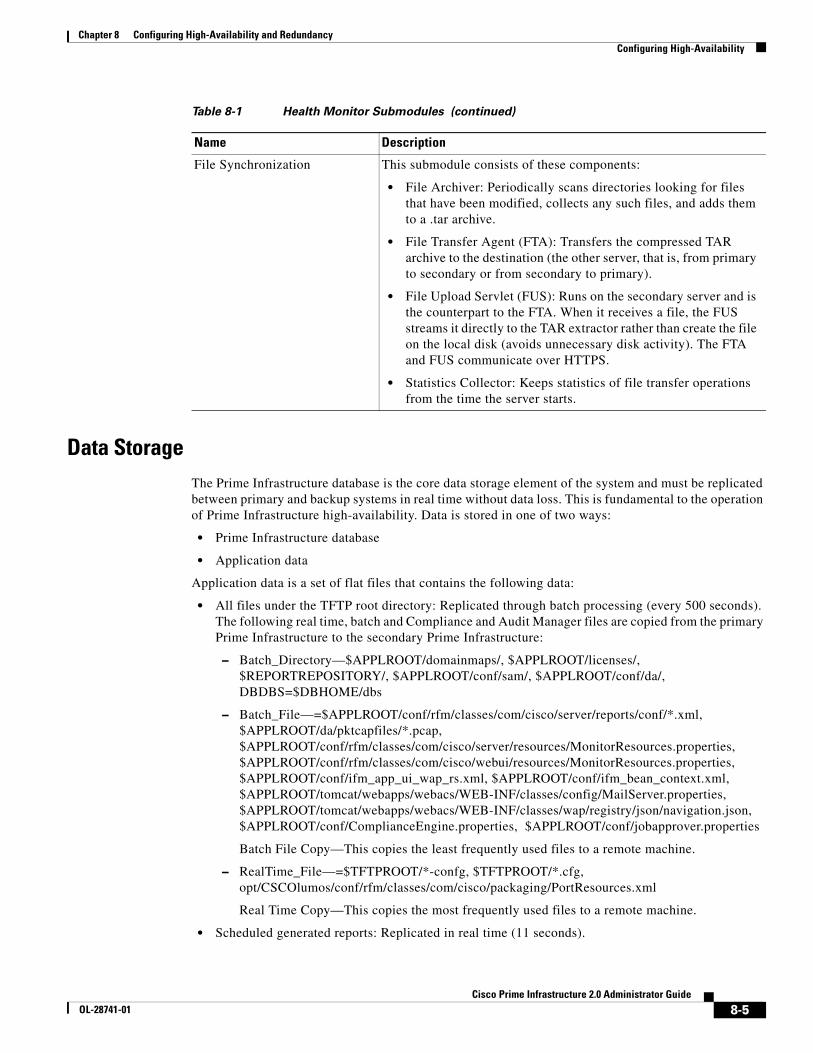
Data StorageThe Prime Infrastructure database is the core data storage element of the system and must be replicated between primary and backup systems in real time without data loss. This is fundamental to the operation of Prime Infrastructure high-availability. Data is stored in one of two ways:
• Prime Infrastructure database
• Application data
Application data is a set of flat files that contains the following data:
• All files under the TFTP root directory: Replicated through batch processing (every 500 seconds). The following real time, batch and Compliance and Audit Manager files are copied from the primary Prime Infrastructure to the secondary Prime Infrastructure:
– Batch_Directory—$APPLROOT/domainmaps/, $APPLROOT/licenses/, $REPORTREPOSITORY/, $APPLROOT/conf/sam/, $APPLROOT/conf/da/, DBDBS=$DBHOME/dbs
– Batch_File—=$APPLROOT/conf/rfm/classes/com/cisco/server/reports/conf/*.xml, $APPLROOT/da/pktcapfiles/*.pcap, $APPLROOT/conf/rfm/classes/com/cisco/server/resources/MonitorResources.properties, $APPLROOT/conf/rfm/classes/com/cisco/webui/resources/MonitorResources.properties, $APPLROOT/conf/ifm_app_ui_wap_rs.xml, $APPLROOT/conf/ifm_bean_context.xml, $APPLROOT/tomcat/webapps/webacs/WEB-INF/classes/config/MailServer.properties, $APPLROOT/tomcat/webapps/webacs/WEB-INF/classes/wap/registry/json/navigation.json, $APPLROOT/conf/ComplianceEngine.properties, $APPLROOT/conf/jobapprover.properties
Batch File Copy—This copies the least frequently used files to a remote machine.
– RealTime_File—=$TFTPROOT/*-confg, $TFTPROOT/*.cfg, opt/CSCOlumos/conf/rfm/classes/com/cisco/packaging/PortResources.xml
Real Time Copy—This copies the most frequently used files to a remote machine.
• Scheduled generated reports: Replicated in real time (11 seconds).
File Synchronization This submodule consists of these components:
• File Archiver: Periodically scans directories looking for files that have been modified, collects any such files, and adds them to a .tar archive.
• File Transfer Agent (FTA): Transfers the compressed TAR archive to the destination (the other server, that is, from primary to secondary or from secondary to primary).
• File Upload Servlet (FUS): Runs on the secondary server and is the counterpart to the FTA. When it receives a file, the FUS streams it directly to the TAR extractor rather than create the file on the local disk (avoids unnecessary disk activity). The FTA and FUS communicate over HTTPS.
• Statistics Collector: Keeps statistics of file transfer operations from the time the server starts.
Table 8-1 Health Monitor Submodules (continued)
Name Description
8-5Cisco Prime Infrastructure 2.0 Administrator Guide
OL-28741-01

Chapter 8 Configuring High-Availability and RedundancyConfiguring High-Availability
LicensingOnly one Prime Infrastructure server license must be purchased; there is no need to purchase a license for the secondary Prime Infrastructure server. The secondary server will use the license from the primary when a failover occurs. The secondary node will simulate the Unique Device Identifier (UDI) information of the primary; thus the secondary server will be able to use the synchronized license from the primary server when the secondary server is active.
The same Prime Infrastructure license file resides on both the primary and secondary Prime Infrastructure servers. Because the Prime Infrastructure JVM is only running on the primary or secondary (not both), the license file is only active on one system at a given point in time.
Guidelines and Limitations for High-AvailabilityBefore initiating failover, you must consider the following prerequisites and limitations:
• You must have the hardware identical to the primary Prime Infrastructure to run a standby instance of Prime Infrastructure.
• Prime Infrastructure supports high-availability on both the physical and virtual appliance deployment models.
• A reliable high-speed wired network must exist between the primary Prime Infrastructure and its backup Prime Infrastructure.
• The primary and secondary Prime Infrastructure must be running the same Prime Infrastructure software release.
• The OVA file size in both primary and secondary Prime Infrastructure must be the same.
• Both primary and secondary Prime Infrastructure must be reachable on both sides.
• The health monitor process for the secondary Prime Infrastructure must be running during the high-availability registration.
• High reliable network must exist between the primary and secondary Prime Infrastructure.
• For primary Prime Infrastructure to initiate high-availability with a secondary Prime Infrastructure, the secondary Prime Infrastructure services must be running and reachable from the primary Prime Infrastructure. Therefore, you must boot the secondary Prime Infrastructure first, and then boot the primary Prime Infrastructure to initiate high-availability registration.
• Failover should be considered temporary. The failed primary Prime Infrastructure should be restored to normal as soon as possible, and failback is initiated. The longer it takes to restore the failed primary Prime Infrastructure, the longer the other Prime Infrastructure sharing that secondary Prime Infrastructure must run without failover support.
• The latest controller software must be used.
• The primary and secondary host are not required to share the same subnet. They can be geographically separated.
• If a secondary host fails for any reason, all the primary instances are affected, and they run in standalone mode without any failover support.
• The ports over which the primary and secondary Prime Infrastructure communicate must be open (not blocked with network firewalls, application fireways, gateways, and so on). The tomcat port is configurable during installation, and its default port is 8082. You should reserve 1522 for solid database port.
8-6Cisco Prime Infrastructure 2.0 Administrator Guide
OL-28741-01

Chapter 8 Configuring High-Availability and RedundancyConfiguring High-Availability
• Any access control lists imposed between the primary and secondary Prime Infrastructure must allow traffic to go between the primary and secondary Prime Infrastructure.
• The primary Prime Infrastructure must have a sufficient number of licenses for the devices. When failover occurs, the secondary Prime Infrastructure uses the licenses of the primary Prime Infrastructure for the devices.
• A secondary Prime Infrastructure can only support one primary Prime Infrastructure.
• When high-availability is enabled for the first time, synchronizing the servers takes a considerable amount of time. The time it would take would be in the order of 30 minutes or more depending on the size of the database.
• During the high-availability registration, ensure that the bandwidth between the primary Prime Infrastructure and the secondary Prime Infrastructure is 1Gbps.
• Ensure that you remove high-availability from the Prime Infrastructure server before initiating the high-availability registration.
High-Availability StatusTo view high-availability details:
Step 1 Choose Administration > High Availability.
Step 2 Choose HA Status from the left sidebar menu. The following information is displayed:
• Current status
• Time, state, and description of each event
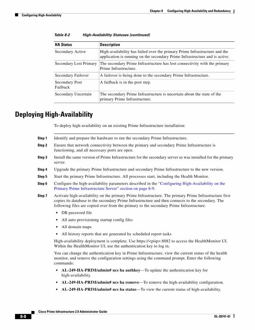
Table 8-2 provides details about the different statuses of high-availability.
Table 8-2 High-Availability Statuses
HA Status Description
HA Not Configured High-availability is not configured yet.
Primary Alone The primary Prime Infrastructure is alone and not synchronizing with the secondary Prime Infrastructure.
HA Initializing High-availability is initializing.
Primary Active The primary Prime Infrastructure is synchronizing with the secondary Prime Infrastructure without problems.
Primary Lost Secondary The primary Prime Infrastructure has lost connectivity with the secondary Prime Infrastructure.
Primary Failback A failback to the primary Prime Infrastructure is being done.
Primary Uncertain The primary Prime Infrastructure is uncertain about the state of the secondary Prime Infrastructure.
Secondary Alone The secondary Prime Infrastructure is alone and not synchronizing with the primary Prime Infrastructure.
Secondary Syncing The secondary Prime Infrastructure is synchronizing with the primary Prime Infrastructure without problems.
8-7Cisco Prime Infrastructure 2.0 Administrator Guide
OL-28741-01
Chapter 8 Configuring High-Availability and RedundancyConfiguring High-Availability
Deploying High-AvailabilityTo deploy high-availability on an existing Prime Infrastructure installation:
Step 1 Identify and prepare the hardware to run the secondary Prime Infrastructure.
Step 2 Ensure that network connectivity between the primary and secondary Prime Infrastructure is functioning, and all necessary ports are open.
Step 3 Install the same version of Prime Infrastructure for the secondary server as was installed for the primary server.
Step 4 Upgrade the primary Prime Infrastructure and secondary Prime Infrastructure to the new version.
Step 5 Start the primary Prime Infrastructure. All processes start, including the Health Monitor.
Step 6 Configure the high-availability parameters described in the “Configuring High-Availability on the Primary Prime Infrastructure Server” section on page 8-9.
Step 7 Activate high-availability on the primary Prime Infrastructure. The primary Prime Infrastructure first copies its database to the secondary Prime Infrastructure and then connects to the secondary. The following files are copied over from the primary to the secondary Prime Infrastructure:
• DB password file
• All auto provisioning startup config files
• All domain maps
• All history reports that are generated by scheduled report tasks
High-availability deployment is complete. Use https://<piip>:8082 to access the HealthMonitor UI. Within the HealthMonitor UI, use the authentication key to log in.
You can change the authentication key in Prime Infrastructure, view the current status of the health monitor, and remove the configuration settings using the command prompt. Enter the following commands:
• AL-249-HA-PRIM/admin# ncs ha authkey—To update the authentication key for high-availability.
• AL-249-HA-PRIM/admin# ncs ha remove—To remove the high-availability configuration.
• AL-249-HA-PRIM/admin# ncs ha status—To view the current status of high-availability.
Secondary Active High-availability has failed over the primary Prime Infrastructure and the application is running on the secondary Prime Infrastructure and is active.
Secondary Lost Primary The secondary Prime Infrastructure has lost connectivity with the primary Prime Infrastructure.
Secondary Failover A failover is being done to the secondary Prime Infrastructure.
Secondary Post Failback
A failback is in the post step.
Secondary Uncertain The secondary Prime Infrastructure is uncertain about the state of the primary Prime Infrastructure.
Table 8-2 High-Availability Statuses (continued)
HA Status Description
8-8Cisco Prime Infrastructure 2.0 Administrator Guide
OL-28741-01

Chapter 8 Configuring High-Availability and RedundancyConfiguring High-Availability
For more information about these commands, see the Command Reference Guide for Cisco Prime Infrastructure, Release 2.0.
Configuring High-Availability on the Primary Prime Infrastructure ServerYou will need to specify the Prime Infrastructure role (primary or secondary) during installation.
Before You Begin
1. Before you can configure high-availability, you must configure a mail server. See “Configuring Email Settings” section on page 2-5 for information about configuring a mail server.
2. If you plan to specify an email address on the HA Configuration page, first make sure that a mail server is configured and reachable.
Note When database transaction logs grow to one-third of the database partition disk space, set the database to standalone mode to prevent transaction logs from growing further. However, a complete netcopy is required the next time a database synchronization occurs.
To configure high-availability on the primary Prime Infrastructure server:
Step 1 Choose Administration > High Availability.
Step 2 Choose HA Configuration from the left sidebar menu. The High Availability Configuration page appears.
The current status of high-availability is shown in the upper portion of the page. For information about different statuses of high-availability, see Table 8-2.
Step 3 Enter the IP address or hostname of the secondary Prime Infrastructure.
Note If the secondary Prime Infrastructure has a multihomed IP address, the first IP address (eth0) will be registered for high-availability.
Step 4 Enter the authentication key specified during the installation of the secondary Prime Infrastructure.
Step 5 The default admin email address that you configured in Administration > Settings > E-mail Server is automatically supplied. You can make any necessary changes. Any changes you make to these e-mail addresses must also be entered in the Secondary SMTP Server section of the Administration > Settings > Mail Server page.
Note You must enter an email address when configuring high-availability for failure notifications. Prime Infrastructure tests the email server configuration, and if the test fails (because the mail server cannot connect), Prime Infrastructure cannot send a failure notification. You can still start the high-availability registration.
8-9Cisco Prime Infrastructure 2.0 Administrator Guide
OL-28741-01
Chapter 8 Configuring High-Availability and RedundancyConfiguring High-Availability
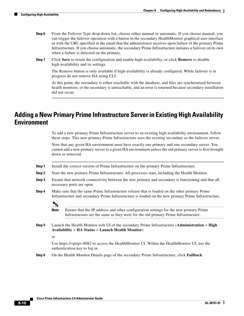
Step 6 From the Failover Type drop-down list, choose either manual or automatic. If you choose manual, you can trigger the failover operation with a button in the secondary HealthMonitor graphical user interface or with the URL specified in the email that the administrator receives upon failure of the primary Prime Infrastructure. If you choose automatic, the secondary Prime Infrastructure initiates a failover on its own when a failure is detected on the primary.
Step 7 Click Save to retain the configuration and enable high-availability, or click Remove to disable high-availability and its settings.
The Remove button is only available if high-availability is already configured. While failover is in progress do not remove HA using CLI.
At this point, the secondary is either reachable with the database, and files are synchronized between health monitors, or the secondary is unreachable, and an error is returned because secondary installation did not occur.
Adding a New Primary Prime Infrastructure Server in Existing High Availability Environment
To add a new primary Prime Infrastructure server to an existing high availability environment, follow these steps. This new primary Prime Infrastructure uses the existing secondary as the failover server.
Note that any given HA environment must have exactly one primary and one secondary server. You cannot add a new primary server to a given HA environment unless the old primary server is first brought down or removed.
Step 1 Install the correct version of Prime Infrastructure on the primary Prime Infrastructure.
Step 2 Start the new primary Prime Infrastructure. All processes start, including the Health Monitor.
Step 3 Ensure that network connectivity between the new primary and secondary is functioning and that all necessary ports are open.
Step 4 Make sure that the same Prime Infrastructure release that is loaded on the other primary Prime Infrastructure and secondary Prime Infrastructure is loaded on the new primary Prime Infrastructure.
Note Ensure that the IP address and other configuration settings for the new primary Prime Infrastructure are the same as they were for the old primary Prime Infrastructure.
Step 5 Launch the Health Monitor web UI of the secondary Prime Infrastructure (Administration > High Availability > HA Status > Launch Health Monitor).
or
Use https://<piip>:8082 to access the HealthMonitor UI. Within the HealthMonitor UI, use the authentication key to log in.
Step 6 On the Health Monitor Details page of the secondary Prime Infrastructure, click Failback.
8-10Cisco Prime Infrastructure 2.0 Administrator Guide
OL-28741-01

Chapter 8 Configuring High-Availability and RedundancyConfiguring High-Availability
The database and other configuration files are copied from the secondary Prime Infrastructure to the new primary Prime Infrastructure. The registration of the new primary Prime Infrastructure with the existing secondary Prime Infrastructure is started. After the primary Prime Infrastructure connects to the secondary, the Health Monitor on the primary connects to the secondary Health Monitor. They mutually acknowledge each other and start the monitoring.
Removing High Availability ConfigurationThere are two ways to remove High Availability Configuration:
• Remove High Availability Configuration from Primary UI
• Remove High Availability Configuration from Primary or Secondary CLI
Remove High Availability Configuration from Primary UI
During Primary Active state, you can remove the High Availability from Primary UI. To do this, go to Administration > High Availability > High Availability Configuration and click the Remove button. It will remove both the Primary and Secondary High Availability configurations.
Remove High Availability Configuration from Primary or Secondary CLI
To remove High Availability Configuration from Primary or Secondary CLI:
Step 1 Login as admin user.
Step 2 Use ncs ha remove command.
Step 3 Provide your inputs on whether to remove only one server or both servers.
Based on your input, the High Availability configuration will be removed.
Configuring an SSO Server in the High-Availability EnvironmentSingle Sign-On Authentication (SSO) is used to authenticate and manage users in a multi-user, multi-repository environment and to store and retrieve the credentials that are used for logging into disparate systems. You can set up Prime Infrastructure as the SSO server for other instances of Prime Infrastructure.
You can choose one of the following options to configure an stateful switchover (SSO) server in the high-availability environment:
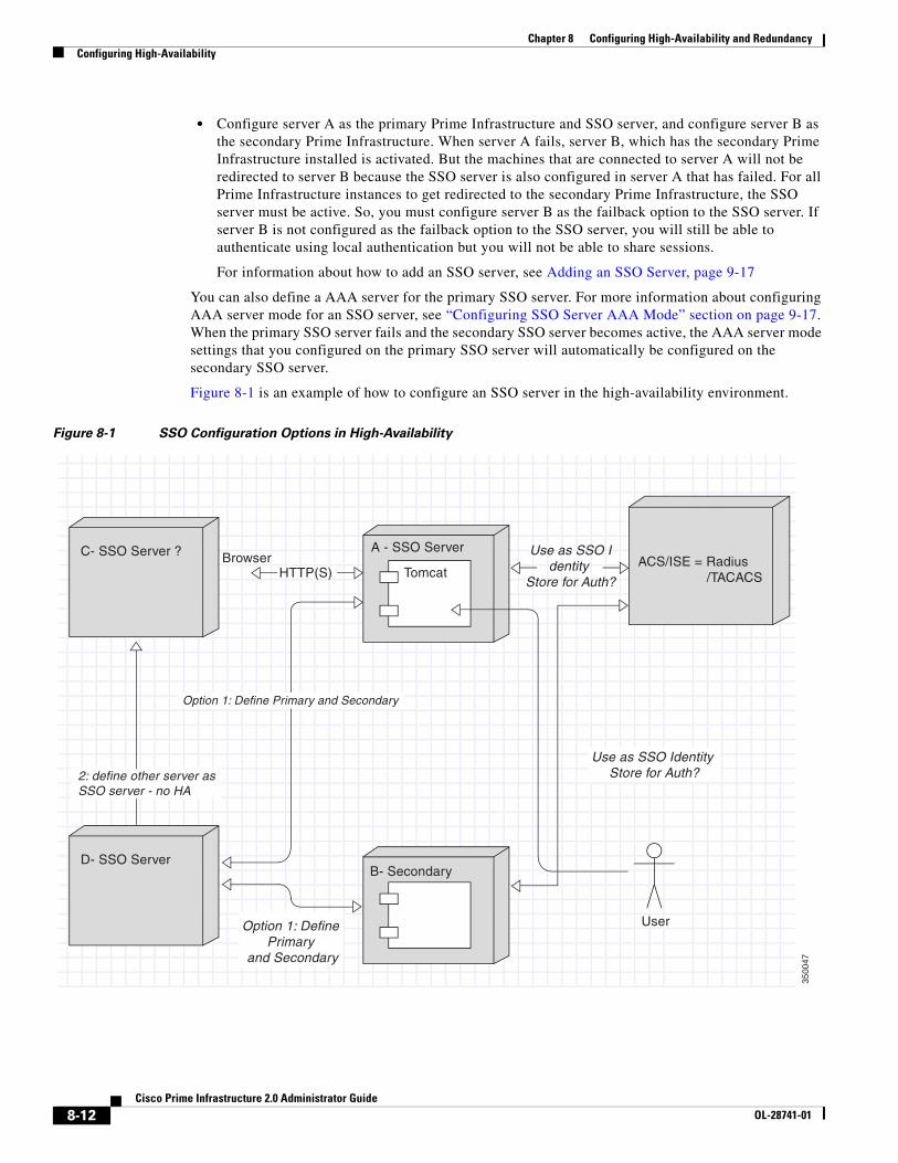
• Configure server A as the primary Prime Infrastructure, server B as the secondary Prime Infrastructure, and server C as the SSO server for both servers A and B. When server A fails, server B, which has the secondary Prime Infrastructure installed, is activated and all the machines that are connected to server A will be redirected to server B. During failback, configuration changes are not required. If server C fails, the SSO functionality is disabled and the local authentication is available for other Prime Infrastructure instances.
8-11Cisco Prime Infrastructure 2.0 Administrator Guide
OL-28741-01
Chapter 8 Configuring High-Availability and RedundancyConfiguring High-Availability
• Configure server A as the primary Prime Infrastructure and SSO server, and configure server B as the secondary Prime Infrastructure. When server A fails, server B, which has the secondary Prime Infrastructure installed is activated. But the machines that are connected to server A will not be redirected to server B because the SSO server is also configured in server A that has failed. For all Prime Infrastructure instances to get redirected to the secondary Prime Infrastructure, the SSO server must be active. So, you must configure server B as the failback option to the SSO server. If server B is not configured as the failback option to the SSO server, you will still be able to authenticate using local authentication but you will not be able to share sessions.
For information about how to add an SSO server, see Adding an SSO Server, page 9-17
You can also define a AAA server for the primary SSO server. For more information about configuring AAA server mode for an SSO server, see “Configuring SSO Server AAA Mode” section on page 9-17. When the primary SSO server fails and the secondary SSO server becomes active, the AAA server mode settings that you configured on the primary SSO server will automatically be configured on the secondary SSO server.
Figure 8-1 is an example of how to configure an SSO server in the high-availability environment.
Figure 8-1 SSO Configuration Options in High-Availability
C- SSO Server ?
D- SSO Server
User
Use as SSO Identity Store for Auth?
Use as SSO Identity
Store for Auth?
A - SSO ServerACS/ISE = Radius /TACACS
B- Secondary
TomcatBrowser
Option 1: Define Primary
and Secondary
HTTP(S)
Option 1: Define Primary and Secondary
2: define other server as SSO server - no HA
3500
47
8-12Cisco Prime Infrastructure 2.0 Administrator Guide
OL-28741-01

Chapter 8 Configuring High-Availability and RedundancyConfiguring High-Availability
Installing Software Updates in the High-Availability EnvironmentYou can install software updates on the high-availability environment under the following scenarios:
• When the high-availability status is Primary Alone, that is, when the primary Prime Infrastructure is alone and not synchronizing with the secondary Prime Infrastructure.
• When high-availability is configured with manual failover type.
• When high-availability is configured with automatic failover type.
The following topics provide instructions on how to install software updates on the high-availability environment:
• Software Update on High-Availability with Primary Alone, page 8-13
• Software Update on High-Availability with Manual Failover Type, page 8-13
• Software Update on High-Availability with Automatic Failover Type, page 8-14
Software Update on High-Availability with Primary Alone
To install software updates when the high-availability status is Primary Alone:
Step 1 Install the primary and secondary Prime Infrastructure servers. Ensure that both servers have the same version of Prime Infrastructure installed.
Step 2 Download the latest software update file (with the extension .ubf) and install the file on the primary Prime Infrastructure when the high-availability status is Primary Alone. For more information on how to install software updates, see Downloading Device Support and Product Updates, page 3-9.
Step 3 Restart the primary Prime Infrastructure and complete the high-availability registration between the primary and secondary Prime Infrastructure.
Step 4 Install the software update file on the secondary Prime Infrastructure.
Note Restarting the secondary Prime Infrastructure is not required because when the failover is initiated, based on the failover type, the secondary Prime Infrastructure is restarted.
If secondary Prime Infrastructure is in synching state, you can use the Software-Update link in the HealthMonitor page to launch the software update page. In other states, you will not be able to find the Software-Update link in HealthMonitor Page. If secondary Prime Infrastructure is in active state, you can navigate to Admin > Software Update to update the software in secondary server.
Software Update on High-Availability with Manual Failover Type
To install software updates when the high-availability is configured with manual failover type:
Step 1 Install the primary and secondary Prime Infrastructure servers. Ensure that both servers have the same version of Prime Infrastructure installed.
Step 2 Complete the high-availability registration between the primary and secondary Prime Infrastructure servers.
8-13Cisco Prime Infrastructure 2.0 Administrator Guide
OL-28741-01
Chapter 8 Configuring High-Availability and RedundancyConfiguring High-Availability
Step 3 Download the latest software update file (with the extension .ubf) and install the file on the primary Prime Infrastructure. For more information on how to install software updates, see Downloading Device Support and Product Updates, page 3-9.
Step 4 Restart the primary Prime Infrastructure. The secondary Prime Infrastructure will not be in the active state now because the failover type for the high-availability is configured as manual. The primary Prime Infrastructure attempts to register with the secondary Prime Infrastructure and the high-availability registration is completed.
Step 5 Install the software update file on the secondary Prime Infrastructure.
Note Restarting the secondary Prime Infrastructure is not required because when you initiate the failover, the secondary Prime Infrastructure is restarted.
Software Update on High-Availability with Automatic Failover Type
To install software updates when the high-availability is configured with automatic failover type:
Step 1 Install the primary and secondary Prime Infrastructure servers. Ensure that both servers have the same version of Prime Infrastructure installed.
Step 2 Complete the high-availability registration between the primary and secondary Prime Infrastructure servers.
Step 3 Download the latest software update file (with the extension .ubf) and install the file on the primary Prime Infrastructure. For more information on how to install software updates, see Downloading Device Support and Product Updates, page 3-9.
Step 4 Restart the primary Prime Infrastructure. The secondary Prime Infrastructure will be in the active state now because the failover type for the high-availability is configured as automatic. So, only the health monitor and database processes in the primary Prime Infrastructure starts.
Step 5 Initiate the failback process.
Step 6 Install the software update file on the secondary Prime Infrastructure before you stop the primary Prime Infrastructure. When the failover is initiated, the secondary Prime Infrastructure is restarted.
Troubleshooting Issues in the High-Availability EnvironmentFollowing are the possible issues that can occur in the high-availability environment:
• The primary or secondary Prime Infrastructure goes down during the high-availability registration process.
• The primary or secondary Prime Infrastructure goes down during the failback process.
• The secondary Prime Infrastructure goes down during the failover process.
The possible causes for the above issues can be that the database or the NMS server has failed to start.
8-14Cisco Prime Infrastructure 2.0 Administrator Guide
OL-28741-01

Chapter 8 Configuring High-Availability and RedundancyConfiguring Redundancy
To avoid these issues:
1. Make sure that you have a backup before starting the high-availability registration or initiating the failback process.
2. If there is any issue with starting the database or the process, complete the following in the primary Prime Infrastructure:
a. Run the following command to re-create a new database:/opt/CSCOlumos/bin/dbmigrate.sh recreateDB
or run the following command in admin console to re-create a new database:
ncs run reset db
b. Run the following command to remove the existing database:rm /opt/CSCOlumos/.dbCreated
c. Stop all the processes.
d. Start all the processes.
e. Restore the backup and continue with the high-availability registration.
Configuring RedundancyThe term redundancy in the Prime Infrastructure refers to the high-availability framework in controllers. Redundancy in wireless networks allows you to reduce the downtime of the networks. In a redundancy architecture, one controller is in the Active state and a second controller is in the Standby state, which continuously monitors the health of the controller in the Active state through a redundant port. Both controllers share the same configurations including the IP address of the management interface.
The Standby or Active state of a controller is based on the redundancy stock keeping unit (SKU), which is a manufacturing ordered unique device identification (UDI). A controller with redundancy SKU UDI is in the Standby state for the first time when it boots and pairs with a controller that runs a permanent count license. For controllers that have permanent count licenses, you can manually configure whether the controller is in the Active state or the Standby state.
In this release, a stateful switchover of access points (AP SSO) is supported. An AP SSO ensures that the AP sessions are intact even after a switchover.
Note The stateful switchover of clients is not supported, which means that all clients, with the exception of clients on locally switched WLANs on access points in FlexConnect mode, are deauthenticated and forced to reassociate with the new controller in the Active state.
This topic contains the following topics:
• Prerequisites and Limitations for Redundancy, page 8-16
• Configuring Redundancy Interfaces, page 8-16
• Configuring Redundancy on a Primary Controller, page 8-17
• Configuring Redundancy on a Secondary Controller, page 8-18
• Monitoring the Redundancy States, page 8-19
• Running the Redundancy Status Background Task, page 8-19
• Configuring a Peer Service Port IP and Subnet Mask, page 8-20
8-15Cisco Prime Infrastructure 2.0 Administrator Guide
OL-28741-01
Chapter 8 Configuring High-Availability and RedundancyConfiguring Redundancy
• Adding a Peer Network Route, page 8-20
• Resetting and Uploading Files from the Secondary Server, page 8-21
• Disabling Redundancy on Controllers, page 8-21
Prerequisites and Limitations for RedundancyBefore configuring redundancy, you must consider the following prerequisites and limitations:
• The redundancy is supported only on the 5500, 7500, 8500, and Wism2 controllers.
• The primary and secondary controllers must be of the same hardware model.
• The primary and secondary controllers must be running the same Controller software release.
• The IP addresses of the management, redundancy management, and peer redundancy management interfaces must be in the same subnet.
• The service port IP address and route information is maintained for each device.
• If the redundancy is enabled on a controller, the Prime Infrastructure or any other device cannot manage the standby controller.
• You cannot enable the redundancy on a controller if the controller is added to the Prime Infrastructure through the service port. You must delete the controller and add it through the management interface to enable the redundancy on that controller.
• When there is an audit mismatch between a controller and the Prime Infrastructure, you must not restore the redundancy parameters from the Prime Infrastructure on to the controller. However, you can refresh the redundancy parameters in the Prime Infrastructure.
• Before you enable the redundancy, you must download the certificates for each device.
• Configuration is downloaded from the network to the active controller, and then the details are transferred to the standby controller through the redundancy interface.
• When an old active controller pairs up with the new active controller, the control is not transferred back to the old active controller and it becomes the standby controller for the new active controller.
Configuring Redundancy InterfacesThere are two redundancy interfaces: redundancy-management interface and redundancy-port interface. The redundancy-management interface is a local physical management interface that shares the subnet mask, gateway, and VLAN ID from the management interface. You must configure only the IP address for the redundancy-management interface to enable redundancy on the primary and secondary controllers. The IP address for the redundancy-port interface is auto-generated and it is used internally.
Step 1 Choose Operate > Device Work Center.
Step 2 Under the Device Group group box, expand Device Type, then expand Wireless Controller.
Step 3 Select the controller that you have chosen as the primary controller. The details of the device appear on the lower part of the page.
Step 4 Click the Configuration tab.
Step 5 From the left sidebar menu, choose System > Interfaces. The Interfaces list page appears.
8-16Cisco Prime Infrastructure 2.0 Administrator Guide
OL-28741-01

Chapter 8 Configuring High-Availability and RedundancyConfiguring Redundancy
Note If you are in the Classic view, choose Configure > Controllers > Ctrl IP addr > System > Interfaces to access the Interfaces list page.
Step 6 Click the redundancy-management interface. The redundancy-management interface details page appears.
Step 7 In the IP Address field, enter an IP address that belongs to the management interface subnet.
Step 8 Click Save.
Note You can also configure the IP address of the redundancy management in the Global Configuration details page. From the Lifecycle view, choose Operate > Device Work Center> Device Type > Wireless Controller > Controller > Configuration > Redundancy > Global Configuration to access the Global Configuration details page. If you are in the Classic view, choose Configure > Controllers > Ctrl IP addr > Redundancy > Global Configuration to access the Global Configuration details page.
Configuring Redundancy on a Primary ControllerTo configure redundancy on a primary or active controller:
Step 1 Choose Operate > Device Work Center.
Step 2 Under the Device Group group box, expand Device Type, then expand Wireless Controller.
Step 3 Select the primary controller for which you have configured the redundancy-management interface IP address. The details of the controller appear on the lower part of the page.
Step 4 Click the Configuration tab.
Step 5 From the left sidebar menu, choose Redundancy > Global Configuration. The Global Configuration details page appears.
Note If you are in the Classic view, choose Configure > Controllers > Ctrl IP addr > Redundancy > Global Configuration to access the Global Configuration details page.
Step 6 You must configure the following parameters before you enable the redundancy mode for the primary controller:
• Redundancy-Management IP—The IP address of the local physical management interface, which you had configured in the redundancy-management interface details page is displayed. You can also modify the IP address.
• Peer Redundancy-Management IP—Enter the IP address of the peer redundancy-management interface.
• Redundant Unit—Choose Primary.
• Mobility MAC Address—Enter the virtual MAC address for the redundancy pair. Ensure that the mobility MAC address that you enter is the same for both primary and secondary controllers.
Step 7 Click Save. The Enabled check box for the redundancy mode becomes available for editing.
8-17Cisco Prime Infrastructure 2.0 Administrator Guide
OL-28741-01

Chapter 8 Configuring High-Availability and RedundancyConfiguring Redundancy
Step 8 Select the Enabled check box for the redundancy mode to enable the redundancy on the primary controller.
Note After you enable the redundancy, you cannot modify the Redundancy-Management IP, Peer Redundancy-Management IP, Redundant Unit, and Mobility MAC Address parameters.
Note You cannot configure this controller during the redundancy pair-up process.
Step 9 Click Save. The configuration is saved and the system reboots.
Configuring Redundancy on a Secondary ControllerTo configure redundancy on a secondary or standby controller:
Step 1 Choose Operate > Device Work Center.
Step 2 Under the Device Group group box, expand Device Type, then expand Wireless Controller.
Step 3 Select the controller that you have chosen as a secondary controller. The details of the controller appear on the lower part of the page.
Step 4 Click the Configuration tab.
Step 5 From the left sidebar menu, choose Redundancy > Global Configuration. The Global Configuration Details page appears.
Note If you are in the Classic view, choose Configure > Controllers > Ctrl IP addr > Redundancy > Global Configuration to access the Global Configuration details page.
Step 6 You must configure the following parameters before you enable the redundancy mode for the secondary controller:
• Redundancy-Management IP—Enter the IP address of the local physical management interface. This IP address must be the same as the IP address of the peer redundancy-management interface of the primary controller.
• Peer Redundancy-Management IP—Enter the IP address of the peer physical management interface. This IP address must be the same as the IP address of the local physical management interface of the primary controller.
• Redundant Unit—Choose Secondary.
• Mobility MAC Address—Enter the virtual MAC address of the redundancy pair. Ensure that the mobility MAC address that you enter is the same for both primary and secondary controllers.
Step 7 Click Save. The Enabled check box for the redundancy mode becomes available for editing.
Step 8 Select the Enabled check box for the redundancy mode to enable the redundancy on the secondary controller.
8-18Cisco Prime Infrastructure 2.0 Administrator Guide
OL-28741-01

Chapter 8 Configuring High-Availability and RedundancyConfiguring Redundancy
Note After you enable the redundancy, you cannot modify the Redundancy-Management IP, Peer Redundancy-Management IP, Redundant Unit, and Mobility MAC Address parameters.
Note You cannot configure the primary controller during the redundancy pair-up process.
Step 9 Click Save. The configuration is saved and the system reboots.
Monitoring the Redundancy StatesAfter the redundancy mode is enabled on the primary and secondary controllers, the system reboots. The redundancy state for both the controllers becomes Enabled in the Wireless Controller Members list page. The following traps are triggered:
• RF_SWITCHOVER_ACTIVITY—This trap is triggered when the standby controller becomes the new active controller.
• RF_PROGRESSION_NOTIFY—This trap is triggered by the primary or active controller when the peer state changes from Disabled to StandbyCold, and then to StandbyHot.
• RF_HA_SUP_FAILURE_EVENT—This trap is triggered when the redundancy fails because of a discrepancy between the active and the standby controllers.
For more information about these traps, see Cisco Prime Infrastructure Alarms and Events.
You can view the redundancy state details such as the local and peer state, unit, IP addresses of the redundancy management, peer redundancy management, redundancy port, peer redundancy port, and peer service port of the paired controller. From the Lifecycle view, choose Operate > Device Work Center > Device Type > Wireless Controller > Controller > Device Details > Redundancy > Redundancy States to view these details. If you are in the Classic view, choose Monitor > Controllers > Ctrl IP addr > Redundancy > Redundancy States to view these details.
Running the Redundancy Status Background TaskSometimes when the peer state changes from StandbyCold to StandbyHot, the redundancy traps are missed by the Prime Infrastructure. As a result, the redundancy pair-up process cannot be completed. To fix this issue, you must run the Redundancy Status background task manually.
To run the Redundancy Status background task:
Step 1 Choose Administration > Background Tasks.
Step 2 Under the Other Background Tasks section, select the Redundancy Status background task.
Step 3 From the Select a command drop-down list, select Execute Now.
Step 4 Click Go.
When traps are missed by the Prime Infrastructure, you must run this background task to complete the following:
8-19Cisco Prime Infrastructure 2.0 Administrator Guide
OL-28741-01

Chapter 8 Configuring High-Availability and RedundancyConfiguring Redundancy
• Remove the standby controller from the Prime Infrastructure.
• Swap the network route table entries with the peer network route table entries.
• Update the redundancy state information and system inventory information.
Once the redundancy pair-up process is completed, the redundancy state for the active controller becomes Paired and the standby controller is removed from the Prime Infrastructure.
Configuring a Peer Service Port IP and Subnet MaskYou can configure a peer service port IP address and a subnet mask only when the state of the peer controller is in StandbyHot. Ensure that DHCP is disabled on local service port before you configure the peer service port IP address.
To configure the peer service port IP and subnet mask:
Step 1 Choose Operate > Device Work Center.
Step 2 Under the Device Group group box, expand Device Type, then expand Wireless Controller.
Step 3 Select the primary or active controller. The details of the controller appear on the lower part of the page.
Step 4 Click the Configuration tab.
Step 5 From the left sidebar menu, choose Redundancy > Global Configuration. The Global Configuration details page appears.
Note If you are in the Classic view, choose Configure > Controllers > Ctrl IP addr > Redundancy > Global Configuration to access the Global Configuration details page.
Step 6 In the Peer Service Port IP field, enter the IP address of the peer service port.
Step 7 In the Peer Service Netmask IP field, enter the IP address of the peer service subnet mask.
Step 8 Click Save.
Adding a Peer Network RouteYou can add a peer network route on an active controller only when the state of the peer controller is in StandbyHot. A new network route table is maintained. When the standby controller becomes active, the entries of the network route table swaps with the entries of the peer network route table.
To add a peer network route:
Step 1 Choose Operate > Device Work Center.
Step 2 Under the Device Group group box, expand Device Type, then expand Wireless Controller.
Step 3 Select the primary controller for which you have configured the redundancy-management interface IP address. The details of the controller appear on the lower part of the page.
Step 4 Click the Configuration tab.
Step 5 From the left sidebar menu, choose Redundancy > Peer Network Route.
8-20Cisco Prime Infrastructure 2.0 Administrator Guide
OL-28741-01

Chapter 8 Configuring High-Availability and RedundancyConfiguring Redundancy
Note If you are in the Classic view, choose Configure > Controllers > Ctrl IP addr > Redundancy > Peer Network Route to access the Peer Network Route list page.
Step 6 From the Select a command drop-down list, choose Add Peer Network Route.
Step 7 Click Go. The Peer Network Route Details page appears.
Step 8 Configure the following fields:
• IP Address—Enter the IP address of the peer network route.
• IP Netmask—Enter the subnet mask of the peer network route.
• Gateway IP Address—Enter the IP address of the peer network route gateway.
Step 9 Click Save. The peer network route is added.
Resetting and Uploading Files from the Secondary ServerYou can reset the secondary server when the secondary server is in the StandbyHot state and the high-availability pair-up process is complete. You can also upload the files from the secondary server to the primary server.
To reset the secondary server and upload files:
Step 1 Choose Operate > Device Work Center > Device Type > Wireless Controller > Controller.
Step 2 Select the primary server for which you have configured the redundancy-management interface IP address, then click the Configuration tab.
Step 3 From the left sidebar menu, choose Device Details > Redundancy > Redundancy Commands.
Note If you are in the Classic view, choose Configure > Controllers > Ctrl IP addr > Redundancy > Redundancy Commands.
Step 4 Choose Reset Standby to reset the secondary server.
Step 5 Choose Upload File from Standby Controller to upload files from the secondary server to primary server.
Disabling Redundancy on ControllersTo disable redundancy on a controller:
Step 1 Choose Operate > Device Work Center.
Step 2 Under the Device Group group box, expand Device Type, then expand Wireless Controller.
Step 3 Select the controller for which you want to disable the redundancy. The details of the controller appear on the lower part of the page.
8-21Cisco Prime Infrastructure 2.0 Administrator Guide
OL-28741-01

Chapter 8 Configuring High-Availability and RedundancyConfiguring Redundancy
Step 4 Click the Configuration tab.
Step 5 From the left sidebar menu, choose Redundancy > Global Configuration. The Global Configuration details page appears.
Note If you are in the Classic view, choose Configure > Controllers > Ctrl IP addr > Redundancy > Global Configuration to access the Global Configuration details page.
Step 6 Deselect the Enabled check box for the redundancy mode to disable the redundancy on the selected controller.
Step 7 Click Save. The configuration is saved and the system reboots.
When you disable redundancy on the controller, both active and standby controllers reboot. You must refresh the configuration from the device to remove any audit mismatches in the redundancy parameters. The active controller becomes a standalone controller and the standby controller reboots with all the ports disabled.
8-22Cisco Prime Infrastructure 2.0 Administrator Guide
OL-28741-01