configuring multiprotocol label switching - · pdf file32-2 cisco ios software configuration...
TRANSCRIPT

CiscoOL-13013-06
C H A P T E R 32
Configuring Multiprotocol Label SwitchingThis chapter describes how to configure Multiprotocol Label Switching (MPLS) in Cisco IOS Release 12.2SX.
Note • MPLS is not supported in PFC3A mode.
• For complete syntax and usage information for the commands used in this chapter, see these publications:
– The Cisco IOS Master Command List, at this URL:
http://www.cisco.com/en/US/docs/ios/mcl/allreleasemcl/all_book.html
– The Release 12.2 publications at this URL:
http://www.cisco.com/en/US/products/sw/iosswrel/ps1835/products_installation_and_configuration_guides_list.html
Tip For additional information about Cisco Catalyst 6500 Series Switches (including configuration examples and troubleshooting information), see the documents listed on this page:
http://www.cisco.com/en/US/products/hw/switches/ps708/tsd_products_support_series_home.html
Participate in the Technical Documentation Ideas forum
This chapter consists of these sections:
• MPLS, page 32-2
• DE/CLP and EXP Mapping on FR/ATMoMPLS VC, page 32-10
• VPN Switching, page 32-13
• Any Transport over MPLS, page 32-17
32-1IOS Software Configuration Guide, Release 12.2SX

Chapter 32 Configuring Multiprotocol Label SwitchingMPLS
MPLSThese sections describe MPLS:
• Understanding MPLS, page 32-2
• Hardware-Supported MPLS Functions, page 32-5
• Supported Cisco IOS Features, page 32-5
• MPLS Guidelines and Restrictions, page 32-7
• Configuring MPLS, page 32-8
• MPLS Per-Label Load Balancing, page 32-8
• MPLS Configuration Examples, page 32-8
Understanding MPLS MPLS uses label switching to forward packets over various link-level technologies such as Packet-over-SONET (POS), Frame Relay, ATM, and Ethernet. Labels are assigned to packets based on groupings or forwarding equivalence classes (FECs). The label is added between the Layer 2 and the Layer 3 header.
In an MPLS network, the label edge router (LER) performs a label lookup of the incoming label, swaps the incoming label with an outgoing label, and sends the packet to the next hop at the label switch router (LSR). Labels are imposed (pushed) on packets only at the ingress edge of the MPLS network and are removed (popped) at the egress edge. The core network LSRs (provider, or P routers) read the labels, apply the appropriate services, and forward the packets based on the labels.
Incoming labels are aggregate or nonaggregate. The aggregate label indicates that the arriving MPLS packet must be switched through an IP lookup to find the next hop and the outgoing interface. The nonaggregate label indicates that the packet contains the IP next hop information.
Figure 32-1 shows an MPLS network of a service provider that connects two sites of a customer network.
Figure 32-1 MPLS Network
For additional information on MPLS, see this publication:
http://www.cisco.com/en/US/docs/ios-xml/ios/mpls/config_library/12-2sx/mp-12-2sx-library.html
CE1
1191
18
PE1 P1 P2 PE2 CE2
IPnetwork
MPLSnetwork
IPnetwork
MPLSnetwork
Host A Host B
Owned byservice provider
32-2Cisco IOS Software Configuration Guide, Release 12.2SX
OL-13013-06

Chapter 32 Configuring Multiprotocol Label SwitchingMPLS
Cisco IOS Release 12.2SX supports Layer 3 Multiprotocol Label Switching (MPLS) virtual private networks (VPNs), and Layer 2 Ethernet over MPLS (EoMPLS), with quality of service (QoS) and security.
The route processor (RP) performs Layer 3 control-plane functions, including address resolution and routing protocols. The RP processes information from the Routing and Label Distribution Protocols and builds the IP forwarding (FIB) table and the label forwarding (LFIB) table. The RP distributes the information in both tables to the PFC3.
The PFC3 receives the information and creates its own copies of the FIB and LFIB tables. Together, these tables comprise the FIB TCAM. The DFC looks up incoming IP packets and labeled packets against the FIB TCAM table. The lookup result is the pointer to a particular adjacency entry. It is the adjacency entry that contains appropriate information for label pushing (for IP to MPLS path), label swapping (for MPLS to MPLS path), label popping (for MPLS to IP path), and encapsulation.
Figure 32-2 shows the various functional blocks that support MPLS. Routing protocol generates a routing information base (RIB) that is used for forwarding IP and MPLS data packets. For Cisco Express Forwarding (CEF), necessary routing information from the RIB is extracted and built into a forwarding information base (FIB). The label distribution protocol (LDP) obtains routes from the RIB and distributes the label across a label switch path to build a label forwarding information base (LFIB) in each of the LSRs and LERs.
Figure 32-2 MPLS Forwarding, Control and Data Planes
IP to MPLS
At the ingress to the MPLS network, the PFC examines the IP packets and performs a route lookup in the FIB TCAM. The lookup result is the pointer to a particular adjacency entry. The adjacency entry contains the appropriate information for label pushing (for IP to MPLS path) and encapsulation. The PFC generates a result containing the imposition label(s) needed to switch the MPLS packet.
Note If MPLS load sharing is configured, the adjacency may point to a load-balanced path. See “Basic MPLS Load Balancing” section on page 32-8.
Routeupdates/
adjacencyLabel updates/
adjacency
MPLSprocess
Control
DataIP forwarding
table (FIB)Label forwarding
table (LFIB)
IP routingprocesses
Route table(RIB)
Label bindings(LIB)
1191
93
32-3Cisco IOS Software Configuration Guide, Release 12.2SX
OL-13013-06

Chapter 32 Configuring Multiprotocol Label SwitchingMPLS
MPLS to MPLS
At the core of an MPLS network, the PFC uses the topmost label to perform a lookup in the FIB TCAM. The successful lookup points to an adjacency that swaps the top label in the packet with a new label as advertised by the downstream label switch router (LSR). If the router is the penultimate hop LSR router (the upstream LSR next to the egress LER), the adjacency instructs the PFCBXL to pop the topmost label, resulting in either an MPLS packet with the remaining label for any VPN or AToM use or a native IP packet.
MPLS to IP
At the egress of the MPLS network there are several possibilities.
For a native IP packet (when the penultimate router has popped the label), the PFC performs a route lookup in the FIB TCAM.
For a MPLS VPN packet, after the Interior Gateway Protocol (IGP) label is popped at penultimate router, the VPN label remains. The operation that the PFC performs depends on the VPN label type. Packets carrying aggregate labels require a second lookup based on the IP header after popping the aggregate label. For a nonaggregate label, the PFC performs a route lookup in the FIB TCAM to obtain the IP next hop information.
For the case of a packet with an IGP label and a VPN label, when there is no penultimate hop popping (PHP), the packet carries the explicit-null label on top of the VPN label. The PFC looks up the top label in the FIB TCAM and recirculates the packet. Then the PFC handles the remaining label as described in the preceding paragraph, depending on whether it is an aggregate or nonaggregate label.
Packets with the explicit-null label for the cases of EoMPLS, MPLS, and MPLS VPN an MPLS are handled the same way.
MPLS VPN Forwarding
There are two types of VPN labels: aggregate labels for directly connected network or aggregate routes, and nonaggregate labels. Packets carrying aggregate labels require a second lookup based on the IP header after popping the aggregate label. The VPN information (VPN-IPv4 address, extended community, and label) is distributed through the Multiprotocol-Border Gateway Protocol (MP-BGP).
Recirculation
In certain cases, the PFC provides the capability to recirculate the packets. Recirculation can be used to perform additional lookups in the ACL or QoS TCAMs, the NetFlow table, or the FIB TCAM table. Recirculation is necessary in these situations:
• To push more than three labels on imposition
• To pop more than two labels on disposition
• To pop an explicit null top label
• When the VPN Routing and Forwarding (VRF) number is more than 511
• For IP ACL on the egress interface (for nonaggregate (per-prefix) labels only)
Packet recirculation occurs only on a particular packet flow; other packet flows are not affected. The rewrite of the packet occurs on the modules; the packets are then forwarded back to the PFC for additional processing.
32-4Cisco IOS Software Configuration Guide, Release 12.2SX
OL-13013-06
Chapter 32 Configuring Multiprotocol Label SwitchingMPLS
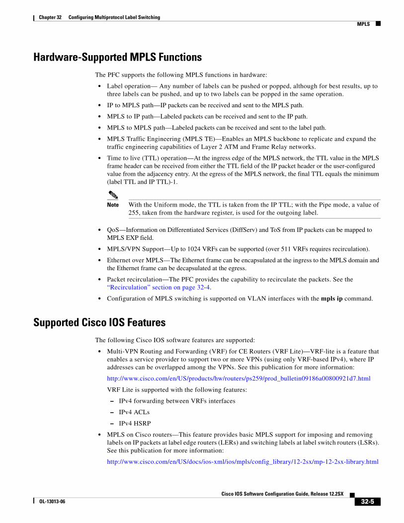
Hardware-Supported MPLS Functions The PFC supports the following MPLS functions in hardware:
• Label operation— Any number of labels can be pushed or popped, although for best results, up to three labels can be pushed, and up to two labels can be popped in the same operation.
• IP to MPLS path—IP packets can be received and sent to the MPLS path.
• MPLS to IP path—Labeled packets can be received and sent to the IP path.
• MPLS to MPLS path—Labeled packets can be received and sent to the label path.
• MPLS Traffic Engineering (MPLS TE)—Enables an MPLS backbone to replicate and expand the traffic engineering capabilities of Layer 2 ATM and Frame Relay networks.
• Time to live (TTL) operation—At the ingress edge of the MPLS network, the TTL value in the MPLS frame header can be received from either the TTL field of the IP packet header or the user-configured value from the adjacency entry. At the egress of the MPLS network, the final TTL equals the minimum (label TTL and IP TTL)-1.
Note With the Uniform mode, the TTL is taken from the IP TTL; with the Pipe mode, a value of 255, taken from the hardware register, is used for the outgoing label.
• QoS—Information on Differentiated Services (DiffServ) and ToS from IP packets can be mapped to MPLS EXP field.
• MPLS/VPN Support—Up to 1024 VRFs can be supported (over 511 VRFs requires recirculation).
• Ethernet over MPLS—The Ethernet frame can be encapsulated at the ingress to the MPLS domain and the Ethernet frame can be decapsulated at the egress.
• Packet recirculation—The PFC provides the capability to recirculate the packets. See the “Recirculation” section on page 32-4.
• Configuration of MPLS switching is supported on VLAN interfaces with the mpls ip command.
Supported Cisco IOS FeaturesThe following Cisco IOS software features are supported:
• Multi-VPN Routing and Forwarding (VRF) for CE Routers (VRF Lite)—VRF-lite is a feature that enables a service provider to support two or more VPNs (using only VRF-based IPv4), where IP addresses can be overlapped among the VPNs. See this publication for more information:
http://www.cisco.com/en/US/products/hw/routers/ps259/prod_bulletin09186a00800921d7.html
VRF Lite is supported with the following features:
– IPv4 forwarding between VRFs interfaces
– IPv4 ACLs
– IPv4 HSRP
• MPLS on Cisco routers—This feature provides basic MPLS support for imposing and removing labels on IP packets at label edge routers (LERs) and switching labels at label switch routers (LSRs). See this publication for more information:
http://www.cisco.com/en/US/docs/ios-xml/ios/mpls/config_library/12-2sx/mp-12-2sx-library.html
32-5Cisco IOS Software Configuration Guide, Release 12.2SX
OL-13013-06

Chapter 32 Configuring Multiprotocol Label SwitchingMPLS
• MPLS TE—MPLS traffic engineering software enables an MPLS backbone to replicate and expand upon the traffic engineering capabilities of Layer 2 ATM and Frame Relay networks. MPLS traffic engineering thereby makes traditional Layer 2 features available to Layer 3 traffic flows. For more information, see these publications:
http://www.cisco.com/en/US/docs/ios-xml/ios/mpls/config_library/12-2sx/mp-12-2sx-library.html
http://www.cisco.com/en/US/tech/tk436/tk428/technologies_configuration_example09186a0080093fcb.shtml
http://www.cisco.com/en/US/tech/tk436/tk428/technologies_configuration_example09186a0080093fd0.shtml
• MPLS TE DiffServ Aware (DS-TE)—This feature provides extensions made to MPLS TE to make it DiffServ aware, allowing constraint-based routing of guaranteed traffic. See this publication for more information:
http://www.cisco.com/en/US/docs/ios-xml/ios/mp_te_diffserv/configuration/12-2sx/mp-te-diffserv-12-2sx-book.html
• MPLS TE Forwarding Adjacency—This feature allows a network administrator to handle a traffic engineering, label-switched path (LSP) tunnel as a link in an Interior Gateway Protocol (IGP) network based on the Shortest Path First (SPF) algorithm. For information on forwarding adjacency with Intermediate System-to-Intermediate System (IS-IS) routing, see this publication:
http://www.cisco.com/en/US/docs/ios-xml/ios/mp_te_path_setup/configuration/12-2sx/mp-te-fwd-adjacency.html
• MPLS TE Interarea Tunnels—This feature allows the router to establish MPLS TE tunnels that span multiple Interior Gateway Protocol (IGP) areas and levels, removing the restriction that had required the tunnel head-end and tail-end routers to be in the same area. See this publication for more information:
http://www.cisco.com/en/US/docs/ios-xml/ios/mp_te_path_setup/configuration/12-2sx/mp-te-interarea-tun.html
• MPLS virtual private networks (VPNs)—This feature allows you to deploy scalable IPv4 Layer 3 VPN backbone services over a Cisco IOS network. See this publication for more information:
http://www.cisco.com/en/US/docs/ios-xml/ios/mpls/config_library/12-2sx/mp-12-2sx-library.html
• MPLS VPN Carrier Supporting Carrier (CSC)—This feature enables one MPLS VPN-based service provider to allow other service providers to use a segment of its backbone network. See this publication for more information:
http://www.cisco.com/en/US/docs/ios-xml/ios/mp_ias_and_csc/configuration/12-2sx/mp-carrier-ldp-igp.html
• MPLS VPN Carrier Supporting Carrier IPv4 BGP Label Distribution—This feature allows you to configure your CSC network to enable Border Gateway Protocol (BGP) to transport routes and MPLS labels between the backbone carrier provider edge (PE) routers and the customer carrier customer edge (CE) routers. See this publication for more information:
http://www.cisco.com/en/US/docs/ios-xml/ios/mp_ias_and_csc/configuration/12-2sx/mp-carrier-bgp.html
• MPLS VPN Interautonomous System (InterAS) Support —This feature allows an MPLS VPN to span service providers and autonomous systems. See this publication for more information:
http://www.cisco.com/en/US/docs/ios-xml/ios/mp_ias_and_csc/configuration/12-2sx/mp-ias-and-csc-12-2sx-book.html
32-6Cisco IOS Software Configuration Guide, Release 12.2SX
OL-13013-06

Chapter 32 Configuring Multiprotocol Label SwitchingMPLS
• MPLS VPN Inter-AS IPv4 BGP label distribution—This feature enables you to set up a VPN service provider network so that the autonomous system boundary routers (ASBRs) exchange IPv4 routes with MPLS labels of the PE routers. See this publication for more information:
http://www.cisco.com/en/US/docs/ios-xml/ios/mp_ias_and_csc/configuration/12-2sx/mp-carrier-ldp-igp.html
• HSRP Support for MPLS VPNs—This feature ensures that the HSRP virtual IP address is added to the correct IP routing table and not to the global routing table. See this publication for more information:
http://www.cisco.com/en/US/docs/ios-xml/ios/ipapp_fhrp/configuration/12-2sx/fhp-hsrp.html
• OSPF Sham-Link Support for MPLS VPN—This feature allows you to use a sham-link to connect VPN client sites that run the Open Shortest Path First (OSPF) protocol and share OSPF links in a MPLS VPN configuration. See this publication for more information:
http://www.cisco.com/en/US/docs/ios-xml/ios/iproute_ospf/configuration/15-sy/iro-sham-link.html
• Any Transport over MPLS (AToM)—Transports Layer 2 packets over an MPLS backbone. See the “Any Transport over MPLS” section on page 32-17.
MPLS Guidelines and RestrictionsWhen configuring MPLS, follow these guidelines and restrictions:
• The PFC3 and DFC3s support up to 16 load-shared paths (Cisco IOS releases for other platforms support only 8 load-shared paths).
• MTU size checking is supported in hardware.
• Fragmentation is supported in software, including traffic that ingresses as IP and egresses as MPLS. To prevent excessive CPU utilization, you can rate-limit the traffic being sent to the RP for fragmentation with the mls rate-limit all mtu-failure command.
Note For information on other limitations and restrictions, see the “MPLS VPN Guidelines and Restrictions” section on page 32-14 and the “EoMPLS Guidelines and Restrictions” section on page 32-18.
Supported MPLS CommandsRelease 12.2SX supports these MPLS commands:
• mpls ip default route
• mpls ip propagate-ttl
• mpls ip ttl-expiration pop
• mpls label protocol
• mpls label range
• mpls ip
• mpls label protocol
• mpls mtu
32-7Cisco IOS Software Configuration Guide, Release 12.2SX
OL-13013-06

Chapter 32 Configuring Multiprotocol Label SwitchingMPLS
For information about these commands, see this publication:
http://www.cisco.com/en/US/docs/ios/mcl/allreleasemcl/all_book.html
Configuring MPLSFor information about configuring MPLS, see the Multiprotocol Label Switching on Cisco Routers publication at the following URL:
http://www.cisco.com/en/US/docs/ios/12_2/switch/configuration/guide/xcftagc.html
MPLS Per-Label Load Balancing The following sections provide information on basic MPLS, MLPS Layer 2 VPN, and MPLS Layer 3 VPN load balancing.
Basic MPLS Load Balancing
The maximum number of load balancing paths is 8. The PFC forwards MPLS labeled packets without explicit configuration. If the packet has three labels or less and the underlying packet is IPv4, then the PFC uses the source and destination IPv4 address. If the underlying packet is not IPv4, or if more than three labels are present, the PFC parses down as deep as the fifth or lowest label and uses it for hashing.
MPLS Layer 2 VPN Load Balancing
Load balancing is based on the VC label in the MPLS core if the first nibble of the MAC address in the customer Ethernet frame is not 4.
Note Load balancing is not supported at the ingress PE for Layer 2 VPNs.
MPLS Layer 3 VPN Load Balancing
MPLS Layer 3 VPN load balancing is similar to basic MPLS load balancing. For more information, see the “Basic MPLS Load Balancing” section on page 32-8.
MPLS Configuration ExamplesThe following is an example of a basic MPLS configuration:
*****Basic MPLS*****
IP ingress interface:
32-8Cisco IOS Software Configuration Guide, Release 12.2SX
OL-13013-06

Chapter 32 Configuring Multiprotocol Label SwitchingMPLS
Router# mpls label protocol ldp
interface GigabitEthernet6/2 ip address 75.0.77.1 255.255.255.0 media-type rj45 speed 1000end
Label egress interface:
interface GigabitEthernet7/15 mtu 9216 ip address 75.0.67.2 255.255.255.0 logging event link-status mpls ip
Router# show ip route 188.0.0.0Routing entry for 188.0.0.0/24, 1 known subnets
O IA 188.0.0.0 [110/1] via 75.0.77.2, 00:00:10, GigabitEthernet6/2
Router# show ip routing 88.0.0.0 Routing entry for 88.0.0.0/24, 1 known subnets
O E2 88.0.0.0 [110/0] via 75.0.67.1, 00:00:24, GigabitEthernet7/15 [110/0] via 75.0.21.2, 00:00:24, GigabitEthernet7/16Router# show mpls forwarding-table 88.0.0.0Local Outgoing Prefix Bytes tag Outgoing Next Hop tag tag or VC or Tunnel Id switched interface 30 50 88.0.0.0/24 0 Gi7/15 75.0.67.1 50 88.0.0.0/24 0 Gi7/16 75.0.21.2
Router# show mls cef 88.0.0.0 detail
Codes: M - mask entry, V - value entry, A - adjacency index, P - priority bit D - full don't switch, m - load balancing modnumber, B - BGP Bucket sel V0 - Vlan 0,C0 - don't comp bit 0,V1 - Vlan 1,C1 - don't comp bit 1 RVTEN - RPF Vlan table enable, RVTSEL - RPF Vlan table selectFormat: IPV4_DA - (8 | xtag vpn pi cr recirc tos prefix)Format: IPV4_SA - (9 | xtag vpn pi cr recirc prefix)M(3223 ): E | 1 FFF 0 0 0 0 255.255.255.0V(3223 ): 8 | 1 0 0 0 0 0 88.0.0.0 (A:344105 ,P:1,D:0,m:1 ,B:0 )M(3223 ): E | 1 FFF 0 0 0 255.255.255.0V(3223 ): 9 | 1 0 0 0 0 88.0.0.0 (V0:0 ,C0:0 ,V1:0 ,C1:0 ,RVTEN:0 ,RVTSEL:0 )Router# show mls cef adj ent 344105
Index: 344105 smac: 0005.9a39.a480, dmac: 000a.8ad8.2340 mtu: 9234, vlan: 1031, dindex: 0x0, l3rw_vld: 1 packets: 109478260, bytes: 7006608640
Router# show mls cef adj ent 344105 de
Index: 344105 smac: 0005.9a39.a480, dmac: 000a.8ad8.2340 mtu: 9234, vlan: 1031, dindex: 0x0, l3rw_vld: 1 format: MPLS, flags: 0x1000008418 label0: 0, exp: 0, ovr: 0 label1: 0, exp: 0, ovr: 0 label2: 50, exp: 0, ovr: 0 op: PUSH_LABEL2 packets: 112344419, bytes: 7190042816
32-9Cisco IOS Software Configuration Guide, Release 12.2SX
OL-13013-06

Chapter 32 Configuring Multiprotocol Label SwitchingDE/CLP and EXP Mapping on FR/ATMoMPLS VC
DE/CLP and EXP Mapping on FR/ATMoMPLS VC
Note Cisco IOS Release 12.2(33)SXH and later releases do not support any Frame Relay interfaces.
The DE/CLP and EXP Mapping on FR/ATMoMPLS VC feature allows you to map the ATM Congestion Loss Priority (CLP) bit to the MPLS EXP value at the ingress to an MPLS AToM network and to map the MPLS EXP value to the ATM CLP bit at the egress of an MPLS AToM network.
The ATM CLP bit indicates whether the cell may be discarded if it encounters extreme congestion as it moves through the network.
In the figure below, the PE1 tags the incoming packet with the MPLS EXP value and sends the packet to the next hop. At each hop, matching is on the EXP value. At the PE2 egress, however, the packet is no longer MPLS but IP, so matching cannot occur on the EXP value.
Internally, the OSM preserves the EXP value in the QoS group so matching on the QoS group at the PE2 egress provides the same effect as matching on the EXP value.
Figure 32-3 CLP and EXP Mapping
See the following sections:
• Match on ATM CLP Bit, page 32-10
• Set on ATM CLP Bit, page 32-12
Match on ATM CLP BitUse Match on ATM CLP Bit at the ingress to an MPLS AToM network to map the ATM cell loss priority (CLP) of the packet arriving at an interface to the EXP value, and then apply the desired QoS functionality and actions (for example, traffic policing) to those packets.
Restrictions for Match on ATM CLP Bit
This feature is supported on policy maps attached to ATM permanent virtual circuits (PVCs) only.
P PE2 CE2CE1 PE1
5952
5
32-10Cisco IOS Software Configuration Guide, Release 12.2SX
OL-13013-06
Chapter 32 Configuring Multiprotocol Label SwitchingDE/CLP and EXP Mapping on FR/ATMoMPLS VC
Configuring Match on ATM CLP Bit for Ingress Policy
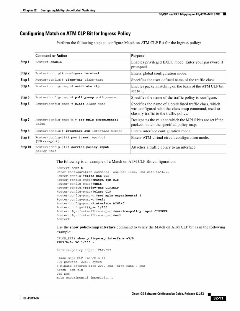
Perform the following steps to configure Match on ATM CLP Bit for the ingress policy:
The following is an example of a Match on ATM CLP Bit configuration:
Router# conf tEnter configuration commands, one per line. End with CNTL/Z.Router(config)#class-map CLPRouter(config-cmap)#match atm clpRouter(config-cmap)#exitRouter(config)#policy-map CLP2EXPRouter(config-pmap)#class CLPRouter(config-pmap-c)#set mpls experimental 1Router(config-pmap-c)#exitRouter(config-pmap)#interface ATM3/0Router(config-if)#pvc 1/100Router(cfg-if-atm-l2trans-pvc)#service-policy input CLP2EXPRouter(cfg-if-atm-l2trans-pvc)#endRouter#
Use the show policy-map interface command to verify the Match on ATM CLP bit as in the following example:
CFLOW_PE1# show policy-map interface a3/0ATM3/0/0: VC 1/100 -
Service-policy input: CLP2EXP
Class-map: CLP (match-all)200 packets, 22400 bytes5 minute offered rate 2000 bps, drop rate 0 bpsMatch: atm clpQoS Setmpls experimental imposition 1
Command or Action Purpose
Step 1 Router# enable Enables privileged EXEC mode. Enter your password if prompted.
Step 2 Router(config)# configure terminal Enters global configuration mode.
Step 3 Router(config)# class-map class-name Specifies the user-defined name of the traffic class.
Step 4 Router(config-cmap)# match atm clp Enables packet matching on the basis of the ATM CLP bit set to 1.
Step 5 Router(config-cmap)# policy-map policy-name Specifies the name of the traffic policy to configure.
Step 6 Router(config-pmap)# class class-name Specifies the name of a predefined traffic class, which was configured with the class-map command, used to classify traffic to the traffic policy.
Step 7 Router(config-pmap-c)# set mpls experimental value
Designates the value to which the MPLS bits are set if the packets match the specified policy map.
Step 8 Router(config)# interface atm interface-number Enters interface configuration mode.
Step 9 Router(config-if)# pvc [name] vpi/vci [l2transport]
Entesr ATM virtual circuit configuration mode.
Step 10 Router(config-if)# service-policy input policy-name
Attaches a traffic policy to an interface.
32-11Cisco IOS Software Configuration Guide, Release 12.2SX
OL-13013-06

Chapter 32 Configuring Multiprotocol Label SwitchingDE/CLP and EXP Mapping on FR/ATMoMPLS VC
Packets marked 200
Class-map: class-default (match-any)0 packets, 0 bytes5 minute offered rate 0 bps, drop rate 0 bpsMatch: anyCFLOW_PE1#
Set on ATM CLP BitUse Set on ATM CLP Bit at the egress of an MPLS AToM network to map the EXP value to the ATM CLP bit.
Restrictions for Set on ATM CLP Bit
This feature is supported on policy maps attached to ATM permanent virtual circuits (PVCs) only.
Configuring Set on ATM CLP Bit for Egress Policy
Perform the following steps to configure Set on ATM CLP Bit for the ingress policy:
The following shows how to configure Set on ATM CLP Bit:
arthos# show policy-map qg2clp
Command or Action Purpose
Step 1 Router# enable Enables privileged EXEC mode. Enter your password if prompted.
Step 2 Router(config)# configure terminal Enters global configuration mode.
Step 3 Router(config)# class-map class-name Specifies the user-defined name of the traffic class.
Step 4 Router(config-cmap)# match qos-group qos-group-value
Identifies a specific quality of service (QoS) group value as a match criterion. The QoS group value has no mathematical significance.
Note The QoS group concept is directly derived from the incoming MPLS EXP value and is valid only with AToM. You cannot use MQC to set QoS group value.
Step 5 Router(config-cmap)# policy-map policy-name Specifies the name of the traffic policy to configure.
Step 6 Router(config-pmap)# class class-name Specifies the name of a predefined traffic class, which was configured with the class-map command, used to classify traffic to the traffic policy.
Step 7 Router(config-pmap-c)# set atm-clp Sets the cell loss priority (CLP) bit when a policy map is configured.
Step 8 Router(config)# interface slot/port Enters the interface and enters interface configuration mode.
Step 9 Router(config-if)# service-policy input policy-name
Attaches a traffic policy to an interface.
32-12Cisco IOS Software Configuration Guide, Release 12.2SX
OL-13013-06

Chapter 32 Configuring Multiprotocol Label SwitchingVPN Switching
Policy Map qg2clp Class qg1 set atm-clparthos# show class-map qg1Class Map match-all qg1 (id 23) Match qos-group 1
arthos# show run int a9/1interface ATM9/1no ip addressatm clock INTERNALatm mtu-reject-callmls qos trust dscppvc 1/100 l2transport encapsulation aal5 mpls l2transport route 101.101.101.101 1000 service-policy out qg2clp
Verify the configuration with the show policy-map interface command.
arthos# show policy interface ATM9/1ATM9/1: VC 1/100 -
Service-policy output: qg2clp
Class-map: qg1 (match-all) 1000 packets, 0 bytes 5 minute offered rate 0 bps, drop rate 0 bps Match: qos-group 1 QoS Set atm-clp Packets marked 1000
VPN SwitchingThese sections describe VPN switching:
• VPN Switching Operation, page 32-13
• MPLS VPN Guidelines and Restrictions, page 32-14
• MPLS VPN Supported Commands, page 32-14
• MPLS VPN Sample Configuration, page 32-15
VPN Switching OperationThe IP VPN feature for MPLS allows a Cisco IOS network to deploy scalable IP Layer 3 VPN backbone services to multiple sites deployed on a shared infrastructure while also providing the same access or security policies as a private network. VPN based on MPLS technology provides the benefits of routing isolation and security, as well as simplified routing and better scalability.
See the Cisco IOS software documentation for a conceptual MPLS VPN overview and configuration details at this URL:
http://www.cisco.com/en/US/docs/ios/12_2/switch/configuration/guide/xcftagov_ps1835_TSD_Products_Configuration_Guide_Chapter.html
A typical MPLS VPN network topology is shown in Figure 32-4.
32-13Cisco IOS Software Configuration Guide, Release 12.2SX
OL-13013-06

Chapter 32 Configuring Multiprotocol Label SwitchingVPN Switching
Figure 32-4 VPNs with Service Provider Backbone
At the ingress PE, the PFC makes a forwarding decision based on the packet headers. The PFC contains a table that maps VLANs to VPNs. In the switch architecture, all physical ingress interfaces in the system are associated with a specific VPN. The PFC looks up the IP destination address in the CEF table but only against prefixes that are in the specific VPN. (The table entry points to a specific set of adjacencies and one is chosen as part of the load-balancing decision if multiple parallel paths exist.)
The table entry contains the information on the Layer 2 header that the packet needs, as well as the specific MPLS labels to be pushed onto the frame. The information to rewrite the packet goes back to the ingress module where it is rewritten and forwarded to the egress line interface.
VPN traffic is handled at the egress from the PE based upon the per-prefix labels or aggregate labels. If per-prefix labels are used, then each VPN prefix has a unique label association; this allows the PE to forward the packet to the final destination based upon a label lookup in the FIB.
Note The PFC allocates only one aggregate label per VRF.
If aggregate labels are used for disposition in an egress PE, many prefixes on the multiple interfaces may be associated with the label. In this case, the PFC must perform an IP lookup to determine the final destination. The IP lookup may require recirculation.
MPLS VPN Guidelines and RestrictionsWhen configuring MPLS VPN, note that VPNs are recirculated when the number of VPNs is over 511.
MPLS VPN Supported CommandsMPLS VPN supports these commands:
CE
PE
PE
CE
PE CE
CE
P
Service providerbackbone
VPN 1
VPN 1
VPN 2
Site 1 Site 1
Site 2
Site 2
P
P
P
1191
22
32-14Cisco IOS Software Configuration Guide, Release 12.2SX
OL-13013-06

Chapter 32 Configuring Multiprotocol Label SwitchingVPN Switching
• address-family
• exit-address-family
• import map
• ip route vrf
• ip route forwarding
• ip vrf
• neighbor activate
• rd
• route-target
For information about these commands, see this publication:
http://www.cisco.com/en/US/docs/ios/mcl/allreleasemcl/all_book.html
Configuring MPLS VPNFor information on configuring MPLS VPN, see the MPLS Virtual Private Networks feature module at this URL:
http://www.cisco.com/en/US/docs/ios/12_2/switch/configuration/guide/xcftagc_ps1835_TSD_Products_Configuration_Guide_Chapter.html#Configuring_MPLS_Virtual_Private_Networks
Note If you use a Layer 3 VLAN interface as the MPLS uplink through a Layer 2 port peering with another MPLS device, then you can use another Layer 3 VLAN interface as the VRF interface.
MPLS VPN Sample Configuration This sample configuration shows LAN and FlexWAN CE-facing interfaces. MPLS switching configuration in Cisco IOS Release 12.2SX is identical to configuration in other releases.
!ip vrf blues rd 100:10 route-target export 100:1 route-target import 100:1!mpls label protocol ldpmpls ldp logging neighbor-changesmls mpls tunnel-recir!interface Loopback0 ip address 10.4.4.4 255.255.255.255!interface GigabitEthernet4/2 description Catalyst link to P2 no ip address mls qos trust dscp!interface GigabitEthernet4/2.42 encapsulation dot1Q 42 ip address 10.0.3.2 255.255.255.0 tag-switching ip!
32-15Cisco IOS Software Configuration Guide, Release 12.2SX
OL-13013-06

Chapter 32 Configuring Multiprotocol Label SwitchingVPN Switching
interface GigabitEthernet7/3 description Catalyst link to CE2 no ip address mls qos trust dscp!interface GigabitEthernet7/3.73 encapsulation dot1Q 73 ip vrf forwarding blues ip address 10.19.7.1 255.255.255.0!interface POS8/1 description OSM link to CE3 ip vrf forwarding blues ip address 10.19.8.1 255.255.255.252 encapsulation ppp mls qos trust dscp pos scramble-atm pos flag c2 22!interface POS9/0/0 description FlexWAN link to CE1 ip vrf forwarding blues ip address 10.19.9.1 255.255.255.252 encapsulation ppp pos scramble-atm pos flag c2 22!router ospf 100 log-adjacency-changes network 10.4.4.4 0.0.0.0 area 0 network 10.0.0.0 0.0.255.255 area 0!router ospf 65000 vrf blues log-adjacency-changes redistribute bgp 100 subnets network 10.19.0.0 0.0.255.255 area 0!router bgp 100 no synchronization bgp log-neighbor-changes neighbor 10.3.3.3 remote-as 100 neighbor 10.3.3.3 description MP-BGP to PE1 neighbor 10.3.3.3 update-source Loopback0 no auto-summary ! address-family vpnv4 neighbor 10.3.3.3 activate neighbor 10.3.3.3 send-community extended exit-address-family ! address-family ipv4 vrf blues redistribute connected redistribute ospf 65000 match internal external 1 external 2 no auto-summary no synchronization exit-address-family!
32-16Cisco IOS Software Configuration Guide, Release 12.2SX
OL-13013-06

Chapter 32 Configuring Multiprotocol Label SwitchingAny Transport over MPLS
Any Transport over MPLSAny Transport over MPLS (AToM) transports Layer 2 packets over an MPLS backbone. AToM uses a directed Label Distribution Protocol (LDP) session between edge routers for setting up and maintaining connections. Forwarding occurs through the use of two level labels that provide switching between the edge routers. The external label (tunnel label) routes the packet over the MPLS backbone to the egress PE at the ingress PE. The VC label is a demuxing label that determines the connection at the tunnel endpoint (the particular egress interface on the egress PE as well as the VLAN identifier for an Ethernet frame).
AToM supports the following like-to-like transport types in Cisco IOS Release 12.2SX:
• Ethernet over MPLS (EoMPLS) (VLAN mode and port mode)
• Frame Relay over MPLS with DLCI-to-DLCI connections
• ATM AAL5 over MPLS
• ATM Cell Relay over MPLS
Note Additional AToM types are planned in future releases.
Cisco IOS Release 12.2SX supports both PFC-accelerated EoMPLS as well as FlexWAN2-based EoMPLS. For more information, see this publication:
http://www.cisco.com/en/US/docs/routers/7600/install_config/12.2SX_OSM_config/mpls.html#Ethernet_over_MPLS
For information on other AToM implementations (ATM AAL5 over MPLS, ATM Cell Relay over MPLS, Frame Relay over MPLS), see this publication:
http://www.cisco.com/en/US/docs/routers/7600/install_config/12.2SX_OSM_config/mpls.html#Any_Transport_over_MPLS
These sections describe AToM:
• AToM Load Balancing, page 32-17
• Understanding EoMPLS, page 32-17
• EoMPLS Guidelines and Restrictions, page 32-18
• Configuring EoMPLS, page 32-19
• Configuring MUX-UNI Support on LAN Cards, page 32-26
AToM Load BalancingEoMPLS in Cisco IOS Release 12.2SX does not support load balancing at the tunnel ingress; only one Interior Gateway Protocol (IGP) path is selected even if multiple IGP paths are available, but load balancing is available at the MPLS core.
Understanding EoMPLSEoMPLS is one of the AToM transport types. AToM transports Layer 2 packets over a MPLS backbone using a directed LDP session between edge routers for setting up and maintaining connections. Forwarding occurs through the use of two level labels that provide switching between the edge routers.
32-17Cisco IOS Software Configuration Guide, Release 12.2SX
OL-13013-06

Chapter 32 Configuring Multiprotocol Label SwitchingAny Transport over MPLS
The external label (tunnel label) routes the packet over the MPLS backbone to the egress PE at the ingress PE. The VC label is a demuxing label that determines the connection at the tunnel endpoint (the particular egress interface on the egress PE as well as the VLAN identifier for an Ethernet frame).
EoMPLS works by encapsulating Ethernet PDUs in MPLS packets and forwarding them across the MPLS network. Each PDU is transported as a single packet.
Note Use FlexWAN-based EoMPLS when you want local Layer 2 switching and EoMPLS on the same VLAN. You need to configure EoMPLS on the SVI; the core-facing card must be a FlexWAN module. When local Layer 2 switching is not required, use PFC-based EoMPLS configured on the subinterface or physical interface.
EoMPLS Guidelines and RestrictionsWhen configuring EoMPLS, follow these guidelines and restrictions:
• Ensure that the maximum transmission unit (MTU) of all intermediate links between endpoints is sufficient to carry the largest Layer 2 packet received.
• EoMPLS supports VLAN packets that conform to the IEEE 802.1Q standard. The 802.1Q specification establishes a standard method for inserting VLAN membership information into Ethernet frames.
• If QoS is disabled globally, both the 802.1p and IP precedence bits are preserved. When the QoS is enabled on a Layer 2 port, either 802.1q P bits or IP precedence bits can be preserved with the trusted configuration. However, by default the unpreserved bits are overwritten by the value of preserved bits. For instance, if you preserve the P bits, the IP precedence bits are overwritten with the value of the P bits. Cisco IOS Release 12.2SX provides a new command that allows you to trust the P bits while preserving the IP precedence bits. To preserve the IP precedence bits, use the no mls qos rewrite ip dscp command.
– The no mls qos rewrite ip dscp command is not compatible with the MPLS and MPLS VPN features. See Chapter 43, “Configuring PFC QoS.”
– Do not use the no mls qos rewrite ip dscp command if you have PFC-based EoMPLS and PXF-based EoMPLS services in the same system.
• EoMPLS is not supported with private VLANs.
• The following restrictions apply to using trunks with EoMPLS:
– To support Ethernet spanning tree bridge protocol data units (BPDUs) across an EoMPLS cloud, you must disable spanning tree for the Ethernet-over-MPLS VLAN. This ensures that the EoMPLS VLANs are carried only on the trunk to the customer switch. Otherwise, the BPDUs are not directed to the EoMPLS cloud.
– The native VLAN of a trunk must not be configured as an EoMPLS VLAN.
• In Cisco IOS Release 12.2SX, all protocols (for example, CDP, VTP, BPDUs) are tunneled across the MPLS cloud without conditions.
• ISL encapsulation is not supported for the interface that receives EoMPLS packets.
• Unique VLANs are required across interfaces. You cannot use the same VLAN ID on different interfaces.
• EoMPLS tunnel destination route in the routing table and the CEF table must be a /32 address (host address where the mask is 255.255.255.255) to ensure that there is a label-switched path (LSP) from PE to PE.
32-18Cisco IOS Software Configuration Guide, Release 12.2SX
OL-13013-06

Chapter 32 Configuring Multiprotocol Label SwitchingAny Transport over MPLS
• For a particular EoMPLS connection, both the ingress EoMPLS interface on the ingress PE and the egress EoMPLS interface on the egress PE have to be subinterfaces with dot1Q encapsulation or neither is a subinterface.
• 802.1Q in 802.1Q over EoMPLS is supported if the outgoing interface connecting to MPLS network is a port on an Layer 2 card.
• Shaping EoMPLS traffic is not supported if the egress interface connecting to an MPLS network is a Layer 2 LAN port (a mode known as PFC-based EoMPLS).
• EoMPLS based on a PFC does not perform any Layer 2 lookup to determine if the destination MAC address resides on the local or remote segment and does not perform any Layer 2 address learning (as traditional LAN bridging does). This functionality (local switching) is available only when using FlexWAN modules as uplinks.
• In previous releases of AToM, the command used to configure AToM circuits was mpls l2 transport route. This command has been replaced with the xconnect command. You can use the xconnect command to configure EoMPLS circuits.
• The AToM control word is not supported.
• EoMPLS is not supported on Layer 3 VLAN interfaces.
• Point-to-point EoMPLS works with a physical interface and subinterfaces.
Configuring EoMPLSThese sections describe how to configure EoMPLS:
• Prerequisites, page 32-19
• Configuring VLAN-Based EoMPLS, page 32-20
• Configuring Port-Based EoMPLS, page 32-23
Prerequisites
Before you configure EoMPLS, ensure that the network is configured as follows:
• Configure IP routing in the core so that the PE routers can reach each other through IP.
• Configure MPLS in the core so that a label switched path (LSP) exists between the PE routers.
EoMPLS works by encapsulating Ethernet PDUs in MPLS packets and forwarding them across the MPLS network. Each PDU is transported as a single packet. Two methods are available to configure EoMPLS in Cisco IOS Release 12.2SX:
• VLAN mode—Transports Ethernet traffic from a source 802.1Q VLAN to a destination 802.1Q VLAN through a single VC over an MPLS network. VLAN mode uses VC type 5 as default (no dot1q tag) and VC type 4 (transport dot1 tag) if the remote PE does not support VC type 5 for subinterface (VLAN) based EoMPLS.
• Port mode—Allows all traffic on a port to share a single VC across an MPLS network. Port mode uses VC type 5.
Note • For both VLAN mode and port mode, EoMPLS in Cisco IOS Release 12.2SX does not allow local switching of packets between interfaces unless you use loopback ports.
32-19Cisco IOS Software Configuration Guide, Release 12.2SX
OL-13013-06

Chapter 32 Configuring Multiprotocol Label SwitchingAny Transport over MPLS
• A system can have both FlexWAN configuration and PFC configuration enabled at the same time. Cisco supports this configuration but does not recommend it. Unless the uplinks to the MPLS core are through FlexWAN interfaces, FlexWAN-based EoMPLS connections will not be active; this causes packets for FlexWAN-based EoMPLS arriving on non-WAN interfaces to be dropped. For information on FlexWAN EoMPLS, see this publication:
http://www.cisco.com/en/US/docs/routers/7600/install_config/12.2SX_OSM_config/mpls.html#Ethernet_over_MPLS
In Cisco IOS Release 12.2SX, LAN ports can receive Layer 2 traffic, impose labels, and switch the frames into the MPLS core without using a FlexWAN module.
With Cisco IOS Release 12.2SX, you can configure a FlexWAN module to face the core of MPLS network and use either the FlexWAN configuration or the PFC configuration. For more information, see this publication:
http://www.cisco.com/en/US/docs/routers/7600/install_config/12.2SX_OSM_config/mpls.html#Ethernet_over_MPLS
Configuring VLAN-Based EoMPLS
When configuring VLAN-based EoMPLS, follow these guidelines and restrictions:
• The AToM control word is not supported.
• Ethernet packets with hardware-level cyclic redundancy check (CRC) errors, framing errors, and runt packets are discarded on input.
• You must configure VLAN-based EoMPLS on subinterfaces.
To configure VLAN-based EoMPLS, perform this task on the provider edge (PE) routers:
This is a VLAN-based EoMPLS configuration sample:
!interface GigabitEthernet7/4.2encapsulation dot1Q 3xconnect 13.13.13.13 3 encapsulation mplsno shut
Command Purpose
Step 1 Router# configure terminal Enters global configuration mode.
Step 2 Router(config)# interface gigabitethernetslot/interface.subinterface
Specifies the Gigabit Ethernet subinterface. Make sure that the subinterface on the adjoining CE router is on the same VLAN as this PE router.
Step 3 Router(config-if)# encapsulation dot1q vlan_id Enables the subinterface to accept 802.1Q VLAN packets.
The subinterfaces between the CE and PE routers that are running Ethernet over MPLS must be in the same subnet. All other subinterfaces and backbone routers do not need to be on the same subnet.
Step 4 Router(config-if)# xconnect peer_router_id vcid encapsulation mpls
Binds the attachment circuit to a pseudowire VC. The syntax for this command is the same as for all other Layer 2 transports.
32-20Cisco IOS Software Configuration Guide, Release 12.2SX
OL-13013-06

Chapter 32 Configuring Multiprotocol Label SwitchingAny Transport over MPLS
Note The IP address is configured on subinterfaces of the CE devices.
Verifying the Configuration
To verify and display the configuration of Layer 2 VLAN transport over MPLS tunnels, perform the following:
• To display a single line for each VLAN, naming the VLAN, status, and ports, enter the show vlan brief command.
Router# show vlan brief
VLAN Name Status Ports---- -------------------------------- --------- -------------------------1 default active 2 VLAN0002 active 3 VLAN0003 active 1002 fddi-default act/unsup 1003 token-ring-default act/unsup 1004 fddinet-default act/unsup 1005 trnet-default act/unsup
• To make sure that the PE router endpoints have discovered each other, enter the show mpls ldp discovery command. When an PE router receives an LDP hello message from another PE router, it considers that router and the specified label space to be “discovered.”
Router# show mpls ldp discovery Local LDP Identifier: 13.13.13.13:0 Discovery Sources: Interfaces: GE-WAN3/3 (ldp): xmit/recv LDP Id: 12.12.12.12:0 Targeted Hellos: 13.13.13.13 -> 11.11.11.11 (ldp): active/passive, xmit/recv LDP Id: 11.11.11.11:0
• To make sure that the label distribution session has been established, enter the show mpls ldp neighbor command. The third line of the output shows that the state of the LDP session is operational and shows that messages are being sent and received.
Router# show mpls ldp neighbor Peer LDP Ident: 12.12.12.12:0; Local LDP Ident 13.13.13.13:0 TCP connection: 12.12.12.12.646 - 13.13.13.13.11010 State: Oper; Msgs sent/rcvd: 1649/1640; Downstream Up time: 23:42:45 LDP discovery sources: GE-WAN3/3, Src IP addr: 34.0.0.2 Addresses bound to peer LDP Ident: 23.2.1.14 37.0.0.2 12.12.12.12 34.0.0.2 99.0.0.1 Peer LDP Ident: 11.11.11.11:0; Local LDP Ident 13.13.13.13:0 TCP connection: 11.11.11.11.646 - 13.13.13.13.11013 State: Oper; Msgs sent/rcvd: 1650/1653; Downstream Up time: 23:42:29 LDP discovery sources: Targeted Hello 13.13.13.13 -> 11.11.11.11, active, passive Addresses bound to peer LDP Ident: 11.11.11.11 37.0.0.1 23.2.1.13
32-21Cisco IOS Software Configuration Guide, Release 12.2SX
OL-13013-06

Chapter 32 Configuring Multiprotocol Label SwitchingAny Transport over MPLS
• To ensure that the label forwarding table is built correctly, enter the show mpls forwarding-table command to verify that a label has been learned for the remote PE and that the label is going from the correct interface to the correct next-hop.
Router# show mpls forwarding-tableLocal Outgoing Prefix Bytes tag Outgoing Next Hop tag tag or VC or Tunnel Id switched interface 16 Untagged 223.255.254.254/32 \ 0 Gi2/1 23.2.0.1 20 Untagged l2ckt(2) 133093 Vl2 point2point 21 Untagged l2ckt(3) 185497 Vl3 point2point 24 Pop tag 37.0.0.0/8 0 GE3/3 34.0.0.2 25 17 11.11.11.11/32 0 GE3/3 34.0.0.2 26 Pop tag 12.12.12.12/32 0 GE3/3 34.0.0.2 Router#
The output shows the following data:
– Local tag—Label assigned by this router.
– Outgoing tag or VC—Label assigned by next hop.
– Prefix or Tunnel Id—Address or tunnel to which packets with this label are going.
– Bytes tag switched— Number of bytes switched out with this incoming label.
– Outgoing interface—Interface through which packets with this label are sent.
– Next Hop—IP address of neighbor that assigned the outgoing label.
• To view the state of the currently routed VCs, enter the show mpls l2transport vc command.
Router# show mpls l2transport vc
Local intf Local circuit Dest address VC ID Status ------------- -------------------- --------------- ---------- ----------Vl2 Eth VLAN 2 11.11.11.11 2 UP Vl3 Eth VLAN 3 11.11.11.11 3 UP
To see detailed information about each VC, add the keyword detail.
Router# show mpls l2transport vc detailLocal interface: Vl2 up, line protocol up, Eth VLAN 2 up Destination address: 11.11.11.11, VC ID: 2, VC status: up Tunnel label: 17, next hop 34.0.0.2 Output interface: GE3/3, imposed label stack {17 18} Create time: 01:24:44, last status change time: 00:10:55 Signaling protocol: LDP, peer 11.11.11.11:0 up MPLS VC labels: local 20, remote 18 Group ID: local 71, remote 89 MTU: local 1500, remote 1500 Remote interface description: Sequencing: receive disabled, send disabled VC statistics: packet totals: receive 1009, send 1019 byte totals: receive 133093, send 138089 packet drops: receive 0, send 0
Local interface: Vl3 up, line protocol up, Eth VLAN 3 up Destination address: 11.11.11.11, VC ID: 3, VC status: up Tunnel label: 17, next hop 34.0.0.2 Output interface: GE3/3, imposed label stack {17 19} Create time: 01:24:38, last status change time: 00:10:55 Signaling protocol: LDP, peer 11.11.11.11:0 up MPLS VC labels: local 21, remote 19 Group ID: local 72, remote 90
32-22Cisco IOS Software Configuration Guide, Release 12.2SX
OL-13013-06

Chapter 32 Configuring Multiprotocol Label SwitchingAny Transport over MPLS
MTU: local 1500, remote 1500 Remote interface description: Sequencing: receive disabled, send disabled VC statistics: packet totals: receive 1406, send 1414 byte totals: receive 185497, send 191917 packet drops: receive 0, send 0
Configuring Port-Based EoMPLS
When configuring port-based EoMPLS in Cisco IOS Release 12.2SX, follow these guidelines and restrictions:
• The AToM control word is not supported.
• Ethernet packets with hardware-level cyclic redundancy check (CRC) errors, framing errors, and runt packets are discarded on input.
• Port-based EoMPLS and VLAN-based EoMPLS are mutually exclusive. If you enable a main interface for port-to-port transport, you also cannot enter commands on a subinterface.
To support 802.1Q-in-802.1Q traffic and Ethernet traffic over EoMPLS in Cisco IOS Release 12.2SX, configure port-based EoMPLS by performing this task:
The following is an example of a port-based configuration:
!EoMPLS:
router# show mpls l2transport vc
Local intf Local circuit Dest address VC ID Status ------------- -------------------- --------------- ---------- ----------Fa8/48 Ethernet 75.0.78.1 1 UP Gi7/11.2000 Eth VLAN 2000 75.0.78.1 2000 UP
Port-Based EoMPLS Config:
router# show run interface f8/48Building configuration...
Current configuration : 86 bytes!interface FastEthernet8/48 no ip address xconnect 75.0.78.1 1 encapsulation mplsend
Sub-Interface Based Mode:
Command Purpose
Step 1 Router# configure terminal Enters global configuration mode.
Step 2 Router(config)# interface gigabitethernetslot/interface
Specifies the Gigabit Ethernet interface. Make sure that the interface on the adjoining CE router is on the same VLAN as this PE router.
Step 3 Router(config-if)# xconnect peer_router_id vcid encapsulation mpls
Binds the attachment circuit to a pseudowire VC. The syntax for this command is the same as for all other Layer 2 transports.
32-23Cisco IOS Software Configuration Guide, Release 12.2SX
OL-13013-06
Chapter 32 Configuring Multiprotocol Label SwitchingAny Transport over MPLS
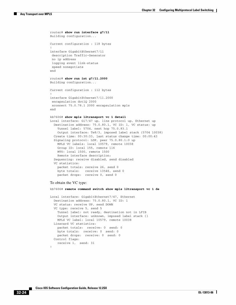
router# show run interface g7/11Building configuration...
Current configuration : 118 bytes!interface GigabitEthernet7/11 description Traffic-Generator no ip address logging event link-status speed nonegotiateend
router# show run int g7/11.2000Building configuration...
Current configuration : 112 bytes!interface GigabitEthernet7/11.2000 encapsulation dot1Q 2000 xconnect 75.0.78.1 2000 encapsulation mplsend
kb7606# show mpls l2transport vc 1 detail Local interface: Gi7/47 up, line protocol up, Ethernet up Destination address: 75.0.80.1, VC ID: 1, VC status: up Tunnel label: 5704, next hop 75.0.83.1 Output interface: Te8/3, imposed label stack {5704 10038} Create time: 00:30:33, last status change time: 00:00:43 Signaling protocol: LDP, peer 75.0.80.1:0 up MPLS VC labels: local 10579, remote 10038 Group ID: local 155, remote 116 MTU: local 1500, remote 1500 Remote interface description: Sequencing: receive disabled, send disabled VC statistics: packet totals: receive 26, send 0 byte totals: receive 13546, send 0 packet drops: receive 0, send 0
To obtain the VC type:
kb7606# remote command switch show mpls l2transport vc 1 de
Local interface: GigabitEthernet7/47, Ethernet Destination address: 75.0.80.1, VC ID: 1 VC status: receive UP, send DOWN VC type: receive 5, send 5 Tunnel label: not ready, destination not in LFIB Output interface: unknown, imposed label stack {} MPLS VC label: local 10579, remote 10038 Linecard VC statistics: packet totals: receive: 0 send: 0 byte totals: receive: 0 send: 0 packet drops: receive: 0 send: 0 Control flags: receive 1, send: 31!
32-24Cisco IOS Software Configuration Guide, Release 12.2SX
OL-13013-06
Chapter 32 Configuring Multiprotocol Label SwitchingAny Transport over MPLS
Verifying the Configuration
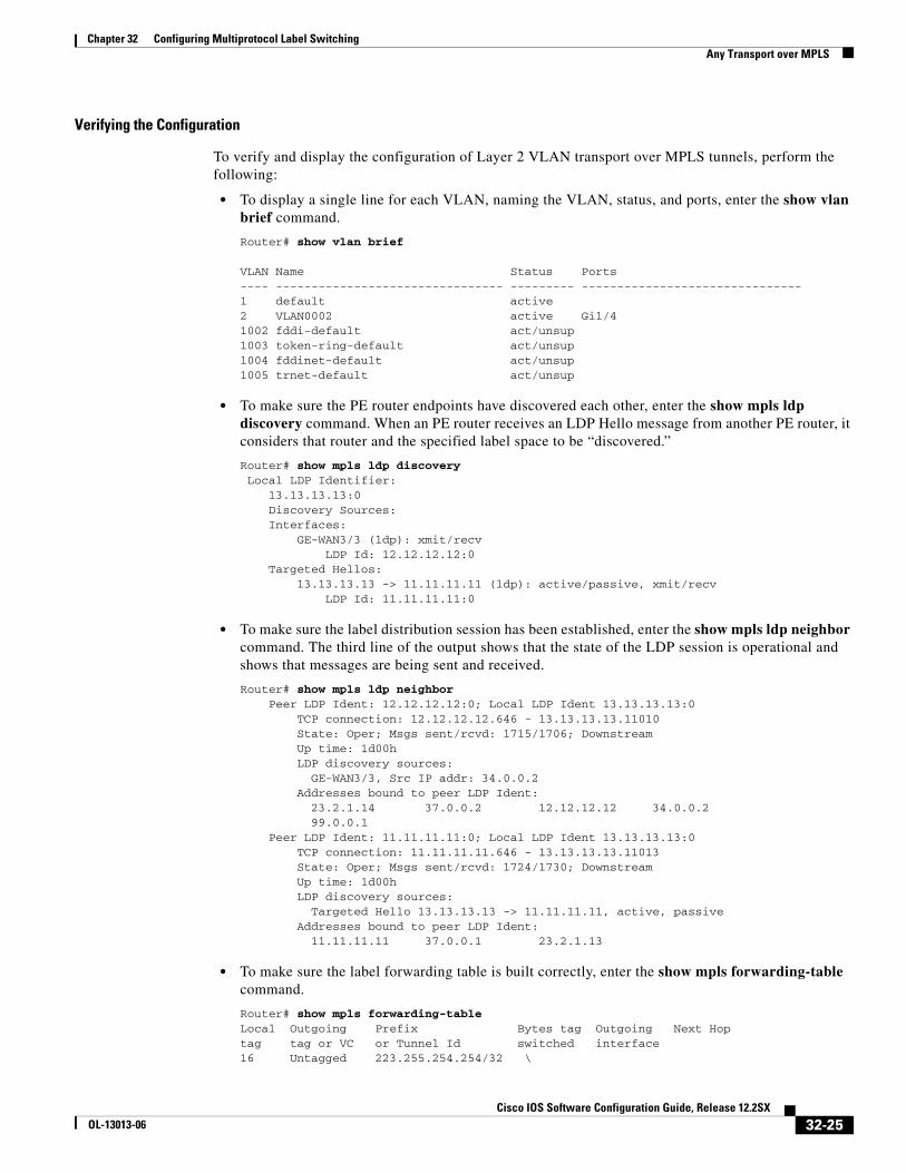
To verify and display the configuration of Layer 2 VLAN transport over MPLS tunnels, perform the following:
• To display a single line for each VLAN, naming the VLAN, status, and ports, enter the show vlan brief command.
Router# show vlan brief
VLAN Name Status Ports---- -------------------------------- --------- -------------------------------1 default active 2 VLAN0002 active Gi1/41002 fddi-default act/unsup 1003 token-ring-default act/unsup 1004 fddinet-default act/unsup 1005 trnet-default act/unsup
• To make sure the PE router endpoints have discovered each other, enter the show mpls ldp discovery command. When an PE router receives an LDP Hello message from another PE router, it considers that router and the specified label space to be “discovered.”
Router# show mpls ldp discovery Local LDP Identifier: 13.13.13.13:0 Discovery Sources: Interfaces: GE-WAN3/3 (ldp): xmit/recv LDP Id: 12.12.12.12:0 Targeted Hellos: 13.13.13.13 -> 11.11.11.11 (ldp): active/passive, xmit/recv LDP Id: 11.11.11.11:0
• To make sure the label distribution session has been established, enter the show mpls ldp neighbor command. The third line of the output shows that the state of the LDP session is operational and shows that messages are being sent and received.
Router# show mpls ldp neighbor Peer LDP Ident: 12.12.12.12:0; Local LDP Ident 13.13.13.13:0 TCP connection: 12.12.12.12.646 - 13.13.13.13.11010 State: Oper; Msgs sent/rcvd: 1715/1706; Downstream Up time: 1d00h LDP discovery sources: GE-WAN3/3, Src IP addr: 34.0.0.2 Addresses bound to peer LDP Ident: 23.2.1.14 37.0.0.2 12.12.12.12 34.0.0.2 99.0.0.1 Peer LDP Ident: 11.11.11.11:0; Local LDP Ident 13.13.13.13:0 TCP connection: 11.11.11.11.646 - 13.13.13.13.11013 State: Oper; Msgs sent/rcvd: 1724/1730; Downstream Up time: 1d00h LDP discovery sources: Targeted Hello 13.13.13.13 -> 11.11.11.11, active, passive Addresses bound to peer LDP Ident: 11.11.11.11 37.0.0.1 23.2.1.13
• To make sure the label forwarding table is built correctly, enter the show mpls forwarding-table command.
Router# show mpls forwarding-tableLocal Outgoing Prefix Bytes tag Outgoing Next Hop tag tag or VC or Tunnel Id switched interface 16 Untagged 223.255.254.254/32 \
32-25Cisco IOS Software Configuration Guide, Release 12.2SX
OL-13013-06

Chapter 32 Configuring Multiprotocol Label SwitchingAny Transport over MPLS
0 Gi2/1 23.2.0.1 20 Untagged l2ckt(2) 55146580 Vl2 point2point 24 Pop tag 37.0.0.0/8 0 GE3/3 34.0.0.2 25 17 11.11.11.11/32 0 GE3/3 34.0.0.2 26 Pop tag 12.12.12.12/32 0 GE3/3 34.0.0.2
• The output shows the following data:
– Local tag—Label assigned by this router.
– Outgoing tag or VC—Label assigned by next hop.
– Prefix or Tunnel Id—Address or tunnel to which packets with this label are going.
– Bytes tag switched— Number of bytes switched out with this incoming label.
– Outgoing interface—Interface through which packets with this label are sent.
– Next Hop—IP address of neighbor that assigned the outgoing label.
• To view the state of the currently routed VCs, enter the show mpls l2transport vc command:
Router# show mpls l2transport vc
Local intf Local circuit Dest address VC ID Status ------------- -------------------- --------------- ---------- ----------Vl2 Eth VLAN 2 11.11.11.11 2 UP
Configuring MUX-UNI Support on LAN CardsA User Network Interface (UNI) is the point where the customer edge (CE) equipment connects to the ingress PE and an attachment VLAN is a VLAN on a UNI port.
The MUX-UNI support on LAN cards feature provides the ability to partition a physical port on an attachment VLAN to provide multiple Layer 2 and Layer 3 services over a single UNI.
When configuring MUX-UNI support on LAN cards, follow these guidelines and restrictions:
• Encapsulation on main interface has to be dot1Q and not ISL.
• With dot1q encapsulation on the main interface, you cannot configure ISL on the subinterfaces; Layer 3 interfaces are unaffected.
To configure MUX-UNI support on LAN cards, perform this task on the provider edge (PE) routers.
Command Purpose
Step 1 Router# configure terminal Enters global configuration mode.
Step 2 Router(config)# interface type number Selects an interface to configure and enters interface configuration mode; valid only for Ethernet ports.
Step 3 Router(config-if)# switchport Puts an interface that is in Layer 3 mode into Layer 2 mode for Layer 2 configuration.
Step 4 Router(config-if)# switchport trunk encapsulation {isl | dot1q}
Configures the port to support 802.1Q encapsulation.
You must configure each end of the link with the same encapsulation type.
Note The valid choice for MUX-UNI support is dot1Q.
Step 5 Router(config-if)# switchport mode trunk Configures the port as a VLAN trunk.
32-26Cisco IOS Software Configuration Guide, Release 12.2SX
OL-13013-06
Chapter 32 Configuring Multiprotocol Label SwitchingAny Transport over MPLS
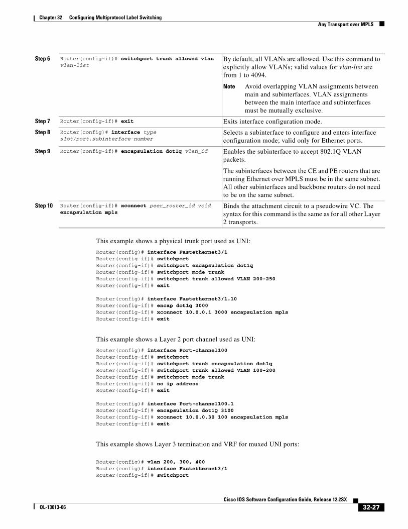
This example shows a physical trunk port used as UNI:
Router(config)# interface Fastethernet3/1Router(config-if)# switchportRouter(config-if)# switchport encapsulation dot1qRouter(config-if)# switchport mode trunkRouter(config-if)# switchport trunk allowed VLAN 200-250Router(config-if)# exit
Router(config)# interface Fastethernet3/1.10Router(config-if)# encap dot1q 3000Router(config-if)# xconnect 10.0.0.1 3000 encapsulation mplsRouter(config-if)# exit
This example shows a Layer 2 port channel used as UNI:
Router(config)# interface Port-channel100Router(config-if)# switchportRouter(config-if)# switchport trunk encapsulation dot1qRouter(config-if)# switchport trunk allowed VLAN 100-200Router(config-if)# switchport mode trunkRouter(config-if)# no ip addressRouter(config-if)# exit
Router(config)# interface Port-channel100.1Router(config-if)# encapsulation dot1Q 3100Router(config-if)# xconnect 10.0.0.30 100 encapsulation mplsRouter(config-if)# exit
This example shows Layer 3 termination and VRF for muxed UNI ports:
Router(config)# vlan 200, 300, 400Router(config)# interface Fastethernet3/1Router(config-if)# switchport
Step 6 Router(config-if)# switchport trunk allowed vlan vlan-list
By default, all VLANs are allowed. Use this command to explicitly allow VLANs; valid values for vlan-list are from 1 to 4094.
Note Avoid overlapping VLAN assignments between main and subinterfaces. VLAN assignments between the main interface and subinterfaces must be mutually exclusive.
Step 7 Router(config-if)# exit Exits interface configuration mode.
Step 8 Router(config)# interface type slot/port.subinterface-number
Selects a subinterface to configure and enters interface configuration mode; valid only for Ethernet ports.
Step 9 Router(config-if)# encapsulation dot1q vlan_id Enables the subinterface to accept 802.1Q VLAN packets.
The subinterfaces between the CE and PE routers that are running Ethernet over MPLS must be in the same subnet. All other subinterfaces and backbone routers do not need to be on the same subnet.
Step 10 Router(config-if)# xconnect peer_router_id vcid encapsulation mpls
Binds the attachment circuit to a pseudowire VC. The syntax for this command is the same as for all other Layer 2 transports.
32-27Cisco IOS Software Configuration Guide, Release 12.2SX
OL-13013-06

Chapter 32 Configuring Multiprotocol Label SwitchingAny Transport over MPLS
Router(config-if)# switchport encapsulation dot1qRouter(config-if)# switchport mode trunkRouter(config-if)# switchport trunk allowed VLAN 200-500Router(config-if)# exit
Router(config)# interface Fastethernet3/1.10Router(config-if)# encap dot1q 3000Router(config-if)# xconnect 10.0.0.1 3000 encapsulation mplsRouter(config-if)# exit
Router(config)# interface Vlan 200Router(config-if)# ip address 1.1.1.3Router(config-if)# exit
Router(config)# interface Vlan 300Router(config-if)# ip vpn VRF ARouter(config-if)# ip address 3.3.3.1Router(config-if)# exit
Router(config)# interface Vlan 400Router(config-if)# ip address 4.4.4.1Router(config-if)# ip ospf network broadcastRouter(config-if)# mpls label protocol ldpRouter(config-if)# mpls ipRouter(config-if)# exit
Tip For additional information about Cisco Catalyst 6500 Series Switches (including configuration examples and troubleshooting information), see the documents listed on this page:
http://www.cisco.com/en/US/products/hw/switches/ps708/tsd_products_support_series_home.html
Participate in the Technical Documentation Ideas forum
32-28Cisco IOS Software Configuration Guide, Release 12.2SX
OL-13013-06