configuring upstream cable interface features on …...table 1: configuring upstream cable...
TRANSCRIPT

Configuring Upstream Cable Interface Featureson the Cisco CMTS Routers
First Published: February 14, 2008
Last Updated: June 19, 2013
Cisco IOS Release 12.2(33)SCA and later releases integrate support for this feature on the Cisco CMTSrouters. This feature is also supported in Cisco IOSRelease 12.3BC, and this document contains informationthat references many legacy documents related to Cisco IOS 12.3BC. In general, any references to CiscoIOS Release 12.3BC also apply to Cisco IOS Release 12.2SC.
Note
The cable interface in the Cisco universal broadband router supports downstream and upstream signals, andserves as the cable TV radio frequency (RF) interface. The downstream signal is output as anintermediate-frequency (IF) signal suitable for use with an external upconverter. Your cable plant, combinedwith your planned and installed subscriber base, service offering, and external network connections, determinesthe combination of cable interfaces, network uplink line cards, and other components that you should use.
The Cisco IOS software command-line interface (CLI) can be used to configure the Cisco cable interfaceline card for correct operation on the hybrid fiber-coaxial (HFC) cable network. This chapter provides aconfiguration summary for the various upstream cable interface features available on a Cisco CMTS router.Details about some of these features can be found in other chapters of this book.
The configuration commands and examples in this chapter may show slot numbering or references toeither Cisco uBR7200 series or Cisco uBR10012 Universal Broadband Routers. However, the featurescan be configured on either platform. Use the slot numbering appropriate for your CMTS routerconfiguration.
Note
Finding Feature Information
Your software release may not support all the features documented in this module. For the latest featureinformation and caveats, see the release notes for your platform and software release. To find informationabout the features documented in this module, and to see a list of the releases in which each feature issupported, see the Feature Information Table at the end of this document.
Cisco CMTS Router Downstream and Upstream Features Configuration Guide OL-27606-08 1
Use Cisco Feature Navigator to find information about platform support and Cisco software image support.To access Cisco Feature Navigator, go to http://tools.cisco.com/ITDIT/CFN/. An account on http://www.cisco.com/ is not required.
Contents
• Prerequisites for Configuring Upstream Cable Interfaces on the Cisco CMTS Routers, page 2
• Prioritizing Upstream Traffic to Initialize Cable Modems, page 3
• Activating the Upstream Minimum Reserved Traffic Rate Plus Excess Traffic Rate, page 5
• Activating Upstream Admission Control, page 6
• Activating Upstream Differential Encoding, page 7
• Activating Upstream Forward Error Correction, page 8
• Activating the Upstream Ports, page 9
• Activating Upstream Power Adjustment, page 10
• Activating the Upstream Scrambler, page 11
• Activating Upstream Timing Adjustment, page 12
• Traffic Shaping, page 13
• Configuring Upstream Rate Limiting and Traffic Shaping, page 15
• Setting Upstream Backoff Values, page 16
• Setting the Upstream Channel Width, page 17
• Setting the Upstream Frequency, page 19
• Setting the Upstream Input Power Level, page 21
• Specifying Upstream Minislot Size, page 23
• Setting Upstream Traffic Shaping, page 24
• Configuring Upstream Drop Classifier, page 26
• Setting Upstream Buffer Control Parameters, page 27
Prerequisites for Configuring Upstream Cable Interfaces on theCisco CMTS Routers
The configuration of upstream cable interface features is supported on the Cisco CMTS routers in Cisco IOSRelease 12.3BC andCisco IOSRelease 12.2SC. The table below shows the hardware compatibility prerequisitesfor this feature.
The hardware components introduced in a given Cisco IOS Release will be supported in all subsequentreleases unless otherwise specified.
Note
Cisco CMTS Router Downstream and Upstream Features Configuration Guide2 OL-27606-08
Configuring Upstream Cable Interface Features on the Cisco CMTS RoutersPrerequisites for Configuring Upstream Cable Interfaces on the Cisco CMTS Routers

Table 1: Configuring Upstream Cable Interfaces on the Cisco CMTS Routers Hardware Compatibility Matrix
Cable Interface CardsProcessor EngineCisco CMTS Platform
Cisco IOS Release 12.2(33)SCBand later releases
• Cisco uBR10-MC5X20U/H
Cisco IOS Release 12.2(33)SCCand later releases
• Cisco UBR-MC20X20V
Cisco IOS Release 12.2(33)SCEand later releases
• Cisco uBR-MC3GX60V 1
Cisco IOS Release 12.2(33)SCA
• PRE2
Cisco IOS Release 12.2(33)SCC
• PRE4
Cisco IOS Release 12.2(33)SCHand later releases
• PRE5
Cisco uBR10012 UniversalBroadband Router
Cisco IOS Release 12.2(33)SCA
• Cisco uBR-MC28U/X
• Cisco uBR-MC16U/X
Cisco IOS Release 12.2(33)SCDand later releases
• Cisco uBR-MC88V2
Cisco IOS Release 12.2(33)SCA
• NPE-G1
• NPE-G2
Cisco IOS Release 12.2(33)SCDand later releases
• NPE-G2
Cisco uBR7246VXR UniversalBroadband Router
Cisco IOS Release 12.2(33)SCA
• Cisco uBR-E-28U
• Cisco uBR-E-16U
• Cisco uBR-MC28U/X
• Cisco uBR-MC16U/X
Cisco IOS Release 12.2(33)SCDand later releases
• Cisco uBR-MC88V
Cisco IOS Release 12.2(33)SCA
• NPE-G1
Cisco IOS Release 12.2(33)SCDand later releases
• NPE-G2
Cisco uBR7225VXR UniversalBroadband Router
1 Cisco uBR-MC3GX60V cable interface line card is not compatible with PRE2.2 Cisco uBR-MC88V cable interface line card is compatible only with NPE-G2.
Prioritizing Upstream Traffic to Initialize Cable ModemsWhen the Cisco CMTS is busy servicing data and bandwidth requests from a large number of online cablemodems, it may deny new registration requests from offline cable modems. This denial of service occurs
Cisco CMTS Router Downstream and Upstream Features Configuration Guide OL-27606-08 3
Configuring Upstream Cable Interface Features on the Cisco CMTS RoutersPrioritizing Upstream Traffic to Initialize Cable Modems

because when a cable modem first begins initializing, its default upstream service flow is assigned a qualityof service (QoS) profile-2 with a priority of zero. Zero is the lowest priority that can be scheduled. Dependingon the priority and rate of bandwidth requests from other online cable modems, the priority-zero queue caneither overflow or get ignored.
To ensure that the initializing cable modems can get online when a large number of online cable modems areactively transmitting data, the Cisco CMTSmust allow the bandwidth request from an initializing cable modemto get priority over those requests from online cable modems.
In Cisco IOS Release 12.2(33)SCD2 and later releases, an operator can configure the priority of QoS profile-2to a higher value.
Configuring the Priority of the QoS ProfileThis configuration is optional. This section describes how you can manually configure a non-zero value forthe QoS profile-2 priority to ensure that initialization requests from offline cable modems are serviced.
It is up to the cable operator to determine the appropriate new priority value.Note
DETAILED STEPS
PurposeCommand or Action
Enables privileged EXECmode. Enter your password if prompted.enable
Example:Router# enable
Step 1
Enters global configuration mode.configure terminal
Example:Router# configure terminal
Step 2
Sets the priority of the QoS profile-2 of the initializing cablemodem.
cable qos pre-registration us-prioritypriority-value
Step 3
Example:Router(config)# cable qospre-registration us-priority 2
The valid priority value range is 0 to 7 where 0 is thedefault value.
Note
• us-priority—Specifies the upstream priority to be assignedto the pre-registration traffic.
• priority-value—User-defined priority value for the QoSprofile-2.
Exits global configuration mode.end
Example:Router(config)# end
Step 4
Cisco CMTS Router Downstream and Upstream Features Configuration Guide4 OL-27606-08
Configuring Upstream Cable Interface Features on the Cisco CMTS RoutersConfiguring the Priority of the QoS Profile

After a cable modem has successfully completed registration, the QoS profile of the default upstream serviceflow is changed from QoS profile-2 to the QoS indicated through the DOCSIS configuration file.
What to Do Next
To determine if the priority of the QoS profile-2 is configured, enter the show cable qos profile commandin privileged EXEC mode.Router# show cable qos profile
ID Prio Max Guarantee Max Max TOS TOS Create B IP prec.upstream upstream downstream tx AND OR by priv ratebandwidth bandwidth bandwidth burst mask mask enab enab
1 0 0 0 0 0 0xFF 0x0 cmts(r) no no2 2 64000 0 1000000 0 0xFF 0x0 cmts(r) no no3 7 31200 31200 0 0 0xFF 0x0 cmts yes no4 7 87200 87200 0 0 0xFF 0x0 cmts yes noRouter#
The Prio column in the ID 2 displays the user-defined value of the QoS profile-2.
Activating the Upstream Minimum Reserved Traffic Rate PlusExcess Traffic Rate
This configuration is optional. Each service flow (SF) carries traffic based on certain defined parameters. Oneof them is the minimum reserved traffic rate.
The minimum reserved traffic rate specifies the minimum traffic rate, in bits/sec, reserved for a service flow.The value of minimum reserved traffic rate is calculated from the byte following the MAC header checksequence (HCS) to the end of the cyclic redundancy check (CRC), including every protocol data unit (PDU)in a concatenated MAC frame. If this parameter is omitted, then it defaults to a value of 0 bits/sec (that is, nobandwidth is reserved for the flow by default).
The Cisco CMTS schedules forwarding traffic of all service flows such that each flow receives at least itsminimum reserved traffic rate when transmitting packets with the assumed minimum reserved rate packetsize. If the service flow requests less bandwidth than its minimum reserved traffic rate, the Cisco CMTSreallocates the excess reserved bandwidth for other purposes. All best effort service flows with or withouttheir minimum reserved traffic rate configured, share the excess bandwidth.
DETAILED STEPS
PurposeCommand or Action
Enables privileged EXEC mode. Enter your password ifprompted.
enable
Example:Router# enable
Step 1
Enters global configuration mode.configure terminal
Example:Router# configure terminal
Step 2
Cisco CMTS Router Downstream and Upstream Features Configuration Guide OL-27606-08 5
Configuring Upstream Cable Interface Features on the Cisco CMTS RoutersActivating the Upstream Minimum Reserved Traffic Rate Plus Excess Traffic Rate

PurposeCommand or Action
Enables a service flow to receive its configured minimumreserved traffic rate plus the expected excess traffic ratebandwidth.
cable rate-limit-algorithm min-plus-excess
Example:Router(config)# cable rate-limit-algorithmmin-plus-excess
Step 3
Exits global configuration mode.end
Example:Router(config)# end
Step 4
What to Do Next
To verify if the upstreammin-plus-excess parameter is configured and activated, run the show interface cablemac-scheduler and the show interface cable service flow commands in privileged EXEC mode.Router# show interface cable 8/0/0 mac-scheduler 0 | include rate
DOCSIS 1.1 MAC scheduler for Cable8/0/0/U0: rate 10240000
Router# show interface cable 8/0/0 service-flow qos us
Sfid Dir Curr Sid Sched Prio MaxSusRate MaxBrst MinRsvRate ThroughState Type
7 US act 1 BE 0 2000000 28000 500000 856051134 US act 120 BE 0 2000000 11000 0 4038409 US act 2 BE 0 2000000 28000 500000 856176129 US act 115 BE 0 2000000 11000 0 40264711 US act 3 BE 0 2000000 28000 500000 856019132 US act 118 BE 0 2000000 11000 0 40275113 US act 4 BE 0 2000000 28000 500000 856394131 US act 117 BE 0 2000000 11000 0 40275415 US act 5 BE 0 2000000 28000 500000 855977135 US act 121 BE 0 2000000 11000 0 40380817 US act 6 BE 0 2000000 28000 500000 685510133 US act 119 BE 0 2000000 11000 0 34145625 US act 13 BE 0 2000000 28000 500000 855598130 US act 116 BE 0 2000000 11000 0 403870Router#
Activating Upstream Admission ControlUpstream admission control tallies up the total amount of guaranteed minimum upstream throughput reservedby CMs on an upstream interface. When the total exceeds an allowable level, no more CMs requiring aguaranteed minimum upstream rate are allowed online on that upstream port.
The Cisco CMTS upstream admission control is turned off by default and must be activated. To set theupstream admission control as a percentage of the upstream channel capacity, use the following command incable interface configuration mode. The admission control is set as a percentage of the specified upstreamchannel capacity. The acceptable range is from 10 to 1000 percent.Router(config-if)# cable upstream usport admission-control percentage
Cisco CMTS Router Downstream and Upstream Features Configuration Guide6 OL-27606-08
Configuring Upstream Cable Interface Features on the Cisco CMTS RoutersActivating Upstream Admission Control

For example:Router(config-if)# cable upstream 0 admission-control ?
Max Reservation Limit As Percentage of Raw Channel Capacity
If percentage is left blank or set to 100%, the Cisco CMTS will only allow the total of the actual availableupstream bandwidth to be guaranteed. If percentage is set to its maximum of 1000, then up to 10 timesof the actual interface bandwidth may be “guaranteed”.
Note
Verifying Upstream Admission ControlTo determine if upstream admission control is configured and activated, enter the show running-configcommand in privileged EXEC mode and look for the cable interface configuration information. If upstreamadmission control is configured and enabled, an admission control entry appears in the show running-configcommand output, indicating the user-defined percentage of upstream channel capacity allowable. If upstreamadmission control is disabled, no admission control entry appears in the output.
Perform these steps if you are having difficulty with verification:
Step 1 Ensure that the cable connections are not loose or disconnected.Step 2 Ensure that the cable interface line card is firmly seated in its chassis slot.Step 3 Ensure that the captive installation screws are tight.Step 4 Verify that you have entered the correct slot and port numbers.Step 5 Verify that you selected a valid frequency for your router.
Activating Upstream Differential EncodingDifferential encoding on the upstream is a digital encoding technique whereby a binary value is denoted bya signal change rather than a particular signal level. To enable differential encoding on upstream traffic to aspecified cable interface, use the following command in cable interface configuration mode. Upstreamdifferential encoding is enabled by default.Router(config-if)# cable upstream usport differential-encoding
Verifying Upstream Differential EncodingTo determine if upstream differential encoding is activated, enter the show running-config command andlook for the cable interface configuration information. If upstream differential encoding is enabled, a differentialencoding entry appears in the show running-config output. If upstream differential encoding is disabled, nodifferential encoding entry appears in the output.
Cisco CMTS Router Downstream and Upstream Features Configuration Guide OL-27606-08 7
Configuring Upstream Cable Interface Features on the Cisco CMTS RoutersVerifying Upstream Admission Control

Perform these steps if you are having difficulty with verification:
Step 1 Ensure that the cable connections are not loose or disconnected.Step 2 Ensure that the cable interface line card is firmly seated in its chassis slot.Step 3 Ensure that the captive installation screws are tight.Step 4 Verify that you have entered the correct slot and port numbers.Step 5 Verify that you selected a valid frequency for your router.
Activating Upstream Forward Error CorrectionThe Cisco uBR7200 series CMTS uses forward error correction (FEC) to attempt to correct any upstreamdata that might have been corrupted. When FEC is activated, all CMs on the network also activate FEC.
Although upstream FEC is an option, it is recommended that you use upstream FEC. FEC is activated bydefault and should not be disabled.
Note
To activate the upstream forward error correction and to enable FEC, use the following command in cableinterface configuration mode.Router(config-if)# cable upstream usport fec
Verifying Upstream FECTo verify whether FEC is activated or deactivated, enter themore system:running-config command andlook for the cable interface configuration information. If FEC is enabled, an FEC entry appears in the showrunning-config command output. If FEC is disabled, no FEC entry appears in the output.
Perform these steps if you are having difficulty with verification:
Step 1 Ensure that the cable connections are not loose or disconnected.Step 2 Ensure that the cable interface line card is firmly seated in its chassis slot.Step 3 Ensure that the captive installation screws are tight.Step 4 Verify that you have entered the correct slot and port numbers.Step 5 Verify that you selected a valid frequency for your router.
Cisco CMTS Router Downstream and Upstream Features Configuration Guide8 OL-27606-08
Configuring Upstream Cable Interface Features on the Cisco CMTS RoutersActivating Upstream Forward Error Correction

Activating the Upstream PortsEach upstream port must be activated to enable upstream data transmission from the CMs on the HFC networkto the Cisco uBR7200 series CMTS.
The upstream cable interface does not operate until you either set a fixed upstream frequency or createand configure a spectrum group. For more information, see the Setting the Upstream Frequency, on page19.
Note
To activate the upstream ports, perform the following steps:
DETAILED STEPS
PurposeCommand or Action
Enables privileged EXEC mode. Enter your passwordif prompted.
enable
Example:Router# enable
Step 1
Enters global configuration mode.configure terminal
Example:Router# configure terminal
Step 2
Specifies a cable interface and enters cable interfaceconfiguration mode.
interface cable slot/port
Example:Router(config)# interface cable 5/0
Step 3
Enables upstream data traffic.no cable upstream usport shutdown
Example:Router(config-if)# no cable upstream 0 shutdown
Step 4
What to Do Next
To determine if the upstream ports are activated or deactivated, enter the show interface cable command forthe upstream port just configured:Router# show interface cable5/0
Cable5/0 is up, line protocol is upHardware is BCM3210 FPGA, address is 00e0.1e5f.7a60 (bia 00e0.1e5f.7a60)Internet address is 1.1.1.3/24MTU 1500 bytes, BW 27000 Kbit, DLY 1000 usec, rely 255/255, load 1/255Encapsulation, loopback not set, keepalive not setARP type: ARPA, ARP Timeout 04:00:00Last input 00:00:25, output 00:00:00, output hang neverLast clearing of “show interface” counters neverQueuing strategy: fifoOutput queue 0/40, 0 drops; input queue 0/75, 0 drops5 minute input rate 0 bits/sea, 0 packets/sec
Cisco CMTS Router Downstream and Upstream Features Configuration Guide OL-27606-08 9
Configuring Upstream Cable Interface Features on the Cisco CMTS RoutersActivating the Upstream Ports

5 minute output rate 0 bits/sec, 0 packets/sec10878 packets input, 853740 bytes, 0 no bufferReceived 3679 broadcasts, 0 runts, 0 giants, 0 throttles0 input errors, 0 CRC, 0 frame, 0 overrun, 0 ignored, 0 abort5401 packets output, 645885 bytes, 0 underruns0 output errors, 0 collisions, 9 interface resets0 output buffer failures, 0 output buffers swapped out
Activating Upstream Power AdjustmentTo enable upstream power adjustment for a specified cable interface, use one of the following commands incable interface configuration mode.
PurposeCommand
Sets theminimum power adjustment in dB that allowscontinued ranging status. Valid values are 2 to 15 dB.Default = 4 dB.
Router(config-if)# cable upstreampower-adjust continuepwr-level
Sets the minimum number (percentage) ofpower-adjustment packets required to justify changingthe upstream power rating. Valid values are 10 to 100percent. The default is 30 percent.
Router(config-if)# cable upstream usportpower-adjust noiseperc-pwr-adj
Sets the power-adjustment threshold in dB. Validvalues are 0 to 2 dB. The default is 1 dB.
Router(config-if)# cable upstream 0power-adjust thresholdvalue
Returns to enable (privileged EXEC) mode.Router(config-if)# endRouter#
To return the automatic upstream power-adjustment ranging value to the default of 4 dB, enter the followingcommand in cable interface configuration mode:Router(config-if)# no cable upstream n power-adjust continue
To return the automatic upstream power-adjustment noise value to the default of 30 percent, enter the followingcommand in cable interface configuration mode:Router(config-if)# no cable upstream n power-adjust noise
To return the upstream power-adjustment threshold value to the default of 1 dB, enter the following commandin cable interface configuration mode:Router(config-if)# no cable upstream n power-adjust threshold
What to Do Next
To determine if upstream power adjustment is configured and activated, enter the show running-configcommand and look for the cable interface configuration information. If upstream power adjustment is enabled,any or all three of the continue, noise, and threshold power-adjustment entries appear in the showrunning-config command output. If all three upstream power adjustments are disabled, no power-adjustmententry appears in the show running-config command output.
Cisco CMTS Router Downstream and Upstream Features Configuration Guide10 OL-27606-08
Configuring Upstream Cable Interface Features on the Cisco CMTS RoutersActivating Upstream Power Adjustment
Activating the Upstream ScramblerThe scrambler on the upstreamRF carrier enables CMs on the HFC network to use built-in scrambler circuitryfor upstream data transmissions. The scrambler circuitry improves reliability of the upstream receiver on thecable interface line card.
The upstream scrambler is activated by default and should not be disabled under normal circumstances.Disabling it can result in corrupted packets. Disable it only for prototype modems that do not support theupstream scrambler.
Caution
To activate the upstream scrambler, use the following command in cable interface configuration mode. Theupstream scrambler is enabled by default.Router(config-if)# cable upstream usport scrambler
Verifying the Upstream ScramblerTo determine if the upstream scrambler is activated, enter themore system:running-config command andlook for the cable interface configuration information. Perform these steps if you are having difficulty withverification:
Step 1 Ensure that the cable connections are not loose or disconnected.Step 2 Ensure that the cable interface line card is firmly seated in its chassis slot.Step 3 Ensure that the captive installation screws are tight.Step 4 Verify that you have entered the correct slot and port numbers.Step 5 Verify that you selected a valid frequency for your router.
Cisco CMTS Router Downstream and Upstream Features Configuration Guide OL-27606-08 11
Configuring Upstream Cable Interface Features on the Cisco CMTS RoutersActivating the Upstream Scrambler

Activating Upstream Timing AdjustmentTo enable upstream timing adjustment for a specified cable interface, use one of the following commands incable interface configuration mode.
PurposeCommand
Sets the minimum timing adjustment that allowscontinued ranging status. Valid second values are 2to 64 seconds. The default is 2 seconds.
Router(config-if)# cable upstream usporttime-adjust continue seconds
Sets the timing adjustment threshold value in seconds.Valid second values are 1to 32 seconds. The defaultis 1 second.
Router(config-if)# cable upstream usporttime-adjust threshold seconds
Returns to enable (privileged EXEC) mode.Router(config-if)# endRouter#
To return the upstream time-adjustment ranging value to the default of 2 seconds, enter the following commandin cable interface configuration mode:Router(config-if)# no cable upstream usport time-adjust continue
To return the upstream time adjustment threshold value to the default of 1 second, enter the following commandin cable interface configuration mode:Router(config-if)# no cable upstream usport time-adjust threshold
Verifying Upstream Timing AdjustmentTo determine if upstream timing adjustment is configured and activated, enter the show running-configcommand and look for the cable interface configuration information. If upstream timing adjustment is enabled,either or both of the continue and threshold timing-adjustment entries appear in the show running-configcommand output. If both the continue and threshold upstream timing adjustments are disabled, no timingadjustment entry appears in the show running-config command output.
Perform the following steps if you are having difficulty with verification:
Step 1 Verify that the cable connections are not loose or disconnected.Step 2 Verify that the cable interface line card is firmly seated in its chassis slotStep 3 Verify that the captive installation screws are tight.Step 4 Confirm that you have entered the correct slot and port numbers.
Cisco CMTS Router Downstream and Upstream Features Configuration Guide12 OL-27606-08
Configuring Upstream Cable Interface Features on the Cisco CMTS RoutersActivating Upstream Timing Adjustment

Traffic ShapingTraffic shaping basically uses queues to limit data surges that can congest a network. The data is buffered andthen sent into the network in regulated amounts to ensure that the traffic fits within the expected traffic envelopefor the particular connection.
Traffic shaping reduces the chance of retransmitting information to hosts on the cable plant. When cablemodems (CMs) have rate limits established, the CMTS typically drops bandwidth requests to enforce the ratelimit. This causes the CM to retransmit the request, thereby putting additional latency in packet transmission.If both the hosts sending and requesting information are on the same cable plant, the upstream bandwidth iswasted as well.
On the DOCSIS downstream and upstream channels, traffic shaping allows the CMTS to perform downstreamrate limiting and bandwidth request shaping allows the CMTS to perform upstream rate limiting. Rate limitingrestricts the data rate to and from a CM; the MAC scheduler supports shaping capabilities for downstreamand upstream traffic. Rate limiting ensures that no single CM consumes all of the channel bandwidth andallows a CMTS administrator to configure different maximum data rates for different subscribers. Subscribersrequiring higher sustained rates and willing to pay for higher rates can be configured with higher sustainedrate limits in their CM DOCSIS configuration file over regular subscribers, who pay less and get lower ratelimits.
Each time a packet belonging to a flow is transmitted on an output channel, the token-bucket policer functionchecks the rate limit status of the flow, parsing the following parameters:
• Token bucket maximum sustained rate in bits per millisecond.
• Token bucket depth (maximum transmit burst) in bits.
• Length of current packet to be sent in bits.
• Pointer to the token bucket of the flow.
• Pointer to the flow’s token bucket last update time stamp.
• Variable to return the milliseconds buffering delay in case the packet needs to be shaped.
• Maximum buffering delay that the subsequent traffic shaper can handle in milliseconds.
Every flow has its own shaping buffer where rate-exceeded packets are typically held back in first-in/first-out(FIFO) order for later releases transmission.
Token bucket policing with shaping is the per-upstream default rate limiting setting at the CMTS. Shapingcan be enabled or disabled for the token-bucket algorithm.
Tip
Upstream Traffic ShapingUpstream traffic shaping allows the CMTS to perform rate limiting on a DOCSIS upstream channel. Theupstream traffic shaping feature delays the scheduling of the upstream packet, which in turn, causes the packetto be buffered on the cable modem device. This allows the user TCP/IP stack to pace the application trafficappropriately and approach throughput commensurate with the subscriber’s defined quality of service (QoS)
Cisco CMTS Router Downstream and Upstream Features Configuration Guide OL-27606-08 13
Configuring Upstream Cable Interface Features on the Cisco CMTS RoutersTraffic Shaping

levels. Upstream traffic shaping enables the CMTS to enforce the peak upstream rate for each CM withoutdegrading overall TCP performance for the subscriber CMs.
When you do not enable the shaping option for upstream rate limiting, the CMTS upstream-rate-policing codedrops bandwidth requests from cable modems that are found to have exceeded their configured-peak-upstreamrate (using different local drop policies). The effect of bandwidth requests (eventually upstream packets) beingdropped causes degraded throughput performance of window-based protocols (like TCP) for these rate-exceededmodems.
Upstream grant shaping is on a per-CM (service identifier-SID) basis. The grant shaping feature is a configurableoption for the current upstream token-bucket rate-limiting algorithm.
A traffic shaping feature is restricted QoS class assignment, which allows a CMTS administrator to overridethe class of service provisioned for a CM.When this feature is enabled, the user-defined QoS profile is enforcedon the CM attempting to register with the CMTS, regardless of the CM’s provisioned class of service. Usethe cable qos profile command to configure a QoS profile.
The restricted QoS class assignment feature is added to address instances where a cable operatorimplemented rate limiting incorrectly. The feature allows an administrator to override the staticallyprovisioned QoS parameters of the CM and force the CM to use a specific QoS profile defined at theCMTS.
Note
Upstream Buffer Control for Maximum Queue DepthUpstream traffic shaping uses queues to control the upstream data flow. The data packets are buffered in aqueue on the CM to regulate traffic and avoid network congestion. Starting with Cisco IOS Release12.2(33)SCF2, the Upstream Buffer Control feature enables the Cisco CMTS to control the size of this queue(or buffer) by controlling the amount of data that can be enqueued for transmission at any point of time.
The Upstream Buffer Control feature supports buffer control TLVs, which allows the user to configure thebuffer size control parameters. These parameters are used to create buffer for each service flow on the CM.The buffer control parameters comprise of three values—minimum buffer, maximum buffer, and target buffer.The minimum buffer and maximum buffer parameters provide a range for the size of the service flow buffer,and the target buffer parameter indicates a desired size of the buffer. The Upstream Buffer Control featuresupports the following sub-TLVs in the service flow TLV (24.35), to control these buffer parameters:
Table 2: Supported Upstream Buffer Control TLVs
TLV DescriptionTLV
Upstream minimum buffer.24.35.1
Upstream target buffer24.35.2
Upstream maximum buffer24.35.3
The CM sends the buffer control TLVs in the registration request or in dynamic service add (or change) requestto the Cisco CMTS. The Cisco CMTS stores the value of the buffer control TLVs and sends its response. Onreceiving the response CM creates a buffer for US service flow based on the TLVs.
Cisco CMTS Router Downstream and Upstream Features Configuration Guide14 OL-27606-08
Configuring Upstream Cable Interface Features on the Cisco CMTS RoutersUpstream Traffic Shaping

The buffer control parameters can be configured in the CM configuration file, or by using the cable serviceclass command in global configuration mode. For more information on how to configure upstream buffercontrol parameters, see Setting Upstream Buffer Control Parameters, on page 27.
Configuring Upstream Rate Limiting and Traffic ShapingYou can configure rate limiting and traffic shaping on a DOCSIS upstream channel. This delays the schedulingof the upstream packet, which in turn causes the packet to be buffered on the cable CPE device. This allowsthe user’s TCP/IP stack to pace the application traffic appropriately and approach throughput commensuratewith the subscriber’s defined QoS levels.To configure this, use the following command in cable interface configuration mode.
PurposeCommand
Enables or disables DOCSIS rate limiting or shapingon an upstream channel. <n1> depends on the numberof upstream channels on the specific cable interfaceline card.
Router(config-if)# [no] cable upstream <n1>rate-limit [token-bucket]
Using Cisco IOS Release 12.0(5)T1 or higher, the software supports:
• Generic calendar queuing routines
• New token bucket policing function
• Grant shaping application of the calendar queues
• Upstream rate shaping option to the token-bucket keyword
• A default state change from 1 second burst policing to token-bucket with shaping
Upstream grant shaping is per CM (SID). Shaping can be enabled or disabled for the token-bucket algorithm.Tip
Before the introduction of this feature, the CMTS would drop bandwidth requests from a CM it detectedas exceeding its configured peak upstream rate. Such request dropping affects the throughput performanceof IP-based protocols such as FTP, TCP, and SMTP. With this feature, the CMTS can shape (buffer) thegrants for a CM that is exceeding its upstream rate, rather than dropping the bandwidth requests.
Note
Router# show interface cable 3/0 sid 1 counters
Sid Inpackets Inoctets Outpackets Outoctets Ratelimit RatelimitBWReqDrop DSPktDrop
1 67859 99158800 67570 98734862 2579 0
Cisco CMTS Router Downstream and Upstream Features Configuration Guide OL-27606-08 15
Configuring Upstream Cable Interface Features on the Cisco CMTS RoutersConfiguring Upstream Rate Limiting and Traffic Shaping

Setting Upstream Backoff ValuesThe DOCSIS-specified method of contention resolution for CMs wanting to transmit data or requests on theupstream channel is a truncated binary exponential backoff value, with the initial backoff window and themaximum backoff window controlled by the CMTS. The Cisco uBR7200 series CMTS specifies backoffwindow values for both data and initial ranging, and sends these values downstream as part of the BandwidthAllocation Map (MAP) MAC message.
The values are configurable on the Cisco uBR7200 series software and are power-of-two values. For example,a value of 4 indicates a window between 0 and 15; a value of 10 indicates a window between 0 and 1023.You can set fixed start and end values for data backoff on the upstream ports, or you can set the upstreamports for automatic data backoff. You have the same options for ranging backoff. For both backoff windows,the default start value is 0; the default end value is 4. Valid values are from 0 to 15.
It is not recommended that you adjust default values, but that you enable the automatic dynamic backoffalgorithm.
Note
To set data or ranging backoff values for an upstream port, use one or more of the following commands incable interface configuration mode.
DETAILED STEPS
PurposeCommand or Action
Optimizes the automatic setting for as many as 250 cable interfacesper upstream port. Sets manual values for data backoff windows
Enter one of the following commands:Step 1
• Router(config-if)#cable upstream usportdata-backoff start end
only when operating with more than 250 cable interfaces perupstream port.
• Router(config-if)#cable upstream usportdata-backoff automatic
Configures the default backoff window values of 0 and 4.
Optimizes the automatic setting for as many as 250 cable interfacesper upstream port. Sets manual values for data backoff windows
Enter one of the following commands:Step 2
• Router(config-if)#cable upstream usport rangestart end
only when operating with more than 250 cable interfaces perupstream port.
• Router(config-if)#cable upstream usport rangeautomatic
Configures the default backoff window values of 0 and 4.
When considering whether to adjust backoff values, keep the following considerations in mind:
• The cable interface reconnection time after a power outage is related to the following factors:
◦DHCP, ToD, and TFTP servers often operate well below 1 percent load under normal situations,but can jump to over 100 percent after an outage.
Cisco CMTS Router Downstream and Upstream Features Configuration Guide16 OL-27606-08
Configuring Upstream Cable Interface Features on the Cisco CMTS RoutersSetting Upstream Backoff Values
◦Adjusting the backoffs to larger numbers slows cable interface reconnection and reduces serverload.
◦Backoffs that are too small result in cable interfaces failing to range the upstreamRF levels correctlyand cycling tomaximumpower, thus increasing connection time and reducing network performance.
◦Backoffs that are too large result in increased recovery time after a large service outage.
◦There is significant variation in cable interface performance (brand to brand) in cable interfacerestart time.
• All cable interfaces should recover in 0 to 10 minutes after all services are restored (Cisco uBR7200series, RF transport, DHCP, TFTP, and ToD servers). A CM that takes longer than 10 minutes could beexperiencing a problem with the modem itself, a problem with CMTS settings, or a problem in theDOCSIS provisioning servers.
Upstream segments serving a relatively large number of cable interfaces (for example, more than 1600)might suffer recovery times greater than 10 minutes.
Note
What to Do Next
To verify backoff window settings, enter the show controllers cable command for the upstream port youconfigured:Router# show controllers cable5/0 upstream 0
Cable5/0 Upstream 0 is upFrequency 24.016 MHz, Channel Width 1.600 MHz, QPSK Symbol Rate 1.280 MspsSpectrum Group is overriddenSNR 33.2560 dBNominal Input Power Level 0 dBmV, Tx Timing Offset 2288Ranging Backoff automatic (Start 0, End 3)Ranging Insertion Interval automatic (60 ms)Tx Backoff Start 0, Tx Backoff End 4Modulation Profile Group 1part_id=0x3137, rev_id=0x03, rev2_id=0xFFnb_agc_thr=0x0000, nb_agc_nom=0x0000Range Load Reg Size=0x58Request Load Reg Size=0x0EMinislot Size in number of Timebase Ticks is = 8Minislot Size in Symbols = 64Bandwidth Requests = 0xFEPiggyback Requests = 0xDInvalid BW Requests= 0x2Minislots Requested= 0x2963Minislots Granted = 0x2963Minislot Size in Bytes = 16Map Advance = 4000 usecsUCD Count = 32964DES Ctrl Reg#0 = C000C043, Reg#1 = 0
Setting the Upstream Channel WidthUse the commands below to enter the upstream channel width in hertz (Hz). For NTSC operations, validvalues are 200000 Hz (160 kilo symbols per second [ksps]), 400,000 Hz (320 ksps), 800,000 Hz (640 ksps),1,600,000 Hz (1280 ksps), and 3,200,000 Hz (2560 ksps). The default is 1,600,000 Hz.
Cisco CMTS Router Downstream and Upstream Features Configuration Guide OL-27606-08 17
Configuring Upstream Cable Interface Features on the Cisco CMTS RoutersSetting the Upstream Channel Width

If no acceptable channels of the specified width are found, the spectrum management card automaticallybegins to scan the upstream spectrum for the next largest available channel width; for example, if the spectrummanagement card is unable to find a usable 1.6 MHz upstream channel, it automatically begins searching forusable 800 kHz channels.
Higher symbol rates are more susceptible to RF noise and interference. If you use a symbol rate ormodulation format beyond the capabilities of your HFC network, you might experience packet loss orloss of cable interface connectivity.
Caution
For QAM-16 channel widths of 400 kHz (320 ksps) or greater, Cisco recommends that you use QAM-16modulation for long and short data, and that you use QPSK for request, initial, and station communications.For QAM-16 channel widths of 200 kHz (160 ksps), all communication must be able to use QAM-16.That is, 160 ksps with QAM-16 requires an exceptional signal-to-noise ratio (SNR) in your upstreamchannels. When you use QAM-16 for request, initial, and station maintenance messages with channelwidths greater than 400 kHz, the QAM-16 preamble and message data take longer to transmit than theQPSK format.
Note
To set the upstream channel width, use the following commands in cable interface configuration mode:
DETAILED STEPS
PurposeCommand or Action
Enters the channel width for your upstream RF carrierin Hz.
Router(config-if)#cable upstream usport channel-widthwidth
Step 1
Returns the channel width to its default setting of1,600,000 Hz.
Router(config-if)#no cable upstream usportchannel-width
Step 2
For additional information about channel width and minislot size, refer to the Cable Radio Frequency (RF)FAQs on Cisco.com.
Verifying Upstream Channel WidthTo verify the current value of the upstream channel width, enter the show controllers cable command forthe upstream port you configured:Router# show controllers cable5/0 upstream 0
Cable5/0 Upstream 0 is upFrequency 24.016 MHz, Channel Width 0.800 MHz, QPSK Symbol Rate 0.640 MspsSpectrum Group is overriddenSNR 33.2560 dBNominal Input Power Level 0 dBmV, Tx Timing Offset 2288Ranging Backoff automatic (Start 0, End 3)Ranging Insertion Interval automatic (60 ms)Tx Backoff Start 0, Tx Backoff End 4Modulation Profile Group 1
Cisco CMTS Router Downstream and Upstream Features Configuration Guide18 OL-27606-08
Configuring Upstream Cable Interface Features on the Cisco CMTS RoutersVerifying Upstream Channel Width

Perform these steps if you are having difficulty with verification:
Step 1 Use a valid combination of modulation format (QPSK and QAM-16), minislot size, frequency, and the no shutdowncommand.
Step 2 Use a recommended or previously tested modulation profile. It is not uncommon to create a modulation profile that doesnot allow cable interface-to-headend communication. Because eachmessage type is individually specified, somemessagesmight not work.
Step 3 Verify using IP ping packets of varying lengths (64 to 1500 bytes). Ping from the headend to the cable interface.Step 4 Verify with your cable interface vendor that your CM software is fully certified or compatible with DOCSIS 1.0 and
extensions, as appropriate.
Copy and Paste Support for TDMA to A-TDMA UpgradeWhen configuration is copied fromMethod of Procedure (MOP) document and pasted, with 6400 kHz specifiedas channel width (as last-choice-width or first-choice-width or both) and the DOCSIS mode set to TDMA ormixed TDMA/A-TDMA mode, the 6400 kHz channel width is rejected. If the configuration is pasted twice,the 6400 kHz channel width is accepted.
To have the 6400 kHz accepted by pasting the configuration only once, Cisco IOS Release 12.2(33)SCG2introduces the Copy and Paste Support for TDMA to A-TDMAUpgrade feature. If 6400 kHz is set as channelwidth in TDMA mode or mixed TDMA/A-TDMA mode, DOCSIS mode automatically changes toA-TDMA-only (DOCSIS 2.0) mode. The command interface displays a message to show the change in theDOCSIS mode.
The automatic change to the DOCSIS mode applies to logical upstream chanels configured for a physical
Only A-TDMA and SCDMA modes support 6400 kHz channel width. To configure 6400 kHz channelwidth with SCDMA mode, use manual configuration. The 6400 kHz channel width is hidden in CLIInteractive Help output for TDMA and mixed TDMA/A-TDMA modes.
Note
Setting the Upstream FrequencyThe upstream channel frequency of your RF output must be set to comply with the expected input frequencyof your Cisco cable interface line card. To configure upstream channel frequencies, perform one of thefollowing tasks:
• Configure a fixed frequency from 5 to 42 MHz for NTSC operations, then enable the upstream port.
• Create a global spectrum group, assign the interface to it, and enable the upstream port.
You can also select a default that does not set a specific fixed value.Note
Cisco CMTS Router Downstream and Upstream Features Configuration Guide OL-27606-08 19
Configuring Upstream Cable Interface Features on the Cisco CMTS RoutersSetting the Upstream Frequency

The upstream port is frequency agile. If you define spectrum groups, the frequency can change while theinterface is up and carrying traffic.
Note
A modulation profile consists of a table of physical layer characteristics for the different types of upstreambursts; for example, initial maintenance, long grant, request/data, request, short grant, and station maintenance.
The upstream cable interface does not operate until you either set a fixed upstream frequency or createand configure a spectrum group. If you are setting a fixed upstream frequency, make sure that the frequencyselected does not interfere with the frequencies used for any other upstream applications running on thecable plant.
Note
To set a fixed upstream frequency, use the following commands in cable interface configuration mode.
DETAILED STEPS
PurposeCommand or Action
Enters the fixed center frequency for your upstream RFcarrier in Hz.
Router(config-if)# cable upstream usport frequencyup-freq-hz
Step 1
Places the upstream port in the “admin up” state.Router(config-if)# no cable upstream usport shutdownStep 2
For National Television Standards Committee (NTSC) operations, valid ranges are 5000000 to 42000000Hz.
Tip
Some cable systems cannot reliably transport frequencies near these band edges. The wider the upstreamchannel (in MHz), the more difficulty you might have. Enter a center frequency between 20 and 38 MHzif you have difficulty.
Caution
You can also select a default that does not set a specific fixed value. The Cisco uBR7200 series softwareinstructs the cable interfaces to use this frequency as the center frequency.
Note
After the spectrum-band is changed, the spectrum management does not rearrange the frequency for eachUS channel if the previous frequency belongs to the range of new spectrum-band, which means that theUS frequency will not be changed; if the previous frequceny is out of range of new spectrum-band, thoseUS channels will not get frequencies.
Note
Cisco CMTS Router Downstream and Upstream Features Configuration Guide20 OL-27606-08
Configuring Upstream Cable Interface Features on the Cisco CMTS RoutersSetting the Upstream Frequency
Verifying the Upstream FrequencyTo verify the current value of the upstream frequency, enter the show controllers cable command for theupstream port you configured:Router# show controllers cable5/0 upstream 0
Cable5/0 Upstream 0 is upFrequency 24.016 MHz, Channel Width 1.600 MHz, QPSK Symbol Rate 1.280 MspsSpectrum Group is overriddenSNR 33.2560 dBNominal Input Power Level 0 dBmV, Tx Timing Offset 2288Ranging Backoff automatic (Start 0, End 3)Ranging Insertion Interval automatic (60 ms)Tx Backoff Start 0, Tx Backoff End 4Modulation Profile Group 1
The upstream frequency displayed in the show controllers cable command output might not match thefrequency that you entered when you set the upstream frequency. The Cisco uBR7200 series CMTSmightselect an upstream frequency close to the frequency you entered that offers better performance. The CiscouBR7200 series CMTS selects the closest frequency available.
Note
Perform these steps if you are having difficulty with verification:
Step 1 Ensure that the cable connections are not loose or disconnectedStep 2 Ensure that the cable interface line card is firmly seated in its chassis slot.Step 3 Ensure that the captive installation screws are tight.Step 4 Verify that you have entered the correct slot and port numbers.Step 5 Verify that you have selected a valid frequency for your router.
Setting the Upstream Input Power LevelThe Cisco uBR7200 series CMTS controls the output power levels of CMs to meet the desired upstream inputpower level. The nominal input power level for the upstream RF carrier is specified in decibels per millivolt(dBmV). The default setting of 0 dBmV is the optimal setting for the upstream power level.
The valid range for the input power level depends on the data rate. At 1.6 MHz, the valid range is –10 to 25dBmV. If your power levels operate at greater than the maximum valid level, use an inline attenuator to bringthe power level to within the valid range.
Cisco CMTS Router Downstream and Upstream Features Configuration Guide OL-27606-08 21
Configuring Upstream Cable Interface Features on the Cisco CMTS RoutersVerifying the Upstream Frequency

If you increase the input power level, CMs on your HFC network increase their transmit power level. Thisincreases the carrier-to-noise ratio (C/N) on the network, but also increases distortion products. CompositeSecond Order Beat (CSO) and Composite Triple Beat (CTB) values worsen by 2 dB for every 1dB-increased C/N. The return path laser immediately enters a nonlinear mode called clipping, and allcommunication becomes unreliable. Many return lasers send short bursts above the clipping thresholdsand fail on longer or successive bursts.
You should not adjust your input power level by more than 5 dB in a 30-second interval. If you increasethe power level by more than 5 dBwithin 30 seconds, cable interface service on your network is disrupted.If you decrease the power level by more than 5 dB within 30 seconds, cable interfaces on your networkare forced offline.
Caution
When you run the cable upstream 0 power-level command, Cisco recommends that the adjacent channelnot have a large variation. The recommended maximum input power variance is 5 to 6 dBmV.
Note
To set the upstream input power level in dBmV, use the following command in cable interface configurationmode. The default is 0 dBmV.Router(config-if)# cable upstream usport power-level dbmv
Verifying the Upstream Input Power LevelTo verify the current value of the upstream input power level, enter the show controllers cable command forthe upstream port you configured:Router# show controllers cable5/0 upstream 0
Cable5/0 Upstream 0 is upFrequency 24.016 MHz, Channel Width 0.800 MHz, QPSK Symbol Rate 0.640 MspsSpectrum Group is overriddenSNR 33.2560 dBNominal Input Power Level 0 dBmV, Tx Timing Offset 2288Ranging Backoff automatic (Start 0, End 3)Ranging Insertion Interval automatic (60 ms)Tx Backoff Start 0, Tx Backoff End 4Modulation Profile Group 1
Perform these steps if you are having difficulty with verification:
Step 1 Verify that the upstream amplitude of an optimal RF carrier (injected at the fiber node reference input point) reaches thecable interface line card input point at a consistent level (node-to-node and port-to-port).
Step 2 Verify that this absolute level, as installed, matches both the design and software settings on the Cisco uBR7200 seriesCMTS.
Cisco CMTS Router Downstream and Upstream Features Configuration Guide22 OL-27606-08
Configuring Upstream Cable Interface Features on the Cisco CMTS RoutersVerifying the Upstream Input Power Level

Software adjustments of 1 to 3 dB can be used to adjust for minor variations in measurement or setup andport-to-port calibration differences. These adjustments can significantly improve cable interfaceperformance, especially in marginal situations. Larger adjustments should be made in conjunction withspectrum analyzer support at the headend or distribution hub.
Note
Specifying Upstream Minislot SizeTo specify the minislot size (in ticks) for specific upstream cable interfaces, use the following command incable interface configuration mode. Acceptable values are 2, 4, 8, 16, 32, 64, and 128. The default is 8.Router(config-if)# cable upstream usport minislot-size size
For additional information about channel width and minislot size, refer to the Cable Radio Frequency (RF)FAQs on Cisco.com.
Verifying Upstream Minislot SizeTo verify upstream minislot size, enter the show controllers cable command for the upstream port youconfigured:Router# show controllers cable5/0 upstream 0
Cable5/0 Upstream 0 is upFrequency 24.016 MHz, Channel Width 1.600 MHz, QPSK Symbol Rate 1.280 MspsSpectrum Group is overriddenSNR 33.2560 dBNominal Input Power Level 0 dBmV, Tx Timing Offset 2288Ranging Backoff automatic (Start 0, End 3)Ranging Insertion Interval automatic (60 ms)Tx Backoff Start 0, Tx Backoff End 4Modulation Profile Group 1part_id=0xFFFF, rev_id=0xFF, rev2_id=0xFFnb_agc_thr=0x0000, nb_agc_nom=0x0000Range Load Reg Size=0x58Request Load Reg Size=0x0EMinislot Size in number of Timebase Ticks is = 8Minislot Size in Symbols = 64Bandwidth Requests = 0xFEPiggyback Requests = 0xDInvalid BW Requests= 0x2Minislots Requested= 0x2963Minislots Granted = 0x2963Minislot Size in Bytes = 16Map Advance = 4000 usecsUCD Count = 32964DES Ctrl Reg#0 = C000C043, Reg#1 = 0
Cisco CMTS Router Downstream and Upstream Features Configuration Guide OL-27606-08 23
Configuring Upstream Cable Interface Features on the Cisco CMTS RoutersSpecifying Upstream Minislot Size
Perform these steps if you are having difficulty with verification:
Step 1 Ensure that the cable connections are not loose or disconnected.Step 2 Ensure that the cable interface line card is firmly seated in its chassis slot.Step 3 Ensure that the captive installation screws are tight.Step 4 Verify that you have entered the correct slot and port numbers.Step 5 Verify that you selected a valid frequency for your router.
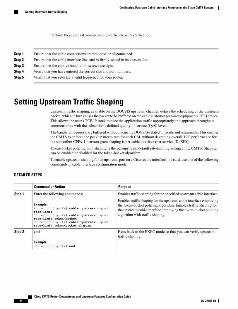
Setting Upstream Traffic ShapingUpstream traffic shaping, available on the DOCSIS upstream channel, delays the scheduling of the upstreampacket, which in turn causes the packet to be buffered on the cable customer premises equipment (CPE) device.This allows the user’s TCP/IP stack to pace the application traffic appropriately and approach throughputcommensurate with the subscriber’s defined quality of service (QoS) levels.The bandwidth requests are buffered without incurring DOCSIS-related timeouts and retransmits. This enablesthe CMTS to enforce the peak upstream rate for each CM, without degrading overall TCP performance forthe subscriber CPEs. Upstream grant shaping is per cable interface (per service ID (SID)).
Token-bucket policing with shaping is the per-upstream default rate-limiting setting at the CMTS. Shapingcan be enabled or disabled for the token-bucket algorithm.
To enable upstream shaping for an upstream port on a Cisco cable interface line card, use one of the followingcommands in cable interface configuration mode.
DETAILED STEPS
PurposeCommand or Action
Enables traffic shaping for the specified upstream cable interface.Enter the following commands:Step 1
Example:Router(config-if)# cable upstream usportrate-limit
Enables traffic shaping for the upstream cable interface employingthe token-bucket policing algorithm. Enables traffic shaping forthe upstream cable interface employing the token-bucket policingalgorithm with traffic shaping.Router(config-if)# cable upstream usport
rate-limit token-bucketRouter(config-if)# cable upstream usportrate-limit token-bucket shaping
Exits back to the EXEC mode so that you can verify upstreamtraffic shaping.
end
Example:Router(config-if)# end
Step 2
Cisco CMTS Router Downstream and Upstream Features Configuration Guide24 OL-27606-08
Configuring Upstream Cable Interface Features on the Cisco CMTS RoutersSetting Upstream Traffic Shaping

To disable upstream traffic shaping for an upstream port, enter the following command in cable interfaceconfiguration mode:Router(config-if)# no cable upstream usport rate-limit
The software supports:
• Generic calendar queuing routines
• New token-bucket policing function
• Grant shaping application of the calendar queues
• Upstream rate-shaping option to the token-bucket keyword
• A default state change from 1-second burst policing to token bucket with shaping
Upstream grant shaping is per CM (per service ID (SID)). Shaping can be enabled or disabled for thetoken-bucket algorithm.
Tip
Before the introduction of this feature, the CMTS would drop bandwidth requests from a CM it detectedas exceeding its configured peak upstream rate. Such request dropping affects the throughput performanceof IP-based protocols such as FTP, TCP, and Simple Network Management Protocol (SNMP). With thisfeature, the CMTS can shape (buffer) the grants for a CM that is exceeding its upstream rate, rather thandropping the bandwidth requests.
Note
Router# show interface cable 5/0 sid 1 counters
00:02:23: %ENVM-3-LASTENV: Cannot save environmental dataSid Req-polls BW-reqs Grants Packets Frag Concatpkts
issued received issued received complete received1 0 22 22 22 0 02 0 3 3 2 0 03 0 0 0 0 0 0
Verifying Upstream Bandwidth Request ShapingTo determine if upstream bandwidth request shaping is configured and activated, enter the show running-configcommand and look for the cable interface configuration information. If upstream bandwidth request shapingis configured and enabled, a shaping entry appears in the show running-config output. If upstream bandwidthrequest shaping is disabled, no cable upstream rate-limit appears in the output.
You can also perform the following tasks to verify that bandwidth request shaping is enabled on the upstreamchannel:
Step 1 Configure a low-peak upstream rate limit for the CM in its QoS profile. Either use the CLI to modify the QoS profile ofthe modem, or edit the TFTP configuration file of the modem. For more information, see the DOCSIS 1.1 for the CiscouBR7200 Series Universal Broadband Routers feature.
Step 2 Use a regular rate-limiting algorithm on the upstream without rate shaping, and note the drops of the excess bandwidthrequests from this CM when it exceeds its peak upstream rate.
Cisco CMTS Router Downstream and Upstream Features Configuration Guide OL-27606-08 25
Configuring Upstream Cable Interface Features on the Cisco CMTS RoutersVerifying Upstream Bandwidth Request Shaping

Use the show interface cx/y sid counters verbose command to see the bandwidth request drops. Verify that the upstreamrate received by that modem is less than its configured peak rate, due to the timeouts and backoffs produced by the dropin bandwidth requests. Enter the show interface cx/y service flow qos command to see the input rate at CMTS in bps.
Step 3 Enable grant shaping on the upstream channel by using the new shaping keyword extension to the token-bucket algorithmCLI command.
Step 4 Make the CM exceed its peak upstream rate by generating upstream traffic, and note the effect of grant buffering (shaping)at the CMTS. If you use CM-to-CMTS pings, there is a perceivable decrease in the frequency of the pings.
Let the pings run long enough to allow the averages at the CMTS to settle; then view the upstream rate received by thissingle modem. Use the show interface cx/y command and see the input rate in bps. This value should be close to themodem’s peak upstream rate. Also note the drop counts for the modem’s SID by using the show interface sid counterscommand, and verify that the CMTS no longer drops the bandwidth requests from the CM.
The bandwidth request drop count (from the previous nonshaping test) remains unchanged when upstream rate shapingis used, indicating that the CMTS is actually shaping (buffering) the grants for the modem. Verify that the input rate atthe CMTS (from the single rate-exceeded CM) stabilizes close to the configured peak rate of 128 Kbps.
Troubleshooting TipsPerform these steps if you are having difficulty with verification:
Step 1 Ensure that the cable connections are not loose or disconnected.Step 2 Ensure that the cable interface line card is firmly seated in its chassis slot.Step 3 Ensure that the captive installation screws are tight.Step 4 Verify that you have entered the correct slot and port numbers.Step 5 Verify that you selected a valid frequency for your router.
Configuring Upstream Drop ClassifierThis configuration in optional. A set of matching criteria is applied by the cable modems to packets to determineif a packet should be dropped. This set of matching criteria when applied to upstream traffic, is called theUpstream Drop Classifier (UDC).
The CMTS enables the UDC feature on the cable modems. The UDC configuration is done by the cablemodem using a configuration file.
Effective with Cisco IOS Release 12.2(33)SCG5, the UDC feature can be enabled for all cable modems onany interface of a Cisco CMTS by using the cable udc-capability command in interface configuration mode.
Cisco CMTS Router Downstream and Upstream Features Configuration Guide26 OL-27606-08
Configuring Upstream Cable Interface Features on the Cisco CMTS RoutersConfiguring Upstream Drop Classifier

DETAILED STEPS
PurposeCommand or Action
Enables privileged EXEC mode.enableStep 1
Example:Router> enable
• Enter your password if prompted.
Enters global configuration mode.configure terminal
Example:Router# configure terminal
Step 2
Enters the interface configuration modeinterface cable slot/subslot/port
Example:Router(config)# interface cable 7/1/0
Step 3
Enables the UDC feature on cable modems.cable udc-capability
Example:Router(config-if)# cable udc-capability
Step 4
Exits interface configuration mode and returns toprivileged EXEC mode.
end
Example:Router(config-if)# end
Step 5
What to Do Next
To verify that the UDC feature is enabled on a specified cable modem, use the show cable modem H.H.Hverbose command (whereH.H.H represents the MAC address of the cable modem) in privilege EXECmode.The following example displays the output of the show command using the ‘|’ and section keyword to showonly the “UDC Enabled” field.Router# show cable modem 4458.2945.3004 verbose | s UDC
UDC Enabled : Y
Router#
If the UDC feature is not enabled, this field shows ‘N’ to denote that the cable modems have not configuredUDC.
Setting Upstream Buffer Control ParametersThis configuration is optional. To configure the upstream buffer control parameters for the CM queue usingthe service class name, use the cable service class command in global configuration mode.
Cisco CMTS Router Downstream and Upstream Features Configuration Guide OL-27606-08 27
Configuring Upstream Cable Interface Features on the Cisco CMTS RoutersSetting Upstream Buffer Control Parameters

DETAILED STEPS
PurposeCommand or Action
Enables privileged EXEC mode.enableStep 1
Example:Router> enable
• Enter your password if prompted.
Enters global configuration mode.configure terminal
Example:Router# configure terminal
Step 2
Configures the following buffer control parameters.cable service class class-index max-buff-size |min-buff-size | tar-buff-size
Step 3
• class-index—The class ID for the class to be modified.
Example:Router(config)# cable service class 10min-buff-size 1000
• max-buff-size—Maximum CM buffer size.
• min-buff-size—Minimum CM buffer size.
• tar-buff-size—Target CM buffer size.
Exits global configuration mode and returns to privileged EXECmode.
end
Example:Router(config)# end
Step 4
Verifying Upstream Buffer Control ParametersTo verify the current values of the upstream buffer control parameters for a particular service class, use theshow cable service-class verbose command in privilege EXEC mode. The following is a sample output ofthe show cable service-class verbose command for a service class with class-index 10:Router# show cable service-class 10 verbose
Index: 10Name: REG-USDirection: UpstreamTraffic Priority: 0Maximum Sustained Rate: 0 bits/secMax Burst: 3044 bytesMinimum Reserved Rate: 0 bits/secMinimum Packet Size 0 bytesPeak Rate 0 bits/secAdmitted QoS Timeout 200 secondsActive QoS Timeout 0 secondsMaximum Concatenated Burst: 1522 bytesScheduling Type: Best EffortRequest/Transmission Policy: 0x0IP ToS Overwrite [AND-mask,OR-mask]: 0xFF,0x0Parameter Presence Bitfield: {0x8, 0x0}!Upstream Buffer Control ParametersMinimum Buffer Size: 1000 bytesTarget Buffer Size: 1500 bytes
Cisco CMTS Router Downstream and Upstream Features Configuration Guide28 OL-27606-08
Configuring Upstream Cable Interface Features on the Cisco CMTS RoutersVerifying Upstream Buffer Control Parameters
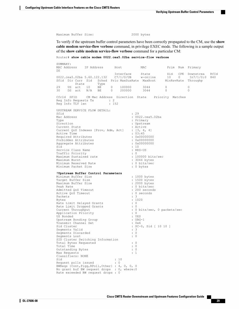
Maximum Buffer Size: 2000 bytes
To verify if the upstream buffer control parameters have been correctly propagated to the CM, use the showcable modem service-flow verbose command, in privilege EXEC mode. The following is a sample outputof the show cable modem service-flow verbose command for a particular CM:Router# show cable modem 0022.cea5.02ba service-flow verbose
SUMMARY:MAC Address IP Address Host MAC Prim Num PrimaryDS
Interface State Sid CPE Downstrea RfId0022.cea5.02ba 5.60.122.132 C7/1/0/UB w-online 10 0 In7/1/0:0 840Sfid Dir Curr Sid Sched Prio MaxSusRate MaxBrst MinRsvRate Throughp
State Type29 US act 10 BE 0 100000 3044 0 030 DS act N/A BE 0 200000 3044 0 0
CfrId SFID CM Mac Address Direction State Priority MatchesReg Info Requests Tx : 2Reg Info TLV len : 152
UPSTREAM SERVICE FLOW DETAIL:Sfid : 29Mac Address : 0022.cea5.02baType : PrimaryDirection : UpstreamCurrent State : ActiveCurrent QoS Indexes [Prov, Adm, Act] : [3, 4, 4]Active Time : 03:45Required Attributes : 0x00000000Forbidden Attributes : 0x00000000Aggregate Attributes : 0x00000000Sid : 10Service Class Name : REG-USTraffic Priority : 0Maximum Sustained rate : 100000 bits/secMaximum Burst : 3044 bytesMinimum Reserved Rate : 0 bits/secMinimum Packet Size : 0 bytes
!Upstream Buffer Control ParametersMinimum Buffer Size : 1000 bytesTarget Buffer Size : 1500 bytesMaximum Buffer Size : 2000 bytesPeak Rate : 0 bits/secAdmitted QoS Timeout : 200 secondsActive QoS Timeout : 0 secondsPackets : 3Bytes : 1020Rate Limit Delayed Grants : 0Rate Limit Dropped Grants : 0Current Throughput : 0 bits/sec, 0 packets/secApplication Priority : 0US Bonded : YESUpstream Bonding Group : UBG-1Transmit Channel Set : 0x6Sid Cluster : SC-0, Sid [ 10 10 ]Segments Valid : 3Segments Discarded : 0Segments Lost : 0SID Cluster Switching InformationTotal Bytes Requested : 0Total Time : 0Outstanding Bytes : 0Max Requests : 1Classifiers: NONESid : 10Request polls issued : 0BWReqs {Cont,Pigg,RPoll,Other} : 4, 0, 0, 0No grant buf BW request drops : 0, where:0Rate exceeded BW request drops : 0
Cisco CMTS Router Downstream and Upstream Features Configuration Guide OL-27606-08 29
Configuring Upstream Cable Interface Features on the Cisco CMTS RoutersVerifying Upstream Buffer Control Parameters

Grants issued : 4Packets received : 4Bytes received : 1488rate-adapt : Disabledrate-adapt {rcvd, Consec-PB} : 0, 0Fragment reassembly completed : 0Fragment reassembly incomplete : 0Concatenated packets received : 0Queue-indicator bit statistics : 0 set, 0 grantedGood Codewords rx : 8Corrected Codewords rx : 0Uncorrectable Codewords rx : 0Concatenated headers received : 0Fragmentation headers received : 0Fragmentation headers discarded: 0ARP Requests Received : 2
Additional References
MIBs
MIBs LinkMIB
To locate and downloadMIBs for selected platforms,Cisco IOS releases, and feature sets, use Cisco MIBLocator found at the following URL:
http://www.cisco.com/go/mibs
DOCS-IF3-MIB
Technical Assistance
LinkDescription
http://www.cisco.com/supportThe Cisco Support website provides extensive onlineresources, including documentation and tools fortroubleshooting and resolving technical issues withCisco products and technologies.
To receive security and technical information aboutyour products, you can subscribe to various services,such as the Product Alert Tool (accessed from FieldNotices), the Cisco Technical Services Newsletter,and Really Simple Syndication (RSS) Feeds.
Access to most tools on the Cisco Support websiterequires a Cisco.com user ID and password.
Cisco CMTS Router Downstream and Upstream Features Configuration Guide30 OL-27606-08
Configuring Upstream Cable Interface Features on the Cisco CMTS RoutersAdditional References

Feature Information for Configuring Upstream Cable Interface Features on theCisco CMTS Routers
Use Cisco Feature Navigator to find information about platform support and software image support.Cisco Feature Navigator enables you to determine which software images support a specific software release,feature set, or platform. To access Cisco Feature Navigator, go to http://www.cisco.com/go/cfn. An accounton Cisco.com is not required.
The table below lists only the software release that introduced support for a given feature in a givensoftware release train. Unless noted otherwise, subsequent releases of that software release train alsosupport that feature.
Note
Table 3: Feature Information for Configuring Upstream Cable Interface Features on the Cisco CMTS Routers
Feature InformationReleasesFeature Name
This feature was introduced on the12.2(33)SC release train.
12.2(33)SCAConfiguring Upstream CableInterface Features on the CiscoCMTS Routers
TheUpstreamMinimumReservedTraffic Rate Plus Excess TrafficRate featurette was introduced.
12.2(33)SCD5Configuring Upstream CableInterface Features on the CiscoCMTS Routers
This feature enables the CiscoCMTS to control the size of theupstream service-flow queue (orbuffer) on a CM.
The following commands weremodified:
• cable service class
• show cable modemservice-flow
• show cable service-class
12.2(33)SCF2Upstream Buffer Control forMaximum Queue Depth
This feature automatically sets theDOCSIS mode to A-TDMA-only(DOCSIS 2.0) mode.
The following command wasmodified:
cable upstream channel-width,cable upstream docsis-mode
12.2(33)SCG2Copy and Paste Support for TDMAto A-TDMA Upgrade
Cisco CMTS Router Downstream and Upstream Features Configuration Guide OL-27606-08 31
Configuring Upstream Cable Interface Features on the Cisco CMTS RoutersFeature Information for Configuring Upstream Cable Interface Features on the Cisco CMTS Routers

Feature InformationReleasesFeature Name
This feature enables the upstreamdrop classifier feature on the cablemodems on a specific interface.
The following commands wereintroduced or modified:
cable udc-capability, show cablemodem verbose
12.2(33)SCG5Upstream Drop Classifier (UDC)
Cisco CMTS Router Downstream and Upstream Features Configuration Guide32 OL-27606-08
Configuring Upstream Cable Interface Features on the Cisco CMTS RoutersFeature Information for Configuring Upstream Cable Interface Features on the Cisco CMTS Routers