confined masonry house
TRANSCRIPT

Build a Safe House with
CONFINED MASONRY
Kamu IyerShibani M. KulkarniShantanu Subramaniam
C. V. R. MurtyRupen Goswami
A. R. Vijayanarayanan
Gujarat State Disaster Management Authority Government of Gujarat

Contents
Preamble 1 Acknowledgment 5
Confined Masonry 7
Options for a Confined Masonry House 15
Basics of Construction 79
Construction of House Option 1 99

Build a Safe House with
CONFINED MASONRY
Kamu IyerShibani M. KulkarniShantanu Subramaniam
C. V. R. MurtyRupen Goswami
A. R. Vijayanarayanan
Gujarat State Disaster Management Authority Government of Gujarat
1
3
4
2
6
5

Contents
Preamble 1 Acknowledgment 5
Confined Masonry 7
Options for a Confined Masonry House 15
Basics of Construction 79
Construction of House Option 1 99

Contents
Preamble 1 Acknowledgment 5
Confined Masonry 7
Options for a Confined Masonry House 15
Basics of Construction 79
Construction of House Option 1 99


Preamble
A village house with unreinforced masonry
Most houses in rural India are masonry houses. The masonry walls are built with burnt clay brick or natural stone masonry. Many choices are made across India for the roof. For instance, a sloping roof with wood truss and burnt clay tile is adopted in Kachchh region of Gujarat (western state of India), and a flat roof with reinforced concrete (RC) slab in Tehri Region of Uttarakhand (northern state of India). These houses are constructed in the conventional manner known to masons. Technically, they are called Unreinforced Masonry (URM) Houses; it has plain masonry walls with no steel reinforcement embedded in them to improve their behaviour during earthquakes. Today, of the existing building stock in India, about 45% of houses are made of burnt clay brick and about 10% of natural stone. Thus, over half of India’s population lives in URM houses.
# 1

Unreinforced masonry (URM) walls are pushed sideways during a strong earthquake, along their length and thickness directions. When shaken along their thickness, they collapse. And, when shaken along their length, they develop diagonal cracks along their length and/or separate at wall junctions. When walls collapse, they bring down the roof along with them. This is the main reason for large loss of lives during earthquakes that have occurred in different regions of the country.
In-plane Walls
Shaking Direction
In-plane Compression
In-plane Tension
Shaking Direction
Out-of-plane Walls
Out-of-plane Bending
Out-of-planeBending
Shaking along length direction of masonry wall results in diagonal cracking
Shaking along thickness direction of masonry wall can result in collapse
Despite houses col laps ing in earthquakes, people still continue to reconstruct their houses in the age old method of unreinforced masonry, thereby making their houses vulnerable to future earthquakes.
I n c i t i e s , R C b u i l d i n g s a r e constructed first by making the RC frame, and then by infilling the spaces between beams and columns with masonry walls made of burnt clay bricks or cement blocks, and cement mortar. To build a house this way requires high levels of technical skills, which usually are not available in small towns and villages. But, everyone, whether residing in a town or a village, wants a pucca house - a house with brick walls and RC roof, just like the buildings in larger towns and cities. This is reason enough to improve earthquake safety measures in these houses.
An RC frame buildingcommonly built in cities
A villager rebuilding his house with unreinforced masonry
1
2
3
Sequence of
RC frame construction with URM infill walls
2 3

Small, but significant, changes should be made in current method of construction of masonry houses in rural India. This improved method of house construction is called Confined Masonry Construction. Loss of life can be reduced considerably in masonry houses during future earthquakes. For this, masonry walls are confined on all four sides with (a) stiffer and stronger vertical elements made in RC, and (b) RC horizontal bands at discrete levels in the masonry walls along the perimeter of all the rooms of the house.
Confined Masonry Housewith clay brick walls and RC slab
Books providing technical information on confined masonry construction are exhaustive, but largely offer generic details. They have to be adapted for specific conditions at site. Often, this is difficult for a man building his house. An illustrated manual such as this is required, that follows the requirements of Confined Masonry Construction in an easy-to-follow language, and provides guidance on how to build a confined masonry house with specific functional design. Such a manual will enable the individual house owner or a 'practical technician' to build such a house. Also, the manual will help local authorities to construct houses under any social housing scheme sponsored by the Governments.
This book illustrates the step-by-step construction of a Confined Masonry House of a specific design. It provides precautions to be taken and amount of material required to construct the house. Also, alternate specific designs are presented.
Acknowledgements
The authors are grateful to the Gujarat State Disaster Management Authority (GSDMA), Government of Gujarat, Gandhinagar (Gujarat, India), for readily agreeing to support the preparation of this book; the generous financial grant provided by GSDMA towards this effort is gratefully acknowledged. The authors also extend their appreciation to Dr. R. Bannerji, IAS, Chief Executive Officer-GSDMA, Dr. V. Thiruppugazh, IAS, Additional Chief Executive Officer, GSDMA and Mr. S. I. Patel, Additional Chief Executive Officer, GSDMA for their invaluable inputs and guidance during the course of preparing and finalizing this book. Ms. Alpa R. Sheth, Managing Director, Vakil Mehta Sheth Consulting Engineers Private Limited, Mumbai, and Seismic Advisor, GSDMA, Gandhinagar, Gujarat, supported idea of developing this book, and guided us throughout the course of this project from discussing the contents, mid-course feedback on the contents, to getting the book reviewed. The authors sincerely thank Mr.Birju Patel, Deputy Director, GSDMA, Gandhinagar, for providing necessary details of government-driven social housing schemes being undertaken in Gujarat, and for the administrative support from GSDMA . Dr. Svetlana N. Brzev, British Columbia Institute of Technology, Vancouver, CANADA, readily agreed to review the early manuscript and provided valuable comments for improving the quality of the publication. The authors are grateful to her for this special contribution. Ms. Betsy Ponnachan, III Year B.Tech. (Civil Engineering) Student of MNIT, Jaipur, played a pivotal role in bringing the document to publishable standards by significantly simplifying many graphics presented in this document; this special contribution is gratefully acknowledged. The authors acknowledge with thanks the support offered by various sections of IIT Madras in administering this book writing project. In particular, the authors gratefully acknowledge support offered by Mrs.S.Kavita, Project Assistant, Department of Civil Engineering, and of Mrs.C.Sankari and Mr.Anand Raj of the Structural Engineering Laboratory of the Institute.
The authors remain indebted to their family members for the unconditional support and understanding throughout the of development of the book… This book is dedicated to all the people of India, who lost their kith and kin in masonry house collapses during past earthquakes in the country…
4 5

Confined Masonry
6 7

Confined Masonry
6 7

What will happen to my house in an earthquake,If masonry is not confined?
Moderate Shaking Walls Crack
Severe ShakingWalls collapse and slab falls
How do I prevent this?
During an earthquake, when the ground shakes moderately, unconfined walls are pushed sideways and therefore develop cracks. When the ground shakes violently, unconfined masonry walls collapse bringing down the roof, either partly or fully.
By confining masonry walls of the house. This is achieved by using: (a) vertical RC elements interlocked with
bricks at all wall junctions and door and window openings, and
(b) horizontal RC bands at plinth, sill and lintel levels.
Masonry confined thus is resistant to earthquakes.
8 9
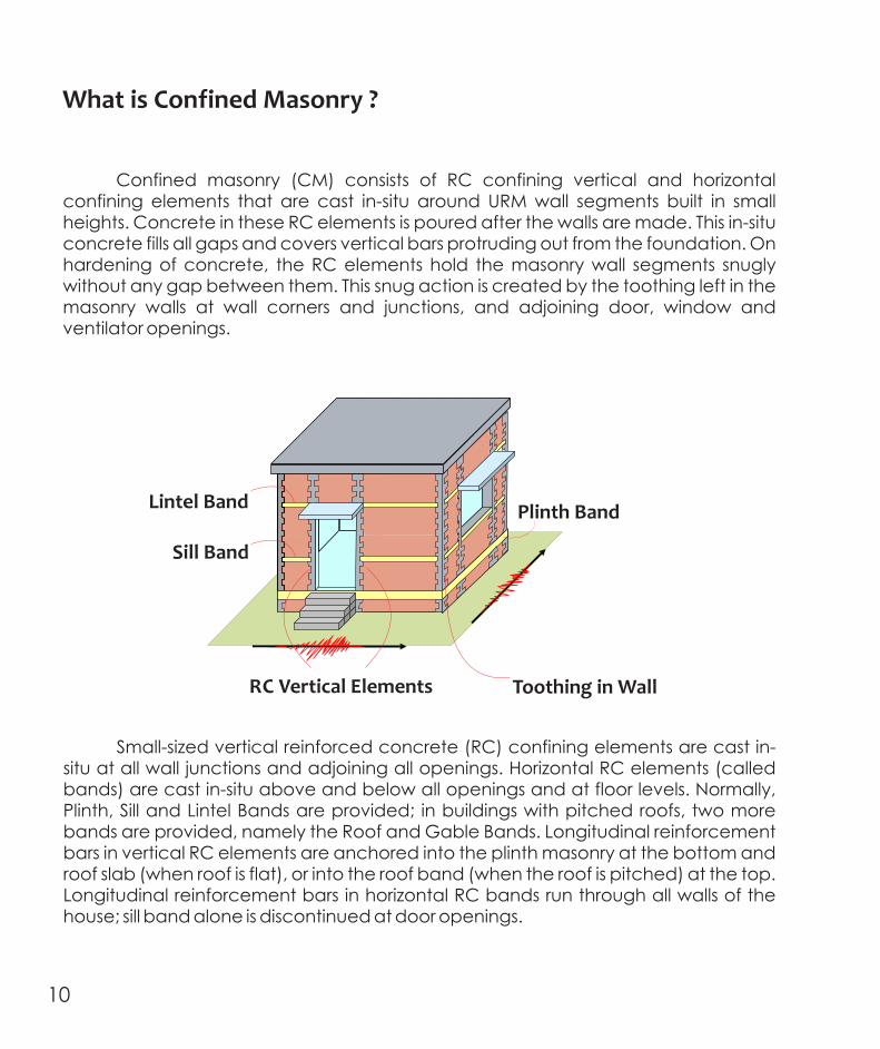
Confined masonry (CM) consists of RC confining vertical and horizontal confining elements that are cast in-situ around URM wall segments built in small heights. Concrete in these RC elements is poured after the walls are made. This in-situ concrete fills all gaps and covers vertical bars protruding out from the foundation. On hardening of concrete, the RC elements hold the masonry wall segments snugly without any gap between them. This snug action is created by the toothing left in the masonry walls at wall corners and junctions, and adjoining door, window and ventilator openings.
What is Confined Masonry ?
Small-sized vertical reinforced concrete (RC) confining elements are cast in-situ at all wall junctions and adjoining all openings. Horizontal RC elements (called bands) are cast in-situ above and below all openings and at floor levels. Normally, Plinth, Sill and Lintel Bands are provided; in buildings with pitched roofs, two more bands are provided, namely the Roof and Gable Bands. Longitudinal reinforcement bars in vertical RC elements are anchored into the plinth masonry at the bottom and roof slab (when roof is flat), or into the roof band (when the roof is pitched) at the top. Longitudinal reinforcement bars in horizontal RC bands run through all walls of the house; sill band alone is discontinued at door openings.
Lintel Band
RC Vertical Elements Toothing in Wall
Plinth Band
Under earthquake shaking, the loads are carr ied primari ly by the composite system of masonry wall and RC elements through load-bearing action. These RC confining elements are small in size and grip the whole width of the wall at door and window openings and wall junctions. They have sufficient stiffness to resist to dilation of masonry wall that otherwise happens during earthquake shaking. Thus, each wall panel bound by the confining RC elements stays as an integral unit without disintegrating into its constituent materials.
Only nominal bending in RC vertical and horizontal elements
Compression
NOGap
RC elements holds masonry walls snugly during earthquake shaking
Sill Band
10 11

Confined masonry is most suitable and practical method for construction of houses by individual home owners in earthquake areas. The level of engineering required is embedded in empirical rules for planning, design and construction of these houses. Two prominent features of confined masonry construction are:(1) Use of a regular grid of walls in both directions with
RC vertical members at all wall junctions and in straight walls of longer lengths, and RC vertical elements (toothed into the masonry wall segments) and RC horizontal bands (resting on the masonry walls of the whole house). These items together confine the wall segments and prevent them from dilating along the length direction of the wall and from falling out-of-plane along the thickness direction of the wall..
(2) Sequence of first making the masonry walls and then pouring in-situ the RC vertical elements and horizontal bands. This choice of construction sequence is responsible for enhancing the integrity of the masonry units and mortar in Confined Masonry, which in turn makes Confined Masonry Construction superior to regular RC frame buildings with plain masonry walls as infills.
Earthquake performance is good of confined masonry construction. While confined masonry constructions sustained severe damage during past earthquakes, complete collapse has not been observed in this typology of construction.
1
3
4
2
6
5
Sequence of
Confined Masonry Construction
What are the main elements of a Confined Masonry House ?
Walls
Roof
Ground
Foundation and Plinth
Foundation All elements of construction from soil level to ground level
Plinth All elements of construction from ground level to floor level
Wall Masonry wall, vertical RC elements and horizontal RC bands
RoofRC slab with all finishes on it in a flat roof, wood/steel truss, clay tiles/sheeting and all finishes on it in a pitched roof
Confining Elements Vertical RC elements, Horizontal RC bands at plinth, sill and lintel levels in a
house with flat roof, and RC eaves and gable bands in a house with pitched roof
12 13

Options of
Confined Masonry Houses
14 15
Options of
Confined Masonry Houses
14 15

What are the available options ?
Option 22Built-up area: 32.03 m2Carpet area: 20.18 m
Option 12Built-up area: 24.67 m2Carpet area: 18.78 m
Roof LineRoof Line
Main Room
Toilet
Bath
Kitchen
Access Road
16 17

What are the available options ?
Option 22Built-up area: 32.03 m2Carpet area: 20.18 m
Option 12Built-up area: 24.67 m2Carpet area: 18.78 m
Roof LineRoof Line
Main Room
Toilet
Bath
Kitchen
Access Road
16 17

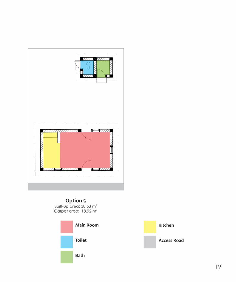
Option 52Built-up area: 30.53 m2Carpet area: 18.92 m
Main Room
Toilet
Bath
Kitchen
Access Road
Option 42Built-up area: 32.47 m2Carpet area: 19.21 m
Option 32Built-up area: 25.54 m2Carpet area: 18.60 m
Roof Line Roof Line
Main Room
Toilet
Bath
Kitchen
Access Road
18 19
Option 52Built-up area: 30.53 m2Carpet area: 18.92 m
Main Room
Toilet
Bath
Kitchen
Access Road
Option 42Built-up area: 32.47 m2Carpet area: 19.21 m
Option 32Built-up area: 25.54 m2Carpet area: 18.60 m
Roof Line Roof Line
Main Room
Toilet
Bath
Kitchen
Access Road
18 19

Option 72Built-up area: 30.53 m each2Carpet area: 18.92 m each
Main Room
Toilet
Bath
Kitchen
Access Road
House 1 House 2
Option 62 Built-up area: 24.67 m each house2Carpet area: 18.78 m each house
House 1 House 2
Main Room
Toilet
Bath
Kitchen
Access Road
20 21

Option 72Built-up area: 30.53 m each2Carpet area: 18.92 m each
Main Room
Toilet
Bath
Kitchen
Access Road
House 1 House 2
Option 62 Built-up area: 24.67 m each house2Carpet area: 18.78 m each house
House 1 House 2
Main Room
Toilet
Bath
Kitchen
Access Road
20 21

Option 1
100
625
75
1000
75
925
450
3250
230
900
150
115
230
230
630
550
900
750
5150
7
12
11
Brick Masonry Courses
Front Elevation
Main Room2.90m x 4.69m
Kitchen 1.20m x 2.31m
Bath1.2m x 1.1m
Toilet
1.2m x 0.9m
Plan
B
A
230 1315 115 900 1885 230
4790
Open Platform
B
A
235
115
115
115
230 230
335
115
750
115
550
230
230
630
550
900
115
115
Toilet1.2 m x 0.9 m
2(1.08 m )Bath1.2 m x 1.1 m
2(1.32 m ) Main Room2.9 m x 4.69 m
2(14.54 m )
Kitchen1.2 m x 2.31 m
2(2.77 m )
5.15
m
4.97 m
Option 1
22 23

Option 1
100
625
75
1000
75
925
450
3250
230
900
150
115
230
230
630
550
900
750
5150
7
12
11
Brick Masonry Courses
Front Elevation
Main Room2.90m x 4.69m
Kitchen 1.20m x 2.31m
Bath1.2m x 1.1m
Toilet
1.2m x 0.9m
Plan
B
A
230 1315 115 900 1885 230
4790
Open Platform
B
A
235
115
115
115
230 230
335
115
750
115
550
230
230
630
550
900
115
115
Toilet1.2 m x 0.9 m
2(1.08 m )Bath1.2 m x 1.1 m
2(1.32 m ) Main Room2.9 m x 4.69 m
2(14.54 m )
Kitchen1.2 m x 2.31 m
2(2.77 m )
5.15
m
4.97 m
Option 1
22 23

Backfilled earth
Unexcavated Ground
Section B‐B
1000
2800
150
50
675
75
900
300
925
75
20002800
150
50
550
150
900
300
Section A‐A
Option 1
100
1350
100
1350
Left Elevation
450
675
3300
Right Elevation
Option 1
450
2000
800
3250
450
2000
100
600
150
450
1000
100
550
150
75
925
2000
75
100
450450
450450
24 25

Option 1
Pivoted WindowClosed Position
Pivoted WindowOpen Position
Option 1
Ventilator with Built-in Steel Grill
Round Steel Bars (10mm diameter)along vertical and horizontal directions
Plan
Elevation Section X‐X
X
X
X
X
Roof Slab
Lintel Band
Vertical RC Elements
26 27

Option 1
Pivoted WindowClosed Position
Pivoted WindowOpen Position
Option 1
Ventilator with Built-in Steel Grill
Round Steel Bars (10mm diameter)along vertical and horizontal directions
Plan
Elevation Section X‐X
X
X
X
X
Roof Slab
Lintel Band
Vertical RC Elements
26 27

Option 1
Lintel Band75 mm deep over windows
Primary Timber Frame75 mm x 25 mm
Secondary Timber Frame50 mm x 25 mm
Window Shutter12 mm thick E Board
Vertical RC Element
around Opening
Timber Frame75mm x 25mm
Timber Frame50mm x 25mm
Detail QSectional Plan
Detail RSectional Elevation
MS Rods20 mm diameter
Option 1
Window Details
1000
1800
550
75
100
75
Ventilator with MS Grill RC Roof Slab
12mm thick E Board
R
W
W
Section W‐W
230
550
Q
Sill Band
Lintel Band
28 29

Option 1
Detail TSectional Plan
Detail VSectional Elevation
Detail USectional Elevation
T.W. member100 mm x 36mm
MS Angle65mm x 65mm x 6mm
I.P.S Threshold38mm x100 mm
E Board12mm thick
T.W. member100 mm x 36mm
MS Angle65mm x 65mm x 6mm
E Board12mm thick
I.P.S Threshold38mm x100 mm MS Angle
65mm x 65mm x 6mm
E Board12mm thick
T.W. member100 mm x 36mm
Option 1
2000
2850
550
100
150
50
S
S
Door Details
230
900
RC Roof Slab
Lintel Band
Section S‐S
T
U
V
30 31

Option 1
450
1000
1075
3600
75
75
925
965 mm
12
11
Brick Masonry Courses
3070 mm
300
1000
1200
3600
75
75
925
150
325
1350
900
Right Elevation
Section C‐C
House with sloping roof
Option 1
Plan
Ridge Line
Main Room2.90m x 4.69m
Kitchen 1.20m x 2.31m
Bath1.2m x 1.1m
Toilet
1.2m x 0.9m
C
C
Backfilled earth
Unexcavated Ground
32 33

Option 1
450
1000
1075
3600
75
75
925
965 mm
12
11
Brick Masonry Courses
3070 mm
300
1000
1200
3600
75
75
925
150
325
1350
900
Right Elevation
Section C‐C
House with sloping roof
Option 1
Plan
Ridge Line
Main Room2.90m x 4.69m
Kitchen 1.20m x 2.31m
Bath1.2m x 1.1m
Toilet
1.2m x 0.9m
C
C
Backfilled earth
Unexcavated Ground
32 33

Option 1 Extended
Option 1 Extended2Built-up area: 40.14 m2Carpet area: 31.77 m
Option 1 Extended
How to extend my house ?
While extending the house, chip only the concrete
from the projected lintel band left for future expansion
To extend the house, leave a 600mm projection
from the Lintel Band in the direction of
proposed expansion
34 35

Option 1 Extended
10003000
150
50
625
75
900
300
100
1350
75
925
Section D‐D
5150
730
1490
115
230
3230
Plan
550115
Option 1 Extended
D
D
Main Room
Toilet
Bath
Kitchen
Access Road
Additional Room
36 37

Option 1 Extended
10003000
150
50
625
75
900
300
100
1350
75
925
Section D‐D
5150
730
1490
115
230
3230
Plan
550115
Option 1 Extended
D
D
Main Room
Toilet
Bath
Kitchen
Access Road
Additional Room
36 37

Option 2
100
625
75
1000
75
925
450
3250
7
12
11
Brick Masonry Courses
Front Elevation
230
900
150
1100
230
230
765
550
765
5150
Main Room3.20m x 4.69m
Kitchen 1.20m x 2.31m
Bath1.2m x 1.1m
Toilet
1.2m x 0.9m
B
230
1315
115
900 1610
230
6220
230
230 230
335
115
750
115
550
230
115
1955115
115
A
A
810
115
550
115
Plan
B
Option 2
6.22 m5.1
5 m
Toilet1.20 m x 0.90 m
2(1.08 m )Bath1.20 m x 1.10 m
2(1.32 m ) Main Room3.20 m x 4.69 m
2(14.54 m )
Kitchen1.20 m x 2.31 m
2(2.77 m )
38 39

Option 2
100
625
75
1000
75
925
450
3250
7
12
11
Brick Masonry Courses
Front Elevation
230
900
150
1100
230
230
765
550
765
5150
Main Room3.20m x 4.69m
Kitchen 1.20m x 2.31m
Bath1.2m x 1.1m
Toilet
1.2m x 0.9m
B
230
1315
115
900 1610
230
6220
230
230 230
335
115
750
115
550
230
115
1955115
115
A
A
810
115
550
115
Plan
B
Option 2
6.22 m5.1
5 m
Toilet1.20 m x 0.90 m
2(1.08 m )Bath1.20 m x 1.10 m
2(1.32 m ) Main Room3.20 m x 4.69 m
2(14.54 m )
Kitchen1.20 m x 2.31 m
2(2.77 m )
38 39

1000
2800
150
50
625
75
900
300
925
75
100
1350
1000
2850
150
50
600
150
900
300
925
75
100
1350
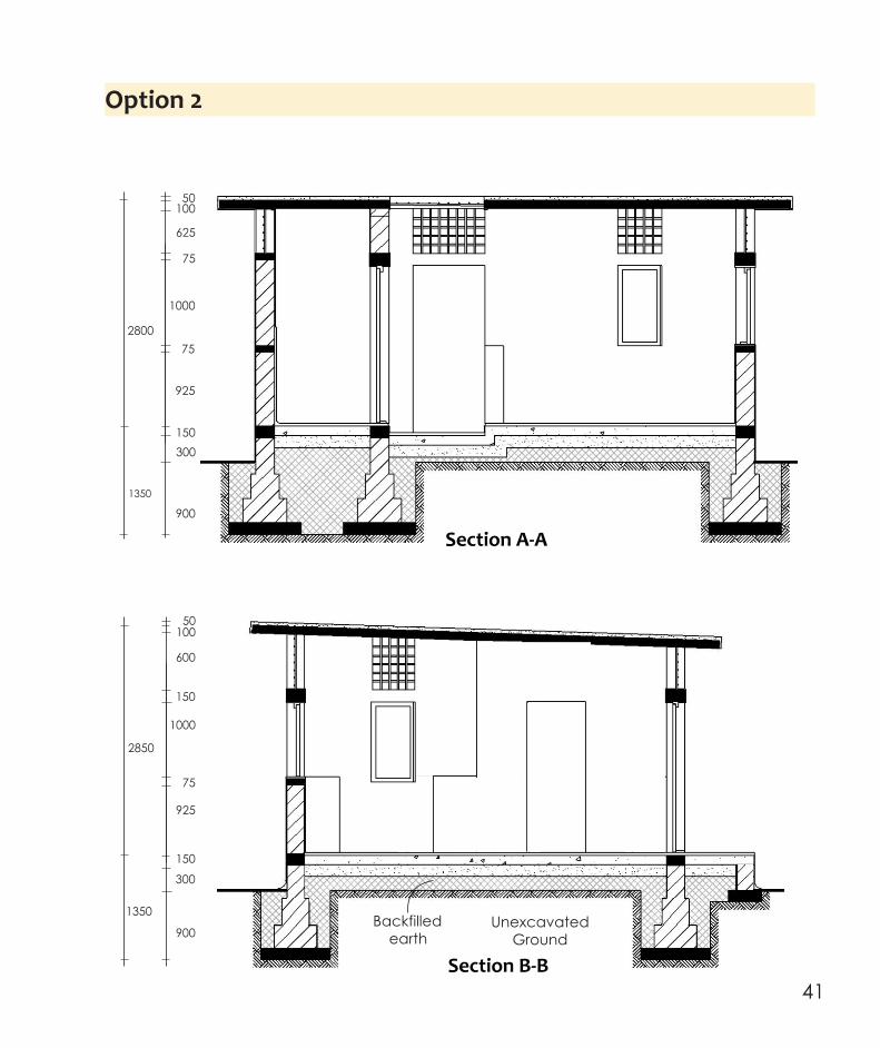
Option 2
Section B‐B
Backfilled earth
Unexcavated Ground
Section A‐A
Option 2
450
1000
625
3250
100
75
50
75
925
450 450
Back Elevation
450
675
3300
2000
75
150
450
1000
150
625
75
75
925
450450
Right Elevation
40 41
1000
2800
150
50
625
75
900
300
925
75
100
1350
1000
2850
150
50
600
150
900
300
925
75
100
1350
Option 2
Section B‐B
Backfilled earth
Unexcavated Ground
Section A‐A
Option 2
450
1000
625
3250
100
75
50
75
925
450 450
Back Elevation
450
675
3300
2000
75
150
450
1000
150
625
75
75
925
450450
Right Elevation
40 41

Option 2
450
1000
1225
3750
75
75
925
3000 mm
1085 mm
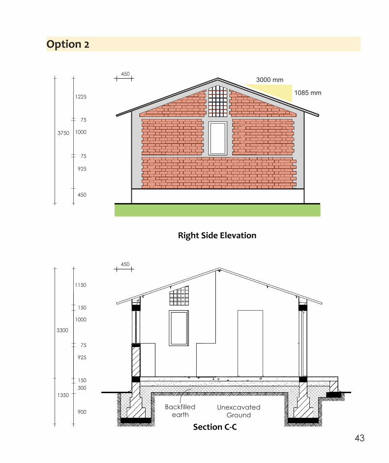
Right Side Elevation
450
1000
3300
150
1150
150
900
300
925
75
1350
450
Option 2
House with sloping roof
Main Room3.20m x 4.69m
Kitchen 1.20m x 2.31m
Bath1.2m x 1.1m
Toilet
1.2m x 0.9m
C
C
Plan Section C‐C
Ridge Line
Backfilled earth
Unexcavated Ground
42 43
Option 2
450
1000
1225
3750
75
75
925
3000 mm
1085 mm
Right Side Elevation
450
1000
3300
150
1150
150
900
300
925
75
1350
450
Option 2
House with sloping roof
Main Room3.20m x 4.69m
Kitchen 1.20m x 2.31m
Bath1.2m x 1.1m
Toilet
1.2m x 0.9m
C
C
Plan Section C‐C
Ridge Line
Backfilled earth
Unexcavated Ground
42 43

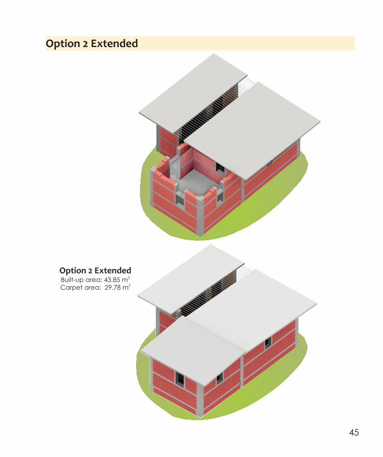
Option 2 Extended
Option 2 Extended2Built-up area: 43.85 m2Carpet area: 29.78 m
Option 2 Extended
How to extend my house ?
To extend the house, leave a 600mm projection from the Lintel Band in the direction of proposed expansion
While extending the house, chip only the concrete from the projected lintel band left for future expansion
44 45
Option 2 Extended
Option 2 Extended2Built-up area: 43.85 m2Carpet area: 29.78 m
Option 2 Extended
How to extend my house ?
To extend the house, leave a 600mm projection from the Lintel Band in the direction of proposed expansion
While extending the house, chip only the concrete from the projected lintel band left for future expansion
44 45
10003000
150
50
750
75
900
300
100
1350
150
925
Section D‐D
Option 2 Extended
Overlap of Roof Slab done for extension
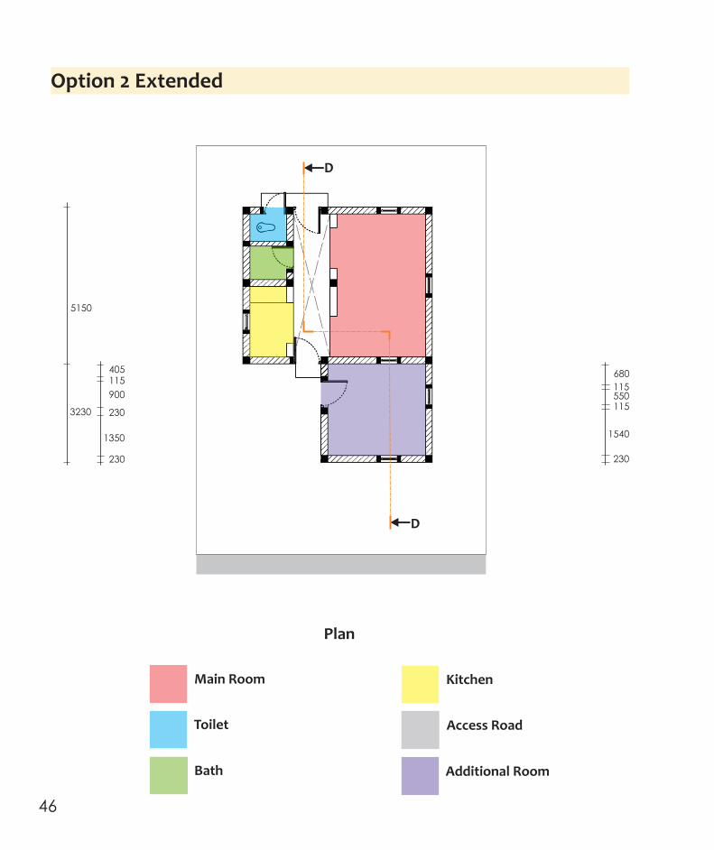
Option 2 Extended
230
5150
115550
230
115
1540
3230
1350
230
900
115405 680
D
D
Plan
Main Room
Toilet
Bath
Kitchen
Access Road
Additional Room
46 47

10003000
150
50
750
75
900
300
100
1350
150
925
Section D‐D
Option 2 Extended
Overlap of Roof Slab done for extension
Option 2 Extended
230
5150
115550
230
115
1540
3230
1350
230
900
115405 680
D
D
Plan
Main Room
Toilet
Bath
Kitchen
Access Road
Additional Room
46 47

Option 3
7
12
11
Brick Masonry Courses
150
550
150
1000
75
925
450
3300
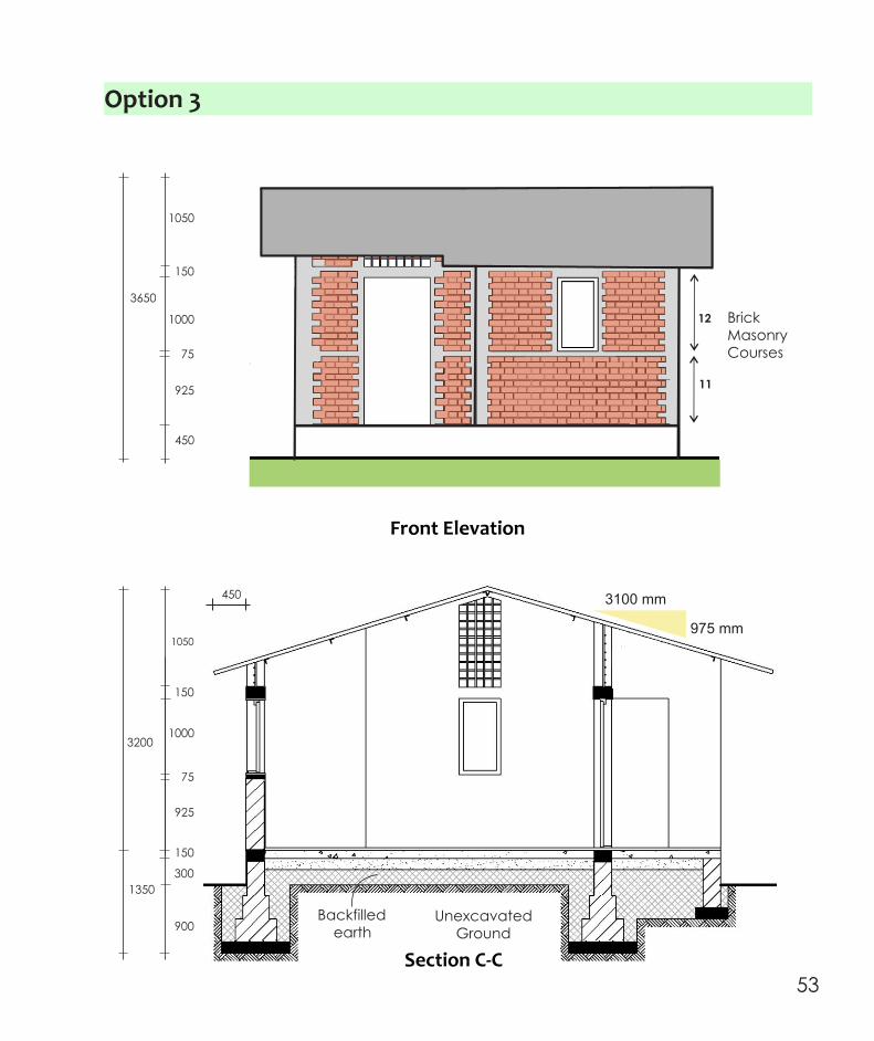
Front Elevation
230
1200
230
1100
1110
5506220
115
115 115
550
230
230
1100
B230 115
590
230
5220900 760
115
550
115
Plan
B
230
230150 150
750
A A
115
510
230
760
1100 900
Kitchen 2.30m x 1.10m
Bath1.1m x 1.2m
Toilet
0.9m x
1.2m
Main Room 4.76m x 3.00m
230
1110
230
230
995
230
115
230
750
335
1110
Option 3
6.22 m
5.22 m
Toilet1.2 m x 0.9 m
2(1.08 m )
Bath1.2 m x 1.1 m
2(1.32 m )
Main Room3.00 m x 4.76 m
2(14.54 m )
Kitchen1.10 m x 2.23 m
2(2.77 m )
48 49

Option 3
7
12
11
Brick Masonry Courses
150
550
150
1000
75
925
450
3300
Front Elevation
230
1200
230
1100
1110
5506220
115
115 115
550
230
230
1100
B230 115
590
230
5220900 760
115
550
115
Plan
B
230
230150 150
750
A A
115
510
230
760
1100 900
Kitchen 2.30m x 1.10m
Bath1.1m x 1.2m
Toilet
0.9m x
1.2m
Main Room 4.76m x 3.00m
230
1110
230
230
995
230
115
230
750
335
1110
Option 3
6.22 m
5.22 m
Toilet1.2 m x 0.9 m
2(1.08 m )
Bath1.2 m x 1.1 m
2(1.32 m )
Main Room3.00 m x 4.76 m
2(14.54 m )
Kitchen1.10 m x 2.23 m
2(2.77 m )
48 49

Option 3
1000
2850
150
50
600
150
900
300
925
75
100
1350
450
1000
150
550
150
75
925
Section A‐A
10002800
150
50
550
150
900
300
925
75
100
1350
Section B‐B
450
1000
675
3300
100
75
50
75
925
Front Elevation
450
450
625
3300
2000
75
150
Right Elevation
7
12
11
Brick Masonry Courses
Option 3
Backfilled earth
Unexcavated Ground
50 51

Option 3
1000
2850
150
50
600
150
900
300
925
75
100
1350
450
1000
150
550
150
75
925
Section A‐A
10002800
150
50
550
150
900
300
925
75
100
1350
Section B‐B
450
1000
675
3300
100
75
50
75
925
Front Elevation
450
450
625
3300
2000
75
150
Right Elevation
7
12
11
Brick Masonry Courses
Option 3
Backfilled earth
Unexcavated Ground
50 51

Option 3
450
1000
1050
3650
150
75
925
Front Elevation
12
11
Brick Masonry Courses
Section C‐C
10003200
150
1050
150
900
300
925
75
1350
450 3100 mm
975 mm
Option 3
House with sloping roof
C
C
Kitchen 2.30m x 1.10m
Bath1.1m x 1.2m
Toilet
0.9 m x
1.2 m
Main Room 4.76m x 3.00m
Plan
Ridge Line
Backfilled earth
Unexcavated Ground
52 53
Option 3
450
1000
1050
3650
150
75
925
Front Elevation
12
11
Brick Masonry Courses
Section C‐C
10003200
150
1050
150
900
300
925
75
1350
450 3100 mm
975 mm
Option 3
House with sloping roof
C
C
Kitchen 2.30m x 1.10m
Bath1.1m x 1.2m
Toilet
0.9 m x
1.2 m
Main Room 4.76m x 3.00m
Plan
Ridge Line
Backfilled earth
Unexcavated Ground
52 53

Option 3 Extended
Option 3 Extended2Built-up area: 47.94 m2Carpet area: 32.20 m
Option 3 Extended
How to extend my house ?
To extend the house, leave a projection of 600mm from the Lintel Band in the direction of proposed extension
While extending the house, chip only the concrete from the projected lintel band left for future expansion
54 55

Option 3 Extended
Option 3 Extended2Built-up area: 47.94 m2Carpet area: 32.20 m
Option 3 Extended
How to extend my house ?
To extend the house, leave a projection of 600mm from the Lintel Band in the direction of proposed extension
While extending the house, chip only the concrete from the projected lintel band left for future expansion
54 55

10003000
150
50
750
75
900
300
100
1350
150
925
Section D-D
Option 3 ExtendedOption 3 Extended
230
1200
230
1110
550
6220115
115
1100
230
115
550115
550
52203000230
D D
Plan
Main Room
Toilet
Bath
Kitchen
Access Road
Additional Room
56 57

10003000
150
50
750
75
900
300
100
1350
150
925
Section D-D
Option 3 ExtendedOption 3 Extended
230
1200
230
1110
550
6220115
115
1100
230
115
550115
550
52203000230
D D
Plan
Main Room
Toilet
Bath
Kitchen
Access Road
Additional Room
56 57

Option 4
150
625
75
1000
75
925
450
3300
Front Elevation
7
12
11
Brick Masonry Courses
230
1275 900
230
6220595 1100
230
1200
Plan
230
900
230
230
230
1100
1215
5150
115
760
550
230
230
230
1100
115
B
230 230
750
A
AMain Room4.69m x 3.00m
Kitchen 1.10m x 2.23m
Bath1.2m x 1.1m
Toilet
1.2m x 0.9m
B
115115230
230230115 115
550 550 945495
115
335
115
690900
6.22 m
5.15 m
Option 4
Toilet1.2 m x 0.9 m
2(1.08 m )
Bath1.2 m x 1.1 m
2(1.32 m )
Main Room3.00 m x 4.69 m
2(14.54 m )
Kitchen1.10 m x 2.23 m
2(2.77 m )
58 59

Option 4
Section J‐J
1000
2850
150
50
675
75
900
300
925
75
100
1350
Option 4
3300
Left Elevation
75
1000
75
450
150
625
925
Section A‐A
1000
2850
150
50
675
75
900
300
925
75
100
1350
2000
2800
150
50
550
150
900
300
100
1350
Section B‐B
2000
2800
150
50
550
150
900
300
100
1350
Backfilled earth
Unexcavated Ground
60 61

Option 4
300
1000
1500
3900
75
75
925
150
325
1350
900
Section C‐C
3400 mm
1300 mm
Front Elevation
1000
1500
3900
75
925
450
150
Option 4
House with sloping roof
C
C
Main Room4.69m x 3.00m
Kitchen 1.10m x 2.23m
Bath1.2m x 1.1m
Toilet
1.2m x 0.9m
Ridge Line
Plan
Backfilled earth
Unexcavated Ground
62 63

Option 4
300
1000
1500
3900
75
75
925
150
325
1350
900
Section C‐C
3400 mm
1300 mm
Front Elevation
1000
1500
3900
75
925
450
150
Option 4
House with sloping roof
C
C
Main Room4.69m x 3.00m
Kitchen 1.10m x 2.23m
Bath1.2m x 1.1m
Toilet
1.2m x 0.9m
Ridge Line
Plan
Backfilled earth
Unexcavated Ground
62 63

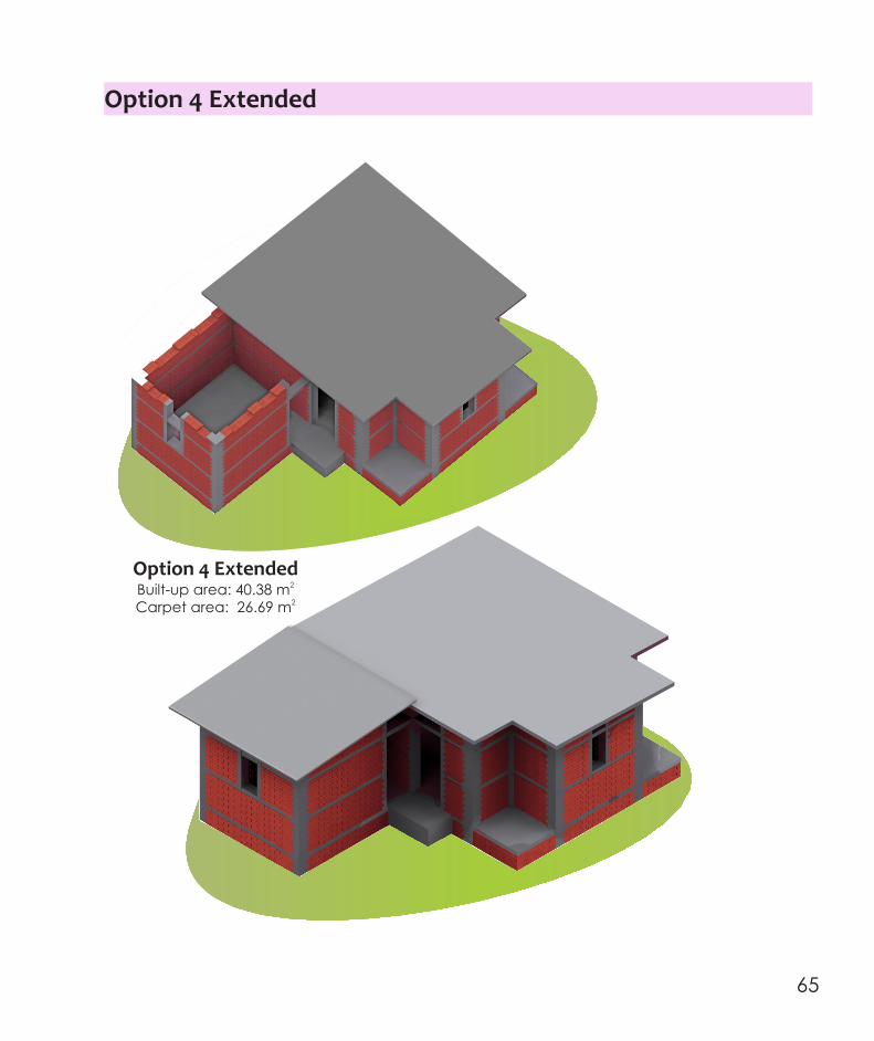
Option 4 Extended
Option 4 Extended2Built-up area: 40.38 m2Carpet area: 26.69 m
Option 4 Extended
How to extend my house ?
While extending the house, chip only the concrete from the projected lintel band left for future expansion
To extend the house, leave a 600mm projection from the Lintel Band in the direction of proposed expansion
64 65
Option 4 Extended
Option 4 Extended2Built-up area: 40.38 m2Carpet area: 26.69 m
Option 4 Extended
How to extend my house ?
While extending the house, chip only the concrete from the projected lintel band left for future expansion
To extend the house, leave a 600mm projection from the Lintel Band in the direction of proposed expansion
64 65

Option 4 Extended
10003000
150
50
825
75
900
300
100
1350
75
925
Section D‐D
Option 4 Extended
230
5150
230
6220550
230
3230
115
900
115115
1110 1110
1985
D
D
Plan
Main Room
Toilet
Bath
Kitchen
Access Road
Additional Room
66 67

Option 4 Extended
10003000
150
50
825
75
900
300
100
1350
75
925
Section D‐D
Option 4 Extended
230
5150
230
6220550
230
3230
115
900
115115
1110 1110
1985
D
D
Plan
Main Room
Toilet
Bath
Kitchen
Access Road
Additional Room
66 67

Option 5
150
625
75
1000
75
925
450
3300
Front Elevation
7
12
11
Brick Masonry Courses
230
1110
115
115
1110
230
5503460
230
750
230
1660
335115
230
1315
115
900 650
230
6090
230 115
550
230115
550860
900
235
230
2690
230 750230 115
B
Plan
230 2301200
B
A
A
Main Room4.20m x 3.00mKitchen
1.20 x 3.00m
Bath1.1m x 1.2mToilet
0.9m x 1.2m
Option 5
3.46 m
Bath1.2 m x 1.1 m
2(1.32 m )
Main Room4.20 m x 3.00 m
2(14.54 m )
Kitchen1.20 m x 3.00 m
2(2.77 m )
Toilet1.2 m x 0.9 m
2(1.08 m )
6.09
m
68 69

Option 5
000
2800
150
50
550
150
900
300
100
1350
75
925
Section A‐A
Section B‐B
2500
150
50
1250
900
300
1075
75
100
1350
2000
450
Option 5
Right Elevation
450
675
3300
2000
75
150
450
1000
100
625
150
75
925
450
600600
Right Elevation
Left Elevation of Toilet
2500
150
1250
300
1075
75
150
450
Backfilled earth
Unexcavated Ground
70 71

Option 5
1185 mm
3230 mm
12
11
Brick Masonry Courses
450
1000
1400
3850
75
75
925
Front Elevation
300
1000
1000
3400
150
75
925
150
250
1350
900
Section C‐C
Option 5
House with sloping roof
Plan
C
C
Main Room4.20m x 3.00m
Kitchen 1.20 x 3.00m
Ridge Line
Bath1.1m x 1.2mToilet
0.9m x 1.2m
Backfilled earth
Unexcavated Ground
72 73

Option 5
1185 mm
3230 mm
12
11
Brick Masonry Courses
450
1000
1400
3850
75
75
925
Front Elevation
300
1000
1000
3400
150
75
925
150
250
1350
900
Section C‐C
Option 5
House with sloping roof
Plan
C
C
Main Room4.20m x 3.00m
Kitchen 1.20 x 3.00m
Ridge Line
Bath1.1m x 1.2mToilet
0.9m x 1.2m
Backfilled earth
Unexcavated Ground
72 73

Option 5 Extended
Option 5 Extended2Built-up area: 40.22 m2Carpet area: 30.86 m
Option 5 Extended
How to extend my house ?
To extend the house, leave a projection of 600mm from the Lintel Band in the direction of proposed extension and while extending the house, chip only the concrete from the projected lintel band left for future expansion
74 75

Option 5 Extended
Option 5 Extended2Built-up area: 40.22 m2Carpet area: 30.86 m
Option 5 Extended
How to extend my house ?
To extend the house, leave a projection of 600mm from the Lintel Band in the direction of proposed extension and while extending the house, chip only the concrete from the projected lintel band left for future expansion
74 75
10003000
150
50
750
75
900
300
100
1350
150
925
Section D‐D
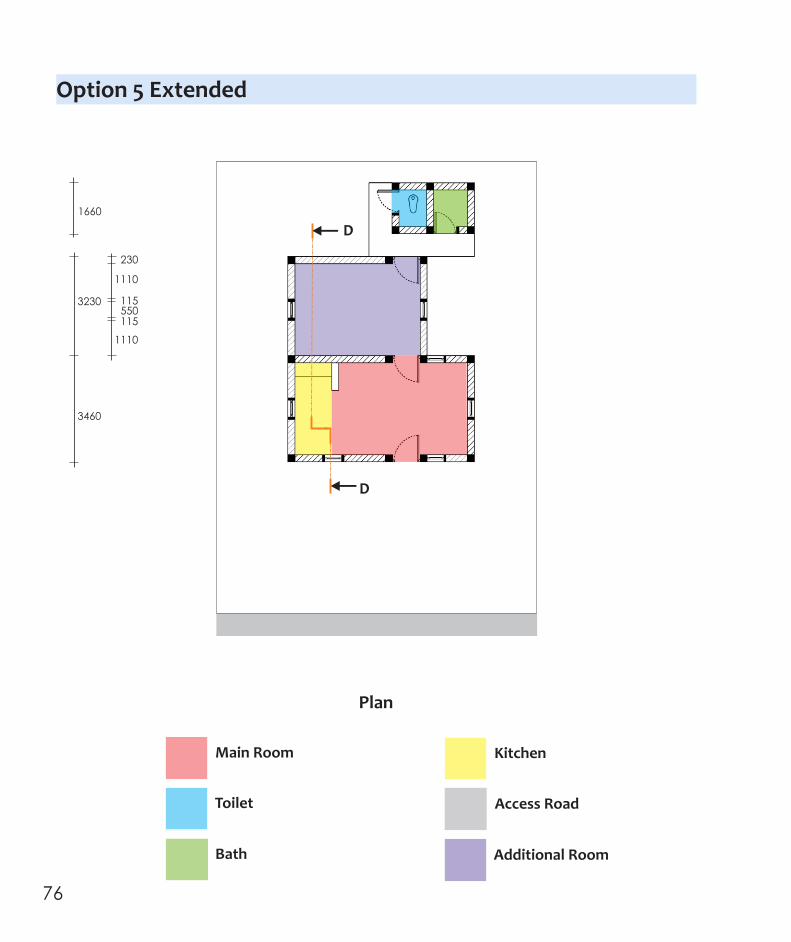
Option 5 ExtendedOption 5 Extended
230
1110
115
115
1110
550
3460
1660
3230
D
D
Plan
Main Room
Toilet
Bath
Kitchen
Access Road
Additional Room
76 77

10003000
150
50
750
75
900
300
100
1350
150
925
Section D‐D
Option 5 ExtendedOption 5 Extended
230
1110
115
115
1110
550
3460
1660
3230
D
D
Plan
Main Room
Toilet
Bath
Kitchen
Access Road
Additional Room
76 77

Basics of Construction
78 79
Basics of Construction
78 79

Cement Grade 33 cement is required in foundation and plinth (in plain concrete mat, and flooring), walls (in mortar, RC bands and RC vertical elements) and roof (reinforced concrete).
Sand Well graded clean river sand is required in foundation and plinth (in plain concrete mat, plinth fill, and flooring), walls (in mortar, RC bands and RC vertical elements) and roof (reinforced concrete).
Aggregate Well graded 20mm down stone aggregate is required in foundation and plinth (in plain concrete mat, and flooring), walls (in RC bands and RC vertical elements) and roof (reinforced concrete).
Steel Steel reinforcing bars of two types are required, namely high yield strength ribbed bars of 10mm diameter and mild steel smooth bars of 6mm diameter. It is required in walls (in RC bands and RC vertical elements) and roof (reinforced concrete).
Masonry Units Masonry units can be burnt clay bricks, natural stone (that is dressed), fly ash bricks or cement blocks. It is required in foundation and plinth (in masonry) and walls (in masonry).
Water Clean potable water is required for all components of the house, namely foundation and plinth, walls and roof.
What basic materials are required to build my house ?
80 81

Natural stone with no or little porosity (like granite) need not be soaked before use, but should be cleaned. But, the burnt clay bricks, fly ash bricks, cement blocks and sandstone blocks are porous, and hence should be watered for about 4 hours before laying. This can be done by (a) Submerging them in a tub, or(b) Watering them regularly with a hose to keep them wet all through.
Should masonry units be watered before I use ?Which masonry units can I use ?
Masonry walls/foundation using cement mortar can be built with following materials:
Burnt Clay Bricks Class B or better bunt clay bricks with compressive strength of at least 7-10 MPa. The size of the bricks considered are the standard brick available in India, namely of size 230mm 115mm 75mm.
Fly Ash Bricks Fly Ash bricks from nearby Thermal Power Plants with compressive strength of at least 7-10 MPa. The size of these units should be similar to that of the burnt clay bricks, namely 230 mm 115 mm 75 mm.
Sandstone Blocks Naturally available sandstone units can be used. Usually, it is relatively light and easy to shape by hand using a steel edge. The compressive strength of such units should be at least 7-10 MPa. The size of such hand-shaped units shall not exceed 300 mm 150 mm 100 mm.
Cement Blocks Machine-made cement blocks with 12.5 mm and down aggregated (in 1:3:6 mix of cement, sand and aggregate) can be used. These units should be properly cured to result in a compressive strength of such units of at least 7-10 MPa. The size of such hand-shaped units shall be similar to that of the burnt clay bricks, namely 230 mm 115 mm 75 mm.
82 83

What materials are required to build my floor ?
Earth Fill
Sand Fill
Plain Concrete Flooring
Earth Fill
Sand Fill
Plain Concrete Flooring
What materials are required to build my roof ?
Flat RoofReinforced Concrete
Sloping RoofMetal Sheet roofing
supported on steel angles
84 85

What materials are required to build my floor ?
Earth Fill
Sand Fill
Plain Concrete Flooring
Earth Fill
Sand Fill
Plain Concrete Flooring
What materials are required to build my roof ?
Flat RoofReinforced Concrete
Sloping RoofMetal Sheet roofing
supported on steel angles
84 85
Clean Sand1 Boxes
Cement1 Box
Water22 Litres
Aggregate4 Boxes
Concrete for roof slab
Concrete for RC vertical element and bands
Cement1 Box
Clean Sand2 Boxes
Water22 Litres
Aggregate6 Boxes
Concrete for foundation mat and flooring
Cement1 Box
Clean Sand3 Boxes
Water22 Litres
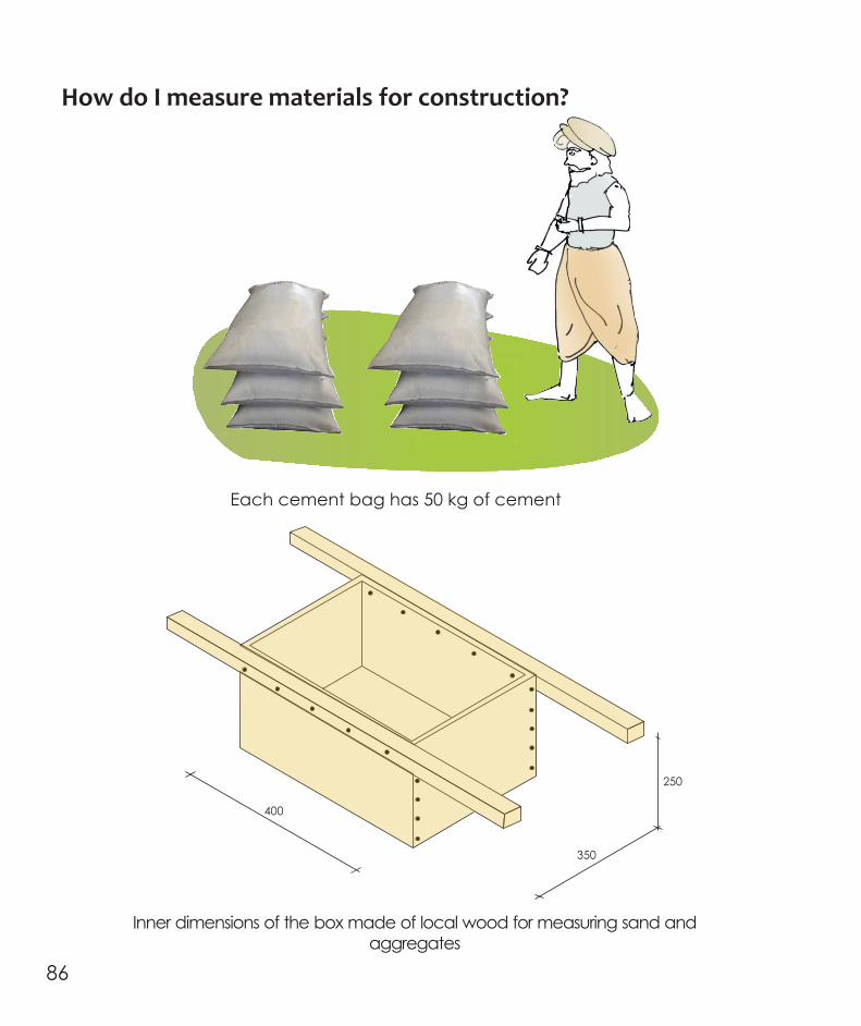
How do I measure materials for construction?
400
350
250
Each cement bag has 50 kg of cement
Inner dimensions of the box made of local wood for measuring sand and aggregates
What proportions of materials do I need?
Aggregate3 Boxes 1
2 /
86 87

Clean Sand1 Boxes
Cement1 Box
Water22 Litres
Aggregate4 Boxes
Concrete for roof slab
Concrete for RC vertical element and bands
Cement1 Box
Clean Sand2 Boxes
Water22 Litres
Aggregate6 Boxes
Concrete for foundation mat and flooring
Cement1 Box
Clean Sand3 Boxes
Water22 Litres
How do I measure materials for construction?
400
350
250
Each cement bag has 50 kg of cement
Inner dimensions of the box made of local wood for measuring sand and aggregates
What proportions of materials do I need?
Aggregate3 Boxes 1
2 /
86 87

Course 1, 3, 5, ...
Course 2, 4, 6, ...
Build walls in Flemish Bond
Do not build walls in English Bond
Course 1, 3, 5, ...
Course 2, 4, 6, ...
How do I make confined masonry walls ?
Clean Sand4 Boxes
Cement1 Box
Water20 Litres
Mortar for masonry
Provide 10mm thick cement mortar joints between brick courses
10 mm thick cement mortar joint
88 89

Course 1, 3, 5, ...
Course 2, 4, 6, ...
Build walls in Flemish Bond
Do not build walls in English Bond
Course 1, 3, 5, ...
Course 2, 4, 6, ...
How do I make confined masonry walls ?
Clean Sand4 Boxes
Cement1 Box
Water20 Litres
Mortar for masonry
Provide 10mm thick cement mortar joints between brick courses
10 mm thick cement mortar joint
88 89

Provide vertical formwork with supports for pouring concrete of RC vertical elements at brick masonry wall junctions
Formwork and supports
Build a maximum of 1.2 m of masonry wall segments in a day
DAY 11.2m
DAY 21.2m
DAY 41.2m
Build the walls leaving slots for RC elements
Day1 Day 2 Day 3
Day 4
DAY 31.2m
90 91

Vertical RC elements and horizontal RC bands hold masonry wall segments together (like a strap holding a package)
Masonry wall segmentsconfined on all sides with RC elements
RC elements prevent masonry form collapsing
Earthquake ground movement
Vertical RC elements keep brick masonry segments in place at the corners
Lintel, Sill and Plinth bands pass though the vertical RC elements RC bands and elements support the brick masonry at openings
Vertical and Horizontal confining elements around all openings
prevent early cracking at wall corners
92 93

How do I make vertical RC elements ?
10 mm diameter Longitudinal HYSD bars
6 mm diameter ties bars @ 200mm c/c
Reinforcement in Vertical RC confining members around door
openings (230mm X 115mm)
230
230
230
115
60 60
60
Straight length is given of hook ends beyond bend
How do I make horizontal RC bands ?
Sill and Lintel Bands
Plinth Band
Two 10 mm longitudinal Bars
6 mm diameter ties @ 200mm c/c
Four 10mm diameter longitudinal bars
6 mm diameter ties @ 200mm c/c
75
230
60 60
150
230
60
94 95

Straight WallsReinforcement bars will be at one level
How do I pass longitudinal bars of horizontal RC bands through vertical RC elements ?
T‐Junction of WallsReinforcement bars will be at two levels, one above the other
L‐Junction of WallsReinforcement will be at two levels, one above the other
600 600
600
600600 600
Window opening
Sill Band
Reinforcement detail at junction of RC element and RC sill band
Elevation
Plan
96 97

Construction of
Confined Masonry House ‐ Option 1
98 99

Construction of
Confined Masonry House ‐ Option 1
98 99

Step‐wise Procedure
Construction of a Confined Masonry House entails 3 major phases, namely
Foundation and Plinth
Superstructure
Roof
In this section, sequence of construction is elaborated pictorially in a step-wise procedure to recall all salient steps in the making of a Confined Masonry House. The following colour code is adopted for the above three phases of construction:
How do I build my Confined Masonry House ?
100 101

PC Mat
Steel reinforcement grill
Step 3Prepare reinforcement grill of RC vertical elements. Use steel reinforcement bars of full height till the roof level, up to which RC vertical elements are required. Provide lateral supports to hold these reinforcement grills during construction.
600
Foundation and Plinth
900
900
150
600
Foundation and Plinth
Step 1Dig a pit 900 mm wide and 900mm deep along the wall line of the house.
Step 2Pour in this pit plain cement concrete (1:3:6 mix of cement, sand and aggregate) of 150 mm thickness
900
900
900
150
900
102 103

Foundation and Plinth
350 450
Step 6Place the next four masonry courses with cement mortar (1:4 mix of cement and sand) above the earlier brick masonry wall
Brick Masonry Stone Masonry
900
300
150
300
Step 5Pour concrete (1:2:4 mix of cement, sand and aggregate) in gaps between brick masonry and steel reinforcement bars.
FIRST part of
RC vertical element
Brick Masonry
Steel Reinforcement Grill
Step 4Lay the first three masonry courses with cement mortar (1:4 mix of cement and sand) over the plain concrete mat leaving gaps near steel reinforcement provided for RC vertical elements.
Foundation and Plinth
Brick Masonry
900
300
150
900
450
900
600
Stone Masonry
104 105

Foundation and Plinth
THIRD part of
RC vertical element
Step 9Pour concrete (1:2:4 mix of cement, sand and aggregate) around steel reinforcement grill up to the top level of masonry course made so far.
Foundation and Plinth
900
300
150
300
350 450
Step 8Place the next four masonry courses with cement mortar (1:4 mix of cement and sand)
230 230
300 450
SECOND part of
RC vertical element
Step 7Pour concrete (1:2:4 mix of cement, sand and aggregate) around steel reinforcement grill up to the top level of masonry course made so far.
Brick Masonry Stone Masonry
106 107

Foundation and Plinth
THIRD part of
RC vertical element
Step 9Pour concrete (1:2:4 mix of cement, sand and aggregate) around steel reinforcement grill up to the top level of masonry course made so far.
Foundation and Plinth
900
300
150
300
350 450
Step 8Place the next four masonry courses with cement mortar (1:4 mix of cement and sand)
230 230
300 450
SECOND part of
RC vertical element
Step 7Pour concrete (1:2:4 mix of cement, sand and aggregate) around steel reinforcement grill up to the top level of masonry course made so far.
Brick Masonry Stone Masonry
106 107
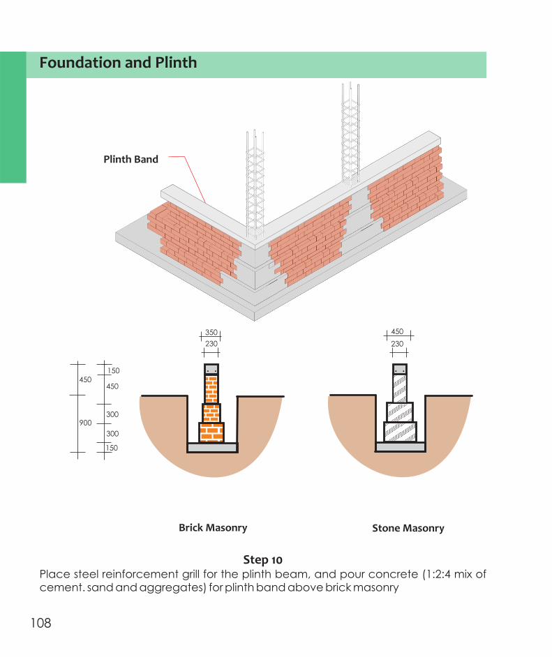
Foundation and Plinth
View of my Confined Masonry House after Step 10
Plain Concrete Mat
Brick Masonry
Vertical RC element
Plinth Band
150
Foundation and Plinth
900
300
150
300
450
230
450 450
Brick Masonry Stone Masonry
350
230
Plinth Band
Step 10Place steel reinforcement grill for the plinth beam, and pour concrete (1:2:4 mix of cement. sand and aggregates) for plinth band above brick masonry
108 109

Foundation and Plinth
For the construction of Foundation and Plinth, the materials required are:
Cement 36 bags
Sand 3 6.8 m
Aggregates3 20 mm (Nominal) : 3.1 m
Steel High Strength Steel : 180 m of 10 mm diameter bars Mild Steel : 190 m of 6 mm diameter bars
Burnt Clay Bricks 3,600
Step 11Fill the plinth with earth up to 225 mm above native ground level.
Step 12Top the earth fill with 150mm thick sand bed.
Step 13Place the plain concrete (1:3:6 mix of cement, sand and aggregate) over the layer of sand.
150 75
225
Step 11 Step 12 Step 13
225
Earth Fill
Sand Fill
Plain Concrete Flooring
Earth Fill
Sand Fill
Foundation and Plinth
110 111

Foundation and Plinth
For the construction of Foundation and Plinth, the materials required are:
Cement 36 bags
Sand 3 6.8 m
Aggregates3 20 mm (Nominal) : 3.1 m
Steel High Strength Steel : 180 m of 10 mm diameter bars Mild Steel : 190 m of 6 mm diameter bars
Burnt Clay Bricks 3,600
Step 11Fill the plinth with earth up to 225 mm above native ground level.
Step 12Top the earth fill with 150mm thick sand bed.
Step 13Place the plain concrete (1:3:6 mix of cement, sand and aggregate) over the layer of sand.
150 75
225
Step 11 Step 12 Step 13
225
Earth Fill
Sand Fill
Plain Concrete Flooring
Earth Fill
Sand Fill
Foundation and Plinth
110 111

Direct wetting with water hose Keeping the jute sheets moist
Step 17Cure the vertical RC elements and horizontal RC bands for at least 7 days. Two options are available, namely (a) wetting the RC elements with direct water jet every hour, and (b) cover the RC elements with jute sheets and keeping the jute sheets moist throughout.
Walls
Step 16
Sill Band
Step 15
Vertical RC Elements
Step 14
Masonry Wall Segments
Step 14Build masonry wall segments till 75 mm below sill level.
Step 15Pour concrete (1:2:4 mix of cement, sand and aggregate) of vertical RC elements around steel reinforcement grill up to the level of top masonry course.
Step 16Place the steel reinforcement cage and pour concrete (1:2:4 mix of cement, sand and aggregate) for Sill Band.
Walls
112 113

Walls
Step 21Build masonry wall segments with cement mortar (1: 4 mix of cement and sand) till the soffit of the roof slab
Step 22Pour concrete (1:2:4 mix of cement, sand and aggregate) around steel reinforcement cage of vertical RC elements up to the level of top masonry course.
Step 22
Vertical RC Elements Step 21
Masonry Wall Segments
Walls
Step 18
Masonry Wall SegmentsStep 19
Vertical RC Elements
Step 20
Lintel Band
Step 18Build masonry wall segments till 75 mm below lintel level.
Step 19Pour concrete (1:2:4 mix of cement, sand and aggregate) of vertical RC elements around steel reinforcement grill up to the level of top masonry course.
Step 20Place the steel reinforcement cage and pour concrete (1:2:4 mix of cement, sand and aggregate) for Lintel Band.
114 115

Walls
Wall EdgeDetail C
Inside WallDetail B
Wall Corner Detail A
600 600
600
Walls
Step 23Bend longitudinal bars of vertical RC elements at the ends into the roof slab
A
C
B
How do I bend reinforcement bars into roof slab?Details of A on next page
116 117
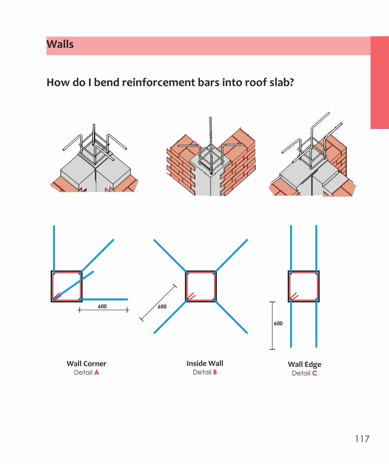
Walls
Wall EdgeDetail C
Inside WallDetail B
Wall Corner Detail A
600 600
600
Walls
Step 23Bend longitudinal bars of vertical RC elements at the ends into the roof slab
A
C
B
How do I bend reinforcement bars into roof slab?Details of A on next page
116 117

Walls
For the construction of Superstructure till Roof Level, the materials required are:
Cement 30 bags
Sand 3 2.5 m
Aggregates3 20 mm (Nominal) : 1.5 m
Steel High Strength Steel : 260 m of 10 mm diameter bars Mild Steel : 230 m of 6 mm diameter bars
Burnt Clay Bricks 4,200
118 119

Walls
For the construction of Superstructure till Roof Level, the materials required are:
Cement 30 bags
Sand 3 2.5 m
Aggregates3 20 mm (Nominal) : 1.5 m
Steel High Strength Steel : 260 m of 10 mm diameter bars Mild Steel : 230 m of 6 mm diameter bars
Burnt Clay Bricks 4,200
118 119

Reinforcement at Slab Corner Edge
Section A‐A
230 450 2000 230 400 450
Bottom Steel grid
Top Steel grid
Roof
1100
2000
1100
6 mm diameter MS bars
on 3 sides
10 mm diameter HYSD bars
on 3 sides
1100
Longitudinal reinforcement grid placed at bottom of slab
with 25 mm clear cover
10 mm diameter bars
on 4th sideA
A
Bottom Layer of Reinforcing Steel
Step 24Place reinforcement cage of RC roof slab
Y X
10 mm diameter HYSD bars @ 200mm centers
(Along Y‐direction: below)10 mm diameter HYSD bars @ 240mm centers
(Along X‐direction: above)
Top Layer of Reinforcing Steel
Along X-direction: belowAlong Y-direction: above
Extra bars for (1) Kitchen and Toilet area, and
(2)Cantilever part of Roof Slab
Confined Masonry Walls
How do I Build my house with a Flat roof
Roof
120 121

Step 26Cure concrete in flat roof slab after a day of casting. To hold the water, make small bunds of 25mm height to break the large slab into smaller ponds; use 1:8 cement-sand mortar for making these bunds. Water the slab for 28 days.
Mortar bunds to pond waterRC Slab
Slope -
1:100
Step 25Pour concrete (1:1 :3 mix of cement, sand and aggregates) of RC flat roof. Finish top surface with a gentle slope of 1:100 to drain rain water to the back side of the house.
Roof Roof
1 2 /
Slope 1:100
122 123

For the construction of Roof, the materials required are:
Cement 26 bags
Sand 3 1.1 m
Aggregates3 20 mm (Nominal) : 2.1 m
Steel High Strength Steel : 500 m of 10 mm diameter bars Mild Steel : 60 m of 6 mm diameter bars
Burnt Clay Bricks None
Roof Roof
124 125

For the construction of Roof, the materials required are:
Cement 26 bags
Sand 3 1.1 m
Aggregates3 20 mm (Nominal) : 2.1 m
Steel High Strength Steel : 500 m of 10 mm diameter bars Mild Steel : 60 m of 6 mm diameter bars
Burnt Clay Bricks None
Roof Roof
124 125

Perspective View
RC Gable Band
Corrugated Metal Roofing Sheets (1 m x 3 m)
Metal Ridge Flashing
Ridge Beam
Purlin
Rafters
P
Wall Runner
5690
1430
450
3130
450
6050
540 1270 1250 1250 1150 540
How do I build my house with a sloping roofMS Ridge Flashing
PurlinISA 65 x 65 x 6 Steel Angle
Corrugated Roofing Sheet (3 m x 1 m)
Section S‐S
Plan
Ridge BeamTwo ISA 65 x 65 x 6 Steel
Angles back to back
RaftersTwo ISA 65 x 65 x 6 Steel Angles
Wall RunnerISA 65 x 65 x 6 Steel Angle
Roof Roof
126 127

For the construction of entire house, the materials required are:
Cement 92 bags
Sand 3 10.4 m
Aggregates3 20 mm (Nominal) : 6.7 m
Steel High Strength Steel : 940 m of 10 mm diameter bars Mild Steel : 480 m of 6 mm diameter bars
Burnt Clay Bricks 7800
Water ~1,630 liters for mortar and concrete Extra for curing
Material required to build the complete house
Steel Channel Sectionscrewed to wall runner and purlin
Purlin
Wall Runner
Detail at P
Roof
128 129
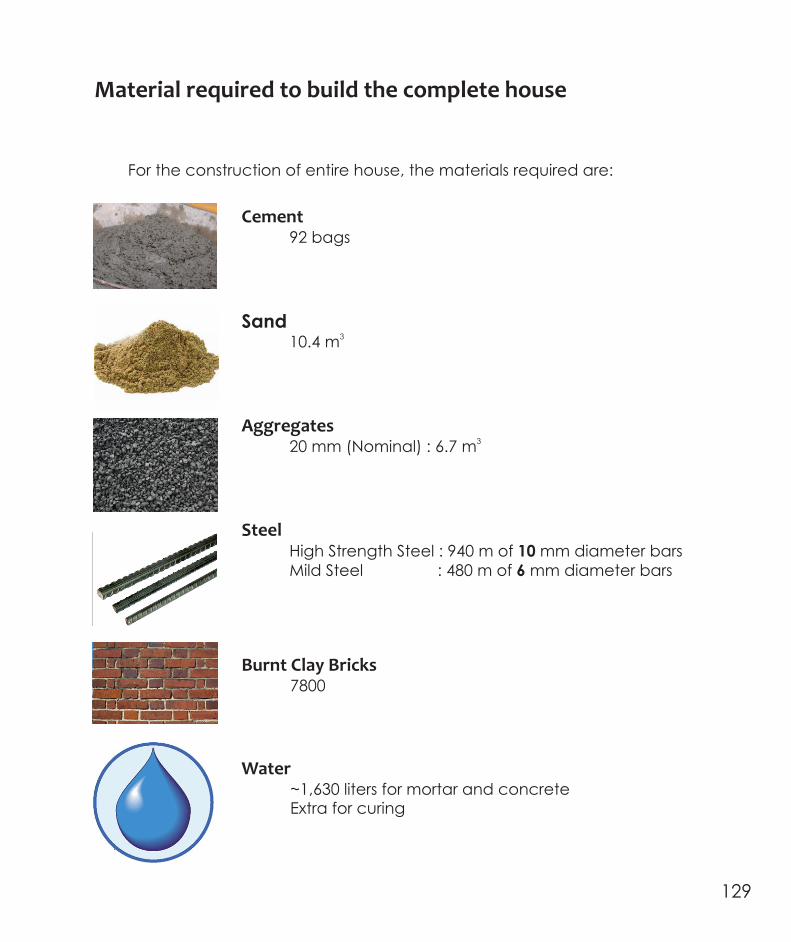

130 #

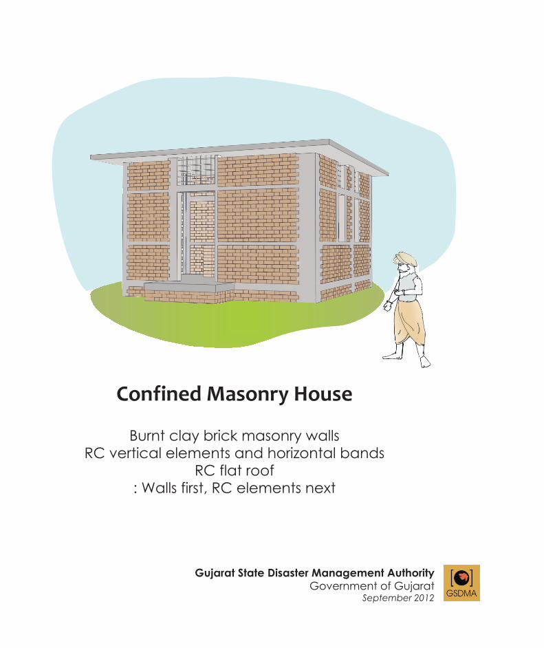
Confined Masonry House
Burnt clay brick masonry wallsRC vertical elements and horizontal bands
RC flat roof: Walls first, RC elements next
Gujarat State Disaster Management Authority Government of Gujarat
September 2012