confined masonrydesignguide82011
TRANSCRIPT
SEISMIC DESIGN GUIDE
FOR LOW-RISE CONFINED MASONRY BUILDINGS
Prepared by
Roberto Meli, Mexico (Co-Chair) Svetlana Brzev, Canada (Co-Chair)
Maximiliano Astroza, Chile Teddy Boen, Indonesia
Francisco Crisafulli, Argentina Junwu Dai, China
Mohammed Farsi, Algeria Tim Hart, USA
Ahmed Mebarki, France A.S. Moghadam, Iran Daniel Quiun, Peru
Miha Tomazevic, Slovenia Luis Yamin, Colombia
August 2011
Confined Masonry Network A Project of the World Housing Encyclopedia, EERI & IAEE
With funding support from Risk Management Solutions

© 2011 Earthquake Engineering Research Institute, Oakland, California 94612-1934. All rights reserved. No part of this book may be reproduced in any form or by any means without the prior written permission of the publisher, Earthquake Engineering Research Institute, 499 14th St., Suite 320, Oakland, CA 94612-1934. Telephone: 510/451-0905, Fax: 510/451-5411, E-mail: [email protected], Web site: www.eeri.org This tutorial is published by the Earthquake Engineering Research Institute, a nonprofit corporation. The objective of the Earthquake Engineering Research Institute is to reduce earthquake risk by advancing the science and practice of earthquake engineering by improving understanding of the impact of earthquakes on the physical, social, economic, political, and cultural environment, and by advocating comprehensive and realistic measures for reducing the harmful effects of earthquakes. Production of this tutorial has been supported in part by a generous contribution from Risk Management Solutions, Inc., Newark, California. This tutorial was written and reviewed by volunteers, all of whom participate in EERI and IAEE’s World Housing Encyclopedia project. Any opinions, findings, conclusions, or recommendations expressed herein are the authors’ and do not necessarily reflect the views of their organizations. ISBN: 978-1-932884-56-2 EERI Publication Number WHE-2011-02

Seismic Design Guide for Low-Rise Confined Masonry Buildings
2
Acknowledgments These guidelines were prepared by a committee of international experts, led by Roberto Meli of Mexico and Svetlana Brzev of Canada. Other committee members were: Maximiliano Astroza, Chile; Teddy Boen, Indonesia; Francisco Crisafulli, Argentina; Junwu Dai, China; Mohammed Farsi, Algeria; Tim Hart, USA; Ahmed Mebarki, France; A.S. Moghadam, Iran; Daniel Quiun, Peru; Miha Tomazevic, Slovenia; and Luis Yamin, Colombia. Particular thanks are due to Leonardo Flores and Miguel Angel Pacheco, research engineers at the National Centre for Disaster Prevention, Mexico City. They were responsible for compiling many of the codes that were reviewed as part of this project, conducting some of the analyses and preparing the drawings and figures. The authors gratefully acknowledge comments and suggestions made by Sergio Alcocer (Mexico), Richard Klingner (USA), and Durgesh Rai (India), who were external reviewers for this document. Detailed review comments by Andrew Charleson, Editor-in-Chief of the World Housing Encyclopedia, contributed to the quality of the document and are gratefully appreciated. The authors would also like to thank Bill McEwen of the Masonry Institute of British Columbia, Vancouver, Canada, Arturo Tena Colunga, and Greg Hale, SWBR, Rochester, NY, USA who reviewed this document and gave very useful comments. The authors would also like to acknowledge the financial support of Risk Management Solutions in the early stages of this project, and in particular the enthusiastic support received from Sahar Safaie. The authors also acknowledge the ongoing support of the Earthquake Engineering Research Institute and the staff member Marjorie Greene. The authors appreciate assistance by Michael Germeraad, EERI Graduate Intern, in the editing stage of this publication. Special thanks are due the National Information Centre of Earthquake Engineering at the Indian Institute of Technology, Kanpur, India, for allowing us to incorporate part of one of their publications on confined masonry, authored by co-chair Svetlana Brzev. If you have comments on this document, please forward them to Marjorie Greene at [email protected].

Seismic Design Guide for Low-Rise Confined Masonry Buildings
3
Table of Contents
1 INTRODUCTION.........................................................................................................................5
1.1 Scope and Objectives ...........................................................................................................................5
1.2 What is Confined Masonry Construction?..........................................................................................6 1.2.1 Key Components of a Confined Masonry Building..........................................................................6 1.2.2 Confined Masonry and Similar Building Technologies....................................................................7
1.3 Seismic Response of Confined Masonry Buildings ....................................................................... 10 1.3.1 Performance of Confined Masonry Buildings in Past Earthquakes.............................................. 10 1.3.2 General System Behavior............................................................................................................. 11 1.3.3 Seismic Failure Mechanisms........................................................................................................ 17 1.3.4 Seismic Response of Multi-story Confined Masonry Buildings .................................................... 21 1.3.5 Design and Construction Deficiencies Observed in Recent Earthquakes ................................... 24
2 GENERAL REQUIREMENTS...................................................................................................28
2.1 Design and Performance Objectives................................................................................................ 28
2.2 Seismic Hazard ................................................................................................................................... 28
2.3 General Planning and Design Aspects ............................................................................................ 29
2.4 Materials .............................................................................................................................................. 32 2.4.1 Units.............................................................................................................................................. 32 2.4.2 Mortar ........................................................................................................................................... 34 2.4.3 Concrete ....................................................................................................................................... 34 2.4.4 Reinforcing Steel .......................................................................................................................... 34 2.4.5 Masonry ........................................................................................................................................ 35 2.4.6 Testing of Masonry Materials ....................................................................................................... 36
3 GUIDELINES FOR NON-ENGINEERED CONFINED MASONRY BUILDINGS......................37
3.1 Building Components ........................................................................................................................ 37 3.1.1 Masonry Walls .............................................................................................................................. 37 3.1.2 Confining Elements (Tie-columns and Tie-beams) ...................................................................... 44 3.1.3 Additional Requirements for Buildings with Flexible Diaphragms................................................ 49
3.2 Construction Quality .......................................................................................................................... 51
CONCLUDING REMARKS..............................................................................................................52
REFERENCES.................................................................................................................................53

Seismic Design Guide for Low-Rise Confined Masonry Buildings
4
APPENDICES A Simplified Method for Wall Density Calculation in Low-Rise Buildings 56 B Guidelines for Inspection of Confined Masonry Construction 70 C Summary of Seismic Design Provisions for Confined Masonry Buildings from Relevant International Codes and Standards 78

Seismic Design Guide for Low-Rise Confined Masonry Buildings
5
1 Introduction
1.1 Scope and Objectives The purpose of this document is to: • Explain the mechanism of seismic response of confined masonry buildings for in- and out-of-
plane seismic effects and other relevant seismic response issues, • Recommend prescriptive design provisions for low-rise buildings related to the wall layout and
density, and prescribe minimum size requirements for structural components of confined masonry buildings (tie-columns, tie-beams, walls), reinforcement size and detailing, and
• Provide a summary of the seismic design provisions for confined masonry buildings from relevant international codes.
This document is divided into three chapters. Chapter 1 provides an overview of confined masonry construction and its components. It discusses the seismic performance of confined masonry buildings in past earthquakes, and is based largely on the publication Earthquake-Resistant Confined Masonry Construction (Brzev, 2008). Chapter 2 presents general requirements related to confined masonry construction. Chapter 3 outlines a guideline for low-rise non-engineered confined masonry buildings (up to two stories high). These buildings could be constructed without engineered design performed by qualified engineers or architects, and thus no design calculations or procedures are included. Many single-family dwellings are built in this manner. Although this guide is focused on low-rise confined masonry buildings, medium-rise engineered buildings of this type (up to five stories high) can be designed and built following the recommendations of this document and other relevant international codes and standards. However, note that additional analysis and design procedures and requirements for engineered confined masonry buildings are outside the scope of this document. It is expected that this guide will be a useful resource for design engineers and architects, academics, code development organizations and non-governmental organizations in countries in which design codes and standards do not contain seismic design provisions for confined masonry construction. This document may also be a useful reference for design engineers and other professionals in the countries where code design provisions for confined masonry construction are currently in place. This document was developed by a group of international experts in earthquake engineering and confined masonry construction. The recommendations are based on design and construction experience and research studies from countries and regions where confined masonry construction has been practiced for many decades, including Mexico, Peru, Chile, Argentina, Iran, Indonesia, China, Algeria and Slovenia. References to relevant provisions of various international standards and codes have been made in the document.
Seismic Design Guide for Low-Rise Confined Masonry Buildings
6
1.2 What is Confined Masonry Construction?
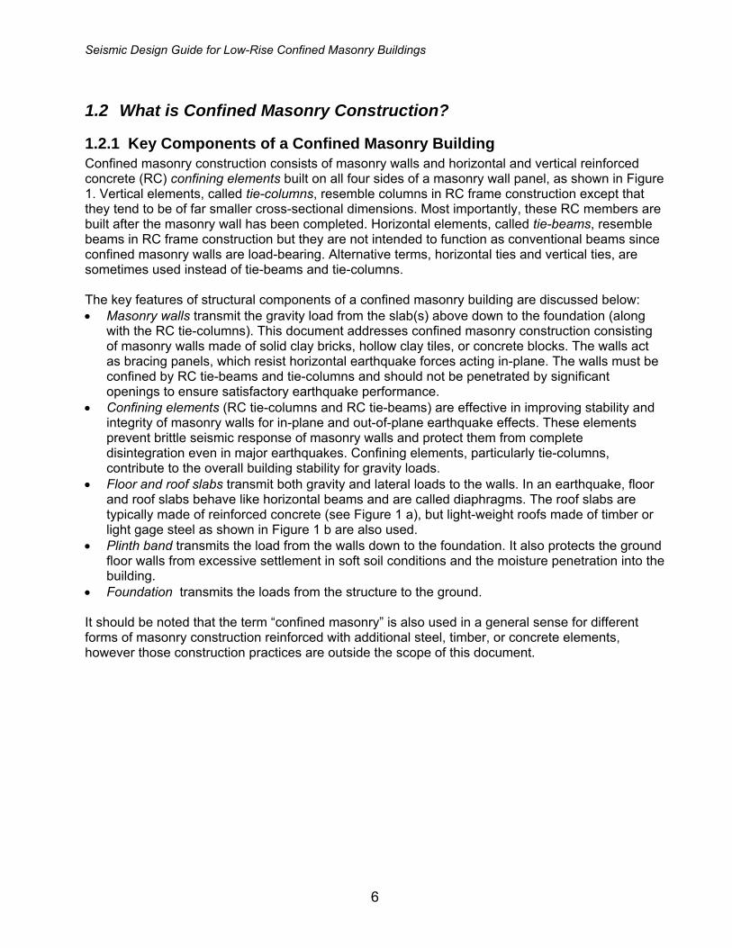
1.2.1 Key Components of a Confined Masonry Building Confined masonry construction consists of masonry walls and horizontal and vertical reinforced concrete (RC) confining elements built on all four sides of a masonry wall panel, as shown in Figure 1. Vertical elements, called tie-columns, resemble columns in RC frame construction except that they tend to be of far smaller cross-sectional dimensions. Most importantly, these RC members are built after the masonry wall has been completed. Horizontal elements, called tie-beams, resemble beams in RC frame construction but they are not intended to function as conventional beams since confined masonry walls are load-bearing. Alternative terms, horizontal ties and vertical ties, are sometimes used instead of tie-beams and tie-columns. The key features of structural components of a confined masonry building are discussed below: • Masonry walls transmit the gravity load from the slab(s) above down to the foundation (along
with the RC tie-columns). This document addresses confined masonry construction consisting of masonry walls made of solid clay bricks, hollow clay tiles, or concrete blocks. The walls act as bracing panels, which resist horizontal earthquake forces acting in-plane. The walls must be confined by RC tie-beams and tie-columns and should not be penetrated by significant openings to ensure satisfactory earthquake performance.
• Confining elements (RC tie-columns and RC tie-beams) are effective in improving stability and integrity of masonry walls for in-plane and out-of-plane earthquake effects. These elements prevent brittle seismic response of masonry walls and protect them from complete disintegration even in major earthquakes. Confining elements, particularly tie-columns, contribute to the overall building stability for gravity loads.
• Floor and roof slabs transmit both gravity and lateral loads to the walls. In an earthquake, floor and roof slabs behave like horizontal beams and are called diaphragms. The roof slabs are typically made of reinforced concrete (see Figure 1 a), but light-weight roofs made of timber or light gage steel as shown in Figure 1 b are also used.
• Plinth band transmits the load from the walls down to the foundation. It also protects the ground floor walls from excessive settlement in soft soil conditions and the moisture penetration into the building.
• Foundation transmits the loads from the structure to the ground. It should be noted that the term “confined masonry” is also used in a general sense for different forms of masonry construction reinforced with additional steel, timber, or concrete elements, however those construction practices are outside the scope of this document.

Seismic Design Guide for Low-Rise Confined Masonry Buildings
7
a) b)
Figure 1. A typical confined masonry building: a) flat RC roof (Brzev, 2008), and b) pitched timber roof (Boen, 2009).
1.2.2 Confined Masonry and Similar Building Technologies Confined masonry building technology is somewhat similar to both reinforced masonry and reinforced concrete frame construction with infill walls. It should be noted, however, that differences between these building technologies are significant in terms of construction sequence, complexity, and seismic performance. Since features of confined masonry construction practice are not well known on a global scale, a comparison of these building technologies is presented next. Reinforced Masonry and Confined Masonry: A Comparison In reinforced masonry, vertical and horizontal reinforcing bars are provided to enhance the strength and ductility (deformability) of masonry walls. Masonry units are usually hollow and made either of concrete or clay. Vertical reinforcing bars are placed in the hollow cores, which are subsequently grouted with a cement-based grout to anchor the reinforcement and protect it from corrosion. Vertical reinforcement is placed at the wall corners and intersections, around the openings, and at additional locations depending on expected seismic loads. Horizontal reinforcement is provided in the form of ladder-shaped wire reinforcement placed in horizontal joints, or deformed reinforcing bars placed in bond beams, typically located at floor and/or lintel levels. In confined masonry, the reinforcement is concentrated in vertical and horizontal RC confining elements whereas the masonry walls are usually free of reinforcement. Figure 2 illustrates the difference between reinforced and confined masonry construction. Advanced construction skills and inspection at different stages of construction are necessary to ensure quality of reinforced masonry. For example, vertical wall reinforcement placed in the hollow cores in masonry blocks must be continuous from the foundation to the roof level, and must match dowels (vertical bars) extended from the foundation. Subsequently, hollow cores (cells) in reinforced masonry blocks need to be filled with cement-based grout with specific mix proportions for placing it into relatively small-sized cores. Horizontal reinforcement is placed into bond beam blocks which also need to be grouted. Specialized equipment is used for pumping grout into masonry. Confined masonry is a simpler and
Seismic Design Guide for Low-Rise Confined Masonry Buildings
8
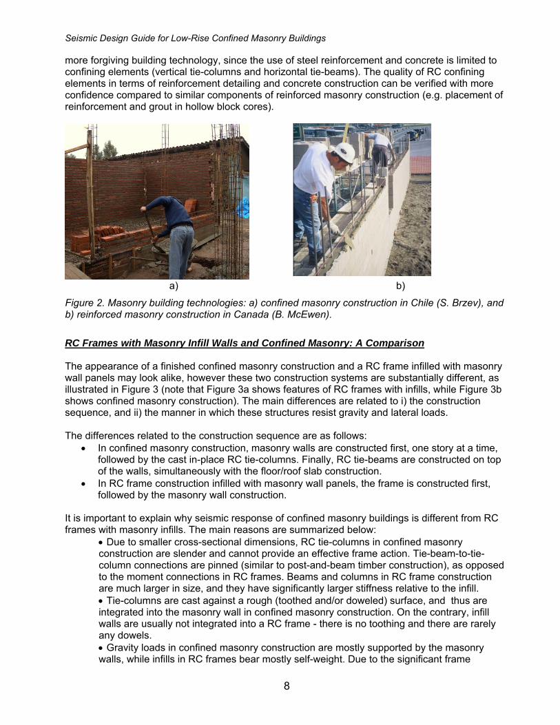
more forgiving building technology, since the use of steel reinforcement and concrete is limited to confining elements (vertical tie-columns and horizontal tie-beams). The quality of RC confining elements in terms of reinforcement detailing and concrete construction can be verified with more confidence compared to similar components of reinforced masonry construction (e.g. placement of reinforcement and grout in hollow block cores).
a) b)
Figure 2. Masonry building technologies: a) confined masonry construction in Chile (S. Brzev), and b) reinforced masonry construction in Canada (B. McEwen).
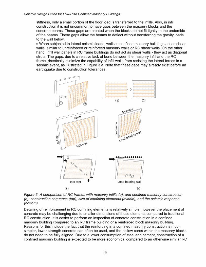
RC Frames with Masonry Infill Walls and Confined Masonry: A Comparison The appearance of a finished confined masonry construction and a RC frame infilled with masonry wall panels may look alike, however these two construction systems are substantially different, as illustrated in Figure 3 (note that Figure 3a shows features of RC frames with infills, while Figure 3b shows confined masonry construction). The main differences are related to i) the construction sequence, and ii) the manner in which these structures resist gravity and lateral loads. The differences related to the construction sequence are as follows:
• In confined masonry construction, masonry walls are constructed first, one story at a time, followed by the cast in-place RC tie-columns. Finally, RC tie-beams are constructed on top of the walls, simultaneously with the floor/roof slab construction.
• In RC frame construction infilled with masonry wall panels, the frame is constructed first, followed by the masonry wall construction.
It is important to explain why seismic response of confined masonry buildings is different from RC frames with masonry infills. The main reasons are summarized below:
• Due to smaller cross-sectional dimensions, RC tie-columns in confined masonry construction are slender and cannot provide an effective frame action. Tie-beam-to-tie-column connections are pinned (similar to post-and-beam timber construction), as opposed to the moment connections in RC frames. Beams and columns in RC frame construction are much larger in size, and they have significantly larger stiffness relative to the infill. • Tie-columns are cast against a rough (toothed and/or doweled) surface, and thus are integrated into the masonry wall in confined masonry construction. On the contrary, infill walls are usually not integrated into a RC frame - there is no toothing and there are rarely any dowels. • Gravity loads in confined masonry construction are mostly supported by the masonry walls, while infills in RC frames bear mostly self-weight. Due to the significant frame
Seismic Design Guide for Low-Rise Confined Masonry Buildings
9
stiffness, only a small portion of the floor load is transferred to the infills. Also, in infill construction it is not uncommon to have gaps between the masonry blocks and the concrete beams. These gaps are created when the blocks do not fit tightly to the underside of the beams. These gaps allow the beams to deflect without transferring the gravity loads to the wall below. • When subjected to lateral seismic loads, walls in confined masonry buildings act as shear walls, similar to unreinforced or reinforced masonry walls or RC shear walls. On the other hand, infill wall panels in RC frame buildings do not act as shear walls - they act as diagonal struts. The gaps, due to a relative lack of bond between the masonry infill and the RC frame, drastically minimize the capability of infill walls from resisting the lateral forces in a seismic event, as illustrated in Figure 3 a. Note that these gaps may already exist before an earthquake due to construction tolerances.
1 21 2
Infill wallLoad bearing wall
colu
mn tie
-col
u mn
beam
tie-beam
Infill wall Load bearing wall a) b)
Figure 3. A comparison of RC frames with masonry infills (a), and confined masonry construction (b): construction sequence (top); size of confining elements (middle), and the seismic response (bottom). Detailing of reinforcement in RC confining elements is relatively simple, however the placement of concrete may be challenging due to smaller dimensions of these elements compared to traditional RC construction. It is easier to perform an inspection of concrete construction in a confined masonry building compared to an RC frame building or a reinforced block masonry building. Reasons for this include the fact that the reinforcing in a confined masonry construction is much simpler, lower strength concrete can often be used, and the hollow cores within the masonry blocks do not need to be fully aligned. Due to a lower consumption of steel and cement, construction of a confined masonry building is expected to be more economical compared to an otherwise similar RC

Seismic Design Guide for Low-Rise Confined Masonry Buildings
10
frame building with masonry infills (particularly in developing countries where labor is relatively inexpensive).
1.3 Seismic Response of Confined Masonry Buildings
1.3.1 Performance of Confined Masonry Buildings in Past Earthquakes Confined masonry construction has evolved through an informal process based on its satisfactory performance in past earthquakes. The first reported use of confined masonry construction was in the reconstruction of buildings destroyed by the 1908 Messina, Italy earthquake (M 7.2), which killed over 70,000 people. Over the last 30 years, confined masonry construction has been practiced in Mediterranean Europe (Italy, Slovenia, Serbia), Latin America (Mexico, Chile, Peru, Colombia, Argentina, and other countries), the Middle East (Iran, Algeria, Morocco), South Asia (Indonesia), and the Far East (China). It is important to note that confined masonry construction is widely used in countries and regions of extremely high seismic hazard. Several examples of confined masonry construction around the world, from Argentina, Chile, Iran, Peru, Serbia and Slovenia, are featured in the World Housing Encyclopedia (EERI/IAEE, 2000). Well built confined masonry buildings were able to survive the effects of major earthquakes without collapse and in most cases without significant damage. Confined masonry tends to be quite forgiving of minor design and construction flaws, as well as material deficiencies provided that the buildings have regular floor plan and sufficient wall density. Poor seismic performance has been noted only where gross construction errors, design flaws, or material deficiencies have been introduced in the building design and construction process. Poor performance is usually associated with insufficient amount of confined masonry walls in one or both plan directions, inadequate size of the tie-columns, deficiencies in tie-column reinforcement in terms of amount and detailing, discontinuous tie-beams, inadequate diaphragm connections, and inappropriate structural configuration. The earliest reports describing the earthquake performance of confined masonry buildings date back to the 1939 Chile earthquake (M 7.8). In Chillán, where Modified Mercalli Intensity (MMI) of IX was reported, over 50% of all inspected confined masonry buildings survived the earthquake without any damage, whereas around 60% of unreinforced masonry buildings either partially or entirely collapsed, resulting in a death toll of 30,000. Following the 1939 earthquake, confined masonry was exposed to several significant earthquakes in Chile, including the 1985 Llolleo earthquake (M 7.8) and, more recently, the February 27, 2010 Maule earthquake (M 8.8). Low-rise confined masonry buildings performed very well in the Maule earthquake. Figure 4 a shows a two-story confined masonry house in Curepto which remained virtually undamaged, while the adjacent adobe house has collapsed (see Astroza et al. (2010) and Brzev et al. (2010) for more details on performance of confined masonry buildings in the 2010 Chile earthquake). A very similar observation was made after the 2007 Pisco, Peru earthquake (M 8.0), where confined masonry buildings performed very well compared to other types of masonry buildings which were badly damaged or collapsed. Figure 4 b shows a four-story confined masonry building in Ica, Peru which remained virtually undamaged in the earthquake. Seismic performance of confined masonry buildings in other countries will be illustrated in the following sections. Earthquake-induced life loss in confined masonry buildings has been insignificant in countries and regions where this technology has been practiced. However, a few medium-rise confined masonry buildings collapsed in recent earthquakes, e.g. the 2010 Maule, Chile earthquake and the 2007 Pisco, Peru earthquake (see Section 1.3.4 for a detailed discussion).
Seismic Design Guide for Low-Rise Confined Masonry Buildings
11
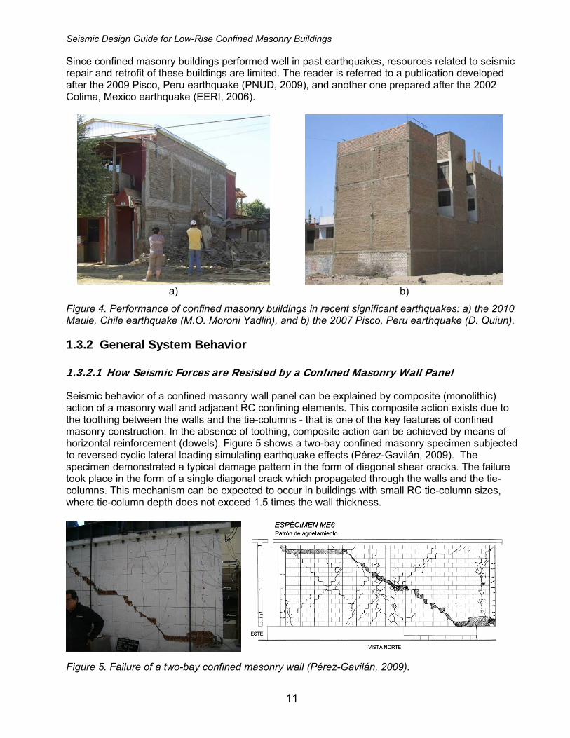
Since confined masonry buildings performed well in past earthquakes, resources related to seismic repair and retrofit of these buildings are limited. The reader is referred to a publication developed after the 2009 Pisco, Peru earthquake (PNUD, 2009), and another one prepared after the 2002 Colima, Mexico earthquake (EERI, 2006).
a)
b)
Figure 4. Performance of confined masonry buildings in recent significant earthquakes: a) the 2010 Maule, Chile earthquake (M.O. Moroni Yadlin), and b) the 2007 Pisco, Peru earthquake (D. Quiun).
1.3.2 General System Behavior 1.3.2.1 How Seismic Forces are Resisted by a Confined Masonry Wall Panel Seismic behavior of a confined masonry wall panel can be explained by composite (monolithic) action of a masonry wall and adjacent RC confining elements. This composite action exists due to the toothing between the walls and the tie-columns - that is one of the key features of confined masonry construction. In the absence of toothing, composite action can be achieved by means of horizontal reinforcement (dowels). Figure 5 shows a two-bay confined masonry specimen subjected to reversed cyclic lateral loading simulating earthquake effects (Pérez-Gavilán, 2009). The specimen demonstrated a typical damage pattern in the form of diagonal shear cracks. The failure took place in the form of a single diagonal crack which propagated through the walls and the tie-columns. This mechanism can be expected to occur in buildings with small RC tie-column sizes, where tie-column depth does not exceed 1.5 times the wall thickness.
Figure 5. Failure of a two-bay confined masonry wall (Pérez-Gavilán, 2009).

Seismic Design Guide for Low-Rise Confined Masonry Buildings
12
When the tie-columns and tie-beams have larger sections (depths in excess of two times the wall thickness), relative stiffness of these elements compared to the walls is significant. As a result, behavior of a confined masonry wall panel is similar to an RC frame with masonry infill wall panel. A confined masonry wall panel can be modeled using the "strut and tie" model, where a vertical crack (separation) develops between the wall and the adjoining tie-columns. At the certain load level, the wall will start to act like a diagonal strut, while the adjacent columns act in tension and/or compression, depending on the direction of lateral earthquake forces. The difference between the two cases is clearly shown in the experimental study by San Bartolomé et al. (2010), where the confined masonry wall specimens had two different tie-column widths (200 and 400 mm). A vertical separation between the wall and tie-columns occurred in the specimen M2 with 400 mm wide tie-columns. Failure mechanism of the specimen M1 with 200 mm wide columns was characterized by composite wall and tie-column action and diagonal cracking, where cracks propagated into the columns. Damage patterns in the specimens at the final stage of testing are shown in Figure 6.
a)
b)
Figure 6. Seismic behavior of masonry walls confined by RC tie-columns: a) composite wall and tie-column action (specimen M1 with 200 mm wide tie-columns), and b) vertical separation at the wall-to-column interface (specimen M2 with 400 mm wide columns) (San Bartolomé et al. 2010).
Shear capacity of a confined masonry wall panel (3) can be determined as the sum of contributions of the masonry wall (1) and the adjacent RC tie-columns (2), as shown in Figure 7. Note that the shear capacity of tie-columns can be reached only after the masonry has been severely cracked and its shear capacity has significantly decreased. As a result, it is recommended to consider only a partial contribution of tie-columns to the shear capacity of a confined masonry panel. A conservative estimate can be made by assuming that the tie-columns are integrated with the masonry wall, thus a cross-sectional area of the confined masonry wall can be calculated by taking into account the total panel length. This approach is the basis for deriving the minimum required wall density (see Appendix A of this document).

Seismic Design Guide for Low-Rise Confined Masonry Buildings
13
It can be seen from the diagram in Figure 7 that the stiffness and strength of a confined masonry panel drop following the onset of diagonal cracking in the wall (point 1). However, the load-resisting capacity of the panel is maintained until the critical regions of the confining elements experience significant cracking (point 2). This shows that a significant lateral deformation and ductility can be attained before the failure of a properly designed and constructed confined masonry panel (point 3).
Displacement
She
ar fo
rce
1 2 3
12
3
P P PV
Vm
Vm
V 'm
Σ Vc
Vc
VcV 'm
Figure 7. Mechanism of shear resistance for a confined masonry wall panel: 1) diagonal cracking in the masonry wall; 2) diagonal cracks have propagated from the wall into the tie-columns, and 3) shear failure of the RC tie-columns and the confined masonry wall panel.
Critical regions in a confined masonry structure are end zones of tie-columns (top and bottom region at each floor level), as shown in Figure 8 a. An example of a confined masonry wall panel which experienced significant damage in the RC tie-columns in the 2010 Chile earthquake is shown in Figure 8 b. In most cases, confined masonry panels demonstrate a shear-dominant seismic response. Longitudinal reinforcement in the RC tie-columns provides an adequate flexural resistance, thus the flexural failure mechanism does not govern; this is an assumption taken in Appendix A of this document.

Seismic Design Guide for Low-Rise Confined Masonry Buildings
14
Masonry wallsCritical regions
Diagonal cracking
window
a)
b)
Figure 8. Critical regions in a confined masonry building: a) a general diagram showing critical regions in the RC tie-columns, and b) tie-column damage observed in the 2010 Chile earthquake (M. Astroza).
Confined masonry panels are subjected to the effects of axial gravity load (due to self-weight and tributary floor/roof loads). Figure 9 a illustrates a confined masonry panel which resists the combined effect of axial load P and bending moment M. The capacity of the composite confined masonry panel section under the combined effect of axial load and bending moment can be determined by treating the confined masonry panel similar to a RC shear wall acting in unison with the adjacent columns. The strain diagram shows that a portion of the panel is in tension, while the remaining portion is in compression (see Figure 9 b). It is assumed that the masonry and concrete are not able to resist tension, hence tensile stresses are resisted by the longitudinal reinforcement in tie-columns. The compression stresses are resisted by concrete, masonry, and longitudinal reinforcement in tie-columns (see Figure 9 c). The flexural capacity of the panel section is determined from the sum of moments created by various internal forces around point O (centroid of the section).

Seismic Design Guide for Low-Rise Confined Masonry Buildings
15
Compressionsteel
Tensionsteel
TensionCompression
Compressionmasonry
Compressionconcrete
h
V
P
M = Vxh
P
a)
b)
c)M
P
O
Figure 9. A confined masonry wall panel subjected to the combined axial load and bending: a) panel elevation and a typical cross-section; b) strain distribution, and c) internal force distribution.
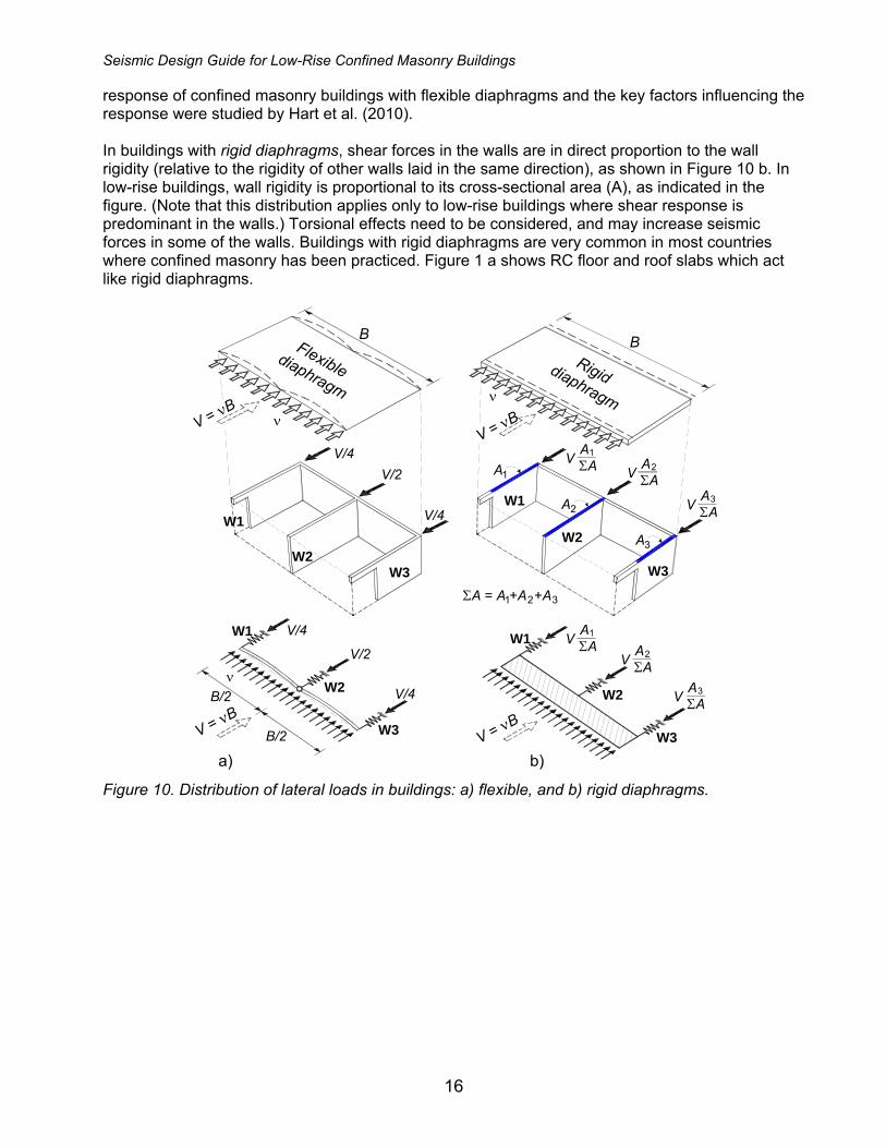
1.3.2.2 The Effect of Floor and Roof Systems The seismic response of a confined masonry building and the internal distribution of earthquake forces depend on the type of floor and/or roof system. Floor and roof systems are horizontal elements of the lateral load-resisting system that act as diaphragms. Their primary role is to transfer earthquake-induced lateral forces in the building to vertical elements (shear walls) that resist these forces. A diaphragm can be treated as an I-shaped beam laid in the horizontal plane. The floor or roof functions as the web to resist the shear forces, while the boundary elements (tie-beams in confined masonry buildings) act as the flanges and resist tension and compression stresses due to bending moments. The manner in which the total shear force is distributed to the vertical elements (walls) depends on the wall rigidity relative to the diaphragm rigidity. For design purposes, diaphragms are usually treated either as flexible or rigid. Timber or light gage steel diaphragms are generally considered as flexible (unless bracing is provided in the plane of the diaphragm), while cast in-place concrete or composite masonry and concrete floor systems are usually considered as rigid diaphragms. In buildings with flexible diaphragms, the distribution of shear forces to walls is independent of their relative rigidity. These diaphragms act like a series of simple horizontal beams spanning between the walls, as shown in Figure 10 a. A flexible diaphragm must have adequate strength to transfer the shear forces to the walls, but cannot distribute torsional forces to the walls in the direction perpendicular to the earthquake ground motion. Flexible diaphragms are not common in confined masonry buildings, with the exception of countries in warm climate regions, e.g. Indonesia, Chile, etc., where timber trusses have been routinely used for the roof construction. An example of a confined masonry building with a flexible timber roof diaphragm is shown in Figure 1 b. Seismic
Seismic Design Guide for Low-Rise Confined Masonry Buildings
16
response of confined masonry buildings with flexible diaphragms and the key factors influencing the response were studied by Hart et al. (2010). In buildings with rigid diaphragms, shear forces in the walls are in direct proportion to the wall rigidity (relative to the rigidity of other walls laid in the same direction), as shown in Figure 10 b. In low-rise buildings, wall rigidity is proportional to its cross-sectional area (A), as indicated in the figure. (Note that this distribution applies only to low-rise buildings where shear response is predominant in the walls.) Torsional effects need to be considered, and may increase seismic forces in some of the walls. Buildings with rigid diaphragms are very common in most countries where confined masonry has been practiced. Figure 1 a shows RC floor and roof slabs which act like rigid diaphragms.
W1
W3W2
W1
W3
W2
BB
νV = νB
V = νBν
V/4V/2
V/4
A1V A
ΣA1
ΣA = A +A +A1
ν
V/4
V/2
V/4B/2
B/2
W1
W2
W3
�
W1
W2
W3
Flexiblediaphragm
Rigiddiaphragm
V AΣA
2
V AΣA
3A2
A3
2 3
V = νB
V AΣA
1
V AΣA
2
V AΣA
3
a) b)
V = νB
Figure 10. Distribution of lateral loads in buildings: a) flexible, and b) rigid diaphragms.

Seismic Design Guide for Low-Rise Confined Masonry Buildings
17
1.3.3 Seismic Failure Mechanisms 1.3.3.1 Introduction Failure mechanisms in confined masonry wall panels depend on the direction of earthquake loading. There are two possible scenarios:
a) Earthquake ground shaking in the direction parallel with the longitudinal wall axis, also known as in-plane seismic loading, or
b) Earthquake ground shaking perpendicular to the longitudinal wall axis, or out-of-plane seismic loading.
Seismic response of confined masonry structures subjected to in-plane and out-of-plane seismic loading is discussed in the following sections. 1.3.3.2 In-plane Failure Mechanisms A confined masonry wall subjected to in-plane lateral earthquake loading develops either a shear or flexural failure mechanism (Tomazevic and Klemenc, 1997; Tomazevic, 1999; Yoshimura et al. 2004). Shear failure mechanism is characterized by distributed diagonal cracking in the wall. The damage is caused either by the bond destruction at the mortar-brick interface (shear-friction mechanism), or tensile cracking in the masonry units. Initially, a masonry wall panel resists the effects of lateral earthquake loads while the RC tie-columns do not play a significant role. However, once cracking takes place, the wall pushes the tie-columns sideways. At that stage, the vertical reinforcement in the tie-columns resists tension and compression stresses (Tomazevic and Klemenc, 1997). Damage in the tie-columns at the ultimate load level is concentrated at the top and bottom of the panel. Shear failure can lead to severe damage in the masonry wall and at the top and bottom of the tie-columns, as shown in Figure 11. (Note that this mechanism was also discussed in Section 1.3.2.1.)
Figure 11. Shear failure of confined masonry walls (Yoshimura et al., 2004 – left; Aguilar and Alcocer, 2001 – right).
In-plane shear failure of ground floor confined masonry walls is the most common damage pattern observed in past earthquakes, e.g. the 1999 Tehuacán and the 2003 Tecomán, Mexico earthquakes, the 2001 San Salvador, El Salvador earthquake, and the 2010 Maule, Chile earthquake. Figure 12 a shows damage at the ground floor level of a three-story building in Cauquenes. The building was constructed in 1993, before the 1997 edition of Chilean code NCh2123, which contains relevant design restrictions for confined masonry buildings, had been issued. Figure 12 b shows shear failure of a pier in a confined masonry building due to the 2001 El Salvador earthquake (note absence of RC tie-columns at openings).

Seismic Design Guide for Low-Rise Confined Masonry Buildings
18
a) b)
Figure 12. In-plane shear failure of poorly confined masonry walls: a) the 2010 Maule, Chile earthquake (M. Astroza), and b) the 2001 El Salvador earthquake (EERI, 2001).
Flexural failure mechanism due to in-plane lateral loads is characterized by horizontal cracking of the mortar bed joints located on the tension side of the wall, as shown in Figure 13 (Yoshimura et al. 2004). Separation of the tie-columns from the wall was observed in some cases when a toothed wall-to-column connection was absent, and there were no connecting ties between the tie-column and the wall. Extensive horizontal cracking in tie-columns and shear cracking in the walls can be observed in Figure 13. Flexural mechanism is not as critical as shear mechanism since it does not lead to brittle failure, although crushing and disintegration of masonry in the compression toe area of the wall may take place.
Figure 13. Flexural failure of confined masonry walls (Yoshimura et al., 2004).
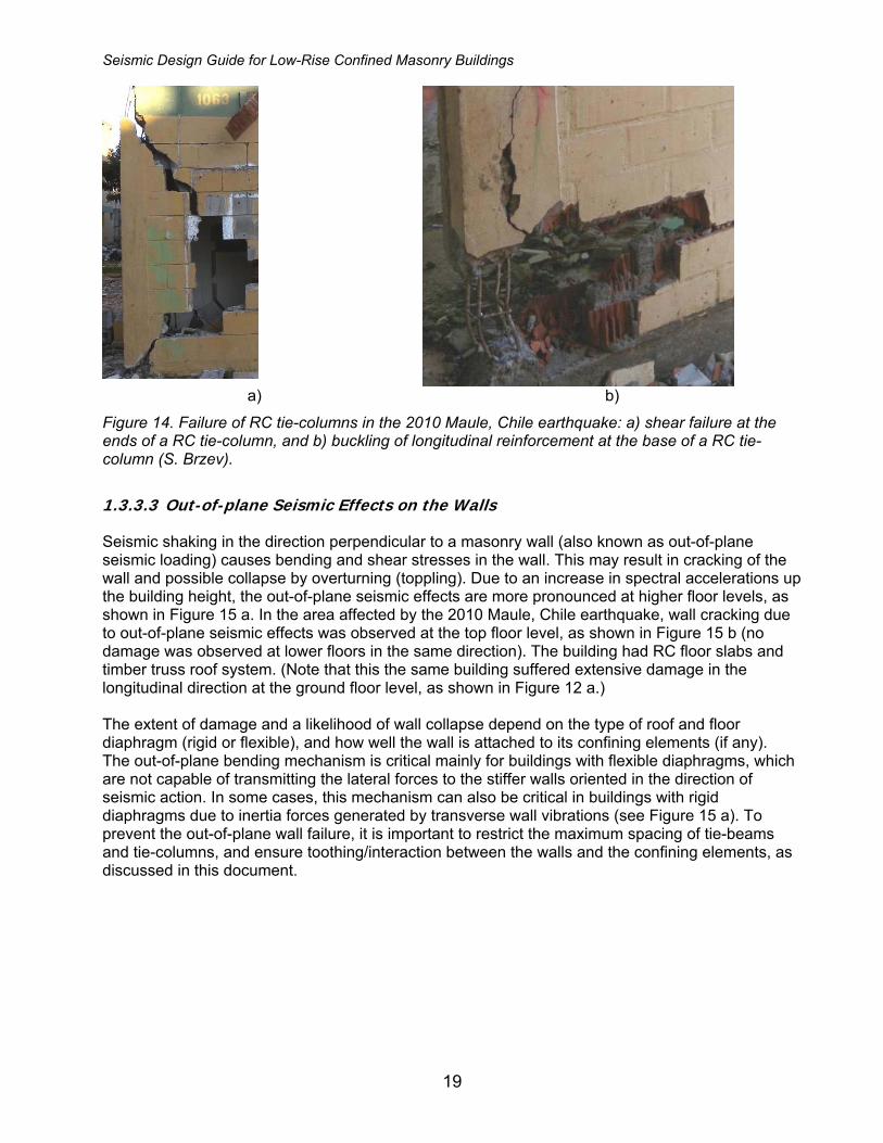
RC tie-columns have a critical role in resisting the gravity loads in damaged confined masonry buildings, and in ensuring their vertical stability (Alcocer, 2006). Due to their high axial stiffness and tension/compression load resistance, tie-columns resist a major portion of gravity load after the walls experience severe damage. The failure of a tie-column usually takes place when cracks propagate from the masonry wall into the tie-column and shear it off. Note that the failure of tie-column could take place either due to the flexural failure mechanism (shown in Figure 13), or shear failure mechanism observed in the 2010 Maule, Chile earthquake (see Figure 14 a). It has been observed that the number of ties at the tie-beam-to-tie-column joint, and the detailing of the longitudinal reinforcement appear to play a role in the tie-column shear resistance. Buckling of longitudinal reinforcement was observed when size and/or spacing of ties at the ends of tie-columns were inadequate (or when the crushing of the masonry units took place), as shown in Figure 14 b.
Seismic Design Guide for Low-Rise Confined Masonry Buildings
19
a) b)
Figure 14. Failure of RC tie-columns in the 2010 Maule, Chile earthquake: a) shear failure at the ends of a RC tie-column, and b) buckling of longitudinal reinforcement at the base of a RC tie-column (S. Brzev).
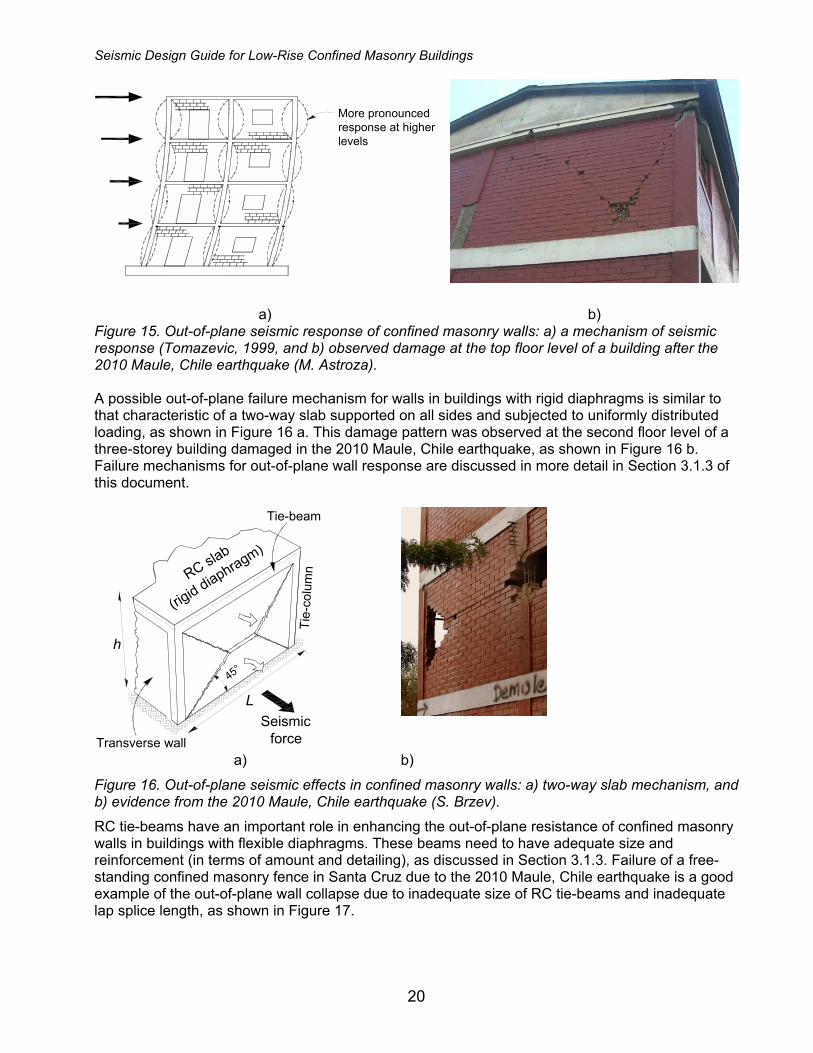
1.3.3.3 Out-of-plane Seismic Effects on the Walls Seismic shaking in the direction perpendicular to a masonry wall (also known as out-of-plane seismic loading) causes bending and shear stresses in the wall. This may result in cracking of the wall and possible collapse by overturning (toppling). Due to an increase in spectral accelerations up the building height, the out-of-plane seismic effects are more pronounced at higher floor levels, as shown in Figure 15 a. In the area affected by the 2010 Maule, Chile earthquake, wall cracking due to out-of-plane seismic effects was observed at the top floor level, as shown in Figure 15 b (no damage was observed at lower floors in the same direction). The building had RC floor slabs and timber truss roof system. (Note that this the same building suffered extensive damage in the longitudinal direction at the ground floor level, as shown in Figure 12 a.) The extent of damage and a likelihood of wall collapse depend on the type of roof and floor diaphragm (rigid or flexible), and how well the wall is attached to its confining elements (if any). The out-of-plane bending mechanism is critical mainly for buildings with flexible diaphragms, which are not capable of transmitting the lateral forces to the stiffer walls oriented in the direction of seismic action. In some cases, this mechanism can also be critical in buildings with rigid diaphragms due to inertia forces generated by transverse wall vibrations (see Figure 15 a). To prevent the out-of-plane wall failure, it is important to restrict the maximum spacing of tie-beams and tie-columns, and ensure toothing/interaction between the walls and the confining elements, as discussed in this document.
Seismic Design Guide for Low-Rise Confined Masonry Buildings
20
More pronouncedresponse at higherlevels
a) b)
Figure 15. Out-of-plane seismic response of confined masonry walls: a) a mechanism of seismic response (Tomazevic, 1999, and b) observed damage at the top floor level of a building after the 2010 Maule, Chile earthquake (M. Astroza). A possible out-of-plane failure mechanism for walls in buildings with rigid diaphragms is similar to that characteristic of a two-way slab supported on all sides and subjected to uniformly distributed loading, as shown in Figure 16 a. This damage pattern was observed at the second floor level of a three-storey building damaged in the 2010 Maule, Chile earthquake, as shown in Figure 16 b. Failure mechanisms for out-of-plane wall response are discussed in more detail in Section 3.1.3 of this document.
L
h
Tie-beam
RC slab
(rigid diaphragm)
Tie-
colu
mn
Seismicforce
45°
Transverse wall
a) b)
Figure 16. Out-of-plane seismic effects in confined masonry walls: a) two-way slab mechanism, and b) evidence from the 2010 Maule, Chile earthquake (S. Brzev).
RC tie-beams have an important role in enhancing the out-of-plane resistance of confined masonry walls in buildings with flexible diaphragms. These beams need to have adequate size and reinforcement (in terms of amount and detailing), as discussed in Section 3.1.3. Failure of a free-standing confined masonry fence in Santa Cruz due to the 2010 Maule, Chile earthquake is a good example of the out-of-plane wall collapse due to inadequate size of RC tie-beams and inadequate lap splice length, as shown in Figure 17.

Seismic Design Guide for Low-Rise Confined Masonry Buildings
21
a) b)
Figure 17. Collapse of a confined masonry fence in the 2010 Maule, Chile earthquake due to out-of-plane seismic effects: a) collapsed fence showing the RC tie-beam failure, and b) detail of RC tie-beam showing excessively short lap splice length in the longitudinal reinforcement (M. Astroza).
The out-of-plane failure of confined masonry walls has also been observed in buildings with flexible roof/floor diaphragms which are common in Indonesia.
1.3.4 Seismic Response of Multi-story Confined Masonry Buildings Earthquake-induced lateral forces in multi-story confined masonry buildings, peak at the ground floor level and may cause significant shear cracking. Under severe earthquake ground shaking, the collapse of a confined masonry building may take place at the first story level, as shown in Figure 18. Note that this mechanism is different from the soft-story collapse mechanism which is found in RC frames with masonry infill walls. In a confined masonry building the stiffness is initially equal at all floor levels, however the collapse occurs at the first story level due to high seismic loads, which cause extensive masonry cracking and a resulting decrease in the lateral stiffness. This behavior was confirmed by experimental studies (Ruiz and Alcocer, 1998; Alcocer et al., 2004, 2004a).
Figure 18. Collapse mechanism for multi-story confined masonry buildings (Alcocer et al., 2004).
In the area affected by the February 2010 Maule, Chile earthquake (M 8.8), a few multi-story confined masonry buildings experienced significant damage at the ground floor level. Two three-story buildings collapsed at the first story level, killing ten people in total. One of the collapsed

Seismic Design Guide for Low-Rise Confined Masonry Buildings
22
buildings was located in Santa Cruz, where the maximum observed seismic intensity on the MSK scale was 7.5; note that the maximum MSK intensity of 9.5 was reported in the earthquake-affected area (Astroza et al., 2010). The building was a part of the complex consisting of 32 identical buildings (two rows of 16), as shown in Figure 19 a. Several factors influenced seismic performance of this building and likely led to its collapse. The building was characterized by inadequate wall density (less than 1 % calculated on a floor basis), which is significantly less than the values recommended in this document. The absence of confining elements around openings resulted in insufficient number of confined wall panels which contribute to lateral load resistance. In addition, poor quality of construction was observed in a few other buildings within the same complex -- this resulted in inadequate shear strength of masonry walls. Exterior masonry walls were built using hollow concrete blocks, while the interior walls were built using hand-made solid clay bricks. Wall thickness was 150 mm and the RC tie-columns were of square shape with 150 mm cross-sectional dimension. The collapsed building lost its ground floor, as shown in Figure 19 b.
a) b)
Figure 19. Collapse of a three-story confined masonry building in Santa Cruz, Chile due to the February 2010 Maule earthquake: a) building complex, and b) a building that experienced collapse at the ground floor level (S. Brzev).
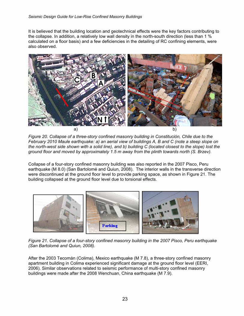
The other collapsed building was located in Constitución, which was affected both by the earthquake and the subsequent tsunami; note that the maximum observed seismic intensity on the MSK scale was 9.0 (significantly higher than Santa Cruz) (Astroza et al., 2010). The collapsed building was a part of a complex of three buildings (A, B, and C) built atop a hill in the proximity of a steep slope, as shown in Figure 20 a. Building C located closest to the slope (5 m distance on the west side) collapsed, while buildings A and B suffered damage. The collapsed building C lost its bottom floor and moved by approximately 1.5 m in the north direction (towards the slope), as shown in Figure 20 b. Note that building B (located closer to building C) experienced more extensive damage than building A. The damage in all buildings was more pronounced in the north-south direction (transverse direction of the building plan). The walls were constructed using hollow clay blocks, and the thickness was 140 mm. RC tie-columns had different cross-sectional dimensions depending on the location; the depth was in the range from 140 to 200 mm, and width was equal to the wall thickness. In addition, a few wide RC columns were placed instead of tie-columns at some locations and were continuous up the building height -- this practice is followed in medium-rise confined masonry construction in Chile. Cross-sectional depth of these wide columns varied from 700 to 900 mm and the width was 140 mm (equal to the wall thickness). The columns were reinforced with vertical and horizontal reinforcement, similar to RC shear walls but without seismic detailing.
Seismic Design Guide for Low-Rise Confined Masonry Buildings
23
It is believed that the building location and geotechnical effects were the key factors contributing to the collapse. In addition, a relatively low wall density in the north-south direction (less than 1 % calculated on a floor basis) and a few deficiencies in the detailing of RC confining elements, were also observed.
a) b)
Figure 20. Collapse of a three-story confined masonry building in Constitución, Chile due to the February 2010 Maule earthquake: a) an aerial view of buildings A, B and C (note a steep slope on the north-west side shown with a solid line), and b) building C (located closest to the slope) lost the ground floor and moved by approximately 1.5 m away from the plinth towards north (S. Brzev).
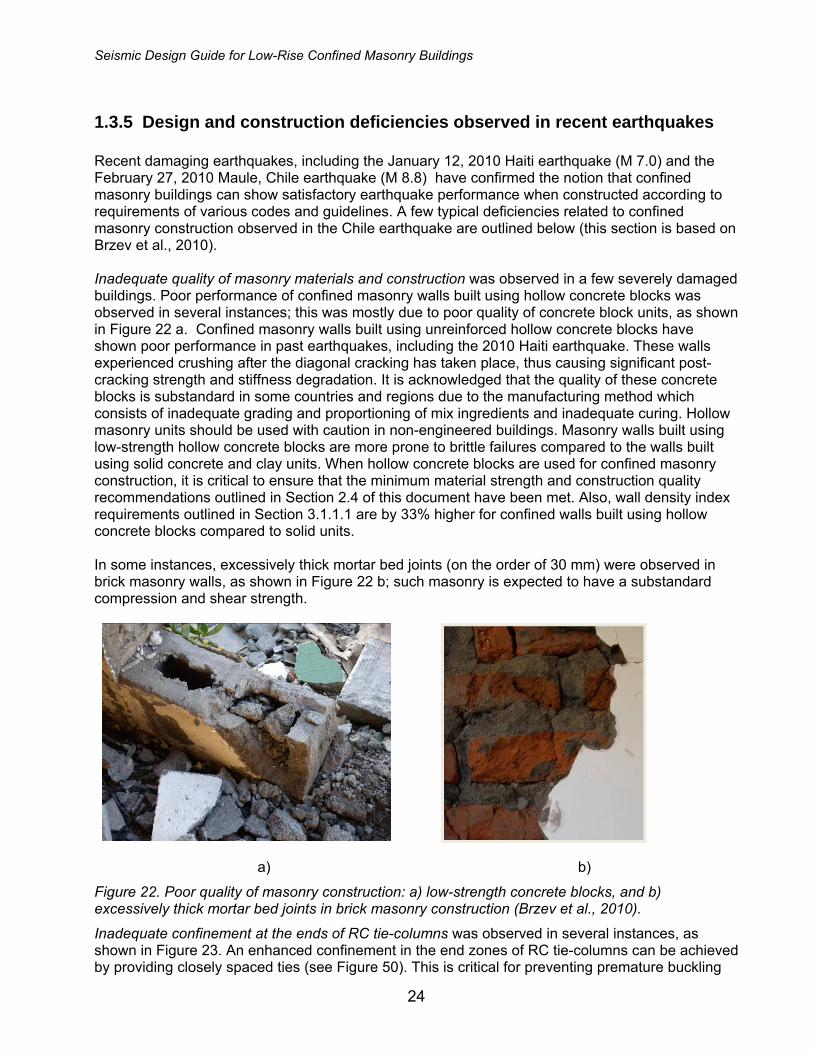
Collapse of a four-story confined masonry building was also reported in the 2007 Pisco, Peru earthquake (M 8.0) (San Bartolomé and Quiun, 2008). The interior walls in the transverse direction were discontinued at the ground floor level to provide parking space, as shown in Figure 21. The building collapsed at the ground floor level due to torsional effects.
Figure 21. Collapse of a four-story confined masonry building in the 2007 Pisco, Peru earthquake (San Bartolomé and Quiun, 2008).
After the 2003 Tecomán (Colima), Mexico earthquake (M 7.8), a three-story confined masonry apartment building in Colima experienced significant damage at the ground floor level (EERI, 2006). Similar observations related to seismic performance of multi-story confined masonry buildings were made after the 2008 Wenchuan, China earthquake (M 7.9).
Seismic Design Guide for Low-Rise Confined Masonry Buildings
24
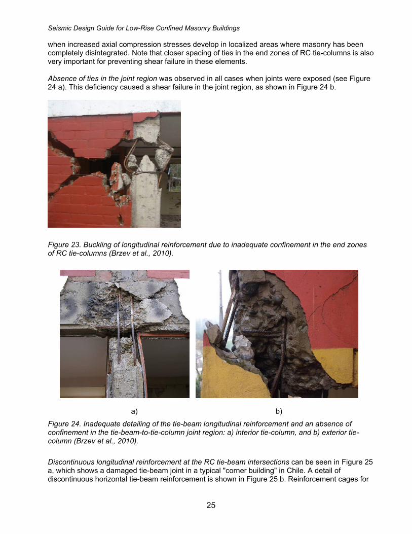
1.3.5 Design and construction deficiencies observed in recent earthquakes Recent damaging earthquakes, including the January 12, 2010 Haiti earthquake (M 7.0) and the February 27, 2010 Maule, Chile earthquake (M 8.8) have confirmed the notion that confined masonry buildings can show satisfactory earthquake performance when constructed according to requirements of various codes and guidelines. A few typical deficiencies related to confined masonry construction observed in the Chile earthquake are outlined below (this section is based on Brzev et al., 2010). Inadequate quality of masonry materials and construction was observed in a few severely damaged buildings. Poor performance of confined masonry walls built using hollow concrete blocks was observed in several instances; this was mostly due to poor quality of concrete block units, as shown in Figure 22 a. Confined masonry walls built using unreinforced hollow concrete blocks have shown poor performance in past earthquakes, including the 2010 Haiti earthquake. These walls experienced crushing after the diagonal cracking has taken place, thus causing significant post-cracking strength and stiffness degradation. It is acknowledged that the quality of these concrete blocks is substandard in some countries and regions due to the manufacturing method which consists of inadequate grading and proportioning of mix ingredients and inadequate curing. Hollow masonry units should be used with caution in non-engineered buildings. Masonry walls built using low-strength hollow concrete blocks are more prone to brittle failures compared to the walls built using solid concrete and clay units. When hollow concrete blocks are used for confined masonry construction, it is critical to ensure that the minimum material strength and construction quality recommendations outlined in Section 2.4 of this document have been met. Also, wall density index requirements outlined in Section 3.1.1.1 are by 33% higher for confined walls built using hollow concrete blocks compared to solid units. In some instances, excessively thick mortar bed joints (on the order of 30 mm) were observed in brick masonry walls, as shown in Figure 22 b; such masonry is expected to have a substandard compression and shear strength.
a) b)
Figure 22. Poor quality of masonry construction: a) low-strength concrete blocks, and b) excessively thick mortar bed joints in brick masonry construction (Brzev et al., 2010).
Inadequate confinement at the ends of RC tie-columns was observed in several instances, as shown in Figure 23. An enhanced confinement in the end zones of RC tie-columns can be achieved by providing closely spaced ties (see Figure 50). This is critical for preventing premature buckling
Seismic Design Guide for Low-Rise Confined Masonry Buildings
25
when increased axial compression stresses develop in localized areas where masonry has been completely disintegrated. Note that closer spacing of ties in the end zones of RC tie-columns is also very important for preventing shear failure in these elements. Absence of ties in the joint region was observed in all cases when joints were exposed (see Figure 24 a). This deficiency caused a shear failure in the joint region, as shown in Figure 24 b.
Figure 23. Buckling of longitudinal reinforcement due to inadequate confinement in the end zones of RC tie-columns (Brzev et al., 2010).
a) b)
Figure 24. Inadequate detailing of the tie-beam longitudinal reinforcement and an absence of confinement in the tie-beam-to-tie-column joint region: a) interior tie-column, and b) exterior tie-column (Brzev et al., 2010).
Discontinuous longitudinal reinforcement at the RC tie-beam intersections can be seen in Figure 25 a, which shows a damaged tie-beam joint in a typical "corner building" in Chile. A detail of discontinuous horizontal tie-beam reinforcement is shown in Figure 25 b. Reinforcement cages for

Seismic Design Guide for Low-Rise Confined Masonry Buildings
26
tie-beams and tie-columns are often assembled off the building site, however additional “continuity reinforcement” should be provided in the joint area after the cages are placed in their final position.
a) b)
Figure 25. Inadequate anchorage of tie-beam reinforcement: a) typical “corner” building, and b) tie-beam intersection showing a discontinuity in the longitudinal reinforcement (Brzev et al., 2010).
Absence of RC tie-columns at openings was observed in several buildings, as shown in Figure 26. This deficiency resulted in extensive damage of masonry piers. Presence of RC tie-columns at openings enables the development of compressive struts in masonry wall panels; this is the key mechanism for lateral load transfer in confined masonry walls. Masonry wall panels without RC tie-columns at both ends are considered to be unconfined. As a result, these panels are not to be considered in wall density calculations (as discussed in Section 3.1.1.1).
Figure 26. Absence of RC tie-columns at openings (Brzev et al., 2010).
The effect of RC confining elements at the openings can be observed in two apartment buildings located in Santiago. The building shown in Figure 27 a had RC tie-columns at the ends of the openings (note the concrete in the tie-column at the right was formed to mimic brick masonry appearance). The other building, shown in Figure 27 b, had a RC tie-column placed in the middle of the pier, which was unnecessary (note the absence of tie-columns at the ends of openings). The

Seismic Design Guide for Low-Rise Confined Masonry Buildings
27
walls in the first building experienced moderate cracking, while severe cracking was reported in most piers at the first story level of the latter building.
a) b)
Figure 27. In-plane shear cracking of piers in confined masonry walls: a) a confined masonry panel with RC tie-columns at both ends (note RC tie-column highlighted with a black ellipse), and b) unconfined opening (note RC tie-column at the middle of the pier highlighted with a red ellipse) (Brzev et al., 2010).

Seismic Design Guide for Low-Rise Confined Masonry Buildings
28
2 General Requirements
2.1 Design and Performance Objectives Seismic provisions of most modern building codes are based on the “life safety” performance objective: extensive structural damage is acceptable in a severe earthquake, but collapse should be avoided so the occupants can safely evacuate the building. The recommendations in this guide are based on the life safety performance objective. Properly designed and constructed, confined masonry buildings with sufficient wall density are not expected to experience damage due to moderate earthquakes.
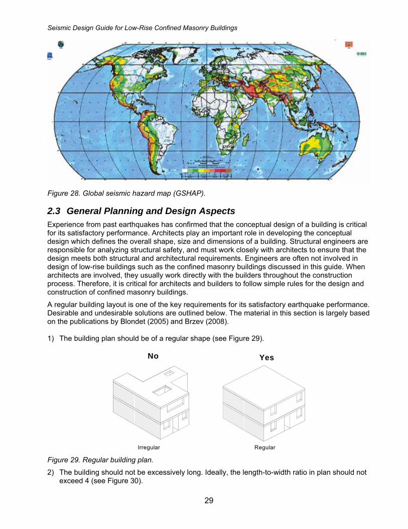
2.2 Seismic Hazard Seismicity levels in this document are based on the global seismic hazard map developed by the Global Seismic Hazard Program (GSHAP) shown in Figure 28. This information can be used in the absence of country or region-specific seismic hazard information often provided by national codes or seismological studies. Peak ground acceleration (PGA) is defined for hard soil conditions at various global localities. Note that the PGA magnitude at a specific site location depends on the type of soil, which is not taken into account by the GSHAP map. The GSHAP seismic hazard levels (low, moderate, high and very high) are summarized in Table 1. Design provisions outlined in Chapter 3 of this guide are focused on confined masonry construction located in regions of moderate and high seismic hazard. For regions of low seismic hazard, it is expected that the building design is not governed by seismic effects (it is more often governed by gravity loads). On the other hand, in regions of very high seismic hazard it is assumed that a specific seismic hazard study is needed to determine the PGA and/or the design spectra for confined masonry buildings. Therefore, Table 1 does not contain the maximum PGA value for regions of very high seismic hazard. Table 1. Seismic hazard levels (based on the GSHAP).
Seismic Hazard Level
PGA (m/sec2) PGA (g)
Low PGA≤0.8 m/sec2 PGA≤0.08g Moderate 0.8 m/sec2<PGA≤2.4 m/sec2 0.08g<PGA≤0.25g High 2.4 m/sec2<PGA≤4.0 m/sec2 0.25g<PGA≤0.4g Very High PGA>4.0 m/sec2 PGA>0.4g
Seismic Design Guide for Low-Rise Confined Masonry Buildings
29
Figure 28. Global seismic hazard map (GSHAP).
2.3 General Planning and Design Aspects Experience from past earthquakes has confirmed that the conceptual design of a building is critical for its satisfactory performance. Architects play an important role in developing the conceptual design which defines the overall shape, size and dimensions of a building. Structural engineers are responsible for analyzing structural safety, and must work closely with architects to ensure that the design meets both structural and architectural requirements. Engineers are often not involved in design of low-rise buildings such as the confined masonry buildings discussed in this guide. When architects are involved, they usually work directly with the builders throughout the construction process. Therefore, it is critical for architects and builders to follow simple rules for the design and construction of confined masonry buildings.
A regular building layout is one of the key requirements for its satisfactory earthquake performance. Desirable and undesirable solutions are outlined below. The material in this section is largely based on the publications by Blondet (2005) and Brzev (2008). 1) The building plan should be of a regular shape (see Figure 29).
No Yes
RegularIrregular Figure 29. Regular building plan.
2) The building should not be excessively long. Ideally, the length-to-width ratio in plan should not exceed 4 (see Figure 30).

Seismic Design Guide for Low-Rise Confined Masonry Buildings
30
YesNo
Less than 4
times the width
WidthMore than 4 times the width
Width
Figure 30. Building length-to-width aspect ratio.
3) The walls should be built in a symmetrical manner to minimize torsional effects. Note that it is
not always possible to have a perfectly symmetrical wall layout – the one shown on the right in Figure 31 is not ideal, but is much better than the layout shown on the left.
YesNo
Figure 31. Wall layout.
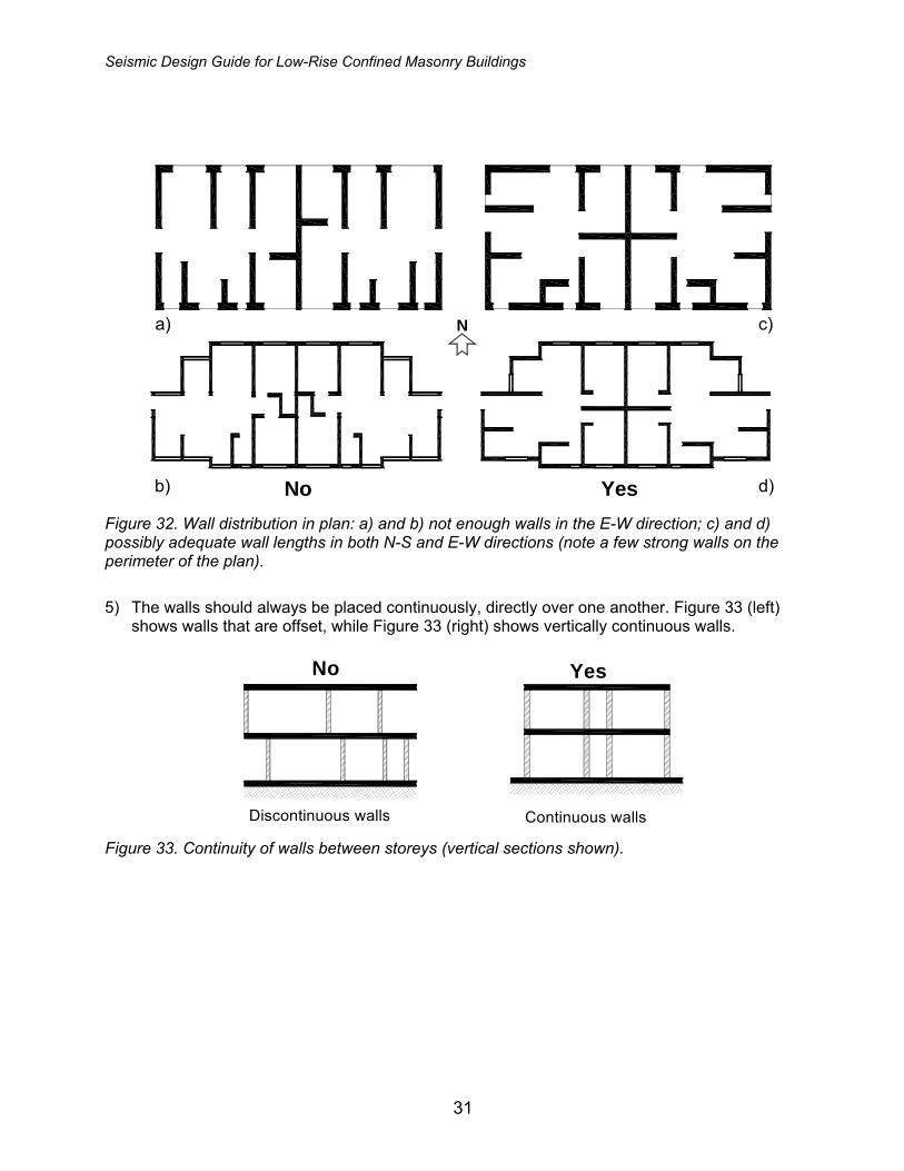
4) Since the earthquake performance of confined masonry buildings largely depends on the shear resistance of masonry walls, it is essential that a sufficient number and total length of walls be provided in each direction. Figure 32 (a and b) show building plans with inadequate wall distribution. To avoid twisting (torsion) of the building in an earthquake, the walls should be placed as far apart as possible, preferably at the exterior of the building, as shown in Figure 32 (c and d).
Seismic Design Guide for Low-Rise Confined Masonry Buildings
31
N
Yes
a)
b)
c)
d)No Figure 32. Wall distribution in plan: a) and b) not enough walls in the E-W direction; c) and d) possibly adequate wall lengths in both N-S and E-W directions (note a few strong walls on the perimeter of the plan).
5) The walls should always be placed continuously, directly over one another. Figure 33 (left)
shows walls that are offset, while Figure 33 (right) shows vertically continuous walls.
Continuous walls
YesNo
Discontinuous walls Figure 33. Continuity of walls between storeys (vertical sections shown).

Seismic Design Guide for Low-Rise Confined Masonry Buildings
32
6) Openings (doors and windows) should be placed in the same position on each floor, as
illustrated in Figure 34.
Inadequate location of windowand door openings
YesNo
Adequate location of openingswith tie-beams and tie-colums
Figure 34. Location of openings in a building.
2.4 Materials
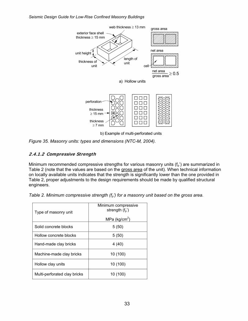
2.4.1 Units 2.4.1.1 Types of Units The following types of masonry units are acceptable for confined masonry construction: 1) Solid concrete blocks, 2) Hollow concrete blocks, 3) Solid clay bricks, and 4) Hollow clay tiles (blocks). Solid masonry units are permitted to have perforations (holes). However, the ratio of net to gross area for a typical unit should be greater than 75%. The hollow units referred to in this document are those having, in their most unfavorable cross section, a net area equal to at least 50% of the gross area, and exterior face shell thickness of not less than 15 mm (see Figure 35 a). For hollow units with two to four cells, the minimum thickness of the interior webs is 13 mm. Multi-perforated units are those with more than seven perforations or cells (see Figure 35 b). For multi-perforated units having perforations of the same dimensions and distribution, the minimum thickness of the interior webs is 7 mm. Hollow masonry units should be used with caution in non-engineered buildings. To ensure satisfactory seismic performance of masonry walls built using concrete blocks, it is critical that the minimum material strength and construction quality recommendations outlined in this document have been met. Note that the wall density index requirements outlined in Section 3.1.1.1 are by 33% higher for walls built using hollow concrete blocks compared to those built using solid units. The following types of units are not recommended for confined masonry construction: 1) Masonry units with horizontal perforations, and 2) Natural stone masonry and adobe (sun-dried earthen units).
Seismic Design Guide for Low-Rise Confined Masonry Buildings
33
gross area
cell
net area
gross areanet area ≥ 0.5
exterior face shellthickness ≥ 15 mm
thickness≥ 15 mm
perforation
unit height
thickness ofunit
length ofunit
a) Hollow units
web thickness ≥ 13 mm
thickness≥ 7 mm
b) Example of multi-perforated units Figure 35. Masonry units: types and dimensions (NTC-M, 2004).
2.4.1.2 Compressive Strength Minimum recommended compressive strengths for various masonry units (fp’) are summarized in Table 2 (note that the values are based on the gross area of the unit). When technical information on locally available units indicates that the strength is significantly lower than the one provided in Table 2, proper adjustments to the design requirements should be made by qualified structural engineers. Table 2. Minimum compressive strength (fp’) for a masonry unit based on the gross area.
Type of masonry unit
Minimum compressive strength (fp’)
MPa (kg/cm2)
Solid concrete blocks 5 (50)
Hollow concrete blocks 5 (50)
Hand-made clay bricks 4 (40)
Machine-made clay bricks 10 (100)
Hollow clay units 10 (100)
Multi-perforated clay bricks 10 (100)
Seismic Design Guide for Low-Rise Confined Masonry Buildings
34
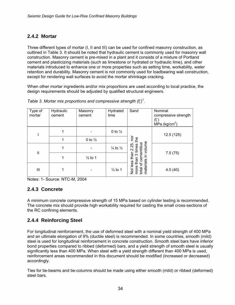
2.4.2 Mortar Three different types of mortar (I, II and III) can be used for confined masonry construction, as outlined in Table 3. It should be noted that hydraulic cement is commonly used for masonry wall construction. Masonry cement is pre-mixed in a plant and it consists of a mixture of Portland cement and plasticizing materials (such as limestone or hydrated or hydraulic lime), and other materials introduced to enhance one or more properties such as setting time, workability, water retention and durability. Masonry cement is not commonly used for loadbearing wall construction, except for rendering wall surfaces to avoid the mortar shrinkage cracking.
When other mortar ingredients and/or mix proportions are used according to local practice, the design requirements should be adjusted by qualified structural engineers. Table 3. Mortar mix proportions and compressive strength (fj’)1. Type of mortar
Hydraulic cement
Masonry cement
Hydrated lime
Sand Nominal compressive strength (fj’) MPa (kg/cm2)
1 - 0 to ¼ I
1 0 to ½ 12.5 (125)
1 - ¼ to ½ II
1 ½ to 1 7.5 (75)
III 1 - ½ to 1
Not
less
than
2.2
5, n
or
mor
e th
an 3
tim
es th
e to
tal o
f cem
entit
ius
mat
eria
ls in
vol
ume
4.0 (40)
Notes: 1- Source: NTC-M, 2004
2.4.3 Concrete A minimum concrete compressive strength of 15 MPa based on cylinder testing is recommended. The concrete mix should provide high workability required for casting the small cross-sections of the RC confining elements.
2.4.4 Reinforcing Steel For longitudinal reinforcement, the use of deformed steel with a nominal yield strength of 400 MPa and an ultimate elongation of 9% (ductile steel) is recommended. In some countries, smooth (mild) steel is used for longitudinal reinforcement in concrete construction. Smooth steel bars have inferior bond properties compared to ribbed (deformed) bars, and a yield strength of smooth steel is usually significantly less than 400 MPa. When steel with a yield strength different than 400 MPa is used, reinforcement areas recommended in this document should be modified (increased or decreased) accordingly. Ties for tie-beams and tie-columns should be made using either smooth (mild) or ribbed (deformed) steel bars.

Seismic Design Guide for Low-Rise Confined Masonry Buildings
35
2.4.5 Masonry Masonry strength has a significant influence upon the seismic resistance of a confined masonry building and life safety of its inhabitants. It is therefore extremely important to perform basic tests outlined in this section using local masonry materials; this is particularly important for projects involving several buildings. 2.4.5.1 Compressive Strength Compressive strength is a very important property of masonry, and it may be highly variable depending on local materials and construction practices. The design compressive strength (fm’) for the combinations of typical masonry units and mortars used in local housing construction practice should preferably be determined by testing prism specimens made of the masonry units and mortar used at construction sites, as shown in Figure 36 a. The prisms should be tested using the same procedures as other masonry wall applications (refer to Section 2.8.1 of NTC-M, 2004). In the absence of testing data, recommended empirical values for the design compressive strength of masonry (fm’) are provided in Table 4. It should be noted that fm’ refers to the ultimate strength intended to be used in designs based on the ultimate limit states design approach (LFRD) using load factors and strength reduction factors. When performing the wall resistance calculations, these values need to be modified by applying the resistance reduction factors specified by the pertinent national code or standard. Table 4. Design compressive strength of masonry (fm’) based on the gross area1.
Design compressive strength (fm’) MPa (kg/cm2) Type of Mortar Type of masonry unit
I II III
Solid clay bricks 1.5 (15) 1.5 (15) 1.5 (15)
Hollow clay units 4.0 (40) 4.0 (40) 3.0 (30)
Hollow concrete blocks 2.0 (20) 1.5 (15) 1.0 (10)
Solid concrete blocks 2.0 (20) 1.5 (15) 1.5 (15)
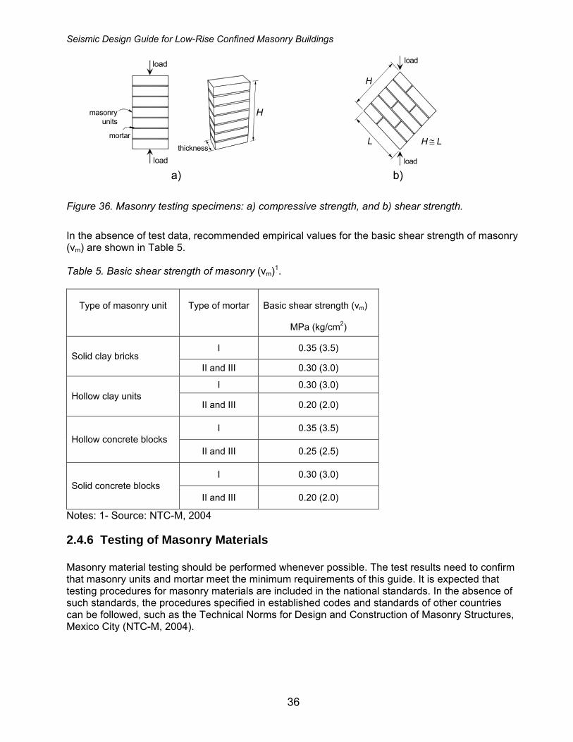
Notes: 1- Source: NTC-M, 2004 2.4.5.2 Basic Shear Strength Basic shear strength (vm) should preferably be determined by diagonal compression testing of small square wall specimens (wallets), as shown in Figure 36 b. The specimens should be made of the same masonry units and mortar as used for the construction. The specimens shall be subjected to monotonic compression loading acting along their diagonals. For more details of the testing procedure, refer to Section 2.8.2 of NTC-M (2004).
Seismic Design Guide for Low-Rise Confined Masonry Buildings
36
H
load
thicknessload
masonryunits
mortar
H ≅ L
H
L
load
load a) b)
Figure 36. Masonry testing specimens: a) compressive strength, and b) shear strength.
In the absence of test data, recommended empirical values for the basic shear strength of masonry (vm) are shown in Table 5. Table 5. Basic shear strength of masonry (vm)1.
Type of masonry unit
Type of mortar
Basic shear strength (vm)
MPa (kg/cm2)
I 0.35 (3.5) Solid clay bricks
II and III 0.30 (3.0)
I 0.30 (3.0) Hollow clay units
II and III 0.20 (2.0)
I 0.35 (3.5) Hollow concrete blocks
II and III 0.25 (2.5)
I 0.30 (3.0) Solid concrete blocks
II and III 0.20 (2.0)
Notes: 1- Source: NTC-M, 2004
2.4.6 Testing of Masonry Materials Masonry material testing should be performed whenever possible. The test results need to confirm that masonry units and mortar meet the minimum requirements of this guide. It is expected that testing procedures for masonry materials are included in the national standards. In the absence of such standards, the procedures specified in established codes and standards of other countries can be followed, such as the Technical Norms for Design and Construction of Masonry Structures, Mexico City (NTC-M, 2004).
Seismic Design Guide for Low-Rise Confined Masonry Buildings
37
3 Guidelines for Non-Engineered Confined Masonry Buildings This chapter outlines recommendations for low-rise non-engineered confined masonry buildings (one- and two-story high). These buildings are usually built without input and/or design calculations performed by qualified structural engineers. In addition to the recommendations presented in this chapter, most recommendations outlined in Chapter 2 apply to non-engineered buildings. Whenever possible, the quality of materials (masonry, concrete, steel) used in construction of non-engineered buildings should be verified following the methods outlined in Chapter 2.
3.1 Building Components
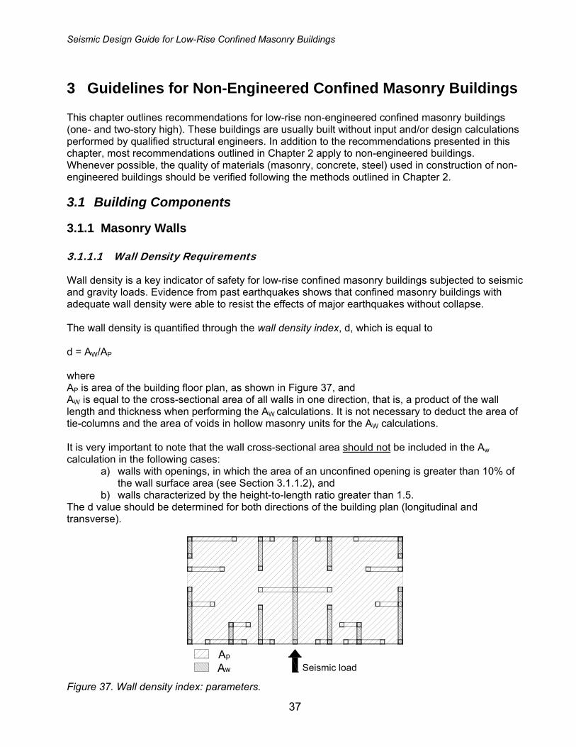
3.1.1 Masonry Walls 3.1.1.1 Wall Density Requirements Wall density is a key indicator of safety for low-rise confined masonry buildings subjected to seismic and gravity loads. Evidence from past earthquakes shows that confined masonry buildings with adequate wall density were able to resist the effects of major earthquakes without collapse. The wall density is quantified through the wall density index, d, which is equal to d = AW/AP where AP is area of the building floor plan, as shown in Figure 37, and AW is equal to the cross-sectional area of all walls in one direction, that is, a product of the wall length and thickness when performing the AW calculations. It is not necessary to deduct the area of tie-columns and the area of voids in hollow masonry units for the AW calculations. It is very important to note that the wall cross-sectional area should not be included in the Aw calculation in the following cases:
a) walls with openings, in which the area of an unconfined opening is greater than 10% of the wall surface area (see Section 3.1.1.2), and
b) walls characterized by the height-to-length ratio greater than 1.5. The d value should be determined for both directions of the building plan (longitudinal and transverse).
Seismic loadAp
Aw Figure 37. Wall density index: parameters.

Seismic Design Guide for Low-Rise Confined Masonry Buildings
38
The minimum wall density index, d, required for a given building can be determined by applying the Simplified Method outlined in Appendix A of this document. In the absence of detailed design calculations, minimum recommended values for wall density index are summarized in Table 6. Table 6. Wall Density Index d (%) for each direction of the building plan
Seismic Hazard1 Low
(PGA ≤ 0.08g) Moderate
(PGA ≤ 0.25g) High
(PGA ≤ 0.4g) Number of stories
n Soil Type A, B or C
Soil Type A
Soil Type B and C
Soil Type A
Soil Type B and C
Solid clay bricks2 (mortar type I, II and III3) Solid concrete blocks (mortar type I)
1 1.0 1.0 1.0 1.5 2.5 2 1.5 1.5 2.0 3.0 4.5
Solid concrete blocks (mortar type II and III) Hollow concrete blocks (mortar type I) Hollow clay bricks (mortar type I)
1 1.0 1.0 2.0 2.0 3.5 2 1.5 1.5 3.5 4.0 6.5
Hollow concrete blocks or hollow clay bricks (mortar type II and III)
1 1.0 1.5 2.5 3.0 5.0 2 2.0 3.0 5.0 6.0 9.5
Notes: 1 - see Section 2.2 for details on seismic hazard levels, and on how to proceed for regions of very high seismic hazard 2 - see Section 2.4.1 for requirements related to masonry units 3 - see Section 0 for the description of mortar types Soil Type: A Rock or firm soil B Compact granular soil C Soft clay soil or soft sand These d values can be used for “simple buildings” complying with the following requirements: 1. General requirements:
a. uniform building plans (equal area) over the building height b. nearly symmetric wall layout in both orthogonal directions over the building height c. exterior walls extend over at least 50% of the length of each end of the building plan at
each story. d. at least 75% of the building weight is supported by confined masonry walls
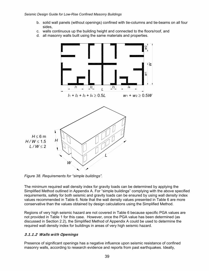
2. Building dimensions (see Figure 38): a. total building height not greater than 6 m (H ≤ 6 m) b. ratio of total building height to the minimum plan width not greater than 1.5 (H/W ≤ 1.5) c. ratio of length to width of the building plan not greater than 2.0 (L/W ≤ 2.0)
3. Floors and roofs act as rigid diaphragms (equivalent to a minimum 10 cm thick solid reinforced concrete slab)
4. Confined masonry walls (see Figure 38): a. masonry properties complying with the minimum requirements specified in Section 2.4
of this document,
Seismic Design Guide for Low-Rise Confined Masonry Buildings
39
b. solid wall panels (without openings) confined with tie-columns and tie-beams on all four sides,
c. walls continuous up the building height and connected to the floors/roof, and d. all masonry walls built using the same materials and properties.
w2
w1
W
l1 l2 l3 l4
l1 + l2 + l3 + l4 ≥ 0.5LL
w1 + w2 ≥ 0.5W
H ≤ 6 mH / W ≤ 1.5
L / W ≤ 2 H
W
L
Figure 38. Requirements for “simple buildings”.
The minimum required wall density index for gravity loads can be determined by applying the Simplified Method outlined in Appendix A. For “simple buildings” complying with the above specified requirements, safety for both seismic and gravity loads can be ensured by using wall density index values recommended in Table 6. Note that the wall density values presented in Table 6 are more conservative than the values obtained by design calculations using the Simplified Method. Regions of very high seismic hazard are not covered in Table 6 because specific PGA values are not provided in Table 1 for this case. However, once the PGA value has been determined (as discussed in Section 2.2), the Simplified Method of Appendix A could be used to determine the required wall density index for buildings in areas of very high seismic hazard. 3.1.1.2 Walls with Openings Presence of significant openings has a negative influence upon seismic resistance of confined masonry walls, according to research evidence and reports from past earthquakes. Ideally,
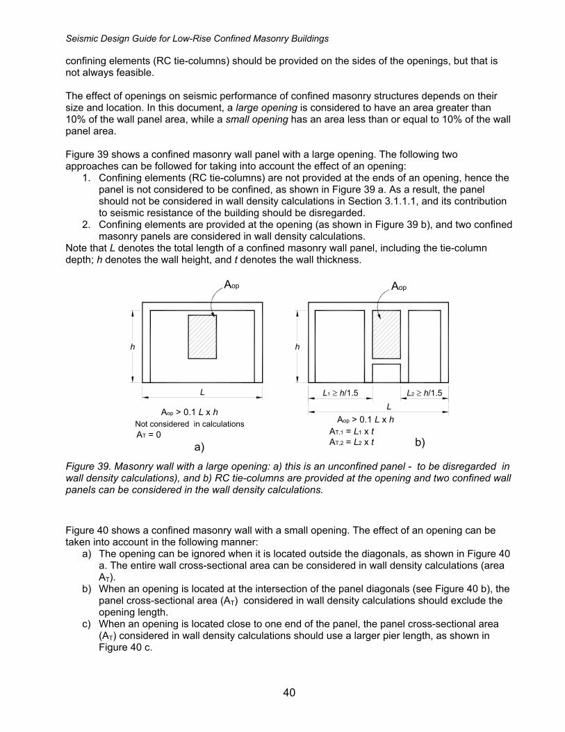
Seismic Design Guide for Low-Rise Confined Masonry Buildings
40
confining elements (RC tie-columns) should be provided on the sides of the openings, but that is not always feasible. The effect of openings on seismic performance of confined masonry structures depends on their size and location. In this document, a large opening is considered to have an area greater than 10% of the wall panel area, while a small opening has an area less than or equal to 10% of the wall panel area. Figure 39 shows a confined masonry wall panel with a large opening. The following two approaches can be followed for taking into account the effect of an opening:
1. Confining elements (RC tie-columns) are not provided at the ends of an opening, hence the panel is not considered to be confined, as shown in Figure 39 a. As a result, the panel should not be considered in wall density calculations in Section 3.1.1.1, and its contribution to seismic resistance of the building should be disregarded.
2. Confining elements are provided at the opening (as shown in Figure 39 b), and two confined masonry panels are considered in wall density calculations.
Note that L denotes the total length of a confined masonry wall panel, including the tie-column depth; h denotes the wall height, and t denotes the wall thickness.
Not considered in calculations
L
h
a)
Aop
Aop > 0.1 L x h
b)
h
Aop
AT,1 = L1 x tAT,2 = L2 x t
Aop > 0.1 L x h
L2 ≥ h/1.5L1 ≥ h/1.5L
AT = 0
Figure 39. Masonry wall with a large opening: a) this is an unconfined panel - to be disregarded in wall density calculations), and b) RC tie-columns are provided at the opening and two confined wall panels can be considered in the wall density calculations.
Figure 40 shows a confined masonry wall with a small opening. The effect of an opening can be taken into account in the following manner:
a) The opening can be ignored when it is located outside the diagonals, as shown in Figure 40 a. The entire wall cross-sectional area can be considered in wall density calculations (area AT).
b) When an opening is located at the intersection of the panel diagonals (see Figure 40 b), the panel cross-sectional area (AT) considered in wall density calculations should exclude the opening length.
c) When an opening is located close to one end of the panel, the panel cross-sectional area (AT) considered in wall density calculations should use a larger pier length, as shown in Figure 40 c.

Seismic Design Guide for Low-Rise Confined Masonry Buildings
41
h
Aop < 0.1 L x h
Aop
h
L ≥ h/1.5
h
L ≥ h/1.5 L
L1 ≥1 m L2 ≥1 m
Aop < 0.1 L x h Aop < 0.1 L x h
AopAop
AT = L x tAT = (L1 + L2) x t
L1 ≥ h/1.5
AT = L1 x t a) b) c)
Figure 40. Confined masonry wall panel with a small opening: a) an opening outside the diagonals can be neglected; b) and c) opening must be taken into account.
3.1.1.3 Wall Spacing Maximum spacing of transverse walls in buildings with flexible diaphragms should not exceed
• 6 m for regions of low and moderate seismicity, and • 4.5 m for regions of high and very high seismicity.
Refer to Section 3.1.3 for special requirements concerning buildings with flexible diaphragms. 3.1.1.4 Wall Dimensions and Height/Thickness Ratio Restrictions
• A minimum wall thickness (t) of 110 mm is required. • The maximum wall height/thickness (H/t) ratio for walls in one- and two-story buildings must
not exceed 25. • The height/length ratio of a wall panel should not be less than 0.5. • The maximum wall height should not exceed 3 m.
3.1.1.5 Parapets and Gable Walls Parapets RC tie-columns and tie-beams should extend to the top of the parapet, as shown in Figure 44. When a parapet is not confined, the height should not exceed 0.5 m, otherwise the height limit is 1.2 m. Gable Walls It is recommended that the top of gable be confined with RC tie-beams and that the RC tie-columns located at the middle of the gable wall be extended from the lower floor to the top of gable wall (whenever applicable), as shown in Figure 41 a. Alternatively, a gable portion of the wall can be made of timber or other light-weight material (see Figure 41 b). To avoid cutting of masonry units, the bottom face of the gable tie-beam can be stepped.

Seismic Design Guide for Low-Rise Confined Masonry Buildings
42
roof tie-beam
tie-column
gabletie-beam
gabletie-beam
roof
a)
light-weightgable panel
tie-column
roof tie-beam
roof
b)
Figure 41. Gable walls: a) RC confining elements, and b) light-weight gable panel.
3.1.1.6 Toothing at the Wall-to-tie-column Interface Good bonding between a masonry wall and adjacent RC tie-columns is important for satisfactory earthquake performance, and for delaying undesirable cracking and separation at the wall-to-tie-column interface. Bonding is an essential feature of confined masonry construction and it can be achieved by toothing at the wall-to-tie-column interface, as shown in Figure 42. Toothed edges should be left on each side of the wall at the interface with the tie-columns. Toothing length should be equal to one-quarter of the masonry unit length, but not less than 5 cm1, as shown in Figure 42 a. It is very important to clean the surfaces of "toothed" masonry units before the concrete has been poured. When hand-made bricks are used, it is desirable to cut the brick edges, as shown in Figure 42 b. Horizontal reinforcement anchored into RC tie-columns, also known as dowels, can be used as an alternative to toothing, as shown in Figure 42 c. Note that the dowels are not necessary when toothed edges are used. Toothing is required for low-strength masonry built using hand-made clay bricks and concrete blocks. Examples of field applications of toothing are shown in Figure 43.
1 Source: NT E.070, 2006; Blondet, 2005

Seismic Design Guide for Low-Rise Confined Masonry Buildings
43
≤ 40 cm
40 cm
Details of thetoothed
wall edges
( ) p q
2.5 cm
3 cm Shearconnectorsor dowels
2.5 cm
5 cm
a) b) c)
Figure 42. Toothing in confined masonry walls: a) machine-made hollow units, b) hand-made solid units, and c) provision of horizontal reinforcement when toothing is not possible.
a) b)
Figure 43. Toothing applications: a) recommended construction practice (S. Brzev), and b) not recommended - absence of toothing in concrete block construction (C. Meisl).

Seismic Design Guide for Low-Rise Confined Masonry Buildings
44
3.1.2 Confining Elements (Tie-columns and Tie-beams) 3.1.2.1 Spacing Tie-columns Tie-columns should be provided at the following locations: • at wall intersections, and • at ends of wall panels that provide lateral load resistance to the building.
When tie-columns are provided at openings, confined masonry wall panels enclosed by these tie-columns can be taken into account in the wall density calculations discussed in Section 3.1.1.1. Spacing of tie-columns should not exceed: • 4.5 m for regions of high seismicity, and • 6 m for regions of moderate seismicity.
Tie-beams A RC tie-beam must be provided at the top of each wall at the maximum spacing of 3 m. Provision of continuous RC tie-beams at intermediate (lintel/sill) levels is not necessary, but it may be beneficial for out-of-plane stability of walls with height/thickness ratio (H/t) is greater than 20. Refer to Section 3.1.3 for more details regarding the intermediate tie-beams. Recommendations regarding the location and spacing of confining elements are illustrated in Figure 44 and Figure 45.
t Tie-column
spacing:
6.0 m (moderate seismicity)
4.5 m (high seismicity)
H / t ≤ 25t ≥ 110 mm
tie-beamspacing≤ 3.0 m
slab
H
tie-beam inparapets ≥ 500 mm
tie-columnsin parapets
Tie-columns atwall intersections
confining elementsaround openings
Figure 44. Key recommendations for non-engineered confined masonry buildings (adapted from NTC-M, 2004).
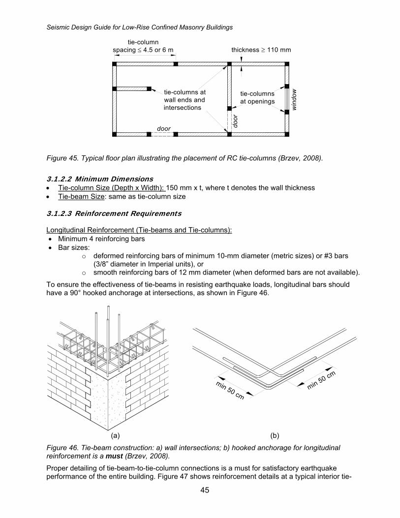
Seismic Design Guide for Low-Rise Confined Masonry Buildings
45
tie-columns atwall ends andintersections
tie-columnsat openings
door
win
dow
door
thickness ≥ 110 mmtie-column
spacing ≤ 4.5 or 6 m
Figure 45. Typical floor plan illustrating the placement of RC tie-columns (Brzev, 2008).
3.1.2.2 Minimum Dimensions • Tie-column Size (Depth x Width): 150 mm x t, where t denotes the wall thickness • Tie-beam Size: same as tie-column size 3.1.2.3 Reinforcement Requirements Longitudinal Reinforcement (Tie-beams and Tie-columns): • Minimum 4 reinforcing bars • Bar sizes:
o deformed reinforcing bars of minimum 10-mm diameter (metric sizes) or #3 bars (3/8” diameter in Imperial units), or
o smooth reinforcing bars of 12 mm diameter (when deformed bars are not available).
To ensure the effectiveness of tie-beams in resisting earthquake loads, longitudinal bars should have a 90° hooked anchorage at intersections, as shown in Figure 46.
min 50 cmmin 50 cm
(a) (b)
Figure 46. Tie-beam construction: a) wall intersections; b) hooked anchorage for longitudinal reinforcement is a must (Brzev, 2008).
Proper detailing of tie-beam-to-tie-column connections is a must for satisfactory earthquake performance of the entire building. Figure 47 shows reinforcement details at a typical interior tie-

Seismic Design Guide for Low-Rise Confined Masonry Buildings
46
beam-to-tie-column joint. It is very important to ensure the continuity of longitudinal tie-beam reinforcement through the joint. An example of a continuous longitudinal reinforcement is shown in Figure 47 a. In some countries (e.g. Mexico, Chile, etc.), prefabricated reinforcement cages are used for tie-beam and tie-column reinforcement. In that case, additional "continuity" reinforcement must be used to provide continuity in the tie-beam-to-tie-column joint regions (see Figure 47 b).
Tie-beam cross section
Plan View
Continuity reinforcement
b) Discontinuous prefabricated cages
a) Continuous tie-beam reinforcement
Cage #1
Cage #2
Figure 47. Tie-beam reinforcement details: a) continuous tie-beam reinforcement, and b) continuity reinforcement must be added when prefabricated reinforcement cages are used.
Reinforcing bars must be properly anchored. A typical connection detail at the roof level is shown in Figure 48. Note that the tie-column longitudinal reinforcement needs to be extended into the tie-beam as much as possible, preferably up to the underside of the top tie-beam reinforcement. A hooked anchorage is required (using 90° hooks) both for the tie-column and tie-beam reinforcement. In buildings with RC floors and roof, it is acceptable to integrate RC tie-beams into an RC floor or roof slab.
ELEVATIONtie-c
olum
n
tie-beam
Figure 48. Anchorage of tie-beam and tie-column longitudinal reinforcement (Alcocer et al., 2003).
When tie-beam depth exceeds 300 mm, vertical reinforcement in the RC tie-column must be confined by the ties, below and above the joint. An additional U-shaped stirrup must be placed at the tie-beam midheight, as shown in Figure 49. This detailing practice is necessary to prevent poor seismic performance illustrated in Figure 24 b.

Seismic Design Guide for Low-Rise Confined Masonry Buildings
47
tie-beam
tie-c
olum
n
ldU-shape
ELEVATION
PLAN VIEW
> 30
0 m
m
ld
Figure 49. Additional confinement for vertical reinforcement in the tie-beam and tie-column end joint region.
It is not necessary to provide additional confinement for vertical reinforcement in joint regions of interior tie-columns. However, to minimize the chances of buckling in vertical reinforcing bars, it is recommended to place the first tie at the ends of tie-columns (top and bottom) as close to the joint as possible (see Figure 50 b); this recommendation applies to all seismic regions. An example of a poor construction practice resulting in earthquake damage is shown in Figure 24 a. General requirements for lap splices in longitudinal reinforcement are summarized below: • The tie-beam longitudinal reinforcement should be hooked and lapped at the ends with the intersecting reinforcement. The lap length of the hook tails should be at least 15 to 20 bar diameters. • Tie-column longitudinal bars at the roof level should be bent and lapped for at least 40 bar diameters with the tie-beam longitudinal reinforcement (see Figure 48). • Tie-column longitudinal reinforcing bars at the lower floor levels should extend far enough above the floor slab to form a lap splice of at least 40 bar diameters with the tie-column bars to be placed above. • Lap splices for longitudinal reinforcement should be at least 40 bar diameters. In tie-beams, the splices should be located at the end one-third of the beam span. The splices should be staggered so that not more than 2 bars are spliced at any one location. When the construction drawings specify 180 degree hooks at the bar ends, this should be verified through site inspection.
Tie Size and Spacing (see Figure 50):
• Size: minimum 6 mm diameter bars should be used (either smooth or deformed steel bars) with 135° hooked ends (staggered); note that db denotes tie diameter in Figure 50 a.
• Tie spacing (s) should not exceed 200 mm - this applies to RC tie-columns and tie-beams o For regions of high and very high seismicity, reduced tie spacing (s/2) is required at
the ends of tie-columns, as shown in Figure 50 b. The length over which the reduced tie spacing is used should not exceed the larger of the following two values: - 2b, where b is the tie-column dimension, or - ho/6, where ho is the tie-column clear height.
o For regions of moderate seismicity, a uniform tie spacing (s) of 200 mm should be used throughout - it is not required to reduce tie-spacing at the tie-column ends.
• Minimum concrete cover to ties is 20 mm.
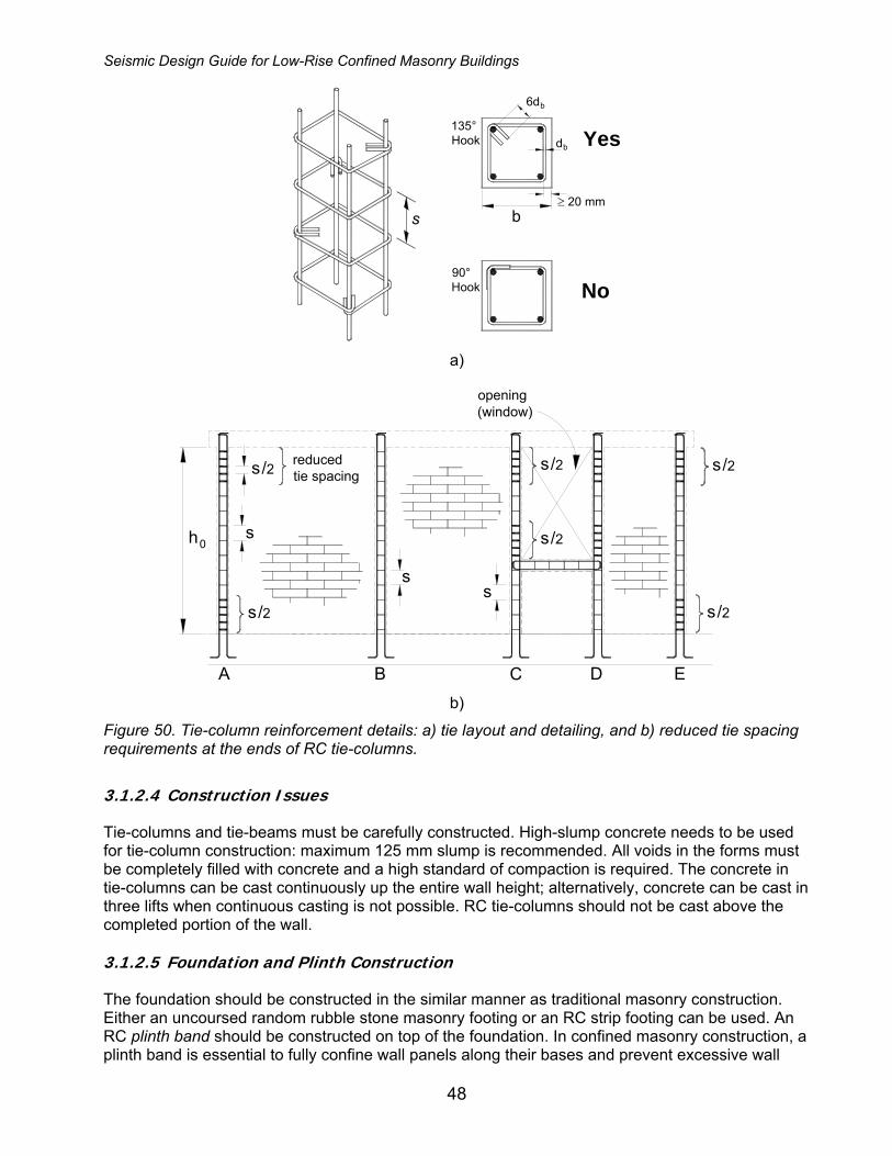
Seismic Design Guide for Low-Rise Confined Masonry Buildings
48
bs≥ 20 mm
90°Hook No
Yesdb
b
135°Hook
6d
a)
h0
opening(window)
s
ss
s /2 reducedtie spacing
A B C D E
s /2
s /2
s /2
s /2
s /2
b)
Figure 50. Tie-column reinforcement details: a) tie layout and detailing, and b) reduced tie spacing requirements at the ends of RC tie-columns.
3.1.2.4 Construction Issues Tie-columns and tie-beams must be carefully constructed. High-slump concrete needs to be used for tie-column construction: maximum 125 mm slump is recommended. All voids in the forms must be completely filled with concrete and a high standard of compaction is required. The concrete in tie-columns can be cast continuously up the entire wall height; alternatively, concrete can be cast in three lifts when continuous casting is not possible. RC tie-columns should not be cast above the completed portion of the wall. 3.1.2.5 Foundation and Plinth Construction The foundation should be constructed in the similar manner as traditional masonry construction. Either an uncoursed random rubble stone masonry footing or an RC strip footing can be used. An RC plinth band should be constructed on top of the foundation. In confined masonry construction, a plinth band is essential to fully confine wall panels along their bases and prevent excessive wall
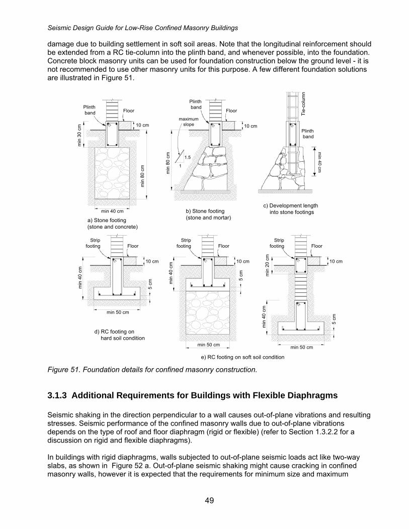
Seismic Design Guide for Low-Rise Confined Masonry Buildings
49
damage due to building settlement in soft soil areas. Note that the longitudinal reinforcement should be extended from a RC tie-column into the plinth band, and whenever possible, into the foundation. Concrete block masonry units can be used for foundation construction below the ground level - it is not recommended to use other masonry units for this purpose. A few different foundation solutions are illustrated in Figure 51.
FloorPlinthband
min
80
cm
min
30
cm
10 cmmaximum
slope
min 40 cm
min 40 cm
Floor
10 cm
min
40
cm
5 cm
Floor
10 cm
min
80
cm
min 50 cm
1.5
1
Stripfooting
Plinthband
Tie-
colu
mn
Plinthband
Floor
10 cmm
in 4
0 cm
5 cm
min 50 cm
StripfootingFloor
10 cm
min
40
cm
5 cm
min 50 cm
Stripfooting
d) RC footing on hard soil condition
e) RC footing on soft soil condition
min
20
cm
a) Stone footing(stone and concrete)
b) Stone footing(stone and mortar)
c) Development length into stone footings
Figure 51. Foundation details for confined masonry construction.
3.1.3 Additional Requirements for Buildings with Flexible Diaphragms Seismic shaking in the direction perpendicular to a wall causes out-of-plane vibrations and resulting stresses. Seismic performance of the confined masonry walls due to out-of-plane vibrations depends on the type of roof and floor diaphragm (rigid or flexible) (refer to Section 1.3.2.2 for a discussion on rigid and flexible diaphragms). In buildings with rigid diaphragms, walls subjected to out-of-plane seismic loads act like two-way slabs, as shown in Figure 52 a. Out-of-plane seismic shaking might cause cracking in confined masonry walls, however it is expected that the requirements for minimum size and maximum
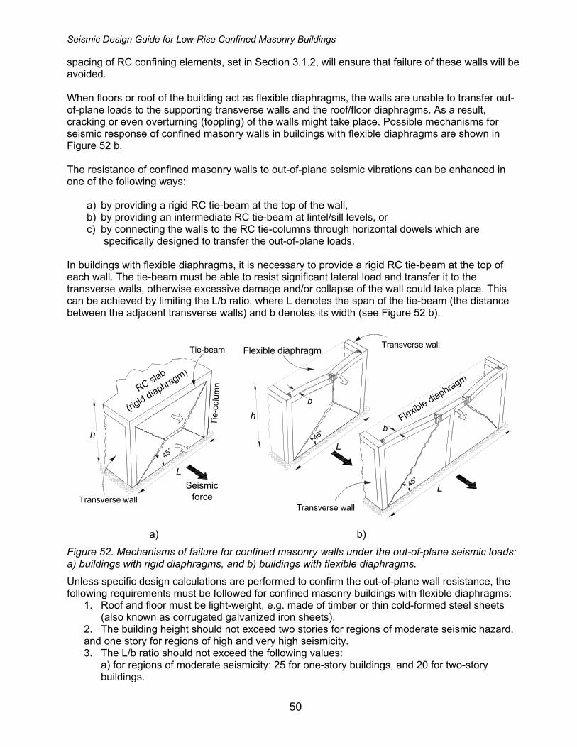
Seismic Design Guide for Low-Rise Confined Masonry Buildings
50
spacing of RC confining elements, set in Section 3.1.2, will ensure that failure of these walls will be avoided. When floors or roof of the building act as flexible diaphragms, the walls are unable to transfer out-of-plane loads to the supporting transverse walls and the roof/floor diaphragms. As a result, cracking or even overturning (toppling) of the walls might take place. Possible mechanisms for seismic response of confined masonry walls in buildings with flexible diaphragms are shown in Figure 52 b. The resistance of confined masonry walls to out-of-plane seismic vibrations can be enhanced in one of the following ways:
a) by providing a rigid RC tie-beam at the top of the wall, b) by providing an intermediate RC tie-beam at lintel/sill levels, or c) by connecting the walls to the RC tie-columns through horizontal dowels which are
specifically designed to transfer the out-of-plane loads. In buildings with flexible diaphragms, it is necessary to provide a rigid RC tie-beam at the top of each wall. The tie-beam must be able to resist significant lateral load and transfer it to the transverse walls, otherwise excessive damage and/or collapse of the wall could take place. This can be achieved by limiting the L/b ratio, where L denotes the span of the tie-beam (the distance between the adjacent transverse walls) and b denotes its width (see Figure 52 b).
Transverse wall
Transverse wall
b
b
45°
Flexible diaphragm
Flexible diaphragm
L
45°
h
L
Transverse wall
45°
Seismicforce
Tie-
colu
mnRC sla
b
(rigid diaphragm)
Tie-beam
h
L
a) b)
Figure 52. Mechanisms of failure for confined masonry walls under the out-of-plane seismic loads: a) buildings with rigid diaphragms, and b) buildings with flexible diaphragms.
Unless specific design calculations are performed to confirm the out-of-plane wall resistance, the following requirements must be followed for confined masonry buildings with flexible diaphragms:
1. Roof and floor must be light-weight, e.g. made of timber or thin cold-formed steel sheets (also known as corrugated galvanized iron sheets).
2. The building height should not exceed two stories for regions of moderate seismic hazard, and one story for regions of high and very high seismicity. 3. The L/b ratio should not exceed the following values:
a) for regions of moderate seismicity: 25 for one-story buildings, and 20 for two-story buildings.

Seismic Design Guide for Low-Rise Confined Masonry Buildings
51
b) for regions of high or very high seismicity: the limit is set to 20 (irrespective of the building height). Note that L denotes the distance between the adjacent transverse walls when L/h ≥ 1.0, otherwise the wall height h should be used instead of L (see Figure 52 b for the notation).
4. The minimum width of a RC tie-beam, b, must not be less than the following values: • 20 cm • L/30 for regions of moderate seismicity, and • L/20 for regions of high and very high seismicity.
Out-of-plane resistance of confined masonry wall panels can also be enhanced by providing horizontal dowels or intermediate RC tie-beams (bands). Horizontal dowels are shown in Figure 42 c, however it is preferred to provide intermediate RC tie-beams shown in Figure 53. It is challenging to ensure adequate embedment of horizontal steel dowels in thin mortar joints, and there is a high chance for the occurrence of corrosion. Note that the thickness of sill and lintel bands is less than that of RC tie-beams, as illustrated in Figure 53.
Plinth bandSill band
Tie-beamLintel band Continuous
lintel band
Max120 cm
≥ 20 mm
≥ 76
mm
Lintel and sill band
Figure 53. Intermediate RC tie-beams (bands) can be provided to enhance the out-of-plane wall resistance (Schacher, 2009).
3.2 Construction Quality Construction quality has a significant bearing on the seismic performance of confined masonry buildings. Properly designed and built confined masonry buildings performed well in past earthquakes in most cases, while poorly built ones experienced damage. Numerous illustrations of recommended construction practices, as well as construction flaws are presented in a publication by SENCICO (2008). In general, it is highly desirable to ensure a good construction quality by performing continuous inspection by qualified professionals. However, it is expected that most non-engineered buildings are not going to be inspected during the construction. In case where inspection is possible, a comprehensive construction inspection checklist included in Appendix B should be used as a reference.

Seismic Design Guide for Low-Rise Confined Masonry Buildings
52
Concluding Remarks Confined masonry buildings have performed well in several earthquakes worldwide. This construction practice is widely used in many countries and regions for the following reasons:
• It is based on traditional masonry construction practice. • It does not require highly qualified labor (as is the case with RC frame construction). • Confined masonry technology falls in between that of unreinforced masonry and RC frame construction; however, due to its smaller member sizes and the lesser amount of reinforcement it is more cost-effective than RC frame construction, especially when labor is inexpensive. • It has a broad range of applications, that is, it can be used for single-family houses as well as for medium-rise apartment buildings.
The following disadvantages are associated with confined masonry construction:
• Confined masonry construction is more expensive than unreinforced masonry construction and requires somewhat higher level of labor skills, however its earthquake performance is significantly better than unreinforced masonry construction; • It is characterized by lower strength and ductility when compared to properly built ductile RC frame construction and may require larger wall area when compared to RC frame construction with masonry infills.
Confined masonry construction has a great potential for saving lives and property in areas of high seismic risk around the world. However, like any other construction practice, good earthquake performance is based on the following premises:
• Use of good quality materials, • Good quality of concrete and masonry construction, and • Simple architectural design.

Seismic Design Guide for Low-Rise Confined Masonry Buildings
53
References Codes and Standards
China (2001). 砌体结 设计规构 范“ (Code for Design of Masonry Structures), China (in Chinese).
Eurocode 6 (2006). Design of Masonry Buildings - Part 1-1: Common Rules for Reinforced and Unreinforced Masonry Structures, EN 1996-1: 2006, CEN, Belgium.
Eurocode 8 (1996). Design Procedures for Earthquake Resistance of Structures. Part 1-3: General Rules – Specific Rules for Various Materials and Elements. ENV1998-1-3, CEN, Brussels.
INPRES (1991). INPRES-CIRSOC 103, Parte III. Normas Argentinas para Construcciones Sismorresistentes. Construcciones de Mampostería (INPRES-CIRSOC 103, Part III. Argentinean Code for Seismic-Resistant Construction. Masonry Construction), Argentina (in Spanish)
Iran (2005). مقررات ملي ساختمان، مبحث هشتم (National Building Regulations. Volume 5: Building Materials. Volume 8: Design and Construction of Masonry Buildings), Iran (in Persian).
NCh2123 (2003). Albañilería Confinada – Requisitos para el diseño y cálculo (NCh 2123.Of97). Instituto Nacional de Normalizacion (Confined Masonry – Requirements for Structural Design), Chile (in Spanish).
NSR-98 (1998). Normas Colombianas de Diseño y Construcción Sismo Resistente – NSR-98 (Colombian Code for the Seismic Design and Construction– NSR-98, Titles D and E), Colombia (in Spanish).
NTC-M (2004). Normas Técnicas Complementarias para Diseño y Construcción de Estructuras de Mampostería (Technical Norms for Design and Construction of Masonry Structures), Mexico D.F. (in Spanish and English).
NTC-S (2004). Normas Técnicas Complementarias para Diseño por Sismo (Complimentary Technical Norms for Seismic Design), Mexico D.F. (in Spanish).
NT E.070 (2006). Reglamento Nacional de Edificaciones, Norma Técnica E.070 Albañilería (National Building Code, Technical Standard E.070 Masonry), Peru (in Spanish).
RPA99 (2003). Règles Parasismiques Algériennes RPA99/Version 2003 (Algerian Seismic Regulations RPA99), Algeria (in French).
Papers and Reports
Aguilar G., and Alcocer S.M. (2001). Effect of Horizontal Reinforcement on the Behavior of Confined Masonry Walls Under Lateral Loads. Centro Nacional de Prevención de Desastres (SEGOB), Mexico City, Mexico, 181 pp (in Spanish).
Alcocer, S. (2006). Personal Communication.
Alcocer, S., Arias, J.G., and Flores, L.E. (2004). Some Developments on Performance-Based Seismic Design of Masonry Structures. International Workshop on Performance-Based Seismic Design, Bled, Slovenia.
Alcocer, S., Arias, J.G., and Vazquez, A. (2004a). Response Assessment of Mexican Confined Masonry Structures Through Shaking Table Tests. Proceedings of the 13th World Conference on Earthquake Engineering, Vancouver, Canada, Paper No. 2130.
Seismic Design Guide for Low-Rise Confined Masonry Buildings
54
Alcocer, S.M., Cesin, J., Flores, L.E., Hemander, O., Meli, R., Tena, A., and Vasconcelos, D. (2003). The New Mexico City Building Code Requirements for Design and Construction of Masonry Structures. Proceedings of the 9th North American Masonry Conference, South Carolina, USA, No. 4B3.
Alcocer S.M. et al. (2001). The Tehuacán Earthquake of June 15, 1999. Centro Nacional de Prevención de Desastres (SEGOB), Mexico City, Mexico, 198 pp (in Spanish).
Alcocer, S.M. and Klingner, R. (1994). Masonry Research in the Americas. Masonry in the Americas, ACI Publication SP-147, American Concrete Institute, Detroit, pp.127-169.
Anderson, D.L., and Brzev, S. (2009). Seismic Design Guide for Masonry Buildings, Canadian Concrete Masonry Producers Association, Toronto, Canada, 317 pp (free download available at www.ccmpa.ca).
Astroza, M., Cabezas, F., Moroni, M., Massone, L., Ruiz, S., Parra,E., Cordero,F., and Mottadelli, A., 2010. Intensidades Sismicas en el Area de Daños del Terremoto del 27 de Febrero de 2010, Universidad de Chile, Santiago (in Spanish) (http://www.eqclearinghouse.org/20100227-chile/wp-content/uploads/2010/04/Informe-de-Intensidades-M.-Astroza-y-otros.pdf)
Blondet, M. (2005). Construction and Maintenance of Masonry Houses – For Masons and Craftsmen. Pontificia Universidad Catolica del Peru, Lima, Peru (free download available at http://www.world-housing.net/, Tutorials page)
Boen,T. (2009). Constructing Seismic Resistant Masonry Houses, Third Edition, United Nations Center for Regional Development, Disaster Management Planning Hyogo Office.
(http://www.hyogo.uncrd.or.jp/publication/pdf/Guide/masonryhousesindonesiaguide.pdf)
Brzev, S., Astroza, M., and Moroni, O. (2010). Performance of Confined Masonry Buildings in the February 27, 2010 Chile Earthquake, Earthquake Engineering Research Institute, Oakland, California (www.confinedmasonry.org).
Brzev, S. (2008). Earthquake-Resistant Confined Masonry Construction, National Information Center for Earthquake Engineering, Kanpur, India (free download available at www.nicee.org/confinedmasonry.php)
Build Change (2006). Earthquake-Resistant Design and Construction Guideline for Single Story Reinforced Concrete Confined Masonry Houses Built in the Aceh Permanent Housing Reconstruction Program.
Build Change (2007). Central Java Earthquake 27 May 2006. Power Point presentation (unpublished).
City University of London (2005). Low-Rise Residential Construction Detailing to Resist Earthquakes. City University of London and Pell Frichmann (www.staff.city.ac.uk/earthquakes/Repairstrengthening/index.php)
EERI (2006). The Tecomán, México Earthquake January 21, 2003. An EERI and SMIS Learning from Earthquakes Reconnaissance Report, Technical Editors S.M. Alcocer and R.E. Klingner, Earthquake Engineering Research Institute, Oakland, California, March 2006.
EERI (2001). Preliminary Reports and Annotated Images from the El Salvador Earthquakes of January 13 and February 13, 2001. Photos by Manuel Alfredo Lopez Menjivar, a CD-Rom publication, Earthquake Engineering Research Institute, California.
Hart,T., Canney,N., Huey,J., and Nixon, R. (2010). Out-of-Plane Study of Confined Masonry Walls with Rigid and Flexible Floor Diaphragms, San Francisco, USA (www.confinedmasonry.org).
GSHAP (1999). Global Seismic Hazard Assessment Program, International Lithosphere Program (www.seismo.ethz.ch/GSHAP/global/).
Seismic Design Guide for Low-Rise Confined Masonry Buildings
55
Meisl, C.S., Safaie, S., Elwood, K.J., Gupta, R., and Kowsari, R. (2006). Housing Reconstruction in Northern Sumatra after the December 2004 Great Sumatra Earthquake and Tsunami. Special Issue on the Great Sumatra Earthquakes and Indian Ocean Tsunamis of 26 December 2004 and 28 March 2005, Earthquake Spectra, Vol. 22, No S3, pp. S777-S802.
Meli, R. (1994). Structural Design of Masonry Buildings: the Mexican Practice. Masonry in the Americas, ACI Publication SP-147, American Concrete Institute, Detroit, pp. 239-262.
Pérez-Gavilán, J.J, Flores, L.E. and Cruz, O. (2009). Ensaye de Muros de Mampostería de Distinta Longitud: Cinemática y Rigidez Lateral (Testing of masonry walls with different lengths: kinematics and lateral stiffness), XVII National Conference on Earthquake Engineering, Puebla, Mexico (in Spanish).
PNUD (2009). Manual Para la Reparación y Reforzamiento de Viviendas de Albañilería Confinada Dañadas por Sismos, Programa de Naciones Unidas para el Desarrollo (PNUD), Lima, Peru (www.pnud.org.pe) (in Spanish).
Ruiz, J. and Alcocer, S.M. (1998). Desempeño Experimental de Estructuras de Mampostería Confinada Rehabilitadas Mediante el Uso de Malla de Alambre, Revista de Ingeniería Sísmica, SMIS, No. 59, pp 59-79, julio-diciembre (in Spanish).
San Bartolome, Á., Bernardo, J., and Peña, M. (2010). Efectos del Peralte de las Columnas en el Comportamiento Sísmico de los Muros de Albañilería Confinada (The effect of column depth on seismic behavior of confined masonry walls), Chilean Conference on Seismology and Earthquake Engineering, Valdivia-Santiago, Chile (in Spanish).
San Bartolomé, A. and Quiun, D. (2008). Pisco, Peru Earthquake and Masonry Seismic Performance - a Code Point of View, Proceedings, Masonry in the Americas Workshop, Cancun, Mexico.
Schacher, T. (2009). Confined Masonry for One and Two Storey Buildings in Low-tech Environments - A Guidebook for Technicians and Artisans, National Information Centre of Earthquake Engineering, Kanpur, India (www.nicee.org).
SENCICO (2008). Comentarios A La Norma Técnica De Edificación E.070 “Albañilería, Servicio Nacional de Capacitación para la Industria de la Construcción, Peru (in Spanish) (http://blog.pucp.edu.pe/blog/albanileria).
Tomazevic, M. and Klemenc, I. (1997). Seismic Behaviour of Confined Masonry Walls. Earthquake Engineering and Structural Dynamics, Vol. 26, pp.1059-1071.
Tomazevic, M. (1999). Earthquake-Resistant Design of Masonry Buildings, Imperial College Press, London, U.K.
Yoshimura, K., Kikuchi, K., Kuroki, M., Nonaka, H., Kim, K.T., Wangdi, R., and Oshikata, A. (2004). Experimental Study for Developing Higher Seismic Performance of Brick Masonry Walls. Proceedings of the 13th World Conference on Earthquake Engineering, Vancouver, Canada, Paper No. 1597.
Relevant Web Sites (resources related to confined masonry) 1. Confined Masonry Network (www.confinedmasonry.org) 2. Masonry blog by Prof. A. San Bartolomé, PUCP, Lima, Peru (http://blog.pucp.edu.pe/blog/albanileria) (in Spanish) 3. World Housing Encyclopedia (WHE) (www.world-housing.net) WHE Tutorials on Confined Masonry (http://www.world-housing.net/tutorials/)

Seismic Design Guide for Low-Rise Confined Masonry Buildings
56
Appendix A
Simplified Method for Wall Density Calculation in Low-Rise Buildings
The Simplified Method presented in this section is used to calculate the wall density index, d. This method is recommended for seismic design of low-rise buildings complying with regularity and symmetry requirements outlined in Section 3.1.1.1, but it can be also used for a preliminary feasibility check of a wall layout in taller buildings, and/or low-rise buildings with complex structural layouts. The following assumptions have been made in developing the Simplified Method:
a) Building safety is governed by shear failure of its walls. Longitudinal reinforcement in tie -columns is assumed to provide sufficient flexural strength in the confined masonry system.
b) The story shear strength is the sum of the shear capacities of all walls in the direction under consideration. Floor/roof systems act as rigid diaphragms. Wall stiffness is mainly governed by shear deformations, and all confined masonry walls are able to reach their shear strength before the failure of any story in the building takes place.
Note that the load and safety factors used to derive the wall density indices in this document are as adopted by the Mexico City Building Code (NTC-M, 2004). However, this concept could be easily adapted to other local building codes and practices, by modifying the safety factors and other parameters as needed.
A.1 Seismic Safety Check Using the Wall Density Index It is assumed that the building will remain safe when exposed to the design earthquake under consideration, provided that the shear strength of each story (FRVR) exceeds the factored seismic shear force (FC VU) according to the following criterion:
FRVR ≥ FC VU (1)
where VR = seismic shear strength for each story VU = seismic force FR = 0.7 strength reduction factor FC = 1.1 load factor The above expression can be rearranged as follows
SR
C
U
R FFF
VV
=≥ (2)
where FS is the safety factor. In this case, FS = 1.1/0.7 = 1.6.
Disclaimer The wall density index (d) values were recommended in Table 6 of Section 3.1.1.1. This appendix outlines design approaches which can be used to calculate more precise d values than those presented in Table 6. It is recommended that users of this appendix have engineering background.
Seismic Design Guide for Low-Rise Confined Masonry Buildings
57
This check needs to be performed for each orthogonal direction of the building plan. Seismic force (VU), also known as the seismic base shear force, depends on the building properties and site conditions. It can be computed by multiplying the total building weight (WT) by the corresponding seismic coefficient (c), as follows
VU = cWT
Building weight (WT) should be calculated from the following equation
WT = AP n w (3)
where AP = area of floor plan for one story w = weight for unit area of floor/roof system, which includes the wall self-weight; typical values range from 6 kPa (600 kg/m2) to 8 kPa (800 kg/m2) for light and heavy floor or roof systems respectively n= number of stories The seismic coefficient, c, should be computed from the following equation:
c = (I KTS/R) a0 (4)
where a0 = peak ground acceleration (PGA) specified by the local code or based on the seismic hazard
map (see Section 2.2) KT = dynamic amplification factor which transforms a0 into the spectral acceleration for a system
with 5% modal damping. KT depends on the fundamental period of the building. The buildings under consideration are characterized by low fundamental periods in the range from 0.1 to 0.4 s. Most seismic codes prescribe a constant spectral acceleration for low-period structures, thus a constant value of 2.5 can be conservatively assigned to KT (this corresponds to a spectral acceleration of 2.5 a0).
I = building importance factor = 1.0 for normal-importance buildings (housing – residential buildings), = 1.3 for high-importance buildings, including schools and places of assembly that could be used as refuge in the event of an earthquake, and = 1.5 for post-disaster facilities (hospitals, emergency control centres, etc.).
S = soil amplification factor, which depends on the building site location = 1.0 for rock or firm soil conditions, = 1.2 for compact granular soil conditions, and = 1.4 for soft clay conditions.
R = a response reduction factor that takes into account ductility and overstrength = 3 hollow masonry units = 4 solid masonry units
The above R values are based on an overstrength factor of 2, and a ductility factor of 2 and 1.5 for solid and hollow masonry units, respectively.

Seismic Design Guide for Low-Rise Confined Masonry Buildings
58
Seismic Shear Strength at the story level (VR) shall be computed for each of the two orthogonal directions of the building plan by multiplying the masonry shear strength (v) by the total effective wall area (AW), that is,
VR = v AW (5)
where Aw = the total effective wall area, and it is equal to the sum of the cross-sectional wall areas (length x thickness) for all walls in the direction being evaluated. Wall cross-sectional areas should not be included in the Aw calculation in the following cases:
c) when walls are characterized by the height-to-length ratio greater than 1.5 (H/L> 1.5), and
d) for walls with openings, where unconfined opening area is greater than 10% of the wall surface area (see Section 3.1.1.2).
Basic masonry shear strength (vm) depends on the type of masonry units and mortar used, and can be determined from the following equation:
v = (0.5vm + 0.3 σ) ≤ 1.5 vm (6)
where σ is the average compressive stress in the load-bearing walls due to gravity loads. Note that the stress σ has positive values for compression. When tensile stresses act on the wall, σ should be taken equal to zero. When the diagonal compression test data are not available for local materials, the vm values recommended in Table 5 may be used. For the first story, the average compressive stress σ can be obtained as the ratio of the total building weight, WT, and the sum of the cross-sectional areas of all walls at the first story level in both directions, WAΣ , thus,
dwn
A/Awn
AAwn
AW
PWW
P
W
T
Σ=
Σ=
Σ=
Σ=σ (7)
where WT is substituted from equation (3), and Σd is the sum of wall densities in both orthogonal directions of the building plan, that is, longitudinal (x) and transverse (y), as follows
Σd = dX + dY
The calculation of wall density index is an iterative process because the d value is required to find the σ value, and subsequently the masonry shear strength (v) value. Moreover, the amount of walls and the corresponding d value influence the floor weight w. Based on the equations presented earlier in this section, the ratio of the shear strength at the story level (VR) and the seismic force (VU) is equal to

Seismic Design Guide for Low-Rise Confined Masonry Buildings
59
dwnc
vAwnc
AvVV
P
w
U
R == (8)
where the wall density index (d) is a ratio of the total wall area (AW) in one orthogonal direction and the building plan area (AP), that is, (see Figure 37)
d = AW/AP (9)
Based on the fundamental design requirement stated at the beginning of this section (equation 2), it follows that
SU
R FVV
≥ (2)
therefore
SFdwnc
v≥
According to the Simplified Method, the building can be considered to be safe for the specified seismic loads provided that the wall density index, d, is greater than or equal to the following value
vwncFd S≥ (10)
The application of the Simplified Method for seismic safety check of confined masonry buildings will be illustrated with two examples.
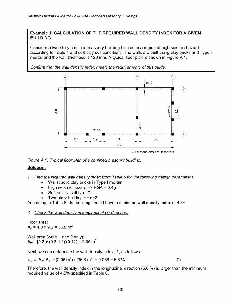
Seismic Design Guide for Low-Rise Confined Masonry Buildings
60
2
1
4.0
1.2
CBA
All dimensions are in meters
9.2
3.03.01.22.0
0.12
door
win
dow
door
Figure A.1. Typical floor plan of a confined masonry building.
Solution: 1. Find the required wall density index from Table 6 for the following design parameters.
• Walls: solid clay bricks in Type I mortar • High seismic hazard => PGA = 0.4g • Soft soil => soil type C • Two-story building => n=2
According to Table 6, the building should have a minimum wall density index of 4.5%. 2. Check the wall density in longitudinal (x) direction. Floor area: Ap = 4.0 x 9.2 = 36.8 m2 Wall area (walls 1 and 2 only): AW = [9.2 + (9.2-1.2)](0.12) = 2.06 m2
Next, we can determine the wall density index, d , as follows:
=xd AW/ Ap = (2.06 m2) / (36.8 m2) = 0.056 = 5.6 % (9)
Therefore, the wall density index in the longitudinal direction (5.6 %) is larger than the minimum required value of 4.5% specified in Table 6.
Example 1: CALCULATION OF THE REQUIRED WALL DENSITY INDEX FOR A GIVEN BUILDING Consider a two-story confined masonry building located in a region of high seismic hazard according to Table 1 and soft clay soil conditions. The walls are built using clay bricks and Type I mortar and the wall thickness is 120 mm. A typical floor plan is shown in Figure A.1. Confirm that the wall density index meets the requirements of this guide.

Seismic Design Guide for Low-Rise Confined Masonry Buildings
61
3. Check the wall density in transverse (y) direction. Wall area (walls A, B, and C): AW = [4.0 + (4.0-1.2) + (4.0-1.2)](0.12) = 1.15 m2
=yd AW/ Ap = (1.15 m2)/ (36.8 m2) = 0.031 = 3.1% (9)
Therefore, the wall density index in the transverse direction (3.1%) is less than the minimum required value of 4.5% prescribed by Table 6. In order to satisfy the wall density requirement, wall thickness can be increased in the transverse direction only. Instead of using the half-brick thick walls, one-brick thick walls can be used. As a result, wall thickness will be increased from 120 mm to 240 mm. Wall density is directly proportional to the wall thickness and so its value will increase to 6.2 %. The revised wall density value is greater than the minimum required value of 4.5 %. Solution: 1. Find the seismic coefficient (c).
c = (I KTS/R)a0 = (1x2.5x1/4)0.4 = 0.25 (4)
2. Calculate the average compressive stress (σ). In order to calculate σ, it is required to make an initial assumption regarding the wall density, that is, dx = dy = 0.01n thus (from equation 9) AW = dAP = 0.01nAP
Example 2a: CALCULATION OF THE REQUIRED WALL DENSITY INDEX FOR A GIVEN BUILDING - GENERIC EQUATION Consider a confined masonry residential building with clay brick masonry walls and Type I mortar. Assume a heavy floor and roof system for this building. The building site is characterized by peak ground acceleration (PGA) of 0.4g and firm soil conditions. The design parameters are summarized below: w = 800 kg/m2 (floor/roof weight per unit floor plan area) a0 = 0.4 (PGA=0.4g) KT = 2.5 (fundamental period less than 0.4 sec) S = 1 (firm soil - Type A) R = 4 (response reduction factor for solid masonry units) I = 1 (normal importance building/residential) vm = 3.5 kg/cm2 (hand-made clay bricks and mortar type I, see Table 5) Fs = 1.6 (safety factor recommended by this document) Find the required wall density for the given building and site information.
Seismic Design Guide for Low-Rise Confined Masonry Buildings
62
This means the wall area in each direction and at each story level is 0.01n times the floor area AP, where n is the number of stories. Calculate σ for the first story level from equation (7):
W
P
W
P
W
T
A2Awn
AAwn
AW
=Σ
=Σ
=σ (7)
= (nx800xAP)/[2x(0.01xnxAP)] = 800/0.02 = 40,000 kg/m2 = 4 kg/cm2 3. Calculate the masonry shear strength (v). b) The masonry shear strength, v, can be determined from the equation (6) as follows
v = (0.5vm + 0.3σ) = 0.5x3.5 + 0.3x4 = 2.95 kg/cm² (6)
Since v = 2.95 kg/cm2 < 1.5vm = 5.25 kg/cm² O.K. 4. Find the wall density index (d). The required wall density index (d) can be found from equation (10) as follows
n011.095.2
08.0n25.06.1v
wncFd S =×××
=≥ (10)
It can be concluded that this building needs to have a wall density index (d) in each direction equal to at least 1.1% of the number of stories n. The required wall density in each orthogonal direction is equal to
d ≥ 0.011n = 0.011×2 = 0.022 = 2.2%
The wall area in each orthogonal direction can be found from equation 9, as follows
AW = d x AP = 0.022 x 100 = 2.2 m²
Example 2b: CALCULATION OF THE REQUIRED WALL DENSITY INDEX FOR A GIVEN TWO-STORY BUILDING Consider a two-story confined masonry building with the required wall density ratio determined in Example 2a. The design parameters are summarized below: n = 2 number of stories AP = 100 m² floor area for each story t = 150 mm wall thickness Find the minimum required wall length in each direction.

Seismic Design Guide for Low-Rise Confined Masonry Buildings
63
The wall area is equal to the product of wall length in one orthogonal direction (x or y), ΣL, and the wall thickness (t), that is,
AW = ΣLX x t = ΣLy x t
it follows that the minimum required wall length in each direction is equal to:
ΣLX = ΣLY = 2.2 / 0.15 = 14.7 m
where t = 150 mm = 0.15 m (wall thickness). Keep the following constraints in mind while planning the wall lengths and openings in this building: 1. The walls shorter than 1.6 m in plan (L < 1.6 m) should not be considered in the AW calculation, because the minimum practical story height (H) of 2.5 m will result in the wall H/L ratio of 1.5. Walls with H/L≥1.5 should not be considered in the AW calculation. 2. Walls with unconfined openings should not be considered. A.2 Wall Density Requirements for Gravity Loads In addition to satisfying the wall density requirements for seismic loads, the walls must meet the gravity load-bearing strength requirements summarized in this section. Average wall normal stress under gravity loads. For a simple verification of the average normal stress, it is required that the factored compression strength (FRσR) is greater than or equal to the factored average normal stress (FCσU), that is,
FR σR ≥ FC σU (11)
where σR = the compression strength of a masonry wall, σU, = the average compression stress, FR = 0.6 strength reduction factor for gravity loading, and FC = 1.4 load factor for gravity loading. The safety factor for gravity loading (FS) can be established as follows
SU
R F≥σσ (12)
where
33.2FFF
R
CS ==
The average compression stress in the walls at the first story level (σU) can be determined as follows
W
P
W
TU A
AwnAW
Σ=
Σ=σ (13)
where n = the number of stories w = weight of floor/roof system per unit floor area ΣAW = the sum of the cross-sectional areas for all walls at the first story level (in both directions)
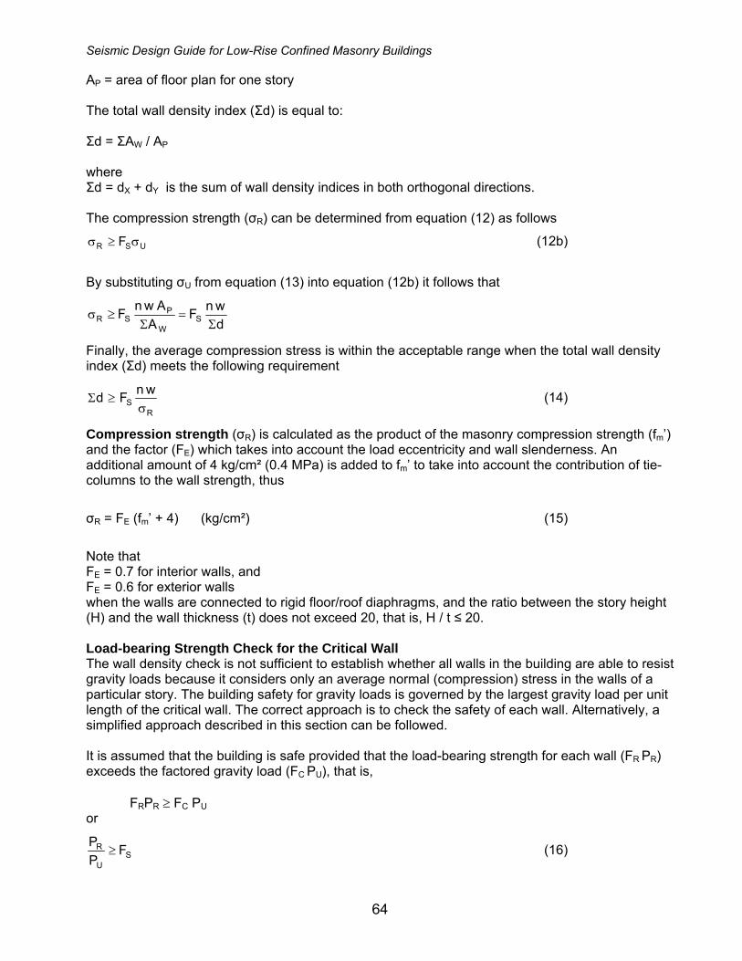
Seismic Design Guide for Low-Rise Confined Masonry Buildings
64
AP = area of floor plan for one story The total wall density index (Σd) is equal to: Σd = ΣAW / AP where Σd = dX + dY is the sum of wall density indices in both orthogonal directions. The compression strength (σR) can be determined from equation (12) as follows
USR F σ≥σ (12b)
By substituting σU from equation (13) into equation (12b) it follows that
dwnF
AAwnF SW
PSR Σ
=Σ
≥σ
Finally, the average compression stress is within the acceptable range when the total wall density index (Σd) meets the following requirement
RS
wnFdσ
≥Σ (14)
Compression strength (σR) is calculated as the product of the masonry compression strength (fm’) and the factor (FE) which takes into account the load eccentricity and wall slenderness. An additional amount of 4 kg/cm² (0.4 MPa) is added to fm’ to take into account the contribution of tie-columns to the wall strength, thus
σR = FE (fm’ + 4) (kg/cm²) (15)
Note that FE = 0.7 for interior walls, and FE = 0.6 for exterior walls when the walls are connected to rigid floor/roof diaphragms, and the ratio between the story height (H) and the wall thickness (t) does not exceed 20, that is, H / t ≤ 20. Load-bearing Strength Check for the Critical Wall The wall density check is not sufficient to establish whether all walls in the building are able to resist gravity loads because it considers only an average normal (compression) stress in the walls of a particular story. The building safety for gravity loads is governed by the largest gravity load per unit length of the critical wall. The correct approach is to check the safety of each wall. Alternatively, a simplified approach described in this section can be followed. It is assumed that the building is safe provided that the load-bearing strength for each wall (FR PR) exceeds the factored gravity load (FC PU), that is, FRPR ≥ FC PU or
SU
R FPP
≥ (16)
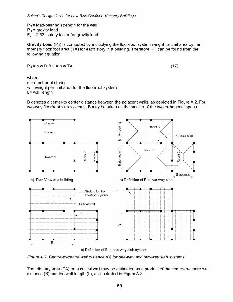
Seismic Design Guide for Low-Rise Confined Masonry Buildings
65
PR = load-bearing strength for the wall PU = gravity load FS = 2.33 safety factor for gravity load Gravity Load (PU) is computed by multiplying the floor/roof system weight for unit area by the tributary floor/roof area (TA) for each story in a building. Therefore, PU can be found from the following equation
PU = n w D B L = n w TA (17)
where n = number of stories w = weight per unit area for the floor/roof system L= wall length B denotes a center-to center distance between the adjacent walls, as depicted in Figure A.2. For two-way floor/roof slab systems, B may be taken as the smaller of the two orthogonal spans.
Critical wall
Critical walls
Girders for thefloor/roof system
c) Definition of B in one-way slab system
b) Definition of B in two-way slaba) Plan View of a building
Roo
m 2
Room 1
Room 3
window
win
dow
B
B
Room 3
B (fo
r roo
m 3
)
Roo
m 2
Room 1
B (f
or ro
om 1
)
B (room 2)
Figure A.2. Centre-to-centre wall distance (B) for one-way and two-way slab systems.
The tributary area (TA) on a critical wall may be estimated as a product of the centre-to-centre wall distance (B) and the wall length (L), as illustrated in Figure A.3.
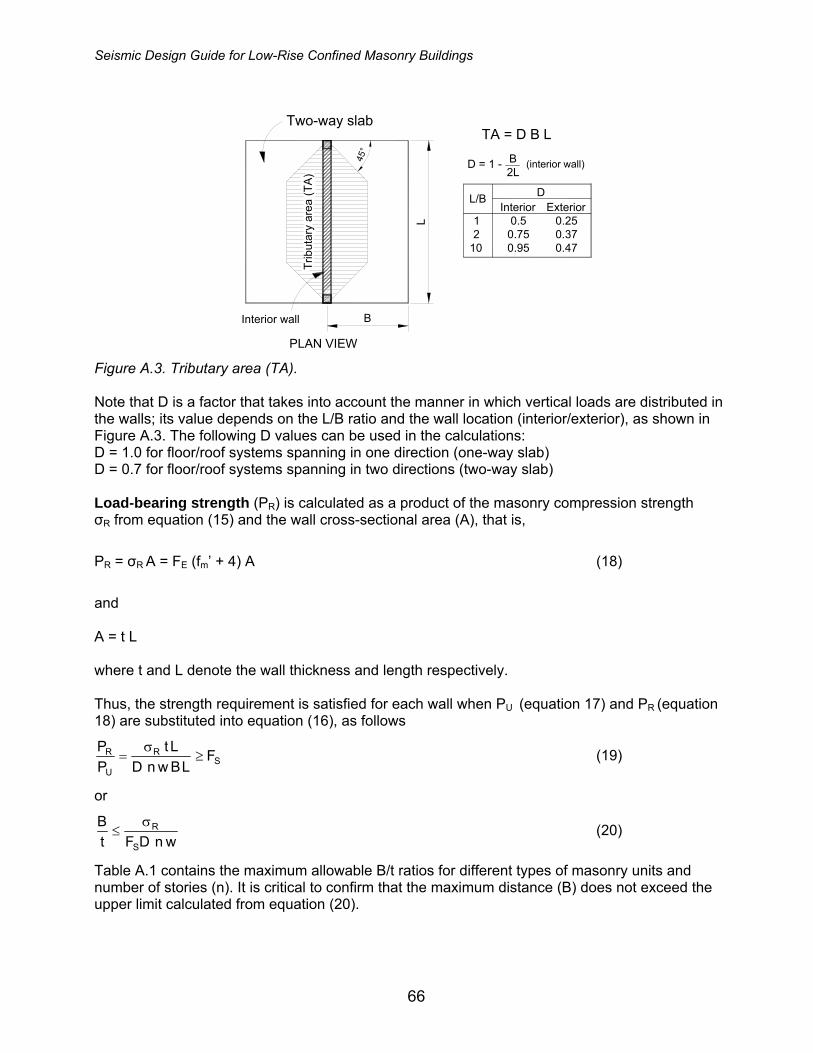
Seismic Design Guide for Low-Rise Confined Masonry Buildings
66
PLAN VIEW
L/B DExterior
0.250.370.47
Interior0.5
0.750.95
12
10
Interior wallTr
ibut
ary
area
(TA
)
Two-way slab
L
B
45°
(interior wall)B2L
D = 1 -
TA = D B L
Figure A.3. Tributary area (TA). Note that D is a factor that takes into account the manner in which vertical loads are distributed in the walls; its value depends on the L/B ratio and the wall location (interior/exterior), as shown in Figure A.3. The following D values can be used in the calculations: D = 1.0 for floor/roof systems spanning in one direction (one-way slab) D = 0.7 for floor/roof systems spanning in two directions (two-way slab) Load-bearing strength (PR) is calculated as a product of the masonry compression strength σR from equation (15) and the wall cross-sectional area (A), that is,
PR = σR A = FE (fm’ + 4) A (18)
and A = t L where t and L denote the wall thickness and length respectively. Thus, the strength requirement is satisfied for each wall when PU (equation 17) and PR (equation 18) are substituted into equation (16), as follows
SR
U
R FLBwnD
LtPP
≥σ
= (19)
or
wnDFtB
S
Rσ≤ (20)
Table A.1 contains the maximum allowable B/t ratios for different types of masonry units and number of stories (n). It is critical to confirm that the maximum distance (B) does not exceed the upper limit calculated from equation (20).
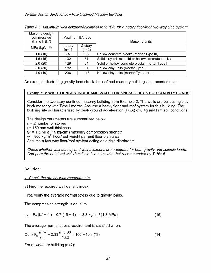
Seismic Design Guide for Low-Rise Confined Masonry Buildings
67
Table A.1. Maximum wall distance/thickness ratio (B/t) for a heavy floor/roof two-way slab system
Masonry design compressive strength (fm’)
Maximum B/t ratio
MPa (kg/cm²) 1-story (n=1)
2-story (n=2)
Masonry units
1.0 (10) 75 38 Hollow concrete blocks (mortar Type III) 1.5 (15) 102 51 Solid clay bricks, solid or hollow concrete blocks 2.0 (20) 129 64 Solid or hollow concrete blocks (mortar Type I) 3.0 (30) 182 91 Hollow clay units (mortar Type III) 4.0 (40) 236 118 Hollow clay units (mortar Type I or II)
An example illustrating gravity load check for confined masonry buildings is presented next. Solution: 1. Check the gravity load requirements. a) Find the required wall density index. First, verify the average normal stress due to gravity loads. The compression strength is equal to
σR = FE (fm’ + 4 ) = 0.7 (15 + 4) = 13.3 kg/cm² (1.3 MPa) (15)
The average normal stress requirement is satisfied when:
(%)n4.11003.1308.0n33.2wnFd
RC =×
⋅=
σ⋅
≥Σ (14)
For a two-story building (n=2):
Example 3: WALL DENSITY INDEX AND WALL THICKNESS CHECK FOR GRAVITY LOADS Consider the two-story confined masonry building from Example 2. The walls are built using clay brick masonry with Type I mortar. Assume a heavy floor and roof system for this building. The building site is characterized by peak ground acceleration (PGA) of 0.4g and firm soil conditions. The design parameters are summarized below: n = 2 number of stories t = 150 mm wall thickness fm’ = 1.5 MPa (15 kg/cm²) masonry compression strength w = 800 kg/m2 floor/roof weight per unit floor plan area Assume a two-way floor/roof system acting as a rigid diaphragm. Check whether wall density and wall thickness are adequate for both gravity and seismic loads. Compare the obtained wall density index value with that recommended by Table 6.
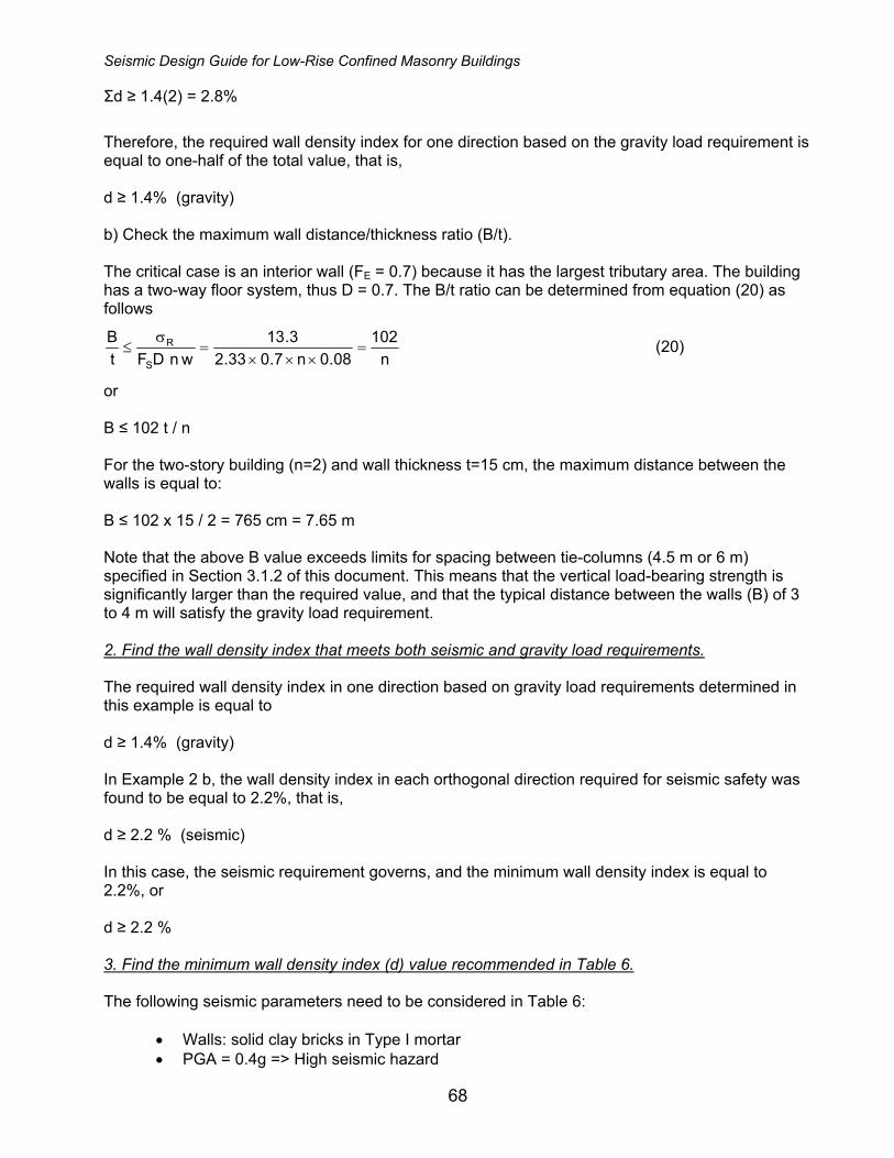
Seismic Design Guide for Low-Rise Confined Masonry Buildings
68
Σd ≥ 1.4(2) = 2.8%
Therefore, the required wall density index for one direction based on the gravity load requirement is equal to one-half of the total value, that is, d ≥ 1.4% (gravity) b) Check the maximum wall distance/thickness ratio (B/t). The critical case is an interior wall (FE = 0.7) because it has the largest tributary area. The building has a two-way floor system, thus D = 0.7. The B/t ratio can be determined from equation (20) as follows
n102
08.0n7.033.23.13
wnDFtB
S
R =×××
=σ
≤ (20)
or B ≤ 102 t / n For the two-story building (n=2) and wall thickness t=15 cm, the maximum distance between the walls is equal to: B ≤ 102 x 15 / 2 = 765 cm = 7.65 m Note that the above B value exceeds limits for spacing between tie-columns (4.5 m or 6 m) specified in Section 3.1.2 of this document. This means that the vertical load-bearing strength is significantly larger than the required value, and that the typical distance between the walls (B) of 3 to 4 m will satisfy the gravity load requirement. 2. Find the wall density index that meets both seismic and gravity load requirements. The required wall density index in one direction based on gravity load requirements determined in this example is equal to d ≥ 1.4% (gravity) In Example 2 b, the wall density index in each orthogonal direction required for seismic safety was found to be equal to 2.2%, that is, d ≥ 2.2 % (seismic) In this case, the seismic requirement governs, and the minimum wall density index is equal to 2.2%, or d ≥ 2.2 % 3. Find the minimum wall density index (d) value recommended in Table 6. The following seismic parameters need to be considered in Table 6:
• Walls: solid clay bricks in Type I mortar • PGA = 0.4g => High seismic hazard

Seismic Design Guide for Low-Rise Confined Masonry Buildings
69
• Firm soil => soil type A • Two-story building => n=2
According to Table 6, the building should have a minimum wall density index of 3.0%, that is, d ≥ 3.0 % (Table 6) Note that Table 6 gives a higher d value (3.0%) compared to that obtained by design calculations using the Simplified Method. It is a common practice for building code provisions to recommend more conservative values when design calculations are not required; this is the case with the d values recommended in Table 6 of this document. Design procedures used in the above examples are summarized below.
EXAMPLE 3: FIND THE WALL DENSITY INDEX BASED ON GRAVITY LOAD REQUIREMENTS 1. Find the compression strength, σR (equation 15). 2. Find the total wall density index (Σd) (equation 14) 3. Find the wall density index for one direction (d). 4. Find the B/t ratio (equation 20) and confirm that B meets the RC tie-column spacing requirements (Section 3.1.2).
EXAMPLE 1: CHECK WHETHER THE WALL DENSITY INDEX FOR A GIVEN BUILDING IS ADEQUATE 1. Find the required wall density ratio, d, from Table 6. 2. Find the wall density index for the longitudinal direction (x) and confirm that dx ≥ d. 3. Find the wall density index for the transverse direction (y) and confirm that dy ≥ d. Note: Wall density index is calculated from equation (9).
EXAMPLE 2: FIND THE REQUIRED WALL DENSITY INDEX FOR THE GIVEN BUILDING AND SITE INFORMATION 1. Find the seismic coefficient, c (equation 4). 2. Calculate the average compressive stress, σ (equation 7). 3. Calculate the masonry shear strength, v (equation 6). 4. Find the required wall density index, d (equation 10).
Seismic Design Guide for Low-Rise Confined Masonry Buildings
70
Appendix B
Guidelines for Inspection of Confined Masonry Construction
Inspection consists of the monitoring of materials and workmanship that are critical to the integrity of a building structure. One of the objectives of building inspection is to ensure the compliance with the approved plans and specifications and relevant codes, ordinances, and guidelines. Many regions where confined masonry construction is being practiced have inspection provisions already in place as part of the governing building code. However, there are other countries and regions where inspection is either not required by the building code or it is not fully enforced. “Inspection” and “testing” associated with a construction project are distinct but related tasks. Some agencies involved in construction inspection also handle the sampling and testing of construction materials, such as concrete, masonry, and reinforcing steel. References in these guidelines to “inspection” are intended to include the sampling and testing tasks. Several quality control and assurance tasks are associated with the construction of confined masonry buildings. To facilitate understanding of these tasks, the inspection guidelines are divided into those associated with the design and others associated with the construction. The inspection tasks included in these design guidelines are those that verify that the construction is consistent with the design criteria and assumptions, including verification of material strengths and placement of reinforcement. Inspection included in the construction guidelines is intended to verify that proper construction techniques are being followed, such as the wetting of bricks and construction of non-structural elements. Many building codes waive inspection requirements for single family houses, non-engineered buildings, and minor construction projects. This does not preclude the architect or engineer from requiring inspection of these projects. However, these projects may not need the same level of quality assurance as required for larger buildings. Therefore, the architect or engineer can consider reducing the extent of inspection for projects of this type. It is important that the persons involved in inspection and quality assurance testing be independent from the builder in order to avoid a direct conflict of interest. The intent of the inspection and testing is to verify the quality of the builder’s work, and thus the builder should not be in a position of performing or directing the inspection. The builder may have a separate in-house quality control program. While such a program can be beneficial for establishing a level of construction quality it should not attempt to replace of an independent quality assurance program. Since inspection and testing are intended to benefit the building owner, he/she should be actively involved in establishing and monitoring the inspection program. The owner should hire the qualified inspectors and meet with them periodically during construction to verify that the construction and inspection is in accordance with the expected quality level. The inspections performed by the local building official are not discussed in this guideline. Since each jurisdiction has different requirements for these inspections, there are far too many to list in these guidelines. Owners, designers, and builders should coordinate the inspections by the building officials with the inspections and the construction schedule. The building official may also require periodic reports from the building inspectors at various stages of construction.
Seismic Design Guide for Low-Rise Confined Masonry Buildings
71
Projects often have problems because the parties involved are not familiar with the project requirements or have not established effective lines of communication. Preconstruction meetings are an excellent way to avoid such problems during the work and possible delays in compliance approval at project completion. These meetings also provide an opportunity for the owners, builders, trade contractors, designers, and inspectors to introduce themselves to one another. Smaller projects should have at least one preconstruction conference. Large projects with long construction schedules may require more meetings as each trade contractor begins their work. During the preconstruction meetings, the designers, builders, and inspectors should identify any areas of special concern. The inspector can also ask for clarification of any specific requirements, particularly the frequency of inspection and the scope of the inspector’s work. It should be noted that the suggestions and recommendations discussed in this guideline are offered in an advisory capacity only. This guideline is not intended to define a standard of practice, nor is it a commentary on building code provisions. Specific guidelines related to soils, concrete and masonry are outlined in Table B.1.

Seismic Design Guide for Low-Rise Confined Masonry Buildings
72
Table B.1 Construction inspection checklist for confined masonry buildings.
GUIDELINE COMMENTARY
SOILS
Inspections of existing site soil conditions, fill placement and load-bearing requirements should be performed according to the recommendations of this section. If a geotechnical investigation has been prepared it should be used to determine compliance. During fill placement, the inspector shall verify whether proper materials and procedures have been used.
1. Verify that materials below footings are adequate to achieve the desired bearing capacity.
The excavations should be clean and free of organic soil, tree trunks, and similar materials. The bottom of the excavation should have no loose soil.
2. Verify materials used for imported fill. When imported fill is used it should be free of organic material. Clayey soil or peat should not be used.
Sand that is used as a base layer should consist of granular material, and it should be clean and free of mud and organic material such as roots. Use of ocean beach sand should be avoided because of its high sodium chloride content.
3. Verify that excavations are extended to proper depth and have reached proper bearing material.
The footing excavation should be level and wide enough for the soil type found at the construction site. A lean concrete base may be needed to mitigate loose soil and create a level surface.
4. Perform testing of compacted soil.
The soil below the footings and the foundation slab should be compacted. Compaction can be tested by driving a 12 mm diameter steel rod with a hand-held hammer into the soil until the rod stops moving. If the rod penetrates by a significant amount (6 cm +/-) then the soil needs further compaction.
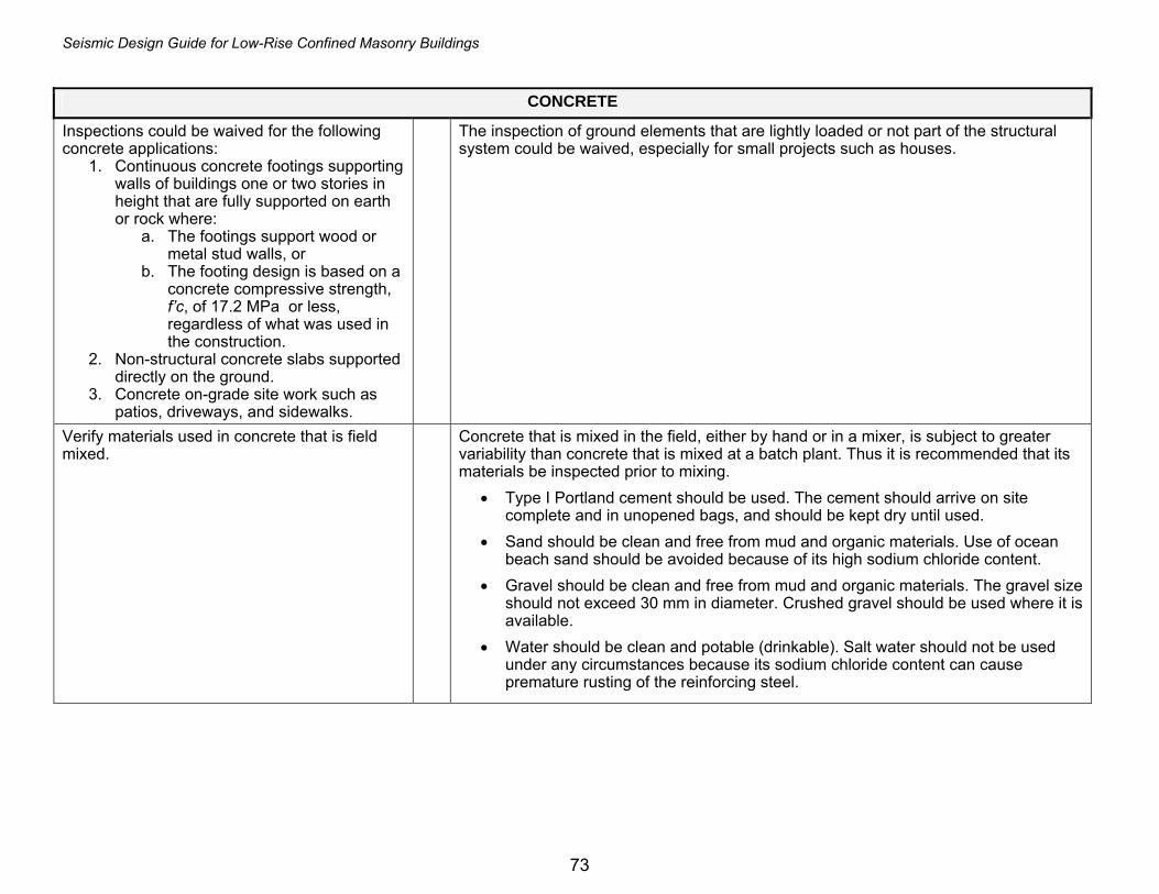
Seismic Design Guide for Low-Rise Confined Masonry Buildings
73
CONCRETE
Inspections could be waived for the following concrete applications:
1. Continuous concrete footings supporting walls of buildings one or two stories in height that are fully supported on earth or rock where:
a. The footings support wood or metal stud walls, or
b. The footing design is based on a concrete compressive strength, f’c, of 17.2 MPa or less, regardless of what was used in the construction.
2. Non-structural concrete slabs supported directly on the ground.
3. Concrete on-grade site work such as patios, driveways, and sidewalks.
The inspection of ground elements that are lightly loaded or not part of the structural system could be waived, especially for small projects such as houses.
Verify materials used in concrete that is field mixed.
Concrete that is mixed in the field, either by hand or in a mixer, is subject to greater variability than concrete that is mixed at a batch plant. Thus it is recommended that its materials be inspected prior to mixing.
• Type I Portland cement should be used. The cement should arrive on site complete and in unopened bags, and should be kept dry until used.
• Sand should be clean and free from mud and organic materials. Use of ocean beach sand should be avoided because of its high sodium chloride content.
• Gravel should be clean and free from mud and organic materials. The gravel size should not exceed 30 mm in diameter. Crushed gravel should be used where it is available.
• Water should be clean and potable (drinkable). Salt water should not be used under any circumstances because its sodium chloride content can cause premature rusting of the reinforcing steel.

Seismic Design Guide for Low-Rise Confined Masonry Buildings
74
Periodic inspection of reinforcing steel. Proper placement of the reinforcing steel in concrete elements, especially at the tie-beam
to tie-column connections, is critical for ensuring that the masonry walls are able to resist the seismic forces. At a minimum, the inspector should review the following:
• Light surface rust is acceptable for ribbed (deformed) rods, but if smooth reinforcing steel is used any rust should be removed by wire brushing.
• All bars should match the size specified on the construction drawings. • The longitudinal bars in the tie-beams and tie-columns are placed straight. • The ties are placed level and are closed with 135 degree hooks. • The tie hooks are staggered such that they do not all occur on the same corner of
the tie-beam or tie-column. • The ties are placed at the spacing shown on the construction drawings. If the
drawings specify closer tie spacing at the tie-column and/or tie-beam ends the inspector should verify that this has been done.
• The tie-column longitudinal bars are placed sufficiently far enough from the wall so that the concrete can be placed into the form. Unless the clearance is specified on the drawings, the following minimum values should be used:
o 15 mm for tie columns with 110x110 mm cross-section o 35 mm for tie-columns with 150x150 mm cross-section and larger. o 25 mm clearance may be acceptable for interior tie-column faces that are
not exposed to weather. • The tie-beam bars are placed with proper clearance from the beam edges. Unless
the clearance is specified on the drawings, it should be not less than 35 mm. • Use of concrete spacers is recommended to ensure adequate clear cover to the
reinforcement in tie-beams and tie-columns. • The tie-beam longitudinal reinforcement is hooked and lapped at the ends with the
intersecting bars. The lap length of the hook tails with the intersecting bars should be at least 15 to 20 bar diameters or as specified on the drawings.
• Tie-column longitudinal bars at the roof level should be bent and lapped with the tie-beam reinforcing by a lap length equal to at least 40 bar diameters.
• Tie-column longitudinal bars at the lower floor levels should extend far enough above the floor slab to form lap splice of at least 40 bar diameters with the tie-column bars to be placed above.
• Lap splices for longitudinal reinforcement should be at least 40 bar diameters. In tie-beams, the splices should be located at the end one-third span length. The splices should be staggered so that no more than 2 bars are spliced at any one location. When the construction drawings specify 180 degree hooks at the bar ends, the inspector should confirm that this has been done.
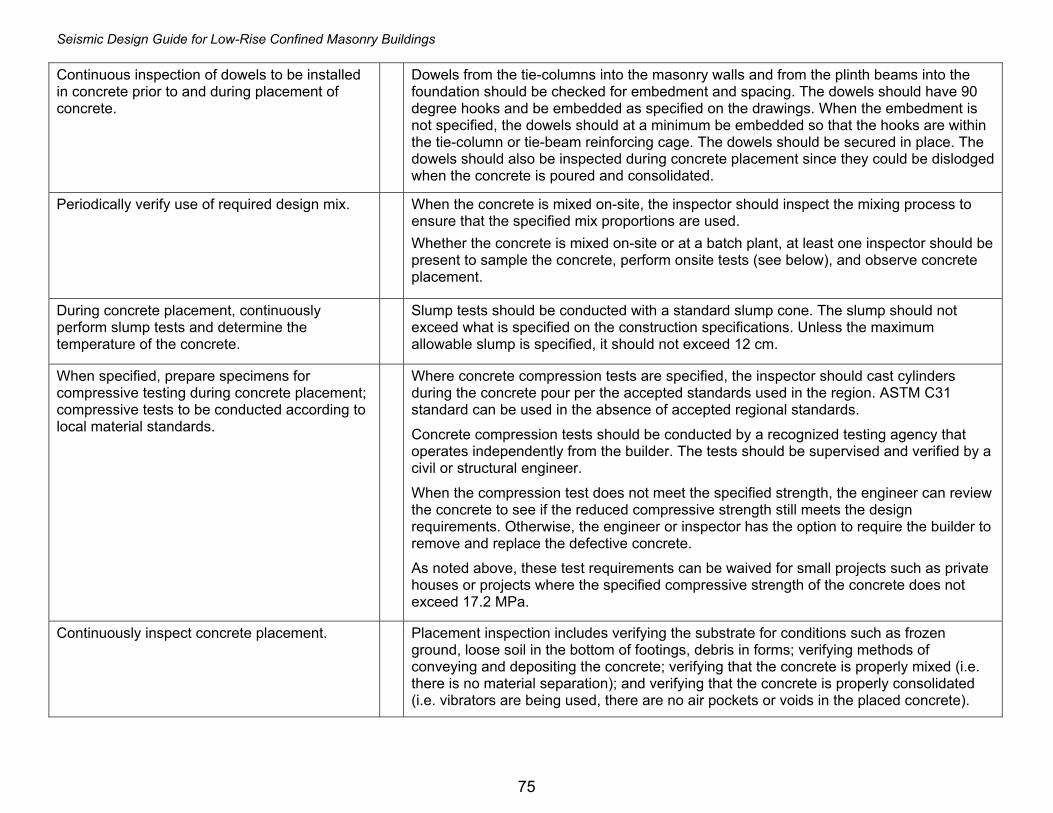
Seismic Design Guide for Low-Rise Confined Masonry Buildings
75
Continuous inspection of dowels to be installed in concrete prior to and during placement of concrete.
Dowels from the tie-columns into the masonry walls and from the plinth beams into the foundation should be checked for embedment and spacing. The dowels should have 90 degree hooks and be embedded as specified on the drawings. When the embedment is not specified, the dowels should at a minimum be embedded so that the hooks are within the tie-column or tie-beam reinforcing cage. The dowels should be secured in place. The dowels should also be inspected during concrete placement since they could be dislodged when the concrete is poured and consolidated.
Periodically verify use of required design mix. When the concrete is mixed on-site, the inspector should inspect the mixing process to ensure that the specified mix proportions are used. Whether the concrete is mixed on-site or at a batch plant, at least one inspector should be present to sample the concrete, perform onsite tests (see below), and observe concrete placement.
During concrete placement, continuously perform slump tests and determine the temperature of the concrete.
Slump tests should be conducted with a standard slump cone. The slump should not exceed what is specified on the construction specifications. Unless the maximum allowable slump is specified, it should not exceed 12 cm.
When specified, prepare specimens for compressive testing during concrete placement; compressive tests to be conducted according to local material standards.
Where concrete compression tests are specified, the inspector should cast cylinders during the concrete pour per the accepted standards used in the region. ASTM C31 standard can be used in the absence of accepted regional standards.
Concrete compression tests should be conducted by a recognized testing agency that operates independently from the builder. The tests should be supervised and verified by a civil or structural engineer.
When the compression test does not meet the specified strength, the engineer can review the concrete to see if the reduced compressive strength still meets the design requirements. Otherwise, the engineer or inspector has the option to require the builder to remove and replace the defective concrete.
As noted above, these test requirements can be waived for small projects such as private houses or projects where the specified compressive strength of the concrete does not exceed 17.2 MPa.
Continuously inspect concrete placement. Placement inspection includes verifying the substrate for conditions such as frozen ground, loose soil in the bottom of footings, debris in forms; verifying methods of conveying and depositing the concrete; verifying that the concrete is properly mixed (i.e. there is no material separation); and verifying that the concrete is properly consolidated (i.e. vibrators are being used, there are no air pockets or voids in the placed concrete).

Seismic Design Guide for Low-Rise Confined Masonry Buildings
76
Periodic inspection of the specified curing temperature and method.
The inspector should observe the initial application of the specified curing method, periodically verify that the curing is maintained, and report curing that does not meet the specifications as non-compliant.
Periodically inspect formwork for shape, location and dimensions of the concrete member being formed.
The width, depth, and bracing of the formwork should be checked.
MASONRY
As masonry construction begins, the following should be periodically verified to ensure compliance:
1) Proportions of mortar. The proportions of cement, sand, and lime (if used) should be as specified in the construction documents. If the proportions are not specified, the mix recommended in these guidelines can be used. If multiple mixes are specified (for example mortar used for damp-proof walls), the inspector should ensure that the contractor uses the correct mix at the correct locations.
2) Construction of mortar joints. The mortar joints should be fully filled, uniform, and have thickness from 10 to 15 mm. Note that the use of excessively thick mortar joints reduces the strength of masonry walls. Joints with voids should be demolished and replaced. The mortar should be placed within 2 hours of initial mixing.
3) Masonry bond. The use of running bond is recommended, that is, vertical (head) joints in successive courses should be offset horizontally by at least 25% (preferably 50%) of the unit length. Stack bond should be avoided.
During construction the inspector should periodically verify:
1) Size and location of structural elements. In addition to verifying that the walls are at the correct locations, the inspector should also verify that the tie-columns are at their correct locations. When toothing is specified, the masonry units should be placed accordingly. Another important wall element to verify is the size and locations of the openings within the wall.
2) Type, size and location of dowels. Dowels between the tie-columns and walls should be evenly spaced and located approximately in the middle of the wall. Unless otherwise specified, the dowels should at a minimum be embedded so that the hooks are within the tie-column or tie-beam reinforcing cage.

Seismic Design Guide for Low-Rise Confined Masonry Buildings
77
3) The protection of masonry during cold weather (temperature below 5o C) or hot weather (temperature above 32o C).
Newly constructed masonry in cold weather conditions should be covered with blankets or otherwise kept warm for at least 24 hours after placement. The following additional provisions should be made in hot weather: • The sand used for the mortar should be kept damp. • The materials and mixing equipment should be protected from direct sunlight. • Cool water should be used to mix the mortar and wet the bricks. However, ice should not be used.
4) Compressive strength of mortar and masonry specimens according to local material standards.
When mortar compressive tests are specified, the inspector should prepare the specimens (mortar cubes) according to the accepted standards used in the region. The ASTM C270 standard can be used in the absence of accepted regional standards.
The determination of the masonry compressive strength can be conducted by one of the following two methods: unit strength or prism tests. Since prism tests can be expensive and require specific test equipment, it is recommended that prism tests are not done unless specified in the contract documents, or the units do not qualify for unit strength testing. An alternative method is to determine the masonry compressive strength both for clay and concrete masonry based on masonry unit strength and mortar type. Testing of masonry units (bricks or blocks) is required to determine compressive strength. Alternatively, when samples do not meet the required strength or are unavailable, masonry prisms can be taken from the constructed work. As this is a destructive process, it is rarely employed and is not recommended unless absolutely necessary. One set of test specimens should be taken for every 500 square meters of wall area. Mortar and prism tests should be conducted by a recognized testing agency that operates independently from the builder. The tests should be supervised and verified by a civil or structural engineer.
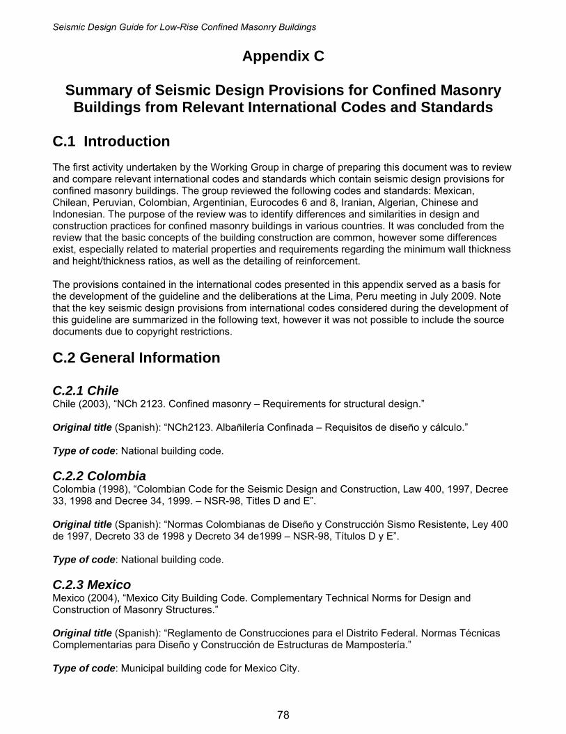
Seismic Design Guide for Low-Rise Confined Masonry Buildings
78
Appendix C
Summary of Seismic Design Provisions for Confined Masonry Buildings from Relevant International Codes and Standards
C.1 Introduction The first activity undertaken by the Working Group in charge of preparing this document was to review and compare relevant international codes and standards which contain seismic design provisions for confined masonry buildings. The group reviewed the following codes and standards: Mexican, Chilean, Peruvian, Colombian, Argentinian, Eurocodes 6 and 8, Iranian, Algerian, Chinese and Indonesian. The purpose of the review was to identify differences and similarities in design and construction practices for confined masonry buildings in various countries. It was concluded from the review that the basic concepts of the building construction are common, however some differences exist, especially related to material properties and requirements regarding the minimum wall thickness and height/thickness ratios, as well as the detailing of reinforcement. The provisions contained in the international codes presented in this appendix served as a basis for the development of the guideline and the deliberations at the Lima, Peru meeting in July 2009. Note that the key seismic design provisions from international codes considered during the development of this guideline are summarized in the following text, however it was not possible to include the source documents due to copyright restrictions. C.2 General Information C.2.1 Chile Chile (2003), “NCh 2123. Confined masonry – Requirements for structural design.” Original title (Spanish): “NCh2123. Albañilería Confinada – Requisitos de diseño y cálculo.” Type of code: National building code. C.2.2 Colombia Colombia (1998), “Colombian Code for the Seismic Design and Construction, Law 400, 1997, Decree 33, 1998 and Decree 34, 1999. – NSR-98, Titles D and E”. Original title (Spanish): “Normas Colombianas de Diseño y Construcción Sismo Resistente, Ley 400 de 1997, Decreto 33 de 1998 y Decreto 34 de1999 – NSR-98, Títulos D y E”. Type of code: National building code. C.2.3 Mexico Mexico (2004), “Mexico City Building Code. Complementary Technical Norms for Design and Construction of Masonry Structures.” Original title (Spanish): “Reglamento de Construcciones para el Distrito Federal. Normas Técnicas Complementarias para Diseño y Construcción de Estructuras de Mampostería.” Type of code: Municipal building code for Mexico City.

Seismic Design Guide for Low-Rise Confined Masonry Buildings
79
C.2.4 Peru Peru (2006), “National Building Code, Technical Standard E.070 Masonry.” Original title (Spanish): “Reglamento Nacional de Edificaciones, Norma Técnica E.070 Albañilería.” Type of code: National building code. C.2.5 Argentina Argentina (1991), “INPRES-CIRSOC 103, Part III. Argentinean Code for Seismic-Resistant Construction. Masonry Construction.” Original title (Spanish): “INPRES-CIRSOC 103, Parte III. Normas Argentinas para Construcciones Sismorresistentes. Construcciones de Mampostería” Type of code: National building code. C.2.6 Eurocode Slovenia (2008), “Eurocode 6: Design of Masonry Buildings - Part 1-1: Common Rules for Reinforced and Unreinforced Masonry Structures (EN 1996-1: 2006).” Original title (Slovene): “Evrokod 6: Projektiranje zidanih stavb - Del 1-1: Splošna pravila za armirano in nearmirano zidovje (SIST EN 1996-1-1: 2006).” Type of code: Norm (standard). C.2.7 Algeria Algeria (1981), “Algerian Seismic Regulations (RPA99).” Original title (French): “Règles Parasismiques Algériennes (RPA99/Version 2003).” Type of code: National building code. C.2.8 China China (2001), “Code for Design of Masonry Structures.” Original title (Chinese): 砌体结 设计规构 范 Type of code: National building code. C.2.9 Iran Iran (2005), “National Building Regulations. Volume 5: Building Materials. Volume 8: Design and Construction of Masonry Buildings.” Original title (Persian): مقررات ملي ساختمان، مبحث هشتم Type of code: National building code

Seismic Design Guide for Low-Rise Confined Masonry Buildings
80
C.2.10 Indonesia Boen, T. (2009). Constructing Seismic Resistant Masonry Houses, Third Edition, United Nations Center for Regional Development. Build Change (2006). Earthquake-Resistant Design and Construction Guideline for Single Story Reinforced Concrete Confined Masonry Houses Built in the Aceh Permanent Housing Reconstruction Program. Type of code: Recommended Practice C.3 Structural Design and Construction Issues C.3.1 Material Characteristics Table C-1. Permitted Types of Masonry Units
M Unit
Country
Solid concrete
units
Hollow concrete
block
Solid clay brick
Hollow clay brick
Perforated clay brick
Silica-lime brick
Autoclaved aerated concrete
Natural stone
Chile X4 X X X Colombia X X X X X Mexico X X X X X X Peru X X X X X X Argentina X X X Eurocode X X X X X X Algeria3 X X X2 X X China X X X X X1 X Iran X X X X X Indonesia X X
1 Includes autoclaved fly ash-lime bricks 2 Horizontal perforations 3 In addition, stabilized earth (with cement) 4 Hand-made unit
Table C-2. Minimum Compressive Strengths for Permitted Masonry Units (MPa)
M Unit
Country
Solid concrete
units
Hollow concrete blocks
Solid clay
bricks
Hollow clay
bricks
Perforated clay bricks
Silica-lime brick
Autoclaved aerated concrete
Natural stone
Chile 12 NA 4 HM 15, 11 15, 11 Colombia - 5 NA 15 5 NA - Mexico 10 6 6 10 10 - Peru 9.3 12.7 6.9 12.7 12.7 17.6 Argentina 5, 6.5 7.5, 12 7.5, 12 Eurocode 7.5 7.5 10 10 10 5 - Algeria - - - - - China - 7.5 10 10 10 10 20 Iran 28 28 8.5 8.5 15 Indonesia 4.6
NA strength over net area HM Hand-made unit
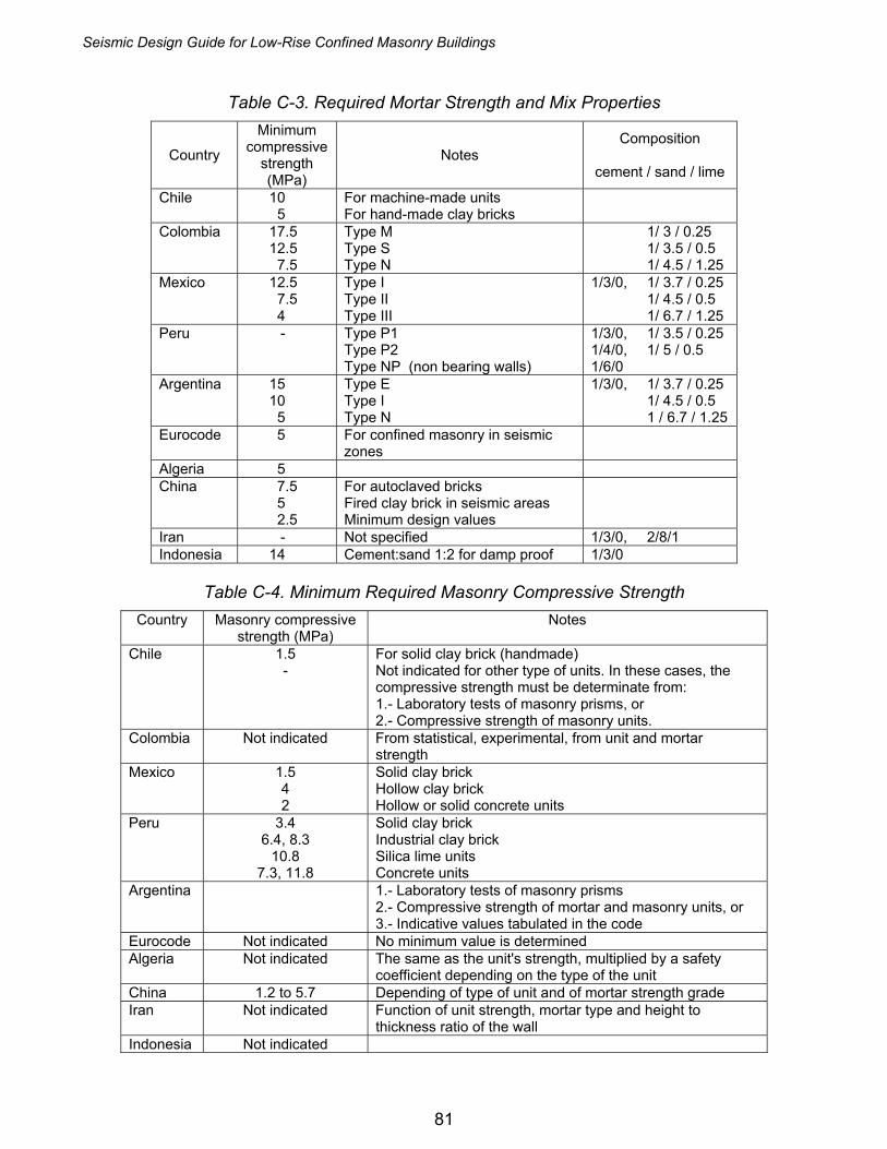
Seismic Design Guide for Low-Rise Confined Masonry Buildings
81
Table C-3. Required Mortar Strength and Mix Properties
Country
Minimum compressive
strength (MPa)
Notes Composition
cement / sand / lime
Chile 10 5
For machine-made units For hand-made clay bricks
Colombia 17.5 12.5
7.5
Type M Type S Type N
1/ 3 / 0.25 1/ 3.5 / 0.5 1/ 4.5 / 1.25
Mexico 12.5 7.5 4
Type I Type II Type III
1/3/0, 1/ 3.7 / 0.25 1/ 4.5 / 0.5 1/ 6.7 / 1.25
Peru - Type P1 Type P2 Type NP (non bearing walls)
1/3/0, 1/ 3.5 / 0.25 1/4/0, 1/ 5 / 0.5 1/6/0
Argentina 15 10
5
Type E Type I Type N
1/3/0, 1/ 3.7 / 0.25 1/ 4.5 / 0.5 1 / 6.7 / 1.25
Eurocode 5 For confined masonry in seismic zones
Algeria 5 China 7.5
5 2.5
For autoclaved bricks Fired clay brick in seismic areas Minimum design values
Iran - Not specified 1/3/0, 2/8/1 Indonesia 14 Cement:sand 1:2 for damp proof 1/3/0
Table C-4. Minimum Required Masonry Compressive Strength
Country Masonry compressive strength (MPa)
Notes
Chile 1.5 -
For solid clay brick (handmade) Not indicated for other type of units. In these cases, the compressive strength must be determinate from: 1.- Laboratory tests of masonry prisms, or 2.- Compressive strength of masonry units.
Colombia Not indicated From statistical, experimental, from unit and mortar strength
Mexico 1.5 4 2
Solid clay brick Hollow clay brick Hollow or solid concrete units
Peru 3.4 6.4, 8.3
10.8 7.3, 11.8
Solid clay brick Industrial clay brick Silica lime units Concrete units
Argentina 1.- Laboratory tests of masonry prisms 2.- Compressive strength of mortar and masonry units, or 3.- Indicative values tabulated in the code
Eurocode Not indicated No minimum value is determined Algeria Not indicated The same as the unit's strength, multiplied by a safety
coefficient depending on the type of the unit China 1.2 to 5.7 Depending of type of unit and of mortar strength grade Iran Not indicated Function of unit strength, mortar type and height to
thickness ratio of the wall Indonesia Not indicated

Seismic Design Guide for Low-Rise Confined Masonry Buildings
82
Table C-5. Minimum Required Concrete and Steel Properties
Country Concrete compressive
strength (MPa)
Type of test
Steel yield
strength (MPa)
Tie wire reinforce
ment (MPa)
Horizontal wire reinf.
(MPa)
External welded
wire mesh (MPa)
Chile 16 Cylinder 280, 420 500 500 n.s. Colombia 17.5 Cylinder 240, 420 n.a. n.a. n.a. Mexico 15 Cylinder 412 250, 600 600 500 Peru 17.2 Cylinder 412 412 412 600 Argentina 11 Cylinder 220, 420 220, 420 220, 420 n.s. Eurocode 12
15 Cylinder Cube
- n.s. n.s. n.s.
Algeria 15 Cylinder ≤500 ≤500 ≤500 - China 9.6 Cube 300 210 210 430 Iran n.s. - ≤400 ≤400 ≤400 n.s. Indonesia 17.2 - 276 276 207 n.s.
n.a. Not allowed n.s. Not specified C.3.2 Masonry Wall Requirements
Table C-6a. Masonry Wall Requirements
Country Maximum height, H Minimum thickness, t (mm) Maximum
height / thickness ratio Chile 25 t 140 Machine-made units
150 Hand-made units 25
Colombia 25 t 110 95 Low seismicity
25
Mexico 30 t 100 30 Peru 20 t
25 t n.s. 20
25 Low seismicity Argentina 4 m 170
130 Low importance, H < 3 m
Eurocode 15 t 190 In Slovenia 15 Algeria 3 m 200 - China 240
190 Small block 22 to 26 depending of mortar
Iran 4 m 200 15 Indonesia 3.2 m 110 Without plaster
130 Not required
n.s. Not specified

Seismic Design Guide for Low-Rise Confined Masonry Buildings
83
Table C-6b. Masonry Wall Requirements (cont`d)
Country Wall density d(1) Shear strength Toothing
Chile n.s. τm obtained from tests of small square walls tested in diagonal compression or based on indicative values (see Table 1 of NCh2123).
Yes
Colombia d ≥ NAa/20 m'f square root of masonry compressive
strength
n.s.
Mexico n.s. vm* masonry shear strength from small square walls tested in diagonal compression
vm* ≤ 0.25 *fm (using MPa)
Yes
Peru
56N.S.U.Zd ≥
V’m shear resistance of masonry Yes
Argentina 0.6 to 3% τm0 nominal shear strength of the masonry (from tests or based on indicative values)
concrete cast after masonry
Eurocode See table below
concrete cast after masonry
Algeria d ≥ 4% at each storey
concrete cast after masonry
China fVE shear strength of a masonry unit destructed along its stepped section
Iran Indonesia d ≥ 3%
m'f square root of masonry compressive strength
toothing not common
n.s. Not specified (1) Ratio between sum of horizontal cross-section area of shear walls in each direction,
and the total floor area
Table C-6c. Wall Density Requirements (Eurocode) Site acceleration ag.S < 0,07 k ⋅g < 0,10 k ⋅g < 0,15 k ⋅g < 0,20 k ⋅g
Type of construction
Number of stories
Minimum sum of cross-sections areas of horizontal shear walls in each direction, as percentage of the total floor area per storey (pA,min)
Confined masonry
2 3 4 5
2,0% 2,0% 4,0% 6,0%
2,5% 3,0% 5,0% n/a
3,0% 4,0% n/a n/a
3,5% n/a n/a n/a
* n/a means “not acceptable”. k = 1 + (lav – 2)/4 ≤ 2 where lav is the average length, expressed in m, of the shear walls considered (k = 1 for other cases)

Seismic Design Guide for Low-Rise Confined Masonry Buildings
84
Table C-7. Tie-Column and Tie-Beam Minimum Requirements
Country Cross-section, cm
Number of bars
Bar size, mm
Reinf. ratio
p = As/Ac
Ties: bar size,
mm
Max. tie spacing,
s, cm Chile 20 × t 4 10 n.s. 6 20, 10 Colombia t × t 3, 4 typ 10 0.0075 6 1.5t ≤ 20 Mexico t × t 3, 4 typ 9.5 typ 0.2 fc’/fy 6 1.5t ≤ 20 Peru 15 × t T-Column
t × slab T-Beam 4 8, 9.5 typ 0.1 fc’/fy 6 25
Argentina 15 × t 4 6, 8 > 0.3 s 20, 10 Eurocode 15 × 15 n.s. 5 0.01 5 15 Algeria 15 × t 4 10 n.s. 6 t ≤ 25 China 24 × 18
24 × 24 19 × 19
T × 12 T-Beam
4 typ 12 6 typ 25, 20
Iran 20 × 20 T-Column t × 2/3 t T-Beam but more than 25 × 25
4 10 n.s. 6 20, 15
Indonesia 15 × 15 Major T-C 11 × 11 Minor T-C 15 × 20 T-Beam
4 10 8
n.s. 6 7.5, 15
n.s. Not specified in the code. t Wall thickness. fc’, fy Concrete compressive strength of and steel yield strength, respectively. typ Typical value As Total area of steel reinforcement in tie-columns Ac Tie column cross-sectional area
Table C-8. Ties in Tie-Columns: Spacing Restrictions Country Chile The maximum permitted tie spacing is 20 cm.
The spacing is reduced to 10 cm within the critical zones at the ends of tie-columns and tie-beams (one-half of the maximum permitted spacing). The length of the critical zone is as follows: Tie-columns: greater of 60 cm or 2 times the column depth, and Tie-beams: 60 cm at the tie-beam ends (with the exception indicated in Cl.7.7.3).
Colombia The maximum permitted tie spacing is 20 cm. For the areas of high seismicity, the ties shall be provided at 10 cm spacing at the ends of tie-columns (critical zones). The length of a critical zone is greater than 45 cm, 3 times the element dimension, or 1/6th of the span length (column height).
Mexico The maximum permitted tie spacing is 20 cm. When the masonry shear strength vm* > 0.6 MPa, the spacing must be reduced at the ends of tie-columns (critical zones). The length of a critical zone is greater than 40 cm, 2 times the element dimension, or 1/6th of the tie-column height.
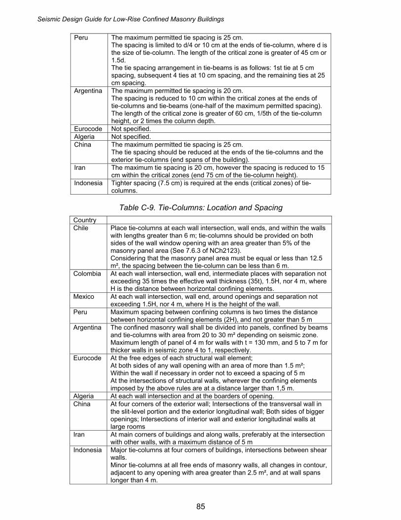
Seismic Design Guide for Low-Rise Confined Masonry Buildings
85
Peru The maximum permitted tie spacing is 25 cm. The spacing is limited to d/4 or 10 cm at the ends of tie-column, where d is the size of tie-column. The length of the critical zone is greater of 45 cm or 1.5d. The tie spacing arrangement in tie-beams is as follows: 1st tie at 5 cm spacing, subsequent 4 ties at 10 cm spacing, and the remaining ties at 25 cm spacing.
Argentina The maximum permitted tie spacing is 20 cm. The spacing is reduced to 10 cm within the critical zones at the ends of tie-columns and tie-beams (one-half of the maximum permitted spacing). The length of the critical zone is greater of 60 cm, 1/5th of the tie-column height, or 2 times the column depth.
Eurocode Not specified. Algeria Not specified. China The maximum permitted tie spacing is 25 cm.
The tie spacing should be reduced at the ends of the tie-columns and the exterior tie-columns (end spans of the building).
Iran The maximum tie spacing is 20 cm, however the spacing is reduced to 15 cm within the critical zones (end 75 cm of the tie-column height).
Indonesia Tighter spacing (7.5 cm) is required at the ends (critical zones) of tie-columns.
Table C-9. Tie-Columns: Location and Spacing
Country Chile Place tie-columns at each wall intersection, wall ends, and within the walls
with lengths greater than 6 m; tie-columns should be provided on both sides of the wall window opening with an area greater than 5% of the masonry panel area (See 7.6.3 of NCh2123). Considering that the masonry panel area must be equal or less than 12.5 m², the spacing between the tie-column can be less than 6 m.
Colombia At each wall intersection, wall end, intermediate places with separation not exceeding 35 times the effective wall thickness (35t), 1.5H, nor 4 m, where H is the distance between horizontal confining elements.
Mexico At each wall intersection, wall end, around openings and separation not exceeding 1.5H, nor 4 m, where H is the height of the wall.
Peru Maximum spacing between confining columns is two times the distance between horizontal confining elements (2H), and not greater than 5 m
Argentina The confined masonry wall shall be divided into panels, confined by beams and tie-columns with area from 20 to 30 m² depending on seismic zone. Maximum length of panel of 4 m for walls with t = 130 mm, and 5 to 7 m for thicker walls in seismic zone 4 to 1, respectively.
Eurocode At the free edges of each structural wall element; At both sides of any wall opening with an area of more than 1.5 m²; Within the wall if necessary in order not to exceed a spacing of 5 m At the intersections of structural walls, wherever the confining elements imposed by the above rules are at a distance larger than 1,5 m.
Algeria At each wall intersection and at the boarders of opening. China At four corners of the exterior wall; Intersections of the transversal wall in
the slit-level portion and the exterior longitudinal wall; Both sides of bigger openings; Intersections of interior wall and exterior longitudinal walls at large rooms
Iran At main corners of buildings and along walls, preferably at the intersection with other walls, with a maximum distance of 5 m
Indonesia Major tie-columns at four corners of buildings, intersections between shear walls. Minor tie-columns at all free ends of masonry walls, all changes in contour, adjacent to any opening with area greater than 2.5 m², and at wall spans longer than 4 m.
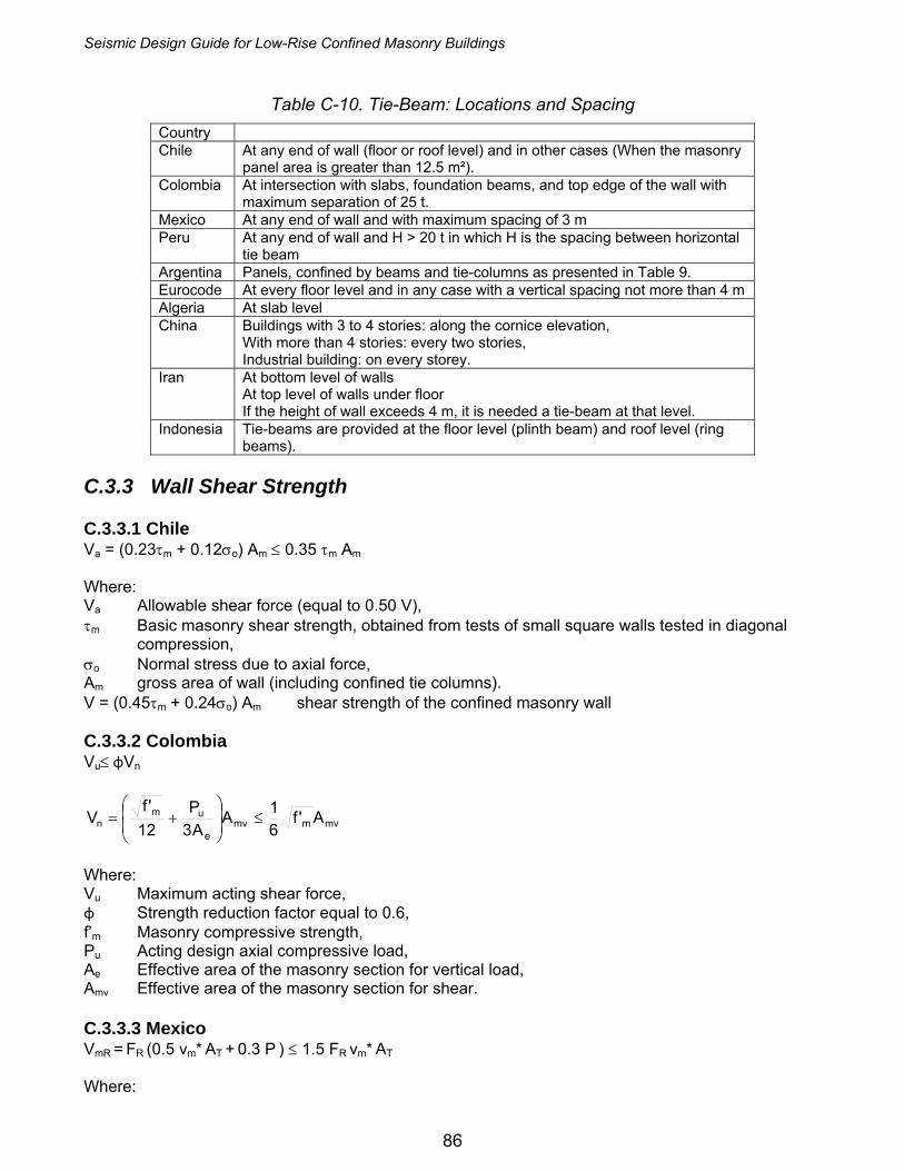
Seismic Design Guide for Low-Rise Confined Masonry Buildings
86
Table C-10. Tie-Beam: Locations and Spacing
Country Chile At any end of wall (floor or roof level) and in other cases (When the masonry
panel area is greater than 12.5 m²). Colombia At intersection with slabs, foundation beams, and top edge of the wall with
maximum separation of 25 t. Mexico At any end of wall and with maximum spacing of 3 m Peru At any end of wall and H > 20 t in which H is the spacing between horizontal
tie beam Argentina Panels, confined by beams and tie-columns as presented in Table 9. Eurocode At every floor level and in any case with a vertical spacing not more than 4 m Algeria At slab level China Buildings with 3 to 4 stories: along the cornice elevation,
With more than 4 stories: every two stories, Industrial building: on every storey.
Iran At bottom level of walls At top level of walls under floor If the height of wall exceeds 4 m, it is needed a tie-beam at that level.
Indonesia Tie-beams are provided at the floor level (plinth beam) and roof level (ring beams).
C.3.3 Wall Shear Strength C.3.3.1 Chile Va = (0.23τm + 0.12σo) Am ≤ 0.35 τm Am Where: Va Allowable shear force (equal to 0.50 V), τm Basic masonry shear strength, obtained from tests of small square walls tested in diagonal
compression, σo Normal stress due to axial force, Am gross area of wall (including confined tie columns). V = (0.45τm + 0.24σo) Am shear strength of the confined masonry wall C.3.3.2 Colombia Vu≤ φVn
mvmmve
umn A'f
61A
A3P
12'f
V ≤⎟⎟⎠
⎞⎜⎜⎝
⎛+=
Where: Vu Maximum acting shear force, φ Strength reduction factor equal to 0.6, f’m Masonry compressive strength, Pu Acting design axial compressive load, Ae Effective area of the masonry section for vertical load, Amv Effective area of the masonry section for shear. C.3.3.3 Mexico VmR = FR (0.5 vm* AT + 0.3 P ) ≤ 1.5 FR vm* AT Where:
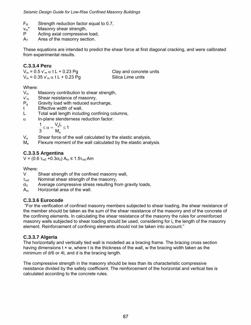
Seismic Design Guide for Low-Rise Confined Masonry Buildings
87
FR Strength reduction factor equal to 0.7, vm* Masonry shear strength, P Acting axial compressive load, AT Area of the masonry section. These equations are intended to predict the shear force at first diagonal cracking, and were calibrated from experimental results. C.3.3.4 Peru Vm = 0.5 v’m α t L + 0.23 Pg Clay and concrete units Vm = 0.35 v’m α t L + 0.23 Pg Silica Lime units Where: Vm Masonry contribution to shear strength, v’m Shear resistance of masonry, Pg Gravity load with reduced surcharge, t Effective width of wall, L Total wall length including confining columns, α In-plane slenderness reduction factor:
1M
LV31
e
e ≤=α≤
Ve Shear force of the wall calculated by the elastic analysis, Me Flexure moment of the wall calculated by the elastic analysis. C.3.3.5 Argentina V = (0.6 τm0 +0.3σ0) Am ≤ 1.5τm0 Am Where: V Shear strength of the confined masonry wall, τm0 Nominal shear strength of the masonry, σ0 Average compressive stress resulting from gravity loads, Am Horizontal area of the wall. C.3.3.6 Eurocode “For the verification of confined masonry members subjected to shear loading, the shear resistance of the member should be taken as the sum of the shear resistance of the masonry and of the concrete of the confining elements. In calculating the shear resistance of the masonry the rules for unreinforced masonry walls subjected to shear loading should be used, considering for lc the length of the masonry element. Reinforcement of confining elements should not be taken into account.” C.3.3.7 Algeria The horizontally and vertically tied wall is modelled as a bracing frame. The bracing cross section having dimensions t × w, where t is the thickness of the wall, w the bracing width taken as the minimum of d/6 or 4t, and d is the bracing length. The compressive strength in the masonry should be less than its characteristic compressive resistance divided by the safety coefficient. The reinforcement of the horizontal and vertical ties is calculated according to the concrete rules.
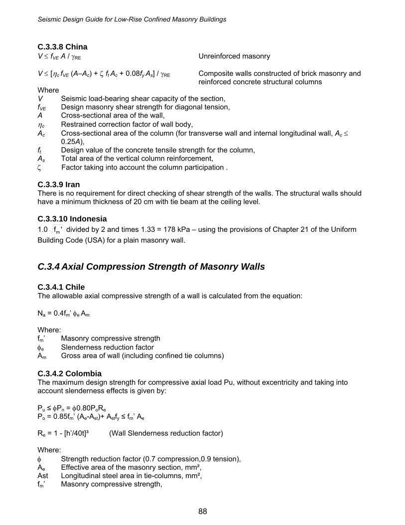
Seismic Design Guide for Low-Rise Confined Masonry Buildings
88
C.3.3.8 China V ≤ fVE A / γRE Unreinforced masonry V ≤ [ηc fVE (A–Ac) + ζ ft Ac + 0.08fy As] / γRE Composite walls constructed of brick masonry and
reinforced concrete structural columns Where V Seismic load-bearing shear capacity of the section, fVE Design masonry shear strength for diagonal tension, A Cross-sectional area of the wall, ηc Restrained correction factor of wall body, Ac Cross-sectional area of the column (for transverse wall and internal longitudinal wall, Ac ≤
0.25A), ft Design value of the concrete tensile strength for the column, As Total area of the vertical column reinforcement, ζ Factor taking into account the column participation . C.3.3.9 Iran There is no requirement for direct checking of shear strength of the walls. The structural walls should have a minimum thickness of 20 cm with tie beam at the ceiling level. C.3.3.10 Indonesia 1.0 'fm divided by 2 and times 1.33 = 178 kPa – using the provisions of Chapter 21 of the Uniform Building Code (USA) for a plain masonry wall. C.3.4 Axial Compression Strength of Masonry Walls C.3.4.1 Chile The allowable axial compressive strength of a wall is calculated from the equation: Na = 0.4fm’ φe Am Where: fm’ Masonry compressive strength φe Slenderness reduction factor Am Gross area of wall (including confined tie columns) C.3.4.2 Colombia The maximum design strength for compressive axial load Pu, without excentricity and taking into account slenderness effects is given by: Pu ≤ φPn = φ0.80PoRe Po = 0.85fm’ (Ae-Ast)+ Astfy ≤ fm’ Ae Re = 1 - [h’/40t]³ (Wall Slenderness reduction factor) Where: φ Strength reduction factor (0.7 compression,0.9 tension), Ae Effective area of the masonry section, mm², Ast Longitudinal steel area in tie-columns, mm², fm’ Masonry compressive strength,

Seismic Design Guide for Low-Rise Confined Masonry Buildings
89
h’ Effective height, t Effective thickness. C.3.4.3 Mexico The vertical strength of a wall is calculated from the equation: PR = FR FE (fm* AT + ΣAs fy ) Where: FR Strength reduction factor (FR = 0.6), FE Reduction factor for wall slenderness and load eccentricity; typical values are 0.7 for interior
walls and 0.6 for exterior walls; fm* Design compressive strength of masonry, AT Wall cross-sectional area, As Area of vertical steel reinforcement in tie-columns, and fy Yield stress of steel. It is allowed to use the following simplified equation: PR = FR FE (fm* + 4) AT (note fm* is increased by 4 kg/cm²). C.3.4.4 Peru The wall compressive strength is calculated from the equation:
'f15.0t35
h1'f2.0tL
Pm
2
mm
m ≤⎥⎥⎦
⎤
⎢⎢⎣
⎡⎟⎠⎞
⎜⎝⎛−≤
⋅=σ
Where: L Total length of the wall, including the columns, t Wall effective thickness, and h Distance between horizontal restraints. C.3.4.5 Argentina Not included in the questionnaire. C.3.4.6 Eurocode In the verification of confined masonry members subjected to bending and/or axial loading, the assumptions given in this EN 1996-1-1 for reinforced masonry members should be adopted. In determining the design value of the moment of resistance of a section a rectangular stress distribution may be assumed, based on the strength of the masonry, only. Reinforcement in compression should also be ignored. C.3.4.7 Algeria The horizontally and vertically tied wall is modelled as a bracing frame C.3.4.8 China 1) Select the masonry materials; 2) confirm the static calculation schemes and select the calculation cell; 3) load calculation; 4) internal force calculation; 5) bearing capacity calculation for wall density; 6) local compression calculation;

Seismic Design Guide for Low-Rise Confined Masonry Buildings
90
C.3.4.9 Iran Although in some code related documents, masonry compressive strength estimation is provided as a function of brick strength, mortar type and height to thickness ratio of the wall, however, the code does not require an explicit control for masonry compressive strength.