conjugate natural convection in a differentially...
TRANSCRIPT

Journal of Porous Media, 18 (7): 699–716 (2015)
CONJUGATE NATURAL CONVECTION IN ADIFFERENTIALLY HEATED COMPOSITE ENCLOSUREFILLED WITH A NANOFLUID
Muneer A. Ismael1 & Ali J. Chamkha2,∗
1Mechanical Engineering Department, Engineering College, University of Basrah, Basrah, Iraq2Mechanical Engineering Department, Prince Mohammad Bin Fahd University, P.O. Box 1664,Al-Khobar 31952, Kingdom of Saudi Arabia
∗Address all correspondence to Ali J. Chamkha E-mail: [email protected]
Original Manuscript Submitted: 10/15/2014; Final Draft Received: 3/3/2015
Laminar natural convection inside a square composite vertically layered cavity is studied numerically using under asuccessive relaxation (USR) upwind-scheme finite difference method. The cavity is set up as follows from the left: a solidwall, a porous layer, and a nanofluid layer. The porous layer is saturated with the same nanofluid. The cavity is heatedisothermally from the solid wall and cooled from the right wall. The top and bottom walls are kept adiabatic. All the wallsare assumed impermeable, except the interface between the porous and nanofluid layers. The Darcy–Brinkman model isinvoked for the porous layer. Double-domain formulation is followed for the porous and nanofluid layers. The studiedparameters are Darcy number Da (10−7–10−1), Rayleigh number Ra (103–106), wall thermal conductivity kw (0.269,14.589 W/m.C), thicknesses of layers Ww (0.1–0.7), Wp (0.1–0.5), and the Cu nanoparticle volume fraction φ (0.0–0.05). Alternative models for the nanofluid thermal conductivity and dynamic viscosity are used, and a comparisonamong different models combinations is conducted. The results show that the enhancement of natural convection isattained when the permeability (Da) of the porous medium is very low and the porous layer thickness is greater than0.5, provided that the Rayleigh number is less than or equal to 104. The solid wall type is found to play a considerablerole in the flow and heat transfer fields. It is also found that the conduction heat transfer within the solid wall is affectedby the permeability of the porous layer.
KEY WORDS: composite cavity, porous layer, nanofluid models, Darcy–Brinkman model, double–domainformulation
1. INTRODUCTION
Studies of buoyancy-driven convection in a confined en-closure, partly filled with a fluid and partly with a porouslayer, have been progressively increased. This is becauseof their essential contribution in the development of manyindustrial and environmental applications. Fibrous ther-mal insulation, solidification, fuel cell, cooling of nuclearfuel debris, solar collectors, and underground storage ofradioactive waste are some of many applications. Accord-ing to its application, the confined layers may be verticallyseparated or horizontally (i.e., fluid overlaying a porous
layer). The interface between the two layers may be per-meable or impermeable (no momentum exchange).
The early studies of Beavers and Joseph (1967) havedemonstrated, experimentally, that the no-slip conditiondue to the tangent velocity at the interface of a fluid flow-ing overlaying a porous layer is not verified. Theoret-ically, this was agreed when assuming the flow withinthe porous layer obey the Darcy law. Limited publishedworks regarding the impermeable interface were found asin Tong and Subramanian (1986) and Sathe et al. (1988).Both studies considered numerical analysis of steady statenatural convection in vertically divided rectangular enclo-
1091–028X/15/$35.00 c⃝ 2015 by Begell House, Inc. 699

700 Ismael& Chamkha
NOMENCLA TURE
Cp specific heat at constant pressure (J kg−1 K−1)Da Darcy number Da =K/L2
g gravitational field (m s−2)k thermal conductivity (W m−1 K−1)K permeability of porous medium (m2)kr1 wall to effective porous layer thermal
conductivities ratiokr1 = kw/keffkr2 effective porous layer to nanofluid thermal
conductivities ratiokr2 = keff/knfkw1 thermal conductivity of stainless steel
solid wall (W/m.C)kw2 thermal conductivity of Perspex solid
wall (W/m.C)L cavity length (m)p pressure (Nm−2)Pr Prandtl numberNu Nusselt numberRa Rayleigh number Ra =gβf (Th − Tc)L
3/νfαf
T temperature (K)u velocity component alongx-direction (m s−1)v velocity component alongy-direction (m s−1)U dimensionless velocity component alongx-directionV dimensionless velocity component along
y-directionW wall thickness (m)x, y Cartesian coordinates (m)X,Y dimensionless Cartesian coordinates
Greek Symbolsα thermal diffusivity (m2 s−1)
β thermal expansion coefficient (K−1)γ ratio of nanolayer to the nanoparticle
thermal conductivitiesγ = knl/knpε porosity of the porous layerµ dynamic viscosity (Pa.s)ν kinematic viscosity (m2 s−1)θ dimensionless temperatureρ density (kg m−3)σ ratio of nanolayer thickness to the
nanoparticle radiusσ = hnl/rnpφ nanoparticles volume fractionψ,Ψ Stream function (m2 s−1),
dimensionless stream functionω,Ω vorticity (s−1), dimensionless vorticity
Subscriptsav averagec coldeff effectiveeq equivalentf fluidh hoti interfacel leftnf nanofluidnl nanolayernp nanoparticlep porousr rightw wall
sures.The Darcy model was adopted by Tong and Sub-ramanian (1986), while the Darcy–Brinkman model wasadopted by Sathe et al. (1988), who considered the perme-able interface in addition. The main finding of these twostudies was that for an impermeable interface, the heattransfer could be minimized by partially filling instead ofentirely filling an enclosure with a porous medium. How-ever, due to their essential applications, the partitionedcavity with permeable interface has attracted vast atten-tion in the literature. The horizontally partitioned cav-ity can be found in Chen and Chen (1992), Kim andChoi (1996), Singh et al. (1999), Zhao and Chen (2001),Lopez and Tapia (2001), Carr and Straughan (2003), Abu-
Hijleh and Al-Nimr (2001), Hirata et al. (2007, 2008,2009), Aguilar-Madera et al. (2011a,b), Bagchi and Ku-lacki (2011, 2012), and Sheremet and Trifonova (2014).A brief description of some of these works will be givenhere; Chen and Chen (1992) conducted experiments ina horizontal superposed fluid and porous layer containedin a test cavity. Three fluids were used while the porouslayer consisted of 3-mm-diameter glass beads. Their mainexperimental results were a steeper decrease in the criti-cal Rayleigh number as the thickness of the fluid layerwas increased and a sudden decrease in the critical wave-form when the fluid layer thickness is between 0.1 and0.2. In a numerical investigation, the experimental re-
Journal of Porous Media
Conjugate Natural Convection in Composite Enclosure 701
sults of Chen and Chen (1992) were verified by Kim andChoi (1996). Heat and mass transfer rates for natural con-vection driven by the temperature and concentration gra-dients in composite cavity was studied by Singh et al.(1999). They reported that the Darcy, thermal and solutalRayleigh numbers played a great role on the fluid penetra-tion into the porous layer. The Nusselt number decreasedwhile the Sherwood number increased with an increase inthe Lewis number. Hirata et al. (2007) performed a com-parative study for the linear stability between the double-domain approach, using the classical Darcy model, andthe one-domain approach. Their conclusion was that theBrinkman model term plays a secondary role on the sta-bility results. A local heating from below was studied nu-merically based on the one-domain approach by Bagchiand Kulacki (2011). They recorded an adverse relationbetween the locally heating source size and the averageNusselt number. The averaged Nusselt number increasedwith the Darcy number. They also reported that the sizeof the heat source did not affect the dependence of theNusselt number on the porous layer thickness and theDarcy number. The same coworkers, Bagchi and Kulacki(2012), conducted an experimental study to ascertain theirprevious findings. Their cavity was simulated by a rect-angular chamber with 3 mm diameter glass beads as theporous layer and distilled water as the saturating fluid.The effect of porous layer thickness was agreed with theirconclusions in Bagchi and Kulacki (2011), but no cleareffect of heater size was noticed. It is worth mentioninghere that the effect of a local heating from below wasmore clarified in a nanofluid filled cavity by Bourantaset al. (2013) and in a nanofluid saturated porous cavity byBourantas et al. (2014). Both studies were achieved us-ing a meshless point collocation method (MPCM) com-bined with the moving least squares (MLS) approxima-tion. Sheremet and Trifonova (2014) conducted a numeri-cal simulation of transient conjugate natural convection ina vertical cylinder partially filled with a porous mediumin conditions of convective cooling from an environmenton the basis of the Darcy and Brinkman-extended Darcymodels. They concluded that at small values of the ther-mal conductivity ratio (solid to porous), the linear Darcymodel is valid for the conjugate natural convection prob-lems. While a high thermal conductivity ratio gives essen-tial quantitative differences between the results obtainedon the basis of the two models.
Vertically divided porous–fluid or porous–fluid–porous cavities have received, somewhat, lesser attentionespecially in the experimental studies. Beckermann et al.(1987) have, numerically and experimentally, performed
a comprehensive analysis to study the natural convectionwith the fluid and porous layers. They found that the de-gree of penetration of fluid into the porous layer dependedroughly on the product of the Rayleigh and the Darcynumbers, which should be greater than about 50 for pen-etration to be significant. Natural convection in an enclo-sure composed of two porous layers, one adjacent to eachvertical wall, with fluid layer occupying the central por-tion of the enclosure was studied by Oosthuizen and Paul(1996). The main conclusion drawn from their results wasthat a substantial increase in the heat transfer rate couldbe obtained by using layers of porous media and purefluid. Beckermann and Viskanta (1988) reported a com-bined numerical and experimental study of solid–liquidphase change in porous media with natural convection inthe melt region. They considered irregular interface of theconstituents. They found the interface shape is consider-ably influenced by the natural convection in the melt re-gion as well as the heat conduction in the solid region.Goyeau and Gobin (1999) focused their study on the in-fluence of the porous layer permeability (Darcy number)and found enhancement in the heat transfer results due tothe flow penetration from a complex interaction betweenthe viscous drag in the porous layer and the driving force.In contrast with Oosthuizen and Paul (1996), Mharzi etal. (2000) considered two fluid layers, one on each cav-ity side while the porous layer was included in the cav-ity center. In addition, they considered the thermosolutalconvection. Extensive analytic study to natural convectionflow in a partly-porous cavity was reported by Mercieret al. (2002). Simple relationships were summarized toshow the influence of the porous layer thickness, perme-ability, and the Rayleigh number on the flow structure andheat transfer. Bennacer et al. (2003) discussed the effectof anisotropicity of porous layers attached to the verticalwalls and confining a fluid at the cavity center on the ther-mosolutal and natural convection. They considered ther-mally and concentration driven flows. A small effect ofthe Darcy number on the rates of heat and mass transferwas recorded in high and low permeability regions. Theyrecorded also a critical anisotropy parameter, at which,the Nusselt number is minimum. Due to their interest insuch field of investigation, Gobin et al. (2005) focusedon the analysis of the influence of the parameters gov-erning double diffusive convection like the ratios of so-lutal and thermal parameters, the diffusivities and buoy-ancy forces. A sole work related in this field was that ofBraga and De Lemos (2005) who studied numerically acomposite square cavity formed by three distinct regions,namely, clear, porous and solid region. Their computa-
Volume 18, Number 7, 2015

702 Ismael& Chamkha
tions were conducted for laminar and turbulent (κ-ε) flowmodels. Within the studied range (Ra= 104–1010), theydid not record a significant variation in the Nusselt num-ber values between the laminar and turbulent model solu-tions. Chamkha and Ismael (2014) demonstrated that theuse of nanofluid in partially porous cavities offered posi-tive enhancement of convective heat transfer, and this ef-fect manifested clearly in a low permeability porous layer.They showed that there was a critical porous layer thick-ness at which the convective heat transfer was maximum.Moreover, they concluded that the material of the matrixforming the pores may play a significant role in such cav-ities
Different geometries, but related with the subject ofthis article, can be found in Merrikh and Mohamad(2002), Phanikumar and Mahajan (2002), Baytas et al.(2009), and Sheremet and Pop (2014). The two verticallayers of Merrikh and Mohamad (2002) were both porousmedia. They studied the validity of the Darcy model.Their results showed that there were different predictionsbetween the Darcy and Brinkman models. A rectangularmetal foam sample (of high porosity) localized on the bot-tom of a fluid-filled cavity and heated from below wasstudied numerically and experimentally by Phanikumarand Mahajan (2002). In other words, they had two, ver-tical and horizontal interfaces. The double diffusive nat-ural convection between a fluid and overlaying a porousmedium with stepped interface was investigated by Bay-tas et al. (2009). Dramatic changes of the heat and masstransfer were recorded in this case. Finally, a steady natu-ral convection flow and heat transfer in a square porouscavity saturated by a nanofluid with solid walls of fi-nite thickness using Buongiorno’s model was carried outnumerically by Sheremet and Pop (2014). Their mainconclusion was that for high thermophoresis parameter,low Brownian motion parameter, low Lewis and Rayleighnumbers, and high thermal conductivity ratio reflect anessential need for the nonhomogeneous model for the de-scription of the system.
However, to the authors’ best knowledge, all the con-sidered fluids in this field were pure fluids such as wa-ter, air, or glycerin. Nanofluids, which attracted signif-icant attention about one decade ago (see, e.g., Choiand Eastman, 1995; Tiwari and Das, 2007), have notfound their place in the investigation of fluid–porouslayers partitioned cavities heated by a solid wall. Thepresent paper deals with a numerical investigation of con-jugate conductive–convective heat transfer in a squareenclosure composed of a heated solid wall, nanofluid-saturated porous layer, and nanofluid layer. The type of
solid wall (its thermal conductivity), the type of porouslayer (its dimensionless porosity, Da), the volume fractionof nanoparticles dispersed in the fluid, and the Rayleighnumber are the parameters that are expected to affectthe natural convection within the present enclosure. Thepresent geometry is sought to contribute in the redesign ofthermal passive systems, controlling the cooling processof electronic devices, for example, and in any problemcontaining more than one domain, such as solidificationand bioconvection fields.
2. MATHEMATICAL MODELING
The physical detail of the present geometry is illustratedschematically in Fig. 1. It is a square cavity of lengthL.A solid wall of thicknessWw is localized at the left side,followed by a porous layer of thicknessWp and saturatedwith a nanofluid. This nanofluid fills the remainder partof the cavity [L−(Ww +Wp)]. The outer surface of thesolid wall is heated isothermally and kept atTh, while theright wall of the cavity is cooled isothermally and keptat Tc. All boundaries are assumed to be impermeable,except the vertical interface between the nanofluid andthe porous layers is assumed permeable. Regarding theporous layer, uniform and undeformable pores betweenthe solid matrix are assumed. The nanofluid is composedof a base fluid (water) and solid Copper nanoparticles.They (the base fluid and the nanoparticles) are assumed
FIG. 1: Physical domain and coordinate system.
Journal of Porous Media

Conjugate Natural Convection in Composite Enclosure 703
to be in thermal equilibrium and no slip occurs betweenthem, a thermal equilibrium between the nanofluid fillingpores and the solid matrix is assumed in addition. The nat-ural convection flow is assumed steady, laminar, and withconstant physical properties except the density where itvaries with temperature according to the Boussinesq’s ap-proximation. Moreover, the Soret and Dufour effects areneglected.
Mathematically, there exist two approaches for deal-ing with a porous–fluid layer cavity, namely, the single-domain approach and the double-domain approach. Theformer puts one set of governing equations for both lay-ers with a binary parameter that modifies the momentumequation to be applicable in any layer. It is simple and re-quires less boundary conditions. But it is restricted by for-mulating the grid in such manner that no grids are locatedalong the fluid–porous interface. With analytical solutionthis restriction is not found (see Prathap Kumar et al.,2012). On the other hand, the double-domain approachemploys a separated set of equations for each layer.
The two sets are matched by appropriate boundaryconditions along the interface. In the present study, and toavoid the restriction of the grid localization due to the in-terface, the double-domain approach is used. The Darcy–Brinkman model is invoked to represent the convectionwithin the porous layer, where in this model there is nobuffering problem in the order of the matched momen-tum equation in the nanofluid and porous layers. The di-mensional governing equations for the porous layer are asfollows:Continuity:
∂up
∂x+
∂vp∂y
= 0 (1)
x-Direction Momentum Equation:
ρnf
(up
∂up
∂x+ vp
∂up
∂y
)= −ε2 ∂p
∂x+ εµnf
×(∂2up
∂x2+
∂2up
∂y2
)− ε2µnf
Kup (2)
y-DirectionMomentum Equation:
ρnf
(up
∂vp∂x
+ vp∂vp∂y
)= −ε2 ∂p
∂y+ εµnf
(∂2vp∂x2
+∂2vp∂y2
)− ε2µnf
Kvp + ε
2βnfρnfg (Tp − To) (3)
Energy Equation:
up∂Tp
∂x+ vp
∂Tp
∂y= αeff
(∂2Tp
∂x2+
∂2Tp
∂y2
)(4)
The dimensional equations of the nanofluid layer are asfollows:Continuity:
∂unf
∂x+
∂vnf∂y
= 0 (5)
x-Direction Momentum Equation:
ρnf
(unf
∂unf
∂x+ v
∂unf
∂y
)= −∂p
∂x+ µnf
×(∂2unf
∂x2+
∂2unf
∂y2
)(6)
y-Direction Momentum Equation:
ρnf
(unf
∂vnf∂x
+ vnf∂vnf∂y
)= −∂p
∂y+ µnf
(∂2vnf∂x2
+∂2vnf∂y2
)+ βnfρnfg (Tnf − To) (7)
Energy Equation:
unf∂Tnf
∂x+ vnf
∂Tnf
∂y= αnf
(∂2Tnf
∂x2+
∂2Tnf
∂y2
)(8)
Due to the solid wall, the energy equation is
∂2Tw
∂x2+
∂2Tw
∂y2= 0 (9)
whereε is the porosity of the porous medium,β is thethermal expansion coefficient,ρ is the density,K is thepermeability of the porous medium,µ is the dynamic vis-cosity, andα is the thermal diffusivity. The subscriptsp,nf , w stand for solid nanoparticles, nanofluid, and solidwall, respectively.
Following the usual way in eliminating the pressuregradient term from each set of momentum equations,and basing the formulation according to the stream func-tion u = (∂ψ)/(∂y), v = −(∂ψ)/(∂x), and vor-ticity ω = (∂v)/(∂x) − (∂u)/(∂y), and introducingthe nondimensional parametersX = x/L, Y = y/L,Ww = ww/L, Wp = wp/L, Ψ = ψ/αf , Ω =ωL2/αf , θ = (T − Tc)/(Th − Tc), Rayleigh numberRa= [gβf (Th − Tc)L
3]/(νfαf ), Prandtl numberPr =νf/αf , and Darcy number Da =K/L2. In the presentstudy, the adopted relations that prescribe the physicalproperties of the nanofluid depend only on the nanopar-ticles volume fractionφ and what are proven and used inmany studies, as follows:
ρnf = (1− ϕ) ρf + ϕρp (10)
Volume 18, Number 7, 2015

704 Ismael& Chamkha
(ρβ)nf = (1− ϕ) (ρβ)f + ϕ (ρβ)p (11)
Thermal Diffusivity:
αnf =knf
(ρCp) nf(12)
αeff =keff
(ρCp) nf(13)
keff = (1− ε) ks + ε knf (14)
whereks is the conductivity of the glass beads formingthe porous medium.
Heat capacity (Khanafer et al., 2003) is
(ρCp)nf = (1− ϕ) (ρCp)f + ϕ (ρCp)p (15)
The thermal conductivity of nanofluid is based on a modelthat takes into account the solid-like nanolayer formed bythe liquid molecules close to the solid surface of nanopar-ticle (Yu and Choi, 2003). This model gives consider-able increase in thermal conductivity particularly whenthe nanoparticle diameterdp<10 nm. It is expressed as
knf =kf
[(keq+ 2kf )+2 (keq−2kf ) (1+σ)
3ϕ
(keq+2kf )−(keq−kf ) (1+σ)3ϕ
](16)
where
keq = knp
[γ2 (1− γ) + (1 + σ)
3(1 + 2γ)
− (1− γ) + (1 + σ)3(1 + 2γ)
],
σ =hnl
rnp, γ =
knlknp
wherehnl is the thickness of the solid-like nanolayer,rnp is the nanoparticle radius (dnp/2) (see Fig. 2), andknl is the thermal conductivity of the solid-like nanolayer(knl = 10 – 100kf ). In the present study, values ofhnl =2 nm,dnp = 10 nm, andknl = 10kf were adopted.
For comparison purposes, the well-known Maxwell–Garnetts model is given:
knf =(knp + 2kf )− 2ϕ (kf − knp)
(knp + 2kf ) + ϕ (kf − knp)kf (17)
To predict the dynamic viscosity of nanofluid, the corre-lation of Corcione (2011) was adopted as follows:
µnf
µf=
1
1− 34.87
(dnpdf
)−0.3
ϕ1.03
(18)
FIG. 2: The effect of solid-layer thermal conductivity, theconcept of Yu and Choi.
where df is defined as the equivalent diameter of themolecule of base fluid (water in the present study):
df =
(6M
Nπρfo
)1/3
(19)
whereM is molecular weight of the base fluid,N is theAvogadro number, andρfo is the density of base fluid atstandard temperature 293 K. Accordingly, and basing onwater as a base fluid, the value ofdf is obtained:
df =
(6× 0.01801528
6.022× 10²³ × π× 998.26
)1/3
= 3.85× 10⁻¹⁰ m
Although Corcione (2011) argued that his model exhibitsan accuracy of (1.85% standard deviation) when it appliedfor 25≤ dnp ≥ 200 nm, his model can be used withdnp= 10 nm but with more than 1.85% error (Abbasian Araniand Amani, 2013). Nevertheless this incorporated smallerror, it is thought that the Corcione model still offer moreaccurate results than the Brinkman (1952) model, whichis also mentioned here, for comparison:
µnf
µf=
1
(1− ϕ)2.5(20)
Hence,the nondimensional set of conservation equationscan be written as for theporous layer:
Journal of Porous Media
Conjugate Natural Convection in Composite Enclosure 705
Continuity:∂2Ψp
∂X2+
∂2Ψp
∂Y 2= −Ωp (21)
Momentum:
∂Ψp
∂Y
∂Ωp
∂X− ∂Ψp
∂X
∂Ωp
∂Y=µnf
µf
ρf
ρnfεPr
(∂2Ωp
∂X2+∂2Ωp
∂Y 2
)− µnf
µf
ρf
ρnfε2
PrDa
Ωp +(ρβ)nfρnfβf
ε2RaPr∂θp∂X
(22)
Energy:
∂Ψp
∂Y
∂θp∂X
− ∂Ψp
∂X
∂θp∂Y
=αeff
αf
(∂2θp
∂X2+
∂2θp
∂Y 2
)(23)
For nanofluid (nonporous layer):Continuity:
∂2Ψnf
∂X2+
∂2Ψnf
∂Y 2= −Ωnf (24)
Momentum:
∂Ψnf
∂Y
∂Ωnf
∂X− ∂Ψnf
∂X
∂Ωnf
∂Y=µnf
µnf
ρf
ρnfPr
×(∂2Ωnf
∂X2+
∂2Ωnf
∂Y 2
)+
(ρβ)nfρnfβf
RaPr∂θnf∂X
(25)
Energy:
∂Ψnf
∂Y
∂θnf∂X
−∂Ψnf
∂X
∂θnf∂Y
=αnf
αf
(∂2θnf
∂X2+∂2θnf
∂Y 2
)(26)
and for solid wall, the energy equation
∂2θw
∂X2+
∂2θw
∂Y 2= 0 (27)
The conditions on the outer boundaries of the cavity are
θ = 1 at X = 0
Ψ = 0, θ = 0, Ω = −(∂2Ψ/∂X2
)at X = 1
∂θ/∂Y = 0, at Y = 0, 1
Ψ = 0, Ω = −(∂2Ψ/∂Y 2
)atY = 0, 1 andX ≥ Ww
The solid–porous layer interface boundary condition canbe written as
θp = θw and kw∂θw∂X
= keff∂θp∂X
or :
∂θp∂X
= kr1∂θw∂X
(28a)
On the other hand, the interface boundary conditions be-tween the porous and nanofluid layers (atX = Ww+Wp)are derived from equating (continuity) of tangential andnormal velocities, shear and normal stresses, tempera-ture and the heat flux across the interface, and assumingthe same dynamic viscosity (µp = µnf ) in both layers.Hence, the interface conditions can be written as
θnf = θp∂θnf∂X
= kr2∂θp∂X
(28b)
Ψnf = Ψp∂Ψnf
∂X=
∂Ψp
∂X(28c)
Ωnf = Ωp∂Ωnf
∂X=
∂Ωp
∂X(28d)
wherekr1 = kw/keff is the ratio of wall to the effec-tive porous layer thermal conductivity ratio andkr2 =keff/knf is the ratio of the effective thermal conductivityof the porous layer [Eq. (14)] to the thermal conductivityof the nanofluid [Eq. (16)].
3. NUMERICAL SOLUTION
The square domain was discretized intoN×N grids. Thegoverning equations (21)–(27) are solved numerically us-ing the central finite difference method, Gauss–Seidel it-eration procedure with the SUR method being followedin the solution. The convective terms of the momentumand energy equations are treated by the upwind schemeto attain the solution stability. The stream function, vor-ticity, and dimensionless temperature are calculated fromthe continuity, momentum, and energy equations, respec-tively. Along the solid boundaries, the condition onΩis interpreted using Wilkes’s formula (Weinan and Liu,1996) as
Ωo,j = −8Ψo+1,j −Ψo+2,j
2∆n2(29)
whereo representsthe boundary node and∆n is the in-terval normal to this boundary. The conditions on thesolid–porous and on the porous–nanofluid layer interfaces[Eqs. (28a)–(28d)] are interpreted numerically by takingthree point backward gradient and three point forwardgradient at each interface. Accordingly, the following dif-ference equations are invoked to compute the interfacepotentials:
θi1(i, j)=
[4θp (i+ 1, j)− θp (i+ 2, j)+ kr1(4θnf (i−1, j)−θnf (i−2, j))
]3 (1 + kr1)
(30a)
Volume 18, Number 7, 2015
706 Ismael& Chamkha
θi2(i, j)=
[4θnf (i+ 1, j)− θnf (i+ 2, j)+ kr2(4θp(i− 1, j)− θp(i− 2, j))
]3 (1 + kr2)
(30b)
Ψi2(i, j) =[4Ψnf (i+ 1, j)−Ψnf (i+ 2, j)
+ 4Ψp(i− 1, j)−Ψp(i− 2, j)]/
6 (30c)
Ωi2(i, j) =[4Ωnf (i+ 1, j)− Ωnf (i+ 2, j)
+ 4Ωp(i− 1, j)− Ωp(i− 2, j)]/
6 (30d)
where the subscripti1 and i2 refers to the interfacebetween the solid wall–porous layer and the porous-nanofluid layers, respectively.
The iteration is terminated when the following crite-rion is satisfied:
max
∣∣∣∣[χnew(i, j)− χold(i, j)χold(i, j)
]∣∣∣∣ ≤ 10−6 (31)
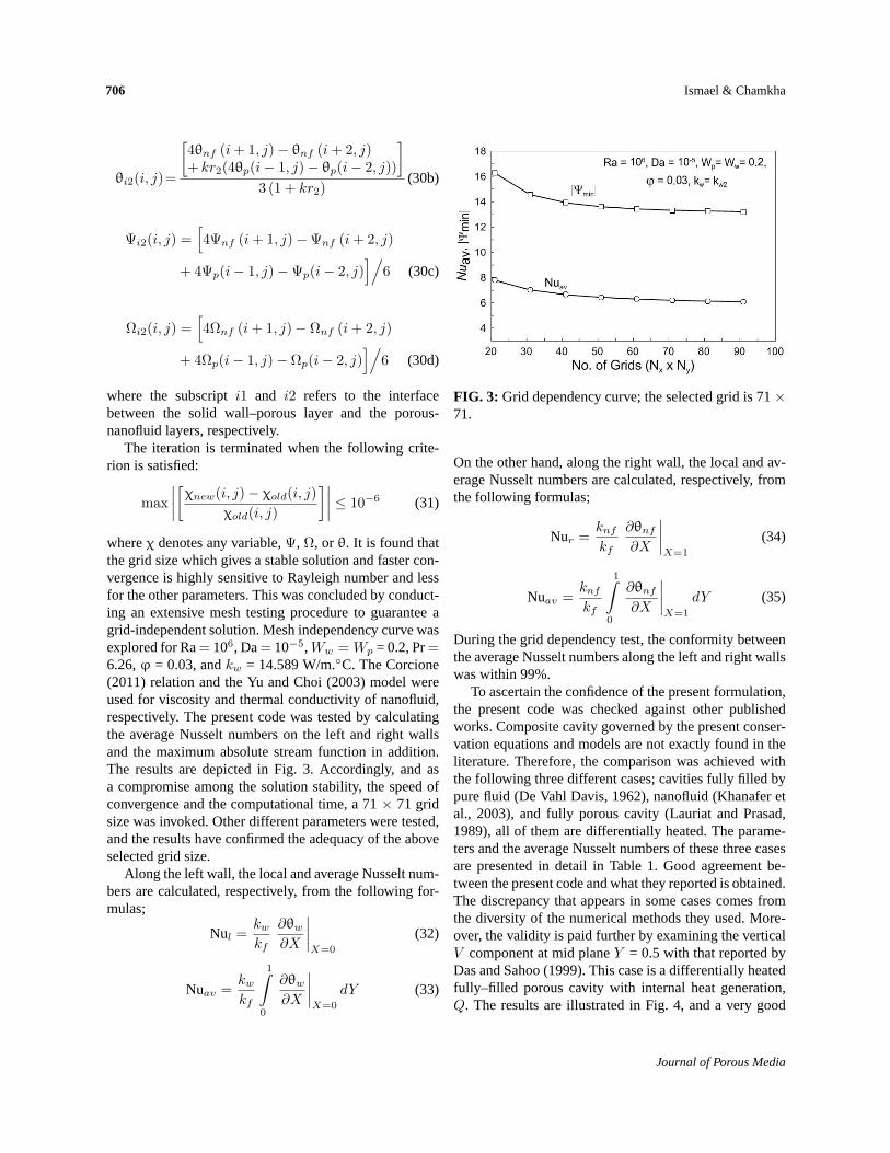
whereχ denotes any variable,Ψ, Ω, or θ. It is found thatthe grid size which gives a stable solution and faster con-vergence is highly sensitive to Rayleigh number and lessfor the other parameters. This was concluded by conduct-ing an extensive mesh testing procedure to guarantee agrid-independent solution. Mesh independency curve wasexplored for Ra= 106, Da= 10−5,Ww = Wp = 0.2, Pr=6.26,φ = 0.03, andkw = 14.589 W/m.C. The Corcione(2011) relation and the Yu and Choi (2003) model wereused for viscosity and thermal conductivity of nanofluid,respectively. The present code was tested by calculatingthe average Nusselt numbers on the left and right wallsand the maximum absolute stream function in addition.The results are depicted in Fig. 3. Accordingly, and asa compromise among the solution stability, the speed ofconvergence and the computational time, a 71× 71 gridsize was invoked. Other different parameters were tested,and the results have confirmed the adequacy of the aboveselected grid size.
Along the left wall, the local and average Nusselt num-bers are calculated, respectively, from the following for-mulas;
Nul =kwkf
∂θw∂X
∣∣∣∣X=0
(32)
Nuav =kwkf
1∫0
∂θw∂X
∣∣∣∣X=0
dY (33)
FIG. 3: Grid dependency curve; the selected grid is 71×71.
On the other hand, along the right wall, the local and av-erage Nusselt numbers are calculated, respectively, fromthe following formulas;
Nur =knfkf
∂θnf∂X
∣∣∣∣X=1
(34)
Nuav =knfkf
1∫0
∂θnf∂X
∣∣∣∣X=1
dY (35)
During the grid dependency test, the conformity betweenthe average Nusselt numbers along the left and right wallswas within 99%.
To ascertain the confidence of the present formulation,the present code was checked against other publishedworks. Composite cavity governed by the present conser-vation equations and models are not exactly found in theliterature. Therefore, the comparison was achieved withthe following three different cases; cavities fully filled bypure fluid (De Vahl Davis, 1962), nanofluid (Khanafer etal., 2003), and fully porous cavity (Lauriat and Prasad,1989), all of them are differentially heated. The parame-ters and the average Nusselt numbers of these three casesare presented in detail in Table 1. Good agreement be-tween the present code and what they reported is obtained.The discrepancy that appears in some cases comes fromthe diversity of the numerical methods they used. More-over, the validity is paid further by examining the verticalV component at mid planeY = 0.5 with that reported byDas and Sahoo (1999). This case is a differentially heatedfully–filled porous cavity with internal heat generation,Q. The results are illustrated in Fig. 4, and a very good
Journal of Porous Media

Conjugate Natural Convection in Composite Enclosure 707
TABLE 1: Comparisons of present numerical solutions with previous works of different cases
Ra DeVahl Davis (1962) PresentCase1,
103 1.118 1.13purefluid-filled cavity,
Pr= 0.71
105 4.519 4.55
106 8.799 8.9
Gr (Ra Pr) φ Khanafer et al. (2003) PresentCase2,
103 0.04 2.08 2.029nanofluid-filled
cavity, Pr= 6.2
103 0.08 2.24 2.17
105 0.04 8.93 8.55
105 0.08 9.6 9.25
Ra Da Lauriat and Prasad (1989) PresentCase3,
103 10−2 1.02 1.022porouscavity,
Pr= 1.0,ε = 0.4
105 10−2 3.8 3.5
107 10−6 1.08 1.042
108 10−6 2.99 2.98
FIG. 4: Vertical velocity distribution along midplane forporous cavity Ra= 105, Da= 10−4, Pr= 1, ε = 0.4 withinternal heat generation (Q= 100); comparison with Dasand Sahoo (1999).
agreement is obtained with theV component. However,the results of the present code which is written in FOR-TRAN can be relied on from an accuracy point of view.
4. RESULTS AND DISCUSSION
A graphical presentation of selective results and their dis-cussion are displayed in this section. The parameters, andtheir effective ranges, that are expected to influence theaspects of flow and heat transfer fields are Ra = 103–106,Da= 10−7–10−1, Ww = 0.1–0.7,Wp = 0.1–0.5,φ = 0–0.05 and two types of the solid wall; stainless steel (kw= 14.589 W/m.C) and Perspex (kw = 0.269 W/m.C);for brevity, they will be expressed askw1 and kw2, re-spectively. The nanofluid is considered to be composedof water-based fluid (Pr= 6.26) and Cu nanoparticles(with physical properties shown in Table 2; Chamkha andIsmael, 2013). The porosity of the porous layer is fixedat ε = 0.398, which corresponds to 3-mm-diameter glassbeads of thermal conductivityks = 0.845 W/m.K.
Figure 5 presents representative contours maps of thestreamlines and the isotherms showing the effect of threedifferent alternative thicknesses of the solid wall and the
Volume 18, Number 7, 2015
708 Ismael& Chamkha
TABLE 2: Thermophysical properties of base fluid andnanoparticles (Chamkha and Ismael, 2013)
Physical property Basefluid (water) CuCp (J/kg/K) 4179 385
ρ (kg/m3) 997.1 8933
k (W/m/K) 0.613 401
β × 10−5 (1/K) 21 1.67
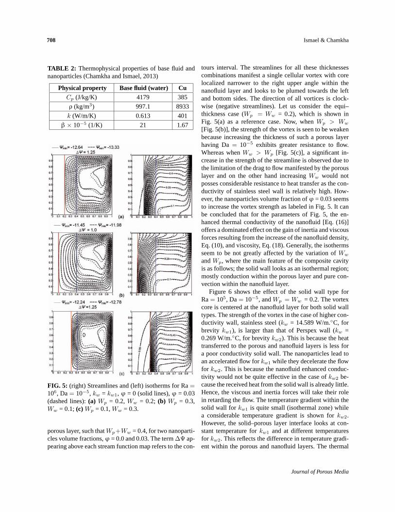
FIG. 5: (right) Streamlines and (left) isotherms for Ra=106, Da= 10−5, kw = kw1, φ = 0 (solid lines),φ = 0.03(dashed lines):(a) Wp = 0.2,Ww = 0.2; (b) Wp = 0.3,Ww = 0.1;(c)Wp = 0.1,Ww = 0.3.
porous layer, such thatWp+Ww = 0.4, for two nanoparti-cles volume fractions,φ = 0.0 and 0.03. The term∆Ψ ap-pearing above each stream function map refers to the con-
tours interval. The streamlines for all these thicknessescombinations manifest a single cellular vortex with corelocalized narrower to the right upper angle within thenanofluid layer and looks to be plumed towards the leftand bottom sides. The direction of all vortices is clock-wise (negative streamlines). Let us consider the equi–thickness case (Wp = Ww = 0.2), which is shown inFig. 5(a) as a reference case. Now, whenWp > Ww
[Fig. 5(b)], the strength of the vortex is seen to be weakenbecause increasing the thickness of such a porous layerhaving Da= 10−5 exhibits greater resistance to flow.Whereas whenWw > Wp [Fig. 5(c)], a significant in-crease in the strength of the streamline is observed due tothe limitation of the drag to flow manifested by the porouslayer and on the other hand increasingWw would notposses considerable resistance to heat transfer as the con-ductivity of stainless steel wall is relatively high. How-ever, the nanoparticles volume fraction ofφ = 0.03 seemsto increase the vortex strength as labeled in Fig. 5. It canbe concluded that for the parameters of Fig. 5, the en-hanced thermal conductivity of the nanofluid [Eq. (16)]offers a dominated effect on the gain of inertia and viscousforces resulting from the increase of the nanofluid density,Eq. (10), and viscosity, Eq. (18). Generally, the isothermsseem to be not greatly affected by the variation ofWw
andWp, where the main feature of the composite cavityis as follows; the solid wall looks as an isothermal region;mostly conduction within the porous layer and pure con-vection within the nanofluid layer.
Figure 6 shows the effect of the solid wall type forRa= 105, Da= 10−5, andWp = Ww = 0.2. The vortexcore is centered at the nanofluid layer for both solid walltypes. The strength of the vortex in the case of higher con-ductivity wall, stainless steel (kw = 14.589 W/m.C, forbrevity kw1), is larger than that of Perspex wall (kw =0.269 W/m.C, for brevitykw2). This is because the heattransferred to the porous and nanofluid layers is less fora poor conductivity solid wall. The nanoparticles lead toan accelerated flow forkw1 while they decelerate the flowfor kw2. This is because the nanofluid enhanced conduc-tivity would not be quite effective in the case ofkw2 be-cause the received heat from the solid wall is already little.Hence, the viscous and inertia forces will take their rolein retarding the flow. The temperature gradient within thesolid wall for kw1 is quite small (isothermal zone) whilea considerable temperature gradient is shown forkw2.However, the solid–porous layer interface looks at con-stant temperature forkw1 and at different temperaturesfor kw2. This reflects the difference in temperature gradi-ent within the porous and nanofluid layers. The thermal
Journal of Porous Media

Conjugate Natural Convection in Composite Enclosure 709
FIG. 6: (right) Streamlines and (left) isotherms for Ra=105, Da= 10−5, Wp = Ww = 0.2,φ = 0 (solid lines),φ = 0.03 (dashed lines):(a) kw = kw1; (b) kw = kw2.
boundary layer close to the right wall seems to be thinnerin kw1 thankw2 which in turn increases the convectiveheat transfer.
The effect of the Rayleigh number is illustrated inFig. 7 forWp = Ww = 0.2, Da= 10−5, andkw1. For Ra=103 [Fig. 7(a)], the porous and nanofluid layers appear asone layer with a weak centered vortex. The correspond-ing mostly vertical isotherms indicate a heat conductiondominance. Increasing Ra to 104 [Fig. 7(b)] leads to astronger vortex with core tending to plume towards theright upper corner within the nanofluid layer. A large por-tion of the nanofluid layer undergoes convection as can beseen in the corresponding contours of the isotherms. Fig-ure 7(c) is discussed earlier in Fig. 5, but it is brought hereto show the effect of increasing Ra to 106, where in thiscase, a stronger vortex leads to large flow quantities whichpenetrate through the porous layer. Mostly, the nanofluidlayer entirely undergoes convection where the feature ofthe isotherms is generally horizontal. However, for Ra≤104, the deceleration in the streamlines resulting from theaddition of nanoparticles is attributed to the inertia forcerather than the viscous force where the latter becomes ac-tive at higher flow quantities. For Ra= 106 the increaseof both the viscous and inertia forces (resulting from the
FIG. 7: (right) Streamlines and (left) isotherms forDa= 10−5, Wp = 0.2,Ww = 0.2,kw = kw1,φ = 0 (solidlines),φ = 0.03 (dashed lines):(a) Ra= 103; (b) Ra=104; (c) Ra= 106.
addition of nanoparticles) becomes unable to overcomethe effect of thermal conductivity enhancement resultingfromφ = 0.03 volume fraction.
The effect of the Darcy number (dimensionless perme-ability of the porous layer) is shown in Fig. 8 forWw =Wp = 0.2, Ra= 106, andkw1. Globally, increasing Dafrom 10−7 [Fig. 8(a)] to 10−1 [Fig. 8(c)] manifests lessdrag by the porous layer. Therefore, it can be seen that acontinual increase of the vortex strength with Da whichis associated by the extension of the core vortex towardsthe porous layer until it breaks to double-cellular vortex atDa=10−1, where the resistance of the porous layer is ap-proximately diminished and most of the streamlines pen-
Volume 18, Number 7, 2015

710 Ismael& Chamkha
FIG. 8: (right) Streamlines and (left) isotherms for Ra=106, Wp = 0.2, Ww = 0.2, kw = kw1, φ = 0 (solidlines),φ = 0.03 (dashed lines):(a) Da= 10−7; (b) Da=10−3; (c) Da= 10−1.
etrate the porous layer. On the other hand, the convectionis the feature of both the porous and the nanofluid layers,this is when Da≥ 10−3, as observed by the isothermscontours. It is seen also that for high Da, the streamlinesdo not show noticeable strength as the main vortex freelypenetrates inside the porous layer.
The local distribution of the vertical velocity compo-nent V and the dimensionless temperatureθ shown inFig. 9 contribute in a more clarification of the effect ofthe Darcy number. TheV profile through the porous layeris changed from uniform and weak at Da= 10−6 to aparabolic and skewed toward the solid wall at Da≥ 10−3.
FIG. 9: Local distribution of (a) the vertical velocitycomponent and(b) the dimensionless temperature alongY = 1/2.
The correspondingθ distribution points out to mostly heatconduction at Da= 10−6 and a conduction–convectionmode at Da≥ 10−3. It is seen that the pure heat conduc-tion through the solid wall is also affected by Da, wherethe gradient ofθ increases with increasing values of Da.This is referred to that more penetration flow comes fromthe cold right wall will reduce the temperature of solid–porous layer interface. Close to the right wall, parabolicV profiles are indicated with increased peaks with Da.
The effects of various parameters on the heat trans-fer can be decided comprehensively by observation ofthe average Nusselt number Nuav over the left hot wall[Eq. (33)]. The next figures will discover these effects.
Journal of Porous Media
Conjugate Natural Convection in Composite Enclosure 711
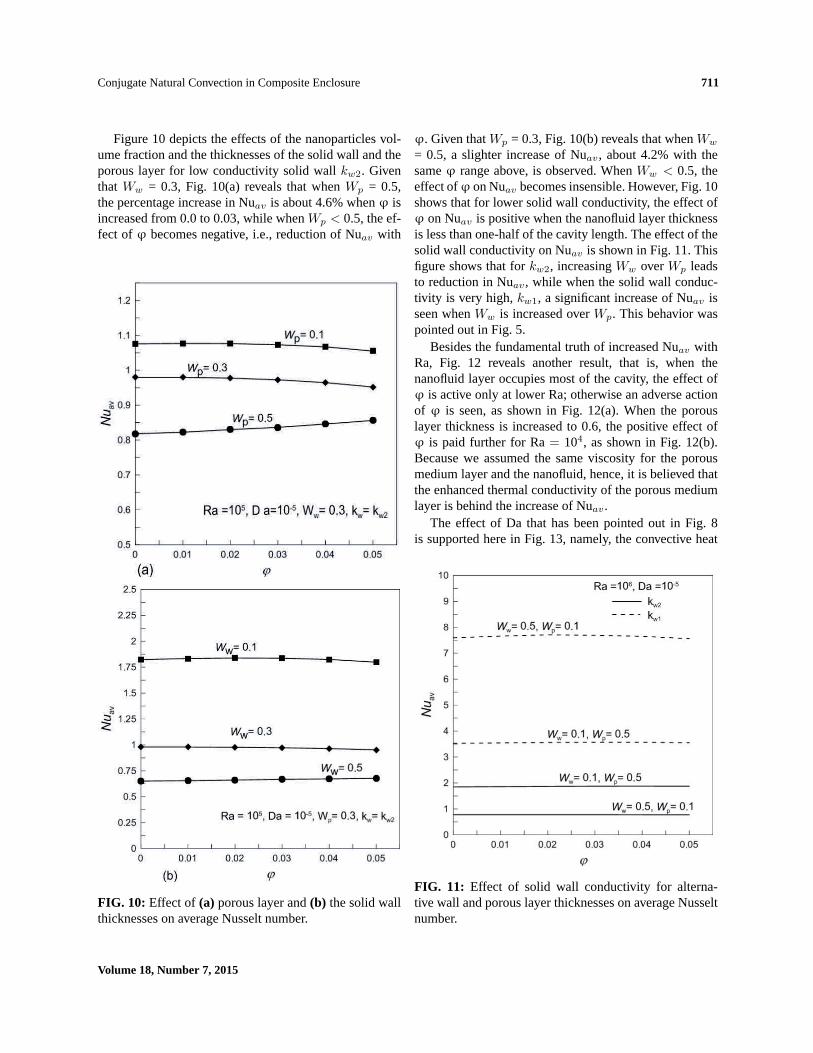
Figure 10 depicts the effects of the nanoparticles vol-ume fraction and the thicknesses of the solid wall and theporous layer for low conductivity solid wallkw2. Giventhat Ww = 0.3, Fig. 10(a) reveals that whenWp = 0.5,the percentage increase in Nuav is about 4.6% whenφ isincreased from 0.0 to 0.03, while whenWp < 0.5, the ef-fect ofφ becomes negative, i.e., reduction of Nuav with
FIG. 10: Effect of (a) porous layer and(b) the solid wallthicknesses on average Nusselt number.
φ. Given thatWp = 0.3, Fig. 10(b) reveals that whenWw
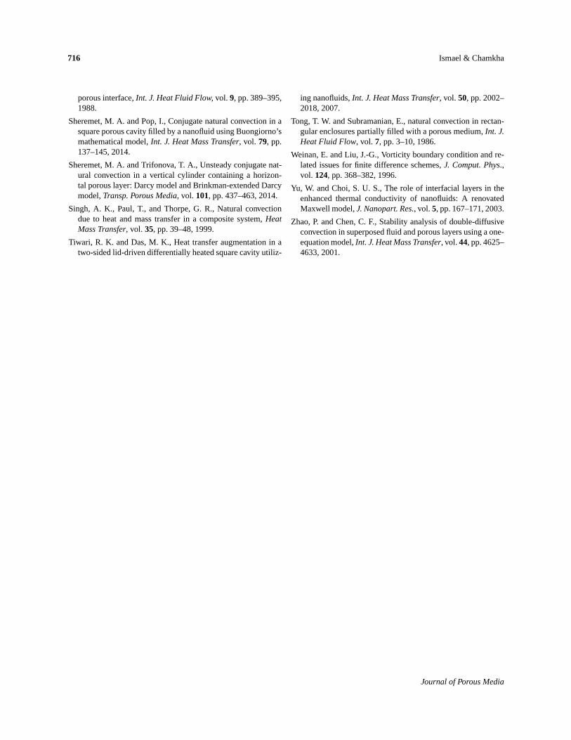
= 0.5, a slighter increase of Nuav, about 4.2% with thesameφ range above, is observed. WhenWw < 0.5, theeffect ofφ on Nuav becomes insensible. However, Fig. 10shows that for lower solid wall conductivity, the effect ofφ on Nuav is positive when the nanofluid layer thicknessis less than one-half of the cavity length. The effect of thesolid wall conductivity on Nuav is shown in Fig. 11. Thisfigure shows that forkw2, increasingWw overWp leadsto reduction in Nuav, while when the solid wall conduc-tivity is very high,kw1, a significant increase of Nuav isseen whenWw is increased overWp. This behavior waspointed out in Fig. 5.
Besides the fundamental truth of increased Nuav withRa, Fig. 12 reveals another result, that is, when thenanofluid layer occupies most of the cavity, the effect ofφ is active only at lower Ra; otherwise an adverse actionof φ is seen, as shown in Fig. 12(a). When the porouslayer thickness is increased to 0.6, the positive effect ofφ is paid further for Ra= 104, as shown in Fig. 12(b).Because we assumed the same viscosity for the porousmedium layer and the nanofluid, hence, it is believed thatthe enhanced thermal conductivity of the porous mediumlayer is behind the increase of Nuav.
The effect of Da that has been pointed out in Fig. 8is supported here in Fig. 13, namely, the convective heat
FIG. 11: Effect of solid wall conductivity for alterna-tive wall and porous layer thicknesses on average Nusseltnumber.
Volume 18, Number 7, 2015

712 Ismael& Chamkha
FIG. 12: Effect of Rayleigh number and the porous layerthickness on average Nusselt number.
transfer increases progressively with increasing values ofthe Da number. Another information could be extractedfrom this figure that is the natural convection is enhancedby the addition of the nanoparticles only for a very lowpermeability porous layer. Otherwise, an adverse actionof φ on Nuav is recorded. This behavior is attributed to
FIG. 13: Effect of Darcy number on average Nusseltnumber.
the fact that when the nanofluid strongly penetrates thehighly permeable porous medium, it will be faced by theaugmented inertia and viscous forces due to the increaseof φ, keeping in mind that this refers to Ra= 106. Exam-ination of different Ra and porous layer thicknesses withDa is presented in Figs. 14 and 15, respectively. Figure 14shows that for low Ra number, Ra= 103, the permeabil-
FIG. 14: Effect Darcy number for different Rayleighnumbers on average Nusselt number.
Journal of Porous Media

Conjugate Natural Convection in Composite Enclosure 713
FIG. 15: Effect of Darcy number for different porouslayer thicknesses on average Nusselt number.
ity of the porous medium layer has no effect on Nuav
because the flow is already weak. The sensitivity to Dabegins for Ra≥ 104. For high values of Ra [Fig. 15(b)],beyond Da= 10−2, the effects of the porous layer thick-ness and its permeability are completely vanished, that is,the porous layer behaves as a pure nanofluid layer.
However, as a reminder, all of the above reported re-sults are based on the Corcione (2011) model for thenanofluid dynamic viscosity and the Yu and Choi (2003)model for the nanofluid thermal conductivity. Althoughmany developed models and correlations for nanofluidproperties, the Brinkman model (for dynamic viscosity)and Maxwell–Garnetts MG model (for thermal conduc-tivity) are still most commonly used in similar investiga-tions, perhaps due to their simplicity. However, four com-binations of the presently used and the most commonlyused models are tested for low Ra= 103 and high Ra=106. The results and combinations marking are presentedin Figs. 16(a,b). Before discussing the behavior models,it is worth mentioning that the results of the Yu and Choi(2003) model are greater than those of MG model be-cause the first takes into account the formed solid-layereffect, and on the other hand, the Corcione (2011) vis-cosity is greater than that of Brinkman. Now, for a lowRayleigh number [Fig. 16(a)], where the inertia and vis-cous forces become inactive against the thermal conduc-tivity, models II and I behave as steeply increasing func-tions ofφ than models IV and III. However, for a highRayleigh number, the effect of viscous force becomes im-
FIG. 16: Four combinations of nanofluid thermal con-ductivity and dynamic viscosity models, examined for(a) Ra= 103 and(b) Ra= 106.
portant and may obviate the thermal conductivity effect.Therefore, the discrepancy among the four combinationsmodels becomes more evident. Combinations containingthe Brinkman effect (II and IV) are still increasing func-tions ofφ regardless of the thermal conductivity model.
Volume 18, Number 7, 2015

714 Ismael& Chamkha
Model III, which offers the worst behavior of Nuav withφ, shows a decreasing function ofφ. This is due to thesmaller thermal conductivity and the larger viscosity. Thepresently used combination model I shows a different be-havior, that is, Nuav is a slow increasing function ofφ upto 0.03, then, an adverse action of nanoparticles occurs,where Nuav at φ = 0.05 reaches to a lesser value thanwhenφ = 0 (clear fluid).
5. CONCLUSIONS
Laminar natural convection in a cavity composed of ananofluid layer and a porous layer saturated by the samenanofluid and heated from the porous layer side by a solidwall, forming a square domain, was studied numerically.The problem was analyzed using SUR upwind finite dif-ference method. The solid wall was treated as a singledomain, and the porous and nanofluid layers were treatedusing the double domain formulation. The main calcula-tions were based on alternative models for the nanofluidthermal conductivity and dynamic viscosity. Other mod-els were presented for comparison purposes. The resultswere obtained by varying the solid wall type (kw), porouslayer type (Da), and their thicknesses, volume fraction ofCu nanoparticles and the Rayleigh number. The obtainedresults led to the following conclusions:
1. The natural convection heat transfer was enhancedby the addition of nanoparticles for special con-strains such as low permeability with considerablethickness (≥0.5) porous medium layer and at limitedRayleigh number (≤104). However, at low Rayleigh(=103), the non-dimensional permeability of theporous medium (Da) became ineffective.
2. For low thermal conductivity of the solid wall(kw = 0.269 W/m.C) which was less than the ef-fective thermal conductivity of the porous medium,increasing the wall thickness with decreasing theporous layer thickness resulted in an attenuation ofnatural convection inside the cavity. On the otherhand, for relatively very high thermal conductivitysolid wall (kw = 14.589 W/m.C), the natural con-vection was quite enhanced by increasing the solidwall thickness at the expense of the porous layerthickness.
3. The dimensionless temperature gradient within thesolid wall was found to be influenced by the Darcynumber of the porous layer, that is, the temperaturegradient increased with Da.
4. For a higher Rayleigh number (Ra= 106) and for ahigher permeability porous layer (Da= 10−1), thenanofluid and the porous layers behaved mostly asa single layer and no effect was recorded due to theporous layer thickness.
5. It is believed that the presently used models for thenanofluid properties gives reasonable results withinwide ranges of the Rayleigh number.
REFERENCES
Abbasian Arani, A. A. and Amani, J., Experimental investiga-tion of diameter effect on heat transfer performance and pres-sure drop of TiO2–water nanofluid,Exp. Thermal Fluid Sci.,vol. 44, pp. 520–533, 2013.
Abu-Hijleh, B. A. and Al-Nimr, M. A., The effect of the lo-cal inertial term on the fluid flow in channels partially filledwith porous material,Int. J. Heat Mass Transfer, vol. 44, pp.1565–1572, 2001.
Aguilar-Madera, C. G., Valdes-Parada, F. J., Goyeau, B., andOchoa-Tapia, J. A., One-domain approach for heat transferbetween a porous medium and a fluid,Int. J. Heat MassTransfer, vol.54, pp. 2089–2099, 2011a.
Aguilar-Madera, C. G., Valdes-Parada, F. J., Goyeau, B., andOchoa-Tapia, J. A., Convective heat transfer in a channel par-tially filled with a porous medium,Int. J. Thermal Sci., vol.50, pp. 1355–1368, 2011b.
Bagchi, A. and Kulacki, F. A., Natural convection in fluid-superposed porous layers heated locally from below,Int. J.Heat Mass Transfer, vol.54, pp. 3672–3682, 2011.
Bagchi, A., and Kulacki, F. A., Experimental study of naturalconvection in fluid-superposed porous layers heated locallyfrom below, Int. J. Heat Mass Transfer, vol.55, pp. 1149–1153, 2012.
Baytas, A. C., Baytas, A. F., Ingham, D. B., and Pop, I., Doublediffusive natural convection in an enclosure filled with a steptype porous layer: Non-Darcy flow,Int. J. Thermal Sci., vol.48, pp. 665–673, 2009.
Beavers, G. S. and Joseph, D. D., Boundary conditions at a nat-urally permeable wall,J. Fluid Mech., vol.30, pp. 197–207,1967.
Beckermann, C. and Viskanta, R., Natural convectionsolid/liquid phase change in porous media,Int. J. Heat MassTransfer, vol.31, pp. 35–46, 1988.
Beckermann, C., Ramadhyani, S., and Viskanta, R., Naturalconvection flow and heat transfer between a fluid layer anda porous layer inside a rectangular enclosure,ASME J. HeatTransfer, vol.109, pp. 363–370, 1987.
Bennacer, R., Beji, H., and Mohamad, A. A., Double diffusiveconvection in a vertical enclosure inserted with two saturated
Journal of Porous Media

Conjugate Natural Convection in Composite Enclosure 715
porous layers confining a fluid layer,Int. J. Thermal Sci., vol.42, pp. 141–151, 2003.
Bourantas, G. C., Skouras, E. D., Loukopoulos, V. C., and Niki-foridis, G. C., Natural convection of nanofluids flow with“nanofluid-oriented” models of thermal conductivity and dy-namic viscosity in the presence of heat source,Int. J. Numer.Methods Heat Fluid Flow, vol. 23, pp. 248–274, 2013.
Bourantas, G. C., Skouras, E. D., Loukopoulos, V. C., andBurganos, V. N., Heat transfer and natural convection ofnanofluids in porous media,Eur. J. Mech. B, vol. 43, pp. 45–56, 2014.
Braga, E. J. and De Lemos, M. J. S., Laminar and turbulent freeconvection in a composite enclosure,Int. J. Heat Mass Trans-fer, vol.52, pp. 588–596, 2009.
Brinkman, H. C., The viscosity of concentrated suspensions andsolutions,J. Chem. Phys., vol. 20, p. 571, 1952.
Carr, M. and Straughan, B., Penetrative convection in a fluidoverlying a porous layer,Adv. Water Resour., vol.26, pp.263–276, 2003.
Chamkha, A. J. and Ismael, M. A., Conjugate heat transfer ina porous cavity filled with nano-fluids and heated by a trian-gular thick wall, Int. J. Thermal Sci., vol. 67, pp. 135–151,2013.
Chamkha, A. J. and Ismael, M. A., Natural convection in differ-entially heated partially porous layered cavities filled with ananofluid,Numer. Heat Transfer, Part A, vol. 65, pp. 1089–1113, 2014.
Chen, F. and Chen, C. F., Convection in superposed fluid andporous layers,J. Fluid Mech., vol. 234, pp. 97–119, 1992.
Choi, S. U. S. and Eastman, J. A., Enhancing thermal conductiv-ity of fluids with nanoparticles,ASME International Mechan-ical Engineering Congress and Exposition,San Francisco,CA, 1995.
Corcione, M., Empirical correlating equations for predictingthe effective thermal conductivity and dynamic viscosity ofnanofluids,Energ. Convers. Manage., vol.52, pp. 789–793,2011.
Das, S. and Sahoo, R. K., Effect of Darcy, Fluid Rayleigh andheat generation parameters on natural convection in a poroussquare enclosure: A Brinkman-extended Darcy model,Int.Commun. Heat Mass Transfer, vol.26, pp. 569–578, 1999.
De Vahl Davis, G., Natural convection of air in a square cav-ity, a benchmark numerical solution,Int. J. Numer. MethodsFluids, vol.3, pp. 249–264, 1962.
Gobin, D., Goyeau, B., and Neculae, A., Convective heat andsolute transfer in partially porous cavities,Int. J. Heat MassTransfer, vol.48, pp. 1898–1908, 2005.
Goyeau, B. and Gobin, D., Heat transfer by thermosolutal natu-ral convection in a vertical composite fluid-porous cavity,Int.Commun. Heat Mass Transfer, vol. 26, pp. 1115–1126, 1999.
Hirata, S. C., Goyeau, B., Gobin, D., Carr, M., and Cotta, R. M.,Linear stability of natural convection in superposed fluid andporous layers: Influence of the interfacial modeling,Int. J.Heat Mass Transfer, vol.50, pp. 1356–1367, 2007.
Hirata, S. C., Goyeau, B., and Gobin, D., Stability analysisof thermosolutal natural convection in a partially porousmedium,5th European Thermal-Sciences Conference,TheNetherlands, 2008.
Hirata, S. C., Goyeau, B., Gobin, D., Chandesris, M., andJamet, D., Stability of natural convection in superposed fluidand porous layers: Equivalence of the one- and two-domainapproaches,Int. J. Heat Mass Transfer, vol. 52, pp. 533–536,2009.
Khanafer, K., Vafai, K., and Lightstone, M., Buoyancy-drivenheat transfer enhancement in a two-dimensional enclosureutilizing nanofluids,Int. J. Heat Mass Transfer, vol.46, pp.3639–3653, 2003.
Kim, S. G. and Choi, C. Y., Convective heat transfer in porousand overlying fluid layers heated from below,Int. J. HeatMass Transfer, vol.39, pp. 319–329, 1996.
Lauriat, G. and Prasad, V., Non-Darcian effects on natural con-vection in a vertical porous enclosure,Int. J. Heat MassTransfer, vol.32, pp. 2135–2148, 1989.
Lopez, J. J. and Tapia, J. A., A study of buoyancy driven flowin a confined fluid overlying porous layer,Int. J. Heat MassTransfer, vol.44, pp. 4725–4736, 2001.
Mercier, J. F., Weisman, C., Firdaouss, M., and Le Quere, P.,Heat transfer associated to natural convection flow in a partlyporous cavity,Trans. ASME J. Heat Transfer, vol. 124, pp.130–143, 2002.
Merrikh, A. A. and Mohamad, A. A., Non-Darcy effects inbuoyancy driven flows in an enclosure filled with verticallylayered porous media,Int. J. Heat Mass Transfer, vol.45, pp.4305–4313, 2002.
Mharzi, M., Daguenetb, M., and Daoud, S., Thermosolutal nat-ural convection in a vertically layered fluid-porous mediumheated from the side,Energ. Convers. Manage., vol.41, pp.1065–1090, 2000.
Oosthuizen, P. H. and Paul, J. T., Natural convection in a squareenclosure partly filled with two layers of porous material,Trans. Eng. Sci., vol. 12, pp. 63–72, 1996.
Phanikumar, M. S. and Mahajan, R. L., Non-Darcy natural con-vection in high porosity metal foams,Int. J. Heat Mass Trans-fer, vol. 45, pp. 3781–3793, 2002.
Prathap Kumar, J. P., Umavathi, J. C., Chamkha, A. J., and Ba-sawaraj, A., Solute dispersion between two parallel platescontaining porous and fluid layers,J. Porous Media, vol. 15,pp. 1031–1047, 2012.
Sathe, S. B., Lin, W. Q., and Tong, T. W., Natural convectionin enclosures containing insulation with a permeable fluid-
Volume 18, Number 7, 2015
716 Ismael& Chamkha
porous interface,Int. J. Heat Fluid Flow,vol. 9, pp. 389–395,1988.
Sheremet, M. A. and Pop, I., Conjugate natural convection in asquare porous cavity filled by a nanofluid using Buongiorno’smathematical model,Int. J. Heat Mass Transfer, vol.79, pp.137–145, 2014.
Sheremet, M. A. and Trifonova, T. A., Unsteady conjugate nat-ural convection in a vertical cylinder containing a horizon-tal porous layer: Darcy model and Brinkman-extended Darcymodel,Transp. Porous Media, vol. 101, pp. 437–463, 2014.
Singh, A. K., Paul, T., and Thorpe, G. R., Natural convectiondue to heat and mass transfer in a composite system,HeatMass Transfer, vol.35, pp. 39–48, 1999.
Tiwari, R. K. and Das, M. K., Heat transfer augmentation in atwo-sided lid-driven differentially heated square cavity utiliz-
ing nanofluids,Int. J. Heat Mass Transfer, vol. 50, pp. 2002–2018, 2007.
Tong, T. W. and Subramanian, E., natural convection in rectan-gular enclosures partially filled with a porous medium,Int. J.Heat Fluid Flow, vol.7, pp. 3–10, 1986.
Weinan, E. and Liu, J.-G., Vorticity boundary condition and re-lated issues for finite difference schemes,J. Comput. Phys.,vol. 124, pp. 368–382, 1996.
Yu, W. and Choi, S. U. S., The role of interfacial layers in theenhanced thermal conductivity of nanofluids: A renovatedMaxwell model,J. Nanopart. Res.,vol. 5, pp. 167–171, 2003.
Zhao, P. and Chen, C. F., Stability analysis of double-diffusiveconvection in superposed fluid and porous layers using a one-equation model,Int. J. Heat Mass Transfer, vol.44, pp. 4625–4633, 2001.
Journal of Porous Media