connected lighting system interoperability study · connected lighting system interoperability...
TRANSCRIPT

Connected Lighting System Interoperability StudyPart 1: Application Programming InterfacesPrepared for the U.S. Department of Energy Solid-State Lighting Program
October 2017
Prepared by Pacific Northwest National Laboratory
Connected Lighting System Interoperability Study,
Part 1: Application Programming Interfaces
Prepared for:
Solid-State Lighting Program
Building Technologies Office
Energy Efficiency and Renewable Energy
U.S. Department of Energy
Prepared by:
Pacific Northwest National Laboratory
October 2017
Authors:
Clement Gaidon
Michael Poplawski
PNNL-26946
iii
Executive Summary
Lighting systems are increasingly incorporating network interfaces and sensors, and metamorphosing
into data collection platforms that can implement advanced adaptive lighting strategies, enabling
data-driven lighting energy management in buildings and cities, and can deliver other potentially
high-value services, ranging from space utilization and office scheduling to asset or inventory
management and many other functions. Although such connected lighting systems (CLS) might
enable dramatic improvements in the energy performance of lighting and other energy-intensive
systems or services, at this early stage in their development, that potential is limited by significant
fragmentation of the underlying technologies and interfaces. As a result, today’s CLS are generally
not natively interoperable, meaning they cannot be assumed to work well together or be capable of
exchanging the data that they collect with one another or other systems.
As the lighting industry brings connectivity to more products, their interoperability becomes key to
leveraging that capability – specifically, the data that might be exchanged between devices and
systems – towards better energy efficiency, lighting quality, user experiences, and perhaps other non-
energy or non-lighting value propositions. Without sufficient interoperability, connected lighting
systems may see limited market adoption. Devices need to use common communication protocols
and information models in order for the number of valuable applications to grow and reach the
critical mass that will drive adoption. Although owners of devices and systems that produce
information are generally understood to own that information, the utility of that ownership is limited
if the information is locked up in a proprietary data model. Interoperability unlocks the data in a
system by allowing it to be communicated to and used by other systems, analyzed by other
applications, and managed or archived in other ways, thereby enabling true ownership.
The main goal of this series of studies is to discern and document the state of CLS interoperability in
this early stage, multi-vendor, multi-technology, and multi-business-model landscape. Although a
number of industry consortia are developing frameworks or technologies that facilitate more native
interoperability, at present these efforts are either incomplete or immature, do not support lighting
applications sufficiently, or are not adopted by a significant number of lighting manufacturers. At
present, interoperability between CLS offered by different vendors – or, in some cases, even between
different solutions from the same vendor – is facilitated primarily through application programming
interfaces (APIs), or not at all.
This initial study, which focuses on interoperability as realized by the use of APIs, explores the
diversity of such interfaces in several CLS; characterizes the extent of interoperability that they
provide; and illustrates challenges, limitations, and tradeoffs that were encountered during this
exploration. More specifically, the system architectures and API structure, nomenclature, and
information models were characterized; the development of a common integration platform was
investigated; and two real-life use-cases were simulated to illustrate the relative effort required to use
APIs to enable new features and capabilities facilitated by information exchange. Commonly
observed issues, such as the challenge of integrating heterogeneous and asynchronous data and
resources from multiple origins, are discussed in detail in this report, and suggestions are made for
how API architectures and information models might be more coordinated, and thereby lower
barriers to interoperability and enable increased CLS adoption.
iv
Key Findings and Lessons Learned, Recommendations, and Next Steps
Although APIs and web services enable a certain level of interaction between heterogeneous systems
on the Internet, they require some effort and skill to use effectively and efficiently, and they do not
serve all interoperability goals. Integrating multiple CLS through APIs does not result in a
homogenous system; at best it yields a common user interface and experience. However, effectively
abstracting any underlying heterogeneous characteristics that do not serve the end user in some
tangible way can require a significant amount of integration work. Managing what functionally
remains a distributed system at one or more interoperability layers can be challenging and can require
substantial effort. Differences among network protocols, device representations, and access policies
that affect performance must be understood, addressed (if possible), and managed – not only initially,
but over the course of hardware, firmware, and software upgrades. Asynchronous data flow can lead
to latency issues and bandwidth bottlenecks. Integrated system failures and performance issues can
be very difficult to debug and subsequently isolate and mitigate, without taking down the entire
system. Implementing mechanisms and policies that maximize reliability and quality of service while
still allowing the integrated system to scale and simultaneously continue to deliver end-use
functionality requires advanced developer skills. Further, at present, system integrators may have to
navigate API implementations that are poorly or insufficiently documented, or have not been well-
exercised, rendering them immature or, in some cases, unusable.
APIs are becoming increasingly available for connected lighting systems. The APIs provided by
current market-available CLS vendors can be utilized to facilitate enough interoperability between
lighting systems to enable lighting-system owners and operators to implement some level of multi-
vendor integration and some remote configuration and management services, as well as some
adaptive lighting strategies. However, in many instances, API inconsistency and immaturity
unnecessarily increase the effort required to implement these services and strategies, and reduce the
value and performance that they deliver. API developers are encouraged to provide up-to-date and
comprehensive API documentation and to support the efficient identification of bugs. Further, they
should explore and attempt to implement common approaches to naming and organizing resources,
as well as common information and data models – which are key to both minimizing the effort
required to integrate heterogeneous systems and enabling functional, high-value use-cases.
The U.S. Department of Energy (DOE) intends to support improved interoperability by continuing to
investigate approaches to realizing interoperability between CLS from different providers, as well as
between connected lighting and non-lighting systems. Without more effective, efficient, and,
ultimately, native interoperability, connected lighting technologies may see limited deployment,
unable to go beyond simple connectivity and to fulfill their energy efficiency and transformative
potential. Lighting industry stakeholders and system integrators are encouraged to provide DOE with
investigation recommendations and to propose collaborations that might best contribute to realizing
these goals.

v
Acknowledgements
The authors are grateful to the following individuals for the input they provided to this study.
Mark Wilbur — Current by GE
James Morgan — Current by GE
Joseph Bullock — Enlighted
Senthil Kumar — Enlighted
Damon Bosetti — Digital Lumens
Dan Buckley — Digital Lumens
Karsten Kelly — PNNL
Yunzhi Huang — PNNL
Sean Tippett — Silverspring Networks
Jean Marc Taing — StreetlightVision
Nimrod Sagi — Telematics
Amir Hirsch — Telematics
John Yriberri — Xicato
Martin Mueller — Xicato
vi
Symbols and Abbreviations
6LoWPAN Internet Protocol IPv6 and Low-power Wireless Personal Area Networks
API application programming interface
CLS connected lighting systems
CLTB Connected Lighting Test Bed
CoAP Constrained Application Protocol
CORS cross-origin resource sharing
CPU central processing unit
DHCP Dynamic Host Configuration Protocol
DOE U.S. Department of Energy
GUI graphical user interface
HTML HyperText Markup Language
HTTP HyperText Transfer Protocol
IETF Internet Engineering Task Force
IoT Internet of Things
ISO International Organization for Standardization
JSON JavaScript Object Notation
LAN local area network
LED light-emitting diode
MD5 Message Digest 5
MQTT Message Queue Telemetry Transport
OCF Open Connectivity Foundation
PNNL Pacific Northwest National Laboratory
REST representational state transfer
RPC remote procedure call
RSSI received signal strength indication
SHA Secure Hash Algorithm
SOAP Simple Object Access Protocol
TCP Transmission Control Protocol
URL Uniform Resource Locator
UDP User Datagram Protocol
W3C World Wide Web Consortium
XML eXtensible Markup Language
XMPP Extensible Messaging and Presence Protocol
XSS cross site scripting
vii
Table of Contents 1 Introduction ......................................................................................................................................... 1
2 Interoperability Background ............................................................................................................... 4
2.1 Interoperability Frameworks and Specifications ................................................................. 5 2.2 RESTful APIs ...................................................................................................................... 7 2.3 DOE Connected Lighting Test Bed ................................................................................... 13 2.4 Web-Based Interoperability Platform ................................................................................ 14
3 Connected Lighting System API Comparison .................................................................................. 16
3.1 CLS APIs ........................................................................................................................... 16 3.2 CLS API Authentication Schemes .................................................................................... 16 3.3 CLS API Origin Policies ................................................................................................... 17 3.4 CLS API Resource Organization ....................................................................................... 17 3.5 CLS API Data Models ....................................................................................................... 21
4 Interoperability Use-Cases ................................................................................................................ 30
4.1 Use-Case 1: Energy Data Reporting .................................................................................. 30 4.2 Use-Case 2: Broadcasting a Lighting Command .............................................................. 36
5 Summary and Recommendations...................................................................................................... 43
1
1 Introduction
The intersection of still-evolving solid-state lighting technology and the emerging Internet of Things
(IoT) is giving rise to a new breed of lighting system. Connected lighting systems (CLS) – composed
of intelligent light-emitting diode (LED) luminaires with one or more modern network interfaces and
one or more sensors – hold the potential to deliver improved energy performance and to become
platforms for the collection of data relevant to their surrounding environment. Although the ability to
control lighting and implement energy-saving strategies is not new, many of today’s lighting systems
and their underlying technologies are rooted in outdated command-and-control architectures that
require significant configuration effort, and that centralize information and intelligence. In contrast,
IoT systems are being built on the most modern and mature communication technologies, with
architectures that allow for information and intelligence to be more distributed and extensible.
Improved connectivity and the ability to collect and use more and new types of data could reduce
historical cost and complexity barriers to the implementation of energy-saving adaptive lighting
strategies. Because data are also the fuel powering emerging IoT capabilities (e.g., space utilization,
location-based services), delivering data can add significant value to lighting systems.
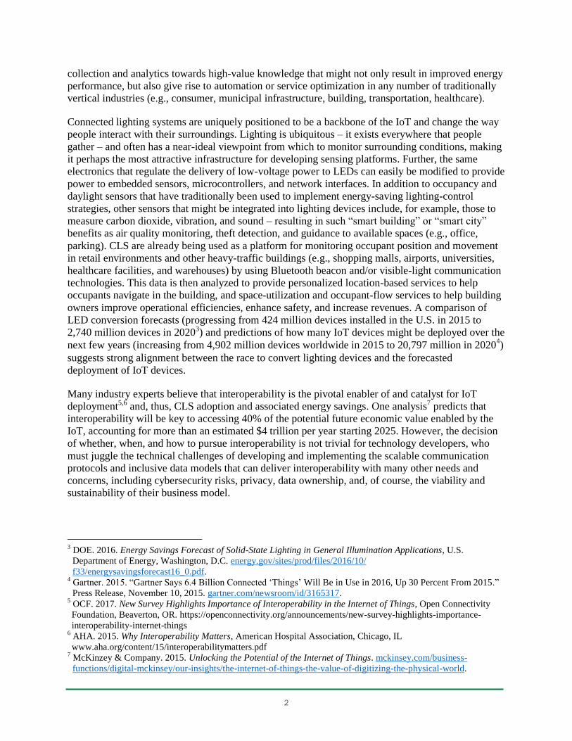
The IoT is not a new concept, and is more or less consistent with the ongoing pursuits of networking,
automation, machine-to-machine communication, and cloud computing. However, the IoT is
receiving increasing attention and business focus, and is being described and marketed by many
different industry stakeholders, resulting in myriad definitions in a wide range of contexts, from
research publications to marketing material. The following examples of definitions show the
diversity in focus1:
The
Internet
of Things
is…
…the network of physical objects that contain embedded technology to communicate and
sense or interact with their internal states or the external environment.
…the internetworking of physical devices … embedded with electronics, software,
sensors, actuators and network connectivity that enable these objects to collect and
exchange data.
…an infrastructure of interconnected objects, people, systems and information resources
together with intelligent services to allow them to process information of the physical and
the virtual world and react.
…a network that connects uniquely identifiable things to the internet. The things have
sensing/actuation and potential programmability capabilities. … Information about the
thing can be collected and the state of the thing can be changed ….
Many industry forecasters are predicting exponential growth in IoT devices over the next few years,
resulting from rapidly falling economic and technological barriers, improved autonomous and self-
learning technologies, and more mature and interoperable communication protocols. The
development and success of new innovative business models are seen as a key catalyst to this
growth; if the value of a network grows with the square of the number of connected nodes,2 the IoT
has a lot of business potential to unlock. Such opportunities are expected to heavily leverage data
1 ISO/IEC JTC-1. 2015. Internet of Things (IoT): Preliminary Report 2015. International Organization for
Standardization, Geneva. https://www.iso.org/files/live/sites/isoorg/files/developing_standards/
docs/%20en/internet_of_things_report-jtc1.pdf. 2 Wikipedia, Metcalfe’s law: wikipedia.org/wiki/Metcalfe's_law.
2
collection and analytics towards high-value knowledge that might not only result in improved energy
performance, but also give rise to automation or service optimization in any number of traditionally
vertical industries (e.g., consumer, municipal infrastructure, building, transportation, healthcare).
Connected lighting systems are uniquely positioned to be a backbone of the IoT and change the way
people interact with their surroundings. Lighting is ubiquitous – it exists everywhere that people
gather – and often has a near-ideal viewpoint from which to monitor surrounding conditions, making
it perhaps the most attractive infrastructure for developing sensing platforms. Further, the same
electronics that regulate the delivery of low-voltage power to LEDs can easily be modified to provide
power to embedded sensors, microcontrollers, and network interfaces. In addition to occupancy and
daylight sensors that have traditionally been used to implement energy-saving lighting-control
strategies, other sensors that might be integrated into lighting devices include, for example, those to
measure carbon dioxide, vibration, and sound – resulting in such “smart building” or “smart city”
benefits as air quality monitoring, theft detection, and guidance to available spaces (e.g., office,
parking). CLS are already being used as a platform for monitoring occupant position and movement
in retail environments and other heavy-traffic buildings (e.g., shopping malls, airports, universities,
healthcare facilities, and warehouses) by using Bluetooth beacon and/or visible-light communication
technologies. This data is then analyzed to provide personalized location-based services to help
occupants navigate in the building, and space-utilization and occupant-flow services to help building
owners improve operational efficiencies, enhance safety, and increase revenues. A comparison of
LED conversion forecasts (progressing from 424 million devices installed in the U.S. in 2015 to
2,740 million devices in 20203) and predictions of how many IoT devices might be deployed over the
next few years (increasing from 4,902 million devices worldwide in 2015 to 20,797 million in 20204)
suggests strong alignment between the race to convert lighting devices and the forecasted
deployment of IoT devices.
Many industry experts believe that interoperability is the pivotal enabler of and catalyst for IoT
deployment5,6 and, thus, CLS adoption and associated energy savings. One analysis7 predicts that
interoperability will be key to accessing 40% of the potential future economic value enabled by the
IoT, accounting for more than an estimated $4 trillion per year starting 2025. However, the decision
of whether, when, and how to pursue interoperability is not trivial for technology developers, who
must juggle the technical challenges of developing and implementing the scalable communication
protocols and inclusive data models that can deliver interoperability with many other needs and
concerns, including cybersecurity risks, privacy, data ownership, and, of course, the viability and
sustainability of their business model.
3 DOE. 2016. Energy Savings Forecast of Solid-State Lighting in General Illumination Applications, U.S.
Department of Energy, Washington, D.C. energy.gov/sites/prod/files/2016/10/
f33/energysavingsforecast16_0.pdf. 4 Gartner. 2015. “Gartner Says 6.4 Billion Connected ‘Things’ Will Be in Use in 2016, Up 30 Percent From 2015.”
Press Release, November 10, 2015. gartner.com/newsroom/id/3165317. 5 OCF. 2017. New Survey Highlights Importance of Interoperability in the Internet of Things, Open Connectivity
Foundation, Beaverton, OR. https://openconnectivity.org/announcements/new-survey-highlights-importance-
interoperability-internet-things 6 AHA. 2015. Why Interoperability Matters, American Hospital Association, Chicago, IL
www.aha.org/content/15/interoperabilitymatters.pdf 7 McKinzey & Company. 2015. Unlocking the Potential of the Internet of Things. mckinsey.com/business-
functions/digital-mckinsey/our-insights/the-internet-of-things-the-value-of-digitizing-the-physical-world.
3
In the early development days of other technology ecosystems (e.g., personal computing, Internet
access, mobile phones), many technology providers initially attempted to chart their own course and
win a competitive advantage by becoming the de facto standard. Although this approach can be
successful, it is the exception rather than the rule. Many technology providers overestimate the value
of their in-house solution8 and are unsuccessful in establishing it as a de facto standard. CLS, and
especially the IoT in its fully imagined form, are arguably more complex technology ecosystems than
any developed previously – spanning dozens if not hundreds of applications, and significantly more
use-cases and device and data types. This suggests that the pursuit of proprietary systems and
“walled-garden” strategies will only limit the potential of connected lighting and the IoT, if not
prevent them from getting off the ground. However, because the IoT market is still relatively young,
highly competitive, and at least perceived as being driven by both cost and time-to-market, market
forces are currently working against interoperability. Many manufacturers are pursuing proprietary
approaches in hopes of becoming a de facto standard and achieving a significant competitive
advantage over other solutions,9 and open specifications and standards have thus far seen a slow
adoption rate.
At present, CLS vendors are addressing interoperability in myriad ways, often pursuing multiple
paths simultaneously. Although some are implementing open specifications or standards, others are
continuing to implement or develop proprietary ones. Some are waiting for specific standards to
develop market momentum, or for competing efforts to converge. In the meantime, end users who
want to install CLS from multiple vendors or integrate their CLS with non-lighting systems must, in
general, develop their own interoperability strategy. Technology providers are primarily supporting
such needs by providing technical assistance for specific integrations, developing and releasing
interfaces for legacy protocols (e.g., DALI, BACnet), and developing and releasing one or more
APIs, by which a CLS can interact with the Internet and, in doing so, communicate and exchange
data with other devices and systems or cloud applications. APIs can come in many flavors, but
effectively they spell out what can be communicated and how communication requests should be
made. More specifically, they comprise a set of data structure and protocol specifications that enable
software applications to expose and share resources.
Consistent with its longstanding mission to accelerate the development of energy-saving
technologies, the U.S. Department of Energy (DOE) is undertaking a series of research studies
focused on CLS interoperability. These studies will characterize the interoperable performance of
emerging systems and highlight the benefits of an interoperable approach and increasing levels of
interoperability. The studies will focus on qualitatively evaluating the interoperability enabled by
consensus industry efforts (e.g., frameworks, specifications, standards), and not on whether, or how
well, specific devices and/or systems comply with said frameworks or platforms, specifications, or
standards. In the early days of LED general lighting technology, immature performance claims were
often misunderstood or, even worse, misleading. Such issues inhibited adoption and slowed the
realization of energy savings, and DOE efforts played a role in identifying and addressing them.
DOE aims, through its research, to play a similar role in studying early interoperability claims. While
these studies may identify interoperability issues that contradict, or are otherwise inconsistent with,
the claims made for a specific framework or platform, specification, or standard, they will not
8 Wikipedia, Not invented here, en.wikipedia.org/wiki/Not_invented_here;
people.hbs.edu/mnorton/norton%20ariely.pdf. 9 Fältström P. 2016. Market-driven Challenges to Open Internet Standards. Paper Series: No. 33 - May 2016, Global
Commission on Internet Governance, Waterloo, Ontario, Canada.
cigionline.org/sites/default/files/gcig_no33web.pdf.
4
determine whether a device or system complies with a given framework or platform, specification, or
standard – that is the role of certification testing and programs.
This first study is focused on the development and use of APIs to achieve interoperability between
CLS. The anticipated impacts of this study include the following:
1. Provide feedback to technology developers on the capabilities and limitations of currently
available APIs.
2. Educate potential CLS owners and operators on what type of data exchange is enabled by
currently available APIs, and the relative effort required to use APIs to realize new features
and capabilities facilitated by such information exchange.
3. Accelerate the development of interoperability frameworks or platforms, specifications, and
standards.
4. Educate (non-lighting) IoT stakeholders about the needs of and opportunities offered by CLS.
2 Interoperability Background
One of the defining attributes of the Internet is the interoperability of devices that comprise it.
Internet hardware and software evolve without requiring a revision of the basic Internet architecture,
and information crosses technology boundaries (e.g., from Ethernet to Wi-Fi) seamlessly. In many
ways, today’s IoT is comparable to the early years of the Internet, when there were several types of
computers and networks, and custom hardware was required to bridge otherwise isolated islands.
Although interoperability has been defined many ways by many authorities, perhaps the most elegant
definition was put forward the European Research Cluster on the Internet of Things, which defines
interoperability simply as the ability of two or more systems or components to exchange data and use
information.10 Regardless of the exact definition, it is important to differentiate interoperability from
the ability to physically exchange systems or components and maintain a defined level of identical
operation (sometimes referred to as interchangeability) and the ability to merely coexist in the same
physical environment (sometimes referred to as compatibility).
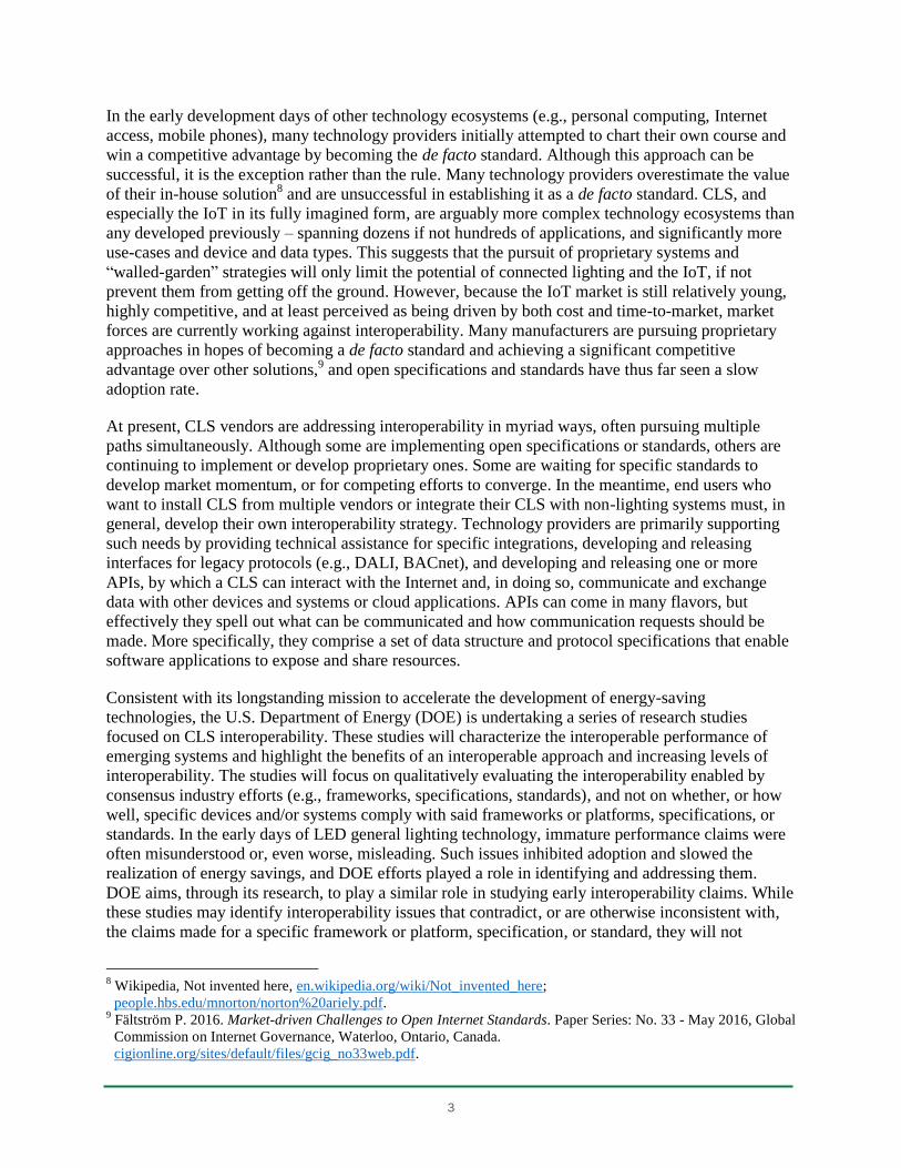
Interoperability implies communication in a form and format that can be understood and processed
across heterogeneous software, operating systems, network communication hardware, and protocols.
As shown in Figure 2.1, when viewed at different depths, it can be broken down into at least three
categories.
10
IERC. 2016. Internet of Things. IoT Semantic Interoperability: Research Challenges, Best Practices,
Recommendations and Next Steps. M Serrano, P Barnaghi, F Carrez, P Cousin, O Vermesan, and P Friess (eds).
European Research Cluster on the Internet of Things, Oslo, Norway. internet-of-things-
research.eu/pdf/IERC_Position_Paper_IoT_Semantic_Interoperability_Final.pdf.
5
Figure 2.1. Three conceptual layers of communication-system interoperability
Limited interoperability can manifest itself in many different ways:
reliability, scalability, and latency issues
difficulty developing cross-platform applications
difficulty maintaining a functioning communication network
slower identification of failure modes and cybersecurity issues
limited reusability of technical solutions
higher costs, lower adoption rates, and higher user dissatisfaction
On the other hand, deeper and more mature interoperability can reduce integration/operation costs;
accelerate competition and innovation; and facilitate more robust security, privacy, and data
management.
2.1 Interoperability Frameworks and Specifications
Many industry associations and standards development bodies are working on interoperability
frameworks and specifications for the IoT. A comprehensive comparison or detailed description of
the technical details that comprise any of them is beyond the scope of this study, as many useful
references exist elsewhere. For example, a high-level overview of many of these efforts can be found
on the website of the Internet Architecture Board committee of the Internet Engineering Task Force
(IETF).11 As a prelude to this exploration of APIs, however, it is useful for understanding some of
the different approaches taken towards harmonization of application layer protocols, and the
definition of common information and data models.
Although some interoperability frameworks and specifications for connected systems have been
under development for years (e.g., Wi-Fi Alliance, ZigBee Alliance), new contenders more focused
on IoT devices are emerging. Historically, adoption and success come to those frameworks and
11
Groves C, L Yan, and Y Weiwei. 2016. Overview of IoT semantics landscape. Huawei Technologies, Plano, TX.
iab.org/wp-content/IAB-uploads/2016/03/IoTSemanticLandscape_HW_v2.pdf.
Semantic interoperability addresses the actual meaning and interpretation of the communicated information. It is the ability to share a common understanding between entities about the content and meaning of the information exchanged. Data can be understood.
Syntactic interoperability introduces a common structure to the communication. Two syntactically interoperable entities will share the same data format, syntax, encoding, and perhaps compression and encryption. Data can be read.
Technical interoperability covers the technical issues of linking communicating entities together. Two technically interoperable devices will share a communication protocol and the hardware and software needed for this communication to take place. Data can be exchanged.
6
specifications that best meet true market needs and are most efficiently validated by user experience
and real-life applications. Products and standards typically evolve in parallel and require efficient
cross-cutting feedback loops, whereby new learning in the development of either informs the other.
The following examples of industry associations working on interoperability illustrate a diversity in
approaches being pursued, as well as in market adoption status.
The Open Connectivity Foundation (OCF), a cross-industry consortium with over 300 members
(including Intel, Qualcomm, Broadcom, Cisco, and Microsoft12), is one of the most active. It is
promoting IoT interoperability around the Constrained Application Protocol (CoAP) by providing
specifications,13,14,15 open-source reference implementations (IoTivity), a collaborative tool for
crowd-sourcing the design of data models (oneIoTa), and a certification program.
Project Haystack,16 a partnership of several industry leaders created to streamline the integration
of IoT data, is focusing on the development of semantic data models and web services
specifications for building systems and intelligent devices.
The FIWARE platform, driven by the European Union with a focus on smart cities, sustainable
transport, and renewable energy, strives “to build an open sustainable ecosystem around public,
royalty-free and implementation-driven software platform standards that will ease the
development of new smart applications in multiple sectors.”17
Google is pursuing an approach that relies on the Android developer community and the
widespread deployment of Google services. They have released a stripped-down embedded
operating system for IoT devices (Android Things) and a communication platform (Weave18),
along with developer tools and device schemas, including provisions for lighting devices.
Application layers in interoperability frameworks essentially define how data should be represented,
structured, and understood. They are often further broken down into (1) information models, which
define schemas for conceptual objects separately from any underlying architecture, interface, or
protocol; and (2) data models, which define those objects at a lower level of abstraction and can
include implementation-specific details.19 There are many different application layer protocols that
could conceivably be used for IoT device communication, and most industry experts do not believe
that a single Internet application layer protocol will be well-suited for all conceivable IoT use-cases.
Although there is some overlap, the fundamental goals, architectures, and capabilities behind each
protocol differ in important ways. The following list briefly describes some of the ones that are
currently most popular:
12
Open Connectivity Foundation: Membership List, openconnectivity.org/about/membership-list. 13
Open Connectivity Foundation: Specifications, openconnectivity.org/resources/specifications. 14
Linux Foundation Collaborative Projects: IoTivity: About, iotivity.org/about. 15
Open Connectivity Foundation: oneIoTA Data Model Tool, openconnectivity.org/resources/oneiota-data-model-
tool. 16
Project Haystack, project-haystack.org. 17
FIWARE: About Us, fiware.org/about-us. 18
Nest Developers: Weave, https://developers.nest.com/weave/?nav=true&hl=zh-CN. 19
Internet Engineering Task Force: On the Difference between Information Models and Data Models,
tools.ietf.org/html/rfc3444.
7
HTTP (Hypertext Transfer Protocol, developed by the IETF and the World Wide Web Consortium
[W3C]) underpins client/server interactions on the Internet. Each resource is identified by a
Uniform Resource Locator (URL) and is accessed and manipulated through request/response
methods (e.g., GET, PUT, POST) over the Transmission Control Protocol (TCP) transport layer.20
MQTT (Message Queue Telemetry Transport) is an International Organization for
Standardization (ISO) standard asynchronous publish/subscribe protocol that runs over TCP. It
was initially developed by IBM for satellite monitoring of oil pipelines and is commonly used in
today’s building-automation and online messaging services. Specifications are available via ISO
and OASIS.21
XMPP (Extensible Messaging and Presence Protocol) is another mature IETF development,22
initially designed for online messaging (originally known as Jabber) and later extended to social
networking, Voice over Internet Protocol (VoIP), and IoT applications. It provides both
request/response and publish/subscribe methods over TCP using eXtensive Markup Language
(XML) payloads.
Websocket is a real-time full-duplex (pub/sub-ish) communication protocol that runs over TCP
and was standardized by the IETF23and W3C as part of the HTML5 specifications, with the goal of
achieving very low-latency connections and real-time web applications.
CoAP was also developed by the IETF24 for use with constrained devices and networks. It is a
lightweight request/response protocol with built-in discovery and multicast support over the UDP
(User Datagram Protocol) transport layer.
Application layers often have dependencies on lower-layer protocols or assumptions regarding their
nature. The underlying dependency on how data is communicated – specifically the transport layer –
is particularly relevant. As noted in the given examples, this is typically a choice between TCP and
UDP. With three-way handshake and error checking, TCP is used when an emphasis is placed on
reliability; in contrast, UDP, which is connectionless and uses smaller headers, is more appropriate
when speed and network efficiency are priorities. Another important distinction is the choice
between request/response and publish/subscribe architectures. Request/response is valued for its
simplicity, but may not be well-suited for IoT use-cases where ecosystems need to scale, not all
messages need to be responded to, or constant polling to request updates might overburden available
central processing unit (CPU) time and network bandwidth. For example, although HTTP might
work well for devices that exchange considerable amounts of data, require a web interface, and are
connected to a reliable source of power, a large constellation of small, limited-CPU, battery-powered
devices might require more lightweight and scalable solutions.
2.2 RESTful APIs
Although there are many ways to implement an API, perhaps the most common technique is to
utilize a Representational State Transfer (REST) architecture that implements resource-oriented
20
Internet Engineering Task Force: Hypertext Transfer Protocol - HTTP/1.1, tools.ietf.org/html/rfc2616. 21
Oasis: MQTT Version 3.1.1 Plus Errata 01, https://docs.oasis-open.org/mqtt/mqtt/v3.1.1/mqtt-v3.1.1.html. 22
Internet Engineering Task Force: Extensible Messaging and Presence Protocol (XMPP): Core,
tools.ietf.org/html/rfc6120. 23
Internet Engineering Task Force: The WebSocket Protocol, tools.ietf.org/html/rfc6455. 24
Internet Engineering Task Force: The Constrained Application Protocol (CoAP), tools.ietf.org/html/rfc7252.
8
client-server interactions. Such RESTful approaches are commonly used to implement the web
services that allow, for example, one website to access information from another website. REST is
not a standard or even a contained specification in and of itself; rather, it comprises a fundamental set
of architectural principles and best practices. Although not all self-proclaimed REST services are
created equal, in general, RESTful practices adhere to two defining implementation constraints25:
Addressability: Each resource or representation of it should be identifiable and accessible.
Uniform Resource Identifiers should define a global namespace and use consistent
nomenclature. Resources can comprise individual items or collections of items, virtual or
physical objects, or computation results.
Statelessness: Each communication should always contain all information and metadata
needed to perform the request. Messages should be self-descriptive and cacheable. Clients
should not need prior context or knowledge of the service to execute the request, and should
be able to dynamically discover available resources and possible actions.
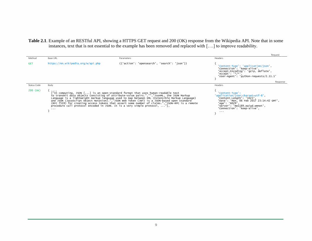
Although REST is not a perfect solution for every real or imagined web service, it is valued for its
flexibility and simplicity. REST is considered lightweight in terms of bandwidth usage, relative to
other web service architectures like SOAP (Simple Object Access Protocol) and RPC (Remote
Procedure Call), and it makes full use of the underlying HTTP transport layer, methods, and
responses. An example of a RESTful request to and response from the Wikipedia public API26 is
shown in Table 2.1 to illustrate the underlying mechanism.
In this example, the API request performs a Wikipedia search for the term “json” and asks for the
results of the search in the JavaScript Object Notation (JSON) data format. JSON is an open,
programming-language-independent data format that uses text that is human-readable and
simultaneously easy for machines to parse to generate data objects. It is based around two structures:
(1) unordered sets of key and value pairs separated by a colon and between braces; and (2) ordered
arrays of values, separated by a colon and between brackets (for example {‘key’: ‘value’, ‘key’:
[‘value’, ’value’]}). JSON is commonly supported by CLS and other IoT systems, because it is less
verbose than many other data formats, such as XML.
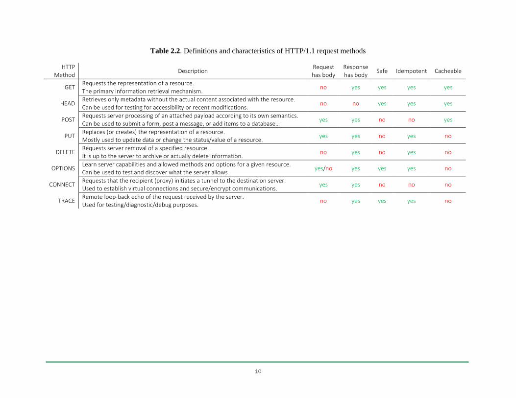
GET is the HTTP method used to retrieve a representation of a given resource. Notably, this method
is characterized as safe (will not change the state of the server), idempotent (multiple identical
requests will generate the same response), and cacheable (allowed to be stored for future use). A
characterization of all methods defined by the HTTP/1.127 specification is provided in Table 2.2.
25
Wikipedia: Representational state transfer, wikipedia.org/wiki/Representational_state_transfer. 26
MediaWiki: API:Opensearch, mediawiki.org/wiki/API:Opensearch. 27
Internet Engineering Task Force: Hypertext Transfer Protocol (HTTP/1.1): Semantics and Content,
tools.ietf.org/html/rfc7231.
9
Table 2.1. Example of an RESTful API, showing a HTTPS GET request and 200 (OK) response from the Wikipedia API. Note that in some
instances, text that is not essential to the example has been removed and replaced with [….] to improve readability.
Request
Method Base URL Parameters Headers GET
https://en.wikipedia.org/w/api.php
({‘action’: ’opensearch’, ‘search’: ’json’})
{ 'Content-Type': 'application/json', 'Connection': 'keep-alive', 'Accept-Encoding': 'gzip, deflate', 'Accept': '*/*', 'User-Agent': 'python-requests/2.11.1' }
Response
Status Code Body Headers 200 (OK)
{ ..., ["In computing, JSON [...] is an open-standard format that uses human-readable text to transmit data objects consisting of attribute-value pairs.","","JsonML, the JSON Markup Language is a lightweight markup language used to map between XML (Extensible Markup Language) and JSON (JavaScript Object Notation).","JSON Web Token (JWT) is a JSON-based open standard (RFC 7519) for creating access tokens that assert some number of claims.","JSON-RPC is a remote procedure call protocol encoded in JSON. It is a very simple protocol, ..."], ... }
{ 'Content-Type': 'application/json;charset=utf-8', 'Content-Length': '1023', 'Date': 'Mon, 06 Feb 2017 23:14:42 GMT', 'Age': '6029', 'Server': 'mw1189.eqiad.wmnet', 'Connection': 'keep-alive', ... }
10
Table 2.2. Definitions and characteristics of HTTP/1.1 request methods
HTTP Method
Description Request has body
Response has body
Safe Idempotent Cacheable
GET Requests the representation of a resource. The primary information retrieval mechanism.
no yes yes yes yes
HEAD Retrieves only metadata without the actual content associated with the resource. Can be used for testing for accessibility or recent modifications.
no no yes yes yes
POST Requests server processing of an attached payload according to its own semantics. Can be used to submit a form, post a message, or add items to a database…
yes yes no no yes
PUT Replaces (or creates) the representation of a resource. Mostly used to update data or change the status/value of a resource.
yes yes no yes no
DELETE Requests server removal of a specified resource. It is up to the server to archive or actually delete information.
no yes no yes no
OPTIONS Learn server capabilities and allowed methods and options for a given resource. Can be used to test and discover what the server allows.
yes/no yes yes yes no
CONNECT Requests that the recipient (proxy) initiates a tunnel to the destination server. Used to establish virtual connections and secure/encrypt communications.
yes yes no no no
TRACE Remote loop-back echo of the request received by the server. Used for testing/diagnostic/debug purposes.
no yes yes yes no
11
Status codes are included in the response to an HTTP request, to indicate whether the request has
been successfully completed or what kind of exception occurred. The first digit specifies the class of
the response: 1xx is informational, 2xx is success, 3xx is redirection, 4xx is client error, and 5xx is
server error. Among the most common response codes, “200 OK” indicates that the request was
successful; “400 Bad Request” occurs when the server cannot process the request because of, for
example, a syntax error; “401 Unauthorized” is the response when the required authentication is
missing or has failed; and “404 Not Found” indicates that the server was unable to find the requested
resource. A detailed list of standard and common HTTP status codes is available elsewhere.28
Headers are used to communicate metadata and operating parameters. In a request, “Content-Type”
specifies – as already noted in the Table 2.1 example – the response data format, “Accept-Encoding”
enumerates the acceptable character encoding schemes, “Accept” defines the acceptable Content-
Types for the response, and “Authorization” is used to transmit authentication credentials or API
tokens. In a response, “Content-Type” specifies the format of the response body, “Age” denotes how
long (in seconds) the object has been in cache, and “Server” spells out the actual server name. Some
headers are automatically added by, for example, the web browser or an associated HTTP library. A
detailed list of common request and response headers is available elsewhere.29
The Wikipedia web service API can be defined as “open,” because it is free to use (i.e., it is not
subject to restrictive terms of service and licensing agreements, without copyright or patent
constraints) and is based on open standards and specifications, such as JSON. Open APIs allow, if
not encourage, more developers to explore ideas for combining different web services and creating
new applications, potentially leading to more innovation and increasing the value of the web service.
However, the physical devices and systems accessed by APIs in the IoT ecosystem are often, if not
typically, more exposed to the world than, for example, the servers that power the web, and thus are
more susceptible to real-world cybersecurity risks. Opening backend resources to the public can
increase these cybersecurity risks. Further, devices on low-bandwidth networks might be
overwhelmed with network traffic if API requests are not secure and well-managed. Fortunately,
closing programming interfaces is not the only tool that developers have for protecting data and
resources. A variety of authentication and authorization schemes have been developed to manage
cybersecurity risks, including the following:
28
Internet Engineering Task Force: Hypertext Transfer Protocol (HTTP) Status Code Registry,
ietf.org/assignments/http-status-codes/http-status-codes.xml. 29
Wikipedia: List of HTTP header fields, wikipedia.org/wiki/List_of_HTTP_header_fields.

12
HTTP basic authentication30 uses the “Authorization” field within the header of each request to
transmit cleartext Base64-encoded username and password credentials to confirm the identity of
the user and enforce access control and permission rules. Transmitted credentials can easily be
decoded, which is why basic authentication has to be secured using HTTPS encryption. As an
alternative to sending cleartext credentials, some implementations use API tokens31 that are
generated and revoked server-side in order to identify users. Typically, these tokens are also just a
cleartext string, and thus do not offer additional security unless a unique, difficult-to-discern
protocol (such as timestamp concatenation or encryption hash calculation) is implemented.
HTTP digest authentication32 uses Message Digest 5 (MD5), a 128-bit cryptographic function, to
transmit a hash of username and password credentials, as well as additional mechanisms to avoid
collision and replay attacks. Although this scheme is not considered secure, it does allow the
server to confirm the user identity without having a cleartext password being transmitted or stored
server-side.
Form or session authentications require the client to send its credentials in the payload of a POST
request - as is sent when filling out an online form- in exchange for a session ID that can then be
stored in a cookie client-side and attached to every subsequent request. However, this scheme
somewhat violates the REST principle of statelessness, as it requires the server to store and
manage session information.
OAuth, an IETF-developed scheme for authorization and API access delegation,33 specifies a
method for issuing tokens that can be used by third-party applications to access protected
resources, with the approval of the resource owner. Two very different and incompatible versions
coexist - OAuth1.0a and OAuth2.0. Where OAuth1.0a specifies a full protocol that relies on
Secure Hash Algorithm (SHA1), a cryptographic signature that can be safely used over unsecured
HTTP, OAuth2.0 provides a framework that offers different scenarios and relies exclusively on
HTTPS for encryption.
Whether hosted locally or in the cloud, APIs are run on servers that must be configured and
administered. Server administrators must carefully balance access with security. Server
administration involves the establishment of policies that, ideally, facilitate efficient access to server
resources to support legitimate uses while protecting the confidentiality and integrity of server data.
The development of applications that access data from multiple servers through APIs, as might be
done when integrating multiple CLS with a control interface or data dashboard, are often challenged
by needs or desires to support various user interfaces, network architectures, and software platforms.
Restrictive server policies can limit application compatibility to specific integration approaches.
However, as recommended by the Mozilla Developer Network,34 “data requested from a remote
website should be treated as untrusted. Executing JavaScript code retrieved from a third-party site
without first determining its validity is not recommended. Server administrators should be careful
30
Internet Engineering Task Force: The 'Basic' HTTP Authentication Scheme, tools.ietf.org/html/rfc7617. 31
World Wide Web Consortium: Token Based Authentication -- Implementation Demonstration,
w3.org/2001/sw/Europe/events/foaf-galway/papers/fp/token_based_authentication. 32
Internet Engineering Task Force: An Extension to HTTP: Digest Access Authentication,
tools.ietf.org/html/rfc2069 , tools.ietf.org/html/rfc2617. 33
Internet Engineering Task Force: The OAuth 1.0 Protocol, tools.ietf.org/html/rfc5849 , tools.ietf.org/html/rfc6749. 34
Ranganathan A. 2009. “Cross-site xmlhttprequest with CORS.” Mozilla Hacks, July 6, 2009.
hacks.mozilla.org/2009/07/cross-site-xmlhttprequest-with-cors/.

13
about leaking private data and should judiciously determine that resources can be called in a cross-
site manner.”
One of the simplest and most common policies that might be implemented is known as a same-origin
policy, under which a web browser permits scripts contained in a first web page to access data in a
second web page, but only if both web pages have the same origin. Same-origin policies, which are
generally enforced by web browsers on the client side rather than on the server that hosts the data,
help prevent malicious code on one website from accessing restricted content on another website.
This behavior, often referred to as cross-site scripting (XSS), is arguably the most common
cybersecurity attack vector. However, rich web experiences commonly require and rely on
simultaneous access to data from multiple origins, making the same-origin policy sometimes too
restrictive. An alternative to the same-origin policy recommended by the W3C is known as Cross-
Origin Resource Sharing (CORS), which defines a method by which clients and servers can interact
to determine whether or not a web page in a given domain is allowed to request data from another
domain. It extends the HTTP specifications with an “Origin” request header and a set of “Access-
Control-Allow” response headers, with which servers can whitelist origins, methods, and headers that
are permitted to access data. CORS is not considered secure, however. Although it is honored by
common web browsers, it can be bypassed by attackers who instead use specialty tools.
In summary, RESTful APIs provide a flexible means for connected lighting and IoT system
developers to facilitate varying levels of interoperability with other systems. This flexibility is
primarily responsible for both its current adoption and its limitations. System developers are free to
expose whatever system data or control points they wish, while leaving others inaccessible, and the
REST approach leverages simple HTTP methods that are well known and used by software
developers. Performance and cybersecurity, however, are primarily a function of the underlying
HTTP implementation, which is subject to many choices. Despite the use of common methods, each
API is generally unique, and there is no requirement for them to be self-explanatory or user-friendly,
nor is there a well-adopted framework for facilitating that. Successful and efficient use of a given
API is often subject to a learning curve, especially in the absence of accurate and up-to-date
documentation or vendor or community-based technical support.
2.3 DOE Connected Lighting Test Bed
Central to DOE’s connected lighting systems efforts is a testing facility, referred to henceforth as the
Connected Lighting Test Bed (CLTB), that was designed and is operated by the Pacific Northwest
National Laboratory (PNNL) to characterize the capabilities of CLS and conduct technology research
and evaluations. These activities aim to increase the visibility and transparency of newly developed
technologies and to create feedback loops to inform technology developers and standards bodies of
needed improvements related not only to interoperability, but also to energy reporting, configuration
complexity, and other new features. More details about the CLTB (Figure 2.2) are available on the
DOE Solid-State Lighting program website.35
35
DOE Office of Energy Efficiency and Renewable Energy: Connected Lighting Test Bed,
energy.gov/eere/ssl/connected-lighting-test-bed.

14
Figure 2.2. Infrastructure for characterizing CLS in the DOE Connected Lighting Test Bed
2.4 Web-Based Interoperability Platform
To enable the testing of multiple devices and systems in the CLTB, a software interoperability
platform was developed to allow installed lighting devices and systems that were not natively
capable of exchanging data with one another to communicate through a defined middleware
interface. The vision for this first version (v1) CLTB interoperability platform was something akin to
If-This-Then-That (IFTTT),36 a popular web-based tool that is simple enough for anyone to use and
was developed primarily to support the integration of residential devices to support simple use-cases.
An attempt was made to develop a similarly easy-to-use tool, with a bit more flexibility, that would
enable interoperability demonstrations and use-case explorations. The basic building blocks include
connected lighting systems’ APIs as well as other web services and online data sources (e.g., real-
time weather or traffic data) that might be combined and used within algorithms and chains of
conditional statements to demonstrate and explore new use-cases.
The developed web application is hosted remotely in the Microsoft Azure cloud, which requires
locally hosted CLS API server requests and responses to be forwarded through the firewall,
representing the first of many tradeoffs inherent in this approach to realizing interoperability. Such
forwarding of server communication exposes the servers to the entire web, thereby increasing their
cybersecurity risks and magnifying any vulnerabilities associated with, for example, their chosen
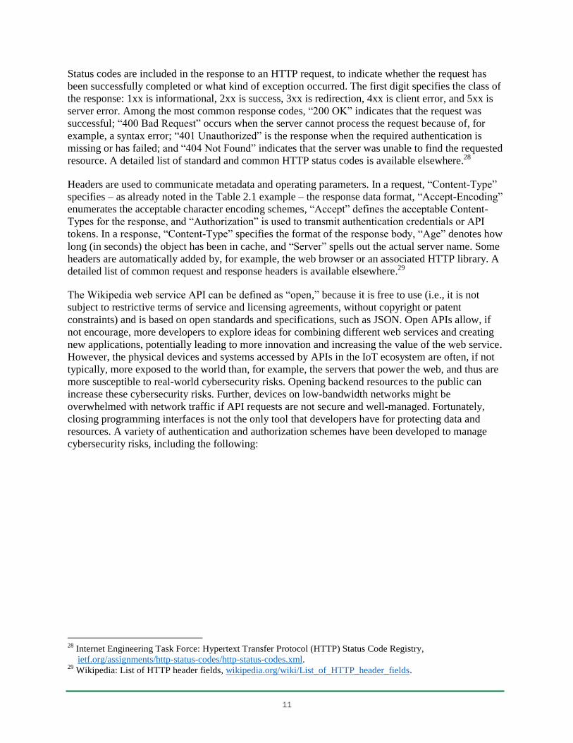
authentication scheme. A user who desires to implement a given use-case is invited, through the
graphical user interface (GUI), to connect to and authenticate available CLS APIs and third-party
web services (Figure 2.3). APIs that facilitate resource discovery automatically populate the
appropriate field after successful authentication. The user then selects from available inputs (e.g.,
CLS sensors, online data sources) and outputs (e.g., CLS light-source output level) that are essential
to the implementation of the targeted use-case.
36
IFTTT, https://ifttt.com/.
15
Figure 2.3. Web-based interoperability platform user interface
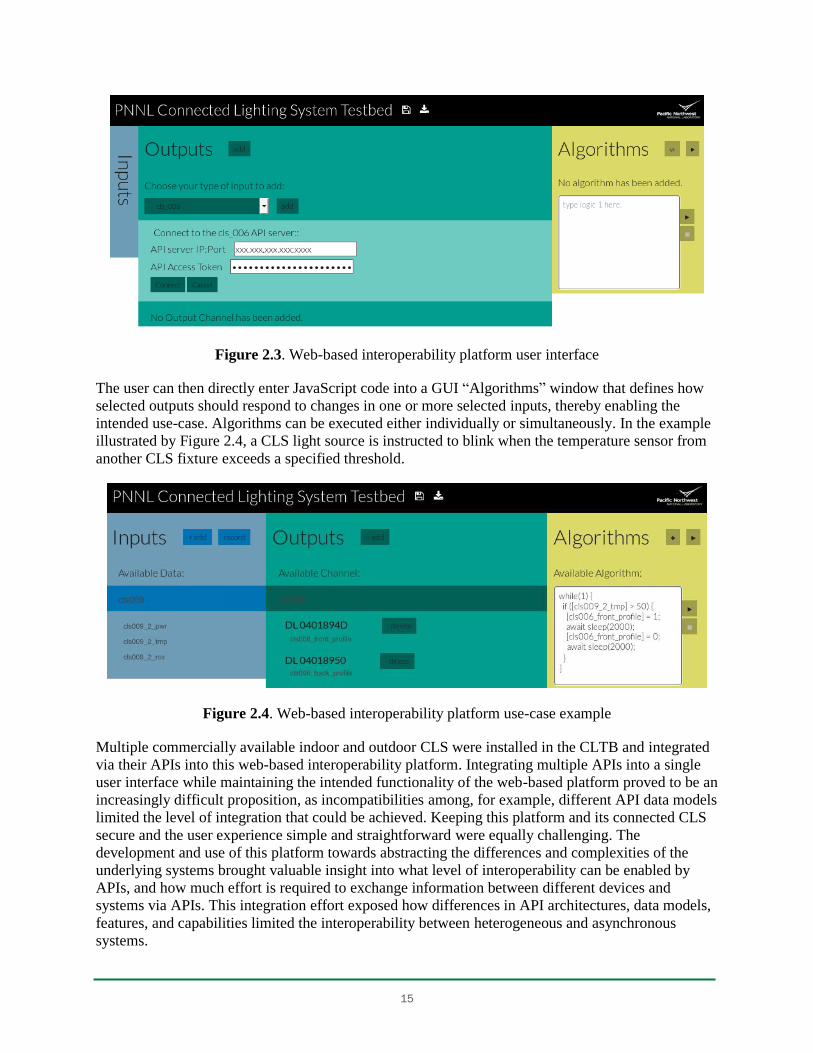
The user can then directly enter JavaScript code into a GUI “Algorithms” window that defines how
selected outputs should respond to changes in one or more selected inputs, thereby enabling the
intended use-case. Algorithms can be executed either individually or simultaneously. In the example
illustrated by Figure 2.4, a CLS light source is instructed to blink when the temperature sensor from
another CLS fixture exceeds a specified threshold.
Figure 2.4. Web-based interoperability platform use-case example
Multiple commercially available indoor and outdoor CLS were installed in the CLTB and integrated
via their APIs into this web-based interoperability platform. Integrating multiple APIs into a single
user interface while maintaining the intended functionality of the web-based platform proved to be an
increasingly difficult proposition, as incompatibilities among, for example, different API data models
limited the level of integration that could be achieved. Keeping this platform and its connected CLS
secure and the user experience simple and straightforward were equally challenging. The
development and use of this platform towards abstracting the differences and complexities of the
underlying systems brought valuable insight into what level of interoperability can be enabled by
APIs, and how much effort is required to exchange information between different devices and
systems via APIs. This integration effort exposed how differences in API architectures, data models,
features, and capabilities limited the interoperability between heterogeneous and asynchronous
systems.
16
3 Connected Lighting System API Comparison
At present, very few commercially available CLS are fully and natively interoperable. Rather,
interoperability is facilitated by using APIs, which, rather than defining a common method for
interacting with a device or system, define how to interact with a given device or system. Although
APIs can facilitate the exchange of information between different systems, they do not deliver native
interoperability. They do, however, enable system integrators to write software that enables systems
to exchange data with one another through some form of software interoperability platform, which
effectively implements a level of interoperability that is a function of the platform architecture and
characteristics.
3.1 CLS APIs
This study focused on the exploration of six CLS, three developed primarily for indoor applications
(Enlighted, Digital Lumens, Xicato) and three developed for outdoor use (Current, powered by GE;
Silver Spring Networks; Telematics Wireless). All CLS were procured or donated prior to June of
2016, and all exploration and characterization was completed prior to June of 2017. These CLS
communicated using a variety of radio (i.e., physical and transport layer) protocols, including
Bluetooth Low Energy, IEEE 802.15.4, ZigBee, and 6LoWPAN, and exhibited significant
differences in system architecture. Some were cloud-centric, while others used a more distributed
intelligence architecture, processing some data at the device level or in gateways at network edges,
an approach sometimes referred to as “fog computing.”37 Data collection and data analytics solutions
were also diverse, as user and application interface servers were remote in some cases and ran on an
onsite device in others. However, the common denominator and basis for this study was that they all
served an HTTP RESTful API to facilitate interoperability.
3.2 CLS API Authentication Schemes
Three of the six API servers were installed and managed on site in the CLTB, and not necessarily
designed to be brought outside of the local area network (LAN). Each of these systems used a
different authentication scheme:
One implemented HTTP basic authentication over unencrypted HTTP with a simple cleartext
32-character API key token.
One implemented HTTP basic authentication over encrypted HTTP Secure (HTTPS) with a
proprietary security measure on top, using a SHA1 cryptographic hash of the user ID, API
token, and millisecond Unix timestamp (to avoid replay attacks) as an authentication key.
One CLS did not offer a commercial gateway server over the period of this study. To
facilitate inclusion in this study, an ad-hoc gateway was built for the sole purpose of serving
a RESTful API that did not require authentication
The three remaining API servers were remote and managed by the vendor. All implemented a
form/session authentication scheme, one over unsecured HTTP and the other two over HTTPS.
37
Wikipedia: Fog Computing, wikipedia.org/wiki/Fog_computing.
17
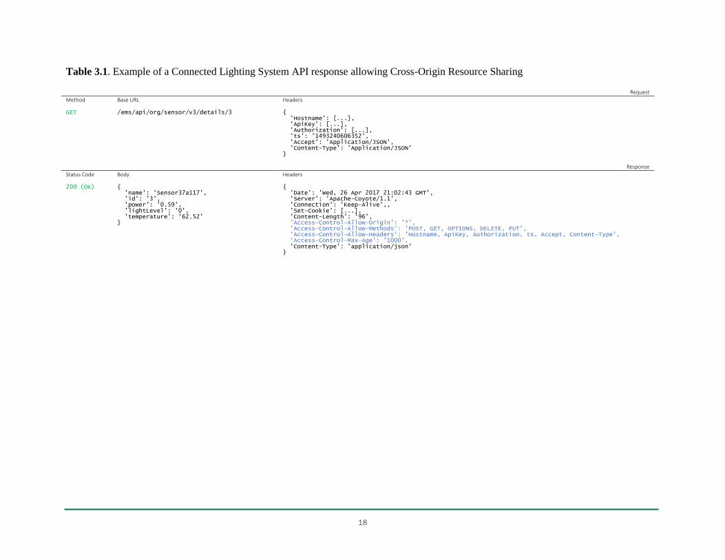
3.3 CLS API Origin Policies
The CLTB web-based interoperability platform was used to explore whether CORS could be enabled
for each of the six CLS. The platform was installed on both a cloud server to enable testing with
onsite API servers, and an onsite server to enable testing with offsite API servers. Only one of the six
API servers was natively capable of supporting CORS, and responded with a descriptive “Access-
Control-Allow” header when presented with a properly configured “Origin header.” An example API
response from this CLS is shown in Table 3.1. The API server for a second CLS was able to be
modified by the manufacturer to support CORS following a request. Attempts to enable CORS with
the other four systems over the course of this study were unsuccessful.
3.4 CLS API Resource Organization
Although the REST architecture specifies that URLs should uniquely identify system resources, it
does not require or even suggest any particular way to name resources or organize them. One
approach might arguably be no better than another if organization and naming were just used by
devices and systems behind the scenes, as is the case when they are natively interoperable. However,
achieving interoperability with APIs requires integration, involving software written by humans, for
whom readability and logic matter. Resource trees are often used to graphically depict how resources
are named and organized. Although some of the APIs that were explored here have a logically
consistent resource tree structure, others were clearly developed incrementally over multiple version
releases, as more features were added over time. Figure 3.1 through Figure 3.3 show examples of
partial API resource trees that were encountered in this study, illustrating significant variation in
structure, nomenclature, and complexity.
18
Table 3.1. Example of a Connected Lighting System API response allowing Cross-Origin Resource Sharing
Request
Method Base URL Headers GET
/ems/api/org/sensor/v3/details/3
{ 'Hostname': [...], 'ApiKey': [...], 'Authorization': [...], 'ts': '1493240606352', 'Accept': 'Application/JSON', 'Content-Type': 'Application/JSON' }
Response
Status Code Body Headers 200 (OK)
{ 'name': 'Sensor37a117', 'id': '3', 'power': '0.59', 'lightLevel': '0', 'temperature': '62.52' }
{ 'Date': 'Wed, 26 Apr 2017 21:02:43 GMT', 'Server': 'Apache-Coyote/1.1', 'Connection': 'Keep-Alive',, 'Set-Cookie': [...], 'Content-Length': '96', 'Access-Control-Allow-Origin': '*', 'Access-Control-Allow-Methods': 'POST, GET, OPTIONS, DELETE, PUT', 'Access-Control-Allow-Headers': 'Hostname, ApiKey, Authorization, ts, Accept, Content-Type', 'Access-Control-Max-Age': '1000', 'Content-Type': 'application/json' }

19
Figure 3.1. Connected lighting system API resource tree, example 1
Figure 3.2. Connected lighting system API resource tree, example 2
http:// <hostname> /<api_path>
/report
/lights
/zones
/rooms
/profiles
/status
/<profile_id>
/active_profiles /<serial_id>
https:// <hostname> /<api_path>
/auth
/devices /<device_id>
/groups
/resources
/relations
/metrology
/control
/groups /<group_id>
/devices /<device_id>
/control

20
Figure 3.3. Connected lighting system API resource tree, example 3
http:// {hostname} /{api_path}
/facility /v2 /[...] /<floor_id> /<from_date> /<to_date>
/floor
/list
/<floor_id>
/area
/v1
/energy /<area_id>
/occ /<area_id>
/out /<area_id>
/setEmergency /<area_id>
/v2 /list /<floor_id>
/sensor
/v2 /stats /<floor_id> /<from_date> /<to_date>
/v3 /details /<sensor_id>
/fixture
/location /list /floor /<floor_id> /1
/v1
/location /list /area /<area_id>
/op
/assignProfile /<fixture_id> /<group_id>
/dim /<mode> /<amout>
/auto
/energy
/<fixture_id>
/area /<area_id>
21
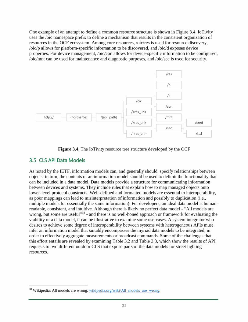
One example of an attempt to define a common resource structure is shown in Figure 3.4. IoTivity
uses the /oic namespace prefix to define a mechanism that results in the consistent organization of
resources in the OCF ecosystem. Among core resources, /oic/res is used for resource discovery,
/oic/p allows for platform-specific information to be discovered, and /oic/d exposes device
properties. For device management, /oic/con allows for device-specific information to be configured,
/oic/mnt can be used for maintenance and diagnostic purposes, and /oic/sec is used for security.
Figure 3.4. The IoTivity resource tree structure developed by the OCF
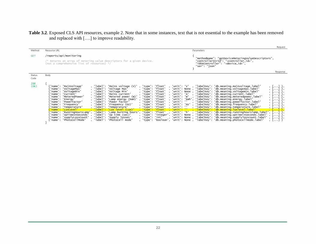
3.5 CLS API Data Models
As noted by the IETF, information models can, and generally should, specify relationships between
objects; in turn, the contents of an information model should be used to delimit the functionality that
can be included in a data model. Data models provide a structure for communicating information
between devices and systems. They include rules that explain how to map managed objects onto
lower-level protocol constructs. Well-defined and formatted models are essential to interoperability,
as poor mappings can lead to misinterpretation of information and possibly to duplication (i.e.,
multiple models for essentially the same information). For developers, an ideal data model is human-
readable, consistent, and intuitive. Although there is likely no perfect data model - “All models are
wrong, but some are useful”38 - and there is no well-honed approach or framework for evaluating the
viability of a data model, it can be illustrative to examine some use-cases. A system integrator who
desires to achieve some degree of interoperability between systems with heterogeneous APIs must
infer an information model that suitably encompasses the myriad data models to be integrated, in
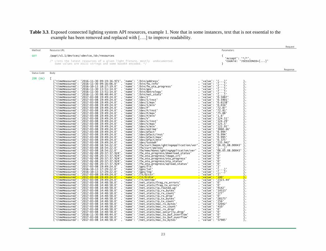
order to effectively aggregate measurements or broadcast commands. Some of the challenges that
this effort entails are revealed by examining Table 3.2 and Table 3.3, which show the results of API
requests to two different outdoor CLS that expose parts of the data models for street lighting
resources.
38
Wikipedia: All models are wrong, wikipedia.org/wiki/All_models_are_wrong.
http:// {hostname} /{api_path}
/oic
/res
/p
/d
/con
/mnt
/sec
/cred
/[...]
/<res_uri>
/<res_uri>
/<res_uri>
22
Table 3.2. Exposed CLS API resources, example 2. Note that in some instances, text that is not essential to the example has been removed
and replaced with [….] to improve readability.
Request
Method Resource URL Parameters GET
/reports/api/monitoring /* Returns an array of metering value descriptors for a given device. (not a comprehensive list of resources) */
{ “methodName”: “getDeviceMeteringValueDescriptors”, “controllerStrId”: “<controller_id>”, “idOnController”: “<device_id>”, “ser”: “json” }
Response
Status Code
Body
200 (OK)
[ {'name': 'MainVoltage' , 'label': 'Mains voltage (V)' , 'type': 'float' , 'unit': 'V' , 'labelKey': 'db.meaning.mainvoltage.label' , [...] }, {'name': 'VoltageMax' , 'label': 'Voltage Max' , 'type': 'float' , 'unit': None , 'labelKey': 'db.meaning.voltagemax.label' , [...] }, {'name': 'VoltageMin' , 'label': 'Voltage Min' , 'type': 'float' , 'unit': None , 'labelKey': 'db.meaning.voltagemin.label' , [...] }, {'name': 'Current' , 'label': 'Mains current' , 'type': 'float' , 'unit': 'A' , 'labelKey': 'db.meaning.current.label' , [...] }, {'name': 'MeteredPower' , 'label': 'Metered power (W)' , 'type': 'float' , 'unit': 'W' , 'labelKey': 'db.meaning.meteredpower.label' , [...] }, {'name': 'Energy' , 'label': 'Lamp energy (kWH)' , 'type': 'float' , 'unit': 'kWh', 'labelKey': 'db.meaning.energy.label' , [...] }, {'name': 'PowerFactor' , 'label': 'Power factor' , 'type': 'float' , 'unit': '' , 'labelKey': 'db.meaning.powerfactor.label' , [...] }, {'name': 'Frequency' , 'label': 'Frequency (Hz)' , 'type': 'float' , 'unit': 'Hz' , 'labelKey': 'db.meaning.frequency.label' , [...] }, {'name': 'Temperature' , 'label': 'Temperature' , 'type': 'float' , 'unit': '' , 'labelKey': 'db.meaning.temperature.label’ , [...] }, {'name': 'LuxLevel' , 'label': 'Lux level (Lux)' , 'type': 'float' , 'unit': '' , 'labelKey': 'db.meaning.luxlevel.label' , [...] }, {'name': 'RunningHoursLamp', 'label': 'Lamp burning hours', 'type': 'float' , 'unit': 'h' , 'labelKey': 'db.meaning.runninghourslamp.label', [...] }, {'name': 'UpTimeInSeconds' , 'label': 'Up time (sec)' , 'type': 'integer', 'unit': None , 'labelKey': 'db.meaning.uptimeinseconds.label' , [...] }, {'name': 'supplyLossCount' , 'label': 'Supply losses' , 'type': 'int' , 'unit': None , 'labelKey': 'db.meaning.supplylosscount.label' , [...] }, {'name': 'PhotocellMode' , 'label': 'Photocell mode' , 'type': 'boolean', 'unit': None , 'labelKey': 'db.meaning.photocellmode.label' , [...] } ]
23
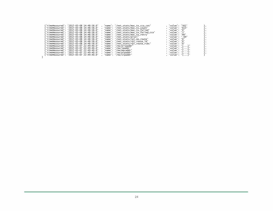
Table 3.3. Exposed connected lighting system API resources, example 1. Note that in some instances, text that is not essential to the
example has been removed and replaced with [….] to improve readability.
Request
Method Resource URL Parameters GET
/papi/v1.1/devices/<device_id>/resources /* Lists the latest resources of a given light fixture, mostly undocumented. Some values are ASCII strings and some base64 encoded. */
{ ‘Accept’: ‘*/*’, ‘Cookie: ‘JSESSIONID=[...]’ }
Response
Status Code Body 200 (OK)
[ {'timeMeasured': '2016-11-30 09:19:36.971', 'name': '/bin/address' , 'value': '[...]' }, {'timeMeasured': '2016-11-30 09:16:06.0' , 'name': '/bin/fw_info' , 'value': '[...]' }, {'timeMeasured': '2016-10-13 18:27:19.0' , 'name': '/bin/fw_ota_progress' , 'value': '[...]' }, {'timeMeasured': '2016-11-30 13:51:14.0' , 'name': '/bin/gps' , 'value': '[...]' }, {'timeMeasured': '2016-11-30 13:51:14.0' , 'name': '/bin/metrology' , 'value': '[...]' }, {'timeMeasured': '2016-11-30 08:48:44.0' , 'name': '/bin/net_stats' , 'value': '[...]' }, {'timeMeasured': '2017-03-08 19:49:24.0' , 'name': '/dev/I' , 'value': '0.5887' }, {'timeMeasured': '2017-03-08 19:49:24.0' , 'name': '/dev/I/inst' , 'value': '0.5901' }, {'timeMeasured': '2017-03-08 19:49:24.0' , 'name': '/dev/I/max' , 'value': '0.6138' }, {'timeMeasured': '2017-03-08 19:49:24.0' , 'name': '/dev/I/min' , 'value': '0.034' }, {'timeMeasured': '2017-03-08 19:49:24.0' , 'name': '/dev/P' , 'value': '72.87' }, {'timeMeasured': '2017-03-08 19:49:24.0' , 'name': '/dev/P/inst' , 'value': '72.81' }, {'timeMeasured': '2017-03-08 19:49:24.0' , 'name': '/dev/P/max' , 'value': '75.88' }, {'timeMeasured': '2017-03-08 19:49:24.0' , 'name': '/dev/P/min' , 'value': '1.6' }, {'timeMeasured': '2017-03-08 19:49:24.0' , 'name': '/dev/V' , 'value': '124.51' }, {'timeMeasured': '2017-03-08 19:49:24.0' , 'name': '/dev/V/inst' , 'value': '124.29' }, {'timeMeasured': '2017-03-08 19:49:24.0' , 'name': '/dev/V/max' , 'value': '125.5' }, {'timeMeasured': '2017-03-08 19:49:24.0' , 'name': '/dev/V/min' , 'value': '122.91' }, {'timeMeasured': '2017-03-08 19:49:24.0' , 'name': '/dev/ontime' , 'value': '3060.46' }, {'timeMeasured': '2017-03-08 19:49:24.0' , 'name': '/dev/pfact' , 'value': '0.994' }, {'timeMeasured': '2017-03-08 19:49:24.0' , 'name': '/dev/pfact/inst' , 'value': '0.994' }, {'timeMeasured': '2017-03-08 19:49:24.0' , 'name': '/dev/pfact/max' , 'value': '0.995' }, {'timeMeasured': '2017-03-08 19:49:24.0' , 'name': '/dev/pfact/min' , 'value': '0.375' }, {'timeMeasured': '2017-03-08 19:49:24.0' , 'name': '/dev/totKwh' , 'value': '235.942' }, {'timeMeasured': '2017-03-08 18:54:22.0' , 'name': '/fw/curr/NanoLightingApplication/ver', 'value': '06.05.08.00043' }, {'timeMeasured': '2017-03-08 18:54:22.0' , 'name': '/fw/curr/pwloss' , 'value': '[...]' }, {'timeMeasured': '2017-03-08 18:54:22.0' , 'name': '/fw/new/NanoLightingApplication/ver' , 'value': '06.05.08.00043' }, {'timeMeasured': '2017-02-08 20:37:37.924', 'name': '/fw_ota_progress/download_status' , 'value': '0' }, {'timeMeasured': '2017-02-08 20:37:37.924', 'name': '/fw_ota_progress/image_crc' , 'value': '0' }, {'timeMeasured': '2017-02-08 20:37:37.924', 'name': '/fw_ota_progress/ota_progress' , 'value': '0' }, {'timeMeasured': '2017-02-08 20:37:37.924', 'name': '/fw_ota_progress/ota_status' , 'value': '0' }, {'timeMeasured': '2017-02-08 20:37:37.924', 'name': '/fw_ota_progress/upload_status' , 'value': '0' }, {'timeMeasured': '2017-03-08 19:49:24.0' , 'name': '/gps/fix' , 'value': '1' }, {'timeMeasured': '2016-10-13 17:29:22.0' , 'name': '/gps/lat' , 'value': '[...]' }, {'timeMeasured': '2016-10-13 17:29:22.0' , 'name': '/gps/lng' , 'value': '[...]' }, {'timeMeasured': '2017-03-08 19:49:24.0' , 'name': '/lt/0/ctr' , 'value': '1' }, {'timeMeasured': '2017-03-08 19:49:24.0' , 'name': '/lt/0/dim' , 'value': '100' }, {'timeMeasured': '2017-03-08 19:49:24.0' , 'name': '/lt/ontime' , 'value': '2323.44' }, {'timeMeasured': '2017-03-08 14:48:58.0' , 'name': '/net_stats/frag_rx_errors' , 'value': '0' }, {'timeMeasured': '2017-03-08 14:48:58.0' , 'name': '/net_stats/frag_tx_errors' , 'value': '0' }, {'timeMeasured': '2017-03-08 14:48:58.0' , 'name': '/net_stats/ip_routed_up' , 'value': '9142' }, {'timeMeasured': '2017-03-08 14:48:58.0' , 'name': '/net_stats/ip_rx_bytes' , 'value': '14513' }, {'timeMeasured': '2017-03-08 14:48:58.0' , 'name': '/net_stats/ip_rx_count' , 'value': '177' }, {'timeMeasured': '2017-03-08 14:48:58.0' , 'name': '/net_stats/ip_rx_drop' , 'value': '0' }, {'timeMeasured': '2017-03-08 14:48:58.0' , 'name': '/net_stats/ip_tx_bytes' , 'value': '28173' }, {'timeMeasured': '2017-03-08 14:48:58.0' , 'name': '/net_stats/ip_tx_count' , 'value': '256' }, {'timeMeasured': '2017-03-08 14:48:58.0' , 'name': '/net_stats/mac_rx_bytes' , 'value': '32042' }, {'timeMeasured': '2017-03-08 14:48:58.0' , 'name': '/net_stats/mac_rx_count' , 'value': '410' }, {'timeMeasured': '2017-03-08 14:48:58.0' , 'name': '/net_stats/mac_rx_drop' , 'value': '0' }, {'timeMeasured': '2017-03-08 14:48:58.0' , 'name': '/net_stats/mac_security_drop' , 'value': '0' }, {'timeMeasured': '2016-11-30 08:48:44.0' , 'name': '/net_stats/mac_tx_buf_overflow' , 'value': '0' }, {'timeMeasured': '2017-03-08 14:48:58.0' , 'name': '/net_stats/mac_tx_buf_overflow' , 'value': '0' }, {'timeMeasured': '2017-03-08 14:48:58.0' , 'name': '/net_stats/mac_tx_bytes' , 'value': '57985' },
24
{'timeMeasured': '2017-03-08 14:48:58.0' , 'name': '/net_stats/mac_tx_cca_cnt' , 'value': '562' }, {'timeMeasured': '2017-03-08 14:48:58.0' , 'name': '/net_stats/mac_tx_count' , 'value': '613' }, {'timeMeasured': '2017-03-08 14:48:58.0' , 'name': '/net_stats/mac_tx_failed' , 'value': '0' }, {'timeMeasured': '2017-03-08 14:48:58.0' , 'name': '/net_stats/mac_tx_failed_cca' , 'value': '3' }, {'timeMeasured': '2017-03-08 14:48:58.0' , 'name': '/net_stats/mac_tx_retry' , 'value': '60' }, {'timeMeasured': '2017-03-08 14:48:58.0' , 'name': '/net_stats/prssi' , 'value': '-69' }, {'timeMeasured': '2017-03-08 14:48:58.0' , 'name': '/net_stats/rpl_no_route' , 'value': '0' }, {'timeMeasured': '2017-03-08 14:48:58.0' , 'name': '/net_stats/rpl_route_ld' , 'value': '0' }, {'timeMeasured': '2017-03-08 14:48:58.0' , 'name': '/net_stats/rpl_route_rcbc' , 'value': '0' }, {'timeMeasured': '2017-03-07 22:49:40.0' , 'name': '/nw/eripaddr' , 'value': '[...]' }, {'timeMeasured': '2017-03-07 22:49:40.0' , 'name': '/nw/ipaddr' , 'value': '[...]' }, {'timeMeasured': '2017-03-07 22:49:40.0' , 'name': '/nw/macaddr' , 'value': '[...]' }, {'timeMeasured': '2017-03-07 22:49:40.0' , 'name': '/nw/pipaddr' , 'value': '[...]' }, {'timeMeasured': '2017-03-07 22:49:40.0' , 'name': '/nw/sipaddr' , 'value': '[...]' } ]
25
The highlighted rows in Table 3.2 and Table 3.3 show the data model for the light-output setting of a
lighting device. Note that in the first example, although the parameter label “LuxLevel” suggests that
light output is specified in lux, and the data type specifies a floating-point representation for the light-
output setting, no parameter unit is actually shown. In the second example, no data type
representation or unit is revealed. Further, the default parameter value of “100” leaves open the
possibility that the data representation is absolute (e.g., in lux or foot-candles) or relative (e.g.,
percent of maximum). The parameter label “dim” suggests the latter.
Although API calls only expose a fragment of the underlying data models, these examples reveal
perhaps the most significant IoT challenge: the coexistence of multiple, often incompatible, data
models. Custom data models are not always thoughtfully designed from a user perspective, or self-
consistent, or even well documented. Consequently, it is often incumbent on the system integrator to
figure out what a resource represents, and what its data model defines (e.g., measurement units, data
type). Although inconsistencies might be resolved by algorithms that, for example, convert lux to
foot-candles or translate from a relative representation of light output to an absolute representation,
these converters and translators must be checked and possibly modified each time an API is updated,
and the approach for implementing and managing them must be capable of scaling as necessary if/as
the size of an integrated CLS grows and/or more CLS are integrated.
As noted in the previous discussion of resource tree organization, some industry consortia are
developing and publishing open-source approaches to and resources for interoperability challenges.
Table 3.4 and Table 3.5 show examples of data models published by two such consortia. The OCF
manages an open-source library of data models that are made available via a web-based tool it refers
to as oneIoTa.39 Developers are encouraged to use existing, and share newly created, data models for
IoT devices and device resources. The tool allows for complex devices and systems to be defined as
collections of simpler devices and resources.
Table 3.4 shows a few of the lighting-related contributions that had been made at the time of this
publication. Notably, they include lighting-device resources but not any specific lighting devices
(e.g., street lighting device, office lighting device).
FIWARE also manages a library of data models that are open-sourced40 under a Creative Commons
license and made available via a web interface. FIWARE is open to library contributions that meet its
guidelines.41 Table 3.5 shows portions (not including optional fields) of the data models for all four
available (street) lighting resources.42
39
oneIoTa, oneiota.org. 40
GitHub: Fiware/dataModels, github.com/Fiware/dataModels. 41
FIWARE Datamodels: Data Models Guidelines, fiware-datamodels.readthedocs.io/en/latest/guidelines/. 42
FIWARE Datamodels: Street Lighting Data Models, fiware-datamodels.readthedocs.io/en/latest/
StreetLighting/doc/introduction.
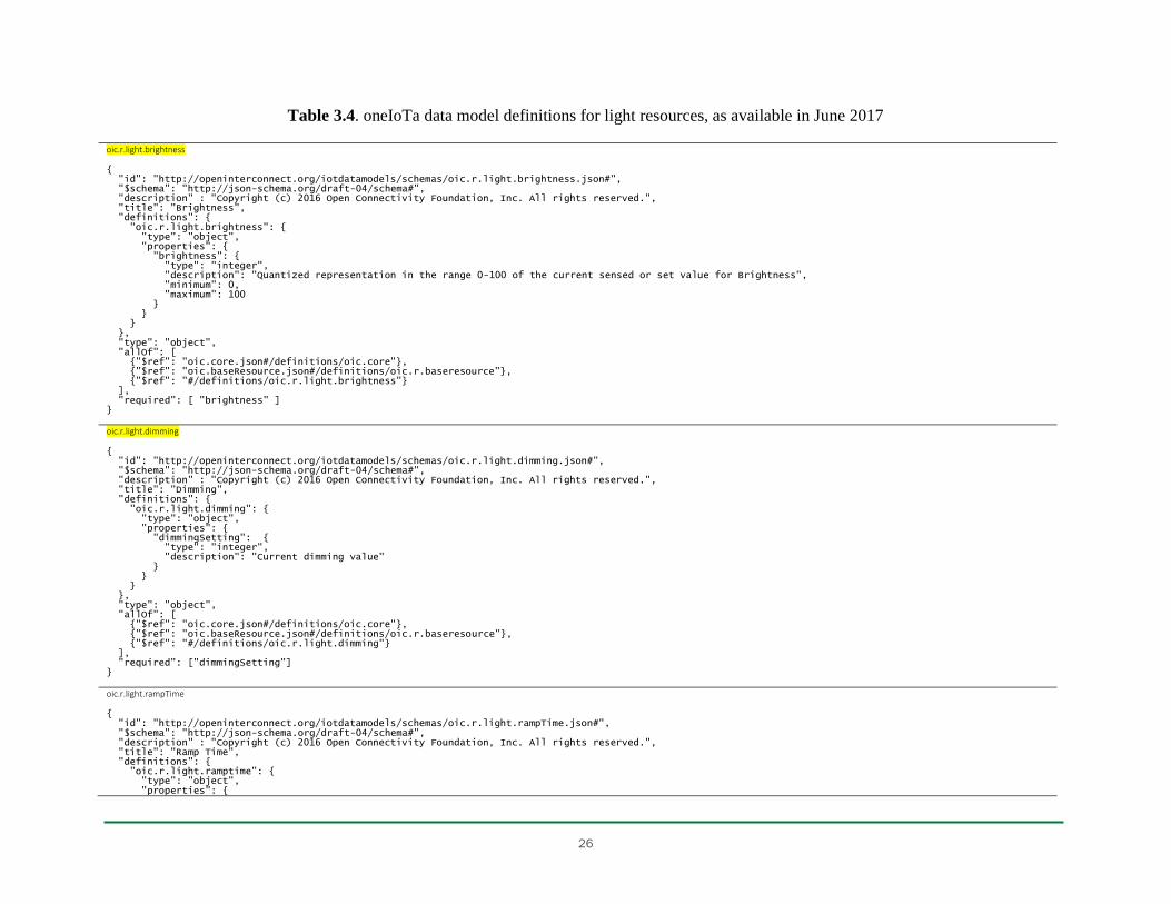
26
Table 3.4. oneIoTa data model definitions for light resources, as available in June 2017
oic.r.light.brightness { "id": "http://openinterconnect.org/iotdatamodels/schemas/oic.r.light.brightness.json#", "$schema": "http://json-schema.org/draft-04/schema#", "description" : "Copyright (c) 2016 Open Connectivity Foundation, Inc. All rights reserved.", "title": "Brightness", "definitions": { "oic.r.light.brightness": { "type": "object", "properties": { "brightness": { "type": "integer", "description": "Quantized representation in the range 0-100 of the current sensed or set value for Brightness", "minimum": 0, "maximum": 100 } } } }, "type": "object", "allOf": [ {"$ref": "oic.core.json#/definitions/oic.core"}, {"$ref": "oic.baseResource.json#/definitions/oic.r.baseresource"}, {"$ref": "#/definitions/oic.r.light.brightness"} ], "required": [ "brightness" ] } oic.r.light.dimming { "id": "http://openinterconnect.org/iotdatamodels/schemas/oic.r.light.dimming.json#", "$schema": "http://json-schema.org/draft-04/schema#", "description" : "Copyright (c) 2016 Open Connectivity Foundation, Inc. All rights reserved.", "title": "Dimming", "definitions": { "oic.r.light.dimming": { "type": "object", "properties": { "dimmingSetting": { "type": "integer", "description": "Current dimming value" } } } }, "type": "object", "allOf": [ {"$ref": "oic.core.json#/definitions/oic.core"}, {"$ref": "oic.baseResource.json#/definitions/oic.r.baseresource"}, {"$ref": "#/definitions/oic.r.light.dimming"} ], "required": ["dimmingSetting"] } oic.r.light.rampTime { "id": "http://openinterconnect.org/iotdatamodels/schemas/oic.r.light.rampTime.json#", "$schema": "http://json-schema.org/draft-04/schema#", "description" : "Copyright (c) 2016 Open Connectivity Foundation, Inc. All rights reserved.", "title": "Ramp Time", "definitions": { "oic.r.light.ramptime": { "type": "object", "properties": {
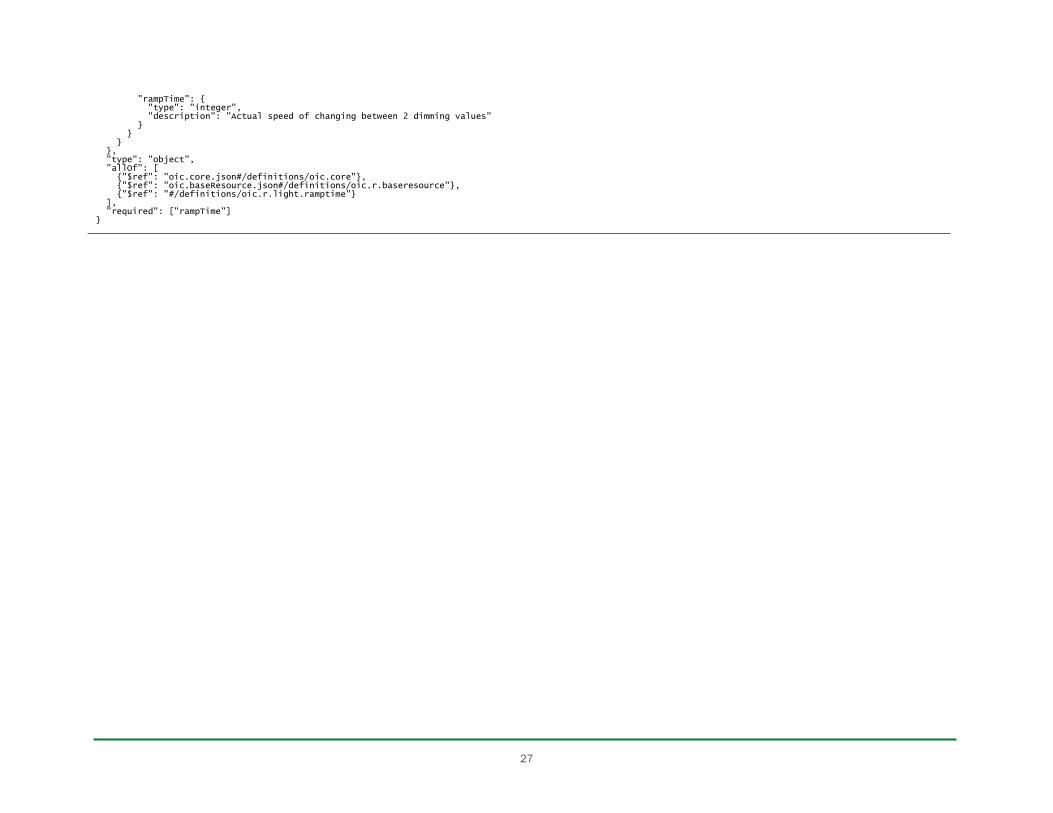
27
"rampTime": { "type": "integer", "description": "Actual speed of changing between 2 dimming values" } } } }, "type": "object", "allOf": [ {"$ref": "oic.core.json#/definitions/oic.core"}, {"$ref": "oic.baseResource.json#/definitions/oic.r.baseresource"}, {"$ref": "#/definitions/oic.r.light.ramptime"} ], "required": ["rampTime"] }

28
Table 3.5. FIWARE data model definitions for street lighting resources
StreetlightModel { "id": "streetlightmodel:TubularNumana:ASR42CG:HPS:100", // Entity's unique identifier "type": "StreetlightModel", // Must be equal to StreetlightModel "name": "Tubular Numana 6M - ASR42CG - Son-T 100", // Name of the streetlight model "columnModelName": "01 TUBULAR P/T 6M NUMANA", // Name of the column's model "columnColor": "green", // Column's painting color (according to the W3C std color keywords) "lanternModelName": "ASR42CG", // Name of the lantern's model "lanternManufacturerName": "Indal WRTL", // Name of the lantern's manufacturer "lampModelName": "SON-T", // Name of the lamp's model "lampBrandName": "Philips", // Name of the lamp's brand "lampTechnology": "HPS", // Technology used by the lamp (allowed values: [LED,LPS,HPS]) "powerConsumption": 100, // Nominal power consumption by the lamp (W) "colorTemperature": 3000, // Correlated color temperature of the lamp (K) "colorRenderingIndex": 25, // Color rendering index of the lamp "luminousFlux": 2300, // Maximum light output which can be provided by the lamp "category": ["postTop"] // Type of asset (allowed values: [postTop,bollard,lamppost,lightTower,flashingBeacon,sideEntry,...]) } Streetlight { "id": "streetlight:guadalajara:4567", // Entity's unique identifier "type": "Streetlight", // Must be equal to Streetlight "location": { // Streetlight location represented using the GeoJSON43 point format "type": "Point", "coordinates": [ -3.164485591715449, 40.62785133667262 ] }, "areaServed": "Roundabouts city entrance", // High level area to which this streetlight belongs to "status": "ok", // Overall status of this streetlight (allowed values: [ok,defectiveLamp,columnIssue,brokenLatern]) "refStreetlightGroup": "streetlightgroup:G345", // Reference to a StreetlightGroup entity, if belongs to any "refStreetlightModel": "streetlightmodel:STEEL_Tubular_10m", // Reference to a StreetlightModel entity "circuit": "C-456-A467", // Identifier of the circuit to which this streetlight connects and gets power from "lanternHeight": 10, // Lantern's height (m) "locationCategory" : "centralIsland", // Allowed values: [facade,sidewalk,pedestrianPath, road,playground,park,garden,bridge,...] "powerState": "off", // Streetlight's power state (allowed values: [on,off,low,bootingUp]) "controllingMethod": "individual", // Method used to control this streetlight (allowed values: [group,individual]) "dateLastLampChange": "2016-07-08T08:02:21.753Z" // Timestamp of the last change of lamp made (datetime type) }
StreetlightGroup { "id": "streetlightgroup:mycity:A12", // Entity's unique identifier "type": "StreetlightGroup", // Must be equal to StreetlightGroup "location": { // Locations of the streetlights in the group, represented using the GeoJSON multigeometry format "type": "MultiLineString", "coordinates": [ [ [100.0, 0.0], [101.0, 1.0] ], [ [102.0, 2.0], [103.0, 3.0] ] ] }, "powerStatus": "on", // StreetlightGroup power state (allowed values: [on,off,low,bootingUp]) "areaServed": "Calle Comercial Centro", // High level area to which this streetlight group belongs to "circuitId": "C-456-A467", // Identifier of the circuit to which these streetlights connect and get power from "dateLastSwitchingOn": "2016-07-07T19:59:06.618Z", // Timestamp of the last switching on "dateLastSwitchingOff": "2016-07-07T07:59:06.618Z", // Timestamp of the last switching off "refStreetlightCabinetController": "cabinetcontroller:CC45A34", // Reference to StreetlightCabinetController(s) entity(ies) "switchingOnHours": [ // Switching on hours, structure used to set special schedules for certain dates
43
Internet Engineering Task Force: The GeoJSON Format draft-ietf-geojson-03, tools.ietf.org/html/draft-ietf-geojson-03.

29
{ "from" : "--11-30", "to" : "--01-07", "hours" : "Mo,Su 16:00-02:00", "description": "Christmas" } ] }
StreetlightControlCabinet { "id": "streetlightcontrolcabinet:A45HGJK", // Entity's unique identifier "type": "StreetlightControlCabinet", // Must be equal to StreetlightControlCabinet "location": { // Control cabinet location represented using the GeoJSON point format "type": "Point", "coordinates": [ -3.164485591715449, 40.62785133667262 ] }, "cupboardMadeOf": "plastic", // Material the cabinet's cupboard is made of (allowed values: [plastic,metal,concrete,other]) "brandName": "Siemens", // Name of the cabinet's brand "modelName": "Simatic S7 1200", // Name of the cabinet's model "refStreetlightGroup": ["streetlightgroup:BG678", // Reference to StreetlightGroup entities controlled "streetlightgroup:789" ], "compliantWith": ["IP54"], // List of standards to which the cabinet controlle is compliant with "dateLastProgramming": "2016-07-08", // Date at which there was a programming operation over the cabinet "maximumPowerAvailable": 10, // The maximum power available for the circuits controlled by this cabinet (kW) "energyConsumed": 162456, // Energy consumed by the circuits controlled since metering started (kWh) "dateMeteringStarted": "2013-07-07", // Timestamp of the starting date for metering energy consumed "lastMeterReading": 161237, // Value of the last reading obtained from the energy metering system (kWh) "meterReadingPeriod": 60, // The periodicity of the energy meter reporting (days) "intensity": { // Electric intensity per alterning current phase (Europe: R,S,T) (A) "R": 20.1, "S": 14.4, "T": 22 }, "reactivePower": { // Reactive power per alternating current phases (kVArh) "R": 45, "S": 43.5, "T": 42 } }
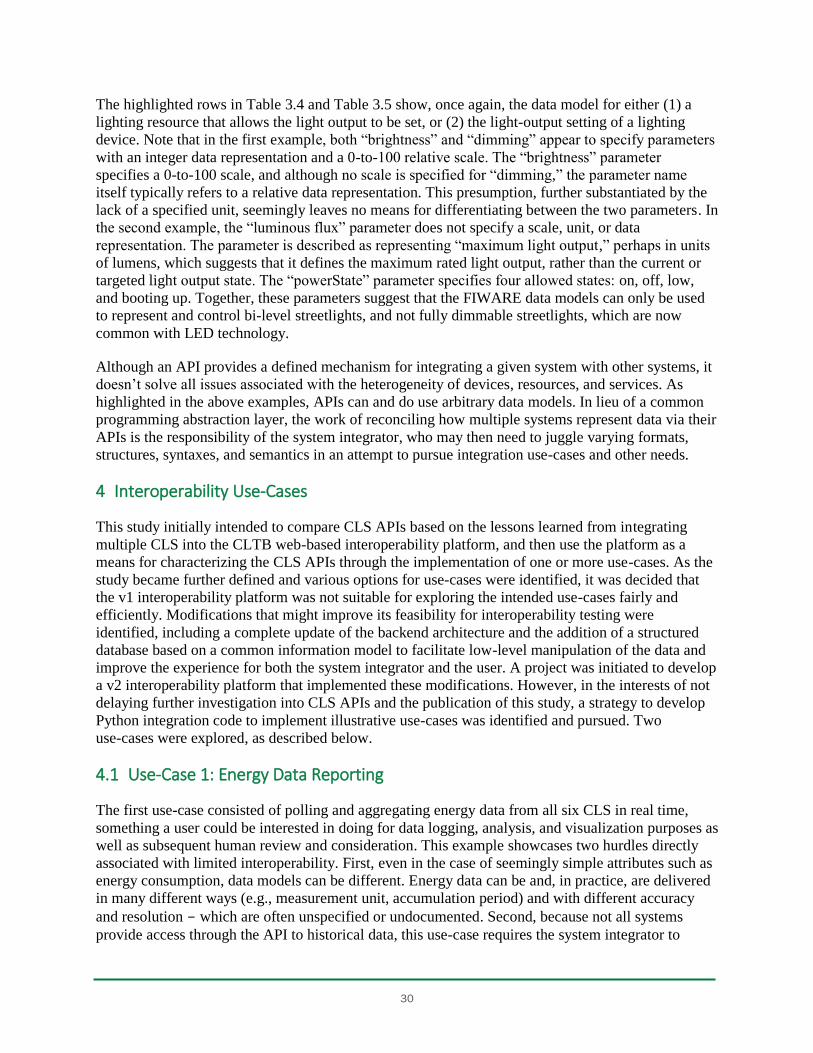
30
The highlighted rows in Table 3.4 and Table 3.5 show, once again, the data model for either (1) a
lighting resource that allows the light output to be set, or (2) the light-output setting of a lighting
device. Note that in the first example, both “brightness” and “dimming” appear to specify parameters
with an integer data representation and a 0-to-100 relative scale. The “brightness” parameter
specifies a 0-to-100 scale, and although no scale is specified for “dimming,” the parameter name
itself typically refers to a relative data representation. This presumption, further substantiated by the
lack of a specified unit, seemingly leaves no means for differentiating between the two parameters. In
the second example, the “luminous flux” parameter does not specify a scale, unit, or data
representation. The parameter is described as representing “maximum light output,” perhaps in units
of lumens, which suggests that it defines the maximum rated light output, rather than the current or
targeted light output state. The “powerState” parameter specifies four allowed states: on, off, low,
and booting up. Together, these parameters suggest that the FIWARE data models can only be used
to represent and control bi-level streetlights, and not fully dimmable streetlights, which are now
common with LED technology.
Although an API provides a defined mechanism for integrating a given system with other systems, it
doesn’t solve all issues associated with the heterogeneity of devices, resources, and services. As
highlighted in the above examples, APIs can and do use arbitrary data models. In lieu of a common
programming abstraction layer, the work of reconciling how multiple systems represent data via their
APIs is the responsibility of the system integrator, who may then need to juggle varying formats,
structures, syntaxes, and semantics in an attempt to pursue integration use-cases and other needs.
4 Interoperability Use-Cases
This study initially intended to compare CLS APIs based on the lessons learned from integrating
multiple CLS into the CLTB web-based interoperability platform, and then use the platform as a
means for characterizing the CLS APIs through the implementation of one or more use-cases. As the
study became further defined and various options for use-cases were identified, it was decided that
the v1 interoperability platform was not suitable for exploring the intended use-cases fairly and
efficiently. Modifications that might improve its feasibility for interoperability testing were
identified, including a complete update of the backend architecture and the addition of a structured
database based on a common information model to facilitate low-level manipulation of the data and
improve the experience for both the system integrator and the user. A project was initiated to develop
a v2 interoperability platform that implemented these modifications. However, in the interests of not
delaying further investigation into CLS APIs and the publication of this study, a strategy to develop
Python integration code to implement illustrative use-cases was identified and pursued. Two
use-cases were explored, as described below.
4.1 Use-Case 1: Energy Data Reporting
The first use-case consisted of polling and aggregating energy data from all six CLS in real time,
something a user could be interested in doing for data logging, analysis, and visualization purposes as
well as subsequent human review and consideration. This example showcases two hurdles directly
associated with limited interoperability. First, even in the case of seemingly simple attributes such as
energy consumption, data models can be different. Energy data can be and, in practice, are delivered
in many different ways (e.g., measurement unit, accumulation period) and with different accuracy
and resolution - which are often unspecified or undocumented. Second, because not all systems
provide access through the API to historical data, this use-case requires the system integrator to
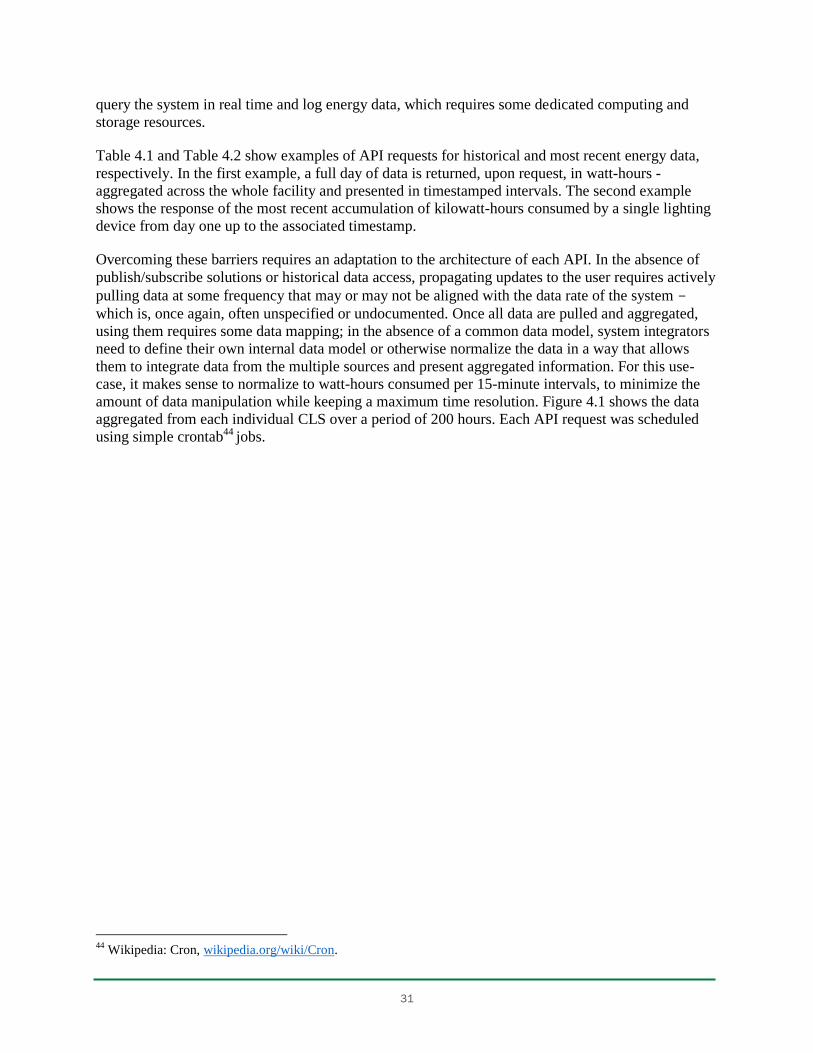
31
query the system in real time and log energy data, which requires some dedicated computing and
storage resources.
Table 4.1 and Table 4.2 show examples of API requests for historical and most recent energy data,
respectively. In the first example, a full day of data is returned, upon request, in watt-hours -
aggregated across the whole facility and presented in timestamped intervals. The second example
shows the response of the most recent accumulation of kilowatt-hours consumed by a single lighting
device from day one up to the associated timestamp.
Overcoming these barriers requires an adaptation to the architecture of each API. In the absence of
publish/subscribe solutions or historical data access, propagating updates to the user requires actively
pulling data at some frequency that may or may not be aligned with the data rate of the system -
which is, once again, often unspecified or undocumented. Once all data are pulled and aggregated,
using them requires some data mapping; in the absence of a common data model, system integrators
need to define their own internal data model or otherwise normalize the data in a way that allows
them to integrate data from the multiple sources and present aggregated information. For this use-
case, it makes sense to normalize to watt-hours consumed per 15-minute intervals, to minimize the
amount of data manipulation while keeping a maximum time resolution. Figure 4.1 shows the data
aggregated from each individual CLS over a period of 200 hours. Each API request was scheduled
using simple crontab44 jobs.
44
Wikipedia: Cron, wikipedia.org/wiki/Cron.
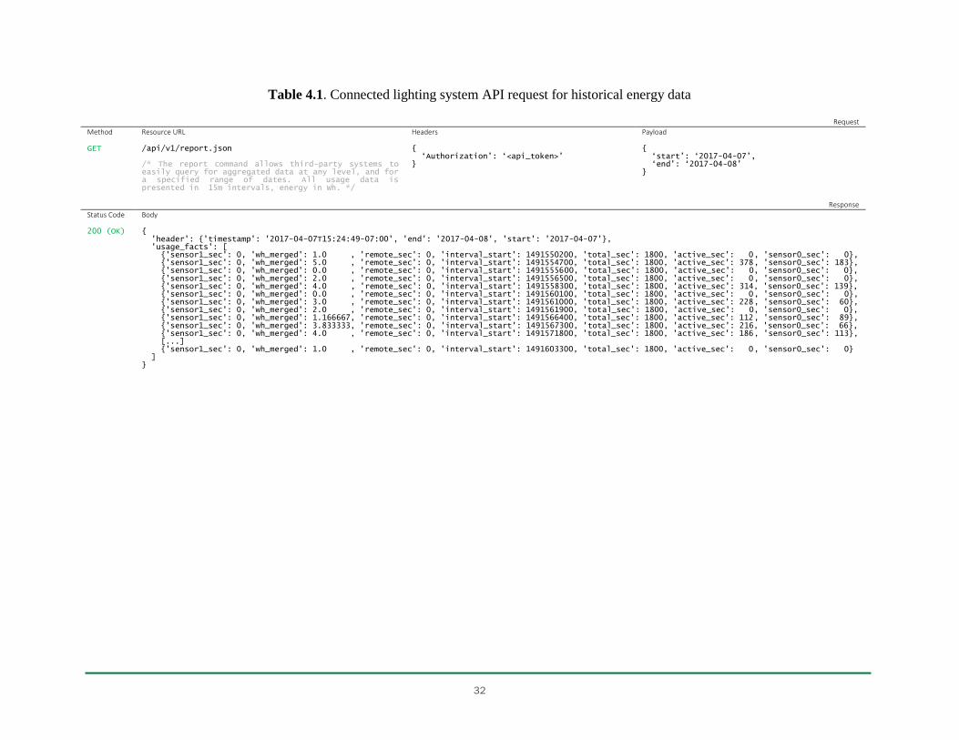
32
Table 4.1. Connected lighting system API request for historical energy data
Request
Method Resource URL Headers Payload GET
/api/v1/report.json /* The report command allows third-party systems to easily query for aggregated data at any level, and for a specified range of dates. All usage data is presented in 15m intervals, energy in Wh. */
{ ‘Authorization’: ‘<api_token>’ }
{ ‘start’: ‘2017-04-07’, ‘end’: ‘2017-04-08’ }
Response
Status Code Body 200 (OK)
{ 'header': {'timestamp': '2017-04-07T15:24:49-07:00', 'end': '2017-04-08', 'start': '2017-04-07'}, 'usage_facts': [ {'sensor1_sec': 0, 'wh_merged': 1.0 , 'remote_sec': 0, 'interval_start': 1491550200, 'total_sec': 1800, 'active_sec': 0, 'sensor0_sec': 0}, {'sensor1_sec': 0, 'wh_merged': 5.0 , 'remote_sec': 0, 'interval_start': 1491554700, 'total_sec': 1800, 'active_sec': 378, 'sensor0_sec': 183}, {'sensor1_sec': 0, 'wh_merged': 0.0 , 'remote_sec': 0, 'interval_start': 1491555600, 'total_sec': 1800, 'active_sec': 0, 'sensor0_sec': 0}, {'sensor1_sec': 0, 'wh_merged': 2.0 , 'remote_sec': 0, 'interval_start': 1491556500, 'total_sec': 1800, 'active_sec': 0, 'sensor0_sec': 0}, {'sensor1_sec': 0, 'wh_merged': 4.0 , 'remote_sec': 0, 'interval_start': 1491558300, 'total_sec': 1800, 'active_sec': 314, 'sensor0_sec': 139}, {'sensor1_sec': 0, 'wh_merged': 0.0 , 'remote_sec': 0, 'interval_start': 1491560100, 'total_sec': 1800, 'active_sec': 0, 'sensor0_sec': 0}, {'sensor1_sec': 0, 'wh_merged': 3.0 , 'remote_sec': 0, 'interval_start': 1491561000, 'total_sec': 1800, 'active_sec': 228, 'sensor0_sec': 60}, {'sensor1_sec': 0, 'wh_merged': 2.0 , 'remote_sec': 0, 'interval_start': 1491561900, 'total_sec': 1800, 'active_sec': 0, 'sensor0_sec': 0}, {'sensor1_sec': 0, 'wh_merged': 1.166667, 'remote_sec': 0, 'interval_start': 1491566400, 'total_sec': 1800, 'active_sec': 112, 'sensor0_sec': 89}, {'sensor1_sec': 0, 'wh_merged': 3.833333, 'remote_sec': 0, 'interval_start': 1491567300, 'total_sec': 1800, 'active_sec': 216, 'sensor0_sec': 66}, {'sensor1_sec': 0, 'wh_merged': 4.0 , 'remote_sec': 0, 'interval_start': 1491571800, 'total_sec': 1800, 'active_sec': 186, 'sensor0_sec': 113}, [...] {'sensor1_sec': 0, 'wh_merged': 1.0 , 'remote_sec': 0, 'interval_start': 1491603300, 'total_sec': 1800, 'active_sec': 0, 'sensor0_sec': 0} ] }
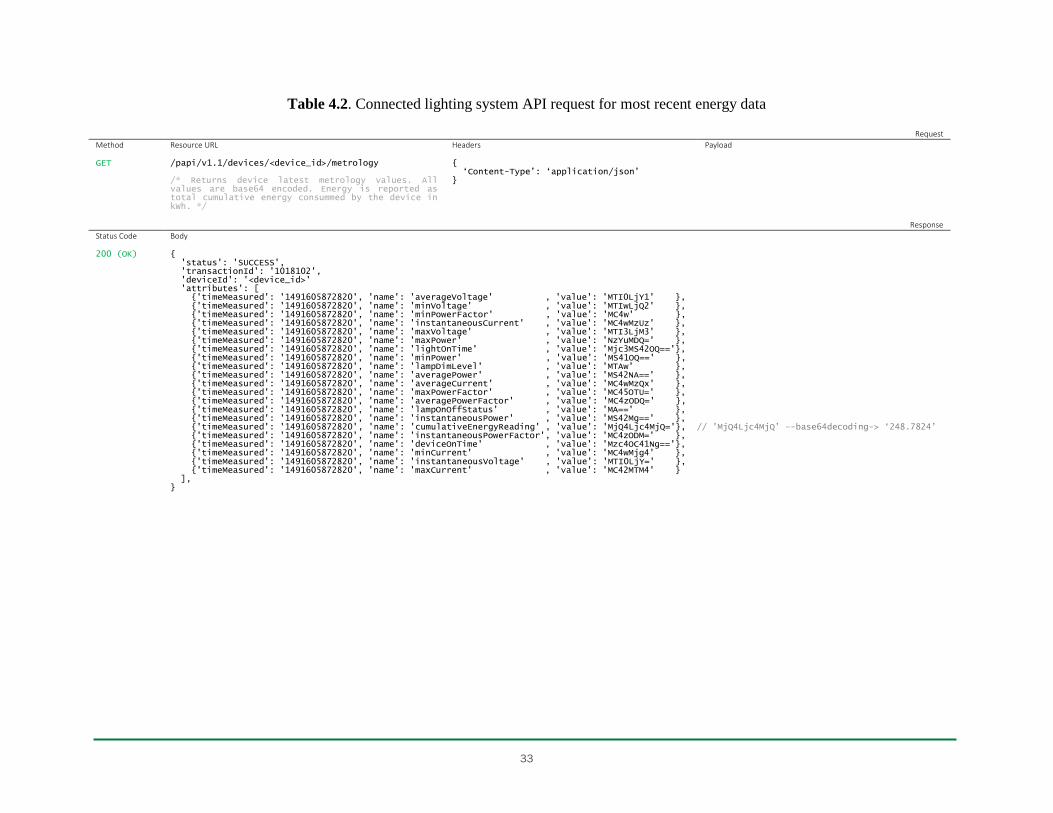
33
Table 4.2. Connected lighting system API request for most recent energy data
Request
Method Resource URL Headers Payload GET
/papi/v1.1/devices/<device_id>/metrology /* Returns device latest metrology values. All values are base64 encoded. Energy is reported as total cumulative energy consummed by the device in kWh. */
{ ‘Content-Type’: ‘application/json’ }
Response
Status Code Body 200 (OK)
{ 'status': 'SUCCESS', 'transactionId': '1018102', 'deviceId': '<device_id>' 'attributes': [ {'timeMeasured': '1491605872820', 'name': 'averageVoltage' , 'value': 'MTI0LjY1' }, {'timeMeasured': '1491605872820', 'name': 'minVoltage' , 'value': 'MTIwLjQ2' }, {'timeMeasured': '1491605872820', 'name': 'minPowerFactor' , 'value': 'MC4w' }, {'timeMeasured': '1491605872820', 'name': 'instantaneousCurrent' , 'value': 'MC4wMzUz' }, {'timeMeasured': '1491605872820', 'name': 'maxVoltage' , 'value': 'MTI3LjM3' }, {'timeMeasured': '1491605872820', 'name': 'maxPower' , 'value': 'NzYuMDQ=' }, {'timeMeasured': '1491605872820', 'name': 'lightOnTime' , 'value': 'Mjc3MS42OQ=='}, {'timeMeasured': '1491605872820', 'name': 'minPower' , 'value': 'MS41OQ==' }, {'timeMeasured': '1491605872820', 'name': 'lampDimLevel' , 'value': 'MTAw' }, {'timeMeasured': '1491605872820', 'name': 'averagePower' , 'value': 'MS42NA==' }, {'timeMeasured': '1491605872820', 'name': 'averageCurrent' , 'value': 'MC4wMzQx' }, {'timeMeasured': '1491605872820', 'name': 'maxPowerFactor' , 'value': 'MC45OTU=' }, {'timeMeasured': '1491605872820', 'name': 'averagePowerFactor' , 'value': 'MC4zODQ=' }, {'timeMeasured': '1491605872820', 'name': 'lampOnOffStatus' , 'value': 'MA==' }, {'timeMeasured': '1491605872820', 'name': 'instantaneousPower' , 'value': 'MS42Mg==' }, {'timeMeasured': '1491605872820', 'name': 'cumulativeEnergyReading' , 'value': 'MjQ4Ljc4MjQ='}, // 'MjQ4Ljc4MjQ’ –-base64decoding-> ‘248.7824’ {'timeMeasured': '1491605872820', 'name': 'instantaneousPowerFactor', 'value': 'MC4zODM=' }, {'timeMeasured': '1491605872820', 'name': 'deviceOnTime' , 'value': 'Mzc4OC41Ng=='}, {'timeMeasured': '1491605872820', 'name': 'minCurrent' , 'value': 'MC4wMjg4' }, {'timeMeasured': '1491605872820', 'name': 'instantaneousVoltage' , 'value': 'MTI0LjY=' }, {'timeMeasured': '1491605872820', 'name': 'maxCurrent' , 'value': 'MC42MTM4' } ], }
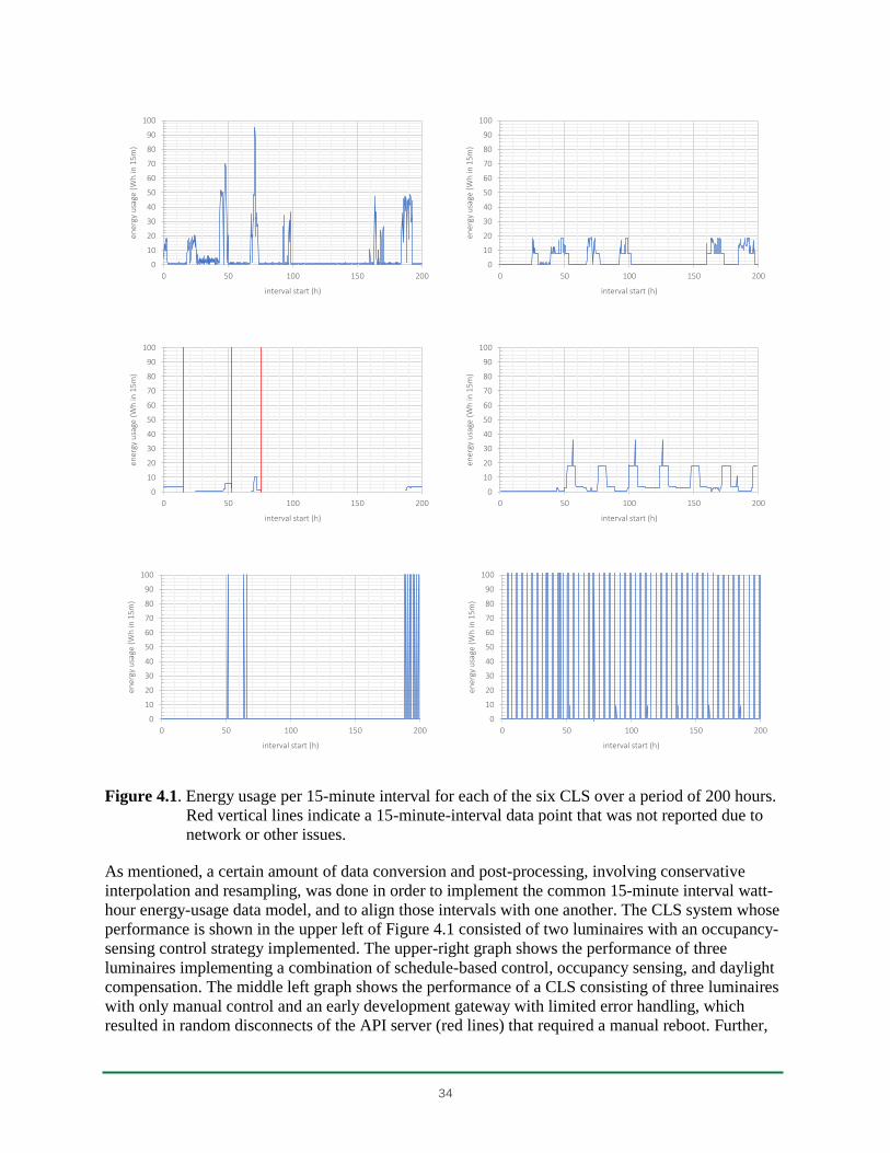
34
Figure 4.1. Energy usage per 15-minute interval for each of the six CLS over a period of 200 hours.
Red vertical lines indicate a 15-minute-interval data point that was not reported due to
network or other issues.
As mentioned, a certain amount of data conversion and post-processing, involving conservative
interpolation and resampling, was done in order to implement the common 15-minute interval watt-
hour energy-usage data model, and to align those intervals with one another. The CLS system whose
performance is shown in the upper left of Figure 4.1 consisted of two luminaires with an occupancy-
sensing control strategy implemented. The upper-right graph shows the performance of three
luminaires implementing a combination of schedule-based control, occupancy sensing, and daylight
compensation. The middle left graph shows the performance of a CLS consisting of three luminaires
with only manual control and an early development gateway with limited error handling, which
resulted in random disconnects of the API server (red lines) that required a manual reboot. Further,
0
10
20
30
40
50
60
70
80
90
100
0 50 100 150 200
ener
gy u
sage
(W
h in
15m
)
interval start (h)
0
10
20
30
40
50
60
70
80
90
100
0 50 100 150 200
ener
gy u
sage
(W
h in
15m
)
interval start (h)
0
10
20
30
40
50
60
70
80
90
100
0 50 100 150 200
ener
gy u
sage
(W
h in
15m
)
interval start (h)
0
10
20
30
40
50
60
70
80
90
100
0 50 100 150 200
ener
gy u
sage
(W
h in
15m
)
interval start (h)
0
10
20
30
40
50
60
70
80
90
100
0 50 100 150 200
ener
gy u
sage
(W
h in
15m
)
interval start (h)
0
10
20
30
40
50
60
70
80
90
100
0 50 100 150 200
ener
gy u
sage
(W
h in
15m
)
interval start (h)
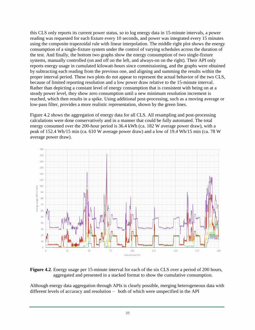
35
this CLS only reports its current power status, so to log energy data in 15-minute intervals, a power
reading was requested for each fixture every 10 seconds, and power was integrated every 15 minutes
using the composite trapezoidal rule with linear interpolation. The middle right plot shows the energy
consumption of a single-fixture system under the control of varying schedules across the duration of
the test. And finally, the bottom two graphs show the energy consumption of two single-fixture
systems, manually controlled (on and off on the left, and always-on on the right). Their API only
reports energy usage in cumulated kilowatt-hours since commissioning, and the graphs were obtained
by subtracting each reading from the previous one, and aligning and summing the results within the
proper interval period. These two plots do not appear to represent the actual behavior of the two CLS,
because of limited reporting resolution and a low power draw relative to the 15-minute interval.
Rather than depicting a constant level of energy consumption that is consistent with being on at a
steady power level, they show zero consumption until a new minimum resolution increment is
reached, which then results in a spike. Using additional post-processing, such as a moving average or
low-pass filter, provides a more realistic representation, shown by the green lines.
Figure 4.2 shows the aggregation of energy data for all CLS. All resampling and post-processing
calculations were done conservatively and in a manner that could be fully automated. The total
energy consumed over the 200-hour period is 36.4 kWh (ca. 182 W average power draw), with a
peak of 152.4 Wh/15 min (ca. 610 W average power draw) and a low of 19.4 Wh/15 min (ca. 78 W
average power draw).
Figure 4.2. Energy usage per 15-minute interval for each of the six CLS over a period of 200 hours,
aggregated and presented in a stacked format to show the cumulative consumption.
Although energy data aggregation through APIs is clearly possible, merging heterogeneous data with
different levels of accuracy and resolution – both of which were unspecified in the API
0
10
20
30
40
50
60
70
80
90
100
110
120
130
140
150
160
0 25 50 75 100 125 150 175 200
ener
gy u
sage
(W
h in
15m
)
interval start (h)
36
documentation of every CLS in this study – clearly shows the limitations of interoperability as
facilitated by APIs. First, the diversity of API architectures and energy data models required a
significant amount of system integration work that required human, computing, and network
bandwidth resources. Secondly, aggregating reported energy data with different overlapping and
unsynchronized accumulation periods can mask actual behavior and result in misconceptions, as the
energy performance of systems with the higher accuracy and resolution is lost in the noise of the
lower-quality data.
4.2 Use-Case 2: Broadcasting a Lighting Command
The second use-case consisted of broadcasting a uniform lighting control command to every
luminaire in all six CLS, as might be done in emergency and/or manual override scenarios. A variety
of API features were used to simultaneously turn all luminaires on to their maximum output level in a
minimum amount of time, including group commands, dynamic discovery, emergency modes,
manual override, and software tools such as coroutine45 networking libraries that enabled the creation
of parallel HTTP requests.
Only one out of the six CLS implemented a dedicated API call for emergency situations that allowed
setting the relative light output of all luminaires to 100% via a single request. For the others, the best
action was to define an “emergency” group containing all luminaires. However, not all systems
implemented the option to group fixtures together, and some had limitations on the creation of those
groups; in some CLS, luminaires could only be assigned to a single group; in others, groups could
not partially overlap (i.e., some luminaires that were in one group could also belong to a fully
overlapped subgroup, but the subgroup could not contain luminaires from outside the main group).
Hence, the creation of an emergency group can limit the ability to implement other control strategies
in specific areas during normal operation. Among CLS investigated in this study, three out of six
enabled the user to define a group that contained all luminaires, as well as smaller subgroups, and
control both through the API. For the remaining systems, implementing this feature required dynamic
discovery and broadcast commands or multiple individual commands, thereby requiring several
HTTP requests to turn all lights on. One of the six CLS did not at the time have any broadcast
capability, or the ability to group luminaires and change the light output for all luminaires in the
group; rather, it required one API call per luminaire to change the light output of the entire CLS.
Table 4.3, Table 4.4, and Table 4.5 show examples of requests and responses for the API methods
used to implement this use-case.
45
Wikipedia: Coroutine, wikipedia.org/wiki/Coroutine.
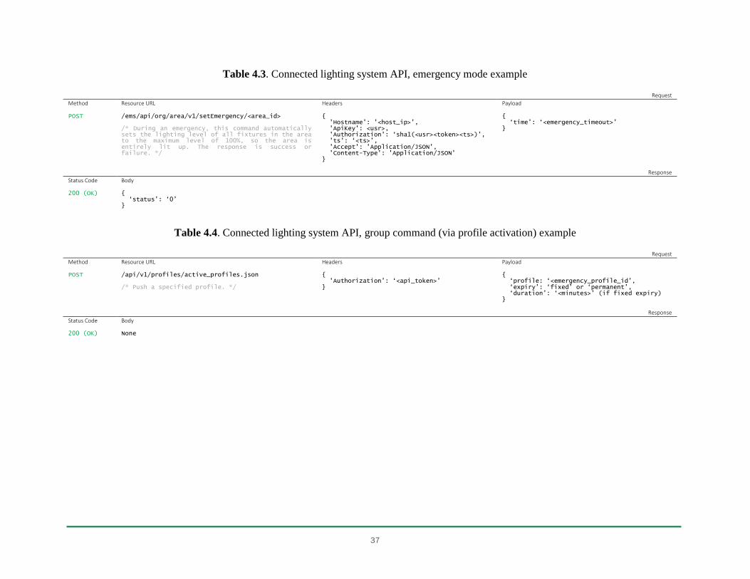
37
Table 4.3. Connected lighting system API, emergency mode example
Request
Method Resource URL Headers Payload POST
/ems/api/org/area/v1/setEmergency/<area_id> /* During an emergency, this command automatically sets the lighting level of all fixtures in the area to the maximum level of 100%, so the area is entirely lit up. The response is success or failure. */
{ 'Hostname': '<host_ip>', 'ApiKey': <usr>, 'Authorization': ‘sha1(<usr><token><ts>)’, 'ts': ‘<ts>’, 'Accept': 'Application/JSON', 'Content-Type': 'Application/JSON' }
{ ‘time’: ‘<emergency_timeout>’ }
Response
Status Code Body 200 (OK)
{ ‘status’: ‘0’ }
Table 4.4. Connected lighting system API, group command (via profile activation) example
Request
Method Resource URL Headers Payload POST
/api/v1/profiles/active_profiles.json /* Push a specified profile. */
{ 'Authorization’: ‘<api_token>’ }
{ ‘profile: ‘<emergency_profile_id’, ‘expiry’: ‘fixed’ or ‘permanent’, ‘duration’: ‘<minutes>’ (if fixed expiry) }
Response
Status Code Body 200 (OK)
None
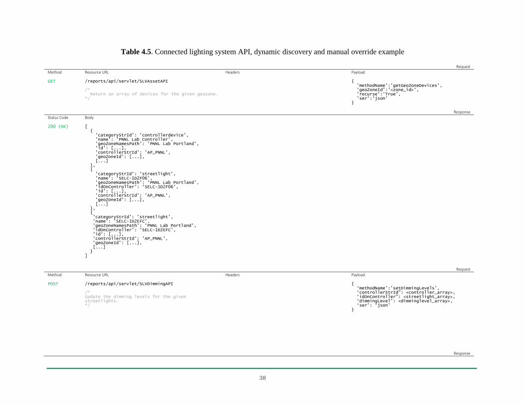
38
Table 4.5. Connected lighting system API, dynamic discovery and manual override example
Request
Method Resource URL Headers Payload GET
/reports/api/servlet/SLVAssetAPI /* Return an array of devices for the given geozone. */
{ 'methodName':'getGeoZoneDevices', 'geoZoneId':'<zone_id>', 'recurse':'True', 'ser':'json' }
Response
Status Code Body 200 (OK)
[ { 'categoryStrId': 'controllerdevice', 'name': 'PNNL Lab Controller', 'geoZoneNamesPath': 'PNNL Lab Portland', 'id': [...], 'controllerStrId': 'AP_PNNL', 'geoZoneId': [...], [...] }, { 'categoryStrId': 'streetlight', 'name': 'SELC-1D2F06', 'geoZoneNamesPath': 'PNNL Lab Portland', 'idOnController': 'SELC-1D2F06', 'id': [...], 'controllerStrId': 'AP_PNNL', 'geoZoneId': [...], [...] }, { 'categoryStrId': 'streetlight', 'name': 'SELC-1D2EFC', 'geoZoneNamesPath': 'PNNL Lab Portland', 'idOnController': 'SELC-1D2EFC', 'id': [...], 'controllerStrId': 'AP_PNNL', 'geoZoneId': [...], [...] } ]
Request
Method Resource URL Headers Payload POST
/reports/api/servlet/SLVDimmingAPI /* Update the dimming levels for the given streetlights. */
{ ‘methodName’:’setDimmingLevels’, ‘controllerStrId": <controller_array>, ‘idOnController": <streetlight_array>, ‘dimmingLevel’: <dimminglevel_array>, ‘ser’: ‘json’ }
Response
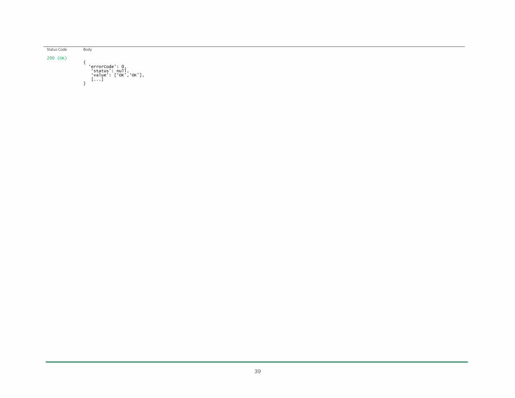
39
Status Code Body 200 (OK)
{ ‘errorCode’: 0, ‘status’: null, ‘value’: [‘OK’,‘OK’], [...] }
40
One challenge a system integrator might encounter when implementing this use-case is the need to
send multiple HTTP requests to several CLS servers in a minimum amount of time. Although the
simplest approach is to send them sequentially and wait for each response before moving to the next
one, doing so might not be compatible with the use-case latency needs. To minimize the time (and
cost) required to send multiple HTTP requests, one can implement a protocol that allows those
requests that can execute concurrently to do so. This can be accomplished by using requests that are
non-blocking and asynchronous (i.e., that return and let work happen in the background before the
response triggers some future action in the program). The ability to launch new requests while
waiting for previous requests to respond can result in a significant reduction in overall latency. The
protocol described and used in this study was developed using Python 2.7 and the grequests46 library;
other Python options include tornado and asyncio HTTP clients.47
A sub-100ms latency illuminance meter was designed and built to measure how quickly CLS react to
commands through their application programing interfaces. The prototype was built using open-
hardware development boards and open-source libraries from Adafruit48,49,50,51 with the Platformio52
cross-platform build system for embedded development. The illuminance meter and its prototype
construction are shown in Figure 4.3, along with its key components. A breadboard schematic as well
as the firmware source code can be found on GitHub.53
The data-rate limitation for this meter comes from the light-sensor analog-to-digital converter that
integrates photodiode current; the fastest setting enables a minimum resolution reading for a 13.7ms
integration time. A small improvement that might be considered for future development would use
the programmable interrupt instead of continuously polling the sensor data registers. The firmware
includes manual control of the sensor gain (1x or 16x) and integration time (13.7ms, 101ms, or
402ms), as well as a deep-sleep mode to minimize battery drain when not in use. The light sensor
provided three outputs per integration period: a) the raw digitized measurement from a broadband
(visible + infrared) photodiode, b) the raw digitized measurement from an infrared photodiode, and
c) an illuminance calculation based on the empirical formula generated from the manufacturer’s
optical testing with fluorescent and incandescent light sources. A Wi-Fi connection is implemented
through Dynamic Host Configuration Protocol (DHCP), the Websocket data is served on port 88, and
a human-readable HTML page is presented on port 80.
46
GitHub: kennethreitz/grequests, github.com/kennethreitz/grequests. 47
tornadoweb.org , docs.python.org/3/library/asyncio 48
Adafruit: Adafruit Feather HUZZAH with ESP8266 WiFi, adafruit.com/products/2821. 49
Adafruit: FeatherWing OLED - 128x32 OLED Add-on For All Feather Boards, adafruit.com/products/2900. 50
Adafruit: Adafruit TSL2561 Digital Luminosity/Lux/Light Sensor Breakout, adafruit.com/products/439. 51
GitHub: Adafruit Industries, github.com/adafruit. 52
PlatformIO, platformio.org. 53
GitHub: clem-g/luxinterior, github.com/clem-g/luxinterior.
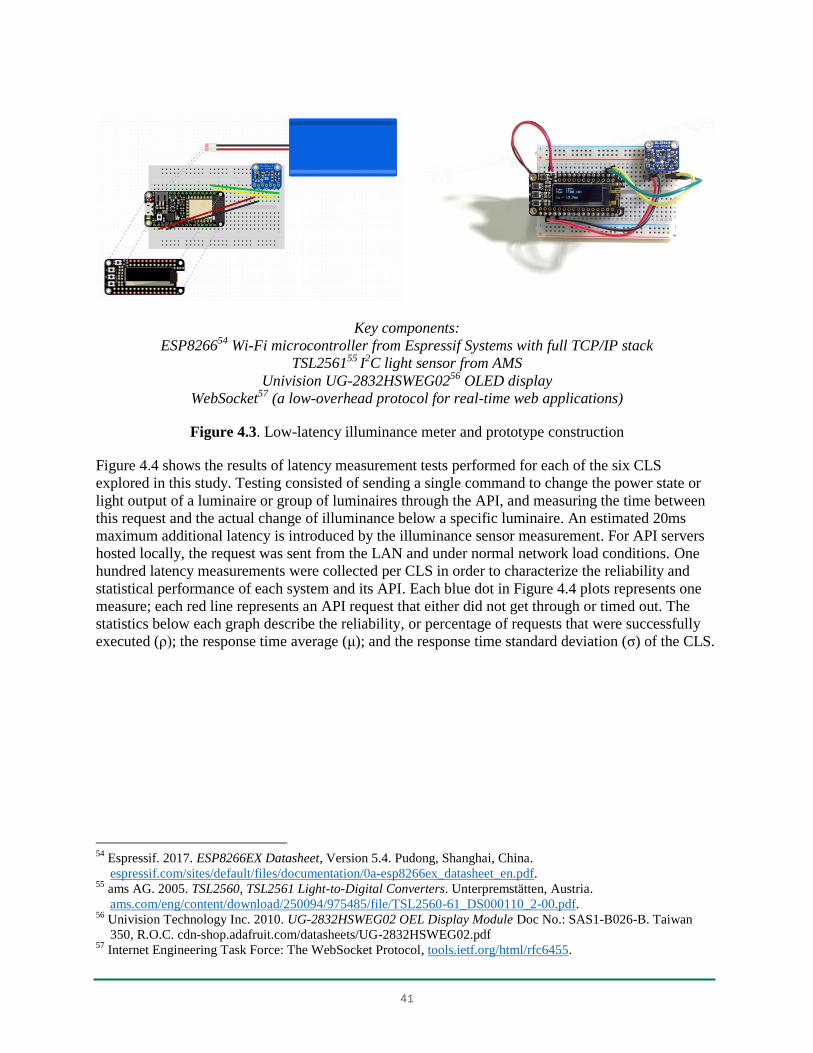
41
Key components:
ESP826654 Wi-Fi microcontroller from Espressif Systems with full TCP/IP stack
TSL256155 I2C light sensor from AMS
Univision UG-2832HSWEG0256 OLED display
WebSocket57 (a low-overhead protocol for real-time web applications)
Figure 4.3. Low-latency illuminance meter and prototype construction
Figure 4.4 shows the results of latency measurement tests performed for each of the six CLS
explored in this study. Testing consisted of sending a single command to change the power state or
light output of a luminaire or group of luminaires through the API, and measuring the time between
this request and the actual change of illuminance below a specific luminaire. An estimated 20ms
maximum additional latency is introduced by the illuminance sensor measurement. For API servers
hosted locally, the request was sent from the LAN and under normal network load conditions. One
hundred latency measurements were collected per CLS in order to characterize the reliability and
statistical performance of each system and its API. Each blue dot in Figure 4.4 plots represents one
measure; each red line represents an API request that either did not get through or timed out. The
statistics below each graph describe the reliability, or percentage of requests that were successfully
executed (ρ); the response time average (μ); and the response time standard deviation (σ) of the CLS.
54
Espressif. 2017. ESP8266EX Datasheet, Version 5.4. Pudong, Shanghai, China.
espressif.com/sites/default/files/documentation/0a-esp8266ex_datasheet_en.pdf. 55
ams AG. 2005. TSL2560, TSL2561 Light-to-Digital Converters. Unterpremstätten, Austria.
ams.com/eng/content/download/250094/975485/file/TSL2560-61_DS000110_2-00.pdf. 56
Univision Technology Inc. 2010. UG-2832HSWEG02 OEL Display Module Doc No.: SAS1-B026-B. Taiwan
350, R.O.C. cdn-shop.adafruit.com/datasheets/UG-2832HSWEG02.pdf 57
Internet Engineering Task Force: The WebSocket Protocol, tools.ietf.org/html/rfc6455.
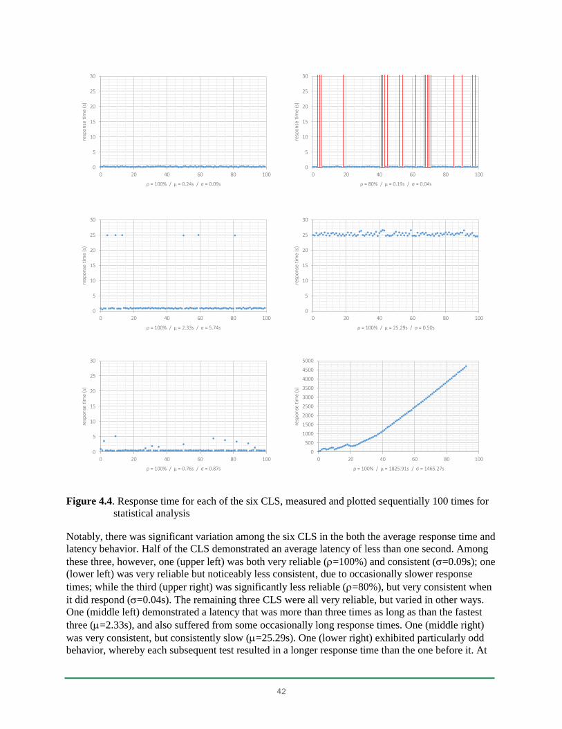
42
Figure 4.4. Response time for each of the six CLS, measured and plotted sequentially 100 times for
statistical analysis
Notably, there was significant variation among the six CLS in the both the average response time and
latency behavior. Half of the CLS demonstrated an average latency of less than one second. Among
these three, however, one (upper left) was both very reliable (=100%) and consistent (=0.09s); one
(lower left) was very reliable but noticeably less consistent, due to occasionally slower response
times; while the third (upper right) was significantly less reliable (=80%), but very consistent when
it did respond (=0.04s). The remaining three CLS were all very reliable, but varied in other ways.
One (middle left) demonstrated a latency that was more than three times as long as than the fastest
three (=2.33s), and also suffered from some occasionally long response times. One (middle right)
was very consistent, but consistently slow (=25.29s). One (lower right) exhibited particularly odd
behavior, whereby each subsequent test resulted in a longer response time than the one before it. At
0
5
10
15
20
25
30
0 20 40 60 80 100
resp
on
se t
ime
(s)
ρ = 100% / μ = 0.24s / σ = 0.09s
0
5
10
15
20
25
30
0 20 40 60 80 100
resp
on
se t
ime
(s)
ρ = 80% / μ = 0.19s / σ = 0.04s
0
5
10
15
20
25
30
0 20 40 60 80 100
resp
on
se t
ime
(s)
ρ = 100% / μ = 2.33s / σ = 5.74s
0
5
10
15
20
25
30
0 20 40 60 80 100
resp
on
se t
ime
(s)
ρ = 100% / μ = 25.29s / σ = 0.50s
0
5
10
15
20
25
30
0 20 40 60 80 100
resp
on
se t
ime
(s)
ρ = 100% / μ = 0.76s / σ = 0.87s
0
500
1000
1500
2000
2500
3000
3500
4000
4500
5000
0 20 40 60 80 100
resp
on
se t
ime
(s)
ρ = 100% / μ = 1825.91s / σ = 1465.27s
43
the time of this publication, the vendor had not yet resolved whatever oddity was causing this clearly
unintended behavior. Long response times, even if they only occur occasionally, can be explained in
different ways: Some systems are designed to administer a significant number of nodes and are not
designed for real-time control; some systems have more complicated network architectures, with
several middleware layers and software stacks; and some APIs are hosted on a remote server and can
therefore be susceptible to sporadic routing delays, reordered or repeated packet delays, overloaded
switches, network timeouts, or connection losses. The reliability issues observed with one CLS
(upper-right plot) were likely due to the gateway being a pre-commercial prototype, for which
connection quality of service was simply determined based on the received-signal-strength indicator
(RSSI) between the gateway and the end nodes, and no handshake had yet been implemented; as a
result, commands were not always received by the luminaires.
5 Summary and Recommendations
The full potential of connected lighting systems will only be realized if they can be easily and
efficiently interconnected to and exchange data with one another and with other (non-lighting)
systems. Although APIs provide a means to bridge islands of data and create coherent ecosystems,
the integration work is not trivial. Beyond the learning curve of each individual interface, API
integration presents new challenges, including data mapping, translation or normalization, workflow
orchestration, and development of a single user interface – all in a secure, scalable, and maintainable
way. Making hardware resources, information, and services accessible in a distributed system is not
easy. They are hosted on different platforms in different networks, using different communication
technologies, information representations, and data models, and are managed by different
administrators. In order to hide the inherent complexity and appear to the users as a single coherent
system, a significant amount of backend integration work is required.
APIs enable the implementation of many use-cases. However, use-case performance may be
hampered by one or more issues. Asynchronicity is a significant hurdle to the creation of an
interoperability platform via APIs. When a number of processes are running in parallel on different
machines in several locations, and the network between them is not always perfectly reliable or
immune to latency issues and bandwidth limitations, synchronization of commands or readings may
be difficult. Further, partial failures of a subsystem or an interface, as well as performance issues, are
difficult to control, debug, and handle in a system stitched together using APIs. Implementing
mechanisms and policies that maximize reliability and quality of service, while still allowing the
integrated system to scale and remain effective and perform when the number of managed resources
or the number of users increases, requires advanced developer skills. Finally, providing a user
experience that reduces the inherent complexity of multiple systems and interfaces requires the
navigation of data residing in multiple heterogeneous locations, potentially presented in different
formats and conveying different information, and also requires an ability to mend structural and
semantic gaps.
This study is the first of a multipart effort to explore the interoperability of commercially available
(or in some cases, pre-commercial) CLS. This exploration was aimed at answering the following key
questions, which might then facilitate the identification of industry needs and the development of
recommendations for meeting those needs:
44
1 Question
How do API implementation and information models currently found in commercially
available CLS vary?
Answer
Availability: Not all APIs were readily available (e.g., described in an unrestricted webpage
or downloadable document). Some required contacting the CLS developer, who in some
instances provided the API readily, and in others required an explanation of why the API
was being requested and how it would be used. Some required a signed nondisclosure
agreement in order to obtain API access or documentation.
Authentication schemes: APIs used a wide variety of authentication schemes – some over
unencrypted HTTP, others over secured HTTPS; some with a simple cleartext key, and
others with a cryptographic hash authentication key. Integration required support of
multiple schemes, subjecting the integrated environment to different cybersecurity
vulnerabilities.
Resource structure: System resources described in APIs were named and organized in
myriad – and, in some cases, inconsistent – ways, with significant variation in structure,
nomenclature, and complexity. Although some APIs had a logically consistent resource-tree
structure, others were apparently developed incrementally over multiple version releases, as
more features were added over time; incremental extensions were not always implemented
consistently or logically.
Data models: APIs used a wide variety of data models, each apparently custom-developed.
Custom data models are not always well designed or documented, or even self-consistent.
Data might exist in very different locations within API resource trees (e.g.,
/devices/<device_id>/resources, /reports/api/monitoring), and very different naming
conventions or labels (e.g., /lt/dim, LuxLevel, brightness, dimming), units (e.g., absolute
lux, relative % illuminance), and data types (e.g., integer, floating point) are used for
seemingly similar or at least related parameters. In some cases, models from different
systems may be functionally incompatible.
CORS support: Some API developers supported CORS, while others either did not, or did
not do so readily (i.e., it was difficult to find the vendor staff who could whitelist access
from specific domains).
Historical data access: Some CLS did not provide API access to historical data outside a
certain time window, or only provided real-time data. In some cases, the real-time update
rate was unspecified, seemingly inconsistent, or asynchronous, and was dependent on how
frequently the CLS could be queried through the API.
Recommendations
CLS developers should make their APIs readily available and ensure that documentation is
synchronized with software updates. Further, they should facilitate easy, efficient bug
reporting.
The lighting industry, and perhaps the IoT industry as well, should consider developing and
adopting a common approach to authentication, with some minimum level of resistance to
cybersecurity vulnerabilities.
45
CLS developers should enable CORS, secured by the use of HTTPS together with
authentication and authorization schemes.
CLS developers should name and organize API resources in readable, logical, and
consistent ways.
CLS developers should fully document API data models, including reporting unit (when
applicable), data type, resolution, and accuracy.
The lighting industry, and perhaps the IoT industry as well, should consider developing and
adopting a well-thought-out, modern, and evolving common resource organization.
The industry should consider developing and adopting well-thought-out, maintained
common information and/or data models. These models should be created by entities with
application expertise specific to the information or data model.
2 Question
What type of effort is required to exchange information between – or, more fundamentally,
to integrate – heterogeneous and asynchronous resources residing in different CLS, via
their APIs, into a single interoperable platform?
Answer
Software coding: Such integration requires some degree of software coding. Although the
type and amount of coding required can vary by the approach pursued, integration via APIs
requires more than configuration and validation. Integration via an existing “platform”
might require less development time – in particular, if the platform was designed for, or
has been previously used to implement, intended use-cases. However, the use of such
“platforms” typically comes with tradeoffs between user-friendliness, functionality, and
flexibility. Further, they must be maintained to address hardware, firmware, and software
updates, and ideally support new systems as they enter the market.
Harmonization: In lieu of sufficient documentation, system integrators may have to
ascertain, sometimes through crude trial-and-error experimentation, what an available API
resource represents and what information and data model it uses. Converters or translators
may need to be developed to handle inconsistent data models. Further, an information
model that suitably encompasses the myriad data models to be integrated may need to be
inferred, in order to effectively aggregate data or broadcast commands, for example.
Maintenance: Integrating multiple CLS through APIs does not result in a homogenous
system; at best, it yields a common user interface and experience. However, effectively
hiding the underlying complexity can require a significant amount of backend integration
work. Managing what functionally remains a distributed system at one or more layers can
be challenging and effortful. Differences between network protocols, device
representations, and access policies that affect performance must be understood, addressed
(if possible), and managed – not only initially, but over the course of hardware, firmware,
and software upgrades.
Recommendations
API developers should explore approaches to reducing system integrator effort – for
example, by providing support for multiple measurement units and time aggregations for
reported data, and support for controls schemes beyond switching between or pushing out
46
of new device profiles.
API developers should consider the implementation of publish-subscribe models for
reported data.
API developers should consider the implementation of override or prioritization schemes
that support adaptive control of configurable system devices.
DOE intends to continue to identify and explore viable interoperability approaches. System
integrators, industry consortia, and CLS developers should inform DOE when existing or
new interoperability approaches reach new levels of functionality, viability, or market
adoption.
3 Question
How might the implementation of real-life use-cases effectively characterize the level of
interoperability found in CLS?
Answer
The implementation of real-life use-cases can expose previously unseen or unanticipated
issues. Often, this occurs when a design constraint, boundary condition, or tradeoff is
challenged by the functional or performance requirements of the use-case. Implementation
can also lead to the identification of new or additional API functionality or features that
might support, or better support, both the use-case under investigation as and other use-
cases.
In this study, implementation of an energy data aggregation use-case exposed issues
beyond the impact of working with different data models. Energy measurement accuracy
and resolution were generally unspecified in marketing literature and API documentation,
raising concern as to how to statistically treat data from different sources. Further, the lack
of API access, in some cases, to historical energy data required the system integrator to
query the CLS in real time and log energy or power data, thereby requiring dedicated
storage and computing resources.
In this study, the implementation of a broadcast lighting command use-case exposed
latency differences between systems that might arguably compromise both the
functionality and performance needs of the use-case.
Recommendations
CLS developers should support user exploration of new and previously unproven use-cases
and facilitate easy, efficient bug reporting.
DOE intends to continue to identify potentially high-value use-cases, and explore how well
they can be implemented by integrated heterogeneous CLS using available interoperability
approaches, as well how they might be enabled by interoperability between CLS and other
systems. Lighting-industry stakeholders should provide DOE with suggestions for use-
cases to explore, and estimates of their relative value.