connection guidelines for small-scale renewable …€¦ · connection guidelines for small-scale...
TRANSCRIPT
Connection Guidelines for Small-Scale Renewable Generating Plant
Ministry of Energy
Connection Guidelines forSmall-Scale Renewable Generating Plant
December, 2012
Connection Guidelines for Small-Scale Renewable Generating Plant
Contents
1. INTRODUCTION AND SCOPE 1
2. DEFINITIONS 2
3. NORMAL LEGAL CONTEXT 7
4. CAPACITY LIMITS AND CONNECTION VOLTAGE 8
5. CONNECTION APPLICATION 8
6. CONNECTION ARRANGEMENTS 12
7. GENERATING PLANT CONNECTION DESIGN AND OPERATION 14
8. PROTECTION 26
9. EARTHING 37
10. INSTALLATION, OPERATION AND CONTROL INTERFACE 42
11. TESTING AND COMMISSIONING 46
12. SAFETY ASPECTS 50
APPENDIX 1 – REFERENCE STANDARDS 52
Figures and Tables
Figure 1: Generic Connection Schematic 9Figure 2: Typical Protection Arrangements for LV Connected Generating Plant 1Figure 3: Typical Protection Arrangements for MV Connected Generating Plant 1Figure 4: Typical Earthing Arrangement for MV Generator Configured for Parallel Operation(network MV earth not shown) 38Figure 5: Typical Earthing Arrangement for MV Connected Generator Configured for both Standbyand Parallel Operation 1Figure 6: Typical Earthing Arrangement for LV Connected Generator Configured for ParallelOperation Only 1Figure 7: Typical Earthing Arrangement for an LV Generator Connected to an MV NetworkConfigured for both Standby and Parallel Operation 1
Table 1: Voltages and Connection Capacities 8Table 2: Connection Process 9Table 3: Protection Settings (Long-Term Parallel Operation) 21Table 4: Total Harmonic Voltage Distortion 22Table 5: Protection Settings (Short-Term Parallel Operation) 32
Connection Guidelines for Small-Scale Renewable Generating Plant
3
1. INTRODUCTION AND SCOPE
1. These guidelines are the product of a project aimed at facilitating the development andconnection to the electricity network of small renewable energy generators. Whilstthey have no regulatory status, they do represent international good practice andreflect the network operator’s statutory obligation to manage the operation and safetyof his system in a responsible manner. Some of the requirements come directly fromthe Grid Code. It is in both the system user and the system operator’s interest to have astable electricity network, so these guidelines should be read by those planning tooperate Generating Plant prior to installation and connection.
2. The purpose of these guidelines is to establish procedures and equipment to protectpersonnel, equipment, and network operator’s systems from any harmful effectsarising from connection and operation of Generating Plant supplied and operated byothers, herein referred to as Generators. They are intended to inform Generators of thehost network operator’s requirements for Generating Plant being connected to its
System.
3. These guidelines are designed to facilitate the connection of Generating Plant whilstmaintaining the safety of, and supply quality from the network. This applies to allGenerating Plant irrespective of the type of electrical equipment used to produceelectrical energy. They do not however provide advice for the design, specification,protection or operation of Generating Plant itself which is the sole responsibility of theGenerator, noting the connection guidance given in this document.
4. The guidelines apply to systems where the Generating Plant can be paralleled with aTransmission/Distribution System or where either the Generating Plant or aTransmission/Distribution System with Generating Plant connected can be used as analternative source of energy to supply the same electrical load.
5. These guidelines are for information only and are subsidiary to the mandatoryrequirements governing the connection of Generators which are generally set out inthe Grid Code.
6. These guidelines generally apply to small and medium scale Generating Plant with acapacity up to 10MW.

Connection Guidelines for Small-Scale Renewable Generating Plant
4
Connection Guidelines for Small-Scale Renewable Generating Plant
5
2. DEFINITIONS
These definitions are provided to assist the interpretation of these Guidelines. Where equivalentterms are defined within statutory instruments, those definitions will take precedence overthese in this document.
Act The Energy Act 2006AVC Automatic Voltage ControllerAVR Automatic Voltage RegulatorCombined Heat and Power (CHP) A plant that generates electricity and supplies
thermal energy, to an industrial or other heating orcooling requirement.
Connection Agreement An agreement between the host network operatorand the Generator setting out the terms relating toa connection to that network.
Connection Point An Entry Point or an Exit Point of a network.Connection Voltage The nominal voltage at which the Grid Connection
is made.Customer A person who is the owner or occupier of premises
that are connected to the network.Customer's Installation The electrical installation on the Customer's side of
the supply terminals together with any equipmentpermanently connected or intended to bepermanently connected thereto.
Customer Average InterruptionDuration Index (CAIDI)
A performance measure of a Distribution Network.It is calculated as the average number of minutesthat the supply is not available per connectedcustomer
Customer Interruption (CI) alsoknown as System AverageInterruptionFrequency Index (SAIFI)
A performance measure of a distribution network.It is measure of the number of events per yearwhere the interruption lasts more than 3 minutes.
Dispatchable Generation The output of a Generating Plant where theproduction profile is subject to dispatch instructionby the network system operator’s control centre.
Distribution Network An electricity supply network operating at orbelow 33kV which is connected to Kenya’selectricity transmission grid or operating as anisolated mini-grid.
Distribution Network Operator (DNO) The licensee responsible for the operation of thedistribution network..
Embedded Generator A Generator connected to a distribution network.Entry Point The point at which a Generator or other Users
connect to a network where power flows into thenetwork under normal circumstances.
Exit Point The point of supply from a network to a Userwhere power flows out from the network undernormal circumstances.
Connection Guidelines for Small-Scale Renewable Generating Plant
6
Export of Electrical Energy Provision of Electrical Energy by a Generator to aNetwork.
Fault Level Prospective current that would flow into ashort-circuit at a stated point in the System andwhich may be expressed in kA or, if referred to aparticular voltage, in MVA.
Generating Plant A power station including any Generation Settherein.
Generation Unit Any apparatus which produces electricity.Generator A person who generates electricity under licence
or exemption. A person who has connected aGenerating Set which is less than 16A per phase inparallel with a Low Voltage Distribution Networkand where this is their only Generation Set is notclassed as a Generator but is subject none the lessto the requirements of ENA G83.
Grid Code The code as prepared by the national energyregulator.
Grid Connection A link between a Network and a Generator’selectricity system, made for the purpose ofExporting or Importing Electrical Energy.
Grid Substation A substation in the main grid where electricalenergy at particular voltage transformed intoanother voltage for the purpose of transmission ora Distribution. In Kenya transmission volatages are400kV, 220kV, and 66kV and distribution voltagesare 33kV,and 11kV.
Host network operator: The licensed operator of the Distribution Systemor Transmission System to which a Customer(Generator or Consumer) is connected.
High Voltage (HV) In Kenya, nominal voltage exceeding 33,000Vbetween conductors.
Import of Electrical Energy Receipt of Electrical Energy by a Generator from aNetwork.
Interface Protection The electrical protection required to ensure thatany Generating Unit is disconnected for any eventthat could impair the integrity or degrade thesafety of the host network.
Islanding The process whereby a Network is separated intotwo or more parts, with Generators supplyingloads connected to some of the separated parts.
Islanded Operation The situation that arises when a part of a Networkis disconnected from the grid and is energised byone or more Generators connected to it.
Loss of Mains Protection (LoM) A protection regime to achieve (amongst otherthings) disconnection of the Generating Plant fromthe Distribution System in the event of loss of oneor more phases of the host network operatorssupply.
Low Voltage (LV) A voltage greater than 50V but not exceeding1000V between conductors and [600]V between
Connection Guidelines for Small-Scale Renewable Generating Plant
7
conductors and earth.Medium Voltage (MV) In Kenya, a nominal voltage, exceeding 1,000V but
less than 33,000V between conductors.Mini-grid A power system that may be operated in isolation
to the Kenya national grid and operated under theregulatory supervision of national EnergyRegulator.
Neutral Voltage Displacement (NVD) A technique to measure the displacement of theneutral voltage with respect to earth.
Normal Operating Frequency The number of Alternating Current cycles persecond, expressed in Hertz at which the Systemnormally operates, in Kenyan the normal operatingfrequency is . 50 Hertz.
Over-current Protection (OC) A form of protection in an electric circuit whichprevents damage resulting from excessive currentand interrupts the flow of current at apredetermined value.
Over-frequency Protection (OF) A form of protection in an electric circuit whichprevents damage resulting from a difference in inthe frequency of two interconnecting systems
Over-voltage Protection (OV) A form of protection in an electric circuit thatprotects downstream circuitry from damage dueto excessive voltage.
Operating Voltage The value of the voltage under normal conditionsat a given instant and at a given point in thesystem.
Point of Common Coupling (PCC) The location on an existing network where aconnection is made for a Customer’s installation.
Point of Supply (POS) The point of electrical connection betweenapparatus owned by the network operator andapparatus owned by the Customer. It is normallythe Entry/Exit Point and the Measurement Point.
Power Factor The ratio of Active Power to apparent power(Active power is the measured power using awattmeter, expressed in Watts. And standardmultiples thereof, while apparent power is theproduct of voltage and alternating currentmeasured in volt-amperes and standard multiplesthereof, ie VA, kVA, MVA).
Power Park A collection of Generation Sets, usually operated inparallel, which are controlled as a singleGenerating Plant e.g. a wind farm
Power Purchase Agreement(PPA) An agreement between a Generator and a buyerfor the purchase of Electrical Energy.
Power System Stabiliser (PSS) Equipment controlling the output of a GeneratingUnit in such a way that power oscillations of theunit are damped.
Protection The provisions for detecting abnormal conditionsin a System and initiating fault clearance oractuating signals or indications.
Connection Guidelines for Small-Scale Renewable Generating Plant
8
Rate-of-change of FrequencyProtection (RoCoF) also known asVector Shift Protection (VS)
A relay that will trip the Generating Unit if the gridfails. This avoids the grid returning when theGenerating Unit is not synchronised which wouldcause a short-circuit fault.
Reactive Power The product of voltage and current and the sine ofthe phase angle between them which is normallymeasured in kilovar (kVAr) or megavar (MVAr).
Restricted Earth Fault Protection Is a unit form of protection scheme which takescare of a particular defined zone of an equipment,while disregarding all faults outside the zone.
Reverse Power Protection (RP) A system of protection that detects power transferin the opposite direction to that expected undernormal operation.
Standby Earth Fault Protection (SBEF) A back up protection system to effect earth faultprotection after a time delay to permit theprincipal protection system to operate.
Step Voltage The difference in surface potential experienced bya person bridging a distance of 1m with his feetwithout contacting any other grounded structure.
Step Voltage Change Following system switching, a fault or a plannedoutage, the change from the initial voltage level tothe resulting voltage level after all the GeneratingUnit automatic voltage regulator (AVR) and staticVAR compensator (SVC) actions, and transientdecay (typically 5 seconds after the fault clearanceor system switching have taken place), but beforeany other automatic or manual tap-changing andswitching actions have commenced.
Synchronism The condition under which a Generating Unit orSystem is connected to another System so that thefrequencies, voltage and phase relationships ofthat Generating Unit or System, as the case maybe, and the System to which it is connected aresimilar within acceptable tolerances.
System Stability The ability of the System, for a given initialoperating condition, to regain a state of operatingequilibrium, after being subjected to a givensystem disturbance, with most System variableswithin acceptable limits so that practically thewhole System remains intact.
Touch Potential The potential difference between the groundpotential rise (GPR) and the surface potential atthe point where a person is standing, where at thesame time having his hands in contact with agrounded structure. GPR is defined as themaximum voltage that a station grounding gridmay attain relative to a distant grounding pointassumed to be at the potential of remote earth.The touch voltage could be from hand to hand aswell.
Terra Neutral Combined-Separate A form of TNS in which part of the system uses a
Connection Guidelines for Small-Scale Renewable Generating Plant
9
Earthing (TNCS) combined protective earth and neutral (PEN)conductor, which is at some point is segregatedinto separate PE and N lines. The combined PENconductor typically occurs between the substationand the entry point into the building.
Terra Neutral Separate Earthing (TNS) In this earthing (grounding) system, the hostnetwork operator provides separate neutral andprotective conductors throughout the system. Theprotective conductor is connected to the neutral ofthe source. All exposed conductive parts of aconsumer’s installation are connected to theprotective conductor provided by the hostnetwork operator via the main earthing terminal ofthe consumer’s installation.
Transmission System Operator (TSO) Entity mandated to operate the NationalTransmission System.
Terra Terra Earthing (TT) An earthing (grounding) system where all exposedconductive parts of an installation are connectedto an earth electrode provided by the consumerwhich is electrically independent of the sourceearth.
Type Verified A class of equipment which has been tested andapproved as compliant to an internationallyrecognised engineering standard.
Under-frequency Protection (UF) See over-frequency protectionUnder-voltage Protection (UV) See under-voltage protectionVector Shift Protection (VS) [see RoCoF Protection]Voltage Level One of the Nominal Voltage values used in a given
system.
Connection Guidelines for Small-Scale Renewable Generating Plant
10
3. NORMAL LEGAL CONTEXT
1. Generators are normally required to enter into a Power Purchase Agreement (PPA)with the host network operator. This specifies the terms and conditions includingtechnical, operating, safety and other requirements under which the Generating Plant isentitled to remain connected to the network. PPAs normally include site specificcommercial issues, including recovery of costs associated with the connection, use ofsystem charges and the applicable energy loss adjustment factors.
2. Generators are bound by their licences or by their PPA, or both, to comply with the GridCode.
3. A site responsibility schedule detailing ownership, maintenance, safety and controlresponsibilities is normally produced when details of the interface between aGenerating Plant and the host network have been agreed.
4. Network operators normally have statutory and licence obligations within which theyhave to offer the most economic, technically feasible option for connecting GeneratingPlant to their systems. The main general design obligations imposed on the networkoperators, amongst others, are to:
a. Maintain supplies to their Customers within defined statutory voltageand frequency limits;
b. Ensure that the networks at all voltage levels are adequately earthed;c. Comply with legal ‘security of supply’ criteria;d. Meet improving standards of supply in terms of Customer Average
Interruption Duration Index (CAIDI) and the number of customerinterruptions (CIs);
e. Maintain a safe operating network;f. Facilitate competition in the connection, generation and supply of
electricity.
The first two criteria, amongst others, define the actions needed to allow ‘islanded’operation of the Generating Plant or to ensure that the Generating Plant is rapidlydisconnected from the network under ‘islanded’ conditions. The third and fourthcriteria influence the type of connection that may be offered without jeopardisingregulated standards or other customers.
5. Network operators do not have to commence or continue to supply a Customer'sInstallation if it is considered to be dangerous or have the potential to cause undueinterference with the System or the supply to other Customers. The host network
Connection Guidelines for Small-Scale Renewable Generating Plant
11
operator can also disconnect any part of the Customer's Installation which presents asimilar risk.
6. No person should operate Generating Plant in parallel with a public network withoutthe agreement of the host network operator and the national energy regulator.
7. Generators will need appropriate contracts in place for the purchase of any energy thatis exported from the Generators’ Generating Plant, and for any energy imported. .
8. Generators wishing to trade ancillary services for transmission system managementpurposes will need appropriate contracts in place with the TSO.
4. CAPACITY LIMITS AND CONNECTION VOLTAGE
1. The following table provides a guide to the approximate upper limits of generatingcapacity that can be connected at a given voltage. In practice, there are a number ofother considerations (e.g. distance from the network) which may require a highervoltage than suggested by the table.
Nominal Voltage Maximum Aggregate Generating Unit Capacity Exported at aPoint of Supply
415V 250kW11kV 3MW33kV 10MW
Table 1: Voltages and Connection Capacities
2. It is to be noted that on the Kenyan distribution system there are significant differencesin inflow levels on the 11kV system. Some sub-stations are fed by a single 2.5MVAtransformer and at the other extreme some by a pair of 30MVA transformers. This willaffect the allowable generator size.
5. CONNECTION APPLICATION
1. General
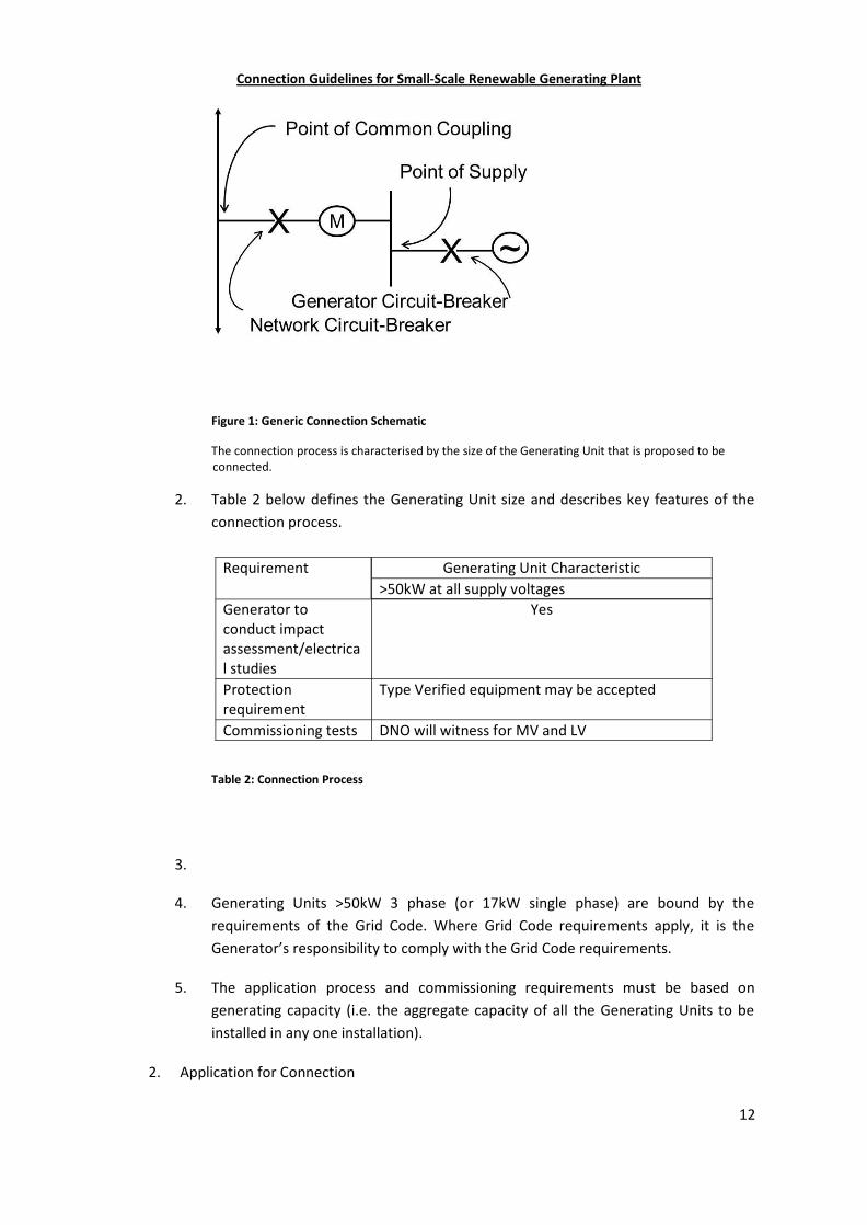
1. The generic connection arrangement and terminology is shown in Figure 1. Theasset boundary is the Point of Supply.
Connection Guidelines for Small-Scale Renewable Generating Plant
12
Figure 1: Generic Connection Schematic
The connection process is characterised by the size of the Generating Unit that is proposed to be connected.
2. Table 2 below defines the Generating Unit size and describes key features of theconnection process.
Requirement Generating Unit Characteristic>50kW at all supply voltages
Generator toconduct impactassessment/electrical studies
Yes
Protectionrequirement
Type Verified equipment may be accepted
Commissioning tests DNO will witness for MV and LV
Table 2: Connection Process
3.
4. Generating Units >50kW 3 phase (or 17kW single phase) are bound by therequirements of the Grid Code. Where Grid Code requirements apply, it is theGenerator’s responsibility to comply with the Grid Code requirements.
5. The application process and commissioning requirements must be based ongenerating capacity (i.e. the aggregate capacity of all the Generating Units to beinstalled in any one installation).
2. Application for Connection
Connection Guidelines for Small-Scale Renewable Generating Plant
13
1. Information about the Generating Plant is needed by the host network operator sothat it can assess the effect that the Generating Plant may have on the network. Inorder to simplify the connection process application forms are often used toreflect the fact that less information is required to connect a smaller GeneratingUnit than a larger one.
The information provided with the application based on using Type verifiedequipment, connected to the Generator’s own local distribution and utilisingapproved metering means that simplified arrangements can be adopted in allcases.
2. On receipt of the application using Standard Application Form, the host networkoperator will assess whether any network studies are required and whether thereis a requirement to witness the commissioning tests. The information providedwith the application should be sufficient to demonstrate whether the GeneratingUnit can be considered to be Type Verified so that the simplified arrangements canbe applied. In some cases studies to assess the impact on the Distribution Systemmay need to be undertaken before a firm quotation can be provided to theGenerator. Any works at the connection site and any associated facilitating workswill need to be completed before the Generating Unit can be commissioned. Onsuccessful completion of the commissioning tests by the commissioning engineer,the host network operator will sanction permanent connection of the GeneratingUnit.
3. For Generating Units below 10MW 3-phase detailed system studies will berequired and consequently the Generator to provide additional information.
3. System Analysis for Connection Design1. Host network operators use a variety of modelling tools to undertake system
analysis. Their exact needs for data and models will vary dependent on the voltagelevel, size, and location of the connection. Generally the host network operatorwill require the key information from the Generator via the application form,usually in a series of exchanges.
2. In the course of planning and designing a power system, it is often necessary tomodel a small section of the wider system in detail. This could be an embeddedsystem at 33kV or less, which is connected to the Transmission System via one ormore step-down transformers.
3. For plant connected at MV, it is generally necessary to build an equivalent modelof the Distribution System. This model will typically include equivalent sourcerepresenting existing Generating plant fault level arising from asynchronous plant,interconnection impedances, loads, and possibly the Generator's proposal forreactive compensation plant. The parameters of these elements will depend upon
Connection Guidelines for Small-Scale Renewable Generating Plant
14
the selection of the boundary nodes between the equivalent and detailednetworks in the model.
4. It may be beneficial to model some of the ‘active’ elements in full detail. Main grid,grid primary and other transformers can be considered active for the purpose ofdetermining voltage control limits. Knowledge of the voltage control set points,transformer tap changing ‘tolerances, and control methods is often essential. Alsoa knowledge of which items of Generating plant are mainly responsible for therange of fault contributions offered at the connection point by the host networkoperator is a useful addition.
Further fault contribution may also arise from other rotating plant within theGenerator infrastructure which may be enhanced under fault conditions.
5. The equivalent System model will not accurately represent the fast dynamic (subsecond) behaviour of the active elements within the Distribution and TransmissionSystem.
6. For synchronous machines, control systems for Generating Units and primemovers have traditionally been provided and modelled in transparent transferfunction block diagram form. These models have been developed over many yearsand include lead/lag elements, gains, limiters and non-linear elements and may be‘tuned’ to obtain a satisfactory response for the particular Generating Unit and gridconnection. The requirement to submit models in this form for directly connectedsynchronous Generating Units is written into the Grid Code.
7. For other generation technologies, the Grid Code includes the requirement tosubmit validated detailed models in respect of non-synchronous Generating Unitswhich are aggregated into a ‘Power Park Module’. A similar requirement may existwhere the host network operator deems it necessary to ensure System Stabilityand security.
8. Distribution network operators generally have a Grid Code obligation to ensurethat validated detailed models are obtained in respect of Generating Unitsembedded within their Distribution Systems unless they are connected at a voltagelevel below that of the lower voltage side of the relevant transmission gridtransformer. This requires the Generating Plant manufacturer to submit aGenerating unit or Power Park model in a format suitable for the TSO usually in adocumented block diagram format.
9. For the host network operator’s own purposes, should a model be required, itwould normally be requested in a compiled form suitable for use with theparticular variety of power system analysis software they use. Recently there is a
Connection Guidelines for Small-Scale Renewable Generating Plant
15
move by manufacturers to create ‘black-box’ models of their Generating Plant orPower Parks using their Generating units. These are programmed for compatibilitywith industry standard power analysis modelling packages. This is in order toprotect the manufacturers’ intellectual property and so lessen the need forconfidentiality agreements between parties. There are potential advantages anddisadvantages to this approach, but must be generally welcomed provided that thetwo main disadvantages of this approach, as described below, can be resolved:
a. The model must not be software version-specific i.e. will work in allfuture versions, or has an assurance of future upgrades for a particularsoftware package;
b. The Generator must provide assurance that the black box modelcorrectly represents the performance of the Generating Plant for loadflow, fault level and transient analysis for the typical range of faultsexperienced by host network operators.
c. The Generator must provide assurance that their system will operateeffectively both during commissioning (when the plant is islanded) andin an export mode.
6. CONNECTION ARRANGEMENTS
1. Operating Modes
1. Generating Plant may be designed for one of three operating modes. These aretermed:
long-term parallel operation;infrequent short-term parallel operation; and,switched alternative-only operation.
For the purpose of these guidelines all renewable energy sources are assumed tobe long-term parallel operation with very short periods of infrequent short-termparalleling operations only during commissioning, maintenance or under faultconsiderations which may result in islanded conditions. Switched alternative modeoperation is therefore not considered further in this guide.
The following application notes are therefore included for long and short termparalleling operation only.
2. Long-Term Parallel Operation
Connection Guidelines for Small-Scale Renewable Generating Plant
16
1. This refers to the frequent or long-term operation of Generating Plant in parallelwith the host network. Unless otherwise stated, all sections in these guidelines areapplicable to this mode of operation.
7. GENERATING PLANT CONNECTION DESIGN AND OPERATION
1. General Criteria
1. The Distribution System, and any Generating Plant connection to that
System, shall be designed:
a. to comply with the obligations (to include security, frequency andvoltage; voltage disturbances and harmonic distortion; autoreclosing and single phase protection operation).
b. according to design principles in relation to Distribution System'splant and equipment, earthing, voltage regulation and control, andprotection, subject to any modification to which the host networkoperator may reasonably consent.
2. Generating Plant should meet a set of technical requirements in relation to itsperformance with respect to frequency and voltage, control capabilities,protection coordination requirements, phase voltage imbalance requirements,neutral earthing provisions, islanding and black start capability.
2. Generating Plant Connection Designs
1. The connection of new Generators, to a Distribution System should not generallyincrease the risk of interruption to existing Customers. For example, alterations toexisting Distribution System designs that cause hitherto normally closed circuits tohave to run on open standby such that other Customers might becomedisconnected for the duration of the auto-switching times are to be avoided.
The security requirements for the connection of Generating Plant are subject toeconomic consideration by the host network operator and the Generator. A firmconnection for Generating Plant should allow the full MVA capacity to be exported
Connection Guidelines for Small-Scale Renewable Generating Plant
17
via the host network at all times of the year and after one outage on any onecircuit of that network.
2. Where the host network operator expects the Generating Plant to contribute tosystem security, the Generating Plant should either remain synchronised and inparallel with the Distribution System under the outage condition being considered,or be capable of being resynchronised within the specified time period. There maybe commercial issues to consider in addition to the connection cost and this mayinfluence the technical method which is used to achieve the desired security oravailability of supply.
3. When designing a scheme to connect Generating Plant, consideration must begiven to the contribution which that Generating Plant will make to short-circuitcurrent flows on the Distribution System. The assessment of the fault levelcontribution from Generating Plant and the impact on the suitability of connectedswitchgear are discussed in Section 7.4.
4. Unwanted tripping of the Generating Plant, particularly where the GeneratingPlant is providing Distribution System or System security should be avoided. Thequality of supply and Stability of Generating Plant performance are discussed inSections 7.6 and 7.7 respectively.
5. Generating Plant may be connected via existing circuits to which load and/orexisting Generating Plant and other Customers are also connected. The duty onsuch circuits, including load cycle, real and reactive power flows, and voltageimplications on the network will need to be carefully reviewed by the host networkoperator, taking account of maximum and minimum load and generation exportconditions during system intact conditions and for maintenance outages of boththe Distribution System and Generation Plant.
6. A host network operator assessing a proposed connection of Generating Plantmust also consider its effects on the Distribution System voltage profile andvoltage control employed on the Distribution System. Voltage limits and controlissues are discussed in Section 7.5.
3. Generating Plant Performance and Control Requirements
Connection Guidelines for Small-Scale Renewable Generating Plant
18
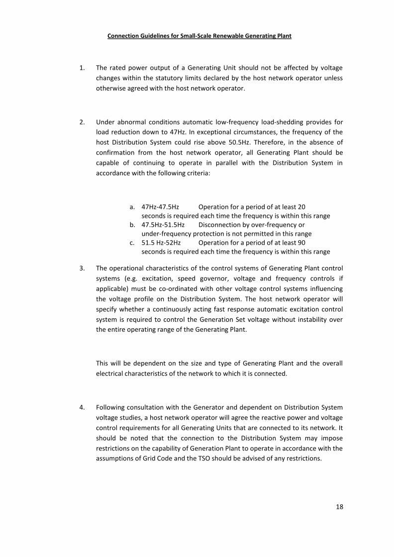
1. The rated power output of a Generating Unit should not be affected by voltagechanges within the statutory limits declared by the host network operator unlessotherwise agreed with the host network operator.
2. Under abnormal conditions automatic low-frequency load-shedding provides forload reduction down to 47Hz. In exceptional circumstances, the frequency of thehost Distribution System could rise above 50.5Hz. Therefore, in the absence ofconfirmation from the host network operator, all Generating Plant should becapable of continuing to operate in parallel with the Distribution System inaccordance with the following criteria:
a. 47Hz-47.5Hz Operation for a period of at least 20seconds is required each time the frequency is within this range
b. 47.5Hz-51.5Hz Disconnection by over-frequency orunder-frequency protection is not permitted in this range
c. 51.5 Hz-52Hz Operation for a period of at least 90seconds is required each time the frequency is within this range
3. The operational characteristics of the control systems of Generating Plant controlsystems (e.g. excitation, speed governor, voltage and frequency controls ifapplicable) must be co-ordinated with other voltage control systems influencingthe voltage profile on the Distribution System. The host network operator willspecify whether a continuously acting fast response automatic excitation controlsystem is required to control the Generation Set voltage without instability overthe entire operating range of the Generating Plant.
This will be dependent on the size and type of Generating Plant and the overallelectrical characteristics of the network to which it is connected.
4. Following consultation with the Generator and dependent on Distribution Systemvoltage studies, a host network operator will agree the reactive power and voltagecontrol requirements for all Generating Units that are connected to its network. Itshould be noted that the connection to the Distribution System may imposerestrictions on the capability of Generation Plant to operate in accordance with theassumptions of Grid Code and the TSO should be advised of any restrictions.
Connection Guidelines for Small-Scale Renewable Generating Plant
19
5. Each item of Generating Plant and its associated control equipment must bedesigned for stable operation in parallel with the local network.
6. Load flow and System Stability studies may be necessary to determine any outputconstraints or post fault actions necessary for fault and planned outages.(Commonly referred to as n-1 and n-2 conditions are the first and second outageconditions). It may be necessary under these fault conditions, where thecombination of Generating Plant output, load and through flow levels leads tocircuit overloading, to rapidly disconnect or constrain the Generating Plant.
4. Fault Level Contributions and Switchgear Considerations
1. The Generator and the host network operator have legal duties to ensure thattheir respective systems are capable of withstanding the short-circuit currentsassociated with their own equipment and any in-feed from any other connectedsystem.
2. The Generator may accept that protection installed on the network can helpdischarge some of his legal obligations relating to fault clearance and, if requested,the host network operator should consider allowing such faults on the Generator'ssystem to be detected by network protection systems and cleared by the hostnetwork operator's circuit breaker. The host network operator will not allow theGenerator to close the network operator's circuit breaker nor to synchronise usingthat circuit breaker. In all such cases the exact nature of the protection afforded bythe host network operator's equipment should be agreed and documented. Thehost network operator may make a charge for the provision of this service.
3. The design and safe operation of the Generator’s and the host network operator'sinstallation’s depend upon accurate assessment of the contribution to theshort-circuit current made by all the Generating Plant operating in parallel with theDistribution System at the instant of fault and the Generator should discuss thiswith the host network operator at the earliest possible stage.
4. Short-circuit current calculations should take account of the contributions from allsynchronous and asynchronous in-feeds including induction motors. Theprospective short-circuit ‘make’ and ‘break’ duties on switchgear should be
Connection Guidelines for Small-Scale Renewable Generating Plant
20
calculated to ensure that plant is not potentially over-stressed. The maximumshort-circuit duty might not occur under maximum generation conditions; it mayoccur during planned or automatic operations carried out either on theDistribution System or Transmission System. Studies must therefore consider allcredible Distribution System running arrangements which are likely to increaseDistribution System short-circuit levels. The level of load used should also reflectcommitted projects as well as the existing loads.
5. The connection of Generating Plant can raise the Distribution Systemreactance/resistance (X/R) ratio.
In some cases, this will place a more onerous duty on switchgear by
a) Increasing the duration and proportion of the DC component of faultcurrent from fault inception.
b) Delay the occurrence of current zeros with respect to voltage zeros duringthe interruption of fault current.
The performance of connected switchgear must be assessed to ensuresafe operation of the Distribution System. The protection performancemay also be impaired by partial or complete saturation of currenttransformers resulting from an increase in Distribution System X/R ratio.
6. Newly installed protection systems and circuit breakers for Generating Unitconnections should be designed, specified and operated to account for thepossibility of out-of-phase operation. It is expected that the host networkoperator's metering/interface circuit breaker will be specified for this duty, but inthe case of existing circuit breakers on the Distribution System, the host networkoperator will need to establish the possibility or otherwise of the host networkoperators protection (or the Generator’s protection if arranged to trip the hostnetwork operator's circuit breaker) initiating a circuit breaker trip during a periodwhen one of more Generating Units might have lost Synchronism with the System.Where necessary, switchgear replacement, improved security arrangements andother control measures should be considered to mitigate this risk.
Connection Guidelines for Small-Scale Renewable Generating Plant
21
7. When connection of Generating Plant is likely to increase short-circuit currentsabove Distribution System design ratings, consideration should be given to thefollowing:-
a) Installation of reactors.
b) Sectionalising networks.
c) Connecting the Generating Plant to part of the Distribution Systemoperating at a higher voltage.
d) Changing the Generating Unit specification or other means of limitingshort-circuit current in-feed.
If fault limiting measures are not cost effective or feasible or have amaterial detrimental effect on other users, Distribution System plant withthe potential to be subjected to short-circuit currents in excess of its ratingshould be replaced or reference made to the relevant manufacturer todetermine whether or not the existing plant rating(s) can be enhanced. Insituations where Distribution System design ratings would be exceeded ininfrequent Distribution System configurations, then constraining theGenerating Plant off during periods of such Distribution Systemconfigurations may provide a suitable solution but noting the requirementsof any commercial agreements.
When assessing short-circuit currents against Distribution System designratings, suitable safety margins should be allowed to cater for tolerancesthat may exist in the Distribution System data and Generating Unitparameters used in system modelling programs.
8. For busbars with three or more direct connections to the rest of the System,consideration may be given to reducing fault levels by having one of theconnections 'open' and on automatic standby. This arrangement will only beacceptable provided that the loss of one of the remaining circuits will not causethe group to come out of Synchronism, cause unacceptable voltage excursions oroverloading of Distribution System or Transmission System plant and equipment.
9. Disconnection of Generating Plant must be achieved by the separation ofmechanical contacts unless the disconnection is at Low Voltage and the equipmentat the point of disconnection contains appropriate self-monitoring of the point ofdisconnection, in which case an appropriate electronic means such as a suitably
Connection Guidelines for Small-Scale Renewable Generating Plant
22
rated semiconductor switching device would be acceptable. The self-monitoringfacility shall incorporate fail safe monitoring to check the voltage level at theoutput stage. In the event that the solid state switching device fails to disconnectthe Generating Unit, the voltage on the output side of the switching device mustbe reduced to a value below 50V within 0.5s to provide LoM disconnection andearth fault protection.
5. Voltage Limits and Control
1. Where Generating Plant is remote from a network voltage control point it may berequired to withstand voltages outside the normal statutory limits. In thesecircumstances, the host network operator should agree with the Generator thedeclared voltage and voltage range at the Connection Point. As a guide acceptanceof the Generating Plant to voltage changes of ±10% of the declared voltage isrecommended, subject to assessment of individual cases.
2. The connection of a Generating Plant to the Distribution System shall be designedin such a way that operation of the Generating Plant does not adversely affect thevoltage profile of and voltage control employed on the Distribution System. Hostnetwork operators have a number of methods for overcoming voltage controllimitations.
3. Where it is agreed that the Generation Plant should operate in voltage control (PV)mode or where there is a need to operate to a ‘setpoint voltage’ and ‘slope’, theGenerating Plant will have a specific role to control the Distribution Systemvoltage. The final responsibility for control of Distribution System voltage doeshowever remain with the host network operator.
4. Automatic Voltage Control (AVC) schemes employed by the host network operatorassume that power flows from parts of the System operating at a higher voltage toparts of the System operating at lower voltages. Export from Generating Plant inexcess of the local loads may result in power flows in the reverse direction. In thiscase AVC referenced to the low voltage side will not operate correctly without animport of reactive power and relay settings appropriate to this operatingcondition. When load current compounding is used with the AVC and thepenetration level of Generating Plant becomes significant compared to normalloads, it may be necessary to switch any compounding out of service.
Connection Guidelines for Small-Scale Renewable Generating Plant
23
5. Generating Plant can cause problems if connected to networks employing AVCschemes which use negative reactance compounding and line drop compensationdue to changes in active and reactive power flows. Techniques such as removingthe generation circuit from the AVC scheme using cancellation CTs can addressthis.
6. An agreement between the host network operator and the Generator may allowthe use of voltage control techniques other than those previously mentioned. Suchan agreement would normally be reached during the negotiating stage of theconnection.
7. The Step Voltage Change caused by the connection and disconnection ofGenerating Plant from the Distribution System must be considered and be subjectto limits to avoid unacceptable voltage changes being experienced by otherCustomers connected to the System. The magnitude of a Step Voltage Changedepends on the method of voltage control, types of load connected and thepresence of local generation.
Typical limits for Step Voltage Change caused by the connection and disconnectionof any Customers equipment to the Distribution System should be ±3% forinfrequent planned switching events or planned outages. For unplanned outagessuch faults it will generally be acceptable to design to a Step Voltage Change of±10%.
8. The voltage reduction arising from transformer magnetising inrush current is ashort-time phenomenon not generally easily captured by the definition of StepVoltage Change used in this document. In addition the quantum is dependent onthe exact point on the cycle of switching and the duration of the depression isrelatively short in that the voltage recovers substantially in less than one second.
9. Customer Installations should be designed such that transformer magnetisinginrush current associated with normal routine switching operations does not causevoltage fluctuations outside ±3%. To achieve this it may be necessary to installswitchgear so that sites containing multiple transformers can be energised instages.
Connection Guidelines for Small-Scale Renewable Generating Plant
24
10. Situations will arise from time to time when complete sites including a significantproportion of interconnected transformers are energised as a result of post faultswitching, post fault maintenance switching or carrying out commissioning tests onthe Distribution System. In these situations it will generally be acceptable todesign to an expected depression of around 10% recognising that a worst caseenergisation might result in a larger depression, such events are considered to berare and it is difficult to predict the exact depression because of the uncertaintywhen the switching occurs on the cycle. Should these switching events becomemore frequent than once per year then the design should revert to aiming to limitdepressions to less than 3%.
11. These threshold limits should be complied with at the Point of Common Coupling.
6. Power Quality
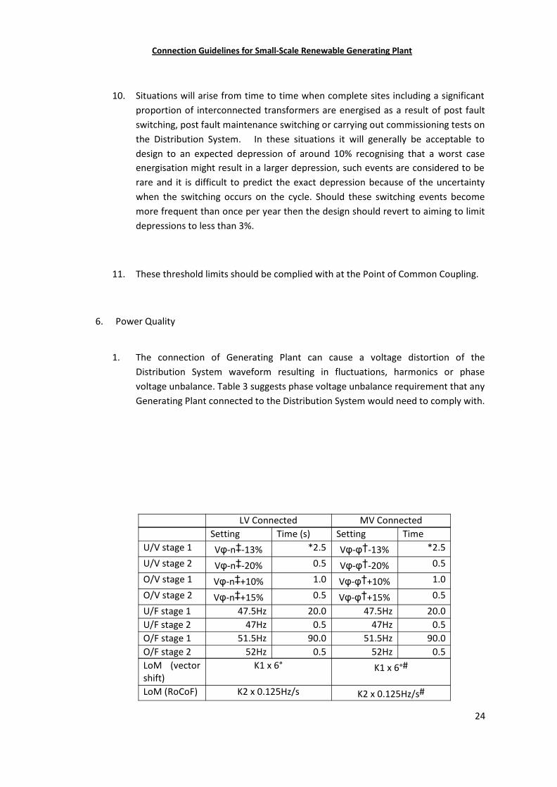
1. The connection of Generating Plant can cause a voltage distortion of theDistribution System waveform resulting in fluctuations, harmonics or phasevoltage unbalance. Table 3 suggests phase voltage unbalance requirement that anyGenerating Plant connected to the Distribution System would need to comply with.
LV Connected MV ConnectedSetting Time (s) Setting Time
U/V stage 1 Vφ-n‡-13% *2.5 Vφ-φ†-13% *2.5
U/V stage 2 Vφ-n‡-20% 0.5 Vφ-φ†-20% 0.5
O/V stage 1 Vφ-n‡+10% 1.0 Vφ-φ†+10% 1.0
O/V stage 2 Vφ-n‡+15% 0.5 Vφ-φ†+15% 0.5
U/F stage 1 47.5Hz 20.0 47.5Hz 20.0U/F stage 2 47Hz 0.5 47Hz 0.5O/F stage 1 51.5Hz 90.0 51.5Hz 90.0O/F stage 2 52Hz 0.5 52Hz 0.5LoM (vectorshift)
K1 x 6° K1 x 6°#
LoM (RoCoF) K2 x 0.125Hz/s K2 x 0.125Hz/s#
Connection Guidelines for Small-Scale Renewable Generating Plant
25
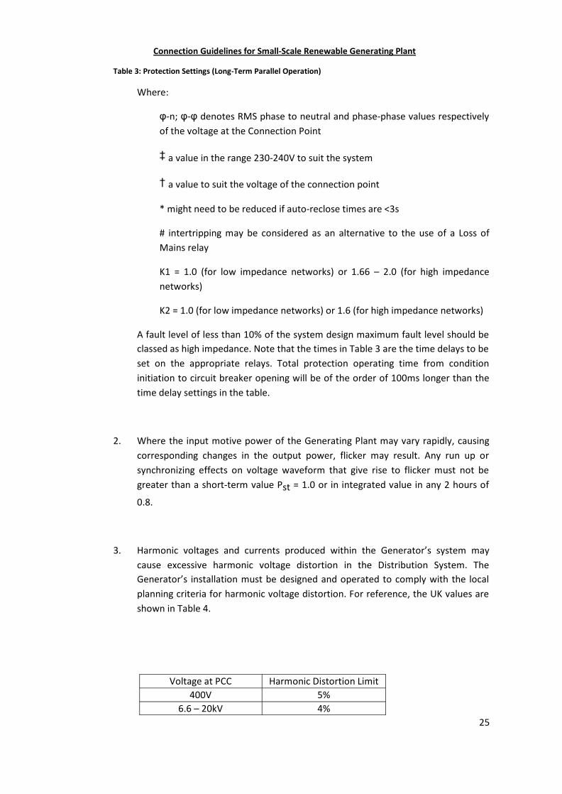
Table 3: Protection Settings (Long-Term Parallel Operation)
Where:
φ-n; φ-φ denotes RMS phase to neutral and phase-phase values respectivelyof the voltage at the Connection Point
‡ a value in the range 230-240V to suit the system
† a value to suit the voltage of the connection point
* might need to be reduced if auto-reclose times are <3s
# intertripping may be considered as an alternative to the use of a Loss ofMains relay
K1 = 1.0 (for low impedance networks) or 1.66 – 2.0 (for high impedancenetworks)
K2 = 1.0 (for low impedance networks) or 1.6 (for high impedance networks)
A fault level of less than 10% of the system design maximum fault level should beclassed as high impedance. Note that the times in Table 3 are the time delays to beset on the appropriate relays. Total protection operating time from conditioninitiation to circuit breaker opening will be of the order of 100ms longer than thetime delay settings in the table.
2. Where the input motive power of the Generating Plant may vary rapidly, causingcorresponding changes in the output power, flicker may result. Any run up orsynchronizing effects on voltage waveform that give rise to flicker must not begreater than a short-term value Pst = 1.0 or in integrated value in any 2 hours of
0.8.
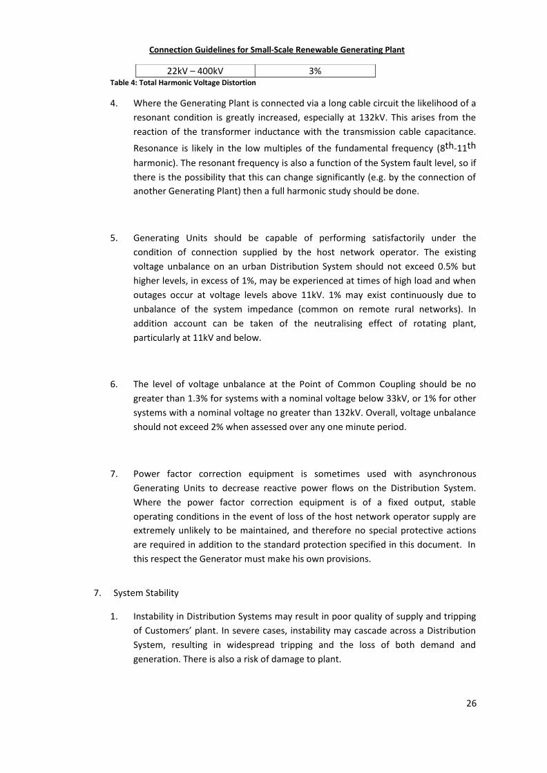
3. Harmonic voltages and currents produced within the Generator’s system maycause excessive harmonic voltage distortion in the Distribution System. TheGenerator’s installation must be designed and operated to comply with the localplanning criteria for harmonic voltage distortion. For reference, the UK values areshown in Table 4.
Voltage at PCC Harmonic Distortion Limit400V 5%
6.6 – 20kV 4%
Connection Guidelines for Small-Scale Renewable Generating Plant
26
22kV – 400kV 3%Table 4: Total Harmonic Voltage Distortion
4. Where the Generating Plant is connected via a long cable circuit the likelihood of aresonant condition is greatly increased, especially at 132kV. This arises from thereaction of the transformer inductance with the transmission cable capacitance.
Resonance is likely in the low multiples of the fundamental frequency (8th-11th
harmonic). The resonant frequency is also a function of the System fault level, so ifthere is the possibility that this can change significantly (e.g. by the connection ofanother Generating Plant) then a full harmonic study should be done.
5. Generating Units should be capable of performing satisfactorily under thecondition of connection supplied by the host network operator. The existingvoltage unbalance on an urban Distribution System should not exceed 0.5% buthigher levels, in excess of 1%, may be experienced at times of high load and whenoutages occur at voltage levels above 11kV. 1% may exist continuously due tounbalance of the system impedance (common on remote rural networks). Inaddition account can be taken of the neutralising effect of rotating plant,particularly at 11kV and below.
6. The level of voltage unbalance at the Point of Common Coupling should be nogreater than 1.3% for systems with a nominal voltage below 33kV, or 1% for othersystems with a nominal voltage no greater than 132kV. Overall, voltage unbalanceshould not exceed 2% when assessed over any one minute period.
7. Power factor correction equipment is sometimes used with asynchronousGenerating Units to decrease reactive power flows on the Distribution System.Where the power factor correction equipment is of a fixed output, stableoperating conditions in the event of loss of the host network operator supply areextremely unlikely to be maintained, and therefore no special protective actionsare required in addition to the standard protection specified in this document. Inthis respect the Generator must make his own provisions.
7. System Stability
1. Instability in Distribution Systems may result in poor quality of supply and trippingof Customers’ plant. In severe cases, instability may cascade across a DistributionSystem, resulting in widespread tripping and the loss of both demand andgeneration. There is also a risk of damage to plant.
Connection Guidelines for Small-Scale Renewable Generating Plant
27
2. In general, System Stability is an important consideration in the design ofGenerating Plant connections to the Distribution System especially at 33kV butmay also be appropriate for some Generating Plant connections at lower voltages.The risks of instability generally increase as Generating Plant capacity increasesrelative to the fault level in-feed from the Distribution System at the ConnectionPoint.
3. System Stability may be classified into several forms, according firstly to the mainsystem variable in which instability can be observed, and secondly to the size ofthe system disturbance. In Distribution Systems, the forms of stability of interestare rotor angle stability and voltage stability.
Rotor angle stability refers to the ability of synchronous machines in aninterconnected system to remain in synchronism after the system issubjected to a disturbance.
Voltage stability refers to the ability of a system to maintain acceptablevoltages throughout the system after being subjected to a disturbance.
4. Both rotor angle stability and voltage stability can be further classified according tothe size of the disturbance.
Small-disturbance stability refers to the ability of a system to maintainstability after being subjected to small disturbances such as smallchanges in load, operating points of Generating Units, transformertap-changing or other normal switching events.
Large-disturbance stability refers to the ability of a system to maintainstability after being subjected to large disturbances such as short-circuitfaults or sudden loss of circuits or Generating Units.
5. Generating Plant and its connection to the Distribution System should be designedto maintain stability of the Distribution System for a defined range of initialoperating conditions and a defined set of system disturbances.
The range of initial operating conditions should be based on those which arereasonably likely to occur over a year of operation. Variables to consider include
Connection Guidelines for Small-Scale Renewable Generating Plant
28
system loads, system voltages, system outages and configurations, and GeneratingPlant operating conditions.
The system disturbances for which stability should be maintained should beselected on the basis that they have a reasonably high probability of occurrence. Itis recommended that these include short-circuit faults on single DistributionSystem circuits (such as transformers, overhead lines and cables) and busbars, thatare quickly cleared by main protection.
It should be noted that it is impractical and uneconomical to design for stability inall circumstances. This may include double circuit fault outages and faults that arecleared by slow protection.
Generating Units that become unstable following system disturbances should bedisconnected as soon as possible.
6. Various measures may be used, where reasonably practicable, to prevent ormitigate system instability. These may include Distribution System and GeneratingPlant solutions, such as:
improved fault clearance times by means of faster protection;
improved performance of Generating Plant control systems (excitationand governor/prime mover control systems; Power System Stabilisers toimprove damping);
improved system voltage support (provision from either GeneratingPlant or Distribution System plant);
reduced plant reactances (if possible);
Protection to identify pole-slipping;
Increased fault level in-feed from the Distribution System at theConnection Point.
In determining mitigation measures which are reasonably practicable, dueconsideration should be given to the cost of implementing the measures andthe benefits to the Distribution System Generators and Customers in terms ofreduced risk of system instability.
Connection Guidelines for Small-Scale Renewable Generating Plant
29
8. Island Mode
1. A fault or planned outage, which results in the disconnection of a Generating Unit,together with an associated section of Distribution System, from the remainder ofthe System, creates the potential for island mode operation. This may also occurduring the initial commissioning stages when there are advantages in notconnecting the Generating plant to the wider network. The key potentialadvantage of operating in Island mode is to maintain continuity of supply to theportion of the Distribution System containing the Generating Unit. The principlesdiscussed in this section generally also apply where Generation Plant on aCustomer’s site is designed to maintain supplies to that site in the event of afailure of the host network operator supply.
2. When considering whether Generating Plant can be permitted to operate in islandmode, detailed studies need to be undertaken to ensure that the islanded system willremain stable and comply with all statutory obligations and relevant planning standardswhen separated from the remainder of the System. Before operation in island mode canbe allowed, a contractual agreement between the host network operator and Generatormust be in place and the legal liabilities associated with such operation must be carefullyconsidered by the host network operator and the Generator. Consideration should begiven to the following areas:
a. load flows, voltage regulation, frequency regulation, voltage unbalance,voltage flicker and harmonic voltage distortion;
b. earthing arrangements;c. short-circuit currents, adequacy of protection arrangements;d. System Stability;e. resynchronisation to the System;f. safety of personnel.
3. Suitable equipment will need to be installed to detect that an island situation hasoccurred and an intertripping scheme is preferred to provide absolutediscrimination at the time of the event. Confirmation that a section of DistributionSystem is operating in island mode, and has been disconnected from the networkwill need to be transmitted to the Generating Unit(s) protection and controlschemes.
4. Supplies to Customers must be maintained within statutory limits at all times i.e.when they are supplied normally and when operating in island mode. Detailedsystem studies including the capability of the Generating Plant and its control/protections systems will be required to determine the capability of the Generating
Connection Guidelines for Small-Scale Renewable Generating Plant
30
Plant to meet these requirements immediately as the island is created and for theduration of the island mode operation.
5. Distribution Systems must also be earthed at all times. Generators, who are notpermitted to operate their installations and plant with an earthed star-point whenin parallel with the Distribution System, must provide an earthing transformer orswitched star-point earth for the purpose of maintaining an earth on the systemwhen islanding occurs. The design of the earthing system that will exist duringisland mode operation should be carefully considered to ensure statutoryobligations are met and that safety of the Distribution System to all users ismaintained. Further details are provided in Section 9.
6. Detailed consideration must be given to ensure that protection arrangements areadequate to satisfactorily clear the full range of potential faults within the islandedsystem taking into account the reduced fault currents and potential longerclearance times that are likely to be associated with an islanded system.
7. Switchgear shall be rated to withstand the voltages which may exist across opencontacts under islanded conditions. The host network operator may requireinterlocking and isolation of its circuit breaker(s) to prevent out of phase voltagesoccurring across the open contacts of its switchgear, intertripping or interlockingshould be agreed between the host network operator and the Generator whereappropriate.
8. Generally it will not be permissible to interrupt supplies to host network operatorCustomers for the purposes of resynchronisation. The design of the islandedsystem must ensure that synchronising facilities are provided at the point ofisolation between the islanded network and the host network operator supply.Specific arrangements for this should be agreed and recorded in the ConnectionAgreement with the host network operator.
8. PROTECTION
1. General
1. The main function of the protection systems and settings described in thisdocument is to prevent the Generating Plant supporting an islanded section of the
Connection Guidelines for Small-Scale Renewable Generating Plant
31
Distribution System when it would or could pose a hazard to the DistributionSystem or customers connected to it. The settings recognize the need to avoidnuisance tripping and therefore require a two stage approach where practicable,i.e. to have a long time delay for smaller excursions that may be experiencedduring normal Distribution System operation, to avoid nuisance tripping, but with afaster trip for greater excursions.
2. In accordance with established practice it is for the Generator to install, own andmaintain this protection. The Generator can therefore determine the approach, i.e.per Generating Unit or per installation, and where in the installation the protectionis sited.
2. Protection Requirements
1. The basic requirements for protection are laid out in Table 3. It is in the interest ofGenerators, DNOs and the TSO that Generating Plant remains synchronised to theDistribution System during system disturbances, and conversely to disconnectreliably for true Loss of Mains situations.
2. Other protection could be required and may include the detection of:
Neutral Voltage Displacement (NVD)
Over Current
Earth Fault
Reverse Power
This protection will normally be installed on equipment owned by the hostnetwork operator unless otherwise agreed between the host network operatorand Generator. This additional protection which is required by the host networkoperator to supplement over current and earth fault protection and protect theDistribution System from the Generating Plant may be installed and arranged tooperate the host network operator interface circuit breaker or any other breakers,subject to the agreement of the host network operator and the Generator.
Connection Guidelines for Small-Scale Renewable Generating Plant
32
When intertripping is considered to be a practical alternative, for detecting a LoMevent, to using discriminating protection relays, the intertripping equipment wouldbe installed by the host network operator.
3. The protective equipment, provided by the Generator, to meet the requirementsof this section must be installed in a suitable location that affords immediate visualinspection of the relays but is secure from interference by unauthorised personnel.
4. If automatic resetting of the protective equipment is used, there must be a timedelay to ensure that healthy supply conditions exist for a minimum continuousperiod of 60s. Reset times may need to be co-ordinated where more than oneGenerating Plant is connected to the same feeder. The automatic reset must beinhibited for faults on the Generator’s installation.
5. Protection equipment is required to function correctly within the environment inwhich it is placed and should satisfy international standards such as:
BS EN61000 (Electromagnetic Standards) BS EN60255 (Electrical Relays);
BS EN61810 (Electrical Elementary Relays);
BS EN60947 (Low Voltage Switchgear and Control gear); BS EN60044(Instrument Transformers).
6. Protection equipment and protection functions may be installed within, or formpart of the Generating Plant control equipment as long as:
a. the control equipment satisfies all the requirements of Section 8.
b. the Generating Plant shuts down in a controlled and safe manner shouldthere be an equipment failure that affects both the protection andcontrol functionality, for example a power supply failure ormicroprocessor failure.
c. the equipment is designed and installed so that protection calibrationand functional tests can be carried out easily and safely using secondaryinjection techniques (i.e. using separate low voltage test equipment).
3. Loss of Mains ( LoM)
Connection Guidelines for Small-Scale Renewable Generating Plant
33
1. In addition to protection installed by the Generator for his own purposes, theGenerator must install protection to achieve (amongst other things) disconnectionof the Generating Plant from the Distribution System in the event of loss of one ormore phases of the host network operators supply. This LoM protection is requiredto ensure that the Generating Plant is disconnected, to ensure that therequirements for Distribution System earthing, and out-of-Synchronism closure arecomplied with and that Customers are not supplied with voltage and frequenciesoutside statutory limits.
2. A problem can arise for Generators who operate Generating Plant in parallel withthe Distribution System prior to a failure of the network supply because if theirGenerating Plant continues to operate in some manner, even for a relatively shortperiod of time, there is a risk that when the network supply is restored theGenerating Plant will be out of Synchronism with the System and suffer damage.LoM protection can be employed to disconnect the Generating Plant immediatelyafter the supply is lost, thereby avoiding damage to the Generating Plant.
3. Some Customers may be connected to parts of Distribution Systems which areautomatically re-energised within a relatively short period following a fault; withdead times typically between 1s and 180s. The use of such schemes is likely toincrease in future as host network operators seek to improve supply availability byinstalling automatic switching equipment on their Distribution Systems.
4. Where the amount of Distribution System load that the Generating Plant willattempt to pick up following a fault on the Distribution System is significantly morethan its capability the Generating Plant will rapidly disconnect, or stall. Howeverdepending on the exact conditions at the time of the Distribution System failure,there may or may not be a sufficient change of load on the Generating Plant to beable to reliably detect the failure. The Distribution System failure may result in oneof the following load conditions being experienced by the Generating Plant:
a. The load may slightly increase or reduce, but remain within the capability ofthe Generating Plant. There may even be no change of load;
b. The load may increase above the capability of the prime mover, in whichcase the Generating Plant will slow down, even though the alternator maymaintain voltage and current within its capacity. This condition ofspeed/frequency reduction can be easily detected; or
Connection Guidelines for Small-Scale Renewable Generating Plant
34
c. The load may increase to several times the capability of the GeneratingPlant, in which case the following easily detectable conditions will occur:
Overload and accompanying speed/frequency reduction
Over current and under voltage on the alternator
5. Conditions (b) and (c) are easily detected by the under and over voltage andfrequency protection required in this document. However condition (a) presentsmost difficulty, particularly if the load change is extremely small and thereforethere is a possibility that part of the Distribution System supply being supplied bythe Generating Plant will be out of Synchronism with the System. LoM protectionis designed to detect these conditions. In some particularly critical circumstances itmay be necessary to improve the dependability of LoM detection by using at leasttwo LoM techniques operating with different principles or by employing a LoMrelay using active methods. LoM signals can also be provided by means ofintertripping signals from circuit breakers that have operated in response to theDistribution System fault. Both these methods are discussed below.
6. The LoM protection can utilise one or a combination of the passive protectionprinciples such as reverse power flow, reverse reactive power, rate of change offrequency (RoCoF) and voltage vector phase shift. Alternatively, active methodssuch as reactive export error detection or frequency shifting may be employed.These may be arranged to trip the interface circuit breaker at the host networkoperator Generator interface, thus, leaving the Generating Plant available tosatisfy the load requirements of the site or the Generating Plant circuit breaker canbe tripped, leaving the breaker at the interface closed and ready to resume supplywhen the Distribution System supply is restored.
The most appropriate arrangement is subject to agreement between the hostnetwork operator and Generator.
7. Protection based on measurement of reverse flow of real or reactive power can beused when circumstances permit and must be set to suit the Generating Plantrating, the site load conditions and requirements for reactive power.
8. Where the Generating Plant capacity is such that the site will always import powerfrom the Distribution System, a reverse power relay may be used to detect failureof the supply. It will usually be appropriate to monitor all three phases for reversepower.
Connection Guidelines for Small-Scale Renewable Generating Plant
35
9. However, where the Generating Plants normal mode of operation is to exportpower, it is not possible to use a reverse power relay and consequently failure ofthe supply cannot be detected by measurement of reverse power flow. Theprotection should then be specifically designed to detect loss of the mainsconnection using techniques to detect the rate of change of frequency or suddenphase shifts of voltage vector and/or power factor. All these techniques aresusceptible to Distribution System conditions and the changes that occur withoutislanding taking place. These relays must be set to prevent islanding but with thebest possible immunity to unwanted nuisance operation.
10. Both RoCoF and vector phase shift relays use a measurement of the period of themains voltage cycle. The RoCoF technique measures the rate of change infrequency caused by any difference between prime mover power and electricaloutput power of the embedded Generating Plant over a number of cycles. RoCoFrelays should normally ignore the slow changes but respond to relatively rapidchanges of frequency which occur when the Generation Plant becomesdisconnected from the System. The voltage vector shift technique tries to detectthe shift in the voltage vector caused by a sudden change in the output ofGenerating Plant or load over one or two cycles (or half cycles). The mainadvantage of a vector shift relays is its speed and response to transientdisturbances which are common to the onset of islanding but often difficult toquantify. Speed of response is also very important where high speed auto reclosingschemes are present.
11. The LoM relay that operates on the principle of voltage vector shift can achievefast disconnection for close up Distribution System faults and power surges, andunder appropriate conditions can also detect islanding when normally a large stepchange in generation occurs. The relay measures the period for each half cycle indegrees and compares it with the previous one to determine if this exceeds itssetting. A typical setting is 6 degrees, which is normally appropriate to avoidoperation for most normal vector changes in low impedance Distribution Systems.This equates to a constant rate of change of frequency of about 1.67Hz/s andhence the relay is insensitive to slow rates of change of frequency. When vectorshift relays are used in higher impedance Distribution Systems, and especially onrural Distribution Systems where auto-reclosing systems are used, a higher settingmay be required to prevent nuisance tripping. Typically this is between 10 and 12degrees however these figures are given as a guide and confirmation must besought from the DNO.
Connection Guidelines for Small-Scale Renewable Generating Plant
36
12. Raising settings on any relay to avoid spurious operation may reduce a relay'scapability to detect islanding and it is important to evaluate fully such changes. Insome circumstances it may be necessary to employ a different technique, or acombination of techniques to satisfy the conflicting requirements of safety andavoidance of nuisance tripping. In those cases where the host network operatorrequires LoM protection this must be provided by a means not susceptible tospurious or nuisance tripping, e.g. intertripping.
13. For a radial or simple Distribution System controlled by circuit breakers that wouldclearly disconnect the entire circuit and associated Generating Plant, for a LoMevent an intertripping scheme can be easy to design and install. For meshed or ringDistribution Systems, it can be difficult to define which circuit breakers may needto be incorporated in an intertripping scheme to detect a LoM event and theinherent risks associated with a complex system should be considered alongsidethose associated with using a simple, but potentially less discriminatory LoM relay.
14. It is the responsibility of the Generator to incorporate the most appropriatetechnique or combination of techniques to detect a LoM event in his protectionsystems. This will be based on knowledge of the Generating Unit, site and networkload conditions. The host network operator will assist in the decision makingprocess by providing information on the Distribution System and its loads. Thesettings applied must be biased to ensure detection of islanding under all practicaloperating conditions.
4. Neutral Voltage Displacement Protection
1. NVD protection can be used to prevent the unsafe situation where GeneratingPlant inadvertently becomes operating in island mode, as described in Section 7.8above, and where there is an earth fault existing on the host network operatorsMV system. In these Circumstances the NVD protection fitted on the host networkoperators MV switchgear will detect the earth fault, and disconnect the MVSystem from the island.
2. Host network operators need to consider specific investigation of the need forNVD protection when, downstream of the same prospective island boundary,there are one or more Generating Units (with an output greater than 200kVA perunit) having the enabled capacity to dynamically alter real and reactive poweroutput in order to maintain voltage profiles, and where such aggregate embeddedgeneration output exceeds 50% of prospective island minimum demand.
Connection Guidelines for Small-Scale Renewable Generating Plant
37
3. As a general rule for generation installations smaller than 5MW and connected at20kV or lower voltages host network operators will not require NVD protection forthe following circumstances;
Single new Generating Unit connection, of any type with an output lessthan 200kVA.
Multiple new Generating Unit connections, of any type, on a single site,with an aggregated output less than 200kVA.
Single or multiple new Generating Unit connections, of any type, wherethe voltage control is disabled or not fitted, on a single site, and wherethe aggregate output is greater than 200kVA.
Single or multiple new Generating Unit connections, of any type, andwhere the voltage control is enabled, on a single site, where theaggregate output is greater than 200kVA ,but where the aggregateoutput is less than 50% of the prospective island minimum demand.
4. If the assessed minimum load on a prospective island is less than twice themaximum combined output of new Generator(s) consideration should be given touse of NVD protection as a part of the interface protection. The considerationshould include an assessment of:
The specification of capability of the LoM protection, including theprovision of multiple independent detection techniques.
The influence of activation of pre-existing NVD protection alreadypresent elsewhere on the same prospective island.
The opportunity arising from asset change/addition associated with theproposed new Generator(s) connection e.g. the margin of additionalcost associated with NVD protection.
5. With arc suppression coil systems, the NVD relay should be arranged to provide analarm only.
5. Protection Settings
1. The protection systems and settings can have an impact on the behaviour ofGenerating Plant when the System is in distress. Where Generating Plant has thecapability to operate at the extremes of the possible operating range of theSystem, it would be inappropriate to artificially impose protection settings that
Connection Guidelines for Small-Scale Renewable Generating Plant
38
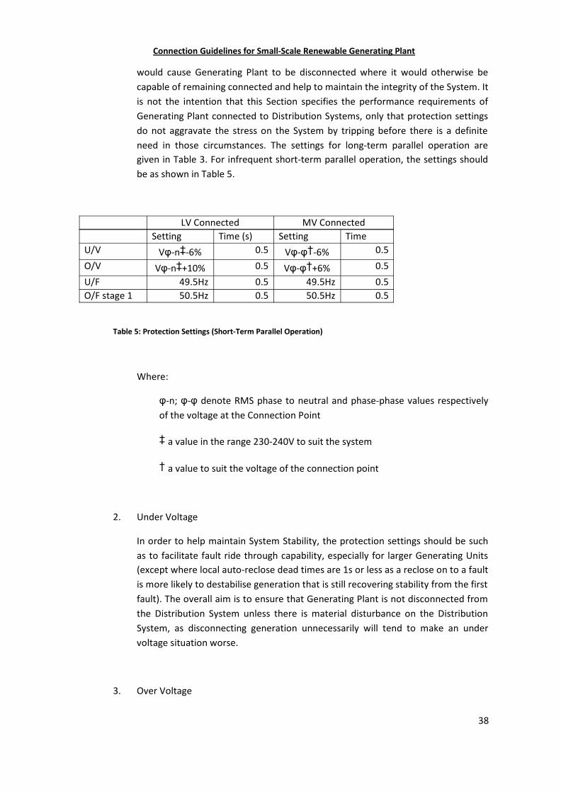
would cause Generating Plant to be disconnected where it would otherwise becapable of remaining connected and help to maintain the integrity of the System. Itis not the intention that this Section specifies the performance requirements ofGenerating Plant connected to Distribution Systems, only that protection settingsdo not aggravate the stress on the System by tripping before there is a definiteneed in those circumstances. The settings for long-term parallel operation aregiven in Table 3. For infrequent short-term parallel operation, the settings shouldbe as shown in Table 5.
LV Connected MV ConnectedSetting Time (s) Setting Time
U/V Vφ-n‡-6% 0.5 Vφ-φ†-6% 0.5
O/V Vφ-n‡+10% 0.5 Vφ-φ†+6% 0.5
U/F 49.5Hz 0.5 49.5Hz 0.5O/F stage 1 50.5Hz 0.5 50.5Hz 0.5
Table 5: Protection Settings (Short-Term Parallel Operation)
Where:
φ-n; φ-φ denote RMS phase to neutral and phase-phase values respectivelyof the voltage at the Connection Point
‡ a value in the range 230-240V to suit the system
† a value to suit the voltage of the connection point
2. Under Voltage
In order to help maintain System Stability, the protection settings should be suchas to facilitate fault ride through capability, especially for larger Generating Units(except where local auto-reclose dead times are 1s or less as a reclose on to a faultis more likely to destabilise generation that is still recovering stability from the firstfault). The overall aim is to ensure that Generating Plant is not disconnected fromthe Distribution System unless there is material disturbance on the DistributionSystem, as disconnecting generation unnecessarily will tend to make an undervoltage situation worse.
3. Over Voltage
Connection Guidelines for Small-Scale Renewable Generating Plant
39
Over voltages are potentially more dangerous than under voltages and hence theacceptable excursions form the norm are smaller and time delays shorter, a2-Stage over voltage protection is as follows:
Stage 1 (LV and MV) should have a permitted time delay of 1.0s and asetting of +10% (i.e. the LV statutory upper voltage limit of 10%, butwith a time delay to avoid nuisance tripping for short durationexcursions).
Stage 2 (LV) should have a setting of +15%, 0.5s (i.e. recognising theneed to disconnect quickly for a material excursion).
Stage 2 (MV) should have a setting of +13%, 0.5s (i.e. recognising theneed to disconnect quickly for a material excursion).
To achieve high utilisation and Distribution System efficiency, it is common for theMV Distribution System to be normally operated near to the upper statutoryvoltage limits. The presence of Generating Plant within such Distribution Systemsmay increase the risk of the statutory limit being exceeded, e.g. when theDistribution System is operating abnormally. In such cases the host networkoperator may specify additional over voltage protection at the Generating Plantconnection point.
This protection will typically have an operating time delay long enough to permitthe correction of transient over voltages by automatic tap-changers.
4. Over and Under voltage protection must operate independently for all threephases in all cases.
5. Over FrequencyIn order to provide the necessary regulation to control the System frequency to asatisfactory level and to prevent the unnecessary disconnection of a large volumeof smaller Generating Plant, all LV and MV connected Generating Plant shouldhave a 2-stage protection:
Stage 1 should have a time delay of 90s and a setting of 51.5Hz. The 90ssetting should provide sufficient time for the TSO to bring the Systemfrequency below this level. Should the frequency rise be the result of agenuine islanding condition which the LoM protection fails to detect,this setting will help to limit the duration of the islanding period.
Connection Guidelines for Small-Scale Renewable Generating Plant
40
Stage 2 should have a time delay of 0.5s and a setting of 52Hz (i.e. tocoordinate with the Grid Code requirement with a practical time delaythat can be tolerated by most Generating Plant). If the frequency rise toand above 52Hz is the result of an undetected islanding condition, theGenerating Plant will be disconnected within 0.5s.
6. Under FrequencyFor all LV and MV connected Generating Plant, the following 2-stage underfrequency protection should be applied:
Stage 1 should have a setting of 47.5 Hz (time delayed by 20s)
Stage 2 should have a setting of 47.0 Hz (time delayed by 0.5s) which arein line with the Grid Code requirements.
7. Loss of Mains (LoM)In order to avoid unnecessary disconnection of Generating Plant duringDistribution System faults or switching events and the consequent disruption toGenerators and customers, as well as take into account the aggregate effectcaused by multiple LoM operations on System Stability, consideration should begiven to use of the appropriately sensitive settings which can be adjusted to takeinto account Generating Plant type & rating and Distribution System fault level.Example setting formulae are indicated in the notes below Table 3.
8. The settings in Table 3 should generally be applied to all Generating Plant. Inexceptional circumstances Generators have the option to agree alternativesettings with the host network operator if there are valid justifications in that theGenerating Plant may become unstable or suffer damage with the settingsspecified in Table 3. The agreed settings should be recorded in the ConnectionAgreement.
9. Once the settings of relays have been agreed between the Generator and the hostnetwork operator they must not be altered without the written agreement of thehost network operator. Any revised settings should be recorded again in theamended Connection Agreement.
10. The Under/Over Voltage and Frequency protection may be duplicated to protectthe Generating Plant when operating in island mode although different settingsmay be required.
Connection Guidelines for Small-Scale Renewable Generating Plant
41
11. Co-ordination with existing protection equipment and any existing auto-reclosescheme is also required. In particular the Generator’s protection should detect aLoM situation and disconnect the Generating Plant in a time shorter than anyauto-reclose dead time. This should include an allowance for circuit breakeroperation and generally a minimum of 0.5s should be allowed for this. Forauto-reclosers set with a dead time of 3s, this implies a LoM response time of 2.5s.A similar response time is expected from Under and Over Voltage relays. Whereauto-reclosers have a dead time of less than 3s, there may be a need to reduce theoperating time of under and over voltage relays.
12. If automatic resetting of the protective equipment is used, as part of an autorestore scheme for the Generating Plant, there must be a time delay to ensure thathealthy supply conditions exist for a continuous period of at least 60s. Theautomatic reset must be inhibited for faults on the Generator’s installation. Stagedtiming may be required where more than one Generating Plant is connected to thesame feeder.
13. Where an installation contains power factor correction equipment which has avariable susceptance controlled to meet the reactive power demands, theprobability of sustained generation is increased. For LV installations, additionalprotective equipment provided by the Generator, is required as in the case ofself-excited asynchronous machines.
14. Typical protection arrangements for MV and LV connected Generating Plant areshown in Figures 2 and 3.
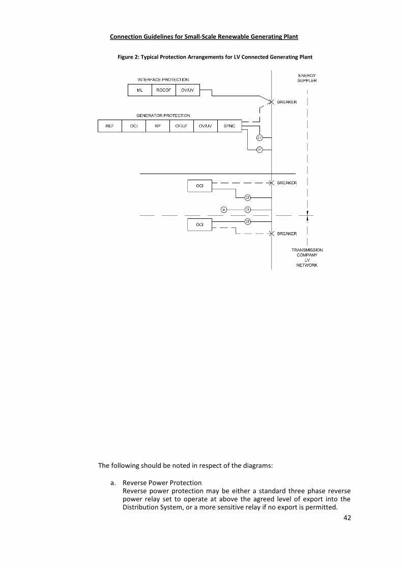
Connection Guidelines for Small-Scale Renewable Generating Plant
42
The following should be noted in respect of the diagrams:
a. Reverse Power ProtectionReverse power protection may be either a standard three phase reversepower relay set to operate at above the agreed level of export into theDistribution System, or a more sensitive relay if no export is permitted.
Figure 2: Typical Protection Arrangements for LV Connected Generating Plant
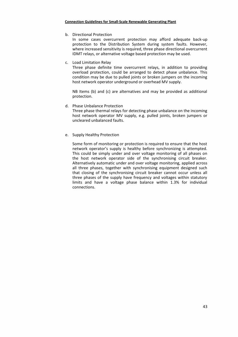
Connection Guidelines for Small-Scale Renewable Generating Plant
43
b. Directional ProtectionIn some cases overcurrent protection may afford adequate back-upprotection to the Distribution System during system faults. However,where increased sensitivity is required, three phase directional overcurrentIDMT relays, or alternative voltage based protection may be used.
c. Load Limitation RelayThree phase definite time overcurrent relays, in addition to providingoverload protection, could be arranged to detect phase unbalance. Thiscondition may be due to pulled joints or broken jumpers on the incominghost network operator underground or overhead MV supply.
NB Items (b) and (c) are alternatives and may be provided as additionalprotection.
d. Phase Unbalance ProtectionThree phase thermal relays for detecting phase unbalance on the incominghost network operator MV supply, e.g. pulled joints, broken jumpers oruncleared unbalanced faults.
e. Supply Healthy Protection
Some form of monitoring or protection is required to ensure that the hostnetwork operator’s supply is healthy before synchronizing is attempted.This could be simply under and over voltage monitoring of all phases onthe host network operator side of the synchronising circuit breaker.Alternatively automatic under and over voltage monitoring, applied acrossall three phases, together with synchronising equipment designed suchthat closing of the synchronising circuit breaker cannot occur unless allthree phases of the supply have frequency and voltages within statutorylimits and have a voltage phase balance within 1.3% for individualconnections.
Connection Guidelines for Small-Scale Renewable Generating Plant
44
Figure 3: Typical Protection Arrangements for MV Connected Generating Plant
Connection Guidelines for Small-Scale Renewable Generating Plant
45
9. EARTHING
1. MV Generating Plant
1. MV Distribution Systems may use direct, resistor, reactor or arc suppression coilmethods of earthing the Distribution System neutral. The magnitude and durationof fault current and voltage displacement during earth faults depend on which ofthese methods is used. The method of earthing therefore has an impact on thedesign and rating of earth electrode systems and the rating of plant andequipment.
2. To ensure compatibility with the earthing on the Distribution System the earthingarrangements of the Generating Plant must be designed in consultation andformally agreed with the network operator. The actual earthing arrangements willalso be dependent on the number of Generating Units in use and the Generator’ssystem configuration and method of operation. The system earth connection shallhave adequate electrical and mechanical capability for the duty.
3. MV Distribution Systems operating at voltages at or below 33kV are generallydesigned for earthing at one point only and it is not normally acceptable for MVGenerators to connect additional MV earths when operating in parallel. Onecommon exception to this rule is where the Generating Plant uses an MV voltagetransformer (VT) for protection, voltage control or instrumentation purposes andthis VT requires an MV earth connection to function correctly.
Systems operating at 132kV are generally designed for multiple earthing, and insuch cases the earthing requirements should be agreed in writing with the TSO.
4. In some cases the host network operator may allow the Generator to earth theGenerator's MV System when operating in parallel with the Distribution System.The details of any such arrangements shall be agreed in writing between therelevant parties.
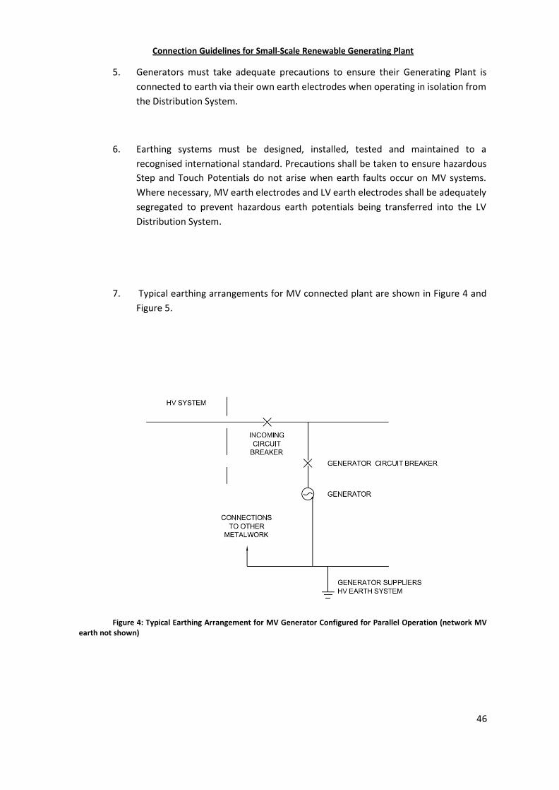
Connection Guidelines for Small-Scale Renewable Generating Plant
46
5. Generators must take adequate precautions to ensure their Generating Plant isconnected to earth via their own earth electrodes when operating in isolation fromthe Distribution System.
6. Earthing systems must be designed, installed, tested and maintained to arecognised international standard. Precautions shall be taken to ensure hazardousStep and Touch Potentials do not arise when earth faults occur on MV systems.Where necessary, MV earth electrodes and LV earth electrodes shall be adequatelysegregated to prevent hazardous earth potentials being transferred into the LVDistribution System.
7. Typical earthing arrangements for MV connected plant are shown in Figure 4 andFigure 5.
Figure 4: Typical Earthing Arrangement for MV Generator Configured for Parallel Operation (network MVearth not shown)
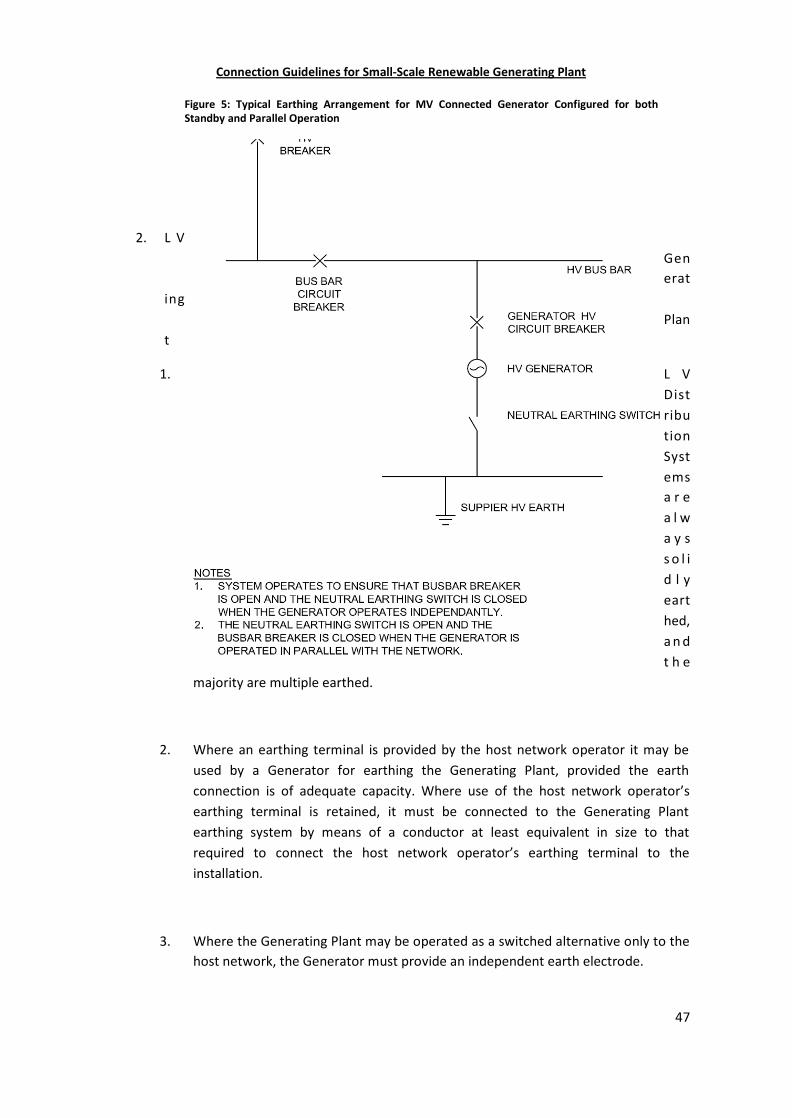
Connection Guidelines for Small-Scale Renewable Generating Plant
47
2. L VGenerat
ingPlan
t
1. L VDistributionSystemsa r ea l wa y ss o l id l yearthed,a n dt h e
majority are multiple earthed.
2. Where an earthing terminal is provided by the host network operator it may beused by a Generator for earthing the Generating Plant, provided the earthconnection is of adequate capacity. Where use of the host network operator’searthing terminal is retained, it must be connected to the Generating Plantearthing system by means of a conductor at least equivalent in size to thatrequired to connect the host network operator’s earthing terminal to theinstallation.
3. Where the Generating Plant may be operated as a switched alternative only to thehost network, the Generator must provide an independent earth electrode.
Figure 5: Typical Earthing Arrangement for MV Connected Generator Configured for bothStandby and Parallel Operation
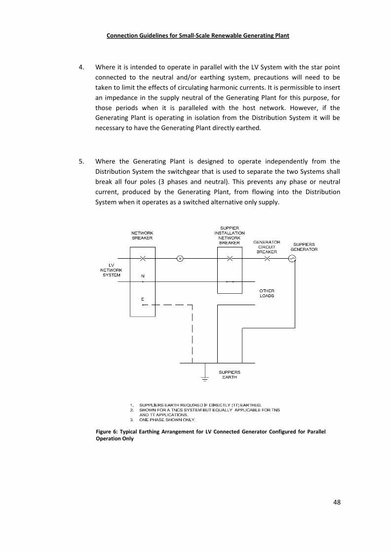
Connection Guidelines for Small-Scale Renewable Generating Plant
48
4. Where it is intended to operate in parallel with the LV System with the star pointconnected to the neutral and/or earthing system, precautions will need to betaken to limit the effects of circulating harmonic currents. It is permissible to insertan impedance in the supply neutral of the Generating Plant for this purpose, forthose periods when it is paralleled with the host network. However, if theGenerating Plant is operating in isolation from the Distribution System it will benecessary to have the Generating Plant directly earthed.
5. Where the Generating Plant is designed to operate independently from theDistribution System the switchgear that is used to separate the two Systems shallbreak all four poles (3 phases and neutral). This prevents any phase or neutralcurrent, produced by the Generating Plant, from flowing into the DistributionSystem when it operates as a switched alternative only supply.
Figure 6: Typical Earthing Arrangement for LV Connected Generator Configured for ParallelOperation Only
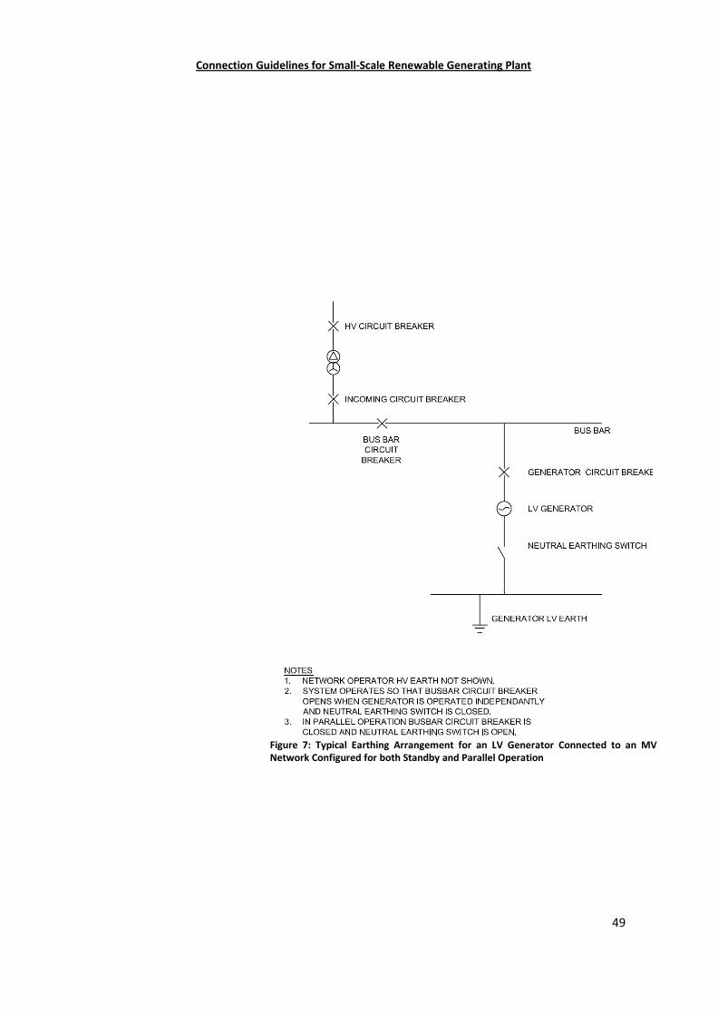
Connection Guidelines for Small-Scale Renewable Generating Plant
49
Figure 7: Typical Earthing Arrangement for an LV Generator Connected to an MVNetwork Configured for both Standby and Parallel Operation
Connection Guidelines for Small-Scale Renewable Generating Plant
50
10. INSTALLATION, OPERATION AND CONTROL INTERFACE
1. General
1. Installations should be carried out by competent persons, who have sufficient skillsand training to apply safe methods of work to install the Generating Plant. Ideallythey should have recognised and approved qualifications relating to the fuel/energy sources and general electrical installations.
2. The installation should be carried out to the standards required in themanufacturer’s installation instructions.
3. The Generator and host network operator must ensure that all personnel arecompetent in that they have adequate knowledge and sufficient judgement to takethe correct action when dealing with an emergency. Failure to take correct actionmay jeopardise the Generator’s equipment or the Distribution System and give riseto danger.
4. No parameter relating to the electrical connection or setting that is subject to typeverification certification shall be modified as part of or after the installationprocess unless previously agreed in writing between the host network operatorand the Generator. User access to change such parameters shall be prevented bythe use of sealing plugs/paper seals etc. where possible.
5. The host network operator and the Generator must agree in writing the salienttechnical requirements of the interface between their two systems. Theserequirements will generally be contained in the Site Responsibility Schedule and/orthe Connection Agreement. In particular it is expected that the agreement willinclude:
a. the means of synchronisation between the Generator’s system and the
Distribution System, where appropriate;
b. the responsibility for plant, equipment and protection systemsmaintenance, and recording failures;
c. the means of connection and disconnection between the host networkoperators and Generator’s systems;
Connection Guidelines for Small-Scale Renewable Generating Plant
51
d. key technical data e.g. import and export capacities, operating powerfactor range, interface protection settings;
e. the competency of all persons carrying out operations on their systems;
f. details of arrangements that will ensure an adequate and reliable means ofcommunication between the host network operator and Generator;
g. the obligation to inform each other of any condition, occurrence orincident which could affect the safety of the other's personnel, or themaintenance of equipment and to keep records of the communication ofsuch information;
h. the names of designated persons with authority to act and communicateon their behalf and their appropriate contact details.
6. The Generators should be aware that host network operators apply auto-reclosesystems to MV overhead line circuits. This may affect the operations of directlyconnected MV Generating Plants and also Generating Plants connected to LVDistribution Systems supplied indirectly by MV overhead lines.
2. Isolation and Safety Labelling
1. Every installation or system which includes Generating Plant operating in parallelwith the Distribution System must include a means of isolation capable ofdisconnecting the whole of the Generating Plant in-feed to the DistributionSystem. This equipment will normally be owned by the Generator, but may byagreement be owned by the host network operator.
2. The Generator must grant the host network operator rights of access to the meansof isolation.
3. To ensure that host network operator staff and that of the Customer and theircontractors are aware of the presence of Generating Plant, appropriate warninglabels should be used.
4. Where the installation is connected to the Low Voltage Distribution System theGenerator should generally provide labelling at the Point of Supply (FusedCut-Out), meter position, consumer unit and at all points of isolation within theCustomer’s premises to indicate the presence of Generating Plant. The labelling
Connection Guidelines for Small-Scale Renewable Generating Plant
52
should be sufficiently robust and if necessary fixed in place to ensure that itremains legible and secure for the lifetime of the installation.
5. Where the installation is connected to the MV Distribution System the Generatorshould give consideration to the labelling requirements. In some installations e.g. acomplex CHP installation, extensive labelling may be required, but in others e.g. awind farm connection, it is likely to be clear that Generating Units are installed onsite and labelling may not be required. Any labels should comply with safetyregulations.
3. Site Responsibility Schedule
1. A Site Responsibility Schedule (SRS) should be prepared by the host networkoperator in conjunction with the Generator. The SRS should clearly indicate theownership, operational and maintenance responsibility of each item of equipmentat the interface between the Distribution System and the Generating Plant, andshould include an operational diagram so that all persons working at the interfacehave sufficient information so that they can undertake their duties safely and tominimise the risk of inadvertently interrupting supplies. The SRS should also recordthe agreed method of communication between the host network operator and theGenerator.
2. The operational diagram should be readily available to those persons requiringaccess to the information contained on it. For example, this could be achieved bydisplaying a paper copy at the Point of Supply, or alternatively provided as part of acomputer based information system to which all site staff has access. The mostappropriate form for this information to be made available should be agreed aspart of the connection application process.
3. In the case of a LV connected Generating Plant, a simple diagram located at thePoint of Supply may be sufficient. The scope of the diagram should cover theDistribution System, Customer's installation and the Generating Plant; however thelocation of any metering devices, consumer unit and circuit protective devices(together with their settings) within the Customer's installation should also beshown. In the case of an MV connected Generating Plant the diagram is likely to bemore complex and contain more detailed information.
4. In addition to preparing the diagram as part of the connection process, there areobligations on the host network operator and the Generator to ensure that the
Connection Guidelines for Small-Scale Renewable Generating Plant
53
Site Responsibility Schedule including the operational diagram are updated toreflect any changes on site. To facilitate this, the Generator must contact the hostnetwork operator when any relevant changes are being considered.
4. Operational and Safety Aspects
1. Where the Point of Supply provided by the host network operator for paralleloperation is at MV, the Generator must ensure:
a. that a person with authority, or his staff, is available at all times to receivecommunications from the host network operator Control Engineer so thatemergencies, requiring urgent action by the Generator, can be dealt withadequately. Where required by the host network operator, it will also be aduty of the Generator’s staff to advise the host network operator ControlEngineer of any abnormalities that occur on the Generating Plant whichhave caused, or might cause, disturbance to the Distribution System, forexample earth faults;
b. Where in the case that it is necessary for the Generator's staff to operatethe host network operators equipment, they must first have beenappropriately trained and designated as a host network operator'Authorised Person’ for this purpose. The names of the Generatorsauthorised persons should be included on the Site Responsibility Schedule.All operation of host network operator equipment must be carried out tothe specific instructions of the host network operator Control Engineer inaccordance with the host network operator’s safety rules.
2. For certain Generating Plant connections to an MV Point of Supply, the Generatorand the host network operator may have mutually agreed to schedule the realand/or reactive power outputs to the Distribution System to ensure stability of thelocal Distribution System. The host network operator may require agreement onspecific written procedures to control the bringing on and taking off of suchGenerating Plant. The action within these procedures will normally be controlledby the host network operators Control Engineer.
3. Where the Point of Supply provided by the host network operator for paralleloperation is at LV, the host network operator, depending upon localcircumstances, may require a similar communications procedure as for MVconnections (see 10.4.1).
5. Synchronizing and Operational Control
Connection Guidelines for Small-Scale Renewable Generating Plant
54
1. Before connecting two energised electrical systems, for example a DistributionSystem and Generating Plant, it is necessary to synchronise them by minimisingtheir voltage, frequency and phase differences.
2. Operational switching, for example synchronising, needs to take account of StepVoltage Changes as detailed in Section 7.5.
3. Automatic synchronising equipment will be the norm which, by control of theGenerating Unit's field system (Automatic Voltage Regulator) and governor, bringsthe incoming unit within the acceptable operating conditions of voltage and speed(frequency), and closes the synchronising circuit breaker.
4. The facility to use the host network operator’s circuit breaker manually forsynchronizing can only be used with the specific agreement of the host networkoperator.
5. The synchronising voltage supply may, with host network operator agreement, beprovided from a host network operator owned voltage transformer. Where soprovided, the voltage supplies should be separately fused at the voltagetransformer.
6. Where the Generator's system comprises ring connections with normal openpoints, it may not be economic to provide synchronising at all such locations. Insuch cases mechanical key interlocking may be applied to prevent closure unlessone side of the ring is electrically dead. A circuit breaker or breakers will still,however, require synchronising facilities to achieve paralleling between theGenerator and the host network operator supply.
7. The conditions to be met in order to allow automatic reconnection when the hostnetwork operator supply is restored are defined in Section 10. Where a Generatorrequires his Generating Plant to continue to supply a temporarily disconnectedsection of the Distribution System in island mode, the special arrangementsnecessary will need to be discussed with the host network operator.
11. TESTING AND COMMISSIONING
Connection Guidelines for Small-Scale Renewable Generating Plant
55
1. General
1. The exact testing and commissioning requirements will be determined by thenetwork operator. The following is intended as a brief summary of genericrequirements. Details of international standards can be found using the referencesgiven in Appendix 1.
2. Generating Units rated up to and including 16A per phase
In satisfying the Type Verification tests, a Generating Unit can be considered asbeing ‘approved’ for connection to a public LV Distribution System and so therequirements for on-site commissioning tests are minimal.
1. The Interface Protection and protection functionality are normally provided byType Verified and tested equipment with protection settings that have beenfactory set so there is no requirement for the protection setting to be confirmedduring the on-site commissioning tests.
2. It is the responsibility of the Generator to ensure that the relevant information isforwarded to the host network operator in accordance with the requirements of asingle unit or multiple unit installation. The Generator self-certifies that not only atype approved Generating Unit is installed, but that it has been installed compliantwith the type approval.
3. A Type Verification test sheet should be submitted to the host network operator aspart of the commissioning notification, but the host network operator does notneed to witness the tests. However, the host network operator will have a right toinspect an installation, if only to verify that the Generating Unit installed relates tothe information that has been provided.
3. Generating Units >16A per Phase but <50kW 3 Phase (or 17kW single Phase)
1. Generating Plant may either comprise ‘type approved Generating Plant’ where theGenerating Unit(s) and the protection function are ‘type approved’ or GeneratingUnits and/or interface equipment that has not been specifically type approved,and where individually certified equipment (e.g. protection relays) will be used.
Connection Guidelines for Small-Scale Renewable Generating Plant
56
2. The Generator should discuss the generation project with the local host networkoperator during the initial stages of the connection process with a view toestablishing whether the proposed installation will comprise ‘type approvedGenerating Plant’ or whether individual equipment that has not been specificallytype approved will be used. Information relating to the approval status of theequipment being proposed should be included in the initial application form wherepossible; however the agreed information relating to testing and commissioningshould be provided at least 15 working days before the proposed commissioningdate. This will provide time for the host network operator to confirm whether theGenerating Plant can be considered to be ‘type approved Generating Plant’, and toestablish any requirement to witness the commissioning tests and to ensure thatstaff are available to witness commissioning tests where this is required.
3. In the case of ‘type approved Generating Plant’:
a. The type testing procedures should be developed by the manufacturer todescribe a methodology for testing the particular type of Generating Plant.The protection settings must follow those given in Sections 7.6 and 8 ofthese guidelines.
b. The type verification test sheet confirming that the Generating Plant hasbeen type tested to satisfy the network operator’s requirements should bemade available to the Generator.
c. It is the responsibility of the Generator to ensure that the relevantinformation, including the type verification test sheet is forwarded to thehost network operator and that the scope, date and time of thecommissioning tests is agreed in advance of the commissioning theGenerating Plant. The host network operator should have the opportunityto witness the commissioning tests undertaken by the Generator andinspect the installation.
d. The Interface Protection and protection functionality is performed by typetested equipment with protection settings that have been factory set sothere is no requirement for the protection setting to be confirmed duringthe on-site commissioning tests.
e. The Generator should self-certify that only type approved Generating Plantis installed and that it has been installed correctly.
f. Within 30 days of completing the commissioning tests, the Generatorshould send the commissioning test results form to the host networkoperator. Where the commissioning tests have not been witnessed by thehost network operator, the completed form should be reviewed by the
Connection Guidelines for Small-Scale Renewable Generating Plant
57
host network operator and any comments, including any requirements forfurther tests or remedial works, provided to the Generator.
4. In the case where the Generating Plant is not ‘type approved Generating Plant’:
a. It is the responsibility of the Generator to ensure that the relevantinformation is forwarded to the host network operator and that the scope,date and time of the commissioning tests is agreed in advance of thecommissioning the Generating Plant. The host network operator shouldhave the opportunity to witness the commissioning tests undertaken bythe Generator and inspect the installation.
b. The Interface Protection and protection functionality will be performed byindividual certified protection relays with settings that can be changed bythe Generator on site. The types of relays used and the proposed settingsshould be submitted to the host network operator 20 days in advance ofthe agreed commissioning date.
c. The Generator must self-certify that the Generating Plant has beeninstalled correctly, including that the appropriate safety labels have beenfitted properly.
d. Within 30 days of completing the commissioning tests, the Generatorshould send the commissioning test results form to the host networkoperator. Where the commissioning tests have not been witnessed by thehost network operator, the completed form should be reviewed by thehost network operator and any comments, including any requirements forfurther tests or remedial works, provided to the Generator.
4. Generating Units Larger Than 50 kW 3 Phase (or 17 kW Single Phase)
1. Generating Units in this category are not normally ‘type approved’ and usuallysome of the Interface Protection function will be performed by either individualprotection relays or a combined protection and control system. Protectionequipment and protection functions installed within or forming part of theGenerator’s control equipment should be consistent with the requirements set outin Section. The settings on relays installed on the Generator's equipment will needto be set by the Generator on site and hence full commissioning tests will berequired.
2. The Generator should discuss the generation project with the local host networkoperator during the initial stages of the connection with a view to establishing thecommissioning tests that need to be undertaken. Detailed information relating to
Connection Guidelines for Small-Scale Renewable Generating Plant
58
testing and commissioning, including the date of the commissioning tests shouldbe provided by the Generator at least 25 working days before the proposedcommissioning date. This will provide time for the host network operator toestablish any requirement to witness the commissioning tests or inspect theinstallation and to ensure that staff are available to witness commissioning testswhere this is required. It is the responsibility of the Generator to undertake thesetests and make appropriate arrangements for them to be witnessed.
3. Where the installation is connected to the MV Distribution System, the tests mustbe witnessed by a representative of the host network operator.
4. Where the installation is connected to the LV Distribution System the host networkoperator should be invited to witness the commissioning tests undertaken by theGenerator and inspect the installation.
5. The tests must be carried out on site; tests performed before delivery andinstallation should not be accepted.
6. Within 30 days of completing the commissioning tests, the Generator should sendthe commissioning test results form to the host network operator. Where thecommissioning tests have not been witnessed by the host network operator, thecompleted form should be reviewed by the host network operator and anycomments, including any requirements for further tests or remedial works,provided to the Generator.
7. The Generator must make a written record of all protection settings and testresults. A copy of the record must be provided to the host network operator. TheGenerator should retain a copy of the record to make available for inspection asrequired by the host network operator or other legitimately interested party.
8. Periodic testing of the Interface Protection should be carried out by the Generatorat intervals to be agreed in discussion with the host network operator. Inaddition it may be necessary to undertake ad-hoc testing to d e t e r m i n efor example:
the voltage dip on synchronising;
,
Connection Guidelines for Small-Scale Renewable Generating Plant
59
the harmonic voltage distortion;
the voltage levels as a result of the connection of the Generating Plant andto confirm that they remain within the statutory limits.
9. Periodic testing of the Generating Plant is recommended at intervals prescribed bythe manufacturer. This information shall be included in the documentationprovided by the Generator. The method of testing and/or servicing should beincluded in the servicing instructions/documentation.
5. Changes in the Installation
1. If during the lifetime of the Generating Plant it is necessary to replace a majorcomponent of a Generating Unit or its protection system, it is only necessary tonotify the host network operator if the operating characteristics of the GeneratingPlant or the protection have been altered when compared against that which wasoriginally commissioned.
2. In the event that Generating Plant is to be decommissioned and will no longeroperate as a source of electrical energy in parallel with the Distribution System, theGenerator should notify the host network operator. Where the presence ofGenerating Plant is indicated in a bespoke Connection Agreement, it will benecessary to amend the Connection Agreement appropriately.
Connection Guidelines for Small-Scale Renewable Generating Plant
60
12. SAFETY ASPECTS
12.1. The Generator shall take precautions to prevent, so far as is reasonably practicable,danger due to the influx of water or any noxious or explosive liquid or gas into anyenclosed space containing its apparatus.
12.1.1. Where apparatus can or does emit noxious or explosive liquids or gasses (for examplebatteries or oil tanks) then the Generator shall ensure that there is adequate ventilation,that appropriate notices of danger are posted, and that when work must be done on theapparatus all doors shall be locked open.
12.1.2. Where the apparatus in an enclosed space is protected by inert gas (COs, N2) firesuppression then the Generator shall ensure that whenever work takes place within theenclosed space the fire suppression is locked of.
12.1.3. All of the Generator's rotating equipment and equipment with other moving parts shallbe constructed, installed, protected and maintained in such a manner as to preventdanger to humans, animals and property. When work must take place on such apparatusthen adequate precautions must be taken to ensure that it is mechanically isolatedincluding electrically isolating associated motors and the locking off of inlets of steam orwater or other physical sources of danger.
12.2. The following shall also apply to Generating Plant connected at medium voltage:
12.2.1. The Generator or host network operator shall enclose any part of a ground-mountedtransformer in the open air, containing live apparatus which is not encased, by a fencenot less than 2.4 metres high to prevent, so far as is reasonably practicable, danger orunauthorised access.
12.2.2. The Generator shall ensure that, so far as is reasonably practicable, there are at all timesdisplayed in a conspicuous position a danger notice in English, and the local languagebearing a sign of a skull and crossbones and a notice giving the name of the Generatorand an address or telephone number where a person appointed by the Generator shallbe in constant attendance.
12.3. The Generator shall take all reasonable precautions to minimise the risk of fire.
12.3.1. At ground-mounted transformers the Generator shall provide fire buckets filled withclean dry sand, fire extinguishers and first aid boxes or cupboards. In addition, anadequate number of gas masks shall be kept conspicuously at accessible locations.
12.3.2. At ground mounted transformers, instructions in English and the local language of thearea, for the restoration of persons suffering from electric shock shall be affixed by theGenerator in a conspicuous place.
Connection Guidelines for Small-Scale Renewable Generating Plant
61
12.4. Where Generating Plant and equipment is exposed as to be liable to damage fromlightning, adequate means for diverting to earth any such electrical surges must beprovided.
12.5. The Generator shall apply protective devices to every system which will so far as isreasonably practicable, prevent any current, including leakage to earth, from flowing inany part of a system for such a period that part of the system can no longer carry thatcurrent without danger.
12.6. The host network operator shall ensure that its entire works on a Customer’s premiseswhich are not under the control of the Customer (whether forming part of theCustomer’s Installation or not) are:
a) suitable for their respective purposes
b) installed and, so far as is reasonably practicable, maintained so as to preventdanger, and
c) protected, so far as is reasonably practicable, by a suitable fusible cut-out orautomatic switching device as close as reasonably practicable to the supplyterminals, provided that no such fusible cut-out or automatic switching deviceshall be inserted in any conductor connected with earth.
12.7. The host network operator shall ensure that every cut-out or automatic switching devicenot within a Distribution compound shall be enclosed in a locked or sealed container.
12.8. The host network operator shall ensure that any electric line which forms part of theDistribution System and which is taken into a building at a point below the level of theground shall be so installed as to prevent, so far as is reasonably practicable, the influx ofany noxious or explosive liquid or gas at the point of entry.
12.9. The host network operator shall mark permanently the separate conductors of electriclines connected to supply terminals as close as practicable to those terminals to showthe phase of each conductor including neutral and earth conductors and, whereappropriate, phase rotation.
12.10. The Customer shall, so far as is reasonably practicable, take precautions for the safecustody of the equipment in its premises belonging to the host network operator.
12.11. If any accident occurs at the Generating Plant resulting in serious injury to or loss of lifeof a human being or serious damage to a property the Generator shall send to theEnergy Regulatory Commission a report of the accident within 24 hours of its knowledgeof the occurrence. In this context serious injury means injury that requires the person tobecome a hospital in-patient, and serious damage to a property means that a significantpart of the property has been damaged or destroyed.
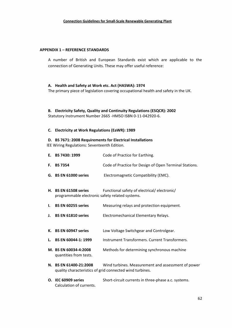
Connection Guidelines for Small-Scale Renewable Generating Plant
62
APPENDIX 1 – REFERENCE STANDARDS
A number of British and European Standards exist which are applicable to theconnection of Generating Units. These may offer useful reference:
A. Health and Safety at Work etc. Act (HASWA): 1974The primary piece of legislation covering occupational health and safety in the UK.
B. Electricity Safety, Quality and Continuity Regulations (ESQCR): 2002Statutory Instrument Number 2665 -HMSO ISBN 0-11-042920-6.
C. Electricity at Work Regulations (EaWR): 1989
D. BS 7671: 2008 Requirements for Electrical Installations lEE Wiring Regulations: Seventeenth Edition.
E. BS 7430: 1999 Code of Practice for Earthing.
F. BS 7354 Code of Practice for Design of Open Terminal Stations.
G. BS EN 61000 series Electromagnetic Compatibility (EMC).
H. BS EN 61508 series Functional safety of electrical/ electronic/programmable electronic safety related systems.
I. BS EN 60255 series Measuring relays and protection equipment.
J. BS EN 61810 series Electromechanical Elementary Relays.
K. BS EN 60947 series Low Voltage Switchgear and Controlgear.
L. BS EN 60044-1: 1999 Instrument Transformers. Current Transformers.
M. BS EN 60034-4:2008 Methods for determining synchronous machinequantities from tests.
N. BS EN 61400-21:2008 Wind turbines. Measurement and assessment of powerquality characteristics of grid connected wind turbines.
O. IEC 60909 series Short-circuit currents in three-phase a.c. systems.Calculation of currents.
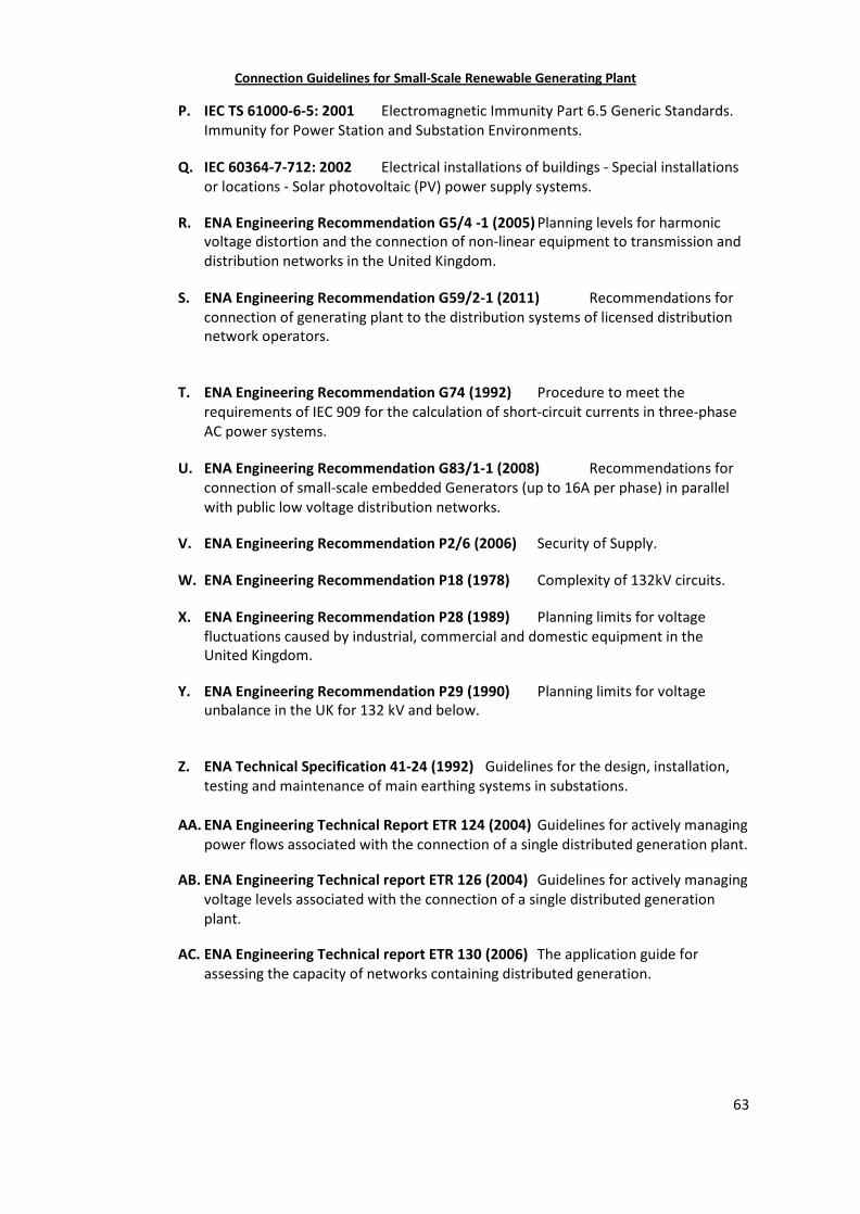
Connection Guidelines for Small-Scale Renewable Generating Plant
63
P. IEC TS 61000-6-5: 2001 Electromagnetic Immunity Part 6.5 Generic Standards.Immunity for Power Station and Substation Environments.
Q. IEC 60364-7-712: 2002 Electrical installations of buildings - Special installationsor locations - Solar photovoltaic (PV) power supply systems.
R. ENA Engineering Recommendation G5/4 -1 (2005) Planning levels for harmonicvoltage distortion and the connection of nonlinear equipment to transmission anddistribution networks in the United Kingdom.
S. ENA Engineering Recommendation G59/2-1 (2011) Recommendations forconnection of generating plant to the distribution systems of licensed distributionnetwork operators.
T. ENA Engineering Recommendation G74 (1992) Procedure to meet therequirements of IEC 909 for the calculation of short-circuit currents in three-phaseAC power systems.
U. ENA Engineering Recommendation G83/1-1 (2008) Recommendations forconnection of small-scale embedded Generators (up to 16A per phase) in parallelwith public low voltage distribution networks.
V. ENA Engineering Recommendation P2/6 (2006) Security of Supply.
W. ENA Engineering Recommendation P18 (1978) Complexity of 132kV circuits.
X. ENA Engineering Recommendation P28 (1989) Planning limits for voltagefluctuations caused by industrial, commercial and domestic equipment in theUnited Kingdom.
Y. ENA Engineering Recommendation P29 (1990) Planning limits for voltageunbalance in the UK for 132 kV and below.
Z. ENA Technical Specification 41-24 (1992) Guidelines for the design, installation,testing and maintenance of main earthing systems in substations.
AA. ENA Engineering Technical Report ETR 124 (2004) Guidelines for actively managingpower flows associated with the connection of a single distributed generation plant.
AB. ENA Engineering Technical report ETR 126 (2004) Guidelines for actively managingvoltage levels associated with the connection of a single distributed generationplant.
AC. ENA Engineering Technical report ETR 130 (2006) The application guide forassessing the capacity of networks containing distributed generation.