connector product locations - farnell element14 · phone: 1.714.557.4700 fax: 1.714.628.2142. 2 ......
TRANSCRIPT

“Engineered for life” is a registered trademarkof ITT Industries.©2005. All other trademarksor registered trademarks are property of theirrespective owners. All data subject to changewithout notice.
CAB 05-Septwww.ittcannon.com
Connector Product Locations
With manufacturing facilities, sales representatives and distributors located worldwide, please visit our website at www.ittcannon.com for a complete listing and tofind the office nearest you.
GERMANYCannonstrasse 1Weinstadt, 71384phone: 49.7151.699.0fax: 49.7151.699.217
HONG KONGUnit 901 & 912, West Tower Shun Tak Center168-200 Connaught RoadCentralphone: 852.2732.2720fax: 852.2732.2919
ITALYVia Pietro Panzeri 10Milano, 20123phone: 39.2.58180.1fax: 39.2.8372036
UKJays Close, Viables EstateBasingstoke, RG22 4BAphone: 44.1256.311200fax: 44.1256.323356
USA666 East Dyer RoadSanta Ana, CA 92705toll free: 1.800.854.3028phone: 1.714.557.4700fax: 1.714.628.2142

2www.ittcannon.com
Table of Contents Introduction . . . . . . . . . . . . . . . . . .3
Technical Data . . . . . . . . . . . . . . . . .4-5
Mounting Dimensions . . . . . . . . . . .6-7
How to Order . . . . . . . . . . . . . . . . .8
Contact Arrangements . . . . . . . . . .10
Connector Dimensions . . . . . . . . . . .28
Coupling Dimensions . . . . . . . . . . . .43
Accessories . . . . . . . . . . . . . . . . . . .44
Contacts . . . . . . . . . . . . . . . . . . . . .50
Product Safety Information . . . . . . .54
Harsh Environments
Cannon MIL-DTL-38999
High density contact arrangements, corrosion-resistant shells, rear release crimpsnap-in contacts, operates under severe hightemperature vibration testing.
In addition to our CA Bayonet series, we also offer these connectivity solutions:
Cannon Trident
Versatile range of electrical connectors basedon a standard contact design. Options include;industrial grade, harsh environment and shielded circulars.
Interconnect Technologies & Solutions
For over 90 years, ITT has been developing innovative solutions for harsh environment applications. We have a proventrack record of demonstrating our expertise and commitment to the industrial industry, offering the broadest portfolioof interconnect products.
Our interconnect range include sealed circulars, plastic and metal shell bayonet coupling circulars, miniature metal shellcirculars, PC board header connectors and sensor and direct device connectors. ITT is also a systems supplier, providingvalue-added module and harness assemblies.
Environmentally Sealed
Cannon KPT / KPSE
Environmentally sealed miniature circular connectorsavailable in two versions: KPT (solder contact) and KPSE(high performance crimp contact). Intermateable andintermountable with all MIL-C-26482 connectors and isavailable with many materials, finishes and configurations.
ITT logo blocks and the composite ITT logo are registeredtrademark of ITT Industries. ©2005

IntroductionCannon CA-Bayonet series was designed in accordance with the VG95234 specification. This versatile and highly reliable connector series is an improvement on the well established MIL-C-5015 series. CA-Bayonet has a proven bayonet couplingdesign that offers exceptional vibration protected sealingagainst fluids, and easy connection/disconnection.
Initially designed for aircraft and airborne applications, theserugged connectors are used in the electrical equipment oftrucks, off-road vehicles, ships, earth-moving equipment, telecommunications and others.
Connectors in accordance with VG95234 are interchangeablewith the corresponding MIL-C-5015 connectors. Both connectorlines feature the same shell dimensions and contacts layouts.However, due to the different coupling systems (MIL-C-5015threaded coupling, VG95234 bayonet coupling) they are not intermateable.
Advantages– rugged shell design– environmental– bayonet coupling for easy mating and unmating– vibration proof– waterproof up to 1 bar (35 feet of water)
Cannon has the complete VG95234 program available and, inaddition, many other types which exceed the requirements ofVG95234 and MIL-C-5015.
www.ittcannon.com
Cannon VG/CA-Bayonet
Attention:Metal shell connectors which may be touched are notsuitable for mains power. See page 54 for Product SafetyInformation, para. 5.
* European Community “Old Car” directive (2000/53/EG)* European Community Waste Electrical and Electronic Equipment (WEEE)
2000/0158 * European Community restrictions of use of certain hazardous substances
in WEEE (ROS) (2000/0159)
Pin contact Pin insulator Barrel
Sealing ring End ringGrommetBayonet
coupling nut
Shell Socket insulator
Socket contactEndbell
3
Connector DesignDue to the rugged shell made of an aluminium alloy, these connectors withstand most severe conditions. Olive drab chromate coating over cadmium plating protects the surface ofthe shell.
Cannon offers zinc cobalt plating as an alternative to customerswho refuse cadmium plating and also as a general improvement of the zinc plating.
The insulators are made of high quality polychloroprene andwithstand temperatures from -67°/+257°F (-55/125°C). This material is self-extinguishing, resistant against hydraulic fluids,jet fuel, diesel fuel, gasolines, lubricants, brake and fire extinguisher fluids.
The contacts are made of copper alloy plated with a hard silverfinish guarantee at least 500 mating cycles.
All solder contacts feature a special passivation to comply withROHS requirements. The crimp contacts allow highly reliable crimping with wires according to TL 6145-009, TL 6145-011 and MIL-W-5086 when using the recommended tools accord-ing to VG95234. Crimp contacts can be exchanged at least fivetimes due to the contact retention.
The insulators are made of high quality polychloroprene andwithstand temperatures from -67°/+257°F (-55/125°C). This material is self-extinguishing, resistant against hydraulic fluids,The bayonet design allows fast and easy coupling and uncoupling. An audible control by metallic sound and visual control by colour-marked snap-in position offer additional coupling security.
VG connectors are basically designed for single wire harnessing.For full environmental sealing each conductor is sealed completely within the grommet. Under certain conditions,jacketed cables can be used for the shell styles E, G, M and N.

4www.ittcannon.com
Dimensions shown in mmSpecifications and dimensions subject to change
Cannon VG/CA-Bayonet
Electrical Data
Contact rating at 68 °F (+20 °C)
Contact size max. currentA
10 816S/15S 2216/15 2212/25 418/60/100 744/160 1350/500 245
Current ratingdepending on ambient temperature
Contact resistance(Millivolt test)
The contact resistance has to be tested according to VG95234 part 2, test no. 5.10.1 and VG 95210, part 37. The measuringpoints are indicated in the illustration.
Operating voltage and connector usage
Connectors in equipments must not be separated or mated under load when used per specifications.
As according to specification the connectors are suitable for anoperating voltage of 50 V (see Product Safety Information). However, this is only valid, when the connectors are freely accessible during operation and consequently might be touchable. When the connectors will be operated with linevoltage, please contact ITT Customer Service.
Contact size Max. contactresistance
metric AWG mΩ10 – 1215S/15 16S/16 625 12 360/100 8 1
160 4 0,5500 0 0,2
Insulation resistanceAcc. to VG95319, part 2, test no. 5.12 and VG95210, part 32,test condition BStandard insulator material > 1000 MΩFKM insulator material (upon request) > 5000 MΩ
Test voltageAcc. to VG95319, part 2, test no. 5.13 and VG 95210, part 31Test voltage for service rating:
Service rating Test voltage Vrms
Instruments 1050A 1600B 4000D 2500E 3000
Air and creepage paths (min.)
Voltage class Instr. A D E
Air and creepage paths mm 0,7 1,1 2,8 4,8

Cannon VG/CA-Bayonet
5www.ittcannon.com
Dimensions shown in mmSpecifications and dimensions subject to change
Mechanical FeaturesAmbient temperatureStandard insulator material–55°/125°C (– 67/257°F)
FKM insulator material*–30°/200°C (– 22/392°F)
Safety provisions**IP 67 acc. to DIN 40 050(1 bar pressure after 12 hrs.)
Vibration test200 m/s2 at 10 to 2000 Hz
Mating cycles500 min.
Separating force per contact.The corresponding separating force has to be measured according to VG95319, part 2, test no. 5.7. using the requiredtest gage.
Contact size Separating force min.metric AWG N Gage10 – 0,3 G 0,9915S/15 16S/16 1,0 G 1,5625 12 1,5 G 2,3660/100 8 3,0 G 3,58
160 4 4,0 G 5,69500 0 8,5 G 9,04
Gage(see also VG 95234, Part 1)
Coupling torque
The allowable coupling torques have to be tested under full bundle conditions of the connectors to VG95319, part 2, test no.5.8.2.
Shell Allowable coupling torquesize closing and opening Opening
Nm max. Nm min.10SL 1,7 0,1512S 2,5 0,2314S 3,6 0,3516S/16 5,5 0,4618 8 0,5820 9 0,722 11 0,824 14 0,828 17 0,9232 19 1,0336 23 1,03
Contact retentionThe contact retention has to be tested according to VG95319,part 2, test no. 5.4. Test force direction = Mating direction.
Contact Test forcesize AWG N10 – 3015S/15 16S/16 3525 12 5560/100 8 80
160 4 90500 0 95
MaterialsShell Aluminum alloyStandard finish Olive drab chromate coating over
cadmium plating
Alternative finish Zinc cobalt (see page 9 – Modification)
Insulator Polychloroprene (Standard) and grommets FKM (High temperature)*
Contacts Copper alloyStandard finish Hard silverSpecial finish A176 nickel and hard gold plating
** upon request
** Longitudinal sealing: The connector is not sealed against fluids enteringthrough the cable, as the sealing lips of the single wire sealing are pressingagainst the jacket of the individual cables.
Gage Contact diameter d L+0,01 –1
G 0,99 0,99 7G 1,56 1,56 9G 2,36 2,36 12G 3,58 3,58 13G 5,69 5,69 13G 9,04 9,04 13

6www.ittcannon.com
Dimensions shown in mmSpecifications and dimensions subject to change
Cannon VG/CA-Bayonet
Mounting HolesMounting holes for wall mounting receptacles style A, B1, B2,C1, C2, J1, J2, N1 and N2 acc. to VG95234, or CA 3100E/F/R-Band CA 3102 E-B.
Shell ø d1H12 ø d2H13 e screws to be usedsize Style A Style B1, B2 Style Style ±0,15 A, B2, C2, J2, B1, C1, J1, N
CA 3102E-B C1, C2, J1, J2 A, B2, C2, B1, C1, J1, N1 N2 CA 3100E, FN1, N2 J2, N2CA 3100E, F, R-B CA-B CA 3100E, F, R-B CA-B-Mod. 05TBF-B/-05 Mod-05
10SL 16,4 18,5 3,4 4,5 18,2 M3...DIN 85 M4...DIN 8412S 16,4 21,7 3,4 4,5 20,6 M3...DIN 85 M4...DIN 8414S 19,7 24,9 3,4 4,5 23,0 M3...DIN 85 M4...DIN 8416S 22,9 27,7 3,4 4,5 24,6 M3...DIN 85 M4...DIN 8416 22,9 27,7 3,4 4,5 24,6 M3...DIN 85 M4...DIN 8418 26,1 31,1 3,4 4,5 27,0 M3...DIN 85 M4...DIN 8420 29,5 34,5 3,4 4,5 29,4 M3...DIN 85 M4...DIN 8422 32,7 37,8 3,4 4,5 31,8 M3...DIN 85 M4...DIN 8424 36,0 41,3 3,9 4,5 34,9 M3,5...DIN 85 M4...DIN 8428 42,0 47,1 3,9 5,5 39,7 M3,5...DIN 85 M5...DIN 8432 48,3 53,8 4,5 5,5 44,5 M4...DIN 85 M5...DIN 8436 54,6 60,0 4,5 5,5 49,2 M4...DIN 85 M5...DIN 84* When used with safety elements the max. outer diameter must not exceed the outer diameter of the screw head.
HarnessingVG95234 connectors are designed for single wire harnessing.Full sealing will be guaranteed only by using wires in accordancewith MIL-W-5086, LN 9251 (for AWG) and TL 6145-009 and TL6145-011 (for metric wires). All other wires have to conform towire and insulation diameters with the data given in the follow-ing table:
Contact size Crimp- and solder contacts Insulation ØAWG metric AWG metric AWG metric
mm mm2 mm– 10 – 0,75-1,0 – 1,45-2,516S/15S 16/15 16 0,75-1,5 1,6-2,8 1,60-2,812 25 12 2,5 2,9-3,5 2,9-3,5– 60 – 6,0 – 3,5-4,98 100 8 10,0 4,2-5,8 5,5-6,54 160 4 16,0 6,2-9,0 7,1-9,00 500 0 50,0 10,5-13,0 10,5-13,0
Wire StrippingEither mechanical or hot stripping can be used. Prevent conductor or insulator damage. For solder contacts, conductorshave to be pretinned.
Note: Do not twist conductors used with crimp contacts. Do nottouch uninsulated conductors before crimping. Twisting of conductors and grease or lubricants on the wires cause poor crimpquality.
Contact size Stripping lengthAWG metric mm
– 10 4,0 + 0,4
16S/15S 16/15 6,0 + 0,5
12 25 6,0 + 0,5
8 60/100 11,0 + 0,8 – 0,4
4 160 11,0 + 0,8 – 0,4
0 500 13,0 + 0,8 – 0,4
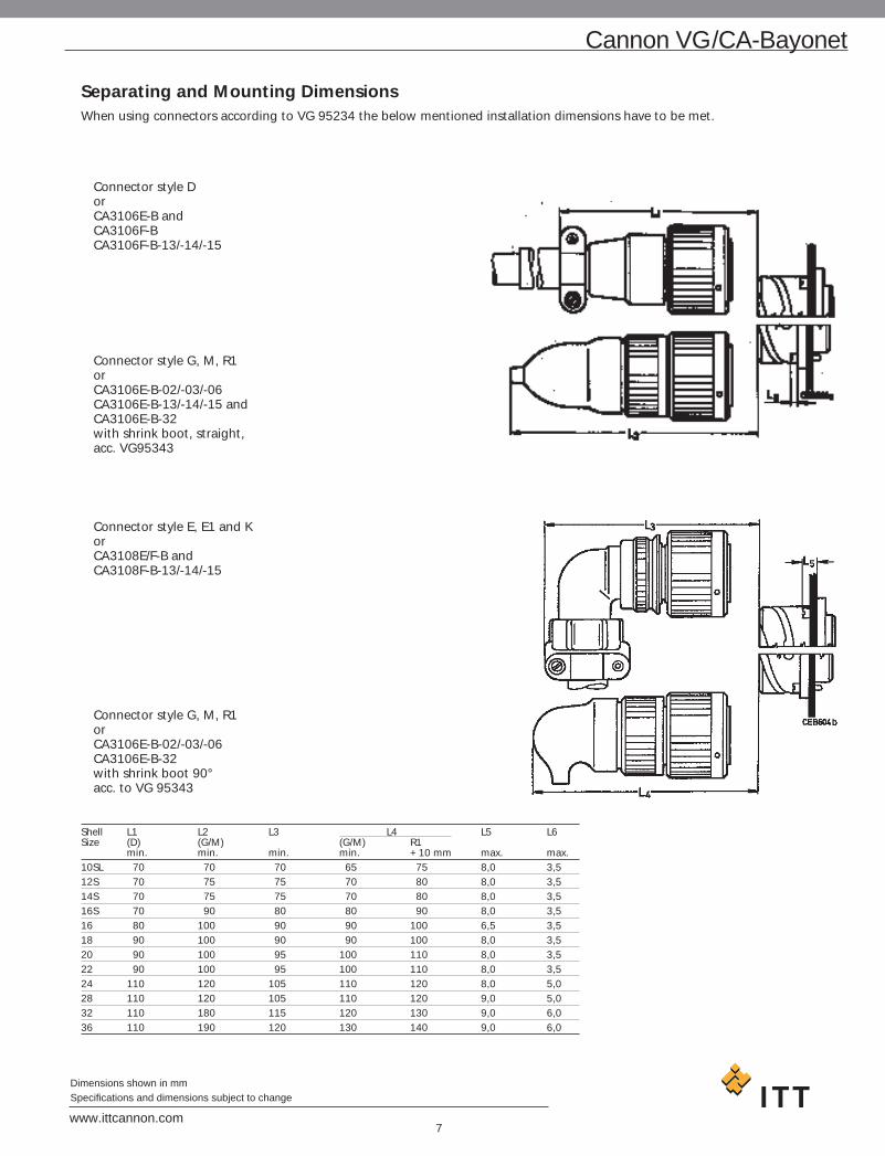
Shell L1 L2 L3 L4 L5 L6Size (D) (G/M) (G/M) R1
min. min. min. min. +10 mm max. max.10SL 70 70 70 65 75 8,0 3,512S 70 75 75 70 80 8,0 3,514S 70 75 75 70 80 8,0 3,516S 70 90 80 80 90 8,0 3,516 80 100 90 90 100 6,5 3,518 90 100 90 90 100 8,0 3,520 90 100 95 100 110 8,0 3,522 90 100 95 100 110 8,0 3,524 110 120 105 110 120 8,0 5,028 110 120 105 110 120 9,0 5,032 110 180 115 120 130 9,0 6,036 110 190 120 130 140 9,0 6,0
Cannon VG/CA-Bayonet
7www.ittcannon.com
Dimensions shown in mmSpecifications and dimensions subject to change
Separating and Mounting DimensionsWhen using connectors according to VG 95234 the below mentioned installation dimensions have to be met.
Connector style D orCA3106E-B and CA3106F-B CA3106F-B-13/-14/-15
Connector style G, M, R1orCA3106E-B-02/-03/-06 CA3106E-B-13/-14/-15 and CA3106E-B-32 with shrink boot, straight,acc. VG95343
Connector style E, E1 and K orCA3108E/F-B and CA3108F-B-13/-14/-15
Connector style G, M, R1orCA3106E-B-02/-03/-06 CA3106E-B-32 with shrink boot 90°acc. to VG 95343

8www.ittcannon.com
Dimensions shown in mmSpecifications and dimensions subject to change
Cannon VG/CA-Bayonet
How to order VG Order reference
VG 95234 A – 32 – 6 S 1 N
Series
Shell style
Dash
Shell size
Contact arrangement
Contact type
Contact termination
Insulator position
ExplanationSeries VG 95234
Shell style J1, J2, N1, N2, S1, U1, U2 – wall mounting receptacleF – cable connection plugA, B1, B2 – box mounting receptacleC1, C2 – bulkhead receptacleD, G, H, L, M, R1 – straight plugE, E1, K – plug 90°
Shell size 10SL, 14S, 16S, 16, 18, 20, 22,24, 28, 32 and 36
Contact arrangement see page 10
Contact type P – Pin contactS – Socket contact
Contact termination without identification – contacts for metric wire sizesidentification 1* – contact for AWG wire sizes
Insulator position see page 24
Accessories acc. to VGDummy receptacles VG95234 BODGaskets, front mount VG95234 DAGaskets, rear mount VG95234 DHProtecting caps VG95234 KRProtecting caps VG95234 KBCabel caps VG95234 KKBushing VG95234 KT
* Only valid for layout within the VG95234.
Layout list permitting identification 1:
Layout Page Number
22-2 1524- 11 1624-12 1728-22 1932-1 1932-6 2036-3 2136-5 2136-6 21
How to order Cannon Order reference
CA 3106 E 18 – 1 S X B – ***
Series
Shell style
Class
Shell size
Contact arrangement
Contact type
Insulator position
Connectors with bayonet coupling
Dash
Modification
ExplanationSeries CA – Circular connectors with bayonet
coupling
Shell style 3100 – Wall mounting receptacle3101 – Cable connecting plug3102 – Box mounting receptacle3105 – Dummy receptacle for front and
panel mounting3106 – Plug, straight3108 – Plug, 90°TBF – Bulkhead receptacle
Class E – environmental with resilientinsulators and endbell with clampand bushing
F – environmental with resilientinsulator and endbell for flex tube
R – environmental with resilientinsulator and shortened light-weightendbell without cable clamp
Shell size 10SL, 12S, 14S, 16S, 16, 18, 20,22, 24, 28, 32 and 36
Contact arrangement see page 10
Contact type P – PinS – SocketPS – one side pin, one side socket
(only for TBF)
Insulator position Besides the normal position further insulatorpositions are possible for Cannon connectors(see page 24) to prevent mismating. Polarization is achieved by turning the pincontact insulator clockwise towards theshell, the socket insulator, however, inopposite clockwise direction. This information refers to the mating side ofthe contact insulator.For special insert alternations of standardinserts see page 25.
Modification see next page

Cannon VG/CA-Bayonet
9www.ittcannon.com
Dimensions shown in mmSpecifications and dimensions subject to change
Modification 01 – metric crimp contacts(only for CA......-B) 02 – adapter for heat shrink boots
AWG crimp contacts03 – adapter for heat shrink boots,
metric contacts04 – rear mount, thread in flange,
metric crimp contacts05 – trear mount, through holes in flange,
(CA3100, CA 3102, CA 20, TBF)
06 – shrink boot adapter, thread holes in flange, solder pot contacts
08 – angular endbell, through holes inflange (for CA3100 only)
09 – angular endbell, through holes in flange (for CA3100 only)
13 – shielded version, solder contacts14 – shielded version, metric crimp con-
tacts15 – shielded version, AWG crimp contacts41 – shielded version, heat shrink boot
adapter32 – endbell for shielded system cable acc.
MTV 6145-005109 – F80, rear mount, thread holes in
flange (for CA3100 only)111 – rear mount, thread holes (CA3102
only), solder contactsF80 – AWG crimp contactsA232 – Zinc cobalt blackA233 – Zinc cobalt greenF42 – less grommet and backshellF0 – less contacts, contacts to be
ordered separatelysee pages 51– 52
Important!When connectors are requested according to VG 95234 modification, e.g. with another finish, with other contact arrange-ments and solder contacts, they are to be ordered only with the ITTCannon order reference.
Connectors acc. to VG95234 are generally available with insert po-sitions X and Y only.
VG order reference with modification is not possible.
With Spring Washer and Friction RingThese connectors feature a spring washer and a friction ring under the coupling nut.
Advantage Vibrations are being compensatedOrdering example according performance class insert
„W“ after Class E, F or RCA06EW – connector with spring washer, endbell
with cable and bushingCA06FW – connector with spring washer, endbell
for flex tubeCA06RW – connector with spring washer and short
endbellCA08EW/FW – connector with spring washer and
90° endbell
The connectors acc. to VG95234 are generally delivered withspring washer.
Other Shell StylesCA3100E-B-02/03/06 – adapter for heat shrink boot CA3100F-B-08/09 – 90° endbell for flex tube CA3100E-B-08/09 – 90° endbell, cable clamp and bushingCA06PG-B – PG adapterCA3101F-B-08/09 – 90° endbell flex tubeCA02L-B – receptacle with pcb solder contactsCA20L-B – rear mount receptacle with pcb solder
contactsCA07A-B – jam nut receptacleCA00EP-B-TL – TINEL-LOCK adapterCA06EW-B-TLXX – TINEL-LOCK adapter

No. Contact arrangement Service Insulator position Position Special Insulator weight of Contact size rating polarization (g) Contacts VG CA N V W X Y Z including contacts
pin socket3 10SL-3 10SL-3 – 0 – – – – – – – 6 9
15S 16S A
2 10SL-4 10SL-415S 16S A 0 – – – – – – – 4 6
2 12S-3– 16S A 0 100 70 145 215 290 – – 4 6
1 12S-4– 16S D 0 – – – – – 3 110 3 4,5
4 12SA10– 16S Instr. 0 – – – – – 3 110 6 8
8 250
3 14S-1– 16S A 0 – – – – – – – 6 9
4 14S-2– 16S Instr. 0 – – 120 240 – – – 7 11
1 14S-4– 16S D 0 – – – – – – – 4 7
5 14S-5– 16S Instr. 0 – – 110 – – – – 9 13
6 14S-6 14S-615S 16S Instr. 0 – – – – – – – 11 15
3 14S-7– 16S A 0 – 90 180 270 – – 6 9
2 14S-9– 16S Instr. 0 – 70 145 215 290 – – 5 18
7 14SA7– 16S Instr. 0 – – – – – – – 10 15
7 16S-1 16S-115S 16S A 0 – 80 – – 280 – – 14 19
2 16S-4 16S-415S 16S D 0 – 35 110 250 325 – – 7 10
3 16S-5– 16S A 0 – 70 145 215 290 – – 8 12
5 16S-8– 16S A 0 – – 170 265 – – – 10 15
10www.ittcannon.com
Dimensions shown in mmSpecifications and dimensions subject to change
Cannon VG/CA-Bayonet
View on Matingface of Pin Insulator
Attention: for all alternate positions of these contact arrangements a tendency to overmate can be stated.It is within the customer’s responsibility to use these insert positions.

No. Contact arrangement Service Insulator position Position Special Insulator weight of Contact size rating polarization (g)Contacts VG CA N V W X Y Z including contacts
pin socket3 16-7 16-7
2 15 16 A 0 – 80 110 250 280 – – 16 251 100 8
4 16-92 – 12 A 0 – 35 110 250 325 – – 13 202 16
3 16-10 16-1025 12 A 0 – 90 180 270 – – – 17 24
2 16-11– 12 A 0 – 35 110 250 325 – – 11 17
1 16-12 16-12160 4 A 0 – – – – – – – 24 28
2 16A11 16A1125 (socket) 12 A 0 – 35 110 250 325 – – 11 1725A (pin)
10 18-1 18-1 A (B, C,15 16 F, G) 0 – 70 145 – 290 – – 24 37
Instr.(all others)
2 18-3– 12 D 0 – 35 110 250 325 – – 13 22
4 18-4– 16 D 0 – 35 110 250 325 – – 19 30
3 18-52 – 12 D 0 – 80 110 250 280 – – 15 251 16
1 18-6– 4 D 0 – – – – – – – 24 32
1 18-7– 8 D 0 – – – – – – – 16 25
8 18-81 – 12 A 0 – 70 – – 290 – – 18 307 16
7 18-92 – 12 Instr. 0 – 80 110 250 280 – – 18 305 16
4 – 18-10 A 0 – – 120 240 – – – 13 2212
5 18-11 18-11 A 0 – – 170 265 – – – 31 4025 12
Cannon VG/CA-Bayonet
11www.ittcannon.com
Dimensions shown in mmSpecifications and dimensions subject to change
View on Matingface of Pin Insulator
Attention: for all alternate positions of these contact arrangements a tendency to overmate can be stated.It is within the customer’s responsibility to use these insert positions.

No. Contact arrangement Service Insulator position Position Special Insulator weight of Contact size rating polarization (g) Contacts VG CA N V W X Y Z including contacts
pin socket6 – 18-12 A 0 – 80 – – 280 – – 15 25
16
4 18-13 18-131 60 8 A 0 – 80 110 250 280 – – 15 243 25 12
7 18-172 – 12 Instr. 0 – – – – – 12 100 15 235 16
10 – 18-19 A 0 – – 120 240 – – – 19 3116
5 – 18-20 A 0 – 90 180 270 – – 15 2516
3 – 18-21 A 0 – – – – – – – 17 2812
3 – 18-22 D 0 – 70 145 215 290 – – 10 2016
1 20-2 20-2 D 0 – – – – – – – 46 55500 0
3 20-3– 12 D 0 – 70 145 215 290 – – 28 42
4 – 20-4 D 0 – 45 110 250 – – – 24 4012
3 – 20-6 D 0 – – – – – – – 22 3616
8 20-7 A (C, D,– 16 E, F) 0 – 80 110 250 280 – – 28 42
D (A, B,H, G)
6 20-8 20-82 100 8 Instr. 0 – 80 110 250 280 – – 37 494 15 16
13 – 20-11 Instr. 0 – – – – – – – 25 4116
12www.ittcannon.com
Dimensions shown in mmSpecifications and dimensions subject to change
Cannon VG/CA-Bayonet
View on Matingface of Pin Insulator
Attention: for all alternate positions of these contact arrangements a tendency to overmate can be stated.It is within the customer’s responsibility to use these insert positions.

No. Contact arrangement Service Insulator position Position Special Insulator weight of Contact size rating polarization (g) Contacts VG CA N V W X Y Z including contacts
pin socket5 – 20-14 A 0 – 80 110 250 280 – – 22 39
3 – 122 8
7 – 20-15 A 0 – 80 – – 280 – – 27 4612
9 20-162 – 12 A 0 – 80 110 250 280 – – 19 327 16
6 20-175 – 12 A 0 – 90 180 270 – – – 20 331 16
9 20-183 – 12 A – – 35 110 250 325 – – 19 326 16
3 – 20-19 A 0 – 90 180 270 – – – 33 468
6 – 20-223 8 A – – 80 110 250 280 – – 37 493 16
2 20-23– 8 A – – 35 110 250 325 – – 25 35
4 – 20-24 A 0 – 35 110 250 325 – – 40 532 82 16
14 – 20-27 A 0 – 35 110 250 325 – – 26 4216
17 – 20-29 A 0 – 80 – – 280 – – 29 4716
Cannon VG/CA-Bayonet
13www.ittcannon.com
Dimensions shown in mmSpecifications and dimensions subject to change
View on Matingface of Pin Insulator
Attention: for all alternate positions of these contact arrangements a tendency to overmate can be stated.It is within the customer’s responsibility to use these insert positions.

No. Contact arrangement Service Insulator position Position Special Insulator weight of Contact size rating polarization (g) Contacts VG CA N V W X Y Z including contacts
pin socket11 – 20-33 A 0 – – – – 2 260 – 23 38
16 3 11017 130
9 20A9 20A9 D (J)25 12 Instr. 0 – – 110 250 – – – 21 35
(all others)
19 20A48 20A48 Instr. 0 – – 80 280 – – – 30 5015 16
2 – 22-1 D 0 – 35 110 250 325 – – 28 428
3 22-2 22-2 D 0 – 70 145 215 290 – – 35 508 8
4 22-42 – 8 A – – 35 110 250 325 – – 34 482 12
6 22-52 – 12 D – – 35 110 250 325 – – 23 384 16
1 22-7– 0 E 0 – – – – – – – 45 57
2 – 22-8– 12 E – – 35 110 250 325 – – 18 28
3 – 22-9 E 0 – 70 145 215 290 – – 21 32– 12
14www.ittcannon.com
Dimensions shown in mmSpecifications and dimensions subject to change
Cannon VG/CA-Bayonet
View on Matingface of Pin Insulator
Attention: for all alternate positions of these contact arrangements a tendency to overmate can be stated.It is within the customer’s responsibility to use these insert positions.

No. Contact arrangement Service Insulator position Position Special Insulator weight of Contact size rating polarization (g) Contacts VG CA N V W X Y Z including contacts
pin socket4 – 22-10
– 16 E – – 35 110 250 325 – – 17 31
5 22-12 22-12 D 0 – 80 110 250 280 – – 28 422 100 83 15 16
19 22-14 22-14 A 0 – 80 – – 280 – – 30 5015 16
6 22-155 12 A (A, B,1 – 16 C, E, F) 0 – 80 110 250 280 – – 30 50
E (D)
9 – 22-16 A 0 – 80 110 250 2803 12 – – – 28 45 6 16
14 – 22-19 A 0 – 80 110 250 280 – – 28 4716
9 – 22-20 A 0 – 35 110 250 325 – – 22 3916
3 – 22-21 A 0 – 80 110 250 2802 16 – – – 49 58 1 0
4 22-22 22-22 A 0 – – 110 250 – – – 42 58100 8
8 – 22-23 D (H)12 A (all 0 – 35 – 250 – – – 34 54
others)
9 22-27 22-27 1 60 8 A (A to H) 0 – 80 – 250 280 – – 21 348 15 16 D (J)
Cannon VG/CA-Bayonet
15www.ittcannon.com
Dimensions shown in mmSpecifications and dimensions subject to change
View on Matingface of Pin Insulator
Attention: for all alternate positions of these contact arrangements a tendency to overmate can be stated.It is within the customer’s responsibility to use these insert positions.

No. Contact arrangement Service Insulator position Position Special Insulator weight of Contact size rating polarization (g) Contacts VG CA N V W X Y Z including contacts
pin socket7 22-28
– 12 A – – 80 – – 280 – – 33 50
22B22 – A 0 – – 110 250 –4 60 – – 42 58
7 – 24-2 D 0 – 80 – – 280 – – 33 5312
4 24-41 – 0 D – – 80 110 250 280 – – 51 63 3 16
16 24-5– 16 A – – 80 110 250 280 – – 30 54
8 24-6 A8 – 12 (B,C,D,E,F) 0 – 80 110 250 280 – – 32 41
16 24-72 – 12 A 0 – 80 110 250 280 – – 45 65
14 16
2 – 24-9 A 0 – 35 110 250 325 – – 45 604
7 24-10 24-10 A 0 – 80 – – 280 – – 65 85100 8
9 24-11 24-113 100/8 8 A 0 – 35 110 250 325 – – 55 75 6 25/12 12
16www.ittcannon.com
Dimensions shown in mmSpecifications and dimensions subject to change
Cannon VG/CA-Bayonet
View on Matingface of Pin Insulator
Attention: for all alternate positions of these contact arrangements a tendency to overmate can be stated.It is within the customer’s responsibility to use these insert positions.

No. Contact arrangement Service Insulator position Position Special Insulator weight of Contact size rating polarization (g) Contacts VG CA N V W X Y Z including contacts
pin socket5 24-12 24-12
2 4 4 A 0 – 80 110 250 280 – – 60 80 3 12 12
12 – 24-19 A 0 – – – – – – – 28 4716
11 24-20 2 – 12 D 0 – 80 110 250 280 – – 40 609 16
4 – 24-22 D 0 – 45 110 250 – – 44 618
7 24-27– 16 E – – 80 – – 280 – – 21 37
24 24-28 24-28 Instr. 0 – 80 110 250 280 – – 40 6515 16
12 – 24A24 A – – – – – – 2 260 46 7112 – – – – – – 4 80
– – – – – – 9 280– – – – – – 12 100
28 24A28– 16 Instr. – – 65 146 235 – – – 42 75
14 28-2 12 – 16 D – – 35 110 250 325 – – 43 61
2 12
5 28-52 – 4 D – – 35 110 250 325 – – 60 702 161 12
Cannon VG/CA-Bayonet
17www.ittcannon.com
Dimensions shown in mmSpecifications and dimensions subject to change
View on Matingface of Pin Insulator
Attention: for all alternate positions of these contact arrangements a tendency to overmate can be stated.It is within the customer’s responsibility to use these insert positions.

No. Contact arrangement Service Insulator position Position Special Insulator weight of Contact size rating polarization (g) Contacts VG CA N V W X Y Z including contacts
pin socket12 28-9
6 – 16 D – – 80 110 250 280 – – 46 656 12
7 28-102 – 4 A (= A, B, C, – – 80 110 250 280 – – 80 912 8 D, E, F)3 12 D (= G)
22 28-11 28-114 25 12 A 0 – 80 110 250 280 – – 65 110
18 15 16
26 – 28-12 A 0 – 90 180 270 – – – 47 7716
35 – 28-15 A 0 – 80 110 250 280 – – 54 9016
20 28-16 A (A-L)– 16 D (M, N, P) 0 – 80 110 250 280 – – 41 68
B (R)
10 28-196 – 16 A (= C, E, G, J, K, L) – – 80 110 250 280 – – 40 584 12 D = A, B
B = H, M
14 28-20 28-2010 25 12 A 0 – 80 110 250 280 – – 65 1104 15 16
18www.ittcannon.com
Dimensions shown in mmSpecifications and dimensions subject to change
Cannon VG/CA-Bayonet
View on Matingface of Pin Insulator
Attention: for all alternate positions of these contact arrangements a tendency to overmate can be stated.It is within the customer’s responsibility to use these insert positions.

No. Contact arrangement Service Insulator position Position Special Insulator weight of Contact size rating polarization (g) Contacts VG CA N V W X Y Z including contacts
pin socket37 28-21 28-21
15 16 A 0 – 80 110 250 280 – – 58 93
6 28-22 28-223 160/4 4 D 0 – 70 145 215 290 – – 80 1203 15/16 16
All alternating insert position as above are permitted for VG95234 types.
12 28-51– 12 D – – 80 135 195 – – – 57 77
9 28A164 – 4 A (e) 0 – – – – – 2 260 100 1355 16 Instr. – – – – – – 3 110
(all others) – – – – – – 8 250– – – – – – 9 280
43 – 28A51 A 0 – – – – – 3 110 64 10716 – – – – – – 4 80
– – – – – – 8 250– – – – – – 9 280– – – – – – 12 100
28 28A63 28A639 25 12 A 0 – – 100 260 – – – 85 135
19 15 16
5 32-1 32-12 500/0 0 E (A) 0 – 80 110 250 280 – – 130 1553 25/12 12 D (all
others)
2 32-50 D 0 – 35 110 250 325 – – 86 114
Cannon VG/CA-Bayonet
19www.ittcannon.com
Dimensions shown in mmSpecifications and dimensions subject to change
View on Matingface of Pin Insulator
Attention: for all alternate positions of these contact arrangements a tendency to overmate can be stated.It is within the customer’s responsibility to use these insert positions.

No. Contact arrangement Service Insulator position Position Special Insulator weight of Contact size rating polarization (g) Contacts VG CA N V W X Y Z including contacts
pin socket23 32-6 32-6
2 160/4 43 60/8 8 A 0 – 80 110 250 280 – – 130 1702 25/12 12
16 15/16 16
35 32-7 32-77 25 12 Instr.
28 15 16 (A, B, U, I.) 0 – 80 125 235 280 – – 110 160A (all others)
30 32-86 – 12 A 0 – 80 125 235 280 – – 105 155
24 16
14 32-912 – 16 D 0 – 80 110 250 280 – – 79 1302 4
23 32-135 – 12 D 0 – 80 110 250 280 – – 95 145
18 16
8 32-152 – 0 D 0 – 35 110 250 325 – – 140 1656 12
4 – 32-17 D 0 – 45 110 250 – – – 80 1164
20www.ittcannon.com
Dimensions shown in mmSpecifications and dimensions subject to change
Cannon VG/CA-Bayonet
View on Matingface of Pin Insulator
Attention: for all alternate positions of these contact arrangements a tendency to overmate can be stated.It is within the customer’s responsibility to use these insert positions.

No. Contact arrangement Service Insulator position Position Special Insulator weight of Contact size rating polarization (g) Contacts VG CA N V W X Y Z including contacts
pin socket– – – – – – 2 260
54 32A10 – – – – – – 3 110– 16 A – – 80 110 250 280 4 80 89 132
– – – – – – 8 250– – – – – – 9 280– – – – – – 12 100
– – – – – – 2 26047 – 32A47 – – – – – – 3 110
16 A – – – – – – 4 80 73 120– – – – – – 8 250– – – – – – 9 280– – – – – – 12 100
55 32A5516 A – – 80 110 250 280 – – 90 134
61 32A69 32A69 Instr. 0 – – 110 250 – – – 49 8420 15 1641 10 20
Not for through-bulkhead receptacle C1 / C2.
6 36-3 36-33 500/0 0 D 0 – 70 145 215 290 – – 165 2003 25/12 12
All alternating insert position as above are permitted for VG95234 type.
4 36-5 36-5 A 0 – – 120 240 – – – 152 181500/0 0
6 36-6 36-64 4 4 A 0 – 35 110 250 325 – – 155 1732 0 0
Cannon VG/CA-Bayonet
21www.ittcannon.com
Dimensions shown in mmSpecifications and dimensions subject to change
View on Matingface of Pin Insulator
Attention: for all alternate positions of these contact arrangements a tendency to overmate can be stated.It is within the customer’s responsibility to use these insert positions.

No. Contact arrangement Service Insulator position Position Special Insulator weight of Contact size rating polarization (g) Contacts VG CA N V W X Y Z including contacts
pin socket47 36-7
7 – 12 A – – 80 110 250 280 – – 92 14440 16
47 36-81 – 12 A – – 80 110 250 280 – – 80 132
46 16
31 36-914 – 16 A 0 – 80 125 235 280 – – 116 15914 122 81 4
48 36-10 36-10 A 0 – 80 125 235 280 – – 79 13315 16
16 36-145 – 8 D 0 – – – – – – – 150 2305 126 16
35 36-15 D (m)– 16 A (all 0 – 60 125 245 305 – – 70 111
others)
22www.ittcannon.com
Dimensions shown in mmSpecifications and dimensions subject to change
Cannon VG/CA-Bayonet
View on Matingface of Pin Insulator
Attention: for all alternate positions of these contact arrangements a tendency to overmate can be stated.It is within the customer’s responsibility to use these insert positions.

No. Contact arrangement Service Insulator position Position Special Insulator weight of Contact size rating polarization (g) Contacts VG CA N V W X Y Z including contacts
pin socket– – – – – – 2 260
52 – 36A34 – – – – – – 3 11016 A – – – – – – 4 80 83 139
– – – – – – 8 250– – – – – – 9 280– – – – – – 12 100– – – – – – 20 220
8 – 36A354 16 A – – – – – – 2 260 172 1834 0 – – – – – – 3 110
– – – – – – 8 250– – – – – – 9 280
– – – – – – 2 26027 – 36A46 – – – – – – 3 110
12 A – – – – – – 4 80 112 154– – – – – – 8 250– – – – – – 9 280– – – – – – 12 100
39 – 36A988 8 Instr. 0 – – – – – – – 160 140
31 16
65 – 36A9915 16 Instr. – – 30 135 – – – – 80 12150 20*
* reduced contact termination 0,3 mm2
Cannon VG/CA-Bayonet
23www.ittcannon.com
Dimensions shown in mmSpecifications and dimensions subject to change
View on Matingface of Pin Insulator
Attention: for all alternate positions of these contact arrangements a tendency to overmate can be stated.It is within the customer’s responsibility to use these insert positions.

24www.ittcannon.com
Dimensions shown in mmSpecifications and dimensions subject to change
Cannon VG/CA-Bayonet
Alternate Insert Positions
Indicates location of centerline of key orkeyway of shells in fixed normal position.Insert is rotated as shown by arrow andletters.
Connectors according to VG95234 aregenerally available with insert positions Xand Y only.
Tolerances:# 10SL-20: ± 2°# 22-36: ± 1,5°# 32A69: ± 1°
PinMating face
Normal position
SocketMating face

Cannon VG/CA-Bayonet
25www.ittcannon.com
Dimensions shown in mmSpecifications and dimensions subject to change
Special Insert Alternations
Special insert alternations are marked by positions. The positionnumber indicates the turning of the contact insert in the directionof the polarizing key in view of the mating or termination side of the socket insulator.
PositionsView shows mating side of pin or termination side of socket.
Insert positions are added without hyphen directly behind thecontact type.
Example: CA3106F32A10P -B-012
Position Polarization2 260°3 110°4 80°5 use pos. 36 85°8 250°9 280°
11 105°12 100°13 use pos. 814 30°15 45°16 120°17 130°18 150°19 195°20 220°21 255°22 290°23 165°24 330°25 235°26 125°
Contact Position Contact Polarizationarrangement of arrangement12SA10 3 12SA10 110°
8 12SA10 250°18-17 12 18-9 100°24A24 2 24A24 260°
4 24A24 80°9 24A24 280°
12 24A24 100°32-16 12 32-6 100°

26www.ittcannon.com
Dimensions shown in mmSpecifications and dimensions subject to change
Cannon VG/CA-Bayonet
Contact No. of Contact sizearrangement contacts 0 4 8 12 16 20
500 160 100 25 15 1060
12S4 1 114S4 1 116-12 1 118-6 1 118-7 1 120-2 1 122-7 1 1
10SL4 2 214S9 2 216S4 2 216-11 2 216A11 2 218-3 2 220-23 2 222-1 2 222-8 2 224-9 2 232-5 2 2
10SL3 3 314S1 3 314S7 3 316S5 3 316-7 3 1 216-10 3 318-5 3 2 118-21 3 318-22 3 320-6 3 320-19 3 322-2 3 322-9 3 322-21 3 1 2
12SA10 4 414S2 4 416-9 4 2 218-4 4 418-10 4 418-13 4 1 320-4 4 420-24 4 2 222-4 4 2 222-10 4 422-22 4 422B22 4 424-4 4 1 324-22 4 432-17 4 436-5 4 4
Contact No. of Contact sizearrangement contacts 0 4 8 12 16 20
500 160 100 25 15 1060
14S5 5 516S8 5 518-11 5 518-20 5 522-12 5 2 324-12 5 2 328-5 5 2 1 232-1 5 2 3
14S6 6 618-12 6 620-8 6 2 420-22 6 3 322-5 6 2 422-15 6 5 128-22 6 3 336-3 6 3 336-6 6 2 4
14SA7 7 716S1 7 718-9 7 2 518-17 7 2 520-15 7 722-28 7 724-2 7 724-10 7 724-27 7 728-10 7 2 2 3
18-8 8 1 720-7 8 822-23 8 832-15 8 2 636A35 8 4 4
20-16 9 2 720-18 9 3 620A9 9 922-16 9 3 622-20 9 922-27 9 1 824-11 9 3 628A16 9 4 5
18-1 10 1018-19 10 1028-19 10 4 6
20-33 11 1124-20 11 2 9
Contact Arrangements

Cannon VG/CA-Bayonet
27www.ittcannon.com
Dimensions shown in mmSpecifications and dimensions subject to change
Contact No. of Contact sizearrangement contacts 0 4 8 12 16 20
500 160 100 25 15 1060
24-19 12 1224A24 12 1228-9 12 6 628-51 12 12
20-11 13 13
20-27 14 1422-19 14 1428-2 14 2 1228-20 14 10 432-9 14 2 12
24-5 16 1624-7 16 2 1436-14 16 5 5 6
20-29 17 17
20A48 19 1922-14 19 19
28-16 20 20
28-11 22 4 18
32-6 23 2 3 2 1632-13 23 5 18
24-28 24 24
28-12 26 26
36A46 27 27
24A28 28 2828A63 28 9 19
32-8 30 6 24
36-9 31 1 2 14 14
28-15 35 3532-7 35 7 2836-15 35 35
28-21 37 37
36A98 39 8 31
Contact No. of Contact sizearrangement contacts 0 4 8 12 16 20
500 160 100 25 15 1060
28A51 43 43
32A47 47 4736-7 47 7 4036-8 47 1 46
36-10 48 48
36A34 52 52
32A10 54 54
32A55 55 55
32A69 61 20 41
36A99 65 15 50
Contact Arrangements

28www.ittcannon.com
Dimensions shown in mmSpecifications and dimensions subject to change
Cannon VG/CA-Bayonet
VG95234 Cannon d1 d2 d3 l1 l2 l3 l4 Weight1)
Part no. Part no. max. H13 –0,15 ±0,3 +0,4 ±0,2 ±0,3 g max.VG95234A-10SL CA3102E10SL-**-B 16,2 3,2 18,2 24,7 14,2 2,8 25,4 12– CA3102E12S-**-B 16,2 3,2 21,4 24,7 14,2 3,2 28,0 15VG95234A-14S CA3102E14S-**-B 19,2 3,2 24,6 24,7 14,2 3,2 30,0 17VG95234A-16S CA3102E16S-**-B 22,4 3,2 27,4 24,7 14,2 3,2 32,5 19VG95234A-16 CA3102E16-**-B 22,4 3,2 27,4 33,8 19,0 3,2 32,5 22VG95234A-18 CA3102E18-**-B 25,6 3,2 30,8 33,8 19,0 4,0 35,0 28VG95234A-20 CA3102E20-**-B 29,0 3,2 34,2 33,8 19,0 4,0 38,0 33VG95234A-22 CA3102E22-**-B 32,2 3,2 37,4 33,8 19,0 4,0 41,0 38VG95234A-24 CA3102E24-**-B 35,3 3,7 40,9 33,8 20,6 4,0 44,5 46VG95234A-28 CA3102E28-**-B 41,4 3,7 46,7 33,8 20,6 4,0 50,8 52VG95234A-32 CA3102E32-**-B 47,8 4,3 53,4 33,8 22,2 4,0 57,0 64VG95234A-36 CA3102E36-**-B 52,6 4,3 59,6 33,8 22,2 4,0 63,5 801) Weight without insulator
Box Mounting Receptacle
VG 95234 – Style ACA 3102E-B and Modifications, see page 9
Receptacle for front panel mounting with square flange.Threaded holes in flange not possible.
CA02L-B designates a receptacle for front panel mountingwith solder pin contacts to solder into printed circuits. Allpattern drawings upon request. For all other dimensions seeabove table.
For contact arrangements with #16 and #12 contacts only.

29www.ittcannon.com
Dimensions shown in mmSpecifications and dimensions subject to change
Cannon VG/CA-Bayonet
Box Mounting Receptacle
VG95234 Style B1 (with threaded holes in flange)
CA3102-B and Modifications, e g -04, -109 or -111
CA3102-B designates a receptacle with square flange for rear panel mounting.
VG95234 Style B2 (with through holes in flange)
CA3102E-B and Modifications, see page 9
VG95234 Cannon d1 d2 d3 l1 l2 l3 l4 Weight1)
Part no. Part no. max. B1 B2 –0,15 ±0,3 +0,4 ±0,2 ±0,3 g max.H13
VG95234XX-10SL-* CA3102E10SL-*B-*** 16,2 M4 3,2 18,2 24,7 18,2 2,8 25,4 14– CA3102E12S-*B-*** 16,2 M4 3,2 21,4 24,7 18,2 3,2 28,0 18VG95234XX-14S-* CA3102E14S-*B-*** 19,2 M4 3,2 24,6 24,7 18,2 3,2 30,0 21CG95234XX-16S-* CA3102E16S-*B-*** 22,4 M4 3,2 27,4 24,7 18,2 3,2 32,5 22VG95234XX-16-* CA3102E16-*B-*** 22,4 M4 3,2 27,4 33,8 21,5 3,2 32,5 27VG95234XX-18-* CA3102E18-*B-*** 25,6 M4 3,2 30,8 33,8 23,05 4,0 35,0 33VG95234XX-20-* CA3102E20-*B-*** 29,0 M4 3,2 34,2 33,8 23,05 4,0 38,0 37VG95234XX-22-* CA3102E22-*B-*** 32,2 M4 3,2 37,4 33,8 23,05 4,0 41,0 42VG95234XX-24-* CA3102E24-*B-*** 35,3 M4 3,7 40,9 33,8 23,05 4,0 44,5 48VG95234XX-28-* CA3102E28-*B-*** 41,4 M5 3,7 46,7 33,8 24,05 4,0 50,8 58VG95234XX-32-* CA3102E32-*B-*** 47,8 M5 4,3 53,4 33,8 24,05 4,0 57,0 72VG95234XX-36-* CA3102E36-*B-*** 54,1 M5 4,3 59,6 33,8 24,05 4,0 63,5 841) Weight without insulator
CA20L-B designates a receptacle for rear panel mountingwith solder pin contacts to solder into printed circuits. Allpattern drawings upon request. For all other dimensions seeabove table.
For contact arrangements with #16 and #12 contacts only.
Style B2
Mod. -05

30www.ittcannon.com
Dimensions shown in mmSpecifications and dimensions subject to change
Cannon VG/CA-Bayonet
Thru-Bulkhead Receptacle
VG 95234 Style C1 resp. TBF-B (with threaded holes)VG 95234 Style C2 resp TBF-B-05 (with flange through holes)
TBF-B designates a bulkhead receptacle with mounting flange.
Modifications see page 9
VG95234 Cannon d2 d2 e l1 l2 l3 l4 Weight1)
Part no. Part no. C1 C2 –0,15 ±0,1 ±0,7 +0,3 ±0,2 ±0,3 g max.H13
VG95234XX-10SL-* TBF10SL-*B-*** M4 3,2 18,2 18,2 37,5 14,2 2,8 25,4 17– TBF12S-*B-*** M4 3,2 21,4 20,6 37,5 14,2 3,2 28,0 24VG95234XX-14S-* TBF14S-*B-*** M4 3,2 24,6 23,0 37,5 14,2 3,2 30,0 29CG95234XX-16S-* TBF16S-*B-*** M4 3,2 27,4 24,6 37,5 14,2 3,2 32,5 34VG95234XX-16-* TBF16-*B-*** M4 3,2 27,4 24,6 51,4 19,0 3,2 32,5 41VG95234XX-18-* TBF18-*B-*** M4 3,2 30,8 27,0 51,4 19,0 4,0 35,0 49VG95234XX-20-* TBF20-*B-*** M4 3,2 34,2 29,4 51,4 19,0 4,0 38,0 56VG95234XX-22-* TBF22-*B-*** M4 3,2 37,4 31,8 51,4 19,0 4,0 41,0 61VG95234XX-24-* TBF24-*B-*** M4 3,7 40,9 34,9 51,4 20,6 4,0 44,5 65VG95234XX-28-* TBF28-*B-*** M5 3,7 46,7 39,7 51,4 20,6 4,0 50,8 76VG95234XX-32-* TBF32-*B-*** M5 4,3 53,4 44,5 51,4 22,2 4,0 57,0 92VG95234XX-36-* TBF36-*B-*** M5 4,3 59,6 49,2 51,4 22,2 4,0 63,5 1031) Weight without insulator, grommets and contacts.
Straight Plug
CA3106E-B designates a straight plug with endbell, cable clamp and telescoping bushing
VG 95234 Style D resp. CA3106E-B and Modifications, see page 9
VG95234 Cannon d1 d22) l1 l2 l3 l4 Weight1)
Part no. Part no. max. max. max. max. max. max. g max.VG95234D-10SL-* CA3106E10SL-**B-*** 22,8 6,5 115 55 22,7 22,7 30
CA3106E12S-**B-*** 26,0 6,5 115 55 22,7 22,7 37VG95234D-14S-* CA3106E14S-**B-*** 29,2 9,0 115 60 27,5 27,5 44VG95234D-16S-* CA3106E16S-**B-*** 32,0 11,0 115 60 30,0 30,0 54VG95234D-16-* CA3106E16-**B-*** 32,0 11,0 120 70 30,0 30,0 62VG95234D-18-* CA3106E18-**B-*** 36,5 14,2 120 75 33,0 33,0 70VG95234D-20-* CA3106E20-**B-*** 39,9 15,8 120 75 37,5 37,5 85VG95234D-22-* CA3106E22-**B-*** 43,1 15,8 120 75 37,5 37,5 92VG95234D-24-* CA3106E24-**B-*** 46,6 21,4 120 90 43,3 43,3 127VG95234D-28-* CA3106E28-**B-*** 53,4 21,4 120 90 48,0 43,3 154VG95234D-32-* CA3106E32-**B-*** 60,1 26,7 120 90 55,0 51,7 199VG95234D-36-* CA3106E36-**B-*** 66,3 31,7 130 100 58,0 58,0 2601) Weight without insulator, grommets and contacts. 2) For max. cable entry.
Style C2
Socket Pin
31www.ittcannon.com
Dimensions shown in mmSpecifications and dimensions subject to change
Cannon VG/CA-Bayonet
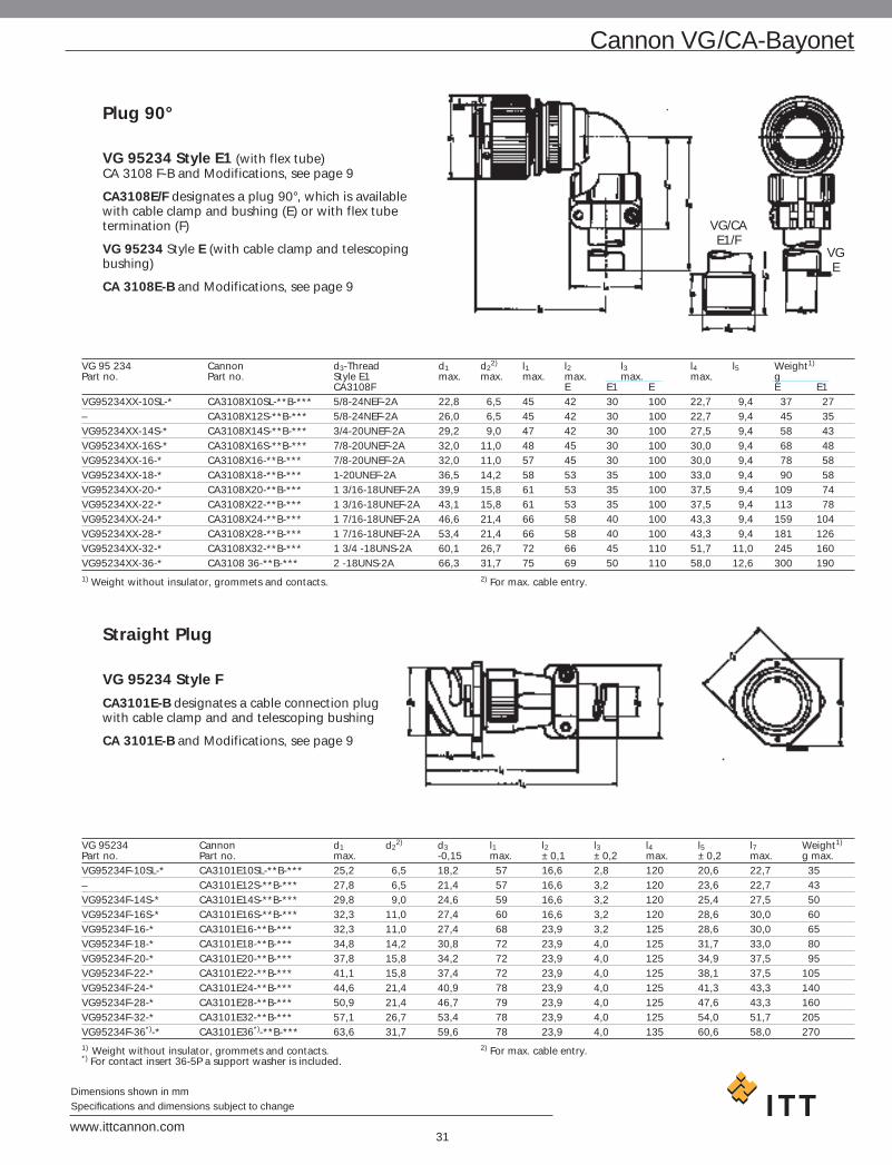
Plug 90°
VG 95234 Style E1 (with flex tube)CA 3108 F-B and Modifications, see page 9
CA3108E/F designates a plug 90°, which is available with cable clamp and bushing (E) or with flex tube termination (F)
VG 95234 Style E (with cable clamp and telescoping bushing)
CA 3108E-B and Modifications, see page 9
VG 95 234 Cannon d3-Thread d1 d22) l1 l2 l3 l4 l5 Weight1)
Part no. Part no. Style E1 max. max. max. max. max. max. gCA3108F E E1 E E E1
VG95234XX-10SL-* CA3108X10SL-**B-*** 5/8-24NEF-2A 22,8 6,5 45 42 30 100 22,7 9,4 37 27– CA3108X12S-**B-*** 5/8-24NEF-2A 26,0 6,5 45 42 30 100 22,7 9,4 45 35VG95234XX-14S-* CA3108X14S-**B-*** 3/4-20UNEF-2A 29,2 9,0 47 42 30 100 27,5 9,4 58 43VG95234XX-16S-* CA3108X16S-**B-*** 7/8-20UNEF-2A 32,0 11,0 48 45 30 100 30,0 9,4 68 48VG95234XX-16-* CA3108X16-**B-*** 7/8-20UNEF-2A 32,0 11,0 57 45 30 100 30,0 9,4 78 58VG95234XX-18-* CA3108X18-**B-*** 1-20UNEF-2A 36,5 14,2 58 53 35 100 33,0 9,4 90 58VG95234XX-20-* CA3108X20-**B-*** 1 3/16-18UNEF-2A 39,9 15,8 61 53 35 100 37,5 9,4 109 74VG95234XX-22-* CA3108X22-**B-*** 1 3/16-18UNEF-2A 43,1 15,8 61 53 35 100 37,5 9,4 113 78VG95234XX-24-* CA3108X24-**B-*** 1 7/16-18UNEF-2A 46,6 21,4 66 58 40 100 43,3 9,4 159 104VG95234XX-28-* CA3108X28-**B-*** 1 7/16-18UNEF-2A 53,4 21,4 66 58 40 100 43,3 9,4 181 126VG95234XX-32-* CA3108X32-**B-*** 1 3/4 -18UNS-2A 60,1 26,7 72 66 45 110 51,7 11,0 245 160VG95234XX-36-* CA3108 36-**B-*** 2 -18UNS-2A 66,3 31,7 75 69 50 110 58,0 12,6 300 1901) Weight without insulator, grommets and contacts. 2) For max. cable entry.
Straight Plug
VG 95234 Style F
CA3101E-B designates a cable connection plug with cable clamp and and telescoping bushing
CA 3101E-B and Modifications, see page 9
VG 95234 Cannon d1 d22) d3 l1 l2 l3 l4 l5 l7 Weight1)
Part no. Part no. max. -0,15 max. ±0,1 ±0,2 max. ±0,2 max. g max.VG95234F-10SL-* CA3101E10SL-**B-*** 25,2 6,5 18,2 57 16,6 2,8 120 20,6 22,7 35– CA3101E12S-**B-*** 27,8 6,5 21,4 57 16,6 3,2 120 23,6 22,7 43VG95234F-14S-* CA3101E14S-**B-*** 29,8 9,0 24,6 59 16,6 3,2 120 25,4 27,5 50VG95234F-16S-* CA3101E16S-**B-*** 32,3 11,0 27,4 60 16,6 3,2 120 28,6 30,0 60VG95234F-16-* CA3101E16-**B-*** 32,3 11,0 27,4 68 23,9 3,2 125 28,6 30,0 65VG95234F-18-* CA3101E18-**B-*** 34,8 14,2 30,8 72 23,9 4,0 125 31,7 33,0 80VG95234F-20-* CA3101E20-**B-*** 37,8 15,8 34,2 72 23,9 4,0 125 34,9 37,5 95VG95234F-22-* CA3101E22-**B-*** 41,1 15,8 37,4 72 23,9 4,0 125 38,1 37,5 105VG95234F-24-* CA3101E24-**B-*** 44,6 21,4 40,9 78 23,9 4,0 125 41,3 43,3 140VG95234F-28-* CA3101E28-**B-*** 50,9 21,4 46,7 79 23,9 4,0 125 47,6 43,3 160VG95234F-32-* CA3101E32-**B-*** 57,1 26,7 53,4 78 23,9 4,0 125 54,0 51,7 205VG95234F-36*)-* CA3101E36*)-**B-*** 63,6 31,7 59,6 78 23,9 4,0 135 60,6 58,0 2701) Weight without insulator, grommets and contacts. 2) For max. cable entry.*) For contact insert 36-5P a support washer is included.
VG/CAE1/F
VGE

32www.ittcannon.com
Dimensions shown in mmSpecifications and dimensions subject to change
Straight Plug
VG95234 – Style G
CA3106E-B, -02, -03 or -06 designates a straight plug with adapter for heat shrinkable boots
CA3106E-B and Modificationes, see page 9
VG 95234 Cannon d1 d2 d3 d4 d5 l1 l2 Weight1)
Part no. Part no. max. ±0,2 ±0,2 max. min. max. ±0,5 g max.VG95234G-10SL-* CA3106E10SL-**B-*** 22,8 17,0 15,5 13,3 7,7 50 11,7 24– CA3106E12S-**B-*** 26,0 17,8 15,5 13,3 7,9 50 11,7 35VG95234G-14S-* CA3106E14S-**B-*** 29,2 20,1 19,1 17,0 10,6 50 11,7 41VG95234G-16S-* CA3106E16S-**B-*** 32,0 23,5 23,9 21,9 13,5 50 11,7 51VG95234G-16-* CA3106E16-**B-*** 32,0 23,5 23,9 21,9 13,5 60 11,7 58VG95234G-18-* CA3106E18-**B-*** 36,5 26,5 23,9 21,9 14,6 60 11,7 65VG95234G-20-* CA3106E20-**B-*** 39,9 30,2 29,6 26,2 18,7 65 12,7 75VG95234G-22-* CA3106E22-**B-*** 43,1 33,6 29,6 26,2 20,8 65 12,7 80VG95234G-24-* CA3106E24-**B-*** 46,6 38,1 37,8 34,5 24,6 65 12,7 95VG95234G-28-* CA3106E28-**B-*** 53,4 41,4 37,8 34,5 27,0 65 12,7 120VG95234G-32-* CA3106E32-**B-*** 60,1 48,6 47,8 43,6 33,3 70 15,2 165VG95234G-36-* CA3106E36-**B-*** 66,3 54,8 47,8 43,6 38,5 80 15,2 1801) Weight without insulator, grommets and contacts.
Straight PlugVG95234 Style H
CA3106-F-B designates a straight plug for flex tube
CA3106-B and Modifications, see page 9
VG 95234 Cannon d3-Thread d1 d2a2) l1 l2 Weight1)
Part no. Part no. max. max. min. g max.VG95234H-10SL-* CA3106F10SL-**B-*** 5/8-24NEF-2A 22,8 8,2 50 9,5 21– CA3106F12S-**B-*** 5/8-24NEF-2A 26,0 8,2 50 9,5 29VG95234H-14S-* CA3106F14S-**B-*** 3/4-20UNEF-2A 29,2 11,1 50 9,5 33VG95234H-16S-* CA3106F16S-**B-*** 7/8-20UNEF-2A 32,0 14,3 50 9,5 42VG95234H-16-* CA3106F16-**B-*** 7/8-20UNEF-2A 32,0 14,3 60 9,5 51VG95234H-18-* CA3106F18-**B-*** 1-20UNEF-2A 36,5 16,7 60 9,5 59VG95234H-20-* CA3106F20-**B-*** 1 3/16-18UNEF-2A 39,9 19,8 60 9,5 59VG96234H-22-* CA3106F22-**B-*** 1 3/16-18UNEF-2A 43,1 19,8 60 9,5 62VG95234H-24-* CA3106F24-**B-*** 1 7/16-18UNEF-2A 46,6 25,4 65 9,5 84VG95234H-28-* CA3106F28-**B-*** 1 7/16-18UNEF-2A 53,4 27,0 65 9,5 100VG95234H-32-* CA3106F32-**B-*** 1 3/4-18UNS-2A 60,1 32,5 65 11,0 116VG95234H-36-* CA3106F36-**B-*** 2-18UNS-2A 66,3 35,7 80 11,8 1421) Weight without insulator, grommets and contacts. 2) For max. cable entry.
Cannon VG/CA-Bayonet

33www.ittcannon.com
Dimensions shown in mmSpecifications and dimensions subject to change
Cannon VG/CA-Bayonet
Wall Mounting Receptaclefor rear mounting
VG95234 Style J1 (with threaded holes in flange)VG95234 Style J2 (with through holes in flange)
CA3100E-B and Modifications e g -05 (with through holes)
CA3100E-B designates a wall mounting receptacle with cable clamp and telescoping bushing
CA3100E-B and Modifications e g -01, -F80 (for ordered contacts)
VG95234 Cannon d1 d21) d3 l1 l2 l3 l4 l5
Part no. Part no. -0,15 J1 J2 max. +0,4 ±0,2 ±0,3 max.VG95234*XX-10SL-* CA3100E10SL-**-B-*** 18,2 6,5 M4 3,2 57 18,2 2,8 25,4 120– CA3100E12S-**-B-*** 21,4 6,5 M4 3,2 57 18,2 3,2 28,0 120VG95234*XX-14S-* CA3100E14S-**-B-*** 24,6 9,0 M4 3,2 59 18,2 3,2 30,0 120VG95234*XX-16S-* CA3100E16S-**-B-*** 27,4 11,0 M4 3,2 60 18,2 3,2 32,5 120VG95234*XX-16-* CA3100E16-**-B-*** 27,4 11,0 M4 3,2 68 21,5 3,2 32,5 125VG95234*XX-18-* CA3100E18-**-B-*** 30,8 14,2 M4 3,2 72 23,05 4,0 35,0 125VG95234*XX-20-* CA3100E20-**-B-*** 34,2 15,8 M4 3,2 72 23,05 4,0 38,0 125VG95234*XX-22-* CA3100E22-**-B-*** 37,4 15,8 M4 3,2 72 23,05 4,0 41,0 125VG95234*XX-24-* CA3100E24-**-B-*** 40,9 21,4 M4 3,7 78 23,05 4,0 44,5 125VG95234*XX-28-* CA3100E28-**-B-*** 46,7 21,4 M5 3,7 79 24,05 4,0 50,8 125VG95234*XX-32-* CA3100E32-**-B-*** 53,4 26,7 M5 4,3 78 24,05 4,0 57,0 125VG95234*XX-36-* CA3100E36-**-B-*** 59,6 31,7 M5 4,3 78 24,05 4,0 63,5 1351) For max. cable entry.
Plug 90°, Shielded
VG95234 Style K
CA3108F-B-13, -14 or -15 designates a shielded plug with 90° endbell for flex tube
CA3108F and Modifications, see page 9
VG96234 Cannon d3-Thread d1 l1 l2 l3 Weight1)
Part no. Part no. max. max. max. min. g max.– CA3108F10SL-**-B-*** 5/8-24UNEF-2A 22,8 45 22 9,4 27VG95234K-12S-* CA3108F12S-**-B-*** 5/8-24UNEF-2A 26,0 45 22 9,4 35VG95234K-14S-* CA3108F14S-**-B-*** 3/4-20UNEF-2A 29,2 47 24 9,4 43VG95234K-16S-* CA3108F16S-**-B-*** 7/8-20UNEF-2A 32,0 48 25 9,4 48VG95234K-16-* CA3108F16-**-B-*** 7/8-20UNEF-2A 32,0 57 25 9,4 58VG95234K-18-* CA3108F18-**-B-*** 1-20UNEF-2A 36,5 58 27 9,4 58VG95234K-20-* CA3108F20-**-B-*** 1 3/16-18UNEF-2A 39,9 61 29 9,4 74VG95234K-22-* CA3108F22-**-B-*** 1 3/16-18UNEF-2A 43,1 61 30 9,4 78VG95234K-24-* CA3108F24-**-B-*** 1 7/16-18UNEF-2A 46,6 66 32 9,4 104VG95234K-28-* CA3108F28-**-B-*** 1 7/16-18UNEF-2A 53,4 66 34 9,4 126CG95234K-32-* CA3108F32-**-B-*** 1 3/4-18UNS-2A 60,1 72 39,5 11,0 160VG95234K-36-* CA3108F36-**-B-*** 2-18UNS-2A 66,3 75 45 12,6 1901) Weight without insulator, grommets and contacts.

34www.ittcannon.com
Dimensions shown in mmSpecifications and dimensions subject to change
Straight Plug, shielded
VG95234 Style L
CA3106F-B-13, -14 or -15 designates a straight plug with endbell for flex tube
CA3106F-B and Modifications, see page 9
VG95234 Cannon d3-Thread d1 d22) l1 l2 Weight1)
Part no. Part no. max. min. g max.VG95234L-10SL-* CA3106F10SL-**-B-*** 5/8-24UNEF-2A 22,8 8,2 50 9,5 21VG95234L-12S-* CA3106F12S-**-B-*** 5/8-24UNEF-2A 26,0 8,2 50 9,5 29VG95234L-14S-* CA3106F14S-**-B-*** 3/4-20UNEF-2A 29,2 11,1 50 9,5 33VG95234L-16S-* CA3106F16S-**-B-*** 7/8-20UNEF-2A 32,0 14,3 50 9,5 42VG95234L-16-* CA3106F-16-**-B-*** 7/8-20UNEF-2A 32,0 14,3 60 9,5 51VG95234L-18-* CA3106F-18-**-B-*** 1-20UNEF-2A 36,5 16,7 60 9,5 59VG95234L-20-* CA3106F-20-**-B-*** 1 3/16-18UNEF-2A 39,9 19,8 60 9,5 58VG95234L-22-* CA3106F-22-**-B-*** 1 3/16-18UNEF-2A 43,1 19,8 60 9,5 62VG95234L-24-* CA3106F-24-**-B-*** 1 7/16-18UNEF-2A 46,6 25,4 65 9,5 84VG95234L-28-* CA3106F-28-**-B-*** 1 7/16-18UNEF-2A 53,4 27,0 65 9,5 100VG95234L-32-* CA3106F-32-**-B-*** 1 3/4-18UNS-2A 60,1 32,5 65 11,0 116VG95234L-36-* CA3106F-36-**-B-*** 2-18UNS-2A 66,3 35,7 80 11,8 1421) Weight without insulator, grommets and contacts. 2) For max. cable entry.
Straight Plug, shielded
VG95234 Style M
CA3106E-B-13, -14 or -15 designates a straight, shielded plug with endbell for shielded braids, and heat shrinkable boots
CA3106E-B and Modifications, see page 9
VG95234 Cannon d1 d22) d3 d4 l1 l2 l3 Weight1)
Part no. Part no. max. min. ±0,5 max. max. +1 ±0,5 g max.VG95234M-10SL-* CA3106E10SL-**-B-*** 22,8 7,7 18,5 16,3 55,0 17,0 7,0 40– CA3106E12S-**-B-*** 26,0 9,3 20,0 17,0 55,0 17,0 7,0 42VG95234M-14S-* CA3106E14S-**-B-*** 29,2 10,6 22,0 20,0 55,0 17,0 7,0 45VG95234M-16S-* CA3106E16S-**-B-*** 32,0 13,5 25,0 23,0 60,0 18,0 8,0 55VG95234M-16-* CA3106E16-**-B-*** 32,0 13,5 25,0 23,0 70,0 18,0 8,0 65VG95234M-18-* CA3106E18-**-B-*** 36,5 14,6 28,0 24,5 70,0 18,0 8,0 75VG95234M-20-* CA3106E20-**-B-*** 39,9 18,5 32,0 28,5 70,0 18,0 10,0 85VG95234M-22-* CA3106E22-**-B-*** 43,1 20,8 34,0 30,5 70,0 18,0 10,0 100VG95234M-24-* CA3106E24-**-B-*** 46,6 24,6 38,0 34,5 70,0 18,0 10,0 115VG95234M-28-* CA3106E28-**-B-*** 53,4 27,0 41,0 37,5 70,0 18,0 10,0 130VG95234M-32-* CA3106E32-**-B-*** 60,1 33,3 48,0 44,0 70,0 18,0 10,0 170VG95234M-36-* CA3106E36-**-B-*** 66,3 38,5 55,0 51,0 80,0 18,0 10,0 1901) Weight without insulator, grommets and contacts. 2) For max. cable entry.
Cannon VG/CA-Bayonet

VG95234 Cannon d1 d2 d3 d42) d5 e l1 l2 l3 l4 Weight1)
Part no. Part no. Thread H13 ±0,5 g-0,15 N1 N2 min. max. ±0,1 max. +0,4 ±0,2 +0,3 max.
VG95234*XX-10SL-* CA3100E10SL-**-B-*** 18,2 M4 3,2 18,5 7,7 16,3 18,2 55 18,2 2,8 25,4 45VG95234*XX-14S-* CA3100E14S-**-B-*** 24,6 M4 3,2 22,0 10,6 20,0 23,0 58 18,2 3,2 30,0 55VG95234*XX-16S-* CA3100E16S-**-B-*** 27,4 M4 3,2 25,0 13,5 23,0 24,6 70 18,2 3,2 32,5 65VG95234*XX-16-* CA3100E16-**-B-*** 27,4 M4 3,2 25,0 13,5 23,0 24,6 70 21,5 3,2 32,5 75VG95234*XX-18-* CA3100E18-**-B-*** 30,8 M4 3,2 28,0 14,6 24,5 27,0 70 23,05 4,0 35,0 85VG95234*XX-20-* CA3100E20-**-B-*** 34,2 M4 3,2 32,0 18,5 28,5 29,4 70 23,05 4,0 38,4 95VG95234*XX-22-* CA3100E22-**-B-*** 37,4 M4 3,2 34,0 20,8 30,5 31,8 70 23,05 4,0 41,0 105VG95234*XX-24-* CA3100E24-**-B-*** 40,9 M4 3,7 38,0 24,6 34,5 34,9 70 23,05 4,0 44,5 120VG95234*XX-28-* CA3100E28-**-B-*** 46,7 M5 3,7 41,0 27,0 37,5 39,7 70 24,05 4,0 50,8 150VG95234*XX-32-* CA3100E32-**-B-*** 53,4 M5 4,3 48,0 33,3 44,0 44,5 75 24,05 4,0 57,0 190VG95234*XX-36-* CA3100E36-**-B-*** 59,6 M5 4,3 55,0 38,5 51,0 49,2 85 24,05 4,0 63,5 2201) Weight without insulator, grommets and contacts. 2) For max. cable entry.
35www.ittcannon.com
Dimensions shown in mmSpecifications and dimensions subject to change
Cannon VG/CA-Bayonet
Wall Mounting Receptacle
VG95234 Style N1 (with threaded holes in flange)VG95234 Style N2 (with through holes in flange)
CA3100E-B , -13, -14 or -15, -05-13, -05-14 or -05-15designates a shielded receptacle with endbell for shielded braids, and also for heat shrinkable boots
CA3100E-B and Modifications, see page 9/Mod.-05
Straight Plug
VG95234 Style R1 (for system cable according to MTV6145-005)
CA3106E-B, -32-DXX designates a straight plug, shielded, with endbell for system cable acc. MTV6145-005.
(DXX means cable entry diameter)
CA3106E-B and Modification, see page 9
VG95234 Cannon d1 d3 d4 d5 d6 d7 l1 l2 Weight1)
Part no. Part no. g max.VG95234R1-14S CA3106E14S-**-B-32 29,2 10,0 14,0 M 20x1 21,0 23,5 57 21,0 50VG95234R1-16S CA3106E16S-**-B-32 32,0 10,0 14,0 M 20x1 21,0 23,5 57 21,0 60– CA3106E16S-**-B-32-D12 32,0 12,2 16,0 M 22x1 23,0 25,5 57 21,0 60VG95234R1-18 CA3106E18-**-B-32 36,5 12,2 16,0 M 22x1 23,0 25,5 66 21,0 80VG95234R1-20 CA3106E20-**-B-32 39,9 13,4 18,0 M 27x1 26,6 30,5 68 21,0 90– CA3106E20-**-B-32-D19 39,9 19,6 22,6 M 27x1 31,5 35,5 68 21,0 90VG95234R1-28 CA3106E28-**-B-32 53,4 19,0 26,0 M 35x1 37,6 41,5 76 26,0 135– CA3106E28-**-B-32-D22 53,4 23,0 26,5 M 35x1 37,6 41,5 76 26,0 135VG95234R1-32 CA3106E32-**-B-32 60,1 21,0 26,5 M 35x1 37,5 41,5 79 26,0 175– CA3106E32-**-B-32-D22 60,3 23,0 26,5 M 35x1 37,5 41,5 82 26,0 200– CA3106E36-**-B-32-D22 66,3 23,0 26,5 M 42x1 37,5 41,5 82 26,0 200– CA3106E36-**-B-32-D26 66,3 27,0 33,0 M 42x1 45,0 49,7 82 26,0 2001) Weight without insulator, grommets and contacts.

VG95234 Cannon d1 d2 d3 d4 d5 e l1 l2 l3 l4 l5Part no. Part no. –0,15 Thread H13 ±0,3 ±0,1 max. ±0,4 ±0,2 ±0,3 max.VG95234S1-14S CA3100E14S-**-B-*** 24,6 M4 3,2 21,0 23,5 10,0 23,0 61 18,2 3,2 30,0 21,0VG95234S1-16S CA3100E16S-**-B-*** 27,4 M4 3,2 21,0 23,5 10,0 24,6 61 18,2 3,2 32,5 21,0VG95234S1-18 CA3100E18-**-B-*** 30,8 M4 3,2 23,0 25,5 12,2 27,0 70 23,05 4,0 35,0 21,0VG95234S1-20 CA3100E20-**-B-*** 34,2 M4 3,2 26,6 30,5 13,4 29,4 72 23,05 4,0 38,0 21,0VG95234S1-28 CA3100E28-**-B-*** 46,7 M5 3,7 37,5 41,5 19,0 39,7 78 24,05 4,0 50,8 26,0VG95234S1-32 CA3100E32-**-B-*** 53,4 M5 4,3 37,5 41,5 21,0 44,5 81 24,05 4,0 57,0 26,0
36www.ittcannon.com
Dimensions shown in mmSpecifications and dimensions subject to change
Cannon VG/CA-Bayonet
Wall Mounting Receptacle
VG95234 Style S1 (with thread holes in flange)
CA3100E-B, -32, -32-05 designates a wall mounting receptacle, shielded, with endbell for system cable acc. MTV 6145-005.
CA3100E-B and Modification, see page 9
Mod. -05
Straight Plug, Shielded with Adapter forHeat Shrink Boots
VG95234 Style T
CA3106E-B, 02-41, 03-41, 06-41 designates a straight plug, shielded, with endbell for heat shrink boot.
CA3106E-B and Modification, see page 9
VG 95234 Cannon d1 d2 d3 d4 d5 l1 l2 Weight1)
Part no. Part no. max. ±0,2 ±0,2 max. min. max. ±0,5 g max.VG95234T-10SL-* CA3106E10SL-**B-*** 22,8 17,0 15,5 13,3 7,7 50 11,7 24– CA3106E12S-**B-*** 26,0 17,8 15,5 13,3 7,9 50 11,7 35VG95234T-14S-* CA3106E14S-**B-*** 29,2 20,1 19,1 17,0 10,6 50 11,7 41VG95234T-16S-* CA3106E16S-**B-*** 32,0 23,5 23,9 21,9 13,5 50 11,7 51VG95234T-16-* CA3106E16-**B-*** 32,0 23,5 23,9 21,9 13,5 60 11,7 58VG95234T-18-* CA3106E18-**B-*** 36,5 26,5 23,9 21,9 14,6 60 11,7 65VG95234T-20-* CA3106E20-**B-*** 39,9 30,2 29,6 26,2 18,7 65 12,7 75VG95234T-22-* CA3106E22-**B-*** 43,1 33,6 29,6 26,2 20,8 65 12,7 80VG95234T-24-* CA3106E24-**B-*** 46,6 38,1 37,8 34,5 24,6 65 12,7 95VG95234T-28-* CA3106E28-**B-*** 53,4 41,4 37,8 34,5 27,0 65 12,7 120VG95234T-32-* CA3106E32-**B-*** 60,1 48,6 47,8 43,6 33,3 70 15,2 165VG95234T-36-* CA3106E36-**B-*** 66,3 54,8 47,8 43,6 38,5 80 15,2 1801) Weight without insulator, grommets and contacts.

37www.ittcannon.com
Dimensions shown in mmSpecifications and dimensions subject to change
Cannon VG/CA-Bayonet
Wall Mounting Receptacle
VG95234 Style U1 (with threaded holes in flange)VG95234 Style U2 (with through holes in flange)
CA3100E-B-02-05, -03-05 or -05-06, -02-03 or -06designates a wall mounting receptacle with adapter for heat shrinkable boots
CA3100E-B and Modifications, see page 9
VG95234 Cannon d1 d2 d3 d4 d5 e l1 l2 l3 l4 Weight1)
Part no. Part no. -0,15 Thread H13 ±0,2 max. ±0,1 max. +0,4 ±0,2 ±0,3 g max.VG95234U1-10SL-* CA3100E10SL-**-B-*** 18,2 M4 3,2 15,5 7,7 13,3 18,2 57 18,2 2,8 25,4 35– CA3100E12S-**-B-*** 21,4 M4 3,2 15,5 7,9 13,3 20,6 57 18,2 3,2 28,0 45VG95234U1-14S-* CA3100E14S-**-B-*** 24,6 M4 3,2 19,1 10,6 17,0 23,0 57 18,2 3,2 30,0 50VG95234U1-16S-* CA3100E16S-**-B-*** 27,4 M4 3,2 23,9 13,5 21,9 24,6 57 18,2 3,2 32,5 60VG95234U1-16-* CA3100E16-**-B-*** 27,4 M4 3,2 23,9 13,5 21,9 24,6 63 21,5 3,2 32,5 65VG95234U1-18-* CA3100E18-**-B-*** 30,8 M4 3,2 23,9 14,6 21,9 27,0 65 23,05 4,0 35,0 80VG95234U1-20-* CA3100E20-**-B-*** 34,2 M4 3,2 29,6 18,7 26,2 29,4 68 23,05 4,0 38,0 95VG95234U1-22-* CA3100E22-**-B-*** 37,4 M4 3,2 29,6 20,8 26,2 31,8 68 23,05 4,0 41,0 105VG95234U1-24-* CA3100E24-**-B-*** 40,9 M4 3,7 37,8 24,6 34,5 34,9 70 23,05 4,0 44,5 140VG95234U1-28-* CA3100E28-**-B-*** 46,7 M5 3,7 37,8 27,0 34,5 39,7 71 24,05 4,0 50,8 160VG95234U1-32-* CA3100E32-**-B-*** 53,4 M5 4,3 47,8 33,3 43,6 44,5 74 24,05 4,0 57,0 205VG95234U1-36-* CA3100E36-**-B-*** 59,6 M5 4,3 47,8 38,5 43,6 49,2 74 24,05 4,0 63,5 2701) Weight without insulator, grommets and contacts.
Straight Plug
VG95234 Style V
CA3101E-B, -02, -03 or -06 designates a cable connection plug with adapter for heat shrinkable boots
CA3101E-B and Modifications, see page 9
VG95234 Cannon d1 d22) d3 d4 d5 l1 l2 l3 l4 l5 Weight1)
Part no. Part no. -0,15 min. ±0,2 max. max. max. +0,4 ±0,2 ±0,5 g max.VG95234V-10SL-* CA3101E10SL-**-B-*** 18,2 7,7 15,5 25,2 13,3 57 18,2 2,8 11,7 20,6 35
CA3101E12S-**-B-*** 21,4 7,9 15,5 27,8 13,3 57 18,2 3,2 11,7 23,6 45VG95234V-14S-* CA3101E14S-**-B-*** 24,6 10,6 19,1 29,8 17,0 57 18,2 3,2 11,7 25,4 50VG95234V-16S-* CA3101E16S-**-B-*** 27,4 13,5 23,9 32,3 21,9 57 18,2 3,2 11,7 28,6 60VG95234V-16-* CA3101E16-**-B-*** 27,4 13,5 23,9 32,3 21,9 63 21,5 3,2 11,5 28,6 65VG95234V-18-* CA3101E18-**-B-*** 30,8 14,6 23,9 34,8 21,9 65 23,05 4,0 11,5 31,7 80VG95234V-20-* CA3101E20-**-B-*** 34,2 18,7 29,6 37,8 26,2 68 23,05 4,0 12,7 34,9 95VG95234V-22-* CA3101E22-**-B-*** 37,4 20,8 29,6 41,1 26,2 68 23,05 4,0 12,7 38,1 105VG95234V-24-* CA3101E24-**-B-*** 40,9 24,6 37,8 44,6 34,5 70 23,05 4,0 12,7 41,3 140VG95234V-28-* CA3101E28-**-B-*** 46,7 27,0 37,8 50,9 34,5 71 24,05 4,0 12,7 47,6 160VG95234V-32-* CA3101E32-**-B-*** 53,4 33,3 47,8 57,1 43,6 74 24,05 4,0 15,2 54,0 205VG95234V-36-* CA3101E36-**-B-*** 59,6 38,5 47,8 63,6 43,6 74 24,05 4,0 15,2 60,6 2701) Weight without insulator, grommets and contacts. 2) For max. cable entry.

Cannon d1 d2 d32) e l1 l2 l3 l4 l5 l6 l7 Weight1)
Part no. -0,15 Thread H13 max. ±0,4 max. +0,4 ±0,2 max. max. max. max. g max.Mod. Mod.08 09
CA3100E10SL-**-B-*** 18,2 M4 3,2 6,5 18,2 50 18,2 2,8 25,4 42 22,7 100 50CA3100E12S-**-B-*** 21,4 M4 3,2 6,5 20,6 50 18,2 3,2 28,0 42 22,7 100 60CA3100E14S-**-B-*** 24,6 M4 3,2 9,0 23,0 52 18,2 3,2 30,0 42 27,5 100 70CA3100E16S-**-B-*** 27,4 M4 3,2 11,0 24,6 53 18,2 3,2 32,5 45 30,0 100 80CA3100E16-**-B-*** 27,4 M4 3,2 11,0 24,6 60 21,5 3,2 32,5 45 30,0 100 90CA3100E18-**-B-*** 30,8 M4 3,2 14,2 27,0 62 23,05 4,0 35,0 53 33,0 100 100CA3100E20-**-B-*** 34,2 M4 3,2 15,8 29,4 66 23,05 4,0 38,0 53 37,5 100 120CA3100E22-**-B-*** 37,4 M4 3,2 15,8 31,8 66 23,05 4,0 41,0 53 37,5 100 130CA3100E24-**-B-*** 40,9 M4 3,7 21,4 34,9 69 23,05 4,0 44,5 58 43,3 100 170CA3100E28-**-B-*** 46,7 M5 3,7 21,4 39,7 70 24,05 4,0 50,8 58 43,3 100 200CA3100E32-**-B-*** 53,4 M5 4,3 26,7 44,5 74 24,05 4,0 57,0 66 51,7 110 265CA3100E36-**-B-*** 59,6 M5 4,3 31,7 49,2 78 24,05 4,0 63,5 69 58,0 110 3251) Weight without insulator, grommets and contacts. 2) For max. cable entry.
38www.ittcannon.com
Dimensions shown in mmSpecifications and dimensions subject to change
Cannon VG/CA-Bayonet
Wall Mounting ReceptacleCA3100F-B-08 (Flange with threated holes)CA3100F-B-09 (Flange with through holes)
CA3100F-B, -08, -09 designates a wall mounting receptacle with 90° endbell and for protective hose
Modifications see page 9
Cannon d1 d2 d3 e l1 l2 l3 l4 l5 l6 Weight1)
Part no. -0,15 Thread H13 Thread ±0,1 max. +0,4 ±0,2 ±0,3 min. max. g max.CA3100F10SL-**-B-*** 18,2 M4 3,2 5/8-24UNEF-2A 18,2 50 18,2 2,8 25,4 9,4 30 47CA3100F12S-**-B-*** 21,4 M4 3,2 5/8-24UNEF-2A 20,6 50 18,2 3,2 28,0 9,4 30 57CA3100F14S-**-B-*** 24,6 M4 3,2 3/4-20UNEF-2A 23,0 52 18,2 3,2 30,0 9,4 30 57CA3100F16S-**-B-*** 27,4 M4 3,2 7/8-20UNEF-2A 24,6 53 18,2 3,2 32,5 9,4 30 75CA3100F16-**-B-*** 27,4 M4 3,2 7/8-20UNEF-2A 24,6 60 21,5 3,2 32,5 9,4 30 85CA3100F18-**-B-*** 30,8 M4 3,2 1-20UNEF-2A 27,0 62 23,05 4,0 35,0 9,4 35 95CA3100F20-**-B-*** 34,2 M4 3,2 1 3/16-18UNEF-2A 29,4 66 23,05 4,0 38,0 9,4 35 115CA3100F22-**-B-*** 37,4 M4 3,2 1 3/16-18UNEF-2A 31,8 66 23,05 4,0 41,0 9,4 35 125CA3100F24-**-B-*** 40,9 M4 3,7 1 7/16-18UNEF-2A 34,9 69 23,05 4,0 44,5 9,4 40 160CA3100F28-**-B-*** 46,7 M5 3,7 1 7/16-18UNEF-2A 39,7 70 24,05 4,0 50,8 9,4 40 190CA3100F32-**-B-*** 53,4 M5 4,3 1 3/4-18UNS-2A 44,5 74 24,05 4,0 57,0 11,0 45 250CA3100F36-**-B-*** 59,6 M5 4,3 2-18UNS-2A 49,2 78 24,05 4,0 63,5 12,6 50 3101) Weight without insulator, grommets and contacts.
Mod -09
Wall Mounting ReceptacleCA3100E-B-08 (Flange with threated holes)CA3100E-B-09 (Flange with through holes)
CA3100E-B-08, -09 designates a wall mounting receptacle, with 90° endbell, cable clamp and telescoping bushing.
Modification see page 9

Cannon d1 d2 d32) d4 e l1 l2 l3 l4 Weight1)
Part no. -0,15 Thread H13 min. max. ±0,1 max. +0,4 ±0,2 ±0,3 g max.CA3100R10SL-**-B-*** 18,2 M4 3,2 9,6 22,0 18,2 50 18,2 2,8 25,4 40CA3100R12S-**-B-*** 21,4 M4 3,2 10,3 23,0 20,6 52 18,2 3,2 28,0 50CA3100R14S-**-B-*** 24,6 M4 3,2 12,4 27,0 23,0 52 18,2 3,2 30,0 60CA3100R16S-**-B-*** 27,4 M4 3,2 15,4 28,0 24,6 58 18,2 3,2 32,5 70CA3100R16-**-B-*** 27,4 M4 3,2 15,4 28,0 24,6 58 21,5 3,2 32,5 75CA3100R18-**-B-*** 30,8 M4 3,2 18,4 31,0 27,0 65 23,05 4,0 35,0 90CA3100R20-**-B-*** 34,2 M4 3,2 22,0 35,0 29,4 65 23,05 4,0 38,0 110CA3100R22-**-B-*** 37,4 M4 3,2 24,7 38,0 31,8 65 23,05 4,0 41,0 125CA3100R24-**-B-*** 40,9 M4 3,7 27,6 42,0 34,9 67 23,05 4,0 44,5 160CA3100R28-**-B-*** 46,7 M5 3,7 31,6 49,0 39,7 67 24,05 4,0 50,8 190CA3100R32-**-B-*** 53,4 M5 4,3 38,5 55,0 44,5 67 24,05 4,0 57,0 230CA3100R36-**-B-*** 59,6 M5 4,3 44,5 62,0 49,2 67 24,05 4,0 63,5 3001) Weight without insulator, grommets and contacts. 2) For max. cable entry.
39www.ittcannon.com
Dimensions shown in mmSpecifications and dimensions subject to change
Cannon VG/CA-Bayonet
Straight PlugCA3101F-B - designates a cable connection plug for flex tube
CA3101F-B and Modifications, see page 9
Cannon d1 d22) d3 d4 l1 l2 l3 l4 l5 Weight1)
Part no. -0,15 min. Thread max. max. +0,4 ±0,2 min. ±0,2 g max.CA3101F10SL-**-B-*** 18,2 8,2 5/8-24NEF-2A 25,2 52 18,2 2,8 9,5 20,6 35CA3101F12S-**-B-*** 21,4 8,2 5/8-24NEF-2A 27,8 52 18,2 3,2 9,5 23,6 45CA3101F14S-**-B-*** 24,6 11,1 3/4-20UNEF-2A 29,8 52 18,2 3,2 9,5 25,4 50CA3101F16S-**-B-*** 27,4 14,3 7/8-20UNEF-2A 32,3 59 18,2 3,2 9,5 28,6 60CA3101F16-**-B-*** 27,4 14,3 7/8-20UNEF-2A 32,3 59 21,5 3,2 9,5 28,6 65CA3101F18-**-B-*** 30,8 16,7 1-20UNEF-2A 34,8 63 23,05 4,0 9,5 31,7 80CA3101F20-**-B-*** 34,2 19,8 1 3/16-18UNEF-2A 37,8 63 23,05 4,0 9,5 34,9 95CA3101F22-**-B-*** 37,4 19,8 1 3/16-18UNEF-2A 41,1 66 23,05 4,0 9,5 38,1 105CA3101F24-**-B-*** 40,9 25,4 1 7/16-18UNEF-2A 44,6 69 23,05 4,0 9,5 41,3 140CA3101F28-**-B-*** 46,7 27,0 1 7/16-18UNEF-2A 50,9 70 24,05 4,0 9,5 47,6 160CA3101F32-**-B-*** 53,4 32,5 1 3/4-16UNS-2A 57,1 71 24,05 4,0 11,0 54,0 205CA3101F36-**-B-*** 59,6 35,7 2-18UNS-2A 63,6 73 24,05 4,0 11,8 60,6 2701) Weight without insulator, grommets and contacts. 2) For max. cable entry.
Wall Mounting ReceptaclesCA3100R-B designates a wall mounting receptacle with short endbell without cable clamp.
CA3100R-B and Modifications, see page 9
Mod -05

40www.ittcannon.com
Dimensions shown in mmSpecifications and dimensions subject to change
Cannon VG/CA-Bayonet
Wall Mounting ReceptacleCA3100F-B designates a wall mounting receptacle withstraight endbell and protective hose.
CA3100F-B and Modifications, see page 9
Cannon d1 d2 d32) d4 e l1 l2 l3 l4 l5 Weight1)
Part no. -0,15 Thread +0,2 Thread ±0,1 max. +0,4 ±0,2 ±0,3 min. g max.CA3100F10SL-**-B-*** 18,2 M4 3,2 8,2 5/8-24NEF-2A 18,2 52 18,2 2,8 25,4 9,5 40CA3100F12S-**-B-*** 21,4 M4 3,2 8,2 5/8-24NEF-2A 20,6 52 18,2 3,2 28,0 9,5 50CA3100F14S-**-B-*** 24,5 M4 3,2 11,1 3/4-20UNEF-2A 23,0 52 18,2 3,2 30,0 9,5 60CA3100F16S-**-B-*** 27,4 M4 3,2 14,3 7/8-20UNEF-2A 24,6 59 18,2 3,2 32,5 9,5 70CA3100F16-**-B-*** 27,4 M4 3,2 14,3 7/8-20UNEF-2A 24,6 59 21,5 3,2 32,5 9,5 75CA3100F18-**-B-*** 30,8 M4 3,2 16,7 1-20UNEF-2A 27,0 63 23,05 4,0 35,0 9,5 90CA3100F20-**-B-*** 34,2 M4 3,2 19,8 1 3/16-18UNEF-2A 29,4 63 23,05 4,0 38,0 9,5 110CA3100F22-**-B-*** 37,4 M4 3,2 19,8 1 3/16-18UNEF-2A 31,8 66 23,05 4,0 42,0 9,5 125CA3100F24-**-B-*** 40,9 M4 3,7 25,4 1 7/16-18UNEF-2A 34,9 69 23,05 4,0 44,5 9,5 160CA3100F28-**-B-*** 46,7 M5 3,7 27,0 1 7/16-18UNEF-2A 39,7 70 24,05 4,0 50,8 9,5 190CA3100F32-**-B-*** 53,4 M5 4,3 32,5 1 3/4-18UNS-2A 44,5 71 24,05 4,0 57,0 11,0 230CA3100F36-**-B-*** 59,6 M5 4,3 35,7 2-18UNS-2A 49,2 73 24,05 4,0 63,5 11,8 3001) Weight without insulator, grommets and contacts. 2) For max. cable entry.
Mod -05

41www.ittcannon.com
Dimensions shown in mmSpecifications and dimensions subject to change
Cannon VG/CA-Bayonet
Straight PlugCA3101R-B designates a cable connection plug with short endbell, without cable clamp
CA3101R-B and Modification, see page 9
Cannon d1 d2 d3 d4 l1 l2 l3 l5 Weight1)
Part no. -0,15 min. max. max. max. +0,4 ±0,2 ±0,2 g max.CA3101R10SL-**-B-*** 18,2 9,6 22,0 25,2 50 18,2 2,8 20,6 32CA3101R12S-**-B-*** 21,4 10,3 23,0 27,8 52 18,2 3,2 23,6 40CA3101R14S-**-B-*** 24,6 12,4 27,0 29,8 52 18,2 3,2 25,4 47CA3101R16S-**-B-*** 27,4 15,4 28,0 32,3 58 18,2 3,2 28,6 55CA3101R16-**-B-*** 27,4 15,4 28,0 32,3 58 21,5 3,2 28,6 60CA3101R18-**-B-*** 30,8 18,4 31,0 34,8 65 23,05 4,0 31,7 75CA3101R20-**-B-*** 34,2 22,0 35,0 37,8 65 23,05 4,0 34,9 90CA3101R22-**-B-*** 37,4 24,7 38,0 41,1 65 23,05 4,0 38,1 100CA3101R24-**-B-*** 40,9 27,6 42,0 44,6 67 23,05 4,0 41,3 135CA3101R28-**-B-*** 46,7 31,6 49,0 50,9 67 24,05 4,0 47,6 155CA3101R32-**-B-*** 53,4 38,5 55,0 57,1 67 24,05 4,0 54,0 200CA3101R36-**-B-*** 59,6 44,5 62,0 63,6 67 24,05 4,0 60,6 2601) Weight without insulator, grommets and contacts.
Straight PlugCA3106R-B designates a straight plug with short endbell,without cable clamp
CA3106R-B and Modification, see page 9
Cannon d1 d21) d3 l1 Weight
Part no. max. max. max. g max.CA3106R10SL-**-B-*** 22,8 9,6 22,0 50 27CA3106R12S-**-B-*** 26,0 10,3 23,0 50 35CA3106R14S-**-B-*** 29,2 12,4 27,0 50 40CA3106R16S-**-B-*** 32,0 15,4 28,0 50 50CA3106R16-**-B-*** 32,0 15,4 28,0 60 57CA3106R18-**-B-*** 36,5 18,4 31,0 62 65CA3106R20-**-B-*** 39,9 22,0 35,0 62 80CA3106R22-**-B-*** 43,1 24,7 38,0 62 87CA3106R24-**-B-*** 46,6 27,6 42,0 62 120CA3100R28-**-B-*** 53,4 31,6 49,0 62 150CA3106R32-**-B-*** 60,1 38,5 55,0 62 190CA3106R36-**-B-*** 66,3 44,5 62,0 62 2501) For max. cable entry.

42www.ittcannon.com
Dimensions shown in mmSpecifications and dimensions subject to change
Cannon VG/CA-Bayonet
Jam Nut ReceptacleCA07A-B
Cannon Part no. d1 d2 d3 Thread (l1) l2 l3 l4 d4 d5 d6 d7 sw d8 l5 l6 l7
CA07A10SL-**B-*** 35,0 8,2 7/8-20UNEF-2A 13,5 12,5 4,0 29,2 22,7 20,9 13,5 31,5 31,8 20,6 3,2 5,0 2,5CA07A12S-**B-*** 38,1 8,2 1-20UNEF-2A 13,5 12,5 4,0 29,2 25,7 24,1 14,8 34,7 34,9 23,8 3,2 5,0 2,5CA07A14S-**B-*** 41,3 11,1 1 1/8-18UNEF-2A 13,5 12,5 4,0 29,2 28,8 27,2 17,9 37,9 38,1 26,9 3,2 6,0 2,5CA07A16S-**B-*** 44,4 14,3 1 1/4-18UNEF-2A 13,5 12,5 4,0 29,2 32,0 30,4 21,1 41,0 41,2 30,1 3,2 6,0 2,5CA07A16-**B-*** 44,4 14,3 1 1/4-18UNEF-2A 13,5 21,0 4,0 37,7 32,0 30,4 21,1 41,0 41,2 30,1 3,2 6,0 2,5CA07A18-**B-*** 48,2 16,7 1 3/8-18UNEF-2A 15,0 21,0 5,0 40,0 35,1 33,6 24,2 44,8 45,0 33,3 4,0 7,0 3,0CA07A20-**B-*** 52,4 19,8 1 1/2-18UNEF-2A 15,0 21,0 5,0 40,0 38,2 36,8 28,2 49,0 49,2 36,5 4,0 7,0 3,0CA07A22-**B-*** 55,5 19,8 1 5/8-18UNEF-2A 15,0 21,0 5,0 40,0 42,0 39,9 31,4 52,2 52,4 39,6 4,0 7,0 3,0CA07A24-**B-*** 59,0 25,4 1 3/4-18UNEF-2A 15,0 21,0 5,0 40,0 44,7 43,1 34,5 55,0 55,2 41,2 4,0 7,0 3,0CA07A28-**B-*** 66,0 27,0 2-18UNEF-2A 15,0 21,0 5,0 40,0 51,1 49,2 40,1 62,0 62,2 47,5 4,0 7,0 3,0CA07A32-**B-*** 72,0 32,5 2 1/4-16UN-2A 15,0 21,0 5,0 40,0 57,4 55,7 46,5 68,0 68,2 54,1 4,0 7,0 3,0CA07A36-**B-*** 80,0 35,7 1/2-16UN-2A 15,0 21,0 5,0 40,0 63,8 62,0 51,2 75,0 75,2 60,5 4,0 8,0 3,0
Straight Plug with PG AdapterCA06PG-B
CA0GME-B
Cannon d1 d3 d4 l1 l2 l3 d2Part no. PG-ThreadCA06PG10SL-**-B-*** 22,8 18,0 9,7 52 9,5 7,0 PG 9CA06PG12S-**-B-*** 26,0 18,8 10,4 52 9,5 7,0 PG 9CA06PG14S-**-B-*** 29,2 22,0 12,5 52 10,0 7,0 PG11CA06PG16S-**-B-*** 32,0 23,6 15,0 54 10,0 7,0 PG13,5CA06PG16-**-B-*** 32,0 24,0 15,0 64 10,0 7,0 PG13,5CA06PG18-**-B-*** 36,5 24,4 17,0 69 11,5 7,5 PG13,5CA06PG20-**-B-*** 39,9 26,8 17,0 70 11,5 7,5 PG16CA06PG22-**-B-*** 42,1 26,4 17,0 73 11,5 7,5 PG16CA06PG24-**-B-*** 46,6 26,8 18,5 74 12,5 7,5 PG16CA06PG28-**-B-*** 53,4 32,0 18,5 74 12,5 7,5 PG21CA06PG32-**-B-*** 60,1 40,8 24,0 76 13,5 8,5 PG29CA06PG36-**-B-*** 66,3 40,8 32,0 87 15,0 9,0 PG29
Cannon d1 d3 d4 l1 l2 l3 d2Part no. MetricCA06ME10SL-**-B-*** 22,8 18,0 9,7 52 9,5 7,0 M16 X 1,5CA06ME12S-**-B-*** 26,0 18,8 10,4 52 9,5 7,0 M16 X 1,5CA06ME14S-**-B-*** 29,2 22,0 12,5 52 10,0 7,0 M20 X 1,5CA06ME16S-**-B-*** 32,0 23,6 15,0 54 10,0 7,0 M20 X 1,5CA06ME16-**-B-*** 32,0 24,0 15,0 64 10,0 7,0 M20 X 1,5CA06ME18-**-B-*** 36,5 24,4 17,0 69 11,5 7,5 M25 X 1,5CA06ME20-**-B-*** 39,9 26,8 17,0 70 11,5 7,5 M25 X 1,5CA06ME22-**-B-*** 42,1 26,4 17,0 73 11,5 7,5 M32 X 1,5CA06ME24-**-B-*** 46,6 26,8 18,5 74 12,5 7,5 M32 X 1,5CA06ME28-**-B-*** 53,4 32,0 18,5 74 12,5 7,5 upon requestCA06ME32-**-B-*** 60,1 40,8 24,0 76 13,5 8,5 upon requestCA06ME36-**-B-*** 66,3 40,8 32,0 87 15,0 9,0 upon request
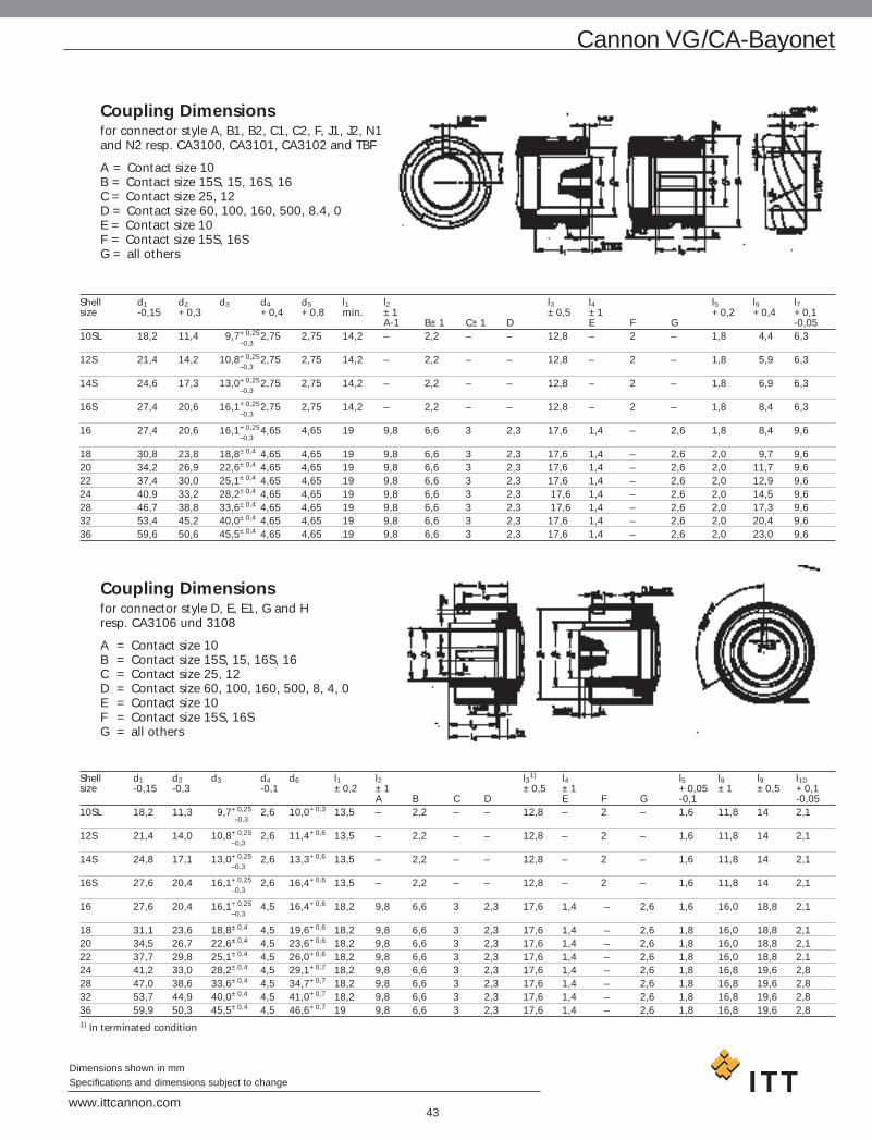
Coupling Dimensionsfor connector style A, B1, B2, C1, C2, F, J1, J2, N1 and N2 resp. CA3100, CA3101, CA3102 and TBF
A = Contact size 10 B = Contact size 15S, 15, 16S, 16C = Contact size 25, 12 D = Contact size 60, 100, 160, 500, 8.4, 0E = Contact size 10F = Contact size 15S, 16SG = all others
Shell d1 d2 d3 d4 d5 l1 l2 l3 l4 l5 l6 l7size -0,15 +0,3 +0,4 +0,8 min. ±1 ±0,5 ±1 +0,2 +0,4 +0,1
A-1 B±1 C±1 D E F G -0,0510SL 18,2 11,4 9,7+0,252,75 2,75 14,2 – 2,2 – – 12,8 – 2 – 1,8 4,4 6,3
–0,3
12S 21,4 14,2 10,8+0,252,75 2,75 14,2 – 2,2 – – 12,8 – 2 – 1,8 5,9 6,3–0,3
14S 24,6 17,3 13,0+0,252,75 2,75 14,2 – 2,2 – – 12,8 – 2 – 1,8 6,9 6,3–0,3
16S 27,4 20,6 16,1+0,252,75 2,75 14,2 – 2,2 – – 12,8 – 2 – 1,8 8,4 6,3–0,3
16 27,4 20,6 16,1+0,254,65 4,65 19 9,8 6,6 3 2,3 17,6 1,4 – 2,6 1,8 8,4 9,6–0,3
18 30,8 23,8 18,8±0,4 4,65 4,65 19 9,8 6,6 3 2,3 17,6 1,4 – 2,6 2,0 9,7 9,620 34,2 26,9 22,6±0,4 4,65 4,65 19 9,8 6,6 3 2,3 17,6 1,4 – 2,6 2,0 11,7 9,622 37,4 30,0 25,1±0,4 4,65 4,65 19 9,8 6,6 3 2,3 17,6 1,4 – 2,6 2,0 12,9 9,624 40,9 33,2 28,2±0,4 4,65 4,65 19 9,8 6,6 3 2,3 17,6 1,4 – 2,6 2,0 14,5 9,628 46,7 38,8 33,6±0,4 4,65 4,65 19 9,8 6,6 3 2,3 17,6 1,4 – 2,6 2,0 17,3 9,632 53,4 45,2 40,0±0,4 4,65 4,65 19 9,8 6,6 3 2,3 17,6 1,4 – 2,6 2,0 20,4 9,636 59,6 50,6 45,5±0,4 4,65 4,65 19 9,8 6,6 3 2,3 17,6 1,4 – 2,6 2,0 23,0 9,6
Coupling Dimensionsfor connector style D, E, E1, G and H resp. CA3106 und 3108
A = Contact size 10 B = Contact size 15S, 15, 16S, 16C = Contact size 25, 12 D = Contact size 60, 100, 160, 500, 8, 4, 0E = Contact size 10 F = Contact size 15S, 16S G = all others
Shell d1 d2 d3 d4 d6 l1 l2 l31) l4 l5 l8 l9 l10size -0,15 -0,3 -0,1 ±0,2 ±1 ±0,5 ±1 +0,05 ±1 ±0,5 +0,1
A B C D E F G -0,1 -0,05 10SL 18,2 11,3 9,7+0,25 2,6 10,0+0,3 13,5 – 2,2 – – 12,8 – 2 – 1,6 11,8 14 2,1
–0,3
12S 21,4 14,0 10,8+0,25 2,6 11,4+0,6 13,5 – 2,2 – – 12,8 – 2 – 1,6 11,8 14 2,1–0,3
14S 24,8 17,1 13,0+0,25 2,6 13,3+0,6 13,5 – 2,2 – – 12,8 – 2 – 1,6 11,8 14 2,1–0,3
16S 27,6 20,4 16,1+0,25 2,6 16,4+0,6 13,5 – 2,2 – – 12,8 – 2 – 1,6 11,8 14 2,1–0,3
16 27,6 20,4 16,1+0,25 4,5 16,4+0,6 18,2 9,8 6,6 3 2,3 17,6 1,4 – 2,6 1,6 16,0 18,8 2,1–0,3
18 31,1 23,6 18,8±0,4 4,5 19,6+0,6 18,2 9,8 6,6 3 2,3 17,6 1,4 – 2,6 1,8 16,0 18,8 2,120 34,5 26,7 22,6±0,4 4,5 23,6+0,6 18,2 9,8 6,6 3 2,3 17,6 1,4 – 2,6 1,8 16,0 18,8 2,122 37,7 29,8 25,1±0,4 4,5 26,0+0,6 18,2 9,8 6,6 3 2,3 17,6 1,4 – 2,6 1,8 16,0 18,8 2,124 41,2 33,0 28,2±0,4 4,5 29,1+0,7 18,2 9,8 6,6 3 2,3 17,6 1,4 – 2,6 1,8 16,8 19,6 2,828 47,0 38,6 33,6±0,4 4,5 34,7+0,7 18,2 9,8 6,6 3 2,3 17,6 1,4 – 2,6 1,8 16,8 19,6 2,832 53,7 44,9 40,0±0,4 4,5 41,0+0,7 18,2 9,8 6,6 3 2,3 17,6 1,4 – 2,6 1,8 16,8 19,6 2,836 59,9 50,3 45,5±0,4 4,5 46,6+0,7 19 9,8 6,6 3 2,3 17,6 1,4 – 2,6 1,8 16,8 19,6 2,81) In terminated condition
Cannon VG/CA-Bayonet
43www.ittcannon.com
Dimensions shown in mmSpecifications and dimensions subject to change

44www.ittcannon.com
Dimensions shown in mmSpecifications and dimensions subject to change
Cannon VG/CA-Bayonet
Part no. Protecting cap forReceptacles Plugs ø A ø B ø D F G HShell size Shell size max. -0,2 +0,2 ±0,2 ±0,2 max.
025-8636-005 10S/10SL – 22,8 17,7 19,7 10,7 14,2 15,9025-8636-006 – 10S/10SL 22,8 10,7 12,9 15,5 17,0 18,7025-8636-008 – 12S 26,0 13,4 15,8 15,5 17,0 18,7025-8636-010 12S/12 – 26,0 20,9 22,9 10,7 14,2 15,9025-8636-016 14S/14 – 29,2 24,1 26,1 10,7 14,2 15,9025-8636-017 – 14S 29,2 16,5 19,1 15,5 17,0 18,7025-8636-018 – 14 29,2 16,5 19,1 20,2 21,7 23,4025-8636-022 – 16S 32,0 19,8 22,4 15,5 17,0 18,7025-8636-024 – 16 32,0 19,8 22,4 20,2 21,7 23,4025-8636-025 16S – 32,0 26,9 28,9 10,7 14,2 15,9025-8636-026 16 – 32,0 26,9 28,9 17,5 19,0 20,7025-8636-034 18 – 36,5 30,3 32,3 17,5 19,0 20,7025-8636-036 – 18 36,5 23,0 25,6 20,2 21,7 23,4025-8636-042 20 – 39,9 33,7 35,7 17,5 19,0 20,7025-8636-044 – 20 39,9 26,1 28,8 20,2 21,7 23,4025-8636-048 – 22 43,1 29,2 31,9 20,2 21,7 23,4025-8636-049 22 – 43,1 36,9 38,9 17,5 19,0 20,7025-8636-053 24 – 46,6 40,4 42,4 19,1 20,6 22,3025-8636-054 – 24 46,6 32,4 35,1 20,2 21,7 23,4025-8636-058 28 – 53,4 46,2 48,2 19,1 20,6 22,3025-8636-060 – 28 53,4 38,0 40,7 20,2 21,7 23,4025-8636-061 – 32 60,1 44,3 47,2 20,2 21,7 23,4025-8636-062 32 – 64,9 52,9 54,9 20,7 22,2 23,9025-8636-064 36 – 71,1 59,1 60,1 20,7 22,2 23,9025-8636-065 – 36 66,3 49,7 51,6 20,2 21,7 23,4
Mating Dimensionsfor shell styles K, L and M, shown without coupling nut
Size d8min.
14S 17,916S 21,216 21,218 24,420 27,6
Size d8min.
22 30,7 24 33,9 28 39,5 32 46,0 36 51,4
Plastic Protecting Caps
Colour: red (similar to RAL 2003)

45www.ittcannon.com
Dimensions shown in mmSpecifications and dimensions subject to change
Metal Protecting Capsfor receptacles, shell style 3100, 3101 und 3102Material: Aluminum alloy
Shell VG95234 VG95234 Cannon Cannon d1 d2 l1 l2 Weightsize Part no. Part no. Part no. Part no. max. +0,6 min. max. g max.
with chain with cord with chain with cord f. chain10SL VG95234KR10SL VG95234KA10SL CA121003-1 CAB81-10SL-D 23,5 4,3 90 20 16 12S – – CA121003-2 CAB81-12S-D 27,0 4,3 90 20 17 14S VG95234KR14S VG95234KA14S CA121003-3 CAB81-14S-D 30,5 4,3 90 20 18 16S VG95234KR16S VG95234KA16S CA121003-4 CAB81-16S-D 33,0 4,3 90 20 19 16 VG95234KR16 VG95234KA16 CA121003-5 CAB81-16-D 33,0 4,3 100 25 23 18 VG95234KR18 VG95234KA18 CA121003-6 CAB81-18-D 37,5 4,3 100 25 27 20 VG95234KR20 VG95234KA20 CA121003-7 CAB81-20-D 41,0 4,3 115 25 30 22 VG95234KR22 VG95234KA22 CA121003-8 CAB81-22-D 44,0 4,3 115 25 33 24 VG95234KR24 VG95234KA24 CA121003-9 CAB81-24-D 47,5 4,3 115 25 37 28 VG95234KR28 VG95234KA28 CA121003-10 CAB81-28-D 54,5 5,5 160 25 42 32 VG95234KR32 VG95234KA32 CA121003-11 CAB81-32-D 61,0 5,5 160 25 48 36 VG95234KR36 VG95234KA36 CA121003-12 CAB81-36-D 67,5 5,5 160 25 55
Metal Protecting Capsfor plugs, shell style 3106 and 3108 Material: Aluminum alloy
Shell VG95234 VG95234 Cannon Cannon d1 d2 l1 l2 Weightsize Part no. Part no. Part no. Part no. max. max. g max.
with chain with cord with chain with cord10SL VG95234KB10SL VG95234KC10SL CA121004-1 CAB80-10SL-D 21,0 4,3 90 29 19 12S – – CA121004-2 CAB80-12S-D 24,0 4,3 100 29 23 14S VG95234KB14S VG95234KC14S CA121004-3 CAB80-14S-D 27,5 4,3 100 29 26 16S VG95234KB16S VG95234KC16S CA121004-4 CAB80-16S-D 30,0 4,3 100 29 28 16 VG95234KB16 VG95234KC16 CA121004-5 CAB80-16-D 30,0 4,3 115 37 33 18 VG95234KB18 VG95234KC18 CA121004-6 CAB80-18-D 33,5 4,3 115 37 36 20 VG95234KB20 VG95234KC20 CA121004-7 CAB80-20-D 37,0 4,7 130 37 43 22 VG95234KB22 VG95234KC22 CA121004-8 CAB80-22-D 40,0 4,7 130 37 47 24 VG95234KB24 VG95234KC24 CA121004-9 CAB80-24-D 43,5 4,7 130 37 53 28 VG95234KB28 VG95234KC28 CA121004-10 CAB80-28-D 49,5 4,7 190 37 63 32 VG95234KB32 VG95234KC32 CA121004-11 CAB80-32-D 56,0 5,5 190 37 75 36 VG95234KB36 VG95234KC36 CA121004-12 CAB80-36-D 62,5 5,5 190 37 88
Cannon VG/CA-Bayonet
VG95234 Style KA with cord VG95234 Style KR with chain
VG95234 Style KC with cord VG95234 Style KB with chain

46www.ittcannon.com
Dimensions shown in mmSpecifications and dimensions subject to change
Accessories
Dummy ReceptaclesFront panel mounting (rear side open)
VG95234 Style BOD (Flange with through-holes)CA3105-B
Shell VG 95234 Cannon d1 d2 l1 l2 l3 l4size Part no. Part no. –0,15 ±0,2 ±0,3 ±0,1 max. +0,310SL VG95234BOD10SL CA3105E10SL-B 18,2 3,2 25,4 18,2 17,5 14,2 12S – CA3105E12S-B 21,4 3,2 28,0 20,6 18,0 14,2 14S VG95234BOD14S CA3105E14S-B 24,6 3,2 30,0 23,0 18,0 14,2 16S VG95234BOD16S CA3105E16S-B 27,4 3,2 32,5 24,6 18,0 14,2 16 VG95234BOD16 CA3105E16-B 27,4 3,2 32,5 24,6 23,5 19,0 18 VG95234BOD18 CA3105E18-B 30,8 3,2 35,0 27,0 23,5 19,0 20 VG95234BOD20 CA3105E20-B 34,2 3,2 38,0 29,4 23,5 19,0 22 VG95234BOD22 CA3105E22-B 37,4 3,2 41,0 31,8 23,5 19,0 24 VG95234BOD24 CA3105E24-B 40,9 3,7 44,5 34,9 25,5 20,6 28 VG95234BOD28 CA3105E28-B 46,7 3,7 50,8 39,7 25,5 20,6 32 VG95234BOD32 CA3105E32-B 53,4 4,3 57,0 44,5 27,0 22,2 36 VG95234BOD36 CA3105E36-B 59,6 4,3 63,5 49,2 27,0 22,2
Dummy ReceptaclesRear panel mounting (rear side closed)
Shell CA3105E-B CA3105E-B-05 d1 l1 l2 l3 l4 Style A Style B size Cannon Part no. Cannon Part no. ±0,25 ±0,3 +0,3 d2 d2±0,2
with thread with through holesStyle A Style B
10SL 248-8513-000 248-8501-000 18,2 25,4 18,2 21,1 18,3 M4 3,2 12S 248-8514-000 248-8502-000 21,4 28,0 20,6 21,5 18,3 M4 3,2 14S 248-8515-000 248-8503-000 24,6 30,0 23,0 21,5 18,3 M4 3,2 16S 248-8516-000 248-8504-000 27,4 32,5 24,6 21,5 18,3 M4 3,2 16 248-8517-000 248-8505-000 27,4 32,5 24,6 24,8 21,6 M4 3,2 18 248-8518-000 248-8506-000 30,8 35,0 27,0 27,2 23,15 M4 3,2 20s 248-8519-000 248-8507-000 34,2 38,0 29,4 27,2 23,15 M4 3,2 22 248-8520-000 248-8508-000 37,4 41,0 31,8 27,2 23,15 M4 3,2 24 248-8521-000 248-8509-000 40,9 44,5 34,9 27,2 23,15 M4 3,7 28 248-8522-000 248-8510-000 46,7 50,8 39,7 28,2 24,15 M5 3,7 32 248-8523-000 248-8511-000 53,4 57,0 44,5 28,2 24,15 M5 4,4 36 248-8524-000 248-8512-000 59,6 63,5 49,2 28,2 24,15 M5 4,4

47www.ittcannon.com
Dimensions shown in mmSpecifications and dimensions subject to change
Accessories
Sealing Ringsfor use on the barrel of the plugSize Part no. d9
10SL 980-8550-000 9,0 12S 980-8551-000 11,5 14S 980-8552-000 14,0 16/16S 980-8553-000 17,0 18 980-8554-000 19,5 20 980-8555-000 22,5 22 980-8556-000 25,4 24 980-8557-000 28,5 28 980-8558-000 34,0 32 980-8559-000 40,0 36 980-8560-000 45,0
Wire Hole FillersWhere contacts are not used, the contact cavities are to be closed by wire holes fillers.
Size VG95234 For contact size d1 d2 l1 l2 Colour Part no.Part no. metr. AWG ±0,1 ±0,2 ±0,1 ±0,3
20 VG95234B20 10 2,3 3,0 2,4 9,7 red 225-1000-00016S VG95234B16S 15S 16S 2,8 3,7 1,5 4,8 nature 225-8510-00016 VG95234B16 15S/15 16S/16 2,8 3,7 3,2 11,9 blue 225-0017-00012 VG95234B12 25/25A 12 3,7 4,6 3,2 11,9 yellow 225-0018-0008 VG95234B08 60/100 8 5 5,8 3,2 11,9 white 225-0019-0004 VG95234B04 160 4 7,6 8,5 3,2 11,9 green 225-8502-0000 VG95234B00 500 0 12,8 13,5 3,2 11,9 black 225-8503-000

48www.ittcannon.com
Dimensions shown in mmSpecifications and dimensions subject to change
Accessories
Cable Clampswithout telescoping bushing
VG95234 Style KK
VG 95234 Former Shell size A-Thread l2 d1 l1 l3 Shell-Part no. Designation MS suitable for max. max. max. max. Weight
connectors gacc. MS
VG95234KK 4 MS3057- 4A* 10SL, 12S, 5/7-24NEF-2B 10,5 7,9 20,8 22,5 13,2VG95234KK 6 MS3057- 6A* 14S, 3/4-20UNEF-2B 10,5 11,1 22,4 27,4 18,6VG95234KK 8 MS3057- 8A* 16S, 16 7/8-20UNEF-2B 10,5 14,2 24,0 29,8 23,6VG95234KK12 MS3057-10A* 18 1-20UNEF-2B 10,5 15,8 24,0 32,2 27,3VG95234KK12 MS3057-12A* 20, 22 1 3/16-18NEF-2B 10,5 19,0 24,0 37,4 37,2VG95234KK16 MS3057-16A* 24, 28 1 7/16-18NEF-2B 10,5 23,7 26,4 43,5 56,3VG95234KK20 MS3057-20A* 32 1 3/4-18NS-2B 12,0 31,8 28,0 51,7 83,9VG95234KK24 MS3057-24A* 36 2-18NS-2B 13,7 34,6 29,6 57,8 109,8
* WB = Cable clamp with cable telescoping bushing
Telescoping BushingsTelescoping bushing (used with MS3057A resp. VG95234KKcable clamp) keep dirt, oil and dust out of endbell. Taping orwrapping wires is eliminated since bushing protects wiresguided through clamp. Combinations of two bushings may beused to decrease inner diameter for improved sealing.
Material: Polychloroprene
Shell VG95234 MS Cannon d1 d2 d3 l Weightsize Part no. Part no. Part no. g10SL, 12S VG95234KT10SL – 012-8552-000 8,0 6,6 9,9 70,0 414S VG95234KT14S – 012-8554-000 10,9 9,1 12,7 67,0 516S, 16 VG95234KT16 MS3420-08 012-0218-000 14,0 11,1 19,0 64,0 618 VG95234KT18 MS3420-10 012-0219-000 15,7 14,3 22,0 60,0 420, 22 VG95234KT20 MS3420-12 012-0220-000 18,8 15,9 26,9 57,0 724 VG95234KT24 – 012-8555-000 21,2 16,6 26,9 57,0 1328 VG95234KT28 – 012-8556-000 23,6 21,5 33,3 54,0 1332 VG95234KT32 – 012-8557-000 26,5 21,5 33,3 54,0 26
– – 012-8558-000 31,5 26,8 40,4 51,0 2636 VG95234KT32 – 012-8558-000 31,5 26,8 40,4 51,0 30
– MS3420-24 012-0223-000 34,7 31,8 46,8 48,0 30

49www.ittcannon.com
Dimensions shown in mmSpecifications and dimensions subject to change
Accessories
GasketsThickness of gasketsmade of Alu-Flex “2“ = 0,5 mmmade of Polychloropren “1“ = 1,0 mm
VG95234 Style DA for front panel mountingVG95234 Style DH for front panel mounting
Size VG 95234 Part no. Part no. l e d1 d2 WeightPart no. Version Version ±0,5 ±0,2 +1 +0,5 g max.
Polychloropen1 Alu-Flex2 front panel10SL VG 95234 DA 10SL-X 075-8512-000 075-8512-001 25,4 18,2 15,7 4,2 212S 075-8513-000 075-8513-001 28,0 20,6 18,9 4,2 214S VG 95234 DA 14S-X 075-8514-000 075-8514-001 30,0 23,0 22,1 4,2 216/16S VG 95234 DA 16X 075-8515-000 075-8515-001 32,5 24,6 25,3 4,2 218 VG 95234 DA 18-X 075-8516-000 075-8516-001 35,0 27,0 28,4 4,2 220 VG 95234 DA 20-X 075-8517-000 075-8517-001 38,0 29,4 31,6 4,2 222 VG 95234 DA 22-X 075-8518-000 075-8518-001 41,0 31,8 34,8 4,2 224 VG 95234 DA 24-X 075-8519-000 075-8519-001 44,5 34,9 38,0 4,2 228 VG 95234 DA 28-X 075-8520-000 075-8520-001 50,8 39,7 44,3 5,1 232 VG 95234 DA 32-X 075-8521-000 075-8521-001 57,0 44,5 50,7 5,1 236 VG 95234 DA 36-X 075-8522-000 075-8522-001 63,5 49,2 57,0 5,1 2
For front panel mounting
Size VG 95234 Part no. Part no. l e d1 d2 WeightPart no. Version Version ±0,5 ±0,2 +1 +0,5 g max.
Polychloropen1 Alu-Flex2 front panel10SL VG 95234 DH 10SL-X 075-8501-000 075-8501-001 25,4 18,2 18,2 4,2 212S 075-8502-000 075-8502-001 28,0 20,6 21,4 4,2 214S VG 95234 DH 14S-X 075-8503-000 075-8503-001 30,0 23,0 24,6 4,2 216/16S VG 95234 DH 16X 075-8504-000 075-8504-001 32,5 24,6 27,4 4,2 218 VG 95234 DH 18-X 075-8505-000 075-8505-001 35,0 27,0 30,8 4,2 220 VG 95234 DH 20-X 075-8506-000 075-8506-001 38,0 29,4 34,2 4,2 222 VG 95234 DH 22-X 075-8507-000 075-8507-001 41,0 31,8 37,4 4,2 224 VG 95234 DH 24-X 075-8508-000 075-8508-001 44,5 34,9 40,9 4,2 228 VG 95234 DH 28-X 075-8509-000 075-8509-001 50,8 39,7 46,7 5,1 232 VG 95234 DH 32-X 075-8510-000 075-8510-001 57,0 44,5 53,4 5,1 236 VG 95234 DH 36-X 075-8511-000 075-8511-001 63,5 49,2 59,6 5,1 2
For rear panel mounting
X = insert “1“ (electrically not conductive) or “2“ (electrically conductive)

ContactsStandard contacts and contacts with reduced termination diameter
Pin contacts
Finish
A36 – 5 µm silver plated and passivatedA176 – 2 µm nickel plated, min. 0,5 µm gold plated
50www.ittcannon.com
Dimensions shown in mmSpecifications and dimensions subject to change
Contacts
Contact VG95234 Wire Part no. with Part no. with d1 d4 d6 d7 l1 l3size Part no. size finish finish -0,05 ±0,15 ±0,5 Color
mm2 AWG Standard: A36 Mod.Code: A176 Codesilver plated gold plated
10/20 VG95234P10-002 0,5-1,0 20/18 030-8585-000 030-8585-006 1,04 1,5 -0,05 1,5 +0,05 2,4 -0,05 28,4 4,75 –VG95234P10-001 0,2-0,4 26/22 030-8585-010 – 1,04 1,5 -0,05 0,9 +0,05 2,4 -0,05 28,4 4,75 blue
15S/16S VG95234P15S-003 0,75-1,5 18/16 030-8586-000 030-8586-006 1,6 1,75 -0,1 1,75 +0,08 2,75 -0,05 27,4 3,85 –VG95234P15S-002 0,3-0,6 22/20 330-8744-000 330-8744-006 1,6 1,75 -0,1 1,2 +0,1 2,75 -0,05 27,4 3,85 redVG95234P15S-001 0,14-0,38 22/26 030-8586-010 – 1,6 1,75 -0,1 0,9 +0,05 2,75 -0,05 27,4 3,85 blue
15/16 VG95234P15-003 0,75-1,5 18/16 030-8587-000 030-8587-006 1,6 1,75 -0,1 1,75 +0,08 2,75 -0,05 31,4 7,9 –VG95234P15-002 0,3-0,6 22/20 330-8659-000 330-8659-006 1,6 1,75 -0,1 1,2 +0,1 2,75 -0,05 31,4 7,9 redVG95234P15-001 0,14-0,38 22/26 030-8587-030 030-8587-036 1,6 1,75 -0,1 0,9 +0,05 2,75 -0,05 31,4 7,9 blue
25/12 VG95234P25-002 2,0-3,0 14/12 030-8588-000 030-8588-006 2,4 3,3 -0,15 2,5 +0,1 3,8 -0,1 37,0 7,9 –VG95234P25-001 0,75-1,5 18/16 030-8588-010 030-8588-016 2,4 3,3 -0,15 1,75 +0,08 3,4 -0,1 37,0 7,9 black
4,0 – 030-8588-054 – 2,4 3,3 -0,15 2,8 +0,1 3,8 -0,1 37,0 7,960/100/8 VG95234P8-001 – 8 030-8612-000 030-8612-006 3,6 6,25 -0,15 4,55 +0,1 6,8 -0,1 39,6 6,35 –
VG95234P60-002 6,0 10 030-8589-000 – 3,6 6,25 -0,15 3,5 +0,1 6,8 -0,1 39,6 6,35 yellowVG95234P100-001 10,0 – 030-8590-000 – 3,6 6,25 -0,15 4,8 +0,1 6,8 -0,1 39,6 6,35 –VG95234P60-001 2,0-3,0 14/12 030-8612-010 – 3,6 6,25 -0,15 2,5 +0,05 6,8 -0,1 39,6 6,35 green
160/4 VG95234P4-001 – 4 030-8613-000 – 5,75 9,55 -0,15 7,1 +0,15 9,55 -0,1 39,6 6,35 –VG95234P160-002 16,0 – 030-8591-000 – 5,75 9,55 -0,15 6,2 +0,15 9,55 -0,1 39,6 6,35 –
10,0 – 030-8591-020 – 5,75 9,55 -0,15 4,8 +0,1 9,55 -0,1 39,6 6,35 –VG95234P160-001 – 6 030-8613-010 – 5,75 9,55 -0,15 5,7 +0,1 9,55 -0,1 39,6 6,35 brown
500/0 VG95234P0-001 – 0 030-8614-000 – 9,1 13,55 -0,15 11,5 +0,15 14,35 -0,1 41,0 6,35 –VG95234P500-003 50,0 – 030-8592-000 – 9,1 13,55 -0,15 10,7 +0,15 14,35 -0,1 41,0 6,35 –VG95234P500-001 25,0 4 030-8614-010 – 9,1 13,55 -0,15 7,6 +0,15 14,35 -0,1 41,0 6,35 whiteVG95234P500-002 35,0 2 030-8614-020 – 9,1 13,55 -0,15 9,1 +0,15 14,35 -0,1 41,0 6,35 grey
16,0 – 030-8614-030 – 9,1 13,55 -0,15 6,2 +0,15 14,35 -0,1 41,0 6,35 –
Size 15S/16S, 15/16, 25/12, 60/100/8, 160/4, 500/0 Size 10/20

51www.ittcannon.com
Dimensions shown in mmSpecifications and dimensions subject to change
Contacts
ContactsStandard contacts and contacts with reduced termination diameter
Socket contacts
Finish
A36 – 5 µm silver plated and passivated
A176 – 2 µm nickel plated, min. 0,5 µm gold plated
Contact VG95234 Wire Part no. with Part no. with d1 d2 d3 d5 d6 l1 l3size Part no. size finish finish +0,05 ±0,2 ±0,1 Color
mm2 AWG Standard: A36 Mod.Code A176 Codesilver plated gold plated
10/20 VG95234S10-002 0,5-1,0 20/18 031-8554-000 031-8554-006 2,0 -0,1 1,07 1,5 -0,05 1,5 +0,05 2,4 -0,05 36,8±0,3 4,75 –VG95234S10-001 0,2-0,4 26/22 031-8554-010 – 2,0 -0,1 1,07 1,5 -0,05 0,9 +0,05 2,4 -0,05 36,8±0,3 4,75 blue
15S/16S VG95234S15S-003 0,75-1,5 18/16 031-8555-110 031-8555-115 3,2 -0,15 1,65 1,75 -0,1 1,75 +0,08 2,75 -0,05 29,1 3,9 –VG95234S15S-002 0,3-0,6 22/20 031-8688-110 031-8688-115 3,2 -0,15 1,65 1,75 -0,1 1,20 +0,1 2,75 -0,05 29,1 3,9 redVG95234S15S-001 0,14-0,38 22/26 031-8555-130 – 3,2 -0,15 1,65 1,75 -0,1 0,90 +0,05 2,75 -0,05 29,1 3,9 blue
15/16 VG95234S15-003 0,75-1,5 18/16 031-8556-110 031-8556-115 3,2 -0,15 1,65 1,75 -0,1 1,75 +0,08 2,75 -0,05 37,8 7,9 –VG95234S15-002 0,3-0,6 22/20 031-8639-120 031-8639-115 3,2 -0,15 1,65 1,75 -0,1 1,2 +0,1 2,75 -0,05 37,8 7,9 redVG95234S15-001 0,14-0,38 22/26 031-8556-130 – 3,2 -0,15 1,65 1,75 -0,1 0,9 +0,05 2,75 -0,05 37,8 7,9 blue
25/12 VG95234S25-002 2,0-3,0 14/12 031-8557-000 031-8557-006 4,8 -0,1 2,45 3,3 -0,1 2,5 +0,1 3,8 -0,1 37,0 7,9 –VG95234S25-001 0,75-1,5 18/16 031-8557-020 031-8557-026 4,8 -0,1 2,45 3,3 -0,1 1,75 +0,08 3,4 -0,1 37,0 7,9 black
4,0 – 031-8557-010 – 4,8 -0,1 2,45 3,3 -0,1 2,8 +0,1 3,8 -0,1 37,0 7,9 –0,3–0,6 22/20 031-8557-040 – 4,8 -0,1 2,45 3,3 -0,1 1,2 +0,1 2,75 -0,1 37,0 7,9 –
60/100/8 VG95234S8-001 – 8 031-8519-000 031-8519-006 6,5 -0,2 3,65 6,25 -0,2 4,55 +0,1 6,8 -0,1 40,1 6,35 –VG95234S60-002 6,0 10 031-8558-000 – 6,5 -0,2 3,65 6,25 -0,2 3,5 +0,1 6,8 -0,1 40,1 6,35 yellowVG95234S100-001 10,0 – 031-8559-000 – 6,5 -0,2 3,65 6,25 -0,2 4,8 +0,1 6,8 -0,1 40,1 6,35 –VG95234S60-001 2,0-3,0 14/12 031-8519-010 – 6,5 -0,2 3,65 6,25 -0,2 2,5 +0,05 6,8 -0,1 40,1 6,35 green
160/4 VG95234S4-001 – 4 031-8520-000 – 8,6 -0,2 5,8 9,55 -0,2 7,1 +0,15 9,55 -0,1 40,1 6,35 –VG95234S160-002 16,0 – 031-8560-000 – 8,6 -0,2 5,8 9,55 -0,2 6,2 +0,15 9,55 -0,1 40,1 6,35 –
10,0 – 031-8560-020 – 8,6 -0,2 5,8 9,55 -0,2 4,8 +0,1 9,55 -0,1 40,1 6,35 –VG95234S160-001 – 6 031-8520-010 – 8,6 -0,2 5,8 9,55 -0,2 5,7 +0,15 9,55 -0,1 40,1 6,35 brown
500/0 VG95234S0-001 – 0 031-8521-000 – 13,2 -0,2 9,15 13,55 -0,2 11,5 +0,15 14,35 -0,1 41,6 6,35 –VG95234S500-003 50,0 – 031-8561-000 – 13,2 -0,2 9,15 13,55 -0,2 10,7 +0,15 14,35 -0,1 41,6 6,35 –VG95234S500-001 25,0 4 031-8521-010 – 13,2 -0,2 9,15 13,55 -0,2 7,6 +0,15 14,35 -0,1 41,6 6,35 whiteVG95234S500-002 35,0 2 031-8521-020 – 13,2 -0,2 9,15 13,55 -0,2 9,1 +0,15 14,35 -0,1 41,6 6,35 grey
16,0 – 031-8521-030 – 13,2 -0,2 9,15 13,55 -0,2 6,2 +0,15 14,35 -0,1 41,6 6,35 –
Size 10/20 Size 25/12
Size 60/100/8, 160/4, 500/0Size 15S/16S, 15/16

52www.ittcannon.com
Dimensions shown in mmSpecifications and dimensions subject to change
Contacts
Termination Toolsfor pin contacts according VG95234 and for Cannon contacts with reduced termination size.
Contact Wire size Hand crimp tool Pneumatic crimp tool1) Universal- Turret forsize Type Crimp die for Standard Turret for type Universal
mm2 AWG M22520-1-01 type Standard typetype
10/20 0,2 – 1,0 20 – 24 600 325 600 098 608 325600 325 600 098 608 325
15S/16S 0,14 – 1,5 16 – 26 TH 452 600 082 TH 452TH 452 600 082 TH 452
15/16 0,14 – 1,5 16 – 26 TH 452 604 292 TH 452TH 452 604 292 TH 452
25/12 0,75 – 4,0 12 – 18 TH 452 600 099 TH 452TH 452 600 099 TH 452TH 452 600 099 TH 452
Contact Wire size Hydraulic basic Crimp tool (2 of each required)size mm2 AWG equipment 6-kt Crimp die60/8 10,0 – 2,0 8 – 14 Electro-hydraulic tool * CT 317-8678-000100/ HK12EL (order number: 121586-5075)
Hand operated hydraulic tool HK120 (order number: 121586-5077)
160/4 16,0 – 10,0 4 – 6 CT 317-8678-001
500/0 50,0 – 16,0 0 – 4 CT 317-8678-002
M22520-1-01Hand crimptool(eight indentcrimp)
Eight indentcrimp612 871
table devicewith foot pedal611 380
Eight indentcrimp612 141
Table devicewith foot pedal611 380
Notes
1. For large series production, semi-automatic crimp machineType HACS-IV-MSXX upon request
2. For insertion and extraction of the contacts and for connector assembly,see Assembly Instructions MIL-C-5015/VG95234
3. Standard contacts acc. to MIL-C-5015/VG95234
* Datasheet available upon request
To insert the socket contact of size 15S/16S, 15/16/25 and 12, the followingguiding pins are to be used:
Part Nr. Contact sizeAWG metric
226-1017-000 16S/16 15S/15226-1018-000 12 25

Contact Wire size Hydraulic basic Crimp tool (2 of each required)size mm2 AWG equipment 6-kt Crimp die60/8 10 – 2 8 – 14 Electro-hydraulic tool * CT 317-8678-000100/ HK12EL (order number: 121586-5075)
Hand operated hydraulic tool HK120 (order number: 121586-5077)
160/4 16 – 10 4 – 6 CT 317-8678-001
500/0 50 – 14 0 – 4CT 317-8678-002
53www.ittcannon.com
Dimensions shown in mmSpecifications and dimensions subject to change
Contacts
Termination Toolsfor pin contacts according VG95234 and Cannon contacts with reduced termination diameter.
Contact Wire Hand crimp tool Pneumatic crimp tool1)
size size Type Crimp die for Standard Turret for Universal Turret formm2 AWG M22520-1-01 type Standard type Universal
type type10/20 0,2-1,0 18 – 24 M22520-1-01 600 325 Eight indent 600 098 Eight indent 600 325
Eight indent 600 325 crimp 600 098 crimp 600 325tool 612 871 612 141
15S/16S 0,2-1,0 16 – 22 (eight indent TH 452 600 083 TH 452Crimp) 611 380 Table device 611 380 table device
and foot pedal with foot pedal15/16 0,2-1,0 16 – 22 TH 452 611 380 604 081 611 380 TH 452
25/12 0,2-1,0 12 – 18 TH 452 600 099 TH 452
Notes
1. For large series production, semi-automatic crimp machineType HACS-IV-MSXX upon request
2. For insertion and extraction of the contacts and for connector assembly,see Assembly Instructions MIL-C-5015/VG95234
3. Standard contacts acc. MIL-C-5015/VG95234
* Datasheet available upon request

54www.ittcannon.com
Dimensions shown in mmSpecifications and dimensions subject to change
THIS NOTE MUST BE READ IN CON-JUNCTION WITH THE PRODUCT DATASHEET/CATALOG. FAILURE TOOBSERVE THE ADVICE IN THIS INFOR-MATION SHEET AND THE OPERATINGCONDITIONS SPECIFIED IN THE PROD-UCT DATA SHEET/ CATALOG COULDRESULT IN HAZARDOUS SITUATIONS.
1. MATERIAL CONTENT AND PHYSICALFORMElectrical connectors do not usually containhazardous materials. They contain conduct-ing and non-conducting materials and canbe divided into two groups.a) Printed circuit types and low cost audiotypes which employ all plastic insulators andcasings.b) Rugged, Fire Barrier and High Reliabilitytypes with metal casings and either naturalrubber, synthetic rubber, plastic or glassinsulating materials. Contact materials varywith type of connector and also applicationand are usually manufactured from either:Copper, copper alloys, nickel, alumel,chromel or steel. In special applications,other alloys may be specified.
2. FIRE CHARACTERISTICS AND ELEC-TRIC SHOCK HAZARDThere is no fire hazard when the connec-tor is correctly wired and used within thespecified parameters. Incorrect wiring orassembly of the connector or carelessuse of metal tools or conductive fluids,or transit damage to any of the compo-nent parts may cause electric shock orburns. Live circuits must not be brokenby separating mated connectors as thismay cause arcing, ionization and burn-ing. Heat dissipation is greater at maximumresistance in a circuit. Hot spots may occurwhen resistance is raised locally by damage,e.g. cracked or deformed contacts, brokenstrands of wire. Local overheating may alsoresult from the use of the incorrect applica-tion tools or from poor quality soldering orslack screw terminals. Overheating mayoccur if the ratings in the product DataSheet/Catalog are exceeded and can causebreakdown of insulation and hence electricshock. If heating is allowed to continue itintensifies by further increasing the localresistance through loss of temper of springcontacts, formation of oxide film on contactsand wires and leakage currents through car-bonization of insulation and tracking paths.Fire can then result in the presence of com-bustible materials and this may release nox-ious fumes. Overheating may not be visuallyapparent. Burns may result from touchingoverheated components.
3. HANDLINGCare must be taken to avoid damage to any component parts of electrical connec-tors during installation and use. Althoughthere are normally no sharp edges, caremust be taken when handling certain com-ponents to avoid injury to fingers. Electricalconnectors may be damaged in transit to thecustomers, and damage may result in cre-ation of hazards. Products should thereforebe examined prior to installation/use andrejected if found to be damaged.
4. DISPOSALIncineration of certain materials may releasenoxious or even toxic fumes.
5. APPLICATIONConnectors with exposed contacts shouldnot be selected for use on the current supplyside of an electrical circuit, because an elec-tric shock could result from touchingexposed contacts on an unmated connector.Voltages in excess of 30 V ac or 42.5 V dcare potentially hazardous and care shouldbe taken to ensure that such voltages can-not be transmitted in any way to exposedmetal parts of the connector body. The con-nector and wiring should be checked, beforemaking live, to have no damage to metalparts or insulators, no solder blobs, loosestrands, conducting lubricants, swarf, or anyother undesired conducting particles. Circuitresistance and continuity check should bemade to make certain that there are no highresistance joints or spurious conductingpaths. Always use the correct applicationtools as specified in the Data Sheet/Catalog.Do not permit untrained personnel to wire,assemble or tamper with connectors. Foroperation voltage please see appropriatenational regulations.
IMPORTANT GENERAL INFORMATION(i) Air and creepage paths/Operating volt-age. The admissible operating voltagesdepend on the individual applications andthe valid national and other applicable safetyregulations.For this reason the air and creepage pathdata are only reference values. Observereduction of air and creepage paths due toPC board and/or harnessing.
(ii) TemperatureAll information given are temperature limits.The operation temperature depends on theindividual application.
(iii) Other important informationCannon continuously endeavors to improvetheir products. Therefore, Cannon productsmay deviate from the description, technicaldata and shape as shown in this catalog anddata sheets.
“Engineered for life” is a registered trade-mark of ITT Industries, ©2005. All othertrademarks or registered trademarks areproperty of their respective owners. All datasubject to change without notice.
Product WarrantyITT Cannon, a Division of ITT Industries,Inc. manufactures the highest quality prod-ucts available in the marketplace; howeverthese products are intended to be used inaccordance with the specifications in thispublication. Any use or application that devi-ates from the stated operating specificationsis not recommended and may be unsafe. Noinformation and data contained in this publi-cation shall be construed to create any liabil-ity on the part of Cannon. Any new issue ofthis publication shall automatically invalidateand supersede any and all previous issues.A limited warranty applies to Cannon prod-ucts. Except for obligations assumed byCannon under this warranty, Cannon shallnot be liable for any loss, damage, cost ofrepairs, incidental or consequential dam-ages of any kind, whether or not based onexpress or implied warranty, contract, negli-gence or strict liability arising in connectionwith the design, manufacture, sale, use orrepair of the products. Product availability,prices and delivery dates are exclusivelysubject to our respective order confirmationform; the same applies to orders based ondevelopment samples delivered. This publi-cation is not to be construed as an offer. It isintended merely as an invitation to make anoffer. By this publication, Cannon does notassume responsibility or any liability for anypatent infringements or other rights of thirdparties which may result from its use.Reprinting this publication is generally per-mitted, indicating the source. However, Can-non's prior consent must be obtained in allcases.
Product Safety Information

ITT ...providing a comprehensive offering of connectivity solutions.In addition to connector products, we provide a complete line of electronic components and value-added solutions.
Modular assembly options include: ESD shielding, keypads, EL backlighting, rigid or flexible circuits
Complete design, engineering and test capabilities
Low, mid and high volume production capabilities
Rubber and In Mold Decoration (IMD) products
Wide range of cosmetic options
Integration of decorated and metalized plastic keytops
Multiple PILL and contact options
Precision molded polymeric solutions
From multi-function grips to sophisticated control systems, hall effect products and front panel assemblies
Electronics and software engineering development
Worldwide design and manufacturing
High-mix production capabilities
Global sourcing and supply chain management
Top/side actuated tacts
Low profile SMT
Navigation / scrolling switches
Toggle, rocker, pushbutton, DIP, slide, snap, switchlock, rotary, thumbwheel
Circular
Compact flash
D-Subminiature
Fiber optics
FilterMicrominiature
Mobile
Rack & Panel
RF
USB
Zero insertion force
Smart Cards

“Engineered for life” is a registered trademarkof ITT Industries.©2005. All other trademarksor registered trademarks are property of theirrespective owners. All data subject to changewithout notice.
CAB 05-Septwww.ittcannon.com
Connector Product Locations
With manufacturing facilities, sales representatives and distributors located worldwide, please visit our website at www.ittcannon.com for a complete listing and tofind the office nearest you.
GERMANYCannonstrasse 1Weinstadt, 71384phone: 49.7151.699.0fax: 49.7151.699.217
HONG KONGUnit 901 & 912, West Tower Shun Tak Center168-200 Connaught RoadCentralphone: 852.2732.2720fax: 852.2732.2919
ITALYVia Pietro Panzeri 10Milano, 20123phone: 39.2.58180.1fax: 39.2.8372036
UKJays Close, Viables EstateBasingstoke, RG22 4BAphone: 44.1256.311200fax: 44.1256.323356
USA666 East Dyer RoadSanta Ana, CA 92705toll free: 1.800.854.3028phone: 1.714.557.4700fax: 1.714.628.2142