connectors for cold-formed steel curtain-wall construction · connectors for cold-formed steel...
TRANSCRIPT
Introducing
Connectors for Cold-Formed Steel Curtain-Wall Construction
(800) 999-5099www.strongtie.com
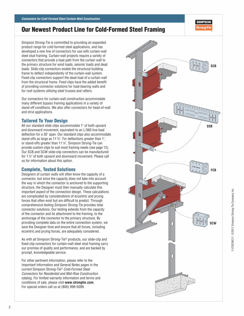
Simpson Strong‑Tie is committed to providing an expanded product range for cold‑formed steel applications, and has developed a new line of connectors for use with curtain‑wall steel stud framing. Curtain‑wall projects require a variety of connectors that provide a load path from the curtain wall to the primary structure for wind loads, seismic loads and dead loads. Slide‑clip connectors enable the structural building frame to deflect independently of the curtain‑wall system. Fixed‑clip connectors support the dead load of a curtain wall from the structural frame. Fixed clips have the added benefit of providing connector solutions for load‑bearing walls and for roof systems utilizing steel trusses and rafters.
Our connectors for curtain‑wall construction accommodate many different bypass framing applications in a variety of stand‑off conditions. We also offer connectors for head‑of‑wall and strut applications.
Tailored To Your DesignAll our standard slide clips accommodate 1" of both upward and downward movement, equivalent to an L/360 live‑load deflection for a 30' span. Our standard clips also accommodate stand‑offs as large as 11 ¼". For deflections greater than 1", or stand‑offs greater than 11 ¼", Simpson Strong‑Tie can provide custom clips to suit most framing needs (see page 12). Our SCB and SCW slide‑clip connectors can be manufactured for 1 ½" of both upward and downward movement. Please call us for information about this option.
Complete, Tested SolutionsDesigners of curtain walls will often know the capacity of a connector, but since the capacity does not take into account the way in which the connector is anchored to the supporting structure, the Designer must then manually calculate this important aspect of the connection design. These calculations are complicated by considerations of eccentric and prying forces that often exist but are difficult to predict. Through comprehensive testing Simpson Strong‑Tie provides total connector solutions. Our testing extends from the capacity of the connector and its attachment to the framing, to the anchorage of the connector to the primary structure. By providing complete data on the entire connection system, we save the Designer time and ensure that all forces, including eccentric and prying forces, are adequately considered.
As with all Simpson Strong‑Tie® products, our slide‑clip and fixed‑clip connectors for curtain‑wall steel stud framing carry our promise of quality and performance, and are backed by prompt, knowledgeable service.
For other pertinent information, please refer to the Important Information and General Notes pages in the current Simpson Strong‑Tie® Cold-Formed Steel Connectors for Residential and Mid-Rise Construction catalog. For limited warranty information and terms and conditions of sale, please visit www.strongtie.com. For special orders call us at (800) 999‑5099.
SCB
SSB
FCB
SCW
Our Newest Product Line for Cold-Formed Steel Framing
2
F‑CF
SCW
C11
©20
11 S
imps
on S
trong
‑Tie
Com
pany
Inc.
Connectors for Cold-Formed Steel Curtain-Wall Construction
General Notes
General Notes for Allowable Connector Load Tables1. Allowable loads are for use when utilizing the traditional Allowable
Stress Design methodology. Contact Simpson Strong‑Tie® for LRFD loads.
2. Allowable loads are based on cold‑formed steel members with a minimum yield strength, Fy, of 33 ksi and tensile strength, Fu, of 45 ksi for 43 mils (18 ga.) and thinner, and a minimum yield strength of 50 ksi and tensile strength of 65 ksi for 54 mils (16 ga.) and thicker.
3. The tabulated values for 54 mil (16 ga.) are applicable for framing members thicker than 54 mil (16 ga.) with a minimum yield strength of 50 ksi and tensile strength of 65 ksi.
4. Allowable loads for the SCB, SCW and SSB connectors are based on #14 shouldered screws (provided with connectors) installed in the center of the slots.
5. Allowable loads may not be increased for wind or seismic load.
6. Clips do not replace stud lateral or stability bracing. Design of bracing is the responsibility of the Designer.
7. It is the responsibility of the Designer to verify the adequacy of the stud. Allowable loads are based on clips installed an adequate distance away from penetrations, notches, ends of studs and other conditions that may affect the clip performance.
8. Industry studies show that hardened fasteners can experience performance problems in wet or corrosive environments. Accordingly, use these products in dry and non‑corrosive environments only.
1. Allowable loads are for use when utilizing the traditional Allowable Stress Design methodology. Contact Simpson Strong‑Tie for LRFD loads.
2. Allowable loads may not be increased for wind or seismic load.
3. Allowable loads for #12‑14 self‑drilling screws are based on a minimum nominal shear strength, Pss, of 2560 lbs., and nominal tension strength, Pts, of 2595 lbs.
4. Allowable loads for #12‑14 self‑drilling screws and PDPT powder‑actuated fasteners are based on installation in minimum 3⁄16" thick structural steel with Fy = 36 ksi. It is the responsibility of the Designer to select the proper length fasteners based on the installation.
5. Allowable loads for Simpson Strong‑Tie® Titen® screws are based on installation in concrete with a minimum f'c = 2500 psi and a maximum f'c = 4000 psi. Reference the current Anchoring and Fastening Systems for Concrete and Masonry catalog and its Addendum for more information about Titen screws.
6. Allowable loads for welded connections require E70XX electrodes with a minimum throat size equal to the clip thickness. Welding shall be in compliance with AWS D1.3. Welding galvanized steel may produce harmful fumes; follow proper welding procedures and precautions.
7. Simpson Strong‑Tie 0.157" dia. knurled PDPAT powder‑actuated fasteners can be used in lieu of 0.145" dia. PDPT powder‑actuated fasteners.
8. Allowable loads are for anchorage only. It is the responsibility of the Designer to verify the strength and stability of the structure for the loads imposed by the cold‑formed steel framing connections.
9. Industry studies show that hardened fasteners can experience performance problems in wet or corrosive environments. Accordingly, use these products in dry and non‑corrosive environments only.
General Notes for Allowable Anchorage Load Tables
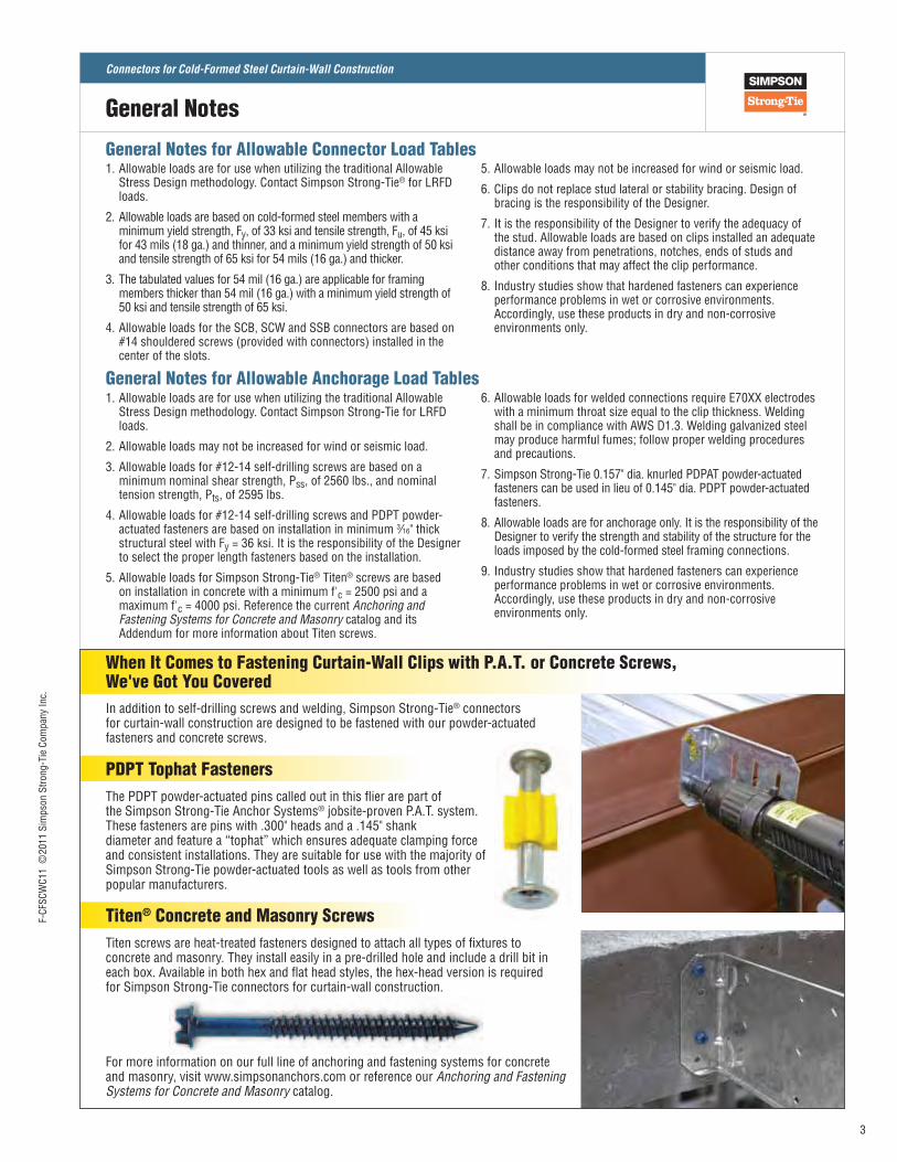
In addition to self‑drilling screws and welding, Simpson Strong‑Tie® connectors for curtain‑wall construction are designed to be fastened with our powder‑actuated fasteners and concrete screws.
When It Comes to Fastening Curtain-Wall Clips with P.A.T. or Concrete Screws, We've Got You Covered
PDPT Tophat Fasteners
Titen screws are heat‑treated fasteners designed to attach all types of fixtures to concrete and masonry. They install easily in a pre‑drilled hole and include a drill bit in each box. Available in both hex and flat head styles, the hex‑head version is required for Simpson Strong‑Tie connectors for curtain‑wall construction.
For more information on our full line of anchoring and fastening systems for concrete and masonry, visit www.simpsonanchors.com or reference our Anchoring and Fastening Systems for Concrete and Masonry catalog.
Titen® Concrete and Masonry Screws
The PDPT powder‑actuated pins called out in this flier are part of the Simpson Strong‑Tie Anchor Systems® jobsite‑proven P.A.T. system. These fasteners are pins with .300" heads and a .145" shank diameter and feature a “tophat” which ensures adequate clamping force and consistent installations. They are suitable for use with the majority of Simpson Strong‑Tie powder‑actuated tools as well as tools from other popular manufacturers.
3
F‑CF
SCW
C11
©20
11 S
imps
on S
trong
‑Tie
Com
pany
Inc.
Connectors for Cold-Formed Steel Curtain-Wall Construction
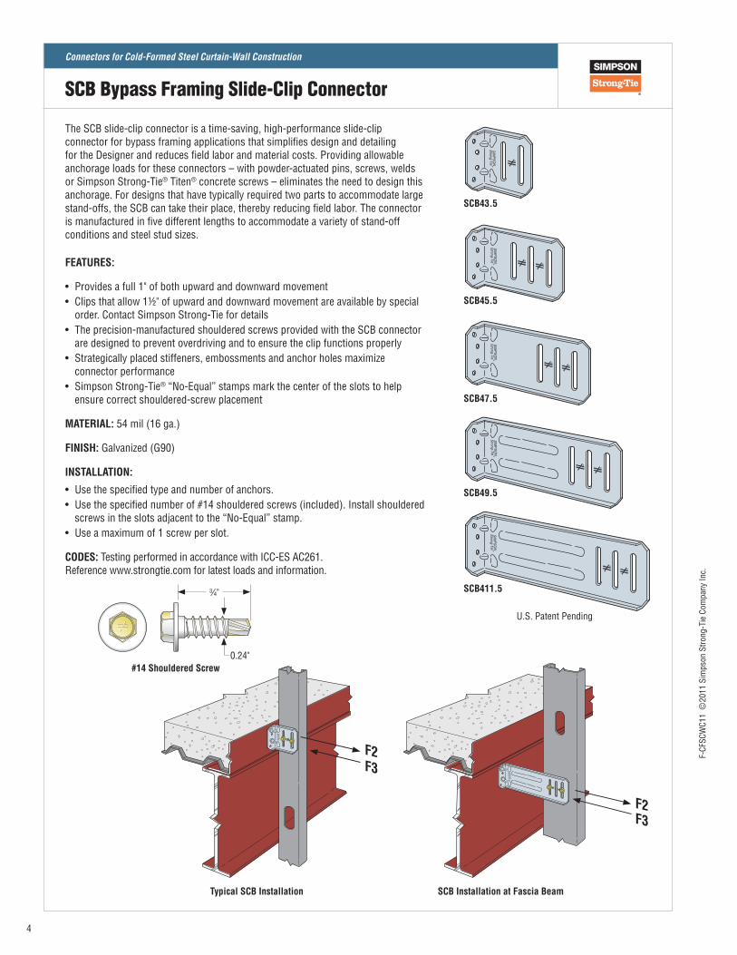
The SCB slide‑clip connector is a time‑saving, high‑performance slide‑clip connector for bypass framing applications that simplifies design and detailing for the Designer and reduces field labor and material costs. Providing allowable anchorage loads for these connectors – with powder‑actuated pins, screws, welds or Simpson Strong‑Tie® Titen® concrete screws – eliminates the need to design this anchorage. For designs that have typically required two parts to accommodate large stand‑offs, the SCB can take their place, thereby reducing field labor. The connector is manufactured in five different lengths to accommodate a variety of stand‑off conditions and steel stud sizes. FEATURES:
• Provides a full 1" of both upward and downward movement• Clips that allow 1½" of upward and downward movement are available by special
order. Contact Simpson Strong‑Tie for details• The precision‑manufactured shouldered screws provided with the SCB connector
are designed to prevent overdriving and to ensure the clip functions properly• Strategically placed stiffeners, embossments and anchor holes maximize
connector performance• Simpson Strong‑Tie® “No‑Equal” stamps mark the center of the slots to help
ensure correct shouldered‑screw placement
MATERIAL: 54 mil (16 ga.)
FINISH: Galvanized (G90)
INSTALLATION:
• Use the specified type and number of anchors.• Use the specified number of #14 shouldered screws (included). Install shouldered
screws in the slots adjacent to the “No‑Equal” stamp.• Use a maximum of 1 screw per slot.
CODES: Testing performed in accordance with ICC‑ES AC261. Reference www.strongtie.com for latest loads and information.
SCB411.5
SCB49.5
SCB47.5
SCB45.5
SCB43.5
U.S. Patent Pending
Typical SCB Installation
F2F3
SCB Installation at Fascia Beam
F2F3
#14 Shouldered Screw0.24"
3⁄4"
SCB Bypass Framing Slide-Clip Connector
4
F‑CF
SCW
C11
©20
11 S
imps
on S
trong
‑Tie
Com
pany
Inc.
Connectors for Cold-Formed Steel Curtain-Wall Construction
Model No.
Connector Material
Thickness mil (ga.)
L(in.)
No. of #14 Shouldered
Screws
Stud Thickness33 mil (20 ga.) 43 mil (18 ga.) 54 mil (16 ga.)
F2 F3 F2 F3 F2 F3
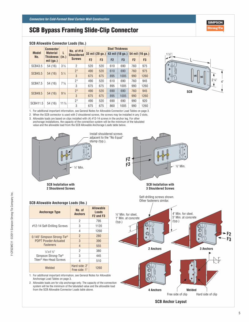
SCB43.5 54 (16) 3 1⁄2 2 520 520 610 690 760 975
SCB45.5 54 (16) 5 1⁄22 3 490 520 610 690 760 9753 675 675 895 1005 990 1260
SCB47.5 54 (16) 7 1⁄22 3 490 520 610 690 760 9453 675 675 895 1005 990 1260
SCB49.5 54 (16) 9 1⁄22 3 490 520 690 690 760 9453 675 675 895 1005 990 1260
SCB411.5 54 (16) 11 1⁄22 3 490 520 690 690 990 9203 675 675 860 1005 990 1260
1. For additional important information, see General Notes for Allowable Connector Load Tables on page 3.2. When the SCB connector is used with 2 shouldered screws, the screws may be installed in any 2 slots.3. Allowable loads are based on clips installed with (4) #12‑14 screws in the anchor leg. For other
anchorage installations, the capacity of the connection system will be the minimum of the tabulated value and the allowable load from the SCB Allowable Anchorage Loads table below.
SCB Allowable Connector Loads (lbs.)
Anchorage Type No. of Anchors
Allowable Loads
F2 and F3
#12‑14 Self‑Drilling Screws2 7953 11204 1260
0.145" Simpson Strong‑Tie® PDPT Powder‑Actuated
Fasteners
2 2803 3904 555
1⁄4"x1 3⁄4" Simpson Strong‑Tie®
Titen® Hex‑Head Screws
2 3803 4454 510
Welded Hard side: 2"Free side: 1" 1260
1. For additional important information, see General Notes for Allowable Anchorage Load Tables on page 3.
2. Allowable loads are for clip anchorage only. The capacity of the connection system will be the minimum of the tabulated value and the allowable load from the SCB Allowable Connector Loads table above.
SCB Allowable Anchorage Loads (lbs.)
SCB Anchor Layout
Self‑drilling screws shown. Other fasteners similar.
Free side of clip Hard side of clip
1"2"
2 Anchors 3 Anchors
4 Anchors Welded
1⁄2" Min. for steel, 1" Min. at concrete (typ.)
4" Min. for steel, 5" Min. at concrete (typ.)
SCB Installation with 2 Shouldered Screws
Install shouldered screws adjacent to the “No Equal” stamp (typ.).
1⁄2" Min.
L
SCB
2 1⁄4" 4"
1 1⁄2"
F2F3
SCB Installation with 3 Shouldered Screws
1⁄2" Min.
F2F3
SCB Bypass Framing Slide-Clip Connector
5
F‑CF
SCW
C11
©20
11 S
imps
on S
trong
‑Tie
Com
pany
Inc.
Connectors for Cold-Formed Steel Curtain-Wall Construction
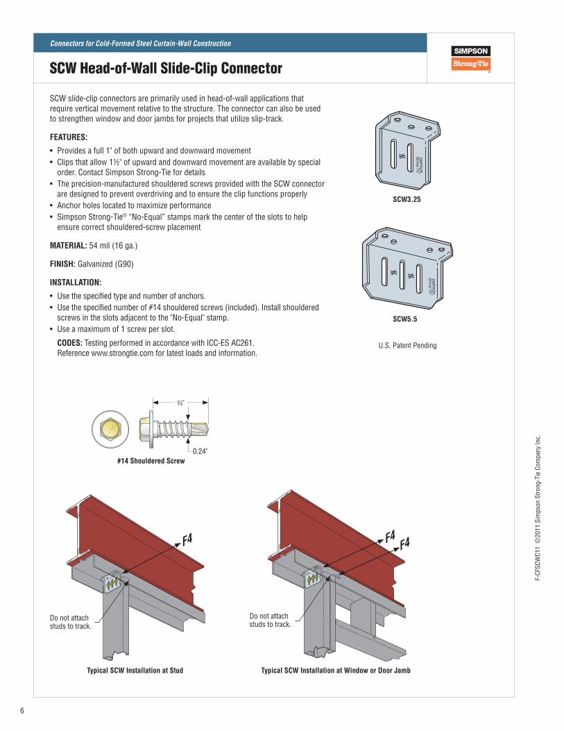
SCW slide‑clip connectors are primarily used in head‑of‑wall applications that require vertical movement relative to the structure. The connector can also be used to strengthen window and door jambs for projects that utilize slip‑track.
FEATURES:
• Provides a full 1" of both upward and downward movement• Clips that allow 1½" of upward and downward movement are available by special
order. Contact Simpson Strong‑Tie for details• The precision‑manufactured shouldered screws provided with the SCW connector
are designed to prevent overdriving and to ensure the clip functions properly• Anchor holes located to maximize performance• Simpson Strong‑Tie® “No‑Equal” stamps mark the center of the slots to help
ensure correct shouldered‑screw placement
MATERIAL: 54 mil (16 ga.)
FINISH: Galvanized (G90)
INSTALLATION:
• Use the specified type and number of anchors.• Use the specified number of #14 shouldered screws (included). Install shouldered
screws in the slots adjacent to the "No‑Equal" stamp.• Use a maximum of 1 screw per slot.
CODES: Testing performed in accordance with ICC‑ES AC261. Reference www.strongtie.com for latest loads and information.
SCW5.5
SCW3.25
U.S. Patent Pending
Typical SCW Installation at Stud
F4
Do not attach studs to track.
Typical SCW Installation at Window or Door Jamb
F4F4
Do not attach studs to track.
#14 Shouldered Screw0.24"
3⁄4"
SCW Head-of-Wall Slide-Clip Connector
6
F‑CF
SCW
C11
©20
11 S
imps
on S
trong
‑Tie
Com
pany
Inc.
Connectors for Cold-Formed Steel Curtain-Wall Construction
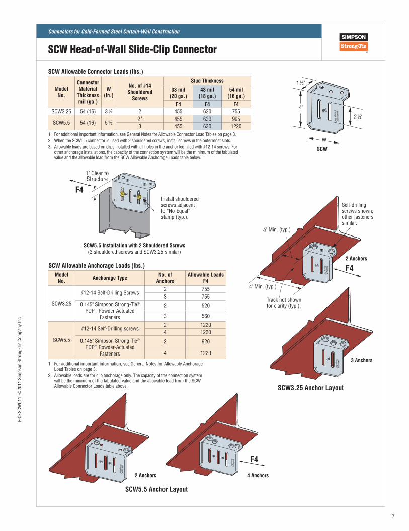
1. For additional important information, see General Notes for Allowable Connector Load Tables on page 3.2. When the SCW5.5 connector is used with 2 shouldered screws, install screws in the outermost slots.3. Allowable loads are based on clips installed with all holes in the anchor leg filled with #12‑14 screws. For
other anchorage installations, the capacity of the connection system will be the minimum of the tabulated value and the allowable load from the SCW Allowable Anchorage Loads table below.
SCW Allowable Connector Loads (lbs.)
Model No.
Connector Material
Thickness mil (ga.)
W(in.)
No. of #14 Shouldered
Screws
Stud Thickness
33 mil (20 ga.)
43 mil (18 ga.)
54 mil (16 ga.)
F4 F4 F4SCW3.25 54 (16) 3 1⁄4 2 455 630 755
SCW5.5 54 (16) 5 1⁄22 3 455 630 9953 455 630 1220
1. For additional important information, see General Notes for Allowable Anchorage Load Tables on page 3.
2. Allowable loads are for clip anchorage only. The capacity of the connection system will be the minimum of the tabulated value and the allowable load from the SCW Allowable Connector Loads table above.
SCW Allowable Anchorage Loads (lbs.)Model
No. Anchorage Type No. of Anchors
Allowable Loads F4
SCW3.25
#12‑14 Self‑Drilling Screws2 7553 755
0.145" Simpson Strong‑Tie® PDPT Powder‑Actuated
Fasteners
2 520
3 560
SCW5.5
#12‑14 Self‑Drilling screws2 12204 1220
0.145" Simpson Strong‑Tie® PDPT Powder‑Actuated
Fasteners
2 920
4 1220
Self‑drilling screws shown; other fasteners similar.
SCW3.25 Anchor Layout
SCW5.5 Anchor Layout
SCW
2 Anchors 4 Anchors
3 Anchors
2 Anchors
1⁄2" Min. (typ.)
4" Min. (typ.)
2 1⁄4"
1 1⁄2"
4"
W
Track not shown for clarity (typ.).
1" Clear toStructure
Install shouldered screws adjacent to “No‑Equal” stamp (typ.).
SCW5.5 Installation with 2 Shouldered Screws(3 shouldered screws and SCW3.25 similar)
F4
F4
F4
SCW Head-of-Wall Slide-Clip Connector
7
F‑CF
SCW
C11
©20
11 S
imps
on S
trong
‑Tie
Com
pany
Inc.
Connectors for Cold-Formed Steel Curtain-Wall Construction
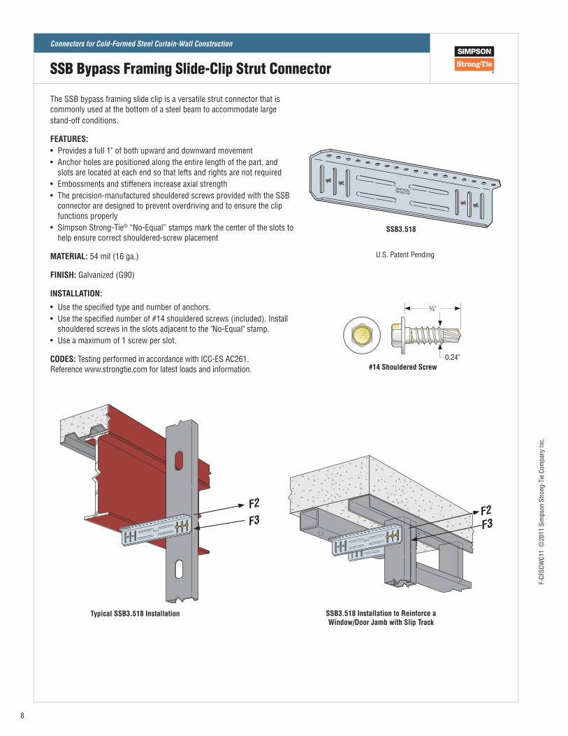
SSB3.518
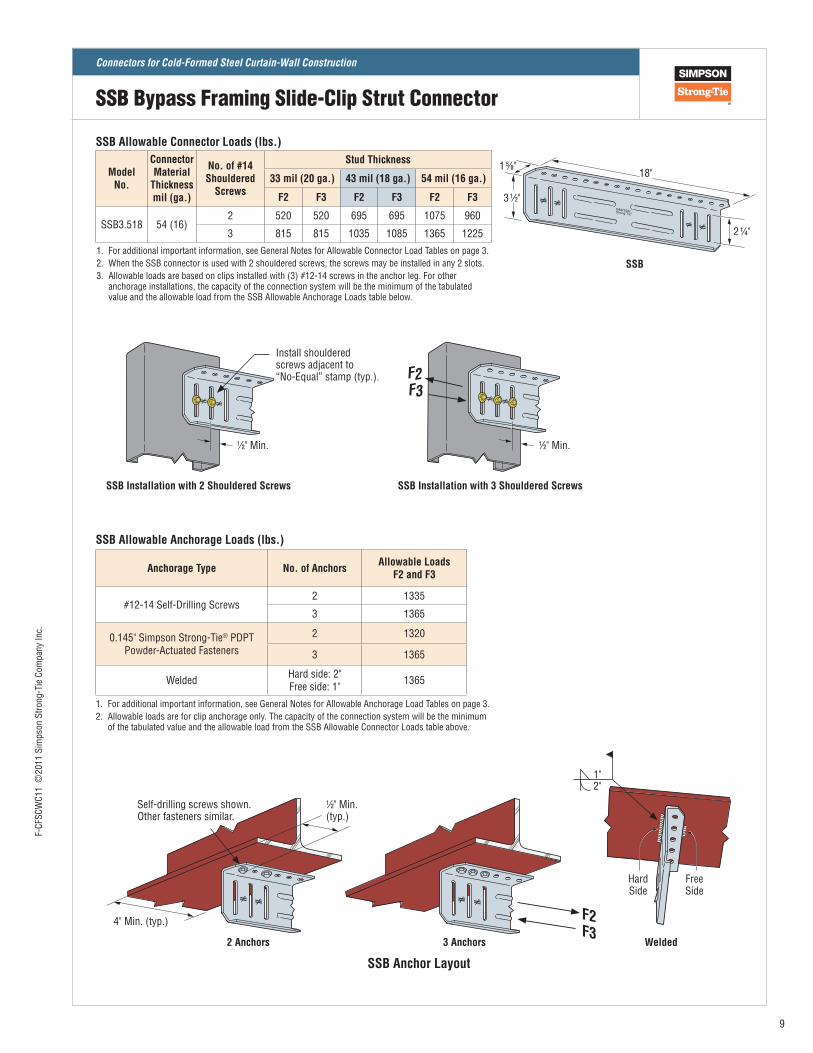
The SSB bypass framing slide clip is a versatile strut connector that is commonly used at the bottom of a steel beam to accommodate large stand‑off conditions.
FEATURES:• Provides a full 1" of both upward and downward movement• Anchor holes are positioned along the entire length of the part, and
slots are located at each end so that lefts and rights are not required• Embossments and stiffeners increase axial strength• The precision‑manufactured shouldered screws provided with the SSB
connector are designed to prevent overdriving and to ensure the clip functions properly
• Simpson Strong‑Tie® “No‑Equal” stamps mark the center of the slots to help ensure correct shouldered‑screw placement
MATERIAL: 54 mil (16 ga.)
FINISH: Galvanized (G90)
INSTALLATION:
• Use the specified type and number of anchors. • Use the specified number of #14 shouldered screws (included). Install
shouldered screws in the slots adjacent to the "No‑Equal" stamp.• Use a maximum of 1 screw per slot.
CODES: Testing performed in accordance with ICC‑ES AC261. Reference www.strongtie.com for latest loads and information.
U.S. Patent Pending
Typical SSB3.518 Installation SSB3.518 Installation to Reinforce a Window/Door Jamb with Slip Track
F2
F3
#14 Shouldered Screw0.24"
3⁄4"
F2F3
SSB Bypass Framing Slide-Clip Strut Connector
8
F‑CF
SCW
C11
©20
11 S
imps
on S
trong
‑Tie
Com
pany
Inc.
Connectors for Cold-Formed Steel Curtain-Wall Construction
Model No.
Connector Material
Thickness mil (ga.)
No. of #14 Shouldered
Screws
Stud Thickness
33 mil (20 ga.) 43 mil (18 ga.) 54 mil (16 ga.)
F2 F3 F2 F3 F2 F3
SSB3.518 54 (16)2 520 520 695 695 1075 960
3 815 815 1035 1085 1365 1225
1. For additional important information, see General Notes for Allowable Connector Load Tables on page 3.2. When the SSB connector is used with 2 shouldered screws, the screws may be installed in any 2 slots.3. Allowable loads are based on clips installed with (3) #12‑14 screws in the anchor leg. For other
anchorage installations, the capacity of the connection system will be the minimum of the tabulated value and the allowable load from the SSB Allowable Anchorage Loads table below.
SSB Allowable Connector Loads (lbs.)
Anchorage Type No. of Anchors Allowable Loads F2 and F3
#12‑14 Self‑Drilling Screws2 1335
3 1365
0.145" Simpson Strong‑Tie® PDPT Powder‑Actuated Fasteners
2 1320
3 1365
Welded Hard side: 2"Free side: 1" 1365
SSB Allowable Anchorage Loads (lbs.)
1. For additional important information, see General Notes for Allowable Anchorage Load Tables on page 3.2. Allowable loads are for clip anchorage only. The capacity of the connection system will be the minimum
of the tabulated value and the allowable load from the SSB Allowable Connector Loads table above.
Install shouldered screws adjacent to “No‑Equal” stamp (typ.).
SSB Installation with 3 Shouldered ScrewsSSB Installation with 2 Shouldered Screws
Self‑drilling screws shown. Other fasteners similar.
1"2"
SSB
SSB Anchor Layout
4" Min. (typ.)
1⁄2" Min. (typ.)
Hard Side
Free Side
2 1⁄4"
18"1 5⁄8"
3 1⁄2"
1⁄2" Min. 1⁄2" Min.
F2F3
F2F3
SSB Bypass Framing Slide-Clip Strut Connector
2 Anchors 3 Anchors Welded
9
F‑CF
SCW
C11
©20
11 S
imps
on S
trong
‑Tie
Com
pany
Inc.
Connectors for Cold-Formed Steel Curtain-Wall Construction
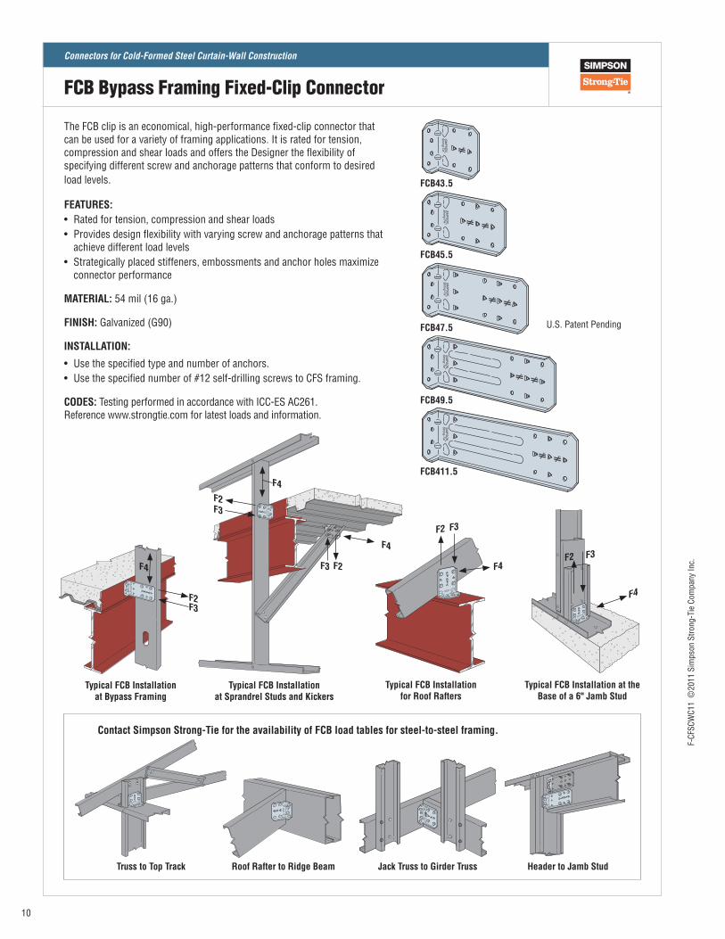
The FCB clip is an economical, high‑performance fixed‑clip connector that can be used for a variety of framing applications. It is rated for tension, compression and shear loads and offers the Designer the flexibility of specifying different screw and anchorage patterns that conform to desired load levels.
FEATURES:• Rated for tension, compression and shear loads• Provides design flexibility with varying screw and anchorage patterns that
achieve different load levels• Strategically placed stiffeners, embossments and anchor holes maximize
connector performance
MATERIAL: 54 mil (16 ga.)
FINISH: Galvanized (G90)
INSTALLATION:
• Use the specified type and number of anchors.• Use the specified number of #12 self‑drilling screws to CFS framing.
CODES: Testing performed in accordance with ICC‑ES AC261. Reference www.strongtie.com for latest loads and information.
FCB411.5
FCB49.5
FCB47.5
FCB45.5
FCB43.5
U.S. Patent Pending
Typical FCB Installation at the Base of a 6" Jamb Stud
Typical FCB Installation at Bypass Framing
Typical FCB Installation for Roof Rafters
F2 F3
F4F2 F3
F4F3F2
F4
Typical FCB Installation at Sprandrel Studs and Kickers
F3
F3 F2
F2
F4
F4
Truss to Top Track Roof Rafter to Ridge Beam Jack Truss to Girder Truss Header to Jamb Stud
Contact Simpson Strong-Tie for the availability of FCB load tables for steel-to-steel framing.
FCB Bypass Framing Fixed-Clip Connector
10
F‑CF
SCW
C11
©20
11 S
imps
on S
trong
‑Tie
Com
pany
Inc.
Connectors for Cold-Formed Steel Curtain-Wall Construction
Model No.
Connector Material
Thickness mil (ga.)
L(in.)
Min./ Max.
No. of #12-14
Self-Drilling Screws
Stud Thickness
33 mil (20 ga.) 43 mil (18 ga.) 54 mil (16 ga.)
F2 F3 F4 F2 F3 F4 F2 F3 F4
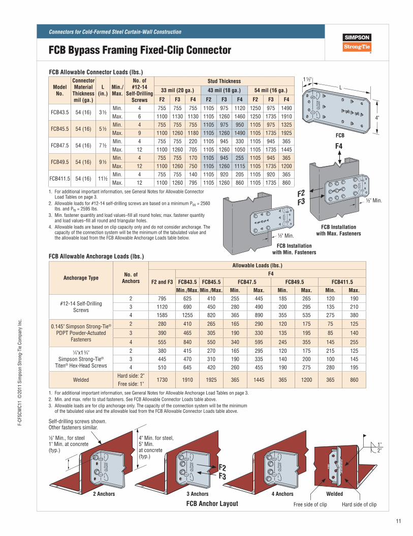
FCB43.5 54 (16) 3 ½Min. 4 755 755 755 1105 975 1120 1250 975 1490Max. 6 1100 1130 1130 1105 1260 1460 1250 1735 1910
FCB45.5 54 (16) 5 ½Min. 4 755 755 755 1105 975 950 1105 975 1325Max. 9 1100 1260 1180 1105 1260 1490 1105 1735 1925
FCB47.5 54 (16) 7 ½Min. 4 755 755 220 1105 945 330 1105 945 365Max. 12 1100 1260 705 1105 1260 1050 1105 1735 1445
FCB49.5 54 (16) 9 ½Min. 4 755 755 170 1105 945 255 1105 945 365Max. 12 1100 1260 750 1105 1260 1115 1105 1735 1200
FCB411.5 54 (16) 11½Min. 4 755 755 140 1105 920 205 1105 920 365Max. 12 1100 1260 795 1105 1260 860 1105 1735 860
1. For additional important information, see General Notes for Allowable Connector Load Tables on page 3.
2. Allowable loads for #12‑14 self‑drilling screws are based on a minimum Pss = 2560 lbs. and Pts = 2595 lbs.
3. Min. fastener quantity and load values–fill all round holes; max. fastener quantity and load values–fill all round and triangular holes.
4. Allowable loads are based on clip capacity only and do not consider anchorage. The capacity of the connection system will be the minimum of the tabulated value and the allowable load from the FCB Allowable Anchorage Loads table below.
FCB Allowable Connector Loads (lbs.)
Anchorage Type No. of Anchors
Allowable Loads (lbs.)
F2 and F3F4
FCB43.5 FCB45.5 FCB47.5 FCB49.5 FCB411.5Min./Max. Min./Max. Min. Max. Min. Max. Min. Max.
#12‑14 Self‑Drilling Screws
2 795 625 410 255 445 185 265 120 1903 1120 690 450 280 490 200 295 135 2104 1585 1255 820 365 890 355 535 275 380
0.145" Simpson Strong‑Tie® PDPT Powder‑Actuated
Fasteners
2 280 410 265 165 290 120 175 75 125
3 390 465 305 190 330 135 195 85 140
4 555 840 550 340 595 245 355 145 255
1⁄4"x1 3⁄4" Simpson Strong‑Tie®
Titen® Hex‑Head Screws
2 380 415 270 165 295 120 175 215 1253 445 470 310 190 335 140 200 100 1454 510 645 420 260 455 190 275 280 195
WeldedHard side: 2"
1730 1910 1925 365 1445 365 1200 365 860Free side: 1"
1. For additional important information, see General Notes for Allowable Anchorage Load Tables on page 3.2. Min. and max. refer to stud fasteners. See FCB Allowable Connector Loads table above.3. Allowable loads are for clip anchorage only. The capacity of the connection system will be the minimum
of the tabulated value and the allowable load from the FCB Allowable Connector Loads table above.
FCB Allowable Anchorage Loads (lbs.)
Self‑drilling screws shown. Other fasteners similar.
FCB Anchor Layout2 Anchors 3 Anchors 4 Anchors
Free side of clip Hard side of clip
1"2"
Welded
1⁄2" Min., for steel 1" Min. at concrete (typ.)
4" Min. for steel, 5" Min. at concrete (typ.)
FCB Installation with Min. Fasteners
1⁄2" Min.
FCB
4"
1 1⁄2"L
F2F3
FCB Installation with Max. Fasteners
1⁄2" Min.F2F3
F4
FCB Bypass Framing Fixed-Clip Connector
11
F‑CF
SCW
C11
©20
11 S
imps
on S
trong
‑Tie
Com
pany
Inc.
Connectors for Cold-Formed Steel Curtain-Wall Construction
800-999-5099www.strongtie.com
This flier is effective until June 30, 2012, and reflects information available as of June 1, 2011. This information is updated periodically and should not be relied upon after June 30, 2012; contact Simpson Strong-Tie for current information and limited warranty or see www.strongtie.com.
©2011SimpsonStrong-TieCompanyInc.•P.O. Box 10789, Pleasanton, CA 94588 F-CFSCWC11 6/11 exp. 6/12
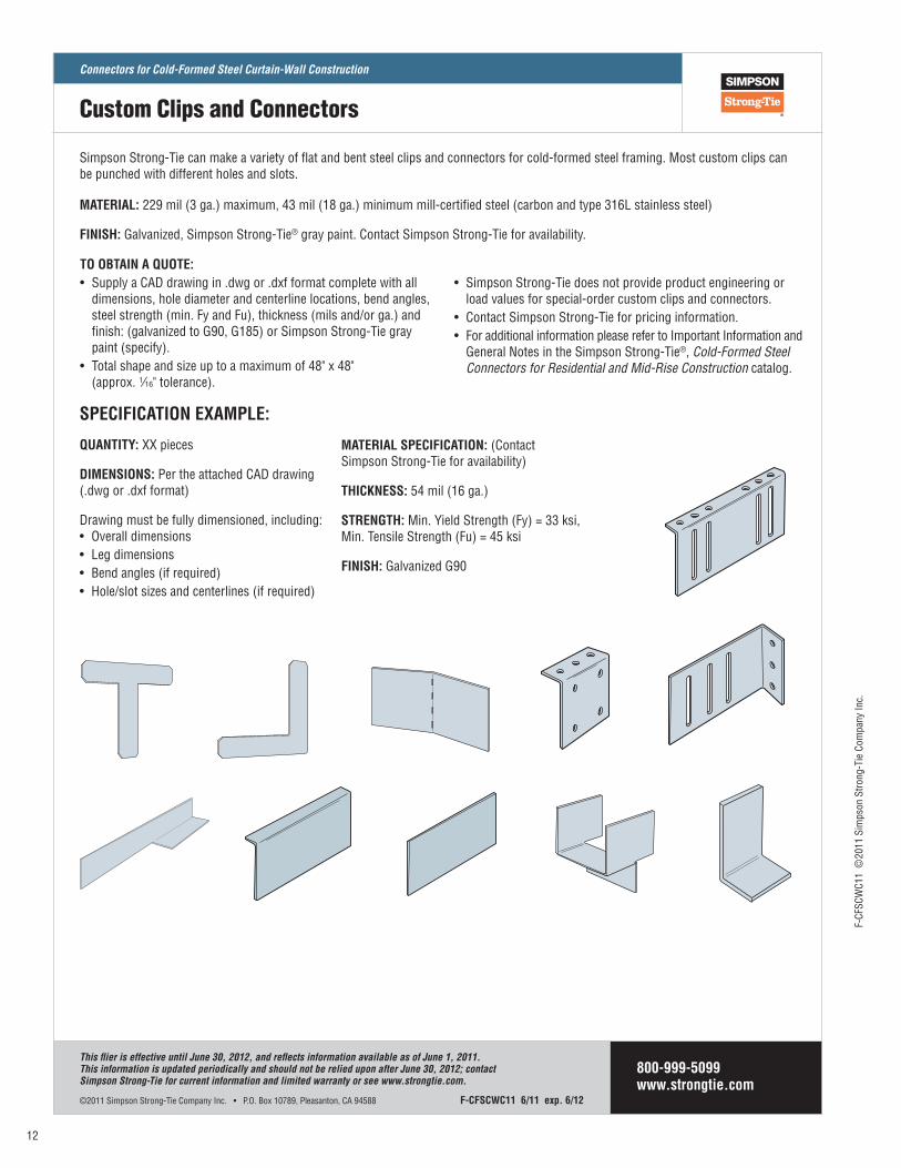
Simpson Strong‑Tie can make a variety of flat and bent steel clips and connectors for cold‑formed steel framing. Most custom clips can be punched with different holes and slots.
MATERIAL: 229 mil (3 ga.) maximum, 43 mil (18 ga.) minimum mill‑certified steel (carbon and type 316L stainless steel)
FINISH: Galvanized, Simpson Strong‑Tie® gray paint. Contact Simpson Strong‑Tie for availability.
SPECIFICATION EXAMPLE:
QUANTITY: XX pieces
DIMENSIONS: Per the attached CAD drawing (.dwg or .dxf format)
Drawing must be fully dimensioned, including:• Overall dimensions• Leg dimensions• Bend angles (if required)• Hole/slot sizes and centerlines (if required)
MATERIAL SPECIFICATION: (Contact Simpson Strong‑Tie for availability)
THICKNESS: 54 mil (16 ga.)
STRENGTH: Min. Yield Strength (Fy) = 33 ksi, Min. Tensile Strength (Fu) = 45 ksi
FINISH: Galvanized G90
TO OBTAIN A QUOTE: • Supply a CAD drawing in .dwg or .dxf format complete with all
dimensions, hole diameter and centerline locations, bend angles, steel strength (min. Fy and Fu), thickness (mils and/or ga.) and finish: (galvanized to G90, G185) or Simpson Strong‑Tie gray paint (specify).
• Total shape and size up to a maximum of 48" x 48" (approx. 1⁄16" tolerance).
• Simpson Strong‑Tie does not provide product engineering or load values for special‑order custom clips and connectors.
• Contact Simpson Strong‑Tie for pricing information.• For additional information please refer to Important Information and
General Notes in the Simpson Strong‑Tie®, Cold-Formed Steel Connectors for Residential and Mid-Rise Construction catalog.
Custom Clips and Connectors
12
F‑CF
SCW
C11
©20
11 S
imps
on S
trong
‑Tie
Com
pany
Inc.
Connectors for Cold-Formed Steel Curtain-Wall Construction