conshelf xiv - aqua lung · 4 conshelf xiv technical manual 3. as the regulator is disassembled,...
TRANSCRIPT

CONSHELF XIV
TECHNICAL MANUAL
Rev. 3/17
2 Conshelf XIV Technical Manual
©2017 AQUA LUNG AMERICA CONSHELF XIV TECHNICAL MANUAL, PN 108101
You can contact a Technical Adviser via e-mail at:
Aqua Lung America
[email protected]@[email protected]
Warnings, Cautions, & NotesPay special attention to information provided in warnings, cautions and notes that are accompanied by one of these symbols:
Trademark NoticeAqua Lung®, is a registered trademark of Aqua Lung America, Inc.
A WARNING indicates a procedure or situation that, if not avoided, could result in serious injury or death to the user.
A CAUTION indicates any situation or technique that could cause damage to the product and could subsequently result in injury to the user.
A NOTE is used to emphasize important points, tips and reminders.
COPYRIGHT NOTICE
This manual is copyrighted, all rights reserved. It may not, in whole or in part, be copied, photocopied, reproduced, translated or reduced to any electronic medium or machine-readable format without prior consent in writing from Aqua Lung America. It may not be distributed through the internet or computer bulletin board systems without prior consent in writing from Aqua Lung America.

3
CONTENTS
INTRODUCTION ..................................................................................................................................4
SCHEDULED SERVICE .......................................................................................................................4
GENERAL GUIDELINES .....................................................................................................................4
GENERAL CONVENTIONS ................................................................................................................4
DISASSEMBLY PROCEDURE ............................................................................................................5
REASSEMBLY PROCEDURE ...........................................................................................................11
FINAL TESTING ..............................................................................................................................21
TABLE 1 - FIRST STAGE TROUBLESHOOTING GUIDE .................................................................22
TABLE 2 - SECOND STAGE TROUBLE SHOOTING GUIDE ...........................................................23
TABLE 3 - LIST OF TOOLS AND SERVICE KITS ............................................................................24
TABLE 4 - TORQUE SPECIFICATIONS ............................................................................................26
TABLE 5 - TEST BENCH SPECIFICATIONS ....................................................................................27
TABLE 6 - RECOMMENDED LUBRICANTS AND CLEANERS .......................................................27
PROCEDURE A - CLEANING AND LUBRICATION .........................................................................28
CONSHELF XIV FIRST STAGE EXPLODED VIEW ..........................................................................29
CONSHELF XIV SECOND STAGE EXPLODED VIEW .....................................................................30
FREE-FLOW CONTROL DEVICE (FCD) EXPLODED VIEW ............................................................31

4 Conshelf XIV Technical Manual
3. As the regulator is disassembled, reusable components should be segregated and not allowed to intermix with nonreusable parts or parts from other units. Delicate parts, including inlet fittings and crowns which contain critical sealing surfaces, must be protected and isolated from other parts to prevent damage during the cleaning procedure.4. Use only genuine Aqua Lung® parts provided in the overhaul parts kit for this product. DO NOT attempt to substitute an Aqua Lung® part with another manufacturer’s, regardless of any similarity in shape or size. 5. Do not attempt to reuse mandatory replacement parts under any circumstances, regardless of the amount of use the product has received since it was manufactured or last serviced.6. When reassembling, it is important to follow every torque specification prescribed in this manual, using a calibrated torque wrench. Most parts are made of either marine brass or plastic, and can be permanently damaged by undue stress.7. In order to make the regulator compatible with Nitrox up to 40% O2 (EAN40), the regulator must be properly cleaned, lubricated and assembled using genuine Aqua Lung® replacement parts. In addition, assembly must be carried out in a clean environment using powderless, latex gloves or equivalent. For more detailed information, be sure to read Procedure A: Cleaning and Lubrication at the back of this manual.
Scheduled ServiceIf the regulator is in good working order, it is permissible to overhaul it every other year with an inspection procedure being performed on the “off” years.For Example:Year #1: InspectionYear #2: OverhaulYear #3: InspectionYear #4: Overhaul, and so on.
IntroductionThis manual provides factory prescribed procedures for the correct service and repair of this Aqua Lung product. It is not intended to be used as an instructional manual for untrained personnel. The procedures outlined in this manual are to be performed only by personnel who have received Factory Authorized training through an Aqua Lung Service & Repair Seminar. If you do not completely understand all of the procedures outlined in this manual, contact Aqua Lung to speak directly with a Technical Advisor before proceeding any further.
An Official Inspection Consists of:1. A pressurized immersion test of the entire unit to check for air leakage.2. Check for stable medium pressure that is within the acceptable range.3. Checking for opening effort that is within the acceptable range.4. Visual inspection of the filter for debris or discoloration.5. A visual inspection of the exhaust valve to see that it is in good shape and that it’s resting against a clean surface.6. A visual inspection of the mouthpiece looking for tears or holes.7. Pulling back hose protectors and checking that the hoses are secure in the hose crimps.If the regulator fails item #1, 2 or 3, the entire regulator should be overhauled. If the regulator fails #4, 5, 6 or 7, it will be up to the technician’s discretion whether or not a full overhaul is required.
WARNING: DO NOT attempt to use a Conshelf XIV Supreme regulator containing silicone fluid with enriched air Nitrox (EAN). Doing so could result in serious injury or death.
General Guidelines1. In order to correctly perform the procedures outlined in this manual, it is important to follow each step exactly in the order given. Read over the entire manual to become familiar with all procedures before attempting to disassemble the product in this manual, and to learn which specialty tools and replacement parts will be required. Keep the manual open beside you for reference while performing each procedure. Do not rely on memory.2. All service and repair should be carried out in a work area specifically set up and equipped for the task. Adequate lighting, cleanliness, and easy access to all required tools are essential for an efficient repair facility.
General ConventionsUnless otherwise instructed, the following terminology and techniques are assumed:1. When instructed to remove, unscrew or loosen a threaded part, turn the part counter-clockwise.When instructed to install, screw or tighten a threaded part, turn the part clockwise.2. The following acronyms are used throughout the manual: LP is Low Pressure; MP is Medium Pressure; and HP is High Pressure.3. Numbers in parentheses reference the key numbers on the exploded parts schematics. For example, in the statement, “... remove the o-ring (7) from the crown (8) “...the number 7 is the key number to the crown o-ring.4. When instructed to remove an o-ring, use the pinch method (see illustration below) or use a brass or plastic o-ring removal tool. Avoid using hardened steel picks (unless directed), as they may damage the o-ring sealing surface. All o-rings that are removed are discarded and replaced with brand new o-rings.
NOTE: A unit that receives heavy or frequent use, such as rental, instruction, or commercial applications, should be serviced at least twice a year - or more often - depending on the conditions of use and the manner in which it is maintained. (Refer to the care and maintenance procedures outlined in the Regulator User’s Manual.)
Pinch MethodPress upwards on sides of o-ring to create a protrusion. Grab o-ring or insert o-ring tool at protrusion.
5
DISASSEMBLY PROCEDURE
First Stage Disassembly
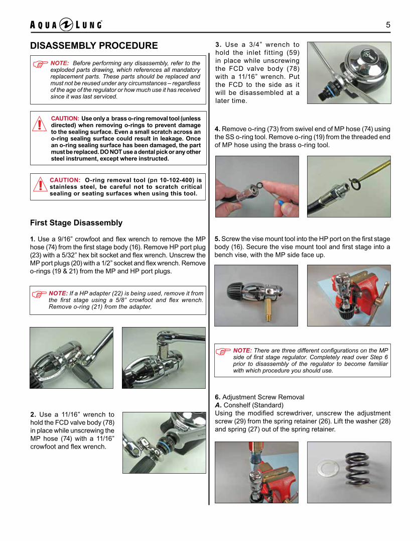
1. Use a 9/16” crowfoot and flex wrench to remove the MP hose (74) from the first stage body (16). Remove HP port plug (23) with a 5/32” hex bit socket and flex wrench. Unscrew the MP port plugs (20) with a 1/2” socket and flex wrench. Remove o-rings (19 & 21) from the MP and HP port plugs.
4. Remove o-ring (73) from swivel end of MP hose (74) using the SS o-ring tool. Remove o-ring (19) from the threaded end of MP hose using the brass o-ring tool.
NOTE: Before performing any disassembly, refer to the exploded parts drawing, which references all mandatory replacement parts. These parts should be replaced and must not be reused under any circumstances – regardless of the age of the regulator or how much use it has received since it was last serviced.
CAUTION: Use only a brass o-ring removal tool (unless directed) when removing o-rings to prevent damage to the sealing surface. Even a small scratch across an o-ring sealing surface could result in leakage. Once an o-ring sealing surface has been damaged, the part must be replaced. DO NOT use a dental pick or any other steel instrument, except where instructed.
5. Screw the vise mount tool into the HP port on the first stage body (16). Secure the vise mount tool and first stage into a bench vise, with the MP side face up.
6. Adjustment Screw RemovalA. Conshelf (Standard)Using the modified screwdriver, unscrew the adjustment screw (29) from the spring retainer (26). Lift the washer (28) and spring (27) out of the spring retainer.
2. Use a 11/16” wrench to hold the FCD valve body (78) in place while unscrewing the MP hose (74) with a 11/16” crowfoot and flex wrench.
3. Use a 3/4” wrench to hold the inlet f it ting (59) in place while unscrewing the FCD valve body (78) with a 11/16” wrench. Put the FCD to the side as it will be disassembled at a later time.
CAUTION: O-ring removal tool (pn 10-102-400) is stainless steel, be careful not to scratch critical sealing or seating surfaces when using this tool.
NOTE: If a HP adapter (22) is being used, remove it from the first stage using a 5/8” crowfoot and flex wrench. Remove o-ring (21) from the adapter.
NOTE: There are three different configurations on the MP side of first stage regulator. Completely read over Step 6 prior to disassembly of the regulator to become familiar with which procedure you should use.

6 Conshelf XIV Technical Manual
B. Conshelf Supreme (Silicone Fluid)Insert the supreme retainer wrench into the two slots on the diaphragm retainer (33) and unscrew the diaphragm retainer from the spring retainer (31). Using your fingers, lift upward on the secondary diaphragm (32) and remove it. Remove the first stage from the bench vise and pour out the silicone fluid in accordance with local directives. Place the first stage back into the vise as previously instructed. Using the modified screwdriver, unscrew the adjustment screw (29) from the spring retainer. Lift the spring (30) out of the spring retainer.
C. Conshelf Supreme (Dry Kit)Insert the supreme retainer wrench into the two slots on the diaphragm retainer (41) and unscrew the diaphragm retainer from the spring retainer (35). Using your fingers, push the external diaphragm (40) out of the diaphragm retainer. Remove the piston (38) from the spring retainer. Using a 6mm hex bit socket and flex wrench, unscrew the adjustment screw (37) from the spring retainer. Lift the washer (28) and spring (36) out of the spring retainer.
9. Remove the dust cap (3) from the inlet boss on the body (16). Remove o-ring (4) from the dust cap.
8. Turn the regulator over and secure the vise mount tool and first stage into a bench vise with the HP side face up. Unscrew the yoke screw (2) from the yoke (6).
7. Using a 1 3/8” crowfoot (34mm for the dry kit spring retainer) and flex wrench, unscrew the spring retainer (26) standard, (31) supreme and (35) dry kit from the body (16). Remove the spring pad (25) standard & supreme and (34) dry kit and thrust washer (24b) from the body.
10. Using circlip pliers, remove the retaining ring (5) from the groove on the inlet boss of the body (16). Unscrew the yoke (6) and remove it from the body.
Yoke Disassembly

7
DIN Disassembly
11. Unscrew the protector cap (42) from the handwheel (46).
12. Secure the vise mount tool and first stage into a bench vise with the HP side face up. Use a flex wrench and 6mm hex bit socket to unscrew the DIN stem (44). Remove both o-rings (43 & 45).
13. Remove the handwheel (46) from the DIN adapter (47). Closely inspect the threads of the handwheel for damage.
14. Apply a 1 1/4” crowfoot and flex wrench to the wrench flats at the base of the DIN adapter (47). Unscrew the DIN adapter from the inlet boss of the first stage body (16). Remove o-ring (48) from inside the DIN adapter.
17. Remove the vise mounting tool and first stage from the vise. Turn the body over and allow the spring (10), spring block (11), spring (14), HP seat (15) and pin (17) to fall out.
15. Insert circlip pliers into the holes of the retaining ring (7). Place your thumb over the retaining ring to prevent ejection of the parts beneath. Remove the retaining ring and washer (8) from the first stage inlet boss.
16. The filter (9) will pop out with the retaining ring (7) and washer (8).
CAUTION: To prevent eye injury and loss of parts, the retaining ring must be removed carefully as the components beneath are under spring tension. Place your thumb over the retaining ring while removing it to keep the parts from forcefully ejecting.
NOTE: There are two types of washers used in the Conshelf XIV regulator. A white nylon washer (air use only) or stainless steel washer (Air or Nitrox up to 40%).
Stainless Steel (Air or Nitrox up to 40%)
Nylon(Air Use Only)
8 Conshelf XIV Technical Manual
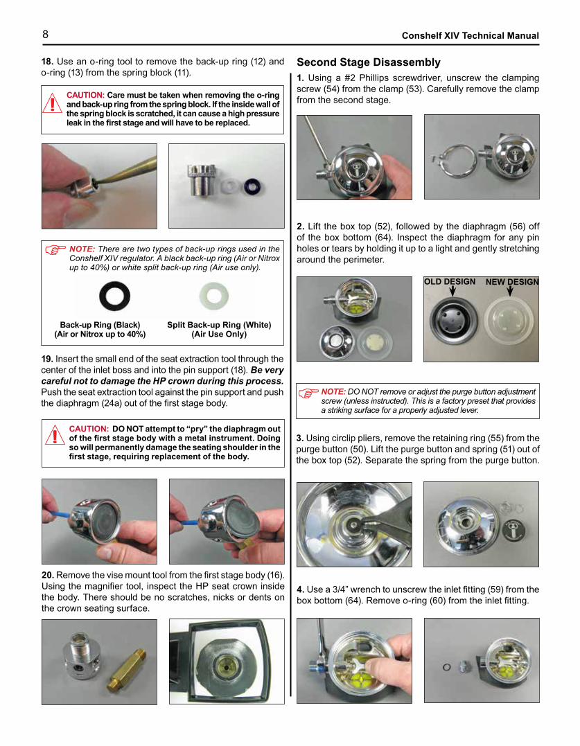
20. Remove the vise mount tool from the first stage body (16). Using the magnifier tool, inspect the HP seat crown inside the body. There should be no scratches, nicks or dents on the crown seating surface.
Second Stage Disassembly1. Using a #2 Phillips screwdriver, unscrew the clamping screw (54) from the clamp (53). Carefully remove the clamp from the second stage.
2. Lift the box top (52), followed by the diaphragm (56) off of the box bottom (64). Inspect the diaphragm for any pin holes or tears by holding it up to a light and gently stretching around the perimeter.
4. Use a 3/4” wrench to unscrew the inlet fitting (59) from the box bottom (64). Remove o-ring (60) from the inlet fitting.
CAUTION: DO NOT attempt to “pry” the diaphragm out of the first stage body with a metal instrument. Doing so will permanently damage the seating shoulder in the first stage, requiring replacement of the body.
18. Use an o-ring tool to remove the back-up ring (12) and o-ring (13) from the spring block (11).
NOTE: There are two types of back-up rings used in the Conshelf XIV regulator. A black back-up ring (Air or Nitrox up to 40%) or white split back-up ring (Air use only).
Back-up Ring (Black) (Air or Nitrox up to 40%)
Split Back-up Ring (White) (Air Use Only)
19. Insert the small end of the seat extraction tool through the center of the inlet boss and into the pin support (18). Be very careful not to damage the HP crown during this process. Push the seat extraction tool against the pin support and push the diaphragm (24a) out of the first stage body.
CAUTION: Care must be taken when removing the o-ring and back-up ring from the spring block. If the inside wall of the spring block is scratched, it can cause a high pressure leak in the first stage and will have to be replaced.
NOTE: DO NOT remove or adjust the purge button adjustment screw (unless instructed). This is a factory preset that provides a striking surface for a properly adjusted lever.
3. Using circlip pliers, remove the retaining ring (55) from the purge button (50). Lift the purge button and spring (51) out of the box top (52). Separate the spring from the purge button.
OLD DESIGN NEW DESIGN

9
CAUTION: The poppet assembly is under spring tension, care should be taken during removal to prevent damage or loss of parts.
6. If the box bottom (64) has a port plug (66), remove the port plug with a 5/32” hex bit socket and flex wrench. Remove the o-ring (65) from the port plug.
8. Remove the washer (67), lever (68) and spacer (69) from the box bottom (64).
13. Grasp the exhaust valve (58) and remove it from the box bottom (64).
11. Cut off the mouthpiece clamp (71) with diagonal pliers and remove the mouthpiece (72) from the box bottom (64). Inspect the mouthpiece to ensure it is free of any tears or cuts that may cause water leakage into the second stage. Discard if damage is found.
CAUTION: Do not attempt to “twist” the exhaust tee off of the box bottom. Doing so will cause damage resulting in the part having to be replaced.
12. Place the box bottom (64) and exhaust tee (57) in hot water (200°F). When the exhaust tee has softened, it can be pulled off the box bottom.
9. Unscrew the poppet wrench from the box bottom (64). Remove the poppet (62) and spring (63) from the box bottom inlet boss.
10. Using the SS o-ring tool, pierce the middle of the MP seat (61) and remove it from the poppet (62).
5. Using the magnifier tool, inspect the MP seat crown on the inlet fitting. There should be no scratches, nicks or dents on the crown seating surface.
1/4” Nut Driver
1/4” Box Wrench
A. Second stage w/o port plug.Fit the poppet wrench over the poppet (62) and thread it into the box bottom (64). Insert a 1/4” box end wrench through open face of the box bottom and onto the locknut (70). Unscrew the locknut from the poppet using the poppet wrench.
B. Second stage with port plug.Fit the poppet wrench over the poppet (62) and thread it into the box bottom (64). Insert LHAT 1/4” nut driver through the side port on box bottom and onto the locknut (70). Unscrew the locknut from the poppet using the poppet wrench.
7. Locknut Removal

10 Conshelf XIV Technical Manual
2. Use SS o-ring tool to remove the three o-rings (75) from inside the collar (77). Remove external blue o-ring (76) from the outside of the collar (only used on AP0235 FCD).
CAUTION: The SS o-ring removal tool is stainless steel, be careful not to scratch the inside of the collar with this tool.
3. Remove o-rings (79 & 81) from the connector (80).
This Concludes the Disassembly Procedures
Before beginning assembly, perform parts cleaning and lubrication in accordance with Procedure A: Cleaning and Lubricating.
Free-Flow Control Device (FCD) Disassembly1. Slide the collar (77) off the outside of the valve body (78). Use your fingernail to grasp and remove the connector (80) from inside the valve body.

11
REASSEMBLY PROCEDURE
2. Install o-rings (19 & 21) onto the corresponding port plugs (20 & 23).
First Stage Reassembly
4. Insert the pin support (18) into the center hole on the MP side of the first stage body (16).NOTE: Before performing any assembly, it is important
to inspect all parts, both new and those that are being reused, to ensure that every part and component is per-fectly clean and free of any dust, corrosion, or blemishes. Before dressing each o-ring with Christo-Lube®, check to ensure it is clean, supple, and free of any blemish.
WARNING: Use only genuine Aqua Lung® parts, sub-assemblies, and components whenever assembling any Aqua Lung® product. DO NOT attempt to substitute an Aqua Lung® part with another manufacturer’s, regard-less of any similarity in shape, size or appearance. Doing so may render the product unsafe, and could result in serious injury or death.
NOTE: The grey diaphragm and thrust washer set (24) can be used for Air or Nitrox up to 40%. The black diaphragm (24a) and thrust washer (24b) can be used for Air only. Be sure to replace these parts as a set to avoid using the wrong parts.
1. Screw the vise mounting tool into the HP port on the first stage body (16). Secure the vise mount tool and first stage into a bench vise with the MP side face up.
3. Lightly lubricate and install MP port plugs (20) into the first stage body (16). Using a 1/2” socket and in lb torque wrench, tighten the MP port plugs to 15 in lb (1.7 Nm).
CAUTION: DO NOT use your fingers to push the diaphragm down into the body. Sharp threads inside the body may cause injury.
5. Lay the diaphragm (24a) inside the body (16). Using the flat end of the seat extractor tool, push the diaphragm down into place. Ensure it is seated evenly on all sides, below the threads inside the body. Repeat the above procedure to install the thrust washer (24b) over the diaphragm.

12 Conshelf XIV Technical Manual
WARNING: DO NOT attempt to use a Conshelf XIV Su-preme regulator containing silicone fluid with enriched air Nitrox (EAN). Doing so will result in damage to the equipment and serious personal injury or death.
6. Install the spring pad (25 or 34) on top of the diaphragm. Lightly lubricate the threads of the spring retainer (26, 31 or 35) and screw it into the first stage body. Torque the spring retainer to 25 ft lb (33.9 Nm) using a 1-3/8” crowfoot and ft lb torque wrench.
7. Adjustment Screw InstallationA. Conshelf (Standard)Insert the spring (27) into the spring retainer (26), making sure it is centered on the spring pad (25). Place the washer (28) on top of the spring. Lightly lubricate the threads on the adjustment screw (29) and install it into the spring retainer. Using the modified screwdriver, turn the adjustment screw until it is flush with the top of the spring retainer.
B. Conshelf Supreme (Silicone Fluid)Insert the spring (30) into the spring retainer (31), making sure it is centered on the spring pad (25). Lightly lubricate the threads on the adjustment screw (29) and install it into the spring retainer. Using the modified screwdriver, turn the adjustment screw until it is flush with the top of the spring retainer. The environmental kit will be installed after first stage adjustment and testing has been completed.
CAUTION: After torquing the spring retainer, wait a minimum of 12 hours and re-torque the spring retainer to 25 ft lb (33.9 Nm).
NOTE: There are three different configurations on the MP side of first stage regulator. Completely read over Step 7 prior to reassembly of the regulator to become familiar with which procedure you should use.
C. Conshelf Supreme (Dry Kit)Insert the spring (36) into the spring retainer (35), making sure it is centered on the spring pad (34). Place the washer (28) on top of the spring. Lightly lubricate the threads on the adjustment screw (37) and install it into the spring retainer. Using a 6mm hex bit socket, turn the adjustment screw until it is flush with the top of the spring retainer. The dry kit will be installed after first stage adjustment and testing has been completed.
13
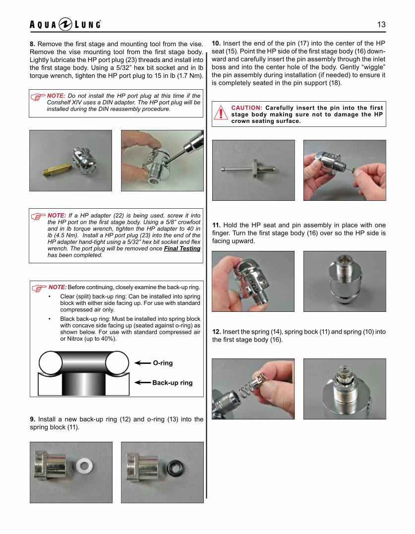
12. Insert the spring (14), spring bock (11) and spring (10) into the first stage body (16).
8. Remove the first stage and mounting tool from the vise. Remove the vise mounting tool from the first stage body. Lightly lubricate the HP port plug (23) threads and install into the first stage body. Using a 5/32” hex bit socket and in lb torque wrench, tighten the HP port plug to 15 in lb (1.7 Nm).
O-ring
Back-up ring
NOTE: Before continuing, closely examine the back-up ring. • Clear (split) back-up ring: Can be installed into spring
block with either side facing up. For use with standard compressed air only.
• Black back-up ring: Must be installed into spring block with concave side facing up (seated against o-ring) as shown below. For use with standard compressed air or Nitrox (up to 40%).
11. Hold the HP seat and pin assembly in place with one finger. Turn the first stage body (16) over so the HP side is facing upward.
10. Insert the end of the pin (17) into the center of the HP seat (15). Point the HP side of the first stage body (16) down-ward and carefully insert the pin assembly through the inlet boss and into the center hole of the body. Gently “wiggle” the pin assembly during installation (if needed) to ensure it is completely seated in the pin support (18).
CAUTION: Carefully insert the pin into the first stage body making sure not to damage the HP crown seating surface.
9. Install a new back-up ring (12) and o-ring (13) into the spring block (11).
NOTE: Do not install the HP port plug at this time if the Conshelf XIV uses a DIN adapter. The HP port plug will be installed during the DIN reassembly procedure.
NOTE: If a HP adapter (22) is being used, screw it into the HP port on the first stage body. Using a 5/8” crowfoot and in lb torque wrench, tighten the HP adapter to 40 in lb (4.5 Nm). Install a HP port plug (23) into the end of the HP adapter hand-tight using a 5/32” hex bit socket and flex wrench. The port plug will be removed once Final Testing has been completed.
14 Conshelf XIV Technical Manual
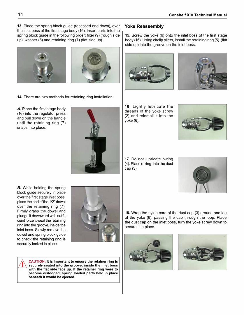
18. Wrap the nylon cord of the dust cap (3) around one leg of the yoke (6), passing the cap through the loop. Place the dust cap on the inlet boss, turn the yoke screw down to secure it in place.
15. Screw the yoke (6) onto the inlet boss of the first stage body (16). Using circlip pliers, install the retaining ring (5) (flat side up) into the groove on the inlet boss.
16. Lightly lubricate the threads of the yoke screw (2) and reinstall it into the yoke (6).
Yoke Reassembly
CAUTION: It is important to ensure the retainer ring is securely seated into the groove, inside the inlet boss with the flat side face up. If the retainer ring were to become dislodged, spring loaded parts held in place beneath it would be ejected.
17. Do not lubricate o-ring (4). Place o-ring into the dust cap (3).
13. Place the spring block guide (recessed end down), over the inlet boss of the first stage body (16). Insert parts into the spring block guide in the following order: filter (9) (rough side up), washer (8) and retaining ring (7) (flat side up).
14. There are two methods for retaining ring installation:
A. Place the first stage body (16) into the regulator press and pull down on the handle until the retaining ring (7) snaps into place.
B. While holding the spring block guide securely in place over the first stage inlet boss, place the end of the 1/2” dowel over the retaining ring (7). Firmly grasp the dowel and plunge it downward with suffi-cient force to seat the retaining ring into the groove, inside the inlet boss. Slowly remove the dowel and spring block guide to check the retaining ring is securely locked in place.
15
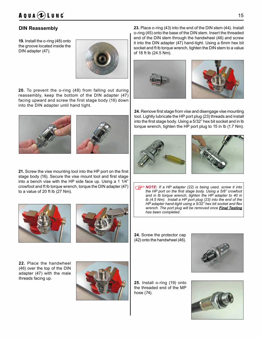
21. Screw the vise mounting tool into the HP port on the first stage body (16). Secure the vise mount tool and first stage into a bench vise with the HP side face up. Using a 1 1/4” crowfoot and ft lb torque wrench, torque the DIN adapter (47) to a value of 20 ft lb (27 Nm).
22. Place the handwheel (46) over the top of the DIN adapter (47) with the male threads facing up.
DIN Reassembly
19. Install the o-ring (48) onto the groove located inside the DIN adapter (47).
20. To prevent the o-ring (48) from falling out during reassembly, keep the bottom of the DIN adapter (47) facing upward and screw the first stage body (16) down into the DIN adapter until hand tight.
24. Screw the protector cap (42) onto the handwheel (46).
23. Place o-ring (43) into the end of the DIN stem (44). Install o-ring (45) onto the base of the DIN stem. Insert the threaded end of the DIN stem through the handwheel (46) and screw it into the DIN adapter (47) hand-tight. Using a 6mm hex bit socket and ft lb torque wrench, tighten the DIN stem to a value of 18 ft lb (24.5 Nm).
25. Install o-ring (19) onto the threaded end of the MP hose (74).
24. Remove first stage from vise and disengage vise mounting tool. Lightly lubricate the HP port plug (23) threads and install into the first stage body. Using a 5/32” hex bit socket and in lb torque wrench, tighten the HP port plug to 15 in lb (1.7 Nm).
NOTE: If a HP adapter (22) is being used, screw it into the HP port on the first stage body. Using a 5/8” crowfoot and in lb torque wrench, tighten the HP adapter to 40 in lb (4.5 Nm). Install a HP port plug (23) into the end of the HP adapter hand-tight using a 5/32” hex bit socket and flex wrench. The port plug will be removed once Final Testing has been completed.

16 Conshelf XIV Technical Manual
2. Place the poppet (62) and spring (63) onto poppet wrench, and carefully insert into the box bottom (64). Screw the poppet wrench all the way into the box bottom, so the stem of the poppet protrudes into the interior of the box bottom.
Second Stage Reassembly
1. Press the new MP seat (61) into the cavity in the head of the poppet (62). Place the spring (63) over the poppet shaft.
3. Place the washer (67) (flat side down), spacer (69), and locknut (70) onto the poppet (62). Screw the locknut onto the poppet until the first threads are engaged.
4. Insert the lever (68) between the washer (67) and spacer (69). Ensure that the lever is properly aligned in its groove inside the box bottom (64).
NOTE: If servicing a Conshelf XIV octopus, be sure to use the octopus spring. It is slightly shorter and has fewer turns than the standard Conshelf XIV spring. After 04/12 the octopus spring was changed to a dark blue color for identification purposes.
108514
New Octo Spring
108504
Reg Spring
108514
Old Octo Spring
5. Locknut AdjustmentA. Second stage w/o port plugWhile holding the locknut (70) with the 1/4” box end wrench, turn the poppet wrench clockwise until about three threads of the poppet (62) are visible beyond the head of the locknut. Remove the 1/4” wrench and poppet wrench from the box bottom (64).
B. Second stage with port plugInsert the LHAT 1/4” nut driver through the open port plug and hold the locknut (70). Turn the poppet wrench clockwise until about three threads of the poppet (62) are visible beyond the head of the locknut. Remove the nut driver and poppet wrench from the box bottom (64).
6. Install o-ring (60) onto the inlet fitting (59). Depress the lever (68) and screw the inlet fitting (59) into the box bottom (64) hand-tight. Using a 3/4” socket and in lb. torque wrench, tighten the inlet fitting to 55 in lb (6.2 Nm).
CAUTION: Failure to depress the lever while screwing the inlet fitting into the box bottom will cause damage to the MP seat, resulting in replacement of the part.

17
A. Second stage w/ port plug.Insert the LHAT 1/4” nut driver through the open port and hold the locknut (70). Insert the LHAT screwdriver through the center of the nut driver and into the end of the poppet. While holding the poppet still with the screwdriver, turn the nut driver to correct the lever height or eliminate excessive “free-play”.
7. Check to ensure the top of the lever (68) is flush with the top of the box bottom (64). Lay a straight edge or “sight” across the top of the box bottom to confirm correct lever height. If the top of the lever is below the top of the box bottom, or there is excessive “free play” in the lever, use the following adjustment procedure:
B. Second stage w/o port plug:Hold the poppet stem with a small, bent shank screw-driver and turn the lock-nut (70) with a 1/4” open end wrench. Adjust only far enough to correct the lever height or eliminate excessive “free-play”.
10. Press the purge button (50) assembly through the box top (52) and use circlip pliers to install the retaining ring (55) in place. Ensure that the flat edge of the retaining ring faces up.
9. Rotate the spring (51), small end first, onto the purge button (50).
11. Heat the exhaust tee (57) in hot water at 200°F; then stretch it over the flange of the box bottom (64).
8. Insert the exhalation valve (58) into the box bottom (64) and pull on the stem of the valve until its barb passes through the hole into the box bottom. Using diagonal pliers, trim the stem end of the valve 1/8” to 1/4” above the barb.
WARNING: Flooding of the second stage may occur if the exhaust valve is folded under or the barb on the stem is not pulled through the hole in the exhaust port all the way.
12. Install the mouthpiece (72) onto the box bottom (64). Loosely fasten a strap clamp (71) into the groove at the base of the mouthpiece with the tab on the MP hose side. Pull the strap clamp tight and trim the excess strap flush using diagonal pliers.
CAUTION: DO NOT try to “twist” the exhaust tee onto the box bottom. Doing so will cause damage to the part resulting in it having to be replaced.
18 Conshelf XIV Technical Manual
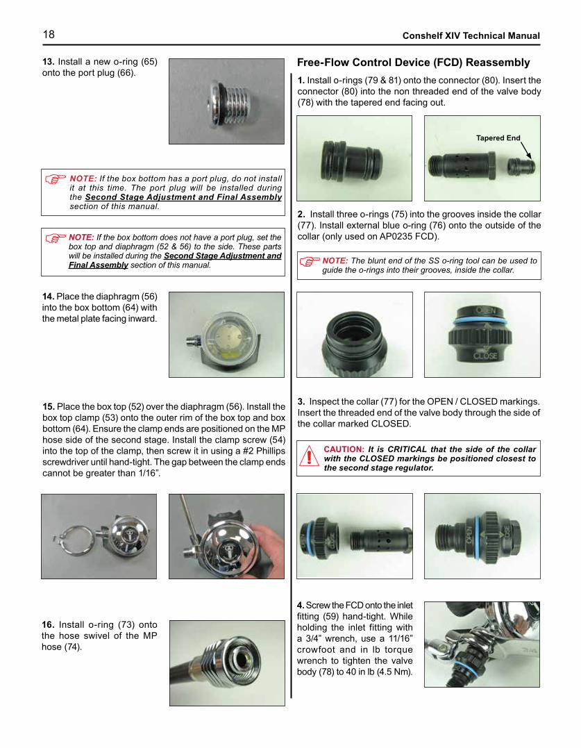
NOTE: If the box bottom does not have a port plug, set the box top and diaphragm (52 & 56) to the side. These parts will be installed during the Second Stage Adjustment and Final Assembly section of this manual.
CAUTION: It is CRITICAL that the side of the collar with the CLOSED markings be positioned closest to the second stage regulator.
4. Screw the FCD onto the inlet fitting (59) hand-tight. While holding the inlet fitting with a 3/4” wrench, use a 11/16” crowfoot and in lb torque wrench to tighten the valve body (78) to 40 in lb (4.5 Nm).
16. Install o-ring (73) onto the hose swivel of the MP hose (74).
NOTE: If the box bottom has a port plug, do not install it at this time. The port plug will be installed during the Second Stage Adjustment and Final Assembly section of this manual.
15. Place the box top (52) over the diaphragm (56). Install the box top clamp (53) onto the outer rim of the box top and box bottom (64). Ensure the clamp ends are positioned on the MP hose side of the second stage. Install the clamp screw (54) into the top of the clamp, then screw it in using a #2 Phillips screwdriver until hand-tight. The gap between the clamp ends cannot be greater than 1/16”.
1. Install o-rings (79 & 81) onto the connector (80). Insert the connector (80) into the non threaded end of the valve body (78) with the tapered end facing out.
Free-Flow Control Device (FCD) Reassembly
2. Install three o-rings (75) into the grooves inside the collar (77). Install external blue o-ring (76) onto the outside of the collar (only used on AP0235 FCD).
NOTE: The blunt end of the SS o-ring tool can be used to guide the o-rings into their grooves, inside the collar.
3. Inspect the collar (77) for the OPEN / CLOSED markings. Insert the threaded end of the valve body through the side of the collar marked CLOSED.
Tapered End
13. Install a new o-ring (65) onto the port plug (66).
14. Place the diaphragm (56) into the box bottom (64) with the metal plate facing inward.

19
1. Screw the MP hose into the open MP port on the first stage body (16). Using a 9/16” crowfoot and in lb torque wrench, tighten the MP hose to 40 in lb (4.5 Nm).
2. Screw the MP test gauge onto the MP hose until hand-tight. Attach the first stage to a fully charged 3000 PSI (207 BAR) cylinder. Open the bleed valve on the test gauge and slowly open the cylinder valve. While watching the test gauge, slowly close the bleed valve.
• If a stable MP has been achieved, note the pressure indicated on the test gauge. Cycle the bleed valve sev-eral times and closely monitor the test gauge for several minutes, making sure the MP has remained stable.
• If the MP exceeds 145 PSI (10 BAR) standard / 130 PSI (9 BAR) supreme or “creeps”, quickly open the bleed valve and close the cylinder valve as this indicates a HP leak. Refer to Table 1: Troubleshooting Guide section of this manual to determine its possible cause.
NOTE: The correct MP is as follows, with an inlet pressure of 3000 PSI (207 BAR).Conshelf XIV: 140 ± 5 PSI (10 ± 0.34 BAR)Conshelf XIV Supreme: 125 ± 5 PSI (9 ± 0.34 BAR)
3. If adjustment to the MP is required, insert the modified screwdriver or 6mm hex bit socket (dry kit only) into the adjustment screw. Slowly turn the adjustment screw in 1/8” increments (clockwise to increase or counter-clockwise to decrease) to adjust the MP. Cycle the bleed valve and monitor the test gauge after each adjustment. Set MP to Standard 140 ± 5 PSI (10 ± 0.34 BAR) / Supreme 125 ± 5 PSI (9 ± 0.34 BAR).
• When a stable MP has been achieved, note the pressure indicated on the test gauge. Cycle the bleed valve several times and closely monitor the test gauge for several min-utes, making sure the MP has remained stable.
• If the MP rises more than 5 PSI (0.34 BAR) in 5-15 seconds after cycling the bleed valve, this indicates a HP leak. Refer to Table 1: Troubleshooting Guide section of this manual to determine its possible cause.
NOTE: If the regulator is a standard Conshelf XIV, proceed to Second Stage Adjustment and Final Assembly. If the regulator is a Conshelf XIV Supreme, proceed to Environ-mental Kit Installation.
NormalConcave
Environmental Kit Installation
To convert a standard Conshelf XIV to a supreme version, perform the following procedures while the regulator is pressurized.
• Verify the regulator MP (125 ± 5 PSI / 9 ± 0.34 BAR) is correct prior to installing the conversion kit.
• While the regulator is pressurized to 3000 PSI (207 BAR), pour silicone fluid into the spring retainer (31) until the level reaches 1/8” below the top of the retainer. Wait for the trapped air bubbles to work out and recheck the silicone fluid level.
• Insert the secondary diaphragm (32) into the spring retainer (31) with the concave side down. The diaphragm must be covered with silicone to function properly.
• Using your finger, smooth out the secondary diaphragm (32) to remove any trapped air bubbles beneath.
• Using the supreme retainer wrench, install the diaphragm retainer (33) onto the spring retainer (31) until hand-tight.
• Close the cylinder valve and depressurize the regulator by opening the bleed valve on the test gauge. Repressurize the regulator and verify the MP has remained unchanged. Depressurize system & remove test gauge when finished.
CAUTION: Attempting to perform the following procedure while the first stage is not pressurized will result in excessive strain on the secondary diaphragm and incorrect MP.
Conshelf XIV Supreme (Silicone Fluid)WARNING: Compressed air can be highly explosive and is dangerous if misused. Ensure the cylinder valve is opened slowly. Use eye and ear personal protective equipment when performing any tests involving compressed air.
4. Close the cylinder valve and open the bleed valve on the test gauge to depressurize the system. Remove the test gauge from the MP hose (74).
First Stage Adjustment (MP) and Final Assembly
WARNING: Be certain not to install a MP hose into the HP port via an adapter. Doing so may cause the hose to rupture when pressurized and could result in serious personal injury.
NOTE: When the regulator is depressurized, the secondary diaphragm will appear slightly concave. When repressurized the secondary diaphragm will return to normal.

20 Conshelf XIV Technical Manual
Environmental Kit Installation
To convert a standard Conshelf XIV to a supreme version, perform the following procedures while the regulator is pressurized.
• Verify the regulator MP (125 ± 5 PSI / 9 ± 0.34 BAR) is correct prior to installing the conversion kit.
• While the regulator is pressurized to 3000 PSI (207 BAR), insert the stem of the piston (38) into the hex opening of the adjustment screw (37).
• Insert the external diaphragm (40) into the diaphragm retainer (41). Press the diaphragm down past the threads of the retainer, making sure it sits evenly against the sealing surface.
• Using the supreme retainer wrench, install the diaphragm retainer (41) onto the spring retainer (35) until hand-tight.
• Close the cylinder valve and depressurize the regulator by opening the bleed valve on the test gauge. Repressurize the regulator and verify the MP has remained unchanged. Depressurize system & remove test gauge when finished.
CAUTION: Attempting to perform the following procedure while the first stage is not pressurized will result in excessive strain on the secondary diaphragm and incorrect MP.
Conshelf XIV Supreme (Dry Kit)
NOTE: When the regulator is depressurized, the secondary diaphragm will appear slightly concave. When repressurized the secondary diaphragm will return to normal.
NormalConcave
3. Lever AdjustmentA. Second stage without port plugInsert a bent shank screwdriver into the end of the poppet (62) while using a 1/4” open end wrench to adjust the locknut (70). Slowly turn the locknut (clockwise to tighten or counter-clockwise to loosen) in 1/4 increments until a slight leak can be heard. Once a slight leak has been established, turn the locknut counter-clockwise until the leak stops. Purge the second stage intermittently between adjustments. Once the leak can no longer be heard, turn the locknut an additional 1/4 turn counter-clockwise. Reinstall the diaphragm and box top onto the box bottom and press the purge button several times to ensure no leaks are present. If no leaks are de-tected and purge flow is good, reinstall the box top clamp and clamp screw.
B. Second stage with port plugInsert the LHAT nut driver through the port and onto the locknut (70). Place the LHAT screwdriver through the center of the nut driver, into the end of the poppet (62). Hold the screwdriver while using the nut driver to adjust the locknut. Slowly turn the locknut (clockwise to tighten or counter-clockwise to loosen) in 1/4 increments until a slight leak can be heard. Once a slight leak has been es-tablished, turn the locknut counter-clockwise until the leak stops. Purge the second stage intermittently between ad-justments. Once the leak can no longer be heard, turn the locknut an additional 1/4 turn counter-clockwise. Press the purge button several times to ensure no leaks are present. If no leaks are detected and purge flow is good, reinstall the port plug (66) into the box bottom (64). Using a in lb torque wrench and 5/32” hex bit socket, tighten the port plug to 15 in lb (1.7 Nm).
Second Stage Adjustment and Final Assembly
1. Screw the MP hose (74) onto the FCD valve body (78). While holding the valve body with a 11/16” wrench, use a 11/16” crowfoot and in lb torque wrench to tighten the MP hose fitting to 40 in lb (4.5 Nm).
2. Attach the first stage to a fully charged 3000 PSI (207 BAR) cylinder. Ensure the FCD is in the OPEN position and slowly pressurize the regulator. Adjust the lever as follows:

21
FINAL TESTING
Subjective Test
WARNING: It is very critical to ensure that no leak-age is present and the Conshelf XIV regulator has met all requirements in the Final Testing section of this manual. DO NOT issue a Conshelf XIV regulator which exhibits any signs of leakage or unsatisfactory performance until the problem has been thoroughly diagnosed and repairs have been made as needed, including the possible replacement of a damaged component or subassembly.
1. Attach the first stage to a fully charged 3000 PSI (207 BAR) cylinder and slowly pressurize the regulator.
2. Press the purge button (50) two times for about five seconds each, with a five second pause between each purge. Ensure no leaks can be heard coming from the second stage. If a leak is detected, refer to Table 1 & 2: Trouble Shooting Guides section of this manual to determine its possible cause.
3. Perform a subjective breathing test to ensure the second stage is operating properly using the following procedure:
• Fully depress the purge button (50) to ensure an adequate volume of air passes through the second stage to clear out any water.
• Inhale slowly but deeply from the second stage. A prop-erly serviced and adjusted regulator should deliver air upon deep inhalation without excessive effort, free-flow or fluttering of the second stage diaphragm (56). When exhaling, there should be no fluttering or sticking of the exhaust valve (58). If any of these problems occur, refer to Table 1 & 2: Trouble Shooting Guides section of this manual to determine its possible cause.
Immersion Test
1. Ensure the first stage is attached to a fully charged 3000 PSI (207 BAR) cylinder and slowly pressurize the regulator.
NOTE: Do not confuse bubbles from trapped air with a true leak. If a true leak is detected, bubbles will come out in a constant stream.
2. Submerge the entire system in a test tank of clean water. Shake the unit to remove trapped bubbles. Observe any bubbles rising from the submerged system over a five minute period. The recommended time is necessary due to slower bubble formation that occurs in smaller leaks. Bubbles indicate a leak, which requires the system to be disassembled at the source to check sealing surfaces, assembly sequence and component positioning in order to correct the problem. If a leak is detected, refer to Table 1 & 2: Troubleshooting Guides section of this manual to determine its possible cause.
3. Upon completion of the immersion test, ensure all water is removed from the regulator. Wipe the entire system dry with a clean towel. Press the purge button (50) to blow any remaining water out of the second stage.
5. Providing the regulator has passed all requirements in Final Testing, the Conshelf XIV is now ready for use.
4. Slide the collar (77) on the FCD to the CLOSED position. Fully depress the purge button, no airflow should be coming from the second stage. If any airflow is heard coming from the second stage, refer to Table 2: Trouble Shooting Guide section of this manual to determine its possible cause. Slide the collar on the FCD back to the OPEN position when finished.
NOTE: Unless otherwise instructed, ensure the FCD is in the OPEN position while performing Final Testing.
NOTE: The Conshelf XIV must be cleaned and sanitized as per local instructions before use.
4. If a HP adapter is being used, remove HP port plug (23) from the end of the adapter using a 5/32” hex bit socket and flex wrench.

22 Conshelf XIV Technical Manual
TABLE 1: FIRST STAGE TROUBLE SHOOTING GUIDESYMPTOM POSSIBLE CAUSE TREATMENT
High or Unstable MP
1. HP seat (15) is worn or damaged 1. Replace HP seat
2. HP crown seating surface on body (16) is damaged 2. Replace body
3. Spring block o-ring (13) damaged or worn 3. Replace o-ring
4. Back-up ring (12) damaged or worn 4. Replace back-up ring
5. Spring block (11) internal wall is damaged 5. Replace spring block
6. Spring block springs (10 & 14) are weak or damaged 6. Replace springs
7. First stage MP is improperly adjusted 7. Readjust the adjustment screw (29 or 37)
External Air Leakage orSecondary diaphragm burst
1. Port plug o-rings (19 & 21) damaged or worn 1. Replace o-rings
2. Diaphragm (24a) worn or damaged 2. Replace diaphragm
3. Diaphragm seating surface inside first stage body is damaged 3. Replace body (16)
4. Secondary diaphragm (32 or 40) is damaged or worn 4. Replace diaphragm
5. DIN adapter o-ring (48) is damaged or worn 5. Replace o-ring
6. Stem o-ring (43) is worn or damaged 6. Replace o-ring
7. Spring retainer (26, 31, 35) is loose 7. Re-torque spring retainer
Restricted air flow or high inhalation resistance through entire system
1. Cylinder valve not completely open 1. Open valve; check fill pressure
2. Cylinder valve needs service 2. Switch to a different cylinder
3. Filter (9) clogged 3. Replace filter (9)
Low MP
1. First stage MP is improperly adjusted 1. Readjust the adjustment screw (29 or 37)
2. Spring (27, 30 or 36) is damaged or worn 2. Replace spring
3. Spring retainer (26, 31, 35) is loose 3. Re-torque spring retainer
23
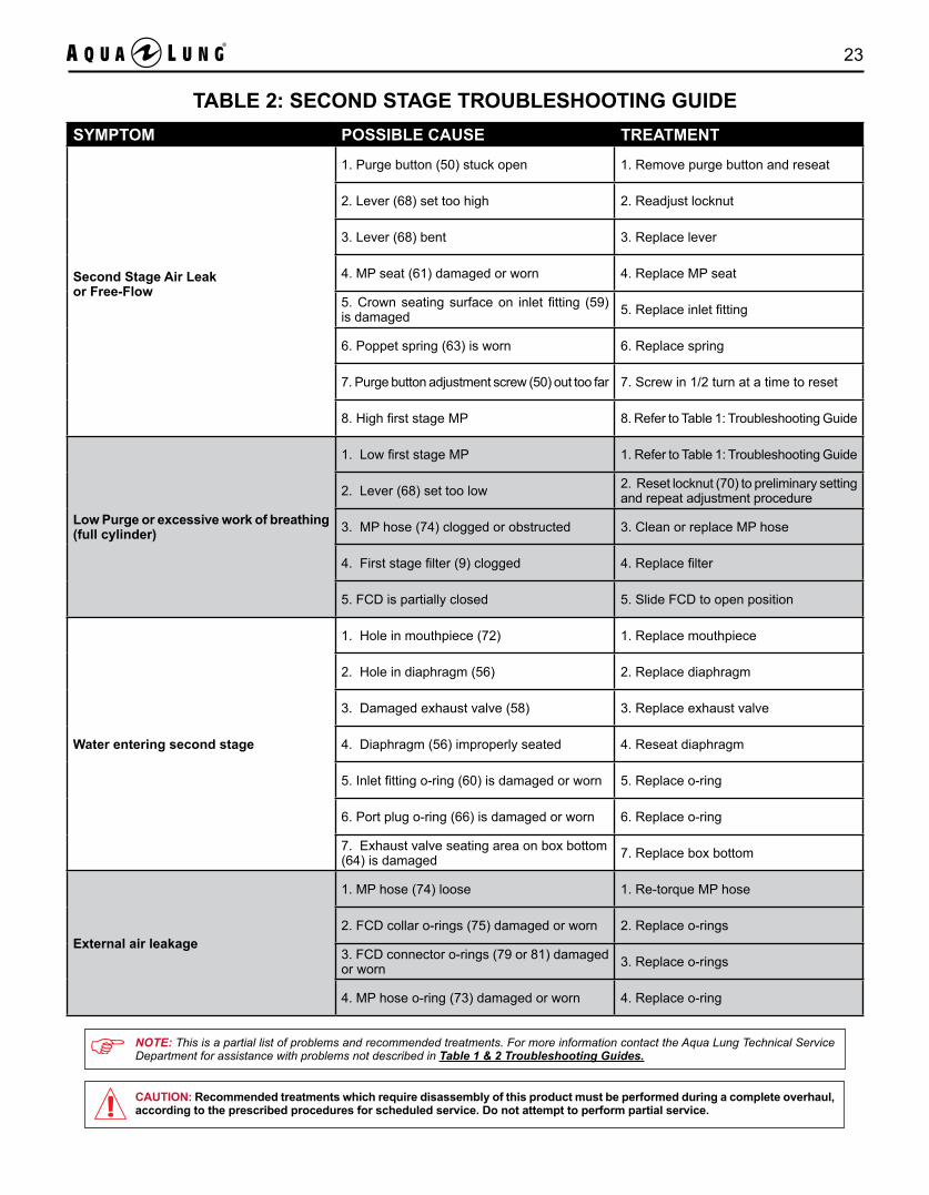
TABLE 2: SECOND STAGE TROUBLESHOOTING GUIDESYMPTOM POSSIBLE CAUSE TREATMENT
Second Stage Air Leak or Free-Flow
1. Purge button (50) stuck open 1. Remove purge button and reseat
2. Lever (68) set too high 2. Readjust locknut
3. Lever (68) bent 3. Replace lever
4. MP seat (61) damaged or worn 4. Replace MP seat
5. Crown seating surface on inlet fitting (59) is damaged 5. Replace inlet fitting
6. Poppet spring (63) is worn 6. Replace spring
7. Purge button adjustment screw (50) out too far 7. Screw in 1/2 turn at a time to reset
8. High first stage MP 8. Refer to Table 1: Troubleshooting Guide
Low Purge or excessive work of breathing (full cylinder)
1. Low first stage MP 1. Refer to Table 1: Troubleshooting Guide
2. Lever (68) set too low 2. Reset locknut (70) to preliminary setting and repeat adjustment procedure
3. MP hose (74) clogged or obstructed 3. Clean or replace MP hose
4. First stage filter (9) clogged 4. Replace filter
5. FCD is partially closed 5. Slide FCD to open position
Water entering second stage
1. Hole in mouthpiece (72) 1. Replace mouthpiece
2. Hole in diaphragm (56) 2. Replace diaphragm
3. Damaged exhaust valve (58) 3. Replace exhaust valve
4. Diaphragm (56) improperly seated 4. Reseat diaphragm
5. Inlet fitting o-ring (60) is damaged or worn 5. Replace o-ring
6. Port plug o-ring (66) is damaged or worn 6. Replace o-ring
7. Exhaust valve seating area on box bottom (64) is damaged 7. Replace box bottom
External air leakage
1. MP hose (74) loose 1. Re-torque MP hose
2. FCD collar o-rings (75) damaged or worn 2. Replace o-rings
3. FCD connector o-rings (79 or 81) damaged or worn 3. Replace o-rings
4. MP hose o-ring (73) damaged or worn 4. Replace o-ring
NOTE: This is a partial list of problems and recommended treatments. For more information contact the Aqua Lung Technical Service Department for assistance with problems not described in Table 1 & 2 Troubleshooting Guides.
CAUTION: Recommended treatments which require disassembly of this product must be performed during a complete overhaul, according to the prescribed procedures for scheduled service. Do not attempt to perform partial service.
24 Conshelf XIV Technical Manual
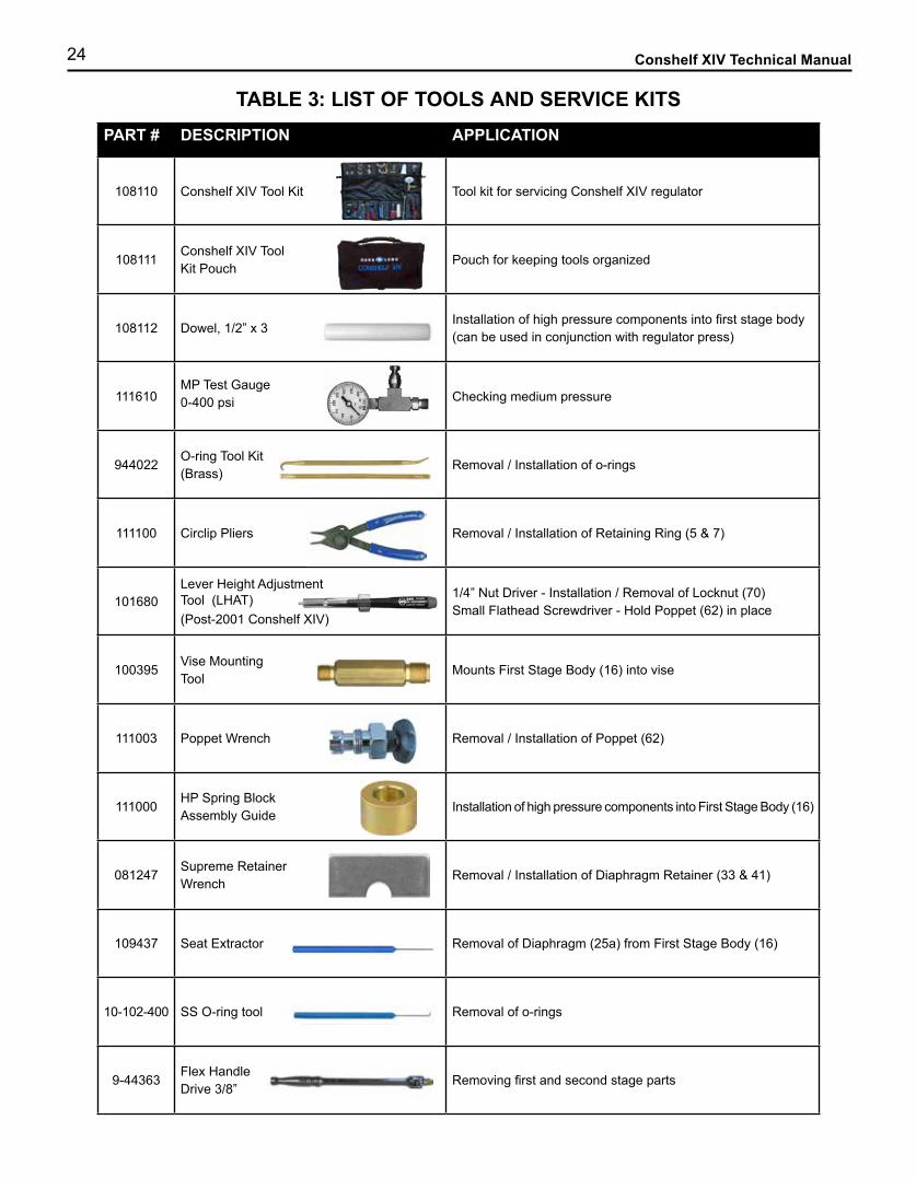
TABLE 3: LIST OF TOOLS AND SERVICE KITS PART # DESCRIPTION APPLICATION
108110 Conshelf XIV Tool Kit Tool kit for servicing Conshelf XIV regulator
108111Conshelf XIV Tool Kit Pouch
Pouch for keeping tools organized
108112 Dowel, 1/2” x 3Installation of high pressure components into first stage body(can be used in conjunction with regulator press)
111610MP Test Gauge0-400 psi Checking medium pressure
944022O-ring Tool Kit(Brass)
Removal / Installation of o-rings
111100 Circlip Pliers Removal / Installation of Retaining Ring (5 & 7)
101680Lever Height Adjustment Tool (LHAT)(Post-2001 Conshelf XIV)
1/4” Nut Driver - Installation / Removal of Locknut (70)Small Flathead Screwdriver - Hold Poppet (62) in place
100395Vise MountingTool
Mounts First Stage Body (16) into vise
111003 Poppet Wrench Removal / Installation of Poppet (62)
111000HP Spring Block Assembly Guide
Installation of high pressure components into First Stage Body (16)
081247Supreme Retainer Wrench
Removal / Installation of Diaphragm Retainer (33 & 41)
109437 Seat Extractor Removal of Diaphragm (25a) from First Stage Body (16)
10-102-400 SS O-ring tool Removal of o-rings
9-44363Flex HandleDrive 3/8”
Removing first and second stage parts

25
PART # DESCRIPTION APPLICATION
1030099-436239-43625FC40AFC44A
5/8” Crowfoot9/16” Crowfoot11/16” Crowfoot1 1/4” Crowfoot1 3/8” Crowfoot
Removal / Installation of HP Adapter (22)Removal / Installation of MP Hose (74) & FCD Valve Body (78)Removal / Installation of MP Hose and 7/16” to 3/8” Adapter (22)Removal / Installation of DIN Adaptor (50)Removal / Installation of Spring Retainer (26, 31 & 35)
5304A51 3/4” Wrench Removal of Inlet Fitting (59)
9-443339-43226
1/2” Socket3/4” Socket
Removal / Installation of Port Plug (20)Installation of Inlet Fitting (59)
9-47436#2 PhillipsScrewdriver
Removal / Installation of Clamp Screw (54)
941586ModifiedScrewdriver
Removal / Installation of Adjustment Screw (29)
5570A525/32” Hex Bit Socket
Removal / Installation of HP Port Plug (23) and Second Stage Port Plug (66)
8367A246 mm HexBit Socket
Removal / Installation of Adjustment Screw (37) and DIN Handwheel Stem (44)
8204662 oz. Tube Christo-Lube©
O-ring lubrication
9-45171Tool, Pliers Diagonal Cutters
Removal / Installation of Clamp Strap (71)
9-BA819008Magnifier w/ Illumination
Inspection of parts
108105Conshelf XIV Regulator Press
Installation of high pressure components into first stage body. (Not included in tool kit)
N/ATorque WrenchInch Pound
Apply torque to parts listed in Table 4: Torque Specifications (Not included in tool kit)
N/A 34 mm CrowfootRemoval / Installation of Spring Retainer (35) (Dry Kit Only)(Not included in tool kit)
TABLE 3: LIST OF TOOLS AND SERVICE KITS (CONTINUED)

26 Conshelf XIV Technical Manual
TABLE 3: LIST OF TOOLS AND SERVICE KITS (CONTINUED)
PART # DESCRIPTION APPLICATION
N/ATorque Wrench Foot Pound
Apply torque to parts listed in Table 4: Torque Specifications (Not included in tool kit)
N/ASmall Bent ShaftScrewdriver (Pre-2001 Conshelf XIV)
Adjustment of poppet (62)(Not included in tool kit)
N/A
N/A
1/4” Wrench(Pre-2001 Conshelf XIV)11/16” Wrench
Adjustment of locknut (70)
Removal / Installation of MP Hose (74) & FCD Valve Body (78)(Not included in tool kit)
108195 Service Kit, Conshelf XIV (First and Second Stage) Annual Service Kit Parts
105994108655108595
Service Kit, Conshelf XIV (First Stage Only)Service Kit, Conshelf XIV Supreme DIN (First Stage Only)Service Kit, Nitrox, Conshelf XIV (First Stage Only)
Annual Service Kit Parts
108592108596
Service Kit, Conshelf XIV (Second Stage Only)Service Kit, Nitrox, Conshelf XIV (Second Stage Only)
Annual Service Kit Parts
NOTE: Tools shown are representative and are not to scale. They are subject to change without notice.
TABLE 4: TORQUE SPECIFICATIONS
PART # DESCRIPTION / KEY ITEM # TORQUE
105326108851106317
Spring Retainer (26)Spring Retainer (supreme) (31)Spring Retainer (dry kit) (35)
25 ft lb (33.9 Nm)
106056 DIN Stem (44) 18 ft lb (24.5 Nm)
106057 DIN Adapter (47) 20 ft lb (27 Nm)
101785 HP Adapter 7/16” to 3/8” (22) 40 in lb (4.5 Nm)
103137 7/16” HP Port Plug (23) 15 in lb (1.7 Nm)
910912104304
3/8” MP Port Plug (20)3/8” MP Port Plug (N/S)
15 in lb (1.7 Nm)
100444 Inlet Fitting (59) 55 in lb (6.2 Nm)
102004 Box Bottom Port Plug (66) 15 in lb (1.7 Nm)
090015 / 090039 / 090025AP1491 / AP1491B
MP Hose (74) to Inlet Fitting (59)FCD Valve Body (78) to Inlet Fitting (59)MP Hose (74) to FCD Valve Body (78)MP Hose (74) to First Stage Body (16) or HP Adapter (22)
40 in lb (4.5 Nm)
27
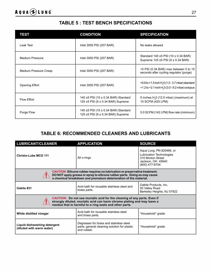
TABLE 5 : TEST BENCH SPECIFICATIONS
TEST CONDITION SPECIFICATION
Leak Test Inlet 3000 PSI (207 BAR) No leaks allowed
Medium Pressure Inlet 3000 PSI (207 BAR)Standard 140 ±5 PSI (10 ± 0.34 BAR) Supreme 125 ±5 PSI (9 ± 0.34 BAR)
Medium Pressure Creep Inlet 3000 PSI (207 BAR) +5 PSI (0.34 BAR) max between 5 to 15 seconds after cycling regulator (purge)
Opening Effort Inlet 3000 PSI (207 BAR)+0.6 to +1.5 inch H20 (1.5 - 3.7 mbar) standard+1.2 to +2.1 inch H20 (3.0 - 9.2 mbar) octopus
Flow Effort140 ±5 PSI (10 ± 0.34 BAR) Standard125 ±5 PSI (9 ± 0.34 BAR) Supreme
5 inches H20 (12.5 mbar) (maximum) at15 SCFM (425 LPM)
Purge Flow140 ±5 PSI (10 ± 0.34 BAR) Standard125 ±5 PSI (9 ± 0.34 BAR) Supreme
5.0 SCFM (142 LPM) flow rate (minimum)
TABLE 6: RECOMMENDED CLEANERS AND LUBRICANTS
LUBRICANT/CLEANER APPLICATION SOURCE
Christo-Lube MCG 111All o-rings
Aqua Lung, PN 820466, orLubrication Technologies 310 Morton Street Jackson, OH 45640 (800) 477-8704
Oakite #31 Acid bath for reusable stainless steel and brass parts.
Oakite Products, Inc. 50 Valley Road Berkeley Heights, NJ 07922
White distilled vinegar Acid bath for reusable stainless steel and brass parts. “Household” grade
Liquid dishwashing detergent (diluted with warm water)
Degreaser for brass and stainless steel parts; general cleaning solution for plastic and rubber.
“Household” grade
CAUTION: Do not use muriatic acid for the cleaning of any parts. Even if strongly diluted, muriatic acid can harm chrome plating and may leave a residue that is harmful to o-ring seals and other parts.
CAUTION: Silicone rubber requires no lubrication or preservative treatment. DO NOT apply grease or spray to silicone rubber parts. Doing so may cause a chemical breakdown and premature deterioration of the material.
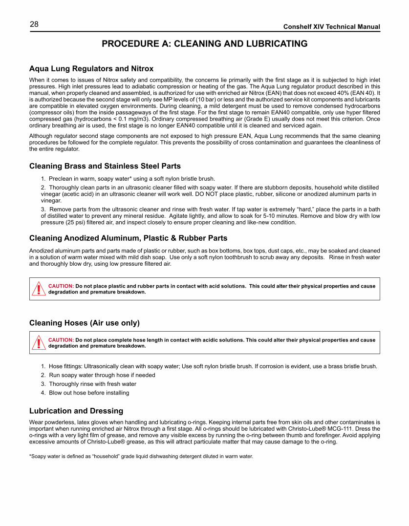
28 Conshelf XIV Technical Manual
Aqua Lung Regulators and NitroxWhen it comes to issues of Nitrox safety and compatibility, the concerns lie primarily with the first stage as it is subjected to high inlet pressures. High inlet pressures lead to adiabatic compression or heating of the gas. The Aqua Lung regulator product described in this manual, when properly cleaned and assembled, is authorized for use with enriched air Nitrox (EAN) that does not exceed 40% (EAN 40). It is authorized because the second stage will only see MP levels of (10 bar) or less and the authorized service kit components and lubricants are compatible in elevated oxygen environments. During cleaning, a mild detergent must be used to remove condensed hydrocarbons (compressor oils) from the inside passageways of the first stage. For the first stage to remain EAN40 compatible, only use hyper filtered compressed gas (hydrocarbons < 0.1 mg/m3). Ordinary compressed breathing air (Grade E) usually does not meet this criterion. Once ordinary breathing air is used, the first stage is no longer EAN40 compatible until it is cleaned and serviced again.
Although regulator second stage components are not exposed to high pressure EAN, Aqua Lung recommends that the same cleaning procedures be followed for the complete regulator. This prevents the possibility of cross contamination and guarantees the cleanliness of the entire regulator.
Cleaning Brass and Stainless Steel Parts1. Preclean in warm, soapy water* using a soft nylon bristle brush.2. Thoroughly clean parts in an ultrasonic cleaner filled with soapy water. If there are stubborn deposits, household white distilled vinegar (acetic acid) in an ultrasonic cleaner will work well. DO NOT place plastic, rubber, silicone or anodized aluminum parts in vinegar.3. Remove parts from the ultrasonic cleaner and rinse with fresh water. If tap water is extremely “hard,” place the parts in a bath of distilled water to prevent any mineral residue. Agitate lightly, and allow to soak for 5-10 minutes. Remove and blow dry with low pressure (25 psi) filtered air, and inspect closely to ensure proper cleaning and like-new condition.
Cleaning Anodized Aluminum, Plastic & Rubber PartsAnodized aluminum parts and parts made of plastic or rubber, such as box bottoms, box tops, dust caps, etc., may be soaked and cleaned in a solution of warm water mixed with mild dish soap. Use only a soft nylon toothbrush to scrub away any deposits. Rinse in fresh water and thoroughly blow dry, using low pressure filtered air.
Cleaning Hoses (Air use only)
1. Hose fittings: Ultrasonically clean with soapy water; Use soft nylon bristle brush. If corrosion is evident, use a brass bristle brush.2. Run soapy water through hose if needed3. Thoroughly rinse with fresh water4. Blow out hose before installing
Lubrication and DressingWear powderless, latex gloves when handling and lubricating o-rings. Keeping internal parts free from skin oils and other contaminates is important when running enriched air Nitrox through a first stage. All o-rings should be lubricated with Christo-Lube® MCG-111. Dress the o-rings with a very light film of grease, and remove any visible excess by running the o-ring between thumb and forefinger. Avoid applying excessive amounts of Christo-Lube® grease, as this will attract particulate matter that may cause damage to the o-ring.
*Soapy water is defined as “household” grade liquid dishwashing detergent diluted in warm water.
PROCEDURE A: CLEANING AND LUBRICATING
CAUTION: Do not place plastic and rubber parts in contact with acid solutions. This could alter their physical properties and cause degradation and premature breakdown.
CAUTION: Do not place complete hose length in contact with acidic solutions. This could alter their physical properties and cause degradation and premature breakdown.
29
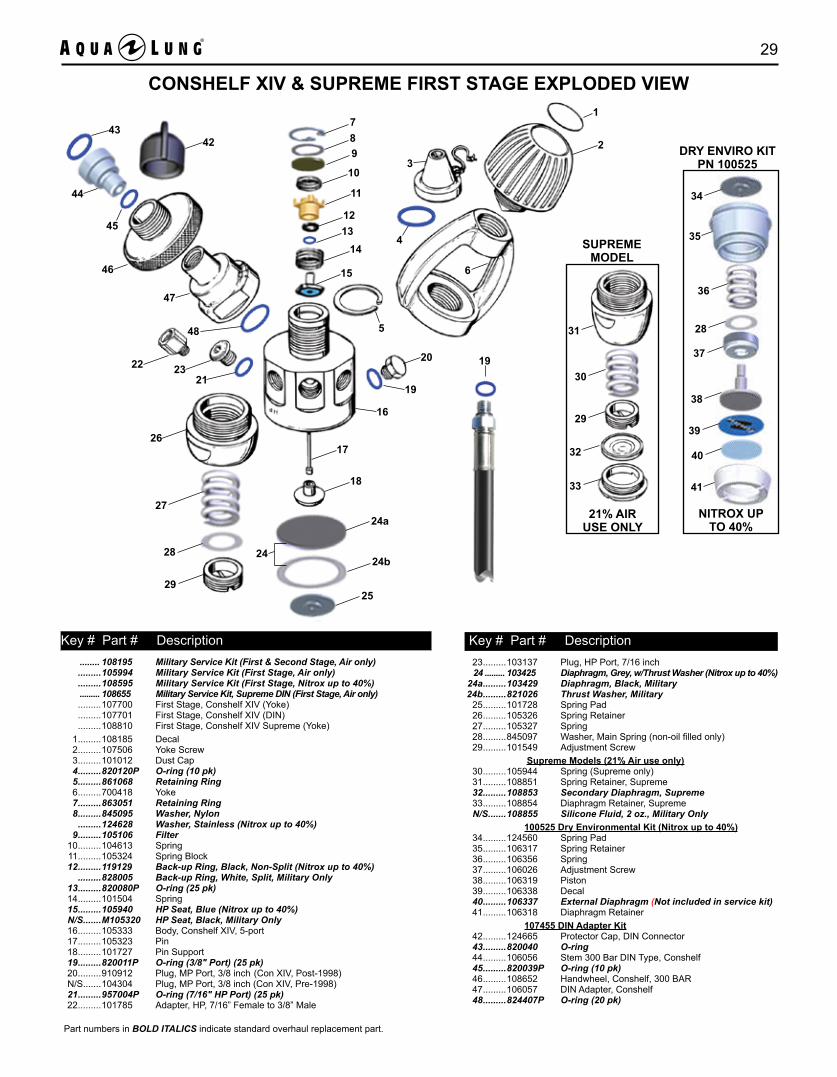
........ 108195 Military Service Kit (First & Second Stage, Air only) .........105994 Military Service Kit (First Stage, Air only) .........108595 Military Service Kit (First Stage, Nitrox up to 40%) ......... 108655 Military Service Kit, Supreme DIN (First Stage, Air only) .........107700 First Stage, Conshelf XIV (Yoke) .........107701 First Stage, Conshelf XIV (DIN) .........108810 First Stage, Conshelf XIV Supreme (Yoke) 1 .........108185 Decal 2 .........107506 Yoke Screw 3 .........101012 Dust Cap 4 .........820120P O-ring (10 pk) 5 .........861068 Retaining Ring 6 .........700418 Yoke 7 .........863051 Retaining Ring 8 .........845095 Washer, Nylon .........124628 Washer, Stainless (Nitrox up to 40%) 9 .........105106 Filter 10 .........104613 Spring 11 .........105324 Spring Block 12 .........119129 Back-up Ring, Black, Non-Split (Nitrox up to 40%) .........828005 Back-up Ring, White, Split, Military Only 13 .........820080P O-ring (25 pk) 14 .........101504 Spring 15 .........105940 HP Seat, Blue (Nitrox up to 40%) N/S.......M105320 HP Seat, Black, Military Only 16 .........105333 Body, Conshelf XIV, 5-port 17 .........105323 Pin 18 .........101727 Pin Support 19 .........820011P O-ring (3/8" Port) (25 pk) 20 .........910912 Plug, MP Port, 3/8 inch (Con XIV, Post-1998) N/S.......104304 Plug, MP Port, 3/8 inch (Con XIV, Pre-1998) 21 .........957004P O-ring (7/16" HP Port) (25 pk) 22 .........101785 Adapter, HP, 7/16” Female to 3/8” Male
23 .........103137 Plug, HP Port, 7/16 inch 24 ......... 103425 Diaphragm, Grey, w/Thrust Washer (Nitrox up to 40%) 24a .........103429 Diaphragm, Black, Military 24b .........821026 Thrust Washer, Military 25 .........101728 Spring Pad 26 .........105326 Spring Retainer 27 .........105327 Spring 28 .........845097 Washer, Main Spring (non-oil filled only) 29 .........101549 Adjustment Screw Supreme Models (21% Air use only) 30 .........105944 Spring (Supreme only) 31 .........108851 Spring Retainer, Supreme 32 .........108853 Secondary Diaphragm, Supreme 33 .........108854 Diaphragm Retainer, Supreme N/S.......108855 Silicone Fluid, 2 oz., Military Only 100525 Dry Environmental Kit (Nitrox up to 40%) 34 .........124560 Spring Pad 35 .........106317 Spring Retainer 36 .........106356 Spring 37 .........106026 Adjustment Screw 38 .........106319 Piston 39 .........106338 Decal 40 .........106337 External Diaphragm (Not included in service kit) 41 .........106318 Diaphragm Retainer 107455 DIN Adapter Kit 42 .........124665 Protector Cap, DIN Connector 43 .........820040 O-ring 44 .........106056 Stem 300 Bar DIN Type, Conshelf 45 .........820039P O-ring (10 pk) 46 .........108652 Handwheel, Conshelf, 300 BAR 47 .........106057 DIN Adapter, Conshelf 48 .........824407P O-ring (20 pk)
SUPREMEMODEL
21% AIRUSE ONLY
31
30
29
32
33
DRY ENVIRO KITPN 100525
NITROX UP TO 40%
41
40
39
38
37
28
36
35
34
Key # Part # Description Key # Part # Description
789
10
11
1213
14
15
5
3
4
1
2
6
17
18
20
19
24a
24b
25
2428
29
27
26
2123
16
46
47
44
45
4342
48
22
CONSHELF XIV & SUPREME FIRST STAGE EXPLODED VIEW
Part numbers in BOLD ITALICS indicate standard overhaul replacement part.
19

30 Conshelf XIV Technical Manual
......... 108195 Military Service Kit (First & Second Stage, Air only) .........108592 Military Service Kit (Second Stage, Air only) .........108596 Military Service Kit (Second Stage, Nitrox up to 40%) .........108530 Conshelf XIV Second Stage .........108538 Conshelf XIV Supreme Second Stage
49 .........108185 Decal, Conshelf XIV .........106188 Decal, Octo, Conshelf XIV 50 .........103706 Purge Button w/ Adjustment Screw 51 .........102708 Purge Spring 52 .........107001 Box Top 53 .........390147 Box Top Clamp 54 .........834023 Clamp Screw 55 .........860037 Retaining Ring 56 .........103732 Demand Diaphragm (U.S. Military Only) 57 .........101919 Exhaust Tee 58 .........105139 Exhaust Valve 59 .........100444 Inlet Fitting 60 .........820014P O-ring (25 pk) 61 .........108510 MP Seat, Black
62 .........104903 Poppet 63 .........108504 Spring (Standard) .........108514 Spring (Octopus, Blue) 64 .........108122 Box Bottom .........108535 Box Bottom Kit (includes 57, 64, 65 & 66) 65 .........957025P O-ring (10 pk) 66 .........102004 Plug 67 .........107607 Washer 68 .........107605 Lever 69 .........107606 Spacer 70 .........102510 Locknut 71 .........104940 Clamp, Clear .........104913 Clamp, Black 72 .........105884 Comfo Bite Mouthpiece, Clear .........105885 Comfo Bite Mouthpiece, Black .........105879 Standard Mouthpiece, Black 73 .........820010P O-ring (25 pk) 74 .........090015 MP Hose, 3/8” x 30” Black .........090039 MP Hose, 3/8” x 39” Yellow .........090025 MP Hose, 3/8” x 39” Black
Part numbers in BOLD ITALICS indicate standard overhaul replacement part
Key # Part # Description Key # Part # Description
CONSHELF XIV SECOND STAGE EXPLODED VIEW
737454
6855
56
53
52
49
50
51
6566
57
58
63
626160
*64
72
71
5967
69 70
*NOTE: When replacing a Conshelf XIV box bottom (64) manufactured before January ‘97 which does not feature an external lever height adjustment port, it is also necessary to order the exhaust tee, o-ring and port plug (items 57, 65 & 66). These four items are available in kit form, PN 108535.

31
.........AP0233 Free-flow Control Device (FCD) .........AP0235 Free-flow Control Device, Black (FCD)
75 .........AP1300P O-ring (10 pk) 76 .........AP1298P O-ring (Blue) (10 pk) 77 .........AP1492 Collar (Silver) .........AP1499 Collar (Black) 78 .........AP1491 Valve Body .........AP1491b Valve Body 79 .........AP1409 O-ring (10 pk) 80 .........AP1490 Connector 81 .........AP1154P O-ring (10 pk)
Key # Part # Description
FREE-FLOW CONTROL DEVICE (FCD)
Part numbers in BOLD ITALICS indicate standard overhaul replacement part.
75
75
79
80
81
75
77
78
76
2340 Cousteau Court • Vista, CA 92081Phone (760) 597-5000 • Fax (760) 597-4900www.aqualung.com/militaryandprofessional
Blue = Pantone 2728C
Primary/Preferred Branding
Secondary Branding
Tertiary Branding
Conshelf XIVTechnical Manual
©2017 Aqua Lung International