considerations for implementing a zone-selective...
TRANSCRIPT

Considerations for Implementing a Zone-Selective Interlocking
Scheme on Medium and Low Voltage Systems
Matt Proctor– GE Grid Automation
2018 –Houston IEEE
1

Zone-Selective InterlockingUsed when time-overcurrent delay is unacceptable. “Chronometric coordination”
There is an inherent consequence in using coordinated time-overcurrent protection. It can be very slow. ZSI can be applied when time-overcurrent delay is not acceptable.- Applied to lines or buses.
2

Zone-Selective Interlocking
Some form of Inter-IED signaling is required. Chronometric coordination + location logic.
51
B1
50
B2
5150
B3
5150
F1
F2
Upstream 50 MUSThave some time delay to allow time to block.
Configure and apply time-overcurrent protection as normal. It still serves as a backup.For fault F1, B2 relay would initiate a blocking signal to prevent the B1 50 from tripping.For fault F2, B1 50 would not be blocked, and it would be allowed to trip fast, without the typical time-coordination delay.
3

Zone-Selective Interlocking - Hardwiring
Mechanical relay contacts can take approximately 4 msto 10 ms to operate.
Solid-state contacts can take approximately 0.1 ms to operate but have leakage current. Beware false-positives!
Zone selective schemes did not come into existence because of modern digital relaying. “Location Logic” can be implemented with hardwiring.Where available, solid state relay contacts can be used to expedite signaling, but beware the adverse effects of the snubber circuitry.
4

Zone-Selective Interlocking - Hardwiring
Fails into fast, non-selective (protective) mode.LV trip units always fail this way!
Fails into slow but selective mode.
Implemented in relays, failure mode is selectable
In a hardwired scheme, selection of the failure mode can be done by applying normally open or normally closed contacts.
5

Zone-Selective Interlocking - Hardwiring
Additional logic can become cumbersome with hardwiring.
M1TRIP
M151
M152 a
M150
TD Time Delay Relay
TD
-DC
+DC
50 – F1F1
TOC
50 – F2F2
TOC
(disconnected position shown)
(disconnected position shown)
This hardwiring shows the restraining relays being removed from the circuit when the breaker is racked out of position. You wouldn’t want to affect your ZSI when you are pushing test currents through a relay whose breaker is racked out. Notice that wiring could get complicated as buses get larger.
6

Zone-Selective Interlocking - Comms
• Communications can be used to simplify wiring.
• Count on 4ms delay for priority GOOSE messages.
• Tripping device has a finite # of devices to which it can subscribe.
Beware proprietary protocols because of possible timing variance. By 61850 standard, a GOOSE message is transmitted, received and parsed in ¼ of a cycle.Be aware that complex network architectures could introduce scenarios where unwanted messaging delay can occur.Comms greatly reduces hardwiring complexity and offers greater flexibility to change the scheme’s implementation.It’s a good idea to monitor comms with an actionable loss of comms alarm.
7

Zone-Selective Interlocking - Comms
Downstream IED’s publish block & TOC status via GOOSE.
IEC61850 is a multicast messaging system, so several “restraining” relays can be programmed to publish the restraint signal.Comms can be configured to accomplish the same jobs as the hardwiring scheme.
8

Zone-Selective Interlocking - Comms
Upstream IED subscribes to block statuses via GOOSE.
Default states are chosen to choose failure mode.ON = Slow/SelectiveOFF = Fast/Non-Selective
The IED is configured to default to an ON or OFF state when comms are lost. This is akin to configuring a hardwired scheme with “normally closed” or “normally open” contacts.
9

Zone-Selective Interlocking - Comms
Logic is applied to fast-tripping element.
IED logic is created.
This logic is identical to the cumbersome wiring shown on a previous slide.With comms, the scheme can be changed, or breakers can be added to the logic without having to change any wiring.
10

Zone-Selective Interlocking - PickupsUpstream pickup must not be more sensitive than any downstream pickup. “Tolerance”
Upstream pickup must not pick up for charging current, inrush, etc.
Downstream pickup must not have any delay!
Beware excessively high pickup settings – DSP clamping
Under no circumstance should the upstream tripping relay detect a feeder fault that is not detected by a blocking relay. Setting the fast tripping element pickup equal to the blocking element pickup may not always be best. Beware the scenario where CT measurement and relay tolerance yield a more sensitive tripping pickup than blocking pickup. It’s best to use identical relays and identical CTs.Using low ratio CT’s on feeders (downstream) and higher ratio CT’s on mains (upstream) present unique challenges.
11

Zone-Selective Interlocking - Timing
0.001
0.010
0.100
Mech. Output contact time + tolerance
0.001
0.010
0.100
Time to over-threshold determination
Input scan time, window to receive restraint signal
SSR Output contact time + tolerance
3 cycle CB clearing
Left TCC shows plot for the relay’s IOC algorithm, 2 mS scan time, SSR output contacts plus tolerance. Right TCC shows mechanical output contacts in lieu of SSR contacts
Tripping can be set with an intentional delay to allow time for restraint signal to be active, OR a relay’s inherent inverse time/current characteristic can be used to time-coordinate.
Precise timing requires detailed info from manufacturer.
Even “instantaneous” has an inverse time/current characteristic.
Time must be given for the restraining signal to prevent the fast-tripping relay from operating. This can be done generally, or it can be accomplished more precisely by taking advantage of a device’s inherent inverse characteristic.This precise method is mostly applied in LV applications. Typically, LV trip units are designed and tested to have very precise timing. Those trip units make use of the inherent inverse characteristic in addition to other proprietary methods to ensure proper timing of a ZSI scheme.If precise timing is to be used with IED’s on a MV system (or any system for that matter), the reward of marginally quicker clearing time should be weighed against the additional engineering effort and inherent risk of implementing a very precisely timed system.
12

Zone-Selective Interlocking - Timing
Tripping delay can be set more generally based on readily available manufacturer info.
Always weigh the benefits and risks when setting the delay. When reduction of clearing time is of utmost importance, attention to timing detail is extremely important.
A more general method of setting the fast-tripping ZSI delay looks at the fastest possible tripping time and the slowest possible blocking time. Then, signaling delay is added.For example, a tripping relay can pickup in 2 ms AT BEST (not typical). A blocking relay might have a published slowest-operating time (assuming all other conditions are within normal operating parameters: no CT saturation, etc) of 20 ms. Factoring a communications time of ¼ cycle, the minimum ZSI trip delay can be assumed to be 20 – 2 + 0.25 = 18.25 ms. Generally, it is a good idea to add additional time to this minimum calculation in order to add extra security to the system. Try not to add too much time so that the Arc Flash PPE Hazard Category is increased.
13

This implementation will only expedite tripping for F1. This scheme will not help F2.
Beware inrush!
ZSI Challenge #1: Transformer In-zone
This is a commonly requested/discussed application because at first glance it potentially offers a solution to arc flash concerns without the hassle of installing CT cabling between switchgear for transformer differential. ZSI across a transformer is not recommended, especially for the purpose of arc flash reduction.
14

MV IED can be blocked for a period of time immediately after energization, but this solution is deficient in two ways:1) Faults during energization would be slow to clear.2) Doesn’t account for transient recovery inrush.
ZSI Challenge #1: Transformer In-zone
This solution seems sort of silly to me. Why are we discussing this at all?
Q: But can’t we just block the ZSI for a brief duration after we energize the transformer? Won’t that address the inrush problem?A: No. Inrush does not occur only on initial energization. You are susceptible to a nuisance-trip when supply voltage dips and the transformer incurs recovery inrush. Besides, your protection would be useless during a critical event, initial energization of the switchgear.
15

ZSI Challenge #1: Transformer In-zone
2nd Harmonic detection can be used to address inrush.
This solution seems sort of silly to me. Why are we discussing this at all?
Q: Can we use 2nd harmonic blocking to prevent tripping on inrush? After all, this is how we avoid tripping for inrush in an 87T application.A: Maybe. The concerns with this approach are: 1) That an arcing fault MAY have a significant enough 2nd harmonic to initiate a false-block. (PCIC 2018 Paper Pending). and 2) the LV feeder breakers would need to be used as blocking devices, not the main. The Main LV trip unit does not address the problem at F2.
16

This implementation can expedite tripping for F1.
It is important for the LV IED CT’s to be removed from the F1 protected area.
ZSI Challenge #1: Transformer In-zone
CT placement is key. CT’s should be placed away from the incoming stabs to ensure that the arcing fault current is detected.A tripping signal needs to be sent to the M1 breaker.
17

Stress of 1 fault can cause a simultaneous fault.
Under very specific circumstances, the blocking relay would prevent the tripping relay from operating fast.
Normally, fault current would be re-directed into upstream fault so block would be removed.
ZSI Challenge #2: Simultaneous Faults
51
M1
F1
MAINBreaker
Feeder 1Breaker
50
5150
Load 1
Phase A -ground fault(significant Z)
I1 = I2 + I3
I2
I3
R
Phase A -ground fault(significant Z)
Can we drop this discussion? Or do you think it is very important?
The effectiveness of a ZSI has been challenged on the basis that the electrical and mechanical stress from one out-of-zone fault could cause a simultaneous in-zone fault. In such a scenario, the blocking relay would improperly prevent the in-zone fault from being cleared quickly. In reality, this is an extremely unlikely scenario. For this to occur, the fault impedance in the in-zone fault would have to be significant enough to allow fault current to be divided between the two faults in a sufficient enough magnitude to allow arcing. In reality, this is so improbable on industrial MV systems, that it is barely worthy of discussion in regards to arc flash concerns.
18
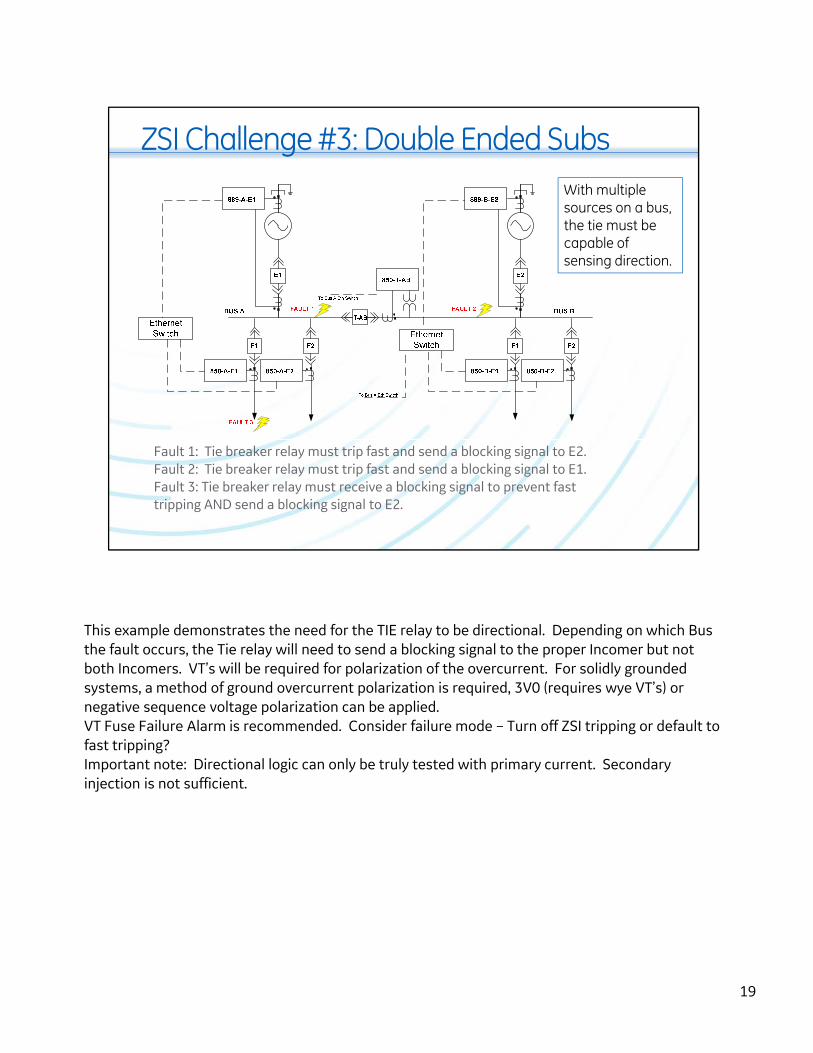
ZSI Challenge #3: Double Ended Subs
Fault 1: Tie breaker relay must trip fast and send a blocking signal to E2.Fault 2: Tie breaker relay must trip fast and send a blocking signal to E1. Fault 3: Tie breaker relay must receive a blocking signal to prevent fasttripping AND send a blocking signal to E2.
With multiple sources on a bus, the tie must be capable of sensing direction.
This example demonstrates the need for the TIE relay to be directional. Depending on which Bus the fault occurs, the Tie relay will need to send a blocking signal to the proper Incomer but not both Incomers. VT’s will be required for polarization of the overcurrent. For solidly grounded systems, a method of ground overcurrent polarization is required, 3V0 (requires wye VT’s) or negative sequence voltage polarization can be applied.VT Fuse Failure Alarm is recommended. Consider failure mode – Turn off ZSI tripping or default to fast tripping? Important note: Directional logic can only be truly tested with primary current. Secondary injection is not sufficient.
19

Conclusions
• ZSI is a longstanding technology that can be used to expedite otherwise slow time-overcurrent protection.
• The scheme can be implemented in many different ways. Consider the failure mode of the scheme.
• Transformer inrush & substations with multiple sources offer challenges to ZSI implementation.
• Choose your ZSI timing carefully.
Thank YouQuestions?
20