considerations of rock dilation on modeling failure and ... · journal of rock mechanics and...
TRANSCRIPT

Journal of Rock Mechanics and Geotechnical Engineering. 2010, 2 (4): 338–349
Considerations of rock dilation on modeling failure and deformation of hard rocks—a case study of the mine-by test tunnel in Canada Xingguang Zhao1*, Meifeng Cai2, M. Cai3 1 Beijing Research Institute of Uranium Geology, Beijing, 100029, China 2 School of Civil and Environmental Engineering, University of Science and Technology Beijing, Beijing, 100083, China 3 School of Engineering, Laurentian University, Sudbury, P3E 2C6, Canada
Received 10 October 2010; received in revised form 30 October 2010; accepted 5 November 2010
Abstract: For the compressive stress-induced failure of tunnels at depth, rock fracturing process is often closely associated with the generation of surface parallel fractures in the initial stage, and shear failure is likely to occur in the final process during the formation of shear bands, breakouts or V-shaped notches close to the excavation boundaries. However, the perfectly elastoplastic, strain-softening and elasto-brittle-plastic models cannot reasonably describe the brittle failure of hard rock tunnels under high in-situ stress conditions. These approaches often underestimate the depth of failure and overestimate the lateral extent of failure near the excavation. Based on a practical case of the mine-by test tunnel at an underground research laboratory (URL) in Canada, the influence of rock mass dilation on the depth and extent of failure and deformation is investigated using a calibrated cohesion weakening and frictional strengthening (CWFS) model. It can be found that, when modeling brittle failure of rock masses, the calibrated CWFS model with a constant dilation angle can capture the depth and extent of stress-induced brittle failure in hard rocks at a low confinement if the stress path is correctly represented, as demonstrated by the failure shape observed in the tunnel. However, using a constant dilation angle cannot simulate the nonlinear deformation behavior near the excavation boundary accurately because the dependence of rock mass dilation on confinement and plastic shear strain is not considered. It is illustrated from the numerical simulations that the proposed plastic shear strain and confinement-dependent dilation angle model in combination with the calibrated CWFS model implemented in FLAC can reasonably reveal both rock mass failure and displacement distribution in vicinity of the excavation simultaneously. The simulation results are in good agreement with the field observations and displacement measurement data. Key words: hard rocks; brittle failure; deformation; dilation angle model; confinement; plastic shear strain; mine-by test
tunnel
1 Introduction
In recent years, there has been an increasing interest
internationally in the construction of underground research laboratories (URLs), high-level radioactive waste repositories and large-scale underground powerhouses, as well as in the mining of massive ore bodies at great depth. The excavation of these underground facilities disturbs the in-situ stress state, leading to stress redistribution and deformation of rock mass around the excavation boundary. When tunnelling or mining in brittle hard rocks under high in-situ stress conditions at depth, the compressive
Doi: 10.3724/SP.J.1235.2010.00338
*Corresponding author. Tel: +86-10-64964573;
E-mail: [email protected]
stress-induced failure process around an underground opening is often accompanied by the generation of surface parallel fractures. This type of failure is often called spalling failure [1], as presented in Fig.1(a). For a circular tunnel, if the difference of the two principal stress components ( 1 , 3 ) is large, breakouts or V-shaped notches can be formed around the excavation boundary (see Fig.1(b)). During the initial formation of the V-shaped notch, the stress-induced fractures formed mostly in the direction parallel to the maximum principal stress ( 1 ) can be revealed by tensile mechanism because of the existence of material heterogeneity (for example, the difference in grain size and material properties). Further increases in stress can induce existing fractures to start to propagate at the fracture tip and neighboring elements. With the continuous accumulation and growth of the fractures, the fracture density will be sufficient to coalesce

Xingguang Zhao et al. / Journal of Rock Mechanics and Geotechnical Engineering. 2010, 2 (4): 338–349 339
(a) Spalling failure showing the layered fracturing that occurred in a deep
mine (photo courtesy of P. K. Kaiser).
(b) V-shaped notch observed in the floor of the mine-by test tunnel [2].
Fig.1 Brittle failure modes observed from a highly stressed ground in Canada.
to create a shear band at the outer ends, and the final notch can take place once these fractures connect to the excavation boundary.
A better understanding of rock brittle failure around the excavation helps us predict or anticipate the extent, shape and displacement of the failed zone, and subsequently assist in designing proper ground support systems. In the past decades, various strength criteria have been developed to describe the behavior of rock masses under different stress states. Among these, the linear Mohr-Coulomb criterion and the nonlinear Hoek-Brown criterion are two of the most widely used strength criteria in rock engineering. For a jointed rock,
the nonlinear Hoek-Brown criterion would be more suitable than the Mohr-Coulomb criterion [3]. The Hoek-Brown strength parameters can be estimated based on the GSI (geological strength index) system, which provides a method for rock mass peak strength estimation. Now the Hoek-Brown criterion has been written in geotechnical softwares, such as Phase2 [4] and FLAC [5]. Since many professional engineers are more used to working with the Mohr-Coulomb criterion, which has been a popular simulation tool, the equivalent friction angles and cohesive strengths for each rock mass and stress range have been determined by Hoek et al. [6]. The latest version of the generalized Hoek-Brown criterion for jointed rock masses [6] is defined by
31 3 c b
c
a
m s
(1)
where 3 and c are the minor principal stress and the uniaxial compressive strength (UCS) of the intact rock, respectively; bm , s and a are the rock mass strength parameters, which all depend upon the characteristics of the rock mass, and are determined using the GSI and mi, as shown in Ref.[6]. Further quantification of the GSI system using block volume and joint surface condition factor for the estimation of peak strength and residual strength parameters are developed by Cai et al. [7, 8]. A simple method to estimate the value of mi in the Hoek-Brown criterion from uniaxial compression test was proposed recently by Cai [9]. The origin of the Hoek-Brown criterion as an empirical criterion is based on the failure of intact laboratory samples and is developed to degrade intact rock strength to the rock mass strength. The funda- mental assumption of the criterion is that a jointed rock mass is weaker in shear than intact rock [10]. However, Cai et al. [7] firstly proposed that the Hoek-Brown criterion was of limited reliability when used for brittle hard rock masses with GSI > 75. Based on numerical modeling method, Pelli et al. [11] found that use of the Hoek-Brown criterion could not predict the observed failure shape near a tunnel in a cemented sand or siltstone. To match the predicted results with field observations, the value of mb has to be reduced to a lower value. Based on in-situ microseismic monitoring data and laboratory tests with acoustic emission measurements on Lac du Bonnet granite, Martin et al. [12, 13] found that mb should be close to zero and s = 0.11 (i.e. mb-zero crack initiation criterion), which implied that the crack initiation stress
Tension Shear
Shear

340 Xingguang Zhao et al. / Journal of Rock Mechanics and Geotechnical Engineering. 2010, 2 (4): 338–349
envelope obtained in the laboratory could be approximately used to predict stress-induced damage initiation in field for moderately jointed to massive hard rock masses. And then Rojat et al. [14] used this proposed mb-zero crack initiation criterion in com- bination with elastic model to predict stress-induced failure in the Steg lateral adit of the Lötschberg tunnel. In terms of brittle failure that occurred at low confining stress conditions (typically less than 5 MPa), Cai et al. [15] developed the generalized crack initiation and crack damage stress thresholds of brittle rock masses, providing a useful approach for assisting the rock mass integrity and reducing the effort to obtain the required material constants for engineering design of underground excavations. Hajiabdolmajid et al. [16, 17] demonstrated that the cohesion and frictional strength in the Mohr-Coulomb criterion could not be mobilized simultaneously at low confinement during brittle failure, and subsequently proposed a plastic strain-dependent cohesion weak- ening and frictional strengthening (CWFS) model. The fundamental assumption in using the CWFS model is that the pre-peak strength mobilezation is dominated by the cohesion of rocks, and frictional strength can only be mobilized when macroscopic failure surfaces are generated. From a similar point of view of the CWFS model, Edelbro [18, 19] introduced an instantaneous cohesion-softening friction-hardening (CSFH) model for use in plastic analysis as an alter- native approach to the CWFS model, and suggested to use both yielded elements and intersecting shear bands as indicators for predicting the failure shape around hard rock tunnels. For modeling brittle failure around the excavation boundaries, previous studies mentioned above focused mainly on cohesion and frictional strength based on modified Hoek-Brown or Mohr-Coulomb criterion. However, the influence of dilation on the stress- induced brittle failure and deformation of hard rock masses was not thoroughly investigated. As noted by Kaiser et al. [20], the volume increase in stress- fractured rocks near an excavation results from three sources: (1) dilation due to new fractures growth; (2) shear along existing fractures or joints; and (3) dilation due to geometrical incompatibilities when blocks of broken rock move relatively to each other as they are forced into the excavation. Hence, the impact of rock dilation on the failure and the displacement near the excavation boundary should not be neglected. As shown in Fig.2, on the boundary of a tunnel unsupported, 3 = 0 (the minor principal stress) and the highest tangential stress ( 1 ) exist. Under such a
Fig.2 Stress and rock fracturing condition near the tunnel
boundary (x0, y0 and z0 are the in-situ stress components) [1].
condition, the maximum rock dilation may take place if rock fails. With an increase in 3 away from the excavation boundary, dilation of surrounding rocks deceases significantly. This means that, from the excavation boundary to deeper grounds, dilation decreases gradually and finally vanishes at high confining stresses, indicating that rock dilation should be a nonlinear and dynamic changing process during failure of rocks. However, the confinement and plastic deformation-dependent dilation of rock masses are often not considered by many researchers or engineers in the analysis.
In the present study, based on a practical case of the mine-by test tunnel at a URL in Canada, different constitutive models including perfectly elastoplastic model, elasto-brittle-plastic model, strain-softening model and calibrated CWFS model are used to predict the extent and depth of brittle failure of the tunnel. In addition, the difference in simulation results caused by different tunnel excavation techniques is discussed, and the influence of a series of constant dilation angles based on the calibrated CWFS model on the failure shape of the tunnel is analyzed. To demonstrate the limited reliability of constant dilation angles, the effect of the plastic shear strain and the confinement- dependent rock dilation on the brittle failure and deformation around the mine-by test tunnel is finally investigated using an empirical dilation angle model developed by the authors [21, 22].
2 Mine-by test tunnel Canadian Underground Research Laboratory owned and operated by Atomic Energy of Canada Limited (AECL) is located approximately 120 km northeast of Winnipeg, Manitoba, Canada in the Lac du Bonnet
1
Induced stress and rock fracturing stateIn-situ stress
y0
x0
z0
3 = 0
2 1
2
3
Tunnel

Xingguang Zhao et al. / Journal of Rock Mechanics and Geotechnical Engineering. 2010, 2 (4): 338–349 341
granite batholith near the western edge of the Canadian Shield. Constructed between 1983 and 1989, the URL provides a well-characterized in-situ environment in a previously undisturbed rock mass, where the experiments are performed to study the feasibility of safe disposal of nuclear fuel in a stable excavation in a low permeability rock mass [23]. The URL has four levels, as presented in Fig.3.
Fig.3 Sketch of the URL surface facilities and underground
layout [24].
The mine-by test at the 420 m-level was conducted between 1989 and 1995 to study the processes involved in excavation-induced damage development and progressive failure of brittle rock around an underground opening subjected to high differential stresses. The experiment involved a 3.5 m-diameter, 46 m-long test tunnel (mine-by test tunnel) excavated between January and July 1992 using a non-explosive technique by parallel hole drilling, which provided an ideal environment to observe and record the brittle failure process of rock mass. The test tunnel was oriented parallel to the trend of intermediate principal stress ( 2 = 45 MPa) to maximize the stress ratio and to create the largest excavation effect on the tunnel, and thereby to promote the stress concentrations in the roof and floor of the tunnel. Figure 4 presents the distributions of in-situ stress, the progressive failure process in the roof and floor over about a five-month period, and the final shape of V-shaped notches as the
Fig.4 Mine-by test tunnel showing the in-situ stress state, the
progressive failure process and the final shape in the roof and
floor of the tunnel [12].
test tunnel face was advanced. The extent of the failure in the roof was greater than that observed in the floor. The reason has been explained by the confining stress provided by the “muck” in the floor and also because the stress path in the floor could be significantly different from that in the roof [12]. 3 Numerical modeling of the tunnel failure shape 3.1 FLAC model description and selection of excavation techniques in simulation The grid used for the mine-by test tunnel simulation is a radial grid with a square shaped boundary containing 19 200 elements. The model of a circular tunnel with the radial grid can be established using FISH language inserted in FLAC. In order to capture the accurate brittle failure in high stress environment, a fine grid distribution around the excavation should be desirable due to the high stress gradient occurring in these elements. The outer boundary, which is about 6 times the excavation diameter, is 22.75 m × 22.75 m. A close-up view of the grid is presented in Fig.5. In reality, the maximum principal stress is inclined at 15°. For the analysis, the grid in Fig.5 is rotated 15° clockwise so that the maximum and minor principal stresses are horizontal and vertical, respectively. For the excavation of tunnels, rocks can be removed by using various excavation techniques such as full-face drilling and blasting, TBM, mechanical excavation, staged excavation, etc.. Different exca- vation methods will produce different responses around the excavation boundary of a tunnel due to different stress paths generated [25]. The correct
Mine-by test tunnel
3 = 11 MPa
3 = 60 MPa
Mine-by test tunnel
130 m-level
300 m-level
Lower vent raise
Upper vent raise
Rectangular shaft
Circular shaft
240 m-level
420 m-level

342 Xingguang Zhao et al. / Journal of Rock Mechanics and Geotechnical Engineering. 2010, 2 (4): 338–349
Fig.5 A zoomed-in FLAC grid of the mine-by test tunnel. rock mass response can be captured only if the stress path is correctly represented. Hence, an important issue in numerical simulation is the selection of excavation techniques. For example, when a tunnel is advanced by long-round drilling and blasting method, which often creates large unbalanced forces and displacements at the excavation boundary, a sudden excavation with low damping can be used in the model. However, when a tunnel is excavated by shovel, jackleg, hydraulic rock-splitting technique or full-face TBM tunneling, some relaxation at the tunnel periphery takes place. Hence, a progressive excavation modeling procedure should be considered, especially for brittle rocks, to eliminate “overshoot” and control sudden unloading. Generally, there are two methods for the latter [25]. One way uses the material softening method. Young’s modulus of the elements in the tunnel area is degraded to zero over a specific period of time or over a few stages to simulate the gradual excavation effect. This method is typical of finite element methods. An alternative approach is called excavation relaxation method. The elements are removed from the simulation and replaced by a set of forces equal to the internal forces of the group removed. The equivalent forces are then relaxed over a specific period of time to minimize the transient effects on simulations, and a gradual excavation process can be simulated. In this study, the excavation relaxation approach is used in the progressive excavation of the mine-by tunnel. A FISH function in FLAC is written to recover the equivalent x- and y-direction forces on the excavation boundary and to control the rate of relaxation at selected tunnel-boundary grid points (see
Fig.6(a)). When the tunnel core is removed, these forces along the tunnel boundary are applied and gradually decreased to zero over an interval of assigned calculation steps until the forced-equilibrium state is reached (see Fig.6(b)). Compared with the finite element method (FEM), FLAC uses an explicit “time-marching” finite difference solution scheme. For each time step, the calculation sequence can be summarized as follows: (1) New strain rates are derived from nodal velocities. (2) Constitutive equations are subsequently used to calculate new stresses from the strain rates and stresses at the previous time. (3) The equations of motion are finally invoked to derive new nodal velocities and displacements from stresses and forces. The sequence is repeated at each calculation step, and the maximum unbalanced force in the model is monitored [5, 26].
(a) Distribution of the reaction forces at the mine-by test tunnel boundary.
(b) Change in relaxation rate with calculation step.
Fig.6 Excavation relaxation approach used in the mine-by tunnel simulation. 3.2 Conventional modeling results Conventional continuum approaches, including perfectly elastoplastic model, elasto-brittle-plastic model and strain-softening model based on the Mohr-Coulomb criterion, are used to predict the extent of brittle failure of the mine-by tunnel. The Hoek- Brown peak strength parameters [12] of rock mass were estimated from GSI = 90, but the residual strength parameters were obtained, following the
1.0
0 5 10 15 20 250.0
0.2
0.4
0.6
0.8
Rel
axat
ion
rate
Step (102)
Reaction force
3 1
Mine-by test tunnel
Tunnel Surrounding rock
6.0
4.0
2.0
0.0
2.0
4.0
6.0
x (m) y
(m)
4.0 2.0 0.0 2.0 4.0 6.0 6.0
Xingguang Zhao et al. / Journal of Rock Mechanics and Geotechnical Engineering. 2010, 2 (4): 338–349 343
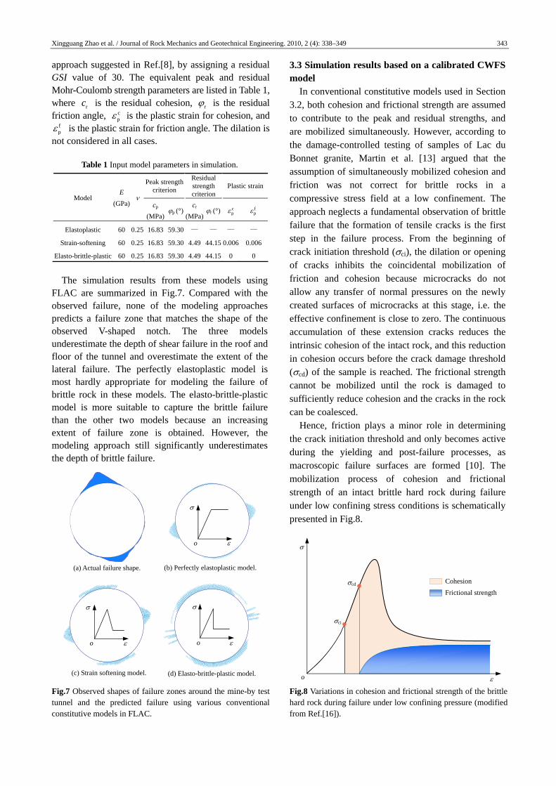
approach suggested in Ref.[8], by assigning a residual GSI value of 30. The equivalent peak and residual Mohr-Coulomb strength parameters are listed in Table 1, where rc is the residual cohesion, r is the residual friction angle, c
p is the plastic strain for cohesion, and fp is the plastic strain for friction angle. The dilation is
not considered in all cases.
Table 1 Input model parameters in simulation.
Peak strength criterion
Residual strength criterion
Plastic strain
Model E
(GPa)
cp
(MPa)p (°)
cr
(MPa)
r (°) cp f
p
Elastoplastic
Strain-softening
Elasto-brittle-plastic
60
60
60
0.25
0.25
0.25
16.83
16.83
16.83
59.30
59.30
59.30
—
4.49
4.49
—
44.15
44.15
—
0.006
0
—
0.006
0
The simulation results from these models using FLAC are summarized in Fig.7. Compared with the observed failure, none of the modeling approaches predicts a failure zone that matches the shape of the observed V-shaped notch. The three models underestimate the depth of shear failure in the roof and floor of the tunnel and overestimate the extent of the lateral failure. The perfectly elastoplastic model is most hardly appropriate for modeling the failure of brittle rock in these models. The elasto-brittle-plastic model is more suitable to capture the brittle failure than the other two models because an increasing extent of failure zone is obtained. However, the modeling approach still significantly underestimates the depth of brittle failure.
Fig.7 Observed shapes of failure zones around the mine-by test tunnel and the predicted failure using various conventional constitutive models in FLAC.
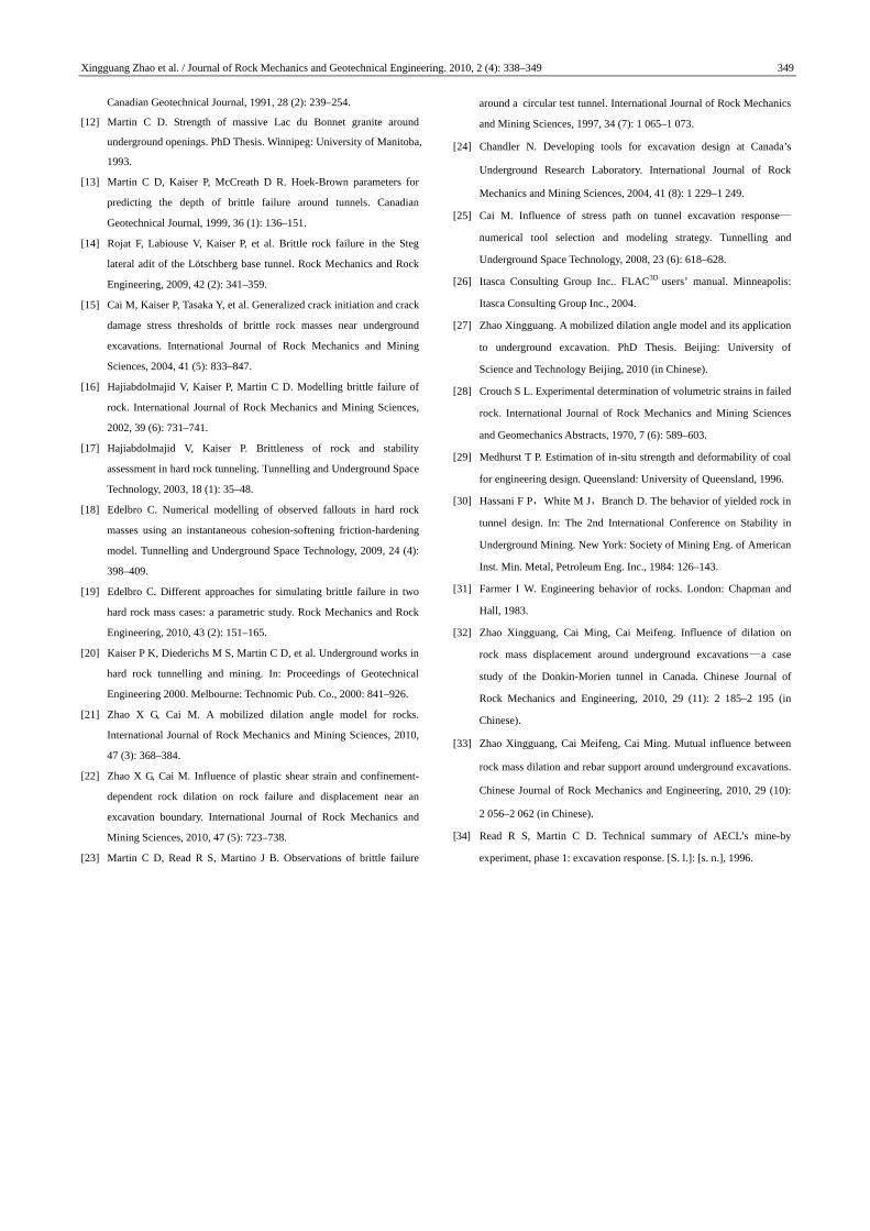
3.3 Simulation results based on a calibrated CWFS model In conventional constitutive models used in Section 3.2, both cohesion and frictional strength are assumed to contribute to the peak and residual strengths, and are mobilized simultaneously. However, according to the damage-controlled testing of samples of Lac du Bonnet granite, Martin et al. [13] argued that the assumption of simultaneously mobilized cohesion and friction was not correct for brittle rocks in a compressive stress field at a low confinement. The approach neglects a fundamental observation of brittle failure that the formation of tensile cracks is the first step in the failure process. From the beginning of crack initiation threshold (ci), the dilation or opening of cracks inhibits the coincidental mobilization of friction and cohesion because microcracks do not allow any transfer of normal pressures on the newly created surfaces of microcracks at this stage, i.e. the effective confinement is close to zero. The continuous accumulation of these extension cracks reduces the intrinsic cohesion of the intact rock, and this reduction in cohesion occurs before the crack damage threshold (cd) of the sample is reached. The frictional strength cannot be mobilized until the rock is damaged to sufficiently reduce cohesion and the cracks in the rock can be coalesced. Hence, friction plays a minor role in determining the crack initiation threshold and only becomes active during the yielding and post-failure processes, as macroscopic failure surfaces are formed [10]. The mobilization process of cohesion and frictional strength of an intact brittle hard rock during failure under low confining stress conditions is schematically presented in Fig.8. Fig.8 Variations in cohesion and frictional strength of the brittle hard rock during failure under low confining pressure (modified from Ref.[16]).
ci
cd
Frictional strength
Cohesion
o
(a) Actual failure shape. (b) Perfectly elastoplastic model.
(c) Strain softening model. (d) Elasto-brittle-plastic model.
o
o o

344 Xingguang Zhao et al. / Journal of Rock Mechanics and Geotechnical Engineering. 2010, 2 (4): 338–349
According to Hajiabdolmajid et al. [16, 17], based on the high quality input data obtained from laboratory and field measurements at URL [12], a characteristic plastic strain-dependent CWFS model was used to predict the shape of spalling failure at the mine-by test tunnel. The CWFS model can be given by
p pn( ) ( , ) ( , ) tanf f c f (2)
where c and are the cohesion and the friction angle, respectively; n is the normal stress; and p is the characteristic plastic strain, which can be expressed as
p p p p p p p1 1 2 2 3 32 / 3(d d d d d d )dt (3)
where p1d , p
2d , and p3d are the principal plastic
strain increments. To investigate the influence of the strength
components and corresponding characteristic plastic strain components on the failure zone (the depth of failure, Rf, and the lateral extent angle, , as shown in Fig.9) around the tunnel, a sensitive analysis for these parameters is first carried out using a standard orthogonal array L25 (5
6). The six control factors and their five levels are listed in Table 2. The orthogonal experiment design as a simple, systematic and efficient Fig.9 The depth of failure and the lateral extent angle of the
mine-by test tunnel [12].
Table 2 Factors and levels used in sensitive analysis for
modeling failure depth and extent of the mine-by test tunnel.
Level
Initial
cohesion
ci (MPa)
Residual
cohesion
cr (MPa)
Initial
friction
angle i
(°)
Residual
friction
angle r
(°)
Plastic strain
for cohesion cp (%)
Plastic strain
for frictional
strength fp (%)
1 65 20 0 60 0.05 0.1
2 60 15 5 55 0.1 0.2
3 55 10 10 50 0.2 0.3
4 50 5 15 45 0.3 0.4
5 45 0 20 40 0.4 0.5
method enables to investigate the relative importance of control factors and identify the best levels for different factors on a performance output, and the results can be analyzed by using a common and rigorous mathematical procedure. This method widely utilized in engineering design and experimental research can significantly reduce experimental time and research cost to obtain reasonable and satisfactory results. To determine the sequence and significance of the effect of the six factors on the parameters of failure zone shape, the analysis of means (ANOM) and the analysis of variation (ANOVA) were both adopted. In ANOM, it is found that the range values of ci and r are higher than those of other factors, as presented in Fig.10, implying that ci and r have more significant influences on both the depth and the extent of the failure zone, and ci is the most important factor in inducing the shape of failure zone. The ANOM also indicates that the lower ci and r would contribute to the deeper and wider failure zone.
(a) Failure depth.
(b) Extent angle.
Fig.10 The range values of each factor for the failure depth and
the extent angle.
To further find out statistical significance of various factors, the ANOVA was performed based on
= 70°
Rf = 2.275 m
Ran
ge v
alue
(m
)
0.0
0.2
0.4
0.6
0.8
1.0
Factor ic rc ri
cp f
p
Factor
Ran
ge v
alue
(°)
0
10
20
30
40
50
60
ic rc r i cp
fp

Xingguang Zhao et al. / Journal of Rock Mechanics and Geotechnical Engineering. 2010, 2 (4): 338–349 345
= 57°
simulation data. The sum of squares is obtained by the following equation:
52
1
5 ( )i iii
SS M M
(4)
where iSS is the sum of squares, iiM is the simulation results, and M is the mean value of 25 simulation results. The sum of squares divided by degrees of freedom produces a variance. The minimum sum of squares is chosen as error, and the other values divided by the error give the variance ratios. This analysis is undertaken for a level of confidence of significance of 5%. A more detailed description of the orthogonal experiment analysis used in simulations can be found in Ref.[27]. The analysis results show that ci and φr have prominent effects on the depth and extent of the failure zone, which is in a good agreement with the ANOM. ci is the most significant factor for predicting the failure shape of the tunnel, which puts forward a requirement for reasonably determining the initial cohesion from some monitoring methods, such as the acoustic emission (AE) and microseismic (MS) measurement techniques.
Based on 25 simulation cases, the optimal control parameters for capturing the failure shape in the roof (Rf = 2.275 m and = 70°) of the mine-by test tunnel are obtained from the ANOM, as shown in Table 3. These parameters by back analysis agree well with those obtained from theoretical and experimental analyses [12, 16]. A simulation is conducted to confirm the results using the optimal combination level of controlling factors, and it turns out that the depth of failure can be captured satisfactorily, as shown in Fig.11(a). However, the extent angle of failure is less than that actually observed underground. Besides, the shape of the bottom V-shaped notch does not match the one formed in the field. The bottom notch formation is complicated, influenced by many factors, as discussed by Martin [12], and in this paper we mainly concentrate on the notch shape in the roof. Table 3 The optimal parameters used to simulate the failure
shape of the mine-by test tunnel.
ci (MPa) cr (MPa) i (°) r (°) cp (%) f
p (%)
50 15 0 60 0.2 0.4
Figure 11(b) presents the simulation results obtained from the instantaneous full-face tunnel excavation approach. Compared with the excavation relaxation method (see Fig.11(a)), the instantaneous full-face excavation approach results in slightly larger failure
(a) Excavation relaxation method. (b) Instantaneous excavation method.
Fig.11 Comparison of the simulation results and field
observations in the mine-by test tunnel.
zones in the tunnel roof and floor. In addition, the failure on the most part of the sidewalls can also be observed, which is not in agreement with the field observations (see Fig.7(a)). The reason is that a dynamic unloading condition can be created by this type of excavation method when the tunnel core is suddenly removed from the simulation. On the contrary, the excavation relaxation technique representing a correct stress path in the simulation can similarly simulate the progressive tunnel excavation process due to the reduction of excavation-disturbed effect on the surrounding rocks of the tunnel. Hence, the overall failure range can be well captured to match actual failure shape of the tunnel for the given constitutive model and in-situ stress condition. 3.4 Influence of constant dilation angles on the failure shape of the tunnel To capture the accurate failure shape and study the impact of dilation angle on the development of failure zone around the tunnel, models with different constant dilation angles are run based on the CWFS model with the optimal parameters listed in Table 3. Figure 12 presents the results showing the influence of dilation angle on notch shape when the dilation angle changes from 15° to 45°. With the increase in the dilation angle, the failure depth shows a slight deceasing trend, but the extent angle of the notch increases. As seen from Fig.12, a range of dilation angle ψ from 30° to 35°, i.e. ψ is approximately equal to half of the residual friction angle r in the calibrated CWFS model, can be used to accurately capture the spalling geometry occurring in the roof of the tunnel. According to the simulation results discussed above, using a suitable constant dilation angle value in combination with the calibrated CWFS model can
= 57°

346 Xingguang Zhao et al. / Journal of Rock Mechanics and Geotechnical Engineering. 2010, 2 (4): 338–349
(a) ψ = 15°. (b) ψ = 25°. (c) ψ = 30°.
(d) ψ = 35°. (e) ψ = 40°. (f) ψ = 45°.
Fig.12 Effect of constant dilation angles on the depth and the
lateral extent of failure around the mine-by test tunnel based on
the calibrated CWFS model.
reproduce the depth and extent of failure zone observed in field reasonably. However, the stress- induced displacement values obtained in this way may not be representative of the field data due to the neglect of dependence of rock dilation on plastic shear strain and confinement. In the next section, the dilation angle model is used to focus on modeling the displacement distribution around the tunnel.
4 Influence of plastic shear strain and confining stress-dependent rock dilation on the displacement of the mine-by test tunnel In the previous study, based on published data [28–31] acquired from modified triaxial compression tests with volumetric strain measurement performed on seven rock types, we proposed a mobilized dilation angle model (see Eq.(5)) [21], which considered the influence of both confining stress and plastic shear strain using nonlinear fitting method based on plasticity mechanics theory. According to the numerical simulation using FLAC, a good agreement between numerical and experimental results has been achieved, indicating that the proposed empirical dilation angle model can predict post-failure dilation behavior of rocks under various confinement conditions. In addition, by analyzing the relationship between the peak friction angle and the dilation angle,
the mobilized dilation angle model is generalized for rock mass using the Hoek-Brown criterion and the GSI system [22], and the influence of the plastic shear strain and confining stress-dependent rock mass dilation on the displacement distributions [32] in the Donkin-Morien tunnel in Canada and the rebar bolt support [33] near the excavation boundary is investigated. This developed rock dilation angle model provides a reasonable means to consider dilation during rock failure in underground excavations:
3
3
p p
1 2 3 3
1 2 3 3
1 2
[exp( ) exp( )] / ( )
exp( / )
exp( / )
c
ab b c c b
a a a a
b b b b
c c c
(5)
where ai, bi and ci (i = 1, 2, 3) are fitting coefficients;
p is the plastic shear strain; and 3 is the confining stress. The rock type of the Lac du Bonnet granite of the mine-by test tunnel at URL is the coarse-grained hard rock. According to the suggested approaches [21, 22, 26] in combination with Eq.(5), the dilation angle model parameters and corresponding model curves are presented in Table 4 and Fig.13, respectively. FLAC allows users to develop user-defined models with embedded FISH language. Hence, the empirical dilation angle model for the Lac du Bonnet granite is implemented in the calibrated CWFS model in FLAC using FISH language. The boundary conditions of the model and the excavation approach are the same as described in Section 3.1.
Table 4 Input parameters of dilation angle model for the Lac du
Bonnet granite.
a1 a2 a3 b1 b2 b3 c1 c2 (%) c3
41.00 20.00 1.00 5.83 36.25 6.77 0.14 1.14 1.23
Fig.13 Dilation angle model of the Lac du Bonnet granite.
Dil
atio
n an
gle
(°)
Plastic shear strain (%)
3 = 0 MPa
3 = 15 MPa
3 = 1 MPa
3 = 10 MPa 3 = 5 MPa
3 = 20 MPa 3 = 25 MPa
0 1 2 3 4 5 6 7 8 9 100
10
20
30
40
50
60
70

Xingguang Zhao et al. / Journal of Rock Mechanics and Geotechnical Engineering. 2010, 2 (4): 338–349 347
Figure 14 presents the distribution of the dilation angle in the failure zone when the tunnel is excavated. It can be observed that the dilation angle in rocks is not constant in our model, but varies with the plastic straining and the confinement condition. The value of dilation angle close to the excavation boundary is large. With an increase in distance away from the excavation surface, the dilation angle decreases significantly. In the elastic zone, where there is no plastic strain, the dilation angles are zero. This demonstrates that rock dilation is influenced by both the confining stress and the post-peak plastic deformation simultaneously. The low confinement (even zero) near the excavation boundary contributes to a large rock dilation. With increasing confining stress and developing plastic deformation of rocks, the rock dilation decreases until it reaches zero, presenting a nonlinear process, which makes more sense physically. However, a constant dilation angle model would assume that all zones have the same dilation angle, whether it is in the plastic zone or the elastic zone. The assumption of constant dilation during rock mass fracturing is an approximation that is clearly not physically correct.
Fig.14 Distribution of dilation angle around the mine-by test
tunnel.
To investigate the influence of tunnel excavation on the rock mass deformation, a series of extensometers were installed in rock mass to measure the excavation- induced displacement [34]. One of the displacement measurement lines is shown in Fig.14. The obtained displacement distribution using the dilation angle model in combination with the calibrated CWFS model is compared to that obtained from constant dilation angles in Fig.15, where R is the tunnel radius.
Fig.15 Comparison of measured tunnel displacement and numerical simulation results based on dilation angle model and constant dilation angles.
It can be seen from Fig.15 that the displacement obtained by our suggested dilation angle model shows a large difference with the results calculated from any constant dilation angle. Under the same condition, when compared with the variable dilation angle model results, constant dilation angle models with small dilation angles (ψ < r/8) may underestimate the displacement close to the excavation boundaries. On the other hand, a large constant dilation angle (ψ = (1/4–1/2)r) may capture the surface displacement right but will overestimate the displacement away from the tunnel boundaries. In addition, a large dilation angle will result in a large range of rock failure based on the CWFS model (see Fig.12). On the contrary, the developed dilation angle model con- sidering the influence of the confining stress and the plastic shear strain can reveal the actual deformation behavior of rocks, and the simulation results are in good agreement with extensometer measurements. The failure shape of the mine-by test tunnel can also be captured satisfactorily, as shown in Fig.14.
5 Conclusions Based on a practical case of the mine-by test tunnel at a URL in Canada, the influence of rock mass dilation on the brittle failure and deformation of the tunnel is investigated using an empirical dilation angle model, which considers the influence of both plastic shear strain and confinement. The main achievements
Distance between the tunnel center and the surrounding rock (R)
Dis
plac
emen
t (m
m)
1.0 1.1 1.3 1.2 -0.6
1.4 1.5
-0.5
-0.4
-0.3
-0.2
-0.1
0.0
= 0°
= r/8
= r/4
= r/2
Dilation angle model Constant dilation angles
Measurement data
Displacement measurement line
Dilation angle ()
0 11 22 33 44 55

348 Xingguang Zhao et al. / Journal of Rock Mechanics and Geotechnical Engineering. 2010, 2 (4): 338–349
and conclusions are drawn as follows: (1) For the given rock mass and boundary conditions, different excavation methods lead to different stress paths, which have an important impact on failure modes around the excavation boundaries. In numerical modeling, the behaviors of rock mass can be reasonably revealed only when the stress path in the rock mass is captured correctly. This has been verified from the simulation results of the brittle failure of the mine-by test tunnel. (2) For modeling brittle failure of rock mass, the conventional models such as perfectly elastoplastic model, strain softening model and elasto-brittle-plastic model cannot predict a failure zone that matches the shape of the observed V-shaped notch. The three models underestimate the depth of shear failure in the roof and floor of the tunnel and overestimate the extent of the lateral failure. A calibrated CWFS model with a constant dilation angle ( ≈ r/2) can capture the stress-induced brittle failure depth and extent in hard rocks at a low confinement, as demonstrated by the notch formation in the mine-by test tunnel. However, the use of a constant dilation angle cannot simulate the nonlinear deformation behavior near the excavation accurately due to the neglect of the dependence of rock mass dilation on confinement and plastic shear strain. (3) It is illustrated from the numerical simulation results that the confinement and the plastic shear strain-dependent dilation angle model proposed in this paper can reasonably describe both the rock mass failure and the displacement distribution near the excavation boundary simultaneously. The predicted failure shape of the tunnel and the rock mass displacement distributions induced by gradual excavation are in good agreement with the field measurement results. The presented study provides a useful approach to understand the nonlinear mechanical behavior of rocks and to investigate the rock dilation near the excavations at depth. (4) It is noted that the influence of intermediate principal stress on the rock dilation, strength, brittle failure and deformation of the mine-by test tunnel is not considered in our analysis. Cai used FEM/DEM combined numerical tool (ELFEN) to investigate the fracturing and strength near the excavation boundaries. The simulation results show that the generation of tunnel surface parallel fractures and microcracks is attributed to material heterogeneity and the existence of relatively high intermediate principal stress, as well
as low confinement [1]. However, due to the limited access to experimental facilities, not enough systematic study results from literature are available to develop a comprehensive dilation angle model considering the intermediate principal stress. In the next phase, further experimental and numerical simulation works on the intermediate principal stress effect of rock dilation and its impact on the brittle failure and the deformation of hard rocks should be an important task. Acknowledgements This work was supported by China Scholarship
Council and GRC/MIRARCO—Mining Innovation of
Laurentian University, Canada.
References
[1] Cai M. Influence of intermediate principal stress on rock fracturing
and strength near excavation boundaries—insight from numerical
modeling. International Journal of Rock Mechanics and Mining
Sciences, 2008, 45 (5): 763–772.
[2] Read R S. 20 years of excavation response studies at AECL’s
Underground Research Laboratory. International Journal of Rock
Mechanics and Mining Sciences, 2004, 41 (8): 1 251–1 275.
[3] Sharan S K. Analytical solutions for stresses and displacements
around a circular opening in a generalized Hoek-Brown rock.
International Journal of Rock Mechanics and Mining Sciences, 2008,
45 (1): 78–85.
[4] Rocscience. Phase2 5.0 users’ guide. Toronto: Rocscience, 2007.
[5] Itasca Consulting Group Inc.. FLAC users’ manual. Minneapolis:
Itasca Consulting Group Inc., 2004.
[6] Hoek E, Carranza-Torres C, Corkum B. Hoek-Brown failure criterion (2002 ed.). In: Proceedings of the 5th North American Rock
Mechanics Symposium. Toronto: Toronto University Press, 2002:
267–273.
[7] Cai M, Kaiser P, Uno H, et al. Estimation of rock mass deformation
modulus and strength of jointed hard rock masses using the GSI
system. International Journal of Rock Mechanics and Mining Sciences,
2004, 41 (1): 3–19.
[8] Cai M, Kaiser P, Tasaka Y, et al. Determination of residual strength
parameters of jointed rock masses using the GSI system. International
Journal of Rock Mechanics and Mining Sciences, 2007, 44 (2):
247–265.
[9] Cai M. Practical estimates of tensile strength and Hoek-Brown
strength parameter mi of brittle rocks. Rock Mechanics and Rock
Engineering, 2010, 43 (2): 167–184.
[10] Diederichs M S, Kaiser P, Eberhardt E. Damage initiation and
propagation in hard rock during tunnelling and the influence of
near-face stress rotation. International Journal of Rock Mechanics and
Mining Sciences, 2004, 41 (5): 785–812.
[11] Pelli F, Kaiser P, Morgenstern N R. An interpretation of ground
movements recorded during construction of the Donkin-Morien tunnel.
Xingguang Zhao et al. / Journal of Rock Mechanics and Geotechnical Engineering. 2010, 2 (4): 338–349 349
Canadian Geotechnical Journal, 1991, 28 (2): 239–254.
[12] Martin C D. Strength of massive Lac du Bonnet granite around
underground openings. PhD Thesis. Winnipeg: University of Manitoba,
1993.
[13] Martin C D, Kaiser P, McCreath D R. Hoek-Brown parameters for
predicting the depth of brittle failure around tunnels. Canadian
Geotechnical Journal, 1999, 36 (1): 136–151.
[14] Rojat F, Labiouse V, Kaiser P, et al. Brittle rock failure in the Steg
lateral adit of the Lötschberg base tunnel. Rock Mechanics and Rock
Engineering, 2009, 42 (2): 341–359.
[15] Cai M, Kaiser P, Tasaka Y, et al. Generalized crack initiation and crack
damage stress thresholds of brittle rock masses near underground
excavations. International Journal of Rock Mechanics and Mining
Sciences, 2004, 41 (5): 833–847.
[16] Hajiabdolmajid V, Kaiser P, Martin C D. Modelling brittle failure of
rock. International Journal of Rock Mechanics and Mining Sciences,
2002, 39 (6): 731–741.
[17] Hajiabdolmajid V, Kaiser P. Brittleness of rock and stability
assessment in hard rock tunneling. Tunnelling and Underground Space
Technology, 2003, 18 (1): 35–48.
[18] Edelbro C. Numerical modelling of observed fallouts in hard rock
masses using an instantaneous cohesion-softening friction-hardening
model. Tunnelling and Underground Space Technology, 2009, 24 (4):
398–409.
[19] Edelbro C. Different approaches for simulating brittle failure in two
hard rock mass cases: a parametric study. Rock Mechanics and Rock
Engineering, 2010, 43 (2): 151–165.
[20] Kaiser P K, Diederichs M S, Martin C D, et al. Underground works in
hard rock tunnelling and mining. In: Proceedings of Geotechnical
Engineering 2000. Melbourne: Technomic Pub. Co., 2000: 841–926.
[21] Zhao X G, Cai M. A mobilized dilation angle model for rocks.
International Journal of Rock Mechanics and Mining Sciences, 2010,
47 (3): 368–384.
[22] Zhao X G, Cai M. Influence of plastic shear strain and confinement-
dependent rock dilation on rock failure and displacement near an
excavation boundary. International Journal of Rock Mechanics and
Mining Sciences, 2010, 47 (5): 723–738.
[23] Martin C D, Read R S, Martino J B. Observations of brittle failure
around a circular test tunnel. International Journal of Rock Mechanics
and Mining Sciences, 1997, 34 (7): 1 065–1 073.
[24] Chandler N. Developing tools for excavation design at Canada’s
Underground Research Laboratory. International Journal of Rock
Mechanics and Mining Sciences, 2004, 41 (8): 1 229–1 249.
[25] Cai M. Influence of stress path on tunnel excavation response—
numerical tool selection and modeling strategy. Tunnelling and
Underground Space Technology, 2008, 23 (6): 618–628.
[26] Itasca Consulting Group Inc.. FLAC3D users’ manual. Minneapolis:
Itasca Consulting Group Inc., 2004.
[27] Zhao Xingguang. A mobilized dilation angle model and its application
to underground excavation. PhD Thesis. Beijing: University of
Science and Technology Beijing, 2010 (in Chinese).
[28] Crouch S L. Experimental determination of volumetric strains in failed
rock. International Journal of Rock Mechanics and Mining Sciences
and Geomechanics Abstracts, 1970, 7 (6): 589–603.
[29] Medhurst T P. Estimation of in-situ strength and deformability of coal
for engineering design. Queensland: University of Queensland, 1996.
[30] Hassani F P,White M J,Branch D. The behavior of yielded rock in
tunnel design. In: The 2nd International Conference on Stability in
Underground Mining. New York: Society of Mining Eng. of American
Inst. Min. Metal, Petroleum Eng. Inc., 1984: 126–143.
[31] Farmer I W. Engineering behavior of rocks. London: Chapman and
Hall, 1983.
[32] Zhao Xingguang, Cai Ming, Cai Meifeng. Influence of dilation on
rock mass displacement around underground excavations—a case
study of the Donkin-Morien tunnel in Canada. Chinese Journal of
Rock Mechanics and Engineering, 2010, 29 (11): 2 185–2 195 (in
Chinese).
[33] Zhao Xingguang, Cai Meifeng, Cai Ming. Mutual influence between
rock mass dilation and rebar support around underground excavations.
Chinese Journal of Rock Mechanics and Engineering, 2010, 29 (10):
2 056–2 062 (in Chinese).
[34] Read R S, Martin C D. Technical summary of AECL’s mine-by
experiment, phase 1: excavation response. [S. l.]: [s. n.], 1996.