consolidated safety valve type 1700-2-s and 1700-3-s · consolidated safety valve ... ix....
TRANSCRIPT
®
ConsolidatedINSTALLATION, OPERATIONAND MAINTENANCE MANUAL
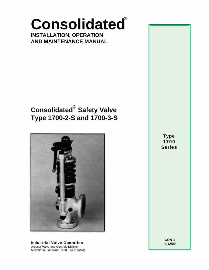
Consolidated Safety ValveType 1700-2-S and 1700-3-S
Industrial Valve OperationDresser Valve and Controls DivisionAlexandria, Louisiana 71309-1430 (USA)
CON-1 9/12/00
®
Type1700
Series

CON-6
1.DANGER — Immediatehazards which WILL resultin severe personal injury ordeath.
2.
WARNING — Hazards orunsafe practices whichCOULD result in severepersonal injury or death.
3.
CAUTION — Hazards orunsafe practices whichCOULD result in minorpersonal injury.
4.
ATTENTION — Hazards orunsafe practices whichCOULD result in product orproperty damage.
Product Safety Sign and Label System
If and when required, appropriate safety labels have been included in therectangular margin blocks throughout this manual. Safety labels are verticallyoriented rectangles as shown in the representative examples (below), consistingof three panels encircled by a narrow border. The panels can contain fourmessages which communicate:
• The level of hazard seriousness.• The nature of the hazard.• The consequence of human or product interaction with the hazard.• The instructions, if necessary, on how to avoid the hazard.
The top panel of the format contains a signal word (DANGER, WARNING,CAUTION or ATTENTION) which communicates the level of hazard seriousness.
The center panel contains a pictorial which communicates the nature of thehazard, and the possible consequence of human or product interaction with thehazard. In some instances of human hazards the pictorial may, instead, depictwhat preventive measures to take, such as wearing protective equipment.
The bottom panel may contain an instruction message on how to avoid thehazard. In the case of human hazard, this message may also contain a moreprecise definition of the hazard, and the consequences of human interaction withthe hazard, then can be communicated by the pictorial.
Do not drop or strikevalve.
42 31
▲! ATTENTION
Know all valveexhaust/leakage pointsto avoid possiblesevere personal injuryor death.
Wear necessaryprotective equipmentto prevent possibleinjury.
▲! CAUTION

CON-1
CONSOLIDATEDMAXIFLOW SAFETY VALVE
WELDED INLET2500 PSIG (175.8 Kg/cm2) CLASS
Part No. Nomenclature
1 Base1a Inlet Neck2 Disc Holder3 Guide4 Upper Adj. Ring5 Spring Assembly
5a Top Washer5b Bottom Washer5c Spring6 Seat Bushing7 Disc8 Lower Adj. Ring9 Disc Collar
10 Lift Stop11 Overlap Collar
*12 Cover Plate Assy.12a Cover Plate12b Floating Washer12c Washer Retainer13 Top Plate Assy.
13a Top Plate13b Washer Retainer13c Floating Washer14 Spindle15 Compression Screw16 Yoke
**17 Yoke Rod**18 Lifting Gear
19 Upper Adj. Ring Pin20 Lower Adj. Ring Pin21 Release Nut22 Compression Screw
Lock Nut
* Includes Pin Screws** See Figure 7 on page 19

CON-1
MAXIFLOW SAFETY VALVEFLANGED INLET
900 PSIG (63.3 Kg/cm2) CLASS
Part No. Nomenclature
1 Base2 Disc Holder3 Guide4 Upper Adj. Ring5 Spring Assembly
5a Top Washer5b Bottom Washer5c Spring6 Seat Bushing7 Disc8 Lower Adj. Ring9 Disc Collar
10 Lift Stop11 Overlap Collar
*12 Cover Plate Assy.12a Cover Plate12b Floating Washer12c Washer Retainer13 Top Plate Assy.
13a Top Plate13b Washer Retainer13c Floating Washer14 Spindle15 Compression Screw16 Yoke
**17 Yoke Rod**18 Lifting Gear
19 Upper Adj. Ring Pin20 Lower Adj. Ring Pin21 Release Nut22 Compression Screw
Lock Nut
* Includes Pin Screws** See Figure 7 on page 19

CON-1
Page 1
Contents
Section Subject Page
I. Safety Notice....................................................................................... 2II. A. Safety Precautions ....................................................................... 3
B. Warranty Information .................................................................... 3III. Introduction ......................................................................................... 4IV. Safety Valve Terminology ................................................................... 5V. Design Features.................................................................................. 7VI. Operating Principles............................................................................ 8VII. Storage and Handling Prior to Installation........................................... 11VIII. Recommended Installation Practices.................................................. 12
A. General Requirements.................................................................. 12B. Outdoor Safety Valve Installation ................................................. 16C. Indoor Safety Valve Installation .................................................... 17D. Cover Plate Vent Piping ............................................................... 17
IX. Hydrostatic Test Plug Removal - Domestic and Export ...................... 18A. General Information ...................................................................... 18B. Domestic Plugs............................................................................. 19C. Export Plugs ................................................................................. 20
X. Field Testing........................................................................................ 21A. General Information ...................................................................... 21B. Popping Point Adjustment ............................................................ 22C. Ring Adjustments, Blowdown and Overlap Collar Adjustments ... 22D. Restricted Lift Valves .................................................................... 27E. Hydroset/EVT Testing................................................................... 27F. Sealing Valves After Test ............................................................. 28
XI. Disassembly Instructions .................................................................... 28A. General Information ...................................................................... 28B. Specific Steps ............................................................................... 28
XII. Inspection............................................................................................ 34A. General Information ...................................................................... 34B. Specific Steps ............................................................................... 34
XIII. Maintenance Instructions .................................................................... 36A. General Information ...................................................................... 36B. Lapping Procedure ....................................................................... 36C. Reseating Machine Information .................................................... 39D. Spindle Runout ............................................................................. 41E. Disc Replacement and Disc/Spindle Bearing Requirements........ 41F. Grinding the Compression Screw................................................. 45G. Thrust Bearing Surfaces ............................................................... 45H. Grinding the Lower Spring Washer .............................................. 45
XIV. Re-Assembly....................................................................................... 46A. General Information ...................................................................... 46B. Specific Steps ............................................................................... 46
XV. Hydrostatic Testing & Gagging ........................................................... 54XVI. Trouble Shooting the Type 1700 Valve............................................... 56XVII. Maintenance Tools & Supplies............................................................ 57XVIII. Service Parts Inventory Philosophy .................................................... 59XIX. Genuine Dresser Parts........................................................................ 61XX. Recommended Spare Parts................................................................ 62XXI. Manufacturer’s Field Service & Repair Program................................. 63
Page 2
I. Safety Notice
▲ Proper installation, operation and maintenance is essential to the safe andreliable operation of all valve products. The relevent proceduresrecommended by Dresser Valve and Controls Division (DVCD), anddescribed in this manual, are effective methods of performing the requiredtasks. Some of these procedures require the use of tools specificallydesigned for an intended purpose. These special tools should be usedwhen, and as, recommended.
It is important to note that this manual contains various “safety messages”which should be carefully read in order to minimize the risk of personalinjury, or the possibility that improper procedures will be followed whichmay damage the involved DVCD product, or render it unsafe. It is alsoimportant to understand that these “safety messages” are not exhaustive.DVCD can not possibly know, evaluate, and advise any customer of all ofthe conceivable ways in which tasks might be performed, or of the possiblehazardous consequences of each way. Consequently, DVCD has notundertaken any such broad evaluation and, thus, anyone who uses aprocedure and/or tool, which is not recommended by DVCD, or deviatesfrom DVCD recommendations, must be thoroughly satisfied that neitherpersonal safety, nor valve safety, will be jeopardized by the method and/or tools selected. If not so satisfied, contact DVCD (at 318/640-2250) if thereare any questions relative to tools/methods. Some of the productsmanufactured by DVCD may be used in radioactive environments.Consequently, prior to starting any operation in a radioactive environment,the proper “health physics” procedures should be consulted and followed,if applicable.
The installation, operation and maintenance of valves and/or valve productsmay involve proximity to fluids at extremely high pressure and/ortemperature. Consequently, every precaution should be taken to preventinjury to personnel during the performance of any procedure. Theseprecautions should consist of, but are not limited to, ear drum protection,eye protection, and the use of protective clothing. (i.e., gloves, etc.) whenpersonnel are in or around a valve work area. Due to the variouscircumstances and conditions in which these operations may be performedon DVCD products, and the possible hazardous consequences of eachway, DVCD can not possibly evaluate all conditions that might injurepersonnel or equipment. Nevertheless, DVCD does offer the safetyprecautions listed on page 3 for customer information only.
It is the responsibility of the purchaser or user of DVCD valves/equipmentto adequately train all personnel who will be working with the involvedvalves/equipment. Further, prior to working with the involved valves/equipment, personnel who are to perform such work should becomethoroughly familiar with the contents of this manual. Accordingly, shouldadditional copies of this manual be required, they can be purchased, at aminimal cost, by contacting DVCD (in writing) at P.O. Box 1430, Alexandria,LA 71309-1430, or (telephonically) at 318/640-2250.
Know nuclear “healthphysics” procedures,if applicable, to avoidpossible severe injuryor death.
Wear necessaryprotective equipmentto prevent possibleinjury.
▲! CAUTION

CON-1

The “safety valve” is the final safeguard between a controlled boiler and acatastrophic explosion. In an over-pressure situation, the pressure in the valveinlet increases until the force on the disc exerted by the system pressure equalsthe force exerted by the spring. This causes the safety valve to pop, or lift,relieving the excess steam until the system pressure is reduced to the desiredlevel.
The Type 1700 Maxiflow Safety Valve represents the state of the art in pressurerelief products. As well as its back pressure assisted closing feature, theMaxiflow Safety Valve incorporates a pressure assisted/temperature stabilizingTHERMOFLEX™ disc for improved seat tightness. This design has beenproven in hundreds of installations world wide.
The Type 1700 Maxiflow Safety Valve is sold with a flanged outlet and either aflanged or buttwelded inlet. Other variations include a thrust bearing assistedcompression screw for high pressure valves, a spring cover and a lifting gearcover for outdoor installations. All export and weld inlet valves are shipped witha hydro plug for protecting the internal parts of the valve and to provide a meansfor the end user to hydrostatically test his system without damaging the disc ornozzle seats.
The information contained in this manual provides the customer with basicconcepts required in maintenance of the Maxiflow Safety Valve, but in no wayis it intended to take the place of experience and technical knowledge requiredto perform adequate valve repair work and maintenance.
III. Introduction
Page 4

CON-1
Page 5
IV. Terminology for Safety Valves(Paraphrased from PTC 25.3)• Back Pressure
Back pressure is the static pressure existing at the outlet of a safety valvedevice due to pressure in the discharge system.
• BlowdownBlowdown is the difference between actual popping pressure of a safetyvalve and actual reseating pressure expressed as a percentage of setpressure, or in pressure units.
• Bore AreaBore area is the minimum cross-sectional area of the nozzle.
• Bore DiameterBore diameter is the minimum diameter of the nozzle.
• ChatterChatter is abnormal, rapid reciprocating motion of the moveable parts ofa safety valve, in which the disc contacts the seat.
• Closing PressureClosing pressure is the value of decreasing inlet static pressure at whichthe valve disc re-establishes contact with the seat, or at which lift becomeszero.
• DiscA disc is the pressure containing moveable member of a safety valvewhich effects closure.
• Inlet SizeInlet size is the nominal pipe size of the inlet of a safety valve, unlessotherwise designated.
• Leak Test PressureLeak test pressure is the specified inlet static pressure at which aquantitative seat leakage test is performed in accordance with a standardprocedure.
• LiftLift is the actual travel of the disc away from closed position when a valveis relieving.
• Lifting DeviceA lifting device is a device for manually opening a safety valve, by theapplication of external force to lessen the spring loading which holds thevalve closed.
• Nozzle/Seat BushingA nozzle is the pressure containing element which constitutes the inlet flowpassage and includes the fixed portion of the seat closure.
• Outlet SizeOutlet size is the nominal pipe size of the outlet passage of a safety valve,unless otherwise designated.
• OverpressureOverpressure is a pressure increase over the set pressure of a safetyvalve, usually expressed as a percentage of set pressure.

CON-1
Page 6
• Popping PressurePopping pressure is the value of increasing inlet static pressure at whichthe disc moves in the opening direction at a faster rate as compared withcorresponding movement at higher or lower pressures. It applies only tosafety or safety relief valves on compressible fluid service.
• Pressure Containing MemberA pressure containing member of a safety valve is a part which is in actualcontact with the pressure media in the protected vessel.
• Pressure Retaining MemberA pressure retaining member of a safety valve is a part which is stresseddue to its function in holding one or more pressure containing members inposition.
• Rated LiftRated lift is the design lift at which a valve attains its rated relievingcapacity.
• Safety ValveA safety valve is a pressure relief valve actuated by inlet static pressureand characterized by rapid opening or pop action.
• Set PressureSet pressure is the value of increasing inlet static pressure at which asafety valve displays the operational characteristics as defined under“Popping Pressure.” It is one value of pressure stamped on the safetyvalve.
• SeatA seat is the pressure containing contact between the fixed and movingportions of the pressure containing elements of a valve.
• Seat DiameterSeat diameter is the smallest diameter of contact between the fixed andmoving members of the pressure containing elements of a valve.
• Seat Tightness PressureSeat tightness pressure is the specific inlet static pressure at which aquantitative seat leakage test is performed in accordance with a standardprocedure.
• SimmerSimmer is the audible or visible escape of fluid between the seat and discat an inlet static pressure below the popping pressure and at no measurablecapacity. It applies to safety valves on compressible fluid service.
• WarnSee “Simmer” (definition above).
IV. (Continued)
CON-1
V. Design Features
Page 7
• BlowdownThe Consolidated® Maxiflow Safety Valve is the valve with 3% attainableblowdown certified by the National Board of Boiler and Pressure VesselInspectors. Adjusting rings are preset at the factory to give slightly longerblowdown. If a verified value of 3% blowdown is required, this can beobtained by actuating the valve on the installation where sufficient capacityis available, and where system operating parameters will permit suchblowdown.
• Body and Neck MaterialsAll pressure retaining parts, with the exception of reheat valves rated to 900psi (62.1 Bar) and lower, are made of forged materials. Forged welded inletneck valves have the three-piece weld construction. Flanged inlet valvesand cast neck welded inlet valves have a top-inserted seal-welded bushing.
• Design LifeFor most service conditions, pressure retaining parts subject to mechanicalstresses, such as valve necks, yoke rods, etc., are designed for a design lifeequivalent to the boiler, and are well in excess of the requirements of thePower Boiler Code.
• Operating GapThe operating gap is defined as the difference between the operatingpressure and the valve set pressure. Consolidated Safety Valves are testedand proven tight for operating gaps of 6%. Although tightness is a functionof design, it should be realized that with smaller operating gaps it is alsonecessary to increase maintenance. Increase in incidents of valve lift,simmer, etc. can be expected with a small operating gap, because there isless allowance for system pressure transients and other unidentifiedvariables.
• Supercritical ValvesMaxiflow Supercritical Valves are used for steam at pressures aboveapproximately 3200 psig. Its internal design is similar to that used insubcritical boiler safety valves.
The springs for supercritical valves are made from alloy steel, the discs fromInconel "X" and the seating surface of the bushing from Stellite. Thesematerials have been found to work very well under the high temperaturesand pressures to which the valves are subjected. A ball thrust bearing isused on the compression screw in all of the valves for better adjustment.
• Thermal CompensationThe yoke rod design, together with proper selection of yoke rod and spindlematerials, renders the valve relatively free from changes in pressuresettings due to inlet temperature variations. High ambient temperaturesadjacent to the valve spring and yoke rods may cause set pressurevariations, and need to be considered when adjusting the valve. Temperaturestabilization is always necessary prior to adjusting a valve for set pressure.
• THERMOFLEX™ discThe THERMOFLEX™ disc design, by allowing for the rapid equalization oftemperature around the valve seat, provides a degree of tightness far abovethat offered by competitive valves. Selection of materials provides desired“Thermal Flexibility” and “Mechanical Flexibility”. THERMOFLEX™ discsare now giving excellent results at 5500 psi (379.3 Bar) and 1150° F (621°C).
CON-1
Page 8
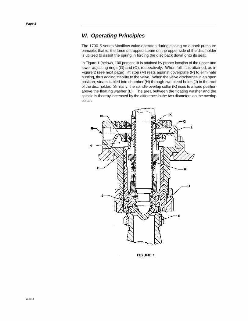
The 1700-S series Maxiflow valve operates during closing on a back pressureprinciple, that is, the force of trapped steam on the upper side of the disc holderis utilized to assist the spring in forcing the disc back down onto its seat.
In Figure 1 (below), 100 percent lift is attained by proper location of the upper andlower adjusting rings (G) and (O), respectively. When full lift is attained, as inFigure 2 (see next page), lift stop (M) rests against coverplate (P) to eliminatehunting, thus adding stability to the valve. When the valve discharges in an openposition, steam is bled into chamber (H) through two bleed holes (J) in the roofof the disc holder. Similarly, the spindle overlap collar (K) rises to a fixed positionabove the floating washer (L). The area between the floating washer and thespindle is thereby increased by the difference in the two diameters on the overlapcollar.
VI. Operating Principles
CON-1
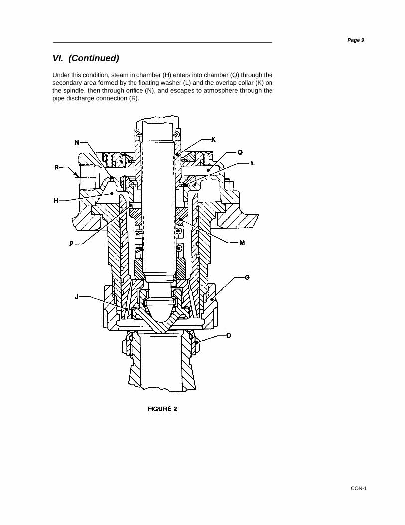
VI. (Continued)
Under this condition, steam in chamber (H) enters into chamber (Q) through thesecondary area formed by the floating washer (L) and the overlap collar (K) onthe spindle, then through orifice (N), and escapes to atmosphere through thepipe discharge connection (R).
Page 9
CON-1
VI. (Continued)
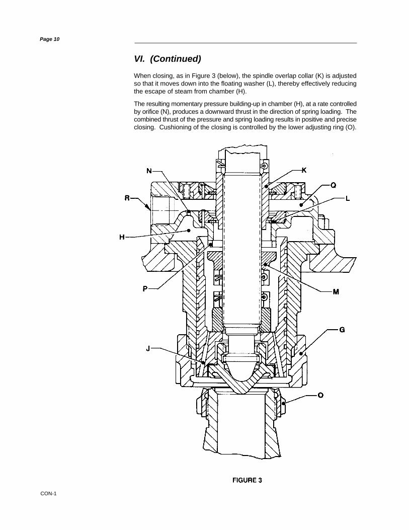
When closing, as in Figure 3 (below), the spindle overlap collar (K) is adjustedso that it moves down into the floating washer (L), thereby effectively reducingthe escape of steam from chamber (H).
The resulting momentary pressure building-up in chamber (H), at a rate controlledby orifice (N), produces a downward thrust in the direction of spring loading. Thecombined thrust of the pressure and spring loading results in positive and preciseclosing. Cushioning of the closing is controlled by the lower adjusting ring (O).
Page 10

CON-1
Safety valves should be stored in a dry environment to protect them from theweather. They should not be removed from the skids or crates until immediatelyprior to installation. Flange protectors and sealing plugs should remain installeduntil just prior to installation.
Safety valves, either crated or uncrated, should never be subjected to sharpimpact. This would be most likely to occur by bumping or dropping during loadingor unloading from a truck or while moving with a power conveyor, such as a forklift truck. The valve, either crated or uncrated, should always be kept with the inletdown (i.e., never laid on its side), to prevent misalignment and damage tointernals. Even crated valves should always be lifted with the inlet down.
Uncrated valves should be moved or hoisted by wrapping a chain or sling, aroundthe discharge neck, then around the upper yoke structure, in such manner as willinsure that the valve is in vertical position during lift, (i.e., not lifted in horizontalposition). Never lift the full weight of the valve by the lifting lever. Never hook tothe spring to lift. When safety valves are uncrated and the flange protectorsremoved, immediately prior to installation, meticulous care should be exercisedto prevent dirt from entering the outlet port while bolting in place.
While hoisting to the installation, care should be exercised to prevent bumpingthe valve against steel structures and other objects.
VII. Storage and Handling Prior to Installation
Page 11

CON-1
VIII. Recommended Installation Practices
A. General Requirements
1. The valve should be installed to meet all the requirements of Figure4 (below).
2. The safety valve shall be connected to the header independent of anyother connection, and attached as close as possible to the header,without any unnecessary intervening pipe or fitting. “Necessary”intervening pipe or fitting shall not be longer than the face-to-facedimension of the corresponding tee fitting of the same diameter andpressure, per ANSI Standards.
3. No valve of any description should be placed between the safety valveand the header, nor on the discharge pipe between the safety valveand the atmosphere.
4. In no case may the inlet piping to the valve have a flow area less thanthe area of the valve inlet.
5. Excessive pressure loss at the inlet of the safety valve will causeextremely rapid opening and closing of the valve, which is known as“chattering”. Chattering may result in lowered capacity as well asdamage to the seating surface of the valve. Severe chattering cancause damage to other parts of the valve.
Page 12

CON-1
VIII.A. (Continued)
Page 13
The following recommendations will assist in eliminating the factors that producechatter:
a. Header nozzle corners must be rounded to a radius of not less than1/4 of the opening diameter.
b. Pressure drop due to friction flow to the inlet of the valve should not begreater than 50% of the expected blowdown of the safety valve.
6. To decrease the effects of a phenomenon known as “sonic vibrations,” thefollowing recommendations are made.a. Safety valves should be installed at least eight to ten pipe diameters
downstream from any bend in a steam line. This distance should beincreased when the valve is installed on the horizontal section of aheader which is preceded by an upward section.
b. Safety valves should not be installed closer than eight to ten pipediameters either upstream or downstream from a diverging, or aconverging, “Y”.
c. In cases where a piping configuration renders the above tworecommendations impractical, or impossible, the downstream corner ofthe header nozzle inlet should be rounded to a greater extent than theupstream corner. The header nozzle entrance should be rounded so theradius at the downstream corner will be equal to a minimum of 1/4 of thenozzle diameter. The radius should be reduced gradually, leaving onlya small portion of the upstream corner with a smaller radius.
d. Safety valves should never be installed, in a steam line, in a positiondirectly opposite to a branch line.
7. Excessive line vibrations are known to produce shifts in safety valve setpressures. Vibrations may possibly introduce chatter, causing damage tothe valve, and reduce its capacity. This vibration also contributes to increasedincidents of seat leakage. Considerations should be given to eliminating thisproblem prior to installing the valve on the unit.
8. Steam flowing vertically out a discharge elbow produces a downwardreaction on the elbow. Bending stress in the valve is determined by theproduct of this reactive force and the moment arm between the point ofsteam exhaust and the section being analyzed for bending stress. Theeffects of reaction force, vibration, and seismic loads, on all valve componentsand discharge piping, should be considered when designing the valvesystem.
9. For optimum performance, safety valves must be serviced regularly andotherwise maintained. So that servicing can be properly performed, valvesshould be located in a manner that allows for easy access. Sufficient workingspace should be provided around and above the valve to permit access toadjusting rings. If two or more valves are located close together, the outletsshould be parallel so as to offer as much protection as possible to personnelrepairing, or working close to, the safety valve.
10. Because foreign material passing into, and through, a safety valve isdamaging, the system on which the valve is tested and finally installed mustalso be inspected and cleaned. New systems are prone to contain weldingbeads, pipe scale, and other foreign materials which are inadvertentlytrapped during construction, and destroy the valve seating surfaces the firstfew times the valve opens. Therefore, the system should be thoroughlypurged before the safety valve is installed.

CON-1
VIII.A. (Continued)
11. With regard to weld-end inlet valves, completely assembled valves may beinstalled without disassembly being necessary at the time of welding. Duringwelding, the valve neck should be insulated to reduce thermal stresses.When stress relieving, insulation should also be utilized to reduce thermalstresses. In service, the valve neck should be insulated at least to the pointof the inlet neck/valve body-bowl juncture.
12. Safety valves should be installed in a vertical position. Nominal tolerance onvertical installation is plus or minus 1 degree.
13. The discharge area of the outlet piping from a safety valve should not be lessthan the area of the outlet connection. Where more than one safety valve isconnected to a common outlet pipe, the area of the pipe should not be lessthan the combined area of the outlet connections to the safety valves.
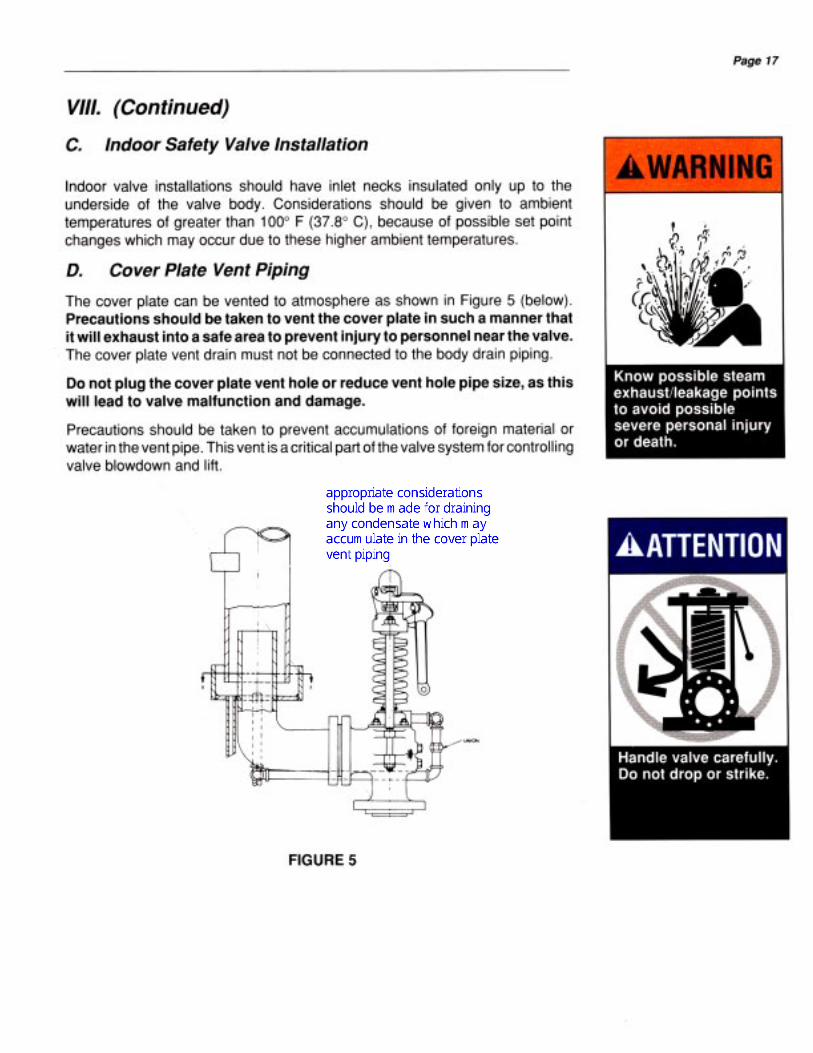
14. All safety valve discharges should be piped so that the effluent is dischargedclear from running boards or platforms. Ample provision for gravity drainshould be made in the discharge pipe at, or near, each safety valve wherewater, or condensation, may collect. Each valve has an open gravity drainthrough the body, below the level of the valve seat, and this drain should bepiped to a safe discharge area.
15. If a silencer is used on a safety valve, it should have sufficient outlet area toprevent back pressure from interfering with the proper operation anddischarge capacity of the valve. The silencer or other piping componentsshould be constructed so as to avoid the possibility of creating corrosiondeposit restrictions in the steam passages.
16. Exhausts, drains, and vents must be installed so that they will not imposeundue stresses on the safety valve. Any such stresses can produce bodydistortion and leakage. Therefore, the following recommendations areprovided:
a. Discharge piping should not be supported by the valve. The maximumweight on the outlet of the valve should not exceed the weight of a shortradius elbow and flange, plus a twelve (12) inch (304.8 mm) straightlength of standard weight thickness pipe (with drip pan).
b. Clearance between the valve exhaust piping and the discharge stackshould be sufficient to prevent contact when considering thermalexpansion of the header, valve, and discharge stack. Movements dueto vibration, temperature changes, and valve reaction forces should alsobe considered, to insure adequate clearance between the exhaustpiping and the discharge stack.
c. Flexible metal hoses are not generally recommended, but if used toconnect valve outlets to discharge stacks, they must be of sufficientlength, and be configured/installed in such a manner, that they will notbecome “solid” in any one position. Better results are obtained if thehoses are installed so that they will permit movement by bending, ratherthan by stretching and compressing along their length.
17. When liftinga valve, the valve should always remain in a vertical position.The valve may be lifted by using a sling around the valve yoke and the valveoutlet neck. In no case should the valve be lifted by the lifting lever.
The valve should not be bumped or dropped during installation. If the valveis dropped, an inspection for damage should be made, and the set pressureof the valve rechecked.
Page 14

CON-1
18. At the time of installation, all protective covers on the valve should beremoved. The internals of the valve are to be checked for cleanliness. Noforeign matter is permitted in the valve inlet or outlet, since it may possiblydamage the valve components, or be dropped into the header.
All face surfaces which require gaskets, to seal pressure, shall be inspectedfor cleanliness, or any defects that can cause leakage. Burrs, mashedserrations, uneven surfaces, etc., are all possible leakage producing defects.Proper gasket sizes and pressure ratings should be checked prior to startingvalve installation.
19. It is of utmost importance that the gaskets used be dimensionally correct forthe specific flange, and that they fully clear the valve inlet and outletopenings. Gaskets, flange facings, and bolting should meet the servicerequirements for the pressure and temperature involved. Other valveinstallation considerations include:
a. Install the inlet gasket, if required, on the header mounting flange. Checkfor cleanliness, surface alignment condition, gasket condition, etc.When possible, inlet studs on the mounting flange should be used toguide the valve on the header mounting flange. Inlet studs should belubricated with the appropriate lubricant.
b. When installing flanged valves, the flange bolts must be pulled downeveningly to prevent body distortion, misalignment, and leakage.
c. With valve in position,screw on the stud nuts until all nuts are finger tight.An initial torque shall be placed, in turn, on each stud nut. Increase thetorque progressively until the final torque is applied. Upon completion,recheck each stud nut’s torque. Required torque will vary with boltingmaterial and gaskets used. See your company engineering orspecification department for details.As an extra precaution, the gap between the two mating flanges shouldbe checked during the torquing process to insure that the flanges arebeing pulled together evenly. Calipers may be used for this verification.A final inspection and review should be made to insure that all of therequirements for bolting the valve inlet have been implemented.
d. In like manner, the outlet piping may now be installed. A completeinspection of components and their cleanliness is to be made prior tofurther work. Studs are to be lubricated with an appropriate lubricant.
e. Install the outlet gasket, studs and nuts. Stud nuts are to be pulled downfinger tight. An initial value of torque is to be applied. The additionalprocedures outlined, in Step 19.c., (above), are also to be followed.
20. After being assured that the valve is properly installed, the drainage pipingfrom the valve body-bowl is to be connected. This line also must be flexible,so it will not create loads on the valve under operating conditions.
21. Prior to completing the installation, a visual check should be made to insurethat the valve lifting lever is free to operate.
22. At the time of installation, an inspection of the valve should be made toconfirm that all adjustment components (i.e., ring pins, cap, etc.) are properlylocked and sealed, as required by the ASME Code.
23. Flanged valves may be installed without insulation.
24. For operational hydrostatic tests at the valve inlet, which do not exceed valve
VIII.A. (Continued)
Page 15

CON-1
set pressure (1.0 x design pressure), the valve may be gagged. Refer to the“Field Testing” portion of this manual (i.e., Section X) for proper techniques.Insure that the gag is removed upon completion of the inlet hydrostatic test.
25. Prior to startup of the unit on steam, the sections of this manual which specifyrequirements for set pressure testing should be reviewed. For conditionswhere the valve is subjected to high steam pressures (i.e., those exceedingnormal operating conditions), preparations should be made to gag thevalves. These preparations should then be cleared with the boilermanufacturer and DVCD Engineering. Refer to Section XV of this manual forthe proper gagging techniques.
26. The safety valve should be tested with full steam pressure to insure that thesafety valve installation has been properly accomplished. In some cases thisis not practical, thus the use of the CONSOLIDATED® Hydroset, or theElectronic Valve Tester (EVT), should be considered. For valves beingtested for set pressure by using a Hydroset or EVT, only the set pressureis being verified. Other factors such as blowdown, lift, reaction force, properdischarge stack sizes and effects of thermal expansion cannot be determined.
27. Vent and drain piping should have a union connection to facilitate valveremoval.
B. Outdoor Safety Valve Installation
Safety valves operating under the best possible conditions (i.e., of favorableoperating gap, relatively stable ambient temperatures, the absence of dirt andin relatively still air) will provide the maximum degree of safety, tightness anddependability.
When a safety valve is installed in an outdoor location, it may be exposed to wind,rain, snow, ice, dirt and varying temperatures. Therefore, the followingrecommendations are made for proper protection, and to insure that operationaldependability can be restored to a level near that of the valve installed under idealconditions:
1. The inlet neck of the safety valve and safety valve body, up to the bottomof the cover plate in the Maxiflow Safety Valve, should be insulated. Theexterior surface of any such insulation should be made weather-proof byany suitable means. In addition to maintaining a more even temperaturewithin the valve body, especially during widely fluctuating ambienttemperatures, this insulation will effectively reduce thermal stresses, dueto high temperature gradients, through the walls of the safety valve nozzle.
2. Spring covers should be used to stabilize (as nearly as possible) thetemperature of the spring, to prevent the accumulation of snow and icebetween the coils of the spring, and to prevent dirt and fly ash fromaccumulating between the coils of the spring.
3. Lifting gear covers should be installed to prevent ice, dirt and fly ash fromaccumulating in areas inside the safety valve cap.
VIII.A. (Continued)
Page 16

CON-1
IX. Hydrostatic Test Plug Removal-Domestic and Export
A. General Information
Flanged inlet safety valves should be removed from the boiler duringhydrostatic tests and boiler nozzles blanked off to prevent possible valvedamage.
All valves shipped outside the continental United States are shipped with anexport hydroplug. All welded inlet valves shipped within the continental UnitedStates are shipped with a domestic hydroplug, unless the customer specificallyrequests otherwise. All flanged inlet valves shipped within the continental UnitedStates are shipped without a hydroplug, unless one is specifically re-quested bythe customer.
Valves shipped with either type of hydroplug are identified by a Red on WhiteCAUTION TAG which is attached to the valve by wires extending through thedrain hole in the valve body. See Figure 6 (below).
The hydrostatic plugs are placed in the bore of the valve, inside the seatingsurface. Their purpose is twofold. First they effect closure at a point differing fromthe seating surface of the valve so that, if the valve is lifted on hydrostatic test,the seating surface is not as likely to be damaged. Second, by raising the discof the valve off its seat and increasing spring compression, the set pressure ofthe valve is increased to a point where the valve will not leak at one and one-halftimes design boiler pressure. It is not necessary to gag safety valves tightly whenhydrostatic plugs are used.
These plugs must, of course, be removed from the valves prior to placing theboiler in service. However, they should be retained, and reinstalled, whenevera hydrostatic test exceeding the low set valve pressure is conducted.
Page 18
CON-1
Page 19
B. Domestic Plugs
1. Disassemble the valve as outlined in Section XI of this manual.
2. Remove the hydrostatic test plug from the seat bushing, and lap discand bushing seat.
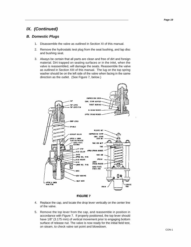
3. Always be certain that all parts are clean and free of dirt and foreignmaterial. Dirt trapped on seating surfaces or in the inlet, when thevalve is reassembled, will damage the seats. Reassemble the valveas outlined in Section XIII of this manual. The lug on the top springwasher should be on the left side of the valve when facing in the samedirection as the outlet. (See Figure 7, below.)
IX. (Continued)
4. Replace the cap, and locate the drop lever vertically on the center lineof the valve.
5. Remove the top lever from the cap, and reassemble in position inaccordance with Figure 7. If properly positioned, the top lever shouldhave 1/8" (3.175 mm) of vertical movement prior to engaging bottomsurface of release nut. The valve is now ready for the initial field test,on steam, to check valve set point and blowdown.
CON-1
Page 20
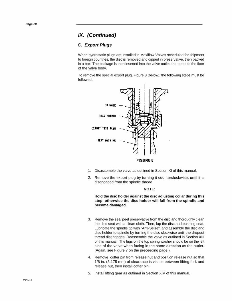
1. Disassemble the valve as outlined in Section XI of this manual.
2. Remove the export plug by turning it counterclockwise, until it isdisengaged from the spindle thread.
NOTE:
Hold the disc holder against the disc adjusting collar during thisstep, otherwise the disc holder will fall from the spindle andbecome damaged.
3. Remove the seal peel preservative from the disc and thoroughly cleanthe disc seat with a clean cloth. Then, lap the disc and bushing seat.Lubricate the spindle tip with "Anti-Seize", and assemble the disc anddisc holder to spindle by turning the disc clockwise until the dropoutthread disengages. Reassemble the valve as outlined in Section XIIIof this manual. The lugs on the top spring washer should be on the leftside of the valve when facing in the same direction as the outlet.(Again, see Figure 7 on the preceeding page.)
4. Remove cotter pin from release nut and position release nut so that1/8 in. (3.175 mm) of clearance is visible between lifting fork andrelease nut, then install cotter pin.
5. Install lifting gear as outlined in Section XIV of this manual.
C. Export Plugs
When hydrostatic plugs are installed in Maxiflow Valves scheduled for shipmentto foreign countries, the disc is removed and dipped in preservative, then packedin a box. The package is then inserted into the valve outlet and taped to the floorof the valve body.
To remove the special export plug, Figure 8 (below), the following steps must befollowed.
IX. (Continued)

CON-1
Page 21
X. Field Testing
A. General Information
All 1700 Maxiflow Safety Valves are steam tested at the factory to verify setpressure adjustability and seat tightness. Every valve is set to have a cleanpopping action and to reseat tightly. However, because the boiler used in settingthe valves has a small capacity, compared to the capacities of the Maxiflow typeof valves, adjustments on the actual installation are necessary to ensure propervalve action and “adjusting ring” settings.
When supplied for pressures over 2500 psi (172.4 Bar), the compression screwlock nut will be locked to the compression screw with a 1/4-20 Allen screw, inorder to locate the exact amount of compression screw engagement in the valveyoke. The compression screw has then been backed out to decrease the springload on the seat by 75%. See Red Letter Warning Tag, attached to compressionscrew of each Maxiflow Valve by means of double strand sealing wire, whichreads as follows:
WARNING
This valve has been steam tested and set to the proper setpressure; however the compression on the spring has beenrelaxed by backing out the compression screw.
Before the hydrostatic test on the boiler the compression screwmust be turned clockwise until the lock nut makes up on the yoke.
Remove the 1/4-20 allen screw to allow the lock nut to turn oncompression screw for future adjustments.
(Note attached tag for hydrostatic plug removal).*
Upon completion of hydrostatic testing of the boiler, but prior to placing the boilerin service, insure that the hydrostatic plugs are removed from all valves. (Note:See Figure 6 on page 18 of this manual). The use of a DVCD Hydroset or EVT,unit can serve to establish set pressure but cannot be used for verifyingblowdown, lift, etc. (For additional information, see Section X.E., of this manual).Gagging of other valves not being set will not generally be necessary; however,for setting of high pressure valves, depending on system pressure being used,it may be necessary to gag the lower set valves.
Boiler safety valve tests can be conducted with the unit either on or off the line.However, with the unit on the line under full load, a sudden load drop could bedangerous as most of the safety valves will be gagged. Therefore, it isrecommended that the safety valves be tested and adjusted with the boilerisolated, or with light load. Boiler control can then be maintained, with little or nooutside influence due to load change.
It is important to note that all adjustments of adjusting rings are DVCD initialadjustments only, and are not intended to be final adjustments. This finaladjustment must be made on the operating system with conditions approximatelythose that will be realized under actual operating conditions. Valves are factoryset for long blowdown to prevent chattering under initial setting conditions.
* This parenthetical statement is a reference to the tag shown in Figure 6, on page 18 of this manual.

CON-1
Page 22
X.A. (Continued)
Factors which can affect valve operation, and which should be considered wheninitially setting a valve, are as follows:
1. Ambient temperature near the valve and valve temperature stabilization.
2. Line vibration.
3. Line capacity at time when the valve must lift.
4. Discharge stack or drain piping binding.
5. Fluid flow vibrations set up by upstream bends and other disturbances.
After each adjustment of the compression screw, the lock nut should betightened. The arm of the top spring washer should always be free from bearingagainst the yoke rod. This can be accomplished by holding a screw driverbetween the arm and the rod to prevent any movement of the top spring washerwhile adjusting the compression screw. Install the cap and lever assembly afterset pressure adjustments have been completed, as outlined in the Re-assemblyinstructions (see Section XIV of this manual).
C. Ring Adjustments, Blowdown andOverlap Collar Adjustments
1. GeneralThe positions of the upper adjusting ring and the lower adjusting ringare locked by means of the upper adjusting ring pin and the loweradjusting ring pin, respectively. These pins are threaded into the valvebody and engage notches which are cut into the rings. To adjust eitherring, the corresponding ring pin must be removed. A screw driver (orother suitable tool), inserted through the ring pin hole, can be used toturn the rings.
NOTE:
Always gag the Safety Valve for protection. This will ensure that thedisc is not accidentally lifted from the seat by the adjusting toolduring ring adjustment. This will also ensure that an unexpected risein system pressure will not be a hazard to service personnel.
B. Popping Point Adjustment
NOTE:
Prior to beginning this procedure, lower the operating pressureon the boiler to a point which ensures that the valve will notopen during adjustment of the compression screw.
To change the popping pressure of the valve, remove the cap and leverassembly, loosen the compression screw locknut and turn the compressionscrew clockwise to increase the pop point, or counterclockwise to decrease thepop point.

CON-1
Page 23
X.C. (Continued)
TABLE IFinal Factory Positions
(Field Starting Positions)
2. Lower Ring AdjustmentIf the lower adjusting ring position is in question, the factory positioncan be attained as follows:
a. Gag the safety valve to prevent the disc from being accidentallylifted from the seat.
b. Remove the service port plugs.
c. Remove the lower adjusting ring pin.
d. Move the lower adjusting ring up until it contacts the disc holder.
e. Refer to Figure 9 (below), and move the lower adjusting ring downthe number of notches indicated in Column A, plus 1 additionalnotch for each 600 psig increment of set pressure, not to exceedsix notches (see Table I, also below).
LOWER RING UPPER RINGHOLDER TO SEAT HOLDER TO SEAT
IN NOTCHES IN NOTCHESORIFICE (Column A) (Column B)
1 7 102 8 123 12 165 12 164 12 166 30 457 30 45Q 30 458 37 45R 38 47
CON-1
X.C. (Continued)
WARNING
Page 24
f. Lock the lower adjusting ring into position by installing the loweradjusting ring pin, clockwise, until tight.
g. Remove the gag.
h. Test the valve on the system and adjust the lower ring to the lowestposition which does not produce simmer.
The ideal ring position must then be found by test for the set ofoperating conditions present. If simmer is present or the valve failsto lift, the lower ring should be moved upward slowly, one notch ata time, to remove the simmer. The most ideal position for the lowerring is the lowest position that does not introduce simmer or abuzzing sound.
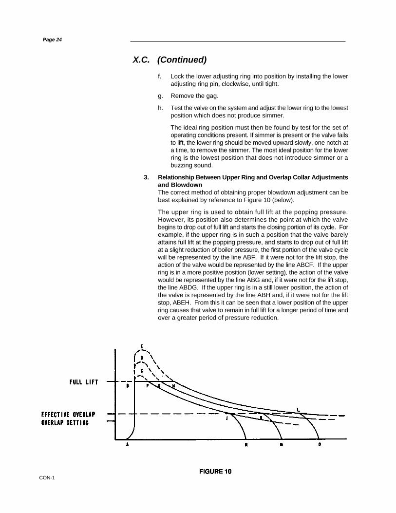
3. Relationship Between Upper Ring and Overlap Collar Adjustmentsand BlowdownThe correct method of obtaining proper blowdown adjustment can bebest explained by reference to Figure 10 (below).
The upper ring is used to obtain full lift at the popping pressure.However, its position also determines the point at which the valvebegins to drop out of full lift and starts the closing portion of its cycle. Forexample, if the upper ring is in such a position that the valve barelyattains full lift at the popping pressure, and starts to drop out of full liftat a slight reduction of boiler pressure, the first portion of the valve cyclewill be represented by the line ABF. If it were not for the lift stop, theaction of the valve would be represented by the line ABCF. If the upperring is in a more positive position (lower setting), the action of the valvewould be represented by the line ABG and, if it were not for the lift stop,the line ABDG. If the upper ring is in a still lower position, the action ofthe valve is represented by the line ABH and, if it were not for the liftstop, ABEH. From this it can be seen that a lower position of the upperring causes that valve to remain in full lift for a longer period of time andover a greater period of pressure reduction.

CON-1
X.C. (Continued)
Page 25
It will further be noted that there is a distinct difference between theactual overlap setting on the valve and the point at which the overlapbegins to take effect. This can be understood since the area in theoverlap vent begins to reduce considerably ahead of the point wherethe upper corner of the overlap bevel actually enters the floatingwasher. This has the effect of rounding off the corners of the diagramat points J, K & L. If the upper ring is in a position to produce the lineABH, the overlap will have to be set considerably higher to obtain ashort blowdown than if the upper ring is set at such a position as toproduce the line ABF. Excessive overlap settings may cause seatdamage when the valve closes. It is therefore desirable to set the upperring in such a position as to cause the valve to stay in full lift for as shorta time as possible. The most desirous complete cycle is representedby the line ABFJM.
NOTES:
• When steam safety valves are subjected to an excessively highwater level, the valve can be expected to have a long blowdownwhich the upper adjusting ring position will be unable to correct.It is recommended that the cause of high water level be corrected,so valves may function correctly at the ordered condition.
• If a superheater valve is set with low temperature steam, it isadvisable to increase the blowdown to compensate for the changein density and other thermal effects taking place when the steamis brought up to working temperature. An approximate rule is toadd 1/2 of 1% of set pressure to the blowdown for each 100°F(37.8°C) of steam temperature below the final temperature.
4. Upper Ring AdjustmentIf the upper adjusting ring position is in question, the factory positioncan be attained as follows:
a. Gag the safety valve to prevent the disc from being accidently liftedfrom the seat.
b. Remove both service port plugs.
c. Remove upper adjusting ring pin.
d. Move the upper adjusting ring until it is level with the disc holder.A flashlight may be needed to provide adequate lighting for thisobservation.
If so, the observation can be made from one of the service portswhile the flashlight is positioned to shine through the other serviceport.
e. From this point, move the upper adjusting ring down the number ofnotches indicated by Column B of Table I (see page 23). This isalso Dimension B in Figure 9 (again, see page 23).
f. Lock the upper adjusting ring into position by installing the upperadjusting ring pin.
g. Remove the gag.
CON-1
X.C. (Continued)
5. Blowdown AdjustmentsWhen further adjustments are required to obtain final blowdown setting,the upper adjusting ring should be moved 5-10 notches at a time asfollows:
a. To reduce blowdown - MOVE RING UP - TURN COUNTER-CLOCKWISE.
b. To increase blowdown - MOVE RING DOWN - TURN CLOCKWISE.
It is possible to raise the upper ring too far and prohibit attainment of fulllift. When this occurs, lower the upper adjusting ring to the point wherefull lift is attainable and finalize the blowdown setting with the overlapcollar adjustments (see Section X.C.6., below). If the valve fails to lift,the lower adjusting ring requires further adjustment (see Lower RingAdjustment on page 23).
In attempting to obtain blowdown of 4%, it is important to be sure thatthe upper and lower adjusting ring positions are not so far apart as tocause loss of control of the valve. The first indication of reaching thiscondition is a slow “up and down hunting” action of the valve immediatelybefore closing. If this action occurs at a blowdown longer than desired,moving both rings downward a small amount will generally produce aslightly shorter blowdown. When making this adjustment, move theupper ring twice as many notches as the lower.
After adjustments are complete, check the ring pins to see that theyengage the ring grooves, but without touching the bottom of the groove.The pins should not bear against the rings.
6. Overlap Collar AdjustmentThe overlap collar is a secondary adjustment point for blowdowncontrol. It is utilized in conjunction with the upper adjusting ring. Therewill be some field conditions where it may not be necessary to use theoverlap collar. However, in no case should the overlap collar be usedexclusively for blowdown setting without first giving due adjustmentattention to the upper adjusting ring.
The overlap collar is moved downward to shorten blowdown andupward to lengthen blowdown. After final setting, be sure to lock theoverlap collar in position by installing the cotter pin.
A guide to how movement of the overlap collar assists in making finalblowdown adjustments is as shown in Table II on the next page.
Page 26

CON-1
Page 28
XI. Disassembly Instructions
A. General Information
The Type 1700 Maxiflow Safety Valve can be easily disassembled for inspection,reconditioning seats, or replacing internal parts. The initial spring load can beestablished after reassembly. (Again, refer to Figure 7, on page 19, for partsnomenclature.)
NOTES:
• Before starting to disassemble the valve, be sure that there isno steam pressure in the drum or header.
• Parts from one valve should not be interchanged with partsfrom another valve.
B. Specific Steps
1. Remove the top lever pin and top lever.
2. Loosen cap set screw and lift off cap and drop lever assembly.
3. Remove the cotter pin which retains the release nut, and then removethe release nut.
F. Sealing Valves After Test
After testing the valve for proper set point and blowdown, the ring pins, overlapcollar and top lever pin will be sealed to conform with the applicable ASME Code.In addition, the cover plate is sealed on restricted lift valves.
Means are provided in the design of all 1700 Maxiflow valves, for use underSection I of the ASME Code, for sealing all external adjustments. Seals areinstalled by DVCD at the time of shipment. It is also required that seals beinstalled, after field adjustment or repair of the valves, by the manufacturer, itsauthorized representative, or the user.
Seals should be installed in such a manner as to prevent changing theadjustment without breaking the seal. They also serve as a means of identifyingthe manufacturer, repairer, or user making the adjustment. Unauthorizedbreakage of the seals will void the valve warranty.
X. (Continued)

CON-1
Page 29
XI.B. (Continued)
4. Refer to Figure 11 (below), and measure and record Dimension A, asthis information will be required to correctly re-assemble the valve.
5. Remove the two top yoke rod nuts evenly, so as to prevent binding ofthe yoke.
6. Carefully lift the yoke over the spindle, and away from the valve.Remove the thrust bearing assembly (if applicable) and the topspring washer.
7. Ensure that the bottom spring washer is not stuck to the spring. If thebottom spring washer is stuck to the spring it may accidentally jarloose and fall. Next, mark the top of the spring, in order to correctlyinstall the spring during re-assembly. Finally, lift the spring over thespindle and away from the valve, and then remove the bottom springwasher.
8. Remove the overlap collar cotter pin from the collar and spindleassembly. Note which overlap collar notch is opposite the cotter pinhole in the spindle. (See Figure 12, below.) Carefully counting eachcollar notch that passes in front of the cotter pin hole in the spindle,begin rotating the collar counterclockwise until the bottom line (of thefour lines) on the collar is even with the upper floating washer. Recordthe number of overlap collar notches that passed in front of the cotterpin hole in the spindle, as this information will be required to correctlyre-assemble the valve.

CON-1
Page 30
XI.B. (Continued)
9. Mark the cover plate vent to establish its relationship to the valvebase, as this will ensure correct alignment during re-assembly, then,remove the cover plate stud nuts, and lift the cover plate over thestuds.
10. Remove the spindle, disc and disc holder assembly from the valveby lifting the spindle. Take care to insure that the disc seatingsurface is not damaged when the assembly is placed on the groundor some other work surface.
11. To remove the disc and disc holder from the spindle, first insert thespindle into a vise (see Figure 13, below) being careful not todamage the threaded end of the spindle. Then, lift up on the discholder and turn the disc/disc holder counterclockwise to engage the"drop-thru" threads. Once the threads are engaged, release the discholder and continue to unthread and remove the disc. After the discis removed, lift the disc holder from the spindle.
NOTE:
Removal of the overlap collar, the lift stop and/or the disc collarfrom the spindle is usually unnecessary, unless the spindle is tobe replaced.

CON-1
XI.B. (Continued)
12. Measure from the top of the guide to the bushing seat (DimensionB, Figure 14, below) with a depth micrometer or other suitablemeasuring device. Record Dimension B. Place a scale or otherthin flat metal surface against the lower face of the upper adjustingring and measure from the top of the guide to the face of the upperadjusting ring (Dimension C, Figure 14, below). Record DimensionC.
Page 31
CON-1
Page 32
XI.B. (Continued)
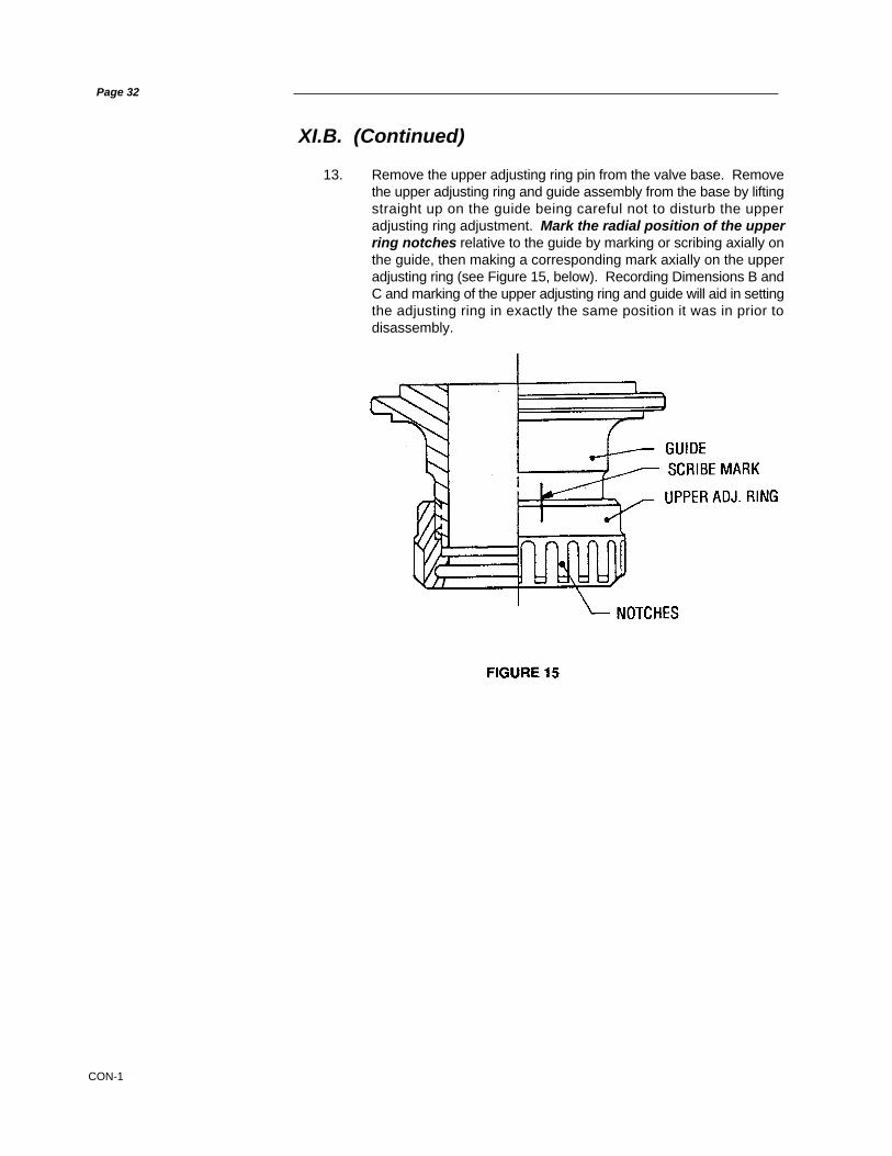
13. Remove the upper adjusting ring pin from the valve base. Removethe upper adjusting ring and guide assembly from the base by liftingstraight up on the guide being careful not to disturb the upperadjusting ring adjustment. Mark the radial position of the upperring notches relative to the guide by marking or scribing axially onthe guide, then making a corresponding mark axially on the upperadjusting ring (see Figure 15, below). Recording Dimensions B andC and marking of the upper adjusting ring and guide will aid in settingthe adjusting ring in exactly the same position it was in prior todisassembly.

CON-1
XI.B. (Continued)
14. Loosen the lower adjusting pin until the pin is slightly clear of thenotches in the lower adjusting ring. Being careful not to move thelower adjusting ring, place a ring lap on top the busing seat. (SeeFigure 16, below). Then, using the ring pin as a “pointer”, orreference point, rotate the lower adjusting ring counterclockwiseand count the number of notches that pass in front of the “pointer”until contact is made with the ring lap. Record this information, as itwill be required to correctly re-assemble the valve.
Page 33
15. Next, remove both the lower adjusting ring pin and the loweradjusting ring from the valve base.
16. Normally the yoke rods do not have to be removed from the valvebase. If however, it becomes necessary to remove them, theprocedure below should be followed:
a. Mark each rod relationship to where it contacts the valve base"ears", and also identifying which rod is to the right and whichrod is to the left of the valve outlet.
b. Loosen the yoke rod nuts using the appropriate size socketand handle.
c. Remove the nuts, and then pull up on each rod to remove itfrom the base.
17. The valve is now ready to be cleaned and the parts inspected forproper size and condition.
FIGURE 16

CON-1
Page 34
XII. Inspection
A. General
Once the valve is disassembled, appropriate parts can be inspected for damageand their suitability for reuse.
B. Specific Steps
As a minimum, the following parts should be inspected as specified below:
1. Disc HolderThe surface on the end of the disc holder closest to the disc must befree from steam erosion. The two small holes must be open to insurethe passage of steam to the chamber above the disc. Make sure theoutside diameter is not egg shaped and the surface is smooth. If anysmall indication of galling is present, polish the high spots with anemery cloth. If serious or large scale galling is present, the disc holdershould be replaced.
2. GuideInspect the guide inside diameter for egging, and insure the insidesurface is smooth. The threads on the outside must be in goodcondition to insure the upper ring will adjust, even when the valve ishot. If serious or large scale galling is present, the guide should bereplaced.
3. ClearanceThe maximum clearance between the disc holder and guide should bein accordance with Table III (below):
TABLE III
ORIFICE SIZE TEMPERATURE MAX. CLEARANCE (in.)
#1 UP TO 750°F .005ABOVE 750°F .008
#2 UP TO 750°F .008ABOVE 750°F .012
#3 UP TO 750°F .010ABOVE 750°F .015
#4 UP TO 750°F .012ABOVE 750°F .018
#5 UP TO 750°F .011ABOVE 750°F .017
#6 UP TO 750°F .016ABOVE 750°F .016
#7 UP TO 750°F .020ABOVE 750°F .020
#Q UP TO 750°F .020ABOVE 750°F .020
#8 UP TO 750°F .020ABOVE 750°F .020
#R UP TO 750°F .020ABOVE 750°F .020

CON-1
XII.B. (Continued)
4. DiscInspect the disc seat for steam cuts, nicks, or other damage. If the seatstep measure less than dimensions specified in Table IV (below), thisindicates that the thermal lip has been lapped to the minimumthickness.
Do not machine any THERMOFLEX™ disc; however, a disc whichis not below minimum relief can be lapped to remove minor damage.(See Figure 18, on page 38 for more information.)
TABLE IV
MINIMUM SEAT RELIEF
ORIFICE M(MIN.) (in)
1 .0042 .0053 .0065 .0074 .0086 .0107 .012Q .0128 .012R .012
5. Overlap CollarInspect the outside diameter for nicks, burrs, tears, pitting and signsof galling. Then, inspect the lugs for bending or damage, and thethreads for signs of galling, tearing, and damage.
6. Cover PlateEnsure that the floating washers are free to move and are not bent ordeformed. Check the surface of the inside diameter on the floatingwashers and the washer retainers for tears, pitting, corrosion, andsigns of galling. Ensure that the bleed hole in the cover plate is notobstructed.
Page 35

CON-1
XIII. Maintenance Instructions
A. General
It is not necessary to remove Type 1700 Maxiflow Safety Valves from the boilerfor maintenance. The normal maintenance required is generally confined totouching up seats and occasionally replacing the disc.
The following tools are recommended for this work:
1. Flat lapping plate (Part No. 0439004)
2. Grinding compounds
3. High temperature lubricant (Fel-Pro Nickel Ease)
4. Two (2) ring laps per valve size and type
See Maintenance Tools & Supplies (in Section XVII of this manual).
All of the above tools can be procured from DVCD, with prices being those thatare in effect at the time of delivery. It may not be necessary to use all of the ring-laps at any one time, but having a sufficient supply on hand will save the time ofreconditioning them during a boiler outage. After the boiler is back on the line,the ringlaps should be reconditioned on the flat lapping plate, or returned to thefactory for reconditioning, at a nominal cost, on a special lapping machine. A lapshould not be used on more than one valve without being reconditioned.
Valves that have been leaking should be disassembled in accordance with priorinstructions. Since the position of the adjusting rings has been recorded, therings can be removed for cleaning every time the valve is disassembled. Partsfor each valve should be kept together or marked, to ensure that they arereplaced in the same valve.
Reconditioning of the seat surface of the disc and seat bushing is accomplishedby lapping with a flat cast iron, ring lap, as outlined in the lapping procedure.(SeeSection XIII.B, below).
B. Lapping Procedure
1. General Information
While the finer points of lapping and “grinding-in” may be consideredas a mechanical art, it is not beyond the ability of the averagemechanic to produce good seats with some practice. No effort hasbeen made in this manual to establish an exact procedure to covereach and every case, because different persons can get the sameresults using their own techniques.
The following precautions and hints will be of assistance when lappingnozzle and/or disc seats:
a. Two (2) ring laps per valve
b. 1A Clover Grinding Compound per tool list*c. 1000 Grit Kwik-Ak-Shun Grinding Compound per tool list*d. Clean, lint free cotton rags
Page 36
* This tool list is located on page 57 of this manual
CON-1
XIII.B. (Continued)
NOTE:
If the bushing seat surface requires extensive lapping orreconditioning, a reseating machine should be used prior tolapping. (See “Reseating Machine“, in Section XIII.C., of thismanual.)
Cover the seat lap face with a light coating of 1-A Clover Compoundand gently place the lap on the valve bushing seat.
NOTE:
A heavy coat of lapping compound tends to round off the edgesof the seat.
Lap, using an oscillating motion in various directions, while holding thelap loosely in the fingers and allowing the weight of the lap to rest onthe seat surface. Control the motion of the lap to prevent either theinside or outside edge of the lap from crossing the bushing seatsurface. If either edge touches the seat surface, the seat can becomescratched and/or rounded.
NOTE:
Care should be used not to run off the seating surface with the lap,as this will cause the seat to become uneven.
Page 37
Before lapping the nozzle and disc seat, the leading edges (insidediameter of seats) of both must be slightly chamfered as follows:
Use a fine grade sandpaper to lightly break the inner edge and outeredge of the nozzle seat and disc seat. The purpose of this is to removeany small metal particles or fins attached to the sharp corner surfaces.Do not exceed .002 inches (.05 mm) chamfer for this purpose.
2. To Lap The Bushing Seat

CON-1
XIII.B. (Continued)
Page 38
Do not lap excessively with a ring lap without resurfacing on a lappingplate as shown in Figure 17 (below). Use a new ring lap, if furtherlapping is required, to remove any defect in the seat. To finish lappingthe bushing seat, apply a light coating of #1000 Grit Compound to theface of the new lap, and repeat the above lapping motion.
Remove the ring lap and wipe the lap surface with a clean, lint freecloth, leaving compound on the bushing seat. Replace the ring lap onthe seat and lap as above, but without adding compound. Repeat thisoperation until the seat has a mirror finish. Any evidence of defects,such as gray areas or scratches, will require a repeat of the wholelapping procedure until a mirror finish is attained.
3. To Lap Disc SeatThe above lapping method is also used on the disc seat. When lappingthe disc seat, the disc should be held stationery, but not rigidly, and thelap moved as above. Use care not to strike the cone of the disc, as thiswould cause the seat to be high on the inside.
The THERMOFLEX™ disc can not be machined. If, after lapping,Dimension M , in Figure 18 (below), does not meet the minimumspecified in Table V (on the opposite page), the disc should bereplaced.
CON-1
XIII.B. (Continued)
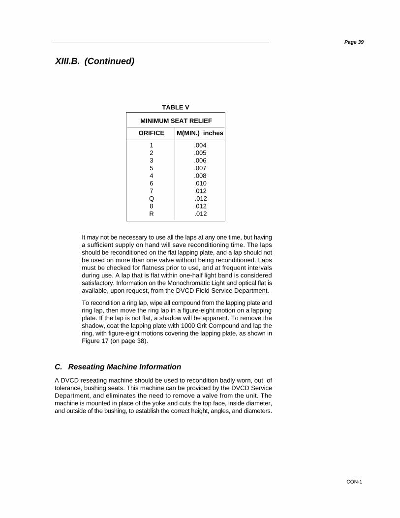
TABLE V
Page 39
MINIMUM SEAT RELIEF
ORIFICE M(MIN.) inches
1 .0042 .0053 .0065 .0074 .0086 .0107 .012Q .0128 .012R .012
It may not be necessary to use all the laps at any one time, but havinga sufficient supply on hand will save reconditioning time. The lapsshould be reconditioned on the flat lapping plate, and a lap should notbe used on more than one valve without being reconditioned. Lapsmust be checked for flatness prior to use, and at frequent intervalsduring use. A lap that is flat within one-half light band is consideredsatisfactory. Information on the Monochromatic Light and optical flat isavailable, upon request, from the DVCD Field Service Department.
To recondition a ring lap, wipe all compound from the lapping plate andring lap, then move the ring lap in a figure-eight motion on a lappingplate. If the lap is not flat, a shadow will be apparent. To remove theshadow, coat the lapping plate with 1000 Grit Compound and lap thering, with figure-eight motions covering the lapping plate, as shown inFigure 17 (on page 38).
C. Reseating Machine Information
A DVCD reseating machine should be used to recondition badly worn, out oftolerance, bushing seats. This machine can be provided by the DVCD ServiceDepartment, and eliminates the need to remove a valve from the unit. Themachine is mounted in place of the yoke and cuts the top face, inside diameter,and outside of the bushing, to establish the correct height, angles, and diameters.

CON-1
XIII.C. (Continued)
Page 40
Replace the seat bushing if critical dimension K (Max.) is exceeded. See Figure19 and Table VI below. Do not remove threads.
TABLE VI
Valve Type
#1 3-1/16#2 3-13/16
17.35, 36, 37 4-7/817.38, 39, 30 5-11/16
#4 5-11/16#5 5-11/16#6 4-3/4#7 5-9/16#Q 5-9/16#8 5-9/16#R 5-9/16
1706RXHPIand
1707R only 7-9/16
Critical Dimension
K (Max.) inches
The use of the reseating machine is suggested for reconditioning badly wornseats, or for re-establishing Dimension E per Figure 20 (below). Dimension Eshould be re-established when it is less than .010 inches for orifices 9, 1, 2, K,3, and 5, and 4 or less than .030 inches for orifices 6, 7, 8, R and RR.
As a result of machining the bushing seat, the length of disc holder extendingabove the disc guide will decrease. Therefore, the top of the disc guide shouldbe kept to a distance of at least 1/16 in. (1.587 mm), beneath the top of the discholder, to facilitate freeing the disc holder, in case a deposit of dirt forms in thepocket between the two parts. This dimension is obtained by machining the topof the disc guide (see Figure 21, on opposite page).
FIGURE 20

CON-1
Page 41
XIII.C. (Continued)
D. Spindle Runout
It is important that the spindle be kept very straight in order to transmit the springforce to the disc without lateral binding. Overgagging is one of the commoncauses of bent spindles. A method to check the essential working surfaces of thespindle is illustrated in Figure 22 (below). This may be performed either with orwithout the disc collar and lift stop on the spindle.
Using Figure 22 (above) as a reference, clamp a V block (A) made of wood, fiberor other suitable material onto the platform railing. Imbed the ball end of thespindle in a piece of soft wood (B) and place the top of the spindle, below thethreads, in the V block (A). Clamp a dial indicator onto the railing and locate atpoint (C). The total indicator reading should not exceed .007 in. (.177 mm) whenthe spindle is rotated. If it does, the spindle must be straightened prior to reuse.To straighten the spindle, place the unthreaded portion of the small and large endin padded V blocks, with the point of maximum indicator readout upward, andthen apply a downward force with a padded press or jack as required, until thespindle is within the specifications.

CON-1
XIII.D. (Continued)
Page 42
Other parts of the spindle not used as working surfaces may run out considerablymore than .007 in. (.177 mm), but this should not be regarded as unacceptable.Although the upper thread end is not a working surface, excessive bending in thisarea could effect the accuracy of the DVCD Hydroset device and/or the DVCDElectronic Valve Tester, if either of these devices is used to verify valve setpressure.
E. Disc Replacement and Disc-Spindle Bearing Requirements
To replace the disc, disassemble the valve in accordance with the instructionsprovided in Section XI of this manual.
Apply a small amount of lapping compound (1A) on the tip of the spindle. Installthe disc - without the disc holder - onto the spindle tip, turning it clockwise untilthe disc threads drop out. Place a ring lap on a table, or similar flat surface, andwipe the exposed surface of the lap clean. Insert the disc nose into a ring lap, sothat the seat contacts the lap surface. Oscillate the spindle using 360 degreeoscillations for approximately 15 seconds, then check the spindle tip and disc“pocket” to determine progress. (See Figure 23, below).
CON-1
XIII.E. (Continued)
Page 43
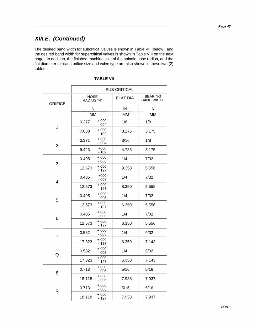
The desired band width for subcritical valves is shown in Table VII (below), andthe desired band width for supercritical valves is shown in Table VIII on the nextpage. In addition, the finished machine size of the spindle nose radius, and theflat diameter for each orifice size and valve type are also shown in these two (2)tables.
NOSERADIUS “R”
BEARINGBAND WIDTHFLAT DIA.
ORIFICEIN. IN. IN.MM MM MM
TABLE VII
SUB CRITICAL
+.000-.004
+.000-.102+.000-.004
+000-.102+.000-.005+.000-.127
+000-.005+.000-.127
+.000-.005+.000-.127+.000-.005
+.000-.127+.000-.005
+.000-.127+.000-.005+.000-.127
+.000-.005+.000-.005
+.000-.005+.000-.127
1
2
3
4
5
6
7
Q
8
R
0.277 1/8 1/8
7.038 3.175 3.175
0.371 3/16 1/8
9.423 4.783 3.175
0.495 1/4 7/32
12.573 9.358 5.556
0.485 1/4 7/32
12.573 8.350 5.558
0.495 1/4 7/32
12.573 6.350 5.556
0.485 1/4 7/32
12.573 6.350 5.556
0.582 1/4 9/32
17.323 6.350 7.143
0.582 1/4 9/32
17.323 6.350 7.143
0.713 5/16 5/16
18.118 7.938 7.937
0.713 5/16 5/16
18.118 7.938 7.937

CON-1
Page 44
XIII.E. (Continued)
If the required bearing band cannot be obtained by hand grinding, then this radiusshould be checked and remachined if necessary.
If the band extends too high on the radius it will be difficult to rock the disc, andthe disc may lock up under pressure. If the band is too narrow, the spindle mayindent the disc and again the rock will be lost.
When the bearing area is re-established, clean both surfaces. Then applylubricant to the spherical surface of the spindle tip, and work it into the surfacesby rotating the disc on the spindle.
Place the disc holder on the spindle, allowing it to rest on the face of the disc collaras previously shown in Figure 13 on page 30. Then assemble the disc holder andnew disc. The disc should be free enough to rock on the spindle tip. If there is nofreedom, lower the disc collar until the disc is free to rock slightly initially,approximately .001 to .002 inches (0.25 to .05mm) rock. The disc collar mustthen be lowered two additional notches from this initial position and secured witha stainless steel cotter pin. (See Figure 25, below).
TABLE VIII
IN IN INMM MM MM
.371 3/16 5/329.423 4.763 3.968
.371 3/16 5/329.423 4.763 3.968
.594 NONE 1/415.087 NONE 5.35
.495 1/4 7.3212.573 6.350 5.556
.495 1/4 7/3212.573 6.350 5.556
.495 1/4 7/3212.573 6.350 5.556
1
2
K
3
4
5
ORIFICE
SUPER CRITICAL NOSERADIUS "R"
BEARINGBAND WIDTHFLAT DIA.
NOTE:Failure to provide the recommended disc rock at assembly will result in aleaking valve.
CON-1
Page 45
H. Grinding The Lower Spring Washer
The lower spring washer bearing surface must be ground to the spindle. To grindthe lower spring washer, a 320 grit (Clover 1A) lapping compound is used forroughing-in, and then finish lap with 1000 Grit Kwik-Ak-Shun lapping compounduntil a satisfactory bearing band is obtained. The bearing width should be 1/8 in.(3.2 mm) min. to 3/16 in. (4.8 mm) max. Clean the lower spring washer andspindle when complete.
G. Thrust Bearing Surfaces
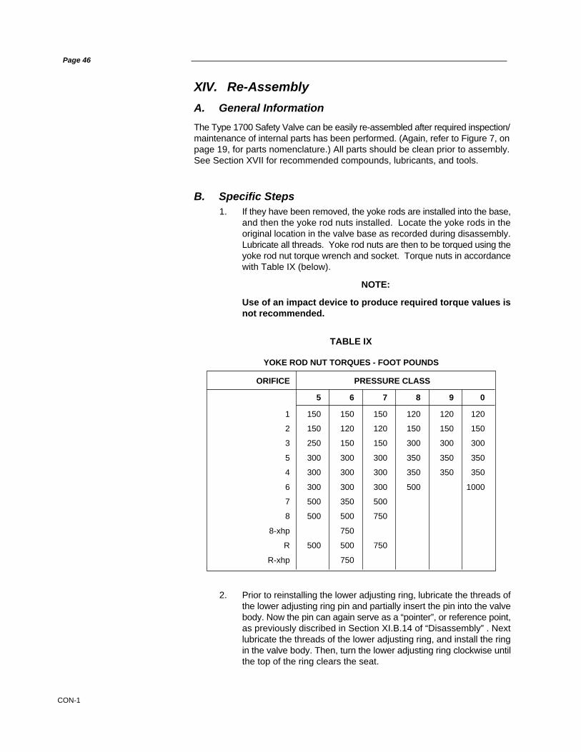
For those designs utilizing a ball-type thrust bearing, the aligning washer mustmatch evenly to the lower thrust bearing spherical surface, such that full facecontact is achieved between the parts (see Figure 27, below). Therefore, grindtogether, or replace the entire thrust bearing, as necessary.
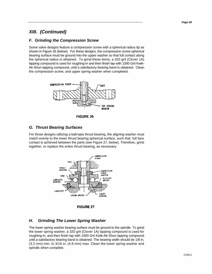
F. Grinding the Compression Screw
Some valve designs feature a compression screw with a spherical radius tip asshown in Figure 26 (below). For these designs, the compression screw sphericalbearing surface must be ground into the upper washer so that full contact alongthe spherical radius is obtained. To grind these items, a 320 grit (Clover 1A)lapping compound is used for roughing-in and then finish lap with 1000 Grit Kwik-Ak-Shun lapping compound, until a satisfactory bearing band is obtained. Cleanthe compression screw, and upper spring washer when completed.
XIII. (Continued)
CON-1
Page 46
1. If they have been removed, the yoke rods are installed into the base,and then the yoke rod nuts installed. Locate the yoke rods in theoriginal location in the valve base as recorded during disassembly.Lubricate all threads. Yoke rod nuts are then to be torqued using theyoke rod nut torque wrench and socket. Torque nuts in accordancewith Table IX (below).
NOTE:
Use of an impact device to produce required torque values isnot recommended.
XIV. Re-Assembly
A. General Information
The Type 1700 Safety Valve can be easily re-assembled after required inspection/maintenance of internal parts has been performed. (Again, refer to Figure 7, onpage 19, for parts nomenclature.) All parts should be clean prior to assembly.See Section XVII for recommended compounds, lubricants, and tools.
B. Specific Steps
2. Prior to reinstalling the lower adjusting ring, lubricate the threads ofthe lower adjusting ring pin and partially insert the pin into the valvebody. Now the pin can again serve as a “pointer”, or reference point,as previously discribed in Section XI.B.14 of “Disassembly” . Nextlubricate the threads of the lower adjusting ring, and install the ringin the valve body. Then, turn the lower adjusting ring clockwise untilthe top of the ring clears the seat.
TABLE IX
ORIFICE PRESSURE CLASS
5 6 7 8 9 0
1 150 150 150 120 120 120
2 150 120 120 150 150 150
3 250 150 150 300 300 300
5 300 300 300 350 350 350
4 300 300 300 350 350 350
6 300 300 300 500 1000
7 500 350 500
8 500 500 750
8-xhp 750
R 500 500 750
R-xhp 750
YOKE ROD NUT TORQUES - FOOT POUNDS

CON-1
Page 47
XIV.B. (Continued)
3. To position the lower adjusting ring, place a clean ring lap on thenozzle seat and move the lower adjusting ring up until it makescontact with the ring lap. If the original location of the adjusting ringwas recorded, simply lower the ring, by moving it down, the samenumber of notches as was recorded in Step XI.B.12 of “Disassembly”.If information on the original lower ring position is not available, thering should be lowered, by moving it down one notch for every 600psig (41.38 bar) of set pressure.
NOTE:
For a valve set pressure of 1200 psig (82.76 bar), the ring willhave to be lowered two (2) notches below the bushing seat. Thiswill be the starting position, with the final position beingdetermined during field testing (see Figure 28, below).
4. Once the lower adjusting ring is in its correct location, lock it in placeby screwing in the lower adjusting ring pin. Verify that the lower ringis capable of a slight movement. If the lower ring does not move, thepin is too long. Should this be the case, grind the end of the pinslightly to shorten it, while retaining the original tip contour, thenreinstall the pin.
5. If the upper adjusting ring has been removed from the guide,lubricate the ring threads and re-install the ring on the guide.
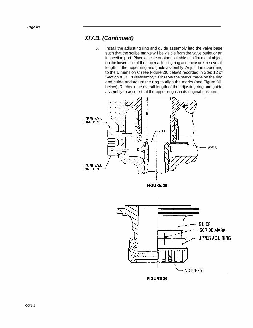
CON-1
6. Install the adjusting ring and guide assembly into the valve basesuch that the scribe marks will be visible from the valve outlet or aninspection port. Place a scale or other suitable thin flat metal objecton the lower face of the upper adjusting ring and measure the overalllength of the upper ring and guide assembly. Adjust the upper ringto the Dimension C (see Figure 29, below) recorded in Step 12 ofSection XI.B., "Disassembly". Observe the marks made on the ringand guide and adjust the ring to align the marks (see Figure 30,below). Recheck the overall length of the adjusting ring and guideassembly to assure that the upper ring is in its original position.
Page 48
XIV.B. (Continued)

CON-1
XIV.B. (Continued)
TABLE X
VERTICAL RING TRAVEL FOR EACHORIFICE NOTCH OF ADJUSTMENT
inches
1 .00252 .00203 .00155 .00154 .00156 .0009
7 & Q .00108 .0016R .0011
7. Measure from the top of the guide to the bushing seat with a depthmicrometer. Subtract Dimension B as measured in Step 12, SectionXI.B., "Disassembly", from the dimension previously measured.The difference is the distance the upper adjusting ring must belowered. Refer to Table X, below, to determine the number ofnotches that the ring is to be lowered.
8. Once certain that the upper adjusting ring/guide assembly is properlyset, lubricate the guide seating surface in the valve base, and re-install the assembly into the base, then, lubricate the threads of theupper adjusting ring pin, and lock the ring/guide assembly in placeby screwing in the pin. Verify that the upper ring is capable of a slightmovement. If the upper ring does not move, the pin is too long.Should this be the case, grind the end of the pin to shorten it, whileretaining the original tip contour, then reinstall the pin.
9. Clamp the spindle in a padded vise, with the “ball end” of the spindleupward.
10. Verify that the spindle bearing has been ground to the disc pocket,as specified in Section XIII.E, “Disc Replacement and Disc SpindleBearing Requirements”, of this manual.
NOTE:This step must be accomplished before proceeding with re-assembly.
11. If the lift stop was removed from the spindle, lubricate the threadsand install the lift stop. Do not install the cotter pin at this time.
12. If the disc collar was removed, lubricate the threads and install onthe spindle. Do not install the cotter pin at this time. Then, carefullylower the disc holder onto the spindle, allowing it to sit on the faceof the disc collar.
Page 49

CON-1
XIV.B. (Continued)
Page 50
13. Thread the disc onto the spindle, ensuring that the disc is free to“rock” on the spindle tip as specified in Section XIII.E., “DiscReplacement and Disc Spindle Bearing Requirements”, of thismanual. If disc “rock” is not satisfactory, correct the cause beforeproceeding. When disc “rock” is satisfactory, remove the disc anddisc holder, and secure the disc collar with a stainless steel cotterpin. Using side cutters, carefully cut off excess cotter pin legs, andbend the cotter pin for a neat installation.
14. Lubricate the spindle tip, and assemble the disc holder and disc tospindle. Recheck the rock.
15. Remove complete assembly from the vise, being sure to protect thedisc seat surface at all times.
16. Prior to installing the spindle assembly into the valve base, wipe thedisc seat with a soft, lint-free cloth. Then, carefully install the spindleassembly into the guide.
17. Install the cover plate over the spindle assembly, ensuring that thecover plate is correctly oriented with regard to the valve base, aspreviously marked for this purpose during disassembly. (See StepXI.B.9., in this manual.) Then, install the cover plate nuts, with thenuts being only hand tightened.
18. Next, install the yoke and compression screw assembly over theyoke rods and spindle.
19. Next, refer to Figure 31 (below) and establish Dimension A.
20. Pull up on the spindle until the lift stop contacts the cover plate andrepeat the measurement of Dimension A, while the lift stop andcover plate are in contact. The difference between these twomeasurements is the valve lift. The valve lift should be equal to thenameplate lift, plus the additional recommended lift as shown inTable XI, on the opposite page.
NOTE:
Do not deviate from stamped nameplate lift.
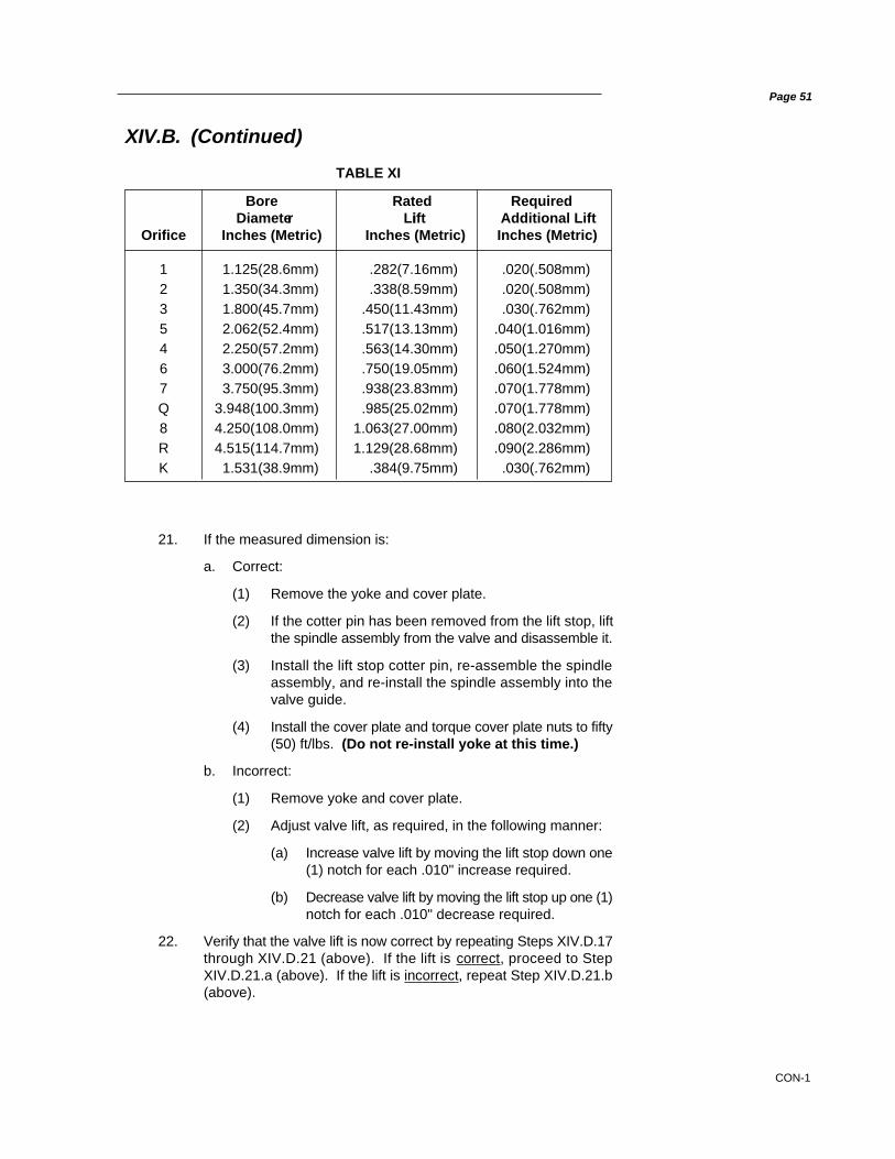
CON-1
Page 51
XIV.B. (Continued)
TABLE XI
Bore Rated RequiredDiameter Liift Additional Lift
Orifice Inches (Metric) Inches (Metric) Inches (Metric)
1 1.125(28.6mm) .282(7.16mm) .020(.508mm)2 1.350(34.3mm) .338(8.59mm) .020(.508mm)3 1.800(45.7mm) .450(11.43mm) .030(.762mm)5 2.062(52.4mm) .517(13.13mm) .040(1.016mm)4 2.250(57.2mm) .563(14.30mm) .050(1.270mm)6 3.000(76.2mm) .750(19.05mm) .060(1.524mm)7 3.750(95.3mm) .938(23.83mm) .070(1.778mm)Q 3.948(100.3mm) .985(25.02mm) .070(1.778mm)8 4.250(108.0mm) 1.063(27.00mm) .080(2.032mm)R 4.515(114.7mm) 1.129(28.68mm) .090(2.286mm)K 1.531(38.9mm) .384(9.75mm) .030(.762mm)
21. If the measured dimension is:
a. Correct:
(1) Remove the yoke and cover plate.
(2) If the cotter pin has been removed from the lift stop, liftthe spindle assembly from the valve and disassemble it.
(3) Install the lift stop cotter pin, re-assemble the spindleassembly, and re-install the spindle assembly into thevalve guide.
(4) Install the cover plate and torque cover plate nuts to fifty(50) ft/lbs. (Do not re-install yoke at this time.)
b. Incorrect:
(1) Remove yoke and cover plate.
(2) Adjust valve lift, as required, in the following manner:
(a) Increase valve lift by moving the lift stop down one(1) notch for each .010" increase required.
(b) Decrease valve lift by moving the lift stop up one (1)notch for each .010" decrease required.
22. Verify that the valve lift is now correct by repeating Steps XIV.D.17through XIV.D.21 (above). If the lift is correct, proceed to StepXIV.D.21.a (above). If the lift is incorrect, repeat Step XIV.D.21.b(above).

CON-1
Page 52
XIV.B. (Continued)
23. If the overlap collar has been removed from the spindle, lubricatethe collar threads and place over the spindle with the notches in thecollar up (i.e., away from the cover plate). Note that the overlapcollar has four circumferential scribe lines. The lower scribe line isthe one farthest away from the notches. (See Figure 32, below.)
Thread the overlap collar onto the spindle by turning in a clockwisedirection, until the lower scribe line is even with the visible floatingwasher. Align the nearest overlap collar notch with the drilled holein the spindle by moving the overlap collar down.
24. Refer to Table XII (below) before making the initial overlap collaradjustment.
Bore Diameter Adjustments (Notches)Orifice Inches (Metric) Standard Restricted Lift
1 1.25 (28.6mm) 6 32 1.350 (34.3mm) 7 33 1.800 (45.7mm) 8 45 2.062 (52.4mm) 9 44 2.250 (57.2mm) 10 56 3.000 (76.2mm) 13 67 3.750 (95.3mm) 16 8Q 3.984 (100.3mm) 16 88 4.250 (108.0mm) 18 9R 4.515 (114.7mm) 20 10
TABLE XII
Note that these adjustments differ for each orifice size. (Also notethat restricted lift valves require a different overlap collar adjustment.)
25. To adjust the overlap collar, move the collar down the number ofnotches specified in Table XII (above) or, if the original setting is tobe re-established, reset the collar to the position previously recordedduring disassembly. (See Section XI.B.8 in this manual.)
26. Install cotter pin through overlap collar notches and spindle. Trimcotter pin to proper length, and bend the ends to secure the overlapcollar and spindle together.
27. Before installing the spring washer, lubricate the bearing surfaceson lower spring washer and the spindle. Then, install lower springwasher onto the spindle.

CON-1
XIV.B. (Continued)
Page 53
28. Determine which end of the spring is to be fitted to the lower springwasher as determined in the disassembly procedure. (See SectionXI.B.7 in this manual.) Lower the spring gently over the spindle untilit is seated on lower spring washer. Install the top spring washeronto the spring, and insure that the lug engages the left yoke rodwhen facing in the same direction as the outlet.
29. If compression screw has been removed, lubricate the threads ofthe compression screw and yoke. Install the lock nut onto thecompression screw and thread the compression screw into yoke,until the screw is just protruding from lower end of the yoke.
NOTE:
If the valve utilizes a bearing with a compression screwadaptor as shown in Figure 27 (on page 45 of this manual),install the adaptor onto the top spring washer. Install thebottom race and pack the thrust bearing with lubricant, theninstall the bearing and the top race into the adaptor.
30. Lubricate upper yoke rod threads. Carefully position the yokeassembly over the yoke rods taking care to align the compressionscrew with either the bearing or upper spring washer as applicable.
31. Using the yoke rod nut torque wrench and the socket, torque theyoke rod nuts as specified in Table IX, on page 46 of this manual.
32. Next, return the compression screw to its original position recordedduring disassembly (see Section XI.B.4 of this manual), and tightencompression screw lock nut.
33. Ensure that the top washer lug does not remain in contact with theyoke rod, after final compression screw adjustment.
34. Install the release nut onto the spindle and thread clockwise, untilthe release nut is fully engaged on the spindle thread.
35. Install the cap over the release nut, and seat the cap firmly intoplace on the yoke. Install the top lever in the cap and, then, insertthe lever pin through the top lever and cap holes.
36. Adjust the release nut, until it clears top lever by 1/8 inches(3.175mm). Remove the lever pin, top lever, and cap. Next, inserta cotter pin through the release nut slots and spindle, and spreadcotter pin ends. (If spindle has been replaced, a cotter pin hole mustbe drilled through the replacement spindle.) Re-assemble the capwith the drop lever, top lever, and top lever pin. Install a cotter pinto lock the top pin in place. A final check should be made to ensurethe proper clearance exists between the release nut and the toplever. Finally, tighten cap set screw to secure the cap.

CON-1
Page 54
XV. Hydrostatic Testing & Gagging
During any hydrostatic test, all safety valves on the unit, which have not beenremoved and do not have hydroplugs, must be gagged. This gagging procedureprevents the possibility of damage to the safety valve internals in the event thatthe test pressure exceeds the safety valve set pressure. When adjusting valveset pressures, other valves in the system should also be gagged.
When valves are subjected to working hydrostatic tests not exceeding the setpressure of the low set valve, valves may be gagged rather than usinghydrostatic test plugs. For higher pressures, hydrostatic plugs should be used.
Probably the most common source of Safety Valve trouble is over-gagging.During hydrostatic testing, and during Safety Valve setting, gags should beapplied only hand tight. During setting, overgagging will also cause damage tothe seating surface and result in seat leakage. In applying gags remember thatthe valve spring will hold the valve closed against its set pressure.
The additional gag load applied should be only enough to ensure that the valvesdo not lift at the expected overpressure.
During start-up, gags should never be applied when the boiler is cold. Thespindle of the Safety Valve expands considerably with the temperature increase.If it is not free to expand with this temperature change it may become seriouslyoverstressed and bent.
Except for hydrostatic tests, boiler pressure should be brought up to within 80%of the pressure of the low set valve before applying gags.
Tighten the gags of drum and superheater valves with only a light force appliedto the gag screw head.

CON-1
Page 55
Do not apply the gag load until the system steam pressure is equal to 80%of the pressure to which the low set valve is adjusted.
Apply the gag load by turning the gag screw clockwise. If the gag on any valvehas not been tightened sufficiently, the valve will leak. On steam service theleakage is accompanied by a “sizzling” sound.
If this occurs, the hydrostatic test pressure or steam pressure should bereduced until the valve becomes tight and, then, the gag should betightened still further.
This procedure must be followed exactly, since it is very difficult to stop the leakby additional gagging once it has started. Any attempt to stop the leakagethrough the valve, without first lowering the system pressure, could result indamage to the valve seats.
After the hydrostatic test or steam test is completed, the gags should be removedwhen the hydrostatic pressure has been reduced to 80% to 90% of the pressureof the low set valve.
NOTE:Under no circumstances should the gags be left on the valves.
APPLICATION OF TEST GAGS (All Pressures)
Refer to Figure 7 on page 19. Remove top lever pin and top lever then loosen thecap screw. Remove cap and drop lever as an assembly. The release nut is fixedto the spindle by means of a cotter pin. Note that the release nut does not quiteengage top of compression screw.
Center the test gag in the exposed end of the SPINDLE and hook the legs of gagunder the sides of the YOKE as shown in Figure 33 (below).
XV. (Continued)
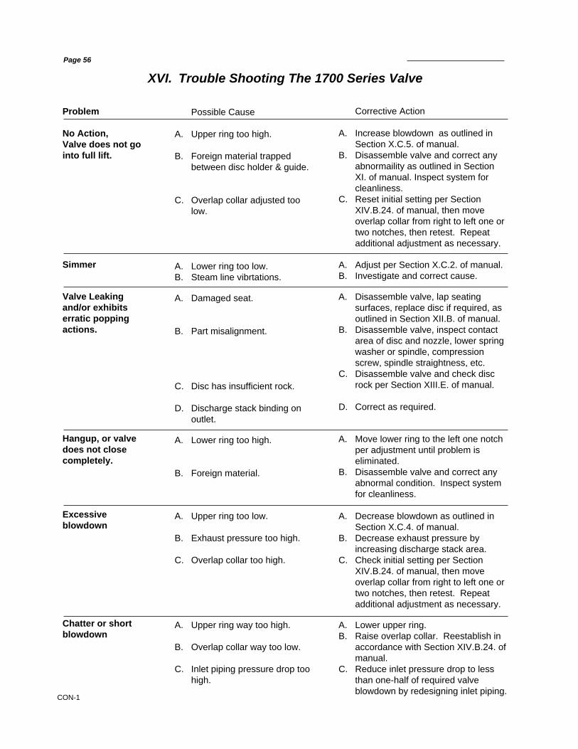
CON-1
XVI. Trouble Shooting The 1700 Series Valve
Corrective Action
A. Increase blowdown as outlined inSection X.C.5. of manual.
B. Disassemble valve and correct anyabnormaility as outlined in SectionXI. of manual. Inspect system forcleanliness.
C. Reset initial setting per SectionXIV.B.24. of manual, then moveoverlap collar from right to left one ortwo notches, then retest. Repeatadditional adjustment as necessary.
A. Adjust per Section X.C.2. of manual.B. Investigate and correct cause.
A. Disassemble valve, lap seatingsurfaces, replace disc if required, asoutlined in Section XII.B. of manual.
B. Disassemble valve, inspect contactarea of disc and nozzle, lower springwasher or spindle, compressionscrew, spindle straightness, etc.
C. Disassemble valve and check discrock per Section XIII.E. of manual.
D. Correct as required.
A. Move lower ring to the left one notchper adjustment until problem iseliminated.
B. Disassemble valve and correct anyabnormal condition. Inspect systemfor cleanliness.
A. Decrease blowdown as outlined inSection X.C.4. of manual.
B. Decrease exhaust pressure byincreasing discharge stack area.
C. Check initial setting per SectionXIV.B.24. of manual, then moveoverlap collar from right to left one ortwo notches, then retest. Repeatadditional adjustment as necessary.
A. Lower upper ring.B. Raise overlap collar. Reestablish in
accordance with Section XIV.B.24. ofmanual.
C. Reduce inlet pressure drop to lessthan one-half of required valveblowdown by redesigning inlet piping.
Possible Cause
A. Upper ring too high.
B. Foreign material trappedbetween disc holder & guide.
C. Overlap collar adjusted toolow.
A. Lower ring too low.B. Steam line vibrtations.
A. Damaged seat.
B. Part misalignment.
C. Disc has insufficient rock.
D. Discharge stack binding onoutlet.
A. Lower ring too high.
B. Foreign material.
A. Upper ring too low.
B. Exhaust pressure too high.
C. Overlap collar too high.
A. Upper ring way too high.
B. Overlap collar way too low.
C. Inlet piping pressure drop toohigh.
Problem
No Action,Valve does not gointo full lift.
Simmer
Valve Leakingand/or exhibitserratic poppingactions.
Hangup, or valvedoes not closecompletely.
Excessiveblowdown
Chatter or shortblowdown
Page 56

CON-1
Rings Laps*
Valve LapOrifice** Part No.
1 16728062 16728073 16728084 16728105 16728096 1672811
7 and Q 16728128, R and RR 1672813
Page 57
LAPPING TOOLSThe following tools are required for proper maintenance of Consolidated® Type1700 Safety Valve seats:
XVII. Maintenance Tools and Supplies
Ring LapThe ring lap is used for lapping the nozzle and disc seats.
Lapping PlateThe lapping plate is used for reconditioning the ring laps. Only one 11” diameterplate is required for all sizes of ring laps.
Resurfacing Plate - 11” Diameter.Part No. 0439004
Lapping CompoundLapping compound is used as a cutting medium for lapping and polishing theseats and bearing surfaces in Type 1700 Safety Valves.
Lapping SizeBrand Grade Grit Function Container Part No.
Clover 1A 320 General 4 oz. 199-3Clover C 220 Coarse 4 oz. 199-2Kwik- - 1000 Polishing 1 lb. 199-11Ak-Shun 2 oz. 199-12
* Note 1: One set of two (2) Ring Laps is recommended for each orifice valvein service, to assure ample flat laps are available at all times.
** Note 2: Valve orifice number is third digit of valve type number, e.g. a 1737Avalve has a #3 orifice.
Gags
Valve GagOrifice** Part No.
1 43630012 43630013 43630014 42177015 42177016 4217701
7 and Q 42177018, R and RR 4217701

CON-1
Page 58
XVII. (Continued)
Wrench Sizes (inches)
Lubricant
Location Lubricant
Bearing Points1. Spindle/Disc2. Compression Screw/Top
Spring Washer Fel-Pro Nickel Ease3. Spindle/Bottom Spring
WasherAll ThreadsAll Nut Contact Faces
MaxiflowSeriesNumber
1710
1712
1715
1716
1717
1718
1719
1720
1722
1725
1726
1727
1728
1729
1730
1732
1735
1736
1737
1738
1739
1740
1742
1745
1746
1747
MaxiflowSeriesNumber
1748
1749
1750
1752
1755
1756
1757
1758
1759
1765
1766
1767
1775
1775Q
1776
1776Q
1777Q
1785
1786
1787
1705R
1706R
1707R
1-7/16 1-5/8 2 2-3/8 2-3/4 3-1/8 1-7/16 1-5/8 2 2-3/8 2-3/4 3-1/8

CON-1
The basic objectives in formulating a replacement parts plan are:
• PROMPT AVAILABILITY
• MINIMUM DOWNTIME
• SENSIBLE COST
• SOURCE CONTROL
Guidelines for establishing meaningful inventory levels:
PARTS CLASSIFICATION
Page 59
XVIII. Service Parts Inventory Philosophy
PART REPLACEMENT PREDICTEDCLASSIFICATION FREQUENCY AVAILABILITY
CLASS I MOST FREQUENT 70%
CLASS II LESS FREQUENT 85%BUT CRITICAL
CLASS III SELDOM REPLACED 95%
CLASS IV HARDWARE 99%
CLASS V PRACTICALLY NEVER 100%REPLACED
Consult the Recommended Spare Parts list (see Section XX of this manual) todefine the parts to be included in the inventory plan.
Select parts and specify quantities.

CON-1
Identification and Ordering EssentialsWhen ordering service parts, please furnish the following information to insurereceiving the correct relacement parts:Identify valve by the following nameplate data:1. Size2. Type3. Temperature Class4. Serial Number
Example One: 2“ 1729WAS/N BG-5171Example Two: 1 1/2” 1712WDS/N BH-9547
Specify parts required by:1. Part Name (See Figure 7 on page 19)2. Part Number (if known)3. Quantity
Contact Parts Marketing: 1-318-640-6044
In addition, the serial number is stamped on the top edge of the outlet flange. Besure to include the one or two letters preceding the figures in the serial number.A typical valve nameplate is shown in Figure 34 (below).
XVIII. (Continued)
FIGURE 34
Page 60
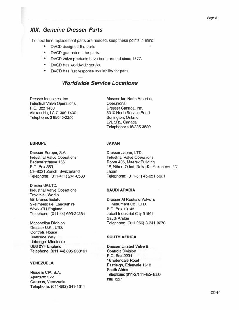
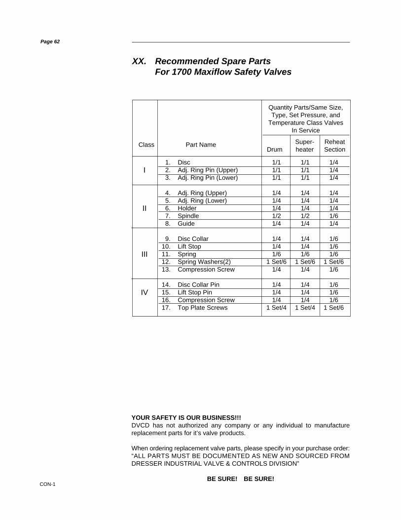
CON-1
YOUR SAFETY IS OUR BUSINESS!!!DVCD has not authorized any company or any individual to manufacturereplacement parts for it’s valve products.
When ordering replacement valve parts, please specify in your purchase order:“ALL PARTS MUST BE DOCUMENTED AS NEW AND SOURCED FROMDRESSER INDUSTRIAL VALVE & CONTROLS DIVISION”
BE SURE! BE SURE!
Page 62
XX. Recommended Spare PartsFor 1700 Maxiflow Safety Valves
1. Disc 1/1 1/1 1/42. Adj. Ring Pin (Upper) 1/1 1/1 1/43. Adj. Ring Pin (Lower) 1/1 1/1 1/4
4. Adj. Ring (Upper) 1/4 1/4 1/45. Adj. Ring (Lower) 1/4 1/4 1/46. Holder 1/4 1/4 1/47. Spindle 1/2 1/2 1/68. Guide 1/4 1/4 1/4
9. Disc Collar 1/4 1/4 1/610. Lift Stop 1/4 1/4 1/611. Spring 1/6 1/6 1/612. Spring Washers(2) 1 Set/6 1 Set/6 1 Set/613. Compression Screw 1/4 1/4 1/6
14. Disc Collar Pin 1/4 1/4 1/615. Lift Stop Pin 1/4 1/4 1/616. Compression Screw 1/4 1/4 1/617. Top Plate Screws 1 Set/4 1 Set/4 1 Set/6
Super- ReheatDrum heater Section
Class Part Name
Quantity Parts/Same Size,Type, Set Pressure, and
Temperature Class ValvesIn Service
I
II
III
IV
CON-1
Page 63
XXI. Manufacturer’s Field Service & Repair Program
FACTORY SETTING VS. FIELD SETTINGEvery CONSOLIDATED® Safety Valve is set and adjusted on steam beforeshipment from the factory. Blowdown adjustments are made as carefully andaccurately as possible on the factory test boiler. However, it must be recognizedthat actual field operating conditions may vary considerably from factory testconditions.
Conditions beyond the manufacturer’s control that affect Safety Valve operationare:
• Quantity of steam being discharged through the valve, i.e. the actualinstallation capacity exceeding that of the test boiler, thus permitting thevalve to flow its full rated capacity.
• Quality of steam being discharged.• Discharge piping stresses and back pressure.• Ambient temperature.• Shipping or storage damage.• Improper gagging• Improper bolting of flanges.• Damage due to foreign material in the steam.
Final Safety Valve adjustments made on the actual installation are the bestmeans of insuring that the valves perform in compliance with the ASME BoilerCode and/or other applicable code requirements.
FIELD SERVICE
Utilities and Process Industries expect and demand service on a moment’snotice CONSOLIDATED Field Service can be depended upon for promptresponse, even in extreme off-hour emergency situations.
DVCD maintains the largest and most competent field service staff in theindustry. Service Engineers are located at strategic points throughout the UnitedStates to respond to customer’s requirements for service. Each Service Engineeris factory trained and long experienced in servicing Safety Valves. DVCDService Engineers restore disc and nozzle critical dimensions which effect valveperformance, and are capable of modernizing valves in the field.
It is highly recommended that the professional talents of a DVCD Field ServiceEngineer be employed to make final field adjustments during the initial setting ofall CONSOLIDATED Safety Valves.
All Field Service Engineers’ activities are coordinated from the Alexandria,Louisiana, Field Service Office. Upon receipt of a purchase order numberauthorizing the trip, the engineer is dispatched.
Contact: Field Service Dept., Field Service Supv., (318) 640-6055
FACTORY REPAIR FACILITIESIf boiler downtime permits, it may be desirable to return the valves to the factoryfor repair or modernizing. The factory at Alexandria, Louisiana, maintains acomplete CONSOLIDATED repair center. The Repair Department is staffed toprovide you rapid repair that meets your needs.
Contact: Repair Dept., Mgr. Valve Repair, (318) 640-6058.


CON-6
Sales Offices LocationsIVO Headquarters & Main FactoryLA Hwy. 3225 at U.S. Hwy. 167 North, P.O. Box 1430, Alexandria, Louisiana 71309-1430Telephone 1-318-640-2250, Telex 586423, Rapifax 1-318-640-6222
Northern Region3201 North Wolf Road, Franklin Park, Illinois 60131Telephone 1-708-451-3913, Rapifax 1-708-451-3997
Pacific Region3931 MacArthur Blvd., Suite 202, Newport Beach, California 92660-3014Telephone 1-714-752-0455, Rapifax 1-714-752-2561
Southern Region16503 Park Row, Houston, Texas 77084-5016Telephone 1-713-579-8720, Rapifax 1-713-579-7844
Dresser Canada, Inc., Valve & Controls – Canadian Operations5010 North Service Road, Burlington, Ontario, L7L 5R5 CanadaTelephone 1-905-335-3529, Rapifax 1-905-336-7628
Dresser Japan, Ltd., Industrial Valve Operation, Room 405, Maersk Bldg.,18, Nihon-Odori, Naka-ku., Yokohama 231 JapanTelephone 81-45-651-5601, Rapifax 81-45-651-5606
Dresser Korea, Inc., Room #2107, Kuk Dong Building60-1, 3-KA, Choongmu-Ro Chung-Ku, Seoul, Korea 100-705Telephone 82-2-274-0792, Telex K22801 DRESSER, Rapifax 82-2-274-0794
Masoneilan Internacional y Compania, S, en N.C., Av. Henry Ford No. 114Apartado Postal 572, 54030 Tlalnepantla, MexicoTelephone 52-5-310-9863, Telex (383) 172645, Rapifax 52-5-310-5584
Dresser Al Rushaid Valve & Instrument Co., Ltd., P.O. Box 10145Jubail Industrial City 31961, Kingdom of Saudi ArabiaTelephone 966-3-341-0278, Telex (928) 832108, Rapifax 966-3-341-7624
Dresser Limited Valve & Controls DivisionP.O. Box 2234, 16 Edendale Road, Eastleigh, Edenvale 1610, South AfricaTelephone 27-11-452-1550/1-7, Rapifax 27-11-452-2903
Dresser Europe, S.A. Industrial Valve OperationBadenerstrasse 156, P.O. Box 369, CH-8021 Zurich, SwitzerlandTelephone 41-1-241-0533, Telex (845) 812429, Rapifax 41-1-241-4218
Dresser U.K., Limited, Industrial Valve Operation, Trevithick WorksGillibrands Estate, Skelmersdale, Lancashire, WN8 9TU EnglandTelephone 44-695-24234, Telex (851) 627039, Rapifax 44-695-20175
Masoneilan Division Dresser U.K., Ltd., Controls HouseRiverside Way, Uxbridge, Middlesex, UB8 2YF EnglandTelephone 44-895-258161, Telex (851) 935174, Rapifax 44-895-234318
RIESE & CIA S.A.Apartado 372, Caracas, VenezuelaTelephone 58-2-541-1311/541-3812, Telex (395) 24796, Rapifax 58-2-545-2702
Note: Numbers in ( ) are codes to be used for calling from U.S.A.
CONSOLIDATED is a registered trademarkof Dresser Industries, Inc.
© 2000 Dresser Industries, Inc.
UNITED STATES
CANADA
JAPAN
KOREA
MEXICO
SAUDI ARABIA
SOUTH AFRICA
SWITZERLAND
UNITED KINGDOM
VENEZUELA