construction - ccs knowledge centre · hitachi49 was contracted to supply a new dual-mode steam...
TRANSCRIPT
CONSTRUCTION
OF THE CLEAN-COAL BD3 POWER PLANT UNIT
43
44
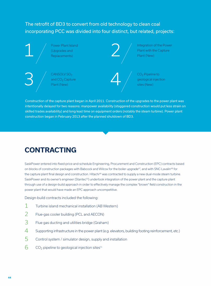
Power Plant Island
(Upgrades and
Replacements)
CANSOLV SO2
and CO2 Capture
Plant (New)
Integration of the Power
Plant with the Capture
Plant (New)
CO2 Pipeline to
geological injection
sites (New)
The retrofit of BD3 to convert from old technology to clean coal
incorporating PCC was divided into four distinct, but related, projects:
Construction of the capture plant began in April 2011. Construction of the upgrades to the power plant was
intentionally delayed for two reasons: manpower availability (staggered construction would put less strain on
skilled trades availability) and long lead time on equipment orders (notably the steam turbine). Power plant
construction began in February 2013 after the planned shutdown of BD3.
1
3
2
4
CONTRACTING
SaskPower entered into fixed-price-and-schedule Engineering, Procurement and Construction (EPC) contracts based
on blocks of construction packages with Babcock and Wilcox for the boiler upgrade47, and with SNC-Lavalin48 for
the capture plant final design and construction. Hitachi49 was contracted to supply a new dual-mode steam turbine.
SaskPower and its owner’s engineer (Stantec50) undertook integration of the power plant and the capture plant
through use of a design-build approach in order to effectively manage the complex “brown” field construction in the
power plant that would have made an EPC approach uncompetitive.
Design-build contracts included the following:
Turbine island mechanical installation (AB Western)
Flue-gas cooler building (PCL and AECON)
Flue gas ducting and utilities bridge (Graham)
Supporting infrastructure in the power plant (e.g. elevators, building footing reinforcement, etc.)
Control system / simulator design, supply and installation
CO2 pipeline to geological injection sites51
1
4
2
5
3
6
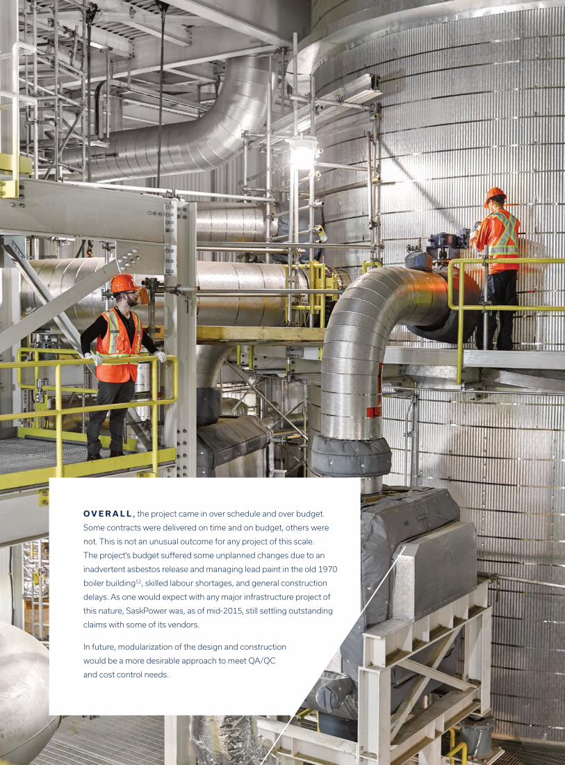
O V E R A L L , the project came in over schedule and over budget.
Some contracts were delivered on time and on budget, others were
not. This is not an unusual outcome for any project of this scale.
The project’s budget suffered some unplanned changes due to an
inadvertent asbestos release and managing lead paint in the old 1970
boiler building52, skilled labour shortages, and general construction
delays. As one would expect with any major infrastructure project of
this nature, SaskPower was, as of mid-2015, still settling outstanding
claims with some of its vendors.
In future, modularization of the design and construction
would be a more desirable approach to meet QA/QC
and cost control needs.
POWER PLANT FINAL DESIGNAND CONSTRUCTION
Prior to any decommissioning and tear down of
the pre-existing power unit, the owner’s engineer,
Stantec, completed a 3D computer model of
the in-situ power plant. Many changes had been
implemented since the unit was constructed in
1970, so the original blue prints were far from
accurate. This 3D model was critical to enabling
what-if modeling during design, made the
implementation of changes to the plant far simpler
during construction, and permitted any construction
errors to be caught early and rectified.
SaskPower designed a 150 MW power plant that
they had anticipated in 2009 would generate 90
MW of net power. Through design optimization and
efficient integration of the capture plant with the
power plant, SaskPower ultimately constructed a
161 MW power plant that will deliver approximately
120 MW to the power grid when the CO2 capture
plant is operated. The optimization and efficiency
gains in power generation that reduced the
burden of SO2/CO2 capture and maximized power
generation were achieved in tiny increments—each
one was a rewarding accomplishment. The entire
accumulation of power improvements was a stellar
achievement.
Ultimately, the parasitic load of PCC was reduced
by one-third compared to what was expected at
the outset of designing the BD3 retrofit in 2009.
The key to this achievement was focusing on
optimization of power generation and secondarily
considering capture plant performance. Additionally,
any economical opportunity to capture otherwise
lost energy in either plant by conversion to power
was seized.
At any point in the power plant design where there
was a risk that power would not be generated
due to uncertain capture plant performance,
redundancy was designed and engineered into the
power plant. This was considered “mission critical
risk management”. Through use of this approach,
SaskPower focused closely on its core mission as a
power utility.
Two major upgrades were
undertaken in the power plant:
The boiler was upgraded from 1000F to 1050F,
and contained significantly more surface area to
increase the efficiency of the boiler compared
to its performance prior to retrofit. The upgrade
of the boiler was accomplished by removal of
the boiler’s internal heat transfer components
and effectively rebuild a new boiler. Due to the
additional weight of the upgraded boiler, this
process was complicated by the necessity of
reinforcement of the columns that support the
boiler’s weight from the top of the building to
the footings.
The 1969 turbine was replaced with a modern
Hitachi, dual-mode turbine that incorporated
better steam and thermal integration, as well
as the capability to handle power up or down
of the capture plant. Given the requirement for
stable and secure power, the power plant was
required to operate at full load whether or not
the capture plant was in operation, and had
to remain operational if the capture plant was
suddenly turned on or off. This had a major
impact on the turbine selection.
The power unit’s output in non-capture
mode was increased by 11.1 MW (7.4%) over
the original retrofit design as a result of the
combined improvements in the boiler and
the turbine.
47
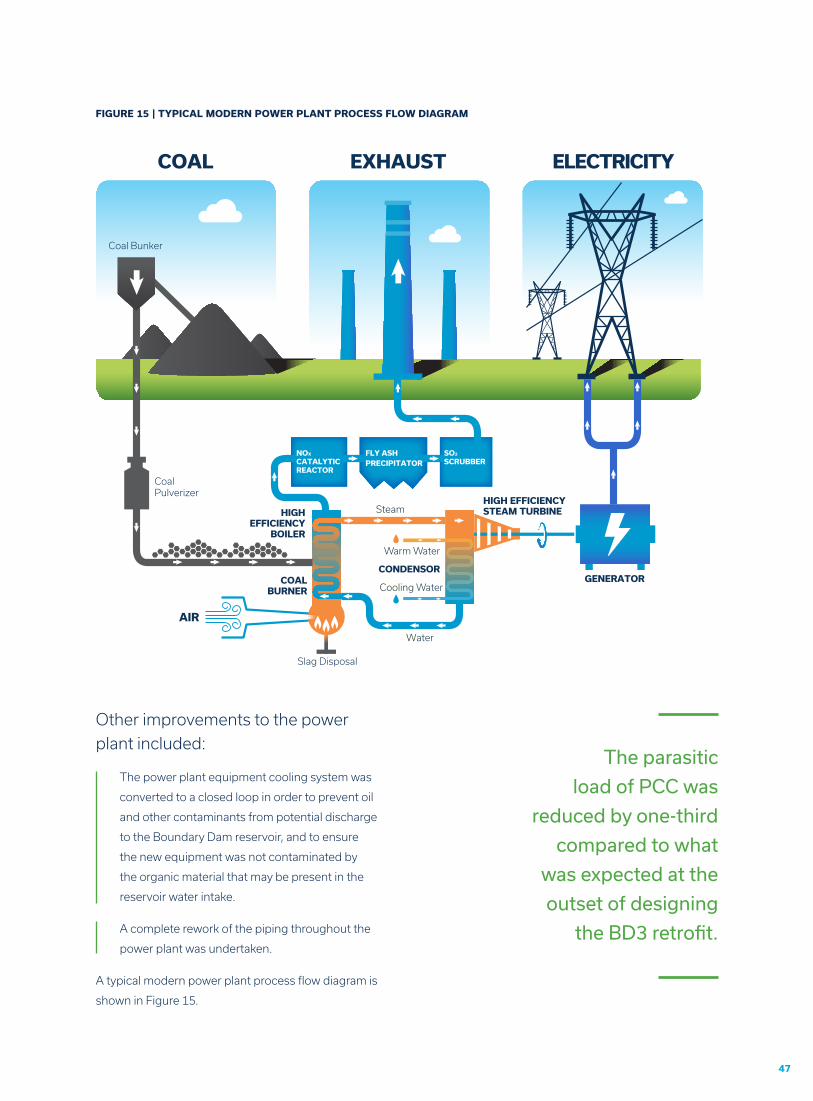
FIGURE 15 | TYPICAL MODERN POWER PLANT PROCESS FLOW DIAGRAM
NOX CATALYTICREACTOR
FLY ASHPRECIPITATOR
SO2 SCRUBBER
HIGHEFFICIENCY
BOILER
COAL EXHAUST ELECTRICITY
GENERATOR
HIGH EFFICIENCYSTEAM TURBINE
COALBURNER
AIR
Slag Disposal
Water
Steam
Coal Bunker
Coal Pulverizer
CONDENSOR
Warm Water
Cooling Water
Other improvements to the power
plant included:
The power plant equipment cooling system was
converted to a closed loop in order to prevent oil
and other contaminants from potential discharge
to the Boundary Dam reservoir, and to ensure
the new equipment was not contaminated by
the organic material that may be present in the
reservoir water intake.
A complete rework of the piping throughout the
power plant was undertaken.
A typical modern power plant process flow diagram is
shown in Figure 15.
The parasitic
load of PCC was
reduced by one-third
compared to what
was expected at the
outset of designing
the BD3 retrofit.
The connections and interactions between the
power plant and the capture plant were an area
of intense focus from concept through design
and engineering and then construction. This will
continue to be fine-tuned over the next year or two
to realize improvements in power generation at BD3.
This optimization process is typical of the period
immediately following the startup of any new
power plant.
The following integration
equipment components were
considered essential to meet
the technical specifications
of the capture plant and to
mitigate technical risk since
the CANSOLV CO2 capture
process had not yet been
operated at commercial scale:
Flue-gas cooling was required to reduce
the flue gas temperature to the operation
temperature required by the CANSOLV SO2
capture process. SaskPower enhanced
this process by addition of a polymer heat
exchanger to recover heat from the cooling
process. The captured heat could then be used
to pre-heat the condenser water used for steam
generation in the power plant, which thereby
improved the efficiency of power generation
by about 3.5 MW through reduction of the
demand on low pressure feed-water heaters
during capture plant operation.
A Direct-Contact Cooler (DCC) was added
as a pre-scrubber to further reduce flue gas
temperature prior to entry to the capture
plant, and to remove particulates and other
contaminants that could negatively impact the
performance of the amines in the SO2 and CO2
absorption towers. Recall: the feedstock for the
capture plant was the flue gas. Its constituent
specifications were required by CANSOLV in order
to meet performance guaranties for the capture
processes. Preconditioning by the DCC was
considered an essential step to meet those flue
gas specifications.
Steam supply from the power plant to the amine
reboilers presented a challenge to the design
and engineering teams. Steam flow would start
or stop when the capture plant was turned on or
off, that would complicate the requirements of
the steam turbine power
generator. Temperature
control was critical at the
capture plant’s reboilers
to prevent degradation of
the amines and production
of toxic by-products. This
is one area that continues
to be worked on during
2015–2016 to ensure
optimal functionality.
A flue-gas diverter was
installed to divert flue gas to the pre-existing
BD3 stack when the capture plant was not in
operation, which would be the case when the
power plant was operating at less than 50% load.
The diverter dampers were designed to allow
incremental adjustment between fully open to the
carbon capture plant, and fully open to the stack.
This adjustability allowed for smoother start-up
and shutdown, and enabled the capture plant
to be run at partial capacity independent of the
power plant.
A new feed water system was installed due to
additional use of steam by the capture plant and
its significant impact on steam pressures in the
turbine and feed water heaters.
INTEGRATION OF THE POWER PLANT AND THE SO2/CO2 CAPTURE PLANT
Steam supply from
the power plant to
the amine reboilers
presented a challenge
to the design and
engineering teams.
49
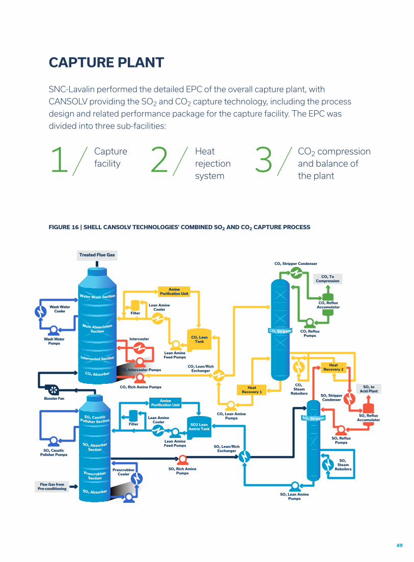
CAPTURE PLANT
SNC-Lavalin performed the detailed EPC of the overall capture plant, with
CANSOLV providing the SO2 and CO2 capture technology, including the process
design and related performance package for the capture facility. The EPC was
divided into three sub-facilities:
Capture facility
Heat rejection system
CO2 compression and balance of the plant
1 2 3
FIGURE 16 | SHELL CANSOLV TECHNOLOGIES’ COMBINED SO2 AND CO2 CAPTURE PROCESS
SO2 LeanAmine Tank
Lean AmineCooler
Filter
Filter
CO2 LeanTank
PrescrubberCooler
FIGURE 16 | SHELL CANSOLV TECHNOLOGIES’ COMBINED SO2 AND CO2 CAPTURE PROCESS
Wash WaterCooler
Wash WaterPumps
Booster Fan
Flue Gas fromPre-conditioning
SO2 toAcid Plant
SO2 StripperCondenser
SO2 CausticPolisher Pumps
AminePurification Unit
AminePurification Unit
SO2 RefluxAccumulator
CO2 RefluxAccumulator
SO2 RefluxPumps
CO2 RefluxPumps
CO2 Lean AminePumps
SO2 Rich AminePumps
SO2 Lean AminePumps
SO2 Lean/RichExchanger
CO2 Lean/RichExchanger
Lean AmineFeed Pumps
Lean AmineFeed Pumps
Intercooler
CO2 Intercooler Pumps
CO2 Rich Amine Pumps
Lean AmineCooler
SO2 Steam
Reboilers
CO2 Steam
Reboilers
HeatRecovery 1
CO2 ToCompression
CO2 Stripper Condenser
HeatRecovery 2
Treated Flue Gas
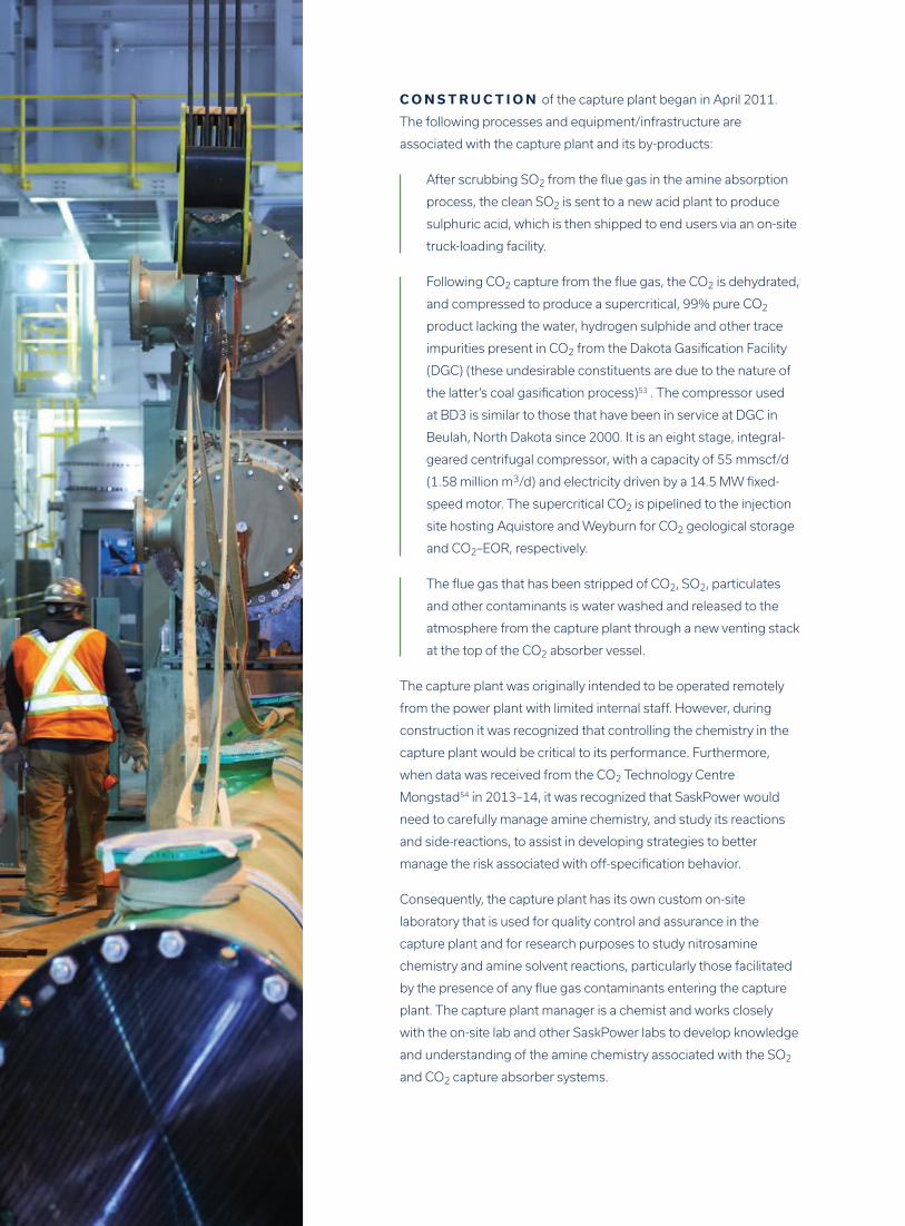
C O N S T R U C T I O N of the capture plant began in April 2011.
The following processes and equipment/infrastructure are
associated with the capture plant and its by-products:
After scrubbing SO2 from the flue gas in the amine absorption
process, the clean SO2 is sent to a new acid plant to produce
sulphuric acid, which is then shipped to end users via an on-site
truck-loading facility.
Following CO2 capture from the flue gas, the CO2 is dehydrated,
and compressed to produce a supercritical, 99% pure CO2
product lacking the water, hydrogen sulphide and other trace
impurities present in CO2 from the Dakota Gasification Facility
(DGC) (these undesirable constituents are due to the nature of
the latter’s coal gasification process)53 . The compressor used
at BD3 is similar to those that have been in service at DGC in
Beulah, North Dakota since 2000. It is an eight stage, integral-
geared centrifugal compressor, with a capacity of 55 mmscf/d
(1.58 million m3/d) and electricity driven by a 14.5 MW fixed-
speed motor. The supercritical CO2 is pipelined to the injection
site hosting Aquistore and Weyburn for CO2 geological storage
and CO2–EOR, respectively.
The flue gas that has been stripped of CO2, SO2, particulates
and other contaminants is water washed and released to the
atmosphere from the capture plant through a new venting stack
at the top of the CO2 absorber vessel.
The capture plant was originally intended to be operated remotely
from the power plant with limited internal staff. However, during
construction it was recognized that controlling the chemistry in the
capture plant would be critical to its performance. Furthermore,
when data was received from the CO2 Technology Centre
Mongstad54 in 2013–14, it was recognized that SaskPower would
need to carefully manage amine chemistry, and study its reactions
and side-reactions, to assist in developing strategies to better
manage the risk associated with off-specification behavior.
Consequently, the capture plant has its own custom on-site
laboratory that is used for quality control and assurance in the
capture plant and for research purposes to study nitrosamine
chemistry and amine solvent reactions, particularly those facilitated
by the presence of any flue gas contaminants entering the capture
plant. The capture plant manager is a chemist and works closely
with the on-site lab and other SaskPower labs to develop knowledge
and understanding of the amine chemistry associated with the SO2
and CO2 capture absorber systems.
51
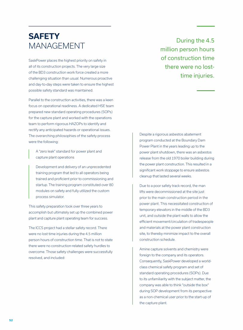
Viability requires minimizing...
thermal energy requirements
parasitic electrical loadAll of the iterations to maximize power generation
and minimize parasitic load of SO2 and CO2 capture
paid off. SaskPower will be able to generate 115–
120 MW of power using a 161 MW turbine once the
construction deficiencies have been rectified and
the initial troubleshooting and optimization have
been completed. The improvements as of Spring
2015 are shown in Figure 17.
SaskPower constructed, owns and operates a
custom-built, carbon steel, supercritical CO2
pipeline that runs approximately 8 km to the
northern edge of its property. Cenovus built the
pipeline from that point to its Weyburn CO2–EOR
operation. Just prior to the change of custody
at the property line, a 2 km pipeline leg runs to
SaskPower’s CO2 injection site at its Carbon
Storage and Research Centre that is located on
the Boundary Dam Power Station property. That
pipeline leg is capable of handling the entire
volume of CO2 produced at the power station
should that become necessary or desirable at
some point in the future.
OVERALL EFFICIENCY IMPROVEMENTS
CO2 PIPELINE
POWER TO GRID (112 MW)
EXISTING PARASITIC LOAD (11 MW)
COMPRESSION (15 MW)
CAPTURE CO2, SO2 (9 MW)
AMINE & HEAT REGENERATION (14 MW)
FIGURE 17 | OPTIMIZING THE PERFORMANCE OF BD3
TO MAXIMIZE POWER GENERATION
52
Despite a rigorous asbestos abatement
program conducted at the Boundary Dam
Power Plant in the years leading up to the
power plant shutdown, there was an asbestos
release from the old 1970 boiler building during
the power plant construction. This resulted in a
significant work stoppage to ensure asbestos
cleanup that lasted several weeks.
Due to a poor safety track record, the man
lifts were decommissioned at the site just
prior to the main construction period in the
power plant. This necessitated construction of
temporary elevators in the middle of the BD3
unit, and outside the plant walls to allow the
efficient movement/circulation of tradespeople
and materials at the power plant construction
site, to thereby minimize impact to the overall
construction schedule.
Amine capture solvents and chemistry were
foreign to the company and its operators.
Consequently, SaskPower developed a world-
class chemical safety program and set of
standard operating procedures (SOPs). Due
to its unfamiliarity with the subject matter, the
company was able to think “outside the box”
during SOP development from its perspective
as a non-chemical user prior to the start-up of
the capture plant.
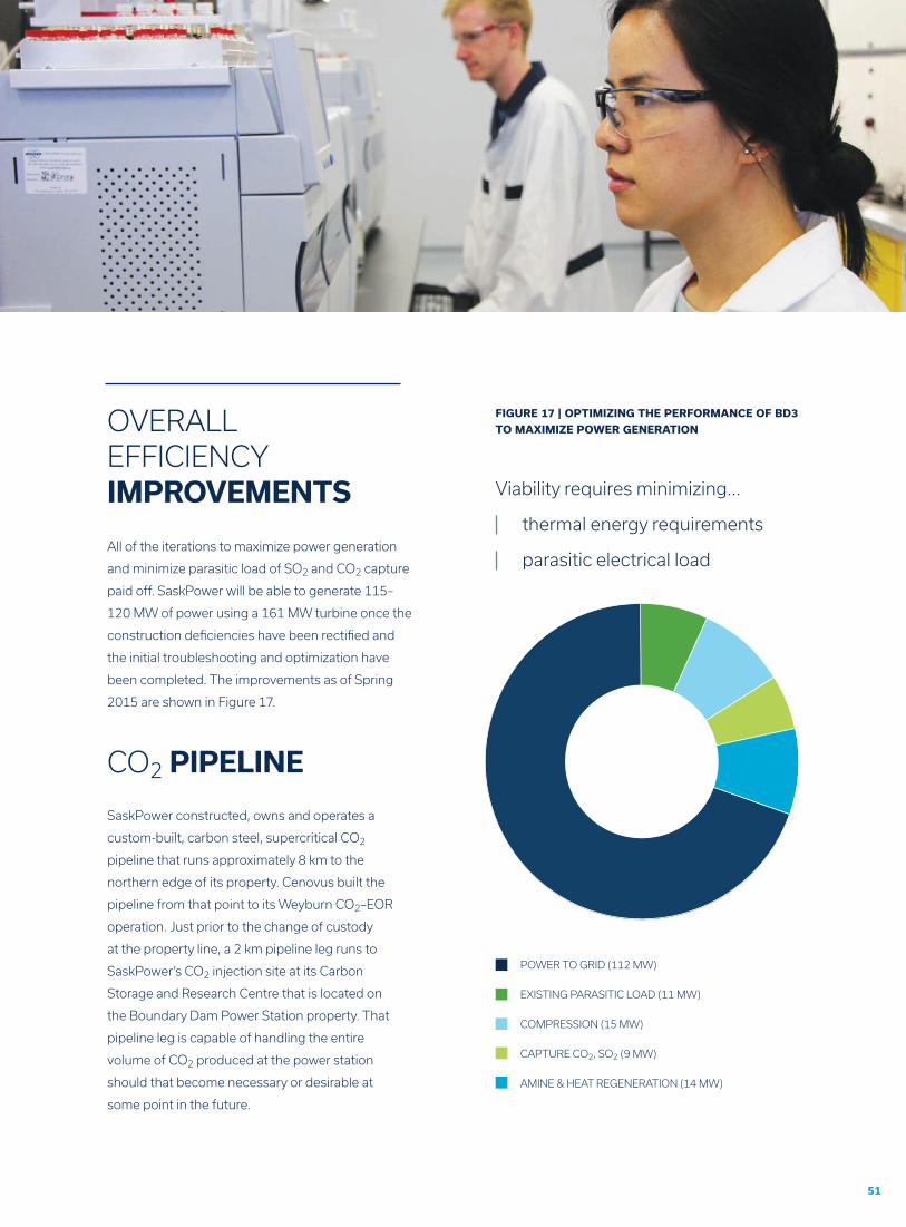
SaskPower places the highest priority on safety in
all of its construction projects. The very large size
of the BD3 construction work force created a more
challenging situation than usual. Numerous proactive
and day-to-day steps were taken to ensure the highest
possible safety standard was maintained.
Parallel to the construction activities, there was a keen
focus on operational readiness. A dedicated HSE team
prepared new standard operating procedures (SOPs)
for the capture plant and worked with the operations
team to perform rigorous HAZOPs to identify and
rectify any anticipated hazards or operational issues.
The overarching philosophies of the safety process
were the following:
A “zero leak” standard for power plant and
capture plant operations
Development and delivery of an unprecedented
training program that led to all operators being
trained and proficient prior to commissioning and
startup. The training program constituted over 80
modules on safety and fully utilized the custom
process simulator.
This safety preparation took over three years to
accomplish but ultimately set up the combined power
plant and capture plant operating team for success.
The ICCS project had a stellar safety record. There
were no lost time injuries during the 4.5 million
person hours of construction time. That is not to state
there were no construction-related safety hurdles to
overcome. Those safety challenges were successfully
resolved, and included:
SAFETYMANAGEMENT
During the 4.5
million person hours
of construction time
there were no lost-
time injuries.
53
Throughout the entire BD3 ICCS project,
SaskPower managed uncertainty well
through a “can-do” attitude that has
been ingrained in its corporate culture.
A lot of activities were undertaken in
parallel, that led to schedule gains at
the cost of efficiency and some re-work.
Effective communication was the key to a
productive work environment. Challenges
were observed from many different angles
and resolution was achieved as a team
effort rather than by any one particular
individual.
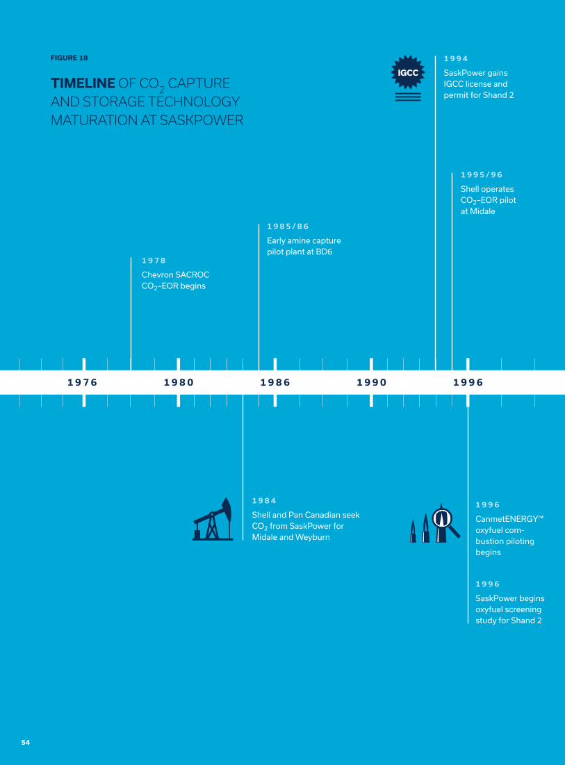
As a result of the BD3 ICCS project,
including its prerequisite exploratory work,
SaskPower has developed a strong and
capable engineering team. Knowledge and
insights have been carefully documented,
along with the entire BD3 retrofit design,
to support option analyses for potential
future coal-fired power plant retrofits. In
fact, this effort is already assisting the
business case decision planning regarding
BD4 and BD5 that is ongoing as of mid-
2015. An illustration of the time frame for
CO2 capture technology maturation within
SaskPower is shown in Figure 18 on the
next page.
Risk was managed throughout design, engineering and
construction with rigorous use of risk registers. Risk
management was a daily focus during construction. There
was continual monitoring of construction productivity,
coupled with ongoing labour availability risk assessment
and planning.
Accommodation risk was a concern. Due to labour
shortages, SaskPower had to ensure it was an “employer
of choice”. This meant compensation had to be maximized
to attract construction labour, which included subsistence
allowances. Consequently, SaskPower had to find cost-
effective, off-site accommodations for up to 1500 staff at
a time when the oil industry also had peak labour demand
in the region. Temporary on-site labour accommodations
were not an option and were not utilized.
Throughout the period from 2008 to late 2014, that
spanned the first request for capture technology proposals
in 2008 through design to engineering and finally through
construction of the BD3 retrofit, SaskPower worked
closely with the Saskatchewan Ministry of Environment on
regulatory permits. Any changes in the design that could
impact permitting were promptly provided to the Ministry’s
Assessment Branch and any issues that might impact
permits were transmitted internally within the Ministry to
the Permitting Branch through a seamless review/assess/
approve/update process. Despite the unusual first-time
nature of the project, the entire reporting and permitting
process was swift and efficient.
The permitting and regulatory process associated with
the CO2 injection and monitoring wells at the SaskPower
Carbon Storage and Research Centre regarding deep
saline storage/disposal of CO2 was handled similarly,
although the permits for the injection and monitoring wells
were issued by the Ministry of Economy that regulated oil
and gas activity in Saskatchewan and hence all deep well
drilling activity.
KNOWLEDGEBUILDING
RISKMANAGEMENT
PERMITTING
1 9 7 6 1 9 8 0 1 9 8 6 1 9 9 0 1 9 9 6
1 9 7 8
Chevron SACROC CO2–EOR begins
1 9 8 5 / 8 6
Early amine capture pilot plant at BD6
1 9 9 4
SaskPower gains IGCC license and permit for Shand 2
1 9 9 5 / 9 6
Shell operates CO2–EOR pilot at Midale
1 9 9 6
CanmetENERGY™ oxyfuel com-bustion piloting begins
1 9 9 6
SaskPower begins oxyfuel screening study for Shand 2
1 9 8 4
Shell and Pan Canadian seek CO2 from SaskPower for Midale and Weyburn
FIGURE 18
TIMELINE OF CO2 CAPTURE AND STORAGE TECHNOLOGY MATURATION AT SASKPOWER
54
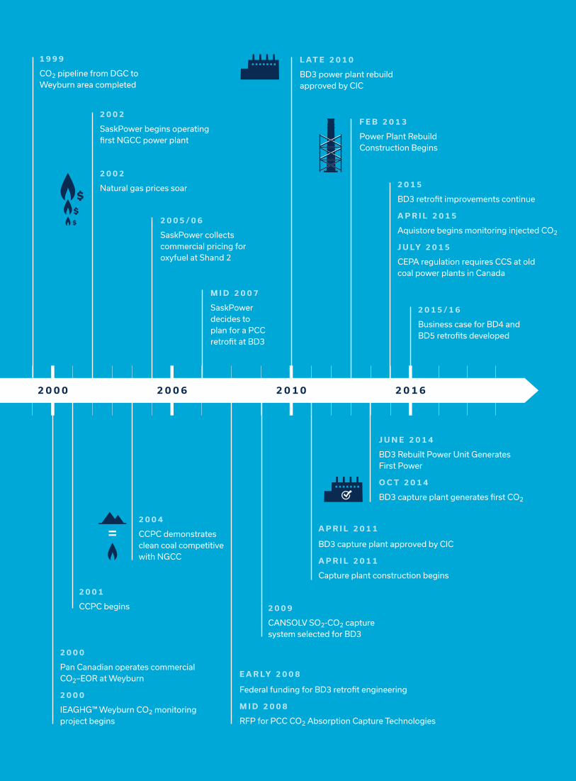
2 0 0 0 2 0 0 6 2 0 1 0 2 0 1 6
2 0 1 5 / 1 6
Business case for BD4 and BD5 retrofits developed
1 9 9 9
CO2 pipeline from DGC to Weyburn area completed
2 0 0 5 / 0 6
SaskPower collects commercial pricing for oxyfuel at Shand 2
M I D 2 0 0 7
SaskPower decides to plan for a PCC retrofit at BD3
L AT E 2 0 1 0
BD3 power plant rebuild approved by CIC
2 0 0 2
SaskPower begins operating first NGCC power plant
2 0 0 2
Natural gas prices soar
F E B 2 0 1 3
Power Plant Rebuild Construction Begins
2 0 1 5
BD3 retrofit improvements continue
A P R I L 2 0 1 5
Aquistore begins monitoring injected CO2
J U LY 2 0 1 5
CEPA regulation requires CCS at old coal power plants in Canada
2 0 0 1
CCPC begins 2 0 0 9
CANSOLV SO2-CO2 capture system selected for BD3
2 0 0 4
CCPC demonstrates clean coal competitive with NGCC
2 0 0 0
Pan Canadian operates commercial CO2–EOR at Weyburn
2 0 0 0
IEAGHG™ Weyburn CO2 monitoring project begins
E A R LY 2 0 0 8
Federal funding for BD3 retrofit engineering
M I D 2 0 0 8
RFP for PCC CO2 Absorption Capture Technologies
A P R I L 2 0 1 1
BD3 capture plant approved by CIC
A P R I L 2 0 1 1
Capture plant construction begins
J U N E 2 0 1 4
BD3 Rebuilt Power Unit Generates First Power
O C T 2 0 1 4
BD3 capture plant generates first CO2