construction details load design charts · construction details & load design charts office and...
TRANSCRIPT

CONSTRUCTION DETAILS&
LOAD DESIGN CHARTSOffice and Production126 New Pace Rd., PO Box 279Newcomerstown, OH 438321-800-446-2188, Fax: 740-498-4184www.buildwithsips.com

Table of ContentsDescription of Detail Detail #
Plate Connections PS-101Surface Spline Connection PS-102Block Spline Connection PS-102aDouble 2x Connection PS-102bI-Beam Connection PS-102cCorner Connection PS-103Angled Corner Connection PS-103aInterior Wall Connection PS-104Foundation Connection - Slab PS-105Foundation Connection - Joist PS-106Foundation Connection - Joist PS-106aFloor Joist Bearing on Wall PS-107SIP as Headers PS-108SIP as Headers PS-109SIP Header PS-110Header PS-111Roof Openings PS-112Truss Bearing on Wall PS-113Wall to Roof Connection PS-114Wall to Roof Connection PS-114aWall to Roof Connection PS-115Roof Eaves Overhang - Ladder Framed PS-116Roof Eaves Overhang - Cant. Panel PS-116aRoof Eaves Overhang - Ladder Framed PS-117Roof Eaves Overhang - Cant. Panel PS-117aRoof Ridge PS-118Roof Ridge Cantilever PS-118aRoof Valley PS-119Surface Spline @ Truss PS-120Surface Spline @ Truss PS-120aSurface Spline @ Truss PS-120bPanel Connection @ Truss PS-121Panel Connection @ Steel Member PS-121aPanel Connection @ Steel Member PS-121bPanel Fastening Connection PS-122Electrical Box PS-124Ceiling Fixture Attachment PS-125Roof Penetrations PS-126
General RecommendationsPACEMAKER Engineered Structural Insulated Panels (SIPs) must be designed and installed in accordance with:
• All Applicable Codes• Load Charts & Construction Details• Information within Quotations & Drawings• Following Items:
Thermal BarriersAll interior surfaces of the PACEMAKER SIPs must be finished with a minimum 15-minute thermal barrier, typically 1/2” gypsum board or 1x wood paneling. One hour fire rated systems can be activated using high performance thermal barriers such as type X and C gypsum board. Buildings with sprinkler systems may notrequire a thermal barrier. Consult applicable codes regarding compliance requirements.
Mechanical VentilationProperly installed PACEMAKER SIPs greatly reduce air movement through walls and roofs. While fewer airexchanges save energy, air quality is affected and humidity is increased possibly causing mold and mildew problems. A professional, familiar with tight construction such as SIPs, should design and install a HVAC systemthat includes an adequate fresh air ventilation feature.
Vapor RetardersWe recommend the use of vapor retarders when mandated by code or required by climate conditions. Sealantsapplied to all connections (foam to foam, foam to wood, and wood to wood) are required. In addition, a 6 milpolyethylene vapor retarder must be installed at all roof panel connections including the ridge.
Weather Resistive BarriersProper usage of sealant at panel connections is necessary. Flashing and sealants around all rough openings andpenetrations is required. Properly installed housewrap will help protect the exterior OSB skin from damage dueto moisture intrusion.
Storage, Handling and Protection• PACEMAKER SIPs must be stored in a level, well supported manner, fully covered with tarps or other
protective wraps.• When installing panels with a crane, straps or an I-bolt should be used. Under no circumstances should
panels be lifted by a single OSB facer.• Roof panels must have a temporary water resistant paper applied after installation.• PACEMAKER Engineered SIPs utilize exposure I rated OSB skins which withstand limited weathering. The
weatherproof exterior cladding system must be installed promptly.• While the SIPs are treated to resist termite and carpenter ant intrusion, standard deterrents such as insect
clips, flashing or traps should be installed.
Other Sources• APA The Engineered Wood Association series ”Build a Better Home“ www.apawood.org• NAHB National Association of Homebuilders www.nahb.com 9323LDETMAP (Rev. 1/04)
Copyright ©2004 Plymouth Foam Incorporated
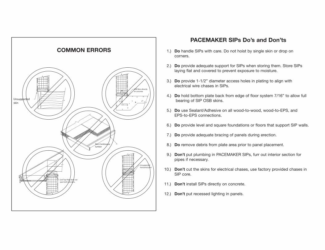
COMMON ERRORS
2nd Top Plate does notspan both osb skins.
Unsupported
OSB Skins directlyon concrete
horizontal jointUnsupported
Non Continuous
skin
lumber
PACEMAKER SIPs Do’s and Don’ts
1.) Do handle SIPs with care. Do not hoist by single skin or drop on corners.
2.) Do provide adequate support for SIPs when storing them. Store SIPs laying flat and covered to prevent exposure to moisture.
3.) Do provide 1-1/2” diameter access holes in plating to align with electrical wire chases in SIPs.
4.) Do hold bottom plate back from edge of floor system 7/16” to allow fullbearing of SIP OSB skins.
5.) Do use Sealant/Adhesive on all wood-to-wood, wood-to-EPS, andEPS-to-EPS connections.
6.) Do provide level and square foundations or floors that support SIP walls.
7.) Do provide adequate bracing of panels during erection.
8.) Do remove debris from plate area prior to panel placement.
9.) Don’t put plumbing in PACEMAKER SIPs, furr out interior section forpipes if necessary.
10.) Don’t cut the skins for electrical chases, use factory provided chases inSIP core.
11.) Don’t install SIPs directly on concrete.
12.) Don’t put recessed lighting in panels.
COMMON ERRORS

Updated 2/12/02
continuousAdhesive
each side.Adhesive typicalSealant/
Sealant/
Plate Connections
Pacemaker® SIPTITLE:
PS-101NO.
Scale: NTS
SECTION
NOTE: Precut interior wall studs to match Pacemaker SIP wall height.
down.panelSlide
capacity. Design asreq'd for specific case.
increase point loadOptional blocking to
standard 8' drywallwhere required forSpacer board (optional)
8d Nails or 14 ga.1 1/2" staples @ 6"o.c. each side, or equivalent. Typicaltop & bottom.
Factory electrical chase
Pacemaker SIPwall panel.
application.
NOTE: Use minimum grade SPF #2 or engineered equivalent for 2x plating
1 1/2"
1 1/2"
Varies
Updated 2/12/02
PS-102Surface Spline
Pacemaker® SIPNO.TITLE: Spline Connection
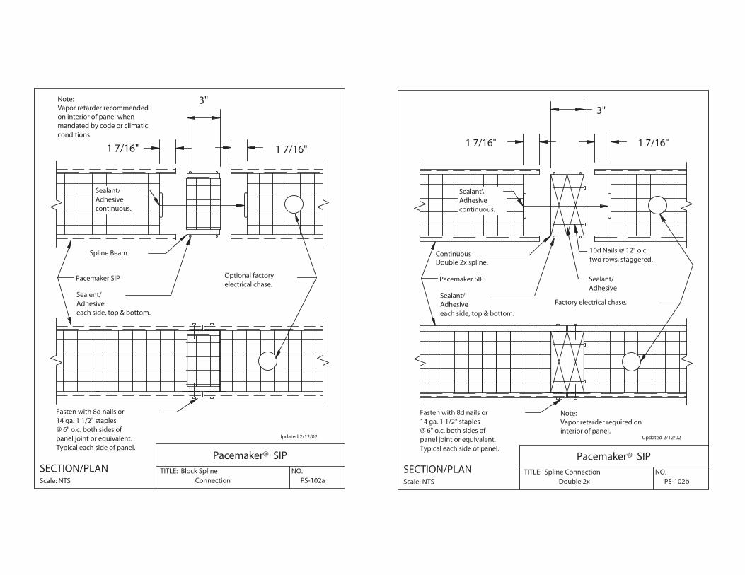
2"
4"
2"
Note:Vapor retarder recommendedon interior of panel whenmandated by code orclimatic conditions.
to the panel skins.min thickness equalNote: Spline to be
splines.each side, bothAdhesiveSealant/
continuous.AdhesiveSealant/
Pacemaker SIP
Factory electrical chase.
Spline
Typical each side of panel.panel joint or equivalent.@ 6" o.c. both sides of 14 ga. 1 1/2" staplesFasten with 8d nails or
Scale: NTS
SECTION/PLAN
Updated 2/12/02
TITLE: Block Spline
Pacemaker® SIP
Connection PS-102aNO.
1 7/16"
3"
1 7/16"
each side, top & bottom.
Typical each side of panel.panel joint or equivalent.@ 6" o.c. both sides of 14 ga. 1 1/2" staplesFasten with 8d nails or
Scale: NTS
SECTION/PLAN
AdhesiveSealent/
Spline Beam.
Pacemaker SIP
continuous.AdhesiveSealant/
electrical chase.Optional factory
Vapor retarder recommendedon interior of panel whenmandated by code or climaticconditions
Note:
Updated 2/12/02
PS-102bDouble 2x
Pacemaker® SIPNO.TITLE: Spline Connection
1 7/16"
3"
1 7/16"
Note:Vapor retarder required oninterior of panel.
two rows, staggered.10d Nails @ 12" o.c.
AdhesiveSealant/
each side, top & bottom.AdhesiveSealant/
continuous.AdhesiveSealant\
Continuous
Pacemaker SIP.
Factory electrical chase.
Typical each side of panel.panel joint or equivalent.@ 6" o.c. both sides of 14 ga. 1 1/2" staplesFasten with 8d nails or
Scale: NTS
SECTION/PLAN
Double 2x spline.

Updated 2/12/02
PS-102cI-Beam Spline Connection
Pacemaker® SIPNO.TITLE: Spline Connection
1 1/4"1 1/4"
2 5/8"
Factoryelectricalchase.
continuous.AdhesiveSealant/
side.both flanges, eachAdhesiveSealant/
SIP.Pacemaker SIP
Continuous I-Beam Spline.
Typical each side of panel.panel joint or equivalent.@ 6" o.c. both sides of 14 ga. 1 1/2" staplesFasten with 8d nails or
Scale: NTS
SECTION/PLAN
Note:Vapor retarder recommended oninterior of panel whenmandated by code or climaticconditions.
This Detail only applies toSIPS 8 5/16" and thicker.
Updated 2/12/02
PS-103Corner Connection
Pacemaker® SIPNO.TITLE:
1 1/2"
1 1/2"
continuous.AdhesiveSealant/
Sealant/
each side.Adhesive
each side.AdhesiveSealant/
Top plate.
@ 24" o.c.Screw FastenerSIP LD
3-16d nails.plate withto verticalNail top plate
board.Gypsum wall
Top plate.
PLAN Scale: NTS
Scale: NTS
SECTION
SIP wall.Pacemaker
or equivalent.o.c. each side1 1/2" staples @ 6"8d Nails or 14 ga.

Updated 2/12/02
Angled Corner Connection
Pacemaker® SIPTITLE:
PS-103aNO.
Top plate.
plate with 3-16d nails.Nail top plate to vertical
between 2x's.Sealant/Adhesivetwo rows, staggered; &with 8d nails @ 12" o.c.Double 2x spline, bevel cut,
Continuous.Adhesive
Scale: 3"=1'
SECTION
Sealant/
SIP wall.Pacemaker
Typical each side of panel.panel joint or equivalent.@ 6" o.c. both sides of 14 ga. 1 1/2" staplesFasten with 8d nails or
PLAN Scale: 3"=1'
Top plate.
wall board.Gypsum
electrical chase.Optional factory
Sealant/AdhesiveContinuous.
Updated 2/12/02 PS-104Interior Wall Connection
Pacemaker SIPNO.TITLE:
®Bottom plate.
Top plate.
board not shown.framing, gypsuminterior wallStandard
face.barrier on insideor approved thermalwith gypsum boardPacemaker SIP wall
Scale: NTS
ISOMETRIC
@ 8" o.c.#10 wood screws

Updated 2/12/02
PS-105Slab Foundation Framing
Pacemaker® SIPNO.TITLE:
as req'd by code.& underlaymentExterior finish
Sealant/Adhesivecontinuous.
Sealant/
each side.Adhesive
AdhesiveSealant/
req'd by code.
by code.
plate.panel bottomField installed
coat.scratchCementitious
Caulk
or flashing.Insect clip
Anchor bolt as
Sill sealer.
as req'd16d nails
Concrete slab.
Treated sill plate.
board.Gypsum wall
Scale: NTS
SECTION
SIP wall.Pacemaker
Expanded Polystyrene.
or equivalent.o.c. each side1 1/2" staples @ 6"8d Nails or 14 ga.
Updated 2/12/02
PS-106Foundation Framing - Joist
Pacemaker® SIPNO.TITLE:
Expanded Polysytrene
Sealant/Adhesive
each side.AdhesiveSealant/
continuous.AdhesiveSealant/
as req'd by code.& underlaymentExterior finish
Rim joist.
Subfloor
by code.Nail as req'd
EPS joist plug.
Floor joist.
foundation wall.Concrete or Masonry
req'd by code.
as req'd by code.
plate.panel bottomField installed
coat.scratchCementitious
Caulk
or flashing.Insect clip
Anchor bolt as
Sill sealer.
into floor joist16d Nails
Treated sill plate.
board.Gypsum wall
Scale: NTS
SECTION
SIP wall.Pacemaker
or equivalent.o.c. each side1 1/2" staples @ 6"8d Nails or 14 ga.

Updated 2-12-02 PS-106aFoundation Framing - Joist
Pacemaker® SIPNO.TITLE:
EPS InsulationPerimeter
each side.AdhesiveSealant/
each side.Adhesive,Sealant/
continuous.AdhesiveSealant/
as req'd by code.& underlaymentExterior finish
Rim joist.
Subfloor
by code.Nail as req'd
Floor joist.
foundation wall.Concrete or Masonry
req'd by code.
as req'd.
plate.panel bottomField installed
coat.scratchCementitious
Caulk
or flashing.Insect clip
Anchor bolt as
Sill sealer.
into sill plate16d Nails
Treated sill plate.
board.Gypsum wall
Scale: NTS
SECTION
SIP wall.Pacemaker
or equivalent.6" o.c. each side1 1/2" staples @8d Nails or 14 ga.
Updated 2/12/02
PS-107Bearing on Wall Panel
Pacemaker® SIPNO.TITLE: Floor Joist
Nail as req'd.
application.standard 8' drywallwhere required for
Spacer board (optional)
wall above.and adhesive, see information, sealant,For connection
Sealant/Adhesive
each side.AdhesiveSealant/
continuous.AdhesiveSealant/
as req'd by code.& underlaymentExterior finish
Rim joist.
Subfloor
by code.Nail as req'd
EPS insulation plug
Floor joist.
as req'd by code.
plate.panel bottomField installed
into floor joist16d Nails
board.Gypsum wall
Scale: NTS
SECTION
SIP wall.Pacemaker
or equivalent.o.c. each side1 1/2" staples @ 6"8d Nails or 14 ga.
(must span both skins)
110
PS
110
PS
110
PS
Updated 2/12/02
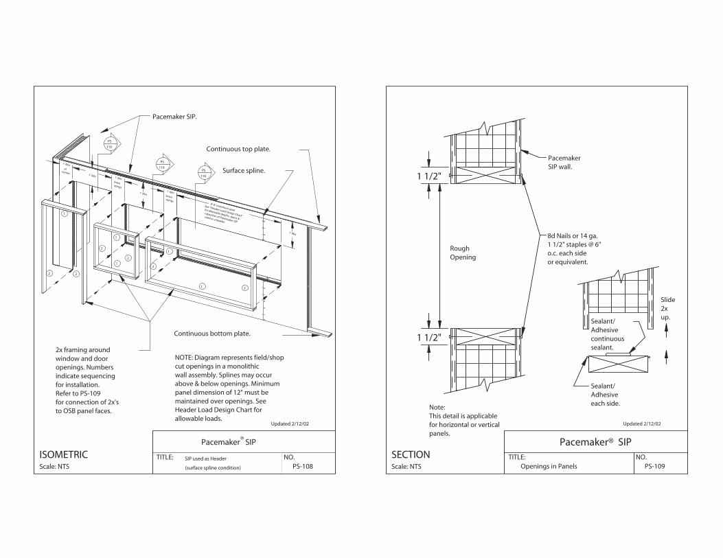
(surface spline condition) PS-108SIP used as Header NO.TITLE:
®Pacemaker SIP
atcorner
btwnopngs
btwnopngs
See "Header Load Design Chart"
for allowable depths, spans &
capacities of Pacemaker SIP
used as a header.
8'-0" maximum span
Surface spline.
allowable loads.Header Load Design Chart formaintained over openings. Seepanel dimension of 12" must beabove & below openings. Minimumwall assembly. Splines may occurcut openings in a monolithicNOTE: Diagram represents field/shop
to OSB panel faces.for connection of 2x'sRefer to PS-109for installation.indicate sequencingopenings. Numberswindow and door2x framing around
Continuous bottom plate.
Continuous top plate.
Pacemaker SIP.
2 2
1
1
1
2
2
2
1 2
1
Scale: NTS
ISOMETRIC
1' Min
1' Min
1' Min1' Min
1' Min
1' Min
Updated 2/12/02
sealant.continuousAdhesiveSealant/
each side.AdhesiveSealant/
PS-109Openings in Panels
Pacemaker® SIPNO.TITLE:
OpeningRough
1 1/2"
1 1/2"
panels.for horizontal or verticalThis detail is applicableNote:
Scale: NTS
SECTION
up.2xSlide
SIP wall.Pacemaker
or equivalent.o.c. each side1 1/2" staples @ 6"8d Nails or 14 ga.

Updated 2/12/02
continuous.Sealant/ Adhesive
typical each side,AdhesiveSealant/
(Pacemaker Panel) PS-110Header sections
Pacemaker® SIPNO.TITLE:
used as header.Pacemaker SIP
as a
hea
der
.Pa
cem
aker
SIP
use
dsp
ans
& c
apac
itie
s o
ffo
r allo
wab
le d
epth
s,Se
e Lo
ad D
esig
n C
har
t
Panel Thickness
12"
MIN
.
each side.AdhesiveSealant/
top & bottom.
Scale: NTS
SECTION
bottom or equivalent.o.c. each side, top &1 1/2" staples @ 6"8d Nails or 14 ga.
Updated 2/12/02
TITLE: NO.Header Detail. PS-111
Pacemaker® PanelISOMETRIC Scale: NTS
PacemakerSIP wall.
SIP wall.Pacemaker
Sill plate.
King stud.
Jamb stud.
Trimmers
Top plate.
Note: King studs,jamb studs, trimmers,header, and bottom infill panelcan be shop or field assembled. Thenumbers indicate sequencing for installation.The full size wall panel pieces are field installed.
See PS-102b forconnection of 2x's.
In fillstuds.
SIP infill.Pacemaker
header panel.Conventional
109
PS
Updated 2/12/02
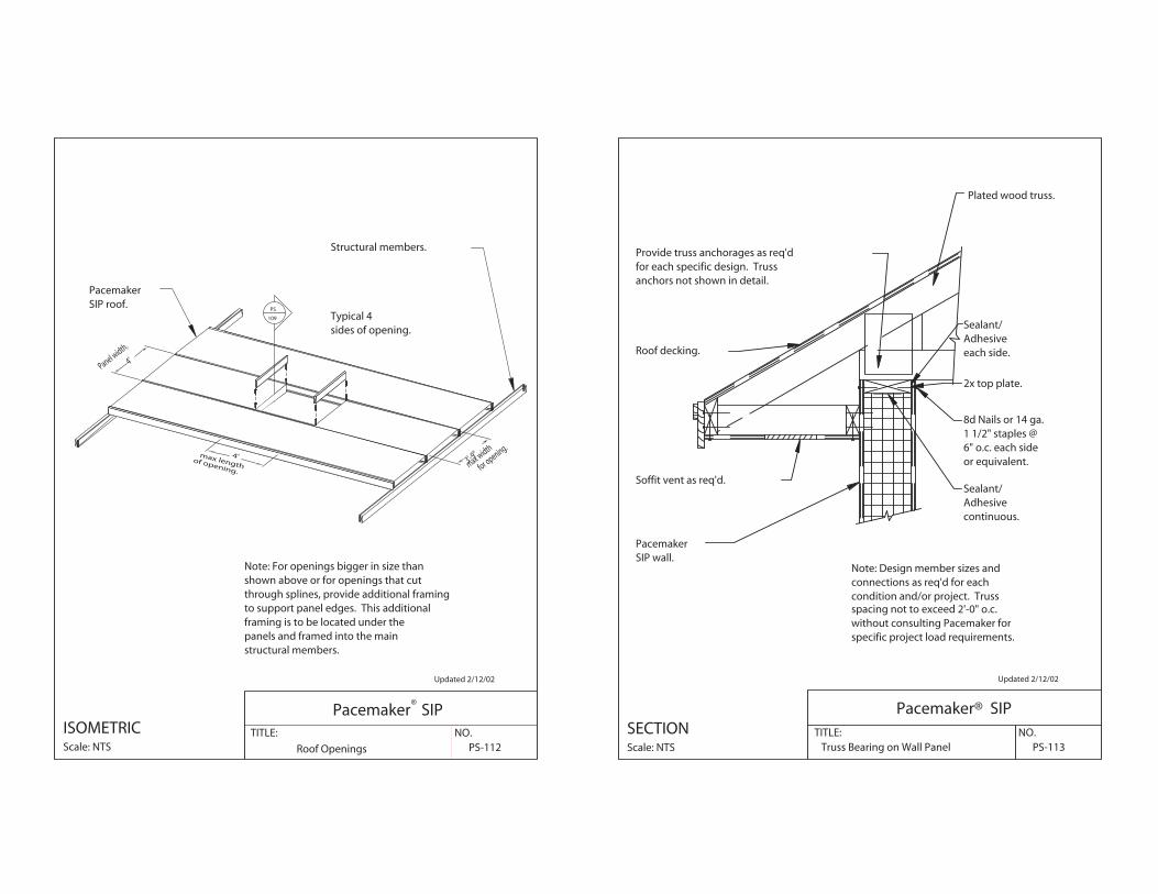
Roof Openings PS-112
Pacemaker SIPNO.TITLE:
®
3'-9"max width
for opening.
4'Panel width.
4'max lengthof opening.
structural members.panels and framed into the mainframing is to be located under theto support panel edges. This additionalthrough splines, provide additional framingshown above or for openings that cutNote: For openings bigger in size than
Structural members.
SIP roof.Pacemaker
sides of opening.Typical 4
Scale: NTS
ISOMETRIC
Updated 2/12/02
Note: Design member sizes andconnections as req'd for eachcondition and/or project. Truss
specific project load requirements.without consulting Pacemaker forspacing not to exceed 2'-0" o.c.
PS-113Truss Bearing on Wall Panel
Pacemaker® SIPNO.TITLE:
continuous.
Roof decking.
Plated wood truss.
anchors not shown in detail.for each specific design. TrussProvide truss anchorages as req'd
Soffit vent as req'd.
1 1/2" staples @6" o.c. each sideor equivalent.
Sealant/Adhesive
8d Nails or 14 ga.
SIP wall.Pacemaker
2x top plate.
Sealant/Adhesiveeach side.
Scale: NTS
SECTION

Updated 2/12/02
top and bottom.nails @ 12" o.c.toe nail with 16dBeveled 2x blocking,
PS-114Beveled 2x Blocking
Pacemaker® SIPNO.TITLE:
Sealant/Adhesivecontinuousalong eave line
continuous.AdhesiveSealant/
continuous.
Insulation
AdhesiveSealant/
or equivalent.6" o.c. each side1 1/2" staples @8d Nails or 14 ga.
each side.AdhesiveSealant/
2x top plate.
PacemakerSIP wall.
spacing requirements.see PS-122 forSIP LD screw,
PacemakerSIP roof.
Scale: NTS
SECTION
Updated 2/12/02
screw is in place.top plate untilattach blocking toUse 16d nails toSIP screw.predrill forBeveled blocking,
PS-114aBeveled Wedge Blocking
Pacemaker® SIPNO.TITLE:
continuous.
panel/blocking joint.
AdhesiveSealant/
or equivalent.6" o.c. each side1 1/2" staples @8d Nails or 14 ga.
each side, and @ roofAdhesiveSealant/
2x top plate.
PacemakerSIP wall.
spacing requirements.see PS-122 forSIP LD screw,
PacemakerSIP roof.
Scale: NTS
SECTION

Updated 2/12/02
PS-115Gable End
Pacemaker® SIPNO.TITLE:
continuous.
panel/top plate joint.
AdhesiveSealant/
or equivalent.6" o.c. each side1 1/2" staples @8d Nails or 14 ga.
each side, and @ roofAdhesive,Sealant/
2x top plate.
PacemakerSIP wall.
spacing requirements.see PS-122 forSIP LD screw, Pacemaker
SIP roof.
Scale: NTS
SECTION
Updated 2/12/02condition and/or project.connections as req'd for eachNote: Design member sizes and
and water shield from fascia.Note: As req'd, extend ice
Soffit
PS-116Built Up - Ladder Framed
Pacemaker® SIPNO.TITLE: Roof Eave
Drip edge.
Strap tie.
for support of roof panel.
Eave wall. See PS-114Fascia
2x Framing Member
2x Framing Member
PacemakerSIP roof.
Scale: NTS
SECTION

Updated 2/12/02
condition and/or project.connections as req'd for eachNote: Design member sizes and
and water shield from fascia.Note: As req'd, extend ice
Soffit
Roof EavePS-116aPlumb Cut - Cant Panel
Pacemaker® SIPNO.TITLE:
Eave wall. See PS-114,
for support of roof panel.
Drip edge.
Certain conditions apply.4' Max Cant
Fascia
2x Framing Member
PacemakerSIP roof.
Scale: NTS
SECTION
Updated 2/12/02condition and/or project.connections as req'd for eachNote: Design member sizes and
and water shield from fascia.Note: As req'd, extend ice
Soffit
Roof GablePS-117Built Up - Ladder Framed
Pacemaker® SIPNO.TITLE:
Drip edge.
Simpson strap tie.
panel.for support of roofGable wall. See PS-115
Fascia
2x Framing Member
PacemakerSIP roof.
Scale: NTS
SECTION

Updated 2/12/02
condition and/or project.connections as req'd for eachNote: Design member sizes and
and water shield from fascia.Note: As req'd, extend ice
Soffit board.
Roof GablePS-117aSquare Cut - Cant Panel
Pacemaker® SIPNO.TITLE:
panel.for support of roofGable wall. See PS-115
Drip edge.
Certain conditions apply.
4' Max Cant
Fascia
PacemakerSIP roof.
Scale: NTS
SECTION
Updated 2/12/02
PS-118Roof Ridge - Plumb Cut
Pacemaker® SIPNO.TITLE:
Vaporretarder
Adhesive each side.Sealant
interior of panel.Note: Vapor retarder on
spacing requirements.see PS-122 forSIP LD screw,
panels each side of joint.with min 2" bearing forStructural support member
SIP roof.Pacemaker
Adhesive, each side.Sealant/
between 2x's.Adhesivewith Sealant/Double 2x spline, bevel cut,
side, top & bottom.AdhesiveSealant/
electrical chase.Optional factory
Typical each side of panel.panel joint or equivalent.@ 6" o.c. both sides of 14 ga. 1 1/2" staplesFasten with 8d nails or
Scale: NTS
SECTION
Ridge Vent and Roofing

Updated 1/31/03
PS-118aPlumb Cut/Cantilever Ridge
Pacemaker® SIPNO.TITLE: Roof Ridge
Vaporretarder
interior of panel.Note: Vapor retarder on
Spline @ 4' o.c.Panels must have double 2x's or I-Beam
staggered.16d nails at 6" o.c.,Fasten with 2 rows of
Support members run parallel to ridge.max. of 4' from center line of ridge.NOTE: Structural support members
SIP roof.Pacemaker
Adhesive, each side.Sealant/
between 2x's.with Sealant/ adhesiveDouble 2x spline, bevel cut,
side, top & bottom.Adhesive eachSealant/
electrical chase.Optional factory
Typical each side of panel.panel joint.@ 6" o.c. both sides of 14 ga. 1 1/2" staplesFasten with 8d nails or
Scale: NTS
SECTION
Updated 2/12/02
PS-119Roof Valley - Plumb Cut
Pacemaker® SIPNO.TITLE:
Vapor retarder
of member.side, top, & bottomAdhesive eachSealant/
Note: Vapor retarder oninterior of panel.
Adhesive between 2x's.
Double 2x spline, bevel cut,with Sealant/
Valley flashing.
spacing requirements.see PS-122 forSIP LD screw,
panels each side of joint.with min 3" bearing forStructural support member
SIP roof.Pacemaker
Adhesive, each side.Sealant/
Adhesive each sideSealant/
electrical chase.Optional factory
Typical each side of panel.panel joint or equivalent.@ 6" o.c. both sides of 14 ga. 1 1/2" staplesFasten with 8d nails or
Scale: NTS
SECTION
Updated 2/12/02
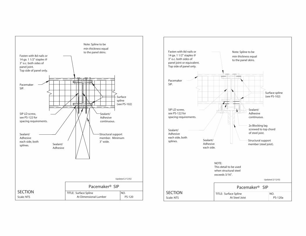
PS-120At Dimensional Lumber
Pacemaker® SIPNO.TITLE: Surface Spline
Surfacespline(see PS-102)
AdhesiveSealant/
to the panel skins.min thickness equal
Note: Spline to be
3" wide.member. MinimumStructural support
spacing requirements.see PS-122 forSIP LD screw,
PacemakerSIP.
splines.each side, bothAdhesiveSealant/
continuous.AdhesiveSealant/
Top side of panel only.panel joint.3" o.c. both sides of 14 ga. 1 1/2" staples @Fasten with 8d nails or
Scale: NTS
SECTION
Updated 2/12/02
PS-120aAt Steel Joist
Pacemaker® SIPNO.TITLE: Surface Spline
Surface spline(see PS-102)
each side.AdhesiveSealant/
Note: Spline to be
min thickness equalto the panel skins.
of steel joist.screwed to top chord2x Blocking lag
member (steel joist).Structural support
spacing requirements.see PS-122 forSIP LD screw,
PacemakerSIP.
splines.each side, bothAdhesiveSealant/
continuous.AdhesiveSealant/
Top side of panel only.panel joint or equivalent.3" o.c. both sides of 14 ga. 1 1/2" staples @Fasten with 8d nails or
Scale: NTS
SECTION
exceeds 3/16".
when structural steelThis detail to be usedNOTE:
Updated 2/12/02
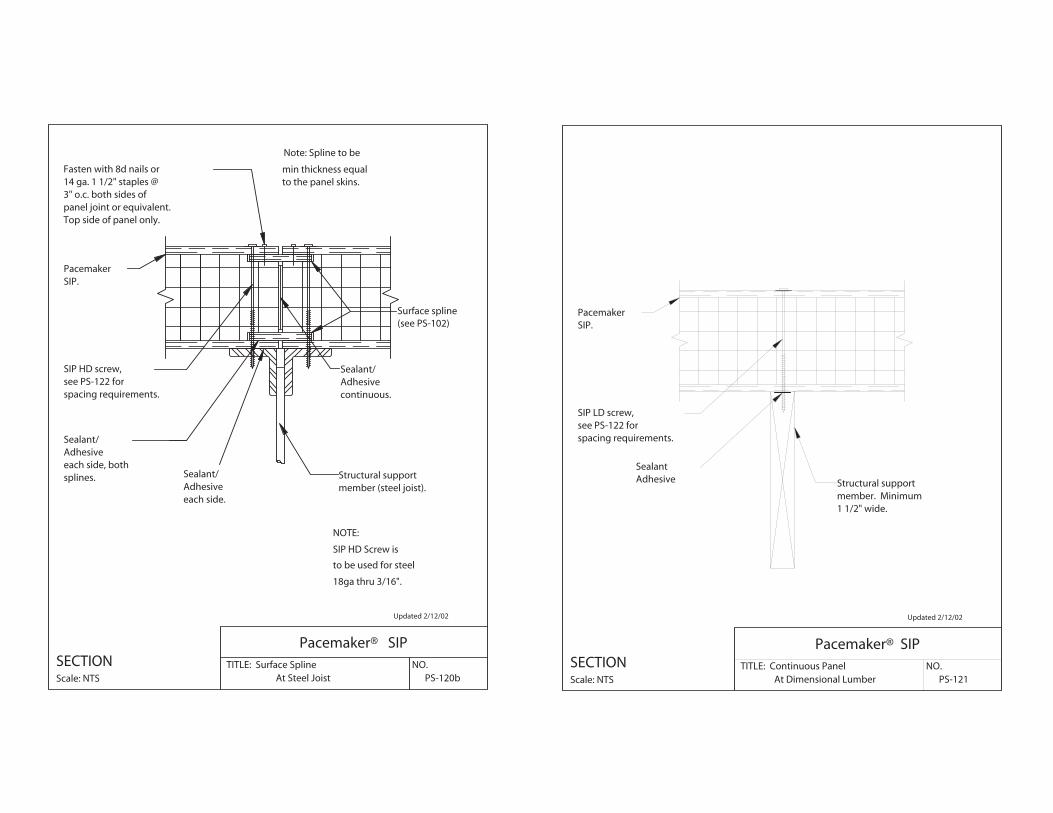
PS-120bAt Steel Joist
Pacemaker® SIPNO.TITLE: Surface Spline
Surface spline(see PS-102)
each side.AdhesiveSealant/
Note: Spline to be
min thickness equalto the panel skins.
member (steel joist).Structural support
spacing requirements.see PS-122 forSIP HD screw,
PacemakerSIP.
splines.each side, bothAdhesiveSealant/
continuous.AdhesiveSealant/
Top side of panel only.panel joint or equivalent.3" o.c. both sides of 14 ga. 1 1/2" staples @Fasten with 8d nails or
Scale: NTS
SECTION
18ga thru 3/16".
NOTE:
to be used for steel
SIP HD Screw is
Updated 2/12/02
PS-121At Dimensional Lumber
Pacemaker® SIPNO.TITLE: Continuous Panel
AdhesiveSealant
1 1/2" wide.member. MinimumStructural support
spacing requirements.see PS-122 forSIP LD screw,
PacemakerSIP.
Scale: NTS
SECTION

Updated 2/12/02
PS-121aAt Steel Joist
Pacemaker® SIPNO.TITLE: Continuous Panel
each side.AdhesiveSealant/
side of joist top flange.Stagger screws each
of steel joist.screwed to top chord2x Blocking lag
member (steel joist).Structural support
spacing requirements.see PS-122 forSIP LD screw,
PacemakerSIP.
Scale: NTS
SECTION
exceeds 3/16".
when structural steelThis detail to be usedNOTE:
Updated 2/12/02
PS-121bAt Steel Joist
Pacemaker® SIPNO.TITLE: Continuous Panel
side of joist top flange.Stagger screws each
member (steel joist).Structural support
spacing requirements.see PS-122 forSIP HD screw,
PacemakerSIP.
Scale: NTS
SECTION
SIP HD Screw is
NOTE:
to be used for steel
18ga thru 3/16".
Updated 2/12/02
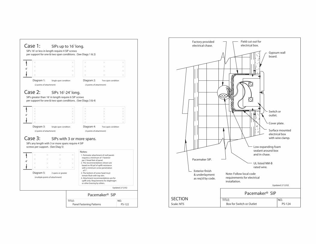
Panel Fastening Patterns
Pacemaker® SIPTITLE:
PS-122NO.
4'
4'
4'
Case 1: SIPs up to 16' long.SIPs 16' or less in length require 4 SIP screwsper support for one & two span conditions. (See Diags 1 & 2)
Diagram 1: Single span condition Diagram 2: Two span condition
(2 points of attachment) (3 points of attachment)
Diagram 3:
per support for one & two span conditions. (See Diags 3 & 4)SIPs greater than 16' in length require 6 SIP screws
Case 2:
(3 points of attachment)
Two span condition
SIPs 16'-24' long.
(2 points of attachment)
Single span condition Diagram 4:
screws per support. (See Diag 5)SIPs any length with 3 or more spans require 4 SIP
Diagram 5:
Case 3: SIPs with 3 or more spans.
(multiple points of attachment)
3 spans or greater
Notes:1. Perimeter attachment of roof panels requires a minimum of 1 fastener per 2 lineal feet of panel.2. The recommendations shown are based on 90 psf of uplift resistance with a minimum screw penetration
of 1".3. The bottom of screw head must remain flush with top skin.4. Attachment recommendations are for uplift only. Requirements for diaphragm or other bracing by others.
Updated 2/12/02
PS-124Box for Switch or Outlet
Pacemaker® SIPNO.TITLE:
Exterior finish& underlaymentas req'd by code.
with wire clamp.electrical boxSurface mounted
installation.requirements for electricalNote: Follow local code
rated wire.UL listed NM-B
and in chase.sealant around boxLow expanding foam
electrical box.Field cut out for
electrical chase.Factory provided
board.Gypsum wall
Cover plate.
outlet.Switch or
Pacemaker SIP.
Scale: NTS
SECTION
Updated 2/12/02
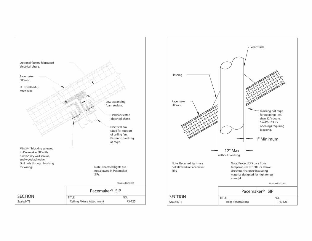
PS-125Ceiling Fixture Attachment
Pacemaker® SIPNO.TITLE:
foam sealant.Low expanding
for wiring.Drill hole through blockingand wood adhesive.
as req'd.Fasten to blockingof ceiling fan.rated for supportElectrical box
rated wire.UL listed NM-B
6-#6x2" dry wall screws,to Pacemaker SIP withMin 3/4" blocking screwed
electrical chase.Field fabricated
electrical chase.Optional factory fabricated
PacemakerSIP roof.
Scale: NTS
SECTION
Note: Recessed lights arenot allowed in PacemakerSIPs.
Updated 2/12/02
PS-126Roof Penetrations
Pacemaker® SIPNO.TITLE:
SIPs.not allowed in PacemakerNote: Recessed lights are
blocking.openings requiringSee PS-109 forthan 12" square.for openings lessBlocking not req'd
as req'd.material designed for high tempsUse zero clearance insulatingtemperatures of 160 F or above.Note: Protect EPS core from
Flashing
without blocking
Vent stack.
1" Minimum
12" Max
PacemakerSIP roof.
Scale: NTS
SECTION
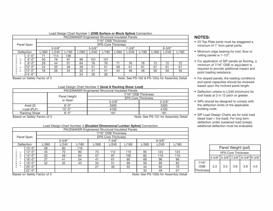
Load Design Chart Number 1 (OSB Surface or Block Spline) ConnectionPACEMAKER Engineered Structural Insulated Panels
7/16” OSB ThicknessPanel Span EPS Core Thickness
3-5/8” 5-5/8” 7-3/8” 9-3/8”Deflection L/360 L/240 L/180 L/360 L/240 L/180 L/360 L/240 L/180 L/360 L/240 L/180
4’-0” 71 114 1366’-0” 50 79 97 89 101 1018’-0” 29 44 57 64 76 76 71 76 76 72 72 72
10’-0” 24 35 46 39 51 51 58 61 61 61 61 6112’-0” 18 26 34 32 41 41 44 46 46 50 50 5014’-0” 24 30 30
Based on Safety Factor of 3 Note: See PS-102 & PS-102a for Assembly Detail
Load Design Chart Number 2 (Axial & Racking Shear Load)PACEMAKER Engineered Structural Insulated Panels
Panel Height7/16” OSB Thickness
or SpanEPS Core Thickness
3-5/8” 5-5/8”Axial (2) 8’-0” 3300 3300
Load (PLF) 10’-0” 4100 4100Racking Shear 8’-0” 181 181
Based on Safety Factor of 3 Note: See PS-101 for Assembly Detail
LOAD
PFS
TRANSVERSE
Load Design Chart Number 3 (Doubled Dimensional Lumber Spline) ConnectionPACEMAKER Engineered Structural Insulated Panels
7/16” OSB ThicknessPanel Span EPS Core Thickness
5-5/8” 7-3/8” 9-3/8”Deflection L/360 L/240 L/180 L/360 L/240 L/180 L/360 L/240 L/180
10’-0” 58 90 11612’-0” 45 70 90 73 112 119 95 124 12414’-0” 32 49 64 57 87 100 82 110 11016’-0” 27 41 54 41 61 80 68 96 9618’-0” 22 32 43 34 51 66 56 80 8320’-0” 27 40 52 44 65 7022’-0” 32 49 57
Based on Safety Factor of 3 Note: See PS-102b for Assembly Detail
LOAD
PFS
TRANSVERSE
NOTES:• 2X Top Plate joints must be staggered a
minimum of 1’ from panel joints.
• Minimum edge bearing for roof, floor orceiling panels is 1-1/2”.
• For application of SIP panels as flooring, aminimum of 7/16” OSB or equivalent isrequired to provide additional impact andpoint loading resistance.
• For sloped panels, the loading conditions and panel capacities should be reviewedbased upon the inclined panel length.
• Deflection criteria is L/240 (minimum) forroof loads at 3 in 12 pitch or greater.
• SIPs should be designed to comply withthe deflection limits of the applicablebuilding code.
• SIP Load Design Charts are for total load(dead load + live load). For long termdeflection under sustained load (creep),additional deflection must be evaluated.
Panel Weight (psf)EPS Core Thickness
3-5/8” 5-5/8” 7-3/8” 9-3/8” 11-3/8”
7/16”OSB 3.3 3.5 3.6 3.8 4.0
Thickness

Load Design Chart Number 3a (Wood I-Beam Spline) ConnectionPACEMAKER Engineered Structural Insulated Panels
7/16” OSB ThicknessPanel Span EPS Core Thickness
7-5/8” 9-3/8” 11-3/8”Deflection L/360 L/240 L/180 L/360 L/240 L/180 L/360 L/240 L/180
14’-0” 52 69 6916’-0” 43 60 63 58 73 7318’-0” 33 50 57 47 63 64 64 68 6820’-0” 35 52 54 55 62 6222’-0” 45 57 5724’-0” 36 51 51
Based on Safety Factor of 3 Note: See PS-102c for Assembly Detail
LOAD
PFS
TRANSVERSE
Load Design Chart Number 4 (Point Load)Panel 1-1/2” Bearing 1-1/2” Bearing 3” Bearing 3” Bearing
Thickness No Additional Plate w/Additional Plate No Additional Plate w/Additional Plate3-5/8” 2180 3360 2610 3920
Header Span, feetLoad (PLF)
Header Depth, in. Deflection 2 3 4 5 6 7 8 9 10L/480 370 344 317 283 248 211 174 161 148
12 L/360 500 485 470 386 302 256 210 187 163L/240 1078 879 679 513 346 305 264 214 163L/180 1813 1813 742 544 346 305 264 214 163L/480 384 475 566 482 398 356 313 295 276
18 L/360 582 636 689 574 459 400 340 308 276L/240 1160 925 689 574 459 400 340 308 276L/180 1500 1095 689 574 459 400 340 308 276L/480 757 737 717 630 543 472 401 345 288
12 L/360 1255 986 717 630 543 472 401 345 288L/240 1695 1206 717 630 543 472 401 345 288L/180 1695 1206 717 630 543 472 401 345 288
Based on Safety Factor of 3 Note: See PS-108 & PS-110 for Assembly Detail
A. OSB FacersB. UL EPS CoreC. OSB SplineD. Wire ChasesE. 2x Top PlateF. 2x Bottom PlateG. Precut OpeningH. Precut Eaves/RidgeI. I-Beam ConnectionJ. Vapor BarrierK. Adhesive/Caulk (at all connections)
A
BC
D
E H
H
I
J
G
F