construction electrician apprenticeship program level 2 ... · level 2 line h: install electrical...
TRANSCRIPT

CONSTRUCTION ELECTRICIAN APPRENTICESHIP PROGRAMLevel 2 Line H: Install Electrical Equipment
LEARNING GUIDE H-2INSTALL TRANSFORMERS
H-2

ForewordThe Industry Training Authority (ITA) is pleased to release this major update of learning resources to support the delivery of the BC Electrician Apprenticeship Program. It was made possible by the dedicated efforts of the Electrical Articulation Committee of BC (EAC).
The EAC is a working group of electrical instructors from institutions across the province and is one of the key stakeholder groups that supports and strengthens industry training in BC. It was the driving force behind the update of the Electrician Apprenticeship Program Learning Guides, supplying the specialized expertise required to incorporate technological, procedural and industry-driven changes. The EAC plays an important role in the province’s post-secondary public institutions. As discipline specialists the committee’s members share information and engage in discussions of curriculum matters, particularly those affecting student mobility.
ITA would also like to acknowledge the Construction Industry Training Organization (CITO) which provides direction for improving industry training in the construction sector. CITO is responsible for organizing industry and instructor representatives within BC to consult and provide changes related to the BC Construction Electrician Training Program.
We are grateful to EAC for their contributions to the ongoing development of BC Construction Electrician Training Program Learning Guides (materials whose ownership and copyright are maintained by the Province of British Columbia through ITA).
Industry Training AuthorityJanuary 2011
DisclaimerThe materials in these Learning Guides are for use by students and instructional staff and have been compiled from sources believed to be reliable and to represent best current opinions on these subjects. These manuals are intended to serve as a starting point for good practices and may not specify all minimum legal standards. No warranty, guarantee or representation is made by the British Columbia Electrical Articulation Committee, the British Columbia Industry Training Authority or the Queen’s Printer of British Columbia as to the accuracy or sufficiency of the information contained in these publications. These manuals are intended to provide basic guidelines for electrical trade practices. Do not assume, therefore, that all necessary warnings and safety precautionary measures are contained in this module and that other or additional measures may not be required.

Acknowledgements and CopyrightCopyright © 2011, 2014 Industry Training Authority
All rights reserved. No part of this publication may be reproduced or transmitted in any form or by any means, electronic or digital, without written permission from Industry Training Authority (ITA). Reproducing passages from this publication by photographic, electrostatic, mechanical, or digital means without permission is an infringement of copyright law.
The issuing/publishing body is: Crown Publications, Queen’s Printer, Ministry of Citizens’ Services
The Industry Training Authority of British Columbia would like to acknowledge the Electrical Articulation Committee and Open School BC, the Ministry of Education, as well as the following individuals and organizations for their contributions in updating the Electrician Apprenticeship Program Learning Guides:
Electrical Articulation Committee (EAC) Curriculum SubcommitteePeter Poeschek (Thompson Rivers University)Ken Holland (Camosun College)Alain Lavoie (College of New Caledonia)Don Gillingham (North Island University)Jim Gamble (Okanagan College)John Todrick (University of the Fraser Valley)
Open School BCOpen School BC provided project management and design expertise in updating the Electrician Apprenticeship Program print materials:
Adrian Hill, Project ManagerEleanor Liddy, Director/SupervisorBeverly Carstensen, Dennis Evans, Laurie Lozoway, Production Technician (print layout, graphics)Christine Ramkeesoon, Graphics Media CoordinatorKeith Learmonth, EditorMax Licht, Graphic Artist Ted Simmons (British Columbia Institute of Technology)
Members of the Curriculum Subcommittee have assumed roles as writers, reviewers, and subject matter experts throughout the development and revision of materials for the Electrician Apprenticeship Program.
Publishing Services, Queen’s PrinterSherry Brown, Director of QP Publishing Services
Intellectual Property Program Ilona Ugro, Copyright Officer, Ministry of Citizens’ Services, Province of British Columbia
To order copies of any of the Electrician Apprenticeship Program Learning Guides, please contact us:
Crown Publications, Queen’s PrinterPO Box 9452 Stn Prov Govt563 Superior Street 2nd FlrVictoria, BC V8W 9V7Phone: 250-387-6409Toll Free: 1-800-663-6105Fax: 250-387-1120Email: [email protected]: www.crownpub.bc.ca
Version 1Corrected, June 2016 Revised, May 2014 Corrected, July 2013 New, August 2011
CONSTRUCTION ELECTRICIAN APPRENTICESHIP PROGRAM: LEVEL 2 5
LEVEL 2, LEARNING GUIDE H-2:
INSTALL TRANSFORMERSLearning Objectives . . . . . . . . . . . . . . . . . . . . . . . . . . . . . . . . . . . . . . . . . . . . . . . 7
Learning Task 1: Describe the operating principles of a transformer . . . . . . . . . . . . . . . . . 9Self-Test 1. . . . . . . . . . . . . . . . . . . . . . . . . . . . . . . . . . . . . . . . . 15
Learning Task 2: Calculate transformer values using ratios. . . . . . . . . . . . . . . . . . . . . . 17Self-Test 2. . . . . . . . . . . . . . . . . . . . . . . . . . . . . . . . . . . . . . . . . 21
Learning Task 3: Describe transformer markings and ratings . . . . . . . . . . . . . . . . . . . . 23Self-Test 3. . . . . . . . . . . . . . . . . . . . . . . . . . . . . . . . . . . . . . . . . 28
Learning Task 4: Describe transformer types and applications . . . . . . . . . . . . . . . . . . . 29Self-Test 4. . . . . . . . . . . . . . . . . . . . . . . . . . . . . . . . . . . . . . . . . 31
Learning Task 5: Determine the polarity and markings for transformers . . . . . . . . . . . . . 33Self-Test 5. . . . . . . . . . . . . . . . . . . . . . . . . . . . . . . . . . . . . . . . . 36
Learning Task 6: Describe the various connections and applications for multi-coil transformers 37Self-Test 6. . . . . . . . . . . . . . . . . . . . . . . . . . . . . . . . . . . . . . . . . 53
Learning Task 7: Solve problems involving transformer calculations . . . . . . . . . . . . . . . . 57Self-Test 7. . . . . . . . . . . . . . . . . . . . . . . . . . . . . . . . . . . . . . . . . 68
Learning Task 8: Describe the effects of load on a transformer . . . . . . . . . . . . . . . . . . . 73Self-Test 8. . . . . . . . . . . . . . . . . . . . . . . . . . . . . . . . . . . . . . . . . 79
Learning Task 9: Describe the application of multi-tap windings and tap changers . . . . . . . 81Self-Test 9. . . . . . . . . . . . . . . . . . . . . . . . . . . . . . . . . . . . . . . . . 85
Learning Task 10: Calculate values involving multi-tap and tap changer transformers . . . . . . 87Self-Test 10 . . . . . . . . . . . . . . . . . . . . . . . . . . . . . . . . . . . . . . . . 91
Learning Task 11: Describe constructional features and applications of autotransformers . . . 93Self-Test 11 . . . . . . . . . . . . . . . . . . . . . . . . . . . . . . . . . . . . . . . . 97
Learning Task 12: Describe how standard two-winding transformers can be connected as autotransformers . . . . . . . . . . . . . . . . . . . . . . . . . . . . . . . . . . 99Self-Test 12 . . . . . . . . . . . . . . . . . . . . . . . . . . . . . . . . . . . . . . . .114
Learning Task 13: Solve problems involving autotransformer calculations . . . . . . . . . . . . .117Self-Test 13 . . . . . . . . . . . . . . . . . . . . . . . . . . . . . . . . . . . . . . . .126
Learning Task 14: Describe the features and applications of instrument transformers . . . . . .129Self-Test 14 . . . . . . . . . . . . . . . . . . . . . . . . . . . . . . . . . . . . . . . .136

6 CONSTRUCTION ELECTRICIAN APPRENTICESHIP PROGRAM: LEVEL 2
Learning Task 15: Illustrate instrument-transformer connections and calculate meter readings . . . . . . . . . . . . . . . . . . . . . . . . . . . . . . . . . . . . .139Self-Test 15 . . . . . . . . . . . . . . . . . . . . . . . . . . . . . . . . . . . . . . . .144
Answer Key . . . . . . . . . . . . . . . . . . . . . . . . . . . . . . . . . . . . . . . . . . . . . . . . . .146
LEARNING ObjECTIVES H-2
CONSTRUCTION ELECTRICIAN APPRENTICESHIP PROGRAM: LEVEL 2 7
Learning Objectives• The learner will be able to connect and maintain single-phase transformers.
• The learner will be able to describe how to connect and operate transformers in parallel.
• The learner will be able to describe voltage-regulation and tap-changer equipment.
• The learner will be able to connect and maintain autotransformers.
• The learner will be able to describe how to connect and maintain instrument transformers.
Activities• Read and study the topics of Learning Guide H-2: Connect and Maintain Transformers.
• Complete Self-Tests 1 to 15. Check your answers with the Answer Key provided at the end of this Learning Guide.
Resources
You are encouraged to obtain the following textbook for supplemental learning information:
• Alternating Current Fundamentals by John R. Duff and Stephen L. Herman; Delmar Publishers Inc.
LEARNING ObjECTIVES H-2
8 CONSTRUCTION ELECTRICIAN APPRENTICESHIP PROGRAM: LEVEL 2
BC Trades Moduleswww.bctradesmodules.ca
We want your feedback! Please go the BC Trades Modules website to enter comments about specific section(s) that require correction or modification. All submissions will be reviewed and considered for inclusion in the next revision.
SAFETY ADVISORYBe advised that references to the Workers’ Compensation Board of British Columbia safety regulations contained within these materials do not/may not reflect the most recent Occupational Health and Safety Regulation. The current Standards and Regulation in BC can be obtained at the following website: http://www.worksafebc.com.
Please note that it is always the responsibility of any person using these materials to inform him/herself about the Occupational Health and Safety Regulation pertaining to his/her area of work.
Industry Training Authority January 2011
CONSTRUCTION ELECTRICIAN APPRENTICESHIP PROGRAM: LEVEL 2 9
Learning Task 1:
Describe the operating principles of a transformerA transformer is a device used to transfer electrical energy from one electrical circuit to another. Transformers can:
• Step up or down voltages
• Step up or down currents
• Electrically isolate circuits
• Facilitate the safe transmission of electrical energy over long distances with minimal loss
• Change the magnitude of: ▸ Resistance
▸ Inductance
▸ Capacitance
Principles of operationTransformers operate on the principle of mutual induction. Mutual induction is the action by which a change in the current in one conductor induces a voltage in a neighbouring conductor.
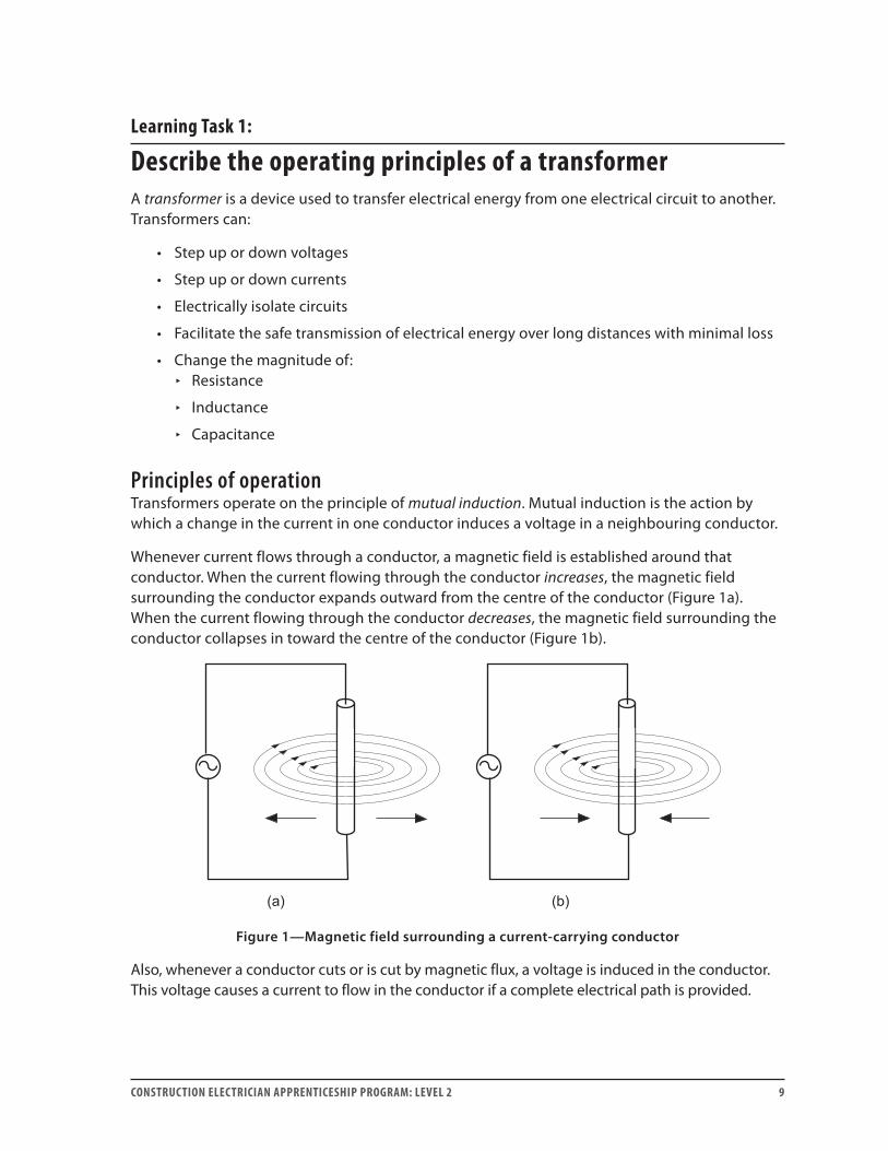
Whenever current flows through a conductor, a magnetic field is established around that conductor. When the current flowing through the conductor increases, the magnetic field surrounding the conductor expands outward from the centre of the conductor (Figure 1a). When the current flowing through the conductor decreases, the magnetic field surrounding the conductor collapses in toward the centre of the conductor (Figure 1b).
Figure 1—Magnetic field surrounding a current-carrying conductor
Also, whenever a conductor cuts or is cut by magnetic flux, a voltage is induced in the conductor. This voltage causes a current to flow in the conductor if a complete electrical path is provided.
LEARNING TASk 1 H-2
10 CONSTRUCTION ELECTRICIAN APPRENTICESHIP PROGRAM: LEVEL 2
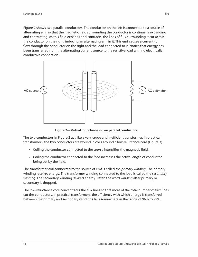
Figure 2 shows two parallel conductors. The conductor on the left is connected to a source of alternating emf so that the magnetic field surrounding the conductor is continually expanding and contracting. As this field expands and contracts, the lines of flux surrounding it cut across the conductor on the right, inducing an alternating emf in it. This emf causes a current to flow through the conductor on the right and the load connected to it. Notice that energy has been transferred from the alternating current source to the resistive load with no electrically conductive connection.
Figure 2—Mutual inductance in two parallel conductors
The two conductors in Figure 2 act like a very crude and inefficient transformer. In practical transformers, the two conductors are wound in coils around a low-reluctance core (Figure 3).
• Coiling the conductor connected to the source intensifies the magnetic field.
• Coiling the conductor connected to the load increases the active length of conductor being cut by the field.
The transformer coil connected to the source of emf is called the primary winding. The primary winding receives energy. The transformer winding connected to the load is called the secondary winding. The secondary winding delivers energy. Often the word winding after primary or secondary is dropped.
The low-reluctance core concentrates the flux lines so that more of the total number of flux lines cut the conductors. In practical transformers, the efficiency with which energy is transferred between the primary and secondary windings falls somewhere in the range of 96% to 99%.
LEARNING TASk 1 H-2
CONSTRUCTION ELECTRICIAN APPRENTICESHIP PROGRAM: LEVEL 2 11
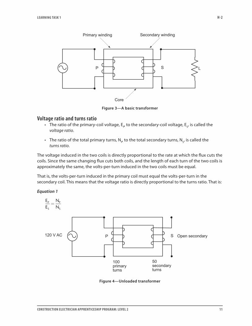
Figure 3—A basic transformer
Voltage ratio and turns ratio• The ratio of the primary-coil voltage, EP, to the secondary-coil voltage, ES, is called the
voltage ratio.
• The ratio of the total primary turns, NP, to the total secondary turns, NS, is called the turns ratio.
The voltage induced in the two coils is directly proportional to the rate at which the flux cuts the coils. Since the same changing flux cuts both coils, and the length of each turn of the two coils is approximately the same, the volts-per-turn induced in the two coils must be equal.
That is, the volts-per-turn induced in the primary coil must equal the volts-per-turn in the secondary coil. This means that the voltage ratio is directly proportional to the turns ratio. That is:
Equation 1
EE
NN
P
S
P
S
=
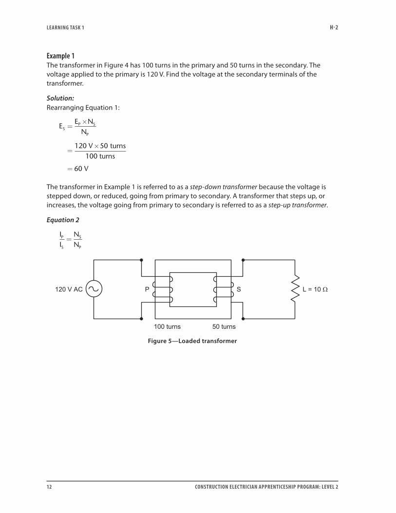
Figure 4—Unloaded transformer
LEARNING TASk 1 H-2
12 CONSTRUCTION ELECTRICIAN APPRENTICESHIP PROGRAM: LEVEL 2
Example 1The transformer in Figure 4 has 100 turns in the primary and 50 turns in the secondary. The voltage applied to the primary is 120 V. Find the voltage at the secondary terminals of the transformer.
Solution:Rearranging Equation 1:
EE N
N
V
V
SP S
P
=×
=×
=
120 50
60
turns100 turns
The transformer in Example 1 is referred to as a step-down transformer because the voltage is stepped down, or reduced, going from primary to secondary. A transformer that steps up, or increases, the voltage going from primary to secondary is referred to as a step-up transformer.
Equation 2
II
NN
P
S
S
P
=
Figure 5—Loaded transformer
LEARNING TASk 1 H-2
CONSTRUCTION ELECTRICIAN APPRENTICESHIP PROGRAM: LEVEL 2 13
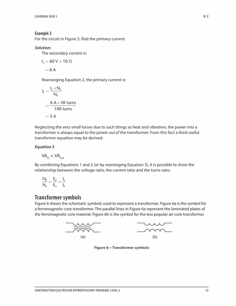
Example 2For the circuit in Figure 5, find the primary current.
Solution: The secondary current is:
I V
A
S = ÷
=
60 10 Ω
6
Rearranging Equation 2, the primary current is:
II N
N
A
A
PS S
P
=×
=×
=
6 50
3
turns100 turns
Neglecting the very small losses due to such things as heat and vibration, the power into a transformer is always equal to the power out of the transformer. From this fact a third useful transformer equation may be derived:
Equation 3
VAin = VAout
By combining Equations 1 and 2 (or by rearranging Equation 3), it is possible to show the relationship between the voltage ratio, the current ratio and the turns ratio.
NN
EE
II
P
S
P
S
S
P
= =
Transformer symbolsFigure 6 shows the schematic symbols used to represent a transformer. Figure 6a is the symbol for a ferromagnetic-core transformer. The parallel lines in Figure 6a represent the laminated plates of the ferromagnetic core material. Figure 6b is the symbol for the less popular air-core transformer.
Figure 6—Transformer symbols
LEARNING TASk 1 H-2
14 CONSTRUCTION ELECTRICIAN APPRENTICESHIP PROGRAM: LEVEL 2
Classification of transformersTransformers may be classified according to:
• Cooling method For example: air, oil, natural convection, forced air, forced oil
• Insulation between the windings For example: class of insulation used in transformer construction
• Number of phases For example: single-phase, polyphase
• Type of service For example: power, distribution, instrument, control
• Type of winding For example: isolated or autotransformer windings
Now complete Self-Test 1 and check your answers.
LEARNING TASk 1 H-2
CONSTRUCTION ELECTRICIAN APPRENTICESHIP PROGRAM: LEVEL 2 15
Self-Test 1
1. Transformers operate on the principle of .
2. Whenever the current through a conductor increases, the magnetic flux around the
conductor .
3. The winding of a transformer that is connected to the source is referred to as the
winding.
4. Transformers typically have efficiencies in the range of to %.
5. State the equation that gives the relationship between voltage ratio and turns ratio.
6. State the equation that gives the relationship between current ratio and turns ratio.
7. A transformer has 150 turns on the primary and 50 turns on the secondary. If 300 V is applied
to the primary, what voltage will appear on the secondary?
8. Is the transformer in Question 7 a step-up or step-down transformer?
9. If a 20 Ω load is connected across the secondary terminals of the transformer in Question 7,
what current flows in the primary circuit?
10. If a 500 VA transformer has a primary voltage rating of 120 V, what is the primary current
rating for this transformer?
Go to the Answer Key at the end of the Learning Guide to check your answers.

16 CONSTRUCTION ELECTRICIAN APPRENTICESHIP PROGRAM: LEVEL 2
CONSTRUCTION ELECTRICIAN APPRENTICESHIP PROGRAM: LEVEL 2 17
Learning Task 2:
Calculate transformer values using ratiosSo far you have learned some of the basic concepts about how transformers operate. At this point in your study, it is a good idea to learn how to use the formulas to solve practical problems.
In Learning Task 1, you were introduced to the following equations:
VAin = VAout assuming 100% efficiency
and
NN
EE
II
P
S
P
S
S
P
= =
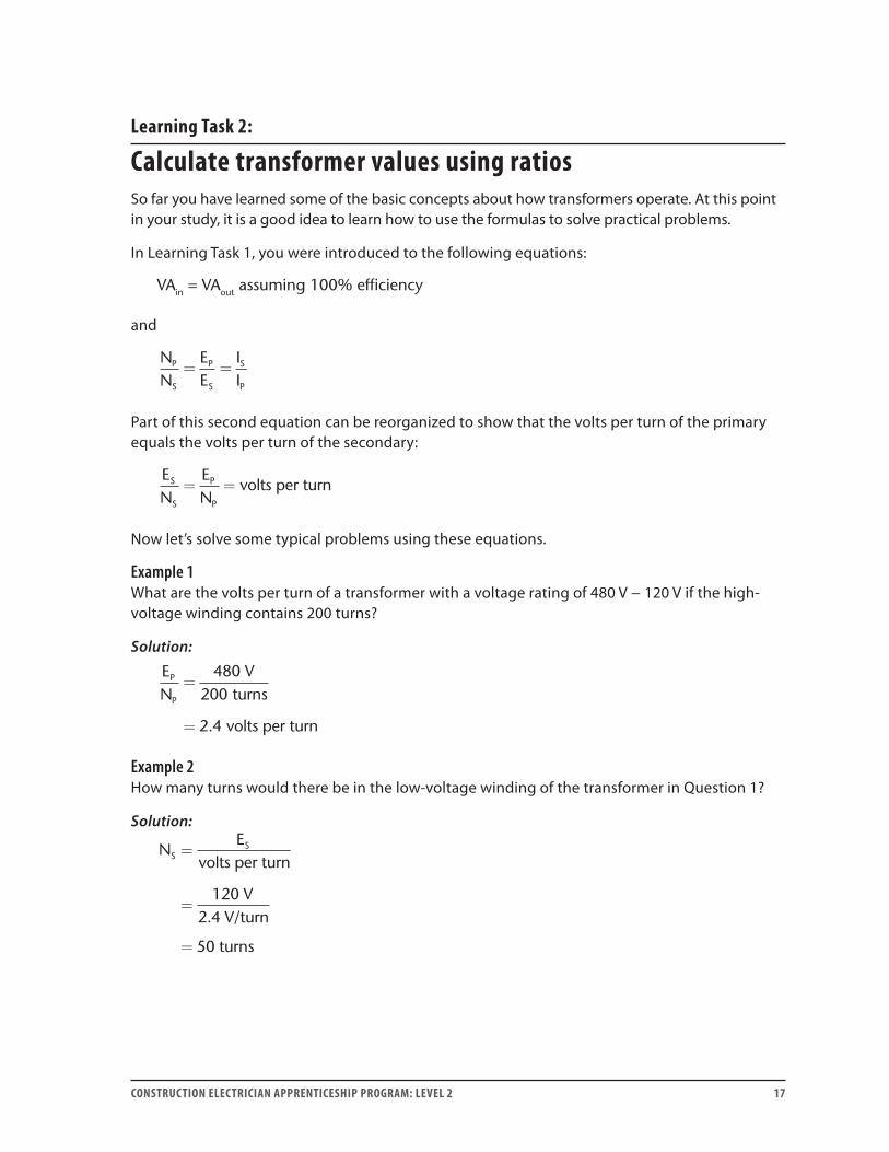
Part of this second equation can be reorganized to show that the volts per turn of the primary equals the volts per turn of the secondary:
EN
EN
volts per turnS
S
P
P
= =
Now let’s solve some typical problems using these equations.
Example 1What are the volts per turn of a transformer with a voltage rating of 480 V − 120 V if the high-voltage winding contains 200 turns?
Solution:
EN
VP
P
=
=
480200
2 4
turns
volts per turn.
Example 2How many turns would there be in the low-voltage winding of the transformer in Question 1?
Solution:
NE
SS=
=
=
volts per turn
120 V2.4 V/turn
50 turns
LEARNING TASk 2 H-2
18 CONSTRUCTION ELECTRICIAN APPRENTICESHIP PROGRAM: LEVEL 2
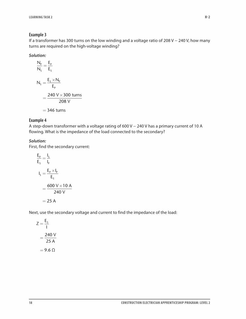
Example 3If a transformer has 300 turns on the low winding and a voltage ratio of 208 V − 240 V, how many turns are required on the high-voltage winding?
Solution:
NN
EE
P
S
P
S
=
NE N
E
VV
SS P
P
=×
=×
=
240 300208
346
turns
turns
Example 4A step-down transformer with a voltage rating of 600 V − 240 V has a primary current of 10 A flowing. What is the impedance of the load connected to the secondary?
Solution:First, find the secondary current:
EE
II
IE I
E
V AV
A
P
S
S
P
SP P
S
=
=×
=×
=
600 10240
25
Next, use the secondary voltage and current to find the impedance of the load:
ZEI
VA
S=
=
=
24025
9 6 Ω.
LEARNING TASk 2 H-2
CONSTRUCTION ELECTRICIAN APPRENTICESHIP PROGRAM: LEVEL 2 19
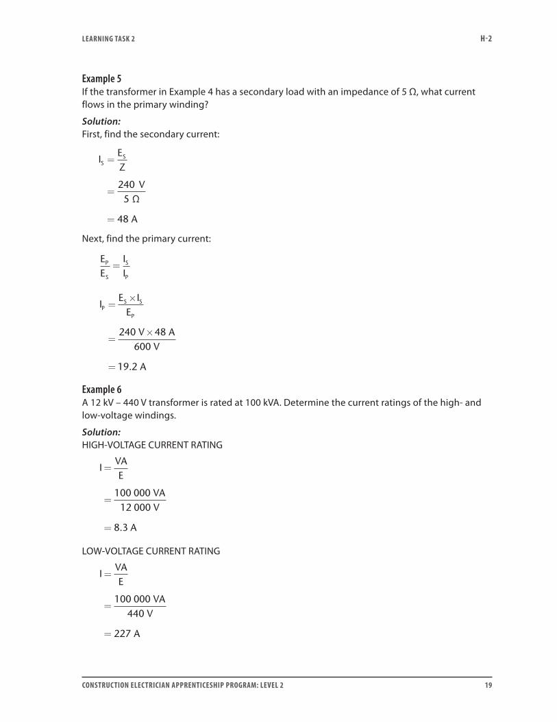
Example 5If the transformer in Example 4 has a secondary load with an impedance of 5 Ω, what current flows in the primary winding?
Solution:First, find the secondary current:
IEZ
V
A
SS=
=
=
2405 Ω
48
Next, find the primary current:
EE
II
P
S
S
P
=
IE I
E
V AV
A
PS S
P
=×
=×
=
240 48600
19 2.
Example 6A 12 kV – 440 V transformer is rated at 100 kVA. Determine the current ratings of the high- and low-voltage windings.
Solution:HIGH-VOLTAGE CURRENT RATING
IVAE
VAV
A
=
=
=
100 00012 000
8 3.
LOW-VOLTAGE CURRENT RATING
IVAE
VAV
A
=
=
=
100 000440
227
LEARNING TASk 2 H-2
20 CONSTRUCTION ELECTRICIAN APPRENTICESHIP PROGRAM: LEVEL 2
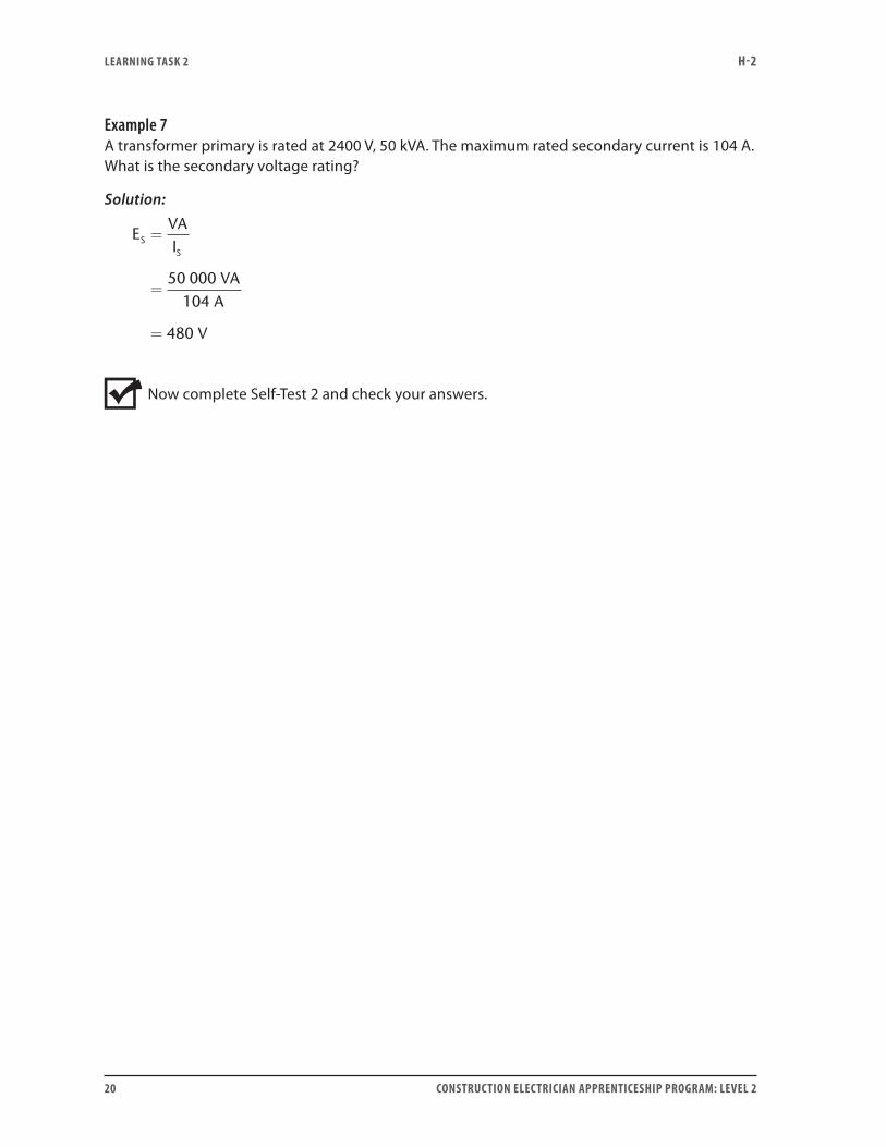
Example 7A transformer primary is rated at 2400 V, 50 kVA. The maximum rated secondary current is 104 A. What is the secondary voltage rating?
Solution:
EVAI
VAA
V
SS
=
=
=
50 000104
480
Now complete Self-Test 2 and check your answers.
LEARNING TASk 2 H-2
CONSTRUCTION ELECTRICIAN APPRENTICESHIP PROGRAM: LEVEL 2 21
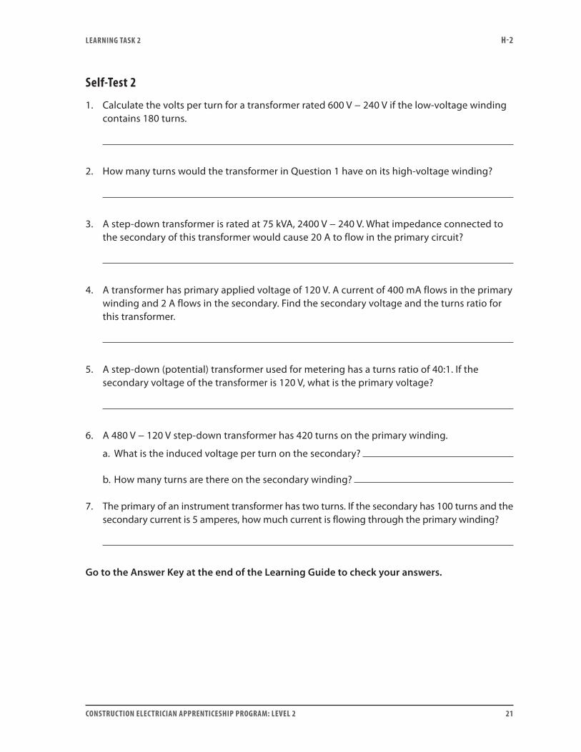
Self-Test 2
1. Calculate the volts per turn for a transformer rated 600 V − 240 V if the low-voltage winding contains 180 turns.
2. How many turns would the transformer in Question 1 have on its high-voltage winding?
3. A step-down transformer is rated at 75 kVA, 2400 V − 240 V. What impedance connected to the secondary of this transformer would cause 20 A to flow in the primary circuit?
4. A transformer has primary applied voltage of 120 V. A current of 400 mA flows in the primary winding and 2 A flows in the secondary. Find the secondary voltage and the turns ratio for this transformer.
5. A step-down (potential) transformer used for metering has a turns ratio of 40:1. If the secondary voltage of the transformer is 120 V, what is the primary voltage?
6. A 480 V − 120 V step-down transformer has 420 turns on the primary winding.
a. What is the induced voltage per turn on the secondary?
b. How many turns are there on the secondary winding?
7. The primary of an instrument transformer has two turns. If the secondary has 100 turns and the secondary current is 5 amperes, how much current is flowing through the primary winding?
Go to the Answer Key at the end of the Learning Guide to check your answers.

22 CONSTRUCTION ELECTRICIAN APPRENTICESHIP PROGRAM: LEVEL 2
CONSTRUCTION ELECTRICIAN APPRENTICESHIP PROGRAM: LEVEL 2 23
Learning Task 3:
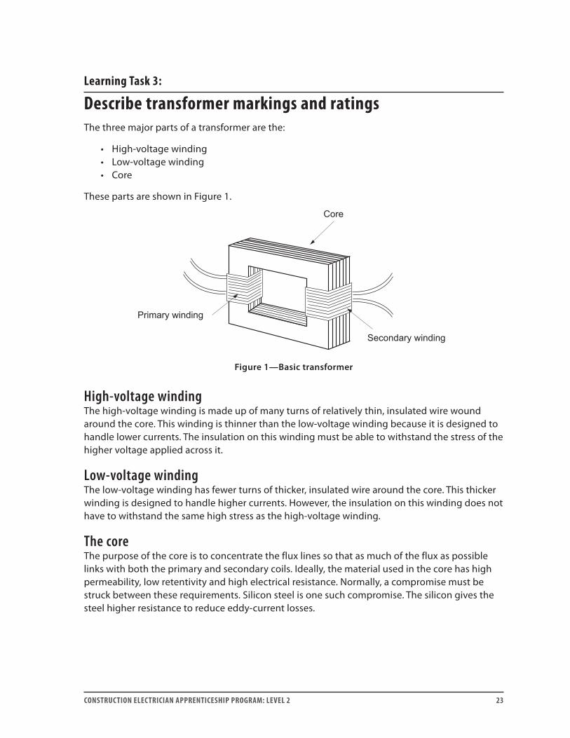
Describe transformer markings and ratingsThe three major parts of a transformer are the:
• High-voltage winding• Low-voltage winding• Core
These parts are shown in Figure 1.
Figure 1—Basic transformer
High-voltage windingThe high-voltage winding is made up of many turns of relatively thin, insulated wire wound around the core. This winding is thinner than the low-voltage winding because it is designed to handle lower currents. The insulation on this winding must be able to withstand the stress of the higher voltage applied across it.
Low-voltage windingThe low-voltage winding has fewer turns of thicker, insulated wire around the core. This thicker winding is designed to handle higher currents. However, the insulation on this winding does not have to withstand the same high stress as the high-voltage winding.
The coreThe purpose of the core is to concentrate the flux lines so that as much of the flux as possible links with both the primary and secondary coils. Ideally, the material used in the core has high permeability, low retentivity and high electrical resistance. Normally, a compromise must be struck between these requirements. Silicon steel is one such compromise. The silicon gives the steel higher resistance to reduce eddy-current losses.
LEARNING TASk 3 H-2
24 CONSTRUCTION ELECTRICIAN APPRENTICESHIP PROGRAM: LEVEL 2
The following facts must be considered:
• The higher the permeability, the greater the number of flux lines created for a given level of current in the windings.
• The lower the retentivity, the less energy is lost in the form of heat due to hysteresis losses.
• The higher the resistance, the less energy is lost in the form of heat due to circulating (eddy) currents in the core.
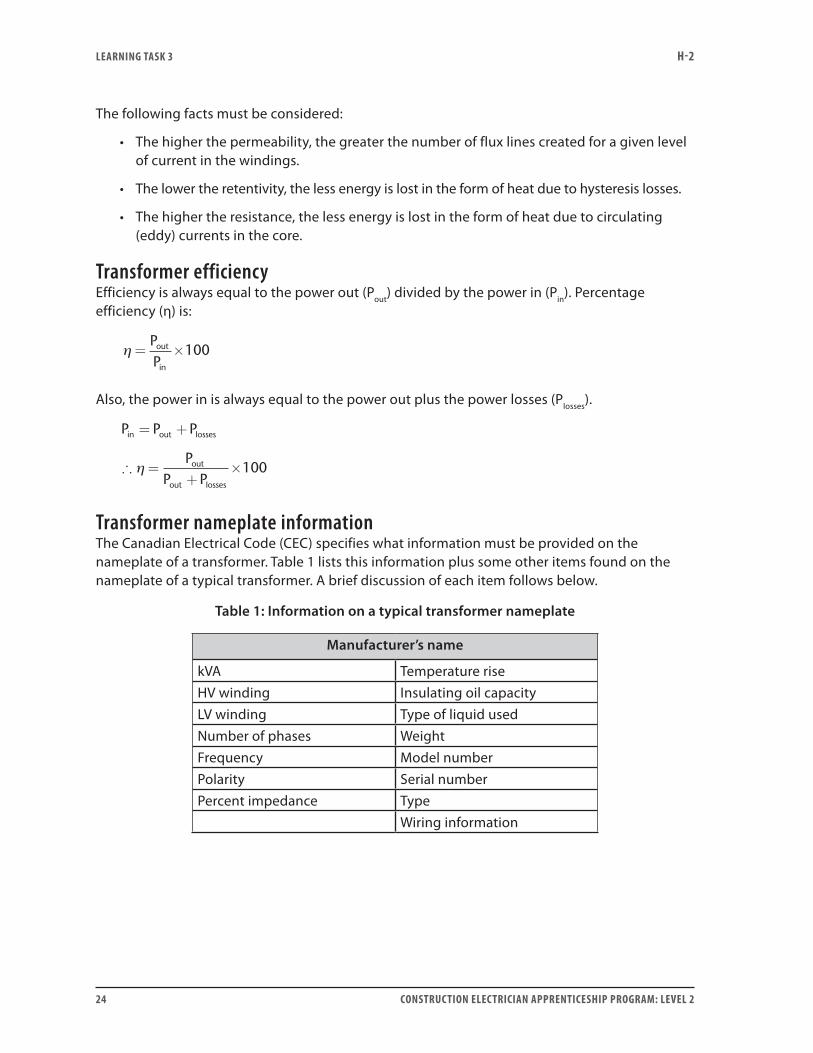
Transformer efficiencyEfficiency is always equal to the power out (Pout) divided by the power in (Pin). Percentage efficiency (η) is:
η = ×PPout
in
100
Also, the power in is always equal to the power out plus the power losses (Plosses).
P P P
PP P
in out losses
out
out losses
= +
∴ =+
×η 100
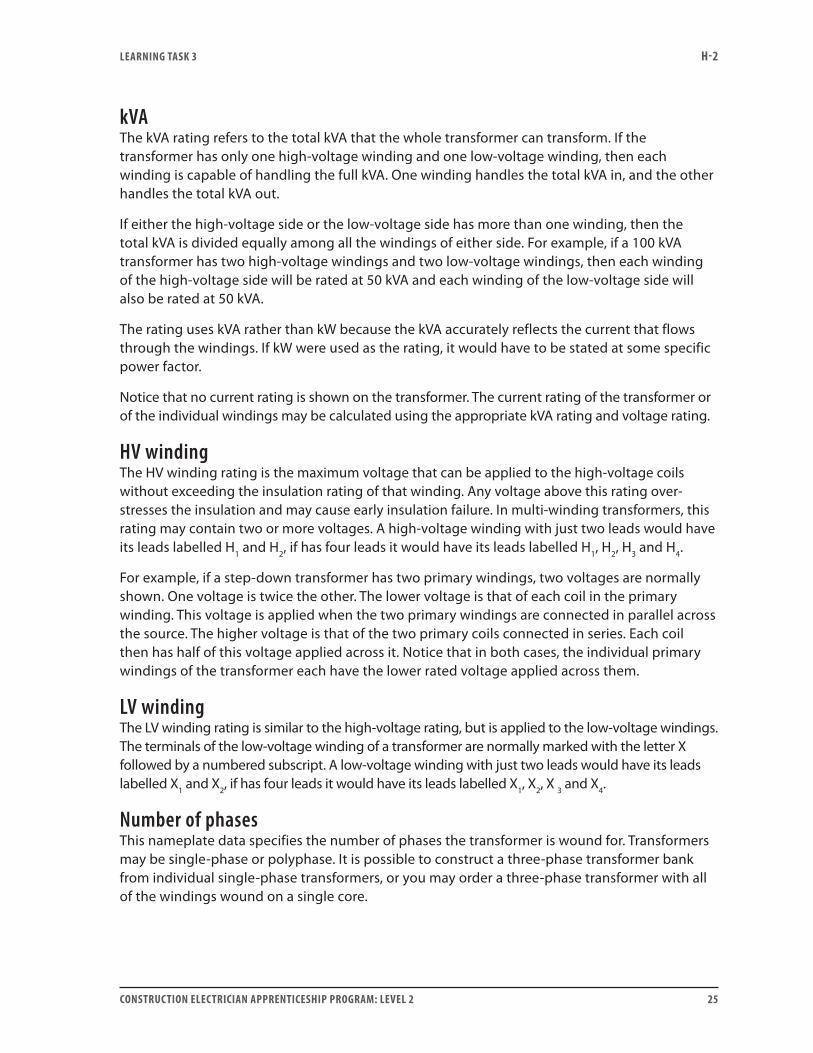
Transformer nameplate informationThe Canadian Electrical Code (CEC) specifies what information must be provided on the nameplate of a transformer. Table 1 lists this information plus some other items found on the nameplate of a typical transformer. A brief discussion of each item follows below.
Table 1: Information on a typical transformer nameplate
Manufacturer’s name
kVA Temperature riseHV winding Insulating oil capacityLV winding Type of liquid usedNumber of phases WeightFrequency Model numberPolarity Serial numberPercent impedance Type
Wiring information
LEARNING TASk 3 H-2
CONSTRUCTION ELECTRICIAN APPRENTICESHIP PROGRAM: LEVEL 2 25
kVAThe kVA rating refers to the total kVA that the whole transformer can transform. If the transformer has only one high-voltage winding and one low-voltage winding, then each winding is capable of handling the full kVA. One winding handles the total kVA in, and the other handles the total kVA out.
If either the high-voltage side or the low-voltage side has more than one winding, then the total kVA is divided equally among all the windings of either side. For example, if a 100 kVA transformer has two high-voltage windings and two low-voltage windings, then each winding of the high-voltage side will be rated at 50 kVA and each winding of the low-voltage side will also be rated at 50 kVA.
The rating uses kVA rather than kW because the kVA accurately reflects the current that flows through the windings. If kW were used as the rating, it would have to be stated at some specific power factor.
Notice that no current rating is shown on the transformer. The current rating of the transformer or of the individual windings may be calculated using the appropriate kVA rating and voltage rating.
HV winding The HV winding rating is the maximum voltage that can be applied to the high-voltage coils without exceeding the insulation rating of that winding. Any voltage above this rating over-stresses the insulation and may cause early insulation failure. In multi-winding transformers, this rating may contain two or more voltages. A high-voltage winding with just two leads would have its leads labelled H1 and H2, if has four leads it would have its leads labelled H1, H2, H3 and H4.
For example, if a step-down transformer has two primary windings, two voltages are normally shown. One voltage is twice the other. The lower voltage is that of each coil in the primary winding. This voltage is applied when the two primary windings are connected in parallel across the source. The higher voltage is that of the two primary coils connected in series. Each coil then has half of this voltage applied across it. Notice that in both cases, the individual primary windings of the transformer each have the lower rated voltage applied across them.
LV winding The LV winding rating is similar to the high-voltage rating, but is applied to the low-voltage windings. The terminals of the low-voltage winding of a transformer are normally marked with the letter X followed by a numbered subscript. A low-voltage winding with just two leads would have its leads labelled X1 and X2, if has four leads it would have its leads labelled X1, X2, X 3 and X4.
Number of phasesThis nameplate data specifies the number of phases the transformer is wound for. Transformers may be single-phase or polyphase. It is possible to construct a three-phase transformer bank from individual single-phase transformers, or you may order a three-phase transformer with all of the windings wound on a single core.
LEARNING TASk 3 H-2
26 CONSTRUCTION ELECTRICIAN APPRENTICESHIP PROGRAM: LEVEL 2
Frequency Inductive reactance limits the current flowing into an unloaded transformer. Since inductive reactance is directly proportional to the frequency of the applied emf (XL = 2πfL), it follows that this frequency affects the current flowing through the transformer windings. Therefore, transformers are designed to operate at a specific frequency. Using the transformer at a lower frequency results in excessive current flowing in the windings, which causes overheating and insulation damage.
PolarityThis rating indicates whether the transformer has additive or subtractive polarity. This indicates the relative position of the specific high- and low-voltage winding leads. This information is critical when paralleling transformers, making instrument connections or building three-phase transformer banks.
Percent impedanceThe percent impedance of the transformer is required for determining available fault current and the suitability of two transformers for parallel operation.
Temperature riseThis indicates the insulation temperature rating of the transformer windings. It indicates the maximum temperature rise above 40°C ambient to which the insulation may be continuously subjected without shortening its life.
Insulating oil capacityThe insulating oil in a transformer is used mainly to carry heat away from the windings and transformer core. All oils have a flashpoint temperature at which the oil will ignite and burn. If the transformer develops a leak and some of the oil leaks out, the remaining oil may not be able to carry the heat away fast enough. In that situation, the temperature of the oil could rise to a value high enough to ignite the oil. The CEC has rules that try to prevent the spread of the fire. The code requirements are tougher for equipment containing larger amounts of liquid dielectric. To apply the code correctly, you must know the volume of oil contained in the transformer.
Type of liquid usedThis rating indicates the type of insulating oil used and whether it contains PCBs.
WeightThis information is useful for shipping and installing the transformer.
Model and serial numbersThese numbers contain the manufacturer’s coded information about the specific construction of the transformer. These are very important when ordering a replacement or parts such as insulating bushings that may have cracked.

LEARNING TASk 3 H-2
CONSTRUCTION ELECTRICIAN APPRENTICESHIP PROGRAM: LEVEL 2 27
TypeThis rating may state designations such as dry, oil filled, auto, control, bell, isolation and power, or it may be a series of letters and numbers representing a specific manufacturer’s code.
Wiring informationSometimes this information is presented as schematic diagrams or voltage-vector diagrams. Other times it is presented in tables indicating which terminals connect to which other terminals or lines. On dual-voltage transformers, the diagrams show the connections for the higher voltage and for the lower voltage.
Now complete Self-Test 3 and check your answers.
LEARNING TASk 3 H-2
28 CONSTRUCTION ELECTRICIAN APPRENTICESHIP PROGRAM: LEVEL 2
Self-Test 3
1. What is the purpose of the ferromagnetic core in a transformer?
2. How is it possible to distinguish the high-voltage winding from the low-voltage winding of a transformer?
3. Ideally, the material used in the core of a power transformer should have the properties
of retentivity, permeability and
resistance.
4. What is the reason for laminating the core of a transformer?
5. Which winding will contain more turns, the high-voltage winding or the low-voltage winding?
6. What letter is normally used to designate a high-voltage winding lead?
7. What letter is normally used to designate a low-voltage winding lead?
Go to the Answer Key at the end of the Learning Guide to check your answers.
CONSTRUCTION ELECTRICIAN APPRENTICESHIP PROGRAM: LEVEL 2 29
Learning Task 4:
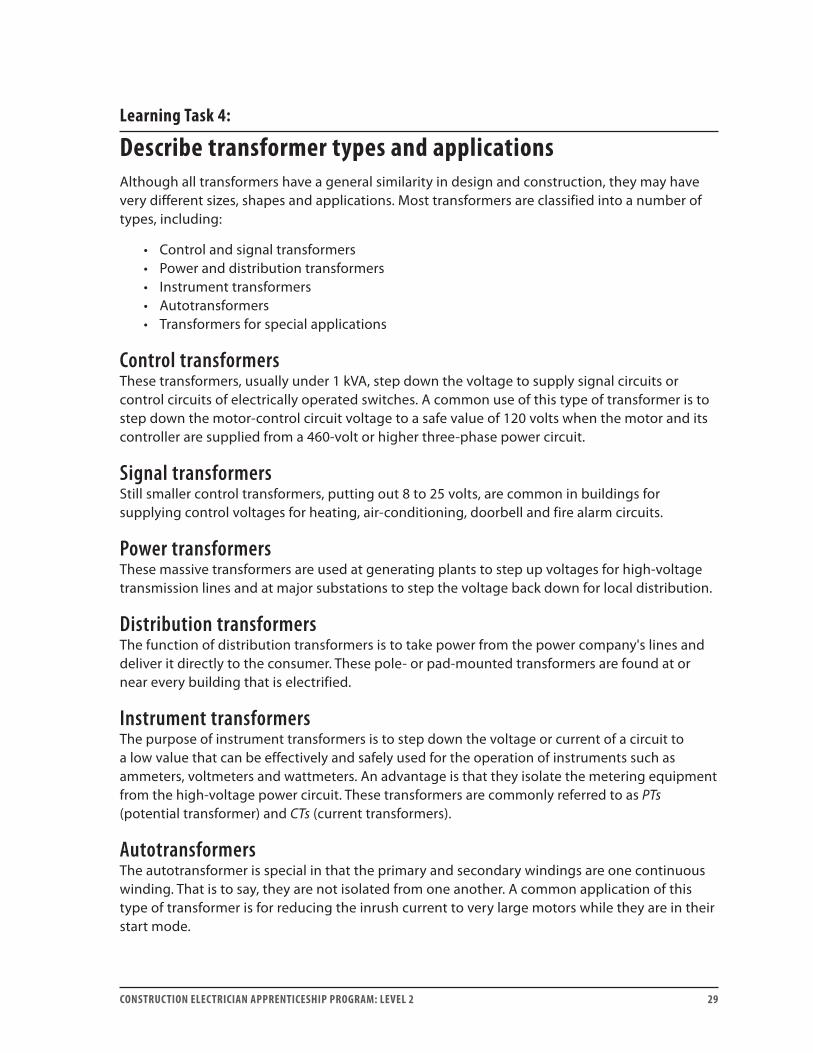
Describe transformer types and applicationsAlthough all transformers have a general similarity in design and construction, they may have very different sizes, shapes and applications. Most transformers are classified into a number of types, including:
• Control and signal transformers• Power and distribution transformers• Instrument transformers• Autotransformers• Transformers for special applications
Control transformersThese transformers, usually under 1 kVA, step down the voltage to supply signal circuits or control circuits of electrically operated switches. A common use of this type of transformer is to step down the motor-control circuit voltage to a safe value of 120 volts when the motor and its controller are supplied from a 460-volt or higher three-phase power circuit.
Signal transformersStill smaller control transformers, putting out 8 to 25 volts, are common in buildings for supplying control voltages for heating, air-conditioning, doorbell and fire alarm circuits.
Power transformersThese massive transformers are used at generating plants to step up voltages for high-voltage transmission lines and at major substations to step the voltage back down for local distribution.
Distribution transformersThe function of distribution transformers is to take power from the power company's lines and deliver it directly to the consumer. These pole- or pad-mounted transformers are found at or near every building that is electrified.
Instrument transformersThe purpose of instrument transformers is to step down the voltage or current of a circuit to a low value that can be effectively and safely used for the operation of instruments such as ammeters, voltmeters and wattmeters. An advantage is that they isolate the metering equipment from the high-voltage power circuit. These transformers are commonly referred to as PTs (potential transformer) and CTs (current transformers).
AutotransformersThe autotransformer is special in that the primary and secondary windings are one continuous winding. That is to say, they are not isolated from one another. A common application of this type of transformer is for reducing the inrush current to very large motors while they are in their start mode.

LEARNING TASk 4 H-2
30 CONSTRUCTION ELECTRICIAN APPRENTICESHIP PROGRAM: LEVEL 2
Special transformersDue to their unique voltage and current characteristics, the transformer types listed below are limited to specialized applications:
• Constant current transformers for street lighting• Ignition transformers for lighting furnace flames• Neon sign transformers for producing high voltages to operate gas-discharge lamps
Now complete Self-Test 4 and check your answers.
LEARNING TASk 4 H-2
CONSTRUCTION ELECTRICIAN APPRENTICESHIP PROGRAM: LEVEL 2 31
Self-Test 4
1. The type of transformer often used to start large motors is called the
.
2. CTs are used for measuring circuit .
3. Pole-mounted transformers in a residential area are referred to as
transformers.
4. A 50 kVA transformer at a hydroelectric site is referred as a
transformer.
5. A small transformer used to power a residential intercom system is an example of a
transformer.
Go to the Answer Key at the end of the Learning Guide to check your answers.

32 CONSTRUCTION ELECTRICIAN APPRENTICESHIP PROGRAM: LEVEL 2
CONSTRUCTION ELECTRICIAN APPRENTICESHIP PROGRAM: LEVEL 2 33
Learning Task 5:
Determine the polarity and markings for transformersImportance of polarity markingsThe terminals of the high-voltage winding of a transformer are normally marked with the letter H followed by a numbered subscript. Two adjacent leads from any one winding always have two consecutive subscript numbers. For example, a high-voltage winding with just two leads would have its leads labelled H1 and H2. Similarly, the terminals of the low-voltage winding of a transformer are normally marked with the letter X followed by a numbered subscript. The numbers indicate the relative polarity of the induced voltages in the two windings. For example, the H1 terminal always has the same instantaneous polarity as the X1 terminal.
The terminal markings are critical for doing such things as paralleling transformers, connecting multi-coil transformers, connecting three-phase transformer banks, and connecting metering and protective relaying. If the terminal markings are incorrect or not observed, the results can be catastrophic.
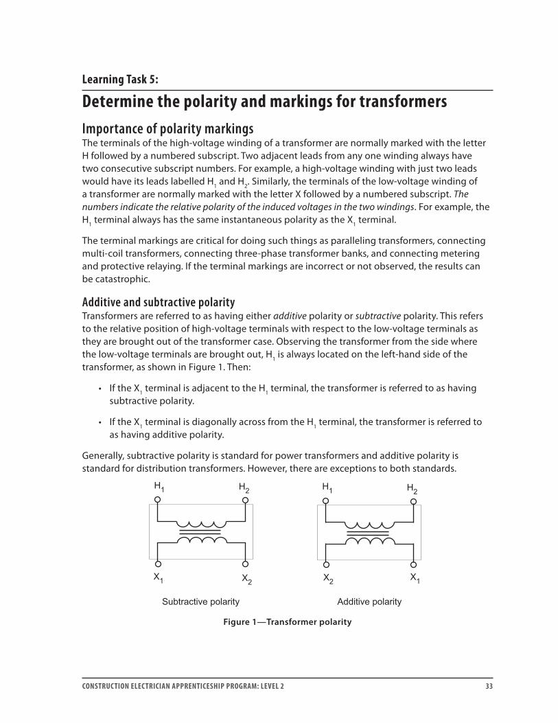
Additive and subtractive polarityTransformers are referred to as having either additive polarity or subtractive polarity. This refers to the relative position of high-voltage terminals with respect to the low-voltage terminals as they are brought out of the transformer case. Observing the transformer from the side where the low-voltage terminals are brought out, H1 is always located on the left-hand side of the transformer, as shown in Figure 1. Then:
• If the X1 terminal is adjacent to the H1 terminal, the transformer is referred to as having subtractive polarity.
• If the X1 terminal is diagonally across from the H1 terminal, the transformer is referred to as having additive polarity.
Generally, subtractive polarity is standard for power transformers and additive polarity is standard for distribution transformers. However, there are exceptions to both standards.
Figure 1—Transformer polarity
LEARNING TASk 5 H-2
34 CONSTRUCTION ELECTRICIAN APPRENTICESHIP PROGRAM: LEVEL 2
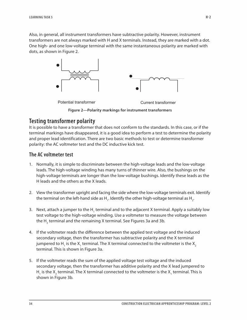
Also, in general, all instrument transformers have subtractive polarity. However, instrument transformers are not always marked with H and X terminals. Instead, they are marked with a dot. One high- and one low-voltage terminal with the same instantaneous polarity are marked with dots, as shown in Figure 2.
Figure 2—Polarity markings for instrument transformers
Testing transformer polarityIt is possible to have a transformer that does not conform to the standards. In this case, or if the terminal markings have disappeared, it is a good idea to perform a test to determine the polarity and proper lead identification. There are two basic methods to test or determine transformer polarity: the AC voltmeter test and the DC inductive kick test.
The AC voltmeter test
1. Normally, it is simple to discriminate between the high-voltage leads and the low-voltage leads. The high-voltage winding has many turns of thinner wire. Also, the bushings on the high-voltage terminals are longer than the low-voltage bushings. Identify these leads as the H leads and the others as the X leads.
2. View the transformer upright and facing the side where the low-voltage terminals exit. Identify the terminal on the left-hand side as H1. Identify the other high-voltage terminal as H2.
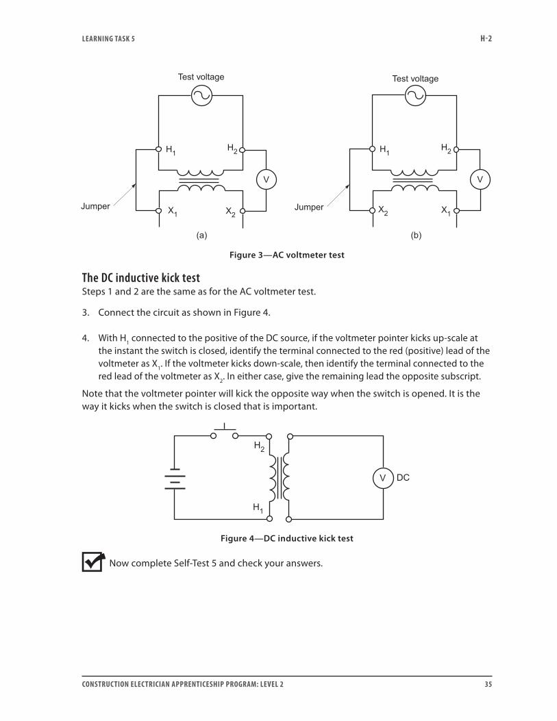
3. Next, attach a jumper to the H1 terminal and to the adjacent X terminal. Apply a suitably low test voltage to the high-voltage winding. Use a voltmeter to measure the voltage between the H2 terminal and the remaining X terminal. See Figures 3a and 3b.
4. If the voltmeter reads the difference between the applied test voltage and the induced secondary voltage, then the transformer has subtractive polarity and the X terminal jumpered to H1 is the X1 terminal. The X terminal connected to the voltmeter is the X2 terminal. This is shown in Figure 3a.
5. If the voltmeter reads the sum of the applied voltage test voltage and the induced secondary voltage, then the transformer has additive polarity and the X lead jumpered to H1 is the X2 terminal. The X terminal connected to the voltmeter is the X1 terminal. This is shown in Figure 3b.
LEARNING TASk 5 H-2
CONSTRUCTION ELECTRICIAN APPRENTICESHIP PROGRAM: LEVEL 2 35
Figure 3—AC voltmeter test
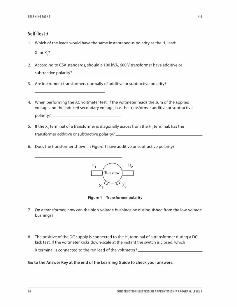
The DC inductive kick testSteps 1 and 2 are the same as for the AC voltmeter test.
3. Connect the circuit as shown in Figure 4.
4. With H1 connected to the positive of the DC source, if the voltmeter pointer kicks up-scale at the instant the switch is closed, identify the terminal connected to the red (positive) lead of the voltmeter as X1. If the voltmeter kicks down-scale, then identify the terminal connected to the red lead of the voltmeter as X2. In either case, give the remaining lead the opposite subscript.
Note that the voltmeter pointer will kick the opposite way when the switch is opened. It is the way it kicks when the switch is closed that is important.
Figure 4—DC inductive kick test
Now complete Self-Test 5 and check your answers.
LEARNING TASk 5 H-2
36 CONSTRUCTION ELECTRICIAN APPRENTICESHIP PROGRAM: LEVEL 2
Self-Test 5
1. Which of the leads would have the same instantaneous polarity as the H1 lead:
X1 or X2?
2. According to CSA standards, should a 100 kVA, 600 V transformer have additive or
subtractive polarity?
3. Are instrument transformers normally of additive or subtractive polarity?
4. When performing the AC voltmeter test, if the voltmeter reads the sum of the applied voltage and the induced secondary voltage, has the transformer additive or subtractive
polarity?
5. If the X1 terminal of a transformer is diagonally across from the H1 terminal, has the
transformer additive or subtractive polarity?
6. Does the transformer shown in Figure 1 have additive or subtractive polarity?
Figure 1—Transformer polarity
7. On a transformer, how can the high-voltage bushings be distinguished from the low-voltage bushings?
8. The positive of the DC supply is connected to the H1 terminal of a transformer during a DC kick test. If the voltmeter kicks down-scale at the instant the switch is closed, which
X terminal is connected to the red lead of the voltmeter?
Go to the Answer Key at the end of the Learning Guide to check your answers.
CONSTRUCTION ELECTRICIAN APPRENTICESHIP PROGRAM: LEVEL 2 37
Learning Task 6:
Describe the various connections and applications for multi-coil transformersSo far you have studied transformers that have only one primary coil and one secondary coil. Many distribution transformers contain more than one primary winding, more than one secondary winding, or both. This kind of transformer is useful for several types of applications.
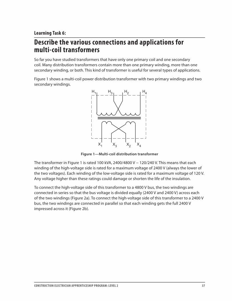
Figure 1 shows a multi-coil power distribution transformer with two primary windings and two secondary windings.
Figure 1—Multi-coil distribution transformer
The transformer in Figure 1 is rated 100 kVA, 2400/4800 V − 120/240 V. This means that each winding of the high-voltage side is rated for a maximum voltage of 2400 V (always the lower of the two voltages). Each winding of the low-voltage side is rated for a maximum voltage of 120 V. Any voltage higher than these ratings could damage or shorten the life of the insulation.
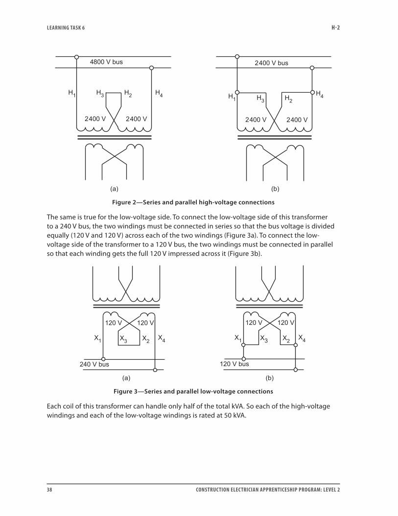
To connect the high-voltage side of this transformer to a 4800 V bus, the two windings are connected in series so that the bus voltage is divided equally (2400 V and 2400 V) across each of the two windings (Figure 2a). To connect the high-voltage side of this transformer to a 2400 V bus, the two windings are connected in parallel so that each winding gets the full 2400 V impressed across it (Figure 2b).
LEARNING TASk 6 H-2
38 CONSTRUCTION ELECTRICIAN APPRENTICESHIP PROGRAM: LEVEL 2
Figure 2—Series and parallel high-voltage connections
The same is true for the low-voltage side. To connect the low-voltage side of this transformer to a 240 V bus, the two windings must be connected in series so that the bus voltage is divided equally (120 V and 120 V) across each of the two windings (Figure 3a). To connect the low-voltage side of the transformer to a 120 V bus, the two windings must be connected in parallel so that each winding gets the full 120 V impressed across it (Figure 3b).
Figure 3—Series and parallel low-voltage connections
Each coil of this transformer can handle only half of the total kVA. So each of the high-voltage windings and each of the low-voltage windings is rated at 50 kVA.
LEARNING TASk 6 H-2
CONSTRUCTION ELECTRICIAN APPRENTICESHIP PROGRAM: LEVEL 2 39
To find the maximum current rating of each winding, simply divide the volt-amperes by the rated voltage:
IVAV
A
IVA
VA
P
S
= =
= =
50 0002400
20 83
50 000120
416 7
.
.
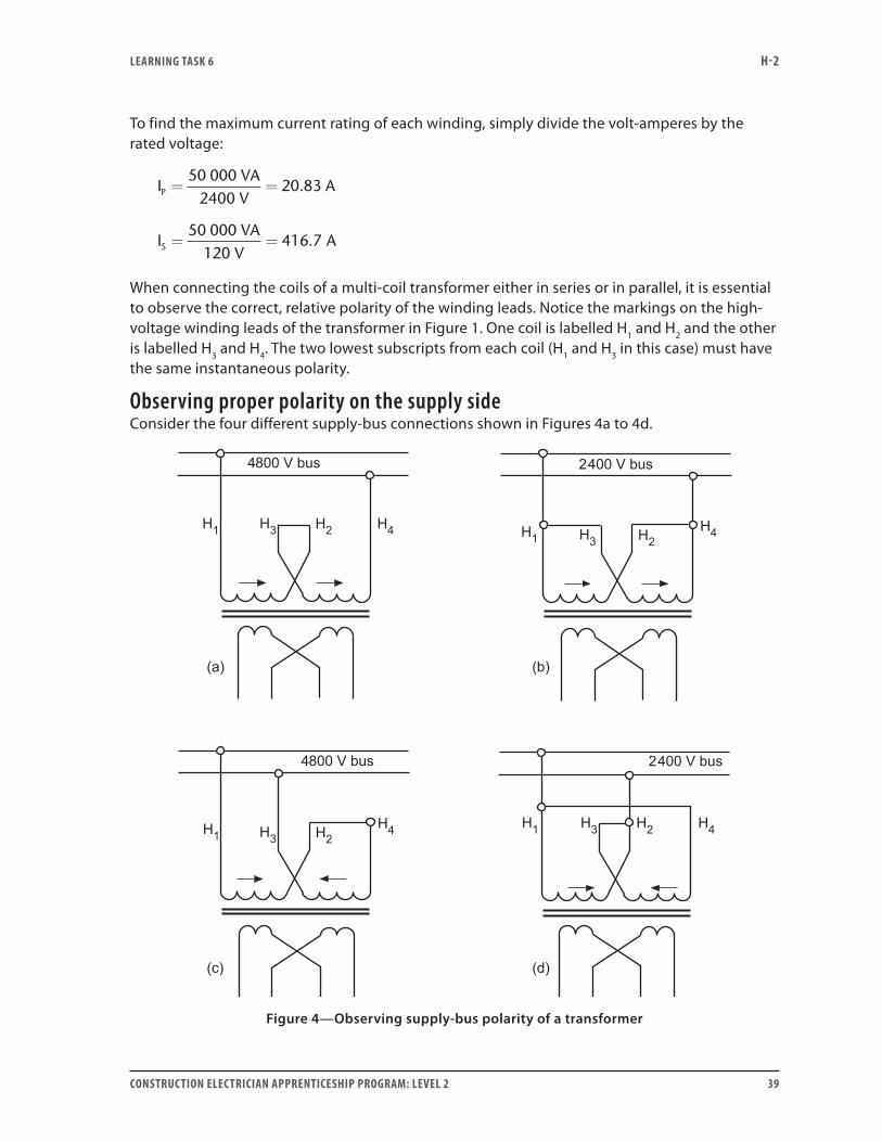
When connecting the coils of a multi-coil transformer either in series or in parallel, it is essential to observe the correct, relative polarity of the winding leads. Notice the markings on the high-voltage winding leads of the transformer in Figure 1. One coil is labelled H1 and H2 and the other is labelled H3 and H4. The two lowest subscripts from each coil (H1 and H3 in this case) must have the same instantaneous polarity.
Observing proper polarity on the supply sideConsider the four different supply-bus connections shown in Figures 4a to 4d.
Figure 4—Observing supply-bus polarity of a transformer

LEARNING TASk 6 H-2
40 CONSTRUCTION ELECTRICIAN APPRENTICESHIP PROGRAM: LEVEL 2
• In Figures 4a and 4b, the flux created by the left-hand coil is in the same direction as that created by the right-hand coil. The two add up to create a larger total flux that induces a counter emf in the two coils. This cemf opposes and limits the supply current, which is good.
• In Figures 4c and 4d, the flux created by the left-hand coil is in the opposite direction to that created by the right-hand coil. The two fluxes cancel each other, resulting in a total flux of zero. The only thing left to oppose the flow of supply current is the very low resistance of the copper windings. This is bad, as damage occurs because of the excessive current flow.
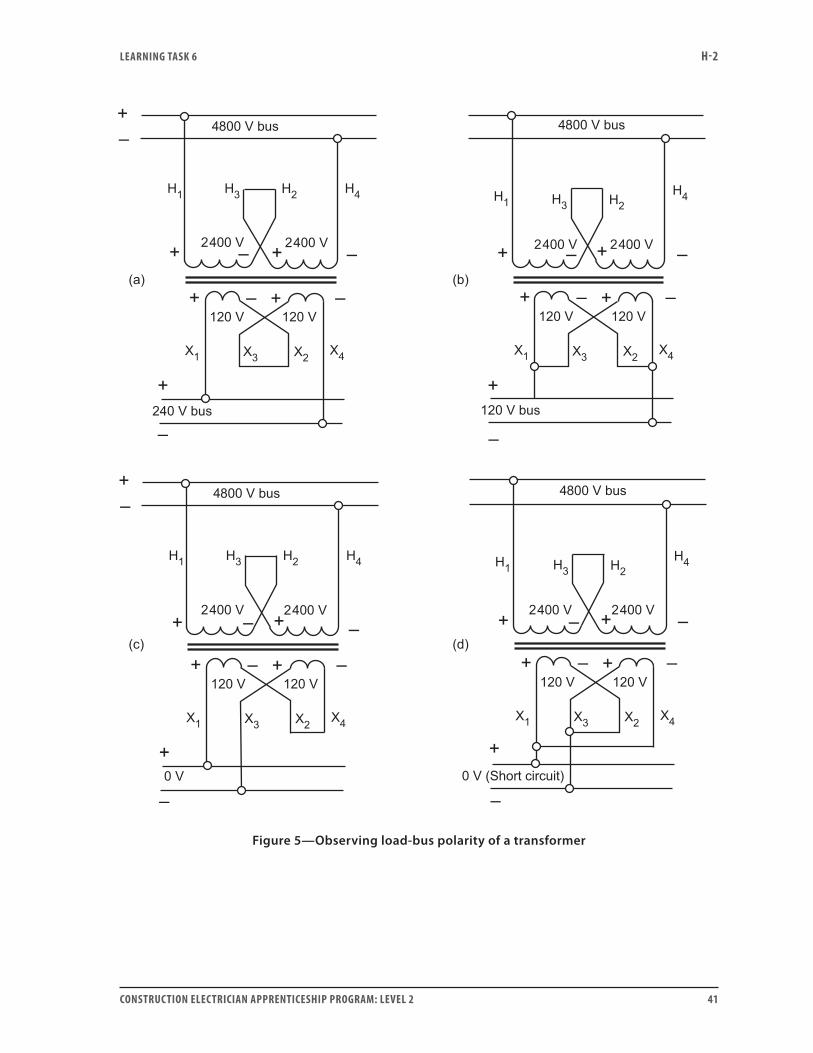
Observing proper polarity on the load sideConsider the four different load-bus connections shown in Figures 5a to 5d on the next page. Note that the proper polarities have been observed on the supply bus connections.
In analyzing the importance of proper secondary polarity, it is easier if an instantaneous polarity is assumed. That is why + and − symbols are included in Figure 5. The equivalent DC battery circuits are shown in Figures 6a to 6d, respectively.
LEARNING TASk 6 H-2
CONSTRUCTION ELECTRICIAN APPRENTICESHIP PROGRAM: LEVEL 2 41
Figure 5—Observing load-bus polarity of a transformer

LEARNING TASk 6 H-2
42 CONSTRUCTION ELECTRICIAN APPRENTICESHIP PROGRAM: LEVEL 2
Figure 6—Equivalent battery circuits for the circuits shown in Figure 5
Figure 6a shows the proper series connection. The two coil voltages add together to produce the desired secondary voltage of 240 V.
Figure 6b shows the proper parallel connection. The two coils act like two batteries connected in parallel to produce the desired secondary voltage of 120 V.
Figure 6c shows the improper series connection. Notice that it is the same as two batteries connected in series opposing. The two voltages oppose each other to produce a secondary bus voltage of 0 V. Of course, this voltage is not very useful to the load.
Figure 6d shows the improper parallel connection. Notice that it is the same as two batteries connected improperly in parallel. This is particularly bad because large circulating currents flow between the two windings with no load to limit the current.
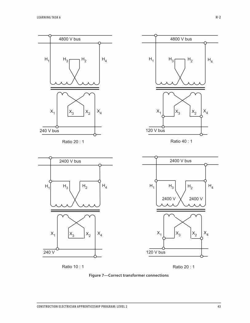
Figure 7 shows four possible correct connections that may be made with the transformer from Figure 1.
LEARNING TASk 6 H-2
CONSTRUCTION ELECTRICIAN APPRENTICESHIP PROGRAM: LEVEL 2 43
Figure 7—Correct transformer connections
LEARNING TASk 6 H-2
44 CONSTRUCTION ELECTRICIAN APPRENTICESHIP PROGRAM: LEVEL 2
In all four cases, the transformer is capable of supplying a total load of 100 kVA without exceeding the current ratings of the transformer’s coils. Notice that the line-to-line voltage ratio changes for different winding connections.
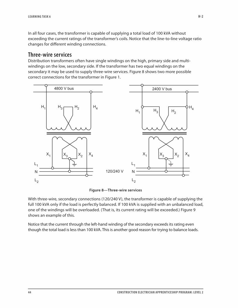
Three-wire servicesDistribution transformers often have single windings on the high, primary side and multi-windings on the low, secondary side. If the transformer has two equal windings on the secondary it may be used to supply three-wire services. Figure 8 shows two more possible correct connections for the transformer in Figure 1.
Figure 8—Three-wire services
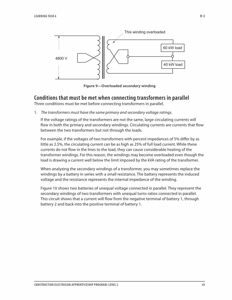
With three-wire, secondary connections (120/240 V), the transformer is capable of supplying the full 100 kVA only if the load is perfectly balanced. If 100 kVA is supplied with an unbalanced load, one of the windings will be overloaded. (That is, its current rating will be exceeded.) Figure 9 shows an example of this.
Notice that the current through the left-hand winding of the secondary exceeds its rating even though the total load is less than 100 kVA. This is another good reason for trying to balance loads.
LEARNING TASk 6 H-2
CONSTRUCTION ELECTRICIAN APPRENTICESHIP PROGRAM: LEVEL 2 45
Figure 9—Overloaded secondary winding
Conditions that must be met when connecting transformers in parallelThree conditions must be met before connecting transformers in parallel.
1. The transformers must have the same primary and secondary voltage ratings.
If the voltage ratings of the transformers are not the same, large circulating currents will flow in both the primary and secondary windings. Circulating currents are currents that flow between the two transformers but not through the loads.
For example, if the voltages of two transformers with percent impedances of 5% differ by as little as 2.5%, the circulating current can be as high as 25% of full load current. While these currents do not flow in the lines to the load, they can cause considerable heating of the transformer windings. For this reason, the windings may become overloaded even though the load is drawing a current well below the limit imposed by the kVA rating of the transformer.
When analyzing the secondary windings of a transformer, you may sometimes replace the windings by a battery in series with a small resistance. The battery represents the induced voltage and the resistance represents the internal impedance of the winding.
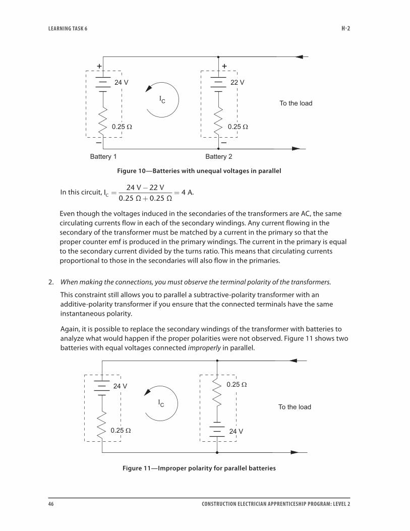
Figure 10 shows two batteries of unequal voltage connected in parallel. They represent the secondary windings of two transformers with unequal turns ratios connected in parallel. This circuit shows that a current will flow from the negative terminal of battery 1, through battery 2 and back into the positive terminal of battery 1.
LEARNING TASk 6 H-2
46 CONSTRUCTION ELECTRICIAN APPRENTICESHIP PROGRAM: LEVEL 2
Figure 10—Batteries with unequal voltages in parallel
In this circuit, IV V
AC =−+
=24 22
0.25 Ω 0.25 Ω4 .
Even though the voltages induced in the secondaries of the transformers are AC, the same circulating currents flow in each of the secondary windings. Any current flowing in the secondary of the transformer must be matched by a current in the primary so that the proper counter emf is produced in the primary windings. The current in the primary is equal to the secondary current divided by the turns ratio. This means that circulating currents proportional to those in the secondaries will also flow in the primaries.
2. When making the connections, you must observe the terminal polarity of the transformers.
This constraint still allows you to parallel a subtractive-polarity transformer with an additive-polarity transformer if you ensure that the connected terminals have the same instantaneous polarity.
Again, it is possible to replace the secondary windings of the transformer with batteries to analyze what would happen if the proper polarities were not observed. Figure 11 shows two batteries with equal voltages connected improperly in parallel.
Figure 11—Improper polarity for parallel batteries
LEARNING TASk 6 H-2
CONSTRUCTION ELECTRICIAN APPRENTICESHIP PROGRAM: LEVEL 2 47
In this circuit, IV V
AC =++
=24 24
960.25 Ω 0.25 Ω
.
Notice that the polarity of one of the batteries is opposite to what it is supposed to be. As a result, an extremely large circulating current flows, damaging the windings of the transformer.
Again, any current flowing in the secondary of the transformer has to be matched by a current in the primary so that the proper counter emf is produced in the primary windings. The current in the primary is equal to the secondary current divided by the turns ratio.
3. All the transformers must have the same percent impedance.
This is important to ensure that the transformers share the load according to their ability. For example, provided they have the same percent impedance, a 100 kVA and a 25 kVA transformer can be paralleled together so that the 100 kVA transformer always carries four times as much of the load as the 25 kVA transformer.
As a transformer is loaded, its terminal voltage changes due to the IZ drop in the windings. Percent impedance is simply an expression of the impedance of the transformer as a percentage of the rated, full-load, load impedance of the transformer. If transformers have the same percent impedances, then their terminal voltages are equal whenever the transformers carry an equal percentage of their full-load currents. This ensures that the transformers share the load according to their individual abilities.
Consider the 100 kVA and 25 kVA transformers mentioned earlier. If these two transformers have the same percent impedance, then together they are capable of supplying a 125 kVA load without exceeding the rating of either transformer. However, if the two transformers have different percent impedances, the one with the lower percent impedance will be overloaded before they reach 125 kVA.
Schematic diagrams to illustrate how single-phase transformers are connected for parallel operationNow you will learn how to properly observe the terminal polarity of two transformers when you connect them in parallel. It is assumed you have ensured that the transformers have similar voltage ratings and equal percent impedances.
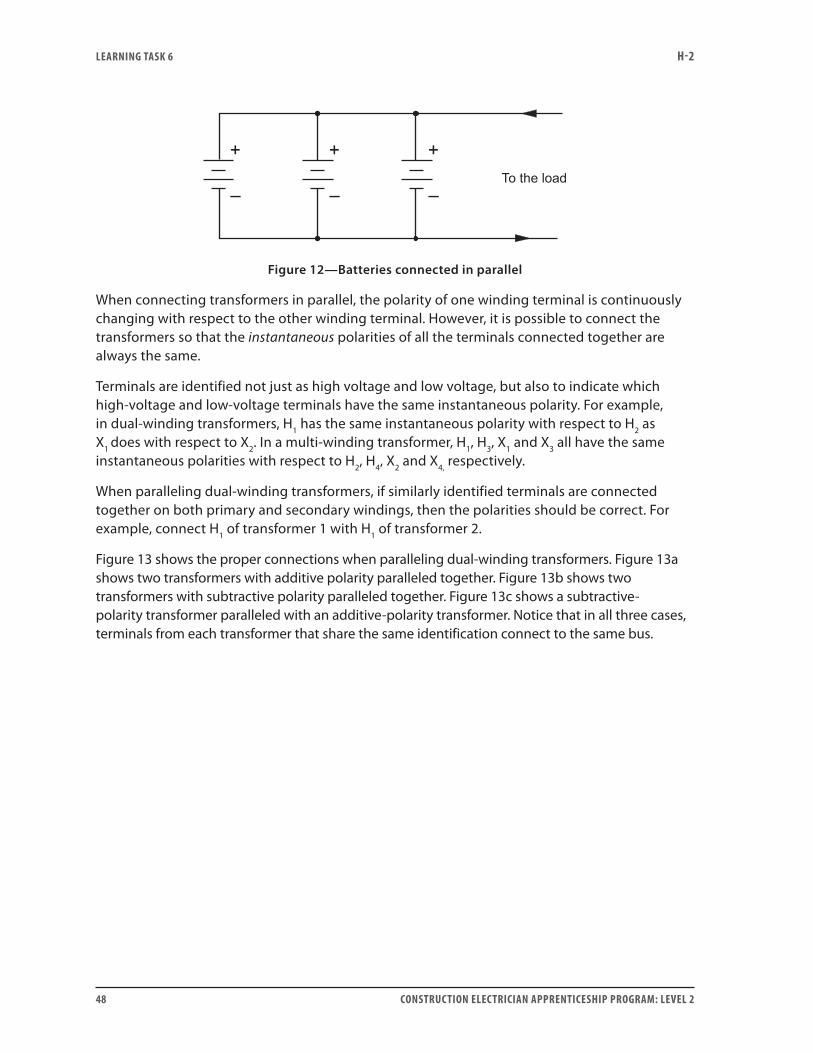
Figure 12 shows three batteries connected in parallel to increase the volt-ampere capacity of the bank. The terminals with like polarities are all connected together. If any one of the batteries were connected backward, it would cause some circulating currents to flow, which is a serious problem.
LEARNING TASk 6 H-2
48 CONSTRUCTION ELECTRICIAN APPRENTICESHIP PROGRAM: LEVEL 2
Figure 12—Batteries connected in parallel
When connecting transformers in parallel, the polarity of one winding terminal is continuously changing with respect to the other winding terminal. However, it is possible to connect the transformers so that the instantaneous polarities of all the terminals connected together are always the same.
Terminals are identified not just as high voltage and low voltage, but also to indicate which high-voltage and low-voltage terminals have the same instantaneous polarity. For example, in dual-winding transformers, H1 has the same instantaneous polarity with respect to H2 as X1 does with respect to X2. In a multi-winding transformer, H1, H3, X1 and X3 all have the same instantaneous polarities with respect to H2, H4, X2 and X4, respectively.
When paralleling dual-winding transformers, if similarly identified terminals are connected together on both primary and secondary windings, then the polarities should be correct. For example, connect H1 of transformer 1 with H1 of transformer 2.
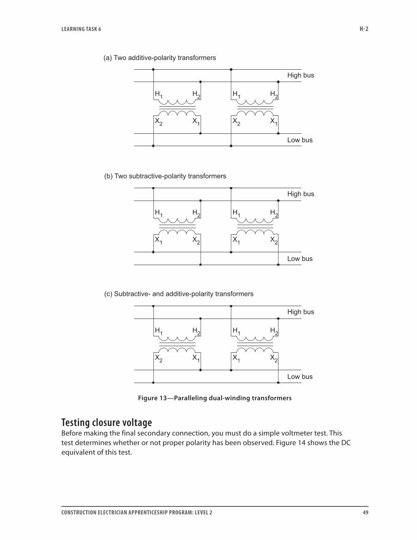
Figure 13 shows the proper connections when paralleling dual-winding transformers. Figure 13a shows two transformers with additive polarity paralleled together. Figure 13b shows two transformers with subtractive polarity paralleled together. Figure 13c shows a subtractive-polarity transformer paralleled with an additive-polarity transformer. Notice that in all three cases, terminals from each transformer that share the same identification connect to the same bus.
LEARNING TASk 6 H-2
CONSTRUCTION ELECTRICIAN APPRENTICESHIP PROGRAM: LEVEL 2 49
Figure 13—Paralleling dual-winding transformers
Testing closure voltageBefore making the final secondary connection, you must do a simple voltmeter test. This test determines whether or not proper polarity has been observed. Figure 14 shows the DC equivalent of this test.
LEARNING TASk 6 H-2
50 CONSTRUCTION ELECTRICIAN APPRENTICESHIP PROGRAM: LEVEL 2
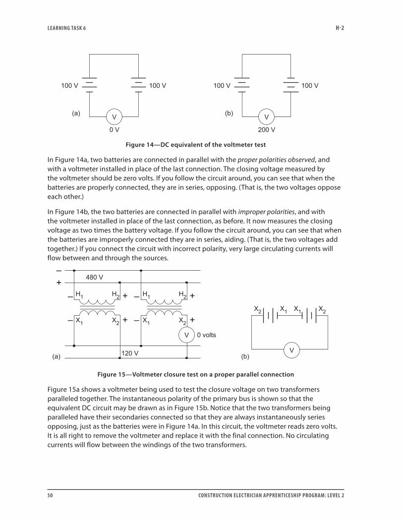
Figure 14—DC equivalent of the voltmeter test
In Figure 14a, two batteries are connected in parallel with the proper polarities observed, and with a voltmeter installed in place of the last connection. The closing voltage measured by the voltmeter should be zero volts. If you follow the circuit around, you can see that when the batteries are properly connected, they are in series, opposing. (That is, the two voltages oppose each other.)
In Figure 14b, the two batteries are connected in parallel with improper polarities, and with the voltmeter installed in place of the last connection, as before. It now measures the closing voltage as two times the battery voltage. If you follow the circuit around, you can see that when the batteries are improperly connected they are in series, aiding. (That is, the two voltages add together.) If you connect the circuit with incorrect polarity, very large circulating currents will flow between and through the sources.
Figure 15—Voltmeter closure test on a proper parallel connection
Figure 15a shows a voltmeter being used to test the closure voltage on two transformers paralleled together. The instantaneous polarity of the primary bus is shown so that the equivalent DC circuit may be drawn as in Figure 15b. Notice that the two transformers being paralleled have their secondaries connected so that they are always instantaneously series opposing, just as the batteries were in Figure 14a. In this circuit, the voltmeter reads zero volts. It is all right to remove the voltmeter and replace it with the final connection. No circulating currents will flow between the windings of the two transformers.
LEARNING TASk 6 H-2
CONSTRUCTION ELECTRICIAN APPRENTICESHIP PROGRAM: LEVEL 2 51
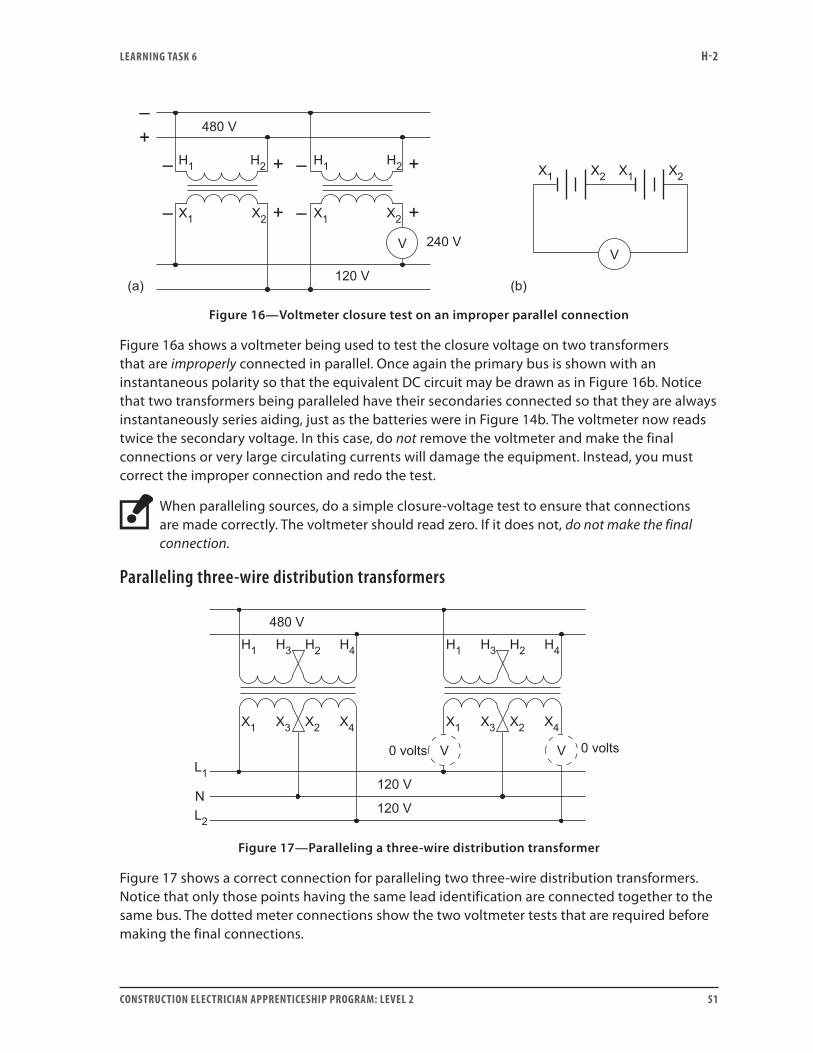
Figure 16—Voltmeter closure test on an improper parallel connection
Figure 16a shows a voltmeter being used to test the closure voltage on two transformers that are improperly connected in parallel. Once again the primary bus is shown with an instantaneous polarity so that the equivalent DC circuit may be drawn as in Figure 16b. Notice that two transformers being paralleled have their secondaries connected so that they are always instantaneously series aiding, just as the batteries were in Figure 14b. The voltmeter now reads twice the secondary voltage. In this case, do not remove the voltmeter and make the final connections or very large circulating currents will damage the equipment. Instead, you must correct the improper connection and redo the test.
When paralleling sources, do a simple closure-voltage test to ensure that connections are made correctly. The voltmeter should read zero. If it does not, do not make the final connection.
Paralleling three-wire distribution transformers
Figure 17—Paralleling a three-wire distribution transformer
Figure 17 shows a correct connection for paralleling two three-wire distribution transformers. Notice that only those points having the same lead identification are connected together to the same bus. The dotted meter connections show the two voltmeter tests that are required before making the final connections.
LEARNING TASk 6 H-2
52 CONSTRUCTION ELECTRICIAN APPRENTICESHIP PROGRAM: LEVEL 2
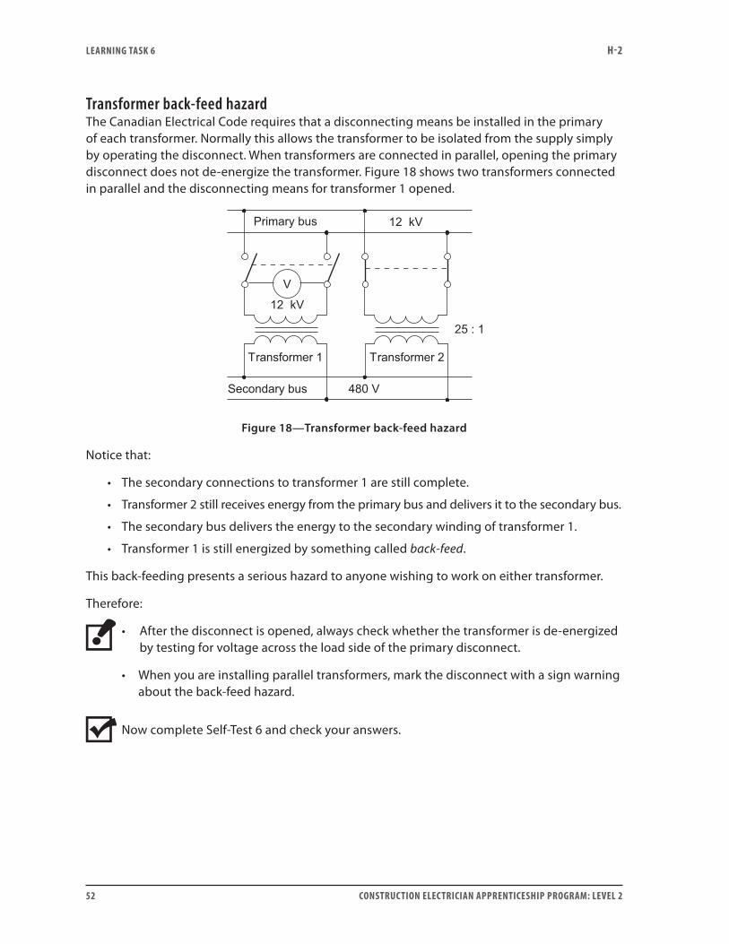
Transformer back-feed hazardThe Canadian Electrical Code requires that a disconnecting means be installed in the primary of each transformer. Normally this allows the transformer to be isolated from the supply simply by operating the disconnect. When transformers are connected in parallel, opening the primary disconnect does not de-energize the transformer. Figure 18 shows two transformers connected in parallel and the disconnecting means for transformer 1 opened.
Figure 18—Transformer back-feed hazard
Notice that:
• The secondary connections to transformer 1 are still complete.
• Transformer 2 still receives energy from the primary bus and delivers it to the secondary bus.
• The secondary bus delivers the energy to the secondary winding of transformer 1.
• Transformer 1 is still energized by something called back-feed.
This back-feeding presents a serious hazard to anyone wishing to work on either transformer.
Therefore:
• After the disconnect is opened, always check whether the transformer is de-energized by testing for voltage across the load side of the primary disconnect.
• When you are installing parallel transformers, mark the disconnect with a sign warning about the back-feed hazard.
Now complete Self-Test 6 and check your answers.

LEARNING TASk 6 H-2
CONSTRUCTION ELECTRICIAN APPRENTICESHIP PROGRAM: LEVEL 2 53
Self-Test 6Questions 1 to 7 refer to a multi-coil, step-down transformer that is rated 50 kVA, 240/480 V – 60/120 V.
1. What is the maximum current rating of each secondary coil?
2. What is the maximum current rating of each primary coil?
3. What is the voltage rating of each primary coil?
4. What is the maximum kVA that each secondary coil can supply?
5. If this transformer is to have its primary connected to a 480 V bus, would the primary coils be
connected in parallel or in series?
6. If this transformer is to have its secondary connected to a 60 V bus, would the secondary
coils be connected in series or in parallel?
7. What is the line-to-line voltage ratio if this transformer is connected as in Questions 5 and 6?
8. Is it important to observe the relative polarity of the winding leads when making multi-winding transformer connections?
9. List the three conditions that must be met before transformers may be paralleled.
•
•
•
LEARNING TASk 6 H-2
54 CONSTRUCTION ELECTRICIAN APPRENTICESHIP PROGRAM: LEVEL 2
10. Why are circulating currents a problem?
11. What causes the terminal voltage of a transformer to change as the load changes?
12. Is it permissible to parallel:
a. transformers with different kVA ratings?
b. an additive-polarity transformer with a subtractive-polarity transformer?
13. If transformers of unequal percent impedances are paralleled, which one will carry more than its share of the load?
14. When a voltmeter closure test is performed on the secondary of two transformers being
paralleled, the meter should read volts.
15. Explain what is meant by the term back-feed.
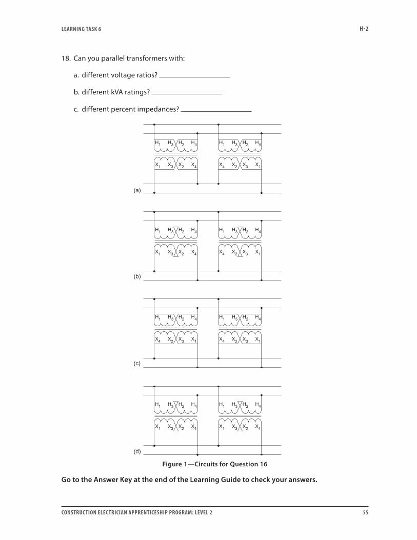
16. Which of the transformers in Figure 1 (next page) is improperly connected for parallel operation?
17. Does opening the primary disconnect for a transformer guarantee that the transformer is de-energized?
LEARNING TASk 6 H-2
CONSTRUCTION ELECTRICIAN APPRENTICESHIP PROGRAM: LEVEL 2 55
18. Can you parallel transformers with:
a. different voltage ratios?
b. different kVA ratings?
c. different percent impedances?
Figure 1—Circuits for Question 16
Go to the Answer Key at the end of the Learning Guide to check your answers.

56 CONSTRUCTION ELECTRICIAN APPRENTICESHIP PROGRAM: LEVEL 2
CONSTRUCTION ELECTRICIAN APPRENTICESHIP PROGRAM: LEVEL 2 57
Learning Task 7:
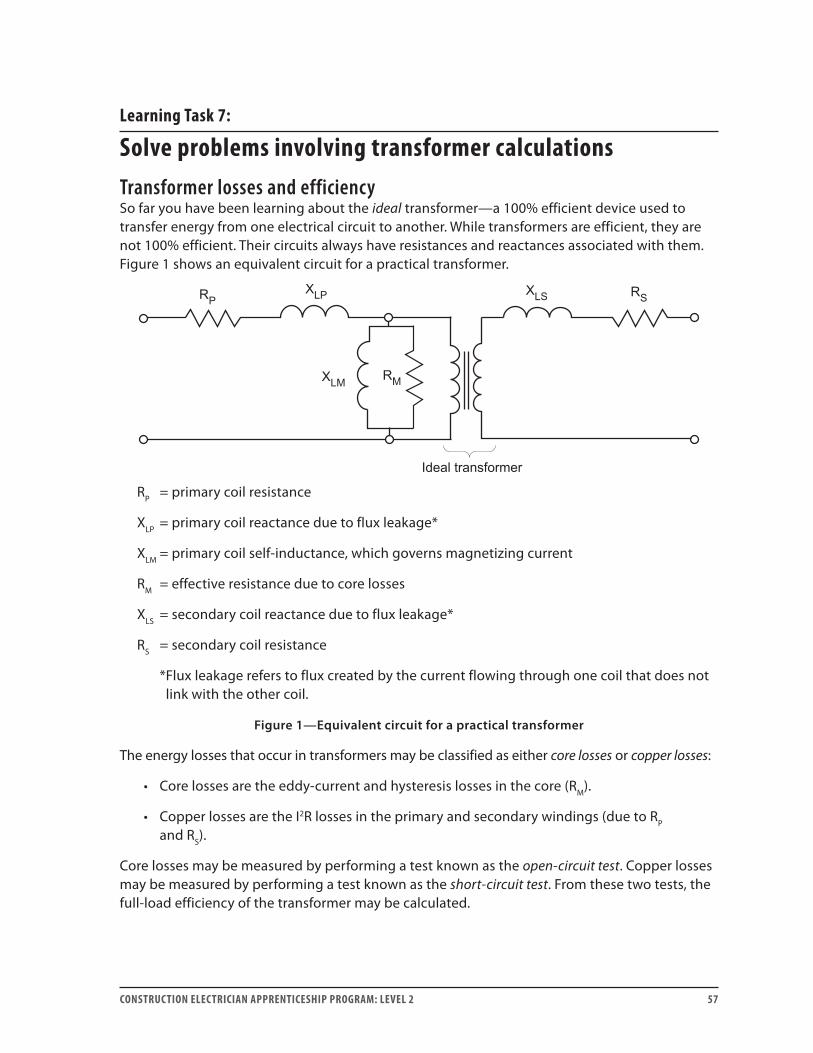
Solve problems involving transformer calculationsTransformer losses and efficiencySo far you have been learning about the ideal transformer—a 100% efficient device used to transfer energy from one electrical circuit to another. While transformers are efficient, they are not 100% efficient. Their circuits always have resistances and reactances associated with them. Figure 1 shows an equivalent circuit for a practical transformer.
RP = primary coil resistance
XLP = primary coil reactance due to flux leakage*
XLM = primary coil self-inductance, which governs magnetizing current
RM = effective resistance due to core losses
XLS = secondary coil reactance due to flux leakage*
RS = secondary coil resistance
* Flux leakage refers to flux created by the current flowing through one coil that does not link with the other coil.
Figure 1—Equivalent circuit for a practical transformer
The energy losses that occur in transformers may be classified as either core losses or copper losses:
• Core losses are the eddy-current and hysteresis losses in the core (RM).
• Copper losses are the I2R losses in the primary and secondary windings (due to RP and RS).
Core losses may be measured by performing a test known as the open-circuit test. Copper losses may be measured by performing a test known as the short-circuit test. From these two tests, the full-load efficiency of the transformer may be calculated.

LEARNING TASk 7 H-2
58 CONSTRUCTION ELECTRICIAN APPRENTICESHIP PROGRAM: LEVEL 2
The open-circuit test for core lossesTwo significant types of energy losses occur in the core of the transformer: eddy-current losses and hysteresis losses.
Figure 2—Open-circuit test circuit
1. For the open-circuit test, connect the transformer and the wattmeter, ammeter and voltmeter as shown in Figure 2.
2. Carefully isolate the high-voltage terminals to prevent any hazard and apply the full-rated, low voltage to the low-voltage terminals.
3. Once the proper voltage has been set, remove the voltmeter from the circuit so that the wattmeter does not read the power taken by the voltmeter as well as by the transformer. Notice that the ammeter is in the circuit ahead of the wattmeter so that it does not affect the wattmeter reading.
4. Now, read the core losses directly from the wattmeter.
Since no load is connected to the transformer, the only current flowing in the circuit is the magnetizing current. This current (approximately 2–5% of full load) establishes the magnetic field that create the counter emf in the primary circuit according to Kirchhoff’s current law. This current creates heat in the core of the transformer due to the circulating eddy currents and the hysteresis effect.
The magnitude of this magnetizing current is directly proportional to the applied source voltage. Since the applied source voltage does not change significantly from no load to full load, the core losses remain relatively constant over the full range of loads.
LEARNING TASk 7 H-2
CONSTRUCTION ELECTRICIAN APPRENTICESHIP PROGRAM: LEVEL 2 59
The short-circuit test for copper losses
WIE
VariableAC
SourceV
A
H1 X1
H2 X2
Figure 3—Short-circuit test
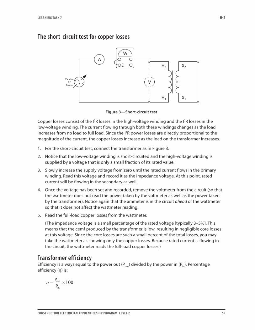
Copper losses consist of the I2R losses in the high-voltage winding and the I2R losses in the low-voltage winding. The current flowing through both these windings changes as the load increases from no load to full load. Since the I2R power losses are directly proportional to the magnitude of the current, the copper losses increase as the load on the transformer increases.
1. For the short-circuit test, connect the transformer as in Figure 3.
2. Notice that the low-voltage winding is short-circuited and the high-voltage winding is supplied by a voltage that is only a small fraction of its rated value.
3. Slowly increase the supply voltage from zero until the rated current flows in the primary winding. Read this voltage and record it as the impedance voltage. At this point, rated current will be flowing in the secondary as well.
4. Once the voltage has been set and recorded, remove the voltmeter from the circuit (so that the wattmeter does not read the power taken by the voltmeter as well as the power taken by the transformer). Notice again that the ammeter is in the circuit ahead of the wattmeter so that it does not affect the wattmeter reading.
5. Read the full-load copper losses from the wattmeter.
(The impedance voltage is a small percentage of the rated voltage [typically 3–5%]. This means that the cemf produced by the transformer is low, resulting in negligible core losses at this voltage. Since the core losses are such a small percent of the total losses, you may take the wattmeter as showing only the copper losses. Because rated current is flowing in the circuit, the wattmeter reads the full-load copper losses.)
Transformer efficiencyEfficiency is always equal to the power out (Pout) divided by the power in (Pin). Percentage efficiency (η) is:
η = ×PPout
in
100
LEARNING TASk 7 H-2
60 CONSTRUCTION ELECTRICIAN APPRENTICESHIP PROGRAM: LEVEL 2
Also, the power in is always equal to the power out plus the power losses (Plosses).
P P P
PP P
in out losses
out
out losses
= +
∴ =+
×η 100
From this it is possible to write an equation for transformer efficiency:
ηθ
θ=
× ×× × + +
E IE I
S S
S S
coscos copper losses core lossee
cos core
s
E IE I I R I R
S S
S S P P S S
×
=× ×
× × + + +
100
2 2
cosθθ llosses
×100
Example 1A transformer is tested and found to have core losses of 1200 W. It also has full-load copper losses of 1627 W in the primary coil and 1562 W in the secondary coil. If the secondary is delivering its full-rated 250 kVA at unity power factor, what is the efficiency of this transformer?
Solution: At unity power factor, cos θ = PF = 1 and Pout = 250 kVA.
ηθ
θ=
× ×× × + +
E IE I
S S
S S
coscos copper losses core lossess
×
=+
×
=+
100
100
250 000250 000 1627
PP P
WW
out
out losses
WW W W+ +×
=
1562 1200100
98 3. %
Significance of percent impedanceThe percent impedance (%Z) is the percent of the rated load impedance possessed by a transformer. An electrician needs to know the percent impedance of a transformer in order to:
• Calculate available fault currents
• Determine whether two transformers are suitable for paralleling
LEARNING TASk 7 H-2
CONSTRUCTION ELECTRICIAN APPRENTICESHIP PROGRAM: LEVEL 2 61
When paralleling transformers it is important that they have the same percent impedance so that they will share the load according to their ability. If they do not, the transformer with the lower %Z will carry more than its share of the load.
You have learned about the short-circuit test. In this, the value of voltage applied to the primary that caused rated current to flow in the short-circuited secondary was referred to as impedance voltage.
If this impedance voltage is expressed as a percentage of the rated primary voltage, then it is referred to as the percent impedance voltage, or %IZ.
%IZ= ×
=×
EE
I Z
short circuit
rated
short circuit tr
100
aansformer
rated rated loadI Z××100
Since Ishort circuit = Irated it is possible to divide both the top and bottom of the equation by I to get:
%
%
IZZ
Z
= ×
=
transformer
rated loadZ100
Since the percent impedance of a transformer is equal to the percent impedance voltage, the percent impedance of a transformer may be determined from the short-circuit test.
Fault-current calculationsTo calculate the fault current available from a transformer if a bolted fault (zero ohms of resistance) occurs across the secondary terminals, use the following formula:
II
Ztshort circuifull load=%
where %Z is expressed as a decimal.
Example 2What is the available fault current at the secondary terminals of a step-down transformer rated at 100 kVA, 2400 V – 120 V, if its percent impedance is 3%?
LEARNING TASk 7 H-2
62 CONSTRUCTION ELECTRICIAN APPRENTICESHIP PROGRAM: LEVEL 2
Solution:
I100 000 VA
120 V
I833 A
full load
short circuit
=
=
=
833 A
00.03
= 27 778 A
Transformers connected in parallelThe kVA rating of a bank of transformers connected in parallel is simply the sum of the individual kVA ratings. For example, if a 100 kVA transformer with a percent impedance of 3% is paralleled with a 200 kVA transformer with a percent impedance of 3%, then the bank will have a rating of 300 kVA and a percent impedance of 3%.
The primary, full-load current rating for a parallel bank of transformers is simply the kVA rating of the bank divided by the primary voltage rating. The secondary, full-load current rating for a parallel bank of transformers is simply the kVA rating of the bank divided by the secondary voltage.
The available fault current from a bank of transformers is simply the sum of the available fault currents of the individual transformers.
Example 3Two transformers are paralleled together to supply a 120 V bus from a 2400 V bus. Both transformers are rated 2400 V/4800 V – 120 V/240 V, 3%Z. Transformer 1 is rated 167.5 kVA and transformer 2 is rated 37.5 kVA.
1. Draw the schematic diagram of the connections.
2. Find the total kVA rating for the bank.
3. Find the full-load current ratings for the bank.
4. Find the full-load current ratings of each transformer as it is connected.
5. Find the full-load current ratings of each transformer winding.
6. Find the available fault current for each transformer.
7. Find the available fault current for the transformer bank.
LEARNING TASk 7 H-2
CONSTRUCTION ELECTRICIAN APPRENTICESHIP PROGRAM: LEVEL 2 63
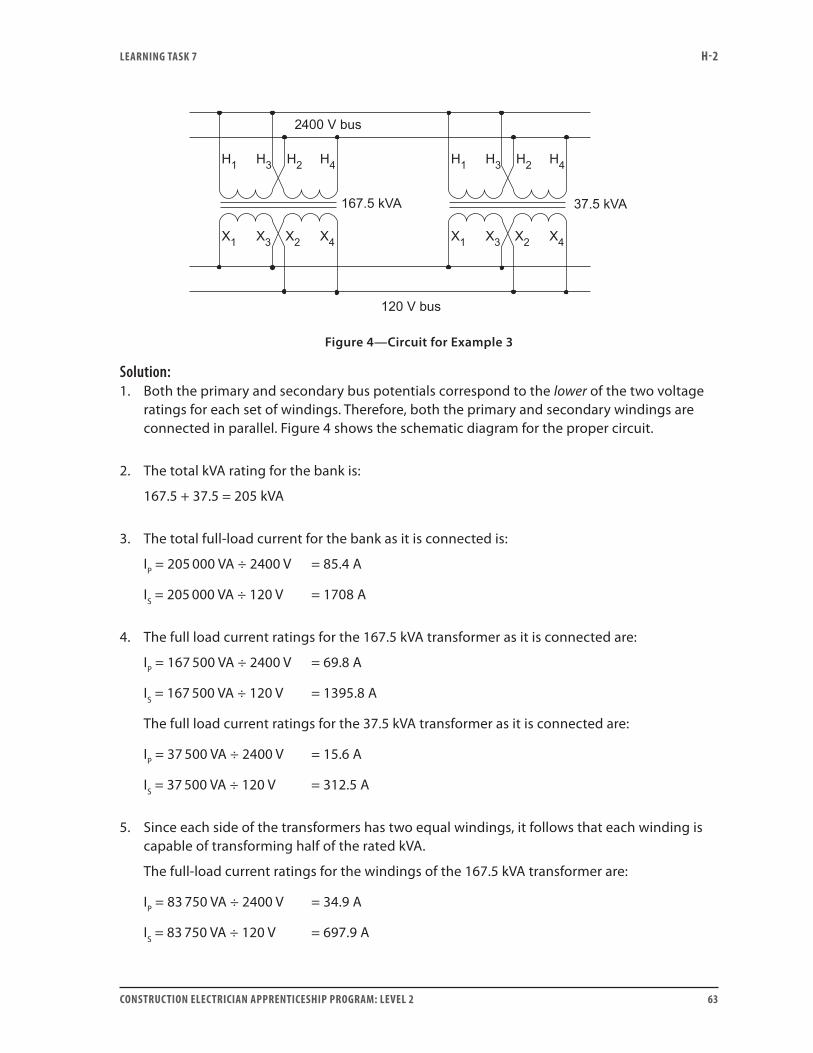
Figure 4—Circuit for Example 3
Solution:1. Both the primary and secondary bus potentials correspond to the lower of the two voltage
ratings for each set of windings. Therefore, both the primary and secondary windings are connected in parallel. Figure 4 shows the schematic diagram for the proper circuit.
2. The total kVA rating for the bank is:
167.5 + 37.5 = 205 kVA
3. The total full-load current for the bank as it is connected is:
IP = 205 000 VA ÷ 2400 V = 85.4 A
IS = 205 000 VA ÷ 120 V = 1708 A
4. The full load current ratings for the 167.5 kVA transformer as it is connected are:
IP = 167 500 VA ÷ 2400 V = 69.8 A
IS = 167 500 VA ÷ 120 V = 1395.8 A
The full load current ratings for the 37.5 kVA transformer as it is connected are:
IP = 37 500 VA ÷ 2400 V = 15.6 A
IS = 37 500 VA ÷ 120 V = 312.5 A
5. Since each side of the transformers has two equal windings, it follows that each winding is capable of transforming half of the rated kVA.
The full-load current ratings for the windings of the 167.5 kVA transformer are:
IP = 83 750 VA ÷ 2400 V = 34.9 A
IS = 83 750 VA ÷ 120 V = 697.9 A
LEARNING TASk 7 H-2
64 CONSTRUCTION ELECTRICIAN APPRENTICESHIP PROGRAM: LEVEL 2
The full load current ratings for the windings of the 37.5 kVA transformer are:
IP = 18 750 VA ÷ 2400 V = 7.8 A
IS = 18 750 VA ÷ 120 V = 156.3 A
6. The available fault current from the 167.5 kVA transformer as it is connected are:
II%Zshort circuitfull load=
=
=
1395 80 03
46 527
..
A
A
The available fault current from the 37.5 kVA transformer as it is connected is:
I312.5 A
0.03short circuit =
= 10 417 A
7. The available fault current from the bank of transformers as it is connected is:
I 46 527 A 10 417 A 56 944 Ashort circuit = + =
To check the answer, calculate it another way by dividing the full load current for the whole bank by the percent impedance.
I1708 A
0.03short circuit =
= 56 933 A
The difference in the two values (which is less than 0.02%) is strictly due to rounding error.
LEARNING TASk 7 H-2
CONSTRUCTION ELECTRICIAN APPRENTICESHIP PROGRAM: LEVEL 2 65
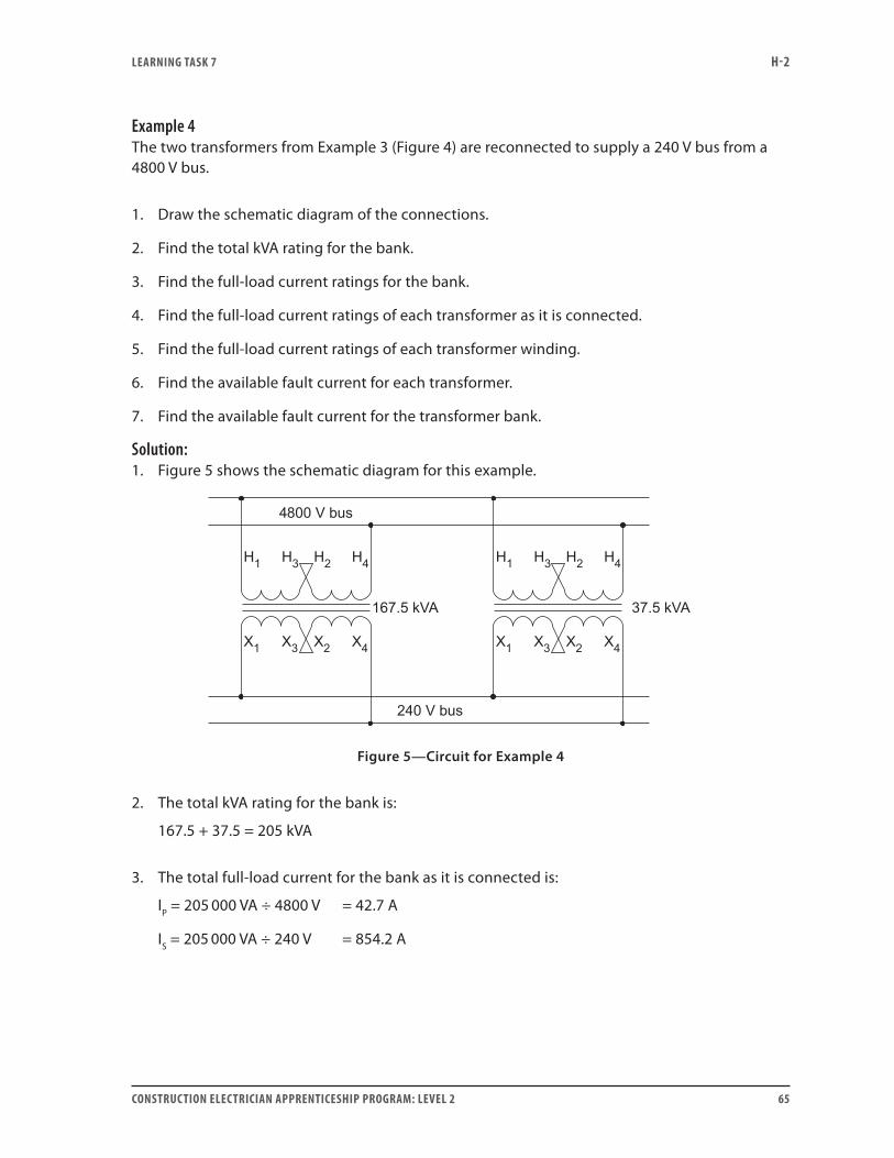
Example 4The two transformers from Example 3 (Figure 4) are reconnected to supply a 240 V bus from a 4800 V bus.
1. Draw the schematic diagram of the connections.
2. Find the total kVA rating for the bank.
3. Find the full-load current ratings for the bank.
4. Find the full-load current ratings of each transformer as it is connected.
5. Find the full-load current ratings of each transformer winding.
6. Find the available fault current for each transformer.
7. Find the available fault current for the transformer bank.
Solution:1. Figure 5 shows the schematic diagram for this example.
Figure 5—Circuit for Example 4
2. The total kVA rating for the bank is:
167.5 + 37.5 = 205 kVA
3. The total full-load current for the bank as it is connected is:
IP = 205 000 VA ÷ 4800 V = 42.7 A
IS = 205 000 VA ÷ 240 V = 854.2 A
LEARNING TASk 7 H-2
66 CONSTRUCTION ELECTRICIAN APPRENTICESHIP PROGRAM: LEVEL 2
4. The full-load current ratings for the 167.5 kVA transformer as it is connected are:
IP = 167 500 VA ÷ 4800 V = 34.9 A
IS = 167 500 VA ÷ 240 V = 697.9 A
The full-load current ratings for the 37.5 kVA transformer as it is connected are:
IP = 37 500 VA ÷ 4800 V = 7.8 A
IS = 37 500 VA ÷ 240 V = 156.3 A
5. Since each side of the transformers has two equal windings, it follows that each winding is capable of transforming half of the rated kVA.
The full-load current ratings for the windings of the 167.5 kVA transformer are:
IP = 83 750 VA ÷ 2400 V = 34.9 A
IS = 83 750 VA ÷ 120 V = 697.9 A
The full-load current ratings for the windings of the 37.5 kVA transformer are:
IP = 18 750 VA ÷ 2400 V = 7.8 A
IS = 18 750 VA ÷ 120 V = 156.3 A
6. The available fault current from the 167.5 kVA transformer as it is connected is:
II%Zshort circuitfull load=
=
=
697 90 03
23 263
..
A
A
The available fault current from the 37.5 kVA transformer as it is connected is:
I156.3 A
0.03short circuit =
= 5210 A
7. The available fault current from the bank of transformers as it is connected is:
I 23 263 A 5210 A 28 473 Ashort circuit = + =
To check the answer, calculate it another way by dividing the full-load current for the whole bank by the percent impedance.

LEARNING TASk 7 H-2
CONSTRUCTION ELECTRICIAN APPRENTICESHIP PROGRAM: LEVEL 2 67
I854.2 A
0.03short circuit =
= 28 473 A
Now complete Self-Test 7 and check your answers.

LEARNING TASk 7 H-2
68 CONSTRUCTION ELECTRICIAN APPRENTICESHIP PROGRAM: LEVEL 2
Self-Test 7
1. Name the two main core losses in a transformer.
2. Does core loss change significantly as load is added to the transformer?
3. Name the two copper losses in a transformer.
4. Do copper losses change significantly as load is added to the transformer?
5. Which test is used to determine the core losses?
6. Which test is used to determine the copper losses?
7. In both of these tests, why is the voltmeter removed from the test circuit before the wattmeter is read?

LEARNING TASk 7 H-2
CONSTRUCTION ELECTRICIAN APPRENTICESHIP PROGRAM: LEVEL 2 69
8. State the formula for calculating transformer efficiency.
9. How is most of the energy lost in a transformer dissipated?
10. Why are transformer cores normally laminated?
11. Each of the secondary windings of a 2400 V − 120/240 V distribution transformer has a maximum current rating of 62.5 A. What is the maximum kVA that the transformer can deliver if the windings are connected in:
a. series?
b. parallel?
12. What is the maximum load current the transformer in Question 11 can deliver connected to the load when connected in:
a. series?
b. parallel?
13. Calculate the available fault current on the secondary terminals of a 167.5 kVA, 2400 V − 120/240 V distribution transformer with a percent impedance of 4%, used to supply a three-wire system.
14. Two transformers are to be paralleled. One has percent impedance of 5% and the other has percent impedance of 3%. Which transformer will carry more than its share of the load?
LEARNING TASk 7 H-2
70 CONSTRUCTION ELECTRICIAN APPRENTICESHIP PROGRAM: LEVEL 2
15. Is it true that the %IZ equals the %Z?
16. What fault current is available from the secondary terminals of a step-down transformer rated at 75 kVA, 2400 V − 240 V if it has a %Z of 3.5%?
17. Two transformers are paralleled together to supply a 120 V/240 V bus from a 2400 V bus. Both transformers are rated 2400 V/4800 V − 120 V/240 V, 3.5%Z. Transformer 1 is rated 100 kVA and transformer 2 is rated 75 kVA.
Draw the schematic diagram of the connections.
18. Find the total kVA rating for the bank in Question 17.
19. Find the full-load current ratings for the bank in Question 17.

LEARNING TASk 7 H-2
CONSTRUCTION ELECTRICIAN APPRENTICESHIP PROGRAM: LEVEL 2 71
20. Find the full-load current ratings of each transformer as it is connected.
21. Find the full-load current ratings of each transformer winding.
22. Find the available fault current for each transformer.

LEARNING TASk 7 H-2
72 CONSTRUCTION ELECTRICIAN APPRENTICESHIP PROGRAM: LEVEL 2
23. Find the available fault current for the transformer bank.
Go to the Answer Key at the end of the Learning Guide to check your answers.
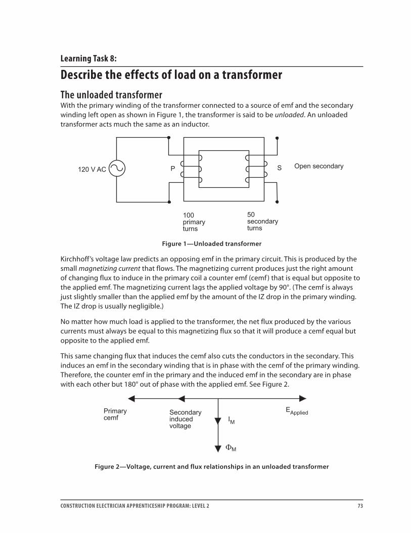
CONSTRUCTION ELECTRICIAN APPRENTICESHIP PROGRAM: LEVEL 2 73
Learning Task 8:
Describe the effects of load on a transformerThe unloaded transformerWith the primary winding of the transformer connected to a source of emf and the secondary winding left open as shown in Figure 1, the transformer is said to be unloaded. An unloaded transformer acts much the same as an inductor.
Figure 1—Unloaded transformer
Kirchhoff’s voltage law predicts an opposing emf in the primary circuit. This is produced by the small magnetizing current that flows. The magnetizing current produces just the right amount of changing flux to induce in the primary coil a counter emf (cemf ) that is equal but opposite to the applied emf. The magnetizing current lags the applied voltage by 90°. (The cemf is always just slightly smaller than the applied emf by the amount of the IZ drop in the primary winding. The IZ drop is usually negligible.)
No matter how much load is applied to the transformer, the net flux produced by the various currents must always be equal to this magnetizing flux so that it will produce a cemf equal but opposite to the applied emf.
This same changing flux that induces the cemf also cuts the conductors in the secondary. This induces an emf in the secondary winding that is in phase with the cemf of the primary winding. Therefore, the counter emf in the primary and the induced emf in the secondary are in phase with each other but 180° out of phase with the applied emf. See Figure 2.
Figure 2—Voltage, current and flux relationships in an unloaded transformer
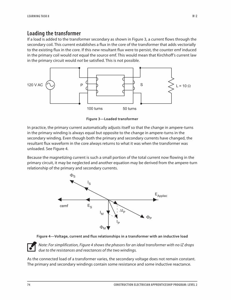
LEARNING TASk 8 H-2
74 CONSTRUCTION ELECTRICIAN APPRENTICESHIP PROGRAM: LEVEL 2
Loading the transformerIf a load is added to the transformer secondary as shown in Figure 3, a current flows through the secondary coil. This current establishes a flux in the core of the transformer that adds vectorially to the existing flux in the core. If this new resultant flux were to persist, the counter emf induced in the primary coil would not equal the source emf. This would mean that Kirchhoff’s current law in the primary circuit would not be satisfied. This is not possible.
Figure 3—Loaded transformer
In practice, the primary current automatically adjusts itself so that the change in ampere-turns in the primary winding is always equal but opposite to the change in ampere-turns in the secondary winding. Even though both the primary and secondary currents have changed, the resultant flux waveform in the core always returns to what it was when the transformer was unloaded. See Figure 4.
Because the magnetizing current is such a small portion of the total current now flowing in the primary circuit, it may be neglected and another equation may be derived from the ampere-turn relationship of the primary and secondary currents.
Figure 4—Voltage, current and flux relationships in a transformer with an inductive load
Note: For simplification, Figure 4 shows the phasors for an ideal transformer with no IZ drops due to the resistances and reactances of the two windings.
As the connected load of a transformer varies, the secondary voltage does not remain constant. The primary and secondary windings contain some resistance and some inductive reactance.
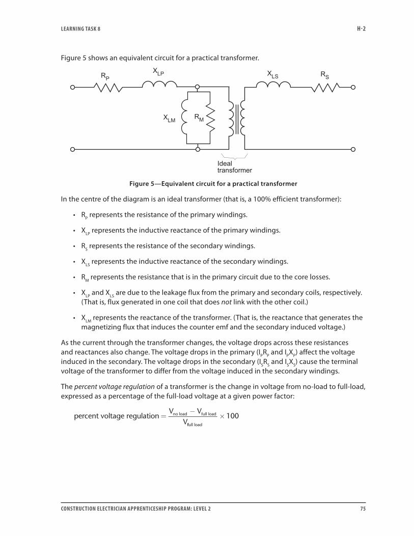
LEARNING TASk 8 H-2
CONSTRUCTION ELECTRICIAN APPRENTICESHIP PROGRAM: LEVEL 2 75
Figure 5 shows an equivalent circuit for a practical transformer.
Figure 5—Equivalent circuit for a practical transformer
In the centre of the diagram is an ideal transformer (that is, a 100% efficient transformer):
• RP represents the resistance of the primary windings.
• XLP represents the inductive reactance of the primary windings.
• RS represents the resistance of the secondary windings.
• XLS represents the inductive reactance of the secondary windings.
• RM represents the resistance that is in the primary circuit due to the core losses.
• XLP and XLS are due to the leakage flux from the primary and secondary coils, respectively. (That is, flux generated in one coil that does not link with the other coil.)
• XLM represents the reactance of the transformer. (That is, the reactance that generates the magnetizing flux that induces the counter emf and the secondary induced voltage.)
As the current through the transformer changes, the voltage drops across these resistances and reactances also change. The voltage drops in the primary (IPRP and IPXP) affect the voltage induced in the secondary. The voltage drops in the secondary (ISRS and ISXS) cause the terminal voltage of the transformer to differ from the voltage induced in the secondary windings.
The percent voltage regulation of a transformer is the change in voltage from no-load to full-load, expressed as a percentage of the full-load voltage at a given power factor:
percent voltage regulationV V
Vno load full load=
−
ffull load
×100
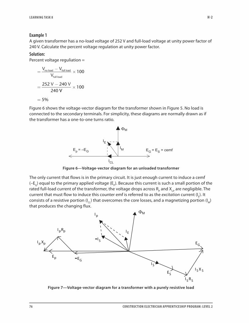
LEARNING TASk 8 H-2
76 CONSTRUCTION ELECTRICIAN APPRENTICESHIP PROGRAM: LEVEL 2
Example 1A given transformer has a no-load voltage of 252 V and full-load voltage at unity power factor of 240 V. Calculate the percent voltage regulation at unity power factor.
Solution: Percent voltage reguliation =
=−
×
=−
V VV
no load full load
full load
100
252 240240V V
VV×
=
100
5%
Figure 6 shows the voltage-vector diagram for the transformer shown in Figure 5. No load is connected to the secondary terminals. For simplicity, these diagrams are normally drawn as if the transformer has a one-to-one turns ratio.
Figure 6—Voltage-vector diagram for an unloaded transformer
The only current that flows is in the primary circuit. It is just enough current to induce a cemf (–EG) equal to the primary applied voltage (EP). Because this current is such a small portion of the rated full-load current of the transformer, the voltage drops across RP and XLP are negligible. The current that must flow to induce this counter emf is referred to as the excitation current (IE). It consists of a resistive portion (ICL) that overcomes the core losses, and a magnetizing portion (IM) that produces the changing flux.
I p
I E
I p
I p
Ep EG
Rp
Xp
I S
ESI S RS
I S X S
EG
–
I S–
Figure 7—Voltage-vector diagram for a transformer with a purely resistive load
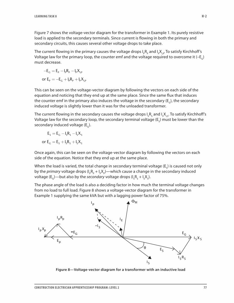
LEARNING TASk 8 H-2
CONSTRUCTION ELECTRICIAN APPRENTICESHIP PROGRAM: LEVEL 2 77
Figure 7 shows the voltage-vector diagram for the transformer in Example 1. Its purely resistive load is applied to the secondary terminals. Since current is flowing in both the primary and secondary circuits, this causes several other voltage drops to take place.
The current flowing in the primary causes the voltage drops IPRP and IPXLP. To satisfy Kirchhoff’s Voltage law for the primary loop, the counter emf and the voltage required to overcome it (–EG) must decrease.
− = − −
=− + +
E E I R I X
E E I R I X
G P P P P LP
P G P P P LPor
This can be seen on the voltage-vector diagram by following the vectors on each side of the equation and noticing that they end up at the same place. Since the same flux that induces the counter emf in the primary also induces the voltage in the secondary (EG), the secondary induced voltage is slightly lower than it was for the unloaded transformer.
The current flowing in the secondary causes the voltage drops ISRS and ISXLS. To satisfy Kirchhoff’s Voltage law for the secondary loop, the secondary terminal voltage (ES) must be lower than the secondary induced voltage (EG).
E E I R I X
E E I R I X
S G S S S S
G S S S S S
= − −
= + +or
Once again, this can be seen on the voltage-vector diagram by following the vectors on each side of the equation. Notice that they end up at the same place.
When the load is varied, the total change in secondary terminal voltage (ES) is caused not only by the primary voltage drops (IPRP + IPXP)—which cause a change in the secondary induced voltage (EG)—but also by the secondary voltage drops (ISRS + ISXS).
The phase angle of the load is also a deciding factor in how much the terminal voltage changes from no load to full load. Figure 8 shows a voltage-vector diagram for the transformer in Example 1 supplying the same kVA but with a lagging power factor of 75%.
I p
I E
I p
I p
Ep
EG
Rp
Xp
I S
ES
I S RS
I S X S
EG–
I S–
θ
Figure 8—Voltage-vector diagram for a transformer with an inductive load

LEARNING TASk 8 H-2
78 CONSTRUCTION ELECTRICIAN APPRENTICESHIP PROGRAM: LEVEL 2
In Figure 8 notice that:
• The terminal-voltage vector (ES) is shorter than it was in Figure 7. This is because of the shift in the angles of the transformer’s internal voltage drops (IPRP, IPZP, ISRS, ISZS).
• The magnitude of the current flowing in the primary and secondary circuits is exactly the same as it was in Figure 7, but the angle between it and the terminal voltage has changed from 0° to 41°.
• Since the primary and secondary impedances are in series with the load, the IR drops are in phase with the current and the IZ drops lead the current by 90°.
• Because the secondary current is lagging, the secondary-voltage-drop triangle has shifted.
• The increased lag of the load’s power factor has caused the terminal voltage of the transformer to drop even more between no load and full load than for the unity-power-factor load.
Figure 9 shows a voltage-vector diagram for the transformer in Example 1 supplying the same kVA but with a leading power factor of 56%. Notice that the terminal voltage vector (ES) is longer than it was in Figure 7. In fact, it is longer than the secondary induced voltage vector (EG). This means that the terminal voltage is actually larger than the secondary induced voltage. The IR drops and IZ drops, because of their angles, are actually causing an increase in the terminal voltage.
I p
I E
I p
I p
Ep
EGRp
Xp
I S
ES I S R S
I S X S
EG–
IS
–
θ
Figure 9—Voltage-vector diagram for a transformer with a capacitive load
With this increase in the terminal voltage of the transformer, it is easy to see why supply utilities do not want customers to over-correct for a lagging power factor. It could increase the line potential and damage other loads connected to the line.
Now complete Self-Test 8 and check your answers.
LEARNING TASk 8 H-2
CONSTRUCTION ELECTRICIAN APPRENTICESHIP PROGRAM: LEVEL 2 79
Self-Test 8
1. Define percent voltage regulation of a transformer.
2. State the equation for calculating the percent voltage regulation of a transformer.
3. Does power factor affect the percent voltage regulation of a transformer?
4. A bell transformer has a no-load secondary terminal voltage of 30 V and a full-load voltage
of 24 V at unity power factor. What is its percent voltage regulation?
5. With a leading-power-factor load, is it possible for the secondary-terminal voltage of a
transformer to rise as the load increases?
6. A transformer has a full-load secondary terminal voltage of 120 V and a percent voltage
regulation of 6%. What is the open-circuit (no-load) voltage for this transformer?
7. A transformer has a no-load voltage of 364 V and a percent voltage regulation of 5%. What is
the full-load secondary terminal voltage for this transformer?
8. Why does the terminal voltage equal the secondary induced voltage when the secondary of the transformer has no-load applied to it?
LEARNING TASk 8 H-2
80 CONSTRUCTION ELECTRICIAN APPRENTICESHIP PROGRAM: LEVEL 2
9. The ISXS voltage drop:
a. is in phase with the secondary load current
b. leads the secondary load current by 90°
c. lags the secondary load current by 90°
d. lags the secondary load current by 180°
10. Could a leading-power-factor load cause a rise in line-bus voltage on the secondary of a
transformer?
Go to the Answer Key at the end of the Learning Guide to check your answers.
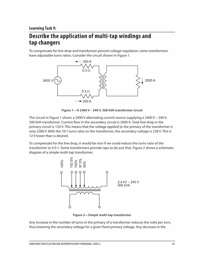
CONSTRUCTION ELECTRICIAN APPRENTICESHIP PROGRAM: LEVEL 2 81
Learning Task 9:
Describe the application of multi-tap windings and tap changersTo compensate for line drop and transformer percent voltage regulation, some transformers have adjustable turns ratios. Consider the circuit shown in Figure 1.
Figure 1—A 2400 V – 240 V, 500 kVA transformer circuit
The circuit in Figure 1 shows a 2400 V alternating current source supplying a 2400 V – 240 V, 500 kVA transformer. Current flow in the secondary circuit is 2000 A. Total line drop in the primary circuit is 120 V. This means that the voltage applied to the primary of the transformer is only 2280 V. With the 10:1 turns ratio on the transformer, the secondary voltage is 228 V. This is 12 V lower than is desired.
To compensate for the line drop, it would be nice if we could reduce the turns ratio of the transformer to 9.5:1. Some transformers provide taps to do just that. Figure 2 shows a schematic diagram of a simple multi-tap transformer.
Figure 2—Simple multi-tap transformer
Any increase in the number of turns in the primary of a transformer reduces the volts per turn, thus lowering the secondary voltage for a given fixed primary voltage. Any decrease in the

LEARNING TASk 9 H-2
82 CONSTRUCTION ELECTRICIAN APPRENTICESHIP PROGRAM: LEVEL 2
number of turns in the primary of the transformer increases the volts per turn, thus raising the secondary voltage for a given fixed primary voltage.
Physically moving the connections to multi-tap transformers is time-consuming and requires the interruption of power for a substantial time. To help solve this problem, tap changers were developed. In their simplest form, tap changers are nothing more than a selector switch.
Tap changers can be divided into two general categories:
• No-load tap changers may be operated only while the circuit is de-energized.
• On-load tap changers may be operated while the circuit is energized.
Transformers may be connected without the use of either type of tap changer. This is normal when the tap is to be selected once and there is no foreseeable need to change it. Other situations require infrequent changes to the tap connections due to a changing load over a period of time.
For example, a distribution transformer may serve a growing residential area. As more residences are added to the area, the transformer’s primary and secondary currents increase. This causes an increase in the line drop. Occasionally, it is necessary to change the tap connection on the transformer to compensate for this steadily increasing load. The no-load tap changer is suitable for this type of application because of its small size and low initial cost. The infrequent momentary interruptions in power are insignificant when compared with the high cost of installing an on-load tap changer.
For cyclical situations where the load increases and decreases over time, the on-load tap changer is more suitable. During the 24-hour day, there are peak periods in the supply of power to the consumer, where load is higher, and other periods where it is lower. The line drops increase and decrease with the changing load. This would result in an unsteady consumer voltage. To help make the consumer voltage more stable, on-load tap changers are used. Connections to the taps of the transformer may be changed without interruption of power to the consumer. Using a no-load tap changer in this situation would result in an unacceptable number of momentary power interruptions.
No-load tap changersFigure 3 shows a typical example of a no-load tap changer connected into a circuit. These switches are not designed to open a circuit carrying load current. The switch provides the jumper connections between the individual taps on the primary winding of the transformer. Notice that whenever the switch is moved it breaks the primary circuit before making the new connection.

LEARNING TASk 9 H-2
CONSTRUCTION ELECTRICIAN APPRENTICESHIP PROGRAM: LEVEL 2 83
Figure 3—No-load tap changer
Never open a no-load tap changer while the circuit is energized. This switch is NOT designed to interrupt the flow of current in the circuit.
On-load tap changerFigure 4 shows an example of an on-load tap changer. There are many different designs, but all of them have the same objective of changing the turns ratio without interrupting the flow of current in the circuit. These tap changers are intended to be used while the circuit is energized.
• Figure 4a shows the tap changer connecting the supply to the 100% tap of the transformer. A reactor is connected in series with the movable contacts. The purpose of the reactor is to prevent short-circuiting of the tap connections during switching. The coil of the reactor is centre-tapped, dividing the flow of current between the two halves. Notice the direction of current flow through the two halves of the reactor at this position: the fluxes created in the core by the two currents cancel each other. The reactor offers negligible opposition to the flow of current.
• Figure 4b shows the tap changer halfway between switching from the 100% tap to the 97.5% tap. The top movable contact is touching the 97.5% tap and the bottom movable contact is touching the 100% tap. With the switch in this position, the currents through the two halves of the reactor winding are wound in directions such that the fluxes they create aid each other. The reactor offers enough opposition to the flow of current that a short circuit does not occur across the portion of the winding spanned by the 100% and 97.5% taps.
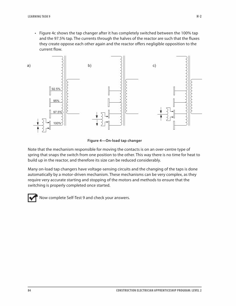
LEARNING TASk 9 H-2
84 CONSTRUCTION ELECTRICIAN APPRENTICESHIP PROGRAM: LEVEL 2
• Figure 4c shows the tap changer after it has completely switched between the 100% tap and the 97.5% tap. The currents through the halves of the reactor are such that the fluxes they create oppose each other again and the reactor offers negligible opposition to the current flow.
Figure 4—On-load tap changer
Note that the mechanism responsible for moving the contacts is on an over-centre type of spring that snaps the switch from one position to the other. This way there is no time for heat to build up in the reactor, and therefore its size can be reduced considerably.
Many on-load tap changers have voltage-sensing circuits and the changing of the taps is done automatically by a motor-driven mechanism. These mechanisms can be very complex, as they require very accurate starting and stopping of the motors and methods to ensure that the switching is properly completed once started.
Now complete Self-Test 9 and check your answers.

LEARNING TASk 9 H-2
CONSTRUCTION ELECTRICIAN APPRENTICESHIP PROGRAM: LEVEL 2 85
Self-Test 9
1. Explain the difference between a no-load tap changer and an on-load tap changer.
2. Which of the two types of tap changers never opens the circuit of the transformer?
3. What is the purpose of the reactor in an on-load tap changer?
4. Why does the reactor in the on-load tap changer offer negligible resistance to the primary circuit current once the switching is complete?
5. Which type of tap changer is generally more expensive?
Go to the Answer Key at the end of the Learning Guide to check your answers.

86 CONSTRUCTION ELECTRICIAN APPRENTICESHIP PROGRAM: LEVEL 2

CONSTRUCTION ELECTRICIAN APPRENTICESHIP PROGRAM: LEVEL 2 87
Learning Task 10:
Calculate values involving multi-tap and tap changer transformersCalculating turns ratio
Figure 1—Simple multi-tap transformer
The transformer in Figure 1 has a turns ratio of 10:1 (2400 V ÷ 240 V) on the 100% tap. The tap percentage indicates the percentage of the full turns for that winding that are effective when the tap is used. When the taps are in the primary winding, the new turns ratio can be calculated by multiplying this percentage by the full turns ratio (Table 2):
Table 2: Calculation of turns ratio
Tap Ratio Calculation
95% 9.5:1 = 10 × 0.95
97.5% 9.75:1 = 10 × 0.975
102.5% 10.25:1 = 10 × 1.025
105% 10.5:1 = 10 × 1.05
With this transformer, the primary voltage can vary between 2250 V and 2550 V. The secondary voltage can be maintained within 1.25% of its rated 240 V (±3 V) simply by changing tap connections. With only 100% of the winding available, the voltage would vary by ±15 V.
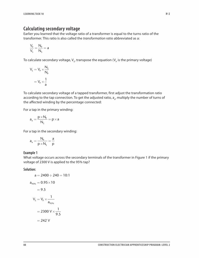
LEARNING TASk 10 H-2
88 CONSTRUCTION ELECTRICIAN APPRENTICESHIP PROGRAM: LEVEL 2
Calculating secondary voltageEarlier you learned that the voltage ratio of a transformer is equal to the turns ratio of the transformer. This ratio is also called the transformation ratio abbreviated as a:
VV
NN
aP
S
P
S
= =
To calculate secondary voltage, VS, transpose the equation (VP is the primary voltage)
V VNN
Va
S PS
P
P
= ×
= ×1
To calculate secondary voltage of a tapped transformer, first adjust the transformation ratio according to the tap connection. To get the adjusted ratio, aa, multiply the number of turns of the affected winding by the percentage connected:
For a tap in the primary winding:
ap N
Np aa
P
S
=×
= ×
For a tap in the secondary winding:
aN
p Napa
P
S
=×
=
Example 1What voltage occurs across the secondary terminals of the transformer in Figure 1 if the primary voltage of 2300 V is applied to the 95% tap?
Solution:a= ÷ =
= ×
=
= ×
=
2400 240 10:1
a 0.95 10
9.5
V V1
a
2300
95%
S P95%
V1
9.5
V
×
= 242
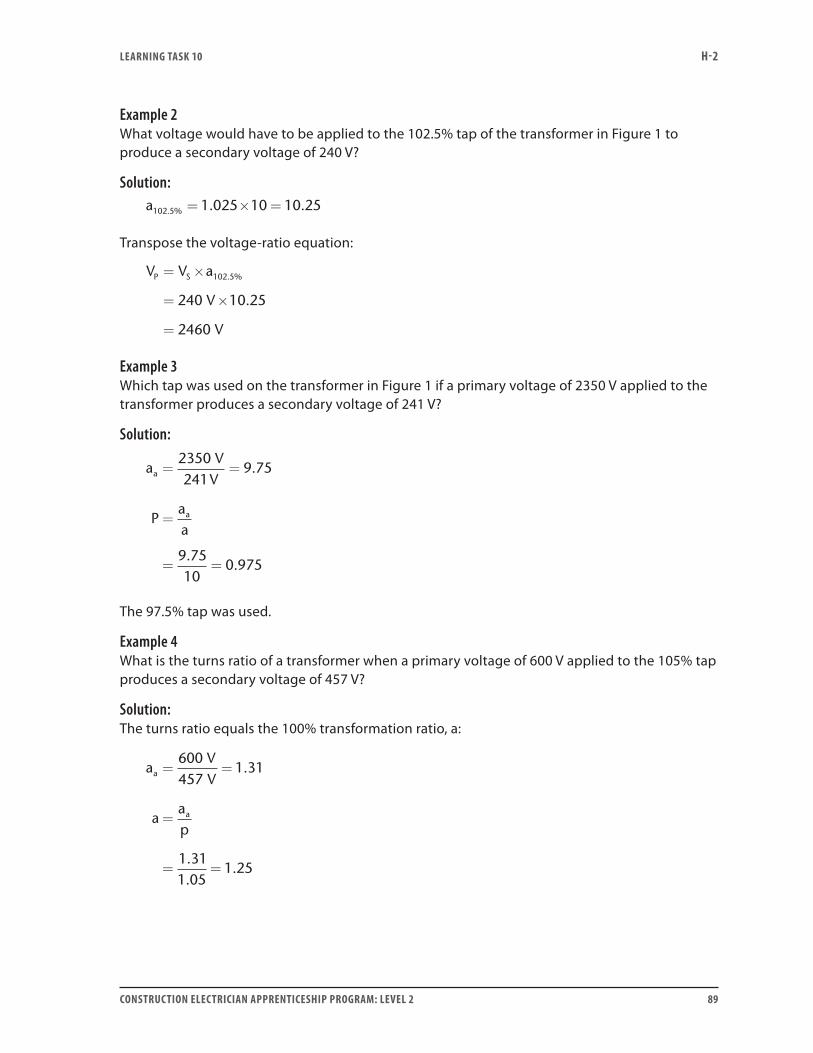
LEARNING TASk 10 H-2
CONSTRUCTION ELECTRICIAN APPRENTICESHIP PROGRAM: LEVEL 2 89
Example 2What voltage would have to be applied to the 102.5% tap of the transformer in Figure 1 to produce a secondary voltage of 240 V?
Solution:a102 5 1 025 10 10 25. % . .= × =
Transpose the voltage-ratio equation:
V V a
V
V
P S= ×
= ×
=
102 5
240 10 25
2460
. %
.
Example 3Which tap was used on the transformer in Figure 1 if a primary voltage of 2350 V applied to the transformer produces a secondary voltage of 241 V?
Solution:
aV
V
Paa
a
a
= =
=
= =
2350241
9 75
9 7510
0 975
.
..
The 97.5% tap was used.
Example 4What is the turns ratio of a transformer when a primary voltage of 600 V applied to the 105% tap produces a secondary voltage of 457 V?
Solution:The turns ratio equals the 100% transformation ratio, a:
aVV
aap
a
a
= =
=
= =
600457
1 31
1 311 05
1 25
.
..
.
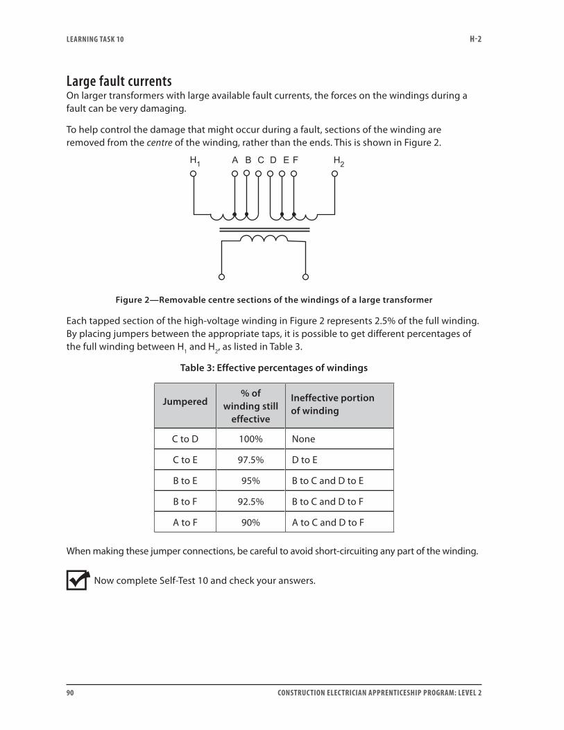
LEARNING TASk 10 H-2
90 CONSTRUCTION ELECTRICIAN APPRENTICESHIP PROGRAM: LEVEL 2
Large fault currentsOn larger transformers with large available fault currents, the forces on the windings during a fault can be very damaging.
To help control the damage that might occur during a fault, sections of the winding are removed from the centre of the winding, rather than the ends. This is shown in Figure 2.
Figure 2—Removable centre sections of the windings of a large transformer
Each tapped section of the high-voltage winding in Figure 2 represents 2.5% of the full winding. By placing jumpers between the appropriate taps, it is possible to get different percentages of the full winding between H1 and H2, as listed in Table 3.
Table 3: Effective percentages of windings
Jumpered% of
winding still effective
Ineffective portion of winding
C to D 100% None
C to E 97.5% D to E
B to E 95% B to C and D to E
B to F 92.5% B to C and D to F
A to F 90% A to C and D to F
When making these jumper connections, be careful to avoid short-circuiting any part of the winding.
Now complete Self-Test 10 and check your answers.
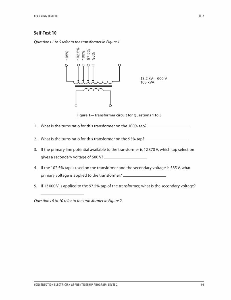
LEARNING TASk 10 H-2
CONSTRUCTION ELECTRICIAN APPRENTICESHIP PROGRAM: LEVEL 2 91
Self-Test 10
Questions 1 to 5 refer to the transformer in Figure 1.
Figure 1—Transformer circuit for Questions 1 to 5
1. What is the turns ratio for this transformer on the 100% tap?
2. What is the turns ratio for this transformer on the 95% tap?
3. If the primary line potential available to the transformer is 12 870 V, which tap selection
gives a secondary voltage of 600 V?
4. If the 102.5% tap is used on the transformer and the secondary voltage is 585 V, what
primary voltage is applied to the transformer?
5. If 13 000 V is applied to the 97.5% tap of the transformer, what is the secondary voltage?
Questions 6 to 10 refer to the transformer in Figure 2.
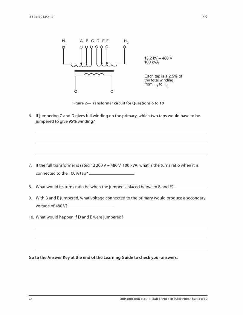
LEARNING TASk 10 H-2
92 CONSTRUCTION ELECTRICIAN APPRENTICESHIP PROGRAM: LEVEL 2
Figure 2—Transformer circuit for Questions 6 to 10
6. If jumpering C and D gives full winding on the primary, which two taps would have to be jumpered to give 95% winding?
7. If the full transformer is rated 13 200 V − 480 V, 100 kVA, what is the turns ratio when it is
connected to the 100% tap?
8. What would its turns ratio be when the jumper is placed between B and E?
9. With B and E jumpered, what voltage connected to the primary would produce a secondary
voltage of 480 V?
10. What would happen if D and E were jumpered?
Go to the Answer Key at the end of the Learning Guide to check your answers.
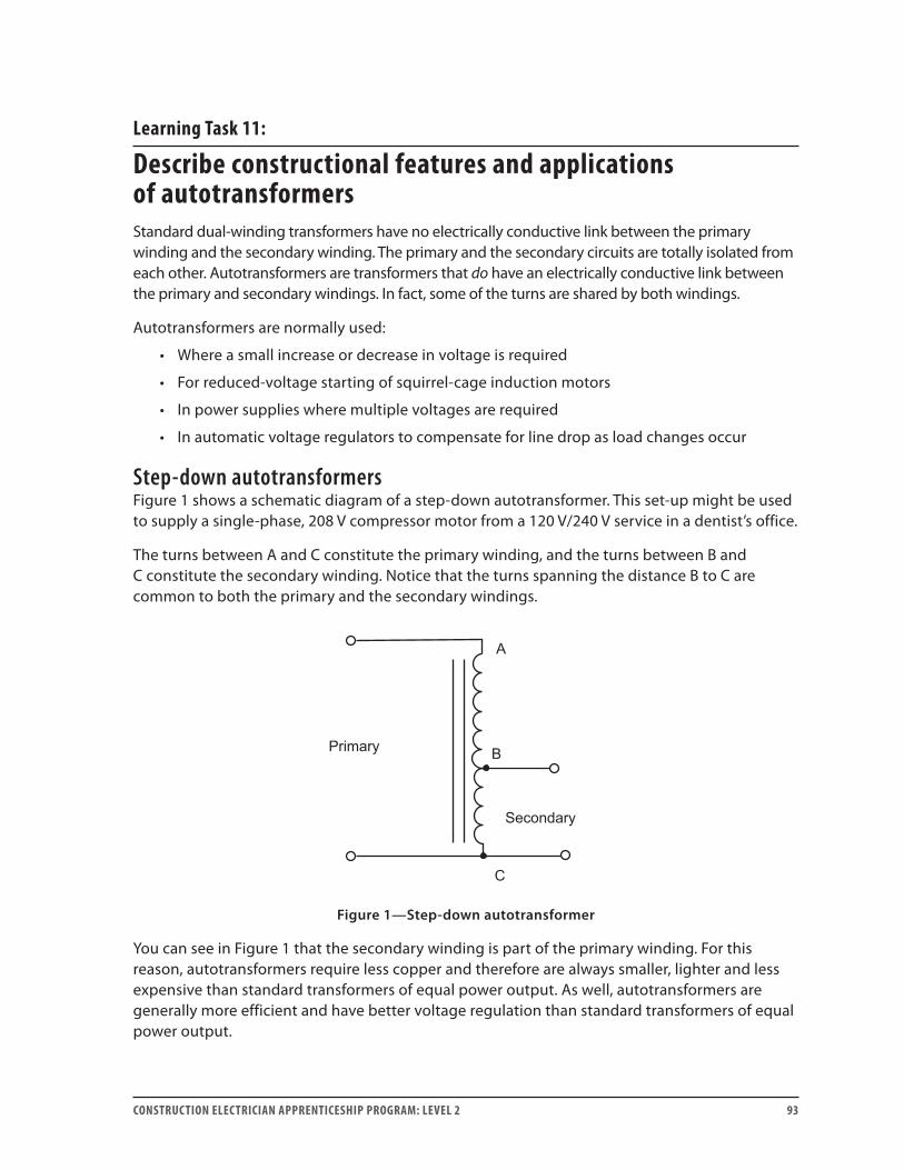
CONSTRUCTION ELECTRICIAN APPRENTICESHIP PROGRAM: LEVEL 2 93
Learning Task 11:
Describe constructional features and applications of autotransformersStandard dual-winding transformers have no electrically conductive link between the primary winding and the secondary winding. The primary and the secondary circuits are totally isolated from each other. Autotransformers are transformers that do have an electrically conductive link between the primary and secondary windings. In fact, some of the turns are shared by both windings.
Autotransformers are normally used:
• Where a small increase or decrease in voltage is required
• For reduced-voltage starting of squirrel-cage induction motors
• In power supplies where multiple voltages are required
• In automatic voltage regulators to compensate for line drop as load changes occur
Step-down autotransformersFigure 1 shows a schematic diagram of a step-down autotransformer. This set-up might be used to supply a single-phase, 208 V compressor motor from a 120 V/240 V service in a dentist’s office.
The turns between A and C constitute the primary winding, and the turns between B and C constitute the secondary winding. Notice that the turns spanning the distance B to C are common to both the primary and the secondary windings.
Figure 1—Step-down autotransformer
You can see in Figure 1 that the secondary winding is part of the primary winding. For this reason, autotransformers require less copper and therefore are always smaller, lighter and less expensive than standard transformers of equal power output. As well, autotransformers are generally more efficient and have better voltage regulation than standard transformers of equal power output.

LEARNING TASk 11 H-2
94 CONSTRUCTION ELECTRICIAN APPRENTICESHIP PROGRAM: LEVEL 2
Using dual-winding transformers, all the energy transferred from the primary circuit to the secondary circuit is transformed. Using autotransformers, some of the energy is transformed and some of the energy is conducted.
Certain relationships that were true for standard transformers are also true for autotransformers. These relationships between primary and secondary VA, turns, voltage and current, can be stated as:
VA VA
N
in out
P
=
=
(neglecting losses of course)
EE
P
S NN
II
NN
S
P
S
S
P
=
Step-up autotransformersFigure 2 shows a schematic diagram of a step-up autotransformer. This set-up might be used where a customer wants to install a 240 V, single-phase shrink wrap machine in a warehouse that only has a 120 V/208 V, three-phase supply. The machine’s heaters would operate at about 75% power due to this 13% decrease in supply voltage. The step-up autotransformer could provide the voltage boost from 208 V to 240 V.
The turns spanning the distance from A to C constitute the secondary winding, while the turns spanning the distance from B to C constitute the primary winding. Notice that the turns spanning the distance from B to C are common to the primary and secondary windings.
It can be seen in Figure 2 that the primary winding is actually a part of the secondary winding. This represents a considerable savings, in copper over a standard dual-winding transformer.
Figure 2—Step-up autotransformer
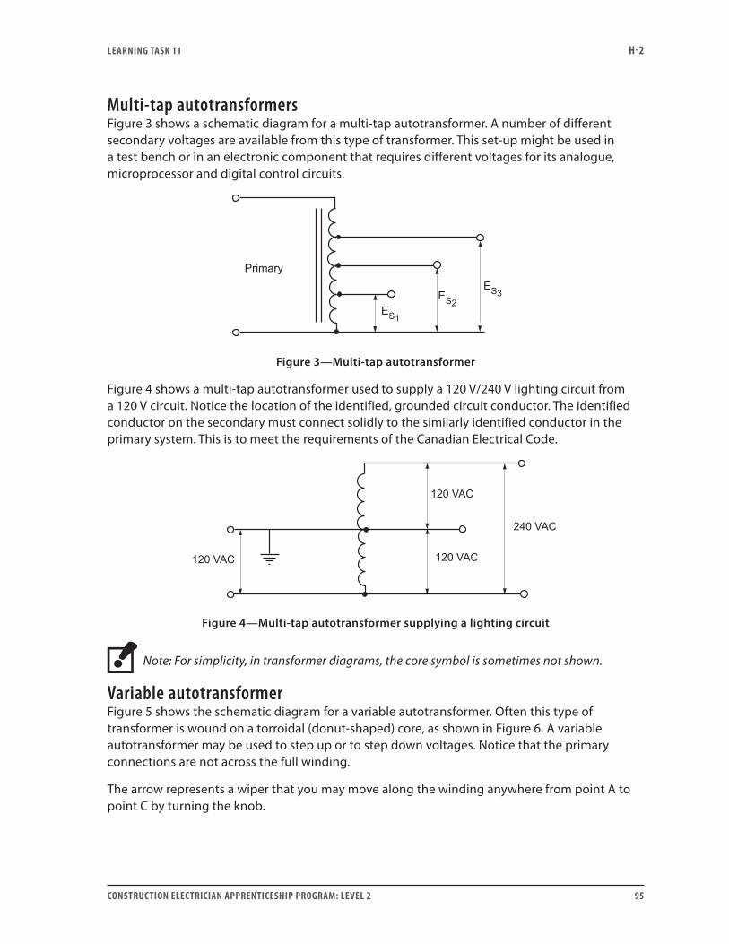
LEARNING TASk 11 H-2
CONSTRUCTION ELECTRICIAN APPRENTICESHIP PROGRAM: LEVEL 2 95
Multi-tap autotransformersFigure 3 shows a schematic diagram for a multi-tap autotransformer. A number of different secondary voltages are available from this type of transformer. This set-up might be used in a test bench or in an electronic component that requires different voltages for its analogue, microprocessor and digital control circuits.
Figure 3—Multi-tap autotransformer
Figure 4 shows a multi-tap autotransformer used to supply a 120 V/240 V lighting circuit from a 120 V circuit. Notice the location of the identified, grounded circuit conductor. The identified conductor on the secondary must connect solidly to the similarly identified conductor in the primary system. This is to meet the requirements of the Canadian Electrical Code.
Figure 4—Multi-tap autotransformer supplying a lighting circuit
Note: For simplicity, in transformer diagrams, the core symbol is sometimes not shown.
Variable autotransformerFigure 5 shows the schematic diagram for a variable autotransformer. Often this type of transformer is wound on a torroidal (donut-shaped) core, as shown in Figure 6. A variable autotransformer may be used to step up or to step down voltages. Notice that the primary connections are not across the full winding.
The arrow represents a wiper that you may move along the winding anywhere from point A to point C by turning the knob.
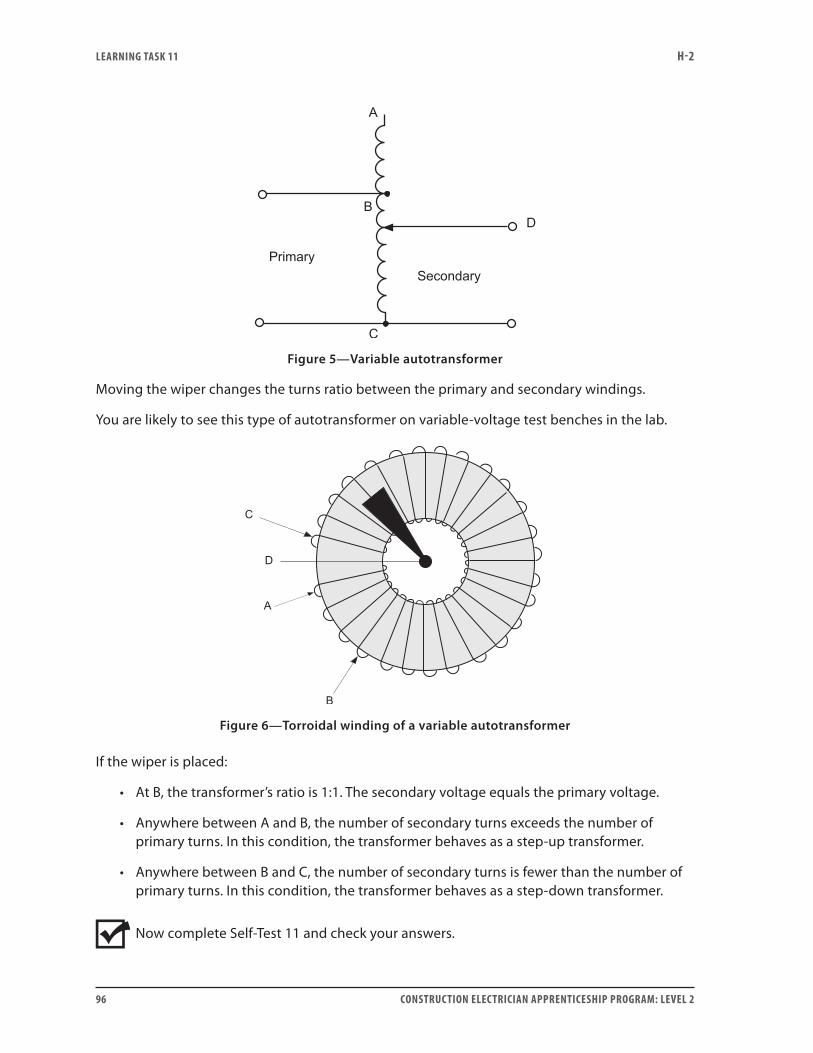
LEARNING TASk 11 H-2
96 CONSTRUCTION ELECTRICIAN APPRENTICESHIP PROGRAM: LEVEL 2
Figure 5—Variable autotransformer
Moving the wiper changes the turns ratio between the primary and secondary windings.
You are likely to see this type of autotransformer on variable-voltage test benches in the lab.
Figure 6—Torroidal winding of a variable autotransformer
If the wiper is placed:
• At B, the transformer’s ratio is 1:1. The secondary voltage equals the primary voltage.
• Anywhere between A and B, the number of secondary turns exceeds the number of primary turns. In this condition, the transformer behaves as a step-up transformer.
• Anywhere between B and C, the number of secondary turns is fewer than the number of primary turns. In this condition, the transformer behaves as a step-down transformer.
Now complete Self-Test 11 and check your answers.
LEARNING TASk 11 H-2
CONSTRUCTION ELECTRICIAN APPRENTICESHIP PROGRAM: LEVEL 2 97
Self-Test 11
1. In a step-down autotransformer, which is true?
a. The secondary winding is part of the primary winding.
b. The primary winding is part of the secondary winding.
2. If the secondary circuit must be electrically isolated from the primary circuit, is an autotransformer a suitable transformer to use?
3. In an autotransformer, what is the relationship between the primary volt-amperes and the secondary volt-amperes?
4. State the equation for an autotransformer that relates the primary-to-secondary voltage ratio to the primary-to-secondary turns ratio.
5. State the equation for an autotransformer that relates the primary-to-secondary current ratio to the primary-to-secondary turns ratio.
LEARNING TASk 11 H-2
98 CONSTRUCTION ELECTRICIAN APPRENTICESHIP PROGRAM: LEVEL 2
6. On a schematic diagram of a variable autotransformer, what does the arrow symbol represent?
7. If a standard, dual-winding transformer is compared with an autotransformer of equal power and voltage ratings, which one contains more copper?
Go to the Answer Key at the end of the Learning Guide to check your answers.
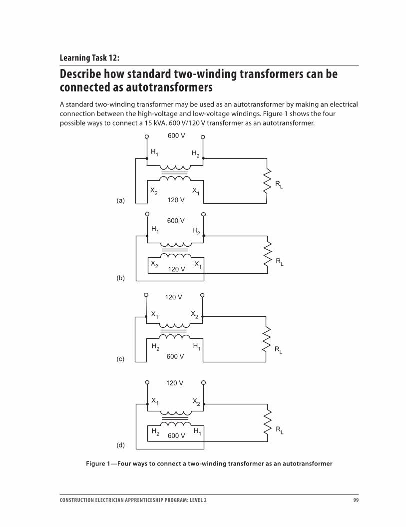
CONSTRUCTION ELECTRICIAN APPRENTICESHIP PROGRAM: LEVEL 2 99
Learning Task 12:
Describe how standard two-winding transformers can be connected as autotransformersA standard two-winding transformer may be used as an autotransformer by making an electrical connection between the high-voltage and low-voltage windings. Figure 1 shows the four possible ways to connect a 15 kVA, 600 V/120 V transformer as an autotransformer.
Figure 1—Four ways to connect a two-winding transformer as an autotransformer
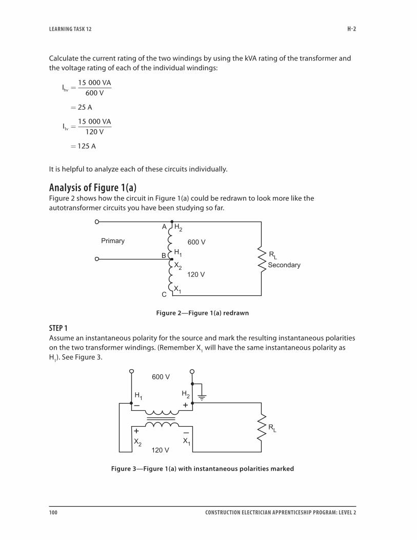
LEARNING TASk 12 H-2
100 CONSTRUCTION ELECTRICIAN APPRENTICESHIP PROGRAM: LEVEL 2
Calculate the current rating of the two windings by using the kVA rating of the transformer and the voltage rating of each of the individual windings:
IVA
V
A
IVA
V
A
hv
v
=
=
=
=
15 000600
25
15 000120
125
1
It is helpful to analyze each of these circuits individually.
Analysis of Figure 1(a)Figure 2 shows how the circuit in Figure 1(a) could be redrawn to look more like the autotransformer circuits you have been studying so far.
Figure 2—Figure 1(a) redrawn
STEP 1Assume an instantaneous polarity for the source and mark the resulting instantaneous polarities on the two transformer windings. (Remember X1 will have the same instantaneous polarity as H1). See Figure 3.
Figure 3—Figure 1(a) with instantaneous polarities marked
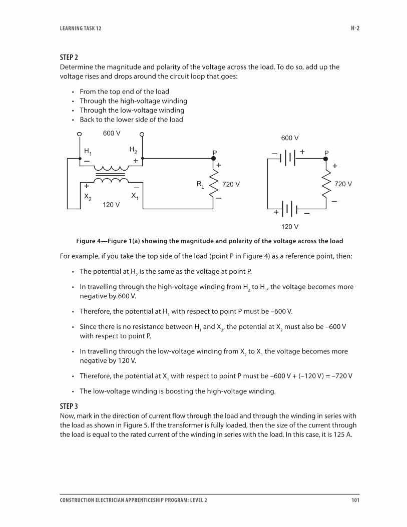
LEARNING TASk 12 H-2
CONSTRUCTION ELECTRICIAN APPRENTICESHIP PROGRAM: LEVEL 2 101
STEP 2Determine the magnitude and polarity of the voltage across the load. To do so, add up the voltage rises and drops around the circuit loop that goes:
• From the top end of the load • Through the high-voltage winding• Through the low-voltage winding• Back to the lower side of the load
Figure 4—Figure 1(a) showing the magnitude and polarity of the voltage across the load
For example, if you take the top side of the load (point P in Figure 4) as a reference point, then:
• The potential at H2 is the same as the voltage at point P.
• In travelling through the high-voltage winding from H2 to H1, the voltage becomes more negative by 600 V.
• Therefore, the potential at H1 with respect to point P must be –600 V.
• Since there is no resistance between H1 and X2, the potential at X2 must also be –600 V with respect to point P.
• In travelling through the low-voltage winding from X2 to X1 the voltage becomes more negative by 120 V.
• Therefore, the potential at X1 with respect to point P must be –600 V + (–120 V) = –720 V
• The low-voltage winding is boosting the high-voltage winding.
STEP 3Now, mark in the direction of current flow through the load and through the winding in series with the load as shown in Figure 5. If the transformer is fully loaded, then the size of the current through the load is equal to the rated current of the winding in series with the load. In this case, it is 125 A.
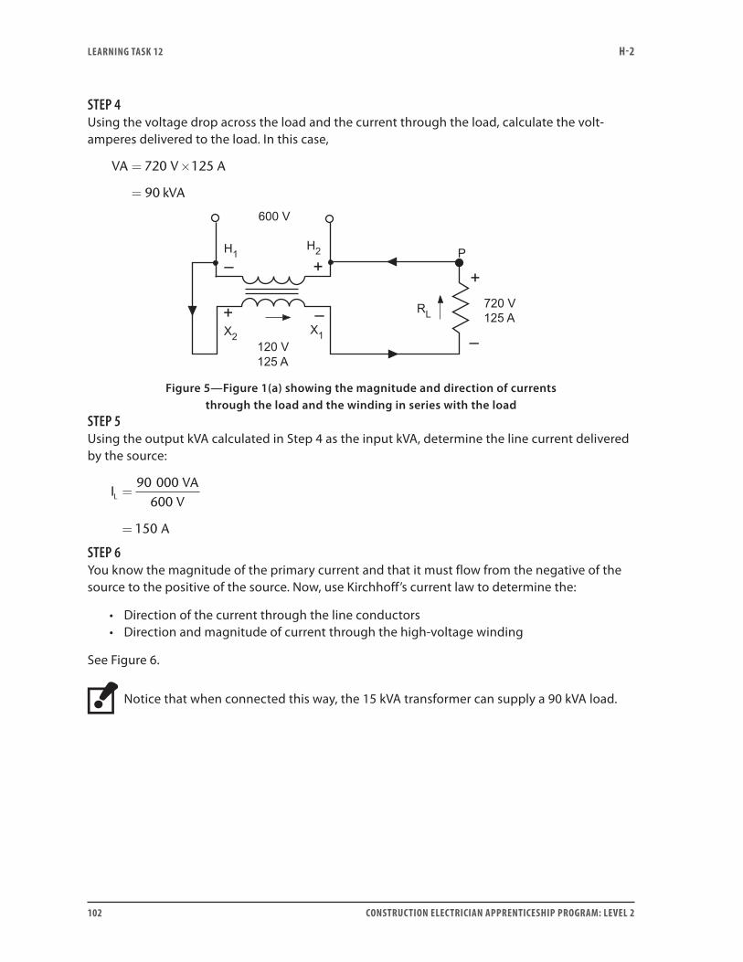
LEARNING TASk 12 H-2
102 CONSTRUCTION ELECTRICIAN APPRENTICESHIP PROGRAM: LEVEL 2
STEP 4Using the voltage drop across the load and the current through the load, calculate the volt-amperes delivered to the load. In this case,
VA V A
kVA
= ×
=
720 125
90
Figure 5—Figure 1(a) showing the magnitude and direction of currents through the load and the winding in series with the load
STEP 5Using the output kVA calculated in Step 4 as the input kVA, determine the line current delivered by the source:
IVA
V
A
L =
=
90 000600
150
STEP 6You know the magnitude of the primary current and that it must flow from the negative of the source to the positive of the source. Now, use Kirchhoff’s current law to determine the:
• Direction of the current through the line conductors• Direction and magnitude of current through the high-voltage winding
See Figure 6.
Notice that when connected this way, the 15 kVA transformer can supply a 90 kVA load.
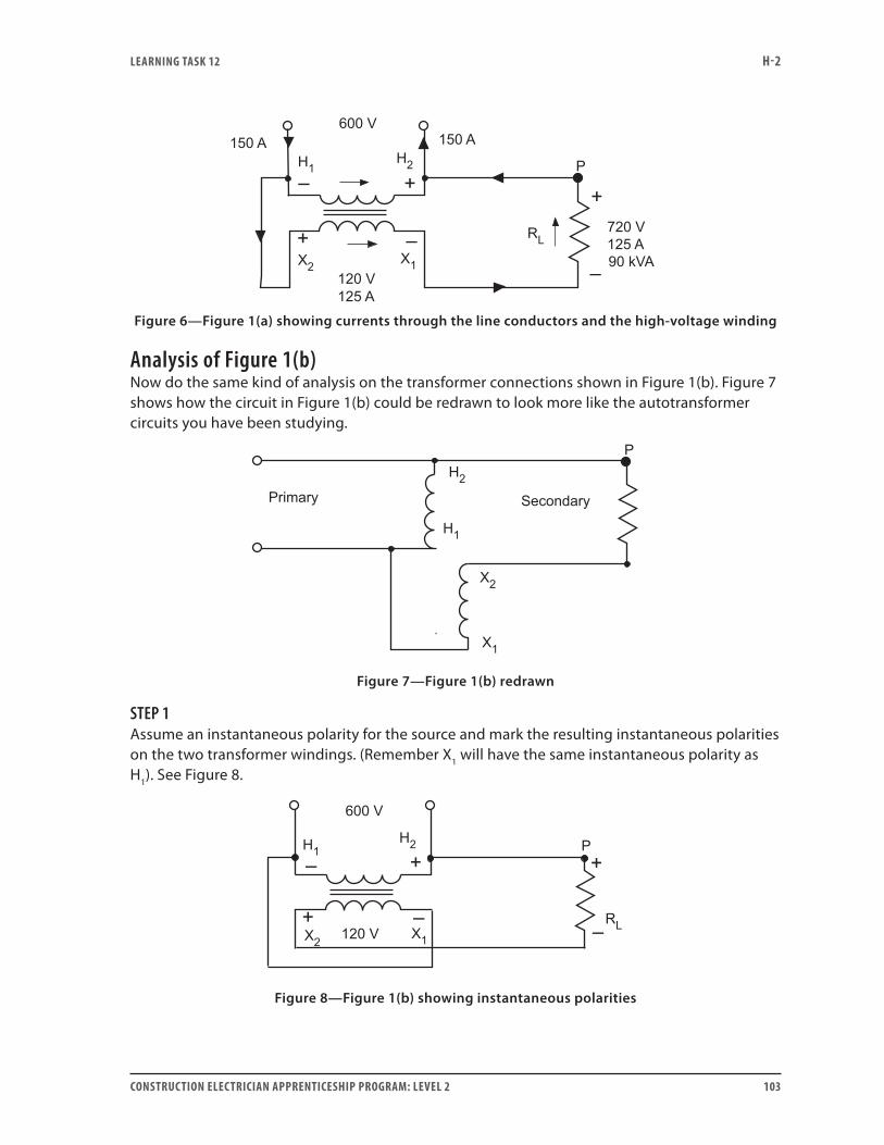
LEARNING TASk 12 H-2
CONSTRUCTION ELECTRICIAN APPRENTICESHIP PROGRAM: LEVEL 2 103
Figure 6—Figure 1(a) showing currents through the line conductors and the high-voltage winding
Analysis of Figure 1(b) Now do the same kind of analysis on the transformer connections shown in Figure 1(b). Figure 7 shows how the circuit in Figure 1(b) could be redrawn to look more like the autotransformer circuits you have been studying.
Figure 7—Figure 1(b) redrawn
STEP 1Assume an instantaneous polarity for the source and mark the resulting instantaneous polarities on the two transformer windings. (Remember X1 will have the same instantaneous polarity as H1). See Figure 8.
Figure 8—Figure 1(b) showing instantaneous polarities
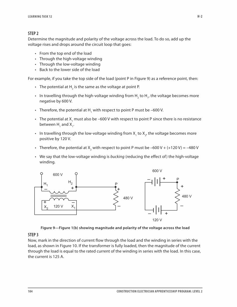
LEARNING TASk 12 H-2
104 CONSTRUCTION ELECTRICIAN APPRENTICESHIP PROGRAM: LEVEL 2
STEP 2Determine the magnitude and polarity of the voltage across the load. To do so, add up the voltage rises and drops around the circuit loop that goes:
• From the top end of the load • Through the high-voltage winding• Through the low-voltage winding• Back to the lower side of the load
For example, if you take the top side of the load (point P in Figure 9) as a reference point, then:
• The potential at H2 is the same as the voltage at point P.
• In travelling through the high-voltage winding from H2 to H1, the voltage becomes more negative by 600 V.
• Therefore, the potential at H1 with respect to point P must be –600 V.
• The potential at X1 must also be –600 V with respect to point P since there is no resistance between H1 and X1.
• In travelling through the low-voltage winding from X1 to X2, the voltage becomes more positive by 120 V.
• Therefore, the potential at X2 with respect to point P must be –600 V + (+120 V) = –480 V
• We say that the low-voltage winding is bucking (reducing the effect of ) the high-voltage winding.
Figure 9—Figure 1(b) showing magnitude and polarity of the voltage across the load
STEP 3Now, mark in the direction of current flow through the load and the winding in series with the load, as shown in Figure 10. If the transformer is fully loaded, then the magnitude of the current through the load is equal to the rated current of the winding in series with the load. In this case, the current is 125 A.
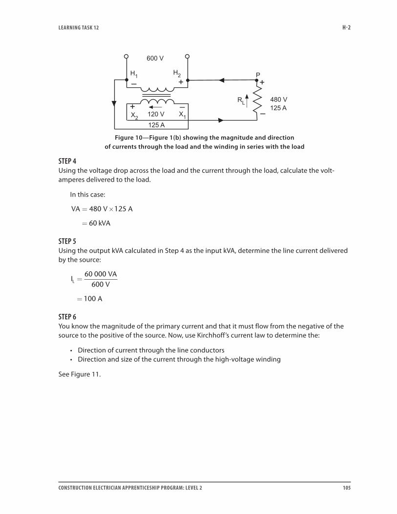
LEARNING TASk 12 H-2
CONSTRUCTION ELECTRICIAN APPRENTICESHIP PROGRAM: LEVEL 2 105
Figure 10—Figure 1(b) showing the magnitude and direction
of currents through the load and the winding in series with the load
STEP 4Using the voltage drop across the load and the current through the load, calculate the volt-amperes delivered to the load.
In this case:
VA V A
kVA
= ×
=
480 125
60
STEP 5Using the output kVA calculated in Step 4 as the input kVA, determine the line current delivered by the source:
IVA
V
A
L =
=
60 000600
100
STEP 6You know the magnitude of the primary current and that it must flow from the negative of the source to the positive of the source. Now, use Kirchhoff’s current law to determine the:
• Direction of current through the line conductors• Direction and size of the current through the high-voltage winding
See Figure 11.
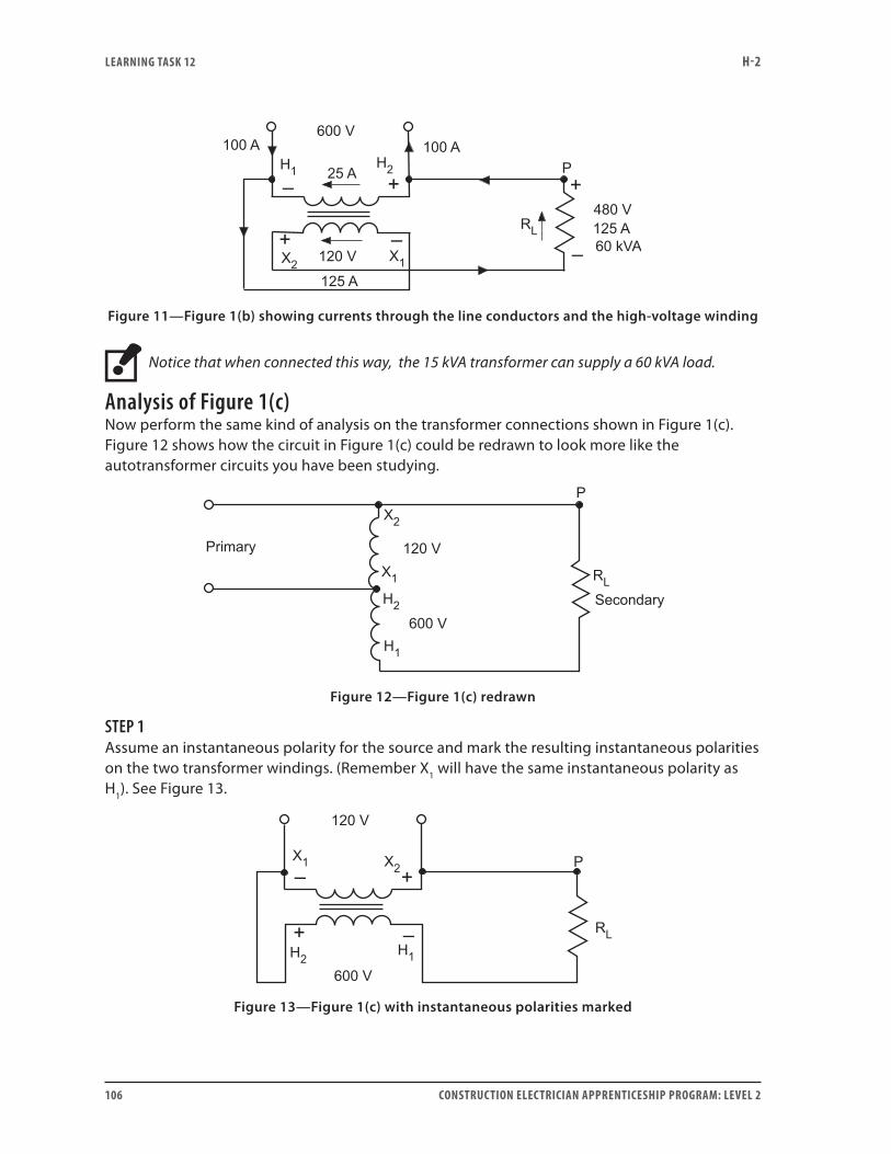
LEARNING TASk 12 H-2
106 CONSTRUCTION ELECTRICIAN APPRENTICESHIP PROGRAM: LEVEL 2
Figure 11—Figure 1(b) showing currents through the line conductors and the high-voltage winding
Notice that when connected this way, the 15 kVA transformer can supply a 60 kVA load.
Analysis of Figure 1(c) Now perform the same kind of analysis on the transformer connections shown in Figure 1(c). Figure 12 shows how the circuit in Figure 1(c) could be redrawn to look more like the autotransformer circuits you have been studying.
Figure 12—Figure 1(c) redrawn
STEP 1Assume an instantaneous polarity for the source and mark the resulting instantaneous polarities on the two transformer windings. (Remember X1 will have the same instantaneous polarity as H1). See Figure 13.
Figure 13—Figure 1(c) with instantaneous polarities marked

LEARNING TASk 12 H-2
CONSTRUCTION ELECTRICIAN APPRENTICESHIP PROGRAM: LEVEL 2 107
STEP 2Determine the magnitude and polarity of the voltage across the load. To do so, add up the voltage rises and drops around the circuit loop that goes:
• From the top end of the load • Through the low-voltage winding• Through the high-voltage winding• Back to the lower side of the load
For example, if you take the top side of the load (point P in Figure 14) as a reference point, then:
• The potential at X2 is the same as the voltage at point P.
• In travelling through the low-voltage winding from X2 to X1, the voltage becomes more negative by 120 V.
• Therefore, the potential at X1 with respect to point P must be –120 V.
• Since there is no resistance between X1 and H2, the potential at H2 must also be –120 V with respect to point P.
• In travelling through the high-voltage winding from H2 to H1, the voltage becomes more positive by 600 V.
• Therefore, the potential at H1 with respect to point P must be –120 V + (–600 V) = –720 V
• The high-voltage winding is boosting the low-voltage winding.
Figure 14—Figure 1(c) showing magnitude and polarity of the voltage across the load
STEP 3Now mark in the direction of current flow through the load and the winding in series with the load, as shown in Figure 15. If the transformer is fully loaded, then the magnitude of the current through the load is equal to the rated current of the winding in series with the load. In this case, the current is 25 A.
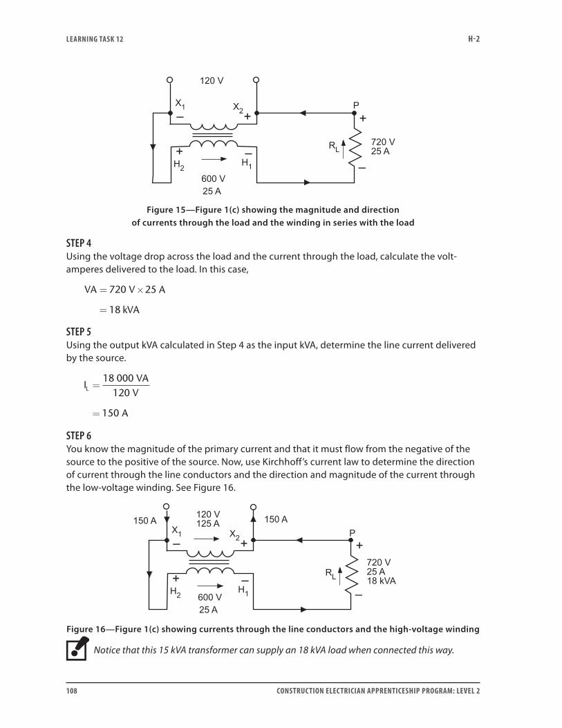
LEARNING TASk 12 H-2
108 CONSTRUCTION ELECTRICIAN APPRENTICESHIP PROGRAM: LEVEL 2
Figure 15—Figure 1(c) showing the magnitude and direction
of currents through the load and the winding in series with the load
STEP 4Using the voltage drop across the load and the current through the load, calculate the volt-amperes delivered to the load. In this case,
VA V A
kVA
= ×
=
720 25
18
STEP 5Using the output kVA calculated in Step 4 as the input kVA, determine the line current delivered by the source.
IVA
V
A
L =
=
18 000120
150
STEP 6You know the magnitude of the primary current and that it must flow from the negative of the source to the positive of the source. Now, use Kirchhoff’s current law to determine the direction of current through the line conductors and the direction and magnitude of the current through the low-voltage winding. See Figure 16.
Figure 16—Figure 1(c) showing currents through the line conductors and the high-voltage winding
Notice that this 15 kVA transformer can supply an 18 kVA load when connected this way.
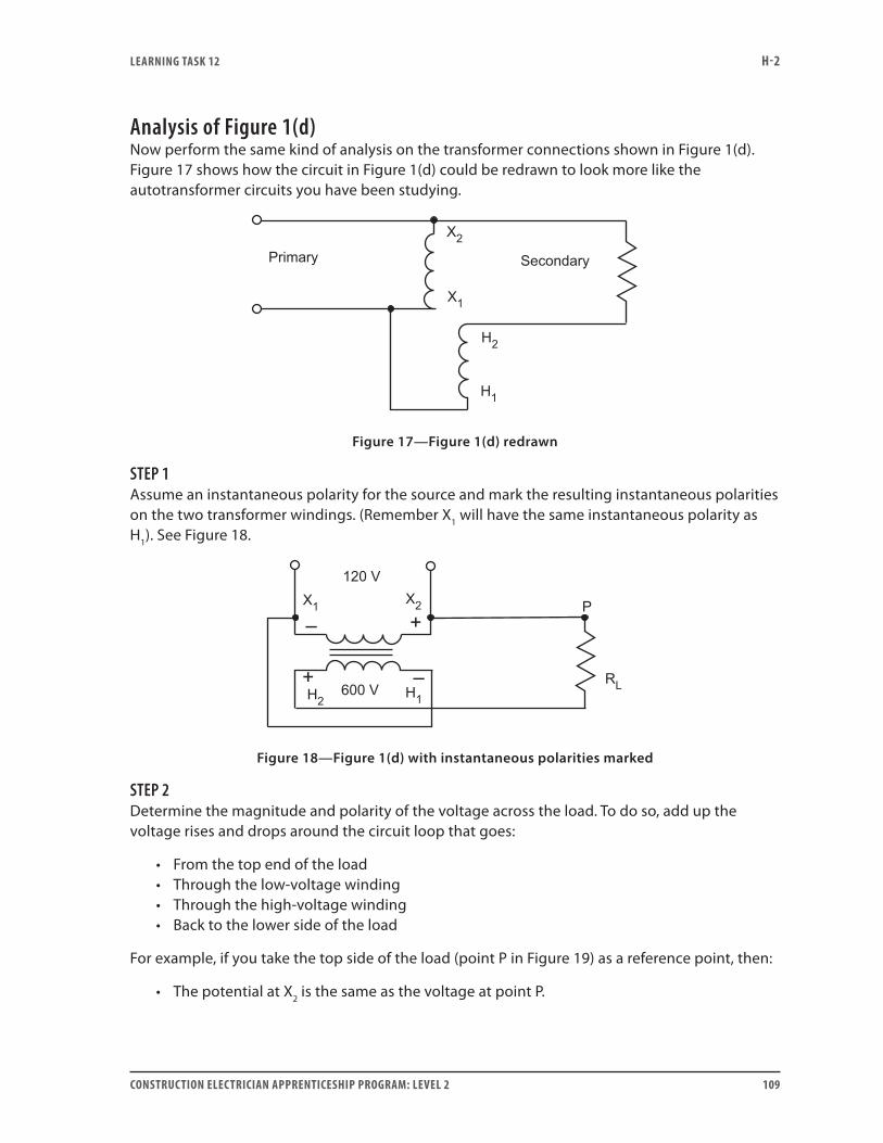
LEARNING TASk 12 H-2
CONSTRUCTION ELECTRICIAN APPRENTICESHIP PROGRAM: LEVEL 2 109
Analysis of Figure 1(d)Now perform the same kind of analysis on the transformer connections shown in Figure 1(d). Figure 17 shows how the circuit in Figure 1(d) could be redrawn to look more like the autotransformer circuits you have been studying.
Figure 17—Figure 1(d) redrawn
STEP 1Assume an instantaneous polarity for the source and mark the resulting instantaneous polarities on the two transformer windings. (Remember X1 will have the same instantaneous polarity as H1). See Figure 18.
Figure 18—Figure 1(d) with instantaneous polarities marked
STEP 2Determine the magnitude and polarity of the voltage across the load. To do so, add up the voltage rises and drops around the circuit loop that goes:
• From the top end of the load • Through the low-voltage winding• Through the high-voltage winding• Back to the lower side of the load
For example, if you take the top side of the load (point P in Figure 19) as a reference point, then:
• The potential at X2 is the same as the voltage at point P.

LEARNING TASk 12 H-2
110 CONSTRUCTION ELECTRICIAN APPRENTICESHIP PROGRAM: LEVEL 2
• In travelling through the low-voltage winding from X2 to X1, the voltage becomes more negative by 120 V.
• Therefore, the potential at X1 with respect to point P must be –120 V.
• Since there is no resistance between X1 and H1, the potential at H1 must also be –120 V with respect to point P.
• In travelling through the high-voltage winding from H1 to H2, the voltage becomes more positive by 600 V.
• Therefore, the potential at H2 with respect to point P must be –120 V + (+600 V) = +480 V
• The high-voltage winding is bucking the low-voltage winding.
Figure 19—Figure 1(d) showing magnitude and polarity of the voltage across the load
STEP 3Now, mark in the direction of current flow through the load and the winding in series with the load, as shown in Figure 20. If the transformer is fully loaded, then the size of the current through the load is equal to the rated current of the winding in series with the load. In this case, It is 25 A.
Figure 20—Figure 1(d) showing the magnitude and direction
of currents through the load and the winding in series with the load

LEARNING TASk 12 H-2
CONSTRUCTION ELECTRICIAN APPRENTICESHIP PROGRAM: LEVEL 2 111
STEP 4Using the voltage drop across the load and the current through the load, calculate the volt-amperes delivered to the load. In this case:
VA V A
kVA
= ×
=
480 25
12
STEP 5Using the output kVA calculated in Step 4 as the input kVA, determine the line current delivered by the source:
IVA
V
A
L =
=
12 000120
100
STEP 6You know the magnitude of the primary current and that it must flow from the negative of the source to the positive of the source. Now, use Kirchhoff’s current law to determine the direction of current through the line conductors and the direction and magnitude of the current through the low-voltage winding. See Figure 21.
Figure 21—Figure 1(d) showing currents through the line conductors and the low-voltage winding
Notice that when connected this way (as shown in Figure 21), this 15 kVA transformer can only supply a 12 kVA load.
Boost/buck voltage regulatorsThis concept of transformer windings bucking and boosting is used to build automatic step-type voltage regulators, as shown in Figure 22 on the next page.
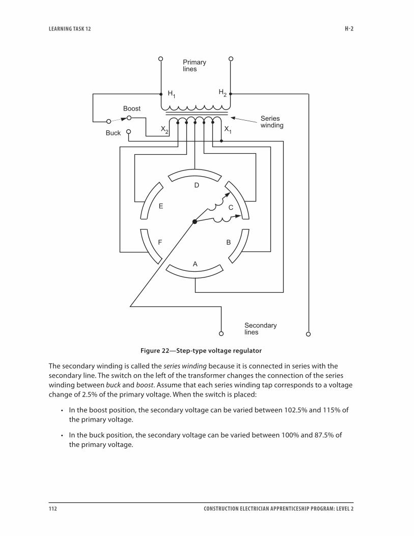
LEARNING TASk 12 H-2
112 CONSTRUCTION ELECTRICIAN APPRENTICESHIP PROGRAM: LEVEL 2
Figure 22—Step-type voltage regulator
The secondary winding is called the series winding because it is connected in series with the secondary line. The switch on the left of the transformer changes the connection of the series winding between buck and boost. Assume that each series winding tap corresponds to a voltage change of 2.5% of the primary voltage. When the switch is placed:
• In the boost position, the secondary voltage can be varied between 102.5% and 115% of the primary voltage.
• In the buck position, the secondary voltage can be varied between 100% and 87.5% of the primary voltage.
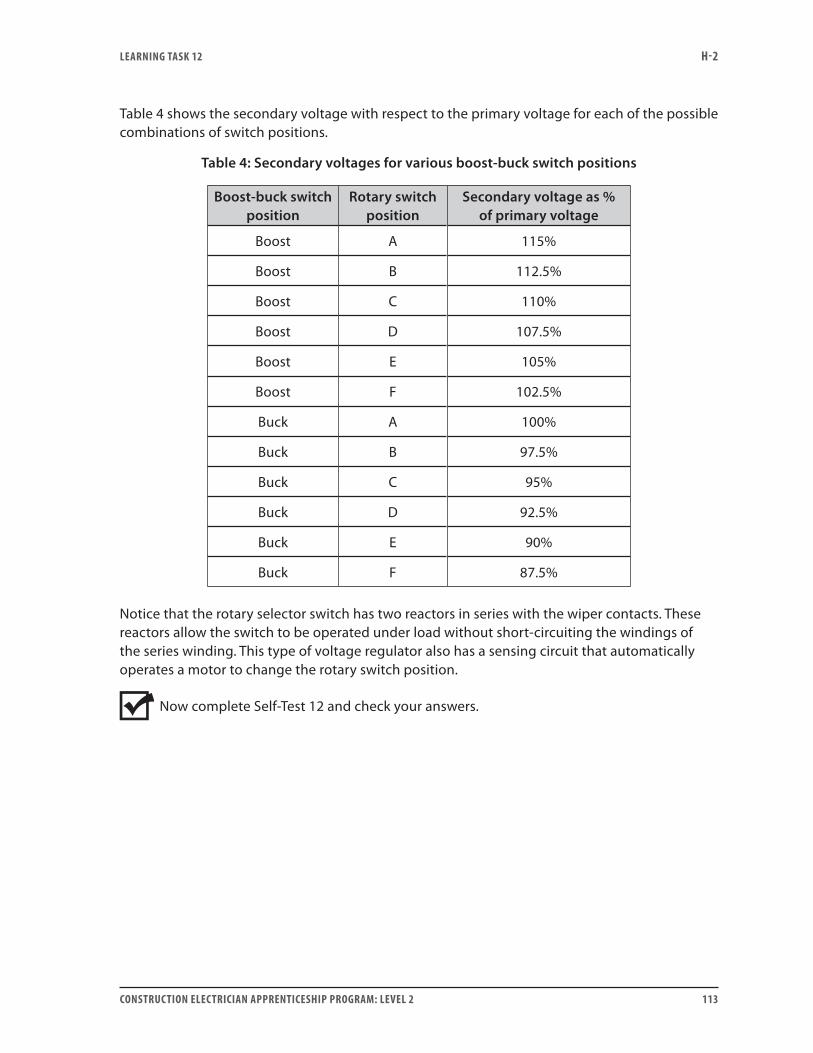
LEARNING TASk 12 H-2
CONSTRUCTION ELECTRICIAN APPRENTICESHIP PROGRAM: LEVEL 2 113
Table 4 shows the secondary voltage with respect to the primary voltage for each of the possible combinations of switch positions.
Table 4: Secondary voltages for various boost-buck switch positions
Boost-buck switch position
Rotary switch position
Secondary voltage as % of primary voltage
Boost A 115%
Boost B 112.5%
Boost C 110%
Boost D 107.5%
Boost E 105%
Boost F 102.5%
Buck A 100%
Buck B 97.5%
Buck C 95%
Buck D 92.5%
Buck E 90%
Buck F 87.5%
Notice that the rotary selector switch has two reactors in series with the wiper contacts. These reactors allow the switch to be operated under load without short-circuiting the windings of the series winding. This type of voltage regulator also has a sensing circuit that automatically operates a motor to change the rotary switch position.
Now complete Self-Test 12 and check your answers.
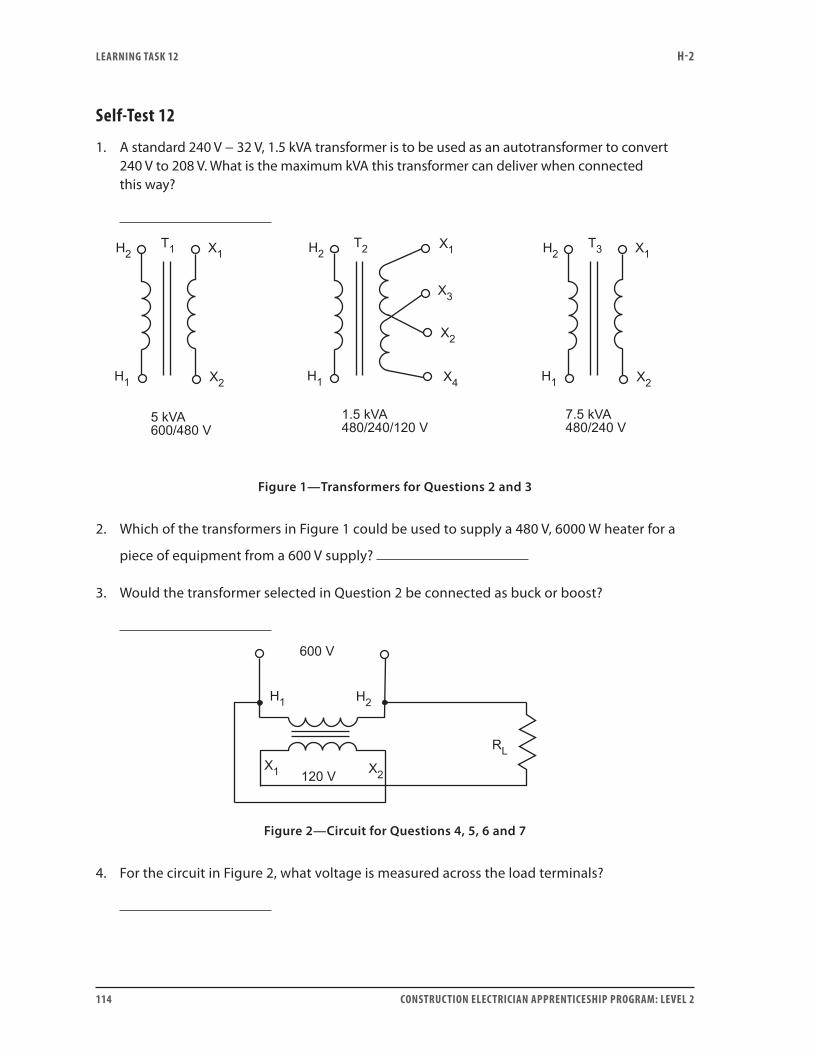
LEARNING TASk 12 H-2
114 CONSTRUCTION ELECTRICIAN APPRENTICESHIP PROGRAM: LEVEL 2
Self-Test 12
1. A standard 240 V − 32 V, 1.5 kVA transformer is to be used as an autotransformer to convert 240 V to 208 V. What is the maximum kVA this transformer can deliver when connected this way?
Figure 1—Transformers for Questions 2 and 3
2. Which of the transformers in Figure 1 could be used to supply a 480 V, 6000 W heater for a
piece of equipment from a 600 V supply?
3. Would the transformer selected in Question 2 be connected as buck or boost?
Figure 2—Circuit for Questions 4, 5, 6 and 7
4. For the circuit in Figure 2, what voltage is measured across the load terminals?
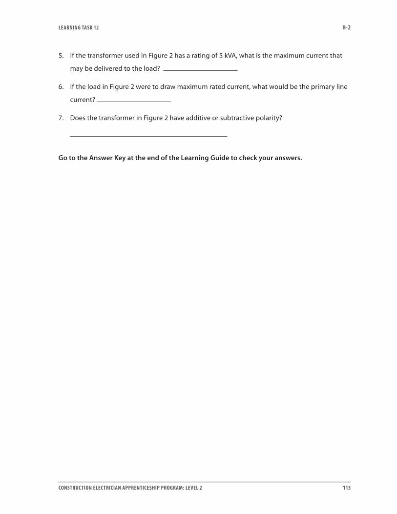
LEARNING TASk 12 H-2
CONSTRUCTION ELECTRICIAN APPRENTICESHIP PROGRAM: LEVEL 2 115
5. If the transformer used in Figure 2 has a rating of 5 kVA, what is the maximum current that
may be delivered to the load?
6. If the load in Figure 2 were to draw maximum rated current, what would be the primary line
current?
7. Does the transformer in Figure 2 have additive or subtractive polarity?
Go to the Answer Key at the end of the Learning Guide to check your answers.

116 CONSTRUCTION ELECTRICIAN APPRENTICESHIP PROGRAM: LEVEL 2
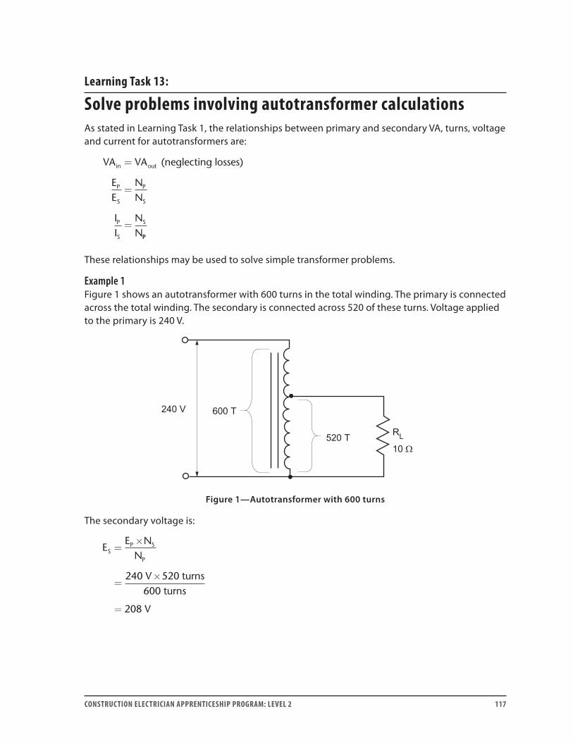
CONSTRUCTION ELECTRICIAN APPRENTICESHIP PROGRAM: LEVEL 2 117
Learning Task 13:
Solve problems involving autotransformer calculationsAs stated in Learning Task 1, the relationships between primary and secondary VA, turns, voltage and current for autotransformers are:
VA VA
EE
NN
II
NN
in out
P
S
P
S
P
S
S
=
=
=
(neglecting losses)
PP
These relationships may be used to solve simple transformer problems.
Example 1Figure 1 shows an autotransformer with 600 turns in the total winding. The primary is connected across the total winding. The secondary is connected across 520 of these turns. Voltage applied to the primary is 240 V.
Figure 1—Autotransformer with 600 turns
The secondary voltage is:
EE N
N
V
V
SP S
P
=×
=×
=
240 520
208
turns600 turns

LEARNING TASk 13 H-2
118 CONSTRUCTION ELECTRICIAN APPRENTICESHIP PROGRAM: LEVEL 2
With 208 V applied across the 10 Ω secondary load, secondary current is:
IER
V
A
SS
S
=
=
=
20810 Ω
208
The primary current is calculated as:
II N
N
A
A
PS S
P
=×
=×
=
208 520
18
turns600 turns
Check to see if the VAin equals the VAout:
VA V A
VA
VA V A
VA
in
out
= ×
=
= ×
=
240 18
4320
208 20 8
4326
.
The small difference is due to rounding error on the 18 A primary current.
Example 2Figure 2 shows the same transformer used as a step-up autotransformer. The transformer is fed from a 208 V source to supply a 10 Ω, 240 V load.
Figure 2—Autotransformer with 600 turns used as a step-up transformer
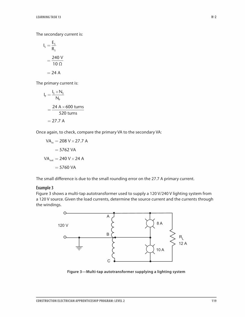
LEARNING TASk 13 H-2
CONSTRUCTION ELECTRICIAN APPRENTICESHIP PROGRAM: LEVEL 2 119
The secondary current is:
IER
V
A
SS
S
=
=
=
24010 Ω
24
The primary current is:
II N
N
A
A
PS S
P
=×
=×
=
24
27 7
600 turns520 turns
.
Once again, to check, compare the primary VA to the secondary VA:
VA V A
VA
VA V A
VA
in
out
= ×
=
= ×
=
208 27 7
5762
240 24
5760
.
The small difference is due to the small rounding error on the 27.7 A primary current.
Example 3Figure 3 shows a multi-tap autotransformer used to supply a 120 V/240 V lighting system from a 120 V source. Given the load currents, determine the source current and the currents through the windings.
Figure 3—Multi-tap autotransformer supplying a lighting system
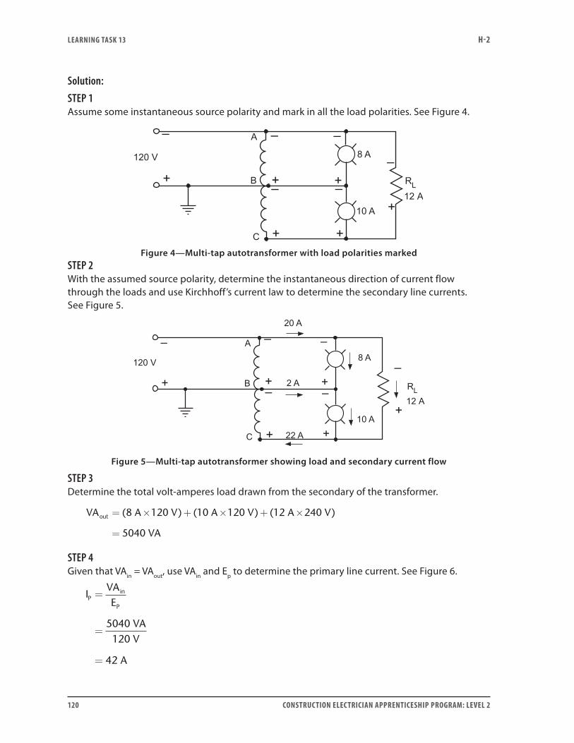
LEARNING TASk 13 H-2
120 CONSTRUCTION ELECTRICIAN APPRENTICESHIP PROGRAM: LEVEL 2
Solution:STEP 1Assume some instantaneous source polarity and mark in all the load polarities. See Figure 4.
Figure 4—Multi-tap autotransformer with load polarities markedSTEP 2With the assumed source polarity, determine the instantaneous direction of current flow through the loads and use Kirchhoff’s current law to determine the secondary line currents. See Figure 5.
Figure 5—Multi-tap autotransformer showing load and secondary current flow
STEP 3Determine the total volt-amperes load drawn from the secondary of the transformer.
VA A V A V A V
VA
out = × + × + ×
=
( ) ( ) ( )8 120 10 120 12 240
5040
STEP 4Given that VAin = VAout, use VAin and Ep to determine the primary line current. See Figure 6.
IVAE
VAV
A
Pin
P
=
=
=
5040120
42
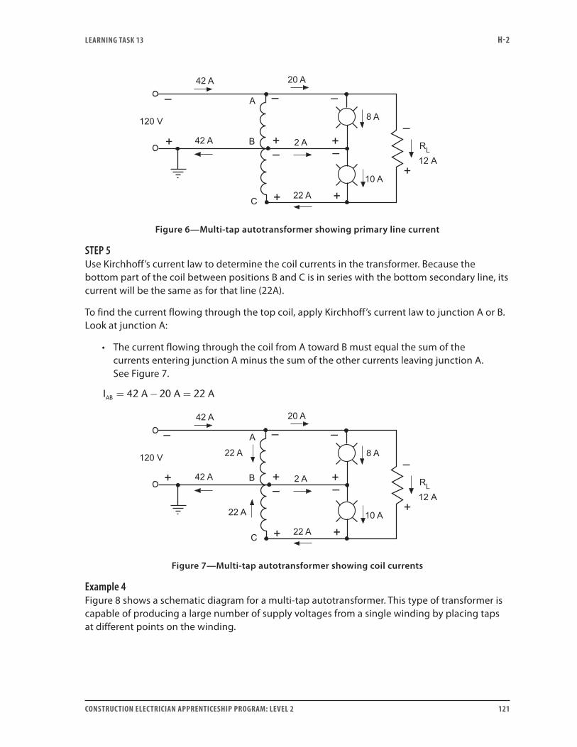
LEARNING TASk 13 H-2
CONSTRUCTION ELECTRICIAN APPRENTICESHIP PROGRAM: LEVEL 2 121
Figure 6—Multi-tap autotransformer showing primary line current
STEP 5Use Kirchhoff’s current law to determine the coil currents in the transformer. Because the bottom part of the coil between positions B and C is in series with the bottom secondary line, its current will be the same as for that line (22A).
To find the current flowing through the top coil, apply Kirchhoff’s current law to junction A or B. Look at junction A:
• The current flowing through the coil from A toward B must equal the sum of the currents entering junction A minus the sum of the other currents leaving junction A. See Figure 7.
I A A AAB = − =42 20 22
Figure 7—Multi-tap autotransformer showing coil currents
Example 4Figure 8 shows a schematic diagram for a multi-tap autotransformer. This type of transformer is capable of producing a large number of supply voltages from a single winding by placing taps at different points on the winding.

LEARNING TASk 13 H-2
122 CONSTRUCTION ELECTRICIAN APPRENTICESHIP PROGRAM: LEVEL 2
Figure 8—Multi-tap autotransformer producing many supply voltages
The easiest way to determine the voltage between any two taps on the transformer in Figure 4 is to first determine the volts per turn for the transformer.
The volts per turn is the source voltage (120 V) divided by the total number of turns between the two points across which the voltage is applied. (In this case, 16 + 16 + 24 + 8 + 16 = 80 turns.)
Volts per turn120 V
80 turns=
= 1 5.
To find the voltage available between any two taps, all you have to do is multiply the volts per turn by the number of turns between the two taps. For example:
EAB = 1.5 V/turn × (20 + 16) = 54 V
ECE = 1.5 V/turn × (24 + 8) = 48 V
EAF = 1.5 V/turn × (20 + 16 + 16 + 24 + 8 + 16) = 150 V
Example 5Figure 9 shows a schematic diagram for a variable autotransformer. This type of transformer allows us to vary the turns ratio between the primary and secondary windings of the transformer. Calculations for this type of transformer are done just as for a fixed-ratio autotransformer.
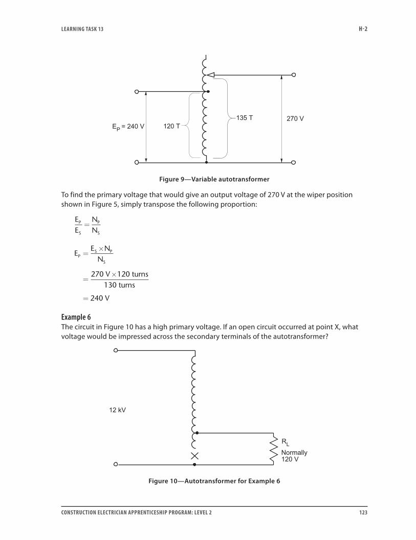
LEARNING TASk 13 H-2
CONSTRUCTION ELECTRICIAN APPRENTICESHIP PROGRAM: LEVEL 2 123
Figure 9—Variable autotransformer
To find the primary voltage that would give an output voltage of 270 V at the wiper position shown in Figure 5, simply transpose the following proportion:
EE
NN
P
S
P
S
=
EE N
N
V
V
PS P
S
=×
=×
=
270
240
120 turns130 turns
Example 6The circuit in Figure 10 has a high primary voltage. If an open circuit occurred at point X, what voltage would be impressed across the secondary terminals of the autotransformer?
Figure 10—Autotransformer for Example 6
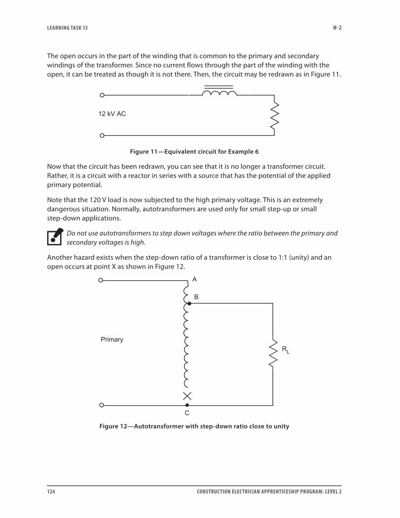
LEARNING TASk 13 H-2
124 CONSTRUCTION ELECTRICIAN APPRENTICESHIP PROGRAM: LEVEL 2
The open occurs in the part of the winding that is common to the primary and secondary windings of the transformer. Since no current flows through the part of the winding with the open, it can be treated as though it is not there. Then, the circuit may be redrawn as in Figure 11.
Figure 11—Equivalent circuit for Example 6
Now that the circuit has been redrawn, you can see that it is no longer a transformer circuit. Rather, it is a circuit with a reactor in series with a source that has the potential of the applied primary potential.
Note that the 120 V load is now subjected to the high primary voltage. This is an extremely dangerous situation. Normally, autotransformers are used only for small step-up or small step-down applications.
Do not use autotransformers to step down voltages where the ratio between the primary and secondary voltages is high.
Another hazard exists when the step-down ratio of a transformer is close to 1:1 (unity) and an open occurs at point X as shown in Figure 12.
Figure 12—Autotransformer with step-down ratio close to unity
LEARNING TASk 13 H-2
CONSTRUCTION ELECTRICIAN APPRENTICESHIP PROGRAM: LEVEL 2 125
If the transformer is heavily loaded:
• A relatively large current still flows through the reactor spanning the windings from A to B.
• This sets up a voltage drop across this series coil.
• The volts per turn in this section of the total transformer winding is also impressed across the portion of the winding from B to C.
• This may result in a voltage across the break that is many times larger than the primary source voltage.
This is extremely hazardous for a maintenance person working live on this transformer.
Now complete Self-Test 13 and check your answers.

LEARNING TASk 13 H-2
126 CONSTRUCTION ELECTRICIAN APPRENTICESHIP PROGRAM: LEVEL 2
Self-Test 13
1. A primary voltage is applied across 500 turns of an autotransformer. The load is connected across 460 turns of the same transformer. Is this a step-up or step-down application?
2. If a primary voltage of 480 V is connected across 400 turns on an autotransformer, how many turns must the load connect across to have a voltage of 277 V across it? Give the answer to
the nearest turn.
3. If a primary voltage of 240 V is applied across 192 turns of an autotransformer, what voltage
would be measured across 120 turns of the same transformer?
4. What is the number of turns in the secondary winding for the autotransformer in Figure 1?
5. What is the volts per turn for the transformer in Figure 1?
Figure 1—Autotransformer for Questions 4 and 5
6. What is the primary voltage for the transformer in Figure 2?
7. What is the volts per turn for the transformer in Figure 2?
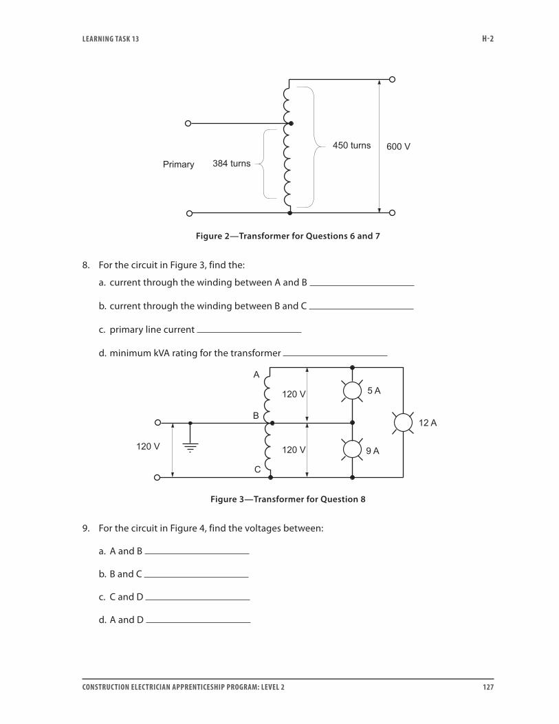
LEARNING TASk 13 H-2
CONSTRUCTION ELECTRICIAN APPRENTICESHIP PROGRAM: LEVEL 2 127
Figure 2—Transformer for Questions 6 and 7
8. For the circuit in Figure 3, find the:
a. current through the winding between A and B
b. current through the winding between B and C
c. primary line current
d. minimum kVA rating for the transformer
Figure 3—Transformer for Question 8
9. For the circuit in Figure 4, find the voltages between:
a. A and B
b. B and C
c. C and D
d. A and D
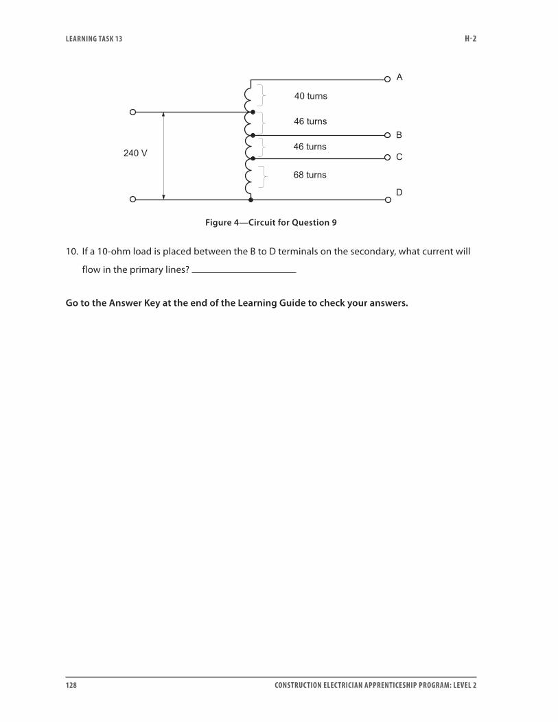
LEARNING TASk 13 H-2
128 CONSTRUCTION ELECTRICIAN APPRENTICESHIP PROGRAM: LEVEL 2
Figure 4—Circuit for Question 9
10. If a 10-ohm load is placed between the B to D terminals on the secondary, what current will
flow in the primary lines?
Go to the Answer Key at the end of the Learning Guide to check your answers.
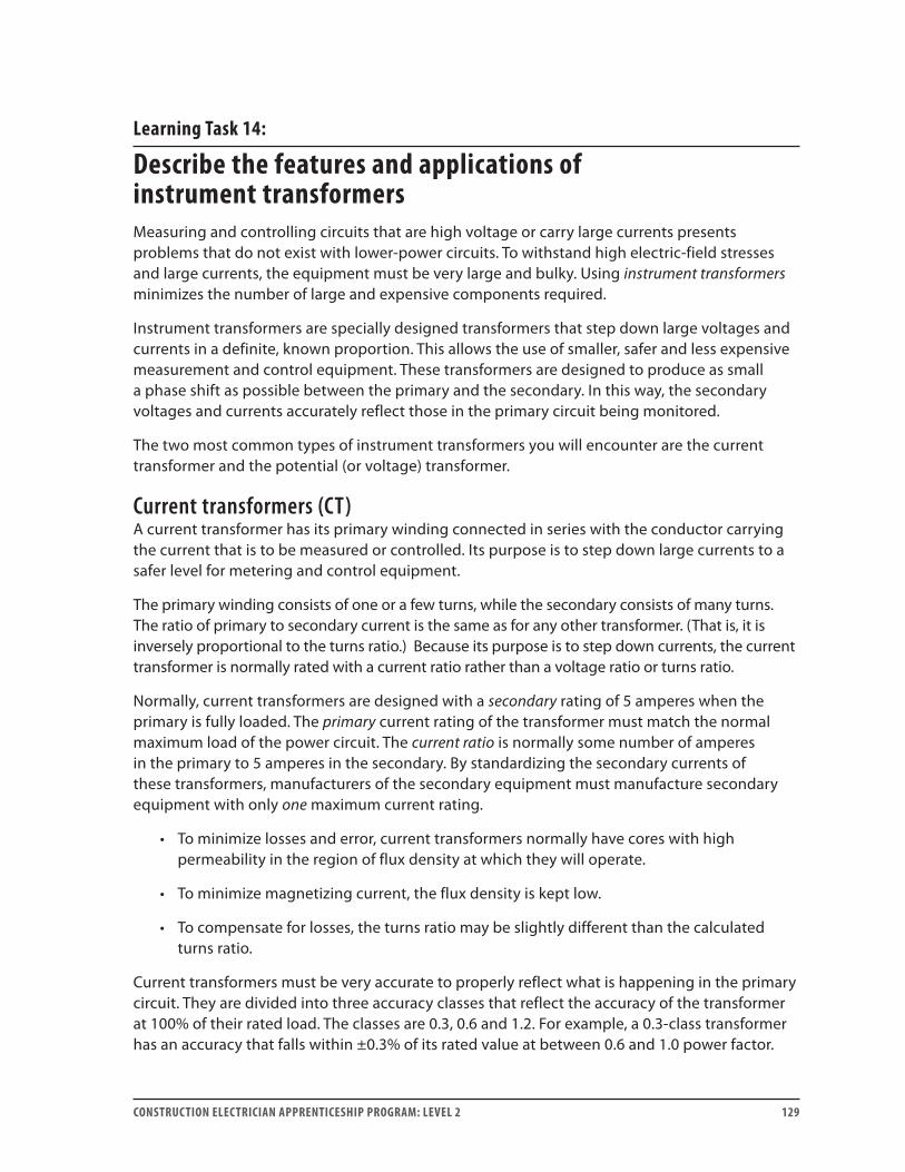
CONSTRUCTION ELECTRICIAN APPRENTICESHIP PROGRAM: LEVEL 2 129
Learning Task 14:
Describe the features and applications of instrument transformersMeasuring and controlling circuits that are high voltage or carry large currents presents problems that do not exist with lower-power circuits. To withstand high electric-field stresses and large currents, the equipment must be very large and bulky. Using instrument transformers minimizes the number of large and expensive components required.
Instrument transformers are specially designed transformers that step down large voltages and currents in a definite, known proportion. This allows the use of smaller, safer and less expensive measurement and control equipment. These transformers are designed to produce as small a phase shift as possible between the primary and the secondary. In this way, the secondary voltages and currents accurately reflect those in the primary circuit being monitored.
The two most common types of instrument transformers you will encounter are the current transformer and the potential (or voltage) transformer.
Current transformers (CT)A current transformer has its primary winding connected in series with the conductor carrying the current that is to be measured or controlled. Its purpose is to step down large currents to a safer level for metering and control equipment.
The primary winding consists of one or a few turns, while the secondary consists of many turns. The ratio of primary to secondary current is the same as for any other transformer. (That is, it is inversely proportional to the turns ratio.) Because its purpose is to step down currents, the current transformer is normally rated with a current ratio rather than a voltage ratio or turns ratio.
Normally, current transformers are designed with a secondary rating of 5 amperes when the primary is fully loaded. The primary current rating of the transformer must match the normal maximum load of the power circuit. The current ratio is normally some number of amperes in the primary to 5 amperes in the secondary. By standardizing the secondary currents of these transformers, manufacturers of the secondary equipment must manufacture secondary equipment with only one maximum current rating.
• To minimize losses and error, current transformers normally have cores with high permeability in the region of flux density at which they will operate.
• To minimize magnetizing current, the flux density is kept low.
• To compensate for losses, the turns ratio may be slightly different than the calculated turns ratio.
Current transformers must be very accurate to properly reflect what is happening in the primary circuit. They are divided into three accuracy classes that reflect the accuracy of the transformer at 100% of their rated load. The classes are 0.3, 0.6 and 1.2. For example, a 0.3-class transformer has an accuracy that falls within ±0.3% of its rated value at between 0.6 and 1.0 power factor.
LEARNING TASk 14 H-2
130 CONSTRUCTION ELECTRICIAN APPRENTICESHIP PROGRAM: LEVEL 2
Current transformers for revenue meters must be in accuracy class 0.3 or 0.6.
Figure 1 shows the schematic symbol for a current transformer.
Figure 1—Schematic symbol for a current transformer
Danger of opening the secondaryIn normal transformers, the secondary current is determined by the load on the secondary. In current transformers, secondary current is determined by the current flowing in the primary.
If the secondary circuit is opened while the primary current is still flowing:
• The off-setting effect of the secondary current is lost and the transformer core is driven hard into saturation.
• Since the primary current goes through current zero 120 times each second, the core flux must collapse 120 times each second.
• As the core flux collapses from saturation to zero flux in an extremely short period, a very high voltage is induced across the secondary winding.
• This voltage is likely in the thousands of volts and is very dangerous to someone working on the secondary circuit.
Figure 2 shows the primary current (IP), core flux (Φ) and secondary induced voltage (ES) for an open-circuited current transformer.
Notice the following:
• The flat top on the flux waveform. This is because the core has become saturated. Any further increase in current results in minimal increase in flux density.
• The steep slope of the flux waveform at the time when the primary current is decreasing. This represents an extremely rapid change in flux in the core of the current transformer.
• The lower graph shows the secondary induced voltage. At the same instant that the flux changes rapidly, a high voltage is induced in the secondary winding.
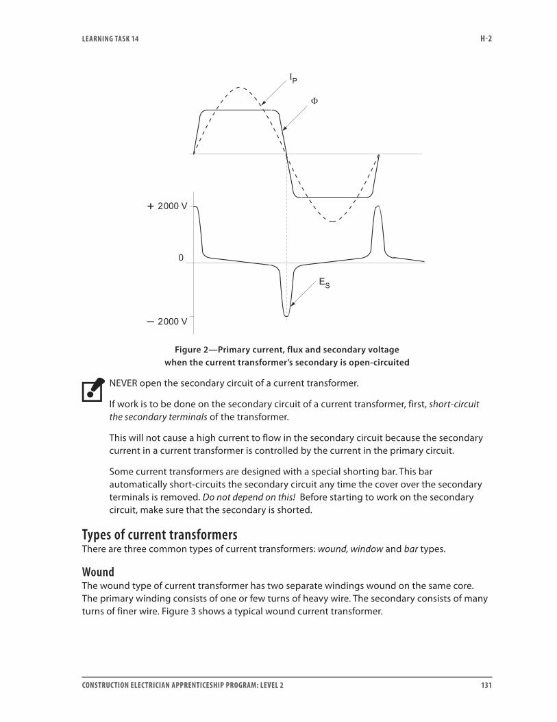
LEARNING TASk 14 H-2
CONSTRUCTION ELECTRICIAN APPRENTICESHIP PROGRAM: LEVEL 2 131
Figure 2—Primary current, flux and secondary voltage when the current transformer’s secondary is open-circuited
NEVER open the secondary circuit of a current transformer.
If work is to be done on the secondary circuit of a current transformer, first, short-circuit the secondary terminals of the transformer.
This will not cause a high current to flow in the secondary circuit because the secondary current in a current transformer is controlled by the current in the primary circuit.
Some current transformers are designed with a special shorting bar. This bar automatically short-circuits the secondary circuit any time the cover over the secondary terminals is removed. Do not depend on this! Before starting to work on the secondary circuit, make sure that the secondary is shorted.
Types of current transformersThere are three common types of current transformers: wound, window and bar types.
WoundThe wound type of current transformer has two separate windings wound on the same core. The primary winding consists of one or few turns of heavy wire. The secondary consists of many turns of finer wire. Figure 3 shows a typical wound current transformer.

LEARNING TASk 14 H-2
132 CONSTRUCTION ELECTRICIAN APPRENTICESHIP PROGRAM: LEVEL 2
Figure 3—Wound type of current transformer
The primary, which is a heavy coil, is connected in series with the primary load so that all the primary current must pass through this winding. All devices in the secondary circuit must be connected in series with the secondary coil so that each device carries the full secondary current.
WindowThe window type of current transformer consists of only a secondary winding wound around a ferromagnetic core. The installer of the transformer provides the primary winding by running the conductor or conductors feeding the load through the window. Clamp-on ammeters, wattmeters and power-factor meters are examples of window-type current transformers. Figure 4 shows typical window-type current transformers.
The window type has the advantage that the turns ratio, and thus the current ratio, may be adjusted. This is done by changing the number of times the primary conductor is coiled through the window. If the primary conductor passes straight through the window, the current ratio is as marked on the transformer. If the primary conductor passes through the transformer more than once, then the current ratio must be reduced by the number of times the primary conductor passes through the window.
Another advantage of the window type of current transformer is that it can be used to sense a difference in current between two conductors. A simple ground-fault-detection circuit works on this principle. You will learn more about this in Learning Task 15.
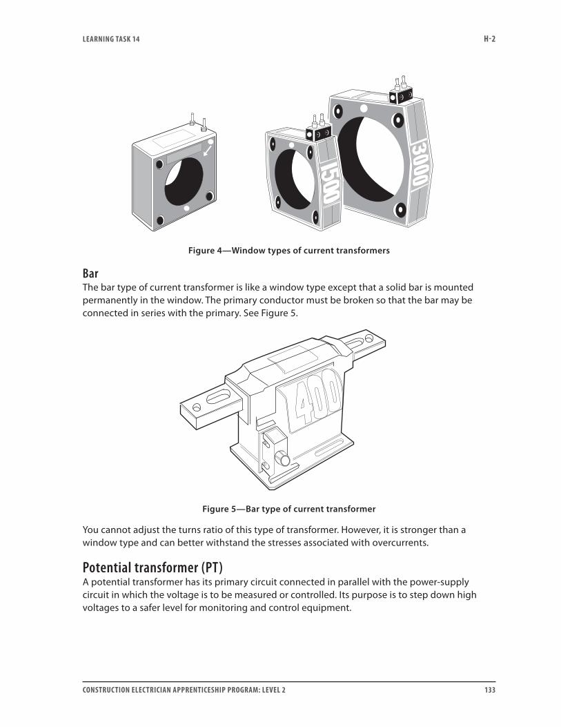
LEARNING TASk 14 H-2
CONSTRUCTION ELECTRICIAN APPRENTICESHIP PROGRAM: LEVEL 2 133
Figure 4—Window types of current transformers
BarThe bar type of current transformer is like a window type except that a solid bar is mounted permanently in the window. The primary conductor must be broken so that the bar may be connected in series with the primary. See Figure 5.
Figure 5—Bar type of current transformer
You cannot adjust the turns ratio of this type of transformer. However, it is stronger than a window type and can better withstand the stresses associated with overcurrents.
Potential transformer (PT)A potential transformer has its primary circuit connected in parallel with the power-supply circuit in which the voltage is to be measured or controlled. Its purpose is to step down high voltages to a safer level for monitoring and control equipment.
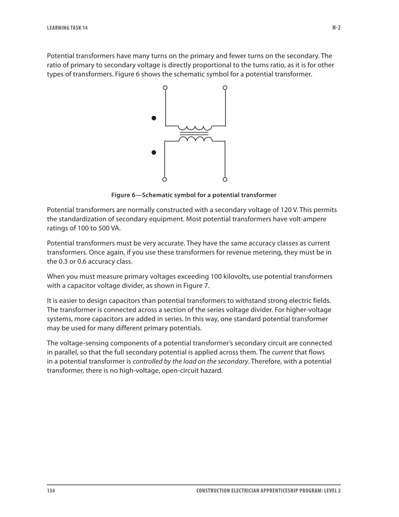
LEARNING TASk 14 H-2
134 CONSTRUCTION ELECTRICIAN APPRENTICESHIP PROGRAM: LEVEL 2
Potential transformers have many turns on the primary and fewer turns on the secondary. The ratio of primary to secondary voltage is directly proportional to the turns ratio, as it is for other types of transformers. Figure 6 shows the schematic symbol for a potential transformer.
Figure 6—Schematic symbol for a potential transformer
Potential transformers are normally constructed with a secondary voltage of 120 V. This permits the standardization of secondary equipment. Most potential transformers have volt-ampere ratings of 100 to 500 VA.
Potential transformers must be very accurate. They have the same accuracy classes as current transformers. Once again, if you use these transformers for revenue metering, they must be in the 0.3 or 0.6 accuracy class.
When you must measure primary voltages exceeding 100 kilovolts, use potential transformers with a capacitor voltage divider, as shown in Figure 7.
It is easier to design capacitors than potential transformers to withstand strong electric fields. The transformer is connected across a section of the series voltage divider. For higher-voltage systems, more capacitors are added in series. In this way, one standard potential transformer may be used for many different primary potentials.
The voltage-sensing components of a potential transformer’s secondary circuit are connected in parallel, so that the full secondary potential is applied across them. The current that flows in a potential transformer is controlled by the load on the secondary. Therefore, with a potential transformer, there is no high-voltage, open-circuit hazard.
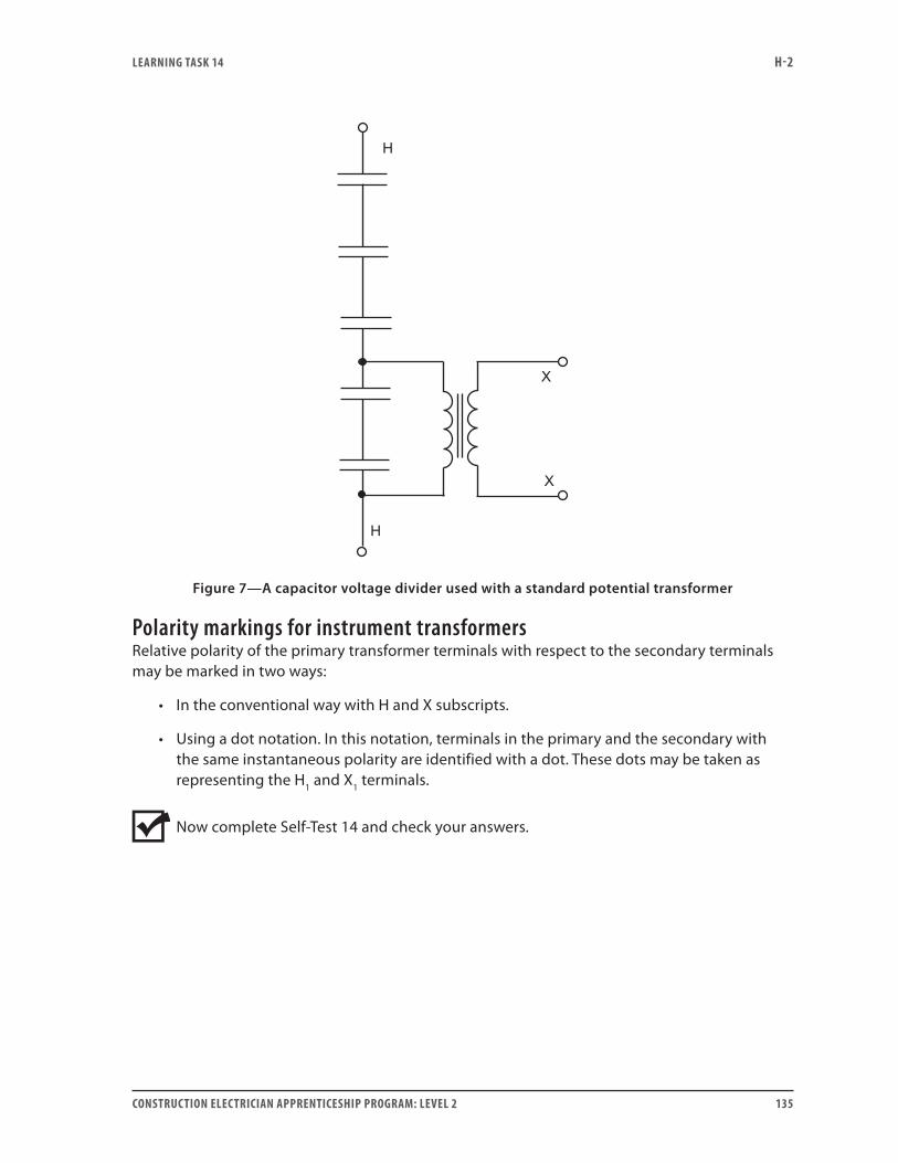
LEARNING TASk 14 H-2
CONSTRUCTION ELECTRICIAN APPRENTICESHIP PROGRAM: LEVEL 2 135
Figure 7—A capacitor voltage divider used with a standard potential transformer
Polarity markings for instrument transformersRelative polarity of the primary transformer terminals with respect to the secondary terminals may be marked in two ways:
• In the conventional way with H and X subscripts.
• Using a dot notation. In this notation, terminals in the primary and the secondary with the same instantaneous polarity are identified with a dot. These dots may be taken as representing the H1 and X1 terminals.
Now complete Self-Test 14 and check your answers.

LEARNING TASk 14 H-2
136 CONSTRUCTION ELECTRICIAN APPRENTICESHIP PROGRAM: LEVEL 2
Self-Test 14
1. What are the two most common types of instrument transformers?
2. How is the primary winding of a current transformer to be connected into the primary circuit?
3. How is the primary winding of a potential transformer to be connected into the primary circuit?
4. What controls the magnitude of the current that flows in the secondary circuit of a current transformer?
5. What controls the magnitude of the current that flows in the secondary circuit of a potential transformer?
6. What hazard must always be considered when working on the secondary circuit of a current transformer?
7. Does this same hazard exist with a potential transformer?
8. List the three common types of current transformers.
LEARNING TASk 14 H-2
CONSTRUCTION ELECTRICIAN APPRENTICESHIP PROGRAM: LEVEL 2 137
9. Why are capacitor voltage dividers normally used with potential transformers to measure primary voltages in excess of 100 kilovolts?
10. In a current transformer, which winding normally has more turns, the primary or the secondary?
11. What is the normal range of the secondary current of a current transformer?
12. What is the normal range of the secondary voltage of a potential transformer?
13. A window type of current transformer is marked with a current ratio of 300 to 5 amperes. If the primary circuit conductor is looped so that it passes through the window twice, what is the current ratio of this current transformer?
14. To what type of current transformer is a clamp-on ammeter similar?
15. In a potential transformer, which winding normally has more turns, the primary or the secondary?
Go to the Answer Key at the end of the Learning Guide to check your answers.

138 CONSTRUCTION ELECTRICIAN APPRENTICESHIP PROGRAM: LEVEL 2
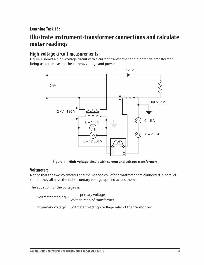
CONSTRUCTION ELECTRICIAN APPRENTICESHIP PROGRAM: LEVEL 2 139
Learning Task 15:
Illustrate instrument-transformer connections and calculate meter readingsHigh-voltage circuit measurementsFigure 1 shows a high-voltage circuit with a current transformer and a potential transformer being used to measure the current, voltage and power.
Figure 1—High-voltage circuit with current and voltage transformers
VoltmetersNotice that the two voltmeters and the voltage coil of the wattmeter are connected in parallel so that they all have the full secondary voltage applied across them.
The equation for the voltages is:
voltmeter readingprimary voltage
voltage ratio=
oof transformer
or primary voltage voltmeter rea= dding voltage ratio of the transformer×
LEARNING TASk 15 H-2
140 CONSTRUCTION ELECTRICIAN APPRENTICESHIP PROGRAM: LEVEL 2
Example 1V1 is a standard 0–150 V voltmeter. To determine the voltage across the primary circuit, multiply the reading on V1 by the voltage ratio of the potential transformer. In this case:
• V1 reads 120 V. • The voltage ratio of the potential transformer is 100:1 (12 000 ÷ 120). • ⸫ actual voltage is 120 × 100 = 12 000 V.
Mechanically and electrically, V2 is identical to V1 except that the scale has been recalibrated to give a direct reading. It will read from 0 to 12 000 V. For this reason, no multiplier is required when reading V2. In this case, V2 reads 12 000 V.
AmmetersNotice that the two ammeters and the current coil of the wattmeter are connected in series, so that each measures the full secondary current.
The equation for the currents is:
ammeter readingprimary current
current ratio of=
transformer
or primary current ammeter reading= ××current ratio of the transformer
Example 2A1 is a standard 0–5 A ammeter. To determine the current flowing in the primary circuit, multiply the reading on A1 by the current ratio of the current transformer. In this case:
• A1 reads 3 A. • The current ratio of the current transformer is 40:1 (200 ÷ 5). • ⸫ actual primary current is 3 × 40 = 120 A.
Mechanically and electrically, A2 is identical to A1 except that the scale has been recalibrated to give a direct reading. It will read from 0 to 200 A. Just as for the direct-reading voltmeter, this ammeter does not require a multiplier. In this case, the direct-reading ammeter reads 120 A.
WattmeterFor simplicity, the load in Figure 1 is purely resistive so that watts equal volt-amperes. Power depends only on the voltage and current, which depend on the voltage and current ratios. The multiplier for the wattmeter is equal to the product of the voltage ratio of the potential transformer and the current ratio of the current transformer.
The equation for power is:
wattmeter readingprimary power
voltage ratio cu=
× rrrentratio
or primary power wattmeter reading v= × ooltage ratio current ratio×

LEARNING TASk 15 H-2
CONSTRUCTION ELECTRICIAN APPRENTICESHIP PROGRAM: LEVEL 2 141
Example 3In this case, using the previous example’s ratios:
• The voltage applied across the voltage coil of the wattmeter is only 1/100 of the primary circuit’s voltage.
• The current flowing through the current coil of the wattmeter is only 1/40 of the current flowing in the primary.
• The wattmeter reads only 1/4000 of the power in the primary (100 × 40 = 4000).
• The wattmeter reads 360 W = 120 V × 3 A.
• True primary power = 360 × 100 × 40 W
= 1 440 000 W
= 12 000 × 120 A.
Wattmeters may have their scales recalibrated to give direct readings.
Overload protection
Figure 2—Overload protection with current transformers
Figure 2(a) shows a motor with a full-load ampacity of 40 A. The heaters and overload relay are small enough that they may be placed directly in series with the motor leads.
Figure 2(b) shows a motor with a full-load ampacity of 200 A. The overload heaters and the associated relay for this kind of current are extremely large and expensive. Therefore, current transformers are installed in their place. Smaller overload heaters having a full-load current of 5 amperes or less are placed in the secondary of the current transformers. The overload relay

LEARNING TASk 15 H-2
142 CONSTRUCTION ELECTRICIAN APPRENTICESHIP PROGRAM: LEVEL 2
does not interrupt the flow of current to the motor. Instead, it interrupts the flow of current to the coil of the magnetic contactor in the control circuit. This causes the magnetic contactor to drop out, opening the main power contacts and stopping the motor.
Example 4Assume 190 A is flowing to the motor in Figure 2(b) and that the current transformer is rated 250:5 amperes. How much current is flowing through the heater elements in the secondary circuit of the transformers?
Solution:The current ratio of the transformers is 50:1, so all we have to do to get the secondary current is divide the primary current by 50:
190 A ÷ 50 = 3.8 A
Ground-fault circuit interruptionFigure 3 shows a current transformer in which both the hot and the neutral conductors pass through the window.
Figure 3—Ground-fault circuit interrupter
Any difference in the current carried by the secondary conductors is sensed by a control circuit. This control circuit opens the circuit-breaker contacts in the primary.
The principle on which a ground-fault circuit interrupter works is as follows:
• If all is well in the circuit, the current flowing in the identified conductor at any instant equals the current flowing in the line conductor. The two conductors pass through the window in such a way that the two currents pass through in opposite directions. Therefore, the two magnetic fields created by the two currents cancel each other. This results in no net magnetic field, and no current is induced in the secondary winding.
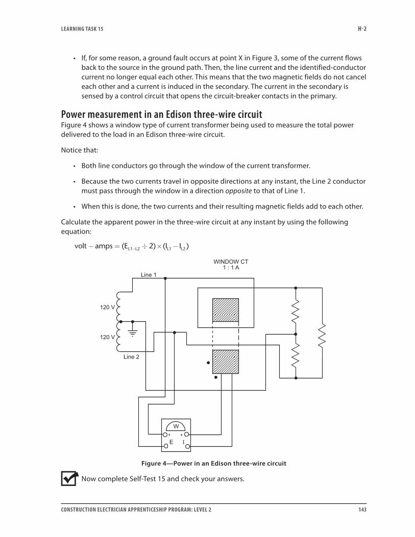
LEARNING TASk 15 H-2
CONSTRUCTION ELECTRICIAN APPRENTICESHIP PROGRAM: LEVEL 2 143
• If, for some reason, a ground fault occurs at point X in Figure 3, some of the current flows back to the source in the ground path. Then, the line current and the identified-conductor current no longer equal each other. This means that the two magnetic fields do not cancel each other and a current is induced in the secondary. The current in the secondary is sensed by a control circuit that opens the circuit-breaker contacts in the primary.
Power measurement in an Edison three-wire circuitFigure 4 shows a window type of current transformer being used to measure the total power delivered to the load in an Edison three-wire circuit.
Notice that:
• Both line conductors go through the window of the current transformer.
• Because the two currents travel in opposite directions at any instant, the Line 2 conductor must pass through the window in a direction opposite to that of Line 1.
• When this is done, the two currents and their resulting magnetic fields add to each other.
Calculate the apparent power in the three-wire circuit at any instant by using the following equation:
volt amps (E 2) (I I )L1 L2 L1 L2− = ÷ × −−
Figure 4—Power in an Edison three-wire circuit
Now complete Self-Test 15 and check your answers.

LEARNING TASk 15 H-2
144 CONSTRUCTION ELECTRICIAN APPRENTICESHIP PROGRAM: LEVEL 2
Self-Test 15Questions 1 to 6 relate to Figure 1.
1. Complete the circuit in Figure 1 to include all of the meters fed from the secondaries of the two instrument transformers.
Figure 1—Partial circuit for Questions 1–6
2. If A1 reads 3.5 A, what is the current flowing in the primary circuit?
3. If V1 reads 118 V, what is the primary voltage?
4. If the load has a power factor of 90%, what is the true power delivered to the load?
5. What power does the wattmeter read?
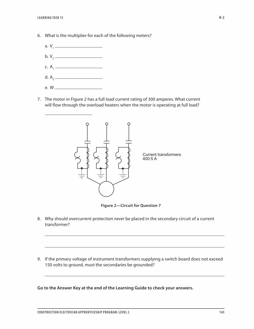
LEARNING TASk 15 H-2
CONSTRUCTION ELECTRICIAN APPRENTICESHIP PROGRAM: LEVEL 2 145
6. What is the multiplier for each of the following meters?
a. V1
b. V2
c. A1
d. A2
e. W
7. The motor in Figure 2 has a full load current rating of 300 amperes. What current will flow through the overload heaters when the motor is operating at full load?
Figure 2—Circuit for Question 7
8. Why should overcurrent protection never be placed in the secondary circuit of a current transformer?
9. If the primary voltage of instrument transformers supplying a switch board does not exceed 150 volts to ground, must the secondaries be grounded?
Go to the Answer Key at the end of the Learning Guide to check your answers.
ANSwER kEY H-2
146 CONSTRUCTION ELECTRICIAN APPRENTICESHIP PROGRAM: LEVEL 2
Answer keySelf-Test 11. mutual induction
2. expands
3. primary
4. 96%, 99%
5. EE
NN
P
S
P
S
=
6. II
NN
P
S
S
P
=
7. 100 V
8. step-down
9. 1.67 A
10. 4.17 A
Self-Test 21. 1.33 V/turn
2. 450 turns
3. 1.2 Ω
4. 24 V
5:1
5. 4800 V
6. a. 1.14 V/turn
b. 105 turns
7. 250 A

ANSwER kEY H-2
CONSTRUCTION ELECTRICIAN APPRENTICESHIP PROGRAM: LEVEL 2 147
Self-Test 31. The purpose of the ferromagnetic core is to concentrate the flux lines to maximize flux
linkage.
2. The high-voltage winding is made up of many turns of fine wire and the low-voltage winding is made up of fewer turns of thicker wire.
3. low retentivity, high permeability, high resistance
4. The core is laminated to reduce the eddy-current losses.
5. the high-voltage winding
6. H
7. X
Self-Test 41. autotransformer
2. current
3. distribution
4. power
5. signal
Self-Test 51. X1
2. additive
3. subtractive
4. additive
5. additive
6. subtractive
ANSwER kEY H-2
148 CONSTRUCTION ELECTRICIAN APPRENTICESHIP PROGRAM: LEVEL 2
7. The high-voltage bushings are longer than the low-voltage bushings.
8. X2
Self-Test 61. 417 A
2. 104 A
3. 240 V
4. 25 kVA
5. series
6. parallel
7. 8:1
8. If you do not observe correct polarity, there will be large short-circuit currents between the transformers, which can damage the equipment.
9. • The transformers must have the same primary and secondary voltage ratings.
• The terminal polarity of the transformers must be observed when the connections are being made.
• The transformers must all have the same percent impedance.
10. Circulating currents cause heating of the core and windings, causing the transformer windings to be overloaded before it supplies rated load. The heat damages the insulation.
11. The terminal voltage drops as the transformer is loaded, due to the voltage drop across the internal impedance of the transformer. IZ increases as I increases.
12. a. yes
b. yes, provided that the proper polarity is observed when the connections are made
13. The transformer with the lowest percent impedance will carry more than its share of the load.
14. zero volts
15. When the primary disconnect for one transformer is opened, the transformer may still be energized by the secondary bus. This is due to energy being “fed back” to the first transformer from a second, parallel transformer that still has its primary disconnect closed.

ANSwER kEY H-2
CONSTRUCTION ELECTRICIAN APPRENTICESHIP PROGRAM: LEVEL 2 149
16. Figure 1b is improperly connected for parallel operation.
17. No. There is still the possibility of back-feed. Open the primary disconnect to make sure the transformer is de-energized, then test with a voltmeter across the load side of the primary disconnect.
18. a. no
b. yes
c. no
Self-Test 71. eddy-current losses, hysteresis losses
2. no
3. primary I2R losses, secondary I2R losses
4. yes
5. open-circuit test
6. short-circuit test
7. The wattmeter reading would be higher because of the power dissipated by the voltmeter.
8. ηθ
θ=
× ×× × + +
E IE I core losses
S S
S S
coscos copper losses
××
=× ×
× × + + +
100
2 2
E IE I I R I R
S S
S S P P S S
coscos
θ
θ core lossses×100
9. as heat
10. to reduce eddy-current losses
11. a. 15 kVA
b. 15 kVA
12. a. 62.5 A
b. 125 A
13. 17 448 A
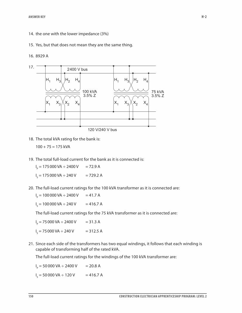
ANSwER kEY H-2
150 CONSTRUCTION ELECTRICIAN APPRENTICESHIP PROGRAM: LEVEL 2
14. the one with the lower impedance (3%)
15. Yes, but that does not mean they are the same thing.
16. 8929 A
17.
18. The total kVA rating for the bank is:
100 + 75 = 175 kVA
19. The total full-load current for the bank as it is connected is:
IP = 175 000 VA ÷ 2400 V = 72.9 A
IS = 175 000 VA ÷ 240 V = 729.2 A
20. The full-load current ratings for the 100 kVA transformer as it is connected are:
IP = 100 000 VA ÷ 2400 V = 41.7 A
IS = 100 000 VA ÷ 240 V = 416.7 A
The full-load current ratings for the 75 kVA transformer as it is connected are:
IP = 75 000 VA ÷ 2400 V = 31.3 A
IS = 75 000 VA ÷ 240 V = 312.5 A
21. Since each side of the transformers has two equal windings, it follows that each winding is capable of transforming half of the rated kVA.
The full-load current ratings for the windings of the 100 kVA transformer are:
IP = 50 000 VA ÷ 2400 V = 20.8 A
IS = 50 000 VA ÷ 120 V = 416.7 A
ANSwER kEY H-2
CONSTRUCTION ELECTRICIAN APPRENTICESHIP PROGRAM: LEVEL 2 151
The full-load current ratings for the windings of the 75 kVA transformer are:
IP = 37 500 VA ÷ 2400 V = 15.6 A
IS = 37 500 VA ÷ 120 V = 312.5 A
22. The available fault current from the 100 kVA transformer as it is connected is:
II%Zshort circuitfull load=
=
=
416 70 035
11906
..
A
A
The available fault current from the 75 kVA transformer as it is connected is:
I312.5 A0.035short circuit =
= 8929 A
23. The available fault current from the bank of transformers as it is connected is:
I 11906 A 8929 A 20 835 Ashort circuit = + =
To check the answer, calculate it another way by dividing the full-load current for the whole bank by the percent impedance:
I729.2 A0.035short circuit =
= 20 834 A
The tiny difference between the two values is due to rounding error.
Self-Test 81. Percent voltage regulation is the change in secondary terminal voltage that occurs from no-
load to full-load, expressed as a percentage of full-load voltage.
2. percent voltage regulation=−
×V V
Vno load full load
full load
100%
3. yes
4. 25%
5. yes

ANSwER kEY H-2
152 CONSTRUCTION ELECTRICIAN APPRENTICESHIP PROGRAM: LEVEL 2
6. 127.2 V
7. 346.7 V
If the no-load voltage is 5% higher than the full-load voltage, then:
∴
Vno load full load
full load
1.05 V
V364 V1.05
= ×
=
= 3466 7. V
8. Since no current is flowing, there can be no IR drops or IX drops.
9. b. leads the secondary load current by 90°
10. yes
Self-Test 91. A no-load tap changer is to be used only when the circuit (primary and secondary) is totally
de-energized. The on-load tap changer is designed to be used on an energized circuit without interrupting the flow of power to the load.
2. The on-load tap changer never opens the circuit.
3. The reactor prevents the short-circuiting of the windings while the switching is taking place.
4. The reactor is centre-tapped. Once the switching is complete, both ends of the reactor are connected to the same point. The current flowing through one end of the reactor is in a direction such that its flux cancels the flux created by the current flowing in the other end of the reactor. With the two fluxes cancelling each other, the reactor has no net inductive reactance.
5. The on-load tap changer is generally many times more expensive because it has more parts.
Self-Test 101. 22:1
2. 20.9:1
3. 97.5% tap
4. 13 192 V
ANSwER kEY H-2
CONSTRUCTION ELECTRICIAN APPRENTICESHIP PROGRAM: LEVEL 2 153
5. 606 V
6. B to E. Jumpering A to D or C to F would also give 95% but it would create unequal stresses on the windings, which could be dangerous in the case of a fault current.
7. 27.5:1
8. 26.125:1
9. 12 540 V
10. The primary circuit would be incomplete and no current would flow in either the primary or the secondary circuit.
Self-Test 111. a. The secondary winding is part of the primary winding.
2. No. Autotransformers have an electrically conductive link between the primary and secondary windings.
3. The primary VA equals the secondary VA, neglecting the small losses.
4. EE
NN
P
S
P
S
=
5. II
NN
P
S
S
P
=
6. The arrow represents the movable wiper.
7. The standard, dual-winding transformer contains more copper.
Self-Test 121. 9.75 kVA
2. transformer T2
3. boost
4. 720 V
5. 41.7 A
6. 50 A
7. subtractive polarity
ANSwER kEY H-2
154 CONSTRUCTION ELECTRICIAN APPRENTICESHIP PROGRAM: LEVEL 2
Self-Test 131. step-down application
2. 231 turns
3. 150 V
4. 350 turns
5. 1.2 volts per turn
6. 512 V
7. 1.33 volts per turn
8. a. 17 A
b. 17 A
c. 38 A
d. 2.04 kVA
9. a. 129 V
b. 69 V
c. 102 V
d. 300 V
10. 12.2 A
Self-Test 141. potential transformers and current transformers
2. in series with the conductor through which the current to be measured is flowing
3. in parallel with the supply
4. the current that flows through the primary
5. the load connected to the secondary of the transformer
6. An open in the secondary circuit will cause a high voltage to be induced in the secondary.
7. no

ANSwER kEY H-2
CONSTRUCTION ELECTRICIAN APPRENTICESHIP PROGRAM: LEVEL 2 155
8. Window, bar, wound
9. It is easier and less expensive to design capacitors to withstand the strong electrostatic fields than it is to design transformers.
10. the secondary
11. 0 to 5 amperes
12. 0 to 120 volts
13. 150 to 5 amperes
14. the window type
15. the primary
Self-Test 151. See Figure 1.
Figure 1—Completed circuit for Question 1
2. 70 A
3. 4720 V
ANSwER kEY H-2
156 CONSTRUCTION ELECTRICIAN APPRENTICESHIP PROGRAM: LEVEL 2
4. 297.36 kW
5. 371.7 W
6. a. 40
b. 1
c. 20
d. 1
e. 800
7. 3.75 A
8. A fuse blowing would cause a dangerous open-circuit voltage to be induced in the secondary circuit.
9. Yes, because it is supplying a switch board.


7960003595
ISBN 978-0-7726-6811-0
9 780772 668110