construction manual by h. wendt · contruction manual euzebox diy kit – rev b euzebox diy kit...
TRANSCRIPT

Contruction manual EUzebox DIY kit – Rev B
EUzebox DIY kit
construction manual
by
H. Wendt
Rev. Date Description
A 2011-07-05 First release
B 2011-07-28 Spelling corrections on page 2Bug fix on page 10: new reference for 1,5K resistors
1 of 24

Contruction manual EUzebox DIY kit – Rev B
You need the following tools:
a regulated soldering iron (25..40W) with small tip
a wet sponge to clean the tip
thin solder wire
a diagonal cutter for wires
Needle nose pliers
2 of 24

Contruction manual EUzebox DIY kit – Rev B
A basic multimeter is not required but recommend
3 of 24

Contruction manual EUzebox DIY kit – Rev B
Bag 1 - Power Supply
1xPower socket
(S1)
1xBridge rectifier
(BR1)
1xelectrolytic capacitor
470uF / 25V(C2)
1xcapacitor
100nF(C4)
1x5V voltage regulator
7805(IC2)
1xLED red, 3mm
(D1)
brown, black, black, brown, brown
1xelectrolytic capacitor
10uF / 10V(C5)
1xresistor 1k / 1%
(R7)
1xM3 screw, 8mm
4 of 24

Contruction manual EUzebox DIY kit – Rev B
1xM3 hexagon nut
5 of 24

Contruction manual EUzebox DIY kit – Rev B
1.) assemble the power socket (S1) and bridge rectifier (BR1)
2.) assemble the condensators (C2, C4, C5)
6 of 24

Contruction manual EUzebox DIY kit – Rev B
3.) assemble the voltage regulator 7805 (IC2)
3.1 bend the connector pins 90° with a tong3.2 mount the voltage regulator with scew and nut3.3 solder the voltage regulator
4.) assemble the LED (D1) and 1K resistor (R7)
7 of 24
K

Contruction manual EUzebox DIY kit – Rev B
5.) Check the function of 5V power supply
5.1 connect a 9V power supply to S15.2 measure the out voltageof IC2:
5.3 check the function of the red LED D1:
5.4 disconnect the external power supply!
8 of 24
5.0V
+ -
Contruction manual EUzebox DIY kit – Rev B
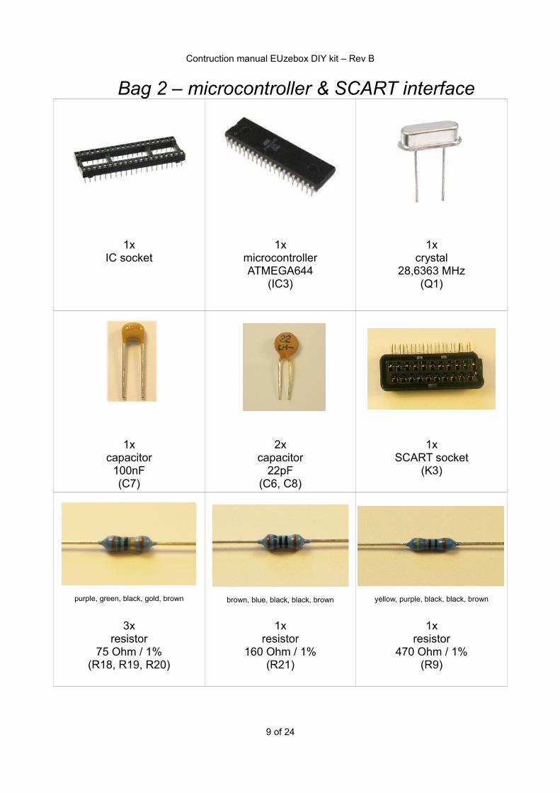
Bag 2 – microcontroller & SCART interface
1xIC socket
1xmicrocontrollerATMEGA644
(IC3)
1xcrystal
28,6363 MHz(Q1)
1xcapacitor
100nF(C7)
2xcapacitor
22pF(C6, C8)
1xSCART socket
(K3)
purple, green, black, gold, brown brown, blue, black, black, brown yellow, purple, black, black, brown
3xresistor
75 Ohm / 1%(R18, R19, R20)
1xresistor
160 Ohm / 1%(R21)
1xresistor
470 Ohm / 1%(R9)
9 of 24

Contruction manual EUzebox DIY kit – Rev B
purple, green, black, black, brown brown, green, black, brown, brown Orange, black, black, brown, brown
3xresistor
750 Ohm / 1%(R10, R13, R16)
3xresistor
1,5K / 1%(R11, R14, R17)
2xresistor3K / 1%
(R12, R15)
10 of 24

Contruction manual EUzebox DIY kit – Rev B
6.) assemble the IC socket
7.) Assemble the crystal (Q1) and capacitors (C6, C7, C8)
11 of 24
nose

Contruction manual EUzebox DIY kit – Rev B
8.) assemble the 160Ohm resistor (R21)
9.) assemble the 470Ohm resistor (R9)
12 of 24

Contruction manual EUzebox DIY kit – Rev B
10.) assemble the 3K resistors (R12, R15)
11.) assemble the 1,5K resistors (R11 R14, R17)
13 of 24

Contruction manual EUzebox DIY kit – Rev B
12.) assemble the 750Ohm resistors (R10, R13, R16)
13.) assemble the 75Ohm resistors (R18, R19, R20)
14 of 24
Contruction manual EUzebox DIY kit – Rev B
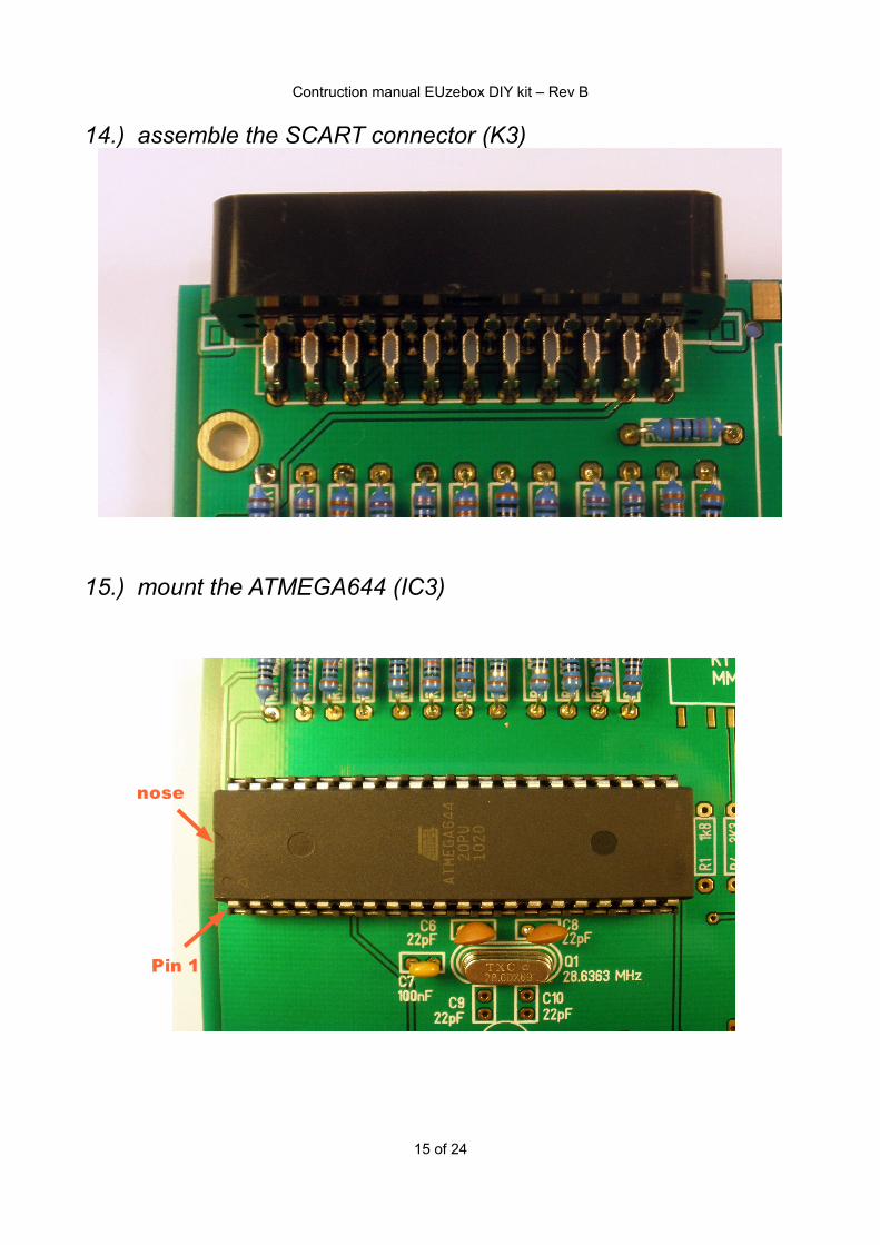
14.) assemble the SCART connector (K3)
15.) mount the ATMEGA644 (IC3)
15 of 24
Pin 1
nose

Contruction manual EUzebox DIY kit – Rev B
16.) Check the video interface
16.1 connect the 9V power supply to S116.2 connect a SCART cable between K3 and the TV set16.3 you should see this picture on your TV set
16.4 disconnect the power supply!!!
16 of 24

Contruction manual EUzebox DIY kit – Rev B
Bag 3 – SD card interface & SNES sockets
1xSD card connector
(K1)
1xISP header
(K2)
1xreset button
(S2)
GND VIN VOUT
1xcapacitor
100nF(C1)
1xelectrolytic capacitor
1uF / 63V(C3)
1x3,3V low drop voltage
regulatorMCP1702-3302E
(IC1)
brown, grey, black, brown, brown orange, orange, black, brown, brownbrown, black, black, red, brown
3xresistor
1,8k / 1%(R1, R2, R3)
3xresistor
3,3k / 1%(R4, R5, R6)
1xresistor 10k / 1%
(R8)
17 of 24

Contruction manual EUzebox DIY kit – Rev B
2xSNES gamepad socket
(X1, X2)
18 of 24

Contruction manual EUzebox DIY kit – Rev B
17.)Assemble ISP header (K2) and 10k resistor (R8)
18.) Assemble reset button (S2)
19 of 24

Contruction manual EUzebox DIY kit – Rev B
19.)Assemble SD card socket (K1)
Don't forget to solder the fixing pins at backside:
20 of 24
c
c

Contruction manual EUzebox DIY kit – Rev B
20.) Assemble the 3,3V power supply (C1, C3, IC1)
21.)Assemble the 3,3K resistors (R4, R5, R6)
21 of 24
3. 2. 1.

Contruction manual EUzebox DIY kit – Rev B
22.)Assemble the 1,8k resistors (R1, R2, R3)
23.) Assemble the SNES gamepad sockets (X1, X2)
Attention. If you want to mount the PCB in a Hammond case then you have to plug the connectors
through the frontplate before soldering!
22 of 24

Contruction manual EUzebox DIY kit – Rev B
24.) Check the function of the EUzebox
24.1 connect the 9V power supply to S124.2 connect a SCART cable between K3 and the TV set24.3 connect a SNES gamepad to X2 (left socket)24.4 you should now see this picture on your TV set
24.5 try to move the arrow with the up/down buttons24.6 select 1 Player and press button A
Congratulation – your Euzebox works!
23 of 24

Contruction manual EUzebox DIY kit – Rev B
Trouble shooting:
Problem SolutionLED D1 don't shine - check the output voltage of your power supply
(9..12V AC or DC)- check the output of IC2 with the multimeter (4.9V to 5.1V is ok)- check the direction of the LED
No picture - check the direction of mounted IC3- check the soldering of Q1, C6 C8- check the soldering of all resistor of SCART interface- TV set is switched to the SCART input?- SCART input is full assembled?- try another TV set
Picture with wrong colors
- check the soldering of SCART connector - check the soldering of all resistor of SCART interface- check SCART interface of short circuits
SD card don't work - measure the output voltage of IC1 (measure the voltage between Pin3 and 4 of K1 – 3,3V required)- check the soldering of K1- try other SD cards- format the SD card again with FAT16
No sound - check the soldering of R9
24 of 24