construction manual of prefabricated timber house - itto
TRANSCRIPT

FRIM Technical Information Handbook No. 5
CONSTRUCTION MANUAL OF PREFABRICATED TIMBER HOUSE
by
Mohd Shukari Midon Chu Vue Pun Hilmi Md Tahir
Nor Azian Mohd Kasby
ITTO

--------_._---------

FRIM Technical Information Handbook No. 5
CONSTRUCTION MANUAL OF PREFABRICATED TIMBER HOUSE
by
Mohd Shukari Midon Chu Vue Pun
Hilmi Md Tahir Nor Azian Mohd Kasby
Manual produced under the project "Research on the Utilization of Tropical Timber in Construction".
An International Tropical Timber Organization (ITTO) funded project carried out at the Forest Research Institute Malaysia (FRIM).
Forest Research Institute Malaysia (FRIM)
1996
ITTO International Tropical Timber
Organisation

© Forest Research Institute Malaysia (FRIM) 1996
Perpustakaan Negara Malaysia Cataloguing-in-Publication Data
Construction manual of prefabricated timber house I by Mohd. Shukari Midon ... [et al.]. (FRIM technical information handbook, ISSN 0127-9793; no. 5) ISBN 983-9592-55-6 1. Wooden-frame houses - Design and construction - Handbooks, manuals, etc. 2. Prefabricated houses - Design and construction -Handbooks, manuals, etc. I. Mohd. Shukari Midon. 11. Institut Penyelidikan Perhutanan Malaysia. Ill. Series. 721.0448
Editorial: Norani Ahmad & Nik Zanariah Nik Mahmood
Typesetter: Zuriati Ahmadin
CONTENTS
PREFACE
ACKNOWLEDGEMENTS
1 INTRODUCTION, 1
2 FABRICATION SYSTEM, 2 Pre-cut system, 1 Modular panel system, 1 Large size panel system, 2 Volume element system, 4
3 DESIGN OF THE HOUSE,S
4 BASIC PRINCIPLES, 8 Sequence of construction, 11
5 GENERAL REQUIREMENTS AND SPECIFICATION OF MATERIAL, 13 General requirement, 13 Specification of material, 14
6 DETAILS OF CONSTRUCTION, 17 Site access, 17 Preparation of site, 17 Setting out, 18 Footings, 21 Platform, 21 Wall panels, 25 Kitchen, 28 Roof trusses, 30 Doors and windows, 34 Railings and stairs, 34 Ceiling, 35 Services, 37 Finishing touches, 38

7 MAINTENANCE AND REPAIR, 39 Raised platform, 39 Exterior walls, 39 Interior, 40 Roof,40
REFERENCES, 41
APPENDIX Appendix I, Detailed Technical Drawings of the Whole House

PREFACE
This manual is the end product of the FRIM/ITTO project on "Research on Utilization of Tropical Timber in Construction". The project which was cqrried out in FRIM was funded by ITTO together with some financial support from PRIM. The aim of the project was to come up with a manual to illustrate the construction of a prefabricated 10w-cost' timber house.
This manual is able to assist those who wish to build prefabricated timber houses either mass-prod uced in a factory or as single uni ts. The type of house given in this manual is of the timber-framed type, based on the platform method. This manual attempts to show builders the good practice of producing houses so that these houses can perform in a manner as expected of a good timber house. The fundamental principles of timber-framed housing are also explained. These general principles are also applicable to other timber frame methods.
The house as described in this manual is only a typical factory made timberframed house. Other arrangements of the house as regards to layout, height, size, etc. are possible and can be built using similar procedure and guidelines as given in this manual.
Beside describing the procedure in building the house, this manual also has a chapter on the maintenance of the house after it has been built and is being occupied. A brief specification of the timbers and the types of materials used in the construction of the house are also given.

ACKNOWLEDGEMENTS
The publication of this manual is made possible with the financial support and assistance from the International Tropical Timber Organization (ITTO) through its funding for the project "Research on the Utilization of Tropical Timber in Construction" which was carried out in the Forest Research Institute Malaysia (FRIM).
We wish to record our thanks to Dr. Salleh Mohd. Nor. the former Director General, and Dr. Abdul Razak Mohd. Ali, the present ,Director General of FRIM for their encouragement, and the supporting staff for their assistance throughout this project.
Chapter 1
INTRODUCTION
There are at present in Malaysia a number of factories making prefabricated timber houses using their own proprietary system of construction. The prefabricated house as proposed here is another method of construction where the parts of the house may be assembled in the factory or at the site in a do-ityourself manner. Since there are very few guides available on the construction of timber houses, it is believed that a manual of this type illustrating such construction would be useful to builders of timber houses.
The aim of this manual is to recommend a system of construction not as a close proprietary system but as a general method for all who are interested in the use of timber.
The system of prefabrication proposed in this manual is the result of research carried out in FRIM on the structural strength of timber, timber joints, wall panels, roof trusses and the different components that made up the whole house. The system proposed here is the Modular Panel System.
The house can be built individually or mass-produced in a factory since they are of the prefabricated system. The step by step procedure in building the house as described herein is straight forward and easy to follow. There are many illustrations or sketches in this manual and this would further help a builder to comprehend what is described in the text. Not all the detailed dimensions of the various components are given in the text of this manual, but attempts are made to show the procedure and the sequence of construction. Detailed dimensions of the various components are given in the drawings of the house, in the Appendix.
Although the house is primarily designed for use in Malaysia, it would also be suitable for the building to be constructed in regions with similar climates, except in places which have very strong winds or hurricanes.
The arrangement of the house such as the partition of the rooms, hall, or other internal partitions can be altered to suit individual preferences without affecting the structural strength of the house as a whole, since these partitions are designed as non-load bearing walls.

Chapter 2
FABRICATION SYSTEM
There are a number of prefabrication systems in building a timber house. The following are some of them.
Pre-cut system
The pre-cut system is the oldest system of prefabrication. Pieces of timber are processed, cut to the required lengths, notched or drilled at the factory. The pieces are then marked and transported to the site for assembly. Transportation of the pre-cut timber is simple because they can be bundled into units and delivered to the building site. Compared to the conventional method of cutting timber in falling lengths at the site, this system is more accurate in its measure-ment and material wastage is minimised. .
Modular panel system
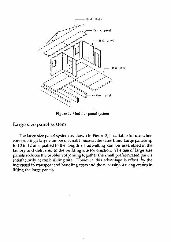
Under the modular panel system, building components are constructed in the factory by two or three men without the use of cranes or other lifting devices. Wall panels are in uniform sizes using a module (M) as a unit of measurement. The normal unit 'M' is 1.22 m (4 ft.) in length to tally with the size of most cladding materials in Malaysia such as plywood, hardboard, chipboard and cement board. The mod ular panel system is the system adopted in this manual (see Figure 1).
r=::=- Roof truss
Ceiling panel
joist
Figure 1. Modular panel system
Large size panel system
The large size panel system as shown in Figure 2, is suitable for use when constructing a large number of small houses at the same time. Large panels up to 10 to 12 m equalled to the length of adwelling can be assembled in the factory and delivered to the building site for erection. The use of large size panels reduces the problem of joining together the small prefabricated panels satisfactorily at the building site. However this advantage is offset by the increased in transport and handling costs and the necessity of using cranes in lifting the large panels.

___ Roof truss
Figure 2. Large size panel system
Volume element system
In the volume element system of prefabricated housing, dwellings are completely finished at the factory. This system permits a home buyer to see exactly what his house will look like before it is built. This method of construction is very much faster than the other methods as far as site erection is concerned, but it requires the use of trailers for transportation and cranes for erection (see Figure 3).
~=------ Foundolion beams
Figure 3. Volume element system
A
Chapter 3
DESIGN OF THE HOUSE
The traditional method of house construction in Malaysia is of the post and beam structural form in which beams spaced widely apart (between 2 and 4 m in domestic buildings) are supported on individual columns or posts to form a skeletal structure. The non-load bearing infill panels will form the wall and window units between the columns.
The house proposed in this manual is the timber-framed or wood-framed house and falls within the category of modular panel system as mentioned previously. The method of timber-framed house construction is traditional in North America, Scandinavia and some other parts of the world but is comparatively new in this country.
Basically there are two methods of building a timber-framed house, the balloon frame and the platform frame method. The balloon frame method has studs running the full height of the building and the intermediate floor joists are side-fixed to the studs and supported from them. The system is only suitable for either two or four storey buildings. In the more common platform frame method the shell is built one storey at a time using storey height wall panels to support the intermediate floors, which are then used as a construction platform to erect the next storey or the roof above. The platform frame method is used in this manual. These two framing methods are shown in Figures 4 and 5.
In timber-framed housing, partitions or wall panels are assembled by having the top and bottom horizontal plates spaced at a distance apart to suit the designed height of the building which in this case is 2.75 mm (9 ft.) high. Vertical studs at generally 0.16 m centres are then nailed to the top and bottom plates. Where necessary noggings are added in to strengthen the edges of the intended sheathings. Sheets are then fixed to the framework either on one side only or on both sides. For simplicity all the framework is assembled with butt joints and fixed with nails. Figure 6 shows such a wall panel which is normally prefabricated at the factory. For ease of man-handling, the pre-assembled wall panels are made to a length not more than 3000 mm long. The wall panels are then erected over the prepared platform and the roof is put over it to complete the building.

Stud full height 01 building
Figure 4. Balloon frame method
The main advantages of the timber-framed system of construction are: (1) Transportation of pre-assembled panels is simple; (2) Less labour is required on site, even when the panels are made up on
site. If the panels are assembled at the factory, considerable saving in labour are possible;
(3) The pre-assembled wall panels can be erected manually by two or three men without the use or cranes;
(4) More speedy erection. It is possible to put up the whole timberframed wall panels of a house within two to three days. Once the roof is covered, other works such as plumbing and electrical services can be started inside under assured dryness;
(5) Houses can be finished at low cost to a high standard of thermal insulation,
(6) Flexibility in architectural design, modification and extension is possible.

Figure 5. Platform frame method
.1 I
\t".".
Figure 6. Typical prefab wall panel

Chapter 4
BASIC PRINCIPLES
The dimensioning of the house is based on a modular system which means the best use is made of materials, especially sheet materials and also the house can easily be extended at a later stage. Most sheet materials obtainable locally are of size 1220 x 2240 mm, therefore the planning of the house is based on the use of dimensions which are multiples of 610 mm. Hence a grid of 610 mm is used in the plan layout as well as positioning in fixing of the partitions, roofs, joists, etc. These and an alternative future extension are shown in Figure 7. In the modular panel system, architects can design a wide variety of houses with many different floor plans using prefabricated panels.
Proposed extensIOn r . Grid tines ~ mm crs.
r 4270
610
I w t:
! I-- c-
I Ki~. S
I
I I I I I Is R 2 I I I
I I I i I ! I ILVD I SR 31
I I I I
BR1 i I I V I I
I I I I
I I I 1 1T I 7320 30<;0
Proposed house With extension
Figure 7. Plan of building on grid lines
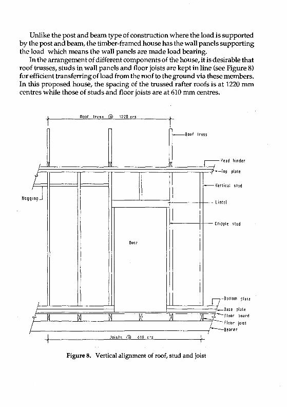
Unlike the post and beam type of construction where the load is supported by the post and beam, the timber-framed house has the wall panels supporting the load which means the wall panels are made load bearing.
In the arrangement of different components of the house, it is desirable that roof trusses, studs in wall panels and floor joists are kept in line (see Figure 8) for efficient transferring of load from the roof to the ground via these members. In this proposed house, the spacing of the trussed rafter roofs is at 1220 mm centres while those of studs and floor joists are at 610 mm centres.
Nog .6=
/
+ M
/
Roof truss @ 1220 ers
Door
[Xl M l~
Joists @ 610 ers
t -Roof truss
lXl
r-;-H ead binder
T op plate
-Veri ieal stud
Lint el
Crip pie stud
11 Bottom plate
,-M-t-
Base plate Floor board
Floor joist Bearer l-
f
Figure 8. Vertical alignment of roof, stud and joist

Wall panels can be of load bearing or non-load bearing walls type. Load bearing walls are designed to support the floor and the roof above them. Nonload bearing walls do not support any load above them and they function as partitions. They are therefore made shorter than the load bearing walls in the same storey so that the roof or the floor joist above them does not rest on these walls as shown in Figure 9.
Hon -load ~bearing wall
Figure 9. Clearance for non-load bearing wall
bearing
If there is an opening in the wall panels such as for door or window, a lintel is required to span the opening. The ends of lintels are supported on extra studs known as cripple studs which are fixed at each side of the door or window opening as in Figure 8. For small openings, lintels are not necessary; they can be fitted between studs and are simply framed up.
The following sizes and tolerances must be observed in making wall panels: (1) Depth oftimber studs must be the same throughout, so thatthe width
of the finished panel with sheathings is the same. For example, if the stud is specified as 47 by 97 mm then the latter dimension must be accurate or regularised.
(2) A vertical gap of between 1 to 3 mm should be provided between plywood sheathings to allow for their expansion. The gap is then covered up with beading.
(3) The finished length of each completed prefabricated panel is to be 1 to 3 mm less than the finished size as stated in drawing.
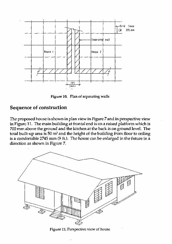
The house may be built as a separate detached unit or linked to each other by a separating wall as shown in Figure 10.
-pr-1.-/ -v / V Separatin wall /
V / House 1 V House 1 /
/ / V /
f' V/ // / // /V Vf / /
,305 \, , (mlnJ '
Figure 10. Plan of separating walls
Sequence of construction
T~r id lines J05 mm
The proposed house is shown in plan view in Figure 7 and in perspective view in Figure 11. The main building at frontal end is on a raised platform which is 700 mm above the ground and the kitchen at the back is on ground level. The total built-up area is 50 m2 and the height of the building from floor to ceiling is a comfortable 2745 mm (9 ft.). The house can be enlarged in the future in a direction as shown in Figure 7.
Figure 11. Perspective view of house

In the sequence of construction the ground is first prepared by laying concrete footings. Posts are erected over the footing. Bearers are attached across the posts with bolts. Floor joists with stiffening across pieces are laid over the bearers. Floor boards with tongue and groove are conceal-nailed to the joists and the platform is now ready for the next stage of construction.
Over the platform, pre-assembled wall panels are put up. During this time work can also start simultaneously in the kitchen which is on ground level and which is not connected to the platform at this stage. When the panels are erected over the platform as well as over the kitchen, head binders or wall plates will then bind the top of the panels together; and they also act as support for roof trusses. The panels are also fixed firmly together sideways with nailed iron plates or angles, which are then concealed with beading.
On top of the wall plates, prefabricated trussed rafter roofs are fixed. The rafters are braced diagonally and purlins are nailed over them. When roofing sheets have been laid, the dwelling is protected from rain and shine. Doors and windows can now be installed. All other subsidiary works such as plumbing, electrical wiring and sanitation can be commenced.
The house may now be painted and is ready for occupation.
Chapter 5
GENERAL REQUIREMENTS AND SPECIFICATION OF MATERIAL
General requirements
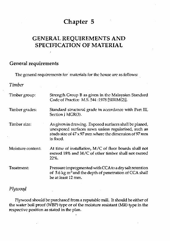
The general requirements for materials for the house are as follows:
Timber
Timber group:
Timber grades:
Timber size:
Moisture content:
Treatment:
PlywoQd
Strength Group B as given in the Malaysian Standard Code of Practice M.S.544 :1978 [SIRIM(2)].
Standard structural grade in accordance with Part Ill, Section J MGR(3).
As given in drawing. Exposed surfaces shall be planed, unexposed surfaces sawn unless regularised, such as studs size of 47 x 97 mm where the dimension of 97 mm is fixed.
At time of installation, MIC of floor boards shall not exceed 18% and MIC of other timber shall not exceed 22%.
Pressure impregmented with CCA to a dry salt retention of 5.6 kg m-3 and the depth of penetration of CCA shall be at least 12 mm.
Plywood should be purchased from a reputable mill. It should be either of the water boil proof (WBP) type or of the moisture resistant (MR) type in the respective position as stated in the plan.
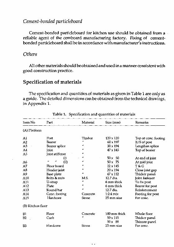
Cement-bonded particleboard
Cement-bonded particleboard for kitchen use should be obtained from a reliable agent of the cemboard manufacturing factory. Fixing of cementbonded particleboard shall be in accordance with manufacturer's instructions.
Others
All other materials should be obtained and used in a manner consistent with good construction practice.
Specification of materials
The specification and quantities.of materials as given in Table 1 are only as a guide. The detailed dimensions can be obtained from the technical drawings, in Appendix 1.
Table 1. Specification and quantities of materials
Item No Part Material Size (mm) Remarks
(A) Platform
Al Post Timber 120 x 120 Top or conc. footing A2 Bearer 60 x 197 B/Sofpost A3 Bearer splice 30x 194 Lengthen splice A4 Joist 47x 145 Top of bearer A5 Joist stiffener
(I) SOx SO At end of joist A6 (II) SOx 75 At mid joist A7 Floorboard 22 x 145 T&G A8 Header joist 20x 194 Oose joist gap A9 Base plate 47x 112 Thicker panel AI0 Bolts & nuts M.5. 12.7 dia. Joint fastener All V-strap 6mm thick To fix post A12 Plate 6mm thick Bearer for post A13 Round bar 12.7 dia. Reinforcement A14 Cone. footing Concrete 1:2:4 mix Footing for post A15 Hardcore Stone 25 mm size Forconc.
(B) Kitchen floor
Bl Floor Concrete 100 mm thick Whole floor B2 Curb 50 x 115 Thicker panel
SOx 88 Thinner panel B3 Hardcore Stone 25 mm size For conc.

(C) Wall panels
Cl C2 C3 C4 CS C6 C7 C8 C9 CI0 Cll C12 C13 C14 C15
Studs (I) (11)
Untel (I) (11)
Sheathing (I) (11)
Sheathing (I) (II)
Beading (I) (II)
Pyrda nail plate angle 11
Plate w /holes Angle plate w /h Dowel
(D) Head binder
Dl D2 D3 D4
(E) Roofing
El E2 E3 E4 E5 E6 E7 E8 E9 ElO
Platform (I) (11)
Kitchen (I) (II)
Rafter, tie, web Brace Nogging Gusset plate Gable end Ceiling Purlin Fascia board Roofmg sheet Ridge piece
(F) Door and window
Fl F2 F3 F4 F5 F6 F7 F8 F9
Flush door (I) " (11) " (III)
Window (I) (II)
Window only Fixed louv. (I)
(11) (Ill)
Timber
Plywood
Cemboard
Plywood Cemboard Product
M.5.
Timber
Timber
Plywood "
Timber
Fibrecem
47x 97 47x 72 97x 145 72 x 145 9mmWBP 6mmMR
10mm 8mm 9mm 8mm 63x 89 44x 44x93 80x 80 48 x48 x80
12.7 dia.
47x 112 22 x 84 47x 115 22 x 88
35 x 72 22 x 97 38x 50 9mmWBP
4mm MR 35x72 20x 145 1830&2440 Product
Ply/timber 0/ A 840 x 2100 770 x 2100 770 x 2100
Adj/fixed louv." 1055 x 1587 414x 1587
Adj.louv. Glass
1055 x 1213 403 x 610 440x 610 700x 610
Thicker panel Thinner" Thicker" Thinner " Outside surface Inside" Kit. O/S Kit. liS In strips
Connection, flat corner
Connection, Cemb. Con. Cem. corner Embedded in curb
Bind thick panel " thin Bind thick panel " thin
Truss assembly Brace truss For ceilling board B/S of truss joint to close end 2' x 8' zigzag Top of truss All round roof 2 sizes At peak
Main entrance Room / kitchen Bath /WC 7 off, platform 1 off, loff, loff, 1 off, 1 off,

(G) Water Tank
Gl Water tank Product 7SOx 1220 x Top of bath 540 high
G2 Beam Timber 4 /47 x 97 Tank support G3 Seating Plydood 9mmWBP Top of beam
(H) Stairs (2 off)
HI Stringer Timber 60 x 219 Entrance & kit. H2 Tread 47x 2SO 2/3 treads H3 Support strip SOx SO Attd. to string H4 Angle iron M.5. 63x 63 x 200 Landing attach
(I) Railing
11 Railing Timber 47x 97 Frame for mesh 12 Balustrade 20x 20 To rail and floor
(J) Wire mesh in Kitchen
Jl Framework Timber 47x 97 Frame for mesh J2 Wire mesh Product SOx SO crs. Oose opening
1£
Chapter 6
DETAILS OF CONSTRUCTION
Site access
Before construction begins, access to the site must be looked into, especially if the house is to be built in a remote area. If necessary an access road suitable for vehicles has to be constructed to transport construction materials to the site.
Al though most of the component parts of the building are pre-assembled at the factory, electric power and water supply are still required for many tasks during the building process. Electric supply may be obtained from the supply mains or obtained from a generator. Water may be obtained from the water mains, well, river or transported to the site.
At the plot, besides the area required for the proposed house, space for the storage of prefabricated components and other building materials must be allocated away from building sites.
Preparation of site
The site of the house must be prepared first before construction work begins. The soil is examined to see whether it is suitable for the building. Since the proposed house is constructed of timber and is therefore light, most normal soils would be suitable for its erection. If the place is known to be infested with termi tes, an anti-termi te treatment is recommended for the soil before construction begins.
The site should be cleared of all unwanted vegetation. During the process of grading, roots and other cellulosic materials should be removed, from the building lot. Care must be taken to obtain adequate drainage of the area and in particular of the building site. The frontal of the house may be built on level ground or on a gentle slope as this portion is of the raised platform type and hence the platform can be made level by adjusting the footing level or the length of the post (see Figure 12). The height of the floor must be at least 700 mm above the ground for effective ventilation. The site for the kitchen at the rear should be made level by cu tting or filling earth with proper ramming to ensure the prepared surface is firm.
17

(il Footing adjustment
_ Oatu~ ~i.!1i (!.!at-fo~ '- __ _
Post
G.L
(ii) Post adjustment
Figure 12. Platform on sloping ground
Setting out
When the site is prepared, the next step is to locate the house on the plot. The house should not be built too close to the boundary to allow rooms for one to move around the house with ease. Also if there is a house in the neighbouring plot, the empty space acts as firebreak. In Malaysia the minimum spacing is specified in the Uniform Building By-laws, 1984 or the latest edition. If the plot is large enough building is located near one end of the plot to give allowance for future extension (see Figure 13).
lR

Proposed building
Future extension /
/ /
/
Figure 13. Position of building in plot
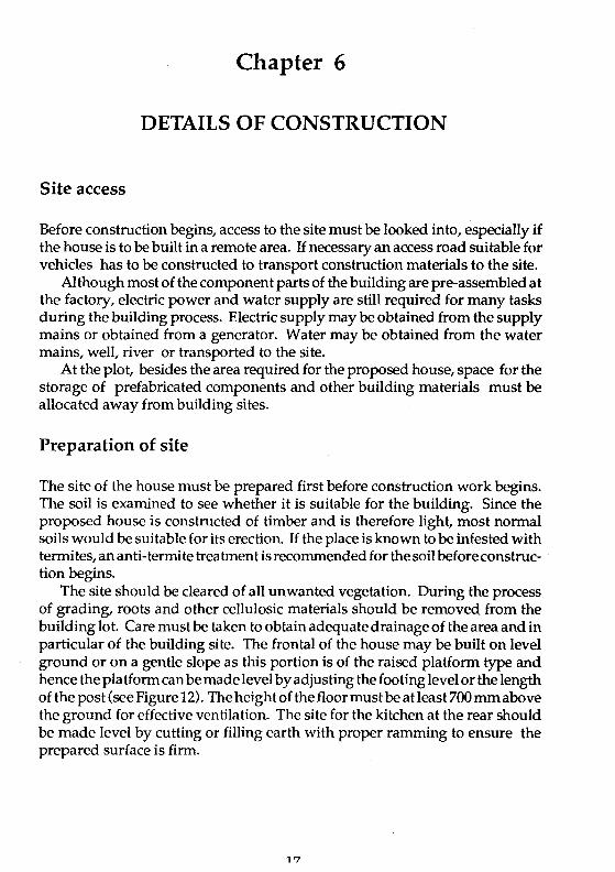
When setting out the position of the platform, first mark on the plot the approximate outline of the whole platform by driving in temporary pegs at the four corners of the house where the footings are to be built.
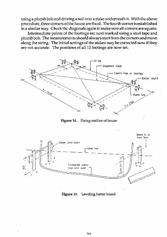
From the markings on the ground, set outthe corners of the house by putting in batter boards. There are two batter boards at each corner, making it eight for the four corners. The batter boards consists of two vertical stakes 50 mm x 100 mm x approximately 1 m long driven into the ground. These stakes are fixed at a minimum distance of 1 m beyond the lines of corner foundation footings to avoid being disturbed during excavation (see Figure 14). A horizontal board of 25 x 150 mm is then nailed to the vertical stakes. The tops of all horizontal batter boards are made the same level. This can be achieved by checking with a surveyor's level or by using a transparent hose filled with water as shown in Figure 15. The highest corner of the house is chosen as the datum batter board where the levels of all other batter boards should follow.
When the batter boards are in position, strings are then stretched taut between the boards. To indicate the positions of the strings in the batter board, a nail is driven or a saw kerf is made on the board so that the string may be replaced if disturbed. Two adjoining sides of the building are first set using two steel tapes. To check the squareness of the two sides, a third tape is used to measure the diagonal. The lengths of the two sides are 7230 mm and 5400 mm. The length of the diagonal is therefore equal to:
Diagonal -J(723()2 + 540()2) == 9096
If the above length is too long, the squareness of the corners can also be achieved by using the common rule of "3-4-5" for a perfect 900 corner as shown in Figure 16. The sketch also shows the position of the first corner by
using a plumb bob and driving a nail into a stake underneath it. With the above procedure, three corners of the house are fixed. The fourth corneris established in a similar way. Check the diagonals again to make sure all corners are square.
Intermediate points of the footings are next marked using a steel tape and plumb bob. The measurements should always start from the corners and move along the string. The ini tial settings of the stakes may be corrected now if they are not accurate. The positions of all 12 footings are now set.
~I
Oiagonals equal
Cenlre line of foolings
Figure 14. Fixing outline of house
Oatum catter boara
Board to be fixed here
Transparent plastIC i(
hose with waterol, f ~ ~~3;,'(~
Figure 15. Leveling batter board

Footings
f',rst cor ner point on ground
Figure 16. Fixing one corner
The strings can now be removed bu t the ba tter boards should be left in position undisturbed, for further alignment and levelling.
Excavate soil for the 12 footings at the positions marked on the ground. The size of each hole is 600 mm square and 400 mm deep. When the holes are ready, hardcore is placed into the holes and rammed properly up to 150 mm thick. A level of sand is put on top of the hardcore.
Construct framework to hold the concrete. The minimum depth of concrete footing is 300 mm but may be of greater depth depending on the contour of the land If it is decided that the top surfaces of all concrete footings are of the same level. Top of concrete footing should be a minimum of 50 mm above the ground level. The other alternative is to vary the lengths of the posts over the footings in which case the footing surfaces need not be of the same level. Before concrete is poured, reinforcement consistingof12 mm diameter Mild Steel (MS) bars are placed near the bottom of each footing and MS V-strap for the posts are put at the top of the footing. The V-straps must be properly aligned and levelled by using strings between batter boards and plumb bobs as shown in Figure 12(0.
Concrete can now be mixed. The proportion of the mix is 1 part cement, 2 to 3 parts sand depending on its wetness and 4 parts stone. Mixing of concrete is preferably done using concrete mixer. If mixer is not available, mixing can be performed manually but it must be done thoroughly until the whole mix is uniform. The mixed concrete is then poured into the prepared framework and
'),

is then rodded or vibrated to achieve a dense concrete making sure the fixed reinforcement is not being disturbed.
Platform
When the concrete footings are made, the next step is to fix the posts over the footings. First put in MS bearing plates 120 x 120 x 6 mm thick within the V-strap and then put in the posts, each measuring 120 x 120 x 499 mm high. Fix the bottom of each post to the V-strap with 2 bolts through holes previously drilled (Figure 17).
~---Bearer 1/.7 x 19,
Conc. looting --.......... Plate 110 x tl0 x G
Figure 17. Joining details of post and bearer
Bearers can now be attached to the top of posts, one on each side with 4 bolts running through the 2 bearers and post. Washers are required for all bolt heads and nuts if they bear directly on the timber surface. The bearers are lengthened by splice jpints at a place between the posts as shown in Figure 17. While fixing the bearers, care should be taken to ensure the posts are truly vertical, the top of all bearers are horiwntal and of the same level.
Floor joists are next placed on top of the bearers. They are fixed to the bearers by slant nailing using 75 mm nails, one on each side of the joist as shown in Figure 18. To stiffen the joists and to prevent them from tilting, stiffening cross
?')

pieces 50 x 50 mm are placed at each end and 50 x 75 mm at the centre. To accommodate the cross pieces, notches are cut at the top ends of the joists. Figure 19 shows the joists being fixed in posi tion with the stiffening cross pieces embedded in the joists.
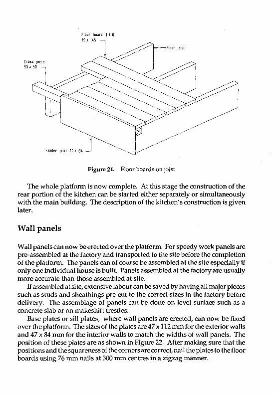
Floor boards in the form of strip flooring 30 x 145 mm with tongue and groove are next laid over the joists. Fit groove of one board to tongue of the matching board snugly and blind-nail through the tongue to the joist below as shown in Figure 20. A board or header joist 20 x 194 mm is fixed to the ends of the joist with its top level with the floor boards as shown in Figure 21. This board will conceal the empty spaces between the joists.
_Joist
Bearer
Figure 18. Slant nailing of joist to bearer

earer
End notch ior
Figure 19. Attachment of cross piece to joist
Groove ----
Tongue
Figure 20. Concealed nailing of floor board
Cross piece 50 x 50
floor board r & G
floor iOISI
Header 10iSl 10 x 19. J Figure 21. Floor boards on joist
The whole platform is now complete. At this stage the construction of the rear portion of the kitchen can be started either separately or simultaneously with the main building. The description of the kitchen's construction is given later.
Wall panels
Wall panels can now be erected over the pIa tform. For speedy work panels are pre-assembled at the factory and transported to the site before the completion of the platform. The panels can of course be assembled at the site especially if only one individual house is built. Panels assembled at the factory are usually more accurate than those assembled at site.
lf assembled at site, extensive labour can be saved by having all major pieces such as studs and sheathings pre-cut to the correct sizes in the factory before delivery. The assemblage of panels can be done on level surface such as a concrete slab or on makeshift trestles.
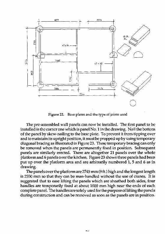
Base plates or sill plates, where wall panels are erected, can now be fixed over the platform. The sizes of the plates are 47 x 112 mm for the exterior walls and 47 x 84 mm for the interior walls to match the widths of wall panels. The position of these plates are as shown in Figure 22. After making sure that the posi tions and the squareness of the corners are correct, nail the plates to the floor boards using 76 mm nails at 300 mm centres in a zigzag manner.
4077 1576
.~
\. v \...
->
'" <-~ 47x84 _
~ \
C "': ~ ---.J f-J -> 3660 r-
47'f ~ '"
'" r '" '" m
( 1'-., ~i -?L f--i'-\'-----./
t 3884 1576
7544 1
o Figure 22. Base plates and the type of joints used
The pre-assembled wall panels can now be installed. The first panel to be installed is the corner one which is panel No. 1 in the drawing. Nail the bottom of the panel by skew-nailing to the base plate. To prevent it from tipping over and to maintain its upright position, it must be propped up by using temporary diagonal bracing as illustrated in Figure 23. These temporary bracing can only be removed when the panels are permanently fixed in position. Subsequent panels are similarly erected. There are altogether 21 panels over the whole platform and 6 panels over the kitchen. Figure 23 shows three panels had been put up over the platform area and are arbitrarily numbered 1, 5 and 6 as in drawing.
The panels over the platform are 2745 mm (9 ft.) high and the longest length is 2550 mm so that they can be man-handled without the use of cranes. It is suggested that to ease lifting the panels which are sheathed both sides, four handles are temporarily fixed at about 1000 mm high near the ends of each complete panel. The handles are solely used for the purpose of lifting the panels during construction and can be removed as soon as the panels are in position.

Figure 23. Erection of panels
Wall plates or head binders are now fixed over the top of the wall panels. Wall plate sizes of 47 x 112 mm are fixed over the thicker exterior walls while the 22 x 84 mm pieces are fixed over the thinner interior walls. As mentioned previously the thinner plates, 22 mm as against 47 mm, are used so that the roof trusses do not rest on them because these interior walls are not designed as load bearing walls. The fixing of wall plates to panels is done by nailing 76 mm nails at 300 mm centres in a zigzag manner as was done in nailing the base plates to the floor boards.
For attaching the panels to base plates, use Pryda knuckle nail plates 2N10 (89 mm wide x 63 mm depth with 2 rows of 10 punched-out nails) or similar type. These plates are fixed at 610 mm centres on the exterior side of the panels while the interior side is fixed with 76 mm nails skew-nailed to the base plates. These metal plates and nails are then covered with plywood skirting 9 mm thick x 100 mm wide. For side attachment of the panels to each other, use 3 pieces of the same type as that used for bottom attachment, i.e. Pryda 2NlO or similar, spaced out evenly. As for corner connection between two walls at right angles, use 3 pieces Pryda angle plates 3NA (44 mm wide x 44 x 95 mm depth) or similar

type, fixed to the interior angle. All these plates should be covered with plywood beading. Figure 24 shows the connection details.
When the wall panels with head binders over them are erected, roof trusses can be put over them. Prior to this, the kitchen walls should be erected first because the extended roof trusses of the main building rest on the rear kitchen wall.
Plywood beading 1/9,71
PI d b d· 9 71 r- ywoo ea ,n9 ,
W }
PanelQ) Panel CD Pane IQ) Panel CD ~
c:
rITill c;/
. I· 1- :,: : I: ,
~ Pryda nail plate I
1 H to 1 1
J-III
---
~ f!::mC
' ' :."t . ..:[ •. ' ". 0-
1 --.. I Pryda anqle ~ plate] "·h
I
(
I L Hail piate &J, S9 e plate Plywood sklrt,ng
COl &10 spacing
1 il Length wise panels liil Corner panels
Figure 24. Connection of panel
Kitchen
Prepare the area for the kitchen which measures approximately 3.1 m x 5.1 m behind the main building. Excavate the ground to the required level. Put in hardcore and ram properly up to 100 mm thick. Blind the top area with sand and wet the top liberally with water before pouring concrete. The mixture of the concrete is 1:2:4 and the thickness is 100 mm. Concrete strip footings
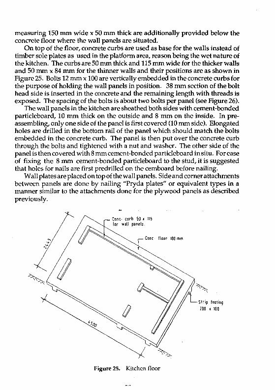
measuring 150 mm wide x 50 mm thick are additionally provided below the concrete floor where the wall panels are situated.
On top of the floor, concrete curbs are used as base for the walls instead of timber sole plates as used in the platform area, reason being the wet nature of the kitchen. The curbs are 50 mm thick and 115 mm wide for the thicker walls and 50 mm x 84 mm for the thinner walls and their positions are as shown in Figure 25. Bolts 12 mm x 100 are vertically embedded in the concrete curbs for the purpose of holding the wall panels in position. 38 mm section of the bolt head side is inserted in the concrete and the remaining length with threads is exposed. The spacing of the bolts is about two bolts per panel (see Figure 26).
The wall panels in the kitchen are sheathed both sides with cement-bonded particleboard, 10 mm thick on the outside and 8 mm on the inside. In preassembling, only one side of the panel is first covered (10 mm side). Elongated holes are drilled in the bottom rail of the panel which should match the bolts embedded in the concrete curb. The panel is then put over the concrete curb through the bolts and tightened with a nut and washer. The other side of the panel is then covered with 8 mm cement-bonded particleboard in situ. For ease of fixing the 8 mm cement-bonded particleboard to the stud, it is suggested that holes for nails are first predrilled on the cemboard before nailing.
Wall plates are placed on top of the wall panels. Side and corner attachments between panels are done by nailing "Pryda plates" or equivalent types in a manner similar to the attachments done for the plywood panels as described previously.
Cone· curb 50 x 115 for wall panels.
floor 100 mm
Figure 25. Kitchen floor
5 I rip foot ing ZOO x 100

·'MAl L PANE L
COHC KER6
Figure 26. Anchoring of wall panel to concrete kerb
Roof truss
As in wall panels, trussed rafter roofs should preferably be pre-assembled at the factory and transported to the site when they are required. The trusses can either be assembled using nailed plywood gusset plates as shown in the plan or using proprietary brand punched metal plates. If metal plates are used, the trusses will have to be fabricated by the factory supplying such plates. In this case the sizes of the plates required for each joint are calculated by the licensed factory while the sizes of truss timber members remained the same as in the drawing.
The first truss is erected at one end. When it is in the correct position, nail the truss to the wall plate. The end truss is then temporarily braced to the ground at two places using 50 x 100 mm timber as shown in Figure 27. This

bracing, although temporary must be firm because all other trusses are to be fastened to this end truss. The second truss can now be erected. The truss is initially put upside down with the two ends resting on opposite sides 0 fthewaIl plates and the peak of the truss pointing downwards as can be seen in Figure 27 above. The truss is then tilted up vertically using a long pole with a "Y" end as shown in Figure 28. When it is in the correct position nail bottom of truss to wall plate and brace temporarily to first truss. The rest of the trusses can be erected in a similar way. Figure 29 shows the attachment of trusses to wall plates by skew nailing 4/100 mm nails for each attachment, two on each side of the truss.
Temporary bracing
Figure 27. Erection of first truss
Figure 28. Erection of second truss
Head binder /./'~,.--.
Wall panel
Platform area
rSPtlce joint
Skew naded to · .... all plate
KItchen area
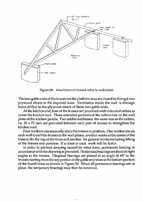
Figure 29. Attachment of trussed rafter to wall plates
The two gable ends of the trusses on the platfonn area are closed by fixing 6 mm plywood sheets to the required sizes. Ventilation inside the roof is through holes drilled in the plywood sheets of these two gable ends.
At the kitchen end, four of the trusses are provided with extended rafters to cover the kitchen roof. These extended portions of the rafters rest on the wall plate of the kitchen panels. Two additional beams the same size as the rafters, i.e. 35 x 72 mm are provided between each pair of trusses to strengthen the kitchen roof.
Four workers can manually erect the trusses in position. One worker sits on each wall to nail the trusses to the wall plates, another works at the centre of the truss to fix the top of the truss and another for general works including lifting of the trusses into position. If a crane is used work will be faster.
In order to prevent swaying caused by wind force, permanent bracing in accordance with the drawing is provided. Horizontal bracings are fixed at right angles to the trusses. Diagonal bracings are placed at an angle of 450 to the trusses starting from the top portion of the gable end truss to the bottom portion of the fourth truss as shown in Figure 30. When all permanent bracings are in place, the temporary bracings may then be removed.

~OiagOnal brace 12 1 97
LHorizontal brace 21 x 97
Figure 30. Bracing for trussed rafters
The next stage of construction is to place purlins on top of the trusses. Purlins are 35 x 72 mm in size and are skew-nailed to each rafter with two 76 mm nails, one on each side ( see Figure 31). Fascia boards and barge boards are fixed to the ends of rafters and purlins.
Roofing sheets can now be laid over the purlins. The sheets are of corrugated asbestos-free fibre cement sheets. They are laid in accordance with the manufacturer's instructions. From this stage onwards, work can be carried out in the dry interior of the building irrespective of the weather conditions.
- Raller 15 x 71
Skew nad b/s
Figure 31. Fixing purlins

Doors and windows
Openings for doors, windows and fixed louvers are provided for when making wall panels. However, for the door openings, a full length bottom rail of the panel is initially retained so as to prevent the frames from being twisted during handling. When the panels are installed, this exposed portion of the bottom rail is cut out together with the base plate at this place as shown in Figure 32. Doors and windows are assembled in the factory and delivered to the site for installation.
The doors are of three sizes: 700 mm wide for WC and bath, 770 mm wide for the kitchen door and 840 mm wide for the main entrance door. The height for all doors is 2100 mm high, measured from floor level. It is important that the dimensions of the doors and windows match exactly the openings provided for on the wall panels after they have been installed in place. All doors should open inwards.
To make the doors, the framework is first assembled making sure the overall dimensions are correct and the corners are squared. Plywood sheets are then glued and nailed to the framework on both sides.
Frames for windows and louvres are made at site in the openings provided for in the wall panels. Adjustable louvre aluminium frames with 8 leaves are then fixed to the wooden window frame. Glazing in the form of glass sheets cut to size are slid into the slots of the adjustable louvre. Glass sheets are also used as fixes glass louvres on top of adjustable louvres.
Railings and stairs
In making railings, use rails 47 x 97 mm and vertical balustrades 20 x 20 mm in size. The top of the rail is constructed at 1000 mm above the floor.
In making staircase, the spacings for rise and run of the stairs are 170 and 230 mm respectively. The treads are 47 x 250 mm resting both ends on ledgers 50 x 50 x 180 mm which are fixed to the stringers 60 x 219 mm. The stringers are leaned against the floor joist at the top and fixed to the concrete landing with angle iron plates at the bottom as illustrated in Figure 33.

Ceiling
Shaded part is cut out only alter erection·
Figure 32. Frame for door opening
Before ceiling sheets are installed, noggings 38 x 50 mm at 610 mm centres are first fixed between the roof trusses as in Figure 34. Ceiling may be of plywood 6 mm or cement-bonded particleboard 6 mm thick. Ceiling is required only for the main building and not the kitchen. The ceiling sheets are nailed to the noggings and trussed rafters in a zigzag pattern.

1 1 1 1 1 1 1 1 1 1 1 1 1 1
'read ~1 , I,\) ----t/f.====----~-~ o~ ~earer ,() ~ <,0 ~ \S\)
1 1 1 1 1 1 1 1 1 1 1 1 1 1 1 1 1 1 1 1 1 1 1 1 1 1 1 1 1 1 1 1 1 1 1 1 1 1 1 1 1 1 1 I

Services
Various services such as plumbing, electrical and sewerage works, can be installed in the building as soon as the roof is covered with roofing sheets. For general wiring, drilled holes in wall frames and floor joists are used. The holes measuring 25 mm diameter are drilled at the centre of the section. They should be located at least 300 mm away from the ends of studs, joists and other structural pieces, and from any other hole as shown in Figure 35.
Notches for piping and wiring can be made at the joists if the following conditions are followed:
(1) All notches must be in top edge of joist, (2) The location of the notches from the support end should be between
1/10 and 1/5 of the joist span, and (3) Maximum depth of notch is equal to 21 mm for a 145 mm joist. Instead of notches, holes can be drilled in joists for piping as shown in Figure
36. All fixtures and fittings can be fixed to the framing timbers forming the
panels. Extra noggings can be added to support heavy fixtures such as wash basins or boilers.
Hole 25 mm dia.
Electric socket fixed blllcking SO x SO
Figure 35. Internal wiring

Joist ~7 K 145
-......_,,--_ Pipe
Bearer 41 x 194
Figure 36. Drilled holes in joists
Finishing touches
Plywood skirtings of size 9 x 100 mm, for the main building can be fixed between the wall and the floor. Plywood beadings of 9 x 72 mm are used to cover all jointings between the plywood pieces.
Finally the whole building can be painted. The primary function of painting the wall is to protect the surface, for easy cleaning and to maintain appearance. Wood surfaces exposed to the weather withou t any finish, will quickly change; hence they need finishing both for appearance and protection.
For floors, the natural colour and grain of wood make them attractive and beautiful. The application of floor finishes should protect the surface from excessive wear and abrasion, and make it easier to clean.
The building now can be occupied.
,.,,,
Chapter 7
MAINTENANCE AND REPAIR
A house if properly designed and constructed with adequate attention given to details and to proper choice of materials used as outlined in this handbook, would require little maintenance. The following are some of the suggestions that may be followed to reduce the cost of maintenance. However, it must always be borne in mind that the two points to ponder are deterioration of timber house caused by termite attack which is mostly found in the tropics and decay caused by moisture and dampness.
Raised platform
(1) Space beneath the platform should be well ventilated. Open spaces must not be blocked by obstacles, including grasses, shrubs and planting.
(2) No water should be allowed to collect under the building. Hence the gradient of the soil should slope away from the house.
(3) Make sure the top of all concrete surfaces such as concrete footings, stair landing and kitchen floor should be between 50 and 100 mm above the ground level as per original design.
(4) Inspect regularly the surrounding area of the house for signs of termite activity. Break the earthen termite tunnel if found because subterranean termites can only survive if there is a connection between the soil and the building. If possible treat the soil with insecticidal solution to prevent termite infestation.
Exterior walls
(1) No part of the building should be allowed to collect water as this increases the moisture content of the wood or plywood therebyencouraging the growth of fungi and causing wood decay or rot. Such damages are common on door and window frames.
(2) Look for cracks or gaps in the exterior wall due to shrinkage or poor workmanship. Seal up the cracks by applying putty.
(3) If non-corrosive nails were used in the construction of the building and were driven flush with the heads exposed rust spots may occur at the nailheads. The remedy for this is to set the nailhead below the surface and apply putty to cover up the head.

(4) If the painting or finishes of the wall surfaces show signs of deterioration, apply fresh coats of paint.
Interior
(1) If there are cracks in the interior walls, fill the cracks with putty and paint over as in exterior walls.
(2) Do not allow moisture to remain long on the surface of any timber or plywood especially in the kitchen area.
(3) The sheathings of wall panels may be accidentally damaged resulting in holes or cracks in the sheets. If the holes are small they may be filled up with putty and sanded smooth. Larger holes may require cutting a section around the damaged portion and replacing it with a new section.
(4) Gaps may form between the floor boards due to shrinkage of the boards because they were originally laid with very high moisture content. One remedial action is to fit matching strips of timber between the flooring strips and glue them in place. In severe cases it may be necessary to replace sections of the floor.
Roof
(1) Stains in the ceiling boards will indicate that the roof is leaking. Check position of leaks and repair the roof.
(2) Make sure air circulation is maintained in the enclosed roofing area by seeing that ventilation openings at the two gable ends are provided and not blocked.
An

References
Uniform Building By-Law 1984. Printed by MDC Sdn. Bhd. Code of Practice for the Structural Use of Timber. Malaysian Standard. M.5. 544: 1978.
Standard and Industrial Research Institute Malaysia (SIRIM). The Malaysian Grading Rules for Sawn Hardwood Timber, (MGR). The Malaysian Timber
Industry Board, 1984.

~
SI ';/.
FRONT ELEVATION
.. ~ .....
'''tt 4210 li"5
r------------------, 1 1
: 11 1 1 1 1 lI"r I ... ICII
IlITI 1 1F=l=11 1 11 r-- -I 1 1 11 1 11 : ________ .1 11 1 IJ:Ej 1 - I J
I 11 BI 11
1111111'lII1l1'1,111 : : 11 I led 21 I 11 I I I 1 I 11 ++ • '0
i IIII~III ~ Illllll 1 1
: IIIII~I L ___________ ~,-- ______ _
n~~ mo ~l112
PLAN
Grid lines 600nvn cr5
Scrip Hoor 22.14'11 T' G
!
R
SIDE ELEVATION
~ Splict 2/.'10.'94 _440 joined
; 4\00 t~ J WU. Hm1S
R-f+-r~ t5....,.......' -'~iEr---:': -.,t ~-A~ 1)114 ..
f 1 j[ 1L Jl U- --LT - Cl
2440 2440 2440 J 2700 2100 J SECTION A- A SECTION B - B
i'-fii' B""I ~ . -
'..J '-I..J - '-
tL ~ Floor IO'ISC 47. 11.5
r I-- I--.~ ,...I~ ,...I~ ,-
Burer 2/60. 194 . :-=1. ~I...J -L 11 I--POSI 120 • 120
Cone. looting 600.600
~
IT rh ... h - h i'-l!! - - _. ~
r22~ 6'0 • ,0 • 6100 B..J P22t n44 IJ
FLOOR JOIST LAYOUT
r _

111)
DETAIL Y
.~oo .10 ' 71\ flO 122
0 ~ I f 1220 I' la m ~
, t::::pl!"! E+3f+311 13. 1bI! If
51
(
KITCHEN _~>lO Iil ~
® Il-----1l l~ /BATH III
~ N '. ---r--
t 0 1810 ®1i11
~f: )~ @
BEDROOM 2
• LIVINGI DINING
~~ :1 @ ® ®~ "" .. ,.
iill
:: BEDROOM I .QI~ IbIN j -~ @,11O ® ,.10 VERANDAH U (D.... 1ll2~. -11 ~ 1'3',10 •• 722 a'\m2
I I~II 11 \V D ~ _.
: ,,2 .. 0 1220 110 ~ 122.} 1101 1220 f 11)2 t X . 7'544
511 .. ® .. DETAIL X
Stilt. Drg,No,
PANEL LAYOUT PLAN 101/94/ 2 of 9 I: 50

. -: v
S61t DOOl
11" 11 I 11 '-I
1==
i= bd F== If T I nil
1" ITl fill ;=
-aJ ~ <{o-
0 , ~
'';; ~
aJ <{ ....
~ r=1
'I :=
Z Z' 0 O~ ;::: ;:::0 U 00: W W & '" "'!:
bd QW 4--- ----t-L
6l~l II DOL
6Ul

Elevlltion 6mm plywood
Elevation 9 mm plywood
Plan view
Elevation
6mm plywood
Elevation 9 mm plywood
Plan view
0'
~i I
l
VOID VOID
xposed (01·
c 9mm
112~ ====:JC===;:= I 6mm:::J
~I "I
If
1 2440
Panel (j)
lIBO
,; I
, 9
l-9111 1220 illjr
o
~,
'J. 9<-
"
,h
1220
+- ""==-='=~~=~ 1722
r panol Cl)
I Bd
So Bb
9,S
ThiS portion to b~ jOined by panel 7
L-r --T-Sg , 11 I: ,
" , 11 I
" B. , "
11 BI " 11 " I: 11 tI 11 I'
" " " 1'
" 1 11 _u
- , .!I ~ I I
"' :ij
"' !p III :11 :11 III III :11 :11 cl
9'S 722 :{
1637 6mm I,
Panel CD
21 I
2d 2.
1220 ;Jt '01
This pOlrtion from
pa~l"l ~~-jn :....~(_ jL ___ lit
, :1
,I' , "' ,
" iI' , :1
,11 , ", ; 20
" 2b '"
" III
11 III , :~ III I
"
iI'
I :: '" III I 11 ,11 I " "I , 11 III
I ___ JU
6.0 722 . I
I 30.S 91
9d " 9.
'--
'r 11
" :1 11
7'3
U 911
"
9~ 713
[11
mo
III ~11 9mmOOJ
.933
Panel CD
.B30
3b
Length of 722 to be jOined to panel 2
30 :~_ =~~ _ :J ,
I VOID
I
Edge of I panel 2-1 , ,
nOB
Exposed col
94 101 70.\
.0.
'Od
1220 ! 610
i- -----rLtO~_rL - -~i , -I
, , 1 1 I
1 1 , , , , , 1 10 b , , I I " , 1 Ii , , 11 I IrI'T --iT 111 I 11 11 11 "' , " iI '00 11 '" ~ I~ 11 ]~
!
-" _.JJ _J
mo f 6'0 I
J!!
'BlO
Panel ®
'220 1121
4d 4.
1220 '112
VOID VOID
1220
,9
1197 ~
4e
~ 1[112
94 nl 70·S
".
lld
1220 blO
'le 1- __ I!_ --if -;; rr
" !., : :1 ! :1
,I U 12d 11 11 11
h 11 11 11
III
1911 9mm l ,
Panel ®
,d I ,. 94 70.5
0 ,b "
Se
1220 1220
111- - - I~ -- - I~.[ III I~ ,
": Ih i~ ::1 Sf :~ S 9 :~ Id I~ ;~
::: :~ [~ III 11, I~
I!I 11 r
iii::;!~:! ::: :;: r:.; r, __ lln :: 'L _ I'~ __
"
~,_6~'~O~ __ ~'2~20---1
IIIJ 111 er 9 ":1
12~
'2 a
,2b
1220 1220
~12q JL .t2A....!,_ - ~
ii 111
, , 1
11 1 il ,
I: lh ,I 1 I, 1
11 ia 1
li 11 I Url'T 1111
11' :: 12f " " " " 11
11 jl I' 11 11 I - 1 j' .1 '1
6,0 ~ 1220
111::3 III
lS43
Panel @
6e
6.
1220
6b
i 1
l1b
13.
: Bc I
, JL. _J
1220
Panel ®
ThiS portion ~o bp olnpd from panel 7 IJ
6f -~; -r ; ,r
" , , " ! : "
, ; Ii
,; I , 11 ~6f: , 6d " " .' ,
" ~, I ,
iI " ,
, " "
,
" I' ,
" ,
" , " .'
, , "
,: 1 , J~ __ J __ :
1220

r r:, I " rn ILl , I IL' ! I ::: 22d i '= I ," 1 ~ I
IL' , ,
"' " I
'" I rlr-- -,r1, IL' 111,1 11 11
"' _:~ 11 21e 11 1I
~~ 1111 11 11 ;..JL .JLJJ
1 ,! J ~L +-1...:.7,-=-2I--lI~I,,-,22,,-0 -+l
10mm Ill!
Panel @
->--
~L 1\,
j
~I lid
~,
L ! 121i.
1\0 ,
0' ,
~i
..f-.-. I 707 610
6 mm it! !I
10l,.!. 1317
9mm
1
47
230 ~
llb 2l,
+-_1!.'-2"'20'----,;_--"12£20<-......;....,101
1220
16 ,
u;
'" "' III ____ JJ
610 I 721
Panel @
~Ol 16,
1210 \ 61G J
+- 16b
!<
1108 i 610 I
.mm 111111 !Ii ,
9mm
I 1610
+-I
~.
co; ,l.-
9. 17,
17d
1110
.1220
t ,-L
240
1220
I!!
24ll
1108
24.b
1213
• 24d n
U n H D U D
__ I
10 mm
jjj 8 mm I ~
Panel @
701
lle 6mm plywoOd
610
,~_-~.l',-_ -i~_
1?b o mm plywood
,
Ir-,r- ~,
" 11
" " 110 ,.
" " ,
" " le -''-I 1220 610
6mm III III I]
1610 9mm I
-
18.
a"",
a ....
18 f
18d 18,
1110 f610
-,r 18 c
18b
" " 11
210
I - -11-! :1 I 2; b ~! I " I I I I I I
, , , ,
I! 11 11
11 __ L _
8 mm i 0
1220 8mm ~
Panel ®
_IL __ ---'
1220 610
6"",
6mm 1810
~' ,-'!!-
8"", 260 26
10 mm
10mm 11, III 11,
2128 8"",
P,nel @
19f
19d 1ge
1220 610
- -;:-'9,-::---- , L , ,r 1 , I' I
" " " " , !I 19b , 190 " " " "
, "
, "
, 11 I
L ___ ll_ - :"" __ -1
1210 J 610 J
.mm
1610 6 .... \
8"",
10mm
1220 d 20g I
l 10f
D D lif 17, 27d
~----~----~ -~"'10'--+~1~10~8 __ ~!
;i---"-- :L-_ ...11 n I
~I " I ::~ [2 I " , ,I ,
"
, ~ I " , "r-,r- , - I " I ;11
" " ' " 127QII1 : 27b:: " 11
" ,I 11 I '" 11 , 11 " " ,
'" " , 11 " 11 , III 11 I " " " I III 11 I "
11 " JU li "
IL
1220 1213.
1120
Panel ®
11011
20h ----t ~! ~,
--,I.
10, 20j
Door Openi rt9
1210
--t
la
1786
6"", ill ill! j.
6mm l 17211
Summ-.ry of wall panels
1\47.1
211
21d
j[]l'
" I!
" 21 Q ::
" " 11 11 iI
" " I' _.JL
Sheathing * Panels Studs ExterNlI
I - 17 47 x 97 Ply. 9mm
18 - 21 47 x 72 Ply' 6mm
22 -24,26-27 47 x 97 Gem. 10 mm
25 47 x 72 Cem. 8mm
9 mm plywood to be of WBP typ"
6 mm plywood to b. of MR type
Internal
Ply. 6m
Ply· 6m
Gem. 8m
Cem. en
Tolerance of sheathing size =-, mm to .. now
expansion g~p between sneath"lngs
1,.
l! -, "
, I I I Jlb
I I I , I I I
j J
1210 Jm,b
6 ....

~
~
r u I- -.JI 1-
: 1 11 1 :1
I I I I 1 1 I 1 I 1 I I I ~
I I I I I I 11 11
I--TI----'!TI-':: 1-I 11 A 11 III I I I I I I 11 I 11 11 I11 I 11· I11 I 11 11 8
11 JI 11 I11 J 11 1 I I 1 I 11 IL __ I..l _____ -.l.l __ LJL __ -I
F.l
t
linltl 97. '41j Framt 47.112
1220
WINOOW
Filled glass IOUYrts Gb ISO·
Btading ",2.12 ~ FrafM eJl 47.112
Naco IOuYrtS
:t~~~~5 b:~~h I JY
S',11 tx 47. IIoIj -----,
:::F 47.97
}
;;! S
Iil
'"
linttl 97. lLS
eripplt stud 47.97
I
11 11 11 ...11 l-
I1 I I lin'tl .-
11 11 B 11 97 •• "] 11 I f---l--U--- --11
~ 11 11 11 11 11 Cripp!tslud- 11 11 11 11 11 11 11 11 11 11 11 11 11 11 11 11 11 11 11
~ 11
iT ~ 11 11 11 11 11
11 11 11 11 11 11 11
11 Cut this off 11 11 'T~,Whtn 'rtcltd 1/
f---j--7? '777/777. r,---ID:
I B 840 l
DOOR '
Ou'sid'
Insid'
SECTION C
!
Stud 21j .,00
I!::::!I ..i... ... 't.~ ... "'or 6 rrnI i i
SECTION B - B Seal •. Org. No.
SECTION A-A 101(9'16 of 9 l' 100
~L~~ = ' rill"
Ctmboard 11 ~ e nwn
.Lm.-.i CORNER OF KITCHEN
CORNER OF MAIN BUILDING
t 'nsidt CtmbOard 8mm?
= 11 11 It~;":" Outsidt LCtmboard 10mm
Kitchen Partition
PlywoOd MR 6 "'"",
~(I I I ::G-~;".d72 LptywOOd MR 6 mm
Internal Partition
t Insidt Plywood MR 6 mm?
~ I I I: I I t~;"~ 91
Outsldt LpI7WOOd WBP 9 mm
External Part'rtion
TYPES OF PANELS

Jo;" ,m~"" c''';' 11"",... IT'SI SliI,,~JO;SI "llIe."
E.~ ~ 22.'" tt ~.~ h-~ ~.~
f ~ f -5714
JOIST STIFFENER
11 11 11 :r~:~'''' wIth ro(:nc~
lot still!!!n"" .
• 8~a'" ,,,,,.* 722 J 610
VIEW E
Pifct ')0 • ')0 10 Slilt~n
Tread 47. 2':10 joisl (ue del ail a bovt I
NI :::~ ·supported on sa. ~g. 181
~ c. RI
~
600
.00 11$0
POST & ENTRANCE STAIRS
Joist 47.14!1
TO'"! 't ! . .
--nil !
I J VIEW D
BUttf 1./60.'94
LI .......,j'L..I.1 --,,=- I
a"rd 20.159
fr" 90u 1o/1Vldia
~ '~
DETAIL OF POST & BEARER
D ... ---'T-~
Bolt 1,).g dia. . Splice 2/10. ,94_440
-~--
{I-.--! ,..--.LL! I ,,--.--If -, 1 ~ : ;~~ ~1 '110,t1l0lIl0!110 1
440
---1r-
r--- -j r----t-'< L ___ -j r----1 ,l ISM ~
VIEW C
r n.... .... I t" __ ,_

Temporary hlnd!t! lor tilting p~".ts (ont! flleh end I
Wall plilllt! 1.7.112
PI dbt!ad'
CONNECTION OF PLYWOOD CORNER PANELS
ii!
~ 9.72 I Plywood bfading 9 • 72 10
'"
1 Knuckle nait plales (Pryd .. , 2NlO(5].891Iixed on t!1I1t!rior !lidt! only
Galva,""sed melat platt! lmm thick O,ill or punch hol.,
2·6 mmiJ- lor 2·6. SO n.ils
ANGLE PLATE FOR CEMBOARD CORNER PANELS
(F.S.)
Wall plllt!
] Nos. ~t."aniUd slt!el plait! eo. 80 (sPe above ) fixed on t!lII:lt!rior side
47. lI~S·:::::!======+==rn=!====t ~ I!
N ~
;or-i~i;;~;~i ~;~I"'~'~;n--oth;; .n·d··~~ ... t!rt!d ..... ith
Umbaard bUding 6 mm thick • 100 mm wide
adlillct!nt pane!
" ~
lO
" 1'01 " 1 :: I " ,'01
PLATE JOINING CEMBOARD PANELS
(F.S.)
Ii:
"0 ISO f?L -'m " :i:E I~: --: .~. ·~1 ::~t .. ·l'!~
81st! pIlI ,.7.112
,!-,!-£ ~:::f:f======:::t::::='==' I ~=l Cone. curb r=i=' ; SO.I1S Cone.lloor
tOOmm )0 mm
,wOOd SIl"I'"g 9 • lOO on b/,
pl;lt~(6).89>G> on exterior ,idt! only
ELEVATION (F. S )
CONNECTION OF PLYWOOD WALL PANELS
sPIcing Olwel bar 12 mm •• 'i0 mm
@ 610 en
CONNECTION OF CEMBOARD WALL PANELS ( F.S.)
NAILING PATTERN OF PANEL
Slu or nlit,: 2.~. \0 Edge diSfJln~: 12 mm Spacing: I'f'fi~"f: I~O mm
Inl~~iJll': lOOmm
Org. No· Scal •. 101/94/8 of 9 I, 20
iJ
860
M ~ ~ N
~
r:: or>
1923 1924
5770
1923
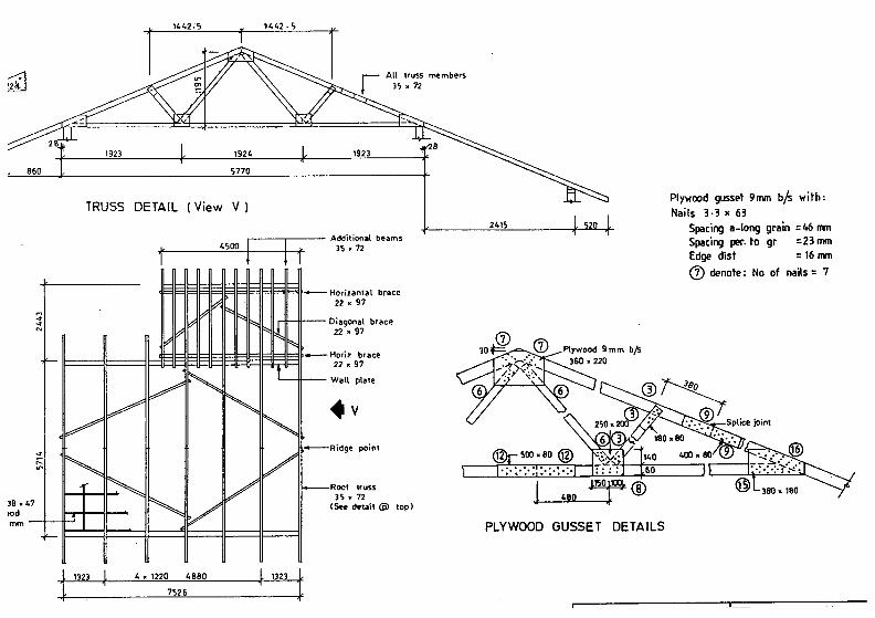
All truss members 35 • 72
TRUSS DETAIL (View V)
.---.---- Additional beams " 4500 • 35 • 72
1 1
~~~~~- Horizantal brace 22 • 97
11 11 Dia90nal brace 22.97
'---+f-- Wall plale .v point
Roer trU5S 35.72
lB.47
'~~~t:J~~WWI (~ delail (ii) lOp)
t 1323 ,L 4 • 1220 4880 ,L 1323 r : 7Y6
Plywood gussl?t 9mm h/s with: Nails 3·3 x 63
2415 Spac ing a-long gri!lin = ~6 rrm Spacing per. to gr =23 mm Edge dist = 16 mm
(J) denote: No of nails = 7
PLYWOOD GUSSET DETAILS

Panels
Panels
CD to
@ to
@
® Plywood sheZlthing 9 mm & 6 mm thick
Cemboard she.athing lOnvn & 8 mm thick
Studs .7 x 97 and .7 x 72
194,
t ZI"
721 1220 1220 610 721 r i ;~ ~ ~I I~I N 0 ~ 0 v] ~1: I~ ,I 1 l
' 610 r , !mo 'I l 111 mo 1220 1105: '10
i 1 ;1
Panel @ Panel @
713 610 mo ---"- 1220 713 r----: 1 I , ~ ~ @I ItA 0 tx1 1,1 111 113 N
!'03~ , 610 poil mo 1220
~ mo
1933' . I ZI43 ~ 1220
""nel @ Pzmel ® Panel ®
t 7ZZ
i 61O
1 .1220 ~
j I
0 @I lul N M ® @ I: :: :: :: :1
2411
mo 1213 2328
j
N 01 1 [I W N ~I 00 0 I~I lOO ml 001 ~
t 831 I 770 723 1101
I
~ I L449-S : 700 I ! .1-124
13Z8 1220 I do r: , 1108 1 .
Panel ® Panel ® Panel @
1'03 lZ14 mo 610
I I , @ Ihl N \4 WQiWla N NI I@ 0
707 ! 610 I ~1l2: n08 610 mo 610
1 1317 1830 1830
""nel® Panel ® Panel ®
1637
911 t
72Z ,JQ4 , ,
® I@ ® IiJ 14 I :~--i@ I~@I~ 11 HI I I~ , ;@I~ 9jP0l,1 mo ~ 1220
t mo , 301 'lOS 1830 !201' .j...lQW. 1103)9 +_:713 , mo ..:. 1220 610 ,
211Z 1125
Panel ® Panel ®
(ripple stud
I ----J..
Panel (i)
2440
PLAN
ELEVATiON
Panel (2)
1220
11 ~I 61O
133Z
P::an.1 (,)
I '91S 71J , Panel CD
J03 ..,,9
lWFmpr M
nz 7ZZ
~ "933 1830
Panel CD Panel @
vOla 01. VOID (01. VOID
ELEVATiON ELEVATiON
I i : : i\1 I: : :: ; : I
1109 J j . mo 1llZ
ZIIZ PLAN
PLAN D ___ I (";\
1220 liDS
(1 M ~I I~ ~ 0 ~
,
~"49. S • 700 \ ,380 '410 'V8' , , 1 '1213 i ~ lZZO
i Z433 +---
Panel ®
-E-!L ~ ~ I ~ ~ i
€1 M I~ @ m t?l ~ fN @ 0 I~ I 1Nl 1
I 1220 1 61O mo I 61O i 1788
~ 934, I
183O t 1830 Z72l.1
Panel ® Panel ® ""nel(@)
mo 610 ,103 , I
® I~ I iiY.1 0 1220 71J
1933
Panel@
DOUble col·
:; :1

-ISBN 983-9592-55-6
11111111111111111 ~