construction of a concrete plug in south deep’s main … · the shafts have been sited to...
TRANSCRIPT
▲213The Journal of The South African Institute of Mining and Metallurgy JULY/AUGUST 1999
Introduction
The shaft sinking contract at Western AreasGold Mine, South Deep Division, is a twinshaft project. The main and ventilation shaftsare being sunk to design depths of 2 765 mand 2 760 m respectively, making them theworld’s deepest single lift shafts. They have afinished lined diameter of 9 m.
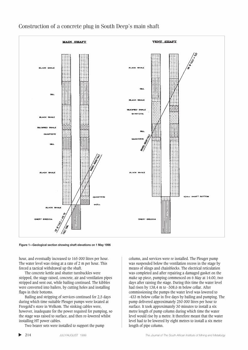
The shafts have been sited to traverse thesteeply dipping Broken Arrow fault at theintersection point of the giant chert brecciaabove the Malmani Dolomites of the TransvaalSeries, as shown in Figure 1.
The sinking method utilizes seven boomsinking drill rigs with pneumatic drifters toadvance 3 m rounds. Cactus grab units areused for mucking into 16 ton kibbles whichare hoisted to surface by double drum winders.The hoisting is guided by a crosshead on thestage ropes. A six deck working stage providesaccess for concrete lining of the shaft. A 6 m
high shutter is used and a concrete lift is castper day, concurrent with sinking.
The initial cover drilling procedure was astandard ring cover round of eight holes,drilled 48m deep, dipping at 10° from thevertical with a 12° clockwise spin. Whenrequired in problem areas, additional umbrellaholes were laid out, typically 24 m deep,dipping 20°‚ from the horizontal with a 20°anti-clockwise spin. Cover overlaps weremaintained at no less than 8 m.
Some of the more important precautionsdetailed in the cover drilling procedures are:
➤ sinking to stop 10 m short of any knownlarge water intersection above 10 000litres per hour as determined byprevious cover holes, and the standardcover round then to be redrilled
➤ all holes injected to 2,5 times the statichead and plugged with thick grout
➤ all holes yielding more than 100 litresper hour to be redrilled and deepened by 3 m.
The shaft bottom was within the standard8 hole cover lift, drilled from -418 m, andwhich included four additional flat holes.
On 1 May 1996 a round was drilled at -447 m and blasted at 08:30. On re-entry,water was noticed in the blasted rock. It wasestablished that the water intersection was onthe sidewall in the north-west sector of theshaft on the Broken Arrow Fault. The inflowoccurred at an estimated rate of approximately10 000 litres per hour. Water was bailed bymeans of kibbles for approximately five hours,then split set rock support installation from themuck pile was started, while bailing continuedfor two further hours. Four hours of shotcreteoperations followed which were concurrentwith bailing. By midnight the bailing no longermatched the inflow and the bottom flooded.The inflow was now about 80 000 litres per
Construction of a concrete plug inSouth Deep’s main shaft to seal off amajor water intersectionby M.F. Wells*
Synopsis
The method used to salvage South Deep’s Main Shaft after it wasflooded by an inrush of water at about 450 m below collar on 1 May1996 is described. The individual techniques employed in thesalvage were all proven technology, but the combination in whichthey were applied is considered to be novel. The operation involvedthe following activities in order of occurrence.
➤ the dewatering of the shaft with submersible pumps➤ the placement of a French drain on the shaft bottom muck
pile➤ the positioning of large diameter heavy walled draft tubes,
and smaller tightening up, grout intrusion and reverse flowpipes
➤ the casting and curing of a structural concrete plug; thecapping of the draft tubes; the intrusion of several thousandtons of cement grout into the aquifer by pressure inducedreverse flow
➤ the sealing of the aquifer➤ extensive probe drilling and sealing of the zone around the
inrush point with cement and other specialized grouts➤ the mining out of the plug and the re-establishment of
normal sinking routines.
* Cementation Mining, Selby, Johannesburg© The South African Institute of Mining and
Metallurgy, 1999. SA ISSN 0038–223X/3.00 +0.00. Paper received Jun. 1998; revised paperreceived May 1999.
Construction of a concrete plug in South Deep’s main shaft
hour, and eventually increased to 165 000 litres per hour.The water level was rising at a rate of 2 m per hour. Thisforced a tactical withdrawal up the shaft.
The concrete kettle and shutter turnbuckles werestripped, the stage raised, concrete, air and ventilation pipesstripped and sent out, while bailing continued. The kibbleswere converted into bailers, by cutting holes and installingflaps in their bottoms.
Bailing and stripping of services continued for 2,5 daysduring which time suitable Pleuger pumps were located atFreegold’s store in Welkom. The sinking cables were,however, inadequate for the power required for pumping, sothe stage was raised to surface, and then re-lowered whilstinstalling HT power cables.
Two bearer sets were installed to support the pump
column, and services were re installed. The Pleuger pumpwas suspended below the ventilation recess in the stage bymeans of slings and chainblocks. The electrical reticulationwas completed and after repairing a damaged gasket on themake up piece, pumping commenced on 6 May at 14:00, twodays after raising the stage. During this time the water levelhad risen by 138,4 m to -308,6 m below collar. Aftercommissioning the pumps the water level was lowered to -433 m below collar in five days by bailing and pumping. Thepump delivered approximately 250 000 litres per hour tosurface. It took approximately 30 minutes to install a sixmetre length of pump column during which time the waterlevel would rise by a metre. It therefore meant that the waterlevel had to be lowered by eight metres to install a six metrelength of pipe column.
▲
214 JULY/AUGUST 1999 The Journal of The South African Institute of Mining and Metallurgy
Figure 1—Geological section showing shaft elevations on 1 May 1996

On 11 May diamond drilling commenced off the stageafter the north side kibble hole had been decked off. Drillingcontinued for five days while the pump held the waterbetween -433 m and -439 m.
On 16 May a site meeting was held to consider options,and to decide on a course of action.
Consideration of options
Several alternative options to overcome the flooding problemwere considered. These included drilling and injecting grout,use of the ventilation shaft for access to -425 m, and theinstallation of a concrete plug to seal off the water inflowarea. These alternatives are considered in turn below, andillustrated in Figure 2.
Drilling and injecting
Five days were spent on the option of drilling from the stage,from 11 to 15 May. Repeated water losses demanded rodpulling, grouting, setting time and redrilling, only to lose thewater again. The attempt eventually failed and this optionwas rejected.
The second option in this alternative was drilling from acubby at -431 m. A 3 m x 3 m x 10 m cubby was considered.The advantage of this option was that a cubby lent itself tobetter diamond drill layouts, away from the shaft, to avoidthe water loss problem. The disadvantages included the timeto cover, excavate and support cubby. Since the cubby wouldbe situated in the hangingwall side of fault, holes would haveto traverse the fault zone, causing potential difficulties and
Construction of a concrete plug in South Deep’s main shaft
▲215The Journal of The South African Institute of Mining and Metallurgy JULY/AUGUST 1999
Figure 2—Considerations of options
Construction of a concrete plug in South Deep’s main shaft
drill steel losses. Holes could transfer water higher up theshaft bringing pressure closer to the sidewall and lining. Ifchemical injections were used, they could restrict theeffectiveness of future reverse flow efforts.
Vent shaft solutions
The options included a pump chamber at -425 m and miniborehole, or a pump chamber and minibore hole at -475 m.
The advantage of the first option was that there wasimmediate access to -425 m elevation, the current ventilationshaft bottom. The disadvantage was the risk of flooding theventilation shaft—the geology was adverse, drilling wouldhave to take place in the shale and traverse the fault zone,the minibore hole could deflect in the shale and miss theshaft, and scaling in the hole could make it difficult to case.
The advantage of the second option was that the geologywas favourable—the minibore hole would be in chert and thefootwall of the fault, making casing easier, and more accuratedrilling would be possible. The main disadvantage was thetime required for the option—half a month would be requiredto sink to -475 m, and two months to cover, excavate,support and equip the pump chamber.
A deeper variation of this option was subsequentlyexecuted at -500 m in the ventilation shaft. This rendered theexcavation of a temporary pump chamber in the main shaftunnecessary.
Concrete plugs
Three options were considered for this alternative:
➤ Flood to equilibrium and cast an underwater plug. Thismethod was used at Western Deep Levels South Shaftin 1982/83, Free State Geduld in 1953, andBlyvooruitzicht in 1937.
➤ It was considered that this method would take thelongest time, though it had a good chance of success.The major disadvantages would be the difficulty of the operation and uncertainties associated with the remoteconstruction of a plug beneath 300 m of flooded shaft.
➤ A plug constructed on the curb. This option was listedas a possibility, but was discounted because ofconstruction difficulties arising from the underside ofthe plug being 20 m above the shaft bottom.
➤ Construct the plug above a French drain on top of themuck pile. The plug would be of structural qualityconcrete, cast in controlled conditions, and superior toa grout intruded plug formed underwater. The reverseflow technique was considered the best solution to sealoff the water source. The risk was that of pump failurebefore capping the draft columns.
➤ At the meeting held on 16 May it was decided topursue this option, and design work beganimmediately. The solution was chosen because of itsdirect access and close proximity to the bottom. Inaddition, this option was based on proventechnologies.
Concrete plug design
The plug design conformed closely with the ‘Chamber ofMines’ Code of Practice on Construction of UndergroundPlugs and Bulkhead Doors Using Grout Intrusion Concrete’,dated February 1983.
The design parameters for the plug were as follows.
➤ maximum pressure likely to result from the reverseflow was 4,5 MPa
➤ plug length to be determined in accordance with theCOM Code of Practice using a sidewall/concreteinterface shear strength of 0,83 MPa
➤ required concrete strength of 30 MPa at 28 days;➤ concrete to be poured continuously at a rate of between
10 m3/hr and 20 m3/hr, with vibration by normalvibrator pokers.
The two substantial keys formed by the existing concretelining were ignored for design purposes, though it wasbelieved they would enhance shear resistance, Further, theplug was regarded as unreinforced, though the sacrificialscaffold, 48 tightening pipes, seven injection pipes and two draft columns would provide substantial reinforcing.
Using these design parameters, a plug length of 13,5 mwas calculated, and the minimum number of tightening pipesrequired determined to be 134.
The large diameter heavy walled draft columns
The two draft columns, known as the north pipe and thesouth pipe, each consisted of a top and bottom section. It wasdecided that the north pipe would be capped last, andtherefore should stand higher above the top of the plug thanthe south pipe. This was to allow enough time after removingthe pump from the north pipe for the column to be cappedbefore the water rose above the top flange.
The additional height on the north pipe was effected bythe inclusion of a 2 m spacer on top of the bottom sectionwith the same specification as the bottom section of pipe.
Bottom draft column specifications
Pipe length - 15 mPipe diameter - 900 mmWall thickness - 10 mmTop flange - 62 mm thick plate, with 24 holes
34 mm in diameter
Top draft column specifications
The maximum pressure that could be exerted on the topsection, which extended through the top of the plug, by thereverse flow process from a reservoir on the bank would be4,5 MPa. The wall thickness calculations were based on 5MPa. The pipe manufacturer was instructed to test the pipesto 6,4 MPa for two hours prior to delivery.
Pipe length - 8 mPipe diameter - 900 mmWall thickness - 12 mmBottom flange - 62 mm thick plate, with 24 holes
34 mm in diameter to match existingflange
Top flange - 147 mm thick plate, with 28 holes 62mm in diameter, for M59 Grade 8,8bolts
Blank flange - as for top flange plus one 150 mmdiameter, 100 mm long, weld-on pipecomplete with flange for reverse flow,and three 50 mm diameter, 50 mm longweld-on sockets for grout injections
▲
216 JULY/AUGUST 1999 The Journal of The South African Institute of Mining and Metallurgy

Flange grade - SABS 1431 Grade 43AGaskets - 3 mm thick Klingerite high pressure
gasketsPuddle flanges - Outside diameter 1100 mm, 16 mm
thick plate, 6 mm continuous filletweld 900 mm NB pipe with flangesand puddle flanges (See Figure 3)
The increased thicknesses of the blank flange and thewalls of the large diameter pipe, required to withstandworking pressures in excess of 10 MPa, discounted thepossibility of being able to supercharge the reverse flowprocess in order to improve the chances of success of thisaspect of the treatment. As it turned out, the 10 mm thickwalls of the north pipe bottom section collapsed duringtightening, requiring that the columns be capped in thereverse sequence.
The structural concrete plug
Using the above design parameters, the Code of Practicedeveloped by the Chamber of Mines, and allowing for aconservative factor of safety, a 14,6 m long structuralconcrete plug was designed and drawn up.
On completion of the design work, the design drawingsand the recent cover drilling records were included with theformal application for permission to construct the plug.
Application seeking permission to construct a plug
Regulation 2.10.14 states:‘Submit for approval to the Government Mining Engineer
plans and specifications giving details of construction andcatchment area of any dam to be constructed for the purposeof conserving water and of any coffer-dam or other barricadewhich is to be constructed underground for keeping back
Construction of a concrete plug in South Deep’s main shaft
▲217The Journal of The South African Institute of Mining and Metallurgy JULY/AUGUST 1999
Figure 3—900 mm pipe with flanges and puddle flanges, top draft column

Construction of a concrete plug in South Deep’s main shaft
water under a pressure exceeding 700 kilopascals.’On 21 May an initial meeting was held with the Regional
Director to communicate the novel aspects of the scheme andthe parameters involved with the design. This was followedup with the formal application at a second meeting on 22May. Senior representatives of the Regional Director’s Office,mechanical and civil engineers, a concrete technologist andthe direct role players were present. The methodology forsealing off the water was debated at length, with two mainreservations coming to the fore.
➤ The selection of the plug location: the proposed plugwas within a fault zone. Concern was expressedregarding the anchoring of the plug, its water tightnessand the possibility of water rising along the fault andbreaking back into the shaft above the plug at the -415 m elevation.
➤ In response to these concerns, the cover drilling recordsat the -380 m, -400 m, and -418 m elevations wereexamined, and it was established that the fault wasmore than adequately tightened in this area of concern.The cover holes were sealed at a pressure of 7,5 MPa,indicating that the fault was well treated and veryunlikely to transfer water where tightened. This wasconfirmed by previous drilling and injections in thetightened fault zone (see Figure 5, cover drill numbers9, 10 and 11).
When tightening the plug through the proposed holes,the fault would be further sealed.
➤ Sealing of the rock plug interface: the reservation wasthat the 48 tightening pipes laid out in the proposalwere less than the number recommended by theformula in the Code of Practice.In consideration of this reservation, the consultants,designers and constructors were of the opinion thatthey were more than adequate for a structural concreteplug.
The following points regarding a comparison betweenstructural concrete and grout intruded plugs were also takeninto account.
➤ Grout intruded plugs are commonly filled with handpacked plums and are usually constructed in thehorizontal plane. The proposed plug was an unrein-forced structural concrete plug in the vertical plane
➤ Grout intruded plugs have previously been castunderwater in flooded shafts. The proposed plug wouldbe cast in controlled conditions and vibrated, whichwould ensure plug quality
➤ The proposed plug was temporary, to seal the inflow,and was not a permanent plug designed to withstand alarge head for a long time.
Additional precautions
The following additional precautions were taken during plugconstruction:
➤ the concrete lining was monitored from the stage, andany indication of increased seepage was immediatelytreated
➤ concrete placing was carried out according to a writtenprocedure
➤ flange tightening and bolt torqueing was supervised bya certificated engineer
➤ pressure gauges and valves were installed on the stageas well as the plug
➤ ladders were installed from the stage to the top of theplug.
Concurrent with the meetings and debate with theRegional Director’s office, the placement of plums for theconstruction of the French drain around the draft columnswas taking place. Once procedures had been formalized forthe Additional Precautions, the Regional Director gavepermission for the plug to be constructed.
Concrete plug construction
After dewatering the shaft, the water level was maintained at-439 m elevation, the shutter was stripped out and thescheme developed for the salvaging of the shaft.
The method, illustrated in Figure 4, entailed theconstruction of a French drain and structural concrete plug,whilst continuing to pump using one submersible pump, withanother commissioned as a standby. A spare pump was kepton surface.
The steps involved in the plug construction were:
➤ install two 900 mm diameter draft columns above themuck pile
➤ install seven 50 mm diameter vertical cementationinjection pipes
➤ tip 4 m of washed plums on top of the muck pile➤ discharge 2 m of washed 19 mm stone down the
concrete pipe on top of the plums➤ place PVC and geofabric sheets on top of the french
drain above the water line➤ erect sacrificial scaffold and tightening pipes➤ cast 15 m concrete plug➤ cure the plug➤ tighten the plug➤ remove pumps and blank flange draft columns➤ start reverse flow accompanied by cement grout
intrusions.
Construction of the French drain
The two bottom sections of the 900 mm draft columns werepositioned on top of the muck pile. Seven 50 mm injectionpipes were placed around the circumference of the shaft.Three of these injection pipes were located in the north-westsector where the water inrush was believed to have occurred.During this time the water was being pumped by one pumpsuspended from the stage on the north side of the shaft.
The tipping of washed plums was then started, but had tobe interrupted to install a second HT cable for the secondpump. A depth of 4 m of plums was discharged into thewater and built up above the muckpile around the pipes. Theplums and stones were washed because the Pleuger pumpscan only handle clean water and are not designed for dirtywater pumping.
A modified lazy chain type tipping arrangement wasimprovised at the bottom of the stage, so that the machinekibble could tip the plums into the centre of the shaft. Handpositioning of plums took place around the large diameterpipes and away from the suspended pumps to avoiddamaging them.
▲
218 JULY/AUGUST 1999 The Journal of The South African Institute of Mining and Metallurgy

During the placement and tipping of the plums the thirdPleuger pump was tested on the second HT cable and tookover the pumping duty, suspended from the stage. The firstpump was then installed in the bottom section of the northpipe, the column extended to the lateral and the pumpingwas again switched over to the north side.
A depth of 2 m of 19 mm washed stone from the batch
plant was discharged down the concrete pipes on top of theplums. Once the stone was above the water line it waspossible to stand on the French drain and level it. Thisallowed men to stand on a ‘false’ bottom, whilst asubmersible pump maintained the water level just under thissurface by handling the 160 000 litres per hour that theaquifer was making.
Construction of a concrete plug in South Deep’s main shaft
▲219The Journal of The South African Institute of Mining and Metallurgy JULY/AUGUST 1999
Figure 4— Structural concrete plug

Construction of a concrete plug in South Deep’s main shaft
During the tipping of the stone, the top 8 m high pressuresection of the south pipe was lowered and installed, and thesecond pump inserted in the now completed south draftcolumn. The pumping was changed over to the south side.
A 50 mm balancing pipe was installed to discharge waterback into the north pipe. This facility dumped water back tothe French drain to ensure that the water level remainedconstant and that the pumps could not run dry. This wasmonitored and controlled by a man on top of the south pipein radio contact with another on the stage operating a valveon the balancing pipe.
The first pump was removed from the bottom section ofthe north pipe, the top section lowered, fastened, and thepump reinstalled. On completion, the pumping was switchedback to the north side.
The preparation, installation of the draft columns, thesecond HT cable run, and the construction of the Frenchdrain took 8 days from 18 to 26 May.
Erection of scaffold and tightening pipes
From 26 to 28 May geofabric and PVC sheets were placed ontop of the stone of the French drain, followed by the erectionof the sacrificial scaffold, platforms and ladderway.
Thirty-two tightening pipes were positioned in fourvertical rings over the length of plug, each consisting of eightpipes equally spaced around the circumference of the shaft.The sacrificial scaffold was required for access whilst castingand vibrating the concrete and to support the tightening pipesin a specific configuration.
Casting and curing of the structural concrete plug
A concrete mix was designed for a strength of 30 MPa at 28days and a procedure for the placing of the concrete wasdrawn up. Preparations that had to be completed beforecasting the plug were the placing of the geofabric and PVCsheets on top of the French drain, so as to prevent cementgetting through to the pumps, and the positioning of thesacrificial scaffold for access during the placement andvibration of the concrete.
Casting began at 10:00 on 28 May. Initially a pouring rateof 10 m3/hr was achieved. A calcium chloride accelerator wasadded to the first 500 mm to form a blinding screed. The pourprogressed well and it was decided to increase the rate to 20m3/hr once the first 5 m had been cast so as to reduce thetime that the pumps would be at risk from dirty water. Theincrease in heat generation from hydration with this high rateof pouring did not prove to be problematic. In fact, evenduring the curing no discernable increase in temperature wasnoted on top of the plug.
On the second day, the pour was stopped temporarily for5 hours to carry out maintenance on the batch plant andkettle, and to change concrete hoses. The last two rows oftightening pipes were installed from the scaffold, concurrentwith the pouring operations.
On 30 May there was some concern when the kibblewinder tripped for three hours. The first pump in the northpipe dropped its delivery rate and water pushed up the draftcolumns onto the plug. Switching over to the second pump inthe south column resulted in a gasket failure. The pumpingwas immediately switched back to the first pump, whichfortunately resumed its normal delivery. Later it was
established that the pump output had been adversely affectedby fine black grit which entered the pump from the fault,clogging the suction. Switching the pump off settled the grit,clearing the suction. The night shift crew had to contend witha minor concrete blockage at the kettle.
The pour was completed at 15:00 on 31 May. A total of1132 m3 had been placed in 3,2 days, resulting in an averagepour rate of 14,7 m3/hr including maintenance, blockage andpump delays.
The plug was allowed to cure for 5,1 days from 31 May to5 June. During the curing period the pump delivery andamperage were monitored and preparations were made fortightening.
Tightening of the plug and capping of the draftcolumns
On 5 June tightening commenced on the bottom ring (A ring,see Figure 4) according to the tightening procedure.Tightening was required to ensure adequate sidewall/concrete interface sealing and to take up any void caused byshrinkage. On 9 June, whilst tightening the first two B holes,the first pump cable developed a fault in the shaft, at a jointbox and along the cable above the stage. Pumping wasswitched to the second pump in the south pipe. It was thenestablished that the first pump and its shroud were stuck inthe 900 mm north pipe. The tightening was stopped. Withouta standby pump it was now considered imperative to cap thedraft columns.
The third Pleuger pump was lowered onto the plug. Thestage was raised, the faulty cable and joint box removed anda new cable installed and connected.
The blank flanges were suspended below the stage. Allthe tightening pipes were closed.
It was established that the bottom pipe in the north draftcolumn had collapsed 10 m below the top of the uppermostflange and the pump was trapped.
The sequence of capping the draft column had to bereversed, with the lower south pipe having to be blankflanged last. The problem was that there would not beenough time, between stopping and removing the pump, toposition the blank flange and torque the bolts, before thewater level would rise above the flange.
The solution lay in an improvised water handlingarrangement. The third Pleuger pump was installed on top ofthe plug in a vent pipe which served as a water tank. A Flygtpump and several Quimbys were placed on top of the plug.This solution was tested by allowing the top of the plug toflood, and then transferring the water with the Flygt to thePleuger in the ventilation pipe. This method proved capableof handling 160 000 litres per hour. Pumping was thenswitched back to the second pump in the south pipe.
Three 25 mm injection pipes were installed in the northpipe past the side of the trapped pump for future use.Concrete blinding was cast on top of sandbags on top of thepump. The blank flange was bolted onto the north pipe andthe column pumped full of cement grout.
The water handling system on top of the plug had beentested and all that remained for the final preparations was tostop the second pump, remove it and cap the south pipe.These preparations included arranging for two professionaldivers to be present to undertake the final bolting should the
▲
220 JULY/AUGUST 1999 The Journal of The South African Institute of Mining and Metallurgy

water rise above the flange. With the divers, senior sitesupervisors and project leaders present, the second pumpwas stopped and withdrawn from the south column. Thewater rose, flooded onto the top of the plug through the 150mm T piece, was picked up by the Flygt and Quimby pumps,delivered to the Pleuger in the vent pipe tank and pumped tosurface.
On 12 June at 22:00 the columns were successfullycapped, which was a significant accomplishment. The waterinflow was under control, and there was no longerdependence on the pump, thus removing the concern ofpump failure.
The initial pressure on the plug was only 2,0 MPa. Amore accurate gauge subsequently recorded 2,9 MPa,
Construction of a concrete plug in South Deep’s main shaft
▲221The Journal of The South African Institute of Mining and Metallurgy JULY/AUGUST 1999
Figure 5—Cover elevations 9, 10, 11

Construction of a concrete plug in South Deep’s main shaft
indicating the water table at -133 m below collar.Immediately following the capping, the reverse flow pump
column changeovers were done on the sub-bank and shaftbottom and the reverse flow process initiated.
Reverse flow and cement grout intrusions
On 12 June the reverse flow tank was commissioned onsurface with a flow meter on the 100 mm column from thedams. The 150 mm valve on the reverse flow column, justabove the blank flange, was opened and the water allowed torise to its equilibrium level. A T-piece was installed on thepump column so that a probe could be lowered to determinethe level of the water table. This probe indicated the level at -156 m below collar. This meant that there was a 300 m headand a pressure of 3,0 MPa was expected. A 40 bar gauge wasinstalled on the south side draft column via a hydraulic hoseto the stage and this gauge recorded 2,9 MPa. A gauge on thereverse flow column on the stage recorded 2,7 MPa.
The reverse flow was started at a rate of approximately60 000 litres per hour after one additional 50 mm waterdelivery feed was installed. On the evening of 13 June cementintrusions began and supplemented the reverse flow. (SeeFigure 6 plan view of reverse flow process pipes.) Thisprocess continued for the next 34 days until water acceptanceby the aquifer stopped on 18 July. A further 6 days of groutinjections followed. All the cementation pipes were finallysealed on 23 July, 40 days after the process had started. Overthis period 7 340 000 kg of cement and 11 mega litres ofreverse flow water were introduced below the plug.
Initially three double drum mixers and pumps were usedfor the cement intrusions, and the mix ratio was increasedfrom 100 kg/300 litre barrel to 150 kg/barrel with a reverseflow of approximately 42 000 litres per hour. On 15 June ahigh shear electric mixer with a storage tank and two pumpswere erected. The plug pressure gauge was now reading 2,5MPa. From 16 to 28 June the mix ratio was increased to 450kg/barrel (1,5:1), with the reverse flow reduced from approx-imately 40 000 to 12 500 litres per hour, and with two tothree pumps running via grout ranges to the variousintrusion pipes. During this period the pressure at the plug
rose from 2,5 MPa to 3,8 MPa.On 28 June the cement mix ratio was increased to 525
kg/barrel (1,8:1), and again on 29 June to 600 kg/barrel(2:1). By 30 June the reverse flow was down to 10 000 litresper hour and about 300 tons of cement was being intrudedper day. On 2 July 1996 the reverse flow and intrusions werestopped and the quantity and pressure of the inflow checkedthrough a 50 mm valve. The inflow was now only 15 120litres per hour, down from the original 165 000 litres perhour, and the water pressure head was only 2,0 MPa. Thereverse flow with the valve fully open would only take 15 600 litres per hour.
When the reverse flow and injection process started upagain, the plug pressure had dropped from 3,8 MPa to 3,4MPa. The cement mix was increased to 750 kg/barrel (2,5:1).On 4 July a record 363 tons of cement were intruded in a 24-hour period. The plug pressure recorded was 3,5 MPa.
On 5 July the reverse flow and intrusion process wasstopped for the second time to test the inflow through a 150mm opening. This time the fissure inflow was measured at19 895 litres per hour. On starting the process again the plugpressure had reduced from 3,5 MPa to 3,0 MPa.
On 7 July the intrusion operation changed to bulk cementinstead of 50 kg pockets, using the batch plant silos andmixers, and then feeding the high shear mixer and storagetank. Extremely thick grout mixes of 2,1:1 to 2,3:1 wereintruded on 8, 9 and 10 July with a reverse flow of approxi-mately 8000 litres per hour. Heating elements were installedin the reverse flow tank.
Over the 11, 12, 13 July the grout mix ratio was reducedto 1,5:1 with approximately 7 000 litres per hour reverseflow.
On 12 July the intrusion pipes blocked and had to beredrilled. The fissure inflow was checked for the third timeand recorded at 14 000 litres per hour. Some sodium silicatewas pumped into the intrusion pipes. Reverse flow andintrusions continued until the reverse flow choked off. On 13July two cementation ranges blocked and had to be openedand repaired. Two cementation pumps were put onto thereverse flow on the blank flange, but this just pushed thewater back to surface. Using one cementation pump, areverse flow of approximately 5000 litres per hour into thefissure was achieved. On 15 July the grout mix was set at1,8:1, the blocked cementation ranges were redrilled, andintrusion resumed with one pump on grout and 3 pumps onwater only. This continued for three days, 100 tons of cementper day being accepted. Plug pressure was steady at 3,9 MPa.
At a meeting on 17 July it was decided to stop the reverseflow and just inject cement grout until the fissure was sealed.Leakage occurred on the gasket of the blank flange and wasrepaired. Holes 6, 2 and 1 sealed off at 6 MPa on 17 and 18July. On 19 July holes 5A and 3 were reinjected and sealed.Holes 1, 4, 5, 6 were redrilled and injected, with holes 1,5and 6 resealing on the same day. No. 4 hole took anotherthree days and 56 tons of cement and finally sealed on 23July.
At this point the reverse flow and intrusion phase wasconsidered complete, and the probe drilling began. Figure 7gives a summary of the reverse flow and cement intrusionphase.
▲
222 JULY/AUGUST 1999 The Journal of The South African Institute of Mining and Metallurgy
Figure 6—Plan view of reverse flow process pipes

During this period an intermediate pump station wasexcavated at -500 m in the Ventilation Shaft.
Drilling programme
It now had to be established, from an extensive drilling andconsolidation programme, if in fact the fissure had beeneffectively sealed. This programme eventually consisted of 33vertical holes, 32 tightening holes, 12 complementary holesof 45,0 m, 12 umbrella holes of 27,0 m, 12 ring cover holesof 43,0 m, and 2 additional holes. A total of 3 754 m ofdiamond and percussion drilling was carried out. Super groutinjections in vertical holes involved 24 640 kg of grout. Totalcement injections were 159 683 kg.
The probe drilling which began on 23 July proved to betime consuming. The extent of the drilling required toconfirm that the water had been sealed off was completed on7 September, some 46 days later.
Vertical holes
The first step in the vertical hole drilling was re-drillingthrough the grout intrusion pipes onto the muckpile andcementating to consolidate the plug, French drain and otherloose material. Screw feed compressed air diamond drillmachines were initially used to drill, re-drill and deepenthese holes to 10 m into the solid footwall to obtain core forgeological evaluation. No chemicals were used at this stage.
The number 2 and 3 grout intrusion pipes containedstuck drill rods from periodic blocking and re-drilling duringreverse flow and intrusions.
The core drilling had very limited success due to the
presence of the gritty fault material not bonding with cementand making consolidation extremely time consuming. Oftencore loss was complete because of the grit.
The only water intersected was 300 litres per hour in hole6 and 100 litres per hour in holes 4 and 5, indicating asuccessful seal. Following the deepening of the groutintrusion pipe holes, a further 27 vertical holes were laid out,running north-south, mainly on the western side of the shaft.These new holes were cased with 6 m casings into the plug,and pressure tested to 10 MPa.
Drilling through the concrete was slow, and advancerates below the concrete plug were severely restricted as aresult of the consolidation work required in the French drainand blasted rock. Some of the holes struck the steel of thescaffolding and tightening pipes and had to be abandoned. Inholes meeting the gritty fault material, the bit or rods jammedas a result of water loss. To speed up the time-consumingconsolidation process, a specialized micro-silica based groutcalled Super Grout was used. This grout was able to bond tothe grit and enabled the holes to penetrate into the solidfootwall. Of these 27 additional vertical holes only holenumber 14 intersected any water, 150 litres per hour. All theremaining holes were dry, confirming successful treatment ofthe zone below the shaft.
Tightening holes, complementary, umbrella and ringcover holes
The 32 tightening holes were deepened to an average of 40 m. Only five of these holes intersected water—hole A5,900 litres per hour; hole C, 300 litres per hour; hole A6, 2100litres per hour; hole D5, 290 litres per hour; hole C4, 1290
Construction of a concrete plug in South Deep’s main shaft
▲223The Journal of The South African Institute of Mining and Metallurgy JULY/AUGUST 1999
Figure 7—Reverse flow and cement intrusions

Construction of a concrete plug in South Deep’s main shaft
litres per hour. 75 220 kg of cement were injected into theseholes.
The bottom was cluttered with casing pipes, wedge boltsand tightening pipes as well as machines, cradles, rigs andcontrols. After ensuring that all the vertical holes were todepth and sealed the casing pipes were cut off on top of theplug.
On 25 August a 12 hole umbrella cover with a dip of +5°,a depth of 27 m, and an anti-clockwise spin was drilled fromthe top of the plug. One hole intersected 1 440 litres per hourand 44 800 kg of cement were injected for the whole cover.
On 29 August the Jumbo drill rig was lowered and anadditional 12 holes, 45 m deep at a dip of -70°, were drilledto complement the tightening pipes and fill the gaps. All theholes were dry and 28 980 kg of cement were injected. The900 mm draft columns and remaining casings were cut off ontop of the plug.
The drill rig was taken down for a 12 hole ring cover,with only two holes intersecting water—a trace and 90 litresper hour. 10 690 kg of cement were injected, completing thecover on 6 September.
It had now been confirmed with confidence that the zone,from 40 m below the plug and radially to 20 m beyond thebarrel, was dry and the excavation of the plug couldcommence.
During the recovery of the Main shaft, the Ventilationshaft had completed the pump station, commissioned thepumps and sunk to -560 m.
Shaft recovery
The removal of the plug began on 7 September. Duringexcavation of the plug to -432,5 m, the drilling and blastingof the concrete went better than expected. Initially, dailyblasts yielded 1,4 m advances. The drill rig achieved goodpenetrations, whilst the lashing cycles were extended due tothe cutting out of the steel and 900 mm draft columns,tightening and intrusion pipes and the scaffolding. Cement-contaminated blow overs were particularly harsh on the crew.
On 12 September a 12 hole, 43 m deep ring cover at 80°was started at -432,5 m elevation. Of the 12 holes, only holenumber 9 intersected trace water. Eleven additional holeswere drilled, all dry, confirming the effectiveness of the seal.
Whilst this cover was being drilled, a diamond drillmachine in the ventilation shaft pump chamber drilled acover hole in the line of the minibore hole from theventilation shaft pump chamber to the main shaft. A secondmachine was aiming at the fault and previous waterintersections. During main shaft injections, coupling occurredwith these approaching holes.
The remaining +6 m of the concrete plug and +3 m of theFrench drain was removed in advances of 1,3 m per blast.The cycle time was 15,5 hours. The 19 mm stone section ofthe French drain was found to be well consolidated. Theminiborer in the ventilation shaft had collared and begunboring. The curb and shutter were reinstalled in the shaft.Five cores were taken from the plug concrete for testing. Theaverage strength was 33 MPa.
On 23 September at -442 m elevation, near the top of theFrench drain, a 12 hole, 48m -80° ring cover was started. 3holes intersected water—hole 7, 900 litres per hour; hole 7A,
300 litres per hour; hole 9, 720 litres per hour; 86 246 kg ofcement and 3 600 kg Super Grout were injected into this lift.
Twelve additional holes were laid out, of which hole 19Aintersected 7 200 litres per hour, and hole 20, 250 litres perhour. On 3 October these additional holes were sealed withprogressive injections of 10 260 kg of cement and 500 kg ofSuper Grout.
The remaining plum section of the French drain wasremoved, recovering the trapped Pleuger pump, damaged butcomplete. The muck pile was removed, uncovering the solidshaft bottom at -450 m and exposing the breach zone.
The sidewalls and bottom were examined on 8 October.The steeply dipping boundary planes of the Broken Arrowfault could be seen distinctly on the sidewalls, with typicalgritty, friable, decomposed infill between the top and bottomboundaries. On the northern sidewall a roughly horizontalfissure, 3,5 m in length varying from between 3 cm and 8 cmin width, was evident running across the steeply dippingfault planes. This fissure was filled with cement and SuperGrout. The shaft had been recovered to the elevation attainedat 1 May 1996 some five months and one week afterflooding. Normal sinking routines could not be resumed,however, owing to the intensive cover drilling at closeintervals which was carried out for the next 120 m ofsinking.
The day after the shaft was recovered the miniborer fromthe ventilation shaft pump chamber holed into the mainshaft. This hole was subsequently reamed to 279 mm indiameter, sleeved, and provides an emergency waterhandling service for both shafts from the intermediate pumpchamber in the ventilation shaft.
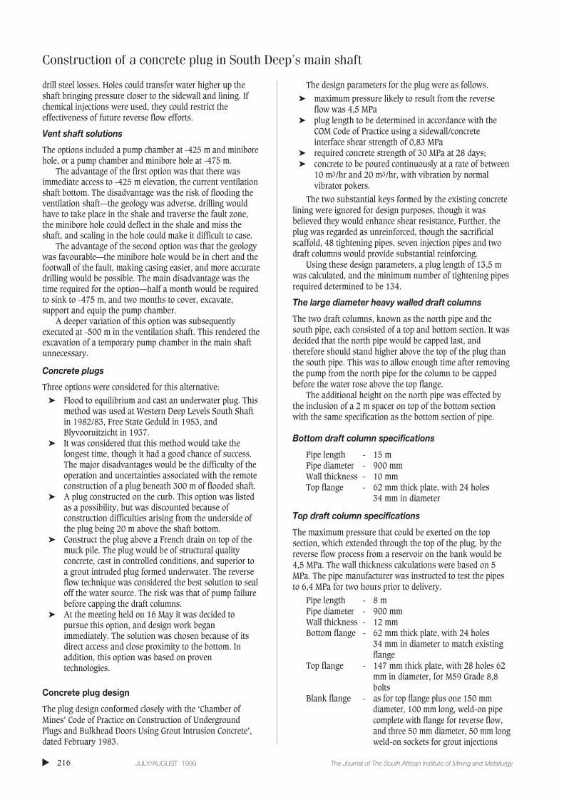
Cover drill rounds used in the dolomites
The cover round consisted of a 16 hole ring cover, a 16 holeumbrella cover and one stab hole as shown in Figure 8. The16 umbrella cover holes numbered U1 to U16 were drilledradially out from the centre of the shaft, collaring at thesidewall/footwall intersection. These holes dipped at -65°from the horizontal, and were drilled to a depth of 24 m.
The stab hole was drilled vertically to a depth of 48 mand positioned within 1,5 m of the shaft centre.
The cover consisted of two rings, one at a radius of 4,5 mand the other at 4,0 m from the centre of the shaft. The outerholes were odd numbered R1, R3 to R15 and the inner holeseven numbered, R2, R4 to R16. All of these holes were spunclockwise at 45° to the tangent and drilled to 48 m. The outerring holes dipped at 75° whilst the inner ring dipped at -80°.
Discussion and conclusions
The salvaging of the shaft was a success and is a tribute toall those involved. The experience was not only an exampleof the benefits of client/contractor cooperation and jointparticipation in problem solving, but was a technologicalachievement which involved the application of all thespecialized mining, drilling and engineering skills of theproject team and contractor.
In consideration of whether the method could beconsidered for future shaft water intersections, and whetherit was efficient, it is necessary for each water intersection to
▲
224 JULY/AUGUST 1999 The Journal of The South African Institute of Mining and Metallurgy
be assessed for its own peculiar characteristics, depth,pressure, volume and pumping facilities. The method utilizedin this case might not suit another set of conditions. Thegreatest risk was the possibility of failure of the Pleugerpump during plug construction. This risk was effectivelyminimized by the initial availability of three commissionedpumps.
In terms of duration, the construction of the French drainand plug, and the curing, tightening and capping took only26 days of the five months and one week salvage period. Thedrilling, blasting and mucking of the 26 m plug, the Frenchdrain and the grouted muck pile from -424 m to -450 m onlytook 14 days.
The bulk of the time, nearly three and a half months wastaken up with the reverse flow and injections, which took 40days; and the redrilling, injections and additional covers took63 days.
The reverse flow technique is the key to sealing exposedaquifers of this nature. Could the reverse flow and groutintrusion process have been made more efficient in terms oftime? Supercharging the reverse flow process by increasingthe feed pressure through a battery of pumps wasconsidered, but the draft column pipes were limited to 7 MPaand there were water supply quantity constraints.
Owing to the large grout acceptances additives wereconsidered to reduce cement costs:
➤ slagment and OPC in a 50:50 mix, but slagment has nomechanical strength
➤ pulverized fuel ash (PFA) could be mixed with thegrout, which provides a more pumpable grout, butincreases setting time
➤ tailings were considered, but rejected on environmentalgrounds, as they could contaminate the groundwaterand choke off fine fissures.
Cement/water ratios were debated at length, and most ofthe grout was intruded at between 1,5:1 and 1,8:1. Extremelythick grouts of as high as 2,3:1 to 2,5:1 were pumped forshort periods. It was found that greater acceptance wasachieved at the lower ratios where the pumps were moreefficient.
Specialized chemical grouts were considered, but notemployed as it was feared they might jeopardize the ultimatesuccess of the reverse flow intrusions.
Coloured dyes were used to indicate coupling betweenintrusion pipes and independent pathways into the fissure.Isotopes were considered to establish cement travel but notused.
On three occasions the reverse flow process and groutintrusions were stopped to determine the fissure flow. Thisconfirmed that the intrusions had reduced the flow to 19 000, and later to 14 000 litres per hour, giving some faithin a seemingly eternal and possibly fruitless process. Inretrospect, these checks probably dislocated some of theaccretion that had taken place, which was noticed in thereduced pressures measured when the flowback was stoppedand the reverse flow started up again.
The introduction of sodium silicate just before the reverseflow stopped and the intrusion pipes blocked was probablycoincidental and not the reason for the final seal.
Pumping of high pressure water to re-open pathwaysthrough the grouted shaft bottom to extend the reverse flowand intrusions probably caused the south pipe gasket to leak.
The reverse flow and grout intrusions seemed to run theirown natural course and eventually a seal was obtained aftera Biblical 40 days and 40 nights. How this process couldhave been accelerated is the subject of continuing debate.The extended drilling programme did confirm that the reverseflow had effectively sealed the fissure.
The probe drilling, injections and additional cover drillingtook most of the time and it is doubtful whether this periodcould have been shortened without endangering the successof the programme. Initial consolidation problems below theplug were later resolved by the utilization of a specializedchemical grout. The drilling programme was extensive andtime consuming, but necessary to establish the confidencethat the water had been sealed.
No significant water was intersected after the 7 360 tonsof cement were intruded by the reverse flow process. Theadditional covers at -424 m, -432 m and -442 m werebasically all dry and accepted only a further 204 tons ofcement and 4,1 tons of Super Grout.
The concern that water might travel back along the faultand break back into the shaft at the lining fault intersectionproved to be groundless, confirming that the fault had beenadequately tightened and treated on the previous covers.
The fact that the tightening phase was cut short by thecollapse of the bottom north pipe proved not to be a problem,as the 416 tons of cement injected during the drilling phasemore than adequately tightened the plug, which wasconfirmed during the plug removal. Whether the collapse ofthe bottom draft columns was due to tightening and/orcasting continues to be deliberated.
The trapped pump was recovered.The grit within the fault proved extremely difficult to
consolidate and was responsible for choking the suction on thepump on numerous occasions. The inflow point turned out tobe at the intersection of some significant geological features—where the steeply dipping Broken Arrow fault intersected thegiant chert breccia above the Malmani dolomites of theTransvaal series. The chert breccia-dolomite contact turned outto be 39 m higher than originally projected.
Construction of a concrete plug in South Deep’s main shaft
▲225The Journal of The South African Institute of Mining and Metallurgy JULY/AUGUST 1999
Figure 8—Typical cover drill rounds used in dolomites

Construction of a concrete plug in South Deep’s main shaft
The revised cover round described for the dolomiticsequence was a more intensive pattern, which left little tochance but took significantly longer to drill and inject.
The connection of the main shaft with a sleeved largediameter hole to a pump chamber in the ventilation shaft, toprovide an emergency water handling facility to surface,proved to be a success, saving the excavation of anintermediate pump chamber in the main shaft.
Acknowledgements
The author wishes to thank the Managing Director andConsulting Engineer of JCI Limited for permission to publishthis paper. Assistance is acknowledged from members of theSouth Deep Project Team; site personnel; CementationMining, Drilling Division; the Design Engineers; the Concrete
Technologist; and the Geology Department of Western AreasGold Mine.
References
1. ALLEN W. and CRAWHALL J.S. Shaft sinking in dolomite at Venterspost,Association of Mine Managers Papers and Discussions. 1937–1938. pp. 1–42.
2. LANCASTER F.H. (1964) Report on research into underground plugs,Transvaal and Orange Free State Chamber of Mines ResearchOrganisation. C.O.M. Project No. 203/64. Research Report No. 27/64,August 1968.
3. SOLMS R.L. DE G. The flooding of Western Deep Levels No. 1 Shaft,Association of Mine Managers Papers and Discussions 1982–83. pp. 249–285.
4. WILLEMSE R.B. Cover drilling during shaft sinking at Western Deep LevelsLimited South, Association of Mine Managers Papers and Discussions,1984-1985. pp. 19–62. ◆
▲
226 JULY/AUGUST 1999 The Journal of The South African Institute of Mining and Metallurgy
For further information, please contact:The Secretariat, SAIMM, P.O. Box 61127, MARSHALLTOWN 2107
Tel.: (011) 834-1273/7, Fax: (011) 838-5923 or 833-8156, e-mail: [email protected]
MINING
SCHOOLNarrow tabular orebody Mining21–22 October 1999, Mintek, RANDBURG
COLLOQUIUMNational Environmental Management Act—Implications forthe Mining and Metallurgical Industry11 November 1999, Mintek, RANDBURG
EXTRACTIVE METALLURGY
SEMINARGravity separation15 September 1999, Randfontein Estate Sports Club
SCHOOLSolvent extraction and electrowinning basic principles andapplications13–14 October 1999, Mövenpick Indaba Hotel
INTERNATIONAL CONFERENCESExtraction Metallurgy Africa ’991–2 November 1999, Indaba Hotel, Fourways, GAUTENG
Heavy Minerals Conference ’9915–17 November 1999, DURBAN
Coal—The future12–15 September 2000, Sandton, GAUTENG
SAIMM DIARY
OBITUAROBITUARYY
Date of Election DateDeceased
P.K. Bredell Retired Member 21 April 1978 May 1999