construction of nz’s strongest strong floor grant …
TRANSCRIPT
CONSTRUCTION OF NZ’S STRONGEST STRONG FLOOR
GRANT THOMAS1, DENE COOK2
1 Dominion Constructors 2 Firth Humes Group
CONSTRUCTION The Canterbury earthquake sequence has highlighted the difficulties associated with applying results from small scale or component tests to real world scenarios. As part of the University of Canterbury College of Engineering campus re-development Dominion Constructors have completed construction of a new Structural Engineering Laboratory (SEL). This is an 800m² facility with a 500m² strong floor and strong walls and provides the necessary infrastructure for testing full-scale building systems under a variety of load conditions. Believed to be the strongest testing facility in New Zealand with its 2m thick reinforced concrete floor and 1.6m thick, 9.2m high L shaped cantilevered wall; post tensioned in both the horizontal and vertical directions. Cast into this floor and walls are Macalloy tension bars with a custom made coupler to allow the University to set up their testing scenarios via M36 bolts on a 400mm grid. There are 2067 bars and couplers in the floor and a further 1540 bars and couplers which are cast into the wall. All 3607 cast in bars and couplers have a positional tolerance of +/- 2mm in the x, y & z axes. Right from the tender stage an integral component of Dominion’s construction methodology was the development of a Building Information Model (BIM) for the project. This was to mitigate the coordination risk of the heavily congested reinforcing steel and post tensioning components incorporating the exacting tolerances for the Macalloy bars and couplers. The model was fully coordinated to include formwork set-out, cast-in place componentry and temporary works. In parallel with the BIM modelling Dominion also undertook construction of mock-ups to verify detailing, buildability and establish benchmark quality. It was at this stage that Dominion and the design team began consultation with Firth Concrete to develop the specialised concrete mixes which ultimately lead to a “layer cake” placement of the concrete within the raft slab. Through the use of BIM and a collaborative approach by the design team working with the model, numerous clashes were identified, allowing reconfiguration and any necessary redesign prior to construction. The model also proved its worth when there was a design change introduced that required the diameter of the cast in couplers on the Macalloy bars to increase. The BIM model allowed the designers to determine the maximum diameter and verify that there were no clashes with the reinforcing across the entire floor and wall. Once the BIM model had been finalised a series of placing sequence and detailing sheets was produced for bending of the reinforcing bars and placement on site which all but eliminated production errors and on-site wastage. With the BIM model developed Dominion and the construction team still had the challenges of constructing to the required millimetre tolerances. On site the model was made available and utilised as a tool by the construction team, using an IPad and BIM 360 Software. It was also
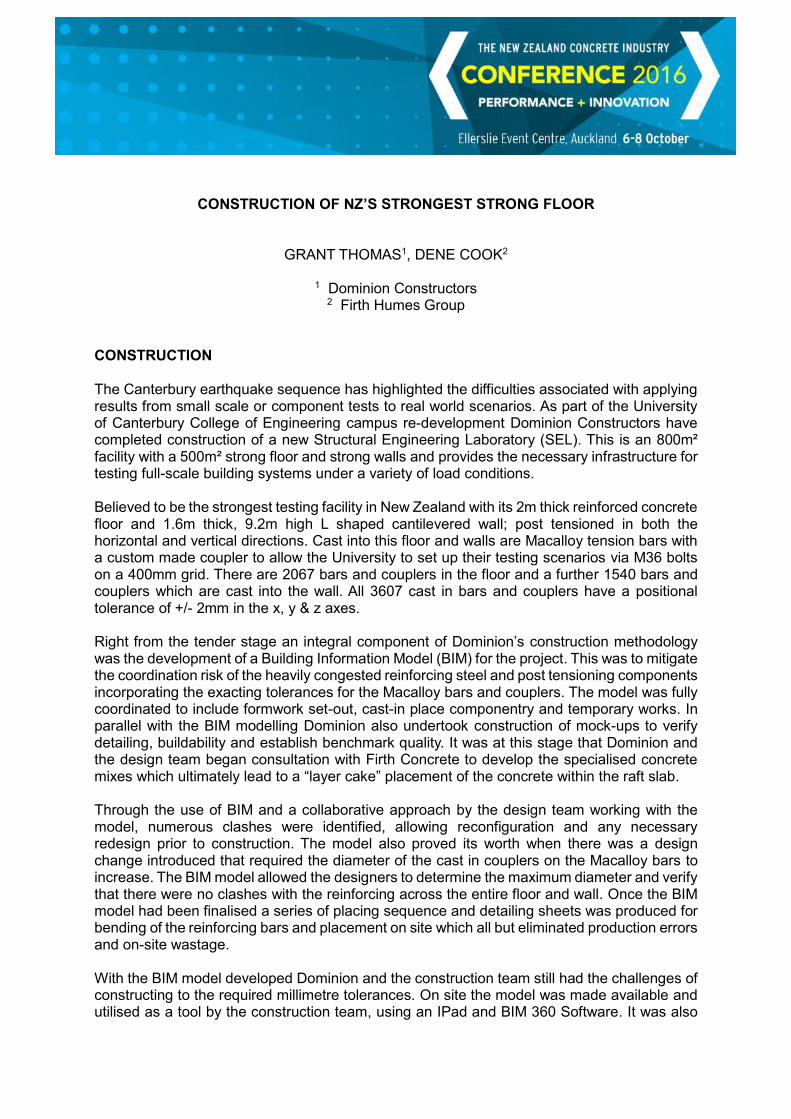
used to assist with quality assurance procedures as it provided an almost photographic representation which could easily be compared with the as-constructed layouts. Construction began with excavation for the 2m deep strong floor, which involved dewatering as the site water-table sat above the base of the excavation. Accuracy had to begin from step one of the process, as such the site concrete at the base of the floor reinforcing was installed using a laser screed. The slab edges were reversed formed or sheet piled and backfilled with concrete rather than using conventional formwork for the duration to create a “swimming pool”. This had the added advantage of preventing any contamination of the reinforcing cage and provided greater safety for the workers as formwork did not need to be constructed and removed from between the reinforcing steel and batter zone. To support the reinforcing steel and hold the Macalloy bar assemblies and couplers in place Dominion utilised a cast-in steel truss. These were accurately levelled and positions above the site concrete and bottom mat of reinforcing.
Installation of the 53 trusses used to suspend the Macalloy bars.
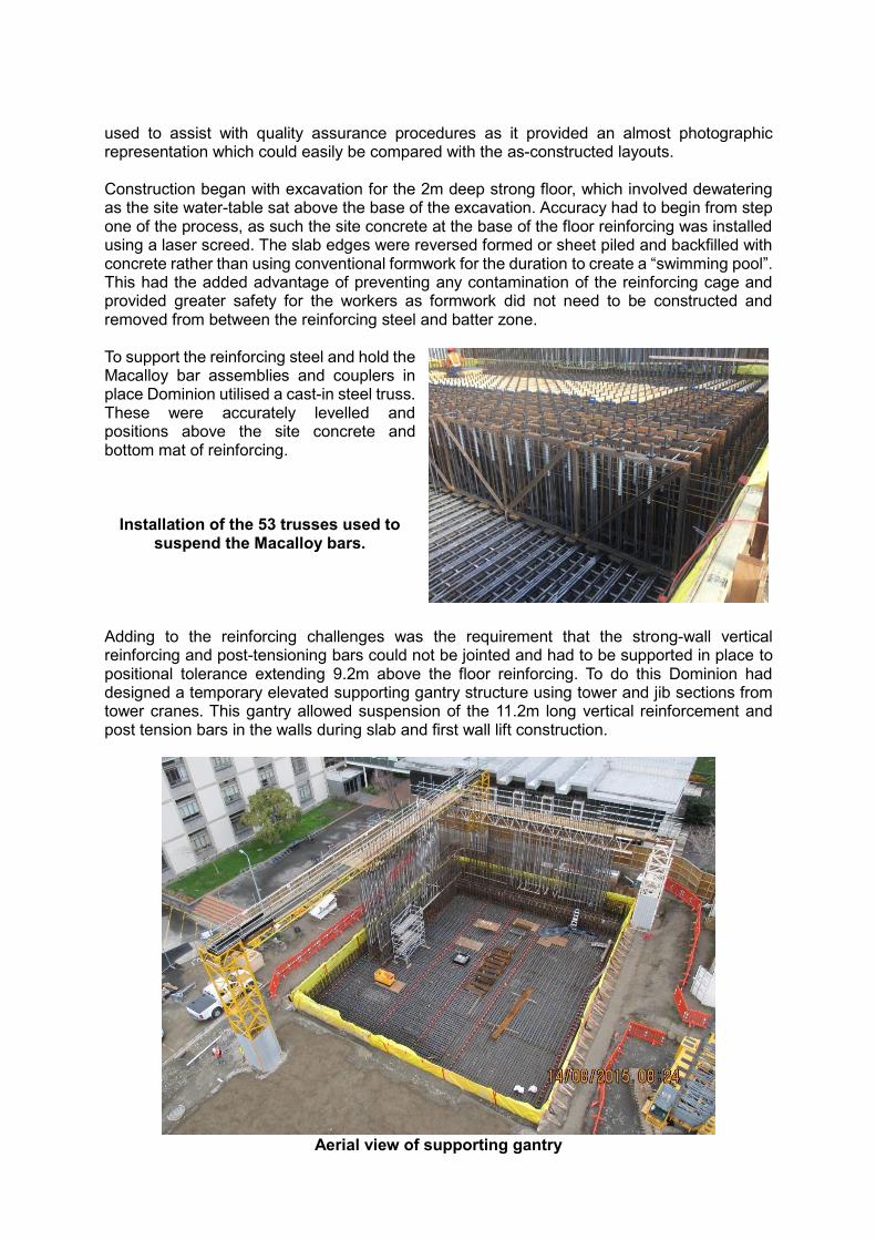
Adding to the reinforcing challenges was the requirement that the strong-wall vertical reinforcing and post-tensioning bars could not be jointed and had to be supported in place to positional tolerance extending 9.2m above the floor reinforcing. To do this Dominion had designed a temporary elevated supporting gantry structure using tower and jib sections from tower cranes. This gantry allowed suspension of the 11.2m long vertical reinforcement and post tension bars in the walls during slab and first wall lift construction.
Aerial view of supporting gantry
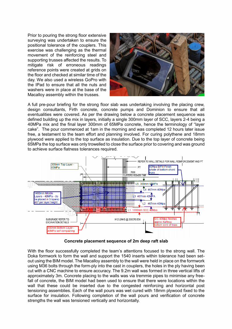
Prior to pouring the strong floor extensive surveying was undertaken to ensure the positional tolerance of the couplers. This exercise was challenging as the thermal movement of the reinforcing steel and supporting trusses affected the results. To mitigate risk of erroneous readings reference points were created at grids on the floor and checked at similar time of the day. We also used a wireless GoPro with the IPad to ensure that all the nuts and washers were in place at the base of the Macalloy assembly within the trusses. A full pre-pour briefing for the strong floor slab was undertaking involving the placing crew, design consultants, Firth concrete, concrete pumps and Dominion to ensure that all eventualities were covered. As per the drawing below a concrete placement sequence was defined building up the mix in layers, initially a single 300mm layer of SCC, layers 2-4 being a 40MPa mix and the final layer 300mm of 65MPa concrete, hence the terminology of “layer cake”. The pour commenced at 1am in the morning and was completed 12 hours later issue free, a testament to the team effort and planning involved. For curing polythene and 18mm plywood were applied to the top surface as insulation. Due to the top layer of concrete being 65MPa the top surface was only trowelled to close the surface prior to covering and was ground to achieve surface flatness tolerances required.
Concrete placement sequence of 2m deep raft slab
With the floor successfully completed the team’s attentions focused to the strong wall. The Doka formwork to form the wall and support the 1540 inserts within tolerance had been set-out using the BIM model. The Macalloy assembly to the wall were held in place on the formwork using M36 bolts through the form-ply into the cast in couplers, the holes in the ply having been cut with a CNC machine to ensure accuracy. The 9.2m wall was formed in three vertical lifts of approximately 3m. Concrete placing to the walls was via tremmie pipes to minimise any free-fall of concrete, the BIM model had been used to ensure that there were locations within the wall that these could be inserted due to the congested reinforcing and horizontal post tensioning assemblies. Each of the wall pours was wet cured with 18mm plywood fixed to the surface for insulation. Following completion of the wall pours and verification of concrete strengths the wall was tensioned vertically and horizontally.
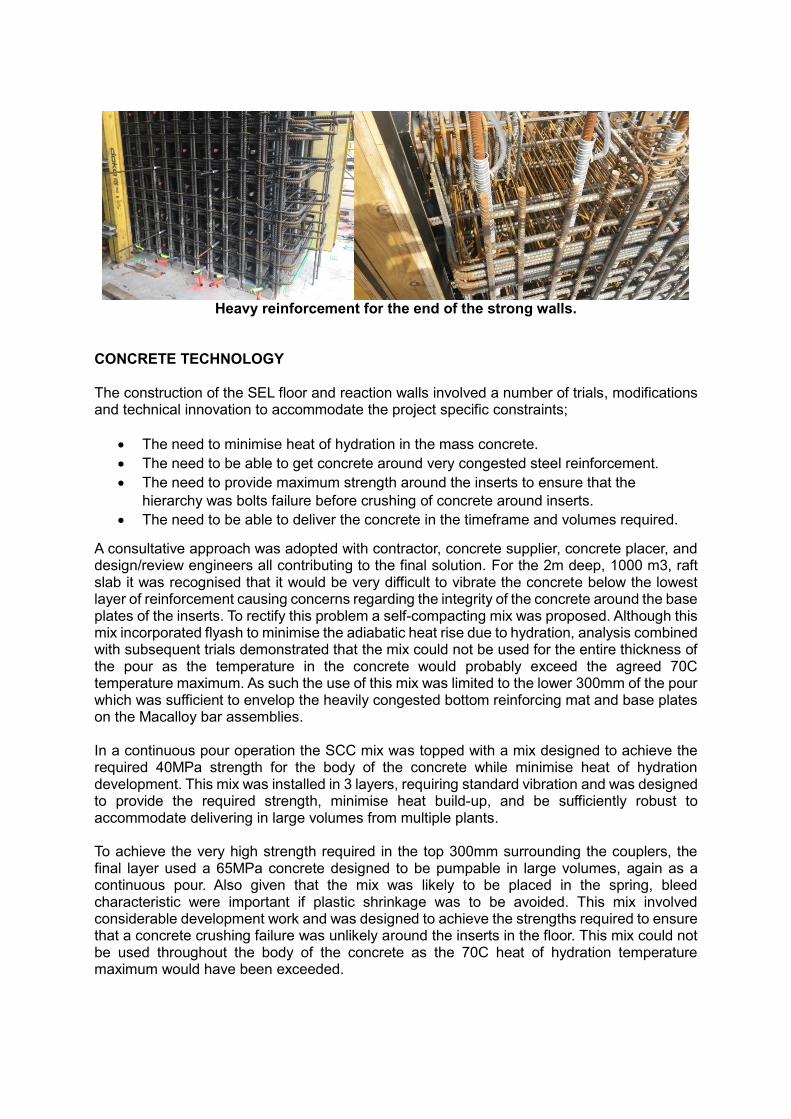
Heavy reinforcement for the end of the strong walls.
CONCRETE TECHNOLOGY The construction of the SEL floor and reaction walls involved a number of trials, modifications and technical innovation to accommodate the project specific constraints;
The need to minimise heat of hydration in the mass concrete.
The need to be able to get concrete around very congested steel reinforcement.
The need to provide maximum strength around the inserts to ensure that the
hierarchy was bolts failure before crushing of concrete around inserts.
The need to be able to deliver the concrete in the timeframe and volumes required.
A consultative approach was adopted with contractor, concrete supplier, concrete placer, and design/review engineers all contributing to the final solution. For the 2m deep, 1000 m3, raft slab it was recognised that it would be very difficult to vibrate the concrete below the lowest layer of reinforcement causing concerns regarding the integrity of the concrete around the base plates of the inserts. To rectify this problem a self-compacting mix was proposed. Although this mix incorporated flyash to minimise the adiabatic heat rise due to hydration, analysis combined with subsequent trials demonstrated that the mix could not be used for the entire thickness of the pour as the temperature in the concrete would probably exceed the agreed 70C temperature maximum. As such the use of this mix was limited to the lower 300mm of the pour which was sufficient to envelop the heavily congested bottom reinforcing mat and base plates on the Macalloy bar assemblies. In a continuous pour operation the SCC mix was topped with a mix designed to achieve the required 40MPa strength for the body of the concrete while minimise heat of hydration development. This mix was installed in 3 layers, requiring standard vibration and was designed to provide the required strength, minimise heat build-up, and be sufficiently robust to accommodate delivering in large volumes from multiple plants. To achieve the very high strength required in the top 300mm surrounding the couplers, the final layer used a 65MPa concrete designed to be pumpable in large volumes, again as a continuous pour. Also given that the mix was likely to be placed in the spring, bleed characteristic were important if plastic shrinkage was to be avoided. This mix involved considerable development work and was designed to achieve the strengths required to ensure that a concrete crushing failure was unlikely around the inserts in the floor. This mix could not be used throughout the body of the concrete as the 70C heat of hydration temperature maximum would have been exceeded.
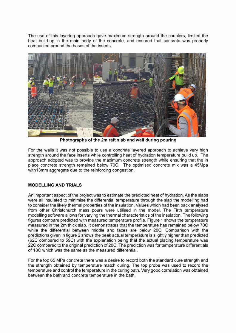
The use of this layering approach gave maximum strength around the couplers, limited the heat build-up in the main body of the concrete, and ensured that concrete was properly compacted around the bases of the inserts.
Photographs of the 2m raft slab and wall during pouring
For the walls it was not possible to use a concrete layered approach to achieve very high strength around the face inserts while controlling heat of hydration temperature build up. The approach adopted was to provide the maximum concrete strength while ensuring that the in place concrete strength remained below 70C. The optimised concrete mix was a 45Mpa with13mm aggregate due to the reinforcing congestion. MODELLING AND TRIALS An important aspect of the project was to estimate the predicted heat of hydration. As the slabs were all insulated to minimise the differential temperature through the slab the modelling had to consider the likely thermal properties of the insulation. Values which had been back analysed from other Christchurch mass pours were utilised in the model. The Firth temperature modelling software allows for varying the thermal characteristics of the insulation. The following figures compare predicted with measured temperature profile. Figure 1 shows the temperature measured in the 2m thick slab. It demonstrates that the temperature has remained below 70C while the differential between middle and faces are below 20C. Comparison with the predictions given in figure 2 shows the peak actual temperature is slightly higher than predicted (62C compared to 59C) with the explanation being that the actual placing temperature was 22C compared to the original prediction of 20C. The prediction was for temperature differentials of 18C which was the same as the measured differential. For the top 65 MPa concrete there was a desire to record both the standard cure strength and the strength obtained by temperature match curing. The top probe was used to record the temperature and control the temperature in the curing bath. Very good correlation was obtained between the bath and concrete temperature in the bath.
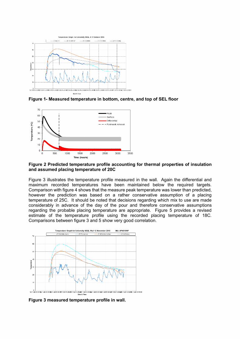
Figure 1- Measured temperature in bottom, centre, and top of SEL floor
Figure 2 Predicted temperature profile accounting for thermal properties of insulation and assumed placing temperature of 20C Figure 3 illustrates the temperature profile measured in the wall. Again the differential and maximum recorded temperatures have been maintained below the required targets. Comparison with figure 4 shows that the measure peak temperature was lower than predicted, however the prediction was based on a rather conservative assumption of a placing temperature of 25C. It should be noted that decisions regarding which mix to use are made considerably in advance of the day of the pour and therefore conservative assumptions regarding the probable placing temperature are appropriate. Figure 5 provides a revised estimate of the temperature profile using the recorded placing temperature of 18C. Comparisons between figure 3 and 5 show very good correlation.
Figure 3 measured temperature profile in wall.
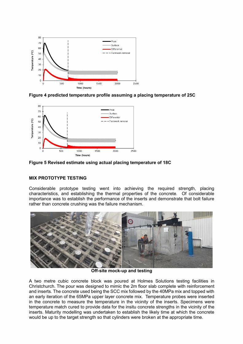
Figure 4 predicted temperature profile assuming a placing temperature of 25C
Figure 5 Revised estimate using actual placing temperature of 18C MIX PROTOTYPE TESTING Considerable prototype testing went into achieving the required strength, placing characteristics, and establishing the thermal properties of the concrete. Of considerable importance was to establish the performance of the inserts and demonstrate that bolt failure rather than concrete crushing was the failure mechanism.
Off-site mock-up and testing
A two metre cubic concrete block was poured at Holmes Solutions testing facilities in Christchurch. The pour was designed to mimic the 2m floor slab complete with reinforcement and inserts. The concrete used being the SCC mix followed by the 40MPa mix and topped with an early iteration of the 65MPa upper layer concrete mix. Temperature probes were inserted in the concrete to measure the temperature in the vicinity of the inserts. Specimens were temperature match cured to provide data for the insitu concrete strengths in the vicinity of the inserts. Maturity modelling was undertaken to establish the likely time at which the concrete would be up to the target strength so that cylinders were broken at the appropriate time.
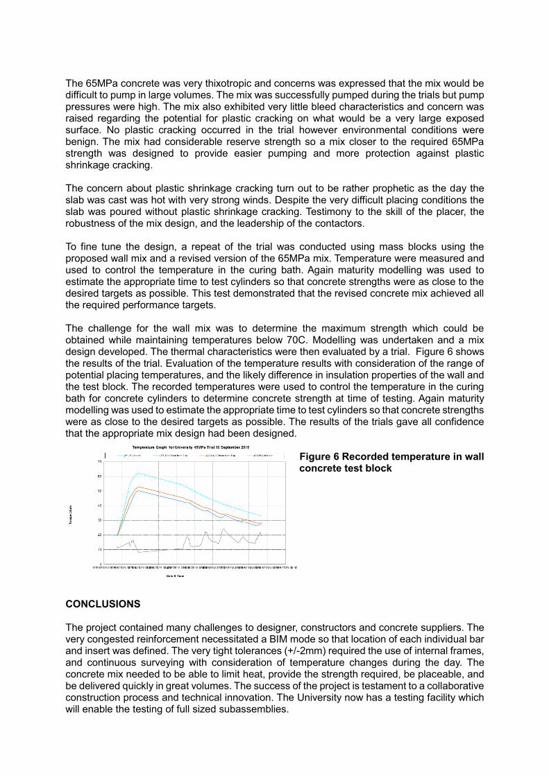
The 65MPa concrete was very thixotropic and concerns was expressed that the mix would be difficult to pump in large volumes. The mix was successfully pumped during the trials but pump pressures were high. The mix also exhibited very little bleed characteristics and concern was raised regarding the potential for plastic cracking on what would be a very large exposed surface. No plastic cracking occurred in the trial however environmental conditions were benign. The mix had considerable reserve strength so a mix closer to the required 65MPa strength was designed to provide easier pumping and more protection against plastic shrinkage cracking. The concern about plastic shrinkage cracking turn out to be rather prophetic as the day the slab was cast was hot with very strong winds. Despite the very difficult placing conditions the slab was poured without plastic shrinkage cracking. Testimony to the skill of the placer, the robustness of the mix design, and the leadership of the contactors. To fine tune the design, a repeat of the trial was conducted using mass blocks using the proposed wall mix and a revised version of the 65MPa mix. Temperature were measured and used to control the temperature in the curing bath. Again maturity modelling was used to estimate the appropriate time to test cylinders so that concrete strengths were as close to the desired targets as possible. This test demonstrated that the revised concrete mix achieved all the required performance targets. The challenge for the wall mix was to determine the maximum strength which could be obtained while maintaining temperatures below 70C. Modelling was undertaken and a mix design developed. The thermal characteristics were then evaluated by a trial. Figure 6 shows the results of the trial. Evaluation of the temperature results with consideration of the range of potential placing temperatures, and the likely difference in insulation properties of the wall and the test block. The recorded temperatures were used to control the temperature in the curing bath for concrete cylinders to determine concrete strength at time of testing. Again maturity modelling was used to estimate the appropriate time to test cylinders so that concrete strengths were as close to the desired targets as possible. The results of the trials gave all confidence that the appropriate mix design had been designed.
Figure 6 Recorded temperature in wall concrete test block
CONCLUSIONS The project contained many challenges to designer, constructors and concrete suppliers. The very congested reinforcement necessitated a BIM mode so that location of each individual bar and insert was defined. The very tight tolerances (+/-2mm) required the use of internal frames, and continuous surveying with consideration of temperature changes during the day. The concrete mix needed to be able to limit heat, provide the strength required, be placeable, and be delivered quickly in great volumes. The success of the project is testament to a collaborative construction process and technical innovation. The University now has a testing facility which will enable the testing of full sized subassemblies.