construction operations - oregonosha.oregon.gov/osharules/technical-manual/section5-chapter4.pdf ·...
TRANSCRIPT

Section V / Chapter 4 - Page 1
Section V (previously Section IV of Oregon OSHA’s Technical Manual)
CONSTRUCTION OPERATIONS
CHAPTER 1: DEMOLITION
CHAPTER 2: EXCAVATIONS: HAZARD
RECOGNITION IN TRENCHING AND
SHORING
CHAPTER 3: CONTROLLING LEAD EXPOSURE IN
THE CONSTRUCTION INDUSTRY:
ENGINEERING AND WORK
PRACTICE CONTROLS
CHAPTER 4: FALL PROTECTION IN
CONSTRUCTION

Section V / Chapter 4 - Page 2
SECTION V: CHAPTER 4
FALL PROTECTION IN CONSTRUCTION
Chapter Revision Information:
This chapter is based on federal OSHA’s Technical Manual (OTM)
Section V: Chapter 4, Fall Protection in Construction which was
released in April, 2016 and Oregon OSHA regulations as of 10-2016.
References to “OSHA Technical Manual (OTM)” were modified to
“Oregon OSHA Technical Manual (TM)”.
References to “Subpart”, where appropriate, were modified to
“Subdivision”.
References to “29 CFR 1926”, where appropriate, were modified to
“Division 3” with the addition of the appropriate Subdivision.
References to “29 CFR 1926”, where appropriate, were modified to
“OAR 437-003”.
References to “1926.501(b) were modified to “OAR 437-003-1501”.
References to “1926.502(g) & (h) were modified to “OAR 437-003-
2501”.
References to “1926.502(k) were modified to “OAR 437-003-1501”.
References to “1926.503 were modified to “OAR 437-003-0503”.
References to “1926.954(b)(3)(iii)(A)” were modified to “2/RR, 437-
002-2306(2)(d)(I)(i)..
In Section I.A.3.ii, reference to federal OSHA’s “Stairway and
Ladder” publication 3124-12R was removed.
In Section I.B.2.II, reference to “SLTC” was removed.
In Section I.C.3.i, Controlled Access Zones (CAZ) are not permitted in
Oregon.
In Section I.D, information about restraint systems was added.
In Section II.B.4, references to “It’s A Snap” were removed.
In Section II.B.6, OAR 437-003-0502(2) permits body belts in a
personal fall restraint system.
Figures II.B.4, 11a, 11c, 11d, 11e, 16b and 19 were added.
Appendix A, B & E: modified to reflect Oregon regulations.
Appendix C & D: reformatted for easier reading. Content unchanged.

Section V / Chapter 4 - Page 3
SECTION V: CHAPTER 4
FALL PROTECTION IN CONSTRUCTION
TABLE OF CONTENTS
INTRODUCTION . . . . . . . . . . . . . . . . . . . . . . . . . . . . . . . . . . . . . . . . . . 5
I. FALL PROTECTION . . . . . . . . . . . . . . . . . . . . . . . . . . . . . . . . . . . . . . . 6
A. Guardrail Systems . . . . . . . . . . . . . . . . . . . . . . . . . . . . . . . . . . . . . . . . 6
1. Temporary Guardrails . . . . . . . . . . . . . . . . . . . . . . . . . . . . . . . . 8
2. Guardrails for Scaffolds, Aerial Lifts, and Scissor Lifts . . . . . . . 8
3. Stairrails and Handrails . . . . . . . . . . . . . . . . . . . . . . . . . . . . . . . . 9
B. Hole Covers . . . . . . . . . . . . . . . . . . . . . . . . . . . . . . . . . . . . . . . . . . . . 9
1. Effective Hole Covers . . . . . . . . . . . . . . . . . . . . . . . . . . . . . . . . 10
2. Plywood Hole Covers . . . . . . . . . . . . . . . . . . . . . . . . . . . . . . . . . 11
C. Warning or Marking Systems . . . . . . . . . . . . . . . . . . . . . . . . . . . . . . . 12
1. Warning Line System . . . . . . . . . . . . . . . . . . . . . . . . . . . . . . . . 12
2. Safety Monitoring System . . . . . . . . . . . . . . . . . . . . . . . . . . . . . 13
3. Access Zoning . . . . . . . . . . . . . . . . . . . . . . . . . . . . . . . . . . . . . . 14
D. Fall Restraint System and Positioning Devices . . . . . . . . . . . . . . . . . . 15
1. Personal Fall Restraint System . . . . . . . . . . . . . . . . . . . . . . . . . 15
2. Positioning Devices . . . . . . . . . . . . . . . . . . . . . . . . . . . . . . . . . . 15
II. FALL ARREST SYSTEMS . . . . . . . . . . . . . . . . . . . . . . . . . . . . . . . . . . . 16
A. Safety Net Systems . . . . . . . . . . . . . . . . . . . . . . . . . . . . . . . . . . . . . . . 16
B. Personal Fall Protection Equipment for Personal Fall Arrest Systems 16
1. Component Compatibility . . . . . . . . . . . . . . . . . . . . . . . . . . . . . . 18
2. Anchorage . . . . . . . . . . . . . . . . . . . . . . . . . . . . . . . . . . . . . . . . . 19
3. Lanyards and Deceleration Devices . . . . . . . . . . . . . . . . . . . . . . 19
4. Vertical and Horizontal Lifelines . . . . . . . . . . . . . . . . . . . . . . . . 20
5. Full-Body Harnesses . . . . . . . . . . . . . . . . . . . . . . . . . . . . . . . . . . 22
6. Body Belts . . . . . . . . . . . . . . . . . . . . . . . . . . . . . . . . . . . . . . . . . . 22
7. Ladder Safety Devices . . . . . . . . . . . . . . . . . . . . . . . . . . . . . . . . . 22
C. Fallen Worker Rescue . . . . . . . . . . . . . . . . . . . . . . . . . . . . . . . . . . . . . 24
1. Aided Rescue . . . . . . . . . . . . . . . . . . . . . . . . . . . . . . . . . . . . . . . 24
2. Self-Rescue . . . . . . . . . . . . . . . . . . . . . . . . . . . . . . . . . . . . . . . . . 24

Section V / Chapter 4 - Page 4
TABLE OF CONTENTS (CONTINUED)
III. MEASUREMENTS FOR ASSESSING FALL HAZARDS AND
CONTROLS. . . . . . . . . . . . . . . . . . . . . . . . . . . . . . . . . . . . . . . . . . . . . . . .
25
A. Total Fall Clearance Distance for PFAS . . . . . . . . . . . . . . . . . . . . . . 25
1. Calculating Total Fall Clearance Distance for Fall Arrest
Systems with a Shock-absorbing Lanyard . . . . . . . . . . . . . . . . .
26
2. Calculating Free Fall Distance . . . . . . . . . . . . . . . . . . . . . . . . . . 27
3. Examples . . . . . . . . . . . . . . . . . . . . . . . . . . . . . . . . . . . . . . . . . . . 28
B. How to Evaluate the Swing Fall Hazard . . . . . . . . . . . . . . . . . . . . . . . 31
LIST OF APPDENENDICES
APPENDIX A FALL PROTECTION FOR SPECIFIC
SCAFFOLODS AND RELATED EQUIPMENT . . . . .
32
APPENDIX B OSHA STANDARDS RELATED TO FALL
PROTECTION . . . . . . . . . . . . . . . . . . . . . . . . . . . . . . .
33
APPENDIX C EXAMPLES: Fall Protection Anchors by Type . . . . . . . 34
APPENDIX D EXAMPLES: Lanyards, Deceleration Devices,
Harnesses, and Body Belts . . . . . . . . . . . . . . . . . . . . . . .
44
APPENDIX E REFERENCES AND RESOURCES . . . . . . . . . . . . . . 48

Section V / Chapter 4 - Page 5
Introduction
This chapter provides technical information about fall hazards and protection methods. The
information is intended to help prepare Oregon OSHA compliance officers to conduct
inspections and investigations. For convenience, links are provided to applicable Oregon OSHA
standards throughout this chapter. This chapter does not cover all Oregon OSHA, nor federal
OSHA, requirements for fall prevention/protection methods, and is not intended to serve as a
comprehensive guide for developing compliant fall protection programs.
Although fall hazards are common at construction worksites, fall-related injuries and fatalities
are preventable. Fall hazards can be addressed in two main ways:
Fall prevention: preventing workers from falling by using engineering controls (e.g.,
guardrails and hole covers) or personal protective equipment (e.g., restraint systems).
Fall arrest/rescue: preventing injury during and after a fall by using personal fall arrest
systems (PFAS) or safety nets, and having an effective rescue plan in place.
Recognizing fall hazards and planning to control them before work begins is critical for
determining the best methods and equipment for protecting workers during construction
activities at heights.
Emergency response planning will identify necessary emergency response training and critical
resources (e.g., trained on-site fall arrest rescue team and rescue equipment).
A number of Oregon OSHA standards contain provisions for protecting workers from falls. In
the construction industry, applicable standards include:
- Division 3, Subdivision M (3/M): Fall Protection;
- Division 3, Subdivision R (3/R), 1926.760: Steel Erection;
- Division 3, Subdivision V = See Division 2, Subdivision RR (2/RR): Electric Power
Generation, Transmission and Distribution; and
- Division 3, Subdivision CC (3/CC), 1926.1423 and 437-003-1423: Cranes and Derricks.
Refer to Appendix B for a more complete list of Oregon OSHA standards on fall protection.

Section V / Chapter 4 - Page 6
I. Fall Prevention
I.A. Guardrail Systems
A guardrail system can be used as a barrier to
prevent workers from falling off a work surface edge
to a lower level. Guardrail systems can be used on
many work surfaces, including rooftops, platforms,
mezzanines, balconies, scaffolds, incomplete decked
floors, catwalks, observation platforms, mobile work
surfaces and ladderway points of access. Figure 1
shows a temporary guardrail system for a walkway
(see Div 3/M, 1926.500; Div 3/M, 1926.502(b)).
Guardrails can also be used to keep workers from
falling into holes or openings in decking or floors
(see Div 3/M, 437-003-1501; Div 3/M, 1926.502(b);
Figure 2).
Guardrails are typically constructed using:
- Upright supports attached to the working
surface;
- A horizontal top rail connected to the
supports;
- One or more midrails running parallel to the
top rail; and
- Toeboards when necessary to protect
workers below from falling objects.
(See Div 3/M, 1926.501(c)(1); Div 3/M,
1926.502(b); Div 3/M, 1926.502(j).)
Effective guardrail systems will have at a minimum:
- A surface that is smooth and free from burrs to prevent punctures and lacerations and to
prevent snagging of clothing (see Div 3/M, 1926.502(b)(6)).
- Toprails and midrails that are at least ¼ inch in diameter (see Div 3/M, 1926.502(b)(9)).
- Strength to withstand at least 200 pounds applied within 2 inches of the top edge in any
outward or downward direction (see Div 3/M, 1926.502(b)(3)) .
- A toprail between 39 and 45 inches from the working level, raised as necessary to
account for workers using stilts or otherwise working in an elevated location above the
work surface (see Div 3/M, 1926.502(b)(1)).
- Midrails (or equivalent structural members) that withstand at least 150 pounds of force
in the downward or outward direction (see Div 3/M, 1926.502(b)(5)).
Figure 1. Guardrail system
Figure 2. Guardrail used around
an opening

Section V / Chapter 4 - Page 7
- A midrail, mesh, screen, or equivalent intermediate structural members installed
between the guardrail system top edge and the walking/working surface when there is no
wall or parapet wall at least 21 inches high (see Div 3/M, 1926.502(b)(2)).
- Intermediate members (such as balusters), when used between posts, that are not more
than 19 inches apart (see Div 3/M, 1926.502(b)(2)(iii)).
- Flags made of high visibility material every 6 feet if wire rope is used for top rails (see
Div 3/M, 1926.502(b)(9)).
Effective guardrail systems will not have:
- Guardrails that deflect to lower than 39 inches above the working surface when 200
pounds of pressure are applied in a downward direction (see Div 3/M, 1926.502(b)(4)).
- Toprails and midrails that overhang terminal posts to constitute a projection hazard (see
Div 3/M, 1926.502(b)(7)).
Basic guardrail components come in a variety of materials and configuration options. It is
common for employers to use material available or produced at the worksite. Upright supports
may be made from wood, formed metal, pipe, or composites. Wire rope is sometimes used for
the top rails and midrails.
Table 1 provides guidelines as a starting point for designing guardrail systems. However, the
guidelines do not provide all the information necessary to build a complete system. The
components of a guardrail system must still be designed and assembled in such a way that the
completed system meets all applicable requirements.
Workers installing or removing guardrails must be protected using other forms of fall protection
whenever the guardrail systems are not attached securely to a stable structure.
Table 1 – Guardrail Component Strength Indicators
Material Strength (minimum criteria)
Posts (minimum criteria)
Top Rail (minimum criteria)
Intermediate
Rail (minimum
criteria)
Wood
guardrails
1,500 lb-ft/in2 fiber
(stress grade)
construction lumber
2 inch × 4 inch
(nominal) lumber
2 inch × 4 inch
(nominal) lumber
1 inch × 6 inch
(nominal) lumber
Pipe guardrails N/A 1.5 inch diameter
(schedule 40 pipe)
1.5 inch diameter
(schedule 40 pipe)
1.5 inch diameter
(schedule 40
pipe)
Structural steel
guardrails
N/A 2 inch × 2 inch ×
3/8 inch
2 inch × 2 inch ×
3/8 inch
2 inch × 2 inch ×
3/8 inch
Spacing N/A All material: no
more than 8 feet
apart (on centers)
N/A N/A
N/A = not applicable.
lb-ft/in2 = pound-foot per square inch. Adapted from 29 CFR 1926 Subpart M, Appendix B.

Section V / Chapter 4 - Page 8
I.A.1. Temporary Guardrails
Premade or job-made guardrails can be used as
temporary guardrails while more permanent
structures are being installed or when the work is
transient or in a space not intended as a permanent
work area. For example, temporary guardrails can
be used while constructing a wall, completing floor
decking, or replacing a roof (see Figure 4). These
guardrails are often constructed from reusable
materials or premade guardrail system components
as shown in Figure 3 and Figure 4 (see Div 3/M,
1926.502(b)).
Premade guardrails are particularly susceptible to
damage if not handled properly when disassembled
and stored. Specific handling instructions are
typically included in the manufacturer’s
recommended procedures for disassembling and
storing the guardrail components. If railing
components are bent, broken, or missing, the
guardrail may not be effective. Damage is more
likely to occur if the components are dropped when
disassembled, transported in vehicles, or stored in
areas not protected from conditions that could cause
corrosion or distortion.
I.A.2. Guardrails for Scaffolds, Aerial Lifts, and Scissor Lifts
Scaffolds, aerial lifts, and scissor lifts can pose similar fall hazards. Guardrails, possibly in
combination with additional types of fall protection systems (e.g., PFAS or restraint system),
may be used to address these hazards. (see Div 3/L, 1926.451(g)(1); Div 3/L, 1926.453(b)(2)(v);
Div 2/RR, 437-002-2306(2)(d)(I)(i)).
For additional information on fall protection for scaffolds and lifts see:
Appendix A (chart describing fall protection for various types of scaffolds and related
equipment)
Federal OSHA Scaffolding eTool:
https://www.osha.gov/SLTC/etools/scaffolding/index.html
Figure 3. Temporary guardrails
Figure 4. Temporary guardrails

Section V / Chapter 4 - Page 9
I.A.3. Stairrails and Handrails
I.A.3.i. Stairrails
A stairrail system is a vertical barrier that runs along the unprotected side edge of a
stairway to prevent workers from falling to lower levels (see Figures 5 and 6). The top
surface of the stair rail system may be used as the handrail (see Div 3/X, 1926.1050(b);
Div 3/X, 1926.1052(c)(7)).
I.A.3.ii. Handrails
Effective handrails provide an adequate handhold for workers to grasp to prevent them from
falling (see Figure 6 and Div 3/X, 1926.1052(c)(1), (c)(9)).
Effective handrails are 30 to 37 inches high and meet the guardrail strength requirements
(i.e., able to withstand 200 pounds of weight applied within two inches of the top edge in any
downward or outward direction at any point along the top edge) (see Div 3/X,
1926.1052(c)(5), (c)(6)).
Effective temporary handrails have a minimum clearance of 3 inches between the handrail
and walls, stairrail systems, and other objects (see Div 3/X, 1926.1052(c)(11)).
I.B. Hole Covers
A hole is a gap or void 2 inches or more in its least dimension in a floor, roof, deck, or other
walking/working surface (see Div 3/M, 1926.500(b); Div 3/M, 437-003-1501(1); Div 3/R,
1926.751; Div 3/R, 437-003-1754) that is hazardous because:
Figure 5. Stairail System
Figure 6. Stairail System with handrail

Section V / Chapter 4 - Page 10
• workers can fall through the hole (see Div 3/M, 437-003-1501(1)(a));
• the hole’s design can create a trip hazard (see Div 3/M, 437-003-1501(1)(b)); and
• objects can fall through the hole and injure workers below (see Div 3/M, 437-003-
1501(1)(c)).
Workers are protected from the hazards associated with holes by the use of covers, personal fall
protection or guardrail systems (see Div 3/M, 437-003-1501).
The following types of holes are commonly found at
construction worksites:
• Holes cut (or constructed) in floors to
receive equipment or ducts and for future
access points (e.g., openings for stairs that
will be installed later);
• Holes cut in roofs in preparation for
installing skylights, ventilation units, and
other features or equipment;
• Excavations for pits, wells, or shafts (e.g., caissons);
• Excavations or cuts in roadways.
I.B.1. Effective Hole Covers
Covers are strong protective surfaces used on walking/working surfaces or roadways to prevent
workers from falling through a hole (see Figure 7).
Covers for permanent holes are typically built for a specific purpose (e.g., permanent access
points, manhole covers, and trap doors) and are only effective when they are properly designed
and secured in place.
Covers for temporary holes are often constructed on work sites with reusable materials, most
commonly using plywood and steel plates. For example, to cover large holes in a road, hinged
steel plate covers can be used. Other options for covers include grates designed to support
weight, custom boxes to cover a hole with an elevated lip or partially installed equipment, and
temporary trapdoors.
Effective hole covers are:
• Large enough to provide appropriate overlap to prevent workers from falling through.
• Strong enough to support at least twice the anticipated weight imposed by the heaviest
load (see Div 3/M, 1926.502(i)(1), (i)(2)).
• Left in place over the hole until access is needed.
• Inspected periodically to identify deterioration.
• Secured (see Div 3/M, 1926.502(i)(3)) and do not create trip hazards.
• Clearly marked as hole covers (see Div 3/M, 1926.502(i)(4)).
Figure 7. Hole cover

Section V / Chapter 4 - Page 11
The following materials lack the strength necessary to prevent a worker from falling through a
hole (see Div 3/M, 1926.502(i)(1), (i)(2)):
• Cardboard;
• Tarps;
• Materials not intended to bear the anticipated load (e.g., plastic or glass);
• Loose materials that could separate (e.g., unsecured two-by-four planks);
• Damaged materials (e.g., deteriorating wood, a bent metal plate);
• Drywall or particle board; and
• Chicken wire or other fencing material.
I.B.2. Plywood Hole Covers
Heavy plywood is a common choice for covering
temporary holes in floors and roofs (see Figure 9), but
plywood strength and durability can vary. Some materials,
including plywood scraps from shipping crates or similar
scrap products, do not have structural value or span ratings,
making it hard to know if they are strong enough. In
addition, strength information on the plywood is
occasionally covered with paint.
I.B.2.i. Plywood Strength
Several factors determine and measure plywood
strength. In the United States, two groups provide the most commonly used plywood
rating systems: APA–The Engineered Wood Association (formerly the American
Plywood Association and Douglas Fir Plywood Association) and the Timber Engineering
Company (TECO). CSHOs should refer to these organizations for detailed information.
The hole size and the expected load weight are considered when determining if the
plywood is effective for use as a hole cover (see Div 3/M, 437-003-1501(1); Div 3/M,
1926.502(i)(1), (i)(2)).
I.B.2.ii. Plywood Durability
Plywood is susceptible to damage over time from exposure to water, traffic, and heavy
loads that may reduce its strength. Some indicators of reduced-strength plywood may
include cracks, chips, a warped appearance, a worn surface, de-lamination, and water
stains. Expected damage after exposure to water depends on whether the plywood is
exterior-grade or interior-grade. The binding agents (i.e., adhesive) used to adhere
interior-grade plywood layers degrade more rapidly in a moist environment than do the
binders used in exterior-grade plywood.
When workers are using hauling equipment, the weight of the equipment and its load is
concentrated into the smaller area that contacts the ground (e.g., the load in a
Figure 9. Plywood hole cover

Section V / Chapter 4 - Page 12
wheelbarrow will concentrate where the wheel hits the ground – an area of just a few
inches in size). Commonly used routes for hauling these loads will experience additional
wear and tear to the flooring. Adding a protective layer to the floor along these routes is
one way to prevent damage to the flooring from concentrated loads. Typical protective
layers may include liquid latex compounds, penetrating oils, sheet plastics, and
interlocking membranes.
I.B.2.iii. Plywood Cover Size and Orientation
The plywood cover’s size and
orientation can affect the cover’s overall
effectiveness. Plywood covers rest on
the hole edges that are supported
through the joists. The following are
indications that a plywood cover’s size
and orientation will generally keep
workers from falling through a hole:
• The plywood piece is larger than the
hole size so that it is possible to cover
the hole with the shortest panel side
overlaying the longest unsupported hole dimension.
• The panel overlaps the supporting surfaces around the hole far enough for needed
support.
• The panel is positioned with the strength axis (grain direction) running along the
shortest unsupported hole dimension (Figure 10 above).
I.C. Warning or Marking Systems
I.C.1. Warning Line Systems
A warning line system is a barrier erected on a flat or low-sloped roof (2-in-12 or less) to warn
workers engaged in roofing work that they are approaching an unprotected roof side or edge (see
Div 3/M, 1926.500(b)); Figure 11a; Figure 11b). A warning line system includes a line (rope,
wire, or chain) and supporting stanchions (see Div 3/M, 1926.502(f)(2)). Warning lines are not
engineered to physically prevent or arrest falls, and may not be used in all situations.
I.C.1.i. Warning Line Systems for Roofers
On flat or low-sloped roofs (2-in-12 or less), roofers inside the warning line system can
use the warning lines as fall protection. Employees performing roofing work between the
roof edge and the warning line must be protected by a personal fall arrest system,
personal fall restraint system, guardrail system, safety net system, or safety monitoring
system. No employee is allowed in the area between a roof edge and a warning line
unless the employee is performing roofing work in that area. (see 3/M, 1926.502(f)(3)).
Figure 10. Plywood orientation relative to hole
orientation and strength axis

Section V / Chapter 4 - Page 13
I.C.1.ii. Warning Lines used as Awareness Barriers for non-Roofers
Trades, other than roofers, cannot use warning
lines as a fall protection system. Warning lines
can be used by trades (other than roofers) only as
an awareness barrier when there is no exposure
to a fall hazard (see Oregon OSHA Fact Sheet
FS-26:
http://osha.oregon.gov/OSHAPubs/factsheets/fs2
6.pdf .)
Additionally, non-roofers cannot work between
the edge and the warning line (awareness
barrier) when protected by a safety monitoring
system (See Div 3/M, 1926.500(b) and 3/M,
437-003-01502).
I.C.2. Safety-Monitoring Systems
In Oregon, 1926.502(h) was not adopted. In Oregon, Div 3/M, 437-003-2502 (Safety monitoring
systems) applies.
Safety monitoring systems must not be used as a fall protection system for any work other than
roofing work. Safety monitoring systems are limited to use on roofs with slopes of 2-in-12 or
Figure 11a. Examples of warning line systems for roofing work
Figure 11b. Warning line (awareness
barrier) for non-roofers

Section V / Chapter 4 - Page 14
less (see Div 3/M, 437-003-2502; Figure 11c). The use of a safety monitoring system alone
(without a warning line system) is not allowed on roofs more than 50 feet in width.
A safety-monitoring system uses a competent person as a safety monitor who can recognize and
warn workers of fall hazards (see Div 3/M, 1926.500(b)).
I.C.3. Access Zoning
I.C.3.i. Controlled Access Zones (CAZs)
Federal OSHA allows the use of controlled access zones in 29 CFR 1926.502(g). In
Oregon, 1926.502(g) was not adopted. The use of controlled access zones for fall
protection in Oregon is not permitted. Federal OSHA allows the following situations to
use controlled access zones as fall protection; however, Oregon OSHA does not:
Overhand bricklaying and related work
Leading edge work
Residential construction
Precast concrete erection
I.C.3.ii. Controlled Decking Zones (CDZs)
A controlled decking zone is a clearly marked work area used during steel erection while
workers are initially installing decking at the leading edge of the work area (see 3/R,
1926.751; 3/R, 1926.760(c); 3/R, 1926 Subpart R Appendix D).
Figure 11c. Examples of a safety monitoring system on a roof less than 50 feet wide

Section V / Chapter 4 - Page 15
I.D. Fall Restraint Systems and Positioning Devices
I.D.1 Personal Fall Restraint Systems
Fall restraint systems (identified in rule as
Personal Fall Restraint) prevent the user from
falling any distance. To determine the force
needed to restrain a worker, consideration is
given to the force that would be generated by the
worker walking, leaning, or sliding down the
working surface. Personal fall restraint systems
must have the capacity to withstand at least
3,000 pounds of force or twice the maximum
expected force that is needed to restrain the
worker from exposure to the fall hazard.
Additionally, fall restraint systems must use fall
arrest system components that conform to the
criteria in Div 3/M, 1926.502 except a body belt
may be used in fall restraint systems and the
attachment point to the body belt or full body
harness may be at the back, front or side D-rings.
(see Div 3/M, 437-003-0502; Figure 11d).
I.D.2 Positioning Devices
Positioning devices are specialized systems that
hold workers in place on an elevated vertical
surface (such as a wall) allowing them to keep
both hands free to work while leaning into the
system (see Div 3/M, 1926.500(b)).
When the worker leans back, the system is
activated (supporting the worker’s body weight).
Positioning devices must be rigged to limit free
falls to 2 feet or less (see Div 3/M,
1926.502(e)(1); Figure 11e).
Figure 11d. Example of a body belt used with
a personal fall restraint system
Figure 11e. Example of a positioning device
system used with a SRL

Section V / Chapter 4 - Page 16
II. Fall Arrest Systems
Fall arrest systems are designed to prevent or reduce injuries when a worker falls from an
elevated height.
II.A. Safety Net Systems
Safety net systems (see Figures 12 and 13) are an option when workers are working at elevated
heights with hazardous vertical drops (see Table 2). Safety net systems are commonly used
during work on bridges and large structures. The nets are available in various sizes and materials,
including materials resistant to ultraviolet deterioration.
Table 2. Safety Net System Dimensions
Vertical Distance from Working Level
to Horizontal Plane of Net
Minimum Required Horizontal Distance
of Outer Edge of Net from Edge of
Working Surface
Up to 5 feet 8 feet
More than 5 feet, up to 10 feet 10 feet
More than 10 feet, up to 30 feet 13 feet
More than 30 feet Safety net not permitted as fall protection
See Div 3/M,1926.502(c)(1), (c)(2)
II.B. Personal Fall Protection Equipment for Personal Fall Arrest Systems
A Personal Fall Arrest System (PFAS) is a system with components that work together to protect
workers when they fall from elevated heights. PFAS components include an anchorage,
connectors, and a full-body harness, and may include a shock-absorbing lanyard, a retractable
lifeline, and/or a deceleration device (see Div 3/M, 1926.500(b)).
Figure 12. Safety net system
Figure 13. Safety net system
Section V / Chapter 4 - Page 17
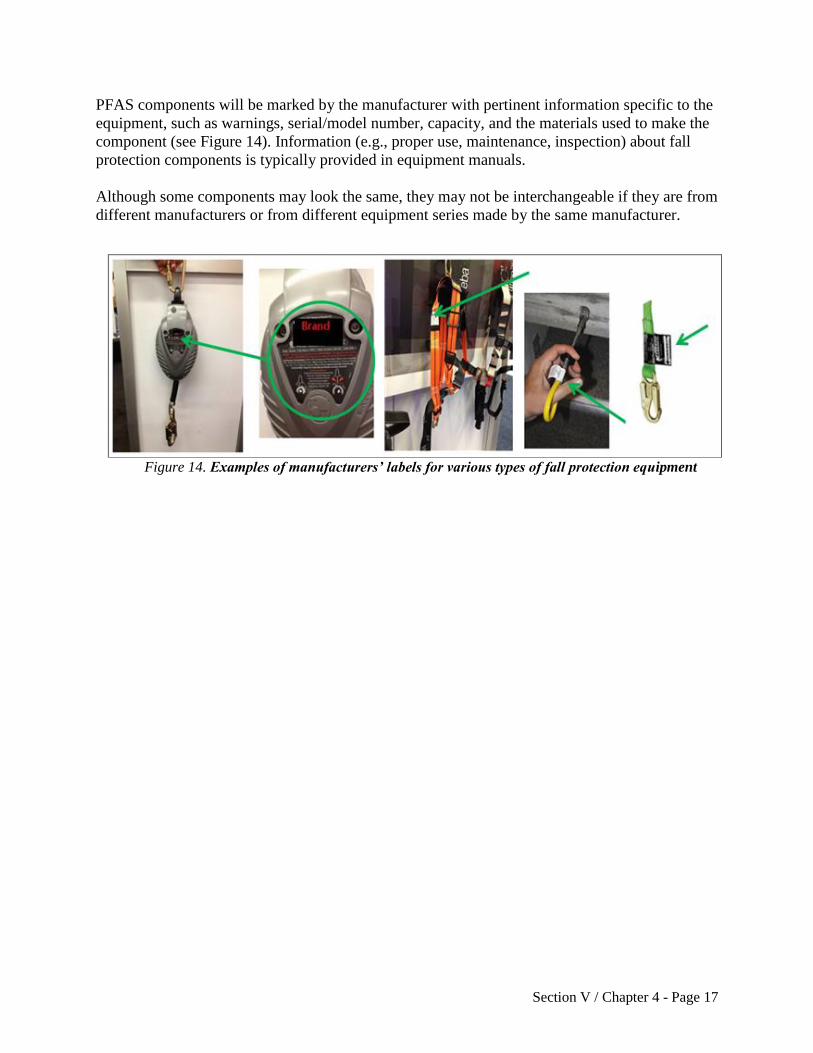
PFAS components will be marked by the manufacturer with pertinent information specific to the
equipment, such as warnings, serial/model number, capacity, and the materials used to make the
component (see Figure 14). Information (e.g., proper use, maintenance, inspection) about fall
protection components is typically provided in equipment manuals.
Although some components may look the same, they may not be interchangeable if they are from
different manufacturers or from different equipment series made by the same manufacturer.
Figure 14. Examples of manufacturers’ labels for various types of fall protection equipment

Section V / Chapter 4 - Page 18
II.B.1. Component Compatibility
Personal fall protection system effectiveness relies on component compatibility. Often,
components are supplied together as a set. Using non-compatible fittings can lead to damage and
system failure (see Div 3/M, 1926.502(d)(5)).
A compatibility assessment should be performed when using fittings from different
manufacturers or different product lines from the same manufacturer. This includes assessing the
way fittings connect to each other and confirming with the manufacturer(s) that the fittings can
be used together safely.
For additional information see:
Compatibility of Personal Fall Protection System Components, federal OSHA Safety and
Health Information Bulletin, www.osha.gov/dts/shib/shib092203.html
Many factors can contribute to a worker’s risk of falling from an elevated work area.
Examples include precarious work positions, excessive leaning or reaching, improper work
practices, unstable structures, trip hazards, slippery surfaces, and distractions.
When guardrails are not an option, personal fall protection equipment is helpful in some
situations, but only when properly selected, worn, and attached to an adequate anchor
point.
A personal fall arrest system was not a good choice in this case. In the illustration below,
the trusses were not fully installed, braced and sheathed, so they did not form a sufficiently
strong anchor point. The structure collapsed when it received the sudden force of the
falling worker.
The fall hazard could have been eliminated by pre-assembling the truss sections (groups of
several trusses) on the ground or using special devices that serve as temporary bracing for
fall arrest equipment.

Section V / Chapter 4 - Page 19
II.B.2. Anchorage
Anchorage systems normally include, at a minimum, a building structure and an anchorage
device to which the worker will tie-off (see Appendix C).
Anchors are fixed to a strong structural member. Anchors are not effective if they are attached to
weak materials. Certain structural members may not be strong enough to hold the sudden weight
imposed by a falling worker. The anchorage manufacturer should provide instructions on anchor
installation (see Div 3/M, 1926.502(d)(15); Div 3/CC, 1926.1423(g)).
Many anchors are removed when they are no longer needed. Other anchors are designed to be
left in place for future use (e.g., repeated servicing), or are covered over during the job (e.g., with
roofing shingles), or are cut flush with the surrounding surface (e.g., concrete bolt-style anchor
protruding from a wall). Appendix C provides fall protection anchor examples. (See Division
3/M, Appendix C(II)(h), Tie-off considerations)
II.B.3. Lanyards
A lanyard is a flexible rope, wire rope, or strap which generally has a connector at each end for
connecting the body belt or body harness to a deceleration device, lifeline, or anchorage point
(see Div 3/M, 1926.500(b)). Some manufacturers offer adjustable length lanyards. Effective
lanyards are maintained in a clean, intact condition, and inspected prior to each use for wear,
tear, and any obvious distortion or signs that the fall arrest (energy-absorbing) system has been
activated (see Div 3/M, 1926.502(d)(21)).
Inspecting a lanyard involves beginning at one end and continuing to the opposite end. During an
inspection, the lanyard is slowly rotated so that its entire circumference is checked. Spliced ends
require particular attention.
Lanyards used for personal fall protection are not to be used for hoisting materials. Equipment
used for hoisting is not suitable for use in a fall protection system (see Div 3/M,
1926.502(d)(18)).
II.B.3.i. Deceleration Device
A deceleration device is a mechanism (e.g., tearing or deforming lanyards) that serves to
dissipate energy during a fall to limit the energy and stress imposed on a worker during a
fall. Deceleration occurs over a maximum distance of 3.5 feet (see Div 3/M,
1926.502(d)(16)(iv)). Deceleration devices vary widely. Examples include:
Self-retracting lanyard. A self-retracting lanyard/lifeline contains a drum-wound
line which can be slowly extracted or retracted. The lanyard extends as necessary
to allow the worker to move about the work area, but retracts as necessary to
maintain slight tension, preventing the line from becoming slack. The drum is
under slight tension during normal worker movement and automatically locks the
drum when the line is extracted too rapidly (see Div 3/M, 1926.500(b)).

Section V / Chapter 4 - Page 20
Self-retracting lanyards and lifelines that limit free fall to 2 feet or less need to
sustain, at a minimum, 3,000 pounds applied to the device with the lanyard in the
fully extended position (see Div 3/M, 1926.502(d)(12)).
Self-retracting lanyards that do not limit free fall to 2 feet or less need to sustain,
at a minimum, 5,000 pounds applied to the device with the lanyard in the fully
extended position (see Div 3/M, 1926.502(d)(13)).
Some retractable lifelines provide a deceleration (energy-absorbing) function.
These lifelines can include a feature that slows the fall over a distance of up to 3.5
feet (see Div 3/M, 1926.502(d)(16)(iv)).
Rip-stitch lanyards. A rip-stitch lanyard has extra webbing incorporated into the
lanyard. The extra webbing is stitched into place and folded lengthwise along the
lanyard. During a fall, the weaker stitching allows the folded webbing to pull
away at a controlled speed, slowing the fall.
Shock-absorbing lanyards. The webbing in a shock-absorbing lanyard is
designed to stretch as it receives the worker’s falling weight. The stretching action
breaks the fall in a controlled manner.
This is not an all-inclusive list of lanyards. Oregon OSHA expects that emerging
lanyard technology will continue to improve safety in the workplace.
II.B.4. Vertical and Horizontal Lifelines
A lifeline is a component consisting of a flexible line for connection to an anchorage at one end
to hang vertically (vertical lifeline) or for connection to anchorages at both ends to stretch
horizontally (horizontal lifeline), and which serves as a means for connecting other components
of a PFAS to the anchorage (see Div 3/M, 1926.500(b)).
Vertical and Horizontal Lifelines
Lifelines function as an extension of an anchorage system, allowing an
employee to move up and down (vertical lifeline) or back and forth
(horizontal lifeline) across a work area. A sliding fitting (rope grab or
shuttle) connects to the line and a lanyard connects the worker’s harness to
that sliding fitting.
Vertical lifelines require active participation by the worker, who must often
reposition the rope grab when moving to a new position.
Vertical lifelines remain connected to a set anchorage point while the lanyard moves with the
worker. If the worker falls, the clip locks (cable grab) to the lifeline and stops the worker from
Section V / Chapter 4 - Page 21
falling further. When vertical lifelines are used each worker generally needs to be attached to a
separate lifeline (see Div 3/M, 1926.502(d)(10)).
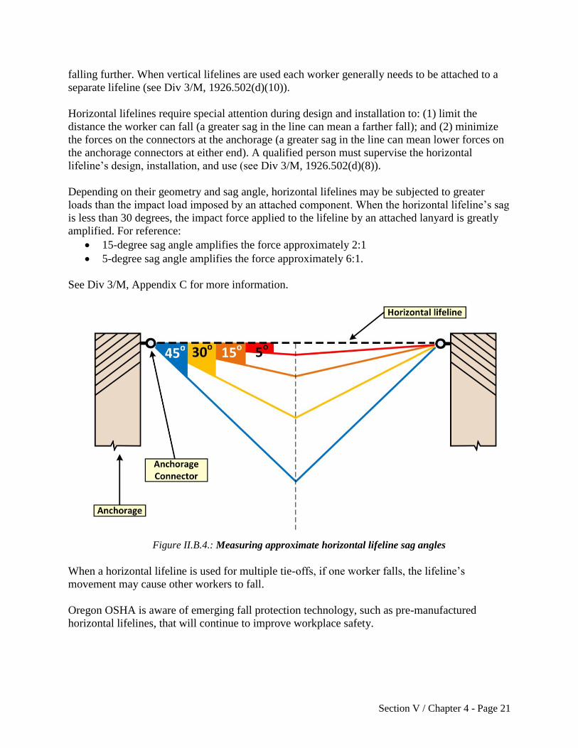
Horizontal lifelines require special attention during design and installation to: (1) limit the
distance the worker can fall (a greater sag in the line can mean a farther fall); and (2) minimize
the forces on the connectors at the anchorage (a greater sag in the line can mean lower forces on
the anchorage connectors at either end). A qualified person must supervise the horizontal
lifeline’s design, installation, and use (see Div 3/M, 1926.502(d)(8)).
Depending on their geometry and sag angle, horizontal lifelines may be subjected to greater
loads than the impact load imposed by an attached component. When the horizontal lifeline’s sag
is less than 30 degrees, the impact force applied to the lifeline by an attached lanyard is greatly
amplified. For reference:
15-degree sag angle amplifies the force approximately 2:1
5-degree sag angle amplifies the force approximately 6:1.
See Div 3/M, Appendix C for more information.
When a horizontal lifeline is used for multiple tie-offs, if one worker falls, the lifeline’s
movement may cause other workers to fall.
Oregon OSHA is aware of emerging fall protection technology, such as pre-manufactured
horizontal lifelines, that will continue to improve workplace safety.
Figure II.B.4.: Measuring approximate horizontal lifeline sag angles

Section V / Chapter 4 - Page 22
II.B.5. Full-Body Harnesses
Harnesses include shoulder straps and leg straps, a sub-pelvic assembly, adjustable buckles or
fasteners, and one or more D-rings to connect to a lanyard.
The dorsal D-ring (between the worker’s shoulder blades) is used with a fall arrest system. D-
rings in other positions are sometimes included for use with ladder safety devices. For this
reason, some harnesses come with D-rings on the front, sides, and lower back.
A safe and effective harness will fit (i.e., be the correct size) and is adjusted so that all straps are
snug (see Figure 15). Dangling leg straps or arm straps are signs that the harness is not being
worn correctly. The sub-pelvic assembly transfers the forces during a fall or suspension to the
worker’s sub-pelvic region. Although adjustable, some models come in different sizes and may
be gender specific.
Inspect Position back
D-ring between
shoulder blades
Buckle up legs Buckle up front Adjust so the
harness fits
snuggly and
D-ring remains
in the correct
position
Figure 15. Simple steps to fitting a full body harness
II.B.6. Body Belts
A body belt is a wide band that buckles around the hips with means both for securing it about the
waist and for attaching it to a lanyard, lifeline, or deceleration device. Body belts serve as
positioning devices or fall restraint devices that position a worker so the person can perform a
job safely in a vertical work position. Body belts are designed to hold a worker in place and
reduce the possibility of a fall (see Div 3/M, 1926.502(e); Div 3/M, Appendix D; Div 3/M, 437-
003-0502(2)).
II.B.7. Ladder Safety Devices
Ladder safety devices or systems are used to climb fixed ladders. The system includes a body
harness, carabiner, carrier rail, and safety sleeve. Ladder safety devices are available as a cable
(i.e., vertical lifeline) or fixed rail system (see Figure 16a and Div 3/X, 1926.1053(a)(18),
(a)(22), (a)(23)).

Section V / Chapter 4 - Page 23
The worker wears a body harness attached to the system by a carabiner. The system uses a
cable/safety sleeve, shuttle, or cable grab specifically designed to attach the climber to the
vertical line or rail. The cable grab or shuttle freely travels up or down the lifeline/rail as the
worker ascends or descends the ladder, allowing the worker to maintain full contact with the
ladder. If the worker falls, a locking cam or friction brake in the cable grab or shuttle locks onto
the cable or rail and arrests the fall.
Typically, cable and fixed rail systems are permanently attached to the ladder or supporting
structure. The cable (flexible carrier) or rail (rigid carrier) is attached by mountings at the top and
bottom of the fixed ladder, with intermediate mountings or cable guides for added strength.
Existing ladders may be retrofitted with commercially available ladder climbing systems.
A ladder climbing system should not be confused with a “climb assist” system, which consists of
motorized equipment that ascends the ladder and partially bears the worker’s weight. Some, but
not all, climb assist systems incorporate fall protection features.
In certain situations, protection from fall hazards can
also be achieved while using portable ladders (see
Figure 16b). The use of a prepositioned vertical
lifeline system equipped with a personal energy
absorber and a fall arrestor such as a rope grab can
provide fall protection. Self-retracting lanyards
(SRL) are also an option for providing protection
while working from a portable ladder. Special care
needs to be taken to avoid swing fall hazards.
Figure 16a. Ladder safety device
Figure 16b. Example of a worker on a
portable ladder protected by a vertical
lifeline.

Section V / Chapter 4 - Page 24
II.C. Fallen Worker Rescue
An effective fallen worker rescue plan addresses the
procedures, equipment, and personnel needed to ensure that a
rescue proceeds quickly and efficiently when a fall occurs.
Even when a PFAS works properly, the fallen worker is still
in danger. The worker’s body weight places pressure on the
harness straps, which can compress the veins, and cause
blood to pool, in the lower extremities and reduce blood
return to the worker’s heart (see Figure 17). This condition is
called suspension trauma, also known as harness hang
syndrome. In medical terms, this results in orthostatic
intolerance. If the pressure is not reduced promptly, the
worker can lose consciousness within minutes.
(See federal OSHA’s Safety and Health Bulletin (SHIB) -
Suspension Trauma/Orthostatic Intolerance
www.osha.gov/dts/shib/shib032404.html)
Examples of self-rescue methods are discussed in Washington Industrial Safety & Health
Division’s Fall Protection Responding to Emergencies:
http://www.lni.wa.gov/safety/topics/atoz/fallprotect/FallProtectionEmergencies.pdf
Self-rescue and aided rescue are two techniques for rescuing a suspended worker. Rescuing the
worker promptly (i.e., aided rescue) or ensuring the worker can self-rescue is imperative to
preventing injury or a fatality (see Div 3/M, 1926.502(d)(20)).
II.C.1. Aided Rescue
A worker who is suspended from a lifeline and cannot perform a self-rescue will need help from
trained rescuers using appropriate equipment, including appropriate fall protection. Off-site
emergency response personnel may rescue suspended workers, although most 911 responders are
not trained in how to do so.
II.C.2. Self-Rescue
With proper personal fall protection equipment, training and practice, a fallen worker can take
steps to minimize suspension trauma. Self-rescue devices and methods allow a fallen worker to
temporarily relieve pressure on the legs or in some cases to even lower himself or herself to a
lower level.
Figure 17. Worker suspended in
harness prior to rescue

Section V / Chapter 4 - Page 25
III. Measurements for Assessing Fall Hazards and Controls
A few basic measurements and equations can aid in evaluating if a PFAS will be sufficient to
prevent workers from contacting a lower level. This section provides information on evaluating:
The necessary total fall clearance distance for PFASs;
Swing fall hazards for PFASs.
III.A. Total Fall Clearance Distance for PFAS
The total fall clearance distance is the minimum vertical distance between the worker and the
lower level that is necessary to ensure the worker does not contact a lower level during a fall.
The total fall clearance distance is calculated before a decision is made to use a PFAS. If the
available distance is not greater than the total fall clearance distance, it is inappropriate to use the
PFAS and a fall restraint system might be used instead. Total fall clearance distance calculations
are simple to perform based on several factors, including:
Lanyard length;
The height at which the lanyard is anchored relative to where the other end attaches to the
worker’s harness;
The distance the worker will travel as the deceleration device absorbs the energy from the
fall (i.e., slows it down);
The worker’s height;
D-ring shift; and
A safety factor.
The following variables are necessary to calculate the total fall clearance distance:
Free fall distance: This is the distance the worker falls before the PFAS begins to slow
the fall. When using a PFAS, this distance must be 6 feet or less and also prevent the
worker from contacting a lower level (see Div 3/M, 1926.502(d)(16)(iii)).
o Free fall distance varies depending on the lanyard’s length and where the anchor
is set relative to the back D-ring on the harness.
Deceleration distance: This is the distance the lanyard stretches in order to arrest the fall.
Deceleration distance must be no greater than 3.5 feet (see Div 3/M,
1926.502(d)(16)(iv)).
D-ring shift: This is the distance the D-ring moves and the harness shifts when they
support the worker’s full weight. As the line tugs upwards, the harness can shift so the D-
ring location is higher on the worker than it was before the fall. This shift is often
assumed to be one foot, but it can vary, depending on the equipment design and the
manufacturer. (See International Safety Equipment Association (ISEA), ISEA. 2015.
Personal Fall Protection Equipment. Use and Selection Guide).

Section V / Chapter 4 - Page 26
Back D-ring height: The D-ring height is measured as the distance between the D-ring
and the worker’s shoe sole while the worker is wearing the harness. This height is often
standardized as five feet for six-foot-tall workers (shorter workers may also be protected
using this default distance). It is necessary to adjust the back D-ring height for workers
taller than six feet. (See International Safety Equipment Association (ISEA), ISEA. 2015.
Personal Fall Protection Equipment. Use and Selection Guide).
Safety factor: A safety factor is an additional distance added to the total fall clearance
distance to ensure there is enough clearance between the worker and the lower level after
a fall. This distance is typically 2 feet.
The total fall clearance distance is calculated by adding these values together.
III.A.1. Calculating Total Fall Clearance Distance for Fall Arrest Systems
with a Shock-absorbing Lanyard
Common assumptions:
Deceleration distance: 3.5 feet (the maximum per Oregon OSHA requirements (see Div
3/M, 1926.502(d)(16)(iv)).
D-ring shift: 1 foot.
D-ring height (shoe sole to point between shoulder blades): 5 feet.
Safety factor: typically 2 feet.
The equation below shows how to add the various values in order to calculate total fall clearance
distance. A fall arrest system will not protect a falling worker if the calculated clearance distance
is greater than the actual distance available below the elevated work area (measured as the
distance between the point at which a worker would be anchored and any lower surface).

Section V / Chapter 4 - Page 27
III.A.2. Calculating Free Fall Distance

Section V / Chapter 4 - Page 28
III.A.3. Examples
Figure 18. Total fall clearance distance – Example with D-ring below anchor
Example 1a
A worker is framing an attic. The worker will wear a PFAS with a 6-foot rip-stitch
lanyard tied off to an anchor attached to a truss’ bottom chord. He will also be standing
on the same bottom chord (so the anchor will be at foot level). Calculate his total fall
clearance distance.
Free fall distance = 6-foot lanyard + 5 feet between the anchor and D-ring = 11
feet.
Answer: The free fall distance (11 feet) is greater than the 6-foot maximum free fall
permitted (see Div 3/M, 1926.502(d)(16)(iii)).
No further calculations are necessary. The free fall distance can be reduced by moving
the anchor above the D-ring. For example, if a section of truss has been stabilized and
sheathed, the anchorage point might be moved above the worker’s head.

Section V / Chapter 4 - Page 29
Example 1b
A competent person sees that the trusses in the adjacent section have been installed,
fastened in place, and sheathed, and are stable enough to serve as an anchorage. An
anchor is installed 2 feet above the back D-ring on the worker’s harness. What is the total
fall clearance distance?
Free fall distance = 6-foot lanyard – 2 feet between the anchor and D-ring = 4 feet
Deceleration distance = 3.5 feet
D-ring shift = 1 foot
Back D-ring height = 5 feet
Safety factor = 2 feet
Answer: total necessary fall clearance distance = 4 + 3.5 + 1 + 5 + 2 = 15.5 feet. This
value can then be compared to the vertical clearance actually available at the work
location.
Example 2
A worker on a concrete wall is wearing a PFAS tied off to a concrete anchor strap, that is
1-foot below his D-ring. His shock-absorbing lanyard is 2 feet long. What is the total fall
clearance distance?
Free fall distance = 2-foot lanyard + 1 foot between the anchor and D-ring = 3
feet
Deceleration distance = 3.5 feet
D-ring shift = 1 foot
Back D-ring height = 5 feet
Safety factor = 2 feet
Answer: total fall clearance distance = 3 + 3.5 + 1 + 5 + 2 = 14.5 feet. This value can
then be compared to the vertical clearance actually available at the work location.
This example demonstrates that, even with a relatively short lanyard (2 feet), a fall arrest
system can require considerable clearance below the elevated work area. In this case the
free fall distance is 3 feet (less than OSHA’s 6-foot maximum); however, the total fall
distance is 14.5 feet (more than the typical space between levels in a building under
construction). A falling concrete worker could come in contact with (and be injured by)
any object within the space 14.5 feet below the worker’s original position.
If fall protection in this configuration is used, there needs to be at least 14.5 feet of clear
space below the worker. The fall protection equipment requires this much vertical
distance to stop a fall and prevent the worker from falling on an object and sustaining an
injury.
Where guardrails cannot be used, fall restraint is a better option than fall arrest for a work
area with limited clearance below.

Section V / Chapter 4 - Page 30
Example 3
A worker welding in a warehouse is using a PFAS. The system includes a 4-foot shock-
absorbing lanyard that is anchored to an I-beam clamp, level with the D-ring on her upper
back. What is her total fall clearance distance?
Free fall distance = 4-foot lanyard
Deceleration distance = 3.5 feet
D-ring shift = 1 foot
Back D-ring height = 5 feet
Safety factor = 2 feet
Answer: total fall clearance distance = 4 + 3.5 + 1 + 5 + 2 = 15.5 feet. This value can
then be compared to the available vertical clearance actually available at the work
location.
Example 4
A construction worker is wearing a PFAS including a 6-foot rip-stitch lanyard. He uses a
strap anchor to tie off around a steel ceiling joist 4 feet above the D-ring on his back.
What is the total fall clearance distance?
Free fall distance = 6-foot lanyard – 4 feet between the D-ring and the anchor = 2
feet
Deceleration distance = 3.5 feet
D-ring shift = 1 foot
Back D-ring height = 5 feet
Safety factor = 2 feet
Answer: total fall clearance distance = 2 + 3.5 + 1 + 5 + 2 = 13.5 feet. This value can
then be compared to the vertical clearance actually available at the work location.
Example 5
The same construction worker is now using a self-retracting lanyard that activates (locks)
within 2 feet if he falls. This new lanyard is connected to the same steel ceiling joist 4
feet above the D-ring on his back. What is the total fall clearance distance?
Free fall distance = 2 feet
This self-retracting lanyard automatically limits free fall distance to 2 feet as
stated in the Example 5 problem statement (see Div 3/M, 1926.502(d)(12)).
Deceleration distance = 3.5 feet
D-ring shift = 1 foot
Back D-ring height = 5 feet
Safety factor = 2 feet
Answer: total fall clearance distance = 2 + 3.5 + 1 + 5 + 2 = 13.5 feet. This value can
then be compared to the vertical clearance actually available at the work location.

Section V / Chapter 4 - Page 31
III.B. How to Evaluate the Swing Fall Hazard
The swing fall hazard is created by the pendulum effect, which can swing a fallen worker into a
nearby surface, such as a wall or protruding beam. It is important to evaluate the swing fall
hazard at any edges where a worker might fall. A worker who falls while connected to an anchor
(unless it is directly overhead) will swing back and forth like a pendulum. Workers can be
seriously injured if they strike objects during a swing fall. Installing the anchorage point directly
above the work area (i.e., connected to an overhead attachment point with sufficient strength)
will help prevent swing fall injuries.
Figure 19. Example of a swing fall hazard
Section V / Chapter 4 - Page 32
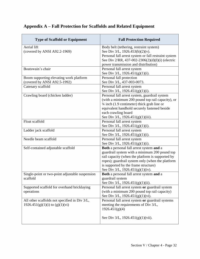
Appendix A – Fall Protection for Scaffolds and Related Equipment
Type of Scaffold or Equipment
Fall Protection Required
Aerial lift
(covered by ANSI A92.2-1969)
Body belt (tethering, restraint system)
See Div 3/L, 1926.453(b)(2)(v).
Personal fall arrest system or fall restraint system
See Div 2/RR, 437-002-2306(2)(d)(I)(i) (electric
power transmission and distribution)
Boatswain’s chair Personal fall arrest system
See Div 3/L, 1926.451(g)(1)(i).
Boom supporting elevating work platform
(covered by ANSI A92.5-1992)
Personal fall protection
See Div 3/L, 437-003-0073.
Catenary scaffold Personal fall arrest system
See Div 3/L, 1926.451(g)(1)(i).
Crawling board (chicken ladder) Personal fall arrest system, guardrail system
(with a minimum 200 pound top rail capacity), or
¾ inch (1.9 centimeter) thick grab line or
equivalent handhold securely fastened beside
each crawling board
See Div 3/L, 1926.451(g)(1)(iii).
Float scaffold Personal fall arrest system
See Div 3/L, 1926.451(g)(1)(i).
Ladder jack scaffold Personal fall arrest system
See Div 3/L, 1926.451(g)(1)(i).
Needle beam scaffold Personal fall arrest system
See Div 3/L, 1926.451(g)(1)(i).
Self-contained adjustable scaffold Both a personal fall arrest system and a
guardrail system with a minimum 200 pound top
rail capacity (when the platform is supported by
ropes); guardrail system only (when the platform
is supported by the frame structure)
See Div 3/L, 1926.451(g)(1)(iv).
Single-point or two-point adjustable suspension
scaffold
Both a personal fall arrest system and a
guardrail system
See Div 3/L, 1926.451(g)(1)(ii).
Supported scaffold for overhand bricklaying
operations
Personal fall arrest system or guardrail system
(with a minimum 200 pound top rail capacity)
See Div 3/L, 1926.451(g)(1)(vi).
All other scaffolds not specified in Div 3/L,
1926.451(g)(1)(i) to (g)(1)(vi)
Personal fall arrest system or guardrail systems
meeting the requirements of Div 3/L,
1926.451(g)(4)
See Div 3/L, 1926.451(g)(1)(vii).

Section V / Chapter 4 - Page 33
Appendix B – Oregon OSHA Standards Related to Fall Protection
This appendix lists some of the Oregon OSHA standards that apply to fall protection in
construction.
Construction
Div 2/RR, 437-002-2306, electric power transmission and distribution (personal protective
equipment)
Div 3/E, 437-003-0134(5), personal protective equipment (fall protection)
Div 3/L, 1926.451, general requirements (scaffolding)
Div 3/L, 1926.452, additional requirements applicable to specific types of scaffolds
Div 3/L, 1926.453, aerial lifts
Div 3/L, 1926.454, training requirements (scaffolding)
Div 3/L, 437-003-0073, boom supported elevating work platforms
Div 3/M, 1926.501, duty to have fall protection
Div 3/M, 437-003-1501, general fall protection
Div 3/M, 1926.502, fall protection systems criteria and practices
Div 3/M, 437-003-0502, personal fall restraint
Div 3/M, 437-003-1502, warning line systems for roofing work
Div 3/M, 437-003-2502, safety monitoring system
Div 3/M, 437-003-3502, slide guard systems
Div 3/M, 437-003-0503, training requirements (fall protection)
Div 3/R, 1926.760, fall protection (steel erection)
Div 3/S, 1926.800, underground construction
Div 3/X, 1926.1051, general requirements (stairways and ladders)
Div 3/X, 1926.1052, stairways
Div 3/X, 1926.1053, ladders
Div 3/X, 1926.1060, training requirements (stairways and ladders)
Div 3/CC, 1926.1423, cranes and derricks in construction (fall protection)

Section V / Chapter 4 - Page 34
Appendix C – Examples: Fall Protection Anchors by Type
This appendix identifies various types of anchors, how they are generally used, and shows an image of the anchor in use.
Anchor Type
Typical Use or Purpose Illustration
Engineered Clamps
En
gin
eere
d
Cla
mp
s
I-beam clamp and
structural steel
(vertical or horizontal
beams)
The clamp adjusts to various
steel beam sizes.
En
gin
eere
d
Cla
mp
s
Trolley beam anchor Allows a worker to have
greater access to a larger area
without a longer lanyard.
Section V / Chapter 4 - Page 35
En
gin
eere
d
Cla
mp
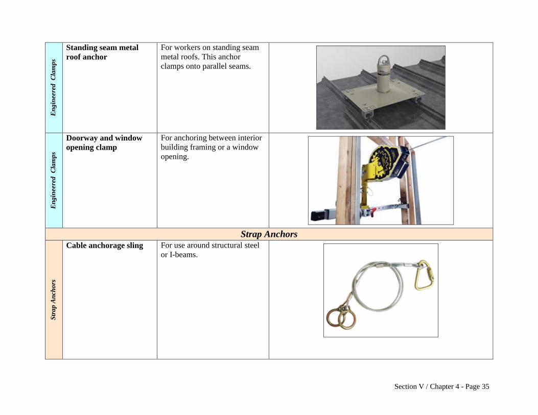
s Standing seam metal
roof anchor
For workers on standing seam
metal roofs. This anchor
clamps onto parallel seams.
En
gin
eere
d
Cla
mp
s
Doorway and window
opening clamp
For anchoring between interior
building framing or a window
opening.
Strap Anchors
Str
ap
An
cho
rs
Cable anchorage sling For use around structural steel
or I-beams.
Section V / Chapter 4 - Page 36
Str
ap
An
cho
rs
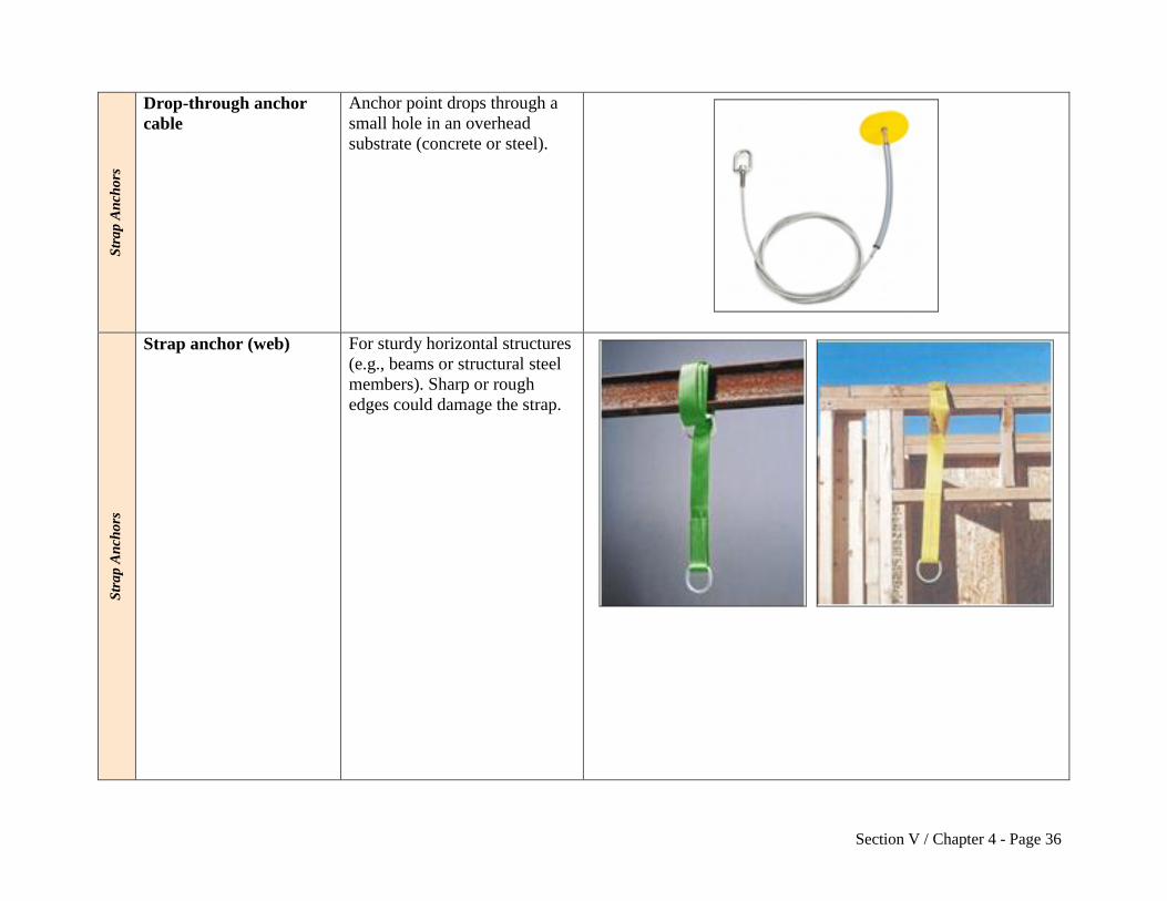
Drop-through anchor
cable
Anchor point drops through a
small hole in an overhead
substrate (concrete or steel).
Str
ap
An
cho
rs
Strap anchor (web) For sturdy horizontal structures
(e.g., beams or structural steel
members). Sharp or rough
edges could damage the strap.

Section V / Chapter 4 - Page 37
Concrete Anchors C
on
cret
e A
nch
ors
Concrete anchor strap
with D-ring
Often used by workers
conducting foundation and
formwork. The concrete anchor
strap has a tough sleeve or
wear-pad that protects it from
abrasion where it contacts
concrete. The strap loop slips
over rebar and is left in place
(with D-ring exposed) when
concrete is poured. When no
longer needed, the strap is cut
flush with the concrete surface.
Photo: a worker connects a shock-absorbing lanyard to an
embedded concrete anchor strap.
Co
ncr
ete
An
cho
rs Precast hollow core
concrete anchor
For workers performing
activities with precast hollow
concrete. Allows a single
worker to tie off.
Co
ncr
ete
An
cho
rs
Bolt-on wall anchor Temporary or permanent
anchor point on a vertical
concrete wall.

Section V / Chapter 4 - Page 38
Welded Anchors W
eld
ed A
nch
ors
Welded D-ring anchor Single D-ring temporary or
permanent anchor point that is
welded onto vertical structural
steel.
Weld
ed A
nch
ors
Weld-on anchor post This permanent anchor point is
welded onto an I-beam.

Section V / Chapter 4 - Page 39
Anchors Not Bolted or Clamped in Place (N.B. or C.I.P.) A
nch
ors
(N
.B.
or
C.I
.P.)
Mobile fall protection
system
Intended for a single worker
using a fall arrest system. It
allows quick mobility from
place to place on a job site.
Larger versions allow multiple
workers to anchor.
An
cho
rs (
N.B
. o
r C
.I.P
.) Rotating retractable
anchor mast
For use on sloped residential
roofs. Allows the worker
greater range of motion (up to
360 degrees for some models)
and helps elevate the anchor
point above the worker.
An
cho
rs (
N.B
. o
r C
.I.P
.)
Dead weight anchor For use on roofs where
penetrating the surface is not an
option. Anchorage is provided
by the weight of heavy
materials (e.g., concrete, steel,
water bladder).

Section V / Chapter 4 - Page 40
An
cho
rs (
N.B
. o
r C
.I.P
.)
Bolt hole anchor For use in horizontal steel bolt
holes.
Other Anchors
Oth
er A
nch
ors
Top Plate Anchor For activities near the framed
wall top plate.
Oth
er A
nch
ors
Peak Anchor
(One or Two D-Rings)
Typically used on a house roof
after it is sheathed or fully
constructed. They are typically
left in place after the job is
completed for future repairs.

Section V / Chapter 4 - Page 41
Oth
er A
nch
ors
Truss Anchor
(including Spreaders)
Used before a structure is fully
framed. A spreader is a method
a qualified person may use to
improve anchor point lateral
stability before trusses are fully
sheathed.
Oth
er A
nch
ors
Trench Box Guardrail
Anchor
For performing deep
excavation. The trench box
guardrail is designed with an
anchor point on a post near the
guardrail.

Section V / Chapter 4 - Page 42
Vertical Lifelines
Ver
tica
l L
ifel
ines
Rope grab (with vertical lifeline)
Rope lifeline attaches to an
anchorage at the top and hangs
vertically down through the
work area. Movable fall arrestor
(rope grab) attaches to the rope.
Lanyard connects the rope grab
to workers’ harness. To move up
and down the work area, the
worker can slide the rope grab
up and down the lifeline, then
relock it in place. If the worker
falls, the rope grab locks onto the
rope to break the fall.
This system’s effectiveness
depends on how well the worker
is trained to reposition the rope
grab while moving about. The
grab can slide off the end of the
rope if the rope is too short, if a
knot is not tied near the end of
the rope, or if the grab is not
installed properly.

Section V / Chapter 4 - Page 43
Horizontal Lifelines
Ho
rizo
nta
l L
ifel
ines
This hybrid system uses
one line (firmly anchored at
both ends) as the anchorage
for another. This allows the
worker greater lateral
movement than a fixed
anchor point. The
components are the same as
other personal fall
protection systems. A
deceleration device or rip-
stitch lanyard can be
included.
In some cases, more than
one worker will connect to
the horizontal lifeline if
approved by the
manufacturer and a
qualified person.
This hybrid system uses one line
(firmly anchored at both ends) as
the anchorage for another. This
allows the worker greater lateral
movement than a fixed anchor
point. The components are the
same as other personal fall
protection systems. A
deceleration device or rip-stitch
lanyard can be included.
In some cases, more than one
worker will connect to the
horizontal lifeline if approved by
the manufacturer and a qualified
person.
Photos used with permission by federal OSHA by the equipment manufacturers.

Section V / Chapter 4 - Page 44
Appendix D – Examples: Lanyards, Deceleration Devices, Harnesses, and Body Belts
Device Type
Typical Use or Purpose Illustration
Lanyards
La
nya
rd
Lanyard
(typical 2-foot and 6-foot
lengths)
Lanyards are available in a
variety of lengths.
La
nya
rd
Y-lanyard
(or twin-leg lanyard)
Typically used during work
on cranes, rebar and steel
structures, and poles. By
attaching and reattaching the
legs in different positions, the
worker can move across the
work face, remaining
connected by at least one leg
of the lanyard at all times.

Section V / Chapter 4 - Page 45
Deceleration Device
Dec
eler
ati
on
Devi
ce
Rip-stitch-style Shock
Absorbing Lanyard
These typically expand by
approximately 3.5 feet during
deceleration, which reduces
the force on the worker.
Dec
eler
ati
on
Devi
ce
Stretch-type Shock-
Absorbing Lanyard
These absorb force in a fall by
stretching (or by a similar
mechanism) on impact to
provide a controlled
deceleration.

Section V / Chapter 4 - Page 46
Dec
eler
ati
on
Devi
ce
Self-retracting lifeline
(SRL)
(line wound on a reel in
a reel-housing)
The lifeline is wound on a reel
and automatically extends or
retracts to take up slack in the
line as the worker moves
about. A sudden extension in
the line activates a locking
mechanism that typically
includes a deceleration
device. Some self-retracting
lanyards can be set to restrict
the distance traveled and so
can also function as part of a
properly designed fall
restraint system.
Body Belt
Bo
dy
Bel
t
Body Belt In general, harnesses are
preferable to body belts. Body
belts may be used in limited
instances (e.g., as part of a
positioning device system).

Section V / Chapter 4 - Page 47
Body Harness B
od
y H
arn
ess
Body Harness Used in personal fall
protection systems. Has a D-
ring on the back between the
shoulders when used for fall
arrest and fall restraint
systems. Workers need to be
fitted with the correct harness
size. Available with special
features such as an integrated
high-visibility vest, extra D-
rings (for use with positioning
devices), life vest (for over-
water work), or various
buckle and closure styles.
Thimble
Th
imb
le
Thimble Thimbles provide a protective
interface between the eye of a
rope loop and a connector.
They are used to prevent
pinching or abrasion of the
rope. The thimble needs to be
firmly seated in the eye of the
rope loop.
Photos used with permission by federal OSHA by the equipment manufacturers.

Section V / Chapter 4 - Page 48
Appendix E – References and Resources
29 CFR 1926 Subpart M (.500, .501, .502, and appendices)
29 CFR 1926 Subpart R and appendices
ARA, AEM, AED, IPAF, and SIA. 2010. Statement of Best Practices of General Training and
Familiarization for Aerial Work Platform Equipment (a joint industry initiative). 02-10-AWP-
SBP001.
ARA, AEM, IPAF, and SIA. 2013. Statement of Best Practices for Workplace Risk Assessment
and Aerial Work Platform Equipment Selection. 02-13-AWP-SBP003.
Bureau of Labor Statistics, 2013. Census of Fatal Occupational Injuries Summary, 2012
(preliminary results). August 22.
eLCOSH. 2007. Fall Protection: Misconceptions & Myths; Working Within the OSHA System.
Originally published by American Society of Safety Engineers.
ISEA. 2015. Personal Fall Protection Equipment. Use and Selection Guide.
[NIOSH] National Institute for Occupational Safety and Health. 2000, Worker Deaths by Falls
(NIOSH document 2000-116).
[NIOSH] National Institute for Occupational Safety and Health. 2004, NIOSH Alert: Preventing
Falls of Workers Through Skylights and Roof and Floor Openings. DHHS (NIOSH) Publication
No. 2004-156.
[NIOSH] National Institute for Occupational Safety and Health. 2011, Workplace Safety & Health
Topics Page: Prevention Through Design.
[NIOSH] National Institute for Occupational Safety and Health. 2014, Workplace Safety & Health
Topics Page: Fall Injuries Prevention in the Workplace. Fall-related Research Projects.
[OR-OSHA] Oregon Occupational Safety & Health Administration. 2016. Oregon OSHA Program
Directive (PD), Guardrail Height in General Industry A-173. Available at:
http://osha.oregon.gov/OSHARules/pd/pd-173.pdf
[OR-OSHA] Oregon Occupational Safety & Health Administration. 2016. Oregon OSHA Program
Directive (PD), Fall Protection: General Industry A-197. Available at:
http://osha.oregon.gov/OSHARules/pd/pd-197.pdf

Section V / Chapter 4 - Page 49
[OR-OSHA] Oregon Occupational Safety & Health Administration. 2016. Oregon OSHA Program
Directive (PD), Fall Protection: Personnel Lifts Used in Construction A-242. Available at:
http://osha.oregon.gov/OSHARules/pd/pd-242.pdf
[OR-OSHA] Oregon Occupational Safety & Health Administration. 2016. Oregon OSHA Fact Sheet
FS-26, Using Warning Lines: Construction Industry Best Practices. Available at:
http://osha.oregon.gov/OSHARules/pd/pd-242.pdf
[OR-OSHA] Oregon Occupational Safety & Health Administration. 2016. Oregon OSHA
Publication, Fall Protection for the Construction Industry (440-2824 - 6/16). Available at:
http://osha.oregon.gov/OSHAPubs/2824.pdf
[OSHA] Occupational Safety & Health Administration. 2002, A Guide to Scaffold Use in the
Construction Industry.
[OSHA] Occupational Safety & Health Administration. No date. Scaffolding. Appendix.
[OSHA] Occupational Safety & Health Administration. No date. OSHA Construction e-Tool:
Personal Fall Arrest Systems.
[OSHA] Occupational Safety & Health Administration. No date. Fall Protection Information.
[OSHA] Occupational Safety & Health Administration. No date. Fall Protection.
[OSHA] Occupational Safety & Health Administration. No date. Plan. Provide. Train. Three Steps
to Preventing Falls.
[OSHA] Occupational Safety & Health Administration. 2003a. Stairways and Ladders: A Guide to
OSHA Rules. 3124-12R.
[OSHA] Occupational Safety & Health Administration. 2011. Suspension Trauma/Orthostatic
Intolerance. SHIB 03-24-2004, updated 2011.
[OSHA] Occupational Safety & Health Administration. 2013. Communication Towers webpage.
Wilmes, LLC. 2013. Fall Protection Force Calculator.
WISHA. (Washington Industrial Safety & Health Division). No date. Fall Protection:
Responding to Emergencies. F417-208-000.
WISHA. No date. Competent Person Evaluation (checklist): Fall Restraint and Fall Arrest.