construction quality assurance (cqa) plan...a construction quality assurance (cqa) plan is required...
TRANSCRIPT

Bangus Quarry Landfill Project Number ISA-161-18-19 Proposed Landfill Development – Cell 1&2 CQA Plan 22 October 2019 Revision 0
InSitu Advisory Pty Ltd i
PROPOSED LANDFILL DEVELOPMENT BANGUS GRAVEL PIT LANDFILL
CONSTRUCTION QUALITY ASSURANCE (CQA) PLAN CELL 1 & 2 CONSTRUCTION
Prepared for MH Earthmoving Pty Ltd 150 Sheridan Street Gundagai NSW 2722 Project Number ISA-161-18-19
Revision 0
22 October 2019

Bangus Quarry Landfill Project Number ISA-161-18-19 Proposed Landfill Development – Cell 1&2 CQA Plan 22 October 2019 Revision 0
InSitu Advisory Pty Ltd ii
REPORT PREPARED BY:
InSitu Advisory Pty Ltd
15/23 Narabang Way, Belrose, NSW 2085
PO Box 503
Frenchs Forest
NSW 1640
ABN 43 612 657 682
❖ This report has been prepared by InSitu Advisory Pty Ltd with all reasonable skill, care and diligence, and taking account of the timescale and resources allocated to it by agreement with the Client.
❖ Information reported herein is based on the interpretation of data received, which has been accepted in good faith as being accurate and valid.
❖ This report is for the exclusive use of MH Earthmoving, nominated contractors and the NSW EPA.
❖ No warranties or guarantees are expressed or should be inferred by any third parties.
❖ This report may not be relied upon by other parties without written consent from InSitu Advisory Pty Ltd.
❖ InSitu Advisory disclaims any responsibility to the Client and others in respect of any matters outside the
agreed scope of the work.
DOCUMENT CONTROL
Report Status Date Prepared Checked Authorised
ISA-161-18-19 Revision 0 22 October 2019 Alan Dyer

Bangus Quarry Landfill Project Number ISA-161-18-19 Proposed Landfill Development – Cell 1&2 CQA Plan 22 October 2019 Revision 0
InSitu Advisory Pty Ltd iii
TABLE OF CONTENTS
1 GENERAL ........................................................................................................................... 1 1.1 INTRODUCTION AND PURPOSE ............................................................................................... 1 1.2 PROJECT DESCRIPTION .......................................................................................................... 1 1.3 SCOPE OF CONSTRUCTION WORKS....................................................................................... 2 1.4 PROJECT REQUIREMENTS ...................................................................................................... 2
1.4.1 Leachate Barrier Containment System ...................................................................... 2 1.5 DEFINITIONS ............................................................................................................................ 3 1.6 RESPONSIBLE PARTIES ........................................................................................................... 4
1.6.1 Land Owner .................................................................................................................... 4 1.6.2 Principal .......................................................................................................................... 4 1.6.3 Superintendent ............................................................................................................... 4 1.6.4 Designer .......................................................................................................................... 5 1.6.5 Contractor ....................................................................................................................... 5 1.6.6 CQA Engineer ................................................................................................................ 5
1.7 HOLD POINTS........................................................................................................................... 7 1.8 MEETINGS ................................................................................................................................ 7
2 EARTHWORKS .................................................................................................................. 9 2.1 GENERAL.................................................................................................................................. 9 2.2 MATERIALS............................................................................................................................... 9 2.3 INSPECTION AND MONITORING ............................................................................................... 9 2.4 INCLEMENT WEATHER ........................................................................................................... 10 2.5 CONTRACTORS PLANT .......................................................................................................... 10 2.6 GENERAL EXCAVATION ......................................................................................................... 10 2.7 FILLING ................................................................................................................................... 10 2.8 COMPACTION ......................................................................................................................... 10 2.9 SUBGRADE ............................................................................................................................. 11 2.10 TOLERANCES ..................................................................................................................... 11 2.11 ANCHOR TRENCHES .......................................................................................................... 11 2.12 CONFORMANCE TESTING .................................................................................................. 12 2.13 AS-BUILT LEVELS .............................................................................................................. 12 2.14 ACCEPTANCE AND SIGNOFF ............................................................................................. 12 2.15 REVIEW OF QUANTITIES .................................................................................................... 12
3 GEOSYNTHETICS ........................................................................................................... 13 3.1 GENERAL................................................................................................................................ 13 3.2 GEOSYNTHETICS MANUFACTURING ..................................................................................... 13
3.2.1 Manufacturer’s Quality Control .................................................................................. 14 3.3 GEOSYNTHETICS DELIVERY AND STORAGE ........................................................................ 14 3.4 TRANSPORTATION AND HANDLING ....................................................................................... 15 3.5 INDEPENDENT CONFORMANCE TESTING ............................................................................. 15
3.5.1 Geosynthetic Clay Liner ............................................................................................. 15 3.5.2 HDPE Geomembrane ................................................................................................. 16 3.5.3 Protection Geotextile ................................................................................................... 17 3.5.4 Separation Geotextile ................................................................................................. 18

Bangus Quarry Landfill Project Number ISA-161-18-19 Proposed Landfill Development – Cell 1&2 CQA Plan 22 October 2019 Revision 0
InSitu Advisory Pty Ltd iv
3.6 GEOSYNTHETICS INSTALLATION OVERVIEW ........................................................................ 18 3.6.1 Subgrade Preparation................................................................................................. 18 3.6.2 Geosynthetics Placement .......................................................................................... 19
3.7 GEOSYNTHETIC CLAY LINER ................................................................................................ 20 3.7.1 Installation ..................................................................................................................... 20 3.7.2 GCL Installation Approval .......................................................................................... 20 3.7.3 GCL Damage, Defects and Repairs ......................................................................... 21
3.8 HDPE GEOMEMBRANE ......................................................................................................... 21 3.8.1 Installation ..................................................................................................................... 21 3.8.2 Trial Seams ..................................................................................................................... 22 3.8.3 Geomembrane Field Seaming ........................................................................................ 22 3.8.4 Non-Destructive Testing ............................................................................................. 23 3.8.5 Qualitative Destructive Testing ................................................................................. 23 3.8.6 Quantitative Destructive Testing ............................................................................... 24 3.8.7 Geomembrane Defects and Repairs............................................................................... 24 3.8.8 Geomembrane Acceptance ............................................................................................ 25
3.9 PROTECTION GEOTEXTILE .................................................................................................... 25 3.9.1 Protection Geotextile Defects and Repairs..................................................................... 26
3.10 SEPARATION GEOTEXTILE ................................................................................................ 26 3.11 COVERING MATERIALS ...................................................................................................... 27
4 LEACHATE COLLECTION AND EXTRACTION SYSTEM ............................................ 28 4.1 GENERAL................................................................................................................................ 28 4.2 LEACHATE DRAINAGE AGGREGATE REQUIREMENTS .......................................................... 28 4.3 INSTALLATION OBSERVATIONS ...................................................................................................... 28
4.3.1 Aggregate Conformance Testing ................................................................................... 29 4.3.2 As-Built Levels................................................................................................................. 29 4.3.3 Acceptance and Signoff .................................................................................................. 30 4.3.4 Review of Quantities ...................................................................................................... 30
4.4 LEACHATE COLLECTION PIPEWORK ..................................................................................... 30 4.4.1 Pipework Installation ..................................................................................................... 31
5 CQA DOCUMENTATION ................................................................................................. 33 5.1 MANUFACTURER DATA SHEETS ..................................................................................................... 33 5.2 MANUFACTURER TEST DATA CERTIFICATES ..................................................................................... 33 5.3 AS-BUILT TOPOGRAPHIC SURVEYS ................................................................................................. 33 5.4 CQA ENGINEER’S DAILY DIARY RECORDS ....................................................................................... 33 5.5 CONSTRUCTION PHOTOGRAPHIC RECORD ....................................................................................... 34 5.6 TEST CERTIFICATION .................................................................................................................... 34 5.7 CQA VALIDATION REPORT ........................................................................................................... 34
6 CLOSURE AND STATEMENT OF COMPLIANCE ........................................................ 36

Bangus Quarry Landfill Project Number ISA-161-18-19 Proposed Landfill Development – Cell 1&2 CQA Plan 22 October 2019 Revision 0
InSitu Advisory Pty Ltd v
LIST OF TABLES
TABLE 1 CONFORMANCE SAMPLING AND TESTING FREQUENCY FOR THE GCL .......................................... 16 TABLE 2 TABLE OF GEOMEMBRANE CONFORMANCE TESTING ..................................................................... 17 TABLE 3 TABLE OF PROTECTION GEOTEXTILE CONFORMANCE TESTING .................................................... 18 TABLE 4 GEOTEXTILES CONFORMANCE TESTING ......................................................................................... 18 TABLE 5 DESTRUCTIVE TEST CRITERIA FOR 2.0MM HDPE GEOMEMBRANE .............................................. 24 TABLE 6 LEACHATE DRAINAGE AGGREGATE TESTING REQUIREMENTS ...................................................... 29
LIST OF FIGURES
Figure 0 – Cover Page and Drawing List
Figure 1 – Site location plan
Figure 2 – Existing Layout & Site Boundaries
Figure 3 – Existing Site Survey
Figure 4 – Proposed Landfill Subgrade Levels and Layout Plan
Figure 5 – Engineered Sub-Base and Bunds Layout Plan
Figure 6 – Proposed Engineered Geosynthetics Layout
Figure 7 – Typical Sections and Construction Details
Figure 8 – Proposed Leachate Drainage Blanket and Pipework Layout Plan
Figure 9 – Leachate Drainage Construction Details
Figure 10 – Phased Excavation Plan
Bangus Quarry Landfill Project Number ISA-161-18-19 Proposed Landfill Development – Cell 1&2 CQA Plan 22 October 2019 Revision 0
InSitu Advisory Pty Ltd vi
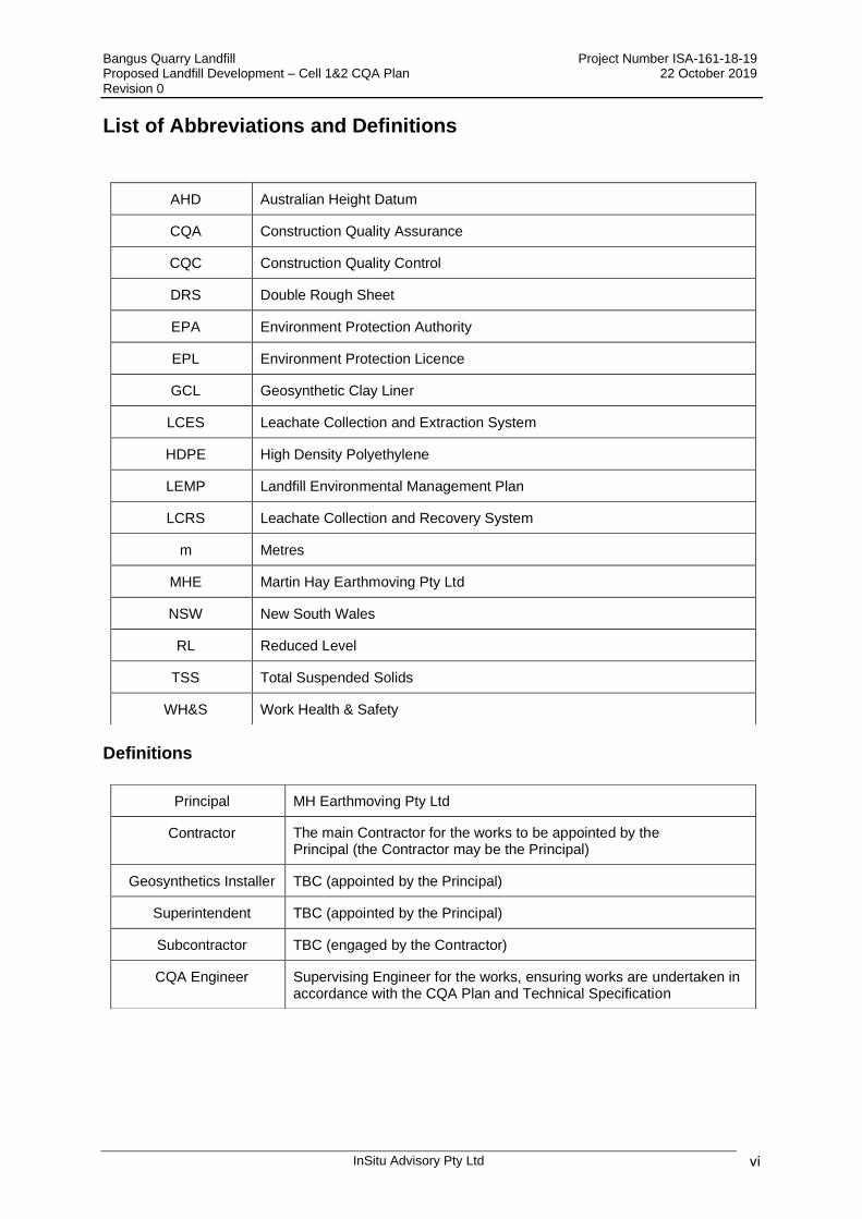
List of Abbreviations and Definitions
Definitions
AHD Australian Height Datum
CQA Construction Quality Assurance
CQC Construction Quality Control
DRS Double Rough Sheet
EPA Environment Protection Authority
EPL Environment Protection Licence
GCL Geosynthetic Clay Liner
LCES Leachate Collection and Extraction System
HDPE High Density Polyethylene
LEMP Landfill Environmental Management Plan
LCRS Leachate Collection and Recovery System
m Metres
MHE Martin Hay Earthmoving Pty Ltd
NSW New South Wales
RL Reduced Level
TSS Total Suspended Solids
WH&S Work Health & Safety
Principal MH Earthmoving Pty Ltd
Contractor The main Contractor for the works to be appointed by the Principal (the Contractor may be the Principal)
Geosynthetics Installer TBC (appointed by the Principal)
Superintendent TBC (appointed by the Principal)
Subcontractor TBC (engaged by the Contractor)
CQA Engineer Supervising Engineer for the works, ensuring works are undertaken in accordance with the CQA Plan and Technical Specification

Bangus Quarry Landfill Project Number ISA-161-18-19 Proposed Landfill Development – Cell 1 & 2 CQA Plan 22 October 2019 Draft
InSitu Advisory Pty Ltd 1
1 GENERAL
1.1 Introduction and Purpose
A Construction Quality Assurance (CQA) Plan is required to meet the requirements of Section 11 of the NSW EPA Environmental Guidelines: Solid Waste Landfills, Second Edition 2016. A CQA Plan details the testing requirements, responsible parties, inspection protocols and documentation required for the proposed construction of Cells 1 & 2 at the proposed Bangus Quarry Landfill project. CQA is undertaken to ensure that the works have been undertaken to the highest of quality assured standards, and in accordance with the agreed Technical Specification and Works Documents. Furthermore, the CQA program is intended to provide a level of confidence to the Principal, Engineer, Regulator and the public that the completed project has been constructed in accordance with the approved specifications and approved works documents.
CQA and testing is typically conducted during the construction phase to ascertain and ensure the quality of the works prior to project completion. Due to potential conflicts of interest, CQA is more often undertaken by an independent organisation, such as an Engineer, rather than being undertaken by the Contractor.
Construction Quality Control (CQC) and testing consists of specific tests and inspections undertaken during production. These tests and checks can ensure that a consistent quality product is delivered and installed by the Contractor as part of the project. While the CQC and testing function is usually the responsibility of the Contractor, the Superintendent may at their discretion, provide information regarding the on-going CQA testing monitoring for the Contractor’s use in implementing the CQC testing program.
This document is intended to detail the quality assurance procedures and requirements for various aspects of the proposed landfill works at Bangus Gravel Pit Landfill, Tumblong, NSW (see Figure 1).
This CQA Plan has been prepared by InSitu Advisory Pty Ltd (InSitu Advisory) to detail the installation and testing quality control procedures that will be followed during the works. The CQA Plan must be read in conjunction with the Technical Specification and other Contract Documents. The Technical Specification and construction drawings have been prepared by InSitu Advisory.
1.2 Project Description
MH Earthmoving Pty Ltd (MHE) has commissioned InSitu Advisory to provide engineering design services for the construction the proposed landfill at the Bangus Gravel Pit Landfill (the Site).
The proposed landfill development seeks to remediate the existing gravel pit which is nearing the end of its useful life, by providing a waste disposal facility which will service Visy, a large major player in the resource recovery and recycling industry.
The Site is identified as Lot 7004 of Deposited Plan 1028797 and Lot 7300 of Deposited Plan 1149008 and was designated as a quarry (Reserve 89508) in 1975. The Site is located within the Tumblong region within the Cootamundra-Gundagai Regional Council area. The Site is located on the gravel surfaced Tumblong Reserve Road, approximately 1.2 kilometres from its intersection with the Old Hume Highway. In turn, the sealed Old Hume Highway intersection with the current Hume Highway lies a further 2.3 kilometres away.
The Site has been utilised for gravel extraction purposes on an “as-required” basis since opening in 1975. The quarry, after the proposed excavation to formation levels will be nearing exhaustion and will require remediation. The proposed landfill development shall progressively rehabilitate the land by landfilling whilst generating further aggregate resource into the future by the additional excavation to design levels.
The Technical Specification details the engineering requirements of a Contractor to be able to build the proposed landfill development in full accordance with the EPA Environmental Guidelines: Solid Waste Landfills Second Edition, 2016.
Bangus Quarry Landfill Project Number ISA-161-18-19 Proposed Landfill Development – Cell 1 & 2 CQA Plan 22 October 2019 Draft
InSitu Advisory Pty Ltd 2
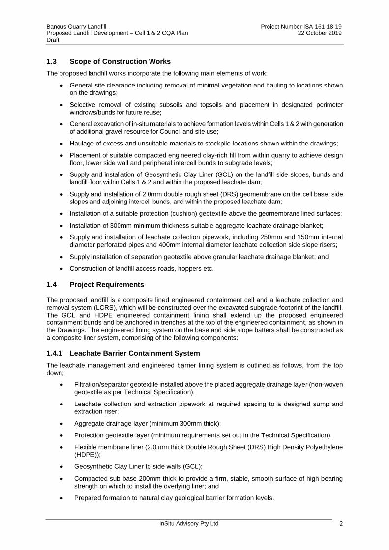
1.3 Scope of Construction Works
The proposed landfill works incorporate the following main elements of work:
• General site clearance including removal of minimal vegetation and hauling to locations shown on the drawings;
• Selective removal of existing subsoils and topsoils and placement in designated perimeter windrows/bunds for future reuse;
• General excavation of in-situ materials to achieve formation levels within Cells 1 & 2 with generation of additional gravel resource for Council and site use;
• Haulage of excess and unsuitable materials to stockpile locations shown within the drawings;
• Placement of suitable compacted engineered clay-rich fill from within quarry to achieve design floor, lower side wall and peripheral intercell bunds to subgrade levels;
• Supply and installation of Geosynthetic Clay Liner (GCL) on the landfill side slopes, bunds and landfill floor within Cells 1 & 2 and within the proposed leachate dam;
• Supply and installation of 2.0mm double rough sheet (DRS) geomembrane on the cell base, side slopes and adjoining intercell bunds, and within the proposed leachate dam;
• Installation of a suitable protection (cushion) geotextile above the geomembrane lined surfaces;
• Installation of 300mm minimum thickness suitable aggregate leachate drainage blanket;
• Supply and installation of leachate collection pipework, including 250mm and 150mm internal diameter perforated pipes and 400mm internal diameter leachate collection side slope risers;
• Supply installation of separation geotextile above granular leachate drainage blanket; and
• Construction of landfill access roads, hoppers etc.
1.4 Project Requirements
The proposed landfill is a composite lined engineered containment cell and a leachate collection and removal system (LCRS), which will be constructed over the excavated subgrade footprint of the landfill. The GCL and HDPE engineered containment lining shall extend up the proposed engineered containment bunds and be anchored in trenches at the top of the engineered containment, as shown in the Drawings. The engineered lining system on the base and side slope batters shall be constructed as a composite liner system, comprising of the following components:
1.4.1 Leachate Barrier Containment System
The leachate management and engineered barrier lining system is outlined as follows, from the top down;
• Filtration/separator geotextile installed above the placed aggregate drainage layer (non-woven geotextile as per Technical Specification);
• Leachate collection and extraction pipework at required spacing to a designed sump and extraction riser;
• Aggregate drainage layer (minimum 300mm thick);
• Protection geotextile layer (minimum requirements set out in the Technical Specification).
• Flexible membrane liner (2.0 mm thick Double Rough Sheet (DRS) High Density Polyethylene (HDPE));
• Geosynthetic Clay Liner to side walls (GCL);
• Compacted sub-base 200mm thick to provide a firm, stable, smooth surface of high bearing strength on which to install the overlying liner; and
• Prepared formation to natural clay geological barrier formation levels.
Bangus Quarry Landfill Project Number ISA-161-18-19 Proposed Landfill Development – Cell 1 & 2 CQA Plan 22 October 2019 Draft
InSitu Advisory Pty Ltd 3
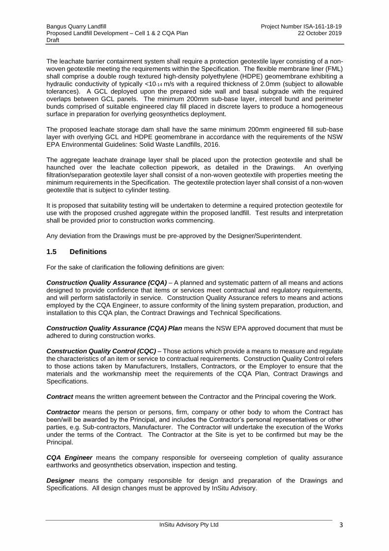
The leachate barrier containment system shall require a protection geotextile layer consisting of a non-woven geotextile meeting the requirements within the Specification. The flexible membrane liner (FML) shall comprise a double rough textured high-density polyethylene (HDPE) geomembrane exhibiting a hydraulic conductivity of typically <10-14 m/s with a required thickness of 2.0mm (subject to allowable tolerances). A GCL deployed upon the prepared side wall and basal subgrade with the required overlaps between GCL panels. The minimum 200mm sub-base layer, intercell bund and perimeter bunds comprised of suitable engineered clay fill placed in discrete layers to produce a homogeneous surface in preparation for overlying geosynthetics deployment.
The proposed leachate storage dam shall have the same minimum 200mm engineered fill sub-base layer with overlying GCL and HDPE geomembrane in accordance with the requirements of the NSW EPA Environmental Guidelines: Solid Waste Landfills, 2016.
The aggregate leachate drainage layer shall be placed upon the protection geotextile and shall be haunched over the leachate collection pipework, as detailed in the Drawings. An overlying filtration/separation geotextile layer shall consist of a non-woven geotextile with properties meeting the minimum requirements in the Specification. The geotextile protection layer shall consist of a non-woven geotextile that is subject to cylinder testing.
It is proposed that suitability testing will be undertaken to determine a required protection geotextile for use with the proposed crushed aggregate within the proposed landfill. Test results and interpretation shall be provided prior to construction works commencing.
Any deviation from the Drawings must be pre-approved by the Designer/Superintendent.
1.5 Definitions
For the sake of clarification the following definitions are given:
Construction Quality Assurance (CQA) – A planned and systematic pattern of all means and actions designed to provide confidence that items or services meet contractual and regulatory requirements, and will perform satisfactorily in service. Construction Quality Assurance refers to means and actions employed by the CQA Engineer, to assure conformity of the lining system preparation, production, and installation to this CQA plan, the Contract Drawings and Technical Specifications.
Construction Quality Assurance (CQA) Plan means the NSW EPA approved document that must be adhered to during construction works.
Construction Quality Control (CQC) – Those actions which provide a means to measure and regulate the characteristics of an item or service to contractual requirements. Construction Quality Control refers to those actions taken by Manufacturers, Installers, Contractors, or the Employer to ensure that the materials and the workmanship meet the requirements of the CQA Plan, Contract Drawings and Specifications.
Contract means the written agreement between the Contractor and the Principal covering the Work.
Contractor means the person or persons, firm, company or other body to whom the Contract has been/will be awarded by the Principal, and includes the Contractor’s personal representatives or other parties, e.g. Sub-contractors, Manufacturer. The Contractor will undertake the execution of the Works under the terms of the Contract. The Contractor at the Site is yet to be confirmed but may be the Principal.
CQA Engineer means the company responsible for overseeing completion of quality assurance earthworks and geosynthetics observation, inspection and testing.
Designer means the company responsible for design and preparation of the Drawings and Specifications. All design changes must be approved by InSitu Advisory.

Bangus Quarry Landfill Project Number ISA-161-18-19 Proposed Landfill Development – Cell 1 & 2 CQA Plan 22 October 2019 Draft
InSitu Advisory Pty Ltd 4
Geosynthetics Installer means the firm responsible for the installation of the geosynthetics, including all field construction quality control activities, including (but not limited to) field seam testing.
Independent Testing Laboratory means the NATA accredited firm responsible for conducting all required laboratory tests.
Principal means the person or persons, firm or company or other body who owns and has responsibility for the facility. For the sake of the contract, the Principal is MH Earthmoving.
Specification means that part of the Contract entered into between the Employer and the Contractor which sets out the Employer’s detailed requirements as to how the works should be constructed, tested and quality assured. The Specification has been provided by InSitu Advisory and forms part of this CQA Plan.
Superintendent means a representative of the MHE who will enter into a contract with a Contractor for the execution of the works detailed in the CQA Plan, Specification and Contract Drawings. The Superintendent will represent the Principal on site, and may delegate some supervision responsibilities to other parties, e.g. the CQA Engineer.
Work(s) means all tools, equipment, supervision, labour, and materials or supplies necessary to complete the project as specified herein and as shown on the Drawings, Plans and Specifications.
1.6 Responsible Parties
The Project Team will comprise the following:
1.6.1 Land Owner
The site is currently owned by Crown Lands, but is currently in the process of being purchased by Council. The land transfer of ownership is imminent (at the time of drafting this report).
1.6.2 Principal
The Principal is MH Earthmoving who has overall responsibility for the proposed landfill facility and the construction project. The Principal shall undertake the following:
• Engage an independent CQA Engineer
• Engage a Contractor for the Works (if required);
• Engage a leak location contractor;
• Discuss with the CQA Engineer and Designer any proposed modifications and changes;
• Submit a CQA Validation Report including as-built Drawings to the NSW EPA at or soon after completion of the Works.
1.6.3 Superintendent
The Superintendent will serve as the Principal’s onsite representative and shall have overall authority for all CQA activities on site. The Superintendent shall be the liaison between the Contractor and the CQA Engineer while keeping the Principal advised regarding progress of the project. All CQA functions will be under his/her direct authority. All coordination, reporting and issues related to non-conformance will be directed through the Superintendent or their representative. The Superintendent may also be the CQA Engineer if required by the Principal.
All coordination, reporting and issues related to non-compliance shall be directed through the Superintendent. Any requests for information, design modifications or proposed changes in the Technical Specification shall be directed through the Superintendent who shall then liaise with the relevant parties to resolve.

Bangus Quarry Landfill Project Number ISA-161-18-19 Proposed Landfill Development – Cell 1 & 2 CQA Plan 22 October 2019 Draft
InSitu Advisory Pty Ltd 5
1.6.4 Designer
The Designer will be responsible for reviewing all design and materials related issues that may arise during construction. The Designer shall consider and approve if appropriate, in consultation with the Superintendent any earthworks or geosynthetic material modifications or any design modifications that may affect the design or performance of the proposed works. Approval by the Designer will be required prior to the implementation of any design changes. The Designer may periodically visit the site during the construction phase in order to advise the Principal/Superintendent on issues pertaining to the design and or construction.
The Designer may consult the NSW EPA regarding any proposed design changes throughout the works in order to allow greater understanding by the NSW EPA when approving the CQA Validation report.
1.6.5 Contractor
The Contractor shall undertake the works, select products and materials in order to meet the requirements of the Technical Specification and CQA Plan, obtain supplier proposals, execute purchase agreements, produce as-built drawings, arrange for product delivery, inspect products on delivery, obtain/collect and forward product certifications and warranties, attend progress meetings, and update schedules. The Contractor shall be responsible for ensuring all CQC activities are undertaken in accordance with the Technical Specification.
The Contractor shall work collaboratively with the Principal, Superintendent, Designer and CQA Engineer in the delivery of the project. The earthworks Contractor may be the Principal.
1.6.6 CQA Engineer
The CQA Engineer may also act as the CQA Monitor for the works. The CQA Engineer shall be responsible for assessing the compliance of the completed Works with the Works Documents. The CQA Engineer will consist of field personnel with specific experience in the inspection and CQA monitoring activities associated with earthwork activities related to landfill construction. The primary responsibilities shall include the following;
• The CQA Engineer will be responsible for assessing all compacted clay liner material and geosynthetic material issues which may arise during construction. In addition, the CQA Engineer shall be responsible for:
• Reviewing the CQA Plan and Technical Specification;
• Prepare and maintain required CQA documentation;
• Coordination of all CQA field testing, sampling and laboratory testing;
• Assigns locations for testing and sampling;
• Review of all field and laboratory test results and preparation of recommendations for appropriate responses;
• Oversees the collection and shipping of all samples for laboratory testing;
• Review of all CQA Monitor's daily reports and logs;
• Attend required meetings;
• Report any unapproved deviations from the CQA Plan to the Superintendent/Principal as soon as practicable;
• Reviewing and recommend rejection or approval of site-specific documentation including Contractor submittals, Manufacturer’s information, Geosynthetic Installer’s information and referenced standards. The Designer/Principal shall make the final decision on approval or disapproval of submittals;
• Subgrade inspection;

Bangus Quarry Landfill Project Number ISA-161-18-19 Proposed Landfill Development – Cell 1 & 2 CQA Plan 22 October 2019 Draft
InSitu Advisory Pty Ltd 6
• Review of the adequacy of all site preparation and construction plant in areas to receive fill;
• Monitoring and evaluation of all engineered fill material processing and moisture conditioning operations;
• Verify that CQA and CQC conformance tests are properly performed, recorded, and the results meet specified requirements;
• Oversee the collection, marking, packaging, and shipping of CQA conformance samples for testing;
• Evaluation of the engineering characteristics of proposed on-site and/or imported materials;
• Prepares, or oversees the ongoing preparation of the as-built drawings;
• Provides all logs and relevant data to the CQA Project Manager for the preparation of final reports;
• Reviews all Certifications and Documentation from the Contractor and makes appropriate recommendations;
• Reports to the CQA Project Manager, and logs in his daily report any relevant observations; and
• Notes and brings to the attention of the Superintendent any on-site activities that could result in damage to the works.
“CQA Project Manager” who will be based at the offices of the CQA Engineer and will be present during the start of the construction works. The CQA Project Manager:
• Attends selected progress or liaison meetings;
• Reviews other site-specific documentation, including proposed layouts, and Contractor’s qualifications where required;
• Administrates the CQA programme;
• Reviews all changes to the design, plans and specifications where required; and
• Oversees and reviews the CQA Certification Reports.
“CQA Monitor”.
CQA monitors will again be representatives of the Principal having duties including the following:
• Observation of the dewatering and site clearance;
• Observation of the cut and fill operations to achieve required levels;
• Observation of the preparation of the subgrade surface;
• Verification checks on imported materials;
• Visual evaluation of soil material properties for consistency with the Specifications;
• Identification of deleterious materials or other deficiencies in compacted clay liner materials before they may be incorporated into the leachate barrier containment system or leachate collection system;
• Monitoring of moisture conditioning, mixing, blending, and processing for uniformity of material;
• Monitoring of activities for removal and/or disaggregation of oversize material from the compacted clay liner or fill;
• Monitoring of lift thickness and number of passes of compaction equipment;
• Observation of uniformity of coverage of compaction equipment; especially at extremities;
Bangus Quarry Landfill Project Number ISA-161-18-19 Proposed Landfill Development – Cell 1 & 2 CQA Plan 22 October 2019 Draft
InSitu Advisory Pty Ltd 7
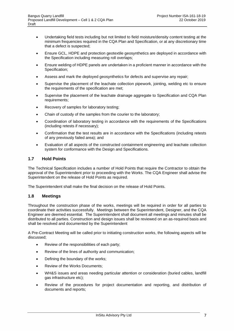
• Undertaking field tests including but not limited to field moisture/density content testing at the minimum frequencies required in the CQA Plan and Specification, or at any discretionary time that a defect is suspected;
• Ensure GCL, HDPE and protection geotextile geosynthetics are deployed in accordance with the Specification including measuring roll overlaps;
• Ensure welding of HDPE panels are undertaken in a proficient manner in accordance with the Specification;
• Assess and mark the deployed geosynthetics for defects and supervise any repair;
• Supervise the placement of the leachate collection pipework, jointing, welding etc to ensure the requirements of the specification are met;
• Supervise the placement of the leachate drainage aggregate to Specification and CQA Plan requirements;
• Recovery of samples for laboratory testing;
• Chain of custody of the samples from the courier to the laboratory;
• Coordination of laboratory testing in accordance with the requirements of the Specifications (including retests if necessary);
• Confirmation that the test results are in accordance with the Specifications (including retests of any previously failed area); and
• Evaluation of all aspects of the constructed containment engineering and leachate collection system for conformance with the Design and Specifications.
1.7 Hold Points
The Technical Specification includes a number of Hold Points that require the Contractor to obtain the approval of the Superintendent prior to proceeding with the Works. The CQA Engineer shall advise the Superintendent on the release of Hold Points as required.
The Superintendent shall make the final decision on the release of Hold Points.
1.8 Meetings
Throughout the construction phase of the works, meetings will be required in order for all parties to coordinate their activities successfully. Meetings between the Superintendent, Designer, and the CQA Engineer are deemed essential. The Superintendent shall document all meetings and minutes shall be distributed to all parties. Construction and design issues shall be reviewed on an as-required basis and shall be resolved and documented by the Superintendent
A Pre-Contract Meeting will be called prior to initiating construction works, the following aspects will be discussed;
• Review of the responsibilities of each party;
• Review of the lines of authority and communication;
• Defining the boundary of the works;
• Review of the Works Documents;
• WH&S issues and areas needing particular attention or consideration (buried cables, landfill gas infrastructure etc);
• Review of the procedures for project documentation and reporting, and distribution of documents and reports;

Bangus Quarry Landfill Project Number ISA-161-18-19 Proposed Landfill Development – Cell 1 & 2 CQA Plan 22 October 2019 Draft
InSitu Advisory Pty Ltd 8
• Review of proposed method statements for the various phases of construction (including equipment), with specific emphasis on methods of excavation, selecting suitable fill, haulage, placement, compaction, stockpiling, processing, moisture conditioning, geosynthetics deployment, drainage pipework and aggregate placement etc;
• Review of the procedures for field and laboratory CQA testing;
• Establishment of procedures for correcting and documenting construction deficiencies;
• Review of the project program and completion dates; and
• Conducting a site inspection of the works and surrounding site area.
Bangus Quarry Landfill Project Number ISA-161-18-19 Proposed Landfill Development – Cell 1 & 2 CQA Plan 22 October 2019 Draft
InSitu Advisory Pty Ltd 9
2 EARTHWORKS
2.1 General
Earthworks requirements for the proposed landfill construction are detailed in the works Technical Specification. Primarily, this will consist of excavation and stockpiling of insitu materials from the proposed landfill footprint, and hauling to the stockpile location shown within Drawing No. 2. Any topsoil and subsoil will be stripped separately for later use.
Earthworks activities will include excavating and trimming in preparation to receive suitable engineered fill provided by the Principal. Bulk excavation and placement of engineered fill will be undertaken to achieve required formation and top of engineered clay sub-base levels. Additional earthworks will include localised cut and fill, placement and compaction of unclassified fill, compaction and trimming of the sub-base to a minimum thickness of 200mm, construction of the perimeter western and northern bunds, the Cell ½ intercell separating bund and anchor trench excavation and backfill. Specific requirements for each earthwork component are again detailed in the Technical Specification.
The following sections detail the CQA inspection, monitoring and testing requirements to be undertaken for the earthworks elements of the proposed works.
2.2 Materials
The CQA Engineer shall undertake the following tasks as part of their duties;
• Inspect proposed engineered fill material source area and/or stockpiles prior to use and advise the Superintendent of the presence of any unsuitable material.
• Review all test results/reports provided by the Principal or Contractor for the proposed engineered fill material to verify that the material is uniform and conforms to the Technical Specification.
• Provide updates to the Superintendent and/or Principal regarding consistency of source material and whether additional testing is required if the material appears to have changed significantly.
2.3 Inspection and Monitoring
The Superintendent (or his debutant) shall be solely responsible for the satisfactory completion of all CQA testing activities in accordance with the Specification and this CQA Plan. The site clearance, soils separation and bulk earthworks shall be undertaken to the satisfaction of the Superintendent or designated representative.
The Superintendent will be responsible for confirming that the finished excavation and all liner system fill levels are in general compliance with the Drawings and Specifications. This may be undertaken by the Contractor providing survey data to cross check against the levels stated on the design drawings. Levels are to be within the specified tolerances.
Material deemed unsuitable and not meeting the Specification shall be removed from the works as soon as practicable and placed in stockpile, or within the active landfill, at the direction of the Superintendent. The excavated ground surface to receive fill shall be prepared to the satisfaction of the CQA Engineer and in accordance with the shear strength requirements stated in the Specification. Subsequent fill shall be placed, spread, moisture conditioned if necessary and compacted in accordance with the Specification and as recommended by the Superintendent and CQA Engineer.
During periods of adverse weather such as heavy rainfall, fill operations shall not be resumed until observations and field tests by the CQA Engineer indicate the moisture content and density of the previously placed fill and/or materials intended for placement are within the limits required within the Specification and CQA Plan.
Bangus Quarry Landfill Project Number ISA-161-18-19 Proposed Landfill Development – Cell 1 & 2 CQA Plan 22 October 2019 Draft
InSitu Advisory Pty Ltd 10
The Superintendent or his debutant shall ensure that the intercell bunds and corresponding lifts of engineered compacted clay liner shall be keyed into existing bunds or placed layers. The connection between new and previously placed compacted clay liner fill shall be stepped in where the two areas meet.
Compacted fill placement shall be undertaken in accordance with the requirements of the Technical Specification.
2.4 Inclement Weather
The CQA Engineer shall ensure that earthworks do not occur during periods of excessive rain, freezing temperatures, or other poor weather conditions that may be detrimental to the previously undertaken works and impede progress and performance of ongoing works.
2.5 Contractors Plant
The CQA Engineer shall visually inspect and verify the Contractors plant and equipment proposed for the placement, compaction and trimming of the earthworks component of the works to ensure they meet the requirements of the Specification and the approved Contractors work method statements.
2.6 General Excavation
During the general excavation phase within the proposed landfill footprint, the CQA Engineer shall ensure the following:
• Unsuitable materials, whether inhomogeneous, water saturated or contaminated and generally not meeting the requirements of the Technical Specification shall be excavated and disposed by the Contractor in locations indicated by the Principal;
• Temporary excavated faces shall be left in a safe, stable condition with fencing or barrier tap Excavated;
• Excavated slopes shall be finished in conformance with the required lines and grades;
• All debris and loose material is removed from the completed trimmed surfaces; and
• The Contractor has implemented protective measures to ensure that the excavation areas are not damaged during periods of inclement weather.
2.7 Filling
During the general filling phase within the landfill footprint, the CQA Engineer shall ensure the following:
• Loose uncompacted lifts are placed no greater than the maximum allowable thickness stated in the Technical Specification;
• Fill contains no large clods, rocks, debris or other non-compliant material stipulated within the Technical Specification;
• Fill material is placed to the lines and levels shown in the Works Documents; and
• Slippage of fill emplacement and compaction plant does not occur on side slopes especially when any fill layer is overlays geosynthetics.
2.8 Compaction
During the compaction of engineered fill phase, the CQA Engineer shall ensure the following:
• Ensure no deleterious materials exist within the uncompacted layer prior to compaction;
• Ensure appropriate plant and equipment is used by the contractor to undertake sufficient compaction;

Bangus Quarry Landfill Project Number ISA-161-18-19 Proposed Landfill Development – Cell 1 & 2 CQA Plan 22 October 2019 Draft
InSitu Advisory Pty Ltd 11
• Verify and ensure the specified minimum number of passes are being made over all areas and over each lift of engineered fill;
• Ensure sufficient compactive effort is afforded to all edges and difficult to access fill emplacement areas;
• Visually observe and ensure adequate compaction around all penetrations ensuring no voids or uncompacted areas remain;
• Verify the surface of each lift is adequately scarified prior to emplacement of any subsequent lift of fill;
• Inspect any pipework that may penetrate fill layers for damage due to placement and compaction equipment; and
• Ensure low ground pressure equipment is used when compaction is required over piping, geosynthetics, leachate drainage aggregate or similar.
2.9 Subgrade
The CQA Engineer shall inspect the completed subgrade and verify the following:
• The subgrade is smooth, free of voids and protrudencies and composed of compliant homogeneous fill materials;
• The CQA Engineer shall witness proof rolling to assess the soundness and suitability of the subgrade based on the requirements of the Specification;
• The elevation of the subgrade surface is correct and to the Works Documents;
• The subgrade provides a stable surface for the overlying geosynthetics;
• All construction stakes, hubs or other items used for grade control and/or verification have been removed;
• Soft spots within the subgrade have been removed and replaced with suitable compacted fill;
• Suitable protection measures are installed to protect the subgrade from degradation or damage; and
• The subgrade is kept free of all debris and deleterious materials.
2.10 Tolerances
The CQA Engineer shall review as-built survey data of the completed surfaces to confirm layer thickness is within the allowable tolerance stated within the Technical Specification.
2.11 Anchor Trenches
The CQA Engineer shall inspect and verify the following:
• The anchor trench has been constructed to the required dimensions and profile;
• Corners of the anchor trench are slightly rounded to avoid sharp apexes that would otherwise damage geosynthetics;
• No loose fill or debris from the anchor trench side walls are left in the base of the formed anchor trench;
• Any standing water within the anchor trench is removed prior to the deployment of geosynthetics;
• Geosynthetic layers have been placed correctly within the anchor trench;
• Construction debris, waste, offcuts, geosynthetic inner rolls or other materials are removed from the anchor trench prior to deployment of geosynthetics;

Bangus Quarry Landfill Project Number ISA-161-18-19 Proposed Landfill Development – Cell 1 & 2 CQA Plan 22 October 2019 Draft
InSitu Advisory Pty Ltd 12
• The anchor trench is backfilled in required layers with suitable approved fill placed at the specified moisture content and density ensuring no damage to the emplaced geosynthetics.
2.12 Conformance Testing
Construction quality assurance testing for engineered fill shall be carried out by an independent testing laboratory accredited by the National Association of Testing Authorities (NATA) to test in the relevant field in accordance with the Technical Specification.
The CQA Engineer shall arrange with the Contractor for conformance testing of the materials used in the Works, in accordance with this CQA Plan and the Technical Specification. Samples shall be collected at locations designated by the CQA Engineer and all conformance sampling shall be witnessed by the CQA Engineer. ensuring that all samples are taken, accurately labelled and packaged in accordance with the Technical Specification and this CQA Plan.
Field tests shall be conducted by suitably qualified and experienced personnel.
A NATA Registered Laboratory who shall supply certificates identifying the material type, specification requirements, and associated results shall undertake the testing.
The CQA Engineer shall;
• Ensure moisture content and insitu density tests are performed at the specified frequency over a representative spread of the construction area;
• Conduct additional tests at any time that in the opinion of the CQA Engineer, additional testing is required and/or a deficiency is suspected;
• The Contractor performs corrective action as a result of failed tests in compliance with the Works Documents and submits documentation describing the corrective measures taken;
• Following a thorough re-working of a failed area, retesting will be performed by the CQA Engineer to evaluate whether the re-worked area meets the requirements of the Technical Specification.
2.13 As-Built Levels
The CQA Engineer will be required to continually review construction levels and positioning with respect to the design drawings and review the Contractor provided final as-built survey data to verify conforming lines, levels and layer thickness are within the allowable tolerance given within the Technical Specification.
2.14 Acceptance and Signoff
At the hold point for completion of earthworks, the Superintendent shall formally sign off the activity prior to the Contractor undertaking subsequent activities. The CQA Engineer shall provide a recommendation to the Superintendent on whether in their opinion, the works have been completed in accordance with the Technical Specification. In order to provide the recommendation, the CQA Engineer shall consider the following:
• Confirm lines, levels and falls have been achieved;
• Review of CQA test results confirming compliant results have been received;
• Detailed monitoring and inspections have been undertaken.
2.15 Review of Quantities
The CQA Engineer may be required to review and comment on any quantity re-measurements submitted by the Contractor for assessment of payment. Field notes and volumetric surveys should be considered when assessing likely volume.
Bangus Quarry Landfill Project Number ISA-161-18-19 Proposed Landfill Development – Cell 1 & 2 CQA Plan 22 October 2019 Draft
InSitu Advisory Pty Ltd 13
3 GEOSYNTHETICS
3.1 General
Geosynthetics are man-made products commonly used in geotechnical and construction related applications, particularly within the landfill engineering industry. Geosynthetics commonly include geomembranes, geotextiles, geosynthetic clay liner (GCL), geogrids, and drainage geonets.
The geosynthetics to be used within the proposed works at the Site will be GCL’s, HDPE geomembranes, protection and filtration/separation geotextiles. Geomembranes can be delivered smooth, or with a blown texturing on the geomembrane surface on one side known as mono rough sheet (MRS), or as a double rough sheet (DRS). Geomembranes are also referred to as flexible membrane liner (FML). The HDPE material should be produced from pure (non-recycled) resins and contain no fillers, plasticisers or additives of any kind with the exception of carbon black or UV inhibitors.
The Technical Specification details the requirements of the GCL, HDPE geomembranes and geotextiles including delivery, handling storage, testing and quality assurance procedures.
All required documentation including certifications will be required from the Contractor and approved by the Superintendent prior to delivery of the geosynthetics to the site. It is the responsibility of the Contractor to ensure that all required documentation and/or certifications are approved prior to shipment.
3.2 Geosynthetics Manufacturing
As part of their quality assurance procedures, geosynthetics manufacturers will perform Quality Control testing for the numerous industry standard properties. These properties and frequencies are detailed within the Specification.
The manufacturer shall be certified AS/NZS ISO 9001:2000 which is audited by a third party accredited by the Joint Accreditation System of Australia and New Zealand (JAS-ANZ).
The GCL proposed for use within the works must meet the requirements of Table 1 of the NSW EPA Environmental Guidelines: Solid Waste Landfills, Second edition 2016.
Two weeks prior to the confirmed delivery date for the delivery of the initial shipment of geosynthetics, the Geosynthetics Manufacturer(s) shall provide the Superintendent with the following:
• A properties sheet for the rolls to be delivered including all specified properties measured using test methods indicated in the Specifications;
• A certification for each roll stating that property values given in the properties sheet are guaranteed by the Geosynthetics Manufacturer(s); and
• The sampling procedure and results of testing.
The CQA Engineer (or his debutant) shall verify that:
• The property values certified by the Geosynthetics Manufacturer(s) meet the Specifications; and
• The measurements of properties by the Geosynthetics Manufacturer(s) are properly documented and that the test methods used are acceptable.
The Geosynthetics Manufacturer(s) shall provide the Superintendent (or his debutant) with a quality control certificate for each roll of geosynthetic material prior to shipment. The quality control certificate(s) shall be signed by a key representative of the geosynthetics manufacturer(s) and shall include:
• Lot/bale or batch and roll numbers, also any additional identification; and
• Sampling procedures and results of quality control tests. At a minimum, results shall be given for those properties identified in the Technical Specification.
Bangus Quarry Landfill Project Number ISA-161-18-19 Proposed Landfill Development – Cell 1 & 2 CQA Plan 22 October 2019 Draft
InSitu Advisory Pty Ltd 14
The CQA Engineer shall:
• Check and verify that the quality control certificates have been provided at the specified frequency, and that each certificate clearly identifies the rolls related to that certificate; and
• Review the manufacturer quality control certificates and verify that the certified roll properties meet the requirements of the Specifications.
• Check that the materials meet the requirements of the Technical Specification.
3.2.1 Manufacturer’s Quality Control
The CQA Engineer shall review the manufacturer’s quality control information and test data prior to delivery of geosynthetics to site to confirm that the material conforms to the requirements of the Technical Specification. The review should include verification that the measurements of properties by the manufacturer are properly documented, test methods are appropriate, sampling procedure detailed and that the proposed geosynthetics meet the Specification.
The Contractor shall submit to the CQA Engineer a copy of the following information prior to the installation of the geosynthetics:
• The origin (suppliers name) and identification of the bentonite used for production of the GCL;
• Copies of dated Quality Control information issued by the supplier;
• Results of Quality Control tests conducted by the GCL manufacturer to verify that the bentonite supplied meets the GCL manufacturer’s specification;
• Copies of dated Quality Control information provided by the geosynthetics manufacturer;
• A specification for the geosynthetics contains all properties contained in the Technical Specification;
• Verification that the measurements of properties by the manufacturer are properly documented, test methods are acceptable, sampling procedure detailed and that the proposed polymer, fibres and geotextile meet the Technical Specification.
• Written certification that the minimum values given in the specification are guaranteed by the manufacturer; and
• Quality Control certificates, signed by a representative party employed by the manufacturer. Each Quality Control certificate shall include roll identification numbers, testing procedures and results of Quality Control tests. As a minimum, results shall be given for the properties listed within the Specification.
3.3 Geosynthetics Delivery and Storage
At least two weeks prior to delivery, all individual manufacturer certifications for each roll required by this CQA Plan and the Technical Specification must be received and approved by the CQA Engineer or his debutant. Any roll that is not approved will not be allowed and unapproved rolls will be transported off-site at the Contractors expense.
The CQA Engineer shall ensure that
• All geosynthetics shall be unloaded, stored, and installed in accordance with the Specification and Manufacturer’s guidelines to ensure that that no damage occurs to the products.
• The HDPE and protection geotextiles shall be stored at a location to be agreed on site and shall not be stacked more than three (3) rolls high.
• The GCL shall be stored at a location to be agreed on site and shall not be stacked more than two (2) rolls high.
• Geosynthetic rolls are packaged in opaque, waterproof, protective coverings. Any protection coatings shall not be removed until the material is ready to be incorporated into the works.
Bangus Quarry Landfill Project Number ISA-161-18-19 Proposed Landfill Development – Cell 1 & 2 CQA Plan 22 October 2019 Draft
InSitu Advisory Pty Ltd 15
• Each roll is clearly labelled to enable identification and cross reference with the manufacturers data sheet and delivery notes, in accordance with the Specification. Each roll should be identified with a unique roll number, the manufacturer’s name, product name and type, batch number, date of manufacture and physical dimensions.
• No materials shall be placed on top of the stacked geosynthetic rolls.
• The storage area shall be firm, clean and rolled flat to avoid damage to the geomembrane liner.
• Ensure that Contractor shall provide adequate and acceptable measures for protecting the materials at all stages of the work from all sources of potential damage, including adverse weather conditions, damage by plant movements, animal/bird damage, theft, vandalism etc until completion of the Works.
• Rolls which are damaged beyond use are removed from the site.
3.4 Transportation and Handling
The Superintendent and CQA Engineer will observe the handling equipment and methods employed on the site and comment on whether it poses any risk of damage to the geosynthetics. All transportation and on-site handling of the geosynthetics is the responsibility of the Contractor and shall be in accordance with manufacturer’s recommendations, this CQA Plan and Technical Specification.
The Superintendent and CQA Engineer shall observe the Contractor and Geosynthetics Installer's handling of the geosynthetics and note whether appropriate care is being taken. The Superintendent shall instruct the Contractor to change his approach if the method employed does not meet the required standards. The Superintendent (or his debutant) shall verify that all documentation required upon delivery has been received.
The CQA Engineer, Contractor and Geosynthetics Installer shall complete a surface observation of all delivered rolls for defects and damage. The CQA Engineer shall report the following to the Contractor:
• Rolls, which visually include minor repairable flaws; and
• Rolls, or portions thereof, which should be rejected and removed from the site because they have extensive damage or severe flaws. All damaged rolls will be documented and logged by the Superintendent.
A geosynthetics inventory log shall be maintained by the CQA Engineer and the Contractor with updates provided to the Superintendent on a timely basis.
3.5 Independent Conformance Testing
3.5.1 Geosynthetic Clay Liner
The CQA Engineer shall, as soon as practicable after delivery of the GCL material to the site, select the rolls of GCL from which conformance samples are to be taken. The Contractor shall cut a sample one (1) metre wide across the entire width of the GCL roll, after the first lap has been discarded, from each of the rolls identified. The Contractor shall submit the conformance testing samples in accordance with the Technical Specification to an independent geosynthetic testing laboratory with suitable Accreditation for the tests required.
Conformance sampling shall be undertaken at the frequency shown in Table 1 and within the Technical Specification or for every change in batch numbers, whichever is the greater.
If any sample fails to meet the criteria within Table 1 and the Technical Specification, the CQA Engineer shall be informed and further conformance samples removed from other rolls for further testing. Where possible, these rolls shall be taken from rolls numerically either side of the failed roll. The roll from which the failed sample was removed shall not be used in the works, pending further conformance testing.
Bangus Quarry Landfill Project Number ISA-161-18-19 Proposed Landfill Development – Cell 1 & 2 CQA Plan 22 October 2019 Draft
InSitu Advisory Pty Ltd 16
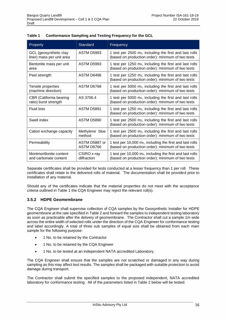
Table 1 Conformance Sampling and Testing Frequency for the GCL
Property Standard Frequency
GCL (geosynthetic clay liner) mass per unit area
ASTM D5993 1 test per 2500 m2, including the first and last rolls (based on production order): minimum of two tests
Bentonite mass per unit area
ASTM D5993 1 test per 1250 m2, including the first and last rolls (based on production order): minimum of two tests
Peel strength ASTM D6496 1 test per 1250 m2, including the first and last rolls (based on production order): minimum of two tests
Tensile properties (machine direction)
ASTM D6768 1 test per 5000 m2, including the first and last rolls (based on production order): minimum of two tests
CBR (California bearing ratio) burst strength
AS 3706.4 1 test per 5000 m2, including the first and last rolls (based on production order): minimum of two tests
Fluid loss ASTM D5891 1 test per 1250 m2, including the first and last rolls (based on production order): minimum of two tests
Swell index ASTM D5890 1 test per 2500 m2, including the first and last rolls (based on production order): minimum of two tests
Cation exchange capacity Methylene blue method
1 test per 2500 m2, including the first and last rolls (based on production order): minimum of two tests
Permeability ASTM D5887 or ASTM D6766
1 test per 10,000 m2, including the first and last rolls (based on production order): minimum of two tests
Montmorillonite content and carbonate content
CSIRO x-ray diffraction
1 test per 10,000 m2, including the first and last rolls (based on production order): minimum of two tests
Separate certificates shall be provided for tests conducted at a lesser frequency than 1 per roll. These certificates shall relate to the delivered rolls of material. The documentation shall be provided prior to installation of any material.
Should any of the certificates indicate that the material properties do not meet with the acceptance criteria outlined in Table 1 the CQA Engineer may reject the relevant roll(s).
3.5.2 HDPE Geomembrane
The CQA Engineer shall supervise collection of CQA samples by the Geosynthetic Installer for HDPE geomembrane at the rate specified in Table 2 and forward the samples to independent testing laboratory as soon as practicable after the delivery of geomembrane. The Contractor shall cut a sample 1m wide across the entire width of selected rolls under the direction of the CQA Engineer for conformance testing and label accordingly. A total of three sub samples of equal size shall be obtained from each main sample for the following purpose:
• 1 No. to be retained by the Contractor
• 1 No. to be retained by the CQA Engineer
• 1 No. to be tested at an independent NATA accredited Laboratory.
The CQA Engineer shall ensure that the samples are not scratched or damaged in any way during sampling as this may affect test results. The samples shall be packaged with suitable protection to avoid damage during transport.
The Contractor shall submit the specified samples to the proposed independent, NATA accredited laboratory for conformance testing. All of the parameters listed in Table 2 below will be tested.

Bangus Quarry Landfill Project Number ISA-161-18-19 Proposed Landfill Development – Cell 1 & 2 CQA Plan 22 October 2019 Draft
InSitu Advisory Pty Ltd 17
Table 2 Table of Geomembrane Conformance Testing
Property Standard Frequency
Thickness ASTM D5994 (textured)
1 test per 5000 m2, including the first and last rolls (based on production order): minimum of two tests
Asperity height (textured)
ASTM D7466 1 test per 5000 m2, including the first and last rolls (based on production order): minimum of two tests
Density ASTM D1505 or ASTM D792
1 test per 5000 m2, including the first and last rolls (based on production order): minimum of two tests
Puncture Resistance ASTM D4833 1 test per 5000 m2, including the first and last rolls (based on production order): minimum of two tests
Tear Resistance ASTM D1004 1 test per 5000 m2, including the first and last rolls (based on production order): minimum of two tests
Carbon Black Content ASTM D1603 or ASTM D4218
1 test per 5000 m2, including the first and last rolls (based on production order): minimum of two tests
Carbon Black Dispersion
ASTM D5596 1 test per 5000 m2, including the first and last rolls (based on production order): minimum of two tests
Stress Crack Resistance ASTM D5397 1 test per 10,000 m2, or resin type or manufacturing run (whichever results in the greatest number of tests), including the first and last rolls (based on
production order): minimum of two tests
Standard oxidative induction time
and
High-pressure oxidative induction time
ASTM D3895
ASTM D5885
1 test per 10,000 m2, or resin type or manufacturing run (whichever results in the greatest number of tests), including the first and last roll (based on
production order): minimum of two tests
The CQA Engineer shall ensure that a copy of the laboratory test results are provided by the Contractor immediately on receipt by the Contractor.
If rolls on site from previous projects are being used in the Works at least 1 conformance sample must be taken from these rolls. Rolls on site from previous projects shall only be used if the roll number, batch number and manufacturers details are known.
If testing shows that the geomembrane does not meet any one of the test values listed in Table 2 then this may be cause for rejection of the material from that roll.
If a conformance sample cut from a roll fails to meet the test values listed in the Specification, the CQA Engineer may accept material from elsewhere on that roll if the Contractor can demonstrate through further laboratory testing that this material does meet the acceptance criteria contained in the Specification.
3.5.3 Protection Geotextile
The protection geotextile shall be non-woven, needle punched, resin or heat bonded manufactured from either polyester, polyethylene or polypropylene.
The protection geotextile shall comprise polymeric yarns or fibres, seamed or drawn strands orientated into a stable network which retains its structure during handling, placement and long term service. The geotextile filaments shall be rot-proof, chemically stable, with no water absorbency and the filaments being able to resist delamination.

Bangus Quarry Landfill Project Number ISA-161-18-19 Proposed Landfill Development – Cell 1 & 2 CQA Plan 22 October 2019 Draft
InSitu Advisory Pty Ltd 18
The CQA Engineer shall supervise collection of CQA samples by the Geosynthetic Installer for geotextiles at the rate specified in Table 3 and forward the samples to independent testing laboratory as soon as practicable after delivery. Table 3 lists the independent conformance testing that shall be performed on the geotextile prior to installation.
Table 3 Table of Protection Geotextile Conformance Testing
PARAMETER TEST METHOD MINIMUM TEST FREQUENCY
COMMENTS
Mass per Unit Area AS 3706.1 1 per 2,500 m² Protection geotextiles
only
Grab Tensile Strength AS 3706.2b 1 per 5,000 m² All geotextiles
CBR Puncture Strength AS 3706.4 1 per 5,000 m² All geotextiles
Trapezoidal Tear Strength
AS 3706.3 1 per 5,000 m² All geotextiles
Pore Size (MaxARV) ASTN D6767 1 per 5,000 m² Separation geotextiles
only
Permittivity AS 3706.9 1 per 5,000 m²
Separation geotextiles only
3.5.4 Separation Geotextile
The separation geotextile shall be non-woven, needle punched, resin or heat bonded manufactured from polyester, polyethylene or polypropylene. The geotextile shall comprise polymeric yarns or fibres, seamed or drawn strands orientated into a stable network which retains its structure during handling, placement and long term service. The geotextile filaments shall be rot-proof, chemically stable, with no water absorbency and the filaments being able to resist delamination.
Comparisons shall be undertaken by the CQA Engineer of the manufacturers roll test data against the product data sheets and the requirements with Table 4 and the Technical Specification.
The geotextile delivered to site is to be tested by an independent (NATA accredited) laboratory in accordance with Table 4 below. The testing is recommended to ensure the materials delivered to site are fully compliant with the required Specification and CQA Plan.
Table 4 Geotextiles Conformance Testing
Property Test Frequency
Tear Strength AS 3706.3
1 sample per 5,000m2
CBR Burst Strength AS 3706.4
Tensile Strength AS 3706.2
3.6 Geosynthetics Installation Overview
3.6.1 Subgrade Preparation
The Contractor shall be responsible for preparing the final subgrade (on side walls), and top of engineered clay liner on the base and lower side slopes in accordance with the Technical Specification.
The Superintendent and CQA Engineer shall observe the following:

Bangus Quarry Landfill Project Number ISA-161-18-19 Proposed Landfill Development – Cell 1 & 2 CQA Plan 22 October 2019 Draft
InSitu Advisory Pty Ltd 19
• The subgrade has been prepared in accordance with the Specification;
• The Geosynthetics Installer has certified in writing that the surface on which the geosynthetics will be installed is acceptable. This will be in the form of a subgrade acceptance certificate that will be reported within the CQA Validation Report
The certificate of acceptance shall be given by the Geosynthetics Installer to the Contractor and the CQA Engineer prior to commencement of geosynthetics installation in the area under consideration.
It shall be the Contractor's responsibility to maintain the liner subgrade after the surface has been accepted and a subgrade certificate signed. This will be the case until the Superintendent or CQA Engineer has approved the installation of the geosynthetics. The Contractor shall promptly repair and unsuitable underlying subgrade (compacted clay liner) surface condition prior to installation of geosynthetics. The subject area will also be observed by the CQA Engineer who shall have the authority to reject an area even after it has been accepted by the Contractor and Geosynthetics Installer.
3.6.2 Geosynthetics Placement
During geosynthetics placement, the CQA Engineer shall periodically:
• Check that there are no stones, construction debris, or other items beneath the geosynthetics that could cause damage;
• Observe that the surface beneath the geosynthetics has not deteriorated since previous acceptance;
• Observe that geosynthetics repairs are to be made in accordance with the Specifications and the Geosynthetics Manufacturer’s guidelines;
• Observe that the equipment used does not damage the geosynthetics by handling, trafficking, leakage of hydrocarbons, or by other means;
• Observe that the geosynthetics is not dragged across an unprepared surface. If the geosynthetics are dragged across an unprepared surface, it shall be inspected for scratches and repaired or rejected, if necessary;
• Observe that the method used to unroll the geosynthetics does not cause scratches or crimps in the geosynthetics and does not damage the supporting soil surface;
• Coordinate with the Superintendent to ensure that the geosynthetics shall not be deployed in the presence of excess moisture (fog, dew, mist, etc.), high winds, dust and extreme temperatures;
• Observe that the Contractors staff or Geosynthetics Installer do not smoke, wear shoes that could damage the geosynthetics, drop metal or heavy equipment onto the liner or engage in activities that could damage the geosynthetics;
• Ensure that the geosynthetics are placed in accordance with the Specification;
• Observe that the method used to deploy the geosynthetics minimizes wrinkles and that the geosynthetics are anchored to prevent movement by the wind; and
• Observe that direct contact with the geosynthetics is minimized (i.e., the geomembrane is protected by geotextiles, extra geomembrane, or other suitable materials, in areas where excessive traffic may be expected).
The CQA Engineer shall inform the Superintendent, Contractor and Geosynthetics Installer if the requirements listed above are not being met.
Bangus Quarry Landfill Project Number ISA-161-18-19 Proposed Landfill Development – Cell 1 & 2 CQA Plan 22 October 2019 Draft
InSitu Advisory Pty Ltd 20
3.7 Geosynthetic Clay Liner
3.7.1 Installation
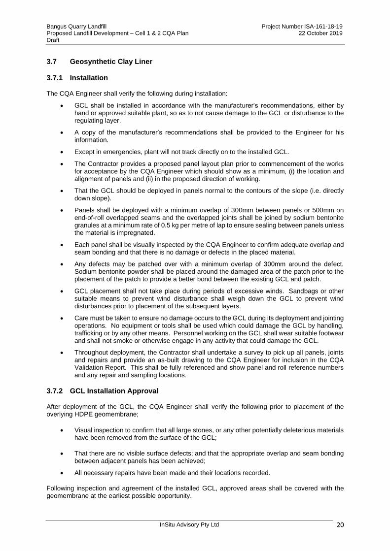
The CQA Engineer shall verify the following during installation:
• GCL shall be installed in accordance with the manufacturer’s recommendations, either by hand or approved suitable plant, so as to not cause damage to the GCL or disturbance to the regulating layer.
• A copy of the manufacturer’s recommendations shall be provided to the Engineer for his information.
• Except in emergencies, plant will not track directly on to the installed GCL.
• The Contractor provides a proposed panel layout plan prior to commencement of the works for acceptance by the CQA Engineer which should show as a minimum, (i) the location and alignment of panels and (ii) in the proposed direction of working.
• That the GCL should be deployed in panels normal to the contours of the slope (i.e. directly down slope).
• Panels shall be deployed with a minimum overlap of 300mm between panels or 500mm on end-of-roll overlapped seams and the overlapped joints shall be joined by sodium bentonite granules at a minimum rate of 0.5 kg per metre of lap to ensure sealing between panels unless the material is impregnated.
• Each panel shall be visually inspected by the CQA Engineer to confirm adequate overlap and seam bonding and that there is no damage or defects in the placed material.
• Any defects may be patched over with a minimum overlap of 300mm around the defect. Sodium bentonite powder shall be placed around the damaged area of the patch prior to the placement of the patch to provide a better bond between the existing GCL and patch.
• GCL placement shall not take place during periods of excessive winds. Sandbags or other suitable means to prevent wind disturbance shall weigh down the GCL to prevent wind disturbances prior to placement of the subsequent layers.
• Care must be taken to ensure no damage occurs to the GCL during its deployment and jointing operations. No equipment or tools shall be used which could damage the GCL by handling, trafficking or by any other means. Personnel working on the GCL shall wear suitable footwear and shall not smoke or otherwise engage in any activity that could damage the GCL.
• Throughout deployment, the Contractor shall undertake a survey to pick up all panels, joints and repairs and provide an as-built drawing to the CQA Engineer for inclusion in the CQA Validation Report. This shall be fully referenced and show panel and roll reference numbers and any repair and sampling locations.
3.7.2 GCL Installation Approval
After deployment of the GCL, the CQA Engineer shall verify the following prior to placement of the overlying HDPE geomembrane;
• Visual inspection to confirm that all large stones, or any other potentially deleterious materials have been removed from the surface of the GCL;
• That there are no visible surface defects; and that the appropriate overlap and seam bonding between adjacent panels has been achieved;
• All necessary repairs have been made and their locations recorded.
Following inspection and agreement of the installed GCL, approved areas shall be covered with the geomembrane at the earliest possible opportunity.
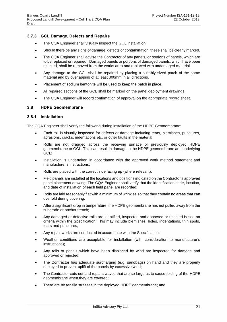
Bangus Quarry Landfill Project Number ISA-161-18-19 Proposed Landfill Development – Cell 1 & 2 CQA Plan 22 October 2019 Draft
InSitu Advisory Pty Ltd 21
3.7.3 GCL Damage, Defects and Repairs
• The CQA Engineer shall visually inspect the GCL installation.
• Should there be any signs of damage, defects or contamination, these shall be clearly marked.
• The CQA Engineer shall advise the Contractor of any panels, or portions of panels, which are to be replaced or repaired. Damaged panels or portions of damaged panels, which have been rejected, shall be removed from the works area and replaced with undamaged material.
• Any damage to the GCL shall be repaired by placing a suitably sized patch of the same material and by overlapping of at least 300mm in all directions.
• Placement of sodium bentonite will be used to keep the patch in place.
• All repaired sections of the GCL shall be marked on the panel deployment drawings.
• The CQA Engineer will record confirmation of approval on the appropriate record sheet.
3.8 HDPE Geomembrane
3.8.1 Installation
The CQA Engineer shall verify the following during installation of the HDPE Geomembrane:
• Each roll is visually inspected for defects or damage including tears, blemishes, punctures, abrasions, cracks, indentations etc, or other faults in the material;
• Rolls are not dragged across the receiving surface or previously deployed HDPE geomembrane or GCL. This can result in damage to the HDPE geomembrane and underlying GCL;
• Installation is undertaken in accordance with the approved work method statement and manufacturer’s instructions;
• Rolls are placed with the correct side facing up (where relevant);
• Field panels are installed at the locations and positions indicated on the Contractor's approved panel placement drawing. The CQA Engineer shall verify that the identification code, location, and date of installation of each field panel are recorded;
• Rolls are laid reasonably flat with a minimum of wrinkles so that they contain no areas that can overfold during covering;
• After a significant drop in temperature, the HDPE geomembrane has not pulled away from the subgrade or anchor trench;
• Any damaged or defective rolls are identified, inspected and approved or rejected based on criteria within the Specification. This may include blemishes, holes, indentations, thin spots, tears and punctures;
• Any repair works are conducted in accordance with the Specification;
• Weather conditions are acceptable for installation (with consideration to manufacturer’s instructions);
• Any rolls or panels which have been displaced by wind are inspected for damage and approved or rejected;
• The Contractor has adequate surcharging (e.g. sandbags) on hand and they are properly deployed to prevent uplift of the panels by excessive wind;
• The Contractor cuts out and repairs waves that are so large as to cause folding of the HDPE geomembrane when they are covered;
• There are no tensile stresses in the deployed HDPE geomembrane; and
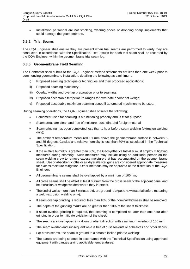
Bangus Quarry Landfill Project Number ISA-161-18-19 Proposed Landfill Development – Cell 1 & 2 CQA Plan 22 October 2019 Draft
InSitu Advisory Pty Ltd 22
• Installation personnel are not smoking, wearing shoes or dropping sharp implements that could damage the geomembrane.
3.8.2 Trial Seams
The CQA Engineer shall ensure they are present when trial seams are performed to verify they are conducted in accordance with the Specification. Test results for each trial seam shall be recorded by the CQA Engineer within the geomembrane trial seam log.
3.8.3 Geomembrane Field Seaming
The Contractor shall submit to the CQA Engineer method statements not less than one week prior to commencing geomembrane installation, detailing the following as a minimum.
i) Proposed seaming technique or techniques and their proposed applications;
ii) Proposed seaming machinery;
iii) Overlap widths and overlap preparation prior to seaming;
iv) Proposed acceptable temperature ranges for extrudate and/or hot wedge;
v) Proposed acceptable maximum seaming speed if automated machinery to be used.
During seaming operations, the CQA Engineer shall observe the following;
• Equipment used for seaming is a functioning properly and is fit for purpose;
• Seam areas are clean and free of moisture, dust, dirt, and foreign material
• Seam grinding has been completed less than 1 hour before seam welding (extrusion welding only);
• The ambient temperature measured 150mm above the geomembrane surface is between 5 and 35 degrees Celsius and relative humidity is less than 80% as stipulated in the Technical Specification;
• If the relative humidity is greater than 80%, the Geosynthetics Installer must employ mitigating measures during seaming. Such measures may include using an additional person on the seam welding crew to remove excess moisture that has accumulated on the geomembrane sheet. Use of absorbent cloths or air dryers/leister guns are considered appropriate measures for excess moisture mitigation. Other methods may be approved at the discretion of the CQA Engineer;
• All geomembrane seams shall be overlapped by a minimum of 100mm;
• All cross seams shall be offset at least 600mm from the cross seam of the adjacent panel and be extrusion or wedge welded where they intersect.
• The end of welds more than 5 minutes old, are ground to expose new material before restarting a weld (extrusion welding only);
• If seam overlap grinding is required, less than 10% of the nominal thickness shall be removed;
• The depth of the grinding marks are no greater than 10% of the sheet thickness
• If seam overlap grinding is required, that seaming is completed no later than one hour after grinding in order to mitigate oxidation of the sheet;
• The seams are overlapped in a down gradient direction with a minimum overlap of 100 mm;
• The seam overlap and subsequent weld is free of dust solvents or adhesives and other debris;
• For cross seams, the seam is ground to a smooth incline prior to welding;
• The panels are being seamed in accordance with the Technical Specification using approved equipment with gauges giving applicable temperatures;

Bangus Quarry Landfill Project Number ISA-161-18-19 Proposed Landfill Development – Cell 1 & 2 CQA Plan 22 October 2019 Draft
InSitu Advisory Pty Ltd 23
• The geomembrane is protected from damage in heavily trafficked areas;
• The generator is placed on a smooth base such that no damage occurs to the geomembrane or GCL;
• The extruder is purged prior to beginning a seam until all the heat-degraded extrudate is removed (extrusion welding only); and
• A smooth insulating plate or fabric is placed beneath the hot welding apparatus after use.
The CQA Engineer shall:
• Log all temperatures and conditions;
• Log seam lengths;
• Record trial welds;
• Ensure "Fishmouths" or wrinkles at the seam overlaps shall be cut along the ridge of the wrinkle in order to achieve a flat overlap. The cut "fishmouths" or wrinkles shall be seamed and any portion where the overlap is inadequate shall then be patched with a patch of the same geomembrane extending a minimum of 150mm beyond the cut in all directions. All corners of the patch shall be rounded with a 25mm minimum radius;
• Mark defect areas with a waterproof marker or spray paint compatible with the lining material and inform the Contractor and/or Geosynthetics Installer and the Superintendent of any required repairs;
• Log and report to the Superintendent any non-compliance.
3.8.4 Non-Destructive Testing
The Contractor shall non-destructively test all field seams over their full length using a vacuum test unit, air pressure testing, or other approved method. The purpose of non-destructive testing is to check the continuity of seams. It does not provide information on seam strength. Continuity testing shall be carried out as the seaming work progresses, not at the completion of field testing.
The CQA Engineer shall verify:
• All seams are visually inspected to assess the quality of the workmanship and the appearance of the welded seam
• That for air pressure testing of fusion seams the test length is sealed at both ends and an approved pressure feed divide inserted into the air channel.
• The channel is pumped to a minimum pressure of 30 psi and allowed to stabilise for 1 minute. The test will have deemed to have failed if the loss of pressure exceeds 2 psi over a 1 minute period following stabilisation.
• All seams are non-destructively tested as seaming work progresses and seams which fail are repaired
• The outcome of all non-destructive seam test results are documented.
The Contractor shall advise the CQA Engineer when he is ready to commence non-destructive testing and shall not perform non-destructive testing unless the CQA Engineer is in attendance. The CQA Engineer will record the results of all non-destructive testing on the seam once testing has been carried out.
3.8.5 Qualitative Destructive Testing
Destructive seam tests shall be performed at preselected locations. The purpose of these tests is to check that welded panels are fully integrated with each other to evaluate seam strength. Seam strength testing shall be undertaken as the seaming work progresses, not at the completion of field seaming.
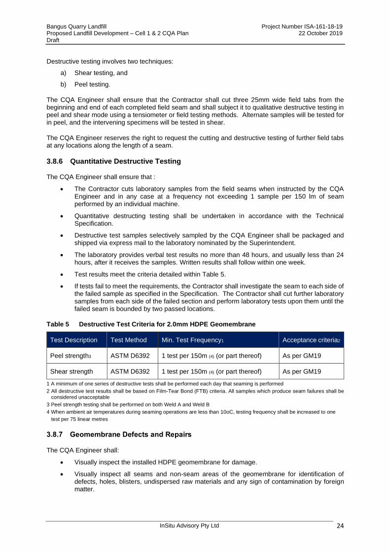
Bangus Quarry Landfill Project Number ISA-161-18-19 Proposed Landfill Development – Cell 1 & 2 CQA Plan 22 October 2019 Draft
InSitu Advisory Pty Ltd 24
Destructive testing involves two techniques:
a) Shear testing, and
b) Peel testing.
The CQA Engineer shall ensure that the Contractor shall cut three 25mm wide field tabs from the beginning and end of each completed field seam and shall subject it to qualitative destructive testing in peel and shear mode using a tensiometer or field testing methods. Alternate samples will be tested for in peel, and the intervening specimens will be tested in shear.
The CQA Engineer reserves the right to request the cutting and destructive testing of further field tabs at any locations along the length of a seam.
3.8.6 Quantitative Destructive Testing
The CQA Engineer shall ensure that :
• The Contractor cuts laboratory samples from the field seams when instructed by the CQA Engineer and in any case at a frequency not exceeding 1 sample per 150 lm of seam performed by an individual machine.
• Quantitative destructing testing shall be undertaken in accordance with the Technical Specification.
• Destructive test samples selectively sampled by the CQA Engineer shall be packaged and shipped via express mail to the laboratory nominated by the Superintendent.
• The laboratory provides verbal test results no more than 48 hours, and usually less than 24 hours, after it receives the samples. Written results shall follow within one week.
• Test results meet the criteria detailed within Table 5.
• If tests fail to meet the requirements, the Contractor shall investigate the seam to each side of the failed sample as specified in the Specification. The Contractor shall cut further laboratory samples from each side of the failed section and perform laboratory tests upon them until the failed seam is bounded by two passed locations.
Table 5 Destructive Test Criteria for 2.0mm HDPE Geomembrane
Test Description Test Method Min. Test Frequency1 Acceptance criteria2
Peel strength3 ASTM D6392 1 test per 150m (4) (or part thereof) As per GM19
Shear strength ASTM D6392 1 test per 150m (4) (or part thereof) As per GM19
1 A minimum of one series of destructive tests shall be performed each day that seaming is performed
2 All destructive test results shall be based on Film-Tear Bond (FTB) criteria. All samples which produce seam failures shall be considered unacceptable
3 Peel strength testing shall be performed on both Weld A and Weld B
4 When ambient air temperatures during seaming operations are less than 10oC, testing frequency shall be increased to one
test per 75 linear metres
3.8.7 Geomembrane Defects and Repairs
The CQA Engineer shall:
• Visually inspect the installed HDPE geomembrane for damage.
• Visually inspect all seams and non-seam areas of the geomembrane for identification of defects, holes, blisters, undispersed raw materials and any sign of contamination by foreign matter.

Bangus Quarry Landfill Project Number ISA-161-18-19 Proposed Landfill Development – Cell 1 & 2 CQA Plan 22 October 2019 Draft
InSitu Advisory Pty Ltd 25
• Highlight any area or seam displaying a defect by marking the geomembrane liner with a defect code and assigning it a number. Each defect location as identified shall be inspected non-destructively tested as described in the Technical Specification
• Note any location which fails the non-destructive testing and mark for repair and retest the geosynthetics installer.
• Ensure that further deployment of covering protection geotextiles shall not proceed with that will cover locations that have been repaired until test results with passing values have been obtained.
• The CQA Engineer shall visually inspect and verify that all deficiencies have been repaired in accordance with the Specification and the manufacturer’s instructions prior to final acceptance.
3.8.8 Geomembrane Acceptance
The Contractor shall not make it past the Hold Point for geomembrane installation until acceptance by the CQA Engineer and the Superintendent. The geomembrane shall be accepted when:
• All seams have been inspected and approved;
• All required CQC tests have been completed and approved;
• The installation is finished and approved;
• Field and laboratory testing results have been received and approved; and
• All required Contractor/Geosynthetics Installer/Geosynthetics Manufacturer supplied documentation has been received and approved.
3.9 Protection Geotextile
The CQA Engineer shall review all submissions by the Contractor and recommend rejection or approval to the Superintendent/Principal. This shall include Contractor work method statements and WH&S procedures.
The CQA Engineer shall review all test results/reports provided by the Contractor to confirm the protection geotextile material conforms to the requirements of the Specification.
The CQA Engineer shall verify the following during installation:
• Each roll is visually inspected for defects or damage including tears, blemishes, punctures, abrasions, thickness, needle punching, presence of needles or broken needles, needle punched density or other faults in the material;
• Any damaged or defective rolls are identified, inspected and approved or rejected based on criteria within the Specification;
• The protection geotextile shall be installed directly above the HDPE geomembrane and anchored as shown within the Drawings and Specification;
• Installation is undertaken in accordance with the approved work method statement and manufacturer’s instructions;
• Rolls are not being damaged during placement or covering;
• Rolls are not dragged across the receiving surface or previously deployed HDPE geomembrane. This can result in damage to the protection geotextile;
• Field panels are installed at the locations and positions indicated on the Contractor's approved panel placement drawing. The CQA Engineer shall verify that the identification code, location, and date of installation of each field panel are recorded;
• Rolls are laid reasonably flat with a minimum of wrinkles so that they contain no areas that can overfold during covering;
Bangus Quarry Landfill Project Number ISA-161-18-19 Proposed Landfill Development – Cell 1 & 2 CQA Plan 22 October 2019 Draft
InSitu Advisory Pty Ltd 26
• Seams are constructed as specified and in accordance with manufacturer’s instructions, and lapped in the correct direction;
• The Contractor cuts out and repairs waves that are so large as to cause folding of the geotextile when they are covered;
• Any damaged or defective rolls are identified, inspected and approved or rejected based on criteria within the Specification;
• Any repair works are conducted in accordance with the Specification;
• Weather conditions are acceptable for installation (with consideration to manufacturer’s instructions);
• Any rolls or panels which have been displaced by wind are inspected for damage and approved or rejected;
• The Contractor has adequate surcharging (e.g. sandbags) on hand and they are properly deployed to prevent uplift of the panels by excessive wind;
• There are no tensile stresses in the deployed geotextile;
• Installation personnel are not smoking, wearing shoes or dropping sharp implements that could damage the geotextile;
• Heat bonded seams are inspected for discontinuities and not being burned through during the fabrication of heat bonded seams; and
• Stitched seams are constructed using the required overlap, thread type and stitch type.
3.9.1 Protection Geotextile Defects and Repairs
The CQA Engineer shall visually inspect the protection geotextile for damage after placement. Damaged areas shall be marked and will document the location of the damaged panels, repairs undertaken and panels which were rejected in the daily report.
The CQA Engineer shall visually inspect and verify that all deficiencies have been repaired in accordance with the Technical Specification and the manufacturer’s recommendations prior to final signoff.
3.10 Separation Geotextile
The separation geotextile shall be installed directly above the placed leachate drainage aggregate as shown within the Drawings.
The CQA Engineer shall verify the following during installation:
• The separation geotextile shall be surcharged with aggregate filled sand bags to mitigate wind uplift, at maximum 2m centres;
• Geotextiles shall be free of any flaws, which may have an adverse effect on the physical or mechanical properties of the product;
• Separation geotextiles shall meet the requirements outlined in the Technical Specification;
• The geotextile manufacturer has provided production test certificates for rolls delivered to site demonstrating that the test values specified for the proposed product have been attained. Certificates relevant to a batch of geotextile protector shall be furnished to the CQA Engineer prior to that batch of geotextile protector being incorporated in the works;
• Joints shall be clean and free from excessive moisture or foreign matter. Joints shall be formed by hot air welding or stitching;
• Overlaps shall be a minimum 500mm; and
Bangus Quarry Landfill Project Number ISA-161-18-19 Proposed Landfill Development – Cell 1 & 2 CQA Plan 22 October 2019 Draft
InSitu Advisory Pty Ltd 27
• Identify are area of defect and make an annotation on the geotextile surface by either spray paint or suitable marker.
The Contractor shall make good the area by removing any offending or deleterious matter and cutting a geotextile patch from the same material with a minimum 500mm overlap in all directions and securing by heat bonding.
3.11 Covering Materials
The CQA procedures outlined in this CQA Plan and Specification are intended to allow the installation of materials in contact with the geosynthetics without causing damage to the geomembrane.
Important points for Quality Assurance of materials in contact with geomembrane include:
• Geosynthetics approved by the Designer shall be installed above the geomembrane;
• Equipment used for placing the overlaying protection geotextile or leachate drainage aggregate shall not be driven directly on the geomembrane;
• In heavily trafficked areas, such as access ramps, soil thickness should be at least six-hundred (600) millimetres over the geosynthetics;
• Placement of soils, gravels, or other types of earth materials on top of the geomembrane shall not be performed until all testing has been performed and accepted;
• Placement of overlying materials shall be performed in a manner to minimize wrinkles. Equipment operators shall be briefed on methods of placement relative to thermal expansion and contraction of the geomembrane; and
• The CQA Engineer shall inform the Superintendent if the above conditions are not fulfilled.
Bangus Quarry Landfill Project Number ISA-161-18-19 Proposed Landfill Development – Cell 1 & 2 CQA Plan 22 October 2019 Draft
InSitu Advisory Pty Ltd 28
4 LEACHATE COLLECTION AND EXTRACTION SYSTEM
4.1 General
A leachate collection and removal system (LCES) comprises a drainage aggregate layer and perforated pipework overlain by a non-woven separation/filtration geotextile fabric. The Site LCES shall incorporate a basal granular drainage layer utilising a 20-40mm aggregate of minimum 300mm thickness and collection pipework in accordance with the Technical Specification and Drawings. Leachate collection pipework placed within the aggregate layer will convey leachate from the Cell 1 and 2 basal areas to a separate leachate sump then pumped out via a side wall riser pipe to the leachate pond for temporary storage and management.
Requirements for each component of the LCES are detailed in the Technical Specification and the design drawings. The Technical Specification and this CQA Plan shall be the project requirements for the LCES except where specifically superseded by prevailing guidance documents of the controlling agency.
The Contractor shall submit a Method Statement to the CQA Engineer, as soon as practical, detailing how each element of the LCES will be handled, stored and installed within the works.
4.2 Leachate Drainage Aggregate Requirements
The drainage aggregate material shall consist of clean, hard, durable, uniform product, free of limestone, organic, and other deleterious material and shall not be subject to weathering, and shall be durable to the extent that minimal breakdown or degradation of the material occurs during placement and compaction.
The leachate drainage aggregate shall:
• Consist of hard, strong, durable and clean gravel that will maintain the required performance under the maximum loads likely to be imposed on it in service;
• Have a saturated hydraulic conductivity greater than 1 x 10⁻³ m/s when tested in accordance with Australian Standard AS 1289.6.7.1 Determination of the Permeability of a Soil (constant head method);
• Be relatively uniform in particle size, with a nominal particle size greater than 20 millimetres and a maximum particle size of 40 millimetres, and with not more than 10% of particles smaller than 20mm in diameter and not more than 3% smaller than 0.075mm;
• Be non-reactive in mildly acidic conditions and chemically resistant to the leachate in the landfill, with a calcium carbonate content of less than 8.5% by mass;
• Not have a shape and angularity that will damage the underlying geomembrane liner (the best type of gravel is rounded and smooth-surfaced); and
• Source material should be tested to show that the gravel drainage material meets these requirements.
4.3 Installation Observations
The CQA Engineer shall:
• Review all test results/reports provided by the Contractor to confirm the drainage aggregate conforms to the requirements of the Technical Specification;
• Ensure the Contractor provides conformance test data to prove the drainage aggregate meets the requirements of the Technical Specification and CQA Plan, prior to delivery to site and installation;
• Inspect drainage aggregate stockpiles prior to use and advise the Superintendent of the presence of any unsuitable material or contamination as per the Technical Specification;

Bangus Quarry Landfill Project Number ISA-161-18-19 Proposed Landfill Development – Cell 1 & 2 CQA Plan 22 October 2019 Draft
InSitu Advisory Pty Ltd 29
• Ensure that a field trial is undertaken by the Contractor to ensure the aggregate blanket is installed in such a manner that the underlying geosynthetics are not disrupted or damaged, placement of aggregate within the works can only occur if a successful field trial is undertaken;
• Ensure the blanket be installed to a minimum thickness of 300mm and extends across the entire base of the landfill, sloped with at least a 1% longitudinal gradient and 3% transverse gradient;
• Ensure oversize and angular material which could damage underlying geosynthetics have been removed prior to aggregate placement;
• Ensure that the drainage blanket is installed such that no wrinkles are developed in the underlying protection geotextile.
• Ensure that a minimum 1m thickness of drainage blanket material shall be maintained between the protection geotextile and haulage vehicles (including waste vehicles);
• Monitor the presence excessive fines generated as a result of handling and placement of the drainage aggregate, and reject any load, or part load from use within the aggregate blanket if required;
• Ensure no slewing of the plant/machinery placing the leachate collection aggregate is be permitted during the works; and
• Ensure no trafficking with heavy machinery is undertaken after placement.
4.3.1 Aggregate Conformance Testing
Samples of aggregate shall be tested to ensure that it meets the required grading specification and that it has a minimum permeability of 1x10⁻³m/s. Testing shall be undertaken in accordance with Table 6.
Table 6 Leachate Drainage Aggregate Testing Requirements
Property Standard Requirement Min. Test Frequency
Particle Size Distribution
-Passing 50mm
-Passing 19mm
-Passing 0.075mm
AS 1141.11,12,13 or AS 1289.3.6.1, 3.6.3
100%
≤ 10%
≤ 3%
Greater of 1 test per 1,000m3, of material or 3
per source
Constant Head Permeability
AS 1289.6.7.1 >1x10⁻³ m/s Greater of 1 test per 10,000m3, of material or 3
per source
Minimum Soaked 10% Fines Value
BS 812-111:1990 or AS 1289.6.7.1
100kN Greater of 1 test per 10,000m3, of material or 3
per source
The NATA accredited laboratory who shall supply certificates identifying the material type, specification requirements, and associated results.
If an area of drainage aggregate does not conform to the Technical Specification, the CQA Engineer shall assist the Contractor in defining the extent of the area requiring mitigating works. This shall be done through the use of additional testing and visual inspection, followed by removal of affected areas and reinstatement if required.
4.3.2 As-Built Levels
The CQA Engineer will be required to continually review construction levels and positioning with respect to the design drawings and review the final as-built survey data to verify conforming lines, levels and layer thickness are within the allowable tolerance given within the Technical Specification.
Bangus Quarry Landfill Project Number ISA-161-18-19 Proposed Landfill Development – Cell 1 & 2 CQA Plan 22 October 2019 Draft
InSitu Advisory Pty Ltd 30
4.3.3 Acceptance and Signoff
At this hold point for completion of LCES, the Superintendent shall formally sign off the activity prior to the Contractor undertaking subsequent activities. The CQA Engineer shall provide a recommendation to the Superintendent on whether in their opinion, the works have been completed in accordance with the Technical Specification. In order to provide the recommendation, the CQA Engineer shall consider the following:
• Confirm lines, levels and falls have been achieved;
• Review of CQA test results confirming compliant results have been received;
• Detailed monitoring and inspections have been undertaken.
4.3.4 Review of Quantities
The CQA Engineer may be required to review and comment on any quantity re-measurements submitted by the Contractor for assessment of payment. Field notes and volumetric surveys should be considered when assessing likely volume.
4.4 Leachate Collection Pipework
A leachate collection pipework system incorporating perforated HDPE SDR11 pipes shall be installed across the base feeding to a sump in accordance with the Drawings. A solid pipe side wall riser pipe will be connected to the perforated basal pipes in order to allow pumped extraction of the accumulated leachate.
The leachate pipes requirements are detailed within the Specification, but shall be HDPE perforated SDR11 250mm ID for the main spine drain, 150mm ID pipes for the spurs and 400mm ID for the side slope extraction riser.
The pipework shall be delivered, handled and stored in accordance with the manufacturer’s quality control documentation. The pipes should be stored on an area flat enough to accommodate the entire length of the pipes and in such a way so that they are not damaged or deformed. The pipes shall not be stacked higher than 1m.
The pipework and fittings shall be strong enough to maintain performance under the maximum loads likely to be imposed in service, complying with the requirements of Australian Standard AS 2566.1-1998 Buried flexible pipelines – Structural design (Standards Australia, various dates)
The Contractor shall submit calculations from the pipe manufacturer to demonstrate that the pipe meets the following requirements:
• Pipe deflection < 5%
• D85/hole diameter >1.0 (Circular perforations)
• D85/slot width >1.2 (Slot perforations)
• Demonstrates suitable crushing stability.
Where D85 refers to the sieve size above which 85% of the granular material surrounding the pipe would be retained. The calculations shall be made using the ATV 127 Method (or similar approved method) with the following assumptions.
• Waste Density 1,000 Kg/m3
• Calculated maximum waste depth = to follow
• Restoration soil density 1800kg/m3
• Maximum soil depth = 1m
Bangus Quarry Landfill Project Number ISA-161-18-19 Proposed Landfill Development – Cell 1 & 2 CQA Plan 22 October 2019 Draft
InSitu Advisory Pty Ltd 31
• Soil stiffness of an uncompacted unconfined gravel surround
The Contractor shall submit their proposals for all SDR11 pipes and fittings to the CQA Engineer for approval and shall provide the Engineer with copies of all pipe manufacturers’ quality control documentation.
The Contractor shall supply the CQA Engineer with the following welding information for each welded joint:
• Date and time of weld.
• Weld number.
• Operator.
• Heater temperature, heat soak time.
• Bead pressure, fusion pressure.
• Actual and target cooling times.
The CQA Engineer shall verify that pipework and fittings are sampled and tested in accordance with the approved manufacturer’s quality control are rejected.
4.4.1 Pipework Installation
The installation and welding of HDPE pipes shall only be undertaken by skilled and experienced personnel. The Contractor shall supply, prior to commencement of the works, a summary of experience or that of their subcontractor with the materials and shall be included as part of the final construction quality assurance validation report.
The CQA Engineer shall ensure:
• Damaged or defective pipework is not used in the works;
• Verify that pipe is sampled and tested in accordance with the approved manufacturer’s quality control manual and test results not meeting the requirements specified results in the rejection of applicable pipe;
• Pipe is carried or lifted into position and not dragged;
• Pipe is placed at the lines and grades indicated in the Works Documents;
• Specified pipe bedding is used for appropriate support of the pipe;
• All pipe joins and junctions shall be manufactured from the same type of materials and display the same strength characteristics as the main leachate collection pipework;
• Pipe and fittings are free of dirt, oil and other contaminants;
• The interior of pipe and accessories are thoroughly cleaned of foreign matter before being installed;
• When work is not ongoing, open ends of pipes and fittings are plugged or capped securely so that no soil or other debris enters the pipe and/or fittings;
• Where pipes are supplied un-perforated, the pipe installer shall perforate the leachate collection pipework by drilling holes into the pipe over the top 240o of the pipe, the lower 120o shall be solid to allow the flow of leachate to the extraction point;
• An end cap of similar strength as the pipe shall be installed on the upstream end of the pipes; and
• All pipework will be butt fusion (full face fusion) welded (Bead free technique) or connected using Electro-fusion couplings.

Bangus Quarry Landfill Project Number ISA-161-18-19 Proposed Landfill Development – Cell 1 & 2 CQA Plan 22 October 2019 Draft
InSitu Advisory Pty Ltd 32
The Contractor shall provide the Superintendent (or his debutant) with Certificates of Compliance issued by the pipework manufacturer, aggregate and filter textile supplier. All Certificates of Compliance shall include the Project Name, inventory of supplied materials and the manufacturer’s certification that the materials provided for the project complies with the Specification.

Bangus Quarry Landfill Project Number ISA-161-18-19 Proposed Landfill Development – Cell 1 & 2 CQA Plan 22 October 2019 Draft
InSitu Advisory Pty Ltd 33
5 CQA DOCUMENTATION
The CQA Engineer shall document all construction activities and testing requirements with daily diary sheets, field logs, reports, test data and photographs.
The CQA Engineer shall maintain all CQA documentation onsite at all times.
5.1 Manufacturer Data Sheets
Manufacturer’s data sheets for the constituent components of the proposed landfill will be collated and presented within the CQA Validation report.
5.2 Manufacturer Test Data Certificates
Manufacturers test data certificates for elements such as GCL, HDPE, geotextiles and pipework etc shall be collated and presented within the CQA Validation report.
5.3 As-Built Topographic Surveys
Prior to commencing the construction works and throughout the construction and CQA programme, a series of as-built surveys will be undertaken by the Contractor to confirm that construction is taking place in accordance with the Specification and CQA Plan.
On completion of the works, final ‘as-built’ drawings shall be prepared by the Contractor utilising the construction records and surveys. The ‘as-built’ drawings and CQA Validation report shall be retained as a permanent record of construction. Surveys shall be used to ascertain final areas and volumes for Contractor payment applications. The ‘as-built’ drawings shall include the following;
• prior to commencing earthworks;
• on completion of general cut;
• on completion of general filling (including placement of engineered perimeter and intercell bunds);
• on completion of GCL deployment;
• on completion of 2.0mm HDPE geomembrane installation i.e. as built panel layout drawings, showing panel numbers, intersections of seams and panels, seam numbers, defect/repair locations, and destructive sample locations;
• on completion of the leachate collection and removal system installation, including top of drainage stone levels, all pipework and installation of the leachate extraction risers/chambers, specifically the base levels of the leachate extraction chambers and concrete target pad; and
• on completion of all stockpiles and fill areas external to the proposed landfill area.
All survey documentation shall be incorporated into the CQA Validation Report.
5.4 CQA Engineer’s Daily Diary Records
The CQA Engineer’s daily dairies shall be prepared to include the following information:
• Location, project name, date and any specific task;
• Weather and site conditions;
• Description of construction activities underway;
• Plant and equipment used;
• Summary of personnel within the construction area, including visitors;

Bangus Quarry Landfill Project Number ISA-161-18-19 Proposed Landfill Development – Cell 1 & 2 CQA Plan 22 October 2019 Draft
InSitu Advisory Pty Ltd 34
• CQA activities performed;
• Summary of results for engineered fill lift thickness, density, number of passes for compaction and moisture content measurements etc;
• Summary of CQA tests performed and test methods;
• Summary of geosynthetic materials deployed including locations, panel numbers, seams completed, test results, repairs, methods of repairs and placement of cover material and temporary protection;
• Comments on clay source borrow pit;
• Corrective actions taken to repair any damage;
• Visual observations noted on all construction activities, including any concerns noted;
• Record of significant discussions or meetings with the Principal, Regulator, Contractor, Geosynthetic Installer etc; and
• Signature of CQA Engineer.
5.5 Construction Photographic Record
The CQA Engineer shall prepare a colour photographic record of each phase of works up to each hold point and shall maintain such documentation on site. Digital photos will be acceptable and should be stored on a cd or suitable data stick.
Photographs shall be of construction activities, defects, corrective actions, and final constructed features.
Selected photographs shall be reproduced as part of the CQA Validation report. The remaining photographs shall be provided to the Principal for archive as part of the permanent records.
5.6 Test Certification
NATA or equivalent test results and certificates shall be collated, including retest data and will be presented within the CQA Validation report.
5.7 CQA Validation Report
The CQA Validation report including all of the documentation listed herein should be prepared and certified by a qualified professional experienced in landfill design and construction to meet the requirements of Section 11.2 of the NSW EPA Environmental Guidelines: Solid Waste Landfills, Second Edition 2016.
Upon completion of the works the CQA Engineer will prepare a CQA Validation Report summarising the works undertaken and including all CQA documentation prepared.
As a minimum this shall include:
• Description of Works;
• Detailed description of the lining systems, including surface area, cross sections and a summary of all materials used;
• Chronological summary of construction activities;
• Daily records and completed proformas;
• Contractor’s documentation;
• Sub-grade acceptance certificates;
Bangus Quarry Landfill Project Number ISA-161-18-19 Proposed Landfill Development – Cell 1 & 2 CQA Plan 22 October 2019 Draft
InSitu Advisory Pty Ltd 35
• Engineered clay liner installation;
• GCL deployment records, defects and repair summaries;
• Geomembrane installation records, welding logs, defects and remedial works logs;
• Test (laboratory and field) reports and sample/test locations;
• Photographic records;
• Discussion of significant changes from design and material specifications
• Contractors as-built drawings; and
• Completion of works sign off statement.
Each stage of the proposed landfill works shall be documented by the CQA Engineer to provide evidence of good working practices and compliance with the Technical Specification.
The CQA Engineer shall maintain daily records of all key activities associated with the work and shall maintain all CQA documentation onsite at all times during the construction period.
A summary statement signed by the CQA Engineer confirming that, based on visual observations and data recorded and collated, CQA was conducted in accordance with the Technical Specification, drawings and this CQA Plan.

Bangus Quarry Landfill Project Number ISA-161-18-19 Proposed Landfill Development – Cell 1 & 2 CQA Plan 22 October 2019 Draft
InSitu Advisory Pty Ltd 36
6 CLOSURE AND STATEMENT OF COMPLIANCE
This report has been prepared by InSitu Advisory with all reasonable skill, care and diligence, and taking account of the manpower and resources devoted to it by agreement with the client. Information reported herein is based on the interpretation of data collected and has been accepted in good faith as being accurate and valid.
This report is for the exclusive use of MH Earthmoving, nominated contractors and the NSW EPA. No warranties or guarantees are expressed or should be inferred by any third parties. This report may not be relied upon by other parties without written consent from InSitu Advisory.
This report is not a detailed design or Specification and should not be used as such, or for any purpose other than its intended use. This report must be read in full and in conjunction with the Technical Specification and associated drawings and any other relevant documentation.
InSitu Advisory Pty Ltd is a Member of the APIV Limitation of Liability Scheme approved under Professional Standards Legislation.
InSitu Advisory disclaims any responsibility to the client and others in respect of any matters outside the agreed scope of the work.

Bangus Quarry Landfill Project Number ISA-161-18-19 Proposed Landfill Development – Cell 1 & 2 CQA Plan 22 October 2019 Draft
InSitu Advisory Pty Ltd 37
FIGURES

InSitu Advisory
Sydney Office 15/23 Narabang Way, Belrose NSW 2085
P.O. Box 503, Frenchs Forest NSW 1640 Phone: +61 (0)409 169 661 Email: [email protected]
Phone: +61 (0)433 984 699 Email: [email protected]
Brisbane Office P.O. Box 713 Ashgrove QLD 4060
Phone: +61 (0)417 638 488 Email: [email protected]
www.insituadvisory.com ABN 43 612 657 682