construction survey of steel structures of offshore units ... · pdf filesection 5 weld...
TRANSCRIPT
Construction Survey of Steel Structures of
Offshore Units and Installations
May 2006
Rule Note NR 426 DT R01 E
17 bis, Place des Reflets – La Défense 2 – 92400 Courbevoie Postal Address : 92077 Paris La Défense Cedex
Tel. 33 (0) 1 42 91 52 91 – Fax. 33 (0) 1 42 91 53 20 Email : [email protected]
Web : http://www.veristar.com

MARINE DIVISION
GENERAL CONDITIONS
������������������ �����������������
��������
� �� �� � �� ��� �� �� � � � �� � �!��"�� "# �� $ ��$ � �� �%� & # � ������'�� ( �) � ��'� *"# �� +� �!��"�,-� � � "# �!.� �%�!�"��'� *+/ .� �%�!�"��',-� �%� �'�� # �$ � ��� ) � �.� ��� "��!"���� �%� �'�� "�$ �� ��� $ ��"� �%� �"� ��� � "�0"# ����'�!�..�!"�) �.��# ����'�%"�����%������"��� ���+� '�",�& # �"# ���.�'1 ���"�� # ���2���) ���������� ���������'�"2� & # �"# ����$ ���"������ .�!�"����"� ������ �'� �'.�'�� & �"�� � ��� $ ��".�� �'� .�'�2� �'!.���'3 � ��0���'� 2# �) ��!��%" 2� ���..�'3 � ��3 2� �%% # ���� �' "�..�"��' � �%� �'�� "�$ �� �'�� �%� �'�� $ ��$ � �2� "# ���� ��.�"��� �'��'!�..�����4 ��$ 0�'"2� �� ������'�"2� �!# �� �& �..�# �����'��$ �$ �.�'� 2�0����'3 �.�3 ��'��0����'3 �$ ��'" ����"# ��& � ��� ���!��������"# ��� �!��"��� # ��� �!��"�5
• $ ��$ ��� ��'��$ ��.� # � �� �.� �%���!.� �%�!�"��'2�6 ����'!��7 �"� ��'���"# �����!�0�'" �*+� �.� ,-8
• � �� �/ ��"�%�!�"� 2��""� "�"��' ��'��� �$ ��" �%�..�& �'3 ��" ��'"��) �'"��' �*+/ ��"�%�!�"� ,-8• $ ��.� # � �� �3 � "�� �� � �� � # �� � �!��"�� �. �� $ ��"�!�$ �"� � �'� "# �� �$ $ .�!�"��'� �%� 7 �"��'�.� �'�� �'"��'�"��'�.� � �3 �.�"��' � ��� "�'���� 2� �'� $ ��"�!�.��� ��� ��.�3 �"��'� %��0� ��%%���'"� 6 �) ��'0�'" �� � # � �� �!"�) �"�� � ���� # ����%"��!�..�!"�) �.����%������"���� �+/ ��"�%�!�"��',�
� ���� # ��� �!��"��!�'��. ��$ ��) ���� ��) �!� ���.�"���"��/ .� �%�!�"��'��'��/ ��"�%�!�"��'� �!# �� � # �$ ��'�!�0$ �'�� �%�"�� 0�'�3 �0�'"� !��"�%�!�"��'8� # �$ � �'�� $ ��"� �!���"�� !��"�%�!�"��'2� "���'�'3 � �!"�) �"�� 8� �..�!"�) �"�� � �'�� ��"�� � �'!���'"�.� "# ���"�� �!# � � � ��!�0�'"�"��'� �'� �'�� �$ $ ��"�'3 � 0��' 2� �%"& ���2�' "��0�'"�"��'2�0�� ���0�'" 2�"� " ��'��"���. ��'�������
���� # ���'"��) �'"��' �0�'"��'����'�����2�������'����9 ��������%������"��� �+� ��) �!� ,��� # ��$ ��"���'�:���" ���$ �� �'"�"�) ����4 �� "�'3 � "# �� ��) �!� � � � # ����'�%"��� ��%������"��� � "# �� +/ .��'",���� �� � ������� ����� ��� ���� � ��� � ������� � � � �� � �� �� �� �� � � � � ��� �� �� ��� �� �� ������� � ���� �� ���� � � �� �� ���������� ���! ������ ����� "� ��# � � � ������ � � ��$ �%�� ��& ��� � � ��$ ' (�� ��������
) � �� � # �� � �!��"�� � �'��"# ����'��0���'�"����!�' �������� ��'� � '���& ��"��2����1 ��� �'� # �$ ; � �.����!# ��"���'3 2�< $ ��"� �'� � '�"; � ) �.��"��'2� / �' �."�'3 �'3 �'���2� / �'"��..��2� 7 �) �.���!# �"�!"2���'�%�!"����2� # �$ ���.���2� � �$ ���� ����2� / # ��"����� ��� � # �$ �& '��� & # �� ���� '�"� ��.��) ��� �%� �'�� �%� "# ���� �< $ �� ��� ���0$ .������.�3 �"��' ������"# ���'"��) �'"��' ��%�"# ��� �!��"��
���������
� ���/ .� �%�!�"��'�� �"# ���$ $ ��� �0�'"�3 �) �'����"# ��� �!��"��%����" �/ .��'"2��"���!��"��'���"�2�%�..�& �'3 ��) �� � ��� �" � � ��) ���� � �.�'3 � "# �� .�'� � $ �!�%���� �'� ��"�!.� � 9 � �'�� �� # ����%"��� �'� "# �� .�) �.� �%!�0$ .��'!���%���� '�"�"���" �� �.� ����$ ��"��%�"# �0��� # � ��$ $ ��� �0�'"�� ���$ �� �'"��������!.� ��'"�����'�"# ��/ ��"�%�!�"� ��'��$ ������!�..��"��' !�������'�"# ��� �!��"�; �� �3 � "���
� � � �� / ��"�%�!�"��'� � �!���������"���� "# �� � �!��"�� �.�'3 � "# �� �0�� .�'� � � � �"� ��"� �'���"�!.� � 9 � �'���# ����%"����'��& �"# ���%���'!��"��"# ���$ $ .�!��.��7 �"��'�.��'���'"��'�"��'�.�� �3 �.�"��' ����� "�'���� �
� � � �� ��� �� � ���� � * ���� � � � �� �� �� ������� �� � � �������� �� �� �� �� ���� �� � � �� �� + ���� � ���� � � ���$ � ,� ��� ��� ���� �� �� + ���� � �� � � ���$ � ���� � �� � �� � �� � �� �� � � ����$ � � ��� � � �� � ���$ � � ������ � � ������ � � � ���� �$ �� ������ ��- ������� � ���� �� ����� ����� � ���� �� � � � $ ���� �� �� � �
�� ���� # ��/ .��'"�� �"��3 �) ��"��"# ��� �!��"���..��!!� ��'���'%��0�"��'�'�!� ����%���"# ��$ ��%��0�'!���%"# ����4 �� "���� ��) �!� �
���������
� � .��� ���� ��� ,� � �� ��� � ��� � ��� � ��� ��� ���� �� � � � �� �� � � ����$ � ��/ �� ���� � ���� � ��� ��� �� �� � ���� � �� ���� � ��� ������ �� �� �� � ����� � � �� ������$ � ������* ��� ��� � � �� ���� ���� ������ / �� � ��� - �� � � �� ���� � � ��$ � �� �$ � ���� �� �� �� �� � �� � � �� �� ��� ���� �� ����� ��� �� - � �� �� � �� � ����������� � �� �� � � ��$� ��� * � � /
/ �00�""�� � !�' � "�'3 � �%� $ �� �'�.�"�� � %��0� "# �� �'�� "��� !�'"����"�� "�� "# �� ��) �.�$ 0�'"� �%� "# � ���!�0�'" �
� � � .��� �� � � ����$ � � ��$ � �� � 0 � ��� ��� � �� ��� � �$ � ��� ��� ��� ���� � �� � ������ ���� �� �� � ��$ � �� ������� ���� �� �� �� ��� �� ����� ���� � �������� ���� ��� ��� � ����$ 1� ������������ �
� � �.�� # ��� ��) �!� ��%�"# ��� �!��"������!���������"����$ ��%� ��'�.�� ��) ���� ��!!����'3 �"��"# ��/ �����%"# �! ��%�"# ����0��� ��%�"# ���'"��'�"��'�.�� �!��"��'��%�/ .� �%�!�"��'�� �!��"�� �*��/ � -�
� �.��� ��� � ������ �� �� ��� ��� � ����$ ����� �� ��� ��- ���� �� ������� ������2��� � ����$ ��� �� � ���� �* $ �� �$� � ���� � � � ��� � ����� �� � ��� � � � � �� �� ��� ��$ � ����� � � ������ � ���� ���� � � ���� ���- � � �� �2� �� � �������� ������ �
��������
���� # ��� �!��"�2��!"�'3 ������%���'!��"���" �� �.� 5
• ��) ��& �"# ��!�' "��!"��'�����'3 �0�'" ��%� "# �� � '�" �� � # �& '��'�"# ����!�0�'" � $ �� �'"������ "# �/ .��'"8
• !�'��!" � ��) �� ��"�"# ��$ .�!���%�"# ����!�' "��!"��'8• !.� � �� '�" ��'���'"�� �"# ����!.� ��'��" �� �3 � "��8• ��) �� �$ ������!�..��"# ��� '�" ��'� ��) �!��"��'�"��"# �"�"# ����4 ����0�'" �%���"# ��0��'"�'�'!���%�!.�
����0�"�
�� ����������� ��� ��� � �� ��� ��� � ����$ �� ��� � � ��� ���$ �� ������ � � ������ �� � ��� �� �$ ���� � ���� ��� ����� ��� ���2������ ��� ��� � ���$ � ��� �* ���� ��- ��
��������)
) � .� �� �� � � ����$ � ���� � �� � �� � �� ��� ��� � � � ������� � �� �� � ����� �� * �� �� �� ��� �� � �� � ��� � * ��- ���� �* �����- �� ���� ��� � ����$ ��� �� * ���������� � ���� ���� ���� ������$
) � �.��� ������� ������ ��� � � �� �* $ ��� ��� � ����$ �� � �� � ������ �) �� �����* � ���������� ����� ����� ���� �������� ��� � � �������� � �� �� + ���� �� � ��� ��� ��� � � �� �� � �� �� � � �� � ���� � � � �� ������� � �� �� �� � �������� �� ��� �� � � �
��� � ������ ���,� �� �� � � ����$ � � � �� � �� �� ��- �- �� ��� ��$ � � � �/ � �������- � �� � �� �� � �� �- �,� * � ��� ��- ,� �� � � ���� ��� ����� ������ ��/ � ,������ �������� ��� � ������ ��� ��� ��+ ���� �� ������� �������� �,������ ��������$�� ��� � �$ � � ������� ,� ��� � ����� �� * �� � ��� � ���* ��� � �� �� � � �� ���� � ��� � ��� � ����� ������ � ����� �� * ��� �� ��� �� ��� ������ � ���� �� ���2� ��� � �� ������$ �� �� � ��$ ,� ����� � � � ���� ��� � �� � � �,�� ��� � ��� ���� �� ��� ��+ ����� ��� ���� ����� �� � ��� ���,���� � ������� ���� �������-
) � � .� �� �� � � ����$ � � � �� � �� �� � ������� �� �� ����� ������ � �� �� � � �� � �� ���- � � � �� + ���,� �� �� � � ����� �� ��� ���� ������� � � �� ��$ �� ��� ���� �� �� �- �,��� ���* ���- ��� ���2��� � ������� � � �� �* ����$ �� ���� �� � ���� ��* � ��� ��,���� � �������$
) � �� � # �� � ��) �!� ��%� "# �� � �!��"��!�''�"�!���"���'����.�3 �"��'������'3 ��'� "# �� � �!��"�����!�' "�"�"���'�& ����'"���%�$ ��$ ����$ ���"��'2�����'���'����$ �� �'"�"��'� �"�%��"# � �'�"# ��� �.� 2��%��'�� � '�"2��4 ��$ 0�'"���0�!# �'���2� !�0$ �"��� �%"& ���� �%� �'�� ��"� ��� �"# ��� !�0$ ����.�� !�'!�$ " � "# �"� # � � ���'� ����!"� "�� �'� ��) ������"# ��� �!��"��
��������3
3 ���� # ��� �!��"���!!�$ " �'���� $ �' ���.�"��%���"# ��� ���%��'%��0�"��'���.�"���"���" �� ��) �!� �& # �!# �& � '�"�$ ��) �����%���"# ��$ ��$ � �����"# ��� �!��"�����& �"# ��" �� � "�'!��
3 � �.�� ��� ��� ������� �� ��� ��� � ����$ ���� � ���� ��� ������������ �� �- ��� � ��� ��� �� �� ��� ��� �* ���� ��� �������� � ���� � ��* �$ � � ��� ���* ��� �� �� �0 � ����� � � ��� ���� �� � �� � � �� � �� �� � � �� �� � � ����$ ,� ��� � ���* ����$�� � ��� � ��� ����������� ���� ���� ��� �������� �� ��� ���� � � ���� � ���� ��� � � ���� ��� �������� ����- ���� � ���� ��� �� �- �,�� �� ��� �� �� � � ������� ����� �� ���� ���� � ����* ��� � * 4������� ���� ���� � � �� ���- � ���� � � � ���%5 ,6 6 6 (��� �� ,���� ��� ���� �2�� � � �� � ��� ��� ��� ��- �������� ���- � ��� � �� ��� ��� � � � ��� �%5 6 6 ,6 6 6 (��� ����� �� ������ ���� �� ���� �� ��� ���* � ���� ����� ��� � ��
�� �� � � ����$ � * ���� ��� � ���* ����$ � � �� ��� ������ � ���� �� �0 � ������� �� � � � � � �� ��� ��- � �� � � � � � ������ �,�� � � � � � � �� ��,� �� � � � � � � �� � � ���� �,� �� � � � ��������� �� � � �� ��� �� ������� � ��� � ��� �� ������ � � ����� ������ ��� �� �� ����- ���� ����
��9 �����..�!.��0 �����"�����$ �� �'"���"��"# ��� �!��"���'�& ��"�'3 �& �"# �'�"# ����0�'"# ��%�"# ����"��& # �'�"# �� ��) �!� �& ���� �$ $ .�������*�%�.�"��-�"# ����"��& # �'�"# ���) �'" �& # �!# �������.�����'��%�& ����%�� "�1 '�& '�"�"# ��/ .��'"2��'���'��!.��0�& # �!# �� �'�"� ��$ �� �'"��� # �..�������0���& ��) ����'���� �.�"�.���������
��������7
7 ���� �4 �� " �%���� ��) �!� �����"������'�& ��"�'3 �
7 � � .� ���� ��� �� �� ������� � �� �� �� � � ����$ � ���� ���� ������ �� � � � ��- � �� �� �� ��0 � �� ��� � � ������� � � ���- ����- ��� ��� �� ���� ���$ ��� ���$ �� �$ � 8�� ��������� ����,� � ���� ���������,���� �� ��� � � ��� ��4� � ������ ��� �� �� ��� �� �� ������������5 �� ���� �� ��
7 � ���� # ��!.� �3 ��'"���"��"# ��!�'!��'���� '�" ��'��"# ��$ ��) ��� .��� ����!��"�%�!�"� ���0��'�) �.����'"�."# �� ��"�� �%� �%%�!"� �%� "# �� '�"�!�� � ���� �!!����'3 � "�� = ���� # ������) �� ����!"� "�� !�0$ .��'!�� & �"# � ��9 �# ������) ���'����"�!.��> �# ����'����
��������5
5 ���� # ��� ��) �!� ��%�"# ��� �!��"�2�& # �"# ���!�0$ .�"������'�"2��') �.) ��"# ��$ ��0�'"��%�%����$ �'���!��$ "�%�"# ���') ��!���'��"# �����0��� �0�'"��%�"# ���< $ �' � ��'!������
5 � �.�# ���� � ���� � � ��� ������������ �� ��� �� ���- � ��* $ �������� ��������� �� ������ ��� ��� ���� � ����* ����- �� ����� �
5 � � .� �� �� ���� � � � � �� + ���� � �$ � * �� � � � � ��� �� � ��� �� �� ������ � � �� �.� �$ � ���� � � ��� � ���� �� ��� �� � �� �� � ���� �� ������ ���� �� �$
ARTICLE 9
9 � �� � # �� ��!�0�'" � �'�� ��"�� $ ��) ����� "�� ��� $ ��$ ����� ��� "# �� � �!��"�� %��� �" � � ��) �!� 2� �'�� "# ��'%��0�"��'��) ��.��.��"��"# ��� �!��"�2�����"���"���� �!�'%���'"��.��? �& �) ��5
• / .��'" � # �) �� �!!� � "�� "# �� ��"�� "# ��� # �) �� $ ��) ����� "�� "# �� � �!��"�� �'�2� ����'3 � "# �� $ ������ �%!.� �%�!�"��'� �%� "# �� � '�"� %��� "# �02� "�� "# �� ���� � � ������ �� ���� !�' � "�'3 � �%� ��) ��� ��$ ��" � �'�!��"�%�!�"� �& # �!# �# �) �����'�$ ��$ ������"��'��"�0�����"# ��� �!��"��%���"# ��!.� �%�!�"��'��%�"# ��� '�"�8
• !�$ �� �%� "# �� ��!�0�'" � 0���� �) ��.��.�� %��� "# �� !.� �%�!�"��'� �%� "# �� � '�"� �'�� �%� �) ��.��.�� ��) ����$ ��" � !�'� ��� # �'���� �) ��� "�� �'�"# ��� / .� �%�!�"��'� � �!��"�� ��0���� �%� "# �� �'"��'�"��'�.� �!��"��'���%�/ .� �%�!�"��'�� �!��"�� �*��/ � -��'�!� ���%��"# ��� '�"; �"��' %����%�!.� 8
• "# ����"����.�"�) ��"��"# ���) �.�"��'��%�"# ��� �3 � "��2�"��"# ��!.� � � $ �' ��'��'��"��"# �� ��) ��� "�"� ��%"# ��� '�" �����$ � ����'�"����/ � ��!!����'3 �"��"# ��� �!��"��'�& ��1 �'3 ���.� 8
• "# ��!��"�%�!�"� 2���!�0�'" ��'�� �'%��0�"��'� ��.�"�) �� "�� "# �� � '�" �!.� ��� & �"# � "# �� � �!��"��0�������) ��& �������'3 ���/ � �����" ��'�������� !.� ����$ �'��������%�"# ��!�'!��'���3 �) ��'0�'"�.�����'"���3 �) ��'0�'"�.���"# ���"�� �����%���/ ���"�# �) �'3 ����� ��!"��'�
� # ����!�0�'" ��'����"������ ����!"�"����%�.��0�'�3 �0�'"�$ .�'�
��������6
6 � �� �'�� ��.��� ��� # ��"!�0�'3 � �'� "# �� $ ��%��0�'!���%� �" � � ��) �!� � ��� "# �� � �!��"�� ��� �'3 � %��0��'�) �'"�'�"���� �'��.��%��� ����.������������'��"# ��!�'"��.��%�"# ��� �!��"�� # �..�������0���'�"�"����������!# ��%�!�'"��!"�
��������
����'�!� ���%���) ��3 �'3 ��$ �'��' �����'3 � ��) �� ���"& ��'�"# ��/ .��'"��'��"# ��� �!��"�; � ��) ����2�"# �� �!��"��0����� �3 '�"���'�"# ����%��" � ��) ���� ��"�"# ����4 �� "��%�"# ��/ .��'"�
� ���( � �3 ���0�'" ��%���"�!# '�!�.�'�"������"& ��'�"# �� / .��'"��'��"# �� � �!��"��!�'���� ��0�""�����"# ��� �!��"��"��"# ����) �!���%��" �����'����) � ����/ �00�""���
���������
��������( � $ �"� ��) ���"# ��� ��) �!� �!���������"������.�3 �"��'��%�6 �) ��'0�'" ������ � ���& �"# �'�"# �%��0�& ��1 ��%�"# ���$ $ .�!��.���3 ���0�'" �& �"# �"# ��� "�"� 2��'"��'�"��'�.�/ �') �'"��' ��'��'�"��'�.���.� �
� � ���( � $ �"� ���� �'3 ���"��%�"# ��$ ��0�'"��%�"# ��� �!��"�; ��') ��!� ����"# ��/ .��'"����� ��0�""���"��"# �/ ���"��%�7 �'"����2����'!��
� � �.�# �� ���� �� � � ��� �� ������ ��� ��� ����: ��������� �� ���� �� �� ��� ������ ��� ������� �� ��� ��� � ����$���� �2��� � ����$ � � � * � ����� � �� � ��* ������� �,� * $ � �� ���� ��* ������ �� ,� ��� �� �� � �� ���� �� ��- � �� � �� ���* ������� �� ���� 9 9 3 � � �� ��$ � � ���� �� �$ � � � � � ������ �� � �� ��.������ ���� �� ���� � �� �� �� ������* ��� ������ ��� � ����$ ���� ��� ���������� � ����* ��- � ������ �* $ ���- ��� � ����
���������
� � .��� �� �� : ��������� �� ���� �� ��� �� ���� ��� �� �� � � ����� ������� ��� � * ��- ���� �� � * ��� ��- � �� - ��� ���� �� � � ����$ � ��� � �� �� ������,� �� � �� �� �2��� � �� �� � � ���� � �� ��� ��� ��� ������� �,� � ����� ���� ,� ���� � ,�� �� ���� �� �� � ��� ����2� ��� � �� ���� � ���� �� # ���0������) �������'�& ��"�'3 ����0�"��.��3 ���0�'"�
� � ���� # ���') �.���"���%��'�����0���� "�$ �.�"��' ��%�"# ��$ �� �'"�6 �'���.�/ �'��"��' ���� �'�"��%%�!"�"# �) �.���"���%�"# ����0��'�'3 �$ ��) � ��' �
� � ���� # ����%�'�"��' �# ����'��"�1 �� $ ��!���'!���) ����'����%�'�"��' � ��) �'3 � "# �� �0��$ ��$ � ��& # �!#0����$ $ �����'��"# �����!�0�'" �� �������"# ��� �!��"��

May 2006
RULE NOTE NR 426
Construction Survey of Steel Structures
of Offshore Units and Installations
SECTION 1 GENERAL
SECTION 2 FORMING
SECTION 3 WELDING OF STEEL STRUCTURES
SECTION 4 APPROVAL OF STEEL WELDING PROCEDURES AND WELDERS
SECTION 5 WELD INSPECTION
2 Bureau Veritas May 2006
Section 1 General
1 Scope - Classification requirements 5
1.1
2 Symbols and abbreviations 5
2.1
3 Structural categories 6
3.1 General3.2 Self-elevating units3.3 Column stabilized units3.4 Surface units3.5 Substructures of fixed platforms (jackets)3.6 Topsides of fixed platforms3.7 Particulars items
Section 2 Forming
1 Cold forming 9
1.1 General1.2 Forming procedure
2 Hot forming 9
2.1 General2.2 Hot forming procedure
3 Post operation on formed plates 10
3.1 Straightening of plates3.2 NDT of formed rolled steel products
Section 3 Welding of Steel Structures
1 General 11
1.1 Scope1.2 Fabrication documentation1.3 Parent metal and filler materials
2 Weld types - weld preparation 12
2.1 General2.2 Edge preparation2.3 Tack welding2.4 Distance between welds2.5 Butt weld assembly2.6 Full penetration angle welds2.7 Welding of thick parts2.8 Connections of pipes2.9 Fillet weld assembly with two limited penetration beads

May 2006 Bureau Veritas 3
3 Recommendations to reduce the risks of lamellar tearing 15
3.1
4 Welding operations 15
4.1 Execution of the welds4.2 Identification of welders4.3 Welding sequence4.4 Preheating during welding4.5 Postheating immediately after welding4.6 Postweld heat treatment (PWHT)4.7 Temperature control
Section 4 Approval of Steel Welding Procedures And Welders
1 General 18
1.1 Scope1.2 Welding procedure
2 Welding procedure qualification tests 19
2.1 Butt joints in plates with full penetration2.2 T butt joints in plates2.3 Fillet weld on plates2.4 Butt joint in pipes with full penetration2.5 Branch connection in pipes2.6 Re-testing2.7 Range of approval
3 Approval of stud welding 30
3.1 General
4 Approval of welders 30
4.1 General
Section 5 Weld Inspection
1 General 32
1.1 Scope1.2 Production tests
2 Visual inspection 32
2.1
3 Non-destructive testing 32
3.1 General3.2 X-Ray or Gamma-Ray testing3.3 Ultrasonic testing
4 Weld imperfections 34
4.1 Acceptance standard of weld defects4.2 Repairs of defects

4 Bureau Veritas May 2006

NR 426, Sec 1
May 2006 Bureau Veritas 5
SECTION 1 GENERAL
1 Scope - Classification requirements
1.1
1.1.1 The present Rule Note applies to the construction ofsteel structures of mobile offshore units and fixed offshoreinstallations intended to be classed under survey of, or cer-tified by, the Society.Note 1: The attention of the Builder is drawn upon the fact that thepresent Rule Note is intended to be used as specified by the appli-cable Rules for the Classification or by an agreed certificationscope, these documents being liable to contain or refer to specificrequirements not included in the present Rule Note.
1.1.2 As soon as the Builder's contract for a structure meet-ing the scope of [1.1.1] has been awarded, the Builder is tocontact the Surveyor of the Society and give him all infor-mation needed to perform survey of the construction.In case of subcontract of a part of the structure, the Builderis to prescribe the requirements of the present Rule Note tohis subcontractor.
1.1.3 As a general rule, the fabrication documents, such as:• quality control plans• fabrication drawings• fabrication procedures, such as:
- Shipyard fabrication standards- welding procedure specifications and existing quali-
fications- welding sequences- welders existing qualifications- procedures for consumable handling and storage- forming procedures and existing qualifications- straightening procedures- heat treatment procedures
• testing procedures, such as:- NDT procedures- hydraulic testing procedures- functional testing procedures
• material certificates,
are to be provided to the Surveyor for review before theconstruction starts.
1.1.4 As a general rule, construction and all necessaryinspections, tests and qualification tests are to be madeunder the Surveyor's survey and to his satisfaction. Theyinclude:• additional qualifications of steel welders and operators• additional welding procedure qualifications• additional forming procedure qualifications• inspections during fabrication
• material inspections• final tests and trials.
Note 1: In this requirement, "Surveyor's survey" is to be understoodas "surveillance by means of at-random inspections and examina-tions".
1.1.5 The requirements of the present Rule Note are formu-lated for structures the design and construction of which areof normal practice; where appropriate, the Surveyor mayadapt them or call for additional requirements to meet theintent of the Rules.
1.1.6 The requirements of the present Rule Note may, at thediscretion of the Society, be alleviated in the case of succes-sive units or installations built under the Society's surveywhich are of one design or undergo only minor alterations.In this case, the party applying for classification is to give allnecessary information about these alterations of design orconstruction conditions in due time.
1.1.7 The present Rule Note specifies requirements for con-struction in C-Mn steel.
1.1.8 The requirements of NR216 “Rules on Materials andWelding for the Classification of Marine Units” are applica-ble to materials used for the construction like steel plates,sections, welded and seamless pipes, forgings, castings,welding consumables etc.
2 Symbols and abbreviations
2.1
2.1.1 SymbolsIn addition to the symbols defined in the text, the followingsymbols are used throughout the present Rule Note:a : Throat thickness, in mm, of a fillet weldDe : External diameter of a pipee : Plate or pipe thickness, in mm; for butt welds of
elements having different thicknesses, e standsfor the thickness of the thinner one
ReG : Minimum specified yield strength, in MPa
Rr : Ultimate tensile strength, in MPaS : Weld root spacing between the edges to be
welded, in mm.
2.1.2 AbbreviationsThe following abbreviations are used in the present RuleNote and/or certificates, survey reports and other relateddocuments:CTOD : Crack tip opening displacementCVN : Charpy V-notchDPI : Dye-penetrant inspection

NR 426, Sec 1
6 Bureau Veritas May 2006
FCAW : Flux-cored arc welding
FL : Fusion line
FL+2 : Fusion line + 2 mm
GMAW : Gas metal arc welding
GTAW : Gas tungsten arc welding
HAZ : Heat affected zone
KVL : Minimum value of impact energy of the steel (injoules) in longitudinal direction
KVT : Minimum value of impact energy of the steel (injoules) in transverse direction
MPI : Magnetic particle inspection
NDT : Non-destructive testing
SAW : Submerged arc welding
SMAW : Shielded metal arc welding
PQR : Procedure qualification record
PWHT : Postweld heat treatment
pWPS : Preliminary welding procedure specification.
TKV : Temperature of CVN test
UT : Ultrasonic testing
WPQ : Welding procedure qualification
WPS : Welding procedure specification.
3 Structural categories
3.1 General
3.1.1 Structural elements in welded steel constructions areclassed into three categories: second, first and special cate-gories.
3.1.2 Second category elements are structural elements ofminor importance, the failure of which might induce onlylocalized effects.
3.1.3 First category elements are main load carrying ele-ments essential to the overall structural integrity of the unitor installation.
3.1.4 Special category elements are parts of first categoryelements located in way or at the vicinity of critical loadtransmission areas and of stress concentration locations.
3.1.5 The Society may, where deemed necessary, upgradeany structural element to account for particular consider-ations such as novel design features or restrictions regardingaccess for quality control and in-service inspections.
3.1.6 Structural categories are to be indicated on the draw-ings submitted to the Society for approval.
3.2 Self-elevating units
3.2.1 The indications given are for guidance only. Theactual categories are to be determined in accordance with[3.1], taking into account the actual design of the unit.
3.2.2 The following elements are normally to be classed inthe special category:
• connection of legs with mat structure for mat type self-elevating units
• nodes in chord of truss legs
• nodes in truss or jackhouses of complex design
• cast steel nodes
• padeyes or bearing members for jacking and leg-locking.
3.2.3 The following elements are normally to be classed inthe first category:
• deck plating, bottom plating, side shell and bulkheadplatings belonging to main structure of the upper hull
• external platings of cylindrical legs
• chords and main bracings of truss legs, except partclassed in the special category
• shell plates of boxed jackhouses and main girders oftruss jackhouses
• platings and bulkheads in spudcans
• deck plating, shell plating and bulkheads in mat structure.
3.2.4 Second category elements are structural elementswhich are classed neither in the special nor in the first cate-gories.
3.3 Column stabilized units
3.3.1 The indications given are for guidance only. Theactual categories are to be determined in accordance with[3.1], taking into account the actual design of the unit.
Particular attention is to be given to areas of difficult accessand to elements exposed to external damages.
3.3.2 The following structural elements are normally to beclassed in the special category:
• deck, bottom, side and bulkhead platings of upper hullat locations of major concentrated loads
• shell at connections between columns and upper hull orlower pontoons
• load-transferring elements at connections of main struc-tural elements (bracings, columns, upper hull, lowerpontoons)
• bracings in the vicinity of connections to upper hull,columns, lower pontoons and major bracing intersec-tions.
3.3.3 The following structural elements are normally to beclassed in the first category, except parts classed in the spe-cial category:
• bracings
• deck, bottom, side or bulkhead platings belonging tomain structure of the upper hull
• external shell of columns
• deck, bottom, side and bulkhead platings of lower pon-toons
• bulkheads, flats, frames and local reinforcements trans-ferring loads at major intersections.

NR 426, Sec 1
May 2006 Bureau Veritas 7
3.3.4 Second category elements are structural elementswhich are classed neither in the special nor in the first cate-gories.
3.4 Surface units
3.4.1 The following indications are given for guidance onlyand apply to typical units (refer also to [3.4.5]).
For units with unusual distribution of weights or particularloadings the categories are to be determined in accordancewith the intent of [3.1].
3.4.2 Particular locations falling within definition of [3.1.4]are normally to be classed in the special category.
3.4.3 The following structural elements are normally to beclassed in the first category:
• bilge, sheerstrake and stringer plates within the wholelength of the unit
• deck plating in way of superstructure ends
• deck and bottom platings in midships region or a largerregion if necessary on account of unusual weights orloads distribution
• upper and lower strakes of longitudinal bulkheads inmidships region or a larger region if necessary onaccount of unusual weights or loads distribution
• other locations falling within definition of [3.1.3].
3.4.4 Second category elements are structural elementswhich are classed neither in the special nor in the first cate-gories.
3.4.5 For surface units with structural type and servicenotation as defined in Part D, Chapter 1, Sec 4, [1.2] of the“Rules for the Classification of Offshore Units”, the struc-tural categories to take into account are those defined as“ship area” or “offshore area” (see Part D, Chapter 1, Sec 3,[1.1] of the “Rules for the Classification of Offshore Units”.
Note 1: These structural type and service notation concern the fol-lowing surface units:
• offshore service barge − oil storage
• offshore service barge − production
• offshore service barge − oil storage/production
• oil tanker ESP/offshore service ship − oil storage
• oil tanker ESP/offshore service ship − production
• oil tanker ESP/offshore service ship − oil storage/production
3.5 Substructures of fixed platforms (jackets)
3.5.1 The indications given are for guidance only. Theactual categories are to be determined in accordance with[3.1] taking into account the actual design of the jacket.
3.5.2 The following structural elements are normally to beclassed in the special category:
• all nodes on legs (main legs, skirts, chords of launch-ways), including cans, brace stubs (if any), ring stiffenersand other reinforcements
• whole legs where no can exists
• complex nodes between bracings of jacket rows
• padeyes for lifting or upending of jacket, including sup-porting cans, ring stiffeners and other reinforcements
• leg to pile connection pieces.
3.5.3 The following structural elements are normally to beclassed in the first category, except parts classed in specialcategory:
• legs (main legs, skirts, chords of launchways)
• all foundation piles
• bracings of rows and levels
• external or internal stiffening of legs
• framing or members supporting conductors, risers andessential caissons
• any attachment pieces onto special category elements.
3.5.4 The following structural elements are normally to beclassed in the second category:
• mudmats
• additional temporary bracings for mudmats or launch-ways
• minor attachment pieces onto first category elements.
3.6 Topsides of fixed platforms
3.6.1 The indications given are for guidance only. Theactual categories are to be determined in accordance with[3.1] taking into account the actual design of the topsides.
3.6.2 The following structural elements are normally to beclassed in the special category, in the same conditions thanin [3.5.2]:
• nodes of deck legs
• padeyes and adjacent structures.
3.6.3 The following structural elements are normally to beclassed in the first category, except parts classed in the spe-cial category:
• deck legs
• heavily loaded elements forming main truss or frames ofintegrated decks, support frames or heavy modules
• structure supporting crane pedestals, large flare towersor long span bridges
• helideck frames
• primary framing of large flare towers or long spanbridges
• all parts of nodes in above constructions
• connecting parts of important elements to legs.
3.6.4 Second category elements are structural elementswhich are classed neither in the special nor in the first cate-gories.

NR 426, Sec 1
8 Bureau Veritas May 2006
3.7 Particulars items
3.7.1 The indications given are for guidance only. Theactual categories are to be determined in accordance with[3.1] taking into account the actual design of the unit orinstallation.
3.7.2 The following structural elements are normally to beclassed in the special category:
• padeyes and adjacent parts when used for essentialoperations
• connecting parts of crane pedestals to main structure.
3.7.3 The following structural elements are normally to beclassed in the first category:
• legs and main beams of drill floor substructure of sur-face and column-stabilized units
• cantilever beams and substructure of drill floor (legs andmain beams) of self-elevating units
• crane pedestals.
3.7.4 A weld is to be classed in the same category than thecategory of the element on which welding is performed. Incase of a weld connecting two elements classed in differentcategories, the weld is to be classed in the category of thehigher classed element.

NR 426, Sec 2
May 2006 Bureau Veritas 9
SECTION 2 FORMING
1 Cold forming
1.1 General
1.1.1 Cold forming means forming at temperature notexceeding 250°C in general.
1.1.2 Usual cold forming processes are cold rolling or coldpressing of plates to cylindrical forms, cold bending ofpipes and cold forming of plates into spherical shapes etc.
1.1.3 The cold forming process is to be such as not toimpair the material properties. The effect of work hardeningis to be considered and suitable heat treatment is to beapplied as far as necessary.
1.2 Forming procedure
1.2.1 The cold forming is to be within the deformationrange specified by the steel manufacturer for the productsinvolved.
The deformation is to be calculated using a formula adaptedto the product and the forming process and is to be submit-ted to the Society.
For cold rolling of plates, the deformation “A” is to be cal-culated using the following formula where Ri is the innerforming radius, or an equivalent formula accepted by theSociety:
For values of deformation above the limit specified by thesteel manufacturer or 5%, whichever is the less, a heat treat-ment is to be performed after cold forming.
The heat treatment may be omitted if strain ageing tests areperformed with satisfactory results in accordance with[2.2.2].
1.2.2 Where applicable strain ageing tests are to be per-formed according to the following procedure:
a) A sample is cold formed under the same conditions asthose used for fabrication or is permanently strained tothe expected permanent elongation used in fabrication.
b) The sample is then subjected to an artificial ageing at250°C for 1 hour.
c) One set of three Charpy V-notch test specimens is takenin the strained sample artificially aged. The notch is tobe located in the plastically strained area, in the part ofthe cross section with the highest strain. The longitudi-nal axis of the specimen is to be located in such way totest in the same direction as required by the base mate-rial specification.
d) The impact testing temperature and the minimum aver-age energy required are to be in accordance with thebase material specification.
e) One cylindrical tensile test specimen is to be taken andtested in order to check the tensile properties in thestrained zone.
If the test results do not satisfy the base material specifica-tion, a suitable heat treatment procedure is to be qualifiedby tests agreed with the Society.
1.2.3 The cold bending of plates using a press for freebending is to be made using a punch with a sufficient radiusin order to avoid excessive localized deformation in theouter side of the plate.
Welding in the bent area of plates intended for special cate-gory element is to be avoided. In other cases, such weldingis subject to qualification tests on a representative sample.
2 Hot forming
2.1 General
2.1.1 Hot forming means forming at temperature exceeding250°C in general.
2.1.2 The hot forming process is to be such as not to impairthe material properties.
2.2 Hot forming procedure
2.2.1 The conditions of the hot forming of steel plates areto be described in a procedure prepared by the Builder withsufficent details and submitted to the Society.
2.2.2 The hot forming is to be in accordance with any limi-tations specified by the steel manufacturer for the productsinvolved. Particular attention is to be paid to products rolledusing thermomechanical controlled process (TM or TMCP).
2.2.3 If forming temperature is greater than 500°C, a suit-able heat treatment is to be carried out after forming.
2.2.4 The forming procedure, together with any eventualsubsequent heat treatment, is to be subject to qualificationtest on sample reproducing all conditions intended for pro-duction heat forming. The qualification tests are to include,as a minimum, a set of three Charpy V notch impact testsand one cylindrical tensile test. The results are to be inaccordance with the base material specification.
2.2.5 In each case, when hot forming is subsequent to heattreatment, the Builder is to demonstrate to the Society thatforming process and operating conditions are such as not toimpair the material properties.
A 100e
2Ri e+------------------=
NR 426, Sec 2
10 Bureau Veritas May 2006
2.2.6 Hot forming of quenched and tempered (QT) steels isto be avoided.
3 Post operation on formed plates
3.1 Straightening of plates
3.1.1 Straightening of distorted structural elements by localheating and flame shrinkage is to be kept to a minimum andis to be subject to an exceptional procedure, in particular inthe case of high tensile steels, due to possible drop ofmechanical characteristics.
3.1.2 Straightening by local heating or flame shrinkage is tobe carried out in accordance with a procedure qualified bytests and submitted to the Society for acceptance.
3.1.3 As a general rule, heating temperature is not toexceed 600°C; after heating, a slow temperature decrease isto be provided; otherwise a heat treatment is to be carriedout for steel to recover its microstructure and its mechanicalcharacteristics.
3.2 NDT of formed rolled steel products
3.2.1 Non destructive testing, when required, is to be madeafter cold forming, cold bending, hot forming or straighten-ing of steel products.
3.2.2 Where elongation of formed, bent or straightenedpieces is equal to 5% and over, elongated regions are to bedye-penetrant or magnetic particle tested.

NR 426, Sec 3
May 2006 Bureau Veritas 11
SECTION 3 WELDING OF STEEL STRUCTURES
1 General
1.1 Scope
1.1.1 Welding operations on offshore units and installa-tions are to comply with the requirements of the presentSec 3.
1.1.2 Welding procedures are to be approved in accor-dance with the requirements of Sec 4 unless otherwiseagreed with the Society.
1.1.3 Welders and welding operators are to be qualified inaccordance with the requirements of Sec 4 unless otherwiseagreed with the Society.
1.1.4 The selection of welding procedure specification(WPS) parameters, such as selection of filler metals, edgepreparations, current and speed parameters, etc., as well asthe use of the WPS within the limits of the range qualifiedand the conditions stated at the time of the approval are theresponsibility of the Builder irrespective of the inspectionsmade by the Society’s surveyors.
1.2 Fabrication documentation
1.2.1 The fabrication documentation, including the fabrica-tion drawings and the fabrication specifications, is to besubmitted to the Society.
1.2.2 Each fabrication drawing is to bear a reference and arevision number, and include an item list or a bill of materi-als, the structural categories and steel grades, the referenceto particular procedures if any, the marking of welds withreference to the welding documentation.
The fabrication drawings are to show the types, dimensionsand locations of the welds. The symbols used are to complywith a recognized international standard like ISO 2553.
The drawings are to show the location of prefabricationjoints welded in the workshop and of assembly joints forprefabricated elements welded on the building site.
Weld categories are to be specified on the drawings interms of element categories.
1.2.3 Fabrication specifications, including all fabricationand building conditions such as forming, welding, heattreatment and inspection, are to be submitted by theBuilder.
The welding documentation included in the fabricationspecifications is to include the welding procedure specifica-tions showing all welding parameters.
1.3 Parent metal and filler materials
1.3.1 The parent metals used in the welded constructionare to be in accordance with the requirements of the appli-cable Rules for Classification and of NR216 “Rules onMaterials of Welding for the Classification of Marine Units”.
1.3.2 Coated electrodes, wire-gas combinations and wire-flux combinations are generally subject to an approval incompliance with the requirements of NR216 “Rules onMaterials of Welding for the Classification of Marine Units”.
1.3.3 As a general rule, only low hydrogen basic electrodesand solid fluxes are to be used.
Rutile electrodes may be used only for non-structural ele-ments and with the agreement of the Surveyor.
1.3.4 For welding of high or very high strength steels (ReG
equal to 300 MPa and over), welding consumable withhydrogen-controlled grade H10 (HH) are to be used.
Welding consumables with hydrogen-controlled grade H5(HHH) are to be sued for highly stressed assemblies unlessotherwise accepted by the Society.
1.3.5 In case of welded connections between two differentgrades as regards strength or Charpy V impact properties,welding consumables selected for the higher grade are tobe used.
1.3.6 The Builder is to make all necessary arrangements tocheck the consistent quality (by example, the hydrogencontents and the mechanical characteristics) of each batchof the electrodes delivered to him and to ensure their properconservation and, in particular, their storage in a controlledtemperature dry place. The Surveyor may require that therelevant test reports be produced.
1.3.7 Before use, the electrodes are to be properly dried bythe Builder, according to the Manufacturer's instructions.
The procedure for handling and storage of electrodes is toinclude storage conditions before opening of containers,temperature to maintain after opening of containers andmethods to overhaul electrodes which have been exposedto atmospheric conditions during more than two hours suc-cessively.
Methods to handle, store and overhaul low-hydrogen elec-trodes are to take into account recommendations, in partic-ular drying temperature specified by the manufacturer offiller products.
Electrodes having had a direct contact with water, oil,grease, rust or other contaminants are to be definitively dis-carded.
1.3.8 A clear and practical procedure to identify wires andelectrodes is to be prepared by the Builder.

NR 426, Sec 3
12 Bureau Veritas May 2006
1.3.9 For submerged automatic arc welding details are tobe given concerning conditioning method of solid flux andprocedures implemented to ensure drying before use,recovery of flux after use, elimination by sieving of foreignmaterial and molten flux, and storage of flux to preventfrom pollution or condensation, according to Manufac-turer's recommendations.
2 Weld types - weld preparation
2.1 General
2.1.1 The Builder is to submit to the Society a welding pro-gramme for approval. This welding programme is to includethe welding procedure specifications to be used for the con-struction and their supporting qualifications.
2.1.2 Parts to be welded are to be squeezed by means ofbolted or welded assemblies or by any other procedureensuring adequate tightening and accurate setting, whilstleaving shrinkage as free as possible.
Where brackets, yokes or welded fasteners are used, theweld operation is to give satisfactory results in conformitywith the Rules or the construction specifications. Afterremoving such brackets, the plate is to be smooth groundand examined to be crack free by liquid penetrant or mag-netic particle testing (special and first categories).
2.1.3 The arrangements made for the design of the joints,the setting of the components, the nature and sequence ofthe welds are to allow avoiding angular deformations likelyto cause buckling of elements in operation, and avoidingthe stress concentration points due to a sharp change ofarea, or any other defect capable of causing fractures orexcessive distortions.
2.1.4 Welding is not permitted to post weld heat treatedfabrications, except for temporary and non-structuralattachments where prior approval of the Society has beenobtained and provided that the thickness of the attachmentdoes not exceed one third of the plate thickness at point ofattachment, and the attachment weld is not closer than100mm from a structural weld.
2.2 Edge preparation
2.2.1 The edges of elements to be welded are generally tobe prepared by machining, or by flame cutting followed bygrinding to bright metal, in accordance with the weldingprocedure specification.
2.2.2 The surfaces to be welded are to be dry, clean andfree from laminations, cracks, loose scale, slag, grease,paint etc. The presence of a protective primer coating maybe permitted where prior tests have been carried out to thesatisfaction of the Surveyor.
2.2.3 For very high strength steels with ReG equal to orhigher than 420 MPa, edges of elements in special and firstcategories are to be examined by liquid penetrant or mag-netic particle testing prior to welding.
2.2.4 For plates thicker than 25 mm, the area which will lieunder a T-joint with full penetration is to be examined usingultrasonic testing on the full length with a width of at least100mm. Where plates manufactured to Z grade are used,this examination is not required.
2.3 Tack welding
2.3.1 Tack welds used for assembly of the fabrication are tobe of a minimum length of 3times the thickness of the thin-ner material of the joint or 100 mm, whichever is the less.
Tack welds are to be carried out according to the qualifiedwelding procedures and by qualified welders.
Tack welds may form part of the completed welds providedthat they are made with consumables meeting the require-ments for the base metal to be welded and free fromdefects. Tack welds intended to form part of the root run areto be tapered at the extremities to ensure complete rootfusion.
2.4 Distance between welds
2.4.1 PlatesThe distance between two butt welded joints on the sameplate or element is to be at least equal to 300mm or tentimes the thickness, whichever is the greater.
Close vicinity of two fillet welds or of fillet weld with buttweld is to be avoided as far as possible (brackets subject of[2.1.4] are to be avoided closer than 50mm from a struc-tural weld).
2.4.2 Tubular connectionsDistances between welds are to be at least equal to the min-imum ones shown on Fig 1.
Figure 1 : Minimum distancebetween welds in tubular joint
• where two values are given on the Figure, the greater one is tobe considered.
D
Heavywallsectionofchord
d
D/4 or 12" minimum
Brace
Separation 2" minimum
d or 24" minimum
Stub of heavy
wall or special
steel in brace
(optional)
Offset,notto
exceed+/-D/4
NR 426, Sec 3
May 2006 Bureau Veritas 13
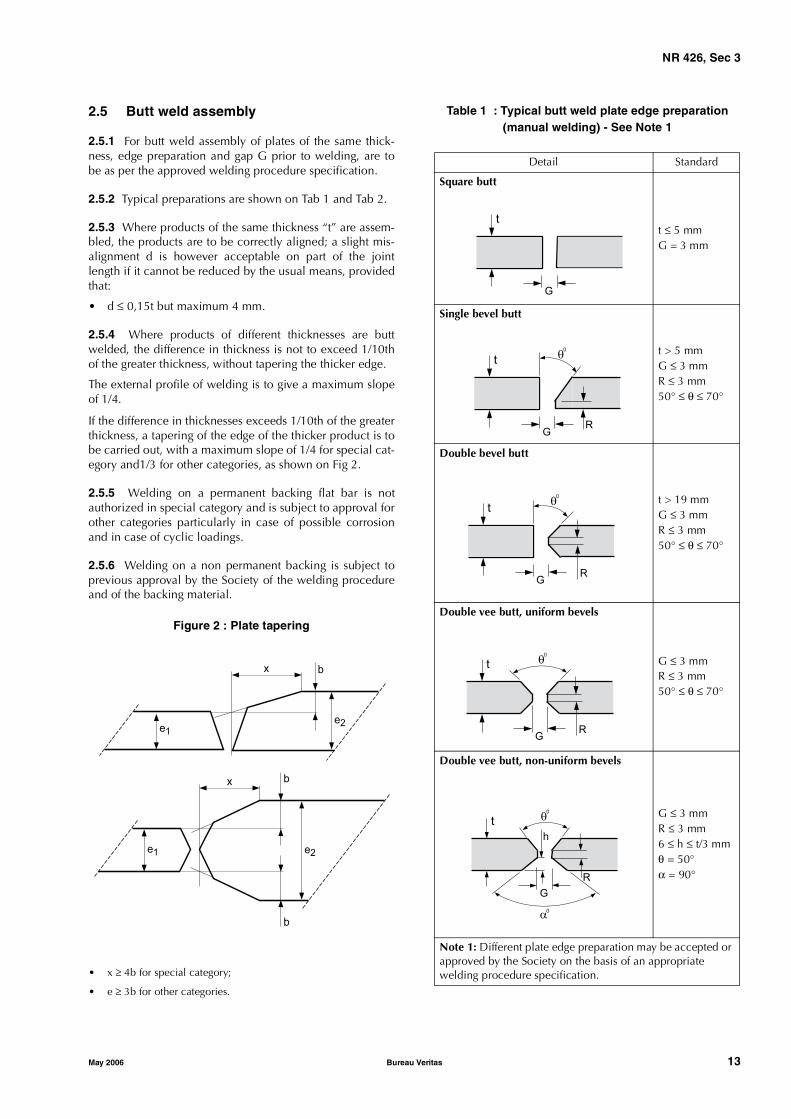
2.5 Butt weld assembly
2.5.1 For butt weld assembly of plates of the same thick-ness, edge preparation and gap G prior to welding, are tobe as per the approved welding procedure specification.
2.5.2 Typical preparations are shown on Tab 1 and Tab 2.
2.5.3 Where products of the same thickness “t” are assem-bled, the products are to be correctly aligned; a slight mis-alignment d is however acceptable on part of the jointlength if it cannot be reduced by the usual means, providedthat:
• d ≤ 0,15t but maximum 4 mm.
2.5.4 Where products of different thicknesses are buttwelded, the difference in thickness is not to exceed 1/10thof the greater thickness, without tapering the thicker edge.
The external profile of welding is to give a maximum slopeof 1/4.
If the difference in thicknesses exceeds 1/10th of the greaterthickness, a tapering of the edge of the thicker product is tobe carried out, with a maximum slope of 1/4 for special cat-egory and1/3 for other categories, as shown on Fig 2.
2.5.5 Welding on a permanent backing flat bar is notauthorized in special category and is subject to approval forother categories particularly in case of possible corrosionand in case of cyclic loadings.
2.5.6 Welding on a non permanent backing is subject toprevious approval by the Society of the welding procedureand of the backing material.
Figure 2 : Plate tapering
• x ≥ 4b for special category;
• e ≥ 3b for other categories.
Table 1 : Typical butt weld plate edge preparation(manual welding) - See Note 1
x
e1
e2
b
b
b
e2
e1
x
Detail Standard
Square butt
t ≤ 5 mmG = 3 mm
Single bevel butt
t > 5 mmG ≤ 3 mmR ≤ 3 mm50° ≤ θ ≤ 70°
Double bevel butt
t > 19 mmG ≤ 3 mmR ≤ 3 mm50° ≤ θ ≤ 70°
Double vee butt, uniform bevels
G ≤ 3 mmR ≤ 3 mm50° ≤ θ ≤ 70°
Double vee butt, non-uniform bevels
G ≤ 3 mmR ≤ 3 mm6 ≤ h ≤ t/3 mmθ = 50°α = 90°
Note 1: Different plate edge preparation may be accepted or approved by the Society on the basis of an appropriatewelding procedure specification.
t
G
t
G
q0
R
t
G
q0
R
t
G
q0
R
t
G
q0
R
a0
h

NR 426, Sec 3
14 Bureau Veritas May 2006
Table 2 : Typical butt weld plate edge preparation(manual welding) - See Note 1
2.6 Full penetration angle welds
2.6.1 Full penetration angle welds are required whenassembling highly stressed elements, playing an importantpart in the structure and in which fatigue phenomena arelikely to occur. This case may occur in particular for ele-ments of special and first categories.
2.6.2 For highly stressed assemblies, corresponding to aspecial category or a first category element, lamellar tearingrisks may be lowered following recommendations given in[3].
2.6.3 For very thick assemblies subject to high restraint andessential to the structural safety of the unit or installation, apostweld heat treatment may be required, as specified in[4.6].
2.6.4 For special category elements submitted to fatiguecycles, the surface condition of the weld, in particular itsconnection with plates, is to be taken care of and inspected.In certain cases, grinding of weld connection with platemay be required.
2.7 Welding of thick parts
2.7.1 When thick parts are intended to be either buttwelded or full penetration angle-welded, special precau-tions are to be taken for welding, concerning the prepara-tion of the edges to be welded and the welding operations(welding sequences aiming at limiting distortions, protec-tion under temporary cover for open air welding, etc.).
2.7.2 Depending upon the steel grade, upon the thicknessof the elements to be assembled and upon the clamping ofthe assembly, preheating may be required, as per [4.4].
2.7.3 A postweld heat treatment may be required for theassembly, as mentioned in [4.6].
2.8 Connections of pipes
2.8.1 Where several pipes are connected, proper prepara-tion of joints before welding is necessary, in particular forspecial and first category elements.
2.8.2 For special and first category elements, all the weldsare to be full penetration welds. The surface of the externalweld is to present a continuous and regular profile, blend-ing without discontinuity and gradually with the surface ofthe two pipes.
2.8.3 All the edges are to be chamfered before welding, thetolerance on the groove angle being ± 10°.
2.8.4 All details about preparation of the edges to bewelded and welding conditions are to be submitted to theSociety's approval within the welding programme.
2.8.5 Weld preparation (groove angle, root opening, pipeconnection angle) is to comply with welded tubular con-nection details given in figure 11.1.3 of API RP2A-WSD, theselection of the weld profile control, if necessary, beingmade in accordance with paragraph 11.1.3.d of the sameAPI Standard.
Alternatively, the "Details for welded tubular joints in T-, Y-,and K-connections made from one side without backing" inSection 10-13 of ANSI/AWS D1-1, may be used, the selec-tion of the profile types having been carried out at thedesign stage, depending upon the fatigue level of the struc-ture.
2.8.6 When, after positioning prior to welding, the gap G,as defined on Tab 1 and Tab 2, is too narrow to allow agood penetration at the weld root, this gap is to beincreased by mechanical gouging or by means of the arc-airprocedure to reach the appropriate gap.
For special and first category elements, when gap G beforewelding is too important, local building up by welding maybe required.
2.8.7 For special category and first category highly stressednodes constituted with thick pipes, the design of the con-nection is to be, as far as possible, such as the weld con-necting braces with chord may be made with sealing runs,with access possible for the welder from both sides of thejoints.
Design of nodes and their welding procedures are to be pre-sented to the examination of the Society at the design stage,under the form of a welding programme, according to[1.2.3].
2.8.8 For highly stressed special category or first categorynodes, lamellar tearing risks on the chord pipe of the nodemay be lowered following recommendations given in [3].
Detail Standard
Single vee butt, one side welding with backing strip (temporary or permanent)
3 ≤ G ≤ 9 mm30° ≤ θ ≤ 45°
Single vee butt
G ≤ 3 mm50° ≤ θ ≤ 70°R ≤ 3 mm
Note 1: Different plate edge preparation may be accepted or approved by the Society on the basis of an appropriate weld-ing procedure specification.
t
G
q0
t
GR
q0

NR 426, Sec 3
May 2006 Bureau Veritas 15
2.8.9 For special category and first category elements, acomplete ultrasonic inspection is to be carried out along apipe strip 100 mm wide, which receives the weld on its sur-face. This 100 mm strip is to be centred on the weld axis.
2.9 Fillet weld assembly with two limitedpenetration beads
2.9.1 These restricted penetration fillet welds are related toconnections of stiffeners to plates, securing brackets, etc.
2.9.2 The value of the throat thickness of a double continu-ous line of welding is determined in terms of the thinnestplate (the thickness of which being noted emin) of the assem-bly under consideration and in terms of minimum weldingheat input necessary to obtain required hardness values.
Except where otherwise stated, the throat thickness for dou-ble fillet welds does not need to exceed 0,45 e. Besides, thethroat thickness is to be at least equal to:
• 3,5 mm in the general case of continuous or discontinu-ous welding
• 3,5 mm for high strength steel assemblies
with emin ≤ 8 mm
• 4 mm for high strength steel assemblies
with emin ≤ 12 mm
• 5 mm for high strength steel assemblies
with emin > 12 mm.
Besides complying with these maximum and minimum val-ues, throat thickness is to be large enough to satisfy thestrength purposes.
Where a deep penetration automatic welding procedure isused, the Rule throat thickness may be reduced accordingto the actual throat of the weld, measured on the macrogra-phy of the qualification test.
However, this reduction is not to exceed 15% of the Rulethroat thickness.
The Surveyor may examine the regularity of deep penetra-tion fillet welding, on macrographic sections made on pro-duction check samples.
2.9.3 The plates are to be correctly adjusted without spac-ing. A slight spacing S is however acceptable over part ofthe joint length where it does not exceed:
• S = 2 mm for emin ≤ 6 mm
• S = 3 mm for emin > 6 mm
• S = 2 mm for fillet welds in the overhead position.
Where there is a spacing between plates, the throat thick-ness of lines of welding is to be increased by one-half of theclearance between the elements to be assembled.
2.9.4 Where the spacing S exceeds the values specified in[2.9.3], a re-welding procedure is to be prepared by theBuilder in agreement with the Surveyor according to theclearance and size of the elements to be assembled.
3 Recommendations to reduce therisks of lamellar tearing
3.1
3.1.1 Factors affecting lamellar tearing
Lamellar tearing affects mainly angle joints, the phenome-non being connected with shrinkage stresses of the weldduring cooling, depending on the assembly rigidity, theclamping of the structure close to the joint, the thickness ofthe material, the presence of imperfections at mid-thick-ness, the distribution and importance of the weld runs.
3.1.2 Means of reducing risks of lamellar tearing
The following precautions are to be taken:
a) At the initial stage of the project, too high servicestresses on strongly clamped cruciform assemblies areto be avoided; furthermore, the structure design is to besimplified with a view to rendering it less sensitive toclamping during welding
b) Ultrasonic testing of the plate on which the weld is to bedeposited is to be carried out along a strip of 100 mm inwidth centred on the weld axis to detect any possiblelamination of the plate located below the weld.
c) Proper preparation, welding sequence and parametersare to be selected (e.g. welding techniques by alternatesymmetrical runs: balanced welding).
d) The plate grade on which the weld is to be carried out isto be also specially selected. Plates manufactured as Zgrade in accordance with NR216 “Materials and Weld-ing” are limiting the risks of lamellar tearing.
The use of Z grade plates does not dispense to takeappropriate measures for welding operations.
e) Buttering technique is to be used, in new building aswell as in repairing.
4 Welding operations
4.1 Execution of the welds
4.1.1 The welding operations are to be carried out undershelter from rain, snow or wind. It is recommended to carryout welding on as many elements as possible under cover.
Work is to be interrupted when the temperature on thewelding site drops below a minimum value determined dur-ing the qualification of the welding process.
In any case, the steel temperature is to be at least equal to0°C, before preheating, in any point of the steel closer than0,5 m to the welding point. In addition, the steel is to beheated at the determined preheating temperature on 75 mmor 3 e (whichever is the greater) on each side of the weld.
Note 1: preheating temperature means the measured steel tempera-ture of the qualification sample just before welding.

NR 426, Sec 3
16 Bureau Veritas May 2006
4.1.2 After each run, slag is to be eliminated and the weldis to be cleaned; the same precaution is to be taken whenresuming an interrupted weld or connecting two welds.
As far as possible, welds are to be carried out from bothsides (mechanical gouging or arc-air gouging of the rootpass being recommended).
4.1.3 Welding is not to be stopped until the joint is 1/3rdfilled with weld metal deposit. Otherwise, preheating is tobe maintained, even when welding is interrupted. In thecase of a clamped or large section assembly or of steels sen-sitive to hardening, welding is to be performed withoutmajor interruption.
4.1.4 Interpass temperature:
• minimum interpass temperature is the preheating tem-perature as defined in [4.1.1]
• maximum interpass temperature is measured during thewelding qualifications and is not to exceed 250°C.
4.1.5 No new run is to be undertaken if the previous one isnot finished.
4.1.6 Runs are not to begin or end at the same point as theprevious one.
4.1.7 For all butt welds and particularly in case of automaticbutt welding, it is recommended to start and end the jointson appendages to be fixed at the ends. When an interruptedweld is resumed manually or by machine, the joint end is tobe carefully cleaned and chiselled. This operation is to becarried out as soon as practicable after the interruption.
4.1.8 Proper operation of the machines is to be frequentlychecked by the welder and the Builder's staff during welding.
4.2 Identification of welders
4.2.1 Any welder is to receive a number or an identifica-tion symbol that he is to use to identify all welds performedby him. Marking is to be made with a weather resistantcrayon or paint.
When a punch is used, it is to create only spherical orrounded marks.
Welds which are not definitely identified may be rejectedby the Surveyor.
4.2.2 A welder is not to change in any case the symbolwhich is assigned to him during a construction. If a welderquits, the symbol which has been assigned to him is not tobe used by another welder.
4.3 Welding sequence
4.3.1 As a general rule, assembly and welding sequencesof the different parts of structure are to be carefully definedsuch as to reduce to a minimum distortions and accumula-tion of residual stresses in any part of the structure. Ade-quate heat treatments are to be carried out after weldingwhen excessive residual stresses in the joint cannot beavoided.
4.3.2 The Builder is to plan and have made all the neces-sary surveys to make sure that contemplated weldingsequences are complied with.
4.3.3 The Builder is to keep the Surveyor informed of anymajor modification of the welding sequence of an assemblyas compared with the sequence contemplated in the weld-ing programme.
4.4 Preheating during welding
4.4.1 Assembly preheating is to be contemplated in termsof the steel grade (examination of its weldability accordingto the carbon equivalent), of the thickness of the elements tobe welded, of the weld preparation (butt, fillet, etc.), of thenature of the welding process (heat input, number of passes,etc.) and of the clamping conditions of the assembly. Pre-heating temperature is to be maintained during the weldingoperations.
4.4.2 The conditions governing preheating are the subjectof a prior agreement between the Builder and the Societyduring the welding procedure approval discussions andaccording to the results of the procedure qualification tests,the minimum preheating temperature being in accordancewith [4.1.1].
The preheating conditions are to be defined during thequalification tests of the welding procedure.
4.4.3 For steels with ReG equal to 300 MPa and over, thepreheating temperature defined during the welding proce-dure qualifications on steel samples with carbon equivalentCEQ is to be increased and the WPS modified accordingly(the procedure being requalified if necessary), if the carbonequivalent CEC of the steel to be welded according to theseprocedures exceeds CEQ by more than 0,03. Consequently,welding procedure remains valid only for:
CEQ ≤ CEQ + 0,03
Note 1:
• The carbon equivalent is given by the formula:
where all components are expressed in percentages from ladleanalysis.
• In all cases, welding is to be carried out with low-hydrogenbasic electrodes suitably dried and baked.
• The welding conditions becoming uncomfortable when thepreheating temperature is too high, the Builder is therefore rec-ommended to order steels having the lowest possible carbonequivalent.
4.5 Postheating immediately after welding
4.5.1 The postheating after welding is to be defined at thestage of welding specification and qualification procedure.
4.5.2 Postheating is defined by its temperature and durationand is performed immediately after welding.
CE C Mn6
---------Cr Mo V+ +
5------------------------------- Ni Cu+
15---------------------+ + +=
NR 426, Sec 3
May 2006 Bureau Veritas 17
4.6 Postweld heat treatment (PWHT)
4.6.1 A postweld heat treatment may be required by theSociety in the case of assemblies which require delicateworkmanship and play a major part in the structure safety,and in the case of assemblies including weld thicknessesequal to 50 mm and over. As a general rule, PWHT is nor-mally required for weld thicknesses equal to 60 mm andover. The Society can require to witness the PWHT opera-tions.
Such a treatment, where contemplated by the Builder, is tobe indicated with all its operating conditions in the weldingprogramme and on the fabrication drawings.
4.6.2 Notwithstanding [4.6.1], PWHT may be dispensedwith by the Builder with the agreement of the Society. Inthis case, fracture mechanics tests, such as CTOD tests, areto be performed during corresponding welding procedurequalifications.
4.6.3 The postweld heat treatment is to be defined at thestage of the design of the structure, so that the mechanicaltests of welding procedure qualification are carried out afterthe same treatment as provided for the structure joint.
4.6.4 Conditions of postweld heat treatment (PWHT) forcarbon non-alloyed or micro-alloyed steels withReG < 420 MPa, may be the following ones:
• heating to 560°C ± 20°C
• holding time at treatment temperature T (in mn), calcu-lated in terms of the thickness e (in mm) of the thickestweld, as follows:
• T = 2e when e ≤ 60 with a minimum of one h
• T = 120 + 0,5 (e − 60) when e > 60.
In any case, conditions of PWHT are to be defined in accor-dance with the recommendations of the steel maker whohas delivered steel, in particular for the temperature step.
Holding time is measured since the moment when ambienttemperature in oven reaches the value contemplated for thetreatment; in the case of a local treatment by heating strips,it is the temperature of the element which is considered.
The rate of temperature rise and drop is to be sufficientlysmall to limit residual stresses and deformations.
As a general rule, this rate is not to exceed:• rise 80°C/h• drop 100°C/h.
For very high strength steels (ReG ≥ 420 MPa), conditions ofheat treatment are to be defined in agreement with the Soci-ety and with the steel maker.
4.6.5 The Surveyor will request the original temperaturecharts at different spots in the oven so as to ascertain tem-perature homogeneity on the part and consistency of therate of temperature rise or drop.
4.6.6 Where a complex prefabricated element is con-cerned, e.g. a node, only the global heat treatment in a spe-cial oven may be contemplated so as to ensure that thetreatment applies to the whole part.
4.6.7 In the case of an isolated circular weld, located on acontinuous element, such as pipe joining, a local heat treat-ment is acceptable. In such case, an adequate number ofthermocouples are to be distributed in contact with theweld and the adjoining areas (inside and outside the pipe)to provide the temperature distribution during the wholetreatment. The original temperature charts are to be pro-duced to the Surveyor.
4.6.8 After final treatment of a welded part, any possiblerepair of a welding defect appeared after this treatment is tobe submitted to the Surveyor's approval, in particular asconcerned with the possibility of a second treatment of thepart after repair.
4.6.9 If non destructive testing is made before PWHT, com-plementary non destructive testing is to be carried out afterPWHT according to a procedure agreed with the Society.However, NDT is mandatory after PWHT for special cate-gory elements and, in all cases, preference is to be given toa whole non destructive testing after PWHT.
4.7 Temperature control
4.7.1 Methods are to be established for all operationsrequiring a control of temperatures of preheating, betweenruns, of postheating or of heat treatment after welding.
4.7.2 Hardness test after PWHT may be required by theSurveyor.
NR 426, Sec 4
18 Bureau Veritas May 2006
SECTION 4 APPROVAL OF STEEL WELDING PROCEDURES
AND WELDERS
1 General
1.1 Scope
1.1.1 General
The requirements relevant to materials not covered hereinare agreed on a case-by-case basis following, as far asapplicable, the criteria specified in this Section.
1.1.2 Other standards and specifications
Procedures considered equivalent by the Society may beaccepted.
1.2 Welding procedure
1.2.1 Welding processes
For reference, the processes are listed with their relevantnumber according to ISO 4063.
Qualification tests are, as a rule, required for the automaticor semi-automatic processes indicated below:
• submerged arc welding with wire electrode: 121
• flux-cored wire metal arc welding without gas shield:114
• metal arc inert gas welding (MIG welding): 131
• metal arc active gas welding (MAG welding): 135
• flux-cored wire metal arc welding with active gasshield: 136
• flux-cored wire metal arc welding with inert gas shield:137
• tungsten inert gas arc welding (TIG welding): 141
• plasma arc welding: 15.
1.2.2 Manual metal arc welding
In the case of manual metal arc welding, where the joint iswelded with approved covered electrodes and by certifiedwelders, qualification tests are generally not required; theresults of tests performed by the shipyard on joints weldedunder similar conditions may be required, to the Surveyor’ssatisfaction.
Qualification tests are required for manual welding of spe-cial or primary category elements.
Qualification tests may be required for one side manualmetal arc welding on ceramic backing.
Qualification tests are required in the case of weldinghigher strength steels having minimum yield stress equal toor higher than 390 N/mm2 and steels not approved or notcomplying with recognised standards.
1.2.3 Welding consumables
Consumables approved in accordance with the require-ments of NR216 “Materials and Welding” are to be usedwithin the limits of their approval.
When non-approved welding consumables are used, therequirements relevant to the qualification of the weldingprocedures are established on a case-by-case basis and ingeneral tests on a deposited metal sample are required.
1.2.4 Preliminary welding procedure specification
A welding procedure specification is to be prepared by theManufacturer or Shipyard which intends to perform thequalification tests. This document is also referred to as apreliminary welding procedure specification (pWPS) and isto be submitted to the Society for review prior to the tests.
This pWPS may be modified and amended during the pro-cedure tests as deemed necessary however it shall define allrelevant variables as mentioned in the welding procedurespecification (refer to [1.2.5]).
In case that the test pieces welded according to the pWPSshow unacceptable results, the pWPS is to be adjusted bythe Shipyard or Manufacturer. The new pWPS is to be pre-pared and the test pieces welded in accordance with thenew pWPS.
In general, the qualification tests is to reflect fabricationconditions in respect to welding equipment, inside or out-side fabrication, weld preparation, preheating and any post-weld heat treatment. It is to the manufacturer’s responsibil-ity to establish and document whether a procedure is suit-able for the particular application.
The test pieces are to be chosen so as to cover all the pro-duction welds in accordance with the approval range ofparameters.
1.2.5 Approval of welding procedure specification
The qualification tests when required, welding of test piecesaccording to the proposed pWPS and testing of test speci-mens, are to be witnessed by the Surveyor.
Upon satisfactory completion of the tests, the Society mayapprove the pWPS as a welding procedure specification.

NR 426, Sec 4
May 2006 Bureau Veritas 19
In its final version, the welding procedure specification(WPS) is to include all the parameters characterising thewelding process; in particular, as applicable:
a) type of welding process and equipment, as appropriate
b) type of joint, preparation and backing material, if any
c) base metal, thickness range, pipe diameter etc.
d) filler metal
e) welding position
f) minimum preheat, minimum and maximum interpasstemperature
g) post-weld heat treatment if applicable
h) shielding gas as applicable
i) welding parameters
j) other information relevant to the welding techniques asapplicable.
The actual parameters used for welding the approval testpieces and the results of the inspections and tests carriedout are to be recorded in the welding procedure qualifica-tion record (WPQR) also referred to as welding procedureapproval record (WPAR).
The WPQR is generally prepared by the shipyard or weldingshops and endorsed by the attending Surveyor.
1.2.6 Certificate of approval of the weldingprocedure
Upon satisfactory completion of the approval tests, a certifi-cate of approval of the welding procedure is generallyissued by the Society to the individual users, stating theconditions of the approval of the WPS such as thicknessrange, positions, steel grades and additional conditions forthe application of the process, as deemed necessary, on thebasis of the indications already given in the WPS.
1.2.7 Inspections
Inspections and control tests may be periodically and ran-domly required as deemed necessary by the Society and areto yield satisfactory results in order to maintain the validityof the approval.
The results of any suitable control performed during pro-duction may be accepted, to the Surveyor’s satisfaction.
1.2.8 Responsibilities of the users
The qualification tests are intended to verify that a manufac-turer is adequately qualified to perform welding operationsusing a particular procedure.
Irrespective of the inspections carried out by the Surveyor,the user is responsible for the use of the approved proce-dures, within the limits of the range qualified and the condi-tions stated at the time of the approval.
Compliance with the above is essential for the validity ofthe approval.
2 Welding procedure qualification tests
2.1 Butt joints in plates with full penetration
2.1.1 Assembly of test pieces
Preparation and welding are to be in accordance with thepWPS and under the general condition of production weld-ing which it represents.
If tack welds and / or start and stop points are a condition ofthe weld process, they are to be fused into the joint and areto be included in the test pieces.
The test assembly is to be of a size sufficient to ensure a rea-sonable heat distribution and is to have the minimum fol-lowing dimensions (see Fig 1):
a) manual or semiautomatic welding:
length L=6t, min. 350mm;
width W with W/2=3t, min. 150mm.
b) automatic welding:
length L=min.1000 mm;
width W with W/2=4t, min. 200 mm.
In the case of steel plates impact tested in the longitudinaldirection (CVN-L), the butt weld of the test piece is perpen-dicular to the rolling direction of the two plates.
In the case of steel plates impact tested in the transversaldirection (CVN-T), the butt weld of the test piece is parallelto the rolling direction of the two plates.
Figure 1 : Test assembly for plate butt weld
2.1.2 Examinations and tests
Non-destructive examinations and destructive tests requiredaccording to Tab 1 are to be carried out, while the locationof the test specimens is to be in accordance with Fig 2.
Plate rollingdirection
50
50
W/2 W/2
L
(Steel plateswith CVN-L)
Plate
rollingdirection
(SteelplateswithCVN-T)
Discard
Discard

NR 426, Sec 4
20 Bureau Veritas May 2006
Figure 2 : Location of test specimens
Weld
M
T1
P1
P2
Cylindricaltensile test
1 Specimens(notch in weld metal)
2 Specimens(notch overlappingthe weld junction)
3 Specimens(notch in HAZ at 2 mmof the weld junction)
P3
P4
T2
M
Macrographic & Hardness
Prismatic tensile test
Face bend test or2 side bend test
Root bend test
Face bend test or2 side bend test
Root bend test
Prismatic tensile test
Macrographic & Hardness
scrap
scrap50
50
d

NR 426, Sec 4
May 2006 Bureau Veritas 21
Table 1 : Examinations and tests for butt jointsin plates
2.1.3 Non-destructive examinationsNon-destructive examinations are to be carried out afterany required or specified post-weld heat treatment andprior to the cutting of test specimens.
Imperfections detected by visual or non-destructive testingare to be assessed in accordance with ISO 5817 class B,except for the following imperfections for which the level Capplies:
• excess weld metal or convexity
• excess throat thickness, and
• excess of penetration.
2.1.4 Transverse tensile testsSpecimens for transverse tensile tests are to be in accor-dance with NR216 “Materials and Welding”.
The tensile strength recorded for each specimen is to be notless than the minimum required for the parent metal; thelocation of the fracture is to be reported.
When butt welds are made between plates of differentgrades, the tensile strength to be obtained on the weldedassembly is to be in accordance with the requirement of thegrade having lower strength.
2.1.5 Tensile tests on cylindrical specimensWhen required (see Tab 1), a round tensile specimen is tobe cut along the weld axis to the dimension given in NR216“Materials and Welding” Ch1, Sec2, Fig1, in the all weldmetal.
Where the size of the deposited metal is too small, a 6 mmdiameter specimen may be taken or a deposited weld metal
test is to be carried out in accordance with the requirementsof NR216 “Materials and Welding” Ch5, Sec 2.
The tensile properties recorded (yield stress ReH, tensilestrength Rm and elongation A5) are to be not less than theminimum required for the approval of the appropriate gradeof consumables.
When more than one welding process or type of consum-able has been used to make the test weld, test specimensare to be removed from the area of the weld where eachwas used with the exception of those processes or consum-ables used to make the first weld run or root deposit.
2.1.6 Bend testsTransverse root bend, face bend and side bend specimensare to be machined to the dimensions given in NR216“Materials and Welding” Ch1, Sec 2 [3.1].
For dissimilar or heterogeneous butt-joints, one longitudinalbend test may be used instead of transverse bend tests.
The test specimens are to be bent on a mandrel having adiameter equal to 4 times the thickness of the specimen; thebending angle is to be 180°.
After testing, the test specimens are not to reveal any opendefect, in any direction, greater than 3 mm. Defects appear-ing at the corners of the test specimen during testing are tobe investigated case-by-case.
When butt welds are made between plates of differentgrades, face and root longitudinal bend test specimens maybe used instead of the transverse bend test specimens.
2.1.7 Impact testsDimensions and testing of Charpy V-notch impact test spec-imens are to be in accordance with NR216 “Materials andWelding” Ch1, Sec 2.
Charpy V-notch impact test specimens in accordance withNR216 “Materials and Welding” Ch1, Sec 2 are to be sam-pled from 1 to 2 mm below the surface of the parent mate-rial, transverse to the weld and on the side containing thelast run.
The Charpy V-notch specimens are located in the butt-welded joint as indicated in Fig 3 and Fig 4, and the V-notch is to be cut perpendicular to the surface of the weld.
The test temperature and absorbed energy are to be inaccordance with the requirements of the base material.
When butt welds are made between different steelgrades/types, the test specimens are to be taken from theside of the joint with steel of lower toughness level. Temper-ature and absorbed energy results are to be in accordancewith the minimum value required for the steel of lowertoughness level.
Where more than one welding process or consumable hasbeen used to make the test weld, impact test specimens areto be removed from the respective areas where each wasemployed. This should not apply to the process or consum-ables used solely to make the first weld run or root deposit.
When cast or forged material with specified impact valuesis to be welded, test temperature and absorbed energy areto be in accordance with the requirements of the base mate-rial.
Type of examination or test Extent of examination or test
Visual examination 100%
Surface crack detection (1) 100%
Radiographic or ultrasonic examination
100%
Transverse tensile test 2 specimens
Transverse bend tests (2) 2 root and 2 face specimens
Charpy V-notch impact tests (3)
3 sets
Macro examination on 1 section
Hardness test (4) on 1 section
Longitudinal tensile test (5) 1 specimen
(1) Dye penetrant according to ISO 3452 (or equivalent accepted standard) or magnetic particle testing; for non-magnetic materials, dye penetrant only.
(2) For t ≥ 12mm, the face and root bends are preferably to be replaced by 4 side bends.
(3) 3 sets each of 3 specimens as per [2.1.7].(4) Only required for high strength steels with minimum
specified yield strength equal to or greater than 355N/mm².
(5) Required only when the use of non-approved filler metal has been accepted (see [1.2.3]).
NR 426, Sec 4
22 Bureau Veritas May 2006
Figure 3 : Location of V-notch fornormal heat input ≤ 50 kJ/cm
a : Centre of weld “WM”
b : On fusion line “FL”
c : In HAZ, 2 mm from fusion line
* : For one side pass welding over 20 mm “WM” FL andHAZ, 2mm from fusion line to be added on root side.
2.1.8 Macro examinations
The test specimens are to be prepared and etched usingsuitable agent on one side to clearly reveal the weld metal,fusion line, the heat affected zone (HAZ) and about 10 mmof unaffected parent metal.
The examination shall reveal a regular weld profile, throughfusion between adjacent layers of weld and base metal andthe absence of defects such as cracks, lack of fusion etc.
2.1.9 Hardness tests
Hardness testing is required for steels with minimum speci-fied yield strength equal to or greater than 355N/mm². Unlessotherwise agreed, the Vickers method HV10 is to be used.
The indentations are to be made in the weld, heat affectedzones, and the parent metals measuring and recording thehardness values. Two rows of indentations are to be carriedout in accordance with Fig 5.
For each row of indentations, there is to be a minimum of3 individual indentations in the weld, the heat affectedzones (both sides) and the parent metals (both sides).
The distance between the indentations may vary from 0,5 to2 mm depending on the zone tested.
Typical example of hardness indentations are given in Fig 5.
The results of hardness tests are not to exceed 350 HV forsteels with a specified minimum yield strength less than orequal to 420N/mm².
Figure 4 : Location of V-notch for high heat input > 50 kJ/cm
a : Centre of weld “WM”
b : On fusion line “FL”
c : In HAZ, 2 mm from fusion line
d : In HAZ, 5 mm from fusion line
e : In HAZ, 10 mm from fusion line in case of heat input > 200 kJ/cm
1-2 mm
b ac
ba c
1-2 mm
1st side
2nd side
t ≤ 50 mm*
1-2 mm
b ac
ba c
1-2 mm
1st side
2nd side
t > 50 mm
ba
a
1-2 mm
b ac
ba c
1-2 mm
1st side
2nd side
t ≤ 50 mm
ba
de
d e
1-2 mm
b ac
ba c
1-2 mm
1st side
2nd side
t ≥ 50 mm
ba
de
d ec
a c
NR 426, Sec 4
May 2006 Bureau Veritas 23
Figure 5 : Examples of hardness indentations
2.2 T butt joints in plates
2.2.1 General
Where this type of joints is predominant in production,qualification tests are to be performed on T butt joint assem-bly in addition to the equivalent qualification on butt joint.
The same principle applies when changes occur in thegeometry of the bevel which may significantly affect thepenetration or fusion.
2.2.2 Assembly and welding
Preparation and welding are to be in accordance with thepWPS and under the general condition of production weld-ing which it represents.
If tack welds are a condition of the weld process, they are tobe fused into the joint and are to be included in the testpieces.
The test assembly is to be of a size sufficient to ensure a rea-sonable heat distribution and is to have the minimum fol-lowing dimensions (reference can be made to Fig 6):
a) manual or semiautomatic welding:
length L=6t, min. 350mm;
width W=3t, min. 150mm.
b) automatic welding:
length L=min.1000 mm;
width W=3t, min. 150 mm.
2.2.3 Examinations and tests
Non-destructive examinations and destructive tests arerequired according to Tab 2; a discard of 50 mm from bothedges is permitted.
Figure 6 : T butt joint in plates
Table 2 : Examinations and tests for T butt jointsin plates
2.2.4 Non-destructive examination
Reference is made to [2.1.3].
2.2.5 Tensile tests on cylindrical specimens
Reference is made to [2.1.5].
2.2.6 Macro examination
Reference is made to [2.1.8].
2 m
mm
ax
2 m
mm
ax2
mm
max
2 m
mm
ax
2 m
mm
ax
t ≤ 5 mmt
t
t > 5 mm
Parent metal Parent metal
HAZ narrow HAZ wide
Weld
Type of examination or test Extent of examination or test
Visual examination 100%
Surface crack detection (1) 100%
Ultrasonic examination (4) 100%
Macro examination on 1 section
Hardness test (2) on 1 section
Longitudinal tensile test (3) 1 specimen
(1) Dye penetrant according to ISO 3452 (or equivalent accepted standard) or magnetic particle testing; for non-magnetic materials, dye penetrant only.
(2) Only required for high strength steels with minimum specified yield strength equal to or greater than 355N/mm².
(3) Required for thickness above 50mm or when the use of non-approved filler metal has been accepted (see [1.2.3]).
(4) Applicable to full penetration weld or to verify the extent of penetration in partial penetration welds
Weld one side or bothsides and fit-up as detailedin the preliminary WeldingProcedure Specification
t1
t2
W
W
LW
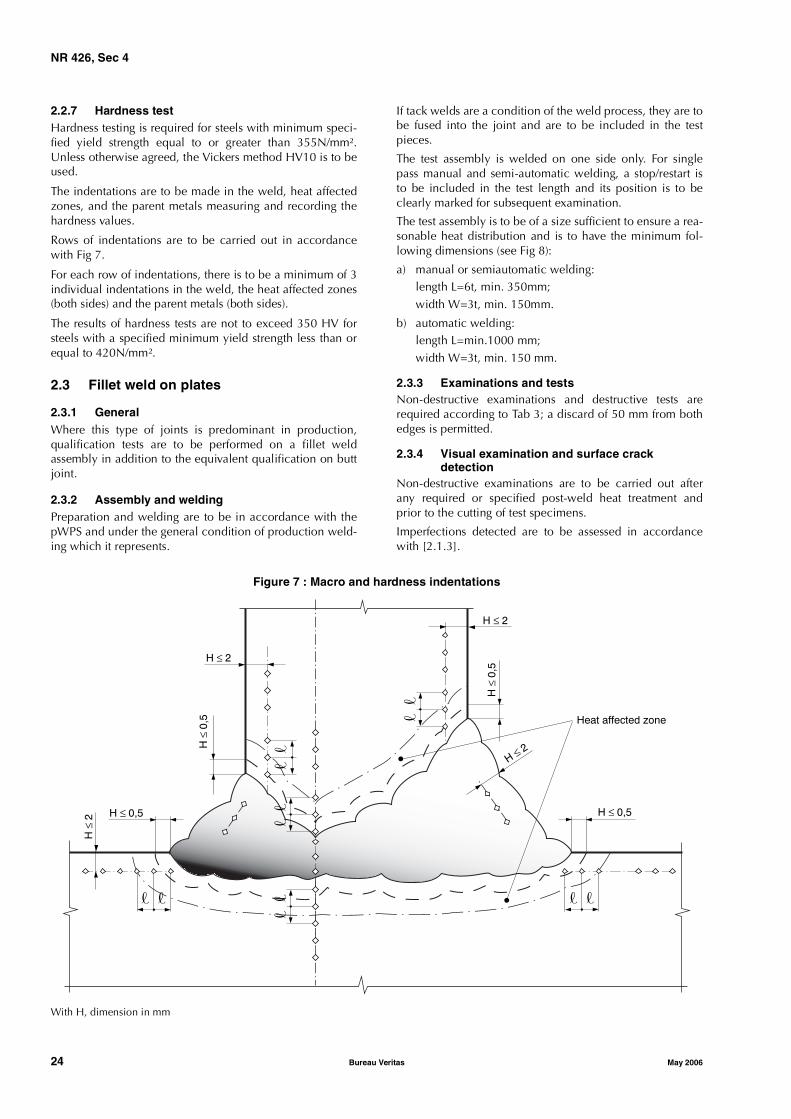
NR 426, Sec 4
24 Bureau Veritas May 2006
2.2.7 Hardness testHardness testing is required for steels with minimum speci-fied yield strength equal to or greater than 355N/mm².Unless otherwise agreed, the Vickers method HV10 is to beused.
The indentations are to be made in the weld, heat affectedzones, and the parent metals measuring and recording thehardness values.
Rows of indentations are to be carried out in accordancewith Fig 7.
For each row of indentations, there is to be a minimum of 3individual indentations in the weld, the heat affected zones(both sides) and the parent metals (both sides).
The results of hardness tests are not to exceed 350 HV forsteels with a specified minimum yield strength less than orequal to 420N/mm².
2.3 Fillet weld on plates
2.3.1 GeneralWhere this type of joints is predominant in production,qualification tests are to be performed on a fillet weldassembly in addition to the equivalent qualification on buttjoint.
2.3.2 Assembly and weldingPreparation and welding are to be in accordance with thepWPS and under the general condition of production weld-ing which it represents.
If tack welds are a condition of the weld process, they are tobe fused into the joint and are to be included in the testpieces.
The test assembly is welded on one side only. For singlepass manual and semi-automatic welding, a stop/restart isto be included in the test length and its position is to beclearly marked for subsequent examination.
The test assembly is to be of a size sufficient to ensure a rea-sonable heat distribution and is to have the minimum fol-lowing dimensions (see Fig 8):
a) manual or semiautomatic welding:length L=6t, min. 350mm;width W=3t, min. 150mm.
b) automatic welding:length L=min.1000 mm;width W=3t, min. 150 mm.
2.3.3 Examinations and testsNon-destructive examinations and destructive tests arerequired according to Tab 3; a discard of 50 mm from bothedges is permitted.
2.3.4 Visual examination and surface crackdetection
Non-destructive examinations are to be carried out afterany required or specified post-weld heat treatment andprior to the cutting of test specimens.
Imperfections detected are to be assessed in accordancewith [2.1.3].
Figure 7 : Macro and hardness indentations
With H, dimension in mm
� �
H ≤ 0,5
� �
H ≤ 0,5
H≤ 2
H ≤ 2
H≤ 0,5
H ≤ 2
H≤ 0,5
��
��
��
��
H≤ 2
Heat affected zone
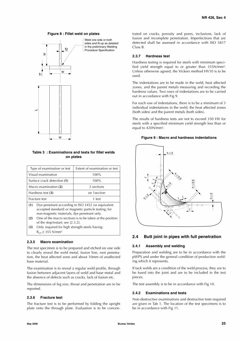
NR 426, Sec 4
May 2006 Bureau Veritas 25
Figure 8 : Fillet weld on plates
Table 3 : Examinations and tests for fillet weldson plates
2.3.5 Macro examination
The test specimen is to be prepared and etched on one sideto clearly reveal the weld metal, fusion line, root penetra-tion, the heat affected zone and about 10mm of unaffectedbase material.
The examination is to reveal a regular weld profile, throughfusion between adjacent layers of weld and base metal andthe absence of defects such as cracks, lack of fusion etc.
The dimensions of leg size, throat and penetration are to bereported.
2.3.6 Fracture test
The fracture test is to be performed by folding the uprightplate onto the through plate. Evaluation is to be concen-
trated on cracks, porosity and pores, inclusions, lack offusion and incomplete penetration. Imperfections that aredetected shall be assessed in accordance with ISO 5817Class B.
2.3.7 Hardness test
Hardness testing is required for steels with minimum speci-fied yield strength equal to or greater than 355N/mm².Unless otherwise agreed, the Vickers method HV10 is to beused.
The indentations are to be made in the weld, heat affectedzones, and the parent metals measuring and recording thehardness values. Two rows of indentations are to be carriedout in accordance with Fig 9.
For each row of indentations, there is to be a minimum of 3individual indentations in the weld, the heat affected zones(both sides) and the parent metals (both sides).
The results of hardness tests are not to exceed 350 HV forsteels with a specified minimum yield strength less than orequal to 420N/mm².
Figure 9 : Macro and hardness indentations
2.4 Butt joint in pipes with full penetration
2.4.1 Assembly and welding
Preparation and welding are to be in accordance with thepWPS and under the general condition of production weld-ing which it represents.
If tack welds are a condition of the weld process, they are tobe fused into the joint and are to be included in the testpieces.
The test assembly is to be in accordance with Fig 10.
2.4.2 Examinations and tests
Non-destructive examinations and destructive tests requiredare given in Tab 1. The location of the test specimens is tobe in accordance with Fig 11.
Type of examination or test Extent of examination or test
Visual examination 100%
Surface crack detection (1) 100%
Macro examination (2) 2 sections
Hardness test (3) on 1section
Fracture test 1 test
(1) Dye penetrant according to ISO 3452 (or equivalent accepted standard) or magnetic particle testing; for non-magnetic materials, dye penetrant only.
(2) One of the macro sections is to be taken at the position of the stop/restart; see [2.3.2].
(3) Only required for high strength steels having:ReH ≥ 355 N/mm2
Weld one side or bothsides and fit-up as detailedin the preliminary WeldingProcedure Specification
t1
t2
W
W
L
W
h ≤ 2
h ≤ 0,5�
h≤ 2
h≤ 2
h≤ 0,5
�
h≤ 2
� �
� �
��
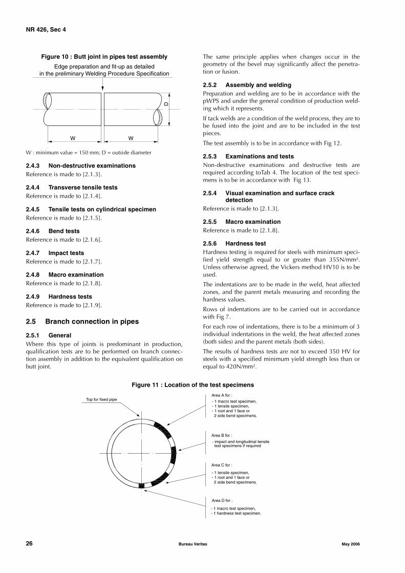
NR 426, Sec 4
26 Bureau Veritas May 2006
Figure 10 : Butt joint in pipes test assembly
W : minimum value = 150 mm; D = outside diameter
2.4.3 Non-destructive examinationsReference is made to [2.1.3].
2.4.4 Transverse tensile testsReference is made to [2.1.4].
2.4.5 Tensile tests on cylindrical specimenReference is made to [2.1.5].
2.4.6 Bend testsReference is made to [2.1.6].
2.4.7 Impact testsReference is made to [2.1.7].
2.4.8 Macro examinationReference is made to [2.1.8].
2.4.9 Hardness testsReference is made to [2.1.9].
2.5 Branch connection in pipes
2.5.1 GeneralWhere this type of joints is predominant in production,qualification tests are to be performed on branch connec-tion assembly in addition to the equivalent qualification onbutt joint.
The same principle applies when changes occur in thegeometry of the bevel may significantly affect the penetra-tion or fusion.
2.5.2 Assembly and weldingPreparation and welding are to be in accordance with thepWPS and under the general condition of production weld-ing which it represents.
If tack welds are a condition of the weld process, they are tobe fused into the joint and are to be included in the testpieces.
The test assembly is to be in accordance with Fig 12.
2.5.3 Examinations and testsNon-destructive examinations and destructive tests arerequired according toTab 4. The location of the test speci-mens is to be in accordance with Fig 13.
2.5.4 Visual examination and surface crackdetection
Reference is made to [2.1.3].
2.5.5 Macro examinationReference is made to [2.1.8].
2.5.6 Hardness testHardness testing is required for steels with minimum speci-fied yield strength equal to or greater than 355N/mm².Unless otherwise agreed, the Vickers method HV10 is to beused.
The indentations are to be made in the weld, heat affectedzones, and the parent metals measuring and recording thehardness values.
Rows of indentations are to be carried out in accordancewith Fig 7.
For each row of indentations, there is to be a minimum of 3individual indentations in the weld, the heat affected zones(both sides) and the parent metals (both sides).
The results of hardness tests are not to exceed 350 HV forsteels with a specified minimum yield strength less than orequal to 420N/mm².
Figure 11 : Location of the test specimens
Edge preparation and fit-up as detailedin the preliminary Welding Procedure Specification
W W
D
Area A for :
- 1 macro test specimen,- 1 tensile specimen,- 1 root and 1 face or 2 side bend specimens.
Area B for :
- impact and longitudinal tensile test specimens if required
Area C for :
- 1 tensile specimen,- 1 root and 1 face or 2 side bend specimens.
Area D for :
- 1 macro test specimen,- 1 hardness test specimen.
Top for fixed pipe

NR 426, Sec 4
May 2006 Bureau Veritas 27
Figure 12 : Test assembly for branch connectionin pipes
Figure 13 : Location of test specimen for branchconnection in pipes
Area 6 o’clock for macrographic examination and hardness tests
Areas 3 or 9 o’clock for macrographic examination
2.6 Re-testing
2.6.1 If the test piece fails to comply with any of therequirements for visual or non-destructive testing, one fur-ther test piece is to be welded and subjected to the sameexamination.
If this additional test piece does not comply with the relevantrequirements, the pWPS is to be regarded as not capable ofcomplying with the requirements without modification.
2.6.2 If any test specimens fails to comply with the relevantrequirements for destructive testing due to weld imperfec-tion only, two further test specimens shall be obtained foreach one that failed. These specimens can be taken fromthe same test piece if there is sufficient material available orfrom a new test piece, and is to be subjected to the sametest. If either of these additional test specimens does notcomply with the relevant requirements, the pWPS is to beregarded as not capable of complying with the require-ments without modification.
Table 4 : Examinations and testsfor branch connection in pipes
2.6.3 If a tensile test specimen fails to meet the require-ments, the re-testing is to be in accordance with NR216“Materials and Welding” Ch1, Sec2, [2.3].
2.6.4 If there is a single hardness value above the maxi-mum values allowed, additional hardness tests shall be car-ried out (on the reverse of the specimen or after sufficientgrinding of the tested surface). None of the additional hard-ness values is to exceed the maximum hardness valuesrequired.
2.6.5 The re-testing of Charpy V-notch impact test speci-mens are to be carried out in accordance with NR216“Materials and Welding” Ch1, Sec2, [4.4].
2.6.6 Where there is not sufficient material remaining inthe test piece to provide the additional test specimens, a fur-ther assembly shall be welded using the same procedure toprovide the additional specimens.
2.7 Range of approval
2.7.1 General
The approval of a WPS obtained by a yard or Manufactureris valid for welding in workshops under the same technicaland quality management, to the Society’s satisfaction.
The welding procedure is to be used within the range of theparameters indicated below; changes outside the rangespecified of one or more of these parameters require a newqualification test.
2.7.2 Parent metal
Where the equivalent carbon of the base material is morethan 0.3% above that of the base material used for the qual-ification, the welding procedure is to be re-qualified.
e1
L>2D
D
�2>2D
d
e 2
α
Vertical axis
12 o'clock
9 o'clock
6 o'clock
3 o'clock
Type of examination or test Extent of examination or test
Visual examination 100%
Surface crack detection (1) 100%
Ultrasonic examination (4) 100%
Macro examination on 1 section
Hardness test (2) on 1 section
Longitudinal tensile test (3) 1 specimen
(1) Dye penetrant according to ISO 3452 (or equivalent accepted standard) or magnetic particle testing; for non-magnetic materials, dye penetrant only.
(2) Only required for high strength steels with minimum specified yield strength equal to or greater than 355N/mm².
(3) Required for thickness above 50mm or when the use of non-approved filler metal has been accepted (see [1.2.3]).
(4) Applicable to full penetration weld or to verify the extent of penetration in partial penetration welds
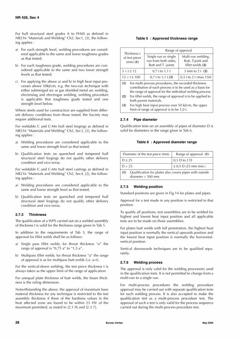
NR 426, Sec 4
28 Bureau Veritas May 2006
For hull structural steel grades A to FH40 as defined inNR216 “Materials and Welding” Ch2, Sec1, [2], the follow-ing applies :
a) For each strength level, welding procedures are consid-ered applicable to the same and lower toughness gradesas that tested;
b) For each toughness grade, welding procedures are con-sidered applicable to the same and two lower strengthlevels as that tested;
c) For applying the above a) and b) to high heat input pro-cesses above 50kJ/cm, e.g. the two-run technique witheither submerged arc or gas shielded metal arc welding,electroslag and electrogas welding, welding procedureis applicable that toughness grade tested and onestrength level below.
Where steels used for construction are supplied from differ-ent delivery conditions from those tested, the Society mayrequire additional tests.
For weldable C and C-Mn hull steel forgings as defined inNR216 “Materials and Welding” Ch2, Sec3, [2], the follow-ing applies :
a) Welding procedures are considered applicable to thesame and lower strength level as that tested;
b) Qualification tests on quenched and tempered hullstructural steel forgings do not qualify other deliverycondition and vice-versa.
For weldable C and C-Mn hull steel castings as defined inNR216 “Materials and Welding” Ch2, Sec4, [2], the follow-ing applies :
a) Welding procedures are considered applicable to thesame and lower strength level as that tested;
b) Qualification tests on quenched and tempered hullstructural steel forgings do not qualify other deliverycondition and vice-versa.
2.7.3 Thickness
The qualification of a WPS carried out on a welded assemblyof thickness t is valid for the thickness range given in Tab 5.
In addition to the requirements of Tab 5, the range ofapproval for fillet welds shall be as follows:
a) Single pass fillet welds; for throat thickness “a” therange of approval is “0,75 a” to “1,5 a”.
b) Multipass fillet welds; for throat thickness “a” the rangeof approval is as for multipass butt welds (i.e. a=t).
For the vertical-down welding, the test piece thickness t isalways taken as the upper limit of the range of application.
For unequal plate thickness of butt welds, the lesser thick-ness is the ruling dimension.
Notwithstanding the above, the approval of maximum basematerial thickness for any technique is restricted to the testassembly thickness if three of the hardness values in theheat affected zone are found to be within 25 HV of themaximum permitted, as stated in [2.1.9] and [2.3.7].
Table 5 : Approved thickness range
2.7.4 Pipe diameter
Qualification tests on an assembly of pipes of diameter D isvalid for diameters in the range given in Tab 6.
Table 6 : Approved diameter range
2.7.5 Welding position
Standard positions are given in Fig 14 for plates and pipes.
Approval for a test made in any position is restricted to thatposition.
To qualify all positions, test assemblies are to be welded forhighest and lowest heat input position and all applicabletests are to be made on those assemblies.
For plates butt welds with full penetration, the highest heatinput position is normally the vertical upwards position andthe lowest heat input position is normally the horizontal-vertical position.
Vertical downwards techniques are to be qualified sepa-rately.
2.7.6 Welding process
The approval is only valid for the welding process(es) usedin the qualification tests. It is not permitted to change from amulti-run to a single run.
For multi-process procedures the welding procedureapproval may be carried out with separate qualification testsfor each welding process. It is also accepted to make thequalification test as a multi-process procedure test. Theapproval of such a test is only valid for the process sequencecarried out during the multi-process procedure test.
Thickness tof test piece
(mm) (1)
Range of approval
Single run or single run from both sides,
Butt and T -joints
Multi-run welding,Butt, T-joint andfillet welds (2)
3 < t ≤ 12 0,7 t to 1,1 t 3 mm to 2 t (2)
12 < t ≤ 100 0,7 t to 1,1 t (3) 0,5 t to 2 t (max.150)
(1) For multi process procedures, the recorded thickness contribution of each process is to be used as a basis for the range of approval for the individual welding process.
(2) For fillet welds, the range of approval is to be applied to both parent materials.
(3) For high heat input process over 50 kJ/cm, the upper limit of range of approval is to be 1,0 t.
Diameter of the test piece (mm) Range of approval (1)
D ≤ 25 0,5 D to 2 D
D > 25 ≥ 0,5 D (25 mm min.)
(1) Qualification for plates also covers pipes with outside diameter > 500 mm.
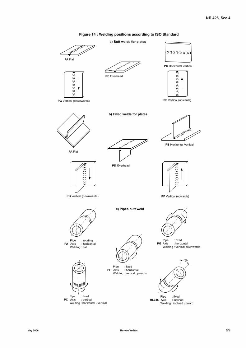
NR 426, Sec 4
May 2006 Bureau Veritas 29
Figure 14 : Welding positions according to ISO Standard
PB Horizontal Vertical
PA Flat
PG Vertical (downwards)
PE Overhead
PC Horizontal Vertical
PF Vertical (upwards)
PA Flat
PD Overhead
PG Vertical (downwards) PF Vertical (upwards)
a) Butt welds for plates
b) Filled welds for plates
45°
Pipe : rotatingPA Axis : horizontal
Welding : flat
c) Pipes butt weld
Pipe : fixedPF Axis : horizontal
Welding : vertical upwards
Pipe : fixedPC Axis : vertical
Welding : horizontal - vertical
Pipe : fixedHL045 Axis : inclined
Welding : inclined upward
Pipe : fixedPG Axis : horizontal
Welding : vertical downwards

NR 426, Sec 4
30 Bureau Veritas May 2006
For the manual metal arc welding process (111) and semi-automatic welding process with flux cored wire withoutshielding gas (114), the approval obtained is valid for thediameter of the electrode used in the welding proceduretest plus or minus one electrode diameter size for each run,except for the root run of the one side welded assemblywithout backing strip, for which no size change is allowed.
For the gas metal arc welding processes (131, 135, 136), theapproval obtained for face and/or back shielding gas isrestricted to the type of gas (nominal composition) usedduring the procedure test. The approval is restricted to thewire system used in the approval test (e.g. single wire ormulti-wire) and, in the case of automatic welding, to the rel-evant welding technique.
For the submerged arc processes (12), the approvalobtained is restricted to the wire system used in theapproval test (e.g. single wire or multi-wire) and relevantwelding technique (T, M, U). Change in the flux trade markrequires new welding procedure approval tests.
2.7.7 Welding consumablesExcept high heat input process (over 50KJ/cm), weldingconsumables tested cover other approved welding consum-ables having the same grade mark including all suffixesspecified in NR216 “Materials and Welding” Ch5, Sec2with that tested.
Change in the trade name of filler metal requires new weld-ing procedure approval tests when Charpy V-notch impacttests are required at temperature strictly below −20°C.
2.7.8 Heat inputThe upper limit of heat input approved is 25% greater thanthat used in welding the test piece or 50KJ/cm whichever issmaller, except that the upper limit is 10% greater than thatfor high heat input processes over 50KJ/cm.
The lower limit of heat input approved is 25% lower thanthat used in welding the test piece.
2.7.9 Preheat and interpass temperatureThe minimum preheat temperature is not to be less than thatused in the qualification test.
The minimum interpass temperature is not to be less thanthe specified preheat temperature.
The maximum interpass temperature is not to be higherthan that used in the qualification test.
2.7.10 Post-weld heat treatmentThe heat treatment used in the qualification test is to bemaintained during manufacture. Holding time may beadjusted as a function of thickness.
2.7.11 Type of jointThe range of approval depending on type of welded jointfor test assembly is given in Tab 7, Tab 8 and Tab 9.
New qualification tests may be required by the Surveyorwhen changes occur in the geometry of the bevel whichmay significantly affect the penetration or fusion.
3 Approval of stud welding
3.1 General
3.1.1 Stud welding to elements in special and first categoryis to be qualified by tests which shall include as a minimummacro-examination and hardness tests to check that thereare no detrimental effects on the base material.
4 Approval of welders
4.1 General
4.1.1 Reference is made to the Bureau Veritas Rule NoteNR476 “Approval testing of Welders”.
Table 7 : Range of approval for butt joints and fillet welds on plates
Type of welded joint for test assembly
Range of approval
Butt joints in plates with full or partial penetration
Fillet welds on plates
Welded from one side Welded from bothsides
Withbacking
Nobacking
Withgouging
Nogouging
Butt joint in plates with full penetration (1)
One side
With backing � − x x x
No backing x � x x x
Both sides
With gouging − − � − x
No gouging − − x � x
Fillet weld on plates (2) − − − − − − �
Note 1:� indicates the type of assembly of qualification test.x indicates on the same line as the symbol � those welds for which the WPS is also approved. − indicates on the same line as the symbol � those welds for which the WPS is not approved.(1) Butt joint in plate qualifies butt joints in pipes having diameter > 500mm within the limitations of the table.(2) In addition to the equivalent qualification on butt joint and where production works include predominantly fillet welding
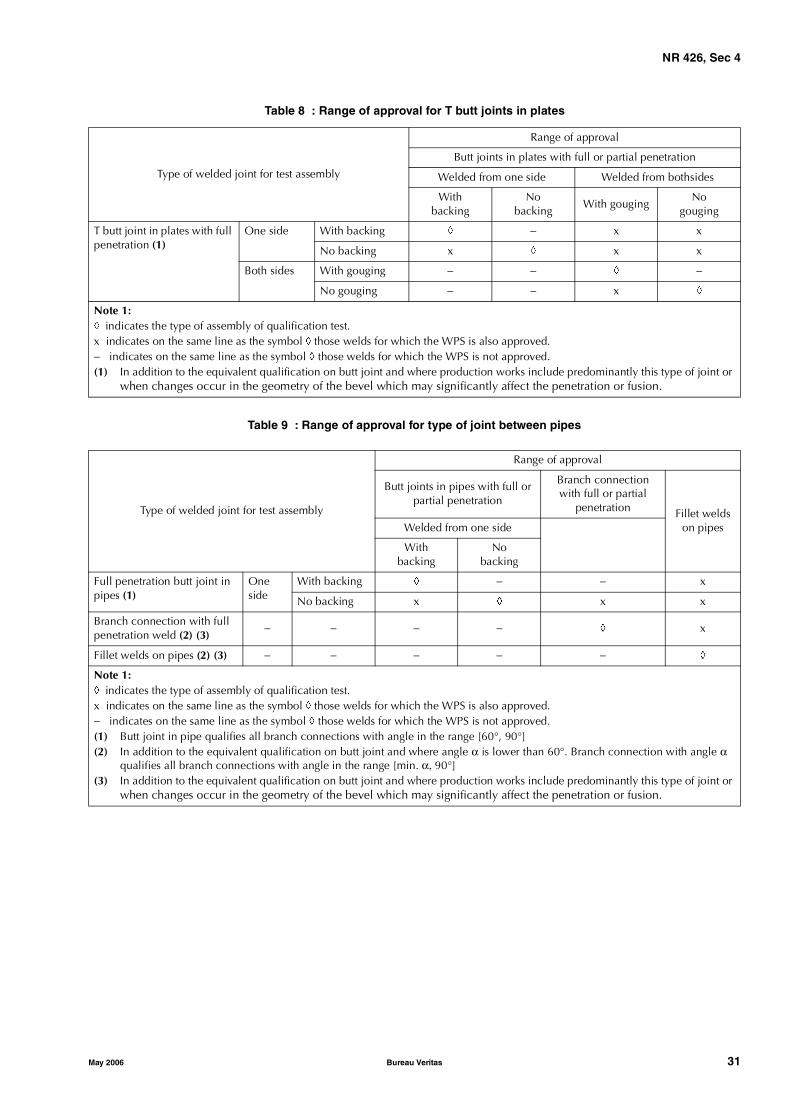
NR 426, Sec 4
May 2006 Bureau Veritas 31
Table 8 : Range of approval for T butt joints in plates
Table 9 : Range of approval for type of joint between pipes
Type of welded joint for test assembly
Range of approval
Butt joints in plates with full or partial penetration
Welded from one side Welded from bothsides
Withbacking
Nobacking
With gougingNo
gouging
T butt joint in plates with full penetration (1)
One side With backing � − x x
No backing x � x x
Both sides With gouging − − � −
No gouging − − x �
Note 1:� indicates the type of assembly of qualification test.x indicates on the same line as the symbol � those welds for which the WPS is also approved. − indicates on the same line as the symbol � those welds for which the WPS is not approved.(1) In addition to the equivalent qualification on butt joint and where production works include predominantly this type of joint or
when changes occur in the geometry of the bevel which may significantly affect the penetration or fusion.
Type of welded joint for test assembly
Range of approval
Butt joints in pipes with full or partial penetration
Branch connection with full or partial
penetration Fillet welds on pipesWelded from one side
Withbacking
Nobacking
Full penetration butt joint in pipes (1)
One side
With backing � − − x
No backing x � x x
Branch connection with full penetration weld (2) (3)
− − − − � x
Fillet welds on pipes (2) (3) − − − − − �
Note 1:� indicates the type of assembly of qualification test.x indicates on the same line as the symbol � those welds for which the WPS is also approved.− indicates on the same line as the symbol � those welds for which the WPS is not approved.(1) Butt joint in pipe qualifies all branch connections with angle in the range [60°, 90°](2) In addition to the equivalent qualification on butt joint and where angle α is lower than 60°. Branch connection with angle α
qualifies all branch connections with angle in the range [min. α, 90°](3) In addition to the equivalent qualification on butt joint and where production works include predominantly this type of joint or
when changes occur in the geometry of the bevel which may significantly affect the penetration or fusion.
NR 426, Sec 5
32 Bureau Veritas May 2006
SECTION 5 WELD INSPECTION
1 General
1.1 Scope
1.1.1 Each Builder is to have, at the disposal of his yard, adepartment entrusted with the inspection of welding opera-tions.The Society's Surveyors cannot be expected to act as substi-tutes to such a department for the work to be undertaken.
1.1.2 During construction, the Builder is to check thatwelding is carried out satisfactorily and in conformity withqualified welding procedures. Destructive testing (produc-tion tests) may be required, especially in case of modifica-tion of the welding procedures during construction.
1.1.3 The weld inspection includes:• production tests, if required• a complete visual inspection of all welds• non-destructive inspections (magnetic particle inspec-
tion, dye-penetrant inspection, ultrasonic inspection, X-Ray inspection or other methods), the procedures ofwhich are to be the subject of an agreement betweenthe Builder and the Society, before the constructionstarts.
1.1.4 Non-Destructive Testing (NDT) operators are to bequalified according to a nationally recognised scheme witha grade equivalent to level II qualification of ISO 9712,SNT-TC-1A, EN473 or ASNT Central Certification Program(ACPP). Operators qualified to level I may be engaged in thetests under the supervision of personnel qualified to level IIor III.Personnel responsible for the preparation and approval ofNDT procedures are to be qualified to a grade equivalent tolevel III of ISO 9712, SNT-TC-1A, EN473, ACCP or ASNT.
Personnel qualifications are to be verified by certification.
1.2 Production tests
1.2.1 During construction, production tests may berequired by the Society to check the mechanical character-istics of the welds produced according to each welding pro-cedure.The frequency and types of tests are to be defined in agree-ment with the Society before the beginning of fabrication.
2 Visual inspection
2.1
2.1.1 A procedure defining tolerances of weld bead geom-etry and (un)acceptable apparent weld imperfections is tobe submitted to the Society.
2.1.2 With reference to the procedure defined in [2.1.1], avisual inspection of the welds is to be made by personneldesignated by the Builder.
2.1.3 In any cases, the welds are to be free from cracks andsignificant planar defects.
2.1.4 Major butt and fillet welds are to be free from appre-ciable undercuts. Defects are to be repaired and, if they aretoo many of them, the weld is to be completely repeatedusing the approved procedure.
2.1.5 For welds of special category elements, a check is tobe made to ensure that over-thicknesses and under-thick-nesses are in accordance with the standard accepted by theSociety. In the case of an abnormal over-thickness, the weldis to be ground; in the case of an abnormal under-thickness,building up is to be performed by welding to ensure properstress continuity, according to an approved procedure.
3 Non-destructive testing
3.1 General
3.1.1 All non-destructive tests to be carried out on thewelds are to be defined at the initial project stage.
These non destructive tests include:
• liquid penetrant testing (for defects emerging on the sur-face)
• magnetic particle testing (acceptable only for defectsclose to the surface and emerging on the surface)
• X-Ray or Gamma-Ray testing
• ultrasonic testing.
The techniques are to be selected according to the jointquality to be obtained, to the assembly type and shape, tothe thickness, etc.
Eddy currents, acoustic testing, etc., may be used afterapproval by the Society.
For steels with specified minimum yield stress of 420N/mm²NDT shall not be carried out before 48 hours after comple-tion of welding. Where post weld heat treatment (PWHT) iscarried out the requirement for testing after 48 hours can berelaxed.
3.1.2 The extent of non destructive testing is to be definedaccording to the category of the element to be welded andto the weld type. Tab 1 gives minimum extent of NDT to beperformed by the Builder.

NR 426, Sec 5
May 2006 Bureau Veritas 33
Table 1 : Minimum extent of non destructive testing
3.1.3 Exemptions to the extent of NDT may be admitted bythe Society where justified in writing by the organization ofthe Builder.
3.2 X-Ray or Gamma-Ray testing
3.2.1 X-Ray or Gamma-Ray inspection is to be used forstructure butt welded joints as specified by Tab 1, accordingto a procedure to be submitted to the Society for approval.
The number and location of X-Ray or Gamma-Ray photo-graphs are to be determined jointly by the Builder and theSociety according to the construction type, service condi-tions and elements of the structure concerned, on the baseof a minimum number of films as specified by Tab 1.
The number of the X-Ray or Gamma-Ray photographs maybe increased at the request of the Surveyor, mainly whenthe visual inspection or X-Ray, Gamma-Ray or ultrasonicsoundings which have been previously carried out showmajor defects.
3.2.2 The following is to be fulfilled:
• the technique is to be in accordance with a recognizedstandard accepted by the Society,
• the image quality is to be verified using an Image Qual-ity Indicator (IQI) in accordance with ISO 2504 orequivalent. The minimum image quality should be inaccordance with Class A of ISO 17636 or equivalent.
• optical density is to lie within 2.0 (1.8 for X-rays) and4.0.
3.2.3 An approval test of X-Ray or Gamma-Ray inspectionprocedure may be required by the Surveyor.
3.3 Ultrasonic testing
3.3.1 Ultrasonic testing is to be carried out as specified in[3.1.2] for butt welds and full penetration angle welds.
Element category (10) (11)
Weld typeInspection method
Visual X-Ray or Gamma-Ray (5) UT (6) Magnetic particle (9)
Special Buttweld 100% 100% of crossings and10% of welds (1) (7) (8)
100% of non X-Ray inspected welds (1)
100%
Full penetration angle weld (2)
100% − 100% 100%
Limited penetration fillet weld (3)
100% − − 100%
First Buttweld 100% 10% of welds including crossings (1) (7) (8)
10% of non X-Ray inspected welds (1) (8)
20% (1) (8)
Full penetration angle weld (2)
100% − 20% (1) (8) 20% (1) (8)
Limited penetration fillet weld (3)
100% − − 20% (1) (8)
Second Buttweld 100% at random (1) (4) − (1) at random (1) (4)
Full penetration angle weld (2)
100% − at random (1) (4) at random (1) (4)
Limited penetration fillet weld (3)
100% − − at random (1) (4)
(1) These values are minimum values subject to be increased, in case of doubt, by the Surveyor.(2) If half the thickness of the thinnest plate or more is welded, the weld is considered as full penetrated - Refer to Sec 4.(3) If less of half the thickness of the thinnest plate is welded, the weld is considered as a limited penetration weld or a fillet weld -
Refer to Sec 4.(4) Inspections at random from 0 to 5% to the Surveyor's satisfaction.(5) For thicknesses equal to 50 mm and over, ultrasonic inspection may be used instead of Gamma or X-Ray inspection.(6) Ultrasonic inspection is to be carried out for thicknesses exceeding 12 mm. For 12 mm or under, Gamma or X-Ray are to be
used (butt welds). In all cases, Gamma or X-Ray Inspection may be used instead of ultrasonic inspection.(7) 100% of beam flanges butt welds are to be inspected.(8) Locations of welds inspections will be notified by the Surveyor after welding.(9) Dye-penetrant inspection may be used instead of magnetic particle inspection (after approval only).(10) In particular cases, weld category may be different from the structural category. In such case, the weld category is to be indi-
cated on the drawings submitted to the Society for approval.(11) In case of welds between two different categories, the welds are to be inspected according to the higher category.
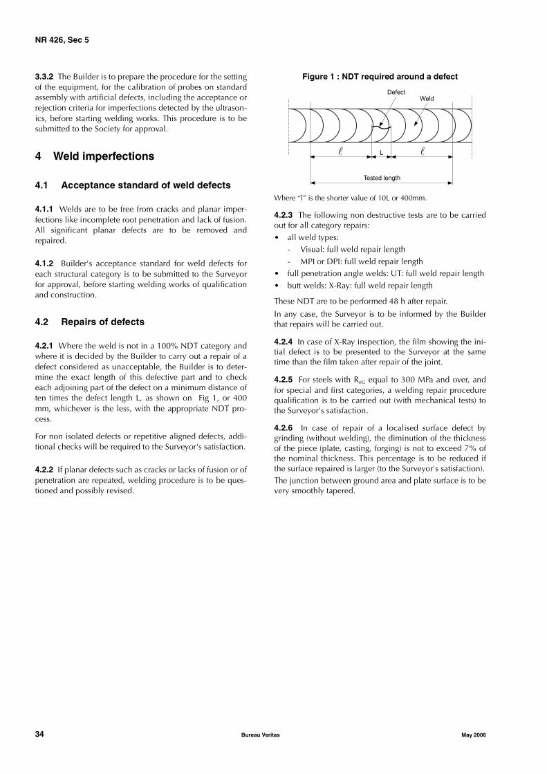
NR 426, Sec 5
34 Bureau Veritas May 2006
3.3.2 The Builder is to prepare the procedure for the settingof the equipment, for the calibration of probes on standardassembly with artificial defects, including the acceptance orrejection criteria for imperfections detected by the ultrason-ics, before starting welding works. This procedure is to besubmitted to the Society for approval.
4 Weld imperfections
4.1 Acceptance standard of weld defects
4.1.1 Welds are to be free from cracks and planar imper-fections like incomplete root penetration and lack of fusion.All significant planar defects are to be removed andrepaired.
4.1.2 Builder's acceptance standard for weld defects foreach structural category is to be submitted to the Surveyorfor approval, before starting welding works of qualificationand construction.
4.2 Repairs of defects
4.2.1 Where the weld is not in a 100% NDT category andwhere it is decided by the Builder to carry out a repair of adefect considered as unacceptable, the Builder is to deter-mine the exact length of this defective part and to checkeach adjoining part of the defect on a minimum distance often times the defect length L, as shown on Fig 1, or 400mm, whichever is the less, with the appropriate NDT pro-cess.
For non isolated defects or repetitive aligned defects, addi-tional checks will be required to the Surveyor's satisfaction.
4.2.2 If planar defects such as cracks or lacks of fusion or ofpenetration are repeated, welding procedure is to be ques-tioned and possibly revised.
Figure 1 : NDT required around a defect
Where “l” is the shorter value of 10L or 400mm.
4.2.3 The following non destructive tests are to be carriedout for all category repairs:• all weld types:
- Visual: full weld repair length- MPI or DPI: full weld repair length
• full penetration angle welds: UT: full weld repair length• butt welds: X-Ray: full weld repair length
These NDT are to be performed 48 h after repair.
In any case, the Surveyor is to be informed by the Builderthat repairs will be carried out.
4.2.4 In case of X-Ray inspection, the film showing the ini-tial defect is to be presented to the Surveyor at the sametime than the film taken after repair of the joint.
4.2.5 For steels with ReG equal to 300 MPa and over, andfor special and first categories, a welding repair procedurequalification is to be carried out (with mechanical tests) tothe Surveyor's satisfaction.
4.2.6 In case of repair of a localised surface defect bygrinding (without welding), the diminution of the thicknessof the piece (plate, casting, forging) is not to exceed 7% ofthe nominal thickness. This percentage is to be reduced ifthe surface repaired is larger (to the Surveyor's satisfaction).The junction between ground area and plate surface is to bevery smoothly tapered.
Tested length
� �L
DefectWeld