contact data - farnell element14 · contact data number of contacts and type 1 changeover contact...
TRANSCRIPT
04-2011, Rev. 0411www.te.com© 2011 Tyco Electronics Corporation,a TE Connectivity Ltd. company
Datasheets and product specification according to IEC 61810-1 and to be used only together with the ‘Definitions’ section.
Datasheets and product data is subject to the terms of the disclaimer and all chapters of the ‘Definitions’ section, available at http://relays.te.com/definitions
Datasheets, product data, ‘Definitions’ sec-tion, application notes and all specifications are subject to change.
1
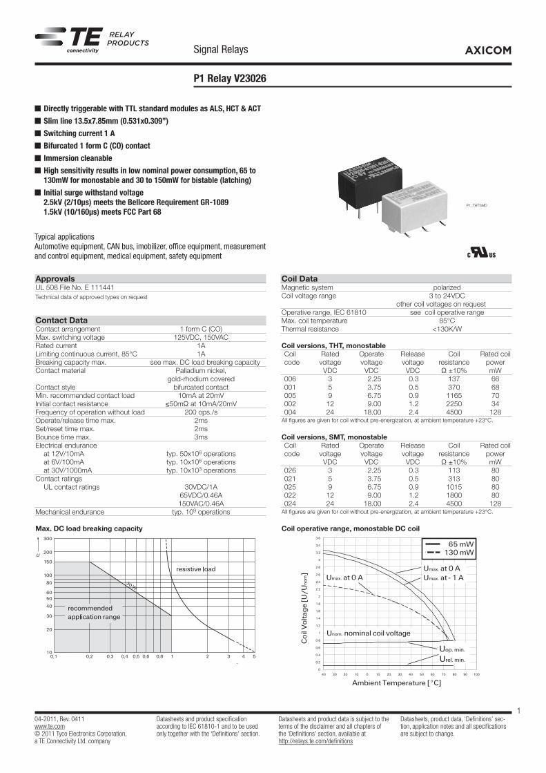
AXICOMSignal Relays
P1 Relay V23026
Coil Data Magnetic system polarizedCoil voltage range 3 to 24VDC other coil voltages on requestOperative range, IEC 61810 see coil operative rangeMax. coil temperature 85°C Thermal resistance <130K/W
Coil versions, THT, monostable Coil Rated Operate Release Coil Rated coil code voltage voltage voltage resistance power VDC VDC VDC Ω ±10% mW 006 3 2.25 0.3 137 66 001 5 3.75 0.5 370 68 005 9 6.75 0.9 1165 70 002 12 9.00 1.2 2250 34 004 24 18.00 2.4 4500 128All figures are given for coil without pre-energization, at ambient temperature +23°C.
Coil versions, SMT, monostable Coil Rated Operate Release Coil Rated coil code voltage voltage voltage resistance power VDC VDC VDC Ω ±10% mW 026 3 2.25 0.3 113 80 021 5 3.75 0.5 313 80 025 9 6.75 0.9 1015 80 022 12 9.00 1.2 1800 80 024 24 18.00 2.4 4500 128All figures are given for coil without pre-energization, at ambient temperature +23°C.
Coil operative range, monostable DC coil
n Directly triggerable with TTL standard modules as ALS, HCT & ACTn Slim line 13.5x7.85mm (0.531x0.309”)n Switching current 1 An Bifurcated 1 form C (CO) contactn Immersion cleanablen High sensitivity results in low nominal power consumption, 65 to
130mW for monostable and 30 to 150mW for bistable (latching)n Initial surge withstand voltage
2.5kV (2/10μs) meets the Bellcore Requirement GR-1089 1.5kV (10/160μs) meets FCC Part 68
Typical applications Automotive equipment, CAN bus, imobilizer, office equipment, measurement and control equipment, medical equipment, safety equipment
Approvals UL 508 File No. E 111441Technical data of approved types on request
Contact Data Contact arrangement 1 form C (CO)Max. switching voltage 125VDC, 150VACRated current 1A Limiting continuous current, 85°C 1ABreaking capacity max. see max. DC load breaking capacityContact material Palladium nickel, gold-rhodium covered Contact style bifurcated contactMin. recommended contact load 10mA at 20mV Initial contact resistance ≤50mΩ at 10mA/20mVFrequency of operation without load 200 ops./sOperate/release time max. 2ms Set/reset time max. 2ms Bounce time max. 3msElectrical endurance at 12V/10mA typ. 50x106 operations at 6V/100mA typ. 10x106 operations at 30V/1000mA typ. 10x103 operationsContact ratings UL contact ratings 30VDC/1A 65VDC/0.46A 150VAC/0.46AMechanical endurance typ. 109 operations Max. DC load breaking capacity
108-98009 Rev. E
All specifications subject to change. Consult Tyco Electronics for latest specifications. 7 of 12
Telecom-, Signal and RF Relays
P1 V23026 Relay
AXICOM
Contact Data
Number of contacts and type 1 changeover contactContact assembly Bifurcated contactContact material Palladium nickel, gold-rhodium coveredLimiting continuous current at max. ambient temperature 1 AMaximum switching current 1 AMaximum swichting voltage 125 Vdc
150 Vac
Maximum switching capacity 30 W, 60 VAThermoelectric potential < 100 µVInitial contact resistance / measuring condition: 10 mA / 20 mV < 50 m
Electrical endurance at 12 V / 10 mA at 6 V / 100 mA at 30 V / 1000 mA
typ. 5 x 10⁷ operationstyp. 1 x 10⁷ operationstyp. 1 x 10⁴ operations
Mechanical endurance typ. 109 operationsUL contact ratings 30 Vdc / 1 A
65 Vdc / 0.46 A150 Vac / 0.46 A
Max. DC Load Breaking Capacity
108-98009 Rev. E
All specifications subject to change. Consult Tyco Electronics for latest specifications. 5 of 12
Telecom-, Signal and RF Relays
P1 V23026 Relay
AXICOM
Coil Operating Range
Unom = Nominal coil voltage
Umax. = Upper limit of the operative range of the coil voltage (limiting voltage) when coils are continously energized
Uop. min. = Lower limit of the operative range of the coil voltage (reliable operate voltage)
Urel. min. = Lower limit of the operative range of the coil voltage (reliable release voltage)
Umax. at 0 AUmax. at - 1 A
Unom. nominal coil voltage
Uop. min.
Urel. min.
Ambient Temperature [°C]
Coi
l Vol
tage
[U/U
nom
] Umax. at 0 A
65 mW130 mW
Ambient Temperature [°C]
Coi
l Vol
tage
[U/U
nom
]
Unom. nominal coil voltage
Umax. - 100 % coil duty at 0 A
65 mW Latching32 mW Latching
Umax. - 5 % coil duty at 1 A
Umax. - 5 % coil duty at 0 A
Uset min.
Z
P1_THTSMD

04-2011, Rev. 0411www.te.com© 2011 Tyco Electronics Corporation,a TE Connectivity Ltd. company
Datasheets and product specification according to IEC 61810-1 and to be used only together with the ‘Definitions’ section.
Datasheets and product data is subject to the terms of the disclaimer and all chapters of the ‘Definitions’ section, available at http://relays.te.com/definitions
Datasheets, product data, ‘Definitions’ sec-tion, application notes and all specifications are subject to change.
2
AXICOMSignal Relays
P1 Relay V23026 (Continued)
THT version
108-98009 Rev. E
All specifications subject to change. Consult Tyco Electronics for latest specifications. 4 of 12
Telecom-, Signal and RF Relays
P1 V23026 Relay
AXICOM
Dimensions Dimensions in mm
THT Version
Mounting hole layout
View onto the component side of the PCB(top view)
Terminal assignment
Relay – top viewContact release or reset condition, coil polarity to set the relay
Non-latching type
not energized condition
Latching type, 1 coil
reset condition
Latching type, 2 coils
reset conditionContacts are shown in reset condition. Both coils can be used either as set or reset coil.
THTV23026-x1xxx-B201
SMTV23026-x1xxx-B201
mm inch mm inchLWH
13.00 ± 0.10 7.60 ± 0.10 6.90 – 0.20
0.512 ± 0.004 0.299 ± 0.004 0.272 – 0.008
13.40 ± 0.10 7.75 ± 0.10 8.00 – 0.20
0.528 ± 0.004 0.305 ± 0.004 0.315 – 0.008
TT1T2SS1S2
3.50 – 0.20N/A
5.08 ± 0.15 0.30 ± 0.10
N/AN/A
0.138 – 0.008N/A
0.200 ± 0.006 0.012 ± 0.004
N/AN/A
N/A 10.90 – 0.50 5.08 ± 0.15
N/A 0.85 ± 0.10 0.20 – 0.15
N/A 0.429 – 0.020 0.200 ± 0.006
N/A 0.033 ± 0.004 0.008 – 0.006
SMT Version
Solder pad layout
View onto the component side of the PCB(top view)
13.0±0.1 7.60±0.1
5.08±0.15
0.3±
0.1
6.9-0.2
3.5-0.2 0.
85±0.1
0.2-0.15
13.4±0.1 7.75±0.1
10.9-0.5
5.08±0.15
8.0-0.2
5.08
5.08
Insulation Data Initial dielectric strength between open contacts 500Vrms between contact and coil 1500VrmsInitial surge withstand voltage between contact and coil 2500VCapacitance between open contacts max. 5pF between contact and coil max. 6pF Clearance/creepage between contact and coil 0.75mm between adjacent contacts 0.75mm
RF Data Isolation at 100MHz/900MHz -30.0dB/-18.0dB Insertion loss at 100MHz/900MHz -0.12dB/-1.9dB Voltage standing wave ratio (VSWR) at 100MHz/900MHz 1.06/1.75
Other Data Material compliance: EU RoHS/ELV, China RoHS, REACH, Halogen content refer to the Product Compliance Support Center at www.te.com/customersupport/rohssupportcenterAmbient temperature -40 to +85°C Category of environmental protection, IEC 61810 RT III - immersion cleanable Vibration resistance (functional) 20g, 200 to 2000Hz 40g, 10 to 200Hz Shock resistance (functional) IEC 60068-2-27 (half sine) 50 gTerminal type PCB terminals and SMT terminals Weight max. 2g Resistance to soldering heat THT IEC 60068-2-20 265 °C/10s Resistance to soldering heat SMT IEC 60068-2-58 see reflow profile Moisture sensitive level, JEDEC J-Std-020D MSL3 Washing not recommended Ultrasonic cleaning possiblePackaging unit THT 2000 pcs. SMT 2400 pcs.
Coil data (continued)
Coil versions, THT and SMT, bistable 2 coils Coil Rated Set Reset Coil Rated coil code voltage voltage voltage resistance power VDC VDC VDC Ω ±10% mW 106 3 2.25 2.25 130 69 101 5 3.75 3.75 390 64 105 9 6.75 6.75 1200 68 102 12 9.00 9.00 1500 96 241) All figures are given for coil without pre-energization, at ambient temperature +23°C.Coils I and II are identical.1) A nominal voltage of 24VDC is feasible with a 12VDC coil with a series resistor (1500Ω).
Coil operative range, bistable
Umax upper limit of the operative range of the coil voltage (limiting voltage) when coils are continuously energized.
Uop min lower limit of the operative range of the coil voltage (reliable operate voltage).Urel min lower limit of the operative range of the coil voltage (reliable release voltage).
108-98009 Rev. E
All specifications subject to change. Consult Tyco Electronics for latest specifications. 5 of 12
Telecom-, Signal and RF Relays
P1 V23026 Relay
AXICOM
Coil Operating Range
Unom = Nominal coil voltage
Umax. = Upper limit of the operative range of the coil voltage (limiting voltage) when coils are continously energized
Uop. min. = Lower limit of the operative range of the coil voltage (reliable operate voltage)
Urel. min. = Lower limit of the operative range of the coil voltage (reliable release voltage)
Umax. at 0 AUmax. at - 1 A
Unom. nominal coil voltage
Uop. min.
Urel. min.
Ambient Temperature [°C]
Coi
l Vol
tage
[U/U
nom
] Umax. at 0 A
65 mW130 mW
Ambient Temperature [°C]
Coi
l Vol
tage
[U/U
nom
]
Unom. nominal coil voltage
Umax. - 100 % coil duty at 0 A
65 mW Latching32 mW Latching
Umax. - 5 % coil duty at 1 A
Umax. - 5 % coil duty at 0 A
Uset min.
PCB layout TOP view on component side of PCB
Dimensions
108-98009 Rev. E
All specifications subject to change. Consult Tyco Electronics for latest specifications. 4 of 12
Telecom-, Signal and RF Relays
P1 V23026 Relay
AXICOM
Dimensions Dimensions in mm
THT Version
Mounting hole layout
View onto the component side of the PCB(top view)
Terminal assignment
Relay – top viewContact release or reset condition, coil polarity to set the relay
Non-latching type
not energized condition
Latching type, 1 coil
reset condition
Latching type, 2 coils
reset conditionContacts are shown in reset condition. Both coils can be used either as set or reset coil.
THTV23026-x1xxx-B201
SMTV23026-x1xxx-B201
mm inch mm inchLWH
13.00 ± 0.10 7.60 ± 0.10 6.90 – 0.20
0.512 ± 0.004 0.299 ± 0.004 0.272 – 0.008
13.40 ± 0.10 7.75 ± 0.10 8.00 – 0.20
0.528 ± 0.004 0.305 ± 0.004 0.315 – 0.008
TT1T2SS1S2
3.50 – 0.20N/A
5.08 ± 0.15 0.30 ± 0.10
N/AN/A
0.138 – 0.008N/A
0.200 ± 0.006 0.012 ± 0.004
N/AN/A
N/A 10.90 – 0.50 5.08 ± 0.15
N/A 0.85 ± 0.10 0.20 – 0.15
N/A 0.429 – 0.020 0.200 ± 0.006
N/A 0.033 ± 0.004 0.008 – 0.006
SMT Version
Solder pad layout
View onto the component side of the PCB(top view)
13.0±0.1 7.60±0.1
5.08±0.15
0.3±
0.1
6.9-0.2
3.5-0.2 0.
85±0.1
0.2-0.15
13.4±0.1 7.75±0.1
10.9-0.5
5.08±0.15
8.0-0.2
5.08
5.08
SMT version
108-98009 Rev. E
All specifications subject to change. Consult Tyco Electronics for latest specifications. 4 of 12
Telecom-, Signal and RF Relays
P1 V23026 Relay
AXICOM
Dimensions Dimensions in mm
THT Version
Mounting hole layout
View onto the component side of the PCB(top view)
Terminal assignment
Relay – top viewContact release or reset condition, coil polarity to set the relay
Non-latching type
not energized condition
Latching type, 1 coil
reset condition
Latching type, 2 coils
reset conditionContacts are shown in reset condition. Both coils can be used either as set or reset coil.
THTV23026-x1xxx-B201
SMTV23026-x1xxx-B201
mm inch mm inchLWH
13.00 ± 0.10 7.60 ± 0.10 6.90 – 0.20
0.512 ± 0.004 0.299 ± 0.004 0.272 – 0.008
13.40 ± 0.10 7.75 ± 0.10 8.00 – 0.20
0.528 ± 0.004 0.305 ± 0.004 0.315 – 0.008
TT1T2SS1S2
3.50 – 0.20N/A
5.08 ± 0.15 0.30 ± 0.10
N/AN/A
0.138 – 0.008N/A
0.200 ± 0.006 0.012 ± 0.004
N/AN/A
N/A 10.90 – 0.50 5.08 ± 0.15
N/A 0.85 ± 0.10 0.20 – 0.15
N/A 0.429 – 0.020 0.200 ± 0.006
N/A 0.033 ± 0.004 0.008 – 0.006
SMT Version
Solder pad layout
View onto the component side of the PCB(top view)
13.0±0.1 7.60±0.1
5.08±0.15
0.3±
0.1
6.9-0.2
3.5-0.2 0.
85±0.1
0.2-0.15
13.4±0.1 7.75±0.1
10.9-0.5
5.08±0.15
8.0-0.2
5.08
5.08
THT version SMT version

04-2011, Rev. 0411www.te.com© 2011 Tyco Electronics Corporation,a TE Connectivity Ltd. company
Datasheets and product specification according to IEC 61810-1 and to be used only together with the ‘Definitions’ section.
Datasheets and product data is subject to the terms of the disclaimer and all chapters of the ‘Definitions’ section, available at http://relays.te.com/definitions
Datasheets, product data, ‘Definitions’ sec-tion, application notes and all specifications are subject to change.
3
AXICOMSignal Relays
P1 Relay V23026 (Continued)
Monostable versionrest condition
108-98009 Rev. E
All specifications subject to change. Consult Tyco Electronics for latest specifications. 4 of 12
Telecom-, Signal and RF Relays
P1 V23026 Relay
AXICOM
Dimensions Dimensions in mm
THT Version
Mounting hole layout
View onto the component side of the PCB(top view)
Terminal assignment
Relay – top viewContact release or reset condition, coil polarity to set the relay
Non-latching type
not energized condition
Latching type, 1 coil
reset condition
Latching type, 2 coils
reset conditionContacts are shown in reset condition. Both coils can be used either as set or reset coil.
THTV23026-x1xxx-B201
SMTV23026-x1xxx-B201
mm inch mm inchLWH
13.00 ± 0.10 7.60 ± 0.10 6.90 – 0.20
0.512 ± 0.004 0.299 ± 0.004 0.272 – 0.008
13.40 ± 0.10 7.75 ± 0.10 8.00 – 0.20
0.528 ± 0.004 0.305 ± 0.004 0.315 – 0.008
TT1T2SS1S2
3.50 – 0.20N/A
5.08 ± 0.15 0.30 ± 0.10
N/AN/A
0.138 – 0.008N/A
0.200 ± 0.006 0.012 ± 0.004
N/AN/A
N/A 10.90 – 0.50 5.08 ± 0.15
N/A 0.85 ± 0.10 0.20 – 0.15
N/A 0.429 – 0.020 0.200 ± 0.006
N/A 0.033 ± 0.004 0.008 – 0.006
SMT Version
Solder pad layout
View onto the component side of the PCB(top view)
13.0±0.1 7.60±0.1
5.08±0.15
0.3±
0.1
6.9-0.2
3.5-0.2 0.
85±0.1
0.2-0.15
13.4±0.1 7.75±0.1
10.9-0.5
5.08±0.15
8.0-0.2
5.08
5.08
Terminal assignment
Bistable version, 1 coilreset condition
108-98009 Rev. E
All specifications subject to change. Consult Tyco Electronics for latest specifications. 4 of 12
Telecom-, Signal and RF Relays
P1 V23026 Relay
AXICOM
Dimensions Dimensions in mm
THT Version
Mounting hole layout
View onto the component side of the PCB(top view)
Terminal assignment
Relay – top viewContact release or reset condition, coil polarity to set the relay
Non-latching type
not energized condition
Latching type, 1 coil
reset condition
Latching type, 2 coils
reset conditionContacts are shown in reset condition. Both coils can be used either as set or reset coil.
THTV23026-x1xxx-B201
SMTV23026-x1xxx-B201
mm inch mm inchLWH
13.00 ± 0.10 7.60 ± 0.10 6.90 – 0.20
0.512 ± 0.004 0.299 ± 0.004 0.272 – 0.008
13.40 ± 0.10 7.75 ± 0.10 8.00 – 0.20
0.528 ± 0.004 0.305 ± 0.004 0.315 – 0.008
TT1T2SS1S2
3.50 – 0.20N/A
5.08 ± 0.15 0.30 ± 0.10
N/AN/A
0.138 – 0.008N/A
0.200 ± 0.006 0.012 ± 0.004
N/AN/A
N/A 10.90 – 0.50 5.08 ± 0.15
N/A 0.85 ± 0.10 0.20 – 0.15
N/A 0.429 – 0.020 0.200 ± 0.006
N/A 0.033 ± 0.004 0.008 – 0.006
SMT Version
Solder pad layout
View onto the component side of the PCB(top view)
13.0±0.1 7.60±0.1
5.08±0.15
0.3±
0.1
6.9-0.2
3.5-0.2 0.
85±0.1
0.2-0.15
13.4±0.1 7.75±0.1
10.9-0.5
5.08±0.15
8.0-0.2
5.08
5.08
Bistable version, 2 coilsreset condition
108-98009 Rev. E
All specifications subject to change. Consult Tyco Electronics for latest specifications. 4 of 12
Telecom-, Signal and RF Relays
P1 V23026 Relay
AXICOM
Dimensions Dimensions in mm
THT Version
Mounting hole layout
View onto the component side of the PCB(top view)
Terminal assignment
Relay – top viewContact release or reset condition, coil polarity to set the relay
Non-latching type
not energized condition
Latching type, 1 coil
reset condition
Latching type, 2 coils
reset conditionContacts are shown in reset condition. Both coils can be used either as set or reset coil.
THTV23026-x1xxx-B201
SMTV23026-x1xxx-B201
mm inch mm inchLWH
13.00 ± 0.10 7.60 ± 0.10 6.90 – 0.20
0.512 ± 0.004 0.299 ± 0.004 0.272 – 0.008
13.40 ± 0.10 7.75 ± 0.10 8.00 – 0.20
0.528 ± 0.004 0.305 ± 0.004 0.315 – 0.008
TT1T2SS1S2
3.50 – 0.20N/A
5.08 ± 0.15 0.30 ± 0.10
N/AN/A
0.138 – 0.008N/A
0.200 ± 0.006 0.012 ± 0.004
N/AN/A
N/A 10.90 – 0.50 5.08 ± 0.15
N/A 0.85 ± 0.10 0.20 – 0.15
N/A 0.429 – 0.020 0.200 ± 0.006
N/A 0.033 ± 0.004 0.008 – 0.006
SMT Version
Solder pad layout
View onto the component side of the PCB(top view)
13.0±0.1 7.60±0.1
5.08±0.15
0.3±
0.1
6.9-0.2
3.5-0.2 0.
85±0.1
0.2-0.15
13.4±0.1 7.75±0.1
10.9-0.5
5.08±0.15
8.0-0.2
5.08
5.08
Contacts are shown in reset condition. Both coils can be used either as set or reset coil.Contact position might change during transportation and must be reset before use.
Recommended soldering conditionsProcessing
108-98009 Rev. E
All specifications subject to change. Consult Tyco Electronics for latest specifications. 9 of 12
Telecom-, Signal and RF Relays
P1 V23026 Relay
AXICOM
Soldering conditions according IEC 60058-2-58 and IPC/JEDEC J-STD-020B
Infrared Soldering: Temperature/Time Profile (Lead and Housing Peak Temperature)
Infrared Soldering: Temperature/Time Profile (Lead and Housing Peak Temperature)
Recommended Soldering Conditions
Resistance to soldering heat - Reow prole
Recommended reow soldering prole
Vapor Phase Soldering: Temperature/Time Profile (Lead and Housing Peak Temperature)
240 °C
180 °C
130 °C
100 °C
20 - 40 sec Full line: typicalDotted line: process limits
forcedcooling
Tem
pera
ture
°C
Tem
pera
ture
°C
Time (s)
Tem
pera
ture
°C
Time (s)
Soldering conditions according IEC 60058-2-58 andIPC/JEDEC J-STD-020B
Resistance to soldering heat - Reflow profile
Recommended reflow soldering profile
Vapor Phase Soldering: temperature/time profile (lead and housing peak temperature)
Infrared Soldering: temperature/time profile (lead and housing peak temperature)
Packing
108-98009 Rev. E
All specifications subject to change. Consult Tyco Electronics for latest specifications. 10 of 12
Telecom-, Signal and RF Relays
P1 V23026 Relay
AXICOM
Packing Dimensions in mm
11.6±0.2
13
.8±0
.2
Tube for THT version 40 relays per tube 2‘000 relays per box
Tape and reel for SMT version 480 relays per reel 2‘400 per box
Reel dimension
Tube for THT version40 relays per tube, 2000 relays per box
108-98009 Rev. E
All specifications subject to change. Consult Tyco Electronics for latest specifications. 10 of 12
Telecom-, Signal and RF Relays
P1 V23026 Relay
AXICOM
Packing Dimensions in mm
11.6±0.2
13
.8±0
.2
Tube for THT version 40 relays per tube 2‘000 relays per box
Tape and reel for SMT version 480 relays per reel 2‘400 per box
Reel dimension
Tape and reel for SMT version480 relays per reel, 2400 relays per box
Reel dimensions
108-98009 Rev. E
All specifications subject to change. Consult Tyco Electronics for latest specifications. 10 of 12
Telecom-, Signal and RF Relays
P1 V23026 Relay
AXICOM
Packing Dimensions in mm
11.6±0.2
13
.8±0
.2
Tube for THT version 40 relays per tube 2‘000 relays per box
Tape and reel for SMT version 480 relays per reel 2‘400 per box
Reel dimension
108-98009 Rev. E
All specifications subject to change. Consult Tyco Electronics for latest specifications. 10 of 12
Telecom-, Signal and RF Relays
P1 V23026 Relay
AXICOM
Packing Dimensions in mm
11.6±0.21
3.8
±0.2
Tube for THT version 40 relays per tube 2‘000 relays per box
Tape and reel for SMT version 480 relays per reel 2‘400 per box
Reel dimension

04-2011, Rev. 0411www.te.com© 2011 Tyco Electronics Corporation,a TE Connectivity Ltd. company
Datasheets and product specification according to IEC 61810-1 and to be used only together with the ‘Definitions’ section.
Datasheets and product data is subject to the terms of the disclaimer and all chapters of the ‘Definitions’ section, available at http://relays.te.com/definitions
Datasheets, product data, ‘Definitions’ sec-tion, application notes and all specifications are subject to change.
4
AXICOMSignal Relays
P1 Relay V23026 (Continued)
Product code structure Typical product code V23026 A1 002 B201
Type V23026 P1 Series Signal RelayVersion A1 THT, monostable D1 SMT, monostable B1 THT, bistable (latching), 2 coils E1 SMT, bistable (latching), 2 coils C1 THT, bistable (latching), 1 coil F1 SMT, bistable (latching), 1 coilCoil Coil code: please refer to coil versions tableContacts B201 1 form C, 1 CO
Product Code Version Coil Coil voltage Part Number V23026A1006B201 THT version monostable 3VDC 1-1393774-7 V23026A1001B201 5VDC 1393774-1 V23026A1005B201 9VDC 1-1393774-5 V23026A1002B201 12VDC 1393774-8 V23026A1004B201 24VDC 1-1393774-2 V23026B1106B201 bistable, 2 coils 3VDC 1393775-3 V23026B1101B201 5VDC 3-1393774-4 V23026B1105B201 9VDC 1393775-2 V23026B1102B201 12VDC 3-1393774-5 V23026C1056B201 3VDC 2-1393774-6 V23026C1051B201 5VDC 2-1393774-0 V23026C1057B201 9VDC 2-1393774-7 V23026C1052B201 12VDC 2-1393774-1 V23026C1054B201 24VDC 2-1393774-4 V23026D1026B201 SMT version monostable 3VDC 1393776-8 V23026D1021B201 5VDC 1393776-3 V23026D1025B201 9VDC 1422015-9 V23026D1022B201 12VDC 1393776-4 V23026D1024B201 24VDC 1393776-7 V23026E1106B201 bistable, 2 coils 3VDC 1393777-3 V23026E1101B201 5VDC 1422015-6 V23026E1105B201 9VDC 1393777-2 V23026E1102B201 12VDC 1393776-9 V23026F1051B201 9VDC 1422015-8 V23026F1052B201 12VDC 4-1393774-3