contact rating load (resistive) 40a 12vdc 40a 12vdc no: 40a 12vdc nc: 30a 12vdc rated carrying...
TRANSCRIPT
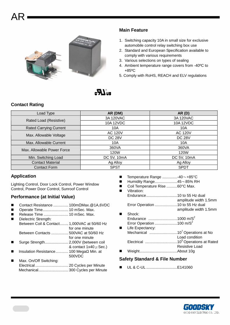
AR
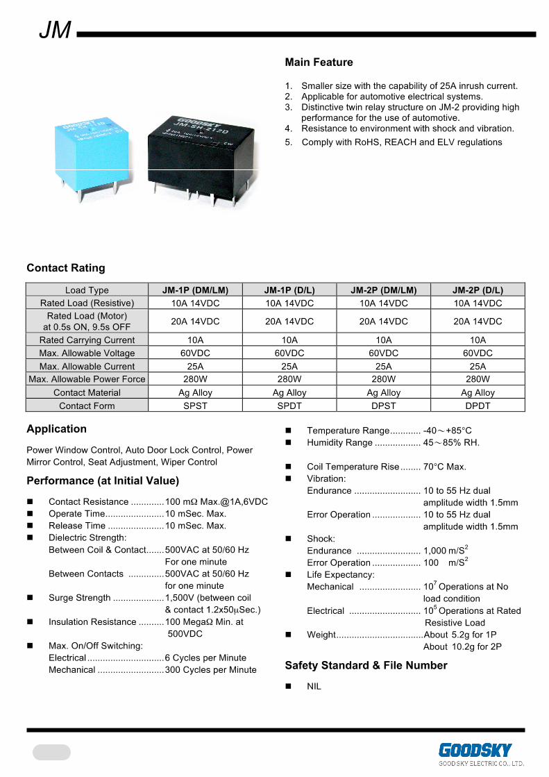
Main Feature 1. Switching capacity 10A in small size for exclusive
automobile control relay switching box use 2. Standard and European Specification available to
comply with various requirements 3. Various selections on types of sealing 4. Ambient temperature range covers from -40ºC to
+85ºC 5. Comply with RoHS, REACH and ELV regulations
Contact Rating
Load Type AR (DM) AR (D) 3A 120VAC 3A 120VAC
Rated Load (Resistive) 10A 12VDC 10A 12VDC
Rated Carrying Current 10A 10A AC 120V AC 120V
Max. Allowable Voltage DC 28V DC 28V
Max. Allowable Current 10A 10A 360VA 360VA
Max. Allowable Power Force 120W 120W
Min. Switching Load DC 5V, 10mA DC 5V, 10mA Contact Material Ag Alloy Ag Alloy
Contact Form SPST SPDT Application
Lighting Control, Door Lock Control, Power Window Control, Power Door Control, Sunroof Control
Performance (at Initial Value)
Contact Resistance .............. 100mΩMax.@1A,6VDC Operate Time........................ 10 mSec. Max. Release Time ....................... 10 mSec. Max. Dielectric Strength:
Between Coil & Contact........ 1,000VAC at 50/60 Hz for one minute Between Contacts ................ 500VAC at 50/60 Hz for one minute
Surge Strength...................... 2,000V (between coil & contact 1x40μSec.) Insulation Resistance............ 100 MegaΩ Min. at 500VDC Max. On/Off Switching:
Electrical ............................... 20 Cycles per Minute Mechanical............................ 300 Cycles per Minute
Temperature Range ..............-40~+85°C Humidity Range.....................45~85% RH Coil Temperature Rise ..........60°C Max. Vibration:
Endurance.............................10 to 55 Hz dual amplitude width 1.5mm Error Operation .....................10 to 55 Hz dual amplitude width 1.5mm
Shock: Endurance ...........................1000 m/S2 Error Operation .....................100 m/S2
Life Expectancy: Mechanical ..........................107 Operations at No Load condition Electrical ..............................105 Operations at Rated Resistive Load
Weight...................................About 10g
Safety Standard & File Number
UL & C-UL .............................E141060
AR
Coil Specification (at 20 °°°°C)
Coil Sensitivity Nominal Voltage (VDC)
Nominal Current (mA)
Coil Resistance (Ω±10%)
Power Consumption
(W)
Pull-In Voltage (VDC)
Drop-Out Voltage (VDC)
Maximum Allowable
Voltage (VDC) 6 150 40 9 93 97
12 77 155 15 59 255 18 47 380
AR (Standard)
24 36 660
Abt. 0.93 80% Maximum
5% Minimum
150% (for short time
carrying current)
6 214 28 12 92 130
AR (European) 24 46 520
Abt. 1.1 60% Maximum
5% Minimum
160% (for short time
carrying current)
Ordering Information
AR - SS - 1 12 D M 1 Specification: Nil: Standard
1: European Contact Form: Nil: One Form C
M: One Form A B: One Form B
Coil Type: D: Standard DC Coil Voltage: 06: 6V, 09: 9V, 12: 12V, 15: 15V, 18: 18V, 24: 24V Number of Pole: 1: One Pole Type of Sealing: Nil: RT 0 Unclosed
SS: RT II Flux Proofed SH: RT III Wash Tight
Type: AR
Classification
Model AR Coil Sensitivity Standard European
Contact Form 1C 1A 1B 1C 1A 1B Unclosed AR-1D AR-1DM AR-1DB AR-1D1 AR-1DM1 AR-1DB1
Flux Proofed AR-SS-1D AR-SS-1DM AR-SS-1DB AR-SS-1D1 AR-SS-1DM1 AR-SS-1DB1 Wash Tight AR-SH-1D AR-SH-1DM AR-SH-1DB AR-SH-1D1 AR-SH-1DM1 AR-SH-1DB1
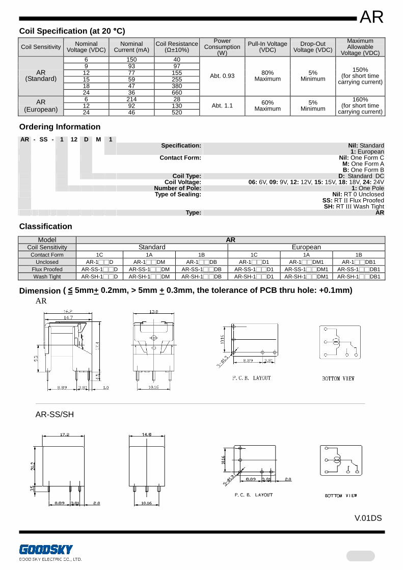
Dimension ( ≤ 5mm+ 0.2mm, > 5mm + 0.3mm, the tolerance of PCB thru hole: +0.1mm) AR
AR-SS/SH
V.01DS
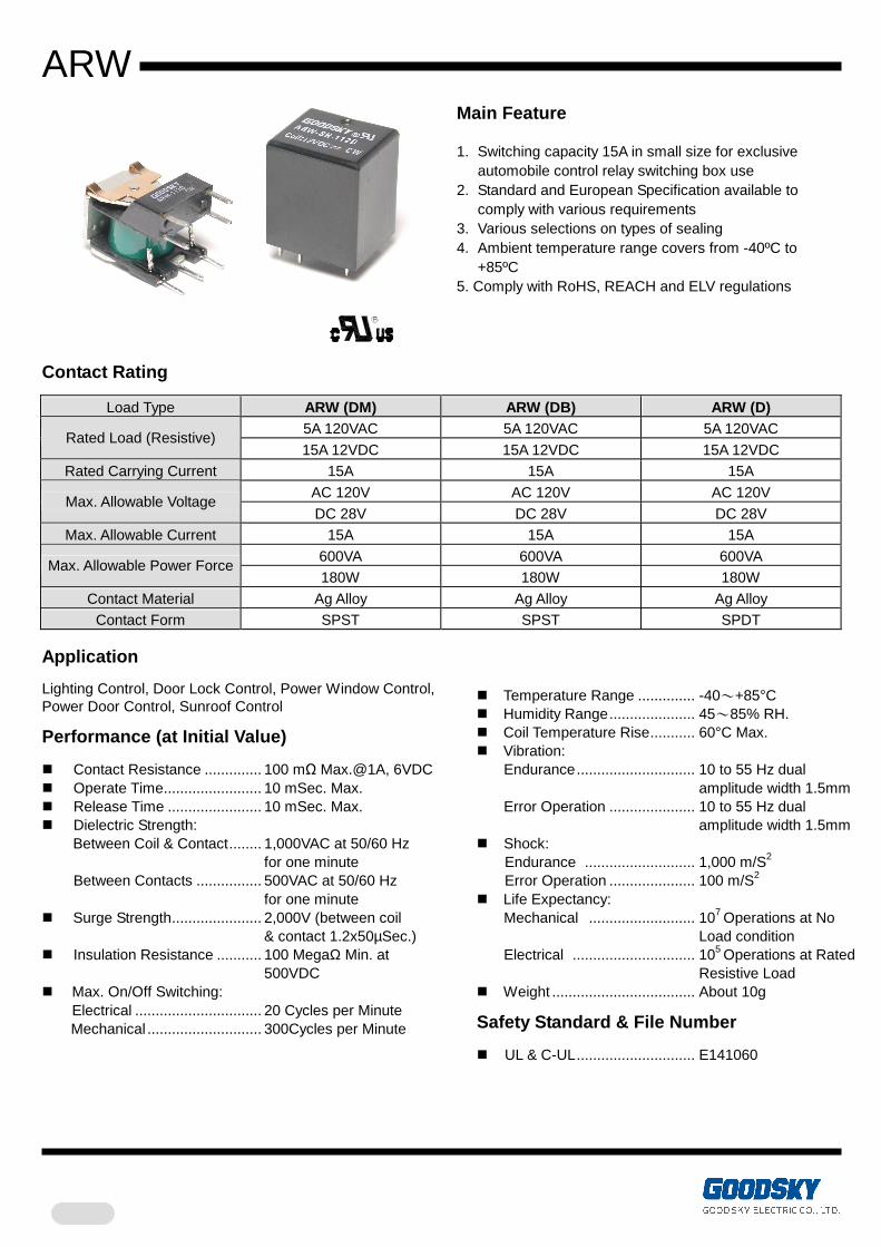
ARW
Main Feature 1. Switching capacity 15A in small size for exclusive
automobile control relay switching box use 2. Standard and European Specification available to
comply with various requirements 3. Various selections on types of sealing 4. Ambient temperature range covers from -40ºC to
+85ºC 5. Comply with RoHS, REACH and ELV regulations
Contact Rating
Load Type ARW (DM) ARW (DB) ARW (D) 5A 120VAC 5A 120VAC 5A 120VAC
Rated Load (Resistive) 15A 12VDC 15A 12VDC 15A 12VDC
Rated Carrying Current 15A 15A 15A
AC 120V AC 120V AC 120V Max. Allowable Voltage
DC 28V DC 28V DC 28V Max. Allowable Current 15A 15A 15A
600VA 600VA 600VA Max. Allowable Power Force
180W 180W 180W
Contact Material Ag Alloy Ag Alloy Ag Alloy Contact Form SPST SPST SPDT
Application
Lighting Control, Door Lock Control, Power Window Control, Power Door Control, Sunroof Control
Performance (at Initial Value)
Contact Resistance .............. 100 mΩ Max.@1A, 6VDC Operate Time........................ 10 mSec. Max. Release Time ....................... 10 mSec. Max. Dielectric Strength:
Between Coil & Contact........ 1,000VAC at 50/60 Hz for one minute Between Contacts ................ 500VAC at 50/60 Hz for one minute
Surge Strength...................... 2,000V (between coil & contact 1.2x50µSec.) Insulation Resistance ........... 100 MegaΩ Min. at 500VDC Max. On/Off Switching:
Electrical ............................... 20 Cycles per Minute Mechanical ............................ 300Cycles per Minute
Temperature Range .............. -40~+85°C Humidity Range..................... 45~85% RH. Coil Temperature Rise........... 60°C Max. Vibration:
Endurance............................. 10 to 55 Hz dual amplitude width 1.5mm
Error Operation ..................... 10 to 55 Hz dual amplitude width 1.5mm
Shock: Endurance ........................... 1,000 m/S2 Error Operation ..................... 100 m/S2
Life Expectancy: Mechanical .......................... 107 Operations at No Load condition
Electrical .............................. 105 Operations at Rated Resistive Load
Weight ................................... About 10g
Safety Standard & File Number
UL & C-UL............................. E141060
ARW
Coil Specification (at 20 °°°°C)
Coil Sensitivity Nominal Voltage (VDC)
Nominal Current (mA)
Coil Resistance (Ω±10%)
Power Consumption
(W)
Pull-In Voltage (VDC)
Drop-Out Voltage (VDC)
Maximum Allowable
Voltage (VDC) 6 150 40 9 93 97
12 77 155 15 59 255 18 47 380
ARW (Standard)
24 36 660
Abt. 0.93 80% Maximum
5% Minimum
150% (for short time
carrying current)
6 214 28 12 92 130 ARW
(European) 24 46 520
Abt. 1.1 60% Maximum
5% Minimum
160% (for short time
carrying current)
Ordering Information
ARW - SS - 1 12 D M 1 Specification: Nil: Standard
1: European Contact Form: Nil: One Form C
M: One Form A B: One Form B
Coil Type: D: Standard DC Coil Voltage: 06: 6V, 09: 9V, 12: 12V, 15: 15V, 18: 18V, 24: 24V Number of Pole: 1: One Pole Type of Sealing: Nil: RT 0 Unclosed
SS: RT II Flux Proofed SH: RT III Wash Tight
Type: ARW
Classification
Model ARW
Coil Sensitivity Standard European
Contact Form 1C 1A 1B 1C 1A 1B
Unclosed ARW-1D ARW-1DM ARW-1DB ARW-1D1 ARW-1DM1 ARW-1DB1
Flux Proofed ARW-SS-1D ARW-SS-1DM ARW-SS-1DB ARW-SS-1D1 ARW-SS-1DM1 ARW-SS-1DB1
Wash Tight ARW-SH-1D ARW-SH-1DM ARW-SH-1DB ARW-SH-1D1 ARW-SH-1DM1 ARW-SH-1DB1
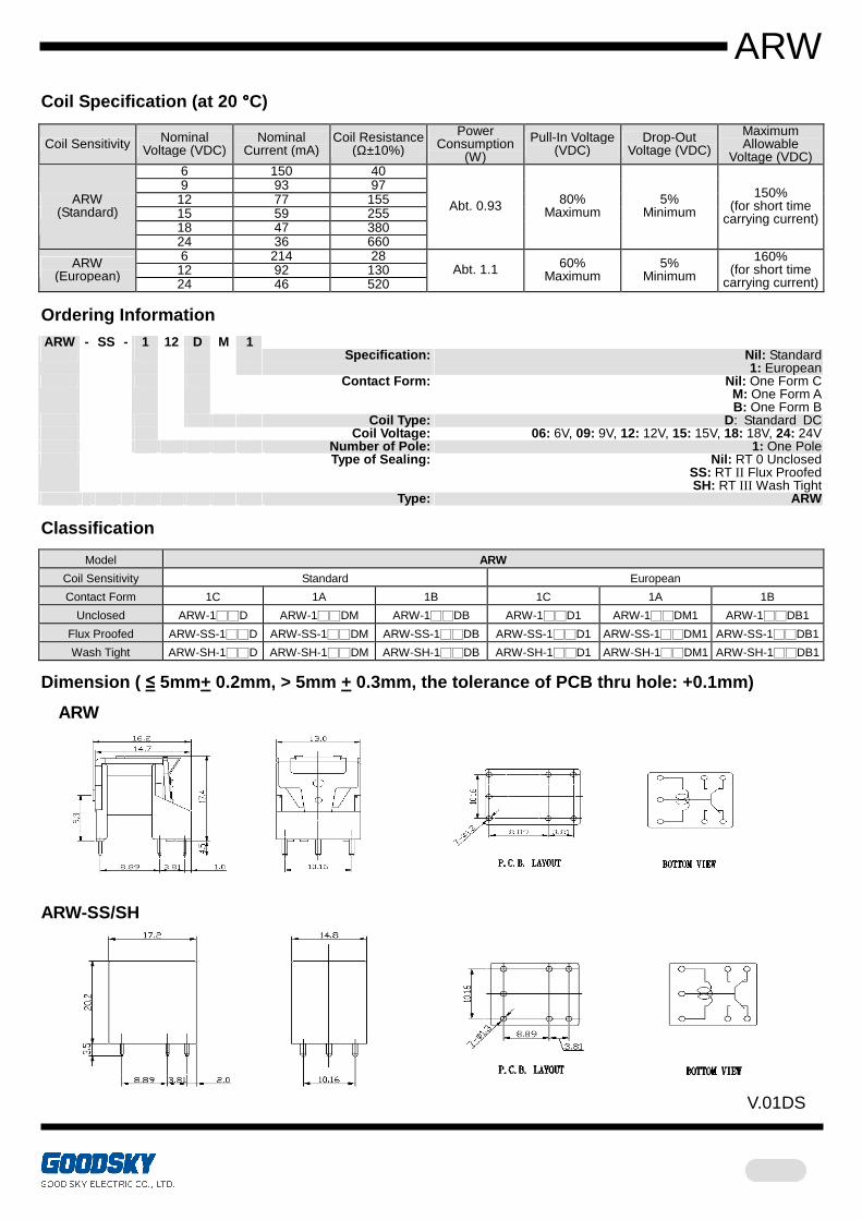
Dimension ( ≤ 5mm+ 0.2mm, > 5mm + 0.3mm, the tolerance of PCB thru hole: +0.1mm)
ARW
ARW-SS/SH
V.01DS
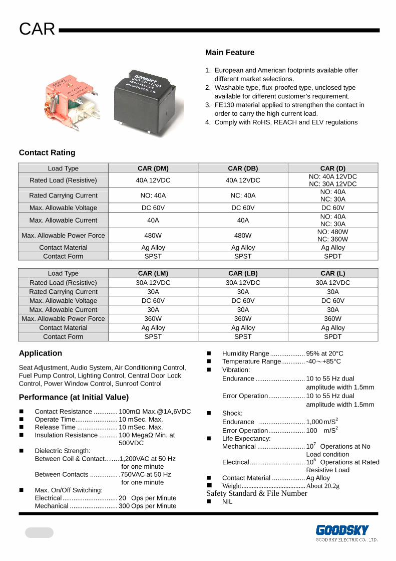
CAR
Main Feature 1. European and American footprints available offer
different market selections. 2. Washable type, flux-proofed type, unclosed type
available for different customer’s requirement. 3. FE130 material applied to strengthen the contact in
order to carry the high current load. 4. Comply with RoHS, REACH and ELV regulations
Contact Rating
Load Type CAR (DM) CAR (DB) CAR (D)
Rated Load (Resistive) 40A 12VDC 40A 12VDC NO: 40A 12VDC NC: 30A 12VDC
Rated Carrying Current NO: 40A NC: 40A NO: 40A NC: 30A
Max. Allowable Voltage DC 60V DC 60V DC 60V
Max. Allowable Current 40A 40A NO: 40A NC: 30A
Max. Allowable Power Force 480W 480W NO: 480W NC: 360W
Contact Material Ag Alloy Ag Alloy Ag Alloy Contact Form SPST SPST SPDT
Load Type CAR (LM) CAR (LB) CAR (L)
Rated Load (Resistive) 30A 12VDC 30A 12VDC 30A 12VDC Rated Carrying Current 30A 30A 30A Max. Allowable Voltage DC 60V DC 60V DC 60V Max. Allowable Current 30A 30A 30A
Max. Allowable Power Force 360W 360W 360W Contact Material Ag Alloy Ag Alloy Ag Alloy
Contact Form SPST SPST SPDT Application
Seat Adjustment, Audio System, Air Conditioning Control, Fuel Pump Control, Lighting Control, Central Door Lock Control, Power Window Control, Sunroof Control
Performance (at Initial Value)
Contact Resistance ............. 100mΩ Max.@1A,6VDC Operate Time....................... 10 mSec. Max. Release Time ...................... 10 mSec. Max. Insulation Resistance .......... 100 MegaΩ Min. at 500VDC Dielectric Strength:
Between Coil & Contact…….1,200VAC at 50 Hz for one minute
Between Contacts ............... .750VAC at 50 Hz for one minute
Max. On/Off Switching: Electrical .............................. 20 Ops per Minute Mechanical .......................... 300 Ops per Minute
Humidity Range ................... 95% at 20°C Temperature Range............. -40~+85°C Vibration:
Endurance ........................... 10 to 55 Hz dual amplitude width 1.5mm Error Operation.................... 10 to 55 Hz dual amplitude width 1.5mm
Shock: Endurance ......................... 1,000 m/S2 Error Operation.................... 100 m/S2
Life Expectancy: Mechanical .......................... 107 Operations at No Load condition Electrical .............................. 105 Operations at Rated Resistive Load
Contact Material .................. Ag Alloy Weight......................................About 20.2g Safety Standard & File Number NIL
CAR
Coil Specification (at 20 °°°°C)
Coil Sensitivity Nominal
Voltage (VDC) Nominal
Current (mA) Coil Resistance
(Ω±10%)
Power Consumption
(W)
Pull-In Voltage (VDC)
Drop-Out Voltage (VDC)
Maximum Allowable
Voltage (VDC) 6 315.7 19 Abt.1.89
12 133.3 90 24 66.2 362 36 44 816
CAR-D/DM/DB (Europe)
48 33 1450
Abt.1.59 70%
Maximum 5%
Minimum 160%
6 100 60 12 50 240 24 25 960 36 16.7 2160
CAR-L/LM/LB (Europe)
48 12.5 3840
Abt.0.6 75%
Maximum 10%
Minimum 160%
6 315.7 19 Abt.1.89 12 133.3 90 24 66.2 362 36 44 816
CAR-D/DM/DB (U.S.A.)
48 33 1450
Abt.1.59 70%
Maximum 5%
Minimum 160%
6 100 60 12 50 240 24 25 960 36 16.7 2160
CAR-L/LM/LB (U.S.A.)
48 12.5 3840
Abt.0.6 75%
Maximum 10%
Minimum 160%
Further coils for motor vehicle applications on request.
The operating voltage limits Umin and Umax depend on temperature in accordance with the following formula: Umin tu = KI x Umin 20°C and Umax tu =Ku x Umax 20°C
tu = ambient temperature Umin tu = minimum voltage at ambient temperature tu
Umax tu = maximum voltage at ambient temperature tu KI and Ku = factors
tu -40°C -30°C -20°C -10°C 0°C 10°C 20°C 30°C 40°C 50°C 60°C 70°C 80°C 85°C KI 0.764 0.804 0.843 0.882 0.921 0.961 1.000 1.039 1.079 1.118 1.157 1.197 1.236 1.255 Ku 1.081 1.069 1.056 1.043 1.029 1.014 1.000 0.985 0.969 0.953 0.935 0.917 0.897 0.887
CAR
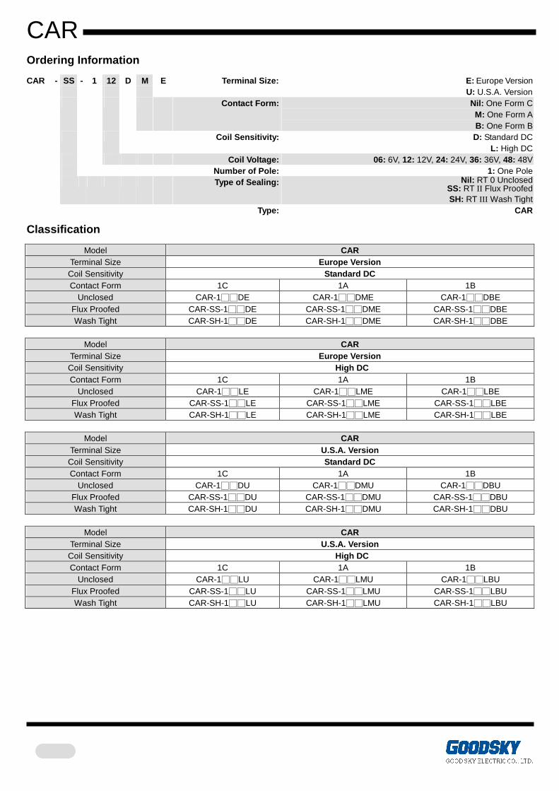
Ordering Information
CAR - SS - 1 12 D M E Terminal Size:
E: Europe Version U: U.S.A. Version
Contact Form: Nil: One Form C M: One Form A B: One Form B
Coil Sensitivity: D: Standard DC L: High DC
Coil Voltage: 06: 6V, 12: 12V, 24: 24V, 36: 36V, 48: 48V Number of Pole: 1: One Pole Type of Sealing: Nil: RT 0 Unclosed
SS: RT II Flux Proofed SH: RT III Wash Tight
Type: CAR
Classification
Model CAR Terminal Size Europe Version Coil Sensitivity Standard DC Contact Form 1C 1A 1B
Unclosed CAR-1DE CAR-1DME CAR-1DBE Flux Proofed CAR-SS-1DE CAR-SS-1DME CAR-SS-1DBE Wash Tight CAR-SH-1DE CAR-SH-1DME CAR-SH-1DBE
Model CAR
Terminal Size Europe Version Coil Sensitivity High DC Contact Form 1C 1A 1B
Unclosed CAR-1LE CAR-1LME CAR-1LBE Flux Proofed CAR-SS-1LE CAR-SS-1LME CAR-SS-1LBE Wash Tight CAR-SH-1LE CAR-SH-1LME CAR-SH-1LBE
Model CAR
Terminal Size U.S.A. Version Coil Sensitivity Standard DC Contact Form 1C 1A 1B
Unclosed CAR-1DU CAR-1DMU CAR-1DBU Flux Proofed CAR-SS-1DU CAR-SS-1DMU CAR-SS-1DBU Wash Tight CAR-SH-1DU CAR-SH-1DMU CAR-SH-1DBU
Model CAR
Terminal Size U.S.A. Version Coil Sensitivity High DC Contact Form 1C 1A 1B
Unclosed CAR-1LU CAR-1LMU CAR-1LBU Flux Proofed CAR-SS-1LU CAR-SS-1LMU CAR-SS-1LBU Wash Tight CAR-SH-1LU CAR-SH-1LMU CAR-SH-1LBU
CAR
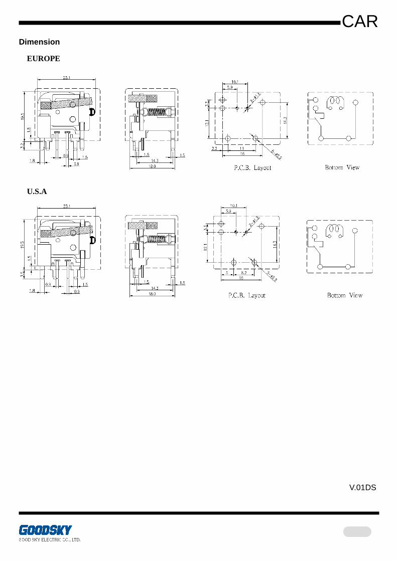
Dimension
EUROPE
U.S.A
V.01DS
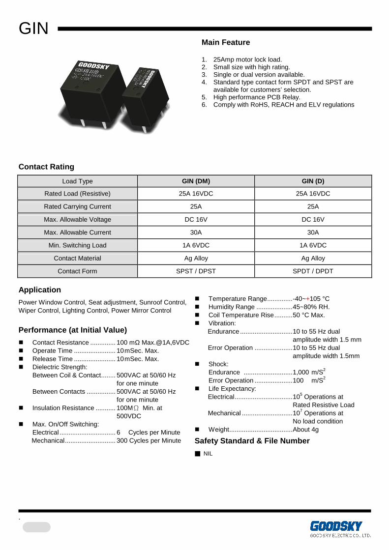
GIN
.
Main Feature 1. 25Amp motor lock load. 2. Small size with high rating. 3. Single or dual version available. 4. Standard type contact form SPDT and SPST are
available for customers’ selection. 5. High performance PCB Relay. 6. Comply with RoHS, REACH and ELV regulations
Contact Rating
Load Type GIN (DM) GIN (D)
Rated Load (Resistive) 25A 16VDC 25A 16VDC
Rated Carrying Current 25A 25A
Max. Allowable Voltage DC 16V DC 16V
Max. Allowable Current 30A 30A
Min. Switching Load 1A 6VDC 1A 6VDC
Contact Material Ag Alloy Ag Alloy
Contact Form SPST / DPST SPDT / DPDT
Application
Power Window Control, Seat adjustment, Sunroof Control, Wiper Control, Lighting Control, Power Mirror Control
Performance (at Initial Value)
Contact Resistance .............. 100 mΩ Max.@1A,6VDC Operate Time ....................... 10 mSec. Max. Release Time ....................... 10 mSec. Max. Dielectric Strength: Between Coil & Contact........ 500VAC at 50/60 Hz
for one minute Between Contacts ................ 500VAC at 50/60 Hz for one minute
Insulation Resistance ........... 100MΩ Min. at 500VDC
Max. On/Off Switching: Electrical ............................... 6 Cycles per Minute Mechanical............................ 300 Cycles per Minute
Temperature Range..............-40~+105 °C Humidity Range ....................45~80% RH. Coil Temperature Rise..........50 °C Max. Vibration:
Endurance .............................10 to 55 Hz dual amplitude width 1.5 mm Error Operation .....................10 to 55 Hz dual amplitude width 1.5mm
Shock: Endurance ...........................1,000 m/S2 Error Operation .....................100 m/S2
Life Expectancy: Electrical................................105 Operations at Rated Resistive Load Mechanical ............................107 Operations at No load condition
Weight...................................About 4g
Safety Standard & File Number
NIL
GIN
.
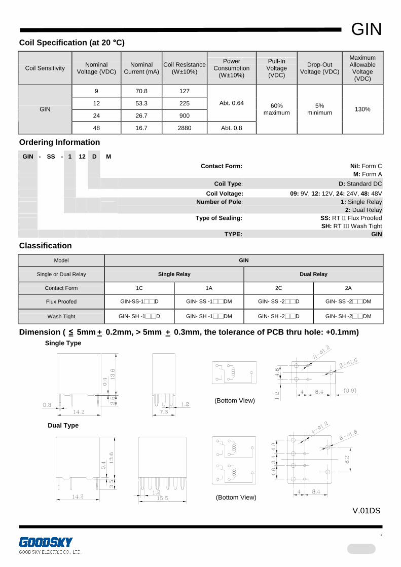
Coil Specification (at 20 °°°°C)
Coil Sensitivity Nominal Voltage (VDC)
Nominal Current (mA)
Coil Resistance (W±10%)
Power Consumption
(W±10%)
Pull-In Voltage (VDC)
Drop-Out Voltage (VDC)
Maximum Allowable Voltage (VDC)
9 70.8 127
12 53.3 225
24 26.7 900
Abt. 0.64 GIN
48 16.7 2880 Abt. 0.8
60% maximum
5% minimum 130%
Ordering Information
GIN - SS - 1 12 D M
Contact Form: Nil: Form C
M: Form A
Coil Type: D: Standard DC
Coil Voltage: 09: 9V, 12: 12V, 24: 24V, 48: 48V
Number of Pole:
1: Single Relay
2: Dual Relay
Type of Sealing:
SS: RT II Flux Proofed SH: RT III Wash Tight
TYPE: GIN
Classification
Model GIN
Single or Dual Relay Single Relay Dual Relay
Contact Form 1C 1A 2C 2A
Flux Proofed GIN-SS-1D GIN- SS -1DM GIN- SS -2D GIN- SS -2DM
Wash Tight GIN- SH -1D GIN- SH -1DM GIN- SH -2D GIN- SH -2DM
Dimension ( UU≤UUU 5mmUUU+UUU 0.2mm, > 5mm UUU+UUU 0.3mm, the tolerance of PCB thru hole: +0.1mm)
(Bottom View)
Single Type
Dual Type
(Bottom View)
V.01DS
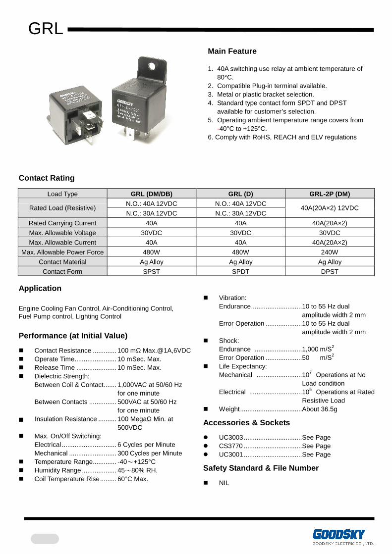
GRL
Main Feature 1. 40A switching use relay at ambient temperature of
80°C. 2. Compatible Plug-in terminal available. 3. Metal or plastic bracket selection. 4. Standard type contact form SPDT and DPST
available for customer’s selection. 5. Operating ambient temperature range covers from
-40°C to +125°C. 6. Comply with RoHS, REACH and ELV regulations
Contact Rating
Load Type GRL (DM/DB) GRL (D) GRL-2P (DM) N.O.: 40A 12VDC N.O.: 40A 12VDC
Rated Load (Resistive) N.C.: 30A 12VDC N.C.: 30A 12VDC
40A(20A×2) 12VDC
Rated Carrying Current 40A 40A 40A(20A×2)
Max. Allowable Voltage 30VDC 30VDC 30VDC
Max. Allowable Current 40A 40A 40A(20A×2)
Max. Allowable Power Force 480W 480W 240W
Contact Material Ag Alloy Ag Alloy Ag Alloy
Contact Form SPST SPDT DPST Application
Engine Cooling Fan Control, Air-Conditioning Control, Fuel Pump control, Lighting Control
Performance (at Initial Value)
Contact Resistance ............. 100 mΩ Max.@1A,6VDC Operate Time....................... 10 mSec. Max. Release Time ...................... 10 mSec. Max. Dielectric Strength:
Between Coil & Contact....... 1,000VAC at 50/60 Hz for one minute Between Contacts ............... 500VAC at 50/60 Hz for one minute
Insulation Resistance .......... 100 MegaΩ Min. at 500VDC Max. On/Off Switching:
Electrical .............................. 6 Cycles per Minute Mechanical .......................... 300 Cycles per Minute
Temperature Range............. -40~+125°C Humidity Range ................... 45~80% RH. Coil Temperature Rise......... 60°C Max.
Vibration:
Endurance............................10 to 55 Hz dual amplitude width 2 mm Error Operation ....................10 to 55 Hz dual amplitude width 2 mm
Shock: Endurance ..........................1,000 m/S2 Error Operation ....................50 m/S2
Life Expectancy: Mechanical .........................107 Operations at No Load condition Electrical .............................105 Operations at Rated Resistive Load
Weight..................................About 36.5g
Accessories & Sockets
UC3003................................See Page CS3770 ................................See Page UC3001................................See Page
Safety Standard & File Number
NIL
GRL
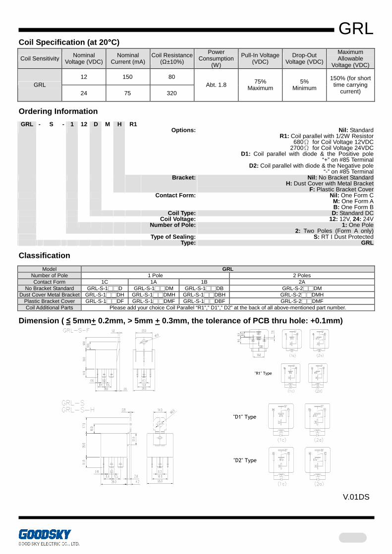
Coil Specification (at 20°°°°C)
Coil Sensitivity Nominal Voltage (VDC)
Nominal Current (mA)
Coil Resistance (Ω±10%)
Power Consumption
(W)
Pull-In Voltage (VDC)
Drop-Out Voltage (VDC)
Maximum Allowable
Voltage (VDC)
12 150 80 GRL
24 75 320 Abt. 1.8 75%
Maximum 5%
Minimum
150% (for short time carrying
current)
Ordering Information
GRL - S - 1 12 D M H R1 Options: Nil: Standard
R1: Coil parallel with 1/2W Resistor 680Ω for Coil Voltage 12VDC
2700Ω for Coil Voltage 24VDC D1: Coil parallel with diode & the Positive pole
“+” on #85 Terminal D2: Coil parallel with diode & the Negative pole
“-” on #85 Terminal Bracket: Nil: No Bracket Standard
H: Dust Cover with Metal Bracket F: Plastic Bracket Cover
Contact Form: Nil: One Form C M: One Form A B: One Form B
Coil Type: D: Standard DC Coil Voltage: 12: 12V, 24: 24V Number of Pole: 1: One Pole
2: Two Poles (Form A only) Type of Sealing: S: RT I Dust Protected Type: GRL
Classification
Model GRL Number of Pole 1 Pole 2 Poles Contact Form 1C 1A 1B 2A
No Bracket Standard GRL-S-1D GRL-S-1DM GRL-S-1DB GRL-S-2DM Dust Cover Metal Bracket GRL-S-1DH GRL-S-1DMH GRL-S-1DBH GRL-S-2DMH
Plastic Bracket Cover GRL-S-1DF GRL-S-1DMF GRL-S-1DBF GRL-S-2DMF Coil Additional Parts Please add your choice Coil Parallel “R1”,” D1”,” D2” at the back of all above-mentioned part number.
Dimension ( ≤ 5mm+ 0.2mm, > 5mm + 0.3mm, the tolerance of PCB thru hole: +0.1mm)
"R1" Type
"D2" Type
"D1" Type
V.01DS
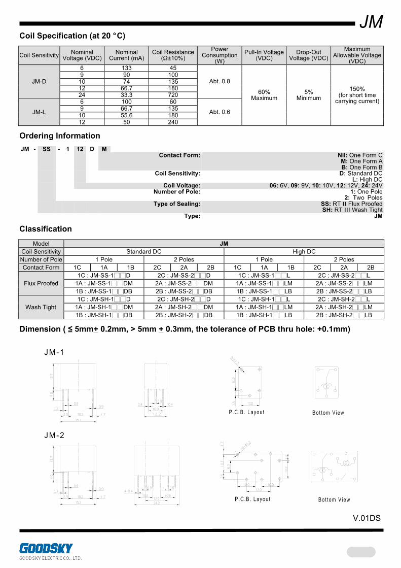

JMW
Main Feature 1. Smaller size with 2×6A of rated carrying current and
double contact type. 2. Applicable for automotive electrical systems. 3. Distinctive twin relay structure on JM-2 providing high
performance for the use of automotive. 4. Resistance to environment with shock and vibration. 5. Plastic sealed type available. 6. Comply with RoHS, REACH and ELV regulations
Contact Rating
Load Type JMW-1P (DM/LM) JMW-2P (DM/LM) Rated Load (Resistive) 2x6A 14VDC 2x6A 14VDC
Rated Carrying Current 2×6A 2×6A
Max. Allowable Voltage 60VDC 60VDC
Max. Allowable Current 12A 12A Max. Allowable Power Force 150W 150W
Contact Material Ag Alloy Ag Alloy
Contact Form SPST DPST Application
Power Window Control, Auto Door Lock Control, Power Mirror Control, Seat Adjustment, Wiper Control
Performance (at Initial Value)
Contact Resistance ............. 100 mΩ Max.@1A,6VDC Operate Time....................... 10 mSec. Max. Release Time ...................... 10 mSec. Max. Dielectric Strength:
Between Coil & Contact....... 500VAC at 50/60 Hz for one minute
Between Contacts ............... 500VAC at 50/60 Hz for one minute
Surge Strength..................... 1,500V (between coil & contact 1.2x50µSec.) Insulation Resistance .......... 100 MegaΩ Min. at 500VDC Max. On/Off Switching:
Electrical…………………… .4 Cycles per Minute. (at 1s ON, 14s OFF)
Mechanical .......................... 300 Cycles per Minute. Temperature Range............. -40~+85°C Humidity Range ................... 45~85% RH. Coil Temperature Rise......... 70°C Max. Vibration:
Endurance............................10 to 55 Hz dual amplitude width 1.5mm
Error Operation ....................10 to 55 Hz dual amplitude width 1.5mm
Shock: Endurance ..........................1,000 m/S2 Error Operation ....................100 m/S2
Life Expectancy: Mechanical .........................107 Operations at No Load condition Electrical .............................105 Operations at Rated
Resistive Load Weight..................................About 5.2g for 1P About 10.2g for 2P
Safety Standard & File Number
NIL
JMW
Coil Specification (at 20 °°°°C)
Coil Sensitivity Nominal Voltage (VDC)
Nominal Current (mA)
Coil Resistance (Ω±10%)
Power Consumption
(W)
Pull-In Voltage (VDC)
Drop-Out Voltage (VDC)
Maximum Allowable
Voltage (VDC) 6 133 45 9 90 100
10 74 135 12 66.7 180
JMW-DM
24 33.3 720
Abt. 0.8
6 100 60 9 66.7 135
10 55.6 180 JMW-LM
12 50 240
Abt. 0.6
60% Maximum
5% Minimum
150% (for short time
carrying current)
Ordering Information
JMW - SS - 1 12 D M Contact Form: M: One Form A Coil Sensitivity: D: Standard DC
L: High DC Coil Voltage: 06: 6V, 09: 9V, 10: 10V, 12: 12V, 24: 24V Number of Pole: 1: One Pole
2: Two Poles Type of Sealing: SS: RT II Flux Proofed
SH: RT III Wash Tight Type: JMW
Classification
Model JMW Coil Sensitivity Standard DC High DC Number of Pole 1 Pole 2 Poles 1 Pole 2 Poles
Flux Proofed JMW-SS-1DM JMW-SS-2DM JMW-SS-1LM JMW-SS-2LM Wash Tight JMW-SH-1DM JMW-SH-2DM JMW-SH-1LM JMW-SH-2LM
Dimension ( ≤ 5mm+ 0.2mm, > 5mm + 0.3mm, the tolerance of PCB thru hole: +0.1mm)
V.01DOS

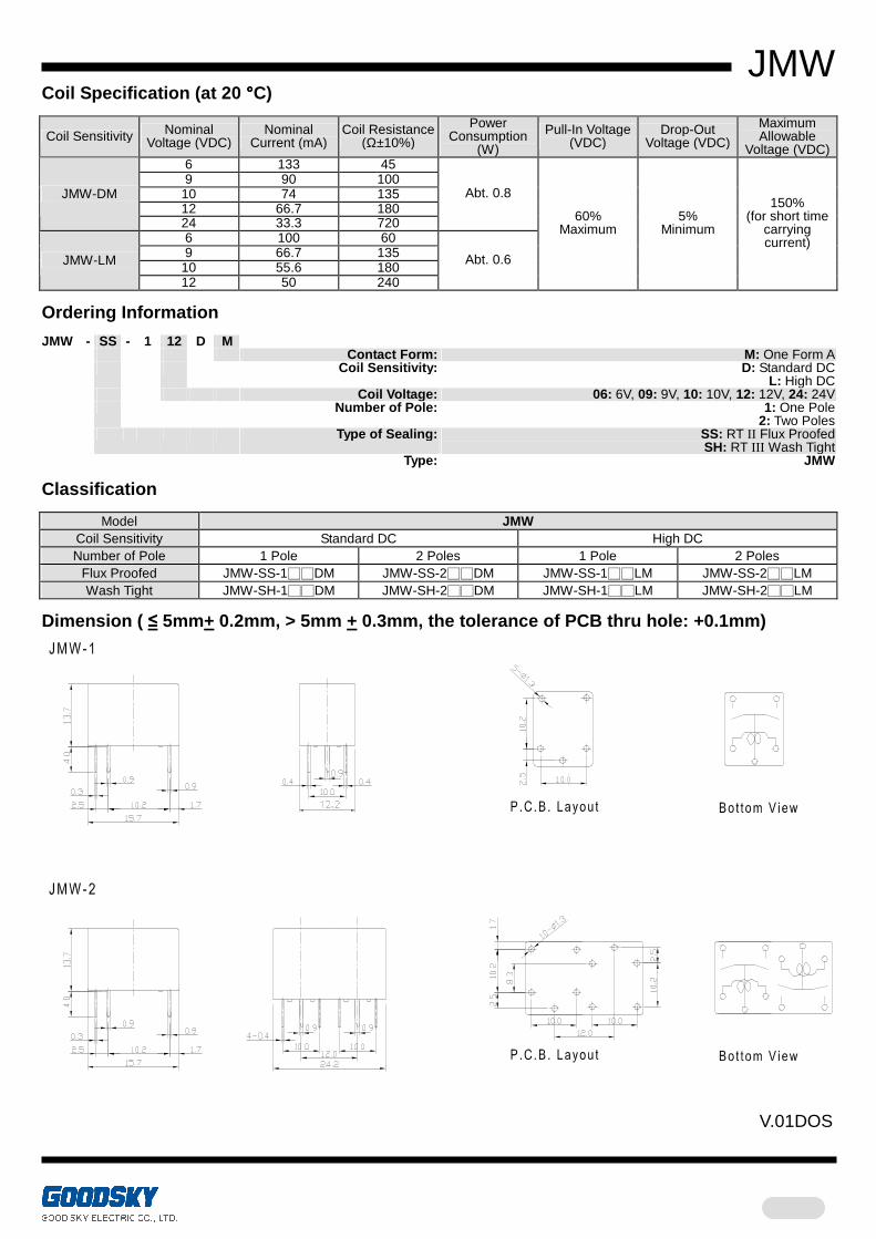
RWM
Main Feature
1. Slim type with 15A rated load. 2. Suitable plastic and metal to high temperature and
various chemical solutions. 3. Highly adapt to harsh environment with shock and
vibration. 4. Wash tight and flux proofed type available.
5. Comply with RoHS and REACH regulations
Contact Rating
Load Type RWM (DM/DB) RWM (D)
Rated Load (Resistive) 15A 15VDC 15A 15VDC
Rated Carrying Current 15A 15A
Max. Allowable Voltage DC 30V DC 30V
Max. Allowable Current 15A 15A
Max. Allowable Power Force 225W 225W
Contact Material Ag Alloy Ag Alloy
Contact Form SPST SPDT
Application
Power Window Control, Sunroof Control, Power Mirror Control, Door Lock Control
Performance (at Initial Value)
Contact Resistance ............. 100mΩ Max.@1A,6VDC Operate Time....................... 10 mSec. Max. Release Time ...................... 5 mSec. Max. Dielectric Strength: Between Coil & Contact....... 1,000VAC at 50/60 Hz
for one minute Between Contacts ............... 500VAC at 50/60 Hz
for one minute Surge Strength..................... 1,000V (between coil & contact 1.2x50µSec.) Insulation Resistance .......... 100 Mega Ω Min. at 500VDC Max. On/Off Switching:
Electrical .............................. 6 Cycles per Minute Mechanical .......................... 300 Cycles per Minute
Temperature Range............. -40~+85°C
Humidity Range ................... 45~85% RH. Coil Temperature Rise......... 55°C Max. Vibration:
Endurance ........................... 10 to 55 Hz dual amplitude width 1.5mm Error Operation.................... 10 to 55 Hz dual amplitude width 1.5mm
Shock: Endurance ......................... 1,000 m/S2 Error Operation.................... 100 m/S2
Life Expectancy: Mechanical ......................... 107 Operations at No Load condition Electrical ............................ 105 Operations at Rated Resistive Load
Weight ................................. About 9g
Safety Standard & File Number
NIL
RWM
Coil Specification (at 20°°°°C)
Coil Sensitivity Nominal
Voltage (VDC) Nominal
Current (mA) Coil Resistance
(Ω±10%)
Power Consumption
(W)
Pull-In Voltage (VDC)
Drop-Out Voltage (VDC)
Maximum Allowable
Voltage (VDC) 9 88.9 100
12 66.7 180 RWM
24 33.3 720
Abt.0.8 80%
Maximum 5%
Minimum 150%
Ordering Information
RWM - SS - 1 12 D M
Contact Form: Nil: One Form C M: One Form A B: One Form B
Coil Type: D: Standard DC
Coil Voltage: 09: 9V, 12: 12V, 24: 24V
Number of Pole: 1: One Pole
Type of Sealing: SS: RT II Flux Proofed
SH: RT III Wash Tight
Type: RWM
Classification
Model RWM Contact Form 1C 1A 1B Flux Proofed RWM-SS-1D RWM-SS-1DM RWM-SS-1DB Wash Tight RWM-SH-1D RWM-SH-1DM RWM-SH-1DB
Dimension ( ≤ 5mm+ 0.2mm, > 5mm + 0.3mm, the tolerance of PCB thru hole: +0.1mm)
P.C.B. Layout Bottom View
3-1.31.00.3
0.6*0.6
1.0
2.0 12.2
3.4
19.0 15.4
0.4 0.4
6.0 6.0
6.0
6.0
2.0 12.2
2-1.0
15.0
4.5
V.01DS
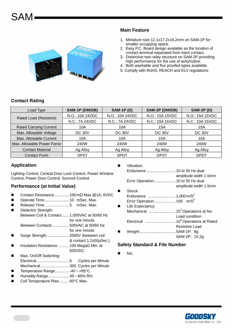
SAM
Main Feature 1. Miniature size 12.1x17.2x16.2mm on SAM-1P for
smaller occupying space. 2. Easy P.C. Board design available as the location of
contact terminal separated from each contact. 3. Distinctive twin relay structure on SAM-2P providing
high performance for the use of automotive. 4. Both washable and flux proofed types available. 5. Comply with RoHS, REACH and ELV regulations
Contact Rating
Load Type SAM-1P (DM/DB) SAM-1P (D) SAM-2P (DM/DB) SAM-2P (D) N.O.: 10A 24VDC N.O.: 10A 24VDC N.O.: 15A 15VDC N.O.: 15A 15VDC
Rated Load (Resistive) N.C.: 7A 24VDC N.C.: 7A 24VDC N.C.: 10A 15VDC N.C.: 10A 15VDC
Rated Carrying Current 10A 10A 15A 15A
Max. Allowable Voltage DC 30V DC 30V DC 30V DC 30V
Max. Allowable Current 10A 10A 15A 15A Max. Allowable Power Force 240W 240W 240W 240W
Contact Material Ag Alloy Ag Alloy Ag Alloy Ag Alloy
Contact Form SPST SPDT DPST DPDT Application
Lighting Control, Central Door Lock Control, Power Window Control, Power Door Control, Sunroof Control
Performance (at Initial Value)
Contact Resistance ............. 100 mΩ Max.@1A, 6VDC Operate Time....................... 10 mSec. Max. Release Time ...................... 5 mSec. Max. Dielectric Strength:
Between Coil & Contact....... 1,000VAC at 50/60 Hz for one minute
Between Contacts ............... 500VAC at 50/60 Hz for one minute
Surge Strength..................... 2000V (between coil & contact 1.2x50µSec.)
Insulation Resistance .......... 100 MegaΩ Min. at 500VDC
Max. On/Off Switching: Electrical .............................. 6 Cycles per Minute Mechanical .......................... 300 Cycles per Minute
Temperature Range............. -40~+85°C Humidity Range ................... 45~85% RH. Coil Temperature Rise......... 60°C Max.
Vibration:
Endurance ........................... 10 to 55 Hz dual amplitude width 1.5mm Error Operation.................... 10 to 55 Hz dual amplitude width 1.5mm
Shock: Endurance ......................... 1,000 m/S2 Error Operation.................... 100 m/S2
Life Expectancy: Mechanical ......................... 107 Operations at No Load condition Electrical ............................ 105 Operations at Rated Resistive Load
Weight ................................. SAM-1P: 8g SAM-2P: 15.2g
Safety Standard & File Number
NIL
SAM
Coil Specification (at 20 °°°°C)
Coil Sensitivity Nominal
Voltage (VDC) Nominal
Current (mA) Coil Resistance
(Ω±10%)
Power Consumption
(W)
Pull-In Voltage (VDC)
Drop-Out Voltage (VDC)
Maximum Allowable
Voltage (VDC) 5 91 55 6 75 80 9 50 180
12 38 320 18 25 720
SAM-1P SAM-2P
24 19 1,280
Abt. 0.45 75%
Maximum 5%
Minimum
150% (for short time carrying
current)
Ordering Information
SAM - SS - 1 12 D M Contact Form: Nil: One Form C
M: One Form A B: One Form B
Coil Type: D: Standard DC Coil Voltage: 05: 5V, 06: 6V, 09: 9V, 12: 12V, 18: 18V, 24: 24V Number of Pole: 1: One Pole
2: Two Poles Type of Sealing: SS: RT II Flux Proofed
SH: RT III Wash Tight Type: SAM
Classification
Model SAM Number Of Pole 1 Pole 2 Poles
Contact Form 1C 1A 1B 2C 2A 2B Flux Proofed SAM-SS-1D SAM-SS-1DM SAM-SS-1DB SAM-SS-2D SAM-SS-2DM SAM-SS-2DB
Wash Tight SAM-SH-1D SAM-SH-1DM SAM-SH-1DB SAM-SH-2D SAM-SH-2DM SAM-SH-2DB
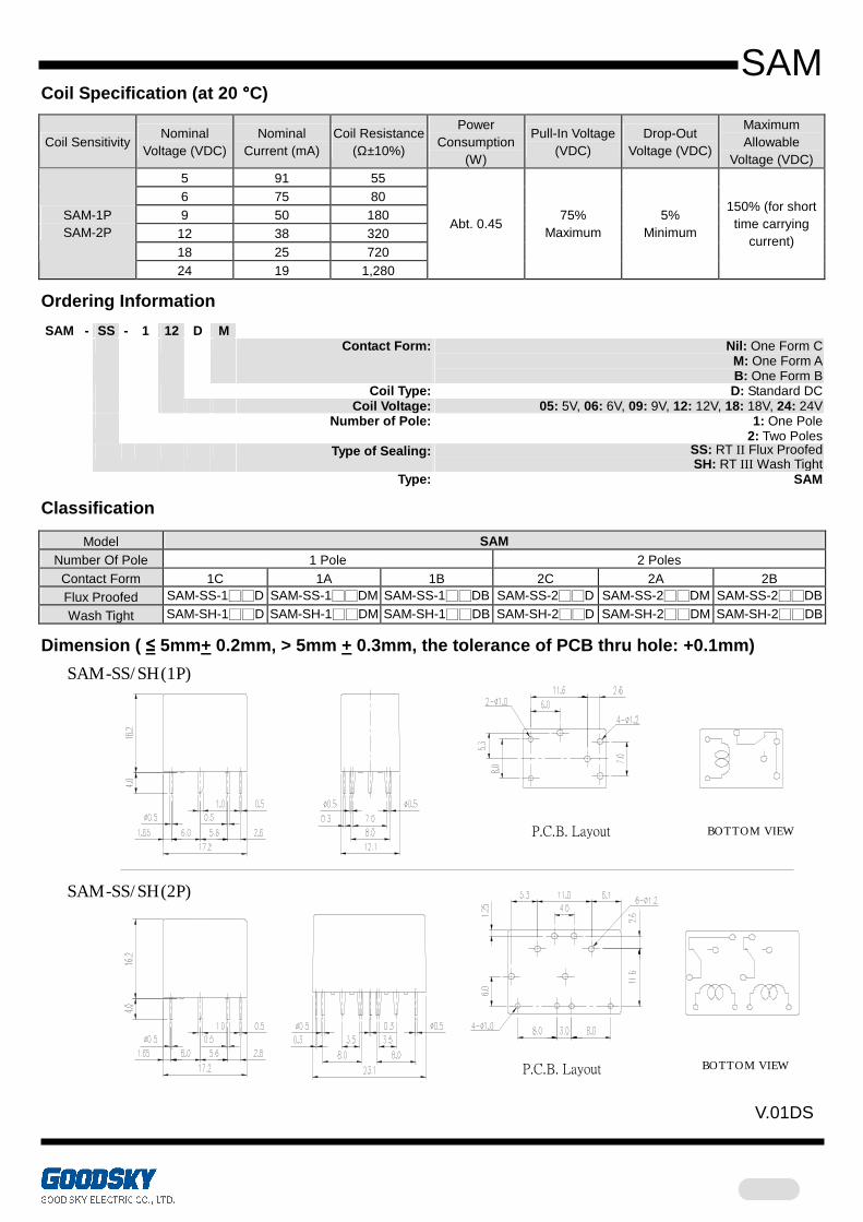
Dimension ( ≤ 5mm+ 0.2mm, > 5mm + 0.3mm, the tolerance of PCB thru hole: +0.1mm)
SAM-SS/ SH(1P)
SAM-SS/ SH(2P)
BOTTOM VIEWBOTTOM VIEW
BOTTOM VIEWBOTTOM VIEW
V.01DS
P.C.B. Layout
P.C.B. Layout
68
ZEM
.
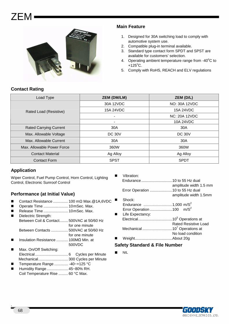
Main Feature 1. Designed for 30A switching load to comply with
automotive system use. 2. Compatible plug-in terminal available. 3. Standard type contact form SPDT and SPST are
available for customers’ selection. 4. Operating ambient temperature range from -40oC to
+125oC. 5. Comply with RoHS, REACH and ELV regulations
Contact Rating
Load Type ZEM (DM/LM) ZEM (D/L)
30A 12VDC NO: 30A 12VDC
15A 24VDC 15A 24VDC
- NC: 20A 12VDC Rated Load (Resistive)
- 10A 24VDC
Rated Carrying Current 30A 30A
Max. Allowable Voltage DC 30V DC 30V
Max. Allowable Current 30A 30A
Max. Allowable Power Force 360W 360W
Contact Material Ag Alloy Ag Alloy
Contact Form SPST SPDT
Application
Wiper Control, Fuel Pump Control, Horn Control, Lighting Control, Electronic Sunroof Control
Performance (at Initial Value)
Contact Resistance .............. 100 mΩ Max.@1A,6VDC Operate Time ....................... 10 mSec. Max. Release Time ....................... 10 mSec. Max. Dielectric Strength: Between Coil & Contact........ 500VAC at 50/60 Hz
for one minute Between Contacts ................ 500VAC at 50/60 Hz for one minute
Insulation Resistance ........... 100MΩ Min. at 500VDC
Max. On/Off Switching: Electrical ............................... 6 Cycles per Minute Mechanical............................ 300 Cycles per Minute
Temperature Range ............. -40~+125 °C Humidity Range .................... 45~80% RH. Coil Temperature Rise ......... 60 °C Max.
Vibration:
Endurance .............................10 to 55 Hz dual amplitude width 1.5 mm Error Operation .....................10 to 55 Hz dual amplitude width 1.5mm
Shock: Endurance ...........................1,000 m/S2 Error Operation .....................100 m/S2
Life Expectancy: Electrical................................105 Operations at Rated Resistive Load Mechanical ............................107 Operations at No load condition
Weight...................................About 20g
Safety Standard & File Number
NIL
ZEM
.
Coil Specification (at 20°°°°C)
Coil Sensitivity Nominal
Voltage (VDC) Nominal
Current (mA) Coil Resistance
(Ω±10%)
Power Consumption
(W±10%)
Pull-In Voltage (VDC)
Drop-Out Voltage (VDC)
Maximum Allowable
Voltage (VDC) 12 133 90 8 1.2
ZEM-D 24 67 360
Abt. 1.6 16 2.4
12 100 120 8 1.2 ZEM-L
24 50 480 Abt. 1.2
16 2.4
130%
Ordering Information
ZEM - S - 1 12 D M R Options: Nil: Standard
R: Coil Parallel With 1/2W Resistor 680Ω for Coil Voltage 12VDC
2700Ω for Coil Voltage 24VDC D1: Coil Parallel with Diode & the Positive Pole
”+” on #85 Terminal D2: Coil Parallel with Diode & the Negative Pole
”-” on #85 Terminal
Contact Form: Nil: One Form C
M: One Form A
Coil Sensitivity: D: Standard DC
L: High DC
Coil Voltage: 12: 12V, 24: 24V Number of Pole: 1: One Pole Type of Sealing: S: RT I Dust Protected Type: ZEM
Classification
Model ZEM Coil Sensitivity Standard DC High DC Contact Form 1C 1A 1C 1A
No Bracket Standard ZEM-S-1D ZEM -S-1DM ZEM -S-1L ZEM -S-1LM
Coil Additional Parts Please add your choice Coil Parallel “R、D1 or D2” at the back of all above-mentioned part number
Dimension ( ≤ 5mm+ 0.2mm, > 5mm + 0.3mm, the tolerance of PCB thru hole: +0.1mm) ZEM-S
Electric diagrams
BOTTOM VIEW
"D1"Type(1C) "D2"Type(1C) "R"Type(1C)1C
V.01DS