contactors dil: efficient solutions for the motor · pdf filecontactors dil: efficient...
TRANSCRIPT

106
Contactors DIL: Efficient Solutions for the Motor Feeder
The identifier for the new contactor generation is the green print. The innovationsare already partly known as they have been integrated into the series on anongoing basis over the last few years. The contactors up to 15.5 A have beenextended with plug-in accessories such as motor filters and solder pin adapters.Motor starters in the size range can also be plugged-in. The necessary openingshave been perfectly enclosed just as the entire contactor to assure perfectoperation. An even higher level of operational safety is now guaranteed by thenew knurled contacts for the auxiliary contacts. The contactors are becoming more efficient, particularly due to the new Eco typesfor 15.5, 38, 72 and 170 A, as well as through the many innovations with themotor starters, for example, such as SmartWire.
44090_10Kap_Leistungs.qxd 27.02.2008 14:31 Uhr Seite 106
For Moeller Electric Sales and Support call KMparts.com (866) 595-9616

107
Contactors DIL M
With the same dimensions for AC andDC contactors, planning andengineering can be carried out witheven greater efficiency. With only fourcomponent sizes covering the ratingrange up to 170 A, engineering is madeeven simpler.A key benefit with contactors up to 38 A is that the auxiliary contact isalready built in, and the DC contactorsinclude a suppressor circuit up to 170 A.From 15 A, the DC contactors have anelectronic drive that removes the needfor coupling relays. With all these extrasalready included in the contactors, your costs are clearly reduced.
Contactor relays DIL A
The new auxiliary contacts DIL A perfectly complement the new motorcontactors DIL M. A wide range of auxiliary contacts specially designed forthe contactor relays ensures optimumsolutions and reliable identification.
ZB overload relays
Overloads relays ZB protect the motoragainst phase failure or overload. Theirauxiliary contacts switch the motor contactor off, and signal the fault.These relays are suitable for protectingEEx e-motors according to the ATEX 100a guideline.
Safety
Continuous operation requires the components used to have a high level of operational reliability. That's why contactors DIL M offer not only offer high lifespan values for standard AC-3 operation, but are also ideally suited fordemanding AC-4 motor inching applications. This increasessafety even when machines and plants are being reset or refitted. Active safety features are inherent in these devices:interlocked opposing contacts, isolation and protectionagainst direct contact are standard.
Economy worldwide
Machine and panel builders alike are looking for economicalsolutions for low-voltage switchgear assemblies.The contactors DIL M and overload relays ZB are ideal for integrating in complete systems, thus enabling considerablecost savings. In many places, coupling levels are completelyunnecessary since intelligent electronics take over this task.The low pick-up and sealing power means that smaller transformers can be used.
Co
nta
cto
r R
elay
s an
d C
on
tact
ors
44090_10Kap_Leistungs.qxd 27.02.2008 14:32 Uhr Seite 107
For Moeller Electric Sales and Support call KMparts.com (866) 595-9616

108
DC
DCAC
The new electronic timer modules DIL M32-XTE are connected to the front of the new contactors DIL M7 toDIL M32, DIL MP20 and DIL A. Thus asimple contactor control with a timerfunction can be created which does notrequire a higher level PLC, or for caseswhere a PLC would be uneconomical.The on-delayed, off-delayed and star-delta functions allow a large rangeof applications.
Speedier wiring using spring-loadedterminations
Moeller provides proven quality withtension clamp terminals. Numeroustests have proved that contactors andmotor-protective circuit-breakers arejust as securely wired in this way as byscrew connection – even in stronglyvibrating machines. But wiring workusing tension clamp terminals is verymuch quicker to do. The main currentpaths on PKZM 0 and motor contactorsup to 12 A all use spring-loaded terminals. The sundries for terminationare always available for both screw andtension clamp connection.
AC and DC Contactors:With Same Frame Size –For Simpler Engineering
The new contactors DIL M are significantly more compact than theirpredecessors, even though, up to 32 A,the auxiliary contact is included. Theadvantage of this is particularly strikingwith the DC contactors that now arethe same size as their AC counterparts.This makes everything easier, i.e.planning, engineering and fitting,without having to alter the controlsystem, even if the control current has to change for another customer.The same range of accessories areused both for AC and DC actuatorscontactors.
No compromise where terminationreliability is concerned
DIL contactors up to 150 A have boxterminals with two clamping cham-bers, allowing unequal cable cross-sections to be terminated absolutelysecurely. This makes wiring easier andcuts down on associated errors.
44090_10Kap_Leistungs.qxd 27.02.2008 14:32 Uhr Seite 108
For Moeller Electric Sales and Support call KMparts.com (866) 595-9616

109
This reduces the cost of your control panel
The space-saving is achieved not just by the reduced componentdimensions, but also due to the lower heat dissipation that,particularly with the DC contactors, helps keep the cabinetsize down and saves the cost of a fan. The significantly reducedsealing consumption achieved by innovative, electronic drivesmakes this possible. The Moeller DC contactors from 17 up to65 A have a sealing consumption of only 0.5 Watt, even thoseat 170 A only use 2.1 Watt. This also results in lower powerconsumption for the whole installation.
Electronic-compatible auxiliary contact
Often very small signals have to be switched for indicating thestate of the contactor to the PLC. In order to increase the ofthe feedback signal Moeller has developed a new auxiliarycontact with a make and break contact which is suitable forswitching small currents with low voltages. The DILA-XHIR11auxiliary contact is tested for contact reliability at 1mA and17VDC. The failure rate is less than 1 failure in 100 millionswitching operations. The auxiliary break contact is designed as a mirror contact sothat it can be used in safety applications as feedback signal.
The benefits of the electronically controlled drive
All DC motor contactors with DC actuation from DIL M17have an electronically controlled drive that offers the follo-wing advantages: • Significantly less heat dissipation due to reduced sealing
consumption • Smaller control transformers because of lower pick-up
consumption • Direct actuation from the PLC without coupling contactors
up to 32 A
Switching contactors directly from the PLC
This is a feature that is becoming increasingly more popularand is primarily made possible by the limitation of the DCpick-up power. Moeller's new contactors DIL M up to 32 A can be switched directly from the PLC using 0.5 A DC outputs.An additional coupling relay thus becomes unnecessary, andthis also applies to expensive and cumbersome relay outputs.The new contactors DIL M thus enable the use of more compact switching cabinets and inexpensive solutions. C
on
tact
or
Rel
ays
and
Co
nta
cto
rs
44090_10Kap_Leistungs.qxd 27.02.2008 14:32 Uhr Seite 109
For Moeller Electric Sales and Support call KMparts.com (866) 595-9616

110
http://www.moeller.net/xstart
6 6
54
45
5
1
3
3
1
11
3
32
2
5
6
Contactor, 3-pole
AC-3 380 V/ 400 V
AC 230 V 50 HZ 240 V 60 Hz, 110 V 50 HZ 120 V 60 Hz, 24 V 50/60 HZ,
DC 24 V
AC384041
Ie
A
P
kW
Contacts Part no.
Add voltages from above
Co
7 3 1N/O DILM7-10 (…) 1N/O7 3 1N/C DILM7-01(…) – 9 4 1N/O DILM9-10 (…) 2N/O9 4 1N/C DILM9-01 (…) 2N/O12 5.5 1N/O DILM12-10 (…) 1N/O12 5.5 1N/C DILM12-01 (…) – 15.5 7.5 1N/O DILM15-10 (…) 1N/O15.5 7.5 1N/C DILM15-01 (…) 4N/O
3N/O2N/O1N/O– 2N/O
18 7.5 1N/O DILM17-10 (…) 2N/O18 7.5 1N/C DILM17-01 (…) 1N/O25 11 1N/O DILM25-10 (…) –25 11 1N/C DILM25-01 (…) 2N/O32 15 1N/O DILM32-10 (…) 1N/O32 15 1N/C DILM32-01 (…) 1N/O
40 18.5 – DILM40 (…) 2N/O50 22 – DILM50 (…) 1N/O65 30 – DILM65 (…) – 72 37 – DILM72 (…) 4N/O
3N/O2N/O1N/O
80 37 – DILM80 (…) – 95 45 – DILM95 (…) 2N/O115 55 – DILM115 (…)1 1N/O150 75 – DILM150 (…)1 1N/O170 90 – DILM170 (…)1
Simply Select: Contactors DIL M:
1 DILM 115, DILM 150, DILM 170 suppressor circuit also not required with the AC version
1. Contactors up to 90 kW2. Suppressor1
3. Overload relays4. Auxiliary contact modules, 2-pole5. Auxiliary contact modules, 4-pole6. Side-mounted auxiliary contact modules, 2-pole
44090_10Kap_Leistungs.qxd 27.02.2008 14:32 Uhr Seite 110
For Moeller Electric Sales and Support call KMparts.com (866) 595-9616

111
Auxiliary contact Overload relay Suppressor1 Electronic timer modules
Hz, Hz,
AC 15, 380 V 400 V 415 V
Setting range, Overload release
Varistor suppressor
* with LED
RC suppressor RAC240 = 200-240V ACRAC130 = 100-130V ACRA24 = 24V AC/DC
m above
Contacts Part no. Ir
A
Part no. Us
V AC
Part no.
Part no. Time ranges Supplementpart no.DILM32-XTE...
1N/O 1N/C DILM 32-XHI112 0.1-0.16 ZB12-0,16 24-48 DILM12-XSPV48 DILM12-XSPR48 on-delayed
– 2N/C DILM 32-XHI022 0.16-0.24 ZB12-0,24 DILM12-XSPVL48* 0.05 s - 100 s E11-100 (RA24)2N/O 2N/C DILM 32-XHI222 0.24-0.4 ZB12-0,4 48-130 DILM12-XSPV130 0.05 s - 100 s E11-100 (RAC130)2N/O – DILA-XHI20 0.4-0.6 ZB12-0,6 130-240 DILM12-XSPV240 DILM12-XSPR240 0.05 s - 100 s E11-100 (RAC240)
…) 1N/O 1N/C DILA-XHI11 0.6-1 ZB12-1,0 DILM12-XSPVL240*…) – 2N/C DILA-XHI02 1-1.6 ZB12-1,6 240-500 DILM12-XSPV500 DILM12-XSPR500 off-delayed
…) 1N/O 1N/C DILA-XHIV11 1.6-2.4 ZB12-2,4 0.05 s - 1 s D11-1 (RA24)…) 4N/O – DILA-XHI40 2.4-4 ZB12-4 0.5 s - 10 s D11-10 (RA24)
3N/O 1N/C DILA-XHI31 4-6 ZB12-6 5 s - 100 s D11-100 (RA24)2N/O 2N/C DILA-XHI22 6-10 ZB12-101N/O 3N/C DILA-XHI13 9-12 ZB12-12 0.05 s - 1 s D11-1 (RAC130)– 4N/C DILA-XHI04 12-16 ZB12-16 0.5 s - 10 s D11-10 (RAC130)2N/O 2N/C DILA-XHIV22
…) 2N/O – DILA-XHIT203 0.1-0.16 ZB32-0,16 24-48 DILM32-XSPV48 DILM32-XSPR48…) 1N/O 1N/C DILA-XHIT113 0.16-0.24 ZB32-0,24 DILM32-XSPVL48* 0.05 s - 1 s D11-1 (RAC240)…) – 2N/C DILA-XHIT023 0.24-0.4 ZB32-0,4 48-130 DILM32-XSPV130 0.5 s - 10 s D11-10 (RAC240)…) 2N/O 2N/C DILA-XHIT223 0.4-0.6 ZB32-0,6 130-240 DILM32-XSPV240 DILM32-XSPR240 5 s - 100 s D11-100 (RAC240)…) 1N/O 1N/C DILA-XHIR114 0.6-1 ZB32-1,0 DILM32-XSPVL240*…) 1N/O 1N/C DILM32-XHI11-S5 1-1.6 ZB32-1,6 240-500 DILM32-XSPV500 DILM32-XSPR500 star-delta
1.6-2.4 ZB32-2,4 1 s - 30 s Y20 (RA24)2.4-4 ZB32-4 switch-over delay Y20 (RAC130)4-6 ZB32-6 50 ms Y20 (RAC240)6-10 ZB32-1010-16 ZB32-1616-24 ZB32-2424-32 ZB32-32
2N/O – DILM150-XHI20 6-10 ZB65-10 24-48 DILM95-XSPV48 DILM95-XSPR481N/O 1N/C DILM150-XHI11 10-16 ZB65-16 DILM95-XSPVL48*– 2N/C DILM150-XHI02 16-24 ZB65-24 48-130 DILM95-XSPV1304N/O – DILM150-XHI40 24-40 ZB65-40 130-240 DILM95-XSPV240 DILM95-XSPR243N/O 1N/C DILM150-XHI31 40-57 ZB65-57 DILM95-XSPVL240*2N/O 2N/C DILM150-XHI22 57-65 ZB65-65 240-500 DILM95-XSPV500 DILM95-XSPR501N/O 3N/C DILM150-XHI13– 4N/C DILM150-XHI04 25-35 ZB150-35 24-48 DILM95-XSPV48 DILM95-XSPR482N/O 2N/C DILM150-XHIV22 35-50 ZB150-50 DILM95-XSPVL48*1N/O 1N/C DILM150-XHI11-SI 50-70 ZB150-70 48-130 DILM95-XSPV1301N/O 1N/C DILM150-XHIA11 70-100 ZB150-100 130-240 DILM95-XSPV240 DILM95-XSPR240
95-125 ZB150-125 DILM95-XSPVL240*120-142 ZB150-150 240-500 DILM95-XSPV500 DILM95-XSPR500
A1
A2
A1
A2
5 s - 100 s D11-100 (RAC130)
2 cannot be combined with DIL M ....-013 high version4 suitable for electronic applications5 side-mounted auxiliary contact modules only for DILM 17, 25, 32, can only be installed on left, cannot be combined with top
mounting auxiliary contacts or mechanical interlocks
UL/CSA see page 124
Co
nta
cto
r R
elay
s an
d C
on
tact
ors
44090_10Kap_Leistungs.qxd 27.02.2008 14:32 Uhr Seite 111
For Moeller Electric Sales and Support call KMparts.com (866) 595-9616

112
Thermistor overload relay EMT6Remarkable functional versatility in the smallest possiblespace the EMT 6 thermistor overload relay protectsmachines against overtemperatures during severe starting duty, braking duty, undervotage and overvoltage,and high switching frequency. The temperature is monitored by means of a thermistor, directly on themotor winding. In the event of overtemperature, theappropriate signal is passed to the EMT 6. It trips, andthe fault is clearly displayed in the control panel. Anotherfield of application for the EMT 6 is the monitoring oftemperatures in bearings, gearboxes, oils and coolants.
Universal and economicalThree types with differing functions are available: EMT6, EMT6-DB,EMT6-DBK. The EMT 6-DBK is the mostversatile with functions such as automatic or manualoperation, recognition of short circuits in the sensor circuit and zero-voltage safety.
Zero-voltage safety ensures reliable fault signalling even inthe event of supply voltage failure; signalling which helpsprevent expensive downtimes. The multivoltage moduleautomatically adapts to all conventional control voltagesfrom 24 V DC to 240 V AC.
Simply Select: Contactor Relays DIL A,Mini Contactor Relays DIL E
Contactor relays DIL A Auxiliary contact modules DIL A Note
AC 15, 380 V 415 VIe 4 A
AC 230 V 50 HZ 240 V 60 Hz, 110 V 50 HZ 120 V 60 Hz,
DC 24 V
AC 15, 380 V / 400 V / 415 V
Ie 4 A
Contacts Part no.
Add voltages from above
Contacts Part no.
4N/O DILA40(…) - 2N/C DILA-XHI023N/O 1N/C DILA31(…) 1N/O 1N/C DILA-XHI112N/O 2N/C DILA22(…) 2N/O - DILA-XHI20
1N/O 1N/C DILA-XHIV11- 4N/C DILA-XHI041N/O 3N/C DILA-XHI132N/O 2N/C DILA-XHI223N/O 1N/C DILA-XHI314N/O - DILA-XHI402N/O 2N/C DILA-XHIV222N/O - DILA-XHIT201N/O 1N/C DILA-XHIT11- 2N/C DILA-XHIT022N/O 2N/C DILA-XHIT22
The listed auxiliary contacts are available withspringloaded terminals.The auxiliary contact modules listed for the contactor relay DIL A can also be used for thecontactors DIL M up to 32 A.Auxiliary contact members: DILA-XHI to EN 50005, DILM32-XHI to DIN 50012The contactor relay DILA-22 can not be combined with the 4-pole auxiliary contactmodule. For use with tool-less plug connectionwe recommend the auxiliary contact DILA-XHIT...in the high version.
44090_10Kap_Leistungs.qxd 27.02.2008 14:32 Uhr Seite 112
For Moeller Electric Sales and Support call KMparts.com (866) 595-9616

113
Thermistor relay for machine protection EMT6
Basic functions: thermistor protection, autoreset, diagnostics LEDs
Functions Part no.
Basic functions 24-240V DC/AC EMT6230 V AC EMT6 (230V)
Basic functions 230V AC EMT6-K+ short-circuit recognition in the sensor circuit
Basic functions 24-240V DC/AC EMT6-DB+ manual/autoreset + remote reset + test function + error memory 230V AC EMT6-DB (230V)
Basic functions 24-240V DC/AC EMT6-KDB+ manual/autoreset + remote reset + test function + error memory + short-circuit recognition in the sensor circuit
Basic functions 24-240V DC/AC EMT6-DBK+ manual/autoreset + remote reset + test function + error memory + short-circuit recognition in the sensor circuit (disconnectable)+ zero-voltage safety (disconnectable)
UL/CSA see page 124
Co
nta
cto
r R
elay
s an
d C
on
tact
ors
Mini contactor relays DIL EM1 Mini contactor relaysDIL ER1
Auxiliary contact modules1
Overload relays ZE
AC-3 380 V/ 400 V
AC 230 V 50 Hz 240 V 60 Hz,
AC 15, 380 V / 400 V / 415 V
Ie 3A
AC 15, 380 V / 400 V / 415 V
Ie 2A
Setting range,overload release
Ie
A
P
kW
Contacts Part no.Add voltages from above
Contacts Part no. Contacts Part no. Ir
A
Part no.
6.6 3 1N/O - DILEEM-10(...) 4N/O - DILER-40(...) - 2N/C 02DILEM 0.1 - 0.16 ZE-0,166.6 3 - 1N/C DILEEM-01(...) 3N/O 1N/C DILER-31(...) 1N/O 1N/C 11DILEM 0.16 - 0.24 ZE-0,248.8 4 1N/O - DILEM-10(...) 2N/O 2N/C DILER-22(...) 2N/O 2N/C 22DILEM 0.24 - 0.4 ZE-0,48.8 4 - 1N/C DILEM-01(...) - 2N/C 02DILE 0.4 - 0.6 ZE-0,6
1N/O 1N/C 11DILE 0.6 - 1 ZE-1,02N/O - 20DILE 1.6 - 2.4 ZE-2,41N/O 1N/C 11DDILE 2.4 - 4 ZE-4- 4N/C 04DILE 4 - 6 ZE-61N/O 3N/C 13DILE 6 - 9 ZE-92N/O 2N/C 22DILE3N/O 1N/C 31DILE4N/O - 40DILE2N/O 2N/C 22DDILE
1 The auxiliary and main contacts listed are available with spring-loaded terminals.
44090_10Kap_Leistungs.qxd 27.02.2008 14:32 Uhr Seite 113
For Moeller Electric Sales and Support call KMparts.com (866) 595-9616

114
DILMP Four-Pole ContactorsCombination plug connections
These combinations always consist ofuniversal standard components whichoffer a constantly high level of qualityat an attractive price due to the largeproduction volumes involved. With contactors < 16 A DIL M12-XSL or DIL M12-XRL star-delta and reversingstarter wiring kits can be fitted in theplug connectors rapidly and with optimum space saving.
Wiring
The coil terminals are now arranged atthe front of the contactors. As they areno longer covered by main current wiringthat is often rigid, this simplifies andreduces the time required for wiringwork and voltage testing. The terminalsof the integrated auxiliary contact arearranged on the second level.
New 4-pole contactors from the xStart series
The new 4-pole contactor from Moeller optimized for AC-1 switched loads.They are the specialists for applications where the mains is switched off or over,heating systems are switched and 4-pole loads are switched.
Four compact contactors cover the performance range up to 200 A. The identi-cal size for AC and DC operated contactors as well as a common range of acces-sories for 3 and 4-pole contactors guarantee efficient and simple planning andengineering.
1 For DILMP20 to DILMP80 230 V 50 HZ 240 V 60 HZ, for DILMP125, DILMP160 and DILMP200 RAC2402 For DILMP20 24 VDC, for DILMP32 to DILMP200 RDC24
4-pole contactor
AC-1 Conventional free airthermal current Open
AC 230 V 50 HZ 240 V 60 Hz, o.RAC2401, 110 V 50 HZ 120 V 60 Hz, 24 V 50/60 Hz,
DC 24 VDC or RDC242
lth=le
A
N/O
N/C
Part No.
Add voltage from above
20 – DILMP20 (…)
3245
1N/O1N/O
DILMP32-10 (…)DILMP45-10 (…)
6380
––
DILMP63 (…)DILMP80 (…)
125160200
–––
DILMP125 (…)DILMP160 (…)DILMP200 (…)
44090_10Kap_Leistungs.qxd 27.02.2008 14:32 Uhr Seite 114
For Moeller Electric Sales and Support call KMparts.com (866) 595-9616

115
Wiring kits
The new reversing and star-delta wiringkits (DIL M32-XRL and DIL M32-XSL) forcontactors from 12 A to 32 A come witha considerably more compact design.They now also fit between contactorand overload relay. The finished wiringkits considerably reduce the time required for mounting.
Reversing starter combinations comewith a particularly slimline design
Moeller is also once more setting newstandards with a more economical product system for the drive systems of its new contactor generation. Newcontactors DIL M have a considerablymore compact design than their predecessors. The reversing starter combination is particularly slimline: The mounting width up to 32 A versions is 90 mm, 110 mm for versionsbetween 32 A and 65 A, and just 180 mm for 65 A to 150 A versions.
Reversing Starter Combinationand Star-Delta Combination
Co
nta
cto
r R
elay
s an
d C
on
tact
ors
Reversing combinations
AC-3 380 V/400 V
AC 230 V 50 HZ 240 V 60 HZ24 V 50/60 HZ
DC 24 V1
Reversingstarter wiring set
Wiring set
IeA
PkW
Part no.Add voltages from above
Coordinationtype “1”
Coordinationtype “2”
7912
345.5
DIULM7/21 (…)DIULM9/21 (…)DIULM12/21 (…)
DILM12-XRL PKZM0-XRM12
182532
7.51115
DIULM17/21 (…)DIULM25/21 (…)DIULM32/21 (…)
DILM32-XRL PKZM0-XRM32
405065
18.52230
DIULM40/11 (…)DIULM50/11 (…)DIULM65/11 (…)
DILM65-XRL –
8095115150
37455575
DIULM80/11 (…)DIULM95/11 (…)DIULM115/11 (…)DIULM150/11 (…)
DILM150-XRL –
Star-delta combinations
AC-3 380 V/400 V
AC 230 V 50 HZ 240 V 60 HZDC 24 V1
Reversingstarter wiring set
Wiring set
IeA
PkW
Part no.Add voltages from above
Coordinationtype “1”
Coordinationtype “2”
121622
5.57.511
SDAINLM12 (...)SDAINLM16 (...)SDAINLM22 (...)
DILM12-XSL PKZM0-XSM12
304555
152230
SDAINLM30 (...)SDAINLM45 (...)SDAINLM55 (...)
DILM32-XSL PKZM0-XSM32
7090115
374555
SDAINLM70 (...)SDAINLM90 (...)SDAINLM115 (...)
DILM65-XSL –
140165
7590
SDAINLM140 (...)SDAINLM165 (...)
DILM95-XSL –
200260
110132
SDAINLM200 (...)SDAINLM260 (...)
DILM150-XSL –
1 for SDAINLM12 - SDAINLM55
44090_10Kap_Leistungs.qxd 27.02.2008 14:33 Uhr Seite 115
For Moeller Electric Sales and Support call KMparts.com (866) 595-9616

116
Base units 3-pole
AC 24 V 50 Hz,230 V 50 Hz 240 V 60 Hz,400 V 50 Hz 440 V 60 Hz
Part no.Complement with above voltages
DILL12(...) DILL18(...) DILL20(...)
Rated operational current Ie AAC1, conventional free air thermal current at 40° C 380 V, 400 V
27 40 45
Lighting loadFilament lamp AHybrid lamps AFluorescent lamps
Conventional choke-starter circuit ADuo circuit (series compensation) A
Electronic upstream device AHigh-pressure mercury-arc lamps AHalogen metal vapour lamp ASodium metal vapour arc lamps ALow-pressure sodium lamps A
Maximum permissible compensation capacity μF
14 21 2712 16 23
20 26 3520 26 3512 18 2012 18 2012 18 20 12 18 207.5 10 12
470 470 470
Simple to select:DIL L – safe switching of lamp loads in the xStart system
The Xstart series has been extended by an additionaldevice the contactor DILL for lighting loads. The DILL has been developed on the basis of the contactor DILM and has been optimised for switchinglamps.The high switching capacity masters the inrush currents associated with all kinds of lamps. The box terminal enables the connection of larger conductor cross-sections in order to facilitate longdistances.
44090_10Kap_Leistungs.qxd 27.02.2008 14:33 Uhr Seite 116
For Moeller Electric Sales and Support call KMparts.com (866) 595-9616

117
Base units for group compensation
Three-phase capacitor 50 – 60 Hzopen
230 V 400 V420 V440 V
525 V 690 V AC 230 V 50 Hz 240 V 60 Hz
kvar kvar kvar kvar
Part no.Complement with above voltages
7.5 12.5 16.7 20 DILK12-11(...)
11 20 25 33.3 DILK20-11(...)
15 25 33.3 40 DILK25-11(...)
20 33.3 40 55 DILK33-10(...)
25 50 65 85 DILK50-10(...)
Simple to select: DIL K – contactor for reactive current compensation systems
The contactors for capacitor have been developed on thebasis of the DILM contactors and thus fit perfectly intothe xStart system range. The installation and connectionas well as the handling are identical with the Xstart standard contactors. In addition to a special anti-weldcontact material, this contactor also contains series resistors. The capacitors are pre-charged via a specialearly-make auxiliary switch and only them do the maincontacts then close and conduct continuous current.
Co
nta
cto
r R
elay
s an
d C
on
tact
ors
44090_10Kap_Leistungs.qxd 27.02.2008 14:33 Uhr Seite 117
For Moeller Electric Sales and Support call KMparts.com (866) 595-9616

118
High Rated Contactors DIL: Switching High Currents Reliably
Contactors DIL M from 580 A and contactors DIL H from 1400 A are vacuumcontactors with significant advantages over air-break contactors:• The electrical lifespan is considerably higher than air-break contactors.• A higher packing density and cleaner distribution compartment are possible
since there are no open arcs and therefore no escaping gases.
Highly efficient switchingThe benefits of vacuum technology arise from the closedsystem of vacuum switching tubes that excludes any externalinfluences on the switching operations inside the tubes and at the same time prevents switch gases from entering theenvironment. The most important feature of the vacuumtubes is the long lifespan when switching high currents.
This is due to the reduction of contact erosion since no switching arcs can be produced in a vacuum. The vacuumtechnology means the small device dimensions are possiblecompared to conventional contactors which switch in air. Even higher currents can be switched with switching tubesconnected in parallel for switching resistive loads (AC-1).
44090_10Kap_Leistungs.qxd 27.02.2008 14:33 Uhr Seite 118
For Moeller Electric Sales and Support call KMparts.com (866) 595-9616
119
All contactors DIL M and DIL H from 185 A to 2200 A are available with electronically-controlled drives. This provides outstanding benefits for your application: • Flexible actuation• Considerably lower switch cabinet temperatures due to reduced
sealing power• Design of smaller control transformers due to reduced pick-up power • Considerably greater control voltage tolerance than required by the
standard, ensuring greater reliability with voltage deviations• Long lifespan of switching contacts, due to optimised contact forces• Integrated suppressor• Auxiliary contact equipped with 2 make contacts, 2 break contacts
Motor protective relay ZEV
The innovative motor protective relayZEV is designed to protect motors up to820 A against phase failure, overloadand current imbalance. An earth fault is detected quickly by the external core-balance transformers. The integratedthermistor connection enables the relay to be upgraded to provide a fullmotor protective system. With eight preselectable tripping classes you caneven control the most difficult startingconditions for motors with long startingtimes.
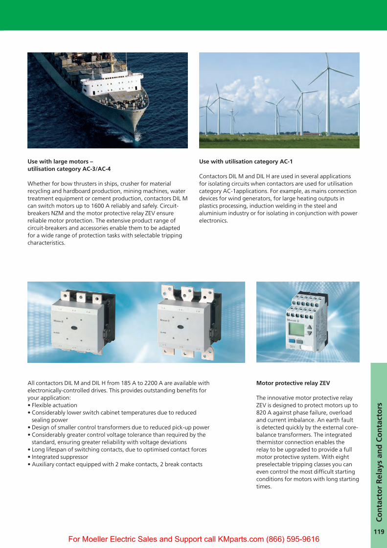
Use with large motors – utilisation category AC-3/AC-4
Whether for bow thrusters in ships, crusher for material recycling and hardboard production, mining machines, watertreatment equipment or cement production, contactors DIL Mcan switch motors up to 1600 A reliably and safely. Circuit-breakers NZM and the motor protective relay ZEV ensurereliable motor protection. The extensive product range ofcircuit-breakers and accessories enable them to be adaptedfor a wide range of protection tasks with selectable trippingcharacteristics.
Use with utilisation category AC-1
Contactors DIL M and DIL H are used in several applications for isolating circuits when contactors are used for utilisationcategory AC-1applications. For example, as mains connectiondevices for wind generators, for large heating outputs in plastics processing, induction welding in the steel andaluminium industry or for isolating in conjunction with powerelectronics.
Co
nta
cto
r R
elay
s an
d C
on
tact
ors
44090_10Kap_Leistungs.qxd 27.02.2008 14:33 Uhr Seite 119
For Moeller Electric Sales and Support call KMparts.com (866) 595-9616

120
1. Moving conductor
2. Metal expansion bellows
3. Fixed contact with fixed conductor
4. Moving contact
5. Arc protection shield
6. Ceramic insulation tube
7. Tube cover
High Rated Contactors –Compact and Powerful
It's your choice: standard or premium versionAll contactors from 185 to 570 A are available as standard or premium versions. All contactors over 570 A are premium versiondevices in all cases.
Compact dimensions
The vacuum switching tubes with theelectromechanical drive system have avery compact design. Vacuum contactorstherefore also offer outstandingly smalldimensions.
A look inside the vacuum
The section drawing of the vacuumtubes shows the fixed and moving contact. The thin metal bellows expandand contract with the moving contactand ensure that the system is sealedduring the frequent movements of thecontact. All copper coloured parts in thedrawing are energized.The ceramic insulation tube isolates theincoming and outgoing sides of theswitching tube. The vacuum switchingtube technology used has been triedand tested since the 1980s.
6
7
4
1
2
35
Contactor actuation Standard Premium
Conventional:A1/A2 are energized in the usualmanner.
L1N
A10
A11
A2
A1
A3
A4
+ +
Directly from the PLC:A 24 V PLC output can be connected atterminals A3/A4 without the need of acoupling relay.
L1N
A10
A11
A2
A1
A3
A4
24 VGND
– +
From low power command devices:Low-power command devices such asboard relays, control circuit devices orposition switches can be connecteddirectly to A10/A11.
L1N
A10
A11
A2
A1
A3
A4
– +
44090_10Kap_Leistungs.qxd 27.02.2008 14:33 Uhr Seite 120
For Moeller Electric Sales and Support call KMparts.com (866) 595-9616

121
User benefits of the innovative motor protective relay ZEV
User-friendliness has top priority withthe motor protective relay ZEV.
- Simple engineering with multi-voltagecoils (24-240 V, 50/60 Hz or DC)
- All settings are menu guided, enablingcurrents, tripping classes and otherfunctions to be set easily.
- Small and light current sensors withexceptionally broad current rangessimplify selection. The cables are simply passed through the sensors.
- With large currents, the sensor beltsare wrapped round the cable andsecured with a Velcro fastener (see picture).
- All three phase symbols – L1, L2, L3 –are displayed, so that a faulty phasecan be indicated quickly: The symbolfor the faulty phase flashes distinctively.
- Differentiated signalling: A trip causedby the thermistor or in the event of anoverload can be indicated separately.
- Prewarning on overload: A prewarningis visually indicated or output via acontact before the device trips.
The motor protective relay ZEV cancontrol even the most difficult startupconditions. The extended trippingclasses up to Class 40 ensure the reliableprotection of motors with long startingtimes. Optimum protection for anymotor startup condition can be providedby selecting one of the eight trippingclasses between 5 and 40.
Co
nta
cto
r R
elay
s an
d C
on
tact
ors
Cool contactors reduce the costs for the switching cabinet
The contactors DIL M and DIL H reducethe sealing power required by up to96 %, which in turn considerablyreduces the temperature inside theswitch cabinet. The costs for the switchcabinet and operating costs are alsoreduced. A smaller switch cabinet canbe used than normally required, andexpensive fans are often unnecessary.Example: DIL M185 (RA250)
DC operatedPower consumption 3.3 Watt
Only four coils for every application
The premium version of the contactorsDIL M enables you to cover all applica-tion ranges and voltages used world-wide with only four coils. This makesfor simple engineering and mostlyonly requires one contactor in stock. The other voltage ranges ofthe coils ensure safe operation evenwith unreliable network conditions.Single voltage coils for the most typicalvoltages used worldwide are availablefor the standard contactors.
100% 4%
ZEV tripping characteristics
x Setting current le
Seco
nd
s
Min
ute
s
44090_10Kap_Leistungs.qxd 27.02.2008 14:33 Uhr Seite 121
For Moeller Electric Sales and Support call KMparts.com (866) 595-9616

122
1
3
4
5
7
2
6
Simply Select: Contactors DIL M and DIL H up to 2200 A
1. Contactors 90 - 900 kW2. Cable terminal block3. Flat strip conductor terminals4. Mechanical interlock5. Overload relay6. Terminal cover, finger-proof7. Auxiliary contact modules,
2-pole, side mounted
Contactor, 3-pole
AC-1 AC-3 Standard electronicsAC:110 - 120 V 50/60 Hz 220 - 240 V 50/60 Hz
Ie=Ith
at 60° C
Ie
A (400 V)
P
kW (400 V)
Part no.
Add voltages from above
275 185 90 DILM185-S/22(...)
315 225 110 DILM225-S/22(...)
350 250 132 DILM250-S/22(...)
400 300 160 DILM300-S/22(...)
500 400 200 DILM400-S/22(...)
700 500 250 DILM500-S/22(...)
750 570 315 DILM570-S/22(...)
800 580 315 –
850 650 355 –
900 750 400 –
1000 820 450 –
1000 1000 560 –
1400 – – –
1800 1600 900 –
2000 – – –
2200 – – –
UL/CSA see page 124
Redundant design of contactors becomes unnecessary
44090_10Kap_Leistungs.qxd 27.02.2008 14:33 Uhr Seite 122
For Moeller Electric Sales and Support call KMparts.com (866) 595-9616
123
Co
nta
cto
r R
elay
s an
d C
on
tact
ors
* RDC48 = 24-48 V DC, RA110 = 48-110 V, 40-60Hz/48-110 V DC, RA250 = 110-250 V, 40-60Hz/110-250 V DC, RAC500 = 250-500 V, 40-60Hz, RAW250 = 230-250 V,40-60Hz/DC
Auxiliary contacts Overload/motor protection
tronics
Hz Hz
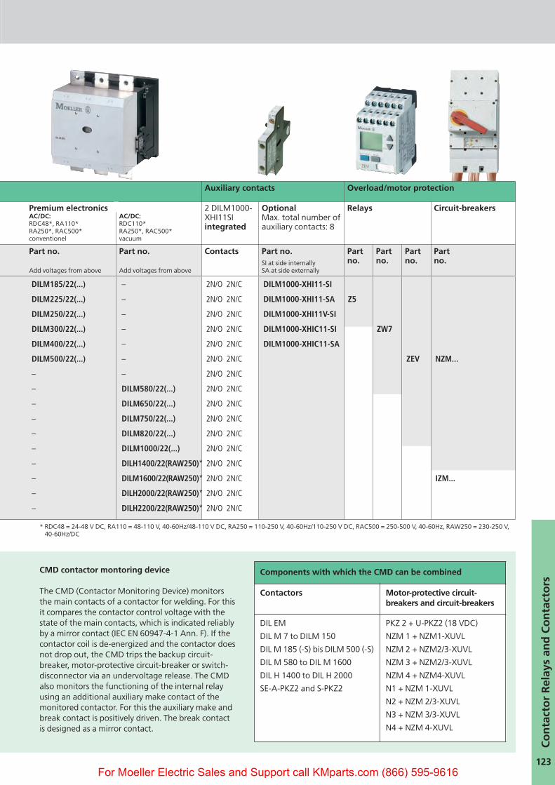
Premium electronics AC/DC:RDC48*, RA110*RA250*, RAC500*conventionel
AC/DC:RDC110*RA250*, RAC500*vacuum
2 DILM1000-XHI11SI integrated
OptionalMax. total number ofauxiliary contacts: 8
Relays Circuit-breakers
above
Part no.
Add voltages from above
Part no.
Add voltages from above
Contacts Part no.SI at side internally SA at side externally
Partno.
Partno.
Partno.
Part no.
..) DILM185/22(...) – 2N/O 2N/C DILM1000-XHI11-SI
..) DILM225/22(...) – 2N/O 2N/C DILM1000-XHI11-SA Z5
..) DILM250/22(...) – 2N/O 2N/C DILM1000-XHI11V-SI
..) DILM300/22(...) – 2N/O 2N/C DILM1000-XHIC11-SI ZW7
..) DILM400/22(...) – 2N/O 2N/C DILM1000-XHIC11-SA
..) DILM500/22(...) – 2N/O 2N/C ZEV NZM...
..) – – 2N/O 2N/C
– DILM580/22(...) 2N/O 2N/C
– DILM650/22(...) 2N/O 2N/C
– DILM750/22(...) 2N/O 2N/C
– DILM820/22(...) 2N/O 2N/C
– DILM1000/22(...) 2N/O 2N/C
– DILH1400/22(RAW250)* 2N/O 2N/C
– DILM1600/22(RAW250)* 2N/O 2N/C IZM...
– DILH2000/22(RAW250)* 2N/O 2N/C
– DILH2200/22(RAW250)* 2N/O 2N/C
CMD contactor montoring device
The CMD (Contactor Monitoring Device) monitorsthe main contacts of a contactor for welding. For thisit compares the contactor control voltage with thestate of the main contacts, which is indicated reliablyby a mirror contact (IEC EN 60947-4-1 Ann. F). If thecontactor coil is de-energized and the contactor doesnot drop out, the CMD trips the backup circuit-breaker, motor-protective circuit-breaker or switch-disconnector via an undervoltage release. The CMDalso monitors the functioning of the internal relayusing an additional auxiliary make contact of themonitored contactor. For this the auxiliary make andbreak contact is positively driven. The break contactis designed as a mirror contact.
Components with which the CMD can be combined
Contactors Motor-protective circuit-breakers and circuit-breakers
DIL EM
DIL M 7 to DILM 150
DIL M 185 (-S) bis DILM 500 (-S)
DIL M 580 to DIL M 1600
DIL H 1400 to DIL H 2000
SE-A-PKZ2 and S-PKZ2
PKZ 2 + U-PKZ2 (18 VDC)
NZM 1 + NZM1-XUVL
NZM 2 + NZM2/3-XUVL
NZM 3 + NZM2/3-XUVL
NZM 4 + NZM4-XUVL
N1 + NZM 1-XUVL
N2 + NZM 2/3-XUVL
N3 + NZM 3/3-XUVL
N4 + NZM 4-XUVL
44090_10Kap_Leistungs.qxd 27.02.2008 14:34 Uhr Seite 123
For Moeller Electric Sales and Support call KMparts.com (866) 595-9616

124
Non-Combination Motor-StarterDILM/Z for North America
Motor starter combinations (Non-Combination Motor Starters) DILM / Z for use in North America
Maximum HP Ratings, 3-phase, 60 Hz, at:
MotorFull LoadCurrent
Contactor OverloadRelay
Maximum Protective devicefor North America
Fuse Circuit Breaker
208 V (200 V)
240 V (230 V)
480 V (460 V)
600 V (575 V)
FLC As perCEC / NEC1)
Rated Current
InstantaneousShort-circuit Trip
HP HP HP HP A Part no. Part no. A A A
- - m m 1 DILEEM ZE-1 3 15 -- - o 1 1.4 DILEEM ZE-1,6 6 15 -m m 1 1m 2.3 DILEEM ZE-2,4 6 15 -1 1 2 3 3.9 DILEEM ZE-4 15 15 -
1m 1m 3 - 6 DILEEM ZE-6 20 15 -1m 2 - - 6.8 DILEEM ZE-9 35 15 -1m 2 5 5 7.8 DILEM ZE-9 35 15 -1m 3 5 5 9.6 DILEM ZE-12 45 - -
- - m m 1 DILM7 ZB12-1 3 25 200- - m 1 1.4 DILM7 ZB12-1,6 6 25 200m m 1 1m 2.3 DILM7 ZB12-2,4 6 25 2001 1 2 3 3.9 DILM7 ZB12-4 15 25 200
1m 1m 3 - 6 DILM7 ZB12-6 20 25 2003 - - 7m 9 DILM9 ZB12-10 25 25 2003 3 5 7m 9.6 DILM12 ZB12-10 25 25 2003 - 7m 10 11 DILM12 ZB12-12 40 25 2005 5 10 - 15.2 DILM15 ZB12-16 40 30 320
- - m m 1 DILM17 ZB32-1 3 25 200- - o 1 1.4 DILM17 ZB32-1,6 6 25 200m m 1 1m 2.3 DILM17 ZB32-2,4 6 25 2001 1 2 3 3.9 DILM17 ZB32-4 15 25 200
1m 1m 3 - 6 DILM17 ZB32-6 20 25 200- 3 5 7m 9.6 DILM17 ZB32-10 25 25 200- - 7m 10 11 DILM17 ZB32-12 40 30 3205 5 10 - 15.2 DILM17 ZB32-16 40 30 320
7m 7m 15 20 22 DILM25 ZB32-24 90 100 120010 10 20 25 32.2 DILM32 ZB32-32 125 125 1200
- 3 5 7,5 9.6 DILM40 ZB65-10 40 40 380- 5 10 10 15.2 DILM40 ZB65-16 60 60 760- 7m 20 25 32.2 DILM40 ZB65-24 90 90 1200
10 10 20 30 34 DILM40 ZB65-40 125 125 120015 20 40 50 54 DILM50 ZB65-57 200 150 200020 20 50 50 63 DILM65/72 ZB65-65 200 150 2000
25 30 60 75 80 DILM80 ZB150-70 250 250 -25 40 75 100 104 DILM95 ZB150-100 J 400 J 400 -40 50 100 100 130 DILM115 ZB150-125 J 400 J 500 -40 60 125 125 156 DILM150/170 ZB150-150 J 600 J 600 -
- 60 125 150 156 DILM185 Z5-160 700 CLASS L 600 7200- 75 150 200 192 DILM225 Z5-220 700 CLASS L 600 7200- 100 200 250 248 DILM250 Z5-250 700 CLASS L 600 7200- 125 250 300 312 DILM300 ZW7-400 800 CLASS L 600 7200- 150 300 400 382 DILM400 ZW7-400 800 CLASS L 600 7200- 200 400 500 480 DILM500 ZW7-540 800 CLASS L 600 7200- 200 400 600 480 DILM580 ZEV-XSW820 2000 - -- 250 500 600 600 DILM650 ZEV-XSW820 2000 - -- 300 600 700 700 DILM750 ZEV-XSW820 2000 - -- 350 700 860 860 DILM820 ZEV-XSW820 2000 - -
1) North American type fuses only.
44090_10Kap_Leistungs.qxd 27.02.2008 14:34 Uhr Seite 124
For Moeller Electric Sales and Support call KMparts.com (866) 595-9616

125
Motor contactors for the North American marketMotor contactors in North America areindustrial control devices (IndustrialControl Equipment per UL 508 andCSA-C22-2 No. 14). North Americanbuyers specify either contactors with so-called „NEMA-Sizes“, or they purchasecomponents specifically for motor switching, which are rated in (HP) Horsepower and can be more customizedfor the application. The table showsthe relationship of power and nominalcurrent ratings corresponding to eachrespective NEMA-size.Moeller contactors Type DIL M7 throughDIL M65, and matching Type Z overloadrelays, each have a basic short circuitrating of 5 kA. Larger Moeller contactorsstarting with the DIL M80 have, together with their corresponding Type Z overload relays, a shorth circuitrating of 10 kA.
Combination “Contactor + Overload Relay”(„Non-combination Motor Starter“)NEMA-sizes, as they relate to the HPratings of Moeller contactors, are provided in the table on the left side. Contactors and overload relays makeup an assembly that is referred to inNorth America as a „Non-combinationmotor starter“. For these assemblies,namely consisting of “Contactor +Overload Relay”, the North Americanbuyer specifies the same ordering information as it applies to individualcontactors. The table clearly indicatesthat, with respect to all common nominalvoltage levels, the combination of „IECstyle“ contactors DIL M with overloadrelays Type Z create many more startercombinations than correspondingstraight NEMA sizing would allow for.
Three Phase NEMA Contactors
NEMA-Sizes
Rated Current Three Phase HP ratings 1)
200 V / 60 Hz 230 V / 60 Hz 460 V / 60 Hz 575 V / 60 Hz
Highest short timeduration current
A HP (PS) HP (PS) HP (PS) A
00 9 1 m 1 m 2 11
0 18 3 3 5 21
1 27 7 m 7 m 10 32
2 45 10 15 25 52
3 90 25 30 50 104
4 135 40 50 100 156
5 270 75 100 200 311
6 540 150 200 400 621
7 810 - 300 600 932
8 1215 - 450 900 1400
9 2250 - 800 1600 2590
1) HP ratings for 3-Phase contactors, single speed motors, with no jogging, reversing anddynamic current braking.
Co
nta
cto
r R
elay
s an
d C
on
tact
ors
44090_10Kap_Leistungs.qxd 27.02.2008 14:34 Uhr Seite 125
For Moeller Electric Sales and Support call KMparts.com (866) 595-9616

7
Content Page
Command and signalling devices RMQ-Titan,RMQ16, Fingerprint system M22-ESA 8 - 27
Position switch LS-Titan, AT...28 - 39
Rotary switches T and switch-disconnectors P40 - 51
Insulated enclosure CI-K52 - 55
Function relays –timing, safety, operating, measuring and monitoring relays 56 - 67
Easy control relay, multi-function-display MFD-Titan, safety-related control relay easySafety, easyControl EC4P 68 - 91
Power supplies SN92 - 93
Frequency inverters DF/DV94 - 97
Semiconductor contactors DS Soft starter DS and DM 98 - 105
Contactors DIL Auxiliary switches DIL, Overload relays Z 106 - 125
Motor-protective circuit-breakers PKZ126 - 139
Motor-starter combinations140 - 151
Decentral Motor Starter and Speed Controller Rapid Link 152 - 153
Circuit-breakers and switch-disconnectors NZM/IZM154 - 189
Switchgear systems xEnergy190 - 195
Characteristics program196 - 199
Miniature circuit-breakers FAZResidual-current circuit-breakers, Combined RCD/MCB switches, Surge arresters, Rail-mounted service installation devices 200 - 207
Transformers and line reactors208 - 211
Safety technology212 - 227
Label editor228 - 231
Approvals232 - 235
Services/Addresses236 - 243
44090_00Kap_Vorlaufseiten.indd 744090_00Kap_Vorlaufseiten.indd 7 28.02.2008 9:43:17 Uhr28.02.2008 9:43:17 Uhr
For Moeller Electric Sales and Support call KMparts.com (866) 595-9616