contactors motor-starters -...
TRANSCRIPT

ContactorsMotor-Starters
D677E141
D677E 1
Technical data, dimension sketches, illustration and weights given in our list and printed matter, are subject to change without notice.
2014
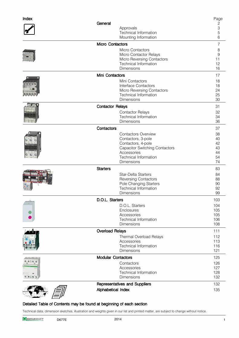
IndexIndexIndexIndexIndex PageGeneralGeneralGeneralGeneralGeneral 2
Approvals 3Technical Information 5Mounting Information 6
Micro ContactorsMicro ContactorsMicro ContactorsMicro ContactorsMicro Contactors 7Micro Contactors 8Micro Contactor Relays 9Micro Reversing Contactors 11Technical Information 12Dimensions 16
Mini ContactorsMini ContactorsMini ContactorsMini ContactorsMini Contactors 17Mini Contactors 18Interface Contactors 18Micro Reversing Contactors 24Technical Information 25Dimensions 30
Contactor RelaysContactor RelaysContactor RelaysContactor RelaysContactor Relays 31Contactor Relays 32Technical Information 34Dimensions 36
ContactorsContactorsContactorsContactorsContactors 37Contactors Overview 38Contactors, 3-pole 40Contactors, 4-pole 42Capacitor Switching Contactors 43Accessories 44Technical Information 54Dimensions 74
StartersStartersStartersStartersStarters 83Star-Delta Starters 84Reversing Contactors 88Pole Changing Starters 90Technical Information 92Dimensions 99
D.O.L. StartersD.O.L. StartersD.O.L. StartersD.O.L. StartersD.O.L. Starters 103D.O.L. Starters 104Enclosures 105Accessories 105Technical Information 106Dimensions 108
Overload RelaysOverload RelaysOverload RelaysOverload RelaysOverload Relays 111Thermal Overload Relays 112Accessories 113Technical Information 116Dimensions 121
Modular ContactorsModular ContactorsModular ContactorsModular ContactorsModular Contactors 125Contactors 126Accessories 127Technical Information 128Dimensions 132
Representatives and SuppliersRepresentatives and SuppliersRepresentatives and SuppliersRepresentatives and SuppliersRepresentatives and Suppliers 132Alphabetical IndexAlphabetical IndexAlphabetical IndexAlphabetical IndexAlphabetical Index 135
Detailed Table of Contents may be found at beginning of each sectionDetailed Table of Contents may be found at beginning of each sectionDetailed Table of Contents may be found at beginning of each sectionDetailed Table of Contents may be found at beginning of each sectionDetailed Table of Contents may be found at beginning of each section

2 D677E
Marking of auxiliary contactsAt several devices in UL-data are two voltages for auxiliary contactsmentioned (e. g.: 600 volts at same potential, 150 volts at differentpotentials). That means, if the voltage is higher than 150 volts, the controlvoltage applied to input terminals must be at the same potential.
Marking of Max. rated values per pole Contactauxiliary contacts Voltage Current Cont. Ratingaccording to Make Break Current CodeCSA and UL V A A A Designation
Heavy Duty AC 120 60 6 10 A150(HD or HVY DTY) AC 240 30 3 10 A300
AC 480 15 1,5 10 A600AC 600 12 1,2 10 A600
DC 125 2,2 2,2 10 N150DC 250 1,1 1,1 10 N300DC 600 0,4 0,4 10 N600
Standard Duty AC 120 30 3 5 B150(SD or STD DTY) AC 240 15 1,5 5 B300
AC 480 7,5 0,75 5 B600AC 600 6 0,6 5 B600
DC 125 1,1 1,1 5 P150DC 250 0,55 0,55 5 P300DC 600 0,2 0,2 5 P600
- AC 120 15 1,5 2,5 C150AC 240 7,5 0,75 2,5 C300AC 480 3,75 0,375 2,5 C600AC 600 3 0,3 2,5 C600
DC 125 0,55 0,55 2,5 Q150DC 250 0,27 0,27 2,5 Q300DC 600 0,1 0,1 2,5 Q600
- AC 120 3,6 0,6 1 D150AC 240 1,8 0,3 1 D300
DC 125 0,22 0,22 1 R150DC 250 0,11 0,11 1 R300
- AC 120 1,8 0,3 0,5 E150
Low voltage switchgear for auxiliary circuits (e. g. contactor relays, controlunits, auxiliary contacts in general) usually approved for "Heavy Duty" or"Standard Duty" UL and besides these marked with the admissible max.voltage or with short codes (see table).
Discernment at UL-Standards
Recognized ComponentRecognized ComponentRecognized ComponentRecognized ComponentRecognized Component ListedListedListedListedListedIndustrial Control EquipmentIndustrial Control EquipmentIndustrial Control EquipmentIndustrial Control EquipmentIndustrial Control Equipment Industrial Control EquipmentIndustrial Control EquipmentIndustrial Control EquipmentIndustrial Control EquipmentIndustrial Control Equipment
UL issues yellow "Guide cards" UL issues white "Guide cards"with Guide- and File-No. with Guide- and File-No.
Devices have permission to be Devices have to be markedmarked with with theon the label "UL-Listing Mark"
Devices as components approved for Devices approved for "field wiring","factory wiring":devices for employment in controlpanels, when they are selected, a) devices for employmentmounted and wired according to in control panels, whenthe charging conditions by skilled they are mounted andworker. wired by skilled worker.
b) devices for retail in USA
Valid UL-Standards: Valid UL-Standards:UL 508 "Standard for Industrial UL 508 "Standard for Industrial Control
Control Equipment" Equipment" (unlimited)(partly limited)
Are devices approved as "Listed Equipment" the approval is also valid
for using as "Recognized Component" .
GeneralGeneralGeneralGeneralGeneral
CE-Marking
The manufacturer has to sign his products with the CE-Marking. With theCE-Marking the manufacturer confirms the accordance with the differentEEC Directives. The CE-Marking is absolutely necessary to sell theproducts in the EEC.Below you find the EEC Directives concerning our products.Low Voltage Directive 2006/95/ECEMC Directive 2004/108/ECRoHS + WEEE 2002/95/EC + "002/96/EC
Test Authorities, Registration Mark, ApprovalsTest Authorities, Registration Mark, ApprovalsTest Authorities, Registration Mark, ApprovalsTest Authorities, Registration Mark, ApprovalsTest Authorities, Registration Mark, Approvals
Low voltage switchgear from Benedict GmbH is built and testedto national and international specifications. All devices suit allimportant specifications without any test obligation, like VDE, BSand also relative to IEC Recommendations and to European Standardslike IEC 947 and EN 60947.It is for this reason of our Low voltage switchgear is used all over theworld. In order to provide special versions, limitations to the max.voltages, currents and power ratings or special markings aresometimes necessary.
Quality Control SystemQuality Control SystemQuality Control SystemQuality Control SystemQuality Control System
Since November 1991 Benedict GmbH has been certified according tothe quality control system ÖNORM EN ISO 29001ÖNORM EN ISO 29001ÖNORM EN ISO 29001ÖNORM EN ISO 29001ÖNORM EN ISO 29001. The target of the ISO-certification is, to grant the customer the quality of the performance ofhis supplier, who is audited in accordance with this standard.
CountryCountryCountryCountryCountry North AmericaNorth AmericaNorth AmericaNorth AmericaNorth America RussiaRussiaRussiaRussiaRussia ChinaChinaChinaChinaChina
State deputy or private examination UL GOST CCC(state admitted) Canada, USA
Label marking Listedof examination boards
Component
Duty of approvals all switchgear all switchgear all switchgear
Explanations for choice and supply of low voltage switchgear in Canada and USAExplanations for choice and supply of low voltage switchgear in Canada and USAExplanations for choice and supply of low voltage switchgear in Canada and USAExplanations for choice and supply of low voltage switchgear in Canada and USAExplanations for choice and supply of low voltage switchgear in Canada and USA

D677E 3
ApprovalsApprovalsApprovalsApprovalsApprovalsCountry North America Switzerland Europe Russia China CENELEC
GOST CB-CertificatesUL SEV
Type
Micro Contactor Relays, Micro Contactors, Micro Reversing Contactors and Accessories
K0-04D.. - - - o - - -K0-05D.. o - - o - - -K0W05D.. o - - o - - -
Mini Contactor Relays, Mini Contactors, Mini Reversing Contactors K1 and Accessories
K1-07D..(=) o - - o o - oK1-07L..(=) - o - o o - oK1-07F..(=) - o - o - - -
K1-09D..(=) o - - o o o oK1-09L..(=) - o - o o o oK1-09F..(=) - o - o - o -
K1-12D..(=) o - - o - o -
K1W09D01(=) o - - o - o -K1W12D01(=) o - - o - o -K1W09L01(=) - o - o - o -
HK.., HKM.. o - - o - - oRC-K1 o - - o - - -
Contactor Relays, Contactors Series K3
K3-07ND..(=) o - - o - - -K3-10N..(=) o - o o o o oK3-14N..(=) o - o o o o oK3-18N..(=) o - o o o o oK3-22N..(=) o - o o o o o
K3-24A..(=) o - o o o o oK3-32A..(=) o - o o o o oK3-40A..(=) o - o o o o o
K3-50A..(=) o - o o o o oK3-62A..(=) o - o o o o oK3-74A..(=) o - o o o o o
K3-90A..(=) o - - o - o -K3-115A..(=) o - - o - o -
K3-151A..(=) o - - o - - -K3-176A..(=) o - - o - - -
K3-210A..(=) x - - o - - -K3-260A..(=) x - - o - - -K3-316A..(=) x - - o - - -
K3-450A..(=) o - - o - - -K3-550A..(=) o - - o - - -
K3-700A..(=) o - - o - - -K3-860A..(=) o - - o - - -K3-1000A..(=) - - - o - - -K3-1200A..(=) o - - o - - -
Contactor Relays, Contactors DC-operated Series KG3
KG3-07.. o - - o - - oKG3-10.., -14.. o - - o - - oKG3-18.., -22.. o - - o - - oKG3-24.., -32.. o - - o - - oKG3-40.. o - - o - - o
Capacitor Contactors Series K3
K3-18K.. o - - o o o oK3-24K.. o - - o o o oK3-32K.. o - - o o o o
K3-50K.. o - - o o o oK3-62K.. o - - o o o oK3-74K.. o - - o o o oK3-90K.. o - - o - o -K3-115K.. o - - o - o -
Aux. contacts
HN.., HTN.. o - - o o o oHA.. o - - o o - oHB.. o - - o o o oK2-DK, K2-SK o - - o - - -
HKA.., HKT.. o - - o - - -HKF22 - - - o - - -
o In standard version approved x In test - Not provided for test till now
4 D677E
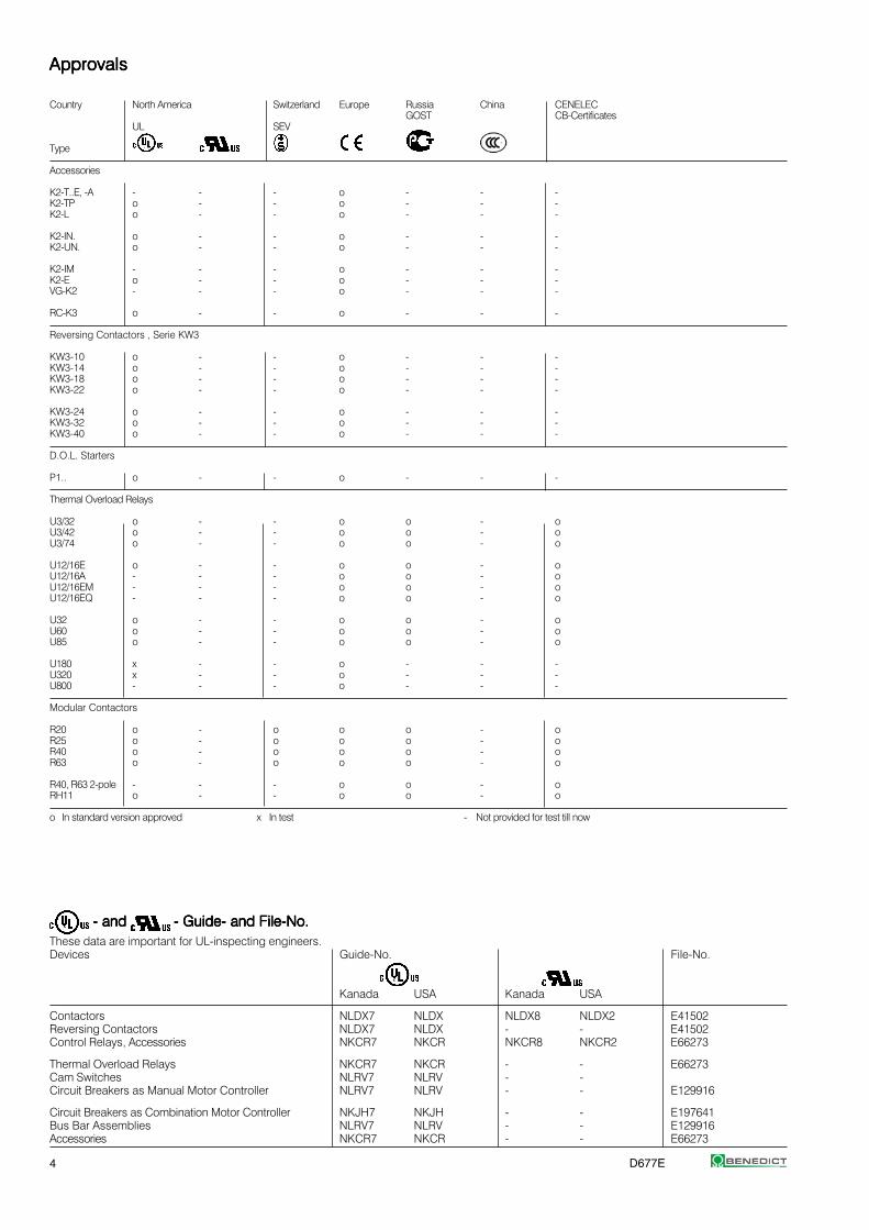
- and - and - and - and - and - Guide- and File-No.- Guide- and File-No.- Guide- and File-No.- Guide- and File-No.- Guide- and File-No.These data are important for UL-inspecting engineers.Devices Guide-No. File-No.
Kanada USA Kanada USA
Contactors NLDX7 NLDX NLDX8 NLDX2 E41502Reversing Contactors NLDX7 NLDX - - E41502Control Relays, Accessories NKCR7 NKCR NKCR8 NKCR2 E66273
Thermal Overload Relays NKCR7 NKCR - - E66273Cam Switches NLRV7 NLRV - -Circuit Breakers as Manual Motor Controller NLRV7 NLRV - - E129916
Circuit Breakers as Combination Motor Controller NKJH7 NKJH - - E197641Bus Bar Assemblies NLRV7 NLRV - - E129916Accessories NKCR7 NKCR - - E66273
ApprovalsApprovalsApprovalsApprovalsApprovals
Country North America Switzerland Europe Russia China CENELECGOST CB-Certificates
UL SEV
Type
Accessories
K2-T..E, -A - - - o - - -K2-TP o - - o - - -K2-L o - - o - - -
K2-IN. o - - o - - -K2-UN. o - - o - - -
K2-IM - - - o - - -K2-E o - - o - - -VG-K2 - - - o - - -
RC-K3 o - - o - - -
Reversing Contactors , Serie KW3
KW3-10 o - - o - - -KW3-14 o - - o - - -KW3-18 o - - o - - -KW3-22 o - - o - - -
KW3-24 o - - o - - -KW3-32 o - - o - - -KW3-40 o - - o - - -
D.O.L. Starters
P1.. o - - o - - -
Thermal Overload Relays
U3/32 o - - o o - oU3/42 o - - o o - oU3/74 o - - o o - o
U12/16E o - - o o - oU12/16A - - - o o - oU12/16EM - - - o o - oU12/16EQ - - - o o - o
U32 o - - o o - oU60 o - - o o - oU85 o - - o o - o
U180 x - - o - - -U320 x - - o - - -U800 - - - o - - -
Modular Contactors
R20 o - o o o - oR25 o - o o o - oR40 o - o o o - oR63 o - o o o - o
R40, R63 2-pole - - - o o - oRH11 o - - o o - o
o In standard version approved x In test - Not provided for test till now
D677E 5
Technical InformationTechnical InformationTechnical InformationTechnical InformationTechnical Information
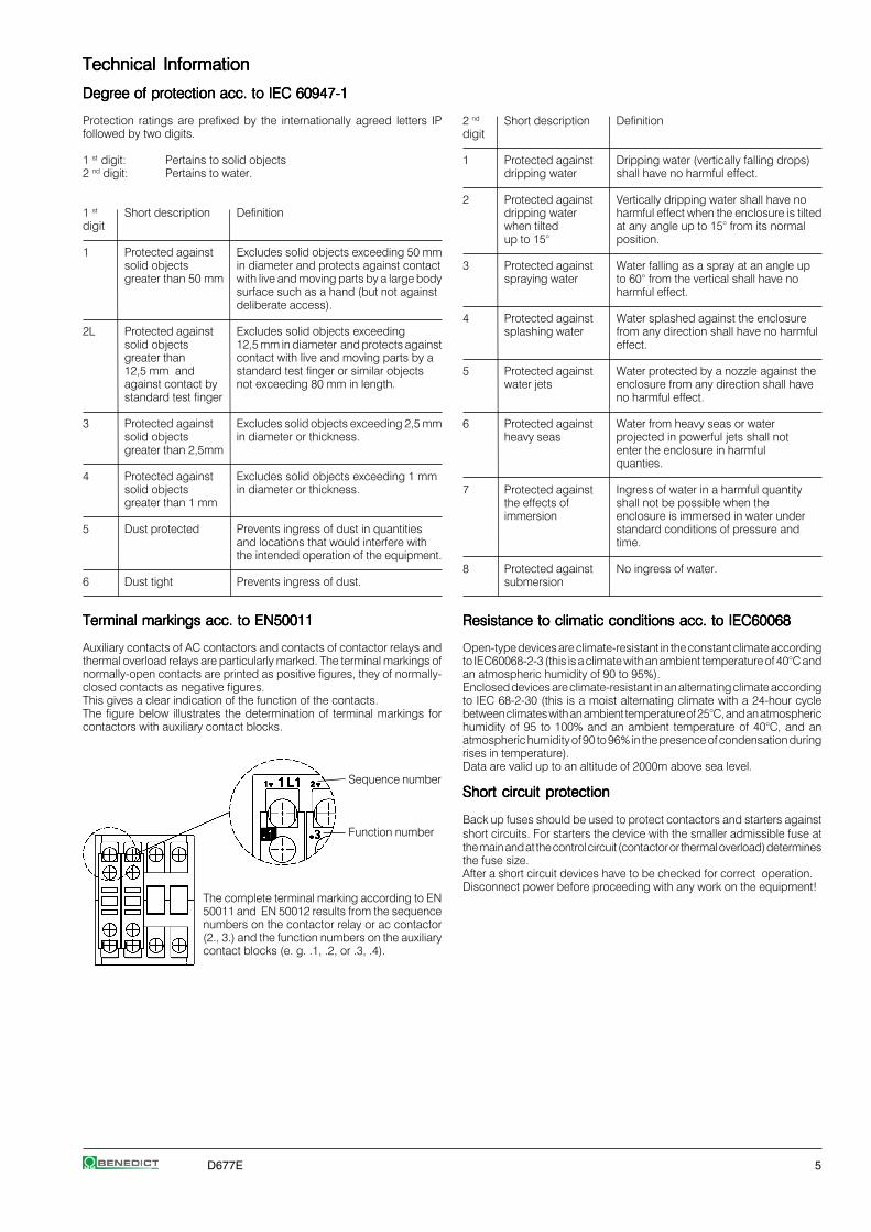
Degree of protection acc. to IEC 60947-1Degree of protection acc. to IEC 60947-1Degree of protection acc. to IEC 60947-1Degree of protection acc. to IEC 60947-1Degree of protection acc. to IEC 60947-1
Protection ratings are prefixed by the internationally agreed letters IPfollowed by two digits.
1 st digit: Pertains to solid objects2 nd digit: Pertains to water.
1 st Short description Definitiondigit
1 Protected against Excludes solid objects exceeding 50 mmsolid objects in diameter and protects against contactgreater than 50 mm with live and moving parts by a large body
surface such as a hand (but not againstdeliberate access).
2L Protected against Excludes solid objects exceedingsolid objects 12,5 mm in diameter and protects againstgreater than contact with live and moving parts by a12,5 mm and standard test finger or similar objectsagainst contact by not exceeding 80 mm in length.standard test finger
3 Protected against Excludes solid objects exceeding 2,5 mmsolid objects in diameter or thickness.greater than 2,5mm
4 Protected against Excludes solid objects exceeding 1 mmsolid objects in diameter or thickness.greater than 1 mm
5 Dust protected Prevents ingress of dust in quantitiesand locations that would interfere withthe intended operation of the equipment.
6 Dust tight Prevents ingress of dust.
Terminal markings acc. to EN50011Terminal markings acc. to EN50011Terminal markings acc. to EN50011Terminal markings acc. to EN50011Terminal markings acc. to EN50011
Auxiliary contacts of AC contactors and contacts of contactor relays andthermal overload relays are particularly marked. The terminal markings ofnormally-open contacts are printed as positive figures, they of normally-closed contacts as negative figures.This gives a clear indication of the function of the contacts.The figure below illustrates the determination of terminal markings forcontactors with auxiliary contact blocks.
Sequence number
Function number
The complete terminal marking according to EN50011 and EN 50012 results from the sequencenumbers on the contactor relay or ac contactor(2., 3.) and the function numbers on the auxiliarycontact blocks (e. g. .1, .2, or .3, .4).
2 nd Short description Definitiondigit
1 Protected against Dripping water (vertically falling drops)dripping water shall have no harmful effect.
2 Protected against Vertically dripping water shall have nodripping water harmful effect when the enclosure is tiltedwhen tilted at any angle up to 15° from its normalup to 15° position.
3 Protected against Water falling as a spray at an angle upspraying water to 60° from the vertical shall have no
harmful effect.
4 Protected against Water splashed against the enclosuresplashing water from any direction shall have no harmful
effect.
5 Protected against Water protected by a nozzle against thewater jets enclosure from any direction shall have
no harmful effect.
6 Protected against Water from heavy seas or waterheavy seas projected in powerful jets shall not
enter the enclosure in harmfulquanties.
7 Protected against Ingress of water in a harmful quantitythe effects of shall not be possible when theimmersion enclosure is immersed in water under
standard conditions of pressure andtime.
8 Protected against No ingress of water.submersion
Resistance to climatic conditions acc. to IEC60068Resistance to climatic conditions acc. to IEC60068Resistance to climatic conditions acc. to IEC60068Resistance to climatic conditions acc. to IEC60068Resistance to climatic conditions acc. to IEC60068
Open-type devices are climate-resistant in the constant climate accordingto IEC60068-2-3 (this is a climate with an ambient temperature of 40°C andan atmospheric humidity of 90 to 95%).Enclosed devices are climate-resistant in an alternating climate accordingto IEC 68-2-30 (this is a moist alternating climate with a 24-hour cyclebetween climates with an ambient temperature of 25°C, and an atmospherichumidity of 95 to 100% and an ambient temperature of 40°C, and anatmospheric humidity of 90 to 96% in the presence of condensation duringrises in temperature).Data are valid up to an altitude of 2000m above sea level.
Short circuit protectionShort circuit protectionShort circuit protectionShort circuit protectionShort circuit protection
Back up fuses should be used to protect contactors and starters againstshort circuits. For starters the device with the smaller admissible fuse atthe main and at the control circuit (contactor or thermal overload) determinesthe fuse size.After a short circuit devices have to be checked for correct operation.Disconnect power before proceeding with any work on the equipment!
6 D677E
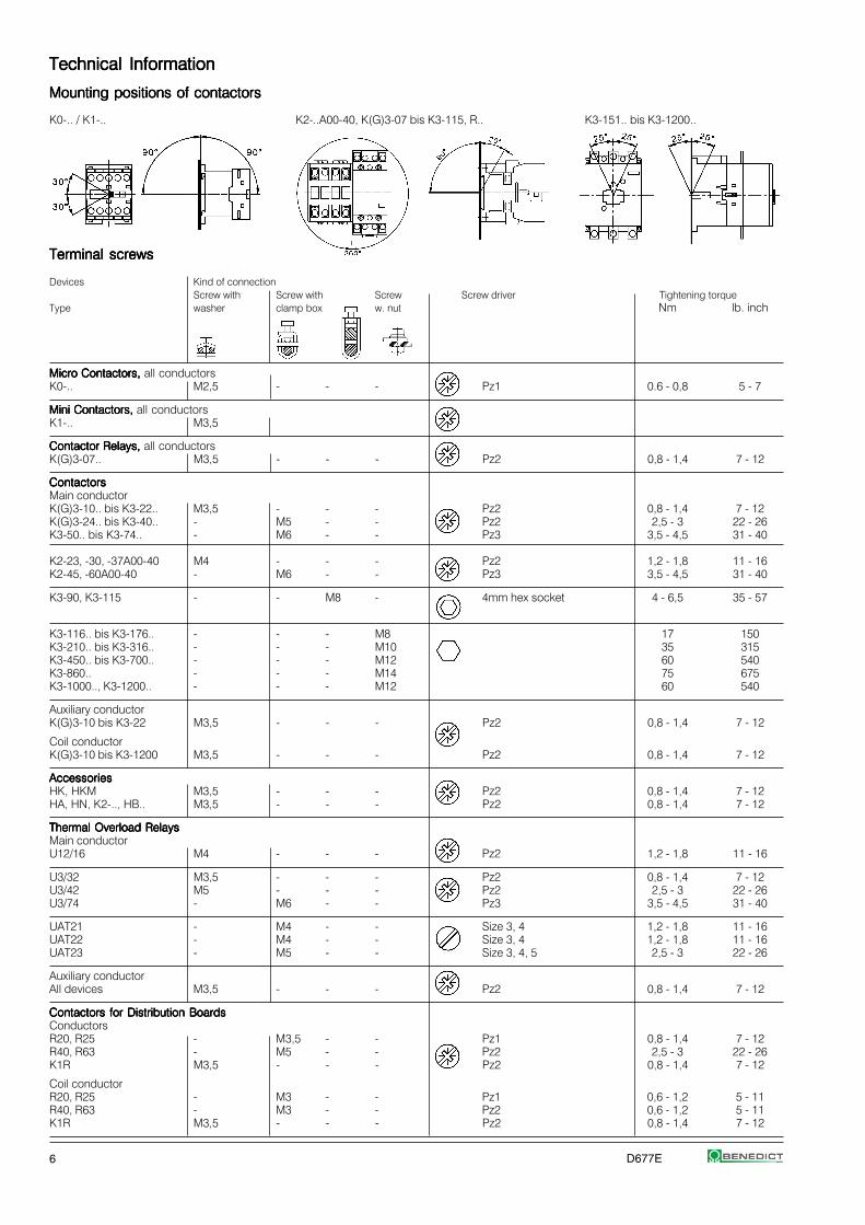
Technical InformationTechnical InformationTechnical InformationTechnical InformationTechnical Information
Mounting positions of contactorsMounting positions of contactorsMounting positions of contactorsMounting positions of contactorsMounting positions of contactors
K0-.. / K1-.. K2-..A00-40, K(G)3-07 bis K3-115, R.. K3-151.. bis K3-1200..
Terminal screwsTerminal screwsTerminal screwsTerminal screwsTerminal screws
Devices Kind of connectionScrew with Screw with Screw Screw driver Tightening torque
Type washer clamp box w. nut Nm lb. inch
Micro Contactors, Micro Contactors, Micro Contactors, Micro Contactors, Micro Contactors, all conductorsK0-.. M2,5 - - - Pz1 0.6 - 0,8 5 - 7
Mini Contactors, Mini Contactors, Mini Contactors, Mini Contactors, Mini Contactors, all conductorsK1-.. M3,5
Contactor Relays,Contactor Relays,Contactor Relays,Contactor Relays,Contactor Relays, all conductorsK(G)3-07.. M3,5 - - - Pz2 0,8 - 1,4 7 - 12
ContactorsContactorsContactorsContactorsContactorsMain conductorK(G)3-10.. bis K3-22.. M3,5 - - - Pz2 0,8 - 1,4 7 - 12K(G)3-24.. bis K3-40.. - M5 - - Pz2 2,5 - 3 22 - 26K3-50.. bis K3-74.. - M6 - - Pz3 3,5 - 4,5 31 - 40
K2-23, -30, -37A00-40 M4 - - - Pz2 1,2 - 1,8 11 - 16K2-45, -60A00-40 - M6 - - Pz3 3,5 - 4,5 31 - 40
K3-90, K3-115 - - M8 - 4mm hex socket 4 - 6,5 35 - 57
K3-116.. bis K3-176.. - - - M8 17 150K3-210.. bis K3-316.. - - - M10 35 315K3-450.. bis K3-700.. - - - M12 60 540K3-860.. - - - M14 75 675K3-1000.., K3-1200.. - - - M12 60 540
Auxiliary conductorK(G)3-10 bis K3-22 M3,5 - - - Pz2 0,8 - 1,4 7 - 12
Coil conductorK(G)3-10 bis K3-1200 M3,5 - - - Pz2 0,8 - 1,4 7 - 12
AccessoriesAccessoriesAccessoriesAccessoriesAccessoriesHK, HKM M3,5 - - - Pz2 0,8 - 1,4 7 - 12HA, HN, K2-.., HB.. M3,5 - - - Pz2 0,8 - 1,4 7 - 12
Thermal Overload RelaysThermal Overload RelaysThermal Overload RelaysThermal Overload RelaysThermal Overload RelaysMain conductorU12/16 M4 - - - Pz2 1,2 - 1,8 11 - 16
U3/32 M3,5 - - - Pz2 0,8 - 1,4 7 - 12U3/42 M5 - - - Pz2 2,5 - 3 22 - 26U3/74 - M6 - - Pz3 3,5 - 4,5 31 - 40
UAT21 - M4 - - Size 3, 4 1,2 - 1,8 11 - 16UAT22 - M4 - - Size 3, 4 1,2 - 1,8 11 - 16UAT23 - M5 - - Size 3, 4, 5 2,5 - 3 22 - 26
Auxiliary conductorAll devices M3,5 - - - Pz2 0,8 - 1,4 7 - 12
Contactors for Distribution BoardsContactors for Distribution BoardsContactors for Distribution BoardsContactors for Distribution BoardsContactors for Distribution BoardsConductorsR20, R25 - M3,5 - - Pz1 0,8 - 1,4 7 - 12R40, R63 - M5 - - Pz2 2,5 - 3 22 - 26K1R M3,5 - - - Pz2 0,8 - 1,4 7 - 12
Coil conductorR20, R25 - M3 - - Pz1 0,6 - 1,2 5 - 11R40, R63 - M3 - - Pz2 0,6 - 1,2 5 - 11K1R M3,5 - - - Pz2 0,8 - 1,4 7 - 12
D677E 7
Micro ContactorsMicro ContactorsMicro ContactorsMicro ContactorsMicro Contactors
Micro Contactor Relays 8
Micro Contactors 9
Micro Contactors With Solder Pins 10
Coil voltages 10
Micro Reversing Contactor 11
Technical Data 12
Dimensions 16

8 D677E
Micro Contactor Relays 4-poleMicro Contactor Relays 4-poleMicro Contactor Relays 4-poleMicro Contactor Relays 4-poleMicro Contactor Relays 4-pole AC Operated
RatingsRatingsRatingsRatingsRatings Therm. Contacts 2) TypeTypeTypeTypeType Coil voltage 1)
Distinc. Additional 2424242424 24V 50/60HzNumber Contact 230230230230230 220-230V 50Hz
AC15AC15AC15AC15AC15 Rated-Current
230V230V230V230V230V 400V Ith acc. to Blocks ⏐⏐⏐⏐⏐ Pack WeightAAAAA A A NO NC EN50011 Type pcs. kg/pc.
4-pole, With Screw Terminals4-pole, With Screw Terminals4-pole, With Screw Terminals4-pole, With Screw Terminals4-pole, With Screw Terminals
xxxxxxxxxxxxxxx3) xxx3) xxx3) 4 - 40E - K0-04D40 . . .K0-04D40 . . .K0-04D40 . . .K0-04D40 . . .K0-04D40 . . . 10 0,064
xxx xxx xxx xxx xxx3) xxx3) xxx3) 3 1 31E - K0-04D31 . . .K0-04D31 . . .K0-04D31 . . .K0-04D31 . . .K0-04D31 . . . 10 0,064
xxx xxx xxx xxx xxx3) xxx3) xxx3) 2 2 22E - K0-04D22 . . .K0-04D22 . . .K0-04D22 . . .K0-04D22 . . .K0-04D22 . . . 10 0,064
K0-04D40K0-04D40K0-04D40K0-04D40K0-04D40 K0-04D31K0-04D31K0-04D31K0-04D31K0-04D31 K0-04D22K0-04D22K0-04D22K0-04D22K0-04D22
1) Other coil voltages on request.2) Contacts suitable for electronic circuits, according to EN947-5-4 for rated voltage 24V DC
(test ratings 17V DC, 5mA). Positively guided contacts.3) Data on request.
D677E 9
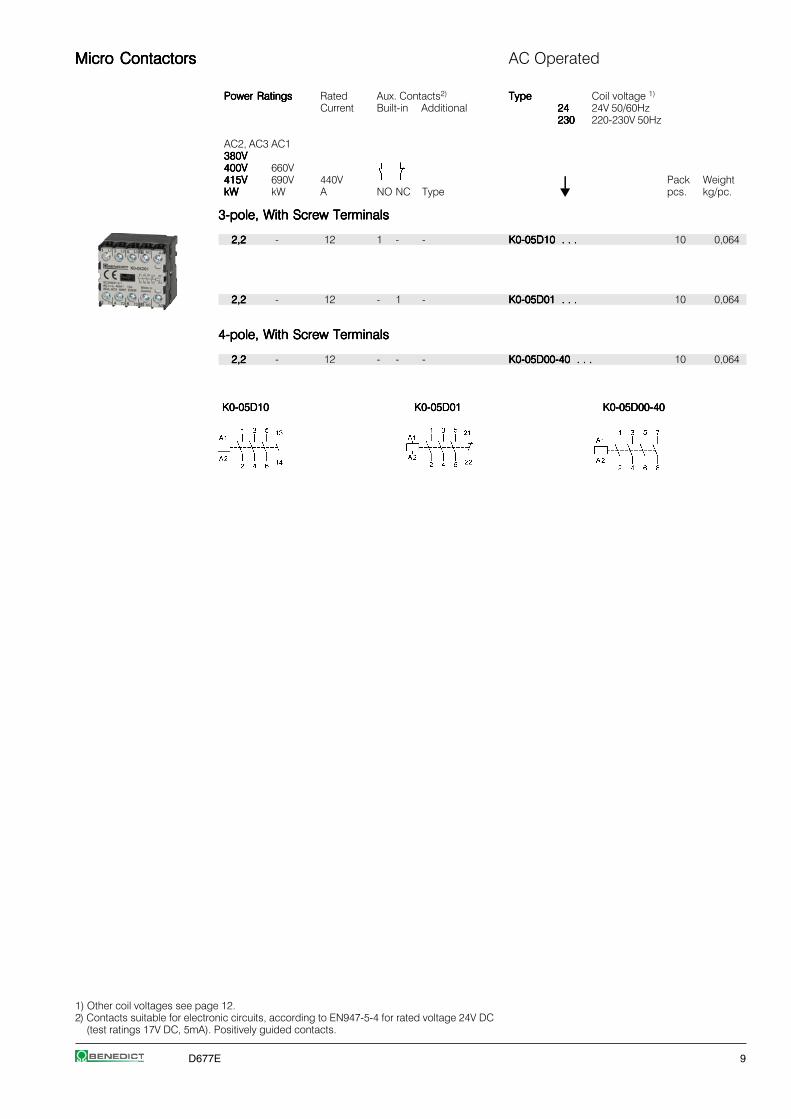
Micro ContactorsMicro ContactorsMicro ContactorsMicro ContactorsMicro Contactors AC Operated
Power RatingsPower RatingsPower RatingsPower RatingsPower Ratings Rated Aux. Contacts2) TypeTypeTypeTypeType Coil voltage 1)
Current Built-in Additional 2424242424 24V 50/60Hz230230230230230 220-230V 50Hz
AC2, AC3 AC1380V380V380V380V380V400V400V400V400V400V 660V415V415V415V415V415V 690V 440V ⏐⏐⏐⏐⏐ Pack WeightkWkWkWkWkW kW A NO NC Type pcs. kg/pc.
3-pole, With Screw Terminals3-pole, With Screw Terminals3-pole, With Screw Terminals3-pole, With Screw Terminals3-pole, With Screw Terminals
2,22,22,22,22,2 - 12 1 - - K0-05D10 . . .K0-05D10 . . .K0-05D10 . . .K0-05D10 . . .K0-05D10 . . . 10 0,064
2,22,22,22,22,2 - 12 - 1 - K0-05D01 . . .K0-05D01 . . .K0-05D01 . . .K0-05D01 . . .K0-05D01 . . . 10 0,064
4-pole, With Screw Terminals4-pole, With Screw Terminals4-pole, With Screw Terminals4-pole, With Screw Terminals4-pole, With Screw Terminals
2,22,22,22,22,2 - 12 - - - K0-05D00-40 . . .K0-05D00-40 . . .K0-05D00-40 . . .K0-05D00-40 . . .K0-05D00-40 . . . 10 0,064
K0-05D10K0-05D10K0-05D10K0-05D10K0-05D10 K0-05D01K0-05D01K0-05D01K0-05D01K0-05D01 K0-05D00-40K0-05D00-40K0-05D00-40K0-05D00-40K0-05D00-40
1) Other coil voltages see page 12.2) Contacts suitable for electronic circuits, according to EN947-5-4 for rated voltage 24V DC
(test ratings 17V DC, 5mA). Positively guided contacts.

10 D677E
Micro ContactorsMicro ContactorsMicro ContactorsMicro ContactorsMicro Contactors AC Operated
Power RatingsPower RatingsPower RatingsPower RatingsPower Ratings Rated Aux. Contacts2) TypeTypeTypeTypeType Coil voltage 1)
Current Built Additional 2424242424 24V 50/60Hzin 230230230230230 220-230V 50Hz
AC2, AC3 AC1380V380V380V380V380V400V400V400V400V400V 660V415V415V415V415V415V 690V 690V ⏐⏐⏐⏐⏐ Pack WeightkWkWkWkWkW kW A NO NC Type pcs. kg/pc.
3-pole, with Solder Pins Ø1,15 for Printed Circuit Applications3-pole, with Solder Pins Ø1,15 for Printed Circuit Applications3-pole, with Solder Pins Ø1,15 for Printed Circuit Applications3-pole, with Solder Pins Ø1,15 for Printed Circuit Applications3-pole, with Solder Pins Ø1,15 for Printed Circuit Applications
2,22,22,22,22,2 - xxx3) 1 - - K0-05L10 . . .K0-05L10 . . .K0-05L10 . . .K0-05L10 . . .K0-05L10 . . . 10 0,064
2,22,22,22,22,2 - xxx3) - 1 - K0-05L01 . . .K0-05L01 . . .K0-05L01 . . .K0-05L01 . . .K0-05L01 . . . 10 0,064
4-pole, with Solder Pins Ø1,15 for Printed Circuit Applications4-pole, with Solder Pins Ø1,15 for Printed Circuit Applications4-pole, with Solder Pins Ø1,15 for Printed Circuit Applications4-pole, with Solder Pins Ø1,15 for Printed Circuit Applications4-pole, with Solder Pins Ø1,15 for Printed Circuit Applications
2,22,22,22,22,2 - xxx3) - - - K0-05L00-40 . . .K0-05L00-40 . . .K0-05L00-40 . . .K0-05L00-40 . . .K0-05L00-40 . . . 10 0,064
K0-05L10K0-05L10K0-05L10K0-05L10K0-05L10 K0-05L01K0-05L01K0-05L01K0-05L01K0-05L01 K0-05L00-40K0-05L00-40K0-05L00-40K0-05L00-40K0-05L00-40
1) Other coil voltages see page 12.2) Contacts suitable for electronic circuits, according to EN947-5-4 for rated voltage 24V DC
(test ratings 17V DC, 5mA). Positively guided contacts.3) Data on request.
SuffixSuffixSuffixSuffixSuffix Voltage Marking Rated Control Voltage Ustototototocontactorcontactorcontactorcontactorcontactor at the coil rangetypetypetypetypetype for for for 50Hz for 60Hze.g. 50Hz 60Hz min. max. min. max.K1-09D10 230 V V V V V V
200 200 200-220 195 205 200 220210 205-215 220-230 205 215 220 230220 210-220 220-240 210 220 220 240230230230230230 220-230220-230220-230220-230220-230 230-250230-250230-250230-250230-250 220220220220220 230230230230230 230230230230230 250250250250250
240 230-240 230 240 250 260
Standard voltages in bold type lettersStandard voltages in bold type lettersStandard voltages in bold type lettersStandard voltages in bold type lettersStandard voltages in bold type lettersOperating range of magnet-coils: 0,85 x UOperating range of magnet-coils: 0,85 x UOperating range of magnet-coils: 0,85 x UOperating range of magnet-coils: 0,85 x UOperating range of magnet-coils: 0,85 x Usssss (min. value of rated (min. value of rated (min. value of rated (min. value of rated (min. value of ratedcontrol voltage) up to 1,1 x Ucontrol voltage) up to 1,1 x Ucontrol voltage) up to 1,1 x Ucontrol voltage) up to 1,1 x Ucontrol voltage) up to 1,1 x Usssss (max. value of rated control voltage) (max. value of rated control voltage) (max. value of rated control voltage) (max. value of rated control voltage) (max. value of rated control voltage)
Coil not exchangeable
SuffixSuffixSuffixSuffixSuffix Voltage Marking Rated Control Voltage Ustototototocontactorcontactorcontactorcontactorcontactor at the coil rangetypetypetypetypetype for for for 50Hz for 60Hze.g. 50Hz 60Hz min. max. min. max.K1-09D10 24 V V V V V V
12 12 12 11 12 12 122424242424 2424242424 2424242424 2222222222 2424242424 2424242424 242424242442 42 42 38,5 42 42 4248 48 48 48 50 48 52
90 100 100 90 100 100 10595 95-100 105-110 95 100 105 110100 100 110-115 100 105 110 115
105 105-110 115-120 105 110 115 120110 110-115 120-125 110 115 120 125180 200 200 185 200 200 210
Coil voltages Coil voltages Coil voltages Coil voltages Coil voltages for AC operated contactors
D677E 11
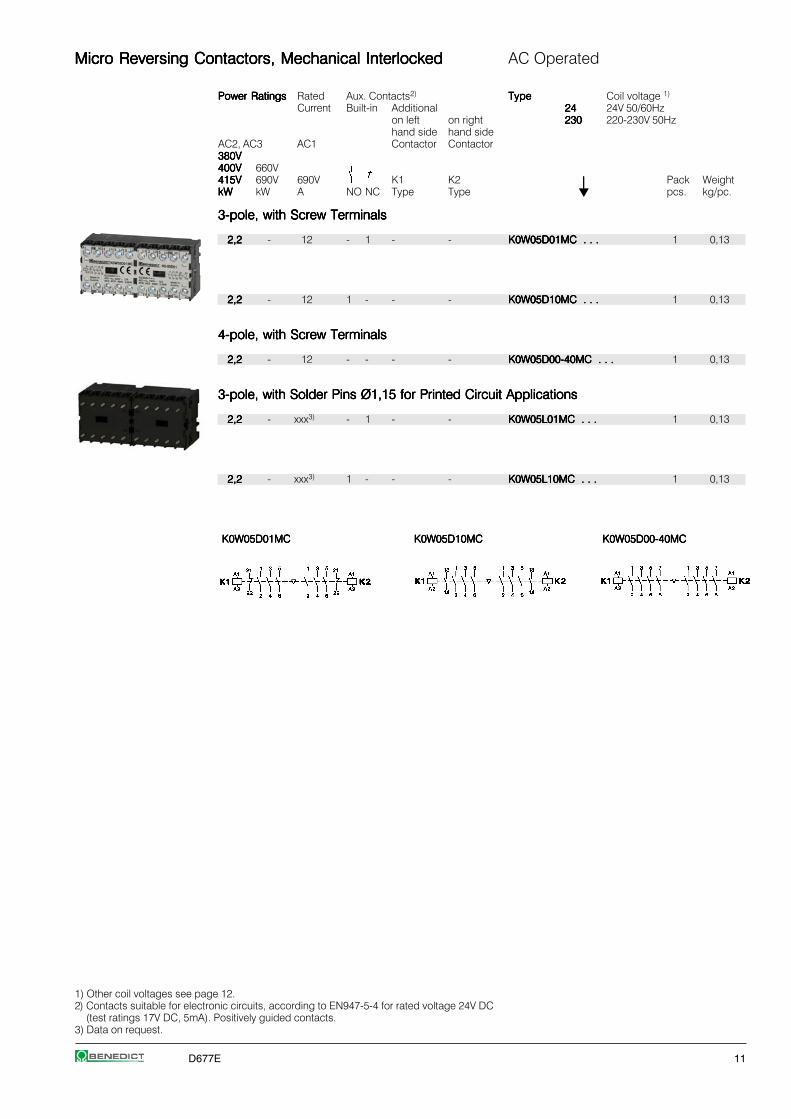
Micro Reversing Contactors, Mechanical InterlockedMicro Reversing Contactors, Mechanical InterlockedMicro Reversing Contactors, Mechanical InterlockedMicro Reversing Contactors, Mechanical InterlockedMicro Reversing Contactors, Mechanical Interlocked AC Operated
Power RatingsPower RatingsPower RatingsPower RatingsPower Ratings Rated Aux. Contacts2) TypeTypeTypeTypeType Coil voltage 1)
Current Built-in Additional 2424242424 24V 50/60Hzon left on right 230230230230230 220-230V 50Hzhand side hand side
AC2, AC3 AC1 Contactor Contactor380V380V380V380V380V400V400V400V400V400V 660V415V415V415V415V415V 690V 690V K1 K2 ⏐⏐⏐⏐⏐ Pack WeightkWkWkWkWkW kW A NO NC Type Type pcs. kg/pc.
3-pole, with Screw Terminals3-pole, with Screw Terminals3-pole, with Screw Terminals3-pole, with Screw Terminals3-pole, with Screw Terminals
2,22,22,22,22,2 - 12 - 1 - - K0W05D01MC . . .K0W05D01MC . . .K0W05D01MC . . .K0W05D01MC . . .K0W05D01MC . . . 1 0,13
2,22,22,22,22,2 - 12 1 - - - K0W05D10MC . . .K0W05D10MC . . .K0W05D10MC . . .K0W05D10MC . . .K0W05D10MC . . . 1 0,13
4-pole, with Screw Terminals4-pole, with Screw Terminals4-pole, with Screw Terminals4-pole, with Screw Terminals4-pole, with Screw Terminals
2,22,22,22,22,2 - 12 - - - - K0W05D00-40MC . . .K0W05D00-40MC . . .K0W05D00-40MC . . .K0W05D00-40MC . . .K0W05D00-40MC . . . 1 0,13
3-pole, with Solder Pins Ø1,15 for Printed Circuit Applications3-pole, with Solder Pins Ø1,15 for Printed Circuit Applications3-pole, with Solder Pins Ø1,15 for Printed Circuit Applications3-pole, with Solder Pins Ø1,15 for Printed Circuit Applications3-pole, with Solder Pins Ø1,15 for Printed Circuit Applications
2,22,22,22,22,2 - xxx3) - 1 - - K0W05L01MC . . .K0W05L01MC . . .K0W05L01MC . . .K0W05L01MC . . .K0W05L01MC . . . 1 0,13
2,22,22,22,22,2 - xxx3) 1 - - - K0W05L10MC . . .K0W05L10MC . . .K0W05L10MC . . .K0W05L10MC . . .K0W05L10MC . . . 1 0,13
K0W05D01MCK0W05D01MCK0W05D01MCK0W05D01MCK0W05D01MC K0W05D10MCK0W05D10MCK0W05D10MCK0W05D10MCK0W05D10MC K0W05D00-40MCK0W05D00-40MCK0W05D00-40MCK0W05D00-40MCK0W05D00-40MC
1) Other coil voltages see page 12.2) Contacts suitable for electronic circuits, according to EN947-5-4 for rated voltage 24V DC
(test ratings 17V DC, 5mA). Positively guided contacts.3) Data on request.
12 D677E
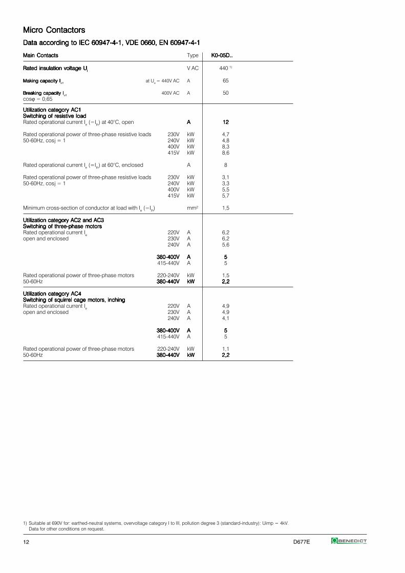
Micro ContactorsMicro ContactorsMicro ContactorsMicro ContactorsMicro Contactors
Data according to IEC 60947-4-1, VDE 0660, EN 60947-4-1Data according to IEC 60947-4-1, VDE 0660, EN 60947-4-1Data according to IEC 60947-4-1, VDE 0660, EN 60947-4-1Data according to IEC 60947-4-1, VDE 0660, EN 60947-4-1Data according to IEC 60947-4-1, VDE 0660, EN 60947-4-1
Main ContactsMain ContactsMain ContactsMain ContactsMain Contacts Type K0-05D..K0-05D..K0-05D..K0-05D..K0-05D..
Rated insulation voltage URated insulation voltage URated insulation voltage URated insulation voltage URated insulation voltage Uiiiii V AC 440 1)
Making capacity IMaking capacity IMaking capacity IMaking capacity IMaking capacity Ieff at Ue = 440V AC A 65
Breaking capacity IBreaking capacity IBreaking capacity IBreaking capacity IBreaking capacity Ieff 400V AC A 50cosϕ = 0,65
Utilization category AC1Utilization category AC1Utilization category AC1Utilization category AC1Utilization category AC1Switching of resistive loadSwitching of resistive loadSwitching of resistive loadSwitching of resistive loadSwitching of resistive loadRated operational current Ie (=Ith) at 40°C, open AAAAA 1212121212
Rated operational power of three-phase resistive loads 230V kW 4,750-60Hz, cosj = 1 240V kW 4,8
400V kW 8,3415V kW 8,6
Rated operational current Ie (=Ith) at 60°C, enclosed A 8
Rated operational power of three-phase resistive loads 230V kW 3,150-60Hz, cosj = 1 240V kW 3,3
400V kW 5,5415V kW 5,7
Minimum cross-section of conductor at load with Ie (=Ith) mm² 1,5
Utilization category AC2 and AC3Utilization category AC2 and AC3Utilization category AC2 and AC3Utilization category AC2 and AC3Utilization category AC2 and AC3Switching of three-phase motorsSwitching of three-phase motorsSwitching of three-phase motorsSwitching of three-phase motorsSwitching of three-phase motorsRated operational current Ie 220V A 6,2open and enclosed 230V A 6,2
240V A 5,6
380-400V380-400V380-400V380-400V380-400V AAAAA 55555415-440V A 5
Rated operational power of three-phase motors 220-240V kW 1,550-60Hz 380-440V380-440V380-440V380-440V380-440V kWkWkWkWkW 2,22,22,22,22,2
Utilization category AC4Utilization category AC4Utilization category AC4Utilization category AC4Utilization category AC4Switching of squirrel cage motors, inchingSwitching of squirrel cage motors, inchingSwitching of squirrel cage motors, inchingSwitching of squirrel cage motors, inchingSwitching of squirrel cage motors, inchingRated operational current Ie 220V A 4,9open and enclosed 230V A 4,9
240V A 4,1
380-400V380-400V380-400V380-400V380-400V AAAAA 55555415-440V A 5
Rated operational power of three-phase motors 220-240V kW 1,150-60Hz 380-440V380-440V380-440V380-440V380-440V kWkWkWkWkW 2,22,22,22,22,2
1) Suitable at 690V for: earthed-neutral systems, overvoltage category I to III, pollution degree 3 (standard-industry): Uimp = 4kV.Data for other conditions on request.

D677E 13
Micro ContactorsMicro ContactorsMicro ContactorsMicro ContactorsMicro Contactors
Data according to IEC 60947-4-1, VDE 0660, EN 60947-4-1Data according to IEC 60947-4-1, VDE 0660, EN 60947-4-1Data according to IEC 60947-4-1, VDE 0660, EN 60947-4-1Data according to IEC 60947-4-1, VDE 0660, EN 60947-4-1Data according to IEC 60947-4-1, VDE 0660, EN 60947-4-1
Main ContactsMain ContactsMain ContactsMain ContactsMain Contacts Type K0-05D..K0-05D..K0-05D..K0-05D..K0-05D..
Utilization category DC1Utilization category DC1Utilization category DC1Utilization category DC1Utilization category DC1Switching of resistive loadSwitching of resistive loadSwitching of resistive loadSwitching of resistive loadSwitching of resistive load 1 pole 24V A 12Time constant L/R ≤1ms 60V A 12Rated operational current Ie 110V A -
220V A -
3 poles in series 24V A 12 60V A 12110V A 12220V A -
Utilization category DC3 and DC5Utilization category DC3 and DC5Utilization category DC3 and DC5Utilization category DC3 and DC5Utilization category DC3 and DC5Switching of shunt motorsSwitching of shunt motorsSwitching of shunt motorsSwitching of shunt motorsSwitching of shunt motors 1 pole 24V A 12and series motorsand series motorsand series motorsand series motorsand series motors 60V A -Time constant L/R ≤15ms 110V A -Rated operational current Ie 220V A -
3 Pole in Serie 24V A 12 60V A 12110V A 12220V A -
Maximum ambient temperatureMaximum ambient temperatureMaximum ambient temperatureMaximum ambient temperatureMaximum ambient temperatureOperation open °C -40 to +60 (+90) 1)
enclosed °C -40 to +40with therminal overload relay open °C -25 to +60
enclosed °C -25 to +40
Storage °C -50 to +90
Short circuit protectionShort circuit protectionShort circuit protectionShort circuit protectionShort circuit protectionfor contactors without thermal overload relay
Coordination-type "1" according to IEC 947-4-1Contact welding without hazard of personsmax. fuse size gL (gG) A 20
Coordination-type “2” according to IEC 947-4-1Light contact welding acceptedmax. fuse size gL (gG) A -
Contact welding not acceptedmax. fuse size gL (gG) A -
For contactors with thermal overload relay thedevice with the smaller admissible backup fuse(contactor or thermal overload relay) determines the fuse size.
Cable cross-sectionsCable cross-sectionsCable cross-sectionsCable cross-sectionsCable cross-sectionsfor contactors without thermal overload relaymain connector solid or stranded mm² 0,5 - 1,5
flexible mm² 0,5 - 1,5flexible with multicore cable end mm² 0,5 - xxx2)
Cables per clamp 2
solid or stranded AWG 18 - 14
Frequency of operation zFrequency of operation zFrequency of operation zFrequency of operation zFrequency of operation z without load 1/h 10000contactors without therminal oberload relay AC3, Ie 1/h 600
AC4, Ie 1/h 120DC3, Ie 1/h 600
Mechanical lifeMechanical lifeMechanical lifeMechanical lifeMechanical life AC operated S x 106 xxx2)
DC operated S x 106 xxx2)
Short time currentShort time currentShort time currentShort time currentShort time current 10s-current A 50
Power loss per polePower loss per polePower loss per polePower loss per polePower loss per pole at Ie /AC3 400V W xxx2)
Resistance to shock according to IEC 68-2-27Resistance to shock according to IEC 68-2-27Resistance to shock according to IEC 68-2-27Resistance to shock according to IEC 68-2-27Resistance to shock according to IEC 68-2-27Shock time 20ms sine-waveAC operated NO g 2,5
NC g 2,5
1) With reduced control voltage range 0,9 up to 1,0 x Us and with reduced rated current Ie /AC1according to Ie /AC3.2) Data on request.

14 D677E
Micro ContactorsMicro ContactorsMicro ContactorsMicro ContactorsMicro Contactors
Data according to IEC 60947-5-1, VDE 0660, EN 60947-5-1Data according to IEC 60947-5-1, VDE 0660, EN 60947-5-1Data according to IEC 60947-5-1, VDE 0660, EN 60947-5-1Data according to IEC 60947-5-1, VDE 0660, EN 60947-5-1Data according to IEC 60947-5-1, VDE 0660, EN 60947-5-1
Auxiliary ContactsAuxiliary ContactsAuxiliary ContactsAuxiliary ContactsAuxiliary Contacts Type K0-04D..K0-04D..K0-04D..K0-04D..K0-04D..K0-05D..K0-05D..K0-05D..K0-05D..K0-05D..
Rated insulation voltageRated insulation voltageRated insulation voltageRated insulation voltageRated insulation voltage UUUUUiiiiiVAC 440 1)
Thermal rated current IThermal rated current IThermal rated current IThermal rated current IThermal rated current Iththththth bis 440V
Ambient temperature 40°C A 1060°C A 6
Verlustleistung Verlustleistung Verlustleistung Verlustleistung Verlustleistung pro Pol bei Ith W 0,5
Utilization category AC15Utilization category AC15Utilization category AC15Utilization category AC15Utilization category AC15Rated operational currrent Ie 220-240V A xxx5)
380-415V A xxx5)
440V A xxx5)
Utilization category DC13Utilization category DC13Utilization category DC13Utilization category DC13Utilization category DC13Rated operational current Ie 60V A xxx5)
--
Maximum ambient temperatureMaximum ambient temperatureMaximum ambient temperatureMaximum ambient temperatureMaximum ambient temperatureOperation open °C -40 bis +60 (+90) 2)
enclosed °C -40 bis +40Storage °C -40 bis +90
Short circuit protectionShort circuit protectionShort circuit protectionShort circuit protectionShort circuit protectionshort-circuit current 1kA,contact welding not acceptedmax. fuse size gL (gG) A xxx5)
For contactors with thermal overload relay thedevice with the smaller admissible control fuse(contactor or thermal overload relay)determines the fuse size.
Power consumption of coilsPower consumption of coilsPower consumption of coilsPower consumption of coilsPower consumption of coilsAC operated inrush VA 17
sealed VA 2,5W xxx5)
Operation rage of coilsOperation rage of coilsOperation rage of coilsOperation rage of coilsOperation rage of coilsin multiples of control voltage Us 0,85 - 1,1
Switching time Switching time Switching time Switching time Switching time at control voltage Us ±10% 3) 4)
AC operated make time ms xxx5)
release time ms xxx5)
arc duration ms xxx5)
DC operated make time ms -release time ms -arc duration ms -
Cablecross-sectionCablecross-sectionCablecross-sectionCablecross-sectionCablecross-sectionall connectors solid mm2 0,5 - 2,5
flexible mm2 0,5 - 2,5flexible with multicore cable end mm2 0,5 - xxx5)
Clamps per pole 2solid or stranded AWG 18 - 14
1) Suitable at 690V for: earthed-neutral systems, overvoltage category I to III, pollution degree 3 (standard-industry): Uimp = 4kV.Data for other conditions on request.
2) With reduced control voltage range 0,9 up to 1,0 x Us and with reduced thermal rated current Ith to Ie /AC15.3) Summary switching time = release time + arc duration.4) Release time of NC make time of NO increase when suppressor units for voltage peak protection are used (Varistor, RC-units, Diode units).5) Data on request.

D677E 15
Micro Contactors for North AmericaMicro Contactors for North AmericaMicro Contactors for North AmericaMicro Contactors for North AmericaMicro Contactors for North America
Data according to UL508Data according to UL508Data according to UL508Data according to UL508Data according to UL508
Main Contacts (cULus)Main Contacts (cULus)Main Contacts (cULus)Main Contacts (cULus)Main Contacts (cULus) Type K0-05D..K0-05D..K0-05D..K0-05D..K0-05D.. K0-04D..K0-04D..K0-04D..K0-04D..K0-04D..K0W05D01..K0W05D01..K0W05D01..K0W05D01..K0W05D01..
Rated operational current "General Use" A 12 5
Rated operational power of three motors 110-120V hp ½ -at 60Hz (3ph) 200-208V hp 1 -
220-240V hp 1 -277V hp 1½
440-480V hp - -550-600V hp - -
Rated operational power of AC motors 110-120V hp -at 60Hz (1ph) 200-208V hp ½ -
220-240V hp ¾
Fuse / Short-circuit current A/kA 30/5 -
Rated voltage VAC 300 300
Auxiliary Contacts (cULus)Auxiliary Contacts (cULus)Auxiliary Contacts (cULus)Auxiliary Contacts (cULus)Auxiliary Contacts (cULus) heavy pilot duty AC B300 B300standard pilot duty DC R300 R300
½6

16 D677E
Micro ContactorsMicro ContactorsMicro ContactorsMicro ContactorsMicro Contactors
DimensionsDimensionsDimensionsDimensionsDimensions
AC operatedAC operatedAC operatedAC operatedAC operatedwith screw terminals
K0-04D..K0-04D..K0-04D..K0-04D..K0-04D..K0-05D..K0-05D..K0-05D..K0-05D..K0-05D..
AC operatedAC operatedAC operatedAC operatedAC operatedwith solder connections
K0-04L..K0-04L..K0-04L..K0-04L..K0-04L..K0-05L..K0-05L..K0-05L..K0-05L..K0-05L..
Reversing ContactorsReversing ContactorsReversing ContactorsReversing ContactorsReversing Contactorswith screw terminals
K0W05D..MCK0W05D..MCK0W05D..MCK0W05D..MCK0W05D..MC
Reversing ContactorsReversing ContactorsReversing ContactorsReversing ContactorsReversing Contactorswith solder connections
K0W05L..MCK0W05L..MCK0W05L..MCK0W05L..MCK0W05L..MC

D677E 17
Mini ContactorsMini ContactorsMini ContactorsMini ContactorsMini Contactors
Mini Contactor Relays 4-pole 18Auxiliary Contact Blocks
Interface Contactor Relays
Mini Contactors 20Auxiliary Contact Blocks
Mini Contactors With Fast On Tab Connectors 22
Mini Contactors With Solder Pins 22
Coil voltages 22
Mini Reversing Contactors 24Auxiliary Contact Blocks
Technical Data 26
Dimensions 30
18 D677E
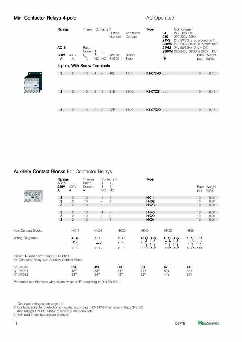
Mini Contactor Relays 4-poleMini Contactor Relays 4-poleMini Contactor Relays 4-poleMini Contactor Relays 4-poleMini Contactor Relays 4-pole AC Operated
RatingsRatingsRatingsRatingsRatings Therm. Contacts 2) TypeTypeTypeTypeType Coil voltage 1)
Distinc. Additional 2424242424 24V 50/60HzNumber Contact 230230230230230 220-230V 50Hz
24VS24VS24VS24VS24VS 24V 50/60Hz w. protection 3)
230VS230VS230VS230VS230VS 220-230V 50Hz w. protection 3)
AC15AC15AC15AC15AC15 Rated 24VM24VM24VM24VM24VM 24V 50/60Hz 24V= DCCurrent 230VM230VM230VM230VM230VM 220-240V 50/60Hz 220V= DC
230V230V230V230V230V 400V Ith acc. to Blocks ⏐⏐⏐⏐⏐ Pack WeightAAAAA A A NO NC EN50011 Type pcs. kg/pc.
4-pole, With Screw Terminals4-pole, With Screw Terminals4-pole, With Screw Terminals4-pole, With Screw Terminals4-pole, With Screw Terminals
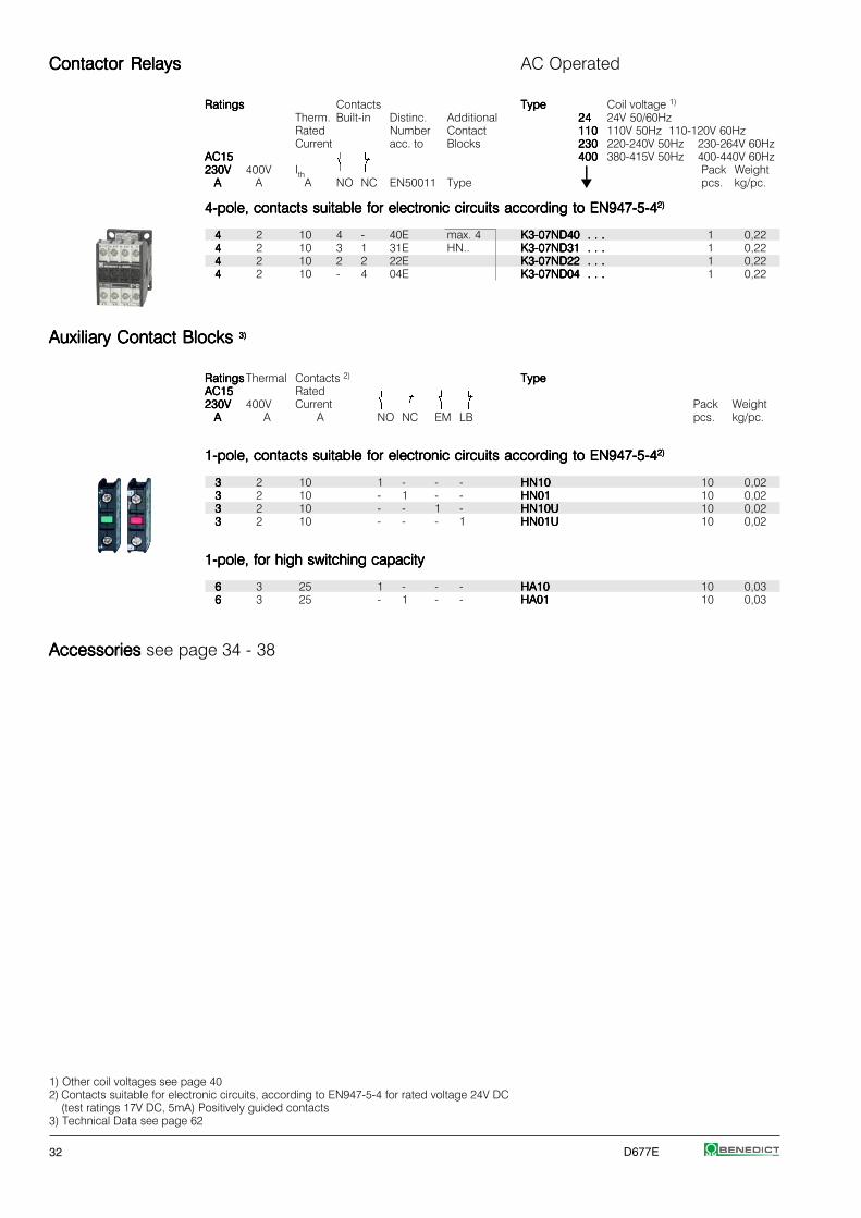
33333 2 10 4 - 40E 1 HK.. K1-07D40 . . .K1-07D40 . . .K1-07D40 . . .K1-07D40 . . .K1-07D40 . . . 10 0,16
33333 2 10 3 1 31E 1 HK.. K1-07D31 . . .K1-07D31 . . .K1-07D31 . . .K1-07D31 . . .K1-07D31 . . . 10 0,16
33333 2 10 2 2 22E 1 HK.. K1-07D22 . . .K1-07D22 . . .K1-07D22 . . .K1-07D22 . . .K1-07D22 . . . 10 0,16
Auxiliary Contact Blocks Auxiliary Contact Blocks Auxiliary Contact Blocks Auxiliary Contact Blocks Auxiliary Contact Blocks For Contactor Relays
RatingsRatingsRatingsRatingsRatings Thermal Contacts 2) TypeTypeTypeTypeTypeAC15AC15AC15AC15AC15 Rated230V230V230V230V230V 400V Current Pack WeightAAAAA A A NO NC pcs. kg/pc.
33333 2 10 1 1 HK11HK11HK11HK11HK11 10 0,0433333 2 10 - 2 HK02HK02HK02HK02HK02 10 0,0433333 2 10 2 - HK20HK20HK20HK20HK20 10 0,04
33333 2 10 4 - HK40HK40HK40HK40HK40 10 0,0433333 2 10 2 2 HK22HK22HK22HK22HK22 10 0,0433333 2 10 - 4 HK04HK04HK04HK04HK04 10 0,04
Aux. Contact Blocks HK11 HK02 HK20 HK40 HK22 HK04
Wiring Diagrams
Distinc. Number according to EN50011for Contactor Relay with Auxiliary Contact Block
K1-07D40 51E51E51E51E51E 42E42E42E42E42E 60E60E60E60E60E 80E80E80E80E80E 62E62E62E62E62E 44E44E44E44E44EK1-07D31 42Y 33Y 51Y 71Y 53Y 35YK1-07D22 33Y 24Y 42Y 62Y 44Y 26Y
Preferable combinations with distinctive letter "E" according to DIN EN 50011
1) Other coil voltages see page 122) Contacts suitable for electronic circuits, according to EN947-5-4 for rated voltage 24V DC
(test ratings 17V DC, 5mA) Positively guided contacts3) with built-in coil suppressor (varistor)
D677E 19
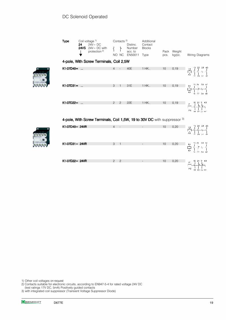
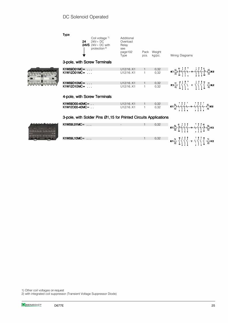
DC Solenoid Operated
TypeTypeTypeTypeType Coil voltage 1) Contacts 2) Additional2424242424 24V= DC Distinc. Contact24VS24VS24VS24VS24VS 24V= DC with Number Blocks
⏐⏐⏐⏐⏐ protection 2) acc. to Pack WeightNO NC EN50011 Type pcs. kg/pc. Wiring Diagrams
4-pole, With Screw Terminals, Coil 2,5W4-pole, With Screw Terminals, Coil 2,5W4-pole, With Screw Terminals, Coil 2,5W4-pole, With Screw Terminals, Coil 2,5W4-pole, With Screw Terminals, Coil 2,5W
K1-07D40= ...K1-07D40= ...K1-07D40= ...K1-07D40= ...K1-07D40= ... 4 - 40E 1 HK.. 10 0,19
K1-07D31= ...K1-07D31= ...K1-07D31= ...K1-07D31= ...K1-07D31= ... 3 1 31E 1 HK.. 10 0,19
K1-07D22= ...K1-07D22= ...K1-07D22= ...K1-07D22= ...K1-07D22= ... 2 2 22E 1 HK.. 10 0,19
4-pole, With Screw Terminals, Coil 1,5W, 19 to 30V DC4-pole, With Screw Terminals, Coil 1,5W, 19 to 30V DC4-pole, With Screw Terminals, Coil 1,5W, 19 to 30V DC4-pole, With Screw Terminals, Coil 1,5W, 19 to 30V DC4-pole, With Screw Terminals, Coil 1,5W, 19 to 30V DC with suppressor 3)
K1-07D40= 24VRK1-07D40= 24VRK1-07D40= 24VRK1-07D40= 24VRK1-07D40= 24VR 4 - - 10 0,20
K1-07D31= 24VRK1-07D31= 24VRK1-07D31= 24VRK1-07D31= 24VRK1-07D31= 24VR 3 1 - 10 0,20
K1-07D22= 24VRK1-07D22= 24VRK1-07D22= 24VRK1-07D22= 24VRK1-07D22= 24VR 2 2 - 10 0,20
1) Other coil voltages on request2) Contacts suitable for electronic circuits, according to EN947-5-4 for rated voltage 24V DC
(test ratings 17V DC, 5mA) Positively guided contacts3) with integrated coil suppressor (Transient Voltage Suppressor Diode)

20 D677E
Mini ContactorsMini ContactorsMini ContactorsMini ContactorsMini Contactors AC Operated
Power RatingsPower RatingsPower RatingsPower RatingsPower Ratings Rated Aux. Contacts2) TypeTypeTypeTypeType Coil voltage 1)
Current Built-in Additional 2424242424 24V 50/60Hz230230230230230 220-230V 50Hz24VS24VS24VS24VS24VS 24V 50/60Hz w. protection 3)
AC2, AC3 AC1 230VS230VS230VS230VS230VS 220-230V 50Hz w. protection 3)
380V380V380V380V380V 24VM24VM24VM24VM24VM 24V 50/60Hz 24V= DC400V400V400V400V400V 660V 230VM230VM230VM230VM230VM220-240V 50/60Hz 220V= DC415V415V415V415V415V 690V 690V ⏐⏐⏐⏐⏐ Pack WeightkWkWkWkWkW kW A NO NC Type pcs. kg/pc.
3-pole, With Screw Terminals3-pole, With Screw Terminals3-pole, With Screw Terminals3-pole, With Screw Terminals3-pole, With Screw Terminals
44444 4 20 1 - 1 HKM.. K1-09D10 . . .K1-09D10 . . .K1-09D10 . . .K1-09D10 . . .K1-09D10 . . . 10 0,165,55,55,55,55,5 5,5 20 1 - 1 HKM.. K1-12D10 . . .K1-12D10 . . .K1-12D10 . . .K1-12D10 . . .K1-12D10 . . . 10 0,16
44444 4 20 - 1 1HK.. K1-09D01 . . .K1-09D01 . . .K1-09D01 . . .K1-09D01 . . .K1-09D01 . . . 10 0,165,55,55,55,55,5 5,5 20 - 1 1HK.. K1-12D01 . . .K1-12D01 . . .K1-12D01 . . .K1-12D01 . . .K1-12D01 . . . 10 0,16
4-pole, With Screw Terminals4-pole, With Screw Terminals4-pole, With Screw Terminals4-pole, With Screw Terminals4-pole, With Screw Terminals
44444 4 20 - - 1HK.. K1-09D00-40 . . .K1-09D00-40 . . .K1-09D00-40 . . .K1-09D00-40 . . .K1-09D00-40 . . . 10 0,165,55,55,55,55,5 5,5 20 - - 1HK.. K1-12D00-40 . . .K1-12D00-40 . . .K1-12D00-40 . . .K1-12D00-40 . . .K1-12D00-40 . . . 10 0,16
Auxiliary Contact Blocks Auxiliary Contact Blocks Auxiliary Contact Blocks Auxiliary Contact Blocks Auxiliary Contact Blocks for Contactors K1-..
RatingsRatingsRatingsRatingsRatings Thermal Contacts 2) TypeTypeTypeTypeTypeAC15AC15AC15AC15AC15 Rated230V230V230V230V230V 400V Current Pack WeightAAAAA A A NO NC pcs. kg/pc.
33333 2 10 1 1 HKM11HKM11HKM11HKM11HKM11 10 0,0433333 2 10 - 2 HKM02HKM02HKM02HKM02HKM02 10 0,0433333 2 10 2 2 HKM22HKM22HKM22HKM22HKM22 10 0,04
Aux. Contact Blocks HKM11 HKM02 HKM22 HK11 HK02 HK40 HK22
Wiring Diagrams
Contactors with Auxiliary Contact BlockContacts according to EN50012K1-..D10 2121212121 1212121212 3232323232 ----- ----- ----- -----
Contacts according to DIN EN50005K1-..D01 - - - 12 03 41 23K1-..D00-40 - - - 11 02 40 22
Prefer combinations according to EN50012
Suppressor Units Suppressor Units Suppressor Units Suppressor Units Suppressor Units for Contactors K1-..
Voltage Range TypeTypeTypeTypeType Pack WeightV pcs. kg/pc.
12 - 48V AC/DC 1600nF / 22 Ohm RC-K1 24RC-K1 24RC-K1 24RC-K1 24RC-K1 24 10 0,0148 - 127V AC/DC 680nF / 270 Ohm RC-K1 110RC-K1 110RC-K1 110RC-K1 110RC-K1 110 10 0,01110 - 250V AC/DC 220nF / 2200 Ohm RC-K1 230RC-K1 230RC-K1 230RC-K1 230RC-K1 230 10 0,01
1) Other coil voltages see page 122) Contacts suitable for electronic circuits, according to EN947-5-4 for rated voltage 24V DC
(test ratings 17V DC, 5mA) Positively guided contacts3) with built-in coil suppressor (varistor)
D677E 21
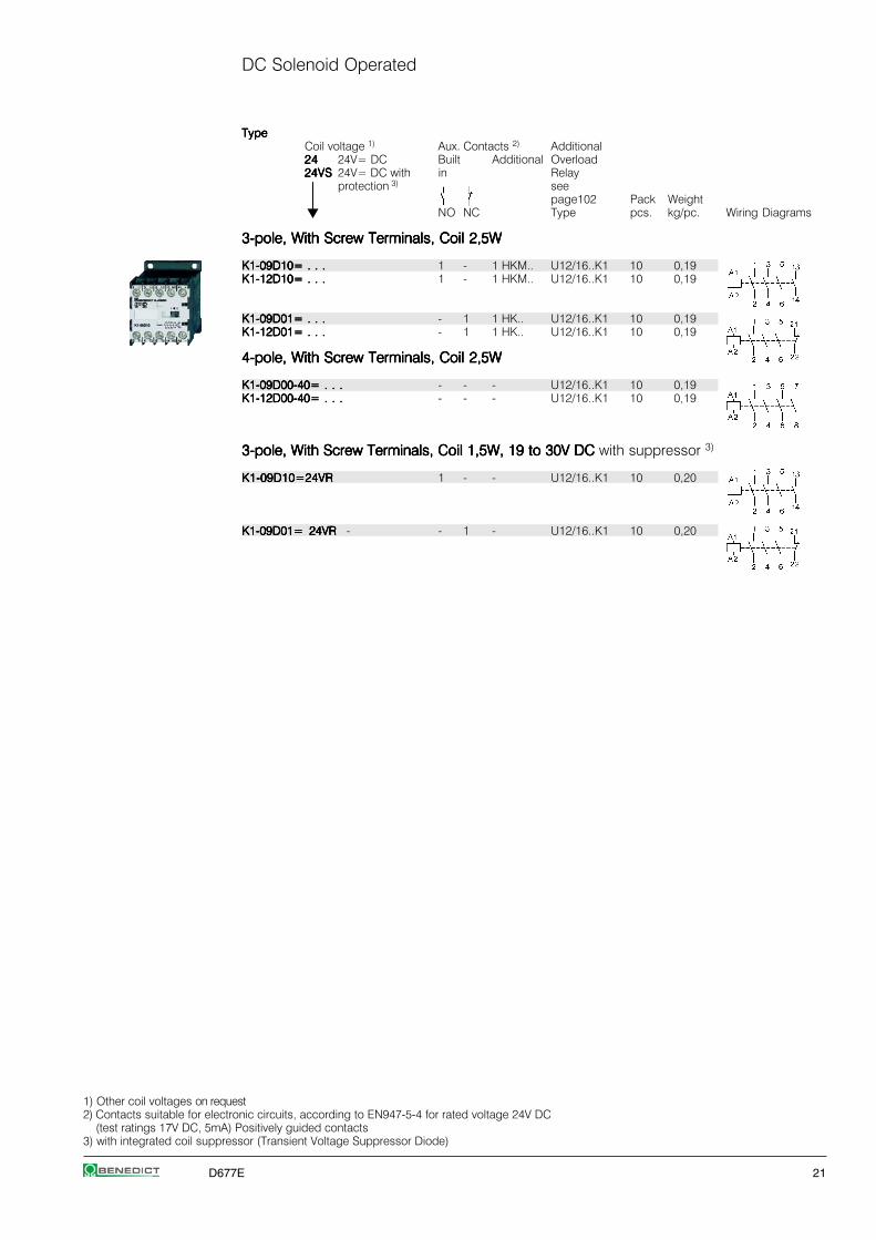
DC Solenoid Operated
TypeTypeTypeTypeTypeCoil voltage 1) Aux. Contacts 2) Additional2424242424 24V= DC Built Additional Overload24VS24VS24VS24VS24VS 24V= DC with in Relay
⏐⏐⏐⏐⏐ protection 3) see
⏐⏐⏐⏐⏐ page102 Pack WeightNO NC Type pcs. kg/pc. Wiring Diagrams
3-pole, With Screw Terminals, Coil 2,5W3-pole, With Screw Terminals, Coil 2,5W3-pole, With Screw Terminals, Coil 2,5W3-pole, With Screw Terminals, Coil 2,5W3-pole, With Screw Terminals, Coil 2,5W
K1-09D10= . . .K1-09D10= . . .K1-09D10= . . .K1-09D10= . . .K1-09D10= . . . 1 - 1 HKM.. U12/16..K1 10 0,19K1-12D10= . . .K1-12D10= . . .K1-12D10= . . .K1-12D10= . . .K1-12D10= . . . 1 - 1 HKM.. U12/16..K1 10 0,19
K1-09D01= . . .K1-09D01= . . .K1-09D01= . . .K1-09D01= . . .K1-09D01= . . . - 1 1 HK.. U12/16..K1 10 0,19K1-12D01= . . .K1-12D01= . . .K1-12D01= . . .K1-12D01= . . .K1-12D01= . . . - 1 1 HK.. U12/16..K1 10 0,19
4-pole, With Screw Terminals, Coil 2,5W4-pole, With Screw Terminals, Coil 2,5W4-pole, With Screw Terminals, Coil 2,5W4-pole, With Screw Terminals, Coil 2,5W4-pole, With Screw Terminals, Coil 2,5W
K1-09D00-40= . . .K1-09D00-40= . . .K1-09D00-40= . . .K1-09D00-40= . . .K1-09D00-40= . . . - - - U12/16..K1 10 0,19K1-12D00-40= . . .K1-12D00-40= . . .K1-12D00-40= . . .K1-12D00-40= . . .K1-12D00-40= . . . - - - U12/16..K1 10 0,19
3-pole, With Screw Terminals, Coil 1,5W, 19 to 30V DC3-pole, With Screw Terminals, Coil 1,5W, 19 to 30V DC3-pole, With Screw Terminals, Coil 1,5W, 19 to 30V DC3-pole, With Screw Terminals, Coil 1,5W, 19 to 30V DC3-pole, With Screw Terminals, Coil 1,5W, 19 to 30V DC with suppressor 3)
K1-09D10=24VRK1-09D10=24VRK1-09D10=24VRK1-09D10=24VRK1-09D10=24VR 1 - - U12/16..K1 10 0,20
K1-09D01= 24VRK1-09D01= 24VRK1-09D01= 24VRK1-09D01= 24VRK1-09D01= 24VR - - 1 - U12/16..K1 10 0,20
1) Other coil voltages on request2) Contacts suitable for electronic circuits, according to EN947-5-4 for rated voltage 24V DC
(test ratings 17V DC, 5mA) Positively guided contacts3) with integrated coil suppressor (Transient Voltage Suppressor Diode)
22 D677E
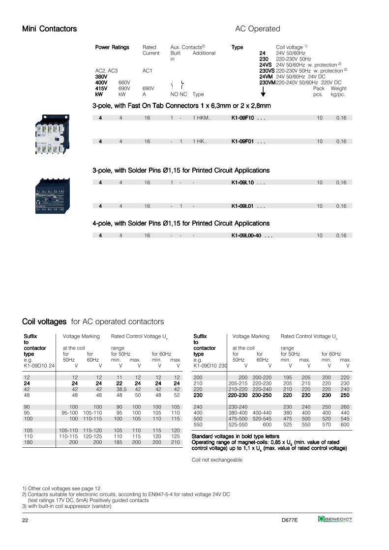
Mini ContactorsMini ContactorsMini ContactorsMini ContactorsMini Contactors AC Operated
Power RatingsPower RatingsPower RatingsPower RatingsPower Ratings Rated Aux. Contacts2) TypeTypeTypeTypeType Coil voltage 1)
Current Built Additional 2424242424 24V 50/60Hzin 230230230230230 220-230V 50Hz
24VS24VS24VS24VS24VS 24V 50/60Hz w. protection 2)
AC2, AC3 AC1 230VS230VS230VS230VS230VS 220-230V 50Hz w. protection 2)
380V380V380V380V380V 24VM24VM24VM24VM24VM 24V 50/60Hz 24V DC400V400V400V400V400V 660V 230VM230VM230VM230VM230VM220-240V 50/60Hz 220V DC415V415V415V415V415V 690V 690V ⏐⏐⏐⏐⏐ Pack WeightkWkWkWkWkW kW A NO NC Type pcs. kg/pc.
3-pole, with Fast On Tab Connectors 1 x 6,3mm or 2 x 2,8mm3-pole, with Fast On Tab Connectors 1 x 6,3mm or 2 x 2,8mm3-pole, with Fast On Tab Connectors 1 x 6,3mm or 2 x 2,8mm3-pole, with Fast On Tab Connectors 1 x 6,3mm or 2 x 2,8mm3-pole, with Fast On Tab Connectors 1 x 6,3mm or 2 x 2,8mm
44444 4 16 1 - 1 HKM.. K1-09F10 . . .K1-09F10 . . .K1-09F10 . . .K1-09F10 . . .K1-09F10 . . . 10 0,16
44444 4 16 - 1 1 HK.. K1-09F01 . . .K1-09F01 . . .K1-09F01 . . .K1-09F01 . . .K1-09F01 . . . 10 0,16
3-pole, with Solder Pins Ø1,15 for Printed Circuit Applications3-pole, with Solder Pins Ø1,15 for Printed Circuit Applications3-pole, with Solder Pins Ø1,15 for Printed Circuit Applications3-pole, with Solder Pins Ø1,15 for Printed Circuit Applications3-pole, with Solder Pins Ø1,15 for Printed Circuit Applications
44444 4 16 1 - - K1-09L10 . . .K1-09L10 . . .K1-09L10 . . .K1-09L10 . . .K1-09L10 . . . 10 0,16
44444 4 16 - 1 - K1-09L01 . . .K1-09L01 . . .K1-09L01 . . .K1-09L01 . . .K1-09L01 . . . 10 0,16
4-pole, with Solder Pins Ø1,15 for Printed Circuit Applications4-pole, with Solder Pins Ø1,15 for Printed Circuit Applications4-pole, with Solder Pins Ø1,15 for Printed Circuit Applications4-pole, with Solder Pins Ø1,15 for Printed Circuit Applications4-pole, with Solder Pins Ø1,15 for Printed Circuit Applications
44444 4 16 - - - K1-09L00-40 . . .K1-09L00-40 . . .K1-09L00-40 . . .K1-09L00-40 . . .K1-09L00-40 . . . 10 0,16
1) Other coil voltages see page 122) Contacts suitable for electronic circuits, according to EN947-5-4 for rated voltage 24V DC
(test ratings 17V DC, 5mA) Positively guided contacts3) with built-in coil suppressor (varistor)
SuffixSuffixSuffixSuffixSuffix Voltage Marking Rated Control Voltage Ustototototocontactorcontactorcontactorcontactorcontactor at the coil rangetypetypetypetypetype for for for 50Hz for 60Hze.g. 50Hz 60Hz min. max. min. max.K1-09D10 230 V V V V V V
200 200 200-220 195 205 200 220210 205-215 220-230 205 215 220 230220 210-220 220-240 210 220 220 240230230230230230 220-230220-230220-230220-230220-230 230-250230-250230-250230-250230-250 220220220220220 230230230230230 230230230230230 250250250250250
240 230-240 230 240 250 260400 380-400 400-440 380 400 400 440500 475-500 520-545 475 500 520 545550 525-550 600 525 550 570 600
Standard voltages in bold type lettersStandard voltages in bold type lettersStandard voltages in bold type lettersStandard voltages in bold type lettersStandard voltages in bold type lettersOperating range of magnet-coils: 0,85 x UOperating range of magnet-coils: 0,85 x UOperating range of magnet-coils: 0,85 x UOperating range of magnet-coils: 0,85 x UOperating range of magnet-coils: 0,85 x Usssss (min. value of rated (min. value of rated (min. value of rated (min. value of rated (min. value of ratedcontrol voltage) up to 1,1 x Ucontrol voltage) up to 1,1 x Ucontrol voltage) up to 1,1 x Ucontrol voltage) up to 1,1 x Ucontrol voltage) up to 1,1 x Usssss (max. value of rated control voltage) (max. value of rated control voltage) (max. value of rated control voltage) (max. value of rated control voltage) (max. value of rated control voltage)
Coil not exchangeable
SuffixSuffixSuffixSuffixSuffix Voltage Marking Rated Control Voltage Ustototototocontactorcontactorcontactorcontactorcontactor at the coil rangetypetypetypetypetype for for for 50Hz for 60Hze.g. 50Hz 60Hz min. max. min. max.K1-09D10 24 V V V V V V
12 12 12 11 12 12 122424242424 2424242424 2424242424 2222222222 2424242424 2424242424 242424242442 42 42 38,5 42 42 4248 48 48 48 50 48 52
90 100 100 90 100 100 10595 95-100 105-110 95 100 105 110100 100 110-115 100 105 110 115
105 105-110 115-120 105 110 115 120110 110-115 120-125 110 115 120 125180 200 200 185 200 200 210
Coil voltages Coil voltages Coil voltages Coil voltages Coil voltages for AC operated contactors

D677E 23
DC Solenoid Operated
TypeTypeTypeTypeTypeCoil voltage 1) Aux. Contacts 2) Additional2424242424 24V= DC Built Additional Overload2 4 V S2 4 V S2 4 V S2 4 V S2 4 V S24V= DC with in Relay see
⏐⏐⏐⏐⏐ protection 3) pages
⏐⏐⏐⏐⏐ 103, 105 Pack WeightNO NC Type pcs. kg/pc. Wiring Diagrams
3-pole, with Fast On Tab Connectors 1 x 6,3mm or 2 x 2,8mm3-pole, with Fast On Tab Connectors 1 x 6,3mm or 2 x 2,8mm3-pole, with Fast On Tab Connectors 1 x 6,3mm or 2 x 2,8mm3-pole, with Fast On Tab Connectors 1 x 6,3mm or 2 x 2,8mm3-pole, with Fast On Tab Connectors 1 x 6,3mm or 2 x 2,8mm
K1-09F10= . . .K1-09F10= . . .K1-09F10= . . .K1-09F10= . . .K1-09F10= . . . 1 - 1 HKM.. 4) 10 0,19
K1-09F01= . . .K1-09F01= . . .K1-09F01= . . .K1-09F01= . . .K1-09F01= . . . - 1 1 HK.. 4) 10 0,19
3-pole, with Solder Pins Ø1,15 for Printed Circuit Applications3-pole, with Solder Pins Ø1,15 for Printed Circuit Applications3-pole, with Solder Pins Ø1,15 for Printed Circuit Applications3-pole, with Solder Pins Ø1,15 for Printed Circuit Applications3-pole, with Solder Pins Ø1,15 for Printed Circuit Applications
K1-09L10= . . .K1-09L10= . . .K1-09L10= . . .K1-09L10= . . .K1-09L10= . . . 1 - - - 10 0,19
K1-09L01= . . .K1-09L01= . . .K1-09L01= . . .K1-09L01= . . .K1-09L01= . . . - 1 - - 10 0,19
4-pole, with Solder Pins Ø1,15 for Printed Circuit Applications4-pole, with Solder Pins Ø1,15 for Printed Circuit Applications4-pole, with Solder Pins Ø1,15 for Printed Circuit Applications4-pole, with Solder Pins Ø1,15 for Printed Circuit Applications4-pole, with Solder Pins Ø1,15 for Printed Circuit Applications
K1-09L00-40= . . .K1-09L00-40= . . .K1-09L00-40= . . .K1-09L00-40= . . .K1-09L00-40= . . . - - - - 10 0,19
1) Other coil voltages on request2) Contacts suitable for electronic circuits, according to EN947-5-4 for rated voltage 24V DC
(test ratings 17V DC, 5mA) Positively guided contacts3) with integrated coil suppressor (Transient Voltage Suppressor Diode)4) U12/16E K3 with U12SMK3 for single mounting

24 D677E
Mini Reversing Contactors, Mechanical InterlockedMini Reversing Contactors, Mechanical InterlockedMini Reversing Contactors, Mechanical InterlockedMini Reversing Contactors, Mechanical InterlockedMini Reversing Contactors, Mechanical Interlocked AC Operated
Power RatingsPower RatingsPower RatingsPower RatingsPower Ratings Rated Aux. Contacts2) TypeTypeTypeTypeType Coil voltage 1)
Current Built-in Additional 2424242424 24V 50/60Hzon left on right 230230230230230 220-230V 50Hzhand side hand side 24VS24VS24VS24VS24VS 24V 50/60Hz w. protection 3)
AC2, AC3 AC1 Contactor Contactor 230VS230VS230VS230VS230VS 220-230V 50Hz w. prot. 3)
380V380V380V380V380V 24VM24VM24VM24VM24VM 24V 50/60Hz 24V DC400V400V400V400V400V 660V 230VM230VM230VM230VM230VM 220-240V 50/60Hz 220V DC415V415V415V415V415V 690V 690V K1 K2 ⏐⏐⏐⏐⏐ Pack WeightkWkWkWkWkW kW A NO NC Type Type pcs. kg/pc.
3-pole, with Screw Terminals3-pole, with Screw Terminals3-pole, with Screw Terminals3-pole, with Screw Terminals3-pole, with Screw Terminals
44444 4 20 - 1 HKM11V HKM11X K1W09D01MC . . .K1W09D01MC . . .K1W09D01MC . . .K1W09D01MC . . .K1W09D01MC . . . 1 0,325,55,55,55,55,5 5,5 20 - 1 HKM11V HKM11X K1W12D01MC . . .K1W12D01MC . . .K1W12D01MC . . .K1W12D01MC . . .K1W12D01MC . . . 1 0,32
44444 4 20 1 - - HKM.. K1W09D10MC . . .K1W09D10MC . . .K1W09D10MC . . .K1W09D10MC . . .K1W09D10MC . . . 1 0,325,55,55,55,55,5 5,5 20 1 - - HKM.. K1W12D10MC . . .K1W12D10MC . . .K1W12D10MC . . .K1W12D10MC . . .K1W12D10MC . . . 1 0,32
4-pole, with Screw Terminals4-pole, with Screw Terminals4-pole, with Screw Terminals4-pole, with Screw Terminals4-pole, with Screw Terminals
44444 4 20 - - - HKM.. K1W09D00-40MC . .K1W09D00-40MC . .K1W09D00-40MC . .K1W09D00-40MC . .K1W09D00-40MC . . 1 0,325,55,55,55,55,5 5,5 20 - - - HKM.. K1W12D00-40MC . .K1W12D00-40MC . .K1W12D00-40MC . .K1W12D00-40MC . .K1W12D00-40MC . . 1 0,32
3-pole, with Solder Pins Ø1,15 for Printed Circuit Applications3-pole, with Solder Pins Ø1,15 for Printed Circuit Applications3-pole, with Solder Pins Ø1,15 for Printed Circuit Applications3-pole, with Solder Pins Ø1,15 for Printed Circuit Applications3-pole, with Solder Pins Ø1,15 for Printed Circuit Applications
44444 4 16 - 1 - - K1W09L01MC . . .K1W09L01MC . . .K1W09L01MC . . .K1W09L01MC . . .K1W09L01MC . . . 1 0,32
44444 4 16 1 - - - K1W09L10MC . . .K1W09L10MC . . .K1W09L10MC . . .K1W09L10MC . . .K1W09L10MC . . . 1 0,32
Auxiliary Contact Blocks Auxiliary Contact Blocks Auxiliary Contact Blocks Auxiliary Contact Blocks Auxiliary Contact Blocks for Mini Reversing Contactors K1-..
RatingsRatingsRatingsRatingsRatings Thermal Contacts 2) TypeTypeTypeTypeTypeAC15AC15AC15AC15AC15 Rated230V230V230V230V230V 400V Current Pack WeightAAAAA A A NO NC pcs. kg/pc.
33333 2 10 1 1 HKM11VHKM11VHKM11VHKM11VHKM11V 10 0,0433333 2 10 1 1 HKM11XHKM11XHKM11XHKM11XHKM11X 10 0,04
Aux. Contact BlocksAux. Contact Blocks HKM11V HKM11X
Wiring Diagrams
Reversing Starter ConnectorReversing Starter ConnectorReversing Starter ConnectorReversing Starter ConnectorReversing Starter Connector
For Reversing Starter Types, incl. Coil Connector TypeTypeTypeTypeType Pack Weightpcs. kg/pc.
K1W09D..MC, K1W12D..MC K1W-VBK1W-VBK1W-VBK1W-VBK1W-VB 1 0,01
1) Other coil voltages see page 122) Contacts suitable for electronic circuits, according to EN947-5-4 for rated voltage 24V DC
(test ratings 17V DC, 5mA) Positively guided contacts3) with built-in coil suppressor (varistor)
D677E 25
DC Solenoid Operated
TypeTypeTypeTypeTypeCoil voltage 1) Additional
2424242424 24V= DC Overload24VS24VS24VS24VS24VS 24V= DC with Relay
⏐⏐⏐⏐⏐ protection 2) see
⏐⏐⏐⏐⏐ page102 Pack WeightType pcs. kg/pc. Wiring Diagrams
3-pole, with Screw Terminals3-pole, with Screw Terminals3-pole, with Screw Terminals3-pole, with Screw Terminals3-pole, with Screw Terminals
K1W09D01MC= . . .K1W09D01MC= . . .K1W09D01MC= . . .K1W09D01MC= . . .K1W09D01MC= . . . U12/16..K1 1 0,32K1W12D01MC= . . .K1W12D01MC= . . .K1W12D01MC= . . .K1W12D01MC= . . .K1W12D01MC= . . . U12/16..K1 1 0,32
K1W09D10MC= . . .K1W09D10MC= . . .K1W09D10MC= . . .K1W09D10MC= . . .K1W09D10MC= . . . U12/16..K1 1 0,32K1W12D10MC= . . .K1W12D10MC= . . .K1W12D10MC= . . .K1W12D10MC= . . .K1W12D10MC= . . . U12/16..K1 1 0,32
4-pole, with Screw Terminals4-pole, with Screw Terminals4-pole, with Screw Terminals4-pole, with Screw Terminals4-pole, with Screw Terminals
K1W09D00-40MC= . .K1W09D00-40MC= . .K1W09D00-40MC= . .K1W09D00-40MC= . .K1W09D00-40MC= . . U12/16..K1 1 0,32K1W12D00-40MC= . .K1W12D00-40MC= . .K1W12D00-40MC= . .K1W12D00-40MC= . .K1W12D00-40MC= . . U12/16..K1 1 0,32
3-pole, with Solder Pins Ø1,15 for Printed Circuits Applications3-pole, with Solder Pins Ø1,15 for Printed Circuits Applications3-pole, with Solder Pins Ø1,15 for Printed Circuits Applications3-pole, with Solder Pins Ø1,15 for Printed Circuits Applications3-pole, with Solder Pins Ø1,15 for Printed Circuits Applications
K1W09L01MC= . . .K1W09L01MC= . . .K1W09L01MC= . . .K1W09L01MC= . . .K1W09L01MC= . . . - 1 0,32
K1W09L10MC= . . .K1W09L10MC= . . .K1W09L10MC= . . .K1W09L10MC= . . .K1W09L10MC= . . . - 1 0,32
1) Other coil voltages on request2) with integrated coil suppressor (Transient Voltage Suppressor Diode)

26 D677E
Mini ContactorsMini ContactorsMini ContactorsMini ContactorsMini Contactors
Data according to IEC 947-4-1, VDE 0660, EN 60947-4-1Data according to IEC 947-4-1, VDE 0660, EN 60947-4-1Data according to IEC 947-4-1, VDE 0660, EN 60947-4-1Data according to IEC 947-4-1, VDE 0660, EN 60947-4-1Data according to IEC 947-4-1, VDE 0660, EN 60947-4-1
Main ContactsMain ContactsMain ContactsMain ContactsMain Contacts Type K1-09D..K1-09D..K1-09D..K1-09D..K1-09D.. K1-09F..K1-09F..K1-09F..K1-09F..K1-09F.. K1-09L..K1-09L..K1-09L..K1-09L..K1-09L.. K1-12D..K1-12D..K1-12D..K1-12D..K1-12D..
Rated insulation voltage URated insulation voltage URated insulation voltage URated insulation voltage URated insulation voltage Uiiiii V AC 690 1) 690 1) 690 2) 690 1)
Making capacity IMaking capacity IMaking capacity IMaking capacity IMaking capacity Ieff at Ue = 690V AC A 165 165 165 165
Breaking capacity IBreaking capacity IBreaking capacity IBreaking capacity IBreaking capacity Ieff 400V AC A 100 100 100 100cosϕ = 0,65 500V AC A 90 90 90 90
690V AC A 80 80 80 80
Utilization category AC1Utilization category AC1Utilization category AC1Utilization category AC1Utilization category AC1Switching of resistive loadSwitching of resistive loadSwitching of resistive loadSwitching of resistive loadSwitching of resistive loadRated operational current Ie (=Ith) at 40°C, open AAAAA 2020202020 1616161616 1616161616 2020202020
Rated operational power of three-phase resistive loads 230V kW 7,9 6 6 7,950-60Hz, cosϕ = 1 240V kW 8,3 6,5 6,5 8,3
400V kW 13,8 11 11 13,8415V kW 14,3 11,5 11,5 14,3
Rated operational current Ie (=Ithe) at 60°C, enclosed A 16 12 12 16
Rated operational power of three-phase resistive loads 230V kW 6,3 4,5 4,5 6,350-60Hz, cosϕ = 1 240V kW 6,7 5 5 6,7
400V kW 11 8 8 11415V kW 11,5 8,5 8,5 11,5
Minimum cross-section of conductor at load with Ie (=Ith) mm² 2,5 2,5 - 2,5
Utilization category AC2 and AC3Utilization category AC2 and AC3Utilization category AC2 and AC3Utilization category AC2 and AC3Utilization category AC2 and AC3Switching of three-phase motorsSwitching of three-phase motorsSwitching of three-phase motorsSwitching of three-phase motorsSwitching of three-phase motorsRated operational current Ie 220V A 12 12 12 15open and enclosed 230V A 11,5 11,5 11,5 14,5
240V A 11 11 11 14
380-400V380-400V380-400V380-400V380-400V AAAAA 99999 99999 99999 1212121212415-440V A 8 8 8 11
500V A 7 7 7 9660-690V A 5 5 5 6,5
Rated operational power of three-phase motors 220-240V kW 3 3 3 450-60Hz 380-440V380-440V380-440V380-440V380-440V kWkWkWkWkW 44444 44444 44444 5,55,55,55,55,5
500-690V kW 4 4 4 5,5
Utilization category AC4Utilization category AC4Utilization category AC4Utilization category AC4Utilization category AC4Switching of squirrel cage motors, inchingSwitching of squirrel cage motors, inchingSwitching of squirrel cage motors, inchingSwitching of squirrel cage motors, inchingSwitching of squirrel cage motors, inchingRated operational current Ie 220V A 12 12 12 15open and enclosed 230V A 11,5 11,5 11,5 14,5
240V A 11 11 11 14
380-400V380-400V380-400V380-400V380-400V AAAAA 99999 99999 99999 1212121212415-440V A 8 8 8 11
500V A 7 7 7 9660-690V A 5 5 5 6,5
Rated operational power of three-phase motors 220-240V kW 3 3 3 450-60Hz 380-440V380-440V380-440V380-440V380-440V kWkWkWkWkW 44444 44444 44444 5,55,55,55,55,5
500-690V kW 4 4 4 5,5
1) Suitable at 690V for: earthed-neutral systems, overvoltage category I to IV, pollution degree 3 (standard-industry): Uimp = 8kV.Data for other conditions on request.
2) Suitable at 690V for pollution degree 2, Uimp = 6kV.Pollution degree 3 Ui = 690V non-tracking of the printed circuit CTI ≥600Pollution degree 3 Ui = 500V non-tracking of the printed circuit CTI ≥400Pollution degree 3 Ui = 400V non-tracking of the printed circuit CTI ≥100

D677E 27
Mini ContactorsMini ContactorsMini ContactorsMini ContactorsMini Contactors
Data according to IEC 947-4-1, VDE 0660, EN 60947-4-1Data according to IEC 947-4-1, VDE 0660, EN 60947-4-1Data according to IEC 947-4-1, VDE 0660, EN 60947-4-1Data according to IEC 947-4-1, VDE 0660, EN 60947-4-1Data according to IEC 947-4-1, VDE 0660, EN 60947-4-1
Main ContactsMain ContactsMain ContactsMain ContactsMain Contacts Type K1-09D..K1-09D..K1-09D..K1-09D..K1-09D.. K1-09F..K1-09F..K1-09F..K1-09F..K1-09F.. K1-09L..K1-09L..K1-09L..K1-09L..K1-09L.. K1-12D..K1-12D..K1-12D..K1-12D..K1-12D..
Utilization category DC1Utilization category DC1Utilization category DC1Utilization category DC1Utilization category DC1Switching of resistive loadSwitching of resistive loadSwitching of resistive loadSwitching of resistive loadSwitching of resistive load 1 pole 24V A 20 16 16 20Time constant L/R ≤1ms 60V A 20 16 16 20Rated operational current Ie 110V A 5 5 5 5
220V A 0,6 0,6 0,6 0,6
3 poles in series 24V A 20 20 20 20 60V A 20 20 20 20110V A 20 20 20 20220V A 16 16 16 16
Utilization category DC3 and DC5Utilization category DC3 and DC5Utilization category DC3 and DC5Utilization category DC3 and DC5Utilization category DC3 and DC5Switching of shunt motorsSwitching of shunt motorsSwitching of shunt motorsSwitching of shunt motorsSwitching of shunt motors 1 pole 24V A 20 16 16 20and series motorsand series motorsand series motorsand series motorsand series motors 60V A 5 5 5 5Time constant L/R ≤15ms 110V A 1 1 1 1Rated operational current Ie 220V A 0,15 0,15 0,15 0,15
3 poles in series 24V A 20 16 16 20 60V A 20 16 16 20110V A 20 16 16 20220V A 2 2 2 2
Maximum ambient temperatureMaximum ambient temperatureMaximum ambient temperatureMaximum ambient temperatureMaximum ambient temperatureOperation open °C -40 to +60 (+90) 1)
enclosed °C -40 to +40with thermal overload relay open °C -25 to +60
enclosed °C -25 to +40
Storage °C -50 to +90
Short circuit protectionShort circuit protectionShort circuit protectionShort circuit protectionShort circuit protectionfor contactors without thermal overload relay
Coordination-type "1" according to IEC 947-4-1Contact welding without hazard of personsmax. fuse size gL (gG) A 40 40 40 40
Coordination-type “2” according to IEC 947-4-1Light contact welding acceptedmax. fuse size gL (gG) A 25 25 25 25
Contact welding not acceptedmax. fuse size gL (gG) A 10 10 10 10
For contactors with thermal overload relay thedevice with the smaller admissible backup fuse(contactor or thermal overload relay) determines the fuse size.
Cable cross-sectionsCable cross-sectionsCable cross-sectionsCable cross-sectionsCable cross-sectionsfor contactors without thermal overload relaymain connector solid or stranded mm² 0,5 - 2,5 Fast on Solder connector 0,5 - 2,5
flexible mm² 0,5 - 2,5 1x 6,3 x 0,8 Ø 1,15 0,5 - 2,5flexible with multicore cable end mm² 0,5 - 1,5 or 0,5 - 1,5
Cables per clamp 2 2x 2,8 x 0,8 - 2
solid or stranded AWG 18 - 14 18 - 14
Frequency of operations zFrequency of operations zFrequency of operations zFrequency of operations zFrequency of operations z without load 1/h 10000 10000 10000 10000Contactors without thermal overload relay AC3, Ie 1/h 600 600 600 700
AC4, Ie 1/h 120 120 120 150DC3, Ie 1/h 600 600 600 700
Mechanical lifeMechanical lifeMechanical lifeMechanical lifeMechanical life AC operated S x 106 5 5 5 5DC operated S x 106 15 15 15 15
Short time currentShort time currentShort time currentShort time currentShort time current 10s-current A 96 96 96 120
Power loss Power loss Power loss Power loss Power loss per pole at Ie/AC3 400V W 0,15 0,15 0,15 0,25
Resistance to shock according to IEC 68-2-27Resistance to shock according to IEC 68-2-27Resistance to shock according to IEC 68-2-27Resistance to shock according to IEC 68-2-27Resistance to shock according to IEC 68-2-27Shock time 20ms sine-waveAC operated NO g 5 5 5 5
NC g 5 5 5 5
DC operated NO g 8 8 8 8NC g 6 6 6 6
1) With reduced control voltage range 0,9 up to 1,0 x Us and with reduced rated current Ie /AC1according to Ie /AC3

28 D677E
Mini ContactorsMini ContactorsMini ContactorsMini ContactorsMini Contactors
Data according to IEC 947-5-1, VDE 0660, EN 60947-5-1Data according to IEC 947-5-1, VDE 0660, EN 60947-5-1Data according to IEC 947-5-1, VDE 0660, EN 60947-5-1Data according to IEC 947-5-1, VDE 0660, EN 60947-5-1Data according to IEC 947-5-1, VDE 0660, EN 60947-5-1
Auxiliary ContactsAuxiliary ContactsAuxiliary ContactsAuxiliary ContactsAuxiliary Contacts Type K1-07D..K1-07D..K1-07D..K1-07D..K1-07D.. K1-07D..=K1-07D..=K1-07D..=K1-07D..=K1-07D..=K1-09D..K1-09D..K1-09D..K1-09D..K1-09D.. K1-09D..=K1-09D..=K1-09D..=K1-09D..=K1-09D..= K1-07D..= 24VRK1-07D..= 24VRK1-07D..= 24VRK1-07D..= 24VRK1-07D..= 24VR K1-07L..(=)K1-07L..(=)K1-07L..(=)K1-07L..(=)K1-07L..(=)K1-12D..K1-12D..K1-12D..K1-12D..K1-12D.. K1-12D..=K1-12D..=K1-12D..=K1-12D..=K1-12D..= K1-09D..= 24VRK1-09D..= 24VRK1-09D..= 24VRK1-09D..= 24VRK1-09D..= 24VR K1-09F..(=)K1-09F..(=)K1-09F..(=)K1-09F..(=)K1-09F..(=) K1-09L..(=)K1-09L..(=)K1-09L..(=)K1-09L..(=)K1-09L..(=) HK..HK..HK..HK..HK..
Rated insulation voltage URated insulation voltage URated insulation voltage URated insulation voltage URated insulation voltage Uiiiii V AC 690 1) 690 1) 690 1) 690 1) 690 2) 690 1)
Thermal rated current IThermal rated current IThermal rated current IThermal rated current IThermal rated current Iththththth to 690VAmbient temperature 40°C A 10 10 10 10 10 10
60°C A 6 6 6 6 6 6
Power loss Power loss Power loss Power loss Power loss per pole at Ith W 0,5 0,5 0,5 0,5 0,5 0,5
Utilization category AC15Utilization category AC15Utilization category AC15Utilization category AC15Utilization category AC15Rated operational current Ie 220-240V A 3 3 3 3 3 3
380-415V A 2 2 2 2 2 2440V A 1,6 1,6 1,6 1,6 1,6 1,6
500V A 1,2 1,2 1,2 1,2 1,2 1,2660-690V A 0,6 0,6 0,6 0,6 0,6 0,6
Utilization category DC13Utilization category DC13Utilization category DC13Utilization category DC13Utilization category DC13Rated operational current Ie 60V A 2 2 2 2 2 2
110V A 0,4 0,4 0,4 0,4 0,4 0,4220V A 0,1 0,1 0,1 0,1 0,1 0,1
Maximum ambient temperatureMaximum ambient temperatureMaximum ambient temperatureMaximum ambient temperatureMaximum ambient temperatureOperation open °C -40 to +60 (+90) 3)
enclosed °C -40 to +40Storage °C -40 to +90
Short circuit protectionShort circuit protectionShort circuit protectionShort circuit protectionShort circuit protectionshort-circuit current 1kA,contact welding not acceptedmax. fuse size gL (gG) A 20 20 20 20 20 20For contactors with thermal overload relay thedevice with the smaller admissible control fuse(contactor or thermal overload relay)determines the fuse size.
Power consumption of coilsPower consumption of coilsPower consumption of coilsPower consumption of coilsPower consumption of coilsAC operated inrush VA 25 - - 25 25 -
sealed VA 4 - 5 - - 4 - 5 4 - 5 -W 1,2 - - 1,2 1,2 -
DC operated inrush W - 2,5 1,5 2,5 2,5 -sealed W - 2,5 1,5 2,5 2,5 -
Operation range of coilsOperation range of coilsOperation range of coilsOperation range of coilsOperation range of coils 19 - 30V DCin multiples of control voltage Us 0,85 - 1,1 0,8 - 1,1 0,85 - 1,1 0,85 - 1,1 -
Switching time Switching time Switching time Switching time Switching time at control voltage Us ±10% 4) 5)
AC operated make time ms 15 - 19 - - 15 - 19 15 - 19 -release time ms 8 - 25 - - 8 - 25 8 - 25 -arc duration ms 10 -15 - - 10 -15 10 -15 -
DC operated make time ms - 15 - 25 15 - 25 15 - 25 15 - 25 -release time ms - 8 - 25 8 - 25 8 - 25 8 - 25 -arc duration ms - 10 -15 10 -15 10 -15 10 -15 -
Cable cross-sectionCable cross-sectionCable cross-sectionCable cross-sectionCable cross-sectionall connectors solid mm2 0,5 - 2,5 0,5 - 2,5 0,5 - 2,5 Fast on Solder connector 0,5 - 2,5
flexible mm2 0,5 - 2,5 0,5 - 2,5 0,5 - 2,5 1x 6,3 x 0,8 Ø 1,15 0,5 - 2,5flexible with multicore cable end mm2 0,5 - 1,5 0,5 - 1,5 0,5 - 1,5 or 0,5 - 1,5
2x 2,8 x 0,8Clamps per pole 2 2 2 - - 2
solid or stranded AWG 18 - 14 18 - 14 18 - 14 18 - 14
1) Suitable at 690V for: earthed-neutral systems, overvoltage category I to IV, pollution degree 3 (standard-industry): Uimp = 8kV.Data for other conditions on request.
2) Suitable at 690V for pollution degree 2, Uimp = 6kV.Pollution degree 3 Ui = 690V non-tracking of the printed circuit CTI ≥600Pollution degree 3 Ui = 500V non-tracking of the printed circuit CTI ≥400Pollution degree 3 Ui = 400V non-tracking of the printed circuit CTI ≥100
3) With reduced control voltage range 0,9 up to 1,0 x Us and with reduced thermal rated current Ith to Ie /AC154) Summary switching time = release time + arc duration5) Release time of NC make time of NO increase when suppressor units for voltage peak protection are used (Varistor, RC-units, Diode units).
D677E 29
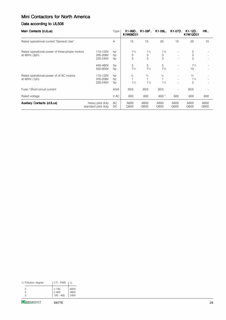
Mini Contactors for North AmericaMini Contactors for North AmericaMini Contactors for North AmericaMini Contactors for North AmericaMini Contactors for North America
Data according to UL508Data according to UL508Data according to UL508Data according to UL508Data according to UL508
Main Contacts (cULus)Main Contacts (cULus)Main Contacts (cULus)Main Contacts (cULus)Main Contacts (cULus) Type K1-09D..K1-09D..K1-09D..K1-09D..K1-09D.. K1-09F..K1-09F..K1-09F..K1-09F..K1-09F.. K1-09L..K1-09L..K1-09L..K1-09L..K1-09L.. K1-07D..K1-07D..K1-07D..K1-07D..K1-07D.. K1-12D..K1-12D..K1-12D..K1-12D..K1-12D.. HK..HK..HK..HK..HK..K1W09D01K1W09D01K1W09D01K1W09D01K1W09D01 K1W12D01K1W12D01K1W12D01K1W12D01K1W12D01
Rated operational current "General Use" A 15 15 20 10 20 10
Rated operational power of three-phase motors 110-120V hp 1½ 1½ 1½ - 2 -at 60Hz (3ph) 200-208V hp 3 3 3 - 3 -
220-240V hp 3 3 3 - 3 -
440-480V hp 5 5 5 - 7½ -550-600V hp 7½ 7½ 7½ - 10 -
Rated operational power of of AC motors 110-120V hp ½ ½ ½ - ¾ -at 60Hz (1ph) 200-208V hp 1 1 1 - 1½ -
220-240V hp 1½ 1½ 1½ - 2 -
Fuse / Short-circuit current A/kA 30/5 30/5 30/5 - 30/5 -
Rated voltage V AC 600 600 600 1) 600 600 600
Auxiliary Contacts (cULus)Auxiliary Contacts (cULus)Auxiliary Contacts (cULus)Auxiliary Contacts (cULus)Auxiliary Contacts (cULus) heavy pilot duty AC A600 A600 A600 A600 A600 A600standard pilot duty DC Q600 Q600 Q600 Q600 Q600 Q600
1) Pollution degree CTI - PWB Ui
2 ≥ 100 600V3 ≥ 400 480V3 100 - 400 240V

30 D677E
Mini ContactorsMini ContactorsMini ContactorsMini ContactorsMini Contactors
DimensionsDimensionsDimensionsDimensionsDimensions
AC and DC operatedAC and DC operatedAC and DC operatedAC and DC operatedAC and DC operatedwith screw terminals with fast on terminals
K1-07D..K1-07D..K1-07D..K1-07D..K1-07D.. K1-07F..K1-07F..K1-07F..K1-07F..K1-07F..K1-09D..K1-09D..K1-09D..K1-09D..K1-09D.. K1-09F..K1-09F..K1-09F..K1-09F..K1-09F..K1-12D..K1-12D..K1-12D..K1-12D..K1-12D..
AC and DC operatedAC and DC operatedAC and DC operatedAC and DC operatedAC and DC operated Auxiliary Contact BlocksAuxiliary Contact BlocksAuxiliary Contact BlocksAuxiliary Contact BlocksAuxiliary Contact Blockswith solder connections
HK..HK..HK..HK..HK..K1-07L..K1-07L..K1-07L..K1-07L..K1-07L..K1-09L..K1-09L..K1-09L..K1-09L..K1-09L..
Suppressor UnitsSuppressor UnitsSuppressor UnitsSuppressor UnitsSuppressor Units
RC-K1RC-K1RC-K1RC-K1RC-K1
Reversing ContactorsReversing ContactorsReversing ContactorsReversing ContactorsReversing Contactors
K1W09D..MCK1W09D..MCK1W09D..MCK1W09D..MCK1W09D..MCK1W12D..MCK1W12D..MCK1W12D..MCK1W12D..MCK1W12D..MC
K1W09D..MC + U12/16E K1K1W09D..MC + U12/16E K1K1W09D..MC + U12/16E K1K1W09D..MC + U12/16E K1K1W09D..MC + U12/16E K1Reversing ContactorsReversing ContactorsReversing ContactorsReversing ContactorsReversing Contactors K1W09D..MC + U12/16E K1K1W09D..MC + U12/16E K1K1W09D..MC + U12/16E K1K1W09D..MC + U12/16E K1K1W09D..MC + U12/16E K1
K1W09L..MCK1W09L..MCK1W09L..MCK1W09L..MCK1W09L..MC

D677E 31
Contactor RelaysContactor RelaysContactor RelaysContactor RelaysContactor Relays
Contactor Relays 4-pole, AC Operated 32
Auxiliary Contact Blocks 1-pole 32
Contactor Relays 4-pole, DC Operated 33
Technical Data 34
Dimensions 36
32 D677E
Contactor RelaysContactor RelaysContactor RelaysContactor RelaysContactor Relays AC Operated
RatingsRatingsRatingsRatingsRatings Contacts TypeTypeTypeTypeType Coil voltage 1)
Therm. Built-in Distinc. Additional 2424242424 24V 50/60HzRated Number Contact 110110110110110 110V 50Hz 110-120V 60HzCurrent acc. to Blocks 230230230230230 220-240V 50Hz 230-264V 60Hz
AC15AC15AC15AC15AC15 400400400400400 380-415V 50Hz 400-440V 60Hz230V230V230V230V230V 400V Ith ⏐⏐⏐⏐⏐ Pack Weight
AAAAA A A NO NC EN50011 Type pcs. kg/pc.
4-pole, contacts suitable for electronic circuits according to EN947-5-44-pole, contacts suitable for electronic circuits according to EN947-5-44-pole, contacts suitable for electronic circuits according to EN947-5-44-pole, contacts suitable for electronic circuits according to EN947-5-44-pole, contacts suitable for electronic circuits according to EN947-5-42)2)2)2)2)
44444 2 10 4 - 40E max. 4 K3-07ND40 . . .K3-07ND40 . . .K3-07ND40 . . .K3-07ND40 . . .K3-07ND40 . . . 1 0,2244444 2 10 3 1 31E HN.. K3-07ND31 . . .K3-07ND31 . . .K3-07ND31 . . .K3-07ND31 . . .K3-07ND31 . . . 1 0,2244444 2 10 2 2 22E K3-07ND22 . . .K3-07ND22 . . .K3-07ND22 . . .K3-07ND22 . . .K3-07ND22 . . . 1 0,2244444 2 10 - 4 04E K3-07ND04 . . .K3-07ND04 . . .K3-07ND04 . . .K3-07ND04 . . .K3-07ND04 . . . 1 0,22
Auxiliary Contact Blocks Auxiliary Contact Blocks Auxiliary Contact Blocks Auxiliary Contact Blocks Auxiliary Contact Blocks 3)3)3)3)3)
RatingsRatingsRatingsRatingsRatings Thermal Contacts 2) TypeTypeTypeTypeTypeAC15AC15AC15AC15AC15 Rated230V230V230V230V230V 400V Current Pack Weight
AAAAA A A NO NC EM LB pcs. kg/pc.
1-pole, contacts suitable for electronic circuits according to EN947-5-41-pole, contacts suitable for electronic circuits according to EN947-5-41-pole, contacts suitable for electronic circuits according to EN947-5-41-pole, contacts suitable for electronic circuits according to EN947-5-41-pole, contacts suitable for electronic circuits according to EN947-5-42)2)2)2)2)
33333 2 10 1 - - - HN10HN10HN10HN10HN10 10 0,0233333 2 10 - 1 - - HN01HN01HN01HN01HN01 10 0,0233333 2 10 - - 1 - HN10UHN10UHN10UHN10UHN10U 10 0,0233333 2 10 - - - 1 HN01UHN01UHN01UHN01UHN01U 10 0,02
1-pole, for high switching capacity1-pole, for high switching capacity1-pole, for high switching capacity1-pole, for high switching capacity1-pole, for high switching capacity
66666 3 25 1 - - - HA10HA10HA10HA10HA10 10 0,0366666 3 25 - 1 - - HA01HA01HA01HA01HA01 10 0,03
Accessories Accessories Accessories Accessories Accessories see page 34 - 38
1) Other coil voltages see page 402) Contacts suitable for electronic circuits, according to EN947-5-4 for rated voltage 24V DC
(test ratings 17V DC, 5mA) Positively guided contacts3) Technical Data see page 62

D677E 33
DC Operated
TypeTypeTypeTypeType Coil voltage 1) Contacts2424242424 24V DC Built-in Distinc. Additional6060606060 60V DC Number Contact110110110110110 110V DC acc. to Blocks220220220220220 220V DC
⏐⏐⏐⏐⏐ Pack WeightNO NC EN50011 Type pcs. kg/pc. Wiring Diagrams
3W Coil power, for high switching capacity3W Coil power, for high switching capacity3W Coil power, for high switching capacity3W Coil power, for high switching capacity3W Coil power, for high switching capacity 3)
KG3-07A40 . . .KG3-07A40 . . .KG3-07A40 . . .KG3-07A40 . . .KG3-07A40 . . . 4 - 40E max. 4 1 0,53 A40, D40KG3-07A31 . . .KG3-07A31 . . .KG3-07A31 . . .KG3-07A31 . . .KG3-07A31 . . . 3 1 31E HN.. 1 0,53KG3-07A22 . . .KG3-07A22 . . .KG3-07A22 . . .KG3-07A22 . . .KG3-07A22 . . . 2 2 22E oder 1 0,53KG3-07A04 . . .KG3-07A04 . . .KG3-07A04 . . .KG3-07A04 . . .KG3-07A04 . . . - 4 04E HA.. 1 0,53
A31, D31
3W Coil power, for electronic circuits 3W Coil power, for electronic circuits 3W Coil power, for electronic circuits 3W Coil power, for electronic circuits 3W Coil power, for electronic circuits 2)3)
KG3-07D40 . . .KG3-07D40 . . .KG3-07D40 . . .KG3-07D40 . . .KG3-07D40 . . . 4 - 40E max. 4 1 0,53KG3-07D31 . . .KG3-07D31 . . .KG3-07D31 . . .KG3-07D31 . . .KG3-07D31 . . . 3 1 31E HN.. 1 0,53 A22, D22KG3-07D22 . . .KG3-07D22 . . .KG3-07D22 . . .KG3-07D22 . . .KG3-07D22 . . . 2 2 22E 1 0,53KG3-07D04 . . .KG3-07D04 . . .KG3-07D04 . . .KG3-07D04 . . .KG3-07D04 . . . - 4 04E 1 0,53
A04, D04
with double winding coil, for electronic circuits with double winding coil, for electronic circuits with double winding coil, for electronic circuits with double winding coil, for electronic circuits with double winding coil, for electronic circuits 2)
K3-07ND40= . . .K3-07ND40= . . .K3-07ND40= . . .K3-07ND40= . . .K3-07ND40= . . . 4 - 40E max. 3 1 0,25 ND40=K3-07ND31= . . .K3-07ND31= . . .K3-07ND31= . . .K3-07ND31= . . .K3-07ND31= . . . 3 1 31E HN.. 1 0,25K3-07ND22= . . .K3-07ND22= . . .K3-07ND22= . . .K3-07ND22= . . .K3-07ND22= . . . 2 2 22E 1 0,25K3-07ND04= . . .K3-07ND04= . . .K3-07ND04= . . .K3-07ND04= . . .K3-07ND04= . . . -4 04E 1 0,25
ND31=
ND22=
ND04=
1) Other coil voltages on request2) Contacts suitable for electronic circuits, according to EN947-5-4 for rated voltage 24V DC
(test ratings 17V DC, 5mA) Positively guided contacts3) with integrated coil suppressor (Transient Voltage Suppressor Diode)
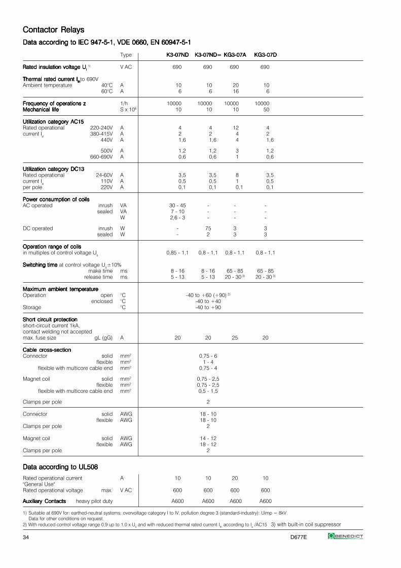
34 D677E
1) Suitable at 690V for: earthed-neutral systems, overvoltage category I to IV, pollution degree 3 (standard-industry): Uimp = 8kV.Data for other conditions on request.
2) With reduced control voltage range 0,9 up to 1,0 x Us and with reduced thermal rated current Ith according to Ie /AC15 3) with built-in coil suppressor
Contactor RelaysContactor RelaysContactor RelaysContactor RelaysContactor Relays
Data according to IEC 947-5-1, VDE 0660, EN 60947-5-1Data according to IEC 947-5-1, VDE 0660, EN 60947-5-1Data according to IEC 947-5-1, VDE 0660, EN 60947-5-1Data according to IEC 947-5-1, VDE 0660, EN 60947-5-1Data according to IEC 947-5-1, VDE 0660, EN 60947-5-1
Type K3-07NDK3-07NDK3-07NDK3-07NDK3-07ND K3-07ND=K3-07ND=K3-07ND=K3-07ND=K3-07ND= KG3-07AKG3-07AKG3-07AKG3-07AKG3-07A KG3-07DKG3-07DKG3-07DKG3-07DKG3-07D
Rated insulation voltage URated insulation voltage URated insulation voltage URated insulation voltage URated insulation voltage Ui i i i i 1) V AC 690 690 690 690
Thermal rated current IThermal rated current IThermal rated current IThermal rated current IThermal rated current Ithththththto 690VAmbient temperature 40°C A 10 10 20 10
60°C A 6 6 16 6
Frequency of operations zFrequency of operations zFrequency of operations zFrequency of operations zFrequency of operations z 1/h 10000 10000 10000 10000Mechanical lifeMechanical lifeMechanical lifeMechanical lifeMechanical life S x 106 10 10 10 50
Utilization category AC15Utilization category AC15Utilization category AC15Utilization category AC15Utilization category AC15Rated operational 220-240V A 4 4 12 4current Ie 380-415V A 2 2 4 2
440V A 1,6 1,6 4 1,6
500V A 1,2 1,2 3 1,2660-690V A 0,6 0,6 1 0,6
Utilization category DC13Utilization category DC13Utilization category DC13Utilization category DC13Utilization category DC13Rated operational 24-60V A 3,5 3,5 8 3,5current Ie 110V A 0,5 0,5 1 0,5per pole 220V A 0,1 0,1 0,1 0,1
Power consumption of coilsPower consumption of coilsPower consumption of coilsPower consumption of coilsPower consumption of coilsAC operated inrush VA 30 - 45 - - -
sealed VA 7 - 10 - - -W 2,6 - 3 - - -
DC operated inrush W - 75 3 3sealed W - 2 3 3
Operation range of coilsOperation range of coilsOperation range of coilsOperation range of coilsOperation range of coilsin multiples of control voltage Us 0,85 - 1,1 0,8 - 1,1 0,8 - 1,1 0,8 - 1,1
Switching time Switching time Switching time Switching time Switching time at control voltage Us±10%make time ms 8 - 16 8 - 16 65 - 85 65 - 85
release time ms 5 - 13 5 - 13 20 - 30 3) 20 - 30 3)
Maximum ambient temperatureMaximum ambient temperatureMaximum ambient temperatureMaximum ambient temperatureMaximum ambient temperatureOperation open °C -40 to +60 (+90) 2)
enclosed °C -40 to +40Storage °C -40 to +90
Short circuit protectionShort circuit protectionShort circuit protectionShort circuit protectionShort circuit protectionshort-circuit current 1kA,contact welding not acceptedmax. fuse size gL (gG) A 20 20 25 20
Cable cross-sectionCable cross-sectionCable cross-sectionCable cross-sectionCable cross-sectionConnector solid mm2 0,75 - 6
flexible mm2 1 - 4flexible with multicore cable end mm2 0,75 - 4
Magnet coil solid mm2 0,75 - 2,5flexible mm2 0,75 - 2,5
flexible with multicore cable end mm2 0,5 - 1,5
Clamps per pole 2
Connector solid AWG 18 - 10flexible AWG 18 - 10
Clamps per pole 2
Magnet coil solid AWG 14 - 12flexible AWG 18 - 12
Clamps per pole 2
Data according to UL508Data according to UL508Data according to UL508Data according to UL508Data according to UL508
Rated operational current A 10 10 20 10"General Use"Rated operational voltage max. V AC 600 600 600 600
Auxiliary ContactsAuxiliary ContactsAuxiliary ContactsAuxiliary ContactsAuxiliary Contacts heavy pilot duty A600 A600 A600 A600

D677E 35
Contactor RelaysContactor RelaysContactor RelaysContactor RelaysContactor Relays
Position of TerminalsPosition of TerminalsPosition of TerminalsPosition of TerminalsPosition of Terminals
AC operated DC operated with double wound coil
K3-07ND22K3-07ND22K3-07ND22K3-07ND22K3-07ND22 K3-07ND31K3-07ND31K3-07ND31K3-07ND31K3-07ND31 K3-07ND40K3-07ND40K3-07ND40K3-07ND40K3-07ND40 K3-07ND04K3-07ND04K3-07ND04K3-07ND04K3-07ND04 K3-07ND22=K3-07ND22=K3-07ND22=K3-07ND22=K3-07ND22= K3-07ND31=K3-07ND31=K3-07ND31=K3-07ND31=K3-07ND31= K3-07ND40=K3-07ND40=K3-07ND40=K3-07ND40=K3-07ND40= K3-07ND04=K3-07ND04=K3-07ND04=K3-07ND04=K3-07ND04=
DC solenoid operated
KG3-07A22KG3-07A22KG3-07A22KG3-07A22KG3-07A22 KG3-07A31KG3-07A31KG3-07A31KG3-07A31KG3-07A31 KG3-07A40KG3-07A40KG3-07A40KG3-07A40KG3-07A40 KG3-07A04KG3-07A04KG3-07A04KG3-07A04KG3-07A04KG3-07D22KG3-07D22KG3-07D22KG3-07D22KG3-07D22 KG3-07D31KG3-07D31KG3-07D31KG3-07D31KG3-07D31 KG3-07D40KG3-07D40KG3-07D40KG3-07D40KG3-07D40 KG3-07D04KG3-07D04KG3-07D04KG3-07D04KG3-07D04
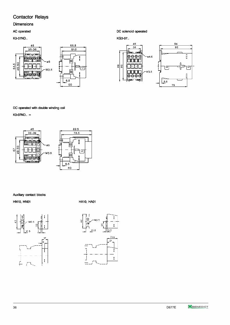
36 D677E
Contactor RelaysContactor RelaysContactor RelaysContactor RelaysContactor Relays
DimensionsDimensionsDimensionsDimensionsDimensions
AC operatedAC operatedAC operatedAC operatedAC operated DC solenoid operatedDC solenoid operatedDC solenoid operatedDC solenoid operatedDC solenoid operated
K3-07ND..K3-07ND..K3-07ND..K3-07ND..K3-07ND.. KG3-07..KG3-07..KG3-07..KG3-07..KG3-07..
DC operated with double winding coilDC operated with double winding coilDC operated with double winding coilDC operated with double winding coilDC operated with double winding coil
K3-07ND.. =K3-07ND.. =K3-07ND.. =K3-07ND.. =K3-07ND.. =
Auxiliary contact blocksAuxiliary contact blocksAuxiliary contact blocksAuxiliary contact blocksAuxiliary contact blocks
HN10, HN01HN10, HN01HN10, HN01HN10, HN01HN10, HN01 HA10, HA01HA10, HA01HA10, HA01HA10, HA01HA10, HA01

D677E 37
ContactorsContactorsContactorsContactorsContactors
Contactor overview 38
Contactors 3-pole, AC Operated 40
Contactors 3-pole, DC Operated 41
Contactors 4-pole 42
Capacitor Switching Contactors 43
Auxiliary Contact Blocks 44Snap-on Momentary ContactsAdditional Fourth Poles for Contactors
Pneumatic Timers 45Electronic Timers On-delayElectronic Timers Off-delay
Mechanical Interlocks 46LatchesAdditional Terminals, Parallel Connectors
Indicator Units 47Fuse HoldersSuppressor Units
Interface 48Terminal CoversMounting Parts, Marking System
Control Voltages 50
Spare Coils AC-operated 50Feeder Groups
Spare Coils DC-operated 51Spare Contacts
Technical Data 54
Dimensions 74

38 D677E
Contactors 3-poleContactors 3-poleContactors 3-poleContactors 3-poleContactors 3-pole
Up to 1200A AC3Up to 1200A AC3Up to 1200A AC3Up to 1200A AC3Up to 1200A AC3Up to 1350A AC1Up to 1350A AC1Up to 1350A AC1Up to 1350A AC1Up to 1350A AC1DIN-rail mounting up to AC3 115ADIN-rail mounting up to AC3 115ADIN-rail mounting up to AC3 115ADIN-rail mounting up to AC3 115ADIN-rail mounting up to AC3 115AInternational ApprovalsInternational ApprovalsInternational ApprovalsInternational ApprovalsInternational ApprovalsData according to IEC 947 / EN 60947Data according to IEC 947 / EN 60947Data according to IEC 947 / EN 60947Data according to IEC 947 / EN 60947Data according to IEC 947 / EN 60947
RatingsRatingsRatingsRatingsRatingsAC3AC3AC3AC3AC3 400V400V400V400V400V MotorMotorMotorMotorMotor 10A10A10A10A10A 14A14A14A14A14A 18A18A18A18A18A 22A22A22A22A22A 24A24A24A24A24A 32A32A32A32A32A 40A40A40A40A40A 50A50A50A50A50A 62A62A62A62A62A 74A74A74A74A74A 90A90A90A90A90A 115A115A115A115A115A
380-400V380-400V380-400V380-400V380-400V 4kW4kW4kW4kW4kW 5,5kW5,5kW5,5kW5,5kW5,5kW 7,5kW7,5kW7,5kW7,5kW7,5kW 11kW11kW11kW11kW11kW 11kW11kW11kW11kW11kW 15kW15kW15kW15kW15kW 18,5kW18,5kW18,5kW18,5kW18,5kW 22kW22kW22kW22kW22kW 30kW30kW30kW30kW30kW 37kW37kW37kW37kW37kW 45kW45kW45kW45kW45kW 55kW55kW55kW55kW55kW660-690V 5,5kW 7,5kW 10kW 10kW 15kW 18,5kW 18,5kW 30kW 37kW 45kW 55kW 55kW
AC1 690V at 40°C 25A 25A 32A 32A 50A 65A 80A 110A 120A 130A 160A 200A
TypeTypeTypeTypeType K3-K3-K3-K3-K3- 10ND1010ND1010ND1010ND1010ND10 14ND1014ND1014ND1014ND1014ND10 18ND1018ND1018ND1018ND1018ND10 22ND1022ND1022ND1022ND1022ND10 24A0024A0024A0024A0024A00 32A0032A0032A0032A0032A00 40A0040A0040A0040A0040A00 50A0050A0050A0050A0050A00 62A0062A0062A0062A0062A00 74A0074A0074A0074A0074A00 90A0090A0090A0090A0090A00 115A00115A00115A00115A00115A00
Auxiliary contacts 1NO 1NO 1NO 1NO - - - - - -
TypeTypeTypeTypeType K3-K3-K3-K3-K3- 10ND0110ND0110ND0110ND0110ND01 14ND0114ND0114ND0114ND0114ND01 18ND0118ND0118ND0118ND0118ND01 22ND0122ND0122ND0122ND0122ND01
Auxiliary contacts 1NC 1NC 1NC 1NC
Cable cross-sectionCable cross-sectionCable cross-sectionCable cross-sectionCable cross-sectionSolid mm2 0,75 - 6 1,5 - 25 4 - 50 10 - 120Flexible mm2 1 - 4 2,5 - 16 10 - 35 10 - 95
Auxiliary contactAuxiliary contactAuxiliary contactAuxiliary contactAuxiliary contactIth 40°C A 10 - - -AC15 230V A 3 - - -
400V A 2 - - -
Power consumptionPower consumptionPower consumptionPower consumptionPower consumption Inrush VA 33 - 45 90 - 115 140 - 165 280of coilsof coilsof coilsof coilsof coils hold VA 7 - 10 9 - 13 13 - 18 5
Operation range of coils 0,85 - 1,1 0,85 - 1,1 0,85 - 1,1 0,85 - 1,1
MountingMountingMountingMountingMounting 35mm DIN-rail or base 2x DIN-railor base
Additional aux. contact blocksAdditional aux. contact blocksAdditional aux. contact blocksAdditional aux. contact blocksAdditional aux. contact blocksFront mounting TypeTypeTypeTypeType HN10HN10HN10HN10HN10 HN01HN01HN01HN01HN01 HA10HA10HA10HA10HA10 HA01HA01HA01HA01HA01 max. max.
contacts 1NO 1NC 1NO 1NC 4 HN.. 7 HN..f. low level f. low level 25A Ith 25A Ith or orswitching switching 4 HA.. 7 HA..
Additional aux. contact blocksAdditional aux. contact blocksAdditional aux. contact blocksAdditional aux. contact blocksAdditional aux. contact blocksSide mounting TypeTypeTypeTypeType ----- ----- ----- ----- HB11HB11HB11HB11HB11 HB02HB02HB02HB02HB02 max.
contacts 1NO+1NC 2NC 2 HB..f. low level f. low levelswitching switching
Overload Relay Overload Relay Overload Relay Overload Relay Overload Relay (thermal)Single phase protectionTemperature compensationTrip and alarm contacts
TypeTypeTypeTypeType U3/32U3/32U3/32U3/32U3/32 U3/74U3/74U3/74U3/74U3/74 U85U85U85U85U85
U12/16..K3U12/16..K3U12/16..K3U12/16..K3U12/16..K3 U3/42U3/42U3/42U3/42U3/42
Number of Setting Ranges 16 16 4 5 2from 0,12 - 30A 0,12 - 32A 10 - 42A 20 - 74A 60 - 120A
Busbar setsBusbar setsBusbar setsBusbar setsBusbar sets - - - - -

D677E 39
150A150A150A150A150A 175A175A175A175A175A 210A210A210A210A210A 260A260A260A260A260A 315A315A315A315A315A 450A450A450A450A450A 550A550A550A550A550A 700A700A700A700A700A 860A860A860A860A860A 1000A1000A1000A1000A1000A 1200A1200A1200A1200A1200A
75kW75kW75kW75kW75kW 90kW90kW90kW90kW90kW 110kW110kW110kW110kW110kW 132kW132kW132kW132kW132kW 160kW160kW160kW160kW160kW 250kW250kW250kW250kW250kW 300kW300kW300kW300kW300kW 400kW400kW400kW400kW400kW 500kW500kW500kW500kW500kW 580kW580kW580kW580kW580kW 680kW680kW680kW680kW680kW90kW 110kW 160kW 210kW 250kW 375kW 475kW 630kW 700kW 850kW 1000kW
230A 250A 350A 450A 500A 600A 760A 1000A 1100A 1200A 1350A
151A00151A00151A00151A00151A00 176A00176A00176A00176A00176A00 210A00210A00210A00210A00210A00 260A00260A00260A00260A00260A00 316A00316A00316A00316A00316A00 450A22450A22450A22450A22450A22 550A22550A22550A22550A22550A22 700A22700A22700A22700A22700A22 860A22860A22860A22860A22860A22 1000A121000A121000A121000A121000A12 1200A121200A121200A121200A121200A12
- - - - - 2NO+2NC 2NO+2NC 2NO+2NC 2NO+2NC 1NO+2NC 1NO+2NC
2 x 16-120 busbar busbar busbar busbar busbar busbar busbar busbar busbar2 x 16-120 30x6 30x6 30x6 30x5 40x6 50x8 50x8 50x10 50x10
- - 10 10- - 3 3- - 2 2
350 350 360 360 360 800-950 800-950 1350-1600 1350-1600 2400 24005 5 5 5 5 9-11 9-11 21-25 21-25 70 70
0,85 - 1,1 0,85 - 1,1 0,85 - 1,1 0,85-1,1
base
HKT11HKT11HKT11HKT11HKT11 HKT22HKT22HKT22HKT22HKT22 HKF22HKF22HKF22HKF22HKF22 HKB11HKB11HKB11HKB11HKB111NO+1NC 2NO+2NC 2NO+2NC 1NO+1NC
max. 1 pc. max. 1 pc. max. 2 pcs.
HKA11HKA11HKA11HKA11HKA11 ----- ----- ----- ----- ----- -----1NO+1NCmax. 2 pcs.
U180U180U180U180U180 U320U320U320U320U320 U800U800U800U800U800
1 2 3120 - 180A 144 - 320A 240 - 800A
integrated integrated SU840/550 SU840/860
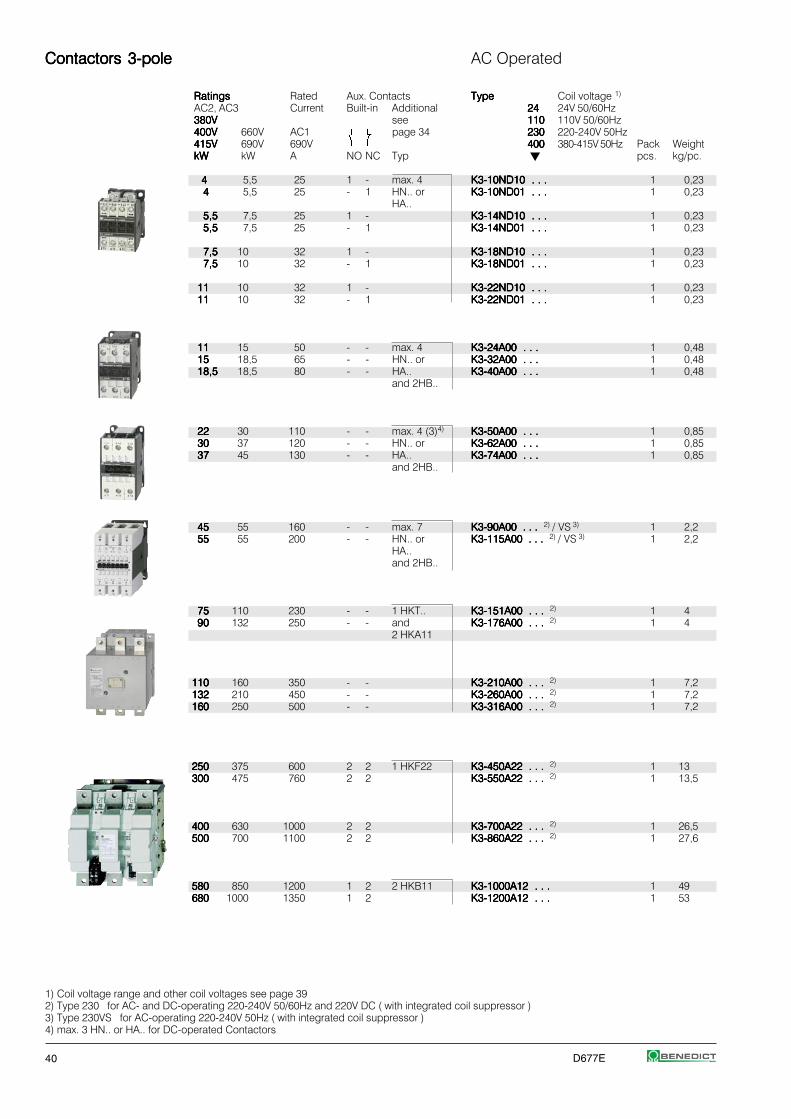
40 D677E
Contactors 3-poleContactors 3-poleContactors 3-poleContactors 3-poleContactors 3-pole AC Operated
RatingsRatingsRatingsRatingsRatings Rated Aux. Contacts TypeTypeTypeTypeType Coil voltage 1)
AC2, AC3 Current Built-in Additional 2424242424 24V 50/60Hz380V380V380V380V380V see 110110110110110 110V 50/60Hz400V400V400V400V400V 660V AC1 page 34 230230230230230 220-240V 50Hz415V415V415V415V415V 690V 690V 400400400400400 380-415V 50Hz Pack WeightkWkWkWkWkW kW A NO NC Typ pcs. kg/pc.
44444 5,5 25 1 - max. 4 K3-10ND10 . . .K3-10ND10 . . .K3-10ND10 . . .K3-10ND10 . . .K3-10ND10 . . . 1 0,2344444 5,5 25 - 1 HN.. or K3-10ND01 . . .K3-10ND01 . . .K3-10ND01 . . .K3-10ND01 . . .K3-10ND01 . . . 1 0,23
HA..5,55,55,55,55,5 7,5 25 1 - K3-14ND10 . . .K3-14ND10 . . .K3-14ND10 . . .K3-14ND10 . . .K3-14ND10 . . . 1 0,235,55,55,55,55,5 7,5 25 - 1 K3-14ND01 . . .K3-14ND01 . . .K3-14ND01 . . .K3-14ND01 . . .K3-14ND01 . . . 1 0,23
7,57,57,57,57,5 10 32 1 - K3-18ND10 . . .K3-18ND10 . . .K3-18ND10 . . .K3-18ND10 . . .K3-18ND10 . . . 1 0,237,57,57,57,57,5 10 32 - 1 K3-18ND01 . . .K3-18ND01 . . .K3-18ND01 . . .K3-18ND01 . . .K3-18ND01 . . . 1 0,23
1111111111 10 32 1 - K3-22ND10 . . .K3-22ND10 . . .K3-22ND10 . . .K3-22ND10 . . .K3-22ND10 . . . 1 0,231111111111 10 32 - 1 K3-22ND01 . . .K3-22ND01 . . .K3-22ND01 . . .K3-22ND01 . . .K3-22ND01 . . . 1 0,23
1111111111 15 50 - - max. 4 K3-24A00 . . .K3-24A00 . . .K3-24A00 . . .K3-24A00 . . .K3-24A00 . . . 1 0,481515151515 18,5 65 - - HN.. or K3-32A00 . . .K3-32A00 . . .K3-32A00 . . .K3-32A00 . . .K3-32A00 . . . 1 0,4818,518,518,518,518,5 18,5 80 - - HA.. K3-40A00 . . .K3-40A00 . . .K3-40A00 . . .K3-40A00 . . .K3-40A00 . . . 1 0,48
and 2HB..
2222222222 30 110 - - max. 4 (3)4) K3-50A00 . . .K3-50A00 . . .K3-50A00 . . .K3-50A00 . . .K3-50A00 . . . 1 0,853030303030 37 120 - - HN.. or K3-62A00 . . .K3-62A00 . . .K3-62A00 . . .K3-62A00 . . .K3-62A00 . . . 1 0,853737373737 45 130 - - HA.. K3-74A00 . . .K3-74A00 . . .K3-74A00 . . .K3-74A00 . . .K3-74A00 . . . 1 0,85
and 2HB..
4545454545 55 160 - - max. 7 K3-90A00 . . .K3-90A00 . . .K3-90A00 . . .K3-90A00 . . .K3-90A00 . . . 2) / VS 3) 1 2,25555555555 55 200 - - HN.. or K3-115A00 . . .K3-115A00 . . .K3-115A00 . . .K3-115A00 . . .K3-115A00 . . . 2) / VS 3) 1 2,2
HA..and 2HB..
7575757575 110 230 - - 1 HKT.. K3-151A00 . . .K3-151A00 . . .K3-151A00 . . .K3-151A00 . . .K3-151A00 . . . 2) 1 49090909090 132 250 - - and K3-176A00 . . .K3-176A00 . . .K3-176A00 . . .K3-176A00 . . .K3-176A00 . . . 2) 1 4
2 HKA11
110110110110110 160 350 - - K3-210A00 . . .K3-210A00 . . .K3-210A00 . . .K3-210A00 . . .K3-210A00 . . . 2) 1 7,2132132132132132 210 450 - - K3-260A00 . . .K3-260A00 . . .K3-260A00 . . .K3-260A00 . . .K3-260A00 . . . 2) 1 7,2160160160160160 250 500 - - K3-316A00 . . .K3-316A00 . . .K3-316A00 . . .K3-316A00 . . .K3-316A00 . . . 2) 1 7,2
250250250250250 375 600 2 2 1 HKF22 K3-450A22 . . .K3-450A22 . . .K3-450A22 . . .K3-450A22 . . .K3-450A22 . . . 2) 1 13300300300300300 475 760 2 2 K3-550A22 . . .K3-550A22 . . .K3-550A22 . . .K3-550A22 . . .K3-550A22 . . . 2) 1 13,5
400400400400400 630 1000 2 2 K3-700A22 . . .K3-700A22 . . .K3-700A22 . . .K3-700A22 . . .K3-700A22 . . . 2) 1 26,5500500500500500 700 1100 2 2 K3-860A22 . . .K3-860A22 . . .K3-860A22 . . .K3-860A22 . . .K3-860A22 . . . 2) 1 27,6
580580580580580 850 1200 1 2 2 HKB11 K3-1000A12 . . .K3-1000A12 . . .K3-1000A12 . . .K3-1000A12 . . .K3-1000A12 . . . 1 49680680680680680 1000 1350 1 2 K3-1200A12 . . .K3-1200A12 . . .K3-1200A12 . . .K3-1200A12 . . .K3-1200A12 . . . 1 53
1) Coil voltage range and other coil voltages see page 392) Type 230 for AC- and DC-operating 220-240V 50/60Hz and 220V DC ( with integrated coil suppressor )3) Type 230VS for AC-operating 220-240V 50Hz ( with integrated coil suppressor )4) max. 3 HN.. or HA.. for DC-operated Contactors

D677E 41
DC Operated
TypeTypeTypeTypeType Coil Additional Wiring DiagramCoil voltage 1) power Overload
2424242424 24V DC Relay Coil Circuits4848484848 48V DC inrush/ see see page 41110110110110110 110V DC hold page 102 Pack Weight
W/W Type pcs. kg/pc. Terminal Markings
KG3-10A10 . . .KG3-10A10 . . .KG3-10A10 . . .KG3-10A10 . . .KG3-10A10 . . . 5) 3/3 U3/32 1 0,53 D10KG3-10A01 . . .KG3-10A01 . . .KG3-10A01 . . .KG3-10A01 . . .KG3-10A01 . . . 5) 3/3 U12/16E 1 0,53
U12/16EQKG3-14A10 . . .KG3-14A10 . . .KG3-14A10 . . .KG3-14A10 . . .KG3-14A10 . . . 5) 3/3 UAT21 1 0,53KG3-14A01 . . .KG3-14A01 . . .KG3-14A01 . . .KG3-14A01 . . .KG3-14A01 . . . 5) 3/3 1 0,53
KG3-18A10 . . .KG3-18A10 . . .KG3-18A10 . . .KG3-18A10 . . .KG3-18A10 . . . 5) 3/3 1 0,53 D01KG3-18A01 . . .KG3-18A01 . . .KG3-18A01 . . .KG3-18A01 . . .KG3-18A01 . . . 5) 3/3 1 0,53
KG3-22A10 . . .KG3-22A10 . . .KG3-22A10 . . .KG3-22A10 . . .KG3-22A10 . . . 5) 3/3 1 0,53KG3-22A01 . . .KG3-22A01 . . .KG3-22A01 . . .KG3-22A01 . . .KG3-22A01 . . . 5) 3/3 1 0,53
KG3-24A00 . . .KG3-24A00 . . .KG3-24A00 . . .KG3-24A00 . . .KG3-24A00 . . . 5) 4/4 U3/32 1 0,57 A00KG3-32A00 . . .KG3-32A00 . . .KG3-32A00 . . .KG3-32A00 . . .KG3-32A00 . . . 5) 4/4 U3/42 1 0,57KG3-40A00 . . .KG3-40A00 . . .KG3-40A00 . . .KG3-40A00 . . .KG3-40A00 . . . 5) 4/4 UAT.. 1 0,57
A00=K3-50A00= . . .K3-50A00= . . .K3-50A00= . . .K3-50A00= . . .K3-50A00= . . . 200/6 U3/74 1 0,9K3-62A00= . . .K3-62A00= . . .K3-62A00= . . .K3-62A00= . . .K3-62A00= . . . 200/6 1 0,9K3-74A00= . . .K3-74A00= . . .K3-74A00= . . .K3-74A00= . . .K3-74A00= . . . 200/6 1 0,9
K3-90A00 . . .K3-90A00 . . .K3-90A00 . . .K3-90A00 . . .K3-90A00 . . . 2) 280/5 U85 1 2,2 A00K3-115A00 . . .K3-115A00 . . .K3-115A00 . . .K3-115A00 . . .K3-115A00 . . . 2) 280/5 1 2,3
K3-151A00 . . .K3-151A00 . . .K3-151A00 . . .K3-151A00 . . .K3-151A00 . . . 2) 350/5 U180 1 4K3-176A00 . . .K3-176A00 . . .K3-176A00 . . .K3-176A00 . . .K3-176A00 . . . 2) 350/5 1 4
K3-210A00 . . .K3-210A00 . . .K3-210A00 . . .K3-210A00 . . .K3-210A00 . . . 2) 360/5 U320 1 7,2K3-260A00 . . .K3-260A00 . . .K3-260A00 . . .K3-260A00 . . .K3-260A00 . . . 2) 360/5 1 7,2K3-316A00 . . .K3-316A00 . . .K3-316A00 . . .K3-316A00 . . .K3-316A00 . . . 2) 360/5 1 7,2
K3-450A22 . . . K3-450A22 . . . K3-450A22 . . . K3-450A22 . . . K3-450A22 . . . 2) 800/10 U800 1 13 A22K3-550A22 . . .K3-550A22 . . .K3-550A22 . . .K3-550A22 . . .K3-550A22 . . . 2) 800/10 +SU840/550 1 13,5
K3-700A22 . . .K3-700A22 . . .K3-700A22 . . .K3-700A22 . . .K3-700A22 . . . 2) 1500/20 U800 1 26,5K3-860A22 . . .K3-860A22 . . .K3-860A22 . . .K3-860A22 . . .K3-860A22 . . . 2) 1500/20 +SU840/860 1 27,6
K3-1000A12= . . .K3-1000A12= . . .K3-1000A12= . . .K3-1000A12= . . .K3-1000A12= . . . 2100/60 1 49 A12K3-1200A12= . . .K3-1200A12= . . .K3-1200A12= . . .K3-1200A12= . . .K3-1200A12= . . . 2100/60 1 53
1) Other coil voltages on request2) Type 230 for AC- and DC-operating 220-240V 50/60Hz and 220V DC ( with integrated coil suppressor )5) with integrated coil suppressor

42 D677E
Contactors 3-poleContactors 3-poleContactors 3-poleContactors 3-poleContactors 3-pole DC Operated
RatingsRatingsRatingsRatingsRatings Rated Aux. Contacts TypeTypeTypeTypeType Coil voltage 1)
AC2 Current Built-in Additional 2424242424 24V= DCAC3 see 6060606060 60V= DC380V380V380V380V380V AC1 page 34 110110110110110 110V= DC400V400V400V400V400V 660V 220220220220220 220V= DC415V415V415V415V415V 690V 690V ⏐⏐⏐⏐⏐ Pack Weight Wiring DiagramkWkWkWkWkW kW A NO NC Type pcs. kg/pc.
44444 5,5 25 1 - max. 3 K3-10ND10= . . .K3-10ND10= . . .K3-10ND10= . . .K3-10ND10= . . .K3-10ND10= . . . 1 0,25 D10=44444 5,5 25 - 1 HN.. K3-10ND01= . . .K3-10ND01= . . .K3-10ND01= . . .K3-10ND01= . . .K3-10ND01= . . . 1 0,25
or5,55,55,55,55,5 7,5 25 1 - HA.. K3-14ND10= . . .K3-14ND10= . . .K3-14ND10= . . .K3-14ND10= . . .K3-14ND10= . . . 1 0,255,55,55,55,55,5 7,5 25 - 1 K3-14ND01= . . .K3-14ND01= . . .K3-14ND01= . . .K3-14ND01= . . .K3-14ND01= . . . 1 0,25
7,57,57,57,57,5 10 32 1 - K3-18ND10= . . .K3-18ND10= . . .K3-18ND10= . . .K3-18ND10= . . .K3-18ND10= . . . 1 0,25 D01=7,57,57,57,57,5 10 32 - 1 K3-18ND01= . . .K3-18ND01= . . .K3-18ND01= . . .K3-18ND01= . . .K3-18ND01= . . . 1 0,25
1111111111 10 32 1 - K3-22ND10= . . .K3-22ND10= . . .K3-22ND10= . . .K3-22ND10= . . .K3-22ND10= . . . 1 0,251111111111 10 32 - 1 K3-22ND01= . . .K3-22ND01= . . .K3-22ND01= . . .K3-22ND01= . . .K3-22ND01= . . . 1 0,25
1111111111 15 50 - - max. 4 K3-24A00= . . .K3-24A00= . . .K3-24A00= . . .K3-24A00= . . .K3-24A00= . . . 1 0,55 ... A00=1515151515 18,5 65 ----- ----- HN.. or K3-32A00= . . .K3-32A00= . . .K3-32A00= . . .K3-32A00= . . .K3-32A00= . . . 1 0,5518,518,518,518,518,5 18,5 80 - - HA.. K3-40A00= . . .K3-40A00= . . .K3-40A00= . . .K3-40A00= . . .K3-40A00= . . . 1 0,55
+ 2HB..
Contactors 4-poleContactors 4-poleContactors 4-poleContactors 4-poleContactors 4-pole AC Operated
RatingsRatingsRatingsRatingsRatings Rated Aux. Contacts TypeTypeTypeTypeType Coil voltage 2)
AC2 AC1 Current Built-in Additional 2424242424 24V 50/60HzAC3 see 110110110110110 110V 50/60Hz380V380V380V380V380V AC1 page 34 230230230230230 220-240V 50Hz400V400V400V400V400V 400400400400400 380-415V 50Hz415V415V415V415V415V 400V400V400V400V400V 690V ⏐⏐⏐⏐⏐ Pack Weight Wiring DiagramkWkWkWkWkW kW A NO NC Type pcs. kg/pc.
4 17,517,517,517,517,5 25 - - max. 4 K3-10NA00-40 . . .K3-10NA00-40 . . .K3-10NA00-40 . . .K3-10NA00-40 . . .K3-10NA00-40 . . . 1 0,22 A00-405,5 17,517,517,517,517,5 25 - - HN.. or K3-14NA00-40 . . .K3-14NA00-40 . . .K3-14NA00-40 . . .K3-14NA00-40 . . .K3-14NA00-40 . . . 1 0,22
HA..7,5 2222222222 32 - - K3-18NA00-40 . . .K3-18NA00-40 . . .K3-18NA00-40 . . .K3-18NA00-40 . . .K3-18NA00-40 . . . 1 0,22
11 2222222222 32 - - K3-22NA00-40 . . .K3-22NA00-40 . . .K3-22NA00-40 . . .K3-22NA00-40 . . .K3-22NA00-40 . . . 1 0,22
11 3131313131 45 - - max. 4 K2-23A00-40 . . .K2-23A00-40 . . .K2-23A00-40 . . .K2-23A00-40 . . .K2-23A00-40 . . . 1 0,65 15 34,534,534,534,534,5 50 - - HN.. K2-30A00-40 . . .K2-30A00-40 . . .K2-30A00-40 . . .K2-30A00-40 . . .K2-30A00-40 . . . 1 0,6518,5 34,534,534,534,534,5 50 - - or K2-37A00-40 . . .K2-37A00-40 . . .K2-37A00-40 . . .K2-37A00-40 . . .K2-37A00-40 . . . 1 0,65
HA..
22 5555555555 80 - - max. 6 K2-45A00-40 . . .K2-45A00-40 . . .K2-45A00-40 . . .K2-45A00-40 . . .K2-45A00-40 . . . 1 1,1 30 6969696969 100 - - HN.. or K2-60A00-40 . . .K2-60A00-40 . . .K2-60A00-40 . . .K2-60A00-40 . . .K2-60A00-40 . . . 1 1,1
HA..
55 139139139139139 200 - - 1HKT.. K3-116A00-40 . . .K3-116A00-40 . . .K3-116A00-40 . . .K3-116A00-40 . . .K3-116A00-40 . . .3) 1 4,7 75 159159159159159 230 - - + K3-151A00-40 . . .K3-151A00-40 . . .K3-151A00-40 . . .K3-151A00-40 . . .K3-151A00-40 . . .3) 1 4,790 173173173173173 250 - - 2xHKA11 K3-176A00-40 . . .K3-176A00-40 . . .K3-176A00-40 . . .K3-176A00-40 . . .K3-176A00-40 . . .3) 1 4,7
110 242242242242242 350 - - K3-210A00-40 . . .K3-210A00-40 . . .K3-210A00-40 . . .K3-210A00-40 . . .K3-210A00-40 . . .3) 1 8132 310310310310310 450 - - K3-260A00-40 . . .K3-260A00-40 . . .K3-260A00-40 . . .K3-260A00-40 . . .K3-260A00-40 . . .3) 1 8160 346346346346346 500 - - K3-316A00-40 . . .K3-316A00-40 . . .K3-316A00-40 . . .K3-316A00-40 . . .K3-316A00-40 . . .3) 1 8
Latch for Contactors 4-pole see page 36
1) Other coil voltages on request2) Coil voltage range and non-standard coil voltages see page 393) with integrated coil suppressor
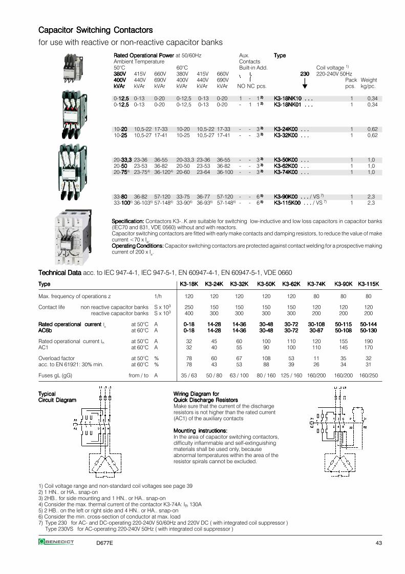
D677E 43
Capacitor Switching ContactorsCapacitor Switching ContactorsCapacitor Switching ContactorsCapacitor Switching ContactorsCapacitor Switching Contactors
for use with reactive or non-reactive capacitor banks
Rated Operational Power Rated Operational Power Rated Operational Power Rated Operational Power Rated Operational Power at 50/60Hz Aux. TypeTypeTypeTypeTypeAmbient Temperature Contacts50°C 60°C Built-in Add. Coil voltage 1)
380V380V380V380V380V 415V 660V 380V 415V 660V 230230230230230 220-240V 50Hz400V400V400V400V400V 440V 690V 400V 440V 690V ⏐⏐⏐⏐⏐ Pack WeightkVArkVArkVArkVArkVAr kVAr kVAr kVAr kVAr kVAr NO NC pcs. pcs. kg/pc.
0-12,512,512,512,512,5 0-13 0-20 0-12,5 0-13 0-20 1 - 1 2) 2) 2) 2) 2) K3-18NK10 . . .K3-18NK10 . . .K3-18NK10 . . .K3-18NK10 . . .K3-18NK10 . . . 1 0,340-12,512,512,512,512,5 0-13 0-20 0-12,5 0-13 0-20 - 1 1 2) 2) 2) 2) 2) K3-18NK01 . . .K3-18NK01 . . .K3-18NK01 . . .K3-18NK01 . . .K3-18NK01 . . . 1 0,34
10-2020202020 10,5-22 17-33 10-20 10,5-22 17-33 - - 3 3) 3) 3) 3) 3) K3-24K00 . . .K3-24K00 . . .K3-24K00 . . .K3-24K00 . . .K3-24K00 . . . 1 0,6210-2525252525 10,5-27 17-41 10-25 10,5-27 17-41 - - 3 3) 3) 3) 3) 3) K3-32K00 . . .K3-32K00 . . .K3-32K00 . . .K3-32K00 . . .K3-32K00 . . . 1 0,62
20-33,333,333,333,333,3 23-36 36-55 20-33,3 23-36 36-55 - - 3 3) 3) 3) 3) 3) K3-50K00 . . .K3-50K00 . . .K3-50K00 . . .K3-50K00 . . .K3-50K00 . . . 1 1,020-5050505050 23-53 36-82 20-50 23-53 36-82 - - 3 3) 3) 3) 3) 3) K3-62K00 . . .K3-62K00 . . .K3-62K00 . . .K3-62K00 . . .K3-62K00 . . . 1 1,020-75757575754) 23-754) 36-1204) 20-60 23-64 36-100 - - 3 3) 3) 3) 3) 3) K3-74K00 . . .K3-74K00 . . .K3-74K00 . . .K3-74K00 . . .K3-74K00 . . . 1 1,0
33-8080808080 36-82 57-120 33-75 36-77 57-120 - - 6 5) 5) 5) 5) 5) K3-90K00 . . . K3-90K00 . . . K3-90K00 . . . K3-90K00 . . . K3-90K00 . . . / VS 7) 1 2,333-1001001001001006) 36-1036) 57-1486) 33-906) 36-936) 57-1486) - - 6 5) 5) 5) 5) 5) K3-115K00 . . . K3-115K00 . . . K3-115K00 . . . K3-115K00 . . . K3-115K00 . . . / VS 7) 1 2,3
Specification:Specification:Specification:Specification:Specification: Contactors K3-..K are suitable for switching low-inductive and low loss capacitors in capacitor banks(IEC70 and 831, VDE 0560) without and with reactors.Capacitor switching contactors are fitted with early make contacts and damping resistors, to reduce the value of makecurrent <70 x Ie.Operating Conditions:Operating Conditions:Operating Conditions:Operating Conditions:Operating Conditions: Capacitor switching contactors are protected against contact welding for a prospective makingcurrent of 200 x Ie.
Technical Data Technical Data Technical Data Technical Data Technical Data acc. to IEC 947-4-1, IEC 947-5-1, EN 60947-4-1, EN 60947-5-1, VDE 0660
TypeTypeTypeTypeType K3-18KK3-18KK3-18KK3-18KK3-18K K3-24KK3-24KK3-24KK3-24KK3-24K K3-32KK3-32KK3-32KK3-32KK3-32K K3-50KK3-50KK3-50KK3-50KK3-50K K3-62KK3-62KK3-62KK3-62KK3-62K K3-74KK3-74KK3-74KK3-74KK3-74K K3-90KK3-90KK3-90KK3-90KK3-90K K3-115KK3-115KK3-115KK3-115KK3-115K
Max. frequency of operations z 1/h 120 120 120 120 120 80 80 80
Contact life non reactive capacitor banks S x 103 250 150 150 150 150 120 120 120reactive capacitor banks S x 103 400 300 300 300 300 200 200 200
Rated operational current Rated operational current Rated operational current Rated operational current Rated operational current Ie at 50°C A 0-180-180-180-180-18 14-2814-2814-2814-2814-28 14-3614-3614-3614-3614-36 30-4830-4830-4830-4830-48 30-7230-7230-7230-7230-72 30-10830-10830-10830-10830-108 50-11550-11550-11550-11550-115 50-14450-14450-14450-14450-144AC6bAC6bAC6bAC6bAC6b at 60°C A 0-180-180-180-180-18 14-2814-2814-2814-2814-28 14-3614-3614-3614-3614-36 30-4830-4830-4830-4830-48 30-7230-7230-7230-7230-72 30-8730-8730-8730-8730-87 50-10850-10850-10850-10850-108 50-13050-13050-13050-13050-130
Rated operational current Ith at 50°C A 32 45 60 100 110 120 155 190AC1 at 60°C A 32 40 55 90 100 110 145 170
Overload factor at 50°C % 78 60 67 108 53 11 35 32acc. to EN 61921: 30% min. at 60°C % 78 43 53 88 39 26 34 31
Fuses gL (gG) from / to A 35 / 63 50 / 80 63 / 100 80 / 160 125 / 160 160/200 160/200 160/250
TypicalTypicalTypicalTypicalTypical Wiring Diagram forWiring Diagram forWiring Diagram forWiring Diagram forWiring Diagram forCircuit DiagramCircuit DiagramCircuit DiagramCircuit DiagramCircuit Diagram Quick Discharge ResistorsQuick Discharge ResistorsQuick Discharge ResistorsQuick Discharge ResistorsQuick Discharge Resistors
Make sure that the current of the dischargeresistors is not higher than the rated current(AC1) of the auxiliary contacts
Mounting instructions:Mounting instructions:Mounting instructions:Mounting instructions:Mounting instructions:In the area of capacitor switching contactors,difficulty inflammable and self-extinguishingmaterials shall be used only, becauseabnormal temperatures within the area of theresistor spirals cannot be excluded.
1) Coil voltage range and non-standard coil voltages see page 392) 1 HN.. or HA.. snap-on3) 2HB.. for side mounting and 1 HN.. or HA.. snap-on4) Consider the max. thermal current of the contactor K3-74A: Ith 130A5) 2 HB.. on the left or right side and 4 HN.. or HA.. snap-on6) Consider the min. cross-section of conductor at max. load7) Type 230 for AC- and DC-operating 220-240V 50/60Hz and 220V DC ( with integrated coil suppressor )
Type 230VS for AC-operating 220-240V 50Hz ( with integrated coil suppressor )

44 D677E
Auxiliary Contact Blocks Auxiliary Contact Blocks Auxiliary Contact Blocks Auxiliary Contact Blocks Auxiliary Contact Blocks for contactors K(G)3-07.. to K3-115.., type HN.. for low level switching 1)
Rated Operational CurrentRated Operational CurrentRated Operational CurrentRated Operational CurrentRated Operational Current Contacts TypeTypeTypeTypeType Pack WeightAC15AC15AC15AC15AC15 AC15 AC1230V230V230V230V230V 400V 690VA A A NO NC EM LB pcs. kg/pc.
33333 2 10 1 - - - HN10HN10HN10HN10HN10 10 0,0233333 2 10 - 1 - - HN01HN01HN01HN01HN01 10 0,02
33333 2 10 - - 1 - HN10UHN10UHN10UHN10UHN10U 10 0,0233333 2 10 - - - 1 HN01UHN01UHN01UHN01UHN01U 10 0,02
66666 3 25 1 - - - HA10HA10HA10HA10HA10 10 0,0366666 3 25 - 1 - - HA01HA01HA01HA01HA01 10 0,03
Auxiliary Contact Block Auxiliary Contact Block Auxiliary Contact Block Auxiliary Contact Block Auxiliary Contact Block for contactors K3-24.. to K3-115.., for low level switching 1)
Rated Operational CurrentRated Operational CurrentRated Operational CurrentRated Operational CurrentRated Operational Current Contacts TypeTypeTypeTypeType Pack WeightAC15AC15AC15AC15AC15 AC15 AC1 mounting:230V230V230V230V230V 400V 690V 1 HB.. on left sideA A A and 1 HB.. on right side NO NC pcs. kg/pc.
33333 2 10 1 1 HB11HB11HB11HB11HB11 10 0,0233333 2 10 - 2 HB02HB02HB02HB02HB02 10 0,02
Auxiliary Contact Blocks Auxiliary Contact Blocks Auxiliary Contact Blocks Auxiliary Contact Blocks Auxiliary Contact Blocks for contactors K3-116.. to K3-1200
Rated Operational CurrentRated Operational CurrentRated Operational CurrentRated Operational CurrentRated Operational Current Contacts TypeTypeTypeTypeType Pack WeightAC15AC15AC15AC15AC15 AC15 AC1230V230V230V230V230V 400V 690VA A A For contactors NO NC pcs. kg/pc.
33333 2 10 K3-116 to K3-316 top 1 1 HKT11HKT11HKT11HKT11HKT11 1 0,0433333 2 10 K3-116 to K3-316 top 2 2 HKT22HKT22HKT22HKT22HKT22 1 0,0533333 2 10 K3-116 to K3-316 outside 1 1 HKA11HKA11HKA11HKA11HKA11 1 0,05
66666 3 16 K3-200 to K3-860 2) 2) 2) 2) 2) 2 2) 2) 2) 2) 2) 2 HKF22HKF22HKF22HKF22HKF22 1 0,1266666 3 16 K3-1000, K3-1200 inside 1 1 HKB11HKB11HKB11HKB11HKB11 1 0,17
Snap-on Momentary Contacts Snap-on Momentary Contacts Snap-on Momentary Contacts Snap-on Momentary Contacts Snap-on Momentary Contacts for K(G)3-07.. to K3-115.. for low level switching1)
Rated Operational CurrentRated Operational CurrentRated Operational CurrentRated Operational CurrentRated Operational Current Contacts TypeTypeTypeTypeType Pack WeightAC15AC15AC15AC15AC15 AC15 AC1230V230V230V230V230V 400V 690VA A A Specification NO NC pcs. kg/pc.
33333 2 10 manual operated 1 - HTN10HTN10HTN10HTN10HTN10 10 0,0233333 2 10 manual operated - 1 HTN01HTN01HTN01HTN01HTN01 10 0,02
Terminal Blocks Terminal Blocks Terminal Blocks Terminal Blocks Terminal Blocks for contactors K(G)3-07.. to K3-115.. and K2-..
Specification Thermal Current Ith TypeTypeTypeTypeType Pack WeightA pcs. kg/pc.
2 terminals interconnected 26 K2-DKK2-DKK2-DKK2-DKK2-DK 10 0,022 terminals insulated 26 K2-SKK2-SKK2-SKK2-SKK2-SK 10 0,02
1)Contacts suitable for electronic circuits, according to IEC60947-5-4 for rated voltage 24V DC(test ratings 17V DC, 5mA) Positively guided contactsTechnical data see page 62
2) Contact travel of make contacts adjustable, see page 63

D677E 45
Wiring DiagramWiring DiagramWiring DiagramWiring DiagramWiring Diagram Timing ChartTiming ChartTiming ChartTiming ChartTiming Chart
Contact S
LEDContactor
Operation RangeOperation RangeOperation RangeOperation RangeOperation Range 0,8 - 1,1 x Us
Time repeat accuracy ≤1%Min. start time 15msRecovery time (typical) 15ms
Voltage DropVoltage DropVoltage DropVoltage DropVoltage Drop <0,7VMax. inrush current (peak value) 25A <10ms
Duty CycleDuty CycleDuty CycleDuty CycleDuty Cycle 100%Ambient temperature -40o - +40oCShort circuit protection 2A
Utilization Category AC15Utilization Category AC15Utilization Category AC15Utilization Category AC15Utilization Category AC15 24 - 60V 100 - 120V 200 - 250V0,75A 0,3A 0,15A
white brown
Elektronic TimerElektronic TimerElektronic TimerElektronic TimerElektronic Timer
for mounting on DIN-rail, Control voltage 24-240V AC/DC, 1 changeover contactOFF-delay without auxiliary voltageReplace Pneumatic Timer K2-TP..
5 Functions 4 Time ranges Rated Current T y p eT y p eT y p eT y p eT y p e Pack WeightAC1 250V
s A pcs. kg/pc.
ON-delay 0,1 - 1 5 K3-T180 240K3-T180 240K3-T180 240K3-T180 240K3-T180 240 1 0,085OFF-delay 1 - 10Single shot trailing edge 6 - 60Single shot leding edge 18 - 180Single shot leading and
trailing edge
Electronic Timer On-delay Electronic Timer On-delay Electronic Timer On-delay Electronic Timer On-delay Electronic Timer On-delay for contactors K(G)3-07.. to K3-115.. and K2-..
Timer will be connected with the contactor coil, can be snapped onto the contactor and occupies 2 add-on spaces. Contactor switches On-delay.
Operational Time Range Rated Current T y p eT y p eT y p eT y p eT y p e Pack WeightVoltage AC15V s A pcs. kg/pc.
24 - 60V AC/DC 1 - 30 0,75 K2-TE30 60K2-TE30 60K2-TE30 60K2-TE30 60K2-TE30 60 1 0,08100 - 250V AC/DC 1 - 30 0,75 K2-TE30 250K2-TE30 250K2-TE30 250K2-TE30 250K2-TE30 250 1 0,08
24 - 60V AC/DC 10 - 180 0,75 K2-TE180 60K2-TE180 60K2-TE180 60K2-TE180 60K2-TE180 60 1 0,08100 - 250V AC/DC 10 - 180 0,75 K2-TE180 250K2-TE180 250K2-TE180 250K2-TE180 250K2-TE180 250 1 0,08
24 - 60V AC/DC 30 - 600 0,75 K2-TE600 60K2-TE600 60K2-TE600 60K2-TE600 60K2-TE600 60 1 0,08100 - 250V AC/DC 30 - 600 0,75 K2-TE600 250K2-TE600 250K2-TE600 250K2-TE600 250K2-TE600 250 1 0,08
Electronic Timer Off-delay Electronic Timer Off-delay Electronic Timer Off-delay Electronic Timer Off-delay Electronic Timer Off-delay for contactors K(G)3-07.. to K3-74.. and K2-..
Timer will be connected with the contactor coil, can be snapped onto the contactor and occupies 2 add-on spaces. Contactor switches Off-delay.
Operational Time Range Rated Current T y p eT y p eT y p eT y p eT y p e Pack WeightVoltage AC15V s A pcs. kg/pc.
24 - 60V AC 1 - 30 0,75 K2-TA30 60K2-TA30 60K2-TA30 60K2-TA30 60K2-TA30 60 1 0,08100 - 120V AC 1 - 30 0,3 K2-TA30 120K2-TA30 120K2-TA30 120K2-TA30 120K2-TA30 120 1 0,08200 - 250V AC 1 - 30 0,15 K2-TA30 250K2-TA30 250K2-TA30 250K2-TA30 250K2-TA30 250 1 0,08
24 - 60V AC 10 - 180 0,75 K2-TA180 60K2-TA180 60K2-TA180 60K2-TA180 60K2-TA180 60 1 0,08100 - 120V AC 10 - 180 0,3 K2-TA180 120K2-TA180 120K2-TA180 120K2-TA180 120K2-TA180 120 1 0,08200 - 250V AC 10 - 180 0,15 K2-TA180 250K2-TA180 250K2-TA180 250K2-TA180 250K2-TA180 250 1 0,08
24 - 60V AC 30 - 600 0,75 K2-TA600 60K2-TA600 60K2-TA600 60K2-TA600 60K2-TA600 60 1 0,08100 - 120V AC 30 - 600 0,3 K2-TA600 120K2-TA600 120K2-TA600 120K2-TA600 120K2-TA600 120 1 0,08200 - 250V AC 30 - 600 0,15 K2-TA600 250K2-TA600 250K2-TA600 250K2-TA600 250K2-TA600 250 1 0,08
Operation RangeOperation RangeOperation RangeOperation RangeOperation Range 0,8 - 1,1 x UsTime repeat accuracy ≤1%Recovery time (typical) 50ms
Voltage Drop Voltage Drop Voltage Drop Voltage Drop Voltage Drop after the time delay te <3V(Control voltage 24V: use contactor with 20V-coil)Max. inrush current (peak value) 25A <10ms
Duty CycleDuty CycleDuty CycleDuty CycleDuty Cycle 100%Ambient temperature -40o - +60oCShort circuit protection 2A
Wiring DiagramWiring DiagramWiring DiagramWiring DiagramWiring Diagram Timing ChartTiming ChartTiming ChartTiming ChartTiming Chart
Control voltage
LED
brownContactor

46 D677E
InterfaceInterfaceInterfaceInterfaceInterface for contactors K3-07.. to K3-74.. and K2-07.. to K2-60..
Input Power Rated Current Ie AC15 TypeTypeTypeTypeType Pack WeightVoltage Ue Consumption 250V AC 400V AC pcs. kg/pc.
24V DC 0,35W 0,75A 0,5A K2-IMK2-IMK2-IMK2-IMK2-IM 1 0,03Amplifier element for contactor controlby programmable controller
Fuse Holders Fuse Holders Fuse Holders Fuse Holders Fuse Holders for contactors K(G)3-07.. to K3-115.. and K2-..
Specifications Rated Voltage TypeTypeTypeTypeType Pack Weightpcs. kg/pc.
Fuse holder for fuse 5x20mm (max. 6,3A) 250V AC K2-FK2-FK2-FK2-FK2-F 1 0,02Fuses are not included.
Rectifier with Fuse Holder Rectifier with Fuse Holder Rectifier with Fuse Holder Rectifier with Fuse Holder Rectifier with Fuse Holder for contactors K(G)3-07.. to K3-115.. and K2-..
Specifications Rated Voltage TypeTypeTypeTypeType Pack Weightpcs. kg/pc.
with built-in rectifier 1A 250V AC K2-RF1K2-RF1K2-RF1K2-RF1K2-RF1 1 0,03with built-in rectifier 3A 250V AC K2-RF3K2-RF3K2-RF3K2-RF3K2-RF3 1 0,03
Latch Latch Latch Latch Latch for contactors K(G)3-07.. to K3-74.. and K2-..
with NC aux. contact TypeTypeTypeTypeType Coil voltage2424242424 22-26V 50/60Hz
power consumption max. 30VA 110110110110110 100-120V 50/60Hz230230230230230 210 -250V 50/60Hz400400400400400 360-440V 50/60Hz
⏐⏐⏐⏐⏐ Pack WeightFor Contactors pcs. kg/pc.
K3-07 to K3-22, K2-07 to K2-16 K2-L22 . . .K2-L22 . . .K2-L22 . . .K2-L22 . . .K2-L22 . . . 1 0,08
K3-24 to K3-40, K2-23 to K2-37, KG3-10 to KG3-40 K2-L40 . . .K2-L40 . . .K2-L40 . . .K2-L40 . . .K2-L40 . . . 1 0,08
K3-50 to K3-74, K2-45 to K2-60 K2-L74 . . .K2-L74 . . .K2-L74 . . .K2-L74 . . .K2-L74 . . . 1 0,08
Technical data see page 62Latch for Contactors K3-200 to K3-860 on requestLatch for Contactors K3-200 to K3-860 on requestLatch for Contactors K3-200 to K3-860 on requestLatch for Contactors K3-200 to K3-860 on requestLatch for Contactors K3-200 to K3-860 on request
Indicator Units Indicator Units Indicator Units Indicator Units Indicator Units for contactors K(G)3-07.. to K3-115.. and K2-..
Specifications Voltage TypeTypeTypeTypeType Pack WeightRange pcs. kg/pc.
Coil Current IndicatorCoil Current IndicatorCoil Current IndicatorCoil Current IndicatorCoil Current Indicator, green (LED) 24 - 660V AC/DC K2-INGK2-INGK2-INGK2-INGK2-ING 10 0,02Coil Current IndicatorCoil Current IndicatorCoil Current IndicatorCoil Current IndicatorCoil Current Indicator, red (LED) 24 - 660V AC/DC K2-INRK2-INRK2-INRK2-INRK2-INR 10 0,02To connect in series with the contactor coil. In case of coilinterruption the indication goes out. Voltage drop appr. 2 volts
Voltage IndicatorVoltage IndicatorVoltage IndicatorVoltage IndicatorVoltage Indicator, clear (glow-disc. l.) 220 - 415V AC/DC K2-UNK2-UNK2-UNK2-UNK2-UN 10 0,02Voltage IndicatorVoltage IndicatorVoltage IndicatorVoltage IndicatorVoltage Indicator, red (LED) 24 - 120V AC/DC K2-UNRK2-UNRK2-UNRK2-UNRK2-UNR 10 0,02To connect parallel to the contactor coil. In case of appliedvoltage the indication also lights at coil interruption.
Snap-On AdapterSnap-On AdapterSnap-On AdapterSnap-On AdapterSnap-On Adapter
For Type Specification TypeTypeTypeTypeType Pack Weightpcs. kg/pc.
K2-DK, K2-SK, K2-TE, K2-TA for snap-on mounting of K2-SMK2-SMK2-SMK2-SMK2-SM 10 0,009K2-IM, K2-F, K2-RF accessories on 35mmK2-IN., K2-UN. DIN-rail acc. DIN EN 50022

D677E 47
Additional 4Additional 4Additional 4Additional 4Additional 4ththththth Poles Poles Poles Poles Poles for contactors K3-315.. to K3-1200
For Ccontactors Thermal Current Ith TypeTypeTypeTypeType Pack WeightA pcs. kg/pc.
K3-315, K3-450, K3-550 325325325325325 NP325NP325NP325NP325NP325 1 0,7K3-315, K3-450, K3-550 500500500500500 NP500NP500NP500NP500NP500 1 1,3K3-450, K3-550 760760760760760 NP760NP760NP760NP760NP760 1 1,4
K3-700, K3-860 500500500500500 NP501NP501NP501NP501NP501 1 1,3K3-700, K3-860 10001000100010001000 NP1000NP1000NP1000NP1000NP1000 1 1,6K3-1000, K3-1200 10001000100010001000 NP1001NP1001NP1001NP1001NP1001 1 1,6
Mechanical InterlocksMechanical InterlocksMechanical InterlocksMechanical InterlocksMechanical Interlocks
Interlocks contactor with contactor Mounting TypeTypeTypeTypeType Pack WeightType Type pcs. kg/pc.
K3-07 to K3-40 K3-07 to K3-40 horizontal LG10889 LG10889 LG10889 LG10889 LG10889 1) 10 0,006KG3-07 to KG3-22 KG3-07 to KG3-22KG3-24 to KG3-40 KG3-24 to KG3-40K2-07 to K2-37 K2-07 to K2-37
K3-24 to K3-74 K3-50 to K3-74 horizontal LG10890 LG10890 LG10890 LG10890 LG10890 1) 1 0,010K2-23 to K2-60 K2-45 to K2-60
K3-90, K3-115 K3-90, K3-115 horizontal LG11478 LG11478 LG11478 LG11478 LG11478 1) 1 0,010
K65 to K110 K65 to K110 horizontal LG8511LG8511LG8511LG8511LG8511 1 0,076
K3-116 to K3-316 K3-116 to K3-316 horizontal LG11223HLG11223HLG11223HLG11223HLG11223H 1 0,06
K3-315 to K3-550 K3-315 to K3-550 horizontal LG10400HLG10400HLG10400HLG10400HLG10400H 1 0,8K3-315 to K3-550 K3-315 to K3-550 vertical LG10400VLG10400VLG10400VLG10400VLG10400V 1 0,8K3-450, K3-550 K3-700, K3-860 horizontal LG10399HLG10399HLG10399HLG10399HLG10399H 1 1,6K3-450, K3-550 K3-700, K3-860 vertical LG10399VLG10399VLG10399VLG10399VLG10399V 1 0,9
K3-700, K3-860 K3-700, K3-860 horizontal LG10402HLG10402HLG10402HLG10402HLG10402H 1 1,5K3-700, K3-860 K3-700, K3-860 vertical LG10402VLG10402VLG10402VLG10402VLG10402V 1 0,9K3-700, K3-860 K3-1000, K3-1200 horizontal LG10401HLG10401HLG10401HLG10401HLG10401H 1 1,9K3-700, K3-860 K3-1000, K3-1200 vertical LG10401VLG10401VLG10401VLG10401VLG10401V 1 1,6
K3-1000, K3-1200 K3-1000, K3-1200 horizontal LG10403HLG10403HLG10403HLG10403HLG10403H 1 1,81) clamps for mounting incl. K3-1000, K3-1200 K3-1000, K3-1200 vertical LG10403VLG10403VLG10403VLG10403VLG10403V 1 1,5
Terminal Covers Terminal Covers Terminal Covers Terminal Covers Terminal Covers for terminal protection according to DIN 57106, VBG 4
For Contactors Specification TypeTypeTypeTypeType Pack Weightpcs. kg/pc.
K65 to K110 (spare part) for 6 terminals LG9333LG9333LG9333LG9333LG9333 1 0,045
K3-151, K3-176 3-pole for 3 terminals LG10404LG10404LG10404LG10404LG10404 1 0,12K3-116 to K3-176 4-pole for 4 terminals LG104044LG104044LG104044LG104044LG104044 1 0,14K3-210, K3-260, K3-316 for 3 terminals LG11457LG11457LG11457LG11457LG11457 1 0,14
K3-200 for 3 terminals LG10405LG10405LG10405LG10405LG10405 1 0,18K3-315, K3-450 for 3 terminals LG10406LG10406LG10406LG10406LG10406 1 0,28
K3-550 for 3 terminals LG10407LG10407LG10407LG10407LG10407 1 0,34K3-700 for 3 terminals LG10408LG10408LG10408LG10408LG10408 1 0,39K3-860 for 3 terminals LG10409LG10409LG10409LG10409LG10409 1 0,49
Additional TerminalsAdditional TerminalsAdditional TerminalsAdditional TerminalsAdditional Terminals
For Contactors Cable Cross-sections to clamp mm² TypeTypeTypeTypeType Pack Weightsolid or flex. with multi-stranded flexible core cable end pcs. kg/pc.
Additional Terminal Single Pole, Additional Terminal Single Pole, Additional Terminal Single Pole, Additional Terminal Single Pole, Additional Terminal Single Pole, with fingertouch protectionK(G)3-10 to K(G)3-22 0,75 - 10 0,75 - 6 0,75 - 6 LG9339NLG9339NLG9339NLG9339NLG9339N 6 0,009K2-09 to K2-16K3-151 to K3-176 16 - 120 + 16 - 95 LG11224LG11224LG11224LG11224LG11224 1 0,10
Additional Terminal Single Pole, Additional Terminal Single Pole, Additional Terminal Single Pole, Additional Terminal Single Pole, Additional Terminal Single Pole, set with 3 piecesK3-50 to K3-74, 4 - 35 6 - 25 4 - 25 LG9030LG9030LG9030LG9030LG9030 1 0,052K2-45, K2-60K3-50 to K3-74 10 - 70 16 - 50 10 - 35 LG9031LG9031LG9031LG9031LG9031 1 0,170K2-45, K2-60

48 D677E
Parallel ConnectorsParallel ConnectorsParallel ConnectorsParallel ConnectorsParallel Connectors
For Contactors Cable Cross-sections to clamp mm² TypeTypeTypeTypeType Pack Weightsolid or flex. with multi-stranded flexible core cable end pcs. kg/pc.
Parallel Connectors, 3 Poles ParallelParallel Connectors, 3 Poles ParallelParallel Connectors, 3 Poles ParallelParallel Connectors, 3 Poles ParallelParallel Connectors, 3 Poles ParallelCurrent-carrying capacity: 2,5 x AC1-value of the contactorK(G)3-10 to K(G)3-22 terminal hole for screw M5 LG9241LG9241LG9241LG9241LG9241 50 0,004K2-09 to K2-16K2-23 to K2-37 4 - 35 6 - 25 4 - 25 LG5587LG5587LG5587LG5587LG5587 10 0,022
Parallel Connectors, 4 Poles ParallelParallel Connectors, 4 Poles ParallelParallel Connectors, 4 Poles ParallelParallel Connectors, 4 Poles ParallelParallel Connectors, 4 Poles ParallelCurrent-carrying capacity: 3,2 x AC1-value of the contactorK(G)3-10 to K(G)3-22 terminal hole for screw M5 LG7360LG7360LG7360LG7360LG7360 10 0,006K2-09 to K2-16
Suppressor UnitsSuppressor UnitsSuppressor UnitsSuppressor UnitsSuppressor Units
Voltage Range Mounting TypeTypeTypeTypeType Pack WeightV pcs. kg/pc.
RC-units RC-units RC-units RC-units RC-units for contactors K3-07 - K3-74
12 - 48V AC/DC to snap 1600nF / 22 Ohm RC-K3N 24RC-K3N 24RC-K3N 24RC-K3N 24RC-K3N 24 10 0,0148 - 127V AC/DC on the 680nF / 270 Ohm RC-K3N 110RC-K3N 110RC-K3N 110RC-K3N 110RC-K3N 110 10 0,01110 - 230V AC/DC contactor 220nF / 2200 Ohm RC-K3N 230RC-K3N 230RC-K3N 230RC-K3N 230RC-K3N 230 10 0,01230 - 415V AC/DC 120nF / 620 Ohm RC-K3N 400RC-K3N 400RC-K3N 400RC-K3N 400RC-K3N 400 10 0,01
RC-units RC-units RC-units RC-units RC-units for reversing contactors K3NWU10 - K3WU74 and contactors K3-07 - K3-74
12 - 48V AC/DC to snap 1600nF / 22 Ohm RC-K3NW 24RC-K3NW 24RC-K3NW 24RC-K3NW 24RC-K3NW 24 10 0,0148 - 127V AC/DC on the 680nF / 270 Ohm RC-K3NW 110RC-K3NW 110RC-K3NW 110RC-K3NW 110RC-K3NW 110 10 0,01110 - 230V AC/DC contactor 220nF / 2200 Ohm RC-K3NW 230RC-K3NW 230RC-K3NW 230RC-K3NW 230RC-K3NW 230 10 0,01230 - 415V AC/DC 120nF / 620 Ohm RC-K3NW 400RC-K3NW 400RC-K3NW 400RC-K3NW 400RC-K3NW 400 10 0,01
Mounting PartsMounting PartsMounting PartsMounting PartsMounting Parts
Description For Type Specification T y p eT y p eT y p eT y p eT y p e Pack Weightpcs. kg/pc.
C lamp,C lamp,C lamp,C lamp,C lamp, K3-07 to K3-115 To join contactors P 4 2 6 - 1P 4 2 6 - 1P 4 2 6 - 1P 4 2 6 - 1P 4 2 6 - 1 50 0,001no distanceno distanceno distanceno distanceno distance K2-07 to K2-37 without distance,
2 pieces required
Clamp,Clamp,Clamp,Clamp,Clamp, K3-07 to K3-115 To join contactors P418-1P418-1P418-1P418-1P418-1 10 0,0027mm distance7mm distance7mm distance7mm distance7mm distance K2-07 to K2-37 with 7mm distance,
2 pieces required
Clamp,Clamp,Clamp,Clamp,Clamp, K3-07 to K3-115 To join contactors P807-1P807-1P807-1P807-1P807-1 10 0,00212mm distance12mm distance12mm distance12mm distance12mm distance K2-07 to K2-37 with 12mm distance,
2 pieces required
ClampClampClampClampClamp K3-07 to K3-40 To join contactors P785-1P785-1P785-1P785-1P785-1 10 0,002asymmetricasymmetricasymmetricasymmetricasymmetric with K3-50 - K3-74 with 12mm distance,
2 pieces required
Marking System Marking System Marking System Marking System Marking System for contactors K3-07.. to K3-115.., K2-.. and aux. contact blocks HN and HA
Description Specification TypeTypeTypeTypeType Pack Weightpcs. kg/100pc
Marking PlateMarking PlateMarking PlateMarking PlateMarking Plate 2-section without marking, divisible P487-1P487-1P487-1P487-1P487-1 100 0,025Marking PlateMarking PlateMarking PlateMarking PlateMarking Plate 3-section without marking, divisible P971-1P971-1P971-1P971-1P971-1 100 0,038Marking PlateMarking PlateMarking PlateMarking PlateMarking Plate 4-section without marking, divisible P245-1P245-1P245-1P245-1P245-1 100 0,050
Marking PlateMarking PlateMarking PlateMarking PlateMarking Plate marked, choice of K1...K32 P245-K..P245-K..P245-K..P245-K..P245-K.. 100 0,013
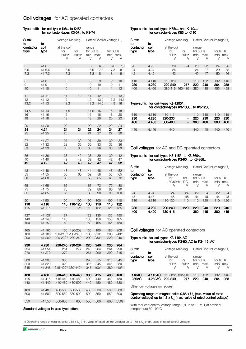
D677E 49
Coil voltages Coil voltages Coil voltages Coil voltages Coil voltages for AC operated contactors
Type-suffixType-suffixType-suffixType-suffixType-suffix for coil-types K6/.. to K45/...for coil-types K6/.. to K45/...for coil-types K6/.. to K45/...for coil-types K6/.. to K45/...for coil-types K6/.. to K45/...for contactor-types K3-07.. to K3-74for contactor-types K3-07.. to K3-74for contactor-types K3-07.. to K3-74for contactor-types K3-07.. to K3-74for contactor-types K3-07.. to K3-74
SuffixSuffixSuffixSuffixSuffix Voltage Marking Rated Control Voltage Ustototototo tototototocontactorcontactorcontactorcontactorcontactor coilcoilcoilcoilcoil at the coil rangetypetypetypetypetype typetypetypetypetype for for for 50Hz for 60Hz
50Hz 60Hz min. max. min. max.V V V V V V
6 41.6 6 6 6,6 6,6 7,36,6 41.6,6 6,6 6,6 7,3 7,3 87,3 41.7,3 7,3 7,3 8 8 9
8 41.8 8 8 9 9 109 41.9 9 9 10 10 1110 41.10 10 10 11 11 12
11 41.11 11 12 11 12 12 13,212 41.12 12 12 13,2 13,2 14,513,2 41.13 13,2 13,2 14,5 14,5 16
14,5 41.14 14,5 14,5 16 16 1816 41.16 16 16 18 18 2018 41.18 18 18 20 20 22
20 41.20 20 20 22 22 242424242424 4.244.244.244.244.24 2424242424 2424242424 2222222222 2424242424 2424242424 272727272725 41.25 25 24 27 27 30
27 41.27 27 32 27 30 30 3332 41.32 32 36 30 33 33 3633 41.33 36 36 33 36 36 39
36 41.36 36 42 36 39 39 4240 41.40 42 42 39 42 42 474242424242 4.424.424.424.424.42 4242424242 4848484848 4242424242 4747474747 4747474747 5252525252
48 41.48 48 48 44 48 48 5255 41.55 55 60 52 58 58 6560 41.60 60 58 65 65 72
65 41.65 65 65 72 72 8075 41.75 75 72 80 80 9085 41.85 85 80 90 90 100
90 41.90 100 100 90 100 100 110110110110110110 4.1104.1104.1104.1104.110 110110110110110 110-120110-120110-120110-120110-120 100100100100100 110110110110110 110110110110110 122122122122122115 41.115 115 125 110 122 122 135
127 41.127 127 122 135 135 150140 41.140 140 135 150 150 165150 41.150 150 150 165 165 180
165 41.165 165 180-208 165 180 180 208180 41.180 180-2101) 200-2401) 180 2101) 200 2401)
200 41.200 200-2301) 220-240 200 2301) 220 240
230230230230230 4.2304.2304.2304.2304.230 220-240220-240220-240220-240220-240 230-264230-264230-264230-264230-264 220220220220220 240240240240240 230230230230230 264264264264264254 41.254 254 277 240 264 264 290270 41.270 270 264 290 290 315
300 41.300 300 290 315 315 345320 41.320 320 315 345 345 380345 41.345 345-4001) 380-4401) 345 4001) 380 4401)
400400400400400 4.4004.4004.4004.4004.400 380-415380-415380-415380-415380-415 400-440400-440400-440400-440400-440 380380380380380 415415415415415 400400400400400 460460460460460415 41.415 415-440 440-480 400 440 440 480440 41.440 440-480 480-500 440 480 480 530
480 41.480 480-500 530-580 480 530 530 580500 41.500 500-550 550-600 500 550 550 600
550 41.550 550-600 600 550 600 600 (650)
Standard voltages in bold type lettersStandard voltages in bold type lettersStandard voltages in bold type lettersStandard voltages in bold type lettersStandard voltages in bold type letters
Type-suffixType-suffixType-suffixType-suffixType-suffix for coil-types K85/... and K110/...for coil-types K85/... and K110/...for coil-types K85/... and K110/...for coil-types K85/... and K110/...for coil-types K85/... and K110/...for contactor-types K85 to K110for contactor-types K85 to K110for contactor-types K85 to K110for contactor-types K85 to K110for contactor-types K85 to K110
SuffixSuffixSuffixSuffixSuffix Voltage Marking Rated Control Voltage Ustototototo tototototocontactorcontactorcontactorcontactorcontactor coilcoilcoilcoilcoil at the coil rangetypetypetypetypetype typetypetypetypetype for for for 50Hz for 60Hz
50Hz 60Hz min. max. min. max.V V V V V V
20 4.20 20 24 20 22 24 2624 4.24 24 24 27 29 3242 4.42 42 42 47 50 56
110 4.110 110-120 110 122 132 146230230230230230 4.2304.2304.2304.2304.230 220-240220-240220-240220-240220-240 277277277277277 220220220220220 240240240240240 264264264264264 288288288288288400 4.400 380-415 460-480 380 415 455 498
Type-suffixType-suffixType-suffixType-suffixType-suffix for coil-types K3-1200/..for coil-types K3-1200/..for coil-types K3-1200/..for coil-types K3-1200/..for coil-types K3-1200/..for contactor-types K3-1000.. to K3-1200..for contactor-types K3-1000.. to K3-1200..for contactor-types K3-1000.. to K3-1200..for contactor-types K3-1000.. to K3-1200..for contactor-types K3-1000.. to K3-1200..
110 4.110 110-115 - 110 115 110 115230230230230230 4.2304.2304.2304.2304.230 220-230220-230220-230220-230220-230 ----- 220220220220220 230230230230230 220220220220220 230230230230230400400400400400 4.4004.4004.4004.4004.400 380-400380-400380-400380-400380-400 ----- 380380380380380 400400400400400 380380380380380 400400400400400
440 4.440 440 - 440 440 440 440
Coil voltages Coil voltages Coil voltages Coil voltages Coil voltages for AC and DC operated contactors
Type-suffixType-suffixType-suffixType-suffixType-suffix for coil-types K3-115/.. to K3-860/..for coil-types K3-115/.. to K3-860/..for coil-types K3-115/.. to K3-860/..for coil-types K3-115/.. to K3-860/..for coil-types K3-115/.. to K3-860/..for contactor-types K3-90.. to K3-860..for contactor-types K3-90.. to K3-860..for contactor-types K3-90.. to K3-860..for contactor-types K3-90.. to K3-860..for contactor-types K3-90.. to K3-860..
SuffixSuffixSuffixSuffixSuffix Voltage Marking Rated Control Voltage Ustototototo tototototocontactorcontactorcontactorcontactorcontactor coilcoilcoilcoilcoil at the coil rangetypetypetypetypetype typetypetypetypetype for for for 50Hz for 60Hz
50/60Hz DC min. max. min. max.V V V V V V
24 4.24 24 24 22 24 22 2448 4.48 48 48 44 48 44 48110 4.110 110-120 110 110 120 110 120
230230230230230 4.2304.2304.2304.2304.230 220-240220-240220-240220-240220-240 220220220220220 220220220220220 240240240240240 220220220220220 240240240240240400400400400400 4.4004.4004.4004.4004.400 380-415380-415380-415380-415380-415 ----- 380380380380380 415415415415415 380380380380380 415415415415415
Coil voltages Coil voltages Coil voltages Coil voltages Coil voltages for AC operated contactors
Type-suffixType-suffixType-suffixType-suffixType-suffix for coil-types K3-115/..ACfor coil-types K3-115/..ACfor coil-types K3-115/..ACfor coil-types K3-115/..ACfor coil-types K3-115/..ACfor contactor-types K3-90..AC to K3-115..ACfor contactor-types K3-90..AC to K3-115..ACfor contactor-types K3-90..AC to K3-115..ACfor contactor-types K3-90..AC to K3-115..ACfor contactor-types K3-90..AC to K3-115..AC
SuffixSuffixSuffixSuffixSuffix Voltage Marking Rated Control Voltage Ustototototo tototototocontactorcontactorcontactorcontactorcontactor coilcoilcoilcoilcoil at the coil rangetypetypetypetypetype typetypetypetypetype for for for 50Hz for 60Hz
50Hz 60Hz min. max. min. max.V V V V V V
110AC110AC110AC110AC110AC 4.110AC4.110AC4.110AC4.110AC4.110AC 110-122 132-146 110 122 132 146230AC230AC230AC230AC230AC 4.230AC4.230AC4.230AC4.230AC4.230AC 220-240220-240220-240220-240220-240 277277277277277 220220220220220 240240240240240 264264264264264 288288288288288
Other coil voltages on request
Operating range of magnet-coils: 0,85 x UOperating range of magnet-coils: 0,85 x UOperating range of magnet-coils: 0,85 x UOperating range of magnet-coils: 0,85 x UOperating range of magnet-coils: 0,85 x Usssss (min. value of rated (min. value of rated (min. value of rated (min. value of rated (min. value of ratedcontrol voltage) up to 1,1 x Ucontrol voltage) up to 1,1 x Ucontrol voltage) up to 1,1 x Ucontrol voltage) up to 1,1 x Ucontrol voltage) up to 1,1 x Usssss (max. value of rated control voltage) (max. value of rated control voltage) (max. value of rated control voltage) (max. value of rated control voltage) (max. value of rated control voltage)
With reduced control voltage range 0,9 up to 1,0 x Us at ambienttemperature 60 - 90°C
1) Operating range of magnet-coils: 0,85 x Us (min. value of rated control voltage) up to 1,05 x Us (max. value of rated control voltage)
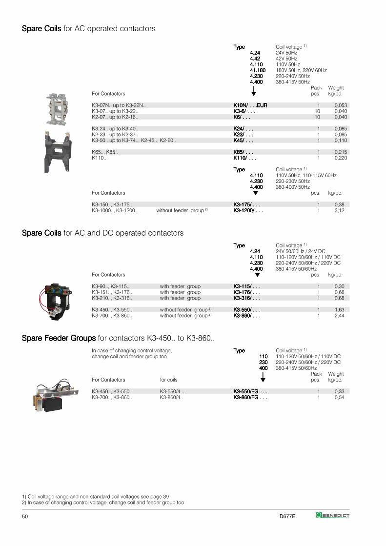
50 D677E
Spare Coils Spare Coils Spare Coils Spare Coils Spare Coils for AC operated contactors
TypeTypeTypeTypeType Coil voltage 1)
4.244.244.244.244.24 24V 50Hz4.424.424.424.424.42 42V 50Hz4.1104.1104.1104.1104.110 110V 50Hz41.18041.18041.18041.18041.180 180V 50Hz, 220V 60Hz4.2304.2304.2304.2304.230 220-240V 50Hz4.4004.4004.4004.4004.400 380-415V 50Hz
⏐⏐⏐⏐⏐ Pack WeightFor Contactors pcs. kg/pc.
K3-07N.. up to K3-22N.. K10N/ . . .EURK10N/ . . .EURK10N/ . . .EURK10N/ . . .EURK10N/ . . .EUR 1 0,053K3-07.. up to K3-22.. K3-6/ . . .K3-6/ . . .K3-6/ . . .K3-6/ . . .K3-6/ . . . 10 0,040K2-07.. up to K2-16.. K6/ . . .K6/ . . .K6/ . . .K6/ . . .K6/ . . . 10 0,040
K3-24.. up to K3-40.. K24/ . . .K24/ . . .K24/ . . .K24/ . . .K24/ . . . 1 0,085K2-23.. up to K2-37.. K23/ . . .K23/ . . .K23/ . . .K23/ . . .K23/ . . . 1 0,085K3-50.. up to K3-74.., K2-45.., K2-60.. K45/ . . .K45/ . . .K45/ . . .K45/ . . .K45/ . . . 1 0,110
K65.., K85.. K85/ . . .K85/ . . .K85/ . . .K85/ . . .K85/ . . . 1 0,215K110.. K110/ . . .K110/ . . .K110/ . . .K110/ . . .K110/ . . . 1 0,220
TypeTypeTypeTypeType Coil voltage 1)
4.1104.1104.1104.1104.110 110V 50Hz, 110-115V 60Hz4.2304.2304.2304.2304.230 220-230V 50Hz4.4004.4004.4004.4004.400 380-400V 50Hz
For Contactors pcs. kg/pc.
K3-150.., K3-175.. K3-175/ . . .K3-175/ . . .K3-175/ . . .K3-175/ . . .K3-175/ . . . 1 0,38K3-1000.., K3-1200.. without feeder group 2) K3-1200/ . . .K3-1200/ . . .K3-1200/ . . .K3-1200/ . . .K3-1200/ . . . 1 3,12
Spare Coils Spare Coils Spare Coils Spare Coils Spare Coils for AC and DC operated contactors
TypeTypeTypeTypeType Coil voltage 1)
4.244.244.244.244.24 24V 50/60Hz / 24V DC4.1104.1104.1104.1104.110 110-120V 50/60Hz / 110V DC4.2304.2304.2304.2304.230 220-240V 50/60Hz / 220V DC4.4004.4004.4004.4004.400 380-415V 50/60Hz
For Contactors pcs. kg/pc.
K3-90.., K3-115.. with feeder group K3-115/ . . .K3-115/ . . .K3-115/ . . .K3-115/ . . .K3-115/ . . . 1 0,30K3-151.., K3-176.. with feeder group K3-176/ . . .K3-176/ . . .K3-176/ . . .K3-176/ . . .K3-176/ . . . 1 0,68K3-210.., K3-316.. with feeder group K3-316/ . . .K3-316/ . . .K3-316/ . . .K3-316/ . . .K3-316/ . . . 1 0,68
K3-450.., K3-550.. without feeder group 2) K3-550/ . . .K3-550/ . . .K3-550/ . . .K3-550/ . . .K3-550/ . . . 1 1,63K3-700.., K3-860.. without feeder group 2) K3-860/ . . .K3-860/ . . .K3-860/ . . .K3-860/ . . .K3-860/ . . . 1 2,44
Spare Feeder Groups Spare Feeder Groups Spare Feeder Groups Spare Feeder Groups Spare Feeder Groups for contactors K3-450.. to K3-860..
In case of changing control voltage, TypeTypeTypeTypeType Coil voltage 1)
change coil and feeder group too 110110110110110 110-120V 50/60Hz / 110V DC230230230230230 220-240V 50/60Hz / 220V DC400400400400400 380-415V 50/60Hz
⏐⏐⏐⏐⏐ Pack WeightFor Contactors for coils pcs. kg/pc.
K3-450.., K3-550.. K3-550/4... K3-550/FG . . .K3-550/FG . . .K3-550/FG . . .K3-550/FG . . .K3-550/FG . . . 1 0,33K3-700.., K3-860.. K3-860/4.. K3-860/FG . . .K3-860/FG . . .K3-860/FG . . .K3-860/FG . . .K3-860/FG . . . 1 0,54
1) Coil voltage range and non-standard coil voltages see page 392) In case of changing control voltage, change coil and feeder group too
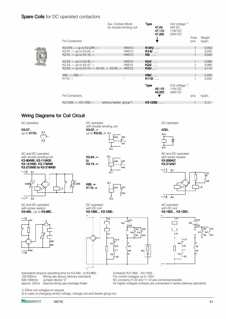
D677E 51
Spare Coils Spare Coils Spare Coils Spare Coils Spare Coils for DC operated contactors
Aux. Contact Block TypeTypeTypeTypeType Coil voltage 1)
for double winding coil 47.2447.2447.2447.2447.24 24V DC47.11047.11047.11047.11047.110 110V DC47.22047.22047.22047.22047.220 220V DC
⏐⏐⏐⏐⏐ Pack WeightFor Contactors pcs. kg/pc.
K3-07N..= up to K3-22N..= HN01U K10N/ . . .K10N/ . . .K10N/ . . .K10N/ . . .K10N/ . . . 1 0,052K3-07..= up to K3-22..= HN01U K3-6/ . . .K3-6/ . . .K3-6/ . . .K3-6/ . . .K3-6/ . . . 1 0,042K2-07..= up to K2-16..= HN01U K6/ . . .K6/ . . .K6/ . . .K6/ . . .K6/ . . . 1 0,042
K3-24..= up to K3-40..= HN01X K24/ . . .K24/ . . .K24/ . . .K24/ . . .K24/ . . . 1 0,090K2-23..= up to K2-37..= HN01X K23/ . . .K23/ . . .K23/ . . .K23/ . . .K23/ . . . 1 0,090K3-50..= up to K3-74..=, K2-45..=, K2-60..= HN01Z K45/ . . .K45/ . . .K45/ . . .K45/ . . .K45/ . . . 1 0,115
K65..=, K85..= - K85/ . . .K85/ . . .K85/ . . .K85/ . . .K85/ . . . 1 0,220K110..= - K110/ . . .K110/ . . .K110/ . . .K110/ . . .K110/ . . . 1 0,225
TypeTypeTypeTypeType Coil voltage 1)
43.11043.11043.11043.11043.110 110V DC43.22043.22043.22043.22043.220 220V DC
For Contactors pcs. kg/pc.
K3-1000..=, K3-1200..= without feeder group 2) K3-1200/ . . .K3-1200/ . . .K3-1200/ . . .K3-1200/ . . .K3-1200/ . . . 1 3,12
Wiring Diagrams for Coil CircuitWiring Diagrams for Coil CircuitWiring Diagrams for Coil CircuitWiring Diagrams for Coil CircuitWiring Diagrams for Coil Circuit
AC operated, DC operated DC operatedwith double winding coil
K3-07..K3-07..K3-07..K3-07..K3-07.. K3-07..=K3-07..=K3-07..=K3-07..=K3-07..= KG3..KG3..KG3..KG3..KG3..up to K110..K110..K110..K110..K110.. up to K3-22..=K3-22..=K3-22..=K3-22..=K3-22..=
AC and DC operated AC and DC operatedwith double winding coil K3-24..=K3-24..=K3-24..=K3-24..=K3-24..= with series resistorK3-90A00, K3-115A00K3-90A00, K3-115A00K3-90A00, K3-115A00K3-90A00, K3-115A00K3-90A00, K3-115A00 tototototo K3-200A21K3-200A21K3-200A21K3-200A21K3-200A21K3-151A00, K3-176A00K3-151A00, K3-176A00K3-151A00, K3-176A00K3-151A00, K3-176A00K3-151A00, K3-176A00 K3-74..=K3-74..=K3-74..=K3-74..=K3-74..= K3-315A21K3-315A21K3-315A21K3-315A21K3-315A21K3-210A00 to K3-316A00K3-210A00 to K3-316A00K3-210A00 to K3-316A00K3-210A00 to K3-316A00K3-210A00 to K3-316A00
K85..=K85..=K85..=K85..=K85..=K110..=K110..=K110..=K110..=K110..=
AC and DC operated DC operated AC operatedwith series resistor with DC coil with DC coilK3-450.. K3-450.. K3-450.. K3-450.. K3-450.. up to K3-860..K3-860..K3-860..K3-860..K3-860.. K3-1000.., K3-1200..K3-1000.., K3-1200..K3-1000.., K3-1200..K3-1000.., K3-1200..K3-1000.., K3-1200.. K3-1000.., K3-1200..K3-1000.., K3-1200..K3-1000.., K3-1200..K3-1000.., K3-1200..K3-1000.., K3-1200..
Adjustable dropout operating time for K3-450.. to K3-860..: Contactor K3-1000.., K3-1200..:150-200ms: Wiring see above (delivery standard) For control voltages up to 125V500-1000ms: Jumper device "Z" NC contacts 21-22 and 11-12 are connected parallel,approx. 20ms: Special wiring see package folder for higher voltages contacts are connected in series (delivery standard).
1) Other coil voltages on request2) In case of changing control voltage, change coil and feeder group too

52 D677E
Spare ContactsSpare ContactsSpare ContactsSpare ContactsSpare Contacts
Main ContactsMain ContactsMain ContactsMain ContactsMain Contacts TypeTypeTypeTypeType Pack Weightfor Contactors pcs. kg/pc.
K85.. EK85/1EK85/1EK85/1EK85/1EK85/1 3 0,235K110.. EK110/1EK110/1EK110/1EK110/1EK110/1 3 0,275
K3-150.. EK3-150/10EK3-150/10EK3-150/10EK3-150/10EK3-150/10 1 0,32K3-151.. EK3-151/10EK3-151/10EK3-151/10EK3-151/10EK3-151/10 1 0,16K3-175.. EK3-175/10EK3-175/10EK3-175/10EK3-175/10EK3-175/10 1 0,32
K3-176.. EK3-176/10EK3-176/10EK3-176/10EK3-176/10EK3-176/10 1 0,16K3-200.. EK3-200/10EK3-200/10EK3-200/10EK3-200/10EK3-200/10 1 0,18K3-210.. EK3-210/10EK3-210/10EK3-210/10EK3-210/10EK3-210/10 1
K3-260.. EK3-260/10EK3-260/10EK3-260/10EK3-260/10EK3-260/10 1K3-315.. EK3-315/10EK3-315/10EK3-315/10EK3-315/10EK3-315/10 1 0,34K3-316.. EK3-316/10EK3-316/10EK3-316/10EK3-316/10EK3-316/10 1
K3-450.. EK3-450/10EK3-450/10EK3-450/10EK3-450/10EK3-450/10 1 0,35K3-550.. EK3-550/10EK3-550/10EK3-550/10EK3-550/10EK3-550/10 1 0,35K3-700.. EK3-700/10EK3-700/10EK3-700/10EK3-700/10EK3-700/10 1 0,85
K3-860.. EK3-860/10EK3-860/10EK3-860/10EK3-860/10EK3-860/10 1 1,0K3-1000.. EK3-1000/10EK3-1000/10EK3-1000/10EK3-1000/10EK3-1000/10 1 1,4K3-1200.. EK3-1200/10EK3-1200/10EK3-1200/10EK3-1200/10EK3-1200/10 1 1,4
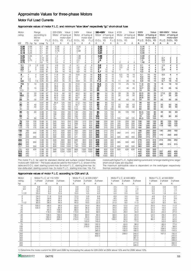
D677E 53
1) Determine the motor current for 200V and 208V by increasing the values for 220-240V at 200V about 15% and for 208V about 10%.
Approximate Values for three-phase MotorsApproximate Values for three-phase MotorsApproximate Values for three-phase MotorsApproximate Values for three-phase MotorsApproximate Values for three-phase Motors
Motor Full Load CurrentsMotor Full Load CurrentsMotor Full Load CurrentsMotor Full Load CurrentsMotor Full Load Currents
Approximate values of motor F.L.C. and minimum "slow blow" respectively "gL" short-circuit fuseApproximate values of motor F.L.C. and minimum "slow blow" respectively "gL" short-circuit fuseApproximate values of motor F.L.C. and minimum "slow blow" respectively "gL" short-circuit fuseApproximate values of motor F.L.C. and minimum "slow blow" respectively "gL" short-circuit fuseApproximate values of motor F.L.C. and minimum "slow blow" respectively "gL" short-circuit fuse
Motor Range 220-230V Value 240V Value 380-400V380-400V380-400V380-400V380-400V Value 415V Valuerating according to Motor of fusing at Motor of fusing at Motor of fusing at Motor of fusing at
BS for motor start motor start motor start motor start415V F.L.C. D.O.L. YD F.L.C. D.O.L. YD F.L.C. D.O.L. YD F.L.C. D.O.L. YD
kW PS~hp hp cosϕ % A A A A A A A A A A A A0,060,060,060,060,06 0,08 - 0,7 59 0,38 1 1 0,35 1 1 0,220,220,220,220,22 1 1 - - -0,090,090,090,090,09 0,12 - 0,7 60 0,55 2 2 0,5 2 2 0,330,330,330,330,33 1 1 - - -0,120,120,120,120,12 0,16 - 0,7 61 0,76 2 2 0,68 2 2 0,420,420,420,420,42 2 2 - - -0,180,180,180,180,18 0,24 - 0,7 61 1,1 2 2 1 2 2 0,640,640,640,640,64 2 2 - - -0,250,250,250,250,25 0,34 - 0,7 62 1,4 4 2 1,38 4 2 0,880,880,880,880,88 2 2 - - -0,370,370,370,370,37 0,5 - 0,72 64 2,1 4 4 1,93 4 4 1,221,221,221,221,22 4 2 - - -0,550,550,550,550,55 0,75 - 0,75 69 2,7 4 4 2,3 4 4 1,51,51,51,51,5 4 2 - - -0,750,750,750,750,75 1 1 0,8 74 3,3 6 4 3,1 6 4 22222 4 4 2 4 41,11,11,11,11,1 1,5 1,5 0,83 77 4,9 10 6 4,1 6 6 2,62,62,62,62,6 4 4 2,5 4 41,51,51,51,51,5 2 2 0,83 78 6,2 10 10 5,6 10 10 3,53,53,53,53,5 6 4 3,5 6 42,22,22,22,22,2 3 3 0,83 81 8,7 16 10 7,9 16 10 55555 10 6 5 10 62,5 3,4 - 0,83 81 9,8 16 16 8,9 16 10 5,75,75,75,75,7 10 10 - - -33333 4 4 0,84 81 11,6 20 16 10,6 20 16 6,66,66,66,66,6 16 10 6,5 16 103,7 5 5 0,84 82 14,2 25 20 13 25 16 8,28,28,28,28,2 16 10 7,5 16 1044444 5,5 - 0,84 82 15,3 25 20 14 25 20 8,58,58,58,58,5 16 10 - - -5,55,55,55,55,5 7,5 7,5 0,85 83 20,6 35 25 18,9 35 25 11,511,511,511,511,5 20 16 11 20 167,57,57,57,57,5 10 10 0,86 85 27,4 35 35 24,8 35 35 15,515,515,515,515,5 25 20 14 25 1688888 11 - 0,86 85 28,8 50 35 26,4 35 35 16,716,716,716,716,7 25 20 - - -
1111111111 15 15 0,86 87 39,2 63 50 35,3 50 50 2222222222 35 25 21 35 2512,5 17 - 0,86 87 43,8 63 50 40,2 63 50 2525252525 35 35 - - -1515151515 20 20 0,86 87 52,6 80 63 48,2 80 63 3030303030 50 35 28 35 3518,518,518,518,518,5 25 25 0,86 88 64,9 100 80 58,7 80 63 3737373737 63 50 35 50 5020 27 - 0,86 88 69,3 100 80 63,4 80 80 4040404040 63 50 - - -2222222222 30 30 0,87 89 75,2 100 80 68 100 80 4444444444 63 50 40 63 5025 34 - 0,87 89 84,4 125 100 77,2 100 100 5050505050 80 63 - - -3030303030 40 40 0,87 90 101 125 125 92,7 125 100 6060606060 80 63 55 80 6337 50 50 0,87 90 124 160 160 114 160 125 7272727272 100 80 66 100 8040 54 - 0,87 90 134 160 160 123 160 160 7979797979 100 100 - - -4545454545 60 60 0,88 91 150 200 160 136 200 160 8585858585 125 100 80 100 10051 70 - 0,88 91 168 200 200 154 200 200 9797979797 125 100 - - -5555555555 75 - 0,88 91 181 250 200 166 200 200 105105105105105 160 125 - - -59 80 80 0,88 91 194 250 250 178 250 200 112112112112112 160 125 105 160 1257575757575 100 100 0,88 91 245 315 250 226 315 250 140140140140140 200 160 135 200 1609090909090 125 125 0,88 92 292 400 315 268 315 315 170170170170170 250 200 165 200 200
110110110110110 150 150 0,88 92 358 500 400 327 400 400 205205205205205 250 250 200 250 250129 175 175 0,88 92 420 500 500 384 500 400 242242242242242 315 250 230 315 250132132132132132 180 - 0,88 92 425 500 500 393 500 500 245245245245245 315 250 - - -147 200 200 0,88 93 472 630 630 432 630 500 273273273273273 315 315 260 315 315160160160160160 220 - 0,88 93 502 630 630 471 630 630 295295295295295 400 315 - - -184 250 250 0,88 93 590 800 630 541 630 630 340340340340340 400 400 325 400 400200200200200200 270 - 0,88 93 626 800 800 589 800 630 370370370370370 500 400 - - -220 300 300 0,88 93 700 1000 800 647 800 800 408408408408408 500 500 385 500 400250250250250250 340 - 0,88 93 803 1000 1000 736 1000 800 460460460460460 630 500 - - -257 350 350 0,88 93 826 1000 1000 756 1000 800 475475475475475 630 630 450 630 500295 400 400 0,88 93 948 1250 1000 868 1000 1000 546546546546546 800 630 500 630 630315315315315315 430 - 0,88 93 990 1250 1250 927 1250 1000 580580580580580 800 630 - - -355355355355355 483 - 0,89 95 - - - - - - 636636636636636 800 800 - - -400400400400400 545 - 0,89 96 - - - - - - 710710710710710 1000 800 - - -
Approximate values of motor F.L.C. according to CSA and ULApproximate values of motor F.L.C. according to CSA and ULApproximate values of motor F.L.C. according to CSA and ULApproximate values of motor F.L.C. according to CSA and ULApproximate values of motor F.L.C. according to CSA and UL
Motor Motor F.L.C. at 110-120V Motor F.L.C. at 220-240V1) Motor F.L.C. at 440-480V Motor F.L.C. at 550-600Vrating 1-phase 2-phase 3-phase 1-phase 2-phase 3-phase 1-phase 2-phase 3-phase 1-phase 2-phase 3-phasehp A A A A A A A A A A A A
1/2 9.8 4.0 4.4 4.9 2.0 2.2 2.5 1.0 1.1 2.0 0.8 0.93/4 13.8 4.8 6.4 6.9 2.4 3.2 3.5 1.2 1.6 2.8 1.0 1.3
1 16.0 6.4 8.4 8.0 3.2 4.2 4.0 1.6 2.1 3.2 1.3 1.71-1/2 20.0 9.0 12.0 10.0 4.5 6.0 5.0 2.3 3.0 4.0 1.8 2.42 24.0 11.8 13.6 12.0 5.9 6.8 6.0 3.0 3.4 4.8 2.4 2.73 34.0 16.6 19.2 17.0 8.3 9.6 8.5 4.2 4.8 6.8 3.3 3.95 56.0 26.4 30.4 28.0 13.2 15.2 14.0 6.6 7.6 11.2 5.3 6.17-1/2 80.0 38.0 44.0 40.0 19.0 22.0 21.0 9.0 11.0 16.0 8.0 9.0
10 100.0 48.0 56.0 50.0 24.0 28.0 26.0 12.0 14.0 20.0 10.0 11.015 135.0 72.0 84.0 68.0 36.0 42.0 34.0 18.0 21.0 27.0 14.0 17.020 - 94.0 108.0 88.0 47.0 54.0 44.0 23.0 27.0 35.0 19.0 22.025 - 118.0 136.0 110.0 59.0 68.0 55.0 29.0 34.0 44.0 24.0 27.030 - 138.0 160.0 136.0 69.0 80.0 68.0 35.0 40.0 54.0 28.0 32.040 - 180.0 208.0 176.0 90.0 104.0 88.0 45.0 52.0 70.0 36.0 41.050 - 226.0 260.0 216.0 113.0 130.0 108.0 56.0 65.0 86.0 45.0 52.060 - - - - 133.0 145.0 - 67.0 77.0 - 53.0 62.075 - - - - 166.0 192.0 - 83.0 96.0 - 66.0 77.0
100 - - - - 218.0 248.0 - 109.0 124.0 - 87.0 99.0125 - - - - - 312.0 - 135.0 156.0 - 108.0 125.0150 - - - - - 360.0 - 156.0 180.0 - 125.0 144.0200 - - - - - 480.0 - 208.0 240.0 - 167.0 192.0250 - - - - - 602.0 - - 302.0 - - 242.0300 - - - - - - - - 361.0 - - 289.0350 - - - - - - - - 414.0 - - 336.0400 - - - - - - - - 477.0 - - 382.0500 - - - - - - - - 590.0 - - 472.0
The motor F.L.C. be valid for standard internal and surface cooled three-polemotors with 1500 min-1. The fuses values be valid for the motor F.L.C. shown in thetable and D.O.L.-start: starting current max. 6x motor F.L.C., starting time max. 5s;star-delta-start: starting current max. 2x motor F.L.C., starting time max. 15s. For
500V Value 660-690V ValueMotor of fusing at Motor of fusing at
motor start motor startF.L.C. D.O.L. YD F.L.C. D.O.L. YDA A A A A A
0,16 1 1 - - -0,24 1 1 - - -0,33 1 1 - - -0,46 1 1 - - -0,59 2 2 - - -0,85 2 2 0,7 2 21,2 4 2 0,9 2 21,48 4 2 1,1 2 22,1 4 4 1,5 4 22,6 4 4 2 4 43,8 6 6 2,9 6 44,3 6 6 - - -5,1 10 10 3,5 6 46,2 16 10 - - -6,5 16 10 4,9 10 68,9 16 10 6,7 16 10
11,9 20 16 9 16 1012,7 20 16 - - -16,7 25 20 13 25 1619 35 25 - - -22,5 35 25 17,5 25 2028,5 50 35 21 35 2530,6 50 35 - - -33 50 50 25 35 3538 63 50 - - -44 63 50 33 50 3554 80 63 42 63 5060 80 63 - - -64,5 100 80 49 63 6373,7 100 80 - - -79 125 100 60 80 6385,3 125 100 - - -
106 160 125 82 125 100128 160 160 98 125 125156 200 200 118 160 125184 250 200 - - -186 250 200 140 200 160207 250 250 - - -220 315 250 170 200 200259 315 315 - - -278 315 315 215 250 250310 400 400 - - -353 500 400 268 315 315363 500 400 - - -416 500 500 - - -445 630 500 337 400 400483 630 630 366 500 400538 630 630 410 500 500
motors with higher F.L.C., higher starting current and / or longer starting time, largershort-circuit fuses are required.The maximum admissible value is dependent on the switchgear respectivelythermal overload relay.
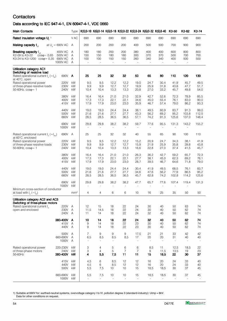
54 D677E
1) Suitable at 690V for: earthed-neutral systems, overvoltage category I to IV, pollution degree 3 (standard-industry): Uimp = 8kV.Data for other conditions on request.
ContactorsContactorsContactorsContactorsContactors
Data according to IEC 947-4-1, EN 60947-4-1, VDE 0660Data according to IEC 947-4-1, EN 60947-4-1, VDE 0660Data according to IEC 947-4-1, EN 60947-4-1, VDE 0660Data according to IEC 947-4-1, EN 60947-4-1, VDE 0660Data according to IEC 947-4-1, EN 60947-4-1, VDE 0660
Main ContactsMain ContactsMain ContactsMain ContactsMain Contacts Type K(G)3-10K(G)3-10K(G)3-10K(G)3-10K(G)3-10 K(G)3-14K(G)3-14K(G)3-14K(G)3-14K(G)3-14 K(G)3-18K(G)3-18K(G)3-18K(G)3-18K(G)3-18 K(G)3-22K(G)3-22K(G)3-22K(G)3-22K(G)3-22 K(G)3-24K(G)3-24K(G)3-24K(G)3-24K(G)3-24 K(G)3-32K(G)3-32K(G)3-32K(G)3-32K(G)3-32 K(G)3-40K(G)3-40K(G)3-40K(G)3-40K(G)3-40 K3-50K3-50K3-50K3-50K3-50 K3-62K3-62K3-62K3-62K3-62 K3-74K3-74K3-74K3-74K3-74
Rated insulation voltage URated insulation voltage URated insulation voltage URated insulation voltage URated insulation voltage Uiiiii 1) V AC 690 690 690 690 690 690 690 690 690 690
Making capacity IMaking capacity IMaking capacity IMaking capacity IMaking capacity Ieff at Ue = 690V AC A 200 200 200 200 400 500 500 700 900 900
Breaking capacity IBreaking capacity IBreaking capacity IBreaking capacity IBreaking capacity Ieff 400V AC A 180 180 200 200 380 400 400 600 800 800K2-09 to K3-22 cosϕ= 0,65 500V AC A 150 150 180 180 300 370 370 500 700 700K3-24 to K3-1200 cosϕ= 0,35 690V AC A 100 100 150 150 260 340 340 400 500 500
1000V AC A - - - - - - - - -
Utilization category AC1Utilization category AC1Utilization category AC1Utilization category AC1Utilization category AC1Switching of resistive loadSwitching of resistive loadSwitching of resistive loadSwitching of resistive loadSwitching of resistive loadRated operational current Ie (=Ith) 690V AAAAA 2525252525 2525252525 3232323232 3232323232 5050505050 6565656565 8080808080 110110110110110 120120120120120 130130130130130at 40°C, openRated operational power 220V kW 9,5 9,5 12,2 12,2 19,0 24,7 30,4 41,9 45,7 49,5of three-phase resistive loads 230V kW 9,9 9,9 12,7 12,7 19,9 25,9 31,8 43,8 47,7 51,750-60Hz, cosϕ= 1 240V kW 10,4 10,4 13,3 13,3 20,8 27,0 33,2 45,7 49,8 54,0
380V kW 16,4 16,4 21,0 21,0 32,9 42,7 52,6 72,3 78,9 85,5400V kW 17,3 17,3 22,1 22,1 34,6 45,0 55,4 76,1 83,0 90,0415V kW 17,9 17,9 23,0 23,0 35,9 46,7 57,4 79,0 86,2 93,3
440V kW 19,0 19,0 24,4 24,4 38,1 49,5 60,9 83,7 91,3 99,0500V kW 21,6 21,6 27,7 27,7 43,3 56,2 69,2 95,2 103,8 112,5660V kW 28,5 28,5 36,5 36,5 57,1 74,2 91,3 125,6 137,0 148,4
690V kW 29,8 29,8 38,2 38,2 59,7 77,6 95,5 131,3 143,2 155,21000V kW - - - - - - - - -
Rated operational current Ie (=Ithe) 690V A 25 25 32 32 40 55 65 90 100 110at 60°C, enclosedRated operational power 220V kW 9,5 9,5 12,2 12,2 15,2 20,9 24,7 34,3 38,1 41,9of three-phase resistive loads 230V kW 9,9 9,9 12,7 12,7 15,9 21,9 25,9 35,8 39,8 43,850-60Hz, cosϕ= 1 240V kW 10,4 10,4 13,3 13,3 16,6 22,8 27,0 37,4 41,5 45,7
380V kW 16,4 16,4 21,0 21,0 26,3 36,2 42,7 59,2 65,7 72,3400V kW 17,3 17,3 22,1 22,1 27,7 38,1 45,0 62,3 69,2 76,1415V kW 17,9 17,9 23,0 23,0 28,7 39,5 46,7 64,6 71,8 79,0
440V kW 19,0 19,0 24,4 24,4 30,4 41,9 49,5 68,5 76,1 83,7500V kW 21,6 21,6 27,7 27,7 34,6 47,6 56,2 77,9 86,5 95,2660V kW 28,5 28,5 36,5 36,5 45,7 62,8 74,2 102,8 114,2 125,6
690V kW 29,8 29,8 38,2 38,2 47,7 65,7 77,6 107,4 119,4 131,31000V kW - - - - - - - - -
Minimum cross-section of conductorat load with Ie (=Ith) mm² 4 4 6 6 10 16 25 35 50 50
Utilization category AC2 and AC3Utilization category AC2 and AC3Utilization category AC2 and AC3Utilization category AC2 and AC3Utilization category AC2 and AC3Switching of three-phase motorsSwitching of three-phase motorsSwitching of three-phase motorsSwitching of three-phase motorsSwitching of three-phase motorsRated operational current Ie 220V A 12 15 18 22 24 30 40 50 63 74open and enclosed 230V A 11,5 14,5 18 22 24 30 40 50 62 74
240V A 11 14 18 22 24 32 40 50 62 74
380-400V380-400V380-400V380-400V380-400V AAAAA 1010101010 1414141414 1818181818 2222222222 2424242424 3232323232 4040404040 5050505050 6262626262 7474747474415V A 9 14 18 22 23 30 40 50 62 74440V A 9 14 18 22 23 30 40 50 62 74
500V A 7 9 9 9 17,5 21 21 33 42 42660-690V A 6,5 8,5 8,5 8,5 17 20 20 31 40 40
1000V A - - - - - - - - -
Rated operational power 220-230V kW 3 4 5 6 6 8,5 11 12,5 18,5 22of three-phase motors 240V kW 3 4 5 7 7 9 11,5 13,5 19 2350-60Hz 380-400V380-400V380-400V380-400V380-400V kWkWkWkWkW 44444 5,55,55,55,55,5 7,57,57,57,57,5 1111111111 1111111111 1515151515 18,518,518,518,518,5 2222222222 3030303030 3737373737
415V kW 4,5 6 8,5 12 12 16 20 24 33 40440V kW 4,5 6 8,5 12 12 16 20 24 33 40500V kW 5,5 7,5 10 10 15 18,5 18,5 30 37 45
660-690V kW 5,5 7,5 10 10 15 18,5 18,5 30 37 451000V kW - - - - - - - - - -

D677E 55
ContactorsContactorsContactorsContactorsContactors
Data according to IEC 947-4-1, EN 60947-4-1, VDE 0660Data according to IEC 947-4-1, EN 60947-4-1, VDE 0660Data according to IEC 947-4-1, EN 60947-4-1, VDE 0660Data according to IEC 947-4-1, EN 60947-4-1, VDE 0660Data according to IEC 947-4-1, EN 60947-4-1, VDE 0660
Type K3-90K3-90K3-90K3-90K3-90 K3-115K3-115K3-115K3-115K3-115 K3-116K3-116K3-116K3-116K3-116 K3-151K3-151K3-151K3-151K3-151 K3-176K3-176K3-176K3-176K3-176 K3-210K3-210K3-210K3-210K3-210 K3-260K3-260K3-260K3-260K3-260 K3-316K3-316K3-316K3-316K3-316 K3-450K3-450K3-450K3-450K3-450 K3-550K3-550K3-550K3-550K3-550 K3-700K3-700K3-700K3-700K3-700 K3-860K3-860K3-860K3-860K3-860 K3-1000K3-1000K3-1000K3-1000K3-1000 K3-1200K3-1200K3-1200K3-1200K3-1200
V~ 1000 1000 1000 1000 1000 1000 1000 1000 1000 1000 690 690 690 690
A 1100 1200 1200 1500 2000 2100 2600 3200 4500 5500 7000 8600 10000 12000
A 950 1100 1000 1200 1500 1600 2100 2600 4500 5500 7000 8000 8000 10000A 850 1000 1000 1200 1500 1600 2100 2600 4500 5500 7000 8000 8000 10000A 600 600 800 1000 800 1200 1900 2300 3200 4400 5600 6900 7000 8000A - - 400 500 600 700 850 1000 - - - - - -
AAAAA 160160160160160 200200200200200 200200200200200 230230230230230 250250250250250 350350350350350 450450450450450 500500500500500 700700700700700 760760760760760 10001000100010001000 11001100110011001100 12001200120012001200 13501350135013501350
kW 60 76 76 87 95 133 171 190 266 289 381 419 457 514kW 63 79 79 91 99 139 179 199 279 302 398 438 478 537kW 66 83 83 95 103 145 187 207 291 315 415 457 498 561
kW 105 131 131 151 164 230 296 329 460 500 658 724 789 888kW 110 138 138 159 173 242 311 346 485 526 692 762 831 935kW 115 143 143 165 179 251 323 359 503 546 718 790 862 970
kW 121 152 152 175 190 266 342 381 533 579 762 838 914 1028kW 138 173 173 199 216 303 389 453 606 658 866 952 1039 1169kW 182 228 228 262 285 400 514 571 800 868 1143 1257 1371 1543
kW 191 239 239 274 298 418 537 597 836 908 1195 1314 1434 1613kW 221 277 216 318 346 433 546 606 692 866 - - - -
A 145 170 170 180 200 280 360 400 550 600 800 875 960 1080
kW 55 64 64 68 76 106 137 152 209 228 304 333 365 411kW 57 67 67 71 79 111 143 159 219 239 318 348 382 430kW 59 70 70 74 83 116 150 166 228 249 332 363 399 448
kW 95 111 111 118 131 184 237 263 362 395 526 575 631 710kW 100 117 117 124 138 193 249 277 381 415 554 606 665 748kW 104 122 122 129 143 201 259 287 395 431 575 628 690 776
kW 110 129 129 137 152 213 274 304 419 457 609 666 731 823kW 125 147 147 155 173 242 312 346 476 519 692 757 831 935kW 165 194 194 205 228 320 412 457 628 685 914 1000 1097 1234
kW 173 202 202 215 239 334 430 478 657 717 956 1045 1147 1290kW 166 187 216 277 346 388 499 554 692 866 - - - -
mm² 95 120 95 95 120 240 2x150 2x(30x6) 2x(40x5) 2x(50x5) 2x(60x5) 2x(60x6) 2x(60x6) 2x(60x8)
A 90 115 115 150 175 210 260 315 450 550 700 860 1000 1200A 90 115 115 150 175 210 260 315 450 550 700 860 1000 1200A 90 115 115 150 175 210 260 315 450 550 700 860 1000 1200
AAAAA 9090909090 115115115115115 115115115115115 150150150150150 175175175175175 210210210210210 260260260260260 315315315315315 450450450450450 550550550550550 700700700700700 860860860860860 10001000100010001000 12001200120012001200A 90 115 115 150 175 210 260 315 450 550 700 860 1000 1200A 90 115 115 150 175 210 260 315 450 550 700 860 1000 1200
A 60 60 115 150 175 210 260 315 450 550 700 860 1000 1200A 58 58 100 120 140 150 180 240 400 500 630 700 860 1000A 58 58 45 60 70 85 100 125 200 250 - - - -
kW 25 33 30 40 50 60 75 90 132 175 225 280 325 390kW 27 35 35 45 55 65 80 100 140 185 235 290 335 400kWkWkWkWkW 4545454545 5555555555 5555555555 7575757575 9090909090 110110110110110 132132132132132 160160160160160 250250250250250 300300300300300 400400400400400 500500500500500 580580580580580 680680680680680
kW 49 63 59 80 95 115 140 180 257 315 415 515 600 710kW 49 63 63 85 100 125 150 190 270 335 450 530 630 750kW 55 55 75 90 100 132 160 210 300 375 500 600 720 850
kW 55 55 90 110 132 132 160 210 375 500 630 700 850 1000kW 55 55 55 75 90 110 132 160 280 355 - - - -

56 D677E
1) Metal halide lamps and sodium-vapour lamps (high- and low-pressure lamps)2) High-pressure lamps3) Blended lamps, containing a mercury high-pressure unit and a tungsten helix in a flourescent glass bulb (daylight lamps)4) Current inrush approx. 16 x Ie
ContactorsContactorsContactorsContactorsContactors
Data according to IEC 947-4-1, EN 60947-4-1, VDE 0660Data according to IEC 947-4-1, EN 60947-4-1, VDE 0660Data according to IEC 947-4-1, EN 60947-4-1, VDE 0660Data according to IEC 947-4-1, EN 60947-4-1, VDE 0660Data according to IEC 947-4-1, EN 60947-4-1, VDE 0660
Main ContactsMain ContactsMain ContactsMain ContactsMain Contacts Type K(G)3-10K(G)3-10K(G)3-10K(G)3-10K(G)3-10 K(G)3-14K(G)3-14K(G)3-14K(G)3-14K(G)3-14 K(G)3-18K(G)3-18K(G)3-18K(G)3-18K(G)3-18 K(G)3-22K(G)3-22K(G)3-22K(G)3-22K(G)3-22 K(G)3-24K(G)3-24K(G)3-24K(G)3-24K(G)3-24 K(G)3-32K(G)3-32K(G)3-32K(G)3-32K(G)3-32 K(G)3-40K(G)3-40K(G)3-40K(G)3-40K(G)3-40 K3-50K3-50K3-50K3-50K3-50 K3-62K3-62K3-62K3-62K3-62 K3-74K3-74K3-74K3-74K3-74
Utilization category AC4Utilization category AC4Utilization category AC4Utilization category AC4Utilization category AC4Switching of squirrel cage motors, inchingSwitching of squirrel cage motors, inchingSwitching of squirrel cage motors, inchingSwitching of squirrel cage motors, inchingSwitching of squirrel cage motors, inchingRated operational current Ie 220V A 12 15 18 18 24 30 40 50 63 63open and enclosed 230V A 11,5 14,5 18 18 24 30 40 50 62 62
240V A 11 14 18 18 24 32 40 50 62 62
380-400V380-400V380-400V380-400V380-400V AAAAA 1010101010 1414141414 1818181818 1818181818 2424242424 3232323232 4040404040 5050505050 6262626262 6262626262415V A 9 14 18 18 23 30 37 45 60 60440V A 9 14 18 18 23 30 37 45 55 55
500V A 9 12 16 16 17,5 21 21 33 42 42660V A 7 9 9 9 17 20 20 31 40 40690V A 6,5 8,5 8,5 8,5 17 20 20 31 40 40
1000V A - - - - - - - - -
Rated operational power 220-230V kW 3 4 5 5 6 8,5 11 12,5 18,5 18,5of three-phase motors 240V kW 3 4 5 5 7 9 11,5 13,5 19 1950-60Hz 380-400V380-400V380-400V380-400V380-400V kWkWkWkWkW 44444 5,55,55,55,55,5 7,57,57,57,57,5 7,57,57,57,57,5 1111111111 1515151515 18,518,518,518,518,5 2222222222 3030303030 3030303030
415V kW 4,5 6 8,5 8,5 12 16 20 24 33 33440V kW 4,5 6 8,5 8,5 12 16 20 24 33 33500V kW 5,5 7,5 10 10 15 18,5 18,5 30 37 37
660-690V kW 5,5 7,5 10 10 15 18,5 18,5 30 37 371000V kW - - - - - - - - - -
Utilization category AC5aUtilization category AC5aUtilization category AC5aUtilization category AC5aUtilization category AC5aSwitching of gas discharge lampsSwitching of gas discharge lampsSwitching of gas discharge lampsSwitching of gas discharge lampsSwitching of gas discharge lampsRated operational current Ieper pole at 220/230V
Fluorescent lamps,uncompensated and serial compensated A 20 20 25 25 40 52 64 88 96 104parallel compensated A 7 9 9 9 18 22 22 30 40 45dual-connection A 22,5 22,5 28 28 45 58 72 98 108 117
Metal halide lamps1),uncompensated A 12 15 19 19 30 39 48 66 72 78parallel compensated A 7 9 9 9 18 22 22 30 40 45
Mercury-vapour lamps2),uncompensated A 22,5 25 28 28 45 58 72 99 108 117parallel compensated A 7 9 9 9 18 22 22 30 40 45
Mixed light lamps3) A 20 20 25 25 40 52 64 88 96 104
Utilization category AC5bUtilization category AC5bUtilization category AC5bUtilization category AC5bUtilization category AC5bSwitching of incandescent lampsSwitching of incandescent lampsSwitching of incandescent lampsSwitching of incandescent lampsSwitching of incandescent lamps4)
Rated operational current Ieper pole at 220/230V A 12,5 12,5 12,5 12,5 25 31 31 43 56 56
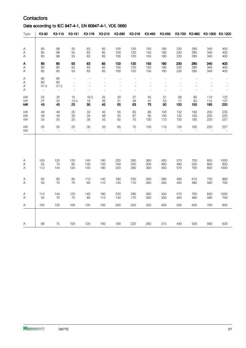
D677E 57
ContactorsContactorsContactorsContactorsContactors
Data according to IEC 947-4-1, EN 60947-4-1, VDE 0660Data according to IEC 947-4-1, EN 60947-4-1, VDE 0660Data according to IEC 947-4-1, EN 60947-4-1, VDE 0660Data according to IEC 947-4-1, EN 60947-4-1, VDE 0660Data according to IEC 947-4-1, EN 60947-4-1, VDE 0660
Type K3-90K3-90K3-90K3-90K3-90 K3-115K3-115K3-115K3-115K3-115 K3-151K3-151K3-151K3-151K3-151 K3-176K3-176K3-176K3-176K3-176 K3-210K3-210K3-210K3-210K3-210 K3-260K3-260K3-260K3-260K3-260 K3-316K3-316K3-316K3-316K3-316 K3-450K3-450K3-450K3-450K3-450 K3-550K3-550K3-550K3-550K3-550 K3-700K3-700K3-700K3-700K3-700 K3-860K3-860K3-860K3-860K3-860 K3-1000K3-1000K3-1000K3-1000K3-1000 K3-1200K3-1200K3-1200K3-1200K3-1200
A 85 98 55 63 85 100 120 150 180 230 280 340 400A 85 98 55 63 85 100 120 150 180 230 280 340 400A 85 98 55 63 85 100 120 150 180 230 280 340 400
AAAAA 8585858585 8585858585 5555555555 6363636363 8585858585 100100100100100 120120120120120 150150150150150 180180180180180 230230230230230 280280280280280 340340340340340 400400400400400A 85 85 55 63 85 100 120 150 180 230 280 340 400A 85 85 55 63 85 100 120 150 180 230 280 340 400
A 85 85 - - - - - - - - - - -A 60 60 - - - - - - - - - - -A 57,5 57,5 - - - - - - - - - - -A - - - - - - - - - - - - -
kW 25 30 15 18,5 25 30 37 45 51 68 80 110 132kW 27 32 15,5 19 26 31 38 47 53 71 83 115 137kWkWkWkWkW 4545454545 4545454545 2525252525 3030303030 4545454545 5555555555 6363636363 7575757575 9090909090 120120120120120 150150150150150 185185185185185 220220220220220
kW 49 49 25 33 45 55 65 80 100 132 160 200 230kW 49 49 30 34 48 55 67 85 100 132 160 200 230kW 55 55 25 30 55 65 75 100 110 150 185 220 257
kW 55 55 25 30 55 65 75 100 110 150 185 220 257kW - - - - - - - - - - - - -
A 100 120 120 140 180 220 280 360 450 570 700 850 1000A 55 70 85 100 130 160 200 300 360 460 550 660 800A 112 144 120 140 180 220 280 360 450 570 700 850 1000
A 85 90 95 110 140 180 230 300 380 490 610 750 890A 55 70 75 85 110 140 170 260 300 400 480 580 700
A 112 144 120 140 180 220 280 360 450 570 700 850 1000A 55 70 75 85 110 140 170 260 300 400 480 580 700
A 100 120 100 120 160 200 250 320 400 500 600 700 800
A 69 75 100 120 160 190 220 260 315 440 500 560 630

58 D677E
ContactorsContactorsContactorsContactorsContactors
Data according to IEC 947-4-1, EN 60947-4-1, VDE 0660Data according to IEC 947-4-1, EN 60947-4-1, VDE 0660Data according to IEC 947-4-1, EN 60947-4-1, VDE 0660Data according to IEC 947-4-1, EN 60947-4-1, VDE 0660Data according to IEC 947-4-1, EN 60947-4-1, VDE 0660
Main ContactsMain ContactsMain ContactsMain ContactsMain Contacts Type K(G)3-10K(G)3-10K(G)3-10K(G)3-10K(G)3-10 K(G)3-14K(G)3-14K(G)3-14K(G)3-14K(G)3-14 K(G)3-18K(G)3-18K(G)3-18K(G)3-18K(G)3-18 K(G)3-22K(G)3-22K(G)3-22K(G)3-22K(G)3-22 K(G)3-24K(G)3-24K(G)3-24K(G)3-24K(G)3-24 K(G)3-32K(G)3-32K(G)3-32K(G)3-32K(G)3-32 K(G)3-40K(G)3-40K(G)3-40K(G)3-40K(G)3-40 K3-50K3-50K3-50K3-50K3-50 K3-62K3-62K3-62K3-62K3-62 K3-74K3-74K3-74K3-74K3-74
Utilization category AC6aUtilization category AC6aUtilization category AC6aUtilization category AC6aUtilization category AC6aTransformer primary switchingTransformer primary switchingTransformer primary switchingTransformer primary switchingTransformer primary switchingat inrush n 30 30 30 30 30 30 30 30 30 30Rated operational current Ie 400V A 4,5 5,5 7,5 7,5 10,5 13,5 13,5 20 27 33
Rated operational power 220-230V kVA 1,8 2,2 3 3 4,2 5,4 5,4 8 10,7 13dependent on inrush n 240V kVA 1,9 2,3 3,1 3,1 4,3 5,6 5,6 8,3 11,2 13,5
380-400V kVA 3,1 3,8 5,2 5,2 7,3 9,3 9,3 13,5 18,5 22,5
For different inrush-factors x 415-440V kVA 3,4 4,2 5,7 5,7 8 10,2 10,2 15 20,5 25use the following formula: 500V kVA 3,9 4,8 6,5 6,5 9 11,5 11,5 17 23 28Px=Pn*(n/x) 660-690V kVA 5,4 6,5 9 9 12,5 16 16 24 32 39
Utilization category AC6bUtilization category AC6bUtilization category AC6bUtilization category AC6bUtilization category AC6bSwitching of three-phase capacitorsSwitching of three-phase capacitorsSwitching of three-phase capacitorsSwitching of three-phase capacitorsSwitching of three-phase capacitorsMaximum inrush current (peak value)as multiple k of thecapacitor rated current k 35 25 20 20 25 25 25 25 25 20Rated operational current Ie 500V A 8 12 15,5 15,5 23 32 32 45 60 70
Rated operational power 220-230V kVAr 3 4,5 6 6 8,5 12 12 17 24 28(sinϕ→1) 240V kVAr 3,5 5 6,5 6,5 9,5 13 13 18,5 25 29
380-400V kVAr 5 7,5 10 10 15 20 20 29 39 46
For different multiples x 415-440V kVAr 5,5 8 11 11 16 22 22 32 43 50use the following formula: 500V kVAr 7 10 13 13 20 26 26 39 50 58Px=Pk*(k/x) 660-690V kVAr 7 10 13 13 20 26 26 40 50 58
Switching ofSwitching ofSwitching ofSwitching ofSwitching ofreactive capacitor banksreactive capacitor banksreactive capacitor banksreactive capacitor banksreactive capacitor banksRated operational current Ie 690V A 8 13 18 20 28 36 42 48 72 108 1)
Rated operational power 220-230V kVAr 2,9 5 7 7,5 11 14 16 20 28 33240V kVAr 3,1 5,4 7 8 11 14 17 20 28 36
380-400V kVAr 5 9 12,5 13 20 25 27,5 33,3 50 75 1)
415-440V kVAr 5,5 9,5 13 14 22 27 30 36 53 75 1)
500V kVAr 6 11 15 17 25 30 36 40 60 75660-690V kVAr 8 15 20 22 33 41 48 55 82 100
1000V kVAr - - - - - - - - - -
Utilization category DC1Utilization category DC1Utilization category DC1Utilization category DC1Utilization category DC1Switching of resistive loadSwitching of resistive loadSwitching of resistive loadSwitching of resistive loadSwitching of resistive loadTime constant L/R ≤1msRated operational current Ie 1 pole 24V A 20 25 32 32 50 65 80 110 120 130
60V A 20 25 32 32 50 65 80 110 120 130110V A 6 6 6 6 10 10 10 12 12 12220V A 0,8 0,8 0,8 0,8 1,4 1,4 1,4 1,4 1,4 1,4
3 poles in series 24V A 20 25 32 32 50 65 80 110 120 130 60V A 20 25 32 32 50 65 80 110 120 130110V A 20 25 32 32 50 65 80 110 120 130220V A 16 20 20 20 30 35 35 63 80 80
Utilization category DC3 and DC5Utilization category DC3 and DC5Utilization category DC3 and DC5Utilization category DC3 and DC5Utilization category DC3 and DC5Switching of shunt motorsSwitching of shunt motorsSwitching of shunt motorsSwitching of shunt motorsSwitching of shunt motorsand series motorsand series motorsand series motorsand series motorsand series motorsTime constant L/R ≤15msRated operational current Ie 1 pole 24V A 20 25 32 32 50 65 80 110 120 130
60V A 6 6 6 6 30 30 30 60 60 60110V A 1,2 1,2 1,2 1,2 1,8 1,8 1,8 1,8 1,8 1,8
220V A 0,2 0,2 0,2 0,2 0,2 0,2 0,2 0,25 0,25 0,25
3 poles in series 24V A 20 25 32 32 50 65 80 110 120 130 60V A 20 25 32 32 40 40 40 80 80 80110V A 20 20 20 20 40 40 40 80 80 80220V A 2,5 2,5 2,5 2,5 4 4 4 5 5 5
1) Consider resistive load (Ith). see page 44

D677E 59
ContactorsContactorsContactorsContactorsContactors
Data according to IEC 947-4-1, EN 60947-4-1, VDE 0660Data according to IEC 947-4-1, EN 60947-4-1, VDE 0660Data according to IEC 947-4-1, EN 60947-4-1, VDE 0660Data according to IEC 947-4-1, EN 60947-4-1, VDE 0660Data according to IEC 947-4-1, EN 60947-4-1, VDE 0660
Type K3-90K3-90K3-90K3-90K3-90 K3-115K3-115K3-115K3-115K3-115 K3-151K3-151K3-151K3-151K3-151 K3-176K3-176K3-176K3-176K3-176 K3-210K3-210K3-210K3-210K3-210 K3-260K3-260K3-260K3-260K3-260 K3-316K3-316K3-316K3-316K3-316 K3-450K3-450K3-450K3-450K3-450 K3-550K3-550K3-550K3-550K3-550 K3-700K3-700K3-700K3-700K3-700 K3-860K3-860K3-860K3-860K3-860 K3-1000K3-1000K3-1000K3-1000K3-1000 K3-1200K3-1200K3-1200K3-1200K3-1200
n 30 30 30 30 30 30 30 30 30 30 30 30 30A 38 50 65 80 90 120 142 203 248 315 390 450 540
kVA 15 20 25 30 34 45 54 77 95 120 148 170 200kVA 15,5 20,5 27 33 37 50 59 80 100 130 160 185 220kVA 26 34 45 55 60 80 95 140 170 210 270 310 370
kVA 29 38 46 57 63 85 100 145 175 220 280 320 380kVA 33 43 55 69 75 100 120 170 210 270 330 380 460kVA 45 60 56 69 100 135 160 200 250 320 350 500 600
k 20 20 20 20 25 20 20 20 20 20 20 20 20A 87 100 120 155 195 225 255 300 370 440 520 680 760
kVAr 33 38 45 60 75 90 100 115 145 170 200 260 290kVAr 36 42 52 62 78 94 104 120 150 175 205 270 300kVAr 57 65 80 100 130 155 170 200 250 300 350 450 500
kVAr 60 70 95 110 135 165 175 210 260 310 360 465 520kVAr 70 80 100 130 170 194 220 260 320 380 450 590 660kVAr 70 80 100 130 170 194 220 260 320 380 450 590 660
A 115 144 115 140 200 225 250 330 420 550 600 680 760
kVAr 45 55 43 53 76 85 95 125 160 209 228 260 290kVAr 45 55 45 55 80 90 100 130 170 220 240 280 310kVAr 80 100 75 90 130 145 160 210 270 350 390 440 480
kVAr 100 120 80 100 140 160 170 230 290 380 420 470 530kVAr 105 125 95 120 170 190 210 280 350 450 500 570 640kVAr 120 148 125 150 200 230 260 350 450 600 650 700 800kVAr 160 200 155 200 300 340 400 500 650 - - - -
A 160 200 - - - - - - - - - - -A 160 200 - - - - - - - - - - -A 20 25 - - - - - - - - - - -A 2 2,5 - - - - - - - - - - -
A 160 200 200 250 350 400 450 600 760 1000 1100 1200 1350A 160 200 200 250 350 400 450 600 760 1000 1100 1200 1350A 160 200 150 170 250 280 315 400 480 560 630 800 900A 100 160 80 100 150 180 200 250 315 400 450 500 600
A 160 200 - - - - - - - - - - -A 85 110 - - - - - - - - - - -A 2 2,5 - - - - - - - - - - -A 0,5 0,5 - - - - - - - - - - -
A 160 200 - - - - - - - - - - -A 100 110 - - - - - - - - - - -A 100 110 - - - - - - - - - - -A 7 8 - - - - - - - - - - -

60 D677E
1) With reduced control voltage range 0,9 up to 1,0 x Us and with reduced rated current Ie /AC1according to Ie /AC3
ContactorsContactorsContactorsContactorsContactors
Data according to IEC 947-4-1, EN 60947-4-1, VDE 0660Data according to IEC 947-4-1, EN 60947-4-1, VDE 0660Data according to IEC 947-4-1, EN 60947-4-1, VDE 0660Data according to IEC 947-4-1, EN 60947-4-1, VDE 0660Data according to IEC 947-4-1, EN 60947-4-1, VDE 0660
Main ContactsMain ContactsMain ContactsMain ContactsMain Contacts Type K(G)3-10K(G)3-10K(G)3-10K(G)3-10K(G)3-10 K(G)3-14K(G)3-14K(G)3-14K(G)3-14K(G)3-14 K(G)3-18K(G)3-18K(G)3-18K(G)3-18K(G)3-18 K(G)3-22K(G)3-22K(G)3-22K(G)3-22K(G)3-22 K(G)3-24K(G)3-24K(G)3-24K(G)3-24K(G)3-24 K(G)3-32K(G)3-32K(G)3-32K(G)3-32K(G)3-32 K(G)3-40K(G)3-40K(G)3-40K(G)3-40K(G)3-40 K3-50K3-50K3-50K3-50K3-50 K3-62K3-62K3-62K3-62K3-62 K3-74K3-74K3-74K3-74K3-74
Maximum ambient temperatureMaximum ambient temperatureMaximum ambient temperatureMaximum ambient temperatureMaximum ambient temperatureOperation open °C -40 to +60 (+90) 1)
enclosed °C -40 to +40with thermal overload relay open °C -25 to +60enclosed °C -25 to +40Storage °C -50 to +90
Short circuit protectionShort circuit protectionShort circuit protectionShort circuit protectionShort circuit protectionfor contactors without thermal overload relay
Coordination-type "1" according to IEC 947-4-1Contact welding withouthazard of personsmax. fuse size gL (gG) A 63 63 63 63 80 80 80 160 160 160
Coordination-type “2” according to IEC 947-4-1Light contact welding acceptedmax. fuse size gL (gG) A 25 35 35 35 50 50 50 100 125 125
Contact welding not acceptedmax. fuse size gL (gG) A 16 16 16 16 25 35 35 50 63 63For contactors with thermal overload relay thedevice with the smaller admissible backup fuse(contactor or thermal overload relay)determines the fuse size.
Cable cross-sectionsCable cross-sectionsCable cross-sectionsCable cross-sectionsCable cross-sectionsfor contactors without thermal overload relay1 cable per clampmain connector solid or stranded mm² 0,75 - 6 1,5 - 25 4 - 50
flexible mm² 1 - 4 2,5 - 16 10 - 35flexible with multicore cable end mm² 0,75 - 4 1,5 - 16 6 - 35
2 cables per clampsolid or stranded mm² 6+(1-6) / 4+(0,75-4) 16+(2,5-16) / 10+(4-16) 50+4 / 35+6 / 25+(6-16)
2,5+(0,75-2,5) / 1,5+(0,75-1,5) 6+(4-16) / 4+(2,5-16) 16+(6-16) / 10+(6-16)flexible mm² 6+(1,5-4) / 4+(1-4) 16+(2,5-6) / 10+(4-10) 50+(4-10) / 35+(4-16)
2,5+(0,75-2,5) / 1,5+(0,75-1,5) 6+(4-16) / 4+(2,5-16) 25+(4-25) / 16+(4-16)
1 cable per clampmain connector solid AWG 18 - 10 16 - 10 12 - 10
flexible AWG 18 - 10 14 - 4 10 - 0
2 cables per clampsolid AWG 10+(16-10) / 12+(18-12) 10+(16-10) / 12+(18-12) 10+(12-10) / 12+12
14+(18-14) / 16+(18-16) 14+(18-14) / 16+(18-16)flexible AWG 10+(14-10) / 12+(18-12) 4+(18-12) / 6+(18-8) 1+(12-10) / 2+(8-12)
14+(18-14) / 16+(18-16) 8+(18-8) / 10+(18-12) 3+(12-8) / 4+(10-6)
Frequency of operations zFrequency of operations zFrequency of operations zFrequency of operations zFrequency of operations zContactors without thermal overload relay
without load 1/h 10000 7000 7000AC3, Ie 1/h 600 600 400AC4, Ie 1/h 120 120 120DC3, Ie 1/h 600 600 400
Mechanical lifeMechanical lifeMechanical lifeMechanical lifeMechanical lifeAC operated S x 106 10 10 10DC operated S x 106 10 10 10DC-solenoid operated (KG3) S x 106 50 50 -
Short time currentShort time currentShort time currentShort time currentShort time current 10s-current A 96 120 144 176 184 240 296 450 504 592120s-current A 42 52 58 66 80 97 110 195 203 222
Power loss Power loss Power loss Power loss Power loss per pole at Ie/AC3 400V W 0,21 0,35 0,5 0,75 0,7 1,3 2 2,2 3,9 5,5contact resistance mOhm 2,1 1,8 1,5 1,5 1,2 1,2 1,2 1 1 1
Resistance to shock acc. to IEC 68-2-27Resistance to shock acc. to IEC 68-2-27Resistance to shock acc. to IEC 68-2-27Resistance to shock acc. to IEC 68-2-27Resistance to shock acc. to IEC 68-2-27Shock time 20ms sine-wave NO g 10 10 10 10 8 8 8 8 8 8
NC g 6 6 6 6 - - - - - -
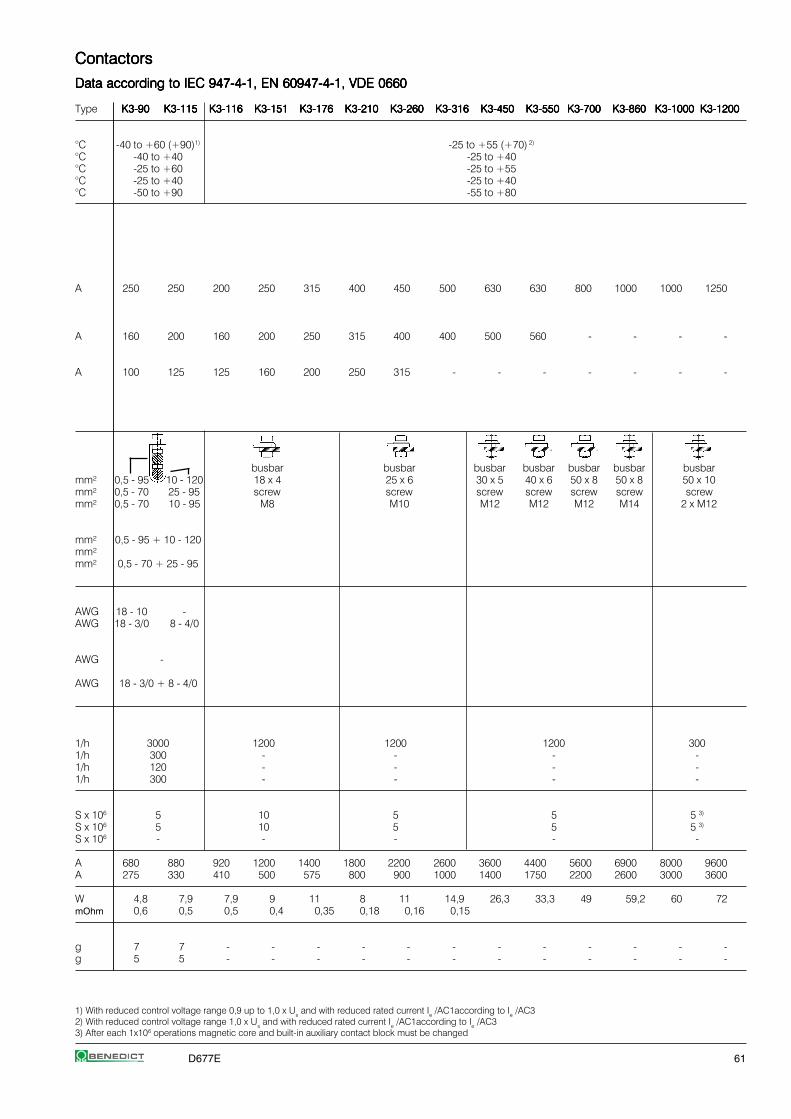
D677E 61
1) With reduced control voltage range 0,9 up to 1,0 x Us and with reduced rated current Ie /AC1according to Ie /AC32) With reduced control voltage range 1,0 x Us and with reduced rated current Ie /AC1according to Ie /AC33) After each 1x10⁶ operations magnetic core and built-in auxiliary contact block must be changed
ContactorsContactorsContactorsContactorsContactors
Data according to IEC 947-4-1, EN 60947-4-1, VDE 0660Data according to IEC 947-4-1, EN 60947-4-1, VDE 0660Data according to IEC 947-4-1, EN 60947-4-1, VDE 0660Data according to IEC 947-4-1, EN 60947-4-1, VDE 0660Data according to IEC 947-4-1, EN 60947-4-1, VDE 0660
Type K3-90K3-90K3-90K3-90K3-90 K3-115K3-115K3-115K3-115K3-115 K3-116K3-116K3-116K3-116K3-116 K3-151K3-151K3-151K3-151K3-151 K3-176K3-176K3-176K3-176K3-176 K3-210K3-210K3-210K3-210K3-210 K3-260K3-260K3-260K3-260K3-260 K3-316K3-316K3-316K3-316K3-316 K3-450K3-450K3-450K3-450K3-450 K3-550K3-550K3-550K3-550K3-550 K3-700K3-700K3-700K3-700K3-700 K3-860K3-860K3-860K3-860K3-860 K3-1000K3-1000K3-1000K3-1000K3-1000 K3-1200K3-1200K3-1200K3-1200K3-1200
°C -40 to +60 (+90)1) -25 to +55 (+70) 2)
°C -40 to +40 -25 to +40°C -25 to +60 -25 to +55°C -25 to +40 -25 to +40°C -50 to +90 -55 to +80
A 250 250 200 250 315 400 450 500 630 630 800 1000 1000 1250
A 160 200 160 200 250 315 400 400 500 560 - - - -
A 100 125 125 160 200 250 315 - - - - - - -
busbar busbar busbar busbar busbar busbar busbarmm² 0,5 - 95 10 - 120 18 x 4 25 x 6 30 x 5 40 x 6 50 x 8 50 x 8 50 x 10mm² 0,5 - 70 25 - 95 screw screw screw screw screw screw screwmm² 0,5 - 70 10 - 95 M8 M10 M12 M12 M12 M14 2 x M12
mm² 0,5 - 95 + 10 - 120mm²mm² 0,5 - 70 + 25 - 95
AWG 18 - 10 -AWG 18 - 3/0 8 - 4/0
AWG -
AWG 18 - 3/0 + 8 - 4/0
1/h 3000 1200 1200 1200 3001/h 300 - - - -1/h 120 - - - -1/h 300 - - - -
S x 106 5 10 5 5 5 3)
S x 106 5 10 5 5 5 3)
S x 106 - - - - -
A 680 880 920 1200 1400 1800 2200 2600 3600 4400 5600 6900 8000 9600A 275 330 410 500 575 800 900 1000 1400 1750 2200 2600 3000 3600
W 4,8 7,9 7,9 9 11 8 11 14,9 26,3 33,3 49 59,2 60 72mOhm 0,6 0,5 0,5 0,4 0,35 0,18 0,16 0,15
g 7 7 - - - - - - - - - - - -g 5 5 - - - - - - - - - - - -

62 D677E
1) Suitable for: earthed-neutral systems, overvoltage category I to IV, pollution degree 3 (standard-industry): Uimp = 8kV. Data for other conditions on request2) Total breaking time = release time + arc duration3) Values for delay of the release time of the make contact and the make time of the break contact will be increased, if magnet coils are protected against voltage
peaks (varistor, RC-unit, diode-unit)4) with built-in coil suppressor 5) for contactors KG3-..A.. only
ContactorsContactorsContactorsContactorsContactors
Data according to IEC 947-4-1, EN 60947-4-1, VDE 0660Data according to IEC 947-4-1, EN 60947-4-1, VDE 0660Data according to IEC 947-4-1, EN 60947-4-1, VDE 0660Data according to IEC 947-4-1, EN 60947-4-1, VDE 0660Data according to IEC 947-4-1, EN 60947-4-1, VDE 0660
Auxiliary ContactsAuxiliary ContactsAuxiliary ContactsAuxiliary ContactsAuxiliary Contacts Type K(G)3-10K(G)3-10K(G)3-10K(G)3-10K(G)3-10 K(G)3-14K(G)3-14K(G)3-14K(G)3-14K(G)3-14 K(G)3-18K(G)3-18K(G)3-18K(G)3-18K(G)3-18 K(G)3-22K(G)3-22K(G)3-22K(G)3-22K(G)3-22 K(G)3-24K(G)3-24K(G)3-24K(G)3-24K(G)3-24 K(G)3-32K(G)3-32K(G)3-32K(G)3-32K(G)3-32 K(G)3-40K(G)3-40K(G)3-40K(G)3-40K(G)3-40 K3-50K3-50K3-50K3-50K3-50 K3-62K3-62K3-62K3-62K3-62 K3-74K3-74K3-74K3-74K3-74
Rated insulation voltage URated insulation voltage URated insulation voltage URated insulation voltage URated insulation voltage Uiiiii 1)1)1)1)1) V~ 690 - -
Thermal rated current IThermal rated current IThermal rated current IThermal rated current IThermal rated current Iththththth to 690VAmbient temperature 40°C A 10 (16)5) - -
60°C A 6 (12)5) - -
Utilization category AC15Utilization category AC15Utilization category AC15Utilization category AC15Utilization category AC15Rated operational current Ie 220-240V A 3 (12)5) - -
380-415V A 2 (4)5) - -440V A 1,6 (4)5) - -
500V A 1,2 (3)5) - -660-690V A 0,6 (1)5) - -
Utilization category DC13Utilization category DC13Utilization category DC13Utilization category DC13Utilization category DC13Rated operational current Ie 60V A 3,5 (8)5) - -
110V A 0,5 (1)5) - -220V A 0,1 - -
Short circuit protectionShort circuit protectionShort circuit protectionShort circuit protectionShort circuit protectionshort-circuit current 1kA,contact welding not acceptedmax. fuse size gL (gG) A 20 (25)5) - -
Control CircuitControl CircuitControl CircuitControl CircuitControl CircuitPower consumption of coilsPower consumption of coilsPower consumption of coilsPower consumption of coilsPower consumption of coilsAC operated inrush VA 33-45 90-115 140-165
sealed VA 7-10 9-13 13-18W 2,6-3 2,7-4 5,4-7
DC operated inrush W 75 140 200double winding coil sealed W 2 2 6
DC solenoid operated inrush W 3 4 -(KG3) sealed W 3 4 -
Operation range of coilsOperation range of coilsOperation range of coilsOperation range of coilsOperation range of coilsin multiples of control voltage Us
AC operated 0,85-1,1 0,85-1,1 0,85-1,1DC operated 0,8-1,1 0,8-1,1 0,8-1,1
Switching time Switching time Switching time Switching time Switching time at control voltage Us ±10% 2) 3)
AC operated make time ms 8-16 10-25 12-28release time ms 5-13 8-15 8-15arc duration ms 10-15 10-15 10-15
DC operated make time ms 8-12 10-20 12-23double winding coil release time ms 8-13 10-15 10-18
arc duration ms 10-15 10-15 10-15
DC solenoid operated make time ms 65 - 85 65 - 85 -(KG3) release time ms 20 - 30 4) 20 - 30 4) -
arc duration ms 10-15 10-15 -
Cable cross-sectionCable cross-sectionCable cross-sectionCable cross-sectionCable cross-sectionAuxiliary connector solid mm² 0,75-6 - -
flexible mm² 1-4 - -flexible with multicore cable end mm² 0,75-4 - -
Magnet coil solid mm² 0,75-2,5 0,75-2,5 0,75-2,5flexible mm² 0,5-2,5 0,5-2,5 0,5-2,5
flexible with multicore cable end mm² 0,5-1,5 0,5-1,5 0,5-1,5Clamps per pole 2 2 2
Auxiliary connector solid AWG 18 - 10 - -flexible AWG 18 - 10 - -
Magnet coil solid AWG 14 - 12 14 - 12 14 - 12flexible AWG 18 - 12 18 - 12 18 - 12
Clamps per pole 2 2 2
For contactors with thermal overload relay the device with the smaller admissible controlfuse (contactor or thermal overload relay) determines the fuse.

D677E 63
ContactorsContactorsContactorsContactorsContactors
Data according to IEC 947-4-1, EN 60947-4-1, VDE 0660Data according to IEC 947-4-1, EN 60947-4-1, VDE 0660Data according to IEC 947-4-1, EN 60947-4-1, VDE 0660Data according to IEC 947-4-1, EN 60947-4-1, VDE 0660Data according to IEC 947-4-1, EN 60947-4-1, VDE 0660
Type K3-90K3-90K3-90K3-90K3-90 K3-115K3-115K3-115K3-115K3-115 K3-116K3-116K3-116K3-116K3-116 K3-151K3-151K3-151K3-151K3-151 K3-176K3-176K3-176K3-176K3-176 K3-210K3-210K3-210K3-210K3-210 K3-260K3-260K3-260K3-260K3-260 K3-316K3-316K3-316K3-316K3-316 K3-450K3-450K3-450K3-450K3-450 K3-550K3-550K3-550K3-550K3-550 K3-700K3-700K3-700K3-700K3-700 K3-860K3-860K3-860K3-860K3-860 K3-1000K3-1000K3-1000K3-1000K3-1000 K3-1200K3-1200K3-1200K3-1200K3-1200
V~ - - - 690 690 690
A - - - 10 10 10A - - - - - - -- - - - - -
A - - - 3 3 3A - - - 2 2 2A - - - 1,5 1,5 1,5
A - - - 1,5 1,5 1,5A - - - 1 1 1
A - - - - - -A - - - 1 1 1A - - - 0,5 0,5 0,5
A - - - 10 10 10
VA 165-220 350 360 800-950 1350-1600 2400VA 2,5-5 5 5 9-11 21-25 70W 2,5-5 5 5 9-11 21-25 70
W 250 350 360 700-850 1300-1550 2100W 5 5 5 8-10 18-22 60
W - - - - - -W - - - - - -
0,85-1,1 0,85-1,1 0,85-1,1 0,85-1,1 0,85-1,10,8-1,1 0,85-1,1 0,85-1,1 0,85-1,1 0,85-1,1
ms 20-35 30-60 40-60 50-100 50-100ms 35-50 30-80 15-45 150-200 / 500-10001) 25-50ms 10-15 - - -
ms 20-35 30-60 40-60 - -ms 35-50 30-80 15-45 - -ms 10-15 - - - -
ms - - - - -ms - - - - -ms - - - - -
mm² - - - 0,75-2,5 0,75-2,5mm² - - - 0,75-2,5 0,75-2,5mm² - - - - -
mm² 0,75-2,5 1-2,5 1-2,5 1-2,5 1-2,5mm² 0,5-2,5 1-2,5 1-2,5 1-2,5 1-2,5mm² 0,5-1,5 - - - -
2 2 2 2 2
AWG - - - 16 - 12 16 - 12AWG - - - 16 - 12 16 - 12
AWG 14 - 12 16 - 12 16 - 12 16 - 12 16 - 12AWG 18 - 12 16 - 12 16 - 12 16 - 12 16 - 12
2 2 2 2 2
1) Normal or delayed drop is adjustable
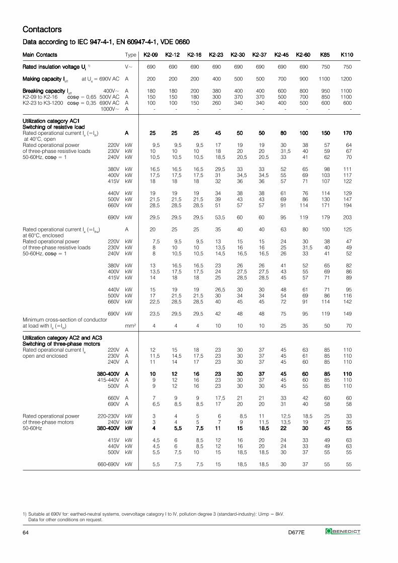
64 D677E
1) Suitable at 690V for: earthed-neutral systems, overvoltage category I to IV, pollution degree 3 (standard-industry): Uimp = 8kV.Data for other conditions on request.
ContactorsContactorsContactorsContactorsContactors
Data according to IEC 947-4-1, EN 60947-4-1, VDE 0660Data according to IEC 947-4-1, EN 60947-4-1, VDE 0660Data according to IEC 947-4-1, EN 60947-4-1, VDE 0660Data according to IEC 947-4-1, EN 60947-4-1, VDE 0660Data according to IEC 947-4-1, EN 60947-4-1, VDE 0660
Main ContactsMain ContactsMain ContactsMain ContactsMain Contacts Type K2-09K2-09K2-09K2-09K2-09 K2-12K2-12K2-12K2-12K2-12 K2-16K2-16K2-16K2-16K2-16 K2-23K2-23K2-23K2-23K2-23 K2-30K2-30K2-30K2-30K2-30 K2-37K2-37K2-37K2-37K2-37 K2-45K2-45K2-45K2-45K2-45 K2-60K2-60K2-60K2-60K2-60 K85K85K85K85K85 K110K110K110K110K110
Rated insulation voltage URated insulation voltage URated insulation voltage URated insulation voltage URated insulation voltage Uiiiii 1) V~ 690 690 690 690 690 690 690 690 750 750
Making capacity IMaking capacity IMaking capacity IMaking capacity IMaking capacity Ieff at Ue = 690V AC A 200 200 200 400 500 500 700 900 1100 1200
Breaking capacity IBreaking capacity IBreaking capacity IBreaking capacity IBreaking capacity Ieff 400V~ A 180 180 200 380 400 400 600 800 950 1100K2-09 to K2-16 cosϕ = 0,65 500V AC A 150 150 180 300 370 370 500 700 850 1100K2-23 to K3-1200 cosϕ = 0,35 690V AC A 100 100 150 260 340 340 400 500 600 600
1000V~ A - - - - - - - - - -
Utilization category AC1Utilization category AC1Utilization category AC1Utilization category AC1Utilization category AC1Switching of resistive loadSwitching of resistive loadSwitching of resistive loadSwitching of resistive loadSwitching of resistive loadRated operational current Ie (=Ith) AAAAA 2525252525 2525252525 2525252525 4545454545 5050505050 5050505050 8080808080 100100100100100 150150150150150 170170170170170 at 40°C, openRated operational power 220V kW 9,5 9,5 9,5 17 19 19 30 38 57 64of three-phase resistive loads 230V kW 10 10 10 18 20 20 31,5 40 59 6750-60Hz, cosϕ = 1 240V kW 10,5 10,5 10,5 18,5 20,5 20,5 33 41 62 70
380V kW 16,5 16,5 16,5 29,5 33 33 52 65 98 111400V kW 17,5 17,5 17,5 31 34,5 34,5 55 69 103 117415V kW 18 18 18 32 36 36 57 71 107 122
440V kW 19 19 19 34 38 38 61 76 114 129500V kW 21,5 21,5 21,5 39 43 43 69 86 130 147660V kW 28,5 28,5 28,5 51 57 57 91 114 171 194
690V kW 29,5 29,5 29,5 53,5 60 60 95 119 179 203
Rated operational current Ie (=Ithe) A 20 25 25 35 40 40 63 80 100 125at 60°C, enclosedRated operational power 220V kW 7,5 9,5 9,5 13 15 15 24 30 38 47of three-phase resistive loads 230V kW 8 10 10 13,5 16 16 25 31,5 40 4950-60Hz, cosϕ = 1 240V kW 8 10,5 10,5 14,5 16,5 16,5 26 33 41 52
380V kW 13 16,5 16,5 23 26 26 41 52 65 82400V kW 13,5 17,5 17,5 24 27,5 27,5 43 55 69 86415V kW 14 18 18 25 28,5 28,5 45 57 71 89
440V kW 15 19 19 26,5 30 30 48 61 71 95500V kW 17 21,5 21,5 30 34 34 54 69 86 116660V kW 22,5 28,5 28,5 40 45 45 72 91 114 142
690V kW 23,5 29,5 29,5 42 48 48 75 95 119 149Minimum cross-section of conductorat load with Ie (=Ith) mm² 4 4 4 10 10 10 25 35 50 70
Utilization category AC2 and AC3Utilization category AC2 and AC3Utilization category AC2 and AC3Utilization category AC2 and AC3Utilization category AC2 and AC3Switching of three-phase motorsSwitching of three-phase motorsSwitching of three-phase motorsSwitching of three-phase motorsSwitching of three-phase motorsRated operational current Ie 220V A 12 15 18 23 30 37 45 63 85 110open and enclosed 230V A 11,5 14,5 17,5 23 30 37 45 61 85 110
240V A 11 14 17 23 30 37 45 60 85 110
380-400V380-400V380-400V380-400V380-400V AAAAA 1010101010 1212121212 1616161616 2323232323 3030303030 3737373737 4545454545 6060606060 8585858585 110110110110110415-440V A 9 12 16 23 30 37 45 60 85 110
500V A 9 12 16 23 30 30 45 55 85 110
660V A 7 9 9 17,5 21 21 33 42 60 60690V A 6,5 8,5 8,5 17 20 20 31 40 58 58
Rated operational power 220-230V kW 3 4 5 6 8,5 11 12,5 18,5 25 33of three-phase motors 240V kW 3 4 5 7 9 11,5 13,5 19 27 3550-60Hz 380-400V380-400V380-400V380-400V380-400V kWkWkWkWkW 44444 5,55,55,55,55,5 7,57,57,57,57,5 1111111111 1515151515 18,518,518,518,518,5 2222222222 3030303030 4545454545 5555555555
415V kW 4,5 6 8,5 12 16 20 24 33 49 63440V kW 4,5 6 8,5 12 16 20 24 33 49 63500V kW 5,5 7,5 10 15 18,5 18,5 30 37 55 55
660-690V kW 5,5 7,5 7,5 15 18,5 18,5 30 37 55 55

D677E 65
1) Metal halide lamps and sodium-vapour lamps (high- and low-pressure lamps)2) High-pressure lamps3) Blended lamps, containing a mercury high-pressure unit and a tungsten helix in a flourescent glass bulb (daylight lamps)4) Current inrush approx. 16 x Ie5) With central compensation pay attention to the current inrush (capacitor switching contactors)
ContactorsContactorsContactorsContactorsContactors
Data according to IEC 947-4-1, EN 60947-4-1, VDE 0660Data according to IEC 947-4-1, EN 60947-4-1, VDE 0660Data according to IEC 947-4-1, EN 60947-4-1, VDE 0660Data according to IEC 947-4-1, EN 60947-4-1, VDE 0660Data according to IEC 947-4-1, EN 60947-4-1, VDE 0660
Main ContactsMain ContactsMain ContactsMain ContactsMain Contacts Type K2-09K2-09K2-09K2-09K2-09 K2-12K2-12K2-12K2-12K2-12 K2-16K2-16K2-16K2-16K2-16 K2-23K2-23K2-23K2-23K2-23 K2-30K2-30K2-30K2-30K2-30 K2-37K2-37K2-37K2-37K2-37 K2-45K2-45K2-45K2-45K2-45 K2-60K2-60K2-60K2-60K2-60 K85K85K85K85K85 K110K110K110K110K110
Utilization category AC4Utilization category AC4Utilization category AC4Utilization category AC4Utilization category AC4Switching of squirrel cage motors, inchingSwitching of squirrel cage motors, inchingSwitching of squirrel cage motors, inchingSwitching of squirrel cage motors, inchingSwitching of squirrel cage motors, inchingRated operational current Ie 220V A 12 15 16 23 30 37 45 63 85 98open and enclosed 230V A 11,5 14,5 16 23 30 37 45 61 85 98
240V A 11 14 16 23 30 37 45 60 85 98
380-400V380-400V380-400V380-400V380-400V AAAAA 1010101010 1212121212 1616161616 2323232323 3030303030 3737373737 4545454545 6060606060 8585858585 8585858585415V A 9 12 16 21 28 37 45 60 85 85440V A 9 12 16 21 28 37 45 60 85 85
500V A 9 12 16 17 23 23 45 55 85 85660V A 7 9 9 13 17 17 33 42 60 60690V A 6,5 8,5 8,5 12,5 16,5 16,5 31 40 57,5 57,5
Rated operational power 220-230V kW 3 4 5 6 8,5 11 12,5 18,5 25 30of three-phase motors 240V kW 3 4 5 7 9 11,5 13,5 19 27 3250-60Hz 380-400V380-400V380-400V380-400V380-400V kWkWkWkWkW 44444 5,55,55,55,55,5 7,57,57,57,57,5 1111111111 1515151515 18,518,518,518,518,5 2222222222 3030303030 4545454545 4545454545
415-440V kW 4,5 6 8,5 11 15 20 24 33 49 49500V kW 5,5 7,5 10 11 15 15 30 37 55 55
660-690V kW 5,5 7,5 7,5 11 15 15 30 37 55 55
Utilization category AC5aUtilization category AC5aUtilization category AC5aUtilization category AC5aUtilization category AC5aSwitching of gas discharge lampsSwitching of gas discharge lampsSwitching of gas discharge lampsSwitching of gas discharge lampsSwitching of gas discharge lampsRated operational current Ieper pole at 220/230V
Fluorescent lamps, uncompensated A 20 20 20 35 40 40 65 85 100 120Fluorescent lamps, compensated A 7 9 9 18 22 22 30 40 55 70Fluorescent lamps, dual-connection A 22,5 22,5 22,5 41 45 45 72 90 112 144
Metal-halide lamps1), uncompensated A 12 15 15 28 30 30 50 62 85 90Metal-halide lamps1), compensated A 7 9 9 18 22 22 30 40 55 70
Mercury-vapour lamps2), uncompensated A 22,5 25 25 41 45 45 72 90 112 144Mercury-vapour lamps2), compensated A 7 9 9 18 22 22 30 40 55 70
Mixed light lamps3) A 20 20 20 35 40 40 65 85 100 120
Utilization category AC5bUtilization category AC5bUtilization category AC5bUtilization category AC5bUtilization category AC5bSwitching of incandescent lampsSwitching of incandescent lampsSwitching of incandescent lampsSwitching of incandescent lampsSwitching of incandescent lamps4)
Rated operational current Ieper pole at 220/230V A 12,5 12,5 12,5 25 31 31 43 56 69 75
Utilization category AC6aUtilization category AC6aUtilization category AC6aUtilization category AC6aUtilization category AC6aTransformer primary switchingTransformer primary switchingTransformer primary switchingTransformer primary switchingTransformer primary switchingat inrush n 30 30 30 30 30 30 30 30 30 30Rated operational current Ie 400V A 4,5 5,5 7,5 10,5 13,5 13,5 20 27 38 50
Rated operational power 220-230V kVA 1,8 2,2 3 4,2 5,4 5,4 8 10,7 15 20dependent on inrush n 240V kVA 1,9 2,3 3,1 4,3 5,6 5,6 8,3 11,2 15,5 20,5
380-400V kVA 3,1 3,8 5,2 7,3 9,3 9,3 13,5 18,5 26 34
For different inrush-factors x 415-440V kVA 3,4 4,2 5,7 8 10,2 10,2 15 20,5 29 38use the following formula: 500V kVA 3,9 4,8 6,5 9 11,5 11,5 17 23 33 43Px=Pn*(n/x) 660-690V kVA 5,4 6,5 9 12,5 16 16 24 32 45 60
Utilization category DC1Utilization category DC1Utilization category DC1Utilization category DC1Utilization category DC1Switching of resistive loadSwitching of resistive loadSwitching of resistive loadSwitching of resistive loadSwitching of resistive loadTime constant L/R ≤1msRated operational current Ie 1 pole 24V A 20 25 25 45 50 50 80 100 150 170
60V A 20 25 25 45 50 50 80 100 150 170110V A 6 6 6 10 10 10 12 12 20 25220V A 0,8 0,8 0,8 1,4 1,4 1,4 1,4 1,4 2 2,5
3 poles in series 24V A 20 25 25 45 50 50 80 100 150 170 60V A 20 25 25 45 50 50 80 100 150 170110V A 20 25 25 45 50 50 80 100 150 170220V A 16 20 20 30 35 35 63 80 100 160

66 D677E
1) With reduced control voltage range 0,9 up to 1,0 x Us and with reduced rated current Ie /AC1according to Ie /AC32) Maximum cable cross-section with prepared conductor
ContactorsContactorsContactorsContactorsContactors
Data according to IEC 947-4-1, EN 60947-4-1, VDE 0660Data according to IEC 947-4-1, EN 60947-4-1, VDE 0660Data according to IEC 947-4-1, EN 60947-4-1, VDE 0660Data according to IEC 947-4-1, EN 60947-4-1, VDE 0660Data according to IEC 947-4-1, EN 60947-4-1, VDE 0660
Main ContactsMain ContactsMain ContactsMain ContactsMain Contacts Type K2-09K2-09K2-09K2-09K2-09 K2-12K2-12K2-12K2-12K2-12 K2-16K2-16K2-16K2-16K2-16 K2-23K2-23K2-23K2-23K2-23 K2-30K2-30K2-30K2-30K2-30 K2-37K2-37K2-37K2-37K2-37 K2-45K2-45K2-45K2-45K2-45 K2-60K2-60K2-60K2-60K2-60 K85K85K85K85K85 K110K110K110K110K110
Utilization category DC3 and DC5Utilization category DC3 and DC5Utilization category DC3 and DC5Utilization category DC3 and DC5Utilization category DC3 and DC5Switching of shunt motorsSwitching of shunt motorsSwitching of shunt motorsSwitching of shunt motorsSwitching of shunt motorsand series motorsand series motorsand series motorsand series motorsand series motorsTime constant L/R ≤15msRated operational current Ie 1 pole 24V A 20 25 25 45 50 50 80 100 150 170
60V A 6 6 6 30 30 30 60 60 85 110110V A 1,2 1,2 1,2 1,8 1,8 1,8 1,8 1,8 2 2,5
220V A 0,2 0,2 0,2 0,2 0,2 0,2 0,25 0,25 0,5 0,5
3 poles in series 24V A 20 25 25 45 50 50 80 100 150 170 60V A 20 25 25 40 40 40 80 80 100 110110V A 20 20 20 40 40 40 80 80 100 110220V A 2,5 2,5 2,5 4 4 4 5 5 7 8
Maximum ambient temperatureMaximum ambient temperatureMaximum ambient temperatureMaximum ambient temperatureMaximum ambient temperatureOperation open °C -40 to +60 (+90) 1)
enclosed °C -40 to +40with thermal overload relay open °C -25 to +60enclosed °C -25 to +40
Storage °C -50 to +90
Short circuit protectionShort circuit protectionShort circuit protectionShort circuit protectionShort circuit protectionfor contactors without thermal overload relay
Coordination-type "1" according to IEC 947-4-1Contact welding withouthazard of personsmax. fuse size gL (gG) A 63 63 63 80 80 80 160 160 250 250
Coordination-type “2” according to IEC 947-4-1Light contact welding acceptedmax. fuse size gL (gG) A 25 35 35 50 50 50 100 125 160 200
Contact welding not acceptedmax. fuse size gL (gG) A 16 16 16 25 35 35 50 63 100 125For contactors with thermal overload relay thedevice with the smaller admissible backup fuse(contactor or thermal overload relay)determines the fuse size.
Cable cross-sectionsCable cross-sectionsCable cross-sectionsCable cross-sectionsCable cross-sectionsfor contactors without thermal overload relaymain connector solid or stranded mm² 0,75 - 4 1,5-10 + 1,5-6 4 - 35 2) 10 - 70 2)
flexible mm² 0,75 - 2,5 1,5-6 + 1,5-4 6 - 25 2) 10 - 70 2)
flexible with multicore cable end mm² 0,5 - 2,5 1,5-6 + 1,5-4 4 - 25 10 - 35Cables per clamp 2 1+1 1 1
main connector solid AWG 14 - 10 14 - 10 + 14 - 10 10 10flexible AWG 18 - 10 14 - 8 + 14 - 10 10 - 2 6 - 0
Cables per clamp 2 1+1 1 1
Frequency of operations zFrequency of operations zFrequency of operations zFrequency of operations zFrequency of operations zContactors without thermal overload relay
without load 1/h 10000 7000 7000 3000AC3, Ie 1/h 600 600 400 300AC4, Ie 1/h 120 120 120 120DC3, Ie 1/h 600 600 400 300
Mechanical lifeMechanical lifeMechanical lifeMechanical lifeMechanical lifeAC operated S x 106 10 10 10 5DC operated with economy resistor S x 106 10 10 10 5
Short time currentShort time currentShort time currentShort time currentShort time current 10s-current A 96 120 144 184 240 296 360 504 680 880
Power loss Power loss Power loss Power loss Power loss per pole at Ie/AC3 400V W 0,21 0,26 0,4 0,63 1,1 1,7 1,8 3,6 4,3 6,0
Resistance to shock acc. to IEC 68-2-27Resistance to shock acc. to IEC 68-2-27Resistance to shock acc. to IEC 68-2-27Resistance to shock acc. to IEC 68-2-27Resistance to shock acc. to IEC 68-2-27Shock time 20ms sine-wave NO g 10 10 10 8 8 8 8 8 7 7
NC g 6 6 6 5 5 5 - - 5 5

D677E 67
1) Suitable for: earthed-neutral systems, overvoltage category I to IV, pollution degree 3 (standard-industry): Uimp = 8kV. Data for other conditions on request2) Total breaking time = release time + arc duration3) Values for delay of the release time of the make contact and the make time of the break contact will be increased, if magnet coils are protected against voltage
peaks (varistor, RC-unit, diode-unit)
ContactorsContactorsContactorsContactorsContactors
Data according to IEC 947-4-1, EN 60947-4-1, VDE 0660Data according to IEC 947-4-1, EN 60947-4-1, VDE 0660Data according to IEC 947-4-1, EN 60947-4-1, VDE 0660Data according to IEC 947-4-1, EN 60947-4-1, VDE 0660Data according to IEC 947-4-1, EN 60947-4-1, VDE 0660
Auxiliary ContactsAuxiliary ContactsAuxiliary ContactsAuxiliary ContactsAuxiliary Contacts Type K2-09K2-09K2-09K2-09K2-09 K2-12K2-12K2-12K2-12K2-12 K2-16K2-16K2-16K2-16K2-16 K2-23K2-23K2-23K2-23K2-23 K2-30K2-30K2-30K2-30K2-30 K2-37K2-37K2-37K2-37K2-37 K2-45K2-45K2-45K2-45K2-45 K2-60K2-60K2-60K2-60K2-60 K85K85K85K85K85 K110K110K110K110K110
Rated insulation voltage URated insulation voltage URated insulation voltage URated insulation voltage URated insulation voltage Uiiiii 1)1)1)1)1) V AC 690 690 - 690
Thermal rated current IThermal rated current IThermal rated current IThermal rated current IThermal rated current Iththththth to 690VAmbient temperature 40°C A 16 16 - 16
60°C A 12 12 - 12
Utilization category AC15Utilization category AC15Utilization category AC15Utilization category AC15Utilization category AC15Rated operational current Ie 220-240V A 12 12 - 12
380-415V A 4 4 - 6440V A 4 4 - 6
500V A 3 3 - 4660-690V A 1 1 - 2
Utilization category DC13Utilization category DC13Utilization category DC13Utilization category DC13Utilization category DC13Rated operational current Ie 60V A 8 8 - 8
110V A 1 1 - 1220V A 0,1 0,1 - 0,1
Short circuit protectionShort circuit protectionShort circuit protectionShort circuit protectionShort circuit protectionshort-circuit current 1kA,contact welding not acceptedmax. fuse size gL (gG) A 25 - - 25For contactors with thermal overload relay thedevice with the smaller admissible control fuse(contactor or thermal overload relay)determines the fuse.
Control CircuitControl CircuitControl CircuitControl CircuitControl Circuit
Power consumption of coilsPower consumption of coilsPower consumption of coilsPower consumption of coilsPower consumption of coils
AC operated inrush VA 33-45 90-115 140-165 280-350 350-420sealed VA 7-10 9-13 13-18 16-23 23-29
W 2,6-3 2,7-4 5,4-7 4-6 6-7,3
DC operated inrush W 75 140 200 170 320with economic circuit sealed W 2 2 6 2 4
Operation range of coilsOperation range of coilsOperation range of coilsOperation range of coilsOperation range of coilsin multiples of control voltage Us
AC operated 0,85-1,1 0,85-1,1 0,85-1,1 0,85-1,1DC operated 0,8-1,1 0,8-1,1 0,8-1,1 0,8-1,1
Switching time Switching time Switching time Switching time Switching time at control voltage Us ±10% 2) 3)
AC operated make time ms 8-16 10-25 12-28 13-30release time ms 5-13 8-15 8-15 8-15arc duration ms 10-15 10-15 10-15 10-15
DC operated make time ms 8-12 10-20 12-23 20-30with AC magnet system release time ms 8-13 10-15 10-18 10-18
arc duration ms 10-15 10-15 10-15 10-15
Cable cross-sectionCable cross-sectionCable cross-sectionCable cross-sectionCable cross-section
Auxiliary connector solid mm² 0,75-4 - - 0,75-2,5flexible mm² 0,75-2,5 - - 0,75-2,5
flexible with multicore cable end mm² 0,5-2,5 - - 0,5-1,5
Magnet coil solid mm² 0,75-2,5 0,75-2,5 0,75-2,5 0,75-2,5flexible mm² 0,5-2,5 0,5-2,5 0,5-2,5 0,5-2,5
flexible with multicore cable end mm² 0,5-1,5 0,5-1,5 0,5-1,5 0,5-1,5
Clamps per pole 2 2 2 2

68 D677E
Contactors for North AmericaContactors for North AmericaContactors for North AmericaContactors for North AmericaContactors for North America
Data according to UL508Data according to UL508Data according to UL508Data according to UL508Data according to UL508
Main Contacts (cULus)Main Contacts (cULus)Main Contacts (cULus)Main Contacts (cULus)Main Contacts (cULus) Type K(G)3-10K(G)3-10K(G)3-10K(G)3-10K(G)3-10 K(G)3-14K(G)3-14K(G)3-14K(G)3-14K(G)3-14 K(G)3-18K(G)3-18K(G)3-18K(G)3-18K(G)3-18 K(G)3-22K(G)3-22K(G)3-22K(G)3-22K(G)3-22 K(G)3-24K(G)3-24K(G)3-24K(G)3-24K(G)3-24 K(G)3-32K(G)3-32K(G)3-32K(G)3-32K(G)3-32 K(G)3-40K(G)3-40K(G)3-40K(G)3-40K(G)3-40 K3-50K3-50K3-50K3-50K3-50 K3-62K3-62K3-62K3-62K3-62 K3-74K3-74K3-74K3-74K3-74
Rated operational current A 25 25 30 30 50 65 80 110 120 130"General Use"
Motor DOL 3-phaseMotor DOL 3-phaseMotor DOL 3-phaseMotor DOL 3-phaseMotor DOL 3-phase at 60HzRated operational current 600V A 10 14 18 22 22 27 34 44 52 66
Rated operational power 110-120V hp 1½ 2 2 3 5 5 7½ 10 10 10200V hp 3 3 5 5 7½ 10 10 15 20 25
220-240V hp 3 3 7½ 7½ 10 10 15 20 25 30277V hp 3 5 7½ 7½ 7½ 10 15 20 25 30
380-415V hp 5 5 10 10 10 15 20 25 30 40440-480V hp 5 7½ 10 15 15 20 25 30 40 50550-600V hp 7½ 10 15 20 20 25 30 40 50 50
Motor DOL 1-phaseMotor DOL 1-phaseMotor DOL 1-phaseMotor DOL 1-phaseMotor DOL 1-phase at 60HzRated operational current 600V A 10 14 18 22 22 27 34 44 52 66
Rated operational power 110-120V hp ½ ¾ 1 1½ 1½ 2 3 3 5 7½of AC motors 200V hp 1 1,5 2 3 3 5 7½ 7½ 10 15at 60Hz (1ph) 220-240V hp 1½ 2 3 3 5 5 7½ 10 15 15
277V hp 2 3 3 5 5 7½ 10 10 15 15
380-415V hp 3 3 5 5 5 7½ 10 15 20 20440-480V hp 3 5 5 7½ 7½ 10 15 20 25 25550-600V hp 3 5 7½ 10 10 15 20 25 30 30
Motor DOL 3-phaseMotor DOL 3-phaseMotor DOL 3-phaseMotor DOL 3-phaseMotor DOL 3-phase according to ANSI A17.5 ANSI A17.5 ANSI A17.5 ANSI A17.5 ANSI A17.5Rated operational current 600V A - - - - 15 22 - 27 37 -
Rated operational power 110-120V hp - - - - 2 3 - 3 5 -of 3-phase motors for elevators 200V hp - - - - 3 5 - 7½ 10 -(500.000 operations) 220-240V hp - - - - 5 7½ - 7½ 10 -
440-480V hp - - - - 10 15 - 20 25 -550-600V hp - - - - 10 20 - 25 30 -
Rated current 2 series contacts 600V A - - - - 22 27 - 44 52 66
Fuse Class RK5 / Short-circuit current A/kA 50/5 50/5 70/5 90/5 90/5 125/5 175/5 200/5 250/5 300/5
Fuse Class T / Short-circuit current A/kA 45/100 50/100 70/100 90/100 110/100 150/100 150/100 175/100 175/100 175/100Rated voltage V 600 600 600 600 600 600 600 600 600 600
Auxiliary Contacts (cULus)Auxiliary Contacts (cULus)Auxiliary Contacts (cULus)Auxiliary Contacts (cULus)Auxiliary Contacts (cULus) A600 A600 A600 A600 - - - - - -
Main Contacts (cULus)Main Contacts (cULus)Main Contacts (cULus)Main Contacts (cULus)Main Contacts (cULus) Type K2-09K2-09K2-09K2-09K2-09 K2-12K2-12K2-12K2-12K2-12 K2-16K2-16K2-16K2-16K2-16 K2-23K2-23K2-23K2-23K2-23 K2-30K2-30K2-30K2-30K2-30 K2-45K2-45K2-45K2-45K2-45 K2-60K2-60K2-60K2-60K2-60 K85K85K85K85K85 K110K110K110K110K110
Rated operational current A 25 25 25 40 40 72 90 125 150"General Use"
Motor DOL 3-phaseMotor DOL 3-phaseMotor DOL 3-phaseMotor DOL 3-phaseMotor DOL 3-phase at 60HzRated operational power 110-120V hp 1½ 2 2 3 5 - - 15 -
200V hp 2 3 3 5 7½ 10 15 - 30220-240V hp 3 3 5 7½ 10 15 20 35 40
440-480V hp 5 7½ 10 15 20 30 40 65 75550-600V hp 7½ 10 15 20 25 40 50 85 100
Motor DOL 1-phaseMotor DOL 1-phaseMotor DOL 1-phaseMotor DOL 1-phaseMotor DOL 1-phase at 60HzRated operational power 110-120V hp ½ ¾ 1 1½ 2 3 5 8 10
200V hp 1 2 2 3 3 5 7½ - 20220-240V hp 1½ 2 3 3 5 7½ 10 20 20
Fuse / Short-circuit current A/kA 30/5 40/5 50/5 60/5 110/5 175/5 175/5 - 300/5
Rated voltage V 600 600 600 600 600 600 600 600 600
Auxiliary Contacts (cULus)Auxiliary Contacts (cULus)Auxiliary Contacts (cULus)Auxiliary Contacts (cULus)Auxiliary Contacts (cULus) A600 A600 A600 A600 A600 - - A600 A600

D677E 69
Contactors for North AmericaContactors for North AmericaContactors for North AmericaContactors for North AmericaContactors for North America
Data according to UL508Data according to UL508Data according to UL508Data according to UL508Data according to UL508
Type K3-90K3-90K3-90K3-90K3-90 K3-115K3-115K3-115K3-115K3-115 K3-116K3-116K3-116K3-116K3-116 K3-151K3-151K3-151K3-151K3-151 K3-176K3-176K3-176K3-176K3-176 K3-210K3-210K3-210K3-210K3-210 K3-260K3-260K3-260K3-260K3-260 K3-316K3-316K3-316K3-316K3-316 K3-450K3-450K3-450K3-450K3-450 K3-550K3-550K3-550K3-550K3-550 K3-700K3-700K3-700K3-700K3-700 K3-860K3-860K3-860K3-860K3-860 K3-1000K3-1000K3-1000K3-1000K3-1000 K3-1200K3-1200K3-1200K3-1200K3-1200
A 160 200 150 180 220 250 300 350 420 520 700 810 - 1215
A 85 99 125 150 190 240 300 300 400 550 700 - 1000
hp 15 20 - - - - - - - - - - -hp 25 35 30 40 50 60 75 100 125 150 200 250 - 450hp 35 40 40 50 60 75 100 125 125 150 250 300 - 450hp - - - - - - - - - - - - - -
hp 50 60 - - - - - - - - - - - -hp 65 75 75 100 125 150 200 250 250 350 500 600 - 900hp 85 100 100 125 150 200 250 300 250 350 500 600 - 900
A 86 103 125 150 - - - - - - - - -
hp 8 10 10 15 25 - - - - - - - - -hp 15 20 20 - - - - - - - - - - -hp 20 25 - 25 30 40 50 50 - - - - - -hp 20 25 - - - - - - - - - - - -
hp 30 40 - - - - - - - - - - - -hp 40 50 - - - - - - - - - - - -hp 50 60 - - - - - - - - - - - -
A - - - - - - - - - - - - - -
hp - - - - - - - - - - - - - -hp - - - - - - - - - - - - -hp - - - - - - - - - - - - - -
hp - - - - - - - - - - - - - -hp - - - - - - - - - - - - - -
A - - - - - - - - - - - - - -
A/kA 300/10 300/10 225/10 300/10 350/10 400/18 500/18 500/18 1200/18 1200/18 2000/30 2000/30 - 2000/42
A/kA 300/100 3) 300/100 3) - - - - - - - - - - - -V 600 600 600 600 600 600 600 600 600 600 600 600 - 600
- - - - - - - - A600 A600 A600 A600 - A600
Main Contacts (cULus)Main Contacts (cULus)Main Contacts (cULus)Main Contacts (cULus)Main Contacts (cULus) Type K3-18NKK3-18NKK3-18NKK3-18NKK3-18NK K3-24KK3-24KK3-24KK3-24KK3-24K K3-32KK3-32KK3-32KK3-32KK3-32K K3-50KK3-50KK3-50KK3-50KK3-50K K3-62KK3-62KK3-62KK3-62KK3-62K K3-74KK3-74KK3-74KK3-74KK3-74K K3-90KK3-90KK3-90KK3-90KK3-90K K3-115KK3-115KK3-115KK3-115KK3-115K
Rated operational powerof 3-phase capacitor banks 110-120V kVAr 0-3,5 3-5,5 3-7 6,5-10 6,5-15 6,5-18 1) 10-24 10-28 2)
at 60Hz (3ph) 200V kVAr 0-6 4,5-10 4,5-12,5 10-16,7 10-25 10-32 1) 17-40 17-46 2)
220-240V kVAr 0-7 5,5-11 5,5-15 12,5-20 12,5-30 12,5-36 1) 20-47 20-56 2)
440-480V kVAr 0-15 11,5-25 11,5-30 25-40 25-60 25-72 1) 40-95 40-114 2)
550-600V kVAr 0-18 14,5-30 14,5-35 31-50 31-75 31-90 1) 50-120 50-143 2)
Fuse Class RK5 / Short-circuit current A/kA 70/5 90/5 125/5 200/5 250/5 300/5 300/10 300/10
Fuse Class T / Short-circuit current A/kA 80/100 110/100 150/100 175/100 175/100 175/100 300/100 3) 300/100 3)
Rated voltage V 600 600 600 600 600 600 600 600
Auxiliary Contacts (cULus)Auxiliary Contacts (cULus)Auxiliary Contacts (cULus)Auxiliary Contacts (cULus)Auxiliary Contacts (cULus) A600 - - - - - - -
1) Consider the max. thermal current of the contactor K3-74A: Ith 130A2) Consider the min. cross-section of conductor at max. load3) Class T and Class RK1
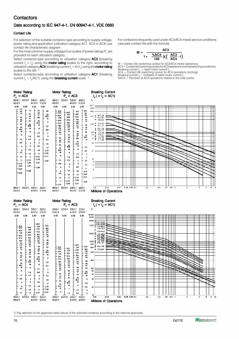
70 D677E
For contactors frequently used under AC3/AC4-mixed service conditionscalculate contact life with the formula:
M = Contact life (switching cycles) for AC3/AC4-mixed operationsAC3 = Contact life (switching cycles) for AC3 operations (normal switching conditions).Breaking current Ia = rated motor current In.AC4 = Contact life (switching cycles) for AC4 operations (inching).Breaking current Ia= multiples of rated motor current In.%AC4 = Percents of AC4-operations related to the total cycles.
Contact LifeContact LifeContact LifeContact LifeContact Life
For selection of the suitable contactor-type according to supply voltage,power rating and application (utilization category AC1, AC3 or AC4) usecontact life characteristic diagram.For the most common supply voltages four scales of power ratings Pn areprovided for each utilization category.Select contactor-type according to utilization category AC3 AC3 AC3 AC3 AC3 (breakingcurrent Ia = Ie) using the motor ratingmotor ratingmotor ratingmotor ratingmotor rating scales to the right, according toutilization category AC4 AC4 AC4 AC4 AC4 (breaking current Ia = 6 x Ie) using the motor ratingmotor ratingmotor ratingmotor ratingmotor ratingscales to the left. 1)
Select contactor-type according to utilization category AC1 AC1 AC1 AC1 AC1 (breakingcurrent Ia = Ie/AC1) using the breaking currentbreaking currentbreaking currentbreaking currentbreaking current scale. 1)
M =1+ -1x( )
Motor RatingMotor RatingMotor RatingMotor RatingMotor Rating Motor RatingMotor RatingMotor RatingMotor RatingMotor Rating Breaking CurrentBreaking CurrentBreaking CurrentBreaking CurrentBreaking CurrentPPPPPn n n n n = AC4 = AC4 = AC4 = AC4 = AC4 PPPPPnnnnn = AC3 = AC3 = AC3 = AC3 = AC3 IIIIIa a a a a ( = I( = I( = I( = I( = Ieeeee = AC1) = AC1) = AC1) = AC1) = AC1)
A
Millions of OperationsMillions of OperationsMillions of OperationsMillions of OperationsMillions of Operations
AC3
%AC4 AC3100 AC4
1) Pay attention to the approved rated values of the selected contactor according to the national approvals
ContactorsContactorsContactorsContactorsContactors
Data according to IEC 947-4-1, EN 60947-4-1, VDE 0660Data according to IEC 947-4-1, EN 60947-4-1, VDE 0660Data according to IEC 947-4-1, EN 60947-4-1, VDE 0660Data according to IEC 947-4-1, EN 60947-4-1, VDE 0660Data according to IEC 947-4-1, EN 60947-4-1, VDE 0660

D677E 71
ContactorsContactorsContactorsContactorsContactors
Utilization CategoriesUtilization CategoriesUtilization CategoriesUtilization CategoriesUtilization Categories
Type ofType ofType ofType ofType of Cate-Cate-Cate-Cate-Cate- Typical applicationsTypical applicationsTypical applicationsTypical applicationsTypical applications RatedRatedRatedRatedRated Test conditions for the number ofTest conditions for the number ofTest conditions for the number ofTest conditions for the number ofTest conditions for the number of Test conditions forTest conditions forTest conditions forTest conditions forTest conditions forcurrentcurrentcurrentcurrentcurrent gorygorygorygorygory operationaloperationaloperationaloperationaloperational on-load operating cycleson-load operating cycleson-load operating cycleson-load operating cycleson-load operating cycles making and breaking capacitiesmaking and breaking capacitiesmaking and breaking capacitiesmaking and breaking capacitiesmaking and breaking capacities
currentcurrentcurrentcurrentcurrent Make Break Make BreakI/Ie U/Ue cosϕ Ic/Ie Ur/Ue cosϕ I/Ie U/Ue cosϕ Ic/Ie Ur/Ue cosϕ
Alter- Non-inductive ornating AC1AC1AC1AC1AC1 slightly inductive loads all values 1 1 0,95 1 1 0,95 1,5 1,05 0,8 1,5 1,05 0,8Current resistance furnaces
Slip-ring motors:AC2AC2AC2AC2AC2 starting, switching off all values 2,5 1 0,65 2,5 1 0,65 4 1,05 0,65 4 1,05 0,65
Squirrel-cage motors: Ie≤ 17A 6 1 0,65 1 0,17 0,65 10 1,05 0,45 8 1,05 0,45AC3AC3AC3AC3AC3 starting, switching off 17A< Ie≤ 100A 6 1 0,35 1 0,17 0,35 10 1,05 0,45 8 1,05 0,45
motors during running Ie> 100A 6 1 0,35 1 0,17 0,35 10 1,05 0,35 8 1,05 0,35
Squirrel-cage motors: Ie≤ 17A 6 1 0,65 6 1 0,65 12 1,05 0,45 10 1,05 0,45AC4AC4AC4AC4AC4 starting, plugging, 17A< Ie≤ 100A 6 1 0,35 6 1 0,35 12 1,05 0,45 10 1,05 0,45
inching Ie> 100A 6 1 0,35 6 1 0,35 12 1,05 0,35 10 1,05 0,35
Switching of electricAC5aAC5aAC5aAC5aAC5a discharge lamp controls all values - - - - - - 3 1,05 0,45 3 1,05 0,45
Switching ofAC5bAC5bAC5bAC5bAC5b incandescent lamps all values - - - - - - 1,5 1,05 1) 4 1,05 1)
Switching ofAC6aAC6aAC6aAC6aAC6a transformers Ie≤ 100A - - - - - - 4,5 1,05 0,45 3,6 1,05 0,45
Ie> 100A - - - - - - 4,5 1,05 0,35 3,6 1,05 0,35
Switching ofAC6bAC6bAC6bAC6bAC6b capacitors - - - - - - - 2) 2)
Slightly inductive loadsAC7aAC7aAC7aAC7aAC7a in household appliances all values - - - - - - 1,5 1,05 0,8 1,5 1,05 0,8
and similar applications
Motor loadsAC7bAC7bAC7bAC7bAC7b for household applications Ie≤ 100A - - - - - - 8 1,05 0,45 6 1,05 0,45
Ie> 100A - - - - - - 8 1,05 0,35 6 1,05 0,35
Hermetic refrigerant compressorAC8aAC8aAC8aAC8aAC8a motor control with manual Ie≤ 100A - - - - - - 6 1,05 0,45 6 1,05 0,45
resetting of overload releases Ie> 100A - - - - - - 6 1,05 0,35 6 1,05 0,35
Hermetic refrigerant compressorAC8bAC8bAC8bAC8bAC8b motor control with automatic Ie≤ 100A - - - - - - 6 1,05 0,45 6 1,05 0,45
resetting of overload releases Ie> 100A - - - - - - 6 1,05 0,35 6 1,05 0,35
Control of resistive loads andAC12AC12AC12AC12AC12 solid state loads with all values - - - - - - 1 1 0,9 1 1 0.9
isolation by opto couplers
Control ofAC13AC13AC13AC13AC13 solid state loads with all values - - - - - - 10 1,1 0,65 1,1 1,1 0,65
transformer isolation
Control ofAC14AC14AC14AC14AC14 small electromagnetic loads - - - - - - - 6 1,1 0,7 6 1,1 0,7
(≤72VA)
Control ofAC15AC15AC15AC15AC15 electromagnetic load - 10 1 0,7 1 1 0,4 10 1,1 0,3 10 1,1 0,3
(>72VA)
Make L/R Break L/R Make L/R Break L/RI/Ie U/Ue [ms] Ic/Ie Ur/Ue [ms] I/Ie U/Ue [ms] Ic/Ie Ur/Ue [ms]
Direct Non-inductive orCurrent DC1DC1DC1DC1DC1 slightly inductive loads all values 1 1 1 1 1 1 1,5 1,05 1 1,5 1,05 1
resistance furnaces
Shunt-motors:DC3DC3DC3DC3DC3 starting, plugging, inching all values 2,5 1 2 2,5 1 2 4 1,05 2,5 4 1,05 2,5
dynamic braking of d.c. motors
Series-motors:DC5DC5DC5DC5DC5 starting, plugging, inching all values 2,5 1 7,5 2,5 1 7,5 4 1,05 15 4 1,05 15
dynamic braking of d.c. motors
Switching ofDC6DC6DC6DC6DC6 incandescent lamps all values - - - - - - 1,5 1,05 1) 4 1,05 1)
Control of resistive loads andDC12DC12DC12DC12DC12 solid state loads with all values - - - - - - 1 1 1 1 1 1
isolation by opto couplers
Control ofDC13DC13DC13DC13DC13 electromagnets all values 1 1 ≤300 1 1 ≤300 1,1 1,1 ≤300 1,1 1,1 ≤300
Control ofDC14DC14DC14DC14DC14 electromagnetic loads having all values - - - - - - 10 1,1 15 10 1,1 15
economy resistors in circuit
Ue Rated operational voltage, U Voltage before make, Ur Recovery voltage, Ie Rated operational current, I Current make, Ic Current broken
1) Test with incandescent lamps2) Test conditions according to standard
For easier choice of devices and in order to make the comparisonof different products simplier are utilization categories for contactorsand motor-starters according to IEC 947-4-1 and VDE 0660 Part 102, for
control circuit devices and switching elements according toIEC 947-5-1 and VDE 0660 Part 200 determind. The table offers differentutilization categories, typical applications and assorted test conditions.
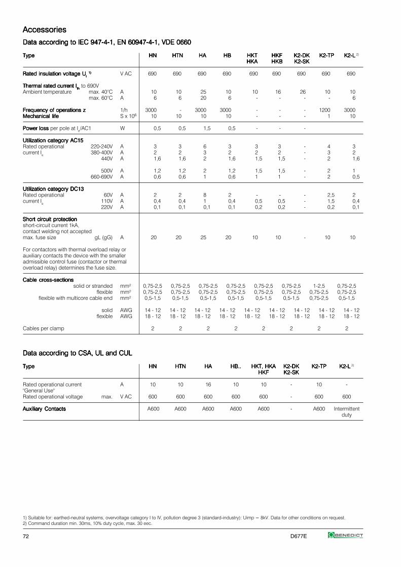
72 D677E
AccessoriesAccessoriesAccessoriesAccessoriesAccessories
Data according to IEC 947-4-1, EN 60947-4-1, VDE 0660Data according to IEC 947-4-1, EN 60947-4-1, VDE 0660Data according to IEC 947-4-1, EN 60947-4-1, VDE 0660Data according to IEC 947-4-1, EN 60947-4-1, VDE 0660Data according to IEC 947-4-1, EN 60947-4-1, VDE 0660
TypeTypeTypeTypeType HNHNHNHNHN HTNHTNHTNHTNHTN HAHAHAHAHA HBHBHBHBHB HKTHKTHKTHKTHKT HKFHKFHKFHKFHKF K2-DKK2-DKK2-DKK2-DKK2-DK K2-TPK2-TPK2-TPK2-TPK2-TP K2-LK2-LK2-LK2-LK2-L 2)
HKAHKAHKAHKAHKA HKBHKBHKBHKBHKB K2-SKK2-SKK2-SKK2-SKK2-SK
Rated insulation voltage URated insulation voltage URated insulation voltage URated insulation voltage URated insulation voltage Uiiiii
1)1)1)1)1) V AC 690 690 690 690 690 690 690 690 690
Thermal rated current IThermal rated current IThermal rated current IThermal rated current IThermal rated current Iththththth to 690V
Ambient temperature max. 40°C A 10 10 25 10 10 16 26 10 10max. 60°C A 6 6 20 6 - - - - 6
Frequency of operations zFrequency of operations zFrequency of operations zFrequency of operations zFrequency of operations z 1/h 3000 - 3000 3000 - - - 1200 3000Mechanical lifeMechanical lifeMechanical lifeMechanical lifeMechanical life S x 106 10 10 10 10 - - - 1 10
Power loss Power loss Power loss Power loss Power loss per pole at Ie/AC1 W 0,5 0,5 1,5 0,5 - - -
Utilization category AC15Utilization category AC15Utilization category AC15Utilization category AC15Utilization category AC15Rated operational 220-240V A 3 3 6 3 3 3 - 4 3current Ie 380-400V A 2 2 3 2 2 2 - 3 2
440V A 1,6 1,6 2 1,6 1,5 1,5 - 2 1,6
500V A 1,2 1,2 2 1,2 1,5 1,5 - 2 1660-690V A 0,6 0,6 1 0,6 1 1 - 2 0,5
Utilization category DC13Utilization category DC13Utilization category DC13Utilization category DC13Utilization category DC13Rated operational 60V A 2 2 8 2 - - - 2,5 2current Ie 110V A 0,4 0,4 1 0,4 0,5 0,5 - 1,5 0,4
220V A 0,1 0,1 0,1 0,1 0,2 0,2 - 0,2 0,1
Short circuit protectionShort circuit protectionShort circuit protectionShort circuit protectionShort circuit protectionshort-circuit current 1kA,contact welding not acceptedmax. fuse size gL (gG) A 20 20 25 20 10 10 - 10 10
For contactors with thermal overload relay orauxiliary contacts the device with the smalleradmissible control fuse (contactor or thermaloverload relay) determines the fuse size.
Cable cross-sectionsCable cross-sectionsCable cross-sectionsCable cross-sectionsCable cross-sectionssolid or stranded mm² 0,75-2,5 0,75-2,5 0,75-2,5 0,75-2,5 0,75-2,5 0,75-2,5 1-2,5 0,75-2,5
flexible mm² 0,75-2,5 0,75-2,5 0,75-2,5 0,75-2,5 0,75-2,5 0,75-2,5 0,75-2,5 0,75-2,5flexible with multicore cable end mm² 0,5-1,5 0,5-1,5 0,5-1,5 0,5-1,5 0,5-1,5 0,5-1,5 0,75-2,5 0,5-1,5
solid AWG 14 - 12 14 - 12 14 - 12 14 - 12 14 - 12 14 - 12 14 - 12 14 - 12 14 - 12flexible AWG 18 - 12 18 - 12 18 - 12 18 - 12 18 - 12 18 - 12 18 - 12 18 - 12 18 - 12
Cables per clamp 2 2 2 2 2 2 2 2
Data according to CSA, UL and CULData according to CSA, UL and CULData according to CSA, UL and CULData according to CSA, UL and CULData according to CSA, UL and CUL
TypeTypeTypeTypeType HNHNHNHNHN HTNHTNHTNHTNHTN HAHAHAHAHA HB..HB..HB..HB..HB.. HKT, HKAHKT, HKAHKT, HKAHKT, HKAHKT, HKA K2-DKK2-DKK2-DKK2-DKK2-DK K2-TPK2-TPK2-TPK2-TPK2-TP K2-LK2-LK2-LK2-LK2-L 2)
HKFHKFHKFHKFHKF K2-SKK2-SKK2-SKK2-SKK2-SK
Rated operational current A 10 10 16 10 10 - 10 -"General Use"Rated operational voltage max. V AC 600 600 600 600 600 - 600 600
Auxiliary ContactsAuxiliary ContactsAuxiliary ContactsAuxiliary ContactsAuxiliary Contacts A600 A600 A600 A600 A600 - A600 Intermittentduty
1) Suitable for: earthed-neutral systems, overvoltage category I to IV, pollution degree 3 (standard-industry): Uimp = 8kV. Data for other conditions on request.2) Command duration min. 30ms, 10% duty cycle, max. 30 eec.

D677E 73
Contactors and AccessoriesContactors and AccessoriesContactors and AccessoriesContactors and AccessoriesContactors and Accessories
Wiring diagramsWiring diagramsWiring diagramsWiring diagramsWiring diagrams
Auxiliary contact blocksAuxiliary contact blocksAuxiliary contact blocksAuxiliary contact blocksAuxiliary contact blocks Snap-on momentary contact blocksSnap-on momentary contact blocksSnap-on momentary contact blocksSnap-on momentary contact blocksSnap-on momentary contact blocks
HN10HN10HN10HN10HN10 HN01HN01HN01HN01HN01 HN10UHN10UHN10UHN10UHN10U HN01UHN01UHN01UHN01UHN01U HTN10HTN10HTN10HTN10HTN10 HTN01HTN01HTN01HTN01HTN01HA10HA10HA10HA10HA10 HA01HA01HA01HA01HA01
HKS11HKS11HKS11HKS11HKS11 HB11HB11HB11HB11HB11 HB02HB02HB02HB02HB02 HKT11HKT11HKT11HKT11HKT11 HB11, HB02:HKA11HKA11HKA11HKA11HKA11 Correct terminal marking
is given by mounting.
HKF22HKF22HKF22HKF22HKF22 HKT22HKT22HKT22HKT22HKT22
Indicator unitsIndicator unitsIndicator unitsIndicator unitsIndicator units
Electronic timerElectronic timerElectronic timerElectronic timerElectronic timer Coil current indicatorCoil current indicatorCoil current indicatorCoil current indicatorCoil current indicator Voltage indicatorVoltage indicatorVoltage indicatorVoltage indicatorVoltage indicator
K3-T180 240K3-T180 240K3-T180 240K3-T180 240K3-T180 240 K2-INGK2-INGK2-INGK2-INGK2-ING K2-UNK2-UNK2-UNK2-UNK2-UNK2-INRK2-INRK2-INRK2-INRK2-INR K2-UNRK2-UNRK2-UNRK2-UNRK2-UNR
red
red
LatchLatchLatchLatchLatch Fuse holderFuse holderFuse holderFuse holderFuse holder InterfaceInterfaceInterfaceInterfaceInterfacewith rectifier
K2-L..K2-L..K2-L..K2-L..K2-L.. K2-FK2-FK2-FK2-FK2-F K2-RF1K2-RF1K2-RF1K2-RF1K2-RF1 K2-IM K2-IM K2-IM K2-IM K2-IMK2-RF3K2-RF3K2-RF3K2-RF3K2-RF3
Regulation of switch position of aux. contakt block HKF22 for contactors K3-450 to K3-860Regulation of switch position of aux. contakt block HKF22 for contactors K3-450 to K3-860Regulation of switch position of aux. contakt block HKF22 for contactors K3-450 to K3-860Regulation of switch position of aux. contakt block HKF22 for contactors K3-450 to K3-860Regulation of switch position of aux. contakt block HKF22 for contactors K3-450 to K3-860
state of delivery NO/NC overlapped NO delayed
HKF22 NC NC NC
HKF22 NO NO NO
Contactor position:open
Standard position of regulation screw Regulation screw position (unscrew by 4 turns) Regulation screw position (screw by 4 turns)
red black Colours mentioned inwiring diagram referto the outgoingconnection wiresof the device.
18 16 14 12 10 8 6 4 2 0 18 16 14 12 10 8 6 4 2 0 18 16 14 12 10 8 6 4 2 0

74 D677E
ContactorsContactorsContactorsContactorsContactors
DimensionsDimensionsDimensionsDimensionsDimensions
AC operatedAC operatedAC operatedAC operatedAC operated DC operatedDC operatedDC operatedDC operatedDC operated
K3-10N..K3-10N..K3-10N..K3-10N..K3-10N.. KG3-10..KG3-10..KG3-10..KG3-10..KG3-10..K3-14N..K3-14N..K3-14N..K3-14N..K3-14N.. KG3-14..KG3-14..KG3-14..KG3-14..KG3-14..K3-18N..K3-18N..K3-18N..K3-18N..K3-18N.. KG3-18..KG3-18..KG3-18..KG3-18..KG3-18..K3-22N..K3-22N..K3-22N..K3-22N..K3-22N.. KG3-22..KG3-22..KG3-22..KG3-22..KG3-22..
K3-24..K3-24..K3-24..K3-24..K3-24.. KG3-24..KG3-24..KG3-24..KG3-24..KG3-24..K3-32..K3-32..K3-32..K3-32..K3-32.. KG3-32..KG3-32..KG3-32..KG3-32..KG3-32..K3-40..K3-40..K3-40..K3-40..K3-40.. KG3-40..KG3-40..KG3-40..KG3-40..KG3-40..
K3-50..K3-50..K3-50..K3-50..K3-50.. K3-50..=K3-50..=K3-50..=K3-50..=K3-50..=K3-62..K3-62..K3-62..K3-62..K3-62.. K3-62..=K3-62..=K3-62..=K3-62..=K3-62..=K3-74..K3-74..K3-74..K3-74..K3-74.. K3-74..=K3-74..=K3-74..=K3-74..=K3-74..=
AC and DC operatedAC and DC operatedAC and DC operatedAC and DC operatedAC and DC operated
K3-90..K3-90..K3-90..K3-90..K3-90..K3-115..K3-115..K3-115..K3-115..K3-115..
1)
1) Minimum side distance toconductive parts for coil voltage:500V Uimp=6kV 2mm660-690V Uimp=8kV 4,5mm

D677E 75
ContactorsContactorsContactorsContactorsContactors
DimensionsDimensionsDimensionsDimensionsDimensions
AC operated, DC operatedAC operated, DC operatedAC operated, DC operatedAC operated, DC operatedAC operated, DC operated
K3-151..K3-151..K3-151..K3-151..K3-151..K3-176..K3-176..K3-176..K3-176..K3-176..
HKA11HKA11HKA11HKA11HKA11 HKT..HKT..HKT..HKT..HKT..
K3-210..K3-210..K3-210..K3-210..K3-210..K3-260..K3-260..K3-260..K3-260..K3-260..K3-316..K3-316..K3-316..K3-316..K3-316..
HKA11HKA11HKA11HKA11HKA11 HKT..HKT..HKT..HKT..HKT..
K3-450..K3-450..K3-450..K3-450..K3-450..K3-550..K3-550..K3-550..K3-550..K3-550..
Typ A B C H N
K3-450 40 10,5 4 233 206K3-550 40 12,5 6 258 228

76 D677E
ContactorsContactorsContactorsContactorsContactors
DimensionsDimensionsDimensionsDimensionsDimensions
AC and DC operatedAC and DC operatedAC and DC operatedAC and DC operatedAC and DC operated
K3-700..K3-700..K3-700..K3-700..K3-700..K3-860..K3-860..K3-860..K3-860..K3-860..
Typ B H N
K3-700 13 310 277K3-860 15 361 325
K3-1000..K3-1000..K3-1000..K3-1000..K3-1000..K3-1200..K3-1200..K3-1200..K3-1200..K3-1200..
1) for K3-1200 in UL conformity application only
Capacitor switching contactors, AC operatedCapacitor switching contactors, AC operatedCapacitor switching contactors, AC operatedCapacitor switching contactors, AC operatedCapacitor switching contactors, AC operated
K3-18NK..K3-18NK..K3-18NK..K3-18NK..K3-18NK.. K3-24K..K3-24K..K3-24K..K3-24K..K3-24K..K3-32K..K3-32K..K3-32K..K3-32K..K3-32K..
K3-50K..K3-50K..K3-50K..K3-50K..K3-50K.. K3-90K..K3-90K..K3-90K..K3-90K..K3-90K..K3-62K..K3-62K..K3-62K..K3-62K..K3-62K.. K3-115K..K3-115K..K3-115K..K3-115K..K3-115K..K3-74K..K3-74K..K3-74K..K3-74K..K3-74K..

D677E 77
ContactorsContactorsContactorsContactorsContactors
DimensionsDimensionsDimensionsDimensionsDimensions
Contactors DC operatedContactors DC operatedContactors DC operatedContactors DC operatedContactors DC operated
K3-10N..=K3-10N..=K3-10N..=K3-10N..=K3-10N..= K3-24..=K3-24..=K3-24..=K3-24..=K3-24..=K3-14N..=K3-14N..=K3-14N..=K3-14N..=K3-14N..= K3-32..=K3-32..=K3-32..=K3-32..=K3-32..=K3-18N..=K3-18N..=K3-18N..=K3-18N..=K3-18N..= K3-40..=K3-40..=K3-40..=K3-40..=K3-40..=K3-22N..=K3-22N..=K3-22N..=K3-22N..=K3-22N..=
Contactors 4-pole, AC operatedContactors 4-pole, AC operatedContactors 4-pole, AC operatedContactors 4-pole, AC operatedContactors 4-pole, AC operated
K3-10NA00-40K3-10NA00-40K3-10NA00-40K3-10NA00-40K3-10NA00-40 K2-23A00-40K2-23A00-40K2-23A00-40K2-23A00-40K2-23A00-40K3-14NA00-40K3-14NA00-40K3-14NA00-40K3-14NA00-40K3-14NA00-40 K2-30A00-40K2-30A00-40K2-30A00-40K2-30A00-40K2-30A00-40K3-18NA00-40K3-18NA00-40K3-18NA00-40K3-18NA00-40K3-18NA00-40 K2-37A00-40K2-37A00-40K2-37A00-40K2-37A00-40K2-37A00-40K3-22NA00-40K3-22NA00-40K3-22NA00-40K3-22NA00-40K3-22NA00-40
Contactors 4-pole, AC operatedContactors 4-pole, AC operatedContactors 4-pole, AC operatedContactors 4-pole, AC operatedContactors 4-pole, AC operated
K2-45A00-40K2-45A00-40K2-45A00-40K2-45A00-40K2-45A00-40 K3-116A00-40K3-116A00-40K3-116A00-40K3-116A00-40K3-116A00-40K2-60A00-40K2-60A00-40K2-60A00-40K2-60A00-40K2-60A00-40 K3-151A00-40K3-151A00-40K3-151A00-40K3-151A00-40K3-151A00-40
K3-176A00-40K3-176A00-40K3-176A00-40K3-176A00-40K3-176A00-40
Contactors 4-pole, AC and DC operatedContactors 4-pole, AC and DC operatedContactors 4-pole, AC and DC operatedContactors 4-pole, AC and DC operatedContactors 4-pole, AC and DC operated
K3-210A00-40K3-210A00-40K3-210A00-40K3-210A00-40K3-210A00-40K3-260A00-40K3-260A00-40K3-260A00-40K3-260A00-40K3-260A00-40K3-316A00-40K3-316A00-40K3-316A00-40K3-316A00-40K3-316A00-40

78 D677E
ContactorsContactorsContactorsContactorsContactors
Dimensions AccessoriesDimensions AccessoriesDimensions AccessoriesDimensions AccessoriesDimensions Accessories
Aux. cont. blocks, terminal blocksAux. cont. blocks, terminal blocksAux. cont. blocks, terminal blocksAux. cont. blocks, terminal blocksAux. cont. blocks, terminal blocks Snap-on momentary cont. blocksSnap-on momentary cont. blocksSnap-on momentary cont. blocksSnap-on momentary cont. blocksSnap-on momentary cont. blocks Auxiliary contact blocksAuxiliary contact blocksAuxiliary contact blocksAuxiliary contact blocksAuxiliary contact blocks
HN10, HN01HN10, HN01HN10, HN01HN10, HN01HN10, HN01 K2-SK, K2-DKK2-SK, K2-DKK2-SK, K2-DKK2-SK, K2-DKK2-SK, K2-DK HTN10, HTN01HTN10, HTN01HTN10, HTN01HTN10, HTN01HTN10, HTN01 HA10, HA01HA10, HA01HA10, HA01HA10, HA01HA10, HA01 HB11, HB02HB11, HB02HB11, HB02HB11, HB02HB11, HB02
4. pole for contactors K3-200 to K3-12004. pole for contactors K3-200 to K3-12004. pole for contactors K3-200 to K3-12004. pole for contactors K3-200 to K3-12004. pole for contactors K3-200 to K3-1200
TypeTypeTypeTypeType A B C D E F G H
NP175NP175NP175NP175NP175 223 148 26 52 98 5 122 M8NP350NP350NP350NP350NP350 223 148 26 52 98 5 122 M8
NP325NP325NP325NP325NP325 262 148 26 55 116 5 122 M10NP500NP500NP500NP500NP500 294 220 53 72 138 5 152 M12NP760NP760NP760NP760NP760 294 220 53 72 138 5 152 M12
NP501NP501NP501NP501NP501 348 220 53 73 145 5 152 M12NP1000NP1000NP1000NP1000NP1000 348 220 53 73 145 8 152 M12
NP1001NP1001NP1001NP1001NP1001 410 220 53 110 157 8 152 M12
Electronic timerElectronic timerElectronic timerElectronic timerElectronic timer Electronic timer on-delayElectronic timer on-delayElectronic timer on-delayElectronic timer on-delayElectronic timer on-delay Electronic timer off-delayElectronic timer off-delayElectronic timer off-delayElectronic timer off-delayElectronic timer off-delay
K3-T180 240K3-T180 240K3-T180 240K3-T180 240K3-T180 240 K2-TE..K2-TE..K2-TE..K2-TE..K2-TE.. K2-TA..K2-TA..K2-TA..K2-TA..K2-TA..
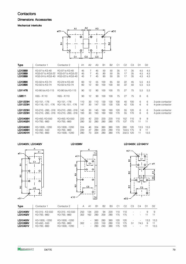
D677E 79
ContactorsContactorsContactorsContactorsContactors
Dimensions AccessoriesDimensions AccessoriesDimensions AccessoriesDimensions AccessoriesDimensions Accessories
Mechanical interlocksMechanical interlocksMechanical interlocksMechanical interlocksMechanical interlocks
TypeTypeTypeTypeType Contactor 1 Contactor 2 A1 A2 A3 B1 B2 C1 C2 C3 D1 D2
LG10889LG10889LG10889LG10889LG10889 K3-07 to K3-40 K3-07 to K3-40 45 7 45 50 50 35 17 35 4,5 4,5LG10889LG10889LG10889LG10889LG10889 KG3-07 to KG3-22 KG3-07 to KG3-22 45 7 45 80 50 35 17 35 4,5 4,5LG10889LG10889LG10889LG10889LG10889 KG3-24 to KG3-40 KG3-22 to KG3-40 45 7 45 80 50 35 17 35 4,5 4,5
LG10890LG10890LG10890LG10890LG10890 K3-50 to K3-74 K3-24 to K3-40 60 12 55 100 65 50 22 45 5,5 4,5LG10890LG10890LG10890LG10890LG10890 K3-50 to K3-74 K3-50 to K3-74 60 12 60 100 100 50 22 50 5,5 5,5
LG11478LG11478LG11478LG11478LG11478 K3-90 bis K3-115 K3-90 bis K3-115 90 12 90 100 100 75 27 75 5,5 5,5
LG8511LG8511LG8511LG8511LG8511 K65 - K110 K65 - K110 90 12 90 100 100 75 27 75 6 6
LG11223HLG11223HLG11223HLG11223HLG11223H K3-151, -176 K3-151, -176 110 30 110 130 130 100 40 100 6 6 3-pole contactorLG11223HLG11223HLG11223HLG11223HLG11223H K3-116,-151, -176 K3-116,-151, -176 147 30 147 130 130 135 42 135 6 6 4-pole contactor
LG11223HLG11223HLG11223HLG11223HLG11223H K3-210, -260, -316 K3-210, -260, -316 145 30 145 160 160 120 55 120 6 6 3-pole contactorLG11223HLG11223HLG11223HLG11223HLG11223H K3-210, -260, -316 K3-210, -260, -316 193 30 193 160 160 170 55 170 6 6 4-pole contactor
LG10400HLG10400HLG10400HLG10400HLG10400H K3-450, K3-550 K3-450, K3-550 220 42 220 220 220 110 152 110 9 9LG10402HLG10402HLG10402HLG10402HLG10402H K3-700, -860 K3-700, -860 280 32 280 280 280 175 137 175 11 11
LG10403HLG10403HLG10403HLG10403HLG10403H K3-1000, -1200 K3-1000, -1200 334 46 334 380 380 120 260 120 13,5 13,5LG10399HLG10399HLG10399HLG10399HLG10399H K3-450, -550 K3-700, -860 220 37 280 220 280 110 144,5 175 9 11LG10401HLG10401HLG10401HLG10401HLG10401H K3-700, -860 K3-1000, -1200 280 73 334 280 380 175 232,5 120 11 13,5
LG10400V, LG10402VLG10400V, LG10402VLG10400V, LG10402VLG10400V, LG10402VLG10400V, LG10402V LG10399VLG10399VLG10399VLG10399VLG10399V LG10403V, LG10401VLG10403V, LG10401VLG10403V, LG10401VLG10403V, LG10401VLG10403V, LG10401V
TypeTypeTypeTypeType Contactor 1 Contactor 2 A A1 B1 B2 B3 C1 C2 C3 C4 D1 D2
LG10400VLG10400VLG10400VLG10400VLG10400V K3-315 - K3-550 K3-315 - K3-550 250 134 220 94 220 110 110 - - 9 9LG10402VLG10402VLG10402VLG10402VLG10402V K3-700, -860 K3-700, -860 302 162 280 200 280 175 175 - - 11 11
LG10403VLG10403VLG10403VLG10403VLG10403V K3-1000, -1200 K3-1000, -1200 - - 380 280 380 120 120 - - 13,5 13,5LG10399VLG10399VLG10399VLG10399VLG10399V K3-450, -550 K3-700, -860 302 - 220 150 280 110 175 51 74,5 9 11LG10401VLG10401VLG10401VLG10401VLG10401V K3-700, -860 K3-1000, -1200 - - 280 240 380 175 120 - - 11 13,5

80 D677E
ContactorsContactorsContactorsContactorsContactors
Dimensions AccessoriesDimensions AccessoriesDimensions AccessoriesDimensions AccessoriesDimensions Accessories
LatchLatchLatchLatchLatch
K2-L..K2-L..K2-L..K2-L..K2-L..
Contactors with additional terminalsContactors with additional terminalsContactors with additional terminalsContactors with additional terminalsContactors with additional terminals
LG9339NLG9339NLG9339NLG9339NLG9339N (2 x 3 pieces)for K3-10N. to K3-22N.
Indicator unitsIndicator unitsIndicator unitsIndicator unitsIndicator units Fuse holderFuse holderFuse holderFuse holderFuse holder Fuse holder with rectifierFuse holder with rectifierFuse holder with rectifierFuse holder with rectifierFuse holder with rectifier
K2-ING, K2-INRK2-ING, K2-INRK2-ING, K2-INRK2-ING, K2-INRK2-ING, K2-INR K2-RFK2-RFK2-RFK2-RFK2-RF K2-RF1K2-RF1K2-RF1K2-RF1K2-RF1K2-UN, K2-UNRK2-UN, K2-UNRK2-UN, K2-UNRK2-UN, K2-UNRK2-UN, K2-UNR K2-RF3K2-RF3K2-RF3K2-RF3K2-RF3
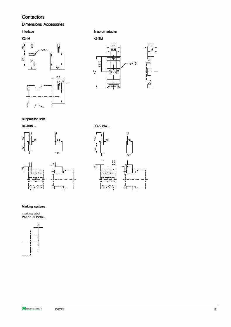
D677E 81
ContactorsContactorsContactorsContactorsContactors
Dimensions AccessoriesDimensions AccessoriesDimensions AccessoriesDimensions AccessoriesDimensions Accessories
InterfaceInterfaceInterfaceInterfaceInterface Snap-on adapterSnap-on adapterSnap-on adapterSnap-on adapterSnap-on adapter
K2-IMK2-IMK2-IMK2-IMK2-IM K2-SMK2-SMK2-SMK2-SMK2-SM
Suppressor unitsSuppressor unitsSuppressor unitsSuppressor unitsSuppressor units
RC-K3N ..RC-K3N ..RC-K3N ..RC-K3N ..RC-K3N .. RC-K3NW ..RC-K3NW ..RC-K3NW ..RC-K3NW ..RC-K3NW ..
Marking systemsMarking systemsMarking systemsMarking systemsMarking systems
marking labelP487-1 P487-1 P487-1 P487-1 P487-1 or P245-.P245-.P245-.P245-.P245-.

82 D677E
ContactorsContactorsContactorsContactorsContactors
Position of terminalsPosition of terminalsPosition of terminalsPosition of terminalsPosition of terminals
K3-10ND10K3-10ND10K3-10ND10K3-10ND10K3-10ND10 K3-10ND01K3-10ND01K3-10ND01K3-10ND01K3-10ND01 K3-24A00, K3-24K00K3-24A00, K3-24K00K3-24A00, K3-24K00K3-24A00, K3-24K00K3-24A00, K3-24K00 K3-50A00, K3-50K00K3-50A00, K3-50K00K3-50A00, K3-50K00K3-50A00, K3-50K00K3-50A00, K3-50K00 K3-10NA00-40K3-10NA00-40K3-10NA00-40K3-10NA00-40K3-10NA00-40 K85A22K85A22K85A22K85A22K85A22K3-14ND10K3-14ND10K3-14ND10K3-14ND10K3-14ND10 K3-14ND01K3-14ND01K3-14ND01K3-14ND01K3-14ND01 K3-32A00, K3-32K00K3-32A00, K3-32K00K3-32A00, K3-32K00K3-32A00, K3-32K00K3-32A00, K3-32K00 K3-62A00, K3-62K00K3-62A00, K3-62K00K3-62A00, K3-62K00K3-62A00, K3-62K00K3-62A00, K3-62K00 K3-14NA00-40K3-14NA00-40K3-14NA00-40K3-14NA00-40K3-14NA00-40 K110A22K110A22K110A22K110A22K110A22K3-18ND10K3-18ND10K3-18ND10K3-18ND10K3-18ND10 K3-18ND01K3-18ND01K3-18ND01K3-18ND01K3-18ND01 K3-40A00K3-40A00K3-40A00K3-40A00K3-40A00 K3-74A00, K3-74K00K3-74A00, K3-74K00K3-74A00, K3-74K00K3-74A00, K3-74K00K3-74A00, K3-74K00 K3-18NA00-40K3-18NA00-40K3-18NA00-40K3-18NA00-40K3-18NA00-40K3-22ND10K3-22ND10K3-22ND10K3-22ND10K3-22ND10 K3-22ND01K3-22ND01K3-22ND01K3-22ND01K3-22ND01 K3-22NA00-40K3-22NA00-40K3-22NA00-40K3-22NA00-40K3-22NA00-40K3-18NK10K3-18NK10K3-18NK10K3-18NK10K3-18NK10 K3-18NK01K3-18NK01K3-18NK01K3-18NK01K3-18NK01 K2-23A00-40 K2-23A00-40 K2-23A00-40 K2-23A00-40 K2-23A00-40 bis
K2-60A00-40K2-60A00-40K2-60A00-40K2-60A00-40K2-60A00-40
K3-116A00-40K3-116A00-40K3-116A00-40K3-116A00-40K3-116A00-40K3-90A00K3-90A00K3-90A00K3-90A00K3-90A00 K3-151A00K3-151A00K3-151A00K3-151A00K3-151A00 K3-151A00-40K3-151A00-40K3-151A00-40K3-151A00-40K3-151A00-40 K3-450A22K3-450A22K3-450A22K3-450A22K3-450A22 K3-1000A12K3-1000A12K3-1000A12K3-1000A12K3-1000A12K3-115A00K3-115A00K3-115A00K3-115A00K3-115A00 K3-176A00K3-176A00K3-176A00K3-176A00K3-176A00 K3-176A00-40K3-176A00-40K3-176A00-40K3-176A00-40K3-176A00-40 K3-550A22K3-550A22K3-550A22K3-550A22K3-550A22 K3-1200A12K3-1200A12K3-1200A12K3-1200A12K3-1200A12
K3-210A00K3-210A00K3-210A00K3-210A00K3-210A00 K3-210A00-40K3-210A00-40K3-210A00-40K3-210A00-40K3-210A00-40 K3-700A22K3-700A22K3-700A22K3-700A22K3-700A22K3-260A00K3-260A00K3-260A00K3-260A00K3-260A00 K3-260A00-40K3-260A00-40K3-260A00-40K3-260A00-40K3-260A00-40 K3-860A22K3-860A22K3-860A22K3-860A22K3-860A22K3-316A00K3-316A00K3-316A00K3-316A00K3-316A00 K3-316A00-40K3-316A00-40K3-316A00-40K3-316A00-40K3-316A00-40
KG3-10A10KG3-10A10KG3-10A10KG3-10A10KG3-10A10 KG3-10A01KG3-10A01KG3-10A01KG3-10A01KG3-10A01 KG3-10A00-40KG3-10A00-40KG3-10A00-40KG3-10A00-40KG3-10A00-40 KG3-24A00KG3-24A00KG3-24A00KG3-24A00KG3-24A00KG3-14A10KG3-14A10KG3-14A10KG3-14A10KG3-14A10 KG3-14A01KG3-14A01KG3-14A01KG3-14A01KG3-14A01 KG3-14A00-40KG3-14A00-40KG3-14A00-40KG3-14A00-40KG3-14A00-40 KG3-32A00KG3-32A00KG3-32A00KG3-32A00KG3-32A00KG3-18A10KG3-18A10KG3-18A10KG3-18A10KG3-18A10 KG3-18A01KG3-18A01KG3-18A01KG3-18A01KG3-18A01 KG3-18A00-40KG3-18A00-40KG3-18A00-40KG3-18A00-40KG3-18A00-40 KG3-40A00KG3-40A00KG3-40A00KG3-40A00KG3-40A00KG3-22A10KG3-22A10KG3-22A10KG3-22A10KG3-22A10 KG3-22A01KG3-22A01KG3-22A01KG3-22A01KG3-22A01 KG3-22A00-40KG3-22A00-40KG3-22A00-40KG3-22A00-40KG3-22A00-40
K3-10ND10=K3-10ND10=K3-10ND10=K3-10ND10=K3-10ND10= K3-10ND01=K3-10ND01=K3-10ND01=K3-10ND01=K3-10ND01= K3-24A00=K3-24A00=K3-24A00=K3-24A00=K3-24A00= K3-50A00=K3-50A00=K3-50A00=K3-50A00=K3-50A00= K85A21=K85A21=K85A21=K85A21=K85A21= K3-1000A12=K3-1000A12=K3-1000A12=K3-1000A12=K3-1000A12=K3-14ND10=K3-14ND10=K3-14ND10=K3-14ND10=K3-14ND10= K3-14ND01=K3-14ND01=K3-14ND01=K3-14ND01=K3-14ND01= K3-32A00=K3-32A00=K3-32A00=K3-32A00=K3-32A00= K3-62A00=K3-62A00=K3-62A00=K3-62A00=K3-62A00= K110A21=K110A21=K110A21=K110A21=K110A21= K3-1200A12=K3-1200A12=K3-1200A12=K3-1200A12=K3-1200A12=K3-18ND10=K3-18ND10=K3-18ND10=K3-18ND10=K3-18ND10= K3-18ND01=K3-18ND01=K3-18ND01=K3-18ND01=K3-18ND01= K3-40A00=K3-40A00=K3-40A00=K3-40A00=K3-40A00= K3-74A00=K3-74A00=K3-74A00=K3-74A00=K3-74A00=K3-22ND10=K3-22ND10=K3-22ND10=K3-22ND10=K3-22ND10= K3-22ND01=K3-22ND01=K3-22ND01=K3-22ND01=K3-22ND01=
1) Type-suffux "EUR" with additional coil terminalOrdering example: K3-10A10EUR 230

D677E 83
Motor StartersMotor StartersMotor StartersMotor StartersMotor Starters
Star-Delta Starters Open Type 84
Star-Delta Starters Enclosed 86Enclosure for Star-Delta Starters 86
Accessories 87
Reversing Contactors 88
Pole Changing Starters 90
Technical Data 92
Wiring Diagrams 95
Dimensions 99

84 D677E
Star-Delta Starters Open TypeStar-Delta Starters Open TypeStar-Delta Starters Open TypeStar-Delta Starters Open TypeStar-Delta Starters Open Type AC Operated
RatingsRatingsRatingsRatingsRatings Rated order separatelyorder separatelyorder separatelyorder separatelyorder separately TypeTypeTypeTypeType Coil voltage 1)
AC3 Current 230230230230230 220-240V 50Hz380V380V380V380V380V 400400400400400 380-415V 50Hz400V400V400V400V400V 660V AC3 Overload Relay ⏐⏐⏐⏐⏐415V415V415V415V415V 500V 690V 400V ⏐⏐⏐⏐⏐ Pack WeightkWkWkWkWkW kW kW A Type pcs. kg/pc.
7,57,57,57,57,5 7,5 11 16 U3/32 K3NY15 . . .K3NY15 . . .K3NY15 . . .K3NY15 . . .K3NY15 . . . 1 0,9U12/16E K3
1515151515 18,5 15 30 K3NY26 . . .K3NY26 . . .K3NY26 . . .K3NY26 . . .K3NY26 . . . 1 0,9
2222222222 30 22 45 U3/42 K3Y40 . . .K3Y40 . . .K3Y40 . . .K3Y40 . . .K3Y40 . . . 1 1,4
3030303030 37 30 60 K3Y52 . . .K3Y52 . . .K3Y52 . . .K3Y52 . . .K3Y52 . . . 1 1,8
4545454545 55 45 85 U3/74 K3Y80 . . .K3Y80 . . .K3Y80 . . .K3Y80 . . .K3Y80 . . . 1 3,5
5555555555 75 55 109 K3Y100 . . .K3Y100 . . .K3Y100 . . .K3Y100 . . .K3Y100 . . . 1 3,7
7575757575 90 90 150 U85 K3Y140 . . .K3Y140 . . .K3Y140 . . .K3Y140 . . .K3Y140 . . . 1 6,6
110110110110110 132 110 205 K3Y200 . . .K3Y200 . . .K3Y200 . . .K3Y200 . . .K3Y200 . . . 1 7
132132132132132 160 160 240 U180 K3Y240 . . .K3Y240 . . .K3Y240 . . .K3Y240 . . .K3Y240 . . . 1 15
160160160160160 180 180 300 K3Y300 . . .K3Y300 . . .K3Y300 . . .K3Y300 . . .K3Y300 . . . 1 15
Star-delta starters are wired to accept thermal overload relay. The thermal overload relay has to be ordered separately.For full load current setting use the YD-dial of thermal overload relay.
Ordering Example:Ordering Example:Ordering Example:Ordering Example:Ordering Example: Star-Delta Starter, open type, rated AC3 at 400V 205Arated control voltage 230V 50Hz - Order Type: K3Y200 230 + U85 120Order Type: K3Y200 230 + U85 120Order Type: K3Y200 230 + U85 120Order Type: K3Y200 230 + U85 120Order Type: K3Y200 230 + U85 120
Thermal Overload RelaysThermal Overload RelaysThermal Overload RelaysThermal Overload RelaysThermal Overload Relays
Rated Motor CurrentRated Motor CurrentRated Motor CurrentRated Motor CurrentRated Motor Current TypeTypeTypeTypeType Pack WeightA pcs. kg/pc. Wiring Diagram
For Star-Delta Starters K3NY15.. to K3Y40..
7 - 10,5 U12/16E 6 K3U12/16E 6 K3U12/16E 6 K3U12/16E 6 K3U12/16E 6 K3 1 0,1010,5 - 15,5 U12/16E 9 K3U12/16E 9 K3U12/16E 9 K3U12/16E 9 K3U12/16E 9 K3 1 0,1014 - 19 U12/16E 11 K3U12/16E 11 K3U12/16E 11 K3U12/16E 11 K3U12/16E 11 K3 1 0,10
18 - 24 U12/16E 14 K3U12/16E 14 K3U12/16E 14 K3U12/16E 14 K3U12/16E 14 K3 1 0,1023 - 31 U12/16E 18 K3U12/16E 18 K3U12/16E 18 K3U12/16E 18 K3U12/16E 18 K3 1 0,10
For Star-Delta Starters K3NY15.. to K3Y52..
7 - 10,5 U3/32 6U3/32 6U3/32 6U3/32 6U3/32 6 1 0,1410,5 - 15,5 U3/32 9U3/32 9U3/32 9U3/32 9U3/32 9 1 0,1414 - 19 U3/32 11U3/32 11U3/32 11U3/32 11U3/32 11 1 0,14
18 - 24 U3/32 14U3/32 14U3/32 14U3/32 14U3/32 14 1 0,1423 - 31 U3/32 18U3/32 18U3/32 18U3/32 18U3/32 18 1 0,1430 - 41 U3/32 24U3/32 24U3/32 24U3/32 24U3/32 24 1 0,14
40 - 55 U3/32 32U3/32 32U3/32 32U3/32 32U3/32 32 1 0,14
For Star-Delta Starters K3Y40.., K3Y52..
24 - 35 U3/42 20U3/42 20U3/42 20U3/42 20U3/42 20 1 0,3035 - 48 U3/42 28U3/42 28U3/42 28U3/42 28U3/42 28 1 0,3048 - 73 U3/42 42U3/42 42U3/42 42U3/42 42U3/42 42 1 0,30
1) Coil voltage range and other coil voltages see page 82
manual andauto reset
manual andauto reset
manual eset
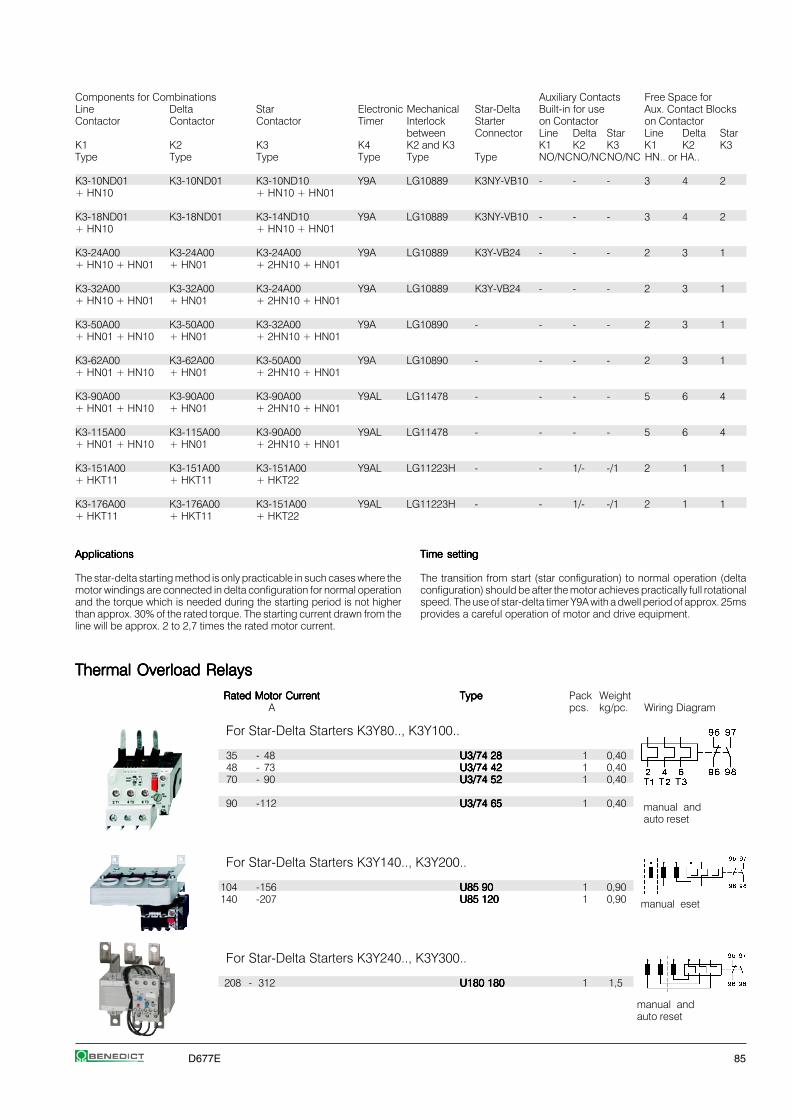
D677E 85
Components for Combinations Auxiliary Contacts Free Space forLine Delta Star Electronic Mechanical Star-Delta Built-in for use Aux. Contact BlocksContactor Contactor Contactor Timer Interlock Starter on Contactor on Contactor
between Connector Line Delta Star Line Delta StarK1 K2 K3 K4 K2 and K3 K1 K2 K3 K1 K2 K3Type Type Type Type Type Type NO/NCNO/NCNO/NC HN.. or HA..
K3-10ND01 K3-10ND01 K3-10ND10 Y9A LG10889 K3NY-VB10 - - - 3 4 2+ HN10 + HN10 + HN01
K3-18ND01 K3-18ND01 K3-14ND10 Y9A LG10889 K3NY-VB10 - - - 3 4 2+ HN10 + HN10 + HN01
K3-24A00 K3-24A00 K3-24A00 Y9A LG10889 K3Y-VB24 - - - 2 3 1+ HN10 + HN01 + HN01 + 2HN10 + HN01
K3-32A00 K3-32A00 K3-24A00 Y9A LG10889 K3Y-VB24 - - - 2 3 1+ HN10 + HN01 + HN01 + 2HN10 + HN01
K3-50A00 K3-50A00 K3-32A00 Y9A LG10890 - - - - 2 3 1+ HN01 + HN10 + HN01 + 2HN10 + HN01
K3-62A00 K3-62A00 K3-50A00 Y9A LG10890 - - - - 2 3 1+ HN01 + HN10 + HN01 + 2HN10 + HN01
K3-90A00 K3-90A00 K3-90A00 Y9AL LG11478 - - - - 5 6 4+ HN01 + HN10 + HN01 + 2HN10 + HN01
K3-115A00 K3-115A00 K3-90A00 Y9AL LG11478 - - - - 5 6 4+ HN01 + HN10 + HN01 + 2HN10 + HN01
K3-151A00 K3-151A00 K3-151A00 Y9AL LG11223H - - 1/- -/1 2 1 1+ HKT11 + HKT11 + HKT22
K3-176A00 K3-176A00 K3-151A00 Y9AL LG11223H - - 1/- -/1 2 1 1+ HKT11 + HKT11 + HKT22
Thermal Overload RelaysThermal Overload RelaysThermal Overload RelaysThermal Overload RelaysThermal Overload Relays
Rated Motor CurrentRated Motor CurrentRated Motor CurrentRated Motor CurrentRated Motor Current TypeTypeTypeTypeType Pack WeightA pcs. kg/pc. Wiring Diagram
For Star-Delta Starters K3Y80.., K3Y100..
35 - 48 U3/74 28U3/74 28U3/74 28U3/74 28U3/74 28 1 0,4048 - 73 U3/74 42U3/74 42U3/74 42U3/74 42U3/74 42 1 0,4070 - 90 U3/74 52U3/74 52U3/74 52U3/74 52U3/74 52 1 0,40
90 -112 U3/74 65U3/74 65U3/74 65U3/74 65U3/74 65 1 0,40
For Star-Delta Starters K3Y140.., K3Y200..
104 -156 U85 90U85 90U85 90U85 90U85 90 1 0,90140 -207 U85 120U85 120U85 120U85 120U85 120 1 0,90
For Star-Delta Starters K3Y240.., K3Y300..
208 - 312 U180 180U180 180U180 180U180 180U180 180 1 1,5
ApplicationsApplicationsApplicationsApplicationsApplications
The star-delta starting method is only practicable in such cases where themotor windings are connected in delta configuration for normal operationand the torque which is needed during the starting period is not higherthan approx. 30% of the rated torque. The starting current drawn from theline will be approx. 2 to 2,7 times the rated motor current.
Time settingTime settingTime settingTime settingTime setting
The transition from start (star configuration) to normal operation (deltaconfiguration) should be after the motor achieves practically full rotationalspeed. The use of star-delta timer Y9A with a dwell period of approx. 25msprovides a careful operation of motor and drive equipment.
manual andauto reset
manual eset
manual andauto reset
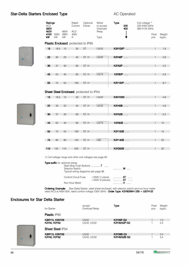
86 D677E
Star-Delta Starters Enclosed TypeStar-Delta Starters Enclosed TypeStar-Delta Starters Enclosed TypeStar-Delta Starters Enclosed TypeStar-Delta Starters Enclosed Type AC Operated
RatingsRatingsRatingsRatingsRatings Rated Optional Wired TypeTypeTypeTypeType Coil voltage 1)
AC3 Current Extras to accept 230230230230230 220-240V 50Hz380V380V380V380V380V Overload 400400400400400 380-415V 50Hz400V400V400V400V400V 660V AC3 Relay ⏐⏐⏐⏐⏐415V415V415V415V415V 500V 690V 400V ⏐⏐⏐⏐⏐ Pack WeightkWkWkWkWkW kW kW A Type pcs. kg/pc.
Plastic EnclosedPlastic EnclosedPlastic EnclosedPlastic EnclosedPlastic Enclosed, protected to IP65
1515151515 18,5 15 30 ST U3/32 K3NY26P . . .K3NY26P . . .K3NY26P . . .K3NY26P . . .K3NY26P . . . 1 1,8
2222222222 30 22 45 ST, H U3/42 K3Y40P . . .K3Y40P . . .K3Y40P . . .K3Y40P . . .K3Y40P . . . 1 3,8
3030303030 37 30 60 ST, H K3Y52P . . .K3Y52P . . .K3Y52P . . .K3Y52P . . .K3Y52P . . . 1 4,2
4545454545 55 45 85 ST, H U3/74 K3Y80P . . .K3Y80P . . .K3Y80P . . .K3Y80P . . .K3Y80P . . . 1 5,9
5555555555 75 55 109 ST, H K3Y100P . . .K3Y100P . . .K3Y100P . . .K3Y100P . . .K3Y100P . . . 1 8,7
Sheet Steel EnclosedSheet Steel EnclosedSheet Steel EnclosedSheet Steel EnclosedSheet Steel Enclosed, protected to IP54
1515151515 18,5 15 30 ST, H U3/32 K3NY26B . . .K3NY26B . . .K3NY26B . . .K3NY26B . . .K3NY26B . . . 1 4,8
2222222222 30 22 45 ST, H U3/42 K3Y40B . . .K3Y40B . . .K3Y40B . . .K3Y40B . . .K3Y40B . . . 1 4,8
3030303030 37 30 60 ST, H K3Y52B . . .K3Y52B . . .K3Y52B . . .K3Y52B . . .K3Y52B . . . 1 5,2
4545454545 55 45 85 ST, H U3/74 K3Y80B . . .K3Y80B . . .K3Y80B . . .K3Y80B . . .K3Y80B . . . 1 15
5555555555 75 55 109 ST, H K3Y100B . . .K3Y100B . . .K3Y100B . . .K3Y100B . . .K3Y100B . . . 1 15
7575757575 90 90 150 ST, H U85 K3Y140B . . .K3Y140B . . .K3Y140B . . .K3Y140B . . .K3Y140B . . . 1 22
110110110110110 132 110 205 ST, H K3Y200B . . .K3Y200B . . .K3Y200B . . .K3Y200B . . .K3Y200B . . . 1 22
1) Coil voltage range and other coil voltages see page 82
Type-suffix Type-suffix Type-suffix Type-suffix Type-suffix for optional extrasStart-Stop Push Buttons . . . . . . .T . . .. . . . . . .T . . .. . . . . . .T . . .. . . . . . .T . . .. . . . . . .T . . .Selector Switch . . . . . . .W . . .. . . . . . .W . . .. . . . . . .W . . .. . . . . . .W . . .. . . . . . .W . . .Typical wiring diagrams see page 86
Control Circuit Fuse <250V (1 piece) . . . . . . .ST . . .. . . . . . .ST . . .. . . . . . .ST . . .. . . . . . .ST . . .. . . . . . .ST . . .>250V (2 pieces) . . . . . . .ST . . .. . . . . . .ST . . .. . . . . . .ST . . .. . . . . . .ST . . .. . . . . . .ST . . .
Run Hour Meter . . . . . . .H . . .. . . . . . .H . . .. . . . . . .H . . .. . . . . . .H . . .. . . . . . .H . . .
Ordering Example:Ordering Example:Ordering Example:Ordering Example:Ordering Example: Star-Delta Starter, steel sheet enclosed, with selector switch and run hour meterrated AC3 at 400V 82A, rated control voltage 230V 50Hz - Order Type: K3Y80BWH 230 + U3/74 52Order Type: K3Y80BWH 230 + U3/74 52Order Type: K3Y80BWH 230 + U3/74 52Order Type: K3Y80BWH 230 + U3/74 52Order Type: K3Y80BWH 230 + U3/74 52
Enclosures for Star Delta StarterEnclosures for Star Delta StarterEnclosures for Star Delta StarterEnclosures for Star Delta StarterEnclosures for Star Delta Starter
accept TypeTypeTypeTypeType Pack Weightfor Starter Overload Relay pcs. kg/pc.
Plastic Plastic Plastic Plastic Plastic IP65
K3NY15, K3NY26K3NY15, K3NY26K3NY15, K3NY26K3NY15, K3NY26K3NY15, K3NY26 U3/32 K3Y26P-G3K3Y26P-G3K3Y26P-G3K3Y26P-G3K3Y26P-G3 1 1,0K3Y40, K3Y52K3Y40, K3Y52K3Y40, K3Y52K3Y40, K3Y52K3Y40, K3Y52 U3/42, U3/32 K3Y40/52P-G3K3Y40/52P-G3K3Y40/52P-G3K3Y40/52P-G3K3Y40/52P-G3 1 2,4
Sheet Steel Sheet Steel Sheet Steel Sheet Steel Sheet Steel IP54
K3NY15, K3NY26K3NY15, K3NY26K3NY15, K3NY26K3NY15, K3NY26K3NY15, K3NY26 U3/32 K3Y26B-G3K3Y26B-G3K3Y26B-G3K3Y26B-G3K3Y26B-G3 1 3,4K3Y40, K3Y52K3Y40, K3Y52K3Y40, K3Y52K3Y40, K3Y52K3Y40, K3Y52 U3/42, U3/32 K3Y40/52B-G3K3Y40/52B-G3K3Y40/52B-G3K3Y40/52B-G3K3Y40/52B-G3 1 3,4
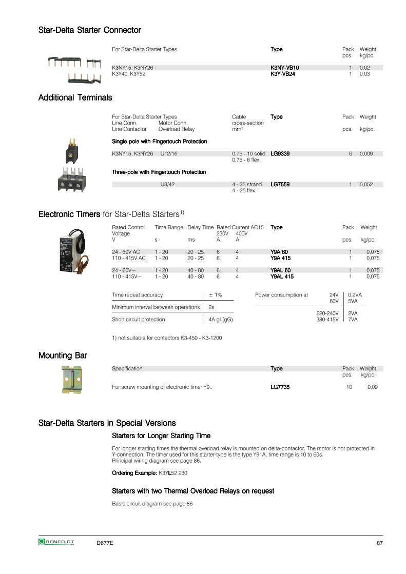
D677E 87
Star-Delta Starter ConnectorStar-Delta Starter ConnectorStar-Delta Starter ConnectorStar-Delta Starter ConnectorStar-Delta Starter Connector
For Star-Delta Starter Types TypeTypeTypeTypeType Pack Weightpcs. kg/pc.
K3NY15, K3NY26 K3NY-VB10K3NY-VB10K3NY-VB10K3NY-VB10K3NY-VB10 1 0,02K3Y40, K3Y52 K3Y-VB24K3Y-VB24K3Y-VB24K3Y-VB24K3Y-VB24 1 0,03
Additional TerminalsAdditional TerminalsAdditional TerminalsAdditional TerminalsAdditional Terminals
For Star-Delta Starter Types Cable TypeTypeTypeTypeType Pack WeightLine Conn. Motor Conn. cross-sectionLine Contactor Overload Relay mm² pcs. kg/pc.
Single pole with Fingertouch ProtectionSingle pole with Fingertouch ProtectionSingle pole with Fingertouch ProtectionSingle pole with Fingertouch ProtectionSingle pole with Fingertouch Protection
K3NY15, K3NY26 U12/16 0,75 - 10 solid LG9339LG9339LG9339LG9339LG9339 6 0,0090,75 - 6 flex.
Three-pole with Fingertouch ProtectionThree-pole with Fingertouch ProtectionThree-pole with Fingertouch ProtectionThree-pole with Fingertouch ProtectionThree-pole with Fingertouch Protection
U3/42 4 - 35 strand. LG7559LG7559LG7559LG7559LG7559 1 0,0524 - 25 flex.
Electronic Timers Electronic Timers Electronic Timers Electronic Timers Electronic Timers for Star-Delta Starters1)
Rated Control Time Range Delay Time Rated Current AC15 TypeTypeTypeTypeType Pack WeightVoltage 230V 400VV s ms A A pcs. kg/pc.
24 - 60V AC 1 - 20 20 - 25 6 4 Y9A 60Y9A 60Y9A 60Y9A 60Y9A 60 1 0,075110 - 415V AC 1 - 20 20 - 25 6 4 Y9A 415Y9A 415Y9A 415Y9A 415Y9A 415 1 0,075
24 - 60V~ 1 - 20 40 - 80 6 4 Y9AL 60Y9AL 60Y9AL 60Y9AL 60Y9AL 60 1 0,075110 - 415V~ 1 - 20 40 - 80 6 4 Y9AL 415Y9AL 415Y9AL 415Y9AL 415Y9AL 415 1 0,075
Time repeat accuracy ± 1% Power consumption at 24V 0,2VA60V 5VA
Minimum interval between operations 2s220-240V 2VA
Short circuit protection 4A gl (gG) 380-415V 7VA
1) not suitable for contactors K3-450 - K3-1200
Mounting BarMounting BarMounting BarMounting BarMounting Bar
Specification TypeTypeTypeTypeType Pack Weightpcs. kg/pc.
For screw mounting of electronic timer Y9.. LG7735LG7735LG7735LG7735LG7735 10 0,09
Star-Delta Starters in Special VersionsStar-Delta Starters in Special VersionsStar-Delta Starters in Special VersionsStar-Delta Starters in Special VersionsStar-Delta Starters in Special Versions
Starters for Longer Starting TimeStarters for Longer Starting TimeStarters for Longer Starting TimeStarters for Longer Starting TimeStarters for Longer Starting Time
For longer starting times the thermal overload relay is mounted on delta-contactor. The motor is not protected inY-connection. The timer used for this starter-type is the type Y91A, time range is 10 to 60s.Principal wiring diagram see page 86.
Ordering Example:Ordering Example:Ordering Example:Ordering Example:Ordering Example: K3YLLLLL52 230
Starters with two Thermal Overload Relays on requestStarters with two Thermal Overload Relays on requestStarters with two Thermal Overload Relays on requestStarters with two Thermal Overload Relays on requestStarters with two Thermal Overload Relays on request
Basic circuit diagram see page 86

88 D677E
Reversing Contactors Reversing Contactors Reversing Contactors Reversing Contactors Reversing Contactors with Mechanical Interlock AC Operated
RatingsRatingsRatingsRatingsRatings Rated Wired TypeTypeTypeTypeType Coil voltage 1)
AC3 Current to accept 110110110110110 110V 50Hz380V380V380V380V380V Overload 230230230230230 220-240V 50Hz400V400V400V400V400V 660V AC3 Relay 400400400400400 380-415 50Hz415V415V415V415V415V 500V 690V 400V page 102 ⏐⏐⏐⏐⏐ Pack Weight>kWkWkWkWkW kW kW A Type pcs. kg/pc.
Open Type
44444 5,5 5,5 10 U3/32 K3NWU10 . . .K3NWU10 . . .K3NWU10 . . .K3NWU10 . . .K3NWU10 . . . 1 0,6U12/16E K3
7,57,57,57,57,5 10 7,5 18 K3NWU18 . . .K3NWU18 . . .K3NWU18 . . .K3NWU18 . . .K3NWU18 . . . 1 0,6
1111111111 15 15 24 U3/42 K3WU24 . . .K3WU24 . . .K3WU24 . . .K3WU24 . . .K3WU24 . . . 1 1,2
1515151515 18,5 18,5 32 K3WU32 . . .K3WU32 . . .K3WU32 . . .K3WU32 . . .K3WU32 . . . 1 1,4
2222222222 30 30 50 U3/74 K3WU50 . . .K3WU50 . . .K3WU50 . . .K3WU50 . . .K3WU50 . . . 1 2,5
3030303030 37 37 62 K3WU62 . . .K3WU62 . . .K3WU62 . . .K3WU62 . . .K3WU62 . . . 1 2,5
3737373737 45 45 74 K3WU74 . . .K3WU74 . . .K3WU74 . . .K3WU74 . . .K3WU74 . . . 1 2,5
Sheet Steel Enclosed, protected to IP54
44444 5,5 5,5 10 U3/32 K3NWU10B . . .K3NWU10B . . .K3NWU10B . . .K3NWU10B . . .K3NWU10B . . . 1 3,9
7,57,57,57,57,5 10 7,5 18 K3NWU18B . . .K3NWU18B . . .K3NWU18B . . .K3NWU18B . . .K3NWU18B . . . 1 4,1
1111111111 15 15 24 U3/42 K3WU24B . . .K3WU24B . . .K3WU24B . . .K3WU24B . . .K3WU24B . . . 1 4,5
1515151515 18,5 18,5 32 K3WU32B . . .K3WU32B . . .K3WU32B . . .K3WU32B . . .K3WU32B . . . 1 4,7
2222222222 30 30 50 U3/74 K3WU50B . . .K3WU50B . . .K3WU50B . . .K3WU50B . . .K3WU50B . . . 1 7,1
3030303030 37 37 62 K3WU62B . . .K3WU62B . . .K3WU62B . . .K3WU62B . . .K3WU62B . . . 1 7,1
Reversing Starter ConnectorReversing Starter ConnectorReversing Starter ConnectorReversing Starter ConnectorReversing Starter Connector
For Reversing Starter Types TypeTypeTypeTypeType Pack Weightpcs. kg/pc.
K3NWU10, K3NWU18 K3NW-VB10K3NW-VB10K3NW-VB10K3NW-VB10K3NW-VB10 1 0,02K3WU24, K3WU32 K3W-VB24K3W-VB24K3W-VB24K3W-VB24K3W-VB24 1 0,025
1) Other coil voltages see page 39

D677E 89
Components for Combinations Auxiliary Contacts Free Space forLeft Hand Side Right Hand Side Mechanical Reversing Built-in for use Aux. Contact BlocksContactor Contactor Interlock Starter on Contactor on Contactor
ConnectorK1 K2 K1 K2 K1 K2Type Type Type Type NO/NC NO/NC HN.. or HA..
K3-10ND10 K3-10ND10 LG10889 K3NW-VB10 - - 3 3+ HN01 + HN01
K3-18ND10 K3-18ND10 LG10889 K3NW-VB10 - - 3 3+ HN01 + HN01
K3-24A00 K3-24A00 LG10889 K3W-VB24 - - 2 2+ HN10 + HN01 + HN10 + HN01
K3-32A00 K3-32A00 LG10889 K3W-VB24 - - 2 2+ HN10 + HN01 + HN10 + HN01
K3-50A00 K3-50A00 LG10890 - - - 2 2+ HN10 + HN01 + HN10 + HN01
K3-62A00 K3-62A00 LG10890 - - - 2 2+ HN10 + HN01 + HN10 + HN01
K3-74A00 K3-74A00 LG10890 - - - 2 2+ HN10 + HN01 + HN10 + HN01
K3-10ND10 K3-10ND10 LG10889 K3NW-VB10 - - 3 3+ HN01 + HN01
K3-18ND10 K3-18ND10 LG10889 K3NW-VB10 - - 3 3+ HN01 + HN01
K3-24A00 K3-24A00 LG10889 K3W-VB24 - - 2 2+ HN10 + HN01 + HN10 + HN01
K3-32A00 K3-32A00 LG10889 K3W-VB24 - - 2 2+ HN10 + HN01 + HN10 + HN01
K3-50A00 K3-50A00 LG10890 - - - 2 2+ HN10 + HN01 + HN10 + HN01
K3-62A00 K3-62A00 LG10890 - - - 2 2+ HN10 + HN01 + HN10 + HN01

90 D677E
Reversing Contactors Reversing Contactors Reversing Contactors Reversing Contactors Reversing Contactors for North America AC Operated
RatingsRatingsRatingsRatingsRatings Rated Wired TypeTypeTypeTypeType Coil voltage 1)
AC3 Current to accept 230230230230230 220-240V 50Hz380V380V380V380V380V Overload 400400400400400 380-415V 50Hz400V400V400V400V400V 660V AC3 Relay ⏐⏐⏐⏐⏐415V415V415V415V415V 500V 690V 400V page 102 ⏐⏐⏐⏐⏐ Pack Weight>kWkWkWkWkW kW kW A Type pcs. kg/pc.
Open Type
44444 5,5 5,5 10 U3/32 KNW3-10 . . .KNW3-10 . . .KNW3-10 . . .KNW3-10 . . .KNW3-10 . . . 1 0,6U12/16E K3
7,57,57,57,57,5 10 10 18 KNW3-18 . . .KNW3-18 . . .KNW3-18 . . .KNW3-18 . . .KNW3-18 . . . 1 0,6
1111111111 15 15 24 U3/42 KW3-24 . . .KW3-24 . . .KW3-24 . . .KW3-24 . . .KW3-24 . . . 1 1,2
1515151515 18,5 18,5 32 KW3-32 . . .KW3-32 . . .KW3-32 . . .KW3-32 . . .KW3-32 . . . 1 1,4
18,518,518,518,518,5 18,5 18,5 40 KW3-40 . . .KW3-40 . . .KW3-40 . . .KW3-40 . . .KW3-40 . . . 1 1,4
Pole Changing StartersPole Changing StartersPole Changing StartersPole Changing StartersPole Changing Starters AC Operated
RatingsRatingsRatingsRatingsRatings Rated Wired TypeTypeTypeTypeType Coil voltage 1)
AC3 at Current to accept 230230230230230 220-240V 50Hz380V380V380V380V380V Overload 400400400400400 380-415V 50Hz400V400V400V400V400V 660V AC3 Relay ⏐⏐⏐⏐⏐415V415V415V415V415V 500V 690V 400V page 102 ⏐⏐⏐⏐⏐ Pack Weight>kWkWkWkWkW kW kW A Type pcs. kg/pc.
Open TypeOpen TypeOpen TypeOpen TypeOpen Type
7,57,57,57,57,5 10 10 18 2 x U3/32 K3NPU18 . . .K3NPU18 . . .K3NPU18 . . .K3NPU18 . . .K3NPU18 . . . 1 1,02 x U12/16E K3
1111111111 15 15 24 K3NPU24 . . .K3NPU24 . . .K3NPU24 . . .K3NPU24 . . .K3NPU24 . . . 1 1,5
1515151515 18,5 18,5 32 2 x U3/32 K3PU32 . . .K3PU32 . . .K3PU32 . . .K3PU32 . . .K3PU32 . . . 1 1,9
2222222222 30 30 50 2 x U3/74 K3PU50 . . .K3PU50 . . .K3PU50 . . .K3PU50 . . .K3PU50 . . . 1 3,9
3030303030 37 37 62 K3PU62 . . .K3PU62 . . .K3PU62 . . .K3PU62 . . .K3PU62 . . . 1 3,9
Sheet Steel EnclosedSheet Steel EnclosedSheet Steel EnclosedSheet Steel EnclosedSheet Steel Enclosed, protected to IP54
7,57,57,57,57,5 10 7,5 18 2x U3/32 K3NPU18B . . .K3NPU18B . . .K3NPU18B . . .K3NPU18B . . .K3NPU18B . . . 1 1,0
1111111111 15 15 24 K3NPU24B . . .K3NPU24B . . .K3NPU24B . . .K3NPU24B . . .K3NPU24B . . . 1 1,5
1515151515 18,5 18,5 32 K3PU32B . . .K3PU32B . . .K3PU32B . . .K3PU32B . . .K3PU32B . . . 1 1,9
1) Other coil voltages see page 40
Ordering Example: Ordering Example: Ordering Example: Ordering Example: Ordering Example: Pole Changing Starter, open version, rated AC3 at 400V 28A and 15A, control voltage 230V 50HzOrder Type:Order Type:Order Type:Order Type:Order Type: K3PU32 230 + U3/32 32 + U3/32 18K3PU32 230 + U3/32 32 + U3/32 18K3PU32 230 + U3/32 32 + U3/32 18K3PU32 230 + U3/32 32 + U3/32 18K3PU32 230 + U3/32 32 + U3/32 18
Pole Changing Starters for Star-Delta Operation on request
1) Other coil voltages see page 39

D677E 91
Components for Combinations Auxiliary Contacts Free Space forLeft Hand Side Right Hand Side Mechanical Built-in for use Aux. Contact BlocksContactor Contactor Interlock on Contactor on Contactor
K1 K2 K1 K2 K1 K2Type Type Type NO/NC NO/NC HN.. or HA..
K3-10ND01 K3-10ND01 LG10889 - - 4 4
K3-18ND01 K3-18ND01 LG10889 - - 4 4
K3-24A00 K3-24A00 LG10889 - - 3 3+ HN01 + HN01
K3-32A00 K3-32A00 LG10889 - - 3 3+ HN01 + HN01
K3-40A00 K3-40A00 LG10890 - - 3 3+ HN01 + HN01
Components for Combinations Free Space forHigh Low Star Aux. Contact Blocks on ContactorSpeed Speed Contactor High Low Star
Speed SpeedK1 K2 K3 K1 K2 K3Type Type Type HN.. or HA..
K3-18ND01 K3-18ND01 K3-14ND10 2 3 4+ 2 x HN10 + HN10
K3-24A00 K3-24A00 K3-18ND10 1 2 4+ HN01 + 2 x HN10 + HN01 + HN10
K3-32A00 K3-32A00 K3-24A00 1 2 3+ HN01 + 2 x HN10 + HN01 + HN10 + HN10
K3-50A00 K3-50A00 K3-32A00 1 2 3+ HN01 + 2 x HN10 + HN01 + HN10 + HN10
K3-62A00 K3-62A00 K3-50A00 1 2 3+ HN01 + 2 x HN10 + HN01 + HN10 + HN10
K3-18ND01 K3-18ND01 K3-14ND10 2 3 4+ 2 x HN10 + HN10
K3-24A00 K3-24A00 K3-18ND10 1 2 4+ HN01 + 2 x HN10 + HN01 + HN10
K3-32A00 K3-32A00 K3-24A00 1 2 3+ HN01 + 2 x HN10 + HN01 + HN10 + HN10

92 D677E
Star-Delta StartersStar-Delta StartersStar-Delta StartersStar-Delta StartersStar-Delta Starters
Data according to IEC 947-4-1, VDE 0660, EN 60947-4-1Data according to IEC 947-4-1, VDE 0660, EN 60947-4-1Data according to IEC 947-4-1, VDE 0660, EN 60947-4-1Data according to IEC 947-4-1, VDE 0660, EN 60947-4-1Data according to IEC 947-4-1, VDE 0660, EN 60947-4-1
TypeTypeTypeTypeType K3NY15K3NY15K3NY15K3NY15K3NY15 K3NY26K3NY26K3NY26K3NY26K3NY26 K3Y40K3Y40K3Y40K3Y40K3Y40 K3Y52K3Y52K3Y52K3Y52K3Y52 K3Y80K3Y80K3Y80K3Y80K3Y80 K3Y100K3Y100K3Y100K3Y100K3Y100 K3Y140K3Y140K3Y140K3Y140K3Y140 K3Y200K3Y200K3Y200K3Y200K3Y200 K3Y240K3Y240K3Y240K3Y240K3Y240 K3Y300K3Y300K3Y300K3Y300K3Y300
Main ContactsMain ContactsMain ContactsMain ContactsMain ContactsRated insulation voltage URated insulation voltage URated insulation voltage URated insulation voltage URated insulation voltage Uiiiii
1) V AC 690 690 690 690 690 690 690 690 690 690
Frequency of operations zFrequency of operations zFrequency of operations zFrequency of operations zFrequency of operations z AC3, Ie 1/h 15Change-over time max. (Y-step) s 20 (Type K3YL ... 60)
Utilization category AC3Utilization category AC3Utilization category AC3Utilization category AC3Utilization category AC3Switching of three-phase motorsSwitching of three-phase motorsSwitching of three-phase motorsSwitching of three-phase motorsSwitching of three-phase motorsRated operational 220-230V A 16 30 45 60 85 109 150 205 240 300current Ie 240V A 16 30 45 60 85 109 150 205 240 300
380-400V380-400V380-400V380-400V380-400V AAAAA 1616161616 3030303030 4545454545 6060606060 8585858585 109109109109109 150150150150150 205205205205205 240 300
415-440V A 15 30 45 60 85 109 150 205 240 300500V A 15 30 45 60 85 95 150 205 190 240
660-690V A 13 17 30 36 57 72 103 118 147 180
Rated operational power 220-230V kW 4 7,5 11 15 22 30 45 55 75 90of three-phase motors 240V kW 5,5 11 15 18,5 22 30 45 55 75 9050-60Hz 380-400V380-400V380-400V380-400V380-400V kWkWkWkWkW 7,57,57,57,57,5 1515151515 2222222222 3030303030 4545454545 5555555555 7575757575 110110110110110 132132132132132 160160160160160
415-440V kW 7,5 15 22 30 45 55 75 110 140 170500V kW 7,5 18,5 30 37 55 75 90 132 132 180
660-690V kW 11 15 22 30 45 55 90 110 132 180
Cable cross-sectionsCable cross-sectionsCable cross-sectionsCable cross-sectionsCable cross-sectionsLine solid or stranded mm² 1,5 - 6 2) 1,5 - 16 10 - 70 3) 10 - 120 busbar
flexible mm² 1,5 - 4 2) 1,5 - 16 16 - 50 3) 10 - 95 18x5lexible with multicore cable end mm² 1,5 - 4 2) 1,5 - 16 10 - 35 10 - 95 M8
Motorsolid or stranded mm² 1,5 - 6 1,5 - 16 4 - 35 3) 10 - 120 busbar
flexible mm² 1,5 - 4 1,5 - 16 6 - 25 3) 10 - 95 18x5lexible with multicore cable end mm² 1,5 - 4 1,5 - 16 4 - 25 10 - 95 M8
Power consumption of the combinationPower consumption of the combinationPower consumption of the combinationPower consumption of the combinationPower consumption of the combinationinrush and change-over VA 55 130 183 560 700
sealed VA 20 26 36 10 10W 6 8 14 10 10
Coil Voltage Ranges and Non Standard Voltages for Star-Delta StartersCoil Voltage Ranges and Non Standard Voltages for Star-Delta StartersCoil Voltage Ranges and Non Standard Voltages for Star-Delta StartersCoil Voltage Ranges and Non Standard Voltages for Star-Delta StartersCoil Voltage Ranges and Non Standard Voltages for Star-Delta Starters
K3NY15.. to K3Y100..K3NY15.. to K3Y100..K3NY15.. to K3Y100..K3NY15.. to K3Y100..K3NY15.. to K3Y100..
Suffix toSuffix toSuffix toSuffix toSuffix to Rated Control Voltage UsStar-Delta StarterStar-Delta StarterStar-Delta StarterStar-Delta StarterStar-Delta Starter range for 50Hz range for 60Hztypetypetypetypetype min. max. min. max.e.g. K3Y80 400400400400400 V V V V
24 24 24 24 2742 42 47 47 52110 100 110 110 122
180 180 210 200 240230230230230230 220220220220220 240240240240240 230230230230230 264264264264264400400400400400 380380380380380 415415415415415 400400400400400 415415415415415
Standard voltages in bold type lettersStandard voltages in bold type lettersStandard voltages in bold type lettersStandard voltages in bold type lettersStandard voltages in bold type letters
1) Suitable for: earthed-neutral systems, overvoltage category I to IV, pollutiondegree 3 (standard-industry): Uimp = 8kV. Data for other conditions on request.2) Additional terminals see page 773) Maximum cable cross-section with prepared conductor
K3Y140, to K3Y300..K3Y140, to K3Y300..K3Y140, to K3Y300..K3Y140, to K3Y300..K3Y140, to K3Y300..
Suffix toSuffix toSuffix toSuffix toSuffix to Rated Control Voltage UsStar-Delta StarterStar-Delta StarterStar-Delta StarterStar-Delta StarterStar-Delta Starter range for 50Hz range for 60Hz for DCtypetypetypetypetype min. max. min. max.e.g. K3Y300 230230230230230 V V V V V
24 24 24 24 24 2448 48 48 48 48 48
110 110 120 110 120 110
230230230230230 220220220220220 240240240240240 220220220220220 240240240240240 220220220220220400400400400400 380380380380380 415415415415415 380380380380380 415415415415415 -----

D677E 93
Reversing StartersReversing StartersReversing StartersReversing StartersReversing Starters
Data according to IEC 947-4-1, VDE 0660, EN 60947-4-1Data according to IEC 947-4-1, VDE 0660, EN 60947-4-1Data according to IEC 947-4-1, VDE 0660, EN 60947-4-1Data according to IEC 947-4-1, VDE 0660, EN 60947-4-1Data according to IEC 947-4-1, VDE 0660, EN 60947-4-1
TypeTypeTypeTypeType K3NWU10K3NWU10K3NWU10K3NWU10K3NWU10 K3NWU18K3NWU18K3NWU18K3NWU18K3NWU18 K3WU24K3WU24K3WU24K3WU24K3WU24 K3WU32K3WU32K3WU32K3WU32K3WU32 K3WU50K3WU50K3WU50K3WU50K3WU50 K3WU62K3WU62K3WU62K3WU62K3WU62 K3WU74K3WU74K3WU74K3WU74K3WU74
Main ContactsMain ContactsMain ContactsMain ContactsMain ContactsRated insulation voltage URated insulation voltage URated insulation voltage URated insulation voltage URated insulation voltage Uiiiii
1) V AC 690 690 690 690 690 690 690
Utilization category AC3Utilization category AC3Utilization category AC3Utilization category AC3Utilization category AC3Switching of three-phase motorsSwitching of three-phase motorsSwitching of three-phase motorsSwitching of three-phase motorsSwitching of three-phase motorsRated operational current Ie 220V A 12 18 23 30 45 63
230V A 11,5 18 24 32 50 62 74240V A 11 18 24 32 50 62 74
380-400V380-400V380-400V380-400V380-400V AAAAA 1010101010 1818181818 2424242424 3232323232 5050505050 6262626262 7474747474415-440V A 9 18 23 30 50 62 74
500V A 9 16 23 30 45 60 74660-690V A 6,5 8,5 17 20 31 40 40
Rated operational power 220-230V kW 3 5 6 8,5 12,5 18,5of three-phase motors 240V kW 3 5 7 9 13,5 19 2350-60Hz 380-400V380-400V380-400V380-400V380-400V kWkWkWkWkW 44444 7,57,57,57,57,5 1111111111 1515151515 2222222222 3030303030 3737373737
415-440V kW 4,5 8,5 12 16 24 33 40500V kW 5,5 10 15 18,5 30 37 45
660-690V kW 5,5 10 15 18,5 30 37 45
Cable cross-sectionsCable cross-sectionsCable cross-sectionsCable cross-sectionsCable cross-sectionsLine solid or stranded mm² 0,75 - 6 1,5 - 25 4 - 50
flexible mm² 1 - 4 2,5 - 16 6 - 35flexible with multicore cable end mm² 0,75 - 4 1,5 - 16 6 - 35
Cables per clamp 1 1 1
Power consumption of the combinationPower consumption of the combinationPower consumption of the combinationPower consumption of the combinationPower consumption of the combinationinrush and change-over VA 33 - 45 90 - 115 140 - 185
sealed VA 7 - 10 9 - 13 13 - 18W 2,6 - 3 2,7 - 4 5,4 - 7
Technical Data according to UL508Technical Data according to UL508Technical Data according to UL508Technical Data according to UL508Technical Data according to UL508
Main Contacts (cULus)Main Contacts (cULus)Main Contacts (cULus)Main Contacts (cULus)Main Contacts (cULus) Type KNW3-10KNW3-10KNW3-10KNW3-10KNW3-10 KNW3-18KNW3-18KNW3-18KNW3-18KNW3-18 KW3-24KW3-24KW3-24KW3-24KW3-24 KW3-32KW3-32KW3-32KW3-32KW3-32 KW3-40KW3-40KW3-40KW3-40KW3-40
Rated operational power 110-120V hp 1½ 2 5 5 7½of three-phase motors 200V hp 3 5 7½ 10 10at 60Hz (3ph) 220-240V hp 3 7½ 10 10 15
277V hp 3 7½ 7½ 10 15
380-415V hp 5 10 10 15 20440-480V hp 5 10 15 20 25550-600V hp 7½ 15 20 25 30
Fuse / Short-circuit current A/kA 30/5 50/5 90/5 125/5 175/5
Rated voltage V 600 600 600 600 600
Auxiliary Contacts (cULus)Auxiliary Contacts (cULus)Auxiliary Contacts (cULus)Auxiliary Contacts (cULus)Auxiliary Contacts (cULus) A600 A600 A600 A600 A600
Cable cross-sectionsCable cross-sectionsCable cross-sectionsCable cross-sectionsCable cross-sectionsfor main connectors solid AWG 18 - 10 16 - 10
flexible AWG 18 - 10 14 - 4Cables per clamp 1 1
1) Suitable for: earthed-neutral systems, overvoltage category I to IV, pollution degree 3 (standard-industry): Uimp = 8kV. Data for other conditions on request.
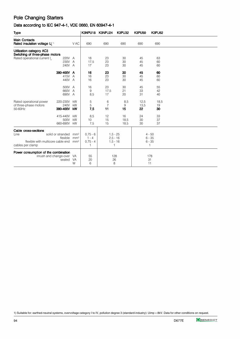
94 D677E
Pole Changing StartersPole Changing StartersPole Changing StartersPole Changing StartersPole Changing Starters
Data according to IEC 947-4-1, VDE 0660, EN 60947-4-1Data according to IEC 947-4-1, VDE 0660, EN 60947-4-1Data according to IEC 947-4-1, VDE 0660, EN 60947-4-1Data according to IEC 947-4-1, VDE 0660, EN 60947-4-1Data according to IEC 947-4-1, VDE 0660, EN 60947-4-1
TypeTypeTypeTypeType K3NPU18K3NPU18K3NPU18K3NPU18K3NPU18 K3NPU24K3NPU24K3NPU24K3NPU24K3NPU24 K3PU32K3PU32K3PU32K3PU32K3PU32 K3PU50K3PU50K3PU50K3PU50K3PU50 K3PU62K3PU62K3PU62K3PU62K3PU62
Main ContactsMain ContactsMain ContactsMain ContactsMain ContactsRated insulation voltage URated insulation voltage URated insulation voltage URated insulation voltage URated insulation voltage Uiiiii
1) V AC 690 690 690 690 690
Utilization category AC3Utilization category AC3Utilization category AC3Utilization category AC3Utilization category AC3Switching of three-phase motorsSwitching of three-phase motorsSwitching of three-phase motorsSwitching of three-phase motorsSwitching of three-phase motorsRated operational current Ie 220V A 18 23 30 45 63
230V A 17,5 23 30 45 60240V A 17 23 30 45 60
380-400V380-400V380-400V380-400V380-400V AAAAA 1616161616 2323232323 3030303030 4545454545 6060606060415V A 16 23 30 45 60440V A 16 23 30 45 60
500V A 16 23 30 45 55660V A 9 17,5 21 33 42690V A 8,5 17 20 31 40
Rated operational power 220-230V kW 5 6 8,5 12,5 18,5of three-phase motors 240V kW 5 7 9 13,5 1950-60Hz 380-400V380-400V380-400V380-400V380-400V kWkWkWkWkW 7,57,57,57,57,5 1111111111 1515151515 2222222222 3030303030
415-440V kW 8,5 12 16 24 33500V kW 10 15 18,5 30 37
660-690V kW 7,5 15 18,5 30 37
Cable cross-sectionsCable cross-sectionsCable cross-sectionsCable cross-sectionsCable cross-sectionsLine solid or stranded mm² 0,75 - 6 1,5 - 25 4 - 50
flexible mm² 1 - 4 2,5 - 16 6 - 35flexible with multicore cable end mm² 0,75 - 4 1,5 - 16 6 - 35
cables per clamp 1 1 1
Power consumption of the combinationPower consumption of the combinationPower consumption of the combinationPower consumption of the combinationPower consumption of the combinationinrush and change-over VA 55 128 178
sealed VA 20 26 31W 6 8 11
1) Suitable for: earthed-neutral systems, overvoltage category I to IV, pollution degree 3 (standard-industry): Uimp = 8kV. Data for other conditions on request.

D677E 95
Star-Delta StartersStar-Delta StartersStar-Delta StartersStar-Delta StartersStar-Delta Starters
Wiring Diagrams Main CircuitWiring Diagrams Main CircuitWiring Diagrams Main CircuitWiring Diagrams Main CircuitWiring Diagrams Main Circuit
Terminal markings of contactors and relays according to DIN EN 50012Connections shown in main and circuits as broken lines are not included.
K3NY15 to K3Y100K3NY15 to K3Y100K3NY15 to K3Y100K3NY15 to K3Y100K3NY15 to K3Y100 K3Y140 to K3Y300K3Y140 to K3Y300K3Y140 to K3Y300K3Y140 to K3Y300K3Y140 to K3Y300with thermal overload relay U3/.. or U12/16 with thermal overload relay U85 or U180
Wiring Diagrams Control CircuitWiring Diagrams Control CircuitWiring Diagrams Control CircuitWiring Diagrams Control CircuitWiring Diagrams Control Circuit
K3NY15 to K3Y52K3NY15 to K3Y52K3NY15 to K3Y52K3NY15 to K3Y52K3NY15 to K3Y52 K3NY15 to K3Y52K3NY15 to K3Y52K3NY15 to K3Y52K3NY15 to K3Y52K3NY15 to K3Y52 K3Y80 to K3Y200K3Y80 to K3Y200K3Y80 to K3Y200K3Y80 to K3Y200K3Y80 to K3Y200operating with control switch operating with push buttons operating with control switch
K3Y80 to K3Y200K3Y80 to K3Y200K3Y80 to K3Y200K3Y80 to K3Y200K3Y80 to K3Y200 K3Y240 to K3Y300K3Y240 to K3Y300K3Y240 to K3Y300K3Y240 to K3Y300K3Y240 to K3Y300 K3Y240 to K3Y300K3Y240 to K3Y300K3Y240 to K3Y300K3Y240 to K3Y300K3Y240 to K3Y300operating with push buttons operating with control switch operating with push buttons
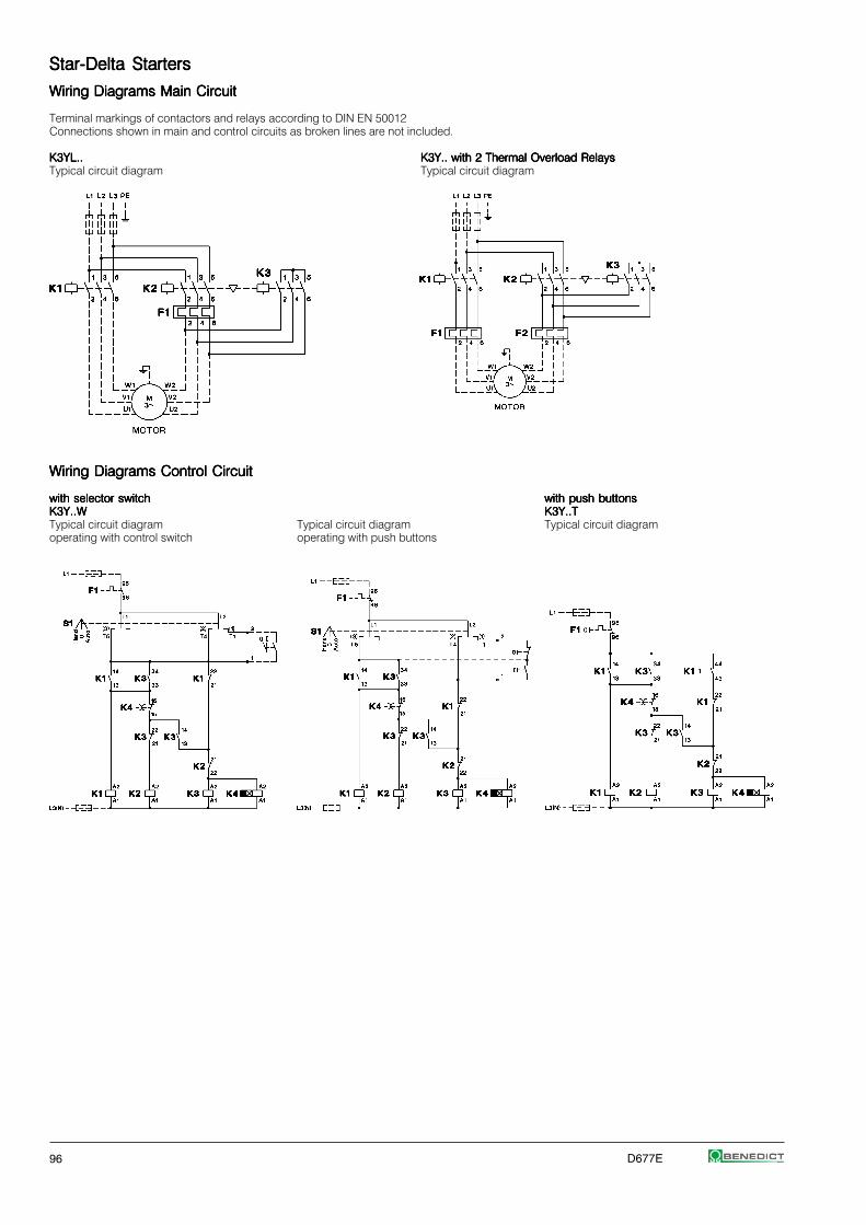
96 D677E
Star-Delta StartersStar-Delta StartersStar-Delta StartersStar-Delta StartersStar-Delta Starters
Wiring Diagrams Main CircuitWiring Diagrams Main CircuitWiring Diagrams Main CircuitWiring Diagrams Main CircuitWiring Diagrams Main Circuit
Terminal markings of contactors and relays according to DIN EN 50012Connections shown in main and control circuits as broken lines are not included.
K3YL..K3YL..K3YL..K3YL..K3YL.. K3Y.. with 2 Thermal Overload RelaysK3Y.. with 2 Thermal Overload RelaysK3Y.. with 2 Thermal Overload RelaysK3Y.. with 2 Thermal Overload RelaysK3Y.. with 2 Thermal Overload RelaysTypical circuit diagram Typical circuit diagram
Wiring Diagrams Control CircuitWiring Diagrams Control CircuitWiring Diagrams Control CircuitWiring Diagrams Control CircuitWiring Diagrams Control Circuit
with selector switchwith selector switchwith selector switchwith selector switchwith selector switch with push buttonswith push buttonswith push buttonswith push buttonswith push buttonsK3Y..WK3Y..WK3Y..WK3Y..WK3Y..W K3Y..TK3Y..TK3Y..TK3Y..TK3Y..TTypical circuit diagram Typical circuit diagram Typical circuit diagramoperating with control switch operating with push buttons

D677E 97
Reversing ContactorsReversing ContactorsReversing ContactorsReversing ContactorsReversing Contactors
Wiring Diagrams Main CircuitWiring Diagrams Main CircuitWiring Diagrams Main CircuitWiring Diagrams Main CircuitWiring Diagrams Main Circuit
Terminal markings of contactors and relays according to DIN EN 50012Connections shown in main and control circuits as broken lines are not included.
K3NWU10 to K3WU74K3NWU10 to K3WU74K3NWU10 to K3WU74K3NWU10 to K3WU74K3NWU10 to K3WU74with thermal overload relay U3/32, U3/42 or U3/74
Wiring Diagrams Control CircuitWiring Diagrams Control CircuitWiring Diagrams Control CircuitWiring Diagrams Control CircuitWiring Diagrams Control Circuit
K3NWU10 to K3WU32K3NWU10 to K3WU32K3NWU10 to K3WU32K3NWU10 to K3WU32K3NWU10 to K3WU32operating with control switch operating with push buttons
Reversing over off-positionReversing over off-positionReversing over off-positionReversing over off-positionReversing over off-position Reversing directReversing directReversing directReversing directReversing direct
K3WU50, K3WU62, K3WU74K3WU50, K3WU62, K3WU74K3WU50, K3WU62, K3WU74K3WU50, K3WU62, K3WU74K3WU50, K3WU62, K3WU74operating with control switch operating with push buttons

98 D677E
Pole Changing StartersPole Changing StartersPole Changing StartersPole Changing StartersPole Changing Starters
Wiring DiagramsWiring DiagramsWiring DiagramsWiring DiagramsWiring Diagrams
Terminal markings of contactors and relays according to DIN EN 50012Connections shown in main and control circuits as broken lines are not included.
Main CircuitMain CircuitMain CircuitMain CircuitMain Circuit Principal Control Circuit Wiring DiagramPrincipal Control Circuit Wiring DiagramPrincipal Control Circuit Wiring DiagramPrincipal Control Circuit Wiring DiagramPrincipal Control Circuit Wiring Diagramoperating with control switch operating with push buttons
Low High Low Highspeed speed speed speed
Operation Delta Double-Star Star Double-StarSpeed relation 1 2 1 2Power relation 1 1,5 - 1,8 0,3 1
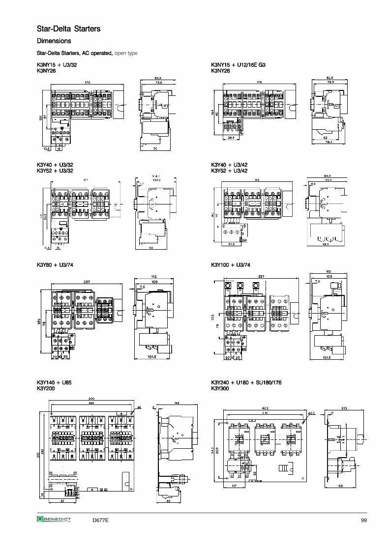
D677E 99
Star-Delta StartersStar-Delta StartersStar-Delta StartersStar-Delta StartersStar-Delta Starters
DimensionsDimensionsDimensionsDimensionsDimensions
Star-Delta Starters, AC operated,Star-Delta Starters, AC operated,Star-Delta Starters, AC operated,Star-Delta Starters, AC operated,Star-Delta Starters, AC operated, open type
K3NY15 + U3/32K3NY15 + U3/32K3NY15 + U3/32K3NY15 + U3/32K3NY15 + U3/32 K3NY15 + U12/16E G3K3NY15 + U12/16E G3K3NY15 + U12/16E G3K3NY15 + U12/16E G3K3NY15 + U12/16E G3K3NY26K3NY26K3NY26K3NY26K3NY26 K3NY26K3NY26K3NY26K3NY26K3NY26
K3Y40 + U3/32K3Y40 + U3/32K3Y40 + U3/32K3Y40 + U3/32K3Y40 + U3/32 K3Y40 + U3/42K3Y40 + U3/42K3Y40 + U3/42K3Y40 + U3/42K3Y40 + U3/42K3Y52 + U3/32K3Y52 + U3/32K3Y52 + U3/32K3Y52 + U3/32K3Y52 + U3/32 K3Y52 + U3/42K3Y52 + U3/42K3Y52 + U3/42K3Y52 + U3/42K3Y52 + U3/42
K3Y80 + U3/74K3Y80 + U3/74K3Y80 + U3/74K3Y80 + U3/74K3Y80 + U3/74 K3Y100 + U3/74K3Y100 + U3/74K3Y100 + U3/74K3Y100 + U3/74K3Y100 + U3/74
K3Y140 + U85K3Y140 + U85K3Y140 + U85K3Y140 + U85K3Y140 + U85 K3Y240 + U180 + SU180/176K3Y240 + U180 + SU180/176K3Y240 + U180 + SU180/176K3Y240 + U180 + SU180/176K3Y240 + U180 + SU180/176K3Y200K3Y200K3Y200K3Y200K3Y200 K3Y300K3Y300K3Y300K3Y300K3Y300
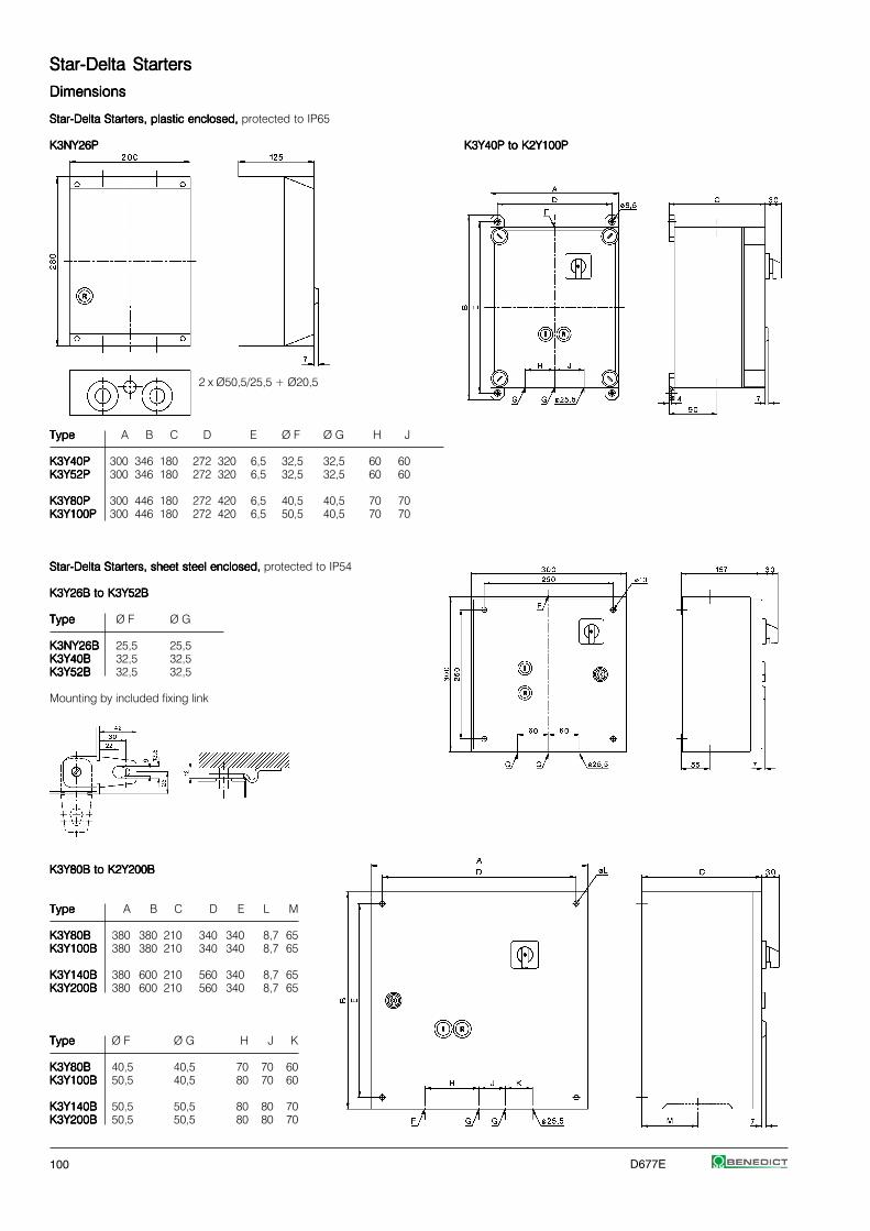
100 D677E
Star-Delta StartersStar-Delta StartersStar-Delta StartersStar-Delta StartersStar-Delta Starters
DimensionsDimensionsDimensionsDimensionsDimensions
Star-Delta Starters, plastic enclosed, Star-Delta Starters, plastic enclosed, Star-Delta Starters, plastic enclosed, Star-Delta Starters, plastic enclosed, Star-Delta Starters, plastic enclosed, protected to IP65
K3NY26PK3NY26PK3NY26PK3NY26PK3NY26P K3Y40P to K2Y100PK3Y40P to K2Y100PK3Y40P to K2Y100PK3Y40P to K2Y100PK3Y40P to K2Y100P
2 x Ø50,5/25,5 + Ø20,5
TypeTypeTypeTypeType A B C D E Ø F Ø G H J
K3Y40PK3Y40PK3Y40PK3Y40PK3Y40P 300 346 180 272 320 6,5 32,5 32,5 60 60K3Y52PK3Y52PK3Y52PK3Y52PK3Y52P 300 346 180 272 320 6,5 32,5 32,5 60 60
K3Y80PK3Y80PK3Y80PK3Y80PK3Y80P 300 446 180 272 420 6,5 40,5 40,5 70 70K3Y100PK3Y100PK3Y100PK3Y100PK3Y100P 300 446 180 272 420 6,5 50,5 40,5 70 70
Star-Delta Starters, sheet steel enclosed, Star-Delta Starters, sheet steel enclosed, Star-Delta Starters, sheet steel enclosed, Star-Delta Starters, sheet steel enclosed, Star-Delta Starters, sheet steel enclosed, protected to IP54
K3Y26B to K3Y52BK3Y26B to K3Y52BK3Y26B to K3Y52BK3Y26B to K3Y52BK3Y26B to K3Y52B
TypeTypeTypeTypeType Ø F Ø G
K3NY26BK3NY26BK3NY26BK3NY26BK3NY26B 25,5 25,5K3Y40BK3Y40BK3Y40BK3Y40BK3Y40B 32,5 32,5K3Y52BK3Y52BK3Y52BK3Y52BK3Y52B 32,5 32,5
Mounting by included fixing link
K3Y80B to K2Y200BK3Y80B to K2Y200BK3Y80B to K2Y200BK3Y80B to K2Y200BK3Y80B to K2Y200B
TypeTypeTypeTypeType A B C D E L M
K3Y80BK3Y80BK3Y80BK3Y80BK3Y80B 380 380 210 340 340 8,7 65K3Y100BK3Y100BK3Y100BK3Y100BK3Y100B 380 380 210 340 340 8,7 65
K3Y140BK3Y140BK3Y140BK3Y140BK3Y140B 380 600 210 560 340 8,7 65K3Y200BK3Y200BK3Y200BK3Y200BK3Y200B 380 600 210 560 340 8,7 65
TypeTypeTypeTypeType Ø F Ø G H J K
K3Y80BK3Y80BK3Y80BK3Y80BK3Y80B 40,5 40,5 70 70 60K3Y100BK3Y100BK3Y100BK3Y100BK3Y100B 50,5 40,5 80 70 60
K3Y140BK3Y140BK3Y140BK3Y140BK3Y140B 50,5 50,5 80 80 70K3Y200BK3Y200BK3Y200BK3Y200BK3Y200B 50,5 50,5 80 80 70
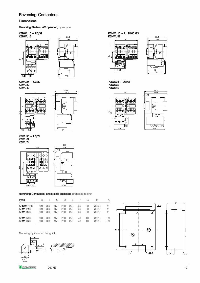
D677E 101
Reversing ContactorsReversing ContactorsReversing ContactorsReversing ContactorsReversing Contactors
DimensionsDimensionsDimensionsDimensionsDimensions
Reversing Starters, AC operated,Reversing Starters, AC operated,Reversing Starters, AC operated,Reversing Starters, AC operated,Reversing Starters, AC operated, open type
K3NWU10 + U3/32K3NWU10 + U3/32K3NWU10 + U3/32K3NWU10 + U3/32K3NWU10 + U3/32 K3NWU10 + U12/16E G3K3NWU10 + U12/16E G3K3NWU10 + U12/16E G3K3NWU10 + U12/16E G3K3NWU10 + U12/16E G3K3NWU18K3NWU18K3NWU18K3NWU18K3NWU18 K3NWU18K3NWU18K3NWU18K3NWU18K3NWU18
K3WU24 + U3/32K3WU24 + U3/32K3WU24 + U3/32K3WU24 + U3/32K3WU24 + U3/32 K3WU24 + U3/42K3WU24 + U3/42K3WU24 + U3/42K3WU24 + U3/42K3WU24 + U3/42K3WU32K3WU32K3WU32K3WU32K3WU32 K3WU32K3WU32K3WU32K3WU32K3WU32K3WU40K3WU40K3WU40K3WU40K3WU40 K3WU40K3WU40K3WU40K3WU40K3WU40
K3WU50 + U3/74K3WU50 + U3/74K3WU50 + U3/74K3WU50 + U3/74K3WU50 + U3/74K3WU62K3WU62K3WU62K3WU62K3WU62K3WU74K3WU74K3WU74K3WU74K3WU74
Reversing Contactors, sheet steel enclosed, Reversing Contactors, sheet steel enclosed, Reversing Contactors, sheet steel enclosed, Reversing Contactors, sheet steel enclosed, Reversing Contactors, sheet steel enclosed, protected to IP54
TypeTypeTypeTypeType A B C D E F G H K
K3NWU18BK3NWU18BK3NWU18BK3NWU18BK3NWU18B 300 300 150 250 250 30 30 Ø25,5 41K3WU24BK3WU24BK3WU24BK3WU24BK3WU24B 300 300 150 250 250 30 30 Ø32,5 41K3WU32BK3WU32BK3WU32BK3WU32BK3WU32B 300 300 150 250 250 30 30 Ø32,5 41
K3WU50BK3WU50BK3WU50BK3WU50BK3WU50B 300 300 150 250 250 40 40 Ø32,5 59K3WU62BK3WU62BK3WU62BK3WU62BK3WU62B 300 300 150 250 250 40 40 Ø32,5 59
Mounting by included fixing link
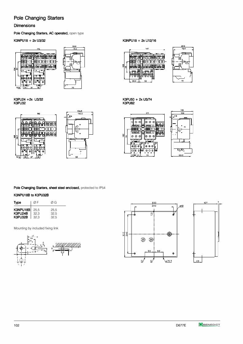
102 D677E
Pole Changing StartersPole Changing StartersPole Changing StartersPole Changing StartersPole Changing Starters
DimensionsDimensionsDimensionsDimensionsDimensions
Pole Changing Starters, AC operated, Pole Changing Starters, AC operated, Pole Changing Starters, AC operated, Pole Changing Starters, AC operated, Pole Changing Starters, AC operated, open type
K3NPU18 + 2x U3/32K3NPU18 + 2x U3/32K3NPU18 + 2x U3/32K3NPU18 + 2x U3/32K3NPU18 + 2x U3/32 K3NPU18 + 2x U12/16K3NPU18 + 2x U12/16K3NPU18 + 2x U12/16K3NPU18 + 2x U12/16K3NPU18 + 2x U12/16
K3PU24 +2x U3/32K3PU24 +2x U3/32K3PU24 +2x U3/32K3PU24 +2x U3/32K3PU24 +2x U3/32 K3PU50 + 2x U3/74K3PU50 + 2x U3/74K3PU50 + 2x U3/74K3PU50 + 2x U3/74K3PU50 + 2x U3/74K3PU32K3PU32K3PU32K3PU32K3PU32 K3PU62K3PU62K3PU62K3PU62K3PU62
Pole Changing Starters, sheet steel enclosed, Pole Changing Starters, sheet steel enclosed, Pole Changing Starters, sheet steel enclosed, Pole Changing Starters, sheet steel enclosed, Pole Changing Starters, sheet steel enclosed, protected to IP54
K3NPU18B to K3PU32BK3NPU18B to K3PU32BK3NPU18B to K3PU32BK3NPU18B to K3PU32BK3NPU18B to K3PU32B
TypeTypeTypeTypeType Ø F Ø G
K3NPU18BK3NPU18BK3NPU18BK3NPU18BK3NPU18B 25,5 25,5K3PU24BK3PU24BK3PU24BK3PU24BK3PU24B 32,3 32,5K3PU32BK3PU32BK3PU32BK3PU32BK3PU32B 32,3 32,5
Mounting by included fixing link

D677E 103
DDDDD.O.O.O.O.O.L.L.L.L.L. Starters. Starters. Starters. Starters. Starters
D.O.L. Starters With Start-Stop Buttons 104
D.O.L. Starters With Selector Switch 104
D.O.L. Starters With Selector Switch And 104Pneumatic Switch For Use In Moist Rooms
Enclosures 105
Accessories 105
Wiring Diagrams 106
Dimensions 108
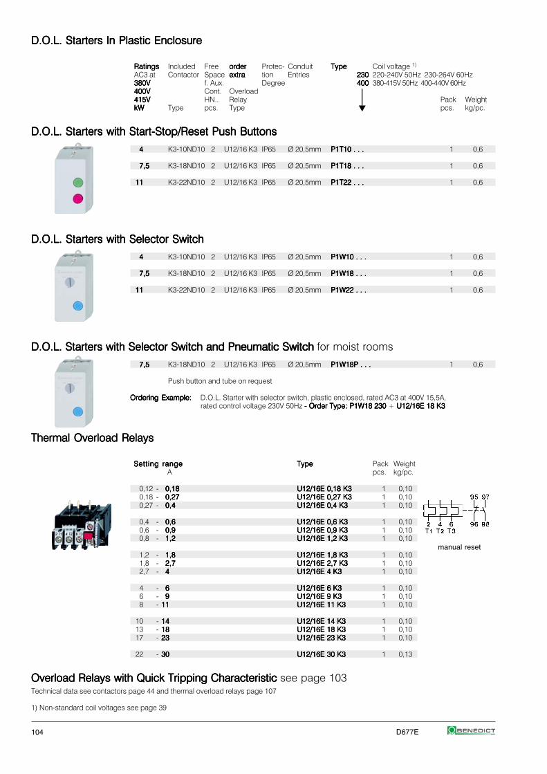
104 D677E
D.O.L. Starters D.O.L. Starters D.O.L. Starters D.O.L. Starters D.O.L. Starters In Plastic EnclosureIn Plastic EnclosureIn Plastic EnclosureIn Plastic EnclosureIn Plastic Enclosure
RatingsRatingsRatingsRatingsRatings Included Free orderorderorderorderorder Protec- Conduit TypeTypeTypeTypeType Coil voltage 1)
AC3 at Contactor Space extraextraextraextraextra tion Entries 230230230230230 220-240V 50Hz 230-264V 60Hz380V380V380V380V380V f. Aux. Degree 400400400400400 380-415V 50Hz 400-440V 60Hz400V400V400V400V400V Cont. Overload ⏐⏐⏐⏐⏐415V415V415V415V415V HN.. Relay ⏐⏐⏐⏐⏐ Pack WeightkWkWkWkWkW Type pcs. Type pcs. kg/pc.
D.O.L. Starters with Start-Stop/Reset Push ButtonsD.O.L. Starters with Start-Stop/Reset Push ButtonsD.O.L. Starters with Start-Stop/Reset Push ButtonsD.O.L. Starters with Start-Stop/Reset Push ButtonsD.O.L. Starters with Start-Stop/Reset Push Buttons
44444 K3-10ND10 2 U12/16 K3 IP65 Ø 20,5mm P1T10 . . .P1T10 . . .P1T10 . . .P1T10 . . .P1T10 . . . 1 0,6
7,57,57,57,57,5 K3-18ND10 2 U12/16 K3 IP65 Ø 20,5mm P1T18 . . .P1T18 . . .P1T18 . . .P1T18 . . .P1T18 . . . 1 0,6
1111111111 K3-22ND10 2 U12/16 K3 IP65 Ø 20,5mm P1T22 . . .P1T22 . . .P1T22 . . .P1T22 . . .P1T22 . . . 1 0,6
D.O.L. Starters with Selector SwitchD.O.L. Starters with Selector SwitchD.O.L. Starters with Selector SwitchD.O.L. Starters with Selector SwitchD.O.L. Starters with Selector Switch
44444 K3-10ND10 2 U12/16 K3 IP65 Ø 20,5mm P1W10 . . .P1W10 . . .P1W10 . . .P1W10 . . .P1W10 . . . 1 0,6
7,57,57,57,57,5 K3-18ND10 2 U12/16 K3 IP65 Ø 20,5mm P1W18 . . .P1W18 . . .P1W18 . . .P1W18 . . .P1W18 . . . 1 0,6
1111111111 K3-22ND10 2 U12/16 K3 IP65 Ø 20,5mm P1W22 . . .P1W22 . . .P1W22 . . .P1W22 . . .P1W22 . . . 1 0,6
D.O.L. Starters with Selector Switch and Pneumatic Switch D.O.L. Starters with Selector Switch and Pneumatic Switch D.O.L. Starters with Selector Switch and Pneumatic Switch D.O.L. Starters with Selector Switch and Pneumatic Switch D.O.L. Starters with Selector Switch and Pneumatic Switch for moist rooms
7,57,57,57,57,5 K3-18ND10 2 U12/16 K3 IP65 Ø 20,5mm P1W18P . . .P1W18P . . .P1W18P . . .P1W18P . . .P1W18P . . . 1 0,6
Push button and tube on request
Ordering Example:Ordering Example:Ordering Example:Ordering Example:Ordering Example: D.O.L. Starter with selector switch, plastic enclosed, rated AC3 at 400V 15,5A,rated control voltage 230V 50Hz - Order Type: P1W18 230 - Order Type: P1W18 230 - Order Type: P1W18 230 - Order Type: P1W18 230 - Order Type: P1W18 230 + U12/16E 18 K3 U12/16E 18 K3 U12/16E 18 K3 U12/16E 18 K3 U12/16E 18 K3
Thermal Overload RelaysThermal Overload RelaysThermal Overload RelaysThermal Overload RelaysThermal Overload Relays
Setting rangeSetting rangeSetting rangeSetting rangeSetting range TypeTypeTypeTypeType Pack WeightA pcs. kg/pc.
0,12 - 0,180,180,180,180,18 U12/16E 0,18 K3U12/16E 0,18 K3U12/16E 0,18 K3U12/16E 0,18 K3U12/16E 0,18 K3 1 0,100,18 - 0,270,270,270,270,27 U12/16E 0,27 K3U12/16E 0,27 K3U12/16E 0,27 K3U12/16E 0,27 K3U12/16E 0,27 K3 1 0,100,27 - 0,40,40,40,40,4 U12/16E 0,4 K3U12/16E 0,4 K3U12/16E 0,4 K3U12/16E 0,4 K3U12/16E 0,4 K3 1 0,10
0,4 - 0,60,60,60,60,6 U12/16E 0,6 K3U12/16E 0,6 K3U12/16E 0,6 K3U12/16E 0,6 K3U12/16E 0,6 K3 1 0,100,6 - 0,90,90,90,90,9 U12/16E 0,9 K3U12/16E 0,9 K3U12/16E 0,9 K3U12/16E 0,9 K3U12/16E 0,9 K3 1 0,100,8 - 1,21,21,21,21,2 U12/16E 1,2 K3U12/16E 1,2 K3U12/16E 1,2 K3U12/16E 1,2 K3U12/16E 1,2 K3 1 0,10
1,2 - 1,81,81,81,81,8 U12/16E 1,8 K3U12/16E 1,8 K3U12/16E 1,8 K3U12/16E 1,8 K3U12/16E 1,8 K3 1 0,101,8 - 2,72,72,72,72,7 U12/16E 2,7 K3U12/16E 2,7 K3U12/16E 2,7 K3U12/16E 2,7 K3U12/16E 2,7 K3 1 0,102,7 - 44444 U12/16E 4 K3U12/16E 4 K3U12/16E 4 K3U12/16E 4 K3U12/16E 4 K3 1 0,10
4 - 66666 U12/16E 6 K3U12/16E 6 K3U12/16E 6 K3U12/16E 6 K3U12/16E 6 K3 1 0,106 - 99999 U12/16E 9 K3U12/16E 9 K3U12/16E 9 K3U12/16E 9 K3U12/16E 9 K3 1 0,108 - 1111111111 U12/16E 11 K3U12/16E 11 K3U12/16E 11 K3U12/16E 11 K3U12/16E 11 K3 1 0,10
10 - 1414141414 U12/16E 14 K3U12/16E 14 K3U12/16E 14 K3U12/16E 14 K3U12/16E 14 K3 1 0,1013 - 1818181818 U12/16E 18 K3U12/16E 18 K3U12/16E 18 K3U12/16E 18 K3U12/16E 18 K3 1 0,1017 - 2323232323 U12/16E 23 K3U12/16E 23 K3U12/16E 23 K3U12/16E 23 K3U12/16E 23 K3 1 0,10
22 - 3030303030 U12/16E 30 K3U12/16E 30 K3U12/16E 30 K3U12/16E 30 K3U12/16E 30 K3 1 0,13
Overload Relays with Quick Tripping Characteristic Overload Relays with Quick Tripping Characteristic Overload Relays with Quick Tripping Characteristic Overload Relays with Quick Tripping Characteristic Overload Relays with Quick Tripping Characteristic see page 103Technical data see contactors page 44 and thermal overload relays page 107
1) Non-standard coil voltages see page 39
manual reset

D677E 105
Enclosures for ContactorsEnclosures for ContactorsEnclosures for ContactorsEnclosures for ContactorsEnclosures for Contactors
Suitable forSuitable forSuitable forSuitable forSuitable for Protection Conduit Entries TypeTypeTypeTypeType Pack Weightcontactorcontactorcontactorcontactorcontactor Degree Top Bottom pcs. kg/pc.
K3-07.. to K3-22..K3-07.. to K3-22..K3-07.. to K3-22..K3-07.. to K3-22..K3-07.. to K3-22.. IP65 2 x Ø 20,5mm 2 x Ø 20,5mm P1P1P1P1P1 1 0,35K3-24..K3-24..K3-24..K3-24..K3-24..1) to K3-40.. to K3-40.. to K3-40.. to K3-40.. to K3-40..1)
Enclosures for D.O.L. Starters Enclosures for D.O.L. Starters Enclosures for D.O.L. Starters Enclosures for D.O.L. Starters Enclosures for D.O.L. Starters with reset button
Suitable forSuitable forSuitable forSuitable forSuitable for Protection Conduit Entries TypeTypeTypeTypeType Pack Weightcontactorcontactorcontactorcontactorcontactor Degree Top Bottom pcs. kg/pc.
K3-10.. to K3-22..K3-10.. to K3-22..K3-10.. to K3-22..K3-10.. to K3-22..K3-10.. to K3-22.. IP65 2 x Ø 20,5mm 2 x Ø 20,5mm P1RP1RP1RP1RP1R 1 0,35+U12/16.. K3+U12/16.. K3+U12/16.. K3+U12/16.. K3+U12/16.. K3
Indicator UnitsIndicator UnitsIndicator UnitsIndicator UnitsIndicator Units
Specifications Voltage Range TypeTypeTypeTypeType Pack Weightpcs. kg/pc.
Coil Current IndicatorCoil Current IndicatorCoil Current IndicatorCoil Current IndicatorCoil Current Indicator, green (LED) 24 - 660V AC/DC K2-INGK2-INGK2-INGK2-INGK2-ING 10 0,02Coil Current IndicatorCoil Current IndicatorCoil Current IndicatorCoil Current IndicatorCoil Current Indicator, red (LED) 24 - 660V AC/DC K2-INRK2-INRK2-INRK2-INRK2-INR 10 0,02To be connected in series with the contactor coil. In case of coilinterruption the indicator goes out. Voltage drop approx. 2 volts
Voltage IndicatorVoltage IndicatorVoltage IndicatorVoltage IndicatorVoltage Indicator, clear (glow-disc. l.) 220 - 415V AC/DC K2-UNK2-UNK2-UNK2-UNK2-UN 10 0,02Voltage IndicatorVoltage IndicatorVoltage IndicatorVoltage IndicatorVoltage Indicator, red (LED) 24 - 120V AC/DC K2-UNRK2-UNRK2-UNRK2-UNRK2-UNR 10 0,02To be connected parallel to the contactor coil. In case ofapplied voltage the indicator also lights at coil interruption.
Lens Caps For Indicator UnitsLens Caps For Indicator UnitsLens Caps For Indicator UnitsLens Caps For Indicator UnitsLens Caps For Indicator Units
Lens cap transparent LG9743TLG9743TLG9743TLG9743TLG9743T 10 0,005Lens cap red LG9743RLG9743RLG9743RLG9743RLG9743R 10 0,005Lens cap green LG9743GRLG9743GRLG9743GRLG9743GRLG9743GR 10 0,005Mounting instructions see page 100
Heating ElementHeating ElementHeating ElementHeating ElementHeating Element
Specifications Voltage Range TypeTypeTypeTypeType Pack Weight Power Consumption pcs. kg/pc.
To avoid condensed water on places 380 - 415V, 1,5W K2-HRK2-HRK2-HRK2-HRK2-HR 10 0,02where high humidity is given together 220 - 240V, 1,5W K2-HR 230K2-HR 230K2-HR 230K2-HR 230K2-HR 230 10 0,02with alterations of ambient temperature
Additional Terminals, Start ContactAdditional Terminals, Start ContactAdditional Terminals, Start ContactAdditional Terminals, Start ContactAdditional Terminals, Start Contact
Specification Cable Cross-sections to clamp mm² TypeTypeTypeTypeType Pack Weightsolid or flexib. w. multi-stranded flexible core cable end pcs. kg/pc.
Neutral TerminalNeutral TerminalNeutral TerminalNeutral TerminalNeutral Terminal 2 x 0,75-4 2 x 0,75-2,5 2 x 0,5-2,5 LG9744LG9744LG9744LG9744LG9744 10 0,009Earth TerminalEarth TerminalEarth TerminalEarth TerminalEarth Terminal 2,5-16 1,5-10 1,5-10 LG9750LG9750LG9750LG9750LG9750 10 0,052Mounting instructions see page 100
Start ContactStart ContactStart ContactStart ContactStart Contact for contactor to be snapped on top of LG9319-K3LG9319-K3LG9319-K3LG9319-K3LG9319-K3 10 0,03K3-10 to K3-22 the auxiliary contact
1) without auxiliary contact blocks
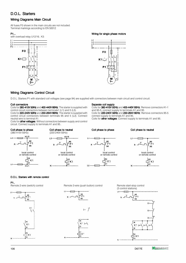
106 D677E
D.O.L. StartersD.O.L. StartersD.O.L. StartersD.O.L. StartersD.O.L. Starters
Wiring Diagrams Main CircuitWiring Diagrams Main CircuitWiring Diagrams Main CircuitWiring Diagrams Main CircuitWiring Diagrams Main Circuit
All fuses F0 shown in the main circuits are not included.Terminal markings according to EN 50012
P1...P1...P1...P1...P1... Wiring for single phase motorsWiring for single phase motorsWiring for single phase motorsWiring for single phase motorsWiring for single phase motorswith overload relay U12/16.. K3
Wiring Diagrams Control CircuitWiring Diagrams Control CircuitWiring Diagrams Control CircuitWiring Diagrams Control CircuitWiring Diagrams Control Circuit
D.O.L. Starters P1 with standard coil voltages (see page 94) are supplied with connectors between main circuit and control circuit.
Coil connectorsCoil connectorsCoil connectorsCoil connectorsCoil connectorsCoils for 380-415V 50Hz380-415V 50Hz380-415V 50Hz380-415V 50Hz380-415V 50Hz and 400-440V 60Hz400-440V 60Hz400-440V 60Hz400-440V 60Hz400-440V 60Hz: The starter is supplied withcontrol circuit connectors between terminals1 (L1) and 5 (L3).Coils for 220-240V 50Hz220-240V 50Hz220-240V 50Hz220-240V 50Hz220-240V 50Hz and 230-264V 60Hz230-264V 60Hz230-264V 60Hz230-264V 60Hz230-264V 60Hz: The starter is supplied withcontrol circuit connectors between terminals 95 and 5 (L3). Connectneutral wire to terminal A1.Coils for other voltagesother voltagesother voltagesother voltagesother voltages: Without connectors between supply and controlcircuit. Connect supply to terminals A1 and 95.
Coil phase to phaseCoil phase to phaseCoil phase to phaseCoil phase to phaseCoil phase to phase Coil phase to neutralCoil phase to neutralCoil phase to neutralCoil phase to neutralCoil phase to neutral(380-415V 50Hz) (220-240V 50Hz)
Separate coil supplySeparate coil supplySeparate coil supplySeparate coil supplySeparate coil supplyCoils for 380-415V 50Hz380-415V 50Hz380-415V 50Hz380-415V 50Hz380-415V 50Hz and 400-440V 60Hz400-440V 60Hz400-440V 60Hz400-440V 60Hz400-440V 60Hz: Remove connectors A1-1and 95-5, connect supply to terminals A1 and 95.Coils for 220-240V 50Hz220-240V 50Hz220-240V 50Hz220-240V 50Hz220-240V 50Hz and 230-264V 60Hz230-264V 60Hz230-264V 60Hz230-264V 60Hz230-264V 60Hz: Remove connectors 95-5connect supply to terminals A1 and 95.Coils for other voltagesother voltagesother voltagesother voltagesother voltages: Connect supply to terminals A1 and 95.
Coil phase to phaseCoil phase to phaseCoil phase to phaseCoil phase to phaseCoil phase to phase Coil phase to neutralCoil phase to neutralCoil phase to neutralCoil phase to neutralCoil phase to neutral
local controlor remote control
local controlor remote control
local controlor remote control
local controlor remote control
D.O.L. Starters with remote controlD.O.L. Starters with remote controlD.O.L. Starters with remote controlD.O.L. Starters with remote controlD.O.L. Starters with remote control
P1..P1..P1..P1..P1..Remote 2-wire (switch) control Remote 3-wire (push button) control Remote start-stop control
(3 control stations)

D677E 107
D.O.L. StartersD.O.L. StartersD.O.L. StartersD.O.L. StartersD.O.L. Starters
Wiring Diagrams Control CircuitsWiring Diagrams Control CircuitsWiring Diagrams Control CircuitsWiring Diagrams Control CircuitsWiring Diagrams Control Circuits
Typical circuit diagram (for separate coil supply, control circuit connected between L1 and N)Terminal markings according to EN 50012
D.O.L. Starters with Start-Stop/Reset Push ButtonsD.O.L. Starters with Start-Stop/Reset Push ButtonsD.O.L. Starters with Start-Stop/Reset Push ButtonsD.O.L. Starters with Start-Stop/Reset Push ButtonsD.O.L. Starters with Start-Stop/Reset Push Buttons
P1T10, P1T18, P1T22P1T10, P1T18, P1T22P1T10, P1T18, P1T22P1T10, P1T18, P1T22P1T10, P1T18, P1T22 P1T10, P1T18, P1T22P1T10, P1T18, P1T22P1T10, P1T18, P1T22P1T10, P1T18, P1T22P1T10, P1T18, P1T22with overload relay U12/16.. K3 with external push buttons
D.O.L. Starters with Selector SwitchD.O.L. Starters with Selector SwitchD.O.L. Starters with Selector SwitchD.O.L. Starters with Selector SwitchD.O.L. Starters with Selector Switch
P1W10, P1W18, P1W22P1W10, P1W18, P1W22P1W10, P1W18, P1W22P1W10, P1W18, P1W22P1W10, P1W18, P1W22 P1W10, P1W18, P1W22P1W10, P1W18, P1W22P1W10, P1W18, P1W22P1W10, P1W18, P1W22P1W10, P1W18, P1W22with external control switch with external push buttons
D.O.L. Starters with Selector Switch and Pneumatic SwitchD.O.L. Starters with Selector Switch and Pneumatic SwitchD.O.L. Starters with Selector Switch and Pneumatic SwitchD.O.L. Starters with Selector Switch and Pneumatic SwitchD.O.L. Starters with Selector Switch and Pneumatic Switchfor Swimmingpool Control Gear and for use in Moist Roomsfor Swimmingpool Control Gear and for use in Moist Roomsfor Swimmingpool Control Gear and for use in Moist Roomsfor Swimmingpool Control Gear and for use in Moist Roomsfor Swimmingpool Control Gear and for use in Moist RoomsP1W18PP1W18PP1W18PP1W18PP1W18Pwith overload relay U12/16.. K3
push buttonON/OFF

108 D677E
D.O.L. StartersD.O.L. StartersD.O.L. StartersD.O.L. StartersD.O.L. Starters
DimensionsDimensionsDimensionsDimensionsDimensions
D.O.L. Starters with Start-Stop/Reset Push Buttons, Plastic EnclosedD.O.L. Starters with Start-Stop/Reset Push Buttons, Plastic EnclosedD.O.L. Starters with Start-Stop/Reset Push Buttons, Plastic EnclosedD.O.L. Starters with Start-Stop/Reset Push Buttons, Plastic EnclosedD.O.L. Starters with Start-Stop/Reset Push Buttons, Plastic Enclosed D.O.L. Starters with Selector Switch, Plastic EnclosedD.O.L. Starters with Selector Switch, Plastic EnclosedD.O.L. Starters with Selector Switch, Plastic EnclosedD.O.L. Starters with Selector Switch, Plastic EnclosedD.O.L. Starters with Selector Switch, Plastic Enclosed
P1T.., P1TP..P1T.., P1TP..P1T.., P1TP..P1T.., P1TP..P1T.., P1TP.. P1W.., P1W18PP1W.., P1W18PP1W.., P1W18PP1W.., P1W18PP1W.., P1W18P
P1W18P:P1W18P:P1W18P:P1W18P:P1W18P: plug-in for air tube inside diameter 3mm
Rear Conduit EntriesRear Conduit EntriesRear Conduit EntriesRear Conduit EntriesRear Conduit Entries
knockouts4 x Ø 23
Earth Terminal LG9750Earth Terminal LG9750Earth Terminal LG9750Earth Terminal LG9750Earth Terminal LG9750 for K2-23 and K2-30 in Enclosure P1 Neutral Terminal LG9744Neutral Terminal LG9744Neutral Terminal LG9744Neutral Terminal LG9744Neutral Terminal LG9744
for K2-23 and K2-30 remove spacing piece
LG9750LG9750LG9750LG9750LG9750
LG9744LG9744LG9744LG9744LG9744
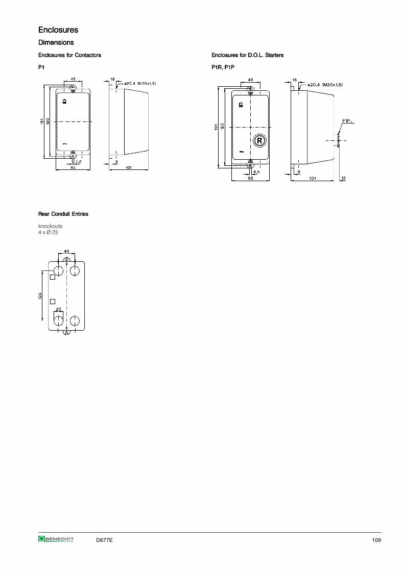
D677E 109
EnclosuresEnclosuresEnclosuresEnclosuresEnclosures
DimensionsDimensionsDimensionsDimensionsDimensions
Enclosures for ContactorsEnclosures for ContactorsEnclosures for ContactorsEnclosures for ContactorsEnclosures for Contactors Enclosures for D.O.L. StartersEnclosures for D.O.L. StartersEnclosures for D.O.L. StartersEnclosures for D.O.L. StartersEnclosures for D.O.L. Starters
P1P1P1P1P1 P1R, P1PP1R, P1PP1R, P1PP1R, P1PP1R, P1P
Rear Conduit EntriesRear Conduit EntriesRear Conduit EntriesRear Conduit EntriesRear Conduit Entries
knockouts4 x Ø 23

110 D677E
D.O.L. StartersD.O.L. StartersD.O.L. StartersD.O.L. StartersD.O.L. Starters
Mounting and Wiring InstructionsMounting and Wiring InstructionsMounting and Wiring InstructionsMounting and Wiring InstructionsMounting and Wiring Instructions
Indicators and Lens Caps Indicators and Lens Caps Indicators and Lens Caps Indicators and Lens Caps Indicators and Lens Caps for D.O.L. Starters P1
K2-UN., K2-IN.K2-UN., K2-IN.K2-UN., K2-IN.K2-UN., K2-IN.K2-UN., K2-IN.
LG9743.LG9743.LG9743.LG9743.LG9743.
Wiring ExamplesWiring ExamplesWiring ExamplesWiring ExamplesWiring Examples
Coil Current IndicatorCoil Current IndicatorCoil Current IndicatorCoil Current IndicatorCoil Current Indicator Voltage IndicatorVoltage IndicatorVoltage IndicatorVoltage IndicatorVoltage Indicator Heating ElementHeating ElementHeating ElementHeating ElementHeating Element
K2-INGK2-INGK2-INGK2-INGK2-ING K2-UNK2-UNK2-UNK2-UNK2-UN K2-HRK2-HRK2-HRK2-HRK2-HR K2-HR 230K2-HR 230K2-HR 230K2-HR 230K2-HR 230K2-INRK2-INRK2-INRK2-INRK2-INR K2-UNRK2-UNRK2-UNRK2-UNRK2-UNR
redred
Colour mentioned in wiring diagrams refer tothe outgoing connection wire of the device.
Start Contact LG9319-K3 Start Contact LG9319-K3 Start Contact LG9319-K3 Start Contact LG9319-K3 Start Contact LG9319-K3 for K3-10ND10 up to K3-22ND10

D677E 111
Thermal Overload RelaysThermal Overload RelaysThermal Overload RelaysThermal Overload RelaysThermal Overload Relays
Thermal Overload Relays for Direct Mounting 112
Thermal Overload Relays for Separate Mounting 114
Accessories 115
Technical Data 116
Dimensions 121

112 D677E
Thermal Overload Relays Thermal Overload Relays Thermal Overload Relays Thermal Overload Relays Thermal Overload Relays for plug-in mounting
Setting RangeSetting RangeSetting RangeSetting RangeSetting Range TypeTypeTypeTypeType Pack WeightD.O.L.D.O.L.D.O.L.D.O.L.D.O.L. (A) (A) pcs. kg/pc. Wiring Diagram
With Manual ResetWith Manual ResetWith Manual ResetWith Manual ResetWith Manual Reset, for contactors K1-..
0,12 - 0,180,180,180,180,18 - U12/16E 0,18 K1U12/16E 0,18 K1U12/16E 0,18 K1U12/16E 0,18 K1U12/16E 0,18 K1 1 0,100,18 - 0,270,270,270,270,27 - U12/16E 0,27 K1U12/16E 0,27 K1U12/16E 0,27 K1U12/16E 0,27 K1U12/16E 0,27 K1 1 0,100,27 - 0,40,40,40,40,4 - U12/16E 0,4 K1U12/16E 0,4 K1U12/16E 0,4 K1U12/16E 0,4 K1U12/16E 0,4 K1 1 0,10
0,4 - 0,60,60,60,60,6 - U12/16E 0,6 K1U12/16E 0,6 K1U12/16E 0,6 K1U12/16E 0,6 K1U12/16E 0,6 K1 1 0,100,6 - 0,90,90,90,90,9 - U12/16E 0,9 K1U12/16E 0,9 K1U12/16E 0,9 K1U12/16E 0,9 K1U12/16E 0,9 K1 1 0,100,8 - 1,21,21,21,21,2 - U12/16E 1,2 K1U12/16E 1,2 K1U12/16E 1,2 K1U12/16E 1,2 K1U12/16E 1,2 K1 1 0,10
1,2 - 1,81,81,81,81,8 - U12/16E 1,8 K1U12/16E 1,8 K1U12/16E 1,8 K1U12/16E 1,8 K1U12/16E 1,8 K1 1 0,101,8 - 2,72,72,72,72,7 - U12/16E 2,7 K1U12/16E 2,7 K1U12/16E 2,7 K1U12/16E 2,7 K1U12/16E 2,7 K1 1 0,102,7 - 44444 - U12/16E 4 K1U12/16E 4 K1U12/16E 4 K1U12/16E 4 K1U12/16E 4 K1 1 0,10
4 - 66666 7 - 10,5 U12/16E 6 K1U12/16E 6 K1U12/16E 6 K1U12/16E 6 K1U12/16E 6 K1 1 0,106 - 99999 10,5 - 15,5 U12/16E 9 K1U12/16E 9 K1U12/16E 9 K1U12/16E 9 K1U12/16E 9 K1 1 0,108 - 1111111111 14 - 19 U12/16E 11 K1U12/16E 11 K1U12/16E 11 K1U12/16E 11 K1U12/16E 11 K1 1 0,10
10 - 1414141414 18 - 24 U12/16E 14 K1U12/16E 14 K1U12/16E 14 K1U12/16E 14 K1U12/16E 14 K1 1 0,10
With Auto ResetWith Auto ResetWith Auto ResetWith Auto ResetWith Auto Reset, for contactors K1-..
0,12 - 0,180,180,180,180,18 - U12/16A 0,18 K1U12/16A 0,18 K1U12/16A 0,18 K1U12/16A 0,18 K1U12/16A 0,18 K1 1 0,100,18 - 0,270,270,270,270,27 - U12/16A 0,27 K1U12/16A 0,27 K1U12/16A 0,27 K1U12/16A 0,27 K1U12/16A 0,27 K1 1 0,100,27 - 0,40,40,40,40,4 - U12/16A 0,4 K1U12/16A 0,4 K1U12/16A 0,4 K1U12/16A 0,4 K1U12/16A 0,4 K1 1 0,10
0,4 - 0,60,60,60,60,6 - U12/16A 0,6 K1U12/16A 0,6 K1U12/16A 0,6 K1U12/16A 0,6 K1U12/16A 0,6 K1 1 0,100,6 - 0,90,90,90,90,9 - U12/16A 0,9 K1U12/16A 0,9 K1U12/16A 0,9 K1U12/16A 0,9 K1U12/16A 0,9 K1 1 0,100,8 - 1,21,21,21,21,2 - U12/16A 1,2 K1U12/16A 1,2 K1U12/16A 1,2 K1U12/16A 1,2 K1U12/16A 1,2 K1 1 0,10
1,2 - 1,81,81,81,81,8 - U12/16A 1,8 K1U12/16A 1,8 K1U12/16A 1,8 K1U12/16A 1,8 K1U12/16A 1,8 K1 1 0,101,8 - 2,72,72,72,72,7 - U12/16A 2,7 K1U12/16A 2,7 K1U12/16A 2,7 K1U12/16A 2,7 K1U12/16A 2,7 K1 1 0,102,7 - 44444 - U12/16A 4 K1U12/16A 4 K1U12/16A 4 K1U12/16A 4 K1U12/16A 4 K1 1 0,10
4 - 66666 7 - 10,5 U12/16A 6 K1U12/16A 6 K1U12/16A 6 K1U12/16A 6 K1U12/16A 6 K1 1 0,106 - 99999 10,5 - 15,5 U12/16A 9 K1U12/16A 9 K1U12/16A 9 K1U12/16A 9 K1U12/16A 9 K1 1 0,108 - 1111111111 14 - 19 U12/16A 11 K1U12/16A 11 K1U12/16A 11 K1U12/16A 11 K1U12/16A 11 K1 1 0,10
10 - 1414141414 18 - 24 U12/16A 14 K1U12/16A 14 K1U12/16A 14 K1U12/16A 14 K1U12/16A 14 K1 1 0,10
With Quick Tripping Characteristic With Quick Tripping Characteristic With Quick Tripping Characteristic With Quick Tripping Characteristic With Quick Tripping Characteristic for EEx e motors and submersible pumps, f. contactors K1-..
0,4 - 0,60,60,60,60,6 - U12/16EQ 0,6 K1U12/16EQ 0,6 K1U12/16EQ 0,6 K1U12/16EQ 0,6 K1U12/16EQ 0,6 K1 1 0,100,6 - 0,90,90,90,90,9 - U12/16EQ 0,9 K1U12/16EQ 0,9 K1U12/16EQ 0,9 K1U12/16EQ 0,9 K1U12/16EQ 0,9 K1 1 0,100,8 - 1,21,21,21,21,2 - U12/16EQ 1,2 K1U12/16EQ 1,2 K1U12/16EQ 1,2 K1U12/16EQ 1,2 K1U12/16EQ 1,2 K1 1 0,10
1,2 - 1,81,81,81,81,8 - U12/16EQ 1,8 K1U12/16EQ 1,8 K1U12/16EQ 1,8 K1U12/16EQ 1,8 K1U12/16EQ 1,8 K1 1 0,101,8 - 2,72,72,72,72,7 - U12/16EQ 2,7 K1U12/16EQ 2,7 K1U12/16EQ 2,7 K1U12/16EQ 2,7 K1U12/16EQ 2,7 K1 1 0,102,7 - 44444 - U12/16EQ 4 K1U12/16EQ 4 K1U12/16EQ 4 K1U12/16EQ 4 K1U12/16EQ 4 K1 1 0,10
4 - 66666 7 - 10,5 U12/16EQ 6 K1U12/16EQ 6 K1U12/16EQ 6 K1U12/16EQ 6 K1U12/16EQ 6 K1 1 0,106 - 99999 10,5 - 15,5 U12/16EQ 9 K1U12/16EQ 9 K1U12/16EQ 9 K1U12/16EQ 9 K1U12/16EQ 9 K1 1 0,108 - 1111111111 14 - 19 U12/16EQ 11 K1U12/16EQ 11 K1U12/16EQ 11 K1U12/16EQ 11 K1U12/16EQ 11 K1 1 0,10
10 - 1414141414 18 - 24 U12/16EQ 14 K1U12/16EQ 14 K1U12/16EQ 14 K1U12/16EQ 14 K1U12/16EQ 14 K1 1 0,10
manual reset
manual reset
auto resetor manual reset

D677E 113
Thermal Overload Relays Thermal Overload Relays Thermal Overload Relays Thermal Overload Relays Thermal Overload Relays for plug-in mounting
Setting RangeSetting RangeSetting RangeSetting RangeSetting Range TypeTypeTypeTypeType Pack WeightD.O.L.D.O.L.D.O.L.D.O.L.D.O.L. (A) (A) pcs. kg/pc. Wiring Diagram
With Manual ResetWith Manual ResetWith Manual ResetWith Manual ResetWith Manual Reset, for contactors K(G)3-10.. to K(G)3-22.. ..
0,12 - 0,180,180,180,180,18 - U12/16E 0,18 K3U12/16E 0,18 K3U12/16E 0,18 K3U12/16E 0,18 K3U12/16E 0,18 K3 1 0,100,18 - 0,270,270,270,270,27 - U12/16E 0,27 K3U12/16E 0,27 K3U12/16E 0,27 K3U12/16E 0,27 K3U12/16E 0,27 K3 1 0,100,27 - 0,40,40,40,40,4 - U12/16E 0,4 K3U12/16E 0,4 K3U12/16E 0,4 K3U12/16E 0,4 K3U12/16E 0,4 K3 1 0,10
0,4 - 0,60,60,60,60,6 - U12/16E 0,6 K3U12/16E 0,6 K3U12/16E 0,6 K3U12/16E 0,6 K3U12/16E 0,6 K3 1 0,100,6 - 0,90,90,90,90,9 - U12/16E 0,9 K3U12/16E 0,9 K3U12/16E 0,9 K3U12/16E 0,9 K3U12/16E 0,9 K3 1 0,100,8 - 1,21,21,21,21,2 - U12/16E 1,2 K3U12/16E 1,2 K3U12/16E 1,2 K3U12/16E 1,2 K3U12/16E 1,2 K3 1 0,10
1,2 - 1,81,81,81,81,8 - U12/16E 1,8 K3U12/16E 1,8 K3U12/16E 1,8 K3U12/16E 1,8 K3U12/16E 1,8 K3 1 0,101,8 - 2,72,72,72,72,7 - U12/16E 2,7 K3U12/16E 2,7 K3U12/16E 2,7 K3U12/16E 2,7 K3U12/16E 2,7 K3 1 0,102,7 - 44444 - U12/16E 4 K3U12/16E 4 K3U12/16E 4 K3U12/16E 4 K3U12/16E 4 K3 1 0,10
4 - 66666 7 - 10,5 U12/16E 6 K3U12/16E 6 K3U12/16E 6 K3U12/16E 6 K3U12/16E 6 K3 1 0,106 - 99999 10,5 - 15,5 U12/16E 9 K3U12/16E 9 K3U12/16E 9 K3U12/16E 9 K3U12/16E 9 K3 1 0,108 - 1111111111 14 - 19 U12/16E 11 K3U12/16E 11 K3U12/16E 11 K3U12/16E 11 K3U12/16E 11 K3 1 0,10
10 - 1414141414 18 - 24 U12/16E 14 K3U12/16E 14 K3U12/16E 14 K3U12/16E 14 K3U12/16E 14 K3 1 0,1013 - 1818181818 23 - 31 U12/16E 18 K3U12/16E 18 K3U12/16E 18 K3U12/16E 18 K3U12/16E 18 K3 1 0,1017 - 2323232323 30 - 40 U12/16E 23 K3U12/16E 23 K3U12/16E 23 K3U12/16E 23 K3U12/16E 23 K3 1 0,10
22 - 3030303030 38 - 52 U12/16E 30 K3U12/16E 30 K3U12/16E 30 K3U12/16E 30 K3U12/16E 30 K3 1 0,13
With quick Tripping Characteristic quick Tripping Characteristic quick Tripping Characteristic quick Tripping Characteristic quick Tripping Characteristic for EEx e motors and under water pumps
0,4 - 0,60,60,60,60,6 - U12/16EQ 0,6 K3U12/16EQ 0,6 K3U12/16EQ 0,6 K3U12/16EQ 0,6 K3U12/16EQ 0,6 K3 1 0,100,6 - 0,90,90,90,90,9 - U12/16EQ 0,9 K3U12/16EQ 0,9 K3U12/16EQ 0,9 K3U12/16EQ 0,9 K3U12/16EQ 0,9 K3 1 0,100,8 - 1,21,21,21,21,2 - U12/16EQ 1,2 K3U12/16EQ 1,2 K3U12/16EQ 1,2 K3U12/16EQ 1,2 K3U12/16EQ 1,2 K3 1 0,10
1,2 - 1,81,81,81,81,8 - U12/16EQ 1,8 K3U12/16EQ 1,8 K3U12/16EQ 1,8 K3U12/16EQ 1,8 K3U12/16EQ 1,8 K3 1 0,101,8 - 2,72,72,72,72,7 - U12/16EQ 2,7 K3U12/16EQ 2,7 K3U12/16EQ 2,7 K3U12/16EQ 2,7 K3U12/16EQ 2,7 K3 1 0,102,7 - 44444 - U12/16EQ 4 K3U12/16EQ 4 K3U12/16EQ 4 K3U12/16EQ 4 K3U12/16EQ 4 K3 1 0,10
4 - 66666 7 - 10,5 U12/16EQ 6 K3U12/16EQ 6 K3U12/16EQ 6 K3U12/16EQ 6 K3U12/16EQ 6 K3 1 0,106 - 99999 10,5 - 15,5 U12/16EQ 9 K3U12/16EQ 9 K3U12/16EQ 9 K3U12/16EQ 9 K3U12/16EQ 9 K3 1 0,108 - 1111111111 14 - 19 U12/16EQ 11 K3U12/16EQ 11 K3U12/16EQ 11 K3U12/16EQ 11 K3U12/16EQ 11 K3 1 0,10
10 - 1414141414 18 - 24 U12/16EQ 14 K3U12/16EQ 14 K3U12/16EQ 14 K3U12/16EQ 14 K3U12/16EQ 14 K3 1 0,10
For contactors K(G)3-10.. to K(G)3-40A..
0,12 - 0,180,180,180,180,18 - U3/32 0,18U3/32 0,18U3/32 0,18U3/32 0,18U3/32 0,18 1 0,140,18 - 0,270,270,270,270,27 - U3/32 0,27U3/32 0,27U3/32 0,27U3/32 0,27U3/32 0,27 1 0,140,27 - 0,40,40,40,40,4 - U3/32 0,4U3/32 0,4U3/32 0,4U3/32 0,4U3/32 0,4 1 0,14
0,4 - 0,60,60,60,60,6 - U3/32 0,6U3/32 0,6U3/32 0,6U3/32 0,6U3/32 0,6 1 0,140,6 - 0,90,90,90,90,9 - U3/32 0,9U3/32 0,9U3/32 0,9U3/32 0,9U3/32 0,9 1 0,140,8 - 1,21,21,21,21,2 - U3/32 1,2U3/32 1,2U3/32 1,2U3/32 1,2U3/32 1,2 1 0,14
1,2 - 1,81,81,81,81,8 - U3/32 1,8U3/32 1,8U3/32 1,8U3/32 1,8U3/32 1,8 1 0,141,8 - 2,72,72,72,72,7 - U3/32 2,7U3/32 2,7U3/32 2,7U3/32 2,7U3/32 2,7 1 0,142,7 - 44444 - U3/32 4U3/32 4U3/32 4U3/32 4U3/32 4 1 0,14
4 - 66666 7 - 10,5 U3/32 6U3/32 6U3/32 6U3/32 6U3/32 6 1 0,146 - 99999 10,5 - 15,5 U3/32 9U3/32 9U3/32 9U3/32 9U3/32 9 1 0,148 - 1111111111 14 - 19 U3/32 11U3/32 11U3/32 11U3/32 11U3/32 11 1 0,14
10 - 1414141414 18 - 24 U3/32 14U3/32 14U3/32 14U3/32 14U3/32 14 1 0,1413 - 1818181818 23 - 31 U3/32 18U3/32 18U3/32 18U3/32 18U3/32 18 1 0,1417 - 2424242424 30 - 41 U3/32 24U3/32 24U3/32 24U3/32 24U3/32 24 1 0,14
23 - 3232323232 40 - 55 U3/32 32U3/32 32U3/32 32U3/32 32U3/32 32 1 0,14
For contactors K(G)3-24A.. to K(G)3-40A ..
10 - 1414141414 18 - 24 U3/42 14U3/42 14U3/42 14U3/42 14U3/42 14 1 0,3014 - 2020202020 24 - 35 U3/42 20U3/42 20U3/42 20U3/42 20U3/42 20 1 0,30
20 - 2828282828 35 - 48 U3/42 28U3/42 28U3/42 28U3/42 28U3/42 28 1 0,3028 - 4242424242 48 - 73 U3/42 42U3/42 42U3/42 42U3/42 42U3/42 42 1 0,30
manual reset
manual andauto reset
manual andauto reset
manual reset

114 D677E
Thermal Overload Relays Thermal Overload Relays Thermal Overload Relays Thermal Overload Relays Thermal Overload Relays for plug-in mounting
Setting RangeSetting RangeSetting RangeSetting RangeSetting Range TypeTypeTypeTypeType Pack WeightD.O.L.D.O.L.D.O.L.D.O.L.D.O.L. (A) (A) pcs. kg/pc. Wiring Diagram
For contactors K3-50A.. to K3-74A..
20 - 2828282828 35 - 48 U3/74 28U3/74 28U3/74 28U3/74 28U3/74 28 1 0,4028 - 4242424242 48 - 73 U3/74 42U3/74 42U3/74 42U3/74 42U3/74 42 1 0,4040 - 5252525252 70 - 90 U3/74 52U3/74 52U3/74 52U3/74 52U3/74 52 1 0,40
52 - 6565656565 90 - 112 U3/74 65U3/74 65U3/74 65U3/74 65U3/74 65 1 0,4060 - 7474747474 104 - 128 U3/74 74U3/74 74U3/74 74U3/74 74U3/74 74 1 0,40
Thermal Overload Relays Thermal Overload Relays Thermal Overload Relays Thermal Overload Relays Thermal Overload Relays for separate mounting
Setting RangeSetting RangeSetting RangeSetting RangeSetting Range TypeTypeTypeTypeType Pack WeightD.O.L.D.O.L.D.O.L.D.O.L.D.O.L. (A) (A) pcs. kg/pc. Wiring Diagram
For contactors K3-90, K3-115, K85, K110
60 - 9090909090 104 - 156 U85 90U85 90U85 90U85 90U85 90 1 0,9080 -120120120120120 140 - 207 U85 120U85 120U85 120U85 120U85 120
For contactors K3-151.. and K3-176.., busbars included
120 - 180180180180180 208 - 312 U180 180U180 180U180 180U180 180U180 180 1 1,5
For contactors K3-210.. up to K3-316.., busbars included
144 - 216216216216216 250 - 374 U320 216U320 216U320 216U320 216U320 216 1 1,8216 - 320320320320320 374 - 554 U320 320U320 320U320 320U320 320U320 320
For contactors K3-315.. , K3-450.. , K3-550.. , K3-700.. , K3-860..
240 - 360360360360360 416 - 623 U800 360U800 360U800 360U800 360U800 360 1 4,1360 - 540540540540540 623 - 935 U800 540U800 540U800 540U800 540U800 540 1 4,1
540 - 800800800800800 935 - 1385 U800 800U800 800U800 800U800 800U800 800 1 4,1
With Slow Tripping Characteristic With Slow Tripping Characteristic With Slow Tripping Characteristic With Slow Tripping Characteristic With Slow Tripping Characteristic for heavy duty starting with long run up timesFor separate mounting, suitable for all contactors
0,8 - 1,21,21,21,21,2 1,2 - 2,1 UAT21 1,2UAT21 1,2UAT21 1,2UAT21 1,2UAT21 1,2 1 1,01,2 - 1,81,81,81,81,8 2,1 - 3,1 UAT21 1,8UAT21 1,8UAT21 1,8UAT21 1,8UAT21 1,8 1 1,01,6 - 2,42,42,42,42,4 2,8 - 4,2 UAT21 2,4UAT21 2,4UAT21 2,4UAT21 2,4UAT21 2,4 1 1,0
2,4 - 3,73,73,73,73,7 4,2 - 6,4 UAT21 3,7UAT21 3,7UAT21 3,7UAT21 3,7UAT21 3,7 1 1,03,7 - 5,75,75,75,75,7 6,4 - 9,9 UAT21 5,7UAT21 5,7UAT21 5,7UAT21 5,7UAT21 5,7 1 1,05,3 - 8,28,28,28,28,2 9,2 - 14,2 UAT21 8,2UAT21 8,2UAT21 8,2UAT21 8,2UAT21 8,2 1 1,0
8 - 1212121212 13,9 - 20,1 UAT21 12UAT21 12UAT21 12UAT21 12UAT21 12 1 1,012 - 1818181818 20,1 - 31,2 UAT21 18UAT21 18UAT21 18UAT21 18UAT21 18 1 1,0
16 - 2424242424 27,7 - 41,6 UAT22 24UAT22 24UAT22 24UAT22 24UAT22 24 1 1,1
24 - 3737373737 41,6 - 64 UAT23 37UAT23 37UAT23 37UAT23 37UAT23 37 1 1,332 - 4949494949 55,4 - 85 UAT23 49UAT23 49UAT23 49UAT23 49UAT23 49 1 1,348 - 7272727272 83 - 125 UAT23 72UAT23 72UAT23 72UAT23 72UAT23 72 1 1,3
manual reset
manual andauto reset
manual reset
manual andauto reset

D677E 115
AccessoriesAccessoriesAccessoriesAccessoriesAccessories
TypeTypeTypeTypeType Pack Weightfor overload relays for contactors set kg/set
Busbar SetsBusbar SetsBusbar SetsBusbar SetsBusbar Sets
U800 K3-450.. , K3-550.. SU840/550SU840/550SU840/550SU840/550SU840/550 1 1,7U800 K3-700.. , K3-860.. SU840/860SU840/860SU840/860SU840/860SU840/860 2,1
Cable Cross-section (mm2) TypeTypeTypeTypeTypesolid or Pack Weight
for overload relay stranded flexible pcs. kg/pc.
Set for Single Mounting Set for Single Mounting Set for Single Mounting Set for Single Mounting Set for Single Mounting on DIN-rail DIN-rail DIN-rail DIN-rail DIN-rail with terminals
U12/16..K3 0,75 - 6 0,75 - 4 U12SM K3U12SM K3U12SM K3U12SM K3U12SM K3 1 0,035
Additional TerminalsAdditional TerminalsAdditional TerminalsAdditional TerminalsAdditional Terminals with fingertouch protection
U3/32 0,75 - 6 0,75 - 4 U3/32SMU3/32SMU3/32SMU3/32SMU3/32SM 1 0,035
Set for Single Mounting Set for Single Mounting Set for Single Mounting Set for Single Mounting Set for Single Mounting on DIN-railDIN-railDIN-railDIN-railDIN-rail
U3/42, U3/74 - - U3/42GU3/42GU3/42GU3/42GU3/42G 1 0,030
Connecting Wire SetConnecting Wire SetConnecting Wire SetConnecting Wire SetConnecting Wire Set for U3/42, U3/74 with Single Mounting
U3/42, U3/74 150mm lang 10mm2 LG5830-4LG5830-4LG5830-4LG5830-4LG5830-4 1 0,060U3/42, U3/74 250mm lang 10mm2 LG5830-2LG5830-2LG5830-2LG5830-2LG5830-2 1 0,100
Additional TerminalsAdditional TerminalsAdditional TerminalsAdditional TerminalsAdditional Terminals with fingertouch protection
1-pole f. U12/16, U3/32 0,75 - 10 0,75 - 6 LG9339LG9339LG9339LG9339LG9339 1 0,009
3-pole for U3/42 4 - 35 6 - 25 LG7559LG7559LG7559LG7559LG7559 1 0,052

116 D677E
Thermal Overload RelaysThermal Overload RelaysThermal Overload RelaysThermal Overload RelaysThermal Overload Relays, tripping times for selection to motors of protection degree EEx e
Relays With Standard Tripping CharacteristicRelays With Standard Tripping CharacteristicRelays With Standard Tripping CharacteristicRelays With Standard Tripping CharacteristicRelays With Standard Tripping Characteristic
Setting RangeSetting RangeSetting RangeSetting RangeSetting Range Tripping time depending on the multipleof the current setting from cold condition(tolerance ±20% of the tripping time)IIIIIAAAAA/I/I/I/I/INNNNN IIIIIAAAAA/I/I/I/I/INNNNN IIIIIAAAAA/I/I/I/I/INNNNN IIIIIAAAAA/I/I/I/I/INNNNN IIIIIAAAAA/I/I/I/I/INNNNN IIIIIAAAAA/I/I/I/I/INNNNN
A AAAAA 3 4 5 6 7,2 8
U3/32 ..U3/32 ..U3/32 ..U3/32 ..U3/32 .. s s s s s s
0,12 - 0,180,180,180,180,18 16,1 9,6 6,8 5,3 4,2 3,70,18 - 0,270,270,270,270,27 16,6 9,7 6,7 5,2 4,1 3,60,27 - 0,40,40,40,40,4 19,4 11,4 7,9 6,1 4,7 4,20,4 - 0,60,60,60,60,6 18,7 10,9 7,6 5,9 4,6 4,0
0,6 - 0,90,90,90,90,9 19,2 11,2 7,7 5,9 4,6 4,10,8 - 1,21,21,21,21,2 20,8 12,3 8,5 6,6 5,2 4,61,2 - 1,81,81,81,81,8 25,5 14,1 9,8 7,6 5,9 5,21,8 - 2,72,72,72,72,7 26,6 15,6 10,9 8,3 6,5 5,7
2,7 - 44444 22,7 13,6 9,5 7,4 5,8 5,14 - 66666 22,2 13,3 9,3 7,1 5,6 4,96 - 99999 20,4 11,9 8,2 6,1 4,7 4,08 - 1111111111 20,9 11,8 7,9 5,7 4,3 3,5
10 - 1414141414 21,3 11,7 7,4 5,1 3,7 3,013 - 1818181818 21,2 12,1 8,0 6,2 4,6 4,117 - 2424242424 20,4 12,0 8,6 6,3 4,5 3,723 - 3232323232 20,2 10,2 6,7 4,7 3,4 2,8
U3/42U3/42U3/42U3/42U3/42 s s s s s s
10 - 1414141414 21,8 11,4 7,0 5,0 3,7 2,814 - 2020202020 22,4 11,2 6,7 4,5 3,2 2,420 - 2828282828 21,8 10,8 6,5 4,5 3,3 2,528 - 4242424242 25,2 13,3 8,0 5,5 4,0 3,1
U3/74U3/74U3/74U3/74U3/74 s s s s s s
20 - 2828282828 21,8 10,8 6,5 4,5 3,3 2,528 - 4242424242 25,2 13,3 8,0 5,5 4,0 3,140 - 5252525252 18,3 9,2 5,6 3,9 2,8 2,252 - 6565656565 17,8 8,7 5,2 3,4 2,5 1,9
U85 ..U85 ..U85 ..U85 ..U85 .. s s s s s s
60 - 9090909090 19,5 13,5 11,0 10,0 9,5 8,580 - 120120120120120 18,0 11,0 10,0 9,0 8,5 8,0
U840 ..U840 ..U840 ..U840 ..U840 .. s s s s s s
260 - 360360360360360 23,3 14,1 10,0 7,6 6,1 5,4340 - 480480480480480 23,0 13,8 9,6 7,6 6,1 5,4440 - 620620620620620 20,5 12,4 9,0 7,0 5,5 5,0560 - 800800800800800 21,0 12,5 9,0 7,0 5,6 5,2
U12/16E(A) ..U12/16E(A) ..U12/16E(A) ..U12/16E(A) ..U12/16E(A) .. s s s s s s
0,12 - 0,180,180,180,180,18 18,5 10,4 7,2 5,5 4,3 3,60,18 - 0,270,270,270,270,27 16,7 9,8 6,5 5,0 4,1 3,50,27 - 0,40,40,40,40,4 19,4 12,1 8,2 5,9 4,9 4,20,4 - 0,60,60,60,60,6 18,7 11,2 8,0 6,0 4,9 4,1
0,6 - 0,90,90,90,90,9 19,7 11,6 8,1 6,1 4,9 4,20,8 - 1,21,21,21,21,2 22,9 13,6 10,0 7,3 6,0 5,21,2 - 1,81,81,81,81,8 22,2 13,2 9,2 7,6 5,8 5,31,8 - 2,72,72,72,72,7 23,0 13,7 9,3 7,6 5,7 5,1
2,7 - 44444 24,0 14,4 9,9 7,8 5,9 5,14 - 66666 24,7 13,8 9,9 7,3 5,6 4,86 - 99999 22,0 13,4 8 5,7 4,1 3,58 - 1111111111 17,4 9,2 5,9 4,1 2,9 2,3
10 - 1414141414 26,4 12,9 7,6 5,2 3,5 2,813 - 1818181818 14,7 7,7 4,8 3,2 2,3 1,717 - 2323232323 16,2 8,4 5,0 3,6 2,4 1,822 - 3030303030 16,8 8,5 5,0 3,6 2,3 1,9
Relays With Quick Tripping CharacteristicRelays With Quick Tripping CharacteristicRelays With Quick Tripping CharacteristicRelays With Quick Tripping CharacteristicRelays With Quick Tripping Characteristicpreferably for motors with short tE timeand for submersible pumps
Setting RangeSetting RangeSetting RangeSetting RangeSetting Range Tripping time depending on the multipleof the current setting from cold condition(tolerance ±20% of the tripping time)IIIIIAAAAA/I/I/I/I/INNNNN IIIIIAAAAA/I/I/I/I/INNNNN IIIIIAAAAA/I/I/I/I/INNNNN IIIIIAAAAA/I/I/I/I/INNNNN IIIIIAAAAA/I/I/I/I/INNNNN IIIIIAAAAA/I/I/I/I/INNNNN
A AAAAA 3 4 5 6 7,2 8
U12/16EQ ..U12/16EQ ..U12/16EQ ..U12/16EQ ..U12/16EQ .. s s s s s s
0,4 - 0,60,60,60,60,6 13,6 8,4 5,9 4,2 3,3 3,00,6 - 0,90,90,90,90,9 13,8 7,8 5,2 4,1 3,2 2,70,8 - 1,21,21,21,21,2 13,1 7,5 5,2 3,9 3,1 2,71,2 - 1,81,81,81,81,8 14,6 8,7 6,0 4,6 3,6 3,2
1,8 - 2,72,72,72,72,7 13,5 7,6 5,3 3,9 3,1 2,72,7 - 44444 11,0 6,0 4,1 2,6 1,7 1,44 - 66666 9,6 5,3 3,3 2,3 1,6 1,36 - 99999 10,2 5,4 3,4 2,3 1,6 1,3
8 - 1111111111 12,0 6,2 3,9 2,5 1,8 1,310 - 1414141414 12,8 6,6 4,0 2,6 1,8 1,4
All tripping times of overload relays U12/16EQ are shorter than theminimum values of the tttttEEEEE time for motors of protection degree EEx e acc.to EN 50019 and therefore are suitable for all motors of protectiondegree EEx e. For these overload relays the selection on basis oftripping curves is thereby not necessary.
When selecting a standard overload, refer to the tripping curve. Determinethe values of the starting current ratio IIIIIAAAAA/I/I/I/I/INNNNN and the time tttttEEEEE which is markedon the label of the motor. The overload must trip within the tttttEEEEE time, whichmeans that the tripping curve from cold condition must be (20% due totolerance) below the co-ordination point IIIIIAAAAA/I/I/I/I/INNNNN and the time tttttEEEEE.IIIIIAAAAA = Starting current of motor IIIIINNNNN = Rated current of motortttttEEEEE = t= t= t= t= tEEEEE-time of motor
Labels of tripping curves for each setting range, sized 148x105mm(self-adhesive) are available on request.Order No. D588, specify type and setting range.
ratio IA/IN
Time tE /Tripping times
Example of selection for thermal overload relay:Technical data of a motor protection EEx ePN= 1,5kW IN = 3,6A IA/IN = 5 tE time = 8s
1) U12/16E 4 (2,7 - 4A)Tripping time at 5 x IN = 9,9s9,9s + 20% tolerance = 11,9s11,9s11,9s11,9s11,9s >>>>> tE Motor = 88888sThe device U12/16E 4 is not suitablenot suitablenot suitablenot suitablenot suitable.
2) U12/16EQ 4 U12/16EQ 4 U12/16EQ 4 U12/16EQ 4 U12/16EQ 4 (2,7 - 4A)Tripping time at 5 x IN = 4,1s4,1s + 20% tolerance = 4,9s <4,9s <4,9s <4,9s <4,9s < tE Motor = 88888sThe device U12/16EQ 4 is therefore suitableThe device U12/16EQ 4 is therefore suitableThe device U12/16EQ 4 is therefore suitableThe device U12/16EQ 4 is therefore suitableThe device U12/16EQ 4 is therefore suitablefor motor protectionfor motor protectionfor motor protectionfor motor protectionfor motor protection
Typical trippingcurve for overloadrelay U12/16E
Minimum values oftttttEEEEE time (motor)acc. to EN50019
Typical trippingcurve for overloadrelay U12/16EQ
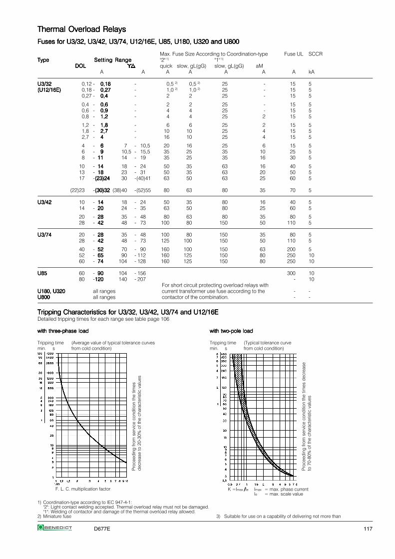
D677E 117
Thermal Overload RelaysThermal Overload RelaysThermal Overload RelaysThermal Overload RelaysThermal Overload Relays
Fuses for U3/32, U3/42, U3/74, U12/16E, U85, U180, U320 and U800Fuses for U3/32, U3/42, U3/74, U12/16E, U85, U180, U320 and U800Fuses for U3/32, U3/42, U3/74, U12/16E, U85, U180, U320 and U800Fuses for U3/32, U3/42, U3/74, U12/16E, U85, U180, U320 and U800Fuses for U3/32, U3/42, U3/74, U12/16E, U85, U180, U320 and U800
Max. Fuse Size According to Coordination-type Fuse UL SCCRTypeTypeTypeTypeType Setting RangeSetting RangeSetting RangeSetting RangeSetting Range "2" 1) "1" 1)
DOLDOLDOLDOLDOL quick slow, gL(gG) slow, gL(gG) aMA A A A A A A kA
U3/32U3/32U3/32U3/32U3/32 0,12 - 0,180,180,180,180,18 - 0,5 2) 0,5 2) 25 - 15 5(U12/16E)(U12/16E)(U12/16E)(U12/16E)(U12/16E) 0,18 - 0,270,270,270,270,27 - 1,0 2) 1,0 2) 25 - 15 5
0,27 - 0,40,40,40,40,4 - 2 2 25 - 15 5
0,4 - 0,60,60,60,60,6 - 2 2 25 - 15 50,6 - 0,90,90,90,90,9 - 4 4 25 - 15 50,8 - 1,21,21,21,21,2 - 4 4 25 2 15 5
1,2 - 1,81,81,81,81,8 - 6 6 25 2 15 51,8 - 2,72,72,72,72,7 - 10 10 25 4 15 52,7 - 44444 - 16 10 25 4 15 5
4 - 66666 7 - 10,5 20 16 25 6 15 56 - 99999 10,5 - 15,5 35 25 35 10 25 58 - 1111111111 14 - 19 35 25 35 16 30 5
10 - 1414141414 18 - 24 50 35 63 16 40 513 - 1818181818 23 - 31 50 35 63 20 50 517 -(23)24(23)24(23)24(23)24(23)24 30 -(40)41 63 50 63 25 60 5
(22)23 -(30)32(30)32(30)32(30)32(30)32 (38)40 -(52)55 80 63 80 35 70 5
U3/42U3/42U3/42U3/42U3/42 10 - 1414141414 18 - 24 50 35 80 16 40 514 - 2020202020 24 - 35 63 50 80 25 60 5
20 - 2828282828 35 - 48 80 63 80 35 80 528 - 4242424242 48 - 73 100 80 150 50 110 5
U3/74U3/74U3/74U3/74U3/74 20 - 2828282828 35 - 48 100 80 150 35 80 528 - 4242424242 48 - 73 125 100 150 50 110 5
40 - 5252525252 70 - 90 160 100 150 63 200 552 - 6565656565 90 - 112 160 125 150 80 250 1060 - 7474747474 104 - 128 160 125 150 80 250 10
U85U85U85U85U85 60 - 9090909090 104 - 156 300 1080 -120120120120120 140 - 207 - 10
For short circuit protecting overload relays withU180, U320U180, U320U180, U320U180, U320U180, U320 all ranges current transformer use fuse according to the - -U800U800U800U800U800 all ranges contactor of the combination. - -
1) Coordination-type according to IEC 947-4-1:"2": Light contact welding accepted. Thermal overload relay must not be damaged."1": Welding of contactor and damage of the thermal overload relay allowed.
2) Miniature fuse 3) Suitable for use on a capability of delivering not more than
with two-pole loadwith two-pole loadwith two-pole loadwith two-pole loadwith two-pole load
Tripping time (Typical tolerance curvemin. s from cold condition)
Pro
ceed
ing
from
ser
vice
con
ditio
n th
e tim
es d
ecre
ase
to 7
0-80
% o
f the
cha
ract
eris
tic v
alue
sTripping Characteristics for U3/32, U3/42, U3/74 and U12/16ETripping Characteristics for U3/32, U3/42, U3/74 and U12/16ETripping Characteristics for U3/32, U3/42, U3/74 and U12/16ETripping Characteristics for U3/32, U3/42, U3/74 and U12/16ETripping Characteristics for U3/32, U3/42, U3/74 and U12/16EDetailed tripping times for each range see table page 106
with three-phase loadwith three-phase loadwith three-phase loadwith three-phase loadwith three-phase load
Tripping time (Average value of typical tolerance curvesmin. s from cold condition)
K =Imax /////Ie Imax = max. phase currentIe = max. scale value
F. L. C. multiplication factor
Pro
ceed
ing
from
ser
vice
con
ditio
n th
e tim
esde
crea
se to
20-
30%
of t
he c
hara
cter
istic
val
ues

118 D677E
Thermal Overload RelaysThermal Overload RelaysThermal Overload RelaysThermal Overload RelaysThermal Overload Relays
Tripping Characteristics for U85, U180, U320, and U800Tripping Characteristics for U85, U180, U320, and U800Tripping Characteristics for U85, U180, U320, and U800Tripping Characteristics for U85, U180, U320, and U800Tripping Characteristics for U85, U180, U320, and U800Detailed tripping times for each range of U85 see table page 106
U85 with three-phase loadU85 with three-phase loadU85 with three-phase loadU85 with three-phase loadU85 with three-phase load U180, U320 with three-phase loadU180, U320 with three-phase loadU180, U320 with three-phase loadU180, U320 with three-phase loadU180, U320 with three-phase load U800 with three-phase loadU800 with three-phase loadU800 with three-phase loadU800 with three-phase loadU800 with three-phase load
Tripping time (Average value of typical tolerance Tripping time (Average value of typical tolerance Tripping time (Average value of typical tolerancemin. s curves from cold condition) min. s curves from cold condition) min. s curves from cold condition)
U85 with two-pole loadU85 with two-pole loadU85 with two-pole loadU85 with two-pole loadU85 with two-pole load
Tripping time (Typical tolerance curvemin. s from cold condition)
Position of TerminalsPosition of TerminalsPosition of TerminalsPosition of TerminalsPosition of Terminals
U3/32U3/32U3/32U3/32U3/32 U12/16E, U12/16EM, U12/16EQU12/16E, U12/16EM, U12/16EQU12/16E, U12/16EM, U12/16EQU12/16E, U12/16EM, U12/16EQU12/16E, U12/16EM, U12/16EQ U12/16AU12/16AU12/16AU12/16AU12/16A U3/42, U3/74U3/42, U3/74U3/42, U3/74U3/42, U3/74U3/42, U3/74
Pro
ceed
ing
from
ser
vice
con
ditio
n th
e tim
es d
ecre
ase
to 7
0-80
% o
f the
cha
ract
eris
tic v
alue
s
F. L. C. multiplication factor F. L. C. multiplication factor
Pro
ceed
ing
from
ser
vice
con
ditio
n th
e tim
esde
crea
se to
20-
30%
of t
he c
hara
cter
istic
val
ues
Pro
ceed
ing
from
ser
vice
con
ditio
n th
e tim
esde
crea
se to
20-
30%
of t
he c
hara
cter
istic
val
ues
K =Imax /////Ie Imax = max. phase currentIe = max. scale value
Pro
ceed
ing
from
ser
vice
con
ditio
n th
e tim
esde
crea
se to
20-
30%
of t
he c
hara
cter
istic
val
ues
F. L. C. multiplication factor

D677E 119
Thermal Overload Relays in Special VersionThermal Overload Relays in Special VersionThermal Overload Relays in Special VersionThermal Overload Relays in Special VersionThermal Overload Relays in Special Version
Fuse for U12/16EQFuse for U12/16EQFuse for U12/16EQFuse for U12/16EQFuse for U12/16EQ
Setting Range Maximum Fuse Acc. to Coordination-type"2" 1) "1" 1)
quick slow, gL(gG) slow, gL(gG)A A A A
0,4 - 0,60,60,60,60,6 2 2 250,6 - 0,90,90,90,90,9 4 4 250,8 - 1,21,21,21,21,2 4 4 25
1,2 - 1,81,81,81,81,8 6 6 251,8 - 2,72,72,72,72,7 10 10 252,7 - 44444 16 10 25
4 - 66666 20 16 256 - 99999 35 25 358 - 1111111111 35 25 35
10 - 1414141414 50 35 63
1) Coordination-type according to IEC 947-4-1:"2": Light contact welding accepted. Thermal overload relay must not be damaged."1": Welding of contactor and damage of the thermal overload relay allowed.
Fuse for U12/16EMFuse for U12/16EMFuse for U12/16EMFuse for U12/16EMFuse for U12/16EM
Setting Range Maximum Fuse Acc. to Coordination-type "2" 1)
380-400V 500V 660-690Vslow, gL(gG) slow, gL(gG) slow, gL(gG)
A A A A
0,12 - 0,180,180,180,180,18 none none on request0,18 - 0,270,270,270,270,27 none none on request0,27 - 0,40,40,40,40,4 none none on request
0,4 - 0,60,60,60,60,6 none none on request0,6 - 0,90,90,90,90,9 none none on request0,8 - 1,21,21,21,21,2 none 10 on request
1,2 - 1,81,81,81,81,8 none 16 on request1,8 - 2,72,72,72,72,7 20 20 on request2,7 - 44444 35 35 on request
Tripping Characteristic Tripping Characteristic Tripping Characteristic Tripping Characteristic Tripping Characteristic for U12/16EQfor U12/16EQfor U12/16EQfor U12/16EQfor U12/16EQDetailed tripping times for each range see table page 106
with three-phase loadwith three-phase loadwith three-phase loadwith three-phase loadwith three-phase load
range 0,4-0,6 to 1,8-2,7ATripping time (Typical tolerance curvemin. s from cold condition)
Tripping Characteristic Tripping Characteristic Tripping Characteristic Tripping Characteristic Tripping Characteristic for U12/16EMfor U12/16EMfor U12/16EMfor U12/16EMfor U12/16EM
with three-phase loadwith three-phase loadwith three-phase loadwith three-phase loadwith three-phase load
Tripping time (Average value of typical tolerancemin. s curves from cold condition)
range 2,7-4 to 10-14ATripping time (Typical tolerance curvemin. s from cold condition)
Fuse for Fuse for Fuse for Fuse for Fuse for UAT21, UAT22, UAT23UAT21, UAT22, UAT23UAT21, UAT22, UAT23UAT21, UAT22, UAT23UAT21, UAT22, UAT23
For short circuit protecting thermal overload relays with currenttransformer use fuse according to the contactor of the combination.
Lower scale valueUpper scale value
Tripping characteristic Tripping characteristic Tripping characteristic Tripping characteristic Tripping characteristic for UAT21, UAT22, UAT23for UAT21, UAT22, UAT23for UAT21, UAT22, UAT23for UAT21, UAT22, UAT23for UAT21, UAT22, UAT23
with three-phase loadwith three-phase loadwith three-phase loadwith three-phase loadwith three-phase load
Tripping time in s (Typical tolerance curve from cold condition)
F. L. C. multiplication factor
F. L. C. multiplication factor
Pro
ceed
ing
from
ser
vice
con
ditio
n th
e tim
es d
ecre
ase
to 2
0-30
% o
f the
cha
ract
eris
tic v
alue
sP
roce
edin
g fro
m s
ervi
ce c
ondi
tion
the
times
dec
reas
eto
20-
30%
of t
he c
hara
cter
istic
val
ues
Pro
ceed
ing
from
ser
vice
con
ditio
n th
e tim
es d
ecre
ase
to 2
0-30
% o
f the
cha
ract
eris
tic v
alue
s
Proceeding from servicecondition the times decreaseto 20-30% of thecharacteristic values
F. L. C. multiplication factor
F. L. C. multiplication factor

120 D677E
Thermal Overload RelaysThermal Overload RelaysThermal Overload RelaysThermal Overload RelaysThermal Overload Relays
Data according to IEC 947-4-1, IEC 947-5-1, VDE 0660, EN 60947-4-1, EN 60947-5-1Data according to IEC 947-4-1, IEC 947-5-1, VDE 0660, EN 60947-4-1, EN 60947-5-1Data according to IEC 947-4-1, IEC 947-5-1, VDE 0660, EN 60947-4-1, EN 60947-5-1Data according to IEC 947-4-1, IEC 947-5-1, VDE 0660, EN 60947-4-1, EN 60947-5-1Data according to IEC 947-4-1, IEC 947-5-1, VDE 0660, EN 60947-4-1, EN 60947-5-1
TypeTypeTypeTypeType U3/32U3/32U3/32U3/32U3/32 U12/16U12/16U12/16U12/16U12/16 6) U3/42U3/42U3/42U3/42U3/42 U3/74U3/74U3/74U3/74U3/74 U85U85U85U85U85 U180U180U180U180U180 U320U320U320U320U320 U800U800U800U800U800 UAT21UAT21UAT21UAT21UAT21 UAT22UAT22UAT22UAT22UAT22 UAT23UAT23UAT23UAT23UAT23
Rated insulation voltage URated insulation voltage URated insulation voltage URated insulation voltage URated insulation voltage Ui i i i i 1)
V~ 690 690 690 690 750 1000 1000 1000 690 690 690Permissible ambient temperaturePermissible ambient temperaturePermissible ambient temperaturePermissible ambient temperaturePermissible ambient temperatureoperation open °C -25 to +60 -25 to +55 -25 to +60storage °C -50 to +70 -40 to +70 -50 to +70
Trip class according to IEC 947-4-1Trip class according to IEC 947-4-1Trip class according to IEC 947-4-1Trip class according to IEC 947-4-1Trip class according to IEC 947-4-110A 10A 10A 10A 10A 20 10A 10A 10 30 30 30
Cable cross-sectionCable cross-sectionCable cross-sectionCable cross-sectionCable cross-sectionmain connector solid or stranded mm² 0,75-6 0,75-6+0,75-2,5 2) 0,75-10 4-35 2) 3) 7) - 7) 0,5-10 0,5-16 0,5-25
flexible mm² 1-4 0,75-4+0,5-2,5 2 ) 0,75-6 6-25 2) 0,5-6 0,5-10 0,5-16flexible with multicore cable end mm² 0,75-4 0,5-2,5+0,5-1,5 0,75-6 4-25 0,5-6 0,5-10 0,5-16
Cables per clamp number 2 1+1 2 1 1 1 1
auxiliary connector solid mm² 0,75-2,5 2) 1-2,52) 0,75-2,5 2)
flexible mm² 0,5-2,5 2) 1-2,5 2) 0,5-2,5 2)
flexible with multicore cable end mm² 0,5-1,5 1-2,5 2) 0,5-1,5Cables per clamp number 2 2 2
TypeTypeTypeTypeType U3/32U3/32U3/32U3/32U3/32 U12/16AU12/16AU12/16AU12/16AU12/16A U12/16EU12/16EU12/16EU12/16EU12/16E U12/16EQU12/16EQU12/16EQU12/16EQU12/16EQ U3/42U3/42U3/42U3/42U3/42 U85U85U85U85U85 U180U180U180U180U180 U800U800U800U800U800 UAT21UAT21UAT21UAT21UAT21U12/16EMU12/16EMU12/16EMU12/16EMU12/16EM U3/74U3/74U3/74U3/74U3/74 U320U320U320U320U320 UAT22UAT22UAT22UAT22UAT22
Auxiliary contactsAuxiliary contactsAuxiliary contactsAuxiliary contactsAuxiliary contacts UAT23UAT23UAT23UAT23UAT23Rated insulation voltage URated insulation voltage URated insulation voltage URated insulation voltage URated insulation voltage Ui i i i i
1)
same potential V~ 690 690 690 690 690 690 690 500 690different potential V~ 440 - 440 440 250 440 440 500 440
Utilization category AC15Utilization category AC15Utilization category AC15Utilization category AC15Utilization category AC15Rated operational 24V A 3 4 5 5 4 5 3 4 5) 5current Ie 230V A 2 2,5 3 3 2,5 3 2 2,5 3
400V A 1 1,5 2 2 1,5 2 1 1,5 2690V A 0,5 0,6 0,6 0,6 0,6 0,6 0,5 0,6 0,6
Utilization category DC13Utilization category DC13Utilization category DC13Utilization category DC13Utilization category DC13Rated operational 24V A 1 1,2 1,2 1,2 1,2 1,2 1,2 1,2 1,2current Ie 110V A 0,15 0,15 0,15 0,15 0,15 0,15 0,15 0,15 0,15
220V A 0,1 0,1 0,1 0,1 0,1 0,1 0,1 0,1 0,1
Short circuit prot. Short circuit prot. Short circuit prot. Short circuit prot. Short circuit prot. (without welding 1kA)highest fuse rating gL (gG) A 4 4 6 6 6 6 4 6 6
TypeTypeTypeTypeType U3/32U3/32U3/32U3/32U3/32 U12/16U12/16U12/16U12/16U12/16 U12/16EU12/16EU12/16EU12/16EU12/16E U3/42U3/42U3/42U3/42U3/42 U3/42U3/42U3/42U3/42U3/42 U3/74U3/74U3/74U3/74U3/74 U3/74U3/74U3/74U3/74U3/74 U85U85U85U85U85Setting range all to 23A 22 - 30A to 28A 28 - 42A to 52A 52 - 65A all
Power loss per current path (max.)Power loss per current path (max.)Power loss per current path (max.)Power loss per current path (max.)Power loss per current path (max.)minimum setting value W 1,1 1,1 1,7 1,3 1,3 2,0 2,9 1,1maximum setting value W 2,3 2,3 3,7 2,6 3,3 3,7 4,5 2,5
Data according to cULusData according to cULusData according to cULusData according to cULusData according to cULus
TypeTypeTypeTypeType U3/32U3/32U3/32U3/32U3/32 U12/16AU12/16AU12/16AU12/16AU12/16A U12/16EU12/16EU12/16EU12/16EU12/16E U12/16EQU12/16EQU12/16EQU12/16EQU12/16EQ U3/42U3/42U3/42U3/42U3/42 U3/74U3/74U3/74U3/74U3/74 U85U85U85U85U85
Rated insulation voltageRated insulation voltageRated insulation voltageRated insulation voltageRated insulation voltage V~ 600 600 600 600 600 600 600Rated currentRated currentRated currentRated currentRated current A 32 23 23 23 42 74 85
Auxiliary contactsAuxiliary contactsAuxiliary contactsAuxiliary contactsAuxiliary contactsRated voltagesame potential V AC 600 600 600 600 600 600 600different potential V~ 150 - 150 150 150 150 150
Switching capacity Switching capacity Switching capacity Switching capacity Switching capacity AC VA 500 500 500 500 600 600 600of aux. contacts A 2 3 4 4 4 4 4
Example:Example:Example:Example:Example: Ambient temperature 70°C, full load motor current 7AAmbient temperature 70°C, full load motor current 7AAmbient temperature 70°C, full load motor current 7AAmbient temperature 70°C, full load motor current 7AAmbient temperature 70°C, full load motor current 7A(70 - 20) x 0,125 = 6,25%(70 - 20) x 0,125 = 6,25%(70 - 20) x 0,125 = 6,25%(70 - 20) x 0,125 = 6,25%(70 - 20) x 0,125 = 6,25%Setting value: 7A + 6,25% = 7,44ASetting value: 7A + 6,25% = 7,44ASetting value: 7A + 6,25% = 7,44ASetting value: 7A + 6,25% = 7,44ASetting value: 7A + 6,25% = 7,44A
Temperature Compensation
In case of higher ambient temperature use the following formula:In case of higher ambient temperature use the following formula:In case of higher ambient temperature use the following formula:In case of higher ambient temperature use the following formula:In case of higher ambient temperature use the following formula:(Ambient temperature - 20) x 0,125 = correction factor in %(Ambient temperature - 20) x 0,125 = correction factor in %(Ambient temperature - 20) x 0,125 = correction factor in %(Ambient temperature - 20) x 0,125 = correction factor in %(Ambient temperature - 20) x 0,125 = correction factor in % of theof theof theof theof the
full load motor currentfull load motor currentfull load motor currentfull load motor currentfull load motor current
1) Suitable for: earthed-neutral systems, overvoltage category I to III, pollution degree 3 (standard-industry): Uimp = 4kV (at 440V), 6kV (at 690V).Data for other conditions on request.
2) Maximum cable cross-section with prepared conductor3) Without terminals, suitable for bushing one connector 70mm² (stranded) per phase4) Switching capacity of the start contact: AC15 300VA, max. 1,5A, DC13 (max. 220V) 30W, max. 1,5A5) Switching capacity of the make contact: AC15 400VA, max. 1,7A, DC13 (max. 220V) 10W, max. 1A6) U12/16E 30: Cable cross-section for main connector like type U3/42, one connector only7) Busbar sets see accessories page 105
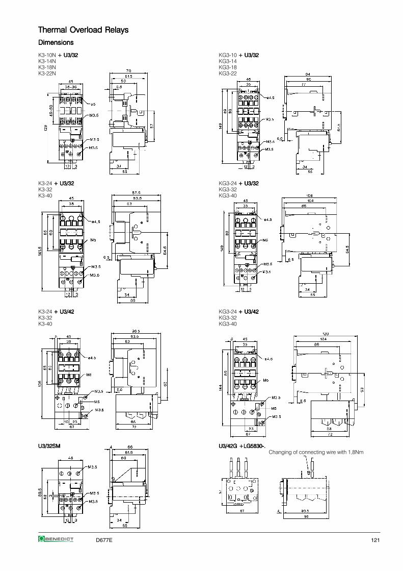
D677E 121
Thermal Overload RelaysThermal Overload RelaysThermal Overload RelaysThermal Overload RelaysThermal Overload Relays
DimensionsDimensionsDimensionsDimensionsDimensions
K3-10N + U3/32+ U3/32+ U3/32+ U3/32+ U3/32 KG3-10 + U3/32 + U3/32 + U3/32 + U3/32 + U3/32K3-14N KG3-14K3-18N KG3-18K3-22N KG3-22
K3-24 + U3/32+ U3/32+ U3/32+ U3/32+ U3/32 KG3-24 + U3/32+ U3/32+ U3/32+ U3/32+ U3/32K3-32 KG3-32K3-40 KG3-40
K3-24 + U3/42+ U3/42+ U3/42+ U3/42+ U3/42 KG3-24 + U3/42+ U3/42+ U3/42+ U3/42+ U3/42K3-32 KG3-32K3-40 KG3-40
U3/32SMU3/32SMU3/32SMU3/32SMU3/32SM U3/42G +LG5830-.U3/42G +LG5830-.U3/42G +LG5830-.U3/42G +LG5830-.U3/42G +LG5830-.Changing of connecting wire with 1,8Nm

122 D677E
Thermal Overload RelaysThermal Overload RelaysThermal Overload RelaysThermal Overload RelaysThermal Overload Relays
DimensionsDimensionsDimensionsDimensionsDimensions
K1-09 + U12/16.. K1+ U12/16.. K1+ U12/16.. K1+ U12/16.. K1+ U12/16.. K1 K3-10 + U12/16..K3 + U12/16..K3 + U12/16..K3 + U12/16..K3 + U12/16..K3K1-12 K3-14
K3-18K3-22
K3-10N + U12/16..K3 + U12/16..K3 + U12/16..K3 + U12/16..K3 + U12/16..K3 KG3-10 + U12/16..K3 + U12/16..K3 + U12/16..K3 + U12/16..K3 + U12/16..K3K3-14N KG3-14K3-18N KG3-18K3-22N KG3-22
U12SM K3U12SM K3U12SM K3U12SM K3U12SM K3
U12/16..K3 + U12SM K3 for snap-on 35mm DIN-rail according toDIN EN50022 and screw mounting (single mounting)
K3-50 + U3/74 + U3/74 + U3/74 + U3/74 + U3/74K3-62K3-74
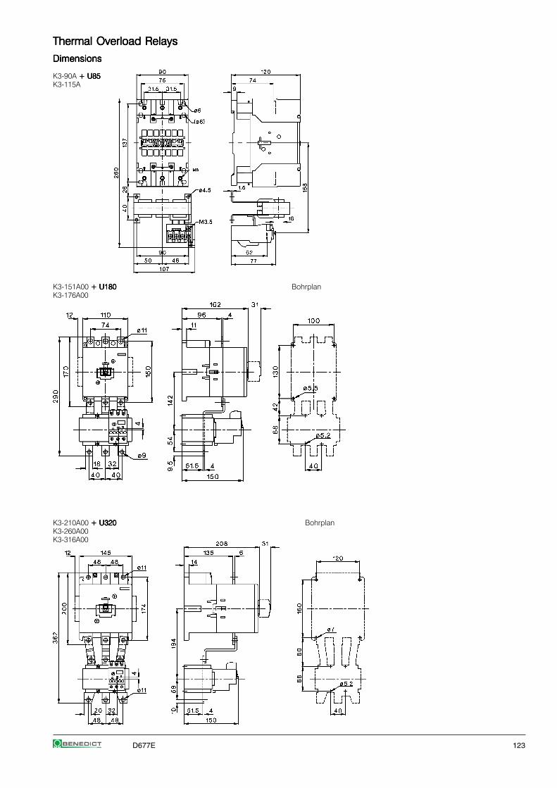
D677E 123
Thermal Overload RelaysThermal Overload RelaysThermal Overload RelaysThermal Overload RelaysThermal Overload Relays
DimensionsDimensionsDimensionsDimensionsDimensions
K3-90A + U85+ U85+ U85+ U85+ U85K3-115A
K3-151A00 + U180 + U180 + U180 + U180 + U180 BohrplanK3-176A00
K3-210A00 + U320 + U320 + U320 + U320 + U320 BohrplanK3-260A00K3-316A00

124 D677E
Thermal Overload RelaysThermal Overload RelaysThermal Overload RelaysThermal Overload RelaysThermal Overload Relays
DimensionsDimensionsDimensionsDimensionsDimensions
U800U800U800U800U800
U800 U800 U800 U800 U800 with A B C D E F G H J K
K3-450K3-450K3-450K3-450K3-450 220 372 110 220 158 40 185 225 12,5 9K3-550K3-550K3-550K3-550K3-550 220 395 110 220 158 40 196 225 12,5 9
K3-700K3-700K3-700K3-700K3-700 280 487 175 280 202 50 257 291 14,5 11K3-860K3-860K3-860K3-860K3-860 280 540 175 280 202 50 280 291 14,5 11
UAT21UAT21UAT21UAT21UAT21 UAT22UAT22UAT22UAT22UAT22
UAT23UAT23UAT23UAT23UAT23
TypeTypeTypeTypeType Setting Range A B
UAT23 37UAT23 37UAT23 37UAT23 37UAT23 37 23-37A 105,5 97,5UAT23 49UAT23 49UAT23 49UAT23 49UAT23 49 32-49A 94 86UAT23 72UAT23 72UAT23 72UAT23 72UAT23 72 48-72A 94 86

D677E 125
Modular ContactorsModular ContactorsModular ContactorsModular ContactorsModular Contactors
Modular Contactors 126
Auxiliary Contact Block 127Accessories 127
Day-Night Reloading Contactors 128
Switching Of Lamps 128
Technical Data 130
Dimensions 132
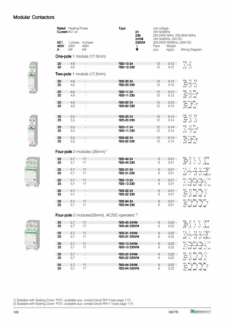
126 D677E
Modular ContactorsModular ContactorsModular ContactorsModular ContactorsModular Contactors
RatedRatedRatedRatedRated Heating Power TypeTypeTypeTypeType coil voltageCurrentCurrentCurrentCurrentCurrent AC1 at 2424242424 24V 50/60Hz
230230230230230 220-240V 50Hz, 230-264V 60Hz24VM24VM24VM24VM24VM 24V 50/60Hz, 24V DC
AC1AC1AC1AC1AC1 1-phase 3-phase 230VM230VM230VM230VM230VM 220-240V 50/60Hz, 220V DC400V400V400V400V400V 230V 400V ⏐⏐⏐⏐⏐ Pack WeightAAAAA kW kW pcs. kg/pc. Wiring Diagram
One-poleOne-poleOne-poleOne-poleOne-pole 1 module (17,5mm)
2020202020 4,6 - R20-10 24R20-10 24R20-10 24R20-10 24R20-10 24 12 0,122020202020 4,6 - R20-10 230R20-10 230R20-10 230R20-10 230R20-10 230 12 0,12
Two-poleTwo-poleTwo-poleTwo-poleTwo-pole 1 module (17,5mm)
2020202020 4,6 - R20-20 24R20-20 24R20-20 24R20-20 24R20-20 24 12 0,122020202020 4,6 - R20-20 230R20-20 230R20-20 230R20-20 230R20-20 230 12 0,12
2020202020 4,6 - R20-11 24R20-11 24R20-11 24R20-11 24R20-11 24 12 0,122020202020 4,6 - R20-11 230R20-11 230R20-11 230R20-11 230R20-11 230 12 0,12
2020202020 4,6 - R20-02 24R20-02 24R20-02 24R20-02 24R20-02 24 12 0,122020202020 4,6 - R20-02 230R20-02 230R20-02 230R20-02 230R20-02 230 12 0,12
2525252525 5,5 - R25-20 24R25-20 24R25-20 24R25-20 24R25-20 24 12 0,142525252525 5,5 - R25-20 230R25-20 230R25-20 230R25-20 230R25-20 230 12 0,14
2525252525 5,5 - R25-11 24R25-11 24R25-11 24R25-11 24R25-11 24 12 0,142525252525 5,5 - R25-11 230R25-11 230R25-11 230R25-11 230R25-11 230 12 0,14
2525252525 5,5 - R25-02 24R25-02 24R25-02 24R25-02 24R25-02 24 12 0,142525252525 5,5 - R25-02 230R25-02 230R25-02 230R25-02 230R25-02 230 12 0,14
Four-poleFour-poleFour-poleFour-poleFour-pole 2 modules (35mm) 1
2525252525 5,7 17 R25-40 24R25-40 24R25-40 24R25-40 24R25-40 24 6 0,212525252525 5,7 17 R25-40 230R25-40 230R25-40 230R25-40 230R25-40 230 6 0,21
2525252525 5,7 17 R25-31 24R25-31 24R25-31 24R25-31 24R25-31 24 6 0,212525252525 5,7 17 R25-31 230R25-31 230R25-31 230R25-31 230R25-31 230 6 0,21
2525252525 5,7 17 R25-13 24R25-13 24R25-13 24R25-13 24R25-13 24 6 0,212525252525 5,7 17 R25-13 230R25-13 230R25-13 230R25-13 230R25-13 230 6 0,21
2525252525 5,7 - R25-22 24R25-22 24R25-22 24R25-22 24R25-22 24 6 0,212525252525 5,7 - R25-22 230R25-22 230R25-22 230R25-22 230R25-22 230 6 0,21
2525252525 5,7 17 R25-04 24R25-04 24R25-04 24R25-04 24R25-04 24 6 0,212525252525 5,7 17 R25-04 230R25-04 230R25-04 230R25-04 230R25-04 230 6 0,21
Four-poleFour-poleFour-poleFour-poleFour-pole 2 modules(35mm), AC/DC-operated 1)
2525252525 5,7 17 R25-40 24VMR25-40 24VMR25-40 24VMR25-40 24VMR25-40 24VM 6 0,222525252525 5,7 17 R25-40 230VMR25-40 230VMR25-40 230VMR25-40 230VMR25-40 230VM 6 0,22
2525252525 5,7 17 R25-31 24VMR25-31 24VMR25-31 24VMR25-31 24VMR25-31 24VM 6 0,222525252525 5,7 17 R25-31 230VMR25-31 230VMR25-31 230VMR25-31 230VMR25-31 230VM 6 0,22
2525252525 5,7 17 R25-13 24VMR25-13 24VMR25-13 24VMR25-13 24VMR25-13 24VM 6 0,222525252525 5,7 17 R25-13 230VMR25-13 230VMR25-13 230VMR25-13 230VMR25-13 230VM 6 0,22
2525252525 5,7 - R25-22 24VMR25-22 24VMR25-22 24VMR25-22 24VMR25-22 24VM 6 0,222525252525 5,7 - R25-22 230VMR25-22 230VMR25-22 230VMR25-22 230VMR25-22 230VM 6 0,22
2525252525 5,7 17 R25-04 24VMR25-04 24VMR25-04 24VMR25-04 24VMR25-04 24VM 6 0,222525252525 5,7 17 R25-04 230VMR25-04 230VMR25-04 230VMR25-04 230VMR25-04 230VM 6 0,22
1) Sealable with Sealing Cover P721, available aux. contact block RH11(see page 117)2) Sealable with Sealing Cover P721, available aux. contact block RH11-1(see page 117)

D677E 127
Modular ContactorsModular ContactorsModular ContactorsModular ContactorsModular Contactors
RatedRatedRatedRatedRated Heating Power TypeTypeTypeTypeType coil voltageCurrentCurrentCurrentCurrentCurrent AC1 at 2424242424 24V 50/60HzAC1AC1AC1AC1AC1 1-phase 3-phase 230230230230230 220-240V 50Hz, 230-264V 60Hz400V400V400V400V400V 230V 400V ⏐⏐⏐⏐⏐ Pack WeightAAAAA kW kW pcs. kg/pc. Wiring Diagram
Two-poleTwo-poleTwo-poleTwo-poleTwo-pole 2 modules (35mm)
4040404040 9 - R40-20 24R40-20 24R40-20 24R40-20 24R40-20 24 6 0,234040404040 9 - R40-20 230R40-20 230R40-20 230R40-20 230R40-20 230 6 0,23
6363636363 14,3 - R63-20 24R63-20 24R63-20 24R63-20 24R63-20 24 6 0,236363636363 14,3 - R63-20 230R63-20 230R63-20 230R63-20 230R63-20 230 6 0,23
Four-poleFour-poleFour-poleFour-poleFour-pole 3 modules (52,5mm) 1)
4040404040 9 27,5 R40-40 24R40-40 24R40-40 24R40-40 24R40-40 24 4 0,354040404040 9 27,5 R40-40 230R40-40 230R40-40 230R40-40 230R40-40 230 4 0,35
4040404040 9 27,5 R40-31 24R40-31 24R40-31 24R40-31 24R40-31 24 4 0,354040404040 9 27,5 R40-31 230R40-31 230R40-31 230R40-31 230R40-31 230 4 0,35
4040404040 9 - R40-22 24R40-22 24R40-22 24R40-22 24R40-22 24 4 0,354040404040 9 - R40-22 230R40-22 230R40-22 230R40-22 230R40-22 230 4 0,35
4040404040 9 27,5 R40-04 24R40-04 24R40-04 24R40-04 24R40-04 24 4 0,354040404040 9 27,5 R40-04 230R40-04 230R40-04 230R40-04 230R40-04 230 4 0,35
6363636363 14,3 43 R63-40 24R63-40 24R63-40 24R63-40 24R63-40 24 4 0,366363636363 14,3 43 R63-40 230R63-40 230R63-40 230R63-40 230R63-40 230 4 0,36
6363636363 14,3 43 R63-31 24R63-31 24R63-31 24R63-31 24R63-31 24 4 0,366363636363 14,3 43 R63-31 230R63-31 230R63-31 230R63-31 230R63-31 230 4 0,36
6363636363 14,3 - R63-22 24R63-22 24R63-22 24R63-22 24R63-22 24 4 0,366363636363 14,3 - R63-22 230R63-22 230R63-22 230R63-22 230R63-22 230 4 0,36
6363636363 14,3 43 R63-04 24R63-04 24R63-04 24R63-04 24R63-04 24 4 0,366363636363 14,3 43 R63-04 230R63-04 230R63-04 230R63-04 230R63-04 230 4 0,36
Auxiliary Contact Block Auxiliary Contact Block Auxiliary Contact Block Auxiliary Contact Block Auxiliary Contact Block ½ module (8,8mm) for contactor R25 (4p.), R40, R63 (max. 1pc.)
Rated currentRated currentRated currentRated currentRated current TypeTypeTypeTypeType Pack WeightAC15AC15AC15AC15AC15 AC15 AC1230V230V230V230V230V 400V 690VA A A for contactor pcs. kg/pc. Wiring Diagram
33333 2 10 R25 2), R40, R63 RH11RH11RH11RH11RH11 3 0,026
33333 2 10 R25-..VMVMVMVMVM RH11-1RH11-1RH11-1RH11-1RH11-1 3 0,026
AccessoriesAccessoriesAccessoriesAccessoriesAccessories TypeTypeTypeTypeType Pack Weightpcs. kg/pc.
RC-unit 2x for R20.. to R63.. RC-R 230RC-R 230RC-R 230RC-R 230RC-R 230 2 0,05for 12V to 250V AC220nF / 100 Ohmnot for R25-..VM
Spacing piece ½ module (8,8mm) P730P730P730P730P730 10 0,012for R20.. to R63..for ambient temperature >40°C
Sealing cover for R25.. (4p.) P721P721P721P721P721 10 0,002Sealing cover for R40.., R63.. P690P690P690P690P690 10 0,003
1) Sealable with Sealing Cover P690, available aux. contact block RH112) AC-operated R25-.., 4-pole
≤ 40°C
40 - 60°C

128 D677E
Day-Night Reloading ContactorsDay-Night Reloading ContactorsDay-Night Reloading ContactorsDay-Night Reloading ContactorsDay-Night Reloading Contactors
Pack WeightTypeTypeTypeTypeType pcs. kg/pc. Wiring Diagram
Compact Module, for separate tarif counters Compact Module, for separate tarif counters Compact Module, for separate tarif counters Compact Module, for separate tarif counters Compact Module, for separate tarif counters 2 modules (35mm)
3-pole 400V 25A3-pole 400V 25A3-pole 400V 25A3-pole 400V 25A3-pole 400V 25A R25-TN 230R25-TN 230R25-TN 230R25-TN 230R25-TN 230 1 0,22
2 Switch positions:DayDayDayDayDay (Reloading, contact 11-14 ... closed, remains in position Night, until the next occurs)Night Night Night Night Night (Basis operation) contact 11-12 ... closed
Contactor Module, for double tarif counters Contactor Module, for double tarif counters Contactor Module, for double tarif counters Contactor Module, for double tarif counters Contactor Module, for double tarif counters 1 module (17,5mm)
2-pole 400V 25A2-pole 400V 25A2-pole 400V 25A2-pole 400V 25A2-pole 400V 25A R25-TN20 230R25-TN20 230R25-TN20 230R25-TN20 230R25-TN20 230 1 0,13
4 Switch position:Day Day Day Day Day (Reloading, contact 1-2 ... closed, remains in position Night, until the next occurs)Night Night Night Night Night (automatic operation, contact 1-2 ... only at night closed)On On On On On (Permanently On)OffOffOffOffOff (permanently Off)
Switch ModuleSwitch ModuleSwitch ModuleSwitch ModuleSwitch Module 1 module (17,5mm)
2-pole 400V 25A2-pole 400V 25A2-pole 400V 25A2-pole 400V 25A2-pole 400V 25A RH25-20RH25-20RH25-20RH25-20RH25-20 1 0,13
Modular ContactorsModular ContactorsModular ContactorsModular ContactorsModular Contactors
Switching of lampsSwitching of lampsSwitching of lampsSwitching of lampsSwitching of lamps
Lamp Type Power Current Capacitors Max. lamps per pole at 230V 50Hz and max. 60°CW A μF R20..R20..R20..R20..R20.. R25..R25..R25..R25..R25.. R40..R40..R40..R40..R40.. R63..R63..R63..R63..R63..
Incandescent lampsIncandescent lampsIncandescent lampsIncandescent lampsIncandescent lamps 60 0,27 - 22 50 92 129100 0,45 - 13 30 55 77200 0,91 - 10 15 27 38
300 1,36 - 4 10 19 26500 2,27 - 3 6 11 16
1000 4,5 - 1 3 6 8
Fluorescent lampsFluorescent lampsFluorescent lampsFluorescent lampsFluorescent lamps 11 0,16 1,3 60 75 210 310uncompensated or 18 0,37 2,7 25 30 90 140serial compensated 24 0,35 2,5 25 30 90 140
36 0,43 3,4 20 25 70 14058 0,67 5,3 14 17 45 7065 0,67 5,3 13 16 40 6585 0,8 5,3 11 14 35 60
Fluorescent lampsFluorescent lampsFluorescent lampsFluorescent lampsFluorescent lamps 11 0,07 - 2 x 100 2 x 110 2 x 220 2 x 250dual-connection 18 0,11 - 2 x 50 2 x 55 2 x 130 2 x 200
24 0,14 - 2 x 40 2 x 44 2 x 110 2 x 160
36 0,22 - 2 x 30 2 x 33 2 x 70 2 x 10058 0,35 - 2 x 20 2 x 22 2 x 45 2 x 7065 0,35 - 2 x 15 2 x 16 2 x 40 2 x 6085 0,47 - 2 x 10 2 x 11 2 x 30 2 x 40
Fluorescent lampsFluorescent lampsFluorescent lampsFluorescent lampsFluorescent lamps 11 0,09 2,0 30 43 67 107parallel compensated 18 0,13 2 20 32 50 80
24 0,16 3 15 32 50 80
36 0,27 4 10 32 50 8058 0,45 7 6 18 36 4665 0,5 7 5 18 36 4685 0,6 8 4 16 33 44

D677E 129
Modular ContactorsModular ContactorsModular ContactorsModular ContactorsModular Contactors
Switching of lampsSwitching of lampsSwitching of lampsSwitching of lampsSwitching of lamps
Lamp Type Power Current Capacitors Max. lamps per pole at 230V 50Hz and max. 60°CW A μF R20..R20..R20..R20..R20.. R25..R25..R25..R25..R25.. R40..R40..R40..R40..R40.. R63..R63..R63..R63..R63..
Fluorescent lampsFluorescent lampsFluorescent lampsFluorescent lampsFluorescent lamps 18 0,09 - 40 40 100 150with electronic fluorescent 36 0,16 - 20 20 52 75lamp ballast 58 0,25 - 15 15 30 55
80 0,4 - 7 10 20 30
2 x 18 0,17 - 20 20 50 602 x 28 0,25 - 15 15 37 452 x 36 0,32 - 10 10 25 302 x 58 0,49 - 7 7 15 202 x 80 0,7 - 4 4 8 10
TransformersTransformersTransformersTransformersTransformers 20 0,09 - 40 52 110 174for metal halidfor metal halidfor metal halidfor metal halidfor metal halid 50 0,22 - 20 24 50 80low voltage lampslow voltage lampslow voltage lampslow voltage lampslow voltage lamps 75 0,33 - 13 16 35 54
100 0,43 - 10 12 27 43150 0,65 - 7 9 19 29200 0,87 - 5 5 14 23300 1,30 - 3 4 9 14
Mercury-vapour lampsMercury-vapour lampsMercury-vapour lampsMercury-vapour lampsMercury-vapour lamps 50 0,61 - 16 21 38 55(high-pressure lamps), 80 0,8 - 12 16 29 40uncompensated 125 1,15 - 8 11 20 28e. g. HQL, HPL
250 2,15 - 4 6 11 15400 3,25 - 3 4 7 10700 5,4 - 1 2 4 6
1000 7,5 - 1 1 3 4
Mercury-vapour lampsMercury-vapour lampsMercury-vapour lampsMercury-vapour lampsMercury-vapour lamps 50 0,28 7 7 18 36 50(high-pressure lamps), 80 0,41 8 5 16 31 44compensated 125 0,65 10 3 13 25 35e. g. HQL, HPL
250 1,22 18 2 7 14 19400 1,95 25 1 5 10 14700 3,45 45 1 3 6 8
1000 4,8 60 - 2 4 6
Metal halide lampsMetal halide lampsMetal halide lampsMetal halide lampsMetal halide lamps 35 0,53 - 22 24 57 65uncompensated 70 1 - 12 14 30 35e. g. HQI, HPI, CDM 150 1,8 - 6 8 17 18
250 3 - 4 5 10 12400 3,5 - 3 4 8 10
1000 9,5 - 1 1 3 42000 16,5 - - - 2 2
400V per pole 2000 10,5 - - - 2 23500 18 - - - 1 1
Metal halide lampsMetal halide lampsMetal halide lampsMetal halide lampsMetal halide lamps 35 0,25 6 8 21 42 58compensated 70 0,45 12 4 11 21 29e. g. HQI, HPI, CDM 150 0,75 20 2 7 13 18
250 1,5 33 1 4 9 11400 2,1 35 1 4 9 10
1000 5,8 95 - 1 3 42000 11,5 148 - - 2 2
400V per pole 2000 6,6 58 - - 3 43500 11,6 100 - - 2 3
Metal halide lampsMetal halide lampsMetal halide lampsMetal halide lampsMetal halide lamps 20 0,1 integrated 9 9 18 20with electronic fluorescent 28 0,15 integriert - - - 18with electronic fluorescent 35 0,2 integrated 6 6 11 13lamp ballast (e. g.: PCI) 70 0,36 integrated 5 5 10 1250-125 x In lamp for 0,6ms 150 0,7 integrated 4 4 8 10
Sodium-vapour lampsSodium-vapour lampsSodium-vapour lampsSodium-vapour lampsSodium-vapour lamps 35 1,5 - 7 9 22 30(low pressure lamps), 55 1,5 - 7 9 22 30uncompensated 90 2,4 - 4 6 13 19
135 3,3 - 3 4 10 14150 3,3 - 3 4 10 14180 3,3 - 3 4 10 14200 3,3 - 3 4 10 14

130 D677E
Modular ContactorsModular ContactorsModular ContactorsModular ContactorsModular Contactors
Switching of lampsSwitching of lampsSwitching of lampsSwitching of lampsSwitching of lamps
Lamp Type Power Current Capacitors Max. lamps per pole at 230V 50Hz and max. 60°CW A μF R20..R20..R20..R20..R20.. R25..R25..R25..R25..R25.. R40..R40..R40..R40..R40.. R63..R63..R63..R63..R63..
Sodium-vapour lamps 35 0,31 20 3 6 15 18(low pressure lamps), 55 0,42 20 2 6 15 18compensated 90 0,63 30 1 4 10 12
135 0,94 45 1 3 7 8150 1 40 1 3 8 9180 1,16 40 1 3 8 9200 1,32 25 - - 10 12
Sodium-vapour lampsSodium-vapour lampsSodium-vapour lampsSodium-vapour lampsSodium-vapour lamps 150 1,8 - 5 8 17 22(high pressure lamps), 250 3 - 4 5 10 13uncompensated 330 3,7 - 3 4 8 10
400 4,7 - 2 3 6 81000 10,3 - 1 1 3 4
Sodium-vapour lampsSodium-vapour lampsSodium-vapour lampsSodium-vapour lampsSodium-vapour lamps 150 0,83 20 2 7 20 25(high pressure lamps), 250 1,5 33 1 4 12 15compensated 330 2 40 1 3 10 13
400 2,4 48 1 2 8 121000 6,3 106 - 1 4 6
Sodium-vapour lampsSodium-vapour lampsSodium-vapour lampsSodium-vapour lampsSodium-vapour lamps 20 0,1 integrated 9 9 18 20(high pressure lamps) 35 0,2 integrated 6 6 11 13with serial electronic 70 0,36 integrated 5 5 10 12(e. g.: PCI) 150 0,7 integrated 4 4 8 1050-125 x Inlamp for 0,6ms
Data according to IEC60 947-4-1, IEC 60947-5-1, VDE 0660-5-1Data according to IEC60 947-4-1, IEC 60947-5-1, VDE 0660-5-1Data according to IEC60 947-4-1, IEC 60947-5-1, VDE 0660-5-1Data according to IEC60 947-4-1, IEC 60947-5-1, VDE 0660-5-1Data according to IEC60 947-4-1, IEC 60947-5-1, VDE 0660-5-1
2-pole2-pole2-pole2-pole2-pole 4-pole4-pole4-pole4-pole4-poleTypeTypeTypeTypeType R20R20R20R20R20 R25R25R25R25R25 R40R40R40R40R40 R63R63R63R63R63 R25R25R25R25R25 R40R40R40R40R40 R63R63R63R63R63 RH11RH11RH11RH11RH11
Main Contacts Main Contacts Main Contacts Main Contacts Main Contacts 5) 6) 7) 5) 6) 7) 5) 6) 7) 5) 6) 7) 5) 6) 7)
Rated insulation voltage Rated insulation voltage Rated insulation voltage Rated insulation voltage Rated insulation voltage UUUUUiiiii V~V~V~V~V~ 440440440440440 2) 2) 2) 2) 2) 440 440 440 440 440 2)2)2)2)2) 440 440 440 440 440 2)2)2)2)2) 440440440440440 2) 2) 2) 2) 2) 440440440440440 2) 2) 2) 2) 2) 440440440440440 2) 2) 2) 2) 2) 440440440440440 2) 2) 2) 2) 2) 440440440440440 2) 2) 2) 2) 2)
Rated operation voltage Ue V~ 440 440 440 440 440 440 440 440
Frequency of operations zFrequency of operations zFrequency of operations zFrequency of operations zFrequency of operations zAC1, AC3 1/h300 300 600 600 300 600 600 600Mechanical lifeMechanical lifeMechanical lifeMechanical lifeMechanical life S x 106 1 1 1 1 1 1 1 1
Utilization category AC1Utilization category AC1Utilization category AC1Utilization category AC1Utilization category AC1Rated operational current Ie (=Ith)open at 60°C A 20 25 40 63 25 40 63 -
Contact lifeContact lifeContact lifeContact lifeContact life S x 106 0,1 0,1 0,1 0,1 0,1 0,1 0,1 -Minimum Switch VoltageMinimum Switch VoltageMinimum Switch VoltageMinimum Switch VoltageMinimum Switch Voltage V/mA 24/100 24/100 24/100 24/100 24/100 24/100 24/100 17/5Short time currentShort time currentShort time currentShort time currentShort time current 10s-current A 72 72 216 240 72 216 240 -Power loss Power loss Power loss Power loss Power loss per pole at Ie/AC1 W 2 3 3 7 2 3 7 0,5
Utilization category AC3 / AC7bUtilization category AC3 / AC7bUtilization category AC3 / AC7bUtilization category AC3 / AC7bUtilization category AC3 / AC7bSwitching of three-phase motorsSwitching of three-phase motorsSwitching of three-phase motorsSwitching of three-phase motorsSwitching of three-phase motorsRated operational current Ie A - - - - 9 27 30 -
Rated operational powerof three-phase motors 220V kW - - - - 2,2 7,5 8 -50-60Hz 230-240V kW - - - - 2,5 8 8,5 -
380-415V kW - - - - 4 12,5 15 -
2-pole motors 230V kW 1,1 1,3 2,6 5 - - - -
Contact lifeContact lifeContact lifeContact lifeContact life S x 106 0,15 0,15 0,15 0,15 0,15 0,15 0,15 -
Power consumption of coilsPower consumption of coilsPower consumption of coilsPower consumption of coilsPower consumption of coilsAC operated inrush VA 7 - 9 7 - 9 20 - 25 33 - 45 33 - 45 -
sealed VA 2,2 - 4,2 2,2 - 4,2 5 - 7 5 - 7 4 - 6 6 - 8 6 - 8 -W 0,8 - 1,6 0,8 - 1,6 1,5 - 2,5 2,6 2,6 -
AC and DC-operated W - - 3 - 4 - - -
Operation range of coilsOperation range of coilsOperation range of coilsOperation range of coilsOperation range of coilsin multiples of control voltage Us (-40°--+40°C) 0,85 - 1,1 0,85 - 1,1 0,85 - 1,1 0,85 - 1,1 0,85 - 1,1 0,85 - 1,1 0,85 - 1,1 -
1) Suitable for: earthed-neutral systems, overvoltage category I to IV, pollution degree 3 (standard-industry): Uimp = 8kV.2) Suitable for: earthed-neutral systems, overvoltage category I to III, pollution degree 3 (standard-industry): Uimp = 4kV.3) Maximum cable cross-section with prepared conductor5) Rated frequency 50/60Hz 6) Max. occ. switching overvoltage <4kV 7) Duty cycle: 100%

D677E 131
Modular ContactorsModular ContactorsModular ContactorsModular ContactorsModular Contactors
Data according to IEC60 947-4-1, IEC 60947-5-1, VDE 0660-5-1Data according to IEC60 947-4-1, IEC 60947-5-1, VDE 0660-5-1Data according to IEC60 947-4-1, IEC 60947-5-1, VDE 0660-5-1Data according to IEC60 947-4-1, IEC 60947-5-1, VDE 0660-5-1Data according to IEC60 947-4-1, IEC 60947-5-1, VDE 0660-5-1
TypeTypeTypeTypeType R20R20R20R20R20 R25 R25 R25 R25 R25 (2p.) R25 R25 R25 R25 R25 (4p.) R25-..VMR25-..VMR25-..VMR25-..VMR25-..VM R40R40R40R40R40 R63R63R63R63R63 RH11RH11RH11RH11RH11
Short circuit protectionShort circuit protectionShort circuit protectionShort circuit protectionShort circuit protectionmax. fuse Coordination-type "1"gL (gG) A 35 35 35 35 63 80 -Rated short circuit current "r" kA 3 3 3 3 3 3 -
"Iq" kA 3 3 10 10 10 10 -
Switching time Switching time Switching time Switching time Switching time at control voltage Us ±10%make time ms 7 - 16 7 - 16 9 - 15 17 - 24 11 - 15 11 - 15 -
release time ms 6 - 12 6 - 12 4 - 8 17 - 23 6 - 13 6 - 13 -arc duration ms 10 - 15 10 - 15 10 - 15 10 - 15 10 - 15 10 - 15 -
Cable cross-sectionsCable cross-sectionsCable cross-sectionsCable cross-sectionsCable cross-sectionsMain connector solid or stranded mm² 1,5 - 10 1,5 - 10 1,5 - 10 1,5 - 10 2,5 - 25 2,5 - 25 0,5 - 2,5 3)
flexible mm² 1,5 - 6 1,5 - 6 1,5 - 6 1,5 - 6 2,5 - 16 2,5 - 16 0,5 - 2,5 3)
flexible with multicore cable end mm² 1,5 - 6 1,5 - 6 1,5 - 6 1,5 - 6 2,5 - 16 2,5 - 16 0,5 - 1,5Clamps per pole 1 1 1 1 1 1 2
Magnetic coil solid or stranded mm² 0,75 - 2,5 0,75 - 2,5 0,75 - 2,5 0,75 - 2,5 0,75 - 2,5 0,75 - 2,5 -flexible mm² 0,5 - 2,5 0,5 - 2,5 0,5 - 2,5 0,5 - 2,5 0,5 - 2,5 0,5 - 2,5 -
flexible with multicore cable end mm² 0,5 - 1,5 0,5 - 2,5 0,5 - 1,5 0,5 - 1,5 0,5 - 1,5 0,5 - 1,5 -Clamps per pole 1 1 1 1 1 1 -
Auxiliary Contacts Auxiliary Contacts Auxiliary Contacts Auxiliary Contacts Auxiliary Contacts 5) 6) 7) 5) 6) 7) 5) 6) 7) 5) 6) 7) 5) 6) 7)
Rated insulation voltage URated insulation voltage URated insulation voltage URated insulation voltage URated insulation voltage Ui i i i i 1) V AC ----- ----- 440 2) 440 2) 440 2) 440 2) 440 2)
Thermal rated current IThermal rated current IThermal rated current IThermal rated current IThermal rated current Iththththth 40°C A ----- ----- 25 25 40 40 10Ambient temperature 60°C A ----- ----- 25 25 40 40 6
Utilization category AC15Utilization category AC15Utilization category AC15Utilization category AC15Utilization category AC15Rated operational 220-240V A ----- ----- 3 3 3 3 3current Ie 380-415V A ----- ----- 2 2 2 2 2
440V A ----- ----- 1,6 1,6 1,6 1,6 1,6
Utilization category DC13Utilization category DC13Utilization category DC13Utilization category DC13Utilization category DC13Rated operational 24-60V A ----- ----- 2 2 2 2 2current Ie 110V A ----- ----- 0,4 0,4 0,4 0,4 0,4per pole 220V A ----- ----- 0,1 0,1 0,1 0,1 0,1
Short circuit protectionShort circuit protectionShort circuit protectionShort circuit protectionShort circuit protectionshort-circuit current 1kA,contact welding not acceptedmax. fuse size gL (gG) A ----- ----- 10 10 10 10 10
Data according to UL508Data according to UL508Data according to UL508Data according to UL508Data according to UL508
Main Contacts (cULus)Main Contacts (cULus)Main Contacts (cULus)Main Contacts (cULus)Main Contacts (cULus) Type R20R20R20R20R20 R25 R25 R25 R25 R25 (2p.) R25 R25 R25 R25 R25 (4p.) R40R40R40R40R40 R63R63R63R63R63 RH11RH11RH11RH11RH11
Rated operational current "General Use" A 20 25 25 40 63 10
Rated operational power of three-phase motors 110-120V hp - - 1 2 3 -at 60Hz (3ph) 200-208V hp - - 2 5 7½ -
220-240V hp - - 3 7½ 10 -265-277V hp - - 3 7½ 10 -
Rated operational power of of AC motors 110-120V hp ½ ½ ½ 1 1½ -at 60Hz (1ph) 200-208V hp 1 1 1 2 3 -
220-240V hp 1½ 1 ½ 1½ 3 5 -265-277V hp 1½ 2 2 3 5 -
Fuses A 40 40 40 80 80 -Suitable for use on a capability of delivering not more than rms A 5000 5000 5000 5000 5000 -
V 300 300 300 300 300 300
Rated operation voltage V~ 300 300 300 300 300 300
Auxiliary Contacts (cULus)Auxiliary Contacts (cULus)Auxiliary Contacts (cULus)Auxiliary Contacts (cULus)Auxiliary Contacts (cULus) heavy pilot duty AC - - - - - C300
2) Suitable for: earthed-neutral systems, overvoltage category I to III, pollution degree 3 (standard-industry): Uimp = 4kV.3) Maximum cable cross-section with prepared conductor 4) AC7b motor 2-pole 230V 1,1kW5) Rated frequency 50/60Hz 6) Max. occ. switching overvoltage <4kV 7) Duty cycle: 100%

132 D677E
European Representations and SuppliersEuropean Representations and SuppliersEuropean Representations and SuppliersEuropean Representations and SuppliersEuropean Representations and Suppliers
BelgiumBelgiumBelgiumBelgiumBelgium +32
TeconexTeconexTeconexTeconexTeconex Tel: 04 / 355 88 26Material Electrique Fax: 04 / 358 21 97Rue de Magnee 108 [email protected] - 4610 Beyne-Heusay www.teconex.eu
BulgariaBulgariaBulgariaBulgariaBulgaria +359
Schrabul LtdSchrabul LtdSchrabul LtdSchrabul LtdSchrabul Ltd Tel: 02 / 958 76 54Yordan Yovkov Str. 8 Fax: 02 / 958 59 95BG - 1408 Sofia [email protected]
CyprusCyprusCyprusCyprusCyprus +357
M. Hadjioannou Ltd.M. Hadjioannou Ltd.M. Hadjioannou Ltd.M. Hadjioannou Ltd.M. Hadjioannou Ltd. Tel: 22 / 348 262Electrotechnical & Lighting Specialists Fax: 22 / 430 107Aegeos 8c, Pallouriotissa [email protected] - Nicosia
CzechCzechCzechCzechCzech +420
Schmachtl CZ s.rSchmachtl CZ s.rSchmachtl CZ s.rSchmachtl CZ s.rSchmachtl CZ s.r.o..o..o..o..o. Tel: 244 001 500Vestec 185 Fax: 244 910 700252 42 Jesenice u Prahy [email protected]
www.schmachtl.czDenmarkDenmarkDenmarkDenmarkDenmark +45
MTO electric a/sMTO electric a/sMTO electric a/sMTO electric a/sMTO electric a/s Tel: 075 / 800 310Stiftsvej 14 Fax: 075 / 800 320DK - 7100 Vejle [email protected]
www.mto-electric.dk
FinlandFinlandFinlandFinlandFinland +358
UTU Powel OyUTU Powel OyUTU Powel OyUTU Powel OyUTU Powel Oy Tel: 09 / 274 64 128Valimotie 26B Fax: 09 / 274 64 141PL 252 [email protected] - 01531 Vantaa www.utu.eu
Modular ContactorsModular ContactorsModular ContactorsModular ContactorsModular Contactors
DimensionsDimensionsDimensionsDimensionsDimensions
R20-.., R25-.. (2-pole) R25-TN R25-.. (4-pole) (+RH11)RC-R 230, RH25-20 R25-..VM (+RH11-1)
R40-.. (2-pole) R40-.. (4-pole) (+RH11) Aux. contact blockAux. contact blockAux. contact blockAux. contact blockAux. contact blockR63-.. (2-pole) R63-.. (4-pole) (+RH11) RH11, RH11-1
FranceFranceFranceFranceFrance +32
TeconexTeconexTeconexTeconexTeconex Tel: 04 / 358 85 75Material Electrique Fax:Rue de Magnee 108 [email protected] - 4610 Beyne-Heusay www.teconex.eu
GermanyGermanyGermanyGermanyGermany +49
TVB - ENSYPA GmbHTVB - ENSYPA GmbHTVB - ENSYPA GmbHTVB - ENSYPA GmbHTVB - ENSYPA GmbH Tel: 040 / 671 02 17-0Neuer Höltingbaum 36 Fax: 040 / 671 02 17-69D - 22143 Hamburg www.tvb-ensypa.com
[email protected], Hamburg, Mecklenburg-Vorpommern, Niedersachsen
Messtechnik GmbHMesstechnik GmbHMesstechnik GmbHMesstechnik GmbHMesstechnik GmbH Tel: 0341 / 550 16 06Rudolf Kiesewetter Fax: 0341 / 550 16 09Prager Straße 34 [email protected] - 04317 Leipzig www.kiesewetter-mt.deRepresentation for Brandenburg, Sachsen-Anhalt, Sachsen, Thüringen
Wagner GmbHWagner GmbHWagner GmbHWagner GmbHWagner GmbH Tel: 02058 / 782 800-0Elektrotechnische Systemlösungen Fax: 02058 / 752 800-49Robert Bosch Straße 35 [email protected] - 42489 Wülfrath www.wagnergmbh.deRepresentation for Nordrhein-Westfalen, Rheinland-Pfalz, Saarland
Wilhelm BeckerWilhelm BeckerWilhelm BeckerWilhelm BeckerWilhelm Becker Tel: 06002 / 992 525 0Elektrohandelsvertretung Fax: 06002 / 992 525 1Elisabethenstraße 4 [email protected] - 61239 Ober-Mörlen www.becker-ehv.deRepresentation for Hessen, Baden-Württemberg
SBV - Gawehn GmbHSBV - Gawehn GmbHSBV - Gawehn GmbHSBV - Gawehn GmbHSBV - Gawehn GmbH Tel: 09101 / 9099-0Industrievertretungen Fax: 09101 / 9099-30Zollnerstraße 2 [email protected] - 90579 LangenzennRepresentation for Bayern

D677E 133
European Representations and SuppliersEuropean Representations and SuppliersEuropean Representations and SuppliersEuropean Representations and SuppliersEuropean Representations and Suppliers
RomaniaRomaniaRomaniaRomaniaRomania +40
Megatech Trading & Consulting SRLMegatech Trading & Consulting SRLMegatech Trading & Consulting SRLMegatech Trading & Consulting SRLMegatech Trading & Consulting SRL Tel: 21 / 317 05 68Str. Buzesti 61, Bl.A6, Sc. 1, Et.6 Fax: 21 / 317 05 68RO - Bukarest 1 [email protected]
www.megatech.ro
RussiaRussiaRussiaRussiaRussia +7
Torgoviy Dom ChEAZTorgoviy Dom ChEAZTorgoviy Dom ChEAZTorgoviy Dom ChEAZTorgoviy Dom ChEAZ Tel: 095 / 99 53 100ChEAZ Trading House LLC Fax: 095 / 99 53 20016/1ul. Dokukina, [email protected] www.cheaz.ruRU-129226 Russia
DIAL Electrolux Ltd.DIAL Electrolux Ltd.DIAL Electrolux Ltd.DIAL Electrolux Ltd.DIAL Electrolux Ltd. Tel: 495 / 48 73 350Bld. 1, Block2, Fl. 7 Fax: 495 / 48 73 654 add. 131Deguninskaia St., Moscow [email protected] Russia www.dialelectrolux.ru
SlowakiaSlowakiaSlowakiaSlowakiaSlowakia +35
DNA Slovakia s.rDNA Slovakia s.rDNA Slovakia s.rDNA Slovakia s.rDNA Slovakia s.r.o..o..o..o..o. Tel: 6400 616Komaroanska cesta 13 Fax: 6401 907940 43 Nove Zamky [email protected]
www.dnacap.sk
SloveniaSloveniaSloveniaSloveniaSlovenia +386
TDR TTDR TTDR TTDR TTDR Tradingradingradingradingrading Tel: 02 / 22 94 650Cesta k Tamu 8 Fax: 02 / 46 14 4502000 Maribor [email protected]
www.tdr-trading.si
SpainSpainSpainSpainSpain +34
CydesaCydesaCydesaCydesaCydesa Tel: 93 / 656 59 50Construcciones y Distribuciones, Fax: 93 / 656 65 59Eléctricas, S.A. [email protected] Industriel Sant www.cydesa.comAntoni Parcela 2 Nave AE - 08620 Sant Vicenc Dels HortsBarcelona
SwedenSwedenSwedenSwedenSweden +46
WWWWWallin & Co ABallin & Co ABallin & Co ABallin & Co ABallin & Co AB Tel: 8 / 860 102Götlundagatan 10 Fax: 8 / 997 050Box 420 [email protected] - 12404 Bandhagen www.wallin-co.se
SwitzerlandSwitzerlandSwitzerlandSwitzerlandSwitzerland +41
Benedict Swiss AGBenedict Swiss AGBenedict Swiss AGBenedict Swiss AGBenedict Swiss AG Tel: 44 / 213 66 00Grindelstraße 19 Fax: 44 / 213 66 09CH - 8303 Bassersdorf [email protected]
www.benedict-swiss.ch
Serbia and MontenegroSerbia and MontenegroSerbia and MontenegroSerbia and MontenegroSerbia and Montenegro +381
Elektro-KElektro-KElektro-KElektro-KElektro-Koil d.o.o.oil d.o.o.oil d.o.o.oil d.o.o.oil d.o.o. Tel: 11 / 75 71 906Ulica Breza 9/13 Fax: 11 / 75 42 931SRJ-11136 Belgrad [email protected]
www.elektrokoil.rs
TurkeyTurkeyTurkeyTurkeyTurkey +90
Ergun Elektrik Co Ltd.Ergun Elektrik Co Ltd.Ergun Elektrik Co Ltd.Ergun Elektrik Co Ltd.Ergun Elektrik Co Ltd. Tel: 232 462 72 00Kazim Dirik Mahallesi Fax: 232 462 72 04Sanayi Caddesi No: 66 [email protected], Izmir www.ergunelektrik.com35100 TURKEY
Great BritainGreat BritainGreat BritainGreat BritainGreat Britain +44
IMO Precision Controls Ltd.IMO Precision Controls Ltd.IMO Precision Controls Ltd.IMO Precision Controls Ltd.IMO Precision Controls Ltd. Tel: 020 / 8452 64441000 North Circular Road Fax: 020 / 8450 2274GB - NW2 7JP London [email protected]
www.imopc.com
GreeceGreeceGreeceGreeceGreece +30
Geyer Hellas s.a.Geyer Hellas s.a.Geyer Hellas s.a.Geyer Hellas s.a.Geyer Hellas s.a. Tel: 22210 / 987 11Electrical And Electronic Material Fax: 22210 / 987 12PO Box 19038 [email protected] - 34100 Drosia-Chalkis www.geyer.gr
HungariaHungariaHungariaHungariaHungaria +36
Dial-Comp GmbHDial-Comp GmbHDial-Comp GmbHDial-Comp GmbHDial-Comp GmbH Tel: 01 / 236 0427Keszkeno u. 46/b. Fax: 01 / 236 0430H - 1131 Budapest [email protected]
www.dialcomp.hu
ItalyItalyItalyItalyItaly +39
SIF sasSIF sasSIF sasSIF sasSIF sas Tel: 035 / 592 931Via del Carraccio 104/1 Fax: 035 / 455 9358I - 24040 Stezzano [email protected]
NetherlandsNetherlandsNetherlandsNetherlandsNetherlands +31
Hirsch-Driebergen B.VHirsch-Driebergen B.VHirsch-Driebergen B.VHirsch-Driebergen B.VHirsch-Driebergen B.V..... Tel: 0343 / 515 534Postbus 143 Fax: 0343 / 520 314NL - 3970 AC Driebergen [email protected]
www.hirsch-driebergen.nl
NorwayNorwayNorwayNorwayNorway +47
Gylling TGylling TGylling TGylling TGylling Teknikk ASeknikk ASeknikk ASeknikk ASeknikk AS Tel: 67 / 15 14 00P. O. Box 103 Fax: 67 / 15 14 01Rudssletta 71 [email protected] - 1351 Rud www.gylling.no
PolandPolandPolandPolandPoland +48
ASTAT Sp. z o.o.ASTAT Sp. z o.o.ASTAT Sp. z o.o.ASTAT Sp. z o.o.ASTAT Sp. z o.o. Tel: 61 / 848 88 71Ul. Dabrowskiego 441 Fax: 61 / 848 82 76PL - 60-451 Poznan [email protected]
www.astat,com.pl
Automatech Sp. z o.o.Automatech Sp. z o.o.Automatech Sp. z o.o.Automatech Sp. z o.o.Automatech Sp. z o.o. Tel: 22 / 723 06 62Ul. Ryzowa 84 Fax: 22 / 723 06 06PL - 05-816 Opacz-Kolonia [email protected]
www.automatech.pl
Dukat Sp. z o.o.Dukat Sp. z o.o.Dukat Sp. z o.o.Dukat Sp. z o.o.Dukat Sp. z o.o. Tel: 422 / 152 571Ul. 20 Stycznia 95/5 Fax: 422 / 152 571PL - 95-200 Pabianice [email protected]
www.dukatad.pl
PortugalPortugalPortugalPortugalPortugal +351
Jayme da CostaJayme da CostaJayme da CostaJayme da CostaJayme da Costa Tel: 22 / 74 70 250Mecanica e Electricidade, S.A. Fax: 22 / 76 40 548Rua de Murraceses, 216 [email protected] - 4416 - 901 Pedroso www.jaymedacosta.pt

134 D677E
Singapore and MalaysiaSingapore and MalaysiaSingapore and MalaysiaSingapore and MalaysiaSingapore and Malaysia +65
Mecomb Singapore Ltd.Mecomb Singapore Ltd.Mecomb Singapore Ltd.Mecomb Singapore Ltd.Mecomb Singapore Ltd. Tel: 646 98 833#04-02 Sime Darby Centre Fax: 646 71 905896 Dunearn Road [email protected] - 589472 Singapore
South AfricaSouth AfricaSouth AfricaSouth AfricaSouth Africa +27
DeebarDeebarDeebarDeebarDeebar Tel: 021 / 873 43 32Mining & Ind. Supplies Fax: 021 / 825 69 84P.O. Box 40325 [email protected] - 2022 Cleveland
Electric AssembliesElectric AssembliesElectric AssembliesElectric AssembliesElectric Assemblies Tel: 021 / 52 3023Unit 2A Simplex Ind. Park Fax: 021 / 52 2704Engine Road, [email protected] - 7441 Cape Town
SyriaSyriaSyriaSyriaSyria +963
T. S. BoyadjianT. S. BoyadjianT. S. BoyadjianT. S. BoyadjianT. S. Boyadjian Tel: 011 / 221 14 45Electrical Equipments Fax: 011 / 221 67 45Halbouni Street no. 9 [email protected]. Box 2822SYR - Damaskus
TaiwanTaiwanTaiwanTaiwanTaiwan +886
Vinmajor Enterprise Co., Ltd.Vinmajor Enterprise Co., Ltd.Vinmajor Enterprise Co., Ltd.Vinmajor Enterprise Co., Ltd.Vinmajor Enterprise Co., Ltd. Tel: 02 / 2643 61838F-2, No. 306, Section 1 Fax: 02 / 8691 6288Ta-Tung Road, Hsi-Chih [email protected] Hsien, TaiwanR.O.C.
U.A.E.U.A.E.U.A.E.U.A.E.U.A.E. +971
Doepke International Trading LLCDoepke International Trading LLCDoepke International Trading LLCDoepke International Trading LLCDoepke International Trading LLC Tel: 4 25 11 123Al Ahbabi Building Fax: 4 25 11 322Al Quasis - Suite 123 info@doepke. aeP.O.Box 48767 Dubai www.doepke.ae
USAUSAUSAUSAUSA +1
B&J USA Inc.B&J USA Inc.B&J USA Inc.B&J USA Inc.B&J USA Inc. Tel: 0800 989 7357120-101 North Tech Drive Fax: 919/553 5565Post Office Box 877 [email protected], N.C. 27528 www.bnj-usa.com
ZimbabweZimbabweZimbabweZimbabweZimbabwe +263
Star Delta ElectrixStar Delta ElectrixStar Delta ElectrixStar Delta ElectrixStar Delta Electrix Tel: 9 / 715 24No 2 Bristol Road South Fax: 9 / 764 75Belmont East [email protected]. Box 3592 www.stardelta.netZW - Bulawayo
AustraliaAustraliaAustraliaAustraliaAustralia +61
IMO Pacific Pty LtdIMO Pacific Pty LtdIMO Pacific Pty LtdIMO Pacific Pty LtdIMO Pacific Pty Ltd Tel: 08 / 4059 0464 8PO Box 1015 Fax:Joondalup DC, [email protected] 6919
BoliviaBoliviaBoliviaBoliviaBolivia +591
Agencias Generales S.A.Agencias Generales S.A.Agencias Generales S.A.Agencias Generales S.A.Agencias Generales S.A. Tel: 04 / 425 10 62Calle Bolivar E-520 Fax: 04 / 425 10 61
[email protected] - 0253 Cochabamba www.agsa.com
CanadaCanadaCanadaCanadaCanada +1
Brook Crompton Ltd.Brook Crompton Ltd.Brook Crompton Ltd.Brook Crompton Ltd.Brook Crompton Ltd. Tel: 0416 / 675 38 44264 Attwell Drive Fax: 0416 / 675 68 85Toronto, ON [email protected] - M9W 5B2 www.brookcromtonna.com
EgyptEgyptEgyptEgyptEgypt +20
Economic Co.Economic Co.Economic Co.Economic Co.Economic Co. Tel: 02 / 592 91 80Electrical Commerce & Import Fax: 02 / 590 78 82ee, Naguib El-Rihani St. [email protected] - Cairo
Hong KongHong KongHong KongHong KongHong Kong +852
Creation Building ServicesCreation Building ServicesCreation Building ServicesCreation Building ServicesCreation Building ServicesMaterials LimitedMaterials LimitedMaterials LimitedMaterials LimitedMaterials Limited Tel: 2398 21065th Floor, Hing Yip Centre Fax: 2191 580837 Beech Street, Tai Kok Tsui [email protected] www.creation-trading.comHong Kong - China SAR
KeniaKeniaKeniaKeniaKenia +254
G.F. Corvin Ltd.G.F. Corvin Ltd.G.F. Corvin Ltd.G.F. Corvin Ltd.G.F. Corvin Ltd. Tel: 02 / 856 06 08P.O. Box 30747 Fax: 02 / 856 19 7400100 Nairobi [email protected]
LibanonLibanonLibanonLibanonLibanon +961
Industrial Technologies. S.A.L.Industrial Technologies. S.A.L.Industrial Technologies. S.A.L.Industrial Technologies. S.A.L.Industrial Technologies. S.A.L. Tel: 1 491 161Afrah PLAZA Center Fax: 1 491 162Blvd Fouad Chehab, [email protected] El Fil, Beirut www.iteclb.com
MexicoMexicoMexicoMexicoMexico +52
B&J USA Inc.B&J USA Inc.B&J USA Inc.B&J USA Inc.B&J USA Inc. Tel: 0800 989 7357120-101 North Tech Drive Fax: 919/553 5565Post Office Box 877 [email protected], N.C. 27528 www.bnj-usa.com
New ZealandNew ZealandNew ZealandNew ZealandNew Zealand +64
Eurotec Instruments Ltd.Eurotec Instruments Ltd.Eurotec Instruments Ltd.Eurotec Instruments Ltd.Eurotec Instruments Ltd. Tel: 09 / 579 1990P.O.Box 14-543 Panmure Fax: 09 /525 33 34750 Gt South Rd, Penrose [email protected] - Auckland www.eurotec.co.nz
Oversea Representations and SuppliersOversea Representations and SuppliersOversea Representations and SuppliersOversea Representations and SuppliersOversea Representations and Suppliers

D677E 135
Alphabetical IndexAlphabetical IndexAlphabetical IndexAlphabetical IndexAlphabetical Index
Description Type Page Description Type Page
AAAAAdditional Terminals for Contactors LG.. 37for D.O.L. Starters LG.. 97for Star-Delta Starters LG.. 77for Thermal Overload Relays LG.. 105
Auxiliary Contact Blocks for Contactors K1-07 HK.. 8for Contactors K1-09, -12 HKM.. 10, 14for Contactors K3 HA.. 22, 34for Contactors K3 HB11 34for Contactors K3 HN.. 22, 34for Contactors K3 HK.. 34for Contactors R.. RH11 117
BBBBBusbar Sets for Thermal Overload Relays SU840/... 99
CCCCCapacitor Switching Contactors K3-18K.. 33K3-24K.. 33K3-32K.. 33K3-50K.. 33K3-62K.. 33K3-74K.. 33K3-90K.. 33K3-115K.. 33
Coil Voltage Ranges for Contactors K1 12for Contactors K3 39
Contactor Relays, AC Operated K3-07.. 20, 21Contactor Relays, DC Operated KG3-07A.. 21Contactors, AC and DC Operated K3-10A.. 30, 31
K3-14A.. 30, 31K3-18A.. 30, 31K3-22A.. 30, 31K3-24A.. 30, 31K3-32A.. 30, 31K3-40A.. 30, 31K3-50A.. 30, 31K3-62A.. 30, 31K3-74A.. 30, 31K3-90A.. 30, 31K3-115A.. 30, 31K3-151A.. 30, 31K3-176A.. 30, 31K3-210A.. 30, 31K3-260A.. 30, 31K3-316A.. 30, 31K3-450A.. 30, 31K3-550A.. 30, 31K3-700A.. 30, 31K3-860A.. 30, 31K3-1000A.. 30, 31K3-1200A.. 30, 31
Contactors, DC Solenoid Operated KG3-10A.. 31KG3-14A.. 31KG3-18A.. 31KG3-22A.. 31KG3-24A00 32KG3-32A00 32KG3-40A00 32
Contactors 4-pole K3-10A00-40 32K3-14A00-40 32K3-18A00-40 32K3-22A00-40 32K2-23A00-40 32K2-30A00-40 32K2-37A00-40 32K2-45A00-40 32K2-60A00-40 32K3-116A00-40 32K3-151A00-40 32K3-176A00-40 32K3-210A00-40 32K3-260A00-40 32K3-316A00-40 32
DDDDD.O.L. Starters with Start-Stop Push Buttons P1T, K2U..PT 96D.O.L. Starters with Selector Switch P1W, K2U..PW 96D.O.L. Starters with Selector and Pneumatic Switch P1W18P 96
EEEEElectronic Timer K3-T180 35EEEEElectronic Timer Off-delay K2-TA.. 35Electronic Timer On-delay K2-TE.. 35Electronic Timer for Star-Delta Starters Y9.. 77Enclosures for Contactors P1 97Enclosures for D.O.L. Starters P1R 97
FFFFFeeder Groups for Contactors K3 K3-../FG... 40Fourth Pole for Contactors K3 NP.. 37Fuse Holders K2-F 36
HHHHHeating Element for D.O.L. Starters K2-HR 97
IIIIIndicator Units, Coil Current Indicator K2-IN. 36, 97Indicator Units, Lens Caps for Indicator Units LG9743.. 97IIIIIndicator Units, Voltage Indicator K2-UN. 36, 97Interface K2-IM 36
LLLLLatch K2-L.. 36
MMMMMarking Systems for Contactors LG.., P... 38Mechanical Interlock LG.. 37Mini Contactor Relays K1-07D.. 8Mini Contactors K1-09.. 10
K1-12D.. 10K1-09F.. 12K1-09L.. 12
Mini Reversing Starters K1W09D.. 14K1W12D.. 14K1W09L.. 14
Modular Contactors R20.. 116R25.. 116R40.. 116R63.. 116
Momentary Contacts for Contactors K2 HTN.. 34Mounting Bar for Electronic Timer Y9.. LG7735 77Mounting Parts for Contactors K2-..SM, P... 36, 38
PPPPParallel Connectors LG.. 38Pole Changing Starters Open Type K3PU.. 80Pole Changing Starters Steel Sheet Enclosed K3PU..B 80
RRRRRectifier with Fuse Holder K2-RF. 36Reversing Starters Connector K1W-VB 14
K3W-VB.. 78Reversing Starters Open Type K3WU.. 78
KW3-.. 80Reversing Starters Steel Sheet Enclosed K2WU..B 78
SSSSSets for Single Mounting Thermal Overload Relays U12SM 105U3/32SM 105U3/42G 105
Spare Contacts for Contactors EK../.. 42Spare Coils for Contactors K../4.. 40, 41Star-Delta Starter Connector K3Y-VB.. 77Star-Delta Starters Open Type K3Y.. 74Star-Delta Starters Plastic Enclosed Type K3Y..P 76Star-Delta Starters Steel Sheet Enclosed Type K3Y..B 76Suppressor Units, RC-units RC-K1 10
RC-units RC-K3 38RC-units RC-R.. 117
TTTTTerminal Block (2 term. insulated) f. Contactors K2 K2-SK 34Terminal Block (2 term. interconn.) f. Contactors K2 K2-DK 34Terminal Covers for Contactors LG.. 37Thermal Overload Relays U12/16A .. K1 102
U12/16E .. K1 102U12/16EQ .. K1 102U12/16E .. K3 103U12/16EQ .. K3 103U3/32 .. 74,103U3/42 .. 74,103U3/74 .. 75,104U85 .. 75,104U180 .. 75,104U320 .. 104U800 .. 104
with Slow Tripping Characteristic UAT.. 104

136 D677E
NoticeNoticeNoticeNoticeNotice