containment structures
TRANSCRIPT

CONTAINMENT STRUCTURES © M. Ragheb
11/16/2017
INTRODUCTION
A misconception about nuclear power plants containment structures is that their
massive concrete construction is a protection against the release of radioactive products
in the case of a postulated accident. Such a task is achieved by the overall containment
system as a collection of the “Engineered Safety Features,” not just by the concrete shell
alone.
It must be understood that the concrete component is meant as a biological shield
against gamma-ray radiation and a protection of the reactor internals against damage
from the effects of the outside elements including missiles such as light posts driven by
tornado or hurricane 100-miles per hour winds, and even the direct impact by a massive
aircraft such as a Boeing-747.
The concrete shell in fact is strong at its exterior curvature, and weak at its interior
curvature. This is an inherent characteristic of shell structures. Think about how difficult
it is to crush an egg by squeezing it in one’s hand, yet it is easy for the weak and helpless
chick to peck its way out of the interior of an egg’s shell.
The concrete shell is designed to withstand the direct impact of an aircraft on its
exterior, but miserably fails a buildup of stress at its interior. An increase of stress by
steam release, if unquenched, at its interior will eventually cause it to fail; much like a
chain at its weakest link. The weakest links in that case occur at the coolant inlet and
outlet pipes and the instrumentation cabling and electrical power penetrations.
Figure 1. Large 22 in Liner Tear near a containment scale model piping penetration.
Source: Sandia Laboratory.

PRESSURIZED WATER REACTOR, PWR CONTAINMENT
SYSTEM
PWR designs are surrounded by a containment system with multiple Engineered
Safety Features, ESFs. A dry containment design is shown in Fig. 2, and consists of a
steel shell containing multiple safety systems. A concrete biological shield surrounds the
steel shell. The biological shield is meant to protect against the outside elements and is
not meant as a barrier against the release of radiation. For instance it is designed to
withstand a direct hit by a Boeing-747 aircraft, and a 100-miles per hour missile such as a
light pole driven by tornado or hurricane winds.
Figure 2. PWR dry steel shell containment surrounded by concrete biological shield.
Another PWR containment design is shown in Fig. 3, where an ice condenser is
used to quench any release of radioactivity or steam caused maybe by an earthquake
event.

Figure 3. Sequoia Unit 1 PWR ice condenser containment.
The containment contains the various circuits for emergency core cooling water
injection into the primary system. These Engineered Safety Features (ESFs) for the PWR
concept include:
1. The control rods, to shut down the chain reaction.
2. The containment vessel and its containment spray system to quench any released
steam in the case of an accident.
3. The accumulators tanks which are large vessels containing water under nitrogen
gas pressure. They are connected to the primary system by automatic valves, which open
if an accident occurs that reduces the primary system pressure below 40 bars.
4. A residual heat removal system heat exchanger.
5. The High pressure Injection System (HPIS) allows pumping of water into the
system at a high head or pressure of about 100 bars but at low flow rates.
6. The Low pressure Injection System (LPIS) allows water to be pumped at a low
head or pressure below 30 bars at high flow rates.
7. A boron injection tank to shut down the chain reaction in case the control rods are
not capable of being inserted into the core.
8. An extra supply of cooling water in the refueling storage tank.

Figure 4. Containment spray and system safeguards components.
Table 1. Functions and types of essential equipment in drywell and the containment
structure.
Function Type
Mitigate event consequences Containment spray isolation valves
Hydrogen igniters
Hydrogen recombiners
Hydrogen mixing fans and compressors
Hydrogen mixing valves
DW VBK valves MOV
Maintain containment integrity Low Pressure Coolant Injection, LPCI isolation valve
Airlock seals
Hatch seals
Electrical penetrations
Maintain core in a safe
condition
Reactor Pressure Vessel, RPV level / pressure transmitters
ADS valves
Post-accident monitoring Hydrogen sensors
Pressure transmitters
Temperature transmitters
Supporting equipment Power cables
Instrument cables
Electrical terminal box/board
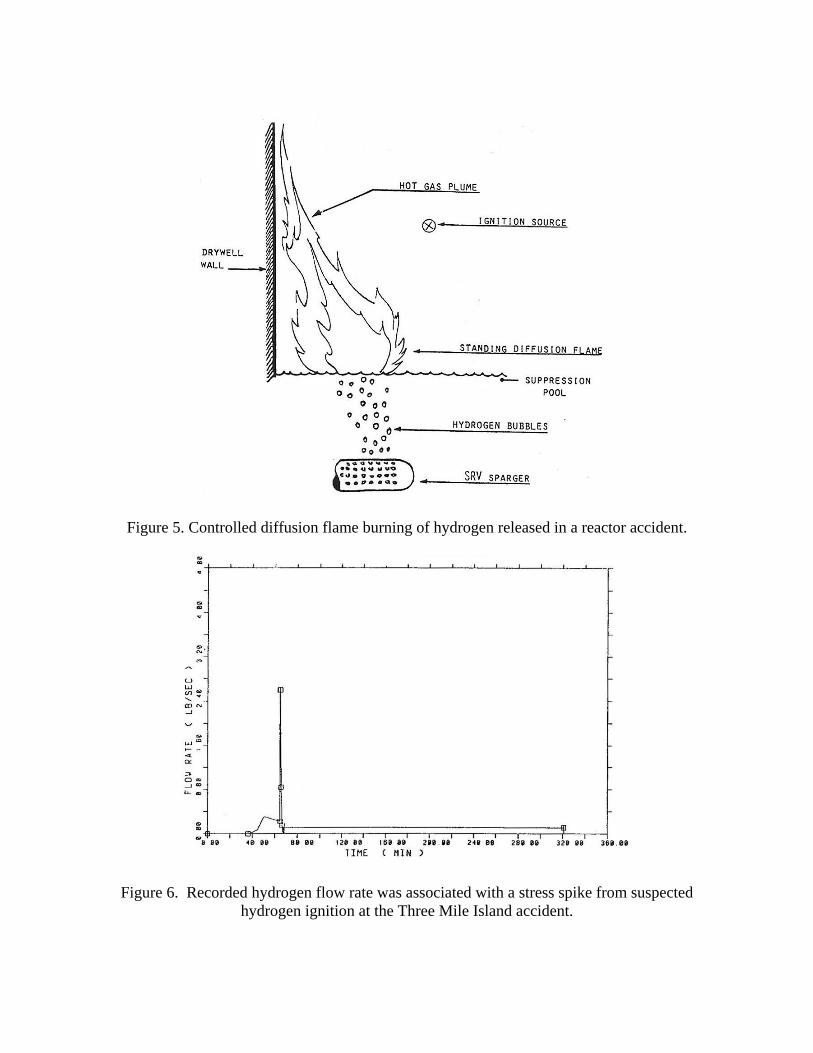
Figure 5. Controlled diffusion flame burning of hydrogen released in a reactor accident.
Figure 6. Recorded hydrogen flow rate was associated with a stress spike from suspected
hydrogen ignition at the Three Mile Island accident.

DESIGN CHARACTERISTICS OF EXISTING CONTAINMENT
SYSTEMS
The concrete structures in the existing power plants designs act as insulators
against the controlled release of energy to the environment and would eventually fail, if
the ESFs fail to perform their functions (Table 1).
They are being replaced by evolutionary designs that allow heat exchange with
the environment, hence avoiding the buildup of pressure in the case of a serious accident
and eventual failure to contain the release of radioactivity in a postulated accident.
Table 2. Simulated performance of different containment types [1].
Containment type,
plant
Parameter Technical
specification
SP-1, Zion Containment capability
Upper bound spike
Early failure physically unreasonable best estimate pressure rise rate, including
heat sinks
Best estimate failure time, with unlimited water in cavity
149 psia
107 psia
10 psi/hr
16 hrs
SP-2, Surry Containment capability
Upper bound spike
Early failure physically unreasonable best estimate failure time, with dry cavity
134 psia
107 psia
Several days
SP-3, Sequoyah Containment capability
Upper bound loading
Lower bound loading
Thermal loads
Early failure
65 psia, 330 oF
70-100 psia
50-70 psia
500-700 oF
Quite likely
SP-4, Browns Ferry Containment capability
Upper bound loading
Lower bound loading
Thermal loads
Early failure
132 psia, 330 oF
132 psia in 40 min
132 psi in 2 hrs
500-700 oF
Quite likely
SP-15, Limerick Containment capability
Upper bound loading
Lower bound loading
Thermal loads
Early failure, upper bound too conservative
155 psia, 330 oF
145 psia in 2-3 hrs
100 psi in 3 hrs
550-700 oF
Rather unlikely
SP-6, Grand Gulf Containment capability
Upper bound loading
Wall fluxes
Penetration seal temperature
Pressurization failure from diffusion flames
Seal failure
75 psia
30 psia
103-104 BTU/(hr.ft2)
345 oF
Unreasonable
Unlikely
SP-A, SP-1 accident
comparative results
Containment capability
Upper bound loading
Thermal loads
Early failure (100 percent core dispersal, 100 percent clad oxidation, no seal
oxidation, no early depressurization, unobstructed flow)
150 psia
176 psia
1,340 oF
Quite likely
MODERN CONTAINMENT DESIGN CONCEPTS
ADVANCED PASSIVE AP600 AND AP1000

Toshiba from Japan and its Westinghouse subsidiary that it acquired from British
Nuclear Fuel Ltd. (BNFL) in the USA are committed to the design and development of
advanced nuclear reactors that are safe, low-cost, reliable, and environmentally
acceptable. Their AP1000 design is meant for near term deployment and their 4S and
hydrogen production systems are targeted for future technology development.
The AP1000 is the only Generation III+ nuclear power plant to receive design
certification from the United States Nuclear Regulatory Commission. It is an advanced
plant that further increases safety through the use of naturally occurring forces such as
gravity, natural circulation, and condensation. In the unlikely event of a plant
emergency, these safety systems, because of their inherent nature, will automatically
activate without the need for human intervention.
In addition to the enhanced safety features, the AP1000 is cost-effective. The
plant is composed of modules that are constructed in either factories or shipyards, thereby
improving quality while reducing the potential for delays that are associated with field
construction.
Even though it is an advanced plant, it is a proven design that is based on the
same Westinghouse PWR technology that has supported the nuclear industry over the last
50 years. Toshiba brings to the partnership with Westinghouse a highly efficient and
reliable turbine generator design, state-of-the-art construction technologies, and
knowledgeable construction management.
Toshiba and Westinghouse are also developing the 4S, a Super Safe, Small, and
Simple reactor. The 4S is a 10-50 MWe, passive safety fast spectrum plant that has a 30-
year operating life before the need to refuel, also known as a battery reactor.
Figure 7. Advanced Passive AP1000 PWR includes a cooling chimney using natural
convection in its containment structure. Source: Toshiba-Westinghouse.
Figure 8. Containment structure of the AP1000 PWR has a gap between the steel shell
and the concrete shield allowing natural convection cooling. The cooling is enhanced
with a tang on top of it containing a supplemental water coolant supply. Source: Toshiba-
Westinghouse.
EVOLUTIONARY PRESSURIZED WATER REACTOR, EPR AREVA
DESIGN
The Evolutionary Pressurized Water Reactor, EPR is a Generation 3+ European
Pressurized Water Reactor design with a capacity of 1600 MWe. It features advanced
technologies, making it a reactor with the advocated following characteristics:
1. A high level of safety:
Extended prevention of the reactor core melt down hypothetical accident and its
potential consequences, resistance to external risks such as an aircraft crash or a strong
earthquake. The major safety systems comprise four sub-systems or "trains". Each train

is capable of performing the entire safety function independently. There is one train in
each of the four safeguard buildings, which are separated from each other by the reactor
building to prevent simultaneous failure of the trains.
2. Optimized environmental qualities:
A 15 percent reduction in the production of long half-life radioactive waste, and
increased performance and thermal efficiency.
3. Simplified operation and maintenance conditions:
Totally computerized control room, with a more user-friendly human-machine
interface.
4. Improved economic competitiveness.
Areva is developing two EPR projects in Europe. In Finland construction is
underway of an EPR for the Finnish utility TVO (Olkiluoto 3 project). The Finnish EPR
will be the first Generation III+ reactor to go into service. In France, Electricité De
France (EDF) has reached a decision to build a series of EPR reactors at the Flamanville-
3 project site.
Figure 9. Cutout through the Evolutionary PWR Reactor, EPR pressurized water reactor
design showing its double walled containment. Source: Areva.

Figure 10. Evolutionary Pressurized Reactor, EPR melted corium retention and auxiliary
water storage pools. Source: Areva.
ADVANCED BOILING WATER REACTOR, ABWR
CONTAINMENT
The ESFs for the Boiling Water Reactor (BWR) concept share similar
components with the PWR ESFs, and include:
1. The control rods, to shut down the chain reaction.
2. The containment-spray system, to quench any steam released under abnormal
conditions.
3. The pressure suppression pool to condense any steam leaking into the
containment vessel.
4. A residual heat removal system heat exchanger.
5. A High Pressure Coolant Injection system, HPCI.
6. A Low Pressure Coolant Injection system, LPCI.
7. A boron injection tank to shut down the chain reaction in case the control rods are
not capable of being inserted into the core.
8. An extra supply of cooling water in the condensate storage tank.
9. An internal core-spray system.

The Advanced Boiling Water Reactor, ABWR containment structure has
replaced the older light bulb design BWR containment.
Figure 11. Advanced Boiling Water Reactor, ABWR containment structure. Source: GE.
PWR CONTAINMENT STRUCTURES
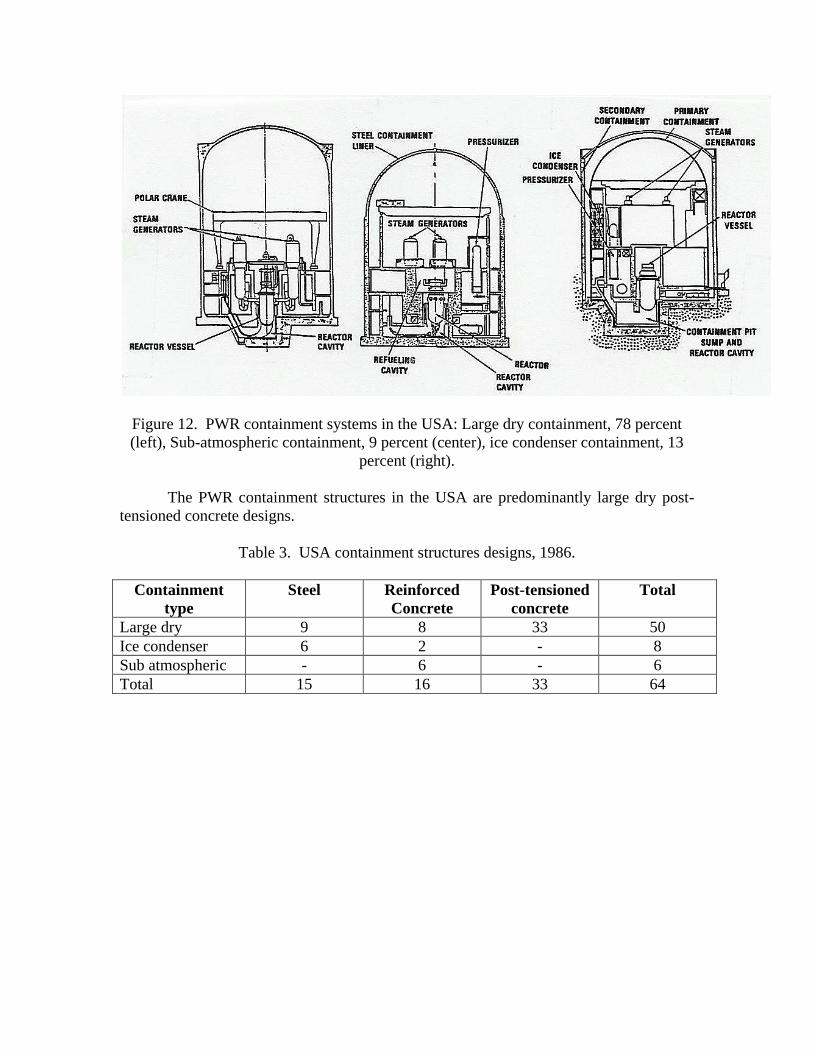
Figure 12. PWR containment systems in the USA: Large dry containment, 78 percent
(left), Sub-atmospheric containment, 9 percent (center), ice condenser containment, 13
percent (right).
The PWR containment structures in the USA are predominantly large dry post-
tensioned concrete designs.
Table 3. USA containment structures designs, 1986.
Containment
type
Steel Reinforced
Concrete
Post-tensioned
concrete
Total
Large dry 9 8 33 50
Ice condenser 6 2 - 8
Sub atmospheric - 6 - 6
Total 15 16 33 64
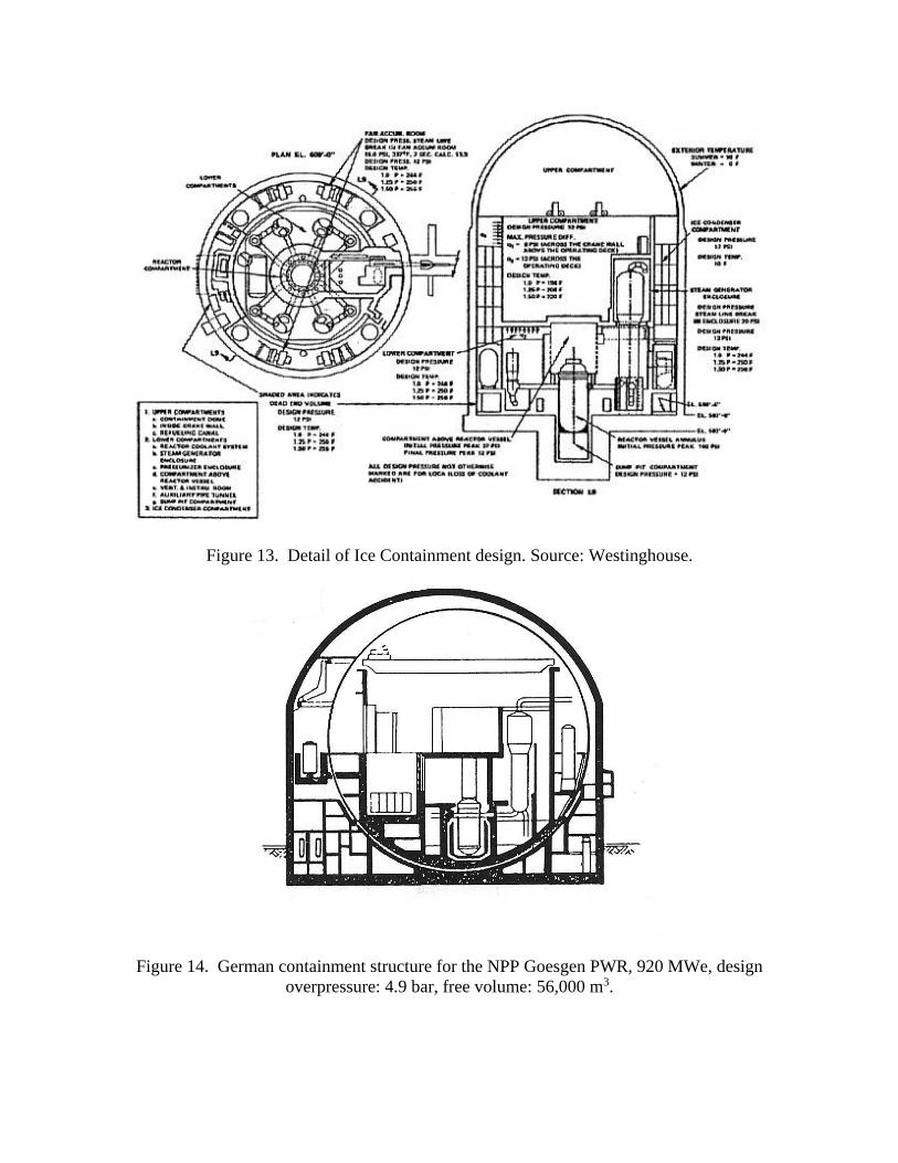
Figure 13. Detail of Ice Containment design. Source: Westinghouse.
Figure 14. German containment structure for the NPP Goesgen PWR, 920 MWe, design
overpressure: 4.9 bar, free volume: 56,000 m3.

Figure 15. Containment structure of the NPP Beznau PWR, 350 MWe, design
overpressure: 2.6 bar, free volume: 37,000 m3.
BWR CONTAINMENT STRUCTURES
The BWR vessel is surrounded in a containment structure equipped with a
pressure suppression pool in a light-bulb containment design, and in steel shell and
concrete containment design.
We suggest that the positioning of the pressure suppression pool below the reactor
core does not allow for natural circulation convective cooling in the case of a loss of
coolant accident (LOCA). More advanced inherently safe designs would position the
pressure suppression pool above the core. In case of an accident, the pressure in the core
and the pressure suppression pool are equalized automatically or by operator action
allowing natural circulation from the core to the pressure suppression pool in this case.

Figure 16. Steel shell and concrete BWR containment structure showing the pressure
suppression pool.
Table 4. USA containment structures designs, 1986.
Containment
type
Steel Reinforced
Concrete
Post-tensioned
concrete
Total
Pre Mark I 4 - - 4
Mark I 22 2 - 24
Mark II 1 3 2 6
Mark III 2 1 - 3
Total 29 6 33 37

Figure 17. Mark I steel containment design used in 60 percent of USA BWRs.
Figure 18. Mark I light bulb BWR containment and toroidal pressure suppression pool
design. Source: GE.

Figure 19. Comparison of Mark II (left), 16 percent and Mark III (right), 8 percent
containment systems. Source: GE.
GE MARK I CONTAINMENT SYSTEM
The BWR containment structures in the USA are predominantly Mark I steel
designs. The GE Company began making the Mark I, light bulb BWR containment
system in the 1960s.
In 1972, concerns were raised that the smaller containment design was more
susceptible to explosion and rupture from a buildup in hydrogen in case of fuel damage in
the core and steam interaction with the Zircaloy metal cladding of the fuel.
Mark 1 containments were thought susceptible to damage should the fuel rods
overheat and melt in an accident and that in an extreme accident, the containment could
fail within 40 minutes.
The assessment was disputed given that its failure probability was about 10
percent in the case of a serious accident, and it remained operational with a proven track
record of safety and reliability for more than 40 years.
There were 32 BWRs with Mark I containment operating around the globe. There
has not been a breach of a Mark I containment system prior to 2011.
Several utilities and plant operators considered suing GE in the late 1980s after
the disclosure of internal company documents dating back to 1975 that suggested the
containment vessel designs were either insufficiently tested or had flaws that could
compromise safety. The key concern was that the containment structure was undersized,
and that a potential accident could overwhelm and rupture it.
The BWR Mark I containments in the USA have undergone a variety of
modifications since these initial concerns were raised. Among these were changes to the
doughnut-shaped torus pressure suppression pool. Steam being quenched from the
primary vessel into the torus under high pressure would act as rocket and could cause
vessel displacement.

In the late 1980s, all BWRs with Mark I containments in the USA were ordered to
be retrofitted with venting systems to help reduce pressure in an overheating situation,
rather than allow it to build up in a containment system that regulators were concerned
could not take it.
A venting system was in place at the Fukushima plants to help relieve built-up
pressure. With electrical power cut off in the aftermath of the earthquake and backup
sources of power either failing or exhausted, workers injected seawater mixed with boron
into the reactor to maintain control reportedly using fire engines pumps. They had
difficulty venting the resulting steam with a report that pressure relief valves were
operated manually.
Figure 20. Mark I General Electric,GE BWR Containment. Source: GE.

Figure 21. Cutout through concrete Mark I light bulb BWR containment design. Source:
GE.

Figure 22. Mark II General Electric, GE BWR Containment. Source: GE.

Figure 23. Cutout through Mark II GE BWR containment. Source: GE.

Figure 24. Mark III General Electric, GE BWR Containment. Source: GE.

Figure 25. Cutout through Mark III, GE BWR Containment. Source: GE
Reactor Building. 1: Shield building, 2: Freestanding steel containment, 3: Upper pool, 4:
Refueling platform, 5: Reactor water cleanup, 6: Reactor vessel, 7: Steam line, 8:
Feedwater line, 9: Recirculation loop, 10: Pressure suppression pool, 11: Weir wall.
Auxiliary Building. 16: Steam line tunnel, 17: Reactor Heat Removal, RHR system,
18:Electrical equipment room.
Fuel Handling Building. 19: Spent fuel shipping cask, 20: Fuel storage pool, 21: Fuel
transfer pool, 22: Cask loading poll, 23: Cask handling crane, 24: Fuel transfer bridge,
25: Fuel cask skid on railroad car.

Figure 26. Containment and ventilation system for the NPP Muehleberg BWR, 322
MWe, free volume (dry and wet wells): 5,800 m3, drywell free volume: 3,700 m3, water
volume in pressure suppression pool: 2,100 m3, design overpressure: 3.8 bar.
Figure 27. Containment structure of NPP Leibstadt BWR, 990 MWe, free volume (dry
and wet wells): 44,000 m3, drywell free volume: 7,770 m3, water volume in pressure
suppression pool: 3,760 m3, design overpressure: 1.0 bar.

Figure 28. ABB Atom Type I BWR containment design, Sweden.

Figure 29. ABB Atom Type II BWR Containment, Sweden.

Figure 30. Siemens Kraft Werk Union, KWU Baulinie 69 BWR containment, Germany.

Figure 31. Siemens Kraft Werk Union, KWU Baulinie 72 BWR containment, Germany.
CONTAINMENT ATMOSPHERE FILTERING AND VENTING
SYSTEMS
Several containment atmosphere filtering and venting systems have been
proposed for containment but were not implemented for economical considerations.
These include sand and gravel as barriers to radioactive releases.

Figure 32. Sand and gravel containment venting system.
Figure 33. BWR Swedish Filtra venting system.
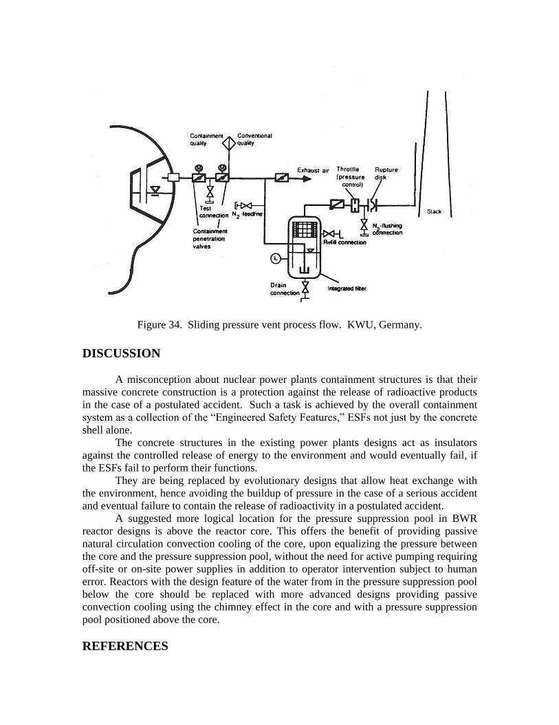
Figure 34. Sliding pressure vent process flow. KWU, Germany.
DISCUSSION
A misconception about nuclear power plants containment structures is that their
massive concrete construction is a protection against the release of radioactive products
in the case of a postulated accident. Such a task is achieved by the overall containment
system as a collection of the “Engineered Safety Features,” ESFs not just by the concrete
shell alone.
The concrete structures in the existing power plants designs act as insulators
against the controlled release of energy to the environment and would eventually fail, if
the ESFs fail to perform their functions.
They are being replaced by evolutionary designs that allow heat exchange with
the environment, hence avoiding the buildup of pressure in the case of a serious accident
and eventual failure to contain the release of radioactivity in a postulated accident.
A suggested more logical location for the pressure suppression pool in BWR
reactor designs is above the reactor core. This offers the benefit of providing passive
natural circulation convection cooling of the core, upon equalizing the pressure between
the core and the pressure suppression pool, without the need for active pumping requiring
off-site or on-site power supplies in addition to operator intervention subject to human
error. Reactors with the design feature of the water from in the pressure suppression pool
below the core should be replaced with more advanced designs providing passive
convection cooling using the chimney effect in the core and with a pressure suppression
pool positioned above the core.
REFERENCES

1. NUREG-1037, “Containment Performance Working Group Report,” May 1985.
2. John G. Collier and Geoffrey F. Hewitt, “Introduction to Nuclear power,” Hemisphere
publishing Corporation, Springer-Verlag, 1987.