contech cmp headwalls
TRANSCRIPT

ENGINEERED SOLUTIONS
Contech CMP Headwalls
PIPE SOLUTIONS

2
MEETING THE TEST OF TIME
Contech has over 100 years of experience manufacturing Corrugated Metal Pipe (CMP) for culverts and other drainage structures.
PROTECTION
CMP Headwalls reduce the potential for scour and the undermining of a culvert during flow events, including a major storm for all types of basins.
EFFICIENT INLET FLOW DESIGN
CMP Headwalls can more efficiently direct flows into culvert, decreasing entrance losses when compared to other entrance conditions.
DURABILITY
CMP Headwalls are available in different metal protective coatings to meet specific site requirements, including; galvanized, aluminized steel type 2 (ALT2), polymer-coated, and aluminum alloy.
PROJECT COST & TIME SAVINGS
Designing with CMP Headwalls can save thousands of dollars versus conventional concrete headwalls. CMP Headwalls provide immediate material savings and construction savings. Crane rental is typically not required when installing CMP Headwalls versus heavy concrete sections.
CMP Headwalls can save substantial construction time versus conventional concrete headwalls.
Contech CMP Headwalls
3
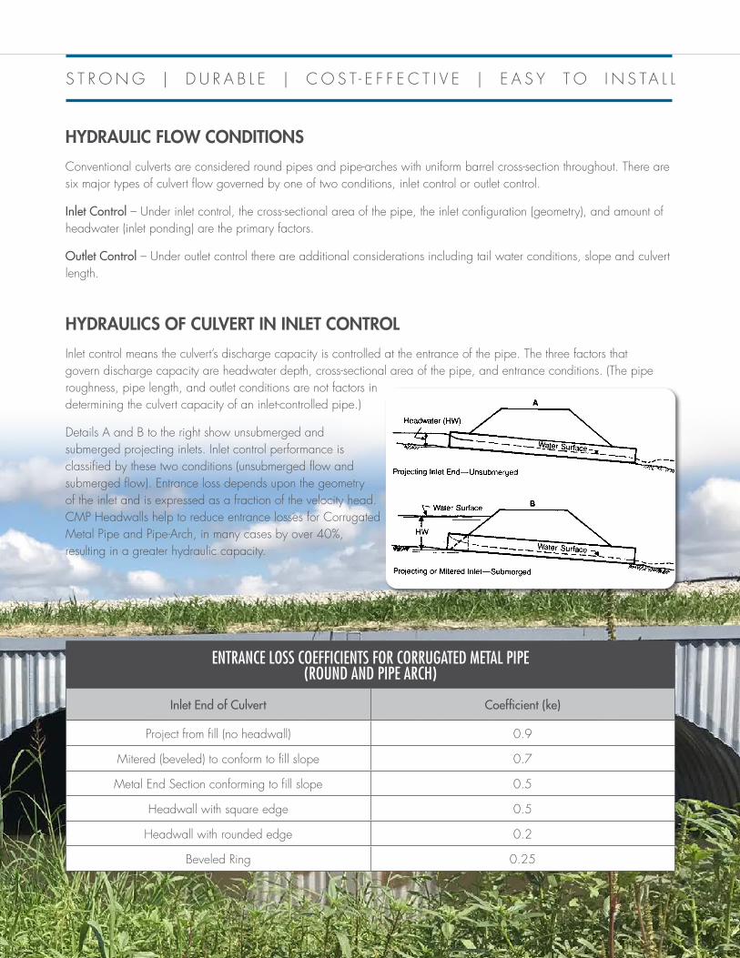
HYDRAULICS OF CULVERT IN INLET CONTROL
Inlet control means the culvert’s discharge capacity is controlled at the entrance of the pipe. The three factors that govern discharge capacity are headwater depth, cross-sectional area of the pipe, and entrance conditions. (The pipe roughness, pipe length, and outlet conditions are not factors in determining the culvert capacity of an inlet-controlled pipe.)
Details A and B to the right show unsubmerged and submerged projecting inlets. Inlet control performance is classified by these two conditions (unsubmerged flow and submerged flow). Entrance loss depends upon the geometry of the inlet and is expressed as a fraction of the velocity head. CMP Headwalls help to reduce entrance losses for Corrugated Metal Pipe and Pipe-Arch, in many cases by over 40%, resulting in a greater hydraulic capacity.
HYDRAULIC FLOW CONDITIONS
Conventional culverts are considered round pipes and pipe-arches with uniform barrel cross-section throughout. There are six major types of culvert flow governed by one of two conditions, inlet control or outlet control.
Inlet Control – Under inlet control, the cross-sectional area of the pipe, the inlet configuration (geometry), and amount of headwater (inlet ponding) are the primary factors.
Outlet Control – Under outlet control there are additional considerations including tail water conditions, slope and culvert length.
140 STEEL DRAINAGE AND HIGHWAY CONSTRUCTION PRODUCTS
Outlet Control – A culvert flowing in outlet control is characterized by relatively
deep, lower velocity flow categorized as subcritical. Outlet control flow occurs
when the culvert barrel is not capable of conveying as much flow as the inlet opening
will accept. The control section is at the outlet of the culvert. In addition to the
factors considered for inlet control, factors that must be considered for outlet control
include (1) the tailwater elevation in the outlet channel, (2) the barrel slope, (3) the
barrel roughness, and (4) the length of the barrel (see Figure 4.5).
Hydraulics of Culverts in Inlet Control
Inlet control means that the discharge capacity is controlled at the entrance by the
headwater depth, cross-sectional area and type of inlet edge. The roughness, length,
and outlet conditions are not factors in determining the culvert capacity.
Sketches A and B in Figure 4.4 show unsubmerged and submerged projecting
inlets. Inlet control performance is classified by these two regions (unsubmerged
flow and submerged flow) as well as a transition region between them.
Entrance loss depends upon the geometry of the inlet edge and is expressed as a
fraction of the velocity head. Research with models and prototype testing have
resulted in coefficients for various types of inlets, as shown in Table 4.5 and
Figure 4.6.
Figure 4.4 Inlet control flow regimes.
Entrance loss coefficients for corrugated steel pipe or pipe-arch
Entrance
Inlet End of Culvert Type Coefficient, ke
Projecting from fill (no headwall) 1 0.9
Mitered (bevelled) to conform to fill slope 2 0.7
Headwall or headwall and wingwalls square-edge 3 0.5
End-Section conforming to fill slope 4 0.5
Headwall rounded edge 5 0.2
Bevelled Ring 6 0.25
Table 4.5
S T R O N G | D U R A B L E | C O S T - E F F E C T I V E | E A S Y T O I N S TA L L
ENTRANCE LOSS COEFFICIENTS FOR CORRUGATED METAL PIPE (ROUND AND PIPE ARCH)
Inlet End of Culvert Coefficient (ke)
Project from fill (no headwall) 0.9
Mitered (beveled) to conform to fill slope 0.7
Metal End Section conforming to fill slope 0.5
Headwall with square edge 0.5
Headwall with rounded edge 0.2
Beveled Ring 0.25

4
Custom Design OptionsContech CMP Headwalls can be designed to meet direct highway loading as well as standard embankment loads. Headwalls can be designed for round and pipe arch shapes. Options including square ends, skewed ends, wing walls, and dead man anchors are available to meet specific site requirements.
Contech can assist you in the design or provide a stamped and sealed design for highway loads on the headwall.
33 ooff 77
45 degree skew cut wall
A load displacement test should be conducted to ensure the structural design and expected service life of the culvert.
5
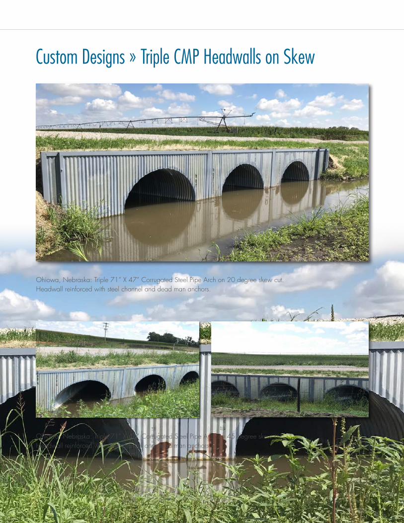
Custom Designs » Triple CMP Headwalls on Skew
Ohiowa, Nebraska: Triple 71” X 47” Corrugated Steel Pipe Arch on 20 degree skew cut. Headwall reinforced with steel channel and dead man anchors.
Ohiowa, Nebraska: Triple 71” X 47” Corrugated Steel Pipe Arch on 45 degree skew cut. Headwall reinforced with steel channel and dead man anchors.

Installation of Contech CMP Headwalls
Group Classification A-1-a A-1-b A-2-4 A-2-5
No. 10 (2.00 mm)
50 Max. -- -- --
No. 40 (0.425 mm)
30 Max 50 Max. -- --
No. 100 (0.150 mm)
-- -- 50 Max. 50 Max.
No. 200 (0.075 mm)
15 Max. 25 Max. 20 Max. 20 Max.
Liquid Limit -- -- 40 Max. 41 Min.Plasticity Index 6 Max. 6 Max. 10 Max. 10 Max.
BEDDING MATERIAL
All pipes must be placed on a granular foundation. Do not install pipe on sod, frozen earth or on a bed that contains large boulders or solid rock. Foundation material must provide an allowable minimum bearing capacity designed by the engineer. When soft, unstable material is encountered at the foundation level, it must be excavated below the flow line grade and backfilled to grade with sand, gravel, or crushed stone material.
BACKFILL MATERIAL
Backfill material shall be a clean, graded, granular and porous material free from frozen material, sod, cinders or organic matter. Backfill material must be free from rocks larger than two inches. Material shall meet AASHTO M-145, table 61 - A-1, A-2-4, or A-2-5 classification.
BACKFILL PLACEMENT
The backfill should be carefully compacted under the haunches of the pipe. Continue placing the backfill equally on both sides of the pipe in 8” to 10” loose lifts thoroughly compacting each layer to a minimum of 90% Standard Proctor density (AASHTO T99) all the way to the top of grade. The backfill lifts shall be balanced between the pipes. At no time should there be more than a 2’ lift differential between neighboring pipe barrels and side compaction fill area.
Backfill must be placed and fully compacted to the minimum cover le vel over the structure before the pipe is subjected to legal design loads. Keep heavy construction equipment that exceeds legal highway loads off the pipe. Light construction equipment on tracks such as a D-3 (or lighter) dozer may cross over the pipe when a minimum of one foot of compacted backfill is over pipe.
LOADING
Backfill must be placed and fully compacted to the minimum cover level over the structure before the pipe is subjected to design loads. When construction equipment that exceeds the legal highway loads will cross the pipe, an extra thickness of compacted fill, beyond that required for planned cover, may be required. Contact the design engineer or manufacturer’s representative if there is any question as to minimum covers required for specific equipment.
GROUP CLASSIFICATION
7
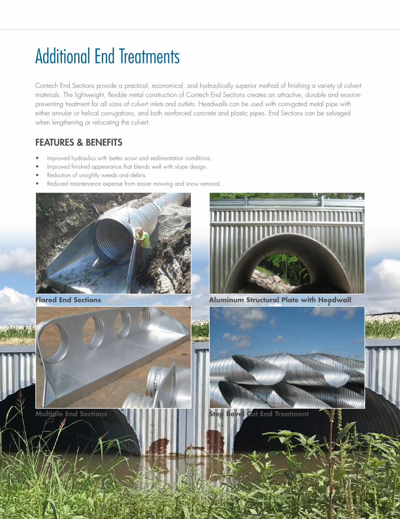
Additional End Treatments
Flared End Sections
Multiple End Sections
Aluminum Structural Plate with Headwall
Step Bevel Cut End Treatment
Contech End Sections provide a practical, economical, and hydraulically superior method of finishing a variety of culvert materials. The lightweight, flexible metal construction of Contech End Sections creates an attractive, durable and erosion-preventing treatment for all sizes of culvert inlets and outlets. Headwalls can be used with corrugated metal pipe with either annular or helical corrugations, and both reinforced concrete and plastic pipes. End Sections can be salvaged when lengthening or relocating the culvert.
FEATURES & BENEFITS• Improved hydraulics with better scour and sedimentation conditions.• Improved finished appearance that blends well with slope design.• Reduction of unsightly weeds and debris.• Reduced maintenance expense from easier mowing and snow removal.

© 2020 Contech Engineered Solutions LLC, a QUIKRETE Company800.338.1122www.ContechES.comAll Rights Reserved. Printed in the USA. NOTHING IN THIS CATALOG SHOULD BE CONSTRUED AS A WARRANTY. APPLICATIONS SUGGESTED HEREIN ARE DESCRIBED ONLY TO HELP READERS MAKE THEIR OWN EVALUATIONS AND DECISIONS, AND ARE NEITHER GUARANTEES NOR WARRANTIES OF SUITABILITY FOR ANY APPLICATION. CONTECH MAKES NO WARRANTY WHATSOEVER, EXPRESS OR IMPLIED, RELATED TO THE APPLICATIONS, MATERIALS, COATINGS, OR PRODUCTS DISCUSSED HEREIN. ALL IMPLIED WARRANTIES OF MERCHANTABILITY AND ALL IMPLIED WARRANTIES OF FITNESS FOR ANY PARTICULAR PURPOSE ARE DISCLAIMED BY CONTECH. SEE CONTECH’S CONDITIONS OF SALE (AVAILABLE AT WWW.CONTECHES.COM/COS) FOR MORE INFORMATION.
ENGINEERED SOLUTIONS
CMP Headwals Bro 10/17 PDF MC
Get Social With Us!
ENGINEERED SOLUTIONS
FOR MORE INFORMATION CALL:Corporate Office - Ohio (Cincinnati) 513-645-7000California (Roseville) 800-548-4667Colorado (Denver) 720-587-2700Florida (Orlando) 321-348-3520Maine (Scarborough) 207-885-9830Maryland (Baltimore) 410-740-8490Oregon (Portland) 503-258-3180Texas (Dallas) 972-590-2000
www.ContechES.com | 800-338-1122
STORMWATER SOLUTIONS
PIPE SOLUTIONS
STRUCTURE SOLUTIONS
Contech® Engineered Solutions provides innovative, cost-effective site solutions to engineers, contractors and developers on projects across North America. Our portfolio includes bridges, drainage, erosion control, retaining wall, sanitary sewer and stormwater management products.