contents 90 introduction . 70– 1 chapter 1
TRANSCRIPT

CONTENTS
Contents
A
ARTICLE90 Introduction ........................................ 70– 1
Chapter 1 General
100 Definitions ......................................... 70– 4
I. General .......................................... 70– 4II. Over 600 Volts, Nominal ..................... 70– 10
110 Requirements for Electrical Installations ..... 70– 11
I. General .......................................... 70– 11II. 600 Volts, Nominal, or Less ................. 70– 14
III. Over 600 Volts, Nominal ..................... 70– 17IV. Tunnel Installations over 600 Volts,
Nominal .......................................... 70– 20V. Manholes and Other Electric
Enclosures Intended for PersonnelEntry, All Voltages. [ROP 1–240] ........... 70– 20
Chapter 2 Wiring and Protection
200 Use and Identification of GroundedConductors .......................................... 70– 23
210 Branch Circuits ................................... 70– 25
I. General Provisions ............................ 70– 25II. Branch-Circuit Ratings ....................... 70– 29
III. Required Outlets ............................... 70– 31
215 Feeders ............................................. 70– 35
220 Branch-Circuit, Feeder, and ServiceCalculations ........................................ 70– 37
I. General .......................................... 70– 37II. Branch Circuit Load Calculations .......... 70– 38
III. Feeder and Service Load Calculations ..... 70– 40IV. Optional Feeder and Service Load
Calculations ..................................... 70– 43V. Farm Load Calculation ...................... 70– 46
225 Outside Branch Circuits and Feeders ......... 70– 47
I. General .......................................... 70– 47II. More Than One Building or Other
Structure ......................................... 70– 50III. Over 600 Volts ................................. 70– 52
230 Services ............................................ 70– 53
I. General .......................................... 70– 53II. Overhead Service-Drop Conductors ........ 70– 54
III. Underground Service-LateralConductors ...................................... 70– 56
IV. Service-Entrance Conductors ................ 70– 56V. Service Equipment — General .............. 70– 58
VI. Service Equipment — DisconnectingMeans ............................................ 70– 59
VII. Service Equipment — OvercurrentProtection ........................................ 70– 60
VIII. Services Exceeding 600 Volts, Nominal ... 70– 62
DR
2005 Edition i
RTICLE
240 Overcurrent Protection ........................... 70– 63
I. General .......................................... 70– 63II. Location ......................................... 70– 66
III. Enclosures ...................................... 70– 70IV. Disconnecting and Guarding ................ 70– 70V. Plug Fuses, Fuseholders, and Adapters .... 70– 70
VI. Cartridge Fuses and Fuseholders ........... 70– 71VII. Circuit Breakers ............................... 70– 71
VIII. Supervised Industrial Installations .......... 70– 72IX. Overcurrent Protection Over 600 Volts,
Nominal .......................................... 70– 73
250 Grounding and Bonding ......................... 70– 74
I. General .......................................... 70– 74II. System Grounding ............................ 70– 77
III. Grounding Electrode System andGrounding Electrode Conductor ............. 70– 83
IV. Enclosure, Raceway, and Service CableGrounding ....................................... 70– 87
V. Bonding ......................................... 70– 88VI. Equipment Grounding and Equipment
Grounding Conductors ........................ 70– 90VII. Methods of Equipment Grounding ......... 70– 95
VIII. Direct-Current Systems ....................... 70– 97IX. Instruments, Meters, and Relays ............ 70– 98X. Grounding of Systems and Circuits of
1 kV and Over (High Voltage) ............... 70– 99
280 Surge Arresters .................................... 70–100
I. General .......................................... 70–100II. Installation ...................................... 70–101
III. Connecting Surge Arresters .................. 70–101
285 Transient Voltage Surge Suppressors:TVSSs ............................................... 70–102
I. General .......................................... 70–102II. Installation ...................................... 70–102
III. Connecting Transient Voltage SurgeSuppressors ...................................... 70–102
Chapter 3 Wiring Methods and Materials
300 Wiring Methods ................................... 70–104
I. General Requirements ........................ 70–104II. Requirements for Over 600 Volts,
Nominal .......................................... 70–114
310 Conductors for General Wiring ................ 70–115
312 Cabinets, Cutout Boxes, and Meter SocketEnclosures .......................................... 70–141
I. Installation ...................................... 70–141II. Construction Specifications .................. 70–144
314 Outlet, Device, Pull, and Junction Boxes;Conduit Bodies; Fittings; and HandholeEnclosures [ROP 9–15, 9–16] ................... 70–145
I. Scope and General ............................ 70–145II. Installation ...................................... 70–145
AFT
NATIONAL ELECTRICAL CODE

CONTENTS
ARTICLE
III. Construction Specifications .................. 70–151IV. Pull and Junction Boxes for Use on
Systems Over 600 Volts, Nominal .......... 70–152
320 Armored Cable: Type AC ....................... 70–152
I. General .......................................... 70–152II. Installation ...................................... 70–153
III. Construction Specifications .................. 70–154
322 Flat Cable Assemblies: Type FC ............... 70–154
I. General .......................................... 70–154II. Installation ...................................... 70–154
III. Construction .................................... 70–154
324 Flat Conductor Cable: Type FCC .............. 70–155
I. General .......................................... 70–155II. Installation ...................................... 70–155
III. Construction .................................... 70–156
326 Integrated Gas Spacer Cable: Type IGS ...... 70–157
I. General .......................................... 70–157II. Installation ...................................... 70–157
III. Construction Specifications .................. 70–157
328 Medium Voltage Cable: Type MV ............. 70–158
I. General .......................................... 70–158II. Installation ...................................... 70–158
III. Construction Specifications .................. 70–158
330 Metal-Clad Cable: Type MC .................... 70–158
I. General .......................................... 70–158II. Installation ...................................... 70–159
III. Construction Specifications .................. 70–160
332 Mineral-Insulated, Metal-Sheathed Cable:Type MI ............................................. 70–160
I. General .......................................... 70–160II. Installation ...................................... 70–160
III. Construction Specifications .................. 70–161
334 Nonmetallic-Sheathed Cable: Types NM,NMC, and NMS ................................... 70–161
I. General .......................................... 70–161II. Installation ...................................... 70–161
III. Construction Specifications .................. 70–163
336 Power and Control Tray Cable: Type TC .... 70–163
I. General .......................................... 70–163II. Installation ...................................... 70–164
III. Construction Specifications .................. 70–164
338 Service-Entrance Cable: Types SE andUSE .................................................. 70–165
I. General .......................................... 70–165II. Installation ...................................... 70–165
III. Construction .................................... 70–165
340 Underground Feeder and Branch-CircuitCable: Type UF .................................... 70–165
I. General .......................................... 70–165II. Installation ...................................... 70–166
DRA
NATIONAL ELECTRICAL CODE ii
ARTICLE
III. Construction Specifications .................. 70–166
342 Intermediate Metal Conduit: Type IMC ...... 70–166
I. General .......................................... 70–166II. Installation ...................................... 70–166
III. Construction Specifications .................. 70–168
344 Rigid Metal Conduit: Type RMC .............. 70–168
I. General .......................................... 70–168II. Installation ...................................... 70–168
III. Construction Specifications .................. 70–169
348 Flexible Metal Conduit: Type FMC ........... 70–169
I. General .......................................... 70–169II. Installation ...................................... 70–170
350 Liquidtight Flexible Metal Conduit: TypeLFMC ............................................... 70–171
I. General .......................................... 70–171II. Installation ...................................... 70–171
III. Construction Specifications .................. 70–172
352 Rigid Nonmetallic Conduit: Type RNC ....... 70–172
I. General .......................................... 70–172II. Installation ...................................... 70–172
III. Construction Specifications .................. 70–174
353 High Density Polyethylene Conduit: TypeHDPE Conduit [ROP 8–96] ..................... 70–174
I. General .......................................... 70–174II. Installation ...................................... 70–175
III. Construction Specifications .................. 70–176
354 Nonmetallic Underground Conduit withConductors: Type NUCC ........................ 70–177
I. General .......................................... 70–177II. Installation ...................................... 70–177
III. Construction Specifications .................. 70–178
356 Liquidtight Flexible Nonmetallic Conduit:Type LFNC ......................................... 70–178
I. General .......................................... 70–178II. Installation ...................................... 70–178
III. Construction Specifications .................. 70–180
358 Electrical Metallic Tubing: Type EMT ........ 70–180
I. General .......................................... 70–180II. Installation ...................................... 70–180
III. Construction Specifications .................. 70–181
360 Flexible Metallic Tubing: Type FMT ......... 70–181
I. General .......................................... 70–181II. Installation ...................................... 70–181
III. Construction Specifications .................. 70–182
362 Electrical Nonmetallic Tubing: Type ENT ... 70–182
I. General .......................................... 70–182II. Installation ...................................... 70–183
III. Construction Specifications .................. 70–184
FT
2005 Edition

A
CONTENTS
ARTICLE
366 Auxiliary Gutters [ROP 8–167a] ............... 70–184
I. General .......................................... 70–184II. Installation ...................................... 70–185
III. Construction Specifications .................. 70–186
368 Busways [ROP 8–172a] ......................... 70–186
I. General Requirements ........................ 70–186II. Installation ...................................... 70–187
III. Construction .................................... 70–188IV. Requirements for Over 600 Volts,
Nominal .......................................... 70–188
370 Cablebus ........................................... 70–189
372 Cellular Concrete Floor Raceways ............ 70–190
374 Cellular Metal Floor Raceways ................ 70–191
I. Installation ...................................... 70–191II. Construction Specifications .................. 70–192
376 Metal Wireways ................................... 70–192
I. General .......................................... 70–192II. Installation ...................................... 70–192
III. Construction Specifications .................. 70–193
378 Nonmetallic Wireways ........................... 70–193
I. General .......................................... 70–193II. Installation ...................................... 70–193
III. Construction Specifications .................. 70–194
380 Multioutlet Assembly ............................ 70–194
382 Nonmetallic Extensions .......................... 70–195
I. General .......................................... 70–195II. Installation ...................................... 70–195
384 Strut-Type Channel Raceway ................... 70–196
I. General .......................................... 70–196II. Installation ...................................... 70–196
III. Construction Specifications .................. 70–197
386 Surface Metal Raceways ........................ 70–197
I. General .......................................... 70–197II. Installation ...................................... 70–197
III. Construction Specifications .................. 70–198
388 Surface Nonmetallic Raceways ................. 70–198
I. General .......................................... 70–198II. Installation ...................................... 70–198
III. Construction Specifications .................. 70–199
390 Underfloor Raceways ............................ 70–199
392 Cable Trays ........................................ 70–200
394 Concealed Knob-and-Tube Wiring ............. 70–207
I. General .......................................... 70–207II. Installation ...................................... 70–207
III. Construction Specifications .................. 70–208
396 Messenger Supported Wiring ................... 70–208
I. General .......................................... 70–208II. Installation ...................................... 70–208
DR
2005 Edition iii
RTICLE
398 Open Wiring on Insulators ...................... 70–209
I. General .......................................... 70–209II. Installation ...................................... 70–209
III. Construction Specifications .................. 70–210
Chapter 4 Equipment for General Use
400 Flexible Cords and Cables ...................... 70–211
I. General .......................................... 70–211II. Construction Specifications .................. 70–223
III. Portable Cables Over 600 Volts,Nominal .......................................... 70–224
402 Fixture Wires ...................................... 70–224
404 Switches ............................................ 70–229
I. Installation ...................................... 70–229II. Construction Specifications .................. 70–232
406 Receptacles, Cord Connectors, andAttachment Plugs (Caps) ......................... 70–232
408 Switchboards and Panelboards ................. 70–235
I. General .......................................... 70–235II. Switchboards ................................... 70–236
III. Panelboards ..................................... 70–236IV. Construction Specifications .................. 70–238
410 Luminaires (Lighting Fixtures),Lampholders, and Lamps ........................ 70–239
I. General .......................................... 70–239II. Luminaire (Fixture) Locations .............. 70–239
III. Provisions at Luminaire (Fixture)Outlet Boxes, Canopies, and Pans ........... 70–240
IV. Luminaire (Fixture) Supports ................ 70–241V. Grounding ...................................... 70–242
VI. Wiring of Luminaires (Fixtures) ............ 70–242VII. Construction of Luminaires (Fixtures) ..... 70–244
VIII. Installation of Lampholders .................. 70–245IX. Construction of Lampholders ................ 70–245X. Lamps and Auxiliary Equipment ........... 70–245
XI. Special Provisions for Flush andRecessed Luminaires (Fixtures) .............. 70–245
XII. Construction of Flush and RecessedLuminaires (Fixtures) .......................... 70–246
XIII. Special Provisions forElectric-Discharge Lighting Systems of1000 Volts or Less ............................. 70–246
XIV. Special Provisions forElectric-Discharge Lighting Systems ofMore Than 1000 Volts ......................... 70–247
XV. Lighting Track ................................. 70–248
411 Lighting Systems Operating at 30 Volts orLess .................................................. 70–249
422 Appliances ......................................... 70–249
I. General .......................................... 70–249II. Installation ...................................... 70–250
III. Disconnecting Means ......................... 70–252IV. Construction .................................... 70–253V. Marking ......................................... 70–254
AFT
NATIONAL ELECTRICAL CODE

CONTENTS
ARTICLE
424 Fixed Electric Space-Heating Equipment ..... 70–254
I. General .......................................... 70–254II. Installation ...................................... 70–255
III. Control and Protection of FixedElectric Space-Heating Equipment .......... 70–255
IV. Marking of Heating Equipment ............. 70–257V. Electric Space-Heating Cables .............. 70–257
VI. Duct Heaters ................................... 70–259VII. Resistance-Type Boilers ...................... 70–260
VIII. Electrode-Type Boilers ....................... 70–261IX. Electric Radiant Heating Panels and
Heating Panel Sets ............................. 70–261
426 Fixed Outdoor Electric Deicing andSnow-Melting Equipment ........................ 70–263
I. General .......................................... 70–263II. Installation ...................................... 70–264
III. Resistance Heating Elements ................ 70–264IV. Impedance Heating ............................ 70–265V. Skin-Effect Heating ........................... 70–266
VI. Control and Protection ........................ 70–266
427 Fixed Electric Heating Equipment forPipelines and Vessels ............................. 70–267
I. General .......................................... 70–267II. Installation ...................................... 70–267
III. Resistance Heating Elements ................ 70–267IV. Impedance Heating ............................ 70–268V. Induction Heating ............................. 70–269
VI. Skin-Effect Heating ........................... 70–269VII. Control and Protection ........................ 70–269
430 Motors, Motor Circuits, and Controllers ...... 70–270
I. General .......................................... 70–270II. Motor Circuit Conductors .................... 70–276
III. Motor and Branch-Circuit OverloadProtection ........................................ 70–278
IV. Motor Branch-Circuit Short-Circuit andGround-Fault Protection ....................... 70–281
V. Motor Feeder Short-Circuit andGround-Fault Protection ....................... 70–285
VI. Motor Control Circuits ....................... 70–285VII. Motor Controllers ............................. 70–287
VIII. Motor Control Centers ........................ 70–290IX. Disconnecting Means ......................... 70–291X. Adjustable-Speed Drive Systems [ROP
11–6] ............................................. 70–294XI. Over 600 Volts, Nominal ..................... 70–295
XII. Protection of Live Parts — AllVoltages .......................................... 70–296
XIII. Grounding — All Voltages ................... 70–296XIV. Tables ............................................ 70–298
440 Air-Conditioning and RefrigeratingEquipment .......................................... 70–301
I. General .......................................... 70–301II. Disconnecting Means ......................... 70–303
III. Branch-Circuit Short-Circuit andGround-Fault Protection ....................... 70–304
IV. Branch-Circuit Conductors ................... 70–305V. Controllers for Motor-Compressors ........ 70–305
VI. Motor-Compressor and Branch-CircuitOverload Protection ............................ 70–306
DRA
NATIONAL ELECTRICAL CODE iv
ARTICLE
VII. Provisions for Room Air Conditioners ..... 70–307
445 Generators ......................................... 70–308
450 Transformers and Transformer Vaults(Including Secondary Ties) ...................... 70–309
I. General Provisions ............................ 70–309II. Specific Provisions Applicable to
Different Types of Transformers ............. 70–314III. Transformer Vaults ............................ 70–315
455 Phase Converters ................................. 70–316
I. General .......................................... 70–316II. Specific Provisions Applicable to
Different Types of Phase Converters ........ 70–318
460 Capacitors .......................................... 70–318
I. 600 Volts, Nominal, and Under ............. 70–318II. Over 600 Volts, Nominal ..................... 70–319
470 Resistors and Reactors....................................................... 70–320
I. 600 Volts, Nominal, and Under ............. 70–320II. Over 600 Volts, Nominal ..................... 70–320
480 Storage Batteries .................................. 70–320
490 Equipment, Over 600 Volts, Nominal ......... 70–322
I. General .......................................... 70–322II. Equipment — Specific Provisions .......... 70–322
III. Equipment — Metal-Enclosed PowerSwitchgear and Industrial ControlAssemblies ...................................... 70–324
IV. Mobile and Portable Equipment ............ 70–326V. Electrode-Type Boilers ....................... 70–327
Chapter 5 Special Occupancies
500 Hazardous (Classified) Locations, ClassesI, II, and III, Divisions 1 and 2 ................. 70–328
501 Class I Locations [ROP 14–19a] ............... 70–336
I. General .......................................... 70–336II. Wiring ........................................... 70–336
III. Equipment ...................................... 70–342
502 Class II Locations [ROP 14–51a] .............. 70–346
I. General .......................................... 70–346II. Wiring ........................................... 70–346
III. Equipment ...................................... 70–348
503 Class III Locations [ROP 14–60a] ............. 70–352
I. General .......................................... 70–352II. Wiring ........................................... 70–352
III. Equipment ...................................... 70–353
504 Intrinsically Safe Systems ....................... 70–355
505 Class I, Zone 0, 1, and 2 Locations ........... 70–358
506 Zone 20, 21, and 22 Locations forFlammable Dusts, Fibers, and Flyings ......... 70–371
510 Hazardous (Classified) Locations —Specific .............................................. 70–377
FT
2005 Edition

A
CONTENTS
ARTICLE
511 Commercial Garages, Repair and Storage .... 70–377
513 Aircraft Hangars .................................. 70–380
514 Motor Fuel Dispensing Facilities .............. 70–383
515 Bulk Storage Plants .............................. 70–387
516 Spray Application, Dipping, and CoatingProcesses ............................................ 70–391
517 Health Care Facilities ............................ 70–397
I. General .......................................... 70–397II. Wiring and Protection ........................ 70–399
III. Essential Electrical System .................. 70–403IV. Inhalation Anesthetizing Locations ......... 70–410V. X-Ray Installations ............................ 70–412
VI. Communications, Signaling Systems,Data Systems, Fire Alarm Systems, andSystems Less Than 120 Volts, Nominal .... 70–414
VII. Isolated Power Systems ...................... 70–414
518 Assembly Occupancies [ROP 15–57] ......... 70–415
520 Theaters, Audience Areas of MotionPicture and Television Studios,Performance Areas, and Similar Locations ... 70–417
I. General .......................................... 70–417II. Fixed Stage Switchboards .................... 70–418
III. Fixed Stage Equipment Other ThanSwitchboards .................................... 70–419
IV. Portable Switchboards on Stage ............ 70–420V. Portable Stage Equipment Other Than
Switchboards .................................... 70–423VI. Dressing Rooms ............................... 70–425
VII. Grounding ...................................... 70–425
525 Carnivals, Circuses, Fairs, and SimilarEvents ............................................... 70–425
I. General Requirements ........................ 70–425II. Power Sources ................................. 70–425
III. Wiring Methods ................................ 70–426IV. Grounding and Bonding ...................... 70–427
530 Motion Picture and Television Studiosand Similar Locations ............................ 70–427
I. General .......................................... 70–427II. Stage or Set .................................... 70–428
III. Dressing Rooms ............................... 70–430IV. Viewing, Cutting, and Patching Tables .... 70–430V. Cellulose Nitrate Film Storage Vaults ..... 70–430
VI. Substations ...................................... 70–430
540 Motion Picture Projection Rooms ............. 70–431
I. General .......................................... 70–431II. Equipment and Projectors of the
Professional Type .............................. 70–431III. Nonprofessional Projectors .................. 70–432IV. Audio Signal Processing, Amplification,
and Reproduction Equipment ................ 70–432
545 Manufactured Buildings ......................... 70–432
547 Agricultural Buildings ........................... 70–433
DR
2005 Edition v
RTICLE
550 Mobile Homes, Manufactured Homes, andMobile Home Parks ............................... 70–436
I. General .......................................... 70–436II. Mobile and Manufactured Homes .......... 70–437
III. Services and Feeders .......................... 70–444
551 Recreational Vehicles and RecreationalVehicle Parks ....................................... 70–446
I. General .......................................... 70–446III. Combination Electrical Systems ............ 70–447IV. Other Power Sources ......................... 70–448V. Nominal 120-Volt or 120/240-Volt
Systems .......................................... 70–449VI. Factory Tests ................................... 70–455
VII. Recreational Vehicle Parks ................... 70–455
552 Park Trailers ....................................... 70–458
I. General .......................................... 70–458II. Low-Voltage Systems ......................... 70–458
III. Combination Electrical Systems ............ 70–459IV. Nominal 120-Volt or 120/240-Volt
Systems .......................................... 70–460V. Factory Tests ................................... 70–467
553 Floating Buildings ................................ 70–467
I. General .......................................... 70–467II. Services and Feeders .......................... 70–467
III. Grounding ...................................... 70–468
555 Marinas and Boatyards .......................... 70–468
590 Temporary Installations [TCC 3–108] ........ 70–471
Chapter 6 Special Equipment
600 Electric Signs and Outline Lighting ........... 70–474
I. General .......................................... 70–474II. Field-Installed Skeleton Tubing ............. 70–477
604 Manufactured Wiring Systems ................. 70–478
605 Office Furnishings (Consisting of LightingAccessories and Wired Partitions) .............. 70–479
610 Cranes and Hoists ................................ 70–480
I. General .......................................... 70–480II. Wiring ........................................... 70–481
III. Contact Conductors ........................... 70–483IV. Disconnecting Means ......................... 70–484V. Overcurrent Protection ........................ 70–484
VI. Control .......................................... 70–485VII. Grounding ...................................... 70–486
620 Elevators, Dumbwaiters, Escalators,Moving Walks, Wheelchair Lifts, andStairway Chair Lifts .............................. 70–486
I. General .......................................... 70–486II. Conductors ...................................... 70–488
III. Wiring ........................................... 70–489IV. Installation of Conductors .................... 70–491V. Traveling Cables ............................... 70–492
VI. Disconnecting Means and Control .......... 70–493VII. Overcurrent Protection ........................ 70–494
AFT
NATIONAL ELECTRICAL CODE

CONTENTS
ARTICLE
VIII. Machine Rooms, Control Rooms,Machinery Spaces, and Control Spaces .... 70–495
IX. Grounding ...................................... 70–495X. Emergency and Standby Power
Systems .......................................... 70–495
625 Electric Vehicle Charging System ............. 70–496
I. General .......................................... 70–496II. Wiring Methods ................................ 70–496
III. Equipment Construction ...................... 70–497IV. Control and Protection ........................ 70–497V. Electric Vehicle Supply Equipment
Locations ........................................ 70–498
630 Electric Welders ................................... 70–499
I. General .......................................... 70–499II. Arc Welders .................................... 70–500
III. Resistance Welders ............................ 70–501IV. Welding Cable ................................. 70–502
640 Audio Signal Processing, Amplification,and Reproduction Equipment .................... 70–502
I. General .......................................... 70–502II. Permanent Audio System Installations ..... 70–505
III. Portable and Temporary Audio SystemInstallations ...................................... 70–506
645 Information Technology Equipment ........... 70–507
647 Sensitive Electronic Equipment ................ 70–509
650 Pipe Organs ........................................ 70–510
660 X-Ray Equipment ................................ 70–511
I. General .......................................... 70–511II. Control .......................................... 70–512
III. Transformers and Capacitors ................ 70–512IV. Guarding and Grounding ..................... 70–512
665 Induction and Dielectric HeatingEquipment .......................................... 70–513
I. General .......................................... 70–513II. Guarding, Grounding, and Labeling ........ 70–514
668 Electrolytic Cells ................................. 70–514
669 Electroplating ...................................... 70–517
670 Industrial Machinery ............................. 70–518
675 Electrically Driven or ControlledIrrigation Machines ............................... 70–519
I. General .......................................... 70–519II. Center Pivot Irrigation Machines ........... 70–521
680 Swimming Pools, Fountains, and SimilarInstallations ......................................... 70–521
I. General .......................................... 70–521II. Permanently Installed Pools ................. 70–524
III. Storable Pools .................................. 70–531IV. Spas and Hot Tubs ............................ 70–532V. Fountains ........................................ 70–534
VI. Pools and Tubs for Therapeutic Use ....... 70–535VII. Hydromassage Bathtubs ...................... 70–536
DRA
NATIONAL ELECTRICAL CODE vi
ARTICLE
682 Natural and Artificially Made Bodies ofWater [ROP 17–154] .............................. 70–537
I. General .......................................... 70–537II. Installation ...................................... 70–537
III. Grounding and Bonding ...................... 70–538
685 Integrated Electrical Systems ................... 70–538
I. General .......................................... 70–538II. Orderly Shutdown ............................. 70–538
690 Solar Photovoltaic Systems ..................... 70–539
I. General .......................................... 70–539II. Circuit Requirements ......................... 70–541
III. Disconnecting Means ......................... 70–543IV. Wiring Methods ................................ 70–545V. Grounding ...................................... 70–546
VI. Marking ......................................... 70–546VII. Connection to Other Sources ................ 70–547
VIII. Storage Batteries ............................... 70–548IX. Systems Over 600 Volts ...................... 70–549
692 Fuel Cell Systems ................................ 70–549
I. General .......................................... 70–549II. Circuit Requirements ......................... 70–550
III. Disconnecting Means ......................... 70–550IV. Wiring Methods ................................ 70–551V. Grounding ...................................... 70–551
VI. Marking ......................................... 70–551VII. Connection to Other Circuits ................ 70–551
VIII. Outputs Over 600 Volts ...................... 70–552
695 Fire Pumps ......................................... 70–552
Chapter 7 Special Conditions
700 Emergency Systems .............................. 70–557
I. General .......................................... 70–557II. Circuit Wiring .................................. 70–558
III. Sources of Power .............................. 70–559IV. Emergency System Circuits for
Lighting and Power ............................ 70–560V. Control — Emergency Lighting
Circuits ........................................... 70–561VI. Overcurrent Protection ........................ 70–561
701 Legally Required Standby Systems ............ 70–561
I. General .......................................... 70–561II. Circuit Wiring .................................. 70–563
III. Sources of Power .............................. 70–563IV. Overcurrent Protection ........................ 70–564
702 Optional Standby Systems ...................... 70–564
I. General .......................................... 70–564II. Circuit Wiring .................................. 70–565
III. Grounding ...................................... 70–565IV. Sources of Power [ROP 13–155] ........... 70–565
705 Interconnected Electric Power ProductionSources .............................................. 70–566
720 Circuits and Equipment Operating at LessThan 50 Volts ...................................... 70–567
FT
2005 Edition

A
T
1
1
1
CONTENTS
ARTICLE
725 Class 1, Class 2, and Class 3Remote-Control, Signaling, andPower-Limited Circuits [ROP 3–126] .......... 70–568
I. General .......................................... 70–568II. Class 1 Circuits ................................ 70–569
III. Class 2 and Class 3 Circuits ................. 70–571VI. Listing Requirements ......................... 70–576
727 Instrumentation Tray Cable: Type ITC ........ 70–577
760 Fire Alarm Systems [ROP 3–223] ............. 70–578
I. General .......................................... 70–578II. Non–Power-Limited Fire Alarm
(NPLFA) Circuits .............................. 70–579III. Power-Limited Fire Alarm (PLFA)
Circuits ........................................... 70–582
770 Optical Fiber Cables and Raceways [ROP16–5] ................................................ 70–587
I. General .......................................... 70–587II. Protection ....................................... 70–588
III. Cables Within Buildings ...... .................... {ROP 16-24]... 70–589VI. Listing Requirements ......................... 70–591
780 Closed-Loop and Programmed PowerDistribution ......................................... 70–592
Chapter 8 Communications Systems
800 Communications Circuits ........................ 70–594
I. General .......................................... 70–594II. Wires and Cables Outside and Entering
Buildings [ROP 16–84] ....................... 70–595III. Protection ....................................... 70–596IV. Grounding Methods ........................... 70–597V. Wires and Cables Within Buildings
[ROP 16–100] ................................... 70–598VI. Listing Requirements ......................... 70–601
810 Radio and Television Equipment ............... 70–603
I. General .......................................... 70–603II. Receiving Equipment — Antenna
Systems .......................................... 70–603III. Amateur Transmitting and Receiving
Stations — Antenna Systems ................. 70–606IV. Interior Installation — Transmitting
Stations ........................................... 70–606
820 Community Antenna Television and RadioDistribution Systems .............................. 70–607
I. General .......................................... 70–607II. Cables Outside and Entering Buildings .... 70–608
III. Protection ....................................... 70–609IV. Grounding Methods ........................... 70–609V. Cables Within Buildings ..................... 70–610
DR
VI. Listing Requirements ......................... 70–6122005 Edition vii
RTICLE
830 Network-Powered BroadbandCommunications Systems ........................ 70–614
I. General .......................................... 70–614II. Cables Outside and Entering Buildings .... 70–615
III. Protection ....................................... 70–618IV. Grounding Methods ........................... 70–619V. Cables Within Buildings ..................... 70–620
VI. Listing Requirements ......................... 70–622ABLES
Chapter 9 Tables
1 Percent of Cross Section of Conduit andTubing for Conductors ........................... 70–624
2 Radius of Conduit and Tubing Bends[ROP 8–24a] ....................................... 70–624
4 Dimensions and Percent Area of Conduitand Tubing(Areas of Conduit or Tubing for theCombinations of Wires Permitted in Table1, Chapter 9) [ROP 8–294] ...................... 70–625
5 Dimensions of Insulated Conductors andFixture Wires ....................................... 70–629
5A Compact Aluminum Building WireNominal Dimensions* and Areas [ROP6–108, 6–109] ...................................... 70–634
8 Conductor Properties [ROP 6–111] ........... 70–634
9 Alternating-Current Resistance andReactance for 600-Volt Cables, 3-Phase,60 Hz, 75°C (167°F) — Three SingleConductors in Conduit ............................ 70–635
1(A) Class 2 and Class 3 Alternating-CurrentPower Source Limitations ........................ 70–637
11(B) Class 2 and Class 3 Direct-Current PowerSource Limitations ................................ 70–637
2(A) PLFA Alternating-Current Power SourceLimitations .......................................... 70–638
2(B) PLFA Direct-Current Power SourceLimitations [ROP 3–301] ........................ 70–638
Annex A ............................................ 70–640
Annex B ............................................ 70–643
Annex C ............................................ 70–657
Annex D ............................................ 70–679
Annex E ............................................. 70–691
Annex F ............................................. 70–693
Annex G ............................................ 70–696
AFT
NATIONAL ELECTRICAL CODE

ARTICLE 90Introduction
90.1 Purpose.
(A) Practical Safeguarding. The purpose of this Code isthe practical safeguarding of persons and property fromhazards arising from the use of electricity.
(B) Adequacy. This Code contains provisions that are con-sidered necessary for safety. Compliance therewith andproper maintenance will result in an installation that is es-sentially free from hazard but not necessarily efficient, con-venient, or adequate for good service or future expansion ofelectrical use.
FPN: Hazards often occur because of overloading of wir-ing systems by methods or usage not in conformity withthis Code. This occurs because initial wiring did not pro-vide for increases in the use of electricity. An initial ad-equate installation and reasonable provisions for systemchanges will provide for future increases in the use ofelectricity.
(C) Intention. This Code is not intended as a design speci-fication or an instruction manual for untrained persons.
(D) Relation to Other International Standards. The re-quirements in this Code address the fundamental principlesof protection for safety contained in Section 131 of Inter-national Electrotechnical Commission Standard 60364-1,Electrical Installations of Buildings. [ROP 1–16a]
FPN: IEC 60364-1, Section 131, contains fundamentalprinciples of protection for safety that encompass protec-tion against electric shock, protection against thermal ef-fects, protection against overcurrent, protection againstfault currents, and protection against overvoltage. All ofthese potential hazards are addressed by the requirements inthis Code.
90.2 Scope.
(A) Covered. This Code covers the installation of electricconductors, cables, equipment, and raceways; signaling andcommunications conductors, cables, equipment, and race-ways; and optical fiber cables and raceways for the follow-ing: [ROP 1–18]
(1) Public and private premises, including buildings, struc-tures, mobile homes, recreational vehicles, and floatingbuildings
(2) Yards, lots, parking lots, carnivals, and industrial sub-stations
FPN: For additional information concerning such installa-tions in an industrial or multibuilding complex, see theANSI C2-2002, National Electrical Safety Code. [ROP1–22a]
(3) Installations of conductors and equipment that connectto the supply of electricity
(4) Installations used by the electric utility, such as officebuildings, warehouses, garages, machine shops, andrecreational buildings, which are not an integral part ofa generating plant, substation, or control center. [ROP1–23]
(B) Not Covered. This Code does not cover the following:
(1) Installations in ships, watercraft other than floatingbuildings, railway rolling stock, aircraft, or automotivevehicles other than mobile homes and recreational ve-hicles
FPN: Although the scope of this Code indicates that theCode does not cover installations in ships, portions of thisCode are incorporated by reference into Title 46, Code ofFederal Regulations, Parts 110–113.
(2) Installations underground in mines and self-propelledmobile surface mining machinery and its attendantelectrical trailing cable [ROP 1–28]
(3) Installations of railways for generation, transformation,transmission, or distribution of power used exclusivelyfor operation of rolling stock or installations used ex-clusively for signaling and communications purposes
(4) Installations of communications equipment under theexclusive control of communications utilities locatedoutdoors or in building spaces used exclusively forsuch installations
(5) Installations under the exclusive control of an electricutility where such installations
a. Consist of service drops or service laterals, and as-sociated metering, or
b. Are located in legally established easements, rights-of-way, or by other agreements either designated byor recognized by public service commissions, utilitycommissions, or other regulatory agencies havingjurisdiction for such installations, or
c. Are on property owned or leased by the electricutility for the purpose of communications, metering,generation, control, transformation, transmission, ordistribution of electric energy.
FPN to (4) and (5): Utilities are organizations, typicallydesignated or recognized by governmental law or regula-tion by public service/utility commissions, that install, op-erate, and maintain electric supply (such as generation,transmission, or distribution systems) or communicationsystems (such as telephone, CATV, Internet, satellite, or
NFPA 70
National Electrical Code®
2005 Edition
70-1ARTICLE 90 INTRODUCTION
2005 EditionNATIONAL ELECTRICAL CODE
DRAFT

data services). As such, the utility is subject to compliancewith codes and standards covering these activities relevantto their industry as adopted under governmental law orregulation. Refer to the appropriate governmental bodies,such as state regulatory commissions, Federal EnergyRegulatory Commission, and Federal CommunicationsCommission. [ROP 1–25]
(C) Special Permission. The authority having jurisdictionfor enforcing this Code may grant exception for the instal-lation of conductors and equipment that are not under theexclusive control of the electric utilities and are used toconnect the electric utility supply system to the service-entrance conductors of the premises served, provided suchinstallations are outside a building or terminate immedi-ately inside a building wall.
90.3 Code Arrangement. This Code is divided into theintroduction and nine chapters, as shown in Figure 90.3.Chapters 1, 2, 3, and 4 apply generally; Chapters 5, 6, and7 apply to special occupancies, special equipment, or otherspecial conditions. These latter chapters supplement ormodify the general rules. Chapters 1 through 4 apply exceptas amended by Chapters 5, 6, and 7 for the particular con-ditions.
Chapter 8 covers communications systems and is notsubject to the requirements of Chapters 1 through 7 exceptwhere the requirements are specifically referenced in Chap-ter 8.
Chapter 9 consists of tables.Annexes are not part of the requirements of this Code
but are included for informational purposes only.
90.4 Enforcement. This Code is intended to be suitablefor mandatory application by governmental bodies that ex-ercise legal jurisdiction over electrical installations, includ-ing signaling and communications systems, and for use byinsurance inspectors. The authority having jurisdiction forenforcement of the Code has the responsibility for makinginterpretations of the rules, for deciding on the approval ofequipment and materials, and for granting the special per-mission contemplated in a number of the rules.
By special permission, the authority having jurisdictionmay waive specific requirements in this Code or permitalternative methods where it is assured that equivalent ob-jectives can be achieved by establishing and maintainingeffective safety.
This Code may require new products, constructions, ormaterials that may not yet be available at the time the Codeis adopted. In such event, the authority having jurisdictionmay permit the use of the products, constructions, or mate-rials that comply with the most recent previous edition ofthis Code adopted by the jurisdiction.
90.5 Mandatory Rules, Permissive Rules, and Explana-tory Material.
(A) Mandatory Rules. Mandatory rules of this Code arethose that identify actions that are specifically required orprohibited and are characterized by the use of the termsshall or shall not.
(B) Permissive Rules. Permissive rules of this Code arethose that identify actions that are allowed but not required,are normally used to describe options or alternative meth-ods, and are characterized by the use of the terms shall bepermitted or shall not be required.
(C) Explanatory Material. Explanatory material, such asreferences to other standards, references to related sectionsof this Code, or information related to a Code rule, is in-cluded in this Code in the form of fine print notes (FPNs).Fine print notes are informational only and are not enforce-able as requirements of this Code.
Brackets containing section references to another NFPAdocument are for informational purposes only and are pro-vided as a guide to indicate the source of the extracted text.These bracketed references immediately follow the ex-tracted text. [ROP 1–34]
FPN: The format and language used in this Code followsguidelines established by NFPA and published in the NECStyle Manual. Copies of this manual can be obtained fromNFPA.
90.6 Formal Interpretations. To promote uniformity ofinterpretation and application of the provisions of thisCode, formal interpretation procedures have been estab-
Chapter 1 — General
Chapter 2 — Wiring and Protection
Chapter 3 — Wiring Methods and Materials
Chapter 4 — Equipment for General Use
Applies generallyto all electrical
installations
Chapter 5 — Special Occupancies
Chapter 6 — Special Equipment
Chapter 7 — Special Conditions
Supplements or modifiesChapters 1 through 4
Chapter 9 — Tables
Annex A through Annex G
Chapter 8 — Communications Systems
Informational only; not mandatory
Applicable as referenced
Chapter 8 is not subject to the requirements of Chapters 1 through 7 except where the requirements are specifically referenced in Chapter 8.
Figure 90.3 Code arrangement.
70-2 ARTICLE 90 INTRODUCTION
2005 Edition NATIONAL ELECTRICAL CODE
DRAFT

lished and are found in the NFPA Regulations GoverningCommittee Projects.
90.7 Examination of Equipment for Safety. For specificitems of equipment and materials referred to in this Code,examinations for safety made under standard conditionsprovide a basis for approval where the record is made gen-erally available through promulgation by organizationsproperly equipped and qualified for experimental testing,inspections of the run of goods at factories, and service-value determination through field inspections. This avoidsthe necessity for repetition of examinations by differentexaminers, frequently with inadequate facilities for suchwork, and the confusion that would result from conflictingreports on the suitability of devices and materials examinedfor a given purpose.
It is the intent of this Code that factory-installed inter-nal wiring or the construction of equipment need not beinspected at the time of installation of the equipment, ex-cept to detect alterations or damage, if the equipment hasbeen listed by a qualified electrical testing laboratory that isrecognized as having the facilities described in the preced-ing paragraph and that requires suitability for installation inaccordance with this Code.
FPN No. 1: See requirements in 110.3.
FPN No. 2: Listed is defined in Article 100.
FPN No. 3: Annex A contains an informative list of prod-uct safety standards for electrical equipment.
90.8 Wire and Cable Planning.
(A) Future Expansion and Convenience. Plans andspecifications that provide ample space in raceways, spareraceways, and additional spaces allow for future increasesin electric power and communication circuits. Distributioncenters located in readily accessible locations provide con-venience and safety of operation. [ROP 1–35]
(B) Number of Circuits in Enclosures. It is elsewhereprovided in this Code that the number of wires and circuitsconfined in a single enclosure be varyingly restricted. Lim-iting the number of circuits in a single enclosure minimizesthe effects from a short circuit or ground fault in one cir-cuit.
90.9 Units of Measurement.
(A) Measurement System of Preference. For the purposeof this Code, metric units of measurement are in accor-
dance with the modernized metric system known as theInternational System of Units (SI).
(B) Dual System of Units. The SI units shall appear first,and the inch-pound units shall immediately follow in pa-rentheses. The conversion from the inch-pound units to SIunits shall be based on hard conversion except as providedin 90.9(C).
(C) Permitted Uses of Soft Conversion. The cases givenin 90.9(C)(1) through (4) shall not be required to use hardconversion and shall be permitted to use soft conversion.
(1) Trade Sizes. Where the actual measured size of a prod-uct is not the same as the nominal size, trade size designa-tors shall be used rather than dimensions. Trade practicesshall be followed in all cases.
(2) Extracted Material. Where material is extracted fromanother standard, the context of the original material shallnot be compromised or violated. Any editing of the ex-tracted text shall be confined to making the style consistentwith that of the NEC.
(3) Industry Practice. Where industry practice is to ex-press units in inch-pound units, the inclusion of SI unitsshall not be required.
(4) Safety. Where a negative impact on safety would re-sult, soft conversion shall be used. [ROP 1–45]
(D) Compliance. The conversion from inch-pound units toSI units shall be permitted to be an approximate conver-sion. Compliance with the numbers shown in either the SIsystem or the inch-pound system shall constitute compli-ance with this Code.
FPN No. 1: Hard conversion is considered a change indimensions or properties of an item into new sizes thatmight or might not be interchangeable with the sizes usedin the original measurement. Soft conversion is considereda direct mathematical conversion and involves a change inthe description of an existing measurement but not in theactual dimension.
FPN No. 2: SI conversions are based on IEEE/ASTM SI10-1997, Standard for the Use of the International Systemof Units (SI): The Modern Metric System.
70-3ARTICLE 90 INTRODUCTION
2005 EditionNATIONAL ELECTRICAL CODE
DRAFT

Chapter 1 General
ARTICLE 100Definitions
Scope. This article contains only those definitions essentialto the proper application of this Code. It is not intended toinclude commonly defined general terms or commonly de-fined technical terms from related codes and standards. Ingeneral, only those terms that are used in two or morearticles are defined in Article 100. Other definitions areincluded in the article in which they are used but may bereferenced in Article 100.
Part I of this article contains definitions intended toapply wherever the terms are used throughout this Code.Part II contains definitions applicable only to the parts ofarticles specifically covering installations and equipmentoperating at over 600 volts, nominal.
I. General
Abandoned Cables. Cable that is neither terminated atboth ends nor identified for future use with a tag. [ROP1–46]
Accessible (as applied to equipment). Admitting closeapproach; not guarded by locked doors, elevation, or othereffective means.
Accessible (as applied to wiring methods). Capable ofbeing removed or exposed without damaging the buildingstructure or finish or not permanently closed in by the struc-ture or finish of the building.
Accessible, Readily (Readily Accessible). Capable of be-ing reached quickly for operation, renewal, or inspectionswithout requiring those to whom ready access is requisiteto climb over or remove obstacles or to resort to portableladders, and so forth.
Air Duct. A conduit for or passageway for conveying air toor from heating, cooling, air conditioning, or ventilatingequipment, but not including the plenum. [ROP 1–49]
Ampacity. The current, in amperes, that a conductor cancarry continuously under the conditions of use without ex-ceeding its temperature rating.
Appliance. Utilization equipment, generally other than in-dustrial, that is normally built in standardized sizes or typesand is installed or connected as a unit to perform one ormore functions such as clothes washing, air conditioning,food mixing, deep frying, and so forth.
Approved. Acceptable to the authority having jurisdiction.[TCC 1–54]
Askarel. A generic term for a group of nonflammable syn-thetic chlorinated hydrocarbons used as electrical insulatingmedia. Askarels of various compositional types are used.Under arcing conditions, the gases produced, while consist-ing predominantly of noncombustible hydrogen chloride,can include varying amounts of combustible gases, depend-ing on the askarel type.
Attachment Plug (Plug Cap) (Plug). A device that, byinsertion in a receptacle, establishes a connection betweenthe conductors of the attached flexible cord and the conduc-tors connected permanently to the receptacle.
Authority Having Jurisdiction (AHJ). The organization,office, or individual responsible for approving equipment,materials, an installation, or a procedure. [ROP 1–57]
FPN: The phrase “authority having jurisdiction” is used inNFPA documents in a broad manner, since jurisdictions andapproval agencies vary, as do their responsibilities. Wherepublic safety is primary, the AHJ may be a federal, state,local, or other regional department or individual such as afire chief; fire marshal; chief of a fire prevention bureau,labor department, or health department; building official;electrical inspector; or others having statutory authority.For insurance purposes, an insurance inspection depart-ment, rating bureau, or other insurance company represen-tative may be the AHJ. In many circumstances, the propertyowner or his or her designated agent assumes the role of theAHJ; at government installations, the commanding officeror departmental official may be the AHJ. [ROP 1–57]
Automatic. Self-acting, operating by its own mechanismwhen actuated by some impersonal influence, as, for ex-ample, a change in current, pressure, temperature, or me-chanical configuration.
Bathroom. An area including a basin with one or more ofthe following: a toilet, a tub, or a shower.
Bonding (Bonded). The permanent joining of metallicparts to form an electrically conductive path that ensureselectrical continuity and the capacity to conduct safely anycurrent likely to be imposed.
Bonding Jumper. A reliable conductor to ensure the re-quired electrical conductivity between metal parts requiredto be electrically connected.
Bonding Jumper, Equipment. The connection betweentwo or more portions of the equipment grounding conduc-tor.
Bonding Jumper, Main. The connection between thegrounded circuit conductor and the equipment groundingconductor at the service.
70-4 ARTICLE 100 DEFINITIONS
2005 Edition NATIONAL ELECTRICAL CODE
DRAFT

Bonding Jumper, System. The connection between thegrounded circuit conductor and the equipment groundingconductor at a separately derived system. [ROP 1–63, TCC1–63]
Branch Circuit. The circuit conductors between the finalovercurrent device protecting the circuit and the outlet(s).
Branch Circuit, Appliance. A branch circuit that suppliesenergy to one or more outlets to which appliances are to beconnected and that has no permanently connected lumi-naires (lighting fixtures) that are not a part of an appliance.
Branch Circuit, General-Purpose. A branch circuit thatsupplies two or more receptacles or outlets for lighting andappliances.
Branch Circuit, Individual. A branch circuit that suppliesonly one utilization equipment.
Branch Circuit, Multiwire. A branch circuit that consistsof two or more ungrounded conductors that have a voltagebetween them, and a grounded conductor that has equalvoltage between it and each ungrounded conductor of thecircuit and that is connected to the neutral or groundedconductor of the system.
Building. A structure that stands alone or that is cut offfrom adjoining structures by fire walls with all openingstherein protected by approved fire doors.
Cabinet. An enclosure that is designed for either surfacemounting or flush mounting and is provided with a frame,mat, or trim in which a swinging door or doors are or canbe hung.
Circuit Breaker. A device designed to open and close acircuit by nonautomatic means and to open the circuit au-tomatically on a predetermined overcurrent without damageto itself when properly applied within its rating.
FPN: The automatic opening means can be integral, directacting with the circuit breaker, or remote from the circuitbreaker.
Adjustable (as applied to circuit breakers). A qualifyingterm indicating that the circuit breaker can be set to trip atvarious values of current, time, or both, within a predeter-mined range.
Instantaneous Trip (as applied to circuit breakers). Aqualifying term indicating that no delay is purposely intro-duced in the tripping action of the circuit breaker.
Inverse Time (as applied to circuit breakers). A qualifyingterm indicating that there is purposely introduced a delay inthe tripping action of the circuit breaker, which delay de-creases as the magnitude of the current increases.
Nonadjustable (as applied to circuit breakers). A quali-fying term indicating that the circuit breaker does not have
any adjustment to alter the value of current at which it willtrip or the time required for its operation.
Setting (of circuit breakers). The value of current, time, orboth, at which an adjustable circuit breaker is set to trip.
Concealed. Rendered inaccessible by the structure or finishof the building. Wires in concealed raceways are consid-ered concealed, even though they may become accessibleby withdrawing them.
Conductor, Bare. A conductor having no covering or elec-trical insulation whatsoever.
Conductor, Covered. A conductor encased within materialof composition or thickness that is not recognized by thisCode as electrical insulation.
Conductor, Insulated. A conductor encased within mate-rial of composition and thickness that is recognized by thisCode as electrical insulation.
Conduit Body. A separate portion of a conduit or tubingsystem that provides access through a removable cover(s)to the interior of the system at a junction of two or moresections of the system or at a terminal point of the system.
Boxes such as FS and FD or larger cast or sheet metalboxes are not classified as conduit bodies.
Connector, Pressure (Solderless). A device that estab-lishes a connection between two or more conductors orbetween one or more conductors and a terminal by meansof mechanical pressure and without the use of solder.
Continuous Load. A load where the maximum current isexpected to continue for 3 hours or more.
Controller. A device or group of devices that serves togovern, in some predetermined manner, the electric powerdelivered to the apparatus to which it is connected.
Cooking Unit, Counter-Mounted. A cooking appliancedesigned for mounting in or on a counter and consisting ofone or more heating elements, internal wiring, and built-inor mountable controls.
Coordination (Selective). Localization of an overcurrentcondition to restrict outages to the equipment affected, ac-complished by the choice of overcurrent-protective devicesor settings. [ROP 1–76]
Copper-Clad Aluminum Conductors. Conductors drawnfrom a copper-clad aluminum rod with the copper metallur-gically bonded to an aluminum core. The copper forms aminimum of 10 percent of the cross-sectional area of asolid conductor or each strand of a stranded conductor.
Cutout Box. An enclosure designed for surface mountingthat has swinging doors or covers secured directly to andtelescoping with the walls of the box proper.
70-5ARTICLE 100 DEFINITIONS
2005 EditionNATIONAL ELECTRICAL CODE
DRAFT

Dead Front. Without live parts exposed to a person on theoperating side of the equipment.
Demand Factor. The ratio of the maximum demand of asystem, or part of a system, to the total connected load of asystem or the part of the system under consideration.
Device. A unit of an electrical system that is intended tocarry or control but not utilize electric energy. [ROP 1–78]
Disconnecting Means. A device, or group of devices, orother means by which the conductors of a circuit can bedisconnected from their source of supply.
Dusttight. Constructed so that dust will not enter the en-closing case under specified test conditions.
Duty, Continuous. Operation at a substantially constantload for an indefinitely long time.
Duty, Intermittent. Operation for alternate intervals of (1)load and no load; or (2) load and rest; or (3) load, no load,and rest.
Duty, Periodic. Intermittent operation in which the loadconditions are regularly recurrent.
Duty, Short-Time. Operation at a substantially constantload for a short and definite, specified time.
Duty, Varying. Operation at loads, and for intervals oftime, both of which may be subject to wide variation.
Dwelling Unit. One or more rooms for the use of one ormore persons as a housekeeping unit with space for eating,living, cooking, and sleeping, and permanent provisions forsanitation. [ROP 1–84]
Dwelling, One-Family. A building that consists solely ofone dwelling unit.
Dwelling, Two-Family. A building that consists solely oftwo dwelling units.
Dwelling, Multifamily. A building that contains three ormore dwelling units.
Electric Sign. A fixed, stationary, or portable self-contained, electrically illuminated utilization equipmentwith words or symbols designed to convey information orattract attention.
Enclosed. Surrounded by a case, housing, fence, or wall(s)that prevents persons from accidentally contacting ener-gized parts.
Enclosure. The case or housing of apparatus, or the fenceor walls surrounding an installation to prevent personnelfrom accidentally contacting energized parts or to protectthe equipment from physical damage.
FPN: See Table 430.91 for examples of enclosure types.
Energized. Electrically connected to, or is, a source ofvoltage. [ROP 1–88]
Equipment. A general term including material, fittings, de-vices, appliances, luminaires (fixtures), apparatus, and thelike used as a part of, or in connection with, an electricalinstallation.
Explosionproof Apparatus. Apparatus enclosed in a casethat is capable of withstanding an explosion of a specifiedgas or vapor that may occur within it and of preventing theignition of a specified gas or vapor surrounding the enclo-sure by sparks, flashes, or explosion of the gas or vaporwithin, and that operates at such an external temperaturethat a surrounding flammable atmosphere will not be ig-nited thereby.
FPN: For further information, see ANSI/UL 1203-1999,Explosion-Proof and Dust-Ignition-Proof Electrical Equip-ment for Use in Hazardous (Classified) Locations.
Exposed (as applied to live parts). Capable of being in-advertently touched or approached nearer than a safe dis-tance by a person. It is applied to parts that are not suitablyguarded, isolated, or insulated.
Exposed (as applied to wiring methods). On or attachedto the surface or behind panels designed to allow access.
Externally Operable. Capable of being operated withoutexposing the operator to contact with live parts.
Feeder. All circuit conductors between the service equip-ment, the source of a separately derived system, or otherpower supply source and the final branch-circuit overcur-rent device.
Festoon Lighting. A string of outdoor lights that is sus-pended between two points.
Fitting. An accessory such as a locknut, bushing, or otherpart of a wiring system that is intended primarily to per-form a mechanical rather than an electrical function.
Garage. A building or portion of a building in which one ormore self-propelled vehicles can be kept for use, sale, stor-age, rental, repair, exhibition, or demonstration purposes.
FPN: For commercial garages, repair and storage, see Ar-ticle 511.
Ground. A conducting connection, whether intentional oraccidental, between an electrical circuit or equipment andthe earth or to some conducting body that serves in place ofthe earth.
Grounded. Connected to earth or to some conducting bodythat serves in place of the earth.
Grounded, Effectively. Intentionally connected to earththrough a ground connection or connections of sufficiently
70-6 ARTICLE 100 DEFINITIONS
2005 Edition NATIONAL ELECTRICAL CODE
DRAFT

low impedance and having sufficient current-carrying ca-pacity to prevent the buildup of voltages that may result inundue hazards to connected equipment or to persons.
Grounded, Solidly. Connected to ground without insertingany resistor or impedance device. [ROP 1–136]
Grounded Conductor. A system or circuit conductor thatis intentionally grounded.
Grounding Conductor. A conductor used to connectequipment or the grounded circuit of a wiring system to agrounding electrode or electrodes.
Grounding Conductor, Equipment. The conductor usedto connect the non–current-carrying metal parts of equip-ment, raceways, and other enclosures to the systemgrounded conductor, the grounding electrode conductor, orboth, at the service equipment or at the source of a sepa-rately derived system.
Grounding Electrode. A device that establishes an electri-cal connection to the earth. [ROP 1–97]
Grounding Electrode Conductor. The conductor used toconnect the grounding electrode(s) to the equipmentgrounding conductor, to the grounded conductor, or to both,at the service, at each building or structure where suppliedby a feeder(s) or branch circuit(s), or at the source of aseparately derived system. [ROP 1–98]
Ground-Fault Circuit Interrupter (GFCI). A device in-tended for the protection of personnel that functions to de-energize a circuit or portion thereof within an establishedperiod of time when a current to ground exceeds the valuesestablished for a Class A device. [ROP 1–94]
FPN: Class A ground-fault circuit interrupters trip whenthe current to ground has a value in the range of 4 mA to 6mA. For further information, see UL 943, Standard forGround-Fault Circuit Interrupters.
Ground-Fault Protection of Equipment (GFPE). A sys-tem intended to provide protection of equipment from dam-aging line-to-ground fault currents by operating to cause adisconnecting means to open all ungrounded conductors ofthe faulted circuit. This protection is provided at currentlevels less than those required to protect conductors fromdamage through the operation of a supply circuit overcur-rent device. [ROP 1–94]
Guarded. Covered, shielded, fenced, enclosed, or other-wise protected by means of suitable covers, casings, barri-ers, rails, screens, mats, or platforms to remove the likeli-hood of approach or contact by persons or objects to a pointof danger.
Guest Room. An accommodation combining living, sleep-ing, sanitary, and storage facilities within a compartment.[ROP 1–101]
Guest Suite. An accommodation with two or more con-tiguous rooms comprising a compartment, with or withoutdoors between such rooms, that provides living, sleeping,sanitary, and storage facilities. [ROP 1–101]
Hoistway. Any shaftway, hatchway, well hole, or other ver-tical opening or space in which an elevator or dumbwaiteris designed to operate.
Identified (as applied to equipment). Recognizable assuitable for the specific purpose, function, use, environ-ment, application, and so forth, where described in a par-ticular Code requirement.
FPN: Some examples of ways to determine suitability ofequipment for a specific purpose, environment, or applica-tion include investigations by a qualified testing laboratory(listing and labeling), an inspection agency, or other orga-nizations concerned with product evaluation.
In Sight From (Within Sight From, Within Sight).Where this Code specifies that one equipment shall be “insight from,” “within sight from,” or “within sight,” and soforth, of another equipment, the specified equipment is tobe visible and not more than 15 m (50 ft) distant from theother.
Interrupting Rating. The highest current at rated voltagethat a device is intended to interrupt under standard testconditions.
FPN: Equipment intended to interrupt current at other thanfault levels may have its interrupting rating implied in otherratings, such as horsepower or locked rotor current.
Isolated (as applied to location). Not readily accessibleto persons unless special means for access are used.
Kitchen. An area used, or designated to be used, for thepreparation of food. [ROP 1–114]
Labeled. Equipment or materials to which has been at-tached a label, symbol, or other identifying mark of anorganization that is acceptable to the authority having juris-diction and concerned with product evaluation, that main-tains periodic inspection of production of labeled equip-ment or materials, and by whose labeling the manufacturerindicates compliance with appropriate standards or perfor-mance in a specified manner.
Lighting Outlet. An outlet intended for the direct connec-tion of a lampholder, a luminaire (lighting fixture), or apendant cord terminating in a lampholder.
Listed. Equipment, materials, or services included in a listpublished by an organization that is acceptable to the au-thority having jurisdiction and concerned with evaluationof products or services, that maintains periodic inspectionof production of listed equipment or materials or periodicevaluation of services, and whose listing states that the
70-7ARTICLE 100 DEFINITIONS
2005 EditionNATIONAL ELECTRICAL CODE
DRAFT

equipment, material, or services either meets appropriatedesignated standards or has been tested and found suitablefor a specified purpose.
FPN: The means for identifying listed equipment mayvary for each organization concerned with product evalua-tion, some of which do not recognize equipment as listedunless it is also labeled. Use of the system employed by thelisting organization allows the authority having jurisdictionto identify a listed product.
Live Parts. Energized conductive components.
Location, Damp. Locations protected from weather andnot subject to saturation with water or other liquids butsubject to moderate degrees of moisture. Examples of suchlocations include partially protected locations under cano-pies, marquees, roofed open porches, and like locations,and interior locations subject to moderate degrees of mois-ture, such as some basements, some barns, and some cold-storage warehouses.
Location, Dry. A location not normally subject to damp-ness or wetness. A location classified as dry may be tem-porarily subject to dampness or wetness, as in the case of abuilding under construction.
Location, Wet. Installations under ground or in concreteslabs or masonry in direct contact with the earth; in loca-tions subject to saturation with water or other liquids, suchas vehicle washing areas; and in unprotected locations ex-posed to weather.
Luminaire. A complete lighting unit consisting of a lampor lamps together with the parts designed to distribute thelight, to position and protect the lamps and ballast (whereapplicable), and to connect the lamps to the power supply.
Metal-Enclosed Power Switchgear. A switchgear assem-bly completely enclosed on all sides and top with sheetmetal (except for ventilating openings and inspection win-dows) containing primary power circuit switching, inter-rupting devices, or both, with buses and connections. Theassembly may include control and auxiliary devices. Accessto the interior of the enclosure is provided by doors, remov-able covers, or both.
Motor Control Center. An assembly of one or more en-closed sections having a common power bus and princi-pally containing motor control units.
Multioutlet Assembly. A type of surface, flush, or free-standing raceway designed to hold conductors and recep-tacles, assembled in the field or at the factory.
Neutral Conductor. A conductor, other than a groundingconductor, that is connected to the common point of a wyeconnection in a polyphase system or the point of a sym-metrical system that is normally at zero voltage. [ROP1–122]
Nonautomatic. Action requiring personal intervention forits control. As applied to an electric controller, nonauto-matic control does not necessarily imply a manual control-ler, but only that personal intervention is necessary.[ROP 1–123]
Nonlinear Load. A load where the wave shape of thesteady-state current does not follow the wave shape of theapplied voltage.
FPN: Electronic equipment, electronic/electric-dischargelighting, adjustable-speed drive systems, and similar equip-ment may be nonlinear loads.
Outlet. A point on the wiring system at which current istaken to supply utilization equipment.
Outline Lighting. An arrangement of lighting equipmentto outline or call attention to certain features such as theshape of a building or the decoration of a window. [ROP1–125]
Overcurrent. Any current in excess of the rated currentof equipment or the ampacity of a conductor. It may resultfrom overload, short circuit, or ground fault.
FPN: A current in excess of rating may be accommodatedby certain equipment and conductors for a given set ofconditions. Therefore the rules for overcurrent protectionare specific for particular situations.
Overload. Operation of equipment in excess of normal,full-load rating, or of a conductor in excess of rated ampac-ity that, when it persists for a sufficient length of time,would cause damage or dangerous overheating. A fault,such as a short circuit or ground fault, is not an overload.
Panelboard. A single panel or group of panel units de-signed for assembly in the form of a single panel, includingbuses and automatic overcurrent devices, and equippedwith or without switches for the control of light, heat, orpower circuits; designed to be placed in a cabinet or cutoutbox placed in or against a wall, partition, or other support;and accessible only from the front.
Plenum. A compartment or chamber to which one ormore air ducts are connected and that forms part of the airdistribution system.
Power Outlet. An enclosed assembly that may includereceptacles, circuit breakers, fuseholders, fused switches,buses, and watt-hour meter mounting means; intended tosupply and control power to mobile homes, recreationalvehicles, park trailers, or boats or to serve as a means fordistributing power required to operate mobile or tempo-rarily installed equipment.
Premises Wiring (System). That interior and exteriorwiring, including power, lighting, control, and signal circuitwiring together with all their associated hardware, fittings,and wiring devices, both permanently and temporarily in-stalled, that extends from the service point or source ofpower, such as a battery, a solar photovoltaic system, or a
70-8 ARTICLE 100 DEFINITIONS
2005 Edition NATIONAL ELECTRICAL CODE
DRAFT

generator, transformer, or converter windings, to the out-let(s). Such wiring does not include wiring internal to ap-pliances, luminaires (fixtures), motors, controllers, motorcontrol centers, and similar equipment.
Qualified Person. One who has skills and knowledge re-lated to the construction and operation of the electricalequipment and installations and has received safety trainingon the hazards involved.
FPN: Examples of this safety training include, but are notlimited to, training in the use of special precautionary tech-niques, personal protective equipment, insulating andshielding materials, and insulated tools and test equipmentwhen working on or near exposed conductors and or circuitparts that are or can become energized. [ROP 1–130]
Raceway. An enclosed channel of metal or nonmetallicmaterials designed expressly for holding wires, cables, orbusbars, with additional functions as permitted in thisCode. Raceways include, but are not limited to, rigid metalconduit, rigid nonmetallic conduit, intermediate metal con-duit, liquidtight flexible conduit, flexible metallic tubing,flexible metal conduit, electrical nonmetallic tubing, elec-trical metallic tubing, underfloor raceways, cellular con-crete floor raceways, cellular metal floor raceways, surfaceraceways, wireways, and busways.
Rainproof. Constructed, protected, or treated so as to pre-vent rain from interfering with the successful operation ofthe apparatus under specified test conditions.
Raintight. Constructed or protected so that exposure to abeating rain will not result in the entrance of water underspecified test conditions.
Receptacle. A receptacle is a contact device installed atthe outlet for the connection of an attachment plug. A singlereceptacle is a single contact device with no other contactdevice on the same yoke. A multiple receptacle is two ormore contact devices on the same yoke.
Receptacle Outlet. An outlet where one or more recep-tacles are installed.
Remote-Control Circuit. Any electric circuit that con-trols any other circuit through a relay or an equivalent de-vice.
Sealable Equipment. Equipment enclosed in a case orcabinet that is provided with a means of sealing or lockingso that live parts cannot be made accessible without open-ing the enclosure. The equipment may or may not be oper-able without opening the enclosure.
Separately Derived System. A premises wiring systemwhose power is derived from a source of electric energyother than a service. Such systems have no direct electricalconnection, including a solidly connected grounded circuitconductor, to supply conductors originating in another sys-tem. [ROP 1–132]
Service. The conductors and equipment for deliveringelectric energy from the serving utility to the wiring systemof the premises served.
Service Cable. Service conductors made up in the formof a cable.
Service Conductors. The conductors from the servicepoint to the service disconnecting means.
Service Drop. The overhead service conductors from thelast pole or other aerial support to and including the splices,if any, connecting to the service-entrance conductors at thebuilding or other structure.
Service-Entrance Conductors, Overhead System. Theservice conductors between the terminals of the serviceequipment and a point usually outside the building, clear ofbuilding walls, where joined by tap or splice to the servicedrop.
Service-Entrance Conductors, Underground System.The service conductors between the terminals of the serviceequipment and the point of connection to the service lateral.
FPN: Where service equipment is located outside thebuilding walls, there may be no service-entrance conduc-tors, or they may be entirely outside the building.
Service Equipment. The necessary equipment, usuallyconsisting of a circuit breaker(s) or switch(es) and fuse(s)and their accessories, connected to the load end of serviceconductors to a building or other structure, or an otherwisedesignated area, and intended to constitute the main controland cutoff of the supply.
Service Lateral. The underground service conductors be-tween the street main, including any risers at a pole or otherstructure or from transformers, and the first point of con-nection to the service-entrance conductors in a terminal boxor meter or other enclosure, inside or outside the buildingwall. Where there is no terminal box, meter, or other enclo-sure, the point of connection is considered to be the point ofentrance of the service conductors into the building.
Service Point. The point of connection between the fa-cilities of the serving utility and the premises wiring.
Show Window. Any window used or designed to be usedfor the display of goods or advertising material, whether itis fully or partly enclosed or entirely open at the rear andwhether or not it has a platform raised higher than the streetfloor level.
Signaling Circuit. Any electric circuit that energizes sig-naling equipment.
Solar Photovoltaic System. The total components andsubsystems that, in combination, convert solar energy intoelectrical energy suitable for connection to a utilizationload.
Special Permission. The written consent of the authorityhaving jurisdiction.
70-9ARTICLE 100 DEFINITIONS
2005 EditionNATIONAL ELECTRICAL CODE
DRAFT

Structure. That which is built or constructed.
Supplementary Overcurrent Protective Device. A de-vice intended to provide limited overcurrent protection forspecific applications and utilization equipment such as lu-minaires (lighting fixtures) and appliances. This limitedprotection is in addition to the protection provided in therequired branch circuit by the branch circuit overcurrentprotective device. [ROP 1–138]
Switch, Bypass Isolation. A manually operated deviceused in conjunction with a transfer switch to provide ameans of directly connecting load conductors to a powersource and of disconnecting the transfer switch.
Switch, General-Use. A switch intended for use in gen-eral distribution and branch circuits. It is rated in amperes,and it is capable of interrupting its rated current at its ratedvoltage.
Switch, General-Use Snap. A form of general-use switchconstructed so that it can be installed in device boxes or onbox covers, or otherwise used in conjunction with wiringsystems recognized by this Code.
Switch, Isolating. A switch intended for isolating anelectric circuit from the source of power. It has no inter-rupting rating, and it is intended to be operated only afterthe circuit has been opened by some other means.
Switch, Motor-Circuit. A switch rated in horsepowerthat is capable of interrupting the maximum operating over-load current of a motor of the same horsepower rating asthe switch at the rated voltage.
Switch, Transfer. An automatic or nonautomatic devicefor transferring one or more load conductor connectionsfrom one power source to another.
Switchboard. A large single panel, frame, or assembly ofpanels on which are mounted on the face, back, or both,switches, overcurrent and other protective devices, buses,and usually instruments. Switchboards are generally acces-sible from the rear as well as from the front and are notintended to be installed in cabinets.
Thermal Protector (as applied to motors). A protectivedevice for assembly as an integral part of a motor or motor-compressor that, when properly applied, protects the motoragainst dangerous overheating due to overload and failureto start.
FPN: The thermal protector may consist of one or moresensing elements integral with the motor or motor-compressor and an external control device.
Thermally Protected (as applied to motors). The wordsThermally Protected appearing on the nameplate of a motoror motor-compressor indicate that the motor is providedwith a thermal protector.
Utilization Equipment. Equipment that utilizes electricenergy for electronic, electromechanical, chemical, heating,lighting, or similar purposes.
Ventilated. Provided with a means to permit circulationof air sufficient to remove an excess of heat, fumes, orvapors.
Volatile Flammable Liquid. A flammable liquid havinga flash point below 38°C (100°F), or a flammable liquidwhose temperature is above its flash point, or a Class IIcombustible liquid that has a vapor pressure not exceeding276 kPa (40 psia) at 38°C (100°F) and whose temperatureis above its flash point.
Voltage (of a circuit). The greatest root-mean-square(rms) (effective) difference of potential between any twoconductors of the circuit concerned.
FPN: Some systems, such as 3-phase 4-wire, single-phase3-wire, and 3-wire direct current, may have various circuitsof various voltages.
Voltage, Nominal. A nominal value assigned to a circuitor system for the purpose of conveniently designating itsvoltage class (e.g., 120/240 volts, 480Y/277 volts, 600volts).
The actual voltage at which a circuit operates can varyfrom the nominal within a range that permits satisfactoryoperation of equipment.
FPN: See ANSI C84.1-1995, Voltage Ratings for ElectricPower Systems and Equipment (60 Hz).
Voltage to Ground. For grounded circuits, the voltagebetween the given conductor and that point or conductor ofthe circuit that is grounded; for ungrounded circuits, thegreatest voltage between the given conductor and any otherconductor of the circuit.
Watertight. Constructed so that moisture will not enterthe enclosure under specified test conditions.
Weatherproof. Constructed or protected so that exposureto the weather will not interfere with successful operation.
FPN: Rainproof, raintight, or watertight equipment canfulfill the requirements for weatherproof where varyingweather conditions other than wetness, such as snow, ice,dust, or temperature extremes, are not a factor.
II. Over 600 Volts, Nominal
Whereas the preceding definitions are intended to applywherever the terms are used throughout this Code, the fol-lowing definitions are applicable only to parts of the articlespecifically covering installations and equipment operatingat over 600 volts, nominal.
Electronically Actuated Fuse. An overcurrent protectivedevice that generally consists of a control module that pro-vides current sensing, electronically derived time–currentcharacteristics, energy to initiate tripping, and an interrupt-ing module that interrupts current when an overcurrent oc-curs. Electronically actuated fuses may or may not operate
70-10 ARTICLE 100 DEFINITIONS
2005 Edition NATIONAL ELECTRICAL CODE
DRAFT

in a current-limiting fashion, depending on the type of con-trol selected.
Fuse. An overcurrent protective device with a circuit-opening fusible part that is heated and severed by the pas-sage of overcurrent through it.
FPN: A fuse comprises all the parts that form a unit ca-pable of performing the prescribed functions. It may or maynot be the complete device necessary to connect it into anelectrical circuit.
Controlled Vented Power Fuse. A fuse with provision forcontrolling discharge circuit interruption such that no solidmaterial may be exhausted into the surrounding atmo-sphere.
FPN: The fuse is designed so that discharged gases willnot ignite or damage insulation in the path of the dischargeor propagate a flashover to or between grounded membersor conduction members in the path of the discharge wherethe distance between the vent and such insulation or con-duction members conforms to manufacturer’srecommendations.
Expulsion Fuse Unit (Expulsion Fuse). A vented fuse unitin which the expulsion effect of gases produced by the arcand lining of the fuseholder, either alone or aided by aspring, extinguishes the arc.
Nonvented Power Fuse. A fuse without intentional provi-sion for the escape of arc gases, liquids, or solid particles tothe atmosphere during circuit interruption.
Power Fuse Unit. A vented, nonvented, or controlledvented fuse unit in which the arc is extinguished by beingdrawn through solid material, granular material, or liquid,either alone or aided by a spring.
Vented Power Fuse. A fuse with provision for the escapeof arc gases, liquids, or solid particles to the surroundingatmosphere during circuit interruption.
Multiple Fuse. An assembly of two or more single-polefuses.
Switching Device. A device designed to close, open, orboth, one or more electric circuits.
Circuit Breaker. A switching device capable of making,carrying, and interrupting currents under normal circuitconditions, and also of making, carrying for a specifiedtime, and interrupting currents under specified abnormalcircuit conditions, such as those of short circuit.
Cutout. An assembly of a fuse support with either a fuse-holder, fuse carrier, or disconnecting blade. The fuseholderor fuse carrier may include a conducting element (fuse link)or may act as the disconnecting blade by the inclusion of anonfusible member.
Disconnecting (or Isolating) Switch (Disconnector, Isola-tor). A mechanical switching device used for isolating acircuit or equipment from a source of power.
Disconnecting Means. A device, group of devices, orother means whereby the conductors of a circuit can bedisconnected from their source of supply.
Interrupter Switch. A switch capable of making, carrying,and interrupting specified currents.
Oil Cutout (Oil-Filled Cutout). A cutout in which all orpart of the fuse support and its fuse link or disconnectingblade is mounted in oil with complete immersion of thecontacts and the fusible portion of the conducting element(fuse link) so that arc interruption by severing of the fuselink or by opening of the contacts will occur under oil.
Oil Switch. A switch having contacts that operate under oil(or askarel or other suitable liquid).
Regulator Bypass Switch. A specific device or combina-tion of devices designed to bypass a regulator.
ARTICLE 110Requirements for Electrical Installations
I. General
110.1 Scope. This article covers general requirements forthe examination and approval, installation and use, accessto and spaces about electrical conductors and equipment;enclosures intended for personnel entry; and tunnel instal-lations. [ROP 1–144a]
110.2 Approval. The conductors and equipment requiredor permitted by this Code shall be acceptable only if ap-proved.
FPN: See 90.7, Examination of Equipment for Safety, and110.3, Examination, Identification, Installation, and Use ofEquipment. See definitions of Approved, Identified, La-beled, and Listed.
110.3 Examination, Identification, Installation, and Useof Equipment.
(A) Examination. In judging equipment, considerationssuch as the following shall be evaluated:
(1) Suitability for installation and use in conformity withthe provisions of this Code
FPN: Suitability of equipment use may be identified by adescription marked on or provided with a product to iden-tify the suitability of the product for a specific purpose,environment, or application. Suitability of equipment maybe evidenced by listing or labeling.
(2) Mechanical strength and durability, including, for partsdesigned to enclose and protect other equipment, theadequacy of the protection thus provided
70-11ARTICLE 110 REQUIREMENTS FOR ELECTRICAL INSTALLATIONS
2005 EditionNATIONAL ELECTRICAL CODE
DRAFT

(3) Wire-bending and connection space(4) Electrical insulation(5) Heating effects under normal conditions of use and also
under abnormal conditions likely to arise in service(6) Arcing effects(7) Classification by type, size, voltage, current capacity,
and specific use(8) Other factors that contribute to the practical safeguard-
ing of persons using or likely to come in contact withthe equipment
(B) Installation and Use. Listed or labeled equipmentshall be installed and used in accordance with any instruc-tions included in the listing or labeling.
110.4 Voltages. Throughout this Code, the voltage consid-ered shall be that at which the circuit operates. The voltagerating of electrical equipment shall not be less than thenominal voltage of a circuit to which it is connected.
110.5 Conductors. Conductors normally used to carry cur-rent shall be of copper unless otherwise provided in thisCode. Where the conductor material is not specified, thematerial and the sizes given in this Code shall apply tocopper conductors. Where other materials are used, the sizeshall be changed accordingly.
FPN: For aluminum and copper-clad aluminum conduc-tors, see 310.15.
110.6 Conductor Sizes. Conductor sizes are expressed inAmerican Wire Gage (AWG) or in circular mils.
110.7 Insulation Integrity. Completed wiring installationsshall be free from short circuits and from grounds otherthan as required or permitted in Article 250.
110.8 Wiring Methods. Only wiring methods recognizedas suitable are included in this Code. The recognized meth-ods of wiring shall be permitted to be installed in any typeof building or occupancy, except as otherwise provided inthis Code.
110.9 Interrupting Rating. Equipment intended to inter-rupt current at fault levels shall have an interrupting ratingsufficient for the nominal circuit voltage and the currentthat is available at the line terminals of the equipment.
Equipment intended to interrupt current at other thanfault levels shall have an interrupting rating at nominalcircuit voltage sufficient for the current that must be inter-rupted.
110.10 Circuit Impedance and Other Characteristics.The overcurrent protective devices, the total impedance, thecomponent short-circuit current ratings, and other charac-
teristics of the circuit to be protected shall be selected andcoordinated to permit the circuit-protective devices used toclear a fault to do so without extensive damage to the elec-trical components of the circuit. This fault shall be assumedto be either between two or more of the circuit conductorsor between any circuit conductor and the grounding con-ductor or enclosing metal raceway. Listed products appliedin accordance with their listing shall be considered to meetthe requirements of this section.
110.11 Deteriorating Agents. Unless identified for use inthe operating environment, no conductors or equipmentshall be located in damp or wet locations; where exposed togases, fumes, vapors, liquids, or other agents that have adeteriorating effect on the conductors or equipment; orwhere exposed to excessive temperatures.
FPN No. 1: See 300.6 for protection against corrosion.
FPN No. 2: Some cleaning and lubricating compoundscan cause severe deterioration of many plastic materialsused for insulating and structural applications in equipment.
[ROP 1–152]
110.12 Mechanical Execution of Work. Electrical equip-ment shall be installed in a neat and workmanlike manner.
FPN: Accepted industry practices are described inANSI/NECA 1-2000, Standard Practices for Good Work-manship in Electrical Contracting, and other ANSI-approved installation standards. [ROP 1–158]
(A) Unused Openings. Unused circuit breaker, cable orraceway, and other similar openings in boxes, raceways,auxiliary gutters, cabinets, cutout boxes, meter socket en-closures, equipment cases, or housings shall be effectivelyclosed to afford protection substantially equivalent to thewall of the equipment. Where metallic plugs or plates areused with nonmetallic enclosures, they shall be recessed atleast 6 mm (1⁄4 in.) from the outer surface of the enclosure.[ROP 1–160]
(B) Subsurface Enclosures. Conductors shall be racked toprovide ready and safe access in underground and subsur-face enclosures into which persons enter for installation andmaintenance.
(C) Integrity of Electrical Equipment and Connections.Internal parts of electrical equipment, including busbars,wiring terminals, insulators, and other surfaces, shall not bedamaged or contaminated by foreign materials such aspaint, plaster, cleaners, abrasives, or corrosive residues.There shall be no damaged parts that may adversely affectsafe operation or mechanical strength of the equipmentsuch as parts that are broken; bent; cut; or deteriorated bycorrosion, chemical action, or overheating.
70-12 ARTICLE 110 REQUIREMENTS FOR ELECTRICAL INSTALLATIONS
2005 Edition NATIONAL ELECTRICAL CODE
DRAFT

110.13 Mounting and Cooling of Equipment.
(A) Mounting. Electrical equipment shall be firmly se-cured to the surface on which it is mounted. Wooden plugsdriven into holes in masonry, concrete, plaster, or similarmaterials shall not be used.
(B) Cooling. Electrical equipment that depends on thenatural circulation of air and convection principles for cool-ing of exposed surfaces shall be installed so that roomairflow over such surfaces is not prevented by walls or byadjacent installed equipment. For equipment designed forfloor mounting, clearance between top surfaces and adja-cent surfaces shall be provided to dissipate rising warm air.
Electrical equipment provided with ventilating open-ings shall be installed so that walls or other obstructions donot prevent the free circulation of air through the equip-ment.
110.14 Electrical Connections. Because of different char-acteristics of dissimilar metals, devices such as pressureterminal or pressure splicing connectors and soldering lugsshall be identified for the material of the conductor andshall be properly installed and used. Conductors of dissimi-lar metals shall not be intermixed in a terminal or splicingconnector where physical contact occurs between dissimilarconductors (such as copper and aluminum, copper andcopper-clad aluminum, or aluminum and copper-clad alu-minum), unless the device is identified for the purpose andconditions of use. Materials such as solder, fluxes, inhibi-tors, and compounds, where employed, shall be suitable forthe use and shall be of a type that will not adversely affectthe conductors, installation, or equipment.
FPN: Many terminations and equipment are marked witha tightening torque.
(A) Terminals. Connection of conductors to terminal partsshall ensure a thoroughly good connection without damag-ing the conductors and shall be made by means of pressureconnectors (including set-screw type), solder lugs, orsplices to flexible leads. Connection by means of wire-binding screws or studs and nuts that have upturned lugs orthe equivalent shall be permitted for 10 AWG or smallerconductors.
Terminals for more than one conductor and terminalsused to connect aluminum shall be so identified.
(B) Splices. Conductors shall be spliced or joined withsplicing devices identified for the use or by brazing, weld-ing, or soldering with a fusible metal or alloy. Solderedsplices shall first be spliced or joined so as to be mechani-cally and electrically secure without solder and then besoldered. All splices and joints and the free ends of conduc-tors shall be covered with an insulation equivalent to that ofthe conductors or with an insulating device identified forthe purpose.
Wire connectors or splicing means installed on conduc-tors for direct burial shall be listed for such use.
(C) Temperature Limitations. The temperature rating as-sociated with the ampacity of a conductor shall be selectedand coordinated so as not to exceed the lowest temperaturerating of any connected termination, conductor, or device.Conductors with temperature ratings higher than specifiedfor terminations shall be permitted to be used for ampacityadjustment, correction, or both.
(1) Equipment Provisions. The determination of termina-tion provisions of equipment shall be based on110.14(C)(1)(a) or (C)(1)(b). Unless the equipment is listedand marked otherwise, conductor ampacities used in deter-mining equipment termination provisions shall be based onTable 310.16 as appropriately modified by 310.15(B)(6).[ROP 1–168]
(a) Termination provisions of equipment for circuitsrated 100 amperes or less, or marked for 14 AWG through1 AWG conductors, shall be used only for one of the fol-lowing:
(1) Conductors rated 60°C (140°F)(2) Conductors with higher temperature ratings, provided
the ampacity of such conductors is determined basedon the 60°C (140°F) ampacity of the conductor sizeused
(3) Conductors with higher temperature ratings if theequipment is listed and identified for use with suchconductors
(4) For motors marked with design letters B, C, or D, con-ductors having an insulation rating of 75°C (167°F) orhigher shall be permitted to be used provided the am-pacity of such conductors does not exceed the 75°C(167°F) ampacity. [ROP 1–167](b) Termination provisions of equipment for circuits
rated over 100 amperes, or marked for conductors largerthan 1 AWG, shall be used only for one of the following:
(1) Conductors rated 75°C (167°F)(2) Conductors with higher temperature ratings, provided
the ampacity of such conductors does not exceed the75°C (167°F) ampacity of the conductor size used, orup to their ampacity if the equipment is listed and iden-tified for use with such conductors
(2) Separate Connector Provisions. Separately installedpressure connectors shall be used with conductors at theampacities not exceeding the ampacity at the listed andidentified temperature rating of the connector.
FPN: With respect to 110.14(C)(1) and (2), equipmentmarkings or listing information may additionally restrictthe sizing and temperature ratings of connected conductors.
110.15 High-Leg Marking. On a 4-wire, delta-connectedsystem where the midpoint of one phase winding is
70-13ARTICLE 110 REQUIREMENTS FOR ELECTRICAL INSTALLATIONS
2005 EditionNATIONAL ELECTRICAL CODE
DRAFT

grounded, only the conductor or busbar having the higherphase voltage to ground shall be durably and permanentlymarked by an outer finish that is orange in color or by othereffective means. Such identification shall be placed at eachpoint on the system where a connection is made if thegrounded conductor is also present. [ROP 1–170]
110.16 Flash Protection. Switchboards, panelboards, in-dustrial control panels, meter socket enclosures, and motorcontrol centers that are in other than dwelling occupanciesand are likely to require examination, adjustment, servic-ing, or maintenance while energized shall be field markedto warn qualified persons of potential electric arc flash haz-ards. The marking shall be located so as to be clearly vis-ible to qualified persons before examination, adjustment,servicing, or maintenance of the equipment. [ROP 1–176]
FPN No. 1: NFPA 70E-2000, Electrical Safety Require-ments for Employee Workplaces, provides assistance in de-termining severity of potential exposure, planning safework practices, and selecting personal protectiveequipment.
FPN No. 2: ANSI Z535.4-1998, Product Safety Signs andLabels, provides guidelines for the design of safety signsand labels for application to products.
110.18 Arcing Parts. Parts of electric equipment that inordinary operation produce arcs, sparks, flames, or moltenmetal shall be enclosed or separated and isolated from allcombustible material.
FPN: For hazardous (classified) locations, see Articles 500through 517. For motors, see 430.14.
110.19 Light and Power from Railway Conductors. Cir-cuits for lighting and power shall not be connected to anysystem that contains trolley wires with a ground return.
Exception: Such circuit connections shall be permitted incar houses, power houses, or passenger and freight stationsoperated in connection with electric railways.
110.20 Enclosure Types. Table 110.20 provides the basisfor selecting enclosures for use in specific locations otherthan hazardous (classified) locations. The enclosures arenot intended to protect against conditions, such as conden-sation, icing, corrosion, or contamination, that may occurwithin the enclosure or enter via the conduit or unsealedopenings. These internal conditions shall require specialconsideration by the installer and user. [ROP 1–157]
Equipment identified only as “dry locations,” “Type 1,”or “indoor use only” shall be protected against permanentdamage from the weather during building construction.[ROP 1–152]
110.21 Marking. The manufacturer’s name, trademark, orother descriptive marking by which the organization re-
sponsible for the product can be identified shall be placedon all electric equipment. Other markings that indicate volt-age, current, wattage, or other ratings shall be provided asspecified elsewhere in this Code. The marking shall be ofsufficient durability to withstand the environment involved.
110.22 Identification of Disconnecting Means. Each dis-connecting means shall be legibly marked to indicate itspurpose unless located and arranged so the purpose is evi-dent. The marking shall be of sufficient durability to with-stand the environment involved.
Where circuit breakers or fuses are applied in compli-ance with the series combination ratings marked on theequipment by the manufacturer, the equipment enclosure(s)shall be legibly marked in the field to indicate the equip-ment has been applied with a series combination rating.The marking shall be readily visible and state the follow-ing:
CAUTION — SERIES COMBINATION SYSTEMRATED ____ AMPERES. IDENTIFIED REPLACEMENTCOMPONENTS REQUIRED.
FPN: See Section 240.86(A) for interrupting rating mark-ing for end-use equipment.
110.23 Current Transformers. Unused current transform-ers associated with potentially energized circuits shall beshort-circuited.
II. 600 Volts, Nominal, or Less
110.26 Spaces About Electrical Equipment. Sufficientaccess and working space shall be provided and maintainedabout all electric equipment to permit ready and safe opera-tion and maintenance of such equipment. Enclosures hous-ing electrical apparatus that are controlled by a lock(s) shallbe considered accessible to qualified persons. [ROP 1–195]
(A) Working Space. Working space for equipment operat-ing at 600 volts, nominal, or less to ground and likely torequire examination, adjustment, servicing, or maintenancewhile energized shall comply with the dimensions of110.26(A)(1), (2), and (3) or as required or permitted else-where in this Code.
(1) Depth of Working Space. The depth of the workingspace in the direction of live parts shall not be less than thatspecified in Table 110.26(A)(1) unless the requirements of110.26(A)(1)(a), (b), or (c) are met. Distances shall be mea-sured from the exposed live parts or from the enclosure oropening if the live parts are enclosed.
(a) Dead-Front Assemblies. Working space shall notbe required in the back or sides of assemblies, such asdead-front switchboards or motor control centers, where all
70-14 ARTICLE 110 REQUIREMENTS FOR ELECTRICAL INSTALLATIONS
2005 Edition NATIONAL ELECTRICAL CODE
DRAFT

Table 110.20 Enclosure Selection [ROP-157]
For Outdoor Use
Provides a Degree ofProtection Against theFollowingEnvironmentalConditions
Enclosure Type Number1
3 3R 3S 3X 3RX 3SX 4 4X 6 6P
Incidental contact with theenclosed equipment
X X X X X X X X X X
Rain, snow, and sleet X X X X X X X X X X
Sleet2 — — X — — X — — — —
Windblown dust X — X X — X X X X X
Hosedown — — — — — — X X X X
Corrosive agents — — — X X X — X — X
Temporary submersion — — — — — — — — X X
Prolonged submersion — — — — — — — — — X
For Indoor Use
Provides a Degree ofProtection Against theFollowingEnvironmentalConditions
Enclosure Type Number1
1 2 4 4X 5 6 6P 12 12K 13
Incidental contact with theenclosed equipment
X X X X X X X X X X
Falling dirt X X X X X X X X X X
Falling liquids and lightsplashing
— X X X X X X X X X
Circulating dust, lint,fibers, and flyings
— — X X — X X X X X
Settling airborne dust, lint,fibers, and flyings
— — X X X X X X X X
Hosedown and splashingwater
— — X X — X X — — —
Oil and coolant seepage — — — — — — — X X X
Oil or coolant sprayingand splashing
— — — — — — — — — X
Corrosive agents — — — X — — X — — —
Temporary submersion — — — — — X X — — —
Prolonged submersion — — — — — — X — — —
1Enclosure type number shall be marked on the motor controller enclosure.2Mechanism shall be operable when ice covered.
70-15ARTICLE 110 REQUIREMENTS FOR ELECTRICAL INSTALLATIONS
2005 EditionNATIONAL ELECTRICAL CODE
DRAFT

connections and all renewable or adjustable parts, such asfuses or switches, are accessible from locations other thanthe back or sides. Where rear access is required to work onnonelectrical parts on the back of enclosed equipment, aminimum horizontal working space of 762 mm (30 in.)shall be provided.
(b) Low Voltage. By special permission, smaller work-ing spaces shall be permitted where all exposed live partsoperate at not greater than 30 volts rms, 42 volts peak, or60 volts dc. [ROP 1–210]
(c) Existing Buildings. In existing buildings whereelectrical equipment is being replaced, Condition 2 workingclearance shall be permitted between dead-front assemblieslocated across the aisle from each other where conditions ofmaintenance and supervision ensure that written procedureshave been adopted to prohibit equipment on both sides ofthe aisle from being open at the same time and qualifiedpersons who are authorized will service the installation.[ROP 1–211]
(2) Width of Working Space. The width of the workingspace in front of the electric equipment shall be the widthof the equipment or 750 mm (30 in.), whichever is greater.In all cases, the work space shall permit at least a 90 degreeopening of equipment doors or hinged panels.
(3) Height of Working Space. The work space shall beclear and extend from the grade, floor, or platform to theheight required by 110.26(E). Within the height require-ments of this section, other equipment that is associatedwith the electrical installation and is located above or be-low the electrical equipment shall be permitted to extendnot more than 150 mm (6 in.) beyond the front of theelectrical equipment.
(B) Clear Spaces. Working space required by this sectionshall not be used for storage. When normally enclosed live
parts are exposed for inspection or servicing, the workingspace, if in a passageway or general open space, shall besuitably guarded.
(C) Entrance to Working Space.
(1) Minimum Required. At least one entrance of suffi-cient area shall be provided to give access to working spaceabout electrical equipment.
(2) Large Equipment. For equipment rated 1200 amperesor more and over 1.8 m (6 ft) wide that contains overcur-rent devices, switching devices, or control devices, thereshall be one entrance to the required working space not lessthan 610 mm (24 in.) wide and 2.0 m (61⁄2 ft) high at eachend of the working space. Where the entrance has a person-nel door(s), the door(s) shall open in the direction of egressand be equipped with panic bars, pressure plates, or otherdevices that are normally latched but open under simplepressure.
A single entrance to the required working space shall bepermitted where either of the conditions in 110.26(C)(2)(a)or (b) is met.
(a) Unobstructed Exit. Where the location permits acontinuous and unobstructed way of exit travel, a singleentrance to the working space shall be permitted.
(b) Extra Working Space. Where the depth of theworking space is twice that required by 110.26(A)(1), asingle entrance shall be permitted. It shall be located so thatthe distance from the equipment to the nearest edge of theentrance is not less than the minimum clear distance speci-fied in Table 110.26(A)(1) for equipment operating at thatvoltage and in that condition.
(D) Illumination. Illumination shall be provided for allworking spaces about service equipment, switchboards,panelboards, or motor control centers installed indoors. Ad-ditional lighting outlets shall not be required where thework space is illuminated by an adjacent light source or aspermitted by 210.70(A)(1), Exception No. 1, for switchedreceptacles. In electrical equipment rooms, the illuminationshall not be controlled by automatic means only.
(E) Headroom. The minimum headroom of workingspaces about service equipment, switchboards, panelboards,or motor control centers shall be 2.0 m (61⁄2 ft). Where theelectrical equipment exceeds 2.0 m (61⁄2 ft) in height, theminimum headroom shall not be less than the height of theequipment.
Exception: In existing dwelling units, service equipmentor panelboards that do not exceed 200 amperes shall bepermitted in spaces where the headroom is less than 2.0 m(61⁄2 ft).
(F) Dedicated Equipment Space. All switchboards, pan-elboards, distribution boards, and motor control centers
Table 110.26(A)(1) Working Spaces
NominalVoltage toGround
Minimum Clear Distance
Condition 1 Condition 2 Condition 3
0–150 900 mm (3 ft) 900 mm (3 ft) 900 mm (3 ft)151–600 900 mm (3 ft) 1.1 m (31⁄2 ft) 1.2 m (4 ft)
Note: Where the conditions are as follows:Condition 1 — Exposed live parts on one side of the working spaceand no live or grounded parts on the other side of the working space,or exposed live parts on both sides of the working space that areeffectively guarded by insulating materials.Condition 2 — Exposed live parts on one side of the working spaceand grounded parts on the other side of the working space. Concrete,brick, or tile walls shall be considered as grounded.Condition 3 — Exposed live parts on both sides of the workingspace. [ROP 1–207a, 1–208]
70-16 ARTICLE 110 REQUIREMENTS FOR ELECTRICAL INSTALLATIONS
2005 Edition NATIONAL ELECTRICAL CODE
DRAFT

shall be located in dedicated spaces and protected fromdamage.
Exception: Control equipment that by its very nature orbecause of other rules of the Code must be adjacent to orwithin sight of its operating machinery shall be permittedin those locations.
(1) Indoor. Indoor installations shall comply with110.26(F)(1)(a) through (d).
(a) Dedicated Electrical Space. The space equal to thewidth and depth of the equipment and extending from thefloor to a height of 1.8 m (6 ft) above the equipment or tothe structural ceiling, whichever is lower, shall be dedicatedto the electrical installation. No piping, ducts, leak protec-tion apparatus, or other equipment foreign to the electricalinstallation shall be located in this zone.
Exception: Suspended ceilings with removable panels shallbe permitted within the 1.8-m (6-ft) zone.
(b) Foreign Systems. The area above the dedicatedspace required by 110.26(F)(1)(a) shall be permitted to con-tain foreign systems, provided protection is installed toavoid damage to the electrical equipment from condensa-tion, leaks, or breaks in such foreign systems.
(c) Sprinkler Protection. Sprinkler protection shall bepermitted for the dedicated space where the piping com-plies with this section.
(d) Suspended Ceilings. A dropped, suspended, orsimilar ceiling that does not add strength to the buildingstructure shall not be considered a structural ceiling.
(2) Outdoor. Outdoor electrical equipment shall be in-stalled in suitable enclosures and shall be protected fromaccidental contact by unauthorized personnel, or by vehicu-lar traffic, or by accidental spillage or leakage from pipingsystems. The working clearance space shall include thezone described in 110.26(A). No architectural appurtenanceor other equipment shall be located in this zone.
110.27 Guarding of Live Parts.
(A) Live Parts Guarded Against Accidental Contact.Except as elsewhere required or permitted by this Code,live parts of electrical equipment operating at 50 volts ormore shall be guarded against accidental contact by ap-proved enclosures or by any of the following means:
(1) By location in a room, vault, or similar enclosure that isaccessible only to qualified persons.
(2) By suitable permanent, substantial partitions or screensarranged so that only qualified persons have access tothe space within reach of the live parts. Any openingsin such partitions or screens shall be sized and locatedso that persons are not likely to come into accidental
contact with the live parts or to bring conducting ob-jects into contact with them.
(3) By location on a suitable balcony, gallery, or platformelevated and arranged so as to exclude unqualified per-sons.
(4) By elevation of 2.5 m (8 ft) or more above the floor orother working surface.
(B) Prevent Physical Damage. In locations where electricequipment is likely to be exposed to physical damage, en-closures or guards shall be so arranged and of such strengthas to prevent such damage.
(C) Warning Signs. Entrances to rooms and other guardedlocations that contain exposed live parts shall be markedwith conspicuous warning signs forbidding unqualified per-sons to enter.
FPN: For motors, see 430.232 and 430.233. For over 600volts, see 110.34.
III. Over 600 Volts, Nominal
110.30 General. Conductors and equipment used on cir-cuits over 600 volts, nominal, shall comply with Part I ofthis article and with the following sections, which supple-ment or modify Part I. In no case shall the provisions ofthis part apply to equipment on the supply side of the ser-vice point.
110.31 Enclosure for Electrical Installations. Electricalinstallations in a vault, room, or closet or in an area sur-rounded by a wall, screen, or fence, access to which iscontrolled by a lock(s) or other approved means, shall beconsidered to be accessible to qualified persons only. Thetype of enclosure used in a given case shall be designed andconstructed according to the nature and degree of the haz-ard(s) associated with the installation. [ROP 1–225a]
For installations other than equipment as described in110.31(D), a wall, screen, or fence shall be used to enclosean outdoor electrical installation to deter access by personswho are not qualified. A fence shall not be less than 2.1 m(7 ft) in height or a combination of 1.8 m (6 ft) or more offence fabric and a 300-mm (1-ft) or more extension utiliz-ing three or more strands of barbed wire or equivalent. Thedistance from the fence to live parts shall be not less thangiven in Table 110.31.
FPN: See Article 450 for construction requirements fortransformer vaults.
(A) Fire Resistivity of Electrical Vaults. The walls, roof,floors, and doorways of vaults containing conductors andequipment over 600 volts, nominal, shall be constructed ofmaterials that have adequate structural strength for the con-ditions, with a minimum fire rating of 3 hours. The floors of
70-17ARTICLE 110 REQUIREMENTS FOR ELECTRICAL INSTALLATIONS
2005 EditionNATIONAL ELECTRICAL CODE
DRAFT

vaults in contact with the earth shall be of concrete that isnot less than 4 in. (102 mm) thick, but where the vault isconstructed with a vacant space or other stories below it,the floor shall have adequate structural strength for the loadimposed on it and a minimum fire resistance of 3 hours. Forthe purpose of this section, studs and wallboards shall notbe considered acceptable.
(B) Indoor Installations.
(1) In Places Accessible to Unqualified Persons. Indoorelectrical installations that are accessible to unqualified per-sons shall be made with metal-enclosed equipment. Metal-enclosed switchgear, unit substations, transformers, pullboxes, connection boxes, and other similar associatedequipment shall be marked with appropriate caution signs.Openings in ventilated dry-type transformers or similaropenings in other equipment shall be designed so that for-eign objects inserted through these openings are deflectedfrom energized parts.
(2) In Places Accessible to Qualified Persons Only. In-door electrical installations considered accessible only toqualified persons in accordance with this section shall com-ply with 110.34, 110.36, and 490.24.
(C) Outdoor Installations.
(1) In Places Accessible to Unqualified Persons. Outdoorelectrical installations that are open to unqualified personsshall comply with Article 225.
FPN: For clearances of conductors for system voltagesover 600 volts, nominal, see ANSI C2-2002, National Elec-trical Safety Code. [ROP 1–22a]
(2) In Places Accessible to Qualified Persons Only. Out-door electrical installations that have exposed live partsshall be accessible to qualified persons only in accordancewith the first paragraph of this section and shall complywith 110.34, 110.36, and 490.24.
(D) Enclosed Equipment Accessible to Unqualified Per-sons. Ventilating or similar openings in equipment shall bedesigned so that foreign objects inserted through these
openings are deflected from energized parts. Where ex-posed to physical damage from vehicular traffic, suitableguards shall be provided. Nonmetallic or metal-enclosedequipment located outdoors and accessible to the generalpublic shall be designed so that exposed nuts or bolts can-not be readily removed, permitting access to live parts.Where nonmetallic or metal-enclosed equipment is acces-sible to the general public and the bottom of the enclosureis less than 2.5 m (8 ft) above the floor or grade level, theenclosure door or hinged cover shall be kept locked. Doorsand covers of enclosures used solely as pull boxes, spliceboxes, or junction boxes shall be locked, bolted, or screwedon. Underground box covers that weigh over 45.4 kg (100lb) shall be considered as meeting this requirement.
110.32 Work Space About Equipment. Sufficient spaceshall be provided and maintained about electric equipmentto permit ready and safe operation and maintenance of suchequipment. Where energized parts are exposed, the mini-mum clear work space shall not be less than 2.0 m (61⁄2 ft)high (measured vertically from the floor or platform) or lessthan 900 mm (3 ft) wide (measured parallel to the equip-ment). The depth shall be as required in 110.34(A). In allcases, the work space shall permit at least a 90 degreeopening of doors or hinged panels.
110.33 Entrance and Access to Work Space.
(A) Entrance. At least one entrance not less than 610 mm(24 in.) wide and 2.0 m (61⁄2 ft) high shall be provided togive access to the working space about electric equipment.Where the entrance has a personnel door(s), the door(s)shall open in the direction of egress and be equipped withpanic bars, pressure plates, or other devices that are nor-mally latched but open under simple pressure.
(1) Large Equipment. On switchboard and control panelsexceeding 1.8 m (6 ft) in width, there shall be one entranceat each end of the equipment. A single entrance to therequired working space shall be permitted where either ofthe conditions in 110.33(A)(1)(a) or (b) is met.
(a) Unobstructed Exit. Where the location permits acontinuous and unobstructed way of exit travel, a singleentrance to the working space shall be permitted.
(b) Extra Working Space. Where the depth of theworking space is twice that required by 110.34(A), a singleentrance shall be permitted. It shall be located so that thedistance from the equipment to the nearest edge of theentrance is not less than the minimum clear distance speci-fied in Table 110.34(A) for equipment operating at thatvoltage and in that condition.
(2) Guarding. Where bare energized parts at any voltageor insulated energized parts above 600 volts, nominal, to
Table 110.31 Minimum Distance from Fence to Live Parts
Minimum Distance to Live Parts
Nominal Voltage m ft
601 – 13,799 3.05 1013,800 – 230,000 4.57 15
Over 230,000 5.49 18
Note: For clearances of conductors for specific system voltages andtypical BIL ratings, see ANSI C2-2002, National Electrical SafetyCode. [ROP 1–22a]
70-18 ARTICLE 110 REQUIREMENTS FOR ELECTRICAL INSTALLATIONS
2005 Edition NATIONAL ELECTRICAL CODE
DRAFT

ground are located adjacent to such entrance, they shall besuitably guarded.
(B) Access. Permanent ladders or stairways shall be pro-vided to give safe access to the working space around elec-tric equipment installed on platforms, balconies, or mezza-nine floors or in attic or roof rooms or spaces.
110.34 Work Space and Guarding.
(A) Working Space. Except as elsewhere required or per-mitted in this Code, equipment likely to require examina-tion, adjustment, servicing, or maintenance while energizedshall have clear working space in the direction of access tolive parts of the electrical equipment and shall not be lessthan specified in Table 110.34(A). Distances shall be mea-sured from the live parts, if such are exposed, or from theenclosure front or opening if such are enclosed. [ROP1–231]
Exception: Working space shall not be required in back ofequipment such as dead-front switchboards or control as-semblies where there are no renewable or adjustable parts(such as fuses or switches) on the back and where all con-nections are accessible from locations other than the back.Where rear access is required to work on de-energizedparts on the back of enclosed equipment, a minimum work-ing space of 750 mm (30 in.) horizontally shall be provided.
(B) Separation from Low-Voltage Equipment. Whereswitches, cutouts, or other equipment operating at 600volts, nominal, or less are installed in a room or enclosurewhere there are exposed live parts or exposed wiring oper-
ating at over 600 volts, nominal, the high-voltage equip-ment shall be effectively separated from the space occupiedby the low-voltage equipment by a suitable partition, fence,or screen.
Exception: Switches or other equipment operating at 600volts, nominal, or less and serving only equipment withinthe high-voltage vault, room, or enclosure shall be permit-ted to be installed in the high-voltage enclosure, room, orvault if accessible to qualified persons only.
(C) Locked Rooms or Enclosures. The entrances to allbuildings, rooms, or enclosures containing exposed liveparts or exposed conductors operating at over 600 volts,nominal, shall be kept locked unless such entrances areunder the observation of a qualified person at all times.
Where the voltage exceeds 600 volts, nominal, perma-nent and conspicuous warning signs shall be provided,reading as follows:
DANGER — HIGH VOLTAGE — KEEP OUT
(D) Illumination. Illumination shall be provided for allworking spaces about electrical equipment. The lightingoutlets shall be arranged so that persons changing lamps ormaking repairs on the lighting system are not endangeredby live parts or other equipment.
The points of control shall be located so that personsare not likely to come in contact with any live part ormoving part of the equipment while turning on the lights.
(E) Elevation of Unguarded Live Parts. Unguarded liveparts above working space shall be maintained at elevationsnot less than required by Table 110.34(E).
(F) Protection of Service Equipment, Metal-EnclosedPower Switchgear, and Industrial Control Assemblies.Pipes or ducts foreign to the electrical installation and re-quiring periodic maintenance or whose malfunction wouldendanger the operation of the electrical system shall not belocated in the vicinity of the service equipment, metal-enclosed power switchgear, or industrial control assem-blies. Protection shall be provided where necessary to avoiddamage from condensation leaks and breaks in such foreign
Table 110.34(A) Minimum Depth of Clear Working Space atElectrical Equipment
Nominal Voltageto Ground
Minimum Clear Distance
Condition 1 Condition 2 Condition 3
601–2500 V 900 mm(3 ft)
1.2 m (4 ft) 1.5 m (5 ft)
2501–9000 V 1.2 m (4 ft) 1.5 m (5 ft) 1.8 m (6 ft)9001–25,000 V 1.5 m (5 ft) 1.8 m (6 ft) 2.8 m (9 ft)25,001V–75 kV 1.8 m (6 ft) 2.5 m (8 ft) 3.0 m (10 ft)Above 75 kV 2.5 m (8 ft) 3.0 m (10 ft) 3.7 m (12 ft)
Note: Where the conditions are as follows:Condition 1 — Exposed live parts on one side and no live orgrounded parts on the other side of the working space, or exposed liveparts on both sides effectively guarded by suitable wood or otherinsulating materials. Insulated wire or insulated busbars operating atnot over 300 volts shall not be considered live parts.Condition 2 — Exposed live parts on one side and grounded parts onthe other side. Concrete, brick, or tile walls shall be considered asgrounded surfaces.Condition 3 — Exposed live parts on both sides of the work space(not guarded as provided in Condition 1) with the operator between.
Table 110.34(E) Elevation of Unguarded Live Parts AboveWorking Space
Nominal VoltageBetween Phases
Elevation
m ft
601–7500 V 2.8 97501–35,000 V 2.9 91⁄2Over 35 kV 2.9 m + 9.5 mm/kV
above 3591⁄2 ft + 0.37 in./kV
above 35
70-19ARTICLE 110 REQUIREMENTS FOR ELECTRICAL INSTALLATIONS
2005 EditionNATIONAL ELECTRICAL CODE
DRAFT

systems. Piping and other facilities shall not be consideredforeign if provided for fire protection of the electrical in-stallation.
110.36 Circuit Conductors. Circuit conductors shall bepermitted to be installed in raceways; in cable trays; asmetal-clad cable, as bare wire, cable, and busbars; or asType MV cables or conductors as provided in 300.37,300.39, 300.40, and 300.50. Bare live conductors shall con-form with 490.24.
Insulators, together with their mounting and conductorattachments, where used as supports for wires, single-conductor cables, or busbars, shall be capable of safelywithstanding the maximum magnetic forces that would pre-vail when two or more conductors of a circuit were sub-jected to short-circuit current.
Exposed runs of insulated wires and cables that have abare lead sheath or a braided outer covering shall be sup-ported in a manner designed to prevent physical damage tothe braid or sheath. Supports for lead-covered cables shallbe designed to prevent electrolysis of the sheath. [ROP1–235]
110.40 Temperature Limitations at Terminations. Con-ductors shall be permitted to be terminated based on the90°C (194°F) temperature rating and ampacity as given inTable 310.67 through Table 310.86, unless otherwise iden-tified.
IV. Tunnel Installations over 600 Volts, Nominal
110.51 General.
(A) Covered. The provisions of this part shall apply to theinstallation and use of high-voltage power distribution andutilization equipment that is portable, mobile, or both, suchas substations, trailers, cars, mobile shovels, draglines,hoists, drills, dredges, compressors, pumps, conveyors, andunderground excavators, and the like.
(B) Other Articles. The requirements of this part shall beadditional to, or amendatory of, those prescribed in Articles100 through 490 of this Code. Special attention shall bepaid to Article 250.
(C) Protection Against Physical Damage. Conductorsand cables in tunnels shall be located above the tunnel floorand so placed or guarded to protect them from physicaldamage.
110.52 Overcurrent Protection. Motor-operated equip-ment shall be protected from overcurrent in accordancewith Parts III, IV, and V of Article 430. Transformers shallbe protected from overcurrent in accordance with 450.3.[ROP 1–276]
110.53 Conductors. High-voltage conductors in tunnelsshall be installed in metal conduit or other metal raceway,Type MC cable, or other approved multiconductor cable.Multiconductor portable cable shall be permitted to supplymobile equipment.
110.54 Bonding and Equipment Grounding Conduc-tors.
(A) Grounded and Bonded. All non–current-carryingmetal parts of electric equipment and all metal racewaysand cable sheaths shall be effectively grounded and bondedto all metal pipes and rails at the portal and at intervals notexceeding 300 m (1000 ft) throughout the tunnel.
(B) Equipment Grounding Conductors. An equipmentgrounding conductor shall be run with circuit conductorsinside the metal raceway or inside the multiconductor cablejacket. The equipment grounding conductor shall be per-mitted to be insulated or bare.
110.55 Transformers, Switches, and Electrical Equip-ment. All transformers, switches, motor controllers, mo-tors, rectifiers, and other equipment installed below groundshall be protected from physical damage by location orguarding.
110.56 Energized Parts. Bare terminals of transformers,switches, motor controllers, and other equipment shall beenclosed to prevent accidental contact with energized parts.
110.57 Ventilation System Controls. Electrical controlsfor the ventilation system shall be arranged so that theairflow can be reversed.
110.58 Disconnecting Means. A switch or circuit breakerthat simultaneously opens all ungrounded conductors of thecircuit shall be installed within sight of each transformer ormotor location for disconnecting the transformer or motor.The switch or circuit breaker for a transformer shall havean ampere rating not less than the ampacity of the trans-former supply conductors. The switch or circuit breaker fora motor shall comply with the applicable requirements ofArticle 430.
110.59 Enclosures. Enclosures for use in tunnels shall bedripproof, weatherproof, or submersible as required by theenvironmental conditions. Switch or contactor enclosuresshall not be used as junction boxes or as raceways forconductors feeding through or tapping off to other switches,unless the enclosures comply with 312.8. [ROP 1–239]
V. Manholes and Other Electric Enclosures Intendedfor Personnel Entry, All Voltages. [ROP 1–240]
110.70 General. Electric enclosures intended for personnelentry and specifically fabricated for this purpose shall be of
70-20 ARTICLE 110 REQUIREMENTS FOR ELECTRICAL INSTALLATIONS
2005 Edition NATIONAL ELECTRICAL CODE
DRAFT

sufficient size to provide safe work space about electricequipment with live parts that is likely to require examina-tion, adjustment, servicing, or maintenance while ener-gized. They shall have sufficient size to permit ready instal-lation or withdrawal of the conductors employed withoutdamage to the conductors or to their insulation. They shallcomply with the provisions of this part.
Exception: Where electric enclosures covered by Part V ofthis article are part of an industrial wiring system operat-ing under conditions of maintenance and supervision thatensure only qualified persons monitor and supervise thesystem, they shall be permitted to be designed and installedin accordance with appropriate engineering practice. If re-quired by the authority having jurisdiction, design docu-mentation shall be provided.
110.71 Strength. Manholes, vaults, and their means of ac-cess shall be designed under qualified engineering supervi-sion and shall withstand all loads likely to be imposed onthe structures.
FPN: See ANSI C2-2002, National Electrical SafetyCode, for additional information on the loading that can beexpected to bear on underground enclosures.
110.72 Cabling Work Space. A clear work space not lessthan 900 mm (3 ft) wide shall be provided where cables arelocated on both sides, and not less than 750 mm (21⁄2 ft)where cables are only on one side. The vertical headroomshall not be less than 1.8 m (6 ft) unless the opening iswithin 300 mm (1 ft), measured horizontally, of the adja-cent interior side wall of the enclosure.
Exception: A manhole containing only one or more of thefollowing shall be permitted to have one of the horizontalwork space dimensions reduced to 600 mm (2 ft) where theother horizontal clear work space is increased so the sumof the two dimensions is not less than 1.8 m (6 ft):
(1) Optical fiber cables as covered in Article 770(2) Power-limited fire alarm circuits supplied in accor-
dance with 760.41(3) Class 2 or Class 3 remote-control and signaling cir-
cuits, or both, supplied in accordance with 725.41
110.73 Equipment Work Space. Where electric equip-ment with live parts that is likely to require examination,adjustment, servicing, or maintenance while energized isinstalled in a manhole, vault, or other enclosure designedfor personnel access, the work space and associated re-quirements in 110.26 shall be met for installations operat-ing at 600 volts or less. Where the installation is over 600volts, the work space and associated requirements in 110.34shall be met. A manhole access cover that weighs over 45kg (100 lb) shall be considered as meeting the requirementsof 110.26.
110.74 Bending Space for Conductors. Bending spacefor conductors operating at 600 volts or below shall beprovided in accordance with the requirements of 314.28Conductors operating over 600 volts shall be provided withbending space in accordance with 314.71 and 314.71 asapplicable. All conductors shall be cabled, racked up, orarranged in an approved manner that provides ready andsafe access for persons to enter for installation and mainte-nance.
Exception: Where 314.71applies, each row or column ofducts on one wall of the enclosure shall be calculated in-dividually, and the single row or column that provides themaximum distance shall be used.
110.75 Access to Manholes.
(A) Dimensions. Rectangular access openings shall not beless than 650 mm × 550 mm (26 in. × 22 in.). Round accessopenings in a manhole shall not be less than 650 mm(26 in.) in diameter.
Exception: A manhole that has a fixed ladder that does notobstruct the opening or that contains only one or more ofthe following shall be permitted to reduce the minimumcover diameter to 600 mm (2 ft):
(1) Optical fiber cables as covered in Article 770.(2) Power-limited fire alarm circuits supplied in accor-
dance with 760.41(3) Class 2 or Class 3 remote-control and signaling cir-
cuits, or both, supplied in accordance with 725.41
(B) Obstructions. Manhole openings shall be free of pro-trusions that could injure personnel or prevent ready egress.
(C) Location. Manhole openings for personnel shall belocated where they are not directly above electric equip-ment or conductors in the enclosure. Where this is not prac-ticable, either a protective barrier or a fixed ladder shall beprovided.
(D) Covers. Covers shall be over 45 kg (100 lb) or other-wise designed to require the use of tools to open. They shallbe designed or restrained so they cannot fall into the man-hole or protrude sufficiently to contact electrical conductorsor equipment within the manhole.
(E) Marking. Manhole covers shall have an identifyingmark or logo that prominently indicates their function, suchas “electric.”
110.76 Access to Vaults and Tunnels.
(A) Location. Access openings for personnel shall be lo-cated where they are not directly above electric equipmentor conductors in the enclosure. Other openings shall be
70-21ARTICLE 110 REQUIREMENTS FOR ELECTRICAL INSTALLATIONS
2005 EditionNATIONAL ELECTRICAL CODE
DRAFT

permitted over equipment to facilitate installation, mainte-nance, or replacement of equipment.
(B) Locks. In addition to compliance with the requirementsof 110.34, if applicable, access openings for personnel shallbe arranged so that a person on the inside can exit when theaccess door is locked from the outside, or in the case ofnormally locking by padlock, the locking arrangement shallbe such that the padlock can be closed on the locking sys-tem to prevent locking from the outside.
110.77 Ventilation. Where manholes, tunnels, and vaultshave communicating openings into enclosed areas used by
the public, ventilation to open air shall be provided wher-ever practicable.
110.78 Guarding. Where conductors or equipment, orboth, could be contacted by objects falling or being pushedthrough a ventilating grating, both conductors and live partsshall be protected in accordance with the requirements of110.27(2) or110.31(1), depending on the voltage.
110.79 Fixed Ladders. Fixed ladders shall be corrosionresistant. [ROP 1–240]
70-22 ARTICLE 110 REQUIREMENTS FOR ELECTRICAL INSTALLATIONS
2005 Edition NATIONAL ELECTRICAL CODE
DRAFT

Chapter 2 Wiring and Protection
ARTICLE 200Use and Identification of Grounded
Conductors
200.1 Scope. This article provides requirements for thefollowing:
(1) Identification of terminals(2) Grounded conductors in premises wiring systems(3) Identification of grounded conductors
FPN: See Article 100 for definitions of Grounded Conduc-tor and Grounding Conductor.
200.2 General. All premises wiring systems, other thancircuits and systems exempted or prohibited by 210.10,215.7, 250.21, 250.22, 250.162, 503.155, 517.63, 668.11,668.21, and 690.41, Exception, shall have a grounded con-ductor that is identified in accordance with 200.6.
The grounded conductor, where insulated, shall haveinsulation that is (1) suitable, other than color, for any un-grounded conductor of the same circuit on circuits of lessthan 1000 volts or impedance grounded neutral systems of1 kV and over, or (2) rated not less than 600 volts forsolidly grounded neutral systems of 1 kV and over as de-scribed in 250.184(A).
200.3 Connection to Grounded System. Premises wiringshall not be electrically connected to a supply system un-less the latter contains, for any grounded conductor of theinterior system, a corresponding conductor that isgrounded. For the purpose of this section, electrically con-nected shall mean connected so as to be capable of carryingcurrent, as distinguished from connection through electro-magnetic induction.
200.6 Means of Identifying Grounded Conductors.
(A) Sizes 6 AWG or Smaller. An insulated grounded con-ductor of 6 AWG or smaller shall be identified by a con-tinuous white or gray outer finish or by three continuouswhite stripes on other than green insulation along its entirelength. Wires that have their outer covering finished toshow a white or gray color but have colored tracer threadsin the braid identifying the source of manufacture shall beconsidered as meeting the provisions of this section. Insu-lated grounded conductors shall also be permitted to beidentified as follows:
(1) The grounded conductor of a mineral-insulated, metal-sheathed cable shall be identified at the time of instal-lation by distinctive marking at its terminations.
(2) A single-conductor, sunlight-resistant, outdoor-ratedcable used as a grounded conductor in photovoltaicpower systems as permitted by 690.31 shall be identi-fied at the time of installation by distinctive whitemarking at all terminations.
(3) Fixture wire shall comply with the requirements forgrounded conductor identification as specified in 402.8
(4) For aerial cable, the identification shall be as above, orby means of a ridge located on the exterior of the cableso as to identify it.
(B) Sizes Larger Than 6 AWG. An insulated groundedconductor larger than 6 AWG shall be identified by one ofthe following means:
(1) A continuous white or gray outer finish(2) By three continuous white stripes along its entire length
on other than green insulation(3) At the time of installation, by a distinctive white or
gray marking at its terminations. This marking shallencircle the conductor or insulation. [ROP 5–16]
(C) Flexible Cords. An insulated conductor that is in-tended for use as a grounded conductor, where containedwithin a flexible cord, shall be identified by a white or grayouter finish or by methods permitted by 400.22. [ROP5–18]
(D) Grounded Conductors of Different Systems. Wheregrounded conductors of different systems are installed inthe same raceway, cable, box, auxiliary gutter, or other typeof enclosure, each grounded conductor shall be identifiedby system. Identification that distinguishes each systemgrounded conductor shall be permitted by one of the fol-lowing means:
(1) One system grounded conductor shall have an outercovering conforming to 200.6(A) or 200.6(B).
(2) The grounded conductor(s) of other systems shall havea different outer covering conforming to 200.6(A) or(B) or by an outer covering of white or gray with areadily distinguishable colored stripe other than greenrunning along the insulation
(3) Other and different means of identification as allowedby 200.6(A) or (B) that will distinguish each systemgrounded conductor.
This means of identification shall be permanently posted ateach branch-circuit panelboard. [ROP 5–20]
(E) Grounded Conductors of Multiconductor Cables.The insulated grounded conductors in a multiconductorcable shall be identified by a continuous white or gray outer
70-23ARTICLE 200 USE AND IDENTIFICATION OF GROUNDED CONDUCTORS
2005 EditionNATIONAL ELECTRICAL CODE
DRAFT

finish or by three continuous white stripes on other thangreen insulation along its entire length. Multiconductor flat4 AWG or larger shall be permitted to employ an externalridge on the grounded conductor.
Exception No. 1: Where the conditions of maintenanceand supervision ensure that only qualified persons servicethe installation, grounded conductors in multiconductorcables shall be permitted to be permanently identified attheir terminations at the time of installation by a distinctivewhite marking or other equally effective means.
Exception No. 2: The grounded conductor of a multicon-ductor varnished-cloth-insulated cable shall be permittedto be identified at its terminations at the time of installationby a distinctive white marking or other equally effectivemeans.
FPN: The color gray may have been used in the past as anungrounded conductor. Care should be taken when workingon existing systems.
200.7 Use of Insulation of a White or Gray Color orwith Three Continuous White Stripes.
(A) General. The following shall be used only for thegrounded circuit conductor, unless otherwise permitted in200.7(B) and (C):
(1) A conductor with continuous white or gray covering(2) A conductor with three continuous white stripes on
other than green insulation(3) A marking of white or gray color at the termination
(B) Circuits of Less Than 50 Volts. A conductor withwhite or gray color insulation or three continuous whitestripes or having a marking of white or gray at the termi-nation for circuits of less than 50 volts shall be required tobe grounded only as required by 250.20(A).
(C) Circuits of 50 Volts or More. The use of insulationthat is white or gray or that has three continuous whitestripes for other than a grounded conductor for circuits of50 volts or more shall be permitted only as in (1) through(3).
(1) If part of a cable assembly and where the insulation ispermanently reidentified to indicate its use as an un-grounded conductor, by painting or other effectivemeans at its termination, and at each location where theconductor is visible and accessible. Identification shallencircle the insulation and shall be a color other thanwhite, gray, or green. [ROP 5–26]
(2) Where a cable assembly contains an insulated conduc-tor for single-pole, 3-way or 4-way switch loops andthe conductor with white or gray insulation or a mark-ing of three continuous white stripes is used for thesupply to the switch but not as a return conductor from
the switch to the switched outlet. In these applications,the conductor with white or gray insulation or withthree continuous white stripes shall be permanently re-identified to indicate its use by painting or other effec-tive means at its terminations and at each locationwhere the conductor is visible and accessible.
(3) Where a flexible cord, having one conductor identifiedby a white or gray outer finish or three continuouswhite stripes or by any other means permitted by400.22, is used for connecting an appliance or equip-ment permitted by 400.7. This shall apply to flexiblecords connected to outlets whether or not the outlet issupplied by a circuit that has a grounded conductor.
FPN: The color gray may have been used in the past as anungrounded conductor. Care should be taken when workingon existing systems.
200.9 Means of Identification of Terminals. The identifi-cation of terminals to which a grounded conductor is to beconnected shall be substantially white in color. The identi-fication of other terminals shall be of a readily distinguish-able different color.
Exception: Where the conditions of maintenance and su-pervision ensure that only qualified persons service the in-stallations, terminals for grounded conductors shall be per-mitted to be permanently identified at the time ofinstallation by a distinctive white marking or other equallyeffective means.
200.10 Identification of Terminals.
(A) Device Terminals. All devices, excluding panel-boards, provided with terminals for the attachment of con-ductors and intended for connection to more than one sideof the circuit shall have terminals properly marked for iden-tification, unless the electrical connection of the terminalintended to be connected to the grounded conductor isclearly evident.
Exception: Terminal identification shall not be requiredfor devices that have a normal current rating of over 30amperes, other than polarized attachment plugs and polar-ized receptacles for attachment plugs as required in200.10(B).
(B) Receptacles, Plugs, and Connectors. Receptacles,polarized attachment plugs, and cord connectors for plugsand polarized plugs shall have the terminal intended forconnection to the grounded conductor identified as follows:
(1) Identification shall be by a metal or metal coating thatis substantially white in color or by the word white orthe letter W located adjacent to the identified terminal.
(2) If the terminal is not visible, the conductor entrancehole for the connection shall be colored white ormarked with the word white or the letter W.
70-24 ARTICLE 200 USE AND IDENTIFICATION OF GROUNDED CONDUCTORS
2005 Edition NATIONAL ELECTRICAL CODE
DRAFT

FPN: See 250.126 for identification of wiring deviceequipment grounding conductor terminals. [ROP 5–33]
(C) Screw Shells. For devices with screw shells, the ter-minal for the grounded conductor shall be the one con-nected to the screw shell.
(D) Screw Shell Devices with Leads. For screw shell de-vices with attached leads, the conductor attached to thescrew shell shall have a white or gray finish. The outerfinish of the other conductor shall be of a solid color thatwill not be confused with the white or gray finish used toidentify the grounded conductor.
FPN: The color gray may have been used in the past as anungrounded conductor. Care should be taken when workingon existing systems.
(E) Appliances. Appliances that have a single-pole switchor a single-pole overcurrent device in the line or any line-connected screw shell lampholders, and that are to be con-nected by (1) a permanent wiring method or (2) field-installed attachment plugs and cords with three or morewires (including the equipment grounding conductor), shallhave means to identify the terminal for the grounded circuitconductor (if any). [ROP 5–35]
200.11 Polarity of Connections. No grounded conductorshall be attached to any terminal or lead so as to reverse thedesignated polarity.
ARTICLE 210Branch Circuits
I. General Provisions
210.1 Scope. This article covers branch circuits except forbranch circuits that supply only motor loads, which arecovered in Article 430. Provisions of this article and Article430 apply to branch circuits with combination loads.
210.2 Other Articles for Specific-Purpose Branch Cir-cuits. Branch circuits shall comply with this article and alsowith the applicable provisions of other articles of this Code.The provisions for branch circuits supplying equipment inTable 210.2 amend or supplement the provisions in thisarticle and shall apply to branch circuits referred to therein.
Table 210.2 Specific-Purpose Branch Circuits
Equipment Article Section
Air-conditioning andrefrigeratingequipment
440.6, 440.31,440.32
Busways 368.9Circuits and
equipment operatingat less than 50 volts
720
Central heatingequipment otherthan fixed electricspace-heatingequipment
422.12
Class 1, Class 2, andClass 3remote-control,signaling, andpower-limitedcircuits
725
Closed-loop andprogrammed powerdistribution
780
Cranes and hoists 610.42Electric signs and
outline lighting600.6
Electric welders 630Elevators,
dumbwaiters,escalators, movingwalks, wheelchairlifts, and stairwaychair lifts
620.61
Fire alarm systems 760Fixed electric heating
equipment forpipelines and vessels
427.4
Fixed electricspace-heatingequipment
424.3
Fixed outdoor electricdeicing andsnow-meltingequipment
426.4
Informationtechnologyequipment
645.5
Infrared lampindustrial heatingequipment
422.48, 424.3
Induction anddielectric heatingequipment
665
Marinas and boatyards 555.19Mobile homes,
manufacturedhomes, and mobilehome parks
550
Motion picture andtelevision studiosand similar locations
530
70-25ARTICLE 210 BRANCH CIRCUITS
2005 EditionNATIONAL ELECTRICAL CODE
DRAFT

Table 210.2 Continued
Equipment Article Section
Motors, motorcircuits, andcontrollers
430
Pipe organs 650.7Recreational vehicles
and recreationalvehicle parks
551
Sound-recording andsimilar equipment
640.8
Switchboards andpanelboards
408.32
Theaters, audienceareas of motionpicture andtelevision studios,and similar locations
520.41, 520.52,520.62
X-ray equipment 660.2, 517.73
210.3 Rating. Branch circuits recognized by this articleshall be rated in accordance with the maximum permittedampere rating or setting of the overcurrent device. The rat-ing for other than individual branch circuits shall be 15, 20,30, 40, and 50 amperes. Where conductors of higher am-pacity are used for any reason, the ampere rating or settingof the specified overcurrent device shall determine the cir-cuit rating.
Exception: Multioutlet branch circuits greater than 50amperes shall be permitted to supply nonlighting outletloads on industrial premises where conditions of mainte-nance and supervision ensure that only qualified personsservice the equipment.
210.4 Multiwire Branch Circuits.
(A) General. Branch circuits recognized by this articleshall be permitted as multiwire circuits. A multiwire circuitshall be permitted to be considered as multiple circuits. Allconductors shall originate from the same panelboard orsimilar distribution equipment. [ROP 2–12]
(B) Devices or Equipment. Where a multiwire branch cir-cuit supplies more than one device or equipment on thesame yoke, a means shall be provided to disconnect simul-taneously all ungrounded conductors supplying those de-vices or equipment at the point where the branch circuitoriginates. [ROP 2–12]
(C) Line-to-Neutral Loads. Multiwire branch circuitsshall supply only line-to-neutral loads.
Exception No. 1: A multiwire branch circuit that suppliesonly one utilization equipment.
Exception No. 2: Where all ungrounded conductors of themultiwire branch circuit are opened simultaneously by thebranch-circuit overcurrent device.
FPN: See 300.13(B) for continuity of grounded conductoron multiwire circuits.
[ROP 2–12, 2–30]
210.5 Identification for Branch Circuits.
(A) Grounded Conductor. The grounded conductor of abranch circuit shall be identified in accordance with 200.6.
(B) Equipment Grounding Conductor. The equipmentgrounding conductor shall be identified in accordance with250.119.
(C) Ungrounded Conductors. Where the premises wiringsystem has branch circuits supplied from more than onenominal voltage system, each ungrounded conductor of abranch circuit, where accessible, shall be identified by sys-tem. The means of identification shall be permitted to be byseparate color coding, marking tape, tagging, or other ap-proved means and shall be permanently posted at eachbranch-circuit panelboard or similar distribution equipment.[ROP 2–30]
210.6 Branch-Circuit Voltage Limitations. The nominalvoltage of branch circuits shall not exceed the values per-mitted by 210.6(A) through (E).
(A) Occupancy Limitation. In dwelling units and guestrooms or guest suites of hotels, motels, and similar occu-pancies, the voltage shall not exceed 120 volts, nominal,between conductors that supply the terminals of the follow-ing: [ROP 2–5]
(1) Luminaires (lighting fixtures)(2) Cord-and-plug-connected loads 1440 volt-amperes,
nominal, or less or less than 1⁄4 hp
(B) 120 Volts Between Conductors. Circuits not exceed-ing 120 volts, nominal, between conductors shall be permit-ted to supply the following:
(1) The terminals of lampholders applied within their volt-age ratings
(2) Auxiliary equipment of electric-discharge lamps(3) Cord-and-plug-connected or permanently connected
utilization equipment
(C) 277 Volts to Ground. Circuits exceeding 120 volts,nominal, between conductors and not exceeding 277 volts,nominal, to ground shall be permitted to supply the follow-ing:
(1) Listed electric-discharge luminaires (lighting fixtures)(2) Listed incandescent luminaires (lighting fixtures),
where supplied at 120 volts or less from the output of astepdown autotransformer that is an integral componentof the luminaire (fixture) and the outer shell terminal is
70-26 ARTICLE 210 BRANCH CIRCUITS
2005 Edition NATIONAL ELECTRICAL CODE
DRAFT

electrically connected to a grounded conductor of thebranch circuit
(3) Luminaires (lighting fixtures) equipped with mogul-base screw shell lampholders
(4) Lampholders, other than the screw shell type, appliedwithin their voltage ratings
(5) Auxiliary equipment of electric-discharge lamps(6) Cord-and-plug-connected or permanently connected
utilization equipment
(D) 600 Volts Between Conductors. Circuits exceeding277 volts, nominal, to ground and not exceeding 600 volts,nominal, between conductors shall be permitted to supplythe following:
(1) The auxiliary equipment of electric-discharge lampsmounted in permanently installed luminaires (fixtures)where the luminaires (fixtures) are mounted in accor-dance with one of the following:
a. Not less than a height of 6.7 m (22 ft) on poles orsimilar structures for the illumination of outdoor ar-eas such as highways, roads, bridges, athletic fields,or parking lots
b. Not less than a height of 5.5 m (18 ft) on otherstructures such as tunnels
(2) Cord-and-plug-connected or permanently connectedutilization equipment other than luminaires (fixtures)[ROP 2–32]
FPN: See 410.78 for auxiliary equipment limitations.
Exception No. 1 to (B), (C), and (D): For lampholders ofinfrared industrial heating appliances as provided in422.14
Exception No. 2 to (B), (C), and (D): For railway proper-ties as described in 110.19
(E) Over 600 Volts Between Conductors. Circuits ex-ceeding 600 volts, nominal, between conductors shall bepermitted to supply utilization equipment in installationswhere conditions of maintenance and supervision ensurethat only qualified persons service the installation.
210.7 Branch Circuit Receptacle Requirements.
(A) Receptacle Outlet Location. Receptacle outlets shallbe located in branch circuits in accordance with Part III ofArticle 210. [ROP 2–32a]
(B) Multiple Branch Circuits. Where two or more branchcircuits supply devices on the same yoke, a means to simul-taneously disconnect the ungrounded conductors supplyingthose devices shall be provided at the point the branchcircuits originate. [ROP 2–35]
210.8 Ground-Fault Circuit-Interrupter Protection forPersonnel.
FPN: See 215.9 for ground-fault circuit-interrupter protec-tion for personnel on feeders.
(A) Dwelling Units. All 125-volt, single-phase, 15- and20-ampere receptacles installed in the locations specified in(1) through (8) shall have ground-fault circuit-interrupterprotection for personnel.
(1) Bathrooms(2) Garages, and also accessory buildings that have a floor
located at or below grade level not intended as habit-able rooms and limited to storage areas, work areas,and areas of similar use
Exception No. 1 to (2): Receptacles that are not readilyaccessible.
Exception No. 2 to (2): A single receptacle or a duplexreceptacle for two appliances located within dedicatedspace for each appliance that, in normal use, is not easilymoved from one place to another and that is cord-and-plugconnected in accordance with 400.7(A)(6), (A)(7), or(A)(8).
Receptacles installed under the exceptions to210.8(A)(2) shall not be considered as meeting the require-ments of 210.52(G)
(3) Outdoors
Exception to (3): Receptacles that are not readily acces-sible and are supplied by a dedicated branch circuit forelectric snow-melting or deicing equipment shall be permit-ted to be installed in accordance with 426.28. [ROP 2–43]
(4) Crawl spaces — at or below grade level
(5) Unfinished basements — for purposes of this section,unfinished basements are defined as portions or areas ofthe basement not intended as habitable rooms and lim-ited to storage areas, work areas, and the like
Exception No. 1 to (5): Receptacles that are not readilyaccessible.
Exception No. 2 to (5): A single receptacle or a duplexreceptacle for two appliances located within dedicatedspace for each appliance that, in normal use, is not easilymoved from one place to another and that is cord-and-plugconnected in accordance with 400.7(A)(6), (A)(7), or(A)(8).
Exception No. 3 to (5): A receptacle supplying only a per-manently installed fire alarm or burglar alarm system shallnot be required to have ground-fault circuit-interrupterprotection.
Receptacles installed under the exceptions to210.8(A)(5) shall not be considered as meeting the require-ments of 210.52(G).
(6) Kitchens — where the receptacles are installed to servethe countertop surfaces
70-27ARTICLE 210 BRANCH CIRCUITS
2005 EditionNATIONAL ELECTRICAL CODE
DRAFT

(7) Wet bar sinks — where the receptacles are installed toserve the countertop surfaces and are located within 1.8m (6 ft) of the outside edge of the wet bar sink.
(8) Boathouses
(B) Other Than Dwelling Units. All 125-volt, single-phase, 15- and 20-ampere receptacles installed in the loca-tions specified in (1), (2), (3), (4), and (5) shall haveground-fault circuit-interrupter protection for personnel:[ROP 2–43]
(1) Bathrooms(2) Commercial and institutional kitchens — for the pur-
poses of this section a kitchen is defined as an area witha sink and permanent facilities for food preparation,and cooking [ROP 2–85]
(3) Rooftops(4) Outdoors in public spaces—for the purpose of this sec-
tion a public space is defined as any space that is foruse by or is accessible to the public [ROP 2–70]
Exception to (3) and (4): Receptacles that are not readilyaccessible and are supplied from a dedicated branch circuitfor electric snow-melting or deicing equipment shall bepermitted to be installed in accordance with the applicableprovisions of Article 426
(5) Outdoors, where installed to comply with 210.63 [ROP2–99]
210.9 Circuits Derived from Autotransformers. Branchcircuits shall not be derived from autotransformers unlessthe circuit supplied has a grounded conductor that is elec-trically connected to a grounded conductor of the systemsupplying the autotransformer.
Exception No. 1: An autotransformer shall be permittedwithout the connection to a grounded conductor wheretransforming from a nominal 208 volts to a nominal 240-volt supply or similarly from 240 volts to 208 volts.
Exception No. 2: In industrial occupancies, where condi-tions of maintenance and supervision ensure that onlyqualified persons service the installation, autotransformersshall be permitted to supply nominal 600-volt loads fromnominal 480-volt systems, and 480-volt loads from nominal600-volt systems, without the connection to a similargrounded conductor.
210.10 Ungrounded Conductors Tapped fromGrounded Systems. Two-wire dc circuits and ac circuits oftwo or more ungrounded conductors shall be permitted tobe tapped from the ungrounded conductors of circuits thathave a grounded neutral conductor. Switching devices ineach tapped circuit shall have a pole in each ungroundedconductor. All poles of multipole switching devices shallmanually switch together where such switching devices
also serve as a disconnecting means as required by thefollowing:
(1) 410.48 for double-pole switched lampholders(2) 410.54(B) for electric-discharge lamp auxiliary equip-
ment switching devices(3) 422.31(B) for an appliance(4) 424.20 for a fixed electric space-heating unit(5) 426.51 for electric deicing and snow-melting equip-
ment(6) 430.85 for a motor controller(7) 430.103 for a motor
210.11 Branch Circuits Required. Branch circuits forlighting and for appliances, including motor-operated appli-ances, shall be provided to supply the loads calculated inaccordance with 220.10. In addition, branch circuits shallbe provided for specific loads not covered by 220.10 whererequired elsewhere in this Code and for dwelling unit loadsas specified in 210.11(C).
(A) Number of Branch Circuits. The minimum numberof branch circuits shall be determined from the total calcu-lated load and the size or rating of the circuits used. In allinstallations, the number of circuits shall be sufficient tosupply the load served. In no case shall the load on anycircuit exceed the maximum specified by 220.18. [ROP2–108]
(B) Load Evenly Proportioned Among Branch Circuits.Where the load is calculated on a volt-amperes/squaremeter or square foot basis, the wiring system up to andincluding the branch-circuit panelboard(s) shall be providedto serve not less than the calculated load. This load shall beevenly proportioned among multioutlet branch circuitswithin the panelboard(s). Branch-circuit overcurrent de-vices and circuits shall only be required to be installed toserve the connected load. [ROP 2–108]
(C) Dwelling Units.
(1) Small-Appliance Branch Circuits. In addition to thenumber of branch circuits required by other parts of thissection, two or more 20-ampere small-appliance branch cir-cuits shall be provided for all receptacle outlets specified by210.52(B).
(2) Laundry Branch Circuits. In addition to the numberof branch circuits required by other parts of this section, atleast one additional 20-ampere branch circuit shall be pro-vided to supply the laundry receptacle outlet(s) required by210.52(F). This circuit shall have no other outlets.
(3) Bathroom Branch Circuits. In addition to the numberof branch circuits required by other parts of this section, atleast one 20-ampere branch circuit shall be provided to
70-28 ARTICLE 210 BRANCH CIRCUITS
2005 Edition NATIONAL ELECTRICAL CODE
DRAFT

supply bathroom receptacle outlet(s). Such circuits shallhave no other outlets. [ROP 2–113]
Exception: Where the 20-ampere circuit supplies a singlebathroom, outlets for other equipment within the samebathroom shall be permitted to be supplied in accordancewith 210.23(A)(1) and (2). [ROP 2–115]
FPN: See Examples D1(A), D1(B), D2(B), and D4(A) inAnnex D.
210.12 Arc-Fault Circuit-Interrupter Protection.
(A) Definition. An arc-fault interrupter is a device in-tended to provide protection from the effects of arc faultsby recognizing characteristics unique to arcing and by func-tioning to de-energize the circuit when an arc fault is de-tected.
(B) Dwelling Unit Bedrooms. All 120-volt, single-phase,15- and 20-ampere branch circuits supplying outlets in-stalled in dwelling unit bedrooms shall be protected by alisted arc-fault circuit interrupter, combination type, in-stalled to provide protection of the branch circuit.
Exception No. 1: The location of the arc-fault circuit in-terrupter shall be permitted to be at other than the origi-nation of the branch circuit in compliance with (a) and (b)
(a) The arc-fault circuit interrupter installed within1.8 m (6 ft) of the branch circuit overcurrent device asmeasured along the branch circuit conductors.
(b) The circuit conductors between the branch circuitovercurrent device and the arc-fault circuit interruptershall be installed in a metal raceway or a cable with ametallic sheath. [ROP 2–134a]
Exception No. 2: AFCI protection shall not be required foran individual branch circuit supplying a dedicated outletfor life support equipment in dwelling unit bedrooms. Suchreceptacles shall be marked “Life Support EquipmentOnly.” [ROP 2–167]
FPN: For information on types of arc-fault circuit inter-rupters, see UL 1699-1999, Standard for Arc-Fault CircuitInterrupters.
II. Branch-Circuit Ratings
210.19 Conductors — Minimum Ampacity and Size.
(A) Branch Circuits Not More Than 600 Volts.
(1) General. Branch-circuit conductors shall have an am-pacity not less than the maximum load to be served. Wherea branch circuit supplies continuous loads or any combina-tion of continuous and noncontinuous loads, the minimumbranch-circuit conductor size, before the application of anyadjustment or correction factors, shall have an allowable
ampacity not less than the noncontinuous load plus125 percent of the continuous load.
Exception: Where the assembly, including the overcurrentdevices protecting the branch circuit(s), is listed for opera-tion at 100 percent of its rating, the allowable ampacity ofthe branch circuit conductors shall be permitted to be notless than the sum of the continuous load plus the noncon-tinuous load.
FPN No. 1: See 310.15 for ampacity ratings ofconductors.
FPN No. 2: See Part II of Article 430 for minimum ratingof motor branch-circuit conductors.
FPN No. 3: See 310.10 for temperature limitation ofconductors.
FPN No. 4: Conductors for branch circuits as defined inArticle 100, sized to prevent a voltage drop exceeding3 percent at the farthest outlet of power, heating, and light-ing loads, or combinations of such loads, and where themaximum total voltage drop on both feeders and branchcircuits to the farthest outlet does not exceed 5 percent,provide reasonable efficiency of operation. See 215.2(A),FPN No. 3 for voltage drop on feeder conductors.
(2) Multioutlet Branch Circuits. Conductors of branchcircuits supplying more than one receptacle for cord-and-plug-connected portable loads shall have an ampacity ofnot less than the rating of the branch circuit.
(3) Household Ranges and Cooking Appliances. Branch-circuit conductors supplying household ranges, wall-mounted ovens, counter-mounted cooking units, and otherhousehold cooking appliances shall have an ampacity notless than the rating of the branch circuit and not less thanthe maximum load to be served. For ranges of 83⁄4 kW ormore rating, the minimum branch-circuit rating shall be 40amperes.
Exception No. 1: Tap conductors supplying electricranges, wall-mounted electric ovens, and counter-mountedelectric cooking units from a 50-ampere branch circuitshall have an ampacity of not less than 20 and shall besuffıcient for the load to be served. These tap conductorsinclude any conductors that are a part of the pigtail sup-plied with the appliance that are smaller than the branchcircuit conductors. The taps shall not be longer than nec-essary for servicing the appliance. [ROP 2–183, 2–184]
Exception No. 2: The neutral conductor of a 3-wirebranch circuit supplying a household electric range, awall-mounted oven, or a counter-mounted cooking unitshall be permitted to be smaller than the ungrounded con-ductors where the maximum demand of a range of 83⁄4 kWor more rating has been calculated according to Column Cof Table 220.55, but shall have an ampacity of not less than70 percent of the branch-circuit rating and shall not besmaller than 10 AWG. [ROP 2–108]
70-29ARTICLE 210 BRANCH CIRCUITS
2005 EditionNATIONAL ELECTRICAL CODE
DRAFT

(4) Other Loads. Branch-circuit conductors that supplyloads other than those specified in 210.2 and other thancooking appliances as covered in 210.19(A)(3) shall havean ampacity sufficient for the loads served and shall not besmaller than 14 AWG.
Exception No. 1: Tap conductors shall have an ampacitysuffıcient for the load served. In addition, they shall have anampacity of not less than 15 for circuits rated less than 40amperes and not less than 20 for circuits rated at 40 or 50amperes and only where these tap conductors supply any ofthe following loads:
(a) Individual lampholders or luminaires (fixtures)with taps extending not longer than 450 mm (18 in.) beyondany portion of the lampholder or luminaire (fixture).
(b) A fixture having tap conductors as provided in410.67.
(c) Individual outlets, other than receptacle outlets,with taps not over 450 mm (18 in.) long.
(d) Infrared lamp industrial heating appliances.(e) Nonheating leads of deicing and snow-melting
cables and mats.
Exception No. 2: Fixture wires and flexible cords shall bepermitted to be smaller than 14 AWG as permitted by240.5.
(B) Branch Circuits Over 600 Volts. The ampacity ofconductors shall be in accordance with 310.15 and 310.60as applicable. Branch-circuit conductors over 600 voltsshall be sized in accordance with 210.19(B)(1) or (B)(2).
(1) General. The ampacity of branch-circuit conductorsshall not be less than 125 percent of the designed potentialload of utilization equipment that will be operated simulta-neously.
(2) Supervised Installations. For supervised installations,branch-circuit conductor sizing shall be permitted to be de-termined by qualified persons under engineering supervi-sion. Supervised installations are defined as those portionsof a facility where all of the following conditions are met:
(1) Conditions of design and installation are provided un-der engineering supervision.
(2) Qualified persons with documented training and expe-rience in over 600-volt systems provide maintenance,monitoring, and servicing of the system.
210.20 Overcurrent Protection. Branch-circuit conduc-tors and equipment shall be protected by overcurrent pro-tective devices that have a rating or setting that complieswith 210.20(A) through (D).
(A) Continuous and Noncontinuous Loads. Where abranch circuit supplies continuous loads or any combina-tion of continuous and noncontinuous loads, the rating of
the overcurrent device shall not be less than the noncon-tinuous load plus 125 percent of the continuous load.
Exception: Where the assembly, including the overcurrentdevices protecting the branch circuit(s), is listed for opera-tion at 100 percent of its rating, the ampere rating of theovercurrent device shall be permitted to be not less than thesum of the continuous load plus the noncontinuous load.
(B) Conductor Protection. Conductors shall be protectedin accordance with 240.4. Flexible cords and fixture wiresshall be protected in accordance with 240.5.
(C) Equipment. The rating or setting of the overcurrentprotective device shall not exceed that specified in the ap-plicable articles referenced in 240.3 for equipment.
(D) Outlet Devices. The rating or setting shall not exceedthat specified in 210.21 for outlet devices.
210.21 Outlet Devices. Outlet devices shall have an am-pere rating that is not less than the load to be served andshall comply with 210.21(A) and (B).
(A) Lampholders. Where connected to a branch circuithaving a rating in excess of 20 amperes, lampholders shallbe of the heavy-duty type. A heavy-duty lampholder shallhave a rating of not less than 660 watts if of the admediumtype and not less than 750 watts if of any other type.
(B) Receptacles.
(1) Single Receptacle on an Individual Branch Circuit.A single receptacle installed on an individual branch circuitshall have an ampere rating not less than that of the branchcircuit.
Exception No. 1: A receptacle installed in accordancewith 430.81(B).
Exception No. 2: A receptacle installed exclusively for theuse of a cord-and-plug-connected arc welder shall be per-mitted to have an ampere rating not less than the minimumbranch-circuit conductor ampacity determined by630.11(A) for arc welders.
FPN: See definition of receptacle in Article 100.
(2) Total Cord-and-Plug-Connected Load. Where con-nected to a branch circuit supplying two or more recep-tacles or outlets, a receptacle shall not supply a total cord-and-plug-connected load in excess of the maximumspecified in Table 210.21(B)(2).
(3) Receptacle Ratings. Where connected to a branch cir-cuit supplying two or more receptacles or outlets, recep-tacle ratings shall conform to the values listed in Table210.21(B)(3), or where larger than 50 amperes, the recep-tacle rating shall not be less than the branch-circuit rating.
70-30 ARTICLE 210 BRANCH CIRCUITS
2005 Edition NATIONAL ELECTRICAL CODE
DRAFT

Exception No. 1: Receptacles for one or more cord-and-plug-connected arc welders shall be permitted to have am-pere ratings not less than the minimum branch-circuit con-ductor ampacity permitted by 630.11(A) or (B) asapplicable for arc welders.
Exception No. 2: The ampere rating of a receptacle in-stalled for electric discharge lighting shall be permitted tobe based on 410.30(C).
(4) Range Receptacle Rating. The ampere rating of arange receptacle shall be permitted to be based on a singlerange demand load as specified in Table 220.55.
210.23 Permissible Loads. In no case shall the load ex-ceed the branch-circuit ampere rating. An individual branchcircuit shall be permitted to supply any load for which it israted. A branch circuit supplying two or more outlets orreceptacles shall supply only the loads specified accordingto its size as specified in 210.23(A) through (D) and assummarized in 210.24 and Table 210.24.
(A) 15- and 20-Ampere Branch Circuits. A 15- or 20-ampere branch circuit shall be permitted to supply lightingunits or other utilization equipment, or a combination ofboth, and shall comply with 210.23(A)(1) and (A)(2).
Exception: The small appliance branch circuits, laundrybranch circuits, and bathroom branch circuits required in adwelling unit(s) by 210.11(C)(1), (2), and (3) shall supplyonly the receptacle outlets specified in that section.
(1) Cord-and-Plug-Connected Equipment Not Fastenedin Place. The rating of any one cord-and-plug-connectedutilization equipment not fastened in place shall not exceed
80 percent of the branch-circuit ampere rating. [ROP2–190]
(2) Utilization Equipment Fastened in Place. The totalrating of utilization equipment fastened in place, other thanluminaires (lighting fixtures), shall not exceed 50 percent ofthe branch-circuit ampere rating where lighting units, cord-and-plug-connected utilization equipment not fastened inplace, or both, are also supplied.
(B) 30-Ampere Branch Circuits. A 30-ampere branch cir-cuit shall be permitted to supply fixed lighting units withheavy-duty lampholders in other than a dwelling unit(s) orutilization equipment in any occupancy. A rating of any onecord-and-plug-connected utilization equipment shall notexceed 80 percent of the branch-circuit ampere rating.
(C) 40- and 50-Ampere Branch Circuits. A 40- or 50-ampere branch circuit shall be permitted to supply cookingappliances that are fastened in place in any occupancy. Inother than dwelling units, such circuits shall be permitted tosupply fixed lighting units with heavy-duty lampholders,infrared heating units, or other utilization equipment.
(D) Branch Circuits Larger Than 50 Amperes. Branchcircuits larger than 50 amperes shall supply only nonlight-ing outlet loads.
210.24 Branch-Circuit Requirements — Summary. Therequirements for circuits that have two or more outlets orreceptacles, other than the receptacle circuits of210.11(C)(1) and (2), are summarized in Table 210.24. Thistable provides only a summary of minimum requirements.See 210.19, 210.20, and 210.21 for the specific require-ments applying to branch circuits.
210.25 Common Area Branch Circuits. Branch circuitsin dwelling units shall supply only loads within that dwell-ing unit or loads associated only with that dwelling unit.Branch circuits required for the purpose of lighting, centralalarm, signal, communications, or other needs for public orcommon areas of a two-family or multifamily dwellingshall not be supplied from equipment that supplies an indi-vidual dwelling unit.
III. Required Outlets
210.50 General. Receptacle outlets shall be installed asspecified in 210.52 through 210.63.
(A) Cord Pendants. A cord connector that is supplied by apermanently connected cord pendant shall be considered areceptacle outlet.
(B) Cord Connections. A receptacle outlet shall be in-stalled wherever flexible cords with attachment plugs are
Table 210.21(B)(2) Maximum Cord-and-Plug-ConnectedLoad to Receptacle
Circuit Rating(Amperes)
Receptacle Rating(Amperes)
Maximum Load(Amperes)
15 or 20 15 1220 20 1630 30 24
Table 210.21(B)(3) Receptacle Ratings for Various SizeCircuits
Circuit Rating (Amperes) Receptacle Rating (Amperes)
15 Not over 1520 15 or 2030 3040 40 or 5050 50
70-31ARTICLE 210 BRANCH CIRCUITS
2005 EditionNATIONAL ELECTRICAL CODE
DRAFT

used. Where flexible cords are permitted to be permanentlyconnected, receptacles shall be permitted to be omitted forsuch cords.
(C) Appliance Outlets. Appliance receptacle outlets in-stalled in a dwelling unit for specific appliances, such aslaundry equipment, shall be installed within 1.8 m (6 ft) ofthe intended location of the appliance.
210.52 Dwelling Unit Receptacle Outlets. This sectionprovides requirements for 125-volt, 15- and 20-ampere re-ceptacle outlets. Receptacle outlets required by this sectionshall be in addition to any receptacle that is part of a lumi-naire (lighting fixture) or appliance, located within cabinetsor cupboards, or located more than 1.7 m (51⁄2 ft) above thefloor.
Permanently installed electric baseboard heatersequipped with factory-installed receptacle outlets or outletsprovided as a separate assembly by the manufacturer shallbe permitted as the required outlet or outlets for the wallspace utilized by such permanently installed heaters. Suchreceptacle outlets shall not be connected to the heater cir-cuits.
FPN: Listed baseboard heaters include instructions thatmay not permit their installation below receptacle outlets.
(A) General Provisions. In every kitchen, family room,dining room, living room, parlor, library, den, sunroom,bedroom, recreation room, or similar room or area ofdwelling units, receptacle outlets shall be installed in accor-dance with the general provisions specified in 210.52(A)(1)through (A)(3).
(1) Spacing. Receptacles shall be installed so that no pointmeasured horizontally along the floor line in any wall spaceis more than 1.8 m (6 ft) from a receptacle outlet.
(2) Wall Space. As used in this section, a wall space shallinclude the following:
(1) Any space 600 mm (2 ft) or more in width (includingspace measured around corners) and unbroken alongthe floor line by doorways, fireplaces, and similar open-ings
(2) The space occupied by fixed panels in exterior walls,excluding sliding panels
(3) The space afforded by fixed room dividers such as free-standing bar-type counters or railings
(3) Floor Receptacles. Receptacle outlets in floors shallnot be counted as part of the required number of receptacleoutlets unless located within 450 mm (18 in.) of the wall.
(B) Small Appliances.
(1) Receptacle Outlets Served. In the kitchen, pantry,breakfast room, dining room, or similar area of a dwellingunit, the two or more 20-ampere small-appliance branchcircuits required by 210.11(C)(1) shall serve all wall andfloor receptacle outlets covered by 210.52(A), all counter-top outlets covered by 210.52(C), and receptacle outlets forrefrigeration equipment. [ROP 2–206]
Exception No. 1: In addition to the required receptaclesspecified by 210.52, switched receptacles supplied from ageneral-purpose branch circuit as defined in 210.70(A)(1),Exception No. 1, shall be permitted.
Table 210.24 Summary of Branch-Circuit Requirements
Circuit Rating 15 A 20 A 30 A 40 A 50 A
Conductors (min. size):Circuit wires1 14 12 10 8 6Taps 14 14 14 12 12Fixture wires and cords — See 240.5
OvercurrentProtection 15 A 20 A 30 A 40 A 50 A
Outlet devices:Lampholderspermitted
Any type Any type Heavy duty Heavy duty Heavy duty
Receptacle rating2 15 max. A 15 or 20 A 30 A 40 or 50 A 50 A
Maximum Load 15 A 20 A 30 A 40 A 50 A
Permissible load See 210.23(A) See 210.23(A) See 210.23(B) See 210.23(C) See 210.23(C)
1These gauges are for copper conductors.2For receptacle rating of cord-connected electric-discharge luminaires (lighting fixtures), see 410.30(C).
70-32 ARTICLE 210 BRANCH CIRCUITS
2005 Edition NATIONAL ELECTRICAL CODE
DRAFT

Exception No. 2: The receptacle outlet for refrigerationequipment shall be permitted to be supplied from an indi-vidual branch circuit rated 15 amperes or greater.
(2) No Other Outlets. The two or more small-appliancebranch circuits specified in 210.52(B)(1) shall have noother outlets.
Exception No. 1: A receptacle installed solely for the elec-trical supply to and support of an electric clock in any ofthe rooms specified in 210.52(B)(1).
Exception No. 2: Receptacles installed to provide powerfor supplemental equipment and lighting on gas-firedranges, ovens, or counter-mounted cooking units.
(3) Kitchen Receptacle Requirements. Receptacles in-stalled in a kitchen to serve countertop surfaces shall besupplied by not fewer than two small-appliance branch cir-cuits, either or both of which shall also be permitted tosupply receptacle outlets in the same kitchen and in otherrooms specified in 210.52(B)(1). Additional small-appliance branch circuits shall be permitted to supply re-ceptacle outlets in the kitchen and other rooms specified in210.52(B)(1). No small-appliance branch circuit shall servemore than one kitchen.
(C) Countertops. In kitchens and dining rooms of dwell-ing units, receptacle outlets for counter spaces shall be in-stalled in accordance with 210.52(C)(1) through (5).
(1) Wall Counter Spaces. A receptacle outlet shall be in-stalled at each wall counter space that is 300 mm (12 in.) orwider. Receptacle outlets shall be installed so that no pointalong the wall line is more than 600 mm (24 in.) measuredhorizontally from a receptacle outlet in that space.
Exception: Receptacle outlets shall not be required on awall directly behind a rangetop or sink. The area directlybehind a rangetop or sink is determined as shown in Figure210.52. Receptacle outlets in this location shall not be con-sidered as the required countertop outlets.
(2) Island Counter Spaces. At least one receptacle shallbe installed at each island counter space with a long dimen-sion of 600 mm (24 in.) or greater and a short dimension of300 mm (12 in.) or greater. Where a rangetop or sink isinstalled in an island counter and the width of the counterbehind the rangetop or sink is less than 300 mm (12 in.),the rangetop or sink is considered to divide the island intotwo separate countertop spaces as defined in 210.52(C)(4).
(3) Peninsular Counter Spaces. At least one receptacleoutlet shall be installed at each peninsular counter spacewith a long dimension of 600 mm (24 in.) or greater and ashort dimension of 300 mm (12 in.) or greater. A peninsularcountertop is measured from the connecting edge.
(4) Separate Spaces. Countertop spaces separated byrangetops, refrigerators, or sinks shall be considered asseparate countertop spaces in applying the requirements of210.52(C)(1), (2), and (3).
(5) Receptacle Outlet Location. Receptacle outlets shallbe located above, but not more than 500 mm (20 in.) above,the countertop. Receptacle outlets rendered not readily ac-cessible by appliances fastened in place, appliance garages,sinks, or rangetops as covered in 210.52(C)(1) Exception,or appliances occupying dedicated space shall not be con-sidered as these required outlets. [ROP 2–211a]
Exception to (5): To comply with the conditions specified in(1) or (2), receptacle outlets shall be permitted to bemounted not more than 300 mm (12 in.) below the counter-top. Receptacles mounted below a countertop in accor-dance with this exception shall not be located where thecountertop extends more than 150 mm (6 in.) beyond itssupport base.
(1) Construction for the physically impaired(2) On island and peninsular countertops where the coun-
tertop is flat across its entire surface (no backsplashes,dividers, etc.) and there are no means to mount a re-ceptacle within 500 mm (20 in.) above the countertop,such as an overhead cabinet
(D) Bathrooms. In dwelling units, at least one receptacleoutlet shall be installed in bathrooms within 900 mm (3 ft)of the outside edge of each basin. The receptacle outletshall be located on a wall or partition that is adjacent to thebasin or basin countertop. [ROP 2–229]
Exception: The receptacle shall not be required to bemounted in the wall or partition where it is installed on theface of the basin cabinet not more than 300 mm (12 in.)below the countertop. [ROP 2–229]
(E) Outdoor Outlets. For a one-family dwelling and eachunit of a two-family dwelling that is at grade level, at leastone receptacle outlet accessible at grade level and not morethan 2.0 m (61⁄2 ft) above grade shall be installed at thefront and back of the dwelling. See 210.8(A)(3).
(F) Laundry Areas. In dwelling units, at least one recep-tacle outlet shall be installed for the laundry.
Exception No. 1: In a dwelling unit that is an apartmentor living area in a multifamily building where laundry fa-cilities are provided on the premises and are available toall building occupants, a laundry receptacle shall not berequired.
Exception No. 2: In other than one-family dwellings wherelaundry facilities are not to be installed or permitted, alaundry receptacle shall not be required.
70-33ARTICLE 210 BRANCH CIRCUITS
2005 EditionNATIONAL ELECTRICAL CODE
DRAFT

(G) Basements and Garages. For a one-family dwelling,at least one receptacle outlet, in addition to any providedfor laundry equipment, shall be installed in each basementand in each attached garage, and in each detached garagewith electric power. See 210.8(A)(2) and (A)(5). Where aportion of the basement is finished into one or more habit-able rooms, each separate unfinished portion shall have areceptacle outlet installed in accordance with this section.
(H) Hallways. In dwelling units, hallways of 3.0 m (10 ft)or more in length shall have at least one receptacle outlet.
As used in this subsection, the hall length shall be con-sidered the length along the centerline of the hall withoutpassing through a doorway.
210.60 Guest Rooms or Guest Suites. [ROP 2–5]
(A) General. Guest rooms or guest suites in hotels, motels,and similar occupancies shall have receptacle outlets in-stalled in accordance with 210.52(A) and 210.52(D). Guestrooms or guest suites provided with permanent provisionsfor cooking shall have receptacle outlets installed in accor-dance with all of the applicable rules in 210.52. [ROP2–242]
(B) Receptacle Placement. In applying the provisions of210.52(A), the total number of receptacle outlets shall notbe less than the minimum number that would comply withthe provisions of that section. These receptacle outlets shallbe permitted to be located conveniently for permanent fur-niture layout. At least two receptacle outlets shall be readilyaccessible. Where receptacles are installed behind the bed,the receptacle shall be located to prevent the bed fromcontacting any attachment plug that may be installed, or thereceptacle shall be provided with a suitable guard.
210.62 Show Windows. At least one receptacle outletshall be installed directly above a show window for each
3.7 linear m (12 ft) or major fraction thereof of show win-dow area measured horizontally at its maximum width.
210.63 Heating, Air-Conditioning, and RefrigerationEquipment Outlet. A 125-volt, single-phase, 15- or 20-ampere-rated receptacle outlet shall be installed at an ac-cessible location for the servicing of heating, air-conditioning, and refrigeration equipment. The receptacleshall be located on the same level and within 7.5 m (25 ft)of the heating, air-conditioning, and refrigeration equip-ment. The receptacle outlet shall not be connected to theload side of the equipment disconnecting means.
Exception: A receptacle outlet shall not be required atone- and two-family dwellings for the service of evapora-tive coolers. [ROP 2–250]
FPN: See 210.8 for ground-fault circuit-interrupterrequirements.
210.70 Lighting Outlets Required. Lighting outlets shallbe installed where specified in 210.70(A), (B), and (C).
(A) Dwelling Units. In dwelling units, lighting outletsshall be installed in accordance with 210.70(A)(1), (2), and(3).
(1) Habitable Rooms. At least one wall switch-controlledlighting outlet shall be installed in every habitable roomand bathroom.
Exception No. 1: In other than kitchens and bathrooms,one or more receptacles controlled by a wall switch shallbe permitted in lieu of lighting outlets.
Exception No. 2: Lighting outlets shall be permitted to becontrolled by occupancy sensors that are (1) in addition towall switches or (2) located at a customary wall switchlocation and equipped with a manual override that willallow the sensor to function as a wall switch.
Outlet within 600 mm(24 in.)
Outlet within 600 mm(24 in.)
Outlets not required
Sink or range extending from face of counter
Outlets not required
Outletsnot
required
Outlet within 600 mm (24 in.)
Sink or range mounted in corner
Outlet within
600 mm(24 in.)
Figure 210.52 Determination of area behind sink or range.
70-34 ARTICLE 210 BRANCH CIRCUITS
2005 Edition NATIONAL ELECTRICAL CODE
DRAFT

(2) Additional Locations. Additional lighting outlets shallbe installed in accordance with (a), (b), and (c).
(a) At least one wall switch-controlled lighting outletshall be installed in hallways, stairways, attached garages,and detached garages with electric power.
(b) For dwelling units, attached garages, and detachedgarages with electric power, at least one wall switch–controlled lighting outlet shall be installed to provide illu-mination on the exterior side of outdoor entrances or exitswith grade level access. A vehicle door in a garage shall notbe considered as an outdoor entrance or exit.
(c) Where one or more lighting outlet(s) are installedfor interior stairways, there shall be a wall switch at eachfloor level, and landing level that includes an entry way, tocontrol the lighting outlet(s) where the stairway betweenfloor levels has six risers or more.
Exception to (a), (b), and (c): In hallways, stairways, andat outdoor entrances, remote, central, or automatic controlof lighting shall be permitted.
(3) Storage or Equipment Spaces. For attics, underfloorspaces, utility rooms, and basements, at least one lightingoutlet containing a switch or controlled by a wall switchshall be installed where these spaces are used for storage orcontain equipment requiring servicing. At least one point ofcontrol shall be at the usual point of entry to these spaces.The lighting outlet shall be provided at or near the equip-ment requiring servicing.
(B) Guest Rooms or Guest Suites. In hotels, motels, orsimilar occupancies, guest rooms or guest suites shall haveat least one wall switch–controlled lighting outlet installedin every habitable room and bathroom.
Exception No. 1: In other than bathrooms and kitchenswhere provided, one or more receptacles controlled by awall switch shall be permitted in lieu of lighting outlets.
Exception No. 2: Lighting outlets shall be permitted to becontrolled by occupancy sensors that are (1) in addition towall switches or (2) located at a customary wall switchlocation and equipped with a manual override that willallow the sensor to function as a wall switch. [ROP 2–264]
(C) Other Than Dwelling Units. For attics and underfloorspaces containing equipment requiring servicing, such asheating, air-conditioning, and refrigeration equipment, atleast one lighting outlet containing a switch or controlledby a wall switch shall be installed in such spaces. At leastone point of control shall be at the usual point of entry tothese spaces. The lighting outlet shall be provided at ornear the equipment requiring servicing.
ARTICLE 215Feeders
215.1 Scope. This article covers the installation require-ments, overcurrent protection requirements, minimum size,and ampacity of conductors for feeders supplying branch-circuit loads.
Exception: Feeders for electrolytic cells as covered in668.3(C)(1) and (4). [ROP 2–265a]
215.2 Minimum Rating and Size.
(A) Feeders Not More Than 600 Volts.
(1) General. Feeder conductors shall have an ampacity notless than required to supply the load as calculated in PartsIII, IV, and V of Article 220. The minimum feeder-circuitconductor size, before the application of any adjustment orcorrection factors, shall have an allowable ampacity notless than the noncontinuous load plus 125 percent of thecontinuous load. [ROP 2–266]
Exception: Where the assembly, including the overcurrentdevices protecting the feeder(s), is listed for operation at100 percent of its rating, the allowable ampacity of thefeeder conductors shall be permitted to be not less than thesum of the continuous load plus the noncontinuous load.
Feeder circuit grounded conductors shall not be smallerthan the required feeder equipment grounding conductorspecified in 250.122. Additional minimum sizes shall be asspecified in (2) and (3) under the conditions stipulated.[ROP 2–270]
[ROP 2–273]
(2) Ampacity Relative to Service Conductors. Thefeeder conductor ampacity shall not be less than that of theservice conductors where the feeder conductors carry thetotal load supplied by service conductors with an ampacityof 55 amperes or less. [ROP 2–273]
(3) Individual Dwelling Unit or Mobile Home Conduc-tors. Feeder conductors for individual dwelling units ormobile homes need not be larger than service conductors.Paragraph 310.15(B)(6) shall be permitted to be used forconductor size. [ROP 2–273]
FPN No. 1: See Examples D1 through D10 in Annex D.
FPN No. 2: Conductors for feeders as defined in Article100, sized to prevent a voltage drop exceeding 3 percent atthe farthest outlet of power, heating, and lighting loads, orcombinations of such loads, and where the maximum totalvoltage drop on both feeders and branch circuits to thefarthest outlet does not exceed 5 percent, will provide rea-sonable efficiency of operation.
70-35ARTICLE 215 FEEDERS
2005 EditionNATIONAL ELECTRICAL CODE
DRAFT

FPN No. 3: See 210.19(A), FPN No. 4, for voltage dropfor branch circuits.
(B) Feeders Over 600 Volts. The ampacity of conductorsshall be in accordance with 310.15 and 310.60 as appli-cable. Where installed, feeder circuit grounded conductorsshall not be smaller than the required feeder equipmentgrounding conductor specified in 250.122. Feeder conduc-tors over 600 volts shall be sized in accordance with215.2(B)(1), (2), or (3). [ROP 2–276]
(1) Feeders Supplying Transformers. The ampacity offeeder conductors shall not be less than the sum of thenameplate ratings of the transformers supplied when onlytransformers are supplied.
(2) Feeders Supplying Transformers and UtilizationEquipment. The ampacity of feeders supplying a combina-tion of transformers and utilization equipment shall not beless than the sum of the nameplate ratings of the transform-ers and 125 percent of the designed potential load of theutilization equipment that will be operated simultaneously.
(3) Supervised Installations. For supervised installations,feeder conductor sizing shall be permitted to be determinedby qualified persons under engineering supervision. Super-vised installations are defined as those portions of a facilitywhere all of the following conditions are met:
(1) Conditions of design and installation are provided un-der engineering supervision.
(2) Qualified persons with documented training and expe-rience in over 600-volt systems provide maintenance,monitoring, and servicing of the system.
215.3 Overcurrent Protection. Feeders shall be protectedagainst overcurrent in accordance with the provisions ofPart I of Article 240. Where a feeder supplies continuousloads or any combination of continuous and noncontinuousloads, the rating of the overcurrent device shall not be lessthan the noncontinuous load plus 125 percent of the con-tinuous load.
Exception No. 1: Where the assembly, including the over-current devices protecting the feeder(s), is listed for opera-tion at 100 percent of its rating, the ampere rating of theovercurrent device shall be permitted to be not less than thesum of the continuous load plus the noncontinuous load.
Exception No. 2: Overcurrent protection for feeders over600 volts, nominal, shall comply with Part IX of Article240.
215.4 Feeders with Common Neutral.
(A) Feeders with Common Neutral. Two or three sets of3-wire feeders or two sets of 4-wire or 5-wire feeders shallbe permitted to utilize a common neutral.
(B) In Metal Raceway or Enclosure. Where installed in ametal raceway or other metal enclosure, all conductors ofall feeders using a common neutral shall be enclosed withinthe same raceway or other enclosure as required in 300.20.
215.5 Diagrams of Feeders. If required by the authorityhaving jurisdiction, a diagram showing feeder details shallbe provided prior to the installation of the feeders. Such adiagram shall show the area in square feet of the buildingor other structure supplied by each feeder, the total calcu-lated load before applying demand factors, the demand fac-tors used, the calculated load after applying demand fac-tors, and the size and type of conductors to be used. [ROP2–266]
215.6 Feeder Conductor Grounding Means. Where afeeder supplies branch circuits in which equipment ground-ing conductors are required, the feeder shall include or pro-vide a grounding means, in accordance with the provisionsof 250.134, to which the equipment grounding conductorsof the branch circuits shall be connected.
215.7 Ungrounded Conductors Tapped from GroundedSystems. Two-wire dc circuits and ac circuits of two ormore ungrounded conductors shall be permitted to betapped from the ungrounded conductors of circuits having agrounded neutral conductor. Switching devices in eachtapped circuit shall have a pole in each ungrounded con-ductor.
[ROP 2–280]
215.9 Ground-Fault Circuit-Interrupter Protection forPersonnel. Feeders supplying 15- and 20-ampere recep-tacle branch circuits shall be permitted to be protected by aground-fault circuit interrupter in lieu of the provisions forsuch interrupters as specified in 210.8 and 590.6(A). [ROP2–282a]
215.10 Ground-Fault Protection of Equipment. Eachfeeder disconnect rated 1000 amperes or more and installedon solidly grounded wye electrical systems of more than150 volts to ground, but not exceeding 600 volts phase-to-phase, shall be provided with ground-fault protection ofequipment in accordance with the provisions of 230.95.
Exception No. 1: The provisions of this section shall notapply to a disconnecting means for a continuous industrialprocess where a nonorderly shutdown will introduce addi-tional or increased hazards.
Exception No. 2: The provisions of this section shall notapply to fire pumps.
Exception No. 3: The provisions of this section shall notapply if ground-fault protection of equipment is provided onthe supply side of the feeder.
70-36 ARTICLE 215 FEEDERS
2005 Edition NATIONAL ELECTRICAL CODE
DRAFT

215.11 Circuits Derived from Autotransformers. Feed-ers shall not be derived from autotransformers unless thesystem supplied has a grounded conductor that is electri-cally connected to a grounded conductor of the system sup-plying the autotransformer.
Exception No. 1: An autotransformer shall be permittedwithout the connection to a grounded conductor wheretransforming from a nominal 208 volts to a nominal 240-volt supply or similarly from 240 volts to 208 volts.
Exception No. 2: In industrial occupancies, where condi-tions of maintenance and supervision ensure that onlyqualified persons service the installation, autotransformersshall be permitted to supply nominal 600-volt loads fromnominal 480-volt systems, and 480-volt loads from nominal600-volt systems, without the connection to a similargrounded conductor.
215.12 Identification for Feeders.
(A) Grounded Conductor. The grounded conductor of afeeder shall be identified in accordance with 200.6.
(B) Equipment Grounding Conductor. The equipmentgrounding conductor shall be identified in accordance with250.119.
(C) Ungrounded Conductors. Where the premises wiringsystem has feeders supplied from more than one nominalvoltage system, each ungrounded conductor of a feeder,where accessible, shall be identified by system. The meansof identification shall be permitted to be by separate colorcoding, marking tape, tagging, or other approved meansand shall be permanently posted at each panelboard. [ROP2–289]
ARTICLE 220Branch-Circuit, Feeder, and Service
Calculations
[ROP 2–292]
I. General
220.1 Scope. This article provides requirements for calcu-lating branch-circuit, feeder, and service loads. Part I pro-vides for general requirements for calculation methods. PartII provides calculation methods for branch circuit loads.Parts III and IV provide calculation methods for feedersand services. Part V provides calculation methods forfarms. [ROP 2–328]
FPN: See Figure 220.1 for information on the organizationof Article 220.
220.3 Application of Other Articles. In other articles ap-plying to the calculation of loads in specialized applica-tions, there are requirements provided in Table 220.3 thatare in addition to, or modifications of, those within thisarticle. [ROP 2–298]
Table 220.3 Additional Load Calculation References. [ROP2–298]
Calculation Article Section (or Part)
Air-Conditioningand RefrigeratingEquipment,Branch-CircuitConductor Sizing
440 Part IV
Cranes and Hoists, 610 610.14Rating and Sizeof Conductors
Electric Welders,ampacitycalculations
630 630.11, 630.31
Electrically Drivenor ControlledIrrigationMachines
675 675.7(A),675.22(A)
Electrolytic CellLines
668 668.3(C)
Electroplating,Branch-CircuitConductor Sizing
669 669.5
Elevator FeederDemand Factors
620 620.14
220.61NeutralLoads
Part I General
Part IIIFeeder andservice loadcalculations
Part II Branch circuit load calculations
Part V Farm load calculations
Part IVOptional
feeder and service load calculations
Farm dwellingsonly
Farm dwellingsonly
Figure 220.1 Branch-circuit, feeder, and service calculationmethods. [ROP 2–294]
70-37ARTICLE 220 BRANCH-CIRCUIT, FEEDER, AND SERVICE CALCULATIONS
2005 EditionNATIONAL ELECTRICAL CODE
DRAFT

Fire Pumps, VoltageDrop (mandatorycalculation)
695 695.7
Fixed ElectricHeatingEquipment forPipelines andVessels,Branch-CircuitSizing
427 427.4
Fixed Electric SpaceHeatingEquipment,Branch-CircuitSizing
424 424.3
Fixed OutdoorElectric Deicingand Snow-MeltingEquipment,Branch-CircuitSizing
426 426.4
IndustrialMachinery, SupplyConductor Sizing
670 670.4(A)
Marinas andBoatyards, Feederand Service LoadCalculations
555 555.12
Mobile Homes,ManufacturedHomes, andMobile HomeParks, Total Loadfor DeterminingPower Supply
550 550.18(B)
Mobile Homes,ManufacturedHomes, andMobile HomeParks, AllowableDemand Factorsfor Park ElectricalWiring Systems
550 550.31
Motion Picture andTelevision Studiosand SimilarLocations —Sizing of FeederConductors forTelevision StudioSets
530 530.19
Motors, FeederDemand Factor
430 430.26
Motors, MultimotorandCombination-LoadEquipment
430 430.25
Motors, SeveralMotors or aMotor(s) andOther Load(s)
430 430.24
Over 600 VoltBranch CircuitCalculations
210 210.19(B)
Over 600 VoltFeederCalculations
215 215.2(B)
Phase Converters,Conductors
455 455.6
Recreational VehicleParks, Basis ofCalculations
551 551.73(A)
Sensitive ElectricalEquipment,Voltage Drop(mandatorycalculation)
647 647.4(D)
Solar PhotovoltaicSystems, CircuitSizing and Current
690 690.8
Storage-Type WaterHeaters
422 422.11(E)
Theaters, StageSwitchboardFeeders
520 520.27
220.5 Calculations.
(A) Voltages. Unless other voltages are specified, for pur-poses of calculating branch-circuit and feeder loads, nomi-nal system voltages of 120, 120/240, 208Y/120, 240, 347,480Y/277, 480, 600Y/347, and 600 volts shall be used.
(B) Fractions of an Ampere. Where calculations result ina fraction of an ampere that is less than 0.5, such fractionsshall be permitted to be dropped. [ROP 2–238]
II. Branch Circuit Load Calculations
220.10 General. Branch-circuit loads shall be calculatedas shown in 220.12, 220.14, and 220.16. [ROP 2–238]
220.12 Lighting Load for Specified Occupancies. A unitload of not less than that specified in Table 220.12 foroccupancies specified therein shall constitute the minimumlighting load. The floor area for each floor shall be calcu-lated from the outside dimensions of the building, dwellingunit, or other area involved. For dwelling units, the calcu-lated floor area shall not include open porches, garages, orunused or unfinished spaces not adaptable for future use.[ROP 2–238]
FPN: The unit values herein are based on minimum loadconditions and 100 percent power factor and may not pro-vide sufficient capacity for the installation contemplated.[ROP 2–292]
220.14 Other Loads — All Occupancies. In all occupan-cies, the minimum load for each outlet for general-use re-ceptacles and outlets not used for general illumination shall
70-38 ARTICLE 220 BRANCH-CIRCUIT, FEEDER, AND SERVICE CALCULATIONS
2005 Edition NATIONAL ELECTRICAL CODE
DRAFT

not be less than that calculated in 220.14 through (K), theloads shown being based on nominal branch-circuit volt-ages. [ROP 2–328]
Exception: The loads of outlets serving switchboards andswitching frames in telephone exchanges shall be waivedfrom the calculations. [ROP 2–328]
(A) Specific Appliances or Loads. An outlet for a specificappliance or other load not covered in (B) through (K) shallbe calculated based on the ampere rating of the appliance orload served. [ROP 2–328]
(B) Electric Dryers and Household Electric CookingAppliances. Load calculations shall be permitted as speci-fied in 220.54 for electric dryers and in 220.55 for electricranges and other cooking appliances. [ROP 2–328]
(C) Motor Loads. Outlets for motor loads shall be calcu-lated in accordance with the requirements in 430.22,430.24, and 440.6 [ROP 2–328]
(D) Luminaires (Lighting Fixtures). An outlet supplyingluminaire(s) [lighting fixture(s)] shall be calculated basedon the maximum volt-ampere rating of the equipment and
lamps for which the luminaire(s) [fixture(s)] is rated. [ROP2–307, 2–328, 2–292]
(E) Heavy-Duty Lampholders. Outlets for heavy-dutylampholders shall be calculated at a minimum of 600 volt-amperes. [ROP 2–328]
(F) Sign and Outline Lighting. Sign and outline lightingoutlets shall be calculated at a minimum of 1200 volt-amperes for each required branch circuit specified in600.5(A). [ROP 2–328]
(G) Show Windows. Show windows shall be calculated inaccordance with either of the following: [ROP 2–328]
(1) The unit load per outlet as required in other provisionsof this section
(2) At 200 volt-amperes per 300 mm (1 ft) of showwindow
(H) Fixed Multioutlet Assemblies. Fixed multioutlet as-semblies used in other than dwelling units or the guestrooms of hotels or motels shall be calculated in accordancewith (1) or (2). For the purposes of this section, the calcu-lation shall be permitted to be based on the portion thatcontains receptacle outlets. [ROP 2–328]
Table 220.12 General Lighting Loads by Occupancy
Type of Occupancy
Unit Load
Volt-Amperes per Square Meter Volt-Amperes per Square Foot
Armories and auditoriums 11 1Banks 39b 31⁄2b
Barber shops and beauty parlors 33 3Churches 11 1Clubs 22 2Court rooms 22 2Dwelling unitsa 33 3Garages — commercial (storage) 6 1⁄2Hospitals 22 2Hotels and motels, including apartment houses without
provision for cooking by tenantsa22 2
Industrial commercial (loft) buildings 22 2Lodge rooms 17 11⁄2Office buildings 39b[ROP 2–303] 31⁄2b
Restaurants 22 2Schools 33 3Stores 33 3Warehouses (storage) 3 1⁄4In any of the preceding occupancies except one-family
dwellings and individual dwelling units of two-familyand multifamily dwellings:Assembly halls and auditoriums 11 1Halls, corridors, closets, stairways 6 1⁄2Storage spaces 3 1⁄4
aSee 220.3(B)(10).bSee 220.14(K). [ROP 2–306]
70-39ARTICLE 220 BRANCH-CIRCUIT, FEEDER, AND SERVICE CALCULATIONS
2005 EditionNATIONAL ELECTRICAL CODE
DRAFT

(1) Where appliances are unlikely to be used simulta-neously, each 1.5 m (5 ft) or fraction thereof of eachseparate and continuous length shall be considered asone outlet of not less than 180 volt-amperes.
(2) Where appliances are likely to be used simultaneously,each 300 mm (1 ft) or fraction thereof shall be consid-ered as an outlet of not less than 180 volt-amperes.
(I) Receptacle Outlets. Except as covered in 220.14(J)and (K), receptacle outlets shall be calculated at not lessthan 180 volt-amperes for each single or for each multiplereceptacle on one yoke. A single piece of equipment con-sisting of a multiple receptacle comprised of four or morereceptacles shall be calculated at not less than 90 volt-amperes per receptacle. This provision shall not be appli-cable to the receptacle outlets specified in 210.11(C)(1) and(2). [ROP 2–306, 2–292]
(J) Dwelling Occupancies. In one-family, two-family, andmultifamily dwellings and in guest rooms of hotels andmotels, the outlets specified in (1), (2), and (3) are includedin the general lighting load calculations of 220.12. No ad-ditional load calculations shall be required for such outlets.
(1) All general-use receptacle outlets of 20–ampere ratingor less, including receptacles connected to the circuitsin 210.11(C)(3)
(2) The receptacle outlets specified in 210.52(E) and (G)(3) The lighting outlets specified in 210.70(A) and (B)
(K) Banks and Office Buildings. In banks or office build-ings, the receptacle loads shall be calculated to be the largerof (1) or (2):
(1) The computed load from 220.14(2) 11 volt-amperes/m2 or 1 volt-ampere/ft2 [ROP 2–306]
(L) Other Outlets. Other outlets not covered in 220.14through (J) shall be calculated based on 180 volt-amperesper outlet. [ROP 2–306]
220.16 Loads for Additions to Existing Installations.
(A) Dwelling Units. Loads added to an existing dwellingunit(s) shall comply with the following as applicable:
(1) Loads for structural additions to an existing dwellingunit or for a previously unwired portion of an existingdwelling unit, either of which exceeds 46.5 m2
(500 ft2), shall be calculated in accordance with 220.12and 220.14. [ROP 2–328]
(2) Loads for new circuits or extended circuits in previ-ously wired dwelling units shall be calculated in accor-dance with either 220.12 or 220.14, as applicable.[ROP 2–328]
(B) Other Than Dwelling Units. Loads for new circuits orextended circuits in other than dwelling units shall be cal-
culated in accordance with either 220.12 or 220.14, as ap-plicable. [ROP 2–328]
220.18 Maximum Loads. The total load shall not exceedthe rating of the branch circuit, and it shall not exceed themaximum loads specified in 220.18(A) through (C) underthe conditions specified therein.
(A) Motor-Operated and Combination Loads. Where acircuit supplies only motor-operated loads, Article 430 shallapply. Where a circuit supplies only air-conditioning equip-ment, refrigerating equipment, or both, Article 440 shallapply. For circuits supplying loads consisting of motor-operated utilization equipment that is fastened in place andhas a motor larger than 1⁄8 hp in combination with otherloads, the total calculated load shall be based on 125 per-cent of the largest motor load plus the sum of the otherloads. [ROP 2-292, 2–328]
(B) Inductive Lighting Loads. For circuits supplyinglighting units that have ballasts, transformers, or autotrans-formers, the calculated load shall be based on the totalampere ratings of such units and not on the total watts ofthe lamps. [ROP 2–328]
(C) Range Loads. It shall be permissible to apply demandfactors for range loads in accordance with Table 220.55,including Note 4.
III. Feeder and Service Load Calculations
220.40 General. The calculated load of a feeder or serviceshall not be less than the sum of the loads on the branchcircuits supplied, as determined by Part II of this article,after any applicable demand factors permitted by Parts IIIor IV or required by Part V have been applied. [ROP2–328]
FPN: See Examples D1(A) through D10 in Annex D. See220.18(B) for the maximum load in amperes permitted forlighting units operating at less than 100 percent powerfactor.
220.42 General Lighting. The demand factors specified inTable 220.42 shall apply to that portion of the total branch-circuit load calculated for general illumination. They shallnot be applied in determining the number of branch circuitsfor general illumination. [ROP 2–328]
220.43 Show-Window and Track Lighting.
(A) Show Windows. For show-window lighting, a load ofnot less than 660 volt-amperes/linear meter or 200 volt-amperes/linear foot shall be included for a show window,measured horizontally along its base.
70-40 ARTICLE 220 BRANCH-CIRCUIT, FEEDER, AND SERVICE CALCULATIONS
2005 Edition NATIONAL ELECTRICAL CODE
DRAFT

FPN: See 220.14(G) for branch circuits supplying showwindows.
(B) Track Lighting. For track lighting in other than dwell-ing units or guest rooms of hotels or motels, an additionalload of 150 volt-amperes shall be included for every600 mm (2 ft) of lighting track or fraction thereof. Wheremulticircuit track is installed, the load shall be consideredto be divided equally between the track circuits. [ROP2–292]
220.44 Receptacle Loads — Other Than DwellingUnits. Receptacle loads calculated in accordance with220.14(H) and (I) shall be permitted to be made subject tothe demand factors given in Table 220.42 or Table 220.44.
220.50 Motors. Motor loads shall be calculated in accor-dance with 430.24, 430.25, and 430.26 and with 440.6 forhermetic refrigerant motor compressors. [ROP 2–328]
220.51 Fixed Electric Space Heating. Fixed electricspace heating loads shall be calculated at 100 percent of the
total connected load; however, in no case shall a feeder orservice load current rating be less than the rating of thelargest branch circuit supplied. [ROP 2–328]
Exception: Where reduced loading of the conductors re-sults from units operating on duty-cycle, intermittently, orfrom all units not operating at the same time, the authorityhaving jurisdiction may grant permission for feeder andservice conductors to have an ampacity less than 100 per-cent, provided the conductors have an ampacity for theload so determined.
220.52 Small Appliance and Laundry Loads — Dwell-ing Unit.
(A) Small Appliance Circuit Load. In each dwelling unit,the load shall be calculated at 1500 volt-amperes for each2-wire small-appliance branch circuit required by210.11(C)(1). Where the load is subdivided through two ormore feeders, the calculated load for each shall include notless than 1500 volt-amperes for each 2-wire small-appliance branch circuit. These loads shall be permitted tobe included with the general lighting load and subjected tothe demand factors provided in Table 220.42. [ROP 2–328]
Exception: The individual branch circuit permitted by210.52(B)(1), Exception No. 2, shall be permitted to beexcluded from the calculation required by 220.52.
(B) Laundry Circuit Load. A load of not less than 1500volt-amperes shall be included for each 2-wire laundrybranch circuit installed as required by 210.11(C)(2). Thisload shall be permitted to be included with the generallighting load and subjected to the demand factors providedin Table 220.42.
220.53 Appliance Load — Dwelling Unit(s). It shall bepermissible to apply a demand factor of 75 percent to thenameplate rating load of four or more appliances fastenedin place, other than electric ranges, clothes dryers, space-heating equipment, or air-conditioning equipment, that areserved by the same feeder or service in a one-family, two-family, or multifamily dwelling.
220.54 Electric Clothes Dryers — Dwelling Unit(s). Theload for household electric clothes dryers in a dwelling
Table 220.42 Lighting Load Demand Factors
Type ofOccupancy
Portion of LightingLoad to WhichDemand FactorApplies(Volt-Amperes)
Demand Factor(Percent)
Dwelling units First 3000 or less at 100From 3001 to120,000 at 35Remainder over120,000 at 25
Hospitals* First 50,000 or lessat 40Remainder over50,000 at 20
Hotels and motels,includingapartment houseswithout provisionfor cooking bytenants*
First 20,000 or lessat 50From 20,001 to100,000 at 40Remainder over100,000 at 30
Warehouses(storage)
First 12,500 or lessat 100Remainder over12,500 at 50
All others Total volt-amperes 100
*The demand factors of this table shall not apply to the calculated loadof feeders or services supplying areas in hospitals, hotels, and motelswhere the entire lighting is likely to be used at one time, as in oper-ating rooms, ballrooms, or dining rooms. [ROP 2–328]
Table 220.44 Demand Factors for Nondwelling ReceptacleLoads
Portion of Receptacle Load to WhichDemand Factor Applies
(Volt-Amperes)Demand Factor
(Percent)
First 10 kVA or less at 100Remainder over 10 kVA at 50
70-41ARTICLE 220 BRANCH-CIRCUIT, FEEDER, AND SERVICE CALCULATIONS
2005 EditionNATIONAL ELECTRICAL CODE
DRAFT

unit(s) shall be 5000 watts (volt-amperes) or the nameplaterating, whichever is larger, for each dryer served. The useof the demand factors in Table 220.54 shall be permitted.Where two or more single-phase dryers are supplied by a3-phase, 4-wire feeder or service, the total load shall becalculated on the basis of twice the maximum number con-nected between any two phases. [ROP 2–328]
220.55 Electric Ranges and Other Cooking Appliances— Dwelling Unit(s). The load for household electricranges, wall-mounted ovens, counter-mounted cookingunits, and other household cooking appliances individuallyrated in excess of 13⁄4 kW shall be permitted to be calcu-lated in accordance with Table 220.55. Kilovolt-amperes(kVA) shall be considered equivalent to kilowatts (kW) forloads calculated under this section. [ROP 2–292, 2–325,2–324, 2–328]
Where two or more single-phase ranges are supplied bya 3-phase, 4-wire, wye-connected feeder or service, the to-tal load shall be calculated on the basis of twice the maxi-mum number connected between any two phases.
Table 220.55 Demand Factors and Loads for HouseholdElectric Ranges, Wall-Mounted Ovens, Counter-MountedCooking Units, and Other Household Cooking Appliancesover 13⁄4 kW Rating (Column C to be used in all casesexcept as otherwise permitted in Note 3.) [ROP 2–326]
Number ofAppliances
Demand Factor (Percent)(See Notes) Column C
MaximumDemand (kW)
(See Notes)(Not over 12kW Rating)
Column A(Less than
31⁄2 kWRating)
Column B (31⁄2kW to 83⁄4 kW
Rating)
1 80 80 82 75 65 113 70 55 144 66 50 175 62 45 20
6 59 43 217 56 40 238 53 36 239 51 35 24
10 49 34 25
11 47 32 2612 45 32 2713 43 32 2814 41 32 2915 40 32 30
16 39 28 3117 38 28 3218 37 28 33
19 36 28 3420 35 28 3521 34 26 3622 33 26 37
23 32 26 3824 31 26 3925 30 26 40
26–30 30 24 15 kW + 1 kWfor each range31–40 30 22
41–50 30 20 25 kW + 3⁄4kW for each
range51–60 30 18
61 and over 30 16
1. Over 12 kW through 27 kW ranges all of same rating. For rangesindividually rated more than 12 kW but not more than 27 kW, themaximum demand in Column C shall be increased 5 percent for eachadditional kilowatt of rating or major fraction thereof by which therating of individual ranges exceeds 12 kW.2. Over 83⁄4 kW through 27 kW ranges of unequal ratings. For rangesindividually rated more than 83⁄4 kW and of different ratings, but noneexceeding 27 kW, an average value of rating shall be calculated byadding together the ratings of all ranges to obtain the total connectedload (using 12 kW for any range rated less than 12 kW) and dividingby the total number of ranges. Then the maximum demand in ColumnC shall be increased 5 percent for each kilowatt or major fractionthereof by which this average value exceeds 12 kW. [ROP 2–328]3. Over 13⁄4 kW through 83⁄4 kW. In lieu of the method provided inColumn C, it shall be permissible to add the nameplate ratings of all
Table 220.54 Demand Factors for Household ElectricClothes Dryers
Number of Dryers Demand Factor (Percent)
1–4 100%5 85%6 75%7 65%8 60%9 55%10 50%11 47%
12–22 % = 47 – (number of dryers −11)
23 35%
24–42 % = 35 – [0.5 × (number ofdryers − 23)]
43 and over 25%
70-42 ARTICLE 220 BRANCH-CIRCUIT, FEEDER, AND SERVICE CALCULATIONS
2005 Edition NATIONAL ELECTRICAL CODE
DRAFT

household cooking appliances rated more than 13⁄4 kW but not morethan 83⁄4 kW and multiply the sum by the demand factors specified inColumn A or B for the given number of appliances. Where the ratingof cooking appliances falls under both Column A and Column B, thedemand factors for each column shall be applied to the appliances forthat column, and the results added together.4. Branch-Circuit Load. It shall be permissible to calculate the branch-circuit load for one range in accordance with Table 220.19. Thebranch-circuit load for one wall-mounted oven or one counter-mounted cooking unit shall be the nameplate rating of the appliance.The branch-circuit load for a counter-mounted cooking unit and notmore than two wall-mounted ovens, all supplied from a single branchcircuit and located in the same room, shall be calculated by adding thenameplate rating of the individual appliances and treating this total asequivalent to one range. [ROP 2–328]5. This table also applies to household cooking appliances rated over13⁄4 kW and used in instructional programs.
FPN No. 1: See Example D5(A) in Annex D.
FPN No. 2: See Table 220.56 for commercial cookingequipment.
FPN No. 3: See the examples in Annex D.
220.56 Kitchen Equipment — Other Than DwellingUnit(s). It shall be permissible to calculate the load forcommercial electric cooking equipment, dishwasherbooster heaters, water heaters, and other kitchen equipmentin accordance with Table 220.56. These demand factorsshall be applied to all equipment that has either thermo-static control or intermittent use as kitchen equipment.They shall not apply to space-heating, ventilating, or air-conditioning equipment. [ROP 2–328]
However, in no case shall the feeder or service calcu-lated load be less than the sum of the largest two kitchenequipment loads. [ROP 2–335]
220.60 Noncoincident Loads. Where it is unlikely thattwo or more noncoincident loads will be in use simulta-neously, it shall be permissible to use only the largestload(s) that will be used at one time, in calculating the totalload of a feeder or service. [ROP 2–328]
220.61 Feeder or Service Neutral Load. [ROP 2–336]
(A) Basic Calculation. The feeder or service neutral loadshall be the maximum unbalance of the load determined bythis article. The maximum unbalanced load shall be themaximum net calculated load between the neutral and anyone ungrounded conductor. [ROP 2–328]
Exception: For 3-wire, 2-phase or 5-wire, 2-phase sys-tems, the maximum unbalanced load shall be the maximumnet calculated load between the neutral and any one un-grounded conductor multiplied by 140 percent. [ROP2–328]
(B) Permitted Reductions. A service or feeder supplyingthe following loads shall be permitted to have an additionaldemand factor of 70 percent applied to the amount in220.61(B)(1) or portion of the amount in 220.61(B)(2) de-termined by the basic calculation:
(1) A feeder or service supplying household electricranges, wall-mounted ovens, counter-mounted cookingunits, and electric dryers, where the maximum unbal-anced load has been determined in accordance withTable 220.55 for ranges and Table 220.54 for dryers.
(2) That portion of the unbalanced load in excess of 200amperes where the feeder or service is supplied from a3-wire dc or single-phase ac system, or a 4-wire,3-phase; 3-wire, 2-phase system, or a 5-wire, 2-phasesystem.
(C) Prohibited Reductions. There shall be no reduction ofthe neutral or grounded conductor capacity applied to theamount in 220.61 (C)(1), or portion of the amount in220.61 (C)(2), from that determined by the basic calcula-tion:
(1) Any portion of a 3-wire circuit consisting of 2-phasewires and the neutral of a 4-wire, 3-phase, wye-connected system
(2) That portion consisting of nonlinear loads suppliedfrom a 4-wire, wye-connected, 3-phase system
FPN No. 1: See Examples D1(A), D1(B), D2(B), D4(A),and D5(A) in Annex D.
FPN No. 2: A 3-phase, 4-wire, wye-connected power sys-tem used to supply power to nonlinear loads may necessi-tate that the power system design allow for the possibilityof high harmonic neutral currents.
IV. Optional Feeder and Service Load Calculations
220.80 General. Optional feeder and service load calcula-tions shall be permitted in accordance with Part IV.
220.82 Dwelling Unit.
(A) Feeder and Service Load. This section applies to adwelling unit having the total connected load served by asingle 120/240-volt or 208Y/120-volt set of 3-wire service
Table 220.56 Demand Factors for Kitchen Equipment —Other Than Dwelling Unit(s)
Number of Units ofEquipment Demand Factor (Percent)
1 1002 1003 904 805 70
6 and over 65
70-43ARTICLE 220 BRANCH-CIRCUIT, FEEDER, AND SERVICE CALCULATIONS
2005 EditionNATIONAL ELECTRICAL CODE
DRAFT

or feeder conductors with an ampacity of 100 or greater, itshall be permissible to calculate the feeder and serviceloads in accordance with this section instead of the methodspecified in Part III of this article. The calculated load shallbe the result of adding the loads from 220.82(B) and (C).Feeder and service-entrance conductors whose calculatedload is determined by this optional calculation shall be per-mitted to have the neutral load determined by 220.61.[ROP 2–328, 2–341]
(B) General Loads. The general calculated load shall benot less than 100 percent of the first 10 kVA plus 40 percentof the remainder of the following loads:
(1) 33 volt-amperes/m2 or 3 volt-amperes/ft2 for generallighting and general-use receptacles. The floor area foreach floor shall be calculated from the outside dimen-sions of the dwelling unit. The calculated floor areashall not include open porches, garages, or unused orunfinished spaces not adaptable for future use. [ROP2–328]
(2) 1500 volt-amperes for each 2-wire, 20-ampere small-appliance branch circuit and each laundry branch cir-cuit specified in 220.52.
(3) The nameplate rating of all appliances that are fastenedin place, permanently connected, or located to be on aspecific circuit, ranges, wall-mounted ovens, counter-mounted cooking units, clothes dryers, and water heat-ers.
(4) The nameplate ampere or kVA rating of all motors andof all low-power-factor loads.
(C) Heating and Air-Conditioning Load. The largest ofthe following six selections (load in kVA) shall be in-cluded: [ROP 2–292, 2–344]
(1) 100 percent of the nameplate rating(s) of the air condi-tioning and cooling.
(2) 100 percent of the nameplate rating(s) of the heatingwhen a heat pump is used without any supplementalelectric heating.
(3) 100 percent of the nameplate ratings of electric thermalstorage and other heating systems where the usual loadis expected to be continuous at the full nameplatevalue. Systems qualifying under this selection shall notbe calculated under any other selection in 220.82(C).
(4) 100 percent of the nameplate rating(s) of the heat pumpcompressor and 65 percent of the supplemental electricheating for central electric space heating systems. If theheat pump compressor is prevented from operating atthe same time as the supplementary heat, it does notneed to be added to the supplementary heat for the totalcentral space heating load.
(5) 65 percent of the nameplate rating(s) of electric spaceheating if less than four separately controlled units.
(6) 40 percent of the nameplate rating(s) of electric spaceheating if four or more separately controlled units.
220.83 Existing Dwelling Unit. This section shall be per-mitted to be used to determine if the existing service orfeeder is of sufficient capacity to serve additional loads.Where the dwelling unit is served by a 120/240-volt or208Y/120-volt, 3-wire service, it shall be permissible tocalculate the total load in accordance with 220.83(A) or(B). [ROP 2–328]
(A) Where Additional Air-Conditioning Equipment orElectric Space-Heating Equipment Is Not to Be In-stalled. The following formula shall be used for existingand additional new loads.
Load calculations shall include the following:
(1) General lighting and general-use receptacles at 33 volt-amperes/m2 or 3 volt-amperes/ft2 as determined by220.12
(2) 1500 volt-amperes for each 2-wire, 20-ampere small-appliance branch circuit and each laundry branch cir-cuit specified in 220.52
(3) Household range(s), wall-mounted oven(s), andcounter-mounted cooking unit(s)
(4) All other appliances that are permanently connected,fastened in place, or connected to a dedicated circuit, atnameplate rating
(B) Where Additional Air-Conditioning Equipment orElectric Space-Heating Equipment Is to Be Installed.The following formula shall be used for existing and addi-tional new loads. The larger connected load of air-conditioning or space-heating, but not both, shall be used.
Other loads shall include the following:
Load (kVa) Percent of Load
First 8 kVA of load at 100Remainder of load at 40
Load [ROP 2–292] Percent of LoadAir-conditioning equipment 100Central electric space heating 100Less than four separately
controlled space-heating units100
First 8 kVA of all other loads 100Remainder of all other loads 40
70-44 ARTICLE 220 BRANCH-CIRCUIT, FEEDER, AND SERVICE CALCULATIONS
2005 Edition NATIONAL ELECTRICAL CODE
DRAFT

(1) General lighting and general-use receptacles at 33 volt-amperes/m2 or 3 volt-amperes/ft2 as determined by220.12
(2) 1500 volt-amperes for each 2-wire, 20-ampere small-appliance branch circuit and each laundry branch cir-cuit specified in 220.52
(3) Household range(s), wall-mounted oven(s), andcounter-mounted cooking unit(s)
(4) All other appliances that are permanently connected,fastened in place, or connected to a dedicated circuit,including four or more separately controlled space-heating units, at nameplate rating
220.84 Multifamily Dwelling.
(A) Feeder or Service Load. It shall be permissible tocalculate the load of a feeder or service that supplies threeor more dwelling units of a multifamily dwelling in accor-dance with Table 220.84 instead of Part III of this articlewhere all the following conditions are met: [ROP 2–328]
(1) No dwelling unit is supplied by more than one feeder.(2) Each dwelling unit is equipped with electric cooking
equipment.
Exception: When the calculated load for multifamily dwell-ings without electric cooking in Part III of this article ex-ceeds that calculated under Part IV for the identical loadplus electric cooking (based on 8 kW per unit), the lesser ofthe two loads shall be permitted to be used. [ROP 2–328]
(3) Each dwelling unit is equipped with either electricspace heating, air conditioning, or both. Feeders andservice conductors whose calculated load is determinedby this optional calculation shall be permitted to havethe neutral load determined by 220.61. [ROP 2–328]
(B) House Loads. House loads shall be calculated in ac-cordance with Part III of this article and shall be in additionto the dwelling unit loads calculated in accordance withTable 220.84. [ROP 2–328]
(C) Connected Loads. The calculated load to which thedemand factors of Table 220.84 apply shall include thefollowing: [ROP 2–328]
(1) 33 volt-amperes/m2 or 3 volt-amperes/ft2 for generallighting and general-use receptacles.
(2) 1500 volt-amperes for each 2-wire, 20-ampere small-appliance branch circuit and each laundry branch cir-cuit specified in 220.52.
(3) The nameplate rating of all appliances that are fastenedin place, permanently connected or located to be on aspecific circuit, ranges, wall-mounted ovens, counter-mounted cooking units, clothes dryers, water heaters,and space heaters. If water heater elements are inter-locked so that all elements cannot be used at the same
time, the maximum possible load shall be consideredthe nameplate load.
(4) The nameplate ampere or kilovolt-ampere rating of allmotors and of all low-power-factor loads.
(5) The larger of the air-conditioning load or the space-heating load.
220.85 Two Dwelling Units. Where two dwelling unitsare supplied by a single feeder and the calculated loadunder Part III of this article exceeds that for three identicalunits calculated under 220.84, the lesser of the two loadsshall be permitted to be used. [ROP 2–328]
220.86 Schools. The calculation of a feeder or serviceload for schools shall be permitted in accordance withTable 220.86 in lieu of Part III of this article whereequipped with electric space heating, air conditioning, orboth. The connected load to which the demand factors ofTable 220.86 apply shall include all of the interior andexterior lighting, power, water heating, cooking, otherloads, and the larger of the air-conditioning load or space-heating load within the building or structure.
Feeders and service-entrance conductors whose calcu-lated load is determined by this optional calculation shall
Table 220.84 Optional Calculations — Demand Factors forThree or More Multifamily Dwelling Units[ROP 2–292, 2–347]
Number of Dwelling Units Demand Factor (Percent)
3–5 456–7 448–10 43
11 4212–13 4114–15 4016–17 3918–20 38
21 3722–23 3624–25 3526–27 3428–30 33
31 3232–33 3134–36 3037–38 2939–42 2843–45 2746–50 2651–55 2556–61 24
62 and over 23
70-45ARTICLE 220 BRANCH-CIRCUIT, FEEDER, AND SERVICE CALCULATIONS
2005 EditionNATIONAL ELECTRICAL CODE
DRAFT

be permitted to have the neutral load determined by 220.61.Where the building or structure load is calculated by thisoptional method, feeders within the building or structureshall have ampacity as permitted in Part III of this article;however, the ampacity of an individual feeder shall not berequired to be larger than the ampacity for the entire build-ing. [ROP 2–351]
This section shall not apply to portable classroom build-ings.
220.87 Determining Existing Loads. The calculation of afeeder or service load for existing installations shall bepermitted to use actual maximum demand to determine theexisting load under the following conditions:
(1) The maximum demand data is available for a 1-yearperiod.
Exception: If the maximum demand data for a 1-year pe-riod is not available, the calculated load shall be permittedto be based on the maximum demand (measure of averagepower demand over a 15-minute period) continuously re-corded over a minimum 30-day period using a recordingammeter or power meter connected to the highest loadedphase of the feeder or service, based on the initial loadingat the start of the recording. The recording shall reflect themaximum demand of the feeder or service by being taken
when the building or space is occupied and shall include bymeasurement or calculation the larger of the heating orcooling equipment load, and other loads that may be peri-odic in nature due to seasonal or similar conditions.
(2) The maximum demand at 125 percent plus the newload does not exceed the ampacity of the feeder orrating of the service.
(3) The feeder has overcurrent protection in accordancewith 240.4, and the service has overload protection inaccordance with 230.90.
220.88 New Restaurants. Calculation of a service orfeeder load, where the feeder serves the total load, for anew restaurant shall be permitted in accordance with Table220.88 in lieu of Part III of this article.
The overload protection of the service conductors shallbe in accordance with 230.90 and 240.4.
Feeder conductors shall not be required to be of greaterampacity than the service conductors.
Service or feeder conductors whose calculated load isdetermined by this optional calculation shall be permittedto have the neutral load determined by 220.61. [ROP2–356]
V. Farm Load Calculation
220.100 General. Farm loads shall be calculated in accor-dance with Part V.
220.102 Farm Loads — Buildings and Other Loads.
(A) Dwelling Unit. The feeder or service load of a farmdwelling unit shall be calculated in accordance with theprovisions for dwellings in Part III or IV of this article.Where the dwelling has electric heat and the farm has elec-tric grain-drying systems, Part IV of this article shall not beused to calculate the dwelling load where the dwelling andfarm load are supplied by a common service. [ROP 2–328]
(B) Other Than Dwelling Unit. Where a feeder or servicesupplies a farm building or other load having two or more
Table 220.88 Optional Method — Permitted Load Calculations for Service and Feeder Conductors for New Restaurants [ROP2–292]
All Electric Restaurant Not All Electric Restaurant
Total Connected Load (kVA) Calculated Loads (kVA) Calculated Loads (kVA)
0–200 80% 100%201–325 10% (amount over 200) + 160.0 50% (amount over 200) + 200.0326–800 50% (amount over 325) + 172.5 45% (amount over 325) + 262.5Over 800 50% (amount over 800) + 410.0 20% (amount over 800) + 476.3
Note: Add all electrical loads, including both heating and cooling loads, to calculate the total connected load. Select the one demand factor thatapplies from the table, and multiply the total connected load by this single demand factor. [ROP 2–328]
Table 220.86 Optional Method — Demand Factors forFeeders and Service-Entrance Conductors for Schools[ROP 2–292]
Connected Load
DemandFactor
(Percent)
First 33 VA/m2
Plus,(3 VA/ft2) at 100
Over 33 to 220 VA/m2
Plus,(3 to 20 VA/ft2) at 75
Remainder over 220VA/m2
(20 VA/ft2) at 25
70-46 ARTICLE 220 BRANCH-CIRCUIT, FEEDER, AND SERVICE CALCULATIONS
2005 Edition NATIONAL ELECTRICAL CODE
DRAFT

separate branch circuits, the load for feeders, service con-ductors, and service equipment shall be calculated in accor-dance with demand factors not less than indicated in Table220.102. [ROP 2–328]
220.103 Farm Loads — Total. Where supplied by a com-mon service, the total load of the farm for service conduc-tors and service equipment shall be calculated in accor-dance with the farm dwelling unit load and demand factorsspecified in Table 220.103. Where there is equipment intwo or more farm equipment buildings or for loads havingthe same function, such loads shall be calculated in accor-dance with Table 220.102 and shall be permitted to becombined as a single load in Table 220.103 for calculatingthe total load. [ROP 2–328]
ARTICLE 225Outside Branch Circuits and Feeders
225.1 Scope. This article covers requirements for outsidebranch circuits and feeders run on or between buildings,structures, or poles on the premises; and electric equipment
and wiring for the supply of utilization equipment that islocated on or attached to the outside of buildings, struc-tures, or poles.
FPN: For additional information on wiring over 600 volts,see ANSI C2-1997, National Electrical Safety Code.
225.2 Other Articles. Application of other articles, includ-ing additional requirements to specific cases of equipmentand conductors, is shown in Table 225.2.
I. General
225.3 Calculation of Loads 600 Volts, Nominal, or Less.
(A) Branch Circuits. The load on outdoor branch circuitsshall be as determined by 220.10.
Table 220.102 Method for Calculating Farm Loads forOther Than Dwelling Unit [ROP 2–328]
Ampere Load at 240 VoltsMaximum Demand Factor (Percent)
Loads expected to operatesimultaneously, but not lessthan 125 percent full-loadcurrent of the largest motorand not less than the first 60amperes of load [ROP 2–358]
100
Next 60 amperes of all otherloads
50
Remainder of other load 25
Table 220.103 Method for Calculating Total Farm Load[ROP 2–328]
Individual Loads Calculated inAccordance with Table 220.102 Demand Factor (Percent)
Largest load 100Second largest load 75Third largest load 65Remaining loads 50
Note: To this total load, add the load of the farm dwelling unit calcu-lated in accordance with Part III or IV of this article. Where thedwelling has electric heat and the farm has electric grain-drying sys-tems, Part IV of this article shall not be used to calculate the dwellingload. [ROP 2–292, 2–328]
Table 225.2 Other Articles
Equipment/Conductors Article
Branch circuits 210Class 1, Class 2, and Class 3
remote-control, signaling,and power-limited circuits
725
Communications circuits 800Community antenna television
and radio distributionsystems
820
Conductors for general wiring 310Electrically driven or
controlled irrigationmachines
675
Electric signs and outlinelighting
600
Feeders 215Fire alarm systems 760Fixed outdoor electric deicing
and snow-melting equipment426
Floating buildings 553Grounding 250Hazardous (classified) locations 500Hazardous (classified) locations
— specific510
Marinas and boatyards 555Messenger supported wiring 396Mobile homes, manufactured
homes, and mobile homeparks (ROP 4–5)
550
Open wiring on insulators 398Over 600 volts, general 490Overcurrent protection 240Radio and television equipment 810Services 230Solar photovoltaic systems 690Swimming pools, fountains,
and similar installations680
Use and identification ofgrounded conductors
200
70-47ARTICLE 225 OUTSIDE BRANCH CIRCUITS AND FEEDERS
2005 EditionNATIONAL ELECTRICAL CODE
DRAFT

(B) Feeders. The load on outdoor feeders shall be as de-termined by Part III of Article 220.
225.4 Conductor Covering. Where within 3.0 m (10 ft) ofany building or structure other than supporting poles ortowers, open individual (aerial) overhead conductors shallbe insulated or covered. Conductors in cables or raceways,except Type MI cable, shall be of the rubber-covered typeor thermoplastic type and, in wet locations, shall complywith 310.8. Conductors for festoon lighting shall be of therubber-covered or thermoplastic type.
Exception: Equipment grounding conductors andgrounded circuit conductors shall be permitted to be bareor covered as specifically permitted elsewhere in this Code.
225.5 Size of Conductors 600 Volts, Nominal, or Less.The ampacity of outdoor branch-circuit and feeder conduc-tors shall be in accordance with 310.15 based on loads asdetermined under 220.10 and Part III of Article 220.
225.6 Conductor Size and Support.
(A) Overhead Spans. Open individual conductors shallnot be smaller than the following:
(1) For 600 volts, nominal, or less, 10 AWG copper or 8AWG aluminum for spans up to 15 m (50 ft) in lengthand 8 AWG copper or 6 AWG aluminum for a longerspan, unless supported by a messenger wire
(2) For over 600 volts, nominal, 6 AWG copper or 4 AWGaluminum where open individual conductors and 8AWG copper or 6 AWG aluminum where in cable
(B) Festoon Lighting. Overhead conductors for festoonlighting shall not be smaller than 12 AWG unless the con-ductors are supported by messenger wires. In all spans ex-ceeding 12 m (40 ft), the conductors shall be supported bymessenger wire. The messenger wire shall be supported bystrain insulators. Conductors or messenger wires shall notbe attached to any fire escape, downspout, or plumbingequipment.
225.7 Lighting Equipment Installed Outdoors.
(A) General. For the supply of lighting equipment in-stalled outdoors, the branch circuits shall comply with Ar-ticle 210 and 225.7(B) through (D).
(B) Common Neutral. The ampacity of the neutral con-ductor shall not be less than the maximum net computedload current between the neutral and all ungrounded con-ductors connected to any one phase of the circuit.
(C) 277 Volts to Ground. Circuits exceeding 120 volts,nominal, between conductors and not exceeding 277 volts,nominal, to ground shall be permitted to supply luminaires
(lighting fixtures) for illumination of outdoor areas of in-dustrial establishments, office buildings, schools, stores,and other commercial or public buildings where the lumi-naires (fixtures) are not less than 900 mm (3 ft) from win-dows, platforms, fire escapes, and the like.
(D) 600 Volts Between Conductors. Circuits exceeding277 volts, nominal, to ground and not exceeding 600 volts,nominal, between conductors shall be permitted to supplythe auxiliary equipment of electric-discharge lamps in ac-cordance with 210.6(D)(1).
[ROP 4–8a]
225.10 Wiring on Buildings. The installation of outsidewiring on surfaces of buildings shall be permitted for cir-cuits of not over 600 volts, nominal, as open wiring oninsulators, as multiconductor cable, as Type MC cable, asType MI cable, as messenger supported wiring, in rigidmetal conduit, in intermediate metal conduit, in rigid non-metallic conduit, in cable trays, as cablebus, in wireways,in auxiliary gutters, in electrical metallic tubing, in flexiblemetal conduit, in liquidtight flexible metal conduit, in liq-uidtight flexible nonmetallic conduit, and in busways. Cir-cuits of over 600 volts, nominal, shall be installed as pro-vided in 300.37. [ROP 4–8b]
225.11 Circuit Exits and Entrances. Where outsidebranch and feeder circuits leave or enter a building, therequirements of 230.52 and 230.54 shall apply.
225.12 Open-Conductor Supports. Open conductorsshall be supported on glass or porcelain knobs, racks,brackets, or strain insulators.
225.14 Open-Conductor Spacings.
(A) 600 Volts, Nominal, or Less. Conductors of 600 volts,nominal, or less, shall comply with the spacings providedin Table 230.51(C).
(B) Over 600 Volts, Nominal. Conductors of over 600volts, nominal, shall comply with the spacings provided in110.36 and 490.24.
(C) Separation from Other Circuits. Open conductorsshall be separated from open conductors of other circuits orsystems by not less than 100 mm (4 in.).
(D) Conductors on Poles. Conductors on poles shall havea separation of not less than 300 mm (1 ft) where notplaced on racks or brackets. Conductors supported on polesshall provide a horizontal climbing space not less than thefollowing:
(1) Power conductors below communications conductors— 750 mm (30 in.)
70-48 ARTICLE 225 OUTSIDE BRANCH CIRCUITS AND FEEDERS
2005 Edition NATIONAL ELECTRICAL CODE
DRAFT

(2) Power conductors alone or above communications con-ductors:
a. 300 volts or less — 600 mm (24 in.)b. Over 300 volts — 750 mm (30 in.)
(3) Communications conductors below power conductors— same as power conductors
(4) Communications conductors alone — no requirement
225.15 Supports over Buildings. Supports over a buildingshall be in accordance with 230.29.
225.16 Attachment to Buildings. [ROP 4–9a]
(A) Point of Attachment. The point of attachment to abuilding shall be in accordance with 230.26.
(B) Means of Attachment. The means of attachment to abuilding shall be in accordance with 230.27. [ROP 4–9a]
225.17 Masts as Supports. Where a mast is used for thesupport of final spans of feeders or branch circuits, it shallbe of adequate strength or be supported by braces or guysto withstand safely the strain imposed by the overheaddrop. Where raceway-type masts are used, all raceway fit-tings shall be identified for use with masts. Only the con-ductors specified herein shall be permitted to be attached toa mast. [ROP 4–9a]
225.18 Clearance from Ground. Overhead spans of openconductors and open multiconductor cables of not over 600volts, nominal, shall have a clearance of not less than thefollowing: [ROP 4–11]
(1) 3.0 m (10 ft) — above finished grade, sidewalks, orfrom any platform or projection from which they mightbe reached where the voltage does not exceed 150 voltsto ground and accessible to pedestrians only
(2) 3.7 m (12 ft) — over residential property and drive-ways, and those commercial areas not subject to trucktraffic where the voltage does not exceed 300 volts toground
(3) 4.5 m (15 ft) — for those areas listed in the 3.7-m(12-ft) classification where the voltage exceeds 300volts to ground
(4) 5.5 m (18 ft) — over public streets, alleys, roads, park-ing areas subject to truck traffic, driveways on otherthan residential property, and other land traversed byvehicles, such as cultivated, grazing, forest, andorchard
225.19 Clearances from Buildings for Conductors ofNot Over 600 Volts, Nominal.
(A) Above Roofs. Overhead spans of open conductors andopen multiconductor cables shall have a vertical clearance
of not less than 2.5 m (8 ft) above the roof surface. Thevertical clearance above the roof level shall be maintainedfor a distance not less than 900 mm (3 ft) in all directionsfrom the edge of the roof.
Exception No. 1: The area above a roof surface subject topedestrian or vehicular traffıc shall have a vertical clear-ance from the roof surface in accordance with the clear-ance requirements of 225.18.
Exception No. 2: Where the voltage between conductorsdoes not exceed 300, and the roof has a slope of 100 mm(4 in.) in 300 mm (12 in.) or greater, a reduction in clear-ance to 900 mm (3 ft) shall be permitted.
Exception No. 3: Where the voltage between conductorsdoes not exceed 300, a reduction in clearance above onlythe overhanging portion of the roof to not less than 450 mm(18 in.) shall be permitted if (1) not more than 1.8 m (6 ft)of the conductors, 1.2 m (4 ft) horizontally, pass above theroof overhang and (2) they are terminated at a through-the-roof raceway or approved support.
Exception No. 4: The requirement for maintaining the ver-tical clearance 900 mm (3 ft) from the edge of the roof shallnot apply to the final conductor span where the conductorsare attached to the side of a building.
(B) From Nonbuilding or Nonbridge Structures. Fromsigns, chimneys, radio and television antennas, tanks, andother nonbuilding or nonbridge structures, clearances —vertical, diagonal, and horizontal — shall not be less than900 mm (3 ft).
(C) Horizontal Clearances. Clearances shall not be lessthan 900 mm (3 ft).
(D) Final Spans. Final spans of feeders or branch circuitsshall comply with 225.19(D)(1), (2), and (3).
(1) Clearance from Windows. Final spans to the buildingthey supply, or from which they are fed, shall be permittedto be attached to the building, but they shall be kept not lessthan 900 mm (3 ft) from windows that are designed to beopened, and from doors, porches, balconies, ladders, stairs,fire escapes, or similar locations.
Exception: Conductors run above the top level of a win-dow shall be permitted to be less than the 900-mm (3-ft)requirement.
(2) Vertical Clearance. The vertical clearance of finalspans above, or within 900 mm (3 ft) measured horizontallyof, platforms, projections, or surfaces from which theymight be reached shall be maintained in accordance with225.18.
(3) Building Openings. The overhead branch-circuit andfeeder conductors shall not be installed beneath openings
70-49ARTICLE 225 OUTSIDE BRANCH CIRCUITS AND FEEDERS
2005 EditionNATIONAL ELECTRICAL CODE
DRAFT

through which materials may be moved, such as openingsin farm and commercial buildings, and shall not be installedwhere they obstruct entrance to these buildings’ openings.
(E) Zone for Fire Ladders. Where buildings exceed threestories or 15 m (50 ft) in height, overhead lines shall bearranged, where practicable, so that a clear space (or zone)at least 1.8 m (6 ft) wide will be left either adjacent to thebuildings or beginning not over 2.5 m (8 ft) from them tofacilitate the raising of ladders when necessary for firefighting.
225.20 Mechanical Protection of Conductors. Mechani-cal protection of conductors on buildings, structures, orpoles shall be as provided for services in 230.50.
225.21 Multiconductor Cables on Exterior Surfaces ofBuildings. Supports for multiconductor cables on exteriorsurfaces of buildings shall be as provided in 230.51.
225.22 Raceways on Exterior Surfaces of Buildings orOther Structures. Raceways on exterior surfaces of build-ings or other structures shall be raintight and arranged todrain.
Exception: Flexible metal conduit, where permitted in348.12(1), shall not be required to be raintight.
225.24 Outdoor Lampholders. Where outdoor lamphold-ers are attached as pendants, the connections to the circuitwires shall be staggered. Where such lampholders haveterminals of a type that puncture the insulation and makecontact with the conductors, they shall be attached only toconductors of the stranded type.
225.25 Location of Outdoor Lamps. Locations of lampsfor outdoor lighting shall be below all energized conduc-tors, transformers, or other electric utilization equipment,unless
(1) Clearances or other safeguards are provided forrelamping operations, or
(2) Equipment is controlled by a disconnecting means thatcan be locked in the open position.
225.26 Vegetation as Support. Vegetation such as treesshall not be used for support of overhead conductor spans.
II. More Than One Building or Other Structure
225.30 Number of Supplies. Where more than one build-ing or other structure is on the same property and undersingle management, each additional building or other struc-ture that is served by a branch circuit or feeder on the loadside of the service disconnecting means shall be supplied
by only one feeder or branch circuit unless permitted in225.30(A) through (E). For the purpose of this section, amultiwire branch circuit shall be considered a single circuit.[ROP 4–20a]
(A) Special Conditions. Additional feeders or branch cir-cuits shall be permitted to supply the following:
(1) Fire pumps(2) Emergency systems(3) Legally required standby systems(4) Optional standby systems [ROP 4–25](5) Parallel power production systems(6) Redundant systems for the purpose of enhanced reli-
ability of the supply [ROP 4–25a]
(B) Special Occupancies. By special permission, addi-tional feeders or branch circuits shall be permitted for thefollowing:
(1) Multiple-occupancy buildings where there is no spaceavailable for supply equipment accessible to all occu-pants, or
(2) A single building or other structure sufficiently large tomake two or more supplies necessary.
(C) Capacity Requirements. Additional feeders or branchcircuits shall be permitted where the capacity requirementsare in excess of 2000 amperes at a supply voltage of 600volts or less.
(D) Different Characteristics. Additional feeders orbranch circuits shall be permitted for different voltages,frequencies, or phases or for different uses, such as controlof outside lighting from multiple locations.
(E) Documented Switching Procedures. Additional feed-ers or branch circuits shall be permitted to supply installa-tions under single management where documented safeswitching procedures are established and maintained fordisconnection.
225.31 Disconnecting Means. Means shall be providedfor disconnecting all ungrounded conductors that supply orpass through the building or structure.
225.32 Location. The disconnecting means shall be in-stalled either inside or outside of the building or structureserved or where the conductors pass through the building orstructure. The disconnecting means shall be at a readilyaccessible location nearest the point of entrance of the con-ductors. For the purposes of this section, the requirementsin 230.6 shall be utilized.
Exception No. 1: For installations under single manage-ment, where documented safe switching procedures are es-tablished and maintained for disconnection, and where the
70-50 ARTICLE 225 OUTSIDE BRANCH CIRCUITS AND FEEDERS
2005 Edition NATIONAL ELECTRICAL CODE
DRAFT

installation is monitored by qualified individuals, the dis-connecting means shall be permitted to be located else-where on the premises.
Exception No. 2: For buildings or other structures quali-fying under the provisions of Article 685, the disconnectingmeans shall be permitted to be located elsewhere on thepremises.
Exception No. 3: For towers or poles used as lightingstandards, the disconnecting means shall be permitted to belocated elsewhere on the premises.
Exception No. 4: For poles or similar structures used onlyfor support of signs installed in accordance with Article600, the disconnecting means shall be permitted to be lo-cated elsewhere on the premises.
225.33 Maximum Number of Disconnects.
(A) General. The disconnecting means for each supplypermitted by 225.30 shall consist of not more than sixswitches or six circuit breakers mounted in a single enclo-sure, in a group of separate enclosures, or in or on a switch-board. There shall be no more than six disconnects persupply grouped in any one location.
Exception: For the purposes of this section, disconnectingmeans used solely for the control circuit of the ground-faultprotection system, or the control circuit of the power-operated supply disconnecting means, installed as part ofthe listed equipment, shall not be considered a supply dis-connecting means.
(B) Single-Pole Units. Two or three single-pole switchesor breakers capable of individual operation shall be permit-ted on multiwire circuits, one pole for each ungroundedconductor, as one multipole disconnect, provided they areequipped with handle ties or a master handle to disconnectall ungrounded conductors with no more than six opera-tions of the hand.
225.34 Grouping of Disconnects.
(A) General. The two to six disconnects as permitted in225.33 shall be grouped. Each disconnect shall be markedto indicate the load served.
Exception: One of the two to six disconnecting meanspermitted in 225.33, where used only for a water pump alsointended to provide fire protection, shall be permitted to belocated remote from the other disconnecting means.
(B) Additional Disconnecting Means. The one or moreadditional disconnecting means for fire pumps or for emer-gency, legally required standby or optional standby systempermitted by 225.30 shall be installed sufficiently remotefrom the one to six disconnecting means for normal supply
to minimize the possibility of simultaneous interruption ofsupply.
225.35 Access to Occupants. In a multiple-occupancybuilding, each occupant shall have access to the occupant’ssupply disconnecting means.
Exception: In a multiple-occupancy building where elec-tric supply and electrical maintenance are provided by thebuilding management and where these are under continu-ous building management supervision, the supply discon-necting means supplying more than one occupancy shall bepermitted to be accessible to authorized management per-sonnel only.
225.36 Suitable for Service Equipment. The disconnect-ing means specified in 225.31 shall be suitable for use asservice equipment.
Exception: For garages and outbuildings on residentialproperty, a snap switch or a set of 3-way or 4-way snapswitches shall be permitted as the disconnecting means.
225.37 Identification. Where a building or structure hasany combination of feeders, branch circuits, or servicespassing through it or supplying it, a permanent plaque ordirectory shall be installed at each feeder and branch-circuitdisconnect location denoting all other services, feeders, orbranch circuits supplying that building or structure or pass-ing through that building or structure and the area served byeach.
Exception No. 1: A plaque or directory shall not be re-quired for large-capacity multibuilding industrial installa-tions under single management, where it is ensured thatdisconnection can be accomplished by establishing andmaintaining safe switching procedures.
Exception No. 2: This identification shall not be requiredfor branch circuits installed from a dwelling unit to a sec-ond building or structure.
225.38 Disconnect Construction. Disconnecting meansshall meet the requirements of 225.38(A) through (D).
Exception: For garages and outbuildings on residentialproperty, snap switches or sets of 3-way or 4-way snapswitches shall be permitted as the disconnecting means.
(A) Manually or Power Operable. The disconnectingmeans shall consist of either (1) a manually operable switchor a circuit breaker equipped with a handle or other suitableoperating means or (2) a power-operable switch or circuitbreaker, provided the switch or circuit breaker can beopened by hand in the event of a power failure.
70-51ARTICLE 225 OUTSIDE BRANCH CIRCUITS AND FEEDERS
2005 EditionNATIONAL ELECTRICAL CODE
DRAFT

(B) Simultaneous Opening of Poles. Each building orstructure disconnecting means shall simultaneously discon-nect all ungrounded supply conductors that it controls fromthe building or structure wiring system.
(C) Disconnection of Grounded Conductor. Where thebuilding or structure disconnecting means does not discon-nect the grounded conductor from the grounded conductorsin the building or structure wiring, other means shall beprovided for this purpose at the location of disconnectingmeans. A terminal or bus to which all grounded conductorscan be attached by means of pressure connectors shall bepermitted for this purpose.
In a multisection switchboard, disconnects for thegrounded conductor shall be permitted to be in any of theswitchboard, provided any such switchboard is marked.
(D) Indicating. The building or structure disconnectingmeans shall plainly indicate whether it is in the open orclosed position.
225.39 Rating of Disconnect. The feeder or branch-circuitdisconnecting means shall have a rating of not less than theload to be carried, determined in accordance with Article220. In no case shall the rating be lower than specified in225.39(A), (B), (C), or (D).
(A) One-Circuit Installation. For installations to supplyonly limited loads of a single branch circuit, the branchcircuit disconnecting means shall have a rating of not lessthan 15 amperes.
(B) Two-Circuit Installations. For installations consistingof not more than two 2-wire branch circuits, the feeder orbranch-circuit disconnecting means shall have a rating ofnot less than 30 amperes.
(C) One-Family Dwelling. For a one-family dwelling, thefeeder disconnecting means shall have a rating of not lessthan 100 amperes, 3-wire.
(D) All Others. For all other installations, the feeder orbranch-circuit disconnecting means shall have a rating ofnot less than 60 amperes.
225.40 Access to Overcurrent Protective Devices. Wherea feeder overcurrent device is not readily accessible,branch-circuit overcurrent devices shall be installed on theload side, shall be mounted in a readily accessible location,and shall be of a lower ampere rating than the feeder over-current device.
III. Over 600 Volts
225.50 Sizing of Conductors. The sizing of conductorsover 600 volts shall be in accordance with 210.19(B) forbranch circuits and 215.2(B) for feeders.
225.51 Isolating Switches. Where oil switches or air, oil,vacuum, or sulfur hexafluoride circuit breakers constitute abuilding disconnecting means, an isolating switch with vis-ible break contacts and meeting the requirements of230.204(B), (C), and (D) shall be installed on the supplyside of the disconnecting means and all associated equip-ment.
Exception: The isolating switch shall not be requiredwhere the disconnecting means is mounted on removabletruck panels or metal-enclosed switchgear units that cannotbe opened unless the circuit is disconnected and that, whenremoved from the normal operating position, automaticallydisconnect the circuit breaker or switch from all energizedparts.
225.52 Location. A building or structure disconnectingmeans shall be located in accordance with 225.31, or itshall be electrically operated by a similarly located remote-control device.
225.53 Type. Each building or structure disconnect shallsimultaneously disconnect all ungrounded supply conduc-tors it controls and shall have a fault-closing rating not lessthan the maximum available short-circuit current availableat its supply terminals.
Where fused switches or separately mounted fuses areinstalled, the fuse characteristics shall be permitted to con-tribute to the fault closing rating of the disconnectingmeans.
225.60 Clearances over Roadways, Walkways, Rail,Water, and Open Land.
(A) 22 kV Nominal to Ground or Less. The clearancesover roadways, walkways, rail, water, and open land forconductors and live parts up to 22 kV nominal to ground orless shall be not less than the values shown in Table 225.60.
(B) Over 22 kV Nominal to Ground. Clearances for thecategories shown in Table 225.60 shall be increased by10 mm (0.4 in.) per kV above 22,000 volts.
(C) Special Cases. For special cases, such as where cross-ings will be made over lakes, rivers, or areas using largevehicles such as mining operations, specific designs shallbe engineered considering the special circumstances andshall be approved by the authority having jurisdiction.
FPN: For additional information, see ANSI C2-1997, Na-tional Electrical Safety Code.
225.61 Clearances over Buildings and Other Struc-tures.
(A) 22 kV Nominal to Ground or Less. The clearancesover buildings and other structures for conductors and live
70-52 ARTICLE 225 OUTSIDE BRANCH CIRCUITS AND FEEDERS
2005 Edition NATIONAL ELECTRICAL CODE
DRAFT

parts up to 22 kV, nominal, to ground or less shall be notless than the values shown in Table 225.61.
(B) Over 22 kV Nominal to Ground. Clearances for thecategories shown in Table 225.61 shall be increased by10 mm (0.4 in.) per kV above 22,000 volts.
FPN: For additional information see ANSI C2-1997, Na-tional Electrical Safety Code.
ARTICLE 230Services
230.1 Scope. This article covers service conductors andequipment for control and protection of services and theirinstallation requirements.
FPN: See Figure 230.1.
I. General
230.2 Number of Services. A building or other structureserved shall be supplied by only one service unless permit-ted in 230.2(A) through (D). For the purpose of 230.40,Exception No. 2 only, underground sets of conductors, 1/0AWG and larger, running to the same location and con-nected together at their supply end but not connected to-gether at their load end shall be considered to be supplyingone service.
Table 225.60 Clearances over Roadways, Walkways, Rail,Water, and Open Land [ROP 4–41, 4–42]
Clearance
Location m ft
Open land subject to vehicles,cultivation, or grazing
5.6 18.5
Roadways, driveways, parkinglots, and alleys
5.6 18.5
Walkways 4.1 13.5
Rails 8.1 26.5
Spaces and ways for pedestriansand restricted traffic
4.4 14.5
Water areas not suitable forboating
5.2 17
Table 225.61 Clearances over Buildings and OtherStructures [ROP 4–42]
Clearance fromConductors or Live
Parts from:
Horizontal Vertical
m ft m ft
Building walls,projections, andwindows
2.3 7.5 — —
Balconies, catwalks, andsimilar areas accessibleto people
2.3 7.5 4.1 13.5
Over or under roofs orprojections not readilyaccessible to people
— — 3.8 12.5
Over roofs accessible tovehicles but not trucks
— — 4.1 13.5
Over roofs accessible totrucks
— — 5.6 18.5
Other structures 2.3 7.5 — —
Source
OverheadLast pole
UndergroundStreet main
Service drop Service lateralPart II Part III
Clearances Depth of burialand protection
230.24 230.49
Service head Terminal box,meter, or otherenclosure
Service-entranceconductors
Part IV
Service equipment—general
Grounding
Part V
Article 250
Disconnecting means Part VI
Overcurrent protection Part VII
Branch circuitsFeeders
Articles 210, 225Articles 215, 225
Part IPart IIPart IIIPart IVPart VPart VIPart VIIPart VIII
GeneralOverhead Service-Drop ConductorsUnderground Service-Lateral ConductorsService-Entrance ConductorsService Equipment—GeneralService Equipment—Disconnecting MeansService Equipment—Overcurrent ProtectionServices Exceeding 600 Volts, Nominal
Figure 230.1 Services.
70-53ARTICLE 230 SERVICES
2005 EditionNATIONAL ELECTRICAL CODE
DRAFT

(A) Special Conditions. Additional services shall be per-mitted to supply the following:
(1) Fire pumps(2) Emergency systems(3) Legally required standby systems(4) Optional standby systems [ROP 4–44](5) Parallel power production systems(6) Redundant systems for the purpose of enhanced reli-
ability of the supply [ROP 4–44a]
(B) Special Occupancies. By special permission, addi-tional services shall be permitted for the following:
(1) Multiple-occupancy buildings where there is no avail-able space for service equipment accessible to all oc-cupants, or
(2) A single building or other structure sufficiently large tomake two or more services necessary
(C) Capacity Requirements. Additional services shall bepermitted under any of the following:
(1) Where the capacity requirements are in excess of 2000amperes at a supply voltage of 600 volts or less
(2) Where the load requirements of a single-phase installa-tion are greater than the serving agency normally sup-plies through one service
(3) By special permission
(D) Different Characteristics. Additional services shallbe permitted for different voltages, frequencies, or phases,or for different uses, such as for different rate schedules.
(E) Identification. Where a building or structure is sup-plied by more than one service, or any combination ofbranch circuits, feeders, and services, a permanent plaqueor directory shall be installed at each service disconnectlocation denoting all other services, feeders, and branchcircuits supplying that building or structure and the areaserved by each. See 225.37.
230.3 One Building or Other Structure Not to Be Sup-plied Through Another. Service conductors supplying abuilding or other structure shall not pass through the inte-rior of another building or other structure.
230.6 Conductors Considered Outside the Building.Conductors shall be considered outside of a building orother structure under any of the following conditions:
(1) Where installed under not less than 50 mm (2 in.) ofconcrete beneath a building or other structure
(2) Where installed within a building or other structure in araceway that is encased in concrete or brick not lessthan 50 mm (2 in.) thick
(3) Where installed in any vault that meets the constructionrequirements of Article 450, Part III
(4) Where installed in conduit and under not less than450 mm (18 in.) of earth beneath a building or otherstructure
230.7 Other Conductors in Raceway or Cable. Conduc-tors other than service conductors shall not be installed inthe same service raceway or service cable.
Exception No. 1: Grounding conductors and bondingjumpers.
Exception No. 2: Load management control conductorshaving overcurrent protection.
230.8 Raceway Seal. Where a service raceway enters abuilding or structure from an underground distribution sys-tem, it shall be sealed in accordance with 300.5(G). Spareor unused raceways shall also be sealed. Sealants shall beidentified for use with the cable insulation, shield, or othercomponents.
230.9 Clearances on Buildings. Service conductors andfinal spans shall comply with 230.9(A), (B), and (C).
(A) Clearances. Service conductors installed as open con-ductors or multiconductor cable without an overall outerjacket shall have a clearance of not less than 900 mm (3 ft)from windows that are designed to be opened, doors,porches, balconies, ladders, stairs, fire escapes, or similarlocations. [ROP 4–55]
Exception: Conductors run above the top level of a win-dow shall be permitted to be less than the 900-mm (3-ft)requirement.
(B) Vertical Clearance. The vertical clearance of finalspans above, or within 900 mm (3 ft) measured horizontallyof, platforms, projections, or surfaces from which theymight be reached shall be maintained in accordance with230.24(B).
(C) Building Openings. Overhead service conductorsshall not be installed beneath openings through which ma-terials may be moved, such as openings in farm and com-mercial buildings, and shall not be installed where theyobstruct entrance to these building openings.
230.10 Vegetation as Support. Vegetation such as treesshall not be used for support of overhead service conduc-tors.
II. Overhead Service-Drop Conductors
230.22 Insulation or Covering. Individual conductorsshall be insulated or covered.
70-54 ARTICLE 230 SERVICES
2005 Edition NATIONAL ELECTRICAL CODE
DRAFT

Exception: The grounded conductor of a multiconductorcable shall be permitted to be bare.
230.23 Size and Rating.
(A) General. Conductors shall have sufficient ampacity tocarry the current for the load as calculated in accordancewith Article 220 and shall have adequate mechanicalstrength. [ROP 4–62]
(B) Minimum Size. The conductors shall not be smallerthan 8 AWG copper or 6 AWG aluminum or copper-cladaluminum.
Exception: Conductors supplying only limited loads of asingle branch circuit — such as small polyphase power,controlled water heaters, and similar loads — shall not besmaller than 12 AWG hard-drawn copper or equivalent.
(C) Grounded Conductors. The grounded conductor shallnot be less than the minimum size as required by250.24(B).
230.24 Clearances. Service-drop conductors shall not bereadily accessible and shall comply with 230.24(A) through(D) for services not over 600 volts, nominal.
(A) Above Roofs. Conductors shall have a vertical clear-ance of not less than 2.5 m (8 ft) above the roof surface.The vertical clearance above the roof level shall be main-tained for a distance of not less than 900 mm (3 ft) in alldirections from the edge of the roof.
Exception No. 1: The area above a roof surface subject topedestrian or vehicular traffıc shall have a vertical clear-ance from the roof surface in accordance with the clear-ance requirements of 230.24(B).
Exception No. 2: Where the voltage between conductorsdoes not exceed 300 and the roof has a slope of 100 mm(4 in.) in 300 mm (12 in.), or greater, a reduction in clear-ance to 900 mm (3 ft) shall be permitted.
Exception No. 3: Where the voltage between conductorsdoes not exceed 300, a reduction in clearance above onlythe overhanging portion of the roof to not less than 450 mm(18 in.) shall be permitted if (1) not more than 1.8 m (6 ft)of service-drop conductors, 1.2 m (4 ft) horizontally, passabove the roof overhang, and (2) they are terminated at athrough-the-roof raceway or approved support.
FPN: See 230.28 for mast supports.
Exception No. 4: The requirement for maintaining the ver-tical clearance 900 mm (3 ft) from the edge of the roof shallnot apply to the final conductor span where the servicedrop is attached to the side of a building.
(B) Vertical Clearance from Ground. Service-drop con-ductors, where not in excess of 600 volts, nominal, shallhave the following minimum clearance from final grade:
(1) 3.0 m (10 ft) — at the electric service entrance tobuildings, also at the lowest point of the drip loop ofthe building electric entrance, and above areas or side-walks accessible only to pedestrians, measured fromfinal grade or other accessible surface only for service-drop cables supported on and cabled together with agrounded bare messenger where the voltage does notexceed 150 volts to ground
(2) 3.7 m (12 ft) — over residential property and drive-ways, and those commercial areas not subject to trucktraffic where the voltage does not exceed 300 volts toground
(3) 4.5 m (15 ft) — for those areas listed in the 3.7 m(12 ft) classification where the voltage exceeds 300volts to ground
(4) 5.5 m (18 ft) — over public streets, alleys, roads, park-ing areas subject to truck traffic, driveways on otherthan residential property, and other land such as culti-vated, grazing, forest, and orchard
(C) Clearance from Building Openings. See 230.9.
(D) Clearance from Swimming Pools. See 680.8.
230.26 Point of Attachment. The point of attachment ofthe service-drop conductors to a building or other structureshall provide the minimum clearances as specified in 230.9and 230.24. In no case shall this point of attachment be lessthan 3.0 m (10 ft) above finished grade. [ROP 4–68]
230.27 Means of Attachment. Multiconductor cables usedfor service drops shall be attached to buildings or otherstructures by fittings identified for use with service conduc-tors. Open conductors shall be attached to fittings identifiedfor use with service conductors or to noncombustible, non-absorbent insulators securely attached to the building orother structure.
230.28 Service Masts as Supports. Where a service mastis used for the support of service-drop conductors, it shallbe of adequate strength or be supported by braces or guysto withstand safely the strain imposed by the service drop.Where raceway-type service masts are used, all racewayfittings shall be identified for use with service masts. Onlypower service-drop conductors shall be permitted to be at-tached to a service mast.
230.29 Supports over Buildings. Service-drop conductorspassing over a roof shall be securely supported by substan-tial structures. Where practicable, such supports shall beindependent of the building.
70-55ARTICLE 230 SERVICES
2005 EditionNATIONAL ELECTRICAL CODE
DRAFT

III. Underground Service-Lateral Conductors
230.30 Insulation. Service-lateral conductors shall be in-sulated for the applied voltage.
Exception: A grounded conductor shall be permitted to beuninsulated as follows:
(1) Bare copper used in a raceway.(2) Bare copper for direct burial where bare copper is
judged to be suitable for the soil conditions.(3) Bare copper for direct burial without regard to soil
conditions where part of a cable assembly identified forunderground use.
(4) Aluminum or copper-clad aluminum without individualinsulation or covering where part of a cable assemblyidentified for underground use in a raceway or for di-rect burial.
230.31 Size and Rating.
(A) General. Service-lateral conductors shall have suffi-cient ampacity to carry the current for the load as calculatedin accordance with Article 220 and shall have adequatemechanical strength. [ROP 4–62]
(B) Minimum Size. The conductors shall not be smallerthan 8 AWG copper or 6 AWG aluminum or copper-cladaluminum.
Exception: Conductors supplying only limited loads of asingle branch circuit — such as small polyphase power,controlled water heaters, and similar loads — shall not besmaller than 12 AWG copper or 10 AWG aluminum orcopper-clad aluminum.
(C) Grounded Conductors. The grounded conductor shallnot be less than the minimum size required by 250.24(B).
230.32 Protection Against Damage. Undergroundservice-lateral conductors shall be protected against dam-age in accordance with 300.5. Service-lateral conductorsentering a building shall be installed in accordance with230.6 or protected by a raceway wiring method identified in230.43.
230.33 Spliced Conductors. Service-lateral conductorsshall be permitted to be spliced or tapped in accordancewith 110.14, 300.5(E), 300.13, and 300.15.
IV. Service-Entrance Conductors
230.40 Number of Service-Entrance Conductor Sets.Each service drop or lateral shall supply only one set ofservice-entrance conductors.
Exception No. 1: A building with one or more than oneoccupancy shall be permitted to have one set of service-
entrance conductors for each service of different character-istics, as defined in 230.2(D), run to each occupancy orgroup of occupancies.
Exception No. 2: Where two to six service disconnectingmeans in separate enclosures are grouped at one locationand supply separate loads from one service drop or lateral,one set of service-entrance conductors shall be permitted tosupply each or several such service equipment enclosures.
Exception No. 3: A single-family dwelling unit and a sepa-rate structure shall be permitted to have one set of service-entrance conductors run to each from a single service dropor lateral.
Exception No. 4: A two-family dwelling or a multifamilydwelling shall be permitted to have one set of service-entrance conductors installed to supply the circuits coveredin 210.25.
Exception No. 5: One set of service-entrance conductorsconnected to the supply side of the normal service discon-necting means shall be permitted to supply each or severalsystems covered by 230.82(4) or (5).
230.41 Insulation of Service-Entrance Conductors.Service-entrance conductors entering or on the exterior ofbuildings or other structures shall be insulated.
Exception: A grounded conductor shall be permitted to beuninsulated as follows:
(1) Bare copper used in a raceway or part of a servicecable assembly.
(2) Bare copper for direct burial where bare copper isjudged to be suitable for the soil conditions.
(3) Bare copper for direct burial without regard to soilconditions where part of a cable assembly identified forunderground use.
(4) Aluminum or copper-clad aluminum without individualinsulation or covering where part of a cable assemblyor identified for underground use in a raceway, or fordirect burial.
(5) Bare conductors used in an auxiliary gutter.
230.42 Minimum Size and Rating.
(A) General. The ampacity of the service-entrance con-ductors before the application of any adjustment or correc-tion factors shall not be less than either (1) or (2). Loadsshall be determined in accordance with Article 220. Am-pacity shall be determined from 310.15. The maximum al-lowable current of busways shall be that value for whichthe busway has been listed or labeled.
(1) The sum of the noncontinuous loads plus 125 percentof continuous loads
(2) The sum of the noncontinuous load plus the continuousload if the service-entrance conductors terminate in an
70-56 ARTICLE 230 SERVICES
2005 Edition NATIONAL ELECTRICAL CODE
DRAFT

overcurrent device where both the overcurrent deviceand its assembly are listed for operation at 100 percentof their rating
(B) Specific Installations. In addition to the requirementsof 230.42(A), the minimum ampacity for ungrounded con-ductors for specific installations shall not be less than therating of the service disconnecting means specified in230.79(A) through (D).
(C) Grounded Conductors. The grounded conductor shallnot be less than the minimum size as required by250.24(B).
230.43 Wiring Methods for 600 Volts, Nominal, or Less.Service-entrance conductors shall be installed in accor-dance with the applicable requirements of this Code cover-ing the type of wiring method used and shall be limited tothe following methods:
(1) Open wiring on insulators(2) Type IGS cable(3) Rigid metal conduit(4) Intermediate metal conduit(5) Electrical metallic tubing(6) Electrical nonmetallic tubing (ENT)(7) Service-entrance cables(8) Wireways(9) Busways
(10) Auxiliary gutters(11) Rigid nonmetallic conduit(12) Cablebus(13) Type MC cable(14) Mineral-insulated, metal-sheathed cable(15) Flexible metal conduit not over 1.8 m (6 ft) long or
liquidtight flexible metal conduit not over 1.8 m (6 ft)long between raceways, or between raceway and ser-vice equipment, with equipment bonding jumperrouted with the flexible metal conduit or the liq-uidtight flexible metal conduit according to the provi-sions of 250.102(A), (B), (C), and (E)
(16) Liquidtight flexible nonmetallic conduit
230.44 Cable Trays. Cable tray systems shall be permittedto support service-entrance conductors. Cable trays used tosupport service-entrance conductors shall contain onlyservice-entrance conductors.
Exception: Conductors other than service-entrance con-ductors shall be permitted to be installed in a cable traywith service-entrance conductors provided a solid fixedbarrier of a material compatible with the cable tray isinstalled to separate the service-entrance conductors fromother conductors installed in the cable tray. [ROP 4–77]
230.46 Spliced Conductors. Service-entrance conductorsshall be permitted to be spliced or tapped in accordancewith 110.14, 300.5(E), 300.13, and 300.15.
230.49 Protection Against Physical Damage — Under-ground. Underground service-entrance conductors shall beprotected against physical damage in accordance with300.5.
230.50 Protection of Open Conductors and CablesAgainst Damage — Above Ground. Service-entranceconductors installed above ground shall be protectedagainst physical damage as specified in 230.50(A) or (B).
(A) Service Cables. Service cables, where subject tophysical damage, shall be protected by any of the follow-ing:
(1) Rigid metal conduit(2) Intermediate metal conduit(3) Schedule 80 rigid nonmetallic conduit(4) Electrical metallic tubing(5) Other approved means
(B) Other Than Service Cable. Individual open conduc-tors and cables other than service cables shall not be in-stalled within 3.0 m (10 ft) of grade level or where exposedto physical damage.
Exception: Type MI and Type MC cable shall be permittedwithin 3.0 m (10 ft) of grade level where not exposed tophysical damage or where protected in accordance with300.5(D).
230.51 Mounting Supports. Cables or individual openservice conductors shall be supported as specified in230.51(A), (B), or (C).
(A) Service Cables. Service cables shall be supported bystraps or other approved means within 300 mm (12 in.) ofevery service head, gooseneck, or connection to a racewayor enclosure and at intervals not exceeding 750 mm(30 in.).
(B) Other Cables. Cables that are not approved formounting in contact with a building or other structure shallbe mounted on insulating supports installed at intervals notexceeding 4.5 m (15 ft) and in a manner that will maintaina clearance of not less than 50 mm (2 in.) from the surfaceover which they pass.
(C) Individual Open Conductors. Individual open con-ductors shall be installed in accordance with Table230.51(C). Where exposed to the weather, the conductorsshall be mounted on insulators or on insulating supportsattached to racks, brackets, or other approved means.
70-57ARTICLE 230 SERVICES
2005 EditionNATIONAL ELECTRICAL CODE
DRAFT

Where not exposed to the weather, the conductors shall bemounted on glass or porcelain knobs.
230.52 Individual Conductors Entering Buildings orOther Structures. Where individual open conductors entera building or other structure, they shall enter through roofbushings or through the wall in an upward slant throughindividual, noncombustible, nonabsorbent insulating tubes.Drip loops shall be formed on the conductors before theyenter the tubes.
230.53 Raceways to Drain. Where exposed to theweather, raceways enclosing service-entrance conductorsshall be raintight and arranged to drain. Where embeddedin masonry, raceways shall be arranged to drain.
Exception: As permitted in 348.12(1).
230.54 Overhead Service Locations.
(A) Raintight Service Head. Service raceways shall beequipped with a raintight service head at the point of con-nection to service-drop conductors.
(B) Service Cable Equipped with Raintight ServiceHead or Gooseneck. Service cables shall be equipped witha raintight service head.
Exception: Type SE cable shall be permitted to be formedin a gooseneck and taped with a self-sealing weather-resistant thermoplastic.
(C) Service Heads and Goosenecks Above Service-DropAttachment. Service heads and goosenecks in service-entrance cables shall be located above the point of attach-ment of the service-drop conductors to the building or otherstructure.
Exception: Where it is impracticable to locate the servicehead or gooseneck above the point of attachment, the ser-vice head or gooseneck location shall be permitted notfarther than 600 mm (24 in.) from the point of attachment.[ROP 4–79]
(D) Secured. Service cables shall be held securely inplace.
(E) Separately Bushed Openings. Service heads shallhave conductors of different potential brought out throughseparately bushed openings.
Exception: For jacketed multiconductor service cablewithout splice.
(F) Drip Loops. Drip loops shall be formed on individualconductors. To prevent the entrance of moisture, service-entrance conductors shall be connected to the service-dropconductors either (1) below the level of the service head or(2) below the level of the termination of the service-entrance cable sheath.
(G) Arranged That Water Will Not Enter Service Race-way or Equipment. Service-drop conductors and service-entrance conductors shall be arranged so that water will notenter service raceway or equipment.
230.56 Service Conductor with the Higher Voltage toGround. On a 4-wire, delta-connected service where themidpoint of one phase winding is grounded, the serviceconductor having the higher phase voltage to ground shallbe durably and permanently marked by an outer finish thatis orange in color, or by other effective means, at eachtermination or junction point.
V. Service Equipment — General
230.62 Service Equipment — Enclosed or Guarded. En-ergized parts of service equipment shall be enclosed asspecified in 230.62(A) or guarded as specified in230.62(B).
(A) Enclosed. Energized parts shall be enclosed so thatthey will not be exposed to accidental contact or shall beguarded as in 230.62(B).
(B) Guarded. Energized parts that are not enclosed shallbe installed on a switchboard, panelboard, or control board
Table 230.51(C) Supports
MaximumVolts
Maximum Distance BetweenSupports
Minimum Clearance
Between Conductors From Surface
m ft mm in. mm in.
600 2.7 9 150 6 50 2600 4.5 15 300 12 50 2300 1.4 41⁄2 75 3 50 2
600* 1.4* 41⁄2* 65* 21⁄2* 25* 1*
*Where not exposed to weather.
70-58 ARTICLE 230 SERVICES
2005 Edition NATIONAL ELECTRICAL CODE
DRAFT

and guarded in accordance with 110.18 and 110.27. Whereenergized parts are guarded as provided in 110.27(A)(1)and (2), a means for locking or sealing doors providingaccess to energized parts shall be provided.
230.66 Marking. Service equipment rated at 600 volts orless shall be marked to identify it as being suitable for useas service equipment. Individual meter socket enclosuresshall not be considered service equipment.
VI. Service Equipment — Disconnecting Means
230.70 General. Means shall be provided to disconnect allconductors in a building or other structure from the service-entrance conductors.
(A) Location. The service disconnecting means shall beinstalled in accordance with 230.70(A)(1), (2), and (3).
(1) Readily Accessible Location. The service disconnect-ing means shall be installed at a readily accessible locationeither outside of a building or structure or inside nearest thepoint of entrance of the service conductors.
(2) Bathrooms. Service disconnecting means shall not beinstalled in bathrooms.
(3) Remote Control. Where a remote control device(s) isused to actuate the service disconnecting means, the servicedisconnecting means shall be located in accordance with230.70(A)(1).
(B) Marking. Each service disconnect shall be perma-nently marked to identify it as a service disconnect.
(C) Suitable for Use. Each service disconnecting meansshall be suitable for the prevailing conditions. Serviceequipment installed in hazardous (classified) locations shallcomply with the requirements of Articles 500 through 517.[ROP 4–84a]
230.71 Maximum Number of Disconnects.
(A) General. The service disconnecting means for eachservice permitted by 230.2, or for each set of service-entrance conductors permitted by 230.40, Exception Nos.1, 3, 4, or 5, shall consist of not more than six switches orsets of circuit breakers, or a combination of not more thansix switches and sets of circuit breakers, mounted in asingle enclosure, in a group of separate enclosures, or in oron a switchboard. There shall be not more than six sets ofdisconnects per service grouped in any one location. Forthe purpose of this section, disconnecting means usedsolely for power monitoring equipment, transient voltagesurge suppressors, or the control circuit of the ground-faultprotection system or power-operable service disconnecting
means, installed as part of the listed equipment, shall not beconsidered a service disconnecting means. [ROP 4–90]
(B) Single-Pole Units. Two or three single-pole switchesor breakers, capable of individual operation, shall be per-mitted on multiwire circuits, one pole for each ungroundedconductor, as one multipole disconnect, provided they areequipped with handle ties or a master handle to disconnectall conductors of the service with no more than six opera-tions of the hand.
FPN: See 408.36(A) for service equipment in panel-boards, and see 430.95 for service equipment in motor con-trol centers.
230.72 Grouping of Disconnects.
(A) General. The two to six disconnects as permitted in230.71 shall be grouped. Each disconnect shall be markedto indicate the load served.
Exception: One of the two to six service disconnectingmeans permitted in 230.71, where used only for a waterpump also intended to provide fire protection, shall be per-mitted to be located remote from the other disconnectingmeans.
(B) Additional Service Disconnecting Means. The one ormore additional service disconnecting means for firepumps, emergency systems, legally required standby, or op-tional standby services permitted by 230.2 shall be installedremote from the one to six service disconnecting means fornormal service to minimize the possibility of simultaneousinterruption of supply. [ROP 4–94]
(C) Access to Occupants. In a multiple-occupancy build-ing, each occupant shall have access to the occupant’s ser-vice disconnecting means.
Exception: In a multiple-occupancy building where elec-tric service and electrical maintenance are provided by thebuilding management and where these are under continu-ous building management supervision, the service discon-necting means supplying more than one occupancy shall bepermitted to be accessible to authorized management per-sonnel only.
230.74 Simultaneous Opening of Poles. Each service dis-connect shall simultaneously disconnect all ungroundedservice conductors that it controls from the premises wiringsystem.
230.75 Disconnection of Grounded Conductor. Wherethe service disconnecting means does not disconnect thegrounded conductor from the premises wiring, other meansshall be provided for this purpose in the service equipment.A terminal or bus to which all grounded conductors can be
70-59ARTICLE 230 SERVICES
2005 EditionNATIONAL ELECTRICAL CODE
DRAFT

attached by means of pressure connectors shall be permit-ted for this purpose. In a multisection switchboard, discon-nects for the grounded conductor shall be permitted to be inany section of the switchboard, provided any such switch-board section is marked.
230.76 Manually or Power Operable. The service dis-connecting means for ungrounded service conductors shallconsist of one of the following:
(1) A manually operable switch or circuit breaker equippedwith a handle or other suitable operating means
(2) A power-operated switch or circuit breaker, providedthe switch or circuit breaker can be opened by hand inthe event of a power supply failure [ROP 4–99]
230.77 Indicating. The service disconnecting means shallplainly indicate whether it is in the open or closed position.
230.79 Rating of Service Disconnecting Means. The ser-vice disconnecting means shall have a rating not less thanthe load to be carried, determined in accordance with Ar-ticle 220. In no case shall the rating be lower than specifiedin 230.79(A), (B), (C), or (D).
(A) One-Circuit Installation. For installations to supplyonly limited loads of a single branch circuit, the servicedisconnecting means shall have a rating of not less than 15amperes.
(B) Two-Circuit Installations. For installations consistingof not more than two 2-wire branch circuits, the servicedisconnecting means shall have a rating of not less than 30amperes.
(C) One-Family Dwelling. For a one-family dwelling, theservice disconnecting means shall have a rating of not lessthan 100 amperes, 3-wire.
(D) All Others. For all other installations, the service dis-connecting means shall have a rating of not less than 60amperes.
230.80 Combined Rating of Disconnects. Where the ser-vice disconnecting means consists of more than one switchor circuit breaker, as permitted by 230.71, the combinedratings of all the switches or circuit breakers used shall notbe less than the rating required by 230.79.
230.81 Connection to Terminals. The service conductorsshall be connected to the service disconnecting means bypressure connectors, clamps, or other approved means.Connections that depend on solder shall not be used.
230.82 Equipment Connected to the Supply Side of Ser-vice Disconnect. Only the following equipment shall be
permitted to be connected to the supply side of the servicedisconnecting means:
(1) Cable limiters or other current-limiting devices.(2) Meters, meter sockets, or meter socket transfer
switches nominally rated not in excess of 600 volts,provided all metal housings and service enclosures aregrounded. [ROP 4–106]
(3) Meter disconnect switches nominally rated not in ex-cess of 600 volts that have a short-circuit current ratingequal to or greater than the available short circuit cur-rent, provided all metal housings and service enclo-sures are grounded. [ROP 4–106]
(4) Instrument transformers (current and voltage), imped-ance shunts, load management devices, and arresters.
(5) Taps used only to supply load management devices,circuits for standby power systems, fire pump equip-ment, and fire and sprinkler alarms, if provided withservice equipment and installed in accordance with re-quirements for service-entrance conductors.
(6) Solar photovoltaic systems, fuel cell systems, or inter-connected electric power production sources.
(7) Control circuits for power-operable service disconnect-ing means, if suitable overcurrent protection and dis-connecting means are provided.
(8) Ground-fault protection systems where installed as partof listed equipment, if suitable overcurrent protectionand disconnecting means are provided.
VII. Service Equipment — Overcurrent Protection
230.90 Where Required. Each ungrounded service con-ductor shall have overload protection.
(A) Ungrounded Conductor. Such protection shall beprovided by an overcurrent device in series with each un-grounded service conductor that has a rating or setting nothigher than the allowable ampacity of the conductor. A setof fuses shall be considered all the fuses required to protectall the ungrounded conductors of a circuit. Single-pole cir-cuit breakers, grouped in accordance with 230.71(B), shallbe considered as one protective device.
Exception No. 1: For motor-starting currents, ratings thatconform with 430.52, 430.62, and 430.63 shall bepermitted.
Exception No. 2: Fuses and circuit breakers with a ratingor setting that conform with 240.4(B) or (C) and 240.6shall be permitted.
Exception No. 3: Two to six circuit breakers or sets offuses shall be permitted as the overcurrent device to pro-vide the overload protection. The sum of the ratings of thecircuit breakers or fuses shall be permitted to exceed theampacity of the service conductors, provided the calculated
70-60 ARTICLE 230 SERVICES
2005 Edition NATIONAL ELECTRICAL CODE
DRAFT

load does not exceed the ampacity of the serviceconductors.
Exception No. 4: Overload protection for fire pump supplyconductors shall conform with 695.4(B)(1).
Exception No. 5: Overload protection for 120/240-volt,3-wire, single-phase dwelling services shall be permitted inaccordance with the requirements of 310.15(B)(6).
(B) Not in Grounded Conductor. No overcurrent deviceshall be inserted in a grounded service conductor except acircuit breaker that simultaneously opens all conductors ofthe circuit.
230.91 Location. The service overcurrent device shall bean integral part of the service disconnecting means or shallbe located immediately adjacent thereto.
230.92 Locked Service Overcurrent Devices. Where theservice overcurrent devices are locked or sealed or are notreadily accessible to the occupant, branch-circuit overcur-rent devices shall be installed on the load side, shall bemounted in a readily accessible location, and shall be oflower ampere rating than the service overcurrent device.
230.93 Protection of Specific Circuits. Where necessaryto prevent tampering, an automatic overcurrent device thatprotects service conductors supplying only a specific load,such as a water heater, shall be permitted to be locked orsealed where located so as to be accessible.
230.94 Relative Location of Overcurrent Device andOther Service Equipment. The overcurrent device shallprotect all circuits and devices.
Exception No. 1: The service switch shall be permitted onthe supply side.
Exception No. 2: High-impedance shunt circuits, surgearresters, surge-protective capacitors, and instrumenttransformers (current and voltage) shall be permitted to beconnected and installed on the supply side of the servicedisconnecting means as permitted in 230.82.
Exception No. 3: Circuits for load management devicesshall be permitted to be connected on the supply side of theservice overcurrent device where separately provided withovercurrent protection.
Exception No. 4: Circuits used only for the operation offire alarm, other protective signaling systems, or the supplyto fire pump equipment shall be permitted to be connectedon the supply side of the service overcurrent device whereseparately provided with overcurrent protection.
Exception No. 5: Meters nominally rated not in excess of600 volts, provided all metal housings and service enclo-sures are grounded. [ROP 4–112a]
Exception No. 6: Where service equipment is power oper-able, the control circuit shall be permitted to be connectedahead of the service equipment if suitable overcurrent pro-tection and disconnecting means are provided.
230.95 Ground-Fault Protection of Equipment. Ground-fault protection of equipment shall be provided for solidlygrounded wye electrical services of more than 150 volts toground but not exceeding 600 volts phase-to-phase for eachservice disconnect rated 1000 amperes or more.
The rating of the service disconnect shall be consideredto be the rating of the largest fuse that can be installed orthe highest continuous current trip setting for which theactual overcurrent device installed in a circuit breaker israted or can be adjusted.
Solidly Grounded — Definition. Connection of thegrounded conductor to ground without inserting any resis-tor or impedance device.
Exception No. 1: The ground-fault protection provisions ofthis section shall not apply to a service disconnect for acontinuous industrial process where a nonorderly shutdownwill introduce additional or increased hazards.
Exception No. 2: The ground-fault protection provisions ofthis section shall not apply to fire pumps.
(A) Setting. The ground-fault protection system shall op-erate to cause the service disconnect to open all un-grounded conductors of the faulted circuit. The maximumsetting of the ground-fault protection shall be 1200 am-peres, and the maximum time delay shall be one second forground-fault currents equal to or greater than 3000 am-peres.
(B) Fuses. If a switch and fuse combination is used, thefuses employed shall be capable of interrupting any currenthigher than the interrupting capacity of the switch during atime that the ground-fault protective system will not causethe switch to open.
(C) Performance Testing. The ground-fault protectionsystem shall be performance tested when first installed onsite. The test shall be conducted in accordance with instruc-tions that shall be provided with the equipment. A writtenrecord of this test shall be made and shall be available tothe authority having jurisdiction.
FPN No. 1: Ground-fault protection that functions to openthe service disconnect affords no protection from faults onthe line side of the protective element. It serves only tolimit damage to conductors and equipment on the load sidein the event of an arcing ground fault on the load side of theprotective element.
FPN No. 2: This added protective equipment at the serviceequipment may make it necessary to review the overallwiring system for proper selective overcurrent protection
70-61ARTICLE 230 SERVICES
2005 EditionNATIONAL ELECTRICAL CODE
DRAFT

coordination. Additional installations of ground-fault pro-tective equipment may be needed on feeders and branchcircuits where maximum continuity of electrical service isnecessary.
FPN No. 3: Where ground-fault protection is provided forthe service disconnect and interconnection is made withanother supply system by a transfer device, means or de-vices may be needed to ensure proper ground-fault sensingby the ground-fault protection equipment.
VIII. Services Exceeding 600 Volts, Nominal
230.200 General. Service conductors and equipment usedon circuits exceeding 600 volts, nominal, shall comply withall the applicable provisions of the preceding sections ofthis article and with the following sections, which supple-ment or modify the preceding sections. In no case shall theprovisions of Part VIII apply to equipment on the supplyside of the service point.
FPN: For clearances of conductors of over 600 volts,nominal, see ANSI C2-2002, National Electrical SafetyCode.
230.202 Service-Entrance Conductors. Service-entranceconductors to buildings or enclosures shall be installed toconform to 230.202(A) and (B).
(A) Conductor Size. Service-entrance conductors shall notbe smaller than 6 AWG unless in multiconductor cable.Multiconductor cable shall not be smaller than 8 AWG.
(B) Wiring Methods. Service-entrance conductors shallbe installed by one of the wiring methods covered in300.37 and 300.50.
230.204 Isolating Switches.
(A) Where Required. Where oil switches or air, oil,vacuum, or sulfur hexafluoride circuit breakers constitutethe service disconnecting means, an isolating switch withvisible break contacts shall be installed on the supply sideof the disconnecting means and all associated serviceequipment.
Exception: An isolating switch shall not be required wherethe circuit breaker or switch is mounted on removable truckpanels or metal-enclosed switchgear units, that
(1) Cannot be opened unless the circuit is disconnected,and
(2) Where all energized parts are automatically discon-nected when the circuit breaker or switch is removedfrom the normal operating position
(B) Fuses as Isolating Switch. Where fuses are of the typethat can be operated as a disconnecting switch, a set of suchfuses shall be permitted as the isolating switch.
(C) Accessible to Qualified Persons Only. The isolatingswitch shall be accessible to qualified persons only.
(D) Grounding Connection. Isolating switches shall beprovided with a means for readily connecting the load sideconductors to ground when disconnected from the source ofsupply.
A means for grounding the load side conductors shallnot be required for any duplicate isolating switch installedand maintained by the electric supply company.
230.205 Disconnecting Means.
(A) Location. The service disconnecting means shall belocated in accordance with 230.70.
(B) Type. Each service disconnect shall simultaneouslydisconnect all ungrounded service conductors that it con-trols and shall have a fault-closing rating that is not lessthan the maximum short-circuit current available at its sup-ply terminals.
Where fused switches or separately mounted fuses areinstalled, the fuse characteristics shall be permitted to con-tribute to the fault-closing rating of the disconnectingmeans.
(C) Remote Control. For multibuilding, industrial instal-lations under single management, the service disconnectingmeans shall be permitted to be located at a separate build-ing or structure. In such cases, the service disconnectingmeans shall be permitted to be electrically operated by areadily accessible, remote-control device.
230.206 Overcurrent Devices as Disconnecting Means.Where the circuit breaker or alternative for it, as specifiedin 230.208 for service overcurrent devices, meets the re-quirements specified in 230.205, they shall constitute theservice disconnecting means.
230.208 Protection Requirements. A short-circuit protec-tive device shall be provided on the load side of, or as anintegral part of, the service disconnect, and shall protect allungrounded conductors that it supplies. The protective de-vice shall be capable of detecting and interrupting all val-ues of current, in excess of its trip setting or melting point,that can occur at its location. A fuse rated in continuousamperes not to exceed three times the ampacity of the con-ductor, or a circuit breaker with a trip setting of not morethan six times the ampacity of the conductors, shall beconsidered as providing the required short-circuit protec-tion.
FPN: See Table 310.67 through Table 310.86 for ampaci-ties of conductors rated 2001 volts and above.
Overcurrent devices shall conform to 230.208(A) and230.208(B).
70-62 ARTICLE 230 SERVICES
2005 Edition NATIONAL ELECTRICAL CODE
DRAFT

(A) Equipment Type. Equipment used to protect service-entrance conductors shall meet the requirements of Article490, Part II.
(B) Enclosed Overcurrent Devices. The restriction to80 percent of the rating for an enclosed overcurrent devicefor continuous loads shall not apply to overcurrent devicesinstalled in systems operating at over 600 volts.
230.209 Surge Arresters (Lightning Arresters). Surgearresters installed in accordance with the requirements ofArticle 280 shall be permitted on each ungrounded over-head service conductor.
230.210 Service Equipment — General Provisions. Ser-vice equipment, including instrument transformers, shallconform to Article 490, Part I.
230.211 Metal-Enclosed Switchgear. Metal-enclosedswitchgear shall consist of a substantial metal structure anda sheet metal enclosure. Where installed over a combustiblefloor, suitable protection thereto shall be provided.
230.212 Over 35,000 Volts. Where the voltage exceeds35,000 volts between conductors that enter a building, theyshall terminate in a metal-enclosed switchgear compart-ment or a vault conforming to the requirements of 450.41through 450.48.
ARTICLE 240Overcurrent Protection
I. General
240.1 Scope. Parts I through VII of this article provide thegeneral requirements for overcurrent protection and over-current protective devices not more than 600 volts, nomi-nal. Part VIII covers overcurrent protection for those por-tions of supervised industrial installations operating atvoltages of not more than 600 volts, nominal. Part IX cov-ers overcurrent protection over 600 volts, nominal.
FPN: Overcurrent protection for conductors and equip-ment is provided to open the circuit if the current reaches avalue that will cause an excessive or dangerous temperaturein conductors or conductor insulation. See also 110.9 forrequirements for interrupting ratings and 110.10 for re-quirements for protection against fault currents.
240.2 Definitions.[ROP 10–6]
Current-Limiting Overcurrent Protective Device. A de-vice that, when interrupting currents in its current-limitingrange, reduces the current flowing in the faulted circuit to amagnitude substantially less than that obtainable in thesame circuit if the device were replaced with a solid con-ductor having comparable impedance.
Supervised Industrial Installation. For the purposes ofPart VIII, the industrial portions of a facility where all ofthe following conditions are met:
(1) Conditions of maintenance and engineering supervisionensure that only qualified persons monitor and servicethe system.
(2) The premises wiring system has 2500 kVA or greater ofload used in industrial process(es), manufacturing ac-tivities, or both, as calculated in accordance with Ar-ticle 220.
(3) The premises has at least one service or feeder that ismore than 150 volts to ground and more than 300 voltsphase-to-phase.
This definition excludes installations in buildings usedby the industrial facility for offices, warehouses, garages,machine shops, and recreational facilities that are not anintegral part of the industrial plant, substation, or controlcenter. [ROP 10–9]
Tap Conductors. As used in this article, a tap conductor isdefined as a conductor, other than a service conductor, thathas overcurrent protection ahead of its point of supply thatexceeds the value permitted for similar conductors that areprotected as described elsewhere in 240.4.
240.3 Other Articles. Equipment shall be protectedagainst overcurrent in accordance with the article in thisCode that covers the type of equipment specified in Table240.3.
240.4 Protection of Conductors. Conductors, other thanflexible cords, flexible cables, and fixture wires, shall beprotected against overcurrent in accordance with their am-pacities specified in 310.15, unless otherwise permitted orrequired in 240.4(A) through (G).
(A) Power Loss Hazard. Conductor overload protectionshall not be required where the interruption of the circuitwould create a hazard, such as in a material-handling mag-net circuit or fire pump circuit. Short-circuit protectionshall be provided.
FPN: See NFPA 20-1999, Standard for the Installation ofStationary Pumps for Fire Protection.
(B) Devices Rated 800 Amperes or Less. The next higherstandard overcurrent device rating (above the ampacity of
70-63ARTICLE 240 OVERCURRENT PROTECTION
2005 EditionNATIONAL ELECTRICAL CODE
DRAFT

the conductors being protected) shall be permitted to beused, provided all of the following conditions are met:
(1) The conductors being protected are not part of a mul-tioutlet branch circuit supplying receptacles for cord-and-plug-connected portable loads.
(2) The ampacity of the conductors does not correspondwith the standard ampere rating of a fuse or a circuitbreaker without overload trip adjustments above its rat-ing (but that shall be permitted to have other trip orrating adjustments).
(3) The next higher standard rating selected does not ex-ceed 800 amperes.
(C) Devices Rated Over 800 Amperes. Where the over-current device is rated over 800 amperes, the ampacity ofthe conductors it protects shall be equal to or greater thanthe rating of the overcurrent device defined in 240.6.
Exception: For devices rated no more than 1600 amperes,the next higher standard overcurrent device rating (abovethe ampacity of the conductors being protected) shall bepermitted to be used, provided all of the following condi-tions are met:
(1) The next higher standard overcurrent device rating(above the ampacity of the conductors being protected)does not exceed 6 percent above the ampacity of theconductors being protected.
(2) The ampacity of the conductors does not correspondwith the standard ampere rating of a fuse or a circuitbreaker without overload trip adjustments above itsrating (but that shall be permitted to have other trip orrating adjustments).
(3) The next higher standard rating selected does not ex-ceed 1600 amperes.
(4) The overcurrent device has been listed for use with thesmaller conductors. [ROP 10–22]
(D) Small Conductors. Unless specifically permitted in240.4(E) or 240.4(G), the overcurrent protection shall notexceed 15 amperes for 14 AWG, 20 amperes for 12 AWG,and 30 amperes for 10 AWG copper; or 15 amperes for 12AWG and 25 amperes for 10 AWG aluminum and copper-clad aluminum after any correction factors for ambient tem-perature and number of conductors have been applied.[ROP 10–23]
(E) Tap Conductors. Tap conductors shall be permitted tobe protected against overcurrent in accordance with the fol-lowing:.
(1) 210.19(A)(3) and (4) Household Ranges and CookingAppliances and Other Loads
(2) 240.5(B)(2) Fixture Wire(3) 240.21 Location in Circuit(4) 368.17(B) Reduction in Ampacity Size of Busway(5) 368.17(C) Feeder or Branch Circuits (busway taps)(6) 430.53(D) Single Motor Taps [ROP 10–24]
Table 240.3 Other Articles
Equipment Article
Air-conditioning and refrigeratingequipment
440
Appliances 422Audio signal processing,
amplification, and reproductionequipment
640
Branch circuits 210Busways 368Capacitors 460Class 1, Class 2, and Class 3
remote-control, signaling, andpower-limited circuits
725
Closed-loop and programmed powerdistribution
780
Cranes and hoists 610Electric signs and outline lighting 600Electric welders 630Electrolytic cells 668Elevators, dumbwaiters, escalators,
moving walks, wheelchair lifts, andstairway chair lifts
620
Emergency systems 700Fire alarm systems 760Fire pumps 695Fixed electric heating equipment for
pipelines and vessels427
Fixed electric space-heatingequipment
424
Fixed outdoor electric deicing andsnow-melting equipment
426
Generators 445Health care facilities 517Induction and dielectric heating
equipment665
Industrial machinery 670Luminaires (lighting fixtures),
lampholders, and lamps (ROP10–14)
410
Motion picture and television studiosand similar locations
530
Motors, motor circuits, andcontrollers
430
Phase converters 455Pipe organs 650Places of assembly 518Receptacles 406Services 230Solar photovoltaic systems 690Switchboards and panelboards 408Theaters, audience areas of motion
picture and television studios, andsimilar locations
520
Transformers and transformer vaults 450X-ray equipment 660
70-64 ARTICLE 240 OVERCURRENT PROTECTION
2005 Edition NATIONAL ELECTRICAL CODE
DRAFT

(F) Transformer Secondary Conductors. Single-phase(other than 2-wire) and multiphase (other than delta-delta,3-wire) transformer secondary conductors shall not be con-sidered to be protected by the primary overcurrent protec-tive device. Conductors supplied by the secondary side of asingle-phase transformer having a 2-wire (single-voltage)secondary, or a three-phase, delta-delta connected trans-former having a 3-wire (single-voltage) secondary, shall bepermitted to be protected by overcurrent protection pro-vided on the primary (supply) side of the transformer, pro-vided this protection is in accordance with 450.3 and doesnot exceed the value determined by multiplying the second-ary conductor ampacity by the secondary to primary trans-former voltage ratio.
(G) Overcurrent Protection for Specific Conductor Ap-plications. Overcurrent protection for the specific conduc-tors shall be permitted to be provided as referenced in Table240.4(G).
240.5 Protection of Flexible Cords, Flexible Cables, andFixture Wires. Flexible cord and flexible cable, includingtinsel cord and extension cords, and fixture wires shall beprotected against overcurrent by either 240.5(A) or (B).
(A) Ampacities. Flexible cord and flexible cable shall beprotected by an overcurrent device in accordance with theirampacity as specified in Table 400.5(A) and Table400.5(B). Fixture wire shall be protected against overcur-rent in accordance with its ampacity as specified in Table402.5. Supplementary overcurrent protection, as in 240.10,shall be permitted to be an acceptable means for providingthis protection.
(B) Branch Circuit Overcurrent Device. Flexible cordshall be protected where supplied by a branch circuit inaccordance with one of the methods described in240.5(B)(1), (2), or (3).
(1) Supply Cord of Listed Appliance or PortableLamps. Where flexible cord or tinsel cord is approved forand used with a specific listed utilization equipment, it shallbe considered to be protected when applied within the ap-pliance or portable lamp listing requirements.
(2) Fixture Wire. Fixture wire shall be permitted to betapped to the branch circuit conductor of a branch circuit inaccordance with the following:
(1) 20-ampere circuits — 18 AWG, up to 15 m (50 ft) ofrun length
(2) 20-ampere circuits — 16 AWG, up to 30 m (100 ft) ofrun length
(3) 20-ampere circuits — 14 AWG and larger(4) 30-ampere circuits — 14 AWG and larger(5) 40-ampere circuits — 12 AWG and larger(6) 50-ampere circuits — 12 AWG and larger
(3) Extension Cord Sets. Flexible cord used in listed ex-tension cord sets shall be considered to be protected whenapplied within the extension cord listing requirements.
(4) Field Assembled Extension Cord Sets. Flexible cordused in extension cords made with separately listed andinstalled components shall be permitted to be supplied by abranch circuit in accordance with the following:
20–ampere circuits — 16 AWG and larger [ROP 10–27]
240.6 Standard Ampere Ratings.
(A) Fuses and Fixed-Trip Circuit Breakers. The stan-dard ampere ratings for fuses and inverse time circuitbreakers shall be considered 15, 20, 25, 30, 35, 40, 45, 50,60, 70, 80, 90, 100, 110, 125, 150, 175, 200, 225, 250, 300,350, 400, 450, 500, 600, 700, 800, 1000, 1200, 1600, 2000,2500, 3000, 4000, 5000, and 6000 amperes. Additionalstandard ampere ratings for fuses shall be 1, 3, 6, 10, and601. The use of fuses and inverse time circuit breakers withnonstandard ampere ratings shall be permitted.
(B) Adjustable-Trip Circuit Breakers. The rating ofadjustable-trip circuit breakers having external means for
Table 240.4(G) Specific Conductor Applications
Conductor Article Section
Air-conditioningand refrigerationequipment circuitconductors
440, Parts III, VI
Capacitor circuitconductors
460 460.8(B) and460.25(A)–(D)
Control andinstrumentationcircuit conductors(Type ITC)
727 727.9
Electric weldercircuit conductors
630 630.12 and 630.32
Fire alarm systemcircuit conductors
760 760.23, 760.24,760.41, and Chapter9, Tables 12(A) and12(B)
Motor-operatedappliance circuitconductors
422, Part II
Motor andmotor-controlcircuit conductors
430, Parts III, IV, V,VI, VII
Phase convertersupply conductors
455 455.7
Remote-control,signaling, andpower- limitedcircuit conductors
725 725.23, 725.24,725.41, and Chapter9, Tables 11(A) and11(B)
Secondary tieconductors
450 450.6
70-65ARTICLE 240 OVERCURRENT PROTECTION
2005 EditionNATIONAL ELECTRICAL CODE
DRAFT

adjusting the current setting (long-time pickup setting), notmeeting the requirements of 240.6(C), shall be the maxi-mum setting possible.
(C) Restricted Access Adjustable-Trip Circuit Break-ers. A circuit breaker(s) that has restricted access to theadjusting means shall be permitted to have an ampere rat-ing(s) that is equal to the adjusted current setting (long-timepickup setting). Restricted access shall be defined as lo-cated behind one of the following:
(1) Removable and sealable covers over the adjustingmeans
(2) Bolted equipment enclosure doors(3) Locked doors accessible only to qualified personnel
240.8 Fuses or Circuit Breakers in Parallel. Fuses andcircuit breakers shall be permitted to be connected in par-allel where they are factory assembled in parallel and listedas a unit. Individual fuses, circuit breakers, or combinationsthereof shall not otherwise be connected in parallel.
240.9 Thermal Devices. Thermal relays and other devicesnot designed to open short circuits or ground faults shallnot be used for the protection of conductors against over-current due to short circuits or ground faults, but the use ofsuch devices shall be permitted to protect motor branch-circuit conductors from overload if protected in accordancewith 430.40.
240.10 Supplementary Overcurrent Protection. Wheresupplementary overcurrent protection is used for luminaires(lighting fixtures), appliances, and other equipment or forinternal circuits and components of equipment, it shall notbe used as a substitute for required branch-circuit overcur-rent devices or in place of the required branch-circuit pro-tection. Supplementary overcurrent devices shall not be re-quired to be readily accessible. [ROP 10–32a]
240.12 Electrical System Coordination. Where an or-derly shutdown is required to minimize the hazard(s) topersonnel and equipment, a system of coordination basedon the following two conditions shall be permitted:
(1) Coordinated short-circuit protection(2) Overload indication based on monitoring systems or
devices
FPN: The monitoring system may cause the condition togo to alarm, allowing corrective action or an orderly shut-down, thereby minimizing personnel hazard and equipmentdamage.
240.13 Ground-Fault Protection of Equipment. Ground-fault protection of equipment shall be provided in accor-dance with the provisions of 230.95 for solidly grounded
wye electrical systems of more than 150 volts to ground butnot exceeding 600 volts phase-to-phase for each individualdevice used as a building or structure main disconnectingmeans rated 1000 amperes or more.
The provisions of this section shall not apply to thedisconnecting means for the following:
(1) Continuous industrial processes where a nonorderlyshutdown will introduce additional or increased haz-ards
(2) Installations where ground-fault protection is providedby other requirements for services or feeders
(3) Fire pumps
240.15 Circuit Breaker as Overcurrent Device. Circuitbreakers shall open all ungrounded conductors of the circuitboth manually and automatically, unless otherwise permit-ted in 240.16. [ROP 10–35]
240.16 Circuit Breaker as a Disconnecting Means. Cir-cuit breakers shall be permitted to be applied as follows fordisconnecting purposes.
(A) Multiwire Branch Circuit. Except where limited by210.4(B), individual single-pole circuit breakers, with orwithout identified handle ties, shall be permitted as the pro-tection for each ungrounded conductor of multiwire branchcircuits that serve only single-phase line-to-neutral loads.[ROP 10–39]
(B) Grounded Single-Phase and 3-Wire dc Circuits. Ingrounded systems, individual single-pole circuit breakerswith identified handle ties shall be permitted as the protec-tion for each ungrounded conductor for line-to-line con-nected loads for single-phase circuits or 3-wire, direct-current circuits. [ROP 10–38, 10–39]
(C) 3-Phase and 2-Phase Systems. For line-to-line loadsin 4-wire, 3-phase systems or 5-wire, 2-phase systems hav-ing a grounded neutral and no conductor operating at avoltage greater than permitted in 210.6, individual single-pole circuit breakers with identified handle ties shall bepermitted as the protection for each ungrounded conductor.[ROP 10–35, 10–39]
II. Location
240.20 Ungrounded Conductors.
(A) Overcurrent Device Required. A fuse or an overcur-rent trip unit of a circuit breaker shall be connected inseries with each ungrounded conductor. A combination of acurrent transformer and overcurrent relay shall be consid-ered equivalent to an overcurrent trip unit.
FPN: For motor circuits, see Parts III, IV, V, and X ofArticle 430.
[ROP 10–35, 10–37]
70-66 ARTICLE 240 OVERCURRENT PROTECTION
2005 Edition NATIONAL ELECTRICAL CODE
DRAFT

(B) Closed-Loop Power Distribution Systems. Listed de-vices that provide equivalent overcurrent protection inclosed-loop power distribution systems shall be permittedas a substitute for fuses or circuit breakers.
240.21 Location in Circuit. Overcurrent protection shallbe provided in each ungrounded circuit conductor and shallbe located at the point where the conductors receive theirsupply except as specified in 240.21(A) through (G). Noconductor supplied under the provisions of 240.21(A)through (G) shall supply another conductor under thoseprovisions, except through an overcurrent protective devicemeeting the requirements of 240.4.
(A) Branch-Circuit Conductors. Branch-circuit tap con-ductors meeting the requirements specified in 210.19 shallbe permitted to have overcurrent protection located asspecified in that section.
(B) Feeder Taps. Conductors shall be permitted to betapped, without overcurrent protection at the tap, to afeeder as specified in 240.21(B)(1) through (5).
(1) Taps Not Over 3 m (10 ft) Long. Where the length ofthe tap conductors does not exceed 3 m (10 ft) and the tapconductors comply with all of the following:
(1) The ampacity of the tap conductors is
a. Not less than the combined calculated loads on thecircuits supplied by the tap conductors, and [ROP10–43]
b. Not less than the rating of the device supplied bythe tap conductors or not less than the rating of theovercurrent-protective device at the termination ofthe tap conductors.
(2) The tap conductors do not extend beyond the switch-board, panelboard, disconnecting means, or control de-vices they supply.
(3) Except at the point of connection to the feeder, the tapconductors are enclosed in a raceway, which shall ex-tend from the tap to the enclosure of an enclosedswitchboard, panelboard, or control devices, or to theback of an open switchboard.
(4) For field installations where the tap conductors leavethe enclosure or vault in which the tap is made, therating of the overcurrent device on the line side of thetap conductors shall not exceed 10 times the ampacityof the tap conductor.
FPN: For overcurrent protection requirements for lightingand appliance branch-circuit panelboards and certain powerpanelboards, see 408.36(A), (B), and (E).
(2) Taps Not Over 7.5 m (25 ft) Long. Where the lengthof the tap conductors does not exceed 7.5 m (25 ft) and thetap conductors comply with all the following:
(1) The ampacity of the tap conductors is not less thanone-third of the rating of the overcurrent device pro-tecting the feeder conductors.
(2) The tap conductors terminate in a single circuit breakeror a single set of fuses that will limit the load to theampacity of the tap conductors. This device shall bepermitted to supply any number of additional overcur-rent devices on its load side.
(3) The tap conductors are protected from physical damagein an approved manner, such as enclosed in a raceway.[ROP 10–44]
(3) Taps Supplying a Transformer [Primary Plus Sec-ondary Not Over 7.5 m (25 ft) Long]. Where the tapconductors supply a transformer and comply with all thefollowing conditions:
(1) The conductors supplying the primary of a transformerhave an ampacity at least one-third the rating of theovercurrent device protecting the feeder conductors.
(2) The conductors supplied by the secondary of the trans-former shall have an ampacity that is not less than thevalue of the primary-to-secondary voltage ratio multi-plied by one-third of the rating of the overcurrent de-vice protecting the feeder conductors. [ROP 10–47]
(3) The total length of one primary plus one secondaryconductor, excluding any portion of the primary con-ductor that is protected at its ampacity, is not over 7.5m (25 ft).
(4) The primary and secondary conductors are protectedfrom physical damage in an approved manner, such asenclosed in a raceway. [ROP 10–48]
(5) The secondary conductors terminate in a single circuitbreaker or set of fuses that limit the load current to notmore than the conductor ampacity that is permitted by310.15.
(4) Taps Over 7.5 m (25 ft) Long. Where the feeder is ina high bay manufacturing building over 11 m (35 ft) high atwalls and the installation complies with all the followingconditions:
(1) Conditions of maintenance and supervision ensure thatonly qualified persons service the systems.
(2) The tap conductors are not over 7.5 m (25 ft) longhorizontally and not over 30 m (100 ft) total length.
(3) The ampacity of the tap conductors is not less thanone-third the rating of the overcurrent device protectingthe feeder conductors.
(4) The tap conductors terminate at a single circuit breakeror a single set of fuses that limit the load to the ampac-ity of the tap conductors. This single overcurrent de-vice shall be permitted to supply any number of addi-tional overcurrent devices on its load side.
70-67ARTICLE 240 OVERCURRENT PROTECTION
2005 EditionNATIONAL ELECTRICAL CODE
DRAFT

(5) The tap conductors are protected from physical damagein an approved manner, such as enclosed in a raceway.[ROP 10–50]
(6) The tap conductors are continuous from end-to-end andcontain no splices.
(7) The tap conductors are sized 6 AWG copper or 4 AWGaluminum or larger.
(8) The tap conductors do not penetrate walls, floors, orceilings.
(9) The tap is made no less than 9 m (30 ft) from the floor.
(5) Outside Taps of Unlimited Length. Where the con-ductors are located outdoors of a building or structure, ex-cept at the point of load termination, and comply with all ofthe following conditions:
(1) The conductors are protected from physical damage inan approved manner. [ROP 10–51]
(2) The conductors terminate at a single circuit breaker ora single set of fuses that limit the load to the ampacityof the conductors. This single overcurrent device shallbe permitted to supply any number of additional over-current devices on its load side.
(3) The overcurrent device for the conductors is an integralpart of a disconnecting means or shall be located im-mediately adjacent thereto.
(4) The disconnecting means for the conductors is installedat a readily accessible location complying with one ofthe following:
a. Outside of a building or structureb. Inside, nearest the point of entrance of the conduc-
torsc. Where installed in accordance with 230.6, nearest
the point of entrance of the conductors
(C) Transformer Secondary Conductors. Each set ofconductors feeding separate loads shall be permitted to beconnected to a transformer secondary, without overcurrentprotection at the secondary, as specified in 240.21(C)(1)through (6). [ROP 10–57]
FPN: For overcurrent protection requirements for trans-formers, see 450.3.
(1) Protection by Primary Overcurrent Device. Conduc-tors supplied by the secondary side of a single-phase trans-former having a 2-wire (single-voltage) secondary, or athree-phase, delta-delta connected transformer having a3-wire (single-voltage) secondary, shall be permitted to beprotected by overcurrent protection provided on the pri-mary (supply) side of the transformer, provided this protec-tion is in accordance with 450.3 and does not exceed thevalue determined by multiplying the secondary conductorampacity by the secondary to primary transformer voltageratio.
Single-phase (other than 2-wire) and multiphase (otherthan delta-delta, 3-wire) transformer secondary conductors
are not considered to be protected by the primary overcur-rent protective device.
(2) Transformer Secondary Conductors Not Over 3 m(10 ft) Long. Where the length of secondary conductordoes not exceed 3 m (10 ft) and complies with all of thefollowing:
(1) The ampacity of the secondary conductors is
a. Not less than the combined calculated loads on thecircuits supplied by the secondary conductors, and[ROP 10–43]
b. Not less than the rating of the device supplied bythe secondary conductors or not less than the ratingof the overcurrent-protective device at the termina-tion of the secondary conductors
(2) The secondary conductors do not extend beyond theswitchboard, panelboard, disconnecting means, or con-trol devices they supply.
(3) The secondary conductors are enclosed in a raceway,which shall extend from the transformer to the enclo-sure of an enclosed switchboard, panelboard, or controldevices or to the back of an open switchboard.
FPN: For overcurrent protection requirements for lightingand appliance branch-circuit panelboards and certain powerpanelboards, see 408.36(A), (B), and (E).
(3) Industrial Installation Secondary Conductors NotOver 7.5 m (25 ft) Long. For industrial installations only,where the length of the secondary conductors does not ex-ceed 7.5 m (25 ft) and complies with all of the following:
(1) The ampacity of the secondary conductors is not lessthan the secondary current rating of the transformer,and the sum of the ratings of the overcurrent devicesdoes not exceed the ampacity of the secondary conduc-tors.
(2) All overcurrent devices are grouped.(3) The secondary conductors are protected from physical
damage in an approved manner, such as enclosed in araceway. [ROP 10–58]
(4) Outside Secondary Conductors. Where the conduc-tors are located outdoors of a building or structure, exceptat the point of load termination, and comply with all of thefollowing conditions: [ROP 10–58a]
(1) The conductors are protected from physical damage inan approved manner. [ROP 10–60]
(2) The conductors terminate at a single circuit breaker ora single set of fuses that limit the load to the ampacityof the conductors. This single overcurrent device shallbe permitted to supply any number of additional over-current devices on its load side.
(3) The overcurrent device for the conductors is an integralpart of a disconnecting means or shall be located im-mediately adjacent thereto.
70-68 ARTICLE 240 OVERCURRENT PROTECTION
2005 Edition NATIONAL ELECTRICAL CODE
DRAFT

(4) The disconnecting means for the conductors is installedat a readily accessible location complying with one ofthe following:
a. Outside of a building or structureb. Inside, nearest the point of entrance of the conduc-
torsc. Where installed in accordance with 230.6, nearest
the point of entrance of the conductors
(5) Secondary Conductors from a Feeder TappedTransformer. Transformer secondary conductors installedin accordance with 240.21(B)(3) shall be permitted to haveovercurrent protection as specified in that section.
(6) Secondary Conductors Not Over 7.5 m (25 ft) Long.Where the length of secondary conductor does not exceed7.5 m (25 ft) and complies with all of the following:
(1) The secondary conductors shall have an ampacity thatis not less than the value of the primary-to-secondaryvoltage ratio multiplied by one-third of the rating of theovercurrent device protecting the primary of the trans-former. [ROP 10–62]
(2) The secondary conductors terminate in a single circuitbreaker or set of fuses that limit the load current to notmore than the conductor ampacity that is permitted by310.15.
(3) The secondary conductors are protected from physicaldamage in an approved manner, such as enclosed in araceway. [ROP 10–63]
(D) Service Conductors. Service-entrance conductorsshall be permitted to be protected by overcurrent devices inaccordance with 230.91.
(E) Busway Taps. Busways and busway taps shall be per-mitted to be protected against overcurrent in accordancewith 368.17.
(F) Motor Circuit Taps. Motor-feeder and branch-circuitconductors shall be permitted to be protected against over-current in accordance with 430.28 and 430.53, respectively.
(G) Conductors from Generator Terminals. Conductorsfrom generator terminals that meet the size requirement in445.13 shall be permitted to be protected against overloadby the generator overload protective device(s) required by445.12.
240.22 Grounded Conductor. No overcurrent device shallbe connected in series with any conductor that is intention-ally grounded, unless one of the following two conditions ismet:
(1) The overcurrent device opens all conductors of the cir-cuit, including the grounded conductor, and is designedso that no pole can operate independently.
(2) Where required by 430.36 or 430.37 for motor over-load protection.
240.23 Change in Size of Grounded Conductor. Where achange occurs in the size of the ungrounded conductor, asimilar change shall be permitted to be made in the size ofthe grounded conductor.
240.24 Location in or on Premises.
(A) Accessibility. Overcurrent devices shall be readily ac-cessible unless one of the following applies:
(1) For busways, as provided in 368.17(C).(2) For supplementary overcurrent protection, as described
in 240.10.(3) For overcurrent devices, as described in 225.40 and
230.92.(4) For overcurrent devices adjacent to utilization equip-
ment that they supply, access shall be permitted to beby portable means.
(B) Occupancy. Each occupant shall have ready access toall overcurrent devices protecting the conductors supplyingthat occupancy.
Exception No. 1: Where electric service and electricalmaintenance are provided by the building management andwhere these are under continuous building managementsupervision, the service overcurrent devices and feederovercurrent devices supplying more than one occupancyshall be permitted to be accessible to only authorized man-agement personnel in the following:
(1) Multiple-occupancy buildings(2) Guest rooms or guest suites of hotels and motels that
are intended for transient occupancy [ROP 10–66]
Exception No. 2: Where electric service and electricalmaintenance are provided by the building management andwhere these are under continuous building managementsupervision, the branch circuit overcurrent devices supply-ing any guest rooms or guest suites shall be permitted to beaccessible to only authorized management personnel forguest rooms of hotels and motels that are intended for tran-sient occupancy. [ROP 10–66]
(C) Not Exposed to Physical Damage. Overcurrent de-vices shall be located where they will not be exposed tophysical damage.
FPN: See 110.11, Deteriorating Agents.
(D) Not in Vicinity of Easily Ignitible Material. Overcur-rent devices shall not be located in the vicinity of easilyignitible material, such as in clothes closets.
(E) Not Located in Bathrooms. In dwelling units andguest rooms or guest suites of hotels and motels, overcur-
70-69ARTICLE 240 OVERCURRENT PROTECTION
2005 EditionNATIONAL ELECTRICAL CODE
DRAFT

rent devices, other than supplementary overcurrent protec-tion, shall not be located in bathrooms. [ROP 10–66, 10–73a]
III. Enclosures
240.30 General.
(A) Protection from Physical Damage. Overcurrent de-vices shall be protected from physical damage by one of thefollowing:
(1) Installation in enclosures, cabinets, cutout boxes, orequipment assemblies
(2) Mounting on open-type switchboards, panelboards, orcontrol boards that are in rooms or enclosures free fromdampness and easily ignitible material and are acces-sible only to qualified personnel
(B) Operating Handle. The operating handle of a circuitbreaker shall be permitted to be accessible without openinga door or cover.
240.32 Damp or Wet Locations. Enclosures for overcur-rent devices in damp or wet locations shall comply with312.2(A).
240.33 Vertical Position. Enclosures for overcurrent de-vices shall be mounted in a vertical position unless that isshown to be impracticable. Circuit breaker enclosures shallbe permitted to be installed horizontally where the circuitbreaker is installed in accordance with 240.81. Listedbusway plug-in units shall be permitted to be mounted inorientations corresponding to the busway mounting posi-tion.
IV. Disconnecting and Guarding
240.40 Disconnecting Means for Fuses. A disconnectingmeans shall be provided on the supply side of all fuses incircuits over 150 volts to ground and cartridge fuses incircuits of any voltage where accessible to other than quali-fied persons, so that each circuit containing fuses can beindependently disconnected from the source of power. Acurrent-limiting device without a disconnecting means shallbe permitted on the supply side of the service disconnectingmeans as permitted by 230.82. A single disconnectingmeans shall be permitted on the supply side of more thanone set of fuses as permitted by 430.112, Exception, forgroup operation of motors and 424.22(C) for fixed electricspace-heating equipment. [ROP 10–74]
240.41 Arcing or Suddenly Moving Parts. Arcing or sud-denly moving parts shall comply with 240.41(A) and (B).
(A) Location. Fuses and circuit breakers shall be locatedor shielded so that persons will not be burned or otherwiseinjured by their operation.
(B) Suddenly Moving Parts. Handles or levers of circuitbreakers, and similar parts that may move suddenly in sucha way that persons in the vicinity are likely to be injured bybeing struck by them, shall be guarded or isolated.
V. Plug Fuses, Fuseholders, and Adapters
240.50 General.
(A) Maximum Voltage. Plug fuses shall be permitted tobe used in the following circuits:
(1) Circuits not exceeding 125 volts between conductors(2) Circuits supplied by a system having a grounded neu-
tral where the line-to-neutral voltage does not exceed150 volts
(B) Marking. Each fuse, fuseholder, and adapter shall bemarked with its ampere rating.
(C) Hexagonal Configuration. Plug fuses of 15-ampereand lower rating shall be identified by a hexagonal configu-ration of the window, cap, or other prominent part to dis-tinguish them from fuses of higher ampere ratings.
(D) No Energized Parts. Plug fuses, fuseholders, andadapters shall have no exposed energized parts after fusesor fuses and adapters have been installed.
(E) Screw Shell. The screw shell of a plug-type fuseholdershall be connected to the load side of the circuit.
240.51 Edison-Base Fuses.
(A) Classification. Plug fuses of the Edison-base typeshall be classified at not over 125 volts and 30 amperes andbelow.
(B) Replacement Only. Plug fuses of the Edison-base typeshall be used only for replacements in existing installationswhere there is no evidence of overfusing or tampering.
240.52 Edison-Base Fuseholders. Fuseholders of theEdison-base type shall be installed only where they aremade to accept Type S fuses by the use of adapters.
240.53 Type S Fuses. Type S fuses shall be of the plugtype and shall comply with 240.53(A) and (B).
(A) Classification. Type S fuses shall be classified at notover 125 volts and 0 to 15 amperes, 16 to 20 amperes, and21 to 30 amperes.
70-70 ARTICLE 240 OVERCURRENT PROTECTION
2005 Edition NATIONAL ELECTRICAL CODE
DRAFT

(B) Noninterchangeable. Type S fuses of an ampere clas-sification as specified in 240.53(A) shall not be inter-changeable with a lower ampere classification. They shallbe designed so that they cannot be used in any fuseholderother than a Type S fuseholder or a fuseholder with a TypeS adapter inserted.
240.54 Type S Fuses, Adapters, and Fuseholders.
(A) To Fit Edison-Base Fuseholders. Type S adaptersshall fit Edison-base fuseholders.
(B) To Fit Type S Fuses Only. Type S fuseholders andadapters shall be designed so that either the fuseholder it-self or the fuseholder with a Type S adapter inserted cannotbe used for any fuse other than a Type S fuse.
(C) Nonremovable. Type S adapters shall be designed sothat once inserted in a fuseholder, they cannot be removed.
(D) Nontamperable. Type S fuses, fuseholders, and adapt-ers shall be designed so that tampering or shunting (bridg-ing) would be difficult.
(E) Interchangeability. Dimensions of Type S fuses, fuse-holders, and adapters shall be standardized to permit inter-changeability regardless of the manufacturer.
VI. Cartridge Fuses and Fuseholders
240.60 General.
(A) Maximum Voltage — 300-Volt Type. Cartridge fusesand fuseholders of the 300-volt type shall be permitted tobe used in the following circuits:
(1) Circuits not exceeding 300 volts between conductors(2) Single-phase line-to-neutral circuits supplied from a
3-phase, 4-wire, solidly grounded neutral source wherethe line-to-neutral voltage does not exceed 300 volts
(B) Noninterchangeable — 0–6000-Ampere CartridgeFuseholders. Fuseholders shall be designed so that it willbe difficult to put a fuse of any given class into a fuseholderthat is designed for a current lower, or voltage higher, thanthat of the class to which the fuse belongs. Fuseholders forcurrent-limiting fuses shall not permit insertion of fusesthat are not current-limiting.
(C) Marking. Fuses shall be plainly marked, either byprinting on the fuse barrel or by a label attached to thebarrel showing the following:
(1) Ampere rating(2) Voltage rating(3) Interrupting rating where other than 10,000 amperes(4) Current limiting where applicable(5) The name or trademark of the manufacturer
The interrupting rating shall not be required to bemarked on fuses used for supplementary protection.
(D) Renewable Fuses. Class H cartridge fuses of the re-newable type shall only be permitted to be used for replace-ment in existing installations where there is no evidence ofoverfusing or tampering. [ROP 10–78]
240.61 Classification. Cartridge fuses and fuseholdersshall be classified according to voltage and amperageranges. Fuses rated 600 volts, nominal, or less shall bepermitted to be used for voltages at or below their ratings.
VII. Circuit Breakers
240.80 Method of Operation. Circuit breakers shall betrip free and capable of being closed and opened by manualoperation. Their normal method of operation by other thanmanual means, such as electrical or pneumatic, shall bepermitted if means for manual operation are also provided.
240.81 Indicating. Circuit breakers shall clearly indicatewhether they are in the open “off” or closed “on” position.
Where circuit breaker handles are operated verticallyrather than rotationally or horizontally, the “up” position ofthe handle shall be the “on” position.
240.82 Nontamperable. A circuit breaker shall be of suchdesign that any alteration of its trip point (calibration) orthe time required for its operation requires dismantling ofthe device or breaking of a seal for other than intendedadjustments.
240.83 Marking.
(A) Durable and Visible. Circuit breakers shall be markedwith their ampere rating in a manner that will be durableand visible after installation. Such marking shall be permit-ted to be made visible by removal of a trim or cover.
(B) Location. Circuit breakers rated at 100 amperes or lessand 600 volts or less shall have the ampere rating molded,stamped, etched, or similarly marked into their handles orescutcheon areas.
(C) Interrupting Rating. Every circuit breaker having aninterrupting rating other than 5000 amperes shall have itsinterrupting rating shown on the circuit breaker. The inter-rupting rating shall not be required to be marked on circuitbreakers used for supplementary protection.
(D) Used as Switches. Circuit breakers used as switches in120-volt and 277-volt fluorescent lighting circuits shall belisted and shall be marked SWD or HID. Circuit breakersused as switches in high-intensity discharge lighting cir-cuits shall be listed and shall be marked as HID.
70-71ARTICLE 240 OVERCURRENT PROTECTION
2005 EditionNATIONAL ELECTRICAL CODE
DRAFT

(E) Voltage Marking. Circuit breakers shall be markedwith a voltage rating not less than the nominal system volt-age that is indicative of their capability to interrupt faultcurrents between phases or phase to ground.
240.85 Applications. A circuit breaker with a straight volt-age rating, such as 240V or 480V, shall be permitted to beapplied in a circuit in which the nominal voltage betweenany two conductors does not exceed the circuit breaker’svoltage rating. A two-pole circuit breaker shall not be usedfor protecting a 3-phase, corner-grounded delta circuit un-less the circuit breaker is marked 1φ–3φ to indicate suchsuitability.
A circuit breaker with a slash rating, such as 120/240Vor 480Y/277V, shall be permitted to be applied in a solidlygrounded circuit where the nominal voltage of any conduc-tor to ground does not exceed the lower of the two valuesof the circuit breaker’s voltage rating and the nominal volt-age between any two conductors does not exceed the highervalue of the circuit breaker’s voltage rating.
FPN: Proper application of molded case circuit breakerson 3-phase systems, other than solidly grounded wye, par-ticularly on corner grounded delta systems, considers thecircuit breakers’ individual pole-interrupting capability.
240.86 Series Ratings. Where a circuit breaker is used ona circuit having an available fault current higher than itsmarked interrupting rating by being connected on the loadside of an acceptable overcurrent protective device havingthe higher rating, 240.86(A) and (B) shall apply.
(A) Marking. The additional series combination interrupt-ing rating shall be marked on the end use equipment, suchas switchboards and panelboards.
(B) Motor Contribution. Series ratings shall not be usedwhere
(1) Motors are connected on the load side of the higher-rated overcurrent device and on the line side of thelower-rated overcurrent device, and
(2) The sum of the motor full-load currents exceeds 1 per-cent of the interrupting rating of the lower-rated circuitbreaker.
VIII. Supervised Industrial Installations
240.90 General. Overcurrent protection in areas of super-vised industrial installations shall comply with all of theother applicable provisions of this article, except as pro-vided in Part VIII. The provisions of Part VIII shall only bepermitted to apply to those portions of the electrical systemin the supervised industrial installation used exclusively formanufacturing or process control activities.
240.92 Location in Circuit. An overcurrent device shallbe connected in each ungrounded circuit conductor as re-quired in 240.92(A) through (D).
(A) Feeder and Branch-Circuit Conductors. Feeder andbranch-circuit conductors shall be protected at the point theconductors receive their supply as permitted in 240.21 or asotherwise permitted in 240.92(B), (C), or (D).
(B) Transformer Secondary Conductors of SeparatelyDerived Systems. Conductors shall be permitted to be con-nected to a transformer secondary of a separately derivedsystem, without overcurrent protection at the connection,where the conditions of 240.92(B))(1), (2), and (3) are met.
(1) Short-Circuit and Ground-Fault Protection. Theconductors shall be protected from short-circuit andground-fault conditions by complying with one of the fol-lowing conditions:
(1) The length of the secondary conductors does not ex-ceed 30 m (100 ft) and the transformer primary over-current device has a rating or setting that does not ex-ceed 150 percent of the value determined bymultiplying the secondary conductor ampacity by thesecondary-to-primary transformer voltage ratio.
(2) The conductors are protected by a differential relaywith a trip setting equal to or less than the conductorampacity.
FPN: A differential relay is connected to be only sensitiveto short circuit or fault currents within the protected zoneand is normally set much lower than the conductor ampac-ity. It is connected to trip protective devices that will de-energize the protected conductors if a short circuit condi-tion occurs. [ROP 10–84]
(3) The conductors shall be considered to be protected ifcalculations, made under engineering supervision, de-termine that the system overcurrent devices will protectthe conductors within recognized time vs. current limitsfor all short-circuit and ground-fault conditions.
(2) Overload Protection. The conductors shall be pro-tected against overload conditions by complying with oneof the following:
(1) The conductors terminate in a single overcurrent devicethat will limit the load to the conductor ampacity.
(2) The sum of the overcurrent devices at the conductortermination limits the load to the conductor ampacity.The overcurrent devices shall consist of not more thansix circuit breakers or sets of fuses, mounted in a singleenclosure, in a group of separate enclosures, or in or ona switchboard. There shall be no more than six over-current devices grouped in any one location.
(3) Overcurrent relaying is connected [with a current trans-former(s), if needed] to sense all of the secondary con-
70-72 ARTICLE 240 OVERCURRENT PROTECTION
2005 Edition NATIONAL ELECTRICAL CODE
DRAFT

ductor current and limit the load to the conductor am-pacity by opening upstream or downstream devices.
(4) Conductors shall be considered to be protected if cal-culations, made under engineering supervision, deter-mine that the system overcurrent devices will protectthe conductors from overload conditions.
(3) Physical Protection. The secondary conductors shallbe protected from physical damage in an approved manner,such as enclosed in a raceway. [ROP 10–85]
(C) Outside Feeder Taps. Outside conductors shall bepermitted to be tapped to a feeder or to be connected at atransformer secondary, without overcurrent protection atthe tap or connection, where all the following conditionsare met:
(1) The conductors are protected from physical damage inan approved manner. [ROP 10–86]
(2) The sum of the overcurrent devices at the conductortermination limits the load to the conductor ampacity.The overcurrent devices shall consist of not more thansix circuit breakers or sets of fuses mounted in a singleenclosure, in a group of separate enclosures, or in or ona switchboard. There shall be no more than six over-current devices grouped in any one location.
(3) The tap conductors are installed outdoors of a buildingor structure except at the point of load termination.
(4) The overcurrent device for the conductors is an integralpart of a disconnecting means or shall be located im-mediately adjacent thereto.
(5) The disconnecting means for the conductors are in-stalled at a readily accessible location complying withone of the following:
a. Outside of a building or structureb. Inside, nearest the point of entrance of the conduc-
torsc. Where installed in accordance with 230.6, nearest
the point of entrance of the conductors
(D) Protection by Primary Overcurrent Device. Con-ductors supplied by the secondary side of a transformershall be permitted to be protected by overcurrent protectionprovided on the primary (supply) side of the transformer,provided the primary device time–current protection char-acteristic, multiplied by the maximum effective primary-to-secondary transformer voltage ratio, effectively protects thesecondary conductors.
IX. Overcurrent Protection Over 600 Volts, Nominal
240.100 Feeders and Branch Circuits.
(A) Location and Type of Protection. Feeder and branch-circuit conductors shall have overcurrent protection in eachungrounded conductor located at the point where the con-
ductor receives its supply or at an alternative location in thecircuit when designed under engineering supervision thatincludes but is not limited to considering the appropriatefault studies and time–current coordination analysis of theprotective devices and the conductor damage curves. Theovercurrent protection shall be permitted to be provided byeither 240.100(A)(1) or (A)(2).
(1) Overcurrent Relays and Current Transformers. Cir-cuit breakers used for overcurrent protection of 3-phasecircuits shall have a minimum of three overcurrent relayelements operated from three current transformers. Theseparate overcurrent relay elements (or protective func-tions) shall be permitted to be part of a single electronicprotective relay unit.
On 3-phase, 3-wire circuits, an overcurrent relay ele-ment in the residual circuit of the current transformers shallbe permitted to replace one of the phase relay elements.
An overcurrent relay element, operated from a currenttransformer that links all phases of a 3-phase, 3-wire cir-cuit, shall be permitted to replace the residual relay elementand one of the phase-conductor current transformers.Where the neutral is not regrounded on the load side of thecircuit as permitted in 250.184(B), the current transformershall be permitted to link all 3-phase conductors and thegrounded circuit conductor (neutral).
(2) Fuses. A fuse shall be connected in series with eachungrounded conductor.
(B) Protective Devices. The protective device(s) shall becapable of detecting and interrupting all values of currentthat can occur at their location in excess of their trip-settingor melting point.
(C) Conductor Protection. The operating time of the pro-tective device, the available short-circuit current, and theconductor used shall be coordinated to prevent damaging ordangerous temperatures in conductors or conductor insula-tion under short-circuit conditions.
240.101 Additional Requirements for Feeders.
(A) Rating or Setting of Overcurrent Protective De-vices. The continuous ampere rating of a fuse shall notexceed three times the ampacity of the conductors. Thelong-time trip element setting of a breaker or the minimumtrip setting of an electronically actuated fuse shall not ex-ceed six times the ampacity of the conductor. For firepumps, conductors shall be permitted to be protected forovercurrent in accordance with 695.4(B).
(B) Feeder Taps. Conductors tapped to a feeder shall bepermitted to be protected by the feeder overcurrent devicewhere that overcurrent device also protects the tap conduc-tor.
70-73ARTICLE 240 OVERCURRENT PROTECTION
2005 EditionNATIONAL ELECTRICAL CODE
DRAFT

ARTICLE 250Grounding and Bonding
[ROP 5–37]
I. General
250.1 Scope. This article covers general requirements forgrounding and bonding of electrical installations, and spe-cific requirements in (1) through (6).
(1) Systems, circuits, and equipment required, permitted,or not permitted to be grounded
(2) Circuit conductor to be grounded on grounded systems(3) Location of grounding connections(4) Types and sizes of grounding and bonding conductors
and electrodes(5) Methods of grounding and bonding(6) Conditions under which guards, isolation, or insulation
may be substituted for grounding
250.2 Definitions.
Effective Ground-Fault Current Path. An intentionallyconstructed, permanent, low-impedance electrically con-ductive path designed and intended to carry current underground-fault conditions from the point of a ground on awiring system to the electrical supply source and facilitatesthe operation of the overcurrent protective device or grounddetectors on high-impedance grounded systems. [ROP5–48]
Ground Fault. An unintentional, electrically conductingconnection between an ungrounded or grounded conductorof an electrical circuit and the normally non–current-carrying conductors, metallic enclosures, metallic race-ways, metallic equipment, or earth. [ROP 5–49]
Ground-Fault Current Path. An electrically conductivepath from the point of a ground fault on a wiring systemthrough normally non–current-carrying conductors, equip-ment, or the earth to the electrical supply source.
FPN: Examples of ground-fault current paths could con-sist of any combination of equipment grounding conduc-tors, metallic raceways, metallic cable sheaths, electricalequipment, and any other electrically conductive materialsuch as metal water and gas piping, steel framing members,stucco mesh, metal ducting, reinforcing steel, shields ofcommunications cables, and the earth itself.
250.3 Application of Other Articles. In other articles ap-plying to particular cases of installation of conductors andequipment, there are requirements identified in Table 250.3that are in addition to, or modifications of, those of thisarticle.
Table 250.3 Additional Grounding Requirements
Conductor/Equipment Article Section
Agriculturalbuildings
547.9 and547.10
Audio signalprocessing,amplification, andreproductionequipment
640.7
Branch circuits 210.5,210.6,406.3
Cablebus 370.9Cable trays (ROP
5–51)392 392.3(C), 392.7
Capacitors 460.10,460.27
Circuits andequipmentoperating at lessthan 50 volts
720
Closed-loop andprogrammedpower distribution
780.3
Communicationscircuits
800
Community antennatelevision andradio distributionsystems
820.33,820.40,820.41
Conductors forgeneral wiring
310
Cranes and hoists 610Electrically driven
or controlledirrigationmachines
675.11(C),675.12,675.13,675.14,675.15
Electric signs andoutline lighting
600
Electrolytic cells 668Elevators,
dumbwaiters,escalators,moving walks,wheelchair lifts,and stairway chairlifts
620
Fire alarm systems 760.9Fixed electric
heating equipmentfor pipelines andvessels
427.29,427.48
Fixed outdoorelectric deicingand snow-meltingequipment
426.27
Flexible cords andcables
400.22,400.23
Floating buildings 553.8,553.10,553.11
70-74 ARTICLE 250 GROUNDING AND BONDING
2005 Edition NATIONAL ELECTRICAL CODE
DRAFT

Table 250.3 Continued
Conductor/Equipment Article Section
Grounding-typereceptacles,adapters, cordconnectors, andattachment plugs
406.9
Hazardous(classified)locations
500–517
Health carefacilities
517
Induction anddielectric heatingequipment
665
Industrialmachinery
670
Informationtechnologyequipment
645.15
Intrinsically safesystems
504.50
Luminaires (lightingfixtures) andlightingequipment
410.17,410.18,410.20,410.21,
410.105(B)Luminaires
(fixtures),lampholders, andlamps
410
Marinas andboatyards
555.15
Mobile homes andmobile home park
550
Motion picture andtelevision studiosand similarlocations
530.20,530.66
Motors, motorcircuits, andcontrollers
430
Outlet, device, pulland junctionboxes, conduitbodies and fittings
314.4,314.25
Over 600 volts,nominal,undergroundwiring methods
300.50(B)
Panelboards 408.20Pipe organs 650Radio and
televisionequipment
810
Receptacles andcord connectors
406.3
Recreationalvehicles andrecreationalvehicle parks
551
Services 230
Table 250.3 Continued
Conductor/Equipment Article Section
Solar photovoltaicsystems
690.41,690.42,690.43,690.45,690.47
Swimming pools,fountains, andsimilarinstallations
680
Switchboards andpanelboards
408.3(D)
Switches 404.12Theaters, audience
areas of motionpicture andtelevision studios,and similarlocations
520.81
Transformers andtransformer vaults
450.10
Use andidentification ofgroundedconductors
200
X-ray equipment 660 517.78
250.4 General Requirements for Grounding and Bond-ing. The following general requirements identify whatgrounding and bonding of electrical systems are required toaccomplish. The prescriptive methods contained in Article250 shall be followed to comply with the performance re-quirements of this section.
(A) Grounded Systems.
(1) Electrical System Grounding. Electrical systems thatare grounded shall be connected to earth in a manner thatwill limit the voltage imposed by lightning, line surges, orunintentional contact with higher-voltage lines and that willstabilize the voltage to earth during normal operation.
(2) Grounding of Electrical Equipment. Non–current-carrying conductive materials enclosing electrical conduc-tors or equipment, or forming part of such equipment, shallbe connected to earth so as to limit the voltage to ground onthese materials.
(3) Bonding of Electrical Equipment. Non–current-carrying conductive materials enclosing electrical conduc-tors or equipment, or forming part of such equipment, shallbe connected together and to the electrical supply source ina manner that establishes an effective ground-fault currentpath.
70-75ARTICLE 250 GROUNDING AND BONDING
2005 EditionNATIONAL ELECTRICAL CODE
DRAFT

(4) Bonding of Electrically Conductive Materials andOther Equipment. Electrically conductive materials thatare likely to become energized shall be connected togetherand to the electrical supply source in a manner that estab-lishes an effective ground-fault current path.
(5) Effective Ground-Fault Current Path. Electricalequipment and wiring and other electrically conductive ma-terial likely to become energized shall be installed in amanner that creates a permanent, low-impedance circuitfacilitating the operation of the overcurrent device orground detector for high-impedance grounded systems. Itshall be capable of safely carrying the maximum ground-fault current likely to be imposed on it from any point onthe wiring system where a ground fault may occur to theelectrical supply source. The earth shall not be consideredas an effective ground-fault current path. [ROP 5–52]
(B) Ungrounded Systems.
(1) Grounding Electrical Equipment. Non–current-carrying conductive materials enclosing electrical conduc-tors or equipment, or forming part of such equipment, shallbe connected to earth in a manner that will limit the voltageimposed by lightning or unintentional contact with higher-voltage lines and limit the voltage to ground on these ma-terials.
(2) Bonding of Electrical Equipment. Non–current-carrying conductive materials enclosing electrical conduc-tors or equipment, or forming part of such equipment, shallbe connected together and to the supply system groundedequipment in a manner that creates a permanent, low-impedance path for ground-fault current that is capable ofcarrying the maximum fault current likely to be imposed onit.
(3) Bonding of Electrically Conductive Materials andOther Equipment. Electrically conductive materials thatare likely to become energized shall be connected togetherand to the supply system grounded equipment in a mannerthat creates a permanent, low-impedance path for ground-fault current that is capable of carrying the maximum faultcurrent likely to be imposed on it.
(4) Path for Fault Current. Electrical equipment, wiring,and other electrically conductive material likely to becomeenergized shall be installed in a manner that creates a per-manent, low-impedance circuit from any point on the wir-ing system to the electrical supply source to facilitate theoperation of overcurrent devices should a second fault oc-cur on the wiring system. The earth shall not be consideredas an effective fault-current path. [ROP 5–54]
FPN No. 1: A second fault that occurs through the equip-ment enclosures and bonding is considered a ground fault.
FPN No. 2: See Figure 250.4 for information on the orga-nization of Article 250.
250.6 Objectionable Current over Grounding Conduc-tors.
(A) Arrangement to Prevent Objectionable Current.The grounding of electrical systems, circuit conductors,surge arresters, and conductive non–current-carrying mate-rials and equipment shall be installed and arranged in amanner that will prevent objectionable current over thegrounding conductors or grounding paths.
(B) Alterations to Stop Objectionable Current. If theuse of multiple grounding connections results in objection-able current, one or more of the following alterations shallbe permitted to be made, provided that the requirements of250.4(A)(5) or 250.4(B)(4) are met:
(1) Discontinue one or more but not all of such groundingconnections.
(2) Change the locations of the grounding connections.(3) Interrupt the continuity of the conductor or conductive
path interconnecting the grounding connections.
Part I General
Part X Grounding of systems and circuits of
1 kV and over (high voltage)
Part II Circuit and system grounding
Part VIII Direct-current systems
Part III Grounding electrode system and grounding electrode conductor
Part IV Enclosure, raceway, and service
cable grounding
Part VI Equipment grounding and equipment
grounding conductors
Part VII Methods of equipment grounding
Part IX Instruments, meters, and relays
Part V Bonding
Figure 250.4 Grounding.
70-76 ARTICLE 250 GROUNDING AND BONDING
2005 Edition NATIONAL ELECTRICAL CODE
DRAFT

(4) Take other suitable remedial and approved action.
(C) Temporary Currents Not Classified as Objection-able Currents. Temporary currents resulting from acciden-tal conditions, such as ground-fault currents, that occuronly while the grounding conductors are performing theirintended protective functions shall not be classified as ob-jectionable current for the purposes specified in 250.6(A)and (B).
(D) Limitations to Permissible Alterations. The provi-sions of this section shall not be considered as permittingelectronic equipment from being operated on ac systems orbranch circuits that are not grounded as required by thisarticle. Currents that introduce noise or data errors in elec-tronic equipment shall not be considered the objectionablecurrents addressed in this section.
(E) Isolation of Objectionable Direct-Current GroundCurrents. Where isolation of objectionable dc ground cur-rents from cathodic protection systems is required, a listedac coupling/dc isolating device shall be permitted in theequipment grounding path to provide an effective returnpath for ac ground-fault current while blocking dc current.
250.8 Connection of Grounding and Bonding Equip-ment. Grounding conductors and bonding jumpers shall beconnected by exothermic welding, listed pressure connec-tors, listed clamps, or other listed means. Connection de-vices or fittings that depend solely on solder shall not beused. Sheet metal screws shall not be used to connectgrounding conductors or connection devices to enclosures.[ROP 5–57]
250.10 Protection of Ground Clamps and Fittings.Ground clamps or other fittings shall be approved for gen-eral use without protection or shall be protected fromphysical damage as indicated in (1) or (2).
(1) In installations where they are not likely to be damaged(2) Where enclosed in metal, wood, or equivalent protec-
tive covering
250.12 Clean Surfaces. Nonconductive coatings (such aspaint, lacquer, and enamel) on equipment to be groundedshall be removed from threads and other contact surfaces toensure good electrical continuity or be connected by meansof fittings designed so as to make such removal unneces-sary.
II. System Grounding
[ROP 5–58]
250.20 Alternating-Current Systems to Be Grounded.Alternating-current systems shall be grounded as provided
for in 250.20(A), (B), (C), or (D). Other systems shall bepermitted to be grounded. If such systems are grounded,they shall comply with the applicable provisions of thisarticle.
FPN: An example of a system permitted to be grounded isa corner-grounded delta transformer connection. See250.26(4) for conductor to be grounded. [ROP 5–58]
(A) Alternating-Current Systems of Less than 50 Volts.Alternating-current systems of less than 50 volts shall begrounded under any of the following conditions:
(1) Where supplied by transformers, if the transformer sup-ply system exceeds 150 volts to ground
(2) Where supplied by transformers, if the transformer sup-ply system is ungrounded
(3) Where installed as overhead conductors outside ofbuildings [ROP 5–58]
(B) Alternating-Current Systems of 50 Volts to 1000Volts. Alternating-current systems of 50 volts to 1000 voltsthat supply premises wiring and premises wiring systemsshall be grounded under any of the following conditions:
(1) Where the system can be grounded so that the maxi-mum voltage to ground on the ungrounded conductorsdoes not exceed 150 volts
(2) Where the system is 3-phase, 4-wire, wye connected inwhich the neutral is used as a circuit conductor
(3) Where the system is 3-phase, 4-wire, delta connected inwhich the midpoint of one phase winding is used as acircuit conductor
(C) Alternating-Current Systems of 1 kV and Over.Alternating-current systems supplying mobile or portableequipment shall be grounded as specified in 250.188.Where supplying other than mobile or portable equipment,such systems shall be permitted to be grounded.
(D) Separately Derived Systems. Separately derived sys-tems, as covered in 250.20(A) or (B), shall be grounded asspecified in 250.30.
FPN No. 1: An alternate ac power source such as anon-site generator is not a separately derived system if theneutral is solidly interconnected to a service-supplied sys-tem neutral.
FPN No. 2: For systems that are not separately derivedand are not required to be grounded as specified in 250.30,see 445.13 for minimum size of conductors that must carryfault current.
(E) Impedance Grounded Neutral Systems. Impedancegrounded neutral systems shall be grounded in accordancewith 250.36 or 250.186. [ROP 5–59]
250.21 Alternating-Current Systems of 50 Volts to 1000Volts Not Required to Be Grounded. The following ac
70-77ARTICLE 250 GROUNDING AND BONDING
2005 EditionNATIONAL ELECTRICAL CODE
DRAFT

systems of 50 volts to 1000 volts shall be permitted to begrounded but shall not be required to be grounded:
(1) Electric systems used exclusively to supply industrialelectric furnaces for melting, refining, tempering, andthe like
(2) Separately derived systems used exclusively for recti-fiers that supply only adjustable-speed industrial drives
(3) Separately derived systems supplied by transformersthat have a primary voltage rating less than 1000 volts,provided that all the following conditions are met:
a. The system is used exclusively for control circuits.b. The conditions of maintenance and supervision en-
sure that only qualified persons service the installa-tion.
c. Continuity of control power is required.d. Ground detectors are installed on the control
system.
(4) High-impedance grounded neutral systems as specifiedin 250.36
[ROP 5–61]
250.22 Circuits Not to Be Grounded. The following cir-cuits shall not be grounded:
(1) Circuits for electric cranes operating over combustiblefibers in Class III locations, as provided in 503.155.
(2) Circuits in health care facilities as provided in 517.61and 517.160
(3) Circuits for equipment within electrolytic cell workingzone as provided in 668.
(4) Secondary circuits of lighting systems as provided in411.5(A) [ROP 5–62a]
250.24 Grounding Service-Supplied Alternating-Current Systems.
(A) System Grounding Connections. A premises wiringsystem supplied by a grounded ac service shall have agrounding electrode conductor connected to the groundedservice conductor, at each service, in accordance with250.24(A)(1) through (A)(5).
(1) General. The connection shall be made at any acces-sible point from the load end of the service drop or servicelateral to and including the terminal or bus to which thegrounded service conductor is connected at the service dis-connecting means.
FPN: See definitions of Service Drop and Service Lateralin Article 100.
(2) Outdoor Transformer. Where the transformer supply-ing the service is located outside the building, at least oneadditional grounding connection shall be made from the
grounded service conductor to a grounding electrode, eitherat the transformer or elsewhere outside the building.
Exception: The additional grounding connection shall notbe made on high-impedance grounded neutral systems. Thesystem shall meet the requirements of 250.36.
(3) Dual Fed Services. For services that are dual fed(double ended) in a common enclosure or grouped togetherin separate enclosures and employing a secondary tie, asingle grounding electrode connection to the tie point of thegrounded conductor(s) from each power source shall bepermitted. [ROP 5–65]
(4) Main Bonding Jumper as Wire or Busbar. Where themain bonding jumper specified in 250.28 is a wire or bus-bar and is installed from the grounded conductor terminalbar or bus to the equipment grounding terminal bar or busin the service equipment, the grounding electrode conduc-tor shall be permitted to be connected to the equipmentgrounding terminal, bar, or bus to which the main bondingjumper is connected. [ROP 5–67]
(5) Load-Side Grounding Connections. A groundingconnection shall not be made to any grounded conductor onthe load side of the service disconnecting means except asotherwise permitted in this article. [ROP 5–65]
FPN: See 250.30(A) for separately derived systems,250.32 for connections at separate buildings or structures,and 250.142 for use of the grounded circuit conductor forgrounding equipment.
(B) Main Bonding Jumper. For a grounded system, anunspliced main bonding jumper shall be used to connect theequipment grounding conductor(s) and the service-disconnect enclosure to the grounded conductor within theenclosure for each service disconnect in accordance with250.28.
Exception No. 1: Where more than one service disconnect-ing means is located in an assembly listed for use as ser-vice equipment, an unspliced main bonding jumper shallbond the grounded conductor(s) to the assembly enclosure.
Exception No. 2: Impedance grounded neutral systemsshall be permitted to be connected as provided in 250.36and 250.186 [ROP 5–65, 5–69]
(C) Grounded Conductor Brought to Service Equip-ment. Where an ac system operating at less than 1000 voltsis grounded at any point, the grounded conductor(s) shallbe run to each service disconnecting means and shall bebonded to each disconnecting means enclosure. Thegrounded conductor(s) shall be installed in accordance with250.24(C)(1) through 250.24(C)(3).
Exception: Where more than one service disconnectingmeans are located in an assembly listed for use as service
70-78 ARTICLE 250 GROUNDING AND BONDING
2005 Edition NATIONAL ELECTRICAL CODE
DRAFT

equipment, it shall be permitted to run the grounded con-ductor(s) to the assembly, and the conductor(s) shall bebonded to the assembly enclosure.
(1) Routing and Sizing. This conductor shall be routedwith the phase conductors and shall not be smaller than therequired grounding electrode conductor specified in Table250.66 but shall not be required to be larger than the largestungrounded service-entrance phase conductor. In addition,for service-entrance phase conductors larger than 1100 kc-mil copper or 1750 kcmil aluminum, the grounded conduc-tor shall not be smaller than 121⁄2 percent of the area of thelargest service-entrance phase conductor. The groundedconductor of a 3-phase, 3-wire delta service shall have anampacity not less than the ungrounded conductors. [ROP5–65]
(2) Parallel Conductors. Where the service-entrancephase conductors are installed in parallel, the size of thegrounded conductor shall be based on the total circular milarea of the parallel conductors as indicated in this section.Where installed in two or more raceways, the size of thegrounded conductor in each raceway shall be based on thesize of the ungrounded service-entrance conductor in theraceway but not smaller than 1/0 AWG.
FPN: See 310.4 for grounded conductors connected inparallel.
(3) High Impedance. The grounded conductor on a high-impedance grounded neutral system shall be grounded inaccordance with 250.36.
(D) Grounding Electrode Conductor. A grounding elec-trode conductor shall be used to connect the equipmentgrounding conductors, the service-equipment enclosures,and, where the system is grounded, the grounded serviceconductor to the grounding electrode(s) required by Part IIIof this article. [ROP 5–1]
High-impedance grounded neutral system connectionsshall be made as covered in 250.36.
FPN: See 250.24(A) for ac system grounding connections.
(E) Ungrounded System Grounding Connections. A pre-mises wiring system that is supplied by an ac service that isungrounded shall have, at each service, a grounding elec-trode conductor connected to the grounding electrode(s)required by Part III of this article. The grounding electrodeconductor shall be connected to a metal enclosure of theservice conductors at any accessible point from the loadend of the service drop or service lateral to the servicedisconnecting means.
250.26 Conductor to Be Grounded — Alternating-Current Systems. For ac premises wiring systems, the
conductor to be grounded shall be as specified in the fol-lowing:
(1) Single-phase, 2-wire — one conductor(2) Single-phase, 3-wire — the neutral conductor(3) Multiphase systems having one wire common to all
phases — the common conductor(4) Multiphase systems where one phase is grounded —
one phase conductor(5) Multiphase systems in which one phase is used as in
(2) — the neutral conductor
250.28 Main Bonding Jumper and System BondingJumper. For a grounded system, main bonding jumpersand system bonding jumpers shall be installed as follows:
(A) Material. Main bonding jumpers and system bondingjumpers shall be of copper or other corrosion-resistant ma-terial. A main bonding jumper and a system bondingjumper shall be a wire, bus, screw, or similar suitable con-ductor.
(B) Construction. Where a main bonding jumper or a sys-tem bonding jumper is a screw only, the screw shall beidentified with a green finish that shall be visible with thescrew installed.
(C) Attachment. Main bonding jumpers and system bond-ing jumpers shall be attached in the manner specified by theapplicable provisions of 250.8.
(D) Size. Main bonding jumpers and system bondingjumpers shall not be smaller than the sizes shown in Table250.66. Where the supply conductors are larger than 1100kcmil copper or 1750 kcmil aluminum, the bonding jumpershall have an area that is not less than 121⁄2 percent of thearea of the largest phase conductor except that, where thephase conductors and the bonding jumper are of differentmaterials (copper or aluminum), the minimum size of thebonding jumper shall be based on the assumed use of phaseconductors of the same material as the bonding jumper andwith an ampacity equivalent to that of the installed phaseconductors. [ROP 5–74]
250.30 Grounding Separately Derived Alternating-Current Systems. [ROP 5–78]
(A) Grounded Systems. A separately derived ac systemthat is grounded shall comply with (1) through (8). Agrounding connection shall not be made to any groundedcircuit conductor on the load side of the point of groundingof the separately derived system except as otherwise per-mitted in this article.
FPN: See 250.32 for connections at separate buildings orstructures, and 250.142 for use of the grounded circuit con-ductor for grounding equipment.
70-79ARTICLE 250 GROUNDING AND BONDING
2005 EditionNATIONAL ELECTRICAL CODE
DRAFT

Exception: Impedance grounded neutral system groundingconnections shall be made as specified in 250.36 or250.186.
(1) System Bonding Jumper. An unspliced system bond-ing jumper in compliance with 250.28(A) through (D) thatis sized based on the derived phase conductors shall beused to connect the equipment grounding conductors of theseparately derived system to the grounded conductor. Thisconnection shall be made at any point on the separatelyderived system from the source to the first system discon-necting means or overcurrent device, or it shall be made atthe source of a separately derived system that has no dis-connecting means or overcurrent devices.
Exception No. 1: For separately derived systems that aredual fed (double ended) in a common enclosure or groupedtogether in separate enclosures and employing a secondarytie, a single system bonding jumper connection to the tiepoint of the grounded circuit conductors from each powersource shall be permitted.
Exception No. 2: A system bonding jumper at both thesource and the first disconnecting means shall be permittedwhere doing so does not establish a parallel path for thegrounded conductor. Where a grounded conductor is usedin this manner, it shall not be smaller than the size specifiedfor the system bonding jumper but shall not be required tobe larger than the ungrounded conductor(s). For the pur-poses of this exception, connection through the earth shallnot be considered as providing a parallel path..
Exception No. 3: The size of the system bonding jumperfor a system that supplies a Class 1, Class 2, or Class 3circuit, and is derived from a transformer rated not morethan 1000 volt-amperes, shall not be smaller than the de-rived phase conductors and shall not be smaller than 14AWG copper or 12 AWG aluminum.
(2) Equipment Bonding Jumper Size. Where a bondingjumper of the wire type is run with the derived phase con-ductors from the source of a separately derived system tothe first disconnecting means, it shall be sized in accor-dance with 250.102(C), based on the size of the derivedphase conductors.
(3) Grounding Electrode Conductor, Single SeparatelyDerived System. A grounding electrode conductor for asingle separately derived system shall be sized in accor-dance with 250.66 for the derived phase conductors andshall be used to connect the grounded conductor of thederived system to the grounding electrode as specified in250.30(A)(7). This connection shall be made at the samepoint on the separately derived system where the systembonding jumper is installed.
Exception No. 1: Where the system bonding jumper speci-fied in 250.30(A)(1) is a wire or busbar, it shall be permit-
ted to connect the grounding electrode conductor to theequipment grounding terminal bar or bus provided theequipment grounding terminal bar or bus is of suffıcientsize for the separately derived system.
Exception No. 2: A grounding electrode conductor shallnot be required for a system that supplies a Class 1, Class2, or Class 3 circuit and is derived from a transformerrated not more than 1000 volt-amperes, provided thegrounded conductor is bonded to the transformer frame orenclosure by a jumper sized in accordance with250.30(A)(1), Exception No. 3, and the transformer frameor enclosure is grounded by one of the means specified in250.134.
(4) Grounding Electrode Conductor, Multiple Sepa-rately Derived Systems. Where more than one separatelyderived system is connected to a common grounding elec-trode conductor, the common grounding electrode conduc-tor shall not be smaller than 3/0 AWG copper or 250 kcmilaluminum.
(a) Grounding Electrode Conductor Taps. Where morethan one separately derived system is installed, it shall bepermissible to connect a tap from each separately derivedsystem to a common grounding electrode conductor. Eachtap conductor shall connect the grounded conductor of theseparately derived system to the common grounding elec-trode conductor.
Exception No. 1: Where the system bonding jumper speci-fied in 250.30(A)(1) is a wire or busbar, it shall be permit-ted to connect the grounding electrode conductor to theequipment grounding terminal bar or bus provided theequipment grounding terminal bar or bus is of suffıcientsize for the separately derived system.
Exception No. 2: A grounding electrode conductor shallnot be required for a system that supplies a Class 1, Class2, or Class 3 circuit and is derived from a transformerrated not more than 1000 volt-amperes, provided the sys-tem grounded conductor is bonded to the transformerframe or enclosure by a jumper sized in accordance with250.30(A)(1), Exception No. 3 and the transformer frameor enclosure is grounded by one of the means specified in250.134.
(b) Tap Conductor Size. Each tap conductor shall besized in accordance with 250.66 based on the derived phaseconductors of the separately derived system it serves.
(c) Connections. All tap connections to the commongrounding electrode conductor shall be made at an acces-sible location by a listed connector, an irreversible com-pression connector listed as grounding and bonding equip-ment, listed connections to copper busbars not less than6 mm × 50 mm (1⁄4 in. × 2 in.), or by the exothermic
70-80 ARTICLE 250 GROUNDING AND BONDING
2005 Edition NATIONAL ELECTRICAL CODE
DRAFT

welding process. The tap conductors shall be connected tothe common grounding electrode conductor in such a man-ner that the common grounding electrode conductor re-mains without a splice or joint.
(5) Installation. The common grounding electrode con-ductor and the tap to each separately derived system shallcomply with 250.64(A), (B), (C), and (E).
(6) Bonding. Structural steel and metal piping shall bebonded in accordance with 250.104.
(7) Grounding Electrode. The grounding electrode shallbe as near as practicable to and preferably in the same areaas the grounding electrode conductor connection to the sys-tem. The grounding electrode shall be the nearest one of thefollowing:
(1) An effectively grounded metal water pipe groundingelectrode as specified in 250.52(A)(1)
(2) An effectively grounded structural metal groundingelectrode as specified in 250.52(A)(2)
Exception No. 1: Any of the other electrodes identified in250.52(A) shall be used where the electrodes specifiedby250.52(A)(7) are not available.
Exception No. 2 to (1) and (2): Where a separately derivedsystem originates in listed equipment suitable for use asservice equipment, the grounding electrode used for theservice or feeder shall be permitted as the grounding elec-trode for the separately derived system, provided thegrounding electrode conductor from the service or feeder tothe grounding electrode is of suffıcient size for the sepa-rately derived system. Where the equipment ground businternal to the equipment is not smaller than the requiredgrounding electrode conductor, the grounding electrodeconnection for the separately derived system shall be per-mitted to be made to the bus.
FPN: See 250.104(A)(4) for bonding requirements of in-terior metal water piping in the area served by separatelyderived systems.
(8) Grounded Conductor. Where a grounded conductor isinstalled and the system bonding jumper is not located atthe source of the separately derived system, the followingshall apply:
(a) Routing and Sizing. This conductor shall be routedwith the derived phase conductors and shall not be smallerthan the required grounding electrode conductor specifiedin Table 250.66, but shall not be required to be larger thanthe largest ungrounded derived phase conductor. In addi-tion, for phase conductors larger than 1100 kcmil copper or1750 kcmil aluminum, the grounded conductor shall not besmaller than 121⁄2 percent of the area of the largest derivedphase conductor. The grounded conductor of a 3-phase,
3-wire delta system shall have an ampacity not less than theungrounded conductors.
(b) Parallel Conductors. Where the derived phase con-ductors are installed in parallel, the size of the groundedconductor shall be based on the total circular mil area of theparallel conductors as indicated in this section. Where in-stalled in two or more raceways, the size of the groundedconductor in each raceway shall be based on the size of theungrounded conductors in the raceway but not smaller than1/0 AWG.
FPN: See 310.4 for grounded conductors connected inparallel.
(c) Impedance Grounded System. The grounded conduc-tor of an impedance grounded neutral system shall be in-stalled in accordance with 250.36 or 250.186. [ROP 5–78]
250.32 Buildings or Structures Supplied by Feeder(s) orBranch Circuit(s). [ROP 5–109]
(A) Grounding Electrode. Building(s) or structure(s) sup-plied by feeder(s) or branch circuit(s) shall have a ground-ing electrode or grounding electrode system installed inaccordance with 250.50. The grounding electrode conduc-tor(s) shall be connected in accordance with 250.32(B) or(C). Where there is no existing grounding electrode, thegrounding electrode(s) required in 250.50 shall be installed.
Exception: A grounding electrode shall not be requiredwhere only a single branch circuit supplies the building orstructure and the branch circuit includes an equipmentgrounding conductor for grounding the conductive non–current-carrying parts of equipment. For the purpose ofthis section, a multiwire branch circuit shall be consideredas a single branch circuit.
(B) Grounded Systems. For a grounded system at theseparate building or structure, the connection to the ground-ing electrode and grounding or bonding of equipment,structures, or frames required to be grounded or bondedshall comply with either 250.32(B)(1) or (2).
(1) Equipment Grounding Conductor. An equipmentgrounding conductor as described in 250.118 shall be runwith the supply conductors and connected to the building orstructure disconnecting means and to the grounding elec-trode(s). The equipment grounding conductor shall be usedfor grounding or bonding of equipment, structures, orframes required to be grounded or bonded. The equipmentgrounding conductor shall be sized in accordance with250.122. Any installed grounded conductor shall not beconnected to the equipment grounding conductor or to thegrounding electrode(s).
(2) Grounded Conductor. Where (1) an equipmentgrounding conductor is not run with the supply to the build-
70-81ARTICLE 250 GROUNDING AND BONDING
2005 EditionNATIONAL ELECTRICAL CODE
DRAFT

ing or structure, (2) there are no continuous metallic pathsbonded to the grounding system in both buildings or struc-tures involved, and (3) ground-fault protection of equip-ment has not been installed on the common ac service, thegrounded conductor run with the supply to the building orstructure shall be connected to the building or structuredisconnecting means and to the grounding electrode(s) andshall be used for grounding or bonding of equipment, struc-tures, or frames required to be grounded or bonded. Thesize of the grounded conductor shall not be smaller than thelarger of
(1) That required by 220.61(2) That required by 250.122 [ROP 5–65]
(C) Ungrounded Systems. The grounding electrode(s)shall be connected to the building or structure disconnect-ing means.
(D) Disconnecting Means Located in Separate Buildingor Structure on the Same Premises. Where one or moredisconnecting means supply one or more additional build-ings or structures under single management, and wherethese disconnecting means are located remote from thosebuildings or structures in accordance with the provisions of225.32, Exception Nos. 1 and 2, all of the following con-ditions shall be met:
(1) The connection of the grounded conductor to thegrounding electrode at a separate building or structureshall not be made. [ROP 5–65]
(2) An equipment grounding conductor for grounding anynon–current-carrying equipment, interior metal pipingsystems, and building or structural metal frames is runwith the circuit conductors to a separate building orstructure and bonded to existing grounding electrode(s)required in Part III of this article, or, where there are noexisting electrodes, the grounding electrode(s) requiredin Part III of this article shall be installed where aseparate building or structure is supplied by more thanone branch circuit.
(3) Bonding the equipment grounding conductor to thegrounding electrode at a separate building or structureshall be made in a junction box, panelboard, or similarenclosure located immediately inside or outside theseparate building or structure.
(E) Grounding Electrode Conductor. The size of thegrounding electrode conductor to the grounding elec-trode(s) shall not be smaller than given in 250.66, based onthe largest ungrounded supply conductor. The installationshall comply with Part III of this article.
250.34 Portable and Vehicle-Mounted Generators.[ROP 5–111]
(A) Portable Generators. The frame of a portable genera-tor shall not be required to be connected to a groundingelectrode as defined in 250.52 for a system supplied by thegenerator under the following conditions:
(1) The generator supplies only equipment mounted on thegenerator, cord-and-plug-connected equipment throughreceptacles mounted on the generator, or both, and
(2) The non–current-carrying metal parts of equipment andthe receptacle terminal(s) for the connection to theequipment grounding conductor are bonded to the gen-erator frame. [ROP 5–111]
(B) Vehicle-Mounted Generators. The frame of a vehicleshall not be required to be connected to a grounding elec-trode as defined in 250.52 for a system supplied by a gen-erator located on the vehicle under the following condi-tions:
(1) The frame of the generator is bonded to the vehicleframe, and
(2) The generator supplies only equipment located on thevehicle or cord-and-plug-connected equipment throughreceptacles mounted on the vehicle, or both equipmentlocated on the vehicle and cord-and-plug-connectedequipment through receptacles mounted on the vehicleor on the generator, and
(3) The non–current-carrying metal parts of equipment andthe receptacle terminal(s) for the connection to theequipment grounding conductor are bonded to the gen-erator frame. [ROP 5–111]
(C) Grounded Conductor Bonding. A system conductorthat is required to be grounded by 250.26 shall be bondedto the generator frame where the generator is a componentof a separately derived system.
FPN: For grounding portable generators supplying fixedwiring systems, see 250.20(D).
250.36 High-Impedance Grounded Neutral Systems.High-impedance grounded neutral systems in which agrounding impedance, usually a resistor, limits the ground-fault current to a low value shall be permitted for 3-phaseac systems of 480 volts to 1000 volts where all the follow-ing conditions are met:
(1) The conditions of maintenance and supervision ensurethat only qualified persons service the installation.
(2) Continuity of power is required.(3) Ground detectors are installed on the system.(4) Line-to-neutral loads are not served.
High-impedance grounded neutral systems shall com-ply with the provisions of 250.36(A) through (G).
(A) Grounding Impedance Location. The grounding im-pedance shall be installed between the grounding electrode
70-82 ARTICLE 250 GROUNDING AND BONDING
2005 Edition NATIONAL ELECTRICAL CODE
DRAFT

conductor and the system neutral. Where a neutral is notavailable, the grounding impedance shall be installed be-tween the grounding electrode conductor and the neutralderived from a grounding transformer.
(B) Neutral Conductor. The neutral conductor from theneutral point of the transformer or generator to its connec-tion point to the grounding impedance shall be fully insu-lated.
The neutral conductor shall have an ampacity of notless than the maximum current rating of the grounding im-pedance. In no case shall the neutral conductor be smallerthan 8 AWG copper or 6 AWG aluminum or copper-cladaluminum.
(C) System Neutral Connection. The system neutral con-ductor shall not be connected to ground except through thegrounding impedance.
FPN: The impedance is normally selected to limit theground-fault current to a value slightly greater than or equalto the capacitive charging current of the system. This valueof impedance will also limit transient overvoltages to safevalues. For guidance, refer to criteria for limiting transientovervoltages in ANSI/IEEE 142-1991, RecommendedPractice for Grounding of Industrial and CommercialPower Systems.
(D) Neutral Conductor Routing. The conductor connect-ing the neutral point of the transformer or generator to thegrounding impedance shall be permitted to be installed in aseparate raceway. It shall not be required to run this con-ductor with the phase conductors to the first system discon-necting means or overcurrent device.
(E) Equipment Bonding Jumper. The equipment bond-ing jumper (the connection between the equipment ground-ing conductors and the grounding impedance) shall be anunspliced conductor run from the first system disconnectingmeans or overcurrent device to the grounded side of thegrounding impedance.
(F) Grounding Electrode Conductor Location. Thegrounding electrode conductor shall be attached at anypoint from the grounded side of the grounding impedanceto the equipment grounding connection at the serviceequipment or first system disconnecting means.
(G) Equipment Bonding Jumper Size. The equipmentbonding jumper shall be sized in accordance with (1) or (2).
(1) Where the grounding electrode conductor connection ismade at the grounding impedance, the equipment bond-ing jumper shall be sized in accordance with 250.66,based on the size of the service entrance conductors fora service or the derived phase conductors for a sepa-rately derived system.
(2) Where the grounding electrode conductor is connectedat the first system disconnecting means or overcurrentdevice, the equipment bonding jumper shall be sizedthe same as the neutral conductor in 250.36(B).
III. Grounding Electrode System and GroundingElectrode Conductor
250.50 Grounding Electrode System. If available on thepremises at each building or structure served, each item in250.52(A)(1) through (A)(6) shall be bonded together toform the grounding electrode system. Where none of theseelectrodes are available, one or more of the electrodesspecified in 250.52(A)(4) through (A)(7) shall be installedand used.
250.52 Grounding Electrodes.
(A) Electrodes Permitted for Grounding.
(1) Metal Underground Water Pipe. A metal under-ground water pipe in direct contact with the earth for 3.0 m(10 ft) or more (including any metal well casing effectivelybonded to the pipe) and electrically continuous (or madeelectrically continuous by bonding around insulating jointsor insulating pipe) to the points of connection of thegrounding electrode conductor and the bonding conductors.Interior metal water piping located more than 1.52 m (5 ft)from the point of entrance to the building shall not be usedas a part of the grounding electrode system or as a conduc-tor to interconnect electrodes that are part of the groundingelectrode system.
Exception: In industrial and commercial buildings orstructures where conditions of maintenance and supervi-sion ensure that only qualified persons service the installa-tion, interior metal water piping located more than 1.52 m(5 ft) from the point of entrance to the building shall bepermitted as a part of the grounding electrode system or asa conductor to interconnect electrodes that are part of thegrounding electrode system, provided that the entire length,other than short sections passing perpendicular throughwalls, floors, or ceilings, of the interior metal water pipethat is being used for the conductor is exposed.
(2) Metal Frame of the Building or Structure. The metalframe of the building or structure, where effectivelygrounded.
(3) Concrete-Encased Electrode. An electrode encasedby at least 50 mm (2 in.) of concrete, located within andnear the bottom of a concrete foundation or footing that isin direct contact with the earth, consisting of at least 6.0 m(20 ft) of one or more bare or zinc galvanized or otherelectrically conductive coated steel reinforcing bars or rodsof not less than 13 mm (1⁄2 in.) in diameter, or consisting of
70-83ARTICLE 250 GROUNDING AND BONDING
2005 EditionNATIONAL ELECTRICAL CODE
DRAFT

at least 6.0 m (20 ft) of bare copper conductor not smallerthan 4 AWG. Reinforcing bars shall be permitted to bebonded together by the usual steel tie wires or other effec-tive means.
(4) Ground Ring. A ground ring encircling the building orstructure, in direct contact with the earth, consisting of atleast 6.0 m (20 ft) of bare copper conductor not smallerthan 2 AWG.
(5) Rod and Pipe Electrodes. Rod and pipe electrodesshall not be less than 2.5 m (8 ft) in length and shall consistof the following materials.
(a) Electrodes of pipe or conduit shall not be smallerthan metric designator 21 (trade size 3⁄4) and, where of ironor steel, shall have the outer surface galvanized or other-wise metal-coated for corrosion protection.
(b) Electrodes of rods of iron or steel shall be at least16 mm (5⁄8 in.) in diameter. Stainless steel and galvanizedrods less than 16 mm (5⁄8 in.) in diameter, nonferrous rods,galvanized rods, or their equivalent shall be listed and shallnot be less than 13 mm (1⁄2 in.) in diameter. [ROP 5–129]
FPN: For further information on ground rods, seeANSI/NEMA GR1-2001, Grounding Rod Electrodes andGrounding Rod Electrode Couplings. [ROP 5–129]
(6) Plate Electrodes. Each plate electrode shall expose notless than 0.186 m2 (2 ft2) of surface to exterior soil. Elec-trodes of iron or steel plates shall be at least 6.4 mm (1⁄4 in.)in thickness. Electrodes of nonferrous metal shall be at least1.5 mm (0.06 in.) in thickness.
(7) Other Local Metal Underground Systems or Struc-tures. Other local metal underground systems or structuressuch as piping systems, underground tanks, and under-ground metal well casings that are not effectively bonded toa metal water pipe. [ROP 5–134]
(B) Electrodes Not Permitted for Grounding. The fol-lowing shall not be used as grounding electrodes:
(1) Metal underground gas piping system(2) Aluminum electrodes
FPN: See 250.104(B) for bonding requirements of gaspiping. [ROP 5–135]
250.53 Grounding Electrode System Installation.
FPN: See 547.9 and 547.10 for special grounding andbonding requirements for agricultural buildings.
(A) Rod, Pipe, and Plate Electrodes. Where practicable,rod, pipe, and plate electrodes shall be embedded belowpermanent moisture level. Rod, pipe, and plate electrodesshall be free from nonconductive coatings such as paint orenamel.
(B) Electrode Spacing. Where more than one of the elec-trodes of the type specified in 250.52(A)(5) or (A)(6) areused, each electrode of one grounding system (includingthat used for air terminals) shall not be less than 1.83 m(6 ft) from any other electrode of another grounding sys-tem. Two or more grounding electrodes that are effectivelybonded together shall be considered a single groundingelectrode system.
(C) Bonding Jumper. The bonding jumper(s) used to con-nect the grounding electrodes together to form the ground-ing electrode system shall be installed in accordance with250.64(A), (B), and (E), shall be sized in accordance with250.66, and shall be connected in the manner specified in250.70.
(D) Metal Underground Water Pipe. Where used as agrounding electrode, metal underground water pipe shallmeet the requirements of 250.53(D)(1) and (D)(2).
(1) Continuity. Continuity of the grounding path or thebonding connection to interior piping shall not rely on wa-ter meters or filtering devices and similar equipment.
(2) Supplemental Electrode Required. A metal under-ground water pipe shall be supplemented by an additionalelectrode of a type specified in 250.52(A)(2) through(A)(7). Where the supplemental electrode is a rod, pipe, orplate type, it shall comply with 250.56. The supplementalelectrode shall be permitted to be bonded to the groundingelectrode conductor, the grounded service-entrance conduc-tor, the nonflexible grounded service raceway, or anygrounded service enclosure.
Exception: The supplemental electrode shall be permittedto be bonded to the interior metal water piping at anyconvenient point as covered in 250.52(A)(1), Exception.
(E) Supplemental Electrode Bonding Connection Size.Where the supplemental electrode is a rod, pipe, or plateelectrode, that portion of the bonding jumper that is the soleconnection to the supplemental grounding electrode shallnot be required to be larger than 6 AWG copper wire or 4AWG aluminum wire.
(F) Ground Ring. The ground ring shall be buried at adepth below the earth’s surface of not less than 750 mm(30 in.).
(G) Rod and Pipe Electrodes. The electrode shall be in-stalled such that at least 2.44 m (8 ft) of length is in contactwith the soil. It shall be driven to a depth of not less than2.44 m (8 ft) except that, where rock bottom is encoun-tered, the electrode shall be driven at an oblique angle notto exceed 45 degrees from the vertical or, where rock bot-tom is encountered at an angle up to 45 degrees, the elec-trode shall be permitted to be buried in a trench that is at
70-84 ARTICLE 250 GROUNDING AND BONDING
2005 Edition NATIONAL ELECTRICAL CODE
DRAFT

least 750 mm (30 in.) deep. The upper end of the electrodeshall be flush with or below ground level unless the above-ground end and the grounding electrode conductor attach-ment are protected against physical damage as specified in250.10.
(H) Plate Electrode. Plate electrodes shall be installed notless than 750 mm (30 in.) below the surface of the earth.
250.54 Supplementary Grounding Electrodes. Supple-mentary grounding electrodes shall be permitted to be con-nected to the equipment grounding conductors specified in250.118 and shall not be required to comply with the elec-trode bonding requirements of 250.50 or 250.53(C) or theresistance requirements of 250.56, but the earth shall not beused as an effective ground-fault current path as specifiedin 250.4(A)(5) and250.4(B)(4). [ROP 5–140]
250.56 Resistance of Rod, Pipe, and Plate Electrodes. Asingle electrode consisting of a rod, pipe, or plate that doesnot have a resistance to ground of 25 ohms or less shall beaugmented by one additional electrode of any of the typesspecified by 250.52(A)(2) through (A)(7). Where multiplerod, pipe, or plate electrodes are installed to meet the re-quirements of this section, they shall not be less than 1.8 m(6 ft) apart.
FPN: The paralleling efficiency of rods longer than 2.5 m(8 ft) is improved by spacing greater than 1.8 m (6 ft).
250.58 Common Grounding Electrode. Where an ac sys-tem is connected to a grounding electrode in or at a build-ing or structure, the same electrode shall be used to groundconductor enclosures and equipment in or on that buildingor structure. Where separate services, feeders, or branchcircuits supply a building and are required to be connectedto a grounding electrode(s), the same grounding elec-trode(s) shall be used.
Two or more grounding electrodes that are effectivelybonded together shall be considered as a single groundingelectrode system in this sense. [ROP 5–147]
250.60 Use of Air Terminals. Air terminal conductors anddriven pipes, rods, or plate electrodes used for groundingair terminals shall not be used in lieu of the groundingelectrodes required by 250.50 for grounding wiring systemsand equipment. This provision shall not prohibit the re-quired bonding together of grounding electrodes of differ-ent systems.
FPN No. 1: See 250.106 for spacing from air terminals.See 800.40(D), 810.21(J), and 820.40(D) for bonding ofelectrodes.
FPN No. 2: Bonding together of all separate groundingelectrodes will limit potential differences between them andbetween their associated wiring systems.
250.62 Grounding Electrode Conductor Material. Thegrounding electrode conductor shall be of copper, alumi-num, or copper-clad aluminum. The material selected shallbe resistant to any corrosive condition existing at the instal-lation or shall be suitably protected against corrosion. Theconductor shall be solid or stranded, insulated, covered, orbare.
250.64 Grounding Electrode Conductor Installation.Grounding electrode conductors shall be installed as speci-fied in 250.64(A) through (F).
(A) Aluminum or Copper-Clad Aluminum Conductors.Bare aluminum or copper-clad aluminum grounding con-ductors shall not be used where in direct contact with ma-sonry or the earth or where subject to corrosive conditions.Where used outside, aluminum or copper-clad aluminumgrounding conductors shall not be terminated within450 mm (18 in.) of the earth.
(B) Securing and Protection Against Physical Damage.Where exposed, a grounding electrode conductor or its en-closure shall be securely fastened to the surface on which itis carried. A 4 AWG or larger copper or aluminum ground-ing electrode conductor shall be protected where exposed tophysical damage. A 6 AWG grounding electrode conductorthat is free from exposure to physical damage shall be per-mitted to be run along the surface of the building construc-tion without metal covering or protection where it is se-curely fastened to the construction; otherwise, it shall be inrigid metal conduit, intermediate metal conduit, rigid non-metallic conduit, electrical metallic tubing, or cable armor.Grounding electrode conductors smaller than 6 AWG shallbe in rigid metal conduit, intermediate metal conduit, rigidnonmetallic conduit, electrical metallic tubing, or cable ar-mor. A bare or insulated direct burial grounding electrodeconductor from the building surface to the grounding elec-trode or run between grounding electrodes shall be installedto a depth of not less than 300 mm (12 in.) below grade.The depth of burial shall be permitted to be reduced to150 mm (6 in.) where the cable is beneath concrete orsimilar material with a thickness of not less than 50 mm(2 in.). [ROP 5–150, 5–154]
(C) Continuous. Grounding electrode conductor(s) shallbe installed in one continuous length without a splice orjoint except as permitted in (1) through (3):
(1) Splicing shall be permitted only by irreversiblecompression-type connectors listed as grounding andbonding equipment or by the exothermic welding pro-cess.
(2) Sections of busbars shall be permitted to be connectedtogether to form a grounding electrode conductor.
(3) Bonding jumper(s) from grounding electrode(s) andgrounding electrode conductor(s) shall be permitted to
70-85ARTICLE 250 GROUNDING AND BONDING
2005 EditionNATIONAL ELECTRICAL CODE
DRAFT

be connected to a copper busbar not less than 6 mm ×50 mm (1⁄4 in. × 2 in.) and of sufficient length for allconnections. The busbar shall be securely fastened andshall be installed in an accessible location. Connectionsshall be made by irreversible compresssion-type con-nectors listed as grounding and bonding equipment orby the exothermic welding process. [ROP 5–158]
(D) Grounding Electrode Conductor Taps. Where a ser-vice consists of more than a single enclosure as permittedin 230.71(A), it shall be permitted to connect taps to thecommon grounding electrode conductor. Each such tapconductor shall extend to the inside of each such enclosure.The common grounding electrode conductor shall be sizedin accordance with 250.66 based on the sum of the circularmil area of the largest ungrounded service entrance conduc-tors, but the tap conductors shall be permitted to be sized inaccordance with the grounding electrode conductors speci-fied in 250.66 for the largest conductor serving the respec-tive enclosures. The tap conductors shall be connected tothe common grounding electrode conductor in such a man-ner that the common grounding electrode conductor re-mains without a splice. [ROP 5–161]
(E) Enclosures for Grounding Electrode Conductors.Ferrous metal enclosures for grounding electrode conduc-tors shall be electrically continuous from the point of at-tachment to cabinets or equipment to the grounding elec-trode and shall be securely fastened to the ground clamp orfitting. Ferrous metal enclosures that are not physicallycontinuous from cabinet or equipment to the groundingelectrode shall be made electrically continuous by bondingeach end of the raceway or enclosure to the groundingelectrode conductor. Bonding shall apply at each end and toall intervening raceways, boxes, and enclosures betweenthe service equipment and the grounding electrode. Thebonding jumper for a grounding electrode conductor race-way or cable armor shall be the same size or larger than therequired enclosed grounding electrode conductor. Where araceway is used as protection for a grounding electrodeconductor, the installation shall comply with the require-ments of the appropriate raceway article. [ROP 5–162]
(F) To Electrode(s). A grounding electrode conductorshall be permitted to be run to any convenient groundingelectrode available in the grounding electrode system or toone or more grounding electrode(s) individually. Thegrounding electrode conductor shall be sized for the largestgrounding electrode conductor required among all the elec-trodes connected to it.
250.66 Size of Alternating-Current Grounding Elec-trode Conductor. The size of the grounding electrode con-ductor of a grounded or ungrounded ac system shall not beless than given in Table 250.66, except as permitted in250.66(A) through (C).
FPN: See 250.24(B) for size of ac system conductorbrought to service equipment.
(A) Connections to Rod, Pipe, or Plate Electrodes.Where the grounding electrode conductor is connected torod, pipe, or plate electrodes as permitted in 250.52(A)(5)or 250.52(A)(6), that portion of the conductor that is thesole connection to the grounding electrode shall not berequired to be larger than 6 AWG copper wire or 4 AWGaluminum wire.
(B) Connections to Concrete-Encased Electrodes.Where the grounding electrode conductor is connected to aconcrete-encased electrode as permitted in 250.52(A)(3),that portion of the conductor that is the sole connection to
Table 250.66 Grounding Electrode Conductor forAlternating-Current Systems [ROP 5–171]
Size of Largest UngroundedService-Entrance
Conductor or EquivalentArea for Parallel
Conductorsa (AWG/kcmil)Size of Grounding Electrode
Conductor (AWG/kcmil)
Copper
Aluminum orCopper-CladAluminum Copper
Aluminum orCopper-CladAluminumb
2 or smaller 1/0 or smaller 8 6
1 or 1/0 2/0 or 3/0 6 4
2/0 or 3/0 4/0 or 250 4 2
Over 3/0through350
Over 250through 500
2 1/0
Over 350through600
Over 500through 900
1/0 3/0
Over 600through1100
Over 900through 1750
2/0 4/0
Over 1100 Over 1750 3/0 250
Notes:1. Where multiple sets of service-entrance conductors are used aspermitted in 230.40, Exception No. 2, the equivalent size of the larg-est service-entrance conductor shall be determined by the largest sumof the areas of the corresponding conductors of each set.2. Where there are no service-entrance conductors, the groundingelectrode conductor size shall be determined by the equivalent size ofthe largest service-entrance conductor required for the load to beserved.aThis table also applies to the derived conductors of separately de-rived ac systems.bSee installation restrictions in 250.64(A).
70-86 ARTICLE 250 GROUNDING AND BONDING
2005 Edition NATIONAL ELECTRICAL CODE
DRAFT

the grounding electrode shall not be required to be largerthan 4 AWG copper wire.
(C) Connections to Ground Rings. Where the groundingelectrode conductor is connected to a ground ring as per-mitted in 250.52(A)(4), that portion of the conductor that isthe sole connection to the grounding electrode shall not berequired to be larger than the conductor used for the groundring.
250.68 Grounding Electrode Conductor and BondingJumper Connection to Grounding Electrodes.
(A) Accessibility. The connection of a grounding electrodeconductor or bonding jumper to a grounding electrode shallbe accessible.
Exception No. 1: An encased or buried connection to aconcrete-encased, driven, or buried grounding electrodeshall not be required to be accessible.
Exception No. 2: An exothermic or irreversible compres-sion connection to fire-proofed structural metal shall not berequired to be accessible. [ROP 5–176, TCC 5–176]
(B) Effective Grounding Path. The connection of agrounding electrode conductor or bonding jumper to agrounding electrode shall be made in a manner that willensure a permanent and effective grounding path. Wherenecessary to ensure the grounding path for a metal pipingsystem used as a grounding electrode, effective bondingshall be provided around insulated joints and around anyequipment likely to be disconnected for repairs or replace-ment. Bonding conductors shall be of sufficient length topermit removal of such equipment while retaining the in-tegrity of the bond.
250.70 Methods of Grounding and Bonding ConductorConnection to Electrodes. The grounding or bonding con-ductor shall be connected to the grounding electrode byexothermic welding, listed lugs, listed pressure connectors,listed clamps, or other listed means. Connections depend-ing on solder shall not be used. Ground clamps shall belisted for the materials of the grounding electrode and thegrounding electrode conductor and, where used on pipe,rod, or other buried electrodes, shall also be listed for directsoil burial or concrete encasement. Not more than one con-ductor shall be connected to the grounding electrode by asingle clamp or fitting unless the clamp or fitting is listedfor multiple conductors. One of the following methodsshall be used:
(1) A pipe fitting, pipe plug, or other approved devicescrewed into a pipe or pipe fitting
(2) A listed bolted clamp of cast bronze or brass, or plainor malleable iron
(3) For indoor telecommunications purposes only, a listedsheet metal strap-type ground clamp having a rigidmetal base that seats on the electrode and having astrap of such material and dimensions that it is notlikely to stretch during or after installation
(4) An equally substantial approved means
IV. Enclosure, Raceway, and Service Cable Grounding
250.80 Service Raceways and Enclosures. Metal enclo-sures and raceways for service conductors and equipmentshall be grounded.
Exception: A metal elbow that is installed in an under-ground installation of rigid nonmetallic conduit and is iso-lated from possible contact by a minimum cover of 450 mm(18 in.) to any part of the elbow shall not be required to begrounded.
250.84 Underground Service Cable or Raceway. [ROP5–181]
(A) Underground Service Cable. The sheath or armor ofa continuous underground metal-sheathed or armored ser-vice cable system that is bonded to the grounded under-ground system shall not be required to be grounded at thebuilding or structure. The sheath or armor shall be permit-ted to be insulated from the interior metal raceway conduitor piping.
(B) Underground Service Raceway Containing Cable.An underground metal service raceway that contains ametal-sheathed or armored cable bonded to the groundedunderground system shall not be required to be grounded atthe building or structure. The sheath or armor shall be per-mitted to be insulated from the interior metal raceway orpiping.
250.86 Other Conductor Enclosures and Raceways. Ex-cept as permitted by 250.112(I), metal enclosures and race-ways for other than service conductors shall be grounded.
Exception No. 1: Metal enclosures and raceways for con-ductors added to existing installations of open wire, knoband tube wiring, and nonmetallic-sheathed cable shall notbe required to be grounded where these enclosures or wir-ing methods
(1) Do not provide an equipment ground;(2) Are in runs of less than 7.5 m (25 ft);(3) Are free from probable contact with ground, grounded
metal, metal lath, or other conductive material; and(4) Are guarded against contact by persons.
Exception No. 2: Short sections of metal enclosures orraceways used to provide support or protection of cable
70-87ARTICLE 250 GROUNDING AND BONDING
2005 EditionNATIONAL ELECTRICAL CODE
DRAFT

assemblies from physical damage shall not be required tobe grounded.
Exception No. 3: A metal elbow shall not be required to begrounded where it is installed in a nonmetallic racewayand is isolated from possible contact by a minimum coverof 450 mm (18 in.) to any part of the elbow or is encased innot less than 50 mm (2 in.) of concrete.
V. Bonding
250.90 General. Bonding shall be provided where neces-sary to ensure electrical continuity and the capacity to con-duct safely any fault current likely to be imposed.
250.92 Services.
(A) Bonding of Services. The non–current-carrying metalparts of equipment indicated in 250.92(A)(1), (2), and (3)shall be effectively bonded together.
(1) The service raceways, cable trays, cablebus framework,auxiliary gutters, or service cable armor or sheath ex-cept as permitted in 250.84.
(2) All service enclosures containing service conductors,including meter fittings, boxes, or the like, interposedin the service raceway or armor.
(3) Any metallic raceway or armor enclosing a groundingelectrode conductor as specified in 250.64(B). Bondingshall apply at each end and to all intervening raceways,boxes, and enclosures between the service equipmentand the grounding electrode.
(B) Method of Bonding at the Service. Electrical conti-nuity at service equipment, service raceways, and serviceconductor enclosures shall be ensured by one of the follow-ing methods:
(1) Bonding equipment to the grounded service conductorin a manner provided in 250.8
(2) Connections utilizing threaded couplings or threadedbosses on enclosures where made up wrenchtight
(3) Threadless couplings and connectors where made uptight for metal raceways and metal-clad cables
(4) Other listed devices, such as bonding-type locknuts,bushings, or bushings with bonding jumpers [ROP5–185]
Bonding jumpers meeting the other requirements of thisarticle shall be used around concentric or eccentric knock-outs that are punched or otherwise formed so as to impairthe electrical connection to ground. Standard locknuts orbushings shall not be the sole means for the bonding re-quired by this section.
250.94 Bonding for Other Systems. An accessible meansexternal to enclosures for connecting intersystem bonding
and grounding electrode conductors shall be provided at theservice equipment and at the disconnecting means for anyadditional buildings or structures by at least one of thefollowing means: [ROP 5–186]
(1) Exposed nonflexible metallic raceways(2) Exposed grounding electrode conductor(3) Approved means for the external connection of a cop-
per or other corrosion-resistant bonding or groundingconductor to the grounded raceway or equipment
FPN No. 1: A 6 AWG copper conductor with one endbonded to the grounded nonflexible metallic raceway orequipment and with 150 mm (6 in.) or more of the otherend made accessible on the outside wall is an example ofthe approved means covered in 250.94(3).
FPN No. 2: See 800.40, 810.21, and 820.40 for bondingand grounding requirements for communications circuits,radio and television equipment, and CATV circuits.
250.96 Bonding Other Enclosures.
(A) General. Metal raceways, cable trays, cable armor,cable sheath, enclosures, frames, fittings, and other metalnon–current-carrying parts that are to serve as groundingconductors, with or without the use of supplementaryequipment grounding conductors, shall be effectivelybonded where necessary to ensure electrical continuity andthe capacity to conduct safely any fault current likely to beimposed on them. Any nonconductive paint, enamel, orsimilar coating shall be removed at threads, contact points,and contact surfaces or be connected by means of fittingsdesigned so as to make such removal unnecessary.
(B) Isolated Grounding Circuits. Where required for thereduction of electrical noise (electromagnetic interference)on the grounding circuit, an equipment enclosure suppliedby a branch circuit shall be permitted to be isolated from araceway containing circuits supplying only that equipmentby one or more listed nonmetallic raceway fittings locatedat the point of attachment of the raceway to the equipmentenclosure. The metal raceway shall comply with provisionsof this article and shall be supplemented by an internalinsulated equipment grounding conductor installed in ac-cordance with 250.146(D) to ground the equipment enclo-sure.
FPN: Use of an isolated equipment grounding conductordoes not relieve the requirement for grounding the racewaysystem.
250.97 Bonding for Over 250 Volts. For circuits of over250 volts to ground, the electrical continuity of metal race-ways and cables with metal sheaths that contain any con-ductor other than service conductors shall be ensured byone or more of the methods specified for services in250.92(B), except for (1).
70-88 ARTICLE 250 GROUNDING AND BONDING
2005 Edition NATIONAL ELECTRICAL CODE
DRAFT

Exception: Where oversized, concentric, or eccentricknockouts are not encountered, or where a box or enclosurewith concentric or eccentric knockouts listed to provide apermanent, reliable electrical bond, the following methodsshall be permitted: [ROP 5–188a]
(1) Threadless couplings and connectors for cables withmetal sheaths
(2) Two locknuts, on rigid metal conduit or intermediatemetal conduit, one inside and one outside of boxes andcabinets
(3) Fittings with shoulders that seat firmly against the boxor cabinet, such as electrical metallic tubing connec-tors, flexible metal conduit connectors, and cable con-nectors, with one locknut on the inside of boxes andcabinets
(4) Listed fittings [ROP 5–188a]
250.98 Bonding Loosely Jointed Metal Raceways. Ex-pansion fittings and telescoping sections of metal racewaysshall be made electrically continuous by equipment bond-ing jumpers or other means.
250.100 Bonding in Hazardous (Classified) Locations.Regardless of the voltage of the electrical system, the elec-trical continuity of non–current-carrying metal parts ofequipment, raceways, and other enclosures in any hazard-ous (classified) location as defined in Article 500 shall beensured by any of the methods specified in 250.92(B)(2)through (4) that are approved for the wiring method used.One or more of these bonding methods shall be usedwhether or not suppplementary equipment grounding con-ductors are installed. [ROP 5–189]
250.102 Equipment Bonding Jumpers.
(A) Material. Equipment bonding jumpers shall be of cop-per or other corrosion-resistant material. A bonding jumpershall be a wire, bus, screw, or similar suitable conductor.
(B) Attachment. Equipment bonding jumpers shall be at-tached in the manner specified by the applicable provisionsof 250.8 for circuits and equipment and by 250.70 forgrounding electrodes.
(C) Size — Equipment Bonding Jumper on Supply Sideof Service. The bonding jumper shall not be smaller thanthe sizes shown in Table 250.66 for grounding electrodeconductors. Where the service-entrance phase conductorsare larger than 1100 kcmil copper or 1750 kcmil aluminum,the bonding jumper shall have an area not less than 121⁄2percent of the area of the largest phase conductor exceptthat, where the phase conductors and the bonding jumperare of different materials (copper or aluminum), the mini-mum size of the bonding jumper shall be based on theassumed use of phase conductors of the same material as
the bonding jumper and with an ampacity equivalent to thatof the installed phase conductors. Where the service-entrance conductors are paralleled in two or more racewaysor cables, the equipment bonding jumper, where routedwith the raceways or cables, shall be run in parallel. Thesize of the bonding jumper for each raceway or cable shallbe based on the size of the service-entrance conductors ineach raceway or cable.
The bonding jumper for a grounding electrode conduc-tor raceway or cable armor as covered in 250.64(E) shall bethe same size or larger than the required enclosed ground-ing electrode conductor.
(D) Size — Equipment Bonding Jumper on Load Sideof Service. The equipment bonding jumper on the load sideof the service overcurrent devices shall be sized, as a mini-mum, in accordance with the sizes listed in Table 250.122,but shall not be required to be larger than the largest un-grounded circuit conductors supplying the equipment andshall not be smaller than 14 AWG.
A single common continuous equipment bondingjumper shall be permitted to bond two or more raceways orcables where the bonding jumper is sized in accordancewith Table 250.122 for the largest overcurrent device sup-plying circuits therein.
(E) Installation. The equipment bonding jumper shall bepermitted to be installed inside or outside of a raceway orenclosure. Where installed on the outside, the length of theequipment bonding jumper shall not exceed 1.8 m (6 ft)and shall be routed with the raceway or enclosure. Whereinstalled inside of a raceway, the equipment bondingjumper shall comply with the requirements of 250.119 and250.148.
Exception: An equipment bonding jumper longer than 1.8 m(6 ft) shall be permitted at outside pole locations for the pur-pose of bonding or grounding isolated sections of metal race-ways or elbows installed in exposed risers of metal conduit orother metal raceway.
250.104 Bonding of Piping Systems and Exposed Struc-tural Steel.
(A) Metal Water Piping. The metal water piping systemshall be bonded as required in (1), (2), (3), or (4) of thissection. The bonding jumper(s) shall be installed in accor-dance with 250.64(A), (B), and (E). The points of attach-ment of the bonding jumper(s) shall be accessible.
(1) General. Metal water piping system(s) installed in orattached to a building or structure shall be bonded to theservice equipment enclosure, the grounded conductor at theservice, the grounding electrode conductor where of suffi-cient size, or to the one or more grounding electrodes used.The bonding jumper(s) shall be sized in accordance with
70-89ARTICLE 250 GROUNDING AND BONDING
2005 EditionNATIONAL ELECTRICAL CODE
DRAFT

Table 250.66 except as permitted in 250.104(A)(2) and(A)(3).
(2) Buildings of Multiple Occupancy. In buildings ofmultiple occupancy where the metal water piping system(s)installed in or attached to a building or structure for theindividual occupancies is metallically isolated from allother occupancies by use of nonmetallic water piping, themetal water piping system(s) for each occupancy shall bepermitted to be bonded to the equipment grounding termi-nal of the panelboard or switchboard enclosure (other thanservice equipment) supplying that occupancy. The bondingjumper shall be sized in accordance with Table 250.122.
(3) Multiple Buildings or Structures Supplied from aCommon Service. The metal water piping system(s) in-stalled in or attached to a building or structure shall bebonded to the building or structure disconnecting meansenclosure where located at the building or structure, to theequipment grounding conductor run with the supply con-ductors, or to the one or more grounding electrodes used.The bonding jumper(s) shall be sized in accordance with250.66, based on the size of the feeder or branch circuitconductors that supply the building. The bonding jumpershall not be required to be larger than the largest un-grounded feeder or branch circuit conductor supplying thebuilding.
(B) Other Metal Piping. Where installed in or attached toa building or structure, metal piping system(s), includinggas piping, that is likely to become energized shall bebonded to the service equipment enclosure, the groundedconductor at the service, the grounding electrode conductorwhere of sufficient size, or to the one or more groundingelectrodes used. The bonding jumper(s) shall be sized inaccordance with 250.122 using the rating of the circuit thatis likely to energize the piping system(s). The equipmentgrounding conductor for the circuit that is likely to energizethe piping shall be permitted to serve as the bonding means.The points of attachment of the bonding jumper(s) shall beaccessible. [ROP 5–197]
FPN: Bonding all piping and metal air ducts within thepremises will provide additional safety.
(C) Structural Metal. Exposed structural metal that is in-terconnected to form a metal building frame and is notintentionally grounded and is likely to become energizedshall be bonded to the service equipment enclosure, thegrounded conductor at the service, the grounding electrodeconductor where of sufficient size, or the one or moregrounding electrodes used. The bonding jumper(s) shall besized in accordance with Table 250.66 and installed in ac-cordance with 250.64(A), (B), and (E). The points of at-tachment of the bonding jumper(s) shall be accessible.[ROP 5–200]
(D) Separately Derived Systems. The grounded conduc-tor of each separately derived system shall be bonded to thenearest available point of the interior metal water pipingsystem(s) in the area served by each separately derivedsystem. This connection shall be made at the same point onthe separately derived system where the grounding elec-trode conductor is connected. Each bonding jumper shall besized in accordance with Table 250.66 based on the largestungrounded conductor of the separately derived system.[ROP 5–193, 5–196]
Exception: A separate water piping bonding jumper shallnot be required where the effectively grounded metal frameof a building or structure is used as the grounding electrodefor a separately derived system and is bonded to the metal-lic water piping in the area served by the separately de-rived system.
250.106 Lightning Protection Systems. The lightningprotection system ground terminals shall be bonded to thebuilding or structure grounding electrode system.
FPN No. 1: See 250.60 for use of air terminals. For furtherinformation, see NFPA 780-2000, Standard for the Instal-lation of Lightning Protection Systems, which contains de-tailed information on grounding, bonding, and spacingfrom lightning protection systems.
FPN No. 2: Metal raceways, enclosures, frames, and othernon–current-carrying metal parts of electric equipment in-stalled on a building equipped with a lightning protectionsystem may require bonding or spacing from the lightningprotection conductors in accordance with NFPA 780-2000,Standard for the Installation of Lightning Protection Sys-tems. Separation from lightning protection conductors istypically 1.8 m (6 ft) through air or 900 mm (3 ft) throughdense materials such as concrete, brick, or wood.
VI. Equipment Grounding and Equipment GroundingConductors
[ROP 5–1]
250.110 Equipment Fastened in Place or Connected byPermanent Wiring Methods (Fixed). Exposed non–current-carrying metal parts of fixed equipment likely tobecome energized shall be grounded under any of the fol-lowing conditions:
(1) Where within 2.5 m (8 ft) vertically or 1.5 m (5 ft)horizontally of ground or grounded metal objects andsubject to contact by persons
(2) Where located in a wet or damp location and not iso-lated
(3) Where in electrical contact with metal(4) Where in a hazardous (classified) location as covered
by Articles 500 through 517(5) Where supplied by a metal-clad, metal-sheathed, metal-
raceway, or other wiring method that provides an
70-90 ARTICLE 250 GROUNDING AND BONDING
2005 Edition NATIONAL ELECTRICAL CODE
DRAFT

equipment ground, except as permitted by 250.86, Ex-ception No. 2, for short sections of metal enclosures
(6) Where equipment operates with any terminal at over150 volts to ground
Exception No. 1: Metal frames of electrically heated ap-pliances, exempted by special permission, in which case theframes shall be permanently and effectively insulated fromground.
Exception No. 2: Distribution apparatus, such as trans-former and capacitor cases, mounted on wooden poles, at aheight exceeding 2.5 m (8 ft) above ground or grade level.
Exception No. 3: Listed equipment protected by a systemof double insulation, or its equivalent, shall not be requiredto be grounded. Where such a system is employed, theequipment shall be distinctively marked.
250.112 Fastened in Place or Connected by PermanentWiring Methods (Fixed) — Specific. Exposed, non–current-carrying metal parts of the kinds of equipment de-scribed in 250.112(A) through (K), and non–current-carrying metal parts of equipment and enclosures describedin 250.112(L) and (M), shall be bonded to the point ofgrounding for service equipment or point of grounding of aseparately derived system regardless of voltage. [ROP5–202]
(A) Switchboard Frames and Structures. Switchboardframes and structures supporting switching equipment, ex-cept frames of 2-wire dc switchboards where effectivelyinsulated from ground.
(B) Pipe Organs. Generator and motor frames in an elec-trically operated pipe organ, unless effectively insulatedfrom ground and the motor driving it.
(C) Motor Frames. Motor frames, as provided by430.242.
(D) Enclosures for Motor Controllers. Enclosures formotor controllers unless attached to ungrounded portableequipment.
(E) Elevators and Cranes. Electric equipment for eleva-tors and cranes.
(F) Garages, Theaters, and Motion Picture Studios.Electric equipment in commercial garages, theaters, andmotion picture studios, except pendant lampholders sup-plied by circuits not over 150 volts to ground.
(G) Electric Signs. Electric signs, outline lighting, and as-sociated equipment as provided in Article 600.
(H) Motion Picture Projection Equipment. Motion pic-ture projection equipment.
(I) Power-Limited Remote-Control, Signaling, and FireAlarm Circuits. Equipment supplied by Class 1 power-limited circuits and Class 1, Class 2, and Class 3 remote-control and signaling circuits, and by fire alarm circuits,shall be grounded where system grounding is required byPart II or Part VIII of this article.
(J) Luminaires (Lighting Fixtures). Luminaires (lightingfixtures) as provided in Part V of Article 410.
(K) Skid Mounted Equipment. Permanently mountedelectrical equipment and skids shall be grounded with anequipment bonding jumper sized as required by 250.122.
(L) Motor-Operated Water Pumps. Motor-operated wa-ter pumps, including the submersible type.
(M) Metal Well Casings. Where a submersible pump isused in a metal well casing, the well casing shall be bondedto the pump circuit equipment grounding conductor.
250.114 Equipment Connected by Cord and Plug. Un-der any of the conditions described in (1) through (4), ex-posed non–current-carrying metal parts of cord-and-plug-connected equipment likely to become energized shall begrounded.
Exception: Listed tools, listed appliances, and listedequipment covered in (2) through (4) shall not be requiredto be grounded where protected by a system of double in-sulation or its equivalent. Double insulated equipment shallbe distinctively marked.
(1) In hazardous (classified) locations (see Articles 500through 517)
(2) Where operated at over 150 volts to ground
Exception No. 1: Motors, where guarded, shall not berequired to be grounded.
Exception No. 2: Metal frames of electrically heated ap-pliances, exempted by special permission, shall not be re-quired to be grounded, in which case the frames shall bepermanently and effectively insulated from ground.
(3) In residential occupancies:
a. Refrigerators, freezers, and air conditionersb. Clothes-washing, clothes-drying, dish-washing ma-
chines; kitchen waste disposers; information tech-nology equipment; sump pumps and electricalaquarium equipment
c. Hand-held motor-operated tools, stationary andfixed motor-operated tools, light industrial motor-operated tools
d. Motor-operated appliances of the following types:hedge clippers, lawn mowers, snow blowers, andwet scrubbers
e. Portable handlamps
70-91ARTICLE 250 GROUNDING AND BONDING
2005 EditionNATIONAL ELECTRICAL CODE
DRAFT

(4) In other than residential occupancies:
a. Refrigerators, freezers, and air conditionersb. Clothes-washing, clothes-drying, dish-washing ma-
chines; information technology equipment; sumppumps and electrical aquarium equipment
c. Hand-held motor-operated tools, stationary andfixed motor-operated tools, light industrial motor-operated tools
d. Motor-operated appliances of the following types:hedge clippers, lawn mowers, snow blowers, andwet scrubbers
e. Portable handlampsf. Cord-and-plug-connected appliances used in damp
or wet locations or by persons standing on theground or on metal floors or working inside of metaltanks or boilers
g. Tools likely to be used in wet or conductive loca-tions
Exception: Tools and portable handlamps likely to be usedin wet or conductive locations shall not be required to begrounded where supplied through an isolating transformerwith an ungrounded secondary of not over 50 volts.
250.116 Nonelectric Equipment. The metal parts of non-electric equipment described in this section shall begrounded.
(1) Frames and tracks of electrically operated cranes andhoists
(2) Frames of nonelectrically driven elevator cars to whichelectric conductors are attached
(3) Hand-operated metal shifting ropes or cables of electricelevators
FPN: Where extensive metal in or on buildings may be-come energized and is subject to personal contact, adequatebonding and grounding will provide additional safety.
250.118 Types of Equipment Grounding Conductors.The equipment grounding conductor run with or enclosingthe circuit conductors shall be one or more or a combina-tion of the following:
(1) A copper, aluminum, or copper-clad aluminum con-ductor. This conductor shall be solid or stranded; in-sulated, covered, or bare; and in the form of a wire ora busbar of any shape.
(2) Rigid metal conduit.(3) Intermediate metal conduit.(4) Electrical metallic tubing. [ROP 5–215](5) Listed flexible metal conduit meeting all the following
conditions:
a. The conduit is terminated in fittings listed forgrounding.
b. The circuit conductors contained in the conduit areprotected by overcurrent devices rated at 20 am-peres or less.
c. The combined length of flexible metal conduit andflexible metallic tubing and liquidtight flexiblemetal conduit in the same ground return path doesnot exceed 1.8 m (6 ft).
d. Where used to connect equipment where flexibilityis required, an equipment grounding conductorshall be installed. [ROP 5–216]
(6) Listed liquidtight flexible metal conduit meeting allthe following conditions:
a. The conduit is terminated in fittings listed forgrounding.
b. For metric designators 12 through 16 (trade sizes3⁄8 through 1⁄2), the circuit conductors contained inthe conduit are protected by overcurrent devicesrated at 20 amperes or less.
c. For metric designators 21 through 35 (trade sizes3⁄4 through 11⁄4), the circuit conductors contained inthe conduit are protected by overcurrent devicesrated not more than 60 amperes and there is noflexible metal conduit, flexible metallic tubing, orliquidtight flexible metal conduit in trade sizesmetric designators 12 through 16 (trade sizes 3⁄8through 1⁄2) in the grounding path.
d. The combined length of flexible metal conduit andflexible metallic tubing and liquidtight flexiblemetal conduit in the same ground return path doesnot exceed 1.8 m (6 ft).
e. Where used to connect equipment where flexibilityis required, an equipment bonding conductor shallbe installed. [ROP 5–218]
(7) Flexible metallic tubing where the tubing is termi-nated in fittings listed for grounding and meeting thefollowing conditions:
a. The circuit conductors contained in the tubing areprotected by overcurrent devices rated at 20 am-peres or less.
b. The combined length of flexible metal conduit andflexible metallic tubing and liquidtight flexiblemetal conduit in the same ground return path doesnot exceed 1.8 m (6 ft).
(8) Armor of Type AC cable as provided in 320.108.(9) The copper sheath of mineral-insulated, metal-
sheathed cable.(10) Type MC cable where listed and identified for ground-
ing in accordance with the following:
a. The combined metallic sheath and grounding con-ductor of interlocked metal tape–type MC cable
70-92 ARTICLE 250 GROUNDING AND BONDING
2005 Edition NATIONAL ELECTRICAL CODE
DRAFT

b. The metallic sheath or the combined metallicsheath and grounding conductors of the smooth orcorrugated tube type MC cable
(11) Cable trays as permitted in 392.3(C) and 392.7.(12) Cablebus framework as permitted in 370.3.(13) Other electrically continuous metal enclosures, race-
ways, and auxiliary gutters listed for grounding.[ROP 5–210]
Exception: Where metallic conduit is installed on roof-tops, an equipment grounding conductor of the types speci-fied in 250.118(1) shall be provided within the raceway andsized per Section 250.122. [ROP 5–211]
250.119 Identification of Equipment Grounding Con-ductors. Unless required elsewhere in this Code, equip-ment grounding conductors shall be permitted to be bare,covered, or insulated. Individually covered or insulatedequipment grounding conductors shall have a continuousouter finish that is either green or green with one or moreyellow stripes except as permitted in this section. Conduc-tors with insulation that is green, green with one or moreyellow stripes, or identified as permitted by this sectionshall be used only as an equipment grounding conductor.[ROP 5–1, 5–220]
(A) Conductors Larger Than 6 AWG. Equipmentgrounding conductors larger than 6 AWG shall comply with(A)(1) and (2). [ROP 5–1, 5–219]
(1) An insulated or covered conductor larger than 6 AWGshall be permitted, at the time of installation, to bepermanently identified as an equipment grounding con-ductor at each end and at every point where the con-ductor is accessible.
Exception: Conductors larger than 6 AWG shall not berequired to be marked in conduit bodies that contain nosplices or unused hubs.
(2) Identification shall encircle the conductor and shall beaccomplished by one of the following:
(a) Stripping the insulation or covering from the entireexposed length
(b) Coloring the exposed insulation or covering green(c) Marking the exposed insulation or covering with
green tape or green adhesive labels.
(B) Multiconductor Cable. Where the conditions ofmaintenance and supervision ensure that only qualified per-sons service the installation, one or more insulated conduc-tors in a multiconductor cable, at the time of installation,shall be permitted to be permanently identified as equip-ment grounding conductors at each end and at every pointwhere the conductors are accessible by one of the followingmeans:
(1) Stripping the insulation from the entire exposed length(2) Coloring the exposed insulation green(3) Marking the exposed insulation with green tape or
green adhesive labels
(C) Flexible Cord. An uninsulated equipment groundingconductor shall be permitted, but, if individually covered,the covering shall have a continuous outer finish that iseither green or green with one or more yellow stripes.
250.120 Equipment Grounding Conductor Installation.An equipment grounding conductor shall be installed inaccordance with 250.120(A), (B), and (C).
(A) Raceway, Cable Trays, Cable Armor, Cablebus, orCable Sheaths. Where it consists of a raceway, cable tray,cable armor, cablebus framework, or cable sheath or whereit is a wire within a raceway or cable, it shall be installed inaccordance with the applicable provisions in this Code us-ing fittings for joints and terminations approved for usewith the type raceway or cable used. All connections,joints, and fittings shall be made tight using suitable tools.
(B) Aluminum and Copper-Clad Aluminum Conduc-tors. Equipment grounding conductors of bare or insulatedaluminum or copper-clad aluminum shall be permitted.Bare conductors shall not come in direct contact with ma-sonry or the earth or where subject to corrosive conditions.Aluminum or copper-clad aluminum conductors shall notbe terminated within 450 mm (18 in.) of the earth.
(C) Equipment Grounding Conductors Smaller Than 6AWG. Equipment grounding conductors smaller than 6AWG shall be protected from physical damage by a race-way or cable armor except where run in hollow spaces ofwalls or partitions, where not subject to physical damage,or where protected from physical damage.
250.122 Size of Equipment Grounding Conductors.[ROP 5–1]
(A) General. Copper, aluminum, or copper-clad aluminumequipment grounding conductors of the wire type shall notbe smaller than shown in Table 250.122 but shall not berequired to be larger than the circuit conductors supplyingthe equipment. Where a raceway or a cable armor or sheathis used as the equipment grounding conductor, as providedin 250.118 and 250.134(A), it shall comply with250.4(A)(5) or 250.4(B)(4). [ROP 5–1]
(B) Increased in Size. Where ungrounded conductors areincreased in size, equipment grounding conductors, whereinstalled, shall be increased in size proportionately accord-ing to circular mil area of the ungrounded conductors.
(C) Multiple Circuits. Where a single equipment ground-ing conductor is run with multiple circuits in the same
70-93ARTICLE 250 GROUNDING AND BONDING
2005 EditionNATIONAL ELECTRICAL CODE
DRAFT

raceway or cable, it shall be sized for the largest overcur-rent device protecting conductors in the raceway or cable.
(D) Motor Circuits. The equipment grounding conductorsize shall not be smaller than determined using Table250.122based upon 125 percent of the motor full-load cur-rent as determined according to 430.6(A)(1). [ROP 5–229]
(E) Flexible Cord and Fixture Wire. Equipment ground-ing conductors that are part of flexible cords or used withfixture wires in accordance with 240.5 shall be not smallerthan 18 AWG copper and not smaller than the circuit con-ductors.
(F) Conductors in Parallel. Where conductors are run inparallel in multiple raceways or cables as permitted in310.4, the equipment grounding conductors, where used,shall be run in parallel in each raceway or cable. One of themethods in 250.122(F)(1) or (2) shall be used to ensure theequipment grounding conductors are protected.
(1) Each parallel equipment grounding conductor shall besized on the basis of the ampere rating of the overcurrentdevice protecting the circuit conductors in the raceway orcable in accordance with Table 250.122.
(2) Where ground-fault protection of equipment is installed,each parallel equipment grounding conductor in a multi-conductor cable shall be permitted to be sized in accor-dance with Table 250.122 on the basis of the trip rating ofthe ground-fault protection where the following conditionsare met:
(1) Conditions of maintenance and supervision ensure thatonly qualified persons will service the installation.
(2) The ground-fault protection equipment is set to trip atnot more than the ampacity of a single ungroundedconductor of one of the cables in parallel.
(3) The ground-fault protection is listed for the purpose ofprotecting the equipment grounding conductor. [ROP5–231a]
(G) Feeder Taps. Equipment bonding conductors run withfeeder taps shall not be smaller than shown in Table250.122 based on the rating of the overcurrent device aheadof the feeder but shall not be required to be larger than thetap conductors. [ROP 5–232]
250.124 Equipment Grounding Conductor Continuity.
(A) Separable Connections. Separable connections suchas those provided in drawout equipment or attachmentplugs and mating connectors and receptacles shall providefor first-make, last-break of the equipment grounding con-ductor. First-make, last-break shall not be required whereinterlocked equipment, plugs, receptacles, and connectorspreclude energization without grounding continuity.
(B) Switches. No automatic cutout or switch shall beplaced in the equipment grounding conductor of a premiseswiring system unless the opening of the cutout or switchdisconnects all sources of energy. [ROP 5–1]
250.126 Identification of Wiring Device Terminals. Theterminal for the connection of the equipment groundingconductor shall be identified by one of the following:
(1) A green, not readily removable terminal screw with ahexagonal head.
(2) A green, hexagonal, not readily removable terminalnut.
(3) A green pressure wire connector. If the terminal for thegrounding conductor is not visible, the conductor en-trance hole shall be marked with the word green or
Table 250.122 Minimum Size Equipment GroundingConductors for Grounding Raceway and Equipment[ROP 5–226]
Rating or Setting ofAutomatic OvercurrentDevice in Circuit Ahead
of Equipment,Conduit, etc.,Not Exceeding
(Amperes)
Size (AWG or kcmil)
Copper
Aluminum orCopper-CladAluminum*
15 14 1220 12 1030 10 8
40 10 860 10 8
100 8 6
200 6 4300 4 2400 3 1
500 2 1/0600 1 2/0800 1/0 3/0
1000 2/0 4/01200 3/0 2501600 4/0 350
2000 250 4002500 350 6003000 400 600
4000 500 8005000 700 12006000 800 1200
Note: Where necessary to comply with 250.4(A)(5) or 250.4(B)(4),the equipment grounding conductor shall be sized larger than given inthis table.*See installation restrictions in 250.120.
70-94 ARTICLE 250 GROUNDING AND BONDING
2005 Edition NATIONAL ELECTRICAL CODE
DRAFT

ground, the letters G or GR or the grounding symbolshown in Figure 250.126, or otherwise identified by adistinctive green color. If the terminal for the equip-ment grounding conductor is readily removable, thearea adjacent to the terminal shall be similarly marked.
VII. Methods of Equipment Grounding
250.130 Equipment Grounding Conductor Connec-tions. Equipment grounding conductor connections at thesource of separately derived systems shall be made in ac-cordance with 250.30(A)(1). Equipment grounding conduc-tor connections at service equipment shall be made as in-dicated in 250.130(A) or (B). For replacement of non–grounding-type receptacles with grounding-type receptaclesand for branch-circuit extensions only in existing installa-tions that do not have an equipment grounding conductor inthe branch circuit, connections shall be permitted as indi-cated in 250.130(C).
(A) For Grounded Systems. The connection shall bemade by bonding the equipment grounding conductor to thegrounded service conductor and the grounding electrodeconductor.
(B) For Ungrounded Systems. The connection shall bemade by bonding the equipment grounding conductor to thegrounding electrode conductor.
(C) Nongrounding Receptacle Replacement or BranchCircuit Extensions. The equipment grounding conductorof a grounding-type receptacle or a branch-circuit extensionshall be permitted to be connected to any of the following:
(1) Any accessible point on the grounding electrode sys-tem as described in 250.50
(2) Any accessible point on the grounding electrode con-ductor
(3) The equipment grounding terminal bar within the en-closure where the branch circuit for the receptacle orbranch circuit originates
(4) For grounded systems, the grounded service conductorwithin the service equipment enclosure
(5) For ungrounded systems, the grounding terminal barwithin the service equipment enclosure
FPN: See 406.3(D) for the use of a ground-fault circuit-interrupting type of receptacle.
250.132 Short Sections of Raceway. Isolated sections ofmetal raceway or cable armor, where required to begrounded, shall be grounded in accordance with 250.134.
250.134 Equipment Fastened in Place or Connected byPermanent Wiring Methods (Fixed) — Grounding. Un-less grounded by connection to the grounded circuit con-ductor as permitted by 250.32, 250.140, and 250.142, non–current-carrying metal parts of equipment, raceways, andother enclosures, if grounded, shall be grounded by one ofthe following methods.
(A) Equipment Grounding Conductor Types. By any ofthe equipment grounding conductors permitted by 250.118.
(B) With Circuit Conductors. By an equipment ground-ing conductor contained within the same raceway, cable, orotherwise run with the circuit conductors.
Exception No. 1: As provided in 250.130(C), the equip-ment grounding conductor shall be permitted to be runseparately from the circuit conductors.
Exception No. 2: For dc circuits, the equipment groundingconductor shall be permitted to be run separately from thecircuit conductors.
FPN No. 1: See 250.102 and 250.168 for equipment bond-ing jumper requirements.
FPN No. 2: See 400.7 for use of cords for fixedequipment.
250.136 Equipment Considered Effectively Grounded.Under the conditions specified in 250.136(A) and (B), thenon–current-carrying metal parts of the equipment shall beconsidered effectively grounded.
(A) Equipment Secured to Grounded Metal Supports.Electrical equipment secured to and in electrical contactwith a metal rack or structure provided for its support andgrounded by one of the means indicated in 250.134. Thestructural metal frame of a building shall not be used as therequired equipment grounding conductor for ac equipment.
(B) Metal Car Frames. Metal car frames supported bymetal hoisting cables attached to or running over metalsheaves or drums of elevator machines that are groundedby one of the methods indicated in 250.134.
250.138 Cord-and-Plug-Connected Equipment. Non–current-carrying metal parts of cord-and-plug-connectedequipment, if grounded, shall be grounded by one of themethods in 250.138(A) or (B).
(A) By Means of an Equipment Grounding Conductor.By means of an equipment grounding conductor run withthe power supply conductors in a cable assembly or flexiblecord properly terminated in a grounding-type attachmentplug with one fixed grounding contact.
Exception: The grounding contacting pole of grounding-type plug-in ground-fault circuit interrupters shall be per-
Figure 250.126 Grounding symbol.
70-95ARTICLE 250 GROUNDING AND BONDING
2005 EditionNATIONAL ELECTRICAL CODE
DRAFT

mitted to be of the movable, self-restoring type on circuitsoperating at not over 150 volts between any two conductorsor over 150 volts between any conductor and ground.
(B) By Means of a Separate Flexible Wire or Strap. Bymeans of a separate flexible wire or strap, insulated or bare,protected as well as practicable against physical damage,where part of equipment.
250.140 Frames of Ranges and Clothes Dryers. Framesof electric ranges, wall-mounted ovens, counter-mountedcooking units, clothes dryers, and outlet or junction boxesthat are part of the circuit for these appliances shall begrounded in the manner specified by 250.134 or 250.138.
Exception: For existing branch circuit installations onlywhere an equipment grounding conductor is not present inthe outlet or junction box, the frames of electric ranges,wall-mounted ovens, counter-mounted cooking units,clothes dryers, and outlet or junction boxes that are part ofthe circuit for these appliances shall be permitted to begrounded to the grounded circuit conductor if all the fol-lowing conditions are met.
(1) The supply circuit is 120/240-volt, single-phase,3-wire; or 208Y/120-volt derived from a 3-phase,4-wire, wye-connected system.
(2) The grounded conductor is not smaller than 10 AWGcopper or 8 AWG aluminum.
(3) The grounded conductor is insulated, or the groundedconductor is uninsulated and part of a Type SE service-entrance cable and the branch circuit originates at theservice equipment.
(4) Grounding contacts of receptacles furnished as part ofthe equipment are bonded to the equipment. [ROP5–235]
250.142 Use of Grounded Circuit Conductor forGrounding Equipment.
(A) Supply-Side Equipment. A grounded circuit conduc-tor shall be permitted to ground non–current-carrying metalparts of equipment, raceways, and other enclosures at anyof the following locations:
(1) On the supply side or within the enclosure of the acservice-disconnecting means
(2) On the supply side or within the enclosure of the maindisconnecting means for separate buildings as providedin 250.32(B)
(3) On the supply side or within the enclosure of the maindisconnecting means or overcurrent devices of a sepa-rately derived system where permitted by 250.30(A)(1)
(B) Load-Side Equipment. Except as permitted in250.30(A)(1) and 250.32(B), a grounded circuit conductorshall not be used for grounding non–current-carrying metal
parts of equipment on the load side of the service discon-necting means or on the load side of a separately derivedsystem disconnecting means or the overcurrent devices fora separately derived system not having a main disconnect-ing means.
Exception No. 1: The frames of ranges, wall-mounted ov-ens, counter-mounted cooking units, and clothes dryers un-der the conditions permitted for existing installations by250.140 shall be permitted to be grounded by a groundedcircuit conductor.
[ROP 5–237]
Exception No. 2: Electrode-type boilers operating at over600 volts shall be grounded as required in 490.72(E)(1)and 490.74.
Exception No. 3: Electrode-type boilers operating at over600 volts shall be grounded as required in 490.72(E)(1)and 490.74
250.144 Multiple Circuit Connections. Where equipmentis required to be grounded and is supplied by separate con-nection to more than one circuit or grounded premises wir-ing system, a means for grounding shall be provided foreach such connection as specified in 250.134 and 250.138.
250.146 Connecting Receptacle Grounding Terminal toBox. An equipment bonding jumper shall be used to con-nect the grounding terminal of a grounding-type receptacleto a grounded box unless grounded as in 250.146(A)through (D).
(A) Surface Mounted Box. Where the box is mounted onthe surface, direct metal-to-metal contact between the de-vice yoke and the box shall be permitted to ground thereceptacle to the box. Insulating washers shall be removedto ensure direct metal-to-metal contact. This provision shallnot apply to cover-mounted receptacles unless the box andcover combination are listed as providing satisfactoryground continuity between the box and the receptacle.[ROP 5–239]
(B) Contact Devices or Yokes. Contact devices or yokesdesigned and listed as self-grounding shall be permitted inconjunction with the supporting screws to establish thegrounding circuit between the device yoke and flush-typeboxes. [ROP 5–238a]
(C) Floor Boxes. Floor boxes designed for and listed asproviding satisfactory ground continuity between the boxand the device shall be permitted.
(D) Isolated Receptacles. Where required for the reduc-tion of electrical noise (electromagnetic interference) on thegrounding circuit, a receptacle in which the grounding ter-minal is purposely insulated from the receptacle mounting
70-96 ARTICLE 250 GROUNDING AND BONDING
2005 Edition NATIONAL ELECTRICAL CODE
DRAFT

means shall be permitted. The receptacle grounding termi-nal shall be grounded by an insulated equipment groundingconductor run with the circuit conductors. This groundingconductor shall be permitted to pass through one or morepanelboards without connection to the panelboard ground-ing terminal as permitted in 408.40, Exception, so as toterminate within the same building or structure directly atan equipment grounding conductor terminal of the appli-cable derived system or service.
FPN: Use of an isolated equipment grounding conductordoes not relieve the requirement for grounding the racewaysystem and outlet box.
250.147 Bonding of General-Use Snap Switches. Snapswitches, including dimmer and similar control switches,shall be connected to the equipment grounding conductorand shall provide a means to bond metal faceplates,whether or not a metal faceplate is installed. Snap switchesshall be bonded by either of the following conditions.
(1) The switch is mounted with metal screws to a metal boxor to a nonmetallic box with integral means for bonding thedevices.
(2) An equipment grounding conductor or equipment bond-ing jumper is connected to the terminal for connecting theequipment grounding conductor.
Exception: Where no equipment grounding conductor ex-ists within the snap-switch enclosure, a snap switch withouta terminal for connecting the equipment grounding conduc-tor shall be permitted for replacement purposes only. Asnap switch wired under the provisions of this exceptionand located within reach of earth, grade conducting floors,or other conducting surfaces shall be provided with a face-plate of nonconducting, noncombustible material. [ROP5–244a]
250.148 Continuity and Attachment of EquipmentGrounding Conductors to Boxes. Where circuit conduc-tors are spliced within a box, or terminated on equipmentwithin or supported by a box, any equipment groundingconductor(s) associated with those circuit conductors shallbe spliced or joined within the box or to the box withdevices suitable for the use in accordance with (A) through(E).
Exception: The equipment grounding conductor permittedin 250.146(D) shall not be required to be connected to theother equipment grounding conductors or to the box.
(A) Connections. Connections and splices shall be madein accordance with 110.14(B) except that insulation shallnot be required.
(B) Grounding Continuity. The arrangement of ground-ing connections shall be such that the disconnection or theremoval of a receptacle, luminaire (fixture), or other devicefed from the box will not interfere with or interrupt thegrounding continuity.
(C) Metal Boxes. A connection shall be made between theone or more equipment grounding conductors and a metalbox by means of a grounding screw that shall be used forno other purpose or a listed grounding device.
(D) Nonmetallic Boxes. One or more equipment ground-ing conductors brought into a nonmetallic outlet box shallbe arranged so that a connection can be made to any fittingor device in that box requiring grounding.
(E) Solder. Connections depending solely on solder shallnot be used. [ROP 5–248]
VIII. Direct-Current Systems
250.160 General. Direct-current systems shall complywith Part VIII and other sections of Article 250 not specifi-cally intended for ac systems.
250.162 Direct-Current Circuits and Systems to BeGrounded. Direct-current circuits and systems shall begrounded as provided for in 250.162(A) and (B).
(A) Two-Wire, Direct-Current Systems. A 2-wire, dcsystem supplying premises wiring and operating at greaterthan 50 volts but not greater than 300 volts shall begrounded.
Exception No. 1: A system equipped with a ground detec-tor and supplying only industrial equipment in limited ar-eas shall not be required to be grounded.
Exception No. 2: A rectifier-derived dc system suppliedfrom an ac system complying with 250.20 shall not be re-quired to be grounded.
Exception No. 3: Direct-current fire alarm circuits havinga maximum current of 0.030 amperes as specified in Article760, Part III, shall not be required to be grounded.
(B) Three-Wire, Direct-Current Systems. The neutralconductor of all 3-wire, dc systems supplying premises wir-ing shall be grounded.
250.164 Point of Connection for Direct-Current Sys-tems.
(A) Off-Premises Source. Direct-current systems to begrounded and supplied from an off-premises source shallhave the grounding connection made at one or more supplystations. A grounding connection shall not be made at indi-vidual services or at any point on the premises wiring.
70-97ARTICLE 250 GROUNDING AND BONDING
2005 EditionNATIONAL ELECTRICAL CODE
DRAFT

(B) On-Premises Source. Where the dc system source islocated on the premises, a grounding connection shall bemade at one of the following:
(1) The source(2) The first system disconnection means or overcurrent
device(3) By other means that accomplish equivalent system pro-
tection and that utilize equipment listed and identifiedfor the use
250.166 Size of Direct-Current Grounding ElectrodeConductor. The size of the grounding electrode conductorfor a dc system shall be as specified in 250.166(A) through(E).
(A) Not Smaller Than the Neutral Conductor. Wherethe dc system consists of a 3-wire balancer set or a balancerwinding with overcurrent protection as provided in445.12(D), the grounding electrode conductor shall not besmaller than the neutral conductor and not smaller than 8AWG copper or 6 AWG aluminum.
(B) Not Smaller Than the Largest Conductor. Where thedc system is other than as in 250.166(A), the groundingelectrode conductor shall not be smaller than the largestconductor supplied by the system, and not smaller than 8AWG copper or 6 AWG aluminum.
(C) Connected to Rod, Pipe, or Plate Electrodes. Whereconnected to rod, pipe, or plate electrodes as in250.52(A)(5) or 250.52(A)(6), that portion of the groundingelectrode conductor that is the sole connection to thegrounding electrode shall not be required to be larger than 6AWG copper wire or 4 AWG aluminum wire.
(D) Connected to a Concrete-Encased Electrode. Whereconnected to a concrete-encased electrode as in250.52(A)(3), that portion of the grounding electrode con-ductor that is the sole connection to the grounding electrodeshall not be required to be larger than 4 AWG copper wire.
(E) Connected to a Ground Ring. Where connected to aground ring as in 250.52(A)(4), that portion of the ground-ing electrode conductor that is the sole connection to thegrounding electrode shall not be required to be larger thanthe conductor used for the ground ring.
250.168 Direct-Current Bonding Jumper. For dc sys-tems, the size of the bonding jumper shall not be smallerthan the system grounding electrode conductor specified in250.166. [ROP 5–250]
250.169 Ungrounded Direct-Current Separately De-rived Systems. Except as otherwise permitted in 250.34 forportable and vehicle-mounted generators, an ungrounded
dc separately derived system supplied from a stand-alonepower source (such as an engine–generator set) shall have agrounding electrode conductor connected to an electrodethat complies with Part III to provide for grounding ofmetal enclosures, raceways, cables, and exposed non–current-carrying metal parts of equipment. The groundingelectrode conductor connection shall be to the metal enclo-sure at any point on the separately derived system from thesource to the first system disconnecting means or overcur-rent device, or it shall be made at the source of a separatelyderived system that has no disconnecting means or overcur-rent devices.
The size of the grounding electrode conductor shall bein accordance with 250.166.
IX. Instruments, Meters, and Relays
250.170 Instrument Transformer Circuits. Secondarycircuits of current and potential instrument transformersshall be grounded where the primary windings are con-nected to circuits of 300 volts or more to ground and, whereon switchboards, shall be grounded irrespective of voltage.
Exception: Circuits where the primary windings are con-nected to circuits of less than 1000 volts with no live partsor wiring exposed or accessible to other than qualifiedpersons.
250.172 Instrument Transformer Cases. Cases or framesof instrument transformers shall be grounded where acces-sible to other than qualified persons.
Exception: Cases or frames of current transformers, theprimaries of which are not over 150 volts to ground andthat are used exclusively to supply current to meters.
250.174 Cases of Instruments, Meters, and Relays Op-erating at Less Than 1000 Volts. Instruments, meters, andrelays operating with windings or working parts at less than1000 volts shall be grounded as specified in 250.174(A),(B), or (C).
(A) Not on Switchboards. Instruments, meters, and relaysnot located on switchboards, operating with windings orworking parts at 300 volts or more to ground, and acces-sible to other than qualified persons, shall have the casesand other exposed metal parts grounded.
(B) On Dead-Front Switchboards. Instruments, meters,and relays (whether operated from current and potentialtransformers or connected directly in the circuit) on switch-boards having no live parts on the front of the panels shallhave the cases grounded.
(C) On Live-Front Switchboards. Instruments, meters,and relays (whether operated from current and potential
70-98 ARTICLE 250 GROUNDING AND BONDING
2005 Edition NATIONAL ELECTRICAL CODE
DRAFT

transformers or connected directly in the circuit) on switch-boards having exposed live parts on the front of panelsshall not have their cases grounded. Mats of insulating rub-ber or other suitable floor insulation shall be provided forthe operator where the voltage to ground exceeds 150.
250.176 Cases of Instruments, Meters, and Relays —Operating Voltage 1 kV and Over. Where instruments,meters, and relays have current-carrying parts of 1 kV andover to ground, they shall be isolated by elevation or pro-tected by suitable barriers, grounded metal, or insulatingcovers or guards. Their cases shall not be grounded.
Exception: Cases of electrostatic ground detectors wherethe internal ground segments of the instrument are con-nected to the instrument case and grounded and the grounddetector is isolated by elevation.
250.178 Instrument Grounding Conductor. The ground-ing conductor for secondary circuits of instrument trans-formers and for instrument cases shall not be smaller than12 AWG copper or 10 AWG aluminum. Cases of instru-ment transformers, instruments, meters, and relays that aremounted directly on grounded metal surfaces of enclosuresor grounded metal switchboard panels shall be consideredto be grounded, and no additional grounding conductorshall be required.
X. Grounding of Systems and Circuits of 1 kV andOver (High Voltage)
250.180 General. Where high-voltage systems aregrounded, they shall comply with all applicable provisionsof the preceding sections of this article and with 250.182through 250.190, which supplement and modify the preced-ing sections.
250.182 Derived Neutral Systems. A system neutral de-rived from a grounding transformer shall be permitted to beused for grounding high-voltage systems.
250.184 Solidly Grounded Neutral Systems. Solidlygrounded systems shall be permitted to be either singlepoint grounded or multigrounded neutral.
(A) Neutral Conductor.
(1) The minimum insulation level for neutral conductorsshall be 600 volts.
Exception No. 1: Bare copper conductors shall be permit-ted to be used for the neutral of service entrances and theneutral of direct buried portions of feeders.
Exception No. 2: Bare conductors shall be permitted forthe neutral of overhead portions installed outdoors.
FPN: See 225.4 for conductor covering within 3.0 m(10 ft) of any building or structure.
(2) The neutral grounded conductor shall be permitted to bea bare conductor if isolated from phase conductors andprotected from physical damage.
(3) The neutral conductor shall be of sufficient ampacity forthe load imposed on the conductor but not less than 331⁄3percent of the ampacity of the phase conductors.
Exception: In industrial and commercial premises underengineering supervision, it shall be permissible to size theneutral conductor to not less than 20 percent of the ampac-ity of the phase conductor.
(B) Single Point Grounded System. A single pointgrounded system shall be permitted to be supplied from:
(1) A separately derived system, or(2) A multigrounded neutral system with an equipment
grounding conductor connected to the multigroundedneutral at the source of the single point grounded sys-tem.
a. A grounding electrode shall be provided for the sys-tem.
b. A grounding electrode conductor shall connect thegrounding electrode to the system neutral.
c. A bonding jumper shall connect the equipmentgrounding conductor to the grounding electrodeconductor.
d. An equipment grounding conductor shall be pro-vided to each building, structure, and equipment en-closure
e. A neutral shall only be required where phase to neu-tral loads are supplied.
f. The neutral, where provided, shall be insulated andisolated from earth except at one location.
g. An equipment grounding conductor shall be runwith the phase conductors and
i. shall not carry continuous load current;ii. may be bare or insulated; and
h. shall have sufficient ampacity for fault current duty.
(C) Multigrounded Neutral Systems.
(1) The multigrounded neutral conductor shall be groundedat each transformer and at other additional locations byconnection to a made or existing electrode.
(2) At least one grounding electrode shall be installed andconnected to the multigrounded neutral circuit conduc-tor every 400 m (1300 ft).
(3) The maximum distance between any two adjacent elec-trodes shall not be more than 400 m (1300 ft).
(4) In a multigrounded shielded cable system, the shieldingshall be grounded at each cable joint that is exposed topersonnel contact. [ROP 5–253]
70-99ARTICLE 250 GROUNDING AND BONDING
2005 EditionNATIONAL ELECTRICAL CODE
DRAFT

250.186 Impedance Grounded Neutral Systems. Imped-ance grounded neutral systems in which a grounding im-pedance, usually a resistor, limits the ground-fault current,shall be permitted where all of the following conditions aremet.
(1) The conditions of maintenance and supervision ensurethat only qualified persons will service the installation.
(2) Ground detectors are installed on the system.(3) Line-to-neutral loads are not served.
Impedance grounded neutral systems shall comply withthe provisions of 250.186(A) through (D).
(A) Location. The grounding impedance shall be insertedin the grounding conductor between the grounding elec-trode of the supply system and the neutral point of thesupply transformer or generator.
(B) Identified and Insulated. The neutral conductor of animpedance grounded neutral system shall be identified, aswell as fully insulated with the same insulation as the phaseconductors.
(C) System Neutral Connection. The system neutral shallnot be connected to ground, except through the neutralgrounding impedance.
(D) Equipment Grounding Conductors. Equipmentgrounding conductors shall be permitted to be bare andshall be electrically connected to the ground bus andgrounding electrode conductor.
250.188 Grounding of Systems Supplying Portable orMobile Equipment. Systems supplying portable or mobilehigh-voltage equipment, other than substations installed ona temporary basis, shall comply with 250.188(A) through(F).
(A) Portable or Mobile Equipment. Portable or mobilehigh-voltage equipment shall be supplied from a systemhaving its neutral grounded through an impedance. Where adelta-connected high-voltage system is used to supply por-table or mobile equipment, a system neutral shall be de-rived.
(B) Exposed Non–Current-Carrying Metal Parts. Ex-posed non–current-carrying metal parts of portable or mo-bile equipment shall be connected by an equipment ground-ing conductor to the point at which the system neutralimpedance is grounded.
(C) Ground-Fault Current. The voltage developed be-tween the portable or mobile equipment frame and groundby the flow of maximum ground-fault current shall notexceed 100 volts.
(D) Ground-Fault Detection and Relaying. Ground-faultdetection and relaying shall be provided to automaticallyde-energize any high-voltage system component that hasdeveloped a ground fault. The continuity of the equipmentgrounding conductor shall be continuously monitored so asto de-energize automatically the high-voltage circuit to theportable or mobile equipment upon loss of continuity of theequipment grounding conductor.
(E) Isolation. The grounding electrode to which the por-table or mobile equipment system neutral impedance isconnected shall be isolated from and separated in theground by at least 6.0 m (20 ft) from any other system orequipment grounding electrode, and there shall be no directconnection between the grounding electrodes, such as bur-ied pipe and fence, and so forth.
(F) Trailing Cable and Couplers. High-voltage trailingcable and couplers for interconnection of portable or mo-bile equipment shall meet the requirements of Part III ofArticle 400 for cables and 490.55 for couplers.
250.190 Grounding of Equipment. All non–current-carrying metal parts of fixed, portable, and mobile equip-ment and associated fences, housings, enclosures, and sup-porting structures shall be grounded.
Exception: Where isolated from ground and located so asto prevent any person who can make contact with groundfrom contacting such metal parts when the equipment isenergized.
Grounding conductors not an integral part of a cableassembly shall not be smaller than 6 AWG copper or 4AWG aluminum.
FPN: See 250.110, Exception No. 2, for pole-mounteddistribution apparatus.
ARTICLE 280Surge Arresters
I. General
280.1 Scope. This article covers general requirements, in-stallation requirements, and connection requirements forsurge arresters installed on premises wiring systems.
280.2 Definition.
Surge Arrester. A protective device for limiting surge volt-ages by discharging or bypassing surge current, and it alsoprevents continued flow of follow current while remainingcapable of repeating these functions.
70-100 ARTICLE 280 SURGE ARRESTERS
2005 Edition NATIONAL ELECTRICAL CODE
DRAFT

280.3 Number Required. Where used at a point on a cir-cuit, a surge arrester shall be connected to each ungroundedconductor. A single installation of such surge arresters shallbe permitted to protect a number of interconnected circuits,provided that no circuit is exposed to surges while discon-nected from the surge arresters.
280.4 Surge Arrester Selection.
(A) Circuits of Less Than 1000 Volts. Surge arresters in-stalled on a circuit of less than 1000 volts shall complywith all of the following:
(1) The rating of the surge arrester shall be equal to orgreater than the maximum continuous phase-to-groundpower frequency voltage available at the point of applica-tion.
(2) Surge arresters installed on circuits of less than 1000volts shall be listed.
(3) Surge arresters shall be marked with a short circuitcurrent rating and shall not be installed at a point on thesystem where the available fault current is in excess of thatrating. [ROP 5–262]
(B) Circuits of 1 kV and Over — Silicon Carbide Types.The rating of a silicon carbide-type surge arrester shall benot less than 125 percent of the maximum continuousphase-to-ground voltage available at the point of applica-tion.
FPN No. 1: For further information on surge arresters, seeANSI/IEEE C62.1-1989, Standard for Gapped Silicon-Carbide Surge Arresters for AC Power Circuits;ANSI/IEEE C62.2-1987, Guide for the Application ofGapped Silicon-Carbide Surge Arresters for Alternating-Current Systems; ANSI/IEEE C62.11-1993, Standard forMetal-Oxide Surge Arresters for Alternating-CurrentPower Circuits; and ANSI/IEEE C62.22-1991, Guide forthe Application of Metal-Oxide Surge Arresters forAlternating-Current Systems.
FPN No. 2: The selection of a properly rated metal oxidearrester is based on considerations of maximum continuousoperating voltage and the magnitude and duration of over-voltages at the arrester location as affected by phase-to-ground faults, system grounding techniques, switchingsurges, and other causes. See the manufacturer’s applica-tion rules for selection of the specific arrester to be used ata particular location.
II. Installation
280.11 Location. Surge arresters shall be permitted to belocated indoors or outdoors. Surge arresters shall be madeinaccessible to unqualified persons, unless listed for instal-lation in accessible locations.
280.12 Routing of Surge Arrester Connections. The con-ductor used to connect the surge arrester to line or bus andto ground shall not be any longer than necessary and shallavoid unnecessary bends.
III. Connecting Surge Arresters
280.21 Installed at Services of Less Than 1000 Volts.Line and ground connecting conductors shall not be smallerthan 14 AWG copper or 12 AWG aluminum. The arrestergrounding conductor shall be connected to one of the fol-lowing:
(1) Grounded service conductor(2) Grounding electrode conductor(3) Grounding electrode for the service(4) Equipment grounding terminal in the service
equipment
280.22 Installed on the Load Side Services of Less Than1000 Volts. Line and ground connecting conductors shallnot be smaller than 14 AWG copper or 12 AWG aluminum.A surge arrester shall be permitted to be connected betweenany two conductors — ungrounded conductor(s), groundedconductor, grounding conductor. The grounded conductorand the grounding conductor shall be interconnected onlyby the normal operation of the surge arrester during a surge.
280.23 Circuits of 1 kV and Over — Surge-ArresterConductors. The conductor between the surge arrester andthe line and the surge arrester and the grounding connectionshall not be smaller than 6 AWG copper or aluminum.
280.24 Circuits of 1 kV and Over — Interconnections.The grounding conductor of a surge arrester protecting atransformer that supplies a secondary distribution systemshall be interconnected as specified in 280.24(A), (B), or(C).
(A) Metallic Interconnections. A metallic interconnectionshall be made to the secondary grounded circuit conductoror the secondary circuit grounding conductor provided that,in addition to the direct grounding connection at the surgearrester, the following occurs:
(1) The grounded conductor of the secondary has else-where a grounding connection to a continuous metalunderground water piping system. However, in urbanwater-pipe areas where there are at least four water-pipe connections on the neutral and not fewer than foursuch connections in each mile of neutral, the metallicinterconnection shall be permitted to be made to thesecondary neutral with omission of the direct ground-ing connection at the surge arrester.
(2) The grounded conductor of the secondary system is apart of a multiground neutral or static system of which
70-101ARTICLE 280 SURGE ARRESTERS
2005 EditionNATIONAL ELECTRICAL CODE
DRAFT

the primary neutral or static has at least four groundconnections in each mile of line in addition to a groundat each service. [ROP 5–265]
(B) Through Spark Gap or Device. Where the surge ar-rester grounding conductor is not connected as in280.24(A) or where the secondary is not grounded as in280.24(A) but is otherwise grounded as in 250.52, an inter-connection shall be made through a spark gap or listeddevice as follows:
(1) For ungrounded or unigrounded primary systems, thespark gap or listed device shall have a 60-Hz break-down voltage of at least twice the primary circuit volt-age but not necessarily more than 10 kV, and there shallbe at least one other ground on the grounded conductorof the secondary that is not less than 6.0 m (20 ft)distant from the surge arrester grounding electrode.
(2) For multigrounded neutral primary systems, the sparkgap or listed device shall have a 60-Hz breakdown ofnot more than 3 kV, and there shall be at least one otherground on the grounded conductor of the secondarythat is not less than 6.0 m (20 ft) distant from the surgearrester grounding electrode.
(C) By Special Permission. An interconnection of thesurge arrester ground and the secondary neutral, other thanas provided in 280.24(A) or (B), shall be permitted to bemade only by special permission.
280.25 Grounding. Except as indicated in this article,surge arrester grounding connections shall be made asspecified in Article 250. Grounding conductors shall not berun in metal enclosures unless bonded to both ends of suchenclosure.
ARTICLE 285Transient Voltage Surge Suppressors:
TVSSs
I. General
285.1 Scope. This article covers general requirements, in-stallation requirements, and connection requirements fortransient voltage surge suppressors (TVSS) permanently in-stalled on premises wiring systems.
285.2 Definition.
Transient Voltage Surge Suppressor (TVSS). A protec-tive device for limiting transient voltages by diverting orlimiting surge current; it also prevents continued flow of
follow current while remaining capable of repeating thesefunctions.
285.3 Uses Not Permitted. A TVSS shall not be used inthe following:
(1) Circuits exceeding 600 volts(2) Ungrounded systems, impedance grounded systems, or
corner grounded delta systems unless listed specificallyfor use on these systems. A TVSS device used on anungrounded system, impedance grounded system, orcorner grounded delta system shall be rated for fullphase-to-phase voltage. [ROP 5–267]
(3) Where the rating of the TVSS is less than the maxi-mum continuous phase-to-ground power frequencyvoltage available at the point of application
FPN: For further information on TVSSs, see NEMA LS1-1992, Standard for Low Voltage Surge Suppression De-vices. The selection of a properly rated TVSS is based oncriteria such as maximum continuous operating voltage, themagnitude and duration of overvoltages at the suppressorlocation as affected by phase-to-ground faults, systemgrounding techniques, and switching surges.
285.4 Number Required. Where used at a point on a cir-cuit, the TVSS shall be connected to each ungrounded con-ductor.
[ROP 5–267]
285.5 Listing. A TVSS shall be a listed device.
285.6 Short Circuit Current Rating. The TVSS shall bemarked with a short circuit current rating and shall not beinstalled at a point on the system where the available faultcurrent is in excess of that rating. This marking requirementshall not apply to receptacles.
II. Installation
285.11 Location. TVSSs shall be permitted to be locatedindoors or outdoors and shall be made inaccessible to un-qualified persons, unless listed for installation in accessiblelocations.
285.12 Routing of Connections. The conductors used toconnect the the TVSS to the line or bus and to ground shallnot be any longer than necessary and shall avoid unneces-sary bends.
III. Connecting Transient Voltage Surge Suppressors
285.21 Connection. Where a TVSS is installed, it shall beconnected as follows.
(A) Location.
70-102 ARTICLE 285 TRANSIENT VOLTAGE SURGE SUPPRESSORS: TVSSS
2005 Edition NATIONAL ELECTRICAL CODE
DRAFT

(1) Service Supplied Building or Structure. The transientvoltage surge suppressor shall be connected on the loadside of a service disconnect overcurrent device required in230.91, unless installed in accordance with 230.82(7).[ROP 5–272]
(2) Feeder Supplied Building or Structure. The transientvoltage surge suppressor shall be connected on the loadside of the first overcurrent device at the building or struc-ture.
Exception to (1) and (2): Where the TVSS is also listed as asurge arrester, the connection shall be as permitted by Ar-ticle 280.
(3) Separately Derived System. The TVSS shall be con-nected on the load side of the first overcurrent device in aseparately derived system.
(B) Conductor Size. Line and ground connecting conduc-tors shall not be smaller than 14 AWG copper or 12 AWGaluminum.
(C) Connection Between Conductors. A TVSS shall bepermitted to be connected between any two conductors —ungrounded conductor(s), grounded conductor, groundingconductor. The grounded conductor and the grounding con-ductor shall be interconnected only by the normal operationof the TVSS during a surge.
285.25 Grounding. Grounding conductors shall not be runin metal enclosures unless bonded to both ends of suchenclosure.
70-103ARTICLE 285 TRANSIENT VOLTAGE SURGE SUPPRESSORS: TVSSS
2005 EditionNATIONAL ELECTRICAL CODE
DRAFT

Chapter 3 Wiring Methods and Materials
ARTICLE 300Wiring Methods
I. General Requirements
300.1 Scope.
(A) All Wiring Installations. This article covers wiringmethods for all wiring installations unless modified byother articles.
(B) Integral Parts of Equipment. The provisions of thisarticle are not intended to apply to the conductors that forman integral part of equipment, such as motors, controllers,motor control centers, or factory assembled control equip-ment or listed utilization equipment.
(C) Metric Designators and Trade Sizes. Metric designa-tors and trade sizes for conduit, tubing, and associated fit-tings and accessories shall be as designated in Table300.1(C).
300.2 Limitations.
(A) Voltage. Wiring methods specified in Chapter 3 shallbe used for 600 volts, nominal, or less where not specifi-cally limited in some section of Chapter 3. They shall bepermitted for over 600 volts, nominal, where specificallypermitted elsewhere in this Code.
(B) Temperature. Temperature limitation of conductorsshall be in accordance with 310.10.
300.3 Conductors.
(A) Single Conductors. Single conductors specified inTable 310.13 shall only be installed where part of a recog-nized wiring method of Chapter 3.
Exception: Individual conductors shall be permittedwhere installed as separate overhead conductors in accor-dance with 225.6. [ROP 3–7]
(B) Conductors of the Same Circuit. All conductors ofthe same circuit and, where used, the grounded conductorand all equipment grounding conductors and bonding con-ductors shall be contained within the same raceway, auxil-iary gutter, cable tray, cablebus assembly, trench, cable, orcord, unless otherwise permitted in accordance with300.3(B)(1) through (4).
(1) Paralleled Installations. Conductors shall be permit-ted to be run in parallel in accordance with the provisionsof 310.4. The requirement to run all circuit conductorswithin the same raceway, auxiliary gutter, cable tray,trench, cable, or cord shall apply separately to each portionof the paralleled installation, and the equipment groundingconductors shall comply with the provisions of 250.122.Parallel runs in cable tray shall comply with the provisionsof 392.8(D).
Exception: Conductors installed in nonmetallic racewaysrun underground shall be permitted to be arranged as iso-lated phase installations. The raceways shall be installed inclose proximity, and the conductors shall comply with theprovisions of 300.20(B).
(2) Grounding and Bonding Conductors. Equipmentgrounding conductors shall be permitted to be installed out-side a raceway or cable assembly where in accordance withthe provisions of 250.130(C) for certain existing installa-tions or in accordance with 250.134(B), Exception No. 2,for dc circuits. Equipment bonding conductors shall be per-mitted to be installed on the outside of raceways in accor-dance with 250.102(E).
(3) Nonferrous Wiring Methods. Conductors in wiringmethods with a nonmetallic or other nonmagnetic sheath,where run in different raceways, auxiliary gutters, cabletrays, trenches, cables, or cords, shall comply with the pro-visions of 300.20(B). Conductors in single-conductor TypeMI cable with a nonmagnetic sheath shall comply with theprovisions of 332.31. Conductors of single-conductor TypeMC cable with a nonmagnetic sheath shall comply with theprovisions of 330.31, 330.116, and 300.20(B). [ROP3–11a]
Table 300.1(C) Metric Designator and Trade Sizes
Metric Designator Trade Size
12 3⁄816 1⁄221 3⁄427 135 11⁄441 11⁄253 263 21⁄278 391 31⁄2
103 4129 5155 6
Note: The metric designators and trade sizes are for identificationpurposes only and are not actual dimensions.
70-104 ARTICLE 300 WIRING METHODS
2005 Edition NATIONAL ELECTRICAL CODE
DRAFT

(4) Enclosures. Where an auxiliary gutter runs between acolumn-width panelboard and a pull box, and the pull boxincludes neutral terminations, the neutral conductors of cir-cuits supplied from the panelboard shall be permitted tooriginate in the pull box.
(C) Conductors of Different Systems.
(1) 600 Volts, Nominal, or Less. Conductors of circuitsrated 600 volts, nominal, or less, ac circuits, and dc circuitsshall be permitted to occupy the same equipment wiringenclosure, cable, or raceway. All conductors shall have aninsulation rating equal to at least the maximum circuit volt-age applied to any conductor within the enclosure, cable, orraceway.
Exception: For solar photovoltaic systems in accordancewith 690.4(B).
FPN: See 725.55(A) for Class 2 and Class 3 circuitconductors.
(2) Over 600 Volts, Nominal. Conductors of circuits ratedover 600 volts, nominal, shall not occupy the same equip-ment wiring enclosure, cable, or raceway with conductorsof circuits rated 600 volts, nominal, or less unless otherwisepermitted in (a) through (e).
(a) Secondary wiring to electric-discharge lamps of1000 volts or less, if insulated for the secondary voltageinvolved, shall be permitted to occupy the same luminaire(fixture), sign, or outline lighting enclosure as the branch-circuit conductors.
(b) Primary leads of electric-discharge lamp ballasts,insulated for the primary voltage of the ballast, where con-tained within the individual wiring enclosure, shall be per-mitted to occupy the same luminaire (fixture), sign, or out-line lighting enclosure as the branch-circuit conductors.
(c) Excitation, control, relay, and ammeter conductorsused in connection with any individual motor or startershall be permitted to occupy the same enclosure as themotor-circuit conductors.
(d) In motors, switchgear and control assemblies, andsimilar equipment, conductors of different voltage ratingsshall be permitted.
(e) In manholes, if the conductors of each system arepermanently and effectively separated from the conductorsof the other systems and securely fastened to racks, insula-tors, or other approved supports, conductors of differentvoltage ratings shall be permitted.
Conductors having nonshielded insulation and operat-ing at different voltage levels shall not occupy the sameenclosure, cable, or raceway.
300.4 Protection Against Physical Damage. Where sub-ject to physical damage, conductors shall be adequatelyprotected.
(A) Cables and Raceways Through Wood Members.
(1) Bored Holes. In both exposed and concealed locations,where a cable- or raceway-type wiring method is installedthrough bored holes in joists, rafters, or wood members,holes shall be bored so that the edge of the hole is not lessthan 32 mm (11⁄4 in.) from the nearest edge of the woodmember. Where this distance cannot be maintained, thecable or raceway shall be protected from penetration byscrews or nails by a steel plate or bushing, at least 1.6 mm(1⁄16 in.) thick, and of appropriate length and width installedto cover the area of the wiring.
Exception No. 1: Steel plates shall not be required toprotect rigid metal conduit, intermediate metal conduit,rigid nonmetallic conduit, or electrical metallic tubing.
Exception No. 2: A listed and marked steel plate less than1.6 mm (1⁄16 in.) thick that provides equal or better protec-tion against nail or screw penetration shall be permitted.[ROP 3–24]
(2) Notches in Wood. Where there is no objection becauseof weakening the building structure, in both exposed andconcealed locations, cables or raceways shall be permittedto be laid in notches in wood studs, joists, rafters, or otherwood members where the cable or raceway at those pointsis protected against nails or screws by a steel plate at least1.6 mm (1⁄16 in.) thick, and of appropriate length and widthinstalled to cover the area of the wiring. The steel plateshall be installed before the building finish is applied.[ROP 3–26]
Exception No. 1: Steel plates shall not be required toprotect rigid metal conduit, intermediate metal conduit,rigid nonmetallic conduit, or electrical metallic tubing.
Exception No. 2: A listed and marked steel plate less than1.6 mm (1⁄16 in.) thick that provides equal or better protec-tion against nail or screw penetration shall be permitted.[ROP 3–27]
(B) Nonmetallic-Sheathed Cables and Electrical Non-metallic Tubing Through Metal Framing Members.
(1) Nonmetallic-Sheathed Cable. In both exposed andconcealed locations where nonmetallic-sheathed cablespass through either factory or field punched, cut, or drilledslots or holes in metal members, the cable shall be pro-tected by listed bushings or listed grommets covering allmetal edges that are securely fastened in the opening priorto installation of the cable.
(2) Nonmetallic-Sheathed Cable and Electrical Nonme-tallic Tubing. Where nails or screws are likely to penetratenonmetallic-sheathed cable or electrical nonmetallic tubing,a steel sleeve, steel plate, or steel clip not less than 1.6 mm
70-105ARTICLE 300 WIRING METHODS
2005 EditionNATIONAL ELECTRICAL CODE
DRAFT

(1⁄16 in.) in thickness shall be used to protect the cable ortubing.
Exception: A listed and marked steel plate less than1.6 mm (1⁄16 in.) thick that provides equal or better protec-tion against nail or screw penetration shall be permitted.[ROP 3–28]
(C) Cables Through Spaces Behind Panels Designed toAllow Access. Cables or raceway-type wiring methods, in-stalled behind panels designed to allow access, shall besupported according to their applicable articles.
(D) Cables and Raceways Parallel to Framing Mem-bers and Furring Strips. In both exposed and concealedlocations, where a cable- or raceway-type wiring method isinstalled parallel to framing members, such as joists,rafters, or studs, or is installed parallel to furring strips, thecable or raceway shall be installed and supported so that thenearest outside surface of the cable or raceway is not lessthan 32 mm (11⁄4 in.) from the nearest edge of the framingmember or furring strips where nails or screws are likely topenetrate. Where this distance cannot be maintained, thecable or raceway shall be protected from penetration bynails or screws by a steel plate, sleeve, or equivalent at least1.6 mm (1⁄16 in.) thick. [ROP 3–17]
Exception No. 1: Steel plates, sleeves, or the equivalentshall not be required to protect rigid metal conduit, inter-mediate metal conduit, rigid nonmetallic conduit, or elec-trical metallic tubing.
Exception No. 2: For concealed work in finished build-ings, or finished panels for prefabricated buildings wheresuch supporting is impracticable, it shall be permissible tofish the cables between access points.
Exception No. 3: A listed and marked steel plate less than1.6 mm (1⁄16 in.) thick that provides equal or better protec-tion against nail or screw penetration shall be permitted.[ROP 3–33]
(E) Cables and Raceways Installed in Shallow Grooves.Cable- or raceway-type wiring methods installed in agroove, to be covered by wallboard, siding, paneling, car-peting, or similar finish, shall be protected by 1.6 mm (1⁄16
in.) thick steel plate, sleeve, or equivalent or by not lessthan 32 mm (11⁄4 in.) free space for the full length of thegroove in which the cable or raceway is installed.
Exception No. 1: Steel plates, sleeves, or the equivalentshall not be required to protect rigid metal conduit, inter-mediate metal conduit, rigid nonmetallic conduit, or elec-trical metallic tubing.
Exception No. 2: A listed and marked steel plate less than1.6 mm (1⁄16 in.) thick that provides equal or better protec-tion against nail or screw penetration shall be permitted.[ROP 3–34]
(F) Insulated Fittings. Where raceways containing un-grounded conductors 4 AWG or larger enter a cabinet, boxenclosure, or raceway, the conductors shall be protected bya substantial fitting providing a smoothly rounded insulat-ing surface, unless the conductors are separated from thefitting or raceway by substantial insulating material that issecurely fastened in place.
Exception: Where threaded hubs or bosses that are anintegral part of a cabinet, box enclosure, or raceway pro-vide a smoothly rounded or flared entry for conductors.
Conduit bushings constructed wholly of insulating ma-terial shall not be used to secure a fitting or raceway. Theinsulating fitting or insulating material shall have a tem-perature rating not less than the insulation temperature rat-ing of the installed conductors.
300.5 Underground Installations.
(A) Minimum Cover Requirements. Direct-buried cableor conduit or other raceways shall be installed to meet theminimum cover requirements of Table 300.5.
[ROP 3–41]
(B) Listing. Cables and insulated conductors installed inenclosures or raceways in underground installations shallbe listed for use in wet locations. [ROP 3–39a]
(C) Underground Cables Under Buildings. Undergroundcable installed under a building shall be in a raceway that isextended beyond the outside walls of the building.
(D) Protection from Damage. Direct-buried conductorsand cables shall be protected from damage in accordancewith (1) through (4). [ROP 3–39a]
(1) Emerging from Grade. Direct-buried conductors andenclosures emerging from grade shall be protected by en-closures or raceways extending from the minimum coverdistance required by 300.5(A) below grade to a point atleast 2.5 m (8 ft) above finished grade. In no case shall theprotection be required to exceed 450 mm (18 in.) belowfinished grade.
(2) Conductors Entering Buildings. Conductors enteringa building shall be protected to the point of entrance.
(3) Service Conductors. Underground service conductorsthat are not encased in concrete and that are buried 450 mm(18 in.) or more below grade shall have their location iden-tified by a warning ribbon that is placed in the trench atleast 300 mm (12 in.) above the underground installation.
(4) Enclosure or Raceway Damage. Where the enclosureor raceway is subject to physical damage, the conductorsshall be installed in rigid metal conduit, intermediate metal
70-106 ARTICLE 300 WIRING METHODS
2005 Edition NATIONAL ELECTRICAL CODE
DRAFT

Table 300.5 Minimum Cover Requirements, 0 to 600 Volts, Nominal, Burial in Millimeters (Inches)
Type of Wiring Method or Circuit
Location of Wiring Method orCircuit
Column 1Direct Burial
Cables orConductors
Column 2Rigid MetalConduit or
IntermediateMetal Conduit
Column 3Nonmetallic
Raceways Listedfor Direct BurialWithout Concrete
Encasement orOther Approved
Raceways
Column 4Residential
Branch CircuitsRated 120 Volts
or Less withGFCI Protectionand Maximum
OvercurrentProtection of 20
Amperes
Column 5Circuits forSubmersibleLuminaires
Operating at 15Volts or Less and
for Control ofIrrigation and
LandscapeLighting Limited
to Not MoreThan 30 Voltsand Installed
with Type UF orin Other
Identified Cableor Raceway[ROP 3–35]
mm in. mm in. mm in. mm in. mm in.
All locations not specifiedbelow
600 24 150 6 450 18 300 12 150 6
In trench below 50-mm (2-in.)thick concrete or equivalent
450 18 150 6 300 12 150 6 150 6
Under a building 0 0 0 0 0 0 0 0 0 0(in raceway only) (in raceway only) (in raceway only)
Under minimum of 102-mm(4-in.) thick concrete exteriorslab with no vehicular trafficand the slab extending notless than 152 mm (6 in.)beyond the undergroundinstallation
450 18 100 4 100 4 150 6 150 6
(direct burial)
100 4
(in raceway)
Under streets, highways, roads,alleys, driveways, and parkinglots
600 24 600 24 600 24 600 24 600 24
One- and two-family dwellingdriveways and outdoorparking areas, and used onlyfor dwelling-related purposes
450 18 450 18 450 18 300 12 450 18
In or under airport runways,including adjacent areaswhere trespassing prohibited
450 18 450 18 450 18 450 18 450 18
Notes:1. Cover is defined as the shortest distance in millimeters (inches) measured between a point on the top surface of any direct-buried conductor,cable, conduit, or other raceway and the top surface of finished grade, concrete, or similar cover.2. Raceways approved for burial only where concrete encased shall require concrete envelope not less than 50 mm (2 in.) thick.3. Lesser depths shall be permitted where cables and conductors rise for terminations or splices or where access is otherwise required.4. Where one of the wiring method types listed in Columns 1–3 is used for one of the circuit types in Columns 4 and 5, the shallower depth ofburial shall be permitted.5. Where solid rock prevents compliance with the cover depths specified in this table, the wiring shall be installed in metal or nonmetallic racewaypermitted for direct burial. The raceways shall be covered by a minimum of 50 mm (2 in.) of concrete extending down to rock.
70-107ARTICLE 300 WIRING METHODS
2005 EditionNATIONAL ELECTRICAL CODE
DRAFT

conduit, Schedule 80 rigid nonmetallic conduit, or equiva-lent. [ROP 3–39a
(E) Splices and Taps. Direct-buried conductors or cablesshall be permitted to be spliced or tapped without the use ofsplice boxes. The splices or taps shall be made in accor-dance with 110.14(B).
(F) Backfill. Backfill that contains large rocks, paving ma-terials, cinders, large or sharply angular substances, or cor-rosive material shall not be placed in an excavation wherematerials may damage raceways, cables, or other substruc-tures or prevent adequate compaction of fill or contribute tocorrosion of raceways, cables, or other substructures.
Where necessary to prevent physical damage to theraceway or cable, protection shall be provided in the formof granular or selected material, suitable running boards,suitable sleeves, or other approved means.
(G) Raceway Seals. Conduits or raceways through whichmoisture may contact live parts shall be sealed or pluggedat either or both ends. [ROP 3–47]
FPN: Presence of hazardous gases or vapors may alsonecessitate sealing of underground conduits or racewaysentering buildings.
(H) Bushing. A bushing, or terminal fitting, with an inte-gral bushed opening shall be used at the end of a conduit orother raceway that terminates underground where the con-ductors or cables emerge as a direct burial wiring method.A seal incorporating the physical protection characteristicsof a bushing shall be permitted to be used in lieu of abushing.
(I) Conductors of the Same Circuit. All conductors ofthe same circuit and, where used, the grounded conductorand all equipment grounding conductors shall be installedin the same raceway or cable or shall be installed in closeproximity in the same trench.
Exception No. 1: Conductors in parallel in raceways orcables shall be permitted, but each raceway or cable shallcontain all conductors of the same circuit includinggrounding conductors.
Exception No. 2: Isolated phase, polarity, grounded con-ductor, and equipment grounding and bonding conductorinstallations shall be permitted in nonmetallic raceways orcables with a nonmetallic covering or nonmagnetic sheathin close proximity where conductors are paralleled as per-mitted in 310.4, and where the conditions of 300.20(B) aremet.
(J) Ground Movement. Where direct-buried conductors,raceways, or cables are subject to movement by settlementor frost, direct-buried conductors, raceways, or cables shall
be arranged to prevent damage to the enclosed conductorsor to equipment connected to the raceways.
FPN: This section recognizes “S” loops in undergrounddirect burial to raceway transitions, expansion fittings inraceway risers to fixed equipment, and, generally, the pro-vision of flexible connections to equipment subject tosettlement or frost heaves.
(K) Directional Boring. Cables or raceways installed us-ing directional boring equipment shall be approved for thepurpose.
300.6 Protection Against Corrosion and Deterioration.Raceways, cable trays, cablebus, auxiliary gutters, cablearmor, boxes, cable sheathing, cabinets, elbows, couplings,fittings, supports, and support hardware shall be of materi-als suitable for the environment in which they are to beinstalled.
(A) Ferrous Metal Equipment. Ferrous metal raceways,cable trays, cablebus, auxiliary gutters, cable armor, boxes,cable sheathing, cabinets, metal elbows, couplings, nipples,fittings, supports, and support hardware shall be suitablyprotected against corrosion inside and outside (exceptthreads at joints) by a coating of listed corrosion-resistantmaterial. Where corrosion protection is necessary and theconduit is threaded in the field, the threads shall be coatedwith a listed electrically conductive, corrosion-resistantcompound. [ROP 3–55]
Exception: Stainless steel shall not be required to haveprotective coatings.
(1) Protected from Corrosion Solely by Enamel. Whereprotected from corrosion solely by enamel, they shall notbe used outdoors or in wet locations as described in300.6(D).
(2) Organic Coatings on Boxes or Cabinets. Whereboxes or cabinets have an approved system of organic coat-ings and are marked “Raintight,” “Rainproof,” or “OutdoorType,” they shall be permitted outdoors.
(3) In Concrete or in Direct Contact with the Earth.Ferrous metal raceways, cable armor, boxes, cable sheath-ing, cabinets, elbows, couplings, nipples, fittings, supports,and support hardware shall be permitted to be installed inconcrete or in direct contact with the earth, or in areassubject to severe corrosive influences where made of mate-rial approved for the condition, or where provided withcorrosion protection approved for the condition.
(B) Non-Ferrous Metal Equipment. Non-ferrous race-ways, cable trays, cablebus, auxiliary gutters, cable armor,boxes, cable sheathing, cabinets, elbows, couplings,nipples, fittings, supports, and support hardware embedded
70-108 ARTICLE 300 WIRING METHODS
2005 Edition NATIONAL ELECTRICAL CODE
DRAFT

or encased in concrete or in direct contact with the earthshall be provided with supplementary corrosion protection.
(C) Nonmetallic Equipment. Nonmetallic raceways,cable trays, cablebus, auxiliary gutters, boxes, cables with anonmetallic outer jacket and internal metal armor or jacket,cable sheathing, cabinets, elbows, couplings, nipples, fit-tings, supports, and support hardware shall be made of ma-terial approved for the condition and shall comply with (1)and (2) as applicable to the specific installation.
(1) Exposed to Sunlight. Where exposed to sunlight, thematerials shall be listed as sunlight resistant or shall beidentified as sunlight resistant.
(2) Chemical Exposure. Where subject to exposure tochemical solvents, vapors, splashing, or immersion, mate-rials or coatings shall either be inherently resistant tochemicals based upon its listing or be identified for thespecific chemical reagent.
(D) Indoor Wet Locations. In portions of dairy processingfacilities, laundries, canneries, and other indoor wet loca-tions, and in locations where walls are frequently washed orwhere there are surfaces of absorbent materials, such asdamp paper or wood, the entire wiring system, where in-stalled exposed, including all boxes, fittings, raceways, andcable used therewith, shall be mounted so that there is atleast a 6-mm (1⁄4-in.) airspace between it and the wall orsupporting surface.
Exception: Nonmetallic raceways, boxes, and fittings shallbe permitted to be installed without the airspace on a con-crete, masonry, tile, or similar surface.
FPN: In general, areas where acids and alkali chemicalsare handled and stored may present such corrosive condi-tions, particularly when wet or damp. Severe corrosive con-ditions may also be present in portions of meatpackingplants, tanneries, glue houses, and some stables; in instal-lations immediately adjacent to a seashore and swimmingpool areas; in areas where chemical deicers are used; and instorage cellars or rooms for hides, casings, fertilizer, salt,and bulk chemicals.
[ROP 3–51]
300.7 Raceways Exposed to Different Temperatures.
(A) Sealing. Where portions of a cable raceway or sleeveare known to be subjected to different temperatures andwhere condensation is known to be a problem, as in coldstorage areas of buildings or where passing from the inte-rior to the exterior of a building, the raceway or sleeve shallbe filled with an approved material to prevent the circula-tion of warm air to a colder section of the raceway orsleeve. An explosionproof seal shall not be required for thispurpose.
(B) Expansion Fittings. Raceways shall be provided withexpansion fittings where necessary to compensate for ther-mal expansion and contraction.
FPN: Table 352.44(A) provides the expansion informationfor polyvinyl chloride (PVC). A nominal number for steelconduit can be determined by multiplying the expansionlength in this table by 0.20. The coefficient of expansion forsteel electrical metallic tubing, intermediate metal conduit,and rigid conduit is 11.70 × 10⁻⁶(0.0000117 mm per mm ofconduit for each °C in temperature change) [6.50 × 10⁻⁶
(0.0000065 in. per inch of conduit for each °F in tempera-ture change)].
300.8 Installation of Conductors with Other Systems.Raceways or cable trays containing electric conductorsshall not contain any pipe, tube, or equal for steam, water,air, gas, drainage, or any service other than electrical.
300.10 Electrical Continuity of Metal Raceways andEnclosures. Metal raceways, cable armor, and other metalenclosures for conductors shall be metallically joined to-gether into a continuous electric conductor and shall beconnected to all boxes, fittings, and cabinets so as to pro-vide effective electrical continuity. Unless specifically per-mitted elsewhere in this Code, raceways and cable assem-blies shall be mechanically secured to boxes, fittings,cabinets, and other enclosures.
Exception No. 1: Short sections of raceways used to pro-vide support or protection of cable assemblies from physi-cal damage shall not be required to be made electricallycontinuous.
Exception No. 2: Equipment enclosures to be isolated, aspermitted by 250.96(B), shall not be required to be metal-lically joined to the metal raceway.
300.11 Securing and Supporting.
(A) Secured in Place. Raceways, cable assemblies, boxes,cabinets, and fittings shall be securely fastened in place.Support wires that do not provide secure support shall notbe permitted as the sole support. Support wires and associ-ated fittings that provide secure support and that are in-stalled in addition to the ceiling grid support wires shall bepermitted as the sole support. Where independent supportwires are used, they shall be secured at both ends. Cablesand raceways shall not be supported by ceiling grids.
(1) Fire-Rated Assemblies. Wiring located within the cav-ity of a fire-rated floor–ceiling or roof–ceiling assemblyshall not be secured to, or supported by, the ceiling assem-bly, including the ceiling support wires. An independentmeans of secure support shall be provided and shall bepermitted to be attached to the assembly. Where indepen-dent support wires are used, they shall be distinguishable
70-109ARTICLE 300 WIRING METHODS
2005 EditionNATIONAL ELECTRICAL CODE
DRAFT

by color, tagging, or other effective means from those thatare part of the fire-rated design. [ROP 3–67]
Exception: The ceiling support system shall be permittedto support wiring and equipment that have been tested aspart of the fire-rated assembly.
FPN: One method of determining fire rating is testing inaccordance with NFPA 251-1999, Standard Methods ofTests of Fire Endurance of Building Construction andMaterials.
(2) Non–Fire-Rated Assemblies. Wiring located withinthe cavity of a non–fire-rated floor–ceiling or roof–ceilingassembly shall not be secured to, or supported by, the ceil-ing assembly, including the ceiling support wires. An inde-pendent means of secure support shall be provided.
Exception: The ceiling support system shall be permittedto support branch-circuit wiring and associated equipmentwhere installed in accordance with the ceiling systemmanufacturer’s instructions.
(B) Raceways Used as Means of Support. Racewaysshall only be used as a means of support for other race-ways, cables, or nonelectric equipment under the followingconditions:
(1) Where the raceway or means of support is identified forthe purpose; or
(2) Where the raceway contains power supply conductorsfor electrically controlled equipment and is used to sup-port Class 2 circuit conductors or cables that are solelyfor the purpose of connection to the equipment controlcircuits; or
(3) Where the raceway is used to support boxes or conduitbodies in accordance with 314.23 or to support lumi-naires (fixtures) in accordance with 410.16(F)
(C) Cables Not Used as Means of Support. Cable wiringmethods shall not be used as a means of support for othercables, raceways, or nonelectrical equipment.
Exception: Cables containing only Class 2 or Class 3circuit conductors that are solely for the purpose of con-nection to the control circuits of the equipment shall bepermitted to be supported from Type AC or Type MC cablesused as the power supply for the equipment. [ROP 3–69]
300.12 Mechanical Continuity — Raceways andCables. Metal or nonmetallic raceways, cable armors, andcable sheaths shall be continuous between cabinets, boxes,fittings, or other enclosures or outlets.
Exception: Short sections of raceways used to providesupport or protection of cable assemblies from physicaldamage shall not be required to be mechanicallycontinuous.
300.13 Mechanical and Electrical Continuity — Con-ductors.
(A) General. Conductors in raceways shall be continuousbetween outlets, boxes, devices, and so forth. There shall beno splice or tap within a raceway unless permitted by300.15; 368.56(A); 376.56; 378.56; 384.56; 386.56;388.56; or 390.6.
(B) Device Removal. In multiwire branch circuits, thecontinuity of a grounded conductor shall not depend ondevice connections such as lampholders, receptacles, andso forth, where the removal of such devices would interruptthe continuity.
300.14 Length of Free Conductors at Outlets, Junc-tions, and Switch Points. At least 150 mm (6 in.) of freeconductor, measured from the point in the box where itemerges from its raceway or cable sheath, shall be left ateach outlet, junction, and switch point for splices or theconnection of luminaires (fixtures) or devices. Where theopening to an outlet, junction, or switch point is less than200 mm (8 in.) in any dimension, each conductor shall belong enough to extend at least 75 mm (3 in.) outside theopening.
Exception: Conductors that are not spliced or terminatedat the outlet, junction, or switch point shall not be requiredto comply with 300.14.
300.15 Boxes, Conduit Bodies, or Fittings — Where Re-quired. A box shall be installed at each outlet and switchpoint for concealed knob-and-tube wiring.
Fittings and connectors shall be used only with the spe-cific wiring methods for which they are designed and listed.
Where the wiring method is conduit, tubing, Type ACcable, Type MC cable, Type MI cable, nonmetallic-sheathed cable, or other cables, a box or conduit body shallbe installed at each conductor splice point, outlet point,switch point, junction point, termination point, or pullpoint, unless otherwise permitted in 300.15(A) through(M). [ROP 3–76]
(A) Wiring Methods with Interior Access. A box or con-duit body shall not be required for each splice, junction,switch, pull, termination, or outlet points in wiring methodswith removable covers, such as wireways, multioutlet as-semblies, auxiliary gutters, and surface raceways. The cov-ers shall be accessible after installation.
(B) Equipment. An integral junction box or wiring com-partment as part of approved equipment shall be permittedin lieu of a box.
(C) Protection. A box or conduit body shall not be re-quired where cables enter or exit from conduit or tubing
70-110 ARTICLE 300 WIRING METHODS
2005 Edition NATIONAL ELECTRICAL CODE
DRAFT

that is used to provide cable support or protection againstphysical damage. A fitting shall be provided on the end(s)of the conduit or tubing to protect the cable from abrasion.
(D) Type MI Cable. A box or conduit body shall not berequired where accessible fittings are used for straight-through splices in mineral-insulated metal-sheathed cable.
(E) Integral Enclosure. A wiring device with integral en-closure identified for the use, having brackets that securelyfasten the device to walls or ceilings of conventional on-site frame construction, for use with nonmetallic-sheathedcable, shall be permitted in lieu of a box or conduit body.
FPN: See 334.30(C); 545.10; 550.15(I); 551.47(E), Ex-ception No. 1; and 552.48(E), Exception No. 1.
(F) Fitting. A fitting identified for the use shall be permit-ted in lieu of a box or conduit body where conductors arenot spliced or terminated within the fitting. The fitting shallbe accessible after installation.
(G) Direct-Buried Conductors. As permitted in 300.5(E),a box or conduit body shall not be required for splices andtaps in direct-buried conductors and cables.
(H) Insulated Devices. As permitted in 334.40(B), a boxor conduit body shall not be required for insulated devicessupplied by nonmetallic-sheathed cable.
(I) Enclosures. A box or conduit body shall not be re-quired where a splice, switch, terminal, or pull point is in acabinet or cutout box, in an enclosure for a switch or over-current device as permitted in 312.8, in a motor controlleras permitted in 430.10(A), or in a motor control center.
(J) Luminaires (Fixtures). A box or conduit body shallnot be required where a luminaire (fixture) is used as araceway as permitted in 410.31 and 410.32.
(K) Embedded. A box or conduit body shall not be re-quired for splices where conductors are embedded as per-mitted in 424.40, 424.41(D), 426.22(B), 426.24(A), and427.19(A).
(L) Manholes and Handholes. Where accessible only toqualified persons, a box or conduit body shall not be re-quired for conductors in manholes or handholes, exceptwhere connecting to electrical equipment. The installationshall comply with the provisions of Part IV of Article 314.[ROP 3–77]
(M) Closed Loop. A box shall not be required with aclosed-loop power distribution system where a device iden-tified and listed as suitable for installation without a box isused.
300.16 Raceway or Cable to Open or Concealed Wir-ing.
(A) Box or Fitting. A box or terminal fitting having aseparately bushed hole for each conductor shall be usedwherever a change is made from conduit, electrical metallictubing, electrical nonmetallic tubing, nonmetallic-sheathedcable, Type AC cable, Type MC cable, or mineral-insulated,metal-sheathed cable and surface raceway wiring to openwiring or to concealed knob-and-tube wiring. A fitting usedfor this purpose shall contain no taps or splices and shallnot be used at luminaire (fixture) outlets.
(B) Bushing. A bushing shall be permitted in lieu of a boxor terminal where the conductors emerge from a racewayand enter or terminate at equipment, such as open switch-boards, unenclosed control equipment, or similar equip-ment. The bushing shall be of the insulating type for otherthan lead-sheathed conductors.
300.17 Number and Size of Conductors in Raceway.The number and size of conductors in any raceway shallnot be more than will permit dissipation of the heat andready installation or withdrawal of the conductors withoutdamage to the conductors or to their insulation.
FPN: See the following sections of this Code: intermedi-ate metal conduit, 342.22; rigid metal conduit, 344.22; flex-ible metal conduit, 348.22; liquidtight flexible metal con-duit, 350.22; rigid nonmetallic conduit, 352.22; liquidtightnonmetallic flexible conduit, 356.22; electrical metallic tub-ing, 358.22; flexible metallic tubing, 360.22; electrical non-metallic tubing, 362.22; cellular concrete floor raceways,372.11; cellular metal floor raceways, 374.5; metal wire-ways, 376.22; nonmetallic wireways, 378.22; surface metalraceways, 386.22; surface nonmetallic raceways, 388.22;underfloor raceways, 390.5; fixture wire, 402.7; theaters,520.6; signs, 600.31(C); elevators, 620.33; audio signalprocessing, amplification, and reproduction equipment,640.23(A) and 640.24; Class 1, Class 2, and Class 3 cir-cuits, Article 725; fire alarm circuits, Article 760; and opti-cal fiber cables and raceways, Article 770.
300.18 Raceway Installations.
(A) Complete Runs. Raceways, other than busways or ex-posed raceways having hinged or removable covers, shallbe installed complete between outlet, junction, or splicingpoints prior to the installation of conductors. Where re-quired to facilitate the installation of utilization equipment,the raceway shall be permitted to be initially installed with-out a terminating connection at the equipment. Prewiredraceway assemblies shall be permitted only where specifi-cally permitted in this Code for the applicable wiringmethod.
Exception: Short sections of raceways used to containconductors or cable assemblies for protection from physi-
70-111ARTICLE 300 WIRING METHODS
2005 EditionNATIONAL ELECTRICAL CODE
DRAFT

cal damage shall not be required to be installed completebetween outlet, junction, or splicing points. [ROP 3–81]
(B) Welding. Metal raceways shall not be supported, ter-minated, or connected by welding to the raceway unlessspecifically designed to be or otherwise specifically permit-ted to be in this Code.
300.19 Supporting Conductors in Vertical Raceways.
(A) Spacing Intervals — Maximum. Conductors in ver-tical raceways shall be supported if the vertical rise exceedsthe values in Table 300.19(A). One cable support shall beprovided at the top of the vertical raceway or as close to thetop as practical. Intermediate supports shall be provided asnecessary to limit supported conductor lengths to notgreater than those values specified in Table 300.19(A).
Exception: Steel wire armor cable shall be supported atthe top of the riser with a cable support that clamps thesteel wire armor. A safety device shall be permitted at thelower end of the riser to hold the cable in the event there isslippage of the cable in the wire-armored cable support.Additional wedge-type supports shall be permitted to re-lieve the strain on the equipment terminals caused by ex-pansion of the cable under load.
(B) Support Methods. One of the following methods ofsupport shall be used.
(1) By clamping devices constructed of or employing insu-lating wedges inserted in the ends of the raceways.Where clamping of insulation does not adequately sup-port the cable, the conductor also shall be clamped.
(2) By inserting boxes at the required intervals in whichinsulating supports are installed and secured in a satis-factory manner to withstand the weight of the conduc-tors attached thereto, the boxes being provided withcovers.
(3) In junction boxes, by deflecting the cables not less than90 degrees and carrying them horizontally to a distancenot less than twice the diameter of the cable, the cablesbeing carried on two or more insulating supports andadditionally secured thereto by tie wires if desired.Where this method is used, cables shall be supported atintervals not greater than 20 percent of those mentionedin the preceding tabulation.
(4) By a method of equal effectiveness.
300.20 Induced Currents in Metal Enclosures or MetalRaceways.
(A) Conductors Grouped Together. Where conductorscarrying alternating current are installed in metal enclo-sures or metal raceways, they shall be arranged so as toavoid heating the surrounding metal by induction. To ac-complish this, all phase conductors and, where used, thegrounded conductor and all equipment grounding conduc-tors shall be grouped together.
Exception No. 1: Equipment grounding conductors forcertain existing installations shall be permitted to be in-stalled separate from their associated circuit conductorswhere run in accordance with the provisions of 250.130(C).
Exception No. 2: A single conductor shall be permitted tobe installed in a ferromagnetic enclosure and used for skin-effect heating in accordance with the provisions of 426.42and 427.47.
(B) Individual Conductors. Where a single conductorcarrying alternating current passes through metal with mag-netic properties, the inductive effect shall be minimized by(1) cutting slots in the metal between the individual holesthrough which the individual conductors pass or (2) passingall the conductors in the circuit through an insulating wallsufficiently large for all of the conductors of the circuit.
Table 300.19(A) Spacings for Conductor Supports
Conductors
Size of Wire
Support ofConductors in
Vertical Raceways
Aluminum or Copper-CladAluminum Copper
m ft m ft
18 AWG through 8 AWG Not greater than 30 100 30 1006 AWG through 1/0 AWG Not greater than 60 200 30 1002/0 AWG through 4/0 AWG Not greater than 55 180 25 80Over 4/0 AWG through 350
kcmilNot greater than 41 135 18 60
Over 350 kcmil through 500kcmil
Not greater than 36 120 15 50
Over 500 kcmil through 750kcmil
Not greater than 28 95 12 40
Over 750 kcmil Not greater than 26 85 11 35
70-112 ARTICLE 300 WIRING METHODS
2005 Edition NATIONAL ELECTRICAL CODE
DRAFT

Exception: In the case of circuits supplying vacuum orelectric-discharge lighting systems or signs or X-ray appa-ratus, the currents carried by the conductors are so smallthat the inductive heating effect can be ignored where theseconductors are placed in metal enclosures or pass throughmetal.
FPN: Because aluminum is not a magnetic metal, therewill be no heating due to hysteresis; however, induced cur-rents will be present. They will not be of sufficient magni-tude to require grouping of conductors or special treatmentin passing conductors through aluminum wall sections.
300.21 Spread of Fire or Products of Combustion. Elec-trical installations in hollow spaces, vertical shafts, andventilation or air-handling ducts shall be made so that thepossible spread of fire or products of combustion will notbe substantially increased. Openings around electrical pen-etrations through fire-resistant-rated walls, partitions,floors, or ceilings shall be firestopped using approved meth-ods to maintain the fire resistance rating.
FPN: Directories of electrical construction materials pub-lished by qualified testing laboratories contain many listinginstallation restrictions necessary to maintain the fire-resistive rating of assemblies where penetrations or open-ings are made. Building codes also contain restrictions onmembrane penetrations on opposite sides of a fire-resistance–rated wall assembly. An example is the 600-mm(24-in.) minimum horizontal separation that usually appliesbetween boxes installed on opposite sides of the wall. As-sistance in complying with 300.21 can be found in buildingcodes, fire resistance directories, and product listings.
300.22 Wiring in Ducts, Plenums, and Other Air-Handling Spaces. The provisions of this section apply tothe installation and uses of electric wiring and equipment inducts, plenums, and other air-handling spaces.
FPN: See Article 424, Part VI, for duct heaters.
(A) Ducts for Dust, Loose Stock, or Vapor Removal. Nowiring systems of any type shall be installed in ducts usedto transport dust, loose stock, or flammable vapors. Nowiring system of any type shall be installed in any duct, orshaft containing only such ducts, used for vapor removal orfor ventilation of commercial-type cooking equipment.
(B) Ducts or Plenums Used for Environmental Air. Onlywiring methods consisting of Type MI cable, Type MCcable employing a smooth or corrugated impervious metalsheath without an overall nonmetallic covering, electricalmetallic tubing, flexible metallic tubing, intermediate metalconduit, or rigid metal conduit without an overall nonme-tallic covering shall be installed in ducts or plenums spe-cifically fabricated to transport environmental air. Flexiblemetal conduit shall be permitted, in lengths not to exceed1.2 m (4 ft), to connect physically adjustable equipment
and devices permitted to be in these ducts and plenumchambers. The connectors used with flexible metal conduitshall effectively close any openings in the connection.Equipment and devices shall be permitted within such ductsor plenum chambers only if necessary for their direct actionupon, or sensing of, the contained air. Where equipment ordevices are installed and illumination is necessary to facili-tate maintenance and repair, enclosed gasketed-type lumi-naires (fixtures) shall be permitted. [ROP 3–93, 3–94]
(C) Other Space Used for Environmental Air. This sec-tion applies to space used for environmental air-handlingpurposes other than ducts and plenums as specified in300.22(A) and (B). It does not include habitable rooms orareas of buildings, the prime purpose of which is not airhandling.
FPN: The space over a hung ceiling used for environmen-tal air-handling purposes is an example of the type of otherspace to which this section applies.
Exception: This section shall not apply to the joist or studspaces of dwelling units where the wiring passes throughsuch spaces perpendicular to the long dimension of suchspaces.
(1) Wiring Methods. The wiring methods for such otherspace shall be limited to totally enclosed, nonventilated,insulated busway having no provisions for plug-in connec-tions, Type MI cable, Type MC cable without an overallnonmetallic covering, Type AC cable, or other factory-assembled multiconductor control or power cable that isspecifically listed for the use, or listed prefabricated cableassemblies of metallic manufactured wiring systems with-out nonmetallic sheath. Other types of cables and conduc-tors shall be installed in electrical metallic tubing, flexiblemetallic tubing, intermediate metal conduit, rigid metalconduit without an overall nonmetallic covering, flexiblemetal conduit, or, where accessible, surface metal racewayor metal wireway with metal covers or solid bottom metalcable tray with solid metal covers.
(2) Equipment. Electrical equipment with a metal enclo-sure, or with a nonmetallic enclosure listed for the use andhaving adequate fire-resistant and low-smoke-producingcharacteristics, and associated wiring material suitable forthe ambient temperature shall be permitted to be installedin such other space unless prohibited elsewhere in thisCode.
Exception: Integral fan systems shall be permitted wherespecifically identified for such use.
(D) Information Technology Equipment. Electric wiringin air-handling areas beneath raised floors for informationtechnology equipment shall be permitted in accordancewith Article 645.
70-113ARTICLE 300 WIRING METHODS
2005 EditionNATIONAL ELECTRICAL CODE
DRAFT

300.23 Panels Designed to Allow Access. Cables, race-ways, and equipment installed behind panels designed toallow access, including suspended ceiling panels, shall bearranged and secured so as to allow the removal of panelsand access to the equipment.
II. Requirements for Over 600 Volts, Nominal
300.31 Covers Required. Suitable covers shall be in-stalled on all boxes, fittings, and similar enclosures to pre-vent accidental contact with energized parts or physicaldamage to parts or insulation.
300.32 Conductors of Different Systems. See300.3(C)(2).
300.34 Conductor Bending Radius. The conductor shallnot be bent to a radius less than 8 times the overall diameterfor nonshielded conductors or 12 times the overall diameterfor shielded or lead-covered conductors during or after in-stallation. For multiconductor or multiplexed single con-ductor cables having individually shielded conductors, theminimum bending radius is 12 times the diameter of theindividually shielded conductors or 7 times the overall di-ameter, whichever is greater. [ROP 3–96]
300.35 Protection Against Induction Heating. Metallicraceways and associated conductors shall be arranged so asto avoid heating of the raceway in accordance with theapplicable provisions of 300.20.
300.37 Aboveground Wiring Methods. Abovegroundconductors shall be installed in rigid metal conduit, in in-termediate metal conduit, in electrical metallic tubing, inrigid nonmetallic conduit, in cable trays, as busways, ascablebus, in other identified raceways, or as exposed runsof metal-clad cable suitable for the use and purpose. Inlocations accessible to qualified persons only, exposed runsof Type MV cables, bare conductors, and bare busbars shallalso be permitted. Busbars shall be permitted to be eithercopper or aluminum. [ROP 3–98]
300.39 Braid-Covered Insulated Conductors — Ex-posed Installation. Exposed runs of braid-covered insu-lated conductors shall have a flame-retardant braid. If theconductors used do not have this protection, a flame-retardant saturant shall be applied to the braid coveringafter installation. This treated braid covering shall bestripped back a safe distance at conductor terminals, ac-cording to the operating voltage. This distance shall not beless than 25 mm (1 in.) for each kilovolt of the conductor-to-ground voltage of the circuit, where practicable. [ROP3–99]
300.40 Insulation Shielding. Metallic and semiconductinginsulation shielding components of shielded cables shall beremoved for a distance dependent on the circuit voltage andinsulation. Stress reduction means shall be provided at allterminations of factory-applied shielding.
Metallic shielding components such as tapes, wires, orbraids, or combinations thereof, and their associated con-ducting or semiconducting components shall be grounded.
300.42 Moisture or Mechanical Protection for Metal-Sheathed Cables. Where cable conductors emerge from ametal sheath and where protection against moisture orphysical damage is necessary, the insulation of the conduc-tors shall be protected by a cable sheath terminating device.
300.50 Underground Installations.
(A) General. Underground conductors shall be identifiedfor the voltage and conditions under which they are in-stalled. Direct burial cables shall comply with the provi-sions of 310.7. Underground cables shall be installed inaccordance with 300.50(A)(1) or (2), and the installationshall meet the depth requirements of Table 300.50.
[ROP 3–101]
(1) Shielded Cables and Nonshielded Cables in Metal-Sheathed Cable Assemblies. Underground cables, includ-ing nonshielded, Type MC and moisture-impervious metalsheath cables, shall have those sheaths grounded through aneffective grounding path meeting the requirements of250.4(A)(5) or 250.4(B)(4). They shall be direct buried orinstalled in raceways identified for the use.
(2) Other Nonshielded Cables. Other nonshielded cablesnot covered in 300.50(A)(1) shall be installed in rigid metalconduit, intermediate metal conduit, or rigid nonmetallicconduit encased in not less than 75 mm (3 in.) of concrete.
(B) Protection from Damage. Conductors emerging fromthe ground shall be enclosed in listed raceways. Racewaysinstalled on poles shall be of rigid metal conduit, interme-diate metal conduit, PVC Schedule 80, or equivalent, ex-tending from the minimum cover depth specified in Table300.50 to a point 2.5 m (8 ft) above finished grade. Con-ductors entering a building shall be protected by an ap-proved enclosure or raceway from the minimum coverdepth to the point of entrance. Where direct-buried conduc-tors, raceways, or cables are subject to movement by settle-ment or frost, they shall be installed to prevent damage tothe enclosed conductors or to the equipment connected tothe raceways. Metallic enclosures shall be grounded.
(C) Splices. Direct burial cables shall be permitted to bespliced or tapped without the use of splice boxes, providedthey are installed using materials suitable for the applica-tion. The taps and splices shall be watertight and protected
70-114 ARTICLE 300 WIRING METHODS
2005 Edition NATIONAL ELECTRICAL CODE
DRAFT

from mechanical damage. Where cables are shielded, theshielding shall be continuous across the splice or tap.
Exception: At splices of an engineered cabling system,metallic shields of direct-buried single-conductor cableswith maintained spacing between phases shall be permittedto be interrupted and overlapped. Where shields are inter-rupted and overlapped, each shield section shall begrounded at one point.
(D) Backfill. Backfill containing large rocks, paving mate-rials, cinders, large or sharply angular substances, or corro-sive materials shall not be placed in an excavation wherematerials can damage or contribute to the corrosion of race-ways, cables, or other substructures or where it may pre-vent adequate compaction of fill. [ROP 3–105]
Protection in the form of granular or selected materialor suitable sleeves shall be provided to prevent physicaldamage to the raceway or cable.
(E) Raceway Seal. Where a raceway enters from an un-derground system, the end within the building shall besealed with an identified compound so as to prevent theentrance of moisture or gases, or it shall be so arranged toprevent moisture from contacting live parts.
ARTICLE 310Conductors for General Wiring
310.1 Scope. This article covers general requirements forconductors and their type designations, insulations, mark-ings, mechanical strengths, ampacity ratings, and uses.These requirements do not apply to conductors that form anintegral part of equipment, such as motors, motor control-lers, and similar equipment, or to conductors specificallyprovided for elsewhere in this Code.
FPN: For flexible cords and cables, see Article 400. Forfixture wires, see Article 402.
310.2 Conductors.
(A) Insulated. Conductors shall be insulated.
Exception: Where covered or bare conductors are specifi-cally permitted elsewhere in this Code.
FPN: See 250.184 for insulation of neutral conductors of asolidly grounded high-voltage system.
Table 300.50 Minimum Cover1 Requirements
General Conditions (not otherwise specified) Special Conditions (use if applicable)
(1)Direct-Buried
Cables
(2)Rigid Nonmetallic
Conduit3
(3)Rigid MetalConduit andIntermediate
Metal Conduit
(4)Raceways
under buildingsor exterior
concrete slabs,100 mm (4 in.)
minimumthickness4
(5)Cables in
airport runwaysor adjacentareas wheretrespass isprohibited
(6)Areas subject tovehicular traffic,
such asthoroughfares and
commercial parkingareas
CircuitVoltage mm in. mm in. mm in. mm in. mm in. mm in.
Over 600 Vthrough 22kV 750 30 450 18 150 6 100 4 450 18 600 24
Over 22 kVthrough 40kV 900 36 600 24 150 6 100 4 450 18 600 24
Over 40 kV 1000 42 750 30 150 6 100 4 450 18 600 24
1. Cover is defined as the shortest distance in millimeters (inches) measured between a point on the top surface of any direct-buried conductor,cable, conduit, or other raceway and the top surface of finished grade, concrete, or similar cover.2. Lesser depths shall be permitted where cables and conductors rise for terminations or splices or where access is otherwise required.3. Listed by a qualified testing agency as suitable for direct burial without encasement. All other nonmetallic systems shall require 50 mm (2 in.)of concrete or equivalent above conduit in addition to the table depth.4. The slab shall extend a minimum of 150 mm (6 in.) beyond the underground installation, and a warning ribbon or other effective means suitablefor the conditions shall be placed above the underground installation.5. Where solid rock prevents compliance with the cover depths specified in this table, the wiring shall be installed in a metal or nonmetallic racewaypermitted for direct burial. The raceways shall be covered by a minimum of 50 mm (2 in.) of concrete extending down to rock. [ROP 3–101]
70-115ARTICLE 310 CONDUCTORS FOR GENERAL WIRING
2005 EditionNATIONAL ELECTRICAL CODE
DRAFT

(B) Conductor Material. Conductors in this article shallbe of aluminum, copper-clad aluminum, or copper unlessotherwise specified.
310.3 Stranded Conductors. Where installed in raceways,conductors of size 8 AWG and larger shall be stranded.
Exception: As permitted or required elsewhere in thisCode.
310.4 Conductors in Parallel. Aluminum, copper-cladaluminum, or copper conductors of size 1/0 AWG andlarger, comprising each phase, polarity, neutral, orgrounded circuit conductor, shall be permitted to be con-nected in parallel. [ROP 6–6a]
Exception No. 1: As permitted in 620.12(A)(1).
Exception No. 2: Conductors in sizes smaller than 1/0AWG shall be permitted to be run in parallel to supplycontrol power to indicating instruments, contactors, relays,solenoids, and similar control devices provided
(a) They are contained within the same raceway orcable,
(b) The ampacity of each individual conductor is suf-ficient to carry the entire load current shared by the paral-lel conductors, and
(c) The overcurrent protection is such that the ampac-ity of each individual conductor will not be exceeded if oneor more of the parallel conductors become inadvertentlydisconnected.
Exception No. 3: Conductors in sizes smaller than 1/0AWG shall be permitted to be run in parallel for frequen-cies of 360 Hz and higher where conditions (a), (b), and (c)of Exception No. 2 are met.
Exception No. 4: Under engineering supervision,grounded neutral conductors in sizes 2 AWG and largershall be permitted to be run in parallel for existinginstallations.
FPN: Exception No. 4 can be used to alleviate overheatingof neutral conductors in existing installations due to highcontent of triplen harmonic currents.
The paralleled conductors in each phase, polarity, neu-tral, or grounded circuit conductor shall [ROP 6–7]
(1) Be the same length(2) Have the same conductor material(3) Be the same size in circular mil area(4) Have the same insulation type(5) Be terminated in the same manner
Where run in separate raceways or cables, the racewaysor cables shall have the same physical characteristics. Con-ductors of one phase, polarity, neutral, or grounded circuitconductor shall not be required to have the same physical
characteristics as those of another phase, polarity, neutral,or grounded circuit conductor to achieve balance. [ROP6–7]
FPN: Differences in inductive reactance and unequal divi-sion of current can be minimized by choice of materials,methods of construction, and orientation of conductors.
Where equipment grounding conductors are used withconductors in parallel, they shall comply with the require-ments of this section except that they shall be sized inaccordance with 250.122.
Conductors installed in parallel shall comply with theprovisions of 310.15(B)(2)(a).
310.5 Minimum Size of Conductors. The minimum sizeof conductors shall be as shown in Table 310.5, except aspermitted elsewhere in this Code. [ROP 6–10a]
[ROP 6–10a]
310.6 Shielding. Solid dielectric insulated conductors op-erated above 2000 volts in permanent installations shallhave ozone-resistant insulation and shall be shielded. Allmetallic insulation shields shall be grounded through aneffective grounding path meeting the requirements of250.4(A)(5) or 250.4(B)(4). Shielding shall be for the pur-pose of confining the voltage stresses to the insulation.
Exception: Nonshielded insulated conductors listed by aqualified testing laboratory shall be permitted for use up to2400 volts under the following conditions:
(a) Conductors shall have insulation resistant to elec-tric discharge and surface tracking, or the insulated con-ductor(s) shall be covered with a material resistant toozone, electric discharge, and surface tracking.
(b) Where used in wet locations, the insulated conduc-tor(s) shall have an overall nonmetallic jacket or a continu-ous metallic sheath.
(c) Where operated at 2400 volts, the insulated con-ductor(s) shall have a nonmetallic jacket over the insula-tion.
(d) Insulation and jacket thicknesses shall be in accor-dance with Table 310.63. [ROP 6–12]
Table 310.5 Minimum Size of Conductors
ConductorVoltage Rating
(Volts)
Minimum Conductor Size (AWG)
CopperAluminum or Copper-Clad
Aluminum
0–2000 14 122001–8000 8 8
8001–15,000 2 215,001–28,000 1 128,001–35,000 1/0 1/0
70-116 ARTICLE 310 CONDUCTORS FOR GENERAL WIRING
2005 Edition NATIONAL ELECTRICAL CODE
DRAFT

310.7 Direct Burial Conductors. Conductors used for di-rect burial applications shall be of a type identified for suchuse.
Cables rated above 2000 volts shall be shielded.
Exception: Nonshielded multiconductor cables rated2001–5000 volts shall be permitted if the cable has anoverall metallic sheath or armor.
The metallic shield, sheath, or armor shall be groundedthrough an effective grounding path meeting the require-ments of 250.4(A)(5) or 250.4(B)(4).
FPN No. 1: See 300.5 for installation requirements forconductors rated 600 volts or less.
FPN No. 2: See 300.50 for installation requirements forconductors rated over 600 volts.
310.8 Locations.
(A) Dry Locations. Insulated conductors and cables usedin dry locations shall be any of the types identified in thisCode.
(B) Dry and Damp Locations. Insulated conductors andcables used in dry and damp locations shall be Types FEP,FEPB, MTW, PFA, RHH, RHW, RHW-2, SA, THHN,THW, THW-2, THHW, THHW-2, THWN, THWN-2, TW,XHH, XHHW, XHHW-2, Z, or ZW.
(C) Wet Locations. Insulated conductors and cables usedin wet locations shall be
(1) Moisture-impervious metal-sheathed;(2) Types MTW, RHW, RHW-2, TW, THW, THW-2,
THHW, THHW-2, THWN, THWN-2, XHHW,XHHW-2, ZW; or
(3) Of a type listed for use in wet locations.
(D) Locations Exposed to Direct Sunlight. Insulated con-ductors and cables used where exposed to direct rays of thesun shall comply with one of the following:
(1) Cables listed for sunlight resistance(2) Conductors listed and identified as being sunlight resis-
tant(3) Insulated conductors covered with material, such as
tape or sleeving, that is listed for the application and isidentified as being sunlight resistant [ROP 6–13]
310.9 Corrosive Conditions. Conductors exposed to oils,greases, vapors, gases, fumes, liquids, or other substanceshaving a deleterious effect on the conductor or insulationshall be of a type suitable for the application.
310.10 Temperature Limitation of Conductors. No con-ductor shall be used in such a manner that its operatingtemperature exceeds that designated for the type of insu-
lated conductor involved. In no case shall conductors beassociated together in such a way with respect to type ofcircuit, the wiring method employed, or the number of con-ductors that the limiting temperature of any conductor isexceeded.
FPN: The temperature rating of a conductor (see Table310.13 and Table 310.61) is the maximum temperature, atany location along its length, that the conductor can with-stand over a prolonged time period without serious degra-dation. The allowable ampacity tables, the ampacity tablesof Article 310 and the ampacity tables of Annex B, thecorrection factors at the bottom of these tables, and thenotes to the tables provide guidance for coordinating con-ductor sizes, types, allowable ampacities, ampacities, ambi-ent temperatures, and number of associated conductors.
The principal determinants of operating temperatureare as follows:
(1) Ambient temperature — ambient temperature may varyalong the conductor length as well as from time totime.
(2) Heat generated internally in the conductor as the resultof load current flow, including fundamental and har-monic currents.
(3) The rate at which generated heat dissipates into theambient medium. Thermal insulation that covers or sur-rounds conductors affects the rate of heat dissipation.
(4) Adjacent load-carrying conductors — adjacent conduc-tors have the dual effect of raising the ambient tempera-ture and impeding heat dissipation.
310.11 Marking.
(A) Required Information. All conductors and cablesshall be marked to indicate the following information, us-ing the applicable method described in 310.11(B):
(1) The maximum rated voltage.(2) The proper type letter or letters for the type of wire or
cable as specified elsewhere in this Code.(3) The manufacturer’s name, trademark, or other distinc-
tive marking by which the organization responsible forthe product can be readily identified.
(4) The AWG size or circular mil area.
FPN: See Conductor Properties, Table 8 of Chapter 9 forconductor area expressed in SI units for conductor sizesspecified in AWG or circular mil area.
(5) Cable assemblies where the neutral conductor issmaller than the ungrounded conductors shall be somarked.
(B) Method of Marking.
(1) Surface Marking. The following conductors andcables shall be durably marked on the surface. The AWGsize or circular mil area shall be repeated at intervals notexceeding 610 mm (24 in.). All other markings shall berepeated at intervals not exceeding 1.0 m (40 in.).
70-117ARTICLE 310 CONDUCTORS FOR GENERAL WIRING
2005 EditionNATIONAL ELECTRICAL CODE
DRAFT

(1) Single- and multiconductor rubber- and thermoplastic-insulated wire and cable
(2) Nonmetallic-sheathed cable(3) Service-entrance cable(4) Underground feeder and branch-circuit cable(5) Tray cable(6) Irrigation cable(7) Power-limited tray cable(8) Instrumentation tray cable
(2) Marker Tape. Metal-covered multiconductor cablesshall employ a marker tape located within the cable andrunning for its complete length.
Exception No. 1: Mineral-insulated, metal-sheathed cable.
Exception No. 2: Type AC cable.
Exception No. 3: The information required in 310.11(A)shall be permitted to be durably marked on the outer non-metallic covering of Type MC, Type ITC, or Type PLTCcables at intervals not exceeding 1.0 m (40 in.).
Exception No. 4: The information required in 310.11(A)shall be permitted to be durably marked on a nonmetalliccovering under the metallic sheath of Type ITC or TypePLTC cable at intervals not exceeding 1.0 m (40 in.).
FPN: Included in the group of metal-covered cables areType AC cable (Article 320), Type MC cable (Article 330),and lead-sheathed cable.
(3) Tag Marking. The following conductors and cablesshall be marked by means of a printed tag attached to thecoil, reel, or carton:
(1) Mineral-insulated, metal-sheathed cable(2) Switchboard wires(3) Metal-covered, single-conductor cables(4) Type AC cable
(4) Optional Marking of Wire Size. The information re-quired in 310.11(A)(4) shall be permitted to be marked onthe surface of the individual insulated conductors for thefollowing multiconductor cables:
(1) Type MC cable(2) Tray cable(3) Irrigation cable(4) Power-limited tray cable(5) Power-limited fire alarm cable(6) Instrumentation tray cable
(C) Suffixes to Designate Number of Conductors. A typeletter or letters used alone shall indicate a single insulatedconductor. The letter suffixes shall be indicated as follows:
(1) D — For two insulated conductors laid parallel withinan outer nonmetallic covering
(2) M — For an assembly of two or more insulated con-ductors twisted spirally within an outer nonmetalliccovering
(D) Optional Markings. All conductors and cables con-tained in Chapter 3 shall be permitted to be surface markedto indicate special characteristics of the cable materials.These markings include, but are not limited to, markingsfor limited smoke, sunlight resistant, and so forth.
310.12 Conductor Identification.
(A) Grounded Conductors. Insulated or coveredgrounded conductors shall be identified in accordance with200.6.
(B) Equipment Grounding Conductors. Equipmentgrounding conductors shall be in accordance with 250.119.
(C) Ungrounded Conductors. Conductors that are in-tended for use as ungrounded conductors, whether used as asingle conductor or in multiconductor cables, shall be fin-ished to be clearly distinguishable from grounded andgrounding conductors. Distinguishing markings shall notconflict in any manner with the surface markings requiredby 310.11(B)(1). Branch-circuit ungrounded conductorsshall be identified in accordance with 210.5(C). Feedersshall be identified in accordance with 215.12. [ROP 6–20]
Exception: Conductor identification shall be permitted inaccordance with 200.7.
310.13 Conductor Constructions and Applications. In-sulated conductors shall comply with the applicable provi-sions of one or more of the following: Table 310.13 , Table310.61, Table 310.62, Table 310.63, and Table 310.64.
These conductors shall be permitted for use in any ofthe wiring methods recognized in Chapter 3 and as speci-fied in their respective tables.
FPN: Thermoplastic insulation may stiffen at temperatureslower than minus 10°C (plus 14°F). Thermoplastic insula-tion may also be deformed at normal temperatures wheresubjected to pressure, such as at points of support. Thermo-plastic insulation, where used on dc circuits in wet loca-tions, may result in electroendosmosis between conductorand insulation.
70-118 ARTICLE 310 CONDUCTORS FOR GENERAL WIRING
2005 Edition NATIONAL ELECTRICAL CODE
DRAFT

Table 310.13 Conductor Application and Insulations
TradeName
TypeLetter
MaximumOperating
TemperatureApplicationProvisions Insulation
Thickness of Insulation
Outer Covering1AWG or kcmil mm mils
Fluorinatedethylenepropylene
FEP orFEPB
90°C194°F200°C392°F
Dry and damplocations
Dry locations —special
applications2
Fluorinatedethylene
propyleneFluorinated
ethylenepropylene
14–108–2
0.510.76
2030
None
14–8 0.36 14 Glass braid
6–2 0.36 14 Glass or othersuitable braid
material
Mineralinsulation(metalsheathed)
MI 90°C194°F250°C482°F
Dry and wetlocations
For specialapplications2
Magnesiumoxide
18–163
16–109–4
3–500
0.580.911.271.40
23365055
Copper or alloysteel
Moisture-,heat-, andoil-resistantthermo-plastic
MTW 60°C140°F
90°C194°F
Machine toolwiring in wet
locationsMachine toolwiring in dry
locations.FPN: See
NFPA 79. [ROP6–27]
Flame-retardant
moisture-,heat-, and
oil-resistantthermoplastic
(A) (B) (A) (B) (A) None(B) Nylon jacket
or equivalent22–121086
4–21–4/0
213–500501–1000
0.760.761.141.521.522.032.412.79
0.380.510.760.761.021.271.521.78
30304560608095110
1520303040506070
Paper 85°C185°F
For undergroundservice
conductors, or byspecial permission
Paper Lead sheath
Perfluoro-alkoxy
PFA 90°C194°F200°C392°F
Dry and damplocations
Dry locations —special
applications2
Perfluoro-alkoxy
14–108–2
1–4/0
0.510.761.14
203045
None
Perfluoro-alkoxy
PFAH 250°C482°F
Dry locationsonly. Only forleads withinapparatus or
within racewaysconnected to
apparatus (nickelor nickel-coated
copper only)
Perfluoro-alkoxy
14–108–2
1–4/0
0.510.761.14
203045
None
Thermoset RHH 90°C194°F
Dry and damplocations
14-108–2
1–4/0213–500501–10001001–2000
For 601–2000see Table310.62.
1.141.522.032.412.793.18
45608095110125
Moisture-resistant,
flame-retardant,
nonmetalliccovering1
Moisture-resistantthermoset
RHW 4 75°C167°F
Dry and wetlocations
Flame-retardant,moisture-resistantthermoset
14–108–2
1–4/0213–500501–10001001–2000
For 601–2000,see Table310.62.
1.141.522.032.412.793.18
45608095110125
Moisture-resistant,
flame-retardant,
nonmetalliccovering5
70-119ARTICLE 310 CONDUCTORS FOR GENERAL WIRING
2005 EditionNATIONAL ELECTRICAL CODE
DRAFT

Table 310.13 Continued
TradeName
TypeLetter
MaximumOperating
TemperatureApplicationProvisions Insulation
Thickness of Insulation
Outer Covering1AWG or kcmil mm mils
Moisture-resistantthermoset
RHW-2 90°C194°F
Dry and wetlocations
Flame-retardantmoisture-resistantthermoset
14–108–2
1-4/0213–500501–10001001–2000
For 601–2000,see Table310.62.
1.141.522.032.412.793.18
45608095110125
Moisture-resistant,
flame-retardant,
nonmetalliccovering5
Silicone SA 90°C194°F200°C392°F
Dry and damplocations
For specialapplication
2
Silicone rubber 14–108–2
1–4/0213–500501–10001001–2000
1.141.522.032.412.793.18
45608095110125
Glass or othersuitable braid
material
Thermoset SIS 90°C194°F
Switchboardwiring only
Flame-retardantthermoset
14–108–2
1–4/0
0.761.142.41
304595
None
Thermo-plasticandfibrousouterbraid
TBS 90°C194°F
Switchboardwiring only
Thermo-plastic
14–108
6–21–4/0
0.761.141.522.03
30456080
Flame-retardant,
nonmetalliccovering
Extendedpolytetra-fluoro-ethylene
TFE 250°C482°F
Dry locationsonly. Only forleads withinapparatus or
within racewaysconnected to
apparatus, or asexposed wiring
(nickel ornickel-coatedcopper only)[ROP 6–23]
Extrudedpolytetra-
fluoro-ethylene
14–108–2
1–4/0
0.510.761.14
203045
None
Heat-resistantthermo-plastic
THHN 90°C194°F
Dry and damplocations
Flame-retardant,
heat-resistantthermoplastic
14–1210
8–64–2
1–4/0250–500501–1000
0.380.510.761.021.271.521.78
15203040506070
Nylon jacket orequivalent
Moisture-and heat-resistantthermo-plastic
THHW 75°C167°F90°C194°F
Wet locationDry location
Flame-retardant,
moisture- andheat-resistant
thermo- plastic
14–108
6–21–4/0
213–500501–1000
0.761.141.522.032.412.79
3045608095110
None
Moisture-and heat-resistantthermo-plastic
THW4 75°C167°F90°C194°F
Dry and wetlocationsSpecial
applicationswithin electric
discharge lightingequipment.
Limited to 1000open-circuit voltsor less. (size 14-8only as permitted
in 410.33)
Flame-retardant,
moisture- andheat-
resistantthermo- plastic
14–108
6–21–4/0
213–500501–10001001–2000
0.761.141.522.032.412.793.18
3045608095110125
None
70-120 ARTICLE 310 CONDUCTORS FOR GENERAL WIRING
2005 Edition NATIONAL ELECTRICAL CODE
DRAFT

Table 310.13 Continued
TradeName
TypeLetter
MaximumOperating
TemperatureApplicationProvisions Insulation
Thickness of Insulation
Outer Covering1AWG or kcmil mm mils
Moisture-and heat-resistantthermo-plastic
THWN4 75°C167°F
Dry and wetlocations
Flame-retardant,
moisture- andheat-
resistantthermo- plastic
14–1210
8–64–2
1–4/0250–500501–1000
0.380.510.761.021.271.521.78
15203040506070
Nylon jacket orequivalent
Moisture-resistantthermo-plastic
TW 60°C140°F
Dry and wetlocations
Flame-retardant,moisture-resistant
thermo- plastic
14–108
6–21–4/0
213–500501–10001001–2000
0.761.141.522.032.412.793.18
3045608095110125
None
Under-groundfeederandbranch-circuitcable —singleconductor(for TypeUF cableemployingmorethan oneconductor,seeArticle339,340.)
UF 60°C140°F75°C
167°F7
See Article 340. Moisture-resistant
Moisture- andheat-
resistant
14–108–2
1–4/0
1.522.032.41
606
806
956
Integral withinsulation
Under-groundservice-entrancecable —singleconductor(for TypeUSEcableemployingmorethan oneconductor,seeArticle338.)
USE4 75°C167°F
See Article 338. Heat- andmoisture-resistant
14–108–2
1–4/0213–500501–10001001–2000
1.141.522.032.412.793.18
456080958
110125
Moisture-resistant
nonmetalliccovering (See
338.2.)
Thermoset XHH 90°C194°F
Dry and damplocations
Flame-retardantthermoset
14–108–2
1–4/0213–500501–10001001–2000
0.761.141.401.652.032.41
304555658095
None
Moisture-resistantthermoset
XHHW 4 90°C194°F75°C167°F
Dry and damplocations
Wet locations
Flame-retardant,moisture-resistantthermoset
14–108–2
1–4/0213–500501–10001001–2000
0.761.141.401.652.032.41
304555658095
None
70-121ARTICLE 310 CONDUCTORS FOR GENERAL WIRING
2005 EditionNATIONAL ELECTRICAL CODE
DRAFT

Table 310.13 Continued
TradeName
TypeLetter
MaximumOperating
TemperatureApplicationProvisions Insulation
Thickness of Insulation
Outer Covering1AWG or kcmil mm mils
Moisture-resistantthermoset
XHHW-2 90°C194°F
Dry and wetlocations
Flame-retardant,moisture-resistantthermoset
14–108–2
1–4/0213–500501–10001001–2000
0.761.141.401.652.032.41
304555658095
None
Modifiedethylenetetra-fluoro-ethylene
Z 90°C194°F150°C302°F
Dry and damplocations
Dry locations —special
applications2
Modifiedethylene tetra-
fluoro-ethylene
14–1210
8–43–1 1/0–4/0
0.380.510.640.891.14
1520253545
None
Modifiedethylenetetra-fluoro-ethylene
ZW4 75°C167°F90°C194°F150°C302°F
Wet locationsDry and damp
locationsDry locations —
specialapplications2
Modifiedethylene tetra-
fluoro-ethylene
14–108–2
0.761.14
3045
None
1 Some insulations do not require an outer covering.2 Where design conditions require maximum conductor operating temperatures above 90°C (194°F).3 For signaling circuits permitting 300-volt insulation.4 Listed wire types designated with the suffix “2,” such as RHW-2, shall be permitted to be used at a continuous 90°C (194°F) operatingtemperature, wet or dry.5 Some rubber insulations do not require an outer covering.6 Includes integral jacket.7 For ampacity limitation, see 340.80.8 Insulation thickness shall be permitted to be 2.03 mm (80 mils) for listed Type USE conductors that have been subjected to special investigations.The nonmetallic covering over individual rubber-covered conductors of aluminum-sheathed cable and of lead-sheathed or multiconductor cableshall not be required to be flame retardant. For Type MC cable, see 330.104. For nonmetallic-sheathed cable, see Article 334, Part III. For Type UFcable, see Article 340, Part III.
310.14 Aluminum Conductor Material. Solid aluminumconductors 8, 10, and 12 AWG shall be made of an AA-8000 series electrical grade aluminum alloy conductor ma-terial. Stranded aluminum conductors 8 AWG through 1000kcmil marked as Type RHH, RHW, XHHW, THW, THHW,THWN, THHN, service-entrance Type SE Style U and SEStyle R shall be made of an AA-8000 series electrical gradealuminum alloy conductor material.
310.15 Ampacities for Conductors Rated 0–2000 Volts.
(A) General.
(1) Tables or Engineering Supervision. Ampacities forconductors shall be permitted to be determined by tables asprovided in 310.15(B) or under engineering supervision, asprovided in 310.15(C). [ROP 6–29]
FPN No. 1: Ampacities provided by this section do nottake voltage drop into consideration. See 210.19(A), FPNNo. 4, for branch circuits and 215.2(A), FPN No. 2, forfeeders.
FPN No. 2: For the allowable ampacities of Type MTWwire, see Table 11 in NFPA 79-1997, Electrical Standardfor Industrial Machinery.
(2) Selection of Ampacity. Where more than one calcu-lated or tabulated ampacity could apply for a given circuitlength, the lowest value shall be used.
Exception: Where two different ampacities apply to adja-cent portions of a circuit, the higher ampacity shall bepermitted to be used beyond the point of transition, a dis-tance equal to 3.0 m (10 ft) or 10 percent of the circuitlength figured at the higher ampacity, whichever is less.
FPN: See 110.14(C) for conductor temperature limitationsdue to termination provisions.
(B) Tables. Ampacities for conductors rated 0 to 2000volts shall be as specified in the Allowable Ampacity Table310.16 through Table 310.19 and Ampacity Table 310.20through 310.21 as modified by (1) through (6).
FPN: Table 310.16 through Table 310.19 are applicationtables for use in determining conductor sizes on loads cal-culated in accordance with Article 220. Allowable ampaci-ties result from consideration of one or more of the follow-ing:
(1) Temperature compatibility with connected equipment,especially the connection points.
(2) Coordination with circuit and system overcurrent pro-tection.
(3) Compliance with the requirements of product listingsor certifications. See 110.3(B).
(4) Preservation of the safety benefits of established indus-try practices and standardized procedures.
(1) General. For explanation of type letters used in tablesand for recognized sizes of conductors for the various con-
70-122 ARTICLE 310 CONDUCTORS FOR GENERAL WIRING
2005 Edition NATIONAL ELECTRICAL CODE
DRAFT

ductor insulations, see 310.13. For installation require-ments, see 310.1 through 310.10 and the various articles ofthis Code. For flexible cords, see Table 400.4, Table400.5(A), and Table 400.5(B).
(2) Adjustment Factors.
(a) More Than Three Current-Carrying Conductors ina Raceway or Cable. Where the number of current-carryingconductors in a raceway or cable exceeds three, or wheresingle conductors or multiconductor cables are stacked orbundled longer than 600 mm (24 in.) without maintainingspacing and are not installed in raceways, the allowableampacity of each conductor shall be reduced as shown inTable 310.15(B)(2)(a) Each current-carrying conductor of aparalleled set of conductors shall be counted as a current-carrying conductor. [ROP 6–33]
FPN No. 1: See Annex B, Table B.310.11, for adjustmentfactors for more than three current-carrying conductors in araceway or cable with load diversity.
FPN No. 2: See 366.23(A) for correction factors for con-ductors in sheet metal auxiliary gutters and 376.22 for cor-rection factors for conductors in metal wireways. [ROP6–30, 8–167a]
Exception No. 1: Where conductors of different systems,as provided in 300.3, are installed in a common raceway orcable, the derating factors shown in Table 310.15(B)(2)(a)shall apply to the number of power and lighting conductorsonly (Articles 210, 215, 220, and 230).
Exception No. 2: For conductors installed in cable trays,the provisions of 392.11 shall apply.
Exception No. 3: Derating factors shall not apply to con-ductors in nipples having a length not exceeding 600 mm(24 in.).
Exception No. 4: Derating factors shall not apply to un-derground conductors entering or leaving an outdoortrench if those conductors have physical protection in theform of rigid metal conduit, intermediate metal conduit, orrigid nonmetallic conduit having a length not exceeding3.05 m (10 ft) and if the number of conductors does notexceed four.
Exception No. 5: Adjustment factors shall not apply toType AC cable or to Type MC cable without an overallouter jacket under the following conditions:
(1) Each cable has not more than three current-carrying conductors.
(2) The conductors are 12 AWG copper.(3) Not more than 20 current-carrying conductors are
bundled, stacked, or supported on “bridle rings.”
A 60 percent adjustment factor shall be applied where thecurrent-carrying conductors in these cables that are
stacked or bundled longer than 600 mm (24 in.) withoutmaintaining spacing exceeds 20.
(b) More Than One Conduit, Tube, or Raceway. Spac-
ing between conduits, tubing, or raceways shall be main-tained.
(c) Installations Outdoors in Direct Sunlight. Wherefeeders or branch-circuits are installed in raceways out-doors on rooftops that are exposed to direct sunlight, theampacities of Tables 310.16 and 310.18 shall be derated bya factor corresponding to an outdoor ambient temperature,plus 17°C (30°F). [ROP 6–45]
(3) Bare or Covered Conductors. Where bare or coveredconductors are used with insulated conductors, their allow-able ampacities shall be limited to those permitted for theadjacent insulated conductors.
(4) Neutral Conductor.
(a) A neutral conductor that carries only the unbal-anced current from other conductors of the same circuitshall not be required to be counted when applying the pro-visions of 310.15(B)(2)(a).
(b) In a 3-wire circuit consisting of two phase wiresand the neutral of a 4-wire, 3-phase, wye-connected sys-tem, a common conductor carries approximately the samecurrent as the line-to-neutral load currents of the other con-ductors and shall be counted when applying the provisionsof 310.15(B)(2)(a).
(c) On a 4-wire, 3-phase wye circuit where the majorportion of the load consists of nonlinear loads, harmoniccurrents are present in the neutral conductor; the neutralshall therefore be considered a current-carrying conductor.
(5) Grounding or Bonding Conductor. A grounding orbonding conductor shall not be counted when applying theprovisions of 310.15(B)(2)(a).
(6) 120/240-Volt, 3-Wire, Single-Phase Dwelling Ser-vices and Feeders. For individual dwelling units of one
Table 310.15(B)(2)(a) Adjustment Factors for More ThanThree Current-Carrying Conductors in a Raceway or Cable
Number of Current-CarryingConductors
Percent of Values in Tables310.16 through 310.19 as
Adjusted for AmbientTemperature if Necessary
4–6 807–9 70
10–20 5021–30 4531–40 40
41 and above 35
70-123ARTICLE 310 CONDUCTORS FOR GENERAL WIRING
2005 EditionNATIONAL ELECTRICAL CODE
DRAFT

family, two-family and multifamily dwellings, conductors,as listed in Table 310.15(B)(6), shall be permitted as120/240-volt, 3-wire, single-phase service-entrance con-ductors, service lateral conductors, and feeder conductorsthat serve as the main power feeder to each dwelling unitand are installed in raceway or cable with or without anequipment grounding conductor. For application of this sec-tion, the main power feeder shall be the feeder(s) betweenthe main disconnect and the lighting and appliance branch-circuit panelboards(s). The feeder conductors to a dwellingunit shall not be required to have an allowable ampacityrating greater than their service-entrance conductors. Thegrounded conductor shall be permitted to be smaller thanthe ungrounded conductors, provided the requirements of215.2, 220.61, and 230.42 are met. [ROP 6–37, 6–41]
(C) Engineering Supervision. Under engineering supervi-sion, conductor ampacities shall be permitted to be calcu-lated by means of the following general formula:
where:TC = conductor temperature in degrees Celsius (°C)TA = ambient temperature in degrees Celsius (°C)
∆TD = dielectric loss temperature riseRDC = dc resistance of conductor at temperature TC
YC = component ac resistance resulting from skineffect and proximity effect
RCA = effective thermal resistance betweenconductor and surrounding ambient
FPN: See Annex B for examples of formula applications.
Table 310.15(B)(6) Conductor Types and Sizes for120/240-Volt, 3-Wire, Single-Phase Dwelling Services andFeeders. Conductor Types RHH, RHW, RHW-2, THHN,THHW, THW, THW-2, THWN, THWN-2, XHHW,XHHW-2, SE, USE, USE-2
Conductor (AWG or kcmil)
Copper
Aluminum orCopper-CladAluminum
Service or FeederRating (Amperes)
4 2 1003 1 1102 1/0 1251 2/0 150
1/0 3/0 1752/0 4/0 2003/0 250 2254/0 300 250250 350 300350 500 350400 600 400
70-124 ARTICLE 310 CONDUCTORS FOR GENERAL WIRING
2005 Edition NATIONAL ELECTRICAL CODE
DRAFT

Table 310.16 Allowable Ampacities of Insulated Conductors Rated 0 Through 2000 Volts, 60°C Through 90°C (140°F Through194°F), Not More Than Three Current-Carrying Conductors in Raceway, Cable, or Earth (Directly Buried), Based on AmbientTemperature of 30°C (86°F)
Size AWG orkcmil
Temperature Rating of Conductor (See Table 310.13.)
Size AWG or kcmil
60°C (140°F) 75°C (167°F) 90°C (194°F)60°C
(140°F) 75°C (167°F) 90°C (194°F)
Types TW, UF
Types RHW,THHW, THW,
THWN, XHHW,USE, ZW
Types TBS, SA,SIS, FEP,
FEPB, MI,RHH, RHW-2,THHN, THHW,
THW-2,THWN-2,
USE-2, XHH,XHHW,
XHHW-2, ZW-2Types TW,
UF
Types RHW,THHW, THW,
THWN, XHHW,USE
Types TBS, SA,SIS, THHN,
THHW, THW-2,THWN-2, RHH,RHW-2, USE-2,XHH, XHHW,
XHHW-2, ZW-2
COPPERALUMINUM OR COPPER-CLAD
ALUMINUM
18 — — 14 — — — —16 — — 18 — — — —
14* 20 20 25 — — — —12* 25 25 30 20 20 25 12*10* 30 35 40 25 30 35 10*
8 40 50 55 30 40 45 8
6 55 65 75 40 50 60 64 70 85 95 55 65 75 43 85 100 110 65 75 85 32 95 115 130 75 90 100 21 110 130 150 85 100 115 1
1/0 125 150 170 100 120 135 1/02/0 145 175 195 115 135 150 2/03/0 165 200 225 130 155 175 3/04/0 195 230 260 150 180 205 4/0
250 215 255 290 170 205 230 250300 240 285 320 190 230 255 300350 260 310 350 210 250 280 350400 280 335 380 225 270 305 400500 320 380 430 260 310 350 500
600 355 420 475 285 340 385 600700 385 460 520 310 375 420 700750 400 475 535 320 385 435 750800 410 490 555 330 395 450 800900 435 520 585 355 425 480 900
1000 455 545 615 375 445 500 10001250 495 590 665 405 485 545 12501500 520 625 705 435 520 585 15001750 545 650 735 455 545 615 17502000 560 665 750 470 560 630 2000
CORRECTION FACTORS
Ambient Temp.(°C)
For ambient temperatures other than 30°C (86°F), multiply the allowable ampacities shown aboveby the appropriate factor shown below.
Ambient Temp. (°F)
21–25 1.08 1.05 1.04 1.08 1.05 1.04 70–77
26–30 1.00 1.00 1.00 1.00 1.00 1.00 78–86
31–35 0.91 0.94 0.96 0.91 0.94 0.96 87–95
36–40 0.82 0.88 0.91 0.82 0.88 0.91 96–104
41–45 0.71 0.82 0.87 0.71 0.82 0.87 105–113
46–50 0.58 0.75 0.82 0.58 0.75 0.82 114–122
51–55 0.41 0.67 0.76 0.41 0.67 0.76 123–131
56–60 — 0.58 0.71 — 0.58 0.71 132–140
61–70 — 0.33 0.58 — 0.33 0.58 141–158
71–80 — — 0.41 — — 0.41 159–176
* See 240.4(D).
70-125ARTICLE 310 CONDUCTORS FOR GENERAL WIRING
2005 EditionNATIONAL ELECTRICAL CODE
DRAFT

Table 310.17 Allowable Ampacities of Single-Insulated Conductors Rated 0 Through 2000 Volts in Free Air, Based on AmbientAir Temperature of 30°C (86°F)
Size AWG orkcmil
Temperature Rating of Conductor (See Table 310.13.)
Size AWG orkcmil
60°C (140°F) 75°C (167°F) 90°C (194°F) 60°C (140°F) 75°C (167°F) 90°C (194°F)
Types TW, UF
Types RHW,THHW, THW,
THWN,XHHW, ZW
Types TBS, SA, SIS,FEP, FEPB, MI, RHH,
RHW-2, THHN, THHW,THW-2, THWN-2,
USE-2, XHH, XHHW,XHHW-2, ZW-2 Types TW, UF
Types RHW,THHW, THW,
THWN,XHHW
Types TBS, SA, SIS,THHN, THHW,
THW-2, THWN-2,RHH, RHW-2, USE-2,
XHH, XHHW,XHHW-2, ZW-2
COPPER ALUMINUM OR COPPER-CLAD ALUMINUM
18 — — 18 — — — —16 — — 24 — — — —
14* 25 30 35 — — — —12* 30 35 40 25 30 35 12*10* 40 50 55 35 40 40 10*
8 60 70 80 45 55 60 8
6 80 95 105 60 75 80 64 105 125 140 80 100 110 43 120 145 165 95 115 130 32 140 170 190 110 135 150 21 165 195 220 130 155 175 1
1/0 195 230 260 150 180 205 1/02/0 225 265 300 175 210 235 2/03/0 260 310 350 200 240 275 3/04/0 300 360 405 235 280 315 4/0
250 340 405 455 265 315 355 250300 375 445 505 290 350 395 300350 420 505 570 330 395 445 350400 455 545 615 355 425 480 400500 515 620 700 405 485 545 500
600 575 690 780 455 540 615 600700 630 755 855 500 595 675 700750 655 785 885 515 620 700 750800 680 815 920 535 645 725 800900 730 870 985 580 700 785 900
1000 780 935 1055 625 750 845 10001250 890 1065 1200 710 855 960 1250
1500 980 1175 1325 795 950 1075 15001750 1070 1280 1445 875 1050 1185 17502000 1155 1385 1560 960 1150 1335 2000
CORRECTION FACTORS
AmbientTemp. (°C)
For ambient temperatures other than 30°C (86°F), multiply the allowable ampacities shown above by theappropriate factor shown below.
AmbientTemp. (˚F)
21–25 1.08 1.05 1.04 1.08 1.05 1.04 70–77
26–30 1.00 1.00 1.00 1.00 1.00 1.00 78–86
31–35 0.91 0.94 0.96 0.91 0.94 0.96 87–95
36–40 0.82 0.88 0.91 0.82 0.88 0.91 96–104
41–45 0.71 0.82 0.87 0.71 0.82 0.87 105–113
46–50 0.58 0.75 0.82 0.58 0.75 0.82 114–122
51–55 0.41 0.67 0.76 0.41 0.67 0.76 123–131
56–60 — 0.58 0.71 — 0.58 0.71 132–140
61–70 — 0.33 0.58 — 0.33 0.58 141–158
71–80 — — 0.41 — — 0.41 159–176
* See 240.4(D).
70-126 ARTICLE 310 CONDUCTORS FOR GENERAL WIRING
2005 Edition NATIONAL ELECTRICAL CODE
DRAFT

Table 310.18 Allowable Ampacities of Insulated Conductors Rated 0 Through 2000 Volts, 150°C Through 250°C (302°FThrough 482°F). Not More Than Three Current-Carrying Conductors in Raceway or Cable, Based on Ambient AirTemperature of 40°C (104°F)
Size AWG or kcmil
Temperature Rating of Conductor (See Table 310.13.)
Size AWG or kcmil
150°C (302°F) 200°C (392°F) 250°C (482°F) 150°C (302°F)
Type ZTypes FEP, FEPB,
PFA, SA [ROP 6–46] Types PFAH, TFE Type Z
COPPER
NICKEL ORNICKEL-COATED
COPPER
ALUMINUM ORCOPPER-CLAD
ALUMINUM
14 34 36 39 — 1412 43 45 54 30 1210 55 60 73 44 10
8 76 83 93 57 8
6 96 110 117 75 64 120 125 148 94 43 143 152 166 109 32 160 171 191 124 21 186 197 215 145 1
1/0 215 229 244 169 1/02/0 251 260 273 198 2/03/0 288 297 308 227 3/04/0 332 346 361 260 4/0
CORRECTION FACTORS
Ambient Temp. (°C) For ambient temperatures other than 40°C (104°F), multiply the allowable ampacities shownabove by the appropriate factor shown below.
Ambient Temp. (°F)
41–50 0.95 0.97 0.98 0.95 105–122
51–60 0.90 0.94 0.95 0.90 123–140
61–70 0.85 0.90 0.93 0.85 141–158
71–80 0.80 0.87 0.90 0.80 159–176
81–90 0.74 0.83 0.87 0.74 177–194
91–100 0.67 0.79 0.85 0.67 195–212
101–120 0.52 0.71 0.79 0.52 213–248
121–140 0.30 0.61 0.72 0.30 249–284
141–160 — 0.50 0.65 — 285–320
161–180 — 0.35 0.58 — 321–356
181–200 — — 0.49 — 357–392
201–225 — — 0.35 — 393–437
310.60 Conductors Rated 2001 to 35,000 Volts.
(A) Definitions.
Electrical Ducts. As used in Article 310, electrical ductsshall include any of the electrical conduits recognized inChapter 3 as suitable for use underground; other racewaysround in cross section, listed for underground use, and em-bedded in earth or concrete.
Thermal Resistivity. As used in this Code, the heat trans-fer capability through a substance by conduction. It is thereciprocal of thermal conductivity and is designated Rhoand expressed in the units °C-cm/watt.
(B) Ampacities of Conductors Rated 2001 to 35,000Volts. Ampacities for solid dielectric-insulated conductorsshall be permitted to be determined by tables or under en-gineering supervision, as provided in 310.60(C) and (D).
(1) Selection of Ampacity. Where more than one calcu-lated or tabulated ampacity could apply for a given circuitlength, the lowest value shall be used.
Exception: Where two different ampacities apply to adja-cent portions of a circuit, the higher ampacity shall bepermitted to be used beyond the point of transition, a dis-tance equal to 3.0 m (10 ft) or 10 percent of the circuitlength figured at the higher ampacity, whichever is less.
70-127ARTICLE 310 CONDUCTORS FOR GENERAL WIRING
2005 EditionNATIONAL ELECTRICAL CODE
DRAFT

FPN: See 110.40 for conductor temperature limitationsdue to termination provisions.
(C) Tables. Ampacities for conductors rated 2001 to35,000 volts shall be as specified in the Ampacity Table310.67 through Table 310.86. Ampacities at ambient tem-peratures other than those shown in the tables shall be de-termined by the formula in 310.60(C)(4).
FPN No. 1: For ampacities calculated in accordance with310.60(B), reference IEEE 835-1994 (IPCEA Pub. No.P-46-426), Standard Power Cable Ampacity Tables, and thereferences therein for availability of all factors andconstants.
FPN No. 2: Ampacities provided by this section do nottake voltage drop into consideration. See 210.19(A), FPNNo. 4, for branch circuits and 215.2(A), FPN No. 2, forfeeders.
(1) Grounded Shields. Ampacities shown in Table 310.69,Table 310.70, Table 310.81, and Table 310.82 are for cablewith shields grounded at one point only. Where shields aregrounded at more than one point, ampacities shall be ad-justed to take into consideration the heating due to shieldcurrents.
Table 310.19 Allowable Ampacities of Single-Insulated Conductors, Rated 0 Through 2000 Volts, 150°C Through 250°C (302°FThrough 482°F), in Free Air, Based on Ambient Air Temperature of 40°C (104°F)
Size AWG or kcmil
Temperature Rating of Conductor (See Table 310.13.)
Size AWG or kcmil
150°C (302°F) 200°C (392°F) 250°C (482°F) 150°C (302°F)
Type Z
Types FEP,FEPB, PFA, SA
[ROP 6–46] Types PFAH, TFE Type Z
COPPERNICKEL, OR
NICKEL-COATED COPPER
ALUMINUM ORCOPPER-CLAD
ALUMINUM
14 46 54 59 — 1412 60 68 78 47 1210 80 90 107 63 10
8 106 124 142 83 8
6 155 165 205 112 64 190 220 278 148 43 214 252 327 170 32 255 293 381 198 21 293 344 440 228 1
1/0 339 399 532 263 1/02/0 390 467 591 305 2/03/0 451 546 708 351 3/04/0 529 629 830 411 4/0
CORRECTION FACTORS
Ambient Temp. (°C) For ambient temperatures other than 40°C (104°F), multiply the allowable ampacities shownabove by the appropriate factor shown below.
Ambient Temp. (°F)
41–50 0.95 0.97 0.98 0.95 105–122
51–60 0.90 0.94 0.95 0.90 123–140
61–70 0.85 0.90 0.93 0.85 141–158
71–80 0.80 0.87 0.90 0.80 159–176
81–90 0.74 0.83 0.87 0.74 177–194
91–100 0.67 0.79 0.85 0.67 195–212
101–120 0.52 0.71 0.79 0.52 213–248
121–140 0.30 0.61 0.72 0.30 249–284
141–160 — 0.50 0.65 — 285–320
161–180 — 0.35 0.58 — 321–356
181–200 — — 0.49 — 357–392
201–225 — — 0.35 — 393–437
70-128 ARTICLE 310 CONDUCTORS FOR GENERAL WIRING
2005 Edition NATIONAL ELECTRICAL CODE
DRAFT

(2) Burial Depth of Underground Circuits. Where theburial depth of direct burial or electrical duct bank circuitsis modified from the values shown in a figure or table,ampacities shall be permitted to be modified as indicated in(a) and (b).
(a) Where burial depths are increased in part(s) of anelectrical duct run, no decrease in ampacity of the conduc-tors is needed, provided the total length of parts of the duct
run increased in depth is less than 25 percent of the totalrun length.
(b) Where burial depths are deeper than shown in aspecific underground ampacity table or figure, an ampacityderating factor of 6 percent per 300-mm (1-ft) increase indepth for all values of rho shall be permitted.
No rating change is needed where the burial depth isdecreased.
Table 310.20 Ampacities of Not More Than Three Single Insulated Conductors, Rated 0 Through 2000 Volts, Supported on aMessenger, Based on Ambient Air Temperature of 40°C (104°F)
Size AWG or kcmil
Temperature Rating of Conductor (See Table 310.13.)
Size AWG or kcmil
75°C (167°F) 90°C (194°F) 75°C (167°F) 90°C (194°F)
Types RHW, THHW,THW, THWN,XHHW, ZW
Types MI, THHN,THHW, THW-2,THWN-2, RHH,RHW-2, USE-2,
XHHW, XHHW-2,ZW-2
Types RHW, THW,THWN, THHW,
XHHW
Types THHN, THHW,RHH, XHHW, RHW-2,
XHHW-2, THW-2,THWN-2, USE-2, ZW-2
COPPER ALUMINUM OR COPPER-CLAD ALUMINUM
8 57 66 44 51 86 76 89 59 69 64 101 117 78 91 43 118 138 92 107 32 135 158 106 123 21 158 185 123 144 1
1/0 183 214 143 167 1/02/0 212 247 165 193 2/03/0 245 287 192 224 3/04/0 287 335 224 262 4/0
250 320 374 251 292 250300 359 419 282 328 300350 397 464 312 364 350400 430 503 339 395 400500 496 580 392 458 500
600 553 647 440 514 600700 610 714 488 570 700750 638 747 512 598 750800 660 773 532 622 800900 704 826 572 669 900
1000 748 879 612 716 1000
CORRECTION FACTORS
Ambient Temp. (°C) For ambient temperatures other than 40°C (104°F), multiply the allowable ampacities shownabove by the appropriate factor shown below.
Ambient Temp. (°F)
21–25 1.20 1.14 1.20 1.14 70–77
26–30 1.13 1.10 1.13 1.10 79–86
31–35 1.07 1.05 1.07 1.05 88–95
36–40 1.00 1.00 1.00 1.00 97–104
41–45 0.93 0.95 0.93 0.95 106–113
46–50 0.85 0.89 0.85 0.89 115–122
51–55 0.76 0.84 0.76 0.84 124–131
56–60 0.65 0.77 0.65 0.77 133–140
61–70 0.38 0.63 0.38 0.63 142–158
71–80 — 0.45 — 0.45 160–176
70-129ARTICLE 310 CONDUCTORS FOR GENERAL WIRING
2005 EditionNATIONAL ELECTRICAL CODE
DRAFT

(3) Electrical Ducts in Figure 310.60. At locations whereelectrical ducts enter equipment enclosures from under-ground, spacing between such ducts, as shown in Figure310.60, shall be permitted to be reduced without requiringthe ampacity of conductors therein to be reduced.
[ROP 6–47]
(4) Ambients Not in Tables. Ampacities at ambient tem-peratures other than those shown in the tables shall be de-termined by means of the following formula:
where:I1 = ampacity from tables at ambient TA1
I2 = ampacity at desired ambient TA2
TC = conductor temperature in degrees Celsius (°C)TA1 = surrounding ambient from tables in degrees
Celsius (°C)TA2 = desired ambient in degrees Celsius (°C)
∆TD = dielectric loss temperature rise
(D) Engineering Supervision. Under engineering supervi-sion, conductor ampacities shall be permitted to be calcu-lated by means of the following general formula:
where:TC = conductor temperature in °CTA = ambient temperature in °C
∆TD = dielectric loss temperature riseRDC = dc resistance of conductor at temperature TC
YC = component ac resistance resulting from skineffect and proximity effect
RCA = effective thermal resistance between conductorand surrounding ambient
FPN: See Annex B for examples of formula applications.
Table 310.21 Ampacities of Bare or Covered Conductors in Free Air, Based on 40°C (104°F) Ambient, 80°C (176°F) TotalConductor Temperature, 610 mm/sec (2 ft/sec) Wind Velocity
Copper Conductors AAC Aluminum Conductors
Bare Covered Bare Covered
AWG orkcmil Amperes
AWG orkcmil Amperes
AWG orkcmil Amperes
AWG orkcmil Amperes
8 98 8 103 8 76 8 806 124 6 130 6 96 6 1014 155 4 163 4 121 4 1272 209 2 219 2 163 2 171
1/0 282 1/0 297 1/0 220 1/0 2312/0 329 2/0 344 2/0 255 2/0 2683/0 382 3/0 401 3/0 297 3/0 3124/0 444 4/0 466 4/0 346 4/0 364250 494 250 519 266.8 403 266.8 423300 556 300 584 336.4 468 336.4 492500 773 500 812 397.5 522 397.5 548750 1000 750 1050 477.0 588 477.0 617
1000 1193 1000 1253 556.5 650 556.5 682— — — — 636.0 709 636.0 744— — — — 795.0 819 795.0 860— — — — 954.0 920 — —— — — — 1033.5 968 1033.5 1017— — — — 1272 1103 1272 1201— — — — 1590 1267 1590 1381— — — — 2000 1454 2000 1527
70-130 ARTICLE 310 CONDUCTORS FOR GENERAL WIRING
2005 Edition NATIONAL ELECTRICAL CODE
DRAFT

Legend
Backfill (earth or concrete)
Electrical duct
Cable or cables
Detail 1290 mm × 290 mm(11.5 in. × 11.5 in.)Electrical duct bankOne electrical duct
Detail 2475 mm × 475 mm(19 in. × 19 in.) Electrical duct bankThree electrical ducts or
Detail 3475 mm × 675 mm(19 in. × 27 in.) Electrical duct bankSix electrical ducts or
Detail 5 Buried 3 conductor cable
Detail 6 Buried 3 conductor cables
Detail 7Buried triplexedcables (1 circuit)
Detail 8Buried triplexedcables (2 circuits)
675 mm × 290 mm(27 in. × 11.5 in.)Electrical duct bankThree electrical ducts
675 mm × 475 mm(27 in. × 19 in.) Electrical duct bankSix electrical ducts
Detail 9Buried single-conductorcables (1 circuit)
Detail 10Buried single-conductorcables (2 circuits)
Note: Minimum burial depths to top electrical ducts or cables shall be in accordance with Section 300.50. Maximum depth to the top of electrical duct banks shall be 750 mm (30 in.) and maximumdepth to the top of direct buried cables shall be 900 mm (36 in.).
600 mm(24 in.)
190
mm
(7.5
in.)
190
mm
(7.5
in.)
190
mm
(7.5
in.)
190 mm (7.5 in.)
190 mm (7.5 in.)
190 mm (7.5 in.)
190 mm (7.5 in.)
190
mm
(7.5
in.)
190 mm (7.5 in.)
190 mm (7.5 in.)
190 mm (7.5 in.)
190 mm (7.5 in.)
190 mm (7.5 in.)
190 mm (7.5 in.)
190 mm (7.5 in.)
190 mm (7.5 in.)
600 mm(24 in.)
600 mm(24 in.)
Figure 310.60 Cable installation dimensions for use with Table 310.77 through Table 310.86.[ROP 6–47]
70-131ARTICLE 310 CONDUCTORS FOR GENERAL WIRING
2005 EditionNATIONAL ELECTRICAL CODE
DRAFT

Table 310.61 Conductor Application and Insulation
TradeName
TypeLetter
MaximumOperatingTempera-
ture
Applica-tion
ProvisionInsulation
OuterCovering
Mediumvoltagesoliddielectric
MV-90MV-105*
90°C105°C
Dryor wetloca-tionsrated2001
volts andhigher
Thermo-plastic orthermo-setting
Jacket,sheath,
or armor
*Where design conditions require maximum conductor temperaturesabove 90°C.
Table 310.62 Thickness of Insulation for 601- to 2000-VoltNonshielded Types RHH and RHW
Conductor Size(AWG or kcmil)
Column A1 Column B2
mm mils mm mils
14–10 2.03 80 1.52 608 2.03 80 1.78 70
6–2 2.41 95 1.78 701–2/0 2.79 110 2.29 90
3/0–4/0 2.79 110 2.29 90213–500 3.18 125 2.67 105501–1000 3.56 140 3.05 120
1001–2000 3.56 140 3.56 140
1Column A insulations are limited to natural, SBR, and butyl rubbers.2Column B insulations are materials such as cross-linked polyethyl-ene, ethylene propylene rubber, and composites thereof. [ROP 6–48]
Table 310.63 Thickness of Insulation and Jacket for Nonshielded Solid Dielectric Insulation [ROP 6–49]
ConductorSize
(AWGor kcmil)
2001–5000 Volts
Dry Locations, Single Conductor Wet or Dry Locations
WithoutJacket
Insulation
With Jacket Single ConductorMulticonductor
Insulation*Insulation Jacket Insulation Jacket
mm mils mm mils mm mils mm mils mm mils mm mils
8 2.79 110 2.29 90 0.76 30 3.18 125 2.03 80 2.29 906 2.79 110 2.29 90 0.76 30 3.18 125 2.03 80 2.29 90
4–2 2.79 110 2.29 90 1.14 45 3.18 125 2.03 80 2.29 901–2/0 2.79 110 2.29 90 1.14 45 3.18 125 2.03 80 2.29 90
3/0–4/0 2.79 110 2.29 90 1.65 65 3.18 125 2.41 95 2.29 90213–500 3.05 120 2.29 90 1.65 65 3.56 140 2.79 110 2.29 90501–750 3.30 130 2.29 90 1.65 65 3.94 155 3.18 125 2.29 90
751–1000 3.30 130 2.29 90 1.65 65 3.94 155 3.18 125 2.29 90
70-132 ARTICLE 310 CONDUCTORS FOR GENERAL WIRING
2005 Edition NATIONAL ELECTRICAL CODE
DRAFT

Table 310.64 Thickness of Insulation for Shielded Solid Dielectric Insulated Conductors Rated 2001 to 35,000 Volts [ROP 6–50]
ConductorSize
(AWGor kcmil)
5001–8000 Volts 8001–15,000 Volts 15,001–25,000 Volts
2001–5000Volts
100PercentInsula-
tionLevel1
133PercentInsula-
tionLevel 2
173PercentInsula-
tionLevel3
100PercentInsula-
tionLevel1
133PercentInsula-
tionLevel2
173PercentInsula-
tionLevel3
100PercentInsula-
tionLevel1
133PercentInsula-
tionLevel2
173PercentInsula-
tionLevel3
mm mils mm mils mm mils mm mils mm mils mm mils mm mils mm mils mm mils mm mils
8 2.29 90 — — — — — — — — — — — — — — — —— —6–4 2.29 90 2.92 115 3.56 140 4.45 175 — — — — — — — — — — — —
2 2.29 90 2.92 115 3.56 140 4.45 175 4.45 175 5.46 215 6.60 260 — — — — — —1 2.29 90 2.92 115 3.56 140 4.45 175 4.45 175 5.59 220 6.60 260 6.60 260 8.13 320 10.67 420
1/0–2000 2.29 90 2.92 115 3.56 140 4.45 175 4.45 175 5.59 220 6.60 260 6.60 260 8.13 320 10.67 42
ConductorSize
(AWGor kcmil)
2001–5000Volts
25,001–28000 Volts 28,001–35,000 Volts
100Percent
InsulationLevel1
133Percent
InsulationLevel 2
173Percent
InsulationLevel3
100Percent
InsulationLevel1
133Percent
InsulationLevel2
173Percent
InsulationLevel3
mm mils mm mils mm mils mm mils mm mils mm mils mm mils
8 2.29 90 — — — — — — — — — — — —6–4 2.29 90 — — — — — — — — — — — —
2 2.29 90 — — — — — — — — — — — —1 2.29 90 7.11 2.80 8.76 345 11..30 445 — — — — — —
1/0–2000 2.29 90 7.11 2.80 8.76 345 11.30 445 8.76 345 10.67 420 14.73 580
Notes to Table 310.64:1100 Percent Insulation Level. Cables in this category shall be permitted to be applied where the system is provided with relay protection suchthat ground faults will be cleared as rapidly as possible but, in any case, within 1 minute. While these cables are applicable to the great majorityof cable installations that are on grounded systems, they shall be permitted to be used also on other systems for which the application of cables isacceptable, provided the above clearing requirements are met in completely de-energizing the faulted section.2133 Percent Insulation Level. This insulation level corresponds to that formerly designated for ungrounded systems. Cables in this category shallbe permitted to be applied in situations where the clearing time requirements of the 100 percent level category cannot be met and yet there isadequate assurance that the faulted section will be de-energized in a time not exceeding 1 hour. Also, they shall be permitted to be used in100 percent insulation level applications where additional insulation is desirable.3173 Percent Insulation Level. Cables in this category shall be permitted to be applied under the following conditions.(1) in industrial establishments where the conditions of maintenance and supervision ensure that only qualified persons service the installation(2) where the fault clearing time requirements of the 133 percent level category cannot be met(3) where an orderly shutdown is essential to protect equipment and personnel, and(4) there is adequate assurance that the faulted section will be de-energized in an orderly shutdownAlso, cables with this insulation thickness shall be permitted to be used in 100 or 133 percent insulation level applications where additionalinsulation strength is desirable. [ROP 6–50]
70-133ARTICLE 310 CONDUCTORS FOR GENERAL WIRING
2005 EditionNATIONAL ELECTRICAL CODE
DRAFT

Table 310.70 Ampacities of Insulated Single AluminumConductor Isolated in Air Based on Conductor Temperaturesof 90°C (194°F) and 105°C (221°F) and Ambient AirTemperature of 40°C (104°F)
ConductorSize
(AWGor kcmil)
Temperature Rating of Conductor (See Table 310.61.)
2001–5000 VoltsAmpacity
5001–15,000Volts Ampacity
15,001–35,000Volts Ampacity
90°C(194°F)
TypeMV-90
105°C(221°F)
TypeMV-105
90°C(194°F)
TypeMV-90
105°C(221°F)
TypeMV-105
90°C(194°F)
TypeMV-90
105°C(221°F)
TypeMV-105
8 64 71 — — — —6 85 95 87 97 — —4 115 125 115 130 — —2 150 165 150 170 — —1 175 195 175 195 175 195
1/0 200 225 200 225 200 2252/0 230 260 235 260 230 2603/0 270 300 270 300 270 3004/0 310 350 310 350 310 345
250 345 385 345 385 345 380350 430 480 430 480 430 475500 545 605 535 600 530 590750 710 790 700 780 685 765
1000 855 950 840 940 825 9201250 980 1095 970 1080 950 10551500 1105 1230 1085 1215 1060 11801750 1215 1355 1195 1335 1165 13002000 1320 1475 1295 1445 1265 1410
Table 310.68 Ampacities of Insulated Single AluminumConductor Cables Triplexed in Air Based on ConductorTemperatures of 90°C (194°F) and 105°C (221°F) andAmbient Air Temperature of 40°C (104°F)
ConductorSize
(AWGor kcmil)
Temperature Rating of Conductor (See Table 310.61.)
2001–5000 VoltsAmpacity
5001–35,000 VoltsAmpacity
90°C(194°F)
Type MV-90
105°C(221°F)
TypeMV-105
90°C(194°F)
Type MV-90
105°C(221°F)
TypeMV-105
8 50 57 — —6 70 77 75 844 90 100 100 1102 125 135 130 1501 145 160 150 175
1/0 170 185 175 2002/0 195 215 200 2303/0 225 250 230 2654/0 265 290 270 305
250 295 325 300 335350 365 405 370 415500 460 510 460 515750 600 665 590 660
1000 715 800 700 780
Table 310.69 Ampacities of Insulated Single CopperConductor Isolated in Air Based on Conductor Temperaturesof 90°C (194°F) and 105°C (221°F) and Ambient AirTemperature of 40°C (104°F)
ConductorSize
(AWGor kcmil)
Temperature Rating of Conductor (See Table 310.61.)
2001–5000 VoltsAmpacity
5001–15,000Volts Ampacity
15,001–35,000Volts Ampacity
90°C(194°F)
TypeMV-90
105°C(221°F)
TypeMV-105
90°C(194°F)
TypeMV-90
105°C(221°F)
TypeMV-105
90°C(194°F)
TypeMV-90
105°C(221°F)
TypeMV-105
8 83 93 — — — —6 110 120 110 125 — —4 145 160 150 165 — —2 190 215 195 215 — —1 225 250 225 250 225 250
1/0 260 290 260 290 260 2902/0 300 330 300 335 300 3303/0 345 385 345 385 345 3804/0 400 445 400 445 395 445
250 445 495 445 495 440 490350 550 615 550 610 545 605500 695 775 685 765 680 755750 900 1000 885 990 870 970
1000 1075 1200 1060 1185 1040 11601250 1230 1370 1210 1350 1185 13201500 1365 1525 1345 1500 1315 14651750 1495 1665 1470 1640 1430 15952000 1605 1790 1575 1755 1535 1710
Table 310.67 Ampacities of Insulated Single CopperConductor Cables Triplexed in Air Based on ConductorTemperatures of 90°C (194°F) and 105°C (221°F) andAmbient Air Temperature of 40°C (104°F)
ConductorSize
(AWGor kcmil)
Temperature Rating of Conductor (See Table 310.61.)
2001–5000 VoltsAmpacity
5001–35,000 VoltsAmpacity
90°C(194°F)
Type MV-90
105°C(221°F)
TypeMV-105
90°C(194°F)
Type MV-90
105°C(221°F)
TypeMV-105
8 65 74 — —6 90 99 100 1104 120 130 130 1402 160 175 170 1951 185 205 195 225
1/0 215 240 225 2552/0 250 275 260 2953/0 290 320 300 3404/0 335 375 345 390
250 375 415 380 430350 465 515 470 525500 580 645 580 650750 750 835 730 820
1000 880 980 850 950
70-134 ARTICLE 310 CONDUCTORS FOR GENERAL WIRING
2005 Edition NATIONAL ELECTRICAL CODE
DRAFT

Table 310.71 Ampacities of an Insulated Three-ConductorCopper Cable Isolated in Air Based on ConductorTemperatures of 90°C (194°F) and 105°C (221°F) andAmbient Air Temperature of 40°C (104°F)
ConductorSize
(AWGor kcmil)
Temperature Rating of Conductor (See Table 310.61.)
2001–5000 VoltsAmpacity
5001–35,000 VoltsAmpacity
90°C(194°F)
Type MV-90
105°C(221°F)
TypeMV-105
90°C (194°F)Type MV-90
105°C(221°F)
TypeMV-105
8 59 66 — —6 79 88 93 1054 105 115 120 1352 140 154 165 1851 160 180 185 210
1/0 185 205 215 2402/0 215 240 245 2753/0 250 280 285 3154/0 285 320 325 360
250 320 355 360 400350 395 440 435 490500 485 545 535 600750 615 685 670 745
1000 705 790 770 860
Table 310.72 Ampacities of an Insulated Three-ConductorAluminum Cable Isolated in Air Based on ConductorTemperatures of 90°C (194°F) and 105°C (221°F) andAmbient Air Temperature of 40°C (104°F)
ConductorSize
(AWGor kcmil)
Temperature Rating of Conductor (See Table 310.61.)
2001–5000 Volts Ampacity5001–35,000 Volts
Ampacity
90°C(194°F)
Type MV-90
105°C(221°F)
TypeMV-105
90°C(194°F)
Type MV-90
105°C(221°F)
TypeMV-105
8 46 51 — —6 61 68 72 804 81 90 95 1052 110 120 125 1451 125 140 145 165
1/0 145 160 170 1852/0 170 185 190 215
3/0 195 215 220 2454/0 225 250 255 285
250 250 280 280 315350 310 345 345 385500 385 430 425 475750 495 550 540 600
1000 585 650 635 705
Table 310.73 Ampacities of an Insulated Triplexed or ThreeSingle-Conductor Copper Cables in Isolated Conduit in AirBased on Conductor Temperatures of 90°C (194°F) and105°C (221°F) and Ambient Air Temperature of 40°C(104°F)
ConductorSize
(AWGor kcmil)
Temperature Rating of Conductor (See Table 310.61.)
2001–5000 VoltsAmpacity
5001–35,000 VoltsAmpacity
90°C(194°F)
TypeMV-90
105°C(221°F) Type
MV-105
90°C(194°F)
TypeMV-90
105°C(221°F) Type
MV-105
8 55 61 — —6 75 84 83 934 97 110 110 1202 130 145 150 1651 155 175 170 190
1/0 180 200 195 2152/0 205 225 225 2553/0 240 270 260 2904/0 280 305 295 330
250 315 355 330 365350 385 430 395 440500 475 530 480 535750 600 665 585 655
1000 690 770 675 755
Table 310.74 Ampacities of an Insulated Triplexed or ThreeSingle-Conductor Aluminum Cables in Isolated Conduit inAir Based on Conductor Temperatures of 90°C (194°F) and105°C (221°F) and Ambient Air Temperature of 40°C(104°F)
ConductorSize (AWGor kcmil)
Temperature Rating of Conductor (See Table 310.61.)
2001–5000 VoltsAmpacity
5001–35,000 VoltsAmpacity
90°C(194°F)
Type MV-90
105°C(221°F)
TypeMV-105
90°C(194°F)
Type MV-90
105°C(221°F)
TypeMV-105
8 43 48 — —6 58 65 65 724 76 85 84 942 100 115 115 1301 120 135 130 150
1/0 140 155 150 1702/0 160 175 175 2003/0 190 210 200 2254/0 215 240 230 260
250 250 280 255 290350 305 340 310 350500 380 425 385 430750 490 545 485 540
1000 580 645 565 640
70-135ARTICLE 310 CONDUCTORS FOR GENERAL WIRING
2005 EditionNATIONAL ELECTRICAL CODE
DRAFT

Table 310.75 Ampacities of an Insulated Three-ConductorCopper Cable in Isolated Conduit in Air Based onConductor Temperatures of 90°C (194°F) and 105°C (221°F)and Ambient Air Temperature of 40°C (104°F)
ConductorSize
(AWGor kcmil)
Temperature Rating of Conductor (See Table 310.61.)
2001–5000 Volts Ampacity5001–35,000 Volts
Ampacity
90°C(194°F)
Type MV-90
105°C(221°F)
TypeMV-105
90°C(194°F)
Type MV-90
105°C(221°F)
TypeMV-105
8 52 58 — —6 69 77 83 924 91 100 105 1202 125 135 145 1651 140 155 165 185
1/0 165 185 195 2152/0 190 210 220 2453/0 220 245 250 2804/0 255 285 290 320
250 280 315 315 350350 350 390 385 430500 425 475 470 525750 525 585 570 635
1000 590 660 650 725
Table 310.76 Ampacities of an Insulated Three-ConductorAluminum Cable in Isolated Conduit in Air Based onConductor Temperatures of 90°C (194°F) and 105°C (221°F)and Ambient Air Temperature of 40°C (104°F)
ConductorSize
(AWGor kcmil)
Temperature Rating of Conductor (See Table 310.61.)
2001–5000 VoltsAmpacity
5001–35,000 VoltsAmpacity
90°C(194°F)
Type MV-90
105°C(221°F)
TypeMV-105
90°C(194°F)
Type MV-90
105°C(221°F)
TypeMV-105
8 41 46 — —6 53 59 64 714 71 79 84 942 96 105 115 1251 110 125 130 145
1/0 130 145 150 1702/0 150 165 170 1903/0 170 190 195 2204/0 200 225 225 255
250 220 245 250 280350 275 305 305 340500 340 380 380 425750 430 480 470 520
1000 505 560 550 615
Table 310.77 Ampacities of Three Single-Insulated CopperConductors in Underground Electrical Ducts (ThreeConductors per Electrical Duct) Based on Ambient EarthTemperature of 20°C (68°F), Electrical Duct Arrangementper Figure 310.60, 100 Percent Load Factor, ThermalResistance (RHO) of 90, Conductor Temperatures of 90°C(194°F) and 105°C (221°F)
ConductorSize
(AWGor kcmil)
Temperature Rating of Conductor (See Table310.61.)
2001–5000 VoltsAmpacity
5001–35,000 VoltsAmpacity
90°C(194°F)
TypeMV-90
105°C(221°F)
TypeMV-105
90°C(194°F)
TypeMV-90
105°C(221°F)
TypeMV-105
One Circuit (See Figure310.60, Detail 1.)
8 64 69 — —6 85 92 90 974 110 120 115 1252 145 155 155 1651 170 180 175 185
1/0 195 210 200 2152/0 220 235 230 2453/0 250 270 260 2754/0 290 310 295 315
250 320 345 325 345350 385 415 390 415500 470 505 465 500750 585 630 565 610
1000 670 720 640 690
Three Circuits (See Figure310.60, Detail 2.)
8 56 60 — —6 73 79 77 834 95 100 99 1052 125 130 130 1351 140 150 145 155
1/0 160 175 165 1752/0 185 195 185 2003/0 210 225 210 2254/0 235 255 240 255
250 260 280 260 280350 315 335 310 330500 375 405 370 395750 460 495 440 475
1000 525 565 495 535
Six Circuits (See Figure310.60, Detail 3.)
8 48 52 — —6 62 67 64 684 80 86 82 882 105 110 105 1151 115 125 120 125
1/0 135 145 135 1452/0 150 160 150 1653/0 170 185 170 1854/0 195 210 190 205
250 210 225 210 225350 250 270 245 265500 300 325 290 310750 365 395 350 375
1000 410 445 390 415
70-136 ARTICLE 310 CONDUCTORS FOR GENERAL WIRING
2005 Edition NATIONAL ELECTRICAL CODE
DRAFT

Table 310.78 Ampacities of Three Single-InsulatedAluminum Conductors in Underground Electrical Ducts(Three Conductors per Electrical Duct) Based on AmbientEarth Temperature of 20°C (68°F), Electrical DuctArrangement per Figure 310.60, 100 Percent Load Factor,Thermal Resistance (RHO) of 90, Conductor Temperaturesof 90°C (194°F) and 105°C (221°F)
ConductorSize
(AWGor kcmil)
Temperature Rating of Conductor (See Table 310.61.)
2001–5000 VoltsAmpacity
5001–35,000 VoltsAmpacity
90°C(194°F)
TypeMV-90
105°C(221°F)
TypeMV-105
90°C(194°F)
TypeMV-90
105°C(221°F)
TypeMV-105
One Circuit (See Figure310.60, Detail 1.)
8 50 54 — —6 66 71 70 754 86 93 91 982 115 125 120 1301 130 140 135 145
1/0 150 160 155 1652/0 170 185 175 1903/0 195 210 200 2154/0 225 245 230 245
250 250 270 250 270350 305 325 305 330500 370 400 370 400750 470 505 455 490
1000 545 590 525 565
Three Circuits (See Figure310.60, Detail 2.)
8 44 47 — —6 57 61 60 654 74 80 77 832 96 105 100 1051 110 120 110 120
1/0 125 135 125 1402/0 145 155 145 1553/0 160 175 165 1754/0 185 200 185 200
250 205 220 200 220350 245 265 245 260500 295 320 290 315750 370 395 355 385
1000 425 460 405 440
Six Circuits (See Figure310.60, Detail 3.)
8 38 41 — —6 48 52 50 544 62 67 64 692 80 86 80 881 91 98 90 99
1/0 105 110 105 1102/0 115 125 115 1253/0 135 145 130 1454/0 150 165 150 160
250 165 180 165 175350 195 210 195 210500 240 255 230 250750 290 315 280 305
1000 335 360 320 345
Table 310.79 Ampacities of Three Insulated CopperConductors Cabled Within an Overall Covering(Three-Conductor Cable) in Underground Electrical Ducts(One Cable per Electrical Duct) Based on Ambient EarthTemperature of 20°C (68°F), Electrical Duct Arrangementper Figure 310.60, 100 Percent Load Factor, ThermalResistance (RHO) of 90, Conductor Temperatures of 90°C(194°F) and 105°C (221°C)
ConductorSize
(AWGor kcmil)
Temperature Rating of Conductor (See Table310.61.)
2001–5000 VoltsAmpacity
5001–35,000 VoltsAmpacity
90°C(194°F)
TypeMV-90
105°C(221°F)
TypeMV-105
90°C(194°F)
TypeMV-90
105°C(221°F)
TypeMV-105
One Circuit (See Figure310.60, Detail 1.)
8 59 64 — —6 78 84 88 954 100 110 115 1252 135 145 150 1601 155 165 170 185
1/0 175 190 195 2102/0 200 220 220 2353/0 230 250 250 2704/0 265 285 285 305
250 290 315 310 335350 355 380 375 400500 430 460 450 485750 530 570 545 585
1000 600 645 615 660
Three Circuits (See Figure310.60, Detail 2.)
8 53 57 — —6 69 74 75 814 89 96 97 1052 115 125 125 1351 135 145 140 155
1/0 150 165 160 1752/0 170 185 185 1953/0 195 210 205 2204/0 225 240 230 250
250 245 265 255 270350 295 315 305 325500 355 380 360 385750 430 465 430 465
1000 485 520 485 515
Six Circuits (See Figure310.60, Detail 3.)
8 46 50 — —6 60 65 63 684 77 83 81 872 98 105 105 1101 110 120 115 125
1/0 125 135 130 1452/0 145 155 150 1603/0 165 175 170 1804/0 185 200 190 200
250 200 220 205 220350 240 270 245 275500 290 310 290 305750 350 375 340 365
1000 390 420 380 405
70-137ARTICLE 310 CONDUCTORS FOR GENERAL WIRING
2005 EditionNATIONAL ELECTRICAL CODE
DRAFT

Table 310.80 Ampacities of Three Insulated AluminumConductors Cabled Within an Overall Covering(Three-Conductor Cable) in Underground Electrical Ducts(One Cable per Electrical Duct) Based on Ambient EarthTemperature of 20°C (68°F), Electrical Duct Arrangementper Figure 310.60, 100 Percent Load Factor, ThermalResistance (RHO) of 90, Conductor Temperatures of 90°C(194°F) and 105°C (221°C)
ConductorSize
(AWGor kcmil)
Temperature Rating of Conductor (See Table310.61.)
2001–5000 VoltsAmpacity
5001–35,000 VoltsAmpacity
90°C(194°F)
TypeMV-90
105°C(221°F)
TypeMV-105
90°C(194°F)
TypeMV-90
105°C(221°F)
TypeMV-105
One Circuit (See Figure310.60, Detail 1.)
8 46 50 — —6 61 66 69 744 80 86 89 962 105 110 115 1251 120 130 135 145
1/0 140 150 150 1652/0 160 170 170 1853/0 180 195 195 2104/0 205 220 220 240
250 230 245 245 265350 280 310 295 315500 340 365 355 385750 425 460 440 475
1000 495 535 510 545
Three Circuits (See Figure310.60, Detail 2.)
8 41 44 — —6 54 58 59 644 70 75 75 812 90 97 100 1051 105 110 110 120
1/0 120 125 125 1352/0 135 145 140 1553/0 155 165 160 1754/0 175 185 180 195
250 190 205 200 215350 230 250 240 255500 280 300 285 305750 345 375 350 375
1000 400 430 400 430
Six Circuits (See Figure310.60, Detail 3.)
8 36 39 — —6 46 50 49 534 60 65 63 682 77 83 80 861 87 94 90 98
1/0 99 105 105 1102/0 110 120 115 1253/0 130 140 130 1404/0 145 155 150 160
250 160 170 160 170350 190 205 190 205500 230 245 230 245750 280 305 275 295
1000 320 345 315 335
Table 310.81 Ampacities of Single Insulated CopperConductors Directly Buried in Earth Based on AmbientEarth Temperature of 20°C (68°F), Arrangement per Figure310.60, 100 Percent Load Factor, Thermal Resistance (RHO)of 90, Conductor Temperatures of 90°C (194°F) and 105°C(221°C)
ConductorSize
(AWGor kcmil)
Temperature Rating of Conductor (See Table310.61.)
2001–5000 VoltsAmpacity
5001–35,000 VoltsAmpacity
90°C(194°F)
TypeMV-90
105°C(221°F)
TypeMV-105
90°C(194°F)
TypeMV-90
105°C(221°F)
TypeMV-105
One Circuit,Three Conductors (SeeFigure310.60, Detail 9.)
8 110 115 — —6 140 150 130 1404 180 195 170 1802 230 250 210 2251 260 280 240 260
1/0 295 320 275 2952/0 335 365 310 3353/0 385 415 355 3804/0 435 465 405 435
250 470 510 440 475350 570 615 535 575500 690 745 650 700750 845 910 805 865
1000 980 1055 930 1005
Two Circuits,Six Conductors (See Figure310.60, Detail 10.)
8 100 110 — —6 130 140 120 1304 165 180 160 1702 215 230 195 2101 240 260 225 240
1/0 275 295 255 2752/0 310 335 290 3153/0 355 380 330 3554/0 400 430 375 405
250 435 470 410 440350 520 560 495 530500 630 680 600 645750 775 835 740 795
1000 890 960 855 920
70-138 ARTICLE 310 CONDUCTORS FOR GENERAL WIRING
2005 Edition NATIONAL ELECTRICAL CODE
DRAFT

Table 310.82 Ampacities of Single Insulated AluminumConductors Directly Buried in Earth Based on AmbientEarth Temperature of 20°C (68°F), Arrangement per Figure310.60, 100 Percent Load Factor, Thermal Resistance (RHO)of 90, Conductor Temperatures of 90°C (194°F) and 105°C(221°F)
ConductorSize
(AWGor kcmil)
Temperature Rating of Conductor (See Table310.61)
2001–5000 VoltsAmpacity
5001–35,000 VoltsAmpacity
90°C(194°F)
TypeMV-90
105°C(221°F)
TypeMV-105
90°C(194°F)
TypeMV-90
105°C(221°F)
TypeMV-105
One Circuit, ThreeConductors (See Figure310.60, Detail 9.)
8 85 90 — —6 110 115 100 1104 140 150 130 1402 180 195 165 1751 205 220 185 200
1/0 230 250 215 2302/0 265 285 245 2603/0 300 320 275 2954/0 340 365 315 340
250 370 395 345 370350 445 480 415 450500 540 580 510 545750 665 720 635 680
1000 780 840 740 795
Two Circuits, SixConductors (See Figure310.60, Detail 10.)
8 80 85 — —6 100 110 95 1004 130 140 125 1302 165 180 155 1651 190 200 175 190
1/0 215 230 200 2152/0 245 260 225 2453/0 275 295 255 2754/0 310 335 290 315
250 340 365 320 345350 410 440 385 415500 495 530 470 505750 610 655 580 625
1000 710 765 680 730
Table 310.83 Ampacities of Three Insulated CopperConductors Cabled Within an Overall Covering(Three-Conductor Cable), Directly Buried in Earth Based onAmbient Earth Temperature of 20°C (68°F), Arrangementper Figure 310.60, 100 Percent Load Factor, ThermalResistance (RHO) of 90, Conductor Temperatures of 90°C(194°F) and 105°C (221°F)
ConductorSize
(AWGor kcmil)
Temperature Rating of Conductor (See Table310.61.)
2001–5000 VoltsAmpacity
5001–35,000 VoltsAmpacity
90°C(194°F)
TypeMV-90
105°C(221°F)
TypeMV-105
90°C(194°F)
TypeMV-90
105°C(221°F)
TypeMV-105
One Circuit (See Figure310.60, Detail 5.)
8 85 89 — —6 105 115 115 1204 135 150 145 1552 180 190 185 2001 200 215 210 225
1/0 230 245 240 2552/0 260 280 270 2903/0 295 320 305 3304/0 335 360 350 375
250 365 395 380 410350 440 475 460 495500 530 570 550 590750 650 700 665 720
1000 730 785 750 810
Two Circuits (See Figure310.60, Detail 6.)
8 80 84 — —6 100 105 105 1154 130 140 135 1452 165 180 170 1851 185 200 195 210
1/0 215 230 220 2352/0 240 260 250 2703/0 275 295 280 3054/0 310 335 320 345
250 340 365 350 375350 410 440 420 450500 490 525 500 535750 595 640 605 650
1000 665 715 675 730
70-139ARTICLE 310 CONDUCTORS FOR GENERAL WIRING
2005 EditionNATIONAL ELECTRICAL CODE
DRAFT

Table 310.84 Ampacities of Three Insulated AluminumConductors Cabled Within an Overall Covering(Three-Conductor Cable), Directly Buried in Earth Based onAmbient Earth Temperature of 20°C (68°F), Arrangementper Figure 310.60, 100 Percent Load Factor, ThermalResistance (RHO) of 90, Conductor Temperatures of 90°C(194°F) and 105°C (221°F)
ConductorSize
(AWGor kcmil)
Temperature Rating of Conductor (See Table310.61.)
2001–5000 VoltsAmpacity
5001–35,000 VoltsAmpacity
90°C(194°F)
TypeMV-90
105°C(221°F)
TypeMV-105
90°C(194°F)
TypeMV-90
105°C(221°F)
TypeMV-105
One Circuit (See Figure310.60, Detail 5.)
8 65 70 — —6 80 88 90 954 105 115 115 1252 140 150 145 1551 155 170 165 175
1/0 180 190 185 2002/0 205 220 210 2253/0 230 250 240 2604/0 260 280 270 295
250 285 310 300 320350 345 375 360 390500 420 450 435 470750 520 560 540 580
1000 600 650 620 665
Two Circuits (See Figure310.60, Detail 6.)
8 60 66 — —6 75 83 80 954 100 110 105 1152 130 140 135 1451 145 155 150 165
1/0 165 180 170 1852/0 190 205 195 2103/0 215 230 220 2404/0 245 260 250 270
250 265 285 275 295350 320 345 330 355500 385 415 395 425750 480 515 485 525
1000 550 590 560 600
Table 310.85 Ampacities of Three Triplexed Single InsulatedCopper Conductors Directly Buried in Earth Based onAmbient Earth Temperature of 20°C (68°F), Arrangementper Figure 310.60, 100 Percent Load Factor, ThermalResistance (RHO) of 90, Conductor Temperatures 90°C(194°F) and 105°C (221°F)
ConductorSize
(AWGor kcmil)
Temperature Rating of Conductor (See Table310.61.)
2001–5000 VoltsAmpacity
5001–35,000 VoltsAmpacity
90°C(194°F)
TypeMV-90
105°C(221°F)
TypeMV-105
90°C(194°F)
TypeMV-90
105°C(221°F)
TypeMV-105
One Circuit, ThreeConductors (See Figure310.60, Detail 7.)
8 90 95 — —6 120 130 115 1204 150 165 150 1602 195 205 190 2051 225 240 215 230
1/0 255 270 245 2602/0 290 310 275 2953/0 330 360 315 3404/0 375 405 360 385
250 410 445 390 410350 490 580 470 505500 590 635 565 605750 725 780 685 740
1000 825 885 770 830
Two Circuits, SixConductors (See Figure310.60, Detail 8.)
8 85 90 — —6 110 115 105 1154 140 150 140 1502 180 195 175 1901 205 220 200 215
1/0 235 250 225 2402/0 265 285 255 2753/0 300 320 290 3154/0 340 365 325 350
250 370 395 355 380350 445 480 425 455500 535 575 510 545750 650 700 615 660
1000 740 795 690 745
70-140 ARTICLE 310 CONDUCTORS FOR GENERAL WIRING
2005 Edition NATIONAL ELECTRICAL CODE
DRAFT

ARTICLE 312Cabinets, Cutout Boxes, and Meter
Socket Enclosures
312.1 Scope. This article covers the installation and con-struction specifications of cabinets, cutout boxes, and metersocket enclosures.
I. Installation
312.2 Damp, Wet, or Hazardous (Classified) Locations.
(A) Damp and Wet Locations. In damp or wet locations,surface-type enclosures within the scope of this article shallbe placed or equipped so as to prevent moisture or waterfrom entering and accumulating within the cabinet or cut-out box, and shall be mounted so there is at least 6 mm (1⁄4in.) airspace between the enclosure and the wall or othersupporting surface. Enclosures installed in wet locationsshall be weatherproof. For enclosures in wet locations,raceways or cables entering above live parts shall use fit-tings listed for wet locations. [ROP 9–5]
Exception: Nonmetallic enclosures shall be permitted tobe installed without the airspace on a concrete, masonry,tile, or similar surface.
FPN: For protection against corrosion, see 300.6.
(B) Hazardous (Classified) Locations. Installations inhazardous (classified) locations shall conform to Articles500 through 517.
312.3 Position in Wall. In walls of concrete, tile, or othernoncombustible material, cabinets shall be installed so thatthe front edge of the cabinet is not set back of the finishedsurface more than 6 mm (1⁄4 in.). In walls constructed ofwood or other combustible material, cabinets shall be flushwith the finished surface or project therefrom.
312.4 Repairing Plaster and Drywall or Plasterboard.Plaster, drywall, or plasterboard surfaces that are broken orincomplete shall be repaired so there will be no gaps oropen spaces greater than 3 mm (1⁄8 in.) at the edge of thecabinet or cutout box. [ROP 9–14]
312.5 Cabinets, Cutout Boxes, and Meter Socket Enclo-sures. Conductors entering enclosures within the scope ofthis article shall be protected from abrasion and shall com-ply with 312.5(A) through (C).
(A) Openings to Be Closed. Openings through which con-ductors enter shall be adequately closed. [ROP 9–10]
(B) Metal Cabinets, Cutout Boxes, and Meter SocketEnclosures. Where metal enclosures within the scope ofthis article are installed with messenger supported wiring,open wiring on insulators or concealed knob-and-tube wir-ing, conductors shall enter through insulating bushings or,in dry locations, through flexible tubing extending from thelast insulating support and firmly secured to the enclosure.[ROP 9–9, 9–10]
(C) Cables. Where cable is used, each cable shall be se-cured to the cabinet, cutout box, or meter socket enclosure.
Table 310.86 Ampacities of Three Triplexed Single InsulatedAluminum Conductors Directly Buried in Earth Based onAmbient Earth Temperature of 20°C (68°F), Arrangementper Figure 310.60, 100 Percent Load Factor, ThermalResistance (RHO) of 90, Conductor Temperatures 90°C(194°F) and 105°C (221°F)
ConductorSize
(AWGor kcmil)
Temperature Rating of Conductor (See Table310.61.)
2001–5000 VoltsAmpacity
5001–35,000 VoltsAmpacity
90°C(194°F)
TypeMV-90
105°C(221°F)
TypeMV-105
90°C(194°F)
TypeMV-90
105°C(221°F)
TypeMV-105
One Circuit, ThreeConductors (See Figure310.60, Detail 7.)
8 70 75 — —6 90 100 90 954 120 130 115 1252 155 165 145 1551 175 190 165 175
1/0 200 210 190 2052/0 225 240 215 2303/0 255 275 245 2654/0 290 310 280 305
250 320 350 305 325350 385 420 370 400500 465 500 445 480750 580 625 550 590
1000 670 725 635 680
Two Circuits, SixConductors (See Figure310.60, Detail 8.)
8 65 70 — —6 85 95 85 904 110 120 105 1152 140 150 135 1451 160 170 155 170
1/0 180 195 175 1902/0 205 220 200 2153/0 235 250 225 2454/0 265 285 255 275
250 290 310 280 300350 350 375 335 360500 420 455 405 435750 520 560 485 525
1000 600 645 565 605
70-141ARTICLE 312 CABINETS, CUTOUT BOXES, AND METER SOCKET ENCLOSURES
2005 EditionNATIONAL ELECTRICAL CODE
DRAFT

Exception: Cables with entirely nonmetallic sheaths shallbe permitted to enter the top of a surface-mounted enclo-sure through one or more nonflexible raceways not lessthan 450 mm (18 in.) or more than 3.0 m (10 ft) in length,provided all the following conditions are met:
(a) Each cable is fastened within 300 mm (12 in.),measured along the sheath, of the outer end of the raceway.
(b) The raceway extends directly above the enclosureand does not penetrate a structural ceiling.
(c) A fitting is provided on each end of the raceway toprotect the cable(s) from abrasion and the fittings remainaccessible after installation.
(d) The raceway is sealed or plugged at the outer endusing approved means so as to prevent access to the enclo-sure through the raceway.
(e) The cable sheath is continuous through the race-way and extends into the enclosure beyond the fitting notless than 6 mm (1⁄4 in.).
(f) The raceway is fastened at its outer end and atother points in accordance with the applicable article.
(g) Where installed as conduit or tubing, the allowablecable fill does not exceed that permitted for complete con-duit or tubing systems by Table 1 of Chapter 9 of this Codeand all applicable notes thereto.
FPN: See Table 1 in Chapter 9, including Note 9, forallowable cable fill in circular raceways. See310.15(B)(2)(a) for required ampacity reductions for mul-tiple cables installed in a common raceway.
312.6 Deflection of Conductors. Conductors at terminalsor conductors entering or leaving cabinets or cutout boxesand the like shall comply with 312.6(A) through (C).
Exception: Wire-bending space in enclosures for motorcontrollers with provisions for one or two wires per termi-nal shall comply with 430.10(B).
(A) Width of Wiring Gutters. Conductors shall not bedeflected within a cabinet or cutout box unless a gutterhaving a width in accordance with Table 312.6(A) is pro-vided. Conductors in parallel in accordance with 310.4shall be judged on the basis of the number of conductors inparallel.
(B) Wire-Bending Space at Terminals. Wire-bendingspace at each terminal shall be provided in accordance with312.6(B)(1) or (2).
(1) Conductors Not Entering or Leaving Opposite Wall.Table 312.6(A) shall apply where the conductor does notenter or leave the enclosure through the wall opposite itsterminal.
(2) Conductors Entering or Leaving Opposite Wall.Table 312.6(B) shall apply where the conductor does enteror leave the enclosure through the wall opposite its termi-nal.
Exception No. 1: Where the distance between the wall andits terminal is in accordance with Table 312.6(A), a con-ductor shall be permitted to enter or leave an enclosurethrough the wall opposite its terminal, provided the con-ductor enters or leaves the enclosure where the gutter joinsan adjacent gutter that has a width that conforms to Table312.6(B) for the conductor.
Table 312.6(A) Minimum Wire-Bending Space at Terminals and Minimum Width of Wiring Gutters
Wires per Terminal
Wire Size(AWG or
kcmil)
1 2 3 4 5
mm in. mm in. mm in. mm in. mm in.
14–10 Not specified — — — — — — — —8–6 38.1 11⁄2 — — — — — — — —4–3 50.8 2 — — — — — — — —
2 63.5 21⁄2 — — — — — — — —1 76.2 3 — — — — — — — —
1/0–2/0 88.9 31⁄2 127 5 178 7 — — — —3/0–4/0 102 4 152 6 203 8 — — — —
250 114 41⁄2 152 6 203 8 254 10 — —300–350 127 5 203 8 254 10 305 12 — —400–500 152 6 203 8 254 10 305 12 356 14600–700 203 8 254 10 305 12 356 14 406 16750–900 203 8 305 12 356 14 406 16 457 18
1000–1250 254 10 — — — — — — — —1500–2000 305 12 — — — — — — — —
Note: Bending space at terminals shall be measured in a straight line from the end of the lug or wire connector (in the direction that the wire leavesthe terminal) to the wall, barrier, or obstruction.
70-142 ARTICLE 312 CABINETS, CUTOUT BOXES, AND METER SOCKET ENCLOSURES
2005 Edition NATIONAL ELECTRICAL CODE
DRAFT

Exception No. 2: A conductor not larger than 350 kcmilshall be permitted to enter or leave an enclosure containingonly a meter socket(s) through the wall opposite its termi-nal, provided the distance between the terminal and theopposite wall is not less than that specified in Table312.6(A) and the terminal is a lay-in type where the termi-nal is either of the following:
(a) Directed toward the opening in the enclosure andwithin a 45 degree angle of directly facing the enclosurewall
(b) Directly facing the enclosure wall and offset notgreater than 50 percent of the bending space specified inTable 312.6(A)
Table 312.6(B) Minimum Wire-Bending Space at Terminals
Wire Size (AWG or kcmil)
Wires per Terminal
1 2 3 4 or More
All OtherConductors
CompactStrandedAA-8000
AluminumAlloy
Conductors(See Note 3.) mm in. mm in. mm in. mm in.
14–10 12–8 Not specified — — — — —8 6 38.1 11⁄2 — — — — —6 4 50.8 2 — — — — —4 2 76.2 3 — — — — —3 1 76.2 3 — — — — —2 1/0 88.9 31⁄2 — — — — —1 2/0 114 41⁄2 — — — — —
1/0 3/0 140 51⁄2 140 51⁄2 178 7 — —2/0 4/0 152 6 152 6 190 71⁄2 — —3/0 250 165a 61⁄2a 165a 61⁄2a 203 8 — —4/0 300 178b 7b 190c 71⁄2c 216a 81⁄2a — —
250 350 216d 81⁄2d 229d 81⁄2d 254 9b 254 10300 400 254e 10e 254d 10d 279b 11b 305 12350 500 305e 12e 305e 12e 330e 13e 356d 14d
400 600 330e 13e 330e 13e 356e 14e 381e 15e
500 700–750 356e 14e 356e 14e 381e 15e 406e 16e
600 800–900 381e 15e 406e 16e 457e 18e 483e 19e
700 1000 406e 16e 457e 18e 508e 20e 559e 22e
750 — 432e 17e 483e 19e 559e 22e 610e 24e
800 — 457 18 508 20 559 22 610 24900 — 483 19 559 22 610 24 610 24
1000 — 508 20 — — — —1250 — 559 22 — — — —1500 — 610 24 — — — —1750 — 610 24 — — — —2000 — 610 24 — — — —
1. Bending space at terminals shall be measured in a straight line from the end of the lug or wire connector in a direction perpendicular to theenclosure wall.2. For removable and lay-in wire terminals intended for only one wire, bending space shall be permitted to be reduced by the following numberof millimeters (inches):a 12.7 mm ( 1⁄2 in.)b 25.4 mm (1 in.)c 38.1 mm (11⁄2 in.)d 50.8 mm (2 in.)e 76.2 mm (3 in.)3. This column shall be permitted to determine the required wire-bending space for compact stranded aluminum conductors in sizes up to 1000kcmil and manufactured using AA-8000 series electrical grade aluminum alloy conductor material in accordance with 310.14.
70-143ARTICLE 312 CABINETS, CUTOUT BOXES, AND METER SOCKET ENCLOSURES
2005 EditionNATIONAL ELECTRICAL CODE
DRAFT

FPN: Offset is the distance measured along the enclosurewall from the axis of the centerline of the terminal to a linepassing through the center of the opening in the enclosure.
(C) Conductors 4 AWG or Larger. Installation shall com-ply with 300.4(F).
312.7 Space in Enclosures. Cabinets and cutout boxesshall have sufficient space to accommodate all conductorsinstalled in them without crowding.
312.8 Enclosures for Switches or Overcurrent Devices.Enclosures for switches or overcurrent devices shall not beused as junction boxes, auxiliary gutters, or raceways forconductors feeding through or tapping off to other switchesor overcurrent devices, unless adequate space for this pur-pose is provided. The conductors shall not fill the wiringspace at any cross section to more than 40 percent of thecross-sectional area of the space, and the conductors,splices, and taps shall not fill the wiring space at any crosssection to more than 75 percent of the cross-sectional areaof that space.
312.9 Side or Back Wiring Spaces or Gutters. Cabinetsand cutout boxes shall be provided with back-wiringspaces, gutters, or wiring compartments as required by312.11(C) and (D).
II. Construction Specifications
312.10 Material. Cabinets, cutout boxes, and meter socketenclosures shall comply with 312.10(A) through (C).
(A) Metal Cabinets and Cutout Boxes. Metal enclosureswithin the scope of this article shall be protected both in-side and outside against corrosion.
FPN: For information on protection against corrosion, see300.6.
(B) Strength. The design and construction of enclosureswithin the scope of this article shall be such as to secureample strength and rigidity. If constructed of sheet steel, themetal thickness shall not be less than 1.35 mm (0.053 in.)uncoated.
(C) Nonmetallic Cabinets. Nonmetallic cabinets shall belisted or they shall be submitted for approval prior to in-stallation.
312.11 Spacing. The spacing within cabinets and cutoutboxes shall comply with 312.11(A) through (D).
(A) General. Spacing within cabinets and cutout boxesshall be sufficient to provide ample room for the distribu-tion of wires and cables placed in them and for a separation
between metal parts of devices and apparatus mountedwithin them as follows.
(1) Base. Other than at points of support, there shall be anairspace of at least 1.59 mm (0.0625 in.) between the baseof the device and the wall of any metal cabinet or cutoutbox in which the device is mounted.
(2) Doors. There shall be an airspace of at least 25.4 mm(1.00 in.) between any live metal part, including live metalparts of enclosed fuses, and the door.
Exception: Where the door is lined with an approved in-sulating material or is of a thickness of metal not less than2.36 mm (0.093 in.) uncoated, the airspace shall not be lessthan 12.7 mm (0.500 in.).
(3) Live Parts. There shall be an airspace of at least12.7 mm (0.500 in.) between the walls, back, gutter parti-tion, if of metal, or door of any cabinet or cutout box andthe nearest exposed current-carrying part of devicesmounted within the cabinet where the voltage does notexceed 250. This spacing shall be increased to at least25.4 mm (1.00 in.) for voltages of 251 to 600, nominal.
Exception: Where the conditions in 312.11(A)(2), Excep-tion, are met, the airspace for nominal voltages from 251 to600 shall be permitted to be not less than 12.7 mm(0.500 in.).
(B) Switch Clearance. Cabinets and cutout boxes shall bedeep enough to allow the closing of the doors when 30-ampere branch-circuit panelboard switches are in any posi-tion, when combination cutout switches are in any position,or when other single-throw switches are opened as far astheir construction permits.
(C) Wiring Space. Cabinets and cutout boxes that containdevices or apparatus connected within the cabinet or box tomore than eight conductors, including those of branch cir-cuits, meter loops, feeder circuits, power circuits, and simi-lar circuits, but not including the supply circuit or a con-tinuation thereof, shall have back-wiring spaces or one ormore side-wiring spaces, side gutters, or wiring compart-ments.
(D) Wiring Space — Enclosure. Side-wiring spaces, sidegutters, or side-wiring compartments of cabinets and cutoutboxes shall be made tight enclosures by means of covers,barriers, or partitions extending from the bases of the de-vices contained in the cabinet, to the door, frame, or sidesof the cabinet.
Exception: Side-wiring spaces, side gutters, and side-wiring compartments of cabinets shall not be required to bemade tight enclosures where those side spaces contain only
70-144 ARTICLE 312 CABINETS, CUTOUT BOXES, AND METER SOCKET ENCLOSURES
2005 Edition NATIONAL ELECTRICAL CODE
DRAFT

conductors that enter the cabinet directly opposite to thedevices where they terminate.
Partially enclosed back-wiring spaces shall be providedwith covers to complete the enclosure. Wiring spaces thatare required by 312.11(C) and are exposed when doors areopen shall be provided with covers to complete the enclo-sure. Where adequate space is provided for feed-throughconductors and for splices as required in 312.8, additionalbarriers shall not be required.
ARTICLE 314Outlet, Device, Pull, and Junction Boxes;Conduit Bodies; Fittings; and Handhole
Enclosures [ROP 9–15, 9–16]
I. Scope and General
314.1 Scope. This article covers the installation and use ofall boxes and conduit bodies used as outlet, device, junc-tion, or pull boxes, depending on their use, and handholeenclosures. Cast, sheet metal, nonmetallic, and other boxessuch as FS, FD, and larger boxes are not classified as con-duit bodies. This article also includes installation require-ments for fittings used to join raceways and to connectraceways and cables to boxes and conduit bodies. [ROP9–18]
314.2 Round Boxes. Round boxes shall not be used whereconduits or connectors requiring the use of locknuts orbushings are to be connected to the side of the box.
314.3 Nonmetallic Boxes. Nonmetallic boxes shall be per-mitted only with open wiring on insulators, concealedknob-and-tube wiring, cabled wiring methods with entirelynonmetallic sheaths, flexible cords, and nonmetallic race-ways.
Exception No. 1: Where internal bonding means are pro-vided between all entries, nonmetallic boxes shall be per-mitted to be used with metal raceways or metal-armoredcables.
Exception No. 2: Where integral bonding means with aprovision for attaching an equipment bonding jumper in-side the box are provided between all threaded entries innonmetallic boxes listed for the purpose, nonmetallic boxesshall be permitted to be used with metal raceways or metal-armored cables.
314.4 Metal Boxes. All metal boxes shall be grounded.[ROP 9–21]
314.5 Short-Radius Conduit Bodies. Conduit bodies suchas capped elbows and service-entrance elbows that encloseconductors 6 AWG or smaller, and are only intended toenable the installation of the raceway and the containedconductors, shall not contain splices, taps, or devices andshall be of sufficient size to provide free space for all con-ductors enclosed in the conduit body.
II. Installation
314.15 Damp, Wet, or Hazardous (Classified) Loca-tions.
(A) Damp or Wet Locations. In damp or wet locations,boxes, conduit bodies, and fittings shall be placed orequipped so as to prevent moisture from entering or accu-mulating within the box, conduit body, or fitting. Boxes,conduit bodies, and fittings installed in wet locations shallbe listed for use in wet locations.
Exception: Handhole enclosures shall not be required toprevent the entrance or accumulation of moisture. [ROP9–23]
FPN No. 1: For boxes in floors, see 314.27(C).
FPN No. 2: For protection against corrosion, see 300.6.
(B) Hazardous (Classified) Locations. Installations inhazardous (classified) locations shall conform to Articles500 through 517.
314.16 Number of Conductors in Outlet, Device, andJunction Boxes, and Conduit Bodies. Boxes and conduitbodies shall be of sufficient size to provide free space forall enclosed conductors. In no case shall the volume of thebox, as calculated in 314.16(A), be less than the fill calcu-lation as calculated in 314.16(B). The minimum volume forconduit bodies shall be as calculated in 314.16(C).
The provisions of this section shall not apply to termi-nal housings supplied with motors.
FPN: For volume requirements of motor terminal hous-ings, see 430.12.
Boxes and conduit bodies enclosing conductors 4 AWGor larger shall also comply with the provisions of 314.28.
(A) Box Volume Calculations. The volume of a wiringenclosure (box) shall be the total volume of the assembledsections, and, where used, the space provided by plasterrings, domed covers, extension rings, and so forth, that aremarked with their volume or are made from boxes the di-mensions of which are listed in Table 314.16(A).
(1) Standard Boxes. The volumes of standard boxes thatare not marked with their volume shall be as given in Table314.16(A).
70-145ARTICLE 314 OUTLET, DEVICE, PULL & JUNCTION BOXES; CONDUIT BODIES; FITTINGS; & HANDHOLE ENCLOSURES
2005 EditionNATIONAL ELECTRICAL CODE
DRAFT

(2) Other Boxes. Boxes 1650 cm3 (100 in.3) or less, otherthan those described in Table 314.16(A), and nonmetallicboxes shall be durably and legibly marked by the manufac-turer with their volume. Boxes described in Table314.16(A) that have a volume larger than is designated inthe table shall be permitted to have their volume marked asrequired by this section.
(B) Box Fill Calculations. The volumes in paragraphs314.16(B)(1) through (5), as applicable, shall be added to-gether. No allowance shall be required for small fittingssuch as locknuts and bushings.
(1) Conductor Fill. Each conductor that originates outsidethe box and terminates or is spliced within the box shall becounted once, and each conductor that passes through thebox without splice or termination shall be counted once.The conductor fill shall be calculated using Table314.16(B). A conductor, no part of which leaves the box,shall not be counted. [ROP 9–26]
Exception: An equipment grounding conductor or conduc-tors or not over four fixture wires smaller than 14 AWG, orboth, shall be permitted to be omitted from the calculationswhere they enter a box from a domed luminaire (fixture) orsimilar canopy and terminate within that box.
(2) Clamp Fill. Where one or more internal cable clamps,whether factory or field supplied, are present in the box, asingle volume allowance in accordance with Table314.16(B) shall be made based on the largest conductorpresent in the box. No allowance shall be required for acable connector with its clamping mechanism outside thebox.
(3) Support Fittings Fill. Where one or more luminaire(fixture) studs or hickeys are present in the box, a singlevolume allowance in accordance with Table 314.16(B)shall be made for each type of fitting based on the largestconductor present in the box.
Table 314.16(A) Metal Boxes
Box Trade SizeMinimum
Volume Maximum Number of Conductors*
mm in. cm3 in.3 18 16 14 12 10 8 6
100 × 32 (4 × 11⁄4) round/octagonal 205 12.5 8 7 6 5 5 5 2100 × 38 (4 × 11⁄2) round/octagonal 254 15.5 10 8 7 6 6 5 3100 × 54 (4 × 21⁄8) round/octagonal 353 21.5 14 12 10 9 8 7 4
100 × 32 (4 × 11⁄4) square 295 18.0 12 10 9 8 7 6 3100 × 38 (4 × 11⁄2) square 344 21.0 14 12 10 9 8 7 4100 × 54 (4 × 21⁄8) square 497 30.3 20 17 15 13 12 10 6
120 × 32 (411⁄16 × 11⁄4) square 418 25.5 17 14 12 11 10 8 5120 × 38 (411⁄16 × 11⁄2) square 484 29.5 19 16 14 13 11 9 5120 × 54 (411⁄16 × 21⁄8) square 689 42.0 28 24 21 18 16 14 8
75 × 50 × 38 (3 × 2 × 11⁄2) device 123 7.5 5 4 3 3 3 2 175 × 50 × 50 (3 × 2 × 2) device 164 10.0 6 5 5 4 4 3 275 × 50 × 57 (3 × 2 × 21⁄4) device 172 10.5 7 6 5 4 4 3 275 × 50 × 65 (3 × 2 × 21⁄2) device 205 12.5 8 7 6 5 5 4 275 × 50 × 70 (3 × 2 × 23⁄4) device 230 14.0 9 8 7 6 5 4 275 × 50 × 90 (3 × 2 × 31⁄2) device 295 18.0 12 10 9 8 7 6 3
100 × 54 × 38 (4 × 21⁄8 × 11⁄2) device 169 10.3 6 5 5 4 4 3 2100 × 54 × 48 (4 × 21⁄8 × 17⁄8) device 213 13.0 8 7 6 5 5 4 2100 × 54 × 54 (4 × 21⁄8 × 21⁄8) device 238 14.5 9 8 7 6 5 4 2
95 × 50 × 65 (33⁄4 × 2 × 21⁄2) masonry box/gang 230 14.0 9 8 7 6 5 4 295 × 50 × 90 (33⁄4 × 2 × 31⁄2) masonry box/gang 344 21.0 14 12 10 9 8 7 4
min. 44.5 depth FS — single cover/gang (13⁄4) 221 13.5 9 7 6 6 5 4 2min. 60.3 depth FD — single cover/gang (23⁄8) 295 18.0 12 10 9 8 7 6 3
min. 44.5 depth FS — multiple cover/gang (13⁄4) 295 18.0 12 10 9 8 7 6 3min. 60.3 depth FD — multiple cover/gang (23⁄8) 395 24.0 16 13 12 10 9 8 4
*Where no volume allowances are required by 314.16(B)(2) through 314.16(B)(5).
70-146 ARTICLE 314 OUTLET, DEVICE, PULL & JUNCTION BOXES; CONDUIT BODIES; FITTINGS; & HANDHOLE ENCLOSURES
2005 Edition NATIONAL ELECTRICAL CODE
DRAFT

(4) Device or Equipment Fill. For each yoke or strap con-taining one or more devices or equipment, a double volumeallowance in accordance with Table 314.16(B) shall bemade for each yoke or strap based on the largest conductorconnected to a device(s) or equipment supported by thatyoke or strap.
(5) Equipment Grounding Conductor Fill. Where one ormore equipment grounding conductors or equipment bond-ing jumpers enter a box, a single volume allowance in ac-cordance with Table 314.16(B) shall be made based on thelargest equipment grounding conductor or equipment bond-ing jumper present in the box. Where an additional set ofequipment grounding conductors, as permitted by250.146(D), is present in the box, an additional volumeallowance shall be made based on the largest equipmentgrounding conductor in the additional set.
(C) Conduit Bodies.
(1) General. Conduit bodies enclosing 6 AWG conductorsor smaller, other than short-radius conduit bodies as de-scribed in 314.5, shall have a cross-sectional area not lessthan twice the cross-sectional area of the largest conduit ortubing to which it is attached. The maximum number ofconductors permitted shall be the maximum number per-mitted by Table 1 of Chapter 9 for the conduit or tubing towhich it is attached.
(2) With Splices, Taps, or Devices. Only those conduitbodies that are durably and legibly marked by the manufac-turer with their volume shall be permitted to containsplices, taps, or devices. The maximum number of conduc-tors shall be calculated in accordance with 314.16(B). Con-duit bodies shall be supported in a rigid and secure manner.[ROP 9–26]
314.17 Conductors Entering Boxes, Conduit Bodies, orFittings. Conductors entering boxes, conduit bodies, or fit-tings shall be protected from abrasion and shall complywith 314.17(A) through (D).
(A) Openings to Be Closed. Openings through which con-ductors enter shall be adequately closed.
(B) Metal Boxes and Conduit Bodies. Where metal boxesor conduit bodies are installed with messenger supportedwiring, open wiring on insulators, or concealed knob-and-tube wiring, conductors shall enter through insulating bush-ings or, in dry locations, through flexible tubing extendingfrom the last insulating support to not less than 6 mm (1⁄4in.) inside the box and beyond any cable clamps. Except asprovided in 300.15(C), the wiring shall be firmly secured tothe box or conduit body. Where raceway or cable is in-stalled with metal boxes or conduit bodies, the raceway orcable shall be secured to such boxes and conduit bodies.[ROP 9–38, 9–39]
(C) Nonmetallic Boxes and Conduit Bodies. Nonmetallicboxes and conduit bodies shall be suitable for the lowesttemperature-rated conductor entering the box. Where non-metallic boxes and conduit bodies are used with messengersupported wiring, open wiring on insulators, or concealedknob-and-tube wiring, the conductors shall enter the boxthrough individual holes. Where flexible tubing is used toenclose the conductors, the tubing shall extend from the lastinsulating support to not less than 6 mm (1⁄4 in.) inside thebox and beyond any cable clamp. Where nonmetallic-sheathed cable or multiconductor Type UF cable is used,the sheath shall extend not less than 6 mm (1⁄4 in.) insidethe box and beyond any cable clamp. In all instances, allpermitted wiring methods shall be secured to the boxes.[ROP 9–40, 9–42]
Exception: Where nonmetallic-sheathed cable or multi-conductor Type UF cable is used with single gang boxesnot larger than a nominal size 57 mm × 100 mm (2 1⁄4 in.× 4 in.) mounted in walls or ceilings, and where the cableis fastened within 200 mm (8 in.) of the box measured alongthe sheath and where the sheath extends through a cableknockout not less than 6 mm (1⁄4 in.), securing the cable tothe box shall not be required. Multiple cable entries shallbe permitted in a single cable knockout opening.
(D) Conductors 4 AWG or Larger. Installation shall com-ply with 300.4(F).
FPN: See 110.12(A) for requirements on closing unusedcable and raceway knockout openings.
314.19 Boxes Enclosing Flush Devices. Boxes used to en-close flush devices shall be of such design that the deviceswill be completely enclosed on back and sides and substan-tial support for the devices will be provided. Screws forsupporting the box shall not be used in attachment of thedevice contained therein.
314.20 In Wall or Ceiling. In walls or ceilings with asurface of concrete, tile, gypsum, plaster, or other noncom-
Table 314.16(B) Volume Allowance Required per Conductor
Size of Conductor(AWG)
Free Space Within Box for EachConductor
cm3 in.3
18 24.6 1.5016 28.7 1.7514 32.8 2.0012 36.9 2.2510 41.0 2.50
8 49.2 3.006 81.9 5.00
70-147ARTICLE 314 OUTLET, DEVICE, PULL & JUNCTION BOXES; CONDUIT BODIES; FITTINGS; & HANDHOLE ENCLOSURES
2005 EditionNATIONAL ELECTRICAL CODE
DRAFT

bustible material, boxes shall be installed so that the frontedge of the box, plaster ring, domed cover, extension ring,or listed extender will not be set back of the finished sur-face more than 6 mm (1⁄4 in.).
In walls and ceilings constructed of wood or other com-bustible surface material, boxes, plaster rings, domed cov-ers, extension rings, or listed extenders shall be flush withthe finished surface or project therefrom. [ROP 9–43]
314.21 Repairing Plaster and Drywall or Plasterboard.Plaster, drywall, or plasterboard surfaces that are broken orincomplete shall be repaired so there will be no gaps oropen spaces greater than 3 mm (1⁄8 in.) at the edge of thebox or fitting.
314.22 Exposed Surface Extensions. Surface extensionsfrom a flush-mounted box shall be made by mounting andmechanically securing an extension ring over the flush box.Equipment grounding and bonding shall be in accordancewith Article 250.
Exception: A surface extension shall be permitted to bemade from the cover of a flush-mounted box where thecover is designed so it is unlikely to fall off or be removedif its securing means becomes loose. The wiring methodshall be flexible for a length suffıcient to permit removal ofthe cover and provide access to the box interior, and ar-ranged so that any bonding or grounding continuity is in-dependent of the connection between the box and cover.
314.23 Supports. Enclosures within the scope of this ar-ticle shall be supported in accordance with one or more ofthe provisions in 314.23(A) through (H).
(A) Surface Mounting. An enclosure mounted on a build-ing or other surface shall be rigidly and securely fastened inplace. If the surface does not provide rigid and secure sup-port, additional support in accordance with other provisionsof this section shall be provided.
(B) Structural Mounting. An enclosure supported from astructural member of a building or from grade shall berigidly supported either directly or by using a metal, poly-meric, or wood brace.
(1) Nails and Screws. Nails and screws, where used as afastening means, shall be attached by using brackets on theoutside of the enclosure, or they shall pass through theinterior within 6 mm (1⁄4 in.) of the back or ends of theenclosure. Screws shall not be permitted to pass through thebox unless exposed threads in the box are protected usingapproved means to avoid abrasion of conductor insulation.[ROP 9–50]
(2) Braces. Metal braces shall be protected against corro-sion and formed from metal that is not less than 0.51 mm
(0.020 in.) thick uncoated. Wood braces shall have a crosssection not less than nominal 25 mm × 50 mm (1 in.× 2 in.). Wood braces in wet locations shall be treated forthe conditions. Polymeric braces shall be identified as beingsuitable for the use.
(C) Mounting in Finished Surfaces. An enclosuremounted in a finished surface shall be rigidly securedthereto by clamps, anchors, or fittings identified for theapplication.
(D) Suspended Ceilings. An enclosure mounted to struc-tural or supporting elements of a suspended ceiling shall benot more than 1650 cm3 (100 in.3) in size and shall besecurely fastened in place in accordance with either (D)(1)or (D)(2).
(1) Framing Members. An enclosure shall be fastened tothe framing members by mechanical means such as bolts,screws, or rivets, or by the use of clips or other securingmeans identified for use with the type of ceiling framingmember(s) and enclosure(s) employed. The framing mem-bers shall be adequately supported and securely fastened toeach other and to the building structure.
(2) Support Wires. The installation shall comply with theprovisions of 300.11(A). The enclosure shall be secured,using methods identified for the purpose, to ceiling supportwire(s), including any additional support wire(s) installedfor that purpose. Support wire(s) used for enclosure supportshall be fastened at each end so as to be taut within theceiling cavity.
(E) Raceway Supported Enclosure, Without Devices,Luminaires (Fixtures), or Lampholders. An enclosurethat does not contain a device(s) other than splicing devicesor support a luminaire(s) [fixture(s)], lampholder, or otherequipment and is supported by entering raceways shall notexceed 1650 cm3 (100 in.3) in size. It shall have threadedentries or have hubs identified for the purpose. It shall besupported by two or more conduits threaded wrenchtightinto the enclosure or hubs. Each conduit shall be securedwithin 900 mm (3 ft) of the enclosure, or within 450 mm(18 in.) of the enclosure if all conduit entries are on thesame side.
Exception: Rigid metal, intermediate metal, or rigid non-metallic conduit or electrical metallic tubing shall be per-mitted to support a conduit body of any size, including aconduit body constructed with only one conduit entry, pro-vided the trade size of the conduit body is not larger thanthe largest trade size of the conduit or electrical metallictubing.
(F) Raceway Supported Enclosures, with Devices, Lu-minaires (Fixtures), or Lampholders. An enclosure that
70-148 ARTICLE 314 OUTLET, DEVICE, PULL & JUNCTION BOXES; CONDUIT BODIES; FITTINGS; & HANDHOLE ENCLOSURES
2005 Edition NATIONAL ELECTRICAL CODE
DRAFT

contains a device(s), other than splicing devices, or sup-ports a luminaire(s) [fixture(s)], lampholder, or other equip-ment and is supported by entering raceways shall not ex-ceed 1650 cm3 (100 in.3) in size. It shall have threadedentries or have hubs identified for the purpose. It shall besupported by two or more conduits threaded wrenchtightinto the enclosure or hubs. Each conduit shall be securedwithin 450 mm (18 in.) of the enclosure. [ROP 9–52]
Exception No. 1: Rigid metal or intermediate metal con-duit shall be permitted to support a conduit body of anysize, including a conduit body constructed with only oneconduit entry, provided the trade size of the conduit body isnot larger than the largest trade size of the conduit.
Exception No. 2: An unbroken length(s) of rigid or inter-mediate metal conduit shall be permitted to support a boxused for luminaire (fixture) or lampholder support, or tosupport a wiring enclosure that is an integral part of aluminaire (fixture) and used in lieu of a box in accordancewith 300.15(B), where all of the following conditions aremet.
(a) The conduit is securely fastened at a point so thatthe length of conduit beyond the last point of conduit sup-port does not exceed 900 mm (3 ft).
(b) The unbroken conduit length before the last pointof conduit support is 300 mm (12 in.) or greater, and thatportion of the conduit is securely fastened at some point notless than 300 mm (12 in.) from its last point of support.
(c) Where accessible to unqualified persons, the lumi-naire (fixture) or lampholder, measured to its lowest point,is at least 2.5 m (8 ft) above grade or standing area and atleast 900 mm (3 ft) measured horizontally to the 2.5 m (8 ft)elevation from windows, doors, porches, fire escapes, orsimilar locations.
(d) A luminaire (fixture) supported by a single conduitdoes not exceed 300 mm (12 in.) in any direction from thepoint of conduit entry.
(e) The weight supported by any single conduit doesnot exceed 9 kg (20 lb).
(f) At the luminaire (fixture) or lampholder end, theconduit(s) is threaded wrenchtight into the box, conduitbody, or integral wiring enclosure, or into hubs identifiedfor the purpose. Where a box or conduit body is used forsupport, the luminaire (fixture) shall be secured directly tothe box or conduit body, or through a threaded conduitnipple not over 75 mm (3 in.) long.
(G) Enclosures in Concrete or Masonry. An enclosuresupported by embedment shall be identified as suitably pro-tected from corrosion and securely embedded in concrete ormasonry.
(H) Pendant Boxes. An enclosure supported by a pendantshall comply with 314.23(H)(1) or (2).
(1) Flexible Cord. A box shall be supported from a mul-ticonductor cord or cable in an approved manner that pro-tects the conductors against strain, such as a strain-reliefconnector threaded into a box with a hub.
(2) Conduit. A box supporting lampholders or luminaires(lighting fixtures), or wiring enclosures within luminaires(fixtures) used in lieu of boxes in accordance with300.15(B), shall be supported by rigid or intermediatemetal conduit stems. For stems longer than 450 mm(18 in.), the stems shall be connected to the wiring systemwith flexible fittings suitable for the location. At the lumi-naire (fixture) end, the conduit(s) shall be threadedwrenchtight into the box or wiring enclosure, or into hubsidentified for the purpose.
Where supported by only a single conduit, the threadedjoints shall be prevented from loosening by the use of set-screws or other effective means, or the luminaire (fixture),at any point, shall be at least 2.5 m (8 ft) above grade orstanding area and at least 900 mm (3 ft) measured horizon-tally to the 2.5 m (8 ft) elevation from windows, doors,porches, fire escapes, or similar locations. A luminaire (fix-ture) supported by a single conduit shall not exceed300 mm (12 in.) in any horizontal direction from the pointof conduit entry.
314.24 Depth of Outlet Boxes. No box shall have an in-ternal depth of less than 12.7 mm (1⁄2 in.). Boxes intendedto enclose flush devices shall have an internal depth of notless than 23.8 mm (15⁄16 in.).
314.25 Covers and Canopies. In completed installations,each box shall have a cover, faceplate, lampholder, or lu-minaire (fixture) canopy, except where the installation com-plies with 410.14(B).
(A) Nonmetallic or Metal Covers and Plates. Nonmetal-lic or metal covers and plates shall be permitted. Wheremetal covers or plates are used, they shall comply with thegrounding requirements of 250.110.
FPN: For additional grounding requirements, see410.18(A) for metal luminaire (fixture) canopies, and404.12 and 406.5(B) for metal faceplates.
(B) Exposed Combustible Wall or Ceiling Finish. Wherea luminaire (fixture) canopy or pan is used, any combus-tible wall or ceiling finish exposed between the edge of thecanopy or pan and the outlet box shall be covered withnoncombustible material.
(C) Flexible Cord Pendants. Covers of outlet boxes andconduit bodies having holes through which flexible cordpendants pass shall be provided with bushings designed forthe purpose or shall have smooth, well-rounded surfaces on
70-149ARTICLE 314 OUTLET, DEVICE, PULL & JUNCTION BOXES; CONDUIT BODIES; FITTINGS; & HANDHOLE ENCLOSURES
2005 EditionNATIONAL ELECTRICAL CODE
DRAFT

which the cords may bear. So-called hard rubber or com-position bushings shall not be used.
314.27 Outlet Boxes.
(A) Boxes at Luminaire (Lighting Fixture) Outlets.Boxes used at luminaire (lighting fixture) or lampholderoutlets shall be designed for the purpose. At every outletused exclusively for lighting, the box shall be designed orinstalled so that a luminaire (lighting fixture) may be at-tached.
Exception: A wall-mounted luminaire (fixture) weighingnot more than 3 kg (6 lb) shall be permitted to be supportedon other boxes or plaster rings that are secured to otherboxes, provided the luminaire (fixture) or its supportingyoke is secured to the box with no fewer than two No. 6 orlarger screws.
(B) Maximum Luminaire (Fixture) Weight. Outlet boxesor fittings installed as required by 314.23 shall be permittedto support luminaires (lighting fixtures) weighing 23 kg (50lb) or less. A luminaire (lighting fixture) that weighs morethan 23 kg (50 lb) shall be supported independently of theoutlet box unless the outlet box is listed for the weight to besupported.
(C) Floor Boxes. Boxes listed specifically for this applica-tion shall be used for receptacles located in the floor.
Exception: Where the authority having jurisdiction judgesthem free from likely exposure to physical damage, mois-ture, and dirt, boxes located in elevated floors of showwindows and similar locations shall be permitted to beother than those listed for floor applications. Receptaclesand covers shall be listed as an assembly for this type oflocation.
(D) Boxes at Ceiling-Suspended (Paddle) Fan Outlets.Outlet boxes or outlet box systems used as the sole supportof a ceiling-suspended (paddle) fan shall be listed, shall bemarked by their manufacturer as suitable for this purpose,and shall not support ceiling-suspended (paddle) fans thatweigh more than 32 kg (70 lb). For outlet boxes or outletbox systems designed to support ceiling-suspended(paddle) fans that weigh more than 16 kg (35 lb), the re-quired marking shall include the maximum weight to besupported. [ROP 9–57]
314.28 Pull and Junction Boxes and Conduit Bodies.Boxes and conduit bodies used as pull or junction boxesshall comply with 314.28(A) through (D).
Exception: Terminal housings supplied with motors shallcomply with the provisions of 430.12.
(A) Minimum Size. For raceways containing conductorsof 4 AWG or larger, and for cables containing conductors of
4 AWG or larger, the minimum dimensions of pull or junc-tion boxes installed in a raceway or cable run shall complywith the following. Where an enclosure dimension is to becalculated based on the diameter of entering raceways, thediameter shall be the metric designator (trade size) ex-pressed in the units of measurement employed.
(1) Straight Pulls. In straight pulls, the length of the boxshall not be less than eight times the metric designator(trade size) of the largest raceway.
(2) Angle or U Pulls. Where splices or where angle or Upulls are made, the distance between each raceway entryinside the box and the opposite wall of the box shall not beless than six times the metric designator (trade size) of thelargest raceway in a row. This distance shall be increasedfor additional entries by the amount of the sum of the di-ameters of all other raceway entries in the same row on thesame wall of the box. Each row shall be calculated indi-vidually, and the single row that provides the maximumdistance shall be used.
Exception: Where a raceway or cable entry is in the wallof a box or conduit body opposite a removable cover, thedistance from that wall to the cover shall be permitted tocomply with the distance required for one wire per terminalin Table 312.6(A).
The distance between raceway entries enclosing thesame conductor shall not be less than six times the metricdesignator (trade size) of the larger raceway.
When transposing cable size into raceway size in314.28(A)(1) and (A)(2), the minimum metric designator(trade size) raceway required for the number and size ofconductors in the cable shall be used.
(3) Smaller Dimensions. Boxes or conduit bodies of di-mensions less than those required in 314.28(A)(1) and(A)(2) shall be permitted for installations of combinationsof conductors that are less than the maximum conduit ortubing fill (of conduits or tubing being used) permitted byTable 1 of Chapter 9, provided the box or conduit body hasbeen listed for and is permanently marked with the maxi-mum number and maximum size of conductors permitted.
(B) Conductors in Pull or Junction Boxes. In pull boxesor junction boxes having any dimension over 1.8 m (6 ft),all conductors shall be cabled or racked up in an approvedmanner.
(C) Covers. All pull boxes, junction boxes, and conduitbodies shall be provided with covers compatible with thebox or conduit body construction and suitable for the con-ditions of use. Where metal covers are used, they shallcomply with the grounding requirements of 250.110. Anextension from the cover of an exposed box shall complywith 314.22, Exception.
70-150 ARTICLE 314 OUTLET, DEVICE, PULL & JUNCTION BOXES; CONDUIT BODIES; FITTINGS; & HANDHOLE ENCLOSURES
2005 Edition NATIONAL ELECTRICAL CODE
DRAFT

(D) Permanent Barriers. Where permanent barriers areinstalled in a box, each section shall be considered as aseparate box.
314.29 Boxes, Conduit Bodies, and Handhole Enclo-sures to Be Accessible. Boxes, conduit bodies, and hand-hole enclosures shall be installed so that the wiring con-tained in them can be rendered accessible without removingany part of the building or, in underground circuits, withoutexcavating sidewalks, paving, earth, or other substance thatis to be used to establish the finished grade.
Exception: Listed boxes and handhole enclosures shall bepermitted where covered by gravel, light aggregate, or non-cohesive granulated soil if their location is effectively iden-tified and accessible for excavation. [ROP 9–68]
314.30 Handhole Enclosures. Handhole enclosures shallbe listed and shall be designed and installed to withstand allloads likely to be imposed.
(A) Size. Handhole enclosures shall be sized in accordancewith 314.28(A) for conductors operating at 600 volts orbelow, and in accordance with 314.71 for conductors oper-ating over 600 volts. Where the provisions of 314.28(A)(2)Exception or 314.71(B)(1) Exception No. 1 apply, the mea-surement to the removable cover shall be taken from theend of the conduit or cable assembly.
(B) Wiring Entries. Underground raceways and cable as-semblies entering a handhole enclosure shall extend intothe enclosure, but they shall not be required to be mechani-cally connected to the enclosure.
(C) Covers. Handhole enclosure covers shall have an iden-tifying mark or logo that prominently identifies their func-tion, such as “electric.” Handhole enclosure covers shallrequire the use of tools to open, or they shall weigh over 45kg (100 lb). Metal covers and other exposed conductivesurfaces shall be bonded in accordance with 250.96(A).[ROP 9–68a]
III. Construction Specifications
314.40 Metal Boxes, Conduit Bodies, and Fittings.
(A) Corrosion Resistant. Metal boxes, conduit bodies,and fittings shall be corrosion resistant or shall be well-galvanized, enameled, or otherwise properly coated insideand out to prevent corrosion.
FPN: See 300.6 for limitation in the use of boxes andfittings protected from corrosion solely by enamel.
(B) Thickness of Metal. Sheet steel boxes not over1650 cm3 (100 in.3) in size shall be made from steel notless than 1.59 mm (0.0625 in.) thick. The wall of a mal-
leable iron box or conduit body and a die-cast orpermanent-mold cast aluminum, brass, bronze, or zinc boxor conduit body shall not be less than 2.38 mm (3⁄32 in.)thick. Other cast metal boxes or conduit bodies shall have awall thickness not less than 3.17 mm (1⁄8 in.).
Exception No. 1: Listed boxes and conduit bodies shownto have equivalent strength and characteristics shall bepermitted to be made of thinner or other metals.
Exception No. 2: The walls of listed short radius conduitbodies, as covered in 314.5, shall be permitted to be madeof thinner metal.
(C) Metal Boxes Over 1650 cm3 (100 in.3). Metal boxesover 1650 cm3 (100 in.3) in size shall be constructed so asto be of ample strength and rigidity. If of sheet steel, themetal thickness shall not be less than 1.35 mm (0.053 in.)uncoated.
(D) Grounding Provisions. A means shall be provided ineach metal box for the connection of an equipment ground-ing conductor. The means shall be permitted to be a tappedhole or equivalent.
314.41 Covers. Metal covers shall be of the same materialas the box or conduit body with which they are used, orthey shall be lined with firmly attached insulating materialthat is not less than 0.79 mm (1⁄32 in.) thick, or they shall belisted for the purpose. Metal covers shall be the same thick-ness as the boxes or conduit body for which they are used,or they shall be listed for the purpose. Covers of porcelainor other approved insulating materials shall be permitted ifof such form and thickness as to afford the required protec-tion and strength.
314.42 Bushings. Covers of outlet boxes and conduit bodieshaving holes through which flexible cord pendants may passshall be provided with approved bushings or shall havesmooth, well-rounded surfaces on which the cord may bear.Where individual conductors pass through a metal cover, aseparate hole equipped with a bushing of suitable insulatingmaterial shall be provided for each conductor. Such separateholes shall be connected by a slot as required by 300.20.
314.43 Nonmetallic Boxes. Provisions for supports orother mounting means for nonmetallic boxes shall be out-side of the box, or the box shall be constructed so as toprevent contact between the conductors in the box and thesupporting screws.
314.44 Marking. All boxes and conduit bodies, covers,extension rings, plaster rings, and the like shall be durablyand legibly marked with the manufacturer’s name or trade-mark.
[ROP 9–73]
70-151ARTICLE 314 OUTLET, DEVICE, PULL & JUNCTION BOXES; CONDUIT BODIES; FITTINGS; & HANDHOLE ENCLOSURES
2005 EditionNATIONAL ELECTRICAL CODE
DRAFT

IV. Pull and Junction Boxes for Use on Systems Over600 Volts, Nominal
314.70 General. Where pull and junction boxes are usedon systems over 600 volts, the installation shall complywith the provisions of Part IV and also with the followinggeneral provisions of this article:
(1) In Part I, 314.2, 314.3, and 314.4(2) In Part II, 314.15; 314.17; 314.20; 314.23(A), (B), or
(G); 314.28(B); and 314.29(3) In Part III, 314.40(A) and (C) and 314.41
314.71 Size of Pull and Junction Boxes. Pull and junctionboxes shall provide adequate space and dimensions for theinstallation of conductors, and they shall comply with thespecific requirements of this section.
Exception: Terminal housings supplied with motors shallcomply with the provisions of 430.12.
(A) For Straight Pulls. The length of the box shall not beless than 48 times the outside diameter, over sheath, of thelargest shielded or lead-covered conductor or cable enteringthe box. The length shall not be less than 32 times theoutside diameter of the largest nonshielded conductor orcable.
(B) For Angle or U Pulls.
(1) Distance to Opposite Wall. The distance between eachcable or conductor entry inside the box and the oppositewall of the box shall not be less than 36 times the outsidediameter, over sheath, of the largest cable or conductor.This distance shall be increased for additional entries by theamount of the sum of the outside diameters, over sheath, ofall other cables or conductor entries through the same wallof the box.
Exception No. 1: Where a conductor or cable entry is inthe wall of a box opposite a removable cover, the distancefrom that wall to the cover shall be permitted to be not lessthan the bending radius for the conductors as provided in300.34.
Exception No. 2: Where cables are nonshielded and notlead covered, the distance of 36 times the outside diametershall be permitted to be reduced to 24 times the outsidediameter.
(2) Distance Between Entry and Exit. The distance be-tween a cable or conductor entry and its exit from the boxshall not be less than 36 times the outside diameter, oversheath, of that cable or conductor.
Exception: Where cables are nonshielded and not leadcovered, the distance of 36 times the outside diameter shallbe permitted to be reduced to 24 times the outside diameter.
(C) Removable Sides. One or more sides of any pull boxshall be removable.
314.72 Construction and Installation Requirements.
(A) Corrosion Protection. Boxes shall be made of mate-rial inherently resistant to corrosion or shall be suitablyprotected, both internally and externally, by enameling, gal-vanizing, plating, or other means.
(B) Passing Through Partitions. Suitable bushings,shields, or fittings having smooth, rounded edges shall beprovided where conductors or cables pass through parti-tions and at other locations where necessary.
(C) Complete Enclosure. Boxes shall provide a completeenclosure for the contained conductors or cables.
(D) Wiring Is Accessible. Boxes shall be installed so thatthe wiring is accessible without removing any part of thebuilding. Working space shall be provided in accordancewith 110.34.
(E) Suitable Covers. Boxes shall be closed by suitablecovers securely fastened in place. Underground box coversthat weigh over 45 kg (100 lb) shall be considered meetingthis requirement. Covers for boxes shall be permanentlymarked “DANGER — HIGH VOLTAGE — KEEP OUT.”The marking shall be on the outside of the box cover andshall be readily visible. Letters shall be block type and atleast 13 mm (1⁄2 in.) in height.
(F) Suitable for Expected Handling. Boxes and theircovers shall be capable of withstanding the handling towhich they may likely be subjected.
ARTICLE 320Armored Cable: Type AC
I. General
320.1 Scope. This article covers the use, installation, andconstruction specifications for armored cable, Type AC.
320.2 Definition.
Armored Cable, Type AC. A fabricated assembly of insu-lated conductors in a flexible metallic enclosure. See320.100.
[ROP 7–8]
70-152 ARTICLE 320 ARMORED CABLE: TYPE AC
2005 Edition NATIONAL ELECTRICAL CODE
DRAFT

II. Installation
320.12 Uses Not Permitted. Type AC cable shall not beused as follows:
(1) Where subject to physical damage(2) In damp or wet locations(3) In air voids of masonry block or tile walls where such
walls are exposed or subject to excessive moisture ordampness
(4) Imbedded in plaster finish on brick or other masonry indamp or wet locations [ROP 7–12, 7–13]
320.15 Exposed Work. Exposed runs of cable, except asprovided in 300.11(A), shall closely follow the surface ofthe building finish or of running boards. Exposed runs shallalso be permitted to be installed on the underside of joistswhere supported at each joist and located so as not to besubject to physical damage.
320.17 Through or Parallel to Framing Members. TypeAC cable shall be protected in accordance with 300.4(A),(C), and (D) where installed through or parallel to framingmembers. [ROP 7–15]
320.23 In Accessible Attics. Type AC cables in accessibleattics or roof spaces shall be installed as specified in320.23(A) and (B).
(A) Where Run Across the Top of Floor Joists. Whererun across the top of floor joists, or within 2.1 m (7 ft) offloor or floor joists across the face of rafters or studding, inattics and roof spaces that are accessible, the cable shall beprotected by substantial guard strips that are at least as highas the cable. Where this space is not accessible by perma-nent stairs or ladders, protection shall only be requiredwithin 1.8 m (6 ft) of the nearest edge of the scuttle hole orattic entrance.
(B) Cable Installed Parallel to Framing Members.Where the cable is installed parallel to the sides of rafters,studs, or floor joists, neither guard strips nor running boardsshall be required, and the installation shall also complywith 300.4(D).
320.24 Bending Radius. Bends in Type AC cable shall bemade so that the cable will not be damaged. The radius ofthe curve of the inner edge of any bend shall not be lessthan five times the diameter of the Type AC cable.
320.30 Securing and Supporting. Type AC cable shall besupported and secured by staples, cable ties, straps, hang-ers, or similar fittings, designed and installed so as not todamage the cable, at intervals not exceeding 1.4 m (4 1⁄2 ft)and within 300 mm (12 in.) of every outlet box, junctionbox, cabinet, or fitting.
(A) Horizontal Runs Through Holes and Notches. Inother than vertical runs, cables installed in accordance with300.4 shall be considered supported and secured wheresuch support does not exceed 1.4-m (41⁄2-ft) intervals andthe armored cable is securely fastened in place by an ap-proved means within 300 mm (12 in.) of each box, cabinet,conduit body, or other armored cable termination.
(B) Unsupported Cables. Type AC cable shall be permit-ted to be unsupported where the cable:
(1) Is fished between access points through concealedspaces in finished buildings or structures and support-ing is impracticable; or
(2) Is not more than 600 mm (2 ft) in length at terminalswhere flexibility is necessary; or
(3) Is not more than 1.8 m (6 ft) in length from the lastpoint of cable support to the point of connection to aluminaire (lighting fixture) or other piece of electricalequipment and the cable and point of connection arewithin an accessible ceiling. For the purposes of thissection, Type AC cable fittings shall be permitted as ameans of cable support. [ROP 7–19]
[ROP 7–19]
320.40 Boxes and Fittings. At all points where the armorof AC cable terminates, a fitting shall be provided to protectwires from abrasion, unless the design of the outlet boxesor fittings is such as to afford equivalent protection, and, inaddition, an insulating bushing or its equivalent protectionshall be provided between the conductors and the armor.The connector or clamp by which the Type AC cable isfastened to boxes or cabinets shall be of such design thatthe insulating bushing or its equivalent will be visible forinspection. Where change is made from Type AC cable toother cable or raceway wiring methods, a box, fitting, orconduit body shall be installed at junction points as re-quired in 300.15.
320.80 Ampacity. The ampacity shall be determined by310.15.
(A) Thermal Insulation. Armored cable installed in ther-mal insulation shall have conductors rated at 90°C (194°F).The ampacity of cable installed in these applications shallbe that of 60°C (140°F) conductors. The 90°C (194°F) rat-ing shall be permitted to be used for ampacity deratingpurposes, provided the final derated ampacity does not ex-ceed that for a 60°C (140°F) rated conductor. [ROP 7–22]
(B) Cable Tray. The ampacity of Type AC cable installedin cable tray shall be determined in accordance with392.11.
70-153ARTICLE 320 ARMORED CABLE: TYPE AC
2005 EditionNATIONAL ELECTRICAL CODE
DRAFT

III. Construction Specifications
320.100 Construction. Type AC cable shall have an armorof flexible metal tape and shall have an internal bondingstrip of copper or aluminum in intimate contact with thearmor for its entire length.
320.104 Conductors. Insulated conductors shall be of atype listed in Table 310.13 or those identified for use in thiscable. In addition, the conductors shall have an overallmoisture-resistant and fire-retardant fibrous covering. ForType ACT, a moisture-resistant fibrous covering shall berequired only on the individual conductors.
320.108 Equipment Grounding. Type AC cable shall pro-vide an adequate path for equipment grounding as requiredby 250.4(A)(5) or 250.4(B)(4).
320.120 Marking. The cable shall be marked in accor-dance with 310.11, except that Type AC shall have readyidentification of the manufacturer by distinctive externalmarkings on the cable sheath throughout its entire length.
ARTICLE 322Flat Cable Assemblies: Type FC
I. General
322.1 Scope. This article covers the use, installation, andconstruction specifications for flat cable assemblies, TypeFC.
322.2 Definition.
Flat Cable Assembly, Type FC. An assembly of parallelconductors formed integrally with an insulating materialweb specifically designed for field installation in surfacemetal raceway.
II. Installation
[ROP 7–25]
322.12 Uses Not Permitted. Flat cable assemblies shallnot be used:
(1) Where subject to corrosive vapors unless suitable forthe application
(2) In hoistways or on elevators or escalators(3) In any hazardous (classified) location(4) Outdoors or in wet or damp locations unless identified
for the use(5) Where subject to physical damage
(6) Where installed less than 2.5 m (8 ft) above the flooror fixed working platform, unless protected by a coveridentified for the use
(7) Where installed in concealed locations(8) Where the rating of the branch circuit exceeds 30
amperes(9) As a branch circuit other than to supply tap devices
for lighting, small appliances, or small power loads(10) In surface metal raceways, unless identified for that
use and, where the channel portion of the surfacemetal raceway systems is installed as a complete sys-tem before the flat cable assemblies are pulled into theraceways [ROP 7–26, 7–27]
322.30 Securing and Supporting. The flat cable assem-blies shall be supported by means of their special designfeatures, within the surface metal raceways.
The surface metal raceways shall be supported as re-quired for the specific raceway to be installed.
322.40 Boxes and Fittings.
(A) Dead Ends. Each flat cable assembly dead end shallbe terminated in an end-cap device identified for the use.
The dead-end fitting for the enclosing surface metalraceway shall be identified for the use.
(B) Luminaire (Fixture) Hangers. Luminaire (fixture)hangers installed with the flat cable assemblies shall beidentified for the use.
(C) Fittings. Fittings to be installed with flat cable assem-blies shall be designed and installed to prevent physicaldamage to the cable assemblies.
(D) Extensions. All extensions from flat cable assembliesshall be made by approved wiring methods, within thejunction boxes, installed at either end of the flat cable as-sembly runs.
322.56 Splices and Taps.
(A) Splices. Splices shall be made in listed junction boxes.
(B) Taps. Taps shall be made between any phase conduc-tor and the grounded conductor or any other phase conduc-tor by means of devices and fittings identified for the use.Tap devices shall be rated at not less than 15 amperes, ormore than 300 volts to ground, and they shall be color-coded in accordance with the requirements of 322.120(C).
III. Construction
322.100 Construction. Flat cable assemblies shall consistof two, three, four, or five conductors.
70-154 ARTICLE 322 FLAT CABLE ASSEMBLIES: TYPE FC
2005 Edition NATIONAL ELECTRICAL CODE
DRAFT

322.104 Conductors. Flat cable assemblies shall haveconductors of 10 AWG special stranded copper wires.
322.112 Insulation. The entire flat cable assembly shall beformed to provide a suitable insulation covering all theconductors and using one of the materials recognized inTable 310.13 for general branch-circuit wiring.
322.120 Marking.
(A) Temperature Rating. In addition to the provisions of310.11, Type FC cable shall have the temperature ratingdurably marked on the surface at intervals not exceeding600 mm (24 in.).
(B) Identification of Grounded Conductor. Thegrounded conductor shall be identified throughout its lengthby means of a distinctive and durable white or gray mark-ing.
FPN: The color gray may have been used in the past as anungrounded conductor. Care should be taken when workingon existing systems.
(C) Terminal Block Identification. Terminal blocks iden-tified for the use shall have distinctive and durable mark-ings for color or word coding. The grounded conductorsection shall have a white marking or other suitable desig-nation. The next adjacent section of the terminal block shallhave a black marking or other suitable designation. Thenext section shall have a red marking or other suitabledesignation. The final or outer section, opposite thegrounded conductor section of the terminal block, shallhave a blue marking or other suitable designation.
ARTICLE 324Flat Conductor Cable: Type FCC
I. General
324.1 Scope. This article covers a field-installed wiringsystem for branch circuits incorporating Type FCC cableand associated accessories as defined by the article. Thewiring system is designed for installation under carpetsquares.
324.2 Definitions.
Bottom Shield. A protective layer that is installed betweenthe floor and Type FCC flat conductor cable to protect thecable from physical damage and may or may not be incor-porated as an integral part of the cable.
Cable Connector. A connector designed to join Type FCCcables without using a junction box.
FCC System. A complete wiring system for branch circuitsthat is designed for installation under carpet squares. TheFCC system includes Type FCC cable and associatedshielding, connectors, terminators, adapters, boxes, and re-ceptacles.
Insulating End. An insulator designed to electrically insu-late the end of a Type FCC cable.
Metal Shield Connections. Means of connection designedto electrically and mechanically connect a metal shield toanother metal shield, to a receptacle housing or self-contained device, or to a transition assembly.
Top Shield. A grounded metal shield covering under-carpetcomponents of the FCC system for the purposes of provid-ing protection against physical damage.
Transition Assembly. An assembly to facilitate connectionof the FCC system to other wiring systems, incorporating(1) a means of electrical interconnection and (2) a suitablebox or covering for providing electrical safety and protec-tion against physical damage.
Type FCC Cable. Three or more flat copper conductorsplaced edge-to-edge and separated and enclosed within aninsulating assembly.
324.6 Listing Requirements. Type FCC cable and associ-ated fittings shall be listed. [ROP 7–32]
II. Installation
[ROP 7–34]
324.12 Uses Not Permitted. FCC systems shall not beused:
(1) Outdoors or in wet locations(2) Where subject to corrosive vapors(3) In any hazardous (classified) location(4) In residential, school, and hospital buildings(5) Where voltage between ungrounded conductors ex-
ceeds 300 volts or the voltage between ungroundedconductors and the grounded conductor exceeds 150volts
(6) Where general-purpose and appliance branch circuitshave ratings exceeding 20 amperes or individualbranch circuits have ratings exceeding 30 amperes
(7) On floors, unless installed on hard, sound, smooth,continuous surfaces made of concrete, ceramic, orcomposition flooring, wood, or similar materials
(8) On wall surfaces, unless enclosed in surface metalraceways
70-155ARTICLE 324 FLAT CONDUCTOR CABLE: TYPE FCC
2005 EditionNATIONAL ELECTRICAL CODE
DRAFT

(9) On heated floors heated in excess of 30°C (86°F),unless the FCC system is identified as suitable for useat that temperature
(10) Where any portion of an FCC system with a heightabove floor level exceeds 2.3 mm (0.090 in.), unlesstapered or feathered at the edges to floor level [ROP7–34]
324.18 Crossings. Crossings of more than two Type FCCcable runs shall not be permitted at any one point. Cross-ings of a Type FCC cable over or under a flat communica-tions or signal cable shall be permitted. In each case, agrounded layer of metal shielding shall separate the twocables, and crossings of more than two flat cables shall notbe permitted at any one point.
324.30 Securing and Supporting. All FCC system com-ponents shall be firmly anchored to the floor or wall usingan adhesive or mechanical anchoring system identified forthis use. Floors shall be prepared to ensure adherence of theFCC system to the floor until the carpet squares are placed.
324.40 Boxes and Fittings.
(A) Cable Connections and Insulating Ends. All TypeFCC cable connections shall use connectors identified fortheir use, installed such that electrical continuity, insulation,and sealing against dampness and liquid spillage are pro-vided. All bare cable ends shall be insulated and sealedagainst dampness and liquid spillage using listed insulatingends.
(B) Polarization of Connections. All receptacles and con-nections shall be constructed and installed so as to maintainproper polarization of the system.
(C) Shields.
(1) Top Shield. A metal top shield shall be installed overall floor-mounted Type FCC cable, connectors, and insulat-ing ends. The top shield shall completely cover all cableruns, corners, connectors, and ends.
(2) Bottom Shield. A bottom shield shall be installed be-neath all Type FCC cable, connectors, and insulating ends.
(D) Connection to Other Systems. Power feed, groundingconnection, and shield system connection between the FCCsystem and other wiring systems shall be accomplished in atransition assembly identified for this use.
(E) Metal-Shield Connectors. Metal shields shall be con-nected to each other and to boxes, receptacle housings,self-contained devices, and transition assemblies usingmetal-shield connectors. [ROP 7–37]
324.41 Floor Coverings. Floor-mounted Type FCC cable,cable connectors, and insulating ends shall be covered withcarpet squares not larger than 914 mm (36 in.) square.Those carpet squares that are adhered to the floor shall beattached with release-type adhesives. [ROP 7–38)
324.42 Devices.
(A) Receptacles. All receptacles, receptacle housings, andself-contained devices used with the FCC system shall beidentified for this use and shall be connected to the TypeFCC cable and metal shields. Connection from any ground-ing conductor of the Type FCC cable shall be made to theshield system at each receptacle.
(B) Receptacles and Housings. Receptacle housings andself-contained devices designed either for floor mounting orfor in-wall or on-wall mounting shall be permitted for usewith the FCC system. Receptacle housings and self-contained devices shall incorporate means for facilitatingentry and termination of Type FCC cable and for electri-cally connecting the housing or device with the metalshield. Receptacles and self-contained devices shall complywith 406.3. Power and communications outlets installedtogether in common housing shall be permitted in accor-dance with 800.55(A)(1)(c), Exception No. 2.
324.56 Splices and Taps.
(A) FCC Systems Alterations. Alterations to FCC sys-tems shall be permitted. New cable connectors shall beused at new connection points to make alterations. It shallbe permitted to leave unused cable runs and associatedcable connectors in place and energized. All cable endsshall be covered with insulating ends.
(B) Transition Assemblies. All transition assemblies shallbe identified for their use. Each assembly shall incorporatemeans for facilitating entry of the Type FCC cable into theassembly, for connecting the Type FCC cable to groundedconductors, and for electrically connecting the assembly tothe metal cable shields and to equipment grounding con-ductors.
324.60 Grounding. All metal shields, boxes, receptaclehousings, and self-contained devices shall be electricallycontinuous to the equipment grounding conductor of thesupplying branch circuit. All such electrical connectionsshall be made with connectors identified for this use. Theelectrical resistivity of such shield system shall not be morethan that of one conductor of the Type FCC cable used inthe installation.
III. Construction
324.100 Construction.
(A) Type FCC Cable. Type FCC cable shall be listed foruse with the FCC system and shall consist of three, four, or
70-156 ARTICLE 324 FLAT CONDUCTOR CABLE: TYPE FCC
2005 Edition NATIONAL ELECTRICAL CODE
DRAFT

five flat copper conductors, one of which shall be an equip-ment grounding conductor.
(B) Shields.
(1) Materials and Dimensions. All top and bottom shieldsshall be of designs and materials identified for their use.Top shields shall be metal. Both metallic and nonmetallicmaterials shall be permitted for bottom shields.
(2) Resistivity. Metal shields shall have cross-sectional ar-eas that provide for electrical resistivity of not more thanthat of one conductor of the Type FCC cable used in theinstallation.
324.101 Corrosion Resistance. Metal components of thesystem shall be either corrosion resistant, coated withcorrosion-resistant materials, or insulated from contact withcorrosive substances. [ROP 7–42]
324.112 Insulation. The insulating material of the cableshall be moisture resistant and flame retardant. All insulat-ing materials in the FCC systems shall be identified fortheir use.
324.120 Markings.
(A) Cable Marking. Type FCC cable shall be clearly anddurably marked on both sides at intervals of not more than610 mm (24 in.) with the information required by310.11(A) and with the following additional information:
(1) Material of conductors(2) Maximum temperature rating(3) Ampacity
(B) Conductor Identification. Conductors shall be clearlyand durably identified on both sides throughout their lengthas specified in 310.12.
ARTICLE 326Integrated Gas Spacer Cable: Type IGS
I. General
326.1 Scope. This article covers the use, installation, andconstruction specifications for integrated gas spacer cable,Type IGS.
326.2 Definition.
Integrated Gas Spacer Cable, Type IGS. A factory as-sembly of one or more conductors, each individually insu-lated and enclosed in a loose fit, nonmetallic flexible con-
duit as an integrated gas spacer cable rated 0 through 600volts.
II. Installation
[ROP 7–44]
326.12 Uses Not Permitted. Type IGS cable shall not be:
(1) Used as interior wiring(2) Exposed in contact with buildings(3) Used above ground [ROP 7–45]
326.24 Bending Radius. Where the coilable nonmetallicconduit and cable is bent for installation purposes or isflexed or bent during shipment or installation, the radii ofbends measured to the inside of the bend shall not be lessthan specified in Table 326.24.
326.26 Bends. A run of Type IGS cable between pullboxes or terminations shall not contain more than theequivalent of four quarter bends (360 degrees total), includ-ing those bends located immediately at the pull box orterminations.
326.40 Fittings. Terminations and splices for Type IGScable shall be identified as a type that is suitable for main-taining the gas pressure within the conduit. A valve and capshall be provided for each length of the cable and conduitto check the gas pressure or to inject gas into the conduit.
326.80 Ampacity. The ampacity of Type IGS cable shallnot exceed the values shown in Table 326.80.
III. Construction Specifications
326.104 Conductors. The conductors shall be solid alumi-num rods, laid parallel, consisting of one to nineteen 12.7mm (1⁄2 in.) diameter rods. The minimum conductor sizeshall be 250 kcmil, and the maximum size shall be 4750kcmil.
Table 326.24 Minimum Radii of Bends
Conduit Size Minimum Radii
Metric Designator Trade Size mm in.
53 2 600 2478 3 900 35
103 4 1150 45
70-157ARTICLE 326 INTEGRATED GAS SPACER CABLE: TYPE IGS
2005 EditionNATIONAL ELECTRICAL CODE
DRAFT

326.112 Insulation. The insulation shall be dry kraft papertapes and a pressurized sulfur hexafluoride gas (SF6), bothapproved for electrical use. The nominal gas pressure shallbe 138 kPa gauge (20 pounds per square inch gauge). Thethickness of the paper spacer shall be as specified in Table326.112.
326.116 Conduit. The conduit shall be a medium densitypolyethylene identified as suitable for use with natural gasrated pipe in metric designator 53, 78, or 103 (trade size 2,3, or 4). The percent fill dimensions for the conduit areshown in Table 326.116.
The size of the conduit permitted for each conductorsize shall be calculated for a percent fill not to exceed thosefound in Table 1, Chapter 9.
326.120 Marking. The cable shall be marked in accor-dance with 310.11(A), 310.11(B)(1), and 310.11(D).
ARTICLE 328Medium Voltage Cable: Type MV
I. General
328.1 Scope. This article covers the use, installation, andconstruction specifications for medium voltage cable, TypeMV.
328.2 Definition.
Medium Voltage Cable, Type MV. A single or multicon-ductor solid dielectric insulated cable rated 2001 volts orhigher.
II. Installation
[ROP 7–49]
328.12 Uses Not Permitted. Unless identified for the use,Type MV cable shall not be used as follows:
(1) Where exposed to direct sunlight(2) In cable trays, unless specified in 392.3(B)(2)(3) Direct buried, unless in accordance with 300.50 [ROP
7–52]
328.80 Ampacity. The ampacity of Type MV cable shallbe determined in accordance with 310.60. The ampacity ofType MV cable installed in cable tray shall be determinedin accordance with 392.13.
III. Construction Specifications
328.100 Construction. Type MV cables shall have copper,aluminum, or copper-clad aluminum conductors and shallcomply with Table 310.61 and Tables 310.63 or 310.64.[ROP 7–53]
328.120 Marking. Medium voltage cable shall be markedas required in 310.11.
ARTICLE 330Metal-Clad Cable: Type MC
I. General
330.1 Scope. This article covers the use, installation, andconstruction specifications of metal-clad cable, Type MC.
Table 326.80 Ampacity of Type IGS Cable
Size (kcmil) Amperes Size (kcmil) Amperes
250 119 2500 376500 168 3000 412750 206 3250 429
1000 238 3500 4451250 266 3750 4611500 292 4000 4761750 344 4250 4912000 336 4500 5052250 357 4750 519
Table 326.112 Paper Spacer Thickness
Size (kcmil)
Thickness
mm in.
250–1000 1.02 0.0401250–4750 1.52 0.060
Table 326.116 Conduit Dimensions
Conduit Size
ActualOutside
DiameterActual Inside
Diameter
MetricDesignator
TradeSize mm in. mm in.
53 2 60 2.375 49.46 1.94778 3 89 3.500 73.30 2.886
103 4 114 4.500 94.23 3.710
70-158 ARTICLE 330 METAL-CLAD CABLE: TYPE MC
2005 Edition NATIONAL ELECTRICAL CODE
DRAFT

330.2 Definition.
Metal Clad Cable, Type MC. A factory assembly of oneor more insulated circuit conductors with or without opticalfiber members enclosed in an armor of interlocking metaltape, or a smooth or corrugated metallic sheath.
II. Installation
[ROP 7–55]
330.12 Uses Not Permitted. Type MC cables shall not beunder the following conditions or in the following loca-tions:
(1) Where subject to physical damage.(2) Unless the metallic sheath is suitable for the conditions,
or protected by materials suitable for the conditions.
a. Where embedded in plaster finish on brick or othermasonry in damp or wet locations.
b. Exposed to corrosive conditions such as:
i. direct burial applications,ii. concrete encasement,
iii. cinder fill, strong chlorides, caustic alkalis, chlo-rine, or hydrochloric acids
(3) In wet locations, unless one the following conditions ismet:
a. The metallic covering is impervious to moisture.b. A lead sheath or moisture-impervious jacket is pro-
vided under the metal covering.c. The insulated conductors under the metallic cover-
ing are listed for use in wet locations.
(4) For direct burial or concrete encasement, unless identi-fied for the use.
(5) In cable tray where the cable has an outer (nonmetallic)jacket, unless identified for the use. [ROP 7–64]
FPN to (3): MC cable that is identified for direct burialapplications is suitable for installation in concrete. [ROP7–64]
330.17 Through or Parallel to Framing Members. TypeMC cable shall be protected in accordance with 300.4(A),(C), and (D) where installed through or parallel to framingmembers. [ROP 7–65]
330.23 In Accessible Attics. The installation of Type MCcable in accessible attics or roof spaces shall also complywith 320.23.
330.24 Bending Radius. Bends in Type MC cable shall bemade so that the cable will not be damaged. The radius ofthe curve of the inner edge of any bend shall not be lessthan shown in 330.24(A) through (C).
(A) Smooth Sheath.
(1) Ten times the external diameter of the metallic sheathfor cable not more than 19 mm (3⁄4 in.) in externaldiameter
(2) Twelve times the external diameter of the metallicsheath for cable more than 19 mm (3⁄4 in.) but not morethan 38 mm (11⁄2 in.) in external diameter
(3) Fifteen times the external diameter of the metallicsheath for cable more than 38 mm (11⁄2 in.) in externaldiameter
(B) Interlocked-Type Armor or Corrugated Sheath.Seven times the external diameter of the metallic sheath.
(C) Shielded Conductors. Twelve times the overall diam-eter of one of the individual conductors or seven times theoverall diameter of the multiconductor cable, whichever isgreater.
330.30 Securing and Supporting. Type MC cable shall besupported and secured by staples, cable ties, straps, hang-ers, or similar fittings or other approved means, designedand installed so as not to damage the cable, at intervals notexceeding 1.8 m (6 ft). Cables containing four or fewerconductors sized no larger than 10 AWG shall be securedwithin 300 mm (12 in.) of every box, cabinet, fitting, orother cable termination.
(A) Horizontal Runs Through Holes and Notches. Inother than vertical runs, cables installed in accordance with330.17 shall be considered supported and secured wheresuch support does not exceed 1.8 m (6 ft) intervals.
(B) Unsupported Cables. Type MC cable shall be permit-ted to be unsupported where the cable:
(1) Is fished between access points through concealedspaces in finished buildings or structures and support-ing is impracticable; or
(2) Is not more than 1.8 m (6 ft) in length from the lastpoint of cable support to the point of connection to aluminaire (lighting fixture) or other piece of electricalequipment and the cable and point of connection arewithin an accessible ceiling. For the purpose of thissection, Type MC cable fittings shall be permitted as ameans of cable support. [ROP 7–73]
330.31 Single Conductors. Where single-conductor cableswith a nonferrous armor or sheath are used, the installationshall comply with 300.20.
330.40 Boxes and Fitting. Fittings used for connectingType MC cable to boxes, cabinets, or other equipment shallbe listed and identified for such use.
70-159ARTICLE 330 METAL-CLAD CABLE: TYPE MC
2005 EditionNATIONAL ELECTRICAL CODE
DRAFT

330.80 Ampacity. The ampacity of Type MC cable shallbe determined in accordance with 310.15 or 310.60 for 14AWG and larger conductors and in accordance with Table402.5 for 18 AWG and 16 AWG conductors. The installa-tion shall not exceed the temperature ratings of termina-tions and equipment.
(A) Type MC Cable Installed in Cable Tray. The am-pacities for Type MC cable installed in cable tray shall bedetermined in accordance with 392.11 and 392.13.
(B) Single Type MC Conductors Grouped Together.Where single Type MC conductors are grouped together ina triangular or square configuration and installed on a mes-senger or exposed with a maintained free airspace of notless than 2.15 times one conductor diameter (2.15 × O.D.)of the largest conductor contained within the configurationand adjacent conductor configurations or cables, the ampac-ity of the conductors shall not exceed the allowable am-pacities of: [ROP 7–81]
(1) Table 310.20 for conductors rated 0 through 2000 volts(2) Table 310.67 and Table 310.68 for conductors rated
over 2000 volts
III. Construction Specifications
330.104 Conductors. The conductors shall be of copper,aluminum, or copper-clad aluminum, solid or stranded. Theminimum conductor size shall be 18 AWG copper and 12AWG aluminum or copper-clad aluminum.
330.108 Equipment Grounding. Type MC cable shallprovide an adequate path for equipment grounding. [ROP7–82]
330.112 Insulation. The insulated conductors shall complywith 330.112(A) or (B).
(A) 600 Volts. Insulated conductors in sizes 18 AWG and16 AWG shall be of a type listed in Table 402.3, with amaximum operating temperature not less than 90°C(194°F) and as permitted by 725.27. Conductors larger than16 AWG shall be of a type listed in Table 310.13 or of atype identified for use in Type MC cable.
(B) Over 600 Volts. Insulated conductors shall be of a typelisted in Table 310.61 through Table 310.64.
330.116 Sheath. The metallic covering shall be one of thefollowing types: smooth metallic sheath, corrugated metal-lic sheath, interlocking metal tape armor. The metallicsheath shall be continuous and close fitting. A nonmagneticsheath or armor shall be used on single conductor TypeMC. Supplemental protection of an outer covering ofcorrosion-resistant material shall be permitted and shall be
required where such protection is needed. The sheath shallnot be used as a current-carrying conductor.
FPN: See 300.6 for protection against corrosion.
ARTICLE 332Mineral-Insulated, Metal-Sheathed
Cable: Type MI
I. General
332.1 Scope. This article covers the use, installation, andconstruction specifications for mineral-insulated, metal-sheathed cable, Type MI.
332.2 Definition.
Mineral-Insulated, Metal-Sheathed Cable, Type MI. Afactory assembly of one or more conductors insulated witha highly compressed refractory mineral insulation and en-closed in a liquidtight and gastight continuous copper oralloy steel sheath.
II. Installation
[ROP 7–84, 7–86]
332.12 Uses Not Permitted. Type MI cable shall not beused under the following conditions or in the followinglocations:
(1) In underground runs unless protected from physicaldamage.
(2) Where exposed to conditions that are destructive andcorrosive to the metallic sheath unless additional pro-tection is provided. [ROP 7–88]
332.17 Through or Parallel to Framing Members. TypeMI cable shall be protected in accordance with 300.4 whereinstalled through or parallel to framing members.
332.24 Bending Radius. Bends in Type MI cable shall bemade so that the cable will not be damaged. The radius ofthe inner edge of any bend shall not be less than shown asfollows:
(1) Five times the external diameter of the metallic sheathfor cable not more than 19 mm (3⁄4 in.) in externaldiameter
(2) Ten times the external diameter of the metallic sheathfor cable greater than 19 mm (3⁄4 in.) but not more than25 mm (1 in.) in external diameter
70-160 ARTICLE 332 MINERAL-INSULATED, METAL-SHEATHED CABLE: TYPE MI
2005 Edition NATIONAL ELECTRICAL CODE
DRAFT

332.30 Securing and Supporting. Type MI cable shall besupported and secured by staples, straps, hangers, or similarfittings, designed and installed so as not to damage thecable, at intervals not exceeding 1.8 m (6 ft).
(A) Horizontal Runs Through Holes and Notches. Inother than vertical runs, cables installed in accordance with300.4 shall be considered supported and secured wheresuch support does not exceed 1.8 m (6 ft) intervals.
(B) Unsupported Cable. Type MI cable shall be permittedto be unsupported where the cable is fished between accesspoints through concealed spaces in finished buildings orstructures and supporting is impracticable. [ROP 7–90]
332.31 Single Conductors. Where single-conductor cablesare used, all phase conductors and, where used, the neutralconductor shall be grouped together to minimize inducedvoltage on the sheath.
332.40 Boxes and Fittings.
(A) Fittings. Fittings used for connecting Type MI cable toboxes, cabinets, or other equipment shall be identified forsuch use.
(B) Terminal Seals. Where Type MI cable terminates, anend seal fitting shall be installed immediately after strippingto prevent the entrance of moisture into the insulation. Theconductors extending beyond the sheath shall be individu-ally provided with an insulating material.
332.80 Ampacity. The ampacity of Type MI cable shall bedetermined in accordance with 310.15. The conductor tem-perature at the end seal fitting shall not exceed the tempera-ture rating of the listed end seal fitting, and the installationshall not exceed the temperature ratings of terminations orequipment.
(A) Type MI Cable Installed in Cable Tray. The ampaci-ties for Type MI cable installed in cable tray shall be deter-mined in accordance with 392.11.
(B) Single Type MI Conductors Grouped Together.Where single Type MI conductors are grouped together in atriangular or square configuration, as required by 332.31,and installed on a messenger or exposed with a maintainedfree air space of not less than 2.15 times one conductordiameter (2.15 × O.D.) of the largest conductor containedwithin the configuration and adjacent conductor configura-tions or cables, the ampacity of the conductors shall notexceed the allowable ampacities of Table 310.17. [ROP7–92]
III. Construction Specifications
332.104 Conductors. Type MI cable conductors shall beof solid copper, nickel, or nickel-coated copper with a re-sistance corresponding to standard AWG and kcmil sizes.
332.108 Equipment Grounding. Where the outer sheathis made of copper, it shall provide an adequate path forequipment grounding purposes. Where made of steel, anequipment grounding conductor shall be provided.
332.112 Insulation. The conductor insulation in Type MIcable shall be a highly compressed refractory mineral thatprovides proper spacing for all conductors.
332.116 Sheath. The outer sheath shall be of a continuousconstruction to provide mechanical protection and moistureseal.
ARTICLE 334Nonmetallic-Sheathed Cable: Types NM,
NMC, and NMS
I. General
334.1 Scope. This article covers the use, installation, andconstruction specifications of nonmetallic-sheathed cable.
334.2 Definitions.
Nonmetallic-Sheathed Cable. A factory assembly of twoor more insulated conductors enclosed within an overallnonmetallic jacket.
Type NM. Insulated conductors enclosed within an overallnonmetallic jacket.
Type NMC. Insulated conductors enclosed within an over-all, corrosion resistant, nonmetallic jacket.
Type NMS. Insulated power or control conductors withsignaling, data, and communications conductors within anoverall nonmetallic jacket. [ROP 7–96]
334.6 Listed. Type NM, Type NMC, and Type NMScables shall be listed.
II. Installation
[ROP 7–99]
334.12 Uses Not Permitted.
(A) Types NM, NMC, and NMS. Types NM, NMC, andNMS cables shall not be permitted under the followingconditions or in the following locations:
70-161ARTICLE 334 NONMETALLIC-SHEATHED CABLE: TYPES NM, NMC, AND NMS
2005 EditionNATIONAL ELECTRICAL CODE
DRAFT

(1) In Type I or II construction unless permitted to beTypes III, IV, or V construction.
(2) In non-dwelling construction unless the cables areconcealed within walls, floors, or ceilings that providea thermal barrier of material that has at least a 15-minute finish rating as identified in listings of fire-rated assemblies
FPN: Building constructions are defined in NFPA 5000™-2003, Building Construction and Safety Code™, or the ap-plicable building code. [ROP 7–101]
(3) For installation in cable tray unless the cable is iden-tified for the use.
(4) Exposed in dropped or suspended ceilings in otherthan one- and two-family and multifamily dwellings.[ROP 7–123]
(5) For installation as service-entrance cable.(6) For use in commercial garages having hazardous
(classified) locations as defined in 511.3.(7) For use in theaters and similar locations, except where
permitted in 518.4(B).(8) For use in motion picture studios(9) For use in storage battery rooms.
(10) For use in hoistways or on elevators or escalators.(11) For installations where the cable is embedded in
poured cement, concrete, or aggregate.(12) For use in hazardous (classified) locations, except
where permitted by the following:
a. 501.10(B)(3) [ROP 7–129]b. 502.10(B)(3) [ROP 7–130]c. 504.20
(B) Types NM and NMS. Types NM and NMS cablesshall not be used under the following conditions or in thefollowing locations:
(1) Where exposed to corrosive fumes or vapors.(2) Where embedded in masonry, concrete, adobe, fill, or
plaster.(3) In a shallow chase in masonry, concrete, or adobe and
covered with plaster, adobe, or similar finish.(4) Where exposed or subject to excessive moisture or
dampness. [ROP 7–115]
334.15 Exposed Work. In exposed work, except as pro-vided in 300.11(A), the cable shall be installed as specifiedin 334.15(A) through (C).
(A) To Follow Surface. The cable shall closely follow thesurface of the building finish or of running boards.
(B) Protection from Physical Damage. The cable shall beprotected from physical damage where necessary by rigidmetal conduit, intermediate metal conduit, electrical metal-lic tubing, Schedule 80 PVC rigid nonmetallic conduit, or
other approved means. Where passing through a floor, thecable shall be enclosed in rigid metal conduit, intermediatemetal conduit, electrical metallic tubing, Schedule 80 PVCrigid nonmetallic conduit, or other approved means extend-ing at least 150 mm (6 in.) above the floor. [ROP 7–132]
Where Type NMC cable is installed in shallow chasesin masonry, concrete, or adobe, the cable shall be protectedagainst nails or screws by a steel plate at least 1.59 mm (1⁄16
in.) thick and covered with plaster, adobe, or similar finish.[ROP 7–134]
(C) In Unfinished Basements. Where the cable is run atangles with joists in unfinished basements, it shall be per-missible to secure cables not smaller than two 6 AWG orthree 8 AWG conductors directly to the lower edges of thejoists. Smaller cables shall be run either through boredholes in joists or on running boards.
334.17 Through or Parallel to Framing Members. TypesNM, NMC, or NMS cable shall be protected in accordancewith 300.4 where installed through or parallel to framingmembers. Grommets used as required in 300.4(B)(1) shallremain in place and be listed for the purpose of cable pro-tection.
334.23 In Accessible Attics. The installation of cable inaccessible attics or roof spaces shall also comply with320.23.
334.24 Bending Radius. Bends in Types NM, NMC, andNMS cable shall be made so that the cable will not bedamaged. The radius of the curve of the inner edge of anybend during or after installation shall not be less than fivetimes the diameter of the cable.
334.30 Securing and Supporting. Nonmetallic-sheathedcable shall be supported and secured by staples, cable ties,straps, hangers, or similar fittings designed and installed soas not to damage the cable, at intervals not exceeding 1.4 m(41⁄2 ft) and within 300 mm (12 in.) of every outlet box,junction box, cabinet, or fitting.
Sections of cable protected from physical damage byraceway shall not be required to be secured within the race-way. [ROP 7–144]
(A) Horizontal Runs through Holes and Notches. Inother than vertical runs, cables installed in accordance with300.4 shall be considered supported and secured wheresuch support does not exceed 1.4-m (41⁄2-ft) intervals andthe nonmetallic-sheathed cable is securely fastened in placeby an approved means within 300 mm (12 in.) of each box,cabinet, conduit body, or other nonmetallic-sheathed cabletermination.
FPN: See 314.17(C) for support where nonmetallic boxesare used. [ROP 7–142]
70-162 ARTICLE 334 NONMETALLIC-SHEATHED CABLE: TYPES NM, NMC, AND NMS
2005 Edition NATIONAL ELECTRICAL CODE
DRAFT

(B) Unsupported Cables. Nonmetallic-sheathed cableshall be permitted to be unsupported where the cable:
(1) Is fished between access points through concealedspaces in finished buildings or structures and support-ing is impracticable
(2) Is not more than 1.4 m (41⁄2 ft) from the last point ofcable support to the point of connection to a luminaire(lighting fixture) or other piece of electrical equipmentand the cable and point of connection are within anaccessible ceiling.
(C) Wiring Device Without a Separate Outlet Box. Awiring device identified for the use, without a separate out-let box, incorporating an integral cable clamp shall be per-mitted where the cable is secured in place at intervals notexceeding 1.4-m (41⁄2-ft) and within 300 mm (12 in.) fromthe wiring device wall opening, and there shall be at least a300 mm (12 in.) loop of unbroken cable or 150 mm (6 in.)of a cable end available on the interior side of the finishedwall to permit replacement. [ROP 7–142]
334.40 Boxes and Fittings.
(A) Boxes of Insulating Material. Nonmetallic outletboxes shall be permitted as provided in 314.3.
(B) Devices of Insulating Material. Switch, outlet, andtap devices of insulating material shall be permitted to beused without boxes in exposed cable wiring and for rewir-ing in existing buildings where the cable is concealed andfished. Openings in such devices shall form a close fitaround the outer covering of the cable, and the device shallfully enclose the part of the cable from which any part ofthe covering has been removed. Where connections to con-ductors are by binding-screw terminals, there shall be avail-able as many terminals as conductors.
(C) Devices with Integral Enclosures. Wiring deviceswith integral enclosures identified for such use shall bepermitted as provided in 300.15(E).
334.80 Ampacity. The ampacity of Types NM, NMC, andNMS cable shall be determined in accordance with 310.15.The ampacity shall be in accordance with the 60°C (140°F)conductor temperature rating. The 90°C (194°F) ratingshall be permitted to be used for ampacity derating pur-poses, provided the final derated ampacity does not exceedthat for a 60°C (140°F) rated conductor. The ampacity ofTypes NM, NMC, and NMS cable installed in cable trayshall be determined in accordance with 392.11.
Where more than two NM cables containing two ormore current-carrying conductors are bundled together andpass through wood framing that is to be fire- or draft-stopped using thermal insulation or sealing foam, the al-
lowable ampacity of each conductor shall be adjusted inaccordance with Table 310.15(B)(2)(a). [ROP 7–150a]
III. Construction Specifications
334.100 Construction. The outer cable sheath ofnonmetallic-sheathed cable shall be a nonmetallic material.
334.104 Conductors. The 600 volt insulated conductorsshall be sizes 14 AWG through 2 AWG copper conductorsor sizes 12 AWG through 2 AWG aluminum or copper-cladaluminum conductors. The signaling conductors shall com-ply with 780.5. The communication conductors shall com-ply with Part V of Article 800. [ROP 7–153]
334.108 Equipment Grounding. In addition to the insu-lated conductors, the cable shall have an insulated or bareconductor for equipment grounding purposes only. [ROP7–154]
334.112 Insulation. The insulated power conductors shallbe one of the types listed in Table 310.13 that is suitable forbranch circuit wiring or one that is identified for use inthese cables. Conductor insulation shall be rated at 90°C(194°F).
FPN: Types NM, NMC, and NMS cable identified by themarkings NM-B, NMC-B, and NMS-B meet thisrequirement.
334.116 Sheath. The outer sheath of nonmetallic-sheathedcable shall comply with 334.116(A), (B), and (C).
(A) Type NM. The overall covering shall be flame retar-dant and moisture resistant.
(B) Type NMC. The overall covering shall be flame retar-dant, moisture resistant, fungus resistant, and corrosion re-sistant.
(C) Type NMS. The overall covering shall be flame retar-dant and moisture resistant. The sheath shall be applied soas to separate the power conductors from the communica-tions and signaling conductors. The signaling conductorsshall be permitted to be shielded. An optional outer jacketshall be permitted.
FPN: For composite optical cable, see 770.5 and 770.55.
ARTICLE 336Power and Control Tray Cable: Type TC
I. General
336.1 Scope. This article covers the use, installation, andconstruction specifications for power and control tray cable,Type TC.
70-163ARTICLE 336 POWER AND CONTROL TRAY CABLE: TYPE TC
2005 EditionNATIONAL ELECTRICAL CODE
DRAFT

336.2 Definition.
Power and Control Tray Cable, Type TC. A factory as-sembly of two or more insulated conductors, with or with-out associated bare or covered grounding conductors, undera nonmetallic jacket. [ROP 7–157]
II. Installation
[ROP 7–160]
336.12 Uses Not Permitted. Type TC tray cable shall notbe used under the following conditions or in the followinglocations:
(1) As an aerial cable unless supported by a messenger inoutdoor locations
(2) For non-power limited fire alarm circuits unless theconductors comply with 760.27.
(3) For installation in a wet location unless the cable isresistant to moisture and corrosive agents.
(4) For installations where the cable is exposed to physicaldamage.
(5) Used where exposed to direct rays of the sun, unlessidentified as sunlight resistant.
(6) Direct burial, unless identified for such use.(7) For exposed runs unless all of the following conditions
are met: [ROP 7–172]
a. The installation is in an industrial establishmentwith written safety procedures, where the conditionsof maintenance and supervision ensure that onlyqualified persons service the installation. [ROP7–173a]
b. The exposed run is between a cable tray and utili-zation equipment or device.
c. The cable is continuously supported and protectedagainst physical damage using mechanical protec-tion, such as struts, angles, or channel.
d. The cable is secured at intervals not exceeding 1.8m (6 ft).
e. The TC cable complies with the crush and impactrequirements of Type MC cable and is identified forsuch use.
f. An equipment grounding conductor for the utiliza-tion equipment is contained within the TC cable. Incables containing conductors size 6 AWG orsmaller, the equipment grounding conductor shallbe provided within the cable or, at the time of in-stallation, one or more insulated conductors shall bepermanently identified as an equipment groundingconductor in accordance with 250.119(B). [ROP7–165]
(8) For installation in other than cable trays, raceways, orwhere supported by a messenger. [ROP 7–172]
336.24 Bending Radius. Bends in Type TC cable shall bemade so as not to damage the cable. For Type TC cablewithout metal shielding, the minimum bending radius shallbe as follows:
(1) Four times the overall diameter for cables 25 mm(1 in.) or less in diameter
(2) Five times the overall diameter for cables larger than25 mm (1 in.) but not more than 50 mm (2 in.) indiameter
(3) Six times the overall diameter for cables larger than50 mm (2 in.) in diameter
Type TC cables with metallic shielding shall have aminimum bending radius of not less than 12 times the cableoverall diameter.
336.80 Ampacity. The ampacity of Type TC tray cableshall be determined in accordance with 392.11 for 14 AWGand larger conductors, in accordance with 402.5 for 18AWG through 16 AWG conductors where installed in cabletray, and in accordance with 310.15 where installed in araceway or as messenger supported wiring.
III. Construction Specifications
336.100 Construction. A metallic sheath or armor as de-fined in 330.116 shall not be permitted either under or overthe nonmetallic jacket. Metallic shield(s) shall be permittedover groups of conductors, under the outer jacket, or both.
336.104 Conductors. The insulated conductors of TypeTC tray cable shall be in sizes 18 AWG through 1000 kcmilcopper and sizes 12 AWG through 1000 kcmil aluminum orcopper-clad aluminum. Insulated conductors of sizes 14AWG and larger copper and sizes 12 AWG and larger alu-minum or copper-clad aluminum shall be one of the typeslisted in Table 310.13 or Table 310.62 that is suitable forbranch circuit and feeder circuits or one that is identifiedfor such use.
(A) Fire Alarm Systems. Where used for fire alarm sys-tems, conductors shall also be in accordance with 760.27.
(B) Thermocouple Circuits. Conductors in Type TCcables used for thermocouple circuits in accordance withPart III of Article 725 shall also be permitted to be any ofthe materials used for thermocouple extension wire. [ROP7–176]
(C) Class I Circuit Conductors. Insulated conductors of18 AWG and 16 AWG copper shall also be in accordancewith 725.27.
336.116 Jacket. The outer jacket shall be a flame-retardant, nonmetallic material.
70-164 ARTICLE 336 POWER AND CONTROL TRAY CABLE: TYPE TC
2005 Edition NATIONAL ELECTRICAL CODE
DRAFT

336.120 Marking. There shall be no voltage marking on aType TC cable employing thermocouple extension wire.
ARTICLE 338Service-Entrance Cable: Types SE and
USE
I. General
338.1 Scope. This article covers the use, installation, andconstruction specifications of service-entrance cable.
338.2 Definitions.
Service-Entrance Cable. A single conductor or multicon-ductor assembly provided with or without an overall cov-ering, primarily used for services, and of the followingtypes:
Type SE. Service-entrance cable having a flame-retardant,moisture-resistant covering.
Type USE. Service-entrance cable, identified for under-ground use, having a moisture-resistant covering, but notrequired to have a flame-retardant covering.
II. Installation
[ROP 7–180]
338.12 Uses Not Permitted. Type SE and USE cable shallnot be used under the following conditions or in the follow-ing locations:
(A) SE Cable.
(1) Where subject to physical damage unless protected inaccordance with 230.50(A)
(2) For underground use unless identified for the purpose(3) Branch circuits and feeders
a. For branch circuit and feeder wiring unless all of thecircuit conductors are insulated.
b. For interior branch circuit and feeder wiring unlessthe installation complies with the requirements ofPart II of Article 334, excluding 334.80.
c. For exterior branch circuit and feeder wiring unlessthe installation complies with the provisions of PartI of Article 225 and is supported in accordance with334.30, unless as messenger supported wiring asallowed by Part II of Article 396.
d. Where the uninsulated conductor is used as agrounded conductor except as permitted by250.140.
(B) USE Cable.
(1) For interior wiring.(2) For exterior feeders and branch circuits unless the in-
stallation complies with the requirements of Part II ofArticle 334.40.
(3) For above ground installations except where USE cableterminates in an enclosure at an outdoor location wherethe cable emerges from the ground.
(4) Above ground unless protected in accordance with300.5(D).
(5) As aerial cable unless it is a multiconductor cable in-stalled as messenger supported wiring in accordancewith 225.10 and Part II of Article 396. [ROP 7–194]
338.24 Bending Radius. Bends in Types USE and SEcable shall be made so that the cable will not be damaged.The radius of the curve of the inner edge of any bend,during or after installation, shall not be less than five timesthe diameter of the cable.
III. Construction
338.100 Construction. Cabled, single-conductor, TypeUSE constructions recognized for underground use shall bepermitted to have a bare copper conductor cabled with theassembly. Type USE single, parallel, or cabled conductorassemblies recognized for underground use shall be permit-ted to have a bare copper concentric conductor applied.These constructions shall not require an outer overall cov-ering.
FPN: See 230.41, Exception, item (b), for directly buried,uninsulated service-entrance conductors.
Type SE or USE cable containing two or more conduc-tors shall be permitted to have one conductor uninsulated.
338.120 Marking. Service-entrance cable shall be markedas required in 310.11. Cable with the neutral conductorsmaller than the ungrounded conductors shall be somarked.
ARTICLE 340Underground Feeder and Branch-Circuit
Cable: Type UF
I. General
340.1 Scope. This article covers the use, installation, andconstruction specifications for underground feeder andbranch-circuit cable, Type UF.
70-165ARTICLE 340 UNDERGROUND FEEDER AND BRANCH-CIRCUIT CABLE: TYPE UF
2005 EditionNATIONAL ELECTRICAL CODE
DRAFT

340.2 Definition.
Underground Feeder and Branch-Circuit Cable, TypeUF. A listed factory assembly of one or more insulatedconductors with an integral or an overall covering of non-metallic material suitable for direct burial in the earth.
II. Installation
[ROP 7–197]
340.12 Uses Not Permitted. Type UF cable shall not beused under the following conditions or in the followinglocations:
(1) As a substitute wiring method for NM cable unlessthe cable is of the multiconductor type and the instal-lation and conductor requirements comply with PartsII and III of Article 334
(2) For cable tray installations unless the cable is of themulticonductor type identified for the use
(3) As service-entrance cable(4) In commercial garages(5) In theaters and similar locations(6) In motion picture studios(7) In storage battery rooms(8) In hoistways, or on elevators or escalators(9) In hazardous (classified) locations
(10) Embedded in poured cement, concrete, or aggregate,except where embedded in plaster as nonheating leadswhere permitted in 424.43
(11) Where exposed to direct rays of the sun, unless iden-tified as sunlight resistant
(12) Where subject to physical damage(13) As overhead cable, except where installed as
messenger-supported wiring in accordance with PartII of Article 396 [ROP 7–203]
340.24 Bending Radius. Bends in Type UF cable shall bemade so that the cable shall not be damaged. The radius ofthe curve of the inner edge of any bend shall not be lessthan five times the diameter of the cable.
340.80 Ampacity. The ampacity of Type UF cable shall bethat of 60°C (140°F) conductors in accordance with 310.15.
III. Construction Specifications
340.104 Conductors. The conductors shall be sizes 14AWG copper or 12 AWG aluminum or copper-clad alumi-num through 4/0 AWG.
340.108 Equipment Grounding. In addition to the insu-lated conductors, the cable shall be permitted to have aninsulated or bare conductor for equipment grounding pur-poses only.
340.112 Insulation. The conductors of Type UF shall beone of the moisture-resistant types listed in Table 310.13that is suitable for branch-circuit wiring or one that is iden-tified for such use. Where installed as a substitute wiringmethod for NM cable, the conductor insulation shall berated 90°C (194°F). [ROP 7–206]
340.116 Sheath. The overall covering shall be flame retar-dant; moisture, fungus, and corrosion resistant; and suitablefor direct burial in the earth.
ARTICLE 342Intermediate Metal Conduit: Type IMC
I. General
342.1 Scope. This article covers the use, installation, andconstruction specifications for intermediate metal conduit(IMC) and associated fittings.
342.2 Definition.
Intermediate Metal Conduit (IMC). A steel threadableraceway of circular cross section designed for the physicalprotection and routing of conductors and cables and for useas an equipment grounding conductor when installed withits integral or associated coupling and appropriate fittings.
342.6 Listing Requirements. IMC, factory elbows andcouplings, and associated fittings shall be listed.
II. Installation
342.10 Uses Permitted.
(A) All Atmospheric Conditions and Occupancies. Useof IMC shall be permitted under all atmospheric conditionsand occupancies.
(B) Corrosion Environments. IMC, elbows, couplings,and fittings shall be permitted to be installed in concrete, indirect contact with the earth, or in areas subject to severecorrosive influences where protected by corrosion protec-tion and judged suitable for the condition.
(C) Cinder Fill. IMC shall be permitted to be installed inor under cinder fill where subject to permanent moisturewhere protected on all sides by a layer of noncinder con-crete not less than 50 mm (2 in.) thick; where the conduit isnot less than 450 mm (18 in.) under the fill; or whereprotected by corrosion protection and judged suitable forthe condition.
70-166 ARTICLE 342 INTERMEDIATE METAL CONDUIT: TYPE IMC
2005 Edition NATIONAL ELECTRICAL CODE
DRAFT

(D) Wet Locations. All supports, bolts, straps, screws, andso forth, shall be of corrosion-resistant materials or pro-tected against corrosion by corrosion-resistant materials.
FPN: See 300.6 for protection against corrosion.
342.14 Dissimilar Metals. Where practicable, dissimilarmetals in contact anywhere in the system shall be avoidedto eliminate the possibility of galvanic action.
Aluminum fittings and enclosures shall be permitted tobe used with IMC.
342.20 Size.
(A) Minimum. IMC smaller than metric designator 16(trade size 1⁄2) shall not be used.
(B) Maximum. IMC larger than metric designator 103(trade size 4) shall not be used.
FPN: See 300.1(C) for the metric designators and tradesizes. These are for identification purposes only and do notrelate to actual dimensions.
342.22 Number of Conductors. The number of conduc-tors shall not exceed that permitted by the percentage fillspecified in Table 1, Chapter 9.
Cables shall be permitted to be installed where such useis not prohibited by the respective cable articles. The num-ber of cables shall not exceed the allowable percentage fillspecified in Table 1, Chapter 9. [ROP 8–8, 8–9]
342.24 Bends — How Made. Bends of IMC shall bemade so that the conduit will not be damaged and so thatthe internal diameter of the conduit will not be effectivelyreduced. The radius of the curve of any field bend to thecenterline of the conduit shall not be less than indicated inTable 2, Chapter 9. [ROP 8–10]
342.26 Bends — Number in One Run. There shall not bemore than the equivalent of four quarter bends (360 degreestotal) between pull points, for example, conduit bodies andboxes.
342.28 Reaming and Threading. All cut ends shall bereamed or otherwise finished to remove rough edges.Where conduit is threaded in the field, a standard cuttingdie with a taper of 1 in 16 (3⁄4 in. taper per foot) shall beused.
FPN: See ANSI/ASME B.1.20.1-1983, Standard for PipeThreads, General Purpose (Inch).
342.30 Securing and Supporting. IMC shall be installedas a complete system and shall be securely fastened inplace and supported in accordance with 342.30(A) and (B).[ROP 8–12, 8–14]
(A) Securely Fastened. Each IMC shall be securely fas-tened within 900 mm (3 ft) of each outlet box, junctionbox, device box, cabinet, conduit body, or other conduittermination. Fastening shall be permitted to be increased toa distance of 1.5 m (5 ft) where structural members do notreadily permit fastening within 900 mm (3 ft). Where ap-proved, conduit shall not be required to be securely fas-tened within 900 mm (3 ft) of the service head for above-the-roof termination of a mast.
(B) Supports. IMC shall be supported in accordance withone of the following:
(1) Conduit shall be supported at intervals not exceeding 3m (10 ft).
(2) The distance between supports for straight runs of con-duit shall be permitted in accordance with Table344.30(B)(2), provided the conduit is made up withthreaded couplings and such supports prevent transmis-sion of stresses to termination where conduit is de-flected between supports.
(3) Exposed vertical risers from industrial machinery orfixed equipment shall be permitted to be supported atintervals not exceeding 6 m (20 ft), if the conduit ismade up with threaded couplings, the conduit is sup-ported and securely fastened at the top and bottom ofthe riser, and no other means of intermediate support isreadily available. [ROP 8–16]
(4) Horizontal runs of IMC supported by openings throughframing members at intervals not exceeding 3 m (10 ft)and securely fastened within 900 mm (3 ft) of termina-tion points shall be permitted.
342.42 Couplings and Connectors.
(A) Threadless. Threadless couplings and connectors usedwith conduit shall be made tight. Where buried in masonryor concrete, they shall be the concretetight type. Whereinstalled in wet locations, they shall comply with314.15(A). Threadless couplings and connectors shall notbe used on threaded conduit ends unless listed for the pur-pose. [ROP 8–18]
(B) Running Threads. Running threads shall not be usedon conduit for connection at couplings.
342.46 Bushings. Where a conduit enters a box, fitting, orother enclosure, a bushing shall be provided to protect thewire from abrasion unless the design of the box, fitting, orenclosure is such as to afford equivalent protection.
FPN: See 300.4(F) for the protection of conductors 4AWG and larger at bushings.
342.56 Splices and Taps. Splices and taps shall be madein accordance with 300.15.
70-167ARTICLE 342 INTERMEDIATE METAL CONDUIT: TYPE IMC
2005 EditionNATIONAL ELECTRICAL CODE
DRAFT

342.60 Grounding. IMC shall be permitted as an equip-ment grounding conductor.
III. Construction Specifications
342.120 Marking. Each length shall be clearly and dura-bly marked at least every 1.5 m (5 ft) with the letters IMC.Each length shall be marked as required in 110.21.
342.130 Standard Lengths. The standard length of IMCshall be 3.05 m (10 ft), including an attached coupling, andeach end shall be threaded. Longer or shorter lengths withor without coupling and threaded or unthreaded shall bepermitted.
ARTICLE 344Rigid Metal Conduit: Type RMC
I. General
344.1 Scope. This article covers the use, installation, andconstruction specifications for rigid metal conduit (RMC)and associated fittings.
344.2 Definition.
Rigid Metal Conduit (RMC). A threadable raceway ofcircular cross section designed for the physical protectionand routing of conductors and cables and for use as anequipment grounding conductor when installed with its in-tegral or associated coupling and appropriate fittings. RMCis generally made of steel (ferrous) with protective coatingsor aluminum (nonferrous). Special use types are siliconbronze and stainless steel.
344.6 Listing Requirements. RMC, factory elbows andcouplings, and associated fittings shall be listed.
II. Installation
344.10 Uses Permitted.
(A) All Atmospheric Conditions and Occupancies. Useof RMC shall be permitted under all atmospheric condi-tions and occupancies. Ferrous raceways and fittings pro-tected from corrosion solely by enamel shall be permittedonly indoors and in occupancies not subject to severe cor-rosive influences.
(B) Corrosion Environments. RMC, elbows, couplings,and fittings shall be permitted to be installed in concrete, indirect contact with the earth, or in areas subject to severe
corrosive influences where protected by corrosion protec-tion and judged suitable for the condition.
(C) Cinder Fill. RMC shall be permitted to be installed inor under cinder fill where subject to permanent moisturewhere protected on all sides by a layer of noncinder con-crete not less than 50 mm (2 in.) thick; where the conduit isnot less than 450 mm (18 in.) under the fill; or whereprotected by corrosion protection and judged suitable forthe condition.
(D) Wet Locations. All supports, bolts, straps, screws, andso forth, shall be of corrosion-resistant materials or pro-tected against corrosion by corrosion-resistant materials.
FPN: See 300.6 for protection against corrosion.
344.14 Dissimilar Metals. Where practicable, dissimilarmetals in contact anywhere in the system shall be avoidedto eliminate the possibility of galvanic action. Aluminumfittings and enclosures shall be permitted to be used withsteel RMC, and steel fittings and enclosures shall be per-mitted to be used with aluminum RMC where not subject tosevere corrosive influences.
344.20 Size.
(A) Minimum. RMC smaller than metric designator 16(trade size 1⁄2) shall not be used.
Exception: For enclosing the leads of motors as permittedin 430.245(B).
(B) Maximum. RMC larger than metric designator 155(trade size 6) shall not be used.
FPN: See 300.1(C) for the metric designators and tradesizes. These are for identification purposes only and do notrelate to actual dimensions.
344.22 Number of Conductors. The number of conduc-tors shall not exceed that permitted by the percentage fillspecified in Table 1, Chapter 9.
Cables shall be permitted to be installed where such useis not prohibited by the respective cable articles. The num-ber of cables shall not exceed the allowable percentage fillspecified in Table 1, Chapter 9. [ROP 8–22, 8–23]
344.24 Bends — How Made. Bends of RMC shall bemade so that the conduit will not be damaged and so thatthe internal diameter of the conduit will not be effectivelyreduced. The radius of the curve of any field bend to thecenterline of the conduit shall not be less than indicated inTable 2, Chapter 9. [ROP 8–24]
344.26 Bends — Number in One Run. There shall not bemore than the equivalent of four quarter bends (360 degrees
70-168 ARTICLE 344 RIGID METAL CONDUIT: TYPE RMC
2005 Edition NATIONAL ELECTRICAL CODE
DRAFT

total) between pull points, for example, conduit bodies andboxes.
344.28 Reaming and Threading. All cut ends shall bereamed or otherwise finished to remove rough edges.Where conduit is threaded in the field, a standard cuttingdie with a 1 in 16 taper (3⁄4-in. taper per foot) shall be used.
FPN: See ANSI/ASME B.1.20.1-1983, Standard for PipeThreads, General Purpose (Inch).
344.30 Securing and Supporting. RMC shall be installedas a complete system and shall be securely fastened inplace and supported in accordance with 344.30(A) and (B).[ROP 8–26, 8–28]
(A) Securely Fastened. RMC shall be securely fastenedwithin 900 mm (3 ft) of each outlet box, junction box,device box, cabinet, conduit body, or other conduit termi-nation. Fastening shall be permitted to be increased to adistance of 1.5 m (5 ft) where structural members do notreadily permit fastening within 900 mm (3 ft). Where ap-proved, conduit shall not be required to be securely fas-tened within 900 mm (3 ft) of the service head for above-the-roof termination of a mast.
(B) Supports. RMC shall be supported in accordance withone of the following.
(1) Conduit shall be supported at intervals not exceeding 3m (10 ft).
(2) The distance between supports for straight runs of con-duit shall be permitted in accordance with Table346.30(B)(2), provided the conduit is made up withthreaded couplings, and such supports prevent trans-mission of stresses to termination where conduit is de-flected between supports.
(3) Exposed vertical risers from industrial machinery orfixed equipment shall be permitted to be supported atintervals not exceeding 6 m (20 ft), if the conduit ismade up with threaded couplings, the conduit is sup-ported and securely fastened at the top and bottom ofthe riser, and no other means of intermediate support isreadily available. [ROP 8–30]
(4) Horizontal runs of RMC supported by openingsthrough framing members at intervals not exceeding 3m (10 ft) and securely fastened within 900 mm (3 ft) oftermination points shall be permitted.
344.42 Couplings and Connectors.
(A) Threadless. Threadless couplings and connectors usedwith conduit shall be made tight. Where buried in masonryor concrete, they shall be the concretetight type. Whereinstalled in wet locations, they shall comply with314.15(A). Threadless couplings and connectors shall not
be used on threaded conduit ends unless listed for the pur-pose. [ROP 8–31]
(B) Running Threads. Running threads shall not be usedon conduit for connection at couplings.
344.46 Bushings. Where a conduit enters a box, fitting, orother enclosure, a bushing shall be provided to protect thewire from abrasion unless the design of the box, fitting, orenclosure is such as to afford equivalent protection.
FPN: See 300.4(F) for the protection of conductors sizes 4AWG and larger at bushings.
344.56 Splices and Taps. Splices and taps shall be madein accordance with 300.15.
344.60 Grounding. RMC shall be permitted as an equip-ment grounding conductor.
III. Construction Specifications
344.120 Marking. Each length shall be clearly and dura-bly identified in every 3 m (10 ft) as required in the firstsentence of 110.21. Nonferrous conduit of corrosion-resistant material shall have suitable markings.
344.130 Standard Lengths. The standard length of RMCshall be 3.05 m (10 ft), including an attached coupling, andeach end shall be threaded. Longer or shorter lengths withor without coupling and threaded or unthreaded shall bepermitted.
ARTICLE 348Flexible Metal Conduit: Type FMC
I. General
348.1 Scope. This article covers the use, installation, andconstruction specifications for flexible metal conduit(FMC) and associated fittings.
Table 344.30(B)(2) Supports for Rigid Metal Conduit
Conduit Size
Maximum DistanceBetween Rigid Metal
Conduit Supports
MetricDesignator Trade Size m ft
16–21 1⁄2–3⁄4 3.0 1027 1 3.7 12
35–41 11⁄4–11⁄2 4.3 1453–63 2–21⁄2 4.9 16
78 and larger 3 and larger 6.1 20
70-169ARTICLE 348 FLEXIBLE METAL CONDUIT: TYPE FMC
2005 EditionNATIONAL ELECTRICAL CODE
DRAFT

348.2 Definition.
Flexible Metal Conduit (FMC). A raceway of circularcross section made of helically wound, formed, interlockedmetal strip.
348.6 Listing Requirements. FMC and associated fittingsshall be listed.
II. Installation
348.10 Uses Permitted. FMC shall be permitted to beused in exposed and concealed locations.
348.12 Uses Not Permitted. FMC shall not be used in thefollowing:
(1) In wet locations unless the conductors are approved forthe specific conditions and the installation is such thatliquid is not likely to enter raceways or enclosures towhich the conduit is connected
(2) In hoistways, other than as permitted in 620.21(A)(1)(3) In storage battery rooms(4) In any hazardous (classified) location other than as per-
mitted in 501.10(B) and 504.20(5) Where exposed to materials having a deteriorating ef-
fect on the installed conductors, such as oil or gasoline(6) Underground or embedded in poured concrete or aggre-
gate(7) Where subject to physical damage
348.20 Size.
(A) Minimum. FMC less than metric designator 16 (tradesize 1⁄2) shall not be used unless permitted in 348.20(A)(1)through (5) for metric designator 12 (trade size 3⁄8).
(1) For enclosing the leads of motors as permitted in430.245(B)
(2) In lengths not in excess of 1.8 m (6 ft) for any of thefollowing uses:
a. For utilization equipmentb. As part of a listed assemblyc. For tap connections to luminaires (lighting fixtures)
as permitted in 410.67(C)
(3) For manufactured wiring systems as permitted in604.6(A)
(4) In hoistways as permitted in 620.21(A)(1)(5) As part of a listed assembly to connect wired luminaire
(fixture) sections as permitted in 410.77(C)
(B) Maximum. FMC larger than metric designator 103(trade size 4) shall not be used.
FPN: See 300.1(C) for the metric designators and tradesizes. These are for identification purposes only and do notrelate to actual dimensions.
348.22 Number of Conductors. The number of conduc-tors shall not exceed that permitted by the percentage fillspecified in Table 1, Chapter 9.
Cables shall be permitted to be installed where such useis not prohibited by the respective cable articles. The num-ber of cables shall not exceed the allowable percentage fillspecified in Table 1, Chapter 9. [ROP 8–38, 8–39]
348.24 Bends — How Made. Bends in conduit shall bemade so that the conduit is not damaged and the internaldiameter of the conduit is not effectively reduced. Bendsshall be permitted to be made manually without auxiliaryequipment. The radius of the curve to the centerline of anybend shall not be less than shown in Table 2, Chapter 9using the column “Other Bends.” [ROP 8–41]
348.26 Bends — Number in One Run. There shall not bemore than the equivalent of four quarter bends (360 degreestotal) between pull points, for example, conduit bodies andboxes.
348.28 Trimming. All cut ends shall be trimmed or other-wise finished to remove rough edges, except where fittingsthat thread into the convolutions are used.
Table 348.22 Maximum Number of Insulated Conductors in Metric Designator 12 (Trade Size 3⁄8) Flexible Metal Conduit*
Types RFH-2, SF-2 Types TF, XHHW, TWTypes TFN, THHN,
THWNTypes FEP, FEBP, PF,
PGF
Size(AWG)
FittingsInside
Conduit
FittingsOutsideConduit
FittingsInside
Conduit
FittingsOutsideConduit
FittingsInside
Conduit
FittingsOutsideConduit
FittingsInside
Conduit
FittingsOutsideConduit
18 2 3 3 5 5 8 5 816 1 2 3 4 4 6 4 614 1 2 2 3 3 4 3 412 — — 1 2 2 3 2 310 — — 1 1 1 1 1 2
*In addition, one covered or bare equipment grounding conductor of the same size shall be permitted.
70-170 ARTICLE 348 FLEXIBLE METAL CONDUIT: TYPE FMC
2005 Edition NATIONAL ELECTRICAL CODE
DRAFT

348.30 Securing and Supporting. FMC shall be securelyfastened in place and supported in accordance with348.30(A) and (B).
(A) Securely Fastened. FMC shall be securely fastened inplace by an approved means within 300 mm (12 in.) ofeach box, cabinet, conduit body, or other conduit termina-tion and shall be supported and secured at intervals not toexceed 1.4 m (41⁄2 ft).
Exception No. 1: Where FMC is fished.
Exception No. 2: At terminals where flexibility is required,lengths shall not exceed:
(1) 900 mm (3 ft) for metric designators 16 through 35(trade sizes 1⁄2 through 11⁄4)
(2) 1200 mm (4 ft) for metric designators 41 to 53 (tradesizes 11⁄2 through 2)
(3) 1500 mm (5 ft) for metric designators 63 (trade size21⁄2) and larger [ROP 8–43]
Exception No. 3: Lengths not exceeding 1.8 m (6 ft) froma luminaire (fixture) terminal connection for tap connec-tions to luminaires (light fixtures) as permitted in410.67(C).
Exception No. 4: Lengths not exceeding 1.8 m (6 ft) fromthe last point of support for connections within an acces-sible ceiling to luminaire(s) [lighting fixture(s)] or otherequipment. [ROP 8–45]
(B) Supports. Horizontal runs of flexible metal conduitFMC supported by openings through framing members atintervals not greater than 1.4 m (41⁄2 ft) and securely fas-tened within 300 mm (12 in.) of termination points shall bepermitted.
348.42 Couplings and Connectors. Angle connectorsshall not be used for concealed raceway installations.
348.56 Splices and Taps. Splices and taps shall be madein accordance with 300.15.
348.60 Grounding and Bonding. Where used to connectequipment where flexibility is required, an equipmentgrounding conductor shall be installed.
Where flexibility is not required, FMC shall be permit-ted to be used as an equipment grounding conductor wheninstalled in accordance with 250.118(5) or (6).
Where required or installed, equipment grounding con-ductors shall be installed in accordance with 250.134(B).
Where required or installed, equipment bonding jump-ers shall be installed in accordance with 250.102. [ROP8–51]
ARTICLE 350Liquidtight Flexible Metal Conduit:
Type LFMC
I. General
350.1 Scope. This article covers the use, installation, andconstruction specifications for liquidtight flexible metalconduit (LFMC) and associated fittings.
350.2 Definition.
Liquidtight Flexible Metal Conduit (LFMC). A racewayof circular cross section having an outer liquidtight, non-metallic, sunlight-resistant jacket over an inner flexiblemetal core with associated couplings, connectors, and fit-tings for the installation of electric conductors.
350.6 Listing Requirements. LFMC and associated fit-tings shall be listed.
II. Installation
350.10 Uses Permitted. LFMC shall be permitted to beused in exposed or concealed locations as follows:
(1) Where conditions of installation, operation, or mainte-nance require flexibility or protection from liquids, va-pors, or solids
(2) As permitted by 501.10(B), 502.10, 503.10, and 504.20and in other hazardous (classified) locations where spe-cifically approved, and by 553.7(B)
(3) For direct burial where listed and marked for thepurpose
350.12 Uses Not Permitted. LFMC shall not be used asfollows:
(1) Where subject to physical damage(2) Where any combination of ambient and conductor tem-
perature produces an operating temperature in excessof that for which the material is approved
350.20 Size.
(A) Minimum. LFMC smaller than metric designator 16(trade size 1⁄2) shall not be used.
Exception: LFMC of metric designator 12 (trade size 3⁄8)shall be permitted as covered in 348.20(A).
(B) Maximum. The maximum size of LFMC shall be met-ric designator 103 (trade size 4).
70-171ARTICLE 350 LIQUIDTIGHT FLEXIBLE METAL CONDUIT: TYPE LFMC
2005 EditionNATIONAL ELECTRICAL CODE
DRAFT

FPN: See 300.1(C) for the metric designators and tradesizes. These are for identification purposes only and do notrelate to actual dimensions.
350.22 Number of Conductors or Cables.
(A) Metric Designators 16 through 103 (Trade Sizes 1⁄2through 4). The number of conductors shall not exceedthat permitted by the percentage fill specified in Table 1,Chapter 9.
Cables shall be permitted to be installed where such useis not prohibited by the respective cable articles. The num-ber of cables shall not exceed the allowable percentage fillspecified in Table 1, Chapter 9. [ROP 8–59, 8–60]
(B) Metric Designator 12 (Trade Size 3⁄8). The number ofconductors shall not exceed that permitted in Table 348.22,“Fittings Outside Conduit” columns.
350.24 Bends — How Made. Bends in conduit shall bemade so that the conduit will not be damaged and the in-ternal diameter of the conduit will not be effectively re-duced. Bends shall be permitted to be made manually with-out auxiliary equipment. The radius of the curve to thecenterline of any bend shall not be less than shown in Table2, Chapter 9 using the column “Other Bends.” [ROP 8–61]
350.26 Bends — Number in One Run. There shall not bemore than the equivalent of four quarter bends (360 degreestotal) between pull points, for example, conduit bodies andboxes.
350.30 Securing and Supporting. LFMC shall be se-curely fastened in place and supported in accordance with350.30(A) and (B).
(A) Securely Fastened. LFMC shall be securely fastenedin place by an approved means within 300 mm (12 in.) ofeach box, cabinet, conduit body, or other conduit termina-tion and shall be supported and secured at intervals not toexceed 1.4 m (41⁄2 ft).
Exception No. 1: Where LFMC is fished.
Exception No. 2: Lengths not exceeding 900 mm (3 ft) atterminals where flexibility is necessary.
Exception No. 3: Lengths not exceeding 1.8 m (6 ft) froma luminaire (fixture) terminal connection for tap conductorsto luminaires (lighting fixtures), as permitted in 410.67(C).
Exception No. 4: Lengths not exceeding 1.8 m (6 ft) fromthe last point of support for connections within an acces-sible ceiling to luminaire(s) [lighting fixture(s)] or otherequipment. [ROP 8–64]
(B) Supports. Horizontal runs of LFMC supported byopenings through framing members at intervals not greater
than 1.4 m (41⁄2 ft) and securely fastened within 300 mm(12 in.) of termination points shall be permitted.
350.42 Couplings and Connectors. Angle connectorsshall not be used for concealed raceway installations.
350.56 Splices and Taps. Splices and taps shall be madein accordance with 300.15.
350.60 Grounding and Bonding. Where used to connectequipment where flexibility is required, an equipmentgrounding conductor shall be installed.
Where flexibility is not required, LFMC shall be per-mitted to be used as an equipment grounding conductorwhen installed in accordance with 250.118(7).
Where required or installed, equipment grounding con-ductors shall be installed in accordance with 250.134(B).
Where required or installed, equipment bonding jump-ers shall be installed in accordance with 250.102. [ROP8–71]
FPN: See 501.30(B), 502.30(B), and 503.30(B) for typesof equipment grounding conductors.
III. Construction Specifications
350.120 Marking. LFMC shall be marked according to110.21. The trade size and other information required bythe listing shall also be marked on the conduit. Conduitsuitable for direct burial shall be so marked.
ARTICLE 352Rigid Nonmetallic Conduit: Type RNC
I. General
352.1 Scope. This article covers the use, installation, andconstruction specifications for rigid nonmetallic conduit(RNC) and associated fittings.
352.2 Definition.
Rigid Nonmetallic Conduit (RNC). A nonmetallic race-way of circular cross section, with integral or associatedcouplings, connectors, and fittings for the installation ofelectrical conductors and cables. [ROP 8–73]
352.6 Listing Requirements. RNC, factory elbows, andassociated fittings shall be listed.
II. Installation
352.10 Uses Permitted. The use of RNC shall be permit-ted under the following conditions.
70-172 ARTICLE 352 RIGID NONMETALLIC CONDUIT: TYPE RNC
2005 Edition NATIONAL ELECTRICAL CODE
DRAFT

FPN: Extreme cold may cause some nonmetallic conduitsto become brittle and therefore more susceptible to damagefrom physical contact.
(A) Concealed. In walls, floors, and ceilings.
(B) Corrosive Influences. In locations subject to severecorrosive influences as covered in 300.6 and where subjectto chemicals for which the materials are specifically ap-proved.
(C) Cinders. In cinder fill.
(D) Wet Locations. In portions of dairies, laundries, can-neries, or other wet locations and in locations where wallsare frequently washed, the entire conduit system includingboxes and fittings used therewith shall be installed andequipped so as to prevent water from entering the conduit.All supports, bolts, straps, screws, and so forth, shall be ofcorrosion-resistant materials or be protected against corro-sion by approved corrosion-resistant materials.
(E) Dry and Damp Locations. In dry and damp locationsnot prohibited by 352.12.
(F) Exposed. For exposed work where not subject tophysical damage if identified for such use.
(G) Underground Installations. For underground installa-tions, see 300.5 and 300.50. [ROP 8–74a]
FPN: Refer to Article 353 for High Density PolyethyleneConduit: Type HDPE. [ROP 8–74a]
(H) Support of Conduit Bodies. Rigid nonmetallic con-duit shall be permitted to support nonmetallic conduit bod-ies not larger than the largest trade size of an enteringraceway. The conduit bodies shall not contain devices orsupport luminaires (fixtures) or other equipment.
352.12 Uses Not Permitted. RNC shall not be used underthe following conditions. [ROP 8–76]
(A) Hazardous (Classified) Locations.
(1) In hazardous (classified) locations, except as permittedin 503.10(A), 504.20, 514.8 Exception No. 2, and515.8
(2) In Class I, Division 2 locations, except as permitted in501.10(B)(3) [ROP 8–77]
(B) Support of Luminaires (Fixtures). For the support ofluminaires (fixtures) or other equipment not described in352.10(H).
(C) Physical Damage. Where subject to physical damageunless identified for such use.
(D) Ambient Temperatures. Where subject to ambienttemperatures in excess of 50°C (122°F) unless listed other-wise.
(E) Insulation Temperature Limitations. For conductorsor cables whose insulation temperature limitations wouldexceed those for which the conduit is listed. [ROP 8–78]
Exception: Conductors or cables rated at a temperaturehigher than the RNC listed temperature rating shall bepermitted to be installed in RNC provided they are notoperated at a temperature higher than the RNC listed tem-perature rating.
(F) Theaters and Similar Locations. In theaters and simi-lar locations, except as provided in 518.4 and 520.5. [ROP8–81]
352.20 Size.
(A) Minimum. RNC smaller than metric designator 16(trade size 1⁄2) shall not be used.
(B) Maximum. RNC larger than metric designator 155(trade size 6) shall not be used.
FPN: The trade sizes and metric designators are for iden-tification purposes only and do not relate to actual dimen-sions. See 300.1(C).
352.22 Number of Conductors. The number of conduc-tors shall not exceed that permitted by the percentage fillspecified in Table 1, Chapter 9.
Cables shall be permitted to be installed where such useis not prohibited by the respective cable articles. The num-ber of cables shall not exceed the allowable percentage fillspecified in Table 1, Chapter 9. [ROP 8–83, 8–84]
352.24 Bends — How Made. Bends shall be made so thatthe conduit will not be damaged and the internal diameterof the conduit will not be effectively reduced. Field bendsshall be made only with bending equipment identified forthe purpose. The radius of the curve to the centerline ofsuch bends shall not be less than shown in Table 2, Chapter9. [ROP 8–85]
352.26 Bends — Number in One Run. There shall not bemore than the equivalent of four quarter bends (360 degreestotal) between pull points, for example, conduit bodies andboxes.
352.28 Trimming. All cut ends shall be trimmed insideand outside to remove rough edges.
352.30 Securing and Supporting. RNC shall be installedas a complete system as provided in 300.18 and shall befastened so that movement from thermal expansion or con-
70-173ARTICLE 352 RIGID NONMETALLIC CONDUIT: TYPE RNC
2005 EditionNATIONAL ELECTRICAL CODE
DRAFT

traction is permitted. RNC shall be securely fastened andsupported in accordance with 352.30(A) and (B).
(A) Securely Fastened. RNC shall be securely fastenedwithin 900 mm (3 ft) of each outlet box, junction box,device box, conduit body, or other conduit termination.Conduit listed for securing at other than 900 mm (3 ft) shallbe permitted to be installed in accordance with the listing.
(B) Supports. RNC shall be supported as required in Table352.30(B). Conduit listed for support at spacings other thanas shown in Table 352.30(B) shall be permitted to be in-stalled in accordance with the listing. Horizontal runs ofRNC supported by openings through framing members atintervals not exceeding those in Table 352.30(B) and se-curely fastened within 900 mm (3 ft) of termination pointsshall be permitted.
352.44 Expansion Fittings. Expansion fittings for RNCshall be provided to compensate for thermal expansion andcontraction where the length change, in accordance withTable 352.44(A) or (B), is expected to be 6 mm (1⁄4 in.) orgreater in a straight run between securely mounted itemssuch as boxes, cabinets, elbows, or other conduit termina-tions.
352.46 Bushings. Where a conduit enters a box, fitting, orother enclosure, a bushing or adapter shall be provided toprotect the wire from abrasion unless the box, fitting, orenclosure design provides equivalent protection.
FPN: See 300.4(F) for the protection of conductors 4AWG and larger at bushings.
352.48 Joints. All joints between lengths of conduit, andbetween conduit and couplings, fittings, and boxes, shall bemade by an approved method.
352.56 Splices and Taps. Splices and taps shall be madein accordance with 300.15.
352.60 Grounding. Where equipment grounding is re-quired, a separate equipment grounding conductor shall beinstalled in the conduit. [ROP 8–92, 8–93]
Exception No. 1: As permitted in 250.134(B), ExceptionNo. 2, for dc circuits and 250.134(B), Exception No. 1, forseparately run equipment grounding conductors.
Exception No. 2: Where the grounded conductor is used toground equipment as permitted in 250.142.
III. Construction Specifications
352.100 Construction. RNC and fittings shall be com-posed of suitable nonmetallic material that is resistant tomoisture and chemical atmospheres. For use above ground,it shall also be flame retardant, resistant to impact andcrushing, resistant to distortion from heat under conditionslikely to be encountered in service, and resistant to lowtemperature and sunlight effects. For use underground, thematerial shall be acceptably resistant to moisture and cor-rosive agents and shall be of sufficient strength to withstandabuse, such as by impact and crushing, in handling andduring installation. Where intended for direct burial, with-out encasement in concrete, the material shall also be ca-pable of withstanding continued loading that is likely to beencountered after installation.
352.120 Marking. Each length of RNC shall be clearlyand durably marked at least every 3 m (10 ft) as required inthe first sentence of 110.21. The type of material shall alsobe included in the marking unless it is visually identifiable.For conduit recognized for use above ground, these mark-ings shall be permanent. For conduit limited to under-ground use only, these markings shall be sufficiently du-rable to remain legible until the material is installed.Conduit shall be permitted to be surface marked to indicatespecial characteristics of the material.
FPN: Examples of these markings include but are notlimited to “limited smoke” and “sunlight resistant.”
ARTICLE 353High Density Polyethylene Conduit:
Type HDPE Conduit [ROP 8–96]
I. General
353.1 Scope. This article covers the use, installation, andconstruction specifications for high density polyethylene(HDPE) conduit and associated fittings.
353.2 Definition.
High Density Polyethylene (HDPE) Conduit. A nonme-tallic raceway of circular cross section, with associated
Table 352.30(B) Support of Rigid Nonmetallic Conduit(RNC)
Conduit SizeMaximum Spacing Between
Supports
MetricDesignator Trade Size mm or m ft
16–27 1⁄2–1 900 mm 335–53 11⁄4–2 1.5 m 563–78 21⁄2–3 1.8 m 691–129 31⁄2–5 2.1 m 7
155 6 2.5 m 8
70-174 ARTICLE 353 HIGH DENSITY POLYETHYLENE CONDUIT: TYPE HDPE CONDUIT [ROP 8–96]
2005 Edition NATIONAL ELECTRICAL CODE
DRAFT

couplings, connectors, and fittings for the installation ofelectrical conductors.
353.6 Listing Requirements. HDPE conduit and associ-ated fittings shall be listed.
II. Installation
353.10 Uses Permitted. The use of HDPE conduit shall bepermitted under the following conditions:
(1) In discrete lengths or in continuous lengths from a reel.(2) In locations subject to severe corrosive influences as
covered in 300.6 and where subject to chemicals forwhich the conduit is listed.
(3) In cinder fill.(4) In direct burial installations in earth or concrete.
FPN: Refer to 300.5 and 300.50.
353.12 Uses Not Permitted. HDPE conduit shall not beused under the following conditions:
(1) Where exposed.(2) Within a building.(3) In hazardous (classified) locations, except as permitted
in 504.20.
(4) Where subject to ambient temperatures in excess of50°C (122°F) unless listed otherwise.
(5) For conductors or cables whose insulation temperaturelimitations would exceed those for which the conduit islisted.
Exception: Conductors or cables rated at a temperaturehigher than the HDPE conduit listed temperature ratingshall be permitted to be installed in HDPE conduit pro-vided they are not operated at a temperature higher thanthe HDPE conduit listed temperature rating.
353.20 Size.
(A) Minimum. HDPE conduit smaller than metric desig-nator 16 (trade size 1⁄2) shall not be used.
(B) Maximum. HDPE conduit larger than metric designa-tor 103 (trade size 4) shall not be used.
FPN: The trade sizes and metric designators are for iden-tification purposes only and do not relate to actual dimen-sions. See 300.1(C).
353.22 Number of Conductors. The number of conduc-tors shall not exceed that permitted by the percentage fillspecified in Table 1, Chapter 9.
Cables shall be permitted to be installed where such useis not prohibited by the respective cable articles. The num-
Table 352.44(A) Expansion Characteristics of PVC Rigid Nonmetallic Conduit Coefficient of Thermal Expansion = 6.084 × 10⁻⁵
mm/mm/°C (3.38 × 10⁻⁵ in./in./°F) [ROP 8–89]
TemperatureChange (°C)
Length Change ofPVC Conduit
(mm/m)TemperatureChange (°F)
Length Change ofPVC Conduit
(in./100 ft)TemperatureChange (°F)
Length Change of PVCConduit (in./100 ft)
5 0.30 5 0.20 105 4.2610 0.61 10 0.41 110 4.4615 0.91 15 0.61 115 4.6620 1.22 20 0.81 120 4.8725 1.52 25 1.01 125 5.0730 1.83 30 1.22 130 5.27
35 2.13 35 1.42 135 5.4840 2.43 40 1.62 140 5.6845 2.74 45 1.83 145 5.8850 3.04 50 2.03 150 6.08
55 3.35 55 2.23 155 6.2960 3.65 60 2.43 160 6.4965 3.95 65 2.64 165 6.6970 4.26 70 2.84 170 6.9075 4.56 75 3.04 175 7.10
80 4.87 80 3.24 180 7.3085 5.17 85 3.45 185 7.5090 5.48 90 3.65 190 7.7195 5.78 95 3.85 195 7.91
100 6.08 100 4.06 200 8.11
70-175ARTICLE 353 HIGH DENSITY POLYETHYLENE CONDUIT: TYPE HDPE CONDUIT [ROP 8–96]
2005 EditionNATIONAL ELECTRICAL CODE
DRAFT

ber of cables shall not exceed the allowable percentage fillspecified in Table 1, Chapter 9.
353.24 Bends — How Made. Bends shall be made so thatthe conduit will not be damaged and the internal diameterof the conduit will not be effectively reduced. Bends shallbe permitted to be made manually without auxiliary equip-ment, and the radius of the curve to the centerline of suchbends shall not be less than shown in Table 354.24.
353.26 Bends — Number in One Run. There shall not bemore than the equivalent of four quarter bends (360 degreestotal) between pull points, for example, conduit bodies andboxes.
353.28 Trimming. All cut ends shall be trimmed insideand outside to remove rough edges.
353.46 Bushings. Where a conduit enters a box, fitting, orother enclosure, a bushing or adapter shall be provided toprotect the wire from abrasion unless the box, fitting, orenclosure design provides equivalent protection.
FPN: See 300.4(F) for the protection of conductors 4AWG and larger at bushings.
353.48 Joints. All joints between lengths of conduit, andbetween conduit and couplings, fittings, and boxes, shall bemade by an approved method.
353.56 Splices and Taps. Splices and taps shall be madein accordance with 300.15.
353.60 Grounding. Where equipment grounding is re-quired, a separate equipment grounding conductor shall beinstalled in the conduit.
Exception No. 1: As permitted in 250.134(B), ExceptionNo. 1, for separately run equipment grounding conductors,and 250.134(B), Exception No. 2, for dc circuits.
Exception No. 2: Where the grounded conductor is used toground equipment as permitted in 250.142.
III. Construction Specifications
353.100 Construction. HDPE conduit shall be composedof suitable nonmetallic material that is resistant to moistureand chemical atmospheres. The material shall be resistantto moisture and corrosive agents and shall be of sufficientstrength to withstand abuse, such as by impact and crush-ing, in handling and during installation. Where intended fordirect burial, without encasement in concrete, the materialshall also be capable of withstanding continued loading thatis likely to be encountered after installation.
353.120 Marking. Each length of HDPE shall be clearlyand durably marked at least every 3 m (10 ft) as required in
Table 352.44(B) Expansion Characteristics of Reinforced Thermosetting Resin Conduit (RTRC) Coefficient of ThermalExpansion = 2.7 × 10⁻⁵ mm/mm/°C (1.5 × 10⁻⁵ in./in./°F) [ROP 8–89]
TemperatureChange (°C)
Length Change ofRTRC Conduit
(mm/m)TemperatureChange (°F)
Length Change ofRTRC Conduit
(in./100 ft)Temperature Change
(°F)
Length Change ofRTRC Conduit
(in./100 ft)
5 0.14 5 0.09 105 1.8910 0.27 10 0.18 110 1.9815 0.41 15 0.27 115 2.0720 0.54 20 0.36 120 2.1625 0.68 25 0.45 125 2.25
30 0.81 30 0.54 130 2.3435 0.95 35 0.63 135 2.4340 1.08 40 0.72 140 2.5245 1.22 45 0.81 145 2.6150 1.35 50 0.90 150 2.70
55 1.49 55 0.99 155 2.7960 1.62 60 1.08 160 2.8865 1.76 65 1.17 165 2.9770 1.89 70 1.26 170 3.0675 2.03 75 1.35 175 3.1580 2.16 80 1.44 180 3.24
85 2.30 85 1.53 185 3.3390 2.43 90 1.62 190 3.4295 2.57 95 1.71 195 3.51
100 2.70 100 1.80 200 3.60
70-176 ARTICLE 353 HIGH DENSITY POLYETHYLENE CONDUIT: TYPE HDPE CONDUIT [ROP 8–96]
2005 Edition NATIONAL ELECTRICAL CODE
DRAFT

110.21. The type of material shall also be included in themarking.
ARTICLE 354Nonmetallic Underground Conduit with
Conductors: Type NUCC
I. General
354.1 Scope. This article covers the use, installation, andconstruction specifications for nonmetallic undergroundconduit with conductors (NUCC).
354.2 Definition.
Nonmetallic Underground Conduit with Conductors(NUCC). A factory assembly of conductors or cables insidea nonmetallic, smooth wall conduit with a circular crosssection.
354.6 Listing Requirements. NUCC and associated fit-tings shall be listed.
II. Installation
354.10 Uses Permitted. The use of NUCC and fittingsshall be permitted in the following:
(1) For direct burial underground installation (For mini-mum cover requirements, see Table 300.5 and Table300.50 under Rigid Nonmetallic Conduit.)
(2) Encased or embedded in concrete(3) In cinder fill(4) In underground locations subject to severe corrosive
influences as covered in 300.6 and where subject tochemicals for which the assembly is specificallyapproved
354.12 Uses Not Permitted. NUCC shall not be used inthe following:
(1) In exposed locations(2) Inside buildings
Exception: The conductor or the cable portion of the as-sembly, where suitable, shall be permitted to extend withinthe building for termination purposes in accordance with300.3.
(3) In hazardous (classified) locations except as permittedby 503.10(A), 504.20, 514.8, and 515.8, and in Class I,Division 2 locations as permitted in 501.10(B)(3)
354.20 Size.
(A) Minimum. NUCC smaller than metric designator 16(trade size 1⁄2) shall not be used.
(B) Maximum. NUCC larger than metric designator 103(trade size 4) shall not be used.
FPN: See 300.1(C) for the metric designators and tradesizes. These are for identification purposes only and do notrelate to actual dimensions.
354.22 Number of Conductors. The number of conduc-tors or cables shall not exceed that permitted by the per-centage fill in Table 1, Chapter 9.
354.24 Bends — How Made. Bends shall be manuallymade so that the conduit will not be damaged and the in-ternal diameter of the conduit will not be effectively re-duced. The radius of the curve of the centerline of suchbends shall not be less than shown in Table 354.24.
354.26 Bends — Number in One Run. There shall not bemore than the equivalent of four quarter bends (360 degreestotal) between termination points.
354.28 Trimming. For termination, the conduit shall betrimmed away from the conductors or cables using an ap-proved method that will not damage the conductor or cableinsulation or jacket. All conduit ends shall be trimmed in-side and out to remove rough edges.
354.46 Bushings. Where the NUCC enters a box, fitting,or other enclosure, a bushing or adapter shall be providedto protect the conductor or cable from abrasion unless thedesign of the box, fitting, or enclosure provides equivalentprotection.
FPN: See 300.4(F) for the protection of conductors size 4AWG or larger.
Table 354.24 Minimum Bending Radius for NonmetallicUnderground Conduit with Conductors (NUCC)
Conduit Size Minimum Bending Radius
MetricDesignator Trade Size mm in.
16 1⁄2 250 1021 3⁄4 300 1227 1 350 1435 11⁄4 450 1841 11⁄2 500 2053 2 650 2663 21⁄2 900 3678 3 1200 48
103 4 1500 60
70-177ARTICLE 354 NONMETALLIC UNDERGROUND CONDUIT WITH CONDUCTORS: TYPE NUCC
2005 EditionNATIONAL ELECTRICAL CODE
DRAFT

354.48 Joints. All joints between conduit, fittings, andboxes shall be made by an approved method.
354.50 Conductor Terminations. All terminations be-tween the conductors or cables and equipment shall bemade by an approved method for that type of conductor orcable.
354.56 Splices and Taps. Splices and taps shall be madein junction boxes or other enclosures.
354.60 Grounding. Where equipment grounding is re-quired, an assembly containing a separate equipmentgrounding conductor shall be used. [ROP 8–99, 8–100]
III. Construction Specifications
354.100 Construction.
(A) General. NUCC is an assembly that is provided incontinuous lengths shipped in a coil, reel, or carton.
(B) Nonmetallic Underground Conduit. The nonmetallicunderground conduit shall be listed and composed of a ma-terial that is resistant to moisture and corrosive agents. Itshall also be capable of being supplied on reels withoutdamage or distortion and shall be of sufficient strength towithstand abuse, such as impact or crushing, in handlingand during installation without damage to conduit or con-ductors.
(C) Conductors and Cables. Conductors and cables usedin NUCC shall be listed and shall comply with 310.8(C).Conductors of different systems shall be installed in accor-dance with 300.3(C).
(D) Conductor Fill. The maximum number of conductorsor cables in NUCC shall not exceed that permitted by thepercentage fill in Table 1, Chapter 9.
354.120 Marking. NUCC shall be clearly and durablymarked at least every 3.05 m (10 ft) as required by 110.21.The type of conduit material shall also be included in themarking.
Identification of conductors or cables used in the assem-bly shall be provided on a tag attached to each end of theassembly or to the side of a reel. Enclosed conductors orcables shall be marked in accordance with 310.11.
ARTICLE 356Liquidtight Flexible Nonmetallic
Conduit: Type LFNC
I. General
356.1 Scope. This article covers the use, installation, andconstruction specifications for liquidtight flexible nonme-tallic conduit (LFNC) and associated fittings.
356.2 Definition.
Liquidtight Flexible Nonmetallic Conduit (LFNC). Araceway of circular cross section of various types as fol-lows:
(1) A smooth seamless inner core and cover bonded to-gether and having one or more reinforcement layersbetween the core and covers, designated as TypeLFNC-A
(2) A smooth inner surface with integral reinforcementwithin the conduit wall, designated as Type LFNC-B
(3) A corrugated internal and external surface without in-tegral reinforcement within the conduit wall, desig-nated as LFNC-C.
LFNC is flame resistant and with fittings and is ap-proved for the installation of electrical conductors.
FPN: FNMC is an alternative designation for LFNC.
356.6 Listing Requirements. LFNC and associated fit-tings shall be listed.
II. Installation
356.10 Uses Permitted. LFNC shall be permitted to beused in exposed or concealed locations for the followingpurposes:
FPN: Extreme cold may cause some types of nonmetallicconduits to become brittle and therefore more susceptible todamage from physical contact.
(1) Where flexibility is required for installation, operation,or maintenance
(2) Where protection of the contained conductors is re-quired from vapors, liquids, or solids
(3) For outdoor locations where listed and marked as suit-able for the purpose
(4) For direct burial where listed and marked for the pur-pose
(5) Type LFNC-B shall be permitted to be installed inlengths longer than 1.8 m (6 ft) where secured in ac-cordance with 356.30
70-178 ARTICLE 356 LIQUIDTIGHT FLEXIBLE NONMETALLIC CONDUIT: TYPE LFNC
2005 Edition NATIONAL ELECTRICAL CODE
DRAFT

(6) Type LFNC-B as a listed manufactured prewired as-sembly, metric designator 16 through 27 (trade size 1⁄2through 1) conduit
356.12 Uses Not Permitted. LFNC shall not be used asfollows:
(1) Where subject to physical damage(2) Where any combination of ambient and conductor tem-
peratures is in excess of that for which the LFNC isapproved
(3) In lengths longer than 1.8 m (6 ft), except as permittedby 356.10(5) or where a longer length is approved asessential for a required degree of flexibility
(4) Where voltage of the contained conductors is in excessof 600 volts, nominal
(5) In any hazardous (classified) location other than as per-mitted in 501.4(B), 502.4(A) and (B), 503.3(A), and504.20. [ROP 8–106]
356.20 Size.
(A) Minimum. LFNC smaller than metric designator 16(trade size 1⁄2) shall not be used unless permitted in356.20(A)(1) through (3) for metric designator 12 (tradesize 3⁄8).
(1) For enclosing the leads of motors as permitted in430.245(B)
(2) In lengths not exceeding 1.8 m (6 ft ) as part of a listedassembly for tap connections to luminaires (lightingfixtures) as required in 410.67(C), or for utilizationequipment
(3) For electric sign conductors in accordance with600.32(A)
(B) Maximum. LFNC larger than metric designator 103(trade size 4) shall not be used.
FPN: See 300.1(C) for the metric designators and tradesizes. These are for identification purposes only and do notrelate to actual dimensions.
356.22 Number of Conductors. The number of conduc-tors shall not exceed that permitted by the percentage fillspecified in Table 1, Chapter 9.
Cables shall be permitted to be installed where such useis not prohibited by the respective cable articles. The num-ber of cables shall not exceed the allowable percentage fillspecified in Table 1, Chapter 9. [ROP 8–107, 8–108]
356.24 Bends — How Made. Bends in conduit shall bemade so that the conduit is not damaged and the internaldiameter of the conduit is not effectively reduced. Bendsshall be permitted to be made manually without auxiliaryequipment. The radius of the curve to the centerline of any
bend shall not be less than shown in Table 2, Chapter 9using the column “Other Bends.” [ROP 8–109]
356.26 Bends — Number in One Run. There shall not bemore than the equivalent of four quarter bends (360 degreestotal) between pull points, for example, conduit bodies andboxes.
356.28 Trimming. All cut ends of conduit shall betrimmed inside and outside to remove rough edges.
356.30 Securing and Supporting. Type LFNC-B shall besecurely fastened and supported in accordance with one ofthe following:
(1) The conduit shall be securely fastened at intervals notexceeding 900 mm (3 ft) and within 300 mm (12 in.)on each side of every outlet box, junction box, cabinet,or fitting when installed in lengths longer than 1.8 m(6 ft). [ROP 8–112]
(2) Securing or supporting of the conduit shall not be re-quired where it is fished, installed in lengths not ex-ceeding 900 mm (3 ft) at terminals where flexibility isrequired, or installed in lengths not exceeding 1.8 m(6 ft) from a luminaire (fixture) terminal connection fortap conductors to luminaires (lighting fixtures) permit-ted in 410.67(C).
(3) Horizontal runs of LFNC supported by openingsthrough framing members at intervals not exceeding900 mm (3 ft) and securely fastened within 300 mm(12 in.) of termination points shall be permitted.
(4) Securing or supporting of LFNC-B shall not be re-quired where installed in lengths not exceeding 1.8 m(6 ft) from the last point of support for connectionswithin an accessible ceiling to luminaire(s) [lightingfixture(s)] or other equipment. [ROP 8–114]
356.42 Couplings and Connectors. Only fittings listed foruse with LFNC shall be used. Angle connectors shall not beused for concealed raceway installations. Straight LFNCfittings are permitted for direct burial or encasement inconcrete. [ROP 8–116, 8–117]
356.56 Splices and Taps. Splices and taps shall be madein accordance with 300.15.
356.60 Grounding and Bonding. Where used to connectequipment where flexibility is required, an equipmentgrounding conductor shall be installed.
Where required or installed, equipment grounding con-ductors shall be installed in accordance with 250.134(B).
Where required or installed, equipment bonding jump-ers shall be installed in accordance with 250.102.
70-179ARTICLE 356 LIQUIDTIGHT FLEXIBLE NONMETALLIC CONDUIT: TYPE LFNC
2005 EditionNATIONAL ELECTRICAL CODE
DRAFT

III. Construction Specifications
356.100 Construction. LFNC-B as a prewired manufac-tured assembly shall be provided in continuous lengths ca-pable of being shipped in a coil, reel, or carton withoutdamage.
356.120 Marking. LFNC shall be marked at least every600 mm (2 ft) in accordance with 110.21. The markingshall include a type designation in accordance with 356.2and the trade size. Conduit that is intended for outdoor useor direct burial shall be marked.
The type, size, and quantity of conductors used inprewired manufactured assemblies shall be identified bymeans of a printed tag or label attached to each end of themanufactured assembly and either the carton, coil, or reel.The enclosed conductors shall be marked in accordancewith 310.11.
ARTICLE 358Electrical Metallic Tubing: Type EMT
I. General
358.1 Scope. This article covers the use, installation, andconstruction specifications for electrical metallic tubing(EMT) and associated fittings.
358.2 Definition.
Electrical Metallic Tubing (EMT). An unthreaded thin-wall raceway of circular cross section designed for thephysical protection and routing of conductors and cablesand for use as an equipment grounding conductor wheninstalled utilizing appropriate fittings. EMT is generallymade of steel (ferrous) with protective coatings or alumi-num (nonferrous).
358.6 Listing Requirements. EMT, factory elbows, andassociated fittings shall be listed.
II. Installation
358.10 Uses Permitted.
(A) Exposed and Concealed. The use of EMT shall bepermitted for both exposed and concealed work.
(B) Corrosion Protection. Ferrous or nonferrous EMT, el-bows, couplings, and fittings shall be permitted to be in-stalled in concrete, in direct contact with the earth, or inareas subject to severe corrosive influences where protected
by corrosion protection and judged suitable for the condi-tion.
(C) Wet Locations. All supports, bolts, straps, screws, andso forth shall be of corrosion-resistant materials or pro-tected against corrosion by corrosion-resistant materials.
FPN: See 300.6 for protection against corrosion.
358.12 Uses Not Permitted. EMT shall not be used underthe following conditions:
(1) Where, during installation or afterward, it will be sub-ject to severe physical damage
(2) Where protected from corrosion solely by enamel(3) In cinder concrete or cinder fill where subject to per-
manent moisture unless protected on all sides by alayer of noncinder concrete at least 50 mm (2 in.) thickor unless the tubing is at least 450 mm (18 in.) underthe fill
(4) In any hazardous (classified) location except as permit-ted by 502.10, 503.10, and 504.20
(5) For the support of luminaires (fixtures) or other equip-ment except conduit bodies no larger than the largesttrade size of the tubing
(6) Where practicable, dissimilar metals in contact any-where in the system shall be avoided to eliminate thepossibility of galvanic action
Exception: Aluminum fittings and enclosures shall be per-mitted to be used with steel EMT where not subject tosevere corrosive influences.
358.20 Size.
(A) Minimum. EMT smaller than metric designator 16(trade size 1⁄2) shall not be used.
Exception: For enclosing the leads of motors as permittedin 430.145(B).
(B) Maximum. The maximum size of EMT shall be met-ric designator 103 (trade size 4).
FPN: See 300.1(C) for the metric designators and tradesizes. These are for identification purposes only and do notrelate to actual dimensions.
358.22 Number of Conductors. The number of conduc-tors shall not exceed that permitted by the percentage fillspecified in Table 1, Chapter 9.
Cables shall be permitted to be installed where such useis not prohibited by the respective cable articles. The num-ber of cables shall not exceed the allowable percentage fillspecified in Table 1, Chapter 9. [ROP 8–125, 8–126]
358.24 Bends — How Made. Bends shall be made so thatthe tubing is not damaged and the internal diameter of the
70-180 ARTICLE 358 ELECTRICAL METALLIC TUBING: TYPE EMT
2005 Edition NATIONAL ELECTRICAL CODE
DRAFT

tubing is not effectively reduced. The radius of the curve ofany field bend to the centerline of the tubing shall not beless than shown in Table 2, Chapter 9 for one-shot and fullshoe benders. [ROP 8–127]
358.26 Bends — Number in One Run. There shall not bemore than the equivalent of four quarter bends (360 degreestotal) between pull points, for example, conduit bodies andboxes.
358.28 Reaming and Threading.
(A) Reaming. All cut ends of EMT shall be reamed orotherwise finished to remove rough edges.
(B) Threading. EMT shall not be threaded.
Exception: EMT with factory threaded integral couplingscomplying with 358.100.
358.30 Securing and Supporting. EMT shall be installedas a complete system and shall be securely fastened inplace and supported in accordance with 358.30(A) and (B).[ROP 8–129]
(A) Securely Fastened. EMT shall be securely fastened inplace at least every 3 m (10 ft). In addition, each EMT runbetween termination points shall be securely fastenedwithin 900 mm (3 ft) of each outlet box, junction box,device box, cabinet, conduit body, or other tubing termina-tion.
Exception No. 1: Fastening of unbroken lengths shall bepermitted to be increased to a distance of 1.5 m (5 ft) wherestructural members do not readily permit fastening within900 mm (3 ft).
Exception No. 2: For concealed work in finished buildingsor prefinished wall panels where such securing is imprac-ticable, unbroken lengths (without coupling) of EMT shallbe permitted to be fished.
(B) Supports. Horizontal runs of EMT supported by open-ings through framing members at intervals not greater than3 m (10 ft) and securely fastened within 900 mm (3 ft) oftermination points shall be permitted.
358.42 Couplings and Connectors. Couplings and con-nectors used with EMT shall be made up tight. Where bur-ied in masonry or concrete, they shall be concretetight type.Where installed in wet locations, they shall comply with314.15(A). [ROP 8–134]
358.56 Splices and Taps. Splices and taps shall be madein accordance with 300.15.
358.60 Grounding. EMT shall be permitted as an equip-ment grounding conductor.
III. Construction Specifications
358.100 Construction. Factory-threaded integral cou-plings shall be permitted. Where EMT with a threaded in-tegral coupling is used, threads for both the tubing andcoupling shall be factory-made. The coupling and EMTthreads shall be designed so as to prevent bending of thetubing at any part of the thread.
358.120 Marking. EMT shall be clearly and durablymarked at least every 3 m (10 ft) as required in the firstsentence of 110.21.
ARTICLE 360Flexible Metallic Tubing: Type FMT
I. General
360.1 Scope. This article covers the use, installation, andconstruction specifications for flexible metallic tubing(FMT) and associated fittings.
360.2 Definition.
Flexible Metallic Tubing (FMT). A raceway that is circu-lar in cross section, flexible, metallic, and liquidtight with-out a nonmetallic jacket.
360.6 Listing Requirements. FMT and associated fittingsshall be listed.
II. Installation
360.10 Uses Permitted. FMT shall be permitted to be usedfor branch circuits as follows:
(1) In dry locations(2) Where concealed(3) In accessible locations(4) For system voltages of 1000 volts maximum
360.12 Uses Not Permitted. FMT shall not be used asfollows:
(1) In hoistways(2) In storage battery rooms(3) In hazardous (classified) locations unless otherwise
permitted under other articles in this Code(4) Under ground for direct earth burial, or embedded in
poured concrete or aggregate
70-181ARTICLE 360 FLEXIBLE METALLIC TUBING: TYPE FMT
2005 EditionNATIONAL ELECTRICAL CODE
DRAFT

(5) Where subject to physical damage(6) In lengths over 1.8 m (6 ft)
360.20 Size.
(A) Minimum. FMT smaller than metric designator 16(trade size 1⁄2) shall not be used.
Exception No. 1: FMT of metric designator 12 (trade size3⁄8) shall be permitted to be installed in accordance with300.22(B) and (C).
Exception No. 2: FMT of metric designator 12 (trade size3⁄8) shall be permitted in lengths not in excess of 1.8 m (6 ft)as part of an approved assembly or for luminaires (lightingfixtures). See 410.67(C).
(B) Maximum. The maximum size of FMT shall be metricdesignator 21 (trade size 3⁄4).
FPN: See 300.1(C) for the metric designators and tradesizes. These are for identification purposes only and do notrelate to actual dimensions.
360.22 Number of Conductors.
(A) FMT — Metric Designators 16 and 21 (Trade Sizes1⁄2 and 3⁄4). The number of conductors in metric designators16 (trade size 1⁄2) and 21 (trade size 3⁄4) shall not exceedthat permitted by the percentage fill specified in Table 1,Chapter 9.
Cables shall be permitted to be installed where such useis not prohibited by the respective cable articles. The num-ber of cables shall not exceed the allowable percentage fillspecified in Table 1, Chapter 9. [ROP 8–141, 8–142]
(B) FMT — Metric Designator 12 (Trade Size 3⁄8). Thenumber of conductors in metric designator 12 (trade size3⁄8) shall not exceed that permitted in Table 348.22.
360.24 Bends.
(A) Infrequent Flexing Use. Where FMT may be infre-quently flexed in service after installation, the radii ofbends measured to the inside of the bend shall not be lessthan specified in Table 360.24(A).
(B) Fixed Bends. Where FMT is bent for installation pur-poses and is not flexed or bent as required by use afterinstallation, the radii of bends measured to the inside of thebend shall not be less than specified in Table 360.24(B).
360.40 Boxes and Fittings. Fittings shall effectively closeany openings in the connection.
360.56 Splices and Taps. Splices and taps shall be madein accordance with 300.15.
360.60 Grounding. FMT shall be permitted as an equip-ment grounding conductor where installed in accordancewith 250.118(8).
III. Construction Specifications
360.120 Marking. FMT shall be marked according to110.21.
ARTICLE 362Electrical Nonmetallic Tubing: Type
ENT
I. General
362.1 Scope. This article covers the use, installation, andconstruction specifications for electrical nonmetallic tubing(ENT) and associated fittings.
362.2 Definition.
Electrical Nonmetallic Tubing (ENT). A nonmetallic pli-able corrugated raceway of circular cross section with inte-gral or associated couplings, connectors, and fittings for theinstallation of electric conductors. ENT is composed of amaterial that is resistant to moisture and chemical atmo-spheres and is flame retardant.
A pliable raceway is a raceway that can be bent by handwith a reasonable force, but without other assistance.
Table 360.24(A) Minimum Radii for Flexing Use
MetricDesignator
Minimum Radii for FlexingUse
Trade Size mm in.
12 3⁄8 25.4 1016 1⁄2 317.5 121⁄221 3⁄4 444.5 171⁄2
Table 360.24(B) Minimum Radii for Fixed Bends
Trade Size
Minimum Radii for FixedBends
MetricDesignator mm in.
12 3⁄8 88.9 31⁄216 1⁄2 101.6 421 3⁄4 127.0 5
70-182 ARTICLE 362 ELECTRICAL NONMETALLIC TUBING: TYPE ENT
2005 Edition NATIONAL ELECTRICAL CODE
DRAFT

362.6 Listing Requirements. ENT and associated fittingsshall be listed.
II. Installation
362.10 Uses Permitted. For the purpose of this article, thefirst floor of a building shall be that floor that has 50 per-cent or more of the exterior wall surface area level with orabove finished grade. One additional level that is the firstlevel and not designed for human habitation and used onlyfor vehicle parking, storage, or similar use shall be permit-ted. The use of ENT and fittings shall be permitted in thefollowing:
(1) In any building not exceeding three floors above grade
a. For exposed work, where not prohibited by 362.12b. Concealed within walls, floors, and ceilings
(2) In any building exceeding three floors above grade,ENT shall be concealed within walls, floors, and ceil-ings where the walls, floors, and ceilings provide athermal barrier of material that has at least a 15-minutefinish rating as identified in listings of fire-rated assem-blies. The 15-minute-finish-rated thermal barrier shallbe permitted to be used for combustible or noncombus-tible walls, floors, and ceilings.
Exception to (2): Where a fire sprinkler system(s) is in-stalled in accordance with NFPA 13-1999, Standard for theInstallation of Sprinkler Systems, on all floors, ENT shallbe permitted to be used within walls, floors, and ceilings,exposed or concealed, in buildings exceeding three floorsabove grade. [ROP 8–147]
FPN: A finish rating is established for assemblies contain-ing combustible (wood) supports. The finish rating is de-fined as the time at which the wood stud or wood joistreaches an average temperature rise of 121°C (250°F) or anindividual temperature of 163°C (325°F) as measured onthe plane of the wood nearest the fire. A finish rating is notintended to represent a rating for a membrane ceiling.
(3) In locations subject to severe corrosive influences ascovered in 300.6 and where subject to chemicals forwhich the materials are specifically approved.
(4) In concealed, dry, and damp locations not prohibited by362.12.
(5) Above suspended ceilings where the suspended ceil-ings provide a thermal barrier of material that has atleast a 15-minute finish rating as identified in listings offire-rated assemblies, except as permitted in362.10(1)(a).
Exception to (5): Where a fire sprinkler system(s) is in-stalled in accordance with NFPA 13-1999, Standard for theInstallation of Sprinkler Systems, on all floors, ENT shallbe permitted to be used within walls, floors, and ceilings,exposed or concealed, in buildings exceeding three floorsabove grade. [ROP 8–149]
(6) Encased in poured concrete, or embedded in a concreteslab on grade where ENT is placed on sand or ap-proved screenings, provided fittings identified for thispurpose are used for connections.
(7) For wet locations indoors as permitted in this section orin a concrete slab on or below grade, with fittings listedfor the purpose.
(8) Metric designator 16 through 27 (trade size 1⁄2 through1) as listed manufactured prewired assembly.
FPN: Extreme cold may cause some types of nonmetallicconduits to become brittle and therefore more susceptible todamage from physical contact.
362.12 Uses Not Permitted. ENT shall not be used in thefollowing:
(1) In hazardous (classified) locations, except as permit-ted by 504.20 and 505.15(A)(1)
(2) For the support of luminaires (fixtures) and otherequipment
(3) Where subject to ambient temperatures in excess of50°C (122°F) unless listed otherwise
(4) For conductors or cables whose insulation tempera-ture limitations would exceed those for which the tub-ing is listed
Exception to (4): Conductors or cables rated at a tempera-ture higher than the ENT listed temperature rating shall bepermitted to be installed in ENT provided they are not op-erated at a temperature higher than the ENT listed tem-perature rating. [ROP 8–151]
(5) For direct earth burial
(6) Where the voltage is over 600 volts
(7) In exposed locations, except as permitted by362.10(1), 362.10(5), and 362.10(7)
(8) In theaters and similar locations, except as provided in518.4 and 520.5. [ROP 8–154]
(9) Where exposed to the direct rays of the sun, unlessidentified as sunlight resistant
(10) Where subject to physical damage
362.20 Size.
(A) Minimum. ENT smaller than metric designator 16(trade size 1⁄2) shall not be used.
(B) Maximum. ENT larger than metric designator 53(trade size 2) shall not be used.
FPN: See 300.1(C) for the metric designators and tradesizes. These are for identification purposes only and do notrelate to actual dimensions.
362.22 Number of Conductors. The number of conduc-tors shall not exceed that permitted by the percentage fill inTable 1, Chapter 9.
70-183ARTICLE 362 ELECTRICAL NONMETALLIC TUBING: TYPE ENT
2005 EditionNATIONAL ELECTRICAL CODE
DRAFT

Cables shall be permitted to be installed where such useis not prohibited by the respective cable articles. The num-ber of cables shall not exceed the allowable percentage fillspecified in Table 1, Chapter 9. [ROP 8–155, 8–156]
362.24 Bends — How Made. Bends shall be made so thatthe tubing will not be damaged and that the internal diam-eter of the tubing will not be effectively reduced. Bendsshall be permitted to be made manually without auxiliaryequipment, and the radius of the curve to the centerline ofsuch bends shall not be less than shown in Table 2, Chapter9 using the column “Other Bends.” [ROP 8–157]
362.26 Bends — Number in One Run. There shall not bemore than the equivalent of four quarter bends (360 degreestotal) between pull points, for example, conduit bodies andboxes.
362.28 Trimming. All cut ends shall be trimmed insideand outside to remove rough edges.
362.30 Securing and Supporting. ENT shall be installedas a complete system and shall be securely fastened inplace and supported in accordance with 362.30(A) and (B).[ROP 8–158, 8–160]
(A) Securely Fastened. ENT shall be securely fastened atintervals not exceeding 900 mm (3 ft). In addition, ENTshall be securely fastened in place within 900 mm (3 ft) ofeach outlet box, device box, junction box, cabinet, or fittingwhere it terminates.
Exception No. 1: Lengths not exceeding a distance of 1.8m (6 ft) from a luminaire (fixture) terminal connection fortap connections to lighting luminaires (fixtures) shall bepermitted without being secured.
Exception No. 2: Lengths not exceeding 1.8 m (6 ft) fromthe last point of support for connections within an acces-sible ceiling to luminaire(s) [lighting fixture(s)] or otherequipment. [ROP 8–162]
(B) Supports. Horizontal runs of ENT supported by open-ings in framing members at intervals not exceeding 900mm (3 ft) and securely fastened within 900 mm (3 ft) oftermination points shall be permitted.
362.46 Bushings. Where a tubing enters a box, fitting, orother enclosure, a bushing or adapter shall be provided toprotect the wire from abrasion unless the box, fitting, orenclosure design provides equivalent protection.
FPN: See 300.4(F) for the protection of conductors size 4AWG or larger.
362.48 Joints. All joints between lengths of tubing andbetween tubing and couplings, fittings, and boxes shall beby an approved method.
362.56 Splices and Taps. Splices and taps shall be madeonly in accordance with 300.15.
FPN: See Article 314 for rules on the installation and useof boxes and conduit bodies.
362.60 Grounding. Where equipment grounding is re-quired, a separate equipment grounding conductor shall beinstalled in the raceway. [ROP 8–164, 8–165]
III. Construction Specifications
362.100 Construction. ENT shall be made of material thatdoes not exceed the ignitibility, flammability, smoke gen-eration, and toxicity characteristics of rigid (nonplasticized)polyvinyl chloride.
ENT, as a prewired manufactured assembly, shall beprovided in continuous lengths capable of being shipped ina coil, reel, or carton without damage.
362.120 Marking. ENT shall be clearly and durablymarked at least every 3 m (10 ft) as required in the firstsentence of 110.21. The type of material shall also be in-cluded in the marking. Marking for limited smoke shall bepermitted on the tubing that has limited smoke-producingcharacteristics.
The type, size, and quantity of conductors used inprewired manufactured assemblies shall be identified bymeans of a printed tag or label attached to each end of themanufactured assembly and either the carton, coil, or reel.The enclosed conductors shall be marked in accordancewith 310.11.
ARTICLE 366Auxiliary Gutters [ROP 8–167a]
I. General
366.1 Scope. This article covers the use, installation, andconstruction requirements of metal auxiliary gutters andnonmetallic auxiliary gutters and associated fittings.
366.2 Definitions.
Metallic Auxiliary Gutters. Sheet metal enclosures withhinged or removable covers for housing and protectingelectric wires, cable, and busbars in which conductors arelaid in place after the wireway has been installed as a com-plete system.
Nonmetallic Auxiliary Gutters. Flame retardant, non-metallic enclosures with removable covers for housing andprotecting electric wires, cable, and busbars in which con-
70-184 ARTICLE 366 AUXILIARY GUTTERS [ROP 8–167A]
2005 Edition NATIONAL ELECTRICAL CODE
DRAFT

ductors are laid in place after the wireway has been in-stalled as a complete system.
366.6 Listing Requirements.
(A) Outdoors. Nonmetallic auxiliary gutters installed out-doors shall be:
(1) Listed as suitable for exposure to sunlight(2) Listed as suitable for use in wet locations(3) Listed for maximum ambient temperature of the
installation
(B) Indoors. Nonmetallic auxiliary gutters installed in-doors shall be listed for the maximum ambient temperatureof the installation.
II. Installation
366.10 Uses Permitted. Auxiliary gutters shall be permit-ted to supplement wiring spaces at meter centers, distribu-tion centers, switchboards, and similar points of wiring sys-tems and may enclose conductors or busbars.
(A) Sheet Metal Auxiliary Gutters.
(1) Indoor and Outdoor Use. Sheet metal auxiliary gut-ters shall be permitted for indoor and outdoor use.
(2) Wet Locations. Sheet metal auxiliary gutters installedin wet locations shall be suitable for such locations.
(B) Nonmetallic Auxiliary Gutters. Nonmetallic auxil-iary gutters shall be listed for the maximum ambient tem-perature of the installation and marked for the installedconductor insulation temperature rating.
(1) Outdoors. Nonmetallic auxiliary gutters shall be per-mitted to be installed outdoors where listed and marked assuitable for the purpose.
FPN: Extreme cold may cause nonmetallic auxiliary gut-ter to become brittle and therefore more susceptible to dam-age from physical contact.
(2) Indoors. Nonmetallic auxiliary gutters shall be permit-ted to be installed indoors.
366.12 Uses Not Permitted. Auxiliary gutters shall not beused under the following conditions:
(1) To enclose switches, overcurrent devices, appliances,or other similar equipment.
(2) To extend a greater distance than 9 m (30 ft) beyondthe equipment that it supplements.
Exception: As permitted in 620.35 for elevators, an aux-iliary gutter shall be permitted to extend a distance greaterthan 9 m (30 ft) beyond the equipment it supplements.
FPN: For wireways, see Articles 376 and 378. Forbusways, see Article 368.
366.22 Number of Conductors.
(A) Sheet Metal Auxiliary Gutters. The sum of the cross-sectional areas of all contained conductors at any crosssection of a sheet metal auxiliary gutter shall not exceed 20percent of the interior cross-sectional area of the sheetmetal auxiliary gutter. The derating factors in310.15(B)(2)(a) shall be applied only where the number ofcurrent-carrying conductors, including neutral conductorsclassified as current-carrying under the provisions of310.15(B)(4), exceeds 30. Conductors for signaling circuitsor controller conductors between a motor and its starter andused only for starting duty shall not be considered ascurrent-carrying conductors.
(B) Nonmetallic Auxiliary Gutters. The sum of cross-sectional areas of all contained conductors at any crosssection of the nonmetallic auxiliary gutter shall not exceed20 percent of the interior cross-sectional area of the non-metallic auxiliary gutter.
366.23 Ampacity of Conductors.
(A) Sheet Metal Auxiliary Gutters. Where the number ofcurrent-carrying conductors contained in the sheet metalauxiliary gutter is 30 or less, the correction factors specifiedin 310.15(B)(2)(a) shall not apply. The current carried con-tinuously in bare copper bars in sheet metal auxiliary gut-ters shall not exceed 1.55 amperes/mm2 (1000amperes/in.2) of cross section of the conductor. For alumi-num bars, the current carried continuously shall not exceed1.09 amperes/mm2 (700 amperes/in.2) of cross section ofthe conductor.
(B) Nonmetallic Auxiliary Gutters. The derating factorsspecified in 310.15(B)(2)(a) shall be applicable to thecurrent-carrying conductors in the nonmetallic auxiliarygutter.
366.30 Securing and Supporting.
(A) Sheet Metal Auxiliary Gutters. Sheet metal auxiliarygutters shall be supported throughout their entire length atintervals not exceeding 1.5 m (5 ft).
(B) Nonmetallic Auxiliary Gutters. Nonmetallic auxil-iary gutters shall be supported at intervals not to exceed900 mm (3 ft) and at each end or joint, unless listed forother support intervals. In no case shall the distance be-tween supports exceed 3 m (10 ft).
366.44 Expansion Fittings. Expansion fittings shall be in-stalled where expected length change, due to expansion and
70-185ARTICLE 366 AUXILIARY GUTTERS [ROP 8–167A]
2005 EditionNATIONAL ELECTRICAL CODE
DRAFT

contraction due to temperature change, is more than 6 mm(0.25 in.).
366.56 Splices and Taps. Splices and taps shall complywith 366.56(A) through (D).
(A) Within Gutters. Splices or taps shall be permittedwithin gutters where they are accessible by means of re-movable covers or doors. The conductors, including splicesand taps, shall not fill the gutter to more than 75 percent ofits area.
(B) Bare Conductors. Taps from bare conductors shallleave the gutter opposite their terminal connections, andconductors shall not be brought in contact with uninsulatedcurrent-carrying parts of different potential.
(C) Suitably Identified. All taps shall be suitably identi-fied at the gutter as to the circuit or equipment that theysupply.
(D) Overcurrent Protection. Tap connections from con-ductors in auxiliary gutters shall be provided with overcur-rent protection as required in 240.21.
366.58 Insulated Conductors.
(A) Deflected Insulated Conductors. Where insulatedconductors are deflected within an auxiliary gutter, either atthe ends or where conduits, fittings, or other raceways orcables enter or leave the gutter, or where the direction ofthe gutter is deflected greater than 30 degrees, dimensionscorresponding to one wire per terminal in Table 312.6(A)shall apply.
(B) Auxiliary Gutters Used as Pullboxes. Where insu-lated conductors 4 AWG or larger are pulled through anauxiliary gutter, the distance between raceway and cableentries enclosing the same conductor shall not be less thanthat required in 314.28(A)(1) for straight pulls and314.28(A)(2) for angle pulls.
366.60 Grounding. Metal auxiliary gutters shall begrounded.
III. Construction Specifications
366.100 Construction.
(A) Electrical and Mechanical Continuity. Gutters shallbe constructed and installed so that adequate electrical andmechanical continuity of the complete system is secured.
(B) Substantial Construction. Gutters shall be of substan-tial construction and shall provide a complete enclosure forthe contained conductors. All surfaces, both interior andexterior, shall be suitably protected from corrosion. Corner
joints shall be made tight, and where the assembly is heldtogether by rivets, bolts, or screws, such fasteners shall bespaced not more than 300 mm (12 in.) apart.
(C) Smooth Rounded Edges. Suitable bushings, shields,or fittings having smooth, rounded edges shall be providedwhere conductors pass between gutters, through partitions,around bends, between gutters and cabinets or junctionboxes, and at other locations where necessary to preventabrasion of the insulation of the conductors.
(D) Covers. Covers shall be securely fastened to the gutter.
(E) Clearance of Bare Live Parts. Bare conductors shallbe securely and rigidly supported so that the minimumclearance between bare current-carrying metal parts of dif-ferent potential mounted on the same surface will not beless than 50 mm (2 in.), nor less than 25 mm (1 in.) forparts that are held free in the air. A clearance not less than25 mm (1 in.) shall be secured between bare current-carrying metal parts and any metal surface. Adequate pro-visions shall be made for the expansion and contraction ofbusbars.
366.120 Marking.
(A) Outdoors. Nonmetallic auxiliary gutters installed out-doors shall have the following markings:
(1) Suitable for exposure to sunlight(2) Suitable for use in wet locations(3) Installed conductor insulation temperature rating
(B) Indoors. Nonmetallic auxiliary gutters installed in-doors shall have the following markings:
(1) Installed conductor insulation temperature rating
ARTICLE 368Busways [ROP 8–172a]
I. General Requirements
368.1 Scope. This article covers service-entrance, feeder,and branch-circuit busways and associated fittings.
368.2 Definition.
Busway. A grounded metal enclosure containing factory-mounted, bare or insulated conductors, which are usuallycopper or aluminum bars, rods, or tubes.
FPN: For cablebus, refer to Article 370.
70-186 ARTICLE 368 BUSWAYS [ROP 8–172A]
2005 Edition NATIONAL ELECTRICAL CODE
DRAFT

II. Installation
368.10 Uses Permitted. Busways shall be permitted to beinstalled where they are located in accordance with (A)through (C).
(A) Exposed. Busways shall be permitted to be located inthe open where visible, except as permitted in (C).
(B) Concealed. Busways shall be permitted to be installedbehind access panels, provided the busways are totally en-closed, of nonventilating-type construction, and installed sothat the joints between sections and at fittings are accessiblefor maintenance purposes. Where installed behind accesspanels, means of access shall be provided, and the follow-ing conditions shall be met:
(1) The space behind the access panels shall not be usedfor air-handling purposes, or
(2) Where the space behind the access panels is used forenvironmental air, other than ducts and plenums, thereshall be no provisions for plug-in connections, and theconductors shall be insulated.
(C) Through Walls and Floors. Busways shall be permit-ted to be installed through walls or floors where the follow-ing conditions are met:
(1) Walls. Unbroken lengths of busway shall be permittedto be extended through dry walls.
(2) Floors. Floor penetrations shall comply with (a) and(b):
(a) Busways shall be permitted to be extended verti-cally through dry floors if totally enclosed (unventilated)where passing through and for a minimum distance of 1.8m (6 ft) above the floor to provide adequate protection fromphysical damage.
(b) In other than industrial establishments, where avertical 100 mm (4 in.) high curb shall be installed aroundall floor openings for riser busways to prevent liquids fromentering the opening. The curb shall be installed within 300mm (12 in.) of the floor opening. Electrical equipment shallbe located so that it will not be damaged by liquids that areretained by the curb.
FPN: See 300.21 for information concerning the spread offire or products of combustion.
368.12 Uses Not Permitted.
(A) Physical Damage. Busways shall not be installedwhere subject to severe physical damage or corrosive va-pors.
(B) Hoistways. Busways shall not be installed in hoist-ways.
(C) Hazardous Locations. Busways shall not be installedin any hazardous (classified) location, unless specificallyapproved for such use.
FPN: See 501.10(B).
(D) Wet Locations. Busways shall not be installed out-doors or in wet or damp locations unless identified for suchuse.
(E) Working Platform. Lighting busway and trolleybusway shall not be installed less than 2.5 m (8 ft) abovethe floor or working platform unless provided with a coveridentified for the purpose.
368.17 Overcurrent Protection. Overcurrent protectionshall be provided in accordance with (A) through (D).
(A) Rating of Overcurrent Protection — Feeders. Abusway shall be protected against overcurrent in accor-dance with the allowable current rating of the busway.
Exception No. 1: The applicable provisions of 240.4 shallbe permitted.
Exception No. 2: Where used as transformer secondaryties, the provisions of 450.6(A)(3) shall be permitted.
(B) Reduction in Ampacity Size of Busway. Overcurrentprotection shall be required where busways are reduced inampacity.
Exception: For industrial establishments only, omission ofovercurrent protection shall be permitted at points wherebusways are reduced in ampacity, provided that the lengthof the busway having the smaller ampacity does not exceed15 m (50 ft) and has an ampacity at least equal to one-thirdthe rating or setting of the overcurrent device next back onthe line, and provided that such busway is free from contactwith combustible material.
(C) Feeder or Branch Circuits. Where a busway is usedas a feeder, devices or plug-in connections for tapping offfeeder or branch circuits from the busway shall contain theovercurrent devices required for the protection of the feederor branch circuits. The plug-in device shall consist of anexternally operable circuit breaker or an externally operablefusible switch. Where such devices are mounted out ofreach and contain disconnecting means, suitable meanssuch as ropes, chains, or sticks shall be provided for oper-ating the disconnecting means from the floor.
Exception No. 1: As permitted in 240.21.
Exception No. 2: For fixed or semifixed luminaires (light-ing fixtures), where the branch-circuit overcurrent device ispart of the luminaire (fixture) cord plug on cord-connectedluminaires (fixtures).
70-187ARTICLE 368 BUSWAYS [ROP 8–172A]
2005 EditionNATIONAL ELECTRICAL CODE
DRAFT

Exception No. 3: Where luminaires (fixtures) withoutcords are plugged directly into the busway and the overcur-rent device is mounted on the luminaire (fixture).
(D) Rating of Overcurrent Protection — Branch Cir-cuits. A busway used as a branch circuit shall be protectedagainst overcurrent in accordance with 210.20.
368.30 Support. Busways shall be securely supported atintervals not exceeding 1.5 m (5 ft) unless otherwise de-signed and marked.
368.56 Branches from Busways. Branches from buswaysshall be permitted to be made in accordance with (A), (B),and (C).
(A) General. Branches from busways shall be permitted touse any of the following wiring methods:
(1) Type AC Armored Cable(2) Type MC Metal-Clad Cable(3) Type MI Mineral-Insulated, Metal-Sheathed Cable(4) Type IMC Intermediate Metal Conduit(5) Type RMC Rigid Metal Conduit(6) Type FMC Flexible Metal Conduit(7) Type LFMC Liquidtight Flexible Metal Conduit(8) Type RNC Rigid Nonmetallic Conduit(9) Type LFNC Liquidtight Flexible Nonmetal Conduit
(10) Type EMT Electrical Metallic Tubing(11) Type ENT Electrical Nonmetallic Tubing(12) Busways(13) Strut-Type Channel Raceway(14) Surface Metal Raceways(15) Surface Nonmetallic Raceways
Where a separate equipment grounding conductor isused, connection of the equipment grounding conductor tothe busway shall comply with 250.8 and 250.12.
(B) Cord and Cable Assemblies. Suitable cord and cableassemblies approved for extra-hard usage or hard usage andlisted bus drop cable shall be permitted as branches frombusways for the connection of portable equipment or theconnection of stationary equipment to facilitate their inter-change in accordance with 400.7 and 400.8 and the follow-ing conditions:
(1) The cord or cable shall be attached to the building byan approved means.
(2) The length of the cord or cable from a busway plug-indevice to a suitable tension take-up support device shallnot exceed 1.8 m (6 ft).
(3) The cord and cable shall be installed as a vertical riserfrom the tension take-up support device to the equip-ment served.
(4) Strain relief cable grips shall be provided for the cordor cable at the busway plug-in device and equipmentterminations.
Exception to (B)(2): In industrial establishments only,where the conditions of maintenance and supervision en-sure that only qualified persons service the installation,lengths exceeding 1.8 m (6 ft) shall be permitted betweenthe busway plug-in device and the tension take-up supportdevice where the cord or cable is supported at intervals notexceeding 2.5 m (8 ft).
(C) Branches from Trolley-Type Busways. Suitable cordand cable assemblies approved for extra-hard usage or hardusage and listed bus drop cable shall be permitted asbranches from trolley-type busways for the connection ofmovable equipment in accordance with 400.7 and 400.8.
368.58 Dead Ends. A dead end of a busway shall beclosed.
368.60 Grounding. Busway shall be grounded.
III. Construction
368.120 Marking. Busways shall be marked with the volt-age and current rating for which they are designed, andwith the manufacturer’s name or trademark in such manneras to be visible after installation.
IV. Requirements for Over 600 Volts, Nominal
368.214 Adjacent and Supporting Structures. Metal-enclosed busways shall be installed so that temperature risefrom induced circulating currents in any adjacent metallicparts will not be hazardous to personnel or constitute a firehazard.
368.234 Barriers and Seals.
(A) Vapor Seals. Busway runs that have sections locatedboth inside and outside of buildings shall have a vapor sealat the building wall to prevent interchange of air betweenindoor and outdoor sections.
Exception: Vapor seals shall not be required in forced-cooled bus.
(B) Fire Barriers. Fire barriers shall be provided wherefire walls, floors, or ceilings are penetrated.
FPN: See 300.21 for information concerning the spread offire or products of combustion.
368.236 Drain Facilities. Drain plugs, filter drains, orsimilar methods shall be provided to remove condensedmoisture from low points in busway run.
368.237 Ventilated Bus Enclosures. Ventilated buswayenclosures shall be installed in accordance with Article 110,Part III, and 490.24.
70-188 ARTICLE 368 BUSWAYS [ROP 8–172A]
2005 Edition NATIONAL ELECTRICAL CODE
DRAFT

368.238 Terminations and Connections. Where bus en-closures terminate at machines cooled by flammable gas,seal-off bushings, baffles, or other means shall be providedto prevent accumulation of flammable gas in the buswayenclosures.
All conductor termination and connection hardwareshall be accessible for installation, connection, and mainte-nance.
368.239 Switches. Switching devices or disconnectinglinks provided in the busway run shall have the same mo-mentary rating as the busway. Disconnecting links shall beplainly marked to be removable only when bus is de-energized. Switching devices that are not load-break shallbe interlocked to prevent operation under load, and discon-necting link enclosures shall be interlocked to prevent ac-cess to energized parts.
368.240 Wiring 600 Volts or Less, Nominal. Secondarycontrol devices and wiring that are provided as part of themetal-enclosed bus run shall be insulated by fire-retardantbarriers from all primary circuit elements with the excep-tion of short lengths of wire, such as at instrument trans-former terminals.
368.244 Expansion Fittings. Flexible or expansion con-nections shall be provided in long, straight runs of bus toallow for temperature expansion or contraction, or wherethe busway run crosses building vibration insulation joints.
368.258 Neutral. Neutral bus, where required, shall besized to carry all neutral load current, including harmoniccurrents, and shall have adequate momentary and short-circuit rating consistent with system requirements.
368.260 Grounding. Metal-enclosed busway shall begrounded.
368.320 Marking. Each busway run shall be providedwith a permanent nameplate on which the following infor-mation shall be provided:
(1) Rated voltage(2) Rated continuous current; if bus is forced-cooled, both
the normal forced-cooled rating and the self-cooled(not forced-cooled) rating for the same temperature riseshall be given
(3) Rated frequency(4) Rated impulse withstand voltage(5) Rated 60-Hz withstand voltage (dry)(6) Rated momentary current(7) Manufacturer’s name or trademark
FPN: See ANSI C37.23-1987 (R1991), Guide for Metal-Enclosed Bus and Calculating Losses in Isolated-Phase
Bus, for construction and testing requirements for metal-enclosed buses.
ARTICLE 370Cablebus
370.1 Scope. This article covers the use and installationrequirements of cablebus and associated fittings.
370.2 Definition.
Cablebus. An assembly of insulated conductors with fit-tings and conductor terminations in a completely enclosed,ventilated protective metal housing. Cablebus is ordinarilyassembled at the point of installation from the componentsfurnished or specified by the manufacturer in accordancewith instructions for the specific job. This assembly is de-signed to carry fault current and to withstand the magneticforces of such current.
370.3 Use. Approved cablebus shall be permitted at anyvoltage or current for which spaced conductors are ratedand shall be installed for exposed work only, except aspermitted in 370.6. Cablebus installed outdoors or in cor-rosive, wet, or damp locations shall be identified for suchuse. Cablebus shall not be installed in hoistways or hazard-ous (classified) locations unless specifically approved forsuch use. Cablebus shall be permitted to be used for branchcircuits, feeders, and services.
Cablebus framework, where bonded, shall be permittedto be used as the equipment grounding conductor forbranch circuits and feeders. [ROP 8–192]
370.4 Conductors.
(A) Types of Conductors. The current-carrying conduc-tors in cablebus shall have an insulation rating of 75°C(167°F) or higher and be an approved type suitable for theapplication. [ROP 8–195]
(B) Ampacity of Conductors. The ampacity of conduc-tors in cablebus shall be in accordance with Table 310.17and Table 310.19, or with Table 310.69 and Table 310.70for installations over 600 volts.
(C) Size and Number of Conductors. The size and num-ber of conductors shall be that for which the cablebus isdesigned, and in no case smaller than 1/0 AWG.
(D) Conductor Supports. The insulated conductors shallbe supported on blocks or other mounting means designedfor the purpose.
70-189ARTICLE 370 CABLEBUS
2005 EditionNATIONAL ELECTRICAL CODE
DRAFT

The individual conductors in a cablebus shall be sup-ported at intervals not greater than 900 mm (3 ft) for hori-zontal runs and 450 mm (11⁄2 ft) for vertical runs. Verticaland horizontal spacing between supported conductors shallnot be less than one conductor diameter at the points ofsupport.
370.5 Overcurrent Protection. Cablebus shall be pro-tected against overcurrent in accordance with the allowableampacity of the cablebus conductors in accordance with240.4.
Exception: Overcurrent protection shall be permitted inaccordance with 240.100 and 240.101 for over 600 volts,nominal.
370.6 Support and Extension Through Walls andFloors.
(A) Support. Cablebus shall be securely supported at in-tervals not exceeding 3.7 m (12 ft).
Exception: Where spans longer than 3.7 m (12 ft) arerequired, the structure shall be specifically designed for therequired span length.
(B) Transversely Routed. Cablebus shall be permitted toextend transversely through partitions or walls, other thanfire walls, provided the section within the wall is continu-ous, protected against physical damage, and unventilated.
(C) Through Dry Floors and Platforms. Except wherefirestops are required, cablebus shall be permitted to extendvertically through dry floors and platforms, provided thecablebus is totally enclosed at the point where it passesthrough the floor or platform and for a distance of 1.8 m(6 ft) above the floor or platform.
(D) Through Floors and Platforms in Wet Locations.Except where firestops are required, cablebus shall be per-mitted to extend vertically through floors and platforms inwet locations where (1) there are curbs or other suitablemeans to prevent waterflow through the floor or platformopening, and (2) where the cablebus is totally enclosed atthe point where it passes through the floor or platform andfor a distance of 1.8 m (6 ft) above the floor or platform.
370.7 Fittings. A cablebus system shall include approvedfittings for the following:
(1) Changes in horizontal or vertical direction of the run(2) Dead ends(3) Terminations in or on connected apparatus or equip-
ment or the enclosures for such equipment(4) Additional physical protection where required, such as
guards where subject to severe physical damage
370.8 Conductor Terminations. Approved terminatingmeans shall be used for connections to cablebus conduc-tors.
370.9 Grounding. A cablebus installation shall begrounded and bonded in accordance with Article 250, ex-cluding 250.86, Exception No. 2.
370.10 Marking. Each section of cablebus shall bemarked with the manufacturer’s name or trade designationand the maximum diameter, number, voltage rating, andampacity of the conductors to be installed. Markings shallbe located so as to be visible after installation.
ARTICLE 372Cellular Concrete Floor Raceways
372.1 Scope. This article covers cellular concrete floorraceways, the hollow spaces in floors constructed of precastcellular concrete slabs, together with suitable metal fittingsdesigned to provide access to the floor cells.
372.2 Definitions.
Cell. A single, enclosed tubular space in a floor made ofprecast cellular concrete slabs, the direction of the cell be-ing parallel to the direction of the floor member.
Header. Transverse metal raceways for electric conductors,providing access to predetermined cells of a precast cellularconcrete floor, thereby permitting the installation of electricconductors from a distribution center to the floor cells.
[ROP 8–201, 8–203]
372.4 Uses Not Permitted. Conductors shall not be in-stalled in precast cellular concrete floor raceways as fol-lows:
(1) Where subject to corrosive vapor(2) In any hazardous (classified) locations except as per-
mitted by 504.20, and in Class I, Division 2 locationsas permitted in 501.10(B)(3)
(3) In commercial garages, other than for supplying ceilingoutlets or extensions to the area below the floor but notabove
FPN: See 300.8 for installation of conductors with othersystems.
372.5 Header. The header shall be installed in a straightline at right angles to the cells. The header shall be me-chanically secured to the top of the precast cellular concretefloor. The end joints shall be closed by a metal closure
70-190 ARTICLE 372 CELLULAR CONCRETE FLOOR RACEWAYS
2005 Edition NATIONAL ELECTRICAL CODE
DRAFT

fitting and sealed against the entrance of concrete. Theheader shall be electrically continuous throughout its entirelength and shall be electrically bonded to the enclosure ofthe distribution center.
372.6 Connection to Cabinets and Other Enclosures.Connections from headers to cabinets and other enclosuresshall be made by means of listed metal raceways and listedfittings.
372.7 Junction Boxes. Junction boxes shall be leveled tothe floor grade and sealed against the free entrance of wateror concrete. Junction boxes shall be of metal and shall bemechanically and electrically continuous with the header.
372.8 Markers. A suitable number of markers shall beinstalled for the future location of cells.
372.9 Inserts. Inserts shall be leveled and sealed againstthe entrance of concrete. Inserts shall be of metal and shallbe fitted with grounded-type receptacles. A grounding con-ductor shall connect the insert receptacles to a positiveground connection provided on the header. Where cuttingthrough the cell wall for setting inserts or other purposes(such as providing access openings between header andcells), chips and other dirt shall not be allowed to remain inthe raceway, and the tool used shall be designed so as toprevent the tool from entering the cell and damaging theconductors.
372.10 Size of Conductors. No conductor larger than 1/0AWG shall be installed, except by special permission.
372.11 Maximum Number of Conductors. The com-bined cross-sectional area of all conductors or cables shallnot exceed 40 percent of the cross-sectional area of the cellor header.
372.12 Splices and Taps. Splices and taps shall be madeonly in header access units or junction boxes.
For the purposes of this section, so-called loop wiring(continuous unbroken conductor connecting the individualoutlets) shall not be considered to be a splice or tap.
372.13 Discontinued Outlets. When an outlet is aban-doned, discontinued, or removed, the sections of circuitconductors supplying the outlet shall be removed from theraceway. No splices or reinsulated conductors, such aswould be the case of abandoned outlets on loop wiring,shall be allowed in raceways.
372.17 Ampacity of Conductors. The ampacity adjust-ment factors, in 310.15(B)(2), shall apply to conductorsinstalled in cellular concrete floor raceways. [ROP 8–202]
ARTICLE 374Cellular Metal Floor Raceways
374.1 Scope. This article covers the use and installationrequirements for cellular metal floor raceways.
374.2 Definitions.
Cellular Metal Floor Raceway. The hollow spaces of cel-lular metal floors, together with suitable fittings, that maybe approved as enclosures for electric conductors.
Cell. A single, enclosed tubular space in a cellular metalfloor member, the axis of the cell being parallel to the axisof the metal floor member.
Header. A transverse raceway for electric conductors, pro-viding access to predetermined cells of a cellular metalfloor, thereby permitting the installation of electric conduc-tors from a distribution center to the cells.
374.3 Uses Not Permitted. Conductors shall not be in-stalled in cellular metal floor raceways as follows:
(1) Where subject to corrosive vapor(2) In any hazardous (classified) location except as permit-
ted by 504.20, and in Class I, Division 2 locations aspermitted in 501.10(B)(3)
(3) In commercial garages, other than for supplying ceilingoutlets or extensions to the area below the floor but notabove
FPN: See 300.8 for installation of conductors with othersystems.
I. Installation
374.4 Size of Conductors. No conductor larger than 1/0AWG shall be installed, except by special permission.
374.5 Maximum Number of Conductors in Raceway.The combined cross-sectional area of all conductors orcables shall not exceed 40 percent of the interior cross-sectional area of the cell or header.
374.6 Splices and Taps. Splices and taps shall be madeonly in header access units or junction boxes.
For the purposes of this section, so-called loop wiring(continuous unbroken conductor connecting the individualoutlets) shall not be considered to be a splice or tap.
374.7 Discontinued Outlets. When an outlet is aban-doned, discontinued, or removed, the sections of circuitconductors supplying the outlet shall be removed from theraceway. No splices or reinsulated conductors, such as
70-191ARTICLE 374 CELLULAR METAL FLOOR RACEWAYS
2005 EditionNATIONAL ELECTRICAL CODE
DRAFT

would be the case with abandoned outlets on loop wiring,shall be allowed in raceways.
374.8 Markers. A suitable number of markers shall beinstalled for locating cells in the future.
374.9 Junction Boxes. Junction boxes shall be leveled tothe floor grade and sealed against the free entrance of wateror concrete. Junction boxes used with these raceways shallbe of metal and shall be electrically continuous with theraceway.
374.10 Inserts. Inserts shall be leveled to the floor gradeand sealed against the entrance of concrete. Inserts shall beof metal and shall be electrically continuous with the race-way. In cutting through the cell wall and setting inserts,chips and other dirt shall not be allowed to remain in theraceway, and tools shall be used that are designed to pre-vent the tool from entering the cell and damaging the con-ductors.
374.11 Connection to Cabinets and Extensions fromCells. Connections between raceways and distribution cen-ters and wall outlets shall be made by means of liquidtightflexible metal conduit, flexible metal conduit where notinstalled in concrete, rigid metal conduit, intermediatemetal conduit, electrical metallic tubing, or approved fit-tings. Where there are provisions for the termination of anequipment grounding conductor, nonmetallic conduit, elec-trical nonmetallic tubing, or liquidtight flexible nonmetallicconduit shall be permitted. Where installed in concrete, liq-uidtight flexible nonmetallic conduit shall be listed andmarked for direct burial. [ROP 8–206]
FPN: Liquidtight flexible metal conduit and liquidtightflexible nonmetallic conduit that is suitable for installationin concrete is listed and marked for direct burial. [ROP8–206]
374.17 Ampacity of Conductors. The ampacity adjust-ment factors in 310.15(B)(2) shall apply to conductors in-stalled in cellular metal floor raceways. [ROP 8–204]
II. Construction Specifications
374.100 General. Cellular metal floor raceways shall beconstructed so that adequate electrical and mechanical con-tinuity of the complete system will be secured. They shallprovide a complete enclosure for the conductors. The inte-rior surfaces shall be free from burrs and sharp edges, andsurfaces over which conductors are drawn shall be smooth.Suitable bushings or fittings having smooth rounded edgesshall be provided where conductors pass. [ROP 8–204]
ARTICLE 376Metal Wireways
I. General
376.1 Scope. This article covers the use, installation, andconstruction specifications for metal wireways and associ-ated fittings.
376.2 Definition.
Metal Wireways. Sheet metal troughs with hinged or re-movable covers for housing and protecting electric wiresand cable and in which conductors are laid in place afterthe wireway has been installed as a complete system.
II. Installation
376.10 Uses Permitted. The use of metal wireways shallbe permitted in the following:
(1) For exposed work(2) In concealed spaces as permitted in 376.10(4)(3) In hazardous (classified) locations as permitted by
501.10(B) for Class I, Division 2 locations; 502.10(B)for Class II, Division 2 locations; and 504.20 for intrin-sically safe wiring. Where installed in wet locations,wireways shall be listed for the purpose.
(4) As extensions to pass transversely through walls if thelength passing through the wall is unbroken. Access tothe conductors shall be maintained on both sides of thewall.
376.12 Uses Not Permitted. Metal wireways shall not beused in the following:
(1) Where subject to severe physical damage(2) Where subject to severe corrosive environments
376.21 Size of Conductors. No conductor larger than thatfor which the wireway is designed shall be installed in anywireway.
376.22 Number of Conductors. The sum of the cross-sectional areas of all contained conductors at any crosssection of a wireway shall not exceed 20 percent of theinterior cross-sectional area of the wireway. The deratingfactors in 310.15(B)(2)(a) shall be applied only where thenumber of current-carrying conductors, including neutralconductors classified as current-carrying under the provi-sions of 310.15(B)(4), exceeds 30. Conductors for signalingcircuits or controller conductors between a motor and itsstarter and used only for starting duty shall not be consid-ered as current-carrying conductors.
70-192 ARTICLE 376 METAL WIREWAYS
2005 Edition NATIONAL ELECTRICAL CODE
DRAFT

376.23 Insulated Conductors. Insulated conductors in-stalled in a metallic wireway shall comply with 376.23(A)and (B).
(A) Deflected Insulated Conductors. Where insulatedconductors are deflected within a metallic wireway, eitherat the ends or where conduits, fittings, or other raceways orcables enter or leave the metallic wireway, or where thedirection of the metallic wireway is deflected greater than30 degrees, dimensions corresponding to one wire per ter-minal in Table 312.6(A) shall apply. [(ROP 8–214]
(B) Metallic Wireways Used as Pullboxes. Where insu-lated conductors 4 AWG or larger are pulled through awireway, the distance between raceway and cable entriesenclosing the same conductor shall not be less than thatrequired in 314.28(A)(1) for straight pulls and314.28(A)(2) for angle pulls. When transposing cable sizeinto raceway size, the minimum metric designator (tradesize) raceway required for the number and size of conduc-tors in the cable shall be used. [ROP 8–216]
376.30 Securing and Supporting. Metal wireways shallbe supported in accordance with 376.30(A) and (B).
(A) Horizontal Support. Wireways shall be supportedwhere run horizontally at each end and at intervals not toexceed 1.5 m (5 ft) or for individual lengths longer than 1.5m (5 ft) at each end or joint, unless listed for other supportintervals. The distance between supports shall not exceed 3m (10 ft).
(B) Vertical Support. Vertical runs of wireways shall besecurely supported at intervals not exceeding 4.5 m (15 ft)and shall not have more than one joint between supports.Adjoining wireway sections shall be securely fastened to-gether to provide a rigid joint.
376.56 Splices and Taps. Splices and taps shall be permit-ted within a wireway provided they are accessible. Theconductors, including splices and taps, shall not fill thewireway to more than 75 percent of its area at that point.
376.58 Dead Ends. Dead ends of metal wireways shall beclosed.
376.70 Extensions from Metal Wireways. Extensionsfrom wireways shall be made with cord pendants installedin accordance with 400.10 or any wiring method in Chapter3 that includes a means for equipment grounding. Where aseparate equipment grounding conductor is employed, con-nection of the equipment grounding conductors in the wir-ing method to the wireway shall comply with 250.8 and250.12.
III. Construction Specifications
376.120 Marking. Metal wireways shall be marked so thattheir manufacturer’s name or trademark will be visible afterinstallation.
ARTICLE 378Nonmetallic Wireways
I. General
378.1 Scope. This article covers the use, installation, andconstruction specifications for nonmetallic wireways andassociated fittings.
378.2 Definition.
Nonmetallic Wireways. Flame retardant, nonmetallictroughs with removable covers for housing and protectingelectric wires and cables in which conductors are laid inplace after the wireway has been installed as a completesystem.
[ROP 8–219]
378.6 Listing Requirements. Nonmetallic wireways andassociated fittings shall be listed.
II. Installation
378.10 Uses Permitted. The use of nonmetallic wirewaysshall be permitted in the following:
(1) Only for exposed work, except as permitted in378.10(4).
(2) Where subject to corrosive environments where identi-fied for the use.
(3) In wet locations where listed for the purpose.
FPN: Extreme cold may cause nonmetallic wireways tobecome brittle and therefore more susceptible to damagefrom physical contact.
(4) As extensions to pass transversely through walls if thelength passing through the wall is unbroken. Access tothe conductors shall be maintained on both sides of thewall.
378.12 Uses Not Permitted. Nonmetallic wireways shallnot be used in the following:
(1) Where subject to physical damage(2) In any hazardous (classified) location, except as permit-
ted in 504.20
70-193ARTICLE 378 NONMETALLIC WIREWAYS
2005 EditionNATIONAL ELECTRICAL CODE
DRAFT

(3) Where exposed to sunlight unless listed and marked assuitable for the purpose
(4) Where subject to ambient temperatures other than thosefor which nonmetallic wireway is listed
(5) For conductors whose insulation temperature limita-tions would exceed those for which the nonmetallicwireway is listed
378.21 Size of Conductors. No conductor larger than thatfor which the nonmetallic wireway is designed shall beinstalled in any nonmetallic wireway.
378.22 Number of Conductors. The sum of cross-sectional areas of all contained conductors at any crosssection of the nonmetallic wireway shall not exceed 20 per-cent of the interior cross-sectional area of the nonmetallicwireway. Conductors for signaling circuits or controllerconductors between a motor and its starter and used onlyfor starting duty shall not be considered as current-carryingconductors.
The derating factors specified in 310.15(B)(2)(a) shallbe applicable to the current-carrying conductors up to andincluding the 20 percent fill specified above.
378.23 Insulated Conductors. Insulated conductors in-stalled in a nonmetallic wireway shall comply with378.23(A) and (B).
(A) Deflected Insulated Conductors. Where insulatedconductors are deflected within a metallic wireway, eitherat the ends or where conduits, fittings, or other raceways orcables enter or leave the metallic wireway, or where thedirection of the metallic wireway is deflected greater than30 degrees, dimensions corresponding to one wire per ter-minal in Table 312.6(A) shall apply. [ROP 8–221]
(B) Nonmetallic Wireways Used as Pull Boxes. Whereinsulated conductors 4 AWG or larger are pulled through awireway, the distance between raceway and cable entriesenclosing the same conductor shall not be less than thatrequired in 314.28(A)(1) for straight pulls and in314.28(A)(2) for angle pulls. When transposing cable sizeinto raceway size, the minimum metric designator (tradesize) raceway required for the number and size of conduc-tors in the cable shall be used. [ROP 8–223]
378.30 Securing and Supporting. Nonmetallic wirewayshall be supported in accordance with 378.30(A) and (B).
(A) Horizontal Support. Nonmetallic wireways shall besupported where run horizontally at intervals not to exceed900 mm (3 ft), and at each end or joint, unless listed forother support intervals. In no case shall the distance be-tween supports exceed 3 m (10 ft).
(B) Vertical Support. Vertical runs of nonmetallic wire-way shall be securely supported at intervals not exceeding1.2 m (4 ft), unless listed for other support intervals, andshall not have more than one joint between supports. Ad-joining nonmetallic wireway sections shall be securely fas-tened together to provide a rigid joint.
378.44 Expansion Fittings. Expansion fittings for nonme-tallic wireway shall be provided to compensate for thermalexpansion and contraction where the length change is ex-pected to be 6 mm (0.25 in.) or greater in a straight run.
FPN: See Table 352.44(A) for expansion characteristics ofPVC rigid nonmetallic conduit. The expansion characteris-tics of PVC nonmetallic wireway are identical.
378.56 Splices and Taps. Splices and taps shall be permit-ted within a nonmetallic wireway, provided they are acces-sible. The conductors, including splices and taps, shall notfill the nonmetallic wireway to more than 75 percent of itsarea at that point.
378.58 Dead Ends. Dead ends of nonmetallic wirewayshall be closed using listed fittings.
378.60 Grounding. Where equipment grounding is re-quired, a separate equipment grounding conductor shall beinstalled in the nonmetallic wireway. Separate equipmentgrounding conductor shall not be required where thegrounded conductor is used to ground equipment as permit-ted in 250.142. [ROP 8–224, 8–225]
378.70 Extensions from Nonmetallic Wireways. Exten-sions from nonmetallic wireway shall be made with cordpendants or any wiring method of Chapter 3. A separateequipment grounding conductor shall be installed in, or anequipment grounding connection shall be made to, any ofthe wiring methods used for the extension.
III. Construction Specifications
378.120 Marking. Nonmetallic wireways shall be markedso that the manufacturer’s name or trademark and interiorcross-sectional area in square inches shall be visible afterinstallation. Marking for limited smoke shall be permittedon the nonmetallic wireways that have limited smoke-producing characteristics.
ARTICLE 380Multioutlet Assembly
380.1 Scope. This article covers the use and installationrequirements for multioutlet assemblies.
70-194 ARTICLE 380 MULTIOUTLET ASSEMBLY
2005 Edition NATIONAL ELECTRICAL CODE
DRAFT

380.2 Use.
(A) Permitted. The use of a multioutlet assembly shall bepermitted in dry locations.
(B) Not Permitted. A multioutlet assembly shall not beinstalled as follows:
(1) Where concealed, except that it shall be permissible tosurround the back and sides of a metal multioutlet as-sembly by the building finish or recess a nonmetallicmultioutlet assembly in a baseboard
(2) Where subject to severe physical damage(3) Where the voltage is 300 volts or more between con-
ductors unless the assembly is of metal having a thick-ness of not less than 1.02 mm (0.040 in.)
(4) Where subject to corrosive vapors(5) In hoistways(6) In any hazardous (classified) locations except Class I,
Division 2 locations as permitted in 501.10(B)(3)
380.3 Metal Multioutlet Assembly Through Dry Parti-tions. It shall be permissible to extend a metal multioutletassembly through (not run within) dry partitions if arrange-ments are made for removing the cap or cover on all ex-posed portions and no outlet is located within the partitions.
ARTICLE 382Nonmetallic Extensions
I. General
382.1 Scope. This article covers the use, installation, andconstruction specifications for nonmetallic extensions.
382.2 Definition.
Nonmetallic Extension. An assembly of two insulatedconductors within a nonmetallic jacket or an extruded ther-moplastic covering. The classification includes surface ex-tensions intended for mounting directly on the surface ofwalls or ceilings.
II. Installation
382.10 Uses Permitted. Nonmetallic extensions shall bepermitted only where all the conditions in 382.10(A), (B),and (C) are met.
(A) From an Existing Outlet. The extension is from anexisting outlet on a 15- or 20-ampere branch circuit.
(B) Exposed and in a Dry Location. The extension is runexposed and in a dry location.
(C) Residential or Offices. For nonmetallic surface exten-sions mounted directly on the surface of walls or ceilings,the building is occupied for residential or office purposesand does not exceed three floors above grade.
FPN No. 1: See 310.10 for temperature limitation ofconductors.
FPN No. 2: See 362.10 for definition of first floor.
382.12 Uses Not Permitted. Nonmetallic extensions shallnot be used as follows:
(1) In unfinished basements, attics, or roof spaces(2) Where the voltage between conductors exceeds 150
volts for nonmetallic surface extension and 300 voltsfor aerial cable
(3) Where subject to corrosive vapors(4) Where run through a floor or partition, or outside the
room in which it originates
382.15 Exposed. One or more extensions shall be permit-ted to be run in any direction from an existing outlet, butnot on the floor or within 50 mm (2 in.) from the floor.
382.26 Bends. A bend that reduces the normal spacing be-tween the conductors shall be covered with a cap to protectthe assembly from physical damage.
382.30 Securing and Supporting. Nonmetallic surfaceextensions shall be secured in place by approved means atintervals not exceeding 200 mm (8 in.), with an allowancefor 300 mm (12 in.) to the first fastening where the connec-tion to the supplying outlet is by means of an attachmentplug. There shall be at least one fastening between each twoadjacent outlets supplied. An extension shall be attached toonly woodwork or plaster finish and shall not be in contactwith any metal work or other conductive material otherthan with metal plates on receptacles.
382.40 Boxes and Fittings. Each run shall terminate in afitting that covers the end of the assembly. All fittings anddevices shall be of a type identified for the use.
382.56 Splices and Taps. Extensions shall consist of acontinuous unbroken length of the assembly, withoutsplices, and without exposed conductors between fittings.Taps shall be permitted where approved fittings completelycovering the tap connections are used. Aerial cable and itstap connectors shall be provided with an approved meansfor polarization. Receptacle-type tap connectors shall be ofthe locking type.
70-195ARTICLE 382 NONMETALLIC EXTENSIONS
2005 EditionNATIONAL ELECTRICAL CODE
DRAFT

ARTICLE 384Strut-Type Channel Raceway
I. General
384.1 Scope. This article covers the use, installation, andconstruction specifications of strut-type channel raceway.
384.2 Definition.
Strut-Type Channel Raceway. A metallic raceway that isintended to be mounted to the surface of or suspended froma structure, with associated accessories for the installationof electrical conductors and cables. [ROP 8–233]
384.6 Listing Requirements. Strut-type channel race-ways, closure strips, and accessories shall be listed andidentified for such use.
II. Installation
384.10 Uses Permitted. The use of strut-type channelraceways shall be permitted in the following:
(1) Where exposed.(2) In dry locations.(3) In locations subject to corrosive vapors where pro-
tected by finishes judged suitable for the condition.(4) Where the voltage is 600 volts or less.(5) As power poles.(6) In Class I, Division 2 hazardous (classified) locations
as permitted in 501.10(B)(3).(7) As extensions of unbroken lengths through walls, par-
titions, and floors where closure strips are removablefrom either side and the portion within the wall, parti-tion, or floor remains covered.
(8) Ferrous channel raceways and fittings protected fromcorrosion solely by enamel shall be permitted onlyindoors.
384.12 Uses Not Permitted. Strut type channel racewaysshall not be used as follows:
(1) Where concealed.(2) Ferrous channel raceways and fittings protected from
corrosion solely by enamel shall not be permittedwhere subject to severe corrosive influences.
384.21 Size of Conductors. No conductor larger than thatfor which the raceway is listed shall be installed in strut-type channel raceways.
384.22 Number of Conductors. The number of conduc-tors permitted in strut-type channel raceways shall not ex-
ceed the percentage fill using Table 384.22 and applicableoutside diameter (O.D.) dimensions of specific types andsizes of wire given in the tables in Chapter 9.
The derating factors of 310.15(B)(2)(a) shall not applyto conductors installed in strut-type channel racewayswhere all of the following conditions are met:
(1) The cross-sectional area of the raceway exceeds2500 mm2 (4 in.2).
(2) The current-carrying conductors do not exceed 30 innumber.
(3) The sum of the cross-sectional areas of all containedconductors does not exceed 20 percent of the interiorcross-sectional area of the strut-type channel raceways.Formula for wire fill:
where:n = number of wires
ca = channel area in square incheswa = wire area
384.30 Securing and Supporting.
(A) Surface Mount. A surface mount strut-type channelraceway shall be secured to the mounting surface with re-tention straps external to the channel at intervals not ex-ceeding 3 m (10 ft) and within 900 mm (3 ft) of each outletbox, cabinet, junction box, or other channel raceway termi-nation.
Table 384.22 Channel Size and Inside Diameter Area
Area 40% Area* 25% Area**
SizeChannel in.2 mm2 in.2 mm2 in.2 mm2
15⁄8 × 13⁄16 0.887 572 0.355 229 0.222 143
15⁄8 × 1 1.151 743 0.460 297 0.288 186
15⁄8 × 13⁄8 1.677 1076 0.671 433 0.419 27015⁄8 × 15⁄8 2.028 1308 0.811 523 0.507 32715⁄8 × 27⁄16 3.169 2045 1.267 817 0.792 51115⁄8 × 31⁄4 4.308 2780 1.723 1112 1.077 69511⁄2 × 3⁄4 0.849 548 0.340 219 0.212 137
11⁄2 × 11⁄2 1.828 1179 0.731 472 0.457 29511⁄2 × 17⁄8 2.301 1485 0.920 594 0.575 37111⁄2 × 3 3.854 2487 1.542 995 0.964 622
*Raceways with external joiners shall use a 40 percent wire fill cal-culation to determine the number of conductors permitted.**Raceways with internal joiners shall use a 25 percent wire fill cal-culation to determine the number of conductors permitted.
70-196 ARTICLE 384 STRUT-TYPE CHANNEL RACEWAY
2005 Edition NATIONAL ELECTRICAL CODE
DRAFT

(B) Suspension Mount. Strut-type channel raceways shallbe permitted to be suspension mounted in air with approvedappropriate methods designed for the purpose at intervalsnot to exceed 3 m (10 ft) and within 900 mm (3 ft) ofchannel raceway terminations and ends.
384.56 Splices and Taps. Splices and taps shall be permit-ted in raceways that are accessible after installation by hav-ing a removable cover. The conductors, including splicesand taps, shall not fill the raceway to more than 75 percentof its area at that point. All splices and taps shall be madeby approved methods.
384.60 Grounding. Strut-type channel raceway enclosuresproviding a transition to or from other wiring methods shallhave a means for connecting an equipment grounding con-ductor. Strut-type channel raceways shall be permitted asan equipment grounding conductor in accordance with250.118. Where a snap-fit metal cover for strut-type chan-nel raceways is used to achieve electrical continuity in ac-cordance with the listing, this cover shall not be permittedas the means for providing electrical continuity for a recep-tacle mounted in the cover.
III. Construction Specifications
384.100 Construction. Strut-type channel raceways andtheir accessories shall be of a construction that distin-guishes them from other raceways. Raceways and their el-bows, couplings, and other fittings shall be designed so thatthe sections can be electrically and mechanically coupledtogether and installed without subjecting the wires to abra-sion. They shall comply with 384.100(A), (B), and (C).
(A) Material. Raceways and accessories shall be formedof steel, stainless steel, or aluminum.
(B) Corrosion Protection. Steel raceways and accessoriesshall be protected against corrosion by galvanizing or anorganic coating.
FPN: Enamel and PVC coatings are examples of organiccoatings that provide corrosion protection.
(C) Cover. Covers of strut-type channel raceway shall beeither metallic or nonmetallic.
384.120 Marking. Each length of strut-type channel race-ways shall be clearly and durably identified as required inthe first sentence of 110.21.
ARTICLE 386Surface Metal Raceways
I. General
386.1 Scope. This article covers the use, installation, andconstruction specifications for surface metal raceways andassociated fittings.
386.2 Definition.
Surface Metal Raceway. A metallic raceway that is in-tended to be mounted to the surface of a structure, withassociated couplings, connectors, boxes, and fittings for theinstallation of electrical conductors.
386.6 Listing Requirements. Surface metal raceway andassociated fittings shall be listed.
II. Installation
386.10 Uses Permitted. The use of surface metal race-ways shall be permitted in the following:
(1) In dry locations.(2) In Class I, Division 2 hazardous (classified) locations
as permitted in 501.10(B)(3).(3) Under raised floors, as permitted in 645.5(D)(2).(4) Extension through walls and floors. Surface metal race-
way shall be permitted to pass transversely through drywalls, dry partitions, and dry floors if the length pass-ing through is unbroken. Access to the conductors shallbe maintained on both sides of the wall, partition, orfloor.
386.12 Uses Not Permitted. Surface metal raceways shallnot be used in the following:
(1) Where subject to severe physical damage, unless oth-erwise approved
(2) Where the voltage is 300 volts or more between con-ductors, unless the metal has a thickness of not lessthan 1.02 mm (0.040 in.) nominal
(3) Where subject to corrosive vapors(4) In hoistways(5) Where concealed, except as permitted in 386.10
386.21 Size of Conductors. No conductor larger than thatfor which the raceway is designed shall be installed insurface metal raceway.
386.22 Number of Conductors or Cables. The number ofconductors or cables installed in surface metal racewayshall not be greater than the number for which the raceway
70-197ARTICLE 386 SURFACE METAL RACEWAYS
2005 EditionNATIONAL ELECTRICAL CODE
DRAFT

is designed. Cables shall be permitted to be installed wheresuch use is not prohibited by the respective cable articles.[ROP 8–240, 8–241]
The derating factors of 310.15(B)(2)(a) shall not applyto conductors installed in surface metal raceways where allof the following conditions are met:
(1) The cross-sectional area of the raceway exceeds2500 mm2 (4 in.2)
(2) The current-carrying conductors do not exceed 30 innumber
(3) The sum of the cross-sectional areas of all containedconductors does not exceed 20 percent of the interiorcross-sectional area of the surface metal raceway
386.56 Splices and Taps. Splices and taps shall be permit-ted in surface metal raceways having a removable coverthat is accessible after installation. The conductors, includ-ing splices and taps, shall not fill the raceway to more than75 percent of its area at that point. Splices and taps insurface metal raceways without removable covers shall bemade only in boxes. All splices and taps shall be made byapproved methods. [ROP 8–243]
Taps of Type FC cable installed in surface metal race-way shall be made in accordance with 322.56(B).
386.60 Grounding. Surface metal raceway enclosures pro-viding a transition from other wiring methods shall have ameans for connecting an equipment grounding conductor.
386.70 Combination Raceways. When combination sur-face nonmetallic raceways are used for both signaling andfor lighting and power circuits, the different systems shallbe run in separate compartments identified by stamping,imprinting, or color coding of the interior finish. [ROP8–245]
III. Construction Specifications
386.100 Construction. Surface metal raceways shall be ofsuch construction as will distinguish them from other race-ways. Surface metal raceways and their elbows, couplings,and similar fittings shall be designed so that the sectionscan be electrically and mechanically coupled together andinstalled without subjecting the wires to abrasion.
Where covers and accessories of nonmetallic materialsare used on surface metal raceways, they shall be identifiedfor such use.
ARTICLE 388Surface Nonmetallic Raceways
I. General
388.1 Scope. This article covers the use, installation, andconstruction specifications for surface nonmetallic race-ways and associated fittings.
388.2 Definition.
Surface Nonmetallic Raceway. A nonmetallic racewaythat is intended to be mounted to the surface of a structure,with associated couplings, connectors, boxes, and fittingsfor the installation of electrical conductors.
388.6 Listing Requirements. Surface nonmetallic race-way and associated fittings shall be listed.
II. Installation
388.10 Uses Permitted. Surface nonmetallic raceway shallbe permitted as follows:
(1) The use of surface nonmetallic raceways shall be per-mitted in dry locations.
(2) Extension through walls and floors shall be permitted.Surface nonmetallic raceway shall be permitted to passtransversely through dry walls, dry partitions, and dryfloors if the length passing through is unbroken. Accessto the conductors shall be maintained on both sides ofthe wall, partition, or floor.
388.12 Uses Not Permitted. Surface nonmetallic race-ways shall not be used in the following:
(1) Where concealed, except as permitted in 388.10(2)(2) Where subject to severe physical damage(3) Where the voltage is 300 volts or more between con-
ductors, unless listed for higher voltage(4) In hoistways(5) In any hazardous (classified) location except Class I,
Division 2 locations as permitted in 501.10(B)(3)(6) Where subject to ambient temperatures exceeding those
for which the nonmetallic raceway is listed(7) For conductors whose insulation temperature limita-
tions would exceed those for which the nonmetallicraceway is listed
388.21 Size of Conductors. No conductor larger than thatfor which the raceway is designed shall be installed insurface nonmetallic raceway.
388.22 Number of Conductors or Cables. The number ofconductors or cables installed in surface nonmetallic race-
70-198 ARTICLE 388 SURFACE NONMETALLIC RACEWAYS
2005 Edition NATIONAL ELECTRICAL CODE
DRAFT

way shall not be greater than the number for which theraceway is designed. Cables shall be permitted to be in-stalled where such use is not prohibited by the respectivecable articles. [ROP 8–249, 8–250]
388.56 Splices and Taps. Splices and taps shall be permit-ted in surface nonmetallic raceways having a removablecover that is accessible after installation. The conductors,including splices and taps, shall not fill the raceway to morethan 75 percent of its area at that point. Splices and taps insurface nonmetallic raceways without removable coversshall be made only in boxes. All splices and taps shall bemade by approved methods. [ROP 8–252]
388.60 Grounding. Where equipment grounding is re-quired, a separate equipment grounding conductor shall beinstalled in the raceway. [ROP 8–253, 8–254]
388.70 Combination Raceways. When combination sur-face nonmetallic raceways are used both for signaling andfor lighting and power circuits, the different systems shallbe run in separate compartments identified by stamping,imprinting, or color coding of the interior finish. [ROP8–256]
III. Construction Specifications
388.100 Construction. Surface nonmetallic raceways shallbe of such construction as will distinguish them from otherraceways. Surface nonmetallic raceways and their elbows,couplings, and similar fittings shall be designed so that thesections can be mechanically coupled together and installedwithout subjecting the wires to abrasion.
Surface nonmetallic raceways and fittings are made ofsuitable nonmetallic material that is resistant to moistureand chemical atmospheres. It shall also be flame retardant,resistant to impact and crushing, resistant to distortion fromheat under conditions likely to be encountered in service,and resistant to low-temperature effects.
388.120 Marking. Surface nonmetallic raceways that havelimited smoke-producing characteristics shall be permittedto be so identified.
ARTICLE 390Underfloor Raceways
390.1 Scope. This article covers the use and installationrequirements for underfloor raceways.
390.2 Use.
(A) Permitted. The installation of underfloor racewaysshall be permitted beneath the surface of concrete or otherflooring material or in office occupancies where laid flushwith the concrete floor and covered with linoleum orequivalent floor covering.
(B) Not Permitted. Underfloor raceways shall not be in-stalled (1) where subject to corrosive vapors or (2) in anyhazardous (classified) locations, except as permitted by504.20 and in Class I, Division 2 locations as permitted in501.10(B)(3). Unless made of a material judged suitable forthe condition or unless corrosion protection approved forthe condition is provided, ferrous or nonferrous metal un-derfloor raceways, junction boxes, and fittings shall not beinstalled in concrete or in areas subject to severe corrosiveinfluences.
390.3 Covering. Raceway coverings shall comply with390.3(A) through (D).
(A) Raceways Not Over 100 mm (4 in.) Wide. Half-round and flat-top raceways not over 100 mm (4 in.) inwidth shall have not less than 20 mm (3⁄4 in.) of concrete orwood above the raceway.
Exception: As permitted in 390.3(C) and (D) for flat-topraceways.
(B) Raceways Over 100 mm (4 in.) Wide But Not Over200 mm (8 in.) Wide. Flat-top raceways over 100 mm(4 in.) but not over 200 mm (8 in.) wide with a minimum of25 mm (1 in.) spacing between raceways shall be coveredwith concrete to a depth of not less than 25 mm (1 in.).Raceways spaced less than 25 mm (1 in.) apart shall becovered with concrete to a depth of 38 mm (11⁄2 in.).
(C) Trench-Type Raceways Flush with Concrete.Trench-type flush raceways with removable covers shall bepermitted to be laid flush with the floor surface. Such ap-proved raceways shall be designed so that the cover platesprovide adequate mechanical protection and rigidityequivalent to junction box covers.
(D) Other Raceways Flush with Concrete. In office oc-cupancies, approved metal flat-top raceways, if not over100 mm (4 in.) in width, shall be permitted to be laid flushwith the concrete floor surface, provided they are coveredwith substantial linoleum that is not less than 1.6 mm (1⁄16
in.) thick or with equivalent floor covering. Where morethan one and not more than three single raceways are eachinstalled flush with the concrete, they shall be contiguouswith each other and joined to form a rigid assembly.
390.4 Size of Conductors. No conductor larger than thatfor which the raceway is designed shall be installed inunderfloor raceways.
70-199ARTICLE 390 UNDERFLOOR RACEWAYS
2005 EditionNATIONAL ELECTRICAL CODE
DRAFT

390.5 Maximum Number of Conductors in Raceway.The combined cross-sectional area of all conductors orcables shall not exceed 40 percent of the interior cross-sectional area of the raceway.
390.6 Splices and Taps. Splices and taps shall be madeonly in junction boxes.
For the purposes of this section, so-called loop wiring(continuous, unbroken conductor connecting the individualoutlets) shall not be considered to be a splice or tap.
Exception: Splices and taps shall be permitted in trench-type flush raceway having a removable cover that is acces-sible after installation. The conductors, including splicesand taps, shall not fill more than 75 percent of the racewayarea at that point.
390.7 Discontinued Outlets. When an outlet is aban-doned, discontinued, or removed, the sections of circuitconductors supplying the outlet shall be removed from theraceway. No splices or reinsulated conductors, such aswould be the case with abandoned outlets on loop wiring,shall be allowed in raceways.
390.8 Laid in Straight Lines. Underfloor raceways shallbe laid so that a straight line from the center of one junctionbox to the center of the next junction box coincides withthe centerline of the raceway system. Raceways shall befirmly held in place to prevent disturbing this alignmentduring construction.
390.9 Markers at Ends. A suitable marker shall be in-stalled at or near each end of each straight run of racewaysto locate the last insert.
390.10 Dead Ends. Dead ends of raceways shall beclosed.
390.13 Junction Boxes. Junction boxes shall be leveled tothe floor grade and sealed to prevent the free entrance ofwater or concrete. Junction boxes used with metal racewaysshall be metal and shall be electrically continuous with theraceways.
390.14 Inserts. Inserts shall be leveled and sealed to pre-vent the entrance of concrete. Inserts used with metal race-ways shall be metal and shall be electrically continuouswith the raceway. Inserts set in or on fiber raceways beforethe floor is laid shall be mechanically secured to the race-way. Inserts set in fiber raceways after the floor is laid shallbe screwed into the raceway. When cutting through theraceway wall and setting inserts, chips and other dirt shallnot be allowed to remain in the raceway, and tools shall beused that are designed so as to prevent the tool from enter-
ing the raceway and damaging conductors that may be inplace.
390.15 Connections to Cabinets and Wall Outlets. Con-nections from underfloor raceways to distribution centersand wall outlets shall be made by approved fittings or byany of the wiring methods in Chapter 3, where installed inaccordance with the provisions of the respective articles.
390.17 Ampacity of Conductors. The ampacity adjust-ment factors, in 310.15(B)(2), shall apply to conductorsinstalled in underfloor raceways. [ROP 8–258]
ARTICLE 392Cable Trays
392.1 Scope. This article covers cable tray systems, in-cluding ladder, ventilated trough, ventilated channel, solidbottom, and other similar structures.
FPN: For further information on cable trays, seeANSI/NEMA–VE 1-1998, Metal Cable Tray Systems;NEMA–VE 2-1996, Metal Cable Tray Installation Guide-lines; and NEMA–FG-1998, Nonmetallic Cable Tray Sys-tems. [ROP 8–261]
392.2 Definition.
Cable Tray System. A unit or assembly of units or sectionsand associated fittings forming a structural system used tosecurely fasten or support cables and raceways.
392.3 Uses Permitted. Cable tray shall be permitted to beused as a support system for service conductors, feeders,branch circuits, communications circuits, control circuits,and signaling circuits. Cable tray installations shall not belimited to industrial establishments. Where exposed to di-rect rays of the sun, insulated conductors and jacketedcables shall be identified as being sunlight resistant. Cabletrays and their associated fittings shall be identified for theintended use. [ROP 8–262]
(A) Wiring Methods. The wiring methods in Table392.3(A) shall be permitted to be installed in cable traysystems under the conditions described in their respectivearticles and sections.
(B) In Industrial Establishments. The wiring methods inTable 392.3(A) shall be permitted to be used in any indus-trial establishment under the conditions described in theirrespective articles. In industrial establishments only, whereconditions of maintenance and supervision ensure that onlyqualified persons service the installed cable tray system,
70-200 ARTICLE 392 CABLE TRAYS
2005 Edition NATIONAL ELECTRICAL CODE
DRAFT

any of the cables in 392.3(B)(1) and (2) shall be permittedto be installed in ladder, ventilated trough, solid bottom, orventilated channel cable trays.
(1) Single Conductors. Single-conductor cables shall bepermitted to be installed in accordance with the following:
(a) Single-conductor cable shall be 1/0 AWG or largerand shall be of a type listed and marked on the surface foruse in cable trays. Where 1/0 AWG through 4/0 AWGsingle-conductor cables are installed in ladder cable tray,the maximum allowable rung spacing for the ladder cabletray shall be 225 mm (9 in.). [ROP 8–265]
(b) Welding cables shall comply with the provisions ofArticle 630, Part IV.
(c) Single conductors used as equipment groundingconductors shall be insulated, covered, or bare, and theyshall be 4 AWG or larger.
(2) Medium Voltage. Single- and multiconductor mediumvoltage cables shall be Type MV cable. Single conductors
shall be installed in accordance with 392.3(B)(1). [ROP8–268]
(C) Equipment Grounding Conductors. Metallic cabletrays shall be permitted to be used as equipment groundingconductors where continuous maintenance and supervisionensure that qualified persons service the installed cable traysystem and the cable tray complies with provisions of392.7.
(D) Hazardous (Classified) Locations. Cable trays inhazardous (classified) locations shall contain only the cabletypes permitted in 501.10, 502.10, 503.10, 504.20, and505.15.
(E) Nonmetallic Cable Tray. In addition to the uses per-mitted elsewhere in 392.3, nonmetallic cable tray shall bepermitted in corrosive areas and in areas requiring voltageisolation. [ROP 8–269]
392.4 Uses Not Permitted. Cable tray systems shall not beused in hoistways or where subject to severe physical dam-age. Cable tray systems shall not be used in ducts, plenums,and other air-handling spaces, except as permitted in300.22, to support wiring methods recognized for use insuch spaces. [ROP 8–271]
392.5 Construction Specifications.
(A) Strength and Rigidity. Cable trays shall have suitablestrength and rigidity to provide adequate support for allcontained wiring.
(B) Smooth Edges. Cable trays shall not have sharp edges,burrs, or projections that could damage the insulation orjackets of the wiring.
(C) Corrosion Protection. Cable tray systems shall becorrosion resistant. If made of ferrous material, the systemshall be protected from corrosion as required by 300.6.
(D) Side Rails. Cable trays shall have side rails or equiva-lent structural members.
(E) Fittings. Cable trays shall include fittings or other suit-able means for changes in direction and elevation of runs.
(F) Nonmetallic Cable Tray. Nonmetallic cable traysshall be made of flame-retardant material.
392.6 Installation.
(A) Complete System. Cable trays shall be installed as acomplete system. Field bends or modifications shall bemade so that the electrical continuity of the cable tray sys-tem and support for the cables is maintained. Cable traysystems shall be permitted to have mechanically discon-tinuous segments between cable tray runs or between cable
Table 392.3(A) Wiring Methods
Wiring Method Article Section
Armored cable 320Communication raceways 800Electrical metallic tubing 358Electrical nonmetallic tubing 362Fire alarm cables 760Flexible metal conduit 348Flexible metallic tubing 360Instrumentation tray cable 727Intermediate metal conduit 342Liquidtight flexible metal
conduit350
Liquidtight flexible nonmetallicconduit
356
Metal-clad cable 330Mineral-insulated,
metal-sheathed cable332
Multiconductor service-entrancecable
338
Multiconductor undergroundfeeder and branch-circuit cable
340
Multipurpose andcommunications cables
800
Nonmetallic-sheathed cable 334Power and control tray cable 336Power-limited tray cable 725.61(C) and
725.82(F)Optical fiber cables 770Optical fiber raceways 770Other factory-assembled,
multiconductor control, signal,or power cables that arespecifically approved forinstallation in cable trays
Rigid metal conduit 344Rigid nonmetallic conduit 352
70-201ARTICLE 392 CABLE TRAYS
2005 EditionNATIONAL ELECTRICAL CODE
DRAFT

tray runs and equipment. The system shall provide for thesupport of the cables in accordance with their correspond-ing articles.
Where cable trays support individual conductors andwhere the conductors pass from one cable tray to another,or from a cable tray to raceway(s) or from a cable tray toequipment where the conductors are terminated, the dis-tance between cable trays or between the cable tray and theraceway(s) or the equipment shall not exceed 1.8 m (6 ft).The conductors shall be secured to the cable tray(s) at thetransition, and they shall be protected, by guarding or bylocation, from physical damage.
A bonding jumper sized in accordance with 250.102shall connect the two sections of cable tray, or the cabletray and the raceway or equipment. Bonding shall be inaccordance with 250.96.
(B) Completed Before Installation. Each run of cabletray shall be completed before the installation of cables.
(C) Supports. Supports shall be provided to prevent stresson cables where they enter raceways or other enclosuresfrom cable tray systems.
Cable trays shall be supported at intervals in accordancewith the installation instructions.
(D) Covers. In portions of runs where additional protec-tion is required, covers or enclosures providing the requiredprotection shall be of a material that is compatible with thecable tray.
(E) Multiconductor Cables Rated 600 Volts or Less.Multiconductor cables rated 600 volts or less shall be per-mitted to be installed in the same cable tray.
(F) Cables Rated Over 600 Volts. Cables rated over 600volts and those rated 600 volts or less installed in the samecable tray shall comply with either of the following:
(1) The cables rated over 600 volts are Type MC.(2) The cables rated over 600 volts are separated from the
cables rated 600 volts or less by a solid fixed barrier ofa material compatible with the cable tray.
(G) Through Partitions and Walls. Cable trays shall bepermitted to extend transversely through partitions andwalls or vertically through platforms and floors in wet ordry locations where the installations, complete with in-stalled cables, are made in accordance with the require-ments of 300.21.
(H) Exposed and Accessible. Cable trays shall be exposedand accessible except as permitted by 392.6(G).
(I) Adequate Access. Sufficient space shall be providedand maintained about cable trays to permit adequate accessfor installing and maintaining the cables.
(J) Raceways, Cables, Boxes, and Conduit Bodies Sup-ported from Cable Tray Systems. In industrial facilitieswhere conditions of maintenance and supervision ensurethat only qualified persons service the installation andwhere the cable tray systems are designed and installed tosupport the load, such systems shall be permitted to supportraceways and cables, and boxes and conduit bodies coveredin 314.1. For raceways terminating at the tray, a listed cabletray clamp or adapter shall be used to securely fasten theraceway to the cable tray system. Additional supporting andsecuring of the raceway shall be in accordance with therequirements of the appropriate raceway article.
For raceways or cables running parallel to and attachedto the bottom or side of a cable tray system, fastening andsupporting shall be in accordance with the requirements ofthe appropriate raceway or cable article.
For boxes and conduit bodies attached to the bottom orside of a cable tray system, fastening and supporting shallbe in accordance with the requirements of 314.23.
392.7 Grounding.
(A) Metallic Cable Trays. Metallic cable trays that sup-port electrical conductors shall be grounded as required forconductor enclosures in accordance with Part IV of Article250. [ROP 8–274]
(B) Steel or Aluminum Cable Tray Systems. Steel oraluminum cable tray systems shall be permitted to be usedas equipment grounding conductors, provided that all thefollowing requirements are met:
(1) The cable tray sections and fittings shall be identifiedfor grounding purposes.
(2) The minimum cross-sectional area of cable trays shallconform to the requirements in Table 392.7(B).
(3) All cable tray sections and fittings shall be legibly anddurably marked to show the cross-sectional area ofmetal in channel cable trays, or cable trays of one-piececonstruction, and the total cross-sectional area of bothside rails for ladder or trough cable trays.
(4) Cable tray sections, fittings, and connected racewaysshall be bonded in accordance with 250.96 using boltedmechanical connectors or bonding jumpers sized andinstalled in accordance with 250.102.
392.8 Cable Installation.
(A) Cable Splices. Cable splices made and insulated byapproved methods shall be permitted to be located within acable tray, provided they are accessible and do not projectabove the side rails.
(B) Fastened Securely. In other than horizontal runs, thecables shall be fastened securely to transverse members ofthe cable trays.
70-202 ARTICLE 392 CABLE TRAYS
2005 Edition NATIONAL ELECTRICAL CODE
DRAFT

(C) Bushed Conduit and Tubing. A box shall not be re-quired where cables or conductors are installed in bushedconduit and tubing used for support or for protectionagainst physical damage.
(D) Connected in Parallel. Where single conductor cablescomprising each phase or neutral of a circuit are connectedin parallel as permitted in 310.4, the conductors shall beinstalled in groups consisting of not more than one conduc-tor per phase or neutral to prevent current unbalance in theparalleled conductors due to inductive reactance.
Single conductors shall be securely bound in circuitgroups to prevent excessive movement due to fault-currentmagnetic forces unless single conductors are cabled to-gether, such as triplexed assemblies.
(E) Single Conductors. Where any of the single conduc-tors installed in ladder or ventilated trough cable trays are1/0 through 4/0 AWG, all single conductors shall be in-stalled in a single layer. Conductors that are bound togetherto comprise each circuit group shall be permitted to beinstalled in other than a single layer.
392.9 Number of Multiconductor Cables, Rated 2000Volts or Less, in Cable Trays. The number of multicon-ductor cables, rated 2000 volts or less, permitted in a single
cable tray shall not exceed the requirements of this section.The conductor sizes herein apply to both aluminum andcopper conductors.
(A) Any Mixture of Cables. Where ladder or ventilatedtrough cable trays contain multiconductor power or lightingcables, or any mixture of multiconductor power, lighting,control, and signal cables, the maximum number of cablesshall conform to the following:
(1) Where all of the cables are 4/0 AWG or larger, orwhere single conductor cables and multiconductorcables are installed in the same cable tray, the sum ofthe diameters of all cables shall not exceed the cabletray width, and the cables shall be installed in a singlelayer. [ROP 8–281]
(2) Where all of the cables are smaller than 4/0 AWG, thesum of the cross-sectional areas of all cables shall notexceed the maximum allowable cable fill area in Col-umn 1 of Table 392.9 for the appropriate cable traywidth.
(3) Where 4/0 AWG or larger cables are installed in thesame cable tray with cables smaller than 4/0 AWG, thesum of the cross-sectional areas of all cables smallerthan 4/0 AWG shall not exceed the maximum allow-able fill area resulting from the calculation in Column 2of Table 392.9 for the appropriate cable tray width. The4/0 AWG and larger cables shall be installed in a singlelayer, and no other cables shall be placed on them.[ROP 8–282]
(B) Multiconductor Control and/or Signal Cables Only.Where a ladder or ventilated trough cable tray having ausable inside depth of 150 mm (6 in.) or less containsmulticonductor control and/or signal cables only, the sumof the cross-sectional areas of all cables at any cross sectionshall not exceed 50 percent of the interior cross-sectionalarea of the cable tray. A depth of 150 mm (6 in.) shall beused to calculate the allowable interior cross-sectional areaof any cable tray that has a usable inside depth of more than150 mm (6 in.). [ROP 8–282]
(C) Solid Bottom Cable Trays Containing Any Mixture.Where solid bottom cable trays contain multiconductorpower or lighting cables, or any mixture of multiconductorpower, lighting, control, and signal cables, the maximumnumber of cables shall conform to the following:
(1) Where all of the cables are 4/0 AWG or larger, the sumof the diameters of all cables shall not exceed 90 per-cent of the cable tray width, and the cables shall beinstalled in a single layer.
(2) Where all of the cables are smaller than 4/0 AWG, thesum of the cross-sectional areas of all cables shall notexceed the maximum allowable cable fill area in Col-umn 3 of Table 392.9 for the appropriate cable traywidth.
Table 392.7(B) Metal Area Requirements for Cable TraysUsed as Equipment Grounding Conductor
Maximum FuseAmpere Rating,Circuit Breaker
Ampere Trip Setting,or Circuit Breaker
Protective RelayAmpere Trip Setting
for Ground-FaultProtection of Any
Cable Circuit in theCable Tray System
Minimum Cross-Sectional Area ofMetala
Steel Cable TraysAluminum
Cable Trays
mm2 in.2 mm2 in.2
60 129 0.20 129 0.20100 258 0.40 129 0.20200 451.5 0.70 129 0.20400 645 1.00 258 0.40600 967.5 1.50b 258 0.40
1000 — — 387 0.601200 — — 645 1.001600 — — 967.5 1.502000 — — 1290 2.00b
aTotal cross-sectional area of both side rails for ladder or trough cabletrays; or the minimum cross-sectional area of metal in channel cabletrays or cable trays of one-piece construction.bSteel cable trays shall not be used as equipment grounding conduc-tors for circuits with ground-fault protection above 600 amperes. Alu-minum cable trays shall not be used as equipment grounding conduc-tors for circuits with ground-fault protection above 2000 amperes.
70-203ARTICLE 392 CABLE TRAYS
2005 EditionNATIONAL ELECTRICAL CODE
DRAFT

(3) Where 4/0 AWG or larger cables are installed in thesame cable tray with cables smaller than 4/0 AWG, thesum of the cross-sectional areas of all cables smallerthan 4/0 AWG shall not exceed the maximum allow-able fill area resulting from the computation in Column4 of Table 392.9 for the appropriate cable tray width.The 4/0 AWG and larger cables shall be installed in asingle layer, and no other cables shall be placed onthem.
(D) Solid Bottom Cable Tray — Multiconductor Con-trol and/or Signal Cables Only. Where a solid bottomcable tray having a usable inside depth of 150 mm (6 in.) orless contains multiconductor control and/or signal cablesonly, the sum of the cross-sectional areas of all cables atany cross section shall not exceed 40 percent of the interiorcross-sectional area of the cable tray. A depth of 150 mm(6 in.) shall be used to calculate the allowable interiorcross-sectional area of any cable tray that has a usableinside depth of more than 150 mm (6 in.). [ROP 8–282]
(E) Ventilated Channel Cable Trays. Where ventilatedchannel cable trays contain multiconductor cables of anytype, the following shall apply:
(1) Where only one multiconductor cable is installed, thecross-sectional area shall not exceed the value specifiedin Column 1 of Table 392.9(E).
(2) Where more than one multiconductor cable is installed,the sum of the cross-sectional area of all cables shallnot exceed the value specified in Column 2 of Table392.9(E).
Table 392.9 Allowable Cable Fill Area for Multiconductor Cables in Ladder, Ventilated Trough, or Solid Bottom Cable Traysfor Cables Rated 2000 Volts or Less
Inside Width ofCable Tray
Maximum Allowable Fill Area for Multiconductor Cables
Ladder or Ventilated Trough Cable Trays,392.9(A) Solid Bottom Cable Trays, 392.9(C)
Column 1 Applicablefor 392.9(A)(2) Only
Column 2a Applicable for392.9(A)(3) Only
Column 3 Applicablefor 392.9(C)(2) Only
Column 4a Applicablefor 392.9(C)(3) Only
mm in. mm2 in.2 mm2 in.2 mm2 in.2 mm2 in.2
150 6.0 4,500 7.0 4,500–(30Sd)b
7–(1.2 Sd)b 3,500 5.5 3,500–Sdb 5.5–Sdb
225 9.0 6,800 10.5 6,800–(30Sd)
10.5–(1.2 Sd) 5,100 8.0 5,100–Sd 8.0–Sd
300 12.0 9,000 14.0 9,000–(30Sd)
14–(1.2 Sd) 7,100 11.0 7,100–Sd 11.0–Sd
450 18.0 13,500 21.0 13,500–(30Sd)
21–(1.2 Sd) 10,600 16.5 10,600–Sd 16.5–Sd
600 24.0 18,000 28.0 18,000–(30Sd)
28–(1.2 Sd) 14,200 22.0 14,200–Sd 22.0–Sd
750 30.0 22,500 35.0 22,500–(30Sd)
35–(1.2 Sd) 17,700 27.5 17,700–Sd 27.5–Sd
900 36.0 27,000 42.0 27,000–(30Sd)
42–(1.2 Sd) 21,300 33.0 21,300–Sd 33.0–Sd
aThe maximum allowable fill areas in Columns 2 and 4 shall be calculated. For example, the maximum allowable fill in mm2 for a 150-mm widecable tray in Column 2 shall be 4500 minus (30 multiplied by Sd) [the maximum allowable fill, in square inches, for a 6-in. wide cable tray inColumn 2 shall be 7 minus (1.2 multiplied by Sd)].bThe term Sd in Columns 2 and 4 is equal to the sum of the diameters, in mm, of all cables 107.2 mm (in inches, of all 4/0 AWG) and largermulticonductor cables in the same cable tray with smaller cables. [ROP 8–280, 8–282]
Table 392.9(E) Allowable Cable Fill Area for MulticonductorCables in Ventilated Channel Cable Trays for Cables Rated2000 Volts or Less
Inside Width ofCable Tray
Maximum Allowable Fill Area forMulticonductor Cables
Column 1 OneCable
Column 2 MoreThan One
Cable
mm in. mm2 in.2 mm2 in.2
75 3 1500 2.3 850 1.3100 4 2900 4.5 1600 2.5150 6 4500 7.0 2450 3.8
70-204 ARTICLE 392 CABLE TRAYS
2005 Edition NATIONAL ELECTRICAL CODE
DRAFT

(F) Solid Channel Cable Trays. Where solid channelcable trays contain multiconductor cables of any type, thefollowing shall apply:
(1) Where only one multiconductor cable is installed, thecross-sectional area of the cable shall not exceed thevalue specified in Column 1 of Table 392.9(F).
(2) Where more than one multiconductor cable is installed,the sum of the cross-sectional area of all cable shall notexceed the value specified in Column 2 of Table392.9(F).
392.10 Number of Single-Conductor Cables, Rated2000 Volts or Less, in Cable Trays. The number of single-conductor cables, rated 2000 volts or less, permitted in asingle cable tray section shall not exceed the requirementsof this section. The single conductors, or conductor assem-blies, shall be evenly distributed across the cable tray. Theconductor sizes herein apply to both aluminum and copperconductors.
(A) Ladder or Ventilated Trough Cable Trays. Whereladder or ventilated trough cable trays contain single-conductor cables, the maximum number of single conduc-tors shall conform to the following:
(1) Where all of the cables are 1000 kcmil or larger, thesum of the diameters of all single-conductor cablesshall not exceed the cable tray width, and the cablesshall be installed in a single layer. [ROP 8–287]
(2) Where all of the cables are from 250 kcmil up to 1000kcmil, the sum of the cross-sectional areas of all single-conductor cables shall not exceed the maximum allow-able cable fill area in Column 1 of Table 392.10(A) forthe appropriate cable tray width.
(3) Where 1000 kcmil or larger single-conductor cables areinstalled in the same cable tray with single-conductorcables smaller than 1000 kcmil, the sum of the cross-sectional areas of all cables smaller than 1000 kcmilshall not exceed the maximum allowable fill area re-
sulting from the computation in Column 2 of Table392.10(A) for the appropriate cable tray width.
(4) Where any of the single conductor cables are 1/0through 4/0 AWG, the sum of the diameters of allsingle conductor cables shall not exceed the cable traywidth.
(B) Ventilated Channel Cable Trays. Where 50 mm(2 in.), 75 mm (3 in.), 100 mm (4 in.), or 150 mm (6 in.)wide ventilated channel cable trays contain single-conductor cables, the sum of the diameters of all singleconductors shall not exceed the inside width of the channel.
392.11 Ampacity of Cables, Rated 2000 Volts or Less, inCable Trays.
(A) Multiconductor Cables. The allowable ampacity ofmulticonductor cables, nominally rated 2000 volts or less,installed according to the requirements of 392.9 shall be asgiven in Table 310.16 and Table 310.18, subject to theprovisions of (1), (2), (3), and 310.15(A)(2).
(1) The derating factors of 310.15(B)(2)(a) shall applyonly to multiconductor cables with more than threecurrent-carrying conductors. Derating shall be limitedto the number of current-carrying conductors in thecable and not to the number of conductors in the cabletray.
(2) Where cable trays are continuously covered for morethan 1.8 m (6 ft) with solid unventilated covers, notover 95 percent of the allowable ampacities of Table310.16 and Table 310.18 shall be permitted for multi-conductor cables.
(3) Where multiconductor cables are installed in a singlelayer in uncovered trays, with a maintained spacing ofnot less than one cable diameter between cables, theampacity shall not exceed the allowable ambienttemperature-corrected ampacities of multiconductorcables, with not more than three insulated conductorsrated 0 through 2000 volts in free air, in accordancewith 310.15(C).
FPN: See Table B.310.3.
Table 392.9(F) Allowable Cable Fill Area for MulticonductorCables in Solid Channel Cable Trays for Cables Rated 2000Volts or Less
Inside Width ofCable Tray
Column 1 OneCable
Column 2More ThanOne Cable
mm in. mm2 in.2 mm2 in.2
50 2 850 1.3 500 0.875 3 1300 2.0 700 1.1
100 4 2400 3.7 1400 2.1150 6 3600 5.5 2100 3.2
70-205ARTICLE 392 CABLE TRAYS
2005 EditionNATIONAL ELECTRICAL CODE
DRAFT

(B) Single-Conductor Cables. The allowable ampacity ofsingle-conductor cables shall be as permitted by310.15(A)(2). The derating factors of 310.15(B)(2)(a) shallnot apply to the ampacity of cables in cable trays. Theampacity of single-conductor cables, or single conductorscabled together (triplexed, quadruplexed, etc.), nominallyrated 2000 volts or less shall comply with the following:
(1) Where installed according to the requirements of392.10, the ampacities for 600 kcmil and larger single-conductor cables in uncovered cable trays shall not ex-ceed 75 percent of the allowable ampacities in Table310.17 and Table 310.19. Where cable trays are con-tinuously covered for more than 1.8 m (6 ft) with solidunventilated covers, the ampacities for 600 kcmil andlarger cables shall not exceed 70 percent of the allow-able ampacities in Table 310.17 and Table 310.19.
(2) Where installed according to the requirements of392.10, the ampacities for 1/0 AWG through 500 kcmilsingle-conductor cables in uncovered cable trays shallnot exceed 65 percent of the allowable ampacities inTable 310.17 and Table 310.19. Where cable trays arecontinuously covered for more than 1.8 m (6 ft) withsolid unventilated covers, the ampacities for 1/0 AWGthrough 500 kcmil cables shall not exceed 60 percentof the allowable ampacities in Table 310.17 and Table310.19.
(3) Where single conductors are installed in a single layerin uncovered cable trays, with a maintained space ofnot less than one cable diameter between individualconductors, the ampacity of 1/0 AWG and larger cablesshall not exceed the allowable ampacities in Table310.17 and Table 310.19.
Exception to (B)(3): For solid bottom cable trays the am-pacity of single conductor cables shall be determined by310.15(C). [ROP 8–291]
(4) Where single conductors are installed in a triangular orsquare configuration in uncovered cable trays, with amaintained free airspace of not less than 2.15 times oneconductor diameter (2.15 × O.D.) of the largest con-ductor contained within the configuration and adjacentconductor configurations or cables, the ampacity of 1/0AWG and larger cables shall not exceed the allowableampacities of two or three single insulated conductorsrated 0 through 2000 volts supported on a messenger inaccordance with 310.15(B).
FPN: See Table 310.20.
392.12 Number of Type MV and Type MC Cables (2001Volts or Over) in Cable Trays. The number of cables rated2001 volts or over permitted in a single cable tray shall notexceed the requirements of this section.
The sum of the diameters of single-conductor and mul-ticonductor cables shall not exceed the cable tray width,and the cables shall be installed in a single layer. Wheresingle conductor cables are triplexed, quadruplexed, orbound together in circuit groups, the sum of the diametersof the single conductors shall not exceed the cable traywidth, and these groups shall be installed in single layerarrangement.
Table 392.10(A) Allowable Cable Fill Area for Single-Conductor Cables in Ladder or Ventilated Trough Cable Trays for CablesRated 2000 Volts or Less
Maximum Allowable Fill Area for Single-Conductor Cables in Ladder or Ventilated TroughCable Trays
Inside Width of Cable TrayColumn 1 Applicable for
392.10(A)(2) Only Column 2a Applicable for 392.10(A)(3) Only
mm in. mm2 in.2 mm2 in.2
150 6 4,200 6.5 4,200–(28 Sd)b 6.5–(1.1 Sd)b
225 9 6,100 9.5 6,100–(28 Sd) 9.5–(1.1 Sd)300 12 8,400 13.0 8,400–(28 Sd) 13.0–(1.1 Sd)450 18 12,600 19.5 12,600–(28 Sd) 19.5–(1.1 Sd)600 24 16,800 26.0 16,800–(28 Sd) 26.0–(1.1 Sd)750 30 21,000 32.5 21,000–(28 Sd) 32.5–(1.1 Sd)900 36 25,200 39.0 25,200–(28 Sd) 39.0–(1.1 Sd)
aThe maximum allowable fill areas in Column 2 shall be calculated. For example, the maximum allowable fill, in mm2, for a 150 mm wide cabletray in Column 2 shall be 4200 minus (28 multiplied by Sd) [the maximum allowable fill, in square inches, for a 6-in. wide cable tray in Column2 shall be 6.5 minus (1.1 multiplied by Sd)].bThe term Sd in Column 2 is equal to the sum of the diameters, in mm, of all cables 507 mm2 (in inches, of all 1000 kcmil) and largersingle-conductor cables in the same ladder or ventilated trough cable tray with small cables. [ROP 8–282, 8–286]
70-206 ARTICLE 392 CABLE TRAYS
2005 Edition NATIONAL ELECTRICAL CODE
DRAFT

392.13 Ampacity of Type MV and Type MC Cables(2001 Volts or Over) in Cable Trays. The ampacity ofcables, rated 2001 volts, nominal, or over, installed accord-ing to 392.12 shall not exceed the requirements of thissection.
(A) Multiconductor Cables (2001 Volts or Over). Theallowable ampacity of multiconductor cables shall be asgiven in Table 310.75 and Table 310.76, subject to thefollowing provisions:
(1) Where cable trays are continuously covered for morethan 1.8 m (6 ft) with solid unventilated covers, notmore than 95 percent of the allowable ampacities ofTable 310.75 and Table 310.76 shall be permitted formulticonductor cables.
(2) Where multiconductor cables are installed in a singlelayer in uncovered cable trays, with maintained spacingof not less than one cable diameter between cables, theampacity shall not exceed the allowable ampacities ofTable 310.71 and Table 310.72.
(B) Single-Conductor Cables (2001 Volts or Over). Theampacity of single-conductor cables, or single conductorscabled together (triplexed, quadruplexed, etc.), shall com-ply with the following:
(1) The ampacities for 1/0 AWG and larger single-conductor cables in uncovered cable trays shall not ex-ceed 75 percent of the allowable ampacities in Table310.69 and Table 310.70. Where the cable trays arecovered for more than 1.8 m (6 ft) with solid unventi-lated covers, the ampacities for 1/0 AWG and largersingle-conductor cables shall not exceed 70 percent ofthe allowable ampacities in Table 310.69 and Table310.70.
(2) Where single-conductor cables are installed in a singlelayer in uncovered cable trays, with a maintained spaceof not less than one cable diameter between individualconductors, the ampacity of 1/0 AWG and larger cablesshall not exceed the allowable ampacities in Table310.69 and Table 310.70.
(3) Where single conductors are installed in a triangular orsquare configuration in uncovered cable trays, with amaintained free air space of not less than 2.15 times thediameter (2.15 × O.D.) of the largest conductor con-tained within the configuration and adjacent conductorconfigurations or cables, the ampacity of 1/0 AWG andlarger cables shall not exceed the allowable ampacitiesin Table 310.67 and Table 310.68.
ARTICLE 394Concealed Knob-and-Tube Wiring
I. General
394.1 Scope. This article covers the use, installation, andconstruction specifications of concealed knob-and-tube wir-ing.
394.2. Definition.
Concealed Knob-and-Tube Wiring. A wiring method us-ing knobs, tubes, and flexible nonmetallic tubing for theprotection and support of single insulated conductors.
II. Installation
394.10 Uses Permitted. Concealed knob-and-tube wiringshall be permitted to be installed in the hollow spaces ofwalls and ceilings or in unfinished attics and roof spaces asprovided in 394.23 only as follows:
(1) For extensions of existing installations(2) Elsewhere by special permission
394.12 Uses Not Permitted. Concealed knob-and-tubewiring shall not be used in the following:
(1) Commercial garages(2) Theaters and similar locations(3) Motion picture studios(4) Hazardous (classified) locations(5) Hollow spaces of walls, ceilings, and attics where such
spaces are insulated by loose, rolled, or foamed-in-place insulating material that envelops the conductors
394.17 Through or Parallel to Framing Members. Con-ductors shall comply with 398.17 where passing throughholes in structural members. Where passing through woodcross members in plastered partitions, conductors shall beprotected by noncombustible, nonabsorbent, insulatingtubes extending not less than 75 mm (3 in.) beyond thewood member.
394.19 Clearances.
(A) General. A clearance of not less than 75 mm (3 in.)shall be maintained between conductors and a clearance ofnot less than 25 mm (1 in.) between the conductor and thesurface over which it passes.
(B) Limited Conductor Space. Where space is too limitedto provide these minimum clearances, such as at meters,panelboards, outlets, and switch points, the individual con-ductors shall be enclosed in flexible nonmetallic tubing,
70-207ARTICLE 394 CONCEALED KNOB-AND-TUBE WIRING
2005 EditionNATIONAL ELECTRICAL CODE
DRAFT

which shall be continuous in length between the last sup-port and the enclosure or terminal point.
(C) Clearance from Piping, Exposed Conductors, andSo Forth. Conductors shall comply with 398.19 for clear-ances from other exposed conductors, piping, and so forth.
394.23 In Accessible Attics. Conductors in unfinished at-tics and roof spaces shall comply with 394.23(A) or (B).
FPN: See 310.10 for temperature limitation of conductors.
(A) Accessible by Stairway or Permanent Ladder. Con-ductors shall be installed along the side of or through boredholes in floor joists, studs, or rafters. Where run throughbored holes, conductors in the joists and in studs or raftersto a height of not less than 2.1 m (7 ft) above the floor orfloor joists shall be protected by substantial running boardsextending not less than 25 mm (1 in.) on each side of theconductors. Running boards shall be securely fastened inplace. Running boards and guard strips shall not be re-quired where conductors are installed along the sides ofjoists, studs, or rafters.
(B) Not Accessible by Stairway or Permanent Ladder.Conductors shall be installed along the sides of or throughbored holes in floor joists, studs, or rafters.
Exception: In buildings completed before the wiring isinstalled, attic and roof spaces that are not accessible bystairway or permanent ladder and have headroom at allpoints less than 900 mm (3 ft), the wiring shall be permittedto be installed on the edges of rafters or joists facing theattic or roof space.
394.30 Securing and Supporting.
(A) Supporting. Conductors shall be rigidly supported onnoncombustible, nonabsorbent insulating materials andshall not contact any other objects. Supports shall be in-stalled as follows:
(1) Within 150 mm (6 in.) of each side of each tap orsplice, and
(2) At intervals not exceeding 1.4 m (41⁄2 ft).
Where it is impracticable to provide supports, conduc-tors shall be permitted to be fished through hollow spacesin dry locations, provided each conductor is individuallyenclosed in flexible nonmetallic tubing that is in continuouslengths between supports, between boxes, or between asupport and a box.
(B) Securing. Where solid knobs are used, conductorsshall be securely tied thereto by tie wires having insulationequivalent to that of the conductor.
394.42 Devices. Switches shall comply with 404.4 and404.10(B).
394.56 Splices and Taps. Splices shall be soldered unlessapproved splicing devices are used. In-line or strain splicesshall not be used.
III. Construction Specifications
394.104 Conductors. Conductors shall be of a type speci-fied by Article 310.
ARTICLE 396Messenger Supported Wiring
I. General
396.1 Scope. This article covers the use, installation, andconstruction specifications for messenger supported wiring.
396.2 Definition.
Messenger Supported Wiring. An exposed wiring supportsystem using a messenger wire to support insulated conduc-tors by any one of the following:
(1) A messenger with rings and saddles for conductor sup-port
(2) A messenger with a field-installed lashing material forconductor support
(3) Factory-assembled aerial cable(4) Multiplex cables utilizing a bare conductor, factory as-
sembled and twisted with one or more insulated con-ductors, such as duplex, triplex, or quadruplex type ofconstruction
II. Installation
396.10 Uses Permitted.
(A) Cable Types. The cable types in Table 396.10(A) shallbe permitted to be installed in messenger supported wiringunder the conditions described in the article or section ref-erenced for each.
(B) In Industrial Establishments. In industrial establish-ments only, where conditions of maintenance and supervi-sion ensure that only qualified persons service the installedmessenger supported wiring, the following shall be permit-ted:
(1) Any of the conductor types shown in Table 310.13 orTable 310.62
70-208 ARTICLE 396 MESSENGER SUPPORTED WIRING
2005 Edition NATIONAL ELECTRICAL CODE
DRAFT

(2) MV cable
Where exposed to weather, conductors shall be listedfor use in wet locations. Where exposed to direct rays ofthe sun, conductors or cables shall be sunlight resistant.
(C) Hazardous (Classified) Locations. Messenger sup-ported wiring shall be permitted to be used in hazardous(classified) locations where the contained cables are permit-ted for such use in 501.10, 502.10, 503.10, and 504.20.
396.12 Uses Not Permitted. Messenger supported wiringshall not be used in hoistways or where subject to physicaldamage. The messenger shall not be used as a current car-rying conductor. [ROP 7–208]
396.30 Messenger Support. The messenger shall be sup-ported at dead ends and at intermediate locations so as toeliminate tension on the conductors. The conductors shallnot be permitted to come into contact with the messengersupports or any structural members, walls, or pipes.
396.56 Conductor Splices and Taps. Conductor splicesand taps made and insulated by approved methods shall bepermitted in messenger supported wiring.
396.60 Grounding. The messenger shall be grounded asrequired by 250.80 and 250.86 for enclosure grounding.
ARTICLE 398Open Wiring on Insulators
I. General
398.1 Scope. This article covers the use, installation, andconstruction specifications of open wiring on insulators.
398.2 Definition.
Open Wiring on Insulators. An exposed wiring methodusing cleats, knobs, tubes, and flexible tubing for the pro-tection and support of single insulated conductors run in oron buildings.
II. Installation
[TCC 7–209]
398.12 Uses Not Permitted. Open wiring on insulatorsshall not be permitted in other than industrial or agriculturalinstallations and
(1) Where concealed by the building structure(2) Where the voltage exceeds 600 volts [ROP 7–209]
398.15 Exposed Work.
(A) Dry Locations. In dry locations, where not exposed tophysical damage, conductors shall be permitted to be sepa-rately enclosed in flexible nonmetallic tubing. The tubingshall be in continuous lengths not exceeding 4.5 m (15 ft)and secured to the surface by straps at intervals not exceed-ing 1.4 m (41⁄2 ft). [ROP 7–211]
(B) Entering Spaces Subject to Dampness, Wetness, orCorrosive Vapors. Conductors entering or leaving loca-tions subject to dampness, wetness, or corrosive vaporsshall have drip loops formed on them and shall then passupward and inward from the outside of the buildings, orfrom the damp, wet, or corrosive location, through non-combustible, nonabsorbent insulating tubes.
FPN: See 230.52 for individual conductors entering build-ings or other structures.
(C) Exposed to Physical Damage. Conductors within 2.1m (7 ft) from the floor shall be considered exposed tophysical damage. Where open conductors cross ceilingjoists and wall studs and are exposed to physical damage,they shall be protected by one of the following methods:
(1) Guard strips not less than 25 mm (1 in.) nominal inthickness and at least as high as the insulating supports,placed on each side of and close to the wiring.
(2) A substantial running board at least 13 mm (1⁄2 in.)thick in back of the conductors with side protections.Running boards shall extend at least 25 mm (1 in.)outside the conductors, but not more than 50 mm(2 in.), and the protecting sides shall be at least 50 mm(2 in.) high and at least 25 mm (1 in.) nominal inthickness.
(3) Boxing made in accordance with (C)(1) or (C)(2) andfurnished with a cover kept at least 25 mm (1 in.) awayfrom the conductors within. Where protecting verticalconductors on side walls, the boxing shall be closed at
Table 396.10(A) Cable Types
Cable Type Section Article
Metal-clad cable 330Mineral-insulated,
metal-sheathed cable332
Multiconductorservice-entrance cable
338
Multiconductor undergroundfeeder and branch-circuitcable
340
Other factory-assembled,multiconductor control,signal, or power cables thatare identified for the use
Power and control tray cable 336Power-limited tray cable 725.61(C) and
725.82(F)
70-209ARTICLE 398 OPEN WIRING ON INSULATORS
2005 EditionNATIONAL ELECTRICAL CODE
DRAFT

the top and the holes through which the conductorspass shall be bushed.
(4) Rigid metal conduit, intermediate metal conduit, rigidnonmetallic conduit, or electrical metallic tubing.When installed in metal piping, the conductors shall beencased in continuous lengths of approved flexible tub-ing. [ROP 7–212]
398.17 Through or Parallel to Framing Members. Openconductors shall be separated from contact with walls,floors, wood cross members, or partitions through whichthey pass by tubes or bushings of noncombustible, nonab-sorbent insulating material. Where the bushing is shorterthan the hole, a waterproof sleeve of noninductive materialshall be inserted in the hole and an insulating bushingslipped into the sleeve at each end in such a manner as tokeep the conductors absolutely out of contact with thesleeve. Each conductor shall be carried through a separatetube or sleeve.
FPN: See 310.10 for temperature limitation of conductors.
398.19 Clearances. Open conductors shall be separated atleast 50 mm (2 in.) from metal raceways, piping, or otherconducting material, and from any exposed lighting, power,or signaling conductor, or shall be separated therefrom by acontinuous and firmly fixed nonconductor in addition to theinsulation of the conductor. Where any insulating tube isused, it shall be secured at the ends. Where practicable,conductors shall pass over rather than under any pipingsubject to leakage or accumulations of moisture.
398.23 In Accessible Attics. Conductors in unfinished at-tics and roof spaces shall comply with 398.23(A) or (B).
(A) Accessible by Stairway or Permanent Ladder. Con-ductors shall be installed along the side of or through boredholes in floor joists, studs, or rafters. Where run throughbored holes, conductors in the joists and in studs or raftersto a height of not less than 2.1 m (7 ft) above the floor orfloor joists shall be protected by substantial running boardsextending not less than 25 mm (1 in.) on each side of theconductors. Running boards shall be securely fastened inplace. Running boards and guard strips shall not be re-quired for conductors installed along the sides of joists,studs, or rafters.
(B) Not Accessible by Stairway or Permanent Ladder.Conductors shall be installed along the sides of or throughbored holes in floor joists, studs, or rafters.
Exception: In buildings completed before the wiring isinstalled, attic and roof spaces that are not accessible bystairway or permanent ladder and have headroom at allpoints less than 900 mm (3 ft), the wiring shall be permitted
to be installed on the edges of rafters or joists facing theattic or roof space.
398.30 Securing and Supporting.
(A) Conductor Sizes Smaller Than 8 AWG. Conductorssmaller than 8 AWG shall be rigidly supported on noncom-bustible, nonabsorbent insulating materials and shall notcontact any other objects. Supports shall be installed asfollows:
(1) Within 150 mm (6 in.) from a tap or splice(2) Within 300 mm (12 in.) of a dead-end connection to a
lampholder or receptacle(3) At intervals not exceeding 1.4 m (41⁄2 ft) and at closer
intervals sufficient to provide adequate support wherelikely to be disturbed
(B) Conductor Sizes 8 AWG and Larger. Supports forconductors 8 AWG or larger installed across open spacesshall be permitted up to 4.5 m (15 ft) apart if noncombus-tible, nonabsorbent insulating spacers are used at least ev-ery 1.4 m (41⁄2 ft) to maintain at least 65 mm (21⁄2 in.)between conductors.
Where not likely to be disturbed in buildings of millconstruction, 8 AWG and larger conductors shall be permit-ted to be run across open spaces if supported from eachwood cross member on approved insulators maintaining150 mm (6 in.) between conductors.
(C) Industrial Establishments. In industrial establish-ments only, where conditions of maintenance and supervi-sion ensure that only qualified persons service the system,conductors of sizes 250 kcmil and larger shall be permittedto be run across open spaces where supported at intervalsup to 9.0 m (30 ft) apart.
(D) Mounting of Conductor Supports. Where nails areused to mount knobs, they shall not be smaller than ten-penny. Where screws are used to mount knobs, or wherenails or screws are used to mount cleats, they shall be of alength sufficient to penetrate the wood to a depth equal to atleast one-half the height of the knob and the full thicknessof the cleat. Cushion washers shall be used with nails.
(E) Tie Wires. 8 AWG or larger conductors supported onsolid knobs shall be securely tied thereto by tie wires hav-ing an insulation equivalent to that of the conductor.
398.42 Devices. Surface-type snap switches shall bemounted in accordance with 404.10(A), and boxes shall notbe required. Other type switches shall be installed in accor-dance with 404.4.
III. Construction Specifications
398.104 Conductors. Conductors shall be of a type speci-fied by Article 310.
70-210 ARTICLE 398 OPEN WIRING ON INSULATORS
2005 Edition NATIONAL ELECTRICAL CODE
DRAFT

Chapter 4 Equipment for General Use
ARTICLE 400Flexible Cords and Cables
I. General
400.1 Scope. This article covers general requirements, ap-plications, and construction specifications for flexible cordsand flexible cables.
400.2 Other Articles. Flexible cords and flexible cablesshall comply with this article and with the applicable pro-visions of other articles of this Code.
400.3 Suitability. Flexible cords and cables and their as-sociated fittings shall be suitable for the conditions of useand location.
400.4 Types. Flexible cords and flexible cables shall con-form to the description in Table 400.4. Types of flexiblecords and flexible cables other than those listed in the tableshall be the subject of special investigation.
Table 400.4 Flexible Cords and Cables (See 400.4.)
NominalInsulationThickness1
UseTradeName
TypeLetter Voltage
AWGor
kcmil
Numberof
Conduc-tors Insulation
AWGor
kcmil mm mils
Braidon EachConduc-
torOuter
Covering
Lampcord
C 300600
18–1614–10
2 ormore
Thermoset orthermo-plastic
18–1614–10
0.761.14
3045
Cotton None Pendantorportable
Dryloca-tions
Nothardusage
Elevatorcable
ESee Note 5.See Note 9.See Note10.
300 or600
20–2 2 or more Thermoset 20–1614–1212–108–2
0.510.761.141.52
20304560
Cotton Threecotton,Outer oneflame-retardant&moisture-resistant.See Note3.
Elevatorlightingandcontrol
Unclassifiedlocations
20–1614–1212–108–2
0.510.761.141.52
20304560
Flexiblenylonjacket
Elevatorcable
EOSee Note 5.See Note10.
300 or600
20–2 2 ormore
Thermoset 20–1614–1212–10
8–2
0.510.761.141.52
20304560
Cotton Outer oneThreecotton,flame-retardant&moisture-resistant.See Note3.
Eleva-torlight-ingandcontrol
Unclassifiedlocations
One cottonand aneoprenejacket. SeeNote 3.
Hazardous(classified)locations
Elevatorcable[ROP6–75]
ETPSee Note 5.See Note10.
300 or600
Rayon Thermo-plastic
Hazardous (classified)locations
70-211ARTICLE 400 FLEXIBLE CORDS AND CABLES
2005 EditionNATIONAL ELECTRICAL CODE
DRAFT

Table 400.4 Continued
NominalInsulationThickness1
UseTradeName
TypeLetter Voltage
AWGor
kcmil
Numberof
Conduc-tors Insulation
AWGor
kcmil mm mils
Braidon EachConduc-
torOuter
Covering
ETTSee Note 5.See Note10.
300 or600
None One cottonorequiva-lentand athermo-plasticjacket
Electricvehiclecable[ROP6–74]
EV 600 18–500SeeNote 11.
2 ormoreplusgroundingconduc-tor(s),plusoptionalhybriddata,signalcom-munica-tions,andopticalfibercables
ThermosetwithoptionalnylonSee Note 12.
18–1614–10
8–21–4/0
250–500
0.76(0.51)1.14
(0.76)1.52
(1.14)2.03
(1.52)2.41
(1.90)
30(20)45(30)60(45)80(60)95(75)SeeNote12.
Optional Thermo-set
Elec-tricvehi-clechar-ging
Wetloca-tions
Extrahardusage
EVJ 300 18–12SeeNote11.
18–12 0.76(0.51)
30(20)SeeNote12.
Hardusage
EVE 600 18–500SeeNote11.
2 ormoreplusgroundingconduc-tor(s),plusoptionalhybriddata,signalcom-munica-tions,andopticalfibercables
Thermo-plasticelastomerwithoptionalnylonSee Note 12.
18–1614–10
8–21–4/0250–500
0.76(0.51)1.14
(0.76)1.52
(1.14)2.03
(1.52)2.41
(1.90)
30(20)45(30)60(45)80(60)95(75)SeeNote12.
Thermo-plasticelastomer
Extrahardusage
EVJE 300 18–12SeeNote11.
18–12 0.76(0.51)
30(20)SeeNote12.
Hardusage
70-212 ARTICLE 400 FLEXIBLE CORDS AND CABLES
2005 Edition NATIONAL ELECTRICAL CODE
DRAFT

Table 400.4 Continued
NominalInsulationThickness1
UseTradeName
TypeLetter Voltage
AWGor
kcmil
Numberof
Conduc-tors Insulation
AWGor
kcmil mm mils
Braidon EachConduc-
torOuter
Covering
EVT 600 18–500SeeNote11.
2 ormoreplusgroundingconduc-tor(s),plusoptionalhybriddata,signalcom-munica-tions,andopticalfibercables
Thermo-plasticwithoptionalnylonSee Note12.
18–1614–10
8–21–4/0
250–500
0.76(0.51)1.14
(0.76)1.52
(1.14)2.03
(1.52)2.41
(1.90)
30(20)45(30)60(45)80(60)95(75)SeeNote12.
Optional Thermo-plastic
Elec-tricvehi-clechar-ging
WetLoca-tions
Extrahardusage
EVJT 300 18–12SeeNote11.
18–12 0.76(0.51)
30(20)See
Note12.
Hardusage
Portablepowercable
G 2000 12–500 2–6 plusgroundingconductor(s)
Thermo-set
12–21–4/0
250–500
1.522.032.41
608095
Oil-resistantthermoset
Portable and extra hardusage
G-GC 2000 12–500 3–6 plusgroundingconductorsand 1groundcheckconductor
Thermo-set
12–21–4/0
250–500
1.522.032.41
608095
Oil-resistantthermoset
Heatercord
HPD 300 18–12 2, 3, or4
Thermo-set
18–1614–12
0.380.76
1530
None Cotton orrayon
Port-ableheaters
Dryloca-tions
Nothardusage
Parallelheatercord
HPNSee Note 6.
300 18–12 2 or 3 Oil-resistantthermoset
18–1614–12
1.141.522.41
456095
None Oil-resistantthermoset
Port-able
Damploca-tions
Nothardusage
Thermosetjacketedheatercords
HSJ 300 18–12 2, 3, or4
Thermo-set
18–16 0.76 30 None Cotton andThermoset
Port-ableorport-ableheater
Damploca-tions
Hardusage
HSJO 300 18–12 Oil-resistantthermoset
14–12 1.14 45 Cotton andoil-resistantthermoset
HSJOO 300 18–12
70-213ARTICLE 400 FLEXIBLE CORDS AND CABLES
2005 EditionNATIONAL ELECTRICAL CODE
DRAFT

Table 400.4 Continued
NominalInsulationThickness1
UseTradeName
TypeLetter Voltage
AWGor
kcmil
Numberof
Conduc-tors Insulation
AWGor
kcmil mm mils
Braidon EachConduc-
torOuter
Covering
Non-integralparallelcords
NISP-1See Note6.
300 20–18 2 or 3 Thermo-set
20–18 0.38 15 None Thermo-set
Pend-antorport-able
Damploca-tions
Nothardusage
NISP-2See Note6.
300 18–16 18–16 0.76 30
NISPE-1SeeNote6.
300 20–18 Thermo-plasticelastomer
20–18 0.38 15 Thermo-plasticelastomer
NISPE-2See Note6.
300 18–16 18–16 0.76 30
NISPT-1See Note6
300 20–18 Thermo-plastic
20–18 0.38 15 Thermo-plastic
NISPT-2See Note6
300 18–16 18–16 0.76 30
Twistedportablecord
PD 300600
18–1614–10
2 ormore
Thermosetor thermo-plastic
18–1614–10
0.761.14
3045
Cotton Cotton orrayon
Pend-antorport-able
Dryloca-tions
Nothardusage
Portablepowercable
PPE 2000 12–500 1–6 plusoptionalgroundingconductor(s)
Thermo-plasticelastomer
12–21–4/0
250–500
1.522.032.41
608095
Oil-resistantthermo-plasticelastomer
Portable, extra hardusage
Hardservicecord
SSee Note 4.
600 18–12 2 ormore
Thermoset 18–1614–10
8–2
0.761.141.52
304560
None Thermoset Pen-dantorport-able
Damploca-tions
Extrahardusage
Flexiblestageandlightingpowercable
SC 600 8–250 1 ormore
8–21–4/0
250
1.522.032.41
608095
Thermoset2 Portable, extra hardusage
SCE 600 Thermo-plasticelastomer
Thermo-plasticelastomer2
SCT 600 Thermo-plastic
Thermo-plastic2
Hardservicecord
SESee Note 4.
600 18–2 2 or more Thermo-plasticelastomer
18–1614–10
8–2
0.761.141.52
304560
None Thermo-plasticelastomer
Pend-antorport-able
Damploca-tions
Extrahardusage
SEWSee Note 4.See Note13.
600 Dampandwetloca-tions
70-214 ARTICLE 400 FLEXIBLE CORDS AND CABLES
2005 Edition NATIONAL ELECTRICAL CODE
DRAFT

Table 400.4 Continued
NominalInsulationThickness1
UseTradeName
TypeLetter Voltage
AWGor
kcmil
Numberof
Conduc-tors Insulation
AWGor
kcmil mm mils
Braidon EachConduc-
torOuter
Covering
SEOSee Note 4.
600 Oil-resistantthermo-plasticelastomer
Damploca-tions
SEOWSee Note 4.See Note13.
600 Dampandwetloca-tions
SEOO SeeNote 4.
600 Oil-resistantthermo-plasticelastomer
Damploca-tions
SEOOWSee Note 4.See Note13.
600 Dampandwetloca-tions
Juniorhardservicecord
SJ 300 18–10 2–6 Thermoset 18–12 0.76 30 None Thermo-set
Pend-antorport-able
Damploca-tions
Hardusage
SJE 300 Thermo-plasticelastomer
Thermo-plasticelastomer
SJEWSee Note13.
300 Dampandwetloca-tions
SJEO 300 Oil-resistantthermo-plasticelastomer
Damploca-tions
SJEOWSee Note13.
300 Dampandwetloca-tions
SJEOO 300 Oil-resistantthermo-plasticelastomer
Damploca-tions
SJEOOWSee Note13.
300 Dampandwetloca-tions
SJO 300 Thermoset Oil-resistantthermoset
Damploca-tions
70-215ARTICLE 400 FLEXIBLE CORDS AND CABLES
2005 EditionNATIONAL ELECTRICAL CODE
DRAFT

Table 400.4 Continued
NominalInsulationThickness1
UseTradeName
TypeLetter Voltage
AWGor
kcmil
Numberof
Conduc-tors Insulation
AWGor
kcmil mm mils
Braidon EachConduc-
torOuter
Covering
SJOWSee Note13.
300 Dampandwetloca-tions
SJOO 300 Oil-resistantthermoset
Damploca-tions
SJOOWSee Note13.
300 Dampandwetloca-tions
SJT 300 Thermo-plastic
10 1.14 45 Thermo-plastic
Damploca-tions
SJTWSee Note13.
300 Dampandwetloca-tions
SJTO 300 Thermo-plastic
18–12 0.76 30 Oil-resistantthermo-plastic
Damploca-tions
SJTOWSee Note13.
300 Dampandwetloca-tions
SJTOO 300 Oil-resistantthermo-plastic
Damploca-tions
SJTOOWSee Note13.
300 Dampandwetloca-tions
Hardservicecord
SOSee Note 4.
600 18–2 2 ormore
Thermoset 18–16 0.76 30 Oil-resistantthermoset
Pend-antorpor-table
Damploca-tions
Extrahardusage
SOWSee Note 4.See Note13.
600 Dampandwetloca-tions
SOOSee Note 4.
600 Oil-resistantthermoset
14–108–2
1.141.52
4560
Damploca-tions
SOOWSee Note 4.See Note13.
600 Dampandwetloca-tions
70-216 ARTICLE 400 FLEXIBLE CORDS AND CABLES
2005 Edition NATIONAL ELECTRICAL CODE
DRAFT

Table 400.4 Continued
NominalInsulationThickness1
UseTradeName
TypeLetter Voltage
AWGor
kcmil
Numberof
Conduc-tors Insulation
AWGor
kcmil mm mils
Braidon EachConduc-
torOuter
Covering
Allther-mosetpar-allelcord
SP-1See Note 6.
300 20–18 2 or 3 Thermoset 20–18 0.76 30 None None Pendantorportable
Damploca-tions
Nothardusage
SP-2See Note 6.
300 18–16 18-16 1.14 45
SP-3See Note 6.
300 18–10 18–16141210
1.522.032.412.80
608095110
Refriger-ators,room aircondi-tion-ers,and asper-mit-tedin422.16(B)
Allelas-tomer(thermo-plastic)parallelcord
SPE-1See Note 6.
300 20-18 2 or 3 Thermo-plasticelastomer
20–18 0.76 30 None None Pend-antorport-able
Damploca-tions
NotHardusage
SPE-2See Note 6.
300 18–16 18–16 1.14 45
SPE-3See Note 6.
300 18–10 18–16141210
1.522.032.412.80
608095110
Refri-ger-ators,room aircondi-tion-ers,and asper-mit-tedin422.16(B)
Allplas-ticparal-lelcord
SPT-1See Note 6.
300 20–18 2 or 3 Thermo-plastic
20–18 0.76 30 None None Pend-antorport-able
Damploca-tions
Nothardusage
SPT-1WSee Note 6.See Note13.
300 Dampandwetloca-tions
70-217ARTICLE 400 FLEXIBLE CORDS AND CABLES
2005 EditionNATIONAL ELECTRICAL CODE
DRAFT

Table 400.4 Continued
NominalInsulationThickness1
UseTradeName
TypeLetter Voltage
AWGor
kcmil
Numberof
Conduc-tors Insulation
AWGor
kcmil mm mils
Braidon EachConduc-
torOuter
Covering
SPT-2See Note 6.
300 18–16 18–16 1.14 45 Damploca-tions
SPT-2WSee Note 6.See Note13.
300 Dampandwetloca-tions
SPT-3See Note 6.
300 18–10 18–16141210
1.522.032.412.80
608095110
Refri-ger-ators,room aircondi-tion-ers,and asper-mit-tedin422.16(B)
Damploca-tions
Nothardusage
Range,dryercable
SRD 300 10–4 3 or 4 Thermoset 10–4 1.14 45 None Thermo-set
Port-able
Damploca-tions
Ranges,dryers
SRDE 300 10–4 3 or 4 Thermo-plasticelastomer
None Thermo-plasticelastomer
SRDT 300 10–4 3 or 4 Thermo-plastic
None Thermo-plastic
Hardservicecord
STSee Note 4.
600 18–2 2 or more Thermo-plastic
18–1614–108–2
0.761.141.52
304560
None Thermo-plastic
Pend-antorport-able
Damploca-tions
Extrahardusage
STWSee Note 4.See Note13.
600 Dampandwetloca-tions
STOSee Note 4.
600 Oil-resistantthermo-plastic
Damploca-tions
STOWSee Note 4.See Note13.
600 Dampandwetloca-tions
STOOSee Note 4.
600 Oil-resistantthermo-plastic
Damploca-tions
STOOWSee Note 4.
600 Dampandwetloca-tions
70-218 ARTICLE 400 FLEXIBLE CORDS AND CABLES
2005 Edition NATIONAL ELECTRICAL CODE
DRAFT

Table 400.4 Continued
NominalInsulationThickness1
UseTradeName
TypeLetter Voltage
AWGor
kcmil
Numberof
Conduc-tors Insulation
AWGor
kcmil mm mils
Braidon EachConduc-
torOuter
Covering
Vacuumcleanercord
SVSee Note 6.
300 18–16 2 or 3 Thermoset 18–16 0.38 15 None Thermoset Pend-antorport-able
Damploca-tions
Nothardusage
SVESee Note 6.
300 Thermo-plasticelastomer
Thermo-plasticelastomer
SVEOSee Note 6.
300 Oil-resistantthermo-plasticelastomer
SVEOOSee Note 6.
300 Oil-resistantthermo-plasticelastomer
SVO 300 Thermoset Oil-resistantthermoset
SVOO 300 Oil-resistantthermoset
Oil-resistantthermoset
SVTSee Note 6.
300 Thermo-plastic
Thermo-plastic
SVTOSee Note 6.
300 Thermo-plastic
Oil-resistantthermo-plastic
SVTOO 300 Oil-resistantthermo-plastic
Paralleltinselcord
TPTSee Note 2.
300 27 2 Thermo-plastic
27 0.76 30 None Thermo-plastic
Attach-edto anap-pliance
Damploca-tions
Nothardusage
Jacketedtinselcord
TSTSee Note 2.
300 27 2 Thermo-plastic
27 0.38 15 None Thermo-plastic
At-tachedto anap-pliance
Damploca-tions
Nothardusage
Portablepower-cable
W 2000 12–500501–1000
1–61
Thermoset 12–21–4/0
250–500501–1000
1.522.032.412.80
608095110
Oil-resistantthermoset
Portable, extra hardusage
*See Note 8.**The required outer covering on some single conductor cables may be integral with the insulation.Notes:1. All types listed in Table 400.4 shall have individual conductors twisted together except for Types HPN, SP-1, SP-2, SP-3, SPE-1, SPE-2, SPE-3,SPT-1, SPT-2, SPT-3, TPT, NISP-1, NISP-2, NISPT-1, NISPT-2, NISPE-1, NISPE-2, and three-conductor parallel versions of SRD, SRDE, andSRDT.
70-219ARTICLE 400 FLEXIBLE CORDS AND CABLES
2005 EditionNATIONAL ELECTRICAL CODE
DRAFT

2. Types TPT and TST shall be permitted in lengths not exceeding 2.5 m (8 ft) where attached directly, or by means of a special type of plug, toa portable appliance rated at 50 watts or less and of such nature that extreme flexibility of the cord is essential.3. Rubber-filled or varnished cambric tapes shall be permitted as a substitute for the inner braids.4. Types G, G-GC, S, SC, SCE, SCT, SE, SEO, SEOO, SO, SOO, ST, STO, STOO, PPE, and W shall be permitted for use on theater stages, ingarages, and elsewhere where flexible cords are permitted by this Code.5. Elevator traveling cables for operating control and signal circuits shall contain nonmetallic fillers as necessary to maintain concentricity. Cablesshall have steel supporting members as required for suspension by 620.41. In locations subject to excessive moisture or corrosive vapors or gases,supporting members of other materials shall be permitted. Where steel supporting members are used, they shall run straight through the center ofthe cable assembly and shall not be cabled with the copper strands of any conductor.
In addition to conductors used for control and signaling circuits, Types E, EO, ETP, and ETT elevator cables shall be permitted to incorporatein the construction, one or more 20 AWG telephone conductor pairs, one or more coaxial cables, or one or more optical fibers. The 20 AWGconductor pairs shall be permitted to be covered with suitable shielding for telephone, audio, or higher frequency communications circuits; thecoaxial cables consist of a center conductor, insulation, and shield for use in video or other radio frequency communications circuits. The opticalfiber shall be suitably covered with flame-retardant thermoplastic. The insulation of the conductors shall be rubber or thermoplastic of thickness notless than specified for the other conductors of the particular type of cable. Metallic shields shall have their own protective covering. Where used,these components shall be permitted to be incorporated in any layer of the cable assembly but shall not run straight through the center. [ROP 6–75]6. The third conductor in these cables shall be used for equipment grounding purpose only. The insulation of the grounding conductor for TypesSPE-1, SPE-2, SPE-3, SPT-1, SPT-2, SPT-3, NISPT-1, NISPT-2, NISPE-1, and NISPE-2 shall be permitted to be thermoset polymer.7. The individual conductors of all cords, except those of heat-resistant cords, shall have a thermoset or thermoplastic insulation, except that theequipment grounding conductor where used shall be in accordance with 400.23(B).8. Where the voltage between any two conductors exceeds 300, but does not exceed 600, flexible cord of 10 AWG and smaller shall have thermosetor thermoplastic insulation on the individual conductors at least 1.14 mm (45 mils) in thickness, unless Type S, SE, SEO, SEOO, SO, SOO, ST,STO, or STOO cord is used.9. Insulations and outer coverings that meet the requirements as flame retardant, limited smoke, and are so listed, shall be permitted to be markedfor limited smoke after the code type designation.10. Elevator cables in sizes 20 AWG through 14 AWG are rated 300 volts, and sizes 10 through 2 are rated 600 volts. 12 AWG is rated 300 voltswith a 0.76-mm (30-mil) insulation thickness and 600 volts with a 1.14-mm (45-mil) insulation thickness.11. Conductor size for Types EV, EVJ, EVE, EVJE, EVT, and EVJT cables apply to nonpower-limited circuits only. Conductors of power-limited(data, signal, or communications) circuits may extend beyond the stated AWG size range. All conductors shall be insulated for the same cablevoltage rating.12. Insulation thickness for Types EV, EVJ, EVEJE, EVT, and EVJT cables of nylon construction is indicated in parentheses.13. Cords that comply with the requirements for outdoor cords and are so listed shall be permitted to be designated as weather and water resistantwith the suffix “W” after the code type designation. Cords with the “W” suffix are suitable for use in wet locations.
400.5 Ampacities for Flexible Cords and Cables. Table400.5(A) provides the allowable ampacities, and Table400.5(B) provides the ampacities for flexible cords andcables with not more than three current-carrying conduc-tors. These tables shall be used in conjunction with appli-cable end-use product standards to ensure selection of theproper size and type. Where cords are used in ambienttemperatures exceeding 30°C (86°F) the temperature cor-rection factors from Table 310.16 that correspond to thetemperature rating of the cord shall be applied to the am-pacity from Table 400.5(B). If the number of current-carrying conductors exceeds three, the allowable ampacityor the ampacity of each conductor shall be reduced fromthe 3-conductor rating as shown in Table 400.5. [ROP6–78]Ultimate Insulation Temperature. In no case shall con-ductors be associated together in such a way with respect tothe kind of circuit, the wiring method used, or the numberof conductors such that the limiting temperature of the con-ductors is exceeded.
A neutral conductor that carries only the unbalancedcurrent from other conductors of the same circuit shall notbe required to meet the requirements of a current-carryingconductor.
In a 3-wire circuit consisting of two phase wires and theneutral of a 4-wire, 3-phase, wye-connected system, a com-
mon conductor carries approximately the same current asthe line-to-neutral currents of the other conductors and shallbe considered to be a current-carrying conductor.
On a 4-wire, 3-phase, wye circuit where the major por-tion of the load consists of nonlinear loads, there are har-monic currents present in the neutral conductor and theneutral shall be considered to be a current-carrying conduc-tor.
An equipment grounding conductor shall not be consid-ered a current-carrying conductor.
Where a single conductor is used for both equipmentgrounding and to carry unbalanced current from other con-ductors, as provided for in 250.140 for electric ranges and
Table 400.5 Adjustment Factors for More Than ThreeCurrent-Carrying Conductors in a Flexible Cord or Cable
Number of ConductorsPercent of Value in Tables400.5(A) and 400.5(B)
4 – 6 807 – 9 70
10 – 20 5021 – 30 4531 – 40 40
41 and above 35
70-220 ARTICLE 400 FLEXIBLE CORDS AND CABLES
2005 Edition NATIONAL ELECTRICAL CODE
DRAFT

electric clothes dryers, it shall not be considered as acurrent-carrying conductor.
Exception: For other loading conditions, adjustment fac-tors shall be permitted to be calculated under 310.15(C).
FPN: See Annex B, Table B.310.11, for adjustment factorsfor more than three current-carrying conductors in a race-way or cable with load diversity.
400.6 Markings.
(A) Standard Markings. Flexible cords and cables shallbe marked by means of a printed tag attached to the coilreel or carton. The tag shall contain the information re-quired in 310.11(A). Types S, SC, SCE, SCT, SE, SEO,SEOO, SJ, SJE, SJEO, SJEOO, SJO, SJT, SJTO, SJTOO,SO, SOO, ST, STO, STOO, SEW, SEOW, SEOOW, SJEW,SJEOW, SJEOOW, SJOW, SJTW, SJTOW, SJTOOW,SOW, SOOW, STW, STOW, and STOOW flexible cordsand G, G-GC, PPE, and W flexible cables shall be durablymarked on the surface at intervals not exceeding 610 mm(24 in.) with the type designation, size, and number ofconductors.
(B) Optional Markings. Flexible cords and cable typeslisted in Table 400.4 shall be permitted to be surfacemarked to indicate special characteristics of the cable ma-terials. These markings include, but are not limited to,markings for limited smoke, sunlight resistance, and soforth.
400.7 Uses Permitted.
(A) Uses. Flexible cords and cables shall be used only forthe following:
(1) Pendants(2) Wiring of luminaires (fixtures)(3) Connection of portable lamps, portable and mobile
signs, or appliances(4) Elevator cables(5) Wiring of cranes and hoists(6) Connection of utilization equipment to facilitate fre-
quent interchange(7) Prevention of the transmission of noise or vibration(8) Appliances where the fastening means and mechanical
connections are specifically designed to permit ready
Table 400.5(A) Allowable Ampacity for Flexible Cords and Cables [Based on Ambient Temperatureof 30°C (86°F). See 400.13 and Table 400.4.]
Thermoset Types C, E, EO, PD, S, SJ, SJO,SJOW, SJOO, SJOOW, SO, SOW, SOO, SOOW,
SP-1, SP-2, SP-3, SRD, SV, SVO, SVOO
Size (AWG)Thermoplastic Types
TPT, TST
Thermoplastic Types ET, ETLB, ETP, ETT, SE,SEW, SEO, SEOW, SEOOW, SJE, SJEW, SJEO,SJEOW, SJEOOW, SJT, SJTW, SJTO, SJTOW,SJTOO, SJTOOW, SPE-1, SPE-2, SPE-3, SPT-1,
SPT-1W, SPT-2, SPT-2W, SPT-3, ST, SRDE,SRDT, STO, STOW, STOO, STOOW, SVE,
SVEO, SVT, SVTO, SVTOOTypes HPD, HPN, HSJ,
HSJO, HSJOO
A+ B+
27* 0.5 — — —20 — 5** *** —18 — 7 10 1017 — — 12 1316 — 10 13 1515 — — — 1714 — 15 18 2012 — 20 25 3010 — 25 30 358 — 35 40 —6 — 45 55 —4 — 60 70 —2 — 80 95 —
*Tinsel cord.**Elevator cables only.***7 amperes for elevator cables only; 2 amperes for other types.+The allowable currents under subheading A apply to 3-conductor cords and other multiconductor cords connected to utilization equipment so thatonly 3 conductors are current-carrying. The allowable currents under subheading B apply to 2-conductor cords and other multiconductor cordsconnected to utilization equipment so that only 2 conductors are current carrying.
70-221ARTICLE 400 FLEXIBLE CORDS AND CABLES
2005 EditionNATIONAL ELECTRICAL CODE
DRAFT

removal for maintenance and repair, and the applianceis intended or identified for flexible cord connection[ROP 6–87]
(9) Connection of moving parts [ROP 6–88]
(B) Attachment Plugs. Where used as permitted in400.7(A)(3), (A)(6), and (A)(8), each flexible cord shall beequipped with an attachment plug and shall be energizedfrom a receptacle outlet.
Exception: As permitted in 368.56.
(C) Attachment Plug and Multi-Outlet Receptacle As-sembly. Where used as permitted in 400.7(A)(3), (A)(6),and (A)(8), each assembly shall consist of an attachmentplug, a flexible cord, and a multi-outlet receptacle strip, andthe following should also apply:
(1) Each assembly shall be energized from a receptacleoutlet
(2) The assembly shall be listed
(3) The overall length of the assembly shall not exceed2.44 m (8 ft). [ROP 6–88a]
400.8 Uses Not Permitted. Unless specifically permittedin 400.7, flexible cords and cables shall not be used for thefollowing:
(1) As a substitute for the fixed wiring of a structure(2) Where run through holes in walls, structural ceilings,
suspended ceilings, dropped ceilings, or floors(3) Where run through doorways, windows, or similar
openings(4) Where attached to building surfaces
Exception to (4): Flexible cord and cable shall be permittedto be installed in accordance with 368.8(B). For other ap-plications, where the length of the cord from the supplytermination to a suitable tension take-up device is limitedto 2.5 m (8 ft), flexible cord shall be permitted to have oneconnection to the building surface. [ROP 6–92]
Table 400.5(B) Ampacity of Cable Types SC, SCE, SCT, PPE, G, G-GC, and W. [Based on Ambient Temperatureof 30°C (86°F). See Table 400.4.] Temperature Rating of Cable.
Size(AWG
or kcmil)
60°C (140°F) 75°C (167°F) 90°C (194°F)
D1 E2 F3 D1 E2 F3 D1 E2 F3
12 — 31 26 — 37 31 — 42 3510 — 44 37 — 52 43 — 59 49
8 60 55 48 70 65 57 80 74 656 80 72 63 95 88 77 105 99 874 105 96 84 125 115 101 140 130 1143 120 113 99 145 135 118 165 152 1332 140 128 112 170 152 133 190 174 1521 165 150 131 195 178 156 220 202 177
1/0 195 173 151 230 207 181 260 234 2052/0 225 199 174 265 238 208 300 271 2373/0 260 230 201 310 275 241 350 313 2744/0 300 265 232 360 317 277 405 361 316
250 340 296 259 405 354 310 455 402 352300 375 330 289 445 395 346 505 449 393350 420 363 318 505 435 381 570 495 433400 455 392 343 545 469 410 615 535 468500 515 448 392 620 537 470 700 613 536600 575 — — 690 — — 780 — —700 630 — — 755 — — 855 — —750 655 — — 785 — — 885 — —800 680 — — 815 — — 920 — —900 730 — — 870 — — 985 — —
1000 780 — — 935 — — 1055 — —
1The ampacities under subheading D shall be permitted for single-conductor Types SC, SCE, SCT, PPE, and W cable only where the individualconductors are not installed in raceways and are not in physical contact with each other except in lengths not to exceed 600 mm (24 in.) wherepassing through the wall of an enclosure.2The ampacities under subheading E apply to two-conductor cables and other multiconductor cables connected to utilization equipment so that onlytwo conductors are current carrying.3The ampacities under subheading F apply to three-conductor cables and other multiconductor cables connected to utilization equipment so thatonly three conductors are current carrying.
70-222 ARTICLE 400 FLEXIBLE CORDS AND CABLES
2005 Edition NATIONAL ELECTRICAL CODE
DRAFT

(5) Where concealed by walls, floors, or ceilings or locatedabove suspended or dropped ceilings
(6) Where installed in raceways, except as otherwise per-mitted in this Code
(7) Where subject to physical damage [ROP 6–89]
400.9 Splices. Flexible cord shall be used only in continu-ous lengths without splice or tap where initially installed inapplications permitted by 400.7(A). The repair of hard-service cord and junior hard-service cord (see Trade Namecolumn in Table 400.4) 14 AWG and larger shall be per-mitted if conductors are spliced in accordance with110.14(B) and the completed splice retains the insulation,outer sheath properties, and usage characteristics of thecord being spliced.
400.10 Pull at Joints and Terminals. Flexible cords andcables shall be connected to devices and to fittings so thattension is not transmitted to joints or terminals.
Exception: Listed portable single pole devices that areintended to accommodate such tension at their terminalsshall be permitted to be used with single-conductor flexiblecable.
FPN: Some methods of preventing pull on a cord frombeing transmitted to joints or terminals are knotting thecord, winding with tape, and fittings designed for thepurpose.
400.11 In Show Windows and Show Cases. Flexiblecords used in show windows and show cases shall be TypeS, SE, SEO, SEOO, SJ, SJE, SJEO, SJEOO, SJO, SJOO,SJT, SJTO, SJTOO, SO, SOO, ST, STO, STOO, SEW,SEOW, SEOOW, SJEW, SJEOW, SJEOOW, SJOW,SJOOW, SJTW, SJTOW, SJTOOW, SOW, SOOW, STW,STOW, or STOOW.
Exception No. 1: For the wiring of chain-supported lumi-naires (lighting fixtures).
Exception No. 2: As supply cords for portable lamps andother merchandise being displayed or exhibited.
400.12 Minimum Size. The individual conductors of aflexible cord or cable shall not be smaller than the sizes inTable 400.4.
Exception: The size of the insulated ground-check conduc-tor of Type G-GC cables shall be not smaller than 10 AWG.
400.13 Overcurrent Protection. Flexible cords notsmaller than 18 AWG, and tinsel cords or cords havingequivalent characteristics of smaller size approved for usewith specific appliances, shall be considered as protectedagainst overcurrent by the overcurrent devices described in240.5.
400.14 Protection from Damage. Flexible cords andcables shall be protected by bushings or fittings where pass-ing through holes in covers, outlet boxes, or similar enclo-sures.
In industrial establishments where the conditions ofmaintenance and supervision ensure that only qualified per-sons service the installation, flexible cords and cables shallbe permitted to be installed in above ground raceways toprotect the flexible cord or cable from physical damage.Where more than three current-carrying conductors are in-stalled within the raceway, the allowable ampacity shall bereduced in accordance with Table 400.5. [ROP 6–95]
II. Construction Specifications
400.20 Labels. Flexible cords shall be examined andtested at the factory and labeled before shipment.
400.21 Nominal Insulation Thickness. The nominalthickness of insulation for conductors of flexible cords andcables shall not be less than specified in Table 400.4.
Exception: The nominal insulation thickness for theground-check conductors of Type G-GC cables shall not beless than 1.14 mm (45 mils) for 8 AWG and not less than0.76 mm (30 mils) for 10 AWG.
400.22 Grounded-Conductor Identification. One con-ductor of flexible cords that is intended to be used as agrounded circuit conductor shall have a continuous markerthat readily distinguishes it from the other conductor orconductors. The identification shall consist of one of themethods indicated in 400.22(A) through (F).
(A) Colored Braid. A braid finished to show a white orgray color and the braid on the other conductor or conduc-tors finished to show a readily distinguishable solid color orcolors.
(B) Tracer in Braid. A tracer in a braid of any color con-trasting with that of the braid and no tracer in the braid ofthe other conductor or conductors. No tracer shall be usedin the braid of any conductor of a flexible cord that containsa conductor having a braid finished to show white or gray.
Exception: In the case of Types C and PD and cordshaving the braids on the individual conductors finished toshow white or gray. In such cords, the identifying markershall be permitted to consist of the solid white or grayfinish on one conductor, provided there is a colored tracerin the braid of each other conductor.
(C) Colored Insulation. A white or gray insulation on oneconductor and insulation of a readily distinguishable coloror colors on the other conductor or conductors for cordshaving no braids on the individual conductors.
70-223ARTICLE 400 FLEXIBLE CORDS AND CABLES
2005 EditionNATIONAL ELECTRICAL CODE
DRAFT

For jacketed cords furnished with appliances, one con-ductor having its insulation colored light blue, with theother conductors having their insulation of a readily distin-guishable color other than white or gray.
Exception: Cords that have insulation on the individualconductors integral with the jacket.
The insulation shall be permitted to be covered with anouter finish to provide the desired color.
(D) Colored Separator. A white or gray separator on oneconductor and a separator of a readily distinguishable solidcolor on the other conductor or conductors of cords havinginsulation on the individual conductors integral with thejacket.
(E) Tinned Conductors. One conductor having the indi-vidual strands tinned and the other conductor or conductorshaving the individual strands untinned for cords having in-sulation on the individual conductors integral with thejacket.
(F) Surface Marking. One or more ridges, grooves, orwhite stripes located on the exterior of the cord so as toidentify one conductor for cords having insulation on theindividual conductors integral with the jacket. [ROP 6–99]
400.23 Equipment Grounding Conductor Identifica-tion. A conductor intended to be used as an equipmentgrounding conductor shall have a continuous identifyingmarker readily distinguishing it from the other conductor orconductors. Conductors having a continuous green color ora continuous green color with one or more yellow stripesshall not be used for other than equipment grounding pur-poses. The identifying marker shall consist of one of themethods in 400.23(A) or (B).
(A) Colored Braid. A braid finished to show a continuousgreen color or a continuous green color with one or moreyellow stripes.
(B) Colored Insulation or Covering. For cords having nobraids on the individual conductors, an insulation of a con-tinuous green color or a continuous green color with one ormore yellow stripes.
400.24 Attachment Plugs. Where a flexible cord is pro-vided with an equipment grounding conductor andequipped with an attachment plug, the attachment plugshall comply with 250.138(A) and (B).
III. Portable Cables Over 600 Volts, Nominal
400.30 Scope. This part applies to multiconductor portablecables used to connect mobile equipment and machinery.
400.31 Construction.
(A) Conductors. The conductors shall be 8 AWG copperor larger and shall employ flexible stranding.
Exception: The size of the insulated ground-check conduc-tor of Type G-GC cables shall be not smaller than 10 AWG.
(B) Shields. Cables operated at over 2000 volts shall beshielded. Shielding shall be for the purpose of confining thevoltage stresses to the insulation.
(C) Equipment Grounding Conductor(s). An equipmentgrounding conductor(s) shall be provided. The total areashall not be less than that of the size of the equipmentgrounding conductor required in 250.122.
400.32 Shielding. All shields shall be grounded.
400.33 Grounding. Grounding conductors shall be con-nected in accordance with Part V of Article 250.
400.34 Minimum Bending Radii. The minimum bendingradii for portable cables during installation and handling inservice shall be adequate to prevent damage to the cable.
400.35 Fittings. Connectors used to connect lengths ofcable in a run shall be of a type that lock firmly together.Provisions shall be made to prevent opening or closingthese connectors while energized. Suitable means shall beused to eliminate tension at connectors and terminations.
400.36 Splices and Terminations. Portable cables shallnot contain splices unless the splices are of the permanentmolded, vulcanized types in accordance with 110.14(B).Terminations on portable cables rated over 600 volts, nomi-nal, shall be accessible only to authorized and qualifiedpersonnel.
ARTICLE 402Fixture Wires
402.1 Scope. This article covers general requirements andconstruction specifications for fixture wires.
402.2 Other Articles. Fixture wires shall comply with thisarticle and also with the applicable provisions of other ar-ticles of this Code.
FPN: For application in luminaires (lighting fixtures), seeArticle 410.
70-224 ARTICLE 402 FIXTURE WIRES
2005 Edition NATIONAL ELECTRICAL CODE
DRAFT

402.3 Types. Fixture wires shall be of a type listed in Table402.3, and they shall comply with all requirements of thattable. The fixture wires listed in Table 402.3 are all suitablefor service at 600 volts, nominal, unless otherwise speci-fied.
FPN: Thermoplastic insulation may stiffen at temperaturescolder than −10°C (+14°F), requiring that care be exercisedduring installation at such temperatures. Thermoplastic in-sulation may also be deformed at normal temperatureswhere subjected to pressure, requiring that care be exer-cised during installation and at points of support.
Table 402.3 Fixture Wires
Thickness of Insulation
NameType
Letter Insulation AWG mm milsOuter
Covering
MaximumOperating
TemperatureApplicationProvisions
Heat-resistantrubber-coveredfixture wire —flexiblestranding
FFH-2 Heat-resistantrubber
18–16 0.76 30 Nonmetalliccovering
75°C167°F
Fixture wiring
Cross-linkedsyntheticpolymer
18–16 0.76 30
ECTFE —solid or 7-strand
HF Ethylenechlorotri-fluoroethylene
18–14 0.38 15 None 150°C302°F
Fixture wiring
ECTFE —flexiblestranding
HFF Ethylenechlorotriflu-oroethylene
18–14 0.38 15 None 150°C302°F
Fixture wiring
Tape insulatedfixture wire— solid or7-strand
KF-1 Aromaticpolyimidetape
18–10 0.14 5.5 None 200°C392°F
Fixture wiring— limited to300 volts
KF-2 Aromaticpolyimidetape
18–10 0.21 8.4 None 200°C392°F
Fixture wiring
Tape insulatedfixture wire— flexiblestranding
KFF-1 Aromaticpolyimidetape
18–10 0.14 5.5 None 200°C392°F
Fixture wiring— limited to300 volts
KFF-2 Aromaticpolyimidetape
18–10 0.21 8.4 None 200°C392°F
Fixture wiring
Perfluoro-alkoxy —solid or 7-strand(nickel ornickel-coatedcopper)
PAF Perfluoro-alkoxy
18–14 0.51 20 None 250°C482°F
Fixture wiring(nickel ornickel-coatedcopper)
Perfluoro-alkoxy— flexiblestranding
PAFF Perfluoro-alkoxy
18–14 0.51 20 None 150°C302°F
Fixture wiring
Fluorinatedethylenepropylenefixture wire— solid or7-strand
PF Fluorinatedethylenepropylene
18–14 0.51 20 None 200°C392°F
Fixture wiring
70-225ARTICLE 402 FIXTURE WIRES
2005 EditionNATIONAL ELECTRICAL CODE
DRAFT

Table 402.3 Continued
Thickness of Insulation
NameType
Letter Insulation AWG mm milsOuter
Covering
MaximumOperating
TemperatureApplicationProvisions
Fluorinatedethylenepropylenefixture wire— flexiblestranding
PFF Fluorinatedethylenepropylene
18–14 0.51 20 None 150°C302°F
Fixture wiring
Fluorinatedethylenepropylenefixture wire— solid or7-strand
PGF Fluorinatedethylenepropylene
18–14 0.36 14 Glass braid 200°C392°F
Fixture wiring
Fluorinatedethylenepropylenefixture wire— flexiblestranding
PGFF Fluorinatedethylenepropylene
18–14 0.36 14 Glass braid 150°C302°F
Fixture wiring
Extrudedpolytetraflu-oroethylene— solid or7-strand(nickel ornickel-coatedcopper)
PTF Extrudedpolytetraflu-oroethylene
18–14 0.51 20 None 250°C482°F
Fixture wiring(nickel ornickel-coatedcopper)
Extrudedpolytetraflu-oroethylene— flexiblestranding26-36 (AWGsilver ornickel-coated coper)
PTFF Extrudedpolytetraflu-oroethylene
18–14 0.51 20 None 150°C302°F
Fixture wiring(silver ornickel-coatedcopper)
Heat-resistantrubber-coveredfixture wire— solid or7-strand
RFH-1 Heat-resistantrubber
18 0.38 15 Nonmetalliccovering
75°C167°F
Fixture wiring— limited to300 volts
RFH-2 Heat-resistantrubberCross-linkedsyntheticpolymer
18–16 0.76 30 None or non-metalliccovering
75°C167°F
Fixture wiring
70-226 ARTICLE 402 FIXTURE WIRES
2005 Edition NATIONAL ELECTRICAL CODE
DRAFT

Table 402.3 Continued
Thickness of Insulation
NameType
Letter Insulation AWG mm milsOuter
Covering
MaximumOperating
TemperatureApplicationProvisions
Heat-resistantcross-linkedsyntheticpolymer-insu-latedfixture wire— solid or 7-strand [ROP6–103]
RFHH-2* Cross-linkedsyntheticpolymer
18–16 0.76 30 None or non-metalliccovering
90°C194°F
Fixture wiring—[ROP 6–103]
RFHH-3* 18–16 1.14 45
Siliconeinsulatedfixture wire— solid or7-strand
SF-1 Siliconerubber
18 0.38 15 Nonmetalliccovering
200°C392°F
Fixture wiring— limited to300 volts
SF-2 Siliconerubber
18–1210
0.761.14
3045
Nonmetalliccovering
200°C392°F
Fixture wiring
Siliconeinsulatedfixture wire— flexiblestranding
SFF-1 Siliconerubber
18 0.38 15 Nonmetalliccovering
150°C302°F
Fixture wiring— limited to300 volts
SFF-2 Siliconerubber
18–1210
0.761.14
3045
Nonmetalliccovering
150°C302°F
Fixture wiring
Thermoplasticcoveredfixture wire— solid or7-strand
TF* Thermo-plastic
18–16 0.76 30 None 60°C140°F
Fixture wiring
Thermoplasticcoveredfixture wire— flexiblestranding
TFF* Thermo-plastic
18–16 0.76 30 None 60°C140°F
Fixture wiring
Heat-resistantthermo-plasticcoveredfixture wire— solid or7-strand
TFN* Thermo-plastic
18–16 0.38 15 Nylon-jacket-ed orequivalent
90°C194°F
Fixture wiring
Heat-resistantthermo-plasticcoveredfixture wire— flexiblestranded
TFFN* Thermoplastic 18–16 0.38 15 Nylon-jacket-ed orequivalent
90°C194°F
Fixture wiring
70-227ARTICLE 402 FIXTURE WIRES
2005 EditionNATIONAL ELECTRICAL CODE
DRAFT

Table 402.3 Continued
Thickness of Insulation
NameType
Letter Insulation AWG mm milsOuter
Covering
MaximumOperating
TemperatureApplicationProvisions
Cross-linkedpolyolefininsulatedfixture wire— solid or7-strand
XF* Cross-linkedpolyolefin
18–1412-10
0.761.14
3045
None 150°C302°F
Fixture wiring— limited to300 volts
Cross-linkedpolyolefininsulatedfixture wire— flexiblestranded
XFF* Cross-linkedpolyolefin
18–1412–10
0.761.14
3045
None 150°C302°F
Fixture wiring— limited to300 volts
Modified ETFE— solid or7- strand
ZF Modifiedethylenetetrafluoro-ethylene
18–14 0.38 15 None 150°C302°F
Fixture wiring
Flexiblestranding
ZFF Modifiedethylenetetrafluoro-ethylene
18–14 0.38 15 None 150°C302°F
Fixture wiring
High temp.modifiedETFE —solid or 7-strand
ZHF Modifiedethylenetetrafluoro-ethylene
18–14 0.38 15 None 200°C392°F
Fixture wiring
*Insulations and outer coverings that meet the requirements of flame retardant, limited smoke, and are so listed shall be permitted to be marked forlimited smoke after the Code type designation.
402.5 Allowable Ampacities for Fixture Wires. The al-lowable ampacity of fixture wire shall be as specified inTable 402.5.
No conductor shall be used under such conditions thatits operating temperature exceeds the temperature specifiedin Table 402.3 for the type of insulation involved.
FPN: See 310.10 for temperature limitation of conductors.
402.6 Minimum Size. Fixture wires shall not be smallerthan 18 AWG.
402.7 Number of Conductors in Conduit or Tubing. Thenumber of fixture wires permitted in a single conduit ortubing shall not exceed the percentage fill specified in Table1, Chapter 9.
402.8 Grounded Conductor Identification. Fixture wiresthat are intended to be used as grounded conductors shallbe identified by one or more continuous white stripes onother than green insulation or by the means described in400.22(A) through (E). [ROP 6–104]
402.9 Marking.
(A) Method of Marking. Thermoplastic insulated fixturewire shall be durably marked on the surface at intervals notexceeding 610 mm (24 in.). All other fixture wire shall bemarked by means of a printed tag attached to the coil, reel,or carton.
(B) Optional Marking. Fixture wire types listed in Table402.3 shall be permitted to be surface marked to indicate
Table 402.5 Allowable Ampacity for Fixture Wires
Size (AWG) Allowable Ampacity
18 616 814 1712 2310 28
70-228 ARTICLE 402 FIXTURE WIRES
2005 Edition NATIONAL ELECTRICAL CODE
DRAFT

special characteristics of the cable materials. These mark-ings include, but are not limited to, markings for limitedsmoke, sunlight resistance, and so forth.
402.10 Uses Permitted. Fixture wires shall be permitted(1) for installation in luminaires (lighting fixtures) and insimilar equipment where enclosed or protected and not sub-ject to bending or twisting in use, or (2) for connectingluminaires (lighting fixtures) to the branch-circuit conduc-tors supplying the luminaires (fixtures).
402.11 Uses Not Permitted. Fixture wires shall not beused as branch-circuit conductors.
402.12 Overcurrent Protection. Overcurrent protectionfor fixture wires shall be as specified in 240.5.
ARTICLE 404Switches
I. Installation
404.1 Scope. The provisions of this article shall apply toall switches, switching devices, and circuit breakers whereused as switches.
404.2 Switch Connections.
(A) Three-Way and Four-Way Switches. Three-way andfour-way switches shall be wired so that all switching isdone only in the ungrounded circuit conductor. Where inmetal raceways or metal-armored cables, wiring betweenswitches and outlets shall be in accordance with 300.20(A).
Exception: Switch loops shall not require a groundedconductor.
(B) Grounded Conductors. Switches or circuit breakersshall not disconnect the grounded conductor of a circuit.
Exception: A switch or circuit breaker shall be permittedto disconnect a grounded circuit conductor where all cir-cuit conductors are disconnected simultaneously, or wherethe device is arranged so that the grounded conductor can-not be disconnected until all the ungrounded conductors ofthe circuit have been disconnected.
404.3 Enclosure.
(A) General. Switches and circuit breakers shall be of theexternally operable type mounted in an enclosure listed forthe intended use. The minimum wire-bending space at ter-
minals and minimum gutter space provided in switch en-closures shall be as required in 312.6.
Exception No. 1: Pendant- and surface-type snap switchesand knife switches mounted on an open-face switchboardor panelboard shall be permitted without enclosures.
Exception No. 2: Switches and circuit breakers installedin accordance with 110.27(A)(1), (2), (3), or (4) shall bepermitted without enclosures.
(B) Used as a Raceway. Enclosures shall not be used asjunction boxes, auxiliary gutters, or raceways for conduc-tors feeding through or tapping off to other switches orovercurrent devices, unless the enclosure complies with312.8.
404.4 Wet Locations. A switch or circuit breaker in a wetlocation or outside of a building shall be enclosed in aweatherproof enclosure or cabinet that shall comply with312.2(A). Switches shall not be installed within wet loca-tions in tub or shower spaces unless installed as part of alisted tub or shower assembly.
404.5 Time Switches, Flashers, and Similar Devices.Time switches, flashers, and similar devices shall be of theenclosed type or shall be mounted in cabinets or boxes orequipment enclosures. Energized parts shall be barriered toprevent operator exposure when making manual adjust-ments or switching.
Exception: Devices mounted so they are accessible only toqualified persons shall be permitted without barriers, pro-vided they are located within an enclosure such that anyenergized parts within 152 mm (6.0 in.) of the manual ad-justment or switch are covered by suitable barriers.
404.6 Position and Connection of Switches.
(A) Single-Throw Knife Switches. Single-throw knifeswitches shall be placed so that gravity will not tend toclose them. Single-throw knife switches, approved for usein the inverted position, shall be provided with a lockingdevice that ensures that the blades remain in the open po-sition when so set.
(B) Double-Throw Knife Switches. Double-throw knifeswitches shall be permitted to be mounted so that the throwis either vertical or horizontal. Where the throw is vertical,integral mechanical means shall be provided to hold theblades in the open position when so set. [ROP 9–80]
(C) Connection of Switches. Single-throw knife switchesand switches with butt contacts shall be connected so thattheir blades are de-energized when the switch is in the openposition. Bolted pressure contact switches shall have barri-ers that prevent inadvertent contact with energized blades.
70-229ARTICLE 404 SWITCHES
2005 EditionNATIONAL ELECTRICAL CODE
DRAFT

Single-throw knife switches, bolted pressure contactswitches, molded case switches, switches with butt con-tacts, and circuit breakers used as switches shall be con-nected so that the terminals supplying the load are de-energized when the switch is in the open position.
Exception: The blades and terminals supplying the load ofa switch shall be permitted to be energized when the switchis in the open position where the switch is connected tocircuits or equipment inherently capable of providing abackfeed source of power. For such installations, a perma-nent sign shall be installed on the switch enclosure or im-mediately adjacent to open switches with the followingwords or equivalent: WARNING — LOAD SIDE TERMI-NALS MAY BE ENERGIZED BY BACKFEED.
404.7 Indicating. General-use and motor-circuit switches,circuit breakers, and molded case switches, where mountedin an enclosure as described in 404.3, shall clearly indicatewhether they are in the open (off) or closed (on) position.
Where these switch or circuit breaker handles are oper-ated vertically rather than rotationally or horizontally, theup position of the handle shall be the (on) position.
Exception No. 1: Vertically operated double-throwswitches shall be permitted to be in the closed (on) positionwith the handle in either the up or down position.
Exception No. 2: On busway installations, tap switchesemploying a center-pivoting handle shall be permitted to beopen or closed with either end of the handle in the up ordown position. The switch position shall be clearly indicat-ing and shall be visible from the floor or from the usualpoint of operation. [ROP 9–80a]
404.8 Accessibility and Grouping.
(A) Location. All switches and circuit breakers used asswitches shall be located so that they may be operated froma readily accessible place. They shall be installed so that thecenter of the grip of the operating handle of the switch orcircuit breaker, when in its highest position, is not morethan 2.0 m (6 ft 7 in.) above the floor or working platform.
Exception No. 1: On busway installations, fused switchesand circuit breakers shall be permitted to be located at thesame level as the busway. Suitable means shall be providedto operate the handle of the device from the floor.
Exception No. 2: Switches and circuit breakers installedadjacent to motors, appliances, or other equipment thatthey supply shall be permitted to be located higher thanspecified in the foregoing and to be accessible by portablemeans.
Exception No. 3: Hookstick operable isolating switchesshall be permitted at greater heights.
(B) Voltage Between Adjacent Devices. A snap switchshall not be grouped or ganged in enclosures with othersnap switches, receptacles, or similar devices, unless theyare arranged so that the voltage between adjacent devicesdoes not exceed 300 volts, or unless they are installed inenclosures equipped with permanently installed barriers be-tween adjacent devices.
A multipole, general use snap switch shall not be per-mitted to be fed from more than a single circuit, unlesslisted and marked as a two circuit or three circuit switch.The voltage to the same single circuit snap switch shall notexceed 300 volts. [ROP 9–85]
404.9 Provisions for General-Use Snap Switches.
(A) Faceplates. Faceplates provided for snap switchesmounted in boxes and other enclosures shall be installed soas to completely cover the opening and, where the switch isflush mounted, seat against the finished surface.
(B) Grounding. Snap switches, including dimmer andsimilar control switches, shall be effectively grounded andshall provide a means to ground metal faceplates, whetheror not a metal faceplate is installed. Snap switches shall beconsidered effectively grounded if either of the followingconditions is met.
(1) The switch is installed with a metal yoke in direct con-tact with a metal box, unless the switch is of the self-grounding type, or the switch is installed on a nonme-tallic box with integral means for grounding devices.[ROP 9–94]
(2) An equipment grounding conductor or equipmentbonding jumper is connected to an equipment ground-ing termination of the snap switch.
Exception to (B): Where no grounding means exists withinthe snap-switch enclosure or where the wiring method doesnot include or provide an equipment ground, a snap switchwithout a grounding connection shall be permitted for re-placement purposes only. A snap switch wired under theprovisions of this exception and located within reach ofearth, grade conducting floors, or other conducting sur-faces shall be provided with a faceplate of nonconducting,noncombustible material.
(C) Construction. Metal faceplates shall be of ferrousmetal not less than 0.76 mm (0.030 in.) in thickness or ofnonferrous metal not less than 1.02 mm (0.040 in.) in thick-ness. Faceplates of insulating material shall be noncombus-tible and not less than 2.54 mm (0.010 in.) in thickness, butthey shall be permitted to be less than 2.54 mm (0.010 in.)in thickness if formed or reinforced to provide adequatemechanical strength.
70-230 ARTICLE 404 SWITCHES
2005 Edition NATIONAL ELECTRICAL CODE
DRAFT

404.10 Mounting of Snap Switches.
(A) Surface-Type. Snap switches used with open wiringon insulators shall be mounted on insulating material thatseparates the conductors at least 13 mm (1⁄2 in.) from thesurface wired over.
(B) Box Mounted. Flush-type snap switches mounted inboxes that are set back of the finished surface as permittedin 314.20 shall be installed so that the extension plaster earsare seated against the surface. Flush-type snap switchesmounted in boxes that are flush with the finished surface orproject from it shall be installed so that the mounting yokeor strap of the switch is seated against the box. [ROP 9–97]
404.11 Circuit Breakers as Switches. A hand-operablecircuit breaker equipped with a lever or handle, or a power-operated circuit breaker capable of being opened by hand inthe event of a power failure, shall be permitted to serve asa switch if it has the required number of poles.
FPN: See the provisions contained in 240.81 and 240.83.
404.12 Grounding of Enclosures. Metal enclosures forswitches or circuit breakers shall be grounded as specifiedin Article 250. Where nonmetallic enclosures are used withmetal raceways or metal-armored cables, provision shall bemade for grounding continuity.
Except as covered in 404.9(B), Exception, nonmetallicboxes for switches shall be installed with a wiring methodthat provides or includes an equipment ground.
404.13 Knife Switches.
(A) Isolating Switches. Knife switches rated at over 1200amperes at 250 volts or less, and at over 600 amperes at251 to 600 volts, shall be used only as isolating switchesand shall not be opened under load.
(B) To Interrupt Currents. To interrupt currents over1200 amperes at 250 volts, nominal, or less, or over 600amperes at 251 to 600 volts, nominal, a circuit breaker or aswitch of special design listed for such purpose shall beused.
(C) General-Use Switches. Knife switches of ratings lessthan specified in 404.13(A) and (B) shall be consideredgeneral-use switches.
FPN: See definition of General-Use Switch in Article 100.
(D) Motor-Circuit Switches. Motor-circuit switches shallbe permitted to be of the knife-switch type.
FPN: See definition of a Motor-Circuit Switch in Article100.
404.14 Rating and Use of Snap Switches. Snap switchesshall be used within their ratings and as indicated in404.14(A) through (D).
FPN No. 1: For switches on signs and outline lighting, see600.6.
FPN No. 2: For switches controlling motors, see 430.83,430.109, and 430.110.
(A) Alternating Current General-Use Snap Switch. Aform of general-use snap switch suitable only for use on accircuits for controlling the following:
(1) Resistive and inductive loads, including electric-discharge lamps, not exceeding the ampere rating of theswitch at the voltage involved
(2) Tungsten-filament lamp loads not exceeding the am-pere rating of the switch at 120 volts
(3) Motor loads not exceeding 80 percent of the ampererating of the switch at its rated voltage
(B) Alternating-Current or Direct-Current General-Use Snap Switch. A form of general-use snap switch suit-able for use on either ac or dc circuits for controlling thefollowing:
(1) Resistive loads not exceeding the ampere rating of theswitch at the voltage applied.
(2) Inductive loads not exceeding 50 percent of the ampererating of the switch at the applied voltage. Switchesrated in horsepower are suitable for controlling motorloads within their rating at the voltage applied.
(3) Tungsten-filament lamp loads not exceeding the am-pere rating of the switch at the applied voltage ifT-rated.
(C) CO/ALR Snap Switches. Snap switches rated 20 am-peres or less directly connected to aluminum conductorsshall be listed and marked CO/ALR.
(D) Alternating-Current Specific-Use Snap SwitchesRated for 347 Volts. Snap switches rated 347 volts ac shallbe listed and shall be used only for controlling the follow-ing.
(1) Noninductive Loads. Noninductive loads other thantungsten-filament lamps not exceeding the ampere and volt-age ratings of the switch.
(2) Inductive Loads. Inductive loads not exceeding theampere and voltage ratings of the switch. Where particularload characteristics or limitations are specified as a condi-tion of the listing, those restrictions shall be observed re-gardless of the ampere rating of the load.
The ampere rating of the switch shall not be less than15 amperes at a voltage rating of 347 volts ac. Flush-typesnap switches rated 347 volts ac shall not be readily inter-
70-231ARTICLE 404 SWITCHES
2005 EditionNATIONAL ELECTRICAL CODE
DRAFT

changeable in box mounting with switches identified in404.14(A) and (B).
(E) Dimmer Switches. General-use dimmer switches shallbe used only to control permanently installed incandescentluminaires (lighting fixtures) unless listed for the control ofother loads and installed accordingly.
II. Construction Specifications
404.15 Marking.
(A) Ratings. Switches shall be marked with the currentvoltage, and, if horsepower rated, the maximum rating forwhich they are designed.
(B) Off Indication. Where in the off position, a switchingdevice with a marked OFF position shall completely dis-connect all ungrounded conductors to the load it controls.
404.16 600-Volt Knife Switches. Auxiliary contacts of arenewable or quick-break type or the equivalent shall beprovided on all knife switches rated 600 volts and designedfor use in breaking current over 200 amperes.
404.17 Fused Switches. A fused switch shall not havefuses in parallel except as permitted in 240.8.
404.18 Wire-Bending Space. The wire-bending space re-quired by 404.3 shall meet Table 312.6(B) spacings to theenclosure wall opposite the line and load terminals.
ARTICLE 406Receptacles, Cord Connectors, and
Attachment Plugs (Caps)
406.1 Scope. This article covers the rating, type, and in-stallation of receptacles, cord connectors, and attachmentplugs (cord caps).
406.2 Receptacle Rating and Type.
(A) Receptacles. Receptacles shall be listed and markedwith the manufacturer’s name or identification and voltageand ampere ratings. [ROP 18–17a]
(B) Rating. Receptacles and cord connectors shall be ratednot less than 15 amperes, 125 volts, or 15 amperes, 250volts, and shall be of a type not suitable for use as lamp-holders.
FPN: See 210.21(B) for receptacle ratings where installedon branch circuits.
(C) Receptacles for Aluminum Conductors. Receptaclesrated 20 amperes or less and designed for the direct con-nection of aluminum conductors shall be marked CO/ALR.
(D) Isolated Ground Receptacles. Receptacles incorpo-rating an isolated grounding connection intended for thereduction of electrical noise (electromagnetic interference)as permitted in 250.146(D) shall be identified by an orangetriangle located on the face of the receptacle.
(1) Receptacles so identified shall be used only withgrounding conductors that are isolated in accordance with250.146(D).
(2) Isolated ground receptacles installed in nonmetallicboxes shall be covered with a nonmetallic faceplate.
Exception: Where an isolated ground receptacle is in-stalled in a nonmetallic box, a metal faceplate shall bepermitted if the box contains a feature or accessory thatpermits the effective grounding of the faceplate.
406.3 General Installation Requirements. Receptacleoutlets shall be located in branch circuits in accordancewith Part III of Article 210. General installation require-ments shall be in accordance with 406.3(A) through (F).
(A) Grounding Type. Receptacles installed on 15- and 20-ampere branch circuits shall be of the grounding type.Grounding-type receptacles shall be installed only on cir-cuits of the voltage class and current for which they arerated, except as provided in Table 210.21(B)(2) and (B)(3).
Exception: Nongrounding-type receptacles installed in ac-cordance with 406.3(D).
(B) To Be Grounded. Receptacles and cord connectorsthat have grounding contacts shall have those contacts ef-fectively grounded.
Exception No. 1: Receptacles mounted on portable andvehicle-mounted generators in accordance with 250.34.
Exception No. 2: Replacement receptacles as permitted by406.3(D).
(C) Methods of Grounding. The grounding contacts ofreceptacles and cord connectors shall be grounded by con-nection to the equipment grounding conductor of the circuitsupplying the receptacle or cord connector.
FPN: For installation requirements for the reduction ofelectrical noise, see 250.146(D).
The branch-circuit wiring method shall include or pro-vide an equipment-grounding conductor to which thegrounding contacts of the receptacle or cord connector shallbe connected.
70-232 ARTICLE 406 RECEPTACLES, CORD CONNECTORS, AND ATTACHMENT PLUGS (CAPS)
2005 Edition NATIONAL ELECTRICAL CODE
DRAFT

FPN No. 1: 250.118 describes acceptable groundingmeans.
FPN No. 2: For extensions of existing branch circuits, see250.130.
(D) Replacements. Replacement of receptacles shall com-ply with 406.3(D)(1), (2), and (3) as applicable.
(1) Grounding-Type Receptacles. Where a groundingmeans exists in the receptacle enclosure or a groundingconductor is installed in accordance with 250.130(C),grounding-type receptacles shall be used and shall be con-nected to the grounding conductor in accordance with406.3(C) or 250.130(C).
(2) Ground-Fault Circuit Interrupters. Ground-faultcircuit-interrupter protected receptacles shall be providedwhere replacements are made at receptacle outlets that arerequired to be so protected elsewhere in this Code.
(3) Nongrounding-Type Receptacles. Where groundingmeans does not exist in the receptacle enclosure, the instal-lation shall comply with (a), (b), or (c).
(a) A nongrounding-type receptacle(s) shall be permit-ted to be replaced with another nongrounding-type recep-tacle(s).
(b) A nongrounding-type receptacle(s) shall be permit-ted to be replaced with a ground-fault circuit interrupter-type of receptacle(s). These receptacles shall be marked“No Equipment Ground.” An equipment grounding con-ductor shall not be connected from the ground-fault circuit-interrupter-type receptacle to any outlet supplied from theground-fault circuit-interrupter receptacle.
(c) A nongrounding-type receptacle(s) shall be permit-ted to be replaced with a grounding-type receptacle(s)where supplied through a ground-fault circuit interrupter.Grounding-type receptacles supplied through the ground-fault circuit interrupter shall be marked “GFCI Protected”and “No Equipment Ground.” An equipment groundingconductor shall not be connected between the grounding-type receptacles.
(E) Cord-and-Plug-Connected Equipment. The installa-tion of grounding-type receptacles shall not be used as arequirement that all cord-and-plug-connected equipment beof the grounded type.
FPN: See 250.114 for types of cord-and-plug-connectedequipment to be grounded.
(F) Noninterchangeable Types. Receptacles connected tocircuits that have different voltages, frequencies, or types ofcurrent (ac or dc) on the same premises shall be of suchdesign that the attachment plugs used on these circuits arenot interchangeable.
406.4 Receptacle Mounting. Receptacles shall bemounted in boxes or assemblies designed for the purpose,and such boxes or assemblies shall be securely fastened inplace unless otherwise permitted elsewhere in this Code.[ROP 18–20]
(A) Boxes That Are Set Back. Receptacles mounted inboxes that are set back of the finished surface as permittedin 314.20 shall be installed so that the mounting yoke orstrap of the receptacle is held rigidly at the finished surfaceor box cover. [ROP 18–20]
(B) Boxes That Are Flush. Receptacles mounted in boxesthat are flush with the finished surface or project therefromshall be installed so that the mounting yoke or strap of thereceptacle is held rigidly against the box or box cover.[ROP 18–20]
(C) Receptacles Mounted on Covers. Receptaclesmounted to and supported by a cover shall be held rigidlyagainst the cover by more than one screw or shall be adevice assembly or box cover listed and identified for se-curing by a single screw.
(D) Position of Receptacle Faces. After installation, re-ceptacle faces shall be flush with or project from faceplatesof insulating material and shall project a minimum of0.4 mm (0.015 in.) from metal faceplates.
Exception: Listed kits or listed assemblies encompassingreceptacles and nonmetallic wall plates shall be permitted.[ROP 18–21]
(E) Receptacles in Countertops and Similar Work Sur-faces in Dwelling Units. Receptacles shall not be installedin a face-up position in countertops or similar work sur-faces.
(F) Exposed Terminals. Receptacles shall be enclosed sothat live wiring terminals are not exposed to contact.
406.5 Receptacle Faceplates (Cover Plates). Receptaclefaceplates shall be installed so as to completely cover theopening and seat against the mounting surface.
(A) Metal faceplates shall be of ferrous metal not less than0.76 mm (0.030 in.) in thickness or of nonferrous metal notless than 1.02 mm (0.040 in.) in thickness.
(B) Metal faceplates shall be grounded.
(C) Faceplates of insulating material shall be noncombus-tible and not less than 2.54 mm (0.10 in.) in thickness butshall be permitted to be less than 2.54 mm (0.10 in.) inthickness if formed or reinforced to provide adequate me-chanical strength.
70-233ARTICLE 406 RECEPTACLES, CORD CONNECTORS, AND ATTACHMENT PLUGS (CAPS)
2005 EditionNATIONAL ELECTRICAL CODE
DRAFT

406.6 Attachment Plugs, Cord Connectors, andFlanged Surface Devices. All attachment plugs, cord con-nectors, and flanged surface devices (inlets and outlets)shall be listed and marked with the manufacturer’s name oridentification and voltage and ampere ratings. [ROP 18–27,18–28a]
(A) Attachment plugs and cord connectors shall be con-structed so that there are no exposed current-carrying partsexcept the prongs, blades, or pins. The cover for wire ter-minations shall be a part that is essential for the operationof an attachment plug or connector (dead-front construc-tion).
(B) Attachment plugs shall be installed so that their prongs,blades, or pins are not energized unless inserted into anenergized receptacle. [ROP 18–29]
(C) Attachment Plug Ejector Mechanisms. Attachmentplug ejector mechanisms shall not adversely affect engage-ment of the blades of the attachment plug with the contactsof the receptacle.
(D) Flanged Surface Inlet. A flanged surface inlet shall beinstalled so that the prongs, blades, or pins are not ener-gized unless an energized cord connector is inserted into it.[ROP 18–30]
406.7 Noninterchangeability. Receptacles, cord connec-tors, and attachment plugs shall be constructed so that re-ceptacle or cord connectors do not accept an attachmentplug with a different voltage or current rating from that forwhich the device is intended. However, a 20-ampere T-slotreceptacle or cord connector shall be permitted to accept a15-ampere attachment plug of the same voltage rating.Non–grounding-type receptacles and connectors shall notaccept grounding-type attachment plugs.
406.8 Receptacles in Damp or Wet Locations.
(A) Damp Locations. A receptacle installed outdoors in alocation protected from the weather or in other damp loca-tions shall have an enclosure for the receptacle that isweatherproof when the receptacle is covered (attachmentplug cap not inserted and receptacle covers closed).
An installation suitable for wet locations shall also beconsidered suitable for damp locations.
A receptacle shall be considered to be in a locationprotected from the weather where located under roofedopen porches, canopies, marquees, and the like, and willnot be subjected to a beating rain or water runoff.
(B) Wet Locations.
(1) 15- and 20-Ampere Outdoor Receptacles. 15- and20-ampere, 125- and 250-volt receptacles installed out-
doors in a wet location shall have an enclosure that isweatherproof whether or not the attachment plug cap isinserted.
(2) Other Receptacles. All other receptacles installed in awet location shall comply with (a) or (b).
(a) A receptacle installed in a wet location, where theproduct intended to be plugged into it is not attended whilein use, shall have an enclosure that is weatherproof with theattachment plug cap inserted or removed. [ROP 18–39]
(b) A receptacle installed in a wet location where theproduct intended to be plugged into it will be attendedwhile in use (e.g., portable tools, and so forth) shall have anenclosure that is weatherproof when the attachment plug isremoved.
(C) Bathtub and Shower Space. Receptacles shall not beinstalled within or directly over the bathtub or shower stall.[ROP 18–41]
(D) Protection for Floor Receptacles. Standpipes of floorreceptacles shall allow floor-cleaning equipment to be op-erated without damage to receptacles.
(E) Flush Mounting with Faceplate. The enclosure for areceptacle installed in an outlet box flush-mounted in afinished surface shall be made weatherproof by means of aweatherproof faceplate assembly that provides a watertightconnection between the plate and the finished surface.[ROP 18–44]
406.9 Grounding-Type Receptacles, Adapters, CordConnectors, and Attachment Plugs.
(A) Grounding Poles. Grounding-type receptacles, cordconnectors, and attachment plugs shall be provided withone fixed grounding pole in addition to the circuit poles.The grounding contacting pole of grounding-type plug-inground-fault circuit interrupters shall be permitted to be ofthe movable, self-restoring type on circuits operating at notover 150 volts between any two conductors or any conduc-tor and ground.
(B) Grounding-Pole Identification. Grounding-type re-ceptacles, adapters, cord connections, and attachment plugsshall have a means for connection of a grounding conductorto the grounding pole.
A terminal for connection to the grounding pole shall bedesignated by one of the following:
(1) A green-colored hexagonal-headed or -shaped terminalscrew or nut, not readily removable.
(2) A green-colored pressure wire connector body (a wirebarrel).
(3) A similar green-colored connection device, in the caseof adapters. The grounding terminal of a grounding
70-234 ARTICLE 406 RECEPTACLES, CORD CONNECTORS, AND ATTACHMENT PLUGS (CAPS)
2005 Edition NATIONAL ELECTRICAL CODE
DRAFT

adapter shall be a green-colored rigid ear, lug, or simi-lar device. The grounding connection shall be designedso that it cannot make contact with current-carryingparts of the receptacle, adapter, or attachment plug. Theadapter shall be polarized.
(4) If the terminal for the equipment grounding conductoris not visible, the conductor entrance hole shall bemarked with the word green or ground, the letters G orGR, or the grounding symbol, as shown in Figure406.9(B)(4), or otherwise identified by a distinctivegreen color. If the terminal for the equipment ground-ing conductor is readily removable, the area adjacent tothe terminal shall be similarly marked.
(C) Grounding Terminal Use. A grounding terminal orgrounding-type device shall not be used for purposes otherthan grounding.
(D) Grounding-Pole Requirements. Grounding-type at-tachment plugs and mating cord connectors and receptaclesshall be designed so that the grounding connection is madebefore the current-carrying connections. Grounding-typedevices shall be designed so grounding poles of attachmentplugs cannot be brought into contact with current-carryingparts of receptacles or cord connectors.
(E) Use. Grounding-type attachment plugs shall be usedonly with a cord having an equipment grounding conductor.
FPN: See 200.10(B) for identification of grounded con-ductor terminals.
406.10 Connecting Receptacle Grounding Terminal toBox. The connection of the receptacle grounding terminalshall comply with 250.146.
ARTICLE 408Switchboards and Panelboards
I. General
408.1 Scope. This article covers the following:
(1) All switchboards, panelboards, and distribution boardsinstalled for the control of light and power circuits
(2) Battery-charging panels supplied from light or powercircuits
408.2 Other Articles. Switches, circuit breakers, and over-current devices used on switchboards, panelboards, and dis-tribution boards, and their enclosures, shall comply withthis article and also with the requirements of Articles 240,250, 312, 314, 404, and other articles that apply. Switch-boards and panelboards in hazardous (classified) locationsshall comply with the requirements of Articles 500 through517.
408.3 Support and Arrangement of Busbars and Con-ductors.
(A) Conductors and Busbars on a Switchboard or Pan-elboard. Conductors and busbars on a switchboard or pan-elboard shall comply with 408.3(A)(1), (2), and (3) as ap-plicable.
(1) Location. Conductors and busbars shall be located soas to be free from physical damage and shall be held firmlyin place.
(2) Service Switchboards. Barriers shall be placed in allservice switchboards such that no uninsulated, ungroundedservice busbar or service terminal is exposed to inadvertentcontact by persons or maintenance equipment while servic-ing load terminations.
(3) Same Vertical Section. Other than the required inter-connections and control wiring, only those conductors thatare intended for termination in a vertical section of aswitchboard shall be located in that section.
Exception: Conductors shall be permitted to travel hori-zontally through vertical sections of switchboards wheresuch conductors are isolated from busbars by a barrier.
(B) Overheating and Inductive Effects. The arrangementof busbars and conductors shall be such as to avoid over-heating due to inductive effects.
(C) Used as Service Equipment. Each switchboard orpanelboard, if used as service equipment, shall be providedwith a main bonding jumper sized in accordance with250.28(D) or the equivalent placed within the panelboardor one of the sections of the switchboard for connecting thegrounded service conductor on its supply side to theswitchboard or panelboard frame. All sections of a switch-board shall be bonded together using an equipment bondingconductor sized in accordance with Table 250.122 or Table250.66 as appropriate. [ROP 9–103]
Exception: Switchboards and panelboards used as serviceequipment on high-impedance grounded-neutral systems in
Figure 406.9(B)(4) Grounding symbol (with or withoutcircle). [ROP 18–48]
70-235ARTICLE 408 SWITCHBOARDS AND PANELBOARDS
2005 EditionNATIONAL ELECTRICAL CODE
DRAFT

accordance with 250.36 shall not be required to be pro-vided with a main bonding jumper.
(D) Terminals. In switchboards and panelboards, load ter-minals for field wiring, including grounded circuit conduc-tor load terminals and connections to the ground bus forload equipment grounding conductors, shall be located sothat it is not necessary to reach across or beyond an unin-sulated ungrounded line bus in order to make connections.
(E) Phase Arrangement. The phase arrangement on3-phase buses shall be A, B, C from front to back, top tobottom, or left to right, as viewed from the front of theswitchboard or panelboard. The B phase shall be that phasehaving the higher voltage to ground on 3-phase, 4-wire,delta-connected systems. Other busbar arrangements shallbe permitted for additions to existing installations and shallbe marked.
Exception: Equipment within the same single section ormultisection switchboard or panelboard as the meter on3-phase, 4-wire, delta-connected systems shall be permittedto have the same phase configuration as the meteringequipment.
FPN: See 110.15 for requirements on marking the busbaror phase conductor having the higher voltage to groundwhere supplied from a 4-wire, delta-connected system.
(F) Minimum Wire-Bending Space. The minimum wire-bending space at terminals and minimum gutter space pro-vided in panelboards and switchboards shall be as requiredin 312.6.
408.4 Circuit Directory. All circuits and circuit modifica-tions shall be legibly identified as to purpose or use on acircuit directory located on the face or inside of the paneldoor in the case of a panelboard, and at each switch on aswitchboard.
408.5 Clearance for Conductor Entering Bus Enclo-sures. Where conduits or other raceways enter a switch-board, floor-standing panelboard, or similar enclosure at thebottom, sufficient space shall be provided to permit instal-lation of conductors in the enclosure. The wiring spaceshall not be less than shown in where the conduit or race-ways enter or leave the enclosure below the busbars, theirsupports, or other obstructions. The conduit or raceways,including their end fittings, shall not rise more than 75 mm(3 in.) above the bottom of the enclosure. [ROP 9–101,9–107]
II. Switchboards
408.16 Switchboards in Damp or Wet Locations.Switchboards in damp or wet locations shall be installed tocomply with 312.2(A).
408.17 Location Relative to Easily Ignitible Material.Switchboards shall be placed so as to reduce to a minimumthe probability of communicating fire to adjacent combus-tible materials. Where installed over a combustible floor,suitable protection thereto shall be provided.
408.18 Clearances.
(A) From Ceiling. For other than a totally enclosedswitchboard, a space not less than 900 mm (3 ft) shall beprovided between the top of the switchboard and any com-bustible ceiling, unless a noncombustible shield is providedbetween the switchboard and the ceiling.
(B) Around Switchboards. Clearances around switch-boards shall comply with the provisions of 110.26.
408.19 Conductor Insulation. An insulated conductorused within a switchboard shall be listed, shall be flameretardant, and shall be rated not less than the voltage ap-plied to it and not less than the voltage applied to otherconductors or busbars with which it may come in contact.
408.20 Location of Switchboards. Switchboards thathave any exposed live parts shall be located in permanentlydry locations and then only where under competent super-vision and accessible only to qualified persons. Switch-boards shall be located so that the probability of damagefrom equipment or processes is reduced to a minimum.[ROP 9–107]
408.22 Grounding of Instruments, Relays, Meters, andInstrument Transformers on Switchboards. Instruments,relays, meters, and instrument transformers located onswitchboards shall be grounded as specified in 250.170through 250.178.
III. Panelboards
408.30 General. All panelboards shall have a rating notless than the minimum feeder capacity required for the load
Table 408.5 Clearance for Conductors Entering BusEnclosures
Minimum Spacing Between Bottomof Enclosure and Busbars, TheirSupports, or Other Obstructions
Conductor mm in.
Insulated busbars, theirsupports, or otherobstructions 200 8
Noninsulated busbars 250 10
70-236 ARTICLE 408 SWITCHBOARDS AND PANELBOARDS
2005 Edition NATIONAL ELECTRICAL CODE
DRAFT

calculated in accordance with Article 220. Panelboardsshall be durably marked by the manufacturer with the volt-age and the current rating and the number of phases forwhich they are designed and with the manufacturer’s nameor trademark in such a manner so as to be visible afterinstallation, without disturbing the interior parts or wiring.[ROP 9–108]
FPN: See 110.22 for additional requirements.
408.34 Classification of Panelboards. Panelboards shallbe classified for the purposes of this article as either light-ing and appliance branch-circuit panelboards or power pan-elboards, based on their content. A lighting and appliancebranch circuit is a branch circuit that has a connection tothe neutral of the panelboard and that has overcurrent pro-tection of 30 amperes or less in one or more conductors.
(A) Lighting and Appliance Branch-Circuit Panel-board. A lighting and appliance branch-circuit panelboardis one having more than 10 percent of its overcurrent de-vices protecting lighting and appliance branch circuits.
(B) Power Panelboard. A power panelboard is one having10 percent or fewer of its overcurrent devices protectinglighting and appliance branch circuits.
408.35 Number of Overcurrent Devices on One Panel-board. Not more than 42 overcurrent devices (other thanthose provided for in the mains) of a lighting and appliancebranch-circuit panelboard shall be installed in any one cabi-net or cutout box.
A lighting and appliance branch-circuit panelboard shallbe provided with physical means to prevent the installationof more overcurrent devices than that number for which thepanelboard was designed, rated, and approved.
For the purposes of this article, a 2-pole circuit breakershall be considered two overcurrent devices; a 3-pole cir-cuit breaker shall be considered three overcurrent devices.
408.36 Overcurrent Protection.
(A) Lighting and Appliance Branch-Circuit PanelboardIndividually Protected. Each lighting and appliancebranch-circuit panelboard shall be individually protected onthe supply side by not more than two main circuit breakersor two sets of fuses having a combined rating not greaterthan that of the panelboard.
Exception No. 1: Individual protection for a lighting andappliance panelboard shall not be required if the panel-board feeder has overcurrent protection not greater thanthe rating of the panelboard.
Exception No. 2: For existing installations, individualprotection for lighting and appliance branch-circuit panel-boards shall not be required where such panelboards are
used as service equipment in supplying an individual resi-dential occupancy.
(B) Power Panelboard Protection. In addition to the re-quirements of 408.30, a power panelboard with supply con-ductors that include a neutral and having more than 10 per-cent of its overcurrent devices protecting branch circuitsrated 30 amperes or less shall be protected by an overcur-rent protective device having a rating not greater than thatof the panelboard. This overcurrent protective device shallbe located within or at any point on the supply side of thepanelboard. [ROP 9–112]
Exception: This individual protection shall not be requiredfor a power panelboard used as service equipment withmultiple disconnecting means in accordance with 230.71.
(C) Snap Switches Rated at 30 Amperes or Less. Panel-boards equipped with snap switches rated at 30 amperes orless shall have overcurrent protection of 200 amperes orless. [ROP 9–114]
(D) Supplied Through a Transformer. Where a panel-board is supplied through a transformer, the overcurrentprotection in 408.16(A), (B), and (C) shall be located onthe secondary side of the transformer.
Exception: A panelboard supplied by the secondary sideof a transformer shall be considered as protected by theovercurrent protection provided on the primary side of thetransformer where that protection is in accordance with240.21(C)(1).
(E) Delta Breakers. A 3-phase disconnect or overcurrentdevice shall not be connected to the bus of any panelboardthat has less than 3-phase buses. Delta breakers shall not beinstalled in panelboards.
(F) Back-Fed Devices. Plug-in-type overcurrent protec-tion devices or plug-in type-main lug assemblies that arebackfed and used to terminate field-installed ungroundedsupply conductors shall be secured in place by an addi-tional fastener that requires other than a pull to release thedevice from the mounting means on the panel.
408.37 Panelboards in Damp or Wet Locations. Panel-boards in damp or wet locations shall be installed to com-ply with 312.2(A).
408.38 Enclosure. Panelboards shall be mounted in cabi-nets, cutout boxes, or enclosures designed for the purposeand shall be dead-front.
Exception: Panelboards other than of the dead-front, ex-ternally operable type shall be permitted where accessibleonly to qualified persons.
70-237ARTICLE 408 SWITCHBOARDS AND PANELBOARDS
2005 EditionNATIONAL ELECTRICAL CODE
DRAFT

408.39 Relative Arrangement of Switches and Fuses. Inpanelboards, fuses of any type shall be installed on the loadside of any switches.
Exception: Fuses installed as part of service equipment inaccordance with the provisions of 230.94 shall be permittedon the line side of the service switch.
408.40 Grounding of Panelboards. Panelboard cabinetsand panelboard frames, if of metal, shall be in physicalcontact with each other and shall be grounded. Where thepanelboard is used with nonmetallic raceway or cable orwhere separate grounding conductors are provided, a termi-nal bar for the grounding conductors shall be secured insidethe cabinet. The terminal bar shall be bonded to the cabinetand panelboard frame, if of metal; otherwise it shall beconnected to the grounding conductor that is run with theconductors feeding the panelboard.
Exception: Where an isolated equipment grounding con-ductor is provided as permitted by 250.146(D), the insu-lated equipment grounding conductor that is run with thecircuit conductors shall be permitted to pass through thepanelboard without being connected to the panelboard’sequipment grounding terminal bar.
Grounding conductors shall not be connected to a ter-minal bar provided for grounded conductors (may be aneutral) unless the bar is identified for the purpose and islocated where interconnection between equipment ground-ing conductors and grounded circuit conductors is permit-ted or required by Article 250.
408.41 Grounded Conductor Terminations. Eachgrounded conductor shall terminate within the panelboardin an individual terminal that is not also used for anotherconductor.
Exception: Grounded conductors of circuits with parallelconductors shall be permitted to terminate in a single ter-minal if the terminal is identified for connection of morethan one conductor.
IV. Construction Specifications
408.50 Panels. The panels of switchboards shall be madeof moisture-resistant, noncombustible material.
408.51 Busbars. Insulated or bare busbars shall be rigidlymounted.
408.52 Protection of Instrument Circuits. Instruments,pilot lights, potential transformers, and other switchboarddevices with potential coils shall be supplied by a circuitthat is protected by standard overcurrent devices rated 15amperes or less.
Exception No. 1: Overcurrent devices rated more than 15amperes shall be permitted where the interruption of thecircuit could create a hazard. Short-circuit protection shallbe provided.
Exception No. 2: For ratings of 2 amperes or less, specialtypes of enclosed fuses shall be permitted.
408.53 Component Parts. Switches, fuses, and fusehold-ers used on panelboards shall comply with the applicablerequirements of Articles 240 and 404.
408.55 Wire-Bending Space in Panelboards. The enclo-sure for a panelboard shall have the top and bottom wire-bending space sized in accordance with Table 312.6(B) forthe largest conductor entering or leaving the enclosure.Side wire-bending space shall be in accordance with Table312.6(A) for the largest conductor to be terminated in thatspace.
Exception No. 1: Either the top or bottom wire-bendingspace shall be permitted to be sized in accordance withTable 312.6(A) for a lighting and appliance branch-circuitpanelboard rated 225 amperes or less.
Exception No. 2: Either the top or bottom wire-bendingspace for any panelboard shall be permitted to be sized inaccordance with Table 312.6(A) where at least one sidewire-bending space is sized in accordance with Table312.6(B) for the largest conductor to be terminated in anyside wire-bending space.
Exception No. 3: The top and bottom wire-bending spaceshall be permitted to be sized in accordance with Table312.6(A) spacings if the panelboard is designed and con-structed for wiring using only one single 90 degree bendfor each conductor, including the grounded circuit conduc-tor, and the wiring diagram shows and specifies the methodof wiring that shall be used.
Exception No. 4: Either the top or the bottom wire-bending space, but not both, shall be permitted to be sizedin accordance with Table 312.6(A) where there are no con-ductors terminated in that space.
408.56 Minimum Spacings. The distance between baremetal parts, busbars, and so forth shall not be less thanspecified in Table 408.56.
Where close proximity does not cause excessive heat-ing, parts of the same polarity at switches, enclosed fuses,and so forth shall be permitted to be placed as close to-gether as convenience in handling will allow.
Exception: The distance shall be permitted to be less thanthat specified in Table 408.56 at circuit breakers andswitches and in listed components installed in switchboardsand panelboards.
70-238 ARTICLE 408 SWITCHBOARDS AND PANELBOARDS
2005 Edition NATIONAL ELECTRICAL CODE
DRAFT

ARTICLE 410Luminaires (Lighting Fixtures),
Lampholders, and Lamps
I. General
410.1 Scope. This article covers luminaires (lighting fix-tures), lampholders, pendants, incandescent filament lamps,arc lamps, electric-discharge lamps, the wiring and equip-ment forming part of such lamps, luminaires (fixtures), andlighting installations.
410.2 Application of Other Articles. Lighting systemsoperating at 30 volts or less shall conform to Article 411.Arc lamps used in theaters shall comply with 520.61, andarc lamps used in projection machines shall comply with540.20. Arc lamps used on constant-current systems shallcomply with the general requirements of Article 490. Unitequipment for emergency illumination shall comply with700.12(E) and unit equipment for legally required standbyillumination shall comply with 701.11(F). [ROP 18–51]
410.3 Live Parts. Luminaires (fixtures), lampholders, andlamps shall have no live parts normally exposed to contact.Exposed accessible terminals in lampholders and switchesshall not be installed in metal luminaire (fixture) canopiesor in open bases of portable table or floor lamps.
Exception: Cleat-type lampholders located at least 2.5 m(8 ft) above the floor shall be permitted to have exposedterminals.
II. Luminaire (Fixture) Locations
410.4 Luminaires (Fixtures) in Specific Locations.
(A) Wet and Damp Locations. Luminaires (fixtures) in-stalled in wet or damp locations shall be installed so thatwater cannot enter or accumulate in wiring compartments,lampholders, or other electrical parts. All luminaires (fix-tures) installed in wet locations shall be marked, “Suitablefor Wet Locations.” All luminaires (fixtures) installed indamp locations shall be marked, “Suitable for Wet Loca-tions” or “Suitable for Damp Locations.”
(B) Corrosive Locations. Luminaires (fixtures) installedin corrosive locations shall be of a type suitable for suchlocations.
(C) In Ducts or Hoods. Luminaires (fixtures) shall be per-mitted to be installed in commercial cooking hoods whereall of the following conditions are met:
(1) The luminaire (fixture) shall be identified for use withincommercial cooking hoods and installed so that thetemperature limits of the materials used are not ex-ceeded.
(2) The luminaire (fixture) shall be constructed so that allexhaust vapors, grease, oil, or cooking vapors are ex-cluded from the lamp and wiring compartment. Diffus-ers shall be resistant to thermal shock.
(3) Parts of the luminaire (fixture) exposed within the hoodshall be corrosion resistant or protected against corro-sion, and the surface shall be smooth so as not to col-lect deposits and to facilitate cleaning.
(4) Wiring methods and materials supplying the lumi-naire(s) [fixture(s)] shall not be exposed within thecooking hood.
FPN: See 110.11 for conductors and equipment exposed todeteriorating agents.
(D) Bathtub and Shower Areas. No parts of cord-connected luminaires (fixtures), chain-, cable-, or cord-suspended-luminaires (fixtures), lighting track, pendants, orceiling-suspended (paddle) fans shall be located within azone measured 900 mm (3 ft) horizontally and 2.5 m (8 ft)vertically from the top of the bathtub rim or shower stallthreshold. This zone is all encompassing and includes thezone directly over the tub or shower stall. [ROP 18–55]
(E) Luminaires (Fixtures) in Indoor Sports, Mixed-Use,and All-Purpose Facilities. Luminaires (fixtures) subjectto physical damage, using a mercury vapor or metal halidelamp, installed in playing and spectator seating areas ofindoor sports, mixed-use, or all-purpose facilities shall beof the type that protects the lamp with a glass, or UVattenuating plastic lens. Such luminaires (fixtures) shall bepermitted to have an additional guard. [ROP 18–57]
Table 408.56 Minimum Spacings Between Bare Metal Parts
Voltage
OppositePolarity WhereMounted on the
Same Surface
OppositePolarity
Where HeldFree in Air
Live Parts toGround*
mm in. mm in. mm in.
Not over125volts,nominal
19.1 3⁄4 12.7 1⁄2 12.7 1⁄2
Not over250volts,nominal
31.8 11⁄4 19.1 3⁄4 12.7 1⁄2
Not over600volts,nominal
50.8 2 25.4 1 25.4 1
*For spacing between live parts and doors of cabinets, see312.11(A)(1), (2), and (3).
70-239ARTICLE 410 LUMINAIRES (LIGHTING FIXTURES), LAMPHOLDERS, AND LAMPS
2005 EditionNATIONAL ELECTRICAL CODE
DRAFT

410.5 Luminaires (Fixtures) Near Combustible Mate-rial. Luminaires (fixtures) shall be constructed, installed, orequipped with shades or guards so that combustible mate-rial is not subjected to temperatures in excess of 90°C(194°F).
410.6 Luminaires (Fixtures) Over Combustible Mate-rial. Lampholders installed over highly combustible mate-rial shall be of the unswitched type. Unless an individualswitch is provided for each luminaire (fixture), lampholdersshall be located at least 2.5 m (8 ft) above the floor or shallbe located or guarded so that the lamps cannot be readilyremoved or damaged.
410.7 Luminaires (Fixtures) in Show Windows. Chain-supported luminaires (fixtures) used in a show windowshall be permitted to be externally wired. No other exter-nally wired luminaires (fixtures) shall be used.
410.8 Luminaires (Fixtures) in Clothes Closets.
(A) Definition.
Storage Space. The volume bounded by the sides and backcloset walls and planes extending from the closet floor ver-tically to a height of 1.8 m (6 ft) or the highest clothes-hanging rod and parallel to the walls at a horizontal dis-tance of 600 mm (24 in.) from the sides and back of thecloset walls, respectively, and continuing vertically to thecloset ceiling parallel to the walls at a horizontal distance of300 mm (12 in.) or the width of the shelf, whichever isgreater; for a closet that permits access to both sides of ahanging rod, this space includes the volume below thehighest rod extending 300 mm (12 in.) on either side of therod on a plane horizontal to the floor extending the entirelength of the rod.
FPN: See Figure 410.8.
(B) Luminaire (Fixture) Types Permitted. Listed lumi-naires (fixtures) of the following types shall be permitted tobe installed in a closet:
(1) A surface-mounted or recessed incandescent luminaire(fixture) with a completely enclosed lamp
(2) A surface-mounted or recessed fluorescent luminaire(fixture)
(C) Luminaire (Fixture) Types Not Permitted. Incandes-cent luminaires (fixtures) with open or partially enclosedlamps and pendant luminaires (fixtures) or lampholdersshall not be permitted.
(D) Location. Luminaires (fixtures) in clothes closets shallbe permitted to be installed as follows:
(1) Surface-mounted incandescent luminaires (fixtures) in-stalled on the wall above the door or on the ceiling,
provided there is a minimum clearance of 300 mm(12 in.) between the luminaire (fixture) and the nearestpoint of a storage space
(2) Surface-mounted fluorescent luminaires (fixtures) in-stalled on the wall above the door or on the ceiling,provided there is a minimum clearance of 150 mm(6 in.) between the luminaire (fixture) and the nearestpoint of a storage space
(3) Recessed incandescent luminaires (fixtures) with acompletely enclosed lamp installed in the wall or theceiling, provided there is a minimum clearance of150 mm (6 in.) between the luminaire (fixture) and thenearest point of a storage space
(4) Recessed fluorescent luminaires (fixtures) installed inthe wall or the ceiling, provided there is a minimumclearance of 150 mm (6 in.) between the luminaire(fixture) and the nearest point of a storage space
410.9 Space for Cove Lighting. Coves shall have ad-equate space and shall be located so that lamps and equip-ment can be properly installed and maintained.
III. Provisions at Luminaire (Fixture) Outlet Boxes,Canopies, and Pans
410.10 Space for Conductors. Canopies and outlet boxestaken together shall provide adequate space so that lumi-naire (fixture) conductors and their connecting devices canbe properly installed.
410.11 Temperature Limit of Conductors in OutletBoxes. Luminaires (fixtures) shall be of such constructionor installed so that the conductors in outlet boxes shall not
300 mm (12 in.) or shelf width
600 mm(24 in.)
600 mm(24 in.)
1.8 m (6 ft) or
rod height
300 mm (12 in.) or shelf width
300 mm (12 in.)
300 mm (12 in.) or shelf width
Figure 410.8 Closet storage space.
70-240 ARTICLE 410 LUMINAIRES (LIGHTING FIXTURES), LAMPHOLDERS, AND LAMPS
2005 Edition NATIONAL ELECTRICAL CODE
DRAFT

be subjected to temperatures greater than that for which theconductors are rated.
Branch-circuit wiring, other than 2-wire or multiwirebranch circuits supplying power to luminaires (fixtures)connected together, shall not be passed through an outletbox that is an integral part of a luminaire (fixture) unlessthe luminaire (fixture) is identified for through-wiring.
FPN: See 410.32 for wiring supplying power to fixturesconnected together.
410.12 Outlet Boxes to Be Covered. In a completed in-stallation, each outlet box shall be provided with a coverunless covered by means of a luminaire (fixture) canopy,lampholder, receptacle, or similar device.
410.13 Covering of Combustible Material at OutletBoxes. Any combustible wall or ceiling finish exposed be-tween the edge of a luminaire (fixture) canopy or pan andan outlet box shall be covered with noncombustible mate-rial.
410.14 Connection of Electric-Discharge Luminaires(Lighting Fixtures).
(A) Independent of the Outlet Box. Electric-discharge lu-minaires (lighting fixtures) supported independently of theoutlet box shall be connected to the branch circuit throughmetal raceway, nonmetallic raceway, Type MC cable, TypeAC cable, Type MI cable, nonmetallic sheathed cable, or byflexible cord as permitted in 410.30(B) or (C).
(B) Access to Boxes. Electric-discharge luminaires (light-ing fixtures) surface mounted over concealed outlet, pull, orjunction boxes shall be provided with suitable openings inthe back of the luminaire (fixture) to provide access to thewiring in the box. [ROP 18–60]
IV. Luminaire (Fixture) Supports
410.15 Supports.
(A) General. Luminaires (fixtures) and lampholders shallbe securely supported. A luminaire (fixture) that weighsmore than 3 kg (6 lb) or exceeds 400 mm (16 in.) in anydimension shall not be supported by the screw shell of alampholder.
(B) Metal or Nonmetallic Poles Supporting Luminaires(Lighting Fixtures). Metal or nonmetallic poles shall bepermitted to be used to support luminaires (lighting fix-tures) and as a raceway to enclose supply conductors, pro-vided the following conditions are met:
(1) A pole shall have a handhole not less than 50 mm× 100 mm (2 in. × 4 in.) with a raintight cover to
provide access to the supply terminations within thepole or pole base.
Exception No. 1: No handhole shall be required in a pole2.5 m (8 ft) or less in height above grade where the supplywiring method continues without splice or pull point, andwhere the interior of the pole and any splices are accessibleby removing the luminaire (fixture).
Exception No. 2: No handhole shall be required in a pole6.0 m (20 ft) or less in height above grade that is providedwith a hinged base.
(2) Where raceway risers or cable is not installed withinthe pole, a threaded fitting or nipple shall be brazed,welded, or attached to the pole opposite the handholefor the supply connection.
(3) A metal pole shall be provided with a grounding termi-nal.
a. A pole with a handhole shall have the groundingterminal accessible from the handhole.
b. A pole with a hinged base shall have the groundingterminal accessible within the base.
Exception: No grounding terminal shall be required in apole 2.5 m (8 ft) or less in height above grade where thesupply wiring method continues without splice or pull, andwhere the interior of the pole and any splices are accessibleby removing the luminaire (fixture).
(4) A metal pole with a hinged base shall have the hingedbase and pole bonded together.
(5) Metal raceways or other equipment grounding conduc-tors shall be bonded to the metal pole with an equip-ment grounding conductor recognized by 250.118 andsized in accordance with 250.122.
(6) Conductors in vertical poles used as raceway shall besupported as provided in 300.19. [ROP 18–61]
410.16 Means of Support.
(A) Outlet Boxes. Outlet boxes or fittings installed as re-quired by 314.23 and complying with the provisions of314.27(A) and 314.27(B) shall be permitted to support lu-minaires (fixtures). [ROP 18–65]
(B) Inspection. Luminaires (fixtures) shall be installed sothat the connections between the luminaire (fixture) con-ductors and the circuit conductors can be inspected withoutrequiring the disconnection of any part of the wiring unlessthe luminaires (fixtures) are connected by attachment plugsand receptacles.
(C) Suspended Ceilings. Framing members of suspendedceiling systems used to support luminaires (fixtures) shallbe securely fastened to each other and shall be securelyattached to the building structure at appropriate intervals.Luminaires (fixtures) shall be securely fastened to the ceil-
70-241ARTICLE 410 LUMINAIRES (LIGHTING FIXTURES), LAMPHOLDERS, AND LAMPS
2005 EditionNATIONAL ELECTRICAL CODE
DRAFT

ing framing member by mechanical means such as bolts,screws, or rivets. Listed clips identified for use with thetype of ceiling framing member(s) and luminaire(s) [fix-ture(s)] shall also be permitted.
(D) Luminaire (Fixture) Studs. Luminaire (fixture) studsthat are not a part of outlet boxes, hickeys, tripods, andcrowfeet shall be made of steel, malleable iron, or othermaterial suitable for the application.
(E) Insulating Joints. Insulating joints that are not de-signed to be mounted with screws or bolts shall have anexterior metal casing, insulated from both screw connec-tions.
(F) Raceway Fittings. Raceway fittings used to support aluminaire(s) [lighting fixture(s)] shall be capable of sup-porting the weight of the complete fixture assembly andlamp(s).
(G) Busways. Luminaires (fixtures) shall be permitted tobe connected to busways in accordance with 368.17(C).
(H) Trees. Outdoor luminaires (lighting fixtures) and asso-ciated equipment shall be permitted to be supported bytrees.
FPN No. 1: See 225.26 for restrictions for support ofoverhead conductors.
FPN No. 2: See 300.5(D) for protection of conductors.
V. Grounding
410.17 General. Luminaires (fixtures) and lighting equip-ment shall be grounded as required in Article 250 and PartV of this article.
410.18 Exposed Luminaire (Fixture) Parts.
(A) Exposed Conductive Parts. Exposed metal parts shallbe grounded or insulated from ground and other conductingsurfaces or be inaccessible to unqualified personnel. Lamptie wires, mounting screws, clips, and decorative bands onglass spaced at least 38 mm (11⁄2 in.) from lamp terminalsshall not be required to be grounded.
(B) Made of Insulating Material. Luminaires (fixtures)directly wired or attached to outlets supplied by a wiringmethod that does not provide a ready means for groundingshall be made of insulating material and shall have no ex-posed conductive parts.
Exception No. 1: Replacement luminaires (fixtures) shallbe permitted to connect an equipment grounding conductorfrom the outlet in compliance with 250.130(C). The lumi-naire (fixture) shall then be grounded in accordance with410.18(A).
Exception No. 2: Replacement luminaires (fixtures) thatare GFCI protected shall not be required to be connected toan equipment grounding conductor. [ROP 18–69]
410.20 Equipment Grounding Conductor Attachment.Luminaires (fixtures) with exposed metal parts shall be pro-vided with a means for connecting an equipment groundingconductor for such luminaires (fixtures).
410.21 Methods of Grounding. Luminaires (fixtures) andequipment shall be considered grounded where mechani-cally connected to an equipment grounding conductor asspecified in 250.118 and sized in accordance with 250.122.
VI. Wiring of Luminaires (Fixtures)
410.22 Luminaire (Fixture) Wiring — General. Wiringon or within fixtures shall be neatly arranged and shall notbe exposed to physical damage. Excess wiring shall beavoided. Conductors shall be arranged so that they are notsubjected to temperatures above those for which they arerated.
410.23 Polarization of Luminaires (Fixtures). Lumi-naires (fixtures) shall be wired so that the screw shells oflampholders are connected to the same luminaire (fixture)or circuit conductor or terminal. The grounded conductor,where connected to a screw-shell lampholder, shall be con-nected to the screw shell.
410.24 Conductor Insulation. Luminaires (fixtures) shallbe wired with conductors having insulation suitable for theenvironmental conditions, current, voltage, and temperatureto which the conductors will be subjected.
FPN: For ampacity of luminaire (fixture) wire, maximumoperating temperature, voltage limitations, minimum wiresize, and so forth, see Article 402.
410.27 Pendant Conductors for Incandescent FilamentLamps.
(A) Support. Pendant lampholders with permanently at-tached leads, where used for other than festoon wiring,shall be hung from separate stranded rubber-covered con-ductors that are soldered directly to the circuit conductorsbut supported independently thereof.
(B) Size. Unless part of listed decorative lighting assem-blies, pendant conductors shall not be smaller than 14 AWGfor mogul-base or medium-base screw-shell lampholders orsmaller than 18 AWG for intermediate or candelabra-baselampholders.
(C) Twisted or Cabled. Pendant conductors longer than900 mm (3 ft) shall be twisted together where not cabled ina listed assembly.
70-242 ARTICLE 410 LUMINAIRES (LIGHTING FIXTURES), LAMPHOLDERS, AND LAMPS
2005 Edition NATIONAL ELECTRICAL CODE
DRAFT

410.28 Protection of Conductors and Insulation.
(A) Properly Secured. Conductors shall be secured in amanner that does not tend to cut or abrade the insulation.
(B) Protection Through Metal. Conductor insulationshall be protected from abrasion where it passes throughmetal.
(C) Luminaire (Fixture) Stems. Splices and taps shall notbe located within luminaire (fixture) arms or stems.
(D) Splices and Taps. No unnecessary splices or taps shallbe made within or on a luminaire (fixture).
FPN: For approved means of making connections, see110.14.
(E) Stranding. Stranded conductors shall be used for wir-ing on luminaire (fixture) chains and on other movable orflexible parts.
(F) Tension. Conductors shall be arranged so that theweight of the luminaire (fixture) or movable parts does notput tension on the conductors.
410.29 Cord-Connected Showcases. Individual show-cases, other than fixed, shall be permitted to be connectedby flexible cord to permanently installed receptacles, andgroups of not more than six such showcases shall be per-mitted to be coupled together by flexible cord and separablelocking-type connectors with one of the group connectedby flexible cord to a permanently installed receptacle.
The installation shall comply with 410.29(A) through(E).
(A) Cord Requirements. Flexible cord shall be of thehard-service type, having conductors not smaller than thebranch-circuit conductors, having ampacity at least equal tothe branch-circuit overcurrent device, and having an equip-ment grounding conductor.
FPN: See Table 250.122 for size of equipment groundingconductor.
(B) Receptacles, Connectors, and Attachment Plugs.Receptacles, connectors, and attachment plugs shall be of alisted grounding type rated 15 or 20 amperes.
(C) Support. Flexible cords shall be secured to the under-sides of showcases so that:
(1) Wiring is not exposed to mechanical damage.(2) A separation between cases not in excess of 50 mm
(2 in.), or more than 300 mm (12 in.) between the firstcase and the supply receptacle, is ensured.
(3) The free lead at the end of a group of showcases has afemale fitting not extending beyond the case.
(D) No Other Equipment. Equipment other than show-cases shall not be electrically connected to showcases.
(E) Secondary Circuit(s). Where showcases are cord-connected, the secondary circuit(s) of each electric-discharge lighting ballast shall be limited to one showcase.
410.30 Cord-Connected Lampholders and Luminaires(Fixtures).
(A) Lampholders. Where a metal lampholder is attachedto a flexible cord, the inlet shall be equipped with an insu-lating bushing that, if threaded, is not smaller than metricdesignator 12 (trade size 3⁄8) pipe size. The cord hole shallbe of a size appropriate for the cord, and all burrs and finsshall be removed in order to provide a smooth bearingsurface for the cord.
Bushing having holes 7 mm (9⁄32 in.) in diameter shallbe permitted for use with plain pendant cord and holes11 mm (13⁄32 in.) in diameter with reinforced cord.
(B) Adjustable Luminaires (Fixtures). Luminaires (fix-tures) that require adjusting or aiming after installationshall not be required to be equipped with an attachmentplug or cord connector, provided the exposed cord is of thehard-usage or extra-hard-usage type and is not longer thanthat required for maximum adjustment. The cord shall notbe subject to strain or physical damage.
(C) Electric-Discharge Luminaires (Fixture). [ROP 18–79]
(1) A listed luminaire (fixture) or a listed assembly shall bepermitted to be cord connected if the following conditionsapply:
(1) The luminaire (fixture) is located directly below theoutlet or busway.
(2) The flexible cord meets all the following:
a. Is visible for its entire length outside the luminaire(fixture)
b. Is not subject to strain or physical damagec. Is terminated in a grounding-type attachment plug
cap, busway plug, or is a part of a listed assemblyincorporating a manufactured wiring system con-nector in accordance with 604.6(C), or has a lumi-naire (fixture) assembly with a strain relief andcanopy
(2) Electric-discharge luminaires (lighting fixtures) pro-vided with mogul-base, screw-shell lampholders shall bepermitted to be connected to branch circuits of 50 amperesor less by cords complying with 240.5. Receptacles andattachment plugs shall be permitted to be of lower ampererating than the branch circuit but not less than 125 percentof the luminaire (fixture) full-load current.
70-243ARTICLE 410 LUMINAIRES (LIGHTING FIXTURES), LAMPHOLDERS, AND LAMPS
2005 EditionNATIONAL ELECTRICAL CODE
DRAFT

(3) Electric-discharge luminaires (lighting fixtures)equipped with a flanged surface inlet shall be permitted tobe supplied by cord pendants equipped with cord connec-tors. Inlets and connectors shall be permitted to be of lowerampere rating than the branch circuit but not less than125 percent of the luminaire (fixture) load current.
410.31 Luminaires (Fixtures) as Raceways. Luminaires(fixtures) shall not be used as a raceway for circuit conduc-tors unless listed and marked for use as a raceway.
410.32 Wiring Supplying Luminaires (Fixtures) Con-nected Together. Luminaires (fixtures) designed for end-to-end connection to form a continuous assembly, or lumi-naires (fixtures) connected together by recognized wiringmethods, shall be permitted to contain the conductors of a2-wire branch circuit, or one multiwire branch circuit, sup-plying the connected luminaires (fixtures) and need not belisted as a raceway. One additional 2-wire branch circuitseparately supplying one or more of the connected lumi-naires (fixtures) shall also be permitted.
FPN: See Article 100 for the definition of MultiwireBranch Circuit.
410.33 Branch Circuit Conductors and Ballasts.Branch-circuit conductors within 75 mm (3 in.) of a ballastshall have an insulation temperature rating not lower than90°C (194°F) unless supplying a luminaire (fixture) listedand marked as suitable for a different insulation tempera-ture.
VII. Construction of Luminaires (Fixtures)
410.34 Combustible Shades and Enclosures. Adequateairspace shall be provided between lamps and shades orother enclosures of combustible material.
410.35 Luminaire (Fixture) Rating.
(A) Marking. All luminaires (fixtures) shall be markedwith the maximum lamp wattage or electrical rating, manu-facturer’s name, trademark, or other suitable means of iden-tification. A luminaire (fixture) requiring supply wire ratedhigher than 60°C (140°F) shall be marked in letters notsmaller than 6 mm (1⁄4 in.) high, prominently displayed onthe luminaire (fixture) and shipping carton or equivalent.
(B) Electrical Rating. The electrical rating shall includethe voltage and frequency and shall indicate the currentrating of the unit, including the ballast, transformer, or au-totransformer.
410.36 Design and Material. Luminaires (fixtures) shallbe constructed of metal, wood, or other material suitable
for the application and shall be designed and assembled soas to secure requisite mechanical strength and rigidity. Wir-ing compartments, including their entrances, shall be de-signed and constructed to permit conductors to be drawn inand withdrawn without physical damage. [ROP 18–81a]
410.37 Nonmetallic Luminaires (Fixtures). When lumi-naire (fixture) wiring compartments are constructed fromcombustible material, armored or lead-covered conductorswith suitable fittings shall be used or the wiring compart-ment shall be lined with metal.
410.38 Mechanical Strength.
(A) Tubing for Arms. Tubing used for arms and stemswhere provided with cut threads shall not be less than1.02 mm (0.040 in.) in thickness and where provided withrolled (pressed) threads shall not be less than 0.64 mm(0.025 in.) in thickness. Arms and other parts shall be fas-tened to prevent turning.
(B) Metal Canopies. Metal canopies supporting lamphold-ers, shades, and so forth exceeding 4 kg (8 lb), or incorpo-rating attachment-plug receptacles, shall not be less than0.51 mm (0.020 in.) in thickness. Other canopies shall notbe less than 0.41 mm (0.016 in.) if made of steel and notless than 0.51 mm (0.020 in.) if of other metals.
(C) Canopy Switches. Pull-type canopy switches shall notbe inserted in the rims of metal canopies that are less than0.64 mm (0.025 in.) in thickness unless the rims are rein-forced by the turning of a bead or the equivalent. Pull-typecanopy switches, whether mounted in the rims or elsewherein sheet metal canopies, shall not be located more than90 mm (31⁄2 in.) from the center of the canopy. Doubleset-screws, double canopy rings, a screw ring, or equalmethod shall be used where the canopy supports a pull-typeswitch or pendant receptacle.
The thickness requirements in the preceding paragraphshall apply to measurements made on finished (formed)canopies.
410.39 Wiring Space. Bodies of luminaires (fixtures), in-cluding portable lamps, shall provide ample space forsplices and taps and for the installation of devices, if any.Splice compartments shall be of nonabsorbent, noncombus-tible material.
410.42 Portable Lamps.
(A) General. Portable lamps shall be wired with flexiblecord recognized by 400.4 and an attachment plug of thepolarized or grounding type. Where used with Edison-baselampholders, the grounded conductor shall be identified andattached to the screw shell and the identified blade of theattachment plug.
70-244 ARTICLE 410 LUMINAIRES (LIGHTING FIXTURES), LAMPHOLDERS, AND LAMPS
2005 Edition NATIONAL ELECTRICAL CODE
DRAFT

(B) Portable Handlamps. In addition to the provisions of410.42(A), portable handlamps shall comply with the fol-lowing:
(1) Metal shell, paper-lined lampholders shall not be used.(2) Handlamps shall be equipped with a handle of molded
composition or other insulating material.(3) Handlamps shall be equipped with a substantial guard
attached to the lampholder or handle.(4) Metallic guards shall be grounded by means of an
equipment grounding conductor run with circuit con-ductors within the power-supply cord.
(5) Portable handlamps shall not be required to begrounded where supplied through an isolating trans-former with an ungrounded secondary of not over 50volts.
410.44 Cord Bushings. A bushing or the equivalent shallbe provided where flexible cord enters the base or stem of aportable lamp. The bushing shall be of insulating materialunless a jacketed type of cord is used.
410.45 Tests. All wiring shall be free from short circuitsand grounds and shall be tested for these defects prior tobeing connected to the circuit.
410.46 Live Parts. Exposed live parts within porcelain lu-minaires (fixtures) shall be suitably recessed and located soas to make it improbable that wires come in contact withthem. There shall be a spacing of at least 13 mm (½ in.)between live parts and the mounting plane of the luminaire(fixture).
VIII. Installation of Lampholders
410.47 Screw-Shell Type. Lampholders of the screw-shelltype shall be installed for use as lampholders only. Wheresupplied by a circuit having a grounded conductor, thegrounded conductor shall be connected to the screw shell.
410.48 Double-Pole Switched Lampholders. Where sup-plied by the ungrounded conductors of a circuit, the switch-ing device of lampholders of the switched type shall simul-taneously disconnect both conductors of the circuit.
410.49 Lampholders in Wet or Damp Locations. Lamp-holders installed in wet or damp locations shall be of theweatherproof type.
IX. Construction of Lampholders
410.50 Insulation. The outer metal shell and the cap shallbe lined with insulating material that prevents the shell andcap from becoming a part of the circuit. The lining shall not
extend beyond the metal shell more than 3 mm (1⁄8 in.) butshall prevent any current-carrying part of the lamp basefrom being exposed when a lamp is in the lampholdingdevice.
410.52 Switched Lampholders. Switched lampholdersshall be of such construction that the switching mechanisminterrupts the electrical connection to the center contact.The switching mechanism shall also be permitted to inter-rupt the electrical connection to the screw shell if the con-nection to the center contact is simultaneously interrupted.
X. Lamps and Auxiliary Equipment
410.53 Bases, Incandescent Lamps. An incandescentlamp for general use on lighting branch circuits shall not beequipped with a medium base if rated over 300 watts, orwith a mogul base if rated over 1500 watts. Special bases orother devices shall be used for over 1500 watts.
410.54 Electric-Discharge Lamp Auxiliary Equipment.
(A) Enclosures. Auxiliary equipment for electric-discharge lamps shall be enclosed in noncombustible casesand treated as sources of heat.
(B) Switching. Where supplied by the ungrounded con-ductors of a circuit, the switching device of auxiliary equip-ment shall simultaneously disconnect all conductors.
XI. Special Provisions for Flush and RecessedLuminaires (Fixtures)
410.64 General. Luminaires (fixtures) installed in recessedcavities in walls or ceilings shall comply with 410.65through 410.72.
410.65 Temperature.
(A) Combustible Material. Luminaires (fixtures) shall beinstalled so that adjacent combustible material will not besubjected to temperatures in excess of 90°C (194°F).
(B) Fire-Resistant Construction. Where a luminaire (fix-ture) is recessed in fire-resistant material in a building offire-resistant construction, a temperature higher than 90°C(194°F) but not higher than 150°C (302°F) shall be consid-ered acceptable if the luminaire (fixture) is plainly markedthat it is listed for that service.
(C) Recessed Incandescent Luminaires (Fixtures). In-candescent luminaires (fixtures) shall have thermal protec-tion and shall be identified as thermally protected.
Exception No. 1: Thermal protection shall not be requiredin a recessed luminaire (fixture) identified for use and in-stalled in poured concrete.
70-245ARTICLE 410 LUMINAIRES (LIGHTING FIXTURES), LAMPHOLDERS, AND LAMPS
2005 EditionNATIONAL ELECTRICAL CODE
DRAFT

Exception No. 2: Thermal protection shall not be requiredin a recessed luminaire (fixture) whose design, construc-tion, and thermal performance characteristics are equiva-lent to a thermally protected luminaire (fixture) and areidentified as inherently protected.
410.66 Clearance and Installation.
(A) Clearance.
(1) Non-Type IC. A recessed luminaire (fixture) that is notidentified for contact with insulation shall have all recessedparts spaced not less than 13 mm (½ in.) from combustiblematerials. The points of support and the trim finishing offthe opening in the ceiling or wall surface shall be permittedto be in contact with combustible materials.
(2) Type IC. A recessed luminaire (fixture) that is identi-fied for contact with insulation, Type IC, shall be permittedto be in contact with combustible materials at recessedparts, points of support, and portions passing through orfinishing off the opening in the building structure.
(B) Installation. Where the installation of insulation is re-quired or planned, recessed luminaries not identified forcontact with insulation shall be provided with a field in-stalled means to prevent insulation from being installedabove or within 75 mm (3 in.) of the recessed luminaire’s(fixture’s) enclosure, wiring compartment, or ballast. [ROP18–89]
410.67 Wiring.
(A) General. Conductors that have insulation suitable forthe temperature encountered shall be used.
(B) Circuit Conductors. Branch-circuit conductors thathave an insulation suitable for the temperature encounteredshall be permitted to terminate in the luminaire (fixture).
(C) Tap Conductors. Tap conductors of a type suitable forthe temperature encountered shall be permitted to run fromthe luminaire (fixture) terminal connection to an outlet boxplaced at least 300 mm (1 ft) from the luminaire (fixture).Such tap conductors shall be in suitable raceway or TypeAC or MC cable of at least 450 mm (18 in.) but not morethan 1.8 m (6 ft) in length.
XII. Construction of Flush and Recessed Luminaires(Fixtures)
410.68 Temperature. Luminaires (fixtures) shall be con-structed so that adjacent combustible material is not subjectto temperatures in excess of 90°C (194°F).
410.70 Lamp Wattage Marking. Incandescent lamp lu-minaires (fixtures) shall be marked to indicate the maxi-
mum allowable wattage of lamps. The markings shall bepermanently installed, in letters at least 6 mm (1⁄4 in.) high,and shall be located where visible during relamping.
410.71 Solder Prohibited. No solder shall be used in theconstruction of a luminaire (fixture) box.
410.72 Lampholders. Lampholders of the screw-shelltype shall be of porcelain or other suitable insulating mate-rials. Where used, cements shall be of the high-heat type.
XIII. Special Provisions for Electric-DischargeLighting Systems of 1000 Volts or Less
410.73 General.
(A) Open-Circuit Voltage of 1000 Volts or Less. Equip-ment for use with electric-discharge lighting systems anddesigned for an open-circuit voltage of 1000 volts or lessshall be of a type intended for such service.
(B) Considered as Energized. The terminals of anelectric-discharge lamp shall be considered as energizedwhere any lamp terminal is connected to a circuit of over300 volts.
(C) Transformers of the Oil-Filled Type. Transformersof the oil-filled type shall not be used.
(D) Additional Requirements. In addition to complyingwith the general requirements for luminaires (lighting fix-tures), such equipment shall comply with Part XIII of thisarticle.
(E) Thermal Protection — Fluorescent Luminaires(Fixtures).
(1) Integral Thermal Protection. The ballast of a fluores-cent luminaire (fixture) installed indoors shall have integralthermal protection. Replacement ballasts shall also havethermal protection integral with the ballast.
(2) Simple Reactance Ballasts. A simple reactance ballastin a fluorescent luminaire (fixture) with straight tubularlamps shall not be required to be thermally protected.
(3) Exit Fixtures. A ballast in a fluorescent exit luminaire(fixture) shall not have thermal protection.
(4) Egress Luminaires (Fixtures). A ballast in a fluores-cent luminaire (fixture) that is used for egress lighting andenergized only during a failure of the normal supply shallnot have thermal protection. [ROP 18–90]
(F) High-Intensity Discharge Luminaires (Fixtures).
(1) Recessed. Recessed high-intensity luminaires (fixtures)designed to be installed in wall or ceiling cavities shall
70-246 ARTICLE 410 LUMINAIRES (LIGHTING FIXTURES), LAMPHOLDERS, AND LAMPS
2005 Edition NATIONAL ELECTRICAL CODE
DRAFT

have thermal protection and be identified as thermally pro-tected.
(2) Inherently Protected. Thermal protection shall not berequired in a recessed high-intensity luminaire (fixture)whose design, construction, and thermal performance char-acteristics are equivalent to a thermally protected luminaire(fixture) and are identified as inherently protected.
(3) Installed in Poured Concrete. Thermal protectionshall not be required in a recessed high-intensity dischargeluminaire (fixture) identified for use and installed in pouredconcrete.
(4) Recessed Remote Ballasts. A recessed remote ballastfor a high-intensity discharge luminaire (fixture) shall havethermal protection that is integral with the ballast and beidentified as thermally protected.
(5) Metal Halide Lamp Containment. Luminaires (fix-tures) that use a metal halide lamp, other than a thick-glassparabolic reflector lamp (PAR), shall be provided with acontainment barrier that encloses the lamp, or shall be pro-vided with a means that only allows the use of a lamp thatis listed for operation in an open luminaire fixture. [ROP18–91]
410.74 Direct-Current Equipment. Luminaires (fixtures)installed on dc circuits shall be equipped with auxiliaryequipment and resistors designed for dc operation. The lu-minaires (fixtures) shall be marked for dc operation.
410.75 Open-Circuit Voltage Exceeding 300 Volts.Equipment having an open-circuit voltage exceeding 300volts shall not be installed in dwelling occupancies unlesssuch equipment is designed so that there will be no exposedlive parts when lamps are being inserted, are in place, orare being removed.
410.76 Luminaire (Fixture) Mounting.
(A) Exposed Ballasts. Luminaires (fixtures) that have ex-posed ballasts or transformers shall be installed so that suchballasts or transformers will not be in contact with combus-tible material.
(B) Combustible Low-Density Cellulose Fiberboard.Where a surface-mounted luminaire (fixture) containing aballast is to be installed on combustible low-density cellu-lose fiberboard, it shall be listed for this condition or shallbe spaced not less than 38 mm (11⁄2 in.) from the surface ofthe fiberboard. Where such luminaires (fixtures) are par-tially or wholly recessed, the provisions of 410.64 through410.72 shall apply.
FPN: Combustible low-density cellulose fiberboard in-cludes sheets, panels, and tiles that have a density of 320
kg/m3 (20 lb/ft3) or less and that are formed of bondedplant fiber material but does not include solid or laminatedwood or fiberboard that has a density in excess of 320kg/m3 (20 lb/ft3) or is a material that has been integrallytreated with fire-retarding chemicals to the degree that theflame spread in any plane of the material will not exceed25, determined in accordance with tests for surface burningcharacteristics of building materials. See ANSI/ASTME84-1997, Test Method for Surface Burning Characteristicsof Building Materials.
410.77 Equipment Not Integral with Luminaire (Fix-ture).
(A) Metal Cabinets. Auxiliary equipment, including reac-tors, capacitors, resistors, and similar equipment, where notinstalled as part of a luminaire (lighting fixture) assembly,shall be enclosed in accessible, permanently installed metalcabinets.
(B) Separate Mounting. Separately mounted ballasts thatare intended for direct connection to a wiring system shallnot be required to be separately enclosed.
(C) Wired Luminaire (Fixture) Sections. Wired lumi-naire (fixture) sections are paired, with a ballast(s) supply-ing a lamp or lamps in both. For interconnection betweenpaired units, it shall be permissible to use metric designator12 (trade size 3⁄8) flexible metal conduit in lengths not ex-ceeding 7.5 m (25 ft), in conformance with Article 348.Luminaire (fixture) wire operating at line voltage, supply-ing only the ballast(s) of one of the paired luminaires (fix-tures), shall be permitted in the same raceway as the lampsupply wires of the paired luminaires (fixtures).
410.78 Autotransformers. An autotransformer that isused to raise the voltage to more than 300 volts, as part ofa ballast for supplying lighting units, shall be supplied onlyby a grounded system.
410.79 Switches. Snap switches shall comply with 404.14.
XIV. Special Provisions for Electric-DischargeLighting Systems of More Than 1000 Volts
410.80 General.
(A) Listing. Electric-discharge lighting systems with anopen-circuit voltage exceeding 1000 volts shall be listedand installed in conformance with that listing.
(B) Dwelling Occupancies. Equipment that has an open-circuit voltage exceeding 1000 volts shall not be installedin or on dwelling occupancies.
(C) Live Parts. The terminal of an electric-discharge lampshall be considered as a live part.
70-247ARTICLE 410 LUMINAIRES (LIGHTING FIXTURES), LAMPHOLDERS, AND LAMPS
2005 EditionNATIONAL ELECTRICAL CODE
DRAFT

(D) Additional Requirements. In addition to complyingwith the general requirements for luminaires (lighting fix-tures), such equipment shall comply with Part XIV of thisarticle.
FPN: For signs and outline lighting, see Article 600.
410.81 Control.
(A) Disconnection. Luminaires (fixtures) or lamp installa-tion shall be controlled either singly or in groups by anexternally operable switch or circuit breaker that opens allungrounded primary conductors.
(B) Within Sight or Locked Type. The switch or circuitbreaker shall be located within sight from the luminaires(fixtures) or lamps, or it shall be permitted elsewhere if it isprovided with a means for locking in the open position.
410.82 Lamp Terminals and Lampholders. Parts thatmust be removed for lamp replacement shall be hinged orheld captive. Lamps or lampholders shall be designed sothat there are no exposed live parts when lamps are beinginserted or removed.
410.83 Transformers.
(A) Type. Transformers shall be enclosed, identified forthe use, and listed.
(B) Voltage. The secondary-circuit voltage shall not ex-ceed 15,000 volts, nominal, under any load condition. Thevoltage to ground of any ouput terminals of the secondarycircuit shall not exceed 7500 volts, under any load condi-tions.
(C) Rating. Transformers shall have a secondary short-circuit current rating of not more than 150 mA if the open-circuit voltage is over 7500 volts, and not more than 300mA if the open-circuit voltage rating is 7500 volts or less.
(D) Secondary Connections. Secondary circuit outputsshall not be connected in parallel or in series.
410.84 Transformer Locations.
(A) Accessible. Transformers shall be accessible after in-stallation.
(B) Secondary Conductors. Transformers shall be in-stalled as near to the lamps as practicable to keep the sec-ondary conductors as short as possible.
(C) Adjacent to Combustible Materials. Transformersshall be located so that adjacent combustible materials arenot subjected to temperatures in excess of 90°C (194°F).
410.85 Exposure to Damage. Lamps shall not be locatedwhere normally exposed to physical damage.
410.86 Marking. Each luminaire (fixture) or each second-ary circuit of tubing having an open-circuit voltage of over1000 volts shall have a clearly legible marking in letters notless than 6 mm (1⁄4 in.) high reading “Caution. . . volts.”The voltage indicated shall be the rated open-circuit volt-age.
410.87 Switches. Snap switches shall comply with 404.4.
XV. Lighting Track
410.100 Definition.
Lighting Track. A manufactured assembly designed tosupport and energize luminaires (lighting fixtures) that arecapable of being readily repositioned on the track. Itslength can be altered by the addition or subtraction of sec-tions of track. [ROP 18–95a]
410.101 Installation.
(A) Lighting Track. Lighting track shall be permanentlyinstalled and permanently connected to a branch circuit.Only lighting track fittings shall be installed on lightingtrack. Lighting track fittings shall not be equipped withgeneral-purpose receptacles.
(B) Connected Load. The connected load on lightingtrack shall not exceed the rating of the track. Lighting trackshall be supplied by a branch circuit having a rating notmore than that of the track.
(C) Locations Not Permitted. Lighting track shall not beinstalled in the following locations:
(1) Where likely to be subjected to physical damage(2) In wet or damp locations(3) Where subject to corrosive vapors(4) In storage battery rooms(5) In hazardous (classified) locations(6) Where concealed(7) Where extended through walls or partitions(8) Less than 1.5 m (5 ft) above the finished floor except
where protected from physical damage or track operat-ing at less than 30 volts rms open-circuit voltage
(9) Where prohibited by 410.4(D) [ROP 18–96]
(D) Support. Fittings identified for use on lighting trackshall be designed specifically for the track on which theyare to be installed. They shall be securely fastened to thetrack, shall maintain polarization and grounding, and shallbe designed to be suspended directly from the track.
70-248 ARTICLE 410 LUMINAIRES (LIGHTING FIXTURES), LAMPHOLDERS, AND LAMPS
2005 Edition NATIONAL ELECTRICAL CODE
DRAFT

410.103 Heavy-Duty Lighting Track. Heavy-duty light-ing track is lighting track identified for use exceeding 20amperes. Each fitting attached to a heavy-duty lightingtrack shall have individual overcurrent protection.
410.104 Fastening. Lighting track shall be securelymounted so that each fastening will be suitable for support-ing the maximum weight of luminaires (fixtures) that canbe installed. Unless identified for supports at greater inter-vals, a single section 1.2 m (4 ft) or shorter in length shallhave two supports, and, where installed in a continuousrow, each individual section of not more than 1.2 m (4 ft) inlength shall have one additional support.
410.105 Construction Requirements.
(A) Construction. The housing for the lighting track sys-tem shall be of substantial construction to maintain rigidity.The conductors shall be installed within the track housing,permitting insertion of a luminaire (fixture), and designedto prevent tampering and accidental contact with live parts.Components of lighting track systems of different voltagesshall not be interchangeable. The track conductors shall bea minimum 12 AWG or equal and shall be copper. Thetrack system ends shall be insulated and capped.
(B) Grounding. Lighting track shall be grounded in accor-dance with Article 250, and the track sections shall be se-curely coupled to maintain continuity of the circuitry, po-larization, and grounding throughout.
ARTICLE 411Lighting Systems Operating at 30 Volts
or Less
411.1 Scope. This article covers lighting systems operatingat 30 volts or less and their associated components.
411.2 Definition.
Lighting Systems Operating at 30 Volts or Less. A light-ing system consisting of an isolating power supply operat-ing at 30 volts (42.4 volts peak) or less, under any loadcondition, with one or more secondary circuits, each lim-ited to 25 amperes maximum, supplying luminaires (light-ing fixtures) and associated equipment identified for theuse.
411.3 Listing Required. Lighting systems operating at 30volts or less shall be listed. [ROP 18–97a]
411.4 Locations Not Permitted. Lighting systems operat-ing at 30 volts or less shall not be installed in the locationsdescribed in 411.4(A) and (B).
(A) Where concealed or extended through a building wallunless permitted in (1) or (2).
(1) Installations performed with any of the wiring methodsspecified in Chapter 3.
(2) Installations performed with wiring supplied by a listedClass 2 power source and installed in accordance with725.52.
(B) Where installed within 3.0 m (10 ft) of pools, spas,fountains, or similar locations, unless permitted by Article680. [ROP 18–98]
411.5 Secondary Circuits.
(A) Grounding. Secondary circuits shall not be grounded.
(B) Isolation. The secondary circuit shall be insulatedfrom the branch circuit by an isolating transformer.
(C) Bare Conductors. Exposed bare conductors andcurrent-carrying parts shall be permitted. Bare conductorsshall not be installed less than 2.1 m (7 ft) above the fin-ished floor, unless specifically listed for a lower installationheight.
411.6 Branch Circuit. Lighting systems operating at 30volts or less shall be supplied from a maximum 20-amperebranch circuit.
411.7 Hazardous (Classified) Locations. Where installedin hazardous (classified) locations, these systems shall con-form with Articles 500 through 517 in addition to this ar-ticle.
ARTICLE 422Appliances
I. General
422.1 Scope. This article covers electric appliances used inany occupancy.
422.3 Other Articles. The requirements of Article 430shall apply to the installation of motor-operated appliances,and the requirements of Article 440 shall apply to the in-stallation of appliances containing a hermetic refrigerantmotor-compressor(s), except as specifically amended in thisarticle. [ROP 17–7a]
70-249ARTICLE 422 APPLIANCES
2005 EditionNATIONAL ELECTRICAL CODE
DRAFT

422.4 Live Parts. Appliances shall have no live parts nor-mally exposed to contact other than those parts functioningas open-resistance heating elements, such as the heatingelement of a toaster, which are necessarily exposed.
II. Installation
422.10 Branch-Circuit Rating. This section specifies theratings of branch circuits capable of carrying appliance cur-rent without overheating under the conditions specified.
(A) Individual Circuits. The rating of an individualbranch circuit shall not be less than the marked rating of theappliance or the marked rating of an appliance having com-bined loads as provided in 422.62.
The rating of an individual branch circuit for motor-operated appliances not having a marked rating shall be inaccordance with Part II of Article 430.
The branch-circuit rating for an appliance that is con-tinuously loaded, other than a motor-operated appliance,shall not be less than 125 percent of the marked rating, ornot less than 100 percent of the marked rating if the branch-circuit device and its assembly are listed for continuousloading at 100 percent of its rating.
Branch circuits for household cooking appliances shallbe permitted to be in accordance with Table 220.55.
(B) Circuits Supplying Two or More Loads. For branchcircuits supplying appliance and other loads, the ratingshall be determined in accordance with 210.23.
422.11 Overcurrent Protection. Appliances shall be pro-tected against overcurrent in accordance with 422.11(A)through (G) and 422.10.
(A) Branch-Circuit Overcurrent Protection. Branch cir-cuits shall be protected in accordance with 240.4.
If a protective device rating is marked on an appliance,the branch-circuit overcurrent device rating shall not ex-ceed the protective device rating marked on the appliance.
(B) Household-Type Appliance with Surface HeatingElements. A household-type appliance with surface heatingelements having a maximum demand of more than 60 am-peres calculated in accordance with Table 220.55 shall haveits power supply subdivided into two or more circuits, eachof which shall be provided with overcurrent protectionrated at not over 50 amperes. [ROP 17–9]
(C) Infrared Lamp Commercial and Industrial HeatingAppliances. Infrared lamp commercial and industrial heat-ing appliances shall have overcurrent protection not ex-ceeding 50 amperes.
(D) Open-Coil or Exposed Sheathed-Coil Types of Sur-face Heating Elements in Commercial-Type Heating
Appliances. Open-coil or exposed sheathed-coil types ofsurface heating elements in commercial-type heating appli-ances shall be protected by overcurrent protective devicesrated at not over 50 amperes.
(E) Single Nonmotor-Operated Appliance. If the branchcircuit supplies a single non–motor-operated appliance, therating of overcurrent protection shall:
(1) Not exceed that marked on the appliance;(2) Not exceed 20 amperes if the overcurrent protection
rating is not marked and the appliance is rated 13.3amperes or less; or
(3) Not exceed 150 percent of the appliance rated current ifthe overcurrent protection rating is not marked and theappliance is rated over 13.3 amperes. Where 150 per-cent of the appliance rating does not correspond to astandard overcurrent device ampere rating, the nexthigher standard rating shall be permitted. [ROP 17–10]
(F) Electric Heating Appliances Employing Resistance-Type Heating Elements Rated More Than 48 Amperes.
(1) Electric Heating Appliances. Electric heating appli-ances employing resistance-type heating elements ratedmore than 48 amperes, other than household applianceswith surface heating elements covered by 422.11(B), andcommercial-type heating appliances covered by 422.11(D),shall have the heating elements subdivided. Each subdi-vided load shall not exceed 48 amperes and shall be pro-tected at not more than 60 amperes.
These supplementary overcurrent protective devicesshall be (1) factory-installed within or on the heater enclo-sure or provided as a separate assembly by the heatermanufacturer; (2) accessible; and (3) suitable for branch-circuit protection.
The main conductors supplying these overcurrent pro-tective devices shall be considered branch-circuit conduc-tors.
(2) Commercial Kitchen and Cooking Appliances. Com-mercial kitchen and cooking appliances using sheathed-type heating elements not covered in 422.11(D) shall bepermitted to be subdivided into circuits not exceeding 120amperes and protected at not more than 150 amperes whereone of the following is met:
(1) Elements are integral with and enclosed within a cook-ing surface.
(2) Elements are completely contained within an enclosureidentified as suitable for this use.
(3) Elements are contained within an ASME-rated andstamped vessel.
(3) Water Heaters and Steam Boilers. Water heaters andsteam boilers employing resistance-type immersion electricheating elements contained in an ASME-rated and stamped
70-250 ARTICLE 422 APPLIANCES
2005 Edition NATIONAL ELECTRICAL CODE
DRAFT

vessel or listed instantaneous water heaters shall be permit-ted to be subdivided into circuits not exceeding 120 am-peres and protected at not more than 150 amperes.
(G) Motor-Operated Appliances. Motors of motor-operated appliances shall be provided with overload protec-tion in accordance with Part III of Article 430. Hermeticrefrigerant motor-compressors in air-conditioning or refrig-erating equipment shall be provided with overload protec-tion in accordance with Part VI of Article 440. Where ap-pliance overcurrent protective devices that are separatefrom the appliance are required, data for selection of thesedevices shall be marked on the appliance. The minimummarking shall be that specified in 430.7 and 440.4.
422.12 Central Heating Equipment. Central heatingequipment other than fixed electric space-heating equip-ment shall be supplied by an individual branch circuit.
Exception: Auxiliary equipment, such as a pump, valve,humidifier, or electrostatic air cleaner directly associatedwith the heating equipment, shall be permitted to be con-nected to the same branch circuit.
422.13 Storage-Type Water Heaters. A fixed storage-type water heater that has a capacity of 450 L (120 gal) orless shall be considered a continuous load. [ROP 17–15]
FPN: For branch-circuit rating, see 422.10.
422.14 Infrared Lamp Industrial Heating Appliances.In industrial occupancies, infrared heating appliance lamp-holders shall be permitted to be operated in series on cir-cuits of over 150 volts to ground, provided the voltagerating of the lampholders is not less than the circuit voltage.
Each section, panel, or strip carrying a number of infra-red lampholders (including the internal wiring of such sec-tion, panel, or strip) shall be considered an appliance. Theterminal connection block of each such assembly shall beconsidered an individual outlet. [ROP 17–16a]
422.15 Central Vacuum Outlet Assemblies.
(A) Listed central vacuum outlet assemblies shall be per-mitted to be connected to a branch circuit in accordancewith 210.23(A).
(B) The ampacity of the connecting conductors shall not beless than the ampacity of the branch circuit conductors towhich they are connected.
(C) An equipment grounding conductor shall be usedwhere the central vacuum outlet assembly has accessiblenon–current-carrying metal parts.
422.16 Flexible Cords.
(A) General. Flexible cord shall be permitted (1) for theconnection of appliances to facilitate their frequent inter-
change or to prevent the transmission of noise or vibrationor (2) to facilitate the removal or disconnection of appli-ances that are fastened in place, where the fastening meansand mechanical connections are specifically designed topermit ready removal for maintenance or repair and theappliance is intended or identified for flexible cord connec-tion.
(B) Specific Appliances.
(1) Electrically Operated Kitchen Waste Disposers.Electrically operated kitchen waste disposers shall be per-mitted to be cord-and-plug connected with a flexible cordidentified as suitable for the purpose in the installation in-structions of the appliance manufacturer, where all of thefollowing conditions are met.
(1) The flexible cord shall be terminated with a groundingtype attachment plug.
Exception: A listed kitchen waste disposer distinctlymarked to identify it as protected by a system of doubleinsulation, or its equivalent, shall not be required to beterminated with a grounding-type attachment plug.
(2) The length of the cord shall not be less than 450 mm(18 in.) and not over 900 mm (36 in.).
(3) Receptacles shall be located to avoid physical damageto the flexible cord.
(4) The receptacle shall be accessible.
(2) Built-in Dishwashers and Trash Compactors.Built-in dishwashers and trash compactors shall be permit-ted to be cord-and-plug connected with a flexible cord iden-tified as suitable for the purpose in the installation instruc-tions of the appliance manufacturer where all of thefollowing conditions are met.
(1) The flexible cord shall be terminated with a grounding-type attachment plug.
Exception: A listed dishwasher or trash compactor dis-tinctly marked to identify it as protected by a system ofdouble insulation, or its equivalent, shall not be required tobe terminated with a grounding-type attachment plug.
(2) The length of the cord shall be 0.9 m to 1.2 m (3 ft to4 ft) measured from the face of the attachment plug tothe plane of the rear of the appliance.
(3) Receptacles shall be located to avoid physical damageto the flexible cord.
(4) The receptacle shall be located in the space occupiedby the appliance or adjacent thereto.
(5) The receptacle shall be accessible.
(3) Wall-Mounted Ovens and Counter-Mounted Cook-ing Units. Wall-mounted ovens and counter-mounted cook-ing units complete with provisions for mounting and for
70-251ARTICLE 422 APPLIANCES
2005 EditionNATIONAL ELECTRICAL CODE
DRAFT

making electrical connections shall be permitted to be per-manently connected or, only for ease in servicing or forinstallation, cord-and-plug connected.
A separable connector or a plug and receptacle combi-nation in the supply line to an oven or cooking unit shall beapproved for the temperature of the space in which it islocated.
(4) Cord-and-Plug-Connected Vending Machines. Cord-and-plug connected vending machines shall be one of thefollowing:
(1) For new and remanufactured machines ground-faultcircuit-interrupter protection for personnel shall befactory-installed, and shall be an integral part of theattachment plug or be located in the power supply cordwithin 300 mm (12 in.) of the attachment plug.
(2) Listed vending machines identified as incorporating asystem of double insulation.
(3) Vending machines shall be connected to a circuit pro-tected by a ground-fault circuit-interrupter. [ROP17–6]
(5) Range Hoods. Range hoods shall be permitted to becord-and-plug connected with a flexible cord identified assuitable for the use on range hoods in the installation in-structions of the appliance manufacturer, where all of thefollowing conditions are met.
(1) The flexible cord shall be terminated with a groundingtype attachment plug.
Exception: A listed range hood distinctly marked to iden-tify it as protected by a system of double insulation, or itsequivalent, shall not be required to be terminated with agrounding-type attachment plug.
(2) The length of the cord shall not be less than 450 mm(18 in.) and not over 900 mm (36 in.).
(3) Receptacles shall be located to avoid physical damageto the flexible cord.
(4) The receptacle shall be accessible.
(5) The receptacle shall be supplied by an individualbranch circuit. [ROP 17–21]
422.17 Protection of Combustible Material. Each elec-trically heated appliance that is intended by size, weight,and service to be located in a fixed position shall be placedso as to provide ample protection between the applianceand adjacent combustible material.
422.18 Support of Ceiling-Suspended (Paddle) Fans.Ceiling-suspended (paddle) fans shall be supported inde-pendently of an outlet box or by listed outlet box or outletbox systems identified for the use and installed in accor-dance with 314.27(D). [ROP 17–23]
422.20 Other Installation Methods. Appliances employ-ing methods of installation other than covered by this ar-ticle shall be permitted to be used only by special permis-sion.
III. Disconnecting Means
422.30 General. A means shall be provided to disconnecteach appliance from all ungrounded conductors in accor-dance with the following sections of Part III. If an appli-ance is supplied by more than one source, the disconnectingmeans shall be grouped and identified.
422.31 Disconnection of Permanently Connected Appli-ances.
(A) Rated at Not Over 300 Volt-Amperes or 1⁄8 Horse-power. For permanently connected appliances rated at notover 300 volt-amperes or 1⁄8 hp, the branch-circuit overcur-rent device shall be permitted to serve as the disconnectingmeans.
(B) Appliances Rated Over 300 Volt-Amperes or 1⁄8Horsepower. For permanently connected appliances ratedover 300 volt-amperes or 1⁄8 hp, the branch-circuit switch orcircuit breaker shall be permitted to serve as the discon-necting means where the switch or circuit breaker is withinsight from the appliance or is capable of being locked in theopen position. The provision for locking or adding a lock tothe disconnecting means shall be permanently installed onor at the switch or circuit breaker used as the disconnectingmeans. [ROP 17–24]
FPN: For appliances employing unit switches, see 422.34.
422.32 Disconnecting Means for Motor-Driven Appli-ance. If a switch or circuit breaker serves as the disconnect-ing means for a permanently connected motor-driven appli-ance of more than 1⁄8 hp, it shall be located within sightfrom the motor controller and shall comply with Part IX ofArticle 430.
Exception: If a motor-driven appliance of more than 1⁄8 hpis provided with a unit switch that complies with 422.34(A),(B), (C), or (D), the switch or circuit breaker serving as theother disconnecting means shall be permitted to be out ofsight from the motor controller.
422.33 Disconnection of Cord-and-Plug-Connected Ap-pliances.
(A) Separable Connector or an Attachment Plug andReceptacle. For cord-and-plug-connected appliances, anaccessible separable connector or an accessible plug andreceptacle shall be permitted to serve as the disconnectingmeans. Where the separable connector or plug and recep-
70-252 ARTICLE 422 APPLIANCES
2005 Edition NATIONAL ELECTRICAL CODE
DRAFT

tacle are not accessible, cord-and-plug-connected appli-ances shall be provided with disconnecting means in accor-dance with 422.31.
(B) Connection at the Rear Base of a Range. For cord-and-plug-connected household electric ranges, an attach-ment plug and receptacle connection at the rear base of arange, if it is accessible from the front by removal of adrawer, shall be considered as meeting the intent of422.33(A).
(C) Rating. The rating of a receptacle or of a separableconnector shall not be less than the rating of any applianceconnected thereto.
Exception: Demand factors authorized elsewhere in thisCode shall be permitted to be applied to the rating of areceptacle or of a separable connector.
422.34 Unit Switch(es) as Disconnecting Means. A unitswitch(es) with a marked-off position that is a part of anappliance and disconnects all ungrounded conductors shallbe permitted as the disconnecting means required by thisarticle where other means for disconnection are provided inthe following types of occupancies.
(A) Multifamily Dwellings. In multifamily dwellings, theother disconnecting means shall be within the dwellingunit, or on the same floor as the dwelling unit in which theappliance is installed, and shall be permitted to controllamps and other appliances.
(B) Two-Family Dwellings. In two-family dwellings, theother disconnecting means shall be permitted either insideor outside of the dwelling unit in which the appliance isinstalled. In this case, an individual switch or circuitbreaker for the dwelling unit shall be permitted and shallalso be permitted to control lamps and other appliances.
(C) One-Family Dwellings. In one-family dwellings, theservice disconnecting means shall be permitted to be theother disconnecting means.
(D) Other Occupancies. In other occupancies, the branch-circuit switch or circuit breaker, where readily accessiblefor servicing of the appliance, shall be permitted as theother disconnecting means.
422.35 Switch and Circuit Breaker to Be Indicating.Switches and circuit breakers used as disconnecting meansshall be of the indicating type.
IV. Construction
422.40 Polarity in Cord-and-Plug-Connected Appli-ances. If the appliance is provided with a manually oper-
ated, line-connected, single-pole switch for applianceon–off operation, an Edison-base lampholder, or a 15- or20-ampere receptacle, the attachment plug shall be of thepolarized or grounding type.
A 2-wire, nonpolarized attachment plug shall be permit-ted to be used on a listed double-insulated shaver.
FPN: For polarity of Edison-base lampholders, see410.42(A).
422.41 Cord-and-Plug-Connected Appliances Subjectto Immersion. Cord-and-plug-connected portable, free-standing hydromassage units and hand-held hair dryersshall be constructed to provide protection for personnelagainst electrocution when immersed while in the “on” or“off” position.
422.42 Signals for Heated Appliances. In other thandwelling-type occupancies, each electrically heated appli-ance or group of appliances intended to be applied to com-bustible material shall be provided with a signal or an in-tegral temperature-limiting device.
422.43 Flexible Cords.
(A) Heater Cords. All cord-and-plug-connected smooth-ing irons and electrically heated appliances that are rated atmore than 50 watts and produce temperatures in excess of121°C (250°F) on surfaces with which the cord is likely tobe in contact shall be provided with one of the types ofapproved heater cords listed in Table 400.4.
(B) Other Heating Appliances. All other cord-and-plug-connected electrically heated appliances shall be connectedwith one of the approved types of cord listed in Table400.4, selected in accordance with the usage specified inthat table.
422.44 Cord-and-Plug-Connected Immersion Heaters.Electric heaters of the cord-and-plug-connected immersiontype shall be constructed and installed so that current-carrying parts are effectively insulated from electrical con-tact with the substance in which they are immersed.
422.45 Stands for Cord-and-Plug-Connected Appli-ances. Each smoothing iron and other cord-and-plug-connected electrically heated appliance intended to be ap-plied to combustible material shall be equipped with anapproved stand, which shall be permitted to be a separatepiece of equipment or a part of the appliance.
422.46 Flatirons. Electrically heated smoothing irons shallbe equipped with an identified temperature-limiting means.
422.47 Water Heater Controls. All storage orinstantaneous-type water heaters shall be equipped with a
70-253ARTICLE 422 APPLIANCES
2005 EditionNATIONAL ELECTRICAL CODE
DRAFT

temperature-limiting means in addition to its control ther-mostat to disconnect all ungrounded conductors. Suchmeans shall be as follows:
(1) Installed to sense maximum water temperature; and(2) Either a trip-free, manually reset type or a type having
a replacement element. Such water heaters shall bemarked to require the installation of a temperature andpressure relief valve.
Exception No. 1: Storage water heaters that are identifiedas being suitable for use with supply water temperature of82°C (180°F) or above and a capacity of 60 kW or above.
Exception No. 2: Instantaneous-type water heaters thatare identified as being suitable for such use, with a capacityof 4 L (1 gal) or less.
FPN: See ANSI Z21.22-1999/CSA 4.4-M99, Relief Valvesfor Hot Water Supply Systems.
422.48 Infrared Lamp Industrial Heating Appliances.
(A) 300 Watts or Less. Infrared heating lamps rated at 300watts or less shall be permitted with lampholders of themedium-base, unswitched porcelain type or other typesidentified as suitable for use with infrared heating lampsrated 300 watts or less.
(B) Over 300 Watts. Screw-shell lampholders shall not beused with infrared lamps rated over 300 watts, unless thelampholders are identified as being suitable for use withinfrared heating lamps rated over 300 watts.
422.49 High-Pressure Spray Washers. All single-phasecord-and-plug-connected high-pressure spray washing ma-chines rated at 250 volts or less shall be provided withfactory-installed ground-fault circuit-interrupter protectionfor personnel. The ground-fault circuit interrupter shall bean integral part of the attachment plug or shall be located inthe supply cord within 300 mm (12 in.) of the attachmentplug.
422.50 Cord-and-Plug-Connected Pipe Heating Assem-blies. Cord-and-plug-connected pipe heating assemblies in-tended to prevent freezing of piping shall be listed.
V. Marking
422.60 Nameplate.
(A) Nameplate Marking. Each electric appliance shall beprovided with a nameplate giving the identifying name andthe rating in volts and amperes, or in volts and watts. If theappliance is to be used on a specific frequency or frequen-cies, it shall be so marked.
Where motor overload protection external to the appli-ance is required, the appliance shall be so marked.
FPN: See 422.11 for overcurrent protection requirements.
(B) To Be Visible. Marking shall be located so as to bevisible or easily accessible after installation.
422.61 Marking of Heating Elements. All heating ele-ments that are rated over one ampere, replaceable in thefield, and a part of an appliance shall be legibly markedwith the ratings in volts and amperes, or in volts and watts,or with the manufacturer’s part number.
422.62 Appliances Consisting of Motors and OtherLoads.
(A) Nameplate Horsepower Markings. Where a motor-operated appliance nameplate includes a horsepower rating,that rating shall not be less than the horsepower rating onthe motor nameplate. Where an appliance consists of mul-tiple motors, or one or more motors and other loads, thenameplate value shall not be less than the equivalent horse-power of the combined loads, calculated in accordance with430.110(C)(1).
(B) Additional Nameplate Markings. Appliances, otherthan those factory-equipped with cords and attachmentplugs and with nameplates in compliance with 422.60, shallbe marked in accordance with 422.62(B)(1) or (2).
(1) Marking. In addition to the marking required in422.60, the marking on an appliance consisting of a motorwith other load(s) or motors with or without other load(s)shall specify the minimum supply circuit conductor ampac-ity and the maximum rating of the circuit overcurrent pro-tective device. This requirement shall not apply to an ap-pliance with a nameplate in compliance with 422.60 whereboth the minimum supply circuit conductor ampacity andmaximum rating of the circuit overcurrent protective deviceare not more than 15 amperes.
(2) Alternate Marking Method. An alternative markingmethod shall be permitted to specify the rating of the larg-est motor in volts and amperes, and the additional load(s) involts and amperes, or volts and watts in addition to themarking required in 422.60. The ampere rating of a motor1⁄8 horsepower or less or a nonmotor load 1 ampere or lessshall be permitted to be omitted unless such loads consti-tute the principal load.
ARTICLE 424Fixed Electric Space-Heating Equipment
I. General
424.1 Scope. This article covers fixed electric equipmentused for space heating. For the purpose of this article, heat-
70-254 ARTICLE 424 FIXED ELECTRIC SPACE-HEATING EQUIPMENT
2005 Edition NATIONAL ELECTRICAL CODE
DRAFT

ing equipment shall include heating cable, unit heaters,boilers, central systems, or other approved fixed electricspace-heating equipment. This article shall not apply toprocess heating and room air conditioning.
424.2 Other Articles. Fixed electric space-heating equip-ment incorporating a hermetic refrigerant motor-compressor shall also comply with Article 440. [ROP 17–28a]
424.3 Branch Circuits.
(A) Branch-Circuit Requirements. Individual branch cir-cuits shall be permitted to supply any size fixed electricspace-heating equipment.
Branch circuits supplying two or more outlets for fixedelectric space-heating equipment shall be rated 15, 20, 25,or 30 amperes. In nondwelling occupancies, fixed infraredheating equipment shall be permitted to be supplied frombranch circuits rated not over 50 amperes.
(B) Branch-Circuit Sizing. Fixed electric space heatingequipment shall be considered continuous load. [ROP 17–29]
II. Installation
424.9 General. All fixed electric space-heating equipmentshall be installed in an approved manner.
Permanently installed electric baseboard heatersequipped with factory-installed receptacle outlets, or outletsprovided as a separate listed assembly, shall be permitted inlieu of a receptacle outlet(s) that is required by 210.50(B).Such receptacle outlets shall not be connected to the heatercircuits.
FPN: Listed baseboard heaters include instructions thatmay not permit their installation below receptacle outlets.
424.10 Special Permission. Fixed electric space-heatingequipment and systems installed by methods other thancovered by this article shall be permitted only by specialpermission.
424.11 Supply Conductors. Fixed electric space-heatingequipment requiring supply conductors with over 60°C in-sulation shall be clearly and permanently marked. Thismarking shall be plainly visible after installation and shallbe permitted to be adjacent to the field connection box.
424.12 Locations.
(A) Exposed to Physical Damage. Where subject tophysical damage, fixed electric space-heating equipmentshall be protected in an approved manner.
(B) Damp or Wet Locations. Heaters and related equip-ment installed in damp or wet locations shall be listed forsuch locations and shall be constructed and installed so thatwater or other liquids cannot enter or accumulate in or onwired sections, electrical components, or ductwork. [ROP17–33]
FPN No. 1: See 110.11 for equipment exposed to deterio-rating agents.
FPN No. 2: See 680.27(C) for pool deck areas.
424.13 Spacing from Combustible Materials. Fixedelectric space-heating equipment shall be installed to pro-vide the required spacing between the equipment and adja-cent combustible material, unless it is listed to be installedin direct contact with combustible material. [ROP 17–34]
III. Control and Protection of Fixed ElectricSpace-Heating Equipment
424.19 Disconnecting Means. Means shall be provided todisconnect the heater, motor controller(s), and supplemen-tary overcurrent protective device(s) of all fixed electricspace-heating equipment from all ungrounded conductors.Where heating equipment is supplied by more than onesource, the disconnecting means shall be grouped andmarked.
(A) Heating Equipment with Supplementary Overcur-rent Protection. The disconnecting means for fixed electricspace-heating equipment with supplementary overcurrentprotection shall be within sight from the supplementaryovercurrent protective device(s), on the supply side of thesedevices, if fuses, and, in addition, shall comply with either424.19(A)(1) or (2).
(1) Heater Containing No Motor Rated Over 1⁄8 Horse-power. The above disconnecting means or unit switchescomplying with 424.19(C) shall be permitted to serve as therequired disconnecting means for both the motor control-ler(s) and heater under either item (1) or (2):
(1) The disconnecting means provided is also within sightfrom the motor controller(s) and the heater.
(2) The disconnecting means provided shall be capable ofbeing locked in the open position.
(2) Heater Containing a Motor(s) Rated Over 1⁄8 Horse-power. The above disconnecting means shall be permittedto serve as the required disconnecting means for both themotor controller(s) and heater by one of the means speci-fied in items (1) through (4):
(1) Where the disconnecting means is also in sight fromthe motor controller(s) and the heater.
(2) Where the disconnecting means is not within sightfrom the heater, a separate disconnecting means shall
70-255ARTICLE 424 FIXED ELECTRIC SPACE-HEATING EQUIPMENT
2005 EditionNATIONAL ELECTRICAL CODE
DRAFT

be installed, or the disconnecting means shall be ca-pable of being locked in the open position, or unitswitches complying with 424.19(C) shall be permitted.
(3) Where the disconnecting means is not within sightfrom the motor controller location, a disconnectingmeans complying with 430.102 shall be provided.
(4) Where the motor is not in sight from the motor control-ler location, 430.102(B) shall apply.
(B) Heating Equipment Without Supplementary Over-current Protection.
(1) Without Motor or with Motor Not Over 1⁄8 Horse-power. For fixed electric space-heating equipment withouta motor rated over 1⁄8 hp, the branch-circuit switch or cir-cuit breaker shall be permitted to serve as the disconnectingmeans where the switch or circuit breaker is within sightfrom the heater or is capable of being locked in the openposition.
(2) Over 1⁄8 Horsepower. For motor-driven electric space-heating equipment with a motor rated over 1⁄8 hp, a discon-necting means shall be located within sight from the motorcontroller or shall be permitted to comply with the require-ments in 424.19(A)(2).
(C) Unit Switch(es) as Disconnecting Means. A unitswitch(es) with a marked “off” position that is part of afixed heater and disconnects all ungrounded conductorsshall be permitted as the disconnecting means required bythis article where other means for disconnection are pro-vided in the types of occupancies in 424.19(C)(1) through(C)(4).
(1) Multifamily Dwellings. In multifamily dwellings, theother disconnecting means shall be within the dwellingunit, or on the same floor as the dwelling unit in which thefixed heater is installed, and shall also be permitted to con-trol lamps and appliances.
(2) Two-Family Dwellings. In two-family dwellings, theother disconnecting means shall be permitted either insideor outside of the dwelling unit in which the fixed heater isinstalled. In this case, an individual switch or circuitbreaker for the dwelling unit shall be permitted and shallalso be permitted to control lamps and appliances.
(3) One-Family Dwellings. In one-family dwellings, theservice disconnecting means shall be permitted to be theother disconnecting means.
(4) Other Occupancies. In other occupancies, the branch-circuit switch or circuit breaker, where readily accessiblefor servicing of the fixed heater, shall be permitted as theother disconnecting means.
424.20 Thermostatically Controlled Switching Devices.
(A) Serving as Both Controllers and DisconnectingMeans. Thermostatically controlled switching devices andcombination thermostats and manually controlled switchesshall be permitted to serve as both controllers and discon-necting means, provided all of the following conditions aremet:
(1) Provided with a marked “off” position(2) Directly open all ungrounded conductors when manu-
ally placed in the “off” position(3) Designed so that the circuit cannot be energized auto-
matically after the device has been manually placed inthe “off” position
(4) Located as specified in 424.19
(B) Thermostats That Do Not Directly Interrupt AllUngrounded Conductors. Thermostats that do not directlyinterrupt all ungrounded conductors and thermostats thatoperate remote-control circuits shall not be required to meetthe requirements of 424.20(A). These devices shall not bepermitted as the disconnecting means.
424.21 Switch and Circuit Breaker to Be Indicating.Switches and circuit breakers used as disconnecting meansshall be of the indicating type.
424.22 Overcurrent Protection.
(A) Branch-Circuit Devices. Electric space-heatingequipment, other than such motor-operated equipment asrequired by Articles 430 and 440 to have additional over-current protection, shall be permitted to be protectedagainst overcurrent where supplied by one of the branchcircuits in Article 210.
(B) Resistance Elements. Resistance-type heating ele-ments in electric space-heating equipment shall be pro-tected at not more than 60 amperes. Equipment rated morethan 48 amperes and employing such elements shall havethe heating elements subdivided, and each subdivided loadshall not exceed 48 amperes. Where a subdivided load isless than 48 amperes, the rating of the supplementary over-current protective device shall comply with 424.3(B). Aboiler employing resistance-type immersion heating ele-ments contained in an ASME rated and stamped vesselshall be permitted to comply with 424.72(A).
Exception: Listed instantaneous electric water heatersshall have their loads subdivided as defined in422.11(F)(3). [ROP 17–36]
(C) Overcurrent Protective Devices. The supplementaryovercurrent protective devices for the subdivided loadsspecified in 424.22(B) shall be (1) factory-installed withinor on the heater enclosure or supplied for use with the
70-256 ARTICLE 424 FIXED ELECTRIC SPACE-HEATING EQUIPMENT
2005 Edition NATIONAL ELECTRICAL CODE
DRAFT

heater as a separate assembly by the heater manufacturer;(2) accessible, but shall not be required to be readily acces-sible; and (3) suitable for branch-circuit protection.
FPN: See 240.10.
Where cartridge fuses are used to provide this overcur-rent protection, a single disconnecting means shall be per-mitted to be used for the several subdivided loads.
FPN No. 1: For supplementary overcurrent protection, see240.10.
FPN No. 2: For disconnecting means for cartridge fuses incircuits of any voltage, see 240.40.
(D) Branch-Circuit Conductors. The conductors supply-ing the supplementary overcurrent protective devices shallbe considered branch-circuit conductors.
Where the heaters are rated 50 kW or more, the con-ductors supplying the supplementary overcurrent protectivedevices specified in 424.22(C) shall be permitted to besized at not less than 100 percent of the nameplate rating ofthe heater, provided all of the following conditions are met:
(1) The heater is marked with a minimum conductor size.(2) The conductors are not smaller than the marked mini-
mum size.(3) A temperature-actuated device controls the cyclic op-
eration of the equipment.
(E) Conductors for Subdivided Loads. Field-wired con-ductors between the heater and the supplementary overcur-rent protective devices shall be sized at not less than125 percent of the load served. The supplementary overcur-rent protective devices specified in 424.22(C) shall protectthese conductors in accordance with 240.4.
Where the heaters are rated 50 kW or more, the ampac-ity of field-wired conductors between the heater and thesupplementary overcurrent protective devices shall be per-mitted to be not less than 100 percent of the load of theirrespective subdivided circuits, provided all of the followingconditions are met:
(1) The heater is marked with a minimum conductor size.(2) The conductors are not smaller than the marked mini-
mum size.(3) A temperature-activated device controls the cyclic op-
eration of the equipment.
IV. Marking of Heating Equipment
424.28 Nameplate.
(A) Marking Required. Each unit of fixed electric space-heating equipment shall be provided with a nameplate giv-ing the identifying name and the normal rating in volts andwatts or in volts and amperes.
Electric space-heating equipment intended for use onalternating current only or direct current only shall bemarked to so indicate. The marking of equipment consist-ing of motors over 1⁄8 hp and other loads shall specify therating of the motor in volts, amperes, and frequency, andthe heating load in volts and watts or in volts and amperes.
(B) Location. This nameplate shall be located so as to bevisible or easily accessible after installation.
424.29 Marking of Heating Elements. All heating ele-ments that are replaceable in the field and are a part of anelectric heater shall be legibly marked with the ratings involts and watts or in volts and amperes.
V. Electric Space-Heating Cables
424.34 Heating Cable Construction. Heating cables shallbe furnished complete with factory-assembled nonheatingleads at least 2.1 m (7 ft) in length.
424.35 Marking of Heating Cables. Each unit shall bemarked with the identifying name or identification symbol,catalog number, and ratings in volts and watts or in voltsand amperes.
Each unit length of heating cable shall have a perma-nent legible marking on each nonheating lead locatedwithin 75 mm (3 in.) of the terminal end. The lead wireshall have the following color identification to indicate thecircuit voltage on which it is to be used:
(1) 120 volt, nominal — yellow(2) 208 volt, nominal — blue(3) 240 volt, nominal — red(4) 277 volt, nominal — brown(5) 480 volt, nominal — orange
424.36 Clearances of Wiring in Ceilings. Wiring locatedabove heated ceilings shall be spaced not less than 50 mm(2 in.) above the heated ceiling and shall be considered asoperating at an ambient temperature of 50°C (122°F). Theampacity of conductors shall be calculated on the basis ofthe correction factors shown in the 0–2000 volt ampacitytables of Article 310. If this wiring is located above thermalinsulation having a minimum thickness of 50 mm (2 in.),the wiring shall not require correction for temperature.[ROP 17–31]
[ROP 17–36a]
424.38 Area Restrictions.
(A) Shall Not Extend Beyond the Room or Area. Heat-ing cables shall not extend beyond the room or area inwhich they originate.
70-257ARTICLE 424 FIXED ELECTRIC SPACE-HEATING EQUIPMENT
2005 EditionNATIONAL ELECTRICAL CODE
DRAFT

(B) Uses Prohibited. Heating cables shall not be installedin the following:
(1) In closets(2) Over walls(3) Over partitions that extend to the ceiling, unless they
are isolated single runs of embedded cable(4) Over cabinets whose clearance from the ceiling is less
than the minimum horizontal dimension of the cabinetto the nearest cabinet edge that is open to the room orarea
(C) In Closet Ceilings as Low-Temperature HeatSources to Control Relative Humidity. The provisions of424.38(B) shall not prevent the use of cable in closet ceil-ings as low-temperature heat sources to control relative hu-midity, provided they are used only in those portions of theceiling that are unobstructed to the floor by shelves or otherpermanent luminaires (fixtures).
424.39 Clearance from Other Objects and Openings.Heating elements of cables shall be separated at least200 mm (8 in.) from the edge of outlet boxes and junctionboxes that are to be used for mounting surface luminaires(lighting fixtures). A clearance of not less than 50 mm(2 in.) shall be provided from recessed luminaires (fixtures)and their trims, ventilating openings, and other such open-ings in room surfaces. Sufficient area shall be provided toensure that no heating cable will be covered by any surface-mounted units.
424.40 Splices. Embedded cables shall be spliced onlywhere necessary and only by approved means, and in nocase shall the length of the heating cable be altered.
424.41 Installation of Heating Cables on Dry Board, inPlaster, and on Concrete Ceilings.
(A) In Walls. Cables shall not be installed in walls unlessit is necessary for an isolated single run of cable to beinstalled down a vertical surface to reach a dropped ceiling.
(B) Adjacent Runs. Adjacent runs of cable not exceeding9 watts/m (23⁄4 watts/ft) shall not be installed less than38 mm (11⁄2 in.) on centers.
(C) Surfaces to Be Applied. Heating cables shall be ap-plied only to gypsum board, plaster lath, or other fire-resistant material. With metal lath or other electrically con-ductive surfaces, a coat of plaster shall be applied tocompletely separate the metal lath or conductive surfacefrom the cable.
FPN: See also 424.41(F).
(D) Splices. All heating cables, the splice between theheating cable and nonheating leads, and 75-mm (3-in.)
minimum of the nonheating lead at the splice shall be em-bedded in plaster or dry board in the same manner as theheating cable.
(E) Ceiling Surface. The entire ceiling surface shall havea finish of thermally noninsulating sand plaster that has anominal thickness of 13 mm (1⁄2 in.), or other noninsulatingmaterial identified as suitable for this use and applied ac-cording to specified thickness and directions.
(F) Secured. Cables shall be secured by means of ap-proved stapling, tape, plaster, nonmetallic spreaders, orother approved means either at intervals not exceeding400 mm (16 in.) or at intervals not exceeding 1.8 m (6 ft)for cables identified for such use. Staples or metal fastenersthat straddle the cable shall not be used with metal lath orother electrically conductive surfaces.
(G) Dry Board Installations. In dry board installations,the entire ceiling below the heating cable shall be coveredwith gypsum board not exceeding 13 mm (1⁄2 in.) thickness.The void between the upper layer of gypsum board, plasterlath, or other fire-resistant material and the surface layer ofgypsum board shall be completely filled with thermallyconductive, nonshrinking plaster or other approved materialor equivalent thermal conductivity.
(H) Free from Contact with Conductive Surfaces.Cables shall be kept free from contact with metal or otherelectrically conductive surfaces.
(I) Joists. In dry board applications, cable shall be in-stalled parallel to the joist, leaving a clear space centeredunder the joist of 65 mm (21⁄2 in.) (width) between centersof adjacent runs of cable. A surface layer of gypsum boardshall be mounted so that the nails or other fasteners do notpierce the heating cable.
(J) Crossing Joists. Cables shall cross joists only at theends of the room unless the cable is required to cross joistselsewhere in order to satisfy the manufacturer’s instructionsthat the installer avoid placing the cable too close to ceilingpenetrations and luminaires (lighting fixtures).
424.42 Finished Ceilings. Finished ceilings shall not becovered with decorative panels or beams constructed ofmaterials that have thermal insulating properties, such aswood, fiber, or plastic. Finished ceilings shall be permittedto be covered with paint, wallpaper, or other approved sur-face finishes.
424.43 Installation of Nonheating Leads of Cables.
(A) Free Nonheating Leads. Free nonheating leads ofcables shall be installed in accordance with approved wir-ing methods from the junction box to a location within the
70-258 ARTICLE 424 FIXED ELECTRIC SPACE-HEATING EQUIPMENT
2005 Edition NATIONAL ELECTRICAL CODE
DRAFT

ceiling. Such installations shall be permitted to be singleconductors in approved raceways, single or multiconductorType UF, Type NMC, Type MI, or other approved conduc-tors.
(B) Leads in Junction Box. Not less than 150 mm (6 in.)of free nonheating lead shall be within the junction box.The marking of the leads shall be visible in the junctionbox.
(C) Excess Leads. Excess leads of heating cables shall notbe cut but shall be secured to the underside of the ceilingand embedded in plaster or other approved material, leav-ing only a length sufficient to reach the junction box withnot less than 150 mm (6 in.) of free lead within the box.
424.44 Installation of Cables in Concrete or PouredMasonry Floors.
(A) Watts per Linear Foot. Constant wattage heatingcables shall not exceed 54 watts/linear meter (161⁄2watts/linear foot) of cable.
(B) Spacing Between Adjacent Runs. The spacing be-tween adjacent runs of cable shall not be less than 25 mm(1 in.) on centers.
(C) Secured in Place. Cables shall be secured in place bynonmetallic frames or spreaders or other approved meanswhile the concrete or other finish is applied.
Cables shall not be installed where they bridge expan-sion joints unless protected from expansion and contrac-tion.
(D) Spacings Between Heating Cable and Metal Em-bedded in the Floor. Spacings shall be maintained betweenthe heating cable and metal embedded in the floor, unlessthe cable is a grounded metal-clad cable.
(E) Leads Protected. Leads shall be protected where theyleave the floor by rigid metal conduit, intermediate metalconduit, rigid nonmetallic conduit, electrical metallic tub-ing, or by other approved means.
(F) Bushings or Approved Fittings. Bushings or ap-proved fittings shall be used where the leads emerge withinthe floor slab.
(G) Ground-Fault Circuit-Interrupter Protection.Ground-fault circuit-interrupter protection for personnelshall be provided for cables installed in electrically heatedfloors of bathrooms and in hydromassage bathtub locations.[ROP 17–38]
424.45 Inspection and Tests. Cable installations shall bemade with due care to prevent damage to the cable assem-
bly and shall be inspected and approved before cables arecovered or concealed.
VI. Duct Heaters
424.57 General. Part VI shall apply to any heater mountedin the airstream of a forced-air system where the air-moving unit is not provided as an integral part of the equip-ment.
424.58 Identification. Heaters installed in an air duct shallbe identified as suitable for the installation.
424.59 Airflow. Means shall be provided to ensure uni-form and adequate airflow over the face of the heater inaccordance with the manufacturer’s instructions.
FPN: Heaters installed within 1.2 m (4 ft) of the outlet ofan air-moving device, heat pump, air conditioner, elbows,baffle plates, or other obstructions in ductwork may requireturning vanes, pressure plates, or other devices on the inletside of the duct heater to ensure an even distribution of airover the face of the heater.
424.60 Elevated Inlet Temperature. Duct heaters in-tended for use with elevated inlet air temperature shall beidentified as suitable for use at the elevated temperatures.
424.61 Installation of Duct Heaters with Heat Pumpsand Air Conditioners. Heat pumps and air conditionershaving duct heaters closer than 1.2 m (4 ft) to the heatpump or air conditioner shall have both the duct heater andheat pump or air conditioner identified as suitable for suchinstallation and so marked.
424.62 Condensation. Duct heaters used with air condi-tioners or other air-cooling equipment that could result incondensation of moisture shall be identified as suitable foruse with air conditioners.
424.63 Fan Circuit Interlock. Means shall be provided toensure that the fan circuit is energized when any heatercircuit is energized. However, time- or temperature-controlled delay in energizing the fan motor shall be per-mitted.
424.64 Limit Controls. Each duct heater shall be providedwith an approved, integral, automatic-reset temperature-limiting control or controllers to de-energize the circuit orcircuits.
In addition, an integral independent supplementary con-trol or controllers shall be provided in each duct heater thatdisconnects a sufficient number of conductors to interruptcurrent flow. This device shall be manually resettable orreplaceable.
70-259ARTICLE 424 FIXED ELECTRIC SPACE-HEATING EQUIPMENT
2005 EditionNATIONAL ELECTRICAL CODE
DRAFT

424.65 Location of Disconnecting Means. Duct heatercontroller equipment shall be either accessible with the dis-connecting means installed at or within sight from the con-troller or as permitted by 424.19(A).
424.66 Installation. Duct heaters shall be installed in ac-cordance with the manufacturer’s instructions in such amanner that operation will not create a hazard to persons orproperty. Furthermore, duct heaters shall be located withrespect to building construction and other equipment so asto permit access to the heater. Sufficient clearance shall bemaintained to permit replacement of controls and heatingelements and for adjusting and cleaning of controls andother parts requiring such attention. See 110.26.
FPN: For additional installation information, seeNFPA 90A-1999, Standard for the Installation of Air Con-ditioning and Ventilating Systems, and NFPA 90B-1999,Standard for the Installation of Warm Air Heating and AirConditioning Systems.
VII. Resistance-Type Boilers
424.70 Scope. The provisions in Part VII of this articleshall apply to boilers employing resistance-type heating el-ements. Electrode-type boilers shall not be considered asemploying resistance-type heating elements. See Part VIIIof this article.
424.71 Identification. Resistance-type boilers shall beidentified as suitable for the installation.
424.72 Overcurrent Protection.
(A) Boiler Employing Resistance-Type ImmersionHeating Elements in an ASME Rated and Stamped Ves-sel. A boiler employing resistance-type immersion heatingelements contained in an ASME rated and stamped vesselshall have the heating elements protected at not more than150 amperes. Such a boiler rated more than 120 amperesshall have the heating elements subdivided into loads notexceeding 120 amperes.
Where a subdivided load is less than 120 amperes, therating of the overcurrent protective device shall complywith 424.3(B).
(B) Boiler Employing Resistance-Type Heating Ele-ments Rated More Than 48 Amperes and Not Con-tained in an ASME Rated and Stamped Vessel. A boileremploying resistance-type heating elements not containedin an ASME rated and stamped vessel shall have the heat-ing elements protected at not more than 60 amperes. Such aboiler rated more than 48 amperes shall have the heatingelements subdivided into loads not exceeding 48 amperes.
Where a subdivided load is less than 48 amperes, therating of the overcurrent protective device shall complywith 424.3(B).
(C) Supplementary Overcurrent Protective Devices.The supplementary overcurrent protective devices for thesubdivided loads as required by 424.72(A) and (B) shall beas follows:
(1) Factory-installed within or on the boiler enclosure orprovided as a separate assembly by the boiler manufac-turer
(2) Accessible, but need not be readily accessible(3) Suitable for branch-circuit protection
Where cartridge fuses are used to provide this overcur-rent protection, a single disconnecting means shall be per-mitted for the several subdivided circuits. See 240.40.
(D) Conductors Supplying Supplementary OvercurrentProtective Devices. The conductors supplying thesesupplementary overcurrent protective devices shall be con-sidered branch-circuit conductors.
Where the heaters are rated 50 kW or more, the con-ductors supplying the overcurrent protective device speci-fied in 424.72(C) shall be permitted to be sized at not lessthan 100 percent of the nameplate rating of the heater,provided all of the following conditions are met:
(1) The heater is marked with a minimum conductor size.(2) The conductors are not smaller than the marked mini-
mum size.(3) A temperature- or pressure-actuated device controls the
cyclic operation of the equipment.
(E) Conductors for Subdivided Loads. Field-wired con-ductors between the heater and the supplementary overcur-rent protective devices shall be sized at not less than125 percent of the load served. The supplementary overcur-rent protective devices specified in 424.72(C) shall protectthese conductors in accordance with 240.4.
Where the heaters are rated 50 kW or more, the ampac-ity of field-wired conductors between the heater and thesupplementary overcurrent protective devices shall be per-mitted to be not less than 100 percent of the load of theirrespective subdivided circuits, provided all of the followingconditions are met:
(1) The heater is marked with a minimum conductor size.(2) The conductors are not smaller than the marked mini-
mum size.(3) A temperature-activated device controls the cyclic op-
eration of the equipment.
424.73 Overtemperature Limit Control. Each boiler de-signed so that in normal operation there is no change instate of the heat transfer medium shall be equipped with atemperature-sensitive limiting means. It shall be installed tolimit maximum liquid temperature and shall directly or in-directly disconnect all ungrounded conductors to the heat-ing elements. Such means shall be in addition to a tempera-
70-260 ARTICLE 424 FIXED ELECTRIC SPACE-HEATING EQUIPMENT
2005 Edition NATIONAL ELECTRICAL CODE
DRAFT

ture regulating system and other devices protecting the tankagainst excessive pressure.
424.74 Overpressure Limit Control. Each boiler de-signed so that in normal operation there is a change in stateof the heat transfer medium from liquid to vapor shall beequipped with a pressure-sensitive limiting means. It shallbe installed to limit maximum pressure and shall directly orindirectly disconnect all ungrounded conductors to theheating elements. Such means shall be in addition to apressure regulating system and other devices protecting thetank against excessive pressure.
VIII. Electrode-Type Boilers
424.80 Scope. The provisions in Part VIII of this articleshall apply to boilers for operation at 600 volts, nominal, orless, in which heat is generated by the passage of currentbetween electrodes through the liquid being heated.
FPN: For over 600 volts, see Part V of Article 490.
424.81 Identification. Electrode-type boilers shall be iden-tified as suitable for the installation.
424.82 Branch-Circuit Requirements. The size ofbranch-circuit conductors and overcurrent protective de-vices shall be calculated on the basis of 125 percent of thetotal load (motors not included). A contactor, relay, or otherdevice, approved for continuous operation at 100 percent ofits rating, shall be permitted to supply its full-rated load.See 210.19(A), Exception. The provisions of this sectionshall not apply to conductors that form an integral part ofan approved boiler.
Where an electrode boiler is rated 50 kW or more, theconductors supplying the boiler electrode(s) shall be per-mitted to be sized at not less than 100 percent of the name-plate rating of the electrode boiler, provided all the follow-ing conditions are met:
(1) The electrode boiler is marked with a minimum con-ductor size.
(2) The conductors are not smaller than the marked mini-mum size.
(3) A temperature- or pressure-actuated device controls thecyclic operation of the equipment.
424.83 Overtemperature Limit Control. Each boiler de-signed so that in normal operation there is no change instate of the heat transfer medium shall be equipped with atemperature-sensitive limiting means. It shall be installed tolimit maximum liquid temperature and shall directly or in-directly interrupt all current flow through the electrodes.Such means shall be in addition to the temperature regulat-
ing system and other devices protecting the tank againstexcessive pressure.
424.84 Overpressure Limit Control. Each boiler de-signed so that in normal operation there is a change in stateof the heat transfer medium from liquid to vapor shall beequipped with a pressure-sensitive limiting means. It shallbe installed to limit maximum pressure and shall directly orindirectly interrupt all current flow through the electrodes.Such means shall be in addition to a pressure regulatingsystem and other devices protecting the tank against exces-sive pressure.
424.85 Grounding. For those boilers designed such thatfault currents do not pass through the pressure vessel, andthe pressure vessel is electrically isolated from the elec-trodes, all exposed non–current-carrying metal parts, in-cluding the pressure vessel, supply, and return connectingpiping, shall be grounded in accordance with Article 250.
For all other designs, the pressure vessel containing theelectrodes shall be isolated and electrically insulated fromground.
424.86 Markings. All electrode-type boilers shall bemarked to show the following:
(1) The manufacturer’s name(2) The normal rating in volts, amperes, and kilowatts(3) The electrical supply required specifying frequency,
number of phases, and number of wires(4) The marking “Electrode-Type Boiler”(5) A warning marking, “All Power Supplies Shall Be Dis-
connected Before Servicing, Including Servicing thePressure Vessel”
The nameplate shall be located so as to be visible afterinstallation.
IX. Electric Radiant Heating Panels and HeatingPanel Sets
424.90 Scope. The provisions of Part IX of this articleshall apply to radiant heating panels and heating panel sets.
424.91 Definitions.
Heating Panel. A complete assembly provided with a junc-tion box or a length of flexible conduit for connection to abranch circuit.
Heating Panel Set. A rigid or nonrigid assembly providedwith nonheating leads or a terminal junction assembly iden-tified as being suitable for connection to a wiring system.
424.92 Markings.
(A) Markings shall be permanent and in a location that isvisible prior to application of panel finish.
70-261ARTICLE 424 FIXED ELECTRIC SPACE-HEATING EQUIPMENT
2005 EditionNATIONAL ELECTRICAL CODE
DRAFT

(B) Each unit shall be identified as suitable for the instal-lation.
(C) Each unit shall be marked with the identifying name oridentification symbol, catalog number, and rating in voltsand watts or in volts and amperes.
(D) The manufacturers of heating panels or heating panelsets shall provide marking labels that indicate that thespace-heating installation incorporates heating panels orheating panel sets and instructions that the labels shall beaffixed to the panelboards to identify which branch circuitssupply the circuits to those space-heating installations. Ifthe heating panels and heating panel set installations arevisible and distinguishable after installation, the labels shallnot be required to be provided and affixed to the panel-boards.
424.93 Installation.
(A) General.
(1) Manufacturer’s Instructions. Heating panels and heat-ing panel sets shall be installed in accordance with themanufacturer’s instructions.
(2) Locations Not Permitted. The heating portion shall not
(1) Be installed in or behind surfaces where subject tophysical damage.
(2) Be run through or above walls, partitions, cupboards,or similar portions of structures that extend to the ceil-ing.
(3) Be run in or through thermal insulation, but shall bepermitted to be in contact with the surface of thermalinsulation.
(3) Separation From Outlets for Luminaires (LightingFixtures). Edges of panels and panel sets shall be separatedby not less than 200 mm (8 in.) from the edges of any outletboxes and junction boxes that are to be used for mountingsurface luminaires (lighting fixtures). A clearance of notless than 50 mm (2 in.) shall be provided from recessedluminaires (fixtures) and their trims, ventilating openings,and other such openings in room surfaces, unless the heat-ing panels and panel sets are listed and marked for lesserclearances, in which case they shall be permitted to beinstalled at the marked clearances. Sufficient area shall beprovided to ensure that no heating panel or heating panelset is to be covered by any surface-mounted units.
(4) Surfaces Covering Heating Panels. After the heatingpanels or heating panel sets are installed and inspected, itshall be permitted to install a surface that has been identi-fied by the manufacturer’s instructions as being suitable forthe installation. The surface shall be secured so that the
nails or other fastenings do not pierce the heating panels orheating panel sets.
(5) Surface Coverings. Surfaces permitted by424.93(A)(4) shall be permitted to be covered with paint,wallpaper, or other approved surfaces identified in themanufacturer’s instructions as being suitable.
(B) Heating Panel Sets.
(1) Mounting Location. Heating panel sets shall be per-mitted to be secured to the lower face of joists or mountedin between joists, headers, or nailing strips.
(2) Parallel to Joists or Nailing Strips. Heating panel setsshall be installed parallel to joists or nailing strips.
(3) Installation of Nails, Staples, or Other Fasteners.Nailing or stapling of heating panel sets shall be done onlythrough the unheated portions provided for this purpose.Heating panel sets shall not be cut through or nailedthrough any point closer than 6 mm (1⁄4 in.) to the element.Nails, staples, or other fasteners shall not be used wherethey penetrate current-carrying parts.
(4) Installed as Complete Unit. Heating panel sets shall beinstalled as complete units unless identified as suitable forfield cutting in an approved manner.
424.94 Clearances of Wiring in Ceilings. Wiring locatedabove heated ceilings shall be spaced not less than 50 mm(2 in.) above the heated ceiling and shall be considered asoperating at an ambient of 50°C (122°F). The ampacityshall be calculated on the basis of the correction factorsgiven in the 0–2000 volt ampacity tables of Article 310. Ifthis wiring is located above thermal insulations having aminimum thickness of 50 mm (2 in.), the wiring shall notrequire correction for temperature. [ROP 17–31]
424.95 Location of Branch-Circuit and Feeder Wiringin Walls.
(A) Exterior Walls. Wiring methods shall comply withArticle 300 and 310.10.
(B) Interior Walls. Any wiring behind heating panels orheating panel sets located in interior walls or partitionsshall be considered as operating at an ambient temperatureof 40°C (104°F), and the ampacity shall be calculated onthe basis of the correction factors given in the 0–2000 voltampacity tables of Article 310. [ROP 17–31]
424.96 Connection to Branch-Circuit Conductors.
(A) General. Heating panels or heating panel sets as-sembled together in the field to form a heating installation
70-262 ARTICLE 424 FIXED ELECTRIC SPACE-HEATING EQUIPMENT
2005 Edition NATIONAL ELECTRICAL CODE
DRAFT

in one room or area shall be connected in accordance withthe manufacturer’s instructions.
(B) Heating Panels. Heating panels shall be connected tobranch-circuit wiring by an approved wiring method.
(C) Heating Panel Sets.
(1) Connection to Branch Circuit Wiring. Heating panelsets shall be connected to branch-circuit wiring by amethod identified as being suitable for the purpose.
(2) Panel Sets with Terminal Junction Assembly. A heat-ing panel set provided with terminal junction assemblyshall be permitted to have the nonheating leads attached atthe time of installation in accordance with the manufactur-er’s instructions.
424.97 Nonheating Leads. Excess nonheating leads ofheating panels or heating panel sets shall be permitted to becut to the required length. They shall meet the installationrequirements of the wiring method employed in accordancewith 424.96. Nonheating leads shall be an integral part of aheating panel and a heating panel set and shall not be sub-jected to the ampacity requirements of 424.3(B) for branchcircuits.
424.98 Installation in Concrete or Poured Masonry.
(A) Maximum Heated Area. Heating panels or heatingpanel sets shall not exceed 355 watts/m2 (33 watts/ft2) ofheated area.
(B) Secured in Place and Identified as Suitable. Heatingpanels or heating panel sets shall be secured in place bymeans specified in the manufacturer’s instructions andidentified as suitable for the installation.
(C) Expansion Joints. Heating panels or heating panelsets shall not be installed where they bridge expansionjoints unless provision is made for expansion and contrac-tion.
(D) Spacings. Spacings shall be maintained between heat-ing panels or heating panel sets and metal embedded in thefloor. Grounded metal-clad heating panels shall be permit-ted to be in contact with metal embedded in the floor.
(E) Protection of Leads. Leads shall be protected wherethey leave the floor by rigid metal conduit, intermediatemetal conduit, rigid nonmetallic conduit, or electrical me-tallic tubing, or by other approved means.
(F) Bushings or Fittings Required. Bushings or approvedfittings shall be used where the leads emerge within thefloor slabs.
424.99 Installation Under Floor Covering.
(A) Identification. Heating panels or heating panel sets forinstallation under floor covering shall be identified as suit-able for installation under floor covering.
(B) Maximum Heated Area. Heating panels or panel sets,installed under floor covering, shall not exceed 160watts/m2 (15 watts/ft2) of heated area.
(C) Installation. Listed heating panels or panel sets, if in-stalled under floor covering, shall be installed on floor sur-faces that are smooth and flat in accordance with the manu-facturer’s instructions and shall also comply with424.99(C)(1) through (C)(5).
(1) Expansion Joints. Heating panels or heating panel setsshall not be installed where they bridge expansion jointsunless protected from expansion and contraction.
(2) Connection to Conductors. Heating panels and heat-ing panel sets shall be connected to branch-circuit and sup-ply wiring by wiring methods recognized in Chapter 3.
(3) Anchoring. Heating panels and heating panel sets shallbe firmly anchored to the floor using an adhesive or anchor-ing system identified for this use.
(4) Coverings. After heating panels or heating panel setsare installed and inspected, they shall be permitted to becovered by a floor covering that has been identified by themanufacturer as being suitable for the installation. The cov-ering shall be secured to the heating panel or heating panelsets with release-type adhesives or by means identified forthis use.
(5) Fault Protection. A device to open all ungroundedconductors supplying the heating panels or heating panelsets, provided by the manufacturer, shall function when alow- or high-resistance line-to-line, line-to-grounded con-ductor, or line-to-ground fault occurs, such as the result ofa penetration of the element or element assembly.
FPN: An integral grounding shield may be required toprovide this protection.
ARTICLE 426Fixed Outdoor Electric Deicing and
Snow-Melting Equipment
I. General
426.1 Scope. The requirements of this article shall apply toelectrically energized heating systems and the installationof these systems.
70-263ARTICLE 426 FIXED OUTDOOR ELECTRIC DEICING AND SNOW-MELTING EQUIPMENT
2005 EditionNATIONAL ELECTRICAL CODE
DRAFT

(A) Embedded. Embedded in driveways, walks, steps, andother areas.
(B) Exposed. Exposed on drainage systems, bridge struc-tures, roofs, and other structures.
426.2 Definitions. For the purpose of this article:
Heating System. A complete system consisting of compo-nents such as heating elements, fastening devices, nonheat-ing circuit wiring, leads, temperature controllers, safetysigns, junction boxes, raceways, and fittings.
Impedance Heating System. A system in which heat isgenerated in a pipe or rod, or combination of pipes androds, by causing current to flow through the pipe or rod bydirect connection to an ac voltage source from a dual-winding transformer. The pipe or rod shall be permitted tobe embedded in the surface to be heated, or constitute theexposed components to be heated.
Resistance Heating Element. A specific separate elementto generate heat that is embedded in or fastened to thesurface to be heated.
FPN: Tubular heaters, strip heaters, heating cable, heatingtape, and heating panels are examples of resistance heaters.
Skin-Effect Heating System. A system in which heat isgenerated on the inner surface of a ferromagnetic envelopeembedded in or fastened to the surface to be heated.
FPN: Typically, an electrically insulated conductor isrouted through and connected to the envelope at the otherend. The envelope and the electrically insulated conductorare connected to an ac voltage source from a dual-windingtransformer.
426.3 Application of Other Articles. Cord-and-plug-connected fixed outdoor electric deicing and snow-meltingequipment intended for specific use and identified as suit-able for this use shall be installed according to Article 422.[ROP 17–41a]
426.4 Continuous Load. Fixed outdoor electric deicingand snow-melting equipment shall be considered as a con-tinuous load. [ROP 17–42]
II. Installation
426.10 General. Equipment for outdoor electric deicingand snow melting shall be identified as being suitable forthe following:
(1) The chemical, thermal, and physical environment(2) Installation in accordance with the manufacturer’s
drawings and instructions
426.11 Use. Electrical heating equipment shall be installedin such a manner as to be afforded protection from physicaldamage.
426.12 Thermal Protection. External surfaces of outdoorelectric deicing and snow-melting equipment that operate attemperatures exceeding 60°C (140°F) shall be physicallyguarded, isolated, or thermally insulated to protect againstcontact by personnel in the area.
426.13 Identification. The presence of outdoor electric de-icing and snow-melting equipment shall be evident by theposting of appropriate caution signs or markings whereclearly visible.
426.14 Special Permission. Fixed outdoor deicing andsnow-melting equipment employing methods of construc-tion or installation other than covered by this article shallbe permitted only by special permission.
III. Resistance Heating Elements
426.20 Embedded Deicing and Snow-Melting Equip-ment.
(A) Watt Density. Panels or units shall not exceed 1300watts/m2 (120 watts/ft2) of heated area.
(B) Spacing. The spacing between adjacent cable runs isdependent upon the rating of the cable and shall be not lessthan 25 mm (1 in.) on centers.
(C) Cover. Units, panels, or cables shall be installed asfollows:
(1) On a substantial asphalt or masonry base at least50 mm (2 in.) thick and have at least 38 mm (11⁄2 in.) ofasphalt or masonry applied over the units, panels, orcables; or
(2) They shall be permitted to be installed over other ap-proved bases and embedded within 90 mm (31⁄2 in.) ofmasonry or asphalt but not less than 38 mm (11⁄2 in.)from the top surface; or
(3) Equipment that has been specially investigated forother forms of installation shall be installed only in themanner for which it has been investigated.
(D) Secured. Cables, units, and panels shall be secured inplace by frames or spreaders or other approved meanswhile the masonry or asphalt finish is applied.
(E) Expansion and Contraction. Cables, units, and pan-els shall not be installed where they bridge expansion jointsunless provision is made for expansion and contraction.
426.21 Exposed Deicing and Snow-Melting Equipment.
(A) Secured. Heating element assemblies shall be securedto the surface being heated by approved means.
70-264 ARTICLE 426 FIXED OUTDOOR ELECTRIC DEICING AND SNOW-MELTING EQUIPMENT
2005 Edition NATIONAL ELECTRICAL CODE
DRAFT

(B) Overtemperature. Where the heating element is notin direct contact with the surface being heated, the designof the heater assembly shall be such that its temperaturelimitations shall not be exceeded.
(C) Expansion and Contraction. Heating elements andassemblies shall not be installed where they bridge expan-sion joints unless provision is made for expansion and con-traction.
(D) Flexural Capability. Where installed on flexiblestructures, the heating elements and assemblies shall have aflexural capability that is compatible with the structure.
426.22 Installation of Nonheating Leads for EmbeddedEquipment.
(A) Grounding Sheath or Braid. Nonheating leads hav-ing a grounding sheath or braid shall be permitted to beembedded in the masonry or asphalt in the same manner asthe heating cable without additional physical protection.
(B) Raceways. All but 25 mm to 150 mm (1 in. to 6 in.) ofnonheating leads of Type TW and other approved types nothaving a grounding sheath shall be enclosed in a rigid con-duit, electrical metallic tubing, intermediate metal conduit,or other raceways within asphalt or masonry; and the dis-tance from the factory splice to raceway shall not be lessthan 25 mm (1 in.) or more than 150 mm (6 in.).
(C) Bushings. Insulating bushings shall be used in the as-phalt or masonry where leads enter conduit or tubing.
(D) Expansion and Contraction. Leads shall be protectedin expansion joints and where they emerge from masonryor asphalt by rigid conduit, electrical metallic tubing, inter-mediate metal conduit, other raceways, or other approvedmeans.
(E) Leads in Junction Boxes. Not less than 150 mm(6 in.) of free nonheating lead shall be within the junctionbox.
426.23 Installation of Nonheating Leads for ExposedEquipment.
(A) Nonheating Leads. Power supply nonheating leads(cold leads) for resistance elements shall be suitable for thetemperature encountered. Not less than 150 mm (6 in.) ofnonheating leads shall be provided within the junction box.Preassembled factory supplied and field assembled non-heating leads on approved heaters shall be permitted to beshortened if the markings specified in 426.25 are retained.[ROP 17–43]
(B) Protection. Nonheating power supply leads shall beenclosed in a rigid conduit, intermediate metal conduit,electrical metallic tubing, or other approved means.
426.24 Electrical Connection.
(A) Heating Element Connections. Electrical connec-tions, other than factory connections of heating elements tononheating elements embedded in masonry or asphalt or onexposed surfaces, shall be made with insulated connectorsidentified for the use.
(B) Circuit Connections. Splices and terminations at theend of the nonheating leads, other than the heating elementend, shall be installed in a box or fitting in accordance with110.14 and 300.15.
426.25 Marking. Each factory-assembled heating unitshall be legibly marked within 75 mm (3 in.) of each end ofthe nonheating leads with the permanent identification sym-bol, catalog number, and ratings in volts and watts or involts and amperes.
426.26 Corrosion Protection. Ferrous and nonferrousmetal raceways, cable armor, cable sheaths, boxes, fittings,supports, and support hardware shall be permitted to beinstalled in concrete or in direct contact with the earth, or inareas subject to severe corrosive influences, where made ofmaterial suitable for the condition, or where provided withcorrosion protection identified as suitable for the condition.
426.27 Grounding Braid or Sheath. Grounding means,such as copper braid, metal sheath, or other approvedmeans, shall be provided as part of the heated section of thecable, panel, or unit.
426.28 Equipment Protection. Ground-fault protection ofequipment shall be provided for fixed outdoor electric de-icing and snow-melting equipment, except for equipmentthat employs mineral-insulated, metal-sheathed cable em-bedded in a noncombustible medium.
IV. Impedance Heating
426.30 Personnel Protection. Exposed elements of im-pedance heating systems shall be physically guarded, iso-lated, or thermally insulated with a weatherproof jacket toprotect against contact by personnel in the area.
426.31 Isolation Transformer. A dual-winding trans-former with a grounded shield between the primary andsecondary windings shall be used to isolate the distributionsystem from the heating system.
426.32 Voltage Limitations. Unless protected by ground-fault circuit-interrupter protection for personnel, the sec-ondary winding of the isolation transformer connected tothe impedance heating elements shall not have an outputvoltage greater than 30 volts ac.
70-265ARTICLE 426 FIXED OUTDOOR ELECTRIC DEICING AND SNOW-MELTING EQUIPMENT
2005 EditionNATIONAL ELECTRICAL CODE
DRAFT

Where ground-fault circuit-interrupter protection forpersonnel is provided, the voltage shall be permitted to begreater than 30 but not more than 80 volts.
426.33 Induced Currents. All current-carrying compo-nents shall be installed in accordance with 300.20.
426.34 Grounding. An impedance heating system that isoperating at a voltage greater than 30 but not more than 80shall be grounded at a designated point(s).
V. Skin-Effect Heating
426.40 Conductor Ampacity. The current through theelectrically insulated conductor inside the ferromagneticenvelope shall be permitted to exceed the ampacity valuesshown in Article 310, provided it is identified as suitablefor this use.
426.41 Pull Boxes. Where pull boxes are used, they shallbe accessible without excavation by location in suitablevaults or above grade. Outdoor pull boxes shall be of wa-tertight construction.
426.42 Single Conductor in Enclosure. The provisions of300.20 shall not apply to the installation of a single con-ductor in a ferromagnetic envelope (metal enclosure).
426.43 Corrosion Protection. Ferromagnetic envelopes,ferrous or nonferrous metal raceways, boxes, fittings, sup-ports, and support hardware shall be permitted to be in-stalled in concrete or in direct contact with the earth, or inareas subjected to severe corrosive influences, where madeof material suitable for the condition, or where providedwith corrosion protection identified as suitable for the con-dition. Corrosion protection shall maintain the original wallthickness of the ferromagnetic envelope.
426.44 Grounding. The ferromagnetic envelope shall begrounded at both ends; and, in addition, it shall be permit-ted to be grounded at intermediate points as required by itsdesign.
The provisions of 250.30 shall not apply to the instal-lation of skin-effect heating systems.
FPN: For grounding methods, see Article 250.
VI. Control and Protection
426.50 Disconnecting Means.
(A) Disconnection. All fixed outdoor deicing and snow-melting equipment shall be provided with a means for dis-connection from all ungrounded conductors. Where readilyaccessible to the user of the equipment, the branch-circuit
switch or circuit breaker shall be permitted to serve as thedisconnecting means. Switches used as the disconnectingmeans shall be of the indicating type.
(B) Cord-and-Plug-Connected Equipment. The factory-installed attachment plug of cord-and-plug-connectedequipment rated 20 amperes or less and 150 volts or less toground shall be permitted to be the disconnecting means.
426.51 Controllers.
(A) Temperature Controller with “Off” Position. Tem-perature controlled switching devices that indicate an “off”position and that interrupt line current shall open all un-grounded conductors when the control device is in the “off”position. These devices shall not be permitted to serve asthe disconnecting means unless provided with a positivelockout in the “off” position.
(B) Temperature Controller Without “Off” Position.Temperature controlled switching devices that do not havean “off” position shall not be required to open all un-grounded conductors and shall not be permitted to serve asthe disconnecting means.
(C) Remote Temperature Controller. Remote controlledtemperature-actuated devices shall not be required to meetthe requirements of 426.51(A). These devices shall not bepermitted to serve as the disconnecting means.
(D) Combined Switching Devices. Switching devicesconsisting of combined temperature-actuated devices andmanually controlled switches that serve both as the control-ler and the disconnecting means shall comply with all ofthe following conditions:
(1) Open all ungrounded conductors when manually placedin the “off” position
(2) Be so designed that the circuit cannot be energizedautomatically if the device has been manually placed inthe “off” position
(3) Be provided with a positive lockout in the “off”position
426.52 Overcurrent Protection. Fixed outdoor electricdeicing and snow-melting equipment shall be permitted tobe protected against overcurrent where supplied by abranch circuit as specified in 426.4.
426.54 Cord-and-Plug-Connected Deicing and Snow-Melting Equipment. Cord-and-plug-connected deicingand snow-melting equipment shall be listed.
70-266 ARTICLE 426 FIXED OUTDOOR ELECTRIC DEICING AND SNOW-MELTING EQUIPMENT
2005 Edition NATIONAL ELECTRICAL CODE
DRAFT

ARTICLE 427Fixed Electric Heating Equipment for
Pipelines and Vessels
I. General
427.1 Scope. The requirements of this article shall apply toelectrically energized heating systems and the installationof these systems used with pipelines or vessels or both.
FPN: For further information, see Standard for the Test-ing, Design, Installation and Maintenance of Electrical Re-sistance Heat Tracing for Industrial Applications,ANSI/IEEE Std. 515-1997 and Recommended Practice forElectrical Impedance, Induction, and Skin Effect Heating ofPipelines and Vessels, ANSI/IEEE Std. 844-2000. [ROP17–45]
427.2 Definitions.
Impedance Heating System. A system in which heat isgenerated in a pipeline or vessel wall by causing current toflow through the pipeline or vessel wall by direct connec-tion to an ac voltage source from a dual-winding trans-former.
Induction Heating System. A system in which heat is gen-erated in a pipeline or vessel wall by inducing current andhysteresis effect in the pipeline or vessel wall from an ex-ternal isolated ac field source.
Integrated Heating System. A complete system consistingof components such as pipelines, vessels, heating elements,heat transfer medium, thermal insulation, moisture barrier,nonheating leads, temperature controllers, safety signs,junction boxes, raceways, and fittings.
Pipeline. A length of pipe including pumps, valves, flanges,control devices, strainers, and/or similar equipment for con-veying fluids.
Resistance Heating Element. A specific separate elementto generate heat that is applied to the pipeline or vesselexternally or internally.
FPN: Tubular heaters, strip heaters, heating cable, heatingtape, heating blankets, and immersion heaters are examplesof resistance heaters.
Skin-Effect Heating System. A system in which heat isgenerated on the inner surface of a ferromagnetic envelopeattached to a pipeline or vessel, or both.
FPN: Typically, an electrically insulated conductor isrouted through and connected to the envelope at the otherend. The envelope and the electrically insulated conductorare connected to an ac voltage source from a dual-windingtransformer.
Vessel. A container such as a barrel, drum, or tank forholding fluids or other material.
427.3 Application of Other Articles. Cord-connectedpipe heating assemblies intended for specific use and iden-tified as suitable for this use shall be installed according toArticle 422. [ROP 17–46a]
427.4 Continuous Load. Fixed electric heating equipmentfor pipelines and vessels shall be considered continuousload. [ROP 17–47]
II. Installation
427.10 General. Equipment for pipeline and vessel electri-cal heating shall be identified as being suitable for (1) thechemical, thermal, and physical environment and (2) instal-lation in accordance with the manufacturer’s drawings andinstructions.
427.11 Use. Electrical heating equipment shall be installedin such a manner as to be afforded protection from physicaldamage.
427.12 Thermal Protection. External surfaces of pipelineand vessel heating equipment that operate at temperaturesexceeding 60°C (140°F) shall be physically guarded, iso-lated, or thermally insulated to protect against contact bypersonnel in the area.
427.13 Identification. The presence of electrically heatedpipelines, vessels, or both, shall be evident by the postingof appropriate caution signs or markings at frequent inter-vals along the pipeline or vessel.
III. Resistance Heating Elements
427.14 Secured. Heating element assemblies shall be se-cured to the surface being heated by means other than thethermal insulation.
427.15 Not in Direct Contact. Where the heating elementis not in direct contact with the pipeline or vessel beingheated, means shall be provided to prevent overtemperatureof the heating element unless the design of the heater as-sembly is such that its temperature limitations will not beexceeded.
427.16 Expansion and Contraction. Heating elementsand assemblies shall not be installed where they bridgeexpansion joints unless provisions are made for expansionand contraction.
70-267ARTICLE 427 FIXED ELECTRIC HEATING EQUIPMENT FOR PIPELINES AND VESSELS
2005 EditionNATIONAL ELECTRICAL CODE
DRAFT

427.17 Flexural Capability. Where installed on flexiblepipelines, the heating elements and assemblies shall have aflexural capability that is compatible with the pipeline.
427.18 Power Supply Leads.
(A) Nonheating Leads. Power supply nonheating leads(cold leads) for resistance elements shall be suitable for thetemperature encountered. Not less than 150 mm (6 in.) ofnonheating leads shall be provided within the junction box.Preassembled factory supplied and field assembled non-heating leads on approved heaters shall be permitted to beshortened if the markings specified in 427.20 are retained.[ROP 17–49]
(B) Power Supply Leads Protection. Nonheating powersupply leads shall be protected where they emerge fromelectrically heated pipeline or vessel heating units by rigidmetal conduit, intermediate metal conduit, electrical metal-lic tubing, or other raceways identified as suitable for theapplication.
(C) Interconnecting Leads. Interconnecting nonheatingleads connecting portions of the heating system shall bepermitted to be covered by thermal insulation in the samemanner as the heaters.
427.19 Electrical Connections.
(A) Nonheating Interconnections. Nonheating intercon-nections, where required under thermal insulation, shall bemade with insulated connectors identified as suitable forthis use.
(B) Circuit Connections. Splices and terminations outsidethe thermal insulation shall be installed in a box or fitting inaccordance with 110.14 and 300.15.
427.20 Marking. Each factory-assembled heating unitshall be legibly marked within 75 mm (3 in.) of each end ofthe nonheating leads with the permanent identification sym-bol, catalog number, and ratings in volts and watts or involts and amperes.
427.22 Equipment Protection. Ground-fault protection ofequipment shall be provided for electric heat tracing andheating panels. This requirement shall not apply in indus-trial establishments where there is alarm indication ofground faults and
(1) Conditions of maintenance and supervision ensure thatonly qualified persons service the installed systems.
(2) Continued circuit operation is necessary for safe opera-tion of equipment or processes.
427.23 Grounded Conductive Covering. Electric heatingequipment shall be listed and have a grounded conductive
covering in accordance with 427.23(A) or (B). The conduc-tive covering shall provide an effective ground path forequipment protection.
(A) Heating Wires or Cables. Heating wires or cablesshall have a grounded conductive covering that surroundsthe heating element and bus wires, if any, and their electri-cal insulation.
(B) Heating Panels. Heating panels shall have a groundedconductive covering over the heating element and its elec-trical insulation on the side opposite the side attached to thesurface to be heated.
IV. Impedance Heating
427.25 Personnel Protection. All accessible external sur-faces of the pipeline, vessel, or both, being heated shall bephysically guarded, isolated, or thermally insulated (with aweatherproof jacket for outside installations) to protectagainst contact by personnel in the area.
427.26 Isolation Transformer. A dual-winding trans-former with a grounded shield between the primary andsecondary windings shall be used to isolate the distributionsystem from the heating system.
427.27 Voltage Limitations. Unless protected by ground-fault circuit-interrupter protection for personnel, the sec-ondary winding of the isolation transformer connected tothe pipeline or vessel being heated shall not have an outputvoltage greater than 30 volts ac.
Where ground-fault circuit-interrupter protection forpersonnel is provided, the voltage shall be permitted to begreater than 30 but not more than 80 volts.
In industrial establishments, the isolation transformerconnected to the pipeline or vessel being heated shall nothave an output voltage greater than 132 volts ac to groundwhere all of the following apply:
(1) Conditions of maintenance and supervision ensure thatonly qualified persons service the installed systems.
(2) Ground fault protection is provided.(3) The pipeline or vessel being heated is completely en-
closed in a grounded metal enclosure.(4) The transformer secondary connections to the pipeline
or vessel being heated are completely enclosed in agrounded metal mesh or metal enclosure. [ROP 17–53]
427.28 Induced Currents. All current-carrying compo-nents shall be installed in accordance with 300.20.
427.29 Grounding. The pipeline, vessel, or both, beingheated that is operating at a voltage greater than 30 but notmore than 80 shall be grounded at designated points.
70-268 ARTICLE 427 FIXED ELECTRIC HEATING EQUIPMENT FOR PIPELINES AND VESSELS
2005 Edition NATIONAL ELECTRICAL CODE
DRAFT

427.30 Secondary Conductor Sizing. The ampacity of theconductors connected to the secondary of the transformershall be at least 100 percent of the total load of the heater.
V. Induction Heating
427.35 Scope. This part covers the installation of line fre-quency induction heating equipment and accessories forpipelines and vessels.
FPN: See Article 665 for other applications.
427.36 Personnel Protection. Induction coils that operateor may operate at a voltage greater than 30 volts ac shall beenclosed in a nonmetallic or split metallic enclosure, iso-lated, or made inaccessible by location to protect personnelin the area.
427.37 Induced Current. Induction coils shall be pre-vented from inducing circulating currents in surroundingmetallic equipment, supports, or structures by shielding,isolation, or insulation of the current paths. Stray currentpaths shall be bonded to prevent arcing.
VI. Skin-Effect Heating
427.45 Conductor Ampacity. The ampacity of the electri-cally insulated conductor inside the ferromagnetic envelopeshall be permitted to exceed the values given in Article 310,provided it is identified as suitable for this use.
427.46 Pull Boxes. Pull boxes for pulling the electricallyinsulated conductor in the ferromagnetic envelope shall bepermitted to be buried under the thermal insulation, pro-vided their locations are indicated by permanent markingson the insulation jacket surface and on drawings. For out-door installations, pull boxes shall be of watertight con-struction.
427.47 Single Conductor in Enclosure. The provisions of300.20 shall not apply to the installation of a single con-ductor in a ferromagnetic envelope (metal enclosure).
427.48 Grounding. The ferromagnetic envelope shall begrounded at both ends, and, in addition, it shall be permit-ted to be grounded at intermediate points as required by itsdesign. The ferromagnetic envelope shall be bonded at alljoints to ensure electrical continuity.
The provisions of 250.30 shall not apply to the instal-lation of skin-effect heating systems.
FPN: See Article 250 for grounding methods.
VII. Control and Protection
427.55 Disconnecting Means.
(A) Switch or Circuit Breaker. Means shall be providedto disconnect all fixed electric pipeline or vessel heatingequipment from all ungrounded conductors. The branch-circuit switch or circuit breaker, where readily accessible tothe user of the equipment, shall be permitted to serve as thedisconnecting means. The disconnecting means shall be ofthe indicating type and shall be provided with a positivelockout in the “off” position.
(B) Cord-and-Plug-Connected Equipment. The factory-installed attachment plug of cord-and-plug-connectedequipment rated 20 amperes or less and 150 volts or less toground shall be permitted to be the disconnecting means.
427.56 Controls.
(A) Temperature Control with “Off” Position. Tempera-ture controlled switching devices that indicate an “off” po-sition and that interrupt line current shall open all un-grounded conductors when the control device is in this“off” position. These devices shall not be permitted to serveas the disconnecting means unless provided with a positivelockout in the “off” position.
(B) Temperature Control Without “Off” Position. Tem-perature controlled switching devices that do not have an“off” position shall not be required to open all ungroundedconductors and shall not be permitted to serve as the dis-connecting means.
(C) Remote Temperature Controller. Remote controlledtemperature-actuated devices shall not be required to meetthe requirements of 427.56(A) and (B). These devices shallnot be permitted to serve as the disconnecting means.
(D) Combined Switching Devices. Switching devicesconsisting of combined temperature-actuated devices andmanually controlled switches that serve both as the control-lers and the disconnecting means shall comply with all thefollowing conditions:
(1) Open all ungrounded conductors when manually placedin the “off” position
(2) Be designed so that the circuit cannot be energizedautomatically if the device has been manually placed inthe “off” position
(3) Be provided with a positive lockout in the “off”position
427.57 Overcurrent Protection. Heating equipment shallbe considered as protected against overcurrent where sup-plied by a branch circuit as specified in 210.3 and 210.23.[ROP 17–54]
70-269ARTICLE 427 FIXED ELECTRIC HEATING EQUIPMENT FOR PIPELINES AND VESSELS
2005 EditionNATIONAL ELECTRICAL CODE
DRAFT

ARTICLE 430Motors, Motor Circuits, and Controllers
I. General
430.1 Scope. This article covers motors, motor branch-circuit and feeder conductors and their protection, motoroverload protection, motor control circuits, motor control-lers, and motor control centers.
FPN No. 1: Installation requirements for motor controlcenters are covered in 110.26(F). Air conditioning and re-frigerating equipment are covered in Article 440.
FPN No. 2: Figure 430.1 is for information only.
430.2 Definitions.
Adjustable Speed Drive. A combination of the power con-verter, motor and motor mounted auxiliary devices such as
encoders, tachometers, thermal switches and detectors, airblowers, heaters, and vibration sensors. [ROP 11–10]
Adjustable-Speed Drive System. An interconnected com-bination of equipment that provides a means of adjustingthe speed of a mechanical load coupled to a motor. A drivesystem typically consists of an adjustable speed drive andauxiliary electrical apparatus. [ROP 11–10]
Controller. For the purpose of this article, a controller isany switch or device that is normally used to start and stopa motor by making and breaking the motor circuit current.[ROP 11–8]
FPN: For the definition of Controller, see Article 100.[ROP 11–8]
Motor Control Circuit. The circuit of a control apparatusor system that carries the electric signals directing the per-formance of the controller but does not carry the mainpower current. [ROP 11–9]
430.3 Adjustable-Speed Drive Systems. The incomingbranch circuit or feeder to power conversion equipmentincluded as a part of an adjustable-speed drive system shallbe based on the rated input to the power conversion equip-ment. Where the power conversion equipment is marked toindicate that overload protection is included, additionaloverload protection shall not be required.
The disconnecting means shall be permitted to be in theincoming line to the conversion equipment and shall have arating not less than 115 percent of the rated input current ofthe conversion unit.
FPN: Electrical resonance can result from the interactionof the nonsinusoidal currents from this type of load withpower factor correction capacitors. [ROP 11–12]
430.4 Part-Winding Motors. A part-winding start induc-tion or synchronous motor is one that is arranged for start-ing by first energizing part of its primary (armature) wind-ing and, subsequently, energizing the remainder of thiswinding in one or more steps. A standard part-winding startinduction motor is arranged so that one-half of its primarywinding can be energized initially, and, subsequently, theremaining half can be energized, both halves then carryingequal current. A hermetic refrigerant compressor motorshall not be considered a standard part-winding start induc-tion motor.
Where separate overload devices are used with a stan-dard part-winding start induction motor, each half of themotor winding shall be individually protected in accor-dance with 430.32 and 430.37 with a trip current one-halfthat specified.
Each motor-winding connection shall have branch-circuit short-circuit and ground-fault protection rated at notmore than one-half that specified by 430.52.
General, 430.1 through 430.18Motor Circuit Conductors, 430.21 through 430.29Motor and Branch-Circuit Overload Protection, 430.31
through 430.44Motor Branch-Circuit Short-Circuit and Ground-FaultProtection, 430.51 through 430.58Motor Feeder Short-Circuit and Ground-Fault Protection, 430.61 through 430.63Motor Control Circuits, 430.71 through 430.74Motor Controllers, 430.81 through 430.91Motor Control Centers, 430.92 through 430.98Disconnecting Means, 430.101 through 430.113Adjustable Speed Drive Systems, 430.120 through 430.128Over 600 Volts, Nominal, 430.221 through 430.227Protection of Live Parts—All Voltages, 430.231
through 430.233Grounding—All Voltages, 430.241 through 430.245Tables, Tables 430.247 through 430.251(B)
Motor feeder
Motor feedershort-circuit andground-fault protection
Motor disconnecting means
Motor branch-circuitshort-circuit andground-fault protection
Motor circuit conductor
Motor controller
Motor control circuits
Motor overload protection
Motor
Thermal protection
Secondary controllerSecondary conductors
Secondary resistor
Part II430.24,
430.25, 430.26
Part V
Part IX
Part IV
Part II
Part VII
Part VI
Part III
Part I
Part III
Part II430.23
Part II430.23 and Article 470
To Supply
Part IPart IIPart III
Part IV
Part V
Part VIPart VIIPart VIIIPart IXPart XPart XIPart XII
Part XIIIPart XIV
Figure 430.1 Article 430 contents.
70-270 ARTICLE 430 MOTORS, MOTOR CIRCUITS, AND CONTROLLERS
2005 Edition NATIONAL ELECTRICAL CODE
DRAFT

Exception: A short-circuit and ground-fault protective de-vice shall be permitted for both windings if the device willallow the motor to start. Where time-delay (dual-element)fuses are used, they shall be permitted to have a rating notexceeding 150 percent of the motor full-load current. [ROP11–13]
430.5 Other Articles. Motors and controllers shall alsocomply with the applicable provisions of Table 430.5.
430.6 Ampacity and Motor Rating Determination. Thesize of conductors supplying equipment covered by Article430 shall be selected from the allowable ampacity tables inaccordance with 310.15(B) or shall be calculated in accor-dance with 310.15(C). Where flexible cord is used, the sizeof the conductor shall be selected in accordance with 400.5.The required ampacity and motor ratings shall be deter-mined as specified in 430.6(A), (B), and (C).
(A) General Motor Applications. For general motor ap-plications, current ratings shall be determined based on (1)and (2).
(1) Table Values. The values given in Table 430.247,Table 430.248, Table 430.249, and Table 430.250 shall beused to determine the ampacity of conductors or ampereratings of switches, branch-circuit short-circuit and ground-fault protection, instead of the actual current rating markedon the motor nameplate. Where a motor is marked in am-peres, but not horsepower, the horsepower rating shall beassumed to be that corresponding to the value given inTable 430.247, Table 430.248, Table 430.249, and Table430.250, interpolated if necessary. Motors build for lowspeeds (less than 1200 RPM) or high torques may havehigher full-load currents, and multispeed motors will havefull-load current varying with speed, in which case thenameplate current ratings shall be used. [ROP 11–88a]
Exception No. 1: Multispeed motors shall be in accor-dance with 430.22(A) and 430.52.
Exception No. 2: For equipment that employs a shaded-pole or permanent-split capacitor-type fan or blower motorthat is marked with the motor type, the full load current forsuch motor marked on the nameplate of the equipment inwhich the fan or blower motor is employed shall be usedinstead of the horsepower rating to determine the ampacityor rating of the disconnecting means, the branch-circuitconductors, the controller, the branch-circuit short-circuitand ground-fault protection, and the separate overload pro-tection. This marking on the equipment nameplate shall notbe less than the current marked on the fan or blower motornameplate.
Exception No. 3: For a listed motor-operated appliancethat is marked with both motor horsepower and full-loadcurrent, the motor full-load current marked on the name-plate of the appliance shall be used instead of the horse-power rating on the appliance nameplate to determine theampacity or rating of the disconnecting means, the branch-circuit conductors, the controller, the branch-circuit short-circuit and ground-fault protection, and any separate over-load protection.
(2) Nameplate Values. Separate motor overload protectionshall be based on the motor nameplate current rating.
(B) Torque Motors. For torque motors, the rated currentshall be locked-rotor current, and this nameplate currentshall be used to determine the ampacity of the branch-circuit conductors covered in 430.22 and 430.24, the am-pere rating of the motor overload protection, and the am-pere rating of motor branch-circuit short-circuit andground-fault protection in accordance with 430.52(B).
FPN: For motor controllers and disconnecting means, see430.83(D) and 430.110.
Table 430.5 Other Articles
Equipment/Occupancy Article Section
Air-conditioning andrefrigerating equipment
440
Capacitors 460.8, 460.9Commercial garages;
aircraft hangars; motorfuel dispensingfacilities; bulk storageplants; sprayapplication, dipping,and coating processes;and inhalationanesthetizing locations
511, 513, 514,515, 516, and517 Part IV
Cranes and hoists 610Electrically driven or
controlled irrigationmachines
675
Elevators, dumbwaiters,escalators, movingwalks, wheelchair lifts,and stairway chair lifts
620
Fire pumps 695Hazardous (classified)
locations500–503 and 505
Industrial machinery 670Motion picture projectors 540.11 and
540.20Motion picture and
television studios andsimilar locations
530
Resistors and reactors 470Theaters, audience areas
of motion picture andtelevision studios, andsimilar locations
520.48
Transformers andtransformer vaults
450
70-271ARTICLE 430 MOTORS, MOTOR CIRCUITS, AND CONTROLLERS
2005 EditionNATIONAL ELECTRICAL CODE
DRAFT

(C) Alternating-Current Adjustable Voltage Motors.For motors used in alternating-current, adjustable voltage,variable torque drive systems, the ampacity of conductors,or ampere ratings of switches, branch-circuit short-circuitand ground-fault protection, and so forth, shall be based onthe maximum operating current marked on the motor orcontrol nameplate, or both. If the maximum operating cur-rent does not appear on the nameplate, the ampacity deter-mination shall be based on 150 percent of the values givenin Table 430.249 and Table 430.250.
430.7 Marking on Motors and Multimotor Equipment.
(A) Usual Motor Applications. A motor shall be markedwith the following information.
(1) Manufacturer’s name.(2) Rated volts and full-load current (FLC). For a multi-
speed motor, full-load current (FLC) for each speed,except shaded-pole and permanent-split capacitor mo-tors where amperes are required only for maximumspeed. [ROP 11–7]
(3) Rated frequency and number of phases if an ac motor.(4) Rated full-load speed.(5) Rated temperature rise or the insulation system class
and rated ambient temperature.(6) Time rating. The time rating shall be 5, 15, 30, or 60
minutes, or continuous.(7) Rated horsepower if 1⁄8 hp or more. For a multispeed
motor 1⁄8 hp or more, rated horsepower for each speed,except shaded-pole and permanent-split capacitor mo-tors 1⁄8 hp or more where rated horsepower is requiredonly for maximum speed. Motors of arc welders arenot required to be marked with the horsepower rating.
(8) Code letter or locked-rotor amperes if an alternating-current motor rated 1⁄2 hp or more. On polyphasewound-rotor motors, the code letter shall be omitted.
FPN: See 430.7(B).
(9) Design letter for design B, C, or D motors. [ROP11–16]
FPN: Motor design letter definitions are found inANSI/NEMA MG 1-1993, Motors and Generators, Part 1,Definitions, and in IEEE 100-1996, Standard Dictionary ofElectrical and Electronic Terms.
(10) Secondary volts and full-load current (FLC) if awound-rotor induction motor.
(11) Field current and voltage for dc excited synchronousmotors.
(12) Winding — straight shunt, stabilized shunt, com-pound, or series, if a dc motor. Fractional horsepowerdc motors 175 mm (7 in.) or less in diameter shall notbe required to be marked.
(13) A motor provided with a thermal protector complyingwith 430.32(A)(2) or (B)(2) shall be marked “Ther-
mally Protected.” Thermally protected motors rated100 watts or less and complying with 430.32(B)(2)shall be permitted to use the abbreviated marking“T.P.”
(14) A motor complying with 430.32(B)(4) shall bemarked “Impedance Protected.” Impedance protectedmotors rated 100 watts or less and complying with430.32(B)(4) shall be permitted to use the abbreviatedmarking “Z.P.”
(15) Motors equipped with electrically powered condensa-tion prevention heaters shall be marked with the ratedheater voltage, number of phases, and the rated powerin watts. [ROP 11–17]
(B) Locked-Rotor Indicating Code Letters. Code lettersmarked on motor nameplates to show motor input withlocked rotor shall be in accordance with Table 430.7(B).
The code letter indicating motor input with locked rotorshall be in an individual block on the nameplate, properlydesignated.
(1) Multispeed Motors. Multispeed motors shall bemarked with the code letter designating the locked-rotorkilovolt-ampere (kVA) per horsepower for the highestspeed at which the motor can be started.
Exception: Constant horsepower multispeed motors shallbe marked with the code letter giving the highest locked-rotor kilovolt-ampere (kVA) per horsepower.
(2) Single-Speed Motors. Single-speed motors starting onwye connection and running on delta connections shall bemarked with a code letter corresponding to the locked-rotor
Table 430.7(B) Locked-Rotor Indicating Code Letters
Code LetterKilovolt-Amperes per Horsepower
with Locked Rotor
A 0–3.14B 3.15–3.54C 3.55–3.99D 4.0–4.49E 4.5–4.99F 5.0–5.59G 5.6–6.29H 6.3–7.09J 7.1–7.99K 8.0–8.99L 9.0–9.99M 10.0–11.19N 11.2–12.49P 12.5–13.99R 14.0–15.99S 16.0–17.99T 18.0–19.99U 20.0–22.39V 22.4 and up
70-272 ARTICLE 430 MOTORS, MOTOR CIRCUITS, AND CONTROLLERS
2005 Edition NATIONAL ELECTRICAL CODE
DRAFT

kilovolt-ampere (kVA) per horsepower for the wye connec-tion.
(3) Dual-Voltage Motors. Dual-voltage motors that have adifferent locked-rotor kilovolt-ampere (kVA) per horse-power on the two voltages shall be marked with the codeletter for the voltage giving the highest locked-rotorkilovolt-ampere (kVA) per horsepower.
(4) 50/60 Hz Motors. Motors with 50- and 60-Hz ratingsshall be marked with a code letter designating the locked-rotor kilovolt-ampere (kVA) per horsepower on 60 Hz.
(5) Part Winding Motors. Part-winding start motors shallbe marked with a code letter designating the locked-rotorkilovolt-ampere (kVA) per horsepower that is based on thelocked-rotor current for the full winding of the motor.
(C) Torque Motors. Torque motors are rated for operationat standstill and shall be marked in accordance with430.7(A), except that locked-rotor torque shall replacehorsepower.
(D) Multimotor and Combination-Load Equipment.
(1) Factory-Wired. Multimotor and combination-loadequipment shall be provided with a visible nameplatemarked with the manufacturer’s name, the rating in volts,frequency, number of phases, minimum supply circuit con-ductor ampacity, and the maximum ampere rating of thecircuit short-circuit and ground-fault protective device. Theconductor ampacity shall be calculated in accordance with430.24 and counting all of the motors and other loads thatwill be operated at the same time. The short-circuit andground-fault protective device rating shall not exceed thevalue calculated in accordance with 430.53. Multimotorequipment for use on two or more circuits shall be markedwith the preceding information for each circuit. [ROP 11–18]
(2) Not Factory-Wired. Where the equipment is notfactory-wired and the individual nameplates of motors andother loads are visible after assembly of the equipment, theindividual nameplates shall be permitted to serve as therequired marking.
430.8 Marking on Controllers. A controller shall bemarked with the manufacturer’s name or identification, thevoltage, the current or horsepower rating, the short-circuitcurrent rating, and such other necessary data to properlyindicate the applications for which it is suitable.
Exception No. 1: The short-circuit current rating is notrequired for controllers applied in accordance with430.81(A), 430.81(B), or 430.83(C).
Exception No. 2: The short-circuit rating is not required tobe marked on the controller when the short-circuit current
rating of the controller is marked elsewhere on theassembly.
Exception No. 3: The short-circuit rating is not required tobe marked on the controller when the assembly into whichit is installed into which it is installed has a marked short-circuit current rating. [ROP 11–18a, 11–19]
A controller that includes motor overload protectionsuitable for group motor application shall be marked withthe motor overload protection and the maximum branch-circuit short-circuit and ground-fault protection for suchapplications.
Combination controllers that employ adjustable instan-taneous trip circuit breakers shall be clearly marked to in-dicate the ampere settings of the adjustable trip element.
Where a controller is built-in as an integral part of amotor or of a motor-generator set, individual marking ofthe controller shall not be required if the necessary data areon the nameplate. For controllers that are an integral part ofequipment approved as a unit, the above marking shall bepermitted on the equipment nameplate.
FPN: See 110.10 for information on circuit impedance andother characteristics.
430.9 Terminals.
(A) Markings. Terminals of motors and controllers shallbe suitably marked or colored where necessary to indicatethe proper connections.
(B) Conductors. Motor controllers and terminals of con-trol circuit devices shall be connected with copper conduc-tors unless identified for use with a different conductor.
(C) Torque Requirements. Control circuit devices withscrew-type pressure terminals used with 14 AWG orsmaller copper conductors shall be torqued to a minimumof 0.8 N•m (7 lb-in.) unless identified for a different torquevalue.
430.10 Wiring Space in Enclosures.
(A) General. Enclosures for motor controllers and discon-necting means shall not be used as junction boxes, auxiliarygutters, or raceways for conductors feeding through or tap-ping off to the other apparatus unless designs are employedthat provide adequate space for this purpose.
FPN: See 312.8 for switch and overcurrent-deviceenclosures.
(B) Wire-Bending Space in Enclosures. Minimum wire-bending space within the enclosures for motor controllersshall be in accordance with Table 430.10(B) where mea-sured in a straight line from the end of the lug or wireconnector (in the direction the wire leaves the terminal) tothe wall or barrier. Where alternate wire termination means
70-273ARTICLE 430 MOTORS, MOTOR CIRCUITS, AND CONTROLLERS
2005 EditionNATIONAL ELECTRICAL CODE
DRAFT

are substituted for that supplied by the manufacturer of thecontroller, they shall be of a type identified by the manu-facturer for use with the controller and shall not reduce theminimum wire-bending space.
430.11 Protection Against Liquids. Suitable guards or en-closures shall be provided to protect exposed current-carrying parts of motors and the insulation of motor leadswhere installed directly under equipment, or in other loca-tions where dripping or spraying oil, water, or other injuri-ous liquid may occur, unless the motor is designed for theexisting conditions.
430.12 Motor Terminal Housings.
(A) Material. Where motors are provided with terminalhousings, the housings shall be of metal and of substantialconstruction.
Exception: In other than hazardous (classified) locations,substantial, nonmetallic, nonburning housings shall be per-mitted, provided an internal grounding means between themotor frame and the equipment grounding connection isincorporated within the housing.
(B) Dimensions and Space — Wire-to-Wire Connec-tions. Where these terminal housings enclose wire-to-wireconnections, they shall have minimum dimensions and us-able volumes in accordance with Table 430.12(B).
Table 430.12(B) Terminal Housings — Wire-to-WireConnections Motors 275 mm (11 in.) in Diameter or Less
Horsepower
Cover OpeningMinimum Dimension
Usable VolumeMinimum
mm in. cm3 in.3
1 andsmallera
41 15⁄8 170 10.5
11⁄2, 2, and3b
45 13⁄4 275 16.8
5 and 71⁄2 50 2 365 22.410 and 15 65 21⁄2 595 36.4
Motors Over 275 mm (11 in.) in Diameter —Alternating-Current Motors
MaximumFull LoadCurrent for3-PhaseMotors withMaximum of12 Leads(Amperes)
TerminalBox CoverOpening
MinimumDimension
UsableVolume
Minimum
TypicalMaximum
Horsepower3-Phase
mm in. cm3 in.3230Volt
460Volt
45 65 2.5 595 36.4 15 3070 84 3.3 1,265 77 25 50
110 100 4.0 2,295 140 40 75160 125 5.0 4,135 252 60 125250 150 6.0 7,380 450 100 200400 175 7.0 13,775 840 150 300600 200 8.0 25,255 1540 250 500
Direct-Current Motors
MaximumFull-LoadCurrent forMotors withMaximum of6 Leads(Amperes)
Terminal BoxMinimum
DimensionsUsable Volume
Minimum
mm in. cm3 in.3
68 65 2.5 425 26105 84 3.3 900 55165 100 4.0 1,640 100240 125 5.0 2,950 180375 150 6.0 5,410 330600 175 7.0 9,840 600900 200 8.0 18,040 1,100
Note: Auxiliary leads for such items as brakes, thermostats, spaceheaters, and exciting fields shall be permitted to be neglected if theircurrent-carrying area does not exceed 25 percent of the current-carrying area of the machine power leads.aFor motors rated 1 hp and smaller and with the terminal housingpartially or wholly integral with the frame or end shield, the volumeof the terminal housing shall not be less than 18.0 cm3 (1.1 in.3) perwire-to-wire connection. The minimum cover opening dimension isnot specified.
Table 430.10(B) Minimum Wire-Bending Space at theTerminals of Enclosed Motor Controllers
Size ofWire
(AWG orkcmil)
Wires per Terminal*
1 2
mm in. mm in.
14–10 Not specified — —8–6 38 11⁄2 — —4–3 50 2 — —
2 65 21⁄2 — —1 75 3 — —
1/0 125 5 125 52/0 150 6 150 6
3/0–4/0 175 7 175 7250 200 8 200 8300 250 10 250 10
350–500 300 12 300 12600–700 350 14 400 16750–900 450 18 475 19
*Where provision for three or more wires per terminal exists, theminimum wire-bending space shall be in accordance with the require-ments of Article 312.
70-274 ARTICLE 430 MOTORS, MOTOR CIRCUITS, AND CONTROLLERS
2005 Edition NATIONAL ELECTRICAL CODE
DRAFT

bFor motors rated 11⁄2, 2, and 3 hp and with the terminal housingpartially or wholly integral with the frame or end shield, the volumeof the terminal housing shall not be less than 23.0 cm3 (1.4 in.3) perwire-to-wire connection. The minimum cover opening dimension isnot specified.
(C) Dimensions and Space — Fixed Terminal Connec-tions. Where these terminal housings enclose rigidlymounted motor terminals, the terminal housing shall be ofsufficient size to provide minimum terminal spacings andusable volumes in accordance with Table 430.12(C)(1) andTable 430.12(C)(2).
(D) Large Wire or Factory Connections. For motorswith larger ratings, greater number of leads, or larger wiresizes, or where motors are installed as a part of factory-wired equipment, without additional connection being re-quired at the motor terminal housing during equipment in-stallation, the terminal housing shall be of ample size tomake connections, but the foregoing provisions for the vol-umes of terminal housings shall not be considered appli-cable.
(E) Equipment Grounding Connections. A means for at-tachment of an equipment grounding conductor terminationin accordance with 250.8 shall be provided at motor termi-nal housings for wire-to-wire connections or fixed terminalconnections. The means for such connections shall be per-mitted to be located either inside or outside the motor ter-minal housing.
Exception: Where a motor is installed as a part of factory-wired equipment that is required to be grounded and with-out additional connection being required at the motor ter-minal housing during equipment installation, a separatemeans for motor grounding at the motor terminal housingshall not be required.
430.13 Bushing. Where wires pass through an opening inan enclosure, conduit box, or barrier, a bushing shall beused to protect the conductors from the edges of openingshaving sharp edges. The bushing shall have smooth, well-rounded surfaces where it may be in contact with the con-ductors. If used where oils, greases, or other contaminantsmay be present, the bushing shall be made of material notdeleteriously affected.
FPN: For conductors exposed to deteriorating agents, see310.9.
430.14 Location of Motors.
(A) Ventilation and Maintenance. Motors shall be lo-cated so that adequate ventilation is provided and so thatmaintenance, such as lubrication of bearings and replacingof brushes, can be readily accomplished.
Exception: Ventilation shall not be required for submers-ible types of motors.
(B) Open Motors. Open motors that have commutators orcollector rings shall be located or protected so that sparkscannot reach adjacent combustible material.
Exception: Installation of these motors on wooden floorsor supports shall be permitted.
430.16 Exposure to Dust Accumulations. In locationswhere dust or flying material collects on or in motors insuch quantities as to seriously interfere with the ventilationor cooling of motors and thereby cause dangerous tempera-tures, suitable types of enclosed motors that do not overheatunder the prevailing conditions shall be used.
FPN: Especially severe conditions may require the use ofenclosed pipe-ventilated motors, or enclosure in separatedusttight rooms, properly ventilated from a source of cleanair.
430.17 Highest Rated or Smallest Rated Motor. In de-termining compliance with 430.24, 430.53(B), and430.53(C), the highest rated or smallest rated motor shallbe based on the rated full-load current as selected fromTable 430.247, Table 430.248, Table 430.249, and Table430.250.
430.18 Nominal Voltage of Rectifier Systems. The nomi-nal value of the ac voltage being rectified shall be used todetermine the voltage of a rectifier derived system.
Table 430.12(C)(1) Terminal Spacings — Fixed Terminals
NominalVolts
Minimum Spacing
Between LineTerminals
Between LineTerminals and Other
Uninsulated MetalParts
mm in. mm in.
240 or less 6 1⁄4 6 1⁄4Over 250
– 60010 3⁄8 10 3⁄8
Table 430.12(C)(2) Usable Volumes — Fixed Terminals
Power-SupplyConductor Size
(AWG)
Minimum Usable Volume perPower-Supply Conductor
cm3 in.3
14 16 112 and 10 20 11⁄4
8 and 6 37 21⁄4
70-275ARTICLE 430 MOTORS, MOTOR CIRCUITS, AND CONTROLLERS
2005 EditionNATIONAL ELECTRICAL CODE
DRAFT

Exception: The nominal dc voltage of the rectifier shall beused if it exceeds the peak value of the ac voltage beingrectified.
II. Motor Circuit Conductors
430.21 General. Part II specifies ampacities of conductorsthat are capable of carrying the motor current without over-heating under the conditions specified.
The provisions of Part II shall not apply to motor cir-cuits rated over 600 volts, nominal.
The provisions of Articles 250, 300, and 310 shall notapply to conductors that form an integral part of equipment,such as motors, motor controllers, motor control centers, orother factory-assembled control equipment.
FPN No. 1: See 300.1(B) and 310.1 for similarrequirements.
FPN No. 2: See 110.14(C) and 430.9(B) for equipmentdevice terminal requirements.
FPN No. 3: For over 600 volts, nominal, see Part XI.
430.22 Single Motor.
(A) General. Conductors that supply a single motor usedin a continuous duty application shall have an ampacity ofnot less than 125 percent of the motor’s full-load currentrating as determined by 430.6(A)(1). [ROP 11–22, 11–23]
Exception: For dc motors operating from a rectifiedsingle-phase power supply, the conductors between the fieldwiring terminals of the rectifier and the motor shall have anampacity of not less than the following percent of the motorfull-load current rating:
(a) Where a rectifier bridge of the single-phase half-wave type is used, 190 percent.
(b) Where a rectifier bridge of the single-phase full-wave type is used, 150 percent.
[ROP 11–21]
(B) Multispeed Motor. For a multispeed motor, the selec-tion of branch-circuit conductors on the line side of thecontroller shall be based on the highest of the full-loadcurrent ratings shown on the motor nameplate. The selec-tion of branch-circuit conductors between the controllerand the motor shall be based on the current rating of thewinding(s) that the conductors energize.
(C) Wye-Start, Delta-Run Motor. For a wye-start, delta-run connected motor, the selection of branch-circuit con-ductors on the line side of the controller shall be based onthe motor full-load current. The selection of conductorsbetween the controller and the motor shall be based on58 percent of the motor full-load current.
(D) Part-Winding Motor. For a part-winding connectedmotor, the selection of branch-circuit conductors on the lineside of the controller shall be based on the motor full-loadcurrent. The selection of conductors between the controllerand the motor shall be based on 50 percent of the motorfull-load current.
(E) Other Than Continuous Duty. Conductors for a mo-tor used in a short-time, intermittent, periodic, or varyingduty application shall have an ampacity of not less than thepercentage of the motor nameplate current rating shown inTable 430.22(E), unless the authority having jurisdictiongrants special permission for conductors of lower ampacity.
Table 430.22(E) Duty-Cycle Service
Nameplate Current Rating Percentages
Classificationof Service
5-MinuteRatedMotor
15-MinuteRatedMotor
30- & 60-MinuteRatedMotor
ContinuousRatedMotor
Short-timedutyoperatingvalves,raisingorloweringrolls, etc.
110 120 150 —
Intermittentdutyfreightandpassengerelevators,toolheads,pumps,drawbridges,turntables,etc. (forarcwelders,see630.11)
85 85 90 140
Periodicdutyrolls,ore- andcoal-handlingmachines,etc.
85 90 95 140
Varyingduty
110 120 150 200
Note: Any motor application shall be considered as continuous dutyunless the nature of the apparatus it drives is such that the motor willnot operate continuously with load under any condition of use.
70-276 ARTICLE 430 MOTORS, MOTOR CIRCUITS, AND CONTROLLERS
2005 Edition NATIONAL ELECTRICAL CODE
DRAFT

(F) Separate Terminal Enclosure. The conductors be-tween a stationary motor rated 1 hp or less and the separateterminal enclosure permitted in 430.245(B) shall be permit-ted to be smaller than 14 AWG but not smaller than 18AWG, provided they have an ampacity as specified in430.22(A).
430.23 Wound-Rotor Secondary.
(A) Continuous Duty. For continuous duty, the conductorsconnecting the secondary of a wound-rotor ac motor to itscontroller shall have an ampacity not less than 125 percentof the full-load secondary current of the motor.
(B) Other Than Continuous Duty. For other than con-tinuous duty, these conductors shall have an ampacity, inpercent of full-load secondary current, not less than thatspecified in Table 430.22(E).
(C) Resistor Separate from Controller. Where the sec-ondary resistor is separate from the controller, the ampacityof the conductors between controller and resistor shall notbe less than that shown in Table 430.23(C).
430.24 Several Motors or a Motor(s) and OtherLoad(s). Conductors supplying several motors, or a mo-tor(s) and other load(s), shall have an ampacity not lessthan 125 percent of the full-load current rating of the high-est rated motor plus the sum of the full-load current ratingsof all the other motors in the group, as determined by430.6(A), plus the ampacity required for the other loads.
FPN: See Annex D, Example No. D8.
Exception No. 1: Where one or more of the motors of thegroup are used for short-time, intermittent, periodic, orvarying duty, the ampere rating of such motors to be usedin the summation shall be determined in accordance with430.22(E). For the highest rated motor, the greater of ei-ther the ampere rating from 430.22(E) or the largest con-tinuous duty motor full-load current multiplied by 1.25shall be used in the summation.
Exception No. 2: The ampacity of conductors supplyingmotor-operated fixed electric space-heating equipmentshall conform with 424.3(B).
Exception No. 3: Where the circuitry is interlocked so asto prevent operation of selected motors or other loads atthe same time, the conductor ampacity shall be permitted tobe based on the summation of the currents of the motorsand other loads to be operated at the same time that resultsin the highest total current.
430.25 Multimotor and Combination-Load Equipment.The ampacity of the conductors supplying multimotor andcombination-load equipment shall not be less than the mini-mum circuit ampacity marked on the equipment in accor-dance with 430.7(D). Where the equipment is not factory-wired and the individual nameplates are visible inaccordance with 430.7(D)(2), the conductor ampacity shallbe determined in accordance with 430.24.
430.26 Feeder Demand Factor. Where reduced heating ofthe conductors results from motors operating on duty-cycle,intermittently, or from all motors not operating at one time,the authority having jurisdiction may grant permission forfeeder conductors to have an ampacity less than specified in430.24, provided the conductors have sufficient ampacityfor the maximum load determined in accordance with thesizes and number of motors supplied and the character oftheir loads and duties.
FPN: Demand factors determined in the design of newfacilities can often be validated against actual historicalexperience from similar installations. Refer to ANSI/IEEEStd. 141, IEEE Recommended Practice for Electric PowerDistribution for Industrial Plants, and ANSI/IEEE Std.241, Recommended Practice for Electric Power Systems inCommercial Buildings, for information on the calculationof loads and demand factor. [ROP 11–24]
430.27 Capacitors with Motors. Where capacitors are in-stalled in motor circuits, conductors shall comply with460.8 and 460.9.
430.28 Feeder Taps. Feeder tap conductors shall have anampacity not less than that required by Part II, shall termi-nate in a device permitted by Article 430, Part IV, for Mo-tor Branch-Circuit Short-Circuit and Ground-Fault Protec-tion. Supplementary overcurrent protective devices are notpermitted for this use. In addition, one of the followingrequirements shall be met: [ROP 11–25]
(1) Be enclosed either by an enclosed controller or by araceway, be not more than 3.0 m (10 ft) in length, and,for field installation, be protected by an overcurrentdevice on the line side of the tap conductor, the ratingor setting of which shall not exceed 1000 percent of thetap conductor ampacity
Table 430.23(C) Secondary Conductor
Resistor Duty Classification
Ampacity of Conductor inPercent of Full-LoadSecondary Current
Light starting duty 35Heavy starting duty 45Extra-heavy starting duty 55Light intermittent duty 65Medium intermittent duty 75Heavy intermittent duty 85Continuous duty 110
70-277ARTICLE 430 MOTORS, MOTOR CIRCUITS, AND CONTROLLERS
2005 EditionNATIONAL ELECTRICAL CODE
DRAFT

(2) Have an ampacity of at least one-third that of the feederconductors, be suitably protected from physical dam-age or enclosed in a raceway, and be not more than 7.5m (25 ft) in length
(3) Have an ampacity not less than the feeder conductors[ROP 11–25]
Exception: Feeder taps over 7.5 m (25 ft) long. In high-baymanufacturing buildings [over 11 m (35 ft) high at walls],where conditions of maintenance and supervision ensurethat only qualified persons service the systems, conductorstapped to a feeder shall be permitted to be not over 7.5 m(25 ft) long horizontally and not over 30.0 m (100 ft) intotal length where all of the following conditions are met:
(1) The ampacity of the tap conductors is not less thanone-third that of the feeder conductors.
(2) The tap conductors terminate with a single circuitbreaker or a single set of fuses conforming with (1) Part IV,where the load-side conductors are a branch circuit, or (2)Part V, where the load-side conductors are a feeder.
(3) The tap conductors are suitably protected fromphysical damage and are installed in raceways.
(4) The tap conductors are continuous from end-to-end and contain no splices.
(5) The tap conductors shall be 6 AWG copper or 4AWG aluminum or larger.
(6) The tap conductors shall not penetrate walls,floors, or ceilings.
(7) The tap shall not be made less than 9.0 m (30 ft)from the floor.
430.29 Constant Voltage Direct-Current Motors —Power Resistors. Conductors connecting the motor con-troller to separately mounted power accelerating and dy-namic braking resistors in the armature circuit shall have anampacity not less than the value calculated from Table430.29 using motor full-load current. If an armature shuntresistor is used, the power accelerating resistor conductorampacity shall be calculated using the total of motor full-load current and armature shunt resistor current.
Armature shunt resistor conductors shall have an am-pacity of not less than that calculated from Table 430.29using rated shunt resistor current as full-load current.
III. Motor and Branch-Circuit Overload Protection
430.31 General. Part III specifies overload devices in-tended to protect motors, motor-control apparatus, and mo-tor branch-circuit conductors against excessive heating dueto motor overloads and failure to start.
Overload in electrical apparatus is an operating overcur-rent that, when it persists for a sufficient length of time,would cause damage or dangerous overheating of the appa-ratus. It does not include short circuits or ground faults.
These provisions shall not be interpreted as requiringoverload protection where it might introduce additional orincreased hazards, as in the case of fire pumps.
FPN: For protection of fire pump supply conductors, see695.6.
The provisions of Part III shall not apply to motor cir-cuits rated over 600 volts, nominal.
FPN No. 1: For over 600 volts, nominal, see Part XI.
FPN No. 2: See Annex D, Example No. D8.
430.32 Continuous-Duty Motors.
(A) More Than 1 Horsepower. Each motor used in a con-tinuous duty application and rated more than 1 hp shall beprotected against overload by one of the means in430.32(A)(1) through (A)(4). [ROP 11–30]
(1) Separate Overload Device. A separate overload de-vice that is responsive to motor current. This device shallbe selected to trip or shall be rated at no more than thefollowing percent of the motor nameplate full-load currentrating:
Modification of this value shall be permitted as provided in430.32(C). For a multispeed motor, each winding connec-tion shall be considered separately.
Where a separate motor overload device is connected sothat it does not carry the total current designated on themotor nameplate, such as for wye-delta starting, the properpercentage of nameplate current applying to the selection or
Table 430.29 Conductor Rating Factors for Power Resistors
Time in SecondsAmpacity ofConductor in
Percent ofFull-Load CurrentOn Off
5 75 3510 70 4515 75 5515 45 6515 30 7515 15 85
Continuous Duty 110
Motors with a marked servicefactor 1.15 or greater
125%
Motors with a markedtemperature rise 40°C orless
125%
All other motors 115%
70-278 ARTICLE 430 MOTORS, MOTOR CIRCUITS, AND CONTROLLERS
2005 Edition NATIONAL ELECTRICAL CODE
DRAFT

setting of the overload device shall be clearly designated onthe equipment, or the manufacturer’s selection table shalltake this into account.
FPN: Where power factor correction capacitors are in-stalled on the load side of the motor overload device, see460.9.
(2) Thermal Protector. A thermal protector integral withthe motor, approved for use with the motor it protects onthe basis that it will prevent dangerous overheating of themotor due to overload and failure to start. The ultimate tripcurrent of a thermally protected motor shall not exceed thefollowing percentage of motor full-load current given inTables 430.248, 430.249, and 430.250:
If the motor current-interrupting device is separate from themotor and its control circuit is operated by a protectivedevice integral with the motor, it shall be arranged so thatthe opening of the control circuit will result in interruptionof current to the motor.
(3) Integral with Motor. A protective device integral witha motor that will protect the motor against damage due tofailure to start shall be permitted if the motor is part of anapproved assembly that does not normally subject the mo-tor to overloads.
(4) Larger Than 1500 Horsepower. For motors largerthan 1500 hp, a protective device having embedded tem-perature detectors that cause current to the motor to beinterrupted when the motor attains a temperature risegreater than marked on the nameplate in an ambient tem-perature of 40°C.
(B) One Horsepower or Less, Automatically Started.Any motor of 1 hp or less that is started automatically shallbe protected against overload by one of the followingmeans.
(1) Separate Overload Device. By a separate overloaddevice following the requirements of 430.32(A)(1). [ROP11–31]
For a multispeed motor, each winding connection shallbe considered separately. Modification of this value shall bepermitted as provided in 430.32(C).
(2) Thermal Protector. A thermal protector integral withthe motor, approved for use with the motor that it protectson the basis that it will prevent dangerous overheating of
the motor due to overload and failure to start. Where themotor current-interrupting device is separate from the mo-tor and its control circuit is operated by a protective deviceintegral with the motor, it shall be arranged so that theopening of the control circuit results in interruption of cur-rent to the motor.
(3) Integral with Motor. A protective device integral witha motor that protects the motor against damage due to fail-ure to start shall be permitted (1) if the motor is part of anapproved assembly that does not subject the motor to over-loads, or (2) if the assembly is also equipped with othersafety controls (such as the safety combustion controls on adomestic oil burner) that protect the motor against damagedue to failure to start. Where the assembly has safety con-trols that protect the motor, it shall be so indicated on thenameplate of the assembly where it will be visible afterinstallation.
(4) Impedance-Protected. In case the impedance of themotor windings is sufficient to prevent overheating due tofailure to start, the motor shall be permitted to be protectedas specified in 430.32(D)(2)(a) for manually started motorsif the motor is part of an approved assembly in which themotor will limit itself so that it will not be dangerouslyoverheated. [ROP 11–31a]
FPN: Many ac motors of less than 1⁄20 hp, such as clockmotors, series motors, and so forth, and also some largermotors such as torque motors, come within this classifica-tion. It does not include split-phase motors having auto-matic switches that disconnect the starting windings.
(C) Selection of Overload Relay. Where the sensing ele-ment or setting of the overload relay selected in accordancewith 430.32(A)(1) and 430.32(B)(1) is not sufficient to startthe motor or to carry the load, higher size sensing elementsor incremental settings shall be permitted to be used, pro-vided the trip current of the overload relay does not exceedthe following percentage of motor nameplate full-load cur-rent rating:
Motor full-load current 9 amperes or less 170%Motor full-load current from 9.1 to, and
including, 20 amperes156%
Motor full-load current greater than 20 amperes 140%
Motors with a marked service factor 1.15 orgreater
125%
Motors with a marked temperature rise 40°C orless
125%
All other motors 115%
Motors with marked service factor 1.15 orgreater
140%
Motors with a marked temperature rise 40°C orless
140%
All other motors 130%
70-279ARTICLE 430 MOTORS, MOTOR CIRCUITS, AND CONTROLLERS
2005 EditionNATIONAL ELECTRICAL CODE
DRAFT

If not shunted during the starting period of the motor asprovided in 430.35, the overload device shall have suffi-cient time delay to permit the motor to start and accelerateits load.
FPN: A Class 20 or 30 overload relay will provide alonger motor acceleration time than a Class 10 or 20, re-spectively. Use of a higher class overload relay may pre-clude the need for selection of a higher trip current.
(D) One Horsepower or Less, NonautomaticallyStarted.
(1) Permanently Installed. Overload protection shall bein accordance with 430.32(B).
(2) Not Permanently Installed.
(a) Within Sight from Controller. Overload protectionshall be permitted to be furnished by the branch circuitshort-circuit and ground-fault protective device; such de-vice, however, shall not be larger than that specified in PartIV of Article 430.
Exception: Any such motor shall be permitted on a nomi-nal 120 volt branch circuit protected at not over 20amperes.
(b) Not Within Sight from Controller. Overload pro-tection shall be in accordance with 430.32(B). [ROP11–32]
(E) Wound-Rotor Secondaries. The secondary circuits ofwound-rotor ac motors, including conductors, controllers,resistors, and so forth, shall be permitted to be protectedagainst overload by the motor-overload device.
430.33 Intermittent and Similar Duty. A motor used fora condition of service that is inherently short-time, intermit-tent, periodic, or varying duty, as illustrated by Table430.22(E), shall be permitted to be protected against over-load by the branch-circuit short-circuit and ground-faultprotective device, provided the protective device rating orsetting does not exceed that specified in Table 430.52.
Any motor application shall be considered to be forcontinuous duty unless the nature of the apparatus it drivesis such that the motor cannot operate continuously withload under any condition of use.
430.35 Shunting During Starting Period.
(A) Nonautomatically Started. For a nonautomaticallystarted motor, the overload protection shall be permitted tobe shunted or cut out of the circuit during the starting pe-riod of the motor if the device by which the overload pro-tection is shunted or cut out cannot be left in the startingposition and if fuses or inverse time circuit breakers ratedor set at not over 400 percent of the full-load current of the
motor are located in the circuit so as to be operative duringthe starting period of the motor.
(B) Automatically Started. The motor overload protec-tion shall not be shunted or cut out during the startingperiod if the motor is automatically started.
Exception: The motor overload protection shall be permit-ted to be shunted or cut out during the starting period onan automatically started motor where
(a) The motor starting period exceeds the time delayof available motor overload protective devices, and
(b) Listed means are provided to
(1) Sense motor rotation and to automatically prevent theshunting or cutout in the event that the motor fails tostart, and
(2) Limit the time of overload protection shunting or cutoutto less than the locked rotor time rating of the protectedmotor, and
(3) Provide for shutdown and manual restart if motor run-ning condition is not reached.
430.36 Fuses — In Which Conductor. Where fuses areused for motor overload protection, a fuse shall be insertedin each ungrounded conductor and also in the groundedconductor if the supply system is 3-wire, 3-phase ac withone conductor grounded.
430.37 Devices Other Than Fuses — In Which Conduc-tor. Where devices other than fuses are used for motoroverload protection, Table 430.37 shall govern the mini-mum allowable number and location of overload units suchas trip coils or relays.
430.38 Number of Conductors Opened by OverloadDevice. Motor overload devices, other than fuses or ther-mal protectors, shall simultaneously open a sufficient num-ber of ungrounded conductors to interrupt current flow tothe motor.
430.39 Motor Controller as Overload Protection. A mo-tor controller shall also be permitted to serve as an overloaddevice if the number of overload units complies with Table430.37 and if these units are operative in both the startingand running position in the case of a dc motor, and in therunning position in the case of an ac motor.
430.40 Overload Relays. Overload relays and other de-vices for motor overload protection that are not capable ofopening short circuits or ground faults shall be protected byfuses or circuit breakers with ratings or settings in accor-dance with 430.52 or by a motor short-circuit protector inaccordance with 430.52.
70-280 ARTICLE 430 MOTORS, MOTOR CIRCUITS, AND CONTROLLERS
2005 Edition NATIONAL ELECTRICAL CODE
DRAFT

Exception: Where approved for group installation andmarked to indicate the maximum size of fuse or inverse timecircuit breaker by which they must be protected, the over-load devices shall be protected in accordance with thismarking.
FPN: For instantaneous trip circuit breakers or motorshort-circuit protectors, see 430.52.
430.42 Motors on General-Purpose Branch Circuits.Overload protection for motors used on general-purposebranch circuits as permitted in Article 210 shall be providedas specified in 430.42(A), (B), (C), or (D).
(A) Not Over 1 Horsepower. One or more motors withoutindividual overload protection shall be permitted to be con-nected to a general-purpose branch circuit only where the
installation complies with the limiting conditions specifiedin 430.32(B) and (D) and 430.53(A)(1) and (A)(2).
(B) Over 1 Horsepower. Motors of ratings larger thanspecified in 430.53(A) shall be permitted to be connected togeneral-purpose branch circuits only where each motor isprotected by overload protection selected to protect the mo-tor as specified in 430.32. Both the controller and the motoroverload device shall be approved for group installationwith the short-circuit and ground-fault protective deviceselected in accordance with 430.53.
(C) Cord-and-Plug Connected. Where a motor is con-nected to a branch circuit by means of an attachment plugand receptacle and individual overload protection is omit-ted as provided in 430.42(A), the rating of the attachmentplug and receptacle shall not exceed 15 amperes at 125volts or 250 volts. Where individual overload protection isrequired as provided in 430.42(B) for a motor or motor-operated appliance that is attached to the branch circuitthrough an attachment plug and receptacle, the overloaddevice shall be an integral part of the motor or of theappliance. The rating of the attachment plug and receptacleshall determine the rating of the circuit to which the motormay be connected, as provided in Article 210.
(D) Time Delay. The branch-circuit short-circuit andground-fault protective device protecting a circuit to whicha motor or motor-operated appliance is connected shallhave sufficient time delay to permit the motor to start andaccelerate its load.
430.43 Automatic Restarting. A motor overload devicethat can restart a motor automatically after overload trip-ping shall not be installed unless approved for use with themotor it protects. A motor overload device that can restart amotor automatically after overload tripping shall not beinstalled if automatic restarting of the motor can result ininjury to persons.
430.44 Orderly Shutdown. If immediate automatic shut-down of a motor by a motor overload protective device(s)would introduce additional or increased hazard(s) to a per-son(s) and continued motor operation is necessary for safeshutdown of equipment or process, a motor overload sens-ing device(s) conforming with the provisions of Part III ofthis article shall be permitted to be connected to a super-vised alarm instead of causing immediate interruption ofthe motor circuit, so that corrective action or an orderlyshutdown can be initiated.
IV. Motor Branch-Circuit Short-Circuit andGround-Fault Protection
430.51 General. Part IV specifies devices intended to pro-tect the motor branch-circuit conductors, the motor control
Table 430.37 Overload Units
Kind of Motor Supply System
Number andLocation of
Overload Units,Such as Trip Coils
or Relays
1-phase ac or dc 2-wire, 1-phase acor dc ungrounded
1 in eitherconductor
1-phase ac or dc 2-wire, 1-phase acor dc, oneconductorgrounded
1 in ungroundedconductor
1-phase ac or dc 3-wire, 1-phase acor dc, groundedneutral
1 in eitherungroundedconductor
1-phase ac Any 3-phase 1 in ungroundedconductor
2-phase ac 3-wire, 2-phase ac,ungrounded
2, one in eachphase
2-phase ac 3-wire, 2-phase ac,one conductorgrounded
2 in ungroundedconductors
2-phase ac 4-wire, 2-phase ac,grounded orungrounded
2, one per phase inungrounded con-ductors
2-phase ac Grounded neutralor 5-wire, 2-phaseac, ungrounded
2, one per phase inany ungroundedphase wire
3-phase ac Any 3-phase 3, one in eachphase*
*Exception: An overload unit in each phase shall not be requiredwhere overload protection is provided by other approved means.
70-281ARTICLE 430 MOTORS, MOTOR CIRCUITS, AND CONTROLLERS
2005 EditionNATIONAL ELECTRICAL CODE
DRAFT

apparatus, and the motors against overcurrent due to shortcircuits or grounds. These rules add to or amend the provi-sions of Article 240. The devices specified in Part IV do notinclude the types of devices required by 210.8, 230.95, and590.6.
The provisions of Part IV shall not apply to motor cir-cuits rated over 600 volts, nominal.
FPN No. 1: For over 600 volts, nominal, see Part XI.
FPN No. 2: See Annex D, Example D8.
430.52 Rating or Setting for Individual Motor Circuit.
(A) General. The motor branch-circuit short-circuit andground-fault protective device shall comply with 430.52(B)and either 430.52(C) or (D), as applicable.
(B) All Motors. The motor branch-circuit short-circuit andground-fault protective device shall be capable of carryingthe starting current of the motor.
(C) Rating or Setting.
(1) In Accordance with Table 430.52. A protective devicethat has a rating or setting not exceeding the value calcu-lated according to the values given in Table 430.52 shall beused.
Exception No. 1: Where the values for branch-circuitshort-circuit and ground-fault protective devices deter-mined by Table 430.52 do not correspond to the standardsizes or ratings of fuses, nonadjustable circuit breakers,thermal protective devices, or possible settings of adjust-able circuit breakers, a higher size, rating, or possible set-ting that does not exceed the next higher standard ampererating shall be permitted.
Exception No. 2: Where the rating specified in Table430.52, as modified by Exception No. 1, is not suffıcient forthe starting current of the motor:
(a) The rating of a nontime-delay fuse not exceeding600 amperes or a time-delay Class CC fuse shall be per-mitted to be increased but shall in no case exceed 400percent of the full-load current.
(b) The rating of a time-delay (dual-element) fuseshall be permitted to be increased but shall in no caseexceed 225 percent of the full-load current.
(c) The rating of an inverse time circuit breaker shallbe permitted to be increased but shall in no case exceed400 percent for full-load currents of 100 amperes or less or300 percent for full-load currents greater than 100 am-peres.
(d) The rating of a fuse of 601–6000 ampere classifi-cation shall be permitted to be increased but shall in nocase exceed 300 percent of the full-load current.
FPN: See Annex D, Example D8, and Figure 430.1.
(2) Overload Relay Table. Where maximum branch-circuit short-circuit and ground-fault protective device rat-ings are shown in the manufacturer’s overload relay tablefor use with a motor controller or are otherwise marked onthe equipment, they shall not be exceeded even if highervalues are allowed as shown above.
(3) Instantaneous Trip Circuit Breaker. An instanta-neous trip circuit breaker shall be used only if adjustableand if part of a listed combination motor controller havingcoordinated motor overload and short-circuit and ground-fault protection in each conductor, and the setting is ad-justed to no more than the value specified in Table 430.52.
FPN: For the purpose of this article, instantaneous-tripcircuit breakers may include a damping means to accom-
Table 430.52 Maximum Rating or Setting of MotorBranch-Circuit Short-Circuit and Ground-Fault ProtectiveDevices [ROP 11–36]
Percentage of Full-Load Current
Type ofMotor
NontimeDelayFuse1
DualElement
(Time-Delay)Fuse1
InstantaneousTrip
Breaker
InverseTime
Breaker2
Single-phasemotors
300 175 800 250
ACpolyphase motors otherthan wound-rotor
Squirrelcage —otherthanDesignBenergyefficient
300 175 800 250
Design Benergyefficient
300 175 1100 250
Synchronous3 300 175 800 250Wound
rotor150 150 800 150
Directcurrent(constantvoltage)
150 150 250 150
Note: For certain exceptions to the values specified, see 430.54.1The values in the Nontime Delay Fuse column apply to Time-DelayClass CC fuses.2The values given in the last column also cover the ratings of nonad-justable inverse time types of circuit breakers that may be modified asin 430.52(C), Exception No. 1 and No. 2.3Synchronous motors of the low-torque, low-speed type (usually 450rpm or lower), such as are used to drive reciprocating compressors,pumps, and so forth, that start unloaded, do not require a fuse rating orcircuit-breaker setting in excess of 200 percent of full-load current.
70-282 ARTICLE 430 MOTORS, MOTOR CIRCUITS, AND CONTROLLERS
2005 Edition NATIONAL ELECTRICAL CODE
DRAFT

modate a transient motor inrush current without nuisancetripping of the circuit breaker.
Exception No. 1: Where the setting specified in Table430.52 is not suffıcient for the starting current of the motor,the setting of an instantaneous trip circuit breaker shall bepermitted to be increased but shall in no case exceed1300 percent of the motor full-load current for other thanDesign B energy effıcient motors and no more than1700 percent of full-load motor current for Design B en-ergy effıcient motors. Trip settings above 800 percent forother than Design B energy effıcient motors and above1100 percent for Design B energy effıcient motors shall bepermitted where the need has been demonstrated by engi-neering evaluation. In such cases, it shall not be necessaryto first apply an instantaneous-trip circuit breaker at800 percent or 1100 percent. [ROP 11–40]
FPN: For additional information on the requirements for amotor to be classified “energy efficient,” see NEMA Stan-dards Publication No. MG1-1993, Revision, Motors andGenerators, Part 12.59.
Exception No. 2: Where the motor full-load current is 8amperes or less, the setting of the instantaneous-trip circuitbreaker with a continuous current rating of 15 amperes orless in a listed combination motor controller that providescoordinated motor branch-circuit overload and short-circuit and ground-fault protection shall be permitted to beincreased to the value marked on the controller.
(4) Multispeed Motor. For a multispeed motor, a singleshort-circuit and ground-fault protective device shall bepermitted for two or more windings of the motor, providedthe rating of the protective device does not exceed theabove applicable percentage of the nameplate rating of thesmallest winding protected.
Exception: For a multispeed motor, a single short-circuitand ground-fault protective device shall be permitted to beused and sized according to the full-load current of thehighest current winding, where all of the following condi-tions are met:
(a) Each winding is equipped with individual overloadprotection sized according to its full-load current.
(b) The branch-circuit conductors supplying eachwinding are sized according to the full-load current of thehighest full-load current winding.
(c) The controller for each winding has a horsepowerrating not less than that required for the winding having thehighest horsepower rating.
(5) Power Electronic Devices. Suitable fuses shall be per-mitted in lieu of devices listed in Table 430.52 for powerelectronic devices in a solid state motor controller system,provided that the marking for replacement fuses is providedadjacent to the fuses.
(6) Self-Protected Combination Controller. A listed self-protected combination controller shall be permitted in lieuof the devices specified in Table 430.52. Adjustableinstantaneous-trip settings shall not exceed 1300 percent offull-load motor current for other than Design B energy ef-ficient motors and not more than 1700 percent of full-loadmotor current for Design B energy efficient motors. [ROP11–41]
FPN: Proper application of self-protected combinationcontrollers on 3-phase systems, other than solidly groundedwye, particularly on corner grounded delta systems, consid-ers the self-protected combination controllers’ individualpole-interrupting capability. [ROP 11–37]
(7) Motor Short-Circuit Protector. A motor short-circuitprotector shall be permitted in lieu of devices listed inTable 430.52 if the motor short-circuit protector is part of alisted combination motor controller having coordinated mo-tor overload protection and short-circuit and ground-faultprotection in each conductor and it will open the circuit atcurrents exceeding 1300 percent of motor full-load currentfor other than Design B energy efficient motors and1700 percent of motor full-load motor current for Design Benergy efficient motors. [ROP 11–42]
(D) Torque Motors. Torque motor branch circuits shall beprotected at the motor nameplate current rating in accor-dance with 240.4(B).
430.53 Several Motors or Loads on One Branch Cir-cuit. Two or more motors or one or more motors and otherloads shall be permitted to be connected to the same branchcircuit under conditions specified in 430.53(D) and in430.53(A), (B), or (C).
(A) Not Over 1 Horsepower. Several motors, each notexceeding 1 hp in rating, shall be permitted on a nominal120-volt branch circuit protected at not over 20 amperes ora branch circuit of 600 volts, nominal, or less, protected atnot over 15 amperes, if all of the following conditions aremet:
(1) The full-load rating of each motor does not exceed 6amperes.
(2) The rating of the branch-circuit short-circuit andground-fault protective device marked on any of thecontrollers is not exceeded.
(3) Individual overload protection conforms to 430.32.
(B) If Smallest Rated Motor Protected. If the branch-circuit short-circuit and ground-fault protective device isselected not to exceed that allowed by 430.52 for the small-est rated motor, two or more motors or one or more motorsand other load(s), with each motor having individual over-load protection, shall be permitted to be connected to abranch circuit where it can be determined that the branch-
70-283ARTICLE 430 MOTORS, MOTOR CIRCUITS, AND CONTROLLERS
2005 EditionNATIONAL ELECTRICAL CODE
DRAFT

circuit short-circuit and ground-fault protective device willnot open under the most severe normal conditions of ser-vice that might be encountered.
(C) Other Group Installations. Two or more motors ofany rating or one or more motors and other load(s), witheach motor having individual overload protection, shall bepermitted to be connected to one branch circuit where themotor controller(s) and overload device(s) are (1) installedas a listed factory assembly and the motor branch-circuitshort-circuit and ground-fault protective device either isprovided as part of the assembly or is specified by a mark-ing on the assembly, or (2) the motor branch-circuit short-circuit and ground-fault protective device, the motor con-troller(s), and overload device(s) are field-installed asseparate assemblies listed for such use and provided withmanufacturers’ instructions for use with each other, and (3)all of the following conditions are complied with:
(1) Each motor overload device is listed for group instal-lation with a specified maximum rating of fuse, inversetime circuit breaker, or both.
(2) Each motor controller is listed for group installationwith a specified maximum rating of fuse, circuitbreaker, or both.
(3) Each circuit breaker is listed and is of the inverse timetype. [ROP 11–45]
(4) The branch circuit shall be protected by fuses or in-verse time circuit breakers having a rating not exceed-ing that specified in 430.52 for the highest rated motorconnected to the branch circuit plus an amount equal tothe sum of the full-load current ratings of all othermotors and the ratings of other loads connected to thecircuit. Where this calculation results in a rating lessthan the ampacity of the supply conductors, it shall bepermitted to increase the maximum rating of the fusesor circuit breaker to a value not exceeding that permit-ted by 240.4(B).
(5) The branch-circuit fuses or inverse time circuit break-ers are not larger than allowed by 430.40 for the over-load relay protecting the smallest rated motor of thegroup.
(6) Overcurrent protection for loads other than motor loadsshall be in accordance with Parts I through VII of Ar-ticle 240. [ROP 11–44]
FPN: See 110.10 for circuit impedance and othercharacteristics.
(D) Single Motor Taps. For group installations describedabove, the conductors of any tap supplying a single motorshall not be required to have an individual branch-circuitshort-circuit and ground-fault protective device, providedthey comply with one of the following:
(1) No conductor to the motor shall have an ampacity lessthan that of the branch-circuit conductors.
(2) No conductor to the motor shall have an ampacity lessthan one-third that of the branch-circuit conductors,with a minimum in accordance with 430.22, the con-ductors to the motor overload device being not morethan 7.5 m (25 ft) long and being protected from physi-cal damage.
(3) Conductors from the branch-circuit short-circuit andground-fault protective device to a listed manual motorcontroller additionally marked “Suitable for Tap Con-ductor Protection in Group Installations” shall be per-mitted to have an ampacity not less than 1⁄10 the ratingor setting of the branch-circuit short-circuit andground-fault protective device. The conductors fromthe controller to the motor shall have an ampacity inaccordance with 430.22. The conductors from thebranch-circuit short-circuit and ground-fault protectivedevice to the controller shall (1) be suitably protectedfrom physical damage and enclosed either by an en-closed controller or by a raceway and shall be not morethan 3 m (10 ft) long or (2) shall have an ampacity notless than that of the branch circuit conductors.
430.54 Multimotor and Combination-Load Equipment.The rating of the branch-circuit short-circuit and ground-fault protective device for multimotor and combination-load equipment shall not exceed the rating marked on theequipment in accordance with 430.7(D).
430.55 Combined Overcurrent Protection. Motorbranch-circuit short-circuit and ground-fault protection andmotor overload protection shall be permitted to be com-bined in a single protective device where the rating or set-ting of the device provides the overload protection specifiedin 430.32.
430.56 Branch-Circuit Protective Devices — In WhichConductor. Branch-circuit protective devices shall complywith the provisions of 240.20.
430.57 Size of Fuseholder. Where fuses are used for mo-tor branch-circuit short-circuit and ground-fault protection,the fuseholders shall not be of a smaller size than requiredto accommodate the fuses specified by Table 430.52.
Exception: Where fuses having time delay appropriate forthe starting characteristics of the motor are used, it shall bepermitted to use fuseholders sized to fit the fuses that areused.
430.58 Rating of Circuit Breaker. A circuit breaker formotor branch-circuit short-circuit and ground-fault protec-tion shall have a current rating in accordance with 430.52and 430.110.
70-284 ARTICLE 430 MOTORS, MOTOR CIRCUITS, AND CONTROLLERS
2005 Edition NATIONAL ELECTRICAL CODE
DRAFT

V. Motor Feeder Short-Circuit and Ground-FaultProtection
430.61 General. Part V specifies protective devices in-tended to protect feeder conductors supplying motorsagainst overcurrents due to short circuits or grounds.
FPN: See Annex D, Example D8.
430.62 Rating or Setting — Motor Load.
(A) Specific Load. A feeder supplying a specific fixed mo-tor load(s) and consisting of conductor sizes based on430.24 shall be provided with a protective device having arating or setting not greater than the largest rating or settingof the branch-circuit short-circuit and ground-fault protec-tive device for any motor supplied by the feeder [based onthe maximum permitted value for the specific type of aprotective device in accordance with 430.52, or 440.22(A)for hermetic refrigerant motor-compressors], plus the sumof the full-load currents of the other motors of the group.
Where the same rating or setting of the branch-circuitshort-circuit and ground-fault protective device is used ontwo or more of the branch circuits supplied by the feeder,one of the protective devices shall be considered the largestfor the above calculations.
Exception No. 1: Where one or more instantaneous tripcircuit breakers or motor short-circuit protectors are usedfor motor branch-circuit short-circuit and ground-fault pro-tection as permitted in 430.52(C), the procedure providedabove for determining the maximum rating of the feederprotective device shall apply with the following provision:For the purpose of the calculation, each instantaneous tripcircuit breaker or motor short-circuit protector shall beassumed to have a rating not exceeding the maximum per-centage of motor full-load current permitted by Table430.52 for the type of feeder protective device employed.
Exception No. 2: Where the feeder overcurrent protectivedevice also provides overcurrent protection for a motorcontrol center, the provisions of 430.94 shall apply.
FPN: See Annex D, Example D8.
(B) Other Installations. Where feeder conductors have anampacity greater than required by 430.24, the rating orsetting of the feeder overcurrent protective device shall bepermitted to be based on the ampacity of the feeder con-ductors.
430.63 Rating or Setting — Power and Lighting Loads.Where a feeder supplies a motor load and, in addition, alighting or a lighting and appliance load, the feeder protec-tive device shall have a rating sufficient to carry the lightingor lighting and appliance load, plus the following:
(1) For a single motor, the rating permitted by 430.52
(2) For a single hermetic refrigerant motor-compressor, therating permitted by 440.22
(3) For two or more motors, the rating permitted by 430.62
Exception: Where the feeder overcurrent device providesthe overcurrent protection for a motor control center, theprovisions of 430.94 shall apply.
VI. Motor Control Circuits
430.71 General. Part VI contains modifications of the gen-eral requirements and applies to the particular conditions ofmotor control circuits.
FPN: See 430.9(B) for equipment device terminalrequirements.
[ROP 11–9, 11–48, 11–50]
430.72 Overcurrent Protection.
(A) General. A motor control circuit tapped from the loadside of a motor branch-circuit short-circuit and ground-faultprotective device(s) and functioning to control the motor(s)connected to that branch circuit shall be protected againstovercurrent in accordance with 430.72. Such a tapped con-trol circuit shall not be considered to be a branch circuitand shall be permitted to be protected by either a supple-mentary or branch-circuit overcurrent protective device(s).A motor control circuit other than such a tapped controlcircuit shall be protected against overcurrent in accordancewith 725.23 or the notes to Table 11(A) and (B) in Chapter9, as applicable.
(B) Conductor Protection. The overcurrent protection forconductors shall be provided as specified in 430.72(B)(1)or (B)(2).
Exception No. 1: Where the opening of the control circuitwould create a hazard as, for example, the control circuit ofa fire pump motor, and the like, conductors of control cir-cuits shall require only short-circuit and ground-fault pro-tection and shall be permitted to be protected by the motorbranch-circuit short-circuit and ground-fault protectivedevice(s).
Exception No. 2: Conductors supplied by the secondaryside of a single-phase transformer having only a two-wire(single-voltage) secondary shall be permitted to be pro-tected by overcurrent protection provided on the primary(supply) side of the transformer, provided this protectiondoes not exceed the value determined by multiplying theappropriate maximum rating of the overcurrent device forthe secondary conductor from Table 430.72(B) by thesecondary-to-primary voltage ratio. Transformer second-ary conductors (other than two-wire) shall not be consid-ered to be protected by the primary overcurrent protection.
70-285ARTICLE 430 MOTORS, MOTOR CIRCUITS, AND CONTROLLERS
2005 EditionNATIONAL ELECTRICAL CODE
DRAFT

(1) Separate Overcurrent Protection. Where the motorbranch-circuit short-circuit and ground-fault protective de-vice does not provide protection in accordance with430.72(B)(2), separate overcurrent protection shall be pro-vided. The overcurrent protection shall not exceed the val-ues specified in Column A of Table 430.72(B).
(2) Branch-Circuit Overcurrent Protective Device. Con-ductors shall be permitted to be protected by the motorbranch-circuit short-circuit and ground-fault protective de-vice and shall require only short-circuit and ground-faultprotection. Where the conductors do not extend beyond themotor control equipment enclosure, the rating of the pro-tective device(s) shall not exceed the value specified inColumn B of Table 430.72(B). Where the conductors ex-tend beyond the motor control equipment enclosure, therating of the protective device(s) shall not exceed the valuespecified in Column C of Table 430.72(B).
(C) Control Circuit Transformer. Where a motor controlcircuit transformer is provided, the transformer shall beprotected in accordance with 430.72(C)(1), (2), (3), (4), or(5).
Exception: Overcurrent protection shall be omitted wherethe opening of the control circuit would create a hazard as,for example, the control circuit of a fire pump motor andthe like.
(1) Compliance with Article 725. Where the transformersupplies a Class 1 power-limited circuit, Class 2, or Class 3remote-control circuit conforming with the requirements ofArticle 725, the protection shall comply with Article 725.
(2) Compliance with Article 450. Protection shall be per-mitted to be provided in accordance with 450.3.
(3) Less Than 50 Volt-Amperes. Control circuit trans-formers rated less than 50 volt-amperes (VA) and that arean integral part of the motor controller and located withinthe motor controller enclosure shall be permitted to be pro-tected by primary overcurrent devices, impedance limitingmeans, or other inherent protective means.
(4) Primary Less Than 2 Amperes. Where the controlcircuit transformer rated primary current is less than 2 am-peres, an overcurrent device rated or set at not more than500 percent of the rated primary current shall be permittedin the primary circuit.
(5) Other Means. Protection shall be permitted to be pro-vided by other approved means.
430.73 Mechanical Protection of Conductor. Wheredamage to a motor control circuit would constitute a haz-ard, all conductors of such a remote motor control circuitthat are outside the control device itself shall be installed ina raceway or be otherwise suitably protected from physicaldamage.
Where one side of the motor control circuit is grounded,the motor control circuit shall be arranged so that an acci-dental ground in the control circuit remote from the motorcontroller will (1) not start the motor and (2) not bypassmanually operated shutdown devices or automatic safetyshutdown devices.
Table 430.72(B) Maximum Rating of Overcurrent Protective Device in Amperes
Column ASeparate Protection
Provided
Protection Provided by Motor Branch-Circuit Protective Device(s)
Column BConductors Within
Enclosure
Column CConductors Extend
BeyondEnclosure
ControlCircuit
ConductorSize (AWG) Copper
Aluminumor
Copper-CladAluminum Copper
Aluminumor
Copper-CladAluminum Copper
Aluminumor
Copper-CladAluminum
18 7 — 25 — 7 —16 10 — 40 — 10 —14 (Note 1) — 100 — 45 —12 (Note 1) (Note 1) 120 100 60 4510 (Note 1) (Note 1) 160 140 90 75
Larger than 10 (Note 1) (Note 1) (Note 2) (Note 2) (Note 3) (Note 3)
Notes:1. Value specified in 310.15 as applicable.2. 400 percent of value specified in Table 310.17 for 60°C conductors.3. 300 percent of value specified in Table 310.16 for 60°C conductors.
70-286 ARTICLE 430 MOTORS, MOTOR CIRCUITS, AND CONTROLLERS
2005 Edition NATIONAL ELECTRICAL CODE
DRAFT

430.74 Disconnection.
(A) General. Motor control circuits shall be arranged sothat they will be disconnected from all ungrounded sourcesof supply conductors when the disconnecting means is inthe open position. The disconnecting means shall be per-mitted to consist of two or more separate devices, one ofwhich disconnects the motor and the controller from thesource(s) of power supply for the motor, and the other(s),the motor control circuit(s) from its power supply. Whereseparate devices are used, they shall be located immedi-ately adjacent to each other. [ROP 11–51]
Exception No. 1: Where more than 12 motor control cir-cuit conductors are required to be disconnected, the discon-necting means shall be permitted to be located other thanimmediately adjacent to each other where all of the follow-ing conditions are complied with.
(a) Access to energized parts is limited to qualifiedpersons in accordance with Part XI of this article.
(b) A warning sign is permanently located on the out-side of each equipment enclosure door or cover permittingaccess to the live parts in the motor control circuit(s),warning that motor control circuit disconnecting means areremotely located and specifying the location and identifica-tion of each disconnect. Where energized parts are not inan equipment enclosure as permitted by 430.232 and430.233, an additional warning sign(s) shall be locatedwhere visible to persons who may be working in the area ofthe energized parts.
Exception No. 2: The motor control circuit disconnectingmeans shall be permitted to be remote from the motor con-troller power supply disconnecting means where the open-ing of one or more motor control circuit disconnect meansmay result in potentially unsafe conditions for personnel orproperty and the conditions of items (a) and (b) of Excep-tion No. 1 are complied with.
(B) Control Transformer in Controller Enclosure.Where a transformer or other device is used to obtain areduced voltage for the motor control circuit and is locatedin the controller enclosure, such transformer or other deviceshall be connected to the load side of the disconnectingmeans for the motor control circuit.
VII. Motor Controllers
430.81 General. Part VII is intended to require suitablecontrollers for all motors.
[ROP 11–8, 11–52]
(A) Stationary Motor of 1⁄8 Horsepower or Less. For astationary motor rated at 1⁄8 hp or less that is normally leftrunning and is constructed so that it cannot be damaged byoverload or failure to start, such as clock motors and the
like, the branch-circuit protective device shall be permittedto serve as the controller.
(B) Portable Motor of 1⁄3 Horsepower or Less. For aportable motor rated at 1⁄3 hp or less, the controller shall bepermitted to be an attachment plug and receptacle.
430.82 Controller Design.
(A) Starting and Stopping. Each controller shall be ca-pable of starting and stopping the motor it controls andshall be capable of interrupting the locked-rotor current ofthe motor.
(B) Autotransformer. An autotransformer starter shallprovide an “off” position, a running position, and at leastone starting position. It shall be designed so that it cannotrest in the starting position or in any position that willrender the overload device in the circuit inoperative.
(C) Rheostats. Rheostats shall be in compliance with thefollowing:
(1) Motor-starting rheostats shall be designed so that thecontact arm cannot be left on intermediate segments.The point or plate on which the arm rests when in thestarting position shall have no electrical connectionwith the resistor.
(2) Motor-starting rheostats for dc motors operated from aconstant voltage supply shall be equipped with auto-matic devices that will interrupt the supply before thespeed of the motor has fallen to less than one-third itsnormal rate.
430.83 Ratings. The controller shall have a rating as speci-fied in 430.83(A), unless otherwise permitted in 430.83(B)or (C), or as specified in 430.83(D), under the conditionsspecified.
(A) General.
(1) Horsepower Ratings. Controllers, other than inversetime circuit breakers and molded case switches, shall havehorsepower ratings at the application voltage not lower thanthe horsepower rating of the motor. [ROP 11–56]
(2) Circuit Breaker. A branch-circuit inverse time circuitbreaker rated in amperes shall be permitted as a controllerfor all motors. Where this circuit breaker is also used foroverload protection, it shall conform to the appropriate pro-visions of this article governing overload protection. [ROP11–54]
(3) Molded Case Switch. A molded case switch rated inamperes shall be permitted as a controller for all motors.[ROP 11–54]
70-287ARTICLE 430 MOTORS, MOTOR CIRCUITS, AND CONTROLLERS
2005 EditionNATIONAL ELECTRICAL CODE
DRAFT

(B) Small Motors. Devices as specified in 430.81(A) and(B) shall be permitted as a controller. [ROP 11–57a]
(C) Stationary Motors of 2 Horsepower or Less. Forstationary motors rated at 2 hp or less and 300 volts or less,the controller shall be permitted to be either of the follow-ing:
(1) A general-use switch having an ampere rating not lessthan twice the full-load current rating of the motor
(2) On ac circuits, a general-use snap switch suitable onlyfor use on ac (not general-use ac–dc snap switches)where the motor full-load current rating is not morethan 80 percent of the ampere rating of the switch
(D) Torque Motors. For torque motors, the controllershall have a continuous-duty, full-load current rating notless than the nameplate current rating of the motor. For amotor controller rated in horsepower but not marked withthe foregoing current rating, the equivalent current ratingshall be determined from the horsepower rating by usingTable 430.247, Table 430.248, Table 430.249, or Table430.250.
(E) Voltage Rating. A controller with a straight voltagerating, for example, 240 volts or 480 volts, shall be permit-ted to be applied in a circuit in which the nominal voltagebetween any two conductors does not exceed the control-ler’s voltage rating. A controller with a slash rating, forexample, 240/120 volts or 480Y/277 volts, shall only beapplied in a solidly grounded circuit in which the nominalvoltage to ground from any conductor does not exceed thelower of the two values of the controller’s voltage ratingand the nominal voltage between any two conductors doesnot exceed the higher value of the controller’s voltage rat-ing. [ROP 11–58a]
430.84 Need Not Open All Conductors. The controllershall not be required to open all conductors to the motor.
Exception: Where the controller serves also as a discon-necting means, it shall open all ungrounded conductors tothe motor as provided in 430.111.
430.85 In Grounded Conductors. One pole of the con-troller shall be permitted to be placed in a permanentlygrounded conductor, provided the controller is designed sothat the pole in the grounded conductor cannot be openedwithout simultaneously opening all conductors of the cir-cuit.
430.87 Number of Motors Served by Each Controller.Each motor shall be provided with an individual controller.
Exception: For motors rated 600 volts or less, a singlecontroller rated at not less than the equivalent horsepower,
as determined in accordance with 430.110(C)(1), of all themotors in the group shall be permitted to serve the groupunder any of the following conditions:
(a) Where a number of motors drive several parts of asingle machine or piece of apparatus, such as metal andwoodworking machines, cranes, hoists, and similar appa-ratus
(b) Where a group of motors is under the protection ofone overcurrent device as permitted in 430.53(A)
(c) Where a group of motors is located in a singleroom within sight from the controller location
430.88 Adjustable-Speed Motors. Adjustable-speed mo-tors that are controlled by means of field regulation shall beequipped and connected so that they cannot be started un-der a weakened field.
Exception: Starting under a weakened field shall be per-mitted where the motor is designed for such starting.
430.89 Speed Limitation. Machines of the followingtypes shall be provided with speed-limiting devices or otherspeed-limiting means:
(1) Separately excited dc motors(2) Series motors(3) Motor-generators and converters that can be driven at
excessive speed from the dc end, as by a reversal ofcurrent or decrease in load
Exception: Separate speed-limiting devices or means shallnot be required under either of the following conditions:
(1) Where the inherent characteristics of the machines,the system, or the load and the mechanical connectionthereto are such as to safely limit the speed
(2) Where the machine is always under the manualcontrol of a qualified operator
430.90 Combination Fuseholder and Switch as Control-ler. The rating of a combination fuseholder and switch usedas a motor controller shall be such that the fuseholder willaccommodate the size of the fuse specified in Part III ofthis article for motor overload protection.
Exception: Where fuses having time delay appropriate forthe starting characteristics of the motor are used, fusehold-ers of smaller size than specified in Part III of this articleshall be permitted.
430.91 Motor Controller Enclosure Types. Table 430.91provides the basis for selecting enclosures for use in spe-cific locations other than hazardous (classified) locations.The enclosures are not intended to protect against condi-tions such as condensation, icing, corrosion, or contamina-tion that may occur within the enclosure or enter via the
70-288 ARTICLE 430 MOTORS, MOTOR CIRCUITS, AND CONTROLLERS
2005 Edition NATIONAL ELECTRICAL CODE
DRAFT

conduit or unsealed openings. These internal conditionsshall require special consideration by the installer and user.
Table 430.91 Motor Controller Enclosure Selection
For Outdoor Use
Provides aDegree ofProtection
Against theFollowing
EnvironmentalConditions
Enclosure Type Number1
3 3R 3S 3X 3RX 3SX 4 4X 6 6P
Incidentalcontact withthe enclosedequipment
X X X X X X X X X X
Rain, snow,and sleet
X X X X X X X X X X
Sleet2 — — X — — X — — — —Windblown
dustX — X X — X X X X X
Hosedown — — — — — — X X X XCorrosive
agents— — — X X X — X — X
Temporarysubmersion
— — — — — — — — X X
Prolongedsubmersion
— — — — — — — — — X
For Indoor Use
Provides aDegree ofProtection
Againstthe
FollowingEnvironmental
Conditions
Enclosure Type Number1
1 2 4 4X 5 6 6P 12 12K 13
Incidentalcontactwith theenclosedequipment
X X X X X X X X X X
Falling dirt X X X X X X X X X XFalling
liquidsand lightsplashing
— X X X X X X X X X
Circulatingdust, lint,fibers,andflyings
— — X X — X X X X X
70-289ARTICLE 430 MOTORS, MOTOR CIRCUITS, AND CONTROLLERS
2005 EditionNATIONAL ELECTRICAL CODE
DRAFT

For Indoor Use
Provides aDegree ofProtection
Againstthe
FollowingEnvironmental
Conditions
Enclosure Type Number1
1 2 4 4X 5 6 6P 12 12K 13
Settlingairbornedust, lint,fibers,andflyings
— — X X X X X X X X
Hosedownandsplashingwater
— — X X — X X — — —
Oil andcoolantseepage
— — — — — — — X X X
Oil orcoolantsprayingandsplashing
— — — — — — — — — X
Corrosiveagents
— — — X — — X — — —
Temporarysubmersion
— — — — — X X — — —
Prolongedsubmersion
— — — — — — X — — —
1Enclosure type number shall be marked on the motor controller enclosure.2Mechanism shall be operable when ice covered.FPN: The term raintight is typically used in conjunction with Enclosure Types 3, 3S, 3SX, 3X, 4, 4X, 6, 6P. The term rainproof is typically usedin conjunction with Enclosure Type 3R, 3RX. The term watertight is typically used in conjunction with Enclosure Types 4, 4X, 6, 6P. The termdriptight is typically used in conjunction with Enclosure Types 2, 5, 12, 12K, 13. The term dusttight is typically used in conjunction with EnclosureTypes 3, 3S, 3SX, 3X, 5, 12, 12K, 13. [ROP 11–61]
VIII. Motor Control Centers
430.92 General. Part VIII covers motor control centersinstalled for the control of motors, lighting, and power cir-cuits.
430.94 Overcurrent Protection. Motor control centersshall be provided with overcurrent protection in accordancewith Parts I, II, and IX of Article 240. The ampere rating orsetting of the overcurrent protective device shall not exceedthe rating of the common power bus. This protection shallbe provided by (1) an overcurrent protective device locatedahead of the motor control center or (2) a main overcurrentprotective device located within the motor control center.
430.95 Service-Entrance Equipment. Where used as ser-vice equipment, each motor control center shall be pro-vided with a single main disconnecting means to disconnectall ungrounded service conductors.
Exception: A second service disconnect shall be permittedto supply additional equipment.
Where a grounded conductor is provided, the motorcontrol center shall be provided with a main bondingjumper, sized in accordance with 250.28(D), within one ofthe sections for connecting the grounded conductor, on itssupply side, to the motor control center equipment groundbus.
Exception: High-impedance grounded neutral systemsshall be permitted to be connected as provided in 250.36.
430.96 Grounding. Multisection motor control centersshall be bonded together with an equipment grounding con-ductor or an equivalent grounding bus sized in accordancewith Table 250.122. Equipment grounding conductors shallterminate on this grounding bus or to a grounding termina-tion point provided in a single-section motor control center.
70-290 ARTICLE 430 MOTORS, MOTOR CIRCUITS, AND CONTROLLERS
2005 Edition NATIONAL ELECTRICAL CODE
DRAFT

430.97 Busbars and Conductors.
(A) Support and Arrangement. Busbars shall be pro-tected from physical damage and be held firmly in place.Other than for required interconnections and control wiring,only those conductors that are intended for termination in avertical section shall be located in that section.
Exception: Conductors shall be permitted to travel hori-zontally through vertical sections where such conductorsare isolated from the busbars by a barrier.
(B) Phase Arrangement. The phase arrangement on3-phase horizontal common power and vertical buses shallbe A, B, C from front to back, top to bottom, or left to right,as viewed from the front of the motor control center. The Bphase shall be that phase having the higher voltage toground on 3-phase, 4-wire, delta-connected systems. Otherbusbar arrangements shall be permitted for additions to ex-isting installations and shall be marked.
Exception: Rear-mounted units connected to a vertical busthat is common to front-mounted units shall be permitted tohave a C, B, A phase arrangement where properlyidentified.
(C) Minimum Wire-Bending Space. The minimum wire-bending space at the motor control center terminals andminimum gutter space shall be as required in Article 312.
(D) Spacings. Spacings between motor control center busterminals and other bare metal parts shall not be less thanspecified in Table 430.97.
(E) Barriers. Barriers shall be placed in all service-entrance motor control centers to isolate service busbarsand terminals from the remainder of the motor control cen-ter.
430.98 Marking.
(A) Motor Control Centers. Motor control centers shallbe marked according to 110.21, and such marking shall be
plainly visible after installation. Marking shall also includecommon power bus current rating and motor control centershort-circuit rating.
(B) Motor Control Units. Motor control units in a motorcontrol center shall comply with 430.8.
IX. Disconnecting Means
430.101 General. Part IX is intended to require discon-necting means capable of disconnecting motors and con-trollers from the circuit.
FPN No. 1: See Figure 430.1.
FPN No. 2: See 110.22 for identification of disconnectingmeans.
430.102 Location.
(A) Controller. An individual disconnecting means shallbe provided for each controller and shall disconnect thecontroller. The disconnecting means shall be located insight from the controller location.
Exception No. 1: For motor circuits over 600 volts, nomi-nal, a controller disconnecting means capable of beinglocked in the open position shall be permitted to be out ofsight of the controller, provided the controller is markedwith a warning label giving the location of the disconnect-ing means.
Exception No. 2: A single disconnecting means shall bepermitted for a group of coordinated controllers that driveseveral parts of a single machine or piece of apparatus.The disconnecting means shall be located in sight from thecontrollers, and both the disconnecting means and the con-trollers shall be located in sight from the machine orapparatus.
(B) Motor. A disconnecting means shall be located in sightfrom the motor location and the driven machinery location.
Table 430.97 Minimum Spacing Between Bare Metal Parts
NominalVoltage
Opposite Polarity WhereMounted on the Same
SurfaceOpposite Polarity Where
Held Free in Air Live Parts to Ground
mm in. mm in. mm in.
Not over 125volts,nominal
19.1 3⁄4 12.7 1⁄2 12.7 1⁄2
Not over 250volts,nominal
31.8 11⁄4 19.1 3⁄4 12.7 1⁄2
Not over 600volts,nominal
50.8 2 25.4 1 25.4 1
70-291ARTICLE 430 MOTORS, MOTOR CIRCUITS, AND CONTROLLERS
2005 EditionNATIONAL ELECTRICAL CODE
DRAFT

Exception: The disconnecting means shall not be requiredunder either condition (a) or (b), provided the disconnect-ing means required in accordance with 430.102(A) is indi-vidually capable of being locked in the open position. Theprovision for locking or adding a lock to the disconnectingmeans shall be permanently installed on or at the switch orcircuit breaker used as the disconnecting means.
(a) Where such a location of the disconnecting meansis impracticable or introduces additional or increased haz-ards to persons or property
(b) In industrial installations, with written safety pro-cedures, where conditions of maintenance and supervisionensure that only qualified persons service the equipment
FPN No. 1: Some examples of increased or additionalhazards include, but are not limited to, motors rated inexcess of 100 hp, multimotor equipment, submersible mo-tors, motors associated with adjustable speed drives, andmotors located in hazardous (classified) locations.
FPN No. 2: For information on lockout/tagout procedures,see NFPA 70E-2000, Standard for Electrical Safety Re-quirements for Employee Workplaces.
The disconnecting means required in accordance with430.102(A) shall be permitted to serve as the disconnectingmeans for the motor if it is located in sight from the motorlocation and the driven machinery location. [ROP 11–65]
430.103 Operation. The disconnecting means shall openall ungrounded supply conductors and shall be designed sothat no pole can be operated independently. The disconnect-ing means shall be permitted in the same enclosure with thecontroller.
FPN: See 430.113 for equipment receiving energy frommore than one source.
430.104 To Be Indicating. The disconnecting means shallplainly indicate whether it is in the open (off) or closed (on)position.
430.105 Grounded Conductors. One pole of the discon-necting means shall be permitted to disconnect a perma-nently grounded conductor, provided the disconnectingmeans is designed so that the pole in the grounded conduc-tor cannot be opened without simultaneously disconnectingall conductors of the circuit.
430.107 Readily Accessible. At least one of the discon-necting means shall be readily accessible.
430.108 Every Disconnecting Means. Every disconnect-ing means in the motor circuit between the point of attach-ment to the feeder and the point of connection to the motorshall comply with the requirements of 430.109 and430.110. [ROP 11–72]
430.109 Type. The disconnecting means shall be a typespecified in 430.109(A), unless otherwise permitted in430.109(B) through (G), under the conditions specified.
(A) General.
(1) Motor Circuit Switch. A listed motor-circuit switchrated in horsepower. [ROP 11–76]
(2) Molded Case Circuit Breaker. A listed molded casecircuit breaker.
(3) Molded Case Switch. A listed molded case switch.
(4) Instantaneous Trip Circuit Breaker. An instanta-neous trip circuit breaker that is part of a listed combinationmotor controller.
(5) Self-Protected Combination Controller. Listed self-protected combination controller.
(6) Manual Motor Controller. Listed manual motor con-trollers additionally marked “Suitable as Motor Discon-nect” shall be permitted as a disconnecting means whereinstalled between the final motor branch-circuit short-circuit and ground-fault protective device and the motor.
(B) Stationary Motors of 1⁄8 Horsepower or Less. Forstationary motors of 1⁄8 hp or less, the branch-circuit over-current device shall be permitted to serve as the disconnect-ing means.
(C) Stationary Motors of 2 Horsepower or Less. Forstationary motors rated at 2 hp or less and 300 volts or less,the disconnecting means shall be permitted to be one of thedevices specified in (1), (2), or (3):
(1) A general-use switch having an ampere rating not lessthan twice the full-load current rating of the motor
(2) On ac circuits, a general-use snap switch suitable onlyfor use on ac (not general-use ac–dc snap switches)where the motor full-load current rating is not morethan 80 percent of the ampere rating of the switch
(3) A listed manual motor controller having a horsepowerrating not less than the rating of the motor and marked“Suitable as Motor Disconnect”
(D) Autotransformer-Type Controlled Motors. For mo-tors of over 2 hp to and including 100 hp, the separatedisconnecting means required for a motor with anautotransformer-type controller shall be permitted to be ageneral-use switch where all of the following provisions aremet:
(1) The motor drives a generator that is provided withoverload protection.
(2) The controller is capable of interrupting the locked-rotor current of the motors, is provided with a no volt-
70-292 ARTICLE 430 MOTORS, MOTOR CIRCUITS, AND CONTROLLERS
2005 Edition NATIONAL ELECTRICAL CODE
DRAFT

age release, and is provided with running overload pro-tection not exceeding 125 percent of the motor full-load current rating.
(3) Separate fuses or an inverse time circuit breaker ratedor set at not more than 150 percent of the motor full-load current are provided in the motor branch circuit.
(E) Isolating Switches. For stationary motors rated atmore than 40 hp dc or 100 hp ac, the disconnecting meansshall be permitted to be a general-use or isolating switchwhere plainly marked “Do not operate under load.”
(F) Cord-and-Plug-Connected Motors. For a cord-and-plug-connected motor, a horsepower-rated attachment plugand receptacle having ratings no less than the motor ratingsshall be permitted to serve as the disconnecting means. Ahorsepower-rated attachment plug and receptacle shall notbe required for a cord-and-plug-connected appliance in ac-cordance with 422.32, a room air conditioner in accordancewith 440.63, or a portable motor rated 1⁄3 hp or less. [ROP11–78]
(G) Torque Motors. For torque motors, the disconnectingmeans shall be permitted to be a general-use switch.
430.110 Ampere Rating and Interrupting Capacity.
(A) General. The disconnecting means for motor circuitsrated 600 volts, nominal, or less shall have an ampere rat-ing not less than 115 percent of the full-load current ratingof the motor. [ROP 11–79]
Exception: A listed nonfused motor-circuit switch havinga horsepower rating not less than the motor horsepowershall be permitted to have an ampere rating less than115 percent of the full-load current rating of the motor.[ROP 11–79]
(B) For Torque Motors. Disconnecting means for atorque motor shall have an ampere rating of at least115 percent of the motor nameplate current.
(C) For Combination Loads. Where two or more motorsare used together or where one or more motors are used incombination with other loads, such as resistance heaters,and where the combined load may be simultaneous on asingle disconnecting means, the ampere and horsepowerratings of the combined load shall be determined as fol-lows.
(1) Horsepower Rating. The rating of the disconnectingmeans shall be determined from the sum of all currents,including resistance loads, at the full-load condition andalso at the locked-rotor condition. The combined full-loadcurrent and the combined locked-rotor current so obtainedshall be considered as a single motor for the purpose of thisrequirement as follows.
The full-load current equivalent to the horsepower rat-ing of each motor shall be selected from Table 430.247,Table 430.248, Table 430.249, or Table 430.250. Thesefull-load currents shall be added to the rating in amperes ofother loads to obtain an equivalent full-load current for thecombined load.
The locked-rotor current equivalent to the horsepowerrating of each motor shall be selected from Table430.251(A) or Table 430.251(B). The locked-rotor currentsshall be added to the rating in amperes of other loads toobtain an equivalent locked-rotor current for the combinedload. Where two or more motors or other loads cannot bestarted simultaneously, the largest sum of locked rotor cur-rents of a motor or group of motors that can be startedsimultaneously and the full load currents of other concur-rent loads shall be permitted to be used to determine theequivalent locked-rotor current for the simultaneous com-bined loads.
Exception: Where part of the concurrent load is resistanceload, and where the disconnecting means is a switch ratedin horsepower and amperes, the switch used shall be per-mitted to have a horsepower rating that is not less than thecombined load of the motor(s), if the ampere rating of theswitch is not less than the locked-rotor current of the mo-tor(s) plus the resistance load.
(2) Ampere Rating. The ampere rating of the disconnect-ing means shall not be less than 115 percent of the sum ofall currents at the full-load condition determined in accor-dance with 430.110(C)(1).
Exception: A listed nonfused motor-circuit switch havinga horsepower rating equal to or greater than the equivalenthorsepower of the combined loads, determined in accor-dance with 430.110(C)(1), shall be permitted to have anampere rating less than 115 percent of the sum of all cur-rents at the full-load condition.
(3) Small Motors. For small motors not covered by Table430.247, Table 430.248, Table 430.249, or Table 430.250,the locked-rotor current shall be assumed to be six timesthe full-load current.
430.111 Switch or Circuit Breaker as Both Controllerand Disconnecting Means. A switch or circuit breakershall be permitted to be used as both the controller anddisconnecting means if it complies with 430.111(A) and isone of the types specified in 430.111(B).
(A) General. The switch or circuit breaker complies withthe requirements for controllers specified in 430.83, opensall ungrounded conductors to the motor, and is protected byan overcurrent device in each ungrounded conductor(which shall be permitted to be the branch-circuit fuses).The overcurrent device protecting the controller shall be
70-293ARTICLE 430 MOTORS, MOTOR CIRCUITS, AND CONTROLLERS
2005 EditionNATIONAL ELECTRICAL CODE
DRAFT

permitted to be part of the controller assembly or shall bepermitted to be separate. An autotransformer-type control-ler shall be provided with a separate disconnecting means.
(B) Type. The device shall be one of the types specified in430.111(B)(1), (2), or (3).
(1) Air-Break Switch. An air-break switch, operable di-rectly by applying the hand to a lever or handle.
(2) Inverse Time Circuit Breaker. An inverse time circuitbreaker operable directly by applying the hand to a lever orhandle. The circuit breaker shall be permitted to be bothpower and manually operable.
(3) Oil Switch. An oil switch used on a circuit whoserating does not exceed 600 volts or 100 amperes, or byspecial permission on a circuit exceeding this capacitywhere under expert supervision. The oil switch shall bepermitted to be both power and manually operable.
430.112 Motors Served by Single Disconnecting Means.Each motor shall be provided with an individual discon-necting means.
Exception: A single disconnecting means shall be permit-ted to serve a group of motors under any one of the condi-tions of (a), (b), and (c). The single disconnecting meansshall be rated in accordance with 430.110(C).
(a) Where a number of motors drive several parts of asingle machine or piece of apparatus, such as metal andwoodworking machines, cranes, and hoists.
(b) Where a group of motors is under the protection ofone set of branch-circuit protective devices as permitted by430.53(A).
(c) Where a group of motors is in a single room withinsight from the location of the disconnecting means.
430.113 Energy from More Than One Source. Motorand motor-operated equipment receiving electrical energyfrom more than one source shall be provided with discon-necting means from each source of electrical energy imme-diately adjacent to the equipment served. Each source shallbe permitted to have a separate disconnecting means.Where multiple disconnecting means are provided, a per-manent warning sign shall be provided on or adjacent toeach disconnecting means.
Exception No. 1: Where a motor receives electrical energyfrom more than one source, the disconnecting means for themain power supply to the motor shall not be required to beimmediately adjacent to the motor, provided the controllerdisconnecting means is capable of being locked in the openposition.
Exception No. 2: A separate disconnecting means shallnot be required for a Class 2 remote-control circuit con-
forming with Article 725, rated not more than 30 volts, andthat is isolated and ungrounded.
X. Adjustable-Speed Drive Systems [ROP 11–6]
430.120 General. The installation provisions of Part Ithrough Part IX are applicable unless modified or supple-mented by this Part.
430.122 Conductors — Minimum Size and Ampacity.
(A) Branch/Feeder Circuit Conductors. Circuit conduc-tors supplying power conversion equipment included aspart of an adjustable-speed drive system shall have an am-pacity not less than 125 percent of the rated input to thepower conversion equipment.
(B) Bypass Device. For an adjustable speed drive systemthat utilizes a bypass device, the conductor ampacity shallnot be less than required by 430.6. The ampacity of circuitconductors supplying power conversion equipment in-cluded as part of an adjustable-speed drive system that uti-lizes a bypass device shall be the larger of:
(1) 125 percent of the rated input to the power conversionequipment, or
(2) 125 percent of the motor full-load current rating asdetermined by 430.6.
430.124 Overload Protection. Overload protection of themotor shall be provided.
(A) Included in Power Conversion Equipment. Wherethe power conversion equipment is marked to indicate thatmotor overload protection is included, additional overloadprotection shall not be required.
(B) Bypass Circuits. For adjustable speed drive systemsthat utilize a bypass device to allow motor operation atrated full load speed, motor overload protection as de-scribed in Article 430 Part III shall be provided in thebypass circuit.
(C) Multiple Motor Applications. For multiple motor ap-plication, individual motor overload protection shall be pro-vided in accordance with Article 430 Part III.
430.126 Motor Overtemperature Protection.
(A) General. Adjustable speed drive systems shall protectagainst motor overtemperature conditions. Overtemperatureprotection is in addition to the conductor protection re-quired in 430.32. Protection shall be provided by one of thefollowing means.
(1) Integral motor thermal protector in accordance with430.32.
70-294 ARTICLE 430 MOTORS, MOTOR CIRCUITS, AND CONTROLLERS
2005 Edition NATIONAL ELECTRICAL CODE
DRAFT

(2) Adjustable speed drive controller with load and speedsensitive overload protection and thermal memory de-tention upon shutdown or power loss.
(3) Overtemperature protection relay utilizing thermal sen-sors embedded in the motor and meeting the require-ments of 430.32(A)(2) or 430.32(B)(2).
(B) Motors with Cooling Systems. Motors that utilize ex-ternal forced air or water cooling systems require overtem-perature protection in the event that cooling system is in-operative or has failed.
(C) Multiple Motor Applications. For multiple motor ap-plication, individual motor overtemperature protection shallbe provided.
FPN: The relationship between motor current and motortemperature changes when the motor is operated by an ad-justable speed drive. When operated at reduced speed, over-heating of motors may occur at current levels less than orequal to a motor’s rated full load current. This is the resultof reduced motor cooling when its shaft-mounted fan isoperating less than rated nameplate RPM.
(D) Automatic Restarting and Orderly Shutdown. Theprovisions of 430.43 and 430.44 shall apply to the motorovertemperature protection means.
430.128 Disconnecting Means. The disconnecting meansshall be permitted to be in the incoming line to the conver-sion equipment and shall have a rating not less than 115percent of the rated input current of the conversion unit.
XI. Over 600 Volts, Nominal
430.221 General. Part XI recognizes the additional hazarddue to the use of higher voltages. It adds to or amends theother provisions of this article.
430.222 Marking on Controllers. In addition to the mark-ing required by 430.8, a controller shall be marked with thecontrol voltage.
430.223 Conductor Enclosures Adjacent to Motors.Flexible metal conduit or liquidtight flexible metal conduitnot exceeding 1.8 m (6 ft) in length shall be permitted to beemployed for raceway connection to a motor terminal en-closure.
430.224 Size of Conductors. Conductors supplying mo-tors shall have an ampacity not less than the current atwhich the motor overload protective device(s) is selected totrip.
430.225 Motor-Circuit Overcurrent Protection.
(A) General. Each motor circuit shall include coordinatedprotection to automatically interrupt overload and fault cur-
rents in the motor, the motor-circuit conductors, and themotor control apparatus.
Exception: Where a motor is vital to operation of the plantand the motor should operate to failure if necessary toprevent a greater hazard to persons, the sensing device(s)shall be permitted to be connected to a supervised annun-ciator or alarm instead of interrupting the motor circuit.
(B) Overload Protection.
(1) Type of Overload Device. Each motor shall be pro-tected against dangerous heating due to motor overloadsand failure to start by a thermal protector integral with themotor or external current-sensing devices, or both.
(2) Wound-Rotor AC Motors. The secondary circuits ofwound-rotor ac motors including conductors, controllers,and resistors rated for the application shall be considered asprotected against overcurrent by the motor overload protec-tion means.
(3) Operation. Operation of the overload interrupting de-vice shall simultaneously disconnect all ungrounded con-ductors.
(4) Automatic Reset. Overload sensing devices shall notautomatically reset after trip unless resetting of the over-load sensing device does not cause automatic restarting ofthe motor or there is no hazard to persons created by auto-matic restarting of the motor and its connected machinery.
(C) Fault-Current Protection.
(1) Type of Protection. Fault-current protection shall beprovided in each motor circuit by one of the followingmeans.
(a) A circuit breaker of suitable type and rating ar-ranged so that it can be serviced without hazard. The circuitbreaker shall simultaneously disconnect all ungroundedconductors. The circuit breaker shall be permitted to sensethe fault current by means of integral or external sensingelements.
(b) Fuses of a suitable type and rating placed in eachungrounded conductor. Fuses shall be used with suitabledisconnecting means, or they shall be of a type that can alsoserve as the disconnecting means. They shall be arrangedso that they cannot be serviced while they are energized.
(2) Reclosing. Fault-current interrupting devices shall notautomatically reclose the circuit.
Exception: Automatic reclosing of a circuit shall be per-mitted where the circuit is exposed to transient faults andwhere such automatic reclosing does not create a hazard topersons.
70-295ARTICLE 430 MOTORS, MOTOR CIRCUITS, AND CONTROLLERS
2005 EditionNATIONAL ELECTRICAL CODE
DRAFT

(3) Combination Protection. Overload protection andfault-current protection shall be permitted to be provided bythe same device.
430.226 Rating of Motor Control Apparatus. The ulti-mate trip current of overcurrent (overload) relays or othermotor-protective devices used shall not exceed 115 percentof the controller’s continuous current rating. Where the mo-tor branch-circuit disconnecting means is separate from thecontroller, the disconnecting means current rating shall notbe less than the ultimate trip setting of the overcurrentrelays in the circuit.
430.227 Disconnecting Means. The controller disconnect-ing means shall be capable of being locked in the openposition.
XII. Protection of Live Parts — All Voltages
430.231 General. Part XII specifies that live parts shall beprotected in a manner judged adequate for the hazard in-volved.
430.232 Where Required. Exposed live parts of motorsand controllers operating at 50 volts or more between ter-minals shall be guarded against accidental contact by en-closure or by location as follows:
(1) By installation in a room or enclosure that is accessibleonly to qualified persons
(2) By installation on a suitable balcony, gallery, or plat-form, elevated and arranged so as to exclude unquali-fied persons
(3) By elevation 2.5 m (8 ft) or more above the floor
Exception: Live parts of motors operating at more than 50volts between terminals shall not require additional guard-ing for stationary motors that have commutators, collec-tors, and brush rigging located inside of motor-end brack-ets and not conductively connected to supply circuitsoperating at more than 150 volts to ground.
430.233 Guards for Attendants. Where live parts of mo-tors or controllers operating at over 150 volts to ground areguarded against accidental contact only by location asspecified in 430.232, and where adjustment or other atten-dance may be necessary during the operation of the appa-ratus, suitable insulating mats or platforms shall be pro-vided so that the attendant cannot readily touch live partsunless standing on the mats or platforms.
FPN: For working space, see 110.26 and 110.34.
XIII. Grounding — All Voltages
430.241 General. Part XIII specifies the grounding of ex-posed non–current-carrying metal parts, likely to become
energized, of motor and controller frames to prevent a volt-age above ground in the event of accidental contact be-tween energized parts and frames. Insulation, isolation, orguarding are suitable alternatives to grounding of motorsunder certain conditions.
430.242 Stationary Motors. The frames of stationary mo-tors shall be grounded under any of the following conditions:
(1) Where supplied by metal-enclosed wiring(2) Where in a wet location and not isolated or guarded(3) If in a hazardous (classified) location as covered in
Articles 500 through 517(4) If the motor operates with any terminal at over 150
volts to ground
Where the frame of the motor is not grounded, it shallbe permanently and effectively insulated from the ground.
430.243 Portable Motors. The frames of portable motorsthat operate at over 150 volts to ground shall be guarded orgrounded.
FPN No. 1: See 250.114(4) for grounding of portable ap-pliances in other than residential occupancies.
FPN No. 2: See 250.119(B) for color of equipmentgrounding conductor.
430.244 Controllers. Controller enclosures shall begrounded regardless of voltage. Controller enclosures shallhave means for attachment of an equipment grounding con-ductor termination in accordance with 250.8.
Exception: Enclosures attached to ungrounded portableequipment shall not be required to be grounded.
430.245 Method of Grounding. Where required, ground-ing shall be done in the manner specified in Part V ofArticle 250.
(A) Grounding Through Terminal Housings. Where thewiring to fixed motors is metal-enclosed cable or in metalraceways, junction boxes to house motor terminals shall beprovided, and the armor of the cable or the metal racewaysshall be connected to them in the manner specified in Ar-ticle 250.
FPN: See 430.12(E) for equipment grounding connectionmeans required at motor terminal housings.
(B) Separation of Junction Box from Motor. The junc-tion box required by 430.245(A) shall be permitted to beseparated from the motor by not more than 1.8 m (6 ft),provided the leads to the motor are stranded conductorswithin Type AC cable, interlocked metal tape Type MCcable where listed and identified in accordance with Section250.118(11), or armored cord or are stranded leads en-
70-296 ARTICLE 430 MOTORS, MOTOR CIRCUITS, AND CONTROLLERS
2005 Edition NATIONAL ELECTRICAL CODE
DRAFT

closed in liquidtight flexible metal conduit, flexible metalconduit, intermediate metal conduit, rigid metal conduit, orelectrical metallic tubing not smaller than metric designator12 (trade size 3⁄8), the armor or raceway being connectedboth to the motor and to the box.
Liquidtight flexible nonmetallic conduit and rigid non-metallic conduit shall be permitted to enclose the leads tothe motor, provided the leads are stranded and the requiredequipment grounding conductor is connected to both themotor and to the box.
Where stranded leads are used, protected as specifiedabove, each strand within the conductor shall be not largerthan 10 AWG and shall comply with other requirements ofthis Code for conductors to be used in raceways.
(C) Grounding of Controller-Mounted Devices. Instru-ment transformer secondaries and exposed non–current-carrying metal or other conductive parts or cases of instru-ment transformers, meters, instruments, and relays shall begrounded as specified in 250.170 through 250.178.
XIV. Tables
Table 430.247 Full-Load Current in Amperes,Direct-Current MotorsThe following values of full-load currents* are for motorsrunning at base speed.
Armature Voltage Rating*
Horse-power
90Volts
120Volts
180Volts
240Volts
500Volts
550Volts
1⁄4 4.0 3.1 2.0 1.6 — —1⁄3 5.2 4.1 2.6 2.0 — —1⁄2 6.8 5.4 3.4 2.7 — —3⁄4 9.6 7.6 4.8 3.8 — —1 12.2 9.5 6.1 4.7 — —
11⁄2 — 13.2 8.3 6.6 — —2 — 17 10.8 8.5 — —3 — 25 16 12.2 — —5 — 40 27 20 — —
71⁄2 — 58 — 29 13.6 12.2
10 — 76 — 38 18 1615 — — — 55 27 2420 — — — 72 34 3125 — — — 89 43 3830 — — — 106 51 4640 — — — 140 67 61
50 — — — 173 83 7560 — — — 206 99 9075 — — — 255 123 111
100 — — — 341 164 148125 — — — 425 205 185150 — — — 506 246 222200 — — — 675 330 294
*These are average dc quantities.
Table 430.248 Full-Load Currents in Amperes, Single-PhaseAlternating-Current MotorsThe following values of full-load currents are for motorsrunning at usual speeds and motors with normal torquecharacteristics.
[ROP 11–88a]The voltages listed are rated motor voltages. The cur-
rents listed shall be permitted for system voltage ranges of110 to 120 and 220 to 240 volts.
Horse-power
115Volts
200Volts
208Volts
230Volts
1⁄6 4.4 2.5 2.4 2.21⁄4 5.8 3.3 3.2 2.91⁄3 7.2 4.1 4.0 3.61⁄2 9.8 5.6 5.4 4.93⁄4 13.8 7.9 7.6 6.91 16 9.2 8.8 8.0
11⁄2 20 11.5 11.0 102 24 13.8 13.2 123 34 19.6 18.7 175 56 32.2 30.8 28
71⁄2 80 46.0 44.0 4010 100 57.5 55.0 50
70-297ARTICLE 430 MOTORS, MOTOR CIRCUITS, AND CONTROLLERS
2005 EditionNATIONAL ELECTRICAL CODE
DRAFT

Table 430.249 Full-Load Current, Two-PhaseAlternating-Current Motors (4-Wire)The following values of full-load current are for motorsrunning at speeds usual for belted motors and motors withnormal torque characteristics. Current in the common con-ductor of a 2-phase, 3-wire system will be 1.41 times thevalue given.
[ROP 11–88a]The voltages listed are rated motor voltages. The cur-
rents listed shall be permitted for system voltage ranges of110 to 120, 220 to 240, 440 to 480, and 550 to 600 volts.
Induction-Type Squirrel Cage andWound
Rotor (Amperes)
Horsepower115
Volts230
Volts460
Volts575
Volts2300Volts
1⁄2 4.0 2.0 1.0 0.8 —3⁄4 4.8 2.4 1.2 1.0 —1 6.4 3.2 1.6 1.3 —
11⁄2 9.0 4.5 2.3 1.8 —2 11.8 5.9 3.0 2.4 —3 — 8.3 4.2 3.3 —5 — 13.2 6.6 5.3 —
71⁄2 — 19 9.0 8.0 —
10 — 24 12 10 —15 — 36 18 14 —20 — 47 23 19 —25 — 59 29 24 —30 — 69 35 28 —40 — 90 45 36 —
50 — 113 56 45 —60 — 133 67 53 1475 — 166 83 66 18
100 — 218 109 87 23125 — 270 135 108 28150 — 312 156 125 32200 — 416 208 167 43
70-298 ARTICLE 430 MOTORS, MOTOR CIRCUITS, AND CONTROLLERS
2005 Edition NATIONAL ELECTRICAL CODE
DRAFT

Table 430.250 Full-Load Current, Three-Phase Alternating-Current MotorsThe following values of full-load currents are typical for motors running at speeds usual for belted motors and motors withnormal torque characteristics.
[ROP 11–88a]The voltages listed are rated motor voltages. The currents listed shall be permitted for system voltage ranges of 110 to
120, 220 to 240, 440 to 480, and 550 to 600 volts.
Horsepower
Induction-Type Squirrel Cage and Wound Rotor (Amperes)Synchronous-Type Unity Power
Factor* (Amperes)
115Volts
200Volts
208Volts
230Volts
460Volts
575Volts
2300Volts
230Volts
460Volts
575Volts
2300Volts
1⁄2 4.4 2.5 2.4 2.2 1.1 0.9 — — — — —3⁄4 6.4 3.7 3.5 3.2 1.6 1.3 — — — — —1 8.4 4.8 4.6 4.2 2.1 1.7 — — — — —
11⁄2 12.0 6.9 6.6 6.0 3.0 2.4 — — — — —2 13.6 7.8 7.5 6.8 3.4 2.7 — — — — —3 — 11.0 10.6 9.6 4.8 3.9 — — — — —5 — 17.5 16.7 15.2 7.6 6.1 — — — — —
71⁄2 — 25.3 24.2 22 11 9 — — — — —
10 — 32.2 30.8 28 14 11 — — — — —15 — 48.3 46.2 42 21 17 — — — — —20 — 62.1 59.4 54 27 22 — — — — —25 — 78.2 74.8 68 34 27 — 53 26 21 —30 — 92 88 80 40 32 — 63 32 26 —40 — 120 114 104 52 41 — 83 41 33 —
50 — 150 143 130 65 52 — 104 52 42 —60 — 177 169 154 77 62 16 123 61 49 1275 — 221 211 192 96 77 20 155 78 62 15
100 — 285 273 248 124 99 26 202 101 81 20125 — 359 343 312 156 125 31 253 126 101 25150 — 414 396 360 180 144 37 302 151 121 30200 552 528 480 240 192 49 400 201 161 40
250 — — — — 302 242 60 — — — —300 — — — — 361 289 72 — — — —350 — — — — 414 336 83 — — — —400 — — — — 477 382 95 — — — —450 — — — — 515 412 103 — — — —500 — — — — 590 472 118 — — — —
*For 90 and 80 percent power factor, the figures shall be multiplied by 1.1 and 1.25, respectively.
70-299ARTICLE 430 MOTORS, MOTOR CIRCUITS, AND CONTROLLERS
2005 EditionNATIONAL ELECTRICAL CODE
DRAFT

Table 430.251(A) Conversion Table of Single-Phase Locked-Rotor Currents for Selection of Disconnecting Means andControllers as Determined from Horsepower and VoltageRatingFor use only with 430.110, 440.12, 440.41 and 455.8(C).
RatedHorsepower
Maximum Locked-Rotor Current inAmperes, Single Phase
115 Volts 208 Volts 230 Volts
½ 58.8 32.5 29.43⁄4 82.8 45.8 41.41 96 53 481½ 120 66 602 144 80 723 204 113 1025 336 186 1687½ 480 265 240
10 600 332 300
Table 430.251(B) Conversion Table of Polyphase Design B, C, and D Maximum Locked-Rotor Currents for Selection ofDisconnecting Means and Controllers as Determined from Horsepower and Voltage Rating and Design Letter [ROP 11–90]For use only with 430.110, 440.12, 440.41 and 455.8(C).
Maximum Motor Locked-Rotor Current in Amperes, Two- and Three-Phase, Design B, C, and D
115 Volts 200 Volts 208 Volts 230 Volts 460 Volts 575 Volts
Rated Horse-power
B, C, D B, C, D B, C, D B, C, D B, C, D B, C, D
½ 40 23 22.1 20 10 83⁄4 50 28.8 27.6 25 12.5 101 60 34.5 33 30 15 12
1½ 80 46 44 40 20 162 100 57.5 55 50 25 203 — 73.6 71 64 32 25.65 — 105.8 102 92 46 36.8
7½ — 146 140 127 63.5 50.8
10 — 186.3 179 162 81 64.815 — 267 257 232 116 9320 — 334 321 290 145 11625 — 420 404 365 183 14630 — 500 481 435 218 17440 — 667 641 580 290 232
50 — 834 802 725 363 29060 — 1001 962 870 435 34875 — 1248 1200 1085 543 434
100 — 1668 1603 1450 725 580125 — 2087 2007 1815 908 726150 — 2496 2400 2170 1085 868200 — 3335 3207 2900 1450 1160
250 — — — — 1825 1460300 — — — — 2200 1760350 — — — — 2550 2040400 — — — — 2900 2320450 — — — — 3250 2600500 — — — — 3625 2900
70-300 ARTICLE 430 MOTORS, MOTOR CIRCUITS, AND CONTROLLERS
2005 Edition NATIONAL ELECTRICAL CODE
DRAFT

ARTICLE 440Air-Conditioning and Refrigerating
Equipment
I. General
440.1 Scope. The provisions of this article apply to electricmotor-driven air-conditioning and refrigerating equipmentand to the branch circuits and controllers for such equip-ment. It provides for the special considerations necessaryfor circuits supplying hermetic refrigerant motor-compressors and for any air-conditioning or refrigeratingequipment that is supplied from a branch circuit that sup-plies a hermetic refrigerant motor-compressor.440.2 Definitions.
Branch-Circuit Selection Current. The value in amperesto be used instead of the rated-load current in determiningthe ratings of motor branch-circuit conductors, disconnect-ing means, controllers, and branch-circuit short-circuit andground-fault protective devices wherever the running over-load protective device permits a sustained current greaterthan the specified percentage of the rated-load current. Thevalue of branch-circuit selection current will always beequal to or greater than the marked rated-load current.
Hermetic Refrigerant Motor-Compressor. A combina-tion consisting of a compressor and motor, both of whichare enclosed in the same housing, with no external shaft orshaft seals, the motor operating in the refrigerant.
Leakage Current Detection and Interruption (LCDI)Protection. A device provided in a power supply cord orcord set that senses leakage current flowing between orfrom the cord conductors and interrupts the circuit at apredetermined level of leakage current.
Rated-Load Current. The rated-load current for a her-metic refrigerant motor-compressor is the current resultingwhen the motor-compressor is operated at the rated load,rated voltage, and rated frequency of the equipment itserves.
440.3 Other Articles.
(A) Article 430. These provisions are in addition to, oramendatory of, the provisions of Article 430 and other ar-ticles in this Code, which apply except as modified in thisarticle.
(B) Articles 422, 424, or 430. The rules of Articles 422,424, or 430, as applicable, shall apply to air-conditioningand refrigerating equipment that does not incorporate a her-metic refrigerant motor-compressor. This equipment in-cludes devices that employ refrigeration compressors
driven by conventional motors, furnaces with air-conditioning evaporator coils installed, fan-coil units, re-mote forced air-cooled condensers, remote commercial re-frigerators, and so forth.
(C) Article 422. Equipment such as room air conditioners,household refrigerators and freezers, drinking water cool-ers, and beverage dispensers shall be considered appli-ances, and the provisions of Article 422 shall also apply.
(D) Other Applicable Articles. Hermetic refrigerantmotor-compressors, circuits, controllers, and equipmentshall also comply with the applicable provisions of Table440.3(D).
440.4 Marking on Hermetic Refrigerant Motor-Compressors and Equipment.
(A) Hermetic Refrigerant Motor-Compressor Name-plate. A hermetic refrigerant motor-compressor shall beprovided with a nameplate that shall indicate the manufac-turer’s name, trademark, or symbol; identifying designa-tion; phase; voltage; and frequency. The rated-load currentin amperes of the motor-compressor shall be marked by theequipment manufacturer on either or both the motor-compressor nameplate and the nameplate of the equipmentin which the motor-compressor is used. The locked-rotorcurrent of each single-phase motor-compressor having arated-load current of more than 9 amperes at 115 volts, ormore than 4.5 amperes at 230 volts, and each polyphasemotor-compressor shall be marked on the motor-
Table 440.3(D) Other Articles
Equipment/Occupancy Article Section
Capacitors 460.9Commercial garages,
aircraft hangars,motor fueldispensingfacilities, bulkstorage plants,spray application,dipping, andcoating processes,and inhalationanesthetizinglocations
511, 513, 514, 515,516, and 517 Part
IV
Hazardous(classified)locations
500–503 and 505
Motion picture andtelevision studiosand similarlocations
530
Resistors andreactors
470
70-301ARTICLE 440 AIR-CONDITIONING AND REFRIGERATING EQUIPMENT
2005 EditionNATIONAL ELECTRICAL CODE
DRAFT

compressor nameplate. Where a thermal protector comply-ing with 440.52(A)(2) and (B)(2) is used, the motor-compressor nameplate or the equipment nameplate shall bemarked with the words “thermally protected.” Where a pro-tective system complying with 440.52(A)(4) and (B)(4) isused and is furnished with the equipment, the equipmentnameplate shall be marked with the words, “thermally pro-tected system.” Where a protective system complying with440.52(A)(4) and (B)(4) is specified, the equipment name-plate shall be appropriately marked.
(B) Multimotor and Combination-Load Equipment.Multimotor and combination-load equipment shall be pro-vided with a visible nameplate marked with the maker’sname, the rating in volts, frequency and number of phases,minimum supply circuit conductor ampacity, and the maxi-mum rating of the branch-circuit short-circuit and ground-fault protective device. The ampacity shall be calculated byusing Part IV and counting all the motors and other loadsthat will be operated at the same time. The branch-circuitshort-circuit and ground-fault protective device rating shallnot exceed the value calculated by using Part III. Multimo-tor or combination-load equipment for use on two or morecircuits shall be marked with the above information foreach circuit.
Exception No. 1: Multimotor and combination-load equip-ment that is suitable under the provisions of this article forconnection to a single 15- or 20-ampere, 120-volt, or a15-ampere, 208- or 240-volt, single-phase branch circuitshall be permitted to be marked as a single load.
Exception No. 2: The minimum supply circuit conductorampacity and the maximum rating of the branch-circuitshort-circuit and ground-fault protective device shall not berequired to be marked on a room air conditioner conform-ing with 440.62(A).
(C) Branch-Circuit Selection Current. A hermetic refrig-erant motor-compressor, or equipment containing such acompressor, having a protection system that is approved foruse with the motor-compressor that it protects and that per-mits continuous current in excess of the specified percent-age of nameplate rated-load current given in 440.52(B)(2)or (B)(4) shall also be marked with a branch-circuit selec-tion current that complies with 440.52(B)(2) or (B)(4). Thismarking shall be provided by the equipment manufacturerand shall be on the nameplate(s) where the rated-load cur-rent(s) appears.
440.5 Marking on Controllers. A controller shall bemarked with the manufacturer’s name, trademark, or sym-bol; identifying designation; voltage; phase; full-load andlocked-rotor current (or horsepower) rating; and such otherdata as may be needed to properly indicate the motor-compressor for which it is suitable.
440.6 Ampacity and Rating. The size of conductors forequipment covered by this article shall be selected fromTable 310.16 through Table 310.19 or calculated in accor-dance with 310.15 as applicable. The required ampacity ofconductors and rating of equipment shall be determinedaccording to 440.6(A) and (B).
(A) Hermetic Refrigerant Motor-Compressor. For a her-metic refrigerant motor-compressor, the rated-load currentmarked on the nameplate of the equipment in which themotor-compressor is employed shall be used in determiningthe rating or ampacity of the disconnecting means, thebranch-circuit conductors, the controller, the branch-circuitshort-circuit and ground-fault protection, and the separatemotor overload protection. Where no rated-load current isshown on the equipment nameplate, the rated-load currentshown on the compressor nameplate shall be used.
Exception No. 1: Where so marked, the branch-circuitselection current shall be used instead of the rated-loadcurrent to determine the rating or ampacity of the discon-necting means, the branch-circuit conductors, the control-ler, and the branch-circuit short-circuit and ground-faultprotection.
Exception No. 2: For cord-and-plug-connected equip-ment, the nameplate marking shall be used in accordancewith 440.22(B), Exception No. 2.
FPN: For disconnecting means and controllers, see 440.12and 440.41.
(B) Multimotor Equipment. For multimotor equipmentemploying a shaded-pole or permanent split-capacitor-typefan or blower motor, the full-load current for such motormarked on the nameplate of the equipment in which the fanor blower motor is employed shall be used instead of thehorsepower rating to determine the ampacity or rating ofthe disconnecting means, the branch-circuit conductors, thecontroller, the branch-circuit short-circuit and ground-faultprotection, and the separate overload protection. This mark-ing on the equipment nameplate shall not be less than thecurrent marked on the fan or blower motor nameplate.
440.7 Highest Rated (Largest) Motor. In determiningcompliance with this article and with 430.24, 430.53(B)and (C), and 430.62(A), the highest rated (largest) motorshall be considered to be the motor that has the highestrated-load current. Where two or more motors have thesame highest rated-load current, only one of them shall beconsidered as the highest rated (largest) motor. For otherthan hermetic refrigerant motor-compressors, and fan orblower motors as covered in 440.6(B), the full-load currentused to determine the highest rated motor shall be theequivalent value corresponding to the motor horsepowerrating selected from Table 430.248, Table 430.249, or Table430.250.
70-302 ARTICLE 440 AIR-CONDITIONING AND REFRIGERATING EQUIPMENT
2005 Edition NATIONAL ELECTRICAL CODE
DRAFT

Exception: Where so marked, the branch-circuit selectioncurrent shall be used instead of the rated-load current indetermining the highest rated (largest) motor-compressor.
440.8 Single Machine. An air-conditioning or refrigerat-ing system shall be considered to be a single machine underthe provisions of 430.87, Exception, and 430.112, Excep-tion. The motors shall be permitted to be located remotelyfrom each other.
II. Disconnecting Means
440.11 General. The provisions of Part II are intended torequire disconnecting means capable of disconnecting air-conditioning and refrigerating equipment, including motor-compressors and controllers from the circuit conductors.
440.12 Rating and Interrupting Capacity.
(A) Hermetic Refrigerant Motor-Compressor. A discon-necting means serving a hermetic refrigerant motor-compressor shall be selected on the basis of the nameplaterated-load current or branch-circuit selection current,whichever is greater, and locked-rotor current, respectively,of the motor-compressor as follows.
(1) Ampere Rating. The ampere rating shall be at least115 percent of the nameplate rated-load current or branch-circuit selection current, whichever is greater.
Exception: A listed nonfused motor circuit switch having ahorsepower rating not less than the equivalent horsepowerdetermined in accordance with 440.12(A)(2) shall be per-mitted to have an ampere rating less than 115 percent of thespecified current.
(2) Equivalent Horsepower. To determine the equivalenthorsepower in complying with the requirements of430.109, the horsepower rating shall be selected from Table430.248, Table 430.249, or Table 430.250 corresponding tothe rated-load current or branch-circuit selection current,whichever is greater, and also the horsepower rating fromTable 430.251(A) or Table 430.251(B) corresponding to thelocked-rotor current. In case the nameplate rated-load cur-rent or branch-circuit selection current and locked-rotorcurrent do not correspond to the currents shown in Table430.248, Table 430.249, Table 430.250, Table 430.251(A),or Table 430.251(B), the horsepower rating correspondingto the next higher value shall be selected. In case differenthorsepower ratings are obtained when applying thesetables, a horsepower rating at least equal to the larger of thevalues obtained shall be selected.
(B) Combination Loads. Where the combined load of twoor more hermetic refrigerant motor-compressors or one ormore hermetic refrigerant motor-compressor with other
motors or loads may be simultaneous on a single discon-necting means, the rating for the disconnecting means shallbe determined in accordance with 440.12(B)(1) and (B)(2).
(1) Horsepower Rating. The horsepower rating of the dis-connecting means shall be determined from the sum of allcurrents, including resistance loads, at the rated-load con-dition and also at the locked-rotor condition. The combinedrated-load current and the combined locked-rotor current soobtained shall be considered as a single motor for the pur-pose of this requirement as follows:
(a) The full-load current equivalent to the horsepowerrating of each motor, other than a hermetic refrigerantmotor-compressor, and fan or blower motors as covered in440.6(B) shall be selected from Table 430.248, Table430.249, or Table 430.250. These full-load currents shall beadded to the motor-compressor rated-load current(s) orbranch-circuit selection current(s), whichever is greater,and to the rating in amperes of other loads to obtain anequivalent full-load current for the combined load.
(b) The locked-rotor current equivalent to the horse-power rating of each motor, other than a hermetic refriger-ant motor-compressor, shall be selected from Table430.251(A) or Table 430.251(B), and, for fan and blowermotors of the shaded-pole or permanent split-capacitor typemarked with the locked-rotor current, the marked valueshall be used. The locked-rotor currents shall be added tothe motor-compressor locked-rotor current(s) and to the rat-ing in amperes of other loads to obtain an equivalentlocked-rotor current for the combined load. Where two ormore motors or other loads such as resistance heaters, orboth, cannot be started simultaneously, appropriate combi-nations of locked-rotor and rated-load current or branch-circuit selection current, whichever is greater, shall be anacceptable means of determining the equivalent locked-rotor current for the simultaneous combined load.
Exception: Where part of the concurrent load is a resis-tance load and the disconnecting means is a switch rated inhorsepower and amperes, the switch used shall be permit-ted to have a horsepower rating not less than the combinedload to the motor-compressor(s) and other motor(s) at thelocked-rotor condition, if the ampere rating of the switch isnot less than this locked-rotor load plus the resistance load.
(2) Full-Load Current Equivalent. The ampere rating ofthe disconnecting means shall be at least 115 percent of thesum of all currents at the rated-load condition determinedin accordance with 440.12(B)(1).
Exception: A listed nonfused motor circuit switch having ahorsepower rating not less than the equivalent horsepowerdetermined by 440.12(B)(1) shall be permitted to have anampere rating less than 115 percent of the sum of allcurrents.
70-303ARTICLE 440 AIR-CONDITIONING AND REFRIGERATING EQUIPMENT
2005 EditionNATIONAL ELECTRICAL CODE
DRAFT

(C) Small Motor-Compressors. For small motor-compressors not having the locked-rotor current marked onthe nameplate, or for small motors not covered by Table430.247, Table 430.248, Table 430.249, or Table 430.250,the locked-rotor current shall be assumed to be six timesthe rated-load current.
(D) Disconnecting Means. Every disconnecting means inthe refrigerant motor-compressor circuit between the pointof attachment to the feeder and the point of connection tothe refrigerant motor-compressor shall comply with the re-quirements of 440.12. [ROP 11–97]
(E) Disconnecting Means Rated in Excess of 100 Horse-power. Where the rated-load or locked-rotor current as de-termined above would indicate a disconnecting means ratedin excess of 100 hp, the provisions of 430.109(E) shallapply.
440.13 Cord-Connected Equipment. For cord-connectedequipment such as room air conditioners, household refrig-erators and freezers, drinking water coolers, and beveragedispensers, a separable connector or an attachment plug andreceptacle shall be permitted to serve as the disconnectingmeans.
FPN: For room air conditioners, see 440.63.
440.14 Location. Disconnecting means shall be locatedwithin sight from and readily accessible from the air-conditioning or refrigerating equipment. The disconnectingmeans shall be permitted to be installed on or within theair-conditioning or refrigerating equipment.
The disconnecting means shall not be located on panelsthat are designed to allow access to the air-conditioning orrefrigeration equipment.
Exception No. 1: Where the disconnecting means providedin accordance with 430.102(A) is capable of being lockedin the open position, and the refrigerating or air-conditioning equipment is essential to an industrial processin a facility with written safety procedures, and where theconditions of maintenance and supervision ensure that onlyqualified persons service the equipment, a disconnectingmeans within sight from the equipment shall not be re-quired. The provision for locking or adding a lock to thedisconnecting means shall be permanently installed on orat the switch or circuit breaker used as the disconnectingmeans. [ROP 11–100]
Exception No. 2: Where an attachment plug and recep-tacle serve as the disconnecting means in accordance with440.13, their location shall be accessible but shall not berequired to be readily accessible.
FPN: See Parts VII and IX of Article 430 for additionalrequirements.
III. Branch-Circuit Short-Circuit and Ground-FaultProtection
440.21 General. The provisions of Part III specify devicesintended to protect the branch-circuit conductors, controlapparatus, and motors in circuits supplying hermetic refrig-erant motor-compressors against overcurrent due to shortcircuits and grounds. They are in addition to or amendatoryof the provisions of Article 240.
440.22 Application and Selection.
(A) Rating or Setting for Individual Motor-Compressor. The motor-compressor branch-circuit short-circuit and ground-fault protective device shall be capableof carrying the starting current of the motor. A protectivedevice having a rating or setting not exceeding 175 percentof the motor-compressor rated-load current or branch-circuit selection current, whichever is greater, shall be per-mitted, provided that, where the protection specified is notsufficient for the starting current of the motor, the rating orsetting shall be permitted to be increased but shall not ex-ceed 225 percent of the motor rated-load current or branch-circuit selection current, whichever is greater.
Exception: The rating of the branch-circuit short-circuitand ground-fault protective device shall not be required tobe less than 15 amperes.
(B) Rating or Setting for Equipment. The equipmentbranch-circuit short-circuit and ground-fault protective de-vice shall be capable of carrying the starting current of theequipment. Where the hermetic refrigerant motor-compressor is the only load on the circuit, the protectionshall conform with 440.22(A). Where the equipment incor-porates more than one hermetic refrigerant motor-compressor or a hermetic refrigerant motor-compressor andother motors or other loads, the equipment short-circuit andground-fault protection shall conform with 430.53 and thefollowing.
(1) Motor-Compressor Largest Load. Where a hermeticrefrigerant motor-compressor is the largest load connectedto the circuit, the rating or setting of the branch-circuitshort-circuit and ground-fault protective device shall notexceed the value specified in 440.22(A) for the largestmotor-compressor plus the sum of the rated-load current orbranch-circuit selection current, whichever is greater, of theother motor-compressor(s) and the ratings of the otherloads supplied.
(2) Motor-Compressor Not Largest Load. Where a her-metic refrigerant motor-compressor is not the largest loadconnected to the circuit, the rating or setting of the branch-circuit short-circuit and ground-fault protective device shallnot exceed a value equal to the sum of the rated-load cur-
70-304 ARTICLE 440 AIR-CONDITIONING AND REFRIGERATING EQUIPMENT
2005 Edition NATIONAL ELECTRICAL CODE
DRAFT

rent or branch-circuit selection current, whichever isgreater, rating(s) for the motor-compressor(s) plus the valuespecified in 430.53(C)(4) where other motor loads are sup-plied, or the value specified in 240.4 where only nonmotorloads are supplied in addition to the motor-compressor(s).
Exception No. 1: Equipment that starts and operates on a15- or 20-ampere 120-volt, or 15-ampere 208- or 240-voltsingle-phase branch circuit, shall be permitted to be pro-tected by the 15- or 20-ampere overcurrent device protect-ing the branch circuit, but if the maximum branch-circuitshort-circuit and ground-fault protective device ratingmarked on the equipment is less than these values, thecircuit protective device shall not exceed the value markedon the equipment nameplate.
Exception No. 2: The nameplate marking of cord-and-plug-connected equipment rated not greater than 250 volts,single-phase, such as household refrigerators and freezers,drinking water coolers, and beverage dispensers, shall beused in determining the branch-circuit requirements, andeach unit shall be considered as a single motor unless thenameplate is marked otherwise.
(C) Protective Device Rating Not to Exceed the Manu-facturer’s Values. Where maximum protective device rat-ings shown on a manufacturer’s overload relay table for usewith a motor controller are less than the rating or settingselected in accordance with 440.22(A) and (B), the protec-tive device rating shall not exceed the manufacturer’s val-ues marked on the equipment.
IV. Branch-Circuit Conductors
440.31 General. The provisions of Part IV and Article 310specify ampacities of conductors required to carry the mo-tor current without overheating under the conditions speci-fied, except as modified in 440.6(A), Exception No. 1.
The provisions of these articles shall not apply to inte-gral conductors of motors, motor controllers and the like, orto conductors that form an integral part of approved equip-ment.
FPN: See 300.1(B) and 310.1 for similar requirements.
440.32 Single Motor-Compressor. Branch-circuit conduc-tors supplying a single motor-compressor shall have an am-pacity not less than 125 percent of either the motor-compressor rated-load current or the branch-circuitselection current, whichever is greater.
For a wye-start, delta-run connected motor-compressor,the selection of branch-circuit conductors between the con-troller and the motor-compressor shall be permitted to bebased on 72 percent of either the motor-compressor rated-load current or the branch-circuit selection current, which-ever is greater. [ROP 11–105]
FPN: The multiplier 72 percent is obtained by multiplying58 percent × 125 percent. [ROP 11–105]
440.33 Motor-Compressor(s) With or Without Addi-tional Motor Loads. Conductors supplying one or moremotor-compressor(s) with or without an additional load(s)shall have an ampacity not less than the sum of the rated-load or branch-circuit selection current ratings, whicheveris larger, of all the motor-compressors plus the full-loadcurrents of the other motors, plus 25 percent of the highestmotor or motor-compressor rating in the group.
Exception No. 1: Where the circuitry is interlocked so asto prevent the starting and running of a second motor-compressor or group of motor-compressors, the conductorsize shall be determined from the largest motor-compressoror group of motor-compressors that is to be operated at agiven time.
Exception No. 2: The branch circuit conductors for roomair conditioners shall be in accordance with Part VII ofArticle 440.
440.34 Combination Load. Conductors supplying amotor-compressor load in addition to a lighting or appli-ance load as calculated from Article 220 and other appli-cable articles shall have an ampacity sufficient for the light-ing or appliance load plus the required ampacity for themotor-compressor load determined in accordance with440.33, or, for a single motor-compressor, in accordancewith 440.32. [ROP 11–106]
Exception: Where the circuitry is interlocked so as to pre-vent simultaneous operation of the motor-compressor(s)and all other loads connected, the conductor size shall bedetermined from the largest size required for the motor-compressor(s) and other loads to be operated at a giventime.
440.35 Multimotor and Combination-Load Equipment.The ampacity of the conductors supplying multimotor andcombination-load equipment shall not be less than the mini-mum circuit ampacity marked on the equipment in accor-dance with 440.4(B).
V. Controllers for Motor-Compressors
440.41 Rating.
(A) Motor-Compressor Controller. A motor-compressorcontroller shall have both a continuous-duty full-load cur-rent rating and a locked-rotor current rating not less thanthe nameplate rated-load current or branch-circuit selectioncurrent, whichever is greater, and locked-rotor current, re-spectively, of the compressor. In case the motor controlleris rated in horsepower but is without one or both of the
70-305ARTICLE 440 AIR-CONDITIONING AND REFRIGERATING EQUIPMENT
2005 EditionNATIONAL ELECTRICAL CODE
DRAFT

foregoing current ratings, equivalent currents shall be de-termined from the ratings as follows. Table 430.248, Table430.249, and Table 430.250 shall be used to determine theequivalent full-load current rating. Table 430.251(A) andTable 430.251(B) shall be used to determine the equivalentlocked-rotor current ratings.
(B) Controller Serving More Than One Load. A control-ler serving more than one motor-compressor or a motor-compressor and other loads shall have a continuous-dutyfull-load current rating and a locked-rotor current rating notless than the combined load as determined in accordancewith 440.12(B).
VI. Motor-Compressor and Branch-Circuit OverloadProtection
440.51 General. The provisions of Part VI specify devicesintended to protect the motor-compressor, the motor-controlapparatus, and the branch-circuit conductors against exces-sive heating due to motor overload and failure to start.
FPN: See 240.4(G) for application of Parts III and VI ofArticle 440.
440.52 Application and Selection.
(A) Protection of Motor-Compressor. Each motor-compressor shall be protected against overload and failureto start by one of the following means:
(1) A separate overload relay that is responsive to motor-compressor current. This device shall be selected to tripat not more than 140 percent of the motor-compressorrated-load current.
(2) A thermal protector integral with the motor-compressor, approved for use with the motor-compressor that it protects on the basis that it will pre-vent dangerous overheating of the motor-compressordue to overload and failure to start. If the current-interrupting device is separate from the motor-compressor and its control circuit is operated by a pro-tective device integral with the motor-compressor, itshall be arranged so that the opening of the controlcircuit will result in interruption of current to themotor-compressor.
(3) A fuse or inverse time circuit breaker responsive tomotor current, which shall also be permitted to serve asthe branch-circuit short-circuit and ground-fault protec-tive device. This device shall be rated at not more than125 percent of the motor-compressor rated-load cur-rent. It shall have sufficient time delay to permit themotor-compressor to start and accelerate its load. Theequipment or the motor-compressor shall be markedwith this maximum branch-circuit fuse or inverse timecircuit breaker rating.
(4) A protective system, furnished or specified and approvedfor use with the motor-compressor that it protects on thebasis that it will prevent dangerous overheating of themotor-compressor due to overload and failure to start. Ifthe current-interrupting device is separate from the motor-compressor and its control circuit is operated by a protec-tive device that is not integral with the current-interrupting device, it shall be arranged so that theopening of the control circuit will result in interruption ofcurrent to the motor-compressor.
(B) Protection of Motor-Compressor Control Appara-tus and Branch-Circuit Conductors. The motor-compressor controller(s), the disconnecting means, and thebranch-circuit conductors shall be protected against over-current due to motor overload and failure to start by one ofthe following means, which shall be permitted to be thesame device or system protecting the motor-compressor inaccordance with 440.52(A):
Exception: Overload protection of motor-compressors andequipment on 15- and 20-ampere, single-phase, branch cir-cuits shall be permitted to be in accordance with 440.54and 440.55.
(1) An overload relay selected in accordance with440.52(A)(1)
(2) A thermal protector applied in accordance with440.52(A)(2), that will not permit a continuous currentin excess of 156 percent of the marked rated-load cur-rent or branch-circuit selection current
(3) A fuse or inverse time circuit breaker selected in accor-dance with 440.52(A)(3)
(4) A protective system, in accordance with 440.52(A)(4),that will not permit a continuous current in excess of156 percent of the marked rated-load current or branch-circuit selection current
440.53 Overload Relays. Overload relays and other de-vices for motor overload protection that are not capable ofopening short circuits shall be protected by fuses or inversetime circuit breakers with ratings or settings in accordancewith Part III unless approved for group installation or forpart-winding motors and marked to indicate the maximumsize of fuse or inverse time circuit breaker by which theyshall be protected.
Exception: The fuse or inverse time circuit breaker sizemarking shall be permitted on the nameplate of approvedequipment in which the overload relay or other overloaddevice is used.
440.54 Motor-Compressors and Equipment on 15- or20-Ampere Branch Circuits — Not Cord-and-Attachment-Plug-Connected. Overload protection for
70-306 ARTICLE 440 AIR-CONDITIONING AND REFRIGERATING EQUIPMENT
2005 Edition NATIONAL ELECTRICAL CODE
DRAFT

motor-compressors and equipment used on 15- or 20-ampere 120-volt, or 15-ampere 208- or 240-volt single-phase branch circuits as permitted in Article 210 shall bepermitted as indicated in 440.54(A) and (B).
(A) Overload Protection. The motor-compressor shall beprovided with overload protection selected as specified in440.52(A). Both the controller and motor overload protec-tive device shall be approved for installation with the short-circuit and ground-fault protective device for the branchcircuit to which the equipment is connected.
(B) Time Delay. The short-circuit and ground-fault protec-tive device protecting the branch circuit shall have suffi-cient time delay to permit the motor-compressor and othermotors to start and accelerate their loads.
440.55 Cord-and-Attachment-Plug-Connected Motor-Compressors and Equipment on 15- or 20-AmpereBranch Circuits. Overload protection for motor-compressors and equipment that are cord-and-attachment-plug-connected and used on 15- or 20-ampere 120-volt, or15-ampere 208- or 240-volt single-phase branch circuits aspermitted in Article 210 shall be permitted as indicated in440.55(A), (B), and (C).
(A) Overload Protection. The motor-compressor shall beprovided with overload protection as specified in440.52(A). Both the controller and the motor overload pro-tective device shall be approved for installation with theshort-circuit and ground-fault protective device for thebranch circuit to which the equipment is connected.
(B) Attachment Plug and Receptacle Rating. The ratingof the attachment plug and receptacle shall not exceed 20amperes at 125 volts or 15 amperes at 250 volts.
(C) Time Delay. The short-circuit and ground-fault protec-tive device protecting the branch circuit shall have suffi-cient time delay to permit the motor-compressor and othermotors to start and accelerate their loads.
VII. Provisions for Room Air Conditioners
440.60 General. The provisions of Part VII shall apply toelectrically energized room air conditioners that controltemperature and humidity. For the purpose of Part VII, aroom air conditioner (with or without provisions for heat-ing) shall be considered as an ac appliance of the air-cooledwindow, console, or in-wall type that is installed in theconditioned room and that incorporates a hermetic refriger-ant motor-compressor(s). The provisions of Part VII coverequipment rated not over 250 volts, single phase, and suchequipment shall be permitted to be cord-and-attachment-plug-connected.
A room air conditioner that is rated three phase or ratedover 250 volts shall be directly connected to a wiringmethod recognized in Chapter 3, and provisions of Part VIIshall not apply.
440.61 Grounding. Room air conditioners shall begrounded in accordance with 250.110, 250.112, and 250.114.
440.62 Branch-Circuit Requirements.
(A) Room Air Conditioner as a Single Motor Unit. Aroom air conditioner shall be considered as a single motorunit in determining its branch-circuit requirements whereall the following conditions are met:
(1) It is cord-and-attachment-plug-connected.(2) Its rating is not more than 40 amperes and 250 volts,
single phase.(3) Total rated-load current is shown on the room air-
conditioner nameplate rather than individual motor cur-rents.
(4) The rating of the branch-circuit short-circuit andground-fault protective device does not exceed the am-pacity of the branch-circuit conductors or the rating ofthe receptacle, whichever is less.
(B) Where No Other Loads Are Supplied. The totalmarked rating of a cord-and-attachment-plug-connectedroom air conditioner shall not exceed 80 percent of therating of a branch circuit where no other loads are supplied.
(C) Where Lighting Units or Other Appliances Are AlsoSupplied. The total marked rating of a cord-and-attachment-plug-connected room air conditioner shall notexceed 50 percent of the rating of a branch circuit wherelighting outlets, other appliances, or general-use receptaclesare also supplied. Where the circuitry is interlocked to pre-vent simultaneous operation of the room air conditioner andenergization of other outlets on the same branch circuit, acord-and-attachment-plug-connected room air conditionershall not exceed 80 percent of the branch-circuit rating.
440.63 Disconnecting Means. An attachment plug and re-ceptacle shall be permitted to serve as the disconnectingmeans for a single-phase room air conditioner rated 250volts or less if (1) the manual controls on the room airconditioner are readily accessible and located within 1.8 m(6 ft) of the floor or (2) an approved manually operabledisconnecting means is installed in a readily accessible lo-cation within sight from the room air conditioner. [ROP11–107]
440.64 Supply Cords. Where a flexible cord is used tosupply a room air conditioner, the following conditionsshall be met:
70-307ARTICLE 440 AIR-CONDITIONING AND REFRIGERATING EQUIPMENT
2005 EditionNATIONAL ELECTRICAL CODE
DRAFT

(A) Length of Cord. The length of such cord shall notexceed 3.0 m (10 ft) for a nominal, 120 volt rating or 1.8 m(6 ft) for a nominal, 208- or 240-volt rating.
(B) Cord Types. The cord shall be listed or approved forhard usage or extra hard usage as specified in Table 400.4.[ROP 11–108]
440.65 Leakage Current Detection and Interruption(LCDI) and Arc Fault Circuit Interrupter (AFCI).Single-phase cord-and-plug-connected room air condition-ers shall be provided with factory-installed LCDI or AFCIprotection. The LCDI or AFCI protection shall be an inte-gral part of the attachment plug or be located in the powersupply cord within 300 mm (12 in.) of the attachment plug.
ARTICLE 445Generators
445.1 Scope. This article covers the installation of genera-tors.
[ROP 13–4a]
445.10 Location. Generators shall be of a type suitable forthe locations in which they are installed. They shall alsomeet the requirements for motors in 430.14. [ROP 13–4b]
445.11 Marking. Each generator shall be provided with anameplate giving the manufacturer’s name, the rated fre-quency, power factor, number of phases if of alternatingcurrent, the subtransient and transient impedances, the rat-ing in kilowatts or kilovolt amperes, the normal volts andamperes corresponding to the rating, rated revolutions perminute, insulation system class and rated ambient tempera-ture or rated temperature rise, and time rating. [ROP 13–5]
445.12 Overcurrent Protection.
(A) Constant-Voltage Generators. Constant-voltage gen-erators, except ac generator exciters, shall be protectedfrom overloads by inherent design, circuit breakers, fuses,or other acceptable overcurrent protective means suitablefor the conditions of use.
(B) Two-Wire Generators. Two-wire, dc generators shallbe permitted to have overcurrent protection in one conduc-tor only if the overcurrent device is actuated by the entirecurrent generated other than the current in the shunt field.The overcurrent device shall not open the shunt field.
(C) 65 Volts or Less. Generators operating at 65 volts orless and driven by individual motors shall be considered as
protected by the overcurrent device protecting the motor ifthese devices will operate when the generators are deliver-ing not more than 150 percent of their full-load rated cur-rent.
(D) Balancer Sets. Two-wire, dc generators used in con-junction with balancer sets to obtain neutrals for 3-wiresystems shall be equipped with overcurrent devices thatwill disconnect the 3-wire system in case of excessive un-balancing of voltages or currents.
(E) Three-Wire, Direct-Current Generators. Three-wire, dc generators, whether compound or shunt wound,shall be equipped with overcurrent devices, one in eacharmature lead, and connected so as to be actuated by theentire current from the armature. Such overcurrent devicesshall consist either of a double-pole, double-coil circuitbreaker or of a 4-pole circuit breaker connected in the mainand equalizer leads and tripped by two overcurrent devices,one in each armature lead. Such protective devices shall beinterlocked so that no one pole can be opened without si-multaneously disconnecting both leads of the armaturefrom the system.
Exception to (A) through (E): Where deemed by the author-ity having jurisdiction, a generator is vital to the operationof an electrical system and the generator should operate tofailure to prevent a greater hazard to persons. The overloadsensing device(s) shall be permitted to be connected to anannunciator or alarm supervised by authorized personnelinstead of interrupting the generator circuit.
445.13 Ampacity of Conductors. The ampacity of theconductors from the generator terminals to the first distri-bution device(s) containing overcurrent protection shall notbe less than 115 percent of the nameplate current rating ofthe generator. It shall be permitted to size the neutral con-ductors in accordance with 220.61. Conductors that mustcarry ground-fault currents shall not be smaller than re-quired by 250.24(B). Neutral conductors of dc generatorsthat must carry ground-fault currents shall not be smallerthan the minimum required size of the largest conductor.
Exception: Where the design and operation of the genera-tor prevent overloading, the ampacity of the conductorsshall not be less than 100 percent of the nameplate currentrating of the generator.
445.14 Protection of Live Parts. Live parts of generatorsoperated at more than 50 volts to ground shall not be ex-posed to accidental contact where accessible to unqualifiedpersons.
445.15 Guards for Attendants. Where necessary for thesafety of attendants, the requirements of 430.233 shall ap-ply.
70-308 ARTICLE 445 GENERATORS
2005 Edition NATIONAL ELECTRICAL CODE
DRAFT

445.16 Bushings. Where wires pass through an opening inan enclosure, conduit box, or barrier, a bushing shall beused to protect the conductors from the edges of an openinghaving sharp edges. The bushing shall have smooth, well-rounded surfaces where it may be in contact with the con-ductors. If used where oils, grease, or other contaminantsmay be present, the bushing shall be made of a material notdeleteriously affected.
445.17 Generator Terminal Housings. Generator termi-nal housings shall comply with 430.12. Where a horse-power rating is required to determine the required mini-mum size of the generator terminal housing, the full-loadcurrent of the generator shall be compared with comparablemotors in Table 430.247 through 430.150. The higherhorsepower rating of Tables 430.147 and 430.150 shall beused whenever the generator selection is between two rat-ings.
445.18 Disconnecting Means Required for Generators.Generators shall be equipped with disconnect(s) by meansof which the generator and all protective devices and con-trol apparatus are able to be disconnected entirely from thecircuits supplied by the generator except where: [ROP13–7]
(1) The driving means for the generator can be readily shutdown; and
(2) The generator is not arranged to operate in parallel withanother generator or other source of voltage.
ARTICLE 450Transformers and Transformer Vaults
(Including Secondary Ties)
450.1 Scope. This article covers the installation of alltransformers.
Exception No. 1: Current transformers.
Exception No. 2: Dry-type transformers that constitute acomponent part of other apparatus and comply with therequirements for such apparatus.
Exception No. 3: Transformers that are an integral part ofan X-ray, high-frequency, or electrostatic-coatingapparatus.
Exception No. 4: Transformers used with Class 2 andClass 3 circuits that comply with Article 725.
Exception No. 5: Transformers for sign and outline light-ing that comply with Article 600.
Exception No. 6: Transformers for electric-dischargelighting that comply with Article 410.
Exception No. 7: Transformers used for power-limited firealarm circuits that comply with Part III of Article 760.
Exception No. 8: Transformers used for research, devel-opment, or testing, where effective arrangements are pro-vided to safeguard persons from contacting energized parts.
This article covers the installation of transformers dedi-cated to supplying power to a fire pump installation asmodified by Article 695.
This article also covers the installation of transformersin hazardous (classified) locations as modified by Articles501 through 504.
I. General Provisions
450.2 Definition. For the purpose of this article, the fol-lowing definition shall apply.
Transformer. An individual transformer, single- orpolyphase, identified by a single nameplate, unless other-wise indicated in this article.
450.3 Overcurrent Protection. Overcurrent protection oftransformers shall comply with 450.3(A), (B), or (C). Asused in this section, the word transformer shall mean atransformer or polyphase bank of two or more single-phasetransformers operating as a unit.
FPN No. 1: See 240.4, 240.21, 240.100, and 240.101 forovercurrent protection of conductors.
FPN No. 2: Nonlinear loads can increase heat in a trans-former without operating its overcurrent protective device.
(A) Transformers Over 600 Volts, Nominal. Overcurrentprotection shall be provided in accordance with Table450.3(A).
(B) Transformers 600 Volts, Nominal, or Less. Overcur-rent protection shall be provided in accordance with Table450.3(B).
Exception: Where the transformer is installed as a motor-control circuit transformer in accordance with430.72(C)(1) through (5).
(C) Voltage Transformers. Voltage transformers installedindoors or enclosed shall be protected with primary fuses.
FPN: For protection of instrument circuits including volt-age transformers, see 408.52.
450.4 Autotransformers 600 Volts, Nominal, or Less.
(A) Overcurrent Protection. Each autotransformer 600volts, nominal, or less shall be protected by an individualovercurrent device installed in series with each ungrounded
70-309ARTICLE 450 TRANSFORMERS AND TRANSFORMER VAULTS (INCLUDING SECONDARY TIES)
2005 EditionNATIONAL ELECTRICAL CODE
DRAFT

input conductor. Such overcurrent device shall be rated orset at not more than 125 percent of the rated full-load inputcurrent of the autotransformer. Where this calculation doesnot correspond to a standard rating of a fuse or nonadjust-able circuit breaker and the rated input current is 9 amperesor more, the next higher standard rating described in 240.6shall be permitted. An overcurrent device shall not be in-stalled in series with the shunt winding (the winding com-mon to both the input and the output circuits) of the au-totransformer between Points A and B as shown in Figure450.4.
Exception: Where the rated input current of the autotrans-former is less than 9 amperes, an overcurrent device rated
Table 450.3(A) Maximum Rating or Setting of Overcurrent Protection for TransformersOver 600 Volts (as a Percentage of Transformer-Rated Current)
Secondary Protection (See Note 2.)
LocationLimitations
TransformerRated
Impedance
Primary Protection Over600 Volts Over 600 Volts
600 Volts orLess {ROP
9–130]
CircuitBreaker
(See Note4.) Fuse Rating
CircuitBreaker (See
Note 4.) Fuse RatingCircuit Breakeror Fuse Rating
Anylocation
Not morethan 6%
600%(See Note
1.)
300%(See Note 1.)
300%(See Note 1.)
250%(See Note 1.)
125%(See Note 1.)
More than6% andnot morethan 10%
400%(See Note
1.)
300%(See Note 1.)
250%(See Note 1.)
225%(See Note 1.)
125%(See Note 1.)
Supervisedlocationsonly (SeeNote 3.)
Any 300%(See Note
1.)
250%(See Note 1.)
Not required Not required Not required
Not morethan 6%
600% 300% 300%(See Note 5.)
250%(See Note 5.)
250%(See Note 5.)
More than6%and notmorethan 10%
400% 300% 250%(See Note 5.)
225%(See Note 5.)
250%(See Note 5.)
Notes:1. Where the required fuse rating or circuit breaker setting does not correspond to a standard rating or setting, a higher rating or setting that doesnot exceed the next higher standard rating or setting shall be permitted.2. Where secondary overcurrent protection is required, the secondary overcurrent device shall be permitted to consist of not more than six circuitbreakers or six sets of fuses grouped in one location. Where multiple overcurrent devices are utilized, the total of all the device ratings shall notexceed the allowed value of a single overcurrent device. If both circuit breakers and fuses are used as the overcurrent device, the total of the deviceratings shall not exceed that allowed for fuses.3. A supervised location is a location where conditions of maintenance and supervision ensure that only qualified persons monitor and service thetransformer installation.4. Electronically actuated fuses that may be set to open at a specific current shall be set in accordance with settings for circuit breakers.5. A transformer equipped with a coordinated thermal overload protection by the manufacturer shall be permitted to have separate secondaryprotection omitted.
Shunt winding(s)
A
B
Figure 450.4 Autotransformer.
70-310 ARTICLE 450 TRANSFORMERS AND TRANSFORMER VAULTS (INCLUDING SECONDARY TIES)
2005 Edition NATIONAL ELECTRICAL CODE
DRAFT

or set at not more than 167 percent of the input currentshall be permitted.
(B) Transformer Field-Connected as an Autotrans-former. A transformer field-connected as an autotrans-former shall be identified for use at elevated voltage.
FPN: For information on permitted uses of autotransform-ers, see 210.9 and 215.11.
450.5 Grounding Autotransformers. Grounding au-totransformers covered in this section are zigzag orT-connected transformers connected to 3-phase, 3-wire un-grounded systems for the purpose of creating a 3-phase,4-wire distribution system or providing a neutral referencefor grounding purposes. Such transformers shall have acontinuous per-phase current rating and a continuous neu-tral current rating.
FPN: The phase current in a grounding autotransformer isone-third the neutral current.
(A) Three-Phase, 4-Wire System. A grounding autotrans-former used to create a 3-phase, 4-wire distribution systemfrom a 3-phase, 3-wire ungrounded system shall conform to450.5(A)(1) through (A)(4).
(1) Connections. The transformer shall be directly con-nected to the ungrounded phase conductors and shall not beswitched or provided with overcurrent protection that is
independent of the main switch and common-trip overcur-rent protection for the 3-phase, 4-wire system.
(2) Overcurrent Protection. An overcurrent sensing de-vice shall be provided that will cause the main switch orcommon-trip overcurrent protection referred to in450.5(A)(1) to open if the load on the autotransformerreaches or exceeds 125 percent of its continuous currentper-phase or neutral rating. Delayed tripping for temporaryovercurrents sensed at the autotransformer overcurrent de-vice shall be permitted for the purpose of allowing properoperation of branch or feeder protective devices on the4-wire system.
(3) Transformer Fault Sensing. A fault-sensing systemthat causes the opening of a main switch or common-tripovercurrent device for the 3-phase, 4-wire system shall beprovided to guard against single-phasing or internal faults.
FPN: This can be accomplished by the use of twosubtractive-connected donut-type current transformers in-stalled to sense and signal when an unbalance occurs in theline current to the autotransformer of 50 percent or more ofrated current.
(4) Rating. The autotransformer shall have a continuousneutral-current rating that is sufficient to handle the maxi-mum possible neutral unbalanced load current of the 4-wiresystem.
(B) Ground Reference for Fault Protection Devices. Agrounding autotransformer used to make available a speci-
Table 450.3(B) Maximum Rating or Setting of Overcurrent Protection for Transformers600 Volts and Less (as a Percentage of Transformer-Rated Current)
Primary ProtectionSecondary Protection (See
Note 2.)
ProtectionMethod
Currents of 9 Amperesor More
Currents LessThan 9 Amperes
Currents LessThan 2 Amperes
Currents of 9Amperes or
More
CurrentsLess Than9 Amperes
Primary onlyprotection
125% (See Note 1.)167% 300% Not required
Not required
Primary andsecondaryprotection
250% (See Note 3.) 250% (See Note 3.) 250% (See Note 3.) 125% (See Note1.)
167%
Notes:1. Where 125 percent of this current does not correspond to a standard rating of a fuse or nonadjustable circuit breaker, a higher rating that doesnot exceed the next higher standard rating shall be permitted.2. Where secondary overcurrent protection is required, the secondary overcurrent device shall be permitted to consist of not more than six circuitbreakers or six sets of fuses grouped in one location. Where multiple overcurrent devices are utilized, the total of all the device ratings shall notexceed the allowed value of a single overcurrent device. If both breakers and fuses are utilized as the overcurrent device, the total of the deviceratings shall not exceed that allowed for fuses.3. A transformer equipped with coordinated thermal overload protection by the manufacturer and arranged to interrupt the primary current shall bepermitted to have primary overcurrent protection rated or set at a current value that is not more than six times the rated current of the transformerfor transformers having not more than 6 percent impedance and not more than four times the rated current of the transformer for transformershaving more than 6 percent but not more than 10 percent impedance.
70-311ARTICLE 450 TRANSFORMERS AND TRANSFORMER VAULTS (INCLUDING SECONDARY TIES)
2005 EditionNATIONAL ELECTRICAL CODE
DRAFT

fied magnitude of ground-fault current for operation of aground-responsive protective device on a 3-phase, 3-wireungrounded system shall conform to 450.5(B)(1) and (2).
(1) Rating. The autotransformer shall have a continuousneutral-current rating sufficient for the specified ground-fault current.
(2) Overcurrent Protection. An overcurrent protectivedevice of adequate short-circuit rating that will open simul-taneously all ungrounded conductors when it operates shallbe applied in the grounding autotransformer branch circuitand shall be rated or set at a current not exceeding 125 per-cent of the autotransformer continuous per-phase currentrating or 42 percent of the continuous-current rating of anyseries connected devices in the autotransformer neutralconnection. Delayed tripping for temporary overcurrents topermit the proper operation of ground-responsive trippingdevices on the main system shall be permitted but shall notexceed values that would be more than the short-time cur-rent rating of the grounding autotransformer or any seriesconnected devices in the neutral connection thereto.
(C) Ground Reference for Damping Transitory Over-voltages. A grounding autotransformer used to limit transi-tory overvoltages shall be of suitable rating and connectedin accordance with 450.5(A)(1).
450.6 Secondary Ties. As used in this article, a secondarytie is a circuit operating at 600 volts, nominal, or less be-tween phases that connects two power sources or powersupply points, such as the secondaries of two transformers.The tie shall be permitted to consist of one or more con-ductors per phase or neutral. Conductors connecting thesecondaries of transformers in accordance with 450.7 shallnot be considered secondary ties.
As used in this section, the word transformer means atransformer or a bank of transformers operating as a unit.
(A) Tie Circuits. Tie circuits shall be provided with over-current protection at each end as required in Parts I, II, andVIII of Article 240.
Under the conditions described in 450.6(A)(1) and450.6(A)(2), the overcurrent protection shall be permittedto be in accordance with 450.6(A)(3).
(1) Loads at Transformer Supply Points Only. Where allloads are connected at the transformer supply points at eachend of the tie and overcurrent protection is not provided inaccordance with Parts I, II, and VIII of Article 240, therated ampacity of the tie shall not be less than 67 percent ofthe rated secondary current of the largest highest ratedtransformer connected to supplying the secondary tie sys-tem.
(2) Loads Connected Between Transformer SupplyPoints. Where load is connected to the tie at any point
between transformer supply points and overcurrent protec-tion is not provided in accordance with Parts I, II, and VIIIof Article 240, the rated ampacity of the tie shall not be lessthan 100 percent of the rated secondary current of the larg-est highest rated transformer connected to supplying thesecondary tie system.
Exception: Tie circuits comprised of multiple conductorsper phase shall be permitted to be sized and protected inaccordance with 450.6(A)(4).
(3) Tie Circuit Protection. Under the conditions describedin 450.6(A)(1) and (A)(2), both supply ends of each un-grounded tie conductor shall be equipped with a protectivedevice that opens at a predetermined temperature of the tieconductor under short-circuit conditions. This protectionshall consist of one of the following: (1) a fusible link cableconnector, terminal, or lug, commonly known as a limiter,each being of a size corresponding with that of the conduc-tor and of construction and characteristics according to theoperating voltage and the type of insulation on the tie con-ductors or (2) automatic circuit breakers actuated by de-vices having comparable time-current characteristics.
(4) Interconnection of Phase Conductors BetweenTransformer Supply Points. Where the tie consists ofmore than one conductor per phase or neutral, the conduc-tors of each phase or neutral shall comply with one of thefollowing provisions.
(a) Interconnected. The conductors shall be intercon-nected in order to establish a load supply point, and theprotective device specified in 450.6(A)(3) shall be providedin each ungrounded tie conductor at this point on both sidesof the interconnection. The means of interconnection shallhave an ampacity not less than the load to be served.
(b) Not Interconnected. The loads shall be connectedto one or more individual conductors of a paralleled con-ductor tie without interconnecting the conductors of eachphase or neutral and without the protection specified in450.6(A)(3) at load connection points. Where this is done,the tie conductors of each phase or neutral shall have acombined capacity ampacity of not less than 133 percent ofthe rated secondary current of the largest highest ratedtransformer connected to supplying the secondary tie sys-tem, the total load of such taps shall not exceed the ratedsecondary current of the largest highest rated transformer,and the loads shall be equally divided on each phase and onthe individual conductors of each phase as far aspracticable.
(5) Tie Circuit Control. Where the operating voltage ex-ceeds 150 volts to ground, secondary ties provided withlimiters shall have a switch at each end that, when open,de-energizes the associated tie conductors and limiters. Thecurrent rating of the switch shall not be less than the rated
70-312 ARTICLE 450 TRANSFORMERS AND TRANSFORMER VAULTS (INCLUDING SECONDARY TIES)
2005 Edition NATIONAL ELECTRICAL CODE
DRAFT

current ampacity of the conductors connected to the switch.It shall be capable of interrupting its rated current, and itshall be constructed so that it will not open under the mag-netic forces resulting from short-circuit current.
(B) Overcurrent Protection for Secondary Connections.Where secondary ties are used, an overcurrent device ratedor set at not more than 250 percent of the rated secondarycurrent of the transformers shall be provided in the second-ary connections of each transformer supplying the tie sys-tem. In addition, an automatic circuit breaker actuated by areverse-current relay set to open the circuit at not more thanthe rated secondary current of the transformer shall be pro-vided in the secondary connection of each transformer.
(C) Grounding. Where the secondary tie system isgrounded, each transformer secondary supplying the tiesystem shall be grounded in accordance with the require-ments of 250.30 for separately derived systems. [ROP9–133]
450.7 Parallel Operation. Transformers shall be permittedto be operated in parallel and switched as a unit providedthe overcurrent protection for each transformer meets therequirements of 450.3(A) for primary and secondary pro-tective devices over 600 volts or 450.3(B) for primary andsecondary protective devices 600 volts or less.
450.8 Guarding. Transformers shall be guarded as speci-fied in 450.8(A) through (D).
(A) Mechanical Protection. Appropriate provisions shallbe made to minimize the possibility of damage to trans-formers from external causes where the transformers areexposed to physical damage.
(B) Case or Enclosure. Dry-type transformers shall beprovided with a noncombustible moisture-resistant case orenclosure that provides protection against the accidentalinsertion of foreign objects.
(C) Exposed Energized Parts. Switches or other equip-ment operating at 600 volts, nominal, or less and servingonly equipment within a transformer enclosure shall be per-mitted to be installed in the transformer enclosure if acces-sible to qualified persons only. All energized parts shall beguarded in accordance with 110.27 and 110.34.
(D) Voltage Warning. The operating voltage of exposedlive parts of transformer installations shall be indicated bysigns or visible markings on the equipment or structures.
450.9 Ventilation. The ventilation shall be adequate to dis-pose of the transformer full-load losses without creating atemperature rise that is in excess of the transformer rating.
FPN No. 1: See ANSI/IEEE C57.12.00-1993, General Re-quirements for Liquid-Immersed Distribution, Power, andRegulating Transformers, and ANSI/IEEE C57.12.01-1989,General Requirements for Dry-Type Distribution andPower Transformers.
FPN No. 2: Additional losses may occur in some trans-formers where nonsinusoidal currents are present, resultingin increased heat in the transformer above its rating. SeeANSI/IEEE C57.110-1993, Recommended Practice for Es-tablishing Transformer Capability When Supplying Nonsi-nusoidal Load Currents, where transformers are utilizedwith nonlinear loads.
Transformers with ventilating openings shall be in-stalled so that the ventilating openings are not blocked bywalls or other obstructions. The required clearances shall beclearly marked on the transformer.
450.10 Grounding. Exposed non–current-carrying metalparts of transformer installations, including fences, guards,and so forth, shall be grounded where required under theconditions and in the manner specified for electric equip-ment and other exposed metal parts in Article 250.
450.11 Marking. Each transformer shall be provided witha nameplate giving the name of the manufacturer, ratedkilovolt-amperes, frequency, primary and secondary volt-age, impedance of transformers 25 kVA and larger, requiredclearances for transformers with ventilating openings, andthe amount and kind of insulating liquid where used. Inaddition, the nameplate of each dry-type transformer shallinclude the temperature class for the insulation system.
450.12 Terminal Wiring Space. The minimum wire-bending space at fixed, 600-volt and below terminals oftransformer line and load connections shall be as requiredin 312.6. Wiring space for pigtail connections shall con-form to Table 314.16(B).
450.13 Accessibility. All transformers and transformervaults shall be readily accessible to qualified personnel forinspection and maintenance or shall meet the requirementsof 450.13(A) or (B).
(A) Open Installations. Dry-type transformers 600 volts,nominal, or less, located in the open on walls, columns, orstructures, shall not be required to be readily accessible.
(B) Hollow Space Installations. Dry-type transformers600 volts, nominal, or less and not exceeding 50 kVA shallbe permitted in hollow spaces of buildings not permanentlyclosed in by structure, provided they meet the ventilationrequirements of 450.9 and separation from combustible ma-terials requirements of 450.21(A). Transformers so installedshall not be required to be readily accessible.
70-313ARTICLE 450 TRANSFORMERS AND TRANSFORMER VAULTS (INCLUDING SECONDARY TIES)
2005 EditionNATIONAL ELECTRICAL CODE
DRAFT

II. Specific Provisions Applicable to Different Types ofTransformers
450.21 Dry-Type Transformers Installed Indoors.
(A) Not Over 1121⁄2 kVA. Dry-type transformers installedindoors and rated 1121⁄2 kVA or less shall have a separationof at least 305 mm (12 in.) from combustible material un-less separated from the combustible material by a fire-resistant, heat-insulated barrier.
Exception: This rule shall not apply to transformers ratedfor 600 volts, nominal, or less that are completely enclosed,with or without ventilating openings.
(B) Over 1121⁄2 kVA. Individual dry-type transformers ofmore than 1121⁄2 kVA rating shall be installed in a trans-former room of fire-resistant construction. Unless specifiedotherwise in this article, the term fire resistant means aconstruction having a minimum fire rating of 1 hour.
Exception No. 1: Transformers with Class 155 or higherinsulation systems and separated from combustible mate-rial by a fire-resistant, heat-insulating barrier or by not lessthan 1.83 m (6 ft) horizontally and 3.7 m (12 ft) vertically.
Exception No. 2: Transformers with Class 155 or higherinsulation systems and completely enclosed except for ven-tilating openings.
FPN: See ANSI/ASTM E119-1995, Method for Fire Testsof Building Construction and Materials, and NFPA 251-1999, Standard Methods of Tests of Fire Endurance ofBuilding Construction and Materials.
(C) Over 35,000 Volts. Dry-type transformers rated over35,000 volts shall be installed in a vault complying withPart III of this article.
450.22 Dry-Type Transformers Installed Outdoors.Dry-type transformers installed outdoors shall have aweatherproof enclosure.
Transformers exceeding 1121⁄2 kVA shall not be locatedwithin 305 mm (12 in.) of combustible materials of build-ings unless the transformer has Class 155 insulation sys-tems or higher and is completely enclosed except for ven-tilating openings.
450.23 Less-Flammable Liquid-Insulated Transform-ers. Transformers insulated with listed less-flammable liq-uids that have a fire point of not less than 300°C shall bepermitted to be installed in accordance with 450.23(A) or(B).
(A) Indoor Installations. Indoor installations shall be per-mitted in accordance with one of the following:
(1) In Type I or Type II buildings, in areas where all of thefollowing requirements are met:
a. The transformer is rated 35,000 volts or less.b. No combustible materials are stored.c. A liquid confinement area is provided.d. The installation complies with all restrictions pro-
vided for in the listing of the liquid.
(2) With an automatic fire extinguishing system and a liq-uid confinement area, provided the transformer is rated35,000 volts or less
(3) In accordance with 450.26
(B) Outdoor Installations. Less-flammable liquid-filledtransformers shall be permitted to be installed outdoors,attached to, adjacent to, or on the roof of buildings, whereinstalled in accordance with (1) or (2):
(1) For Type I and Type II buildings, the installation shallcomply with all restrictions provided for in the listingof the liquid.
FPN: Installations adjacent to combustible material, fireescapes, or door and window openings may require addi-tional safeguards such as those listed in 450.27.
(2) In accordance with 450.27.
FPN No. 1: As used in this section, Type I and Type IIbuildings refers to Type I and Type II building constructionas defined in NFPA 220-1999, Standard on Types of Build-ing Construction. Combustible materials refers to thosematerials not classified as noncombustible or limited-combustible as defined in NFPA 220-1999, Standard onTypes of Building Construction.
FPN No. 2: See definition of Listed in Article 100.
450.24 Nonflammable Fluid-Insulated Transformers.Transformers insulated with a dielectric fluid identified asnonflammable shall be permitted to be installed indoors oroutdoors. Such transformers installed indoors and ratedover 35,000 volts shall be installed in a vault. Such trans-formers installed indoors shall be furnished with a liquidconfinement area and a pressure-relief vent. The transform-ers shall be furnished with a means for absorbing any gasesgenerated by arcing inside the tank, or the pressure-reliefvent shall be connected to a chimney or flue that will carrysuch gases to an environmentally safe area.
FPN: Safety may be increased if fire hazard analyses areperformed for such transformer installations.
For the purposes of this section, a nonflammable dielec-tric fluid is one that does not have a flash point or fire pointand is not flammable in air.
450.25 Askarel-Insulated Transformers Installed In-doors. Askarel-insulated transformers installed indoors andrated over 25 kVA shall be furnished with a pressure-reliefvent. Where installed in a poorly ventilated place, theyshall be furnished with a means for absorbing any gases
70-314 ARTICLE 450 TRANSFORMERS AND TRANSFORMER VAULTS (INCLUDING SECONDARY TIES)
2005 Edition NATIONAL ELECTRICAL CODE
DRAFT

generated by arcing inside the case, or the pressure-reliefvent shall be connected to a chimney or flue that carriessuch gases outside the building. Askarel-insulated trans-formers rated over 35,000 volts shall be installed in a vault.
450.26 Oil-Insulated Transformers Installed Indoors.Oil-insulated transformers installed indoors shall be in-stalled in a vault constructed as specified in Part III of thisarticle.
Exception No. 1: Where the total capacity does not exceed112½ kVA, the vault specified in Part III of this article shallbe permitted to be constructed of reinforced concrete that isnot less than 100 mm (4 in.) thick.
Exception No. 2: Where the nominal voltage does notexceed 600, a vault shall not be required if suitable ar-rangements are made to prevent a transformer oil fire fromigniting other materials and the total capacity in one loca-tion does not exceed 10 kVA in a section of the buildingclassified as combustible or 75 kVA where the surroundingstructure is classified as fire-resistant construction.
Exception No. 3: Electric furnace transformers that havea total rating not exceeding 75 kVA shall be permitted to beinstalled without a vault in a building or room of fire-resistant construction, provided suitable arrangements aremade to prevent a transformer oil fire from spreading toother combustible material.
Exception No. 4: A transformer that has a total rating notexceeding 75 kVA and a supply voltage of 600 volts or lessthat is an integral part of charged-particle-acceleratingequipment shall be permitted to be installed without a vaultin a building or room of noncombustible or fire-resistantconstruction, provided suitable arrangements are made toprevent a transformer oil fire from spreading to other com-bustible material.
Exception No. 5: Transformers shall be permitted to beinstalled in a detached building that does not comply withPart III of this article if neither the building nor its contentspresent a fire hazard to any other building or property, andif the building is used only in supplying electric service andthe interior is accessible only to qualified persons.
Exception No. 6: Oil-insulated transformers shall be per-mitted to be used without a vault in portable and mobilesurface mining equipment (such as electric excavators) ifeach of the following conditions is met:
(a) Provision is made for draining leaking fluid to theground.
(b) Safe egress is provided for personnel.(c) A minimum 6-mm (1⁄4-in.) steel barrier is provided
for personnel protection.
450.27 Oil-Insulated Transformers Installed Outdoors.Combustible material, combustible buildings, and parts of
buildings, fire escapes, and door and window openingsshall be safeguarded from fires originating in oil-insulatedtransformers installed on roofs, attached to or adjacent to abuilding or combustible material.
In cases where the transformer installation presents afire hazard, one or more of the following safeguards shallbe applied according to the degree of hazard involved:
(1) Space separations(2) Fire-resistant barriers(3) Automatic fire suppression systems(4) Enclosures that confine the oil of a ruptured trans-
former tank
Oil enclosures shall be permitted to consist of fire-resistant dikes, curbed areas or basins, or trenches filledwith coarse, crushed stone. Oil enclosures shall be providedwith trapped drains where the exposure and the quantity ofoil involved are such that removal of oil is important.
FPN: For additional information on transformers installedon poles or structures or under ground, see ANSI C2-1997,National Electrical Safety Code.
450.28 Modification of Transformers. When modifica-tions are made to a transformer in an existing installationthat change the type of the transformer with respect to PartII of this article, such transformer shall be marked to showthe type of insulating liquid installed, and the modifiedtransformer installation shall comply with the applicablerequirements for that type of transformer.
III. Transformer Vaults
450.41 Location. Vaults shall be located where they can beventilated to the outside air without using flues or ductswherever such an arrangement is practicable.
450.42 Walls, Roofs, and Floors. The walls and roofs ofvaults shall be constructed of materials that have adequatestructural strength for the conditions with a minimum fireresistance of 3 hours. The floors of vaults in contact withthe earth shall be of concrete that is not less than 100 mm(4 in.) thick, but where the vault is constructed with avacant space or other stories below it, the floor shall haveadequate structural strength for the load imposed thereonand a minimum fire resistance of 3 hours. For the purposesof this section, studs and wallboard construction shall notbe acceptable.
Exception: Where transformers are protected with auto-matic sprinkler, water spray, carbon dioxide, or halon, con-struction of 1-hour rating shall be permitted.
FPN No. 1: For additional information, see ANSI/ASTME119-1995, Method for Fire Tests of Building Constructionand Materials, and NFPA 251-1999, Standard Methods of
70-315ARTICLE 450 TRANSFORMERS AND TRANSFORMER VAULTS (INCLUDING SECONDARY TIES)
2005 EditionNATIONAL ELECTRICAL CODE
DRAFT

Tests of Fire Endurance of Building Construction andMaterials.
FPN No. 2: A typical 3-hour construction is 150 mm(6 in.) thick reinforced concrete.
450.43 Doorways. Vault doorways shall be protected inaccordance with 450.43(A), (B), and (C).
(A) Type of Door. Each doorway leading into a vault fromthe building interior shall be provided with a tight-fittingdoor that has a minimum fire rating of 3 hours. The author-ity having jurisdiction shall be permitted to require such adoor for an exterior wall opening where conditions warrant.
Exception: Where transformers are protected with auto-matic sprinkler, water spray, carbon dioxide, or halon, con-struction of 1-hour rating shall be permitted.
FPN: For additional information, see NFPA 80-1999,Standard for Fire Doors and Fire Windows.
(B) Sills. A door sill or curb that is of sufficient height toconfine the oil from the largest transformer within the vaultshall be provided, and in no case shall the height be lessthan 100 mm (4 in.).
(C) Locks. Doors shall be equipped with locks, and doorsshall be kept locked, access being allowed only to qualifiedpersons. Personnel doors shall swing out and be equippedwith panic bars, pressure plates, or other devices that arenormally latched but open under simple pressure.
450.45 Ventilation Openings. Where required by 450.9,openings for ventilation shall be provided in accordancewith 450.45(A) through (F).
(A) Location. Ventilation openings shall be located as faras possible from doors, windows, fire escapes, and combus-tible material.
(B) Arrangement. A vault ventilated by natural circula-tion of air shall be permitted to have roughly half of thetotal area of openings required for ventilation in one ormore openings near the floor and the remainder in one ormore openings in the roof or in the sidewalls near the roof,or all of the area required for ventilation shall be permittedin one or more openings in or near the roof.
(C) Size. For a vault ventilated by natural circulation of airto an outdoor area, the combined net area of all ventilatingopenings, after deducting the area occupied by screens,gratings, or louvers, shall not be less than 1900 mm2
(3 in.2) per kVA of transformer capacity in service, and inno case shall the net area be less than 0.1 m2 (1 ft2) for anycapacity under 50 kVA.
(D) Covering. Ventilation openings shall be covered withdurable gratings, screens, or louvers, according to the treat-ment required in order to avoid unsafe conditions.
(E) Dampers. All ventilation openings to the indoors shallbe provided with automatic closing fire dampers that oper-ate in response to a vault fire. Such dampers shall possess astandard fire rating of not less than 11⁄2 hours.
FPN: See ANSI/UL 555-1995, Standard for FireDampers.
(F) Ducts. Ventilating ducts shall be constructed of fire-resistant material.
450.46 Drainage. Where practicable, vaults containingmore than 100 kVA transformer capacity shall be providedwith a drain or other means that will carry off any accumu-lation of oil or water in the vault unless local conditionsmake this impracticable. The floor shall be pitched to thedrain where provided.
450.47 Water Pipes and Accessories. Any pipe or ductsystem foreign to the electrical installation shall not enteror pass through a transformer vault. Piping or other facili-ties provided for vault fire protection, or for transformercooling, shall not be considered foreign to the electricalinstallation.
450.48 Storage in Vaults. Materials shall not be stored intransformer vaults.
ARTICLE 455Phase Converters
I. General
455.1 Scope. This article covers the installation and use ofphase converters.
455.2 Definitions.
Manufactured Phase. The manufactured or derived phaseoriginates at the phase converter and is not solidly con-nected to either of the single-phase input conductors.
Phase Converter. An electrical device that converts single-phase power to 3-phase electrical power.
FPN: Phase converters have characteristics that modifythe starting torque and locked-rotor current of motorsserved, and consideration is required in selecting a phaseconverter for a specific load.
Rotary-Phase Converter. A device that consists of a rotarytransformer and capacitor panel(s) that permits the opera-tion of 3-phase loads from a single-phase supply.
70-316 ARTICLE 455 PHASE CONVERTERS
2005 Edition NATIONAL ELECTRICAL CODE
DRAFT

Static-Phase Converter. A device without rotating parts,sized for a given 3-phase load to permit operation from asingle-phase supply.
455.3 Other Articles. All applicable requirements of thisCode shall apply to phase converters except as amended bythis article.
455.4 Marking. Each phase converter shall be providedwith a permanent nameplate indicating the following:
(1) Manufacturer’s name(2) Rated input and output voltages(3) Frequency(4) Rated single-phase input full-load amperes(5) Rated minimum and maximum single load in kilovolt-
amperes (kVA) or horsepower(6) Maximum total load in kilovolt-amperes (kVA) or
horsepower(7) For a rotary-phase converter, 3-phase amperes at full
load
455.5 Equipment Grounding Connection. A means forattachment of an equipment grounding conductor termina-tion in accordance with 250.8 shall be provided.
455.6 Conductors.
(A) Ampacity. The ampacity of the single-phase supplyconductors shall be determined by 455.6(A)(1) or (A)(2).
FPN: Single-phase conductors sized to prevent a voltagedrop not exceeding 3 percent from the source of supply tothe phase converter may help ensure proper starting andoperation of motor loads.
(1) Variable Loads. Where the loads to be supplied arevariable, the conductor ampacity shall not be less than125 percent of the phase converter nameplate single-phaseinput full-load amperes.
(2) Fixed Loads. Where the phase converter supplies spe-cific fixed loads, and the conductor ampacity is less than125 percent of the phase converter nameplate single-phaseinput full-load amperes, the conductors shall have an am-pacity not less than 250 percent of the sum of the full-load,3-phase current rating of the motors and other loads servedwhere the input and output voltages of the phase converterare identical. Where the input and output voltages of thephase converter are different, the current as determined bythis section shall be multiplied by the ratio of output toinput voltage.
(B) Manufactured Phase Marking. The manufacturedphase conductors shall be identified in all accessible loca-tions with a distinctive marking. The marking shall be con-sistent throughout the system and premises.
455.7 Overcurrent Protection. The single-phase supplyconductors and phase converter shall be protected fromovercurrent by 455.7(A) or (B). Where the required fuse ornonadjustable circuit breaker rating or settings of adjustablecircuit breakers do not correspond to a standard rating orsetting, a higher rating or setting that does not exceed thenext higher standard rating shall be permitted. [ROP 13–11]
(A) Variable Loads. Where the loads to be supplied arevariable, overcurrent protection shall be set at not morethan 125 percent of the phase converter nameplate single-phase input full-load amperes.
(B) Fixed Loads. Where the phase converter supplies spe-cific fixed loads and the conductors are sized in accordancewith 455.6(A)(2), the conductors shall be protected in ac-cordance with their ampacity. The overcurrent protectiondetermined from this section shall not exceed 125 percentof the phase converter nameplate single-phase input am-peres.
455.8 Disconnecting Means. Means shall be provided todisconnect simultaneously all ungrounded single-phasesupply conductors to the phase converter.
(A) Location. The disconnecting means shall be readilyaccessible and located in sight from the phase converter.
(B) Type. The disconnecting means shall be a switch ratedin horsepower, a circuit breaker, or a molded-case switch.Where only nonmotor loads are served, an ampere-ratedswitch shall be permitted.
(C) Rating. The ampere rating of the disconnecting meansshall not be less than 115 percent of the rated maximumsingle-phase input full-load amperes or, for specific fixedloads, shall be permitted to be selected from 455.7(C)(1) or(C)(2).
(1) Current Rated Disconnect. The disconnecting meansshall be a circuit breaker or molded-case switch with anampere rating not less than 250 percent of the sum of thefollowing:
(1) Full-load, 3-phase current ratings of the motors(2) Other loads served
(2) Horsepower Rated Disconnect. The disconnectingmeans shall be a switch with a horsepower rating. Theequivalent locked rotor current of the horsepower rating ofthe switch shall not be less than 200 percent of the sum ofthe following:
(1) Nonmotor loads(2) The 3-phase, locked-rotor current of the largest motor
as determined from Table 430.251(B)
70-317ARTICLE 455 PHASE CONVERTERS
2005 EditionNATIONAL ELECTRICAL CODE
DRAFT

(3) The full-load current of all other 3-phase motors oper-ating at the same time
(D) Voltage Ratios. The calculations in 455.8(C) shall ap-ply directly where the input and output voltages of thephase converter are identical. Where the input and outputvoltages of the phase converter are different, the currentshall be multiplied by the ratio of the output to input volt-age.
455.9 Connection of Single-Phase Loads. Where single-phase loads are connected on the load side of a phase con-verter, they shall not be connected to the manufacturedphase.
455.10 Terminal Housings. A terminal housing shall beprovided on a phase converter, and the terminal housingshall be in accordance with the provisions of 430.12.
II. Specific Provisions Applicable to Different Types ofPhase Converters
455.20 Disconnecting Means. The single-phase discon-necting means for the input of a static phase converter shallbe permitted to serve as the disconnecting means for thephase converter and a single load if the load is within sightof the disconnecting means.
455.21 Start-Up. Power to the utilization equipment shallnot be supplied until the rotary-phase converter has beenstarted.
455.22 Power Interruption. Utilization equipment sup-plied by a rotary-phase converter shall be controlled in sucha manner that power to the equipment will be disconnectedin the event of a power interruption.
FPN: Magnetic motor starters, magnetic contactors, andsimilar devices, with manual or time delay restarting for theload, provide restarting after power interruption.
455.23 Capacitors. Capacitors that are not an integral partof the rotary-phase conversion system but are installed for amotor load shall be connected to the line side of that motoroverload protective device.
ARTICLE 460Capacitors
460.1 Scope. This article covers the installation of capaci-tors on electric circuits.
Surge capacitors or capacitors included as a componentpart of other apparatus and conforming with the require-ments of such apparatus are excluded from these require-ments.
This article also covers the installation of capacitors inhazardous (classified) locations as modified by Articles 501through 503.
460.2 Enclosing and Guarding.
(A) Containing More Than 11 L (3 gal) of FlammableLiquid. Capacitors containing more than 11 L (3 gal) offlammable liquid shall be enclosed in vaults or outdoorfenced enclosures complying with Article 110, Part III. Thislimit shall apply to any single unit in an installation ofcapacitors.
(B) Accidental Contact. Where capacitors are accessibleto unauthorized and unqualified persons, they shall be en-closed, located, or guarded so that persons cannot comeinto accidental contact or bring conducting materials intoaccidental contact with exposed energized parts, terminals,or buses associated with them. However, no additionalguarding is required for enclosures accessible only to au-thorized and qualified persons.
I. 600 Volts, Nominal, and Under
460.6 Discharge of Stored Energy. Capacitors shall beprovided with a means of discharging stored energy.
(A) Time of Discharge. The residual voltage of a capaci-tor shall be reduced to 50 volts, nominal, or less within 1minute after the capacitor is disconnected from the sourceof supply.
(B) Means of Discharge. The discharge circuit shall beeither permanently connected to the terminals of the capaci-tor or capacitor bank or provided with automatic means ofconnecting it to the terminals of the capacitor bank on re-moval of voltage from the line. Manual means of switchingor connecting the discharge circuit shall not be used.
460.8 Conductors.
(A) Ampacity. The ampacity of capacitor circuit conduc-tors shall not be less than 135 percent of the rated current ofthe capacitor. The ampacity of conductors that connect acapacitor to the terminals of a motor or to motor circuitconductors shall not be less than one-third the ampacity ofthe motor circuit conductors and in no case less than135 percent of the rated current of the capacitor.
(B) Overcurrent Protection. An overcurrent device shallbe provided in each ungrounded conductor for each capaci-
70-318 ARTICLE 460 CAPACITORS
2005 Edition NATIONAL ELECTRICAL CODE
DRAFT

tor bank. The rating or setting of the overcurrent deviceshall be as low as practicable.
Exception: A separate overcurrent device shall not be re-quired for a capacitor connected on the load side of amotor overload protective device.
(C) Disconnecting Means. A disconnecting means shallbe provided in each ungrounded conductor for each capaci-tor bank and shall meet the following requirements:
(1) The disconnecting means shall open all ungroundedconductors simultaneously.
(2) The disconnecting means shall be permitted to discon-nect the capacitor from the line as a regular operatingprocedure.
(3) The rating of the disconnecting means shall not be lessthan 135 percent of the rated current of the capacitor.
Exception: A separate disconnecting means shall not berequired where a capacitor is connected on the load side ofa motor controller.
460.9 Rating or Setting of Motor Overload Device.Where a motor installation includes a capacitor connectedon the load side of the motor overload device, the rating orsetting of the motor overload device shall be based on theimproved power factor of the motor circuit.
The effect of the capacitor shall be disregarded in de-termining the motor circuit conductor rating in accordancewith 430.22.
460.10 Grounding. Capacitor cases shall be grounded inaccordance with Article 250.
Exception: Capacitor cases shall not be grounded wherethe capacitor units are supported on a structure designed tooperate at other than ground potential.
460.12 Marking. Each capacitor shall be provided with anameplate giving the name of the manufacturer, rated volt-age, frequency, kilovar or amperes, number of phases, and,if filled with a combustible liquid, the volume of liquid.Where filled with a nonflammable liquid, the nameplateshall so state. The nameplate shall also indicate whether acapacitor has a discharge device inside the case.
II. Over 600 Volts, Nominal
460.24 Switching.
(A) Load Current. Group-operated switches shall be usedfor capacitor switching and shall be capable of the follow-ing:
(1) Carrying continuously not less than 135 percent of therated current of the capacitor installation
(2) Interrupting the maximum continuous load current ofeach capacitor, capacitor bank, or capacitor installationthat will be switched as a unit
(3) Withstanding the maximum inrush current, includingcontributions from adjacent capacitor installations
(4) Carrying currents due to faults on capacitor side ofswitch
(B) Isolation.
(1) General. A means shall be installed to isolate from allsources of voltage each capacitor, capacitor bank, or ca-pacitor installation that will be removed from service as aunit. The isolating means shall provide a visible gap in theelectrical circuit adequate for the operating voltage.
(2) Isolating or Disconnecting Switches with No Inter-rupting Rating. Isolating or disconnecting switches (withno interrupting rating) shall be interlocked with the load-interrupting device or shall be provided with prominentlydisplayed caution signs in accordance with 490.22 to pre-vent switching load current.
(C) Additional Requirements for Series Capacitors. Theproper switching sequence shall be ensured by use of oneof the following:
(1) Mechanically sequenced isolating and bypass switches(2) Interlocks(3) Switching procedure prominently displayed at the
switching location
460.25 Overcurrent Protection.
(A) Provided to Detect and Interrupt Fault Current. Ameans shall be provided to detect and interrupt fault currentlikely to cause dangerous pressure within an individual ca-pacitor.
(B) Single Pole or Multipole Devices. Single-pole or mul-tipole devices shall be permitted for this purpose.
(C) Protected Individually or in Groups. Capacitorsshall be permitted to be protected individually or in groups.
(D) Protective Devices Rated or Adjusted. Protective de-vices for capacitors or capacitor equipment shall be rated oradjusted to operate within the limits of the safe zone forindividual capacitors. If the protective devices are rated oradjusted to operate within the limits for Zone 1 or Zone 2,the capacitors shall be enclosed or isolated.
In no event shall the rating or adjustment of the protec-tive devices exceed the maximum limit of Zone 2.
FPN: For definitions of Safe Zone, Zone 1, and Zone 2, seeANSI/IEEE 18-1992, Shunt Power Capacitors.
70-319ARTICLE 460 CAPACITORS
2005 EditionNATIONAL ELECTRICAL CODE
DRAFT

460.26 Identification. Each capacitor shall be providedwith a permanent nameplate giving the manufacturer’sname, rated voltage, frequency, kilovar or amperes, numberof phases, and the volume of liquid identified as flammable,if such is the case.
460.27 Grounding. Capacitor neutrals and cases, ifgrounded, shall be grounded in accordance with Article250.
Exception: Where the capacitor units are supported on astructure that is designed to operate at other than groundpotential.
460.28 Means for Discharge.
(A) Means to Reduce the Residual Voltage. A meansshall be provided to reduce the residual voltage of a capaci-tor to 50 volts or less within 5 minutes after the capacitor isdisconnected from the source of supply.
(B) Connection to Terminals. A discharge circuit shall beeither permanently connected to the terminals of the capaci-tor or provided with automatic means of connecting it tothe terminals of the capacitor bank after disconnection ofthe capacitor from the source of supply. The windings ofmotors, transformers, or other equipment directly con-nected to capacitors without a switch or overcurrent deviceinterposed shall meet the requirements of 460.28(A).
ARTICLE 470Resistors and Reactors
I. 600 Volts, Nominal, and Under
470.1 Scope. This article covers the installation of separateresistors and reactors on electric circuits.
Exception: Resistors and reactors that are componentparts of other apparatus.
This article also covers the installation of resistors andreactors in hazardous (classified) locations as modified byArticles 501 through 504.
470.2 Location. Resistors and reactors shall not be placedwhere exposed to physical damage.
470.3 Space Separation. A thermal barrier shall be re-quired if the space between the resistors and reactors andany combustible material is less than 305 mm (12 in.).
470.4 Conductor Insulation. Insulated conductors usedfor connections between resistance elements and controllersshall be suitable for an operating temperature of not lessthan 90°C (194°F).
Exception: Other conductor insulations shall be permittedfor motor starting service.
II. Over 600 Volts, Nominal
470.18 General.
(A) Protected Against Physical Damage. Resistors andreactors shall be protected against physical damage.
(B) Isolated by Enclosure or Elevation. Resistors and re-actors shall be isolated by enclosure or elevation to protectpersonnel from accidental contact with energized parts.
(C) Combustible Materials. Resistors and reactors shallnot be installed in close enough proximity to combustiblematerials to constitute a fire hazard and shall have a clear-ance of not less than 305 mm (12 in.) from combustiblematerials.
(D) Clearances. Clearances from resistors and reactors togrounded surfaces shall be adequate for the voltage in-volved.
FPN: See Article 490.
(E) Temperature Rise from Induced Circulating Cur-rents. Metallic enclosures of reactors and adjacent metalparts shall be installed so that the temperature rise frominduced circulating currents is not hazardous to personnelor does not constitute a fire hazard.
470.19 Grounding. Resistor and reactor cases or enclo-sures shall be grounded in accordance with Article 250.
Exception: Resistor or reactor cases or enclosures sup-ported on a structure designed to operate at other thanground potential shall not be grounded.
470.20 Oil-Filled Reactors. Installation of oil-filled reac-tors, in addition to the above requirements, shall complywith applicable requirements of Article 450.
ARTICLE 480Storage Batteries
480.1 Scope. The provisions of this article shall apply toall stationary installations of storage batteries.
70-320 ARTICLE 480 STORAGE BATTERIES
2005 Edition NATIONAL ELECTRICAL CODE
DRAFT

480.2 Definitions.
Nominal Battery Voltage. The voltage calculated on thebasis of 2 volts per cell for the lead-acid type and 1.2 voltsper cell for the alkali type. [ROP 13–13]
Sealed Cell or Battery. A sealed cell or battery is one thathas no provision for the addition of water or electrolyte orfor external measurement of electrolyte specific gravity.The individual cells shall be permitted to contain a ventingarrangement as described in 480.10(B).
Storage Battery. A battery comprised of one or more re-chargeable cells of the lead-acid, nickel-cadmium, or otherrechargeable electrochemical types.
480.3 Wiring and Equipment Supplied from Batteries.Wiring and equipment supplied from storage batteries shallbe subject to the requirements of this Code applying towiring and equipment operating at the same voltage, unlessotherwise permitted by 480.4.
480.4 Overcurrent Protection for Prime Movers. Over-current protection shall not be required for conductors froma battery rated less than 50 volts if the battery providespower for starting, ignition, or control of prime movers.Section 300.3 shall not apply to these conductors.
[ROP 13–18a]
480.6 Insulation of Batteries Not Over 250 Volts. Thissection shall apply to storage batteries having cells con-nected so as to operate at a nominal battery voltage of notover 250 volts.
(A) Vented Lead-Acid Batteries. Cells and multicompart-ment batteries with covers sealed to containers of noncon-ductive, heat-resistant material shall not require additionalinsulating support.
(B) Vented Alkaline-Type Batteries. Cells with coverssealed to jars of nonconductive, heat-resistant material shallrequire no additional insulation support. Cells in jars ofconductive material shall be installed in trays of noncon-ductive material with not more than 20 cells (24 volts,nominal) in the series circuit in any one tray.
(C) Rubber Jars. Cells in rubber or composition contain-ers shall require no additional insulating support where thetotal nominal voltage of all cells in series does not exceed150 volts. Where the total voltage exceeds 150 volts, bat-teries shall be sectionalized into groups of 150 volts or less,and each group shall have the individual cells installed intrays or on racks.
(D) Sealed Cells or Batteries. Sealed cells and multicom-partment sealed batteries constructed of nonconductive,heat-resistant material shall not require additional insulat-
ing support. Batteries constructed of a conducting containershall have insulating support if a voltage is present betweenthe container and ground.
480.7 Insulation of Batteries of Over 250 Volts. The pro-visions of 480.6 shall apply to storage batteries having thecells connected so as to operate at a nominal voltage ex-ceeding 250 volts, and, in addition, the provisions of thissection shall also apply to such batteries. Cells shall beinstalled in groups having a total nominal voltage of notover 250 volts. Insulation, which can be air, shall be pro-vided between groups and shall have a minimum separationbetween live battery parts of opposite polarity of 50 mm(2 in.) for battery voltages not exceeding 600 volts.
480.8 Racks and Trays. Racks and trays shall complywith 480.8(A) and (B).
(A) Racks. Racks, as required in this article, are rigidframes designed to support cells or trays. They shall besubstantial and be made of one of the following:
(1) Metal, treated so as to be resistant to deteriorating ac-tion by the electrolyte and provided with nonconduct-ing members directly supporting the cells or with con-tinuous insulating material other than paint onconducting members
(2) Other construction such as fiberglass or other suitablenonconductive materials
(B) Trays. Trays are frames, such as crates or shallowboxes usually of wood or other nonconductive material,constructed or treated so as to be resistant to deterioratingaction by the electrolyte.
480.9 Battery Locations. Battery locations shall conformto 480.9(A), (B) and (C).
(A) Ventilation. Provisions shall be made for sufficientdiffusion and ventilation of the gases from the battery toprevent the accumulation of an explosive mixture.
(B) Live Parts. Guarding of live parts shall comply with110.27.
(C) Working Space. Working space about the battery sys-tems shall comply with 110.26. Working clearance shall bemeasured from the edge of the battery rack.
480.10 Vents.
(A) Vented Cells. Each vented cell shall be equipped witha flame arrester that is designed to prevent destruction ofthe cell due to ignition of gases within the cell by an exter-nal spark or flame under normal operating conditions.
70-321ARTICLE 480 STORAGE BATTERIES
2005 EditionNATIONAL ELECTRICAL CODE
DRAFT

(B) Sealed Cells. Sealed battery or cells shall be equippedwith a pressure-release vent to prevent excessive accumu-lation of gas pressure, or the battery or cell shall be de-signed to prevent scatter of cell parts in event of a cellexplosion.
ARTICLE 490Equipment, Over 600 Volts, Nominal
I. General
490.1 Scope. This article covers the general requirementsfor equipment operating at more than 600 volts, nominal.
FPN No. 1: See NFPA 70E-2000, Standard for ElectricalSafety Requirements for Employee Workplaces, for electri-cal safety requirements for employee workplaces.
FPN No. 2: For further information on hazard signs andlabels, see ANSI Z535-4, Product Signs and Safety Labels.
490.2 Definition.
High Voltage. For the purposes of this article, more than600 volts, nominal.
490.3 Oil-Filled Equipment. Installation of electricalequipment, other than transformers covered in Article 450,containing more than 38 L (10 gal) of flammable oil perunit shall meet the requirements of Parts II and III of Ar-ticle 450.
II. Equipment — Specific Provisions
490.21 Circuit-Interrupting Devices.
(A) Circuit Breakers.
(1) Location.
(a) Circuit breakers installed indoors shall be mountedeither in metal-enclosed units or fire-resistant cell-mountedunits, or they shall be permitted to be open-mounted inlocations accessible to qualified persons only.
(b) Circuit breakers used to control oil-filled trans-formers shall either be located outside the transformer vaultor be capable of operation from outside the vault.
(c) Oil circuit breakers shall be arranged or located sothat adjacent readily combustible structures or materials aresafeguarded in an approved manner.
(2) Operating Characteristics. Circuit breakers shall havethe following equipment or operating characteristics:
(1) An accessible mechanical or other approved means formanual tripping, independent of control power.
(2) Be release free (trip free).(3) If capable of being opened or closed manually while
energized, the main contacts shall operate indepen-dently of the speed of the manual operation.
(4) A mechanical position indicator at the circuit breaker toshow the open or closed position of the main contacts.
(5) A means of indicating the open and closed position ofthe breaker at the point(s) from which they may beoperated.
(3) Nameplate. A circuit breaker shall have a permanentand legible nameplate showing manufacturer’s name ortrademark, manufacturer’s type or identification number,continuous current rating, interrupting rating in megavolt-amperes (MVA) or amperes, and maximum voltage rating.Modification of a circuit breaker affecting its rating(s) shallbe accompanied by an appropriate change of nameplateinformation.
(4) Rating. Circuit breakers shall have the following rat-ings:
(1) The continuous current rating of a circuit breaker shallnot be less than the maximum continuous currentthrough the circuit breaker.
(2) The interrupting rating of a circuit breaker shall not beless than the maximum fault current the circuit breakerwill be required to interrupt, including contributionsfrom all connected sources of energy.
(3) The closing rating of a circuit breaker shall not be lessthan the maximum asymmetrical fault current intowhich the circuit breaker can be closed.
(4) The momentary rating of a circuit breaker shall not beless than the maximum asymmetrical fault current atthe point of installation.
(5) The rated maximum voltage of a circuit breaker shallnot be less than the maximum circuit voltage.
(B) Power Fuses and Fuseholders.
(1) Use. Where fuses are used to protect conductors andequipment, a fuse shall be placed in each ungrounded con-ductor. Two power fuses shall be permitted to be used inparallel to protect the same load if both fuses have identicalratings and both fuses are installed in an identified commonmounting with electrical connections that will divide thecurrent equally. Power fuses of the vented type shall not beused indoors, under ground, or in metal enclosures unlessidentified for the use.
(2) Interrupting Rating. The interrupting rating of powerfuses shall not be less than the maximum fault current thefuse will be required to interrupt, including contributionsfrom all connected sources of energy.
(3) Voltage Rating. The maximum voltage rating of powerfuses shall not be less than the maximum circuit voltage.
70-322 ARTICLE 490 EQUIPMENT, OVER 600 VOLTS, NOMINAL
2005 Edition NATIONAL ELECTRICAL CODE
DRAFT

Fuses having a minimum recommended operating voltageshall not be applied below this voltage.
(4) Identification of Fuse Mountings and Fuse Units.Fuse mountings and fuse units shall have permanent andlegible nameplates showing the manufacturer’s type or des-ignation, continuous current rating, interrupting current rat-ing, and maximum voltage rating.
(5) Fuses. Fuses that expel flame in opening the circuitshall be designed or arranged so that they function properlywithout hazard to persons or property.
(6) Fuseholders. Fuseholders shall be designed or in-stalled so that they are de-energized while a fuse is beingreplaced.
Exception: Fuses and fuseholders designed to permit fusereplacement by qualified persons using equipment designedfor the purpose without de-energizing the fuseholder shallbe permitted.
(7) High-Voltage Fuses. Metal-enclosed switchgear andsubstations that utilize high-voltage fuses shall be providedwith a gang-operated disconnecting switch. Isolation of thefuses from the circuit shall be provided by either connect-ing a switch between the source and the fuses or providingroll-out switch and fuse-type construction. The switch shallbe of the load-interrupter type, unless mechanically or elec-trically interlocked with a load-interrupting device arrangedto reduce the load to the interrupting capability of theswitch.
Exception: More than one switch shall be permitted as thedisconnecting means for one set of fuses where the switchesare installed to provide connection to more than one set ofsupply conductors. The switches shall be mechanically orelectrically interlocked to permit access to the fuses onlywhen all switches are open. A conspicuous sign shall beplaced at the fuses identifying the presence of more thanone source.
(C) Distribution Cutouts and Fuse Links — ExpulsionType.
(1) Installation. Cutouts shall be located so that they maybe readily and safely operated and re-fused, and so that theexhaust of the fuses does not endanger persons. Distribu-tion cutouts shall not be used indoors, underground, or inmetal enclosures.
(2) Operation. Where fused cutouts are not suitable tointerrupt the circuit manually while carrying full load, anapproved means shall be installed to interrupt the entireload. Unless the fused cutouts are interlocked with theswitch to prevent opening of the cutouts under load, a con-spicuous sign shall be placed at such cutouts identifyingthat they shall not be operated under load.
(3) Interrupting Rating. The interrupting rating of distri-bution cutouts shall not be less than the maximum faultcurrent the cutout is required to interrupt, including contri-butions from all connected sources of energy.
(4) Voltage Rating. The maximum voltage rating of cut-outs shall not be less than the maximum circuit voltage.
(5) Identification. Distribution cutouts shall have on theirbody, door, or fuse tube a permanent and legible nameplateor identification showing the manufacturer’s type or desig-nation, continuous current rating, maximum voltage rating,and interrupting rating.
(6) Fuse Links. Fuse links shall have a permanent andlegible identification showing continuous current rating andtype.
(7) Structure Mounted Outdoors. The height of cutoutsmounted outdoors on structures shall provide safe clearancebetween lowest energized parts (open or closed position)and standing surfaces, in accordance with 110.34(E).
(D) Oil-Filled Cutouts.
(1) Continuous Current Rating. The continuous currentrating of oil-filled cutouts shall not be less than the maxi-mum continuous current through the cutout.
(2) Interrupting Rating. The interrupting rating of oil-filled cutouts shall not be less than the maximum faultcurrent the oil-filled cutout is required to interrupt, includ-ing contributions from all connected sources of energy.
(3) Voltage Rating. The maximum voltage rating of oil-filled cutouts shall not be less than the maximum circuitvoltage.
(4) Fault Closing Rating. Oil-filled cutouts shall have afault closing rating not less than the maximum asymmetri-cal fault current that can occur at the cutout location, unlesssuitable interlocks or operating procedures preclude thepossibility of closing into a fault.
(5) Identification. Oil-filled cutouts shall have a perma-nent and legible nameplate showing the rated continuouscurrent, rated maximum voltage, and rated interrupting cur-rent.
(6) Fuse Links. Fuse links shall have a permanent andlegible identification showing the rated continuous current.
(7) Location. Cutouts shall be located so that they arereadily and safely accessible for re-fusing, with the top ofthe cutout not over 1.5 m (5 ft) above the floor or platform.
(8) Enclosure. Suitable barriers or enclosures shall be pro-vided to prevent contact with nonshielded cables or ener-gized parts of oil-filled cutouts.
70-323ARTICLE 490 EQUIPMENT, OVER 600 VOLTS, NOMINAL
2005 EditionNATIONAL ELECTRICAL CODE
DRAFT

(E) Load Interrupters. Load-interrupter switches shall bepermitted if suitable fuses or circuit breakers are used inconjunction with these devices to interrupt fault currents.Where these devices are used in combination, they shall becoordinated electrically so that they will safely withstandthe effects of closing, carrying, or interrupting all possiblecurrents up to the assigned maximum short-circuit rating.
Where more than one switch is installed with intercon-nected load terminals to provide for alternate connection todifferent supply conductors, each switch shall be providedwith a conspicuous sign identifying this hazard.
(1) Continuous Current Rating. The continuous currentrating of interrupter switches shall equal or exceed themaximum continuous current at the point of installation.
(2) Voltage Rating. The maximum voltage rating of inter-rupter switches shall equal or exceed the maximum circuitvoltage.
(3) Identification. Interrupter switches shall have a perma-nent and legible nameplate including the following infor-mation: manufacturer’s type or designation, continuous cur-rent rating, interrupting current rating, fault closing rating,maximum voltage rating.
(4) Switching of Conductors. The switching mechanismshall be arranged to be operated from a location where theoperator is not exposed to energized parts and shall bearranged to open all ungrounded conductors of the circuitsimultaneously with one operation. Switches shall be ar-ranged to be locked in the open position. Metal-enclosedswitches shall be operable from outside the enclosure.
(5) Stored Energy for Opening. The stored-energy opera-tor shall be permitted to be left in the uncharged positionafter the switch has been closed if a single movement of theoperating handle charges the operator and opens the switch.
(6) Supply Terminals. The supply terminals of fused in-terrupter switches shall be installed at the top of the switchenclosure, or, if the terminals are located elsewhere, theequipment shall have barriers installed so as to preventpersons from accidentally contacting energized parts ordropping tools or fuses into energized parts.
490.22 Isolating Means. Means shall be provided to com-pletely isolate an item of equipment. The use of isolatingswitches shall not be required where there are other ways ofde-energizing the equipment for inspection and repairs,such as draw-out-type metal-enclosed switchgear units andremovable truck panels.
Isolating switches not interlocked with an approvedcircuit-interrupting device shall be provided with a signwarning against opening them under load.
A fuseholder and fuse, designed for the purpose, shallbe permitted as an isolating switch.
490.23 Voltage Regulators. Proper switching sequence forregulators shall be ensured by use of one of the following:
(1) Mechanically sequenced regulator bypass switch(es)(2) Mechanical interlocks(3) Switching procedure prominently displayed at the
switching location
490.24 Minimum Space Separation. In field-fabricatedinstallations, the minimum air separation between bare liveconductors and between such conductors and adjacentgrounded surfaces shall not be less than the values given inTable 490.24. These values shall not apply to interior por-tions or exterior terminals of equipment designed, manufac-tured, and tested in accordance with accepted national stan-dards.
III. Equipment — Metal-Enclosed Power Switchgearand Industrial Control Assemblies
490.30 General. This part covers assemblies of metal-enclosed power switchgear and industrial control, includingbut not limited to switches, interrupting devices and theircontrol, metering, protection and regulating equipment,where an integral part of the assembly, with associated in-terconnections and supporting structures. This part also in-cludes metal-enclosed power switchgear assemblies thatform a part of unit substations, power centers, or similarequipment.
490.31 Arrangement of Devices in Assemblies. Arrange-ment of devices in assemblies shall be such that individualcomponents can safely perform their intended functionwithout adversely affecting the safe operation of other com-ponents in the assembly.
490.32 Guarding of High-Voltage Energized PartsWithin a Compartment. Where access for other than vi-sual inspection is required to a compartment that containsenergized high-voltage parts, barriers shall be provided toprevent accidental contact by persons, tools, or other equip-ment with energized parts. Exposed live parts shall only bepermitted in compartments accessible to qualified persons.Fuses and fuseholders designed to enable future replace-ment without de-energizing the fuse holder shall only bepermitted for use by qualified persons.
490.33 Guarding of Low-Voltage Energized PartsWithin a Compartment. Energized bare parts mounted ondoors shall be guarded where the door must be opened for
70-324 ARTICLE 490 EQUIPMENT, OVER 600 VOLTS, NOMINAL
2005 Edition NATIONAL ELECTRICAL CODE
DRAFT

maintenance of equipment or removal of draw-out equip-ment.
490.34 Clearance for Cable Conductors Entering En-closure. The unobstructed space opposite terminals or op-posite raceways or cables entering a switchgear or controlassembly shall be adequate for the type of conductor andmethod of termination.
490.35 Accessibility of Energized Parts.
(A) High-Voltage Equipment. Doors that would provideunqualified persons access to high-voltage energized partsshall be locked.
(B) Low-Voltage Control Equipment. Low-voltage con-trol equipment, relays, motors, and the like shall not beinstalled in compartments with exposed high-voltage ener-gized parts or high-voltage wiring unless either of the fol-lowing conditions is met:
(1) The access means is interlocked with the high-voltageswitch or disconnecting means to prevent the accessmeans from being opened or removed.
(2) The high-voltage switch or disconnecting means is inthe isolating position.
(C) High-Voltage Instruments or Control Transformersand Space Heaters. High-voltage instrument or controltransformers and space heaters shall be permitted to beinstalled in the high-voltage compartment without accessrestrictions beyond those that apply to the high-voltagecompartment generally.
490.36 Grounding. Frames of switchgear and control as-semblies shall be grounded.
490.37 Grounding of Devices. Devices with metal casesor frames, or both, such as instruments, relays, meters, andinstrument and control transformers, located in or onswitchgear or control, shall have the frame or casegrounded.
490.38 Door Stops and Cover Plates. External hingeddoors or covers shall be provided with stops to hold them inthe open position. Cover plates intended to be removed forinspection of energized parts or wiring shall be equippedwith lifting handles and shall not exceed 1.1 m2 (12 ft2) inarea or 27 kg (60 lb) in weight, unless they are hinged andbolted or locked.
Table 490.24 Minimum Clearance of Live Parts*
NominalVoltageRating(kV)
Impulse Withstand,B.I.L (kV)
Minimum Clearance of Live Parts
Phase-to-Phase Phase-to-Ground
Indoors Outdoors Indoors Outdoors
Indoors Outdoors mm in. mm in. mm in. mm in.
2.4–4.16 60 95 115 4.5 180 7 80 3.0 155 67.2 75 95 140 5.5 180 7 105 4.0 155 6
13.8 95 110 195 7.5 305 12 130 5.0 180 714.4 110 110 230 9.0 305 12 170 6.5 180 723 125 150 270 10.5 385 15 190 7.5 255 10
34.5 150 150 320 12.5 385 15 245 9.5 255 10200 200 460 18.0 460 18 335 13.0 335 13
46 — 200 — — 460 18 — — 335 13— 250 — — 535 21 — — 435 17
69 — 250 — — 535 21 — — 435 17— 350 — — 790 31 — — 635 25
115 — 550 — — 1350 53 — — 1070 42138 — 550 — — 1350 53 — — 1070 42
— 650 — — 1605 63 — — 1270 50161 — 650 — — 1605 63 — — 1270 50
— 750 — — 1830 72 — — 1475 58230 — 750 — — 1830 72 — — 1475 58
— 900 — — 2265 89 — — 1805 71— 1050 — — 2670 105 — — 2110 83
*The values given are the minimum clearance for rigid parts and bare conductors under favorable service conditions. They shall be increased forconductor movement or under unfavorable service conditions or wherever space limitations permit. The selection of the associated impulsewithstand voltage for a particular system voltage is determined by the characteristics of the surge protective equipment.
70-325ARTICLE 490 EQUIPMENT, OVER 600 VOLTS, NOMINAL
2005 EditionNATIONAL ELECTRICAL CODE
DRAFT

490.39 Gas Discharge from Interrupting Devices. Gasdischarged during operating of interrupting devices shall bedirected so as not to endanger personnel.
490.40 Inspection Windows. Windows intended for in-spection of disconnecting switches or other devices shall beof suitable transparent material.
490.41 Location of Devices.
(A) Control and Instrument Transfer Switch Handlesor Push Buttons. Control and instrument transfer switchhandles or push buttons other than those covered in490.41(B) shall be in a readily accessible location at anelevation of not over 2.0 m (78 in.).
Exception: Operating handles requiring more than 23 kg(50 lb) of force shall be located no higher than 1.7 m(66 in.) in either the open or closed position.
(B) Infrequently Operated Devices. Operating handlesfor infrequently operated devices, such as drawout fuses,fused potential or control transformers and their primarydisconnects, and bus transfer switches, shall be permitted tobe located where they are safely operable and serviceablefrom a portable platform.
490.42 Interlocks — Interrupter Switches. Interrupterswitches equipped with stored energy mechanisms shallhave mechanical interlocks to prevent access to the switchcompartment unless the stored energy mechanism is in thedischarged or blocked position.
490.43 Stored Energy for Opening. The stored energyoperator shall be permitted to be left in the uncharged po-sition after the switch has been closed if a single movementof the operating handle charges the operator and opens theswitch.
490.44 Fused Interrupter Switches.
(A) Supply Terminals. The supply terminals of fused in-terrupter switches shall be installed at the top of the switchenclosure or, if the terminals are located elsewhere, theequipment shall have barriers installed so as to preventpersons from accidentally contacting energized parts ordropping tools or fuses into energized parts.
(B) Backfeed. Where fuses can be energized by backfeed,a sign shall be placed on the enclosure door identifying thishazard.
(C) Switching Mechanism. The switching mechanismshall be arranged to be operated from a location outside theenclosure where the operator is not exposed to energizedparts and shall be arranged to open all ungrounded conduc-
tors of the circuit simultaneously with one operation.Switches shall be capable of being locked in the open po-sition.
490.45 Circuit Breakers — Interlocks.
(A) Circuit Breakers. Circuit breakers equipped withstored energy mechanisms shall be designed to prevent therelease of the stored energy unless the mechanism has beenfully charged.
(B) Mechanical Interlocks. Mechanical interlocks shallbe provided in the housing to prevent the complete with-drawal of the circuit breaker from the housing when thestored energy mechanism is in the fully charged position,unless a suitable device is provided to block the closingfunction of the circuit breaker before complete withdrawal.
IV. Mobile and Portable Equipment
490.51 General.
(A) Covered. The provisions of this part shall apply toinstallations and use of high-voltage power distribution andutilization equipment that is portable, mobile, or both, suchas substations and switch houses mounted on skids, trailers,or cars; mobile shovels; draglines; cranes; hoists; drills;dredges; compressors; pumps; conveyors; underground ex-cavators; and the like.
(B) Other Requirements. The requirements of this partshall be additional to, or amendatory of, those prescribed inArticles 100 through 725 of this Code. Special attentionshall be paid to Article 250.
(C) Protection. Adequate enclosures, guarding, or both,shall be provided to protect portable and mobile equipmentfrom physical damage.
(D) Disconnecting Means. Disconnecting means shall beinstalled for mobile and portable high-voltage equipmentaccording to the requirements of Part VIII of Article 230and shall disconnect all ungrounded conductors.
490.52 Overcurrent Protection. Motors driving single ormultiple dc generators supplying a system operating on acyclic load basis do not require overload protection, pro-vided that the thermal rating of the ac drive motor cannotbe exceeded under any operating condition. The branch-circuit protective device(s) shall provide short-circuit andlocked-rotor protection and shall be permitted to be exter-nal to the equipment.
490.53 Enclosures. All energized switching and controlparts shall be enclosed in effectively grounded metal cabi-nets or enclosures. These cabinets or enclosures shall be
70-326 ARTICLE 490 EQUIPMENT, OVER 600 VOLTS, NOMINAL
2005 Edition NATIONAL ELECTRICAL CODE
DRAFT

marked “DANGER — HIGH VOLTAGE — KEEP OUT”and shall be locked so that only authorized and qualifiedpersons can enter. Circuit breakers and protective equip-ment shall have the operating means projecting through themetal cabinet or enclosure so these units can be reset with-out opening locked doors. With doors closed, reasonablesafe access for normal operation of these units shall beprovided.
490.54 Collector Rings. The collector ring assemblies onrevolving-type machines (shovels, draglines, etc.) shall beguarded to prevent accidental contact with energized partsby personnel on or off the machine.
490.55 Power Cable Connections to Mobile Machines.A metallic enclosure shall be provided on the mobile ma-chine for enclosing the terminals of the power cable. Theenclosure shall include provisions for a solid connection forthe ground wire(s) terminal to effectively ground the ma-chine frame. Ungrounded conductors shall be attached toinsulators or be terminated in approved high-voltage cablecouplers (which include ground wire connectors) of propervoltage and ampere rating. The method of cable termina-tion used shall prevent any strain or pull on the cable fromstressing the electrical connections. The enclosure shallhave provision for locking so only authorized and qualifiedpersons may open it and shall be marked
DANGER — HIGH VOLTAGE — KEEP OUT.
490.56 High-Voltage Portable Cable for Main PowerSupply. Flexible high-voltage cable supplying power toportable or mobile equipment shall comply with Article 250and Article 400, Part III.
V. Electrode-Type Boilers
490.70 General. The provisions of this part shall apply toboilers operating over 600 volts, nominal, in which heat isgenerated by the passage of current between electrodesthrough the liquid being heated.
490.71 Electric Supply System. Electrode-type boilersshall be supplied only from a 3-phase, 4-wire solidlygrounded wye system, or from isolating transformers ar-ranged to provide such a system. Control circuit voltagesshall not exceed 150 volts, shall be supplied from agrounded system, and shall have the controls in the un-grounded conductor.
490.72 Branch-Circuit Requirements.
(A) Rating. Each boiler shall be supplied from an indi-vidual branch circuit rated not less than 100 percent of thetotal load.
(B) Common-Trip Fault-Interrupting Device. The cir-cuit shall be protected by a 3-phase, common-trip fault-interrupting device, which shall be permitted to automati-cally reclose the circuit upon removal of an overloadcondition but shall not reclose after a fault condition.
(C) Phase-Fault Protection. Phase-fault protection shallbe provided in each phase, consisting of a separate phase-overcurrent relay connected to a separate current trans-former in the phase.
(D) Ground Current Detection. Means shall be providedfor detection of the sum of the neutral and ground currentsand shall trip the circuit-interrupting device if the sum ofthose currents exceeds the greater of 5 amperes or 71⁄2percent of the boiler full-load current for 10 seconds orexceeds an instantaneous value of 25 percent of the boilerfull-load current.
(E) Grounded Neutral Conductor. The grounded neutralconductor shall be as follows:
(1) Connected to the pressure vessel containing the elec-trodes
(2) Insulated for not less than 600 volts(3) Have not less than the ampacity of the largest un-
grounded branch-circuit conductor(4) Installed with the ungrounded conductors in the same
raceway, cable, or cable tray, or, where installed asopen conductors, in close proximity to the ungroundedconductors
(5) Not used for any other circuit
490.73 Pressure and Temperature Limit Control. Eachboiler shall be equipped with a means to limit the maxi-mum temperature, pressure, or both, by directly or indi-rectly interrupting all current flow through the electrodes.Such means shall be in addition to the temperature, pres-sure, or both, regulating systems and pressure relief orsafety valves.
490.74 Grounding. All exposed non–current-carryingmetal parts of the boiler and associated exposed groundedstructures or equipment shall be bonded to the pressurevessel or to the neutral conductor to which the vessel isconnected in accordance with 250.102, except the ampacityof the bonding jumper shall not be less than the ampacity ofthe neutral conductor.
70-327ARTICLE 490 EQUIPMENT, OVER 600 VOLTS, NOMINAL
2005 EditionNATIONAL ELECTRICAL CODE
DRAFT

Chapter 5 Special Occupancies
ARTICLE 500Hazardous (Classified) Locations, Classes
I, II, and III, Divisions 1 and 2
FPN: Rules that are followed by a reference in bracketscontain text that has been extracted from NFPA 497, Rec-ommended Practice for the Classification of FlammableLiquids, Gases, or Vapors and of Hazardous (Classified)Locations for Electrical Installations in Chemical ProcessAreas, 1997 edition, and NFPA 499, Recommended Prac-tice for the Classification of Combustible Dusts and of Haz-ardous (Classified) Locations for Electrical Installation inChemical Process Areas, 1997 edition. Only editorialchanges were made to the extracted text to make it consis-tent with this Code.
500.1 Scope — Articles 500 Through 504. Articles 500through 504 cover the requirements for electrical and elec-tronic equipment and wiring for all voltages in Class I,Divisions 1 and 2; Class II, Divisions 1 and 2; and ClassIII, Divisions 1 and 2 locations where fire or explosionhazards may exist due to flammable gases or vapors, flam-mable liquids, combustible dust, or ignitible fibers or fly-ings.
FPN No. 1: The unique hazards associated with explo-sives, pyrotechnics, and blasting agents are not addressed inthis article.
FPN No. 2: For the requirements for electrical and elec-tronic equipment and wiring for all voltages in Class I,Zone 0, Zone 1, and Zone 2 hazardous (classified) locationswhere fire or explosion hazards may exist due to flammablegases or vapors or flammable liquids, refer to Article 505.[ROP 14–5]
500.2 Definitions. For purposes of Articles 500 through504 and Articles 510 through 516, the following definitionsapply.
Associated Nonincendive Field Wiring Apparatus. Ap-paratus in which the circuits are not necessarily nonincen-dive themselves but that affect the energy in nonincendivefield wiring circuits and are relied upon to maintain nonin-cendive energy levels. Associated nonincendive field wir-ing apparatus may be either of the following:
(1) Electrical apparatus that has an alternative type of pro-tection for use in the appropriate hazardous (classified)location
(2) Electrical apparatus not so protected that shall not beused in a hazardous (classified) location
FPN: Associated nonincendive field wiring apparatus hasdesignated associated nonincendive field wiring apparatus
connections for nonincendive field wiring apparatus andmay also have connections for other electrical apparatus.
Combustible Gas Detection System. A protection tech-nique utilizing stationary gas detectors in industrial estab-lishments.
Control Drawing. A drawing or other document providedby the manufacturer of the intrinsically safe or associatedapparatus, or of the nonincendive field wiring apparatus orassociated nonincendive field wiring apparatus, that detailsthe allowed interconnections between the intrinsically safeand associated apparatus or between the nonincendive fieldwiring apparatus or associated nonincendive field wiringapparatus.
Dust-Ignitionproof. Equipment enclosed in a manner thatexcludes dusts and does not permit arcs, sparks, or heatotherwise generated or liberated inside of the enclosure tocause ignition of exterior accumulations or atmosphericsuspensions of a specified dust on or in the vicinity of theenclosure.
FPN: For further information on dust-ignitionproof enclo-sures, see Type 9 enclosure in ANSI/NEMA 250-1991, En-closures for Electrical Equipment, and ANSI/UL 1203-1994, Explosionproof and Dust-Ignitionproof ElectricalEquipment for Hazardous (Classified) Locations.
Dusttight. Enclosures constructed so that dust will not en-ter under specified test conditions.
FPN: See ANSI/ISA 12.12.01-2000, Nonincendive Elec-trical Equipment for Use in Class I and II, Division 2, andClass III, Divisions 1 and 2 Hazardous (Classified) Loca-tions, and UL 1604-1994, Electrical Equipment for Use inClass I and II, Division 2 and Class III Hazardous (Clas-sified) Locations.
Electrical and Electronic Equipment. Materials, fittings,devices, appliances, and the like that are part of, or inconnection with, an electrical installation.
FPN: Portable or transportable equipment having self-contained power supplies, such as battery-operated equip-ment, could potentially become an ignition source in haz-ardous (classified) locations. See ISA-RP12.12.03-2002,Portable Electronic Products Suitable for Use in Class Iand II, Division 2, Class I Zone 2 and Class III, Division 1and 2 Hazardous (Classified) Locations. [ROP 14–6]
Explosionproof Apparatus. Apparatus enclosed in a casethat is capable of withstanding an explosion of a specifiedgas or vapor that may occur within it and of preventing theignition of a specified gas or vapor surrounding the enclo-sure by sparks, flashes, or explosion of the gas or vaporwithin, and that operates at such an external temperature
70-328 ARTICLE 500 HAZARDOUS (CLASSIFIED) LOCATIONS, CLASSES I, II, AND III, DIVISIONS 1 AND 2
2005 Edition NATIONAL ELECTRICAL CODE
DRAFT

that a surrounding flammable atmosphere will not be ig-nited thereby.
FPN: For further information, see ANSI/UL 1203-1994,Explosion-Proof and Dust-Ignition-Proof Electrical Equip-ment for Use in Hazardous (Classified) Locations.
Hermetically Sealed. Equipment sealed against the en-trance of an external atmosphere where the seal is made byfusion, for example, soldering, brazing, welding, or the fu-sion of glass to metal.
FPN: For further information, see ANSI/ISA 12.12.01-2000, Nonincendive Electrical Equipment for Use in ClassI and II, Division 2, and Class III, Division 1 and 2 Haz-ardous (Classified) Locations.
Nonincendive Circuit. A circuit, other than field wiring, inwhich any arc or thermal effect produced under intendedoperating conditions of the equipment is not capable, underspecified test conditions, of igniting the flammable gas–air,vapor–air, or dust–air mixture.
FPN: Conditions are described in ANSI/ISA 12.12.01-2000, Nonincendive Electrical Equipment for Use in ClassI and II, Division 2, and Class III, Divisions 1 and 2 Haz-ardous (Classified) Locations.
Nonincendive Component. A component having contactsfor making or breaking an incendive circuit and the con-tacting mechanism is constructed so that the component isincapable of igniting the specified flammable gas–air orvapor–air mixture. The housing of a nonincendive compo-nent is not intended to exclude the flammable atmosphereor contain an explosion.
FPN: For further information, see UL 1604-1994, Electri-cal Equipment for Use in Class I and II, Division 2, andClass III Hazardous (Classified) Locations.
Nonincendive Equipment. Equipment havingelectrical/electronic circuitry that is incapable, under nor-mal operating conditions, of causing ignition of a specifiedflammable gas–air, vapor–air, or dust–air mixture due toarcing or thermal means.
FPN: For further information, see ANSI/ISA 12.12.01-2000, Nonincendive Electrical Equipment for Use in ClassI and II, Division 2, and Class III, Divisions 1 and 2 Haz-ardous (Classified) Locations.
Nonincendive Field Wiring. Wiring that enters or leavesan equipment enclosure and, under normal operating con-ditions of the equipment, is not capable, due to arcing orthermal effects, of igniting the flammable gas–air, vapor–air, or dust–air mixture. Normal operation includes open-ing, shorting, or grounding the field wiring.
Nonincendive Field Wiring Apparatus. Apparatus in-tended to be connected to nonincendive field wiring.
FPN: For further information see ANSI/ISA 12.12.01-2000, Nonincendive Electrical Equipment for Use in Class
I and II, Division 2, and Class III, Divisions 1 and 2 Haz-ardous (Classified) Locations.
Oil Immersion. Electrical equipment immersed in a pro-tective liquid in such a way that an explosive atmospherethat may be above the liquid or outside the enclosure can-not be ignited.
FPN: For further information, see ANSI/UL 698-1995,Industrial Control Equipment for Use in Hazardous (Clas-sified) Locations.
Purged and Pressurized. The process of (1) Purging, sup-plying an enclosure with a protective gas at a sufficient flowand positive pressure to reduce the concentration of anyflammable gas or vapor initially present to an acceptablelevel and (2) Pressurization, supplying an enclosure with aprotective gas with or without continuous flow at sufficientpressure to prevent the entrance of a flammable gas orvapor, a combustible dust, or an ignitible fiber. [ROP 14–8]
FPN: For further information, see ANSI/ NFPA 496-2003,Purged and Pressurized Enclosures for Electrical Equip-ment. [ROP 14–8]
Unclassified Locations. Locations determined to be neitherClass I, Division 1; Class I, Division 2; Class I, Zone 0;Class I, Zone 1; Class I, Zone 2; Class II, Division 1; ClassII, Division 2; Class III, Division 1; Class III, Division 2; orany combination thereof.
500.3 Other Articles. Except as modified in Articles 500through 504, all other applicable rules contained in thisCode shall apply to electrical equipment and wiring in-stalled in hazardous (classified) locations.
500.4 General.
(A) Documentation. All areas designated as hazardous(classified) locations shall be properly documented. Thisdocumentation shall be available to those authorized to de-sign, install, inspect, maintain, or operate electrical equip-ment at the location.
(B) Reference Standards. Important information relatingto topics covered in Chapter 5 may be found in other pub-lications.
FPN No. 1: It is important that the authority having juris-diction be familiar with recorded industrial experience aswell as with the standards of the National Fire ProtectionAssociation (NFPA), the American Petroleum Institute(API), and the Instrumentation, Systems, and AutomationSociety (ISA) that may be of use in the classification ofvarious locations, the determination of adequate ventilation,and the protection against static electricity and lightninghazards.
FPN No. 2: For further information on the classification oflocations, see NFPA 30-2000, Flammable and CombustibleLiquids Code; NFPA 32-2000, Standard for Drycleaning
70-329ARTICLE 500 HAZARDOUS (CLASSIFIED) LOCATIONS, CLASSES I, II, AND III, DIVISIONS 1 AND 2
2005 EditionNATIONAL ELECTRICAL CODE
DRAFT

Plants; NFPA 33-2000, Standard for Spray Application Us-ing Flammable or Combustible Materials; NFPA 34-2000,Standard for Dipping and Coating Processes Using Flam-mable or Combustible Liquids; NFPA 35-1999, Standardfor the Manufacture of Organic Coatings; NFPA 36-2001,Standard for Solvent Extraction Plants; NFPA 45-2000,Standard on Fire Protection for Laboratories Using Chemi-cals; NFPA 50A-1999, Standard for Gaseous HydrogenSystems at Consumer Sites; NFPA 50B-1999, Standard forLiquefied Hydrogen Systems at Consumer Sites; NFPA 58-2001, Liquefied Petroleum Gas Code; NFPA 59-2001, Util-ity LP-Gas Plant Code; NFPA 497-1997, RecommendedPractice for the Classification of Flammable Liquids,Gases, or Vapors and of Hazardous (Classified) Locationsfor Electrical Installations in Chemical Process Areas;NFPA 499-1997, Recommended Practice for the Classifica-tion of Combustible Dusts and of Hazardous (Classified)Locations for Electrical Installations in Chemical ProcessAreas; NFPA 820-1999, Standard for Fire Protection inWastewater Treatment and Collection Facilities; ANSI/APIRP500-1997, Recommended Practice for Classification ofLocations of Electrical Installations at Petroleum FacilitiesClassified as Class I, Division 1 and Division 2; ISA 12.10-1988, Area Classification In Hazardous (Classified) DustLocations.
FPN No. 3: For further information on protection againststatic electricity and lightning hazards in hazardous (classi-fied) locations, see NFPA 77-2000, Recommended Practiceon Static Electricity; NFPA 780-1997, Standard for the In-stallation of Lightning Protection Systems; and API RP2003-1998, Protection Against Ignitions Arising Out ofStatic Lightning and Stray Currents.
FPN No. 4: For further information on ventilation, seeNFPA 30-2000, Flammable and Combustible Liquids Code;and API RP 500-1997, Recommended Practice for Classi-fication of Locations for Electrical Installations at Petro-leum Facilities Classified as Class I, Division 1 and Divi-sion 2.
FPN No. 5: For further information on electrical systemsfor hazardous (classified) locations on offshore oil- and gas-producing platforms, see ANSI/API RP 14F-1999, Recom-mended Practice for Design and Installation of ElectricalSystems for Fixed and Floating Offshore Petroleum Facili-ties for Unclassified and Class I, Division 1 and Division 2Locations.
500.5 Classifications of Locations.
(A) Classifications of Locations. Locations shall be clas-sified depending on the properties of the flammable vapors,liquids, or gases, or combustible dusts or fibers that may bepresent, and the likelihood that a flammable or combustibleconcentration or quantity is present. Where pyrophoric ma-terials are the only materials used or handled, these loca-tions shall not be classified. Each room, section, or areashall be considered individually in determining its classifi-cation.
FPN: Through the exercise of ingenuity in the layout ofelectrical installations for hazardous (classified) locations,it is frequently possible to locate much of the equipment ina reduced level of classification or in an unclassified loca-
tion and, thus, to reduce the amount of special equipmentrequired.
Rooms and areas containing ammonia refrigeration sys-tems that are equipped with adequate mechanical ventila-tion may be classified as “unclassified” locations.
FPN: For further information regarding classification andventilation of areas involving ammonia, seeANSI/ASHRAE 15-1994, Safety Code for Mechanical Re-frigeration, and ANSI/CGA G2.1-1989, Safety Require-ments for the Storage and Handling of AnhydrousAmmonia.
(B) Class I Locations. Class I locations are those in whichflammable gases or vapors are or may be present in the airin quantities sufficient to produce explosive or ignitiblemixtures. Class I locations shall include those specified in500.5(B)(1) and (B)(2).
(1) Class I, Division 1. A Class I, Division 1 location is alocation
(1) In which ignitible concentrations of flammable gases orvapors can exist under normal operating conditions, or
(2) In which ignitible concentrations of such gases or va-pors may exist frequently because of repair or mainte-nance operations or because of leakage, or
(3) In which breakdown or faulty operation of equipmentor processes might release ignitible concentrations offlammable gases or vapors and might also cause simul-taneous failure of electrical equipment in such a way asto directly cause the electrical equipment to become asource of ignition.
FPN No. 1: This classification usually includes the follow-ing locations:
(1) Where volatile flammable liquids or liquefied flam-mable gases are transferred from one container to an-other
(2) Interiors of spray booths and areas in the vicinity ofspraying and painting operations where volatile flam-mable solvents are used
(3) Locations containing open tanks or vats of volatileflammable liquids
(4) Drying rooms or compartments for the evaporation offlammable solvents
(5) Locations containing fat- and oil-extraction equip-ment using volatile flammable solvents
(6) Portions of cleaning and dyeing plants where flam-mable liquids are used
(7) Gas generator rooms and other portions of gas manu-facturing plants where flammable gas may escape
(8) Inadequately ventilated pump rooms for flammablegas or for volatile flammable liquids
(9) The interiors of refrigerators and freezers in whichvolatile flammable materials are stored in open,lightly stoppered, or easily ruptured containers
(10) All other locations where ignitible concentrations offlammable vapors or gases are likely to occur in thecourse of normal operations
FPN No. 2: In some Division 1 locations, ignitible con-centrations of flammable gases or vapors may be present
70-330 ARTICLE 500 HAZARDOUS (CLASSIFIED) LOCATIONS, CLASSES I, II, AND III, DIVISIONS 1 AND 2
2005 Edition NATIONAL ELECTRICAL CODE
DRAFT

continuously or for long periods of time. Examples includethe following:
(1) The inside of inadequately vented enclosures contain-ing instruments normally venting flammable gases orvapors to the interior of the enclosure
(2) The inside of vented tanks containing volatile flam-mable liquids
(3) The area between the inner and outer roof sections of afloating roof tank containing volatile flammable fluids
(4) Inadequately ventilated areas within spraying or coat-ing operations using volatile flammable fluids
(5) The interior of an exhaust duct that is used to ventignitible concentrations of gases or vapors
Experience has demonstrated the prudence of avoiding theinstallation of instrumentation or other electric equipment inthese particular areas altogether or where it cannot be avoidedbecause it is essential to the process and other locations are notfeasible [see 500.5(A), FPN] using electric equipment or in-strumentation approved for the specific application or consist-ing of intrinsically safe systems as described in Article 504.
(2) Class I, Division 2. A Class I, Division 2 location is alocation
(1) In which volatile flammable liquids or flammable gasesare handled, processed, or used, but in which the liq-uids, vapors, or gases will normally be confined withinclosed containers or closed systems from which theycan escape only in case of accidental rupture or break-down of such containers or systems or in case of ab-normal operation of equipment, or
(2) In which ignitible concentrations of gases or vapors arenormally prevented by positive mechanical ventilation,and which might become hazardous through failure orabnormal operation of the ventilating equipment, or
(3) That is adjacent to a Class I, Division 1 location, and towhich ignitible concentrations of gases or vapors mightoccasionally be communicated unless such communi-cation is prevented by adequate positive-pressure ven-tilation from a source of clean air and effective safe-guards against ventilation failure are provided.
FPN No. 1: This classification usually includes locationswhere volatile flammable liquids or flammable gases orvapors are used but that, in the judgment of the authorityhaving jurisdiction, would become hazardous only in caseof an accident or of some unusual operating condition. Thequantity of flammable material that might escape in case ofaccident, the adequacy of ventilating equipment, the totalarea involved, and the record of the industry or businesswith respect to explosions or fires are all factors that meritconsideration in determining the classification and extent ofeach location.
FPN No. 2: Piping without valves, checks, meters, andsimilar devices would not ordinarily introduce a hazardouscondition even though used for flammable liquids or gases.Depending on factors such as the quantity and size of thecontainers and ventilation, locations used for the storage offlammable liquids or liquefied or compressed gases insealed containers may be considered either hazardous (clas-
sified) or unclassified locations. See NFPA 30-2000, Flam-mable and Combustible Liquids Code, and NFPA 58-2001,Liquefied Petroleum Gas Code.
(C) Class II Locations. Class II locations are those thatare hazardous because of the presence of combustible dust.Class II locations shall include those specified in500.5(C)(1) and (C)(2).
(1) Class II, Division 1. A Class II, Division 1 location isa location
(1) In which combustible dust is in the air under normaloperating conditions in quantities sufficient to produceexplosive or ignitible mixtures, or
(2) Where mechanical failure or abnormal operation ofmachinery or equipment might cause such explosive orignitible mixtures to be produced, and might also pro-vide a source of ignition through simultaneous failureof electric equipment, through operation of protectiondevices, or from other causes, or
(3) In which Group E combustible dusts may be present inquantities sufficient to be hazardous.
FPN: Dusts containing magnesium or aluminum are par-ticularly hazardous, and the use of extreme precaution isnecessary to avoid ignition and explosion. [ROP 14–76]
(2) Class II, Division 2. A Class II, Division 2 location isa location
(1) In which combustible dust due to abnormal operationsmay be present in the air in quantities sufficient toproduce explosive or ignitible mixtures;
(2) Where combustible dust accumulations are present butare normally insufficient to interfere with the normaloperation of electrical equipment or other apparatus,but could as a result of infrequent malfunctioning ofhandling or processing equipment become suspendedin the air; or
(3) In which combustible dust accumulations on, in, or inthe vicinity of the electrical equipment could be suffi-cient to interfere with the safe dissipation of heat fromelectrical equipment, or could be ignitible by abnormaloperation or failure of electrical equipment. [ROP14–11]
FPN No. 1: The quantity of combustible dust that may bepresent and the adequacy of dust removal systems are fac-tors that merit consideration in determining the classifica-tion and may result in an unclassified area.
FPN No. 2: Where products such as seed are handled in amanner that produces low quantities of dust, the amount ofdust deposited may not warrant classification.
(D) Class III Locations. Class III locations are those thatare hazardous because of the presence of easily ignitiblefibers or flyings, but in which such fibers or flyings are notlikely to be in suspension in the air in quantities sufficient
70-331ARTICLE 500 HAZARDOUS (CLASSIFIED) LOCATIONS, CLASSES I, II, AND III, DIVISIONS 1 AND 2
2005 EditionNATIONAL ELECTRICAL CODE
DRAFT

to produce ignitible mixtures. Class III locations shall in-clude those specified in 500.5(D)(1) and (D)(2).
(1) Class III, Division 1. A Class III, Division 1 locationis a location in which easily ignitible fibers or materialsproducing combustible flyings are handled, manufactured,or used.
FPN No. 1: Such locations usually include some parts ofrayon, cotton, and other textile mills; combustible fibermanufacturing and processing plants; cotton gins andcotton-seed mills; flax-processing plants; clothing manufac-turing plants; woodworking plants; and establishments andindustries involving similar hazardous processes orconditions.
FPN No. 2: Easily ignitible fibers and flyings includerayon, cotton (including cotton linters and cotton waste),sisal or henequen, istle, jute, hemp, tow, cocoa fiber, oa-kum, baled waste kapok, Spanish moss, excelsior, and othermaterials of similar nature.
(2) Class III, Division 2. A Class III, Division 2 locationis a location in which easily ignitible fibers are stored orhandled other than in the process of manufacture.
500.6 Material Groups. For purposes of testing, approval,and area classification, various air mixtures (not oxygen-enriched) shall be grouped in accordance with 500.6(A)and 500.6(B).
Exception: Equipment identified for a specific gas, vapor,or dust.
FPN: This grouping is based on the characteristics of thematerials. Facilities are available for testing and identifyingequipment for use in the various atmospheric groups.
(A) Class I Group Classifications. Class I groups shall beaccording to 500.6(A)(1) through (A)(4).
FPN No. 1: FPN Nos. 2 and 3 apply to 500.6(A).
FPN No. 2: The explosion characteristics of air mixturesof gases or vapors vary with the specific material involved.For Class I locations, Groups A, B, C, and D, the classifi-cation involves determinations of maximum explosionpressure and maximum safe clearance between parts of aclamped joint in an enclosure. It is necessary, therefore, thatequipment be identified not only for class but also for thespecific group of the gas or vapor that will be present.
FPN No. 3: Certain chemical atmospheres may have char-acteristics that require safeguards beyond those required forany of the Class I groups. Carbon disulfide is one of thesechemicals because of its low ignition temperature [100°C(212°F)] and the small joint clearance permitted to arrest itsflame.
(1) Group A. Acetylene. [NFPA 497, 1-3]
(2) Group B. Flammable gas, flammable liquid–producedvapor, or combustible liquid–produced vapor mixed withair that may burn or explode, having either a maximum
experimental safe gap (MESG) value less than or equal to0.45 mm or a minimum igniting current ratio (MIC ratio)less than or equal to 0.40. [NFPA 497, 1-3]
FPN: A typical Class I, Group B material is hydrogen.
Exception No. 1: Group D equipment shall be permitted tobe used for atmospheres containing butadiene, provided allconduit runs into explosionproof equipment are providedwith explosionproof seals installed within 450 mm (18 in.)of the enclosure.
Exception No. 2: Group C equipment shall be permitted tobe used for atmospheres containing allyl glycidyl ether,n-butyl glycidyl ether, ethylene oxide, propylene oxide, andacrolein, provided all conduit runs into explosionproofequipment are provided with explosionproof seals installedwithin 450 mm (18 in.) of the enclosure.
(3) Group C. Flammable gas, flammable liquid–producedvapor, or combustible liquid–produced vapor mixed withair that may burn or explode, having either a maximumexperimental safe gap (MESG) value greater than 0.45 mmand less than or equal to 0.75 mm, or a minimum ignitingcurrent ratio (MIC ratio) greater than 0.40 and less than orequal to 0.80. [NFPA 497, 1-3]
FPN: A typical Class I, Group C material is ethylene.
(4) Group D. Flammable gas, flammable liquid–producedvapor, or combustible liquid–produced vapor mixed withair that may burn or explode, having either a maximumexperimental safe gap (MESG) value greater than 0.75 mmor a minimum igniting current ratio (MIC ratio) greaterthan 0.80. [NFPA 497, 1-3]
FPN No. 1: A typical Class I, Group D material ispropane.
FPN No. 2: For classification of areas involving ammoniaatmospheres, see ANSI/ASHRAE 15-1994, Safety Code forMechanical Refrigeration, and ANSI/CGA G2.1-1989,Safety Requirements for the Storage and Handling of An-hydrous Ammonia.
(B) Class II Group Classifications. Class II groups shallbe according to 500.6(B)(1) through (B)(3).
(1) Group E. Atmospheres containing combustible metaldusts, including aluminum, magnesium, and their commer-cial alloys, or other combustible dusts whose particle size,abrasiveness, and conductivity present similar hazards inthe use of electrical equipment. [NFPA 499, 1-3]
FPN: Certain metal dusts may have characteristics thatrequire safeguards beyond those required for atmospherescontaining the dusts of aluminum, magnesium, and theircommercial alloys. For example, zirconium, thorium, anduranium dusts have extremely low ignition temperatures [aslow as 20°C (68°F)] and minimum ignition energies lowerthan any material classified in any of the Class I or Class IIgroups.
70-332 ARTICLE 500 HAZARDOUS (CLASSIFIED) LOCATIONS, CLASSES I, II, AND III, DIVISIONS 1 AND 2
2005 Edition NATIONAL ELECTRICAL CODE
DRAFT

(2) Group F. Atmospheres containing combustible carbon-aceous dusts that have more than 8 percent total entrappedvolatiles (see ASTM D 3175-89, Standard Test Method forVolatile Material in the Analysis Sample for Coal andCoke, for coal and coke dusts) or that have been sensitizedby other materials so that they present an explosion hazard.Coal, carbon black, charcoal, and coke dusts are examplesof carbonaceous dusts. [NFPA 499, 1-3]
(3) Group G. Atmospheres containing combustible dustsnot included in Group E or F, including flour, grain, wood,plastic, and chemicals.
FPN No. 1: For additional information on group classifi-cation of Class II materials, see NFPA 499-1997, Recom-mended Practice for the Classification of CombustibleDusts and of Hazardous (Classified) Locations for Electri-cal Installations in Chemical Process Areas.
FPN No. 2: The explosion characteristics of air mixturesof dust vary with the materials involved. For Class II loca-tions, Groups E, F, and G, the classification involves thetightness of the joints of assembly and shaft openings toprevent the entrance of dust in the dust-ignitionproof enclo-sure, the blanketing effect of layers of dust on the equip-ment that may cause overheating, and the ignition tempera-ture of the dust. It is necessary, therefore, that equipment beidentified not only for the class, but also for the specificgroup of dust that will be present.
FPN No. 3: Certain dusts may require additional precau-tions due to chemical phenomena that can result in thegeneration of ignitible gases. See ANSI C2-1997, NationalElectrical Safety Code, Section 127A, Coal HandlingAreas.
500.7 Protection Techniques. Section 500.7(A) through(L) shall be acceptable protection techniques for electricaland electronic equipment in hazardous (classified) loca-tions.
(A) Explosionproof Apparatus. This protection techniqueshall be permitted for equipment in Class I, Division 1 or 2locations.
(B) Dust Ignitionproof. This protection technique shall bepermitted for equipment in Class II, Division 1 or 2 loca-tions.
(C) Dusttight. This protection technique shall be permit-ted for equipment in Class II, Division 2 or Class III, Di-vision 1 or 2 locations.
(D) Purged and Pressurized. This protection techniqueshall be permitted for equipment in any hazardous (classi-fied) location for which it is identified.
(E) Intrinsic Safety. This protection technique shall bepermitted for equipment in Class I, Division 1 or 2; orClass II, Division 1 or 2; or Class III, Division 1 or 2locations. The provisions of Articles 501 through 503 and
Articles 510 through 516 shall not be considered applicableto such installations, except as required by Article 504, andinstallation of intrinsically safe apparatus and wiring shallbe in accordance with the requirements of Article 504.
(F) Nonincendive Circuit. This protection technique shallbe permitted for equipment in Class I, Division 2; Class II,Division 2; or Class III, Division 1 or 2 locations.
(G) Nonincendive Equipment. This protection techniqueshall be permitted for equipment in Class I, Division 2;Class II, Division 2; or Class III, Division 1 or 2 locations.
(H) Nonincendive Component. This protection techniqueshall be permitted for equipment in Class I, Division 2;Class II, Division 2; or Class III, Division 1 or 2 locations.
(I) Oil Immersion. This protection technique shall be per-mitted for current-interrupting contacts in Class I, Division2 locations as described in 501.115(B)(1)(2).
(J) Hermetically Sealed. This protection technique shallbe permitted for equipment in Class I, Division 2; Class II,Division 2; or Class III, Division 1 or 2 locations.
(K) Combustible Gas Detection System. A combustiblegas detection system shall be permitted as a means of pro-tection in industrial establishments with restricted publicaccess and where the conditions of maintenance and super-vision ensure that only qualified persons service the instal-lation. Gas detection equipment shall be listed for detectionof the specific gas or vapor to be encountered. Where sucha system is installed, equipment specified in 500.7(K)(1),(2), or (3) shall be permitted.
The type of detection equipment, its listing, installationlocation(s), alarm and shutdown criteria, and calibrationfrequency shall be documented when combustible gas de-tectors are used as a protection technique. [ROP 14–13]
FPN No. 1: For further information, see ANSI/ISA-12.13.01, Performance Requirements, Combustible GasDetectors.
FPN No. 2: For further information, see ANSI/API RP500, Recommended Practice for Classification of Locationsfor Electrical Installations at Petroleum Facilities Classi-fied as Class I, Division I or Division 2.
FPN No. 3: For further information, see ISA-RP12.13.02,Installation, Operation, and Maintenance of CombustibleGas Detection Instruments. [ROP 14–14]
(1) Inadequate Ventilation. In a Class I, Division 1 loca-tion that is so classified due to inadequate ventilation, elec-trical equipment suitable for Class I, Division 2 locationsshall be permitted.
(2) Interior of a Building. In a building located in, or withan opening into, a Class I, Division 2 location where theinterior does not contain a source of flammable gas or va-
70-333ARTICLE 500 HAZARDOUS (CLASSIFIED) LOCATIONS, CLASSES I, II, AND III, DIVISIONS 1 AND 2
2005 EditionNATIONAL ELECTRICAL CODE
DRAFT

por, electrical equipment for unclassified locations shall bepermitted.
(3) Interior of a Control Panel. In the interior of a controlpanel containing instrumentation utilizing or measuringflammable liquids, gases, or vapors, electrical equipmentsuitable for Class I, Division 2 locations shall be permitted.
(L) Other Protection Techniques. Other protection tech-niques used in equipment identified for use in hazardous(classified) locations.
500.8 Equipment. Articles 500 through 504 require equip-ment construction and installation that ensure safe perfor-mance under conditions of proper use and maintenance.
FPN No. 1: It is important that inspection authorities andusers exercise more than ordinary care with regard to in-stallation and maintenance.
FPN No. 2: Low ambient conditions require special con-sideration. Explosionproof or dust-ignitionproof equipmentmay not be suitable for use at temperatures lower than−25ºC (−13ºF) unless they are identified for low-temperature service. However, at low ambient tempera-tures, flammable concentrations of vapors may not exist ina location classified Class I, Division 1 at normal ambienttemperature.
(A) Approval for Class and Properties.
(1) Equipment shall be identified not only for the class oflocation but also for the explosive, combustible, or ignitibleproperties of the specific gas, vapor, dust, fiber, or flyingsthat will be present. In addition, Class I equipment shall nothave any exposed surface that operates at a temperature inexcess of the ignition temperature of the specific gas orvapor. Class II equipment shall not have an external tem-perature higher than that specified in 500.8(C)(2). Class IIIequipment shall not exceed the maximum surface tempera-tures specified in 503.5.
FPN: Luminaires (lighting fixtures) and other heat-producing apparatus, switches, circuit breakers, and plugsand receptacles are potential sources of ignition and areinvestigated for suitability in classified locations. Suchtypes of equipment, as well as cable terminations for entryinto explosionproof enclosures, are available as listed forClass I, Division 2 locations. Fixed wiring, however, mayutilize wiring methods that are not evaluated with respect toclassified locations. Wiring products such as cable, race-ways, boxes, and fittings, therefore, are not marked as be-ing suitable for Class I, Division 2 locations. Also see Ex-ception No. 3 to 500.8(B).
Suitability of identified equipment shall be determinedby any of the following:
(1) Equipment listing or labeling(2) Evidence of equipment evaluation from a qualified test-
ing laboratory or inspection agency concerned withproduct evaluation
(3) Evidence acceptable to the authority having jurisdictionsuch as a manufacturer’s self-evaluation or an owner’sengineering judgment.
(2) Equipment that has been identified for a Division 1location shall be permitted in a Division 2 location of thesame class, group, and temperature class. Intrinsically safeapparatus evaluated only for use in Division 1 and whosecontrol drawing requires the installation of associated ap-paratus when installed in Division 1, shall incorporate thatsame associated apparatus if installed in Division 2. [ROP14–15]
(3) Where specifically permitted in Articles 501 through503, general-purpose equipment or equipment in general-purpose enclosures shall be permitted to be installed inDivision 2 locations if the equipment does not constitute asource of ignition under normal operating conditions.
(4) Equipment, regardless of the classification of the loca-tion in which it is installed, that depends on a single com-pression seal, diaphragm, or tube to prevent flammable orcombustible fluids from entering the equipment shall beidentified for a Class I, Division 2 location. Equipmentinstalled in a Class I, Division 1 location shall be identifiedfor the Class I, Division 1 location.
FPN: See 501.15(F)(3) for additional requirements.
(5) Unless otherwise specified, normal operating conditionsfor motors shall be assumed to be rated full-load steadyconditions.
(6) Where flammable gases or combustible dusts are ormay be present at the same time, the simultaneous presenceof both shall be considered when determining the safe op-erating temperature of the electrical equipment.
FPN: The characteristics of various atmospheric mixturesof gases, vapors, and dusts depend on the specific materialinvolved.
(B) Marking. Equipment shall be marked with the follow-ing:
Exception No. 1: Fixed general-purpose equipment inClass I locations, other than fixed luminaires (lighting fix-tures), that is acceptable for use in Class I, Division 2locations shall not be required to be marked with the class,division, group, or temperature class.
Exception No. 2: Fixed dusttight equipment other thanfixed luminaires (lighting fixtures) that is acceptable for usein Class II, Division 2 and Class III locations shall not berequired to be marked with the class, division, group, ortemperature class.
Exception No. 3: Associated intrinsically safe apparatusand associated nonincendive field wiring apparatus, which
70-334 ARTICLE 500 HAZARDOUS (CLASSIFIED) LOCATIONS, CLASSES I, II, AND III, DIVISIONS 1 AND 2
2005 Edition NATIONAL ELECTRICAL CODE
DRAFT

are not protected by an alternative type of protection, shallnot be marked with the Class, Division, Group, and tem-perature class, but shall be marked with the applicableClass, Division, and Group to which they may beconnected.
(1) Class
(2) Division
Exception: Equipment suitable for use in Division 1 neednot be marked with the Division.
FPN: Equipment not marked to indicate a division, ormarked “Division 1” or “Div. 1,” is suitable for both Divi-sion 1 and 2 locations, see 500.8(A)(2). Equipment marked“Division 2” or “Div. 2” is suitable for Division 2 locationsonly.
(3) Applicable gas classification groups in accordance with500.6(A)
Exception: Fixed luminaires (lighting fixtures) marked foruse in Class I, Division 2 or Class II, Division 2 locationsonly shall not be required to be marked to indicate thegroup.
(4) Temperature class or operating temperature at a 40°Cambient temperature
Exception No. 1: Equipment of the non-heat-producingtype, such as junction boxes, conduit, and fittings, andequipment of the heat-producing type having a maximumtemperature not more than 100°C (212°F) shall not be re-quired to have a marked operating temperature or tempera-ture class.
Exception No. 2: The temperature class or operating tem-perature of equipment rated and marked for an ambienttemperature of greater than 40°C shall be determined atthe higher marked ambient.
FPN: More than one marked temperature class or operat-ing temperature, for gases and vapors, dusts, and differentambient temperatures, may appear.
Exception No. 3: Simple apparatus as defined in 504.2
(5) Ambient temperature range, including either the sym-bol “Ta” or “Tamb” together with the special range ofambient temperatures
FPN: As an example, such a marking might be “−30°C Ta+ 40°C.”
Exception: Equipment rated for an ambient temperaturerange of −25°C to +40°C.
The temperature class, if provided, shall be indicatedusing the temperature class (T Codes) shown in Table500.8(B). Equipment for Class I and Class II shall bemarked with the maximum safe operating temperature, asdetermined by simultaneous exposure to the combinationsof Class I and Class II conditions.
FPN: Since there is no consistent relationship betweenexplosion properties and ignition temperature, the two areindependent requirements. [ROP 14–17a]
(C) Temperature.
(1) Class I Temperature. The temperature marking speci-fied in 500.8(B) shall not exceed the ignition temperature ofthe specific gas or vapor to be encountered.
FPN: For information regarding ignition temperatures ofgases and vapors, see NFPA 497-1997, RecommendedPractice for the Classification of Flammable Liquids,Gases, or Vapors, and of Hazardous (Classified) Locationsfor Electrical Installations in Chemical Process Areas.
(2) Class II Temperature. The temperature markingspecified in 500.8(B) shall be less than the ignition tem-perature of the specific dust to be encountered. For organicdusts that may dehydrate or carbonize, the temperaturemarking shall not exceed the lower of either the ignitiontemperature or 165°C (329°F).
FPN: See NFPA 499-1997, Recommended Practice for theClassification of Combustible Dusts and of Hazardous(Classified) Locations for Electrical Installations in Chemi-cal Process Areas, for minimum ignition temperatures ofspecific dusts.
The ignition temperature for which equipment was ap-proved prior to this requirement shall be assumed to be asshown in Table 500.8(C)(2).
(D) Threading. All threaded conduit or fittings referred toherein shall be threaded with a National (American) Stan-dard Pipe Taper (NPT) standard conduit cutting die thatprovides a taper of 1 in 16 (3⁄4-in. taper per foot). Suchconduit shall be made wrenchtight to prevent sparking
Table 500.8(B) Classification of Maximum SurfaceTemperature
Maximum TemperatureTemperature Class
(T Code)C° F°
450 842 T1300 572 T2280 536 T2A260 500 T2B230 446 T2C215 419 T2D200 392 T3180 356 T3A165 329 T3B160 320 T3C135 275 T4120 248 T4A100 212 T585 185 T6
70-335ARTICLE 500 HAZARDOUS (CLASSIFIED) LOCATIONS, CLASSES I, II, AND III, DIVISIONS 1 AND 2
2005 EditionNATIONAL ELECTRICAL CODE
DRAFT

when fault current flows through the conduit system and toensure the explosionproof or flameproof integrity of theconduit system where applicable. Equipment provided withthreaded entries for field wiring connections shall be in-stalled in accordance with 500.8(D)(1) or (D)(2).
(1) Equipment Provided with Threaded Entries forNPT Threaded Conduit or Fittings. For equipment pro-vided with threaded entries for NPT threaded conduit orfittings, listed conduit, conduit fittings, or cable fittingsshall be used.
FPN: Thread form specifications for NPT threads are lo-cated in ANSI/ASME B1.20.1-1983, Pipe Threads, Gen-eral Purpose (Inch).
(2) Equipment Provided with Threaded Entries forMetric Threaded Conduit or Fittings. For equipmentwith metric threaded entries, such entries shall be identifiedas being metric, or listed adapters to permit connection toconduit or NPT-threaded fittings shall be provided with theequipment. Adapters shall be used for connection to con-duit or NPT-threaded fittings. Listed cable fittings that havemetric threads shall be permitted to be used.
FPN: Threading specifications for metric threaded entriesare located in ISO 965/1-1980, Metric Screw Threads, andISO 965/3-1980, Metric Screw Threads.
(E) Fiber Optic Cable Assembly. Where a fiber opticcable assembly contains conductors that are capable of car-rying current, the fiber optic cable assembly shall be in-stalled in accordance with the requirements of Articles 500,501, 502, or 503, as applicable.
500.9 Specific Occupancies. Articles 510 through 517cover garages, aircraft hangars, motor fuel dispensing fa-cilities, bulk storage plants, spray application, dipping andcoating processes, and health care facilities.
ARTICLE 501Class I Locations [ROP 14–19a]
I. General
501.1 Scope. Article 501 covers the requirements for elec-trical and electronic equipment and wiring for all voltagesin Class I, Divisions 1 and 2 locations where fire or explo-sion hazards may exist due to flammable gases or vapors,or flammable liquids.
FPN: For the requirements for electrical and electronicequipment and wiring for all voltages in Class I, Zone 0,Zone 1, or Zone 2 hazardous (classified) locations wherefire or explosion hazards may exist due to flammable gasesor vapors or flammable liquids, refer to Article 505.
501.5 General. The general rules of this Code shall applyto the electric wiring and equipment in locations classifiedas Class I in 500.5.
Exception: As modified by this article.
Equipment listed and marked in accordance with505.9(C)(2) for use in Class I, Zone 0, 1, or 2 locationsshall be permitted in Class I, Division 1 or 2 locations forthe same gas and with a suitable temperature class.
II. Wiring
501.10 Wiring Methods. Wiring methods shall complywith 501.10(A) or (B).
(A) Class I, Division 1.
(1) General. In Class I, Division 1 locations, the wiringmethods in (a) through (d) shall be permitted.
(a) Threaded rigid metal conduit or threaded steel inter-mediate metal conduit. Threaded joints shall be made upwith at least five threads fully engaged.
Exception: Rigid nonmetallic conduit complying with Ar-ticle 352 shall be permitted where encased in a concreteenvelope a minimum of 50 mm (2 in.) thick and providedwith not less than 600 mm (24 in.) of cover measured fromthe top of the conduit to grade. The concrete encasementshall be permitted to be omitted where subject to the pro-visions of 514.8, Exception No. 2; and 515.8(A). Threadedrigid metal conduit or threaded steel intermediate metalconduit shall be used for the last 600 mm (24 in.) of theunderground run to emergence or to the point of connectionto the aboveground raceway. An equipment grounding con-ductor shall be included to provide for electrical continuityof the raceway system and for grounding of non–current-carrying metal parts.
Table 500.8(C)(2) Class II Temperatures
Class IIGroup
EquipmentNot Subject
toOverloading
Equipment (Such as Motors orPower Transformers) That May
Be Overloaded
NormalOperation
AbnormalOperation
°C °F °C °F °C °F
E 200 392 200 392 200 392F 200 392 150 302 200 392G 165 329 120 248 165 329
70-336 ARTICLE 501 CLASS I LOCATIONS [ROP 14–19A]
2005 Edition NATIONAL ELECTRICAL CODE
DRAFT

(b) Type MI cable with termination fittings listed for thelocation. Type MI cable shall be installed and supported ina manner to avoid tensile stress at the termination fittings.
(c) In industrial establishments with restricted publicaccess, where the conditions of maintenance and supervi-sion ensure that only qualified persons service the installa-tion, Type MC-HL cable, listed for use in Class I, Division1 locations, with a gas/vaportight continuous corrugatedmetallic sheath, an overall jacket of suitable polymeric ma-terial, separate grounding conductors in accordance with250.122, and provided with termination fittings listed forthe application.
FPN: See 330.12 for restrictions on use of Type MC cable.
(d) In industrial establishments with restricted publicaccess, where the conditions of maintenance and supervi-sion ensure that only qualified persons service the installa-tion, Type ITC-HL cable, listed for use in Class I, Division1 locations, with a gas/vaportight continuous corrugatedmetallic sheath, an overall jacket of suitable polymeric ma-terial and provided with termination fittings listed for theapplication.
(2) Flexible Connections. Where necessary to employflexible connections, as at motor terminals, flexible fittingslisted for Class I, Division 1 locations or flexible cord inaccordance with the provisions of 501.140 shall be permit-ted.
(3) Boxes and Fittings. All boxes and fittings shall beapproved for Class I, Division 1. [ROP 14–26]
(B) Class I, Division 2.
(1) General. In Class I, Division 2 locations, the followingwiring methods shall be permitted:
(1) All wiring methods permitted in Article 501.10(A).(2) Threaded rigid metal conduit, threaded steel intermedi-
ate metal conduit.(3) Rigid nonmetallic conduit with an equipment ground-
ing conductor. [ROP 14–27]
FPN: See Article 352. [ROP 14–27]
(4) Enclosed gasketed busways, enclosed gasketed wire-ways.
(5) Type PLTC cable in accordance with the provisions ofArticle 725, or in cable tray systems. PLTC shall beinstalled in a manner to avoid tensile stress at the ter-mination fittings.
(6) Type ITC cable as permitted in 727.4. [ROP 14–29](7) Type MI, MC, MV, or TC cable with termination fit-
tings, or in cable tray systems and installed in a mannerto avoid tensile stress at the termination fittings. Singleconductor Type MV cables shall be shielded or metallicarmored. [ROP 14–47]
(2) Flexible Connections. Where provision must be madefor limited flexibility, one or more of the following wiringmethods shall be permitted:
(1) Flexible metal fittings(2) Flexible metal conduit with listed fittings(3) Liquidtight flexible metal conduit with listed fittings(4) Liquidtight flexible nonmetallic conduit with listed fit-
tings(5) Flexible cord listed for extra-hard usage and provided
with listed bushed fittings. An additional conductor forgrounding shall be included in the flexible cord.
[ROP 14–30]
FPN: See 501.30(B) for grounding requirements whereflexible conduit is used.
(3) Nonincendive Field Wiring. Nonincendive field wir-ing shall be permitted using any of the wiring methodspermitted for unclassified locations. Nonincendive fieldwiring systems shall be installed in accordance with thecontrol drawing(s). Simple apparatus, not shown on thecontrol drawing, shall be permitted in a nonincendive fieldwiring circuit, provided the simple apparatus does not in-terconnect the nonincendive field wiring circuit to any othercircuit.
FPN: Simple apparatus is defined in 504.2.
Separate nonincendive field wiring circuits shall be in-stalled in accordance with one of the following:
(1) In separate cables(2) In multiconductor cables where the conductors of each
circuit are within a grounded metal shield(3) In multiconductor cables, where the conductors of each
circuit have insulation with a minimum thickness of0.25 mm (0.01 in.)
(4) Boxes and Fittings. Boxes and fittings shall not berequired to be explosionproof except as required by501.105(B)(1), 501.115(B)(1), and 501.150(B)(1). [ROP14–26]
501.15 Sealing and Drainage. Seals in conduit and cablesystems shall comply with 501.15(A) through (F). Sealingcompound shall be used in Type MI cable termination fit-tings to exclude moisture and other fluids from the cableinsulation.
FPN No. 1: Seals are provided in conduit and cable sys-tems to minimize the passage of gases and vapors and pre-vent the passage of flames from one portion of the electricalinstallation to another through the conduit. Such communi-cation through Type MI cable is inherently prevented byconstruction of the cable. Unless specifically designed andtested for the purpose, conduit and cable seals are not in-tended to prevent the passage of liquids, gases, or vapors ata continuous pressure differential across the seal. Even at
70-337ARTICLE 501 CLASS I LOCATIONS [ROP 14–19A]
2005 EditionNATIONAL ELECTRICAL CODE
DRAFT

differences in pressure across the seal equivalent to a fewinches of water, there may be a slow passage of gas orvapor through a seal and through conductors passingthrough the seal. See 501.15(E)(2). Temperature extremesand highly corrosive liquids and vapors can affect the abil-ity of seals to perform their intended function. See501.15(C)(2).
FPN No. 2: Gas or vapor leakage and propagation offlames may occur through the interstices between thestrands of standard stranded conductors larger than 2 AWG.Special conductor constructions, for example, compactedstrands or sealing of the individual strands, are means ofreducing leakage and preventing the propagation of flames.
(A) Conduit Seals, Class I, Division 1. In Class I, Divi-sion 1 locations, conduit seals shall be located in accor-dance with 501.15(A)(1) through (A)(4).
(1) Entering Enclosures. In each conduit entry into anexplosionproof enclosure where either:
(1) The enclosure contains apparatus, such as switches, cir-cuit breakers, fuses, relays, or resistors, that may pro-duce arcs, sparks, or high temperatures that are consid-ered to be an ignition source in normal operation, or
(2) The entry is metric designator 53 (trade size 2) orlarger and the enclosure contains terminals, splices, ortaps.
For the purposes of this section, high temperatures shallbe considered to be any temperatures exceeding 80 percentof the autoignition temperature in degrees Celsius of thegas or vapor involved.
Exception to 501.15(A)(1)(1): Seals shall not be requiredfor conduit entering an enclosure where such switches, cir-cuit breakers, fuses, relays, or resistors are
(1) Enclosed within a chamber hermetically sealed againstthe entrance of gases or vapors, or
(2) Immersed in oil in accordance with 501.115(B)(1)(2),or
(3) Enclosed within a factory-sealed explosionproof cham-ber located within the enclosure, identified for the lo-cation, and marked “factory sealed” or equivalent, un-less the enclosure entry is metric designator 53 (tradesize 2) or larger.
(4) In nonincendive circuits.
Factory-sealed enclosures shall not be considered toserve as a seal for another adjacent explosionproof enclo-sure that is required to have a conduit seal.
Conduit seals shall be installed within 450 mm (18 in.)from the enclosure. Only explosionproof unions, couplings,reducers, elbows, capped elbows, and conduit bodies simi-lar to L, T, and Cross types that are not larger than the tradesize of the conduit shall be permitted between the sealingfitting and the explosionproof enclosure.
(2) Pressurized Enclosures. In each conduit entry into apressurized enclosure where the conduit is not pressurizedas part of the protection system. Conduit seals shall beinstalled within 450 mm (18 in.) from the pressurized en-closure.
FPN No. 1: Installing the seal as close as possible to theenclosure will reduce problems with purging the dead air-space in the pressurized conduit.
FPN No. 2: For further information, see NFPA 496-2003,Standard for Purged and Pressurized Enclosures for Elec-trical Equipment.
(3) Two or More Explosionproof Enclosures. Where twoor more explosionproof enclosures for which conduit sealsare required under 501.15(A)(1) are connected by nipplesor by runs of conduit not more than 900 mm (36 in.) long,a single conduit seal in each such nipple connection or runof conduit shall be considered sufficient if located not morethan 450 mm (18 in.) from either enclosure.
(4) Class I, Division 1 Boundary. In each conduit runleaving a Class I, Division 1 location. The sealing fittingshall be permitted on either side of the boundary of suchlocation within 3.05 m (10 ft) of the boundary and shall bedesigned and installed so as to minimize the amount of gasor vapor within the Division 1 portion of the conduit frombeing communicated to the conduit beyond the seal. Exceptfor listed explosionproof reducers at the conduit seal, thereshall be no union, coupling, box, or fitting between theconduit seal and the point at which the conduit leaves theDivision 1 location.
Exception No. 1: Metal conduit that contains no unions,couplings, boxes, or fittings and passes completely througha Class I, Division 1 location with no fittings less than300 mm (12 in.) beyond each boundary shall not require aconduit seal if the termination points of the unbroken con-duit are in unclassified locations.
Exception No. 2: For underground conduit installed inaccordance with 300.5 where the boundary is beneath theground, the sealing fitting shall be permitted to be installedafter the conduit leaves the ground, but there shall be nounion, coupling, box, or fitting, other than listed explosion-proof reducers at the sealing fitting, in the conduit betweenthe sealing fitting and the point at which the conduit leavesthe ground.
(B) Conduit Seals, Class I, Division 2. In Class I, Divi-sion 2 locations, conduit seals shall be located in accor-dance with 501.15(B)(1) and (B)(2).
(1) Entering Enclosures. For connections to enclosuresthat are required to be explosionproof, a conduit seal shallbe provided in accordance with 501.15(A)(1) and (A)(3).All portions of the conduit run or nipple between the sealand such enclosure shall comply with 501.10(A).
70-338 ARTICLE 501 CLASS I LOCATIONS [ROP 14–19A]
2005 Edition NATIONAL ELECTRICAL CODE
DRAFT

(2) Class I, Division 2 Boundary. In each conduit runpassing from a Class I, Division 2 location into an unclas-sified location. The sealing fitting shall be permitted oneither side of the boundary of such location within 3.05 m(10 ft) of the boundary. Rigid metal conduit or threadedsteel intermediate metal conduit shall be used between thesealing fitting and the point at which the conduit leaves theDivision 2 location, and a threaded connection shall beused at the sealing fitting. Except for listed reducers at theconduit seal, there shall be no union, coupling, box, orfitting between the conduit seal and the point at which theconduit leaves the Division 2 location. Conduits shall besealed to minimize the amount of gas or vapor within theDivision 2 portion of the conduit from being communicatedto the conduit beyond the seal. Such seals shall not berequired to be explosionproof. [ROP 14–34]
Exception No. 1: Metal conduit that contains no unions,couplings, boxes, or fittings and passes completely througha Class I, Division 2 location with no fittings less than300 mm (12 in.) beyond each boundary shall not be re-quired to be sealed if the termination points of the unbrokenconduit are in unclassified locations.
Exception No. 2: Conduit systems terminating at an un-classified location where a wiring method transition ismade to cable tray, cablebus, ventilated busway, Type MIcable, or cable not installed in any cable tray or racewaysystem, shall not be required to be sealed where passingfrom the Class I, Division 2 location into the unclassifiedlocation. The unclassified location shall be outdoors or, ifthe conduit system is all in one room, it shall be permittedto be indoors. The conduits shall not terminate at an enclo-sure containing an ignition source in normal operation.[ROP 14–33]
Exception No. 3: Conduit systems passing from an enclo-sure or room that is unclassified as a result of pressuriza-tion into a Class I, Division 2 location shall not require aseal at the boundary.
FPN: For further information, refer to NFPA 496-2003,Standard for Purged and Pressurized Enclosures for Elec-trical Equipment.
Exception No. 4: Segments of aboveground conduit sys-tems shall not be required to be sealed where passing froma Class I, Division 2 location into an unclassified locationif the following conditions are met:
(1) No part of the conduit system segment passes through aClass I, Division 1 location where the conduit containsunions, couplings, boxes, or fittings within 300 mm(12 in.) of the Class I, Division 1 location; and
(2) The conduit system segment is located entirely in out-door locations; and
(3) The conduit system segment is not directly connected tocanned pumps, process or service connections for flow,
pressure, or analysis measurement, and so forth, thatdepend on a single compression seal, diaphragm, ortube to prevent flammable or combustible fluids fromentering the conduit system; and
(4) The conduit system segment contains only threadedmetal conduit, unions, couplings, conduit bodies, andfittings in the unclassified location; and
(5) The conduit system segment is sealed at its entry toeach enclosure or fitting housing terminals, splices, ortaps in Class I, Division 2 locations
(C) Class I, Divisions 1 and 2. Where required, seals inClass I, Division 1 and 2 locations shall comply with501.15(C)(1) through (C)(6).
(1) Fittings. Enclosures for connections or equipment shallbe provided with an integral means for sealing, or sealingfittings listed for the location shall be used. Sealing fittingsshall be listed for use with one or more specific compoundsand shall be accessible.
(2) Compound. The compound shall provide a seal againstpassage of gas or vapors through the seal fitting, shall notbe affected by the surrounding atmosphere or liquids, andshall not have a melting point of less than 93°C (200°F).
(3) Thickness of Compounds. Except for listed cablesealing fittings, the thickness of the sealing compound in acompleted seal shall not be less than the trade size of thesealing fitting in inches, and, in no case, less than 16 mm(5⁄8 in.). [ROP 14–37]
(4) Splices and Taps. Splices and taps shall not be made infittings intended only for sealing with compound, nor shallother fittings in which splices or taps are made be filledwith compound.
(5) Assemblies. In an assembly where equipment that mayproduce arcs, sparks, or high temperatures is located in acompartment separate from the compartment containingsplices or taps, and an integral seal is provided where con-ductors pass from one compartment to the other, the entireassembly shall be identified for the location. Seals in con-duit connections to the compartment containing splices ortaps shall be provided in Class I, Division 1 locationswhere required by 501.15(A)(1)(2).
(6) Conductor Fill. The cross-sectional area of the con-ductors permitted in a seal shall not exceed 25 percent ofthe cross-sectional area of a rigid metal conduit of the sametrade size unless it is specifically identified for a higherpercentage of fill.
(D) Cable Seals, Class I, Division 1. In Class I, Division 1locations, cable seals shall be located according to501.15(D)(1) through (D)(3).
70-339ARTICLE 501 CLASS I LOCATIONS [ROP 14–19A]
2005 EditionNATIONAL ELECTRICAL CODE
DRAFT

(1) At Terminations. Cable shall be sealed at all termina-tions. The sealing fitting shall comply with 501.15(C). Mul-ticonductor Type MC-HL cables with a gas/vaportight con-tinuous corrugated metallic sheath and an overall jacket ofsuitable polymeric material shall be sealed with a listedfitting after removing the jacket and any other covering sothat the sealing compound surrounds each individual insu-lated conductor in such a manner as to minimize the pas-sage of gases and vapors.
Exception: Shielded cables and twisted pair cables shallnot require the removal of the shielding material or sepa-ration of the twisted pairs, provided the termination is byan approved means to minimize the entrance of gases orvapors and prevent propagation of flame into the cablecore.
(2) Cables Capable of Transmitting Gases or Vapors.Cables in conduit with a gas/vaportight continuous sheathcapable of transmitting gases or vapors through the cablecore shall be sealed in the Division 1 location after remov-ing the jacket and any other coverings so that the sealingcompound will surround each individual insulated conduc-tor and the outer jacket.
Exception: Multiconductor cables with a gas/vaportightcontinuous sheath capable of transmitting gases or vaporsthrough the cable core shall be permitted to be consideredas a single conductor by sealing the cable in the conduitwithin 450 mm (18 in.) of the enclosure and the cable endwithin the enclosure by an approved means to minimize theentrance of gases or vapors and prevent the propagation offlame into the cable core, or by other approved methods.For shielded cables and twisted pair cables, it shall not berequired to remove the shielding material or separate thetwisted pair.
(3) Cables Incapable of Transmitting Gases or Vapors.Each multiconductor cable in conduit shall be considered asa single conductor if the cable is incapable of transmittinggases or vapors through the cable core. These cables shallbe sealed in accordance with 501.15(A).
(E) Cable Seals, Class I, Division 2. In Class I, Division 2locations, cable seals shall be located in accordance with501.15(E)(1) through (E)(4).
(1) Terminations. Cables entering enclosures that are re-quired to be explosionproof shall be sealed at the point ofentrance. The sealing fitting shall comply with501.15(B)(1). Multiconductor cables with a gas/vaportightcontinuous sheath capable of transmitting gases or vaporsthrough the cable core shall be sealed in a listed fitting inthe Division 2 location after removing the jacket and anyother coverings so that the sealing compound surroundseach individual insulated conductor in such a manner as to
minimize the passage of gases and vapors. Multiconductorcables in conduit shall be sealed as described in 501.15(D).
Exception No. 1: Cables passing from an enclosure orroom that is unclassified as a result of Type Z pressuriza-tion into a Class I, Division 2 location shall not require aseal at the boundary.
Exception No. 2: Shielded cables and twisted pair cablesshall not require the removal of the shielding material orseparation of the twisted pairs, provided the termination isby an approved means to minimize the entrance of gases orvapors and prevent propagation of flame into the cablecore.
(2) Cables That Do Not Transmit Gases or Vapors.Cables that have a gas/vaportight continuous sheath and donot transmit gases or vapors through the cable core in ex-cess of the quantity permitted for seal fittings shall not berequired to be sealed except as required in 501.15(E)(1).The minimum length of such cable run shall not be lessthan that length that limits gas or vapor flow through thecable core to the rate permitted for seal fittings [200 cm3/hr(0.007 ft3/hr) of air at a pressure of 1500 pascals (6 in. ofwater)].
FPN No. 1: See ANSI/UL 886-1994, Outlet Boxes andFittings for Use in Hazardous (Classified) Locations.
FPN No. 2: The cable core does not include the intersticesof the conductor strands.
(3) Cables Capable of Transmitting Gases or Vapors.Cables with a gas/vaportight continuous sheath capable oftransmitting gases or vapors through the cable core shallnot be required to be sealed except as required in501.15(E)(1), unless the cable is attached to process equip-ment or devices that may cause a pressure in excess of1500 pascals (6 in. of water) to be exerted at a cable end, inwhich case a seal, barrier, or other means shall be providedto prevent migration of flammables into an unclassified lo-cation.
Exception: Cables with an unbroken gas/vaportight con-tinuous sheath shall be permitted to pass through a Class I,Division 2 location without seals.
(4) Cables Without Gas/Vaportight Sheath. Cables thatdo not have gas/vaportight continuous sheath shall besealed at the boundary of the Division 2 and unclassifiedlocation in such a manner as to minimize the passage ofgases or vapors into an unclassified location.
(F) Drainage.
(1) Control Equipment. Where there is a probability thatliquid or other condensed vapor may be trapped withinenclosures for control equipment or at any point in theraceway system, approved means shall be provided to pre-
70-340 ARTICLE 501 CLASS I LOCATIONS [ROP 14–19A]
2005 Edition NATIONAL ELECTRICAL CODE
DRAFT

vent accumulation or to permit periodic draining of suchliquid or condensed vapor.
(2) Motors and Generators. Where the authority havingjurisdiction judges that there is a probability that liquid orcondensed vapor may accumulate within motors or genera-tors, joints and conduit systems shall be arranged to mini-mize the entrance of liquid. If means to prevent accumula-tion or to permit periodic draining are judged necessary,such means shall be provided at the time of manufactureand shall be considered an integral part of the machine.
(3) Process Sealing. Electrical connections to equipmentsuch as canned pumps, or instruments for flow, pressure, oranalysis measurement, shall be provided with sealing toprevent the process fluid from entering the raceway orcable system in accordance with (a) or (b).
(a) Equipment that is listed as and marked “Dual Seal”does not require additional process sealing when usedwithin the manufacturer’s ratings. [ROP 14–40]
FPN: For additional information, reference ISA 12.27.01,Requirements for Process Sealing Between Electrical Sys-tems and Flammable or Combustible Process Fluids.
(b) Equipment that depends on compression seals, dia-phragms, or tubes to prevent flammable or combustible flu-ids from entering the electrical raceway or cable systemcapable of transmitting process fluids requires an additionalapproved seal, barrier, or other means to prevent the pro-cess fluid from entering the raceway or cable system ca-pable of transmitting process fluids beyond the additionalseal, barrier, or other means, in the event of primary sealfailure. The additional approved seal, barrier, or othermeans along with the interconnecting enclosure shall meetthe temperature and pressure conditions to which they willbe subjected upon failure of the primary seal, unless otherapproved means are provided to accomplish the purposeabove. Drains, vents, or other devices shall be provided sothat primary seal leakage will be obvious. [ROP 14–40]
FPN: See also the fine print notes to 501.15.
501.20 Conductor Insulation, Class I, Divisions 1 and 2.Where condensed vapors or liquids may collect on, or comein contact with, the insulation on conductors, such insula-tion shall be of a type identified for use under such condi-tions; or the insulation shall be protected by a sheath oflead or by other approved means.
501.25 Uninsulated Exposed Parts, Class I, Divisions 1and 2. Uninsulated exposed parts, such as electric conduc-tors, buses, terminals, or components, shall not present arisk of electrical shock and shall additionally be protectedby a protection technique according to 500.7(E), 500.7(F),or 500.7(G) that is suitable for the location. [ROP 14–47a]
501.30 Grounding and Bonding, Class I, Divisions 1and 2. Wiring and equipment in Class I, Division 1 and 2locations shall be grounded as specified in Article 250 andwith the requirements in 501.30(A) and (B). [ROP 14–50]
(A) Bonding. The locknut-bushing and double-locknuttypes of contacts shall not be depended on for bondingpurposes, but bonding jumpers with proper fittings or otherapproved means of bonding shall be used. Such means ofbonding shall apply to all intervening raceways, fittings,boxes, enclosures, and so forth between Class I locationsand the point of grounding for service equipment or pointof grounding of a separately derived system.
Exception: The specific bonding means shall only be re-quired to the nearest point where the grounded circuit con-ductor and the grounding electrode are connected togetheron the line side of the building or structure disconnectingmeans as specified in 250.32(A), (B), and (C), provided thebranch-circuit overcurrent protection is located on the loadside of the disconnecting means.
FPN: See 250.100 for additional bonding requirements inhazardous (classified) locations.
(B) Types of Equipment Grounding Conductors. Whereflexible metal conduit or liquidtight flexible metal conduitis used as permitted in 501.10(B) and is to be relied on tocomplete a sole equipment grounding path, it shall be in-stalled with internal or external bonding jumpers in parallelwith each conduit and complying with 250.102.
Exception: In Class I, Division 2 locations, the bondingjumper shall be permitted to be deleted where all the fol-lowing conditions are met.
(1) Listed liquidtight flexible metal conduit 1.8 m (6 ft) orless in length, with fittings listed for grounding, is used.
(2) Overcurrent protection in the circuit is limited to 10amperes or less.
(3) The load is not a power utilization load.
501.35 Surge Protection.
(A) Class I, Division 1. Surge arresters, transient voltagesurge suppressors (TVSS), and capacitors shall be installedin enclosures identified for Class I, Division 1 locations.Surge-protective capacitors shall be of a type designed forspecific duty.
(B) Class I, Division 2. Surge arresters and TVSS shall benonarcing, such as metal-oxide varistor (MOV), sealedtype, and surge-protective capacitors shall be of a type de-signed for specific duty. Enclosures shall be permitted to beof the general-purpose type. Surge protection of types otherthan described above shall be installed in enclosures iden-tified for Class I, Division 1 locations. [ROP 14–51]
70-341ARTICLE 501 CLASS I LOCATIONS [ROP 14–19A]
2005 EditionNATIONAL ELECTRICAL CODE
DRAFT

501.40 Multiwire Branch Circuits. In a Class I, Division1 location, a multiwire branch circuit shall not be permit-ted.
Exception: Where the disconnect device(s) for the circuitopens all ungrounded conductors of the multiwire circuitsimultaneously.
III. Equipment
501.100 Transformers and Capacitors.
(A) Class I, Division 1. In Class I, Division 1 locations,transformers and capacitors shall comply with501.100(A)(1) and (A)(2).
(1) Containing Liquid That Will Burn. Transformers andcapacitors containing a liquid that will burn shall be in-stalled only in vaults that comply with 450.41 through450.48 and, in addition, with (1) through (4).
(1) There shall be no door or other communicating openingbetween the vault and the Division 1 location.
(2) Ample ventilation shall be provided for the continuousremoval of flammable gases or vapors.
(3) Vent openings or ducts shall lead to a safe locationoutside of buildings.
(4) Vent ducts and openings shall be of sufficient area torelieve explosion pressures within the vault, and allportions of vent ducts within the buildings shall be ofreinforced concrete construction.
(2) Not Containing Liquid That Will Burn. Transform-ers and capacitors that do not contain a liquid that will burnshall be installed in vaults complying with 501.100(A)(1)or be approved for Class I locations.
(B) Class I, Division 2. In Class I, Division 2 locations,transformers and capacitors shall comply with 450.21through 450.27.
501.105 Meters, Instruments, and Relays.
(A) Class I, Division 1. In Class I, Division 1 locations,meters, instruments, and relays, including kilowatt-hourmeters, instrument transformers, resistors, rectifiers, andthermionic tubes, shall be provided with enclosures identi-fied for Class I, Division 1 locations. Enclosures for ClassI, Division 1 locations include explosionproof enclosuresand purged and pressurized enclosures.
FPN: See NFPA 496-2003, Standard for Purged and Pres-surized Enclosures for Electrical Equipment.
(B) Class I, Division 2. In Class I, Division 2 locations,meters, instruments, and relays shall comply with501.105(B)(1) through (B)(6).
(1) Contacts. Switches, circuit breakers, and make-and-break contacts of pushbuttons, relays, alarm bells, andhorns shall have enclosures identified for Class I, Division1 locations in accordance with 501.105(A).
Exception: General-purpose enclosures shall be permittedif current-interrupting contacts are
(1) Immersed in oil, or(2) Enclosed within a chamber that is hermetically sealed
against the entrance of gases or vapors, or(3) In nonincendive circuits, or(4) Listed for Division 2.
(2) Resistors and Similar Equipment. Resistors, resis-tance devices, thermionic tubes, rectifiers, and similarequipment that are used in or in connection with meters,instruments, and relays shall comply with 501.105(A).
Exception: General-purpose-type enclosures shall be per-mitted if such equipment is without make-and-break or slid-ing contacts [other than as provided in 501.105(B)(1)] andif the maximum operating temperature of any exposed sur-face will not exceed 80 percent of the ignition temperaturein degrees Celsius of the gas or vapor involved or has beentested and found incapable of igniting the gas or vapor.This exception shall not apply to thermionic tubes.
(3) Without Make-or-Break Contacts. Transformerwindings, impedance coils, solenoids, and other windingsthat do not incorporate sliding or make-or-break contactsshall be provided with enclosures. General-purpose-typeenclosures shall be permitted.
(4) General-Purpose Assemblies. Where an assembly ismade up of components for which general-purpose enclo-sures are acceptable as provided in 501.105(B)(1), (B)(2),and (B)(3), a single general-purpose enclosure shall be ac-ceptable for the assembly. Where such an assembly in-cludes any of the equipment described in 501.105(B)(2),the maximum obtainable surface temperature of any com-ponent of the assembly shall be clearly and permanentlyindicated on the outside of the enclosure. Alternatively,equipment shall be permitted to be marked to indicate thetemperature class for which it is suitable, using the tem-perature class (T Code) of Table 500.8(B).
(5) Fuses. Where general-purpose enclosures are permittedin 501.105(B)(1), (B)(2), (B)(3), and (B)(4), fuses for over-current protection of instrument circuits not subject to over-loading in normal use shall be permitted to be mounted ingeneral-purpose enclosures if each such fuse is preceded bya switch complying with 501.105(B)(1).
(6) Connections. To facilitate replacements, process con-trol instruments shall be permitted to be connected through
70-342 ARTICLE 501 CLASS I LOCATIONS [ROP 14–19A]
2005 Edition NATIONAL ELECTRICAL CODE
DRAFT

flexible cord, attachment plug, and receptacle, provided allof the following conditions apply:
(1) A switch complying with 501.105(B)(1) is provided sothat the attachment plug is not depended on to interruptcurrent.
(2) The current does not exceed 3 amperes at 120 volts,nominal.
(3) The power-supply cord does not exceed 900 mm (3 ft),is of a type listed for extra-hard usage or for hard usageif protected by location, and is supplied through anattachment plug and receptacle of the locking andgrounding type.
(4) Only necessary receptacles are provided.(5) The receptacle carries a label warning against unplug-
ging under load.
501.115 Switches, Circuit Breakers, Motor Controllers,and Fuses.
(A) Class I, Division 1. In Class I, Division 1 locations,switches, circuit breakers, motor controllers, and fuses, in-cluding pushbuttons, relays, and similar devices, shall beprovided with enclosures, and the enclosure in each case,together with the enclosed apparatus, shall be identified as acomplete assembly for use in Class I locations.
(B) Class I, Division 2. Switches, circuit breakers, motorcontrollers, and fuses in Class I, Division 2 locations shallcomply with 501.115(B)(1) through (B)(4).
(1) Type Required. Circuit breakers, motor controllers,and switches intended to interrupt current in the normalperformance of the function for which they are installedshall be provided with enclosures identified for Class I,Division 1 locations in accordance with 501.105(A), unlessgeneral-purpose enclosures are provided and any of the fol-lowing apply:
(1) The interruption of current occurs within a chamberhermetically sealed against the entrance of gases andvapors.
(2) The current make-and-break contacts are oil-immersedand of the general-purpose type having a 50-mm (2-in.)minimum immersion for power contacts and a 25-mm(1-in.) minimum immersion for control contacts.
(3) The interruption of current occurs within a factory-sealed explosionproof chamber.
(4) The device is a solid state, switching control withoutcontacts, where the surface temperature does not ex-ceed 80 percent of the ignition temperature in degreesCelsius of the gas or vapor involved.
(2) Isolating Switches. Fused or unfused disconnect andisolating switches for transformers or capacitor banks thatare not intended to interrupt current in the normal perfor-
mance of the function for which they are installed shall bepermitted to be installed in general-purpose enclosures.
(3) Fuses. For the protection of motors, appliances, andlamps, other than as provided in 501.115(B)(4), standardplug or cartridge fuses shall be permitted, provided they areplaced within enclosures identified for the location; or fusesshall be permitted if they are within general-purpose enclo-sures, and if they are of a type in which the operatingelement is immersed in oil or other approved liquid, or theoperating element is enclosed within a chamber hermeti-cally sealed against the entrance of gases and vapors, or thefuse is a nonindicating, filled, current-limiting type.
(4) Fuses Internal to Luminaires (Lighting Fixtures).Listed cartridge fuses shall be permitted as supplementaryprotection within luminaires (lighting fixtures).
501.120 Control Transformers and Resistors. Trans-formers, impedance coils, and resistors used as, or in con-junction with, control equipment for motors, generators,and appliances shall comply with 501.120(A) and (B).
(A) Class I, Division 1. In Class I, Division 1 locations,transformers, impedance coils, and resistors, together withany switching mechanism associated with them, shall beprovided with enclosures identified for Class I, Division 1locations in accordance with 501.105(A).
(B) Class I, Division 2. In Class I, Division 2 locations,control transformers and resistors shall comply with501.120(B)(1) through (B)(3).
(1) Switching Mechanisms. Switching mechanisms usedin conjunction with transformers, impedance coils, and re-sistors shall comply with 501.115(B).
(2) Coils and Windings. Enclosures for windings of trans-formers, solenoids, or impedance coils shall be permitted tobe of the general-purpose type.
(3) Resistors. Resistors shall be provided with enclosures;and the assembly shall be identified for Class I locations,unless resistance is nonvariable and maximum operatingtemperature, in degrees Celsius, will not exceed 80 percentof the ignition temperature of the gas or vapor involved orhas been tested and found incapable of igniting the gas orvapor.
501.125 Motors and Generators.
(A) Class I, Division 1. In Class I, Division 1 locations,motors, generators, and other rotating electric machineryshall be as follows:
(1) Identified for Class I, Division 1 locations; or
70-343ARTICLE 501 CLASS I LOCATIONS [ROP 14–19A]
2005 EditionNATIONAL ELECTRICAL CODE
DRAFT

(2) Of the totally enclosed type supplied with positive-pressure ventilation from a source of clean air withdischarge to a safe area, so arranged to prevent ener-gizing of the machine until ventilation has been estab-lished and the enclosure has been purged with at least10 volumes of air, and also arranged to automaticallyde-energize the equipment when the air supply fails; or
(3) Of the totally enclosed inert gas-filled type suppliedwith a suitable reliable source of inert gas for pressur-izing the enclosure, with devices provided to ensure apositive pressure in the enclosure and arranged to au-tomatically de-energize the equipment when the gassupply fails; or
(4) Of a type designed to be submerged in a liquid that isflammable only when vaporized and mixed with air, orin a gas or vapor at a pressure greater than atmosphericand that is flammable only when mixed with air; andthe machine is arranged so to prevent energizing it untilit has been purged with the liquid or gas to exclude air,and also arranged to automatically de-energize theequipment when the supply of liquid or gas or vaporfails or the pressure is reduced to atmospheric.
Totally enclosed motors of the types specified in501.125(A)(2) or (A)(3) shall have no external surface withan operating temperature in degrees Celsius in excess of80 percent of the ignition temperature of the gas or vaporinvolved. Appropriate devices shall be provided to detectand automatically de-energize the motor or provide an ad-equate alarm if there is any increase in temperature of themotor beyond designed limits. Auxiliary equipment shall beof a type identified for the location in which it is installed.
FPN: See D 2155-69, ASTM Test Procedure.
(B) Class I, Division 2. In Class I, Division 2 locations,motors, generators, and other rotating electric machinery inwhich are employed sliding contacts, centrifugal or othertypes of switching mechanism (including motor overcur-rent, overloading, and overtemperature devices), or integralresistance devices, either while starting or while running,shall be identified for Class I, Division 1 locations, unlesssuch sliding contacts, switching mechanisms, and resis-tance devices are provided with enclosures identified forClass I, Division 2 locations in accordance with501.105(B). The exposed surface of space heaters used toprevent condensation of moisture during shutdown periodsshall not exceed 80 percent of the ignition temperature indegrees Celsius of the gas or vapor involved when operatedat rated voltage, and the maximum surface temperature[based on a 40°C (104°F) ambient] shall be permanentlymarked on a visible nameplate mounted on the motor. Oth-erwise, space heaters shall be identified for Class I, Divi-sion 2 locations. In Class I, Division 2 locations, the instal-lation of open or nonexplosionproof enclosed motors, suchas squirrel-cage induction motors without brushes, switch-
ing mechanisms, or similar arc-producing devices that arenot identified for use in a Class I, Division 2 location, shallbe permitted.
FPN No. 1: It is important to consider the temperature ofinternal and external surfaces that may be exposed to theflammable atmosphere.
FPN No. 2: It is important to consider the risk of ignitiondue to currents arcing across discontinuities and overheat-ing of parts in multisection enclosures of large motors andgenerators. Such motors and generators may need equipo-tential bonding jumpers across joints in the enclosure andfrom enclosure to ground. Where the presence of ignitiblegases or vapors is suspected, clean-air purging may beneeded immediately prior to and during start-up periods.
FPN No. 3: For further information on the application ofelectric motors in Class Division 2 hazardous (classified)locations, see IEEE Std. 1349-2001, IEEE Guide for theApplication of Electric Motors in Class I, Division 2 Haz-ardous (Classified) Locations. [ROP 14–43]
501.130 Luminaires (Lighting Fixtures). Luminaires(lighting fixtures) shall comply with 501.130(A) or (B).
(A) Class I, Division 1. In Class I, Division 1 locations,luminaires (lighting fixtures) shall comply with501.130(A)(1) through (A)(4).
(1) Luminaires (Lighting Fixtures). Each luminaire(lighting fixture) shall be identified as a complete assemblyfor the Class I, Division 1 location and shall be clearlymarked to indicate the maximum wattage of lamps forwhich it is identified. Luminaires (lighting fixtures) in-tended for portable use shall be specifically listed as a com-plete assembly for that use.
(2) Physical Damage. Each luminaire (lighting fixture)shall be protected against physical damage by a suitableguard or by location.
(3) Pendant Luminaires (Lighting Fixtures). Pendant lu-minaires (lighting fixtures) shall be suspended by and sup-plied through threaded rigid metal conduit stems orthreaded steel intermediate conduit stems, and threadedjoints shall be provided with set-screws or other effectivemeans to prevent loosening. For stems longer than 300 mm(12 in.), permanent and effective bracing against lateral dis-placement shall be provided at a level not more than300 mm (12 in.) above the lower end of the stem, or flex-ibility in the form of a fitting or flexible connector identi-fied for the Class I, Division 1 location shall be providednot more than 300 mm (12 in.) from the point of attachmentto the supporting box or fitting.
(4) Supports. Boxes, box assemblies, or fittings used forthe support of luminaires (lighting fixtures) shall be identi-fied for Class I locations.
70-344 ARTICLE 501 CLASS I LOCATIONS [ROP 14–19A]
2005 Edition NATIONAL ELECTRICAL CODE
DRAFT

(B) Class I, Division 2. In Class I, Division 2 locations,luminaires (lighting fixtures) shall comply with501.130(B)(1) through (B)(5).
(1) Portable Lighting Equipment. Portable lightingequipment shall comply with 501.130(A)(1).
Exception: Where portable lighting equipment is mountedon movable stands and is connected by flexible cords, ascovered in 501.140, it shall be permitted, where mounted inany position, if it conforms to 501.130(B)(2).
(2) Fixed Luminaires (Lighting Fixtures). Luminaires(lighting fixtures) for fixed lighting shall be protected fromphysical damage by suitable guards or by location. Wherethere is danger that falling sparks or hot metal from lampsor fixtures might ignite localized concentrations of flam-mable vapors or gases, suitable enclosures or other effec-tive protective means shall be provided. Where lamps areof a size or type that may, under normal operating condi-tions, reach surface temperatures exceeding 80 percent ofthe ignition temperature in degrees Celsius of the gas orvapor involved, fixtures shall comply with 501.130(A)(1)or shall be of a type that has been tested in order to deter-mine the marked operating temperature or temperatureclass (T Code).
(3) Pendant Luminaires (Fixtures). Pendant luminaires(lighting fixtures) shall be suspended by threaded rigidmetal conduit stems, threaded steel intermediate metal con-duit stems, or other approved means. For rigid stems longerthan 300 mm (12 in.), permanent and effective bracingagainst lateral displacement shall be provided at a level notmore than 300 mm (12 in.) above the lower end of thestem, or flexibility in the form of an identified fitting orflexible connector shall be provided not more than 300 mm(12 in.) from the point of attachment to the supporting boxor fitting.
(4) Switches. Switches that are a part of an assembledfixture or of an individual lampholder shall comply with501.115(B)(1).
(5) Starting Equipment. Starting and control equipmentfor electric-discharge lamps shall comply with 501.120(B).
Exception: A thermal protector potted into a thermallyprotected fluorescent lamp ballast if the luminaire (lightingfixture) is identified for the location.
501.135 Utilization Equipment.
(A) Class I, Division 1. In Class I, Division 1 locations, allutilization equipment shall be identified for Class I, Divi-sion 1 locations.
(B) Class I, Division 2. In Class I, Division 2 locations, allutilization equipment shall comply with 501.135(B)(1)through (B)(3).
(1) Heaters. Electrically heated utilization equipment shallconform with either item (1) or (2):
(1) The heater shall not exceed 80 percent of the ignitiontemperature in degrees Celsius of the gas or vapor in-volved on any surface that is exposed to the gas orvapor when continuously energized at the maximumrated ambient temperature. If a temperature controlleris not provided, these conditions shall apply when theheater is operated at 120 percent of rated voltage.
Exception No. 1: For motor-mounted anticondensationspace heaters, see 501.125.
Exception No. 2: Where current-limiting device is appliedto the circuit serving the heater to limit the current in theheater to a value less than that required to raise the heatersurface temperature to 80 percent of the ignitiontemperature.
(2) The heater shall be identified for Class I, Division 1locations.
Exception: Electrical resistance heat tracing identified forClass I, Division 2 locations.
(2) Motors. Motors of motor-driven utilization equipmentshall comply with 501.125(B).
(3) Switches, Circuit Breakers, and Fuses. Switches, cir-cuit breakers, and fuses shall comply with 501.115(B).
501.140 Flexible Cords, Class I, Divisions 1 and 2.
(A) Permitted Uses. Flexible cord shall be permitted:
(1) For connection between portable lighting equipment orother portable utilization equipment and the fixed por-tion of their supply circuit.
(2) In an industrial establishment where conditions ofmaintenance and engineering supervision ensure thatonly qualified persons install and service the installa-tion, for that portion of the circuit where the fixed wir-ing methods of 501.10(A) cannot provide the necessarydegree of movement for fixed and mobile electricalutilization equipment, and the flexible cord is protectedby location or by a suitable guard from damage.
(3) For electric submersible pumps with means for re-moval without entering the wet-pit, the extension of theflexible cord within a suitable raceway between thewet-pit and the power source shall be permitted.
(4) For electric mixers intended for travel into and out ofopen-type mixing tanks or vats. [ROP 14–45]
(B) Installation. Where flexible cords are used, the cordsshall
(1) Be of a type listed for extra-hard usage(2) Contain, in addition to the conductors of the circuit, a
grounding conductor complying with 400.23
70-345ARTICLE 501 CLASS I LOCATIONS [ROP 14–19A]
2005 EditionNATIONAL ELECTRICAL CODE
DRAFT

(3) Be connected to terminals or to supply conductors in anapproved manner
(4) Be supported by clamps or by other suitable means insuch a manner that there is no tension on the terminalconnections
(5) Be provided with suitable seals where the flexible cordenters boxes, fittings, or enclosures of the explosion-proof type
Exception to (5): Seals shall not be required as provided in501.10(B) and 501.105(B)(6). [ROP 14–45]
(6) Be of continuous length.
FPN: See 501.20 for flexible cords exposed to liquidshaving a deleterious effect on the conductor insulation.
501.145 Receptacles and Attachment Plugs, Class I, Di-visions 1 and 2. Receptacles and attachment plugs shall beof the type providing for connection to the grounding con-ductor of a flexible cord and shall be identified for thelocation.
Exception: As provided in 501.105(B)(6).
501.150 Signaling, Alarm, Remote-Control, and Com-munications Systems.
(A) Class I, Division 1. In Class I, Division 1 locations, allapparatus and equipment of signaling, alarm, remote-control, and communications systems, regardless of volt-age, shall be identified for Class I, Division 1 locations, andall wiring shall comply with 501.10(A) and 501.15(A) and(C).
(B) Class I, Division 2. In Class I, Division 2 locations,signaling, alarm, remote-control, and communications sys-tems shall comply with 501.150(B)(1) through (B)(4).
(1) Contacts. Switches, circuit breakers, and make-and-break contacts of pushbuttons, relays, alarm bells, andhorns shall have enclosures identified for Class I, Division1 locations in accordance with 501.105(A).
Exception: General-purpose enclosures shall be permittedif current-interrupting contacts are one of the following:
(1) Immersed in oil, or(2) Enclosed within a chamber hermetically sealed against
the entrance of gases or vapors, or(3) In nonincendive circuits, or(4) Part of a listed nonincendive component
(2) Resistors and Similar Equipment. Resistors, resis-tance devices, thermionic tubes, rectifiers, and similarequipment shall comply with 501.105(B)(2).
(3) Protectors. Enclosures shall be provided for lightningprotective devices and for fuses. Such enclosures shall bepermitted to be of the general-purpose type.
(4) Wiring and Sealing. All wiring shall comply with501.10(B) and 501.15(B) and (C).
ARTICLE 502Class II Locations [ROP 14–51a]
I. General
502.1 Scope. Article 502 covers the requirements for elec-trical and electronic equipment and wiring for all voltagesin Class II, Divisions 1 and 2 locations where fire or explo-sion hazards may exist due to combustible dust.
502.5 General. The general rules of this Code shall applyto the electric wiring and equipment in locations classifiedas Class II locations in 500.5(C).
Exception: As modified by this article.
Equipment installed in Class II locations shall be ableto function at full rating without developing surface tem-peratures high enough to cause excessive dehydration orgradual carbonization of any organic dust deposits that mayoccur.
FPN: Dust that is carbonized or excessively dry is highlysusceptible to spontaneous ignition.
Explosionproof equipment and wiring shall not be re-quired and shall not be acceptable in Class II locationsunless identified for such locations. [ROP 14–76]
II. Wiring
502.10 Wiring Methods. Wiring methods shall complywith 502.10(A) or (B).
(A) Class II, Division 1.
(1) General. In Class II, Division 1 locations, the wiringmethods in (1) through (4) shall be permitted.
(1) Threaded rigid metal conduit, or threaded steel inter-mediate metal conduit.
(2) Type MI cable with termination fittings listed for thelocation. Type MI cable shall be installed and sup-ported in a manner to avoid tensile stress at the termi-nation fittings.
(3) In industrial establishments with limited public access,where the conditions of maintenance and supervisionensure that only qualified persons service the installa-tion, Type MC cable, listed for use in Class II, Division1 locations, with a gas/vaportight continuous corru-gated metallic sheath, an overall jacket of suitable
70-346 ARTICLE 502 CLASS II LOCATIONS [ROP 14–51A]
2005 Edition NATIONAL ELECTRICAL CODE
DRAFT

polymeric material, separate grounding conductors inaccordance with 250.122, and provided with termina-tion fittings listed for the application, shall be permit-ted.
(4) Fittings and boxes shall be provided with threadedbosses for connection to conduit or cable terminationsand shall be dusttight. Fittings and boxes in which taps,joints, or terminal connections are made, or that areused in Group E locations, shall be identified for ClassII locations.
(2) Flexible Connections. Where necessary to employflexible connections, one or more of the following wiringmethods shall be permitted:
(1) Dusttight flexible connectors(2) Liquidtight flexible metal conduit with listed fittings(3) Liquidtight flexible nonmetallic conduit with listed fit-
tings(4) Flexible cord listed for extra-hard usage and provided
with bushed fittings shall be used. Where flexible cordsare used, they shall comply with 502.140. [ROP 14-55]
FPN: See 502.30(B) for grounding requirements whereflexible conduit is used.
(B) Class II, Division 2.
(1) General. In Class II, Division 2 locations, the follow-ing wiring methods shall be permitted:
(1) All wiring methods permitted in 502.10(A).(2) Rigid metal conduit, intermediate metal conduit, elec-
trical metallic tubing, dusttight wireways.(3) Type MC or MI cable with listed termination fittings.(4) Type PLTC in cable trays.(5) Type ITC in cable trays.(6) Type MC, MI, or TC cable installed in ladder, venti-
lated trough, or ventilated channel cable trays in asingle layer, with a space not less than the larger cablediameter between the two adjacent cables, shall be thewiring method employed.
Exception: Type MC cable listed for use in Class II, Divi-sion 1 locations shall be permitted to be installed withoutthe above required spacings.
(2) Flexible Connections. Where provision must be madefor flexibility, 502.10(A)(2) shall apply.
(3) Nonincendive Field Wiring. Nonincendive field wir-ing shall be permitted using any of the wiring methodspermitted for unclassified locations. Nonincendive fieldwiring systems shall be installed in accordance with thecontrol drawing(s). Simple apparatus, not shown on thecontrol drawing, shall be permitted in a nonincendive field
wiring circuit, provided the simple apparatus does not in-terconnect the nonincendive field wiring circuit to any othercircuit.
FPN: Simple apparatus is defined in 504.2.
Separate nonincendive field wiring circuits shall be asfollows:
(1) In separate cables, or(2) In multiconductor cables where the conductors of each
circuit are within a grounded metal shield, or(3) In multiconductor cables where the conductors of each
circuit have insulation with a minimum thickness of0.25 mm (0.01 in.)
(4) Boxes and Fittings. All boxes and fittings shall bedusttight.
502.15 Sealing, Class II, Divisions 1 and 2. Where araceway provides communication between an enclosurethat is required to be dust-ignitionproof and one that is not,suitable means shall be provided to prevent the entrance ofdust into the dust-ignitionproof enclosure through the race-way. One of the following means shall be permitted:
(1) A permanent and effective seal(2) A horizontal raceway not less than 3.05 m (10 ft) long,
or(3) A vertical raceway not less than 1.5 m (5 ft) long and
extending downward from the dust-ignitionproofenclosure
Where a raceway provides communication between anenclosure that is required to be dust-ignitionproof and anenclosure in an unclassified location, seals shall not be re-quired.
Sealing fittings shall be accessible.Seals shall not be required to be explosionproof.
FPN: Electrical sealing putty is a method of sealing.
502.25 Uninsulated Exposed Parts, Class II, Divisions 1and 2. Uninsulated exposed parts, such as electric conduc-tors, buses, terminals, or components, shall not present arisk of electrical shock and shall additionally be protectedby a protection technique according to 500.7(E), 500.7(F),or 500.7(G) that is suitable for the location. [ROP 14–47a]
502.30 Grounding and Bonding, Class II, Divisions 1and 2. Wiring and equipment in Class II, Divisions 1 and 2locations shall be grounded as specified in Article 250 andwith the requirements in 502.30(A) and (B). [ROP 14–59]
(A) Bonding. The locknut-bushing and double-locknuttypes of contact shall not be depended on for bonding pur-poses, but bonding jumpers with proper fittings or otherapproved means of bonding shall be used. Such means of
70-347ARTICLE 502 CLASS II LOCATIONS [ROP 14–51A]
2005 EditionNATIONAL ELECTRICAL CODE
DRAFT

bonding shall apply to all intervening raceways, fittings,boxes, enclosures, and so forth, between Class II locationsand the point of grounding for service equipment or pointof grounding of a separately derived system.
Exception: The specific bonding means shall only be re-quired to the nearest point where the grounded circuit con-ductor and the grounding electrode conductor are con-nected together on the line side of the building or structuredisconnecting means as specified in 250.32(A), (B), and(C), if the branch-circuit overcurrent protection is locatedon the load side of the disconnecting means.
FPN: See 250.100 for additional bonding requirements inhazardous (classified) locations.
(B) Types of Equipment Grounding Conductors. Whereflexible conduit is used as permitted in 502.10, it shall beinstalled with internal or external bonding jumpers in par-allel with each conduit and complying with 250.102.
Exception: In Class II, Division 2 locations, the bondingjumper shall be permitted to be deleted where all the fol-lowing conditions are met:
(1) Listed liquidtight flexible metal conduit 1.8 m (6 ft) orless in length, with fittings listed for grounding, is used.
(2) Overcurrent protection in the circuit is limited to 10amperes or less.
(3) The load is not a power utilization load.
502.35 Surge Protection — Class II, Divisions 1 and 2.Surge arresters and transient voltage surge suppressors(TVSS) installed in a Class II, Division 1 location shall bein suitable enclosures. Surge-protective capacitors shall beof a type designed for specific duty. [ROP 14–60]
502.40 Multiwire Branch Circuits. In a Class II, Division1 location, a multiwire branch circuit shall not be permit-ted.
Exception: Where the disconnect device(s) for the circuitopens all ungrounded conductors of the multiwire circuitsimultaneously.
III. Equipment
502.100 Transformers and Capacitors.
(A) Class II, Division 1. In Class II, Division 1 locations,transformers and capacitors shall comply with502.100(A)(1) through (A)(3).
(1) Containing Liquid That Will Burn. Transformers andcapacitors containing a liquid that will burn shall be in-stalled only in vaults complying with 450.41 through450.48, and, in addition, (1), (2), and (3) shall apply.
(1) Doors or other openings communicating with the Divi-sion 1 location shall have self-closing fire doors onboth sides of the wall, and the doors shall be carefullyfitted and provided with suitable seals (such as weatherstripping) to minimize the entrance of dust into thevault.
(2) Vent openings and ducts shall communicate only withthe outside air.
(3) Suitable pressure-relief openings communicating withthe outside air shall be provided.
(2) Not Containing Liquid That Will Burn. Transform-ers and capacitors that do not contain a liquid that will burnshall be installed in vaults complying with 450.41 through450.48 or be identified as a complete assembly, includingterminal connections for Class II locations.
(3) Metal Dusts. No transformer or capacitor shall be in-stalled in a location where dust from magnesium, alumi-num, aluminum bronze powders, or other metals of simi-larly hazardous characteristics may be present.
(B) Class II, Division 2. In Class II, Division 2 locations,transformers and capacitors shall comply with502.100(B)(1) through (B)(3).
(1) Containing Liquid That Will Burn. Transformers andcapacitors containing a liquid that will burn shall be in-stalled in vaults that comply with 450.41 through 450.48.
(2) Containing Askarel. Transformers containing askareland rated in excess of 25 kVA shall be as follows:
(1) Provided with pressure-relief vents(2) Provided with a means for absorbing any gases gener-
ated by arcing inside the case, or the pressure-reliefvents shall be connected to a chimney or flue that willcarry such gases outside the building
(3) Have an airspace of not less than 150 mm (6 in.) be-tween the transformer cases and any adjacent combus-tible material
(3) Dry-Type Transformers. Dry-type transformers shallbe installed in vaults or shall have their windings and ter-minal connections enclosed in tight metal housings withoutventilating or other openings and shall operate at not over600 volts, nominal.
502.115 Switches, Circuit Breakers, Motor Controllers,and Fuses.
(A) Class II, Division 1. In Class II, Division 1 locations,switches, circuit breakers, motor controllers, and fuses shallcomply with 502.115(A)(1) through (A)(3).
(1) Type Required. Switches, circuit breakers, motor con-trollers, and fuses, including pushbuttons, relays, and simi-
70-348 ARTICLE 502 CLASS II LOCATIONS [ROP 14–51A]
2005 Edition NATIONAL ELECTRICAL CODE
DRAFT

lar devices that are intended to interrupt current duringnormal operation or that are installed where combustibledusts of an electrically conductive nature may be present,shall be provided with identified dust-ignitionproof enclo-sures.
(2) Isolating Switches. Disconnecting and isolatingswitches containing no fuses and not intended to interruptcurrent and not installed where dusts may be of an electri-cally conductive nature shall be provided with tight metalenclosures that shall be designed to minimize the entranceof dust and that shall (1) be equipped with telescoping orclose-fitting covers or with other effective means to preventthe escape of sparks or burning material and (2) have noopenings (such as holes for attachment screws) throughwhich, after installation, sparks or burning material mightescape or through which exterior accumulations of dust oradjacent combustible material might be ignited.
(3) Metal Dusts. In locations where dust from magnesium,aluminum, aluminum bronze powders, or other metals ofsimilarly hazardous characteristics may be present, fuses,switches, motor controllers, and circuit breakers shall haveenclosures identified for such locations.
(B) Class II, Division 2. In Class II, Division 2 locations,enclosures for fuses, switches, circuit breakers, and motorcontrollers, including bushbuttons, relays, and similar de-vices, shall be dusttight.
502.120 Control Transformers and Resistors.
(A) Class II, Division 1. In Class II, Division 1 locations,control transformers, solenoids, impedance coils, resistors,and any overcurrent devices or switching mechanisms as-sociated with them shall have dust-ignitionproof enclosuresidentified for Class II locations. No control transformer,impedance coil, or resistor shall be installed in a locationwhere dust from magnesium, aluminum, aluminum bronzepowders, or other metals of similarly hazardous character-istics may be present unless provided with an enclosureidentified for the specific location.
(B) Class II, Division 2. . In Class II, Division 2 locations,transformers and resistors shall comply with 502.120(B)(1)through (B)(3).
(1) Switching Mechanisms. Switching mechanisms (in-cluding overcurrent devices) associated with control trans-formers, solenoids, impedance coils, and resistors shall beprovided with dusttight enclosures.
(2) Coils and Windings. Where not located in the sameenclosure with switching mechanisms, control transform-ers, solenoids, and impedance coils shall be provided withtight metal housings without ventilating openings.
(3) Resistors. Resistors and resistance devices shall havedust-ignitionproof enclosures identified for Class II loca-tions.
Exception: Where the maximum normal operating tem-perature of the resistor will not exceed 120°C (248°F),nonadjustable resistors or resistors that are part of an au-tomatically timed starting sequence shall be permitted tohave enclosures complying with 502.120(B)(2).
502.125 Motors and Generators.
(A) Class II, Division 1. In Class II, Division 1 locations,motors, generators, and other rotating electrical machineryshall be
(1) Identified for Class II, Division 1 locations, or(2) Totally enclosed pipe-ventilated, meeting temperature
limitations in 502.5
(B) Class II, Division 2. In Class II, Division 2 locations,motors, generators, and other rotating electrical equipmentshall be totally enclosed nonventilated, totally enclosedpipe-ventilated, totally enclosed water-air-cooled, totallyenclosed fan-cooled or dust-ignitionproof for which maxi-mum full-load external temperature shall be in accordancewith 500.8(C)(2) for normal operation when operating infree air (not dust blanketed) and shall have no externalopenings.
Exception: If the authority having jurisdiction believes ac-cumulations of nonconductive, nonabrasive dust will bemoderate and if machines can be easily reached for routinecleaning and maintenance, the following shall be permittedto be installed:
(1) Standard open-type machines without sliding contacts,centrifugal or other types of switching mechanism (in-cluding motor overcurrent, overloading, and overtem-perature devices), or integral resistance devices
(2) Standard open-type machines with such contacts,switching mechanisms, or resistance devices enclosedwithin dusttight housings without ventilating or otheropenings
(3) Self-cleaning textile motors of the squirrel-cage type
502.128 Ventilating Piping. Ventilating pipes for motors,generators, or other rotating electric machinery, or for en-closures for electric equipment, shall be of metal not lessthan 0.53 mm (0.021 in.) in thickness or of equally substan-tial noncombustible material and shall comply with all ofthe following:
(1) Lead directly to a source of clean air outside of build-ings
(2) Be screened at the outer ends to prevent the entrance ofsmall animals or birds
70-349ARTICLE 502 CLASS II LOCATIONS [ROP 14–51A]
2005 EditionNATIONAL ELECTRICAL CODE
DRAFT

(3) Be protected against physical damage and against rust-ing or other corrosive influences
Ventilating pipes shall also comply with 502.128(A)and (B).
(A) Class II, Division 1. In Class II, Division 1 locations,ventilating pipes, including their connections to motors orto the dust-ignitionproof enclosures for other equipment,shall be dusttight throughout their length. For metal pipes,seams and joints shall comply with one of the following:
(1) Be riveted and soldered(2) Be bolted and soldered(3) Be welded(4) Be rendered dusttight by some other equally effective
means
(B) Class II, Division 2. In Class II, Division 2 locations,ventilating pipes and their connections shall be sufficientlytight to prevent the entrance of appreciable quantities ofdust into the ventilated equipment or enclosure and to pre-vent the escape of sparks, flame, or burning material thatmight ignite dust accumulations or combustible material inthe vicinity. For metal pipes, lock seams and riveted orwelded joints shall be permitted; and tight-fitting slip jointsshall be permitted where some flexibility is necessary, as atconnections to motors.
502.130 Luminaires (Lighting Fixtures). Luminaires(lighting fixtures) shall comply with 502.130(A) and (B).
(A) Class II, Division 1. In Class II, Division 1 locations,luminaires (lighting fixtures) for fixed and portable lightingshall comply with 502.130(A)(1) through (A)(4).
(1) Fixtures. Each luminaire (fixture) shall be identifiedfor Class II locations and shall be clearly marked to indi-cate the maximum wattage of the lamp for which it isdesigned. In locations where dust from magnesium, alumi-num, aluminum bronze powders, or other metals of simi-larly hazardous characteristics may be present, luminaires(fixtures) for fixed or portable lighting and all auxiliaryequipment shall be identified for the specific location.
(2) Physical Damage. Each luminaire (fixture) shall beprotected against physical damage by a suitable guard or bylocation.
(3) Pendant Luminaires (Fixtures). Pendant luminaires(fixtures) shall be suspended by threaded rigid metal con-duit stems, threaded steel intermediate metal conduit stems,by chains with approved fittings, or by other approvedmeans. For rigid stems longer than 300 mm (12 in.), per-manent and effective bracing against lateral displacementshall be provided at a level not more than 300 mm (12 in.)above the lower end of the stem, or flexibility in the form
of a fitting or a flexible connector listed for the locationshall be provided not more than 300 mm (12 in.) from thepoint of attachment to the supporting box or fitting.Threaded joints shall be provided with set-screws or othereffective means to prevent loosening. Where wiring be-tween an outlet box or fitting and a pendant luminaire (fix-ture) is not enclosed in conduit, flexible cord listed for hardusage shall be used, and suitable seals shall be providedwhere the cord enters the luminaire (fixture) and the outletbox or fitting. Flexible cord shall not serve as the support-ing means for a fixture.
(4) Supports. Boxes, box assemblies, or fittings used forthe support of luminaires (lighting fixtures) shall be identi-fied for Class II locations.
(B) Class II, Division 2. In Class II, Division 2 locations,luminaires (lighting fixtures) shall comply with502.130(B)(1) through (B)(5).
(1) Portable Lighting Equipment. Portable lightingequipment shall be identified for Class II locations. Theyshall be clearly marked to indicate the maximum wattage oflamps for which they are designed.
(2) Fixed Lighting. Luminaires (lighting fixtures) for fixedlighting, where not of a type identified for Class II loca-tions, shall provide enclosures for lamps and lampholdersthat shall be designed to minimize the deposit of dust onlamps and to prevent the escape of sparks, burning mate-rial, or hot metal. Each fixture shall be clearly marked toindicate the maximum wattage of the lamp that shall bepermitted without exceeding an exposed surface tempera-ture in accordance with 500.8(C)(2) under normal condi-tions of use.
(3) Physical Damage. Luminaires (lighting fixtures) forfixed lighting shall be protected from physical damage bysuitable guards or by location.
(4) Pendant Luminaires (Fixtures). Pendant luminaires(fixtures) shall be suspended by threaded rigid metal con-duit stems, threaded steel intermediate metal conduit stems,by chains with approved fittings, or by other approvedmeans. For rigid stems longer than 300 mm (12 in.), per-manent and effective bracing against lateral displacementshall be provided at a level not more than 300 mm (12 in.)above the lower end of the stem, or flexibility in the formof an identified fitting or a flexible connector shall be pro-vided not more than 300 mm (12 in.) from the point ofattachment to the supporting box or fitting. Where wiringbetween an outlet box or fitting and a pendant luminaire(fixture) is not enclosed in conduit, flexible cord listed forhard usage shall be used. Flexible cord shall not serve asthe supporting means for a fixture.
70-350 ARTICLE 502 CLASS II LOCATIONS [ROP 14–51A]
2005 Edition NATIONAL ELECTRICAL CODE
DRAFT

(5) Electric-Discharge Lamps. Starting and controlequipment for electric-discharge lamps shall comply withthe requirements of 502.120(B).
502.135 Utilization Equipment.
(A) Class II, Division 1. In Class II, Division 1 locations,all utilization equipment shall be identified for Class IIlocations. Where dust from magnesium, aluminum, alumi-num bronze powders, or other metals of similarly hazard-ous characteristics may be present, such equipment shall beidentified for the specific location.
(B) Class II, Division 2. In Class II, Division 2 locations,all utilization equipment shall comply with 502.135(B)(1)through (B)(4).
(1) Heaters. Electrically heated utilization equipment shallbe identified for Class II locations.
Exception: Metal-enclosed radiant heating panel equip-ment shall be dusttight and marked in accordance with500.8(B).
(2) Motors. Motors of motor-driven utilization equipmentshall comply with 502.125(B).
(3) Switches, Circuit Breakers, and Fuses. Enclosuresfor switches, circuit breakers, and fuses shall be dusttight.
(4) Transformers, Solenoids, Impedance Coils, and Re-sistors. Transformers, solenoids, impedance coils, and re-sistors shall comply with 502.120(B).
502.140 Flexible Cords — Class II, Divisions 1 and 2. .Flexible cords used in Class II locations shall comply withall of the following:
(1) Be of a type listed for extra-hard usage
Exception: Flexible cord listed for hard usage as permittedby 502.130(A)(3) and (B)(4).
(2) Contain, in addition to the conductors of the circuit, agrounding conductor complying with 400.23
(3) Be connected to terminals or to supply conductors in anapproved manner
(4) Be supported by clamps or by other suitable means insuch a manner that there will be no tension on theterminal connections
(5) Be provided with suitable seals to prevent the entranceof dust where the flexible cord enters boxes or fittingsthat are required to be dust-ignitionproof
502.145 Receptacles and Attachment Plugs.
(A) Class II, Division 1. In Class II, Division 1 locations,receptacles and attachment plugs shall be of the type pro-
viding for connection to the grounding conductor of theflexible cord and shall be identified for Class II locations.
(B) Class II, Division 2. In Class II, Division 2 locations,receptacles and attachment plugs shall be of the type thatprovides for connection to the grounding conductor of theflexible cord and shall be designed so that connection to thesupply circuit cannot be made or broken while live parts areexposed.
502.150 Signaling, Alarm, Remote-Control, and Com-munications Systems; and Meters, Instruments, and Re-lays.
FPN: See Article 800 for rules governing the installationof communications circuits.
(A) Class II, Division 1. In Class II, Division 1 locations,signaling, alarm, remote-control, and communications sys-tems; and meters, instruments, and relays shall comply with502.150(A)(1) through (A)(6).
(1) Wiring Methods. The wiring method shall complywith 502.10(A).
(2) Contacts. Switches, circuit breakers, relays, contactors,fuses and current-breaking contacts for bells, horns, howl-ers, sirens, and other devices in which sparks or arcs maybe produced shall be provided with enclosures identified fora Class II location.
Exception: Where current-breaking contacts are immersedin oil or where the interruption of current occurs within achamber sealed against the entrance of dust, enclosuresshall be permitted to be of the general-purpose type.
(3) Resistors and Similar Equipment. Resistors, trans-formers, choke coils, rectifiers, thermionic tubes, and otherheat-generating equipment shall be provided with enclo-sures identified for Class II locations.
Exception: Where resistors or similar equipment are im-mersed in oil or enclosed in a chamber sealed against theentrance of dust, enclosures shall be permitted to be of thegeneral-purpose type.
(4) Rotating Machinery. Motors, generators, and other ro-tating electric machinery shall comply with 502.125(A).
(5) Combustible, Electrically Conductive Dusts. Wheredusts are of a combustible, electrically conductive nature,all wiring and equipment shall be identified for Class IIlocations.
(6) Metal Dusts. Where dust from magnesium, aluminum,aluminum bronze powders, or other metals of similarlyhazardous characteristics may be present, all apparatus andequipment shall be identified for the specific conditions.
70-351ARTICLE 502 CLASS II LOCATIONS [ROP 14–51A]
2005 EditionNATIONAL ELECTRICAL CODE
DRAFT

(B) Class II, Division 2. In Class II, Division 2 locations,signaling, alarm, remote-control, and communications sys-tems; and meters, instruments, and relays shall comply withthe following.
(1) Contacts. Enclosures shall comply with 502.150(A)(2)or contacts shall have tight metal enclosures designed tominimize the entrance of dust and shall have telescoping ortight-fitting covers and no openings through which, afterinstallation, sparks or burning material might escape.
Exception: In nonincendive circuits, enclosures shall bepermitted to be of the general-purpose type.
(2) Transformers and Similar Equipment. The windingsand terminal connections of transformers, choke coils, andsimilar equipment shall be provided with tight metal enclo-sures without ventilating openings.
(3) Resistors and Similar Equipment. Resistors, resis-tance devices, thermionic tubes, rectifiers, and similarequipment shall comply with 502.130(A)(3).
Exception: Enclosures for thermionic tubes, nonadjust-able resistors, or rectifiers for which maximum operatingtemperature will not exceed 120°C (248°F) shall be permit-ted to be of the general-purpose type.
(4) Rotating Machinery. Motors, generators, and other ro-tating electric machinery shall comply with 502.125(B).
(5) Wiring Methods. The wiring method shall complywith 502.10(B).
ARTICLE 503Class III Locations [ROP 14–60a]
I. General
503.1 Scope. Article 503 covers the requirements for elec-trical and electronic equipment and wiring for all voltagesin Class III, Divisions 1 and 2 locations where fire or ex-plosion hazards may exist due to ignitible fibers or flyings.
503.5 General. The general rules of this Code shall applyto electric wiring and equipment in locations classified asClass III locations in 500.5(D).
Exception: As modified by this article.
Equipment installed in Class III locations shall be ableto function at full rating without developing surface tem-peratures high enough to cause excessive dehydration orgradual carbonization of accumulated fibers or flyings. Or-ganic material that is carbonized or excessively dry is
highly susceptible to spontaneous ignition. The maximumsurface temperatures under operating conditions shall notexceed 165°C (329°F) for equipment that is not subject tooverloading, and 120°C (248°F) for equipment (such asmotors or power transformers) that may be overloaded.
FPN: For electric trucks, see NFPA 505-2002, Fire SafetyStandard for Powered Industrial Trucks Including TypeDesignations, Areas of Use, Conversions, Maintenance,and Operation.
II. Wiring
503.10 Wiring Methods. Wiring methods shall complywith 503.10(A) or (B).
(A) Class III, Division 1. In Class III, Division 1 loca-tions, the wiring method shall be rigid metal conduit, rigidnonmetallic conduit, intermediate metal conduit, electricalmetallic tubing, dusttight wireways, or Type MC or MIcable with listed termination fittings.
(1) Boxes and Fittings. All boxes and fittings shall bedusttight.
(2) Flexible Connections. Where necessary to employflexible connections, dusttight flexible connectors, liq-uidtight flexible metal conduit with listed fittings, liq-uidtight flexible nonmetallic conduit with listed fittings, orflexible cord in conformance with 503.140 shall be used.
FPN: See 503.30(B) for grounding requirements whereflexible conduit is used.
(3) Nonincendive Field Wiring. Nonincendive field wir-ing shall be permitted using any of the wiring methodspermitted for unclassified locations. Nonincendive fieldwiring systems shall be installed in accordance with thecontrol drawing(s). Simple apparatus, not shown on thecontrol drawing, shall be permitted in a nonincendive fieldwiring circuit, provided the simple apparatus does not in-terconnect the nonincendive field wiring circuit to any othercircuit.
FPN: Simple apparatus is defined in 504.2.
Separate nonincendive field wiring circuits shall be asfollows:
(1) In separate cables, or(2) In multiconductor cables where the conductors of each
circuit are within a grounded metal shield, or(3) In multiconductor cables where the conductors of each
circuit have insulation with a minimum thickness of0.25 mm (0.01 in.) [ROP 14–63]
(B) Class III, Division 2. In Class III, Division 2 loca-tions, the wiring method shall comply with 503.10(A).
70-352 ARTICLE 503 CLASS III LOCATIONS [ROP 14–60A]
2005 Edition NATIONAL ELECTRICAL CODE
DRAFT

Exception: In sections, compartments, or areas usedsolely for storage and containing no machinery, open wir-ing on insulators shall be permitted where installed in ac-cordance with Article 398, but only on condition that pro-tection as required by 398.15(C) be provided whereconductors are not run in roof spaces and are well out ofreach of sources of physical damage.
503.25 Uninsulated Exposed Parts, Class III, Divisions1 and 2. Uninsulated exposed parts, such as electric con-ductors, buses, terminals, or components, shall not presenta risk of electrical shock and shall additionally be protectedby a protection technique according to 500.7(E), 500.7(F),or 500.7(G) that is suitable for the location. [ROP 14–47a]
Exception: As provided in 503.155.
503.30 Grounding and Bonding — Class III, Divisions1 and 2. Wiring and equipment in Class III, Divisions 1and 2 locations shall be grounded as specified in Article250 and with the following additional requirements in503.30(A) and (B). [ROP 14–66]
(A) Bonding. The locknut-bushing and double-locknuttypes of contacts shall not be depended on for bondingpurposes, but bonding jumpers with proper fittings or otherapproved means of bonding shall be used. Such means ofbonding shall apply to all intervening raceways, fittings,boxes, enclosures, and so forth, between Class III locationsand the point of grounding for service equipment or pointof grounding of a separately derived system.
Exception: The specific bonding means shall only be re-quired to the nearest point where the grounded circuit con-ductor and the grounding electrode conductor are con-nected together on the line side of the building or structuredisconnecting means as specified in 250.32(A), (B), and(C), if the branch-circuit overcurrent protection is locatedon the load side of the disconnecting means.
FPN: See 250.100 for additional bonding requirements inhazardous (classified) locations.
(B) Types of Equipment Grounding Conductors. Whereflexible conduit is used as permitted in 503.10, it shall beinstalled with internal or external bonding jumpers in par-allel with each conduit and complying with 250.102.
Exception: In Class III, Division 1 and 2 locations, thebonding jumper shall be permitted to be deleted where allthe following conditions are met:
(1) Listed liquidtight flexible metal 1.8 m (6 ft) or less inlength, with fittings listed for grounding, is used.
(2) Overcurrent protection in the circuit is limited to 10amperes or less.
(3) The load is not a power utilization load.
III. Equipment
503.100 Transformers and Capacitors — Class III, Di-visions 1 and 2. Transformers and capacitors shall complywith 502.100(B).
503.115 Switches, Circuit Breakers, Motor Controllers,and Fuses — Class III, Divisions 1 and 2. Switches, cir-cuit breakers, motor controllers, and fuses, including push-buttons, relays, and similar devices, shall be provided withdusttight enclosures.
503.120 Control Transformers and Resistors — ClassIII, Divisions 1 and 2. Transformers, impedance coils, andresistors used as or in conjunction with control equipmentfor motors, generators, and appliances shall be providedwith dusttight enclosures complying with the temperaturelimitations in 503.5.
503.125 Motors and Generators — Class III, Divisions1 and 2. In Class III, Divisions 1 and 2 locations, motors,generators, and other rotating machinery shall be totallyenclosed nonventilated, totally enclosed pipe ventilated, ortotally enclosed fan cooled.
Exception: In locations where, in the judgment of the au-thority having jurisdiction, only moderate accumulations oflint or flyings are likely to collect on, in, or in the vicinity ofa rotating electric machine and where such machine isreadily accessible for routine cleaning and maintenance,one of the following shall be permitted:
(1) Self-cleaning textile motors of the squirrel-cage type(2) Standard open-type machines without sliding contacts,
centrifugal or other types of switching mechanisms, in-cluding motor overload devices
(3) Standard open-type machines having such contacts,switching mechanisms, or resistance devices enclosedwithin tight housings without ventilating or otheropenings
503.128 Ventilating Piping — Class III, Divisions 1 and2. Ventilating pipes for motors, generators, or other rotatingelectric machinery, or for enclosures for electric equipment,shall be of metal not less than 0.53 mm (0.021 in.) inthickness, or of equally substantial noncombustible mate-rial, and shall comply with the following:
(1) Lead directly to a source of clean air outside of build-ings
(2) Be screened at the outer ends to prevent the entrance ofsmall animals or birds
(3) Be protected against physical damage and against rust-ing or other corrosive influences
Ventilating pipes shall be sufficiently tight, includingtheir connections, to prevent the entrance of appreciable
70-353ARTICLE 503 CLASS III LOCATIONS [ROP 14–60A]
2005 EditionNATIONAL ELECTRICAL CODE
DRAFT

quantities of fibers or flyings into the ventilated equipmentor enclosure and to prevent the escape of sparks, flame, orburning material that might ignite accumulations of fibersor flyings or combustible material in the vicinity. For metalpipes, lock seams and riveted or welded joints shall bepermitted; and tight-fitting slip joints shall be permittedwhere some flexibility is necessary, as at connections tomotors.
503.130 Luminaires (Lighting Fixtures) — Class III,Divisions 1 and 2.
(A) Fixed Lighting. Luminaires (lighting fixtures) forfixed lighting shall provide enclosures for lamps and lam-pholders that are designed to minimize entrance of fibersand flyings and to prevent the escape of sparks, burningmaterial, or hot metal. Each luminaire (fixture) shall beclearly marked to show the maximum wattage of the lampsthat shall be permitted without exceeding an exposed sur-face temperature of 165°C (329°F) under normal conditionsof use.
(B) Physical Damage. A luminaire (fixture) that may beexposed to physical damage shall be protected by a suitableguard.
(C) Pendant Luminaires (Fixtures). Pendant luminaires(fixtures) shall be suspended by stems of threaded rigidmetal conduit, threaded intermediate metal conduit,threaded metal tubing of equivalent thickness, or by chainswith approved fittings. For stems longer than 300 mm(12 in.), permanent and effective bracing against lateral dis-placement shall be provided at a level not more than300 mm (12 in.) above the lower end of the stem, or flex-ibility in the form of an identified fitting or a flexible con-nector shall be provided not more than 300 mm (12 in.)from the point of attachment to the supporting box or fit-ting.
(D) Portable Lighting Equipment. Portable lightingequipment shall be equipped with handles and protectedwith substantial guards. Lampholders shall be of the un-switched type with no provision for receiving attachmentplugs. There shall be no exposed current-carrying metalparts, and all exposed non-current-carrying metal partsshall be grounded. In all other respects, portable lightingequipment shall comply with 503.130(A).
503.135 Utilization Equipment — Class III, Divisions 1and 2.
(A) Heaters. Electrically heated utilization equipmentshall be identified for Class III locations.
(B) Motors. Motors of motor-driven utilization equipmentshall comply with 503.125.
(C) Switches, Circuit Breakers, Motor Controllers, andFuses. Switches, circuit breakers, motor controllers, andfuses shall comply with 503.115.
503.140 Flexible Cords — Class III, Divisions 1 and 2.Flexible cords shall comply with the following:
(1) Be of a type listed for extra-hard usage(2) Contain, in addition to the conductors of the circuit, a
grounding conductor complying with 400.23(3) Be connected to terminals or to supply conductors in an
approved manner(4) Be supported by clamps or other suitable means in such
a manner that there will be no tension on the terminalconnections
(5) Be provided with suitable means to prevent the en-trance of fibers or flyings where the cord enters boxesor fittings
503.145 Receptacles and Attachment Plugs — Class III,Divisions 1 and 2. Receptacles and attachment plugs shallbe of the grounding type and shall be designed so as tominimize the accumulation or the entry of fibers or flyings,and shall prevent the escape of sparks or molten particles.
Exception: In locations where, in the judgment of the au-thority having jurisdiction, only moderate accumulations oflint or flyings will be likely to collect in the vicinity of areceptacle, and where such receptacle is readily accessiblefor routine cleaning, general-purpose grounding-type re-ceptacles mounted so as to minimize the entry of fibers orflyings shall be permitted.
503.150 Signaling, Alarm, Remote-Control, and LocalLoudspeaker Intercommunications Systems — ClassIII, Divisions 1 and 2. Signaling, alarm, remote-control,and local loudspeaker intercommunications systems shallcomply with the requirements of Article 503 regarding wir-ing methods, switches, transformers, resistors, motors, lu-minaires (lighting fixtures), and related components.
503.155 Electric Cranes, Hoists, and Similar Equip-ment — Class III, Divisions 1 and 2. Where installed foroperation over combustible fibers or accumulations of fly-ings, traveling cranes and hoists for material handling, trav-eling cleaners for textile machinery, and similar equipmentshall comply with 503.155(A) through (D).
(A) Power Supply. Power supply to contact conductorsshall be electrically isolated from all other systems, un-grounded, and shall be equipped with an acceptable grounddetector that gives an alarm and automatically de-energizesthe contact conductors in case of a fault to ground or givesa visual and audible alarm as long as power is supplied to
70-354 ARTICLE 503 CLASS III LOCATIONS [ROP 14–60A]
2005 Edition NATIONAL ELECTRICAL CODE
DRAFT

the contact conductors and the ground fault remains. [ROP14–64]
(B) Contact Conductors. Contact conductors shall be lo-cated or guarded so as to be inaccessible to other thanauthorized persons and shall be protected against accidentalcontact with foreign objects.
(C) Current Collectors. Current collectors shall be ar-ranged or guarded so as to confine normal sparking andprevent escape of sparks or hot particles. To reduce spark-ing, two or more separate surfaces of contact shall be pro-vided for each contact conductor. Reliable means shall beprovided to keep contact conductors and current collectorsfree of accumulations of lint or flyings.
(D) Control Equipment. Control equipment shall complywith 503.115 and 503.120.
503.160 Storage Battery Charging Equipment — ClassIII, Divisions 1 and 2. Storage battery charging equipmentshall be located in separate rooms built or lined with sub-stantial noncombustible materials. The rooms shall be con-structed to prevent the entrance of ignitible amounts offlyings or lint and shall be well ventilated.
ARTICLE 504Intrinsically Safe Systems
504.1 Scope. This article covers the installation of intrin-sically safe (I.S.) apparatus, wiring, and systems for Class I,II, and III locations.
FPN: For further information, see ANSI/ISA RP 12.06.01-2002, Wiring Methods for Hazardous (Classified) LocationsInstrumentation — Part 1: Intrinsic Safety. [ROP 14–66a]
504.2 Definitions.
Associated Apparatus. Apparatus in which the circuits arenot necessarily intrinsically safe themselves but that affectthe energy in the intrinsically safe circuits and are relied onto maintain intrinsic safety. Associated apparatus may beeither of the following:
(1) Electrical apparatus that has an alternative-type protec-tion for use in the appropriate hazardous (classified)location, or
(2) Electrical apparatus not so protected that shall not beused within a hazardous (classified) location
FPN No. 1: Associated apparatus has identified intrinsi-cally safe connections for intrinsically safe apparatus and
also may have connections for nonintrinsically safeapparatus.
FPN No. 2: An example of associated apparatus is anintrinsic safety barrier, which is a network designed to limitthe energy (voltage and current) available to the protectedcircuit in the hazardous (classified) location, under speci-fied fault conditions.
Control Drawing. See definition in 500.2.
Different Intrinsically Safe Circuits. Intrinsically safe cir-cuits in which the possible interconnections have not beenevaluated and identified as intrinsically safe.
Intrinsically Safe Apparatus. Apparatus in which all thecircuits are intrinsically safe.
Intrinsically Safe Circuit. A circuit in which any spark orthermal effect is incapable of causing ignition of a mixtureof flammable or combustible material in air under pre-scribed test conditions.
FPN: Test conditions are described in ANSI/UL 913-1997,Standard for Safety, Intrinsically Safe Apparatus and Asso-ciated Apparatus for Use in Class I, II, and III, Division 1,Hazardous (Classified) Locations.
Intrinsically Safe System. An assembly of interconnectedintrinsically safe apparatus, associated apparatus, and inter-connecting cables in that those parts of the system that maybe used in hazardous (classified) locations are intrinsicallysafe circuits.
FPN: An intrinsically safe system may include more thanone intrinsically safe circuit.
Simple Apparatus. An electrical component or combina-tion of components of simple construction with well-defined electrical parameters that does not generate morethan 1.5 volts, 100 milliamps, and 25 milliwatts, or a pas-sive component that does not dissipate more than 1.3 wattsand is compatible with the intrinsic safety of the circuit inwhich it is used.
FPN: The following apparatus are examples of simple ap-paratus:
(a) Passive components; for example, switches, junc-tion boxes, resistance temperature devices, and simplesemiconductor devices such as LEDs
(b) Sources of generated energy, for example, thermo-couples and photocells, which do not generate more than1.5 V, 100 mA, and 25 mW
504.3 Application of Other Articles. Except as modifiedby this article, all applicable articles of this Code shallapply.
504.4 Equipment. All intrinsically safe apparatus and as-sociated apparatus shall be listed.
70-355ARTICLE 504 INTRINSICALLY SAFE SYSTEMS
2005 EditionNATIONAL ELECTRICAL CODE
DRAFT

Exception: Simple apparatus, as described on the controldrawing, shall not be required to be listed.
504.10 Equipment Installation.
(A) Control Drawing. Intrinsically safe apparatus, associ-ated apparatus, and other equipment shall be installed inaccordance with the control drawing(s).
Exception: A simple apparatus that does not interconnectintrinsically safe circuits.
FPN: The control drawing identification is marked on theapparatus.
(B) Location. Intrinsically safe apparatus shall be permit-ted to be installed in any hazardous (classified) location forwhich it has been identified. General-purpose enclosuresshall be permitted for intrinsically safe apparatus.
Associated apparatus shall be permitted to be installedin any hazardous (classified) location for which it has beenidentified or, if protected by other means, permitted by Ar-ticles 501 through 503 and Article 505.
Simple apparatus shall be permitted to be installed inany hazardous (classified) location in which the maximumsurface temperature of the simple apparatus does not ex-ceed the ignition temperature of the flammable gases orvapors, flammable liquids, combustible dusts, or ignitiblefibers or flyings present.
For simple apparatus, the maximum surface tempera-ture can be determined from the values of the output powerfrom the associated apparatus or apparatus to which it isconnected to obtain the temperature class. The temperatureclass can be determined by:
(1) Reference to Table 504.10(B)(2) Calculation using the formula:
T = PoRth + Tambwhere:T is the surface temperaturePo is the output power marked on the associated appa-
ratus or intrinsically safe apparatusRth is the thermal resistance of the simple apparatusTamb is the ambient temperature (normally 40°C) and
reference Table 500.8(B)In addition, components with a surface area smaller
than 10 cm2 (excluding lead wires) may be classified as T5if their surface temperature does not exceed 150°C.
FPN: The following apparatus are examples of simple ap-paratus:
(1) Passive components; for example, switches, junctionboxes, resistance temperature devices, and simplesemiconductor devices such as LEDs
(2) Sources of generated energy, for example, thermo-couples and photocells, which do not generate morethan 1.5 V, 100 mA, and 25 mW
504.20 Wiring Methods. Intrinsically safe apparatus andwiring shall be permitted to be installed using any of thewiring methods suitable for unclassified locations, includ-ing Chapter 7 and Chapter 8. Sealing shall be as providedin 504.70, and separation shall be as provided in 504.30.
504.30 Separation of Intrinsically Safe Conductors.[ROP 14–68]
(A) From Nonintrinsically Safe Circuit Conductors.
(1) In Raceways, Cable Trays, and Cables. Conductorsof intrinsically safe circuits shall not be placed in any race-way, cable tray, or cable with conductors of any nonintrin-sically safe circuit.
Exception No. 1: Where conductors of intrinsically safecircuits are separated from conductors of nonintrinsicallysafe circuits by a distance of at least 50 mm (2 in.) andsecured, or by a grounded metal partition or an approvedinsulating partition.
FPN: No. 20 gauge sheet metal partitions 0.91 mm(0.0359 in.) or thicker are generally considered acceptable.
Exception No. 2: Where either (1) all of the intrinsicallysafe circuit conductors or (2) all of the nonintrinsically safecircuit conductors are in grounded metal-sheathed ormetal-clad cables where the sheathing or cladding is ca-pable of carrying fault current to ground.
FPN: Cables meeting the requirements of Articles 330 and332 are typical of those considered acceptable.
(2) Within Enclosures.
(1) Conductors of intrinsically safe circuits shall be sepa-rated at least 50 mm (2 in.) from conductors of anynonintrinsically safe circuits, or as specified in504.30(A)(2).
Table 504.10(B) Assessment for T4 Classification Accordingto Component Size and Temperature [ROP 14–67]
Total Surface AreaExcluding Lead Wires
Requirement for T4Classification (Based on 40°C
Ambient Temperature)
<20 mm2 Surface temperature ≤275°C≥20 mm2 ≤10 cm2 Surface temperature ≤200°C
≥20 mm2 Power not exceeding 1.3 W*
*Reduce to 1.2 W with an ambient of 60°C or 1.0 W with 80°Cambient temperature.
70-356 ARTICLE 504 INTRINSICALLY SAFE SYSTEMS
2005 Edition NATIONAL ELECTRICAL CODE
DRAFT

(2) All conductors shall be secured so that any conductorthat might come loose from a terminal cannot come incontact with another terminal.
FPN No. 1: The use of separate wiring compartments forthe intrinsically safe and nonintrinsically safe terminals isthe preferred method of complying with this requirement.
FPN No. 2: Physical barriers such as grounded metal par-titions or approved insulating partitions or approved re-stricted access wiring ducts separated from other such ductsby at least 19 mm (3⁄4 in.) can be used to help ensure therequired separation of the wiring.
(3) Other (Not in Raceway or Cable Tray Systems).Conductors and cables of intrinsically safe circuits run inother than raceway or cable tray systems shall be separatedby at least 50 mm (2 in.) and secured from conductors andcables of any nonintrinsically safe circuits.
Exception: Where either (1) all of the intrinsically safecircuit conductors are in Type MI or MC cables or (2) all ofthe nonintrinsically safe circuit conductors are in racewaysor Type MI or MC cables where the sheathing or claddingis capable of carrying fault current to ground.
(B) From Different Intrinsically Safe Circuit Conduc-tors. Different intrinsically safe circuits shall be in separatecables or shall be separated from each other by one of thefollowing means:
(1) The conductors of each circuit are within a groundedmetal shield.
(2) The conductors of each circuit have insulation with aminimum thickness of 0.25 mm (0.01 in.).
Exception: Unless otherwise identified.
(3) The clearance between two terminals for connection offield wiring of different intrinsically safe circuits shallbe at least 6 mm (0.25 in.) unless permitted by thecontrol drawing. [ROP 14–68a]
504.50 Grounding.
(A) Intrinsically Safe Apparatus, Associated Apparatus,and Raceways. Intrinsically safe apparatus, associated ap-paratus, cable shields, enclosures, and raceways, if ofmetal, shall be grounded.
FPN: Supplementary bonding to the grounding electrodemay be needed for some associated apparatus, for example,zener diode barriers, if specified in the control drawing. SeeANSI/ISA RP 12.06.01-2002, Wiring Methods for Hazard-ous (Classified) Locations Instrumentation Part 1: IntrinsicSafety. [ROP 14–66a]
(B) Connection to Grounding Electrodes. Where con-nection to a grounding electrode is required, the groundingelectrode shall be as specified in 250.52(A)(1), (2), (3), and(4) and shall comply with 250.30(A)(4). Section250.52(A)(5), (6), and (7) shall not be used if electrodes
specified in 250.52(A)(1), (2), (3), or (4) are available.[ROP 14–69]
(C) Shields. Where shielded conductors or cables are used,shields shall be grounded.
Exception: Where a shield is part of an intrinsically safecircuit.
504.60 Bonding.
(A) Hazardous Locations. In hazardous (classified) loca-tions, intrinsically safe apparatus shall be bonded in thehazardous (classified) location in accordance with 250.100.
(B) Unclassified. In unclassified or nonhazardous loca-tions, where metal raceways are used for intrinsically safesystem wiring in hazardous (classified) locations, associ-ated apparatus shall be bonded in accordance with501.30(A), 502.30(A), 503.30(A), or 505.25, as applicable.
504.70 Sealing. Conduits and cables that are required to besealed by 501.25, 502.25, and 505.16 shall be sealed tominimize the passage of gases, vapors, or dusts. Such sealsshall not be required to be explosionproof or flameproof.[ROP 14–70]
Exception: Seals shall not be required for enclosures thatcontain only intrinsically safe apparatus, except as re-quired by 501.15(F)(3).
504.80 Identification. Labels required by this section shallbe suitable for the environment where they are installedwith consideration given to exposure to chemicals and sun-light.
(A) Terminals. Intrinsically safe circuits shall be identifiedat terminal and junction locations in a manner that willprevent unintentional interference with the circuits duringtesting and servicing.
(B) Wiring. Raceways, cable trays, and other wiring meth-ods for intrinsically safe system wiring shall be identifiedwith permanently affixed labels with the wording “IntrinsicSafety Wiring” or equivalent. The labels shall be located soas to be visible after installation and placed so that theymay be readily traced through the entire length of the in-stallation. Intrinsic safety circuit labels shall appear in ev-ery section of the wiring system that is separated by enclo-sures, walls, partitions, or floors. Spacing between labelsshall not be more than 7.5 m (25 ft).
Exception: Circuits run underground shall be permitted tobe identified where they become accessible after emergencefrom the ground.
FPN No. 1: Wiring methods permitted in unclassified lo-cations may be used for intrinsically safe systems in haz-
70-357ARTICLE 504 INTRINSICALLY SAFE SYSTEMS
2005 EditionNATIONAL ELECTRICAL CODE
DRAFT

ardous (classified) locations. Without labels to identify theapplication of the wiring, enforcement authorities cannotdetermine that an installation is in compliance with theCode.
FPN No. 2: In unclassified locations, the identification isnecessary to ensure that nonintrinsically safe wire will notbe inadvertently added to existing raceways at a later date.
(C) Color Coding. Color coding shall be permitted toidentify intrinsically safe conductors where they are col-ored light blue and where no other conductors colored lightblue are used. Likewise, color coding shall be permitted toidentify raceways, cable trays, and junction boxes wherethey are colored light blue and contain only intrinsicallysafe wiring.
ARTICLE 505Class I, Zone 0, 1, and 2 Locations
FPN: Rules that are followed by a reference in bracketscontain text that has been extracted from NFPA 497-1997,Recommended Practice for the Classification of FlammableLiquids, Gases, or Vapors and of Hazardous (Classified)Locations for Electrical Installations in Chemical ProcessAreas. Only editorial changes were made to the extractedtext to make it consistent with this Code.
505.1 Scope. This article covers the requirements for thezone classification system as an alternative to the divisionclassification system covered in Article 500 for electricaland electronic equipment and wiring for all voltages inClass I, Zone 0, Zone 1, and Zone 2 hazardous (classified)locations where fire or explosion hazards may exist due toflammable gases, vapors, or liquids.
FPN: For the requirements for electrical and electronicequipment and wiring for all voltages in Class I, Division 1or Division 2; Class II, Division 1 or Division 2; and ClassIII, Division 1 or Division 2 hazardous (classified) loca-tions where fire or explosion hazards may exist due to flam-mable gases or vapors, flammable liquids, or combustibledusts or fibers, refer to Articles 500 through 504.
505.2 Definitions. For purposes of this article, the follow-ing definitions apply.
Combustible Gas Detection System. A protection tech-nique utilizing stationary gas detectors in industrial estab-lishments.
Electrical and Electronic Equipment. Materials, fittings,devices, appliances, and the like that are part of, or inconnection with, an electrical installation.
FPN: Portable or transportable equipment having self-contained power supplies, such as battery-operated equip-
ment, could potentially become an ignition source in haz-ardous (classified) locations.
Encapsulation “m”. Type of protection where electricalparts that could ignite an explosive atmosphere by eithersparking or heating are enclosed in a compound in such away that this explosive atmosphere cannot be ignited.
FPN: See ANSI/ISA 12.23.01-2002, Electrical Apparatusfor Use in Class I, Zone 1 Hazardous (Classified) Loca-tions, Type of Protection — Encapsulation “m”; IEC60079-18-1992, Electrical Apparatus for Explosive Gas At-mospheres — Part 18: Encapsulation “m” ; and ANSI/UL60079–18, Electrical apparatus for explosive gas atmo-spheres — Part 18: Encapsulation “m”. [ROP 14–73]
Flameproof “d”. Type of protection where the enclosurewill withstand an internal explosion of a flammable mixturethat has penetrated into the interior, without suffering dam-age and without causing ignition, through any joints orstructural openings in the enclosure, of an external explo-sive gas atmosphere consisting of one or more of the gasesor vapors for which it is designed.
FPN: See ANSI/ISA 12.22.01-2002, Electrical Apparatusfor Use in Class I, Zone 1 and 2 Hazardous (Classified)Locations, Type of Protection — Flameproof “d”; IEC60079-1-2000, Electrical Apparatus for Explosive Gas At-mospheres, Part 1 — Construction and Verification Test ofFlameproof Enclosures of Electrical Apparatus; ANSI/UL60079–1, Electrical apparatus for explosive gas atmo-spheres — Part 1: Flameproof enclosures “d”. [ROP14–73]
Increased Safety “e”. Type of protection applied to elec-trical equipment that does not produce arcs or sparks innormal service and under specified abnormal conditions, inwhich additional measures are applied so as to give in-creased security against the possibility of excessive tem-peratures and of the occurrence of arcs and sparks.
FPN: See ANSI/ISA — 12.16.01-2002, Electrical Appa-ratus for Use in Class I, Zone 1 Hazardous (Classified)Locations, Type of Protection — Increased Safety “e”; IEC60079-7-1990, Electrical Apparatus for Explosive Gas At-mospheres — Part 7: Increased Safety “e”, AmendmentNo. 1 (1991) and Amendment No. 2 (1993); and ANSI/UL60079-7, Electrical apparatus for explosive gas atmo-spheres — Part 7: Increased Safety “e”. [ROP 14–73]
Intrinsic Safety “i”. Type of protection where any spark orthermal effect is incapable of causing ignition of a mixtureof flammable or combustible material in air under pre-scribed test conditions.
FPN No. 1: See ANSI/UL 913-1997, Intrinsically SafeApparatus and Associated Apparatus for Use in Class I, II,and III, Hazardous Locations; ISA 12.02.01-1999, Electri-cal Apparatus for Use in Class I, Zones 0, 1 and 2 Hazard-ous (Classified) Locations — Intrinsic Safety “i”; IEC60079-11-1999, Electrical Apparatus for Explosive Gas At-mospheres — Part 11: Intrinsic Safety “i”; and ANSI/UL
70-358 ARTICLE 505 CLASS I, ZONE 0, 1, AND 2 LOCATIONS
2005 Edition NATIONAL ELECTRICAL CODE
DRAFT

60079-11, Electrical apparatus for explosive gas atmo-spheres — Part II: Intrinsic safety “i”. [ROP 14–73]
FPN No. 2: Intrinsic safety is designated type of protec-tion “ia” for use in Zone 0 locations. Intrinsic safety isdesignated type of protection “ib” for use in Zone 1locations.
FPN No. 3: Intrinsically safe associated apparatus, desig-nated by [ia] or [ib], is connected to intrinsically safe ap-paratus (“ia” or “ib,” respectively) but is located outside thehazardous (classified) location unless also protected by an-other type of protection (such as flameproof).
Oil Immersion “o”. Type of protection where electricalequipment is immersed in a protective liquid in such a waythat an explosive atmosphere that may be above the liquidor outside the enclosure cannot be ignited.
FPN: See ISA 12.26.01-1998, Electrical Apparatus forUse in Class I, Zone 1 Hazardous (Classified) Locations,Type of Protection — Oil-Immersion “o”; IEC 60079-6-1995, Electrical Apparatus for Explosive Gas Atmospheres,Part 6 — Oil-Immersion “o”; and ANSI/UL 60079-6, Elec-trical apparatus for explosive gas atmospheres — Part 6:Oil-immersion “o”. [ROP 14–73]
Powder Filling “q”. Type of protection where electricalparts capable of igniting an explosive atmosphere are fixedin position and completely surrounded by filling material(glass or quartz powder) to prevent the ignition of an ex-ternal explosive atmosphere.
FPN: See ANSI/ISA-12.25.01-2002, Electrical Apparatusfor Use in Class I, Zone 1 Hazardous (Classified) LocationsType of Protection — Powder Filling “q”; IEC 60079-5-1996, Electrical Apparatus for Explosive Gas Atmospheres— Part 5: Powder Filling, Type of Protection “q” ; andANSI/UL 60079-5,, Electrical apparatus for explosive gasatmospheres — Part 5: Powder filling “q”. [ROP 14–73]
Purged and Pressurized. Type of protection for electricalequipment that uses the technique of guarding against theingress of the external atmosphere, which may be explo-sive, into an enclosure by maintaining a protective gastherein at a pressure above that of the external atmosphere.
FPN No. 1: See NFPA 496-1998, Standard for Purged andPressurized Enclosures for Electrical Equipment.
FPN No. 2: See IEC 60079-2-2000, Electrical Apparatusfor Explosive Gas Atmospheres — Part 2: Electrical Appa-ratus, Type of Protection “p”; and IEC 60079-13-1982,Electrical Apparatus for Explosive Gas Atmospheres —Part 13: Construction and Use of Rooms or Buildings Pro-tected by Pressurization.
Type of Protection “n”. Type of protection where electri-cal equipment, in normal operation, is not capable of ignit-ing a surrounding explosive gas atmosphere and a faultcapable of causing ignition is not likely to occur.
FPN: See IEC 60079-15-1987, Electrical Apparatus forExplosive Gas Atmospheres, Part 15 — Electrical Appara-tus with Type of Protection “n”; and ANSI/UL 60079-15-
2002, Electrical apparatus for explosive gas atmospheres— Part 15: Type of protection “n”; and ANSI/ISA12.12.02-2003, Electrical apparatus for use in Class I,Zone 2 Hazardous (Classified) Locations: Type of protec-tion “n”. [ROP 14–73a]
Unclassified Locations. Locations determined to be neitherClass I, Division 1; Class I, Division 2; Class I, Zone 0;Class I, Zone 1; Class I, Zone 2; Class II, Division 1; ClassII, Division 2; Class III, Division 1; Class III, Division 2; orany combination thereof.
505.3 Other Articles. All other applicable rules containedin this Code shall apply to electrical equipment and wiringinstalled in hazardous (classified) locations.
Exception: As modified by Article 504 and this article.
505.4 General. [ROP 14–75]
(A) Documentation for Industrial Occupancies. All ar-eas in industrial occupancies designated as hazardous (clas-sified) locations shall be properly documented. This docu-mentation shall be available to those authorized to design,install, inspect, maintain, or operate electrical equipment atthe location.
FPN: For examples of area classification drawings, seeANSI/API RP 505-1997, Recommended Practice for Clas-sification of Locations for Electrical Installations at Petro-leum Facilities Classified as Class I, Zone 0, Zone 1, orZone 2; ISA RP12.24.01-1998, Recommended Practice forClassification of Locations for Electrical Installations Clas-sified as Class I, Zone 0, Zone 1, or Zone 2; IEC 60079-10-1995, Electrical Apparatus for Explosive Gas Atmo-spheres, Classification of Hazardous Areas; and ModelCode of Safe Practice in the Petroleum Industry, Part 15:Area Classification Code for Petroleum Installations, IP 15,The Institute of Petroleum, London.
(B) Reference Standards. Important information relatingto topics covered in Chapter 5 may be found in other pub-lications.
FPN No. 1: It is important that the authority having juris-diction be familiar with recorded industrial experience aswell as with standards of the National Fire Protection As-sociation (NFPA), the American Petroleum Institute (API),the Instrumentation, Systems, and Automation Society(ISA), and the International Electrotechnical Commission(IEC) that may be of use in the classification of variouslocations, the determination of adequate ventilation, and theprotection against static electricity and lightning hazards.
FPN No. 2: For further information on the classification oflocations, see ANSI/API RP 505-1997, RecommendedPractice for Classification of Locations for Electrical In-stallations at Petroleum Facilities Classified as Class I,Zone 0, Zone 1, or Zone 2; ISA RP 12.24.01-1998, Recom-mended Practice for Classification of Locations for Electri-cal Installations Classified as Class I, Zone 0, Zone 1, orZone 2; IEC 60079-10-1995, Electrical Apparatus for Ex-plosive Gas Atmospheres, Classification of Hazardous Ar-
70-359ARTICLE 505 CLASS I, ZONE 0, 1, AND 2 LOCATIONS
2005 EditionNATIONAL ELECTRICAL CODE
DRAFT

eas; and Model Code of Safe Practice in the PetroleumIndustry, Part 15: Area Classification Code for PetroleumInstallations, IP 15, The Institute of Petroleum, London.
FPN No. 3: For further information on protection againststatic electricity and lightning hazards in hazardous (classi-fied) locations, see NFPA 77-2000, Recommended Practiceon Static Electricity; NFPA 780-2000, Standard for the In-stallation of Lightning Protection Systems; and API RP2003-1998, Protection Against Ignitions Arising Out ofStatic Lightning and Stray Currents.
FPN No. 4: For further information on ventilation, seeNFPA 30-2000, Flammable and Combustible Liquids Code,and ANSI/API RP 505-1997, Recommended Practice forClassification of Locations for Electrical Installations atPetroleum Facilities Classified as Class I, Zone 0, Zone 1,or Zone 2.
FPN No. 5: For further information on electrical systemsfor hazardous (classified) locations on offshore oil and gasproducing platforms, see ANSI/API RP 14FZ-2000, Rec-ommended Practice for Design and Installation of Electri-cal Systems for Fixed and Floating Offshore Petroleum Fa-cilities for Unclassified and Class I, Zone 0, Zone 1, andZone 2 Locations.
FPN No. 6: For further information on the installation ofelectrical equipment in hazardous (classified) locations ingeneral, see IEC 60079-14-1996, Electrical Apparatus forExplosive Gas Atmospheres — Part 14: Electrical Installa-tions in Explosive Gas Atmospheres (Other Than Mines),and IEC 60079-16-1990, Electrical Apparatus for Explo-sive Gas Atmospheres — Part 16: Artificial Ventilation forthe Protection of Analyzer(s) Houses.
FPN No. 7: For further information on application of elec-trical equipment in hazardous (classified) locations in gen-eral, see ANSI/ISA 12.00.01-2002, Electrical Apparatusfor Use in Class I, Zones 0 and 1, Hazardous (Classified)Locations: General Requirements; ISA 12.01.01-1999,Definitions and Information Pertaining to Electrical Appa-ratus in Hazardous (Classified) Locations; and ANSI/UL60079-0, Electrical apparatus for explosive gas atmo-spheres — Part 0: General requirements. [ROP 14–75]
505.5 Classifications of Locations.
(A) Classification of Locations. Locations shall be classi-fied depending on the properties of the flammable vapors,liquids, or gases that may be present and the likelihood thata flammable or combustible concentration or quantity ispresent. Where pyrophoric materials are the only materialsused or handled, these locations shall not be classified.Each room, section, or area shall be considered individuallyin determining its classification.
FPN No. 1: See 505.7 for restrictions on areaclassification.
FPN No. 2: Through the exercise of ingenuity in the lay-out of electrical installations for hazardous (classified) lo-cations, it is frequently possible to locate much of theequipment in reduced level of classification or in an unclas-sified location and, thus, to reduce the amount of specialequipment required.
Rooms and areas containing ammonia refrigeration sys-tems that are equipped with adequate mechanical ventila-tion may be classified as “unclassified” locations.
FPN: For further information regarding classification andventilation of areas involving ammonia, seeANSI/ASHRAE 15-1994, Safety Code for Mechanical Re-frigeration; and ANSI/CGA G2.1-1989 (14-39), Safety Re-quirements for the Storage and Handling of AnhydrousAmmonia.
(B) Class I, Zone 0, 1, and 2 Locations. Class I, Zone 0,1, and 2 locations are those in which flammable gases orvapors are or may be present in the air in quantities suffi-cient to produce explosive or ignitible mixtures. Class I,Zone 0, 1, and 2 locations shall include those specified in505(B)(1), (B)(2), and (B)(3).
(1) Class I, Zone 0. A Class I, Zone 0 location is a loca-tion in which
(1) Ignitible concentrations of flammable gases or vaporsare present continuously, or
(2) Ignitible concentrations of flammable gases or vaporsare present for long periods of time.
FPN No. 1: As a guide in determining when flammablegases or vapors are present continuously or for long periodsof time, refer to ANSI/API RP 505-1997, RecommendedPractice for Classification of Locations for Electrical In-stallations of Petroleum Facilities Classified as Class I,Zone 0, Zone 1 or Zone 2; ISA 12.24.01-1998, Recom-mended Practice for Classification of Locations for Electri-cal Installations Classified as Class I, Zone 0, Zone 1, orZone 2; IEC 60079-10-1995, Electrical Apparatus for Ex-plosive Gas Atmospheres, Classifications of Hazardous Ar-eas; and Area Classification Code for Petroleum Installa-tions, Model Code, Part 15, Institute of Petroleum.
FPN No. 2: This classification includes locations insidevented tanks or vessels that contain volatile flammable liq-uids; inside inadequately vented spraying or coating enclo-sures, where volatile flammable solvents are used; betweenthe inner and outer roof sections of a floating roof tankcontaining volatile flammable liquids; inside open vessels,tanks and pits containing volatile flammable liquids; theinterior of an exhaust duct that is used to vent ignitibleconcentrations of gases or vapors; and inside inadequatelyventilated enclosures that contain normally venting instru-ments utilizing or analyzing flammable fluids and ventingto the inside of the enclosures.
FPN No. 3: It is not good practice to install electricalequipment in Zone 0 locations except when the equipmentis essential to the process or when other locations are notfeasible. [See 505.5(A) FPN No. 2.] If it is necessary toinstall electrical systems in a Zone 0 location, it is goodpractice to install intrinsically safe systems as described byArticle 504.
(2) Class I, Zone 1. A Class I, Zone 1 location is a loca-tion
70-360 ARTICLE 505 CLASS I, ZONE 0, 1, AND 2 LOCATIONS
2005 Edition NATIONAL ELECTRICAL CODE
DRAFT

(1) In which ignitible concentrations of flammable gases orvapors are likely to exist under normal operating con-ditions; or
(2) In which ignitible concentrations of flammable gases orvapors may exist frequently because of repair or main-tenance operations or because of leakage; or
(3) In which equipment is operated or processes are carriedon, of such a nature that equipment breakdown orfaulty operations could result in the release of ignitibleconcentrations of flammable gases or vapors and alsocause simultaneous failure of electrical equipment in amode to cause the electrical equipment to become asource of ignition; or
(4) That is adjacent to a Class I, Zone 0 location fromwhich ignitible concentrations of vapors could be com-municated, unless communication is prevented by ad-equate positive pressure ventilation from a source ofclean air and effective safeguards against ventilationfailure are provided.
FPN No. 1: Normal operation is considered the situationwhen plant equipment is operating within its design param-eters. Minor releases of flammable material may be part ofnormal operations. Minor releases include the releases frommechanical packings on pumps. Failures that involve repairor shutdown (such as the breakdown of pump seals andflange gaskets, and spillage caused by accidents) are notconsidered normal operation.
FPN No. 2: This classification usually includes locationswhere volatile flammable liquids or liquefied flammablegases are transferred from one container to another. In areasin the vicinity of spraying and painting operations whereflammable solvents are used; adequately ventilated dryingrooms or compartments for evaporation of flammable sol-vents; adequately ventilated locations containing fat and oilextraction equipment using volatile flammable solvents;portions of cleaning and dyeing plants where volatile flam-mable liquids are used; adequately ventilated gas generatorrooms and other portions of gas manufacturing plantswhere flammable gas may escape; inadequately ventilatedpump rooms for flammable gas or for volatile flammableliquids; the interiors of refrigerators and freezers in whichvolatile flammable materials are stored in the open, lightlystoppered, or in easily ruptured containers; and other loca-tions where ignitible concentrations of flammable vapors orgases are likely to occur in the course of normal operationbut not classified Zone 0.
(3) Class I, Zone 2. A Class I, Zone 2 location is a loca-tion
(1) In which ignitible concentrations of flammable gases orvapors are not likely to occur in normal operation and,if they do occur, will exist only for a short period; or
(2) In which volatile flammable liquids, flammable gases,or flammable vapors are handled, processed, or usedbut in which the liquids, gases, or vapors normally areconfined within closed containers of closed systemsfrom which they can escape, only as a result of acci-dental rupture or breakdown of the containers or sys-
tem, or as a result of the abnormal operation of theequipment with which the liquids or gases are handled,processed, or used; or
(3) In which ignitible concentrations of flammable gases orvapors normally are prevented by positive mechanicalventilation but which may become hazardous as a re-sult of failure or abnormal operation of the ventilationequipment; or
(4) That is adjacent to a Class I, Zone 1 location, fromwhich ignitible concentrations of flammable gases orvapors could be communicated, unless such communi-cation is prevented by adequate positive-pressure ven-tilation from a source of clean air and effective safe-guards against ventilation failure are provided.
FPN: The Zone 2 classification usually includes locationswhere volatile flammable liquids or flammable gases orvapors are used but which would become hazardous only incase of an accident or of some unusual operating condition.
505.6 Material Groups. For purposes of testing, approval,and area classification, various air mixtures (not oxygenenriched) shall be grouped as required in 505.6(A), (B), and(C).
FPN: Group I is intended for use in describing atmo-spheres that contain firedamp (a mixture of gases, com-posed mostly of methane, found underground, usually inmines). This Code does not apply to installations under-ground in mines. See 90.2(B).
Group II shall be subdivided into IIC, IIB, and IIA, asnoted in 505.6(A), (B), and (C), according to the nature ofthe gas or vapor, for protection techniques “d”, “ia”, “ib”,“[ia]”, and “[ib]”, and, where applicable, “n” and “o”.
FPN No. 1: The gas and vapor subdivision as describedabove is based on the maximum experimental safe gap(MESG), minimum igniting current (MIC), or both. Testequipment for determining the MESG is described in IEC60079-1A-1975, Amendment No. 1 (1993), Constructionand Verification Tests of Flameproof Enclosures of Electri-cal Apparatus; and UL Technical Report No. 58 (1993).The test equipment for determining MIC is described inIEC 60079-11-1999, Electrical Apparatus for ExplosiveGas Atmospheres — Part 11: Intrinsic Safety “i”. The clas-sification of gases or vapors according to their maximumexperimental safe gaps and minimum igniting currents isdescribed in IEC 60079-12-1978, Classification of Mixturesof Gases or Vapours with Air According to Their MaximumExperimental Safe Gaps and Minimum Igniting Currents.
FPN No. 2: Verification of electrical equipment utilizingprotection techniques “e”, “m”, “p”, and “q”, due to designtechnique, does not require tests involving MESG or MIC.Therefore, Group II is not required to be subdivided forthese protection techniques.
FPN No. 3: It is necessary that the meanings of the dif-ferent equipment markings and Group II classifications becarefully observed to avoid confusion with Class I, Divi-sions 1 and 2, Groups A, B, C, and D.
70-361ARTICLE 505 CLASS I, ZONE 0, 1, AND 2 LOCATIONS
2005 EditionNATIONAL ELECTRICAL CODE
DRAFT

Class I, Zone 0, 1, and 2, groups shall be as follows:
(A) Group IIC. Atmospheres containing acetylene, hydro-gen, or flammable gas, flammable liquid-produced vapor,or combustible liquid-produced vapor mixed with air thatmay burn or explode, having either a maximum experimen-tal safe gap (MESG) value less than or equal to 0.50 mm orminimum igniting current ratio (MIC ratio) less than orequal to 0.45. [NFPA 497, 1-3]
FPN: Group IIC is equivalent to a combination of Class I,Group A, and Class I, Group B, as described in 500.6(A)(1)and 500.6(A)(2).
(B) Group IIB. Atmospheres containing acetaldehyde,ethylene, or flammable gas, flammable liquid-produced va-por, or combustible liquid-produced vapor mixed with airthat may burn or explode, having either maximum experi-mental safe gap (MESG) values greater than 0.50 mm andless than or equal to 0.90 mm or minimum igniting currentratio (MIC ratio) greater than 0.45 and less than or equal to0.80. [NFPA 497, 1-3]
FPN: Group IIB is equivalent to Class I, Group C, asdescribed in 500.6(A)(3).
(C) Group IIA. Atmospheres containing acetone, ammo-nia, ethyl alcohol, gasoline, methane, propane, or flam-mable gas, flammable liquid-produced vapor, or combus-tible liquid-produced vapor mixed with air that may burn orexplode, having either a maximum experiment safe gap(MESG) value greater than 0.90 mm or minimum ignitingcurrent ratio (MIC ratio) greater than 0.80. [NFPA 497, 1-3]
FPN: Group IIA is equivalent to Class I, Group D asdescribed in 500.6(A)(4).
505.7 Special Precaution. Article 505 requires equipmentconstruction and installation that ensures safe performanceunder conditions of proper use and maintenance.
FPN No. 1: It is important that inspection authorities andusers exercise more than ordinary care with regard to theinstallation and maintenance of electrical equipment in haz-ardous (classified) locations.
FPN No. 2: Low ambient conditions require special con-sideration. Electrical equipment depending on the protec-tion techniques described by 505.8(A) may not be suitablefor use at temperatures lower than −20°C (−4°F) unlessthey are identified for use at lower temperatures. However,at low ambient temperatures, flammable concentrations ofvapors may not exist in a location classified Class I, Zones0, 1, or 2 at normal ambient temperature.
(A) Supervision of Work. Classification of areas and se-lection of equipment and wiring methods shall be under thesupervision of a qualified Registered Professional Engineer.
(B) Dual Classification. In instances of areas within thesame facility classified separately, Class I, Zone 2 locations
shall be permitted to abut, but not overlap, Class I, Division2 locations. Class I, Zone 0 or Zone 1 locations shall notabut Class I, Division 1 or Division 2 locations.
(C) Reclassification Permitted. A Class I, Division 1 orDivision 2 location shall be permitted to be reclassified as aClass I, Zone 0, Zone 1, or Zone 2 location, provided all ofthe space that is classified because of a single flammablegas or vapor source is reclassified under the requirementsof this article.
(D) Solid Obstacles. Flameproof equipment with flangedjoints shall not be installed such that the flange openingsare closer than the distances shown in Table 505.7(D) toany solid obstacle that is not a part of the equipment (suchas steelworks, walls, weather guards, mounting brackets,pipes, or other electrical equipment) unless the equipmentis listed for a smaller distance of separation.
505.8 Protection Techniques. Acceptable protection tech-niques for electrical and electronic equipment in hazardous(classified) locations shall be as described in 505.8(A)through (I).
FPN: For additional information, see ANSI/ISA 12.00.01-2002, Electrical Apparatus for Use in Class I, Zones 0 and1 Hazardous (Classified) Locations, General Requirements;ANSI/ISA 12.01.01-2002, Definitions and Information Per-taining to Electrical Apparatus in Hazardous (Classified)Locations; ANSI/UL 60079–0, Electrical apparatus for ex-plosive gas atmospheres — Part 0: General requirements;and IEC 60079-0-1998, Electrical Apparatus for ExplosiveGas Atmospheres — Part 0: General Requirements. [ROP14–80]
(A) Flameproof “d”. This protection technique shall bepermitted for equipment in Class I, Zone 1 or Zone 2 loca-tions.
(B) Purged and Pressurized. This protection techniqueshall be permitted for equipment in those Class I, Zone 1 orZone 2 locations for which it is identified.
(C) Intrinsic Safety. This protection technique shall bepermitted for apparatus and associated apparatus in Class I,Zone 0, Zone 1, or Zone 2 locations for which it is listed.
Table 505.7(D) Minimum Distance of Obstructions fromFlameproof “d” Flange Openings
Gas Group
Minimum Distance
mm in.
IIC 40 137⁄64
IIB 30 13⁄16
IIA 10 25⁄64
70-362 ARTICLE 505 CLASS I, ZONE 0, 1, AND 2 LOCATIONS
2005 Edition NATIONAL ELECTRICAL CODE
DRAFT

(D) Type of Protection “n”. This protection techniqueshall be permitted for equipment in Class I, Zone 2 loca-tions. Type of protection “n” is further subdivided into nA,nC, and nR.
FPN: See Table 505.9(C)(2)(4) for the descriptions of sub-divisions for type of protection “n”.
(E) Oil Immersion “o”. This protection technique shall bepermitted for equipment in Class I, Zone 1 or Zone 2 loca-tions.
(F) Increased Safety “e”. This protection technique shallbe permitted for equipment in Class I, Zone 1 or Zone 2locations.
(G) Encapsulation “m”. This protection technique shallbe permitted for equipment in Class I, Zone 1 or Zone 2locations.
(H) Powder Filling “q”. This protection technique shallbe permitted for equipment in Class I, Zone 1 or Zone 2locations.
(I) Combustible Gas Detection System. A combustiblegas detection system shall be permitted as a means of pro-tection in industrial establishments with restricted publicaccess and where the conditions of maintenance and super-vision ensure that only qualified persons service the instal-lation. Gas detection equipment shall be listed for detectionof the specific gas or vapor to be encountered. Where sucha system is installed, equipment specified in 505.8(I)(1),(2), or (3) shall be permitted. The type of detection equip-ment, its listing, installation location(s), alarm and shut-down criteria, and calibration frequency shall be docu-mented when combustible gas detectors are used as aprotection technique. [ROP 14–85]
FPN No. 1: For further information, see ANSI/ISA-12.13.01, Performance Requirements, Combustible GasDetectors.
FPN No. 2: For further information, see ANSI/API RP505, Recommended Practice for Classification of Locationsfor Electrical Installations at Petroleum Facilities Classi-fied as Class I, Zone 0, Zone 1, and Zone 2.
FPN No. 3: For further information, see ISA-RP12.13.02,Installation, Operation, and Maintenance of CombustibleGas Detection Instruments. [ROP 14–86]
(1) Inadequate Ventilation. In a Class I, Zone 1 locationthat is so classified due to inadequate ventilation, electricalequipment suitable for Class I, Zone 2 locations shall bepermitted.
(2) Interior of a Building. In a building located in, or withan opening into, a Class I, Zone 2 location where the inte-rior does not contain a source of flammable gas or vapor,electrical equipment for unclassified locations shall be per-mitted.
(3) Interior of a Control Panel. In the interior of a controlpanel containing instrumentation utilizing or measuringflammable liquids, gases, or vapors, electrical equipmentsuitable for Class I, Zone 2 locations shall be permitted.
[ROP 14–86]
505.9 Equipment.
(A) Suitability. Suitability of identified equipment shall bedetermined by one of the following:
(1) Equipment listing or labeling(2) Evidence of equipment evaluation from a qualified test-
ing laboratory or inspection agency concerned withproduct evaluation
(3) Evidence acceptable to the authority having jurisdictionsuch as a manufacturer’s self-evaluation or an owner’sengineering judgment
(B) Listing.
(1) Equipment that is listed for a Zone 0 location shall bepermitted in a Zone 1 or Zone 2 location of the samegas or vapor provided that it is installed in accordancewith the requirements for the marked type of protec-tion. Equipment that is listed of a Zone 1 location shallbe permitted in a Zone 2 location of the same gas orvapor provided that it is installed in accordance withthe requirements for the marked type of protection.[ROP 14–88]
(2) Equipment shall be permitted to be listed for a specificgas or vapor, specific mixtures of gases or vapors, orany specific combination of gases or vapors.
FPN: One common example is equipment marked for“IIB. + H2.”
(C) Marking. Equipment shall be marked in accordancewith 505.9(C)(1) or (2).
(1) Division Equipment. Equipment identified for Class I,Division 1 or Class I, Division 2 shall, in addition to beingmarked in accordance with 500.8(B), be permitted to bemarked with the following:
(1) Class I, Zone 1 or Class I, Zone 2 (as applicable), and(2) Applicable gas classification group(s) in accordance
with Table 505.9(C), and(3) Temperature classification in accordance with
505.9(D)(1).
Table 505.9(C) Gas Classification Groups
Gas Group Comment
IIC See 505.6(A)(1)IIB See 505.6(A)(2)IIA See 505.6(A)(3)
70-363ARTICLE 505 CLASS I, ZONE 0, 1, AND 2 LOCATIONS
2005 EditionNATIONAL ELECTRICAL CODE
DRAFT

(2) Zone Equipment. Equipment meeting one or more ofthe protection techniques described in 505.8 shall bemarked with the following in the order shown:
(1) Class(2) Zone(3) Symbol “AEx”(4) Protection technique(s) in accordance with Table
505.9(C)(2)(4)(5) Applicable gas classification group(s) in accordance
with Table 505.9(C)(6) Temperature classification in accordance with
505.9(D)(1).
Exception No. 1: Associated apparatus suitable for instal-lation in a hazardous (classified) location shall be requiredto be marked only with (3), (4), and (5), for example AExd[ia] IIC.
Exception No. 2: Associated apparatus NOT suitable forinstallation in a hazardous (classified) locations shall berequired to be marked only with (3), (4), and (5), but BOTHthe symbol AEx (3) and the symbol for the type of protec-tion (4) shall be enclosed within the same square brackets,for example, [AEx ia] IIC. [ROP 14–88a]
Exception No. 3: Simple aparatus as defined in 504.2 shallnot be required to have a marked operating temperature ortemperature class. [ROP 14–89]
Electrical equipment of types of protection “e”, “m”,“p”, or “q” shall be marked Group II. Electrical equipmentof types of protection “d”, “ia”, “ib”, “[ia]”, or “[ib]” shallbe marked Group IIA, IIB, or IIC, or for a specific gas orvapor. Electrical equipment of types of protection “n” shallbe marked Group II unless it contains enclosed-break de-vices, nonincendive components, or energy-limited equip-ment or circuits, in which case it shall be marked GroupIIA, IIB, or IIC, or a specific gas or vapor. Electrical equip-ment of other types of protection shall be marked Group IIunless the type of protection utilized by the equipment re-quires that it shall be marked Group IIA, IIB, or IIC, or aspecific gas or vapor.
FPN: An example of such a required marking is “Class I,Zone 0, AEx ia IIC T6.” An explanation of the marking thatis required is shown in FPN Figure 505.9(C)(2).
(D) Class I Temperature. The temperature marking speci-fied below shall not exceed the ignition temperature of thespecific gas or vapor to be encountered.
FPN: For information regarding ignition temperatures ofgases and vapors, see NFPA 497-1997, RecommendedPractice for the Classification of Flammable Liquids,Gases, or Vapors and of Hazardous (Classified) Locationsfor Electrical Installations in Chemical Process Areas; andIEC 60079-20-1996, Electrical Apparatus for ExplosiveGas Atmospheres, Data for Flammable Gases and Vapours,Relating to the Use of Electrical Apparatus.
(1) Temperature Classifications. Equipment shall bemarked to show the operating temperature or temperatureclass referenced to a 40°C (104°F) ambient. The tempera-ture class, if provided, shall be indicated using the tempera-ture class (T Code) shown in Table 505.9(D)(1).
Electrical equipment designed for use in the ambienttemperature range between −20°C and +40°C shall requireno additional ambient temperature marking.
Electrical equipment that is designed for use in a rangeof ambient temperatures other than −20°C and +40°C isconsidered to be special; and the ambient temperature rangeshall then be marked on the equipment, including either thesymbol “Ta” or “Tamb” together with the special range of
Area classification
Symbol for equipment built to American standards
Type(s) of protection designation
Gas classification group (not required for protectiontechniques indicated in 505.6, FPN No. 2)
Temperature classification
Example: Class I Zone 0 AEx ia IIC T6
FPN Figure 505.9(C)(2) Zone equipment marking.
Table 505.9(C)(2)(4) Types of Protection Designation
Designation Technique Zone*
d Flameproofenclosure
1
e Increased safety 1ia Intrinsic safety 0ib Intrinsic safety 1
[ia] Associatedapparatus
Unclassified
[ib] Associatedapparatus
Unclassified
m Encapsulation 1nA Nonsparking
equipment2
nC Sparking equipmentin which thecontacts aresuitably protectedother than byrestricted breath-ing enclosure
2
nR Restricted breathingenclosure
2
o Oil immersion 1p Purged and
pressurized1 or 2
q Powder filled 1
*Does not address use where a combination of techniques is used.
70-364 ARTICLE 505 CLASS I, ZONE 0, 1, AND 2 LOCATIONS
2005 Edition NATIONAL ELECTRICAL CODE
DRAFT

ambient temperatures. As an example, such a markingmight be “−30°C ≤ Ta ≤ + 40°C.”
Electrical equipment suitable for ambient temperaturesexceeding 40°C (104°F) shall be marked with both themaximum ambient temperature and the operating tempera-ture or temperature class at that ambient temperature.
Exception No. 1: Equipment of the non–heat-producingtype, such as conduit fittings, and equipment of the heat-producing type having a maximum temperature of not morethan 100°C (212°F) shall not be required to have a markedoperating temperature or temperature class.
Exception No. 2: Equipment identified for Class I, Division1 or Division 2 locations as permitted by 505.20(B) and (C)shall be permitted to be marked in accordance with500.8(B) and Table 500.8(B).
(E) Threading. All threaded conduit referred to hereinshall be threaded with a National (American) Standard PipeTaper (NPT) standard conduit cutting die that provides ataper of 1 in 16 (3⁄4-in. taper per foot). Such conduit shall bemade wrenchtight to prevent sparking when fault currentflows through the conduit system, and to ensure the explo-sionproof or flameproof integrity of the conduit systemwhere applicable. Threaded joints shall be made up with atleast five threads fully engaged for entries into flameproofor explosionproof equipment.
Equipment provided with threaded entries for field wir-ing connections shall be installed in accordance with505.9(E)(1) or (E)(2). [ROP 14–91]
(1) Equipment Provided with Threaded Entries forNPT Threaded Conduit or Fittings. For equipment pro-vided with threaded entries for NPT threaded conduit orfittings, listed conduit fittings, or cable fittings shall beused.
FPN: Thread form specifications for NPT threads are lo-cated in ANSI/ASME B1.20.1-1983, Pipe Threads, Gen-eral Purpose (Inch).
(2) Equipment Provided with Threaded Entries forMetric Threaded Conduit or Fittings. For equipmentwith metric threaded entries, such entries shall be identified
as being metric, or listed adapters to permit connection toconduit or NPT-threaded fittings shall be provided with theequipment. Adapters shall be used for connection to con-duit or NPT-threaded fittings. Listed cable fittings that havemetric threads shall be permitted to be used.
FPN: Threading specifications for metric threaded entriesare located in ISO 965/1-1980, Metric Screw Threads; andISO 965/3-1980, Metric Screw Threads.
505.15 Wiring Methods. Wiring methods shall maintainthe integrity of protection techniques and shall comply with505.15(A), (B), or (C).
(A) Class I, Zone 0. In Class I, Zone 0 locations, onlyintrinsically safe wiring methods in accordance with Article504 shall be permitted.
FPN: Article 504 only includes protection technique “ia”.
(B) Class I, Zone 1.
(1) General. In Class I, Zone 1 locations, the wiring meth-ods in (a) through (f) shall be permitted.
(a) All wiring methods permitted by 505.15(A). [ROP14–96]
(b) In industrial establishments with restricted publicaccess, where the conditions of maintenance and supervi-sion ensure that only qualified persons service the installa-tion, and where the cable is not subject to physical damage,Type MC-HL cable listed for use in Class I, Zone 1 orDivision 1 locations, with a gas/vaportight continuous cor-rugated metallic sheath, an overall jacket of suitable poly-meric material, separate grounding conductors in accor-dance with 250.122, and provided with termination fittingslisted for the application.
FPN: See 330.12 for restrictions on use of Type MC cable.
(c) In industrial establishments with restricted publicaccess, where the conditions of maintenance and supervi-sion ensure that only qualified persons service the installa-tion, and where the cable is not subject to physical damage,Type ITC-HL cable, listed for use in Class I, Zone 1 orDivision 1 locations, with a gas/vaportight continuous cor-rugated metallic sheath, an overall jacket of suitable poly-meric material and provided with termination fittings listedfor the application.
(d) Type MI cable with termination fittings listed forClass I, Zone 1 or Division 1 locations. Type MI cable shallbe installed and supported in a manner to avoid tensilestress at the termination fittings.
(e) Threaded rigid metal conduit, or threaded steel in-termediate metal conduit.
(f) Rigid nonmetallic conduit complying with Article352 shall be permitted where encased in a concrete enve-lope a minimum of 50 mm (2 in.) thick and provided with
Table 505.9(D)(1) Classification of Maximum SurfaceTemperature for Group II Electrical Equipment
Temperature Class(T Code)
Maximum SurfaceTemperature (°C)
T1 ≤450T2 ≤300T3 ≤200T4 ≤135T5 ≤100T6 ≤85
70-365ARTICLE 505 CLASS I, ZONE 0, 1, AND 2 LOCATIONS
2005 EditionNATIONAL ELECTRICAL CODE
DRAFT

not less than 600 mm (24 in.) of cover measured from thetop of the conduit to grade. Threaded rigid metal conduit orthreaded steel intermediate metal conduit shall be used forthe last 600 mm (24 in.) of the underground run to emer-gence or to the point of connection to the abovegroundraceway. An equipment grounding conductor shall be in-cluded to provide for electrical continuity of the racewaysystem and for grounding of non–current-carrying metalparts.
(2) Flexible Connections. Where necessary to employflexible connections, flexible fittings listed for Class I, Zone1 or Division 1 locations or flexible cord in accordancewith the provisions of 505.17 shall be permitted.
(C) Class I, Zone 2.
(1) General. In Class I, Zone 2 locations, the wiring meth-ods in (a) through (g) shall be permitted.
(a) All wiring methods permitted by 505.15(B).(b) Types MI, MC, MV, or TC cable with termination
fittings, or in cable tray systems and installed in a mannerto avoid tensile stress at the termination fittings. Singleconductor Type MV cables shall be shielded or metallic-armored. [ROP 14–100]
(c) Type ITC cable as permitted in 727.4. [ROP 14–102]
(d) Type PLTC cable in accordance with the provi-sions of Article 725, or in cable tray systems. PLTC shall beinstalled in a manner to avoid tensile stress at the termina-tion fittings.
(e) Enclosed gasketed busways, enclosed gasketedwireways.
(f) Threaded rigid metal conduit, threaded steel inter-mediate metal conduit.
(g) Nonincendive field wiring shall be permitted usingany of the wiring methods permitted for unclassified loca-tions. Nonincendive field wiring systems shall be installedin accordance with the control drawing(s). Simple appara-tus, not shown on the control drawing, shall be permitted ina nonincendive field wiring circuit, provided the simpleapparatus does not interconnect the nonincendive field wir-ing circuit to any other circuit.
FPN: Simple apparatus is defined in 504.2.
Separate nonincendive field wiring circuits shall be in-stalled as follows:
(1) In separate cables, or(2) In multiconductor cables where the conductors of each
circuit are within a grounded metal shield, or(3) In multiconductor cables where the conductors of each
circuit have insulation with a minimum thickness of0.25 mm (0.01 in.)
(2) Flexible Connections. Where provision must be madefor limited flexibility, flexible metal fittings, flexible metalconduit with listed fittings, liquidtight flexible metal con-duit with listed fittings, liquidtight flexible nonmetallic con-duit with listed fittings, or flexible cord in accordance withthe provisions of 505.17 shall be permitted.
FPN: See 505.25(B) for grounding requirements whereflexible conduit is used.
505.16 Sealing and Drainage. Seals in conduit and cablesystems shall comply with 505.16(A) through (E). Sealingcompound shall be used in Type MI cable termination fit-tings to exclude moisture and other fluids from the cableinsulation.
FPN No. 1: Seals are provided in conduit and cable sys-tems to minimize the passage of gases and vapors and pre-vent the passage of flames from one portion of the electricalinstallation to another through the conduit. Such communi-cation through Type MI cable is inherently prevented byconstruction of the cable. Unless specifically designed andtested for the purpose, conduit and cable seals are not in-tended to prevent the passage of liquids, gases, or vapors ata continuous pressure differential across the seal. Even atdifferences in pressure across the seal equivalent to a fewinches of water, there may be a slow passage of gas orvapor through a seal, and through conductors passingthrough the seal. See 505.16(C)(2)(b). Temperature ex-tremes and highly corrosive liquids and vapors can affectthe ability of seals to perform their intended function. See505.16(D)(2).
FPN No. 2: Gas or vapor leakage and propagation offlames may occur through the interstices between thestrands of standard stranded conductors larger than 2 AWG.Special conductor constructions, for example, compactedstrands or sealing of the individual strands, are means ofreducing leakage and preventing the propagation of flames.
(A) Zone 0. In Class I, Zone 0 locations, seals shall belocated according to 505.16(A)(1), (A)(2), and (A)(3).
(1) Conduit Seals. Seals shall be provided within 3.05 m(10 ft) of where a conduit leaves a Zone 0 location. Thereshall be no unions, couplings, boxes, or fittings, exceptlisted reducers at the seal, in the conduit run between theseal and the point at which the conduit leaves the location.
Exception: A rigid unbroken conduit that passes com-pletely through the Zone 0 location with no fittings lessthan 300 mm (12 in.) beyond each boundary shall not berequired to be sealed if the termination points of the unbro-ken conduit are in unclassified locations.
(2) Cable Seals. Seals shall be provided on cables at thefirst point of termination after entry into the Zone 0 loca-tion.
(3) Not Required to Be Explosionproof or Flameproof.Seals shall not be required to be explosionproof or flame-proof.
70-366 ARTICLE 505 CLASS I, ZONE 0, 1, AND 2 LOCATIONS
2005 Edition NATIONAL ELECTRICAL CODE
DRAFT

(B) Zone 1. In Class I, Zone 1 locations, seals shall belocated in accordance with 505.16(B)(1) through (B)(8).
(1) Type of Protection “d” or “e” Enclosures. Conduitseals shall be provided for each conduit entering enclosureshaving type of protection “d” or “e”.
Exception: Where the enclosure having type of protection“d” is marked to indicate that a seal is not required.
(2) Explosionproof Equipment. Conduit seals shall beprovided for each conduit entering explosionproof equip-ment according to (a), (b), and (c).
(a) In each conduit entry into an explosionproof enclo-sure where either (1) the enclosure contains apparatus, suchas switches, circuit breakers, fuses, relays, or resistors, thatmay produce arcs, sparks, or high temperatures that areconsidered to be an ignition source in normal operation, or(2) the entry is metric designator 53 (trade size 2) or largerand the enclosure contains terminals, splices, or taps. Forthe purposes of this section, high temperatures shall beconsidered to be any temperatures exceeding 80 percent ofthe autoignition temperature in degrees Celsius of the gasor vapor involved.
Exception: Conduit entering an enclosure where suchswitches, circuit breakers, fuses, relays, or resistors are
(1) Enclosed within a chamber hermetically sealed againstthe entrance of gases or vapors, or
(2) Immersed in oil, or(3) Enclosed within a factory-sealed explosionproof cham-
ber located within the enclosure, identified for the lo-cation, and marked “factory sealed” or equivalent, un-less the entry is metric designator 53 (trade size 2) orlarger. Factory-sealed enclosures shall not be consid-ered to serve as a seal for another adjacent explosion-proof enclosure that is required to have a conduit seal.
(b) Conduit seals shall be installed within 450 mm(18 in.) from the enclosure. Only explosionproof unions,couplings, reducers, elbows, capped elbows, and conduitbodies similar to L, T, and Cross types that are not largerthan the trade size of the conduit shall be permitted be-tween the sealing fitting and the explosionproof enclosure.
(c) Where two or more explosionproof enclosures forwhich conduit seals are required under 505.16(B)(2) areconnected by nipples or by runs of conduit not more than900 mm (36 in.) long, a single conduit seal in each suchnipple connection or run of conduit shall be consideredsufficient if located not more than 450 mm (18 in.) fromeither enclosure.
(3) Pressurized Enclosures. Conduit seals shall be pro-vided in each conduit entry into a pressurized enclosurewhere the conduit is not pressurized as part of the protec-
tion system. Conduit seals shall be installed within 450 mm(18 in.) from the pressurized enclosure.
FPN No. 1: Installing the seal as close as possible to theenclosure reduces problems with purging the dead airspacein the pressurized conduit.
FPN No. 2: For further information, see NFPA 496-2003,Standard for Purged and Pressurized Enclosures for Elec-trical Equipment.
(4) Class I, Zone 1 Boundary. Conduit seals shall be pro-vided in each conduit run leaving a Class I, Zone 1 loca-tion. The sealing fitting shall be permitted on either side ofthe boundary of such location within 3.05 m (10 ft) of theboundary and shall be designed and installed so as to mini-mize the amount of gas or vapor within the Zone 1 portionof the conduit from being communicated to the conduitbeyond the seal. Except for listed explosionproof reducersat the conduit seal, there shall be no union, coupling, box,or fitting between the conduit seal and the point at whichthe conduit leaves the Zone 1 location.
Exception: Metal conduit containing no unions, couplings,boxes, or fittings and passing completely through a Class I,Zone 1 location with no fittings less than 300 mm (12 in.)beyond each boundary shall not require a conduit seal ifthe termination points of the unbroken conduit are in un-classified locations.
(5) Cables Capable of Transmitting Gases or Vapors.Conduits containing cables with a gas/vaportight continu-ous sheath capable of transmitting gases or vapors throughthe cable core shall be sealed in the Zone 1 location afterremoving the jacket and any other coverings so that thesealing compound surrounds each individual insulated con-ductor and the outer jacket.
Exception: Multiconductor cables with a gas/vaportightcontinuous sheath capable of transmitting gases or vaporsthrough the cable core shall be permitted to be consideredas a single conductor by sealing the cable in the conduitwithin 450 mm (18 in.) of the enclosure and the cable endwithin the enclosure by an approved means to minimize theentrance of gases or vapors and prevent the propagation offlame into the cable core, or by other approved methods.For shielded cables and twisted pair cables, it shall not berequired to remove the shielding material or separate thetwisted pair.
(6) Cables Incapable of Transmitting Gases or Vapors.Each multiconductor cable in conduit shall be considered asa single conductor if the cable is incapable of transmittinggases or vapors through the cable core. These cables shallbe sealed in accordance with 505.16(D).
(7) Cables Entering Enclosures. Cable seals shall be pro-vided for each cable entering flameproof or explosionproofenclosures. The seal shall comply with 505.16(D).
70-367ARTICLE 505 CLASS I, ZONE 0, 1, AND 2 LOCATIONS
2005 EditionNATIONAL ELECTRICAL CODE
DRAFT

(8) Class I, Zone 1 Boundary. Cables shall be sealed atthe point at which they leave the Zone 1 location.
Exception: Where cable is sealed at the termination point.
(C) Zone 2. In Class I, Zone 2 locations, seals shall belocated in accordance with 505.16(C)(1) and (C)(2).
(1) Conduit Seals. Conduit seals shall be located in accor-dance with (a) and (b).
(a) For connections to enclosures that are required tobe flameproof or explosionproof, a conduit seal shall beprovided in accordance with 505.16(B)(1) and505.16(B)(2). All portions of the conduit run or nipple be-tween the seal and such enclosure shall comply with505.16(B).
(b) In each conduit run passing from a Class I, Zone 2location into an unclassified location. The sealing fittingshall be permitted on either side of the boundary of suchlocation within 3.05 m (10 ft) of the boundary and shall bedesigned and installed so as to minimize the amount of gasor vapor within the Zone 2 portion of the conduit frombeing communicated to the conduit beyond the seal. Rigidmetal conduit or threaded steel intermediate metal conduitshall be used between the sealing fitting and the point atwhich the conduit leaves the Zone 2 location, and athreaded connection shall be used at the sealing fitting.Except for listed explosionproof reducers at the conduitseal, there shall be no union, coupling, box, or fitting be-tween the conduit seal and the point at which the conduitleaves the Zone 2 location.
Exception No. 1: Metal conduit containing no unions, cou-plings, boxes, or fittings and passing completely through aClass I, Zone 2 location with no fittings less than 300 mm(12 in.) beyond each boundary shall not be required to besealed if the termination points of the unbroken conduit arein unclassified locations.
Exception No. 2: Conduit systems terminating at an un-classified location where a wiring method transition ismade to cable tray, cablebus, ventilated busway, Type MIcable, or cable that is not installed in a raceway or cabletray system, shall not be required to be sealed where pass-ing from the Class I, Zone 2 location into the unclassifiedlocation. The unclassified location shall be outdoors or, ifthe conduit system is all in one room, it shall be permittedto be indoors. The conduits shall not terminate at an enclo-sure containing an ignition source in normal operation.[ROP 14–105]Exception No. 3: Conduit systems passing from an enclo-sure or room that is unclassified as a result of pressuriza-tion into a Class I, Zone 2 location shall not require a sealat the boundary.
FPN: For further information, refer to NFPA 496-2003,Standard for Purged and Pressurized Enclosures for Elec-trical Equipment.
Exception No. 4: Segments of aboveground conduit sys-tems shall not be required to be sealed where passing froma Class I, Zone 2 location into an unclassified location if allthe following conditions are met:
(1) No part of the conduit system segment passesthrough a Class I, Zone 0 or Class I, Zone 1 location wherethe conduit contains unions, couplings, boxes, or fittingswithin 300 mm (12 in.) of the Class I, Zone 0 or Class I,Zone 1 location.
(2) The conduit system segment is located entirely inoutdoor locations.
(3) The conduit system segment is not directly con-nected to canned pumps, process or service connections forflow, pressure, or analysis measurement, and so forth, thatdepend on a single compression seal, diaphragm, or tube toprevent flammable or combustible fluids from entering theconduit system.
(4) The conduit system segment contains only threadedmetal conduit, unions, couplings, conduit bodies, and fit-tings in the unclassified location.
(5) The conduit system segment is sealed at its entry toeach enclosure or fitting housing terminals, splices, or tapsin Class I, Zone 2 locations.
(2) Cable Seals. Cable seals shall be located in accordancewith (a), (b), and (c).
(a) Explosionproof and Flameproof Enclosures.Cables entering enclosures required to be flameproof orexplosionproof shall be sealed at the point of entrance. Theseal shall comply with 505.16(D). Multiconductor cableswith a gas/vaportight continuous sheath capable of trans-mitting gases or vapors through the cable core shall besealed in the Zone 2 location after removing the jacket andany other coverings so that the sealing compound surroundseach individual insulated conductor in such a manner as tominimize the passage of gases and vapors. Multiconductorcables in conduit shall be sealed as described in505.16(B)(4).
Exception No. 1: Cables passing from an enclosure orroom that is unclassified as a result of Type Z pressuriza-tion into a Class I, Zone 2 location shall not require a sealat the boundary.
Exception No. 2: Shielded cables and twisted pair cablesshall not require the removal of the shielding material orseparation of the twisted pairs, provided the termination isby an approved means to minimize the entrance of gases orvapors and prevent propagation of flame into the cablecore.
(b) Cables That Will Not Transmit Gases or Vapors.Cables with a gas/vaportight continuous sheath and thatwill not transmit gases or vapors through the cable core inexcess of the quantity permitted for seal fittings shall not berequired to be sealed except as required in 505.16(C)(2)(a).
70-368 ARTICLE 505 CLASS I, ZONE 0, 1, AND 2 LOCATIONS
2005 Edition NATIONAL ELECTRICAL CODE
DRAFT

The minimum length of such cable run shall not be lessthan the length that limits gas or vapor flow through thecable core to the rate permitted for seal fittings [200 cm3/hr(0.007 ft3/hr) of air at a pressure of 1500 pascals (6 in. ofwater)].
FPN No. 1: See ANSI/UL 886-1994, Outlet Boxes andFittings for Use in Hazardous (Classified) Locations.
FPN No. 2: The cable core does not include the intersticesof the conductor strands.
(c) Cables Capable of Transmitting Gases or Vapors.Cables with a gas/vaportight continuous sheath capable oftransmitting gases or vapors through the cable core shallnot be required to be sealed except as required in505.16(C)(2)(a), unless the cable is attached to processequipment or devices that may cause a pressure in excess of1500 pascals (6 in. of water) to be exerted at a cable end, inwhich case a seal, barrier, or other means shall be providedto prevent migration of flammables into an unclassifiedarea.
Exception: Cables with an unbroken gas/vaportight con-tinuous sheath shall be permitted to pass through a Class I,Zone 2 location without seals.
(d) Cables Without Gas/Vaportight Continuous Sheath.Cables that do not have gas/vaportight continuous sheathshall be sealed at the boundary of the Zone 2 and unclassi-fied location in such a manner as to minimize the passageof gases or vapors into an unclassified location.
FPN: The cable sheath may be either metal or a nonme-tallic material.
(D) Class I, Zones 0, 1, and 2. Where required, seals inClass I, Zones 0, 1, and 2 locations shall comply with505.16(D)(1) through (D)(5).
(1) Fittings. Enclosures for connections or equipment shallbe provided with an integral means for sealing, or sealingfittings listed for the location shall be used. Sealing fittingsshall be listed for use with one or more specific compoundsand shall be accessible.
(2) Compound. The compound shall provide a seal againstpassage of gas or vapors through the seal fitting, shall notbe affected by the surrounding atmosphere or liquids, andshall not have a melting point less than 93°C (200°F).
(3) Thickness of Compounds. In a completed seal, theminimum thickness of the sealing compound shall not beless than the trade size of the sealing fitting and, in no case,less than 16 mm (5⁄8 in.).
Exception: Listed cable sealing fittings shall not be re-quired to have a minimum thickness equal to the trade sizeof the fitting.
(4) Splices and Taps. Splices and taps shall not be made infittings intended only for sealing with compound, nor shallother fittings in which splices or taps are made be filledwith compound.
(5) Conductor Fill. The cross-sectional area of the con-ductors permitted in a seal shall not exceed 25 percent ofthe cross-sectional area of a rigid metal conduit of the sametrade size unless it is specifically listed for a higher percent-age of fill.
(E) Drainage.
(1) Control Equipment. Where there is a probability thatliquid or other condensed vapor may be trapped withinenclosures for control equipment or at any point in theraceway system, approved means shall be provided to pre-vent accumulation or to permit periodic draining of suchliquid or condensed vapor.
(2) Motors and Generators. Where the authority havingjurisdiction judges that there is a probability that liquid orcondensed vapor may accumulate within motors or genera-tors, joints and conduit systems shall be arranged to mini-mize entrance of liquid. If means to prevent accumulationor to permit periodic draining are judged necessary, suchmeans shall be provided at the time of manufacture andshall be considered an integral part of the machine.
(3) Process Sealing. Electrical connections to equipmentsuch as canned pumps or instruments for flow, pressure, oranalysis measurement shall be provided with sealing to pre-vent the process fluid from entering the raceway or cablesystem in accordance with (a) or (b). [ROP 14–106]
(a) Equipment that is listed as and marked “Dual Seal”does not require additional process sealing when usedwithin the manufacturer’s ratings.
FPN: For additional information, reference ISA 12.27.01,Requirements for Process Sealing Between Electrical Sys-tems and Flammable or Combustible Process Fluids.
(b) Equipment that depends on compression seals, dia-phragms, or tubes to prevent flammable or combustible flu-ids from entering the electrical raceway or cable systemcapable of transmitting process fluids requires an additionalapproved seal, barrier, or other means to prevent the pro-cess fluid from entering the raceway or cable system ca-pable of transmitting process fluids beyond the additionalseal, barrier, or other means, in the event of primary sealfailure. The additional approved seal, barrier, or othermeans along with the interconnecting enclosure shall meetthe temperature and pressure conditions to which they willbe subjected upon failure of the primary seal, unless otherapproved means are provided to accomplish the purposeabove. Drains, vents, or other devices shall be provided sothat primary seal leakage will be obvious.
70-369ARTICLE 505 CLASS I, ZONE 0, 1, AND 2 LOCATIONS
2005 EditionNATIONAL ELECTRICAL CODE
DRAFT

FPN: See also the fine print notes to 505.16. [ROP14–106]
505.17 Flexible Cords, Class I, Zones 1 and 2. A flexiblecord shall be permitted for connection between portablelighting equipment or other portable utilization equipmentand the fixed portion of their supply circuit. Flexible cordshall also be permitted for that portion of the circuit wherethe fixed wiring methods of 505.15(B) cannot provide thenecessary degree of movement for fixed and mobile elec-trical utilization equipment, in an industrial establishmentwhere conditions of maintenance and engineering supervi-sion ensure that only qualified persons install and servicethe installation, and the flexible cord is protected by loca-tion or by a suitable guard from damage. The length of theflexible cord shall be continuous. Where flexible cords areused, the cords shall be as follows:
(1) Of a type listed for extra-hard usage;(2) Contain, in addition to the conductors of the circuit, a
grounding conductor complying with 400.23;(3) Connected to terminals or to supply conductors in an
approved manner;(4) Be supported by clamps or by other suitable means in
such a manner that there will be no tension on theterminal connections; and
(5) Be provided with listed seals where the flexible cordenters boxes, fittings, or enclosures that are required tobe explosionproof or flameproof.
Exception: As provided in 505.16.
Electric submersible pumps with means for removalwithout entering the wet-pit shall be considered portableutilization equipment. The extension of the flexible cordwithin a suitable raceway between the wet-pit and thepower source shall be permitted.
Electric mixers intended for travel into and out of open-type mixing tanks or vats shall be considered portable uti-lization equipment.
FPN: See 505.18 for flexible cords exposed to liquidshaving a deleterious effect on the conductor insulation.
505.18 Conductors and Conductor Insulation.
(A) Conductors. For type of protection “e”, field wiringconductors shall be copper. Every conductor (includingspares) that enters Type “e” equipment shall be terminatedat a Type “e” terminal. [ROP 14–79]
(B) Conductor Insulation. Where condensed vapors orliquids may collect on, or come in contact with, the insula-tion on conductors, such insulation shall be of a type iden-tified for use under such conditions or the insulation shallbe protected by a sheath of lead or by other approvedmeans.
505.19 Uninsulated Exposed Parts. Uninsulated exposedparts, such as electric conductors, buses, terminals, or com-ponents, shall not present a risk of electrical shock andshall additionally be protected by type of protection ia, ib,or nA that is suitable for the location. [ROP 14–47a]
505.20 Equipment Requirements.
(A) Zone 0. In Class I, Zone 0 locations, only equipmentspecifically listed and marked as suitable for the locationshall be permitted.
Exception: Intrinsically safe apparatus listed for use inClass I, Division 1 locations for the same gas, or as per-mitted by 505.9(B)(2), and with a suitable temperatureclass shall be permitted.
(B) Zone 1. In Class I, Zone 1 locations, only equipmentspecifically listed and marked as suitable for the locationshall be permitted.
Exception No. 1: Equipment identified for use in Class I,Division 1 or listed for use in Class I, Zone 0 locations forthe same gas, or as permitted by 505.9(B)(2), and with asuitable temperature class shall be permitted.
Exception No. 2: Equipment identified for Class I, Zone 1,or Zone 2 type of protection “p” shall be permitted.
(C) Zone 2. In Class I, Zone 2 locations, only equipmentspecifically listed and marked as suitable for the locationshall be permitted.
Exception No. 1: Equipment listed for use in Class I, Zone0 or Zone 1 locations for the same gas, or as permitted by505.9(B)(2), and with a suitable temperature class, shall bepermitted.
Exception No. 2: Equipment identified for Class I, Zone 1or Zone 2 type of protection “p” shall be permitted.
Exception No. 3: Equipment identified for use in Class I,Division 1 or Division 2 locations for the same gas, or aspermitted by 505.9(B)(2), and with a suitable temperatureclass shall be permitted.
Exception No. 4: In Class I, Zone 2 locations, the instal-lation of open or nonexplosionproof or nonflameproof en-closed motors, such as squirrel-cage induction motorswithout brushes, switching mechanisms, or similar arc-producing devices that are not identified for use in a ClassI, Zone 2 location shall be permitted.
FPN No. 1: It is important to consider the temperature ofinternal and external surfaces that may be exposed to theflammable atmosphere.
FPN No. 2: It is important to consider the risk of ignitiondue to currents arcing across discontinuities and overheat-ing of parts in multisection enclosures of large motors andgenerators. Such motors and generators may need equipo-tential bonding jumpers across joints in the enclosure and
70-370 ARTICLE 505 CLASS I, ZONE 0, 1, AND 2 LOCATIONS
2005 Edition NATIONAL ELECTRICAL CODE
DRAFT

from enclosure to ground. Where the presence of ignitiblegases or vapors is suspected, clean air purging may beneeded immediately prior to and during start-up periods.
(D) Manufacturer’s Instructions. Electrical equipmentinstalled in hazardous (classified) locations shall be in-stalled in accordance with the instructions (if any) providedby the manufacturer.
505.21 Multiwire Branch Circuits. In a Class I, Zone 1location, a multiwire branch circuit shall not be permitted.
Exception: Where the disconnect device(s) for the circuitopens all ungrounded conductors of the multiwire circuitsimultaneously.
505.22 Increased Safety “e” Motors and Generators. InClass I, Zone 1 locations, Increased Safety “e” motors andgenerators of all voltage ratings shall be listed for Class I,Zone 1 locations, and shall comply with the following:
(1) Motors shall be marked with the current ratio, IA/IN,and time, tE.
(2) Motors shall have controllers marked with the model oridentification number, output rating (horsepower orkilowatt), full-load amperes, starting current ratio(IA/IN), and time (tE) of the motors that they are in-tended to protect; the controller marking shall also in-clude the specific overload protection type (and setting,if applicable) that is listed with the motor or generator.
(3) Connections shall be made with the specific terminalslisted with the motor or generator.
(4) Terminal housings shall be permitted to be of substan-tial, nonmetallic, nonburning material, provided an in-ternal grounding means between the motor frame andthe equipment grounding connection is incorporatedwithin the housing.
(5) The provisions of Part III of Article 430 shall applyregardless of the voltage rating of the motor.
(6) The motors shall be protected against overload by aseparate overload device that is responsive to motorcurrent. This device shall be selected to trip or shall berated in accordance with the listing of the motor and itsoverload protection.
(7) Sections 430.32(C) and 430.44 shall not apply to suchmotors.
(8) The motor overload protection shall not be shunted orcut out during the starting period.
505.25 Grounding and Bonding. Grounding and bondingshall comply with Article 250 and the requirements in505.25(A) and (B).
(A) Bonding. The locknut-bushing and double-locknuttypes of contacts shall not be depended on for bondingpurposes, but bonding jumpers with proper fittings or other
approved means of bonding shall be used. Such means ofbonding shall apply to all intervening raceways, fittings,boxes, enclosures, and so forth, between Class I locationsand the point of grounding for service equipment or pointof grounding of a separately derived system.
Exception: The specific bonding means shall only be re-quired to the nearest point where the grounded circuit con-ductor and the grounding electrode are connected togetheron the line side of the building or structure disconnectingmeans as specified in 250.32(A), (B), and (C), provided thebranch-circuit overcurrent protection is located on the loadside of the disconnecting means.
FPN: See 250.100 for additional bonding requirements inhazardous (classified) locations.
(B) Types of Equipment Grounding Conductors. Whereflexible metal conduit or liquidtight flexible metal conduitis used as permitted in 505.15(C) and is to be relied on tocomplete a sole equipment grounding path, it shall be in-stalled with internal or external bonding jumpers in parallelwith each conduit and complying with 250.102.
Exception: In Class I, Zone 2 locations, the bondingjumper shall be permitted to be deleted where all the fol-lowing conditions are met:
(a) Listed liquidtight flexible metal conduit 1.8 m (6 ft)or less in length, with fittings listed for grounding, is used.
(b) Overcurrent protection in the circuit is limited to10 amperes or less.
(c) The load is not a power utilization load.
ARTICLE 506Zone 20, 21, and 22 Locations for
Flammable Dusts, Fibers, and Flyings
[ROP 14–108a]
506.1 Scope. This article covers the requirements for thezone classification system as an alternative to the Class IIand III, Division 1 and 2, classification system covered inArticle 500 for electrical and electronic equipment and wir-ing for all voltages in Zone 20, Zone 21, and Zone 22hazardous (classified) locations where fire and explosionhazards may exist due to flammable dusts, fibers, or flyings.
FPN No. 1: For the requirements for electrical and elec-tronic equipment and wiring for all voltages in Class I,Division 1 or Division 2; Class II, Division 1 or Division 2;and Class I, Zone 0 or Zone 1 or Zone 2 hazardous (clas-sified) locations where fire or explosion hazards may existdue to flammable gases or vapors, flammable liquids, or
70-371ARTICLE 506 ZONE 20, 21, AND 22 LOCATIONS FOR FLAMMABLE DUSTS, FIBERS, AND FLYINGS
2005 EditionNATIONAL ELECTRICAL CODE
DRAFT

combustible dusts or fibers, refer to Articles 500 through505.
FPN No. 2: Zone 20, Zone 21, and Zone 22 area classifi-cations are based on the IEC area classification system asdefined in ISA 12.10.05, Electrical Apparatus for Use inZone 20, Zone 21 and Zone 22 Hazardous (Classified)Locations- Classification of Zone 20, Zone 21 and Zone 22Hazardous (Classified) Locations (IEC 61241-10 Mod);and IEC 61241-10, Electrical Apparatus for Use in thePresence of Combustible Dust, Part 10: Classification ofareas where combustible dusts are or may be present, anddoes not divide flammable dusts and fibers into Class II fordust, and Class III for fibers and flyings, as defined in500.5(C) and (D), but treats dust, fibers, and flyingsequally.
506.2 Definitions. For purposes of this article, the follow-ing definitions apply.
Protection by Enclosures “tD”. Type of protection forelectrical equipment based on the limitation of the maxi-mum surface temperature of the enclosure and on othersurfaces that could be in contact with dust, fibers, and fly-ings, and on the restriction of dust, fiber, or flying ingressinto the enclosure.
Protection by Pressurization “pD”. Type of protectionthat guards against the ingress of a mixture of combustibledust, fibers, or flyings in air into an enclosure containingelectrical equipment by providing and maintaining a pro-tective gas atmosphere inside the enclosure at a pressureabove that of the external atmosphere.
FPN: For additional information see IEC 61241-2, Elec-trical Apparatus for Use in the Presence of CombustibleDust — Part 2: Electrical Apparatus — Protection by Pres-surization “pD”.
Protection by Intrinsic Safety “iD”. Type of protectionwhere any spark or thermal effect is incapable of causingignition of a mixture of combustible dust, fibers, or flyingsin air under prescribed test conditions.
Protection by Encapsulation “mD”. Type of protectionwhere electrical parts that could cause ignition of a mixtureof combustible dust, fibers, or flyings in air are protected byenclosing them in a compound in such a way the explosiveatmosphere cannot be ignited.
506.3 Other Articles. All other applicable rules containedin this Code shall apply to electrical equipment and wiringinstalled in hazardous (classified) locations.
Exception: As modified by this article.
506.4 General.
(A) Documentation for Industrial Occupancies. All ar-eas in industrial occupancies designated as hazardous (clas-sified) locations shall be properly documented. This docu-
mentation shall be available to those authorized to design,install, inspect, maintain or operate electrical equipment atthe location.
(B) Reference Standards. Important information relatingto topics covered in Chapter 5 may be found in other pub-lications.
FPN: It is important that the authority having jurisdictionbe familiar with the recorded industrial experience as wellas with standards of the National Fire Protection Associa-tion (NFPA), the Instrumentation, Systems, & AutomationSociety (ISA), and the International Electrotechnical Com-mission (IEC) that may be of use in the classification ofvarious locations, the determination of adequate ventilation,and the protection against static electricity and lightninghazards.
506.5 Classification of Locations.
(A) Classifications of Locations. Locations shall be clas-sified depending on the properties of the combustible dustor ignitible fibers or flyings that may be present and thelikelihood that a combustible concentration or quantity ispresent. Where pyrophoric materials are the only materialsused or handled, these locations shall not be classified.Each room, section, or area shall be considered individuallyin determining its classification.
(B) Zone 20, Zone 21, and Zone 22 Locations. Zone 20,Zone 21, and Zone 22 locations are those in which com-bustible dust, fibers, or flyings are or may be present in theair or in layers, in quantities sufficient to produce explosiveor ignitible mixtures. Zone 20, Zone 21, and Zone 22 loca-tions shall include those specified in 506.5(B)(1), (B)(2),and (B)(3).
FPN: Through the exercise of ingenuity in the layout ofelectrical installations for hazardous (classified) locations,it is frequently possible to locate much of the equipment ina reduced level of classification, and, thus, to reduce theamount of special equipment required.
(1) Zone 20. A Zone 20 location is a location in which
(1) Ignitible concentrations of combustible dust, fibers, orflyings are present continuously, or
(2) Ignitable concentrations of combustible dust, fibers, orflyings are present for long periods of time.
(3) In which combustible metallic dusts are present con-tinuously or for long periods of time in quantities suf-ficient to be hazardous.
FPN No. 1: As a guide to classification of Zone 20 loca-tions, refer to ISA 12.10.05, Electrical Apparatus for Use inZone 20, Zone 21 and Zone 22 Hazardous (Classified) Lo-cations — Classification of Zone 20, Zone 21 and Zone 22Hazardous (Classified) Locations (IEC 61241-10 Mod);and IEC 61241-10, Electrical Apparatus for Use in thePresence of Combustible Dust, Part 10: Classification ofareas where combustible dusts are or may be present.
70-372 ARTICLE 506 ZONE 20, 21, AND 22 LOCATIONS FOR FLAMMABLE DUSTS, FIBERS, AND FLYINGS
2005 Edition NATIONAL ELECTRICAL CODE
DRAFT

FPN No. 2: Zone 20 classification includes locations in-side dust containment systems; hoppers, silos, etc.; cy-clones and filters, dust transport systems, except some partsof belt and chain conveyors, etc.; blenders, mills, dryers,bagging equipment, etc.
(2) Zone 21. A Zone 21 location is a location
(1) In which ignitible concentrations of combustible dust,fibers, or flyings are likely to exist occasionally undernormal operating conditions; or
(2) In which ignitible concentrations of combustible dust,fibers, or flyings may exist frequently because of repairor maintenance operations or because of leakage; or
(3) In which equipment is operated or processes are carriedon, of such a nature that equipment breakdown orfaulty operations could result in the release of ignitibleconcentrations of combustible dust, fibers, or flyingsand also cause simultaneous failure of electrical equip-ment in a mode to cause the electrical equipment tobecome a source of ignition; or
(4) That is adjacent to a Zone 20 location from whichignitible concentrations of dust, fibers, or flyings couldbe communicated, unless communication is preventedby adequate positive pressure ventilation from a sourceof clean air and effective safeguards against ventilationfailure are provided.
(5) In which combustible metallic dusts may be presentunder normal operating conditions in quantities suffi-cient to be hazardous.
FPN No. 1: As a guide to classification of Zone 21 loca-tions, refer to ISA 12.10.05, Electrical Apparatus for Use inZone 20, Zone 21 and Zone 22 Hazardous (Classified) Lo-cations — Classification of Zone 20, Zone 21 and Zone 22Hazardous (Classified) Locations (IEC 61241-10 Mod);and IEC 61241-10, Electrical Apparatus for Use in thePresence of Combustible Dust, Part 10: Classification ofareas where combustible dusts are or may be present.
FPN No. 2: This classification usually includes locationsoutside dust containment and in the immediate vicinity ofaccess doors subject to frequent removal or opening foroperation purposes when internal combustible mixtures arepresent; locations outside dust containment in the proximityof filling and emptying points, feed belts, sampling points,truck dump stations, belt dump over points, etc. where nomeasures are employed to prevent the formation of flam-mable mixtures; locations outside dust containment wheredust accumulates and where due to process operations thedust layer is likely to be disturbed and form combustiblemixtures; locations inside dust containment where explo-sive dust clouds are likely to occur (but neither continu-ously, nor for long periods, nor frequently) as, e.g., silos (iffilled and/or emptied only occasionally) and the dirty sideof filters if large self-cleaning intervals are occurring.
(3) Zone 22. A Zone 22 location is a location
(1) In which ignitible concentrations of combustible dust,fibers, or flyings are not likely to occur in normal op-
eration, and if they do occur, will only persist for ashort period; or
(2) In which combustible dust, fibers, or flyings arehandled, processed, or used but in which the dust, fi-bers, or flyings are normally confined within closedcontainers of closed systems from which they can es-cape, only as a result of the abnormal operation of theequipment with which the dust, fibers, or flyings arehandled, processed, or used; or
(3) That is adjacent to a Zone 21 location, from whichcombustible concentrations of dust, fibers, or flyingscould be communicated, unless such communication isprevented by adequate positive pressure ventilationfrom a source of clean air and effective safeguardsagainst ventilation failure are provided.
FPN No. 1: As a guide to classification of Zone 22 loca-tions, refer to ISA 12.10.05, Electrical Apparatus for Use inZone 20, Zone 21 and Zone 22 Hazardous (Classified) Lo-cations — Classification of Zone 20, Zone 21 and Zone 22Hazardous (Classified) Locations (IEC 61241-10 Mod);and IEC 61241-10, Electrical Apparatus for Use in thePresence of Combustible Dust, Part 10: Classification ofareas where combustible dusts are or may be present.
FPN No. 2: Zone 22 locations usually include outlets frombag filter vents, because in the event of a malfunction therecan be emission of flammable mixtures; locations nearequipment that has to be opened at infrequent intervals orequipment that from experience can easily form leakswhere, due to pressure above atmospheric, dust will beblown out; pneumatic equipment, flexible connections thatcan become damaged, etc.; storage locations for bags con-taining dusty product, since failure of bags can occur dur-ing handling, causing dust leakage; and locations wherecontrollable dust layers are formed that are likely to beraised into explosive dust/air mixtures. Only if the layer isremoved by cleaning before hazardous dust/air mixturescan be formed, the area is designated non-hazardous.
FPN No. 3: Locations that normally are classified as Zone21 can fall into Zone 22 when measures are employed toprevent the formation of explosive dust/air mixtures. Suchmeasures include exhaust ventilation. The measures shouldbe used in the vicinity of (bag) filling and emptying points,feed belts, sampling points, truck dump stations, belt dumpover points, etc.
506.6 Special Precaution. Article 506 requires equipmentconstruction and installation that ensures safe performanceunder conditions of proper use and maintenance.
FPN: It is important that inspection authorities and usersexercise more than ordinary care with regard to the instal-lation and maintenance of electrical equipment in hazard-ous (classified) locations.
(A) Supervision of Work. Classification of areas and se-lections of equipment and wiring methods shall be underthe supervision of a qualified Registered Professional En-gineer.
70-373ARTICLE 506 ZONE 20, 21, AND 22 LOCATIONS FOR FLAMMABLE DUSTS, FIBERS, AND FLYINGS
2005 EditionNATIONAL ELECTRICAL CODE
DRAFT

(B) Dual Classification. In instances of areas within thesame facility classified separately, Zone 22 locations shallbe permitted to abut, but not overlap, Class II, Division 2locations. Zone 20 or Zone 21 locations shall not abut ClassII, Division 1 or Division 2 locations.
(C) Reclassification Permitted. A Class II, Division 1 orDivision 2 location shall be permitted to be reclassified as aZone 20, Zone 21, or Zone 22 location, provided that all ofthe space that is classified because of a single combustibledust, fiber or flying source is reclassified under the require-ments of this article.
(D) Simultaneous Presence of Flammable Gases andCombustible Dusts, Fibers, or Flyings. Where flammablegases or combustible dusts, fibers, or flyings are or may bepresent at the same time, the simultaneous presence shall beconsidered during the selection and installation of the elec-trical equipment and the wiring methods, including the de-termination of the safe operating temperature of the electri-cal equipment.
506.8 Protection Techniques. Acceptable protection tech-niques for electrical and electronic equipment in hazardous(classified) locations shall be as described in 506.2(A)through (D).
(A) Protection by Enclosures “tD”. This protection tech-nique shall be permitted for equipment in Zone 20, Zone21, or Zone 22 locations for which it is listed.
(B) Protection by Pressurization “pD”. This protectiontechnique shall be permitted for equipment in Zone 21 orZone 22 locations for which it is identified.
FPN: For additional information, see IEC 61241-2, Elec-trical Apparatus for Use in the Presence of CombustibleDust-Part 2; Electrical Apparatus-Protection by Pressuriza-tion “pD”.
(C) Protection by Intrinsic Safety “iD”. This protectiontechnique shall be permitted for equipment in Zone 20,Zone 21, or Zone 22 locations for which it is listed.
(D) Protection by Encapsulation “mD”. This protectiontechnique shall be permitted for equipment in Zone 20,Zone 21, or Zone 22 locations for which it is listed.
506.9 Equipment Requirements.
(A) Suitability. Suitability of identified equipment shall bedetermined by one of the following:
(1) Equipment listing or labeling(2) Evidence of equipment evaluation from a qualified test-
ing laboratory or inspection agency concerned withproduct evaluation
(3) Evidence acceptable to the authority having jurisdictionsuch as a manufacturer’s self evaluation or an owner’sengineering judgement
(B) Listing.
(1) Equipment that is listed for Zone 20 shall be permittedin a Zone 21 or Zone 22 location of the same dust,fiber, or flying. Equipment that is listed for Zone 21may be used in a Zone 22 location of the same dust,fiber, or flying.
(2) Equipment shall be permitted to be listed for a specificdust, fiber, or flying or any specific combination ofdust, fibers, or flyings.
(C) Marking. Equipment shall be marked in accordancewith 506.9(C)(1) or (2).
(1) Division Equipment. Equipment identified for ClassII, Division 1 or Class II, Division 2 shall, in addition tobeing marked in accordance with 500.8(B), be permitted tobe marked with the following, along with a temperatureclassification in accordance with 506.9(C)(6):
(a) Equipment identified for Class II, Division 1 maybe marked as Zone 21 or Zone 22
(b) Equipment identified for Class II, Division 2 maybe marked as Zone 22
(2) Zone Equipment. Equipment meeting one or more ofthe protection techniques described in 506.8 shall bemarked with the following in the order shown:
(1) Symbol “AEx”(2) Protection technique(s) in accordance with Table
506.20 (F) (1)(3) Zone(4) Ingress protection level
FPN: Information on ingress protection can be found inIEC 60259:1989, Degrees of protection provided by enclo-sures (IP Code).
(5) Temperature classification, marked as a temperaturevalue, in degrees C
(6) Ambient temperature marking in accordance with506.9(D)
(D) Temperature. Equipment shall be marked to show theoperating temperature referenced to a 40°C (104°F) ambi-ent.
Electrical equipment designed for use in the ambienttemperature range between −20°C and +40°C shall requireno additional ambient temperature marking.
Electrical equipment that is designed for use in a rangeof ambient temperatures other than −20°C and +40°C isconsidered to be special; and the ambient temperature rangeshall then be marked on the equipment, including either the
70-374 ARTICLE 506 ZONE 20, 21, AND 22 LOCATIONS FOR FLAMMABLE DUSTS, FIBERS, AND FLYINGS
2005 Edition NATIONAL ELECTRICAL CODE
DRAFT

symbol “Ta” or “Tamb” together with the special range ofambient temperatures. As an example, such a markingmight be “−30°C ≤ Ta ≤ +40°C”.
Electrical equipment suitable for ambient temperaturesexceeding 40°C (104°F) shall be marked with both themaximum ambient temperature and the operating tempera-ture at that ambient temperature.
Exception No. 1: Equipment of the non-heat producingtype, such as conduit fittings, shall not be required to havea marked operating temperature.
Exception No. 2: Equipment identified for Class II, Divi-sion 1 or Class II, Division 2 locations as permitted by506.20(B) and (C) shall be permitted to be marked in ac-cordance with 500.6(D) and Table 500.6(D).
(E) Threading. All threaded conduit referred to hereinshall be threaded with a National (American) Standard PipeTaper (NPT) standard conduit cutting die that provides ataper of 1 in 16 (3⁄4-in. taper per foot). Such conduit shall bemade wrenchtight to prevent sparking when the fault cur-rent flows through the conduit system, and to insure theintegrity of the conduit system.
Equipment provided with threaded entries for field wir-ing connections shall be installed in accordance with506.9(E)(1) or (2).
(1) Equipment Provided with Threaded Entries forNPT Threaded Conduit or Fittings. For equipment pro-vided with threaded entries for NPT threaded conduit orfittings, listed conduit fittings, or cable fittings shall beused.
(2) Equipment Provided with Threaded Entries forMetric Threaded Conduit or Fittings. For equipmentwith metric threaded entries, such entries shall be identifiedas being metric, or listed adapters to permit connection toconduit or NPT-threaded fittings shall be provided with theequipment. Adapters shall be used for connection to con-duit or NPT-threaded fittings. Listed cable fittings that havemetric threads shall be permitted to be used.
506.15 Wiring Methods. Wiring methods shall maintainthe integrity of the protection techniques and shall complywith 506.15(A), (B), or (C).
(A) Zone 20. In Zone 20 locations, the wiring methods in(1) through (5) shall be permitted.
(1) Threaded rigid metal conduit, or threaded steel inter-mediate metal conduit.
(2) Type MI cable with termination fittings listed for thelocation. Type MI cable shall be installed and sup-ported in a manner to avoid tensile stress at the termi-nation fittings.
Exception: MI cable and fittings listed for Class II, Divi-sion 1 locations are permitted to be used.
(3) In industrial establishments with limited public access,where the conditions of maintenance and supervisionassure that only qualified persons service the installa-tion, Type MC cable, listed for continuous use in Zone20 locations, with a gas/vaportight continuous corru-gated metallic sheath, and overall jacket of suitablepolymeric material, separate grounding conductors inaccordance with 250.122, and provided with termina-tion fittings listed for the application, shall be permit-ted.
Exception: MC cable and fittings listed for Class II, Divi-sion 1 locations are permitted to be used.
(4) Fittings and boxes shall be identified for use in Zone 20locations.
Exception: Boxes and fittings listed for Class II, Division1 locations are permitted to be used.
(5) Where necessary to employ flexible connections, liq-uidtight flexible metal conduit with listed fittings, liq-uidtight flexible nonmetallic conduit with listed fittings,or flexible cord listed for extra-hard usage and providedwith listed fittings shall be used. Where flexible cordsare used, they shall also comply with 506.17. Whereflexible connections are subject to oil or other corrosiveconditions, the insulation of the conductors shall be ofa type listed for the condition or shall be protected bymeans of a suitable sheath.
Exception: Flexible conduit and flexible conduit and cordfittings listed for Class II, Division 1 locations are permit-ted to be used.
FPN: See 506.25 for grounding requirements where flex-ible conduit is used.
(B) Zone 21. In Zone 21 locations, the wiring methods in(1) through (2) shall be permitted.
(1) All wiring methods permitted in 506.15(A).(2) Fittings and boxes that are dusttight, provided with
threaded bosses for connection to conduit, in whichtaps, joints, or terminal connections are not made, andare not used in locations where metal dust is present,may be used.
(C) Zone 22. In Zone 22 locations, the wiring methods in(1) through (5) shall be permitted.
(1) All wiring methods permitted in 506.15(B).(2) Rigid metal conduit, intermediate metal conduit, elec-
trical metallic tubing, dusttight wireways.(3) Type MC or MI cable with listed termination fittings.(4) Type PLTC in cable trays.(5) Type ITC in cable trays.
70-375ARTICLE 506 ZONE 20, 21, AND 22 LOCATIONS FOR FLAMMABLE DUSTS, FIBERS, AND FLYINGS
2005 EditionNATIONAL ELECTRICAL CODE
DRAFT

(6) Type MC, MI, MV, or TC cable installed in ladder,ventilated trough, or ventilated channel cable trays in asingle layer, with a space not less than the larger cablediameter between two adjacent cables, shall be the wir-ing method employed. Single conductor Type MVcables shall be shielded or metallic armored.
(7) Nonincendive field wiring shall be permitted using anyof the wiring methods permitted for unclassified loca-tions. Nonincendive field wiring systems shall be in-stalled in accordance with the control drawing(s).Simple apparatus, not shown on the control drawing,shall be permitted in a nonincendive field wiring cir-cuit, provided the simple apparatus does not intercon-nect the nonincendive field wiring circuit to any othercircuit.
FPN: Simple apparatus is defined in 504.2.
Separation of nonincendive field wiring circuitsshall be as follows:
(1) In separate cables, or(2) In multiconductor cables where the conductors of
each circuit are within a grounded metal shield, or(3) In multiconductor cables where the conductors
have insulation with a minimum thickness of 0.25 mm(0.01 in.).
(8) Boxes and fittings shall be dusttight.
506.16 Sealing. Where necessary to protect against the in-gress of dust, fibers, or flyings, or to maintain the type ofprotection, such as for Type of Protection pD, seals shall beprovided using one of the following means:
(1) A permanent and effective seal(2) A horizontal raceway not less than 3.05 m (10 ft) long,
or(3) A vertical raceway not less than 1.5 m (5 ft) long and
extending downward from the enclosure
Where a raceway provides communication between anenclosure in a Zone 20, 21, or 22 location and an enclosurein an unclassified location, seals shall not be required.
Sealing fittings shall be accessible.Seals shall not be required to be explosionproof.
FPN: Electrical sealing putty is a method of sealing.
506.17 Flexible Cords. Flexible cords used in Zone 20,Zone 21, and Zone 22 locations shall comply with all of thefollowing:
(1) Be of a type listed for extra-hard usage.(2) Contain, in addition to the conductors of the circuit, a
grounding conductor in complying with 400.23(3) Be connected to terminals or to supply conductors in a
approved manner
(4) Be supported by clamps or by other suitable means insuch a manner that there will be no tension on theterminal connections
(5) Be provided with suitable seals to prevent the entranceof dust, fibers, or flyings where the flexible cord entersboxes or fittings.
506.20 Equipment Installation.
(A) Zone 20. In Zone 20 locations, only equipment spe-cifically listed and marked as suitable for the location shallbe permitted.
Exception: Intrinsically safe apparatus listed for use inClass II, Division 1 locations with a suitable temperaturerating shall be permitted, provided it is installed in accor-dance with the requirements for the Class II, Division 1apparatus.
(B) Zone 21. In Zone 21 locations, only equipment spe-cifically identified and marked as suitable for the locationshall be permitted.
Exception: Apparatus listed for use in Class II, Division 1locations with a suitable temperature rating shall be per-mitted, provided it is installed in accordance with the re-quirements for the Class II, Division 1 apparatus.
(C) Zone 22. In Zone 22 locations, only equipment spe-cifically identified and marked as suitable for the locationshall be permitted.
Exception: Apparatus listed for use in Class II, Division 1provided it is installed in accordance with the requirementsfor the Class II, Division 1 apparatus or Class II, Division2 locations with a suitable temperature rating shall be per-mitted provided it is installed in accordance with the re-quirements for the Class II, Division 2 apparatus.
(D) Manufacturer’s Instructions. Electrical equipmentinstalled in hazardous (classified) locations shall be in-stalled in accordance with the instructions (if any) providedby the manufacturer.
(E) Temperature. The temperature marking specified in506.9(C)(2)(5) or 506.9(C)(2)(6) shall be less than the ig-nition temperature of the specific dust, fiber, or flying to beencountered. For organic dusts that may dehydrate or car-bonize, the temperature marking shall not exceed the lowerof either the ignition temperature or 165°C (329°F). Forignitible fibers or flyings, the maximum surface tempera-tures under operating conditions shall not exceed 165°C(329°F) for equipment that is not subject to overloading,and 120°C (248°F) for equipment (such as motors or powertransformers) that may be overloaded.
FPN: See NFPA 499-1997, Recommended Practice for theClassification of Combustible Dusts and of Hazardous
70-376 ARTICLE 506 ZONE 20, 21, AND 22 LOCATIONS FOR FLAMMABLE DUSTS, FIBERS, AND FLYINGS
2005 Edition NATIONAL ELECTRICAL CODE
DRAFT

(Classified) Locations for Electrical Installations in Chemi-cal Processing Areas, for minimum ignition temperaturesof specific dusts.
(F) Types of Protection Allowed. The types of protectionallowed in Zones 20, 21, and 22 are shown in Table506.20(F).
506.21 Multiwire Branch Circuits. In Zone 20 and Zone21 locations, a multiwire branch circuit shall not be permit-ted.
Exception: Where the disconnect device(s) for the circuitopens all ungrounded conductors of the multiwire circuitsimultaneously.
506.25 Grounding and Bonding. Grounding and bondingshall comply with Article 250 and the requirements in506.25(A) and (B).
(A) Bonding. The locknut-bushing and double-locknuttypes of contacts shall not be depended on for bondingpurposes, but bonding jumpers with proper fittings or otherapproved means of bonding shall be used. Such means ofbonding shall apply to all intervening raceways, fittings,boxes, enclosures, and so forth, between Zone 20, Zone 21,and Zone 22 locations and the point of grounding for ser-vice equipment or point of grounding of a separately de-rived system.
Exception: The specific bonding means shall only be re-quired to the nearest point where the grounded circuit con-ductor and the grounding electrode conductor are con-nected together on the line side of the building or structuredisconnecting means as specified in 250.32(A), (B), and(C), if the branch side overcurrent protection is located onthe load side of the disconnecting means.
FPN: See 250.100 for additional bonding requirements inhazardous (classified) locations.
(B) Types of Equipment Grounding Conductors. Whereflexible conduit is used as permitted in 506.15, it shall beinstalled with internal or external bonding jumpers in par-allel with each conduit and complying with 250.102.
Exception: In Zone 22 locations, the bonding jumper shallbe permitted to be deleted where all of the following con-ditions are met:
(1) Listed liquidtight flexible metal conduit 1.8 m (6 ft) orless in length, with fittings listed for grounding, is used.
(2) Overcurrent protection in the circuit is limited to 10amperes or less.
(3) The load is not a power utilization load.
ARTICLE 510Hazardous (Classified) Locations —
Specific
510.1 Scope. Articles 511 through 517 cover occupanciesor parts of occupancies that are or may be hazardous be-cause of atmospheric concentrations of flammable liquids,gases, or vapors, or because of deposits or accumulations ofmaterials that may be readily ignitible.
510.2 General. The general rules of this Code and theprovisions of Articles 500 through 504 shall apply to elec-tric wiring and equipment in occupancies within the scopeof Articles 511 through 517, except as such rules are modi-fied in Articles 511 through 517. Where unusual conditionsexist in a specific occupancy, the authority having jurisdic-tion shall judge with respect to the application of specificrules.
ARTICLE 511Commercial Garages, Repair and
Storage
FPN: Rules that are followed by a reference in bracketscontain text that has been extracted from NFPA 30A-2000,Code for Motor Fuel Dispensing Facilities and Repair Ga-rages. Only editorial changes were made to the extractedtext to make it consistent with this Code. [ROP 14–111]
511.1 Scope. These occupancies shall include locationsused for service and repair operations in connection with
Table 506.20(F) Types of Protection Designation
ProtectionType
Zone 20 Zone 21 Zone 22
Protection byenclosures“tD”
tD20 tD20 tD21 tD20 tD21tD22
Protection bypressurization“pD”
Not allowed pD pD
Protection byintrinsicsafety “iD”
iaD iaD ibD iaD ibD
Protection byencapsulation“mD”
maD maD maD
mbD mbD
70-377ARTICLE 511 COMMERCIAL GARAGES, REPAIR AND STORAGE
2005 EditionNATIONAL ELECTRICAL CODE
DRAFT

self-propelled vehicles (including, but not limited to, pas-senger automobiles, buses, trucks, and tractors) in whichvolatile flammable liquids or flammable gases are used forfuel or power.
511.3 Classifications of Locations. [ROP 14–111]
(A) Unclassified Locations.
(1) Parking and Repair Garages. Parking garages usedfor parking or storage shall be permitted to be unclassified.Repair garages shall be permitted to be unclassified whendesigned in accordance with 511.3(A)(2) through511.3(A)(7).
FPN: For further information, see NFPA 88A-2002, Stan-dard for Parking Structures, and NFPA 30A-2000, Code forMotor Fuel Dispensing Facilities and Repair Garages.
(2) The storage, handling, or dispensing into motor vehiclesof alcohol-based windshield washer fluid in areas used forthe service and repair operations of the vehicles shall notcause such areas to be classified as hazardous (classified)locations.
FPN: For further information, see 8.3.5, Exception, ofNFPA 30A-2000, Code for Motor Fuel Dispensing Facili-ties and Repair Garages.
(3) Specific Areas Adjacent to Classified Locations. Ar-eas adjacent to classified locations in which flammable va-pors are not likely to be released, such as stock rooms,switchboard rooms, and other similar locations, shall not beclassified where mechanically ventilated at a rate of four ormore air changes per hour, or designed with positive airpressure, or where effectively cut off by walls or partitions.
(4) Pits in Lubrication or Service Room Where Class ILiquids Are Not Transferred. Any pit, belowgrade workarea, or subfloor work area that is provided with exhaustventilation at a rate of not less than 0.3 m3/min/m2 (1cfm/ft2) of floor area at all times that the building is occu-pied or when vehicles are parked in or over this area andwhere exhaust air is taken from a point within 300 mm(12 in.) of the floor of the pit, belowgrade work area, orsubfloor work area is unclassified. [NFPA 30A-2000,7.4.5.4 and Table 8.3.1]
(5) Up to a Level of 450 mm (18 in.) Above the Floor inLubrication or Service Rooms Where Class I LiquidsAre Transferred. For each floor, the entire area up to alevel of 450 mm (18 in.) above the floor shall be consideredunclassified where there is mechanical ventilation provid-ing a minimum of four air changes per hour or one cubicfoot per minute of exchanged air for each square foot offloor area. Ventilation shall provide for air exchange acrossthe entire floor area and exhaust air shall be taken at a pointwithin 0.3 m (12 in.) of the floor.
(6) Where flammable liquids having a flash point below38°C (100°F), such as gasoline or liquefied natural gas(LNG), will not be transferred, such location shall be con-sidered to be unclassified.
(7) Within 450 mm (18 in.) of the Ceiling. In major re-pair garages, where compressed natural gas (CNG), or liq-uefied natural gas (LNG), or other lighter-than-air fueledvehicles are repaired or stored, the area within 450 mm(18 in.) of the ceiling shall be considered unclassifiedwhere ventilation of at least 1 cfm/ft2 of ceiling area takenfrom a point within 18 inches of the highest point in theceiling is provided.
FPN: For further information on definition of a “majorrepair garage,” see 3.1.16.1 of NFPA 30A-2000, Code forMotor Fuel Dispensing Facilities and Repair Garages.
(B) Classified Locations.
(1) Areas in which flammable fuel is dispensed into vehiclefuel tanks shall conform to Article 514.
(2) Lubrication or Service Room Where Class I Liquidsor Liquefied Natural Gas (LNG) Are Not Transferred.The following spaces that are not designed in accordancewith 511.3(A)(4) shall be classified as Class I, Division 2:
(a) Entire area within any unventilated pit, belowgradework area, or subfloor area.
(b) Area up to 450 mm (18 in.) above any such un-ventilated pit, belowgrade work area, or subfloor work areaand extending a distance of 900 mm (3 ft) horizontallyfrom the edge of any such pit, belowgrade work area, orsubfloor work area.
(3) Lubrication or Service Room Where Class I Liquidsor Liquefied Natural Gas (LNG) Are Transferred. Thefollowing spaces that are not designed in accordance with511.3(A)(5) shall be classified as follows:
(a) Up to a Level of 450 mm (18 in.) Above the Floor.For each floor, the entire area up to a level of 450 mm(18 in.) above the floor shall be a Class I, Division 2 loca-tion.
(b) Any Unventilated Pit or Depression Below FloorLevel. Any unventilated pit or depression below floor levelshall be a Class I, Division 1 location and shall extend up tosaid floor level.
(c) Any Ventilated Pit or Depression Below FloorLevel. Any ventilated pit or depression in which six airchanges per hour are exhausted from a point within300 mm (12 in.) of the floor level of the pit shall be a ClassI, Division 2 location.
(d) Space above an Unventilated Pit or DepressionBelow Floor Level. Above a pit, or depression below floorlevel, the space up to 450 mm (18 in.) above the floor or
70-378 ARTICLE 511 COMMERCIAL GARAGES, REPAIR AND STORAGE
2005 Edition NATIONAL ELECTRICAL CODE
DRAFT

grade level and 900 mm (3 ft) horizontally from a lubrica-tion pit shall be a Class I, Division 2 location.
(e) Dispenser for Class I Liquids, Other Than Fuels.Within 900 mm (3 ft) of any fill or dispensing point, ex-tending in all directions shall be a Class I, Division 2 loca-tion. See also 511.3 (B)(1).
(4) Within 450 mm (18 in.) of the Ceiling. In major repairgarages where compressed natural gas (CNG), liquefiednatural gas (LNG), or other lighter-than-air fueled vehiclesare repaired or stored, ceiling spaces that are not designedin accordance with 511.3(A)(7) shall be classified as ClassI, Division 2. [NFPA 30A-2000, 8.2.1]
FPN: For further information on definition of a “majorrepair garage,” see 3.1.16.1 of NFPA 30A-2000, Code forMotor Fuel Dispensing Facilities and Repair Garages.[ROP 14–111]
511.4 Wiring and Equipment in Class I Locations.
(A) Wiring Located in Class I Locations. Within Class Ilocations as classified in 511.3, wiring shall conform toapplicable provisions of Article 501. [ROP 14–115]
(B) Equipment Located in Class I Locations. WithinClass I locations as defined in 511.3, equipment shall con-form to applicable provisions of Article 501.
(1) Fuel-Dispensing Units. Where fuel-dispensing units(other than liquid petroleum gas, which is prohibited) arelocated within buildings, the requirements of Article 514shall govern.
Where mechanical ventilation is provided in the dis-pensing area, the control shall be interlocked so that thedispenser cannot operate without ventilation as prescribedin 500.5(B)(2).
(2) Portable Lighting Equipment. Portable lightingequipment shall be equipped with handle, lampholder,hook, and substantial guard attached to the lampholder orhandle. All exterior surfaces that might come in contactwith battery terminals, wiring terminals, or other objectsshall be of nonconducting material or shall be effectivelyprotected with insulation. Lampholders shall be of an un-switched type and shall not provide means for plug-in ofattachment plugs. The outer shell shall be of molded com-position or other suitable material. Unless the lamp and itscord are supported or arranged in such a manner that theycannot be used in the locations classified in 511.3, theyshall be of a type identified for Class I, Division 1 loca-tions.
511.7 Wiring and Equipment Installed Above Class ILocations.
(A) Wiring in Spaces Above Class I Locations.
(1) Fixed Wiring Above Class I Locations. All fixed wir-ing above Class I locations shall be in metal raceways, rigidnonmetallic conduit, electrical nonmetallic tubing, flexiblemetal conduit, liquidtight flexible metal conduit, or liq-uidtight flexible nonmetallic conduit or shall be Type MC,MI, manufactured wiring systems, or PLTC cable in accor-dance with Article 725, or Type TC cable or Type ITCcable in accordance with Article 727. Cellular metal floorraceways or cellular concrete floor raceways shall be per-mitted to be used only for supplying ceiling outlets or ex-tensions to the area below the floor, but such raceways shallhave no connections leading into or through any Class Ilocation above the floor.
(2) Pendant. For pendants, flexible cord suitable for thetype of service and listed for hard usage shall be used.
(B) Electrical Equipment Installed Above Class I Loca-tions.
(1) Fixed Electrical Equipment. Electrical equipment in afixed position shall be located above the level of any de-fined Class I location or shall be identified for the location.
(a) Arcing Equipment. Equipment that is less than 3.7m (12 ft) above the floor level and that may produce arcs,sparks, or particles of hot metal, such as cutouts, switches,charging panels, generators, motors, or other equipment(excluding receptacles, lamps, and lampholders) havingmake-and-break or sliding contacts, shall be of the totallyenclosed type or constructed so as to prevent the escape ofsparks or hot metal particles.
(b) Fixed Lighting. Lamps and lampholders for fixedlighting that is located over lanes through which vehiclesare commonly driven or that may otherwise be exposed tophysical damage shall be located not less than 3.7 m (12 ft)above floor level, unless of the totally enclosed type orconstructed so as to prevent escape of sparks or hot metalparticles.
511.9 Sealing. Seals conforming to the requirements of501.15 and 501.15(B)(2) shall be provided and shall applyto horizontal as well as vertical boundaries of the definedClass I locations.
511.10 Special Equipment.
(A) Battery Charging Equipment. Battery chargers andtheir control equipment, and batteries being charged, shallnot be located within locations classified in 511.3.
(B) Electric Vehicle Charging Equipment.
(1) General. All electrical equipment and wiring shall beinstalled in accordance with Article 625, except as noted in511.10(B)(2) and (B)(3). Flexible cords shall be of a typeidentified for extra-hard usage.
70-379ARTICLE 511 COMMERCIAL GARAGES, REPAIR AND STORAGE
2005 EditionNATIONAL ELECTRICAL CODE
DRAFT

(2) Connector Location. No connector shall be locatedwithin a Class I location as defined in 511.3.
(3) Plug Connections to Vehicles. Where the cord is sus-pended from overhead, it shall be arranged so that the low-est point of sag is at least 150 mm (6 in.) above the floor.Where an automatic arrangement is provided to pull bothcord and plug beyond the range of physical damage, noadditional connector shall be required in the cable or at theoutlet.
511.12 Ground-Fault Circuit-Interrupter Protection forPersonnel. All 125-volt, single-phase, 15- and 20-amperereceptacles installed in areas where electrical diagnosticequipment, electrical hand tools, or portable lighting equip-ment are to be used shall have ground-fault circuit-interrupter protection for personnel.
511.16 Grounded and Grounding Requirements.
(A) General Grounding Requirements. All metal race-ways, the metal armor or metallic sheath on cables, and allnon–current-carrying metal parts of fixed or portable elec-trical equipment, regardless of voltage, shall be groundedas provided in Article 250.
(B) Supplying Circuits with Grounded and GroundingConductors in Class I Locations. Grounding in Class Ilocations shall comply with 501.30.
(1) Circuits Supplying Portable Equipment or Pen-dants. Where a circuit supplies portables or pendants andincludes a grounded conductor as provided in Article 200,receptacles, attachment plugs, connectors, and similar de-vices shall be of the grounding type, and the groundedconductor of the flexible cord shall be connected to thescrew shell of any lampholder or to the grounded terminalof any utilization equipment supplied.
(2) Approved Means. Approved means shall be providedfor maintaining continuity of the grounding conductor be-tween the fixed wiring system and the non–current-carryingmetal portions of pendant luminaires (fixtures), portablelamps, and portable utilization equipment.
ARTICLE 513Aircraft Hangars
513.1 Scope. This article shall apply to buildings or struc-tures in any part of which aircraft containing Class I (flam-mable) liquids or Class II (combustible) liquids whose tem-peratures are above their flash points are housed or stored
and in which aircraft might undergo service, repairs, oralterations. It shall not apply to locations used exclusivelyfor aircraft that have never contained fuel or unfueled air-craft.
FPN No. 1: For definitions of aircraft hangar and unfueledaircraft, see NFPA 409-2001, Standard on AircraftHangars.
FPN No. 2: For further information on fuel classificationsee NFPA 30-2000, Flammable and Combustible LiquidsCode.
513.2 Definitions. For the purpose of this article, the fol-lowing definitions shall apply.
Mobile Equipment. Equipment with electric componentssuitable to be moved only with mechanical aids or is pro-vided with wheels for movement by person(s) or powereddevices.
Portable Equipment. Equipment with electric componentssuitable to be moved by a single person without mechanicalaids.
513.3 Classification of Locations.
(A) Below Floor Level. Any pit or depression below thelevel of the hangar floor shall be classified as a Class I,Division 1 or Zone 1 location that shall extend up to saidfloor level.
(B) Areas Not Cut Off or Ventilated. The entire area ofthe hangar, including any adjacent and communicating ar-eas not suitably cut off from the hangar, shall be classifiedas a Class I, Division 2 or Zone 2 location up to a level450 mm (18 in.) above the floor.
(C) Vicinity of Aircraft. The area within 1.5 m (5 ft) hori-zontally from aircraft power plants or aircraft fuel tanksshall be classified as a Class I, Division 2 or Zone 2 loca-tion that shall extend upward from the floor to a level 1.5 m(5 ft) above the upper surface of wings and of engine en-closures.
(D) Areas Suitably Cut Off and Ventilated. Adjacent ar-eas in which flammable liquids or vapors are not likely tobe released, such as stock rooms, electrical control rooms,and other similar locations, shall not be classified whereadequately ventilated and where effectively cut off from thehangar itself by walls or partitions.
513.4 Wiring and Equipment in Class I Locations.
(A) General. All wiring and equipment that is or may beinstalled or operated within any of the Class I locationsdefined in 513.3 shall comply with the applicable provi-sions of Article 501 or Article 505 for the division or zonein which they are used.
70-380 ARTICLE 513 AIRCRAFT HANGARS
2005 Edition NATIONAL ELECTRICAL CODE
DRAFT

Attachment plugs and receptacles in Class I locationsshall be identified for Class I locations or shall be designedso that they cannot be energized while the connections arebeing made or broken.
(B) Stanchions, Rostrums, and Docks. Electric wiring,outlets, and equipment (including lamps) on or attached tostanchions, rostrums, or docks that are located or likely tobe located in a Class I location, as defined in 513.3(C),shall comply with the applicable provisions of Article 501or Article 505 for the division or zone in which they areused.
513.7 Wiring and Equipment Not Installed in Class ILocations.
(A) Fixed Wiring. All fixed wiring in a hangar but notinstalled in a Class I location as classified in 513.3 shall beinstalled in metal raceways or shall be Type MI, TC, or MCcable.
Exception: Wiring in unclassified locations, as describedin 513.3(D), shall be permitted to be any suitable typewiring method recognized in Chapter 3. [ROP 14–126]
(B) Pendants. For pendants, flexible cord suitable for thetype of service and identified for hard usage or extra-hardusage shall be used. Each such cord shall include a separateequipment grounding conductor.
(C) Arcing Equipment. In locations above those de-scribed in 513.3, equipment that is less than 3.0 m (10 ft)above wings and engine enclosures of aircraft and that mayproduce arcs, sparks, or particles of hot metal, such aslamps and lampholders for fixed lighting, cutouts, switches,receptacles, charging panels, generators, motors, or otherequipment having make-and-break or sliding contacts, shallbe of the totally enclosed type or constructed so as to pre-vent the escape of sparks or hot metal particles.
Exception: Equipment in areas described in 513.3(D)shall be permitted to be of the general-purpose type.
(D) Lampholders. Lampholders of metal-shell, fiber-linedtypes shall not be used for fixed incandescent lighting.
(E) Stanchions, Rostrums, or Docks. Where stanchions,rostrums, or docks are not located or likely to be located ina Class I location, as defined in 513.3(C), wiring and equip-ment shall comply with 513.7, except that such wiring andequipment not more than 457 mm (18 in.) above the floorin any position shall comply with 513.4(B). Receptaclesand attachment plugs shall be of a locking type that will notreadily disconnect.
(F) Mobile Stanchions. Mobile stanchions with electricequipment complying with 513.7(E) shall carry at least one
permanently affixed warning sign with the following wordsor equivalent:
WARNINGKEEP 5 FT CLEAR OF AIRCRAFTENGINES AND FUEL TANK AREAS
or
WARNINGKEEP 1.5 METERS CLEAR OF AIRCRAFTENGINES AND FUEL TANK AREAS
513.8 Underground Wiring.
(A) Wiring and Equipment Embedded, Under Slab, orUnder Ground. All wiring installed in or under the hangarfloor shall comply with the requirements for Class I, Divi-sion 1 locations. Where such wiring is located in vaults,pits, or ducts, adequate drainage shall be provided.
(B) Uninterrupted Raceways, Embedded, Under Slab,or Underground. Uninterrupted raceways that are embed-ded in a hangar floor or buried beneath the hangar floorshall be considered to be within the Class I location abovethe floor, regardless of the point at which the raceway de-scends below or rises above the floor.
513.9 Sealing. Seals shall be provided in accordance with501.15 or 505.16, as applicable. Sealing requirementsspecified shall apply to horizontal as well as to verticalboundaries of the defined Class I locations. [ROP 14–127a]
513.10 Special Equipment.
(A) Aircraft Electrical Systems.
(1) De-energizing Aircraft Electrical Systems. Aircraftelectrical systems shall be de-energized when the aircraft isstored in a hangar and, whenever possible, while the air-craft is undergoing maintenance.
(2) Aircraft Batteries. Aircraft batteries shall not becharged where installed in an aircraft located inside or par-tially inside a hangar.
(B) Aircraft Battery Charging and Equipment. Batterychargers and their control equipment shall not be located oroperated within any of the Class I locations defined in513.3 and shall preferably be located in a separate buildingor in an area such as defined in 513.3(D). Mobile chargersshall carry at least one permanently affixed warning signwith the following words or equivalent:
WARNINGKEEP 5 FT CLEAR OF AIRCRAFT ENGINESAND FUEL TANK AREAS
or
70-381ARTICLE 513 AIRCRAFT HANGARS
2005 EditionNATIONAL ELECTRICAL CODE
DRAFT

WARNINGKEEP 1.5 METERS CLEAR OF AIRCRAFTENGINES AND FUEL TANK AREAS
Tables, racks, trays, and wiring shall not be locatedwithin a Class I location and, in addition, shall comply withArticle 480.
(C) External Power Sources for Energizing Aircraft.
(1) Not Less Than 450 mm (18 in.) Above Floor. Aircraftenergizers shall be designed and mounted so that all electricequipment and fixed wiring will be at least 450 mm (18 in.)above floor level and shall not be operated in a Class Ilocation as defined in 513.3(C).
(2) Marking for Mobile Units. Mobile energizers shallcarry at least one permanently affixed warning sign with thefollowing words or equivalent:
WARNINGKEEP 5 FT CLEAR OF AIRCRAFTENGINES AND FUEL TANK AREAS.
or
WARNINGKEEP 1.5 METERS CLEAR OF AIRCRAFTENGINES AND FUEL TANK AREAS
(3) Cords. Flexible cords for aircraft energizers andground support equipment shall be identified for the type ofservice and extra-hard usage and shall include an equip-ment grounding conductor.
(D) Mobile Servicing Equipment with Electric Compo-nents.
(1) General. Mobile servicing equipment (such as vacuumcleaners, air compressors, air movers, etc.) having electricwiring and equipment not suitable for Class I, Division 2 orZone 2 locations shall be designed and mounted so that allsuch fixed wiring and equipment will be at least 450 mm(18 in.) above the floor. Such mobile equipment shall not beoperated within the Class I location defined in 513.3(C) andshall carry at least one permanently affixed warning signwith the following words or equivalent:
WARNINGKEEP 5 FT CLEAR OF AIRCRAFT ENGINESAND FUEL TANK AREAS
or
WARNINGKEEP 1.5 METERS CLEAR OF AIRCRAFT ENGINESAND FUEL TANK AREAS
(2) Cords and Connectors. Flexible cords for mobileequipment shall be suitable for the type of service and
identified for extra-hard usage and shall include an equip-ment grounding conductor. Attachment plugs and recep-tacles shall be identified for the location in which they areinstalled and shall provide for connection of the equipmentgrounding conductor.
(3) Restricted Use. Equipment that is not identified assuitable for Class I, Division 2 locations shall not be oper-ated in locations where maintenance operations likely torelease flammable liquids or vapors are in progress.
(E) Portable Equipment.
(1) Portable Lighting Equipment. Portable lightingequipment that is used within a hangar shall be identifiedfor the location in which they are used. For portable lamps,flexible cord suitable for the type of service and identifiedfor extra-hard usage shall be used. Each such cord shallinclude a separate equipment grounding conductor.
(2) Portable Utilization Equipment. Portable utilizationequipment that is or may be used within a hangar shall beof a type suitable for use in Class I, Division 2 or Zone 2locations. For portable utilization equipment flexible cordsuitable for the type of service and approved for extra-hardusage shall be used. Each such cord shall include a separateequipment grounding conductor.
513.12 Ground-Fault Circuit-Interrupter Protection forPersonnel. All 125-volt, 50/60 Hz, single phase, 15 and 20ampere receptacles installed in areas where electrical diag-nostic equipment, electrical hand tools, or portable lightingequipment are to be used shall have ground-fault circuit-interrupter protection for personnel. [ROP 14–132]
513.16 Grounded and Grounding Requirements.
(A) General Grounding Requirements. All metal race-ways, the metal armor or metallic sheath on cables, and allnon–current-carrying metal parts of fixed or portable elec-trical equipment, regardless of voltage, shall be groundedas provided in Article 250. Grounding in Class I locationsshall comply with 501.30 for Class I, Division 1 and 2locations and 505.25 for Class I, Zone 0, 1, and 2 locations.
(B) Supplying Circuits with Grounded and GroundingConductors in Class I Locations.
(1) Circuits Supplying Portable Equipment or Pen-dants. Where a circuit supplies portables or pendants andincludes a grounded conductor as provided in Article 200,receptacles, attachment plugs, connectors, and similar de-vices shall be of the grounding type, and the groundedconductor of the flexible cord shall be connected to thescrew shell of any lampholder or to the grounded terminalof any utilization equipment supplied.
70-382 ARTICLE 513 AIRCRAFT HANGARS
2005 Edition NATIONAL ELECTRICAL CODE
DRAFT

(2) Approved Means. Approved means shall be providedfor maintaining continuity of the grounding conductor be-tween the fixed wiring system and the non–current-carryingmetal portions of pendant luminaires (fixtures), portablelamps, and portable utilization equipment.
ARTICLE 514Motor Fuel Dispensing Facilities
FPN: Rules that are followed by a reference in bracketscontain text that has been extracted from NFPA 30A-2000,Code for Motor Fuel Dispensing Facilities and Repair Ga-rages. Only editorial changes were made to the extractedtext to make it consistent with this Code.
514.1 Scope. This article shall apply to motor fuel dispens-ing facilities, marine/motor fuel dispensing facilities, motorfuel dispensing facilities located inside buildings, and fleetvehicle motor fuel dispensing facilities. [ROP 14–134]
FPN: For further information regarding safeguards formotor fuel dispensing facilities, see NFPA 30A-2000, Codefor Motor Fuel Dispensing Facilities and Repair Garages.
514.2 Definition.
Motor Fuel Dispensing Facility. That portion of a prop-erty where motor fuels are stored and dispensed from fixedequipment into the fuel tanks of motor vehicles or marinecraft or into approved containers, including all equipmentused in connection therewith. [NFPA 30A, 3.1.15] [ROP14–134]
FPN: Refer to Articles 510 and 511 with respect to electricwiring and equipment for other areas used as lubritoriums,service rooms, repair rooms, offices, salesrooms, compres-sor rooms, and similar locations.
514.3 Classification of Locations.
(A) Unclassified Locations. Where the authority havingjurisdiction can satisfactorily determine that flammable liq-
uids having a flash point below 38°C (100°F), such as gaso-line, will not be handled, such location shall not be requiredto be classified.
(B) Classified Locations.
(1) Class I Locations. Table 514.3(B)(1) shall be appliedwhere Class I liquids are stored, handled, or dispensed andshall be used to delineate and classify motor fuel dispens-ing facilities and commercial garages as defined in Article511. Table 515.3 shall be used for the purpose of delineat-ing and classifying aboveground tanks. A Class I locationshall not extend beyond an unpierced wall, roof, or othersolid partition. [NFPA 30A, 8.1, 8.3]
(2) Compressed Natural Gas, Liquefied Natural Gas,and Liquefied Petroleum Gas Areas. Table 514.3(B)(2)shall be used to delineate and classify areas where com-pressed natural gas (CNG), liquefied natural gas (LNG), orliquefied petroleum gas (LPG) are stored, handled, or dis-pensed. Where CNG or LNG dispensers are installed be-neath a canopy or enclosure, either the canopy or enclosureshall be designed to prevent accumulation or entrapment ofignitible vapors, or all electrical equipment installed be-neath the canopy or enclosure shall be suitable for Class I,Division 2 hazardous (classified) locations. Dispensing de-vices for liquefied petroleum gas shall be located not lessthan 1.5 m (5 ft) from any dispensing device for Class Iliquids. [NFPA 30A, 12.1, 12.4, 12.5]
FPN No. 1: For information on area classification whereliquefied petroleum gases are dispensed, see NFPA 58-2001, Liquefied Petroleum Gas Code.
FPN No. 2: For information on classified areas pertainingto LP-Gas systems other than residential or commercial,see NFPA 58-2001, Liquefied Petroleum Gas Code, andNFPA 59-2001, Utility LP-Gas Plant Code.
FPN No. 3: See 555.21 for motor fuel dispensing stationsin marinas and boatyards. [ROP 14–135]
Table 514.3(B)(1) Class I Locations — Motor Fuel Dispensing Facilities [ROP 14–136, 14–136a, 14–137]
LocationClass I, Group D
Division Extent of Classified Location1
Underground TankFill opening 1 Any pit or box below grade level, any part of which is within the
Division 1 or Division 2, Zone 1 or Zone 2 classified location2 Up to 450 mm (18 in.) above grade level within a horizontal
radius of 3.0 m (10 ft) from a loose fill connection and within ahorizontal radius of 1.5 m (5 ft) from a tight fill connection
Vent — discharging upward 1 Within 900 mm (3 ft) of open end of vent, extending in alldirections
2 Space between 900 mm (3 ft) and 1.5 m (5 ft) of open end ofvent, extending in all directions
70-383ARTICLE 514 MOTOR FUEL DISPENSING FACILITIES
2005 EditionNATIONAL ELECTRICAL CODE
DRAFT
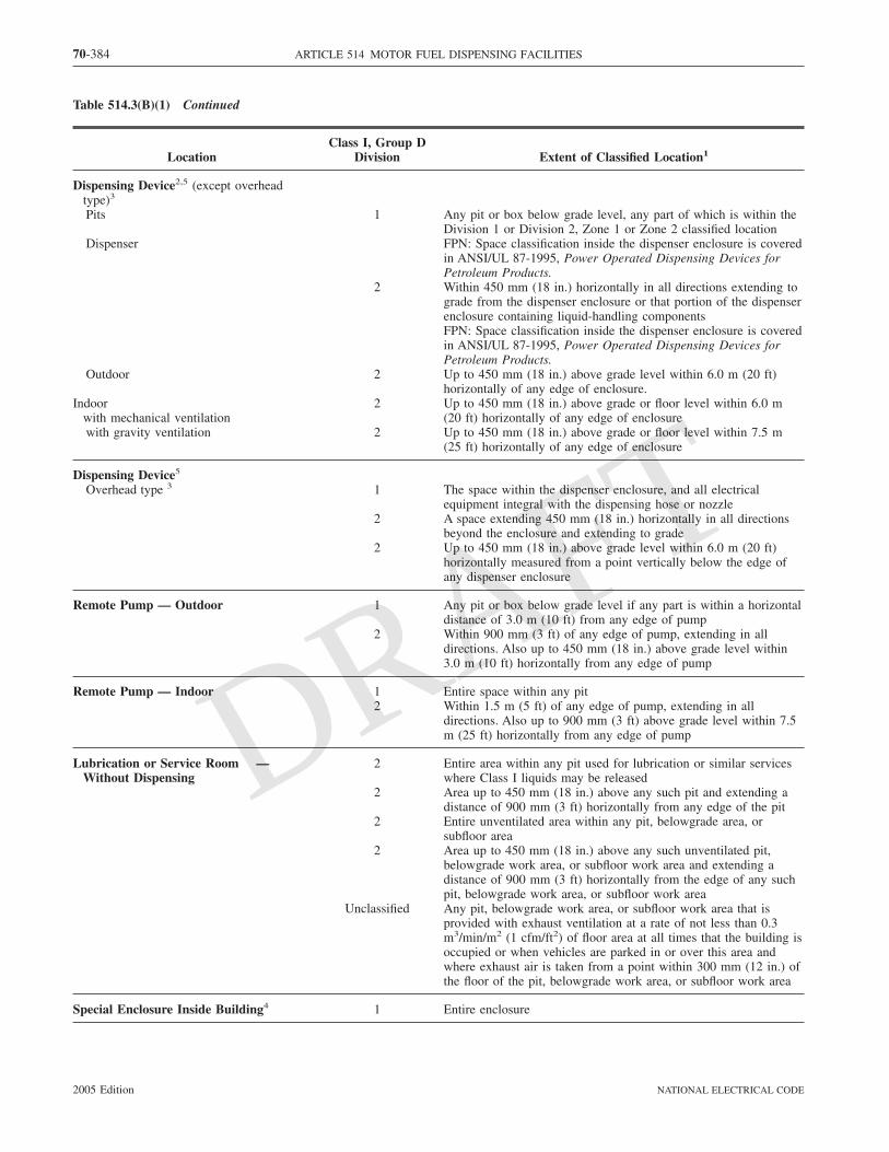
Table 514.3(B)(1) Continued
LocationClass I, Group D
Division Extent of Classified Location1
Dispensing Device2,5 (except overheadtype)3
Pits 1 Any pit or box below grade level, any part of which is within theDivision 1 or Division 2, Zone 1 or Zone 2 classified location
Dispenser FPN: Space classification inside the dispenser enclosure is coveredin ANSI/UL 87-1995, Power Operated Dispensing Devices forPetroleum Products.
2 Within 450 mm (18 in.) horizontally in all directions extending tograde from the dispenser enclosure or that portion of the dispenserenclosure containing liquid-handling componentsFPN: Space classification inside the dispenser enclosure is coveredin ANSI/UL 87-1995, Power Operated Dispensing Devices forPetroleum Products.
Outdoor 2 Up to 450 mm (18 in.) above grade level within 6.0 m (20 ft)horizontally of any edge of enclosure.
Indoorwith mechanical ventilation
2 Up to 450 mm (18 in.) above grade or floor level within 6.0 m(20 ft) horizontally of any edge of enclosure
with gravity ventilation 2 Up to 450 mm (18 in.) above grade or floor level within 7.5 m(25 ft) horizontally of any edge of enclosure
Dispensing Device5
Overhead type 3 1 The space within the dispenser enclosure, and all electricalequipment integral with the dispensing hose or nozzle
2 A space extending 450 mm (18 in.) horizontally in all directionsbeyond the enclosure and extending to grade
2 Up to 450 mm (18 in.) above grade level within 6.0 m (20 ft)horizontally measured from a point vertically below the edge ofany dispenser enclosure
Remote Pump — Outdoor 1 Any pit or box below grade level if any part is within a horizontaldistance of 3.0 m (10 ft) from any edge of pump
2 Within 900 mm (3 ft) of any edge of pump, extending in alldirections. Also up to 450 mm (18 in.) above grade level within3.0 m (10 ft) horizontally from any edge of pump
Remote Pump — Indoor 1 Entire space within any pit2 Within 1.5 m (5 ft) of any edge of pump, extending in all
directions. Also up to 900 mm (3 ft) above grade level within 7.5m (25 ft) horizontally from any edge of pump
Lubrication or Service Room —Without Dispensing
2 Entire area within any pit used for lubrication or similar serviceswhere Class I liquids may be released
2 Area up to 450 mm (18 in.) above any such pit and extending adistance of 900 mm (3 ft) horizontally from any edge of the pit
2 Entire unventilated area within any pit, belowgrade area, orsubfloor area
2 Area up to 450 mm (18 in.) above any such unventilated pit,belowgrade work area, or subfloor work area and extending adistance of 900 mm (3 ft) horizontally from the edge of any suchpit, belowgrade work area, or subfloor work area
Unclassified Any pit, belowgrade work area, or subfloor work area that isprovided with exhaust ventilation at a rate of not less than 0.3m3/min/m2 (1 cfm/ft2) of floor area at all times that the building isoccupied or when vehicles are parked in or over this area andwhere exhaust air is taken from a point within 300 mm (12 in.) ofthe floor of the pit, belowgrade work area, or subfloor work area
Special Enclosure Inside Building4 1 Entire enclosure
70-384 ARTICLE 514 MOTOR FUEL DISPENSING FACILITIES
2005 Edition NATIONAL ELECTRICAL CODE
DRAFT

Table 514.3(B)(1) Continued
LocationClass I, Group D
Division Extent of Classified Location1
Sales, Storage, and Rest Rooms Unclassified If there is any opening to these rooms within the extent of aDivision 1 location, the entire room shall be classified as Division1
Vapor Processing Systems Pits 1 Any pit or box below grade level, any part of which is within aDivision 1 or Division 2 classified location or that houses anyequipment used to transport or process vapors
Vapor Processing Equipment LocatedWithin Protective EnclosuresFPN: See 10.1.7 of NFPA 30A-2000,Code for Motor Fuel DispensingFacilities and Repair Garages.
2 Within any protective enclosure housing vapor processingequipment
Vapor Processing Equipment Not WithinProtective Enclosures (excluding pipingand combustion devices)
2 The space within 450 mm (18 in.) in all directions of equipmentcontaining flammable vapor or liquid extending to grade level. Upto 450 mm (18 in.) above grade level within 3.0 m (10 ft)horizontally of the vapor processing equipment
Equipment Enclosures 1 Any space within the enclosure where vapor or liquid is presentunder normal operating conditions
Vacuum-Assist Blowers 2 The space within 450 mm (18 in.) in all directions extending tograde level. Up to 450 mm (18 in.) above grade level within 3.0m (10 ft) horizontally
1For marine application, grade level means the surface of a pier extending down to water level.2Refer to Figure 514.3 for an illustration of classified location around dispensing devices.3Ceiling mounted hose reel.4FPN: See 4.3.9 of NFPA 30A-2000, Code for Motor Fuel Dispensing Facilities and Repair Garages.5FPN: Area classification inside the dispenser enclosure is covered in ANSI/UL 87-1995, Power-Operated Dispensing Devices for PetroleumProducts [NFPA 30A, Table 8.3.1].
Table 514.3(B)(2) Electrical Equipment Classified Areas for Dispensing Devices
Extent of Classified Area
Dispensing Device Class I, Division 1 Class I, Division 2
Compressed natural gas Entire space within the dispenser enclosure 1.5 m (5 ft) in all directions from dispenserenclosure
Liquefied natural gas Entire space within the dispenser enclosure and1.5 m (5 ft) in all directions from the dispenserenclosure
From 1.5 m to 3.0 m (5 ft to 10 ft) in alldirections from the dispenser enclosure
Liquefied petroleum gas Entire space within the dispenser enclosure;450 mm (18 in.) from the exterior surface ofthe dispenser enclosure to an elevation of 1.2 m(4 ft) above the base of the dispenser; the entirepit or open space beneath the dispenser andwithin 6.0 m (20 ft) horizontally from any edgeof the dispenser when the pit or trench is notmechanically ventilated.
Up to 450 mm (18 in.) aboveground and within6.0 m (20 ft) horizontally from any edge of thedispenser enclosure, including pits or trencheswithin this area when provided with adequatemechanical ventilation
[NFPA 30A, Table 12.6.2]
70-385ARTICLE 514 MOTOR FUEL DISPENSING FACILITIES
2005 EditionNATIONAL ELECTRICAL CODE
DRAFT
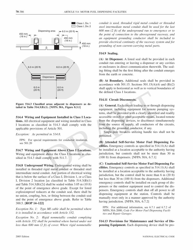
514.4 Wiring and Equipment Installed in Class I Loca-tions. All electrical equipment and wiring installed in ClassI locations as classified in 514.3 shall comply with theapplicable provisions of Article 501.
Exception: As permitted in 514.8.
FPN: For special requirements for conductor insulation,see 501.20
514.7 Wiring and Equipment Above Class I Locations.Wiring and equipment above the Class I locations as clas-sified in 514.3 shall comply with 511.7.
514.8 Underground Wiring. Underground wiring shall beinstalled in threaded rigid metal conduit or threaded steelintermediate metal conduit. Any portion of electrical wiringthat is below the surface of a Class I, Division 1, or a ClassI, Division 2 location [as classified in Table 514.3(B)(1)and Table 514.3(B)(2)] shall be sealed within 3.05 m (10 ft)of the point of emergence above grade. Except for listedexplosionproof reducers at the conduit seal, there shall beno union, coupling, box, or fitting between the conduit sealand the point of emergence above grade. Refer to Table300.5. [ROP 14–122]
Exception No. 1: Type MI cable shall be permitted whereit is installed in accordance with Article 332.
Exception No. 2: Rigid nonmetallic conduit complyingwith Article 352 shall be permitted where buried under notless than 600 mm (2 ft) of cover. Where rigid nonmetallic
conduit is used, threaded rigid metal conduit or threadedsteel intermediate metal conduit shall be used for the last600 mm (2 ft) of the underground run to emergence or tothe point of connection to the aboveground raceway, andan equipment grounding conductor shall be included toprovide electrical continuity of the raceway system and forgrounding of non–current-carrying metal parts.
514.9 Sealing.
(A) At Dispenser. A listed seal shall be provided in eachconduit run entering or leaving a dispenser or any cavitiesor enclosures in direct communication therewith. The seal-ing fitting shall be the first fitting after the conduit emergesfrom the earth or concrete.
(B) At Boundary. Additional seals shall be provided inaccordance with 501.15. Sections 501.15(A)(4) and (B)(2)shall apply to horizontal as well as to vertical boundaries ofthe defined Class I locations.
514.11 Circuit Disconnects.
(A) General. Each circuit leading to or through dispensingequipment, including equipment for remote pumping sys-tems, shall be provided with a clearly identified and readilyaccessible switch or other acceptable means, located remotefrom the dispensing devices, to disconnect simultaneouslyfrom the source of supply, all conductors of the circuits,including the grounded conductor, if any.
Single-pole breakers utilizing handle ties shall not bepermitted.
(B) Attended Self-Service Motor Fuel Dispensing Fa-cilities. Emergency controls as specified in 514.11(A) shallbe installed at a location acceptable to the authority havingjurisdiction, but controls shall not be more than 30 m(100 ft) from dispensers. [NFPA 30A, 6.7.1]
(C) Unattended Self-Service Motor Fuel Dispensing Fa-cilities. Emergency controls as specified in 514.11(A) shallbe installed at a location acceptable to the authority havingjurisdiction, but the control shall be more than 6 m (20 ft)but less than 30 m (100 ft) from the dispensers. Additionalemergency controls shall be installed on each group of dis-pensers or the outdoor equipment used to control the dis-pensers. Emergency controls shall shut off all power to alldispensing equipment at the station. Controls shall bemanually reset only in a manner approved by the authorityhaving jurisdiction. [NFPA 30A, 6.7.2]
FPN: For additional information, see 6.7.1 and 6.7.2 ofNFPA 30A-2000, Code For Motor Fuel Dispensing Facili-ties and Repair Garages.
514.13 Provisions for Maintenance and Service of Dis-pensing Equipment. Each dispensing device shall be pro-
Class I, Div. 1Class I, Div. 2
Dispensing area
450 mm(18 in.)
450 mm(18 in.)
6.0 m (20 ft)
Dispensers
6.0 m (20 ft) 6.0 m (20 ft)
6.0 m(20 ft)
6.0 m(20 ft)
450 mm(18 in.)
Figure 514.3 Classified areas adjacent to dispensers as de-tailed in Table 514.3(B)(1). [NFPA 30A, Figure 8.3.1]
70-386 ARTICLE 514 MOTOR FUEL DISPENSING FACILITIES
2005 Edition NATIONAL ELECTRICAL CODE
DRAFT

vided with a means to remove all external voltage sources,including feedback, during periods of maintenance and ser-vice of the dispensing equipment. The location of thismeans shall be permitted to be other than inside or adjacentto the dispensing device.
514.16 Grounding. All metal raceways, the metal armor ormetallic sheath on cables, and all non–current-carrying metalparts of fixed portable electrical equipment, regardless of volt-age, shall be grounded as provided in Article 250. Groundingin Class I locations shall comply with 501.30.
ARTICLE 515Bulk Storage Plants
FPN: Rules that are followed by a reference in bracketscontain text that has been extracted from NFPA 30-2000,Flammable and Combustible Liquids Code. Only editorialchanges were made to the extracted text to make it consis-tent with this Code.
515.1 Scope. This article covers a property or portion of aproperty where flammable liquids are received by tank ves-sel, pipelines, tank car, or tank vehicle and are stored orblended in bulk for the purpose of distributing such liquids
by tank vessel, pipeline, tank car, tank vehicle, portabletank, or container.
515.2 Definition.
Bulk Plant or Terminal. That portion of a property whereliquids are received by tank vessel, pipelines, tank car, ortank vehicle and are stored or blended in bulk for the pur-pose of distributing such liquids by tank vessel, pipeline,tank car, tank vehicle, portable tank, or container.[NFPA 30, 1.6.35.1] [ROP 14–134]
FPN: For further information, see NFPA 30-2000, Flam-mable and Combustible Liquids Code.
515.3 Class I Locations. Table 515.3 shall be appliedwhere Class I liquids are stored, handled, or dispensed andshall be used to delineate and classify bulk storage plants.The class location shall not extend beyond a floor, wall,roof, or other solid partition that has no communicatingopenings. [NFPA 30, 5.9.5.1, 5.9.5.3]
FPN No. 1: The area classifications listed in Table 515.3are based on the premise that the installation meets theapplicable requirements of NFPA 30-2000, Flammable andCombustible Liquids Code, Chapter 5, in all respects.Should this not be the case, the authority having jurisdic-tion has the authority to classify the extent of the classifiedspace.
FPN No. 2: See 555.21 for gasoline dispensing stations inmarinas and boatyards.
Table 515.3 Electrical Area Classifications
LocationNEC Class I
Division Zone Extent of Classified Area
Indoor equipment installed in accordance with5.3 of NFPA 30 where flammable vapor–airmixtures can exist under normal operation
1 0 The entire area associated with such equipmentwhere flammable gases or vapors are presentcontinuously or for long periods of time
1 1 Area within 1.5 m (5 ft) of any edge of suchequipment, extending in all directions
2 2 Area between 1.5 m and 2.5 m (5 ft and 8 ft) ofany edge of such equipment, extending in alldirections; also, space up to 900 mm (3 ft) abovefloor or grade level within 1.5 m to 7.5 m (5 ft to25 ft) horizontally from any edge of suchequipment1
Outdoor equipment of the type covered in 5.3of NFPA 30 where flammable vapor–airmixtures may exist under normal operation
1 0 The entire area associated with such equipmentwhere flammable gases or vapors are presentcontinuously or for long periods of time
1 1 Area within 900 mm (3 ft) of any edge of suchequipment, extending in all directions
2 2 Area between 900 mm (3 ft) and 2.5 m (8 ft) ofany edge of such equipment, extending in alldirections; also, space up to 900 mm (3 ft) abovefloor or grade level within 900 mm to 3.0 m (3 ftto 10 ft) horizontally from any edge of suchequipment
70-387ARTICLE 515 BULK STORAGE PLANTS
2005 EditionNATIONAL ELECTRICAL CODE
DRAFT

Table 515.3 Continued
LocationNEC Class I
Division Zone Extent of Classified Area
Tank storage installations inside buildings 1 1 All equipment located below grade level2 2 Any equipment located at or above grade level
Tank – aboveground 1 0 Inside fixed roof tank1 1 Area inside dike where dike height is greater than
the distance from the tank to the dike for morethan 50 percent of the tank circumference
Shell, ends, or roof and dike area 2 2 Within 3.0 m (10 ft) from shell, ends, or roof oftank; also, area inside dike to level of top of tank
Vent 1 0 Area inside of vent piping or opening1 1 Within 1.5 m (5 ft) of open end of vent, extending
in all directions2 2 Area between 1.5 m and 3.0 m (5 ft and 10 ft)
from open end of vent, extending in all directionsFloating roof with fixed outer roof 1 0 Area between the floating and fixed roof sections
and within the shellFloating roof with no fixed outer roof 1 1 Area above the floating roof and within the shell
Underground tank fill opening 1 1 Any pit, or space below grade level, if any part iswithin a Division 1 or 2, or Zone 1 or 2, classifiedlocation
2 2 Up to 450 mm (18 in.) above grade level within ahorizontal radius of 3.0 m (10 ft) from a loose fillconnection, and within a horizontal radius of 1.5m (5 ft) from a tight fill connection
Vent – discharging upward 1 0 Area inside of vent piping or opening1 1 Within 900 mm (3 ft) of open end of vent,
extending in all directions2 2 Area between 900 mm and 1.5 m (3 ft and 5 ft) of
open end of vent, extending in all directionsDrum and container filling – outdoors or
indoors1 0 Area inside the drum or container
1 1 Within 900 mm (3 ft) of vent and fill openings,extending in all directions
2 2 Area between 900 mm and 1.5 m (3 ft and 5 ft)from vent or fill opening, extending in alldirections; also, up to 450 mm (18 in.) above flooror grade level within a horizontal radius of 3.0 m(10 ft) from vent or fill opening
Pumps, bleeders, withdrawal fittings,Indoors 2 2 Within 1.5 m (5 ft) of any edge of such devices,
extending in all directions; also, up to 900 mm(3 ft) above floor or grade level within 7.5 m(25 ft) horizontally from any edge of such devices
Outdoors 2 2 Within 900 mm (3 ft) of any edge of suchdevices, extending in all directions. Also, up to450 mm (18 in.) above grade level within 3.0 m(10 ft) horizontally from any edge of such devices
Pits and sumpsWithout mechanical ventilation 1 1 Entire area within a pit or sump if any part is
within a Division 1 or 2, or Zone 1 or 2, classifiedlocation
With adequate mechanical ventilation 2 2 Entire area within a pit or sump if any part iswithin a Division 1 or 2, or Zone 1 or 2, classifiedlocation
70-388 ARTICLE 515 BULK STORAGE PLANTS
2005 Edition NATIONAL ELECTRICAL CODE
DRAFT

Table 515.3 Continued
LocationNEC Class I
Division Zone Extent of Classified Area
Containing valves, fittings, or piping, and notwithin a Division 1 or 2, or Zone 1 or 2,classified location
2 2 Entire pit or sump
Drainage ditches, separators, impounding basinsOutdoors 2 2 Area up to 450 mm (18 in.) above ditch,
separator, or basin; also, area up to 450 mm(18 in.) above grade within 4.5 m (15 ft)horizontally from any edge
Indoors Same classified area as pits
Tank vehicle and tank car2 loading throughopen dome
1 0 Area inside of the tank
1 1 Within 900 mm (3 ft) of edge of dome, extendingin all directions
2 2 Area between 900 mm and 4.5 m (3 ft and 15 ft)from edge of dome, extending in all directions
Loading through bottom connections withatmospheric venting
1 0 Area inside of the tank1 1 Within 900 mm (3 ft) of point of venting to
atmosphere, extending in all directions2 2 Area between 900 mm and 4.5 m (3 ft and 15 ft)
from point of venting to atmosphere, extending inall directions; also, up to 450 mm (18 in.) abovegrade within a horizontal radius of 3.0 m (10 ft)from point of loading connection
Office and rest rooms Ordinary If there is any opening to these rooms within theextent of an indoor classified location, the roomshall be classified the same as if the wall, curb, orpartition did not exist.
Loading through closed dome with atmosphericventing
1 1 Within 900 mm (3 ft) of open end of vent,extending in all directions
2 2 Area between 900 mm and 4.5 m (3 ft and 15 ft)from open end of vent, extending in all directions;also, within 900 mm (3 ft) of edge of dome,extending in all directions
Loading through closed dome with vaporcontrol
2 2 Within 900 mm (3 ft) of point of connection ofboth fill and vapor lines extending in all directions
Bottom loading with vapor control or anybottom unloading
2 2 Within 900 mm (3 ft) of point of connections,extending in all directions; also up to 450 mm(18 in.) above grade within a horizontal radius of3.0 m (10 ft) from point of connections
Storage and repair garage for tank vehicles 1 1 All pits or spaces below floor level2 2 Area up to 450 mm (18 in.) above floor or grade
level for entire storage or repair garageGarages for other than tank vehicles Ordinary If there is any opening to these rooms within the
extent of an outdoor classified location, the entireroom shall be classified the same as the areaclassification at the point of the opening.
Outdoor drum storage OrdinaryInside rooms or storage lockers used for the
storage of Class I liquids2 2 Entire room
70-389ARTICLE 515 BULK STORAGE PLANTS
2005 EditionNATIONAL ELECTRICAL CODE
DRAFT
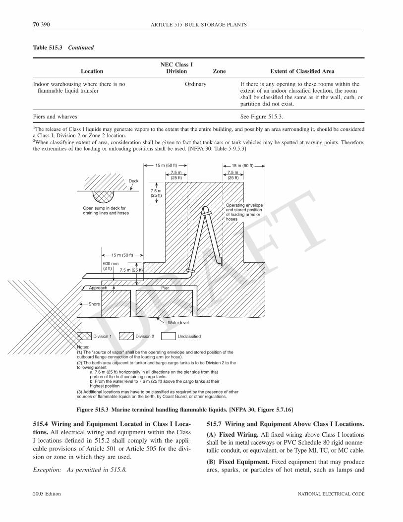
Table 515.3 Continued
LocationNEC Class I
Division Zone Extent of Classified Area
Indoor warehousing where there is noflammable liquid transfer
Ordinary If there is any opening to these rooms within theextent of an indoor classified location, the roomshall be classified the same as if the wall, curb, orpartition did not exist.
Piers and wharves See Figure 515.3.
1The release of Class I liquids may generate vapors to the extent that the entire building, and possibly an area surrounding it, should be considereda Class I, Division 2 or Zone 2 location.2When classifying extent of area, consideration shall be given to fact that tank cars or tank vehicles may be spotted at varying points. Therefore,the extremities of the loading or unloading positions shall be used. [NFPA 30: Table 5-9.5.3]
515.4 Wiring and Equipment Located in Class I Loca-tions. All electrical wiring and equipment within the ClassI locations defined in 515.2 shall comply with the appli-cable provisions of Article 501 or Article 505 for the divi-sion or zone in which they are used.
Exception: As permitted in 515.8.
515.7 Wiring and Equipment Above Class I Locations.
(A) Fixed Wiring. All fixed wiring above Class I locationsshall be in metal raceways or PVC Schedule 80 rigid nonme-tallic conduit, or equivalent, or be Type MI, TC, or MC cable.
(B) Fixed Equipment. Fixed equipment that may producearcs, sparks, or particles of hot metal, such as lamps and
Division 1 Division 2 Unclassified
Water level
Shore
Approach Pier
600 mm(2 ft)
15 m (50 ft)
7.5 m (25 ft)
Deck
Open sump in deck fordraining lines and hoses
Operating envelopeand stored positionof loading arms orhoses
Notes:(1) The "source of vapor" shall be the operating envelope and stored position of theoutboard flange connection of the loading arm (or hose).(2) The berth area adjacent to tanker and barge cargo tanks is to be Division 2 to thefollowing extent: a. 7.6 m (25 ft) horizontally in all directions on the pier side from that portion of the hull containing cargo tanks b. From the water level to 7.6 m (25 ft) above the cargo tanks at their highest position(3) Additional locations may have to be classified as required by the presence of othersources of flammable liquids on the berth, by Coast Guard, or other regulations.
15 m (50 ft)
7.5 m (25 ft)
7.5 m (25 ft)
15 m (50 ft)
7.5 m (25 ft)
Figure 515.3 Marine terminal handling flammable liquids. [NFPA 30, Figure 5.7.16]
70-390 ARTICLE 515 BULK STORAGE PLANTS
2005 Edition NATIONAL ELECTRICAL CODE
DRAFT

lampholders for fixed lighting, cutouts, switches, recep-tacles, motors, or other equipment having make-and-breakor sliding contacts, shall be of the totally enclosed type orbe constructed so as to prevent the escape of sparks or hotmetal particles.
(C) Portable Lamps or Other Utilization Equipment.Portable lamps or other utilization equipment and theirflexible cords shall comply with the provisions of Article501 or Article 505 for the class of location above whichthey are connected or used.
515.8 Underground Wiring.
(A) Wiring Method. Underground wiring shall be in-stalled in threaded rigid metal conduit or threaded steelintermediate metal conduit or, where buried under not lessthan 600 mm (2 ft) of cover, shall be permitted in rigidnonmetallic conduit or a listed cable. Where rigid nonme-tallic conduit is used, threaded rigid metal conduit orthreaded steel intermediate metal conduit shall be used forthe last 600 mm (2 ft) of the conduit run to emergence or tothe point of connection to the aboveground raceway. Wherecable is used, it shall be enclosed in threaded rigid metalconduit or threaded steel intermediate metal conduit fromthe point of lowest buried cable level to the point of con-nection to the aboveground raceway.
(B) Insulation. Conductor insulation shall comply with501.20.
(C) Nonmetallic Wiring. Where rigid nonmetallic conduitor cable with a nonmetallic sheath is used, an equipmentgrounding conductor shall be included to provide for elec-trical continuity of the raceway system and for groundingof non–current-carrying metal parts.
515.9 Sealing. Sealing requirements shall apply to hori-zontal as well as to vertical boundaries of the defined ClassI locations. Buried raceways and cables under defined ClassI locations shall be considered to be within a Class I, Divi-sion 1 or Zone 1 location.
515.10 Special Equipment — Gasoline Dispensers.Where gasoline or other volatile flammable liquids or liq-uefied flammable gases are dispensed at bulk stations, theapplicable provisions of Article 514 shall apply.
515.16 Grounding. All metal raceways, the metal armoror metallic sheath on cables, and all non–current-carryingmetal parts of fixed or portable electrical equipment, re-gardless of voltage, shall be grounded as provided in Ar-ticle 250. Grounding in Class I locations shall comply with501.30 for Class I, Division 1 and 2 locations and 505.25for Class I, Zone 0, 1, and 2 locations.
FPN: For information on grounding for static protection,see 5.6.3.4 and 5.6.3.5 of NFPA 30-2000, Flammable andCombustible Liquids Code.
ARTICLE 516Spray Application, Dipping, and Coating
Processes
FPN: Rules that are followed by a reference in bracketscontain text that has been extracted from NFPA 33-2000,Standard for Spray Application Using Flammable andCombustible Materials, or NFPA 34-2000, Standard forDipping and Coating Processes Using Flammable or Com-bustible Liquids. Only editorial changes were made to theextracted text to make it consistent with this Code.
516.1 Scope. This article covers the regular or frequentapplication of flammable liquids, combustible liquids, andcombustible powders by spray operations and the applica-tion of flammable liquids, or combustible liquids at tem-peratures above their flashpoint, by dipping, coating, orother means.
FPN: For further information regarding safeguards for theseprocesses, such as fire protection, posting of warning signs,and maintenance, see NFPA 33-2000, Standard for Spray Ap-plication Using Flammable and Combustible Materials, andNFPA 34-2000, Standard for Dipping and Coating ProcessesUsing Flammable or Combustible Liquids. For additional in-formation regarding ventilation, see NFPA 91-1999, Standardfor Exhaust Systems for Air Conveying of Vapors, Gases,Mists, and Noncombustible Particulate Solids.
516.2 Definitions. For the purpose of this article, the fol-lowing definitions shall apply.
Spray Area. Normally locations outside of buildings or lo-calized operations within a larger room or space. Such arenormally provided with some local vapor extraction/ventilation system. In automated operations, the area limitsshall be the maximum area in the direct path of spray opera-tions. In manual operations, the area limits shall be the maxi-mum area of spray when aimed at 180 degrees to the applica-tion surface. [NFPA 33, 1.6, Definitions]
Spray Booth. An enclosure or insert within a larger roomused for spray/coating/dipping applications. A spray boothmay be fully enclosed or have open front or face and mayinclude separate conveyor entrance and exit. The spraybooth is provided with a dedicated ventilation exhaust butmay draw supply air from the larger room or have a dedi-cated air supply. [NFPA 33, 1.6, Definitions]
Spray Room. A purposefully enclosed room built forspray/coating/dipping applications provided with dedicatedventilation supply and exhaust. Normally the room is con-figured to house the item to be painted, providing reason-able access around the item/process. Depending on the sizeof the item being painted, such rooms may actually be the
70-391ARTICLE 516 SPRAY APPLICATION, DIPPING, AND COATING PROCESSES
2005 EditionNATIONAL ELECTRICAL CODE
DRAFT

entire building or the major portion thereof. [NFPA 33, 1.6,Definitions]
516.3 Classification of Locations. Classification is basedon dangerous quantities of flammable vapors, combustiblemists, residues, dusts, or deposits. [ROP 14–145a]
(A) Class I, Division 1 or Class I, Zone 0 Locations. Thefollowing spaces shall be considered Class I, Division 1, orClass I, Zone 0, as applicable:
(1) The interior of any open or closed container of a flam-mable liquid
(2) The interior of any dip tank or coating tank
FPN: For additional guidance and explanatory diagrams,see Subsection 4.3.5 of NFPA 33-2003, Standard for SprayApplication Using Flammable or Combustible Materials,and Sections 4.2, 4.3, and 4.4 of NFPA 34-2003, Standardfor Dipping and Coating Processes Using Flammable orCombustible Liquids.
(B) Class I or Class II, Division 1 Locations. The follow-ing spaces shall be considered Class I, Division 1, or ClassI, Zone 1, or Class II, Division 1 locations, as applicable:
(1) The interior of spray booths and rooms except as spe-cifically provided in 516.3(D).
(2) The interior of exhaust ducts.(3) Any area in the direct path of spray operations.(4) For dipping and coating operations, all space within a
1.5-m (5-ft) radial distance from the vapor sources ex-tending from these surfaces to the floor. The vaporsource shall be the liquid exposed in the process andthe drainboard, and any dipped or coated object fromwhich it is possible to measure vapor concentrationsexceeding 25 percent of the lower flammable limit at adistance of 300 mm (1 ft), in any direction, from theobject.
(5) Sumps, pits, or belowgrade channels within 7.5 m(25 ft) horizontally of a vapor source. If the sump, pit,or channel extends beyond 7.5 m (25 ft) from the vaporsource, it shall be provided with a vapor stop or it shallbe classified as Class I, Division 1 for its entire length.
(C) Class I or Class II, Division 2 Locations. The follow-ing spaces shall be considered Class I, Division 2 or ClassI, Zone 2, or Class II, Division 2 as applicable.
(1) Open Spraying. For open spraying, all space outsideof but within 6 m (20 ft) horizontally and 3 m (10 ft)vertically of the Class I, Division 1 or Class I, Zone 1location as defined in 516.3(A), and not separated from itby partitions. See Figure 516.3(B)(1) .
(2) Closed-Top, Open-Face, and Open-Front Spraying.If spray application operations are conducted within aclosed-top, open-face, or open-front booth or room, any
electrical wiring or utilization equipment located outside ofthe booth or room but within the boundaries designated asDivision 2 or Zone 2 in Figure 516.3(B)(2) shall be suitablefor Class I, Division 2, Class I, Zone 2, or Class II, Divi-sion 2 locations, whichever is applicable. The Class I, Di-vision 2, Class I, Zone 2, or Class II, Division 2 locationsshown in Figure 516.3(B)(2) shall extend from the edges ofthe open face or open front of the booth or room in accor-dance with the following:
(a) If the exhaust ventilation system is interlockedwith the spray application equipment, then the Division 2or Zone 2 location shall extend 1.5 m (5 ft) horizontally and900 mm (3 ft) vertically from the open face or open front ofthe booth or room, as shown in Figure 516.3(B)(2), top.
(b) If the exhaust ventilation system is not interlockedwith the spray application equipment, then the Division 2or Zone 2 location shall extend 3 m (10 ft) horizontally and900 mm (3 ft) vertically from the open face or open front ofthe booth or room, as shown in Figure 516.3(B)(2), bottom.
For the purposes of this subsection, interlocked shallmean that the spray application equipment cannot be oper-ated unless the exhaust ventilation system is operating and
6100 mm(20 ft)
3050 m(10 ft)
Spray area
Top (plan)
Roof
Front (elevation)
Class I, Division 1, Class I, Zone 1,or Class II, Division 1
Class I, Division 2, Class I, Zone 2,or Class II, Division 2
Spray area
Figure 516.3(B)(1) Electrical area classification for openspray areas. [NFPA 33, Figure 4.3.1]
70-392 ARTICLE 516 SPRAY APPLICATION, DIPPING, AND COATING PROCESSES
2005 Edition NATIONAL ELECTRICAL CODE
DRAFT

functioning properly and spray application is automaticallystopped if the exhaust ventilation system fails.
(3) Open-Top Spraying. For spraying operations con-ducted within an open top spray booth, the space 900 mm(3 ft) vertically above the booth and within 900 mm (3 ft)of other booth openings shall be considered Class I, Divi-sion 2, Class I, Zone 2, or Class II, Division 2.
(4) Enclosed Booths and Rooms. For spraying operationsconfined to an enclosed spray booth or room, the spacewithin 900 mm (3 ft) in all directions from any openingsshall be considered Class I, Division 2, Class I, or Zone 2,or Class II, Division 2 as shown in Figure 516.3(B)(4)
(5) Dip Tanks and Drain Boards — Surrounding Space.For dip tanks and drain boards, the 914-mm (3-ft) spacesurrounding the Class I, Division 1 or Class I, Zone 1location as defined in 516.3(A)(4) and as shown in Figure516.3(B)(5).
(6) Dip Tanks and Drain Boards — Space Above Floor.For dip tanks and drain boards, the space 900 mm (3 ft)above the floor and extending 6 m (20 ft) horizontally in alldirections from the Class I, Division 1 or Class I, Zone 1location.
Exception: This space shall not be required to be consid-ered a hazardous (classified) location where the vaporsource area is 0.46 m2 (5 ft2) or less, and where the con-tents of the open tank trough or container do not exceed 19L (5 gal). In addition, the vapor concentration during op-eration and shutdown periods shall not exceed 25 percentof the lower flammable limit outside the Class I locationspecified in 516.3(A)(4). [NFPA 33, 4.3.1, 4.3.2, 4.3.3,4.3.4; NFPA 34, 4.2.3, 4.2.4]
(D) Enclosed Coating and Dipping Operations. Thespace adjacent to an enclosed dipping or coating process orapparatus shall be considered unclassified.
Exception: The space within 900 mm (3 ft) in all direc-tions from any opening in the enclosures shall be classifiedas Class I, Division 2 or Class I, Zone 2, as applicable.[NFPA 34, 4.3.2]
(E) Adjacent Locations. Adjacent locations that are cutoff from the defined Class I or Class II locations by tight
Open face
Conveyor opening
1525 mm (5 ft) radius
1525 mm(5 ft) radius
915 mm (3 ft) radius
915 mm (3 ft) radius
915 mm (3 ft) radius
915 mm (3 ft) radius
915 mm (3 ft) radius915 mm (3 ft) radius
915 mm (3 ft) radius915 mm (3 ft) radius
915 mm (3 ft) radius
915 mm (3 ft) radius915 mm (3 ft) radius
915 mm (3 ft) radius
Open face
Conveyor opening
3050 m (10 ft) radius
3050 m (10 ft) radius
Figure 516.3(B)(2) Class I, Division 2, Class I, Zone 2, orClass II, Division 2 locations adjacent to a closed top, openface, or open front spray booth or room. [NFPA 33, Figures4.3.2(a) and 4.3.2(b)]
900 mm R(3 ft)
Enclosed spraybooth or room
(Class I, Division 1 orClass II, Division 1 within)
Plan view
Extent of Class I or Class II, Division 2 area
Elevation
900 mm R(3 ft)
900 mm R(3 ft)
900 mm R(3 ft)
900 mm R(3 ft)
900 mm R (3 ft) 900 mm R (3 ft)
Figure 516.3(B)(4) Class I, Division 2, Class I, Zone 2, orClass II, Division 2 locations adjacent to an enclosed spraybooth or spray room. [NFPA 33, Figure 4.3.4]
70-393ARTICLE 516 SPRAY APPLICATION, DIPPING, AND COATING PROCESSES
2005 EditionNATIONAL ELECTRICAL CODE
DRAFT

partitions without communicating openings, and withinwhich flammable vapors or combustible powders are notlikely to be released, shall be unclassified.
(F) Unclassified Locations. Locations using drying, cur-ing, or fusion apparatus and provided with positive me-chanical ventilation adequate to prevent accumulation offlammable concentrations of vapors, and provided with ef-fective interlocks to de-energize all electrical equipment(other than equipment identified for Class I locations) incase the ventilating equipment is inoperative, shall be per-mitted to be unclassified where the authority having juris-diction so judges.
FPN: For further information regarding safeguards, seeNFPA 86-1999, Standard for Ovens and Furnaces.
516.4 Wiring and Equipment in Class I Locations.
(A) Wiring and Equipment — Vapors. All electric wir-ing and equipment within the Class I location (containingvapor only — not residues) defined in 516.3 shall complywith the applicable provisions of Article 501 or Article 505,as applicable. [ROP 14–145a]
(B) Wiring and Equipment — Vapors and Residues.Unless specifically listed for locations containing depositsof dangerous quantities of flammable or combustible va-pors, mists, residues, dusts, or deposits (as applicable),there shall be no electrical equipment in any spray area asherein defined whereon deposits of combustible residuemay readily accumulate, except wiring in rigid metal con-duit, intermediate metal conduit, Type MI cable, or in metal
boxes or fittings containing no taps, splices, or terminalconnections. [NFPA 33, 4.2]
(C) Illumination. Illumination of readily ignitible areasthrough panels of glass or other transparent or translucentmaterial shall be permitted only if it complies with thefollowing:
(1) Fixed lighting units are used as the source of illumina-tion.
(2) The panel effectively isolates the Class I location fromthe area in which the lighting unit is located.
(3) The lighting unit is identified for its specific location.(4) The panel is of a material or is protected so that break-
age is unlikely.(5) The arrangement is such that normal accumulations of
hazardous residue on the surface of the panel will notbe raised to a dangerous temperature by radiation orconduction from the source of illumination.
(D) Portable Equipment. Portable electric lamps or otherutilization equipment shall not be used in a spray area dur-ing spray operations.
Exception No. 1: Where portable electric lamps are re-quired for operations in spaces not readily illuminated byfixed lighting within the spraying area, they shall be of thetype identified for Class I, Division 1 or Class 1, Zone 1locations where readily ignitible residues may be present.[ROP 14–145a]
Exception No. 2: Where portable electric drying appara-tus is used in automobile refinishing spray booths and thefollowing requirements are met.
Diptank
DrainboardPitFloor
Point beyond which objectis no longer a vapor source as defined in 516.3(B)(4)
Conveyor rail
915 mm (3 ft)
6100 mm (20 ft)1525 mm
(5 ft)1525 mm
(5 ft)
Class I, Division 1 or Zone 0
Class I, Division 1 or Zone 1
Class I, Division 2 or Zone 2
915 mm (3 ft)
915 mm(3 ft)
1525 mm(5 ft)
1525 mm(5 ft)
915 mm (3 ft)
915 mm (3 ft)
915 mm(3 ft)
1525 mm(5 ft)
1525 mm (5 ft)
6100 mm (20 ft)
Figure 516.3(B)(5) Electrical area classification for open processes without vapor containment or ventilation. [NFPA 34, Figure4.2(a)]
70-394 ARTICLE 516 SPRAY APPLICATION, DIPPING, AND COATING PROCESSES
2005 Edition NATIONAL ELECTRICAL CODE
DRAFT

(a) The apparatus and its electrical connections arenot located within the spray enclosure during spray opera-tions.
(b) Electrical equipment within 450 mm (18 in.) of thefloor is identified for Class I, Division 2 or Class I, Zone 2locations. [ROP 14–145a]
(c) All metallic parts of the drying apparatus are elec-trically bonded and grounded.
(d) Interlocks are provided to prevent the operation ofspray equipment while drying apparatus is within the sprayenclosure, to allow for a 3-minute purge of the enclosurebefore energizing the drying apparatus and to shut off dry-ing apparatus on failure of ventilation system. [NFPA 33,4.7]
(E) Electrostatic Equipment. Electrostatic spraying ordetearing equipment shall be installed and used only asprovided in 516.10.
FPN: For further information, see NFPA 33-2000, Stan-dard for Spray Application Using Flammable or Combus-tible Materials.
516.7 Wiring and Equipment Not Within Class I and IILocations.
(A) Wiring. All fixed wiring above the Class I and II lo-cations shall be in metal raceways, rigid nonmetallic con-duit, or electrical nonmetallic tubing, or shall be Type MI,TC, or MC cable. Cellular metal floor raceways shall bepermitted only for supplying ceiling outlets or extensions tothe area below the floor of a Class I or II location, but suchraceways shall have no connections leading into or throughthe Class I or II location above the floor unless suitableseals are provided.
(B) Equipment. Equipment that may produce arcs, sparks,or particles of hot metal, such as lamps and lampholders forfixed lighting, cutouts, switches, receptacles, motors, orother equipment having make-and-break or sliding con-tacts, where installed above a Class I or II location or abovea location where freshly finished goods are handled, shallbe of the totally enclosed type or be constructed so as toprevent the escape of sparks or hot metal particles.
516.10 Special Equipment.
(A) Fixed Electrostatic Equipment. This section shall ap-ply to any equipment using electrostatically charged ele-ments for the atomization, charging, and/or precipitation ofhazardous materials for coatings on articles or for othersimilar purposes in which the charging or atomizing deviceis attached to a mechanical support or manipulator. Thisshall include robotic devices. This section shall not apply todevices that are held or manipulated by hand. Where robotor programming procedures involve manual manipulation
of the robot arm while spraying with the high voltage on,the provisions of 516.10(B) shall apply. The installation ofelectrostatic spraying equipment shall comply with516.10(A)(1) through (A)(10). Spray equipment shall belisted. All automatic electrostatic equipment systems shallcomply with 516.4(A)(1) through (A)(9).
(1) Power and Control Equipment. Transformers, high-voltage supplies, control apparatus, and all other electricportions of the equipment shall be installed outside of theClass I location as defined in 516.3 or be of a type identi-fied for the location.
Exception: High-voltage grids, electrodes, electrostaticatomizing heads, and their connections shall be permittedwithin the Class I location.
(2) Electrostatic Equipment. Electrodes and electrostaticatomizing heads shall be adequately supported in perma-nent locations and shall be effectively insulated fromground. Electrodes and electrostatic atomizing heads thatare permanently attached to their bases, supports, recipro-cators, or robots shall be deemed to comply with this sec-tion.
(3) High-Voltage Leads. High-voltage leads shall be prop-erly insulated and protected from mechanical damage orexposure to destructive chemicals. Any exposed element athigh voltage shall be effectively and permanently supportedon suitable insulators and shall be effectively guardedagainst accidental contact or grounding.
(4) Support of Goods. Goods being coated using this pro-cess shall be supported on conveyors or hangers. The con-veyors or hangers shall be arranged (1) to ensure that theparts being coated are electrically connected to ground witha resistance of 1 megohm or less and (2) to prevent partsfrom swinging.
(5) Automatic Controls. Electrostatic apparatus shall beequipped with automatic means that will rapidly de-energize the high-voltage elements under any of the follow-ing conditions:
(1) Stoppage of ventilating fans or failure of ventilatingequipment from any cause
(2) Stoppage of the conveyor carrying goods through thehigh-voltage field unless stoppage is required by thespray process
(3) Occurrence of excessive current leakage at any point inthe high-voltage system
(4) De-energizing the primary voltage input to the powersupply
(6) Grounding. All electrically conductive objects in thespray area, except those objects required by the process tobe at high voltage, shall be adequately grounded. This re-
70-395ARTICLE 516 SPRAY APPLICATION, DIPPING, AND COATING PROCESSES
2005 EditionNATIONAL ELECTRICAL CODE
DRAFT

quirement shall apply to paint containers, wash cans,guards, hose connectors, brackets, and any other electri-cally conductive objects or devices in the area.
(7) Isolation. Safeguards such as adequate booths, fencing,railings, interlocks, or other means shall be placed aboutthe equipment or incorporated therein so that they, either bytheir location, character, or both, ensure that a safe separa-tion of the process is maintained.
(8) Signs. Signs shall be conspicuously posted to conveythe following:
(1) Designate the process zone as dangerous with regard tofire and accident
(2) Identify the grounding requirements for all electricallyconductive objects in the spray area
(3) Restrict access to qualified personnel only
(9) Insulators. All insulators shall be kept clean and dry.
(10) Other Than Nonincendive Equipment. Spray equip-ment that cannot be classified as nonincendive shall complywith (a) and (b).
(a) Conveyors or hangers shall be arranged so as tomaintain a safe distance of at least twice the sparking dis-tance between goods being painted and electrodes, electro-static atomizing heads, or charged conductors. Warningsdefining this safe distance shall be posted.
(b) The equipment shall provide an automatic meansof rapidly de-energizing the high-voltage elements in theevent the distance between the goods being painted and theelectrodes or electrostatic atomizing heads falls below thatspecified in (a). [NFPA 33, Chapter 9]
(B) Electrostatic Hand-Spraying Equipment. This sec-tion shall apply to any equipment using electrostaticallycharged elements for the atomization, charging, and/or pre-cipitation of materials for coatings on articles, or for othersimilar purposes in which the atomizing device is hand-held or manipulated during the spraying operation. Electro-static hand-spraying equipment and devices used in con-nection with paint-spraying operations shall be of listedtypes and shall comply with 516.10(B)(1) through (B)(5).
(1) General. The high-voltage circuits shall be designed soas not to produce a spark of sufficient intensity to ignite themost readily ignitible of those vapor–air mixtures likely tobe encountered, or result in appreciable shock hazard uponcoming in contact with a grounded object under all normaloperating conditions. The electrostatically charged exposedelements of the handgun shall be capable of being ener-gized only by an actuator that also controls the coatingmaterial supply.
(2) Power Equipment. Transformers, power packs, con-trol apparatus, and all other electric portions of the equip-
ment shall be located outside of the Class I location or beidentified for the location.
Exception: The handgun itself and its connections to thepower supply shall be permitted within the Class I location.
(3) Handle. The handle of the spraying gun shall be elec-trically connected to ground by a metallic connection andbe constructed so that the operator in normal operating posi-tion is in intimate electrical contact with the grounded handleto prevent buildup of a static charge on the operator’s body.Signs indicating the necessity for grounding other persons en-tering the spray area shall be conspicuously posted.
(4) Electrostatic Equipment. All electrically conductiveobjects in the spraying area shall be adequately grounded.This requirement shall apply to paint containers, wash cans,and any other electrical conductive objects or devices in thearea. The equipment shall carry a prominent, permanentlyinstalled warning regarding the necessity for this groundingfeature.
(5) Support of Objects. Objects being painted shall bemaintained in metallic contact with the conveyor or othergrounded support. Hooks shall be regularly cleaned to en-sure adequate grounding of 1 megohm or less. Areas ofcontact shall be sharp points or knife edges where possible.Points of support of the object shall be concealed from ran-dom spray where feasible; and, where the objects beingsprayed are supported from a conveyor, the point of attach-ment to the conveyor shall be located so as to not collect spraymaterial during normal operation. [NFPA 33, Chapter 10]
(C) Powder Coating. This section shall apply to processesin which combustible dry powders are applied. The hazardsassociated with combustible dusts are present in such aprocess to a degree, depending on the chemical composi-tion of the material, particle size, shape, and distribution.
(1) Electric Equipment and Sources of Ignition. Electricequipment and other sources of ignition shall comply withthe requirements of Article 502. Portable electric lamps andother utilization equipment shall not be used within a ClassII location during operation of the finishing processes.Where such lamps or utilization equipment are used duringcleaning or repairing operations, they shall be of a typeidentified for Class II, Division 1 locations, and all exposedmetal parts shall be effectively grounded.
Exception: Where portable electric lamps are required foroperations in spaces not readily illuminated by fixed light-ing within the spraying area, they shall be of the type listedfor Class II, Division 1 locations where readily ignitibleresidues may be present.
(2) Fixed Electrostatic Spraying Equipment. The provi-sions of 516.10(A) and 516.10(C)(1) shall apply to fixedelectrostatic spraying equipment.
70-396 ARTICLE 516 SPRAY APPLICATION, DIPPING, AND COATING PROCESSES
2005 Edition NATIONAL ELECTRICAL CODE
DRAFT

(3) Electrostatic Hand-Spraying Equipment. The provi-sions of 516.10(B) and 516.10(C)(1) shall apply to electro-static hand-spraying equipment.
(4) Electrostatic Fluidized Beds. Electrostatic fluidizedbeds and associated equipment shall be of identified types.The high-voltage circuits shall be designed so that any dis-charge produced when the charging electrodes of the bedare approached or contacted by a grounded object shall notbe of sufficient intensity to ignite any powder–air mixturelikely to be encountered or to result in an appreciable shockhazard.
(a) Transformers, power packs, control apparatus, andall other electric portions of the equipment shall be locatedoutside the powder-coating area or shall otherwise complywith the requirements of 516.10(C)(1).
Exception: The charging electrodes and their connectionsto the power supply shall be permitted within the powder-coating area.
(b) All electrically conductive objects within thepowder-coating area shall be adequately grounded. Thepowder-coating equipment shall carry a prominent, perma-nently installed warning regarding the necessity for ground-ing these objects.
(c) Objects being coated shall be maintained in elec-trical contact (less than 1 megohm) with the conveyor orother support in order to ensure proper grounding. Hangersshall be regularly cleaned to ensure effective electrical con-tact. Areas of electrical contact shall be sharp points orknife edges where possible.
(d) The electric equipment and compressed air sup-plies shall be interlocked with a ventilation system so thatthe equipment cannot be operated unless the ventilatingfans are in operation. [NFPA 33, Chapter 13]
516.16 Grounding. All metal raceways, the metal armorsor metallic sheath on cables, and all non–current-carryingmetal parts of fixed or portable electrical equipment, re-gardless of voltage, shall be grounded as provided in Ar-ticle 250. Grounding shall comply with 501.30, 502.30, or505.25, as applicable. [ROP 14–145a]
ARTICLE 517Health Care Facilities
FPN: Rules that are followed by a reference in bracketscontain text that has been extracted from NFPA 99-2002,Standard for Health Care Facilities. Only editorial changeswere made to the extracted text to make it consistent withthis Code. [ROP 15–5]
I. General
517.1 Scope. The provisions of this article shall apply toelectrical construction and installation criteria in health carefacilities that provide services to human beings.
The requirements in Parts II and III not only apply tosingle-function buildings but are also intended to be indi-vidually applied to their respective forms of occupancywithin a multifunction building (e.g., a doctor’s examiningroom located within a limited care facility would be re-quired to meet the provisions of 517.10).
FPN: For information concerning performance, mainte-nance, and testing criteria, refer to the appropriate healthcare facilities documents.
517.2 Definitions.
Alternate Power Source. One or more generator sets, orbattery systems where permitted, intended to provide powerduring the interruption of the normal electrical services orthe public utility electrical service intended to providepower during interruption of service normally provided bythe generating facilities on the premises.
Ambulatory Health Care Facility. A building or partthereof used to provide services or treatment to four ormore patients at the same time and meeting either (1) or(2).
(1) Those facilities that provide, on an outpatient basis,treatment for patients that would render them incapableof taking action for self-preservation under emergencyconditions without assistance from others, such as he-modialysis units or freestanding emergency medicalunits.
(2) Those facilities that provide, on an outpatient basis,surgical treatment requiring general anesthesia.
Anesthetizing Location. Any area of a facility that hasbeen designated to be used for the administration of anyflammable or nonflammable inhalation anesthetic agent inthe course of examination or treatment, including the use ofsuch agents for relative analgesia.
Critical Branch. A subsystem of the emergency systemconsisting of feeders and branch circuits supplying energyto task illumination, special power circuits, and selectedreceptacles serving areas and functions related to patientcare, and which are connected to alternate power sourcesby one or more transfer switches during interruption of thenormal power source.
Electrical Life-Support Equipment. Electrically poweredequipment whose continuous operation is necessary tomaintain a patient’s life.
70-397ARTICLE 517 HEALTH CARE FACILITIES
2005 EditionNATIONAL ELECTRICAL CODE
DRAFT

Emergency System. A system of circuits and equipmentintended to supply alternate power to a limited number ofprescribed functions vital to the protection of life andsafety.
Equipment System. A system of circuits and equipmentarranged for delayed, automatic, or manual connection tothe alternate power source and that serves primarily3-phase power equipment.
Essential Electrical System. A system comprised of alter-nate sources of power and all connected distribution sys-tems and ancillary equipment, designed to ensure continu-ity of electrical power to designated areas and functions ofa health care facility during disruption of normal powersources, and also designed to minimize disruption withinthe internal wiring system.
Exposed Conductive Surfaces. Those surfaces that are ca-pable of carrying electric current and that are unprotected,unenclosed, or unguarded, permitting personal contact.Paint, anodizing, and similar coatings are not consideredsuitable insulation, unless they are listed for such use.
Fault Hazard Current. See Hazard Current.
Flammable Anesthetics. Gases or vapors, such as flurox-ene, cyclopropane, divinyl ether, ethyl chloride, ethyl ether,and ethylene, which may form flammable or explosive mix-tures with air, oxygen, or reducing gases such as nitrousoxide.
Flammable Anesthetizing Location. Any area of the fa-cility that has been designated to be used for the adminis-tration of any flammable inhalation anesthetic agents in thenormal course of examination or treatment.
Hazard Current. For a given set of connections in anisolated power system, the total current that would flowthrough a low impedance if it were connected betweeneither isolated conductor and ground.
Fault Hazard Current. The hazard current of a given iso-lated system with all devices connected except the lineisolation monitor.
Monitor Hazard Current. The hazard current of the lineisolation monitor alone.
Total Hazard Current. The hazard current of a given iso-lated system with all devices, including the line isolationmonitor, connected.
Health Care Facilities. Buildings or portions of buildingsin which medical, dental, psychiatric, nursing, obstetrical,or surgical care are provided. Health care facilities include,but are not limited to, hospitals, nursing homes, limitedcare facilities, clinics, medical and dental offices, and am-bulatory care centers, whether permanent or movable.
Hospital. A building or part thereof used for the medical,psychiatric, obstetrical, or surgical care, on a 24-hour basis,of four or more inpatients. Hospital, wherever used in thisCode, shall include general hospitals, mental hospitals, tu-berculosis hospitals, children’s hospitals, and any such fa-cilities providing inpatient care.
Isolated Power System. A system comprising an isolatingtransformer or its equivalent, a line isolation monitor, andits ungrounded circuit conductors.
Isolation Transformer. A transformer of the multiple-winding type, with the primary and secondary windingsphysically separated, which inductively couples its second-ary winding to the grounded feeder systems that energizeits primary winding.
Life Safety Branch. A subsystem of the emergency systemconsisting of feeders and branch circuits, meeting the re-quirements of Article 700 and intended to provide adequatepower needs to ensure safety to patients and personnel, andwhich are automatically connected to alternate powersources during interruption of the normal power source.
Limited Care Facility. A building or part thereof used on a24-hour basis for the housing of four or more persons whoare incapable of self-preservation because of age, physicallimitation due to accident or illness, or mental limitations,such as mental retardation/developmental disability, mentalillness, or chemical dependency.
Line Isolation Monitor. A test instrument designed to con-tinually check the balanced and unbalanced impedancefrom each line of an isolated circuit to ground and equippedwith a built-in test circuit to exercise the alarm withoutadding to the leakage current hazard.
Monitor Hazard Current. See Hazard Current.
Nurses’ Stations. Areas intended to provide a center ofnursing activity for a group of nurses serving bed patients,where the patient calls are received, nurses are dispatched,nurses’ notes written, inpatient charts prepared, and medi-cations prepared for distribution to patients. Where suchactivities are carried on in more than one location within anursing unit, all such separate areas are considered a part ofthe nurses’ station.
Nursing Home. A building or part thereof used for thelodging, boarding, and nursing care, on a 24-hour basis, offour or more persons who, because of mental or physicalincapacity, may be unable to provide for their own needsand safety without the assistance of another person. Nurs-ing home, wherever used in this Code, shall include nursingand convalescent homes, skilled nursing facilities, interme-diate care facilities, and infirmaries of homes for the aged.
Patient Bed Location. The location of an inpatient sleep-ing bed; or the bed or procedure table used in a criticalpatient care area.
70-398 ARTICLE 517 HEALTH CARE FACILITIES
2005 Edition NATIONAL ELECTRICAL CODE
DRAFT

Patient Care Area. Any portion of a health care facilitywherein patients are intended to be examined or treated.Areas of a health care facility in which patient care is ad-ministered are classified as general care areas or criticalcare areas, either of which may be classified as a wet loca-tion. The governing body of the facility designates theseareas in accordance with the type of patient care anticipatedand with the following definitions of the area classification.
FPN: Business offices, corridors, lounges, day rooms, din-ing rooms, or similar areas typically are not classified aspatient care areas.
General Care Areas. Patient bedrooms, examining rooms,treatment rooms, clinics, and similar areas in which it isintended that the patient will come in contact with ordinaryappliances such as a nurse call system, electrical beds, ex-amining lamps, telephone, and entertainment devices. Insuch areas, it may also be intended that patients be con-nected to electromedical devices (such as heating pads,electrocardiographs, drainage pumps, monitors, otoscopes,ophthalmoscopes, intravenous lines, etc.).
Critical Care Areas. Those special care units, intensivecare units, coronary care units, angiography laboratories,cardiac catheterization laboratories, delivery rooms, operat-ing rooms, and similar areas in which patients are intendedto be subjected to invasive procedures and connected toline-operated, electromedical devices.
Wet Locations. Those patient care areas that are normallysubject to wet conditions while patients are present. Theseinclude standing fluids on the floor or drenching of thework area, either of which condition is intimate to the pa-tient or staff. Routine housekeeping procedures and inci-dental spillage of liquids do not define a wet location.
Patient Equipment Grounding Point. A jack or terminalbus that serves as the collection point for redundantgrounding of electric appliances serving a patient vicinityor for grounding other items in order to eliminate electro-magnetic interference problems.
Patient Vicinity. In an area in which patients are normallycared for, the patient vicinity is the space with surfaceslikely to be contacted by the patient or an attendant whocan touch the patient. Typically in a patient room, this en-closes a space within the room not less than 1.8 m (6 ft)beyond the perimeter of the bed in its nominal location, andextending vertically not less than 2.3 m (71⁄2 ft) above thefloor.
Psychiatric Hospital. A building used exclusively for thepsychiatric care, on a 24-hour basis, of four or more inpa-tients.
Reference Grounding Point. The ground bus of the pan-elboard or isolated power system panel supplying the pa-tient care area.
Relative Analgesia. A state of sedation and partial block ofpain perception produced in a patient by the inhalation ofconcentrations of nitrous oxide insufficient to produce lossof consciousness (conscious sedation).
Selected Receptacles. A minimum number of electric re-ceptacles to accommodate appliances ordinarily requiredfor local tasks or likely to be used in patient care emergen-cies.
Task Illumination. Provision for the minimum lighting re-quired to carry out necessary tasks in the described areas,including safe access to supplies and equipment, and accessto exits.
Therapeutic High Frequency Diathermy Equipment.Therapeutic high-frequency diathermy equipment is thera-peutic induction and dielectric heating equipment.
Total Hazard Current. See Hazard Current.
X-Ray Installations, Long-Time Rating. A rating basedon an operating interval of 5 minutes or longer.
X-Ray Installations, Mobile. X-ray equipment mountedon a permanent base with wheels, casters, or a combinationof both to facilitate moving the equipment while com-pletely assembled.
X-Ray Installations, Momentary Rating. A rating basedon an operating interval that does not exceed 5 seconds.
X-Ray Installations, Portable. X-ray equipment designedto be hand carried.
X-Ray Installations, Transportable. X-ray equipment tobe installed in a vehicle or that may be readily disas-sembled for transport in a vehicle.
II. Wiring and Protection
517.10 Applicability.
(A) Part II shall apply to patient care areas of all health carefacilities.
(B) Part II shall not apply to the following:
(1) Business offices, corridors, waiting rooms, and the likein clinics, medical and dental offices, and outpatientfacilities
(2) Areas of nursing homes and limited care facilitieswired in accordance with Chapters 1 through 4 of thisCode where these areas are used exclusively as patientsleeping rooms
FPN: See NFPA 101®-2003, Life Safety Code®.
517.11 General Installation — Construction Criteria. Itis the purpose of this article to specify the installation cri-
70-399ARTICLE 517 HEALTH CARE FACILITIES
2005 EditionNATIONAL ELECTRICAL CODE
DRAFT

teria and wiring methods that minimize electrical hazardsby the maintenance of adequately low potential differencesonly between exposed conductive surfaces that are likely tobecome energized and could be contacted by a patient.
FPN: In a health care facility, it is difficult to prevent theoccurrence of a conductive or capacitive path from the pa-tient’s body to some grounded object, because that pathmay be established accidentally or through instrumentationdirectly connected to the patient. Other electrically conduc-tive surfaces that may make an additional contact with thepatient, or instruments that may be connected to the patient,then become possible sources of electric currents that cantraverse the patient’s body. The hazard is increased as moreapparatus is associated with the patient, and, therefore,more intensive precautions are needed. Control of electricshock hazard requires the limitation of electric current thatmight flow in an electric circuit involving the patient’sbody by raising the resistance of the conductive circuit thatincludes the patient, or by insulating exposed surfaces thatmight become energized, in addition to reducing the poten-tial difference that can appear between exposed conductivesurfaces in the patient vicinity, or by combinations of thesemethods. A special problem is presented by the patient withan externalized direct conductive path to the heart muscle.The patient may be electrocuted at current levels so lowthat additional protection in the design of appliances, insu-lation of the catheter, and control of medical practice isrequired.
517.12 Wiring Methods. All branch circuits serving pa-tient care areas shall be provided with a ground path forfault current by installation in a metal raceway system, or acable having a metallic armor or sheath assembly. Themetal raceway system, or metallic cable armor, or sheathassembly, shall itself qualify as an equipment groundingreturn path in accordance with 250.118. Type AC, TypeMC, Type MI cables shall have an outer metal armor orsheath that is identified as an acceptable grounding returnpath. requirements of Chapters 1 through 4 of this Code.
517.13 Grounding of Receptacles and Fixed ElectricEquipment in Patient Care Areas. Wiring in patient careareas shall comply with 517.13(A) and (B).
(A) Wiring Methods. All branch circuits serving patientcare areas shall be provided with a ground path for faultcurrent by installation in a metal raceway system, or a cablehaving a metallic armor or sheath assembly. The metalraceway system, or metallic cable armor, or sheath assem-bly, shall itself qualify as an equipment grounding returnpath in accordance with 250.118. [ROP 15–17]
(B) Insulated Equipment Grounding Conductor. Thegrounding terminals of all receptacles and all non–current-carrying conductive surfaces of fixed electric equipmentlikely to become energized that are subject to personal con-tact, operating at over 100 volts, shall be grounded by aninsulated copper conductor. The equipment grounding con-
ductor shall be sized in accordance with Table 250.122 andinstalled in metal raceways or as a part of listed cableshaving a metallic armor or sheath assembly with thebranch-circuit conductors supplying these receptacles orfixed equipment. [ROP 15–17]
Exception No. 1: Metal faceplates shall be permitted to begrounded by means of a metal mounting screw(s) securingthe faceplate to a grounded outlet box or grounded wiringdevice.
Exception No. 2: Luminaires (light fixtures) more than 2.3m (71⁄2 ft) above the floor and switches located outside ofthe patient vicinity shall not be required to be grounded byan insulated equipment grounding conductor.
517.14 Panelboard Bonding. The equipment groundingterminal buses of the normal and essential branch-circuitpanelboards serving the same individual patient vicinityshall be bonded together with an insulated continuous cop-per conductor not smaller than 10 AWG. Where two ormore panelboards serving the same individual patient vicin-ity are served from separate transfer switches on the emer-gency system, the equipment grounding terminal buses ofthose panelboards shall be bonded together with an insu-lated continuous copper conductor not smaller than 10AWG. Where more than two panelboards serve the samelocation, this conductor shall be continuous from panel topanel but shall be permitted to be broken in order to termi-nate on the ground bus in each panel. [ROP 15–22]
517.16 Receptacles with Insulated Grounding Termi-nals. Receptacles with insulated grounding terminals, aspermitted in 250.146(D), shall be identified; such identifi-cation shall be visible after installation.
FPN: Caution is important in specifying such a systemwith receptacles having insulated grounding terminals,since the grounding impedance is controlled only by thededicated equipment grounding conductors and does notbenefit functionally from any parallel grounding paths. Thistype of installation is typically used where a reduction ofelectrical noise (electromagnetic interference) is necessaryand parallel grounding paths are to be avoided. [ROP15–24]
517.17 Ground-Fault Protection.
(A) Applicability. The requirements of 517.17 shall applyto hospitals and other buildings housing critical care areasor utilizing life support equipment, and buildings that pro-vide essential utilities or services for the operation of criti-cal care areas or electrical life support equipment.
(B) Feeders. Where ground-fault protection is providedfor operation of the service disconnecting means or feederdisconnecting means as specified by 230.95 or 215.10, anadditional step of ground-fault protection shall be provided
70-400 ARTICLE 517 HEALTH CARE FACILITIES
2005 Edition NATIONAL ELECTRICAL CODE
DRAFT

in all next level feeder disconnecting means downstreamtoward the load. Such protection shall consist of overcur-rent devices and current transformers or other equivalentprotective equipment that shall cause the feeder disconnect-ing means to open.
The additional levels of ground-fault protection shallnot be installed as follows:
(1) On the load side of an essential electrical system trans-fer switch
(2) Between the on-site generating unit(s) described in517.35(B) and the essential electrical system transferswitch(es)
(3) On electrical systems that are not solidly grounded wyesystems with greater than 150 volts to ground but notexceeding 600 volts phase-to-phase [ROP 15–24a]
(C) Selectivity. Ground-fault protection for operation ofthe service and feeder disconnecting means shall be fullyselective such that the feeder device and not the servicedevice shall open on ground faults on the load side of thefeeder device. A six-cycle minimum separation between theservice and feeder ground-fault tripping bands shall be pro-vided. Operating time of the disconnecting devices shall beconsidered in selecting the time spread between these twobands to achieve 100 percent selectivity.
FPN: See 230.95, fine print note, for transfer of alternatesource where ground-fault protection is applied.
(D) Testing. When equipment ground-fault protection isfirst installed, each level shall be performance tested toensure compliance with 517.17(C). [ROP 15–24a]
517.18 General Care Areas.
(A) Patient Bed Location. Each patient bed location shallbe supplied by at least two branch circuits, one from theemergency system and one from the normal system. Allbranch circuits from the normal system shall originate inthe same panelboard.
Exception No. 1: Branch circuits serving only special-purpose outlets or receptacles, such as portable X-ray out-lets, shall not be required to be served from the same dis-tribution panel or panels.
Exception No. 2: Requirements of 517.18(A) shall not ap-ply to patient bed locations in clinics, medical and dentaloffıces, and outpatient facilities; psychiatric, substanceabuse, and rehabilitation hospitals; sleeping rooms of nurs-ing homes and limited care facilities meeting the require-ments of 517.10(B)(2).
Exception No. 3: A general care patient bed locationserved from two separate transfer switches on the emer-gency system shall not be required to have circuits from thenormal system.
(B) Patient Bed Location Receptacles. Each patient bedlocation shall be provided with a minimum of four recep-tacles. They shall be permitted to be of the single or duplextypes or a combination of both. All receptacles, whetherfour or more, shall be listed “hospital grade” and so iden-tified. Each receptacle shall be grounded by means of aninsulated copper conductor sized in accordance with Table250.122.
Exception No. 1: Requirements of 517.18(B) shall not ap-ply to psychiatric, substance abuse, and rehabilitation hos-pitals meeting the requirements of 517.10(B)(2).
Exception No. 2: Psychiatric security rooms shall not berequired to have receptacle outlets installed in the room.
FPN: It is not intended that there be a total, immediatereplacement of existing non-hospital grade receptacles. It isintended, however, that non-hospital grade receptacles bereplaced with hospital grade receptacles upon modificationof use, renovation, or as existing receptacles needreplacement.
(C) Pediatric Locations. Receptacles located within therooms, bathrooms, playrooms, activity rooms, and patientcare areas of pediatric wards shall be listed tamper resistantor shall employ a listed tamper resistant cover. [ROP 15–33]
(D) Psychiatric Locations. Receptacles located withinpsychiatric wards, rooms, bathrooms, dining, or other pa-tient areas shall be listed tamper resistant or shall employ alisted tamper resistant cover. [ROP 15–30]
517.19 Critical Care Areas.
(A) Patient Bed Location Branch Circuits. Each patientbed location shall be supplied by at least two branch cir-cuits, one or more from the emergency system and one ormore circuits from the normal system. At least one branchcircuit from the emergency system shall supply an outlet(s)only at that bed location. All branch circuits from the nor-mal system shall be from a single panelboard. Emergencysystem receptacles shall be identified and shall also indicatethe panelboard and circuit number supplying them.
Exception No. 1: Branch circuits serving only special-purpose receptacles or equipment in critical care areasshall be permitted to be served by other panelboards.
Exception No. 2: Critical care locations served from twoseparate transfer switches on the emergency system shallnot be required to have circuits from the normal system.
(B) Patient Bed Location Receptacles.
(1) Minimum Number and Supply. Each patient bed lo-cation shall be provided with a minimum of six receptacles,at least one of which shall be connected to either of thefollowing:
70-401ARTICLE 517 HEALTH CARE FACILITIES
2005 EditionNATIONAL ELECTRICAL CODE
DRAFT

(1) The normal system branch circuit required in517.19(A)
(2) An emergency system branch circuit supplied by a dif-ferent transfer switch than the other receptacles at thesame location
(2) Receptacle Requirements. The receptacles required in517.19(B)(1) shall be permitted to be of the single or du-plex types or a combination of both. All receptacles,whether six or more, shall be listed “hospital grade” and soidentified. Each receptacle shall be grounded to the refer-ence grounding point by means of an insulated copperequipment grounding conductor.
(C) Patient Vicinity Grounding and Bonding (Op-tional). A patient vicinity shall be permitted to have a pa-tient equipment grounding point. The patient equipmentgrounding point, where supplied, shall be permitted to con-tain one or more listed grounding and bonding jacks. Anequipment bonding jumper not smaller than 10 AWG shallbe used to connect the grounding terminal of all grounding-type receptacles to the patient equipment grounding point.The bonding conductor shall be permitted to be arrangedcentrically or looped as convenient. [ROP 15–35a]
FPN: Where there is no patient equipment groundingpoint, it is important that the distance between the referencegrounding point and the patient vicinity be as short as pos-sible to minimize any potential differences.
(D) Panelboard Grounding. Where a grounded electricaldistribution system is used and metal feeder raceway orType MC or MI cable is installed, grounding of a panel-board or switchboard shall be ensured by one of the follow-ing means at each termination or junction point of the race-way or Type MC or MI cable:
(1) A grounding bushing and a continuous copper bondingjumper, sized in accordance with 250.122, with thebonding jumper connected to the junction enclosure orthe ground bus of the panel
(2) Connection of feeder raceways or Type MC or MIcable to threaded hubs or bosses on terminating enclo-sures
(3) Other approved devices such as bonding-type locknutsor bushings
(E) Additional Protective Techniques in Critical CareAreas (Optional). Isolated power systems shall be permit-ted to be used for critical care areas, and, if used, the iso-lated power system equipment shall be listed as isolatedpower equipment. The isolated power system shall be de-signed and installed in accordance with 517.160. [ROP15–35b]
Exception: The audible and visual indicators of the lineisolation monitor shall be permitted to be located at thenursing station for the area being served.
(F) Isolated Power System Grounding. Where an iso-lated ungrounded power source is used and limits the first-fault current to a low magnitude, the grounding conductorassociated with the secondary circuit shall be permitted tobe run outside of the enclosure of the power conductors inthe same circuit.
FPN: Although it is permitted to run the grounding con-ductor outside of the conduit, it is safer to run it with thepower conductors to provide better protection in case of asecond ground fault.
(G) Special-Purpose Receptacle Grounding. The equip-ment grounding conductor for special-purpose receptacles,such as the operation of mobile X-ray equipment, shall beextended to the reference grounding points of branch cir-cuits for all locations likely to be served from such recep-tacles. Where such a circuit is served from an isolated un-grounded system, the grounding conductor shall not berequired to be run with the power conductors; however, theequipment grounding terminal of the special-purpose recep-tacle shall be connected to the reference grounding point.
517.20 Wet Locations.
(A) Receptacles and Fixed Equipment. All receptaclesand fixed equipment within the area of the wet locationshall have ground-fault circuit-interrupter protection forpersonnel if interruption of power under fault conditionscan be tolerated, or be served by an isolated power systemif such interruption cannot be tolerated.
Exception: Branch circuits supplying only listed, fixed,therapeutic and diagnostic equipment shall be permitted tobe supplied from a normal grounded service, single- or3-phase system, provided that
(a) Wiring for grounded and isolated circuits does notoccupy the same raceway, and
(b) All conductive surfaces of the equipment aregrounded.
(B) Isolated Power Systems. Where an isolated powersystem is utilized, the isolated power equipment shall belisted as isolated power equipment, and the isolated powersystem shall be designed and installed in accordance with517.160. [ROP 15–36a]
FPN: For requirements for installation of therapeuticpools and tubs, see Part VI of Article 680.
517.21 Ground-Fault Circuit-Interrupter Protection forPersonnel. Ground-fault circuit-interrupter protection forpersonnel shall not be required for receptacles installed inthose critical care areas where the toilet and basin are in-stalled within the patient room.
70-402 ARTICLE 517 HEALTH CARE FACILITIES
2005 Edition NATIONAL ELECTRICAL CODE
DRAFT

III. Essential Electrical System
517.25 Scope. The essential electrical system for these fa-cilities shall comprise a system capable of supplying a lim-ited amount of lighting and power service, which is consid-ered essential for life safety and orderly cessation ofprocedures during the time normal electrical service is in-terrupted for any reason. This includes clinics, medical anddental offices, outpatient facilities, nursing homes, limitedcare facilities, hospitals, and other health care facilitiesserving patients.
FPN: For information as to the need for an essential elec-trical system, see NFPA 99-2002, Standard for Health CareFacilities.
516.26 Application of Other Articles. The essential elec-trical system shall meet the requirements of Article 700,except as amended by Article 517. [ROP 15–38]
517.30 Essential Electrical Systems for Hospitals.
(A) Applicability. The requirements of Part III, 517.30through 517.35, shall apply to hospitals where an essentialelectrical system is required.
FPN No. 1: For performance, maintenance, and testingrequirements of essential electrical systems in hospitals, seeNFPA 99-2002, Standard for Health Care Facilities. Forinstallation of centrifugal fire pumps, see NFPA 20-2002,Standard for the Installation of Stationary Fire Pumps forFire Protection. [ROP 15–5]
FPN No. 2: For additional information, see NFPA 99-2002, Standard for Health Care Facilities. [ROP 15–5]
(B) General.
(1) Separate Systems. Essential electrical systems for hos-pitals shall be comprised of two separate systems capableof supplying a limited amount of lighting and power ser-vice, which is considered essential for life safety and effec-tive hospital operation during the time the normal electricalservice is interrupted for any reason. These two systemsshall be the emergency system and the equipment system.
(2) Emergency Systems. The emergency system shall belimited to circuits essential to life safety and critical patientcare. These are designated the life safety branch and thecritical branch.
(3) Equipment System. The equipment system shall sup-ply major electrical equipment necessary for patient careand basic hospital operation.
(4) Transfer Switches. The number of transfer switches tobe used shall be based on reliability, design, and load con-siderations. Each branch of the emergency system and eachequipment system shall have one or more transfer switches.One transfer switch shall be permitted to serve one or more
branches or systems in a facility with a maximum demandon the essential electrical system of 150 kVA.
FPN No. 1: See NFPA 99-2002, Standard for Health CareFacilities: 4.4.3.2, Transfer Switch Operation Type I;4.4.2.1.4, Automatic Transfer Switch Features; and4.4.2.1.6, Nonautomatic Transfer Device Features. [ROP15–5]
FPN No. 2: See FPN Figure 517.30, No. 1.
FPN No. 3: See FPN Figure 517.30, No. 2.
(5) Other Loads. Loads served by the generating equip-
ment not specifically named in Article 517 shall be servedby their own transfer switches such that these loads:
Normalsource
Life safetybranch
Criticalbranch
Emergency system
Equipmentsystem
Essential electrical system
Alternate powersource
Automaticswitchingequipment
Delayedautomaticswitchingequipment
Nonessentialloads
Normalsystem
FPN Figure 517.30, No. 1 Hospital — minimum requirementfor transfer switch arrangement.
Normal powersource
Life safetybranch
Equipmentsystem
Essential electrical system
Alternate powersource
Automaticswitchingequipment
Nonessentialloads
Normalsupply
Criticalbranch
FPN Figure 517.30, No. 2 Hospital — minimum requirement(150 kVA or less) for transfer switch arrangement.
70-403ARTICLE 517 HEALTH CARE FACILITIES
2005 EditionNATIONAL ELECTRICAL CODE
DRAFT

(1) Shall not be transferred if the transfer will overload thegenerating equipment.
(2) Shall be automatically shed upon generating equipmentoverloading.
(6) Contiguous Facilities. Hospital power sources and al-ternate power sources shall be permitted to serve the essen-tial electrical systems of contiguous or same site facilities.[NFPA 99, 4.4.2.2.1, 13.3.3.2] [ROP 15–5]
(C) Wiring Requirements.
(1) Separation from Other Circuits. The life safetybranch and critical branch of the emergency system shall bekept entirely independent of all other wiring and equipmentand shall not enter the same raceways, boxes, or cabinetswith each other or other wiring.
Wiring of the life safety branch and the critical branchshall be permitted to occupy the same raceways, boxes, orcabinets of other circuits not part of the branch where suchwiring is as follows:
(1) In transfer equipment enclosures, or(2) In exit or emergency luminaires (lighting fixtures) sup-
plied from two sources, or(3) In a common junction box attached to exit or emer-
gency luminaires (lighting fixtures) supplied from twosources, or
(4) For two or more emergency circuits supplied from thesame branch
The wiring of the equipment system shall be permittedto occupy the same raceways, boxes, or cabinets of othercircuits that are not part of the emergency system.
(2) Isolated Power Systems. Where isolated power sys-tems are installed in any of the areas in 517.33(A)(1) and(A)(2), each system shall be supplied by an individual cir-cuit serving no other load.
(3) Mechanical Protection of the Emergency System.The wiring of the emergency system in a hospital shall bemechanically protected. The following wiring methodsshall be permitted:
(1) Nonflexible metal raceways, Type MI cable, or Sched-ule 80 rigid nonmetallic conduit. Nonmetallic racewaysshall not be used for branch circuits that supply patientcare areas.
(2) Where encased in not less than 50 mm (2 in.) of con-crete, Schedule 40 rigid nonmetallic conduit or flexiblenonmetallic raceways listed for installation in concrete.Nonmetallic raceways shall not be used for branch cir-cuits that supply patient care areas.
(3) Flexible metal raceways and metal sheathed cable as-semblies as follows:
a. When used in listed prefabricated medical head-walls,
b. In listed office furnishings,c. Where fished into existing walls or ceilings, not oth-
erwise accessible and not subject to physical dam-age, or
d. Where necessary for flexible connection to equip-ment. Where installed as branch circuits in patientcare areas, the installation shall comply with therequirements of 517.13(A) and (B).
(4) Flexible power cords of appliances or other utilizationequipment connected to the emergency system.
(5) Secondary circuits of Class 2 or Class 3 communica-tion or signaling systems. [ROP 15–42]
FPN: See 517.13 for additional grounding requirements inpatient care areas.
(D) Capacity of Systems. The essential electrical systemshall have adequate capacity to meet the demand for theoperation of all functions and equipment to be served byeach system and branch.
Feeders shall be sized in accordance with Articles 215and 220. The generator set(s) shall have sufficient capacityand proper rating to meet the demand produced by the loadof the essential electrical system(s) at any given time.
Demand calculations for sizing of the generator set(s)shall be based on the following:
(1) Prudent demand factors and historical data, or(2) Connected load, or(3) Feeder calculation procedures described in Article 220,
or(4) Any combination of the above
The sizing requirements in 700.5 and 701.6 shall notapply to hospital generator set(s).
(E) Receptacle Identification. The cover plates for theelectrical receptacles or the electrical receptacles them-selves supplied from the emergency system shall have adistinctive color or marking so as to be readily identifiable.[NFPA 99, 4.4.2.2.4.2(B)] [ROP 15–5]
517.31 Emergency System. Those functions of patientcare depending on lighting or appliances that are connectedto the emergency system shall be divided into two manda-tory branches: the life safety branch and the critical branch,described in 517.32 and 517.33.
The branches of the emergency system shall be in-stalled and connected to the alternate power source so thatall functions specified herein for the emergency systemshall be automatically restored to operation within 10 sec-onds after interruption of the normal source. [NFPA 99,4.4.2.2.2.1, 4.5.2.2.2] [ROP 15–5]
517.32 Life Safety Branch. No function other than thoselisted in 517.32(A) through (G) shall be connected to the
70-404 ARTICLE 517 HEALTH CARE FACILITIES
2005 Edition NATIONAL ELECTRICAL CODE
DRAFT

life safety branch. The life safety branch of the emergencysystem shall supply power for the following lighting, recep-tacles, and equipment.
(A) Illumination of Means of Egress. Illumination ofmeans of egress, such as lighting required for corridors,passageways, stairways, and landings at exit doors, and allnecessary ways of approach to exits. Switching arrange-ments to transfer patient corridor lighting in hospitals fromgeneral illumination circuits to night illumination circuitsshall be permitted, provided only one of two circuits can beselected and both circuits cannot be extinguished at thesame time.
FPN: See NFPA 101-2003, Life Safety Code, 7.8 and 7.9.
(B) Exit Signs. Exit signs and exit directional signs.
FPN: See NFPA 101-2003, Life Safety Code, 7.10.
(C) Alarm and Alerting Systems. Alarm and alerting sys-tems including the following:
(1) Fire alarms
FPN: See NFPA 101-2003, Life Safety Code, 9.6 and18.3.4.
(2) Alarms required for systems used for the piping ofnonflammable medical gases
FPN: See NFPA 99-2002, Standard for Health Care Fa-cilities, 4.4.2.2.2.2(3). [ROP 15–5]
(D) Communications Systems. Hospital communicationssystems, where used for issuing instructions during emer-gency conditions.
(E) Generator Set Location. Task illumination batterycharger for emergency battery-powered lighting unit(s) andselected receptacles at the generator set location.
(F) Elevators. Elevator cab lighting, control, communica-tions, and signal systems.
(G) Automatic Doors. Automatically operated doors usedfor building egress. [NFPA 99, 4.4.2.2.2.2] [ROP 15–5]
517.33 Critical Branch.
(A) Task Illumination and Selected Receptacles. Thecritical branch of the emergency system shall supply powerfor task illumination, fixed equipment, selected receptacles,and special power circuits serving the following areas andfunctions related to patient care:
(1) Critical care areas that utilize anesthetizing gases —task illumination, selected receptacles, and fixed equip-ment
(2) The isolated power systems in special environments
(3) Patient care areas — task illumination and selected re-ceptacles in the following:
a. Infant nurseriesb. Medication preparation areasc. Pharmacy dispensing areasd. Selected acute nursing arease. Psychiatric bed areas (omit receptacles)f. Ward treatment roomsg. Nurses’ stations (unless adequately lighted by corri-
dor luminaires)
(4) Additional specialized patient care task illuminationand receptacles, where needed
(5) Nurse call systems(6) Blood, bone, and tissue banks(7) Telephone equipment rooms and closets(8) Task illumination, selected receptacles, and selected
power circuits for the following:
a. General care beds (at least one duplex receptacleper patient bedroom)
b. Angiographic labsc. Cardiac catheterization labsd. Coronary care unitse. Hemodialysis rooms or areasf. Emergency room treatment areas (selected)g. Human physiology labsh. Intensive care unitsi. Postoperative recovery rooms (selected)
(9) Additional task illumination, receptacles, and selectedpower circuits needed for effective hospital operation.Single-phase fractional horsepower motors shall bepermitted to be connected to the critical branch.[NFPA 99, 4.4.2.2.2.3] [ROP 15–5]
(B) Subdivision of the Critical Branch. It shall be per-mitted to subdivide the critical branch into two or morebranches.
FPN: It is important to analyze the consequences of sup-plying an area with only critical care branch power whenfailure occurs between the area and the transfer switch.Some proportion of normal and critical power or criticalpower from separate transfer switches may be appropriate.
517.34 Equipment System Connection to AlternatePower Source. The equipment system shall be installedand connected to the alternate power source such that theequipment described in 517.34(A) is automatically restoredto operation at appropriate time-lag intervals following theenergizing of the emergency system. Its arrangement shallalso provide for the subsequent connection of equipmentdescribed in 517.34(B). [NFPA 99, 4.4.2.2.3.2] [ROP 15–5]
Exception: For essential electrical systems under 150kVA, deletion of the time-lag intervals feature for delayedautomatic connection to the equipment system shall bepermitted.
70-405ARTICLE 517 HEALTH CARE FACILITIES
2005 EditionNATIONAL ELECTRICAL CODE
DRAFT

(A) Equipment for Delayed Automatic Connection. Thefollowing equipment shall be arranged for delayed auto-matic connection to the alternate power source.
(1) Central suction systems serving medical and surgicalfunctions, including controls. Such suction systemsshall be permitted on the critical branch.
(2) Sump pumps and other equipment required to operatefor the safety of major apparatus, including associatedcontrol systems and alarms.
(3) Compressed air systems serving medical and surgicalfunctions, including controls. Such air systems shall bepermitted on the critical branch.
(4) Smoke control and stair pressurization systems, orboth.
(5) Kitchen hood supply or exhaust systems, or both, ifrequired to operate during a fire in or under the hood.[NFPA 99, 4.4.2.2.3.4(5)] [ROP 15–5]
Exception: Sequential delayed automatic connection tothe alternate power source to prevent overloading the gen-erator shall be permitted where engineering studies indi-cate it is necessary.
(B) Equipment for Delayed Automatic or Manual Con-nection. The following equipment shall be arranged foreither delayed automatic or manual connection to the alter-nate power source:
(1) Heating equipment to provide heating for operating,delivery, labor, recovery, intensive care, coronary care,nurseries, infection/isolation rooms, emergency treat-ment spaces, and general patient rooms and pressuremaintenance (jockey or make-up) pump(s) for water-based fire protection systems.
Exception: Heating of general patient rooms andinfection/isolation rooms during disruption of the normalsource shall not be required under any of the followingconditions:
(1) The outside design temperature is higher than−6.7°C (20°F).
(2) The outside design temperature is lower than−6.7°C (20°F), and where a selected room(s) is providedfor the needs of all confined patients, only such room(s)need be heated.
(3) The facility is served by a dual source of normalpower.
FPN No. 1: The design temperature is based on the 971⁄2percent design value as shown in Chapter 24 of theASHRAE Handbook of Fundamentals (1997).
FPN No. 2: For a description of a dual source of normalpower, see 517.35(C), FPN.
(2) An elevator(s) selected to provide service to patient,surgical, obstetrical, and ground floors during interrup-
tion of normal power. In instances where interruptionof normal power would result in other elevators stop-ping between floors, throw-over facilities shall be pro-vided to allow the temporary operation of any elevatorfor the release of patients or other persons who may beconfined between floors.
(3) Supply, return, and exhaust ventilating systems for air-borne infectious/isolation rooms, protective environ-ment rooms, exhaust fans for laboratory fume hoods,nuclear medicine areas where radioactive material isused, ethylene oxide evacuation and anesthesia evacu-ation. Where delayed automatic connection is not ap-propriate, such ventilation systems shall be permitted tobe placed on the critical branch. [NFPA 99,4.4.2.2.3.4(6)] [ROP 15–5]
(4) Hyperbaric facilities.(5) Hypobaric facilities.(6) Automatically operated doors.(7) Minimal electrically heated autoclaving equipment
shall be permitted to be arranged for either automaticor manual connection to the alternate source.
(8) Controls for equipment listed in 517.34.(9) Other selected equipment shall be permitted to be
served by the equipment system. [NFPA 99,4.4.2.2.3.5(9)] [ROP 15–5]
(C) AC Equipment for Nondelayed Automatic Connec-tion. Generator accessories, including but limited to, thetransfer fuel pump, electrically operated louvers, and othergenerator accessories essential for generator operation,shall be arranged for automatic connection to the alternatepower source. [NFPA 99:4.4.2.2.3.3] [ROP 15–47]
517.35 Sources of Power.
(A) Two Independent Sources of Power. Essential elec-trical systems shall have a minimum of two independentsources of power: a normal source generally supplying theentire electrical system and one or more alternate sourcesfor use when the normal source is interrupted. [NFPA 99,4.4.1.1.4] [ROP 15–5]
(B) Alternate Source of Power. The alternate source ofpower shall be one of the following:
(1) Generator(s) driven by some form of prime mover(s)and located on the premises
(2) Another generating unit(s) where the normal sourceconsists of a generating unit(s) located on the premises
(3) An external utility service when the normal source con-sists of a generating unit(s) located on the premises
(4) A battery system located on the premises [NFPA 99,4.4.1.2][ROP 15–48, TCC 15–48]
(C) Location of Essential Electrical System Compo-nents. Careful consideration shall be given to the location
70-406 ARTICLE 517 HEALTH CARE FACILITIES
2005 Edition NATIONAL ELECTRICAL CODE
DRAFT

of the spaces housing the components of the essential elec-trical system to minimize interruptions caused by naturalforces common to the area (e.g., storms, floods, earth-quakes, or hazards created by adjoining structures or activi-ties). Consideration shall also be given to the possible in-terruption of normal electrical services resulting fromsimilar causes as well as possible disruption of normal elec-trical service due to internal wiring and equipment failures.
FPN: Facilities in which the normal source of power issupplied by two or more separate central station-fed ser-vices experience greater than normal electrical service reli-ability than those with only a single feed. Such a dualsource of normal power consists of two or more electricalservices fed from separate generator sets or a utility distri-bution network that has multiple power input sources and isarranged to provide mechanical and electrical separation sothat a fault between the facility and the generating sourcesis not likely to cause an interruption of more than one of thefacility service feeders.
517.40 Essential Electrical Systems for Nursing Homesand Limited Care Facilities.
(A) Applicability. The requirements of Part III, 517.40(C)through 517.44, shall apply to nursing homes and limitedcare facilities.
Exception: The requirements of Part III, 517.40(C)through 517.44, shall not apply to freestanding buildingsused as nursing homes and limited care facilities, providedthat the following apply:
(a) Admitting and discharge policies are maintainedthat preclude the provision of care for any patient or resi-dent who may need to be sustained by electrical life-support equipment.
(b) No surgical treatment requiring general anesthesiais offered.
(c) An automatic battery-operated system(s) or equip-ment is provided that shall be effective for at least 11⁄2hours and is otherwise in accordance with 700.12 and thatshall be capable of supplying lighting for exit lights, exitcorridors, stairways, nursing stations, medical preparationareas, boiler rooms, and communications areas. This sys-tem shall also supply power to operate all alarm systems.[NFPA 99, 17.3.4.1.2(3), 18.3.4.1.2(3)] [ROP 15–5]
FPN: See NFPA 101-2000, Life Safety Code.
(B) Inpatient Hospital Care Facilities. Nursing homesand limited care facilities that provide inpatient hospitalcare shall comply with the requirements of Part III, 517.30through 517.35.
(C) Facilities Contiguous or Located on the Same Sitewith Hospitals. Nursing homes and limited care facilitiesthat are contiguous or located on the same site with a hos-
pital shall be permitted to have their essential electricalsystems supplied by that of the hospital.
FPN: For performance, maintenance, and testing require-ments of essential electrical systems in nursing homes andlimited care facilities, see NFPA 99-2002, Standard forHealth Care Facilities. [ROP 15–5]
517.41 Essential Electrical Systems.
(A) General. Essential electrical systems for nursinghomes and limited care facilities shall be comprised of twoseparate branches capable of supplying a limited amount oflighting and power service, which is considered essentialfor the protection of life safety and effective operation ofthe institution during the time normal electrical service isinterrupted for any reason. These two separate branchesshall be the life safety branch and the critical branch.[NFPA 99, 4.5.2.2.1] [ROP 15–5]
(B) Transfer Switches. The number of transfer switches tobe used shall be based on reliability, design, and load con-siderations. Each branch of the essential electrical systemshall be served by one or more transfer switches. One trans-fer switch shall be permitted to serve one or more branchesor systems in a facility with a maximum demand on theessential electrical system of 150 kVA. [NFPA 99,4.5.2.2.1] [ROP 15–5]
FPN No. 1: See NFPA 99-2002, Standard for Health CareFacilities, 4.5.3.2, Transfer Switch Operation Type II;4.4.2.1.4, Automatic Transfer Switch Features; and4.4.2.1.6, Nonautomatic Transfer Device Features.
FPN No. 2: See FPN Figure 517.41, No. 1.
FPN No. 3: See FPN Figure 517.41, No. 2.
Normal powersource
Life safetybranch
Criticalbranch
Essential electrical system
Alternate powersource
Automaticswitchingequipment
Delayedautomaticswitchingequipment
Nonessentialloads
Normalsystem
FPN Figure 517.41, No. 1 Nursing home and limited healthcare facilities — minimum requirement for transfer switcharrangement.
70-407ARTICLE 517 HEALTH CARE FACILITIES
2005 EditionNATIONAL ELECTRICAL CODE
DRAFT

(C) Capacity of System. The essential electrical system
shall have adequate capacity to meet the demand for theoperation of all functions and equipment to be served byeach branch at one time.
(D) Separation from Other Circuits. The life safetybranch shall be kept entirely independent of all other wiringand equipment and shall not enter the same raceways,boxes, or cabinets with other wiring except as follows:
(1) In transfer switches(2) In exit or emergency luminaires (lighting fixtures) sup-
plied from two sources, or(3) In a common junction box attached to exit or emer-
gency luminaires (lighting fixtures) supplied from twosources
The wiring of the critical branch shall be permitted tooccupy the same raceways, boxes, or cabinets of other cir-cuits that are not part of the life safety branch.
(E) Receptacle Identification. The cover plates for theelectrical receptacles or the electrical receptacles them-selves supplied from the emergency system shall have adistinctive color or marking so as to be readily identifiable.[NFPA 99, 4.5.2.2.4.2] [ROP 15–5]
517.42 Automatic Connection to Life Safety Branch.The life safety branch shall be installed and connected tothe alternate source of power so that all functions specifiedherein shall be automatically restored to operation within10 seconds after the interruption of the normal source. Nofunctions other than those listed in 517.42(A) through (G)
shall be connected to the life safety branch. The life safetybranch shall supply power for the following lighting, recep-tacles, and equipment.
FPN: The life safety branch is called the emergency sys-tem in NFPA 99-2002, Standard for Health Care Facilities.[ROP 15–5]
(A) Illumination of Means of Egress. Illumination ofmeans of egress as is necessary for corridors, passageways,stairways, landings, and exit doors and all ways of ap-proach to exits. Switching arrangement to transfer patientcorridor lighting from general illumination circuits shall bepermitted, providing only one of two circuits can be se-lected and both circuits cannot be extinguished at the sametime.
FPN: See NFPA 101-2003, Life Safety Code, 7.8 and 7.9.
(B) Exit Signs. Exit signs and exit directional signs.
FPN: See NFPA 101-2003, Life Safety Code, 7.10.
(C) Alarm and Alerting Systems. Alarm and alerting sys-tems, including the following:
(1) Fire alarms
FPN: See NFPA 101-2003, Life Safety Code,, 9.6 and18.3.4.
(2) Alarms required for systems used for the piping ofnonflammable medical gases
FPN: See NFPA 99-2002, Standard for Health Care Fa-cilities, 17.3.4.1.2(3).
(D) Communications Systems. Communications systems,where used for issuing instructions during emergency con-ditions.
(E) Dining and Recreation Areas. Sufficient lighting indining and recreation areas to provide illumination to exitways.
(F) Generator Set Location. Task illumination and se-lected receptacles in the generator set location.
(G) Elevators. Elevator cab lighting, control, communica-tions, and signal systems. [NFPA 99, 4.5.2.2.2(7)] [ROP15–5]
517.43 Connection to Critical Branch. The criticalbranch shall be installed and connected to the alternatepower source so that the equipment listed in 517.43(A)shall be automatically restored to operation at appropriatetime-lag intervals following the restoration of the life safetybranch to operation. Its arrangement shall also provide forthe additional connection of equipment listed in 517.43(B)by either delayed automatic or manual operation.
Normal powersource
Life safetybranch
Essential electrical system
Alternate powersource
Automaticswitchingequipment
Nonessentialloads
Normalsystem
Criticalbranch
FPN Figure 517.41, No. 2 Nursing home and limited healthcare facilities — minimum requirement (150 kVA or less) fortransfer switch arrangement.
70-408 ARTICLE 517 HEALTH CARE FACILITIES
2005 Edition NATIONAL ELECTRICAL CODE
DRAFT

Exception: For essential electrical systems under 150kVA, deletion of the time-lag intervals feature for delayedautomatic connection to the equipment system shall bepermitted.
(A) Delayed Automatic Connection. The followingequipment shall be connected to the critical branch andshall be arranged for delayed automatic connection to thealternate power source:
(1) Patient care areas — task illumination and selected re-ceptacles in the following:
a. Medication preparation areasb. Pharmacy dispensing areasc. Nurses’ stations (unless adequately lighted by corri-
dor luminaires)
(2) Sump pumps and other equipment required to operatefor the safety of major apparatus and associated controlsystems and alarms
(3) Smoke control and stair pressurization systems(4) Kitchen hood supply and/or exhaust systems, if re-
quired to operate during a fire in or under the hood(5) Supply, return and exhaust ventilating systems for air-
borne infectious isolation rooms
(B) Delayed Automatic or Manual Connection. The fol-lowing equipment shall be connected to the critical branchand shall be arranged for either delayed automatic ormanual connection to the alternate power source.
(1) Heating equipment to provide heating for patientrooms.
Exception: Heating of general patient rooms during dis-ruption of the normal source shall not be required underany of the following conditions:
(1) The outside design temperature is higher than−6.7°C (20°F), or
(2) The outside design temperature is lower than−6.7°C (20°F) and where a selected room(s) is provided forthe needs of all confined patients, only such room(s) needbe heated.
(3) The facility is served by a dual source of normalpower as described in 517.44(C), FPN.
FPN: The outside design temperature is based on the 971⁄2percent design values as shown in Chapter 24 of theASHRAE Handbook of Fundamentals (1997).
(2) Elevator service — in instances where disruption ofpower would result in elevators stopping betweenfloors, throw-over facilities shall be provided to allowthe temporary operation of any elevator for the releaseof passengers. For elevator cab lighting, control, andsignal system requirements, see 517.42(G).
(3) Additional illumination, receptacles, and equipmentshall be permitted to be connected only to the criticalbranch. [NFPA 99, 4.5.2.2.3.3(c)] [ROP 15–5]
517.44 Sources of Power.
(A) Two Independent Sources of Power. Essential elec-trical systems shall have a minimum of two independentsources of power: a normal source generally supplying theentire electrical system and one or more alternate sourcesfor use when the normal source is interrupted. [NFPA 99,4.4.1.1.4] [ROP 15–5]
(B) Alternate Source of Power. The alternate source ofpower shall be a generator(s) driven by some form of primemover(s) and located on the premises.
Exception No. 1: Where the normal source consists ofgenerating units on the premises, the alternate source shallbe either another generator set or an external utilityservice.
Exception No. 2: Nursing homes or limited care facilitiesmeeting the requirements of 517.40(A), Exception, shall bepermitted to use a battery system or self-contained batteryintegral with the equipment. [NFPA 99, 4.4.1.1.1,17.3.4.1.1, 18.3.4.1.1] [ROP 15–5]
(C) Location of Essential Electrical System Compo-nents. Careful consideration shall be given to the locationof the spaces housing the components of the essential elec-trical system to minimize interruptions caused by naturalforces common to the area (e.g., storms, floods, earth-quakes, or hazards created by adjoining structures or activi-ties). Consideration shall also be given to the possible in-terruption of normal electrical services resulting fromsimilar causes as well as possible disruption of normal elec-trical service due to internal wiring and equipment failures.
FPN: Facilities in which the normal source of power issupplied by two or more separate central station-fed ser-vices experience greater than normal electrical service reli-ability than those with only a single feed. Such a dualsource of normal power consists of two or more electricalservices fed from separate generator sets or a utility distri-bution network that has multiple power input sources and isarranged to provide mechanical and electrical separation sothat a fault between the facility and the generating sourceswill not likely cause an interruption of more than one of thefacility service feeders.
517.45 Essential Electrical Systems for Other HealthCare Facilities.
(A) Essential Electrical Distribution. The essential elec-trical distribution system shall be a battery or generatorsystem. [NFPA 99, 14.3.4.1] [ROP 15–5]
(B) Electrical Life Support Equipment. Where electricallife support equipment is required, the essential electrical
70-409ARTICLE 517 HEALTH CARE FACILITIES
2005 EditionNATIONAL ELECTRICAL CODE
DRAFT

distribution system shall be as described in 517.30 through517.35. [NFPA 99, 14.3.4.1]
(C) Critical Care Areas. Where critical care areas arepresent, the essential electrical distribution system shall beas described in 517.30 through 517.35. [NFPA 99, 14.3.4.2][ROP 15–5]
(D) Power Systems. Battery systems shall be installed inaccordance with the requirements of Article 700, and gen-erator systems shall be as described in 517.30 through517.35.
IV. Inhalation Anesthetizing Locations
FPN: For further information regarding safeguards foranesthetizing locations, see NFPA 99-2002, Standard forHealth Care Facilities. [ROP 15–5]
517.60 Anesthetizing Location Classification.
FPN: If either of the anesthetizing locations in 517.60(A)or (B) is designated a wet location, refer to 517.20.
(A) Hazardous (Classified) Location.
(1) Use Location. In a location where flammable anesthet-ics are employed, the entire area shall be considered to be aClass I, Division 1 location that shall extend upward to alevel 1.52 m (5 ft) above the floor. The remaining volumeup to the structural ceiling is considered to be above ahazardous (classified) location. [NFPA 99, Annex E, E.1,E.2, E.3] [ROP 15–5]
(2) Storage Location. Any room or location in whichflammable anesthetics or volatile flammable disinfectingagents are stored shall be considered to be a Class I, Divi-sion 1 location from floor to ceiling.
(B) Other-Than-Hazardous (Classified) Location. Anyinhalation anesthetizing location designated for the exclu-sive use of nonflammable anesthetizing agents shall be con-sidered to be an other-than-hazardous (classified) location.
517.61 Wiring and Equipment.
(A) Within Hazardous (Classified) Anesthetizing Loca-tions.
(1) Isolation. Except as permitted in 517.160, each powercircuit within, or partially within, a flammable anesthetiz-ing location as referred to in 517.60 shall be isolated fromany distribution system by the use of an isolated powersystem. [NFPA 99, Annex E, E.6.6.2] [ROP 15–5]
(2) Design and Installation. Where an isolated power sys-tem is utilized, the isolated power equipment shall be listedas isolated power equipment, and the isolated power system
shall be designed and installed in accordance with 517.160.[ROP 15–50a]
(3) Equipment Operating at More Than 10 Volts. Inhazardous (classified) locations referred to in 517.60, allfixed wiring and equipment and all portable equipment,including lamps and other utilization equipment, operatingat more than 10 volts between conductors shall complywith the requirements of 501.1 through 501.25, 501.100through 501.150, and 501.30(A) and (B) for Class I, Divi-sion 1 locations. All such equipment shall be specificallyapproved for the hazardous atmospheres involved.[NFPA 99, Annex E, E.2.1, E.4.5, E.4.6, E.4.7] [ROP 15–5]
(4) Extent of Location. Where a box, fitting, or enclosureis partially, but not entirely, within a hazardous (classified)location(s), the hazardous (classified) location(s) shall beconsidered to be extended to include the entire box, fitting,or enclosure.
(5) Receptacles and Attachment Plugs. Receptacles andattachment plugs in a hazardous (classified) location(s)shall be listed for use in Class I, Group C hazardous (clas-sified) locations and shall have provision for the connectionof a grounding conductor.
(6) Flexible Cord Type. Flexible cords used in hazardous(classified) locations for connection to portable utilizationequipment, including lamps operating at more than 8 voltsbetween conductors, shall be of a type approved for extra-hard usage in accordance with Table 400.4 and shall in-clude an additional conductor for grounding.
(7) Flexible Cord Storage. A storage device for the flex-ible cord shall be provided and shall not subject the cord tobending at a radius of less than 75 mm (3 in.).
(B) Above Hazardous (Classified) Anesthetizing Loca-tions.
(1) Wiring Methods. Wiring above a hazardous (classi-fied) location referred to in 517.60 shall be installed in rigidmetal conduit, electrical metallic tubing, intermediate metalconduit, Type MI cable, or Type MC cable that employs acontinuous, gas/vaportight metal sheath.
(2) Equipment Enclosure. Installed equipment that mayproduce arcs, sparks, or particles of hot metal, such aslamps and lampholders for fixed lighting, cutouts, switches,generators, motors, or other equipment having make-and-break or sliding contacts, shall be of the totally enclosedtype or be constructed so as to prevent escape of sparks orhot metal particles.
Exception: Wall-mounted receptacles installed above thehazardous (classified) location in flammable anesthetizinglocations shall not be required to be totally enclosed or
70-410 ARTICLE 517 HEALTH CARE FACILITIES
2005 Edition NATIONAL ELECTRICAL CODE
DRAFT

have openings guarded or screened to prevent dispersion ofparticles.
(3) Luminaires (Lighting Fixtures). Surgical and otherluminaires (lighting fixtures) shall conform to 501.130(B).
Exception No. 1: The surface temperature limitations setforth in 501.130(B)(2) shall not apply.
Exception No. 2: Integral or pendant switches that arelocated above and cannot be lowered into the hazardous(classified) location(s) shall not be required to beexplosionproof.
(4) Seals. Approved seals shall be provided in conform-ance with 501.15 and 501.15(A)(4) shall apply to horizon-tal as well as to vertical boundaries of the defined hazard-ous (classified) locations.
(5) Receptacles and Attachment Plugs. Receptacles andattachment plugs located above hazardous (classified) anes-thetizing locations shall be listed for hospital use for ser-vices of prescribed voltage, frequency, rating, and numberof conductors with provision for the connection of thegrounding conductor. This requirement shall apply to at-tachment plugs and receptacles of the 2-pole, 3-wiregrounding type for single-phase, 120-volt, nominal, ac ser-vice.
(6) 250-Volt Receptacles and Attachment Plugs Rated50 and 60 Amperes. Receptacles and attachment plugsrated 250 volts, for connection of 50-ampere and 60-ampere ac medical equipment for use above hazardous(classified) locations shall be arranged so that the 60-ampere receptacle will accept either the 50-ampere or the60-ampere plug. Fifty-ampere receptacles shall be designedso as not to accept the 60-ampere attachment plug. Theattachment plugs shall be of the 2-pole, 3-wire design witha third contact connecting to the insulated (green or greenwith yellow stripe) equipment grounding conductor of theelectrical system.
(C) Other-Than-Hazardous (Classified) AnesthetizingLocations.
(1) Wiring Methods. Wiring serving other-than-hazardous(classified) locations, as defined in 517.60, shall be in-stalled in a metal raceway system or cable assembly. Themetal raceway system or cable armor or sheath assemblyshall qualify as an equipment grounding return path in ac-cordance with 250.118. Type MC and Type MI cable shallhave an outer metal armor or sheath that is identified as anacceptable grounding return path.
Exception: Pendant receptacle constructions that employat least Type SJO or equivalent flexible cords suspendednot less than 1.8 m (6 ft) from the floor shall not be requiredto be installed in a metal raceway or cable assembly.
(2) Receptacles and Attachment Plugs. Receptacles andattachment plugs installed and used in other-than-hazardous(classified) locations shall be listed for hospital use for ser-vices of prescribed voltage, frequency, rating, and numberof conductors with provision for connection of the ground-ing conductor. This requirement shall apply to 2-pole,3-wire grounding type for single-phase, 120-, 208-, or 240-volt, nominal, ac service.
(3) 250-Volt Receptacles and Attachment Plugs Rated50 and 60 Amperes. Receptacles and attachment plugsrated 250 volts, for connection of 50-ampere and 60-ampere ac medical equipment for use in other-than-hazardous (classified) locations shall be arranged so that the60-ampere receptacle will accept either the 50-ampere orthe 60-ampere plug. Fifty-ampere receptacles shall be de-signed so as not to accept the 60-ampere attachment plug.The attachment plugs shall be of the 2-pole, 3-wire designwith a third contact connecting to the insulated (green orgreen with yellow stripe) equipment grounding conductorof the electrical system.
517.62 Grounding. In any anesthetizing area, all metalraceways and metal-sheathed cables and all non–current-carrying conductive portions of fixed electric equipmentshall be grounded. Grounding in Class I locations shallcomply with 501.30.
Exception: Equipment operating at not more than 10 voltsbetween conductors shall not be required to be grounded.
517.63 Grounded Power Systems in Anesthetizing Lo-cations.
(A) Battery-Powered Emergency Lighting Units. One ormore battery-powered emergency lighting units shall beprovided in accordance with 700.12(F).
(B) Branch-Circuit Wiring. Branch circuits supplyingonly listed, fixed, therapeutic and diagnostic equipment,permanently installed above the hazardous (classified) loca-tion and in other-than-hazardous (classified) locations, shallbe permitted to be supplied from a normal grounded ser-vice, single- or three-phase system, provided the followingapply:
(1) Wiring for grounded and isolated circuits does not oc-cupy the same raceway or cable.
(2) All conductive surfaces of the equipment are grounded.(3) Equipment (except enclosed X-ray tubes and the leads
to the tubes) are located at least 2.5 m (8 ft) above thefloor or outside the anesthetizing location.
(4) Switches for the grounded branch circuit are locatedoutside the hazardous (classified) location.
Exception: Sections 517.63(B)(3) and (B)(4) shall not ap-ply in other-than-hazardous (classified) locations.
70-411ARTICLE 517 HEALTH CARE FACILITIES
2005 EditionNATIONAL ELECTRICAL CODE
DRAFT

(C) Fixed Lighting Branch Circuits. Branch circuits sup-plying only fixed lighting shall be permitted to be suppliedby a normal grounded service, provided the following ap-ply:
(1) Such luminaires (fixtures) are located at least 2.5 m(8 ft) above the floor.
(2) All conductive surfaces of luminaires (fixtures) aregrounded.
(3) Wiring for circuits supplying power to luminaires (fix-tures) does not occupy the same raceway or cable forcircuits supplying isolated power.
(4) Switches are wall-mounted and located above hazard-ous (classified) locations.
Exception: Sections 517.63(C)(1) and (C)(4) shall not ap-ply in other-than-hazardous (classified) locations.
(D) Remote-Control Stations. Wall-mounted remote-control stations for remote-control switches operating at 24volts or less shall be permitted to be installed in any anes-thetizing location.
(E) Location of Isolated Power Systems. Where an iso-lated power system is utilized, the isolated power equip-ment shall be listed as isolated power equipment. Isolatedpower equipment and its grounded primary feeder shall bepermitted to be located in an anesthetizing location, pro-vided it is installed above a hazardous (classified) locationor in an other-than-hazardous (classified) location. [ROP15–52a]
(F) Circuits in Anesthetizing Locations. Except as per-mitted above, each power circuit within, or partially within,a flammable anesthetizing location as referred to in 517.60shall be isolated from any distribution system supplyingother-than-anesthetizing locations.
517.64 Low-Voltage Equipment and Instruments.
(A) Equipment Requirements. Low-voltage equipmentthat is frequently in contact with the bodies of persons orhas exposed current-carrying elements shall be as follows:
(1) Operate on an electrical potential of 10 volts or less, or(2) Approved as intrinsically safe or double-insulated
equipment, or(3) Moisture resistant
(B) Power Supplies. Power shall be supplied to low-voltage equipment from the following:
(1) An individual portable isolating transformer (autotrans-formers shall not be used) connected to an isolatedpower circuit receptacle by means of an appropriatecord and attachment plug, or
(2) A common low-voltage isolating transformer installedin an other-than-hazardous (classified) location, or
(3) Individual dry-cell batteries, or(4) Common batteries made up of storage cells located in
an other-than-hazardous (classified) location
(C) Isolated Circuits. Isolating-type transformers for sup-plying low-voltage circuits shall have the following:
(1) Approved means for insulating the secondary circuitfrom the primary circuit, and
(2) The core and case grounded
(D) Controls. Resistance or impedance devices shall bepermitted to control low-voltage equipment but shall not beused to limit the maximum available voltage to the equip-ment.
(E) Battery-Powered Appliances. Battery-powered appli-ances shall not be capable of being charged while in opera-tion unless their charging circuitry incorporates an integralisolating-type transformer.
(F) Receptacles or Attachment Plugs. Any receptacle orattachment plug used on low-voltage circuits shall be of atype that does not permit interchangeable connection withcircuits of higher voltage.
FPN: Any interruption of the circuit, even circuits as lowas 10 volts, either by any switch or loose or defective con-nections anywhere in the circuit, may produce a spark thatis sufficient to ignite flammable anesthetic agents. [ROP15–52b]
V. X-Ray Installations
Nothing in this part shall be construed as specifying safe-guards against the useful beam or stray X-ray radiation.
FPN No. 1: Radiation safety and performance require-ments of several classes of X-ray equipment are regulatedunder Public Law 90-602 and are enforced by the Depart-ment of Health and Human Services.
FPN No. 2: In addition, information on radiation protec-tion by the National Council on Radiation Protection andMeasurements is published as Reports of the NationalCouncil on Radiation Protection and Measurement. Thesereports are obtainable from NCRP Publications, P.O. Box30175, Washington, DC 20014.
517.71 Connection to Supply Circuit.
(A) Fixed and Stationary Equipment. Fixed and station-ary X-ray equipment shall be connected to the power sup-ply by means of a wiring method that meets the generalrequirements of this Code.
Exception: Equipment properly supplied by a branch cir-cuit rated at not over 30 amperes shall be permitted to besupplied through a suitable attachment plug and hard-service cable or cord.
70-412 ARTICLE 517 HEALTH CARE FACILITIES
2005 Edition NATIONAL ELECTRICAL CODE
DRAFT

(B) Portable, Mobile, and Transportable Equipment.Individual branch circuits shall not be required for portable,mobile, and transportable medical X-ray equipment requir-ing a capacity of not over 60 amperes.
(C) Over 600-Volt Supply. Circuits and equipment oper-ated on a supply circuit of over 600 volts shall comply withArticle 490.
517.72 Disconnecting Means.
(A) Capacity. A disconnecting means of adequate capacityfor at least 50 percent of the input required for the momen-tary rating or 100 percent of the input required for thelong-time rating of the X-ray equipment, whichever isgreater, shall be provided in the supply circuit.
(B) Location. The disconnecting means shall be operablefrom a location readily accessible from the X-ray control.
(C) Portable Equipment. For equipment connected to a120-volt branch circuit of 30 amperes or less, a grounding-type attachment plug and receptacle of proper rating shallbe permitted to serve as a disconnecting means.
517.73 Rating of Supply Conductors and OvercurrentProtection.
(A) Diagnostic Equipment.
(1) Branch Circuits. The ampacity of supply branch-circuit conductors and the current rating of overcurrent pro-tective devices shall not be less than 50 percent of themomentary rating or 100 percent of the long-time rating,whichever is greater.
(2) Feeders. The ampacity of supply feeders and the cur-rent rating of overcurrent protective devices supplying twoor more branch circuits supplying X-ray units shall not beless than 50 percent of the momentary demand rating of thelargest unit plus 25 percent of the momentary demand rat-ing of the next largest unit plus 10 percent of the momen-tary demand rating of each additional unit. Where simulta-neous biplane examinations are undertaken with the X-rayunits, the supply conductors and overcurrent protective de-vices shall be 100 percent of the momentary demand ratingof each X-ray unit.
FPN: The minimum conductor size for branch and feedercircuits is also governed by voltage regulation require-ments. For a specific installation, the manufacturer usuallyspecifies minimum distribution transformer and conductorsizes, rating of disconnecting means, and overcurrentprotection.
(B) Therapeutic Equipment. The ampacity of conductorsand rating of overcurrent protective devices shall not be
less than 100 percent of the current rating of medical X-raytherapy equipment.
FPN: The ampacity of the branch-circuit conductors andthe ratings of disconnecting means and overcurrent protec-tion for X-ray equipment are usually designated by themanufacturer for the specific installation.
517.74 Control Circuit Conductors.
(A) Number of Conductors in Raceway. The number ofcontrol circuit conductors installed in a raceway shall bedetermined in accordance with 300.17.
(B) Minimum Size of Conductors. Size 18 AWG or 16AWG fixture wires as specified in 725.27 and flexible cordsshall be permitted for the control and operating circuits ofX-ray and auxiliary equipment where protected by notlarger than 20-ampere overcurrent devices.
517.75 Equipment Installations. All equipment for newX-ray installations and all used or reconditioned X-rayequipment moved to and reinstalled at a new location shallbe of an approved type.
517.76 Transformers and Capacitors. Transformers andcapacitors that are part of X-ray equipment shall not berequired to comply with Articles 450 and 460.
Capacitors shall be mounted within enclosures of insu-lating material or grounded metal.
517.77 Installation of High-Tension X-Ray Cables.Cables with grounded shields connecting X-ray tubes andimage intensifiers shall be permitted to be installed in cabletrays or cable troughs along with X-ray equipment controland power supply conductors without the need for barriersto separate the wiring.
517.78 Guarding and Grounding.
(A) High-Voltage Parts. All high-voltage parts, includingX-ray tubes, shall be mounted within grounded enclosures.Air, oil, gas, or other suitable insulating media shall be usedto insulate the high-voltage from the grounded enclosure.The connection from the high-voltage equipment to X-raytubes and other high-voltage components shall be madewith high-voltage shielded cables.
(B) Low-Voltage Cables. Low-voltage cables connectingto oil-filled units that are not completely sealed, such astransformers, condensers, oil coolers, and high-voltageswitches, shall have insulation of the oil-resistant type.
(C) Noncurrent–Carrying Metal Parts. Noncurrent-carrying metal parts of X-ray and associated equipment(controls, tables, X-ray tube supports, transformer tanks,shielded cables, X-ray tube heads, etc.) shall be grounded
70-413ARTICLE 517 HEALTH CARE FACILITIES
2005 EditionNATIONAL ELECTRICAL CODE
DRAFT

in the manner specified in Article 250, as modified by517.13(A) and (B).
VI. Communications, Signaling Systems, DataSystems, Fire Alarm Systems, and Systems LessThan 120 Volts, Nominal
517.80 Patient Care Areas. Equivalent insulation and iso-lation to that required for the electrical distribution systemsin patient care areas shall be provided for communications,signaling systems, data system circuits, fire alarm systems,and systems less than 120 volts, nominal.
FPN: An acceptable alternate means of providing isolationfor patient/nurse call systems is by the use of nonelectrifiedsignaling, communications, or control devices held by thepatient or within reach of the patient.
517.81 Other-Than-Patient-Care Areas. In other-than-patient-care areas, installations shall be in accordance withthe appropriate provisions of Articles 640, 725, 760, and800.
517.82 Signal Transmission Between Appliances.
(A) General. Permanently installed signal cabling from anappliance in a patient location to remote appliances shallemploy a signal transmission system that prevents hazard-ous grounding interconnection of the appliances.
FPN: See 517.13(A) for additional grounding require-ments in patient care areas.
(B) Common Signal Grounding Wire. Common signalgrounding wires (i.e., the chassis ground for single-endedtransmission) shall be permitted to be used between appli-ances all located within the patient vicinity, provided theappliances are served from the same reference groundingpoint.
VII. Isolated Power Systems
517.160 Isolated Power Systems.
(A) Installations.
(1) Isolated Power Circuits. Each isolated power circuitshall be controlled by a switch that has a disconnecting polein each isolated circuit conductor to simultaneously discon-nect all power. Such isolation shall be accomplished bymeans of one or more transformers having no electricalconnection between primary and secondary windings, bymeans of motor generator sets, or by means of suitablyisolated batteries.
(2) Circuit Characteristics. Circuits supplying primariesof isolating transformers shall operate at not more than 600volts between conductors and shall be provided with proper
overcurrent protection. The secondary voltage of suchtransformers shall not exceed 600 volts between conductorsof each circuit. All circuits supplied from such secondariesshall be ungrounded and shall have an approved overcur-rent device of proper ratings in each conductor. Circuitssupplied directly from batteries or from motor generatorsets shall be ungrounded and shall be protected againstovercurrent in the same manner as transformer-fed second-ary circuits. If an electrostatic shield is present, it shall beconnected to the reference grounding point. [NFPA 99,4.3.2.6.1] [ROP 15–5]
(3) Equipment Location. The isolating transformers, mo-tor generator sets, batteries and battery chargers, and asso-ciated primary or secondary overcurrent devices shall notbe installed in hazardous (classified) locations. The isolatedsecondary circuit wiring extending into a hazardous anes-thetizing location shall be installed in accordance with501.10.
(4) Isolation Transformers. An isolation transformer shallnot serve more than one operating room except as coveredin (a) and (b).
For purposes of this section, anesthetic induction roomsare considered part of the operating room or rooms servedby the induction rooms.
(a) Induction Rooms. Where an induction room servesmore than one operating room, the isolated circuits of theinduction room shall be permitted to be supplied from theisolation transformer of any one of the operating roomsserved by that induction room.
(b) Higher Voltages. Isolation transformers shall bepermitted to serve single receptacles in several patient areaswhere the following apply:
(1) The receptacles are reserved for supplying power toequipment requiring 150 volts or higher, such as por-table X-ray units.
(2) The receptacles and mating plugs are not interchange-able with the receptacles on the local isolated powersystem. [NFPA 99, 13.4.1.2.6.4, 13.4.1.2.6.6] [ROP15–5]
(5) Conductor Identification. The isolated circuit conduc-tors shall be identified as follows:
(1) Isolated Conductor No. 1 — Orange(2) Isolated Conductor No. 2 — Brown
For 3-phase systems, the third conductor shall be iden-tified as yellow. Where isolated circuit conductors supply125-volt, single-phase, 15- and 20-ampere receptacles, theorange conductor(s) shall be connected to the terminal(s)on the receptacles that are identified in accordance with200.10(B) for connection to the grounded circuit conductor.
70-414 ARTICLE 517 HEALTH CARE FACILITIES
2005 Edition NATIONAL ELECTRICAL CODE
DRAFT

(6) Wire-Pulling Compounds. Wire-pulling compoundsthat increase the dielectric constant shall not be used on thesecondary conductors of the isolated power supply.
FPN No. 1: It is desirable to limit the size of the isolationtransformer to 10 kVA or less and to use conductor insula-tion with low leakage to meet impedance requirements.
FPN No. 2: Minimizing the length of branch-circuit con-ductors and using conductor insulations with a dielectricconstant less than 3.5 and insulation resistance constantgreater than 6100 megohm-meters (20,000 megohm-ft) at16°C (60°F) reduces leakage from line to ground, reducingthe hazard current.
(B) Line Isolation Monitor.
(1) Characteristics. In addition to the usual control andovercurrent protective devices, each isolated power systemshall be provided with a continually operating line isolationmonitor that indicates total hazard current. The monitorshall be designed so that a green signal lamp, conspicu-ously visible to persons in each area served by the isolatedpower system, remains lighted when the system is ad-equately isolated from ground. An adjacent red signal lampand an audible warning signal (remote if desired) shall beenergized when the total hazard current (consisting of pos-sible resistive and capacitive leakage currents) from eitherisolated conductor to ground reaches a threshold value of 5mA under nominal line voltage conditions. The line moni-tor shall not alarm for a fault hazard of less than 3.7 mA orfor a total hazard current of less than 5 mA.
Exception: A system shall be permitted to be designed tooperate at a lower threshold value of total hazard current.A line isolation monitor for such a system shall be permit-ted to be approved with the provision that the fault hazardcurrent shall be permitted to be reduced but not to less than35 percent of the corresponding threshold value of the totalhazard current, and the monitor hazard current is to becorrespondingly reduced to not more than 50 percent of thealarm threshold value of the total hazard current.
(2) Impedance. The line isolation monitor shall be de-signed to have sufficient internal impedance such that,when properly connected to the isolated system, the maxi-mum internal current that can flow through the line isola-tion monitor, when any point of the isolated system isgrounded, shall be 1 mA.
Exception: The line isolation monitor shall be permitted tobe of the low-impedance type such that the current throughthe line isolation monitor, when any point of the isolatedsystem is grounded, will not exceed twice the alarm thresh-old value for a period not exceeding 5 milliseconds.
FPN: Reduction of the monitor hazard current, providedthis reduction results in an increased “not alarm” thresholdvalue for the fault hazard current, will increase circuitcapacity.
(3) Ammeter. An ammeter calibrated in the total hazardcurrent of the system (contribution of the fault hazard cur-rent plus monitor hazard current) shall be mounted in aplainly visible place on the line isolation monitor with the“alarm on” zone at approximately the center of the scale.
Exception: The line isolation monitor shall be permitted tobe a composite unit, with a sensing section cabled to aseparate display panel section on which the alarm or testfunctions are located.
FPN: It is desirable to locate the ammeter so that it isconspicuously visible to persons in the anesthetizinglocation.
ARTICLE 518Assembly Occupancies [ROP 15–57]
518.1 Scope. This article covers all buildings or portionsof buildings or structures designed or intended for the as-sembly of 100 or more persons.
518.2 General Classification.
(A) Examples. Assembly occupancies shall include, butnot be limited to, the following:
[ROP 15–63]
(B) Multiple Occupancies. Where an assembly occupancyforms a portion of a building containing other occupancies,Article 518 only applies to that portion of the buildingconsidered an assembly occupancy. Occupancy of anyroom or space for assembly purposes by less than 100 per-sons in a building of other occupancy, and incidental tosuch other occupancy, shall be classified as part of the otheroccupancy and subject to the provisions applicable thereto.[ROP 15–63]
(C) Theatrical Areas. Where any such building structure,or portion thereof, contains a projection booth or stage plat-
Armories Exhibition hallsAssembly halls GymnasiumsAuditoriums Mortuary chapelsBowling lanes Multipurpose roomsClub rooms MuseumsConference rooms Places of awaiting transportationCourtrooms Places of religious worshipDance halls Pool roomsDining and drinking
facilitiesRestaurantsSkating rinks
70-415ARTICLE 518 ASSEMBLY OCCUPANCIES [ROP 15–57]
2005 EditionNATIONAL ELECTRICAL CODE
DRAFT

form or area for the presentation of theatrical or musicalproductions, either fixed or portable, the wiring for thatarea, including associated audience seating areas, and allequipment that is used in the referenced area, and portableequipment and wiring for use in the production that will notbe connected to permanently installed wiring, shall complywith Article 520.
FPN: For methods of determining population capacity, seelocal building code or, in its absence, NFPA 101-2003, LifeSafety Code.
518.3 Other Articles.
(A) Hazardous (Classified) Areas. Electrical installationsin hazardous (classified) areas located in assembly ocupan-cies shall comply with Article 500. [ROP 15–64a]
(B) Temporary Wiring. In exhibition halls used for dis-play booths, as in trade shows, the temporary wiring shallbe installed in accordance with Article 590. Flexible cablesand cords approved for hard or extra-hard usage shall bepermitted to be laid on floors where protected from contactby the general public. The ground-fault circuit-interrupterrequirements of 590.6 shall not apply.
Exception: Where conditions of supervision and mainte-nance ensure that only qualified persons will service theinstallation, flexible cords or cables identified in Table400.4 for hard usage or extra-hard usage shall be permit-ted in cable trays used only for temporary wiring. All cordsor cables shall be installed in a single layer. A permanentsign shall be attached to the cable tray at intervals not toexceed 7.5 m (25 ft). The sign shall read
CABLE TRAY FOR TEMPORARY WIRING ONLY
(C) Emergency Systems. Control of emergency systemsshall comply with Article 700.
518.4 Wiring Methods.
(A) General. The fixed wiring methods shall be metalraceways, flexible metal raceways, nonmetallic racewaysencased in not less than 50 mm (2 in.) of concrete, TypeMI, MC, or AC cable containing an insulated equipmentgrounding conductor sized in accordance with Table250.122.
Exception: Fixed wiring methods shall be as provided in
(a) Audio signal processing, amplification, and repro-duction equipment — Article 640
(b) Communications circuits — Article 800(c) Class 2 and Class 3 remote-control and signaling
circuits — Article 725(d) Fire alarm circuits — Article 760
(B) Nonrated Construction. In addition to the wiringmethods of (A), nonmetallic-sheathed cable, Type ACcable, electrical nonmetallic tubing, and rigid nonmetallicconduit shall be permitted to be installed in those buildingsor portions thereof that are not required to be of fire-ratedconstruction by the applicable building code. [ROP 15–67]
FPN: Fire-rated construction is the fire-resistive classifica-tion used in building codes.
(C) Spaces with Finish Rating. Electrical nonmetallictubing and rigid nonmetallic conduit shall be permitted tobe installed in club rooms, conference and meeting roomsin hotels or motels, courtrooms, dining facilities, restau-rants, mortuary chapels, museums, libraries, and places ofreligious worship where the following apply: [ROP 15–68]
(1) The electrical nonmetallic tubing or rigid nonmetallicconduit is installed concealed within walls, floors, andceilings where the walls, floors, and ceilings provide athermal barrier of material that has at least a 15-minutefinish rating as identified in listings of fire-rated assem-blies.
(2) The electrical nonmetallic tubing or rigid nonmetallicconduit is installed above suspended ceilings where thesuspended ceilings provide a thermal barrier of mate-rial that has at least a 15-minute finish rating as iden-tified in listings of fire-rated assemblies.
Electrical nonmetallic tubing and rigid nonmetallic con-duit are not recognized for use in other space used forenvironmental air in accordance with 300.22(C).
FPN: A finish rating is established for assemblies contain-ing combustible (wood) supports. The finish rating is de-fined as the time at which the wood stud or wood joistreaches an average temperature rise of 121°C (250°F) or anindividual temperature rise of 163°C (325°F) as measuredon the plane of the wood nearest the fire. A finish rating isnot intended to represent a rating for a membrane ceiling.
518.5 Supply. Portable switchboards and portable powerdistribution equipment shall be supplied only from listedpower outlets of sufficient voltage and ampere rating. Suchpower outlets shall be protected by overcurrent devices.Such overcurrent devices and power outlets shall not beaccessible to the general public. Provisions for connectionof an equipment grounding conductor shall be provided.The neutral of feeders supplying solid-state, 3-phase,4-wire dimmer systems shall be considered a current-carrying conductor.
70-416 ARTICLE 518 ASSEMBLY OCCUPANCIES [ROP 15–57]
2005 Edition NATIONAL ELECTRICAL CODE
DRAFT

ARTICLE 520Theaters, Audience Areas of Motion
Picture and Television Studios,Performance Areas, and Similar
Locations
I. General
520.1 Scope. This article covers all buildings or that partof a building or structure, indoor or outdoor, designed orused for presentation, dramatic, musical, motion pictureprojection, or similar purposes and to specific audienceseating areas within motion picture or television studios.
520.2 Definitions.
Border Light. A permanently installed overhead strip light.
Breakout Assembly. An adapter used to connect a multi-pole connector containing two or more branch circuits tomultiple individual branch-circuit connectors.
Bundled. Cables or conductors that are physically tied,wrapped, taped or otherwise periodically bound together.[ROP 15–73, TCC 15–73]
Connector Strip. A metal wireway containing pendant orflush receptacles.
Drop Box. A box containing pendant- or flush-mountedreceptacles attached to a multiconductor cable via strainrelief or a multipole connector.
Footlight. A border light installed on or in the stage.
Grouped. Cables or conductors positioned adjacent to oneanother but not in continuous contact with each other.
Performance Area. The stage and audience seating areaassociated with a temporary stage structure, whether in-doors or outdoors, constructed of scaffolding, truss, plat-forms, or similar devices, that is used for the presentationof theatrical or musical productions or for public presenta-tions.
Portable Equipment. Equipment fed with portable cordsor cables intended to be moved from one place to another.
Portable Power Distribution Unit. A power distributionbox containing receptacles and overcurrent devices.
Proscenium. The wall and arch that separates the stagefrom the auditorium (house).
Stand Lamp (Work Light). A portable stand that containsa general-purpose luminaire (lighting fixture) or lampholderwith guard for the purpose of providing general illumina-tion on the stage or in the auditorium.
Strip Light. A luminaire (lighting fixture) with multiplelamps arranged in a row.
Two-Fer. An adapter cable containing one male plug andtwo female cord connectors used to connect two loads toone branch circuit.
520.3 Motion Picture Projectors. Motion picture equip-ment and its installation and use shall comply with Article540.
520.4 Audio Signal Processing, Amplification, and Re-production Equipment. Audio signal processing, amplifi-cation, and reproduction equipment and its installation shallcomply with Article 640.
520.5 Wiring Methods.
(A) General. The fixed wiring method shall be metal race-ways, nonmetallic raceways encased in at least 50 mm(2 in.) of concrete, Type MI cable, MC cable, or AC cablecontaining an insulated equipment grounding conductorsized in accordance with Table 250.122.
Exception: Fixed wiring methods shall be as provided inArticle 640 for audio signal processing, amplification, andreproduction equipment, in Article 800 for communicationcircuits, in Article 725 for Class 2 and Class 3 remote-control and signaling circuits, and in Article 760 for firealarm circuits.
(B) Portable Equipment. The wiring for portable switch-boards, stage set lighting, stage effects, and other wiring notfixed as to location shall be permitted with approved flex-ible cords and cables as provided elsewhere in Article 520.Fastening such cables and cords by uninsulated staples ornailing shall not be permitted.
(C) Nonrated Construction. Nonmetallic-sheathed cable,Type AC cable, electrical nonmetallic tubing, and rigidnonmetallic conduit shall be permitted to be installed inthose buildings or portions thereof that are not required tobe of fire-rated construction by the applicable buildingcode.
520.6 Number of Conductors in Raceway. The numberof conductors permitted in any metal conduit, rigid nonme-tallic conduit as permitted in this article, or electrical me-tallic tubing for border or stage pocket circuits or forremote-control conductors shall not exceed the percentagefill shown in Table 1 of Chapter 9. Where contained withinan auxiliary gutter or a wireway, the sum of the cross-sectional areas of all contained conductors at any crosssection shall not exceed 20 percent of the interior cross-sectional area of the auxiliary gutter or wireway. The 30-conductor limitation of 366.6 and 376.22 shall not apply.
70-417ARTICLE 520 MOTION PICTURE AND TELEVISION STUDIOS, AND SIMILAR LOCATIONS
2005 EditionNATIONAL ELECTRICAL CODE
DRAFT

520.7 Enclosing and Guarding Live Parts. Live partsshall be enclosed or guarded to prevent accidental contactby persons and objects. All switches shall be of the exter-nally operable type. Dimmers, including rheostats, shall beplaced in cases or cabinets that enclose all live parts.
520.8 Emergency Systems. Control of emergency systemsshall comply with Article 700.
520.9 Branch Circuits. A branch circuit of any size sup-plying one or more receptacles shall be permitted to supplystage set lighting. The voltage rating of the receptacles shallnot be less than the circuit voltage. Receptacle ampere rat-ings and branch-circuit conductor ampacity shall not be lessthan the branch-circuit overcurrent device ampere rating.Table 210.21(B)(2) shall not apply.
520.10 Portable Equipment. Portable stage and studiolighting equipment and portable power distribution equip-ment shall be permitted for temporary use outdoors, pro-vided the equipment is supervised by qualified personnelwhile energized and barriered from the general public.
II. Fixed Stage Switchboards
520.21 Dead Front. Stage switchboards shall be of thedead-front type and shall comply with Part IV of Article384 unless approved based on suitability as a stage switch-board as determined by a qualified testing laboratory andrecognized test standards and principles.
520.22 Guarding Back of Switchboard. Stage switch-boards having exposed live parts on the back of suchboards shall be enclosed by the building walls, wire meshgrilles, or by other approved methods. The entrance to thisenclosure shall be by means of a self-closing door.
520.23 Control and Overcurrent Protection of Recep-tacle Circuits. Means shall be provided at a stage-lightingswitchboard to which load circuits are connected for over-current protection of stage-lighting branch circuits, includ-ing branch circuits supplying stage and auditorium recep-tacles used for cord- and plug-connected stage equipment.Where the stage switchboard contains dimmers to controlnonstage lighting, the locating of the overcurrent protectivedevices for these branch circuits at the stage switchboardshall be permitted.
520.24 Metal Hood. A stage switchboard that is not com-pletely enclosed dead-front and dead-rear or recessed into awall shall be provided with a metal hood extending the fulllength of the board to protect all equipment on the boardfrom falling objects.
520.25 Dimmers. Dimmers shall comply with 520.25(A)through (D).
(A) Disconnection and Overcurrent Protection. Wheredimmers are installed in ungrounded conductors, each dim-mer shall have overcurrent protection not greater than125 percent of the dimmer rating and shall be disconnectedfrom all ungrounded conductors when the master or indi-vidual switch or circuit breaker supplying such dimmer isin the open position.
(B) Resistance- or Reactor-Type Dimmers. Resistance-or series reactor-type dimmers shall be permitted to beplaced in either the grounded or the ungrounded conductorof the circuit. Where designed to open either the supplycircuit to the dimmer or the circuit controlled by it, thedimmer shall then comply with 404.2(B). Resistance- orreactor-type dimmers placed in the grounded neutral con-ductor of the circuit shall not open the circuit. [ROP 15–79]
(C) Autotransformer-Type Dimmers. The circuit supply-ing an autotransformer-type dimmer shall not exceed 150volts between conductors. The grounded conductor shall becommon to the input and output circuits.
FPN: See 210.9 for circuits derived fromautotransformers.
(D) Solid-State-Type Dimmers. The circuit supplying asolid-state dimmer shall not exceed 150 volts between con-ductors unless the dimmer is listed specifically for highervoltage operation. Where a grounded conductor supplies adimmer, it shall be common to the input and output circuits.Dimmer chassis shall be connected to the equipmentgrounding conductor.
520.26 Type of Switchboard. A stage switchboard shallbe either one or a combination of the types specified in520.26(A), (B), and (C).
(A) Manual. Dimmers and switches are operated byhandles mechanically linked to the control devices.
(B) Remotely Controlled. Devices are operated electri-cally from a pilot-type control console or panel. Pilot con-trol panels either shall be part of the switchboard or shall bepermitted to be at another location.
(C) Intermediate. A stage switchboard with circuit inter-connections is a secondary switchboard (patch panel) orpanelboard remote to the primary stage switchboard. Itshall contain overcurrent protection. Where the requiredbranch-circuit overcurrent protection is provided in thedimmer panel, it shall be permitted to be omitted from theintermediate switchboard.
70-418 ARTICLE 520 MOTION PICTURE AND TELEVISION STUDIOS, AND SIMILAR LOCATIONS
2005 Edition NATIONAL ELECTRICAL CODE
DRAFT

520.27 Stage Switchboard Feeders.
(A) Type of Feeder. Feeders supplying stage switchboardsshall be one of the types in 520.27(A)(1) through (A)(3).
(1) Single Feeder. A single feeder disconnected by a singledisconnect device.
(2) Multiple Feeders to Intermediate Stage Switch-board (Patch Panel). Multiple feeders of unlimited quan-tity shall be permitted, provided that all multiple feeders arepart of a single system. Where combined, neutral conduc-tors in a given raceway shall be of sufficient ampacity tocarry the maximum unbalanced current supplied by mul-tiple feeder conductors in the same raceway, but they neednot be greater than the ampacity of the neutral supplyingthe primary stage switchboard. Parallel neutral conductorsshall comply with 310.4.
(3) Separate Feeders to Single Primary Stage Switch-board (Dimmer Bank). Installations with separate feedersto a single primary stage switchboard shall have a discon-necting means for each feeder. The primary stage switch-board shall have a permanent and obvious label stating thenumber and location of disconnecting means. If the discon-necting means are located in more than one distributionswitchboard, the primary stage switchboard shall be pro-vided with barriers to correspond with these multiple loca-tions.
(B) Neutral. The neutral of feeders supplying solid-state,3-phase, 4-wire dimming systems shall be considered acurrent-carrying conductor.
(C) Supply Capacity. For the purposes of calculating sup-ply capacity to switchboards, it shall be permissible to con-sider the maximum load that the switchboard is intended tocontrol in a given installation, provided that the followingapply: [ROP 15–81]
(1) All feeders supplying the switchboard shall be pro-tected by an overcurrent device with a rating notgreater than the ampacity of the feeder.
(2) The opening of the overcurrent device shall not affectthe proper operation of the egress or emergency light-ing systems.
FPN: For calculation of stage switchboard feeder loads,see 220.40. [ROP 15–81]
III. Fixed Stage Equipment Other Than Switchboards
520.41 Circuit Loads.
(A) Circuits Rated 20 Amperes or Less. Footlights, bor-der lights, and proscenium sidelights shall be arranged sothat no branch circuit supplying such equipment carries aload exceeding 20 amperes.
(B) Circuits Rated Greater Than 20 Amperes. Whereheavy-duty lampholders only are used, such circuits shallbe permitted to comply with Article 210 for circuits sup-plying heavy-duty lampholders.
520.42 Conductor Insulation. Foot, border, proscenium,or portable strip lights and connector strips shall be wiredwith conductors that have insulation suitable for the tem-perature at which the conductors are operated, but not lessthan 125°C (257°F). The ampacity of the 125°C (257°F)conductors shall be that of 60°C (140°F) conductors. Alldrops from connector strips shall be 90°C (194°F) wiresized to the ampacity of 60°C (140°F) cords and cableswith no more than 150 mm (6 in.) of conductor extendinginto the connector strip. Section 310.15(B)(2)(a) shall notapply.
FPN: See Table 310.13 for conductor types.
520.43 Footlights.
(A) Metal Trough Construction. Where metal troughconstruction is employed for footlights, the trough contain-ing the circuit conductors shall be made of sheet metal notlighter than 0.81 mm (0.032 in.) and treated to preventoxidation. Lampholder terminals shall be kept at least13 mm (1⁄2 in.) from the metal of the trough. The circuitconductors shall be soldered to the lampholder terminals.
(B) Other-Than-Metal Trough Construction. Where themetal trough construction specified in 520.43(A) is notused, footlights shall consist of individual outlets with lam-pholders wired with rigid metal conduit, intermediate metalconduit, or flexible metal conduit, Type MC cable, ormineral-insulated, metal-sheathed cable. The circuit con-ductors shall be soldered to the lampholder terminals.
(C) Disappearing Footlights. Disappearing footlightsshall be arranged so that the current supply is automaticallydisconnected when the footlights are replaced in the storagerecesses designed for them.
520.44 Borders and Proscenium Sidelights.
(A) General. Borders and proscenium sidelights shall beas follows:
(1) Constructed as specified in 520.43(2) Suitably stayed and supported(3) Designed so that the flanges of the reflectors or other
adequate guards protect the lamps from mechanicaldamage and from accidental contact with scenery orother combustible material
(B) Cords and Cables for Border Lights.
70-419ARTICLE 520 MOTION PICTURE AND TELEVISION STUDIOS, AND SIMILAR LOCATIONS
2005 EditionNATIONAL ELECTRICAL CODE
DRAFT

(1) General. Cords and cables for supply to border lightsshall be listed for extra-hard usage. The cords and cablesshall be suitably supported. Such cords and cables shall beemployed only where flexible conductors are necessary.Ampacity of the conductors shall be as provided in 400.5.
(2) Cords and Cables Not in Contact with Heat-Producing Equipment. Listed multiconductor extra-hard-usage-type cords and cables not in direct contact withequipment containing heat-producing elements shall be per-mitted to have their ampacity determined by Table 520.44.Maximum load current in any conductor with an ampacitydetermined by Table 520.44 shall not exceed the values inTable 520.44.
520.45 Receptacles. Receptacles for electrical equipmenton stages shall be rated in amperes. Conductors supplyingreceptacles shall be in accordance with Articles 310 and400.
520.46 Connector Strips, Drop Boxes, Floor Pockets,and Other Outlet Enclosures. Receptacles for the connec-tion of portable stage-lighting equipment shall be pendantor mounted in suitable pockets or enclosures and shall com-ply with 520.45. Supply cables for connector strips anddrop boxes shall be as specified in 520.44(B).
520.47 Backstage Lamps (Bare Bulbs). Lamps (barebulbs) installed in backstage and ancillary areas where theycan come in contact with scenery shall be located andguarded so as to be free from physical damage and shall
provide an air space of not less than 50 mm (2 in.) betweensuch lamps and any combustible material.
Exception: Decorative lamps installed in scenery shall notbe considered to be backstage lamps for the purpose of thissection.
520.48 Curtain Machines. Curtain machines shall belisted.
520.49 Smoke Ventilator Control. Where stage smokeventilators are released by an electrical device, the circuitoperating the device shall be normally closed and shall becontrolled by at least two externally operable switches, oneswitch being placed at a readily accessible location on stageand the other where designated by the authority havingjurisdiction. The device shall be designed for the full volt-age of the circuit to which it is connected, no resistancebeing inserted. The device shall be located in the loft abovethe scenery and shall be enclosed in a suitable metal boxhaving a tight, self-closing door.
IV. Portable Switchboards on Stage
520.50 Road Show Connection Panel (A Type of PatchPanel). A panel designed to allow for road show connec-tion of portable stage switchboards to fixed lighting outletsby means of permanently installed supplementary circuits.The panel, supplementary circuits, and outlets shall complywith 520.50(A) through (D).
(A) Load Circuits. Circuits shall terminate in grounding-type polarized inlets of current and voltage rating thatmatch the fixed-load receptacle.
Table 520.44 Ampacity of Listed Extra-Hard-Usage Cordsand Cables with Temperature Ratings of 75°C (167°F) and90°C (194°F)* [Based on Ambient Temperature of 30°C(86°F)]
Temperature Rating of Cordsand Cables Maximum
Rating ofOvercurrent
DeviceSize
(AWG)75°C
(167°F)90°C
(194°F)
14 24 28 1512 32 35 2010 41 47 25
8 57 65 356 77 87 454 101 114 602 133 152 80
* Ampacity shown is the ampacity for multiconductor cords andcables where only three copper conductors are current-carrying asdescribed in 400.5. If the number of current-carrying conductors in acord or cable exceeds three and the load diversity factor is a minimumof 50 percent, the ampacity of each conductor shall be reduced asshown in the following table.
Number of Conductors Percent of Ampacity
4–6 807–24 7025–42 60
43 and above 50
Note: Ultimate insulation temperature. In no case shall conductors beassociated together in such a way with respect to the kind of circuit,the wiring method used, or the number of conductors such that thetemperature limit of the conductors is exceeded.
A neutral conductor that carries only the unbalanced current fromother conductors of the same circuit need not be considered as acurrent-carrying conductor.
In a 3-wire circuit consisting of two phase wires and the neutral ofa 4-wire, 3-phase, wye-connected system, a common conductor car-ries approximately the same current as the line-to-neutral currents ofthe other conductors and shall be considered to be a current-carryingconductor.
On a 4-wire, 3-phase, wye circuit where the major portion of theload consists of nonlinear loads such as electric-discharge lighting,electronic computer/data processing, or similar equipment, there areharmonic currents present in the neutral conductor, and the neutralshall be considered to be a current-carrying conductor.
70-420 ARTICLE 520 MOTION PICTURE AND TELEVISION STUDIOS, AND SIMILAR LOCATIONS
2005 Edition NATIONAL ELECTRICAL CODE
DRAFT

(B) Circuit Transfer. Circuits that are transferred betweenfixed and portable switchboards shall have all circuit con-ductors transferred simultaneously.
(C) Overcurrent Protection. The supply devices of thesesupplementary circuits shall be protected by branch-circuitovercurrent protective devices. The individual supplemen-tary circuit, within the road show connection panel andtheater shall be protected by branch-circuit overcurrent pro-tective devices of suitable ampacity installed within theroad show connection panel.
(D) Enclosure. Panel construction shall be in accordancewith Article 408.
520.51 Supply. Portable switchboards shall be suppliedonly from power outlets of sufficient voltage and ampererating. Such power outlets shall include only externally op-erable, enclosed fused switches or circuit breakers mountedon stage or at the permanent switchboard in locationsreadily accessible from the stage floor. Provisions for con-nection of an equipment grounding conductor shall be pro-vided. The neutral of feeders supplying solid-state, 3-phase,4-wire dimmer systems shall be considered a current-carrying conductor.
520.52 Overcurrent Protection. Circuits from portableswitchboards directly supplying equipment containing in-candescent lamps of not over 300 watts shall be protectedby overcurrent protective devices having a rating or settingof not over 20 amperes. Circuits for lampholders over 300watts shall be permitted where overcurrent protection com-plies with Article 210.
520.53 Construction and Feeders. Portable switchboardsand feeders for use on stages shall comply with 520.53(A)through (P).
(A) Enclosure. Portable switchboards shall be placedwithin an enclosure of substantial construction, which shallbe permitted to be arranged so that the enclosure is openduring operation. Enclosures of wood shall be completelylined with sheet metal of not less than 0.51 mm (0.020 in.)and shall be well galvanized, enameled, or otherwise prop-erly coated to prevent corrosion or be of a corrosion-resistant material.
(B) Energized Parts. There shall not be exposed ener-gized parts within the enclosure.
(C) Switches and Circuit Breakers. All switches and cir-cuit breakers shall be of the externally operable, enclosedtype.
(D) Circuit Protection. Overcurrent devices shall be pro-vided in each ungrounded conductor of every circuit sup-
plied through the switchboard. Enclosures shall be providedfor all overcurrent devices in addition to the switchboardenclosure.
(E) Dimmers. The terminals of dimmers shall be providedwith enclosures, and dimmer faceplates shall be arrangedso that accidental contact cannot be readily made with thefaceplate contacts.
(F) Interior Conductors.
(1) Type. All conductors other than busbars within theswitchboard enclosure shall be stranded. Conductors shallbe approved for an operating temperature at least equal tothe approved operating temperature of the dimming devicesused in the switchboard and in no case less than the follow-ing:
(1) Resistance-type dimmers — 200°C (392°F); or(2) Reactor-type, autotransformer, and solid-state dimmers
— 125°C (257°F).
All control wiring shall comply with Article 725.
(2) Protection. Each conductor shall have an ampacity notless than the rating of the circuit breaker, switch, or fusethat it supplies. Circuit interrupting and bus bracing shall bein accordance with 110.9 and 110.10. The short-circuit cur-rent rating shall be marked on the switchboard.
Conductors shall be enclosed in metal wireways or shallbe securely fastened in position and shall be bushed wherethey pass through metal.
(G) Pilot Light. A pilot light shall be provided within theenclosure and shall be connected to the circuit supplyingthe board so that the opening of the master switch does notcut off the supply to the lamp. This lamp shall be on anindividual branch circuit having overcurrent protectionrated or set at not over 15 amperes.
(H) Supply Conductors.
(1) General. The supply to a portable switchboard shall beby means of listed extra-hard usage cords or cables. Thesupply cords or cable shall terminate within the switch-board enclosure, in an externally operable fused masterswitch or circuit breaker or in a connector assembly iden-tified for the purpose. The supply cords or cable (and con-nector assembly) shall have sufficient ampacity to carry thetotal load connected to the switchboard and shall be pro-tected by overcurrent devices.
(2) Single-Conductor Cables. Single-conductor portablesupply cable sets shall not be smaller than 2 AWG conduc-tors. The equipment grounding conductor shall not besmaller than 6 AWG conductor. Single-conductor groundedneutral cables for a supply shall be sized as per520.53(O)(2). Where single conductors are paralleled for
70-421ARTICLE 520 MOTION PICTURE AND TELEVISION STUDIOS, AND SIMILAR LOCATIONS
2005 EditionNATIONAL ELECTRICAL CODE
DRAFT

increased ampacity, the paralleled conductors shall be ofthe same length and size. Single-conductor supply cablesshall be grouped together but not bundled. The equipmentgrounding conductor shall be permitted to be of a differenttype, provided it meets the other requirements of this sec-tion, and it shall be permitted to be reduced in size aspermitted by 250.122. Grounded (neutral) and equipmentgrounding conductors shall be identified in accordance with200.6, 250.119, and 310.12. Grounded conductors shall bepermitted to be identified by marking at least the first150 mm (6 in.) from both ends of each length of conductorwith white or gray. Equipment grounding conductors shallbe permitted to be identified by marking at least the first150 mm (6 in.) from both ends of each length of conductorwith green or green with yellow stripes. Where more thanone nominal voltage exists within the same premises, eachungrounded conductor shall be identified by system.
(3) Supply Conductors Not Over 3.0 m (10 ft) Long.Where supply conductors do not exceed 3.0 m (10 ft) inlength between supply and switchboard or supply and asubsequent overcurrent device, the supply conductors shallbe permitted to be reduced in size where all of the follow-ing conditions are met:
(1) The ampacity of the supply conductors shall be at leastone-quarter of the ampacity of the supply overcurrentprotection device.
(2) The supply conductors shall terminate in a single over-current protection device that will limit the load to theampacity of the supply conductors. This single overcur-rent device shall be permitted to supply additionalovercurrent devices on its load side.
(3) The supply conductors shall not penetrate walls, floors,or ceilings or be run through doors or traffic areas. Thesupply conductors shall be adequately protected fromphysical damage.
(4) The supply conductors shall be suitably terminated inan approved manner.
(5) Conductors shall be continuous without splices or con-nectors.
(6) Conductors shall not be bundled.(7) Conductors shall be supported above the floor in an
approved manner.
(4) Supply Conductors Not Over 6.0 m (20 ft) Long.Where supply conductors do not exceed 6.0 m (20 ft) inlength between supply and switchboard or supply and asubsequent overcurrent protection device, the supply con-ductors shall be permitted to be reduced in size where all ofthe following conditions are met:
(1) The ampacity of the supply conductors shall be at leastone-half of the ampacity of the supply overcurrent pro-tection device.
(2) The supply conductors shall terminate in a single over-current protection device that limits the load to theampacity of the supply conductors. This single overcur-rent device shall be permitted to supply additionalovercurrent devices on its load side.
(3) The supply conductors shall not penetrate walls, floors,or ceilings or be run through doors or traffic areas. Thesupply conductors shall be adequately protected fromphysical damage.
(4) The supply conductors shall be suitably terminated inan approved manner.
(5) The supply conductors shall be supported in an ap-proved manner at least 2.1 m (7 ft) above the floorexcept at terminations.
(6) The supply conductors shall not be bundled.(7) Tap conductors shall be in unbroken lengths.
(5) Supply Conductors Not Reduced in Size. Supplyconductors not reduced in size under provisions of520.53(H)(3) or 520.53(H)(4) shall be permitted to passthrough holes in walls specifically designed for the pur-pose. If penetration is through the fire-resistant–rated wall,it shall be in accordance with 300.21.
(I) Cable Arrangement. Cables shall be protected bybushings where they pass through enclosures and shall bearranged so that tension on the cable is not transmitted tothe connections. Where power conductors pass throughmetal, the requirements of 300.20 shall apply.
(J) Number of Supply Interconnections. Where connec-tors are used in a supply conductor, there shall be a maxi-mum number of three interconnections (mated connectorpairs) where the total length from supply to switchboarddoes not exceed 30 m (100 ft). In cases where the totallength from supply to switchboard exceeds 30 m (100 ft),one additional interconnection shall be permitted for eachadditional 30 m (100 ft) of supply conductor.
(K) Single-Pole Separable Connectors. Where single-pole portable cable connectors are used, they shall be listedand of the locking type. Sections 400.10, 406.6, and 406.7shall not apply to listed single-pole separable connectorsand single-conductor cable assemblies utilizing listedsingle-pole separable connectors. Where paralleled sets ofcurrent-carrying, single-pole separable connectors are pro-vided as input devices, they shall be prominently labeledwith a warning indicating the presence of internal parallelconnections. The use of single-pole separable connectorsshall comply with at least one of the following conditions:
(1) Connection and disconnection of connectors are onlypossible where the supply connectors are interlocked tothe source and it is not possible to connect or discon-nect connectors when the supply is energized.
70-422 ARTICLE 520 MOTION PICTURE AND TELEVISION STUDIOS, AND SIMILAR LOCATIONS
2005 Edition NATIONAL ELECTRICAL CODE
DRAFT

(2) Line connectors are of the listed sequential-interlockingtype so that load connectors shall be connected in thefollowing sequence:
a. Equipment grounding conductor connectionb. Grounded circuit conductor connection, if providedc. Ungrounded conductor connection, and that discon-
nection shall be in the reverse order
(3) A caution notice shall be provided adjacent to the lineconnectors indicating that plug connection shall be inthe following order:
a. Equipment grounding conductor connectorsb. Grounded circuit conductor connectors, if providedc. Ungrounded conductor connectors, and that discon-
nection shall be in the reverse order
(L) Protection of Supply Conductors and Connectors.All supply conductors and connectors shall be protectedagainst physical damage by an approved means. This pro-tection shall not be required to be raceways.
(M) Flanged Surface Inlets. Flanged surface inlets (re-cessed plugs) that are used to accept the power shall berated in amperes.
(N) Terminals. Terminals to which stage cables are con-nected shall be located so as to permit convenient access tothe terminals.
(O) Neutral.
(1) Neutral Terminal. In portable switchboard equipmentdesigned for use with 3-phase, 4-wire with ground supply,the supply neutral terminal, its associated busbar, orequivalent wiring, or both, shall have an ampacity equal toat least twice the ampacity of the largest ungrounded sup-ply terminal.
Exception: Where portable switchboard equipment is spe-cifically constructed and identified to be internally con-verted in the field, in an approved manner, from use with abalanced 3-phase, 4-wire with ground supply to a balancedsingle-phase, 3-wire with ground supply, the supply neutralterminal and its associated busbar, equivalent wiring, orboth, shall have an ampacity equal to at least that of thelargest ungrounded single-phase supply terminal.
(2) Supply Neutral. The power supply conductors for por-table switchboards shall be sized considering the neutral asa current-carrying conductor. Where single-conductorfeeder cables, not installed in raceways, are used on mul-tiphase circuits, the grounded neutral conductor shall havean ampacity of at least 130 percent of the ungrounded cir-cuit conductors feeding the portable switchboard.
(P) Qualified Personnel. The routing of portable supplyconductors, the making and breaking of supply connectors
and other supply connections, and the energization and de-energization of supply services shall be performed by quali-fied personnel, and portable switchboards shall be somarked, indicating this requirement in a permanent andconspicuous manner.
Exception: A portable switchboard shall be permitted tobe connected to a permanently installed supply receptacleby other than qualified personnel, provided that the supplyreceptacle is protected for its rated ampacity by an over-current device of not greater than 150 amperes, and wherethe receptacle, interconnection, and switchboard further
(a) Employ listed multipole connectors suitable for thepurpose for every supply interconnection, and
(b) Prevent access to all supply connections by thegeneral public, and
(c) Employ listed extra-hard usage multiconductorcords or cables with an ampacity suitable for the type ofload and not less than the ampere rating of the connectors.
V. Portable Stage Equipment Other ThanSwitchboards
520.61 Arc Lamps. Arc lamps, including enclosed arclamps and associated ballasts, shall be listed. Interconnect-ing cord sets and interconnecting cords and cables shall beextra-hard usage type and listed.
520.62 Portable Power Distribution Units. Portablepower distribution units shall comply with 520.62(A)through (E).
(A) Enclosure. The construction shall be such that nocurrent-carrying part will be exposed.
(B) Receptacles and Overcurrent Protection. Recep-tacles shall comply with 520.45 and shall have branch-circuit overcurrent protection in the box. Fuses and circuitbreakers shall be protected against physical damage. Cordsor cables supplying pendant receptacles shall be listed forextra-hard usage.
(C) Busbars and Terminals. Busbars shall have an am-pacity equal to the sum of the ampere ratings of all thecircuits connected to the busbar. Lugs shall be provided forthe connection of the master cable.
(D) Flanged Surface Inlets. Flanged surface inlets (re-cessed plugs) that are used to accept the power shall berated in amperes.
(E) Cable Arrangement. Cables shall be adequately pro-tected where they pass through enclosures and be arrangedso that tension on the cable is not transmitted to the termi-nations.
70-423ARTICLE 520 MOTION PICTURE AND TELEVISION STUDIOS, AND SIMILAR LOCATIONS
2005 EditionNATIONAL ELECTRICAL CODE
DRAFT

520.63 Bracket Fixture Wiring.
(A) Bracket Wiring. Brackets for use on scenery shall bewired internally, and the fixture stem shall be carriedthrough to the back of the scenery where a bushing shall beplaced on the end of the stem. Externally wired brackets orother fixtures shall be permitted where wired with cordsdesigned for hard usage that extend through scenery andwithout joint or splice in canopy of fixture back and termi-nate in an approved-type stage connector located, wherepractical, within 450 mm (18 in.) of the fixture.
(B) Mounting. Fixtures shall be securely fastened in place.
520.64 Portable Strips. Portable strips shall be con-structed in accordance with the requirements for borderlights and proscenium sidelights in 520.44(A). The supplycable shall be protected by bushings where it passesthrough metal and shall be arranged so that tension on thecable will not be transmitted to the connections.
FPN No. 1: See 520.42 for wiring of portable strips.
FPN No. 2: See 520.68(A)(3) for insulation types requiredon single conductors.
520.65 Festoons. Joints in festoon wiring shall be stag-gered. Lamps enclosed in lanterns or similar devices ofcombustible material shall be equipped with guards.
520.66 Special Effects. Electrical devices used for simu-lating lightning, waterfalls, and the like shall be constructedand located so that flames, sparks, or hot particles cannotcome in contact with combustible material.
520.67 Multipole Branch-Circuit Cable Connectors.Multipole branch-circuit cable connectors, male and fe-male, for flexible conductors shall be constructed so thattension on the cord or cable is not transmitted to the con-nections. The female half shall be attached to the load endof the power supply cord or cable. The connector shall berated in amperes and designed so that differently rated de-vices cannot be connected together; however, a 20-ampereT-slot receptacle shall be permitted to accept a 15-ampereattachment plug of the same voltage rating. Alternating-current multipole connectors shall be polarized and complywith 406.6 and 406.9.
FPN: See 400.10 for pull at terminals.
520.68 Conductors for Portables.
(A) Conductor Type.
(1) General. Flexible conductors, including cable exten-sions, used to supply portable stage equipment shall belisted extra-hard usage cords or cables.
(2) Stand Lamps. Listed, hard usage cord shall be permit-ted to supply stand lamps where the cord is not subject tophysical damage and is protected by an overcurrent devicerated at not over 20 amperes.[ROP 15–86a]
(3) High-Temperature Applications. A special assemblyof conductors in sleeving not longer than 1.0 m (3.3 ft)shall be permitted to be employed in lieu of flexible cord ifthe individual wires are stranded and rated not less than125°C (257°F) and the outer sleeve is glass fiber with awall thickness of at least 0.635 mm (0.025 in.).
Portable stage equipment requiring flexible supply con-ductors with a higher temperature rating where one end ispermanently attached to the equipment shall be permitted toemploy alternate, suitable conductors as determined by aqualified testing laboratory and recognized test standards.
(4) Breakouts. Listed, hard usage (junior hard service)cords shall be permitted in breakout assemblies where all ofthe following conditions are met:
(1) The cords are utilized to connect between a single mul-tipole connector containing two or more branch circuitsand multiple 2-pole, 3-wire connectors.
(2) The longest cord in the breakout assembly does notexceed 6.0 m (20 ft).
(3) The breakout assembly is protected from physical dam-age by attachment over its entire length to a pipe, truss,tower, scaffold, or other substantial support structure.
(4) All branch circuits feeding the breakout assembly areprotected by overcurrent devices rated at not over 20amperes.
(B) Conductor Ampacity. The ampacity of conductorsshall be as given in 400.5, except multiconductor, listed,extra-hard usage portable cords that are not in direct con-tact with equipment containing heat-producing elementsshall be permitted to have their ampacity determined byTable 520.44. Maximum load current in any conductor withan ampacity determined by Table 520.44 shall not exceedthe values in Table 520.44.
Exception: Where alternate conductors are allowed in520.68(A)(3), their ampacity shall be as given in the appro-priate table in this Code for the types of conductorsemployed.
520.69 Adapters. Adapters, two-fers, and other single-and multiple-circuit outlet devices shall comply with520.69(A), (B), and (C).
(A) No Reduction in Current Rating. Each receptacleand its corresponding cable shall have the same current andvoltage rating as the plug supplying it. It shall not be uti-lized in a stage circuit with a greater current rating.
(B) Connectors. All connectors shall be wired in accor-dance with 520.67.
70-424 ARTICLE 520 MOTION PICTURE AND TELEVISION STUDIOS, AND SIMILAR LOCATIONS
2005 Edition NATIONAL ELECTRICAL CODE
DRAFT

(C) Conductor Type. Conductors for adapters and two-fers shall be listed, extra-hard usage or listed, hard usage(junior hard service) cord. Hard usage (junior hard service)cord shall be restricted in overall length to 1.0 m (3.3 ft).
VI. Dressing Rooms
520.71 Pendant Lampholders. Pendant lampholders shallnot be installed in dressing rooms.
520.72 Lamp Guards. All exposed incandescent lamps indressing rooms, where less than 2.5 m (8 ft) from the floor,shall be equipped with open-end guards riveted to the outletbox cover or otherwise sealed or locked in place.
520.73 Switches Required. All lights and any receptaclesadjacent to the mirror(s) and above the dressing tablecounter(s) installed in dressing rooms shall be controlled bywall switches installed in the dressing room(s). Each switchcontrolling receptacles adjacent to the mirror(s) and abovethe dressing table counter(s) shall be provided with a pilotlight located outside the dressing room, adjacent to the doorto indicate when the receptacles are energized. Other out-lets installed in the dressing room shall not be required tobe switched.
VII. Grounding
520.81 Grounding. All metal raceways and metal-sheathed cables shall be grounded. The metal frames andenclosures of all equipment, including border lights andportable luminaires (lighting fixtures), shall be grounded.Grounding, where used, shall be in accordance with Article250.
ARTICLE 525Carnivals, Circuses, Fairs, and Similar
Events
I. General Requirements
525.1 Scope. This article covers the installation of portablewiring and equipment for carnivals, circuses, fairs, andsimilar functions, including wiring in or on all structures.
525.3 Other Articles.
(A) Portable Wiring and Equipment. Wherever the re-quirements of other articles of this Code and Article 525differ, the requirements of Article 525 shall apply to theportable wiring and equipment.
(B) Permanent Structures. Articles 518 and 520 shall ap-ply to wiring in permanent structures.
(C) Audio Signal Processing, Amplification, and Repro-duction Equipment. Article 640 shall apply to the wiringand installation of audio signal processing, amplification,and reproduction equipment.
(D) Attractions Utilizing Pools, Fountains, and SimilarInstallations with Contained Volumes of Water. Thisequipment shall be installed to comply with the applicablerequirements of Article 680.
525.5 Overhead Conductor Clearances.
(A) Vertical Clearances. Conductors shall have a verticalclearance to ground in accordance with 225.18. Theseclearances shall apply only to wiring installed outside oftents and concessions.
(B) Clearance to Rides and Attractions. Amusementrides and amusement attractions shall be maintained notless than 4.5 m (15 ft) in any direction from overheadconductors operating at 600 volts or less, except for theconductors supplying the amusement ride or attraction.Amusement rides or attractions shall not be located underor within 4.5 m (15 ft) horizontally of conductors operatingin excess of 600 volts.
525.6 Protection of Electrical Equipment. Electricalequipment and wiring methods in or on rides, concessions,or other units shall be provided with mechanical protectionwhere such equipment or wiring methods are subject tophysical damage.
II. Power Sources
525.10 Generators. Generators shall comply with the re-quirements of Article 445 and, as applicable, 250.30 or250.34. [ROP 15–91]
525.11 Transformers. Transformers shall comply with theapplicable requirements of 240.4(A), (B)(3), and (C);250.30; and Article 450. [ROP 15–91]
525.12 Services. Services shall be installed in accordancewith the applicable requirements of Article 230 and, in ad-dition, shall comply with 525.12(A) and (B). [ROP 15–91]
(A) Guarding. Service equipment shall not be installed ina location that is accessible to unqualified persons, unlessthe equipment is lockable.
(B) Mounting and Location. Service equipment shall bemounted on a solid backing and be installed so as to be
70-425ARTICLE 525 CARNIVALS, CIRCUSES, FAIRS, AND SIMILAR EVENTS
2005 EditionNATIONAL ELECTRICAL CODE
DRAFT

protected from the weather, unless of weatherproof con-struction. [ROP 15–91]
III. Wiring Methods
525.20 Wiring Methods.
(A) Type. Where flexible cords or cables are used, theyshall be listed for extra hard usage. Where flexible cords orcables are used and are not subject to physical damage,they shall be permitted to be listed for hard usage. Whereused outdoors, flexible cords and cables shall also be listedfor wet locations and shall be sunlight resistant. Extra-hardusage flexible cords or cables shall be permitted for use aspermanent wiring on portable amusement rides and attrac-tions where not subject to physical damage.
(B) Single-Conductor. Single-conductor cable shall bepermitted only in sizes 2 AWG or larger.
(C) Open Conductors. Open conductors are prohibitedexcept as part of a listed assembly or festoon lighting in-stalled in accordance with Article 225.
(D) Splices. Flexible cords or cables shall be continuouswithout splice or tap between boxes or fittings.
(E) Cord Connectors. Cord connectors shall not be laidon the ground unless listed for wet locations. Connectorsand cable connections shall not be placed in audience trafficpaths or within areas accessible to the public unlessguarded.
(F) Support. Wiring for an amusement ride, attraction,tent, or similar structure shall not be supported by any otherride or structure unless specifically designed for the pur-pose.
(G) Protection. Flexible cords or cables accessible to thepublic shall be arranged to minimize the tripping hazardand shall be permitted to be covered with nonconductivematting, provided that the matting does not constitute agreater tripping hazard than the uncovered cables. It shallbe permitted to bury cables. The requirements of 300.5shall not apply.
(H) Boxes and Fittings. A box or fitting shall be installedat each connection point, outlet, switchpoint, or junctionpoint.
525.21 Rides, Tents and Concessions.
(A) Disconnecting Means. Each ride and concession shallbe provided with a fused disconnect switch or circuitbreaker located within sight and within 1.8 m (6 ft) of theoperator’s station. The disconnecting means shall be readilyaccessible to the operator, including when the ride is in
operation. Where accessible to unqualified persons, the en-closure for the switch or circuit breaker shall be of thelockable type. A shunt trip device that opens the fuseddisconnect or circuit breaker when a switch located in theride operator’s console is closed shall be a permissiblemethod of opening the circuit.
(B) Portable Wiring Inside Tents and Concessions.Electrical wiring for lighting, where installed inside of tentsand concessions, shall be securely installed and, where sub-ject to physical damage, shall be provided with mechanicalprotection. All lamps for general illumination shall be pro-tected from accidental breakage by a suitable fixture orlampholder with a guard.
525.22 Portable Distribution or Termination Boxes.Portable distribution or termination boxes shall complywith 525.22(A) through (D).
(A) Construction. Boxes shall be designed so that no liveparts are exposed to accidental contact. Where installedoutdoors, the box shall be of weatherproof construction andmounted so that the bottom of the enclosure is not less than150 mm (6 in.) above the ground.
(B) Busbars and Terminals. Busbars shall have an am-pere rating not less than the overcurrent device supplyingthe feeder supplying the box. Where conductors terminatedirectly on busbars, busbar connectors shall be provided.
(C) Receptacles and Overcurrent Protection. Recep-tacles shall have overcurrent protection installed within thebox. The overcurrent protection shall not exceed the am-pere rating of the receptacle, except as permitted in Article430 for motor loads.
(D) Single-Pole Connectors. Where single-pole connec-tors are used, they shall comply with 530.22.
525.23 Ground-Fault Circuit-Interrupter (GFCI) Pro-tection.
(A) Where GFCI Protection Is Required.
(1) 125-volt, single-phase, 15- and 20-ampere non-lockingtype receptacles used for disassembly and reassemblyor readily accessible to the general public.
(2) Equipment that is readily accessible to the general pub-lic and supplied from a 125-volt, single-phase, 15- or20-ampere branch circuit.
(B) Where GFCI Protection Is Not Required. Recep-tacles that only facilitate quick disconnecting and recon-necting of electrical equipment shall not be required to beprovided with GFCI protection. These receptacles shall beof the locking type.
70-426 ARTICLE 525 CARNIVALS, CIRCUSES, FAIRS, AND SIMILAR EVENTS
2005 Edition NATIONAL ELECTRICAL CODE
DRAFT

(C) Where GFCI Protection Is Not Permitted. Egresslighting shall not be protected by a GFCI. [ROP 15–94]
IV. Grounding and Bonding
525.30 Equipment Bonding. The following equipmentconnected to the same source shall be bonded:
(1) Metal raceways and metal-sheathed cable(2) Metal enclosures of electric equipment(3) Metal frames and metal parts of rides, concessions,
tents, trailers, trucks, or other equipment that contain orsupport electrical equipment
525.31 Equipment Grounding. All equipment requiringgrounding shall be grounded by an equipment groundingconductor of a type and size recognized by 250.118 andinstalled in accordance with Article 250. The equipmentgrounding conductor shall be bonded to the systemgrounded conductor at the service disconnecting means or,in the case of a separately derived system such as a genera-tor, at the generator or first disconnecting means suppliedby the generator. The grounded circuit conductor shall notbe connected to the equipment grounding conductor on theload side of the service disconnecting means or on the loadside of a separately derived system disconnecting means.
525.32 Grounding Conductor Continuity Assurance.The continuity of the grounding conductor system used toreduce electrical shock hazards as required by 250.114,250.138, 406.3(C), and 590.4(D) shall be verified each timethat portable electrical equipment is connected.
ARTICLE 530Motion Picture and Television Studios
and Similar Locations
I. General
530.1 Scope. The requirements of this article shall apply totelevision studios and motion picture studios using eitherfilm or electronic cameras, except as provided in 520.1, andexchanges, factories, laboratories, stages, or a portion of thebuilding in which film or tape more than 22 mm (7⁄8 in.) inwidth is exposed, developed, printed, cut, edited, rewound,repaired, or stored.
FPN: For methods of protecting against cellulose nitratefilm hazards, see NFPA 40-2001, Standard for the Storageand Handling of Cellulose Nitrate Motion Picture Film.
530.2 Definitions.
Alternating-Current Power Distribution Box(Alternating-Current Plugging Box, Scatter Box). An ac
distribution center or box that contains one or moregrounding-type polarized receptacles that may containovercurrent protection devices.
Bull Switch. An externally operated wall-mounted safetyswitch that may or may not contain overcurrent protectionand is designed for the connection of portable cables andcords.
Location (Shooting Location). A place outside a motionpicture studio where a production or part of it is filmed orrecorded.
Location Board (Deuce Board). Portable equipment con-taining a lighting contactor or contactors and overcurrentprotection designed for remote control of stage lighting.
Motion Picture Studio (Lot). A building or group ofbuildings and other structures designed, constructed, or per-manently altered for use by the entertainment industry forthe purpose of motion picture or television production.
Portable Equipment. Equipment intended to be movedfrom one place to another.
Plugging Box. A dc device consisting of one or more2-pole, 2-wire, nonpolarized, nongrounding-type recep-tacles intended to be used on dc circuits only.
Single-Pole Separable Connector. A device that is in-stalled at the ends of portable, flexible, single-conductorcable that is used to establish connection or disconnectionbetween two cables or one cable and a single-pole, panel-mounted separable connector.
Spider (Cable Splicing Block). A device that contains bus-bars that are insulated from each other for the purpose ofsplicing or distributing power to portable cables and cordsthat are terminated with single-pole busbar connectors.
Stage Effect (Special Effect). An electrical or electrome-chanical piece of equipment used to simulate a distinctivevisual or audible effect such as wind machines, lightningsimulators, sunset projectors, and the like.
Stage Property. An article or object used as a visual ele-ment in a motion picture or television production, exceptpainted backgrounds (scenery) and costumes.
Stage Set. A specific area set up with temporary sceneryand properties designed and arranged for a particular scenein a motion picture or television production.
Stand Lamp (Work Light). A portable stand that containsa general-purpose luminaire (lighting fixture) or lampholderwith guard for the purpose of providing general illumina-tion in the studio or stage.
Television Studio or Motion Picture Stage (SoundStage). A building or portion of a building usually insulated
70-427ARTICLE 530 MOTION PICTURE AND TELEVISION STUDIOS AND SIMILAR LOCATIONS
2005 EditionNATIONAL ELECTRICAL CODE
DRAFT

from the outside noise and natural light for use by theentertainment industry for the purpose of motion picture,television, or commercial production.
530.6 Portable Equipment. Portable stage and studiolighting equipment and portable power distribution equip-ment shall be permitted for temporary use outdoors if theequipment is supervised by qualified personnel while ener-gized and barriered from the general public.
II. Stage or Set
530.11 Permanent Wiring. The permanent wiring shall beType MC cable, Type AC cable containing an insulatedequipment grounding conductor sized in accordance withTable 250.122, Type MI cable, or in approved raceways.
Exception: Communications circuits; audio signal pro-cessing, amplification, and reproduction circuits; Class 1,Class 2, and Class 3 remote-control or signaling circuitsand power-limited fire alarm circuits shall be permitted tobe wired in accordance with Articles 640, 725, 760, and800.
530.12 Portable Wiring.
(A) Stage Set Wiring. The wiring for stage set lightingand other supply wiring not fixed as to location shall bedone with listed hard usage flexible cords and cables.Where subject to physical damage, such wiring shall belisted extra-hard usage flexible cords and cables. Splices ortaps in cables shall be permitted if the total connected loaddoes not exceed the maximum ampacity of the cable.
(B) Stage Effects and Electrical Equipment Used asStage Properties. The wiring for stage effects and electri-cal equipment used as stage properties shall be permitted tobe wired with single- or multiconductor listed flexible cordsor cables if the conductors are protected from physicaldamage and secured to the scenery by approved cable tiesor by insulated staples. Splices or taps shall be permittedwhere such are made with listed devices and the circuit isprotected at not more than 20 amperes.
(C) Other Electrical Equipment. Cords and cables otherthan extra-hard usage, where supplied as a part of a listedassembly, shall be permitted.
530.13 Stage Lighting and Effects Control. Switchesused for studio stage set lighting and effects (on the stagesand lots and on location) shall be of the externally operabletype. Where contactors are used as the disconnecting meansfor fuses, an individual externally operable switch, such asa tumbler switch, for the control of each contactor shall belocated at a distance of not more than 1.8 m (6 ft) from thecontactor, in addition to remote-control switches. A single
externally operable switch shall be permitted to simulta-neously disconnect all the contactors on any one locationboard, where located at a distance of not more than 1.8 m(6 ft) from the location board.
530.14 Plugging Boxes. Each receptacle of dc pluggingboxes shall be rated at not less than 30 amperes.
530.15 Enclosing and Guarding Live Parts.
(A) Live Parts. Live parts shall be enclosed or guarded toprevent accidental contact by persons and objects.
(B) Switches. All switches shall be of the externally oper-able type.
(C) Rheostats. Rheostats shall be placed in approved casesor cabinets that enclose all live parts, having only the op-erating handles exposed.
(D) Current-Carrying Parts. Current-carrying parts ofbull switches, location boards, spiders, and plugging boxesshall be enclosed, guarded, or located so that persons can-not accidentally come into contact with them or bring con-ductive material into contact with them.
530.16 Portable Lamps. Portable lamps and work lightsshall be equipped with flexible cords, composition ormetal-sheathed porcelain sockets, and substantial guards.
Exception: Portable lamps used as properties in a motionpicture set or television stage set, on a studio stage or lot,or on location shall not be considered to be portable lampsfor the purpose of this section.
530.17 Portable Arc Lamps.
(A) Portable Carbon Arc Lamps. Portable carbon arclamps shall be substantially constructed. The arc shall beprovided with an enclosure designed to retain sparks andcarbons and to prevent persons or materials from cominginto contact with the arc or bare live parts. The enclosuresshall be ventilated. All switches shall be of the externallyoperable type.
(B) Portable Noncarbon Arc Electric-Discharge Lamps.Portable noncarbon arc lamps, including enclosed arclamps, and associated ballasts shall be listed. Interconnect-ing cord sets and interconnecting cords and cables shall beextra-hard usage type and listed.
530.18 Overcurrent Protection — General. Automaticovercurrent protective devices (circuit breakers or fuses)for motion picture studio stage set lighting and the stagecables for such stage set lighting shall be as given in530.18(A) through (G). The maximum ampacity allowed
70-428 ARTICLE 530 MOTION PICTURE AND TELEVISION STUDIOS AND SIMILAR LOCATIONS
2005 Edition NATIONAL ELECTRICAL CODE
DRAFT

on a given conductor, cable, or cord size shall be as givenin the applicable tables of Articles 310 and 400.
(A) Stage Cables. Stage cables for stage set lighting shallbe protected by means of overcurrent devices set at notmore than 400 percent of the ampacity given in the appli-cable tables of Articles 310 and 400.
(B) Feeders. In buildings used primarily for motion pic-ture production, the feeders from the substations to thestages shall be protected by means of overcurrent devices(generally located in the substation) having a suitable am-pere rating. The overcurrent devices shall be permitted tobe multipole or single-pole gang operated. No pole shall berequired in the neutral conductor. The overcurrent devicesetting for each feeder shall not exceed 400 percent of theampacity of the feeder, as given in the applicable tables ofArticle 310.
(C) Cable Protection. Cables shall be protected by bush-ings where they pass through enclosures and shall be ar-ranged so that tension on the cable is not transmitted to theconnections. Where power conductors pass through metal,the requirements of 300.20 shall apply.
Portable feeder cables shall be permitted to temporarilypenetrate fire-rated walls, floors, or ceilings provided thatall of the following apply:
(1) The opening is of noncombustible material.(2) When in use, the penetration is sealed with a temporary
seal of a listed firestop material.(3) When not in use, the opening shall be capped with a
material of equivalent fire rating.
(D) Location Boards. Overcurrent protection (fuses or cir-cuit breakers) shall be provided at the location boards.Fuses in the location boards shall have an ampere rating ofnot over 400 percent of the ampacity of the cables betweenthe location boards and the plugging boxes.
(E) Plugging Boxes. Cables and cords supplied throughplugging boxes shall be of copper. Cables and cords smallerthan 8 AWG shall be attached to the plugging box by meansof a plug containing two cartridge fuses or a 2-pole circuitbreaker. The rating of the fuses or the setting of the circuitbreaker shall not be over 400 percent of the rated ampacityof the cables or cords as given in the applicable tables ofArticles 310 and 400. Plugging boxes shall not be permittedon ac systems.
(F) Alternating-Current Power Distribution Boxes.Alternating-current power distribution boxes used on soundstages and shooting locations shall contain connection re-ceptacles of a polarized, grounding type.
(G) Lighting. Work lights, stand lamps, and luminaires(fixtures) rated 1000 watts or less and connected to dc plug-
ging boxes shall be by means of plugs containing two car-tridge fuses not larger than 20 amperes, or they shall bepermitted to be connected to special outlets on circuits pro-tected by fuses or circuit breakers rated at not over 20amperes. Plug fuses shall not be used unless they are on theload side of the fuse or circuit breakers on the locationboards.
530.19 Sizing of Feeder Conductors for Television Stu-dio Sets.
(A) General. It shall be permissible to apply the demandfactors listed in Table 530.19(A) to that portion of themaximum possible connected load for studio or stage setlighting for all permanently installed feeders between sub-stations and stages and to all permanently installed feedersbetween the main stage switchboard and stage distributioncenters or location boards.
(B) Portable Feeders. A demand factor of 50 percent ofmaximum possible connected load shall be permitted for allportable feeders.
530.20 Grounding. Type MC cable, Type MI cable, metalraceways, and all non–current-carrying metal parts of ap-pliances, devices, and equipment shall be grounded asspecified in Article 250. This shall not apply to pendant andportable lamps, to stage lighting and stage sound equip-ment, or to other portable and special stage equipment op-erating at not over 150 volts dc to ground.
530.21 Plugs and Receptacles.
(A) Rating. Plugs and receptacles shall be rated in am-peres. The voltage rating of the plugs and receptacles shallnot be less than the circuit voltage. Plug and receptacleampere ratings for ac circuits shall not be less than thefeeder or branch-circuit overcurrent device ampere rating.Table 210.21(B)(2) shall not apply.
(B) Interchangeability. Plugs and receptacles used in por-table professional motion picture and television equipmentshall be permitted to be interchangeable for ac or dc use onthe same premises provided they are listed for ac/dc use
Table 530.19(A) Demand Factors for Stage Set Lighting
Portion of Stage Set Lighting Load toWhich Demand Factor Applied
(volt-amperes)Feeder Demand
Factor
First 50,000 or less at 100%From 50,001 to 100,000 at 75%From 100,001 to 200,000 at 60%Remaining over 200,000 at 50%
70-429ARTICLE 530 MOTION PICTURE AND TELEVISION STUDIOS AND SIMILAR LOCATIONS
2005 EditionNATIONAL ELECTRICAL CODE
DRAFT

and marked in a suitable manner to identify the system towhich they are connected.
530.22 Single-Pole Separable Connectors.
(A) General. Where ac single-pole portable cable connec-tors are used, they shall be listed and of the locking type.Sections 400.10, 406.6, and 406.7 shall not apply to listedsingle-pole separable connections and single-conductorcable assemblies utilizing listed single-pole separable con-nectors. Where paralleled sets of current-carrying single-pole separable connectors are provided as input devices,they shall be prominently labeled with a warning indicatingthe presence of internal parallel connections. The use ofsingle-pole separable connectors shall comply with at leastone of the following conditions:
(1) Connection and disconnection of connectors are onlypossible where the supply connectors are interlocked tothe source and it is not possible to connect or discon-nect connectors when the supply is energized.
(2) Line connectors are of the listed sequential-interlockingtype so that load connectors shall be connected in thefollowing sequence:
a. Equipment grounding conductor connectionb. Grounded circuit conductor connection, if providedc. Ungrounded conductor connection, and that discon-
nection shall be in the reverse order
(3) A caution notice shall be provided adjacent to the lineconnectors, indicating that plug connection shall be inthe following order:
a. Equipment grounding conductor connectorsb. Grounded circuit-conductor connectors, if providedc. Ungrounded conductor connectors, and that discon-
nection shall be in the reverse order
(B) Interchangeability. Single-pole separable connectorsused in portable professional motion picture and televisionequipment shall be permitted to be interchangeable for acor dc use or for different current ratings on the same pre-mises, provided they are listed for ac/dc use and marked ina suitable manner to identify the system to which they areconnected.
530.23 Branch Circuits. A branch circuit of any size sup-plying one or more receptacles shall be permitted to supplystage set lighting loads.
III. Dressing Rooms
530.31 Dressing Rooms. Fixed wiring in dressing roomsshall be installed in accordance with the wiring methodscovered in Chapter 3. Wiring for portable dressing roomsshall be approved.
IV. Viewing, Cutting, and Patching Tables
530.41 Lamps at Tables. Only composition or metal-sheathed, porcelain, keyless lampholders equipped withsuitable means to guard lamps from physical damage andfrom film and film scrap shall be used at patching, viewing,and cutting tables.
V. Cellulose Nitrate Film Storage Vaults
530.51 Lamps in Cellulose Nitrate Film Storage Vaults.Lamps in cellulose nitrate film storage vaults shall be in-stalled in rigid fixtures of the glass-enclosed and gasketedtype. Lamps shall be controlled by a switch having a polein each ungrounded conductor. This switch shall be locatedoutside of the vault and provided with a pilot light to indi-cate whether the switch is on or off. This switch shall dis-connect from all sources of supply all ungrounded conduc-tors terminating in any outlet in the vault.
530.52 Electrical Equipment in Cellulose Nitrate FilmStorage Vaults. Except as permitted in 530.51, no recep-tacles, outlets, heaters, portable lights, or other portableelectric equipment shall be located in cellulose nitrate filmstorage vaults. Electric motors shall be permitted, providedthey are listed for the application and comply with Article500, Class I, Division 2.
VI. Substations
530.61 Substations. Wiring and equipment of over 600volts, nominal, shall comply with Article 490.
530.62 Portable Substations. Wiring and equipment inportable substations shall conform to the sections applyingto installations in permanently fixed substations, but, due tothe limited space available, the working spaces shall bepermitted to be reduced, provided that the equipment shallbe arranged so that the operator can work safely and so thatother persons in the vicinity cannot accidentally come intocontact with current-carrying parts or bring conducting ob-jects into contact with them while they are energized.
530.63 Overcurrent Protection of Direct-Current Gen-erators. Three-wire generators shall have overcurrent pro-tection in accordance with 445.12(E).
530.64 Direct-Current Switchboards.
(A) General. Switchboards of not over 250 volts dc be-tween conductors, where located in substations or switch-board rooms accessible to qualified persons only, shall notbe required to be dead-front.
70-430 ARTICLE 530 MOTION PICTURE AND TELEVISION STUDIOS AND SIMILAR LOCATIONS
2005 Edition NATIONAL ELECTRICAL CODE
DRAFT

(B) Circuit Breaker Frames. Frames of dc circuit break-ers installed on switchboards shall not be required to begrounded.
ARTICLE 540Motion Picture Projection Rooms
I. General
540.1 Scope. The provisions of this article apply to motionpicture projection rooms, motion picture projectors, and as-sociated equipment of the professional and nonprofessionaltypes using incandescent, carbon arc, xenon, or other lightsource equipment that develops hazardous gases, dust, orradiation.
FPN: For further information, see NFPA 40-2001, Stan-dard for the Storage and Handling of Cellulose NitrateMotion Picture Film.
540.2 Definitions.
Nonprofessional Projector. Nonprofessional projectors arethose types other than as described in 540.2.
Professional Projector. A type of projector using 35- or70-mm film that has a minimum width of 35 mm (13⁄8 in.)and has on each edge 212 perforations per meter (5.4 per-forations per inch), or a type using carbon arc, xenon, orother light source equipment that develops hazardous gases,dust, or radiation.
II. Equipment and Projectors of the Professional Type
540.10 Motion Picture Projection Room Required. Ev-ery professional-type projector shall be located within aprojection room. Every projection room shall be of perma-nent construction, approved for the type of building inwhich the projection room is located. All projection ports,spotlight ports, viewing ports, and similar openings shall beprovided with glass or other approved material so as tocompletely close the opening. Such rooms shall not be con-sidered as hazardous (classified) locations as defined in Ar-ticle 500.
FPN: For further information on protecting openings inprojection rooms handling cellulose nitrate motion picturefilm, see NFPA 101-2003, Life Safety Code.
540.11 Location of Associated Electrical Equipment.
(A) Motor Generator Sets, Transformers, Rectifiers,Rheostats, and Similar Equipment. Motor generator sets,transformers, rectifiers, rheostats, and similar equipment for
the supply or control of current to projection or spotlightequipment shall, where nitrate film is used, be located in aseparate room. Where placed in the projection room, theyshall be located or guarded so that arcs or sparks cannotcome in contact with film, and the commutator end or endsof motor generator sets shall comply with one of the con-ditions in 540.11(A)(1) through (A)(6).
(1) Types. Be of the totally enclosed, enclosed fan-cooled,or enclosed pipe-ventilated type.
(2) Separate Rooms or Housings. Be enclosed in separaterooms or housings built of noncombustible material con-structed so as to exclude flyings or lint, and properly ven-tilated from a source of clean air.
(3) Solid Metal Covers. Have the brush or sliding-contactend of motor-generator enclosed by solid metal covers.
(4) Tight Metal Housings. Have brushes or sliding con-tacts enclosed in substantial, tight metal housings.
(5) Upper and Lower Half Enclosures. Have the upperhalf of the brush or sliding-contact end of the motor-generator enclosed by a wire screen or perforated metal andthe lower half enclosed by solid metal covers.
(6) Wire Screens or Perforated Metal. Have wire screensor perforated metal placed at the commutator of brush ends.No dimension of any opening in the wire screen or perfo-rated metal shall exceed 1.27 mm (0.05 in.), regardless ofthe shape of the opening and of the material used.
(B) Switches, Overcurrent Devices, or Other Equip-ment. Switches, overcurrent devices, or other equipmentnot normally required or used for projectors, sound repro-duction, flood or other special effect lamps, or other equip-ment shall not be installed in projection rooms.
Exception No. 1: In projection rooms approved for useonly with cellulose acetate (safety) film, the installation ofappurtenant electrical equipment used in conjunction withthe operation of the projection equipment and the control oflights, curtains, and audio equipment, and so forth, shall bepermitted. In such projection rooms, a sign reading “SafetyFilm Only Permitted in This Room” shall be posted on theoutside of each projection room door and within the pro-jection room itself in a conspicuous location.
Exception No. 2: Remote-control switches for the controlof auditorium lights or switches for the control of motorsoperating curtains and masking of the motion picturescreen shall be permitted to be installed in projectionrooms.
(C) Emergency Systems. Control of emergency systemsshall comply with Article 700.
70-431ARTICLE 540 MOTION PICTURE PROJECTION ROOMS
2005 EditionNATIONAL ELECTRICAL CODE
DRAFT

540.12 Work Space. Each motion picture projector, flood-light, spotlight, or similar equipment shall have clear work-ing space not less than 750 mm (30 in.) wide on each sideand at the rear thereof.
Exception: One such space shall be permitted betweenadjacent pieces of equipment.
540.13 Conductor Size. Conductors supplying outlets forarc and xenon projectors of the professional type shall notbe smaller than 8 AWG and shall be of sufficient size forthe projector employed. Conductors for incandescent-typeprojectors shall conform to normal wiring standards as pro-vided in 210.24.
540.14 Conductors on Lamps and Hot Equipment. In-sulated conductors having a rated operating temperature ofnot less than 200°C (392°F) shall be used on all lamps orother equipment where the ambient temperature at the con-ductors as installed will exceed 50°C (122°F).
540.15 Flexible Cords. Cords approved for hard usage, asprovided in Table 400.4, shall be used on portable equip-ment.
540.20 Approval. Projectors and enclosures for arc, xenonand incandescent lamps and rectifiers, transformers, rheo-stats, and similar equipment shall be listed.
540.21 Marking. Projectors and other equipment shall bemarked with the manufacturer’s name or trademark andwith the voltage and current for which they are designed inaccordance with 110.21.
III. Nonprofessional Projectors
540.31 Motion Picture Projection Room Not Required.Projectors of the nonprofessional or miniature type, whereemploying cellulose acetate (safety) film, shall be permittedto be operated without a projection room.
540.32 Approval. Projection equipment shall be listed.
IV. Audio Signal Processing, Amplification, andReproduction Equipment
540.50 Audio Signal Processing, Amplification, and Re-production Equipment. Audio signal processing, amplifi-cation, and reproduction equipment shall be installed asprovided in Article 640.
ARTICLE 545Manufactured Buildings
545.1 Scope. This article covers requirements for a manu-factured building and building components as herein de-fined.
545.2 Definitions.[ROP 19–5a, ROP 19–7 ]
Building Component. Any subsystem, subassembly, orother system designed for use in or integral with or as partof a structure, which can include structural, electrical, me-chanical, plumbing, and fire protection systems, and othersystems affecting health and safety.
Building System. Plans, specifications, and documentationfor a system of manufactured building or for a type or asystem of building components, which can include struc-tural, electrical, mechanical, plumbing, and fire protectionsystems, and other systems affecting health and safety, andincluding such variations thereof as are specifically permit-ted by regulation, and which variations are submitted aspart of the building system or amendment thereto.
Closed Construction. Any building, building component,assembly, or system manufactured in such a manner that allconcealed parts of processes of manufacture cannot be in-spected before installation at the building site without dis-assembly, damage, or destruction.
Manufactured Building. Any building that is of closedconstruction and is made or assembled in manufacturingfacilities on or off the building site for installation, or forassembly and installation on the building site, other thanmanufactured homes, mobile homes, park trailers, or recre-ational vehicles.
545.4 Wiring Methods.
(A) Methods Permitted. All raceway and cable wiringmethods included in this Code and such other wiring sys-tems specifically intended and listed for use in manufac-tured buildings shall be permitted with listed fittings andwith fittings listed and identified for manufactured build-ings.
(B) Securing Cables. In closed construction, cables shallbe permitted to be secured only at cabinets, boxes, or fit-tings where 10 AWG or smaller conductors are used andprotection against physical damage is provided.
545.5 Supply Conductors. Provisions shall be made toroute the service-entrance, service-lateral, feeder, or
70-432 ARTICLE 545 MANUFACTURED BUILDINGS
2005 Edition NATIONAL ELECTRICAL CODE
DRAFT

branch-circuit supply to the service or building disconnect-ing means conductors.
545.6 Installation of Service-Entrance Conductors.Service-entrance conductors shall be installed after erectionat the building site.
Exception: Where point of attachment is known prior tomanufacture.
545.7 Service Equipment. Service equipment shall be in-stalled in accordance with 230.70.
545.8 Protection of Conductors and Equipment. Protec-tion shall be provided for exposed conductors and equip-ment during processes of manufacturing, packaging, intransit, and erection at the building site.
545.9 Boxes.
(A) Other Dimensions. Boxes of dimensions other thanthose required in Table 314.16(A) shall be permitted to beinstalled where tested, identified, and listed to applicablestandards.
(B) Not Over 1650 cm3 (100 in.3). Any box not over1650 cm3 (100 in.3) in size, intended for mounting inclosed construction, shall be affixed with anchors or clampsso as to provide a rigid and secure installation.
545.10 Receptacle or Switch with Integral Enclosure. Areceptacle or switch with integral enclosure and mountingmeans, where tested, identified, and listed to applicablestandards, shall be permitted to be installed.
545.11 Bonding and Grounding. Prewired panels andbuilding components shall provide for the bonding, orbonding and grounding, of all exposed metals likely to be-come energized, in accordance with Article 250, Parts V,VI, and VII.
545.12 Grounding Electrode Conductor. Provisions shallbe made to route a grounding electrode conductor from theservice, feeder, or branch-circuit supply to the point of at-tachment to the grounding electrode.
545.13 Component Interconnections. Fittings and con-nectors that are intended to be concealed at the time ofon-site assembly, where tested, identified, and listed to ap-plicable standards, shall be permitted for on-site intercon-nection of modules or other building components. Suchfittings and connectors shall be equal to the wiring methodemployed in insulation, temperature rise, and fault-currentwithstand and shall be capable of enduring the vibration
and minor relative motions occurring in the components ofmanufactured building.
ARTICLE 547Agricultural Buildings
547.1 Scope. The provisions of this article shall apply tothe following agricultural buildings or that part of a build-ing or adjacent areas of similar or like nature as specified in547.1(A) and (B).
(A) Excessive Dust and Dust with Water. Agriculturalbuildings where excessive dust and dust with water mayaccumulate, including all areas of poultry, livestock, andfish confinement systems, where litter dust or feed dust,including mineral feed particles, may accumulate.
(B) Corrosive Atmosphere. Agricultural buildings wherea corrosive atmosphere exists. Such buildings include areaswhere the following conditions exist:
(1) Poultry and animal excrement may cause corrosive va-pors.
(2) Corrosive particles may combine with water.(3) The area is damp and wet by reason of periodic wash-
ing for cleaning and sanitizing with water and cleans-ing agents.
(4) Similar conditions exist.
547.2 Definitions.
Distribution Point. An electrical supply point from whichservice drops, service laterals, feeders, or branch circuits toagricultural buildings, associated farm dwelling(s), and as-sociated buildings under single management are supplied.
FPN No. 1: Distribution points are also known as thecenter yard pole, meterpole or the common distributionpoint.
FPN No. 2: The service point as defined in Article 100 istypically at the distribution point.
Equipotential Plane. An area where wire mesh or otherconductive elements are embedded in or placed under con-crete, bonded to all metal structures and fixed nonelectricalequipment that may become energized, and connected tothe electrical grounding system to prevent a difference involtage from developing within the plane.
Site-Isolating Device. A disconnecting means installed atthe distribution point for the purposes of isolation, systemmaintenance, emergency disconnection, or connection ofoptional standby systems. [ROP 19–7a]
70-433ARTICLE 547 AGRICULTURAL BUILDINGS
2005 EditionNATIONAL ELECTRICAL CODE
DRAFT

547.3 Other Articles. For agricultural buildings not hav-ing conditions as specified in 547.1, the electrical installa-tions shall be made in accordance with the applicable ar-ticles in this Code.
547.4 Surface Temperatures. Electrical equipment or de-vices installed in accordance with the provisions of thisarticle shall be installed in a manner such that they willfunction at full rating without developing surface tempera-tures in excess of the specified normal safe operating rangeof the equipment or device.
547.5 Wiring Methods.
(A) Wiring Systems. Types UF, NMC, copper SE cables,jacketed Type MC cable, rigid nonmetallic conduit, liq-uidtight flexible nonmetallic conduit, or other cables orraceways suitable for the location, with approved termina-tion fittings, shall be the wiring methods employed. Article502 wiring methods shall be permitted for areas describedin 547.1(A). [ROP 19–8]
FPN: See 300.7 and 352.44 for installation of racewaysystems exposed to widely different temperatures.
(B) Mounting. All cables shall be secured within 200 mm(8 in.) of each cabinet, box, or fitting. The 6-mm (1⁄4-in.)airspace required for nonmetallic boxes, fittings, conduit,and cables in 300.6(C) shall not be required in buildingscovered by this article.
(C) Equipment Enclosures, Boxes, Conduit Bodies, andFittings.
(1) Excessive Dust. Equipment enclosures, boxes, conduitbodies, and fittings installed in areas of buildings whereexcessive dust may be present shall be designed to mini-mize the entrance of dust and shall have no openings (suchas holes for attachment screws) through which dust couldenter the enclosure.
(2) Damp or Wet Locations. In damp or wet locations,equipment enclosures, boxes, conduit bodies, and fittingsshall be placed or equipped so as to prevent moisture fromentering or accumulating within the enclosure, box, conduitbody, or fitting. In wet locations, including normally dry ordamp locations where surfaces are periodically washed orsprayed with water, boxes, conduit bodies, and fittings shallbe listed for use in wet locations and equipment enclosuresshall be weatherproof.
(3) Corrosive Atmosphere. Where wet dust, excessivemoisture, corrosive gases or vapors, or other corrosive con-ditions may be present, equipment enclosures, boxes, con-duit bodies, and fittings shall have corrosion resistanceproperties suitable for the conditions.
FPN No. 1: See Table 430.91 for appropriate enclosuretype designations.
FPN No. 2: Aluminum and magnetic ferrous materialsmay corrode in agricultural environments.
(D) Flexible Connections. Where necessary to employflexible connections, dusttight flexible connectors, liq-uidtight flexible conduit, or flexible cord listed and identi-fied for hard usage shall be used. All connectors and fittingsused shall be listed and identified for the purpose.
(E) Physical Protection. All electrical wiring and equip-ment subject to physical damage shall be protected.
(F) Separate Equipment Grounding Conductor. Non–current-carrying metal parts of equipment, raceways, andother enclosures, where required to be grounded, shall begrounded by a copper equipment grounding conductor in-stalled between the equipment and the building disconnect-ing means. If installed underground, the equipment ground-ing conductor shall be insulated or covered.
(G) Ground Fault Protection. Ground-fault protectionshall be provided in accordance with (1) and (2) below:
(1) General Purpose Receptacles. All 125-volt, single-phase, 15- and 20-ampere general-purpose receptacles in-stalled in the following locations shall have ground-faultcircuit-interrupter protection for personnel:
(a) Areas having an equipotential plane(b) Outdoors(c) Damp or wet locations(d) Dirt confinement areas as covered in 547.10(B)
(2) Other Circuits. Other circuits providing electric powerto metallic equipment that may become energized and isaccessible to livestock in dirt confinement areas as coveredin 547.10(B) shall have ground-fault protection of equip-ment. [ROP 19–10a]
547.6 Switches, Receptacles, Circuit Breakers, Control-lers, and Fuses. Switches, including pushbuttons, relays,and similar devices, receptacles, circuit breakers, control-lers, and fuses, shall be provided with enclosures as speci-fied in 547.5(C).
547.7 Motors. Motors and other rotating electrical ma-chinery shall be totally enclosed or designed so as to mini-mize the entrance of dust, moisture, or corrosive particles.
547.8 Luminaires (Lighting Fixtures). Luminaires (light-ing fixtures) shall comply with the following.
(A) Minimize the Entrance of Dust. Luminaires (lightingfixtures) shall be installed to minimize the entrance of dust,foreign matter, moisture, and corrosive material.
70-434 ARTICLE 547 AGRICULTURAL BUILDINGS
2005 Edition NATIONAL ELECTRICAL CODE
DRAFT

(B) Exposed to Physical Damage. Any luminaire (light-ing fixture) that may be exposed to physical damage shallbe protected by a suitable guard.
(C) Exposed to Water. A luminaire (fixture) that may beexposed to water from condensation, building cleansingwater, or solution shall be watertight.
547.9 Electrical Supply to Building(s) or Structure(s)from a Distribution Point. [ROP 19–12a]
(A) Site-Isolating Device. Site-isolating devices shallcomply with 547.9(A)(1) through (A)(9).
(1) Where Required. A site-isolating device shall be in-stalled at the distribution point where two or more agricul-tural buildings, structures, associated farm dwelling(s), orother buildings are supplied from the distribution point.
(2) Location. The site-isolating device shall be pole-mounted and shall meet the clearance requirements of230.24.
(3) Operation. The site-isolating device shall simulta-neously disconnect all ungrounded service conductors fromthe premises wiring.
(4) Bonding Provisions. The site-isolating device enclo-sure shall be bonded to the grounded circuit conductor andthe grounding electrode system.
(5) Grounding. At the site-isolating device the systemgrounded conductor shall be connected to a grounding elec-trode system via a grounding electrode conductor.
(6) Rating. The site-isolating device shall be rated for thecalculated load as determined by Part IV of Article 220.
(7) Overcurrent Protection. The site-isolating deviceshall not be required to provide overcurrent protection.
(8) Accessibility. Where the site-isolating device is notreadily accessible, it shall be capable of being remotelyoperated by an operating handle installed at a readily ac-cessible location. The operating handle of the site-isolatingdevice, when in its highest position, shall not be more than2.0 m (6 ft 7 in.) above grade or a working platform.
(9) Series Devices. An additional site-isolating device forthe premises wiring system shall not be required where asite-isolating device meeting all applicable requirements ofthis section is provided by the serving utility as part of theirservice requirements and meets the requirements of547.9(A)(7).
(B) Service Disconnecting Means and Overcurrent Pro-tection at the Building(s) or Structure(s). Where the ser-vice disconnecting means and overcurrent protection are
located at the building(s) or structure(s), the requirementsof 547.9(B)(1) through (B)(4) shall apply.
(1) Conductor Sizing. The supply conductors shall besized in accordance with Part IV of Article 220.
(2) Conductor Installation. The supply conductors shallbe installed in accordance with the requirements of Part IIof Article 225.
(3) Grounding and Bonding. For each building or struc-ture, the conditions in either (a) or (b) shall be permitted.
(a) System with grounded neutral conductor. Thegrounded circuit conductor shall be connected to the build-ing disconnecting means and to the grounding electrodesystem of that building or structure where all the require-ments of 250.32(B)(2) are met.
FPN: A system with a grounded neutral conductor is com-monly referred to as a “3-wire system” in single-phaseapplications.
(b) System with separate equipment grounding con-ductor. A separate equipment-grounding conductor shall berun with the supply conductors to the building(s) or struc-ture(s) and the following conditions shall be met:
FPN: A system with a separate equipment grounding con-ductor is commonly referred to as a “4-wire system” insingle-phase applications.
(1) The equipment grounding conductor is the same size asthe largest supply conductor, if of the same material, oris adjusted in size in accordance with the equivalentsize columns of Table 250.122 if of different materials.
(2) The equipment grounding conductor is bonded to thegrounded circuit conductor and the site-isolating deviceat the distribution point.
(3) A grounding electrode system is provided in accor-dance with Part III of Article 250 and connected to theequipment-grounding conductor at the building(s) orstructure(s) disconnecting means.
(4) The grounded circuit conductor is not connected to agrounding electrode or to any equipment-groundingconductor on the load side of the distribution point.
(C) Service Disconnecting Means and Overcurrent Pro-tection at the Distribution Point. Where the service dis-connecting means and overcurrent protection for each set offeeder conductors are located at the distribution point, feed-ers to building(s) or structure(s) shall meet the requirementsof 250.32 and Article 225, Parts I and II.
FPN No. 1: A service rated transfer switch is typicallyinstalled ahead of a service with multiple disconnects tomeet the requirements for a site-isolating device.
FPN No. 2: Methods to reduce neutral-to-earth voltages inlivestock facilities include supplying buildings or structureswith 4-wire single-phase services, sizing of 3-wire single-
70-435ARTICLE 547 AGRICULTURAL BUILDINGS
2005 EditionNATIONAL ELECTRICAL CODE
DRAFT