contents ahf005/010 design guidefiles.danfoss.com/download/drives/doc_mg80c302.pdf · 3.2 harmonic...
TRANSCRIPT

Contents
1 How to Read this Design Guide 3
2 Safety and Conformity 4
2.1.2 Abbreviations 4
2.1.3 CE Conformity and Labelling 5
2.1.4 Warnings 5
3 Introduction to Harmonics and Mitigation 7
3.1 What are Harmonics? 7
3.1.1 Linear Loads 7
3.1.2 Non-linear Loads 7
3.1.3 The Effect of Harmonics in a Power Distribution System 9
3.2 Harmonic Limitation Standards and Requirements 9
3.3 Harmonic Mitigation 10
4 Introduction to Advanced Harmonic Filters 12
4.1 Operation Principle 12
4.1.1 Power Factor 13
4.1.2 Capacitor Disconnect 14
5 Selection of Advanced Harmonic Filter 15
5.1 How to Select the Correct AHF 15
5.1.1 Calculation of the Correct Filter Size Needed 15
5.1.2 Calculation Example 15
5.2 Electrical Data 16
5.2.1 Accessories 22
5.3 General Specification 23
5.3.1 General Technical Data 23
5.3.2 Environmental Data 23
6 How to Install 24
6.1 Mechanical Mounting 24
6.1.1 Safety Requirements of Mechanical Installation 24
6.1.2 Mounting 24
6.1.3 Recommendations for Installation in Industrial Enclosures 24
6.1.4 Ventilation 24
6.2 Electrical Installation 25
6.2.1 Over Temperature Protection 25
6.2.2 Capacitor Disconnect 25
6.2.3 Wiring 27
6.2.4 Fuses 28
Contents AHF005/010 Design Guide
MG.80.C3.02 - VLT® is a registered Danfoss trademark 1

6.3 Mechanical Dimensions 29
6.3.1 Sketches 29
6.3.2 Physical Dimension 41
6.3.3 Weight 41
7 How to Programme the Frequency Converter 42
7.1.1 DC-link Compensation Disabling 42
Index 43
Contents AHF005/010 Design Guide
2 MG.80.C3.02 - VLT® is a registered Danfoss trademark

1 How to Read this Design Guide
This Design Guide will introduce all aspects of the AdvancedHarmonic Filters for your VLT® FC Series Drive. It describesHarmonics and how to mitigate them, provide installationinstructions and guidance about how to programme thefrequency converter.
Danfoss technical literature is also available online atwww.danfoss.com/BusinessAreas/DrivesSolutions/Documen-tations/Technical+Documentation.
How to Read this Design Gui... AHF005/010 Design Guide
MG.80.C3.02 - VLT® is a registered Danfoss trademark 3
1 1

2 Safety and Conformity
2.1.1 Symbols
Symbols used in this manual:
NOTEIndicates something to be noted by the reader.
CAUTION
Indicates a general warning.
WARNING
Indicates a high-voltage warning.
✮ Indicates default setting
2.1.2 Abbreviations
Active Power P
Advanced Harmonic Filter AHF
Alternating current AC
American wire gauge AWG
Ampere/AMP A
Apparent Power S
Degrees Celsius °CDirect current DC
Displacement Power Factor DPF
Electro Magnetic Compatibility EMC
Drive FC
Gram g
Harmonic Calculation Software HCS
Hertz Hz
Kilohertz kHz
Local Control Panel LCP
Meter m
Millihenry Inductance mH
Milliampere mA
Millisecond ms
Minute min
Motion Control Tool MCT
Nanofarad nF
Newton Meters Nm
Nominal motor current IM,N
Nominal motor frequency fM,N
Nominal motor power PM,N
Nominal motor voltage UM,N
Parameter par.
Partial Weighted Harmonic Distor-tion
PWHD
Point of Common Coupling PCC
Power Factor PF
Protective Extra Low Voltage PELV
Rated Inverter Output Current IINV
Reactive Power Q
Revolutions Per Minute RPM
Second s
Short circuit ratio RSCE
Total Demand Distortion TDD
Total Harmonic Distortion THD
Total Harmonic Current Distortior THiD
Total Harmonic Voltage Distortior THvD
True Power Factor TPF
Volts V
IVLT,MAX The maximum output current.
IVLT,N The rated output currentsupplied by the frequencyconverter.
Safety and Conformity AHF005/010 Design Guide
4 MG.80.C3.02 - VLT® is a registered Danfoss trademark
22

Equipment containing electrical components maynot be disposed of together with domestic waste.It must be separately collected with electrical andelectronic waste according to local and currentlyvalid legislation.
MCC 101/102Design Guide
2.1.3 CE Conformity and Labelling
What is CE Conformity and Labelling?The purpose of CE labelling is to avoid technical tradeobstacles within EFTA and the EU. The EU has introduced theCE label as a simple way of showing whether a productcomplies with the relevant EU directives. The CE label saysnothing about the specifications or quality of the product.The low-voltage directive (73/23/EEC)Frequency converters must be CE labelled in accordance withthe low-voltage directive of January 1, 1997. The directiveapplies to all electrical equipment and appliances used in the50 - 1000 V AC and the 75 - 1500 V DC voltage ranges. DanfossCE-labels in accordance with the directive and issues adeclaration of conformity upon request.
2.1.4 Warnings
WARNING
Improper installation of the filter or the frequencyconverter may cause equipment failure, serious injury ordeath. Follow this Design Guide and install according toNational and Local Electrical Codes.
WARNING
Never work on a filter in operation. Touching the electri-cal parts may be fatal - even after the equipment hasbeen disconnected from the drive or motor.
WARNING
Before disconnecting the filter, wait at least the voltagedischarge time stated in the Design Guide for thecorresponding frequency converter to avoid electricalshock hazard.
CAUTION
When in use the filter surface temperature rises. DO NOTtouch filter during operation.
CAUTION
To prevent resonances in the DC-link, it is recommendedto disable the dynamic DC-link compensation by settingpar. 14-51 to OFF.Se chapter Ho to Programme theFrequency Converter.
CAUTION
Temperature contactor must be used to preventdamage of the filter caused by over temperature. Animmediate stop or a controlled ramp down within 30seconds has to be performed to prevent filter damage.
NOTENever attempt to repair a defect filter.
NOTEThe filters represented in this Design Guide are speciallydesigned and tested for operation with Danfossfrequency converters (FC 102/202/301 and 302) Danfosstakes no responsibility for the use of the filters with thirdparty frequency converters.
WARNING
Non - authorized removal of required cover, inappropri-ate use, incorrect installation or operation, creates therisk of severe injury to persons or damage to materialassets.
CAUTION
All operations concerning transport, installation andcommissioning as well as maintenance must be carriedout by qualified, skilled personnel (IEC 60364 andCENELEC HD 384 or IEC 60364 and IEC-Report 664 or DINVDE 0110. National regulations for the prevention ofaccidents must be observed).
NOTEAccording to this basic safety information qualifiedskilled personnel are persons who are familiar with theassembly, commissioning and operation of the productand who have the qualifications necessary for theiroccupation .
Safety and Conformity AHF005/010 Design Guide
MG.80.C3.02 - VLT® is a registered Danfoss trademark 5
2 2

NOTEThe filters are components, that are designed for instal-lation in electrical systems or machinery.When installing in machines, commissioning of thefilters (i.e. the starting of operation as directed) isprohibited until it is proven, that the machinecorresponds to the regulations of the EC Directive83/392/EEC (Machinery Directive); EN 60204 must beobserved.
NOTECommissioning (i.e. starting operation as directed) isonly allowed when there is compliance with the EMC-Directive 89/336/EEC.The filters meet the requirements of the Low-VoltageDirective 73/23/EEC. The technical data and informationon the connection conditions must be obtained fromthe nameplate and the documentation and must beobserved in all cases.
NOTEThe filter must be protected from inappropriate loads. Inparticular; during transport and handling: Componentsare not allowed to be bent. Distance between isolationmust not be altered. Touching of electronic componentsand contacts must be avoided.
NOTEWhen measuring on live filters, the valid national regula-tions for the prevention of accidents (e.g. VBG 4) mustbe observed.The electrical installation must be carried out accordingto the appropriate regulations (e.g. cable cross-sections,fuses, PE-connection). When using the filters withfrequency converters without safe separation from thesupply line (to VDE 0100) all control wiring has to beincluded in further protective measures (e.g. doubleinsulated or shielded, grounded and insulated).
NOTESystems where filters are installed, if applicable, have tobe equipped with additional monitoring and protectivedevices according to the valid safety regulations e.g. lawon technical tools, regulations for the prevention ofaccidents, etc.
Safety and Conformity AHF005/010 Design Guide
6 MG.80.C3.02 - VLT® is a registered Danfoss trademark
22

3 Introduction to Harmonics andMitigation
3.1 What are Harmonics?
3.1.1 Linear Loads
On a sinusoidal AC supply a purely resistive loads (for examplean incandescent light bulb) will draw a sinusoidal current, inphase with the supply voltage.
The power dissipated by the load is:P = U × I
For reactive loads (such as an induction motor) the current willno longer be in phase with the voltage, but will lag thevoltage creating a lagging true power factor with a value lessthan 1. In the case of capacitive loads the current is in advanceof the voltage, creating a leading true power factor with avalue less than 1.
In this case, the AC power has three components: real power(P), reactive power (Q) and apparent power (S). The apparentpower is:S = U × I
(where S=[kVA], P=[kW] and Q=[kVAR])
In the case of a perfectly sinusoidal waveform P, Q and S canbe expressed as vectors that form a triangle:S 2 = P 2 + Q 2
The displacement angle between current and voltage is φ. Thedisplacement power factor is the ratio between the activepower (P) and apparent power (S):DPF = P
S = cos(ϕ)
3.1.2 Non-linear Loads
Non-linear loads (such as diode rectifiers) draw a non-sinusoi-dal current. The figure below shows the current drawn by a6-pulse rectifier on a three phase supply.
A non-sinusoidal waveform can be decomposed in a sum ofsinusoidal waveforms with periods equal to integer multiplesof the fundamental waveform.f (t) =∑ ah × sin(hω1t)See following illustrations.
Introduction to Harmonics a... AHF005/010 Design Guide
MG.80.C3.02 - VLT® is a registered Danfoss trademark 7
3 3

1
1 2 3 4 5 6 7
0.
0
0
-
-
1
1 2 3 4 5 6 7
0.
0
0
-
-
130B
B539
.10
The integer multiples of the fundamental frequency ω1 arecalled harmonics. The RMS value of a non-sinusoidalwaveform (current or voltage) is expressed as:
IRMS = ∑h=1
hmaxI(h )2
The amount of harmonics in a waveform gives the distortionfactor, or total harmonic distortion (THD), represented by theratio of RMS of the harmonic content to the RMS value of thefundamental quantity, expressed as a percentage of thefundamental:
THD = ∑h=2
hmax ( IhI1 )2 × 100 %
Using the THD, the relationship between the RMS current IRMS
and the fundamental current I1 can be expressed as:IRMS = I1 × 1 + THD 2
The same applies for voltage.
The true power factor PF (λ) is:PF = P
S
In a linear system the true power factor is equal to thedisplacement power factor:PF = DPF = cos(ϕ)
In non-linear systems the relationship between true powerfactor and displacement power factor is:PF = DPF
1 + THD 2
The power factor is decreased by reactive power and harmon-ic loads. Low power factor results in a high RMS current thatproduces higher losses in the supply cables and transformers.
In the power quality context, the total demand distortion(TDD) term is often encountered. The TDD does not character-ize the load, but it is a system parameter. TDD expresses thecurrent harmonic distortion in percentage of the maximumdemand current IL.
TDD = ∑h=2
hmax ( IhIL )2 × 100 %
Another term often encountered in literature is the partialweighted harmonic distortion (PWHD). PWHD represents aweighted harmonic distortion that contains only the harmon-ics between the 14th and the 40th, as shown in the followingdefinition:
Introduction to Harmonics a... AHF005/010 Design Guide
8 MG.80.C3.02 - VLT® is a registered Danfoss trademark
33

PWHD = ∑h=14
40 ( IhI1 )2 × 100 %
3.1.3 The Effect of Harmonics in a PowerDistribution System
The figure below shows an example of a small distributionsystem. A transformer is connected on the primary side to apoint of common coupling PCC1, on the medium voltagesupply. The transformer has an impedance Zxfr and feeds anumber of loads. The point of common coupling where allloads are connected together is PCC2. Each load is connectedthrough cables that have an impedance Z1, Z2, Z3.
Harmonic currents drawn by non-linear loads cause distortionof the voltage because of the voltage drop on the impedancesof the distribution system. Higher impedances result in higherlevels of voltage distortion.
Current distortion relates to apparatus performance and itrelates to the individual load. Voltage distortion relates tosystem performance. It is not possible to determine thevoltage distortion in the PCC knowing only the load’s harmon-ic performance. In order to predict the distortion in the PCCthe configuration of the distribution system and relevantimpedances must be known.
A commonly used term for describing the impedance of a gridis the short circuit ratio Rsce, defined as the ratio between theshort circuit apparent power of the supply at the PCC (Ssc) andthe rated apparent power of the load (Sequ):
Rsce =Sce
Sequ
where Ssc = U 2Zsupply
and Sequ = U × Iequ
The negative effect of harmonics is twofold:
• Harmonic currents contribute to system losses (incabling, transformer)
• Harmonic voltage distortion causes disturbance toother loads and increase losses in other loads
3.2 Harmonic Limitation Standards andRequirements
The requirements for harmonic limitation can be:
• Application specific requirements
• Requirements from standards that have to beobserved
The application specific requirements are related to a specificinstallation where there are technical reasons for limiting theharmonics.
For example on a 250 kVA transformer with two 110 kWmotors connected. One is connected direct on-line and theother one is supplied through a frequency converter. If thedirect on-line motor should also be supplied through afrequency converter the transformer will, in this case, beundersized. In order to retrofit, without changing thetransformer, the harmonic distortion from the two drives hasto be mitigated using AHF filters.
There are various harmonic mitigation standards, regulationsand recommendations. Different standards apply in differentgeographical areas and industries. The following fourcommonly encountered standards will be presented:
• IEC61000-3-2
• IEC61000-3-12
• IEC61000-3-4
• IEEE 519
• G5/4
Introduction to Harmonics a... AHF005/010 Design Guide
MG.80.C3.02 - VLT® is a registered Danfoss trademark 9
3 3

IEC61000-3-2, Limits for harmonic current emissions(equipment input current ≤ 16 A per phase)The scope of IEC61000-3-2 is equipment connected to thepublic low-voltage distribution system having an input currentup to and including 16 A per phase. Four emission classes aredefined: Class A through D. The VLT drives are in Class A.However, there are no limits for professional equipment with atotal rated power greater than 1 kW.
IEC61000-3-12, Limits for harmonic currents produced byequipment connected to public low-voltage systems withinput current >16 A and ≤75 AThe scope of IEC61000-3-12 is equipment connected to thepublic low-voltage distribution system having an input currentbetween 16 A and 75 A. The emission limits are currently onlyfor 230/400 V 50 Hz systems and limits for other systems willbe added in the future. The emission limits that apply fordrives are given in Table 4 in the standard. There are require-ments for individual harmonics (5th, 7th, 11th, and 13th) andfor THD and PWHD. Frequency converters from the Automa-tion Drive series (FC 102 HVAC, FC 202 Aqua and FC 302Industry) comply with these limits without additional filtering.
IEC61000-3-4, Limits, Limitation of emission of harmoniccurrents in low-voltage power supply systems for equipmentwith rated current greater than 16 AIEC61000-3-12 supersedes IEC61000-3-4 for currents up to 75A. Therefore the scope of IEC61000-3-4 is equipment withrated current greater than 75 A connected to the public low-voltage distribution system. It has the status of Technical reportand should not be seen as an international standard. A three-stage assessment procedure is described for the connection ofequipment to the public supply and equipment above 75 A islimited to stage 3 connection based on the load's agreed power.The supply authority may accept the connection of theequipment on the basis of the agreed active power of theload's installation and local requirements of the power supplyauthority apply. The manufacturer shall provide individualharmonics and the values for THD and PWHD.
IEEE519, IEEE recommended practices and requirements forharmonic control in electrical power systemsIEEE519 establishes goals for the design of electrical systemsthat include both linear and nonlinear loads. Waveform distor-tion goals are established and the interface between sourcesand loads is described as point of common coupling (PCC).
IEEE519 is a system standard that aims the control of thevoltage distortion at the PCC to a THD of 5 % and limits themaximum individual frequency voltage harmonic to 3 %. Thedevelopment of harmonic current limits aims the limitation ofharmonic injection from individual customers so they will notcause unacceptable voltage distortion levels and the limita-tion of the overall harmonic distortion of the system voltagesupplied by the utility.
The current distortion limits are given in Table 10.3 in thestandard and depend on the ratio ISC/IL where ISC is the shortcircuit current at the utility PCC and IL is the maximumdemand load current. The limits are given for individualharmonics up to the 35th and total demand distortion (TDD).
Please note that these limits apply at the PCC to the utility.While requiring individual loads to comply with these limitsalso ensures the compliance at the PCC, this is rarely the mosteconomic solution, being unnecessarily expensive. The mosteffective way to meet the harmonic distortion requirements isto mitigate at the individual loads and measure at the PCC.
However, if in a specific application it is required that theindividual drive should comply with the IEEE519 currentdistortion limits, an AHF can be employed to meet theselimits.
G5/4, Engineering recommendation, planning levels forharmonic voltage distortion and the connection of non-linearequipment to transmission systems and distribution networksin the United KingdomG5/4 sets planning levels for harmonic voltage distortion to beused in the process of connecting non-linear equipment. Aprocess for establishing individual customer emission limitsbased on these planning levels is described. G5/4 is a systemlevel standard.
For 400 V the voltage THD planning level is 5 % at the PCC.Limits for odd and even harmonics in 400 V systems are givenin Table 2 in the standard. An assessment procedure for theconnection of non-linear equipment is described. Theprocedure follows three stages, aiming to balance the level ofdetail required by the assessment process with the degree ofrisk that the connection of particular equipment will result inunacceptable voltage harmonic distortion.
Compliance of a system containing VLT® frequency convertersdepends on the specific topology and population of non-linear loads. AHF can be employed to meet the requirementsof G5/4.
3.3 Harmonic Mitigation
To mitigate the harmonics caused by the frequency converter6-pulse recitifier several solutions exist and they all have theiradvantages and disadvantages. The choice of the rightsolution depends on several factors:
• The grid (background distortion, mains unbalance,resonance and type of supply - transformer/genera-tor)
• Application (load profile, number of loads and loadsize)
• Local/national requirements/regulations (IEEE519,IEC, G5/4, etc.)
• Total cost of ownership (initial cost, efficiency,maintenance, etc.)
Harmonic solutions can be divided into two main categories:passive and active. Where the passive solutions consist ofcapacitors, inductors or a combination of the two in differentarrangements.
Introduction to Harmonics a... AHF005/010 Design Guide
10 MG.80.C3.02 - VLT® is a registered Danfoss trademark
33

The simplest solution is to add inductors/reactors of typically 3% to 5 % in front of the frequency converter. This addedinductance reduces the amount of harmonic currentsproduced by the drive. More advanced passive solutionscombine capacitors and inductors in trap arrangementspecially tuned to eliminate harmonics starting from e.g. the5th harmonic.
The active solutions determine the exact current that wouldcancel the harmonics present in the circuit and synthesizesand injects that current into the system. Thus the activesolution can mitigate the real-time harmonic disturbances,which makes these solutions very effective at any load profile.To read more about the Danfoss active solutions Low Harmon-ic Drive (LHD) or Active Filters (AAF) please see MG.34.Ox.yyand MG.90.Vx.yy.
Introduction to Harmonics a... AHF005/010 Design Guide
MG.80.C3.02 - VLT® is a registered Danfoss trademark 11
3 3

4 Introduction to AdvancedHarmonic Filters
4.1 Operation Principle
The Danfoss Advanced Harmonic Filters (AHF) consist of amain inductor L0 and a two-stage absorption circuit with theinductors L1 and L2 and the capacitors C1 and C2. The absorp-tion circuit is specially tuned to eliminate harmonics startingwith the 5th harmonic and is specific for the designed supplyfrequency. Consequently the circuit for 50 Hz has differentparameters than the circuit for 60 Hz.
AHFs are available in two variants for two performance levels:AHF005 with 5 % THiD (total current harmonic distortion) andAHF010 with 10 % THiD. The strategy behind the two levels isto offer a performance similar to 12 pulse rectifiers with theAHF010 and a performance similar to 18 pulse rectifiers withAHF005.
The filter performance in terms of THiD varies as a function ofthe load. At nominal load the performance of the filter shouldbe equal or better than 10 % THiD for AHF010 and 5 % THiDfor AHF005.
At partial load the THiD has higher values. However, theabsolute value of the harmonic current is lower at partialloads, even if the THiD has a higher value. Consequently, thenegative effect of the harmonics at partial loads will be lowerthan at full load.
Example:An 18.5 kW drive is installed on a 400 V/50 Hz grid with a 34 AAHF010 (type code AHF-DA-34-400-50-20-A).Following values are measured for different load currents,using a harmonic analyzer:
I line RMS [A] Fundamental
current at 50 Hz I1
RMS [A]
THiD [%] Total harmoniccurrent Ih RMS
[A]1
9.6 9.59 5.45 0.52
15.24 15.09 13.78 2.07
20.24 20.08 12.46 2.5
25.17 25 11.56 2.89
30.27 30.1 10.5 3.15
34.2 34.03 9.95 3.39
1)The total harmonic current has been calculated. The THiD vs.load plot is shown in the following figure:
It can be observed that at partial load, 15 A, the THiD isapproximately 14 %, compared to 10 % at the nominal load of34 A. On the other hand, the total harmonic current is only2.07 A at 15 A line current against 3.39 A harmonic current at34 A line current. Thus, THiD is only a relative indicator of theharmonic performance. The harmonic distortion of the voltagewill be less at partial load than at nominal load.
Factors such as background distortion and grid unbalance canaffect the performance of AHF filters. The specific figures aredifferent from filter to filter and the graphs below show typicalperformance characteristics. For specific details a harmonicdesign tool such as MCT 31 or Harmonic Calculation Software(HCS) should be used.
Background distortion: The design of the filters aims toachieve 10 % respectively 5 % THiD levels with a backgrounddistortion of THvD = 2 %. Practical measurements on typicalgrid conditions in installations with frequency convertersshow that often the performance of the filter is slightly betterwith a 2 % background distortion. However, the complexity ofthe grid conditions and mix of specific harmonics can notallow a general rule about the performance on a distortedgrid. Therefore we have chosen to present worst-caseperformance deterioration characteristics with thebackground distortion.
Introduction to Advanced Ha... AHF005/010 Design Guide
12 MG.80.C3.02 - VLT® is a registered Danfoss trademark
44

Illustration 4.1: AHF005
Illustration 4.2: AHF010
Performance at 10% THvD has not been plotted. However, thefilters have been tested and can operate at 10% THvD but thefilter performance can no longer be guaranteed.
The filter performance also deteriorates with the unbalance ofthe supply. Typical performance is shown in the graphs below:
Illustration 4.3: AHF005
Illustration 4.4: AHF010
4.1.1 Power Factor
In no load conditions (the frequency converter is in stand-by)the frequency converter current is negligible and the maincurrent drawn from the grid is the current through the capaci-tors in the harmonic filter. Therefore the power factor is closeto 0, capacitive. The capacitive current is approximately 25 %of the filter nominal current (depends on filter size, typicalvalues between 20 and 25 %). The power factor increases withthe load. Because of the higher value of the main inductor L0in the AHF005, the power factor is slightly higher than in theAHF010.
Following graphs show typical values for the true power factoron AHF010 and AHF005.
Illustration 4.5: AHF005
Illustration 4.6: AHF010
Introduction to Advanced Ha... AHF005/010 Design Guide
MG.80.C3.02 - VLT® is a registered Danfoss trademark 13
4 4

4.1.2 Capacitor Disconnect
If the specific application requires a higher power factor at no-load and the reduction of the capacitive current in stand-by, acapacitor disconnect should be used. A contactor disconnectsthe capacitor at loads below 20 %. It is important to note thatthe capacitors may not be connected at full load or disconnec-ted at no load.
It is very important to consider the capacitive current in thedesign of applications where the harmonic filter is supplied bya generator. The capacitive current can overexcite the genera-tor in no-load and low-load condition. The over-excitationcauses an increase of the voltage that can exceed the allowedvoltage for the AHF and the frequency converter. Therefore acapacitor disconnect should always be used in generatorapplications and the design carefully considered.
Compared to multi-pulse rectifiers, passive harmonic filter(such as AHF) are more robust against background distortionand supply imbalance. However, the performance of passivefilters is inferior to the performance of active filters when itcomes to partial load performance and power factor. Fordetails about the performance positioning of the variousharmonic mitigation solutions offered by Danfoss, pleaseconsult the relevant harmonic mitigation literature.
Introduction to Advanced Ha... AHF005/010 Design Guide
14 MG.80.C3.02 - VLT® is a registered Danfoss trademark
44

5 Selection of Advanced Harmon-ic Filter
This chapter will provide guidance about how to choose theright filter size and contains calculation examples, electricaldata and the general specification of the filters.
5.1 How to Select the Correct AHF
For optimal performance the AHF should be sized for themains input current to the frequency converter. This is theinput current drawn based on the expected load of thefrequency converter and not the size of the frequencyconverter itself.
5.1.1 Calculation of the Correct Filter SizeNeeded
The mains input current of the frequency converter (IFC,L) canbe calculated using the nominal motor current (IM,N) and thedisplacement factor (Cos φ) of the motor. Both values arenormally printed on the name plate of the motor. In case thenominal motor voltage (UM,N) is unequal to the actual mainsvoltage (UL), the calculated current must be corrected with theratio between these voltages as shown in the following
equation:IFC .L = 1.1 × IM ,N × cos(ρ) ×UM,N
UL
The AHF chosen must have a nominal current (IAHF,N) equal toor larger than the calculated frequency converter mains inputcurrent (IFC,L).
NOTEDo not oversize the AHF. The best harmonic perform-ance is obtained at nominal filter load. Using anoversized filter will most likely result in reduced THiDperformance.
If several frequency converters are to be connected to thesame filter, the AHF must be sized according to the sum of thecalculated mains input currents.
NOTEIf the AHF is sized for a specific load and the motor ischanged, the current must be recalculated to avoidoverloading the AHF.
5.1.2 Calculation Example
System mains voltage (UL): 380 V
Motor name plate power(PM): 55 kW
Motor efficiency (ƞM): 0.96
FC efficiency (ƞFC): 0.97
AHF effiency (ƞAHF)(worst case estimate): 0.98
Maximum line current (RMS):
PM × 1000
UL × ηM × ηFC × ηAHF × 3 = 55 × 1000380 × 0.96 × 0.97 × 0.98 × 3 = 91.57 A
In this case a 96 A filter must be chosen.
Selection of Advanced Harmo... AHF005/010 Design Guide
MG.80.C3.02 - VLT® is a registered Danfoss trademark 15
5 5

5.2 Electrical Data
380 V - 415 V, 50 Hz
Code
num
ber
AH
F005
IP00
/IP20
Code
num
ber
AH
F010
IP00
/IP20
Filte
r cu
rren
tra
ting
Typi
cal m
otor
VLT
pow
er a
nd c
urre
ntra
tings
Loss
esA
cous
tic n
oise
Fram
e si
zeA
HF0
05A
HF0
10A
kWkW
AW
WdB
AA
HF0
05A
HF0
1013
0B13
9213
0B12
2913
0B12
6213
0B10
2710
3PK
37-P
4K0
1.2-
913
193
<70
X1X1
130B
1393
130B
1231
130B
1263
130B
1058
147.
5P5
K5-P
7K5
14.4
184
118
<70
X1X1
130B
1394
130B
1232
130B
1268
130B
1059
2211
P11K
2225
820
6<7
0X2
X2
130B
1395
130B
1233
130B
1270
130B
1089
2915
P15K
2929
822
4<7
0X2
X2
130B
1396
130B
1238
130B
1273
130B
1094
3418
.5P1
8K34
335
233
<72
X3X3
130B
1397
130B
1239
130B
1274
130B
1111
4022
P22K
4039
624
2<7
2X3
X3
130B
1398
130B
1240
130B
1275
130B
1176
5530
P30K
5548
227
4<7
2X3
X3
130B
1399
130B
1241
130B
1281
130B
1180
6637
P37K
6657
435
2<7
2X4
X4
130B
1442
130B
1247
130B
1291
130B
1201
8245
P45K
8268
837
4<7
2X4
X4
130B
1443
130B
1248
130B
1292
130B
1204
9655
P55K
9674
742
8<7
5X5
X5
130B
1444
130B
1249
130B
1293
130B
1207
133
75P7
5K13
384
148
8<7
5X5
X5
130B
1445
130B
1250
130B
1294
130B
1213
171
90P9
0K17
196
269
2<7
5X6
X6
130B
1446
130B
1251
130B
1295
130B
1214
204
110
P110
204
1080
742
<75
X6X6
130B
1447
130B
1258
130B
1369
130B
1215
251
132
P132
251
1195
864
<75
X7X7
130B
1448
130B
1259
130B
1370
130B
1216
304
160
P160
304
1288
905
<75
X7X7
130B
1449
130B
1260
130B
1389
130B
1217
381
200
P200
381
1510
1175
<77
X8X7
130B
1469
130B
1261
130B
1391
130B
1228
480
250
P250
472
1852
1542
<77
X8X8
Selection of Advanced Harmo... AHF005/010 Design Guide
16 MG.80.C3.02 - VLT® is a registered Danfoss trademark
55

Code
num
ber
AH
F005
IP00
/IP20
Code
num
ber
AH
F010
IP00
/IP20
Filte
r cu
rren
tra
ting
Typi
cal m
otor
VLT
pow
er a
ndcu
rren
t ra
tings
Loss
esA
cous
tic n
oise
Fram
e si
zeA
HF0
05A
HF0
10A
kWkW
AW
WdB
AA
HF0
05
AH
F010
2 x
130B
1448
2 x
130B
1259
2 x
130B
1370
2 x
130B
1216
608
315
P315
590
2576
1810
<80
2 x
130B
3153
2 x
130B
3152
2 x
130B
3151
2 x
130B
3136
650
355
P355
647
2812
1904
<80
130B
1448
+ 1
30B1
449
130B
1259
+ 1
30B1
260
130B
1370
+ 1
30B1
389
130B
1216
+ 1
30B1
217
685
400
P400
684
2798
2080
<80
2 x
130B
1449
2 x
130B
1260
2 x
130B
1389
2 x
130B
1217
762
450
P450
779
3020
2350
<80
130B
1449
+ 1
30B1
469
130B
1260
+ 1
30B1
261
130B
1389
+ 1
30B1
391
130B
1217
+ 1
30B1
228
861
500
P500
857
3362
2717
<80
2 x
130B
1469
2 x
130B
1261
2 x
130B
1391
2 x
130B
1228
960
560
P560
964
3704
3084
<80
3 x
130B
1449
3 x
130B
1260
3 x
130B
1389
3 x
130B
1217
1140
630
P630
1090
4530
3525
<80
2 x
130B
1449
+ 1
30B1
469
2 x
130B
1260
+ 1
30B1
261
2 x
130B
1389
+ 1
30B1
391
2 x
130B
1217
+ 1
30B1
228
1240
710
P710
1227
4872
3892
<80
3 x
130B
1469
3 x
1301
261
3 x
130B
1391
3 x
130B
1228
1440
800
P800
1422
5556
4626
<80
2 x
130B
1449
+ 2
x 1
30B1
469
2 x
130B
1260
+ 2
x 1
30B1
261
2 x
130B
1389
+ 2
x 1
30B1
391
2 x
130B
1217
+ 2
x 1
30B1
228
1720
1000
P100
016
7567
2454
34<8
0
Selection of Advanced Harmo... AHF005/010 Design Guide
MG.80.C3.02 - VLT® is a registered Danfoss trademark 17
5 5

380 V - 415 V, 60 Hz
Code
num
ber
AH
F005
IP00
/IP20
Code
num
ber
AH
F010
IP00
/IP20
Filte
r cu
rren
tra
ting
Typi
cal m
otor
VLT
pow
er a
nd c
urre
ntra
tings
Loss
esA
cous
tic n
oise
Fram
e si
zeA
HF0
05A
HF0
10A
kWkW
AW
WdB
AA
HF0
05A
HF0
1013
0B30
9513
0B12
5713
0B28
7413
0B22
6210
3PK
37-P
4K0
1.2-
913
193
<70
X1X1
130B
3096
130B
2858
130B
2875
130B
2265
147.
5P5
K5-P
7K5
14.1
418
411
8<7
0X1
X1
130B
3097
130B
2859
130B
2876
130B
2268
2211
P11K
2225
820
6<7
0X2
X2
130B
3098
130B
2860
130B
2877
130B
2294
2915
P15K
2929
822
4<7
0X2
X2
130B
3099
130B
2861
130B
3000
130B
2297
3418
.5P1
8K34
335
233
<72
X3X3
130B
3124
130B
2862
130B
3083
130B
2303
4022
P22K
4039
624
2<7
2X3
X3
130B
3125
130B
2863
130B
3084
130B
2445
5530
P30K
5548
227
4<7
2X3
X3
130B
3026
130B
2864
130B
3085
130B
2459
6637
P37K
6657
435
2<7
2X4
X4
130B
3127
130B
2865
130B
3086
130B
2488
8245
P45K
8268
837
4<7
2X4
X4
130B
3128
130B
2866
130B
3087
130B
2489
9655
P55K
9674
742
7<7
5X5
X5
130B
3129
130B
2867
130B
3088
130B
2498
133
75P7
5K13
384
148
8<7
5X5
X5
130B
3130
130B
2868
130B
3089
130B
2499
171
90P9
0K17
196
269
2<7
5X6
X6
130B
3131
130B
2869
130B
3090
130B
2500
204
110
P110
204
1080
743
<75
X6X6
130B
3132
130B
2870
130B
3091
130B
2700
251
132
P132
251
1194
864
<75
X7X7
130B
3133
130B
2871
130B
3092
130B
2819
304
160
P160
304
1288
905
<75
X7X7
130B
3134
130B
2872
130B
3093
130B
2855
381
200
P200
381
1510
1175
<77
X8X8
130B
3135
130B
2873
130B
3094
130B
2856
480
250
P250
472
1850
1542
<77
X8X8
Selection of Advanced Harmo... AHF005/010 Design Guide
18 MG.80.C3.02 - VLT® is a registered Danfoss trademark
55

Code
num
ber
AH
F005
IP00
/IP20
Code
num
ber
AH
F010
IP00
/IP20
Filte
r cu
rren
tra
ting
Typi
cal
mot
orVL
T po
wer
and
cur
rent
ratin
gsLo
sses
Aco
ustic
noi
seFr
ame
size
AH
F005
AH
F010
AkW
kWA
WW
dBA
AH
F005
AH
F010
2 x
130B
3133
2 x
130B
2871
2 x
130B
3092
2 x
130B
2819
608
315
P315
590
2576
1810
<80
2 x
130B
3157
2 x
130B
3156
2 x
130B
3155
2 x
130B
3154
650
315
P355
647
2812
1904
<80
130B
3133
+ 1
30B3
134
130B
2871
+ 1
30B2
872
130B
3092
+ 1
30B3
093
130B
2819
+ 1
30B2
855
685
355
P400
684
2798
2080
<80
2 x
130B
3134
2 x
130B
2872
2 x
130B
3093
2 x
130B
2855
762
400
P450
779
3020
2350
<80
130B
3134
+ 1
30B3
135
130B
2872
+ 1
30B3
135
130B
3093
+ 1
30B3
094
130B
2855
+ 1
30B2
856
861
450
P500
857
3362
2717
<80
2 x
130B
3135
2 x
130B
2873
2 x
130B
3094
2 x
130B
2856
960
500
P560
964
3704
3084
<80
3 x
130B
3134
3 x
130B
2872
3 x
130B
3093
3 x
130B
2855
1140
560
P630
1090
4530
3525
<80
2 x
130B
3134
+ 1
30B3
135
2 x
130B
2872
+ 1
30B2
873
2 x
130B
3093
+ 1
30B3
094
2 x
130B
2855
+ 1
30B2
856
1240
630
P710
1227
4872
3892
<80
3 x
130B
3135
3 x
130B
2873
3 x
130B
3094
3 x
130B
2856
1440
710
P800
1422
5556
4626
<80
2 x
130B
3134
+ 2
x 1
30B3
135
2 x
130B
2872
+ 2
x 1
30B2
873
2 x
130B
3093
+ 2
x 1
30B3
094
2 x
130B
2855
+ 2
x 1
30B2
856
1722
800
P100
016
7567
2454
34<8
0
Selection of Advanced Harmo... AHF005/010 Design Guide
MG.80.C3.02 - VLT® is a registered Danfoss trademark 19
5 5

440 V - 480 V, 60 Hz
Code
num
ber
AH
F005
IP00
/IP20
Code
num
ber
AH
F010
IP00
/IP20
Filte
r cu
rren
tra
ting
Typi
cal m
otor
VLT
pow
er a
nd c
urre
ntra
tings
Loss
esA
cous
tic n
oise
Fram
e si
zeA
HF0
05A
HF0
10A
kWkW
AW
WdB
AA
HF0
05A
HF0
1013
0B17
8713
0B17
5213
0B17
7013
0B14
8210
3PK
37-P
4K0
1-7.
413
193
<70
X1X1
130B
1788
130B
1753
130B
1771
130B
1483
177.
5P5
K5-P
7K5
9.9+
1318
418
8<7
0X1
X1
130B
1789
130B
1754
130B
1772
130B
1484
1911
P11K
1925
820
6<7
0X2
X2
130B
1790
130B
1755
130B
1773
130B
1485
2515
P15K
2529
822
4<7
0X2
X2
130B
1791
130B
1756
130B
1774
130B
1486
3118
.5P1
8K31
335
233
<72
X3X3
130B
1792
130B
1757
130B
1775
130B
1487
3622
P22K
3639
624
2<7
2X3
X3
130B
1793
130B
1758
130B
1776
130B
1488
4830
P30K
4748
237
4<7
2X3
X3
130B
1794
130B
1759
130B
1777
130B
1491
6037
P37K
5957
435
2<7
2X4
X4
130B
1795
130B
1760
130B
1778
130B
1492
7345
P45K
7368
837
4<7
2X4
X4
130B
1796
130B
1761
130B
1779
130B
1793
9555
P55K
9574
742
8<7
5X5
X5
130B
1797
130B
1762
130B
1780
130B
1494
118
75P7
5K11
884
148
8<7
5X5
X5
130B
1798
130B
1763
130B
1781
130B
1495
154
90P9
0K15
496
269
2<7
5X6
X6
130B
1799
130B
1764
130B
1782
130B
1496
183
110
P110
183
1080
743
<75
X6X6
130B
1900
130B
1765
130B
1783
130B
1497
231
132
P132
231
1194
864
<75
X7X7
130B
2200
130B
1766
130B
1784
130B
1498
291
160
P160
291
1288
905
<75
X7X7
130B
2257
130B
1768
130B
1785
130B
1499
355
200
P200
348
1406
952
<75
X8X8
130B
2259
130B
1769
130B
1786
130B
1751
436
250
P250
436
1852
1542
<77
X8X7
Selection of Advanced Harmo... AHF005/010 Design Guide
20 MG.80.C3.02 - VLT® is a registered Danfoss trademark
55

Code
num
ber
AH
F005
IP00
/IP20
Code
num
ber
AH
F010
IP00
/IP20
Filte
r cu
rren
tra
ting
Typi
cal
mot
orVL
T po
wer
and
cur
rent
ratin
gsLo
sses
Aco
ustic
noi
seFr
ame
size
AH
F005
AH
F010
AkW
kWA
WW
dBA
AH
F005
AH
F010
130B
1900
+ 1
30B2
200
130B
1765
+ 1
30B1
766
130B
1783
+ 1
30B1
784
130B
1497
+ 1
30B1
498
522
315
P315
531
2482
1769
<80
2 x
130B
2200
2 x
130B
1766
2 x
130B
1784
2 x
130B
1498
582
355
P355
580
2576
1810
<80
130B
2200
+ 1
30B3
166
130B
1766
+ 1
30B3
167
130B
1784
+ 1
30B3
166
130B
1498
+ 1
30B3
165
671
400
P400
667
2798
2080
<80
2 x
130B
2257
2 x
130B
1768
2 x
130B
1785
2 x
130B
1499
710
450
P450
711
2812
1904
<80
2 x
130B
3168
2 x
130B
3167
2 x
130B
3166
2 x
130B
3165
760
500
P500
759
3020
2350
<80
2 x
130B
2259
2 x
130B
1769
2 x
130B
1786
2 x
130B
1751
872
560
P560
867
3704
3084
<80
3 x
130B
2257
3 x
130B
1768
3 x
130B
1785
3 x
130B
1499
1065
630
P630
1022
4218
2856
<80
3 x
130B
3168
3 x
130B
3167
3 x
130B
3166
3 x
130B
3165
1140
710
P710
1129
4530
3525
<80
3 x
130B
2259
3 x
130B
1769
3 x
130B
1786
3 x
130B
1751
1308
800
P800
1344
5556
4626
<80
2 x
130B
2257
+ 2
x 1
30B2
259
2 x
130B
1768
+ 2
x 1
30B1
768
2 x
130B
1785
+ 2
x 1
30B1
786
2 x
130B
1499
+ 2
x 1
30B1
751
1582
1000
P100
014
9065
1659
88<8
0
Selection of Advanced Harmo... AHF005/010 Design Guide
MG.80.C3.02 - VLT® is a registered Danfoss trademark 21
5 5

5.2.1 Accessories
IP21/NEMA1 enclosure kits for the IP20 filters are available andlisted here:
Danfoss part number IP21/NEMA1 kit for IP20 enclosure
130B3274 X1
130B3275 X2
130B3276 X3
130B3277 X4
130B3278 X5
130B3279 X6
130B3281 X7
130B3282 X8
The kit consists of two parts:A top plate that prevents vertically falling drops of water anddirt from entering the filter and a terminal cover ensuringtouch safe terminals. The terminal cover is prepared for instal-lation of a contactor for capacitor disconnect.
Enclosure type a(mm)
b(mm)
c(mm)
d(mm)
e(mm)
X1 120 160 329.5 344.5 215.5
X2 190 180 433.5 448.5 257.5
X3 145 210 543.5 558.5 252
X4 230 230 573.5 558.5 343
X5 230 250 681.5 696.5 343
X6 300 270 681.5 696.5 410
X7 300 320 796.5 811.5 458.5
X8 400 350 796.5 811.5 553
Selection of Advanced Harmo... AHF005/010 Design Guide
22 MG.80.C3.02 - VLT® is a registered Danfoss trademark
55

NOTEThe NEMA 1 cover is designed for the mounting ofDanfoss contactors.When using non Danfoss contactors, please observe thedimensions of the NEMA 1 terminal cover and ensurethat there is space for the contactor.
5.3 General Specification
5.3.1 General Technical Data
Supply voltage tolerance +/- 10 %
Supply frequency tolerance +5 %/-1.5 %
Overload capability 160 % for 60 seconds
Efficiency >0.98
THiD* AHF005 < 5 %AHF010 < 10 %
Cos φ of IL 0.5 cap at 25 % IAHF,N
0.8 cap at 50 % IAHF,N
0.85 cap at 75 % IAHF,N
0.99 cap at 100 % IAHF,N
1.00 cap at 160 % IAHF,N
Power derating Temperature - see deratingcurve below.1000 m altitude above sea level< h < 2000 m = 5 % per 1000m
NOTEThe reduction of the low harmonic current emission tothe rated THiD implies that the THvD of the non-influenced mains voltage is lower than 2% and the ratioof short circuit power to installed load (RSCE) is at least66. Under these conditions the THiD of the mainscurrent of the frequency converter is reduced to 10 % or5 % (typical values at nominal load). If these conditionsare not or only partially fulfilled, a significant reductionof the harmonic components can still be achieved, butthe rated THiD values may not be observed.
Enclosure Type
Dimensions in mm
A (height) B (width) C (depth)
X1 332 190 206
X2 436 232 248
X3 594 378 242
X4 634 378 333
X5 747 418 333
X6 778 418 396
X7 909 468 449
X8 911 468 549
Table 5.1: Enclosure dimensions
5.3.2 Environmental Data
Surroundings
Ambient tempera-ture during full-scaleoperation
5˚C... + 45˚C - without derating
5˚C... + 60˚C - with derating
Temperature duringstorage/transport
-25˚C... + 65˚C - transport
-25˚C... + 55˚C - storage
Max. altitude abovesea level
1000 m (without derating)Between 1000 m and 2000 m (with derating)
Max. relativehumidity
Humidity class F without condensation - 5 % -85 % - Class 3K3 (non-sondensing) duringoperation
Insulation strength Overvoltage category lll according toENG61800-5-1
Packaging DIN55468 for transport packaging materials
Illustration 5.1: Temperature derating curve
Selection of Advanced Harmo... AHF005/010 Design Guide
MG.80.C3.02 - VLT® is a registered Danfoss trademark 23
5 5

6 How to Install
6.1 Mechanical Mounting
6.1.1 Safety Requirements of MechanicalInstallation
NOTEPlease observe the filter weight and ensure that properlifting equipment is used.
NOTEWhen installing the filter use the lifting eyes on bothsides to lift the filter.
NOTEDo not use other parts (terminals, enclosures, etc.).
6.1.2 Mounting
The filters are available in IP00 and IP20 and for both IP ratingsthe following guidance must be followed during installation:
• All filters must be mounted vertically with theterminals at the bottom
• Do not mount the filter close to other heatingelements or heat sensitive material (such as wood)
IP00:
• The surface temperature of the IP00 filters canexceed 70°C and a hot surface warning label isplaced on the filter
IP20:
• Top and bottom clearance is minimum 150 mm
• The surface temperature of the IP20 filters does notexceed 70°C
• The filter can be side-by-side mounted with thefrequency converter and there is no requirement forspacing between then
6.1.3 Recommendations for Installation inIndustrial Enclosures
To avoid high frequency noise coupling keep a minimumdistance of 150 mm (5.91 inches) to:
- mains/supply wires
- motor wires of frequency converter
- control- and signal wires (voltage range < 48 V)
To obtain low impedance HF-connections, grounding, screen-ing and other metallic connections (e.g. mounting plates,mounted units) should have a surface as large as possible tometallic ground. Use grounding and potential equalisationwires with a cross section as large as possible (min. 10 mm2) orthick grounding tapes. Use copper or tinned copper screenedwires only, as steel screened wires are not suitable for highfrequency applications. Connect the screen with metal clampsor metal glands to the equalisation bars or PE-connections.
Inductive switching units (relay, magnetic contactor etc.) mustalways be equipped with varistors, RC-circuits or suppressordiodes.
6.1.4 Ventilation
The filters are cooled by means of air circulation. Consequentlythe air needs to be able to move freely above and below thefilter.
When mounting the filters in panels or other industrialenclosures it must be ensured that there is a sufficient airflowthrough the filter to reduce the risk of overheating the filterand the surrounding components.
If other heat sources (such as frequency converters) are instal-led in the same enclosure, the heat they generate also needsto be taken into account when dimensioning the cooling ofthe enclosure.
The filters have to be mounted on a wall in order to guide airthrough the gap between the wall and the filter. In installa-tions (e.g. panels) where the filter is mounted on rails, the filterwill not be sufficiently cooled because of false airflow andtherefore a back plate can be ordered separately. See follow-ing illustration.
Danfoss part number Back plate
130B3283 X1
130B3284 X2
130B3285 X3
130B3286 X4
130B3287 X5 and X6
130B3288 X7 and X8
How to Install AHF005/010 Design Guide
24 MG.80.C3.02 - VLT® is a registered Danfoss trademark
66

6.2 Electrical Installation
6.2.1 Over Temperature Protection
The Danfoss harmonic filters AHF005 and AHF010 are allequipped with a galvanic isolated switch (PELV) that is closedunder normal operating conditions and open if the filter isoverheated.
NOTEThe over temperature protection must be used toprevent damage of the filter caused by over tempera-ture. An immediate stop or a controlled ramp downwithin max. 30 s has to be performed to prevent filterdamage.
There are many ways the switch can be used and one exampleis to connect terminal A of the harmonic filter to terminal 12 or13 (voltage supply digital input, 24 V) of the Danfoss frequen-cy converter and terminal B to terminal 27. Program digitalinput terminal 27 to Coast Inverse. The frequency converterwill coast the motor and thereby unload the filter if an overtemperature is detected. Alternatively use terminal 12/33 andset par. 1-90 to motor terminal protection.
NOTEThe maximum rating of the over temperature contactoris 250 V AC and 10 A.
6.2.2 Capacitor Disconnect
The power factor of the harmonic filter AHF 005/010 isdecreasing with decreasing load. At no load the power factoris zero and the capacitors produce leading current of approx-imately 25 % of rated the filter current. In applications wherethis reactive current is not acceptable the terminals X3.1, X3.2,X3.3 and X4.1, X4, X4.3 provide access to the capacitor bank,so it can be disconnected.
Default (on delivery) the wiring will shorten terminal X3.1 withX4.1, X3.2 with X4.2 and X3.3 with X.4.3. In the case that nocapacitor disconnect is required, no changes should be madeto these shorted terminals.
If a disconnection of the capacitors is required a three-phasecontactor should be placed between terminals X3 and X4. It isrecommended to use AC3 contactors.
How to Install AHF005/010 Design Guide
MG.80.C3.02 - VLT® is a registered Danfoss trademark 25
6 6

NOTEIt is not allowed to use one common 3 poled contactorwith several paralleled Advanced Harmonic Filters.
NOTEThe AHF filters in stand-by and under low loadconditions, when the capacitors are not disconnected,boost the input voltage with up to 5 %. That means thatthe voltage at the drive terminals is up to 5 % higherthan the voltage at the input of the filter. This should beconsidered at the design of the installation. Special careshould be taken in 690 V applications where the voltagetolerance of the drive is reduced to + 5 %, unless acapacitor disconnect is used.
NOTEOnly switch the contactor at less than 20 % outputpower. Allow minimum 25 s for the capacitors todischarge before re-connecting
Current rating380-415 V, 50 and
60 Hz
Currentrating
440-480 V,60 Hz
Danfoss Contac-tors for AHF005
and AHF010Alternativetype AC3
A A Type
Contactor
rating1) KVAr
10 10 CI 9 1
14 14 CI 9 2
22 19 CI 9 4
29 25 CI 9 6
34 31 CI 16 7
40 36 CI 16 7
55 48 CI 16 9
66 60 CI 61 11
82 73 CI 61 15
96 95 CI 61 17
133 118 CI 61 22
171 154 CI 61 29
204 183 CI 61 36
251 231 CI 110 44
304 291 CI 110 51
325 355 CI 110 58
380 380 CI 110 66
480 436 CI 141 88
1) min. 50 % of the nominal load
How to Install AHF005/010 Design Guide
26 MG.80.C3.02 - VLT® is a registered Danfoss trademark
66
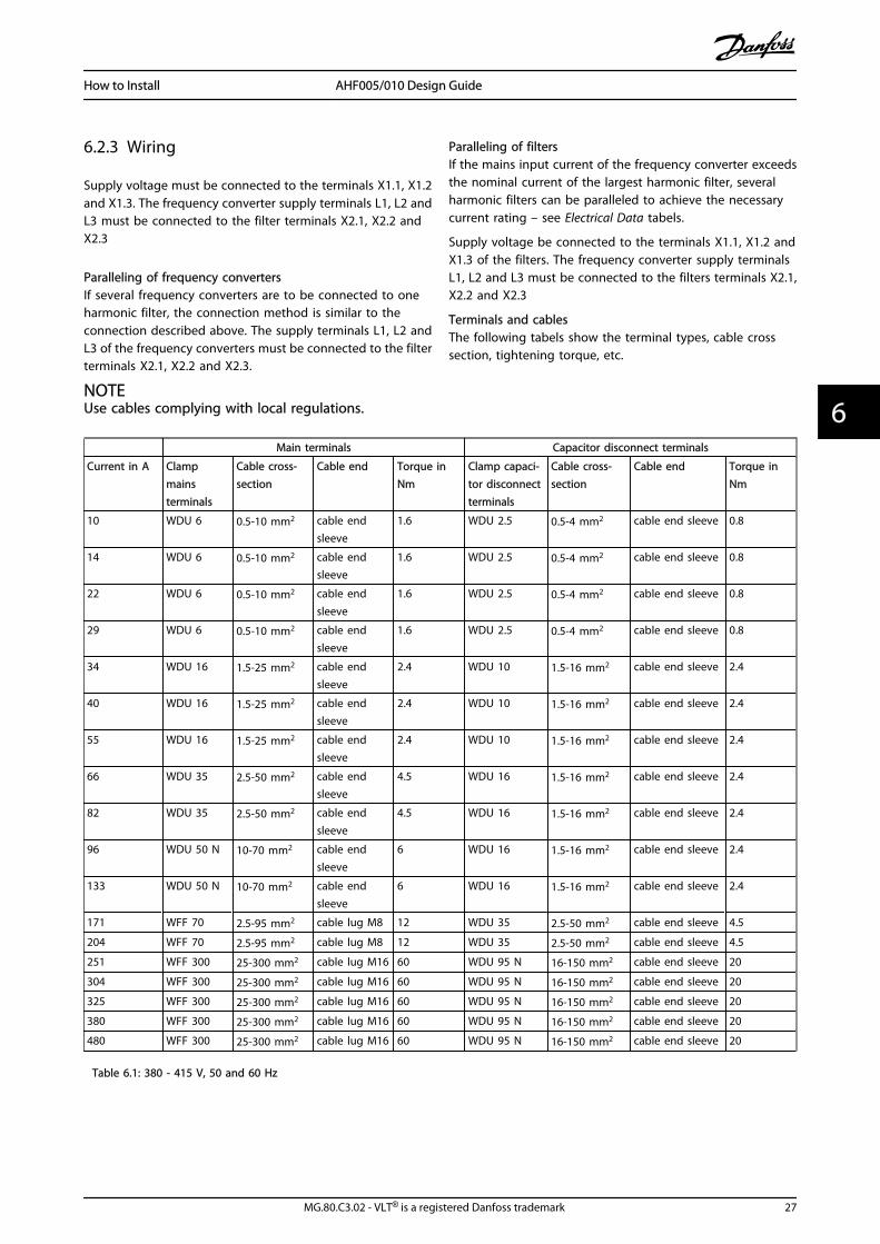
6.2.3 Wiring
Supply voltage must be connected to the terminals X1.1, X1.2and X1.3. The frequency converter supply terminals L1, L2 andL3 must be connected to the filter terminals X2.1, X2.2 andX2.3
Paralleling of frequency convertersIf several frequency converters are to be connected to oneharmonic filter, the connection method is similar to theconnection described above. The supply terminals L1, L2 andL3 of the frequency converters must be connected to the filterterminals X2.1, X2.2 and X2.3.
NOTEUse cables complying with local regulations.
Paralleling of filtersIf the mains input current of the frequency converter exceedsthe nominal current of the largest harmonic filter, severalharmonic filters can be paralleled to achieve the necessarycurrent rating – see Electrical Data tabels.
Supply voltage be connected to the terminals X1.1, X1.2 andX1.3 of the filters. The frequency converter supply terminalsL1, L2 and L3 must be connected to the filters terminals X2.1,X2.2 and X2.3
Terminals and cablesThe following tabels show the terminal types, cable crosssection, tightening torque, etc.
Main terminals Capacitor disconnect terminals
Current in A Clampmainsterminals
Cable cross-section
Cable end Torque inNm
Clamp capaci-tor disconnectterminals
Cable cross-section
Cable end Torque inNm
10 WDU 6 0.5-10 mm2 cable endsleeve
1.6 WDU 2.5 0.5-4 mm2 cable end sleeve 0.8
14 WDU 6 0.5-10 mm2 cable endsleeve
1.6 WDU 2.5 0.5-4 mm2 cable end sleeve 0.8
22 WDU 6 0.5-10 mm2 cable endsleeve
1.6 WDU 2.5 0.5-4 mm2 cable end sleeve 0.8
29 WDU 6 0.5-10 mm2 cable endsleeve
1.6 WDU 2.5 0.5-4 mm2 cable end sleeve 0.8
34 WDU 16 1.5-25 mm2 cable endsleeve
2.4 WDU 10 1.5-16 mm2 cable end sleeve 2.4
40 WDU 16 1.5-25 mm2 cable endsleeve
2.4 WDU 10 1.5-16 mm2 cable end sleeve 2.4
55 WDU 16 1.5-25 mm2 cable endsleeve
2.4 WDU 10 1.5-16 mm2 cable end sleeve 2.4
66 WDU 35 2.5-50 mm2 cable endsleeve
4.5 WDU 16 1.5-16 mm2 cable end sleeve 2.4
82 WDU 35 2.5-50 mm2 cable endsleeve
4.5 WDU 16 1.5-16 mm2 cable end sleeve 2.4
96 WDU 50 N 10-70 mm2 cable endsleeve
6 WDU 16 1.5-16 mm2 cable end sleeve 2.4
133 WDU 50 N 10-70 mm2 cable endsleeve
6 WDU 16 1.5-16 mm2 cable end sleeve 2.4
171 WFF 70 2.5-95 mm2 cable lug M8 12 WDU 35 2.5-50 mm2 cable end sleeve 4.5
204 WFF 70 2.5-95 mm2 cable lug M8 12 WDU 35 2.5-50 mm2 cable end sleeve 4.5
251 WFF 300 25-300 mm2 cable lug M16 60 WDU 95 N 16-150 mm2 cable end sleeve 20
304 WFF 300 25-300 mm2 cable lug M16 60 WDU 95 N 16-150 mm2 cable end sleeve 20
325 WFF 300 25-300 mm2 cable lug M16 60 WDU 95 N 16-150 mm2 cable end sleeve 20
380 WFF 300 25-300 mm2 cable lug M16 60 WDU 95 N 16-150 mm2 cable end sleeve 20
480 WFF 300 25-300 mm2 cable lug M16 60 WDU 95 N 16-150 mm2 cable end sleeve 20
Table 6.1: 380 - 415 V, 50 and 60 Hz
How to Install AHF005/010 Design Guide
MG.80.C3.02 - VLT® is a registered Danfoss trademark 27
6 6

Main terminals Capacitor disconnect terminals
Current in A Clampmainsterminals
Cable cross-section
Cable end Torque inNm
Clamp capaci-tor disconnectterminals
Cable cross-section
Cable end Torque in Nm
10 WDU 6 0.5-10 mm2 cable end sleeve 1.6 WDU 2.5 0.5-4 mm2 cable end sleeve 0.8
14 WDU 6 0.5-10 mm2 cable end sleeve 1.6 WDU 2.5 0.5-4 mm2 cable end sleeve 0.8
19 WDU 6 0.5-10 mm2 cable end sleeve 1.6 WDU 2.5 0.5-4 mm2 cable end sleeve 0.8
25 WDU 6 0.5-10 mm2 cable end sleeve 1.6 WDU 2.5 0.5-4 mm2 cable end sleeve 0.8
31 WDU 16 1.5-25mm2 cable end sleeve 2.4 WDU 10 1.5-16 mm2 cable end sleeve 2.4
36 WDU 16 1.5-25mm2 cable end sleeve 2.4 WDU 10 1.5-16 mm2 cable end sleeve 2.4
48 WDU 16 1.5-25mm2 cable end sleeve 2.4 WDU 10 1.5-16 mm2 cable end sleeve 2.4
60 WDU 35 2.5-50 mm2 cable end sleeve 4.5 WDU 16 1.5-25 mm2 cable end sleeve 2.4
73 WDU 35 2.5-50 mm2 cable end sleeve 4.5 WDU 16 1.5-25 mm2 cable end sleeve 2.4
95 WDU 50 N 10-70 mm2 cable end sleeve 6 WDU 16 1.5-25 mm2 cable end sleeve 2.4
118 WDU 50 N 10-70 mm2 cable end sleeve 6 WDU 16 1.5-25 mm2 cable end sleeve 2.4
154 WFF 70 2.5-95 mm2 cable lug M8 12 WDU 35 2.5-50 mm2 cable end sleeve 4.5
183 WFF 70 2.5-95 mm2 cable lug M8 12 WDU 35 2.5-50 mm2 cable end sleeve 4.5
231 WFF 300 25-300 mm2 cable lug M16 60 WDU 95 N 16-150 mm2 cable end sleeve 20
291 WFF 300 25-300 mm2 cable lug M16 60 WDU 95 N 16-150 mm2 cable end sleeve 20
355 WFF 300 25-300 mm2 cable lug M16 60 WDU 95 N 16-150 mm2 cable end sleeve 20
380 WFF 300 25-300 mm2 cable lug M16 60 WDU 95 N 16-150 mm2 cable end sleeve 20
436 WFF 300 25-300 mm2 cable lug M16 60 WDU 95 N 16-150 mm2 cable end sleeve 20
Table 6.2: 440 - 480 V, 60 Hz
6.2.4 Fuses
In order to protect the installation against electrical and firehazards, all filters in an installation must be short-circuit andover-current protected according to national/internationalregulations.
To protect both drive and filter please choose the type of fusesrecommended in the VLT® Design Guide. The maximum fuserating per filter size is listed below.
Filter current
Maximum size of fuse380 V, 60 Hz400 V, 50 Hz
460 V, 60 Hz
[A] [A] [A]
10 10 16
14 14 35
22 19 35
29 25 50
34 31 50
40 36 63
55 48 80
66 60 125
82 73 160
96 95 250
133 118 250
171 154 315
204 183 350
251 231 400
304 291 500
325 355 630
380 380 630
480 436 800
In applications where filters are paralleled it might be necessa-ry to install fuses in front of each filter and in front of the drive.
How to Install AHF005/010 Design Guide
28 MG.80.C3.02 - VLT® is a registered Danfoss trademark
66

6.3 Mechanical Dimensions
6.3.1 Sketches
Illustration 6.1: X1 no fan
How to Install AHF005/010 Design Guide
MG.80.C3.02 - VLT® is a registered Danfoss trademark 29
6 6

Illustration 6.2: X2 internal fan
How to Install AHF005/010 Design Guide
30 MG.80.C3.02 - VLT® is a registered Danfoss trademark
66

Illustration 6.3: X2 external fan
How to Install AHF005/010 Design Guide
MG.80.C3.02 - VLT® is a registered Danfoss trademark 31
6 6

Illustration 6.4: X3 internal fan
How to Install AHF005/010 Design Guide
32 MG.80.C3.02 - VLT® is a registered Danfoss trademark
66

Illustration 6.5: X4 internal fan
How to Install AHF005/010 Design Guide
MG.80.C3.02 - VLT® is a registered Danfoss trademark 33
6 6
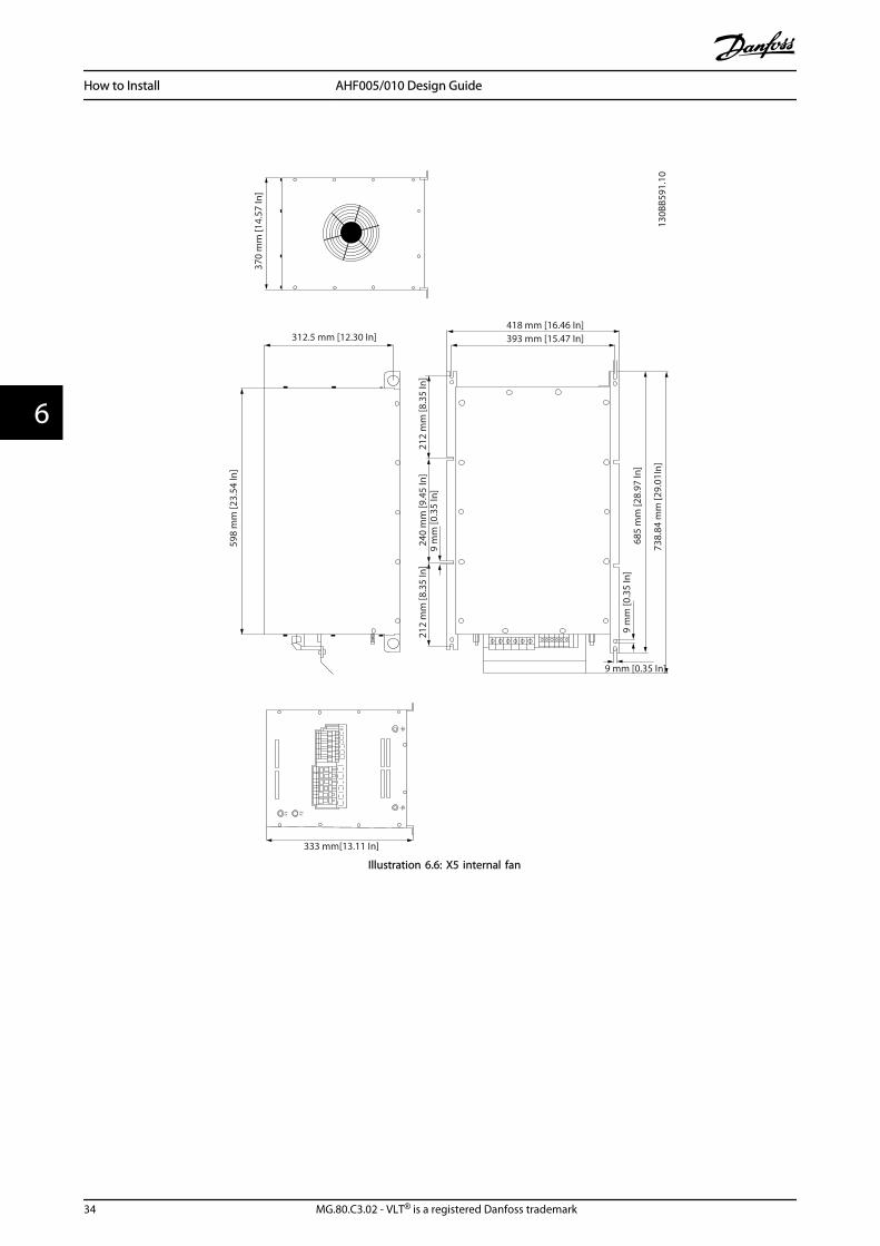
Illustration 6.6: X5 internal fan
How to Install AHF005/010 Design Guide
34 MG.80.C3.02 - VLT® is a registered Danfoss trademark
66

Illustration 6.7: X6 internal fan
How to Install AHF005/010 Design Guide
MG.80.C3.02 - VLT® is a registered Danfoss trademark 35
6 6

Illustration 6.8: X6 external fan
How to Install AHF005/010 Design Guide
36 MG.80.C3.02 - VLT® is a registered Danfoss trademark
66

Illustration 6.9: X7 internal fan
How to Install AHF005/010 Design Guide
MG.80.C3.02 - VLT® is a registered Danfoss trademark 37
6 6

Illustration 6.10: X7 external fan
How to Install AHF005/010 Design Guide
38 MG.80.C3.02 - VLT® is a registered Danfoss trademark
66

Illustration 6.11: X8 internal fan
How to Install AHF005/010 Design Guide
MG.80.C3.02 - VLT® is a registered Danfoss trademark 39
6 6

Illustration 6.12: X8 external fan
How to Install AHF005/010 Design Guide
40 MG.80.C3.02 - VLT® is a registered Danfoss trademark
66

6.3.2 Physical Dimension
Enclosuretype
Dimensions in mm
A (height) B (width) C (Depth)
X1 245 190 205
X2 350 230 248
X3 460 330 242
X4 490 330 333
X5 747 370 333
X6 778 370 400
X7 909 468 450
X8 911 468 550
6.3.3 Weight
AHF010 380 - 415 V, 50 Hz AHF005 380 - 415 V, 50 Hz
Currentrating
frame
weightIP20
weightIP00 frame weight IP20
weightIP00
[A] size [kg] [kg] size [kg] [kg]
10 X1 12 8 X1 16 12
14 X1 13 9 X1 20 16
22 X2 22 17 X2 34 29
29 X2 25 20 X2 42 37
34 X3 36 30 X3 50 44
40 X3 40 33 X3 52 45
55 X3 42 35 X3 75 68
66 X4 52 45 X4 82 75
82 X4 56 47 X4 96 87
96 X5 62 52 X5 104 94
133 X5 74 64 X5 130 120
171 X6 85 74 X6 135 124
204 X6 105 94 X6 168 157
251 X7 123 106 X7 197 180
304 X7 136 120 X7 220 204
325 X7 142 126 X7 228 212
381 X7 163 147 X8 260 244
480 X8 205 186 X8 328 309
AHF010 380 - 415 V, 60 Hz AHF005 380 - 415 V, 60 Hz
Currentrating frame
weightIP20
weightIP00 frame
weightIP20
weightIP00
[A] size [kg] [kg] size [kg] [kg]
10 X1 12 8 X1 16 12
14 X1 13 9 X1 20 16
22 X2 22 17 X2 34 29
29 X2 25 20 X2 42 37
34 X3 36 30 X3 50 44
40 X3 40 33 X3 52 45
55 X3 42 35 X3 75 68
66 X4 52 45 X4 82 75
82 X4 56 47 X4 96 87
96 X5 62 52 X5 104 94
133 X5 74 64 X5 130 120
171 X6 85 74 X6 135 124
204 X6 105 94 X6 168 157
251 X7 123 106 X7 197 180
304 X7 136 120 X7 220 204
325 X7 142 126 X7 228 212
381 X7 163 147 X8 260 244
480 X8 205 186 X8 328 309
AHF010 440 - 480 V, 60 HzAHF005 440 - 480 V, 60
Hz
Currentrating frame weight IP20
weightIP00 frame
weightIP20
weightIP00
[A] size [kg] [kg] size [kg] [kg]
10 X1 12 8 X1 16 12
14 X1 13 9 X1 20 16
19 X2 22 17 X2 34 29
25 X2 25 20 X2 42 37
31 X3 36 30 X3 50 44
36 X3 40 33 X3 52 45
48 X3 42 35 X3 75 68
60 X4 52 45 X4 82 75
73 X4 56 47 X4 96 87
95 X5 62 52 X5 104 84
118 X5 74 64 X5 130 120
154 X6 85 74 X6 135 124
183 X6 105 94 X6 168 157
231 X7 123 106 X7 197 180
291 X7 136 120 X7 220 204
355 X7 163 126 X7 260 212
380 X7 178 147 X8 295 244
436 X8 205 186 X8 328 309
How to Install AHF005/010 Design Guide
MG.80.C3.02 - VLT® is a registered Danfoss trademark 41
6 6

7 How to Programme theFrequency Converter
7.1.1 DC-link Compensation Disabling
The FC series include a feature which ensures that the outputvoltage is independent of any voltage fluctuation in the DClink, e.g. caused by fast fluctuation in the mains supplyvoltage. In some cases this very dynamic compensation canproduce resonances in the DC link and should then bedisabled. Typical cases are where AHF005/010 is used onsupply grids with high short circuit ratio. Fluctuations canoften be recognized by increased acoustical noise and inextreme cases by unintended tripping. To prevent resonancesin the DC-link, it is recommended to disable the dynamic DC-link compensation by setting par. 14-51 to off.
14-51 DC Link Compensation
Option: Function:
[0] Off Disables DC Link Compensation.
[1] * On Enables DC Link Compensation.
How to Programme the Freque... AHF005/010 Design Guide
42 MG.80.C3.02 - VLT® is a registered Danfoss trademark
77

Index
AAbbreviations 4
Active Filters 14
Apparent Power 7
BBackground Distortion 12
CCapacitive Current 14
Capacitor Disconnect 14
CE Conformity and Labelling 5
DDC Link Compensation 14-51 42
Derating 23
Displacement Angle 7
Displacement Power Factor 8
EEfficiency 23
FFundamental Frequency 8
GG5/4 9
General Warning 4
Generator 14
Grid Unbalance 12
Grounding 24
HHarmonic Calculation Software 12
Harmonic Mitigation Standards 9
High-voltage Warning 4
IIEC61000-3-2 9
IEC61000-3-4 9
IEEE 519 9
IP21/NEMA1 enclosure kits 22
LLeading Current 25
MMCT 31 12
NNominal Motor Current 15
Non-linear Loads 7
OOver Temperature Protection 25
PPartial Load 12
Partial Weighted Harmonic Distortion 8
Point Of Common Coupling 9
Power Factor 7, 14, 25
RReactive Power 7
Real Power 7
SScreening 24
Short Circuit Ratio 9
TThe Low-voltage Directive (73/23/eec) 5
Total Current Harmonic Distortion 12
Total Demand Distortion 8
Total Harmonic Distortion (thd) 8
True Power Factor 8, 13
Index AHF005/010 Design Guide
MG.80.C3.02 - VLT® is a registered Danfoss trademark 43