contents anilam bridgeport fanuc yasnac - sjcc-cnc.orgsjcc-cnc.org/mach153b/text/appendix_a.pdf ·...
TRANSCRIPT
ADVANCED TECHNIQUES APPENDIX A - 1
�
�
�
�
�
�
�
�
�
CONTENTS
� Anilam
� Bridgeport
� Fanuc
� Yasnac
� Haas
� Fadal
� Okuma

APPENDIX A - 2 ADVANCED TECHNIQUES
ADVANCED TECHNIQUES APPENDIX A - 3
ANILAM CODES
The following is a list of Machinist Shop Language commands located on buttons or keyswitches on a CNCControl Unit.
A - absolute positioning.
ARC - Command to cut an arc with the data entered. If used with a CW or CCW the it is a direction instruction.
AUX - Auxilliary code for changes in normal control functions.
CALL - Direct the program to a subroutine location. Accompanied by a number to identify which subroutine.
CCW - Counterclockwise instruction.
CW - Clockwise instruction.
DO - Do loop instruction. Accompanied by a number to denote the number of times to loop.
DWELL - Stops all further program execution until a signal to continue is received.
END - Has three purposes: 1) end of a do loop. 2) end of a subroutine. 3) end of the program.
F - Programmed feedrate.
FEED - Accompanied with a feedrate value.
G - Identifies a canned cycle.
I - Incremental positioning.
R - Rapid traverse.
SUBR - A Subroutine call accompanied by a number to identify which subroutine.
TOOL - Has two purposes: 1) Tool change accompanied by 1 or 2 numbers. 2) Assign Tool Length Offset or Cutter Offset.
V - Variable
PREPARATORY FUNCTIONSG40 - Cutter diameter compensation cancel.G41 - Cutter diameter compensation left.G42 - Cutter diameter compensation right.G51 - Begin polar rotation.G52 - Polar rotation cancel.G53 - Begin scaling.G54 - Cancel scaling.
APPENDIX A - 4 ADVANCED TECHNIQUES
G76 - Hole Milling.G77 - Circular pocket milling.G78 - Rectangular pocket milling.G79 - Bolt Circle pattern.G80 - Canned cycle cancel.G81 - Drilling Cycle.G82 - Counter-boring; Spot facing (feed in, timed dwell, rapid out).G83 - Peck drilling (feed in, rapid out, feed in, etc.).G85 - Boring (feed in, feed out).G86 - Boring (feed in, rapid out)G87 - Peck drilling (feed in, retract .05, feed in, etc.).G89 - Boring (feed in, timed dwell, feed out).
VARIABLE CODESV11 - X axis polar center (absolute).V12 - Y axis polar center (absolute).V13 - Polar rotation index angle. Clockwise (-) or counterclockwise (+).V14 - Radius for polar moves.V15 - Angle for polar moves or first angle in a bolt circle.V16 - Angle of last hole in bolt circle; x-axis scale valus.V17 - Number of holes in a bolt circle; y-axis scale value.V18 - Diameter of bolt circle; z-axis scale value.V20 - Feedrate for G80 series canned cycles.V21 - Buffer height for G80 series canned cycles. Must be .100" for G83/G87.V22 - Dwell time when using G82 or G89.V23 - Maximum peck for G83 or G87.V40 - Z-axis start height for pecked milling.V41 - Incremental length of x-axis pocket.V42 - Incremental width of y-axis pocket.V43 - Z-axis depth of pocket.V44 - Pocket corner radius; circle diameter if circular pocket milling.V45 - Stepover value for pocket milling.V46 - Maximum depth of cut.V47 - Stock left for finish pass.V48 - Finish pass feedrate.V49 - Tool diameter for pocket milling.
AUXILLIARY CODESAUX 100 - Reverses the sign of the X axis.AUX 200 - Reverses the sign of the Y axis.AUX 300 - Reverses the sign of the X and Y axes.AUX 400 - Reverses the sign of the Z axis.AUX 500 - Reverses the sign of the X and Z axes.AUX 600 - Reverses the sign of the Y and Z axes.AUX 700 - Reverses the sign of the X, Y, and Z axes.AUX 800 - Turns off mirror image.AUX 1000 - Deceleration override when contouring.AUX 1101 - Absolute zero shift.AUX 1110 - Turn off software limits.AUX 1111 - Turn on software limits.AUX 1400 - Percent feed override for feedrate.AUX 1401 - Percent feed override for feed and rapid moves.AUX 1900 - Single-step event mode.AUX 1901 - Single-step axis movement mode.AUX 2000 - Cancel AUX 1000AUX 2500 - Set control to use Z axis.AUX 2600 - Set control to allow manual use of the Z axis.
ADVANCED TECHNIQUES APPENDIX A - 5
PREPARATORY FUNCTIONS
G0 - Rapid Traverse
G1 - Linear Interpolation
G2 - Circular Interpolation, clockwise
G3 - Circular Interpolation; counterclockwise
G4 - Dwell
G12 - Helical Interpolation CW
G13 - Helical Interpolation CCW
G17 - XY Plane Selection
G18 - XZ Plane Selection
G19 - YZ Plane Selection
G21 - Inside Filet
G22 - Outside Radius
G30 - Mirror Image Cancel
G31 Mirror Image X-axis
G32 - Mirror Image Y-axis
G40 - Cutter Compensation Cancel
G41 - Cutter Compensation Left
G42 - Cutter Compensation Right
G44 - Constant Surface Feed Cancel
G45 - Constant Surface Feed On
G70 - Inch Programming
G71 - Metric Programming
G72 - Transformation off
G73 - Transformation/Rotation/Scaling
G74 - Multi-Quadrandt Circle Input Off
BRIDGEPORT BOSS 8-9G CODES
G75 - Multi Quadrant Circular Interpolation On
G77 - Zig Zag Milling Cycle
G78 - Pocket Mill Cycle
G79 - Bore cycle
G80 - Canned Cycle Cancel
G81 - Drill Cycle
G82 - Drill Cycle with Dwell
G83 - Deep Hole
G84 - Tapping Cycle
G85 - Bore Cycle; Feed in - Feed out
G86 - Bore Cycle; Feed in - Stop - Rapid out
G87 - Chip Break
G89 - Bore Cycle; Feed in - Dwell - Feed out
G90 - Absolute Positioning
G91 - Incremental Positioning
G92 - Preset Part Program Zero Point
G96 - Restore Base Part Program Coordinate System
G97 - Set Work Coordinate System
G99 - Decelleration Override
G170 - Outside Frame Mill
G171 - Inside Frame Milling
G172 - Pocket Frame mill
G173 - Outside Face mill
G174 - Inside Face Mill
G175 - Outside Circle Mill
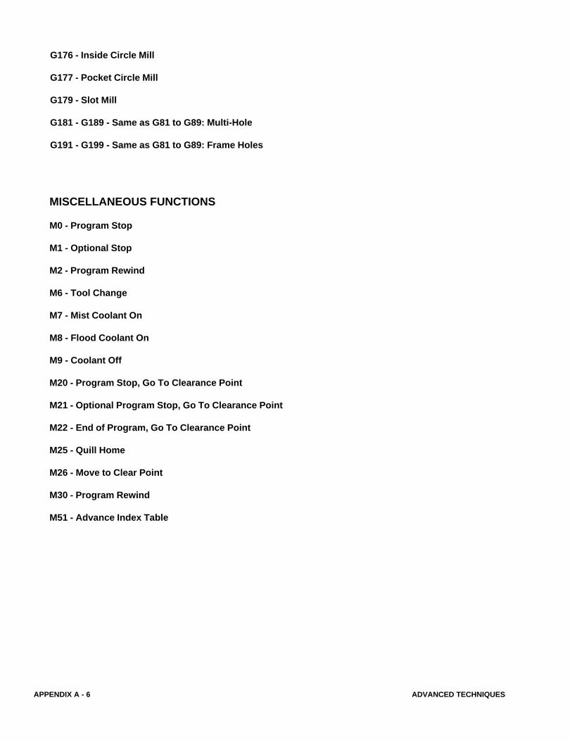
APPENDIX A - 6 ADVANCED TECHNIQUES
MISCELLANEOUS FUNCTIONS
M0 - Program Stop
M1 - Optional Stop
M2 - Program Rewind
M6 - Tool Change
M7 - Mist Coolant On
M8 - Flood Coolant On
M9 - Coolant Off
M20 - Program Stop, Go To Clearance Point
M21 - Optional Program Stop, Go To Clearance Point
M22 - End of Program, Go To Clearance Point
M25 - Quill Home
M26 - Move to Clear Point
M30 - Program Rewind
M51 - Advance Index Table
G176 - Inside Circle Mill
G177 - Pocket Circle Mill
G179 - Slot Mill
G181 - G189 - Same as G81 to G89: Multi-Hole
G191 - G199 - Same as G81 to G89: Frame Holes
ADVANCED TECHNIQUES APPENDIX A - 7
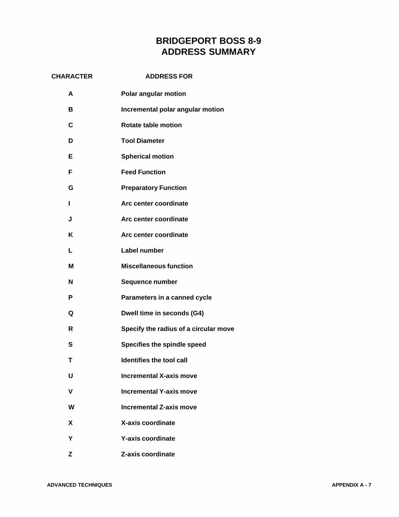
BRIDGEPORT BOSS 8-9ADDRESS SUMMARY
A Polar angular motion
B Incremental polar angular motion
C Rotate table motion
D Tool Diameter
E Spherical motion
F Feed Function
G Preparatory Function
I Arc center coordinate
J Arc center coordinate
K Arc center coordinate
L Label number
M Miscellaneous function
N Sequence number
P Parameters in a canned cycle
Q Dwell time in seconds (G4)
R Specify the radius of a circular move
S Specifies the spindle speed
T Identifies the tool call
U Incremental X-axis move
V Incremental Y-axis move
W Incremental Z-axis move
X X-axis coordinate
Y Y-axis coordinate
Z Z-axis coordinate
CHARACTER ADDRESS FOR
APPENDIX A - 8 ADVANCED TECHNIQUES
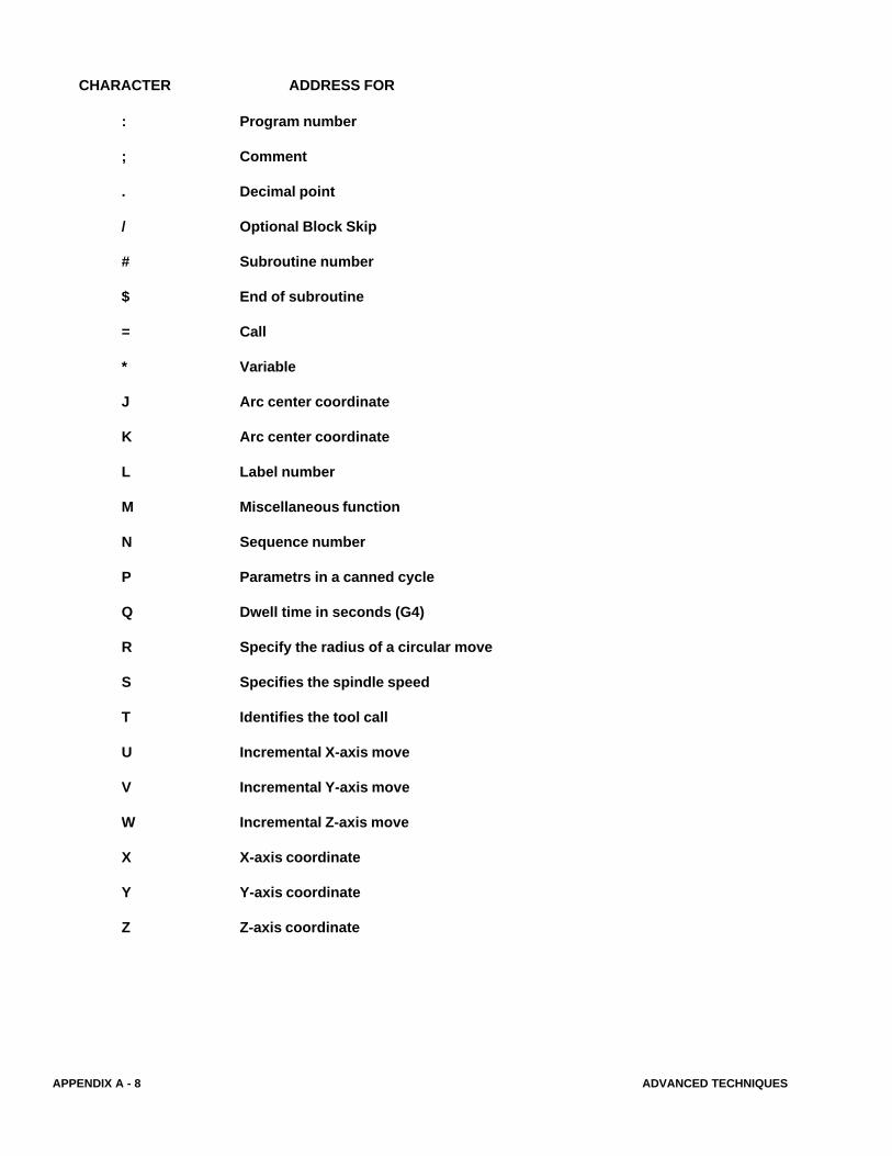
CHARACTER ADDRESS FOR
: Program number
; Comment
. Decimal point
/ Optional Block Skip
# Subroutine number
$ End of subroutine
= Call
* Variable
J Arc center coordinate
K Arc center coordinate
L Label number
M Miscellaneous function
N Sequence number
P Parametrs in a canned cycle
Q Dwell time in seconds (G4)
R Specify the radius of a circular move
S Specifies the spindle speed
T Identifies the tool call
U Incremental X-axis move
V Incremental Y-axis move
W Incremental Z-axis move
X X-axis coordinate
Y Y-axis coordinate
Z Z-axis coordinate
ADVANCED TECHNIQUES APPENDIX A - 9
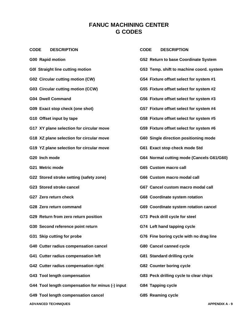
FANUC MACHINING CENTERG CODES
CODE DESCRIPTION
G00 Rapid motion
G0l Straight line cutting motion
G02 Circular cutting motion (CW)
G03 Circular cutting motion (CCW)
G04 Dwell Command
G09 Exact stop check (one shot)
G10 Offset input by tape
G17 XY plane selection for circular move
G18 XZ plane selection for circular move
G19 YZ plane selection for circular move
G20 Inch mode
G21 Metric mode
G22 Stored stroke setting (safety zone)
G23 Stored stroke cancel
G27 Zero return check
G28 Zero return command
G29 Return from zero return position
G30 Second reference point return
G31 Skip cutting for probe
G40 Cutter radius compensation cancel
G41 Cutter radius compensation left
G42 Cutter radius compensation right
G43 Tool length compensation
G44 Tool length compensation for minus (-) input
G49 Tool length compensation cancel
CODE DESCRIPTION
G52 Return to base Coordinate System
G53 Temp. shift to machine coord. system
G54 Fixture offset select for system #1
G55 Fixture offset select for system #2
G56 Fixture offset select for system #3
G57 Fixture offset select for system #4
G58 Fixture offset select for system #5
G59 Fixture offset select for system #6
G60 Single direction positioning mode
G61 Exact stop check mode Std
G64 Normal cutting mode (Cancels G61/G60)
G65 Custom macro call
G66 Custom macro modal call
G67 Cancel custom macro modal call
G68 Coordinate system rotation
G69 Coordinate system rotation cancel
G73 Peck drill cycle for steel
G74 Left hand tapping cycle
G76 Fine boring cycle with no drag line
G80 Cancel canned cycle
G81 Standard drilling cycle
G82 Counter boring cycle
G83 Peck drilling cycle to clear chips
G84 Tapping cycle
G85 Reaming cycle
APPENDIX A - 10 ADVANCED TECHNIQUES
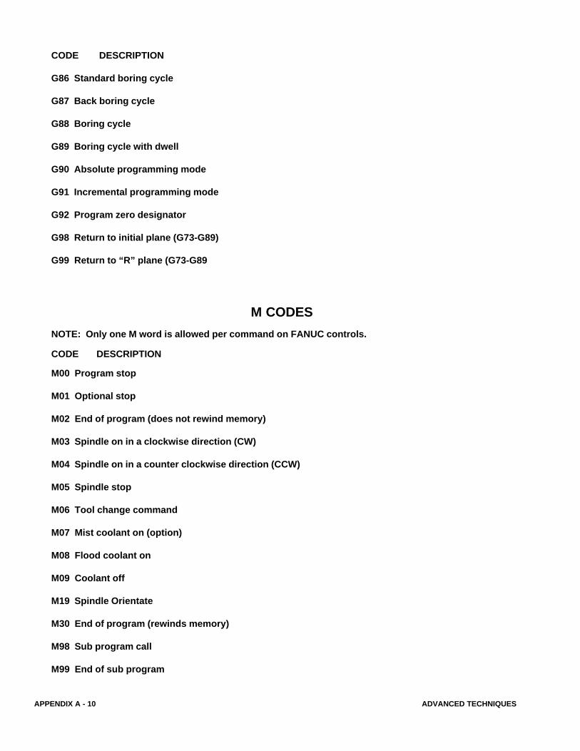
CODE DESCRIPTION
G86 Standard boring cycle
G87 Back boring cycle
G88 Boring cycle
G89 Boring cycle with dwell
G90 Absolute programming mode
G91 Incremental programming mode
G92 Program zero designator
G98 Return to initial plane (G73-G89)
G99 Return to “R” plane (G73-G89
CODE DESCRIPTION
M00 Program stop
M01 Optional stop
M02 End of program (does not rewind memory)
M03 Spindle on in a clockwise direction (CW)
M04 Spindle on in a counter clockwise direction (CCW)
M05 Spindle stop
M06 Tool change command
M07 Mist coolant on (option)
M08 Flood coolant on
M09 Coolant off
M19 Spindle Orientate
M30 End of program (rewinds memory)
M98 Sub program call
M99 End of sub program
M CODES
NOTE: Only one M word is allowed per command on FANUC controls.
ADVANCED TECHNIQUES APPENDIX A - 11
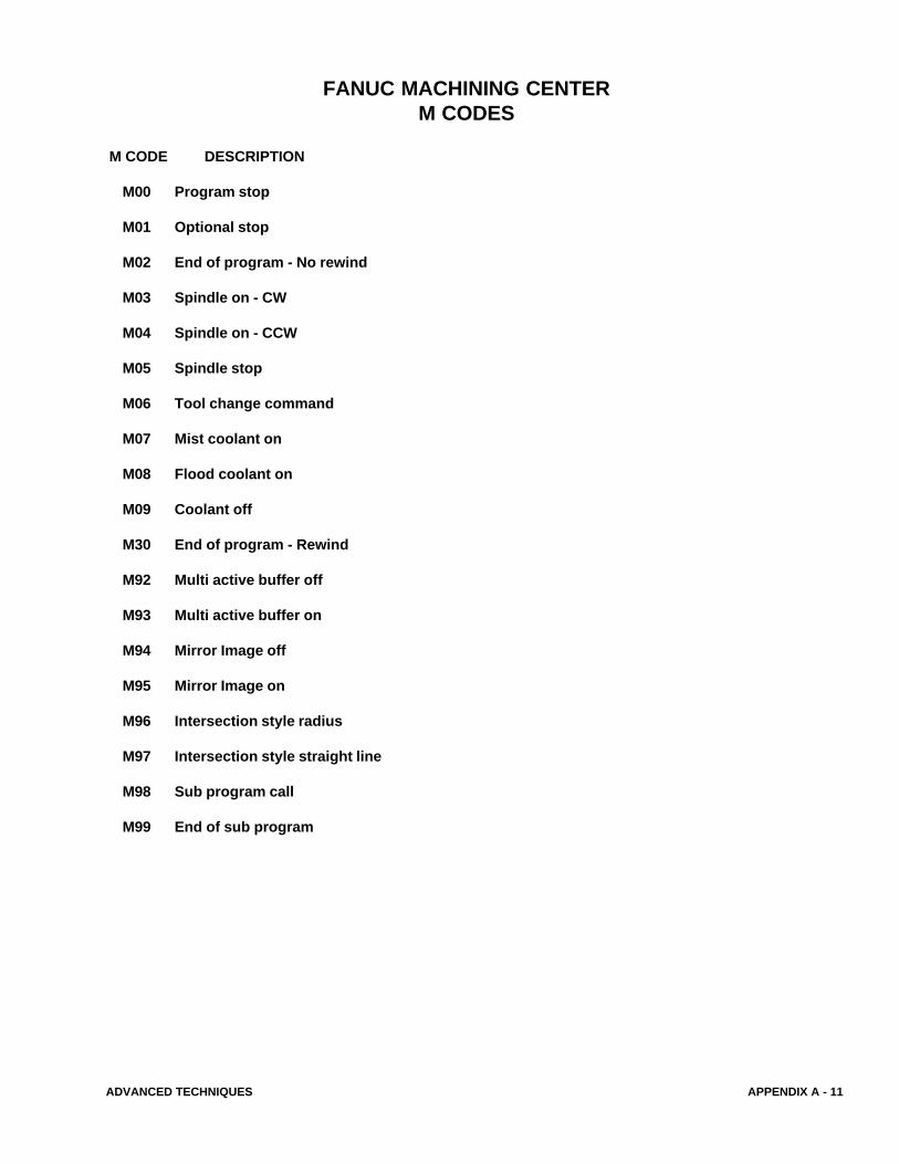
FANUC MACHINING CENTERM CODES
M CODE DESCRIPTION
M00 Program stop
M01 Optional stop
M02 End of program - No rewind
M03 Spindle on - CW
M04 Spindle on - CCW
M05 Spindle stop
M06 Tool change command
M07 Mist coolant on
M08 Flood coolant on
M09 Coolant off
M30 End of program - Rewind
M92 Multi active buffer off
M93 Multi active buffer on
M94 Mirror Image off
M95 Mirror Image on
M96 Intersection style radius
M97 Intersection style straight line
M98 Sub program call
M99 End of sub program
APPENDIX A - 12 ADVANCED TECHNIQUES
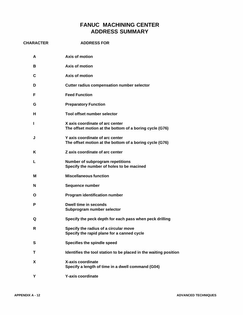
CHARACTER ADDRESS FOR
FANUC MACHINING CENTERADDRESS SUMMARY
A Axis of motion
B Axis of motion
C Axis of motion
D Cutter radius compensation number selector
F Feed Function
G Preparatory Function
H Tool offset number selector
I X axis coordinate of arc centerThe offset motion at the bottom of a boring cycle (G76)
J Y axis coordinate of arc centerThe offset motion at the bottom of a boring cycle (G76)
K Z axis coordinate of arc center
L Number of subprogram repetitionsSpecify the number of holes to be macined
M Miscellaneous function
N Sequence number
O Program identification number
P Dwell time in secondsSubprogram number selector
Q Specify the peck depth for each pass when peck drilling
R Specify the radius of a circular moveSpecify the rapid plane for a canned cycle
S Specifies the spindle speed
T Identifies the tool station to be placed in the waiting position
X X-axis coordinateSpecify a length of time in a dwell command (G04)
Y Y-axis coordinate
ADVANCED TECHNIQUES APPENDIX A - 13
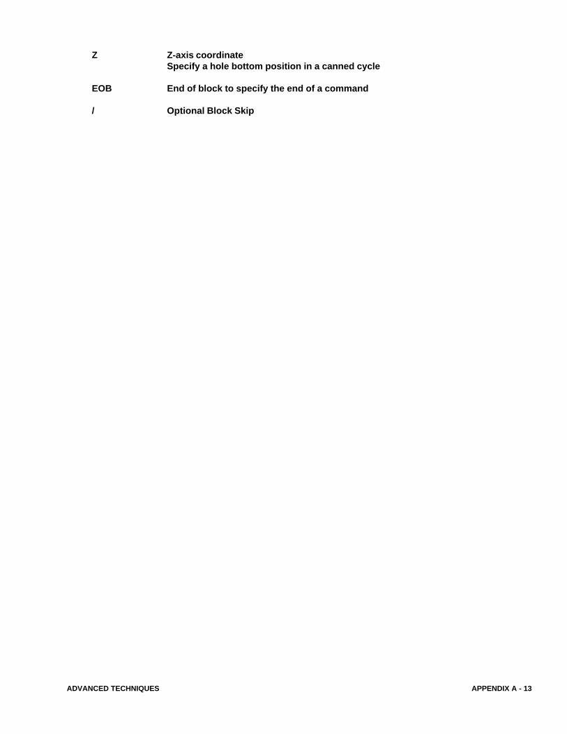
Z Z-axis coordinateSpecify a hole bottom position in a canned cycle
EOB End of block to specify the end of a command
/ Optional Block Skip
APPENDIX A - 14 ADVANCED TECHNIQUES
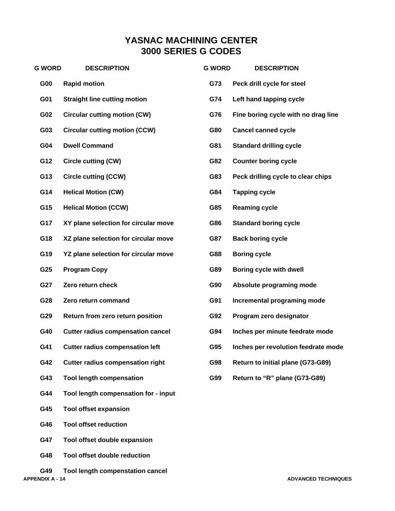
G WORD DESCRIPTION
G00 Rapid motion
G01 Straight line cutting motion
G02 Circular cutting motion (CW)
G03 Circular cutting motion (CCW)
G04 Dwell Command
G12 Circle cutting (CW)
G13 Circle cutting (CCW)
G14 Helical Motion (CW)
G15 Helical Motion (CCW)
G17 XY plane selection for circular move
G18 XZ plane selection for circular move
G19 YZ plane selection for circular move
G25 Program Copy
G27 Zero return check
G28 Zero return command
G29 Return from zero return position
G40 Cutter radius compensation cancel
G41 Cutter radius compensation left
G42 Cutter radius compensation right
G43 Tool length compensation
G44 Tool length compensation for - input
G45 Tool offset expansion
G46 Tool offset reduction
G47 Tool offset double expansion
G48 Tool offset double reduction
G49 Tool length compenstation cancel
YASNAC MACHINING CENTER3000 SERIES G CODES
G WORD DESCRIPTION
G73 Peck drill cycle for steel
G74 Left hand tapping cycle
G76 Fine boring cycle with no drag line
G80 Cancel canned cycle
G81 Standard drilling cycle
G82 Counter boring cycle
G83 Peck drilling cycle to clear chips
G84 Tapping cycle
G85 Reaming cycle
G86 Standard boring cycle
G87 Back boring cycle
G88 Boring cycle
G89 Boring cycle with dwell
G90 Absolute programing mode
G91 Incremental programing mode
G92 Program zero designator
G94 Inches per minute feedrate mode
G95 Inches per revolution feedrate mode
G98 Return to initial plane (G73-G89)
G99 Return to “R” plane (G73-G89)
ADVANCED TECHNIQUES APPENDIX A - 15
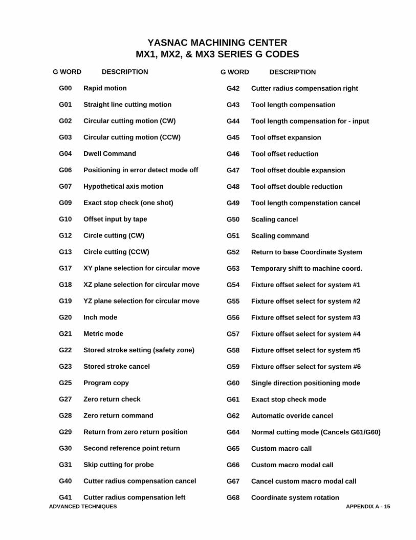
G WORD DESCRIPTION
G00 Rapid motion
G01 Straight line cutting motion
G02 Circular cutting motion (CW)
G03 Circular cutting motion (CCW)
G04 Dwell Command
G06 Positioning in error detect mode off
G07 Hypothetical axis motion
G09 Exact stop check (one shot)
G10 Offset input by tape
G12 Circle cutting (CW)
G13 Circle cutting (CCW)
G17 XY plane selection for circular move
G18 XZ plane selection for circular move
G19 YZ plane selection for circular move
G20 Inch mode
G21 Metric mode
G22 Stored stroke setting (safety zone)
G23 Stored stroke cancel
G25 Program copy
G27 Zero return check
G28 Zero return command
G29 Return from zero return position
G30 Second reference point return
G31 Skip cutting for probe
G40 Cutter radius compensation cancel
G41 Cutter radius compensation left
YASNAC MACHINING CENTERMX1, MX2, & MX3 SERIES G CODES
G WORD DESCRIPTION
G42 Cutter radius compensation right
G43 Tool length compensation
G44 Tool length compensation for - input
G45 Tool offset expansion
G46 Tool offset reduction
G47 Tool offset double expansion
G48 Tool offset double reduction
G49 Tool length compenstation cancel
G50 Scaling cancel
G51 Scaling command
G52 Return to base Coordinate System
G53 Temporary shift to machine coord.
G54 Fixture offset select for system #1
G55 Fixture offset select for system #2
G56 Fixture offset select for system #3
G57 Fixture offset select for system #4
G58 Fixture offset select for system #5
G59 Fixture offser select for system #6
G60 Single direction positioning mode
G61 Exact stop check mode
G62 Automatic overide cancel
G64 Normal cutting mode (Cancels G61/G60)
G65 Custom macro call
G66 Custom macro modal call
G67 Cancel custom macro modal call
G68 Coordinate system rotation
APPENDIX A - 16 ADVANCED TECHNIQUES
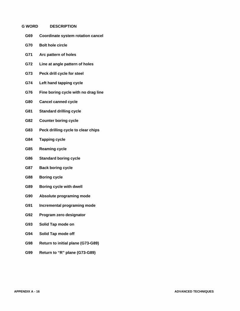
G WORD DESCRIPTION
G69 Coordinate system rotation cancel
G70 Bolt hole circle
G71 Arc pattern of holes
G72 Line at angle pattern of holes
G73 Peck drill cycle for steel
G74 Left hand tapping cycle
G76 Fine boring cycle with no drag line
G80 Cancel canned cycle
G81 Standard drilling cycle
G82 Counter boring cycle
G83 Peck drilling cycle to clear chips
G84 Tapping cycle
G85 Reaming cycle
G86 Standard boring cycle
G87 Back boring cycle
G88 Boring cycle
G89 Boring cycle with dwell
G90 Absolute programing mode
G91 Incremental programing mode
G92 Program zero designator
G93 Solid Tap mode on
G94 Solid Tap mode off
G98 Return to initial plane (G73-G89)
G99 Return to “R” plane (G73-G89)
ADVANCED TECHNIQUES APPENDIX A - 17
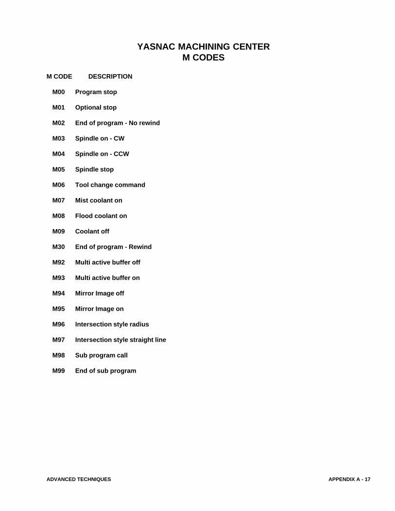
YASNAC MACHINING CENTERM CODES
M CODE DESCRIPTION
M00 Program stop
M01 Optional stop
M02 End of program - No rewind
M03 Spindle on - CW
M04 Spindle on - CCW
M05 Spindle stop
M06 Tool change command
M07 Mist coolant on
M08 Flood coolant on
M09 Coolant off
M30 End of program - Rewind
M92 Multi active buffer off
M93 Multi active buffer on
M94 Mirror Image off
M95 Mirror Image on
M96 Intersection style radius
M97 Intersection style straight line
M98 Sub program call
M99 End of sub program
APPENDIX A - 18 ADVANCED TECHNIQUES
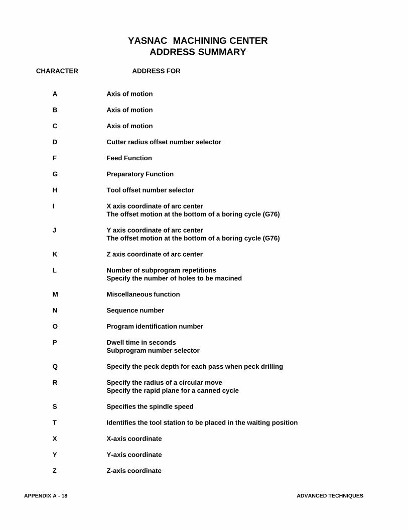
CHARACTER ADDRESS FOR
YASNAC MACHINING CENTERADDRESS SUMMARY
A Axis of motion
B Axis of motion
C Axis of motion
D Cutter radius offset number selector
F Feed Function
G Preparatory Function
H Tool offset number selector
I X axis coordinate of arc centerThe offset motion at the bottom of a boring cycle (G76)
J Y axis coordinate of arc centerThe offset motion at the bottom of a boring cycle (G76)
K Z axis coordinate of arc center
L Number of subprogram repetitionsSpecify the number of holes to be macined
M Miscellaneous function
N Sequence number
O Program identification number
P Dwell time in secondsSubprogram number selector
Q Specify the peck depth for each pass when peck drilling
R Specify the radius of a circular moveSpecify the rapid plane for a canned cycle
S Specifies the spindle speed
T Identifies the tool station to be placed in the waiting position
X X-axis coordinate
Y Y-axis coordinate
Z Z-axis coordinate
ADVANCED TECHNIQUES APPENDIX A - 19
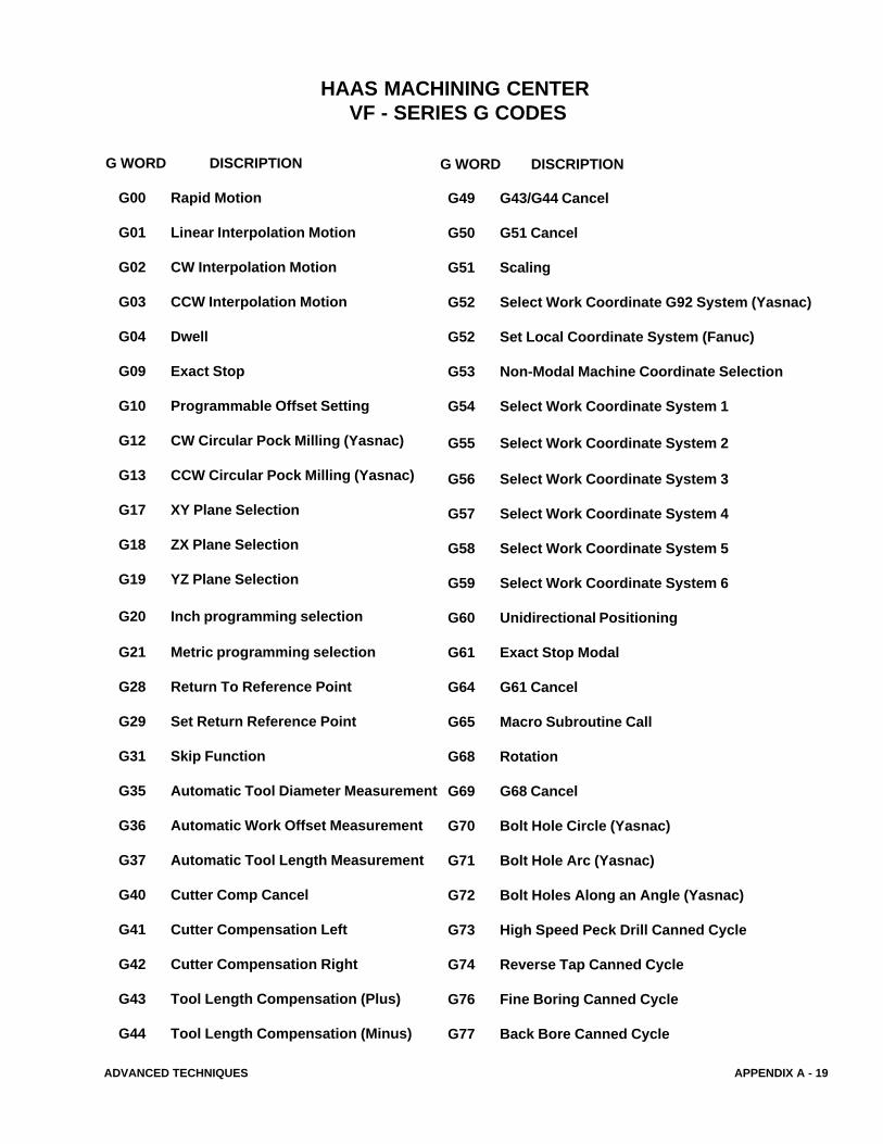
G WORD DISCRIPTION
G00 Rapid Motion
G01 Linear Interpolation Motion
G02 CW Interpolation Motion
G03 CCW Interpolation Motion
G04 Dwell
G09 Exact Stop
G10 Programmable Offset Setting
G12 CW Circular Pock Milling (Yasnac)
G13 CCW Circular Pock Milling (Yasnac)
G17 XY Plane Selection
G18 ZX Plane Selection
G19 YZ Plane Selection
G20 Inch programming selection
G21 Metric programming selection
G28 Return To Reference Point
G29 Set Return Reference Point
G31 Skip Function
G35 Automatic Tool Diameter Measurement
G36 Automatic Work Offset Measurement
G37 Automatic Tool Length Measurement
G40 Cutter Comp Cancel
G41 Cutter Compensation Left
G42 Cutter Compensation Right
G43 Tool Length Compensation (Plus)
G44 Tool Length Compensation (Minus)
HAAS MACHINING CENTER VF - SERIES G CODES
G49 G43/G44 Cancel
G50 G51 Cancel
G51 Scaling
G52 Select Work Coordinate G92 System (Yasnac)
G52 Set Local Coordinate System (Fanuc)
G53 Non-Modal Machine Coordinate Selection
G54 Select Work Coordinate System 1
G55 Select Work Coordinate System 2
G56 Select Work Coordinate System 3
G57 Select Work Coordinate System 4
G58 Select Work Coordinate System 5
G59 Select Work Coordinate System 6
G60 Unidirectional Positioning
G61 Exact Stop Modal
G64 G61 Cancel
G65 Macro Subroutine Call
G68 Rotation
G69 G68 Cancel
G70 Bolt Hole Circle (Yasnac)
G71 Bolt Hole Arc (Yasnac)
G72 Bolt Holes Along an Angle (Yasnac)
G73 High Speed Peck Drill Canned Cycle
G74 Reverse Tap Canned Cycle
G76 Fine Boring Canned Cycle
G77 Back Bore Canned Cycle
G WORD DISCRIPTION
APPENDIX A - 20 ADVANCED TECHNIQUES
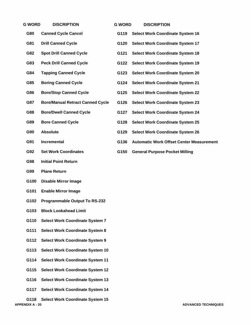
G80 Canned Cycle Cancel
G81 Drill Canned Cycle
G82 Spot Drill Canned Cycle
G83 Peck Drill Canned Cycle
G84 Tapping Canned Cycle
G85 Boring Canned Cycle
G86 Bore/Stop Canned Cycle
G87 Bore/Manual Retract Canned Cycle
G88 Bore/Dwell Canned Cycle
G89 Bore Canned Cycle
G90 Absolute
G91 Incremental
G92 Set Work Coordinates
G98 Initial Point Return
G99 Plane Return
G100 Disable Mirror Image
G101 Enable Mirror Image
G102 Programmable Output To RS-232
G103 Block Lookahead Limit
G110 Select Work Coordinate System 7
G111 Select Work Coordinate System 8
G112 Select Work Coordinate System 9
G113 Select Work Coordinate System 10
G114 Select Work Coordinate System 11
G115 Select Work Coordinate System 12
G116 Select Work Coordinate System 13
G117 Select Work Coordinate System 14
G118 Select Work Coordinate System 15
G WORD DISCRIPTION
G119 Select Work Coordinate System 16
G120 Select Work Coordinate System 17
G121 Select Work Coordinate System 18
G122 Select Work Coordinate System 19
G123 Select Work Coordinate System 20
G124 Select Work Coordinate System 21
G125 Select Work Coordinate System 22
G126 Select Work Coordinate System 23
G127 Select Work Coordinate System 24
G128 Select Work Coordinate System 25
G129 Select Work Coordinate System 26
G136 Automatic Work Offset Center Measurement
G150 General Purpose Pocket Milling
G WORD DISCRIPTION
ADVANCED TECHNIQUES APPENDIX A - 21
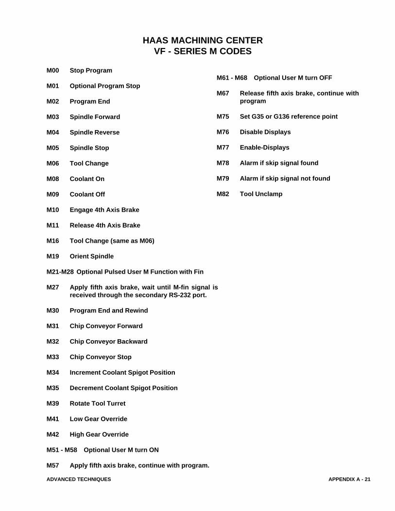
M00 Stop Program
M01 Optional Program Stop
M02 Program End
M03 Spindle Forward
M04 Spindle Reverse
M05 Spindle Stop
M06 Tool Change
M08 Coolant On
M09 Coolant Off
M10 Engage 4th Axis Brake
M11 Release 4th Axis Brake
M16 Tool Change (same as M06)
M19 Orient Spindle
M21-M28 Optional Pulsed User M Function with Fin
M27 Apply fifth axis brake, wait until M-fin signal isreceived through the secondary RS-232 port.
M30 Program End and Rewind
M31 Chip Conveyor Forward
M32 Chip Conveyor Backward
M33 Chip Conveyor Stop
M34 Increment Coolant Spigot Position
M35 Decrement Coolant Spigot Position
M39 Rotate Tool Turret
M41 Low Gear Override
M42 High Gear Override
M51 - M58 Optional User M turn ON
M57 Apply fifth axis brake, continue with program.
HAAS MACHINING CENTERVF - SERIES M CODES
M61 - M68 Optional User M turn OFF
M67 Release fifth axis brake, continue withprogram
M75 Set G35 or G136 reference point
M76 Disable Displays
M77 Enable-Displays
M78 Alarm if skip signal found
M79 Alarm if skip signal not found
M82 Tool Unclamp
APPENDIX A - 22 ADVANCED TECHNIQUES
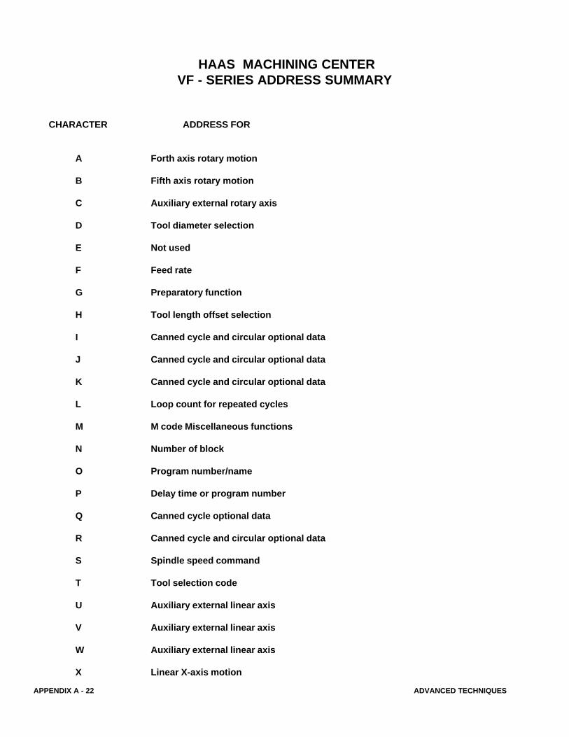
HAAS MACHINING CENTERVF - SERIES ADDRESS SUMMARY
CHARACTER ADDRESS FOR
A Forth axis rotary motion
B Fifth axis rotary motion
C Auxiliary external rotary axis
D Tool diameter selection
E Not used
F Feed rate
G Preparatory function
H Tool length offset selection
I Canned cycle and circular optional data
J Canned cycle and circular optional data
K Canned cycle and circular optional data
L Loop count for repeated cycles
M M code Miscellaneous functions
N Number of block
O Program number/name
P Delay time or program number
Q Canned cycle optional data
R Canned cycle and circular optional data
S Spindle speed command
T Tool selection code
U Auxiliary external linear axis
V Auxiliary external linear axis
W Auxiliary external linear axis
X Linear X-axis motion

ADVANCED TECHNIQUES APPENDIX A - 23
CHARACTER ADDRESS FOR
Y Linear Y-axis motion
Z Linear Z-axis motion
APPENDIX A - 24 ADVANCED TECHNIQUES
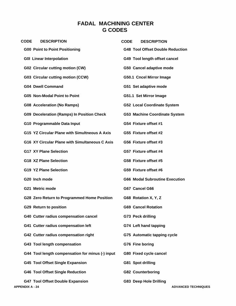
FADAL MACHINING CENTER G CODES
G00 Point to Point Positioning
G0l Linear Interpolation
G02 Circular cutting motion (CW)
G03 Circular cutting motion (CCW)
G04 Dwell Command
G05 Non-Modal Point to Point
G08 Acceleration (No Ramps)
G09 Deceleration (Ramps) In Position Check
G10 Programmable Data Input
G15 YZ Circular Plane with Simultneous A Axis
G16 XY Circular Plane with Simultaneous C Axis
G17 XY Plane Selection
G18 XZ Plane Selection
G19 YZ Plane Selection
G20 Inch mode
G21 Metric mode
G28 Zero Return to Programmed Home Position
G29 Return to position
G40 Cutter radius compensation cancel
G41 Cutter radius compensation left
G42 Cutter radius compensation right
G43 Tool length compensation
G44 Tool length compensation for minus (-) input
G45 Tool Offset Single Expansion
G46 Tool Offset Single Reduction
G47 Tool Offset Double Expansion
G48 Tool Offset Double Reduction
G49 Tool length offset cancel
G50 Cancel adaptive mode
G50.1 Cncel Mirror Image
G51 Set adaptive mode
G51.1 Set Mirror Image
G52 Local Coordinate System
G53 Machine Coordinate System
G54 Fixture offset #1
G55 Fixture offset #2
G56 Fixture offset #3
G57 Fixture offset #4
G58 Fixture offset #5
G59 Fixture offset #6
G66 Modal Subroutine Execution
G67 Cancel G66
G68 Rotation X, Y, Z
G69 Cancel Rotation
G73 Peck drilling
G74 Left hand tapping
G75 Automatic tapping cycle
G76 Fine boring
G80 Fixed cycle cancel
G81 Spot drilling
G82 Counterboring
G83 Deep Hole Drilling
CODE DESCRIPTION CODE DESCRIPTION
ADVANCED TECHNIQUES APPENDIX A - 25
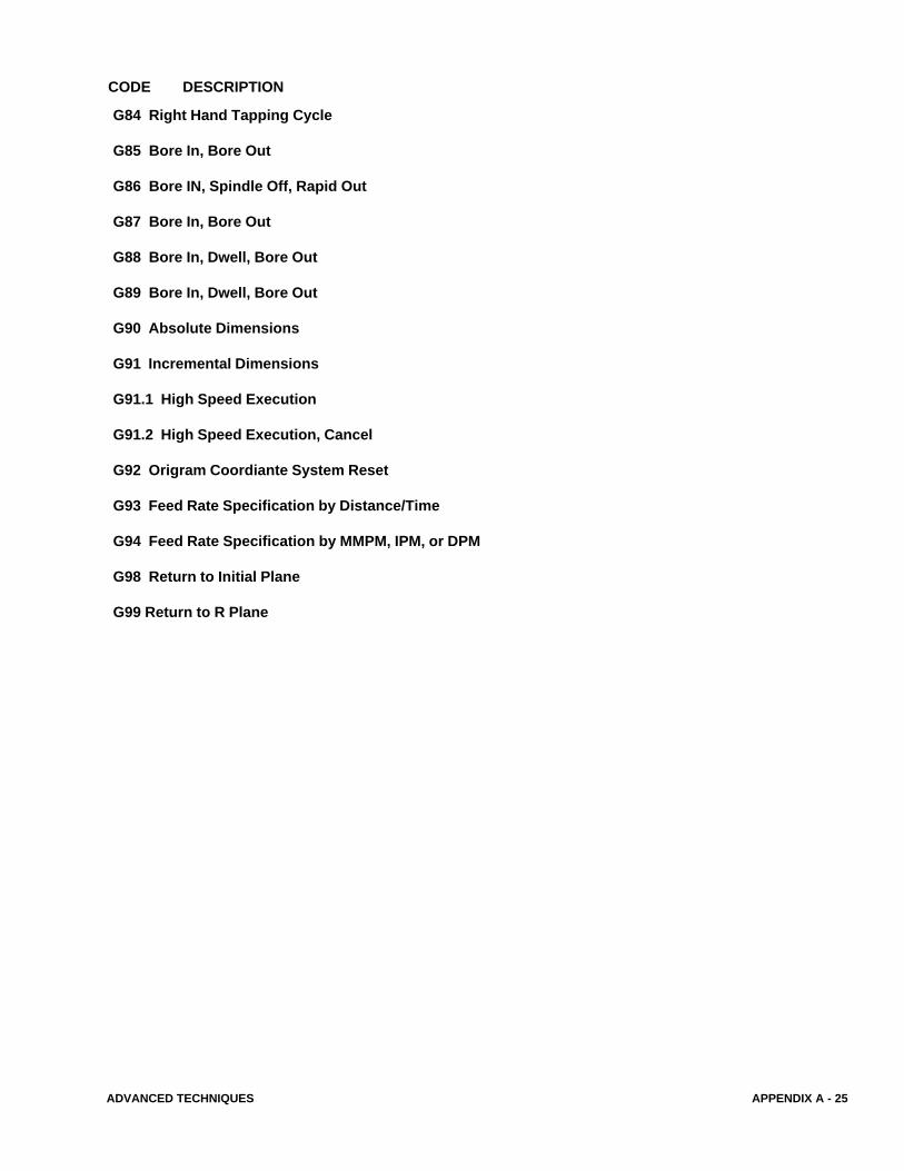
G84 Right Hand Tapping Cycle
G85 Bore In, Bore Out
G86 Bore IN, Spindle Off, Rapid Out
G87 Bore In, Bore Out
G88 Bore In, Dwell, Bore Out
G89 Bore In, Dwell, Bore Out
G90 Absolute Dimensions
G91 Incremental Dimensions
G91.1 High Speed Execution
G91.2 High Speed Execution, Cancel
G92 Origram Coordiante System Reset
G93 Feed Rate Specification by Distance/Time
G94 Feed Rate Specification by MMPM, IPM, or DPM
G98 Return to Initial Plane
G99 Return to R Plane
CODE DESCRIPTION
APPENDIX A - 26 ADVANCED TECHNIQUES
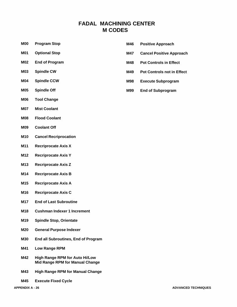
FADAL MACHINING CENTERM CODES
M00 Program Stop
M01 Optional Stop
M02 End of Program
M03 Spindle CW
M04 Spindle CCW
M05 Spindle Off
M06 Tool Change
M07 Mist Coolant
M08 Flood Coolant
M09 Coolant Off
M10 Cancel Recriprocation
M11 Recriprocate Axis X
M12 Recriprocate Axis Y
M13 Recriprocate Axis Z
M14 Recriprocate Axis B
M15 Recriprocate Axis A
M16 Recriprocate Axis C
M17 End of Last Subroutine
M18 Cushman Indexer 1 Increment
M19 Spindle Stop, Orientate
M20 General Purpose Indexer
M30 End all Subroutines, End of Program
M41 Low Range RPM
M42 High Range RPM for Auto Hi/LowMid Range RPM for Manual Change
M43 High Range RPM for Manual Change
M45 Execute Fixed Cycle
M46 Positive Approach
M47 Cancel Positive Approach
M48 Pot Controls in Effect
M49 Pot Controls not in Effect
M98 Execute Subprogram
M99 End of Subprogram

ADVANCED TECHNIQUES APPENDIX A - 27
FADAL MACHINING CENTERADDRESS SUMMARY
CHARACTER ADDRESS FOR
A Angular dimension (decimal degrees) for A Axis
B Angular dimension (decimal degrees) for B Axis
C Angular dimension (decimal degrees) for C Axis
D Tool offset number selector
E Fixture offset number selector
F Feed Function
G Preparatory Function
H Tool offset selector number
I X axis coordinate of arc centerThe initial peck size for drilling (G73, G83)
J Y axis coordinate of arc centerThe reducing value of the initial peck (G73, G83)
K Z axis coordinate of arc centerThe minimum peck size for drilling (G73, G83)
L Subroutine definition & callNumber of subprogram repetitions (M98)Work offset operation selector (G10Line repeat function
M Miscellaneous function
N Sequence number
O Program identification number
P Dwell time in milliseconds (G04)Percentage factor for retracting feed on tapping cyclesWork offset number selector (G10)Subprogram number selector (M98)Value for R0 - R9 (G10)
Q Step distance of the thread lead in fixed cycleThe diameter for automatic tool diameter override (H99)Scale factor for cam machining on the rotary head
APPENDIX A - 28 ADVANCED TECHNIQUES
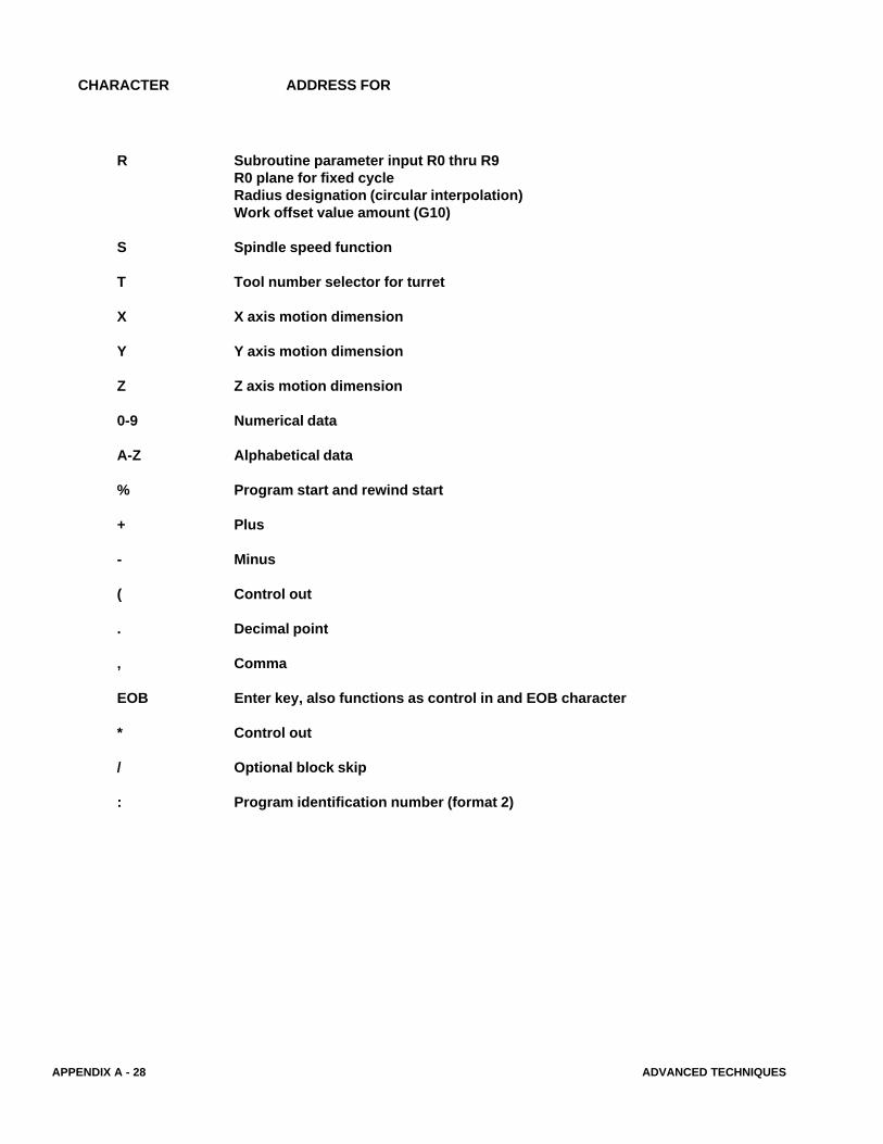
CHARACTER ADDRESS FOR
R Subroutine parameter input R0 thru R9R0 plane for fixed cycleRadius designation (circular interpolation)Work offset value amount (G10)
S Spindle speed function
T Tool number selector for turret
X X axis motion dimension
Y Y axis motion dimension
Z Z axis motion dimension
0-9 Numerical data
A-Z Alphabetical data
% Program start and rewind start
+ Plus
- Minus
( Control out
. Decimal point
, Comma
EOB Enter key, also functions as control in and EOB character
* Control out
/ Optional block skip
: Program identification number (format 2)
ADVANCED TECHNIQUES APPENDIX A - 29
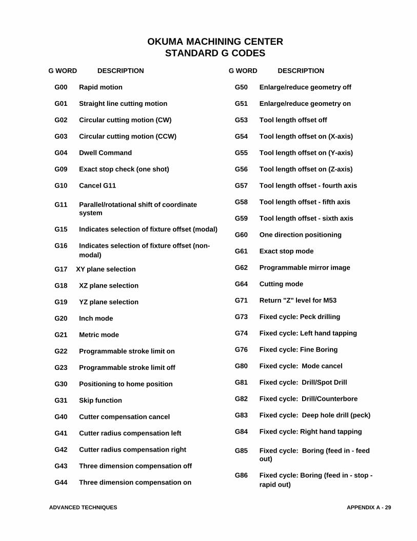
G WORD DESCRIPTION
G00 Rapid motion
G01 Straight line cutting motion
G02 Circular cutting motion (CW)
G03 Circular cutting motion (CCW)
G04 Dwell Command
G09 Exact stop check (one shot)
G10 Cancel G11
G11 Parallel/rotational shift of coordinatesystem
G15 Indicates selection of fixture offset (modal)
G16 Indicates selection of fixture offset (non-modal)
G17 XY plane selection
G18 XZ plane selection
G19 YZ plane selection
G20 Inch mode
G21 Metric mode
G22 Programmable stroke limit on
G23 Programmable stroke limit off
G30 Positioning to home position
G31 Skip function
G40 Cutter compensation cancel
G41 Cutter radius compensation left
G42 Cutter radius compensation right
G43 Three dimension compensation off
G44 Three dimension compensation on
OKUMA MACHINING CENTERSTANDARD G CODES
G WORD DESCRIPTION
G50 Enlarge/reduce geometry off
G51 Enlarge/reduce geometry on
G53 Tool length offset off
G54 Tool length offset on (X-axis)
G55 Tool length offset on (Y-axis)
G56 Tool length offset on (Z-axis)
G57 Tool length offset - fourth axis
G58 Tool length offset - fifth axis
G59 Tool length offset - sixth axis
G60 One direction positioning
G61 Exact stop mode
G62 Programmable mirror image
G64 Cutting mode
G71 Return "Z" level for M53
G73 Fixed cycle: Peck drilling
G74 Fixed cycle: Left hand tapping
G76 Fixed cycle: Fine Boring
G80 Fixed cycle: Mode cancel
G81 Fixed cycle: Drill/Spot Drill
G82 Fixed cycle: Drill/Counterbore
G83 Fixed cycle: Deep hole drill (peck)
G84 Fixed cycle: Right hand tapping
G85 Fixed cycle: Boring (feed in - feedout)
G86 Fixed cycle: Boring (feed in - stop -rapid out)
APPENDIX A - 30 ADVANCED TECHNIQUES
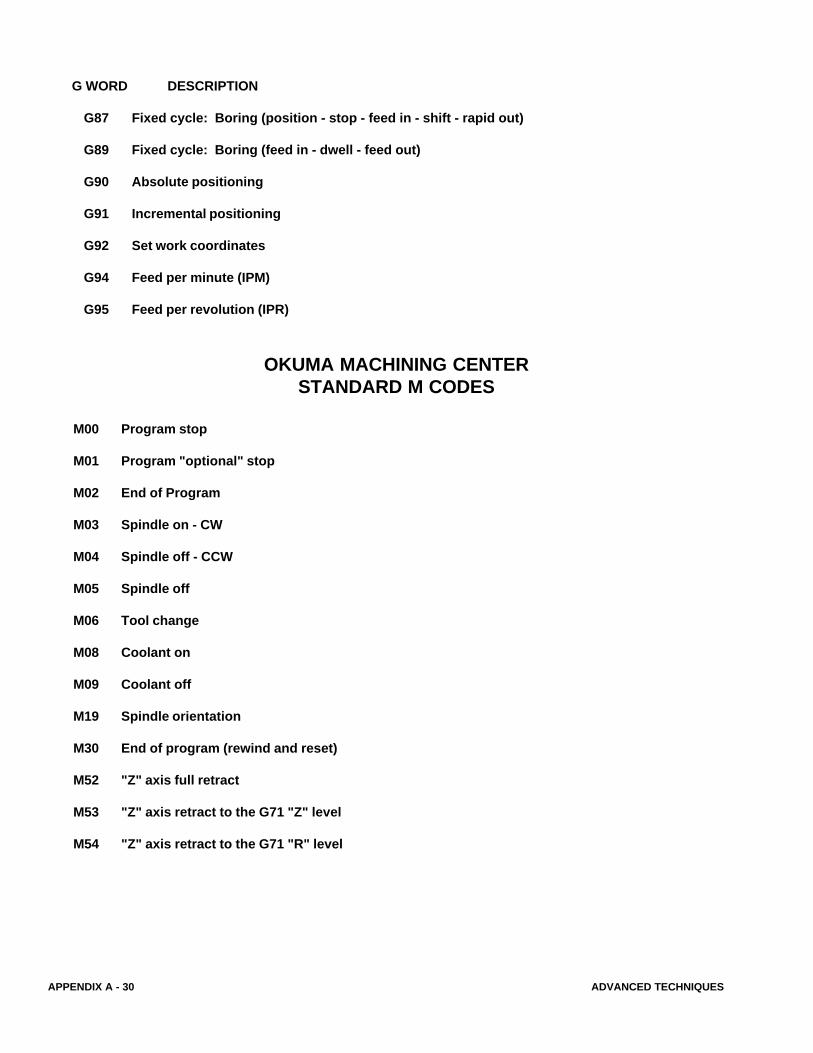
G WORD DESCRIPTION
G87 Fixed cycle: Boring (position - stop - feed in - shift - rapid out)
G89 Fixed cycle: Boring (feed in - dwell - feed out)
G90 Absolute positioning
G91 Incremental positioning
G92 Set work coordinates
G94 Feed per minute (IPM)
G95 Feed per revolution (IPR)
OKUMA MACHINING CENTERSTANDARD M CODES
M00 Program stop
M01 Program "optional" stop
M02 End of Program
M03 Spindle on - CW
M04 Spindle off - CCW
M05 Spindle off
M06 Tool change
M08 Coolant on
M09 Coolant off
M19 Spindle orientation
M30 End of program (rewind and reset)
M52 "Z" axis full retract
M53 "Z" axis retract to the G71 "Z" level
M54 "Z" axis retract to the G71 "R" level