contents mazda3 bodyshop general information 00 … bodyshop manual... · construction 80a panel...
TRANSCRIPT

Title Section
GENERAL INFORMATION 00
BODYSTRUCTURE
CONSTRUCTION 80A
PANEL REPLACEMENT 80B
WATER-PROOF AND RUST PREVENTIVE TREATMENT 80C
DIMENSIONS 80D
PLASTIC BODY PARTS 80E
CONTENTS2004-2009Mazda3BodyshopManual
FOREWORD
This bodyshop manual is intended for use by technicians of Authorized Mazda Dealers to help them service and repair Mazda vehicles. It can also be useful to owners and operators of Mazda vehicles in performing limited repair and maintenance on Mazda vehicles.
For proper repair and maintenance, a thorough familiarization with this manual is important, and it should always be kept in a handy place for quick and easy reference.
All the contents of this manual, including drawings and specifications, are the latest available at the time of printing.As modifications affecting repair or maintenance occur, relevant information supplementary to this volume will be made available at Mazda dealers. This manual should be kept up-to-date.
Mazda North American Operations reserves the right to alter the specifications and contents of this manual without obligation or advance notice.
All rights reserved. No part of this book may be reproduced or used in any form or by any means, electronic or mechanical including photocopying and recording and the use of any kind of information storage and retrieval system-without permission in writing.
Mazda Motor CorporationHIROSHIMA, JAPAN
APPLICATION:This manual is applicable to vehicles beginningwith the Vehicle Identification Numbers (VIN),shown on the following page.
© 2003 Mazda Motor CorporationPRINTED IN U.S.A., OCTOBER 2003Form No. 3386–1U–03JPart No. 9999–95–036F–04

VEHICLE IDENTIFICATION NUMBERS (VIN)
JM1 BK123✻4# 100001—JM1 BK223✻4# 100001—JM1 BK323✻4# 100001—JM1 BK12F✻4# 100001—JM1 BK22F✻4# 100001—JM1 BK32F✻4# 100001—JM1 BK143✻4# 100001—JM1 BK243✻4# 100001—JM1 BK343✻4# 100001—

00GENERAL INFORMATION
00–00–1
SECTION00–00
Toc of SCTGENERAL INFORMATION. . . . 00-00
Toc of SCT
00–00 GENERAL INFORMATIONHOW TO USE THIS MANUAL . . . . . . . . . 00–00–2
Efficient Replacement of Body Panels . . . . . . . . . . . . . . . . . . . . 00–00–2
Symbols of Panel Replacement . . . . . . 00–00–2Body Dimensions
(Flat-plane Dimensions) . . . . . . . . . . . 00–00–3Body Dimensions
(Straight-line Dimensions). . . . . . . . . . 00–00–4Symbols of Body Dimensions . . . . . . . . 00–00–4
SERVICE PRECAUTIONS . . . . . . . . . . . . 00–00–5Arrangement of Workshop . . . . . . . . . . 00–00–5Safety Precautions . . . . . . . . . . . . . . . . 00–00–5Vehicle Protection . . . . . . . . . . . . . . . . . 00–00–5Remove Dangerous Articles . . . . . . . . . 00–00–5Use of Pulling Equipment . . . . . . . . . . . 00–00–5Prevent Short Circuits . . . . . . . . . . . . . . 00–00–6
EFFICIENT REMOVAL OF BODY PANELS . . . . . . . . . . . . . . . . . . . 00–00–6
Body Measurements . . . . . . . . . . . . . . . 00–00–6Prevention of Body Deformation . . . . . . 00–00–6Selection of Cut-and-join Locations . . . 00–00–7Removal of Associated Parts . . . . . . . . 00–00–7
Rough Cutting of Damaged Panel . . . . 00–00–7INSTALLATION PREPARATIONS . . . . . 00–00–7
Rough Cutting of New Parts. . . . . . . . . 00–00–7Determination of Welding Method . . . . 00–00–7Making Holes for CO2 Arc Welding . . . 00–00–8Application of Weld-through Primer . . . 00–00–8
EFFICIENT INSTALLATION OF BODY PANELS . . . . . . . . . . . . . . . . . . . 00–00–8
Checking Preweld Measurements And Watching . . . . . . . . . . . . . . . . . . . 00–00–8
Welding Notes . . . . . . . . . . . . . . . . . . . 00–00–9Spot Welding Notes . . . . . . . . . . . . . . . 00–00–9Checking Weld Strength. . . . . . . . . . . . 00–00–10
ANTICORROSION, SOUND INSULATION, AND VIBRATION INSULATION . . . . . . . . . . . . . . . . . . . . . 00–00–11
Body Sealing . . . . . . . . . . . . . . . . . . . . 00–00–11Application of Undercoating . . . . . . . . . 00–00–11Application of Rust Inhibitor . . . . . . . . . 00–00–11Application of Floor Silencer. . . . . . . . . 00–00–12
ABBREVIATION . . . . . . . . . . . . . . . . . . . 00–00–12
End of Toc

GENERAL INFORMATION
00–00–2
HOW TO USE THIS MANUALC3U000000000B01
Efficient Replacement of Body Panels• This section contains information on the body panels in regard to the welding types, number of spot welds, and
cut-and-join locations that are necessary for panel removal and installation.• The type of weld and position are indicated by symbols.• Some sections have notes concerning the operation being performed. Thoroughly read and understand the
notes before carrying out any procedures.Example
Symbols of Panel Replacement• The following 6 symbols are used to indicate the type of weld that is used when replacing body panels.
REAR FENDER PANEL REMOVALShows operation section
Shows procedure, caution and note
BRAZE WELDING
CUT-AND-JOINT LOCATION
CUT-AND-JOINT LOCATION
ROUGH CUT LOCATION
ROUGH CUT LOCATION
Shows number of weld
Shows welding region
Shows a cross
Shows a insulator
Shows a dimensionsShows a cross location
Avoid cutting with a flame as the insulator (shaded) is flammable.
1.The rear fender panel and wheel house are joined with glue at the wheel arch line.
Drill the 24 weld locations indicated by (A), from the room side.
Caution
NOTE
BOTTOM SIDE 1
{9.84in}250mm
(A)24 19
17
A-A
A A
B-B
30mm
BB
{1.18in}
8
4
MZZ2010B001
SYMBOL MEANING
Spot welding
CO2 arc welding (plug welding)
CO2 spot welding
SYMBOL MEANING
Continuous MIG welding (Cut-and-join location)
Braze welding
Rough cut location
MZZ2010B002

GENERAL INFORMATION
00–00–3
00–00
Body Dimensions (Flat-plane Dimensions)• Flat-plane dimensions are the dimensions measured by projecting certain reference points onto a plane
surface.• When there are no specific indications, the standard points and dimensions are symmetrical in regard to the
center of the vehicle.• The hypothetical lines may differ according to the vehicle model.
Example
Shows vehicle section When there are no specific indications, all of units are in millimeters (mm).
Shows outline drawing
Shows dimension
The dimensions on the left and right in regard to the center of the vehicle are different.
Shows hypothetical standard line
Shows point symbol
Pointsymbol Designation
Hole diameteror bolt or nut size mm {in}
1,03
0 {4
0.55
}
1,16
2 {4
5.78
}
918
{38.
14}
690
{27.
17}
800
{31.
50}
1,08
9 {4
2.87
}
1,06
0 {4
1.73
}
495
{19
.48}
485
{19
.09}
619
{24
.38}
725
{28
.55}
1,21
1 {
47.6
8}
609
{24
.00}
527
{20
.75}
487
{19
.19}
587
{23
.11}
547
{21
.54}
624
{24
.56}
700
{27
.58}
716 {28.21}
1,240 {48.82}
320 {12.62}55
{2.19}
185 {7.28}
98
{3.86}
425
{16.73}
315
{12.40}
489
{19.27}
A
Crossmember No,1 standard hole
B
Front side frame standard hole
C
Front suspension mountingblock surface hole center
D
Front suspension mounting bolt
E
Front frame rear standard hole
F
Front frame rear standard hole
G
Rear side frame standard hole
H
Link bracket
I
Rear suspension housing
J
A
B
C
D
E
FG
H
I
J Rear side frame standard hole
Shows bolt sizeShows hole diameter
Shows slot
mm {in}
UNDERBODY FLAT-PLANE DIMENSIONS
φ 16 {0.62}
φ 16 {0.62}
φ 16 {0.62}
M14 {0.55}
φ 80 {3.14}
Pointsymbol Designation
Hole diameteror bolt or nut size mm {in}
φ 16 {0.62}
φ 12 {0.47}
φ 16 {0.62}φ 18 {0.62}
17 × 29.5{0.66×1.16}
1,22
0 {4
8.03
}
MZZ2010B003

GENERAL INFORMATION
00–00–4
Body Dimensions (Straight-line Dimensions)• Straight-line dimensions are the actual dimensions between two standard points.• When there are no specific indications, the standard points and dimensions are symmetrical in regard to the
center of the vehicle.Example
Symbols of Body Dimensions• The following 8 symbols are used to indicate the standard points.
End Of Sie
ROOM STRAIGHT-LINE DIMENSIONS (2)
Shows vehicle section Shows dimension location Shows outline drawing
C
D
A
G
Shows point symbol
Shows point indicationWithout apostrophe:RHWith apostrophe:LHShows details of the standard
point locationShows position and shape of the points
Shows dimension No indication are shown within theoutline drawing.
AFr
Fr
Fr FrFr
Fr
FrFr
Fr
Measuredlocation
Dimension mm {in}
1234567
1,184 {46.61}1,064 {41.89}
919 {36.18}690 {27.17}
1,185 {46.65}901 {35,47}607 {23.90}
Measuredlocation Dimension mm {in}
891011
B-B'C-C'D-D'
1,667 {65.63}1,672 {65.83}1,037 {40.83}1,290 {50.79}1,208 {47.56}
1,463 {57.60}1,642 {64.65}
B-B,
C-C,
D-D,
H-H,
G-G,
F-F,
E-E,
H,
E. E,
H
I
B
F,
I - I,
1 5
6
9
73
2
48
F
11
10
MZZ2010B004
SYMBOL MEANING SYMBOL MEANING
Center of circular hole
Center elliptical hole
Notch
Panel seam, bead, etc.
Bolt tip(arrow only)
Center of rectangular-shaped hole
Edge of rectangular-shaped hole
MZZ2010B016

GENERAL INFORMATION
00–00–5
00–00
SERVICE PRECAUTIONSC3U000000000B02
Arrangement of Workshop• Arrangement of the workshop is important for safe and efficient work.
Safety Precautions• Protective head covering and safety shoes should
always be worn. Depending upon the nature of the work, gloves, safety glasses, ear protectors, face shield, etc., should also be used.
Vehicle Protection• Use seat covers and floor covers.• Use heat-resistant protective covers to protect glass areas and seats from heat or sparks during welding.• Protect items such as moldings, garnishes, and
ornaments with tape when welding.
Remove Dangerous Articles• Remove the fuel tank before using an open flame
in that area. Plug connection piping to prevent fuel leakage.
Use of Pulling Equipment• When using pulling equipment, keep away from
the pulling area and use safety wires to prevent accidents.
Weldingglasses
Earprotectors
Weldlnggloves
Cottongloves
Dust mask Safety glasses
Face shield
Safety shoes
MZZ2036B001
MZZ2036B002
MZZ2036B003
Safety wires
MZZ2036B004

GENERAL INFORMATION
00–00–6
Prevent Short Circuits• Turn the ignition switch to the LOCK position.• Disconnect the battery cables.
• Securely connect the welding machine ground near the welding area.
End Of Sie
EFFICIENT REMOVAL OF BODY PANELSC3U000000000B03
Body Measurements• Before removal or rough-cutting, first measure the
body at and around the damaged area against the standard reference dimension specifications. If there is deformation, use frame repair equipment to make a rough correction.
Prevention of Body Deformation• Use a clamp or a jack for removal and reinforce at
and around the rough-cutting location to prevent deforming of the body.
Battery cable
MZZ2036B005
Ground
MZZ2036B006
MZJ2038B001
MZJ2038B002

GENERAL INFORMATION
00–00–7
00–00
Selection of Cut-and-join Locations• For parts where complete replacement is not
feasible, careful cutting and joining operations should be followed. If the location to be cut is a flat area where there is no reinforcement, the selected cutting location should be where the welding distortion will be minimal.
Removal of Associated Parts• Protect moldings, garnishes, and ornaments with tape when removing associated parts.
Rough Cutting of Damaged Panel• Verify that there are no parts (such as pipes, hoses, and wiring harness) nearby or on the opposite side of a
panel which could be damaged by heat.• For cut-and-join areas, allow for an overlap of
30—50 mm {1.18—1.97 in} and then rough-cut the damaged panel.
End Of Sie
INSTALLATION PREPARATIONSC3U000000000B04
Rough Cutting of New Parts• For cut-and-join areas, allow for an overlap of 30—50 mm {1.18—1.97 in} with the remaining area on the body
side and then rough-cut the new parts.
Determination of Welding Method• If the total thickness at the area to be welded is 3 mm {0.12 in} or more, use a CO2 gas shielded-arc welder to
make the plug welds.
MZJ2038B003
Wiring harness
Rough cut location Cut-and-join locationMZZ2038B001
Over lap Over lap
Body side rough cut locationNew part rough cut location
30-50mm{1.18-1.97in} 30-50mm{1.18-1.97in}
MZZ2038B002
3mm{0.12in}or more
MZZ2038B003

GENERAL INFORMATION
00–00–8
Making Holes for CO2 Arc Welding• For places that cannot be spot welded, make a hole for CO2 arc welding using a punch or drill as follows.
(mm {in})
• Grind the shaded section indicated in the diagram below and create a hole in the part where the 3—4 plates are put together. Also, weld the plates together tightly so that gaps do not develop.
Application of Weld-through Primer• For treatment against corrosion, remove the paint grease, and other material from the portion of new part and
body to be welded, and apply weld-through primer.End Of Sie
EFFICIENT INSTALLATION OF BODY PANELSC3U000000000B05
Checking Preweld Measurements And Watching• Align to the standard reference dimensions,
based upon the body dimensions illustration, so that new parts are installed in the correct position.
Panel thickness (ø) Hole diameter (ø)0.60—0.90 {0.02—0.03} 5 {0.19}0.91—1.20 {0.04—0.05} 6 {0.23}
1.21—1.80 {0.051—0.07} 8 {0.31}1.81—4.50 {0.071—0.17} 10 {0.39}
φ10mm{0.39in}
Outer panel
Middie panel
Inner panel
30° 30°
MZZ2038B004
MZJ2038B008
MZJ2038B009

GENERAL INFORMATION
00–00–9
00–00
Welding Notes• For the number of weld points, welding should be
performed in accordance with the following reference standards.
Spot Welding Notes• The shape of the spot welder tip is D=(2×t)+3. If
the upper panel thickness is different from that of the under panel, adjust to the thinner one.
• Because the weld strength is affected by the shape of the spot welder tip, the optimum condition of the tip should always be maintained.
• Spot welds should be made at points other than the originally welded points.
• Before spot welding, make a trial weld using the same material as the body panel to check the weld strength.
Spot welding Original weldPitch: 50mm{1.97in}
If 3mm{0.12in} or more
Repair weldPitch: within 35mm{1.38in}
Original number of welds x 1.3 or more
CO2 arc weldingOriginal spot weld
Repair weld
Original number of weldsor more
MZZ2038B005
D
70 - 120°
t
MZZ2038B009
MZJ2038B012
Test piece method
Nagget diameter:4/5 of tip
MZZ2038B006

GENERAL INFORMATION
00–00–10
Checking Weld Strength• Installation locations of the engine, chassis, and
seat belts are designated as important safety locations for weld strength. Check weld strength by driving a chisel between the panels at every fourth or fifth weld spot, and every tenth regular weld location.
• Drive the chisel between the panels according to the number of panels as shown below.
• To determine weld strength, drive the chisel between the panel and check whether the panels come apart. If the panels come apart, make another weld near the original weld.
• Restore the shape of the checked area.End Of Sie
Chisel dimensions
25mm{0.98in}
8mm{0.31in}
{0.20in}
{0.20in}
20°
Weld location
Within 5mm
Within 5mm
MZZ2038B007
Two panels Weld location
Three panelsWeld location
One location
Two location
Four panelsWeld location
Three location
MZZ2038B008

GENERAL INFORMATION
00–00–11
00–00
ANTICORROSION, SOUND INSULATION, AND VIBRATION INSULATIONC3U000000000B06
Body Sealing• Apply body sealer where necessary.• For locations where application of body sealer is difficult after installation, apply it before installation.
Application of Undercoating• Apply an undercoat to the required location of the body.
Application of Rust Inhibitor• Apply rust inhibitor (wax, oil, etc.) to the back of the welded areas.
YMU980PAR
YMU980PAS
YMU980PAT

GENERAL INFORMATION
00–00–12
Application of Floor Silencer• Apply floor silencer by heating with an infrared ray lamp.
End Of SieABBREVIATION
C3U000000000B07
End Of Sie
YMU980PAU
CM Control moduleCtr CenterDSC Dynamic stability controlFr FrontHU Hydraulic unitLH LeftM MetallicMC MicaRH RightRr Rear

09–80A–1
09BODY & ACCESSORIESSECTION
09–80A
Toc of SCTCONSTRUCTION . . . . . . . . . . . 09-80APANEL REPLACEMENT . . . . . 09-80BWATER-PROOF AND RUST
PREVENTIVE TREATMENT. .09-80C
DIMENSIONS . . . . . . . . . . . . . . 09-80DPLASTIC BODY PARTS . . . . . 09-80E
Toc of SCT
09–80A BODY STRUCTURE [CONSTRUCTION]BODY COMPONENTS CONSTRUCTION09–80A–2
4SD . . . . . . . . . . . . . . . . . . . . . . . . . . . . 09–80A–25HB . . . . . . . . . . . . . . . . . . . . . . . . . . . 09–80A–5
End of Toc

BODY STRUCTURE [CONSTRUCTION]
09–80A–2
BODY COMPONENTS CONSTRUCTIONC3U098007000B01
4SD
.
8
75
4
3
1
2
9
18
1716
14
15
13
12
10
35
11
36
26
24
25
23
22
20
21
19
27
39
38
3732
34
31
33
30
28
29
40
47
46
4544
50
43
42
5351
52
41
48
49
6
B3U0980B041

BODY STRUCTURE [CONSTRUCTION]
09–80A–3
09–80A
x:Applied-:Not applied
No. Part Name High- tension steel Rust proof steelThickness
(mm) {in}1 Hood - x 0.70 {0.028}2 Front bumper bracket x x 2.90 {0.114}3 Front side frame (inner) x x 1.60 {0.063}4 Front side frame (outer) x x 1.60 {0.063}5 Apron reinforcement (lower) - x 0.70 {0.028}6 Apron reinforcement (upper) - x 1.00 {0.039}7 Shroud side panel x x 1.00 {0.039}8 Suspension housing - x 2.60 {0.102}9 Front fender panel x x 0.65 {0.026}
10 Side member deck - x 1.80 {0.071}11 Front frame rear reinforcement x x 0.80 {0.031}12 Front frame (rear) x x 1.80 {0.071}13 Torque box - x 1.60 {0.063}14 Dash lower member x x 1.40 {0.055}15 Dash lower panel x 0.80 {0.031}16 Wiper bracket - x 1.40 {0.055}17 Dash upper panel - x 0.85 {0.033}18 Cowl panel - x 0.80 {0.031}19 Cowl side reinforcement - x 0.70 {0.028}20 Hinge pillar (inner) x x 1.60 {0.063}
21
Front pillar (inner)LH x - 1.40 {0.055}RH x - 1.60 {0.063}
Center pillar (inner)Upper
LH x - 1.60 {0.063}RH x - 1.80 {0.071}
Center x - 1.20 {0.047}Lower x - 1.00 {0.039}
22 Center pillar reinforcement (inner) x - 1.80 {0.071}23 Roof rail (inner, rear) x - 1.00 {0.039}
24Front pillar reinforcement
Upper x - 1.80 {0.071}Lower x - 1.80 {0.071}
Center pillar reinforcementUpper x - 1.40 {0.055}Lower x - 1.20 {0.047}
25 Side sill reinforcement x - 1.40 {0.055}26 Wheel house (inner) - x 0.70 {0.028}27 Rear pillar (inner) - x 0.65 {0.026}28 Rear fender lower panel - x 0.70 {0.028}29 Front header - - 0.65 {0.026}30 Roof reinforcement (front) - - 0.55 {0.021}31 Roof reinforcement center - - 1.00 {0.039}32 Roof reinforcement (rear) - - 1.00 {0.039}33 Rear header - - 0.70 {0.028}34 Roof panel - - 0.70 {0.028}35 Package tray - - 0.60 {0.024}36 Rear fender rain rail - x 0.70 {0.028}37 Corner plate - x 0.70 {0.028}38 Trunk lid panel x x 0.70 {0.028}39 Side panel (outer) - x 0.70 {0.028}40 Rear door - x 0.65 {0.026}41 Front door - x 0.70 {0.028}42 Side sill (inner) x x 1.40 {0.055}43 Front B frame x x 0.90 {0.035}

BODY STRUCTURE [CONSTRUCTION]
09–80A–4
44 Crossmember No.2 x - 1.20 {0.047}45 Front floor pan - x 0.70 {0.028}46 Crossmember No.3 x x 1.60 {0.063}47 Crossmember No.4 gusset - x 1.40 {0.055}
48 Rear side frameFront x x 2.00 {0.079}Center x x 2.60 {0.102}Rear x x 1.80 {0.071}
49 Crossmember No.3 (front) - x 1.60 {0.063}50 Suspension housing - x 0.75 {0.030}51 Rear floor pan - x 2.00 {0.079}52 Rear end member - - 0.60 {0.024}53 Rear end panel - x 0.60 {0.024}
No. Part Name High- tension steel Rust proof steelThickness
(mm) {in}

BODY STRUCTURE [CONSTRUCTION]
09–80A–5
09–80A
5HB
.
8
75
4
3
1
2
9
18
1716
14
15
13
12
10
29
1119
30
28
27
26
24
25
23
22
20
21
31
43
42
41
36 37
38 39
40
3534
32
33
44
51
50
49
48
54
47
46
55
45
5253
6
B3U0980B043

BODY STRUCTURE [CONSTRUCTION]
09–80A–6
x:Applied-:Not applied
No. Part Name High- tension steel Rust proof steelThickness
(mm) {in}1 Hood x x 0.70 {0.028}2 Front bumper bracket x x 2.90 {0.114}3 Front side frame (inner) x x 1.60 {0.063}4 Front side frame (outer) x x 1.60 {0.063}5 Apron reinforcement (lower) - x 0.70 {0.028}6 Apron reinforcement (upper) - x 1.00 {0.039}7 Shroud side panel x x 1.00 {0.039}8 Suspension housing - x 2.60 {0.102}9 Front fender panel x x 0.65 {0.026}
10 Side member deck - x 1.80 {0.071}11 Front frame rear reinforcement x x 0.80 {0.031}12 Front frame (rear) x x 1.80 {0.071}13 Torque box - x 1.60 {0.063}14 Dash lower member x x 1.40 {0.055}15 Dash lower panel x 0.80 {0.031}16 Wiper bracket - x 1.40 {0.055}17 Dash upper panel - x 0.85 {0.033}18 Cowl panel - x 0.80 {0.031}19 Cowl side reinforcement - x 0.70 {0.028}20 Hinge pillar (inner) x x 1.60 {0.063}
21
Front pillar (inner)LH x - 1.40 {0.055}RH x - 1.60 {0.063}
Center pillar (inner)Upper
LH x - 1.60 {0.063}RH x - 1.80 {0.071}
Center x - 1.20 {0.047}Lower x - 1.00 {0.039}
22 Center pillar reinforcement (inner) x - 1.80 {0.071}23 Roof rail (inner, rear) x - 1.00 {0.039}
24Front pillar reinforcement
Upper x - 1.80 {0.071}Lower x - 1.80 {0.071}
Center pillar reinforcementUpper x - 1.40 {0.055}Lower x - 1.20 {0.047}
25 Side sill reinforcement x - 1.40 {0.055}26 Wheel house (inner) - x 0.70 {0.028}27 Rear pillar (inner) - x 0.65 {0.026}28 Rear pillar (outer) - x 0.70 {0.028}29 Corner plate - x 0.70 {0.028}30 Rear side panel - - 0.70 {0.028}31 Rear pillar reinforcement - - 0.70 {0.028}32 Rear fender lower panel - x 0.70 {0.028}33 Front header - - 0.65 {0.026}34 Roof reinforcement (front) - - 0.55 {0.021}35 Roof reinforcement center (front) - - 1.00 {0.039}36 Roof reinforcement center (rear) - - 0.75 {0.030}37 Roof reinforcement (rear) - - 0.55 {0.021}38 Rear header - - 0.75 {0.030}39 Roof panel - - 0.75 {0.030}40 Liftgate panel - x 0.70 {0.028}41 Side panel (outer) - x 0.70 {0.028}42 Rear door - x 0.65 {0.026}43 Front door x x 0.70 {0.028}

BODY STRUCTURE [CONSTRUCTION]
09–80A–7
09–80A
End Of Sie
44 Side sill (inner) x x 1.40 {0.055}45 Front B frame x x 0.90 {0.035}46 Crossmember No.2 x - 1.20 {0.047}47 Front floor pan - x 0.70 {0.028}48 Crossmember No.3 x x 1.60 {0.063}49 Crossmember No.4 gusset - x 1.40 {0.055}
50 Rear side frameFront x x 2.00 {0.079}Center x x 2.60 {0.102}Rear x x 1.80 {0.071}
51 Crossmember No.3 (front) - x 1.60 {0.063}52 Rear floor pan - x 0.75 {0.030}53 Suspension housing - x 2.00 {0.079}54 Rear end member - - 1.20 {0.047}55 Rear end panel - x 0.60 {0.024}
No. Part Name High- tension steel Rust proof steelThickness
(mm) {in}

BODY STRUCTURE [PANEL REPLACEMENT]
09–80B–1
09–80B
09–80B BODY STRUCTURE [PANEL REPLACEMENT]FRONT BUMPER BRACKET
REMOVAL . . . . . . . . . . . . . . . . . . . . . . . 09–80B–2FRONT BUMPER BRACKET
INSTALLATION. . . . . . . . . . . . . . . . . . . 09–80B–3SHROUD SIDE PANEL REMOVAL . . . . 09–80B–4SHROUD SIDE PANEL
INSTALLATION. . . . . . . . . . . . . . . . . . . 09–80B–5COWL SIDE REINFORCEMENT
REMOVAL . . . . . . . . . . . . . . . . . . . . . . . 09–80B–6COWL SIDE REINFORCEMENT
INSTALLATION. . . . . . . . . . . . . . . . . . . 09–80B–7APRON REINFORCEMENT (LOWER)
REMOVAL . . . . . . . . . . . . . . . . . . . . . . . 09–80B–8APRON REINFORCEMENT (LOWER)
INSTALLATION. . . . . . . . . . . . . . . . . . . 09–80B–9APRON REINFORCEMENT (PARTIAL
CUTTING) REMOVAL. . . . . . . . . . . . . . 09–80B–10APRON REINFORCEMENT (PARTIAL
CUTTING) INSTALLATION. . . . . . . . . . 09–80B–12WHEEL APRON PANEL (FRONT)
REMOVAL . . . . . . . . . . . . . . . . . . . . . . . 09–80B–14WHEEL APRON PANEL (FRONT)
INSTALLATION. . . . . . . . . . . . . . . . . . . 09–80B–15FRONT SIDE FRAME COMPONENT
REMOVAL . . . . . . . . . . . . . . . . . . . . . . . 09–80B–15FRONT SIDE FRAME COMPONENT
INSTALLATION. . . . . . . . . . . . . . . . . . . 09–80B–19FRONT SIDE FRAME (PARTIAL
CUTTING) REMOVAL. . . . . . . . . . . . . . 09–80B–22FRONT SIDE FRAME (PARTIAL
CUTTING) INSTALLATION. . . . . . . . . . 09–80B–22TORQUE BOX REMOVAL . . . . . . . . . . . 09–80B–25TORQUE BOX INSTALLATION . . . . . . . 09–80B–26FRONT FRAME (REAR) REMOVAL . . . 09–80B–27FRONT FRAME (REAR)
INSTALLATION. . . . . . . . . . . . . . . . . . . 09–80B–28FRONT PILLAR REMOVAL . . . . . . . . . . 09–80B–28FRONT PILLAR INSTALLATION . . . . . . 09–80B–32CENTER PILLAR REMOVAL . . . . . . . . . 09–80B–35CENTER PILLAR INSTALLATION. . . . . 09–80B–37REAR FENDER PANEL REMOVAL. . . . 09–80B–40
4SD . . . . . . . . . . . . . . . . . . . . . . . . . . . 09–80B–40
5HB . . . . . . . . . . . . . . . . . . . . . . . . . . . . 09–80B–41REAR FENDER PANEL
INSTALLATION . . . . . . . . . . . . . . . . . . . 09–80B–424SD . . . . . . . . . . . . . . . . . . . . . . . . . . . . 09–80B–425HB . . . . . . . . . . . . . . . . . . . . . . . . . . . . 09–80B–43
REAR FENDER LOWER PANEL REMOVAL . . . . . . . . . . . . . . . . . . . . . . . 09–80B–44
4SD . . . . . . . . . . . . . . . . . . . . . . . . . . . . 09–80B–445HB . . . . . . . . . . . . . . . . . . . . . . . . . . . . 09–80B–45
REAR FENDER LOWER PANEL INSTALLATION . . . . . . . . . . . . . . . . . . . 09–80B–46
4SD . . . . . . . . . . . . . . . . . . . . . . . . . . . . 09–80B–465HB . . . . . . . . . . . . . . . . . . . . . . . . . . . . 09–80B–47
SIDE SILL PANEL REMOVAL. . . . . . . . . 09–80B–48SIDE SILL PANEL INSTALLATION. . . . . 09–80B–49REAR END PANEL REMOVAL . . . . . . . . 09–80B–50
4SD . . . . . . . . . . . . . . . . . . . . . . . . . . . . 09–80B–505HB . . . . . . . . . . . . . . . . . . . . . . . . . . . . 09–80B–51
REAR END PANEL INSTALLATION. . . . 09–80B–524SD . . . . . . . . . . . . . . . . . . . . . . . . . . . . 09–80B–525HB . . . . . . . . . . . . . . . . . . . . . . . . . . . . 09–80B–53
REAR FENDER RAIN RAIL AND CORNER PLATE REMOVAL. . . . . . . . . 09–80B–54
4SD . . . . . . . . . . . . . . . . . . . . . . . . . . . . 09–80B–545HB . . . . . . . . . . . . . . . . . . . . . . . . . . . . 09–80B–55
REAR FENDER RAIN RAIL AND CORNER PLATE INSTALLATION . . . . 09–80B–56
4SD . . . . . . . . . . . . . . . . . . . . . . . . . . . . 09–80B–565HB . . . . . . . . . . . . . . . . . . . . . . . . . . . . 09–80B–57
REAR FLOOR PAN REMOVAL. . . . . . . . 09–80B–58REAR FLOOR PAN INSTALLATION. . . . 09–80B–60REAR SIDE FRAME (PARTIAL CUTTING)
REMOVAL . . . . . . . . . . . . . . . . . . . . . . . 09–80B–62REAR SIDE FRAME (PARTIAL CUTTING)
INSTALLATION . . . . . . . . . . . . . . . . . . . 09–80B–63ROOF PANEL REMOVAL . . . . . . . . . . . . 09–80B–64
4SD . . . . . . . . . . . . . . . . . . . . . . . . . . . . 09–80B–645HB . . . . . . . . . . . . . . . . . . . . . . . . . . . . 09–80B–65
ROOF PANEL INSTALLATION . . . . . . . . 09–80B–664SD . . . . . . . . . . . . . . . . . . . . . . . . . . . . 09–80B–665HB . . . . . . . . . . . . . . . . . . . . . . . . . . . . 09–80B–67
End of Toc

BODY STRUCTURE [PANEL REPLACEMENT]
09–80B–2
FRONT BUMPER BRACKET REMOVALC3U098053896B01
1. Remove the front bumper bracket.
Caution•••• Only the procedure for the left side is described. The shape for the right side is different.
End Of Sie
FRONT BUMPER BRACKET
B3E0980B047

BODY STRUCTURE [PANEL REPLACEMENT]
09–80B–3
09–80B
FRONT BUMPER BRACKET INSTALLATIONC3U098053896B02
1. When installing new parts, measure and adjust the body as necessary to conform with standard dimensions.2. After temporarily installing new parts, make sure the related parts fit properly.
End Of Sie
FRONT BUMPER BRACKET
B3E0980B048

BODY STRUCTURE [PANEL REPLACEMENT]
09–80B–4
SHROUD SIDE PANEL REMOVALC3U098053140B01
1. Remove the shroud side panel.
End Of Sie
2
1
1
3
3
3
2
1
4
1
SHROUD SIDE PANEL LH
SHROUD SIDE PANEL RH
B3E0980B049

BODY STRUCTURE [PANEL REPLACEMENT]
09–80B–5
09–80B
SHROUD SIDE PANEL INSTALLATIONC3U098053140B02
1. When installing new parts, measure and adjust the body as necessary to conform with standard dimensions.2. Drill holes for plug welds before installing new parts.3. After temporarily installing new parts, make sure the related parts fit properly.
End Of Sie
2
1
1
3
2
1
3
2
1
4
1
SHROUD SIDE PANEL LH
SHROUD SIDE PANEL RH
B3E0980B050

BODY STRUCTURE [PANEL REPLACEMENT]
09–80B–6
COWL SIDE REINFORCEMENT REMOVALC3U098053290B01
1. Remove the cowl side reinforcement.
Caution•••• Be careful not to damage the windshield when drilling the 2 locations indicated by (A).
End Of Sie
1
4
(A)2
7
2
2
8
COWL SIDE REINFORCEMENT
B3E0980B051

BODY STRUCTURE [PANEL REPLACEMENT]
09–80B–7
09–80B
COWL SIDE REINFORCEMENT INSTALLATIONC3U098053290B02
1. When installing new parts, measure and adjust the body as necessary to conform with standard dimensions.2. Drill holes for plug welds before installing new parts.3. After temporarily installing new parts, make sure the related parts fit properly.
End Of Sie
1
4
2
7
2
2
8
COWL SIDE REINFORCEMENT
B3E0980B052

BODY STRUCTURE [PANEL REPLACEMENT]
09–80B–8
APRON REINFORCEMENT (LOWER) REMOVALC3U098053260B01
1. Remove the apron reinforcement (lower).
End Of Sie
12
10
3
APRON REINFORCEMENT (LOWER)
B3E0980B053

BODY STRUCTURE [PANEL REPLACEMENT]
09–80B–9
09–80B
APRON REINFORCEMENT (LOWER) INSTALLATIONC3U098053260B02
1. When installing new parts, measure and adjust the body as necessary to conform with standard dimensions.2. Drill holes for plug welds before installing new parts.3. After temporarily installing new parts, make sure the related parts fit properly.
End Of Sie
12
10
3
APRON REINFORCEMENT (LOWER)
B3E0980B054

BODY STRUCTURE [PANEL REPLACEMENT]
09–80B–10
APRON REINFORCEMENT (PARTIAL CUTTING) REMOVALC3U098053260B03
1. Rough cut at the locations shown in the figure to remove damaged parts.2. Remove the apron reinforcement.
CUT-AND-JOIN LOCATION APRON REINFORCEMENT (LOWER)
APRON REINFORCEMENT (UPPER)
CUT-AND-JOIN LOCATION FOR APRON REINFORCEMENT (UPPER)
APRON REINFORCEMENT (LOWER)
ROUGH CUT LOCATION FOR APRON REINFORCEMENT 50mm {1.97 in}
200mm {7.87 in}
120mm {4.72 in}
B3E0980B055

BODY STRUCTURE [PANEL REPLACEMENT]
09–80B–11
09–80B
End Of Sie
5
3
APRON REINFORCEMENT
B3E0980B056

BODY STRUCTURE [PANEL REPLACEMENT]
09–80B–12
APRON REINFORCEMENT (PARTIAL CUTTING) INSTALLATIONC3U098053260B04
1. When installing new parts, measure and adjust the body as necessary to conform with standard dimensions.2. Drill holes for plug welds before installing new parts.3. After temporarily installing new parts, make sure the related parts fit properly.
APRON REINFORCEMENT (UPPER)
CUT-AND-JOIN LOCATION FOR APRON REINFORCEMENT (UPPER)
CUT-AND-JOIN LOCATION FOR APRON REINFORCEMENT (LOWER)
APRON REINFORCEMENT (LOWER)
120mm {4.72 in}
50mm {1.97 in}
3
B3E0980B057

BODY STRUCTURE [PANEL REPLACEMENT]
09–80B–13
09–80B
End Of Sie
7
5
APRON REINFORCEMENT
B3E0980B058

BODY STRUCTURE [PANEL REPLACEMENT]
09–80B–14
WHEEL APRON PANEL (FRONT) REMOVALC3U098053210B01
1. Remove the wheel apron panel (front).
End Of Sie
6
4
4
DRIVER,S SIDE: 4
WHEEL APRON PANEL (FRONT)
ENGINE MOUNT REINFORCEMENT
B3E0980B059

BODY STRUCTURE [PANEL REPLACEMENT]
09–80B–15
09–80B
WHEEL APRON PANEL (FRONT) INSTALLATIONC3U098053210B02
1. When installing new parts, measure and adjust the body as necessary to conform with standard dimensions.2. Drill holes for plug welds before installing new parts.3. After temporarily installing new parts, make sure the related parts fit properly.
End Of Sie
6
4
4
DRIVER,S SIDE: 4
WHEEL APRON PANEL (FRONT)
ENGINE MOUNT REINFORCEMENT
B3E0980B060

BODY STRUCTURE [PANEL REPLACEMENT]
09–80B–16
FRONT SIDE FRAME COMPONENT REMOVALC3U098053300B01
1. Drill the 26 locations indicated by (A).
(A)4
(A)4
(A)4
(A)5
(A)9
SIDE MEMBER DECKFRONT SIDE FRAME
B3E0980B061

BODY STRUCTURE [PANEL REPLACEMENT]
09–80B–17
09–80B
2. Drill the 65 locations indicated by (B), 4 locations on the driver’s side indicated by (C), and 3 locations on the passenger’s side.
3. Drill the 5 locations indicated by (D) from the bottom.4. Drill the 1 location indicated by (E) from the bottom, as it cannot be seen from the interior.
(B)3
(C)
(B)5
(B)3
(B)7
(B)6
(D)2
(D)3
(B)6
(B)10
(B)11
(B)14
(E)1
DRIVER,S SIDE: 4
PASSENGER,S SIDE: 3
B3E0980B062

BODY STRUCTURE [PANEL REPLACEMENT]
09–80B–18
5. Drill the 9 locations indicated by (F), 6 locations on the driver’s side indicated by (G), 5 locations on the passenger’s side.
6. When the front side frame component is being removed, the hinge pillar (inner) may interfere with the apron reinforcement (upper) and make removal difficult, drill the 2 locations indicated by (H), 3 locations indicated by (I), and then open the front pillar (outer) outward.
7. Drill the 3 locations indicated by (J), and remove the front side frame component.
End Of Sie
(I)2
(J)3
(H)2
(I)1
(F)6
(F)3
(G) DRIVER,S SIDE: 6
PASSENGER,S SIDE: 5
SUSPENSION HOUSING (UPPER)
FRONT PILLAR (OUTER)
COWL PANEL
APRON REINFORCEMENT (UPPER)
B3E0980B063

BODY STRUCTURE [PANEL REPLACEMENT]
09–80B–19
09–80B
FRONT SIDE FRAME COMPONENT INSTALLATIONC3U098053300B02
1. When installing new parts, measure and adjust the body as necessary to conform with standard dimensions.2. Drill holes for plug welds before installing new parts.3. Weld the 3 locations indicated by (A) and temporarily install the front side frame component.4. After temporarily installing new parts, make sure the related parts fit properly.5. Weld the remaining weld locations and install the front side frame component.
2
(A)3
2
1
6
DRIVER,S SIDE: 6
PASSENGER,S SIDE: 5
SUSPENSION HOUSING (UPPER)
FRONT PILLAR (OUTER)
COWL PANEL
APRON REINFORCEMENT (UPPER)
3
B3E0980B064

BODY STRUCTURE [PANEL REPLACEMENT]
09–80B–20
3
6
3
5
7
2
3
6
10
11
14
1
DRIVER,S SIDE: 4
PASSENGER,S SIDE: 3
B3E0980B065

BODY STRUCTURE [PANEL REPLACEMENT]
09–80B–21
09–80B
End Of Sie
4
4
4
5
9
FRONT SIDE FRAMESIDE MEMBER DECK
B3E0980B066

BODY STRUCTURE [PANEL REPLACEMENT]
09–80B–22
FRONT SIDE FRAME (PARTIAL CUTTING) REMOVALC3U098053300B03
1. Rough cut and remove the damaged part of the front side frame.
End Of SieFRONT SIDE FRAME (PARTIAL CUTTING) INSTALLATION
C3U098053300B04
Caution•••• The cut-and-joint area indicates the maximum size range of the installation position.
1. Make a reinforcement panel using the material of the front side frame.2. To cut-and-join the new and existing parts, cut at the locations for the new part indicated in the figure below and
bevel the locations where the new and existing parts are joined.3. When installing the new parts, trial-fit new and existing parts, and then measure and adjust the body to conform
with standard dimensions.
40mm {1.57 in}
40mm {1.57 in}
130mm {5.12 in}
310mm {12.20 in}
CUT-AND-JOIN LOCATION FOR APRON OUTERROUGH CUT LOCATION
FOR OUTER
ROUGH CUT LOCATION FOR INNER
CUT-AND-JOIN LOCATION FOR INNER
FRONT SIDE FRAME
5
6
B3E0980B067

BODY STRUCTURE [PANEL REPLACEMENT]
09–80B–23
09–80B
4. To install the inner, trial-fit the new and existing parts, weld the existing parts and the reinforcement, and then butt weld the new and existing parts.
5. Because the outer cannot be welded to the existing parts from the inside of the frame, drill 2 plug weld holes at the locations indicated by (A) on the existing parts. Install the reinforcement and the existing parts by plug welding from the outside of the frame, then butt weld the new and existing parts.
6. Grind the area where the inner and outer are butt welded with a disk grinder to finish the surface.
L=10mm {0.39 in} x 6
OUTER : t=1.6mm {0.06 in}INNER : t=1.6mm {0.06 in}
L=10mm {0.39 in} x 2
310mm {12.20 in}
30mm {1.18 in}
65m
m {
2.56
in}
NEW FRONT SIDE FRAME (INNER)
REINFORCEMENT
REINFORCEMENT
CUT-AND-JOIN LOCATION FOR INNER
FRONT SIDE FRAME (INNER)
B3E0980B068

BODY STRUCTURE [PANEL REPLACEMENT]
09–80B–24
End Of Sie
(A)2
5
6
L=10mm {0.39 in} x 2
130mm {5.12 in}
NEW FRONT SIDE FRAME (OUTER)
REINFORCEMENT
CUT-AND-JOIN LOCATION FOR OUTER
FRONT SIDE FRAME (OUTER)
B3E0980B069

BODY STRUCTURE [PANEL REPLACEMENT]
09–80B–25
09–80B
TORQUE BOX REMOVALC3U098053381B01
1. Remove the torque box.
End Of Sie
6
4
7
2
3
3
TORQUE BOX
B3E0980B070

BODY STRUCTURE [PANEL REPLACEMENT]
09–80B–26
TORQUE BOX INSTALLATIONC3U098053381B02
1. When installing new parts, measure and adjust the body as necessary to conform with standard dimensions.2. Drill holes for plug welds before installing new parts.3. After temporarily installing new parts, make sure the related parts fit properly.
End Of Sie
6
4
7
2
3
3
TORQUE BOX
B3E0980B071

BODY STRUCTURE [PANEL REPLACEMENT]
09–80B–27
09–80B
FRONT FRAME (REAR) REMOVALC3U098053390B01
1. Remove the front frame (rear).
End Of Sie
18
6
110
2
1
FRONT FRAME (REAR)
B3E0980B072

BODY STRUCTURE [PANEL REPLACEMENT]
09–80B–28
FRONT FRAME (REAR) INSTALLATIONC3U098053390B02
1. When installing new parts, measure and adjust the body as necessary to conform with standard dimensions.2. Drill holes for plug welds before installing new parts.3. After temporarily installing new parts, make sure the related parts fit properly.
End Of SieFRONT PILLAR REMOVAL
C3U098074090B011. Rough cut area (A) and drill the 69 locations indicated by (B).
Caution•••• Avoid cutting with a blowtorch or similar tools as the insulator (shaded area) is flammable.
2. When the front pillar (outer) is being removed, the cowl panel may interfere with the front pillar (outer) and make removal difficult. Therefore, drill the 2 locations indicated by (C) and then open the cowl panel outward.
3. Remove the front pillar (outer).
18
6
110
2
1
FRONT FRAME (REAR)
B3E0980B073

BODY STRUCTURE [PANEL REPLACEMENT]
09–80B–29
09–80B
B
B
(B)23
(B)1
(B)2
(B)2
(B)4
(B)3(B)3
(B)8
(B)11
(B)11
(C)2
(B)1
A
A
A-A B-B
CUT-AND-JOIN LOCATION FOR OUTER
CUT-AND-JOIN LOCATION FOR OUTER
FRONT PILLAR (OUTER)
INSULATOR
(A) ROUGH CUT LOCATION FOR OUTER
(A) ROUGH CUT LOCATION FOR OUTER
COWL PANEL
60mm {2.36 in}
40mm {1.57 in}
50mm {1.97 in}
550mm {21.65 in}
B3E0980B074

BODY STRUCTURE [PANEL REPLACEMENT]
09–80B–30
4. Rough cut area (D) and drill the 10 locations indicated by (E).5. Drill the 6 locations indicated by (F) from the interior.6. Remove the front pillar reinforcement.7. Rough cut area (G) and remove the side sill reinforcement.
(E)1
(E)1
(E)1
(E)2
(E)5
(F)3
(F)3
CUT-AND-JOIN LOCATION FOR REINFORCEMENT
CUT-AND-JOIN LOCATION FOR SIDE SILL REINFORCEMENT
SIDE SILL REINFORCEMENT (UPPER)
SIDE SILL REINFORCEMENT SIDE SILL GUSSET
(D) ROUGH CUT LOCATION FOR REINFORCEMENT
FRONT PILLAR REINFORCEMENT
(G) ROUGH CUT LOCATION FOR SIDE SILL REINFORCEMENT
60mm {2.36 in}
140mm {5.51 in}
50mm {1.97 in}
50mm {1.97 in}
B3E0980B075

BODY STRUCTURE [PANEL REPLACEMENT]
09–80B–31
09–80B
8. Rough cut area (H), drill the 9 locations indicated by (I), and then remove the front pillar (inner).
End Of Sie
(I)7
(I)2
CUT-AND-JOIN LOCATION FOR INNER
(H)ROUGH CUT LOCATION FOR INNER
FRONT PILLAR (INNER)
110mm {4.33 in}
65mm {2.56 in}
B3E0980B076

BODY STRUCTURE [PANEL REPLACEMENT]
09–80B–32
FRONT PILLAR INSTALLATIONC3U098074090B02
1. When joining and cutting the new and existing parts, trial fit the new part in position, and then measure and adjust the body as necessary to conform with standard dimensions.
2. Drill holes for plug welds before installing new parts.
Note• In areas where the outer, reinforcement, inner, and other parts are in 3-4 layers, drill holes for plug welds
in all but the innermost panel.
3. After temporarily installing new parts, make sure the related parts fit properly.
7
2
CUT-AND-JOIN LOCATION FOR INNER
FRONT PILLAR (INNER)
110mm {4.33 in}
B3E0980B077

BODY STRUCTURE [PANEL REPLACEMENT]
09–80B–33
09–80B
1
1
1
2
5
3
3
CUT-AND-JOIN LOCATION FOR SIDE SILL REINFORCEMENT
CUT-AND-JOIN LOCATION FOR REINFORCEMENT
SIDE SILL REINFORCEMENT (UPPER)
SIDE SILL REINFORCEMENT
SIDE SILL GUSSET
FRONT PILLAR REINFORCEMENT
140mm {5.51 in}
60mm {2.36 in}
B3E0980B078

BODY STRUCTURE [PANEL REPLACEMENT]
09–80B–34
End Of Sie
23
1
2
2
4
3 3
8
11
11
2
1
CUT-AND-JOIN LOCATION FOR OUTER
CUT-AND-JOIN LOCATION FOR OUTER
FRONT PILLAR (OUTER)
COWL PANEL
610mm {24.01 in}
50mm {1.97 in}
B3E0980B079

BODY STRUCTURE [PANEL REPLACEMENT]
09–80B–35
09–80B
CENTER PILLAR REMOVALC3U098070350B01
1. Rough cut area (A), drill the 59 locations indicated by (B), and then remove the center pillar (outer).
Caution•••• Avoid cutting with a blowtorch or similar tools as the insulator (shaded area) is flammable.
2. Rough cut area (C), drill the 18 locations indicated by (D), and then remove the center pillar reinforcement.3. Rough cut area (E), drill the 4 locations indicated by (F), and then remove the side sill reinforcement.4. Drill the 19 locations indicated by (G) and remove the center pillar (inner).
(B)20
A-A
B-B
C-C
(B)18
(B)2
(B)2
(B)17
B
B
A
C
C
A
CUT-AND-JOIN LOCATION FOR OUTER
CUT-AND-JOIN LOCATION FOR OUTER
CUT-AND-JOIN LOCATION FOR OUTER
CUT-AND-JOIN LOCATION FOR OUTER
(A) ROUGH CUT LOCATION FOR OUTER
(A) ROUGH CUT LOCATION FOR OUTER
(A) ROUGH CUT LOCATION FOR OUTER
(A) ROUGH CUT LOCATION FOR OUTER
5HB
INSULATOR
INSULATOR
CENTER PILLAR (OUTER)
80mm {3.15 in}30mm {1.18 in}
80mm {3.15 in}
45mm {1.77 in}45mm
{1.77 in}
95mm {3.74 in}
30mm {1.18 in}
30mm {1.18 in}
B3E0980B080

BODY STRUCTURE [PANEL REPLACEMENT]
09–80B–36
End Of Sie
(D)1(D)1
(D)2 (D)1
(D)10
(D)1
(D)2
(F)4
(G)11
(G)8
CUT-AND-JOIN LOCATION FOR REINFORCEMENT
CUT-AND-JOIN LOCATION FOR SIDE SILL REINFORCEMENT
CUT-AND-JOIN LOCATION FOR SIDE SILL REINFORCEMENT
(C) ROUGH CUT LOCATION FOR REINFORCEMENT
(E) ROUGH CUT LOCATION FOR SIDE SILL REINFORCEMENT
SIDE SILL REINFORCEMENT
(E) ROUGH CUT LOCATION FOR SIDE SILL REINFORCEMENT
CENTER PILLAR REINFORCEMENT
CENTER PILLAR (INNER)
15mm {0.59 in}30mm {1.18 in}
80mm {3.15 in}
40mm {1.57 in}
40mm {1.57 in}
25mm {0.98 in}
B3E0980B081

BODY STRUCTURE [PANEL REPLACEMENT]
09–80B–37
09–80B
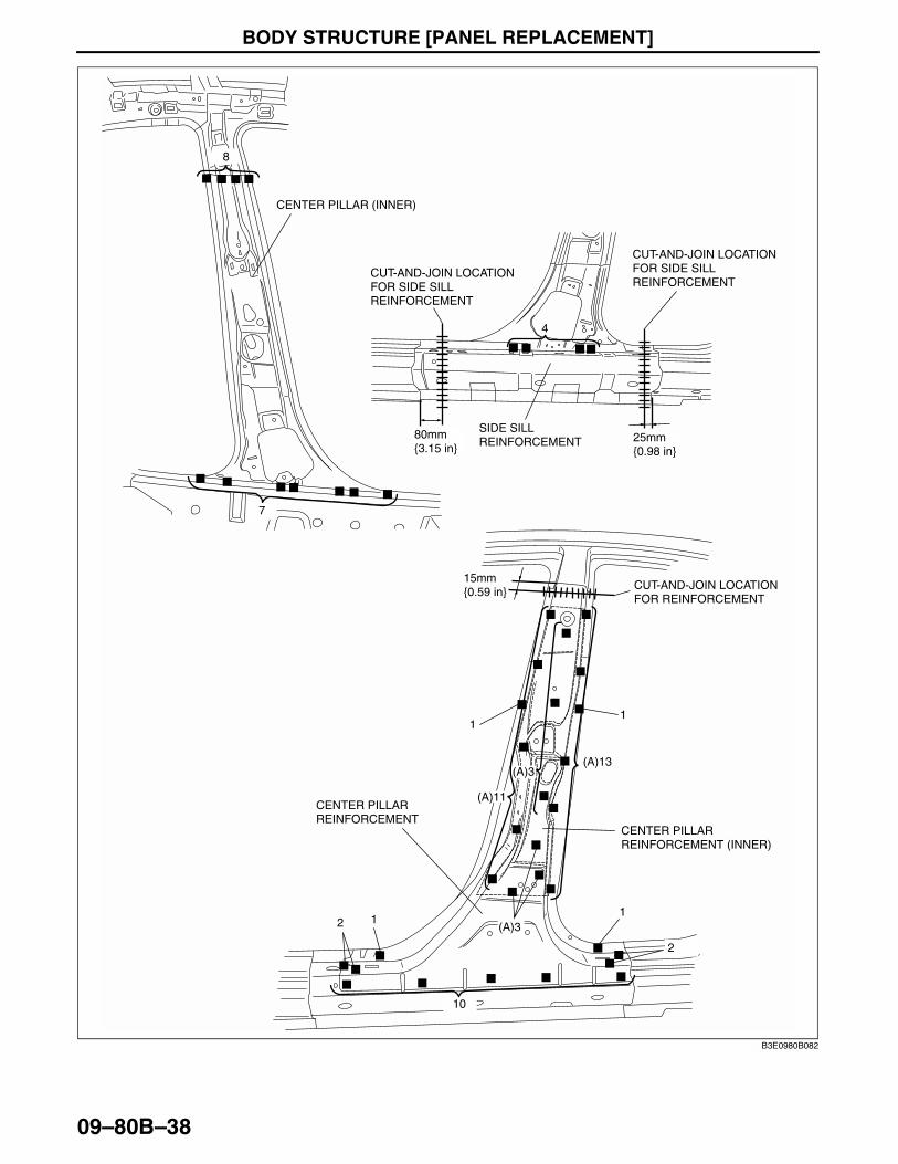
CENTER PILLAR INSTALLATIONC3U098070350B02
1. When joining and cutting the new and existing parts, trial fit the new part in position, and then measure and adjust the body as necessary to conform with standard dimensions.
2. Drill holes for plug welds before installing new parts.
Note• In areas where the outer, reinforcement, inner, and other parts are in 3-4 layers, drill holes for plug welds
in all but the innermost panel.
3. Install in the following order: inner, reinforcement, and outer.4. Weld the 30 locations indicated by (A) and install the center pillar reinforcement (inner) to the center pillar
reinforcement.5. After temporarily installing new parts, make sure the related parts fit properly.
BODY STRUCTURE [PANEL REPLACEMENT]
09–80B–38
11
(A)11
(A)13
2 1(A)3
(A)3
10
1
2
4
7
8
CUT-AND-JOIN LOCATION FOR SIDE SILL REINFORCEMENT
CUT-AND-JOIN LOCATION FOR SIDE SILL REINFORCEMENT
CUT-AND-JOIN LOCATION FOR REINFORCEMENT
SIDE SILL REINFORCEMENT
CENTER PILLAR (INNER)
CENTER PILLAR REINFORCEMENT (INNER)
CENTER PILLAR REINFORCEMENT
80mm {3.15 in}
15mm {0.59 in}
25mm {0.98 in}
B3E0980B082

BODY STRUCTURE [PANEL REPLACEMENT]
09–80B–39
09–80B
End Of Sie
20
18
2
2
17
CUT-AND-JOIN LOCATION FOR OUTER
CUT-AND-JOIN LOCATION FOR OUTER
CUT-AND-JOIN LOCATION FOR OUTER
CENTER PILLAR (OUTER)
80mm {3.15 in}
95mm {3.74 in}30mm {1.18 in}
B3E0980B083

BODY STRUCTURE [PANEL REPLACEMENT]
09–80B–40
REAR FENDER PANEL REMOVALC3U098074100B01
4SD
Caution•••• Avoid cutting with a blowtorch or similar tools as the insulator (shaded area) is flammable.
1. The rear fender panel and the rear pillar (inner) are joined with glue at the wheel arch line. Use a chisel or similar tool to separate the rear fender panel from the rear pillar (inner), then remove the rear fender panel.
28
77
16
B
B
7
5A
B-B
A-A
A
7
CUT-AND-JOIN LOCATION
REAR FENDER PANEL
ROUGH CUT LOCATION
INSULATOR
ROUGH CUT LOCATION CUT-AND-JOIN
LOCATION
170mm {6.69 in}
50mm {1.97 in}
50mm {1.97 in}
90mm {3.53 in}
B3E0980B084

BODY STRUCTURE [PANEL REPLACEMENT]
09–80B–41
09–80B
5HB
Caution•••• Avoid cutting with a blowtorch or similar tools as the insulator (shaded area) is flammable.
1. The rear fender panel and the rear pillar (inner) are joined with glue at the wheel arch line. Use a chisel or similar tool to separate the rear fender panel from the rear pillar (inner), then remove the rear fender panel.
End Of Sie
7
7
A
C
C
B
A-A B-B C-C
B
A
3
9
17
6
77
CUT-AND-JOIN LOCATION REAR FENDER PANEL
INSULATOR
ROUGH CUT LOCATION
ROUGH CUT LOCATION
ROUGH CUT LOCATION
CUT-AND-JOIN LOCATION
CUT-AND-JOIN LOCATION
100mm {3.94 in}
20mm {0.79 in}40mm {1.57 in}40mm
{1.57 in}
50mm {1.97 in}
170mm {6.69 in}
B3E0980B085

BODY STRUCTURE [PANEL REPLACEMENT]
09–80B–42
REAR FENDER PANEL INSTALLATIONC3U098074100B02
4SD1. When joining and cutting the new and existing parts, trial fit the new part in position, and then measure and
adjust the body as necessary to conform with standard dimensions.2. Drill holes for plug welds before installing new parts.3. Before installing new parts, apply spot weld sealer to the wheel arch line.4. After temporarily installing new parts, make sure the related parts fit properly.
28
77
16
2
4
7
5
7
REAR FENDER PANEL
CUT-AND-JOIN LOCATION
CUT-AND-JOIN LOCATION
140mm {5.51 in}
170mm {6.69 in}
B3E0980B086

BODY STRUCTURE [PANEL REPLACEMENT]
09–80B–43
09–80B
5HB1. When joining and cutting the new and existing parts, trial fit the new part in position, and then measure and
adjust the body as necessary to conform with standard dimensions.2. Drill holes for plug welds before installing new parts.3. Before installing new parts, apply spot weld sealer to the wheel arch line.4. After temporarily installing new parts, make sure the related parts fit properly.
End Of Sie
2
4
77
7
7
3
9
17
6
REAR FENDER PANEL
CUT-AND-JOIN LOCATION CUT-AND-JOIN LOCATION
CUT-AND-JOIN LOCATION
100mm {3.94 in}
170mm {6.69 in}
20mm {0.79 in}
B3E0980B087

BODY STRUCTURE [PANEL REPLACEMENT]
09–80B–44
REAR FENDER LOWER PANEL REMOVALC3U098074100B03
4SD1. Remove the rear fender lower panel.
6
5
4
REAR FENDER LOWER PANEL
B3E0980B088

BODY STRUCTURE [PANEL REPLACEMENT]
09–80B–45
09–80B
5HB1. Drill the 16 locations indicated by (A).2. Drill the 2 locations indicated by (B) and remove the rear fender lower panel.
End Of Sie
(A)3
(B)2
(A)4
(A)1
(A)8
REAR END PANEL
REAR FENDER LOWER PANEL
B3E0980B089

BODY STRUCTURE [PANEL REPLACEMENT]
09–80B–46
REAR FENDER LOWER PANEL INSTALLATIONC3U098074100B04
4SD1. When installing new parts, measure and adjust the body as necessary to conform with standard dimensions.2. Drill holes for plug welds before installing new parts.3. After temporarily installing new parts, make sure the related parts fit properly.
6
5
4
REAR FENDER LOWER PANEL
B3E0980B090

BODY STRUCTURE [PANEL REPLACEMENT]
09–80B–47
09–80B
5HB1. When installing new parts, measure and adjust the body as necessary to conform with standard dimensions.2. Drill holes for plug welds before installing new parts.3. Weld the 2 locations indicated by (A) and install the rear fender lower panel.4. After temporarily installing new parts, make sure the related parts fit properly.
End Of Sie
3
(A)2
4
1
8
REAR END PANEL
REAR FENDER LOWER PANEL
B3E0980B091

BODY STRUCTURE [PANEL REPLACEMENT]
09–80B–48
SIDE SILL PANEL REMOVALC3U098070270B01
1. Rough cut area (A), drill the 99 locations indicated by (B), the 2 locations (4SD) or 3 locations (5HB) indicated by (C), and then remove the side sill (outer).
Caution•••• Avoid cutting with a blowtorch or similar tools as the insulator (shaded area) is flammable.
2. Rough cut area (D) and drill the 3 locations indicated by (E).3. Drill the 4 locations indicated by (F) from the interior and remove the side sill reinforcement.
End Of Sie
(B)4
(F)4
(B)43
(E)1(E)1(E)1
(B)24(B)2
(B)18(B)8
(C)
CB
A A
B
C
4SD:25HB:3
A-A B-B C-C
CUT-AND-JOIN LOCATION FOR OUTER
CUT-AND-JOIN LOCATION FOR OUTER
CUT-AND-JOIN LOCATION FOR OUTER
(A)ROUGH CUT LOCATION FOR OUTER
SIDE SILL (OUTER)
SIDE SILL REINFORCEMENT
(A)ROUGH CUT LOCATION FOR OUTER
(D)ROUGH CUT LOCATION FOR REINFORCEMENT
(D)ROUGH CUT LOCATION FOR REINFORCEMENT
(A)ROUGH CUT LOCATION FOR OUTER
INSULATORINSULATOR
CUT-AND-JOIN LOCATION FOR REINFORCEMENT
CUT-AND-JOIN LOCATION FOR REINFORCEMENT
240mm {9.45 in}
35mm {1.38 in}
260mm {10.24 in}
30mm {1.18 in}
30mm {1.18 in}
25mm {0.98 in}55mm {2.17 in}50mm
{1.97 in}
30mm {1.18 in}
130mm {5.12 in}
B3U0980B092

BODY STRUCTURE [PANEL REPLACEMENT]
09–80B–49
09–80B
SIDE SILL PANEL INSTALLATIONC3U098070270B02
1. When joining and cutting the new and existing parts, trial fit the new part in position, and then measure and adjust the body as necessary to conform with standard dimensions.
2. Drill holes for plug welds before installing new parts.
Note• In areas where the outer, reinforcement, inner, and other parts are in 3-4 layers, drill holes for plug welds
in all but the innermost panel.
3. Weld the 7 locations indicated by (A) and temporarily install the side sill reinforcement.4. After temporarily installing new parts, make sure the related parts fit properly.
End Of Sie
4SD:25HB:3
4
(A)4
43
(A)1(A)1
(A)1
24
2
188
CUT-AND-JOIN LOCATION FOR OUTER
CUT-AND-JOIN LOCATION FOR OUTER
CUT-AND-JOIN LOCATION FOR OUTER
SIDE SILL (OUTER)
SIDE SILL REINFORCEMENT
CUT-AND-JOIN LOCATION FOR REINFORCEMENT CUT-AND-JOIN LOCATION
FOR REINFORCEMENT
260mm {10.24 in}
50mm {1.97 in}
55mm {2.17 in}
240mm {9.45 in} 130mm
{5.12 in}
B3E0980B093

BODY STRUCTURE [PANEL REPLACEMENT]
09–80B–50
REAR END PANEL REMOVALC3U098070750B01
4SD1. Remove the rear end panel.
1
6
7
3
5 5
15
1
3
7
6REAR END PANEL
B3E0980B094

BODY STRUCTURE [PANEL REPLACEMENT]
09–80B–51
09–80B
5HB1. Remove the rear end panel.
End Of Sie
55
5
5
5
5
655
6
15
44
2
2
2
REAR END PANEL
B3E0980B095

BODY STRUCTURE [PANEL REPLACEMENT]
09–80B–52
REAR END PANEL INSTALLATIONC3U098070750B024SD
1. When installing new parts, measure and adjust the body as necessary to conform with standard dimensions.2. Drill holes for plug welds before installing new parts.3. After temporarily installing new parts, make sure the related parts fit properly.
1
6
7
3
5 5
15
1
3
7
6REAR END PANEL
B3E0980B096

BODY STRUCTURE [PANEL REPLACEMENT]
09–80B–53
09–80B
5HB1. When installing new parts, measure and adjust the body as necessary to conform with standard dimensions.2. Drill holes for plug welds before installing new parts.3. After temporarily installing new parts, make sure the related parts fit properly.
End Of Sie
55
5
5
5
5
655
6
15
44
2
2
2
REAR END PANEL
B3E0980B097

BODY STRUCTURE [PANEL REPLACEMENT]
09–80B–54
REAR FENDER RAIN RAIL AND CORNER PLATE REMOVALC3U098070440B01
4SD1. Remove the rear fender rain rail and corner plate.
Note• When removing the rear fender rain rail and the corner plate separately, drill the 3 locations indicated by
(A).
2
32
(A)3
3
1
REAR FENDER RAIN RAIL
CORNER PLATE
B3E0980B098

BODY STRUCTURE [PANEL REPLACEMENT]
09–80B–55
09–80B
5HB1. Remove the rear fender rain rail and corner plate.
Note• When removing the rear fender rain rail and the corner plate separately, drill the 8 locations indicated by
(A).
End Of Sie
6
(A)4
(A)4
1
CUT-AND-JOIN LOCATION
REAR CUT LOCATION
REAR FENDER RAIN RAIL
CORNER PLATE
110mm {4.33 in}
40mm {1.57 in}
B3E0980B099

BODY STRUCTURE [PANEL REPLACEMENT]
09–80B–56
REAR FENDER RAIN RAIL AND CORNER PLATE INSTALLATIONC3U098070440B02
4SD1. When installing new parts, measure and adjust the body as necessary to conform with standard dimensions.2. Drill holes for plug welds before installing new parts.3. After temporarily installing new parts, make sure the related parts fit properly.
Note• When replacing the rear fender rain rail and corner plate separately, weld the 3 locations indicated by (A).
2
32
(A)3
3
1
REAR FENDER RAIN RAIL
CORNER PLATE
B3E0980B100

BODY STRUCTURE [PANEL REPLACEMENT]
09–80B–57
09–80B
5HB1. When installing new parts, measure and adjust the body as necessary to conform with standard dimensions.2. Drill holes for plug welds before installing new parts.3. After temporarily installing new parts, make sure the related parts fit properly.
Note• When replacing the rear fender rain rail and corner plate separately, weld the 8 locations indicated by (A).
End Of Sie
6
(A)4
(A)4
1
CUT-AND-JOIN LOCATION
REAR FENDER RAIN RAIL
CORNER PLATE
110mm {4.33 in}
B3E0980B101

BODY STRUCTURE [PANEL REPLACEMENT]
09–80B–58
REAR FLOOR PAN REMOVALC3U098053750B01
1. Rough cut area (A).
Caution•••• When rough cutting area (A), cut 20mm {0.79 in} away from the flange (towards rear) at the rear of
the lower anchor.
2. Remove the rear floor pan.
3
5
1313
8
6
46
4
8
3
5
8
A-A
A
A
(A) ROUGH CUT LOCATION FOR REAR FLOOR PAN
REAR FLOOR PAN
REAR FLOOR PAN
LOWER ANCHOR
CROSSMEMBER No.4
(A) ROUGH CUT LOCATION FOR REAR FLOOR PAN
20mm {0.79 in}
B3E0980B102

BODY STRUCTURE [PANEL REPLACEMENT]
09–80B–59
09–80B
End Of Sie
3
2
B3E0980B103

BODY STRUCTURE [PANEL REPLACEMENT]
09–80B–60
REAR FLOOR PAN INSTALLATIONC3U098053750B02
1. To prepare for installation, cut area (A) on the new rear floor pan, drill the 20 locations indicated by (B) and then remove the lower anchor.
Caution•••• When rough cutting area (A), cut 30 mm {1.18 in} away from the flange (towards front) at the rear of
the lower anchor.
2. Drill the 11 locations indicated by (A).3. Separate the lower anchor where joined using a chisel or similar tool and bend upwards to facilitate installation.
A(B)5 (B)5 (B)5 (B)5
A
A-A
(A) ROUGH CUT LOCATION FOR REAR FLOOR PAN REAR FLOOR PAN
LOWER ANCHOR
CROSSMEMBER No.4
(A) ROUGH CUT LOCATION FOR REAR FLOOR PAN
NEW REAR FLOOR PAN
30mm {1.18 in}
B3E0980B104
(C)3 (C)3 (C)2(C)3 LOWER ANCHOR
EXISTING REAR FLOOR PAN
B3E0980B105

BODY STRUCTURE [PANEL REPLACEMENT]
09–80B–61
09–80B
4. Apply spot sealer to the areas where both the overlapping ends of the new and existing parts will be welded. Adhere the sections to be welded, and plug weld in 18 locations indicated by (D). Fillet weld along the seams of the lower anchor, and new and existing parts at the locations indicated by (E).
Note• Create a flange with flanging seal where new and existing parts are joined.
5. Weld the remaining weld locations and install the rear floor pan.
End Of Sie
3
3
5
1313
8
6
46
4
8
3
5
8
B-B
2
B
B
(D)3 (D)2 (D)3 (D)2(D)3 (D)3 (D)2
NEW PARTS
EXISTING PARTS
(E) FILLET WELDIMG
REAR FLOOR PAN
LOWER ANCHOR
CROSSMEMBER No.4
B3E0980B106

BODY STRUCTURE [PANEL REPLACEMENT]
09–80B–62
REAR SIDE FRAME (PARTIAL CUTTING) REMOVALC3U098053810B01
1. Rough cut and remove the damaged part of the rear side frame.
End Of Sie
CUT-AND-JOIN LOCATION
ROUGH CUT LOCATION
200mm {7.87 in}
50mm {1.97 in}
B3E0980B107

BODY STRUCTURE [PANEL REPLACEMENT]
09–80B–63
09–80B
REAR SIDE FRAME (PARTIAL CUTTING) INSTALLATIONC3U098053810B02
1. Cut the new and existing parts at the cut-and-join location, and bevel the parts.2. To cut-and-join the new part, cut at the locations indicated in the figure below and bevel the cut-and-join
locations of the new parts.3. When installing the new parts, trial-fit new and existing parts, and then measure and adjust the body to conform
with standard dimensions.4. After temporarily installing new parts, make sure the related parts fit properly.
Caution•••• The cut-and-join area indicates the maximum size range of the installation position.
End Of Sie
CUT-AND-JOIN LOCATION
200mm {7.87 in}
B3E0980B108
BODY STRUCTURE [PANEL REPLACEMENT]
09–80B–64
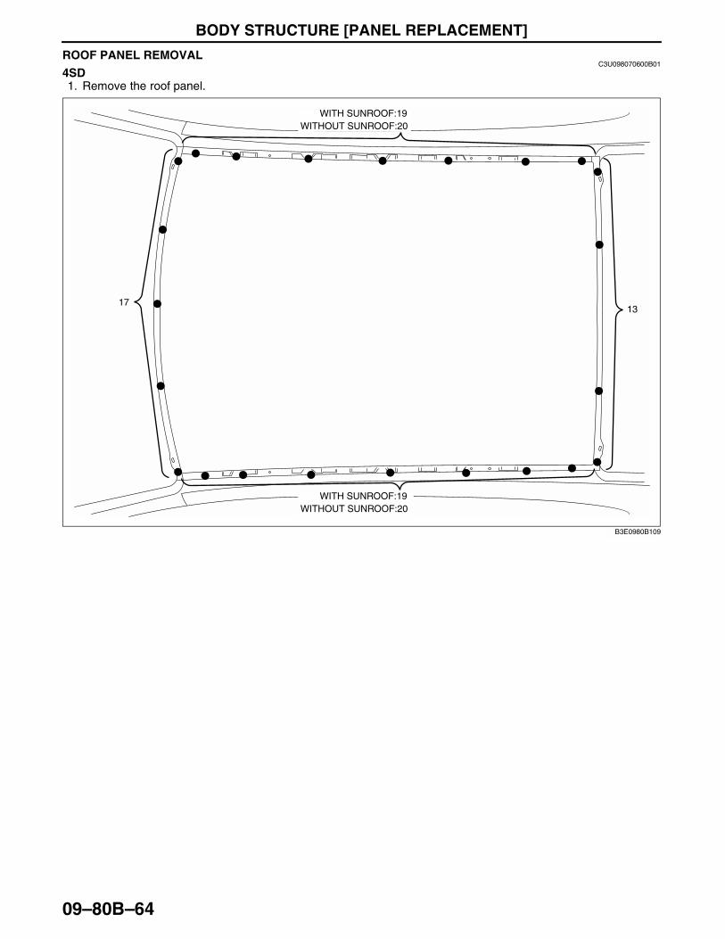
ROOF PANEL REMOVALC3U098070600B01
4SD1. Remove the roof panel.
WITH SUNROOF:19WITHOUT SUNROOF:20
WITH SUNROOF:19WITHOUT SUNROOF:20
1713
B3E0980B109

BODY STRUCTURE [PANEL REPLACEMENT]
09–80B–65
09–80B
5HB1. Remove the roof panel.
End Of Sie
4
3
28
17
28
15
1
B3E0980B110

BODY STRUCTURE [PANEL REPLACEMENT]
09–80B–66
ROOF PANEL INSTALLATIONC3U098070600B02
4SD1. When installing new parts, measure and adjust the body as necessary to conform with standard dimensions.2. Drill holes for plug welds before installing new parts.3. After temporarily installing new parts, make sure the related parts fit properly.
1713
WITH SUNROOF:19WITHOUT SUNROOF:20
WITH SUNROOF:19WITHOUT SUNROOF:20
B3E0980B111

BODY STRUCTURE [PANEL REPLACEMENT]
09–80B–67
09–80B
5HB1. When installing new parts, measure and adjust the body as necessary to conform with standard dimensions.2. Drill holes for plug welds before installing new parts.3. After temporarily installing new parts, make sure the related parts fit properly.
End Of Sie
4
3
28
17
28
15
1
B3E0980B112

BODY STRUCTURE [WATER-PROOF AND RUST PREVENTIVE]
09–80C–1
09–80C
09–80C BODY STRUCTURE [WATER-PROOF AND RUST PREVENTIVE]BODY SEALING . . . . . . . . . . . . . . . . . . . 09–80C–2
4SD . . . . . . . . . . . . . . . . . . . . . . . . . . . 09–80C–25HB . . . . . . . . . . . . . . . . . . . . . . . . . . . 09–80C–5
UNDER COATING. . . . . . . . . . . . . . . . . . 09–80C–8CHIPPING-RESISTANT COATING. . . . . 09–80C–9
With Side Step Molding . . . . . . . . . . . . . 09–80C–9Without Side Step Molding . . . . . . . . . . 09–80C–9
RUST PREVENTIVE TREATMENT . . . . . 09–80C–104SD . . . . . . . . . . . . . . . . . . . . . . . . . . . . 09–80C–105HB . . . . . . . . . . . . . . . . . . . . . . . . . . . . 09–80C–11
End of Toc

BODY STRUCTURE [WATER-PROOF AND RUST PREVENTIVE]
09–80C–2
BODY SEALINGC3U098007000B02
Sealant is applied to the parts where the panels meet and to the hemmed parts of the door panel and hood panel to provide water proofing and rust proofing.
4SD
B3U0980B032

BODY STRUCTURE [WATER-PROOF AND RUST PREVENTIVE]
09–80C–3
09–80C
B3U0980B033

BODY STRUCTURE [WATER-PROOF AND RUST PREVENTIVE]
09–80C–4
HOOD
DOOR
TRUNK LID
B3U0980B034

BODY STRUCTURE [WATER-PROOF AND RUST PREVENTIVE]
09–80C–5
09–80C
5HB
B3U0980B035

BODY STRUCTURE [WATER-PROOF AND RUST PREVENTIVE]
09–80C–6
B3U0980B033

BODY STRUCTURE [WATER-PROOF AND RUST PREVENTIVE]
09–80C–7
09–80C
End Of Sie
HOOD
DOOR
LIFTGATE
B3U0980B037

BODY STRUCTURE [WATER-PROOF AND RUST PREVENTIVE]
09–80C–8
UNDER COATINGC3U098007000B03
The shaded areas indicated under body locations that are undercoated to prevent noise and rusting.End Of Sie
B3U0980B038

BODY STRUCTURE [WATER-PROOF AND RUST PREVENTIVE]
09–80C–9
09–80C
CHIPPING-RESISTANT COATINGC3U098007000B04
The coating locations are indicated by the shaded areas.
With Side Step Molding
Without Side Step Molding
End Of Sie
A
A
URETHANE PAINT
OVER SPRAY ALLOWED
A-A
B3E0980B039
A-A
A
A
OVER SPRAY ALLOWED
URETHANE PAINT
B3U0980B046

BODY STRUCTURE [WATER-PROOF AND RUST PREVENTIVE]
09–80C–10
RUST PREVENTIVE TREATMENTC3U098007000B05
4SD
DOOR
TRUNK LID
HOOD
B3U0980B040

BODY STRUCTURE [WATER-PROOF AND RUST PREVENTIVE]
09–80C–11
09–80C
5HB
End Of Sie
DOOR
LIFTGATE
HOOD
B3U0980B045

BODY STRUCTURE [DIMENSIONS]
09–80D–1
09–80D
09–80D BODY STRUCTURE [DIMENSIONS]UNDERBODY FLAT-PLANE
DIMENSIONS . . . . . . . . . . . . . . . . . . . . 09–80D–2UNDERBODY STRAIGHT-LINE
DIMENSIONS . . . . . . . . . . . . . . . . . . . . 09–80D–3FRONT BODY STRAIGHT-LINE
DIMENSIONS (1) . . . . . . . . . . . . . . . . . . 09–80D–4FRONT BODY STRAIGHT-LINE
DIMENSIONS (2) . . . . . . . . . . . . . . . . . . 09–80D–54SD . . . . . . . . . . . . . . . . . . . . . . . . . . . 09–80D–55HB . . . . . . . . . . . . . . . . . . . . . . . . . . . 09–80D–6
FRONT BODY STRAIGHT-LINE DIMENSIONS (3) . . . . . . . . . . . . . . . . . . 09–80D–7
4SD . . . . . . . . . . . . . . . . . . . . . . . . . . . 09–80D–75HB . . . . . . . . . . . . . . . . . . . . . . . . . . . 09–80D–8
CABIN SIDE FRAME STRAIGHT-LINE DIMENSIONS . . . . . . . . . . . . . . . . . . . . . 09–80D–9
4SD . . . . . . . . . . . . . . . . . . . . . . . . . . . . 09–80D–95HB . . . . . . . . . . . . . . . . . . . . . . . . . . . . 09–80D–10
ROOM STRAIGHT-LINE DIMENSIONS (1) . . . . . . . . . . . . . . . . . . 09–80D–11
ROOM STRAIGHT-LINE DIMENSIONS (2) . . . . . . . . . . . . . . . . . . 09–80D–12
4SD . . . . . . . . . . . . . . . . . . . . . . . . . . . . 09–80D–125HB . . . . . . . . . . . . . . . . . . . . . . . . . . . . 09–80D–13
REAR BODY STRAIGHT-LINE DIMENSIONS . . . . . . . . . . . . . . . . . . . . . 09–80D–14
4SD . . . . . . . . . . . . . . . . . . . . . . . . . . . . 09–80D–145HB . . . . . . . . . . . . . . . . . . . . . . . . . . . . 09–80D–15
End of Toc

BODY STRUCTURE [DIMENSIONS]
09–80D–2
UNDERBODY FLAT-PLANE DIMENSIONSC3U098053010B01
.
A B C D E F G H I J LK M
958
707
474 365
164
180 341 581 364849
{18.66} {14.37}{6.46}
170{6.69}
51{2.01}
{7.09} {13.43} {22.88} {14.33}{33.43}
1,14
1
945
722
482 43
0
288
960
960
940
1,19
6{37.
72}
{44.
92}
1,21
6{47
.87}
{37.
20}
{28.
43}
{18.
98}
{16.
93}
{11.
34}
{37.
80}
{37.
80}
{37.
01}
{47.
09}
1,14
1{4
4.92
}
684
1,11
1
488
454
455
455
447
468
528
666
667
{27.
83}
{26.
93}
{43.
74}
1,10
2{4
3.39
}
{19.
21}
{17.
87}
{17.
91}
{17.
91}
{17.
60}
{18.
43}
{20.
79}
{26.
22}
{26.
26}
mm {in}
B3E0980B001
Point symbol Designation
Hole diameter or bolt or nut size mm {in}
A Front side frame standard hole ø16 {0.63}
B Front suspension mounting block ø46 {1.81}
C Front suspension mounting bracket ø19 {0.75}
D Front frame (rear) standard hole ø20 {0.79}
E Torque box standard hole ø16 {0.63}
F Front frame (rear) standard hole
16 x 6{0.63 x 0.24}
G Front B frame standard hole ø16 {0.63}
H Front B frame standard hole ø7 {0.28}
I Crossmember No.3 reinforcement
36 x 22{1.41 x 0.87}
J Rear side frame standard hole ø16 {0.63}
K Rear suspension mounting block ø40 {1.57}
L Rear side frame standard hole ø14 {0.55}
M Rear side frame standard hole16 x20
{0.63 x 0.79}
Point symbol Designation
Hole diameter or bolt or nut size mm {in}

BODY STRUCTURE [DIMENSIONS]
09–80D–3
09–80D
End Of Sie
UNDERBODY STRAIGHT-LINE DIMENSIONSC3U098053010B02
.
A C D F G H I J L M
9
8
7
5
4
3
10
19
18
17
15
16
14
1311
12
20 24
23
21
226
1
2
B3E0980B002
A
I
C
J
D
L
F,G
M
H
F
G
Fr
Fr
Fr
FrFr
Fr Fr Fr Fr
B3E0980B003
Measured location Dimensions mm {in}
1 475 {18.70}2 1,063 {41.85}3 429 {16.89}4 931 {36.65}5 875 {34.45}6 1,207 {47.52}7 1,115 {43.90}8 1,306 {51.42}9 254 {10.00}
10 642 {25.28}11 166 {6.54}12 485 {19.09}
13 852 {33.54}14 921 {36.26}15 489 {19.25}16 764 {30.08}17 366 {14.41}18 1,132 {44.57}19 598 {23.54}20 1,122 {44.17}21 364 {14.33}22 1,017 {40.04}23 1,307 {51.46}24 1,690 {66.54}
Measured location Dimensions mm {in}

BODY STRUCTURE [DIMENSIONS]
09–80D–4
End Of Sie
FRONT BODY STRAIGHT-LINE DIMENSIONS (1)C3U098053020B01
.
End Of Sie
9 8
7 5
4
3
10
6
1
2
A
A'
B'
B
C
D
E
F
E'
C'
D'
F'
B3E0980B004
B
D E
F
E'
F'
C
C,D E,F E',F'
Fr FrFr
A
B3E0980B005
Measured location Dimensions mm {in}
1 1,069 {42.09}2 1,446 {56.93}3 4SD:685 {26.97}, 5HB:684 {26.93}4 4SD:1,518 {59.76}, 5HB:1,519 {59.80}5 1,425 {56.10}
6 1,463 {57.60}7 1,489 {58.62}8 882 {34.72}9 891 {35.08}
10 882 {34.72}
Measured location Dimensions mm {in}

BODY STRUCTURE [DIMENSIONS]
09–80D–5
09–80D
FRONT BODY STRAIGHT-LINE DIMENSIONS (2)C3U098053020B02
4SD
.
A
C
B
D
B'C'
A'
D'
9
8
7
54
3
10
14
13
11
12
6 1
2
B3E0980B006
A B C D
FrFr Fr Fr
B3E0980B007
Measured location Dimensions mm {in}
1 1,494 {58.82}2 1,103 {43.43}3 1,491 {58.70}4 1,368 {53.86}5 414 {16.30}6 1,349 {53.11}7 407 {16.02}
8 1,547 {60.91}9 200 {7.87}
10 1,298 {51.10}11 308 {12.13}12 1,461 {57.52}13 708 {27.87}14 1,596 {62.83}
Measured location Dimensions mm {in}

BODY STRUCTURE [DIMENSIONS]
09–80D–6
5HB
.
End Of Sie
A
C
B
D
B'C'
A'
D'
9
8
7
54
3
10
14
13
11
12
6 1
2
B3E0980B008
A B C D
FrFr Fr
Fr
B3E0980B009
Measured location Dimensions mm {in}
1 1,494 {58.82}2 1,103 {43.43}3 1,508 {59.37}4 1,368 {53.86}5 414 {16.30}6 1,349 {53.11}7 410 {16.14}
8 1,556 {61.26}9 208 {8.19}
10 1,306 {51.42}11 304 {11.97}12 1,468 {57.80}13 708 {27.87}14 1,596 {62.83}
Measured location Dimensions mm {in}

BODY STRUCTURE [DIMENSIONS]
09–80D–7
09–80D
FRONT BODY STRAIGHT-LINE DIMENSIONS (3)C3U098053020B03
4SD
.
B
D
F
B'
C
E
D'
F'
G'
G
A
9
8
7 5
4
3
10
6
12
B3E0980B010
A B C
F G
D E
Fr
Fr
Fr
Fr
FrFr Fr
B3E0980B011
Measured location Dimensions mm {in}
1 851 {33.50}2 806 {31.73}3 1,268 {49.92}4 570 {22.44}5 1,203 {47.36}
6 408 {16.06}7 1,239 {48.78}8 432 {17.01}9 1,160 {45.67}
10 331 {13.03}
Measured location Dimensions mm {in}

BODY STRUCTURE [DIMENSIONS]
09–80D–8
5HB
.
B
D
F
B'
C
E
D'
F'
G'
G
A
9
8
7 5
4
3
10
6
12
B3E0980B014
A B C
F G
D E
Fr
Fr
Fr
Fr
Fr Fr
Fr
B3E0980B015
Measured location Dimensions mm {in}
1 851 {33.50}2 806 {31.73}3 1,268 {49.92}4 570 {22.44}5 1,205 {47.44}
6 398 {15.67}7 1,241 {48.86}8 421 {16.57}9 1,160 {45.67}
10 331 {13.03}
Measured location Dimensions mm {in}

BODY STRUCTURE [DIMENSIONS]
09–80D–9
09–80D
End Of Sie
CABIN SIDE FRAME STRAIGHT-LINE DIMENSIONSC3U098070010B01
4SD
.
A
B
C
D
G
F
E
H
I
L
MK
J
4
3
1
2
9
87
5
10
19
1817 15
16
14
1311
12
20
25
2624
2321 22
6
B3E0980B018
A
G,H
GH
J K L M
B C D,E
E
F I
D
F,I
Fr FrFr
Fr
Fr Fr
FrFrFr Fr
B3E0980B019
Measured location Dimensions mm {in}
1 642 {25.28}2 719 {28.31}3 916 {36.06}4 882 {34.72}5 1,325 {52.17}6 1,133 {44.61}7 1,125 {44.29}8 595 {23.43}9 1,500 {59.06}
10 1,192 {46.93}11 1,079 {42.48}12 399 {15.71}13 884 {34.80}
14 712 {28.03}15 808 {31.81}16 1,434 {56.46}17 865 {34.06}18 988 {38.90}19 947 {37.28}20 795 {31.30}21 548 {21.57}22 1,101 {43.35}23 857 {33.74}24 342 {13.46}25 637 {25.08}26 1,212 {47.72}
Measured location Dimensions mm {in}

BODY STRUCTURE [DIMENSIONS]
09–80D–10
5HB
.
End Of Sie
4
3
1
2
A
B
C
DE
H
F
G
M
J
K
L
I
9
8 7
5
10
1918
17
1516
14
1311
12
20
25
26
24
23
21226
B3E0980B020
A
G,H
GH
J,K L MJ
K
B C D,E F,I
FrFr
Fr
Fr
FrFrFr Fr
Fr
E
F I
D
B3E0980B021
Measured location Dimensions mm {in}
1 642 {25.28}2 719 {28.31}3 916 {36.06}4 882 {34.72}5 1,325 {52.17}6 1,133 {44.61}7 1,125 {44.29}8 595 {23.43}9 1,500 {59.06}
10 1,192 {46.93}11 1,079 {42.48}12 399 {15.71}13 884 {34.80}
14 712 {28.03}15 598 {23.54}16 766 {30.16}17 865 {34.06}18 988 {38.90}19 930 {36.61}20 939 {36.97}21 795 {31.30}22 548 {21.57}23 1,162 {45.75}24 1,108 {43.62}25 857 {33.74}26 342 {13.46}
Measured location Dimensions mm {in}

BODY STRUCTURE [DIMENSIONS]
09–80D–11
09–80D
ROOM STRAIGHT-LINE DIMENSIONS (1)C3U098070001B01
.
End Of Sie
A
D
B
C
E
F
G
IH
5
4
3
6
1
2
B3E0980B022
A
F G
B C
H I
D E
Fr
Fr
FrFr Fr Fr
Fr FrFr
B3E0980B023
Measured location Dimensions mm {in}
1 1033 {40.67}2 957 {37.68}3 765 {30.12}4 1339 {52.72}
5 1154 {45.43}6 1003 {39.49}
H-H’ 1485 {58.46}I-I’ 1466 {57.72}
Measured location Dimensions mm {in}

BODY STRUCTURE [DIMENSIONS]
09–80D–12
ROOM STRAIGHT-LINE DIMENSIONS (2)C3U098070001B02
4SD
.
DC
B
A
E
F
G
H
I
7
54
3
1
26
B3E0980B024
A
G H
B C
I
D E,F
E F
Fr
FrFrFr Fr Fr
Fr
Fr
B3E0980B025
Measured location Dimensions mm {in}
1 1,046 {41.18}2 908 {35.75}3 816 {32.13}4 1,081 {42.56}
5 1,211 {47.68}6 1,079 {42.48}7 787 {30.98}
I-I’ 1,510 {59.45}
Measured location Dimensions mm {in}

BODY STRUCTURE [DIMENSIONS]
09–80D–13
09–80D
5HB
.
End Of Sie
A
B
C D
I
H
E
F
G
8
75
4
3
1
2
6
J
B3E0980B026
A
F G H I
B C D E
Fr Fr FrFr
FrFr Fr FrFr
J
Fr
B3E0980B027
Measured location Dimensions mm {in}
1 1,046 {41.18}2 908 {35.75}3 816 {32.13}4 1,088 {42.83}5 928 {36.54}
6 787 {30.98}7 1,328 {52.28}8 1,373 {54.06}
J-J’ 1,510 {59.45}
Measured location Dimensions mm {in}

BODY STRUCTURE [DIMENSIONS]
09–80D–14
REAR BODY STRAIGHT-LINE DIMENSIONSC3U098070002B01
4SD
.
C,
B,
A,
C
B
A
E,
D,
E
D
9
8
7
5
4
3
1
2
10
11
6
B3E0980B028
A
E,
B C D E
Fr
Fr
FrFr
Fr Fr
B3E0980B029
Measured location Dimensions mm {in}
1 1,007 {39.65}2 781 {30.75}3 1,190 {46.85}4 800 {31.50}5 425 {16.73}6 851 {33.50}
7 679 {26.73}8 1,436 {56.54}9 620 {24.41}
10 1,191 {46.89}11 720 {28.35}
Measured location Dimensions mm {in}

BODY STRUCTURE [DIMENSIONS]
09–80D–15
09–80D
5HB
.
End Of Sie
B,
A,
B
A
D,
C,
D
C
8
7
5
4
3
1
2
6
B3E0980B030
Fr
A B C D D,
Fr Fr FrFr
B3E0980B031
Measured location Dimensions mm {in}
1 700 {27.56}2 871 {34.29}3 1,114 {43.86}4 688 {27.09}
5 1,474 {58.03}6 596 {23.46}7 1,190 {46.85}8 720 {28.35}
Measured location Dimensions mm {in}

BODY STRUCTURE [PLASTIC BODY PARTS]
09–80E–1
09–80E
09–80E BODY STRUCTURE [PLASTIC BODY PARTS]PLASTIC PARTS HEAT RESISTING
TEMPERATURE . . . . . . . . . . . . . . . . . . 09–80E–1REPAIRABLE RANGE OF
POLYPROPYLENE BUMPERS . . . . . . 09–80E–2
Repairable Bumpers . . . . . . . . . . . . . . . 09–80E–2POLYPROPYLENE BUMPER REPAIR . . 09–80E–3PROCEDURE . . . . . . . . . . . . . . . . . . . . . . 09–80E–4
End of Toc
PLASTIC PARTS HEAT RESISTING TEMPERATUREC3U098050000B01
Note• The application of temperatures higher than heat resisting temperatures may result in part deformation.
End Of Sie
Part Name Code Material Name Heat resistingTemperature°°°°C{F°°°°}
WINDSHIELD MOULDING PVC POLYVINYLCHLORIDE 95 {203}COWL GRILLE PP POLYPROPYLENE 95 {203}
FRONT COMBINATION LIGHT
LENS PC POLYCARBONATE 130 {266}HOUSING PP POLYPROPYLENE 90 {194}
RADIATOR GRILLE
4SDSTANDARD AES AES 80 {176}
SPORT PC/ABS POLYCARBONATE-ABS 80 {176}
5HBSTANDARD AES AES 80 {176}
SPORT ABS ABS 80 {176}FRONT BUMPER PP POLYPROPYLENE 100 {212}FRONT FLAP PE POLYETHLENE 75 {167}
FRONT SIDE MAKER LIGHT
LENS PMMA ACRYLIC 75 {167}HOUSING PC-PBT POLYCARBONATE-PBT 80 {176}
OUTSIDE MIRRORBASE AAS AAS 88 {190}OUTER PANEL ABS ABS 88 {190}
SIDE PROTECTOR PVC POLYVINYLCHLORIDE 80 {176}SIDE STEP MOLDING PP POLYPROPYLENE 75 {167}ROOF MOULDING AES AES 80 {176}REAR BUMPER PP POLYPROPYLENE 100 {212}
REFLECTORLENS PMMA ACRYLIC 75 {167}HOUSING ABS ABS 70 {158}
REAR COMBINATION LIGHT
LENS PMMA ACRYLIC 80 {176}HOUSING AES AES 70 {158}
OUTER HANDLELEVER PC-PBT POLYCARBONATE-PBT 80 {176}BASE PC-PET POLYCARBONATE-PET 80 {176}
HIGH-MOUNT BRAKE LIGHT
LENS PC POLYCARBONATE 130 {266}HOUSING PP POLYPROPYLENE 95 {203}
LIFTGATE GARNISH PP POLYPROPYLENE 95 {203}
REAR SPOILER4SD ABS ABS 90 {194}
5HBUPPER SMC SMC 90 {194}LOWER PP POLYPROPYLENE 90 {194}
BELTLINE MOLDING AES AES 90 {194}SHROUD PANEL PP POLYPROPYLENE 100 {212}

BODY STRUCTURE [PLASTIC BODY PARTS]
09–80E–2
REPAIRABLE RANGE OF POLYPROPYLENE BUMPERSC3U098050000B02
The three types of damaged bumpers shown below are considered repairable. Although a bumper which has been damaged greater than this could also be repaired, it should be replaced with a new one because such repair would detract from the looks and quality of the bumper. In addition, such repair is not considered reasonable in terms of work time.
Repairable Bumpers1. A bumper with a hole less than 50 mm {1.97 in} in
diameter.
2. A bumper with a crack less than 100 mm {3.94 in} in length.
3. A bumper with a crack less than 100 mm {3.94 in} in length that is less than half of the width of the bumper.
End Of Sie
YMU980PCM
YMU980PCN
YMU980PCP

BODY STRUCTURE [PLASTIC BODY PARTS]
09–80E–3
09–80E
POLYPROPYLENE BUMPER REPAIRC3U098050000B03
End Of Sie
YMU980PCQ

BODY STRUCTURE [PLASTIC BODY PARTS]
09–80E–4
PROCEDUREC3U098050000B04
Repair of polypropylene bumpers having damage that has reached the surface of the polypropylene and are too serious to be restored by painting only.
1. Cut the rough edges around the damage with a knife to make it smooth. Sand the area with a sander to make an angle of about 45°.
YMU980PCR
YMU980PCS

BODY STRUCTURE [PLASTIC BODY PARTS]
09–80E–5
09–80E
2. Weld the damaged area.• For repair of a cracked area, melt the crack together with a heat gun and a melting attachment.
• For repair of a hole, degrease the area on both sides of the bumper and apply aluminium tape on the reverse side of the damage area.
3. Melt the polypropylene welding rod with a heat gun and deposit it the cracked area.
Note• Heat the shaded area to melt it.• Take care not to overly melt welding rod. If the part is welded with the welding rod melted like jelly, the
welding strength will be reduced.• Hold the heat gun 10—20 mm {0.39—0.79 in} from the part being welded.• Do not move the welding rod until the welded parts cool.
YMU980PCT
YMU980PCU
YMU980PCV
YMU980PCW

BODY STRUCTURE [PLASTIC BODY PARTS]
09–80E–6
4. Sand the surface of the polypropylene gradually as it is easily melted by the abrasion heat. Sand the area to which repair agent will be applied.
5. Uniformly apply polypropylene primer with a brush to an area larger than the repaired area. Allow to dry about 10 minutes at 20 °C {68 °F}.
6. Mix the main agent and the stiffening agent in a ratio of one to one. Apply the mixed repair agent to the damaged area.
Note• When mixing the main and stiffening agents, take care not to allow bubbles to form.• The repair agent hardens quickly (about 5 minutes); proceed with the work immediately after mixing the
agents.• Allow about 30 minutes to dry (20 °C {68 °F}) before sanding.
The repair agent is a two part epoxy adhesive.When the repair agent hardens, it will provide a good finish with the same flexibility as the polypropylens.The repair agent for a urethane bumper is also a two part adhesive compound. However, this is different from that for a polypropylene bumper. If the incorrect repair agent is used, the repair will be faulty.
YMU980PCX
YMU980PCY
YMU980PCZ

BODY STRUCTURE [PLASTIC BODY PARTS]
09–80E–7
09–80E
7. Sand the area with #180—240 sandpaper.
Note• If excessive force is applied to the area when sanding, the surface will be damaged.• If fuzz remains around the repaired area, melt it with a heat gun.
8. Degrease the painted surface.9. Mix the primer and the hardener at a ratio of one to one. Apply the primer to the repaired area and the surface
of the bumper with a brush or spray.
Use the primer within 16 hours after it is mixed.
Note• Polypropylene primer will dissolve even after drying if it is wiped with solvent. Use only water to clean
around the primer.
10. Allow the part to dry.
YMU980PD0
YMU980PD1

BODY STRUCTURE [PLASTIC BODY PARTS]
09–80E–8
11. Add the softener to the urethane primer surfacer and spray it on the repaired area.a. Mixing method
Urethane primer surfacer + Softener ..... Mixture AMixture A + hardener ..... Mixture BDilute mixture B with thinner to spray on bumper
b. Viscosity14—16 seconds/viscosimeter 20 °C {68 °F}
Note• Mix the solutions at the specified ratio.
c. Spray pressure300—400 kPa {3—4 kg/cm2, 43—57 psi}
d. Standard film thickness30—40 µ
e. Spray methodSpot-spray primer surfacer on bumper three of four times
12. Air drying 20 °C {68 °F} — 8 hours minimum.Forced drying 60 °C {140 °F} — 1 hour
13. Lightly sand the complete surface of the bumper with #400—#600 sandpaper. Do not expose the surface of the polypropylene. (Wet or dry sanding is acceptable.)
14. Wipe the complete surface of the bumper with degreasing agent. Quickly wipe the surface with a clean rag to degrease it.
15. Apply a matching coat of body color to the polypropylene bumper.
Note• Be sure to use only urethane primer for a urethane bumper and polypropylene primer for a polypropylene
bumper. Other paints for repairing a polypropylene bumper are the same as those for the urethane bumper.
16. Air drying 20 °C {68 °F} — 8 hours minimum.Forced drying 60 °C {140 °F} — 1 hour
Note• Let the part air dry when possible as forced drying could cause bubbles in the top coat.
End Of Sie
YMU980PD2