contents page preface ' 7 chapter 1 — introduction 9 chapter 2
TRANSCRIPT

Contents
Page
Preface ' 7
Chapter 1 — Introduction 9
Chapter 2— The cylinder head 13
Chapter 3 — Porting and cylinder scavenging 27
Chapter 4 — The exhaust 76
Chapter 5 — Carburation 93
Chapter 6 — Ignition 125
Chapter 7— The bottom end 143
Chapter 8— Lubrication and cooling 166
Chapter 9— Power measurement and gearing 174
Appendix I — Introduction 187A Motocross modifications 187B Enduro modifications 198C Road race modifications 202
Appendix I I — Table of useful equivalents 219
Appendix III—Speciality suppliers • 220
Index 222


PrefaceFROM A very humble beginning, the two-stroke internal combustion engine has
now been developed to a degree that was not thought possible just a few years ago. Iam sure even the engineers who have stood by the two-stroke principle for so long findit staggering that this mechanically simple device can produce as much power as it doestoday, with relative reliability.
Originally, I looked upon two-stroke engines with contempt. They made a horriblering-ding noise, nothing like the beautiful note of four-stroke racing engines. Theyemitted a blue haze from their tailpipes too, which appeared unsightly, long before anyof us heard of the word pollution. On hot days these engines seized with monotonousregularity. Difficult starting, flooding and plug fouling seemed the order of the day.
Consequently I wrote off two-strokes, convinced I would never lower myself todevelop one of these unreliable little beasts in my workshop. But that all changed whentwo of my friends bought themselves 250cc Bultaco Pursang motocross bikes andinsisted I prepared them. I took up the challenge and was rewarded with the knowledgethat a ring-ding I had developed came home 3rd in the National MotocrossChampionship with a B grade rider on board.
From then on the challenge has not abated as I have strived to unravel the mysteryof what makes a two-stroke tick. Instead of looking on the two-stroke with contempt, Inow view this little marvel with fascination. Four-stroke engine development has justabout reached its peak, but there is much yet to be learned about the two-stroke powerunit.
It is my hope that this book will assist the enthusiast involved in motocross,enduro, desert, road or go-kart racing to develop and tune his two-stroke engine forhorsepower and reliability.
MaitlandNew South Wales

Chapter 1Introduction
MECHANICALLY, the two-stroke engine is very simple, and unfortunately ontoo many occasions this apparent simplicity has fooled would-be tuners into believingthat this type of power unit is easy to modify. Just a few hours work with a file in theexhaust and inlet ports can change the entire character of the engine for the better, butif you go just 0.5mm too far, you could end up with a device slower than its stockcounterpart.
Therefore modifications must be planned carefully, keeping in mind that seldom,if ever, is the biggest (or most expensive) the best. As you plan your modificationsalways tend to be conservative. If necessary, you can go bigger later.
Possibly the worst viewpoint you can start out with is that the manufacturer didn'tknow what he was doing. I started out thinking that way too; but then I began to realisewhy the engineers did it that way. Pretty soon I was learning more about what makes atwo-stroke fire — and making fewer mistakes.
You must keep in mind that all production engines are a compromise, even highlydeveloped racing engines like the Yamaha TZ250. You can make the TZ churn outmore power, but will you be able to ride it with the power band narrowed right down,and do you have the experience to handle a sudden rush of power at the top end on anoily or wet track? Also, think about the added wear caused by more rpm andhorsepower; do you have the finances to replace the crankshaft, pistons and cylindermore frequently now that you are running at 12,500rpm instead of 11,500rpm? Whenyou begin to think about things like this, you start to understand a few of the reasonswhy manufacturers make compromise engines and machines. Remember the TZ250started out as a road racer, so you can imagine some of the problems you could comeup against if you were to modify a single cylinder 125 motocross engine for use in aroad racer.
Obviously the first work you should do is bring the engine up to themanufacturer's specifications. This is termed blueprinting, and involves accuratelymeasuring everything and then correcting any errors made in production. You will be 9

Two Stroke Performance Tuning
amazed at the gains to be made, particularly in reliability, and to a lesser extent inperformance, by correcting manufacturing deficiencies. I am convinced manufacturersbolt their road racers together merely to make shipping all the pieces easier, such aretheir tolerances.
I have seen engines that have never been started with piston clearances larger thanthe manufacturer's serviceable limit. Conrods that vary 0.4mm in centre to centrelength and 20 grams in weight, on the same crank. Crankwheels which are 0.1mmoutside true centre. Cylinder heads with a squish band clearance of 1.7mm, instead of0.7-1.0mm. Cylinders with port edges so sharp that the side of the piston and ringswould have been shaved away in a few minutes' running. New pistons with cracks. Newcylinder heads that are porous.
Included in blueprinting is cleaning the rough cast out of the ports, and matchingall gaskets so they don't overlap the ports. The transfer ports must be matched to thecrankcase. The carburettor should coincide with the mounting flange and inlet port.Anything the manufacturer has not done (presumably to cut costs), you should do.
Blueprinting is slow, tedious work, and it can be expensive when crankshafts haveto be separated and then machined and trued, or when cylinder heads have to bemachined to close up the squish band without raising the compression ratio. It is notvery exciting work because when you have finished the engine is stock standard, andtelling your mates all the work you have done won't impress them. But don't let thisput you off, the basis for any serious tuning must begin with bringing the engine up tothe manufacturer's specifications.
Most people won't believe how close to standard are the motors used by thefactory racing teams. Other riders are convinced that, because the factory boys arequicker, they must have more power and lots of trick parts. In truth, the differences arein frame geometry and the ability of the factory rider to ride faster and make the rightchoice of tyres, suspension settings, gearing, jetting etc. Plus, of course, they useblueprinted engines.
So that there is no misunderstanding of the two-stroke operating cycle I willdescribe what goes on in each cylinder, every revolution of the crankshaft.
The first example is the piston-ported Bultaco Matador Mk4 which, like mostmodern two-strokes, operates on the loop scavenge principle. As the piston goes up,the inlet port is opened by the piston skirt at 75° before TDC (Top Dead Centre) andthe atmospheric pressure (14.7 psi) forces air/fuel mixture in to fill the crankcase(FIGURE 1.1). The piston continues to rise to TDC, compressing the fuel/air chargeadmitted on the previous cycle. At 3.2mm before TDC the spark plug fires, sending thepiston down on the power cycle. As the piston continues its descent the inlet port isclosed and the fuel/air mixture is partially compressed in the crankcase. 85° beforeBDC (Bottom Dead Centre) the exhaust port is opened by the piston crown and theexhaust gases flow out. After another 22° (63° before BDC) the blow-down periodfinishes and the piston crown exposes the transfer ports to admit the fresh fuel/aircharge. This is forced up the transfer passages due to the descending piston reducingthe crankcase volume by the equivalent of the cylinder displacement, in this instance244cc. As the piston begins rising, the mixture continues to flow into the cylinder andthe exhaust gas continues flowing out. The piston continues rising, closing off first thetransfer and then exhaust ports. Next the inlet port opens, to start the cycle over again.
10 Rotary valve engines operate on the same loop scavenge principle, but in this case

Introduction
B
A -mixture in cylinder is compressed & inlet cycle begins.B-mixture in crankcase is compressed.
C- exhaust cycle begins & primary compression continues.D- transfer cycle begins & exhaust cycle continues.
Fig. 1 .1 Basic two stroke operation. 11
A

Two Stroke Performance Tuning
a disc partially cut away and attached to the end of the crankshaft opens and closes aninlet port in the side of the crankcase. The Morbidelli 125 twin road racer is a rotaryvalve engine. The inlet port opens 30° after BDC and closes 79° after TDC. The pistoncrown opens and closes the exhaust and transfer ports.
The following pages will provide you with the knowledge necessary to develop asuccessful two-stroke competition engine, but do keep in mind the principles outlinedin this chapter so that you avoid the most basic pitfalls associated with two-stroketuning.

Chapter 2The Cylinder Head
THE TWO-STROKE cylinder head certainly doesn't look very exciting but itsdesign has a large bearing on how well your engine will run. Manufacturers use variousexternal shapes and cooling fin patterns but the main requirement here is that thecooling area be large enough to adequately cool the engine. Some people feel that thehead must have radial fins to be any good, but I disagree. Conventional finning isentirely adequate. It is the surface area which counts, not the fin pattern.
What is more important is the shape of the combustion chamber and the locationof the spark plug. Over the years many combustion chamber designs have been tried,but only a couple are conducive to a reliable, high horsepower engine. The one thing apowerful two-stroke doesn't need is a combustion chamber that promotes detonation,the killer scourge of all racing two-strokes.
To understand the type of combustion chamber you need it is necessary toappreciate just what detonation is and what can be done to be rid of the problem.Detonation occurs when a portion of the fuel/air change begins to burn spontaneouslyafter normal ignition takes place. The flame front created by this condition ultimatelycollides with the flame initiated by the spark plug. This causes a rapid and violentpressure build-up, and the resulting explosion hammers the engine's internalcomponents.
Detonation leaves many tell-tale signs for which the two-stroke tuner should havean ever-wary eye. The most obvious sign is a piston crown peppered around the edge asthough it has been sand blasted. Bikes with plated aluminium cylinders will usuallyshow the same sand blasted effect around the top lip of the bore. A cracked (notmolten) spark plug insulator also indicates detonation. If kept running, a detonatingengine will eventually seize and/or have a hole punched right through the top of thepiston.
The conditions leading to detonation are high fuel/air mixture density, highcompression, high charge temperature and excessive spark advance. A high pistoncrown or combustion chamber temperature can also lead to this condition. In a racing 13

Two Stroke Performance Tuning
two-stroke all of these detonation triggers are virtually unavoidable, with the exceptionof excessive spark lead.
Researchers have found that it is the gases at the very outer limits of thecombustion chamber, called the 'end gases', that self-ignite to cause detonation. Theseend gases are heated by the surrounding metal of the piston crown and combustionchamber, and also by the heat radiating from the advancing spark-ignited flame. If thespark flame reaches the outer edges of the combustion chamber quickly enough, theseend gases will not have time to heat up sufficiently to self-ignite and precipitatedetonation. Herein lies the key to prevent detonation — keep the end gases cool andreduce the time required for the combustion flame to reach the end gases.
The most obvious step that would satisfy the second requirement is to make thecombustion chamber as small as possible, and then place the spark plug in the centre ofthe chamber. Naturally the combustion flame will reach the end gases in a smallcombustion space more quickly than if the chamber were twice as wide. Additionally, acentral spark plug reduces flame travel to a minimum. (FIGURE 2.1)
In meeting the second requirement, the need to keep the end gases cool can also beaccommodated. If we move the combustion chamber down as close to the piston crownas possible, no combustion will occur around the edges of the chamber until the pistonhas travelled well past TDC. This large surface area acts as a heat sink and conductsheat away from the end gases, preventing self-ignition.
The chamber just described is called a squish-type combustion chamber because ofthe squish band around its edge. Originally, the squish band was designed to squish thefuel/air charge from the edges of the cylinder toward the spark plug which, of course,it still does. The fast moving gases meet the spark plug and quickly carry thecombustion flame to the extremity of the combustion chamber, thus preventingdetonation.
Since that time, more benefits of the squish chamber have come to light. Themixture being purged across the combustion chamber from the squish bandhomogenises the fuel/air mixture more thoroughly and also mixes any residual exhaustgas still present with the fuel charge. This serves to speed up combustion by preventingstale gas pockets from forming. Such pockets slow down, and in some instances canprevent, flame propogation.
Turbulence caused by the squish band also serves to enhance heat transfer at thespark-initiated flame front. Without proper heat transfer, jets of flame would tend toshoot out toward the edges of the combustion chamber, prematurely heating thesurrounding gases to start off the cycle leading to detonation.
Rapid combustion has other advantages besides controlling detonation. With anincrease in combustion speed there is, of necessity, a corresponding decrease in sparkadvance. The closer to TDC we can ignite the charge, the less negative work we have todo compressing a burning charge that is endeavouring to expand. Also there is lessenergy loss in the form of heat being transferred to the cylinder head and piston crown.
When less heat is conducted to the head and piston, the engine runs cooler andmakes more power. A side benefit resulting from the cooler piston also enhances thepower output. A cool piston does not heat the charge trapped in the crankcase asmuch, therefore a cooler, denser fuel/air charge enters the cylinder each cycle, to makemore power.
14 If you think about it, you will see that the compact squish type combustion

Quiescent chamber with offset spark plug.End gases detonate.
Squish chamber with central spark plug.
Ignition flame advances smoothly.
Squish band.
Fig. 2.1 Squish chamber promotes good combustion. 15
Two Stroke Performance Tuning
chamber also contributes to a cool piston by confining the very intense combustionflame to about 50% of the piston crown just before and after TDC.
Engine designers have known about these things for a considerable time. This iswhy you will find the best racing engines follow the squish design. Also you will noticethat these engines have a very small bore in relation to their stroke, as this too cutsdown the size of the combustion chamber and reduces the area of piston crown exposedto the combustion flame.
In an effort to minimise cylinder and piston distortion, some manufacturers havechosen to use an offset squish type combustion chamber (FIGURE 2.2). The exhaustside of a two-stroke cylinder and piston is always the hottest, even though cooling airflow is much better here than on the back (inlet side) of the engine. There are severalreasons for this, all associated with the passage of very hot (630°C) exhaust gasthrough the exhaust port. The escaping gas heats the exhaust port and cylinder wall aswell as the side of the piston. This can cause the piston to expand abnormally and insome circumstances to seize. To take care of this possibility, the manufacturer maychoose to increase piston to cylinder clearance, but this may not be desirable as extraclearance can increase leakage past the rings and usually results in high piston wear. Asafer step is to move the combustion chamber to the rear of the head. If this is done,the front of the piston crown is shielded from the combustion flame by the squishsurface. Then, when the front of the piston is heated during the exhaust stroke, it willnot expand so far due to its being initially much cooler.
Several two-stroke engines are produced with squish and offset squish chambers,but unfortunately mass production usually reduces their effectiveness. It is a verydifficult task to keep tolerances of closer than about 0.2mm in production. Thereforeyou find many engines with a squish clearance of 1.3-1.8mm instead of the 0.6-0.8mmclearance that is required.
Combustion chamber offset torear of cylinder.
Exhaust port.
Fig. 2.2 Offset squish type combustion chamber.

The Cylinder Head
If your machine is only for play, and that's the use to which many motocross bikesare put, a wide squish clearance will not matter. You will not get peak power, but youwill possibly never know the difference. And you will probably never ride hard enoughto experience detonation.
However, if you want top power and no risk of detonation, the squish clearancemust be closed up. A squish band that isn't working is worse than no squish band at allas it wastes part of your fuel/air charge. Wasted fuel charge spells less horsepower.
To give you an idea of how much horsepower you could be losing it would be goodto consider the example of a TZ250 Yamaha road racer. These engines have a bore54mm in diameter and an offset squish chamber. The compression ratio uncorrected isabout 15:1, meaning that the trapped charge is compressed into a space 8.8cc involume. If the squish clearance is 1.7mm (lots of motors come from the factory likethat) 1.94cc of the trapped charge will not be burned until well past TDC, too late toproduce any power. 1.94cc represents 22% of the inlet charge lost. When the squishclearance is reduced to 0.8mm the charge loss is reduced to 0.92cc or 10.5%. On paperit would seem an easy way to pick up 11.5% more power, but losses reduce this increaseto about 5-6% on the dyno. Therefore maximum power goes up from 52 to 55 hp. Mid-range power can rise as much as 10%, so the bike is easier to ride and it doesn'tdetonate.
Reducing the squish clearance is not easy, you can't just machine 1mm, orwhatever, off the head as the compression ratio would end up many numbers too high.Also you must be sure not to reduce the clearance so much that the piston will banginto the head at high rpm. The clearance required will vary from engine to engine, andalso on how careful you intend to be each time you replace a piston, rod or barrel.
Pistons usually vary in compression height by up to 0.2mm. Conrods are supposedto be within a 0.2mm range but they can be up to 0.5mm out. Cylinder heights aremaintained within 0.4mm. In the worst case you could rebuild the motor with a newpiston, rod and barrel. The piston could be 0.2mm taller and the rod 0.2mm longer.Together with a cylinder 0.4mm shorter than before, the new parts could reduce yoursquish clearance by 0.2 + 0.2 + 0.4 = 0.8mm which would result in a blown motor if theclearance was set at 0.8mm previously. Manufacturers realise this, so they purposelyset the clearance wide to make allowance for the worst possible parts size combination.
If you are willing to measure the squish clearance each time you do a rebuild, andthen compensate for inadequate clearance by fitting a thicker barrel base gasket or athicker head gasket, you can reduce the clearance down to the amount shown inTABLE 2.1.
To find accurately what the squish clearance figure is, the barrel must be tensioneddown on a standard thickness base gasket. Clean all traces of carbon from the head andpiston. Place a strip of modelling clay 20mm wide by 3mm thick across the piston
TABLE 2.1 Minimum squish clearances
Cylinder size (cc) Clearance (mm)
50-80 0.6-0.8100-125 0.7-0.9175-250 1.0-1.4300-500 1.1-1.5 17
Two Stroke Performance Tuning
crown. Fit the head gasket and head and turn the crank to move the piston just pastTDC. Remove the head and then cut the clay down the middle with a sharp, wet knife.Carefully pull one strip of clay off the piston and then measure the thickness of the clayleft on the piston. You have to be accurate, so use the end of your vernier calipers. As across-check also measure the clay thickness on the other side of the piston. If thethicknesses vary this would indicate that the head gasket surface has been machined ona different plane to that of the combustion chamber. Also at this time measure andrecord, for future reference, the compressed thickness of the base gasket and headgasket. (FIGURE 2.3).
After the clay thickness is measured you can work out how far the head must bemachined to give the desired squish clearance. As mentioned previously, the combustionchamber must also be machined deeper into the head to keep the compression ratio atan acceptable level. If you wish to keep the compression ratio the same as standard, thecombustion chamber will have to be machined twice as deep as the amount skimmedoff to reduce the squish clearance, assuming a 50% squish band. Therefore if 0.9mm isremoved, the combustion chamber will have to be made 1.8mm deeper. A 50% squishband is one having an area equal to half the cylinder bore area ie. an engine with a54mm bore would have a squish band approximately 8mm wide (FIGURE 2.4).
To check that the machine shop recuts the combustion chamber to the original
18

The Cylinder Head
contour when it is deepened, you will have to make a template of the chamber shapebefore you send the head off. The template can be made out of any light gauge metal oreven stiff cardboard. (FIGURE 2.5).
Most people like to see the compression ratio pushed up as high as possible. Highcompression has always been equated with high horsepower. I agree that thecompression ratio should be made as high as practicable, but often the manufacturerhas already found the limit and built his engines accordingly. All you can do in thisinstance is check that production tolerances have not lowered the ratio significantlybelow that which the manufacturer intended.
Something you must always remember when dealing with two-stroke engines isthat increasing the compression ratio will not give a power gain equivalent to thatwhich you would pick up with a four-stroke engine.
Squish hand.
Fig. 2.4 A 5O% squish band.
Template made of cardboardor light gauge metal.
Fig. 2 .5 Combustion chamber template. 19
Two Stroke Performance Tuning
Heat is the enemy of two-stroke engines and stretching the compression ratio togive a 10% power increase will possibly result in a 3% power rise at the most; the restwill be lost in heat energy and pumping losses. However, at lower engine speeds thecylinder will not be completely filled with fuel/air mixture and the power may jump by5-6% because there is not such a heat loss. This is, in fact, the real benefit of raising thecompression ratio, not to increase maximum power but to pick up mid-range powerand possibly widen the power band.
Because so much confusion exists in the motorcycle industry relating tocompression ratio we need to define exactly what we are talking about when we use theterm. Ever since the first internal combustion engines, regardless of whether theengines were two-stroke, four-stroke, diesel, petrol, etc., compression ratio was takento mean the ratio of the volume of the cylinder with the piston at BDC to the volume ofthe cylinder with the piston at TDC (FIGURE 2.6). This relationship is expressed in theformula:
Fig. 2.6 The uncorrected compression ratio.

The Cylinder Head
CCV, combustion chamber volume, is made up of the volume of the combustionchamber, plus any space existing between the piston crown and the top of the cylinder,plus the head gasket. This volume can be worked out geometrically but it is muchsimpler to bring the piston up to TDC. Seal around the edge of the piston with a thinlayer of grease. Fit the head and head gasket and measure the volume with water orparaffin, using a burette graduated in 0.lcc.
As an example of how these formulas work we will consider the long strokeBultaco Pursang 125. This engine has a bore of 51.5mm, a stroke of 60mm and,according to the manufacturers, a compression ratio of 14:1.
Measured with a burette CCV is found to be 9.8cc
Therefore the engine has a compression ratio just a touch lower than specification.As this engine will be running at the speedway using 110 octane fuel (Avgas 100/130)the compression ratio will be increased to 15:1. The standard motor is designed to runon 95 octane fuel.
The formula to find the required combustion chamber volume is:-
Therefore the combustion chamber volume must be reduced by 9.8 - 8.93 = 0.87ccTo find how much the head must be skimmed to reduce the volume by 0.87cc we
use the cylinder displacement formula transposed to read:-
The above compression ratio is now referred to as the uncorrected compressionratio. The Japanese have introduced a new way of measuring the compression ratio,called in various circles effective, corrected, actual or trapped compression ratio. Thiscan be very confusing because an 8:1 corrected compression ratio is about equivalent toa 15:1 compression ratio calculated by the old method.
The Japanese theory is that compression does not begin until the piston closes theexhaust port. Therefore the corrected compression ratio is taken to mean the ratio ofthe volume of the cylinder with the piston just closing the exhaust port relative to the 21

Two Stroke Performance Tuning
volume of the cylinder with the piston at TDC (FIGURE 2.7). This is expressed in theformula:-
where CCR = corrected compression ratioECV = effective cylinder volumeCCV = combustion chamber volume
To determine the effective cylinder volume, the distance from the top of theexhaust port to the top of the piston stroke (i.e. the TDC point) must be known. TheECV is found using the formul
D= bore diameter in mmES = effective stroke in mm
In this example we will use the Suzuki PE175C enduro bike. It has a bore of62mm, a stroke of 57mm and a corrected compression ratio of 7.6:1, according toSuzuki. By measurement I have found that the exhaust port is 31.5mm from the top ofthe barrel, but at TDC the piston is 0.3mm from the top of the barrel, which means theeffective stroke is 31.5 - 0.3 = 31.2mm.
Measured with a burette, the combustion chamber volume was found to be 14.7cc.Therefore the corrected compression ratio is:-
Instead of working with corrected, actual, true, call them what you likecompression ratios, I prefer to convert back to the old uncorrected figures which makesense to me, even if they don't make sense to the Japanese. If there were any basis tothe Japanese system we should be able to race a PE175 in the l00cc class as its effectivedisplacement is only 94cc, but try getting any motorcycling or karting organization toswallow that one! What I would really like to know is why isn't the PE175 called aPE100? Also, while we are on the subject, how does Yamaha work out the correctedcompression ratio for their YZR500 road racer? This motor has a variable exhaust portthat changes height to suit the rpm the motor is operating at, to give more power out ofthe corners.
As the Japanese motorcycling industry has been working with expansion chambersas long as most, I am sure they are aware of the fact that the return wave actually forces

Two Stroke Performance Tuning
As this bike is designed to run on 90-95 octane fuel the compression can safely bebumped up to 13.7:1 for competition use on 100 octane racing fuel.
After all this confusion over all sorts of compression ratios you are probablybewildered and wondering what compression ratio your motor will be safe on. If youtake a look at TABLE 2.2, you will find the answer. These figures are what I considerto be the maximum safe compression ratio for competition engines with good air
TABLE 2.2 Permissible compression ratio
Cylinder size (cc)
50-80100-125175250350500
700 Octane
15.5:114.3:113.5:112.5:112.2:111.8:1
100/130 Avgas
16:115:114:113:112.5:112:1
Fuel type115/145 Avgas
17:115.7:114.7:114:113:113:1
Methanol
19:118:116.5:115.7:115:115:1
24
cooling and an operative squish band. Water-cooled engines will generally run 0.5-1ratio higher than indicated and motors grossly oversquare for their capacity i.e.,Yamaha IT 175 usually require a number 0.5-1 lower than shown. Engines running apump fuel should not have the compression ratio pushed higher than the manufacturerhas specified. Most companies set their off-road engines up to run on 90-95 octanepetrol (gasoline) but some, like the Rotax engines used in the SWM and Can-Am bikes,are really only happy on 100 octane. Road racing engines require 100 octane fuel onstandard compression.
To keep all that tightly compressed fuel/air charge in the engine there must be aperfect seal between the head and barrel. If you are really desperate, you could weld thehead to the barrel like they do in the twin turbo Le Mans Porsches, but the the moreusual method is to use an annealed copper or aluminium head gasket inserted betweenthe two.
McCulloch go-kart engines have used a thin 0.4mm aluminium head gasket foryears without too many problems, providing the engine remains stock, but I can'treally recommend aluminium for any other two-stroke as there always seems to be aproblem with leakage. McCulloch experienced a reverse problem in that they had usedaluminium gaskets for years then, on the MC-92 motor, they switched to copper. Thecopper gasket always seemed to leak as you couldn't get the head tension high enoughto crush the copper gasket without the head distorting. On the new MC-93 they havereverted back to the old aluminium gasket.
When a copper gasket is used, there is always a temptation to reuse the old one.My advice is don't, unless the gasket has exactly the same inside and outside diameteras the top lip of the barrel. Even then the gasket should be heated with a low heat gasflame and allowed to cool and anneal.
Generally, I prefer to run air-cooled motors without a head gasket if the head isrecessed to give a spigot fit with the top of the barrel. In this instance I lap the headonto the barrel, using valve grinding paste. When you are finished, be very careful toget all traces of paste out of the cylinder and then clean the head and barrel so that the

The Cylinder Head
Fiq 2 . 8 Cylinder head tensioninq sequences 25

Two Stroke Performance Tuning
gasket sealant will take. Remember that removing the head gasket will raise thecompression ratio significantly.
Regardless of the type of gasket used, or even if you choose not to use a gasket, Irecommend the use of either Permatex No.3 or Hylomar SQ-32M gasket sealant. Bothsealants will provide a good seal at the elevated temperatures experienced in two-strokeengines.
To ensure the head-barrel joint will not leak, the head bolts must be progressivelytensioned in sequence, to the tension recommended by the manufacturer. A typicalsequence is shown in FIGURE 2.8. This sequence must be reversed when the head isbeing removed.
Two-stroke cylinder heads are easily distorted, so you have to be very careful notto tension the studs more than recommended. Overtensioning will always cause thehead to warp. You must be careful to tighten the studs in at least three progressivesteps. If the head required 20ft/lb tension, you should take all the nuts down fingertight and then to 10, 15 and finally 20ft/lb. After about 15 minutes go over the nutsagain and then, after the motor has cooled from a run for a minimum of one hour,tension the nuts again.

Porting andCylinder Scavenging
TODAY, when we take a look down the cylinder of a two-stroke engine, we findits walls literally filled with ports to handle the induction, transfer and exhaust phasesof gas flow through the engine. Those of us who have grown up in the Japanese two-stroke era take it for granted that every cylinder has a huge exhaust port flanked byanything from four to six transfer ports' However, it hasn't always been this way. Asfar back as 1904 Alfred Scott patented his original two-stroke vertical twin. Then in1906 the French Garard motor appeared with a rotary disc inlet valve. Scott alsodeveloped a rotary valve engine in 1912, winning the Senior TT in that year and thefollowing year. However in spite of some very innovative designs being incorporated intwo-stroke engines they continued to be embarrassingly unreliable and this singlefactor stifled development right up until the time of World War II.
In the mid-1930s, the DKW company set out to make two-strokes respectable.They were in the business of manufacturing economical two-stroke motorcycles andstood to profit from changing the two-stroke's image. They engaged the services of anengineer named Zoller to build a 250 racer, which ultimately won the Isle of Man TT in1938. This led to the development of a 125 single employing a porting arrangementoriginally invented for two-stroke diesels by German engineer Dr.E.Schneurle. It wasthis concept which ultimately brought success to the two-stroke, both as an economicalpower source for transport and as a powerful, light-weight power source forcompetition. Schneurle's loop-scavenging method, patented in 1925, employed a singleexhaust port flanked by two small scavenge or transfer ports, whose air streams wereaimed to converge on the cylinder wall opposite the exhaust (FIGURE 3.1). Beingaimed away from the exhaust, the transfer streams had a natural resistance to short-circuiting straight out the exhaust. Earlier designs had used deflector-dome pistons tokeep the fuel/air charge away from the exhaust port. This increased the piston's heatgathering area and meant that only low power outputs could be aimed for withoutcontinually risking piston seizure.
After the war DKW moved to Ingolstadt in West Germany, while their old plant at • 27

Two Stroke Performance Tuning
Exhaust
Transfer streams directedtoward rear of cylinder &up toward head .
28 Fig. 3 .1 The Schneurle loop scavenge system.
Port and Cylinder Scavenging
Zschopau in East Germany was rebuilt as Motorradwerke Zschopau, or MZ. In 1952Walter Kaaden joined MZ to take over development. His early work concentrated onexhaust development and alternate scavenge methods. After much experimentation heproved that the Schneurle loop-scavenge system yielded the best power and reliability.Then in 1957 he added a third transfer port, opposite the exhaust. Its air stream joinedwith the two main transfer ports, directing flow up toward the head (FIGURE 3.2).
Contemporary two-stroke technology was introduced initially to Suzuki, and laterto Yamaha in Japan when Ernst Degner defected from East Germany to join Suzuki.By combining designs which Degner brought from MZ with Japanese technology in thefield of metallurgy two-stroke power outputs and reliability took a leap forward.During the '60s Suzuki and Yamaha both won world championships using exoticporting and rotary valve induction systems originally developed by DKW and MZ. TheYamaha engineers, however, went one step further. They added a pair of auxiliarytransfer ports alongside the main transfers, which also directed mixture flow towardthe rear of the cylinder and up (FIGURE 3.3). The Japanese engineers then realised, asdid Walter Kaaden back in 1957, that there was a section of cylinder wall at the rearwhich could also be filled with another one or two ports. Transfer flow improved and,as the velocity of the fuel/air charge entering the cylinder was reduced, mixture loss outof the exhaust was decreased (FIGURE 3.4).
Boost port.
Fig. 3.2 Komet K78 TT porting.
Back in Europe two-stroke engineers were battling excessive ring and cylinderwear, due to the exhaust port width being too great. A narrow port reduced power butimproved reliability. A taller port restored lost power but made the power bandunacceptably narrow. To get around the problem Rotax engineer Dr.Hans Lippitschadded a pair of small auxiliary exhaust ports alongside the large oval exhaust port andabove the main transfers. The two auxiliary ports connect with the main exhaust portbefore the exhaust flange (FIGURE 3.5). 29

Two Stroke Performance Tuning
All dimensions in mm.
Auxiliary transfer ports.
Fig. 3 .3 Yamaha TZ25O D/E/F porting.
All dimensions in mm.Boost ports in rear of cylinder.
30 Fig. 3 . 4 Suzuki PE175 C porting.

Port and Cylinder Scavenging
All dimensions in mm.
Auxiliary exhaust ports. Boost port.
Fig. 3 .5 Rotax 124 LC porting.
Yamaha engineers tackled the problem with their power valve system (FIGURE3.6), which is basically a mechanism to vary the exhaust port height without narrowingthe power band. As you can see, there is a drum-like valve up against the cylinder wall.At high rpm the port is raised, increasing hp while permitting a relatively narrow portwidth for good ring life. At lower speeds the port is lowered, which improves mid-range power and widens the power band. The YZR500 works racer's power valve iscontrolled electronically by a battery-powered motor, but the TZ500 productionmachine utilises a much simpler system. Cables run from the tachometer to acentrifugal governor that raises and lowers the port in harmony with engine rpm.Exhaust duration at higher speeds (i.e., above 10,500 rpm) is 202°, which is aboutaverage for a road racer. Low rpm duration is about 180°, or similar to that of a 400motocross engine.
When it comes to modifying a cylinder, the most logical place to start is the
Powervalve.
Exhaust port
Variable port height.
Fig. 3 .6 Yamaha powervalve. 31
Two Stroke Performance Tuning
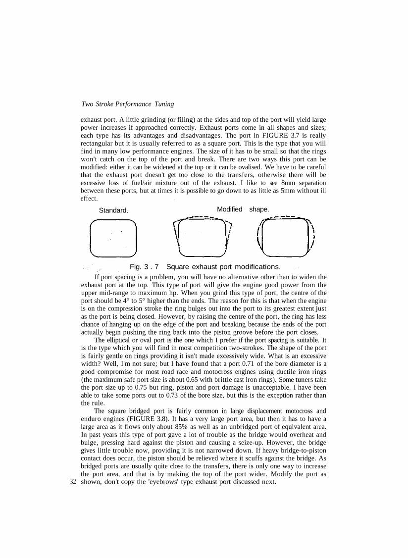
exhaust port. A little grinding (or filing) at the sides and top of the port will yield largepower increases if approached correctly. Exhaust ports come in all shapes and sizes;each type has its advantages and disadvantages. The port in FIGURE 3.7 is reallyrectangular but it is usually referred to as a square port. This is the type that you willfind in many low performance engines. The size of it has to be small so that the ringswon't catch on the top of the port and break. There are two ways this port can bemodified: either it can be widened at the top or it can be ovalised. We have to be carefulthat the exhaust port doesn't get too close to the transfers, otherwise there will beexcessive loss of fuel/air mixture out of the exhaust. I like to see 8mm separationbetween these ports, but at times it is possible to go down to as little as 5mm without illeffect.
Standard. Modified shape.
32
Fig. 3 . 7 Square exhaust port modifications.If port spacing is a problem, you will have no alternative other than to widen the
exhaust port at the top. This type of port will give the engine good power from theupper mid-range to maximum hp. When you grind this type of port, the centre of theport should be 4° to 5° higher than the ends. The reason for this is that when the engineis on the compression stroke the ring bulges out into the port to its greatest extent justas the port is being closed. However, by raising the centre of the port, the ring has lesschance of hanging up on the edge of the port and breaking because the ends of the portactually begin pushing the ring back into the piston groove before the port closes.
The elliptical or oval port is the one which I prefer if the port spacing is suitable. Itis the type which you will find in most competition two-strokes. The shape of the portis fairly gentle on rings providing it isn't made excessively wide. What is an excessivewidth? Well, I'm not sure; but I have found that a port 0.71 of the bore diameter is agood compromise for most road race and motocross engines using ductile iron rings(the maximum safe port size is about 0.65 with brittle cast iron rings). Some tuners takethe port size up to 0.75 but ring, piston and port damage is unacceptable. I have beenable to take some ports out to 0.73 of the bore size, but this is the exception rather thanthe rule.
The square bridged port is fairly common in large displacement motocross andenduro engines (FIGURE 3.8). It has a very large port area, but then it has to have alarge area as it flows only about 85% as well as an unbridged port of equivalent area.In past years this type of port gave a lot of trouble as the bridge would overheat andbulge, pressing hard against the piston and causing a seize-up. However, the bridgegives little trouble now, providing it is not narrowed down. If heavy bridge-to-pistoncontact does occur, the piston should be relieved where it scuffs against the bridge. Asbridged ports are usually quite close to the transfers, there is only one way to increasethe port area, and that is by making the top of the port wider. Modify the port asshown, don't copy the 'eyebrows' type exhaust port discussed next.

Standard.
Port and Cylinder Scavenging
Modified shape.
Fig. 3 .8 Bridged exhaust port modification.
The 'T' or eyebrows port is seldom seen these days although it was used by Suzuki,Kawasaki and Honda in the past (FIGURE 3.9). This type of port has very little goingfor it as the sudden change in shape above the main transfers is very harsh on bothpiston and rings. Usually there is very little that can be done to improve this type ofport.
Bridged exhaust ports can be made very wide, but there is a limit to how far youcan go. With the Suzuki RM125 engines (all models A to T), the maximum width is23mm for the left port window (viewed from the front of the bike) and 25.5mm for theright half of the port. If you go any wider than this, the piston will not be able to sealthe crankcase from the exhaust port because the skirt is relieved around the pin bosses.There should always be sufficient cylinder wall on the sides of both exhaust and inletports for a 2mm width of piston skirt to bear against and effect a seal.
To ensure that you don't go too far in widening the exhaust port, you will have tocarefully scribe the outline of the port windows on the piston skirt with the crankshaft
All dimensions in mm.
Fig. 3.9 Honda MT125 RIII porting. 33

Two Stroke Performance Tuning
rotated to TDC. Then remove the barrel and measure the distance from the scribedlines to the relieved area around the piston pin bosses. Subtract 2mm from themeasurement and this is the amount the port can be increased in width. The amountwhich can be removed from bridged inlet ports can be ascertained in a similar way, butwith the piston at BDC.
Thus far we have talked about changing the shape and width of the exhaust portbut not the height. Increasing the width of an exhaust port will always result in a powerincrease from the upper mid-range to peak rpm. Usually there will be little or no loss inmid-range power. Raising the port, on the other hand, will always knock bottom endpower. Increasing the duration, the port open period, by just a couple of degrees canmake a bike unrideable in some instances. Just how far you can raise the exhaust port isthe million dollar question everyone would like to know. Some tuners work to a time-area/angle-area formula devised some time back. Frankly, I have found this method ofcalculating port timing completely useless. The geometry and mathematics involved isvery tedious and, when you have finished the entire routine, you find that the answerbears little relationship with present-day two-stroke technology.
I have certain ideas on exhaust port timing, but blindly following my suggestionscould get you into a lot of trouble. My theory is that an engine requires a certainexhaust duration to attain a specific engine speed. Therefore, if an engine is required tomake maximum hp at, say, 12,000rpm, the exhaust duration required will be the same(±1°) regardless of whether the engine is an 80cc motocross engine or a twin cylinder250 road racer. From experience I have a fair idea of just how much duration specificengines need (see TABLE 3.1). However, if the cylinder has a shorter transfer openperiod than I like, the exhaust duration will have to be reduced, otherwise the bike will
TABLE 3.1 Exhaust port duration
Engine size (cc) Application Engine speed (rpm) Exhaust duration (°)
34
2x62x80x80x80x100xl00x125x125x125x125
2x1254x125x175x175
2x175x250X250x250x400x400
Mote: 1
Road raceMotoXMoto XRoad raceMotoXGo-kartMotoXMoto XRoad raceRoad raceRoad raceRoad raceEnduroEnduroRoad raceEnduroMoto XRoad raceEnduroMoto X
x 100 go-kart refers to a motor
13500110001200013000112001080010000110001200012500120001150090009500
1120080008500
1050070007500
with fixed gearing,
206-208196-198202-204205-207198-200176-178190-192196-198202-204203-205202-204200-202184-186186-188198-200180-182183-185194-196175-177176-178
hence short exhaust open period.

Port and Cylinder Scavenging
be too 'pipey' to ride. On the other hand, I may choose to raise the transfer ports anduse the suggested exhaust timing.
You can easily tie yourself in knots when you tackle cylinder porting. I've knowntuners who have moved exhaust ports up and down and all over the place, searching formore power or a better spread of power. After months of hard work they haveachieved nothing, basically because the transfer duration was too short and/or theexpansion chamber was all wrong. While it may appear rather arbitrary to select anexhaust timing figure and stick to that, I feel that this is currently the best way to goabout two-stroke tuning. Then, if the engine does exhibit some undesirable trait, like anarrow power range, I change the expansion chamber design to produce the requiredpower characteristics. What I'm saying is that expansion chamber design is far morecritical than exhaust port duration. The exhaust open period determines to some extentwhat the maximum hp will be and at what engine speed it will be produced. Theexpansion chamber, on the other hand, 'adjusts' the power characteristics of the engineat speeds above and below maximum hp revs.
The formula which I use to calculate exhaust open duration (and transferduration) is fairly straight forward, but if you do much work on two-strokes it wouldbe money well spent if you purchased an electronic calculator with a full scientificfunction to speed up your calculations. The formula is as follows:-
where T= R + L + C - ER = stroke divided by 2 in mmL = con rod length in mm centre to centre (usually the stroke multiplied
by 2)C= deck clearance in mm (i.e. the distance the piston is below the top
of the barrel at TDC)E = distance from the top of exhaust port to top of barrel
For example, the exhaust duration of the Morbidelli 125 twin production racer(FIGURE 3.10) is as follows:-
R= 20.5mmL = 87mmC= 0mmT= R + L + C - E

Two Stroke Performance Tuning
All dimensions in mm.
Fig. 3 . 1O Morbidelli 125 racer porting.
Looking at TABLE 3.1 you can see that the exhaust duration is right where wewant it for peak hp at 13,500-13,700rpm. However, if we were going to modify thisengine extensively by boring the Mikunis 1mm to 29mm and fabricating a new set ofexpansion chambers, we would want the power peak at a little over 14,000rpm, whichwould mean that the duration would have to be increased to 208° to take advantage ofthe engine's improved breathing. Therefore we would raise the exhaust port 0.35mm.E will now equal 17.85mm and T will equal 20.5 + 87 + 0-17.85 = 89.65.
36
= (180-Cos .24169) x 2= (180-76) X 2= 208°
On some engines fitted with Dykes rings, the top piston ring and not the pistoncrown controls the opening and closing of the exhaust and transfer ports. With theseengines, the exhaust duration is calculated using the same formula, however dimensionC (the deck clearance in mm) must be very carefully measured using a depth gaugeotherwise your calculations will be several degrees out. In engines where the Dykes ringactually determines the port opening and closing, dimension C is the distance the ring isbelow the top of the barrel at TDC. Referring back to FIGURE 3.5 you will note thatthe Rotax kart engine appears to have mild porting for a road racer. This engine, infact, has a single Dykes ring located very close to the top of the piston. Dimension C is1.8mm, so what looks like motocross porting is truly road race porting. In this case theexhaust duration is 201°.
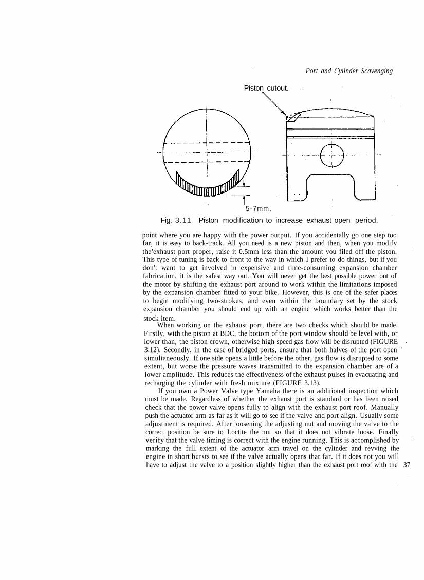
If you have not had any previous experience tuning two-strokes it is a lot safer tomodify the piston crown to increase exhaust duration rather than raise the port. Onceyou have taken the metal away you can't put it back, but fortunately pistons are a gooddeal less expensive than barrels so all you have to do is keep accurate notes and thenretrogress one step when you have gone too far (FIGURE 3.11). The idea is toprogressively file 0.5mm off the exhaust side of the piston crown until you reach a
Port and Cylinder Scavenging
Piston cutout.
5-7mm.
Fig. 3.11 Piston modification to increase exhaust open period.
point where you are happy with the power output. If you accidentally go one step toofar, it is easy to back-track. All you need is a new piston and then, when you modifythe 'exhaust port proper, raise it 0.5mm less than the amount you filed off the piston.This type of tuning is back to front to the way in which I prefer to do things, but if youdon't want to get involved in expensive and time-consuming expansion chamberfabrication, it is the safest way out. You will never get the best possible power out ofthe motor by shifting the exhaust port around to work within the limitations imposedby the expansion chamber fitted to your bike. However, this is one of the safer placesto begin modifying two-strokes, and even within the boundary set by the stockexpansion chamber you should end up with an engine which works better than thestock item.
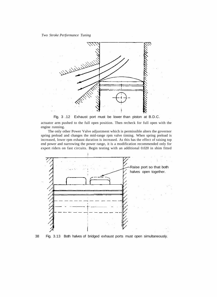
When working on the exhaust port, there are two checks which should be made.Firstly, with the piston at BDC, the bottom of the port window should be level with, orlower than, the piston crown, otherwise high speed gas flow will be disrupted (FIGURE3.12). Secondly, in the case of bridged ports, ensure that both halves of the port open 'simultaneously. If one side opens a little before the other, gas flow is disrupted to someextent, but worse the pressure waves transmitted to the expansion chamber are of alower amplitude. This reduces the effectiveness of the exhaust pulses in evacuating andrecharging the cylinder with fresh mixture (FIGURE 3.13).
If you own a Power Valve type Yamaha there is an additional inspection whichmust be made. Regardless of whether the exhaust port is standard or has been raisedcheck that the power valve opens fully to align with the exhaust port roof. Manuallypush the actuator arm as far as it will go to see if the valve and port align. Usually someadjustment is required. After loosening the adjusting nut and moving the valve to thecorrect position be sure to Loctite the nut so that it does not vibrate loose. Finallyverify that the valve timing is correct with the engine running. This is accomplished bymarking the full extent of the actuator arm travel on the cylinder and revving theengine in short bursts to see if the valve actually opens that far. If it does not you willhave to adjust the valve to a position slightly higher than the exhaust port roof with the 37
Two Stroke Performance Tuning
Fig. 3 .12 Exhaust port must be lower than piston at B.D.C.
actuator arm pushed to the full open position. Then recheck for full open with theengine running.
The only other Power Valve adjustment which is permissible alters the governorspring preload and changes the mid-range rpm valve timing. When spring preload isincreased, lower rpm exhaust duration is increased. As this has the effect of raising topend power and narrowing the power range, it is a modification recommended only forexpert riders on fast circuits. Begin testing with an additional 0.020 in shim fitted
-Raise port so that bothhalves open together.
38 Fig. 3.13 Both halves of bridged exhaust ports must open simultaneously.

Port and Cylinder Scavenging
behind the governor spring. If the power comes on too quickly or the power range istoo narrow, try a 0.012 in shim.
In recent years, the physical size and shape of the exhaust port between the portwindow and the flange where the expansion chamber connects, is under close scrutiny.Attempts are now being made to keep the diameter of the port as small as possible,without impeding the flow of gas out of the cylinder. Whereas the port diameter of atypical 125cc cylinder was 40 to 42mm a few years ago, most exhaust ports for a 125 arenow about 37 or 38mm diameter. This is being done to keep the exhaust pulse wave at ahigh amplitude so that the cylinder is scavenged and recharged more completely. It hasbeen found that allowing the exhaust gases to expand and cool too quickly, as occurswhen the exhaust port is large, actually diminishes the strength of the exhaust pulse.
Naturally the tuner's desire to keep the exhaust gas confined so that a strong pulsewave is transmitted through the expansion chamber, has to be balanced against theneed for a free-flowing exhaust passage, which allows the burnt gases to streamunimpeded out of the cylinder. To this end, the exhaust port must be relatively straight,without abrupt directional changes, to eliminate eddying, and the exhaust flange mustmatch the port perfectly and not change the direction of exhaust flow. When anexhaust port meets these requirements, gas flow out of the cylinder will be good, eventhough the port diameter is relatively small to keep pulse intensity at a high value.
A quick look through the exhaust flange and port will indicate how straight is theexhaust passage. However, unless you are very experienced in the science of gas flow,you will not know if the exhaust gases are eddying or not. If you are using castor oil orsome other oil which produced a fair buildup of carbon, you will be able to see wherethe exhaust port is 'dead'. Any place where there is a layer of carbon in a port which isbasically carbon-free is a place of little flow activity. In such an area you can be fairlycertain that the gases are eddying and disrupting flow out of the cylinder.
At times, the low pressure area can be eliminated by grinding metal out of theport, but more often than not the port will require welding up. The exhaust portillustrated in FIGURE 3.14 is a particularly nasty one. The flange changes the directionof flow very abruptly, which produces an eddy current in the top of the flange. Also thefloor of the port drops away too quickly, causing eddying in this area.
There are two ways to tackle the problem with the flange. The roof of the portmay be ground higher and the flange raised to reduce the kink in the port's roof. Onthe other hand a new flange can be fabricated with the roof in line with the roof of theexhaust port. Either way, the floor of the port, and perhaps the floor of the flange too,will have to be welded up to improve the profile. The aluminium floor naturally willhave to be argon-arc welded. Fill in only a little at a time and allow the cylinder plentyof time to cool between each run, otherwise it will distort.
As shown in FIGURE 3.15 the exhaust flange may be out of line when viewedfrom above. Again this must be corrected by fabricating a new flange which aligns withthe exhaust port.
From the aspect of two-stroke engine design, I feel that the transfer ports are themost important. Unfortunately, from the average tuner's viewpoint, the transfers arethe most difficult to modify and the least understood. By definition, the transfer portshave the job of transferring the fuel/air mixture from the crankcase into the cylinder.That sounds simple enough but, after we consider all of the factors involved, you willbetter appreciate what a mammoth task this really is. 39

Two Stroke Performance Tuning
Standard.
Kinks must be eliminated.
Exhaust flange.
Fabricate a newexhaust flange.
Fill floor.
Fig. 3 .14 Exhaust port must be correctly modified to assist flow.
In an average racing engine the induction cycle will take place during around 190°of crankshaft rotation. The exhaust cycle will occur over a period of 200°. The transferphase, however, has to be completed through 130° of crankshaft movement. Not onlydo the transfers have an extremely short time in which to recharge the cylinder withfuel/air mixture, they must also control the flow pattern of the charge to preventmixture loss out of the exhaust, and drive exhaust gases from the rear of the cylinder
40 towards the exhaust port.

Port and Cylinder Scavenging
Bend must be eliminated
Exhaust
Fig. 3.15 Flange must be in line with exhaust port to stop eddying.
During the '60s, when Suzuki and Yamaha dominated Grand Prix racing, theirengineers revived a myth which surfaced from the development of BSA Bantam andVilliers engines for racing just after the war. These engines had massive spaces in thecrankcase and tuners reasoned, rightly enough, that filling the crankcase with a varietyof 'staffers' would reduce crankcase volume and hence increase crankcase compressionwhen the piston descended to BDC. Increasing crankcase compression naturallyenough results in higher crankcase pressure which, all else being equal, raises transferflow and improves maximum hp output. Tuners cited the reason for this as being dueto the transfer streams erupting under considerable pressure into the cylinder. Becauseof this the fuel/air charge tended to behave like a wedge on entering the cylinder. Itdidn't break up and mingle with the exhaust gases, but pushed them out of the cylinderwith considerable force.
So effective was this method of cylinder scavenging that the fuel/air 'wedge' wasactually being partly lost out of the exhaust before the port closed. Two-stroke tunersovercame this problem by opening the transfer ports later and closing them earlier,reducing traditional transfer duration from 130° down to 120°. Because of more fuelcharge being contained within the cylinder, power increased. This encouragedengineers to further increase crankcase compression and reduce the transfer openperiod to less than 110°. Horsepower again rose, instilling in Japanese engineers theidea that dominance in Grand Prix racing would depend on them reducing transferduration to contain charge loss out of the exhaust and increasing crankcasecompression to ensure efficient pumping of the fuel/air mixture from the crankcaseinto the cylinder.
The theory sounds good, but in practice there were problems. True, power outputsrose to levels previously unknown from two-strokes, but the power bands became razor 41

Two Stroke Performance Tuning
thin and engine speeds rose to incredible levels. Not to be deterred, the Japaneseengineers embarked on a scheme of cylinder size reduction to enable very high rpm tobe attained reliably. Again power levels increased, providing a further stimulus toreduce cylinder displacement. This led to the development of such machines as thethree cylinder 50cc Suzuki and the four cylinder Yamaha 125 which produced 40hp at18,000rpm. At this time road racers had from ten to eighteen gears, such were thepower characteristics of these engines.
The problem was that in spite of the very limited transfer open periods employed,at lower engine speeds too much charge was being lost out of the exhaust. Thisoccurred because the transfer charge entered the cylinder under so much pressure thatit had time to spurt right out of the exhaust at low rpm. Hence little power wasproduced at speeds below maximum hp revs. At higher rpm, power was againrestricted, due to the transfer ports being too small to flow a larger volume of fuel/airmixture in the available time.
Today, the very same problem occurs when very short transfer periods areemployed. Generally, you will find that bikes which are 'pipey', coming onto the powertoo quickly or exhibiting a narrow power range, are that way because the transfer portsare too low (i.e., short duration) or because the ports are incorrectly aimed.
Fortunately, manufacturers have mostly got away from the idea of using highcrankcase compression to push the fuel charge through the transfers into the cylinder,so we can forget about crankcase compression and concentrate on the transfer ports.However, for those who are interested, primary compression or crankcase compressionis calculated using this formula:-
where CCV = crankcase volume at TDCCV = cylinder volume
To measure the crankcase volume (CCV), first turn the engine onto its side, withthe inlet port facing up, and rotate the crank to bring the piston up to TDC. Then,using a burette filled with liquid paraffin (kerosene) and engine oil, mixed 50-50, fillthe crankcase up to the cylinder wall face of the inlet port. If this equals, say, 425cc,and the engine has a 125cc cylinder, the primary compression ratio will be 1.42:1.
At this time, instead of relying solely on crankcase pressure to push the fuel/airmix into the cylinder, we also use the suction wave produced in the expansion chamberto pull the intake charge up through the transfers. If we use an expansion chamber withshallow tapers, maximum power will be suppressed, but the suction wave will be activein drawing mixture into the cylinder over a wide rpm range. On the other hand achamber with steeper cones will produce a stronger suction wave, raising peak hp, butit will be effective over a much narrower rev range.
Obviously the longer we leave the transfer ports open, the larger the rpm range willbe over which the exhaust pulses effectively pull up fresh mixture from the crankcase.Conversely, if transfer duration is kept short, we have to rely more on crankcasecompression to shift the fuel/air charge, as the suction pulse in the exhaust will only
42 arrive at the right time to draw up fuel over a limited rpm range. It stands to reason, if

Port and Cylinder Scavenging
the transfer port is closed when the pulse wave arrives, it will not do any good. On theother hand, if we keep the port open for as long as possible we have a better chance ofhaving pulse waves arrive at the right time, over a wider range of engine speeds.
With this idea in mind, we should realise that the transfer duration will vary forhigh and low speed engines. A high speed engine (i.e. 13,500rpm) will want the transferports open for 140-142° while an engine running at 6500rpm will be happy with aduration of 120-124° when exhaust port open periods are close to those in TABLE 3.1.At higher engine speeds there is less time for cylinder filling so we need a longertransfer period, but at lower speeds a long transfer period will allow too much chargeto escape out of the exhaust so a shorter duration is in order for low speed engines.TABLE 3.2 sets out the transfer durations which I have found to allow good enginebreathing at the speeds indicated. To pick up mid-range power the shorter durationshould be chosen. The engine won't rev far past maximum hp revs but the poweroutput below maximum will be superior. For good power past maximum rpm thelonger transfer period is desirable. If exhaust port durations longer than thoseindicated in TABLE 3.1 are used, then more transfer timing may be necessaryotherwise the engine could become too 'pipey'.
One ploy which is very effective in giving the engine good power over a wide rangeis to use staggered transfer durations. The old MZ 125 racer had the two main transferports open for 136°, while the third transfer port in the rear of the cylinder had a muchshorter duration of 128°. Many of the Italian go-kart engines also used this type ofporting in past years. When Honda introduced the MT-125RII production racer in1977, they took this principle one step further. The main transfers opened 39.2mmfrom the top of the cylinder (126° duration), the secondary transfers opened a littleearlier at 38.5mm (130° duration) and the boost port in the back of the cylinder openedthe last, 39.7mm down (123° duration).
Tuners reasoned that as the back port aimed its flow towards the exhaust portthere would be some loss of charge, unless steps were taken to prevent this occurring.Therefore the back port was opened around 1mm after the main transfers, so that flowfrom the main transfer ports, being aimed towards the rear of the cylinder, wouldactually form a wall of mixture in front of the boost port and thus prevent a loss ofcharge out of the exhaust. Furthermore, it was felt that delaying the opening of the rearport would allow crankcase pressure to 'blow down' through the main transfers. Hence
TABLE 3.2rpm
650080009000
1000011000120001300014000
Transfer port durationTransfer duration (°)
120-124124-128126-130128-132130-134132-136134-140136-142
Note: The transfer duration refers to the open period of the main transfer ports in particular. Thesecondary transfers and the boost port may beneficially use durations longer than shown. 43

Two Stroke Performance Tuning
a high pressure stream would not erupt from the back port and head right out of theexhaust.
Today those theories have been forgotten. The majority of engines come from themanufacturers with all the transfer ports at the same height. However, this does notmean that staggered porting does not work. Most tuners recognise that it does; but thetransfers are staggered in reverse to the old school of thought. At this time, when acylinder is modified, the back port is often opened 1.0 to 1.5mm earlier than the othertransfers. Also I have found that opening the secondary transfers 0.8mm before themain transfers benefits the power curve as well.
There are several reasons why staggered-type porting works so well at this time.For one thing the manufacturers have forgotten their preoccupation with highcrankcase pressure. Therefore, the transfer charge enters the cylinder in a more orderlyand controlled manner. Additionally, the transfer ports have been re-aimed. Whereasthe ports were tilted upwards so that the mixture streams from opposite sides of thecylinder gently met at a point in the cylinder just slightly higher than mid-stroke,today's ports are tilted very little or not at all (FIGURE 3.16). This means that the flowstreams hug the piston crown, rather than shooting up towards the head to mingle withexhaust gases. Instead, the streams crash into each other, dissipating much of theirenergy. The mixture then rises relatively slowly in the cylinder, where it is trapped asthe exhaust port closes. For these reasons, we can open the boost port and thesecondary transfer ports a little earlier, as there is less risk of mixture escaping out ofthe exhaust, even at lower speeds when there is more time for this to occur. If the maintransfers were opened earlier, exhaust flow would tend to turn the transfer flow aroundand direct it out of the exhaust port, but flow through ports further away from theexhaust port are not influenced to such an extent by the direction of exhaust flow.
When staggered porting is employed, it is usual for mid-range and maximumpower to increase, due to the longer transfer periods improving cylinder filling,particularly at high rpm. Much of the mid-range power gain, I feel, is due to thecylinder being scavenged better. With the new type of transfer porting, a pocket of
Old style.
44 Fig. 3 .16 Old & new transfer port designs.

Port and Cylinder Scavenging
exhaust gas can be left unscavenged high up in the cylinder at lower engine speeds.Opening the boost port early would tend to get this pocket of stagnant gas moving,because its flow stream is still directed upwards at 45° to 60°. Some fuel charge ispossibly lost out of the exhaust but, because this pocket of exhaust gas is purged out ofthe cylinder, there is less dilution of the remaining fuel/air mixture. Consequentlycombustion will be faster and more complete, raising the hp output.
Because the direction of transfer flow is so very important in obtaining a highpower output and a good power range, only very experienced tuners should attempt tomodify the top section of transfer ports. If you don't know what you are doing, youcould easily render the cylinder useless. When the transfer duration is too short, raisethe barrel using an aluminium spacer of the required thickness, and fit a base gasket oneach side to ensure a good seal. Naturally the compression will have to be restored byturning an amount equal to the thickness of the spacer, plus the thickness of one basegasket, from the barrel or cylinder head. Keep in mind, when the cylinder is raised, thatthe piston rings may become exposed in the inlet port. This is of no consequenceproviding the top of the port is correctly shaped and providing the ring ends are notexposed. If just the bottom ring is opening into the inlet port, it can be removed if theengine is usually operated at 8000rpm plus. In piston-ported engines, raising the barrelwill shorten the inlet open period so the inlet port will have to be lowered tocompensate.
Cylinders employing the type of boost port usually found in reed valve engines (eg.Yamaha) are quite easy to modify. This type of back port can be raised or increased inwidth, using hand files. Take care that you don't nick the bore wall with the file and donot make the port so wide that it opens out to the piston ring pegs. A width equal tothat of the main transfer port is close to what is required, but always check to be sure.
The secondary transfers should be raised by a professional tuner with goodknowledge of the subject and good equipment to do the job. The alternative, whichworks very well, is to file metal off the piston crown (see FIGURE 3.11) in the mannerdescribed for increasing exhaust port duration. If the piston is fitted with a Dykes ringhigh up (eg. Bultaco) this method will not work, as the piston ring and not the pistoncrown actually controls the exhaust and transfer opening.
The safest part of the transfer port for you to modify is the bottom of the portwhere it joins the crankcase. Cut the base gasket to match the crankcase cut-outs andthen match the transfers to the base gasket. This will ensure that there is no step in theport to disrupt flow. Then carefully smooth the transfers, removing all castingimperfections. The piston cut-out below the gudgeon pin is also a part of the transferport, so dress it up too.
Thus far we have only discussed working with the ports provided by themanufacturer, but extra transfer ports can often be added. Here there are twoapproaches which we can take, depending on whether we want a small increase inperformance and good piston cooling, or a larger power rise without the benefit ofimproved piston cooling.
We will deal with the cool piston approach first, which can be applied to manyengines regardless of the type of induction system employed. I first saw porting likethat illustrated in FIGURE 3.17 on the old 250 Bultaco Pursang and Matador. As youcan see, two boost ports are machined the depth of the cylinder liner about 7-9mmwide, on either side of the inlet port. These ports are fed through two holes in the 45

Two Stroke Performance Tuning
This section of port alignswith feed hole in piston.
Boost ports.
Mixture feed hole.
46
Fig. 3.17 A common type of boost porting.
piston. The flow of mixture past the little end and under the piston crown does much toreduce their temperatures. Desert racing engines in particular benefit from this type ofporting. There isn't a huge increase in power, but usually a couple of horsepower willbe picked up at the top end of the power band.
The next type of boost porting also improves little end lubrication and pistoncooling (FIGURE 3.18). It is intended for piston-ported engines which have a lot ofcylinder wall height between the top of the inlet port and the piston crown at BDC.Two boost ports are machined into the cylinder, generally with a 13mm cutter tilted at25°. Ensure that the boost ports are at least 1.5mm above the inlet port, to ensure aneffective seal.
The third type of boost porting shouldn't really be called boost porting (FIGURE3.19). It doesn't do anything to increase hp output, but it will extend piston and little

Port and Cylinder Scavenging
Boost port/s.X
Fig. 3 18 Some engines may utilise boost ports above the inlet port.
Boost ports.
Fig. 3.19 Boost porting for desert bikes. 47
Two Stroke Performance Tuning
end life in desert bikes. I call it 'last resort' porting. Two 9mm wide slots are machinedthe depth of the cylinder liner to join with the main transfers. Holes in the piston feedthese ports as in the first example.
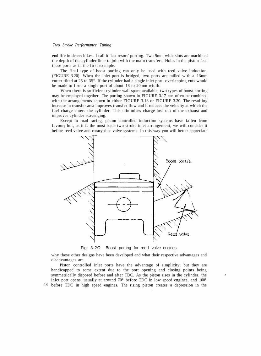
The final type of boost porting can only be used with reed valve induction.(FIGURE 3.20). When the inlet port is bridged, two ports are milled with a 13mmcutter tilted at 25 to 35°. If the cylinder had a single inlet port, overlapping cuts wouldbe made to form a single port of about 18 to 20mm width.
When there is sufficient cylinder wall space available, two types of boost portingmay be employed together. The porting shown in FIGURE 3.17 can often be combinedwith the arrangements shown in either FIGURE 3.18 or FIGURE 3.20. The resultingincrease in transfer area improves transfer flow and it reduces the velocity at which thefuel charge enters the cylinder. This minimises charge loss out of the exhaust andimproves cylinder scavenging.
Except in road racing, piston controlled induction systems have fallen fromfavour; but, as it is the most basic two-stroke inlet arrangement, we will consider itbefore reed valve and rotary disc valve systems. In this way you will better appreciate
48
Fig. 3.2O Boost porting for reed valve engines.
why these other designs have been developed and what their respective advantages anddisadvantages are.
Piston controlled inlet ports have the advantage of simplicity, but they arehandicapped to some extent due to the port opening and closing points beingsymmetrically disposed before and after TDC. As the piston rises in the cylinder, theinlet port opens, usually at around 70° before TDC in low speed engines, and 100°before TDC in high speed engines. The rising piston creates a depression in the

Port and Cylinder Scavenging
crankcase, thus air rushes down the inlet tract to fill the crankcase. However, at TDCthe port is still open so, as the piston descends, fuel/air mixture will be pushed out ofthe crankcase through the open inlet port. Fortunately, reverse flow occurs only afterthe piston has travelled about 50° past TDC at engine speeds around 4,000rpm.Therefore, if the inlet port closes at 70° after TDC, only a small amount of fuel chargewill be lost. At higher engine speeds there won't be any loss of mixture, as thecombined force of pulse waves and the inertia of the high velocity mixture is strongerthan the pressure created in the crankcase by the descending piston. For this reason wecan employ longer inlet durations in high speed engines, but at lower rpm they sufferfrom such a bad dose of the blubbers that they will hardly run.
The poor low speed running is partly due to not enough fuel/air mixture beingavailable in the crankcase to adequately fill the cylinder, but there is another reason.The low rpm blubbers and stumbles are basically due to flooding. When the mixture ispushed out of the crankcase and up the inlet tract, it eventually passes through thecarburettor. On its way through it picks up another load of fuel, then when the inletport again opens the fuel/air mixture reverses and travels back through thecarburettor, collecting yet another load of fuel. The rich mixture which results burnsslowly and wets the spark plug.
The inlet durations set out in TABLE 3.3 will give good power at the speedsindicated. The shorter duration will improve mid-range pulling power and the longerduration for each speed will enable the engine to produce more power at rpm in excessof maximum hp revs. Motocross and enduro engines such as the RM and PE seriesSuzukis, with crankcase type reed valves, would normally want inlet durations 15° and25° shorter respectively. When RM Suzuki engines are used for flat track and roadracing, the inlet open period is as indicated in TABLE 3.3, as mid-range power is not soimportant.
TABLE 3.3rpm
700080009500
1100012000
Inlet port durationInlet duration (°)150-155155-160165-170185-190195-200
Two Stroke Performance Tuning
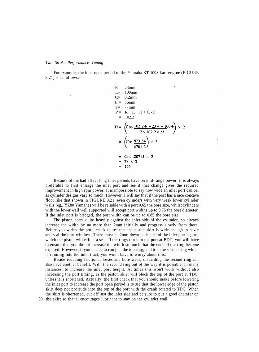
For example, the inlet open period of the Yamaha KT-100S kart engine (FIGURE3.21) is as follows:-
R= 23mm 'L= 100mmC= 0.2mmH = 56mmF= 77mmP = R + L + H + C - F
= 102.2
Because of the bad effect long inlet periods have on mid-range power, it is alwayspreferable to first enlarge the inlet port and see if that change gives the requiredimprovement in high rpm power. It is impossible to say how wide an inlet port can be,as cylinder designs vary so much. However, I will say that if the port has a nice concavefloor like that shown in FIGURE 3.21, even cylinders with very weak lower cylinderwalls (eg., YZ80 Yamaha) will be reliable with a port 0.65 the bore size, whilst cylinderswith the lower wall well supported will accept port widths up to 0.75 the bore diameter.If the inlet port is bridged, the port width can be up to 0.85 the bore size.
The piston bears quite heavily against the inlet side of the cylinder, so alwaysincrease the width by no more than 2mm initially and progress slowly from there.Before you widen the port, check to see that the piston skirt is wide enough to coverand seal the port window. There must be 2mm down each side of the inlet port againstwhich the piston will effect a seal. If the rings run into the port at BDC, you will haveto ensure that you do not increase the width so much that the ends of the ring becomeexposed. However, if you decide to run just the top ring, and it is the second ring whichis running into the inlet tract, you won't have to worry about this.
Beside reducing frictional losses and bore wear, discarding the second ring canalso have another benefit. With the second ring out of the way it is possible, in manyinstances, to increase the inlet port height. At times this won't work without alsoincreasing the port timing, as the piston skirt will block the top of the port at TDC,unless it is shortened. Actually, the first check that you should make before loweringthe inlet port to increase the port open period is to see that the lower edge of the pistonskirt does not protrude into the top of the port with the crank rotated to TDC. Whenthe skirt is shortened, cut off just the inlet side and be sure to put a good chamfer on
50 the skirt so that it encourages lubricant to stay on the cylinder wall.

Port and Cylinder Scavenging
ALL dimensions in mm.
Fig. 3 . 21 Yamaha KT-1OOS porting & piston dimensions.
A lot of tuners lengthen the inlet timing just by shortening the piston. Sometimesthere is no alternative, as the cylinder may be too weak to stand having metal removed,but, generally, skirt cutting is the easy way out. Even though cutting 3mm off the skirtwill increase the inlet duration to the same figure as lowering the inlet floor by 3mm,you will find that maximum hp will not be as high and the engine will not rev as far pastmaximum hp revs. The simple truth is that the port area, as well as the duration, mustbe increased to flow the amount of air necessary to improve the power output. I havefound, as a general rule, that the piston skirt will have to be shortened by 4mm to givethe same high speed power characteristics as obtained by lowering the port 3mm.However, mid-range power is not as good, due to increased blow-back caused by thelonger duration. For maximum power, the inlet port area should be about 10 to 15%larger than the area of the carburettor bore.
When the inlet floor is lowered, the full length of the port floor right back to the 51

Port and Cylinder Scavenging
Fig. 3
Raise carburettor to minimisekink in induction tract.
23 Raise carburettor to improve inlet flow.
Inlet port open.
Rotary valve disc.
Fig. 3 . 24 Rotary valve induction arrangement. 53
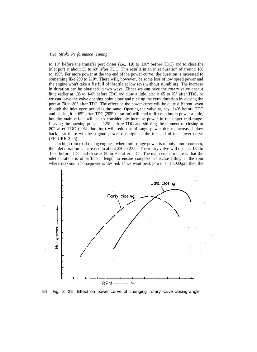
Two Stroke Performance Tuning
to 10° before the transfer port closes (i.e., 120 to 130° before TDC) and to close theinlet port at about 55 to 60° after TDC. This results in an inlet duration of around 180to 190°. For more power at the top end of the power curve, the duration is increased tosomething like 200 to 210°. There will, however, be some loss of low speed power andthe engine won't take a fistfull of throttle at low revs without stumbling. The increasein duration can be obtained in two ways. Either we can have the rotary valve open alittle earlier at 135 to 140° before TDC and close a little later at 65 to 70° after TDC, orwe can leave the valve opening point alone and pick up the extra duration by closing theport at 70 to 80° after TDC. The effect on the power curve will be quite different, eventhough the inlet open period is the same. Opening the valve at, say, 140° before TDCand closing it at 65° after TDC (205° duration) will tend to lift maximum power a little,but the main effect will be to considerably increase power in the upper mid-range.Leaving the opening point at 125° before TDC and shifting the moment of closing to80° after TDC (205° duration) will reduce mid-range power due to increased blowback, but there will be a good power rise right at the top end of the power curve(FIGURE 3.25).
In high rpm road racing engines, where mid-range power is of only minor concern,the inlet duration is increased to about 220 to 235°. The rotary valve will open at 135 to150° before TDC and close at 80 to 90° after TDC. The main concern here is that theinlet duration is of sufficient length to ensure complete crankcase filling at the rpmwhere maximum horsepower is desired. If we want peak power at 14,000rpm then the
54 Fig. 3 .25 Effect on power curve of changing rotary valve closing angle.
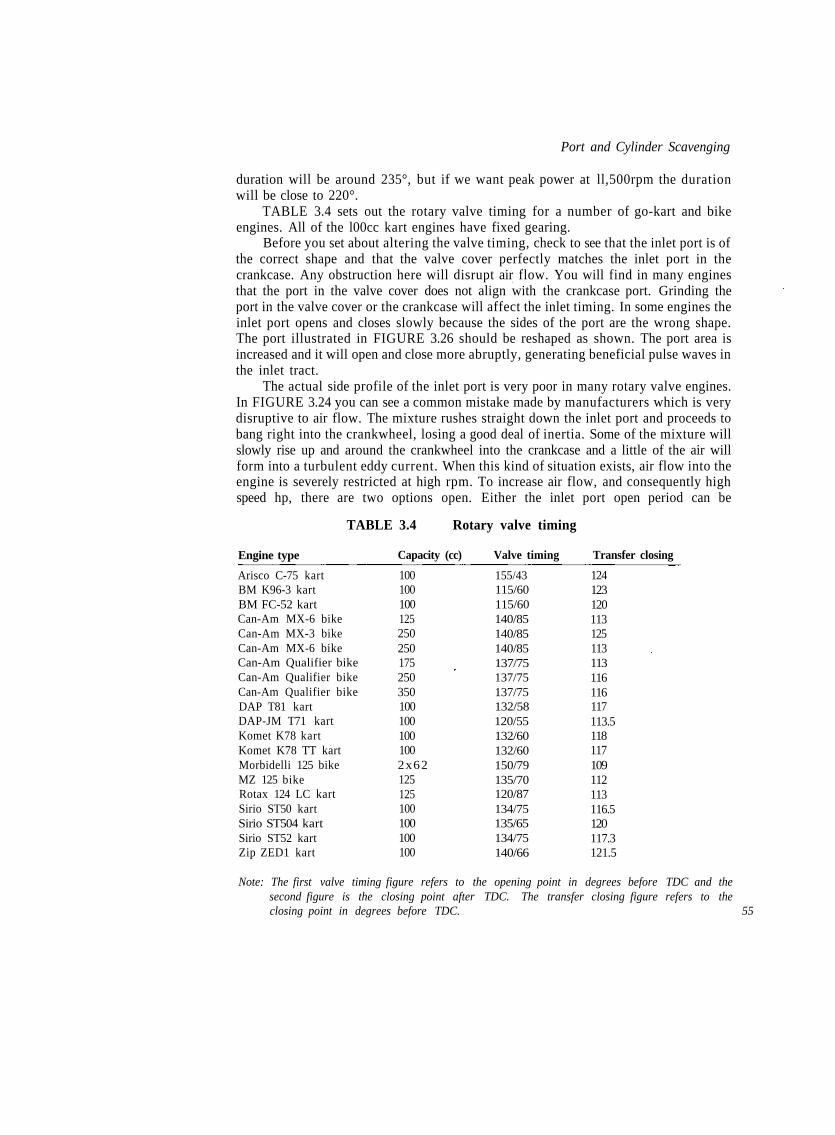
Port and Cylinder Scavenging
duration will be around 235°, but if we want peak power at ll,500rpm the durationwill be close to 220°.
TABLE 3.4 sets out the rotary valve timing for a number of go-kart and bikeengines. All of the l00cc kart engines have fixed gearing.
Before you set about altering the valve timing, check to see that the inlet port is ofthe correct shape and that the valve cover perfectly matches the inlet port in thecrankcase. Any obstruction here will disrupt air flow. You will find in many enginesthat the port in the valve cover does not align with the crankcase port. Grinding theport in the valve cover or the crankcase will affect the inlet timing. In some engines theinlet port opens and closes slowly because the sides of the port are the wrong shape.The port illustrated in FIGURE 3.26 should be reshaped as shown. The port area isincreased and it will open and close more abruptly, generating beneficial pulse waves inthe inlet tract.
The actual side profile of the inlet port is very poor in many rotary valve engines.In FIGURE 3.24 you can see a common mistake made by manufacturers which is verydisruptive to air flow. The mixture rushes straight down the inlet port and proceeds tobang right into the crankwheel, losing a good deal of inertia. Some of the mixture willslowly rise up and around the crankwheel into the crankcase and a little of the air willform into a turbulent eddy current. When this kind of situation exists, air flow into theengine is severely restricted at high rpm. To increase air flow, and consequently highspeed hp, there are two options open. Either the inlet port open period can be
Engine type
TABLE 3.4 Rotary valve timing
Capacity (cc) Valve timing Transfer closing
Arisco C-75 kartBM K96-3 kartBM FC-52 kartCan-Am MX-6 bikeCan-Am MX-3 bikeCan-Am MX-6 bikeCan-Am Qualifier bikeCan-Am Qualifier bikeCan-Am Qualifier bikeDAP T81 kartDAP-JM T71 kartKomet K78 kartKomet K78 TT kartMorbidelli 125 bikeMZ 125 bikeRotax 124 LC kartSirio ST50 kartSirio ST504 kartSirio ST52 kartZip ZED1 kart
1001001001252502501752503501001001001002x62125125100100100100
155/43115/60115/60140/85140/85140/85137/75137/75137/75132/58120/55132/60132/60150/79135/70120/87134/75135/65134/75140/66
124123120113125113113116116117113.5118117109112113116.5120117.3121.5
Note: The first valve timing figure refers to the opening point in degrees before TDC and thesecond figure is the closing point after TDC. The transfer closing figure refers to theclosing point in degrees before TDC. 55

Two Stroke Performance Tuning
Leave 2mm. minimum for discto seal against. Required port shape.
56
Fig. 3 . 26 Modifying inlet port shape without affecting rotary valve timing.
increased, which will reduce mid-range power, or we can reprofile the inlet port andincrease air flow in this way. Top end power will improve and often mid-range powerrises too.
What we must do is change the shape of the inlet port, so as to encourage themixture to turn up and over the crankwheel. In effect, the edge of the crankwheel hasto become a part of the inlet tract floor, instead of a barrier at the end of a hole. InFIGURE 3.27 you can see the shape we have to aim for. The floor of the port is builtup to blend into the crankwheel, and the lip formed by the port roof and the transfercutout is radiused. The port can be built up using Devcon F aluminium epoxy. Itcontains 80% aluminium, is heat resistant to 250°F and is not attacked by petrol,methanol, oil or toluol.
Ideally, manufacturers should turn to the use of larger disc valves so that the inletport floor could be in line with the top of the crankwheel. In this situation the fuel/aircharge would flow straight into the crankcase unimpeded. In addition to this, there isanother advantage in the use of large diameter discs, which is the primary reason fortheir existence on the works Minarelli and Morbidelli Grand Prix racers. When therotary disc diameter is increased, there is a corresponding decrease in the durationangle actually taken up by the inlet port itself, assuming the inlet port width is notaltered. This allows for a longer duration angle with the large disc without increasingthe actual inlet port open period. The power output then goes up, because the inlet port

Fill floor with epoxyto improve flow. .
Port and Cylinder Scavenging
Radius corner.
Fig. 3 .27 Modify inlet port to increase flow.
is fully open for a greater number of degrees, without being partially closed by the disc,or as the engine sees it for more time, so more air flows into the crankcase. Conversely,if the engine is already producing ample power at the top end of the rpm range, thenthe inlet open period can be reduced with the large diameter disc. In this way peakpower will remain the same, but the mid-range to upper mid-range will riseappreciably.
Trying to get the sense of this is quite hard just using words, so I will help you toreason it out with an example and an illustration (FIGURE 3.28). As you can see, bothengines have an inlet port 34mm wide and an inlet duration of 200°. The engine withthe small 100mm diameter disc (engine A) has an inlet port and rotary disc which takesup 40° and 160° respectively of the 200° inlet cycle. On the other hand the inlet portand disc occupy 27° and 173° respectively when a 150mm disc (engine B) is used. Thismeans that the inlet port is not obstructed in any way by the rotary valve for 120°(200 - [2 x 40] = 120°) in the case of engine A and for 146° (200 - [2 x 27] = 146°) forengine B. In other words the inlet port will be fully open for 26° or 22% longer. Asregards time this represents 0.00166 sec. for engine A and 0.00203 sec. for engine B at12,000rpm.
Before you modify the rotary valve to change either the inlet opening or closingpoints, it is a good idea to find out exactly what the standard timing is for your engineand then compare that with the manufacturer's specifications. At times there can be 57

Two Stroke Performance Tuning
. . , . Engine "A"
58
Fig. 3. 28 Comparison of small & large rotary valves.
variations, because a keyway or master spline is cut slightly out or, in some engines, itis possible that the disc valve has been fitted one tooth out on the drive gear eitherduring manufacture or when the engine has been repaired.
To check the valve timing you will require a 360° timing disc or, if you can'tobtain one of these in your area, buy a large 200mm diameter protractor and drill asuitable size hole exactly in the centre so that it fits the end of the crankshaft. You willalso need a good solid pointer which can be fixed under a stud in the crankcase. If youdon't have a dial timing gauge to find TDC, then you will have to make a positive stopto prevent the piston rising to the top of its stroke. The best positive stop is one madeout of an old Bosch spark plug and a length of 6mm mild steel rod. A Bosch plug ispreferred as its insulator is very easy to remove. Under the hexagon shaped part of theplug shell you will see a groove running right the way around. Cut through this groovewith a hacksaw and the insulator can be pulled out. Then weld a piece of rod into theplug shell, just long enough to stop the piston reaching TDC.

Port and Cylinder Scavenging
Using a dial gauge find TDC and rotate the timing disc to align the zero mark withthe pointer. Lock the disc in place on the crank and again check that the pointer pointsto zero when the dial gauge indicates TDC. Then simply rotate the crankshaft in thenormal direction of rotation, noting at what angle the inlet port opens and closes.When making this check it is necessary to shine a light down the inlet port so it can beclearly seen when the valve opens and closes.
Using a positive stop, the procedure is a little different. Rotate the engine in onedirection until the piston contacts the stop. Note the angle and then rotate the crank inthe opposite direction until the piston contacts the stop. Again note the angle. Midwaybetween these two angles TDC is located. Let's say that there is 36° difference betweenthe two angles. In this case TDC will be 18° (36 /2=18° ) around from where thecrankshaft is now stopped. Therefore loosen the timing disc and move it around untilthe pointer indicates 18° or 342° depending on which way the crankshaft is beingrotated. Having done that, lock the timing disc in position and again rotate the crankone way and then the other until the piston contacts the stop. If in one direction thepointer indicates 342° and in the other direction it indicates 18°, you can be sure thatthe timing disc is locked onto the crank in the correct position. After this, remove thepositive stop and make a note of the rotary valve's opening and closing angles.
Instead of using a degree wheel to physically determine the valve timing, it may becalculated mathematically using this formula if the engine has a Dykes ring fitted rightat the top of the piston:-
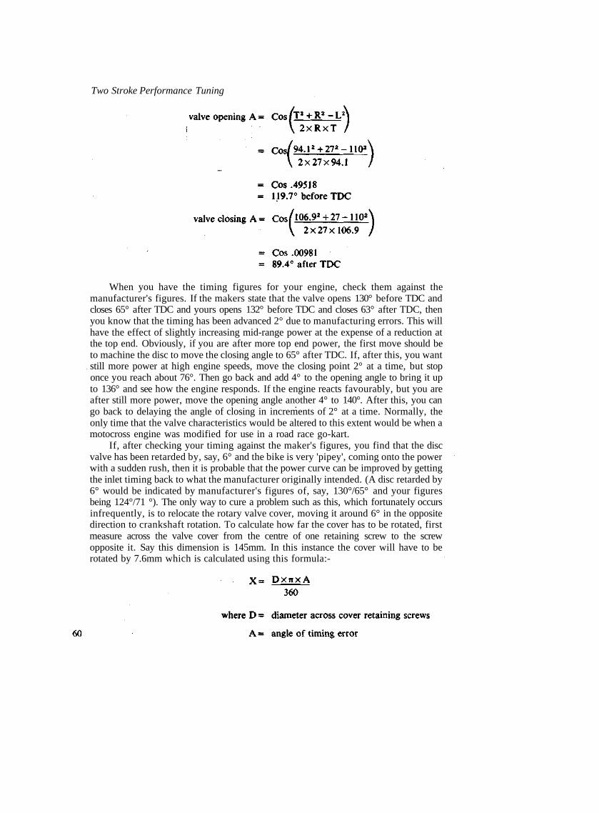
Two Stroke Performance Tuning
When you have the timing figures for your engine, check them against themanufacturer's figures. If the makers state that the valve opens 130° before TDC andcloses 65° after TDC and yours opens 132° before TDC and closes 63° after TDC, thenyou know that the timing has been advanced 2° due to manufacturing errors. This willhave the effect of slightly increasing mid-range power at the expense of a reduction atthe top end. Obviously, if you are after more top end power, the first move should beto machine the disc to move the closing angle to 65° after TDC. If, after this, you wantstill more power at high engine speeds, move the closing point 2° at a time, but stoponce you reach about 76°. Then go back and add 4° to the opening angle to bring it upto 136° and see how the engine responds. If the engine reacts favourably, but you areafter still more power, move the opening angle another 4° to 140°. After this, you cango back to delaying the angle of closing in increments of 2° at a time. Normally, theonly time that the valve characteristics would be altered to this extent would be when amotocross engine was modified for use in a road race go-kart.
If, after checking your timing against the maker's figures, you find that the discvalve has been retarded by, say, 6° and the bike is very 'pipey', coming onto the powerwith a sudden rush, then it is probable that the power curve can be improved by gettingthe inlet timing back to what the manufacturer originally intended. (A disc retarded by6° would be indicated by manufacturer's figures of, say, 130°/65° and your figuresbeing 124°/71 °). The only way to cure a problem such as this, which fortunately occursinfrequently, is to relocate the rotary valve cover, moving it around 6° in the oppositedirection to crankshaft rotation. To calculate how far the cover has to be rotated, firstmeasure across the valve cover from the centre of one retaining screw to the screwopposite it. Say this dimension is 145mm. In this instance the cover will have to berotated by 7.6mm which is calculated using this formula:-

The idea is to then drill a new set of fixing holes in the valve cover 7.6mm from theoriginal hole centres. Having done this, refit the cover and check when the rotary valveopens and closes the port in the valve cover. Actually, the port timing figures shouldalways be taken off the valve cover, never the crankcase port. If the timing is correct, itis advantageous to take the machine for a test run before you spend a lot of timematching the ports. Naturally, the engine will be down on top end power, but it is its'pipeyness' which you are checking, not top end power. If the results are satisfactorythen match the ports, filling one side with Devcon F as shown in FIGURE 3.29 andgrinding the other side out.
It is not always necessary to relocate the rotary valve cover to correct valve timingerrors. Some engines, for example those made by Rotax, have the rotary valve drivenby a hub which is located on the crankshaft by a key. In the case of Rotax motors thehub is cut with 22 external gear teeth so moving the rotary valve one tooth on the hubwill alter the timing by 16.4° (360° 4- 22= 16.4°) which isn't of much use to us.However, by machining a new keyway in the hub and by moving the valve around theappropriate number of teeth timing errors can be corrected.
For example, machining a new keyway 90° around from the original and movingthe valve around by 5 or 6 teeth (depending on whether the timing is advanced orretarded) will correct an 8° timing error. That is quite an easy one to work out, but
Fig. 3 . 29 Match inlet port after relocating rotary valve cover . 61
Two Stroke Performance Tuning
what if the timing is retarded by 6°? To calculate how many degrees around the newkeyway has to be cut, add the angle of error to 90° and subtract 8°, which equals 88°(90° + 6° - 8° = 88°.) The new keyway will therefore have to be cut 88° around fromthe original, but will it be to the left (counter-clockwise) or right (clockwise) of theoriginal? Since the valve is presently retarded it will have to be advanced to correct thetiming error. The engine turns counter-clockwise so the new keyway will have to bemachined 88° to the left of the original keyway, which will advance the hub by 88°.Retarding the rotary valve (i.e., moving it in the same direction as crank rotation) by 5teeth will retard the timing by 82° (16.36° x 5 = 82°), consequently the timing will finishup being advanced by 6° (88°-82° =6°) from what the original timing figure was,which should be the figure specified by the manufacturer. You must be very carefulthat this type of work is carried out by only a top class machinist as it is exceedinglydifficult to work to such fine tolerances in a bore as small as that found in the hub of arotary valve.
To change the opening and closing points of the rotary valve disc proper is a littledifficult, unless you make a special setting-up template of white cardboard or cartridgepaper. In the centre of the template draw a cross ( + ) with lines about 150mm longintersecting at exactly 90°. Using the cross as the centre, draw a circle exactly the samediameter as the rotary valve disc. Carefully lay the rotary valve on the template withinthe confines of the circle which you just drew and using a sharp pencil draw the disccut-out. (Be sure that the outside face of the disc is facing up.). Now draw anothercircle, using the cross as the centre, about 50mm larger in diameter than the rotaryvalve. After this, set a large (100mm or larger) protractor exactly on centre and note theangle of the disc's opening and closing points. Now carefully mark in the new openingor closing angle which you want. Draw a line from the centre through this point rightout to the edge of the large circle. Lay the disc back onto the template, the correct wayup, being careful to line it up within the boundary formed by the small circle and theoriginal opening and closing lines. Now scribe a line across the disc exactly in line withthe line you drew to show the new opening or closing angle. With that done, the disccan be modified to change the inlet timing.
The clearance between the valve cover and the rotary disc is very important. If theclearance is too tight, power is lost due to friction and, if the clearance is excessive, lowspeed and mid-range power is lost due to fuel/air charge leakage out past the valve.Unless otherwise specified, the clearance should normally be between 0.25mm and0.35mm. If it is less than 0.25mm the face of the valve cover will have to be machinedthe appropriate amount. On the other hand, if the clearance is greater than 0.35mm themating surface of the cover will require machining.
Reed valve induction was first introduced to the motorcycle world in 1972 whenYamaha released their range of 'Torque Induction' bikes (FIGURE 3.20). The reedvalve functions as a simple check valve and prevents blow-back in the inlet tract.Therefore, a reed engine can be lugged down to very low rpm (depending on theexhaust timing), as the air flowing down the inlet tract is trapped once it passes the reedvalve. Low speed cylinder filling improves and, because the air passes through thecarburettor just once, the fuel/air ratio remains correct. This results in good low speedcombustion.
Reed valve induction, however, is not entirely free of problems. Until very62 recently, the stiffness of the reed petals was severely compromised. To ensure good low
Port and Cylinder Scavenging
speed crankcase filling, the reed petals must be thin and flexible so that they open easilyand do not unduly restrict air flow. On the other hand the petals must be thick andstiff, otherwise crankcase filling at high speeds is not good. At high speeds thin,flexible petals flutter, allowing reverse flow out of the crankcase. They tend to closeand then rebound from their seats due to inertia and/or resonance in the inductiontract.
A dual reed assembly patented by Eyvind Boyesen reduces this compromise aconsiderable amount. The presence of a reed cage and petals in the induction tract stillreduces high speed air flow below that possible with rotary valve or piston portedinduction, but the difference is not so great as before. The Boyesen assemblycomprises a thin 0.25mm reed, riding on top of a thicker 0.7mm reed. The thin reedopens easily under a low pressure drop and the thicker one takes over at higher rpm.This gives the benefits of good low speed air flow, as well as an absence of high speedpetal flutter. As an added benefit, the ribs in the reed cage can be cut out when theBoyensen assembly is fitted, such is the design of the thick petal. This alone improvesair flow and crankcase filling at higher speeds.
Over the years a lot has been said about the benefits of reed valve induction, but itseems that very few people realise the very high power outputs now being produced bymotocross and enduro engines are not a direct result of reed valve induction. A lotseem to think that, because the piston is cut away, or has windows in it, allowing insome engines up to 360° inlet open period, this automatically results in a high poweroutput. I can assure you that this is not so. In itself a reed valve improves low speed andmid-range power only, by preventing blow-back.
To give you some proof of why I say this, we will have a look at the effect ofadding a reed valve to an old 250 Bultaco Matador. In standard tune the engine hadexhaust, transfer and inlet open periods of 170°, 126° and 150° respectively. As shownin TABLE 3.5, the engine has a gentle power curve. It pulls very well at low speed andproduces a maximum of 25.8 hp at 7000rpm. In test 2 a reed valve was added and four16mm holes were drilled in the piston skirt, increasing the inlet timing to 360°. As youcan see, there has been very little increase in power at the top end in spite of the factthat a 34mm Bing carburettor was fitted to replace the stock 32mm Amal. Note, too,that there has been only a marginal decrease in low speed power, due to the reed valveoffsetting to some extent the bad effect the larger carburettor would have had at lowrpm.
In test 3, however, you can see that power right through the range has risen by anaverage of 1.5 hp below 5500rpm, and by up to 3.1 hp between 6000 and 7000rpm.What brought about such a sudden power increase? In this test, two boost ports wereadded in the rear of the cylinder. The ports were cut with a 13mm cutter tilted at 30°. Soit was the increase in transfer port area which picked up power significantly, not theaddition of a reed valve.
In test 4, there was an increase in power above 6500rpm, but a decrease at lowerspeeds. For this test, a new piston was fitted which had 13mm removed from thebottom of the inlet skirt to give an inlet open period of 200°. This means that the pistonexercises control over which direction transfer flow will take. In test 3, the boost portsare always connected with the crankcase (i.e., for 360°) but in test 4 the boost ports areisolated from the crankcase (see FIGURE 3.20) once the piston skirt drops below thelevel of the inlet port floor. Thus, any flow through the reed valve will be diverted up 63

Two Stroke Performance Tuning
TABLE 3.5 Effect of reed valve induction
rprn Test 1 (hp) Test 2 (hp) Test 3 (hp) Test 4 (hp)300035004000450050005500600065007000750080008500
6.87.911.914.216.018.122.623.325.825.623.718.1
6.48.111.313.615.618.022.924.926.725.124.820.6
8.310.912.114.817.019.726.027.227.826.325.522.1
7.910.411.814.616.619.325.727.128.427.626.222.8
Test 1 — standard Bultaco Matador 250cc
Test 2 — reed valve assembly and 34mm Bing carburettor added; piston modified to give 360°inlet open period.
Test 3 — as above, with the addition of two boost ports in rear of cylinder.
Test 4 — as above but with piston modified to give 200° inlet open period, i.e., 'powerported'.
through the boost ports once the piston closes the inlet tract off from the crankcase.With this arrangement, low speed power falls away, because the boost ports flow onlyif the exhaust pulses create a depression low enough to open the reed valve and pullfuel/air mixture up through the boost ports. However, at higher speeds, peak power isincreased with this system, because the piston closes off the crankcase from the inlettract, preventing back flow out of the crankcase as the piston descends to BDC.Without the effects of reverse flow to fight against, mixture will continue on flowingthrough the reed valve and up through the boost ports until cylinder pressure equalspressure in the inlet tract, causing the reed valve to close.
When this latter type of 'power porting' (i.e., test 4) is applied to more moderntwo-stroke engines, there is often little or no loss of low speed power because of largertransfer port areas being employed today. However, on some bikes the power curvecan become very peaky, making the bike difficult to ride. This is why you will seldomsee this arrangement employed on anything but small displacement motocross bikesand reed valve road race engines. Of course, with many engines there isn't much youcan do to convert from the conventional type of boost porting to power porting, unlessyou can find a suitable piston from another engine which doesn't have windows in theskirt. However, with some engines, such as the Honda CR125R, it is possible toconvert easily to power porting. These engines have two small passages, instead ofpiston skirt windows, which connect the inlet tract with the crankcase. If these boostpassages are filled with an epoxy such as Devcon F, the inlet tract will be isolated fromthe crankcase when the piston skirt closes the inlet port allowing the engine to operate
64 as a power ported engine.

Port and Cylinder Scavenging
In TABLE 3.6 you can see the effect which such a modification had on a HondaCR125R equipped with a Mugen air cooled hot-up kit. As you can see, low speedpower has not been affected by blocking up the two small crankcase feed passages.From 7500rpm up to maximum rpm, there is a steady power increase. Peak power is up0.9 hp, but at higher speeds the power rise is more dramatic. It is up by 2.2 hp and 5.1hp at 10,500rpm and ll.000rpm respectively, and at ll,500rpm the engine is stillmaking 15.8 hp. I must point out that some of this high speed power increase alsocomes about due to changes in the transfer open period. When the cylinder wasconverted to power porting the auxiliary transfers were raised 0.8mm and the boostport was raised 1.2mm. These modifications probably accounted for about 50% of thepower increase from 10,500rpm up. In both tests the engine was equipped with a 34mmMikuni carburettor bored out to 35.3mm and a special expansion chamber was used.Without these additions, power above 10,500rpm would have been suppressed in bothtests.
In 1976, Suzuki introduced us to a new type of reed valve system with the releaseof their 'A' series RM motocross bikes. The 'Power Reed Intake System', as it is calledby Suzuki, or more commonly a case reed, is an attempt to combine good features ofboth reed induction and piston-ported induction (FIGURE 3.30). With the case reedsystem, both the reed valve and the action of the piston opening and closing the inletport controls mixture flow into the crankcase. Even a very potent engine like the littleRM125 has an inlet open period of only about 150°, which is very short whencompared with the average 125 piston port engine employing 170° inlet duration.When a short inlet duration is used, there is very little blow back at low speeds, so
TABLE 3.6 Effect of power porting
rpm30003500400045005000550060006500700075008000850090009500
10000105001100011500
Standardhp2.53.04.04.85.96.77.78.99.310.414.518.019.021.322.120.816.5
boost portingTorque (Ib/ft)
4.44.55.35.66.26.46.77,27,07.39.5
11,111.111.811.610.47.9
Power portinghp2.63,94.55.0
6.47.17.88.58:9
11.316.118.3mo22.123.023.021.615,8
Torque (Ib/ft)
4.55.85.95.86.76.86.86.96.77.9
10.611.311.712.212.111.510.37.2
Note: Inlet port open period was 230° with power porting. 65
Two Stroke Performance Tuning
Flow path.
Crankcase reed valve.
3.3O Crankcase reed valve assembly.
throttle response and low speed running is good. As shown in FIGURE 3.31, the reedvalve operates even at low rpm, ensuring good crankcase filling. Then at higher speedsthe reed valve stays open until after the piston timed inlet tract has closed, ensuringgood high speed hp.
What is the difference in performance between case reed induction andconventional reed induction? When I first saw the Suzuki system, I was convinced thatit would enable much higher power outputs than a conventional reed engine, but sincethen 1 have been proved wrong. Even in road race go-kart applications, where theunobstructed inlet tract of the Suzuki should assist air flow, an engine like the YZYamaha with conventional reed induction will pick up one or two lengths on a Suzukidown the longer straights, or up hills. However, out of corners, the Suzuki will run allover a Yamaha, showing superior mid-range power. Of course the Suzuki case reedsystem was originally designed for motocross and later enduro bikes. It is in these
66 applications where this type of induction is in its element. With fairly conservative

Port and Cylinder Scavenging,
Fig. 3 31 Crankcase reed valve opening/closing angles .
porting, the case reed engine will make the same power as a conventional reed engine,but in the mid-range it is much stronger and it delivers the power to the rear wheel moresmoothly.
When you make a more careful examination of a case reed engine like the Suzuki(KTM and Rotax also use a case reed on some of their engines), you can see why it willnot make as much power as a Yamaha or Honda in all-out applications like flat trackracing or go-kart road racing. It highlights, once again, the importance of the transferports. With conventional reed engines the back transfer port, or boost port, can bemade very large and, as it enters right into the inlet port and is free of obstruction, itflows well. Case reed engines have two tiny boost ports and, because the transferpassagrs which feed these ports enter at such a strange angle, directional control of thetransfer streams is not good. 67

Two Stroke Performance Tuning
Regardless of the type of reed employed, the same basic principles apply for themodification of reed valve systems. Naturally, the entrance of the reed cage must beperfectly matched to the inlet manifold to ensure minimal air flow disruption. If thereed fixing screws protrude into the air stream, grind them off flush with the reed cage.However, if the screws are well below the surface, fill the holes with Devcon F. Be sureto put a drop of Loctite (blue grade) on the fixing screws each time that they arerefitted.
Within the reed cage you will often find little steps and ridges which can be filedout. When you do this, be sure to leave a 1mm wide seat for the reed to seal againstand, when you refit the reed petals, carefully line them up with the cage openings.Unfortunately, some manufacturers make the petal fixing holes so much larger thanthe diameter of the fixing screws that the petals can be fitted seating over an area 2mmwide on one side and barely covering the cage opening on the other side.
If you are not after a huge increase in high speed air flow, then I wouldrecommend that you retain the standard reed cage and fit phenolic reed petals or,better still, a set of dual Boyesen petals. Phenolic petals wear out fairly quickly, whichis why most bike manufacturers prefer stainless steel petals. However, phenolic petalsrespond to the air requirement of the engine more quickly and they do not flutter andrebound off the cage to the same extent as stainless steel petals. To increase the life ofphenolic petals they should be carefully sanded around the edges, using 600 grit wetand dry carborundum paper, before being fitted. Some petals are smooth on one sideonly, so be sure to fit these with the smooth side sealing against the reed cage.
When a large increase in high rpm air flow is required, a larger reed valve assemblywill be necessary. There are special assemblies available for some engines but often itwill be necessary to adapt a reed valve from a larger, or more potent, engine. This canbe quite frustrating, as you won't find many dealers with reed valves in their parts binsfor you to inspect for size. The best way is to go to a motorcycle wrecker, cylinder inhand, and look through his range of reed valves. Don't look for a reed valve which willdrop straight into the inlet tract of your cylinder, as it probably won't be much biggerthan the standard assembly. Instead, look for a valve which is a little wider and perhapsa little higher than standard. The fixing holes probably will not line up with the holes inyour cylinder, but that is not a great problem providing the wrecker has the inletmanifold which matches the reed valve. Check that the inlet manifold has a hole of thecorrect size to suit your carburettor; if it does, you are in business.
The next problem is enlarging the inlet cavity to suit the bigger reed cage. Toaccomplish this, you will have to use your judgement. Start by measuring the reedassembly and comparing its size with the reed cavity in the inlet port. If it's 4mm wider,then grind 2mm off each side of the cavity and so on.
When the reed valve fits the cavity, you can then decide what has to be done to fixthe reed valve and manifold to the cylinder. If the fixing holes are close, then it may bepossible to elongate the holes in the reed cage and manifold to align with the cylinder.In some cases, it will be a matter of filling the stud holes in the cylinder and thendrilling and tapping new fixing holes. Probably the most extreme case is when theYamaha RD350 or 400 is fitted with TZ 750 reeds. In this instance, an aluminium platewith fixing holes to suit the TZ reeds is welded to the RD cylinder face.
Before some special replacement reed assemblies are fitted, they have to be68 modified in ways different to that outlined on preceding pages. One such reed which

Port and Cylinder Scavenging
comes to mind is the R & R Hi-Volume reed for RM and PE model Suzukis. This reedflows very well but it falls short in two areas, which could easily catch the unsuspectingtuner out. The first problem is that the screw heads on the lower side of the reedprevent the cage from seating properly against the base of the cylinder. Thus an air leakcan develop and spoil engine performance. What must be done is file the edges of thescrew heads flush with the cage mounting face, so that the cage can seal against thecylinder base. The other problem involves the reed stop for the main (i.e., bigger) reedpetal. The stop is too flexible and actually rebounds the reed petal when it comesagainst the stop. This sends the petal into flutter and reduces high speed power. To curethis, the R & R stop should be removed and the standard Suzuki reed stop fitted. Youwill note that the Suzuki stop is much thicker, so longer fixing screws are required. Ifthese are unobtainable, the holes in the stop can be countersunk to give the screws morebite.
Before we close the subject of reed valve induction, there are a couple of don'tswhich you should keep in mind. Don't ever bend the reed stops to increase reed lift anddon't ever fit a spacer under the stop to increase reed lift. Either practice will causepetal flutter at higher rpm, because the reed becomes unstable (i.e., out of control). Onthe average 125 motocrosser, increasing reed lift by just 0.7mm will knock 2 hp off thetop end between 9000 and 10,500rpm.
The other don't is this: don't waste your time cutting the back out of the piston orenlarging the skirt windows. This weakens the piston and there is little or no gain in hpanywhere in the power range. The only exceptions to this rule would be in the case ofdesert racers, or bikes which are very pipey, if they don't have any holes high up on thepiston skirt. Drilling a pair of round holes just below the ring land will help cool thepiston crown and little end, or if the bike is very peaky and nothing else has tamed thepush of power, maybe a pair of holes will help. The holes shouldn't be too large: 10 to13mm is plenty big enough for a 125 or 175, and larger engines could use holes about 14to 16mm in diameter. After the holes are drilled, carefully chamfer them on the insideand outside of the piston, then dress the holes with 180 grit wet and dry. Theseprecautions will help prevent premature cracking of the piston skirt.
69

Chapter 4The Exhaust
IT IS TRUE to say that the largest contribution towards achieving the current highpower levels from the two-stroke engine has come from increasing knowledge in thearea of exhaust system design. Originally, the exhaust pipe was designed to get burntgases out of the engine as quickly as possible. Then, as designers learned more aboutpressure waves, they attempted to make use of them to scavenge the cylinder of exhaustgases.
The basic theory of pressure waves is quite easy to understand, but the practicalapplication of pressure wave phenomenon is very difficult to formulate. Fortunately,the experimental work done by two-stroke engineers during the past twenty years hasmade the task of building an effective exhaust well within the grasp of any two-strokeengine tuner. This is not to imply that the first exhaust you fabricate will be perfect.The Japanese manufacturers, and in particular Yamaha and Suzuki, know as much asanyone about exhaust tuning, but you will find they are constantly updating theexpansion chambers on both their works and production racers, proving they are stilllooking for the best design.
Understanding exhaust design begins with an appreciation of the behaviour ofsonic waves travelling through a pipe. These waves travel at a speed determined by thetemperature and pressure of the outflowing exhaust gas. This speed always equals thespeed of sound, which averages around 1675ft. per second in hot exhaust gas.
Sonic waves have the strange property of being reflected back along the pipe theyare travelling through, regardless of whether the pipe has an open or closed end. Evenmore peculiar is another fundamental law of acoustics which causes a pressure wave toinvert its sign on reaching the open end of a pipe. A positive pressure wave, on reachingthe pipe's open end, goes back up the pipe as a negative wave, and vice versa.Reflection from a pipe's closed end does not change sign, a positive wave stayspositive.
The earliest exhausts were a piece of straight pipe, but these were not able to take70 full advantage of putse waves to 'suck' exhaust gases out of the cylinder. In this type of

The Exhaust
system a positive pressure wave charged down the pipe immediately the exhaust portopened. On reaching the end of the pipe it was reflected as a negative wave, but withreduced intensity because much of its wave energy was lost to the surroundingatmosphere. However, some energy did rerriain and if, when the negative wave reachedthe exhaust port, the port was still open, it would assist in a small way in evacuating thecylinder. This being the case, the wave would turn round and travel back down theexhaust still negative, then, on reaching the open end of the pipe, be reflected up againas a positive pressure wave. If the exhaust was of the correct length, the positive waveshould have arrived back at the exhaust port just before it closed, forcing any fuel/airmixture that had spilled into the exhaust back into the cylinder to be burned.
In theory it sounds good, but in practice the straight pipe exhaust never workedtoo well, primarily because so much kinetic energy was lost each time the sonic wavereached the open end of the exhaust pipe. A two-stroke engine requires strong pressurepulses to work efficiently, so engineers added a megaphone to the end of the straightpipe.
A megaphone, more correctly called a diffuser, is in effect a relatively efficientenergy inverter. In a diffuser the walls diverge causing the sonic wave to react just asthough it had reached the open end of the exhaust. However, the reflected wave retainsmost of its energy and can create a vacuum as low as 6 psi. Obviously a pulse wave ofthis magnitude can be very effective in drawing exhaust gas out of the cylinder, and inpulling the fresh charge from the crankcase up through the transfer ports.
The problem with this system is that much of the time the strong negative pulsewave will arrive at the wrong moment, and draw a considerable amount of fuel/airmixture into the exhaust. The exhaust port will close before the reflected positive wavearrives, to force the mixture back into the cylinder.
The next step was to add a reverse cone with a small outlet to the diffuser, and thisproved to be the real break-through in two-stroke exhaust design. This type of exhaustis referred to as an expansion chamber. The addition of the reverse cone with a smallbleed-off hole acts as a closed pipe, giving the exhaust a double pulse action. When thepositive wave reaches the diffuser, part of the wave is inverted and reflected as anegative wave to evacuate the cylinder. However, part of this wave continues on to bereflected by the reverse cone. Because of the pressure buildup caused by the small bleedhole, the reverse cone acts like a closed pipe, reflecting the wave with the same positivesign. This strong positive pulse arrives just before the exhaust port closes, forcing anyescaped mixture back into the cylinder, increasing power output and reducing fuelconsumption.
On paper that theory, too, sounds very simple, but there is much more involvedwhen we actually set about designing a system! Obviously the expansion chamber mustbe of the correct length to ensure the pulse waves are reflected to arrive at the exhaustport at the proper time.
The formula we use to determine the tuned length of the exhaust is:-
where L= tuned length in mmED = exhaust duration in degrees
fpm = engine speed exhaust is tuned to work best at

Two Stroke Performance Tuning
Assuming we had an engine with an exhaust duration of 196° and producingmaximum power at ll.OOOrpm, the tuned length would be:
The length of 758mm is measured from the piston face to the assumed reflectionpoint of the reverse cone. This point is half way along the cone but, because the top iscut from the cone, the point must be calculated mathematically. (FIGURE 4.1).
The first part of the expansion chamber, the header pipe, may be either a straightpipe with parallel walls, or a tapered pipe with diverging walls. A tapered header pipe isto be preferred, as it will improve the power and power range; however, it is muchmore difficult to fabricate than the straight pipe. For this reason, some designs utilise aparallel-wall header. Most go-kart headers, and also the Honda CR250R expansionchamber for example, have a non-diverging header pipe. (FIGURE 4.2).
The actual length required for the header pipe can only be determined accuratelyby testing. Over the years, I have devised and tried all kinds of formulae to calculatethe length of the header, but I've never found one that works too well. It has been myexperience that it is much quicker to make an educated guess and work from there.
In TABLE 4.1, I have set out what I consider to be a good starting point inworking out the header pipe length. For example, if you are building a chamber for aroad race 125 with an exhaust port inside diameter of 38mm and you intended tofabricate a multi-stage diffuser, then the header would be between 247mm and 285mmlong. However, if you were to use a single stage diffuser, the header would be a littlelonger at 296 to 323mm. Usually, you will find the shorter length in both instances tobe very close to what is required for best performance. Lengthening the header has theeffect of increasing mid-range power at the expense of a drop in maximum hp.
It is important to note that the above rule for calculating the header length canwork only if the exhaust port is of a standard diameter for that particular size ofengine. If the engine has a port size outside that shown in TABLE 4.2, then it will be
TABLE 4.1 Calculating header pipe length
Road race Motocross & EnduroCylinder size (cc) single stage multi-stage single stage multi-stage
50-80100-125175-250350-500
8.5-9.57.8-8.57.3-8.3
8-96.5-7.56.5-7.5
10-117.8-8.59-108.5-9.5
8.5-9.56.5-7.58.2-9.27.5-8.5
Note: To calculate header pipe length multiply exhaust port diameter by the appropriatemultiplying factor.Single stage refers to a single stage diffuser.
72 Multi-stage refers to a multi-stage diffuser.

The Exhaust
Fig. 4.1 Basic two stroke expansion chamber. 73

The Exhaust
Fig. 4.1 Basic two stroke expansion chamber. 73

Two Stroke Performance Tuning
Hartman go-kart pipe.
All dimensions in mm.
Yamaha MX36O pipe.
Fig. 4.2 Expansion chambers with parallel-wall header pipes.
necessary to work out the length based on a standard port diameter. Also, keep in mindthat the calculated length of the header is the measurement from the piston to the endof the header pipe. Therefore, when you fabricate the pipe, remember to subtract thelength of the exhaust port.
Over the past ten years the majority of manufactures have realised the benefits tobe gained from a tapered-wall header and have gone over to this design. In the firstinstance it increases chamber volume, which effectively broadens the power range.Secondly, its diverging walls reduce flow resistance both in and out of the cylinder. Theburnt gases flow out easily with a minimum of turbulence and any fuel mixture whichhas spilled into the exhaust is rammed back into the engine more efficiently. Thirdly,and this is the most important reason for the justification of tapered headers, theshallow taper allows the exhaust gas to expand and cool more gently. This results in lessloss of kinetic pulse energy than if the gases were to expand rapidly and abruptly onpassing from a straight header into the diffuser section of the expansion chamber. With
TABLE 4.2 Standard exhaust port diameter
Cylinder size (cc) Port inside diameter (mm)
74
62-80100125175250350-500
30-3234-3737-4042-4644-4845-50

The Exhaust
more pulse energy available, a stronger evacuation wave to scavenge the cylinder, and astronger wave to ram spilled mixture back into the cylinder, is produced.
The taper of the header is normally between 1.15° and 1.5°. However, somemanufacturers have used tapers as shallow as 0.8° and as steep as 2.3° in certaincircumstances. If the diffuser taper is very shallow (i.e., 2.8° to 3.25°) then a 0.8°header taper is at times in order. Conversely, if the exhaust port and flange is very long(i.e., 75mm to 100mm) a steeper 1.7° to 2.3° header may be necessary. (FIGURE 4.3).
To work out the physical size of a diverging header pipe of a particular length andtaper, we use this formula:-
where D2 = header pipe major inside diameter
DI = header pipe minor inside diameter
LH = header pipe length minus the length of the exhaust port and flange
Cot H = cotangent of header pipe's angle of taper
We will assume our road racer has a cylinder volume of 125cc and an exhaust portand flange 70mm long by 40mm id. The total length of the header will be (40 x 6.5) - 70= 190mm. The taper of the pipe will be 1.5°, which has a cotangent of 38.19 (fromTABLE 4.3)
TABLE 4.3 Useful Cotangents
Angle Cotangent Angle Cotangent Angle Cotangent
0.811.251.51.7522.533.544.555.5
71.6257.2945.8338.1932.7328.6422.9019.0816.3514.3012.7111.4310.39
66.56.7577.257.57.7588.599.51010.5
9.51448.77698.45268.14437.87127.59587.34987.11546.69126.31385.97585.67135.3955
111.1.51212.51313.514151617181920
5.14464.91524.70464.51074.33154.16534.01083.73213.48743.27093.07772.90422.7475 75

Two Stroke Performance Tuning
Yamaha TZ75OC pipe.
All dimensions in mm.
76
Fig. 4.3 Expansion chambers with tapered header.The next stage of the expansion chamber, the diffuser, is, as we mentioned earlier,
a wave inverter. The duration and intensity of the inverted return wave is determinedby the diffuser taper. A shallow taper returns a wave of long duration and lowintensity. This has the effect of cutting maximum power but, beneficially, it boostsmid-range power by allowing the expansion chamber to stay 'in tune' with the engineover a larger rpm band. (FIGURE 4.4).
Conversely, a steeply-tapered diffuser reflects a pulse of high intensity and shortduration. Maximum power will be increased but at the expense of narrowing the powerband. In applications such as road racing this may be acceptable if the machine has aclose ratio 6-speed gearbox and the rider has the necessary riding skill to ride a bikewith a narrow power range and a sudden rush of power.
In TABLE 4.4, you can see the sort of angles that I recommend for diffusers.Some people build expansion chambers with larger diffuser tapers, but I tend to valuegood mid-range power and a wide, easily managed power band much more than all-outpower.
The length of the diffuser is determined by the diameter to which it expands,which should normally be 2.5 times the exhaust port diameter. If you have room on thebike, and you wish to experiment, you may be able to spread the power range bymaking the diffuser taper to 2.7 - 2.9 times the port diameter. This move will at timessuppress maximum power, but the improvement lower down the scale usuallycompensates. On many bikes, it is difficult to find room for a large diameter exhaust,so you may have to be satisfied with a less than perfect chamber. Most bikes havetrouble catering for an exhaust in excess of 110mm diameter, so this could restrict thediffuser outlet to something closer to 2.2 times the port diameter in bikes over 175cc.
Going back to our previous example, we calculate the diffuser size based on a 7°taper (i.e., 14° divergence) and 2.5 times the port diameter (i.e., 40mm x 2.5 = 100mm).

.4 Effect of diffuser taper on intensity & duration of return wave. 77
The Exhaust
The formula is:-
Today, instead of relying on a single taper diffuser, we are using multi-stagediffusers. Generally, a two or three section diffuser is utilised, although some tuners

Two Stroke Performance Tuning
TABLE 4.4 Diffuser tapers
Diffuser angle (degrees)Cylinder size (cc) Road race Motocross & Enduro
<- single stage two stage three stage single stage two stage
50-80100-125175250350-500
6.5 to 76.5 to 7.56.5 to 7.57 to 7.5
4.5 & 74.5 & 7.54.5 & 74.5 & 7
4 & 6 & S4 . S & 7 & 94.5 & 7 & 104.5 & 7 & 10
3 to 3.54 to 4.83.5 to 4,54 to 4.54 to 5
3 & 53.3 & 63.5 & 64 & 73.5 & 6
and manufacturers are turning to the use of four stage diffusers. For motocross andenduro bikes, I usually work with a two-stage diffuser as relatively shallow tapers areinvolved. Road race engines and 125 motocross engines with near road race portingrequire a three stage diffuser, due to the need for steeper angles of taper to pick uppeak power.
A multi-section diffuser allows the exhaust gas to expand and cool moregradually, which means there is less loss of kinetic pulse energy than if the gases wereallowed to expand more rapidly in a single taper diffuser. With extra pulse energyavailable, the expansion chamber can do a better job of scavenging exhaust gases outof the cylinder and drawing up the fresh fuel/air charge through the transfer ports.
In TABLE 4.4 you will note the diffuser angles which I have found to work wellwhen multi-stage diffusers are utilised. For example, a twin cylinder road race 250would use a diffuser with the first section tapering at 4.5°, the second section at 7° and.the third section at 9°. Just how long each section should be is a secret most two-stroketuners keep to themselves. However, I will tell you this: motocross and enduro bikesusing a two-stage diffuser will usually require the first section to be 200 to 240mm long;road race bikes with a two-stage diffuser will usually require the first stage to be 140 to160mm long and, with a three-stage diffuser, the first stage will be 110mm to 140mmlong. If, after building an expansion chamber with a diffuser like this, you find that theengine is too peaky, then increase the length of the first stage of the diffuser. This willbroaden the power band. Conversely, if the engine lacks peak power, decrease thelength of the first diffuser section and lengthen the second stage. In FIGURE 4.5 youwill note the diffuser designs which a variety of manufacturers are using.
The parallel belly section of the expansion chamber naturally has the samediameter as the diffuser outlet, but we cannot calculate its length until we have arrivedat a suitable size for the rear baffle cone. After that, the mid-section fills the gap to givethe chamber its correct tuned length.
As noted earlier, the baffle cone (or reverse cone) reflects a wave of like sign tostuff the fuel/air charge back into the cylinder. A flat plate could do the same job butthe wave duration would be so short that this would only occur over a very narrow rpmrange. A cone, on the other hand, extends the duration of the pressure pulse, althoughreducing its intensity. This serves to broaden the engine's useful power band.
Again, the actual taper of the baffle cone affects the pulse time/intensity factorjust as in the case of the diffuser. A short, sharp baffle will increase maximum power,but the motor will lose out in the mid-range; also it will tend to cut dead at just a couple
78 of hundred revs past maximum power rpm. A shallow taper baffle reduces top end
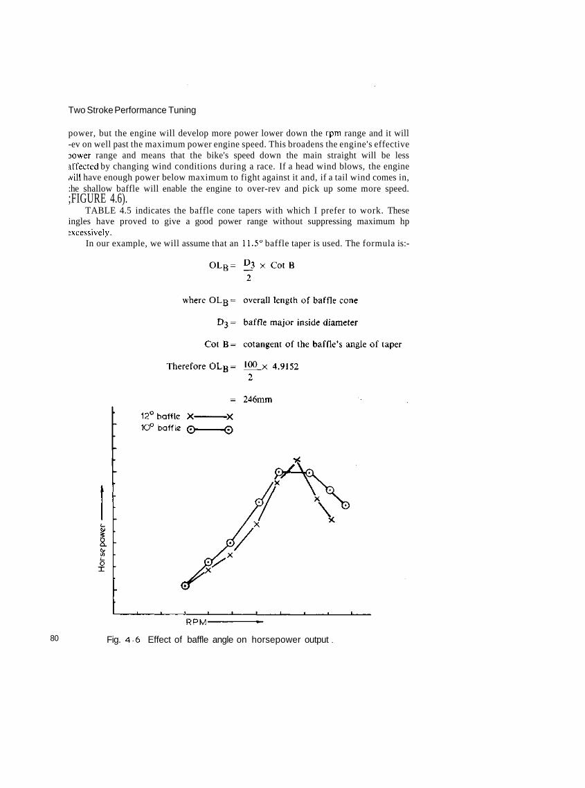
Two Stroke Performance Tuning
power, but the engine will develop more power lower down the rpm range and it will-ev on well past the maximum power engine speed. This broadens the engine's effectiveDower range and means that the bike's speed down the main straight will be lessiffected by changing wind conditions during a race. If a head wind blows, the enginewill have enough power below maximum to fight against it and, if a tail wind comes in,:he shallow baffle will enable the engine to over-rev and pick up some more speed.;FIGURE 4.6).
TABLE 4.5 indicates the baffle cone tapers with which I prefer to work. Theseingles have proved to give a good power range without suppressing maximum hpexcessively.
In our example, we will assume that an 11.5° baffle taper is used. The formula is:-
80 Fig. 4 6 Effect of baffle angle on horsepower output

The Exhaust
You will note that this calculation gives us the overall length of the cone, withoutallowing for a part of the top to be cut off where the stinger will be attached to bleedpressure from the chamber. By halving this figure, 246mm, we can determine the meanreflection point of the baffle and then go back and calculate how long the belly sectionhas to be to give us the tuned length of 758mm which we originally worked out.
In an effort to broaden the power band on motocross bikes and smalldisplacement road race bikes, tuners and manufacturers have been experimenting withtwo-stage baffles over the past few years (FIGURE 4.7). Unfortunately the results havenot been as promising as expected. However, small gains have been made by sometuners working with 62cc and 125cc size cylinders. If you wish to do someexperimentation along these lines, start out using a baffle which has the first stagetapering at 4.5° to 5.5° over a length of 70 to 90mm, and the second stage tapering at12° to 14°.
The last section of the expansion chamber, called the 'stinger', is in reality a bleedpipe. Its function is to restrict gas flow out of the exhaust and create back pressure byslowly bleeding off exhaust gas. This serves to assist the positive pulse wave in pushingany spilled fuel/air charge back into the motor.
TABLE 4.5 Baffle tapers
Baffle angleCylinder size (cc) Road race Motocross & Enduro
50-80100125175250350-500
10.5-1210.5-129.5-1210-1210-12
8.5-9.59-108.5-108-107.5-109-11

Two Stroke Performance Tuning
Suzuki RM125B/C pipe.
All dimensions in mm.
Fig. 4.7 Expansion chamber with multi-stage baffle.
TABLE 4.6 indicates the stinger dimensions which I have found to be mostsuccessful. You may find that a minor reduction in pipe diameter will raise the poweroutput, but do be careful. A stinger pipe smaller in diameter or longer than specifiedcould easily result in engine overheating and seizure. Therefore, I would suggest youmake only small changes and then thoroughly test the pipe before going any smaller.Engine overheating, in its early stages, is indicated by the presence of oil burnt darkbrown under the piston crown. On the next stage the burnt oil turns black, until finally'death ash' appears. After this, the piston can be holed at any time.
TABLE 4.6 Stinger dimensions
Cylinder size (cc)
50-80100125175250350-500
Stinger length (mm)
205-230230-250265-290270-295280-305285-310
Inside
17-1919-2122-2425-2726-2827-29
dia. (mm)
Note: When using this table, first select an intermediate size in both length and diameter andwork from there. Do not start with the smallest diameter and greatest length.Most road race expansion chambers will require a stinger not more than 200mm long andof the smallest diameter indicated for each engine size.
All dimensions in mm.
82 Fig. 4.8 125 road race expansion chamber.

The Exhaust
In the example we have been using right the way through, we would select a stinger23mm in diameter (id) and about 240mm long. The entire expansion chamber wouldlook like that shown in FIGURE 4.8.
The addition of the stinger shortens the baffle cone; its final length can becalculated using the same formula as for the diffuser cone:
To draw out the shape of either the diffuser or baffle cone on a piece of sheetmetal is quite difficult. The cone's dimensions, when rolled out flat, can be worked outgeometrically, or the sizes can be calculated mathematically. I prefer the latter method.
Assuming we were going to fabricate the baffle cone for this expansion chamber,we would calculate its size, before being rolled into a cone, in this way.
Looking at FIGURE 4.9, you will note we only know the inside diameter of thebaffle's inlet and outlet, and its length through the centre. The next dimension we mustcalculate is the length of the cone when measured along the tapered wall, dimensionAC. We use the formula:-

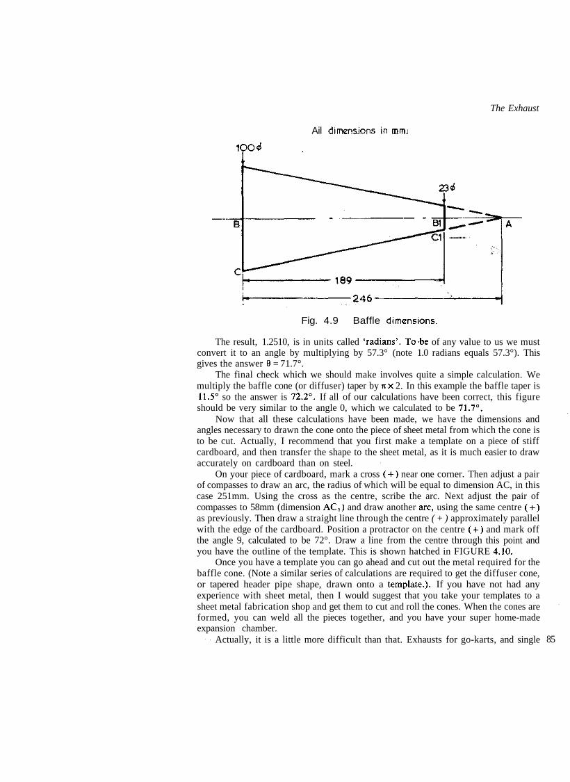
The Exhaust
Ail dimensions in mm.i
lOO«f
Fig. 4.9 Baffle dimensions.
The result, 1.2510, is in units called 'radians'. To-be of any value to us we mustconvert it to an angle by multiplying by 57.3° (note 1.0 radians equals 57.3°). Thisgives the answer 8 = 71.7°.
The final check which we should make involves quite a simple calculation. Wemultiply the baffle cone (or diffuser) taper by nx 2. In this example the baffle taper is11.5° so the answer is 72.2°. If all of our calculations have been correct, this figureshould be very similar to the angle 0, which we calculated to be 71.7°.
Now that all these calculations have been made, we have the dimensions andangles necessary to drawn the cone onto the piece of sheet metal from which the cone isto be cut. Actually, I recommend that you first make a template on a piece of stiffcardboard, and then transfer the shape to the sheet metal, as it is much easier to drawaccurately on cardboard than on steel.
On your piece of cardboard, mark a cross (+) near one corner. Then adjust a pairof compasses to draw an arc, the radius of which will be equal to dimension AC, in thiscase 251mm. Using the cross as the centre, scribe the arc. Next adjust the pair ofcompasses to 58mm (dimension AC,) and draw another arc, using the same centre (+)as previously. Then draw a straight line through the centre ( + ) approximately parallelwith the edge of the cardboard. Position a protractor on the centre ( + ) and mark offthe angle 9, calculated to be 72°. Draw a line from the centre through this point andyou have the outline of the template. This is shown hatched in FIGURE 4.10.
Once you have a template you can go ahead and cut out the metal required for thebaffle cone. (Note a similar series of calculations are required to get the diffuser cone,or tapered header pipe shape, drawn onto a template.). If you have not had anyexperience with sheet metal, then I would suggest that you take your templates to asheet metal fabrication shop and get them to cut and roll the cones. When the cones areformed, you can weld all the pieces together, and you have your super home-madeexpansion chamber.
Actually, it is a little more difficult than that. Exhausts for go-karts, and single 85
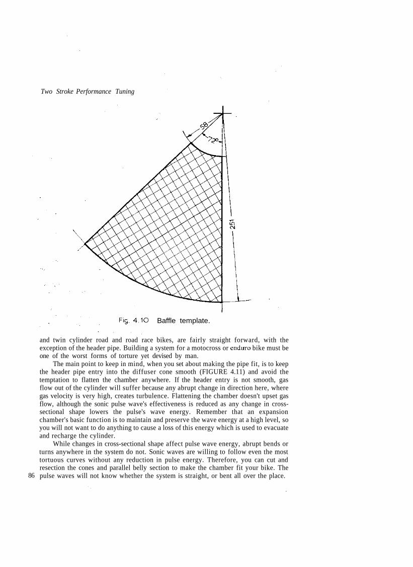
Two Stroke Performance Tuning
Fig. 4.1O Baffle template.
86
and twin cylinder road and road race bikes, are fairly straight forward, with theexception of the header pipe. Building a system for a motocross or enduro bike must beone of the worst forms of torture yet devised by man.
The main point to keep in mind, when you set about making the pipe fit, is to keepthe header pipe entry into the diffuser cone smooth (FIGURE 4.11) and avoid thetemptation to flatten the chamber anywhere. If the header entry is not smooth, gasflow out of the cylinder will suffer because any abrupt change in direction here, wheregas velocity is very high, creates turbulence. Flattening the chamber doesn't upset gasflow, although the sonic pulse wave's effectiveness is reduced as any change in cross-sectional shape lowers the pulse's wave energy. Remember that an expansionchamber's basic function is to maintain and preserve the wave energy at a high level, soyou will not want to do anything to cause a loss of this energy which is used to evacuateand recharge the cylinder.
While changes in cross-sectional shape affect pulse wave energy, abrupt bends orturns anywhere in the system do not. Sonic waves are willing to follow even the mosttortuous curves without any reduction in pulse energy. Therefore, you can cut andresection the cones and parallel belly section to make the chamber fit your bike. Thepulse waves will not know whether the system is straight, or bent all over the place.

The Exhaust
Correct.
Smooth header entry assists gas flow& pulse wave intensity.
Incorrect.
Abrupt header joint disrupts gas flow'& weakens pulse wave.
Fig. 4.11 Header joints must always be smooth.
There are two ways to cut and resection an expansion chamber to form a bend: theeasy way and the right way. (FIGURE 4.12). When you cut a cone and reweld it theeasy way, you will lose out in two ways. First, the length of the cone is reduced, alteringthe tuned length of the exhaust, and secondly wave energy will be lost as the exhaustgases will no longer be expanding at a progressive 7° (or whatever the cone taper is)along the inner wall of the cone.
The correct method to form a bend is to make the first cut right through the coneand then take the second cut only as far as the cone's centre. When the cone isresectioned, the piece which is cut out is welded into the outside of the bend. Thistechnique keeps the length of the cone, through the centre, the same as it was whenstraight. There is still some change in the taper of the walls and in the cross-sectionaldimensions, however, which will have a small effect on the pulse wave.
The next thing you must think seriously about is an effective muffler. I'm not toohappy having to fit mufflers to a road racer, but this is what nearly all sanctioningbodies require. A muffler just adds more weight and knocks the edge off maximumpower, also this requirement is just another example of discrimination againstmotorcycles. Racing cars are not required to be fitted with mufflers and yet bikes,running on the same road circuits and speedways, must be silenced.
On the other hand, I feel every effort should be made to silence motorcycles to awhisper when they are being used on public roads, on private and government land,deserts and reserves etc. The noise of two wheelers in these areas is upsetting a lot ofpeople and driving wildlife back into more remote areas. This is bad for you and allother off-road riders, because every day a few more gates, which were previouslyalways open to motorcyclists, will be closed and locked. If you want your freedom toride in the places where you are currently permitted to ride, then you are going to haveto make sure that the people who live around those areas are free of the noise of yourmotorcycle.
There are several choices open as to the type of silencer which can be fitted. A few 87
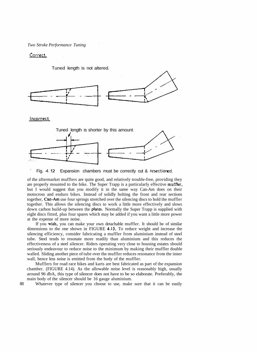
Two Stroke Performance Tuning
Correct.
Tuned length is not altered.
Incorrect.
Tuned length is shorter by this amount
88
' Fig. 4.12 Expansion chambers must be correctly cut & resectioned.
of the aftermarket mufflers are quite good, and relatively trouble-free, providing theyare properly mounted to the bike. The Super Trapp is a particularly effective muffler,but I would suggest that you modify it in the same way Can-Am does on theirmotocross and enduro bikes. Instead of solidly bolting the front and rear sectionstogether, Can-Am use four springs stretched over the silencing discs to hold the mufflertogether. This allows the silencing discs to work a little more effectively and slowsdown carbon build-up between the plates. Normally the Super Trapp is supplied witheight discs fitted, plus four spares which may be added if you want a little more powerat the expense of more noise.
If you wish, you can make your own detachable muffler. It should be of similardimensions to the one shown in FIGURE 4.13. To reduce weight and increase thesilencing efficiency, consider fabricating a muffler from aluminium instead of steeltube. Steel tends to resonate more readily than aluminium and this reduces theeffectiveness of a steel silencer. Riders operating very close to housing estates shouldseriously endeavour to reduce noise to the minimum by making their muffler doublewalled. Sliding another piece of tube over the muffler reduces resonance from the innerwall, hence less noise is emitted from the body of the muffler.
Mufflers for road race bikes and karts are best fabricated as part of the expansionchamber. (FIGURE 4.14). As the allowable noise level is reasonably high, usuallyaround 96 dbA, this type of silencer does not have to be so elaborate. Preferably, themain body of the silencer should be 16 gauge aluminium.
Whatever type of silencer you choose to use, make sure that it can be easily

6 mm. holes
The Exhaust
16gauge steel.
Perforated tube 8mm larger in diameterthan stinger.
Fig. 4.13 Detachable muffler.
dismantled. Then, when the fiberglass sound-absorbing material is choked with oil andcarbon, it can be easily replaced with new fiberglass to restore the muffler to its originalsilencing capacity.
It is not of much use if your exhaust has a good quiet muffler, but the expansionchamber is cracked and almost falling off because of incorrect mounting. FIGURE4.15 shows the mounting arrangements that it is advisable to use. You will note in bothinstances, where the exhaust is attached to the machine by welded brackets, the largearea over which the load is supported. This reduces the possibility of the chamber orthe bracket cracking. If the mount does start to crack, a length of 6mm rod can bewelded into the corners where the mount angles away abruptly from the chamber.
The third method of mounting is the system used by most go-karters. A saddle isfabricated out of fairly heavy steel, usually 4mm thick by 13mm wide, to support thechamber, which is held in place by two springs.
The exhaust flange and joint is also a mount of a kind, as well as being a gas andwater-tight connection. Usually, the header pipe is secured to the exhaust flange byeither a system of springs or a large flange nut. Whatever method is used, make surethe header pipe will not slip out of the flange in the middle of a race. This means if aflange nut is the method of attachment, it must be tight and properly prevented fromloosening by the attachment of two springs from the header pipe to the nut as is doneon the older Bultacos.
Most two-strokes use a flexible slip joint connection with the header pipe held intothe exhaust flange by two or three springs. The thing to watch here is that the headerand flange should overlap by at least 25mm. This reduces exhaust leakage and makes itmuch harder for the header pipe to jump out of the flange.
FIGURE 4.16 illustrates the two most common types of flexible slip joints. Thesimpler joint is used by the majority of motorcycle manufacturers for economicreasons. As you can see, if the exhaust port is made the correct diameter, the headerpipe is too large, or if the manufacturer makes the header pipe the correct size, theexhaust port ends up too small. The joint I prefer is more complicated and can make 89

Two Stroke Performance Tuning
Low restriction muffler.
Steel flange.4 mm. holes.
16 gauge aluminium.
Perforated tube 8mm. largerin diameter than stinger.
-8O-minimum
Low noise muffler,The basic construction is similar to the low restriction muffler exceptthe perforated tube is packed with glasswool. I
Glasswool.Perforated tube 8mm. largerin diameter than stinger.
\
Fig. 4.14 Road race mufflers.
the expansion chamber difficult to get on and off the bike, but it does keep the port andheader pipe sizes matched and it reduces leakage at the joint to a minimum.
Many people don't worry too much about exhaust flange leakage, yet every effortshould be made to prevent this, as any leakage reduces the pressure in the chamber,upsetting sonic wave speed and changing the tuned length of the system. If the leak isserious enough, the chamber will cease to evacuate the cylinder properly. Instead, thesuction pulse wave draws air into the chamber through the leaky joint. Then thepressure wave will push this air up the exhaust port, and into the cylinder. The fuel/airratio is upset, power is lost and, in severe cases, piston burning and seizure is the endproduct.
If you are an off-road rider, you don't want an exhaust flange leak for another90 reason. A leak that gas can find its way through will also often allow water through

Fig. 4.15 Suitable expansion chamber mounts.too. Every off reader, sooner or later, stalls or bogs in a creek, and when this occursyou don't want water to seep into the motor to worsen the situation in which you findyourself.
All exhaust flanges leak to some degree, but slip joint flanges appear to be theworst, until carbon begins to build up and seal the joint. Unfortunately, racing engineshave the barrels and chambers removed too frequently for the carbon to seal properly,so it is necessary to use some sort of exhaust putty to stop leakage. I use Silastic RTVsilicone to seal all exhaust joints.
Two-stroke exhausts are not a fit-and-forget proposition, as they require fairlyfrequent maintenance to clean out carbon build-up. Depending on the shape of thesystem, a layer of carbon l-2mm thick may form in the header pipe after just a few racemeetings and the diffuser and baffle cones usually get a good coat of oily goo at thesame time. The carbon and gum deposits upset gas flow by constricting the internaldimensions of the header pipe and by creating turbulence in the system. These effectsadversely alter performance, therefore the system must be regularly cleaned out. 91

Two Stroke Performance Tuning
Step between flange & header.
Fig. 4.16 Slip-joint header connections.
Some people use a hot caustic soda solution to scour the chamber internally, but Ifeel the most effective method is to burn the system clean with either an oxy-acetyleneor propane gas torch. This may be done by heating the outside of the system to a redheat and occasionally directing the flame down the header pipe to ignite any oil gumpresent. If the chamber is made of 16 or 18 gauge steel, it is an idea to tap the chamberquite vigorously with a piece of broom handle as this will help free the carbon clingingto the walls. Wait until the chamber cools a little before you do any banging, otherwisethe walls could easily be deformed.
Chambers made of 20 or 22 gauge material are much more difficult to clean, as theheating will often cause the chamber walls to deform slightly, and banging with a stickwhile the chamber is still hot, to loosen baked on carbon, is definitely out. About allyou can do is not use an intense flame, but wait until the chamber is quite cool beforeattempting to free the burned carbon ash. You can tap the chamber lightly with a rodor you can throw a few rough stones or a short length of chain inside and give it a goodshake.
There is something you should remember, and that is to give your exhaust a burn-out in a well ventilated area, and preferably outside your shed. The oil in the chambergives off foul fumes, which will soon have your eyes watering and your throat hurting,so be warned.
The other part of exhaust maintenance involves a careful inspection for any signof cracks. These usually appear in the mounting bracket proper, or around where thebrackets are welded to the main body of the chamber. Chambers constructed of verylight gauge material will often crack along seams in the parallel belly section, as this
92 section tends to pulse in harmony with the system's sonic waves.

Chapter 5Carburation
THE BASIC requirement for any carburettor is that it meters the fuel and air insuch proportions as to be easily combustible and hence enable the engine to producegood power over a wide rpm band. Usually, the mixture we want is around 1:12 or1:13, i.e., one pound of petrol (gasoline) for every twelve or thirteen pounds of air.Such a blend is just right for full throttle operation, but for other conditions, such asstarting or light load operation, the fuel-air requirement is different (TABLE 5.1).Therefore, the carburettor has to 'sense' the engine's operating conditions accuratelyand adjust the fuel-air mix accordingly. If the carburettor is not able to do this, flatspots and engine surging will result, spoiling performance. For this reason we have tobe very selective as to the type and size of carburettor we choose for our particularengine.
To understand more fully what we should be looking for in a carburettor to suitour engine's requirements, we need to go back to basics and get to know how acarburettor works. Nearly all two-stroke carburettors are a slide throttle typeemploying a fuel inlet system, an idle system and a main running system.
The inlet system consists of the fuel bowl, float and needle valve (or needle andseat). The fuel, before passing to the metering systems, is stored in the fuel bowl, and itis maintained at the correct level by the float and needle valve.
If the fuel is not at the correct level in the fuel bowl, the fuel metering systems will
TABLE 5.1 Fuel/air requirements
Running condition Mixing ratio (by weight)Fuel: Air
Starting 1 : 1 - 3Idling . 1 : 8-10Low speed running 1 : 10-13Light load ordinary running 1 : 14-16Heavy load running 1 : 12-14 93

Two Stroke Performance Tuning
not be able to mix the fuel and air in the correct proportions, particularly whenaccelerating, cornering and braking. A high fuel level will richen the mixture, earningexcessive fuel consumption and poor running. On the other hand, a low fuel level canbe even more serious due to the leaning effect it has. This may result in flat spots whenaccelerating out of turns, or, in extreme cases, the engine could overheat and seize.
A high fuel level may be due to an incorrectly adjusted float, or a needle and seatwhich is not seating properly and shutting off the fuel when the float rises to the correctlevel. This can be caused by excessive wear to the needle and/or seat, or by a speck ofdirt which may prevent the needle closing fully.
A low fuel level condition may also be the result of an improperly adjusted float,but it could be due to the fuel lines or the needle and seat being too small to flowsufficient fuel to keep the fuel bowl full.
The fuel bowl is always vented so that the fuel is being mixed according to theoutside air pressure. Without a vent, accurate metering would not be possible, as fuelvapours would build up pressure in the bowl and displace fuel out through the mainand idle metering circuits.
The float is usually made of brass stampings soldered together into an airtightassembly, but it may also be formed from plastic or a closed cellular material. Brassfloats are resistant to all types of fuel except nitromethane, and generally plastic orcellular floats are not damaged by most common fuels. However, if you intend to use afuel other than petrol or methanol, it is wise to check with the carburettormanufacturer regarding possible float damage.
The needle and seat is usually made of steel, although some needles may have aViton coating on the tip. The Viton promotes excellent sealing and acts as a shockdamper, but it should not be used with fuels containing any alcohol or nitro.
The needle valve controls the flow of fuel into the bowl, so some thought must begiven to increasing its flow capabilities if an alcohol fuel is being used. Generally, it isnot possible to obtain larger needle and seat assemblies for this purpose, so it will benecessary to modify the seat by very carefully drilling the fuel discharge holes oversize.I would recommend you use a pin vice to hold the drill when you do this.
The idle system provides a rich mixture at idle and low speeds when not enough airis being drawn through the carburettor to cause the main system to operate. (FIGURE5.1).
When the throttle slide is nearly closed, the restriction to air flow causes a highvacuum on the engine side of the throttle slide. This high vacuum provides the pressuredifferential necessary for the idle system to operate. The normal air pressure (14.7 psi)acts on the fuel in the float bojvl, forcing it up through the idle jet and into the airstream. 6;
To emulsify the fuel as it passes through the idle jet (pilot jet), and to provide afine adjustment of the idle mixture strength, an air bleed circuit and an air adjustmentscrew is incorporated in the idle system. Turning the air screw out (anti-clockwise)decreases the air bleed restriction and leans the idle mixture. Conversely, turning thescrew clockwise richens the mixture by reducing the amount of air passing through theair bleed circuit.
Many carburettors have the two hole type idle system illustrated in FIGURE 5.1,which gives better low speed and mid-range throttle response than the simpler one hole
94 type. At very small throttle openings, the by-pass hole, and not the pilot hole, actually

Carburation
Pilot hole.
Bypass hole.
Air Weed holes. ^— ,-—7 -r-~~mm~—^^r —Pilot air screw.
Pilot (or idle) jet.
Fig. 5 Idle system operation.
provides the engine with fuel. Instead, the pilot hole acts as a supplementary air bleedto further atomise the fuel after it passes through the idle jet. Then as the throttle openswider the pilot hole, too, begins to spray fuel. This serves to supply the engine withadditional fuel until the air speed through the carburettor increases sufficiently to startthe main system flowing fuel into the air stream.
As the throttle is opened wider and engine speed rises, so the air speed through thecarburettor increases, bringing the main fuel delivery system into operation (FIGURE5.2). If a carburettor of the correct size has been selected, this should happen at aboutquarter throttle as the idle circuit reaches the limit of its fuel flow capability at thattime. A serious flat spot would result if the main system was not operational andsupplying the additional fuel required to prevent a lean mixture.
In the two-stroke engine, a partial vacuum is created in the crankcase by theupward movement of the piston. Because atmospheric pressure is higher than thepressure in the crankcase, air rushes in through the carburettor to equalise the pressure
. difference. On its way into the crankcase, the air has to speed up as it passes throughthe carburettor bore. This speeding up of the air reduces the pressure belowatmospheric inside the carburettor bore, allowing normal atmospheric pressure (14.7psi) to force fuel up through the main jet and past the needle into the air stream. Thepressure differential existing here is often referred to as the 'signal' of the main
cvctprn it starts anH etnns flnv 95
Two Stroke Performance Tuning
No fuel discharges from the main metering system until air flow through thecarburettor produces a pressure drop or signal of sufficient intensity for theatmospheric pressure, acting on the fuel in the fuel bowl, to push fuel up through themain jet and past the metering needle to be discharged into the air stream. Pressuredrop (or vacuum) within the carburettor varies with the engine speed and throttleopening. Wide open throttle and peak rpm give the highest air flow, and consequentlythe highest pressure difference between the fuel bowl and the needle jet's dischargeorifice. This, in turn, produces the highest rate of fuel flow into the engine.
To compensate for various engine displacements and engine operational speeds, arange of carburettors with a variety of bore diameters are available to create thepressure drop necessary to bring the main fuel circuit into operation. A smallcarburettor will provide a higher pressure difference, at any given rpm and throttleopening, than a larger carburettor, assuming engine size is the same. This is a veryimportant aspect of carburation, which partly explains why the biggest is seldom thebest. If the signal being applied is too weak (due to the bore diameter being excessivelylarge), this could delay fuel discharge in the main system, causing a flat spot due toexcessive mixture leanness. Also, fuel atomisation will not be good at any engine speed.Poor atomisation spells poor combustion and reduced horsepower, so, if you must errwhen selecting a carburettor, err on the small side, as the effect on performance will befar less devastating.
In the main fuel system, metering is controlled by the main jet, the needle jet andthe needle.
The main jet controls fuel flow from the fuel bowl into the needle jet. An increasein the main jet diameter richens the mixture, but there are other aspects worthy .ofconsideration. The shape of the jet entry and exit, as well as thqjfore finish, also affectfuel flow. Carburettor manufacturers measure the flow of every jet, and then numberthe jet according to its flow characteristics, not according, to the nominal borediameter. For this reason, jets used to meter petrol should not be drilled to increasetheir size if you desire accurate fuel metering. An engine burning alcohol does notrequire such accurate metering, unless fuel consumption is a consideration, so jetdrilling may be in order when large jets are not available.
In the case of Mikuni carburettors in particular, there is another problem. Due toits popularity, outsiders are manufacturing main jets to suit these carburettors but,unfortunately, many of the jets fall far below the level of quality and flow parity of thegenuine Mikuni item. I have seen many jets improperly drilled. Some had deep spiralgrooves in the bore, others had steps and tapers in the bore. When jets like that passthrough quality control undetected, then obviously their flow checking must be eithernon-existent or at best haphazard, so I would suggest that you use only genuine jetsfrom the carburettor manufacturer. 1̂
At most throttle openings, the volume of fuel introduced into the air stream iscontrolled primarily by the taper of the needle and the diameter of the needle jet. Asillustrated in FIGURE 5.2, it is the clearance between the needle and needle jet whichregulates fuel flow between quarter and three quarters throttle, although the main jetdoes have some influence. Above three quarter throttle the main jet mainly controlsfuel metering, but the needle/needle jet does exercise partial control.
To assist in atomisation and high speed fuel flow metering, many carburettors also96 incorporate an air bleed circuit in the main metering system. The air bleed aids fuel

Carburation
Throttle slide cutaway.
Needle jet.
Air bleed holes.
Main jet.
Fig. 5 . 2 Main metering system operation.
vaporisation by introducing air into the fuel before it enters the air stream. When thefuel is thus broken down into smaller particles, combustion speeds up because there ismore fuel surface area exposed to the combustion flame.
The air bleed also acts as a compensator or air corrector in adjusting high speedfuel flow requirements. Uncorrected, the carburettor would deliver a fuel/air mixturewhich would become richer as air speed through the carburettor increased. The reasonfor this is that the pressure drop in the carburettor is in direct proportion to the airspeed through its bore and, in turn, fuel flow is in direct proportion to the pressuredrop thus created. However, the actual mass of air passing into the engine does notremain in proportion with air speed, so the mixture strength would become excessivelyrich with increases in air speed through the carburettor if uncorrected.
Fuel flow, in both the jdle and main circuits, is also influenced by the throttle slidecutaway size at throttle openings between one eighth and half throttle (FIGURE 5.3).Increasing the cutaway size reduces airflow resistance and leans the mixture. Thisoccurs because air flow into the engine is greater (due to reduced air flow resistance)but fuel flow does not increase proportionately, as the larger cutaway reduces thepressure drop within the carburettor bore.
The Mikuni Powerjet carburettor is still rather new to road racing motorcycles(although Yamaha have been using them since 1976), being originally designed forsnowmobile racing engines. These carburettors have, in addition to the normal 97

Two Stroke Performance Tuning
Cutaway height.
98
TFig. 5 . 3 Throttle slide cutaway size.
metering systems, another separate system with its own power jet and delivery tube,hence the name Powerjet. The delivery tube hangs in the air intake, in front of thethrottle slide, and is connected through a metering orifice to the float bowl. Up toalmost full throttle, the Powerjet carb operates just like any other Mikuni but, as fullthrottle is approached, the air moving past the tip of the Powerjet delivery tube createsa depression great enough to allow atmospheric pressure to push fuel through thepower metering jet and up the delivery tube into the airstream.
The Powerjet therefore has the effect of enriching the mixture at full, and close tofull throttle, and then only when air velocity is high enough to create a vacuum ofsufficient intensity to discharge fuel. It is, in effect, a load sensitive enrichment systemwhich allows for more accurate (i.e., leaner) fuel metering at part-throttle operation.This ensures clean acceleration and smooth running out of turns, yet gives proper fullthrottle mixture richness for high power and effective engine cooling. The effect is animprovement in part-throttle performance and reduced fuel consumption.Additionally, some two-strokes have a tendency to lean out as they pass beyond fullpower rpm with conventional carburettors, but the Powerjet Mikuni is able to curethis. Normally, when a Powerjet carburettor is used, the main jet size will be around70-100 smaller, depending on the size of the power jet fitted to the carburettor.(TABLES 5.2a & 5.2b).
Having discussed the way a carburettor works, it should be obvious that not allcarburettors are suitable for high performance applications. Some are just too small;others do not have jets and needles that are readily obtainable; some have meteringsystems which allow acceptable performance on stock machines, but are too crude toprovide the correct fuel/air mixture in a racing engine; and others have totallyinadequate float/needle valve systems, so that flooding, hard starting and poorrunning is always a problem. For these reasons I limit myself to the use of Mikunicarburettors. Of course there are other good carburettors around, but I have foundMikunis to be the most easily obtainable, and there is no problem finding suitableneedles and jets etc. There is no point in using a carburettor that can't be properlytuned due to the non-availability of alternative needles and jets.
Obviously the choice is yours when it comes to selecting a carburettor, but do giveheed to my advice regarding the size to use. Always remember that the carburettor
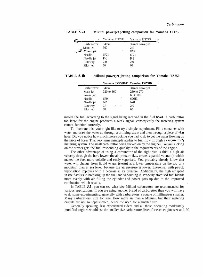
Carburation
TABLE 5.2a Mikuni powerjet jetting comparison for Yamaha IT 175
illilil !'111Carburettor
j Main jet_^ Powerjet
NeedleNeedle jetCutawayPilot jet
Yamaha IT175F
34mm360
6F21P-82.070
Yamaha IT175G
32mm Powerjet21082.56F21P-82.060
'5f|
TABLE 5.2b Mikuni powerjet jetting comparison for Yamaha TZ250
Yamaha TZ250D/E Yamaha TZ250G
CarburettorMain jetPower jetNeedleNeedle jetCutawayPilot jet
34mm320 to 360
6F90-22.5 -• ' •-70
34mm Powerjet230 to 27060 to 806DH3N-82.060
meters the fuel according to the signal being received in the fuel bowl. A carburettortoo large for the engine produces a weak signal, consequently the metering systemcannot function correctly.
To illustrate this, you might like to try a simple experiment. Fill a container withwater and draw the water up through a drinking straw and then through a piece of 3/iinhose. Did you notice how much more sucking you had to do to get the water flowing upthe piece of hose? That very same principle applies to fuel flow through a carburettor'smetering system. The small carburettor being sucked on by the engine (like you suckingon the straw) gets the fuel responding quickly to the requirements of the engine.
The other advantage of using a carburettor of the right size is this: a high airvelocity through the bore lowers the air pressure (i.e., creates a partial vacuum), whichmakes the fuel more volatile and easily vaporised. You probably already know thatwater will change from liquid to gas (steam) at a lower temperature on the top of amountain than at sea level, because the air pressure is lower. Likewise, with petrol,vaporisation improves with a decrease in air pressure. Additionally, the high air speedin itself assists in breaking up the fuel and vaporising it. Properly atomised fuel blendsmore evenly with air filling the cylinder and power goes up due to the improvedcombustion which results.
In TABLE 5.3, you can see what size Mikuni carburettors are recommended forvarious applications. If you are using another brand of carburettor then you will haveto do some experimenting, generally with carburettors a couple of millimetres smaller.Many carburettors, size for size, flow more air than a Mikuni, but their meteringcircuits are not so sophisticated, hence the need for a smaller size.
Generally speaking, less experienced riders and all those operating moderatelymodified engines would use the smaller size carburettors listed for each engine size and 99
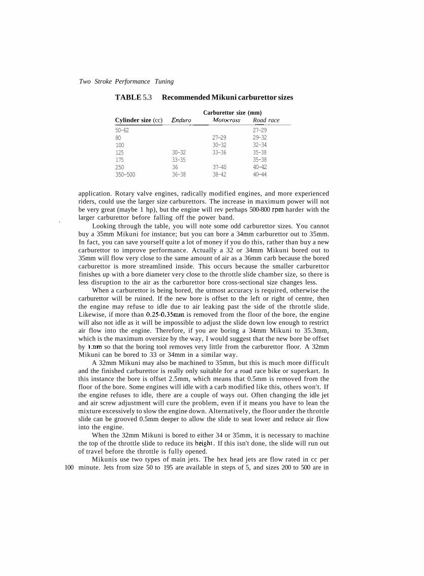
Two Stroke Performance Tuning
TABLE 5.3 Recommended Mikuni carburettor sizes
Carburettor size (mm)Cylinder size (cc) Enduro Motocross Road race
50-6280100125175250350-500
30-3233-353636-38
27-2930-3233-36
37-4038-42
27-2929-3232-3435-3835-3840-4240-44
application. Rotary valve engines, radically modified engines, and more experiencedriders, could use the larger size carburettors. The increase in maximum power will notbe very great (maybe 1 hp), but the engine will rev perhaps 500-800 rpm harder with thelarger carburettor before falling off the power band.
Looking through the table, you will note some odd carburettor sizes. You cannotbuy a 35mm Mikuni for instance; but you can bore a 34mm carburettor out to 35mm.In fact, you can save yourself quite a lot of money if you do this, rather than buy a newcarburettor to improve performance. Actually a 32 or 34mm Mikuni bored out to35mm will flow very close to the same amount of air as a 36mm carb because the boredcarburettor is more streamlined inside. This occurs because the smaller carburettorfinishes up with a bore diameter very close to the throttle slide chamber size, so there isless disruption to the air as the carburettor bore cross-sectional size changes less.
When a carburettor is being bored, the utmost accuracy is required, otherwise thecarburettor will be ruined. If the new bore is offset to the left or right of centre, thenthe engine may refuse to idle due to air leaking past the side of the throttle slide.Likewise, if more than 0.25-0.35mm is removed from the floor of the bore, the enginewill also not idle as it will be impossible to adjust the slide down low enough to restrictair flow into the engine. Therefore, if you are boring a 34mm Mikuni to 35.3mm,which is the maximum oversize by the way, I would suggest that the new bore be offsetby l.nm so that the boring tool removes very little from the carburettor floor. A 32mmMikuni can be bored to 33 or 34mm in a similar way.
A 32mm Mikuni may also be machined to 35mm, but this is much more difficultand the finished carburettor is really only suitable for a road race bike or superkart. Inthis instance the bore is offset 2.5mm, which means that 0.5mm is removed from thefloor of the bore. Some engines will idle with a carb modified like this, others won't. Ifthe engine refuses to idle, there are a couple of ways out. Often changing the idle jetand air screw adjustment will cure the problem, even if it means you have to lean themixture excessively to slow the engine down. Alternatively, the floor under the throttleslide can be grooved 0.5mm deeper to allow the slide to seat lower and reduce air flowinto the engine.
When the 32mm Mikuni is bored to either 34 or 35mm, it is necessary to machinethe top of the throttle slide to reduce its height. If this isn't done, the slide will run outof travel before the throttle is fully opened.
Mikunis use two types of main jets. The hex head jets are flow rated in cc per100 minute. Jets from size 50 to 195 are available in steps of 5, and sizes 200 to 500 are in
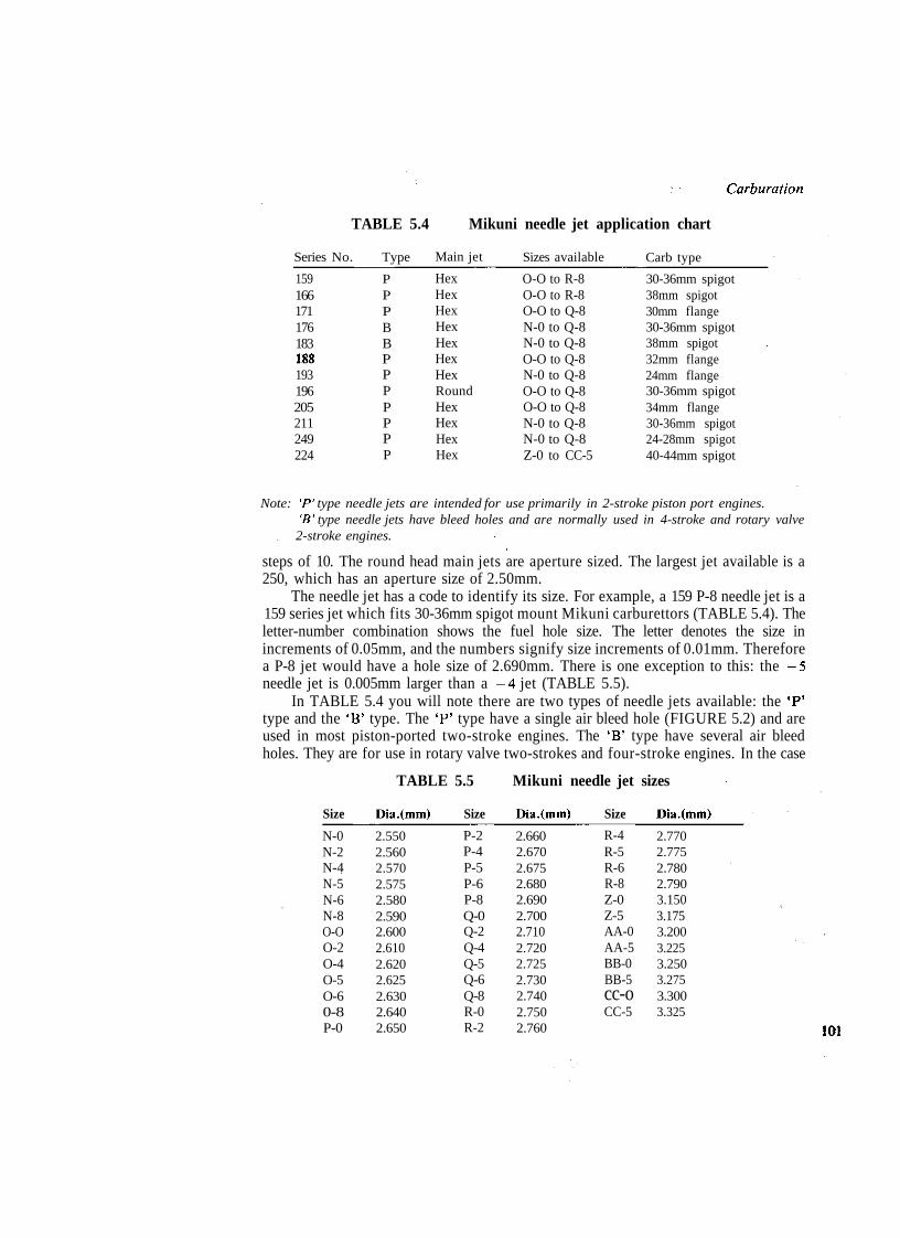
Carburation
TABLE 5.4 Mikuni needle jet application chart
Series No.
159166171176183188193196205211249224
Type
PPPBBPPPPPPP
Main jet
HexHexHexHexHexHexHexRoundHexHexHexHex
Sizes available
O-O to R-8O-O to R-8O-O to Q-8N-0 to Q-8N-0 to Q-8O-O to Q-8N-0 to Q-8O-O to Q-8O-O to Q-8N-0 to Q-8N-0 to Q-8Z-0 to CC-5
Carb type
30-36mm spigot38mm spigot30mm flange30-36mm spigot38mm spigot32mm flange24mm flange30-36mm spigot34mm flange30-36mm spigot24-28mm spigot40-44mm spigot
Note: 'P' type needle jets are intended for use primarily in 2-stroke piston port engines.'B' type needle jets have bleed holes and are normally used in 4-stroke and rotary valve2-stroke engines.
steps of 10. The round head main jets are aperture sized. The largest jet available is a250, which has an aperture size of 2.50mm.
The needle jet has a code to identify its size. For example, a 159 P-8 needle jet is a159 series jet which fits 30-36mm spigot mount Mikuni carburettors (TABLE 5.4). Theletter-number combination shows the fuel hole size. The letter denotes the size inincrements of 0.05mm, and the numbers signify size increments of 0.01mm. Thereforea P-8 jet would have a hole size of 2.690mm. There is one exception to this: the -5needle jet is 0.005mm larger than a -4 jet (TABLE 5.5).
In TABLE 5.4 you will note there are two types of needle jets available: the 'P'type and the 'B' type. The 'P' type have a single air bleed hole (FIGURE 5.2) and areused in most piston-ported two-stroke engines. The 'B' type have several air bleedholes. They are for use in rotary valve two-strokes and four-stroke engines. In the case
TABLE 5.5 Mikuni needle jet sizes
Size Dia.(mm) Size Dia.(mm) Size Dia.(mm)
N-0N-2N-4N-5N-6N-8O-OO-2O-4O-5O-60-8P-0
2.5502.5602.5702.5752.5802.5902.6002.6102.6202.6252.6302.6402.650
P-2P-4P-5P-6P-8Q-0Q-2Q-4Q-5Q-6Q-8R-0R-2
2.6602.6702.6752.6802.6902.7002.7102.7202.7252.7302.7402.7502.760
R-4R-5R-6R-8Z-0Z-5AA-0AA-5BB-0BB-5cc-oCC-5
2.7702.7752.7802.7903.1503.1753.2003.2253.2503.2753.3003.325
101

Two Stroke Performance Tuning
of the primary ('P') type, air that comes from the air bleed orifice is mixed with fuelwhich has already been metered by the needle and needle jet. The bleed ('B') type, onthe other hand, is designed to hold air in the body section of the needle jet, so in thiscase fuel and air (actually a frothy fuel/air mixture) is metered by the needle and needlejet.
The metering needles are identified by a code such as 6DH2. The first numberindicates the needle series. The following letter/s indicate the needle taper. If there isone letter, the taper is uniform along the length of the needle, but if there are twoletters, this indicates that the taper changes midway along the tapered section. The firstletter indicates the upper taper and the second letter the lower taper.
Starting with letter A, which has a meaning of 15 minutes of arc, each letter insequence denotes an additional 15 minutes to the angle between the two sides of theneedle. Therefore a DH taper has an angle of 1°0' on the top, and 2°0' on the bottomtaper (TABLE 5.6).
TABLE 5.6
Letter
ABCDEFGHI
Taper
0°15'0°30'0°45'1°0'1°15'1°30'1°45<2°0'2° 15'
Letter
JKLMNOPQR
TABLE
Needle
4D34D84E14DG64DH74F154J134L64F64L134F104J114P3
To fit some
X
50.350.350.350.350.350.350.250.350.545.150.241.550.5
26mm
\
25.322.828.024.023.026.524.024.525.325.024.521.325.0
5.7acarburettors
10
2.5112.5192.5152.5182.5182.5122.5132.5152.5142.5182.5132.5122.510
Mikuni
Taper
2°30'2°45'3°0'3°15'3°30'3°45'4°0'4°15'4°30'
Mikuni
needle tapers
Letter
STUVwXYZ
Taper4°45 '5°0'5°15'5°30'5°45'6°0'6°15'6°30'
series 4 needlesand 22 & 24mm flange
20
2.5112.5192.5152.5182.5182.5122.5132.5152.5142.5162.5132.5062.506
30
2.4212.3812.3452.4052.3862.4002.2302.1782.4062.3392.3852.1882.436
mount carburettors
40
2.2532.2112.1272.1192.0982.1201.8001.6602.1451.8422.1351.7762.284
50
2.1002.000
.924
.850
.790
.881
.400
.190
.876
1.877
2.122
Note: X is the overall length of the needle in mm.Y is the dimension from the top of the needle to the start of the taper.The numbers 10, 20, 30 etc., indicate the needle diameter in mm at a point 10, 20, 30 etc.
102 mm from the top of the needle.

Carburation
The number after the letters is a manufacturing code which indicates how fardown the needle the taper starts and/or the initial needle diameter, eg: needles marked6DH2 and 6DH3 have the same taper, but 6DH3 is the richer needle as the taper starts22.0mm from the top of the needle, whereas the taper begins 28.0mm down with the6DH2. TABLES 5.7 indicate the dimensions of the more common Mikuni needles.
If the needle is identified as a 6DP5-3 in the bike owner's handbook, this wouldindicate that the needle is a 6DP5 and that it is fitted standard with the circlip in thethird groove, counting the top groove as number one.
The throttle slide cutaway size is indicated by a number stamped under the slide,eg: a 2.0 signifies a 2.0mm cutaway. Smaller engines usually need a 1.5, 2.0 or 2.5cutaway, and larger engines a 2.5 or 3.0.
The idle jet (pilot jet) is available in sizes 15 to 80, in steps of 5. Fine adjustment ofthe idle mixture is by means of the idle air screw which richens the idle mixture whenturned in (clockwise).
The float level is adjusted with the fuel bowl removed and the carburettor inverted
TABLE 5.7b Mikuni series 5 needlesTo fit 26-32mm spigot mount & 28-34mm flange mount carburettors
Needle 10 20 30 40 50 60
5D65FJ95D1205F35EH75E135EJ13SDL 135EJ115EL95FL115EP85FL145FL75DP75J65L15C45F185J95F125D15DP25145D5
59.359.259.158.057.657.557.860.260.360.360.360.258.058.057.658.058.055.158.058.051.553.560.360.057.6
27.535.028.227.428.529.526.532.028.527.028.233.028.028.026.427.527.024.027.027.023.327.632.427.030.0
2.5152.5172.5202.5192.5172.5152.5192.5152.5152.5172.5182.5132.5202,5182.5122.518 '2.5182.5162.5212.5222.0212.5102.5152.5142.513
2.5152.5172.5202.5192.5172.5152.5192.5152.5152.5172.5182.5132.5202.5182.5122.5182.5182.5162.5212.5202.0212.5102.5142.5092.513
2.4602.5172.4792.4192.4732.4842.4312.5152.5152.4412.4382.5132.4402.4402.4402.3402.3302.4482.5151.4321.8822.4962.5132.4422.510
2.290 i2.364 i2.3112.1352.2102.1972.2102.3622.2412.2212.1752.2452.1702.1702.2591.8901.8112.3102.257 ;1.9961.6312.338 :2.418 ;2.0712.366 :
2.1202.021.980.863.848.803.766.922.839.780.740.780.735
1.7351.5801.4501.297Z.I 792.0061.5051.3752.1692.0671.6902.205
1.4631.4201.2481.2561.120
1.4181.332
Note: X is the overall length of the needle in mm.Y is the dimension from the top of the needle to the start of the taper.The numbers 10, 20, 30 etc., indicate the needle diameter in mm at a point 10, 20, 30 etc.mm from the top of the needle. 103

Two Stroke Performance Tuning
Float. Float arm.
Main jet.
Float arm.
104
Fig. 5 .4 Mikuni float levelling.
(FIGURE 5.4). With the float tongue contacting the needle valve, the distance 'A'should be equal to the specified float level. Usually, this will be 20 to 35mm dependingon the carburettor type. This measurement is made with the fuel bowl gasket removed.
Some Mikuni carburettors have the float level adjusted to dimension 'B'. In thisinstance the level is usually around 9 to 10mm; again this varies from model to model.
Many tuners begin tuning carburettors by trying to determine the correct main jetsize. This procedure is correct if the engine has not been extensively modified and thestandard carburettor is still being used. However, if you find large changes in the sizeof the main jet do not seem to be having very much influence on the half to full throttlemixture strength, then you can be fairly certain that a larger needle jet is required.
When an engine has been extensively modified, I prefer to begin testing (afterensuring that the float level is correct) with the main jet removed. If the engine will justrun at part throttle, but floods as the throttle is opened, then the needle jet is largeenough. However, if you find that the engine keeps going at three quarter to fullthrottle you can be sure a larger needle jet is needed. Note that this test should be donewith the needle lowered to the No.l (i.e., lean) clip position.
After you have determined a needle and needle jet combination that is too rich,you can then try various size main jets until you find one that allows the engine to runreasonably well at full throttle. Don't worry about throttle response or acceleration for

Carburation
the time being. Carry out this test with the needle raised to the middle clip position.Next we have to find what size idle jet (pilot jet) is required. Start these
adjustments by backing out the idle speed screw until the throttle slide is completelyclosed, and then turn the screw back in until the slide just barely breaks open. Havingdone that, close the idle air screw completely and back it out 1 to 1 Vi turns. Start theengine and attempt to obtain a smooth 1000-1500rpm idle, by juggling the air screwand the idle speed screw in turn.
TABLE 5.7ci Mikuni series 6 needlesTo fit 30-38mm spigot mount carburettors
Needle 10 20 30 40 50 60
6H16DH26F96CF16FJ66DH36J36L16DP56N16DP16F36DH46J16DH7
62.362.362.361.562.362.362.362.362.362.362.360.562.364.062.2
37.528.028.929.535.222.036.737.032.137.028.934.225.536.228.5
2.5102.5112.5162.5122.5052.5122.5152.5122.5182.5142.5112.5122.5202.5172.516
2.5102.5112.5162.5122.5052.5122.5152.5122.5182.5142.5112.5122.5202.5172.516
2.5102.4662.4752.4292.5052.4582.5152.5122.5182.5142.4762.5122.4402.5172.505
2.412 ;2.295 ;2.2102.2402.376 :2.2862.3592.3352.3722.2782.3122.313 :2.2582.3392.316 ;
'.041LOGO.949.974
'.040.948.912.826.834.672.748
-.050.915.919
'.009
.696
.660
.678
.710
.606
.607
.456
.313
.141
.0581.075
1.5751.4951.688
Note: X is the overall length of the needle in mm.Y is the dimension from the top of the needle to the start of the taper.The numbers 10, 20, 30 etc., indicate the needle diameter in mm at a point 10, 20, 30 etc.mm from the top of the needle.
TABLE S.Tcii Mikuni series 6 needlesTo fit 30-38mm spigot mount carburettors
Needle X 10 20 30 40 50 60
6F56F46F86FJ116F166DH216F16
62.362.362.362.359.152.364.6
38.132.034.036.036.730.131.2
19.019.421.518.718.516.518.4
2.5152.5152.5122.5192.5192.5152.520
2.4562.4422.5122.4812.4892.4702.404
2.4542.4362.3862.4812.4892.4652.400
2.3642.2062.2142.3672.3722.3282.201
2.0981.9391.9452.0302.1042.0241.941
1.840 -1.6781.6881.610
1.679
Note: X is the overall length of the needle in mm.Y is the dimension from the top of the needle to the start of the taper.Z is the dimension in mm from the top of the needle to the pronounced taper point.The numbers 10, 20, 30 etc., indicate the needle diameter in mm at a point 10, 20, 30 etc.mm from the top of the needle. 105

Two Stroke Performance Tuning
TABLE 5.7d Mikuni series 7 needlesTo fit 40-44mm spigot mount carburettors
Needle X Y 10 20 30 40 50 60 70
7FO67H27J2
72.372.372.3
29.028.928.8
3.0053.0053.005
3.0053.0053.005
2.9512.9282.904
2.6802.5752.460
2.4152.2302.010
2.1401.8681.569
1.8761.5071.125
7F2 73.0 43.5 2.515 2.515 2.515 2.515 2.312 2.040 1.703
Note: X is the overall length of the needle in mm.Y is the dimension from the top of the needle to the start of the taper.The numbers 10, 20, 30 etc., indicate the needle diameter in mm at a point 10, 20, 30 etc.mm from the top of the needle.
If you are tuning a multi-cylinder engine and you can get the engine to settle downto a good idle at this point, you should then synchronise the throttle slides so that theyopen and close together. The easiest way to do this is to remove the needle and needlejet and then open the throttle just wide enough for a length of '/sin bronze welding wireto be slipped down a carburettor throat for the throttle slide to seat on. Then, holdingthe throttle open just wide enough to keep the welding wire trapped, adjust the throttlecable length on the other carburettor/s so that another piece of '/sin welding rod canjust slip under the throttle slides.
If the engine will not idle, it is probable that the idle jets are wrong. Jets that aretoo small are indicated by an increasing idle speed as the air screws are turned in.Turning the screws in should cause the engine to run rich at some point (usually '/2 to 1turns from being fully closed) when the idle jets are of the correct size. An idle jet thatis too large is indicated by an ever-increasing idle speed, as the air screws are backedfurther and further out. Note that the air screws must not be opened more than 3 turns,otherwise they will vibrate out.
Once the idle has been adjusted, you can test that the slide cutaway is of thecorrect height. The cutaway influences the mixture between '/« and '/2 throttle, andespecially in the range of Ys and 14 throttle opening. Therefore, if the engine tends tocough and die when the throttle is cracked open, but gains revs as the throttle is closed,change to slides with less cutaway (i.e., richer). (At times minor leanness at this pointcan be corrected by raising the needle one or more notches).
If you find it necessary to change the slides, recheck throttle synchronisation anddetermine that the idle jet is still of the correct size. A change in idle jet size is generallyonly required when a large change in cutaway height has been made.
Now take the bike for a run and check that the main jet is approximately correctby testing how it runs at 3/4 to full throttle. If the engine runs well and the plug reads agood colour then the main jet is close enough to begin searching out the correct needleprofile and/or needle position.
> The needle taper and position controls the fuel/air mixture between !4 and 3/4throttle. To determine if a change is required, test the bike on a smooth and level roadfor at least half a mile at !4 throttle, and then at '/2 and finally % throttle. If the engine'four strokes' and misses at a steady throttle opening, the mixture is too rich, so lowerthe needle one groove at a time until smooth running is realised. On the other hand, an
106 engine that snatches and surges is running lean, so the needle will require raising.

Carburation
TABLE 5.8 Mikuni metering guide
Throttle opening position#., '/* % '/2 3/4 full
Slide cutawayPilot or idle jetPilot air screwNeedle jetNeedle sizeNeedle positionMain jetPower jet
AAABCBDD
.AA -AABBDD
BBBAAACD
BCCCAACD
CDDCBBBC
DDDDCDAA
These letters indicate metering effectiveness at various slide openings.A — most effectiveB — fairly effectiveC — small influenceD — no influence
Next, try steady accelerations from !4 to VT. throttle and from Vi to % throttle andnote whether the engine appears to be lean or rich. Then repeat the test but snap thethrottle open each time. You may find that the mixture is lean at V4 throttle andchanges to rich between Vi and % throttle. This would indicate that the needle is toothin between those points, so a change to a needle with a thicker profile, generally atthe 30 and 40mm points (see TABLES 5.7) would be required. After fitting the newneedle you may find it necessary to change the clip position either up or down,depending on the needle thickness at the 10 and 20mm points, to cure the !4 throttleleanness originally experienced.
Once the correct needle and needle position has been determined, the bike shouldbe tested at three quarter to full throttle to find the right main jet diameter. What wewant is a mixture rich enough to avoid piston and engine overheating, but not so richthat the engine is losing power due to poor combustion.
When trying to find the optimum size main jet, it is always preferable to begintesting with a main jet way too large and work down from there, otherwise if you startout testing with a jet too small the engine could easily overheat and seize. As you comedown closer and closer to the size required, the engine will perform progressivelybetter. When you reach the point where the engine feels to be running at its best, youshould do some careful and serious spark plug reading to ensure that the mixture is, inactual fact, correct.
It takes practice and a proper magnifier of 4X or 6X power to pinpoint correctmixture strength. The things to look for that indicate certain operating conditions areindicated in TABLE 5.9. You will note that all of the plug end actually exposed to thecombustion flame is examined and read, not just the insulator nose as some somistakenly believe.
For the plug reading to be accurate, it will be necessary to run the engine at fullthrottle and maximum speed for at least 6 miles, and then immediately cut the enginedead. If you allow the engine to slow down as you bring the bike to a stop, and thenslowly trickle through the pits, the plug reading will be meaningless. , 107
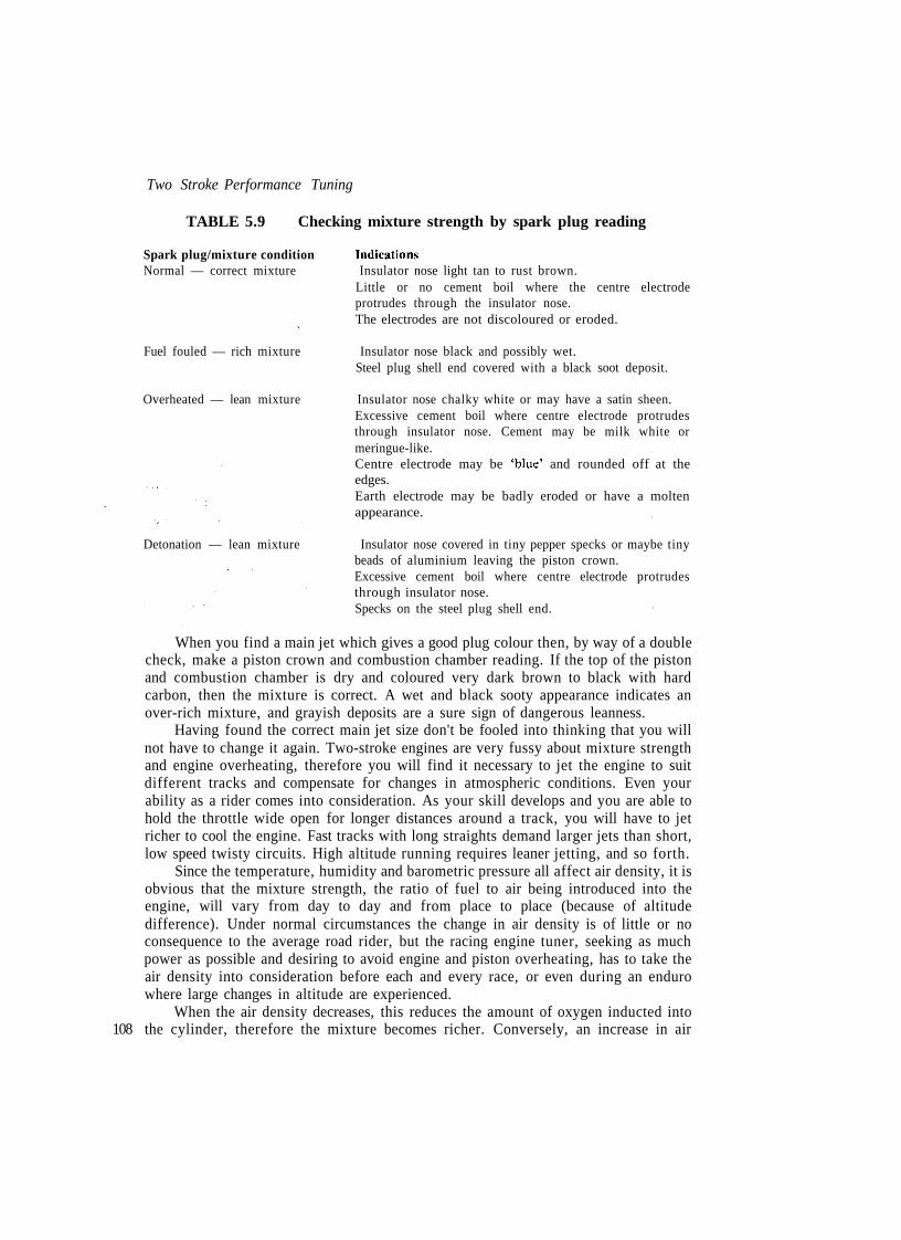
Two Stroke Performance Tuning
TABLE 5.9 Checking mixture strength by spark plug reading
Spark plug/mixture condition IndicationsNormal — correct mixture Insulator nose light tan to rust brown.
Little or no cement boil where the centre electrodeprotrudes through the insulator nose.The electrodes are not discoloured or eroded.
Fuel fouled — rich mixture Insulator nose black and possibly wet.Steel plug shell end covered with a black soot deposit.
Overheated — lean mixture Insulator nose chalky white or may have a satin sheen.Excessive cement boil where centre electrode protrudesthrough insulator nose. Cement may be milk white ormeringue-like.Centre electrode may be 'blue' and rounded off at theedges.Earth electrode may be badly eroded or have a moltenappearance.
Detonation — lean mixture Insulator nose covered in tiny pepper specks or maybe tinybeads of aluminium leaving the piston crown.Excessive cement boil where centre electrode protrudesthrough insulator nose.Specks on the steel plug shell end.
When you find a main jet which gives a good plug colour then, by way of a doublecheck, make a piston crown and combustion chamber reading. If the top of the pistonand combustion chamber is dry and coloured very dark brown to black with hardcarbon, then the mixture is correct. A wet and black sooty appearance indicates anover-rich mixture, and grayish deposits are a sure sign of dangerous leanness.
Having found the correct main jet size don't be fooled into thinking that you willnot have to change it again. Two-stroke engines are very fussy about mixture strengthand engine overheating, therefore you will find it necessary to jet the engine to suitdifferent tracks and compensate for changes in atmospheric conditions. Even yourability as a rider comes into consideration. As your skill develops and you are able tohold the throttle wide open for longer distances around a track, you will have to jetricher to cool the engine. Fast tracks with long straights demand larger jets than short,low speed twisty circuits. High altitude running requires leaner jetting, and so forth.
Since the temperature, humidity and barometric pressure all affect air density, it isobvious that the mixture strength, the ratio of fuel to air being introduced into theengine, will vary from day to day and from place to place (because of altitudedifference). Under normal circumstances the change in air density is of little or noconsequence to the average road rider, but the racing engine tuner, seeking as muchpower as possible and desiring to avoid engine and piston overheating, has to take theair density into consideration before each and every race, or even during an endurowhere large changes in altitude are experienced.
When the air density decreases, this reduces the amount of oxygen inducted into108 the cylinder, therefore the mixture becomes richer. Conversely, an increase in air

Carburation
density increases the quantity of oxygen entering the motor, so there is a correspondingleaning of the fuel/air mixture. To compensate, it will be necessary to fit richer orleaner main jets.
Remember, when compensating for a change in air density, that the change indensity also affects the pressure exerted on the fuel in the float bowl. Therefore adecrease in relative air density (RAD) will automatically lean the fuel/air mixture to adegree, because of the lower air pressure. This means that you don't fit 5% smaller jetswhen the RAD falls by 5%. I usually reckon that a change in RAD of 12 to 15%requires a 5% change in fuel jet size. Remember, too, that a decrease in RAD is usuallydue to hot or high altitude conditions, conditions which in themselves reduce theengine's cooling efficiency. To compensate for possible engine overheating it is good tokeep the mixture slightly rich when the RAD is low.
If you intend to tune your carburettor taking RAD changes into consideration,you must have a reference point and work from there. After you have tuned yourcarburettor as outlined on previous pages, you should make a record of the RAD andthen experiment with jet sizes at other RADs, according to the percentage differencebetween the baseline RAD and the RAD on the day you are retuning the carb.
The relative air density can be worked out from FIGURE 5.5, providing you knowthe air temperature and the uncorrected barometric pressure. RAD meters are availableand these give a direct percentage density reading.
There is another factor involved and, unfortunately, this cannot be read off theRAD graph or meter but, as the humidity affects true air density, we have to take itinto account to be completely accurate. The effect of the humidity is quite small, exceptwhen both the temperature and relative humidity are high. Water vapour has weightand, as such, combines with the weight of the air to distort the true 'weight', or density,of the air. Think of it in this way: you are the air and your clothing is water vapour,wearing clothes you are going to exert more pressure (weight) on the bathroom scalesthan your true undressed weight. To find your true weight, you have to subtract thepressure exerted by your clothes. Similarly, when we want to find the true air density,we have to subtract the pressure exerted by water vapour in the atmosphere.
If you take a look at TABLE 5.10, you can see that the pressure exerted by watervapour at 100°F is 1.93in Hg. If the barometric pressure at the time is 30in Hg the trueair pressure is only 30.0- 1.93 = 28.07in Hg, a decrease of 6.4%. Therefore, in thisinstance, the mixture could have ended up 6.4% rich if the relative humidity was nottaken into account.
Usually the amount of water vapour is less than the amount indicated in thecolumn headed 'Saturation Pressure', as this assumes a relative humidity of 100%.(Relative humidity compares the amount of water vapour present with what theatmosphere is capable of holding.)
To find the true air nressure. use the formula:-
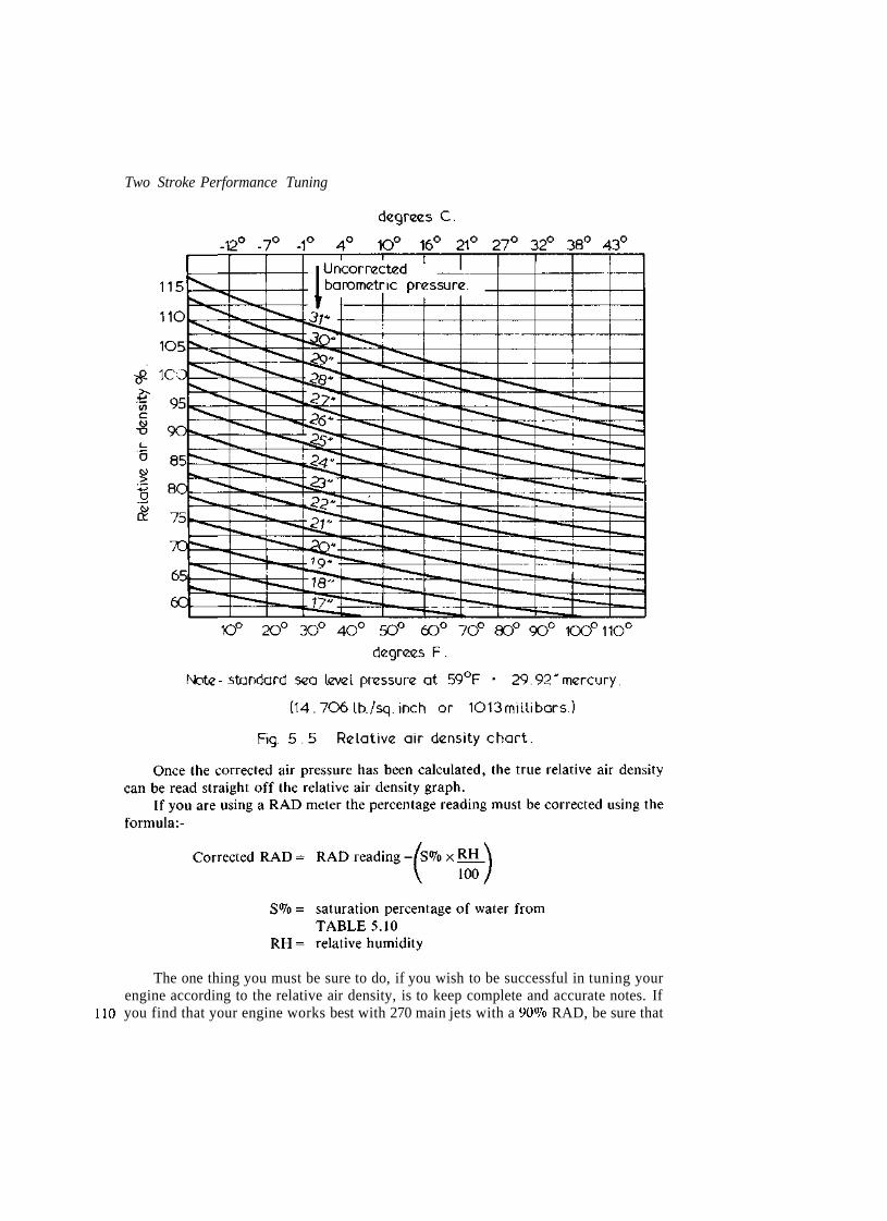
Two Stroke Performance Tuning
The one thing you must be sure to do, if you wish to be successful in tuning yourengine according to the relative air density, is to keep complete and accurate notes. If
110 you find that your engine works best with 270 main jets with a 90% RAD, be sure that

Carburation
TABLE 5.10 Humidity saturation pressure and percentage
Temperature Saturation pressure Saturation percentage of water°F °C inHg Millibars
4060708090100
4.415.621.126.732.237.8
0.2470.5210.7391.031.421.93
1 81825354865
0.831.72.53.34.76.5
you make a note of the fact in your tuning diary. Then, on each occasion the air densityis again 90%, you will know exactly what size jets to use, providing the tracks are of asimilar layout. If the track is a faster one with larger straights, you may have to jetricher. At another location the RAD might be 98%, so armed with the information inyour diary you know that you should try a 280 main jet. May be it will be the correctsize, but then it may not be. There are no hard and fast rules here, no two enginesrespond to RAD changes exactly alike. Usually small displacement, high rpm road raceengines and liquid cooled engines in a high state of tune are most affected by a changein air density.
The mixture ratio is also affected if there are any air leaks, so you must be verycareful to seal the manifold to the barrel, and the carburettor to the manifold, using thecorrect gasket and the right type of gasket cement. This may seem a rather small thing,but you would be amazed at the number of tuners who use Silastic to seal themanifold/carburettor. Silastic is excellent as an oil sealant, but it is not petrol resistant,therefore it should not be used anywhere in the induction tract. I recommend the use ofPermatex No.3 for this purpose.
An air filter also reduces the air density (particularly if it is clogged full of dirt),but in this instance by restricting air flow into the cylinders. Obviously the restrictioncan be done away with by removing the filter. This may be acceptable for some roadracing bikes, but all other types, including road race karts, should be fitted witheffective filters.
Long engine life and effective air filtration are very closely related and, contrary topopular opinion, a clean air filter of good design (such as K & N) does not reduceengine power output by very much at all. On road bikes such as the Yamaha RD400,however, the air filtration system does have a devastating effect on performance. Thisis due to the use of a tiny air filter and a very restrictive air box, designed to cut downinduction roar and reduce noise pollution.
Many enthusiasts are fooled into thinking that they have gained many horsepowerby fitting 32 and 34mm Mikunis to their otherwise standard RD250s and RD400s.Usually, the improvement in power is more the result of the removal of the air box andfilter than from the larger carburettors. Carburettors of the size indicated work verywell on hot street RDs and also production racers, but they are too large for standardengines. TABLE 5.11 indicates the performance increase realised from removing theair box and filter off an RD400 and fitting a pair of K & N filters to the standard 28mmcarbs, which have been jetted richer. Compared to what a pair of 34mm Mikunis willdo, you can see that the smaller carbs come out on top. If you don't want to fit K & N 111

Two Stroke Performance Tuning
TABLE 5.11 Yamaha RD400E dyno test(Standard European engine)
rpm Test 1 (hp) Test 2 (hp)
8,312,816,620,624,2MX33 J'35,9mi33,13M-22,2
Test 3 (hp)
5.77.79.3
13.115.618.024.726.931.135.538.538.932.724.820.2
Test 1 — Standard 28mm carburettors with standard air box and filter connected.Test 2 — 34mm Mikuni carburettors with K & N filters.Test 3 — Standard 28mm carburettors with air box and filter removed andK& N filters fitted.
Note: Dyno would not hold a steady load below 3500rpm with the 34mm carburettors, so thesefigures have been omitted.
filters to your street bike, but prefer the standard setup, do cut the muffling ribs andbaffles out of the air box and drill lots of holes in it so as to allow a free flow of air intothe engine. With richer jetting, this alone will give a 7-10% power increase.
If you are an off-road rider, you should take a good, careful look at your bike'sfiltering system. I would estimate that the majority of dirt bikes suffer considerablymore wear from inducting dust, mud and water into their internals than they do fromvery hard, high speed competition riding. We don't want any dust or mud going intothe engine at all. This material is very abrasive, prematurely wearing the piston, rings,cylinder and bearings. Also, we must keep water out of the engine. A few specks ofwater on the plug will stop the engine dead. If the engine takes a good gulp of water,the piston and head could crack because of the sudden temperature decrease.
The first thing you need is a good air filter, properly oiled. For dry events, I thinkthe K & N range of cotton filters are tops. If there is a lot of mud and water around, Iprefer the Uni foam filter as it does a better job of keeping water out. Whatever type offilter you use it must be oiled, but be sure to use a water-resistant oil, not engine oil.Waterproof oils will not stop water getting into the engine, that is the task of the filter,but they will not break down into a soapy mess like engine oils, and most gear oils,when they contact water. When an oil breaks down like this, the air filter operates in asimilar way to an unoiled filter: very poorly. Bel-Ray filter oil is good, but expensive. Ifyou are worried by the price, try Castrol ST90. It is a 90 weight waterproof gear oil,about one third the price of Bel-Ray filter oil.
112 A good, well oiled filter is totally useless if it isn't correctly fitted. Unfortunately
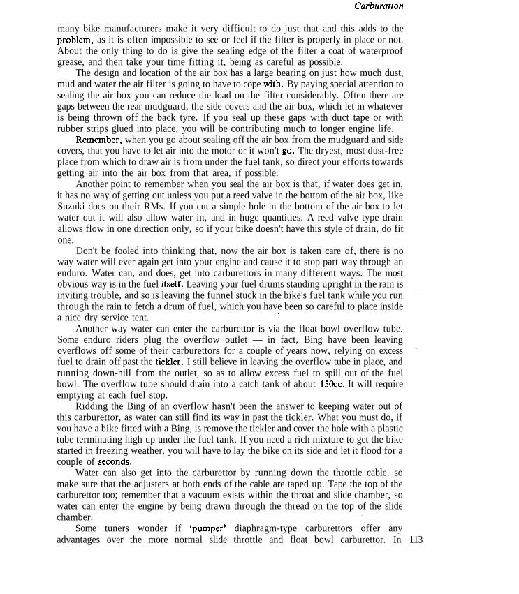
Carburation
many bike manufacturers make it very difficult to do just that and this adds to theproblem, as it is often impossible to see or feel if the filter is properly in place or not.About the only thing to do is give the sealing edge of the filter a coat of waterproofgrease, and then take your time fitting it, being as careful as possible.
The design and location of the air box has a large bearing on just how much dust,mud and water the air filter is going to have to cope with. By paying special attention tosealing the air box you can reduce the load on the filter considerably. Often there aregaps between the rear mudguard, the side covers and the air box, which let in whateveris being thrown off the back tyre. If you seal up these gaps with duct tape or withrubber strips glued into place, you will be contributing much to longer engine life.
Remember, when you go about sealing off the air box from the mudguard and sidecovers, that you have to let air into the motor or it won't go. The dryest, most dust-freeplace from which to draw air is from under the fuel tank, so direct your efforts towardsgetting air into the air box from that area, if possible.
Another point to remember when you seal the air box is that, if water does get in,it has no way of getting out unless you put a reed valve in the bottom of the air box, likeSuzuki does on their RMs. If you cut a simple hole in the bottom of the air box to letwater out it will also allow water in, and in huge quantities. A reed valve type drainallows flow in one direction only, so if your bike doesn't have this style of drain, do fitone.
Don't be fooled into thinking that, now the air box is taken care of, there is noway water will ever again get into your engine and cause it to stop part way through anenduro. Water can, and does, get into carburettors in many different ways. The mostobvious way is in the fuel itself. Leaving your fuel drums standing upright in the rain isinviting trouble, and so is leaving the funnel stuck in the bike's fuel tank while you runthrough the rain to fetch a drum of fuel, which you have been so careful to place insidea nice dry service tent.
Another way water can enter the carburettor is via the float bowl overflow tube.Some enduro riders plug the overflow outlet — in fact, Bing have been leavingoverflows off some of their carburettors for a couple of years now, relying on excessfuel to drain off past the tickler. I still believe in leaving the overflow tube in place, andrunning down-hill from the outlet, so as to allow excess fuel to spill out of the fuelbowl. The overflow tube should drain into a catch tank of about 150cc. It will requireemptying at each fuel stop.
Ridding the Bing of an overflow hasn't been the answer to keeping water out ofthis carburettor, as water can still find its way in past the tickler. What you must do, ifyou have a bike fitted with a Bing, is remove the tickler and cover the hole with a plastictube terminating high up under the fuel tank. If you need a rich mixture to get the bikestarted in freezing weather, you will have to lay the bike on its side and let it flood for acouple of seconds.
Water can also get into the carburettor by running down the throttle cable, somake sure that the adjusters at both ends of the cable are taped up. Tape the top of thecarburettor too; remember that a vacuum exists within the throat and slide chamber, sowater can enter the engine by being drawn through the thread on the top of the slidechamber.
Some tuners wonder if 'pumper' diaphragm-type carburettors offer anyadvantages over the more normal slide throttle and float bowl carburettor. In 113

Two Stroke Performance Tuning
motorcycle applications, I would say a definite 'No', but they do have a place on go-kart engines which otherwise require the extra burden of a fuel pump to lift fuel fromthe fuel tank up to the carburettor. The majority of kart engines are fitted with thistype of carburettor which employs engine crankcase pulses to both pump and meterfuel.
Karts with fixed gearing (i.e., no gearbox) require a carburettor capable ofaccurate fuel metering over the greatest possible rpm range, and the pulse carburettorfills this need. The lOOcc McCulloch engine, for example, utilises a large 35mm borecarburettor for good high speed air flow, yet the pulse metering enables the engine torun well and accelerate cleanly out of tight turns where engine speed drops to SOOOrpm.
The main difficulty with pulse carburettors is that they work well only on theengine for which have been specifically made. Their air passages, which bleedcrankcase pressure into and away from the chamber behind the metering diaphragm,have orifices calibrated to be sensitive to the crankcase compression ratio and thecylinder displacement. Any change in either of these factors will upset fuel metering.
The other problem with pulse carburettors concerns the tuning of them. I haveseen many engines seize because their tuners didn't understand very basic tuningprocedure. Maybe it is because these carburettors are so simple to tune that some havebeen caught out. There are just two screws to adjust: one controls the low speedmixture and the other the high speed mixture. There is an overlap of functions atmedium speed, and herein lies the problem. If the low speed mixture is adjusted toorich, then the high speed screw will have to be leaned right off to allow cleanacceleration out of tight corners. This then causes an excessive lean condition at highspeed, so that the engine overheats and locks up.
What you have to do is adjust both the low and the high speed screw to the settingrecommended by the manufacturer, and then do your fine tuning out on the circuit.McCulloch recommend 1 Vz-2 turns open for the high speed screw and 1-1 !4 turns openfor the low speed screw. I have found it preferable to set the screws a little closer thanthis. Usually % turn open for the low speed and 1 Vi turns open for the high speed is agood place to begin testing on short tight sprint tracks.
After you have allowed the engine to warm up to normal operating temperature,you can fine tune the mixture adjustment. Turn the high speed screw out until theengine 'four strokes' and then lean it off a little at a time (^turn) until the engine runscorrectly at full throttle and maximum rpm on the main straight. Next adjust the lowspeed mixture for good acceleration out of tight turns. If the engine runs rough andsmokes badly when accelerating, turn the low speed screw in to lean the mixture. If theengine falters and misses coming out of turns, open the low speed screw a little to attainsmooth acceleration. When you are happy with the way the engine pulls out of corners,you should check the high speed adjustment again to ensure that the mixture is stillcorrect.
It is very important that you adjust the mixture in the way outlined, otherwise youwill soon run into trouble. I would say that of the seized kart motors I have worked on80% have been caused by improper carburettor tuning. Usually, I find the low speedscrew is anywhere from 4 to 7 turns open, and the high speed screw closed up to aboutV* to !/2 turn open.
Many go-kart classes are Box Stock categories which do not permit carburettor114 modifications. However, if you read the regulations you will generally find a maximum

Carburation
size listed for the carburettor bore, for example, also the rules usually state that allfixing devices (i.e., nuts, bolts, screws, etc.) are free. To get the best out of your engineyou will have to use these rules to advantage, for you can be sure other tuners will. ThelOOcc Box Stock McCulloch class rules give the maximum carburettor size as 35.66mmfor the throttle bore, and 29.08mm for the venturi diameter. Many carburettors have aventuri closer to 28.3mm, so you should enlarge and polish it, using a hand scraper andemery paper. The screw fixing the butterfly to the throttle shaft should also bemodified to reduce air flow restrictions. Remove the star washer from under the headof the screw and file the screw down until there is a groove just deep enough to turn thescrew back into the shaft. Put Loctite on the screw to prevent it vibrating back out ofthe throttle shaft. Next file the protruding thread of the screw flush with throttle shaft.
If the carburettor regulations are free, performance can be improved by heliarcwelding the butterfly to the throttle shaft, and then filing the shaft down to a thicknessof 1.5mm. When this is done, be sure to adjust your throttle pedal stop so that you canjust get full throttle, otherwise you will twist the end off the throttle shaft.
The fuel discharge nozzle causes quite a loss of flow, so this should be filed toreduce its width to a minimum. You will also note a small plug protruding into theairstream of the McCulloch carburettor just in front of the venturi. This can beremoved entirely and the hole filled with epoxy, or the plug can be shortened andrefitted.
Karts raced on faster circuits may have the venturi diameter increased up to amaximum of 32mm, but do be careful to richen the mixture as this modification cangive rise to a dangerous high speed lean-out.
All McCulloch carburettors benefit from an air horn to smooth air flow into thecarburettor bore. An air horn, with a nicely rolled radius similar to that illustrated inFIGURE 5.6, should be fabricated. Without the air horn, flow is reduced by up to 8%.
Most road race karts use motorcycle engines equipped with conventional floatchamber carburettors, which of course means that some type of fuel pump must beinstalled. The pump which I recommend is a pulse type unit manufactured in Americaby Outboard Marine Corporation. The type 'AY' pump (Part No. 385784), designedfor 60-100 hp outboard motors, is the most readily available and easily capable ofsupplying the required fuel volume for even the hottest TZ250 engines.
To ensure a good strong pulse, the pulse tube connecting the crankcase with thepump must be short (i.e., no longer than 4in) and of small internal diameter. (Mostfittings require >/4in bore tube.). If you find the pump will not supply sufficient fuel(this usually only occurs when pulse tubes longer than recommended, and very wildinlet port timings approaching 200° duration, are used), you can fit a small 150ccauxiliary fuel tank to gravity feed straight into the carburettor fuel inlet. The auxiliarytank fills at low rpm and keeps the carburettor full at high speeds when pump pulsesare weak. Common plastic tubing is best for the pulse line as it is much stiffer thanneoprene tube, hence it conveys a stronger pulse to the pump.
Unlike automobile carburettors, motorcycle carburettors will not tolerate evenvery low fuel pressure before they give way to flooding. Being designed for gravity feedoperation, their float system is not capable of shutting off fuel flow through the needleand seat at a pressure as low as 1 psi. Therefore, when a pulse pump is fitted, you willhave to incorporate a fuel by-pass line, and also perhaps a pressure regulator, in yourfuel system. (FIGURE 5.7). The by-pass line should be of the same internal diameter as 115

Two Stroke Performance Tuning
Fig. 5 . 6 McCulloch carburettor air horn & filter.
Vent.
Return line.
Pressure regulator,(if required)
'Pulse pump.
: Fig. 5.7 Road race kart fuel supply arrangement

Carburation
the fuel line, and installed such that it is at a level approximately 6-12 inches higherthan the carburettor fuel inlet. It must tee-off within one or two inches of the fuel inletand discharge excess fuel in the top of the fuel tank. These precautions will ensure thefuel will not take a path of low resistance and return to the fuel tank, starving theengine.
When a carburettor is being installed, there are a few things you need to watch.The first point you must check is that you are actually getting full throttle.Inexperienced tuners are often fooled to believe the slide is opening fully when they seeit disappear from the bore of the carburettor, forgetting that the cutaway is perhaps2-3mm higher than the back of the throttle slide. What you must do is look right downthe bore of the carburettor, using a mirror if necessary, and see if the back of the slideis hanging in the airstream. Alternatively, you can remove the needle and feel with yourfinger if the slide is opening fully.
Also check that the carburettor, manifold and inlet port are correctly aligned, asmisalignment will disrupt air flow. Most inlet manifolds are a loose fit on theirretaining bolts, so if care is not exercised the manifold can quite easily be mounted outof line with the inlet port. When you test the alignment of the carburettor and inletmanifold, ensure that the retaining clamp is fully tightened as this tends to distort theneoprene material of which the manifold is made. Without the clamp tensioned, thecarburettor and manifold often appear to mate perfectly, but once tightened the neckof the manifold may protrude into the air stream. Any offending material should becut away with a very sharp knife or razor blade. Then dress the surface with a highspeed grinder or a chainsaw file.
Each time the carburettor is refitted to the engine, ensure that it is not tilted offcentre. Some manufacturers have a locating notch moulded in the inlet manifold tofacilitate correct carburettor positioning, but most leave it up to the tuner to sightthrough and line up. A carburettor, when tilted off vertical, will be leaned-out, as thislowers the fuel level in the float bowl.
The type of fuel that you are permitted to use in your engine will be laid down bythe body governing your particular branch of competition. Generally, fuel of a muchhigher octane rating than that which is available at the local service station pumps canbe used. In nearly all forms of racing, 100 octane aviation petrol (100/130 Avgas) isallowed and, at times, 115 octane aviation fuel (115/145 Avgas) or even alcohol fuelsare permitted.
In most brands the higher octane rating is obtained by adding tetra-ethyl-lead andethylene dibromide. The decomposition products from these additives may causetrouble in two-stroke engines, therefore I recommend the use of racing fuels thatcontain very little t.e.l. Instead, the higher octane should be obtained by the fuelcompany blending additives such as acetone, toluol (methyl benzine), benzole, ethanolor methanol. Fuels using these additives will not cause any problems in two-strokeengines, but usually they are considerably more expensive than those with an octanerating boosted purely by the addition of t.e.l.
One problem with t.e.l. is that it builds up on the spark plug insulator and, beingelectrically conductive, will cause the engine to misfire. I have found some fuels soloaded with t.e.l. that the plug has shorted out completely and stopped the engine afteronly a short period of running.
Alcohol fuel is permitted in most categories of speedway and dirt flat-track racing. 117

Two Stroke Performance Tuning
Both methanol (methyl alcohol) and ethanol (ethyl alcohol) have an octane rating bythe Research method of 140-160, depending on mixture richness. Therefore thesefuels can be used with very high compression ratios.
Methanol and ethanol have a very high latent heat of vaporisation, i.e., it takes alot of heat to convert them from liquid form into vapour. Petrol has a latent heat ofevaporation of 135 Btu/lb., methanol 472 Btu/lb. and ethanol 410 Btu/lb. This heat,required for proper atomisation, is removed from the piston crown, combustionchamber and the cylinder, resulting in an internally cooler engine.
An engine burning methanol will usually show a 6-8% power increase over onerunning on Avgas 100/130 (i.e., Racing Fuel 100), without any change in compressionratio. With the compression ratio increased to its maximum, power can rise as much as15-17%. Where does the power increase come from?
The two cycle engine is a type of heat engine, i.e., one that burns fuel to cause theexpansion of gas, and the subsequent movement of the piston. The more heat producedby the combustion fire, the more pressure there will be exerted on the piston, whichgives us a power increase.
Using petrol, the fuel/air ratio for best power (i.e., the strongest force on thepiston) is 1:12.5. With methanol, for example, we can increase the fuel/air ratio to1:4.5, although I usually prefer a ratio of 1:5.5; less than 1:7 is too lean.
One pound of petrol has the energy potential of about 19,000 Btu (one BritishThermal Unit is the amount of energy required to raise the temperature of one poundof water one degree Fahrenheit.). In comparison, methanol delivers around 9,800Btu/lb., which means that it produces less than 52% of the heat energy of lib of petrol.However, because we are mixing more methanol with each pound of air (1:5.5) thanpetrol (1:12.5), we are actually producing more heat energy by burning methanol.
To work out how much more heat energy is produced, we have to divide 12.5 by5.5, which equals 2.27. Next we multiply 9800 by 2.27, which gives us 22,246. Thisindicates that methanol, in the correct fuel/air proportions, will produce 17% moreheat energy than petrol at the correct fuel/air ratio.
By comparison, the maximum increase we can obtain using ethanol is about 10%,although it does have anti-knock and cooling properties very nearly the same asmethanol. In coming years, I expect we will see a marked increase in the useage ofethanol in both racing and road engines. As the world's oil supply dries up, moreracing organisations and governments will encourage the production and use ofethanol derived from grain and sugar producing plants. Strong public opinion againstall forms of motor sport using valuable reserves of crude based fuels will, I expect,soon force many sanctioning bodies to ban the use of petrol in motor racing, with theobvious alternatives being ethanol or ethanol/toluol, ethanol/acetone blends.
From the above calculation, you can see that an engine running on straightmethanol will burn more than twice as much fuel (1.8 times as much for ethanol) as oneburning petrol. Therefore you must be careful to ensure that the fuel tap, fuel lines andneedle valve will flow the required amount of fuel.
This can present some problems, as many carburettors will not flow the required

Carburation
amount of fuel through the standard needle and seat. Often a larger replacement is notavailable, so you will have to enlarge the discharge holes to increase flow by theamount necessary. At times you will find it impossible to get main jets large enough, soagain you will have to resort to some drilling.
Most Mikuni carburettor jets (the hex head type) are classified with regard to theirfuel flow rate, the number stamped on the jet standing for the ccs of fuel the jet iscapable of flowing in a certain time. If you are changing from petrol to methanol, thenyou should start testing with jets at least 2.3 times as large, eg: change 210 jet to a 480.
The round head Mikuni jets are rated according to their nominal bore diameter inmillimetres, eg: a round head 250 jet has a nominal aperture of 2.5mm. Again, whenchanging from petrol to methanol you will have to begin with jets with an aperture area2.3 times as large. (Aperture area = nr2).
Keep in mind also when you convert to an alcohol fuel, either neat or blended, thatthe fuel/oil ratio may have need of adjustment. Straight methanol would require only80% as much oil, or a 25:1 ratio in many applications, although some engines willrequire a 16:1 mix. It is always best to start testing at 20:1 and work from there.
There are other problems involved in the change to alcohol, some of which willaffect you and some your engine. Since your life is the most important, we will dealwith you first. Methanol is extremely poisonous and, as it is an accumulative poison, itcan build up over a period of time and oxidise to form formaldehyde, eventuallycausing blindness or even insanity. It is absorbed through the skin and lungs, either bydirect contact or from the vapours. Inhalation of the exhaust gas can also be dangerousas vaporised methanol is usually present, especially when rich mixtures are being used.
Alcohols are a very effective paint stripper, and they may attack some fibreglassresins. They have a scouring effect on fuel tanks and lines so these should be soaked inalcohol and then drained so that the residue does not find its way into the carburettorwhen you switch from petrol to alcohol.
Methanol and ethanol will absorb huge amounts of water out of the air, so theymust always be kept in an air-tight container. The fuel will also have to be completelydrained from the tank and the carburettor to prevent the formation of water-inducedcorrosion and oxidization. This can be particularly damaging to a carburettor andusually results in blocked metering passages.
After burning alcohol in a two-stroke engine it is most important to run apetrol/oil mix rich in oil through the engine each time you put your machine away aftera day's running. If this is not done, you v,'ill soon find corrosion and etching of thecylinder wall, crank and piston pin, needle and ball bearings that will lead to prematurefailure. To prevent this occurrence, I would suggest that you run a half pint of 16:1petrol/oil mixture through the engine.
In colder climates, starting difficulties may be encountered when pure alcohol isbeing burned. Some use other more volatile fuels blended in, to help overcome thisproblem. Usually 5% acetone or a maximum of 3% ether is used. I do not recommendstarting aerosols containing ether, due to the possibility of engine damage being causedby detonation. Personally I feel the best method is to remove the spark plug and pourabout a half teaspoon of either petrol or neat acetone into the cylinder before youattempt to start the engine.
Alcohol burners demand a good ignition system. Not only does the ignition haveto cope with much higher compression pressures, it may also be called on to fire plugs

Two Stroke Performance Tuning
wetted by the very rich mixture being inducted. Alcohol fuels burn much more slowlythan petrol, so it will be necessary to experiment with more ignition advance. It is notpossible to predict just how much additional advance will be required as there are somany variables involved, but you should begin testing with about an extra 3-5°advance.
Before you advance the spark lead, do make sure that the carburation is fullysorted out. If the engine runs just slightly lean, with added spark lead you could veryeasily hole a piston. As well as a much larger main jet, it is probable that a differentneedle profile and a larger needle jet will be required. To correct off idle leanness, abigger pilot jet and a small 1.0 to 1.5mm slide cutaway may be needed.
Nitromethane, as such, isn't really a good fuel but it can give two-stroke engines apower boost if used sensibly. Nitro's only virtue is that it contains approximately 53%by weight oxygen, so in effect it is a chemical super-charger. In drag car engines it isblended 80-90% nitro to 10-20% methanol, but there is no way a two-stroke engine canhold together with more than a 20% nitro-80% methanol blend. Even then, I wouldonly use nitro in small and rugged single cylinder dirt track engines. To deterdetonation, or other engine damage, it is always necessary to lower the compressionratio. If your engine runs reliably at a 17:1 compression ratio on methanol, then youshould be able to use a 14:1 ratio with a 20% nitro-80% methanol fuel mix.
As with methanol, nitromethane demands a rich fuel/air mixture. Using a 20%nitro blend, the mixture would be approximately one part fuel to three or four partsair, i.e., 1:3-4. This means that you will have to increase the main jet size by about22-25% above that required for pure methanol with a 20% nitro-80% methanolmixture. A 12-15% jet increase will be close for a 10% nitro blend.
The safest way to avoid error when mixing nitro with other fuels is to mixaccording to volume, eg: for a 20% nitro blend you will use one gallon of nitro to fourgallons of methanol.
Care is in order when handling nitromethane, as it may become explosive.Normally nitro is quite safe, but it may be made shock sensitive by any of the followingpractices:-a) the addition of hydrazine in fuel blendingb) the use of caustic soda or any other alkaline for cleaning the mixing drumc) the use of 'unpickled' anodised aluminium fuel tanks. After anodising, the tank
must be allowed to stand for a few days filled with a solution 10% vinegar—90%water.
TABLE 5.12 indicates the basic fuels available to the racer. Some may be usedneat or blended, others are combustion accelerators and, as such, are blended in verysmall quantities with alcohol fuels only.
When methanol or ethanol is the base fuel, propylene oxide may be added toincrease the combustion flame speed. If you decide to use propylene oxide, be verycareful to blend in not more than 3-5% by volume and ensure a rich fuel/air mixture of1:4.5-5.0 is maintained, otherwise mechanical damage may result. Propylene oxide tanbecome explosive if allowed to come in contact with rust particles or copper and itsalloys. Therefore it must be stored in plastic or aluminium containers. Once blendedwith other fuels it is relatively stable.
Acetone is often blended with alcohol to accelerate combustion flame speed, and• also to reduce its tendency to pre-ignite when lean mixtures are used. Usually a 10%
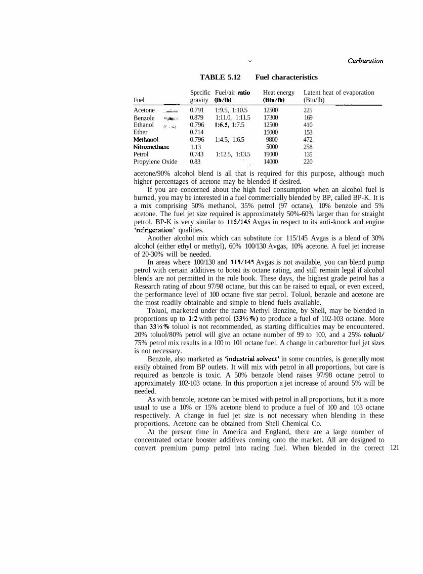
Carburation
TABLE 5.12 Fuel characteristics
Fuel
AcetoneBenzole f*i«i«iiEthanolEtherMethanolNitromethanePetrolPropylene Oxide
Specific Fuel/air ratiogravity (Ib/lb)
0.791 1:9.5, 1:10.50.879 1:11.0, 1:11.50.796 1:6.5, 1:7.50.7140.796 1:4.5, 1:6.51.130.743 1:12.5, 1:13.50.83
Heat energy(Btu/lb)
1250017300125001500098005000
1900014000
Latent heat(Btu/lb)
225169410153472258135220
of evaporation
acetone/90% alcohol blend is all that is required for this purpose, although muchhigher percentages of acetone may be blended if desired.
If you are concerned about the high fuel consumption when an alcohol fuel isburned, you may be interested in a fuel commercially blended by BP, called BP-K. It isa mix comprising 50% methanol, 35% petrol (97 octane), 10% benzole and 5%acetone. The fuel jet size required is approximately 50%-60% larger than for straightpetrol. BP-K is very similar to 115/145 Avgas in respect to its anti-knock and engine'refrigeration' qualities.
Another alcohol mix which can substitute for 115/145 Avgas is a blend of 30%alcohol (either ethyl or methyl), 60% 100/130 Avgas, 10% acetone. A fuel jet increaseof 20-30% will be needed.
In areas where 100/130 and 115/145 Avgas is not available, you can blend pumppetrol with certain additives to boost its octane rating, and still remain legal if alcoholblends are not permitted in the rule book. These days, the highest grade petrol has aResearch rating of about 97/98 octane, but this can be raised to equal, or even exceed,the performance level of 100 octane five star petrol. Toluol, benzole and acetone arethe most readily obtainable and simple to blend fuels available.
Toluol, marketed under the name Methyl Benzine, by Shell, may be blended inproportions up to 1:2 with petrol (33!4%) to produce a fuel of 102-103 octane. Morethan 33!/3% toluol is not recommended, as starting difficulties may be encountered.20% toluol/80% petrol will give an octane number of 99 to 100, and a 25% toluol/75% petrol mix results in a 100 to 101 octane fuel. A change in carburettor fuel jet sizesis not necessary.
Benzole, also marketed as 'industrial solvent' in some countries, is generally mosteasily obtained from BP outlets. It will mix with petrol in all proportions, but care isrequired as benzole is toxic. A 50% benzole blend raises 97/98 octane petrol toapproximately 102-103 octane. In this proportion a jet increase of around 5% will beneeded.
As with benzole, acetone can be mixed with petrol in all proportions, but it is moreusual to use a 10% or 15% acetone blend to produce a fuel of 100 and 103 octanerespectively. A change in fuel jet size is not necessary when blending in theseproportions. Acetone can be obtained from Shell Chemical Co.
At the present time in America and England, there are a large number ofconcentrated octane booster additives coming onto the market. All are designed toconvert premium pump petrol into racing fuel. When blended in the correct 121
Carburation
behaviour identical to the fuel being tested. At this point the quality of the test fuelwould be rated in relation to the percentage of iso-octane in the reference fuel mixturewhich gave identical test results. For example, a test fuel which behaved the same as amixture of 75% iso-octane/25% n-heptane would be called 75 octane fuel. Using thisstandard test procedure, fuel of constant quality could be refined and supplied for avariety of applications.
Since that time a number of test procedures have come into use to simulate avariety of engine operating conditions. Motor spirit is usually rated according to theResearch or Motor test methods. Both measuring techniques use the same singlecylinder, variable compression test engine, but the Motor method employs a greaterengine speed and a higher inlet mixture temperature than the Research test. Hence theMotor method is a more severe test, and generally yields octane numbers 6 to 12 lessthan the Research test. (TABLE 5.13). This distinction is important, as it informs usthat the Motor Octane Number (MON) is more relevant to a racing engine than is theResearch Octane Number (RON).
Another common number seen on American service station pumps is the PumpOctane Number (PON). This is the average of the RON and MON:
RON + MON. . . . . - • ; . . , . . . . . . . 2
and yields a very creditable rating of a fuel's performance under actual roadconditions.
The Supercharge test is applied to aircraft fuels which exceed 100 octane numbers,as the other tests become meaningless at just over 100. The SON (Supercharge OctaneNumbers) are significant from 100 to well over 300. Two tests are involved, the F3 andF4 tests, which explains why aircraft fuels have a dual rating such as 100/130. The firstnumber refers to the F3 test, which simulates a supercharged engine running on achemically-correct fuel/air mixture, as when cruising. The F4 number gives anindication of the fuel's performance rating with an enriched mixture and increasedsupercharge boost, as would be supplied during aircraft take-off or during combatconditions.
Numbers over 100 cannot refer to percentages of iso-octane. They are, in fact,performance numbers devised to extend the scale of anti-knock measurement past thatpossible with pure iso-octane. As such, they give a rough estimate of the powerpotential of the fuel when a heavy supercharge boost is applied to a suitable engine. Forexample, 115/145 Avgas has the potential of increasing an aircraft engine's power by45% over that possible using pure iso-octane fuel.
TABLE 5.13 Octane test comparison
Research octane number Motor octane number Pump octane number
92 85.7 88.897 89 93100 91.6 95.8103 92.5 97.75105 94.2 99.6108 97 102.5110 99 104.5 123

Two Stroke Performance Tuning
The anti-knock properties of hydrocarbon fuels are related to their molecularstructures. The paraffins (such as normal heptane and kerosene) are long chains ofcarbon and hydrogen held together by weak molecular bonds which are easily brokenby heat. Iso-octane is a member of the iso-paraffin family. These have a branched-chain structure that form stronger bonds to resist detonation better. The cyclo-paraffins (or napthenes) also have good anti-detonation properties with their hydrogenand carbon atoms well bonded in a ring shape molecule. The aromatic fuels, such astoluol, also have a ring-shaped structure with very strong bonds. This explains whythey have such good anti-knock characteristics.
The chemical composition of the fuel determines just how rapidly the fuel willburn and whether it will be resistant to detonation at high compression pressures andtemperatures. The fuels with weak molecular bonds break up and burn spontaneously(i.e., without being ignited by the combustion flame initiated by the firing of the sparkplug) at lower temperatures and pressure than fuels with strongly bonded structures.Some fuel additives, such as the aromatics, make excellent anti-detonants because theyburn slowly and don't oxidise or burn completely until combustion chambertemperature and pressure is very high. Aromatic fuels therefore inhibit, or slow down,combustion. For this reason a high octane fuel will not increase engine power unless theengine actually needs a fuel which is chemically stable at high temperature andpressure. Obviously, if the engine does not have a compression ratio and spark advancegreat enough to produce high combustion pressure and temperature, then the highoctane racing fuel will not burn completely, resulting in loss of power.
124

Chapter 6Ignition
TWO-STROKE engines of the type being considered in this book rely on anelectric spark to initiate combustion of the fuel/air charge which has been inducted intothe cylinder. For the engine to operate efficiently, the spark must be delivered atprecisely the right moment in relation to the position of the piston in the cylinder andthe rotational speed of the crankshaft. Additionally, the spark must be of sufficientintensity to fire the fuel mixture, even at high compression pressure and high rpm.
Today, very few two-stroke engines use a coil and battery ignition system.However, we will consider the operation of this type of ignition first as this willenhance your understanding of the workings of magneto, magneto-type capacitordischarge, and battery-type capacitor discharge systems.
The battery and coil type system relies on a battery, either 6 or 12 volt, to supplythe initial electrical energy; a set of points to time the spark, and a coil to intensify thevoltage of the electrical energy supplied by the battery so that it is capable of jumpingthe spark plug gap and firing the fuel mixture (FIGURE 6.1).
When the points are closed, electric current flows through the coil's low voltageprimary winding, and then through the points to earth. The current in the low tensionwinding produces a magnetic field which surrounds the coil's secondary or high tensionwinding. As soon as the points open, current flow through the primary stops, and themagnetic field collapses, causing an electric current to be inducted in the secondarywinding. This creates a high voltage spark (up to 25,000 volts) capable of jumpingacross the spark plug electrodes to fire the fuel/air mixture.
In FIGURE 6.1, you will note that a condenser is also included in the primaryignition circuit. Many have the idea that the condenser stops the points from burning,but this is secondary to its main function, which is to drain off electrical energy quicklyfrom the coil's primary winding. This speeds up the collapse of the magnetic field whenthe points open and increases the high voltage spark intensity. Without a condenser,the electrical energy inducted in the coil's high voltage winding would be too feeble toproduce a spark. 125

Two Stroke Performance Tuning
126
Fig. 6 .1 Conventional negative earth ignition system.
The coil and battery system works very reliably and efficiently, even in high speedfour-stroke racing engines. However, due to ignition problems peculiar to two-strokeengines, this type of ignition has largely been replaced by ignition systems whichproduce a high voltage spark more quickly. The rise time (i.e., the time from 10% ofmaximum output voltage to 90% of maximum output voltage) is between 75 and 125microseconds with a conventional coil and battery system. In that interval a spark plug,surrounded by a conductive petrol/oil mist, will have time to bleed off voltage acrossthe insulator nose, causing a misfire, or at best result in a spark of low intensity.Capacitor discharge and magneto systems both overcome this problem, having a risetime of 20 microseconds and 45 microseconds respectively.
The magneto systems fitted to two-stroke engines have, over the years, oftengained a bad reputation. True, in a few instances this reputation was well founded but,generally, a magneto system will give reliable and efficient service if correctlymaintained. The most common causes of trouble are burned out and pitted points dueto a lack of regular maintenance, and electrical collapse of the condenser. This is
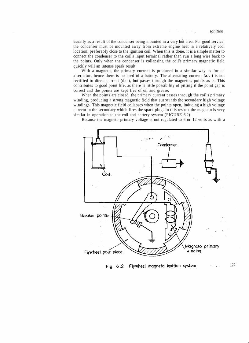
Ignition
usually as a result of the condenser being mounted in a very hot area. For good service,the condenser must be mounted away from extreme engine heat in a relatively coollocation, preferably close to the ignition coil. When this is done, it is a simple matter toconnect the condenser to the coil's input terminal rather than run a long wire back tothe points. Only when the condenser is collapsing the coil's primary magnetic fieldquickly will an intense spark result.
With a magneto, the primary current is produced in a similar way as for analternator, hence there is no need of a battery. The alternating current (a.c.) is notrectified to direct current (d.c.), but passes through the magneto's points as is. Thiscontributes to good point life, as there is little possibility of pitting if the point gap iscorrect and the points are kept free of oil and grease.
When the points are closed, the primary current passes through the coil's primarywinding, producing a strong magnetic field that surrounds the secondary high voltagewindings. This magnetic field collapses when the points open, inducing a high voltagecurrent in the secondary which fires the spark plug. In this respect the magneto is verysimilar in operation to the coil and battery system (FIGURE 6.2).
Because the magneto primary voltage is not regulated to 6 or 12 volts as with a
127

Two Stroke Performance Tuning
battery ignition system, the primary voltage increases proportionately with the enginespeed. This feature of the magneto ensures that the coil is fully energised (saturated)between each plug firing, regardless of how fast the engine is spinning. Also, becausethe primary voltage increases with an increase in rpm, the secondary voltage doeslikewise, producing a proportionately bigger spark. For example, if a primary voltageof 8 volts induces 10,000 volts in the secondary, then a primary voltage of 24 volts willresult in a secondary voltage of 30,000 volts.
At this time, the majority of two-stroke engines come from the manufacturerswith capacitor discharge ignition (GDI). There are two types of GDI systems, thebattery type and the magneto type. The battery type requires a battery to supply thesystem's primary current, while the magneto type generates its own primary current. Inall other respects both types function in a similar way.
Without a good understanding of electronic circuitry and switching, it is quitedifficult to comprehend exactly how GDI systems work. My knowledge in this field islimited, but I will endeavour to explain simply how GDI operates.
Basically, the system utilises electronic devices to step-up the output voltage fromthe battery or magneto to something like 375-400 volts. The primary current, afterbeing boosted to this voltage, is then stored in the storage capacitor. An electro-magnetic trigger (usually located in the rotor attached to the end of the crankshaft), onpassing close by the trigger coil, induces a pulse which closes an electronic switch calledan SCR (silicon controlled rectifier). This allows the storage capacitor to send a surgeof power through the ignition coil's primary windings, which induces a high voltage inthe secondary to fire the spark plug.
GDI systems will generally give good.service if a few basic precautions are taken.Most problems result from poor electrical connections or poor earth connections. Toavoid bad connections, clean all the terminals with solvent and, when pushing theconnectors together, ensure that they are a good tight fit. Then tape the connectorstogether so that they cannot vibrate apart. Earth connections are just as important as
, any other electrical connection. Usually, the connection between the 'black box', forexample, and the bike's frame, is quite good. As the earth has to go back to the engine,test to see that the engine is earthed to the frame, using a continuity tester.
When mounting the 'black box' and coils on a sidecar outfit or go-kart, keep themaway from engine or exhaust heat. Heat is a killer of electronic components, which iswhy they are often mounted on a heat sink. Remember that, as well as dissipating heat,a heat sink can also absorb huge amounts of heat if mounted in a hot environment.
With capacitor discharge ignition it is very important to ensure that a spark plugwire will not jump off or be in a position where it could be pulled off accidentally. Ifthis occurs when the engine is running, it is quite probable that the electrical insulationof certain components will break down and cause the system to burn out. Also, keep inmind that you should ensure the plug wires are grounded if you ever flood the engineand it becomes necessary to turn it over vigorously with the plugs removed.
Unfortunately, GDI systems do, at times, fail. Total failure in itself is quiteserious, especially if you are in the lead! But more difficult to detect is the type ofproblem more usual with GDI. Generally, the spark-producing system functions veryreliably, but the automatic advance/retard station, which is made up of electroniccomponents, does give trouble. When this occurs, the engine will continue to run, as
128 strong sparks are still being supplied. But if the system is 'locked' in the full advance

Ignition
mode, detonation and engine seizure are a likely result. Less serious is a systemfunctioning fully retarded, as this will cause sluggish performance at lower enginespeeds.
There is nothing that you can do to prevent advance/retard system failure, but youcan save yourself a good deal of expense and worry if you realise such a problem canexist. Some racers chase their tails for a whole season trying to find lost horsepower,unaware that the GDI is the cause of the trouble. Others spend hundreds of dollarsreplacing seized pistons and barrels for several successive meetings when all along thetrouble has been the GDI stuck on full advance.
If your bike has a GDI with an advance/retard system (check with themanufacturer) you can avoid this sort of unnecessary expense and frustration byregularly checking the timing with a strobe light. Usually you will have to connect thestrobe to a 12 volt battery as most bikes do not have a suitable power source. If theadvance/retard system is working properly, you will note that the timing marks line upat certain engine speeds and move apart at others. When the system is malfunctioning,the timing marks will not line up at any speed, or in the case of a system which employsa high rpm retard mechanism which has locked on full advance, they will remainaligned at all engine speeds.
To get some idea of how seriously over-advanced an engine can be when ahigh-speed retard station fails to function correctly, we should examine the Motoplatignition unit fitted by Rotax to their type 124 air-cooled and liquid-cooled kart engines.Prior to mid-1980, the ignition provided steady ignition timing (i.e., without anyadvance/retard). With this Motoplat unit the timing was set at 1 .Omm before TDC (14°advance). Later model engines were fitted with an ignition unit incorporating ahigh-speed retard function. With this type of Motoplat the advance is set at 3.76mmbefore TDC (27.5° advance). After SOOOrpm the automatic retard gradually reducesthe ignition advance with rising engine speed, so that at ll,000rpm the timing hasdecreased to 1.2mm or 15.5° before TDC. Obviously if the automatic spark retardfailed, and the engine was operated with the Motoplat locked on full advance, theengine would quickly fail.
Regardless of the ignition system employed, the spark plug must fire at the correcttime if good power is to be made and engine damage avoided. Some two-strokes aretimed to spark at 2mm before TDC, others at anywhere from 0.4mm to 4mm.Probably you are wondering why the difference? Well, first, the length of the engine'sstroke will affect the amount of advance required. A short stroke engine with 2mmadvance will have considerably more advance measured in degrees of crankshaftrotation than a long stroke engine with spark timing of 2mm before TDC. Forexample, a 125cc engine with a stroke of 60mm and 2mm ignition advance has 18.8°advance, the same as a 125 engine with a 50mm stroke and 1.65mm advance. Theadvance angle can be calcuated using the formula:-
A= CoSP 2+R 2 -L*2 x P x R
where A = ignition advance in degreesR == engine stroke divided by 2 in mmL= con-rod length (usually stroke multiplied by 2) in mmT = ingition timing in mmP= R + L-T 129

Two Stroke Performance Tuning
As mentioned in the previous chapter, the burn rate of individual fuels differs.Methanol burns slowly, therefore more advance is required as the combustion flamemust have progressed just as far by the time the piston passes TDC as it would if thefuel were petrol. To compensate for the slower rate of burning, the flame must bestarted earlier.
Beside the type of fuel being burnt, there are other factors which influence flamespeed. Very rich and very lean mixtures both burn slowly, hence more spark advancewill be needed. A mixture close to full power lean burns the hottest and requires theleast advance.
An increase in the compression ratio increases the density and temperature of thecompressed fuel/air charge. This increases the rate of combustion. Likewise, animprovement in the volumetric efficiency of the engine will have a similar effect.Therefore a change in porting, a new expansion chamber, or a carburettor whichallows the engine to breathe better, may require that the spark lead is reduced.
As the engine speed increases, fuel atomisation improves, which means that thefuel will be broken up into smaller particles. Small fuel particles have a proportionatelylarger surface area, therefore they burn more rapidly, which means less advance isnecessary. This is why an engine which required, say, 1.8mm advance running atlO.OOOrpm may require only 1.0mm advance operating at ll,500rpm.
The size of the combustion space and the position of the spark plug in that spacealso influences the advance required. Obviously the further the flame has to travel, thelonger it will take to completely burn the mixture. Consequently an engine with asquishless (quiescent) combustion chamber or a large bore diameter will usually requiremore advance. Also an engine in which the spark plug is offset from the centre of thecombustion chamber will increase the distance the flame must travel, hence the needfor additional advance.
Any modification which significantly raises the peak hp output of a two-strokeusually results in higher piston crown and cylinder head temperatures. A hot fuelcharge burns more quickly, so the advance must be reduced.
With four-stroke engines it is usual for the modified engine to require considerablymore advance than standard. However, from the foregoing you can see that this doesnot apply in the case of two-strokes. In fact, it is quite unusual for a two-stroke engineto need more advance than that specified by the manufacturer. It is difficult to say justhow much advance a modified engine will require, but as they can be easily damagedbecause of too much ignition advance, I would suggest that you reduce therecommended timing by 20% to begin with. Therefore, if the standard timing is 2.5mmbefore TDC, start testing with 2mm advance and then increase it in steps of O.lmm tofind if more advance improves the performance. Many enthusiasts have a tendency toover-advance the timing in an effort to pick up every last fraction of performance. Myadvice is to use the least amount of advance conducive to peak performance. For thisreason, I think it is a good idea to back-track to make sure that more advance is better.In this example, if the engine seemed to run better with each O.lmm increase until youarrived at the standard timing of 2.5mm, drop back to 2.2mm just to make sure thatthe engine is really performing at its best with 2.5mm advance.
Obviously, to do any timing changes you are going to need a timing dial gauge. Itis one of the most important tools in a two-stroke tuner's kit, so purchase a good one,
130 after all they are only the price of a couple of new pistons. Some enthusiasts think that
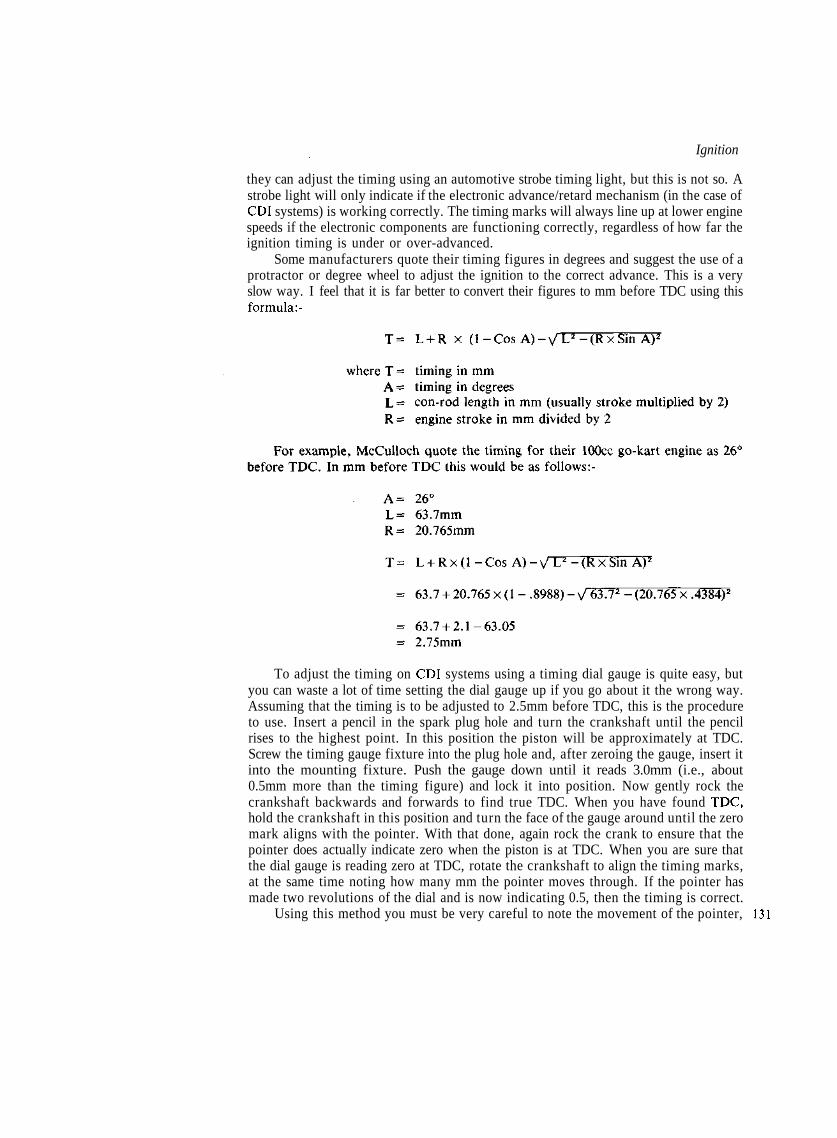
Ignition
they can adjust the timing using an automotive strobe timing light, but this is not so. Astrobe light will only indicate if the electronic advance/retard mechanism (in the case ofGDI systems) is working correctly. The timing marks will always line up at lower enginespeeds if the electronic components are functioning correctly, regardless of how far theignition timing is under or over-advanced.
Some manufacturers quote their timing figures in degrees and suggest the use of aprotractor or degree wheel to adjust the ignition to the correct advance. This is a veryslow way. I feel that it is far better to convert their figures to mm before TDC using thisformula:-
To adjust the timing on GDI systems using a timing dial gauge is quite easy, butyou can waste a lot of time setting the dial gauge up if you go about it the wrong way.Assuming that the timing is to be adjusted to 2.5mm before TDC, this is the procedureto use. Insert a pencil in the spark plug hole and turn the crankshaft until the pencilrises to the highest point. In this position the piston will be approximately at TDC.Screw the timing gauge fixture into the plug hole and, after zeroing the gauge, insert itinto the mounting fixture. Push the gauge down until it reads 3.0mm (i.e., about0.5mm more than the timing figure) and lock it into position. Now gently rock thecrankshaft backwards and forwards to find true TDC. When you have found TDC,hold the crankshaft in this position and turn the face of the gauge around until the zeromark aligns with the pointer. With that done, again rock the crank to ensure that thepointer does actually indicate zero when the piston is at TDC. When you are sure thatthe dial gauge is reading zero at TDC, rotate the crankshaft to align the timing marks,at the same time noting how many mm the pointer moves through. If the pointer hasmade two revolutions of the dial and is now indicating 0.5, then the timing is correct.
Using this method you must be very careful to note the movement of the pointer, 131
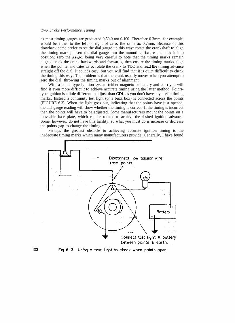
Two Stroke Performance Tuning
as most timing gauges are graduated 0-50-0 not 0-100. Therefore 0.3mm, for example,would be either to the left or right of zero, the same as 0.7mm. Because of thisdrawback some prefer to set the dial gauge up this way: rotate the crankshaft to alignthe timing marks; insert the dial gauge into the mounting fixture and lock it intoposition; zero the gauge, being very careful to note that the timing marks remainaligned; rock the crank backwards and forwards, then ensure the timing marks alignwhen the pointer indicates zero; rotate the crank to TDC and read'the timing advancestraight off the dial. It sounds easy, but you will find that it is quite difficult to checkthe timing this way. The problem is that the crank usually moves when you attempt tozero the dial, throwing the timing marks out of alignment.
With a points-type ignition system (either magneto or battery and coil) you willfind it even more difficult to achieve accurate timing using the latter method. Points-type ignition is a little different to adjust than GDI, as you don't have any useful timingmarks. Instead a continuity test light (or a buzz box) is connected across the points(FIGURE 6.3). When the light goes out, indicating that the points have just opened,the dial gauge reading will show whether the timing is correct. If the timing is incorrectthen the points will have to be adjusted. Some manufacturers mount the points on amoveable base plate, which can be rotated to achieve the desired ignition advance.Some, however, do not have this facility, so what you must do is increase or decreasethe points gap to change the timing.
Perhaps the greatest obstacle to achieving accurate ignition timing is theinadequate timing marks which many manufacturers provide. Generally, I have found
132

Ignition
it impossible to adjust the timing to an accuracy of better than ±0.15mm of the desiredfigure, using the naked eye and the manufacturer's standard timing marks. To makethe timing marks easier to see, they should be painted black and the surrounding arealeft unpainted, or else the entire area should be painted black and the marks paintedwhite or silver. Often, you will find that the rotor face stands proud of the stator byanything up to 5mm, which means that it will be very difficult, if not impossible, toadjust the timing accurately because of parallax error, even if the timing marks areclearly visible. In this situation you have two options. Either you can make a fixturewith a sight slot, like a gun sight, to sight through onto the timing marks, or you canpull the rotor off the end of the crank and very accurately extend the timing mark ontothe rotor's periphery, using a three corner file or a scriber. Anything which you can doto improve the accuracy and repeatability of ignition timing adjustments will lessen thepossibility of detonation and allow the engine to perform at its best.
If your machine has a points-type ignition system, don't attempt to adjust thetiming using the stock timing marks. Instead, always set the advance with a dial gaugeand a light connected across the points. Many of the piston failures experienced byengines like the early Yamaha RD twins can be traced back to inaccurate ignitiontiming as a result of the tuner relying on the stock timing marks.
Detonation, and to a lesser extent pre-ignition, both damage many two-strokeengines. Detonation occurs when a portion of the fuel/air mixture, usually the 'endgases', begin to burn spontaneously after normal ignition takes place. The flame frontcreated by this condition eventually collides with the flame initiated by the spark plug.This causes a rapid and violent burning of any remaining fuel (almost an explosion)which hammers the engine's internal components with such force that the cylinder walland piston crown actually vibrate. This vibration makes the pinging sound which analert ear can pick up. Pre-ignition is ignition of the fuel/air charge by a 'hot spot'before the spark plug fires to initiate normal combustion. Typically, this leads to a lossin performance much like excessive ignition advance in its early stages. If allowed tocontinue it can destroy an engine.
When engine damage results from either type of abnormal combustion, the culpritcan usually be identified after an examination of the piston and spark plug. Pre-ignition damage is caused by the extreme combustion temperature which results,melting the piston crown and also, possibly, the ring lands. If a hole is present in thepiston, it will appear to have been burned through with a welding torch. The metalaround the hole will be fused and have a melted appearance. The spark plug may havethe centre electrode melted away and, in extreme cases, the insulator nose and earthelectrode will also be fused.
A piston damaged by detonation will show signs of pitting on the crown. The edgewill be gray and eroded, as if sandblasted. In the very early stages, gray ash-likedeposits form on the exhaust-side edge of the piston crown. In extreme examples, thepiston will be holed. The hole will appear to have been punched through, with radialcracks and a depressed area around the hole. A spark plug subjected to fairly severedetonation will usually show signs of cracking at the insulator nose. Engines withplated aluminium cylinders will exhibit a sand-blasted effect around the top lip of thebore.
Pre-ignition can frequently be traced to deposits in the combustion chamber or onthe piston crown becoming incandescent. Since these deposits do not conduct heat well, 133

Two Stroke Performance Tuning
very high temperatures can be reached within such accumulations. Spark plug heatranges can also affect pre-ignition. If the electrodes retain too much heat from previouscombustion cycles, they will glow and pre-ignite the fuel.
The conditions which lead to detonation are high fuel/air mixture density, highcompression ratio, high inlet charge temperature, best power fuel/air ratio (i.e.,1:12.5), and excessive spark advance. A piston crown or combustion chamberoverheated by pre-ignition can initiate detonation by excessively heating the 'endgases'. Go-kart engines with fixed gearing may also suffer from detonation whenpulling out of low speed corners, if geared too high. Except in the latter two cases,detonation is eliminated by reducing the ignition advance and possibly by jetting richer(TABLES 6.1 and 6.2).
TABLE 6.1 Effect of ignition advance on combustion temperature
Ignition timing (mm) Spark plug electrode temp. (°C)
2.0 8532.25 876
2.5 : 9082.75 '. 962
TABLE 6.2 Effect of fuel flow on combustion temperature
Fuel flow (litre/hr) Spark plug electrode temp. (°C)
3.0 9043.25 8803.5 85?3.75 8324.0 8004.25 766
Due to increased combustion temperatures in a modified engine, considerationmust be given to finding a spark plug with the correct heat range. A hot plug transferscombustion heat slowly and is used to avoid fouling in engines with relatively lowcombustion temperatures. A cold plug, on the other hand, transfers heat rapidly fromthe firing end. It is used to avoid overheating where temperatures are high, as in aracing engine (TABLE 6.3).
TABLE 6.3 Effect of spark plug heat range on plug temperature
The length of the insulator nose and the composition of the electrode alloy are theprimary factors in establishing the heat rating of a particular plug. Hot plugs have long
134 insulator noses, and hence a long heat transfer path. Cold plugs have shorter nose

Ignition
lengths to transfer heat more rapidly from the insulator tip to the cylinder head fins (orwater jacket), via the metal spark plug body (FIGURE 6.4).
Generally, two-stroke engines do not require a plug more than one or two gradescolder than standard, even when extensively modified for very high power outputs.Providing the engine is in good condition, and the carburettor is correctly tuned,reading the nose of the plug will indicate if one with the correct heat range has beenchosen. So that you do not end up with engine damage it is advisable to begin testingwith a plug which is too cold, or else test the machine at moderate load and speed, andthen check the plug before you engage in any full power running.
For the plug reading to be accurate, it will be necessary to run the engine at fullthrottle and maximum speed and then cut the engine dead. If you allow the engine tokeep running as you bring the bike to a stop, the plug reading will be meaningless.
The signs to look for when reading a plug are indicated in TABLE 6.4. You willnote that it is not just the colour of the insulator nose in which we are interested. Theentire firing end of the plug exposed to the combustion flame must be examined andread.
Of course, spark plug heat range must be tailored to each race circuit. Tracks witha long, fast straight may require a plug one grade colder. Conversely, a tight, wet trackmay require a plug one grade hotter than normal.
Once you have determined the correct plug heat range, don't swap over to anotherbrand with an 'equivalent' heat range. Heat range conversion charts should be used asa guide only, when you swap from one plug brand to another, as individual plugmanufacturers use different methods of determining the heat range of their plugs. Ifyou cross-reference the conversion charts from all the plug manufacturers you will findthat they disagree with each other, due to varying test procedures.
As well as the heat range, the gap style of the plug must also be considered to 135

Two Stroke Performance Tuning
TABLE 6.4 Spark plug reading for heat range and other conditions
Spark plug conditionNormal — correct heat range
Too cold — use hotter plug
Too hot — use colder plug
Pre-ignition — use a colderplug and remove piston andcombustion chamber deposits
Detonation — retard ignitionand richen mixture
IndicationsInsulator nose white or very light tan to rust brown.Little or no cement boil where the centre electrodeprotrudes through the insulator nose.The electrodes are not discoloured or eroded.
Insulator nose dark grey or black.Steel plug shell end covered with tar-like deposit.
Insulator nose chalky white or may have satin sheen.Excessive cement boil where centre electrode protrudesthrough the insulator nose. Cement may be milk white ormeringue-like.Centre electrode may 'blue' and be rounded off at theedges.Earth electrode may be badly eroded or have a moltenappearance.
Insulator nose blistered or fused.Centre electrode and side electrode burned or meltedaway.
Fractured insulator nose in sustained or extreme cases.Insulator nose covered in tiny pepper specks or even tinybeads of aluminium leaving the piston.Excessive cement boil where centre electrode protrudesthrough insulator nose.Specks on plug shell end.
136
obtain the best performance, and in a few instances to avoid engine damage (FIGURE6.5). The spark plug which I recommend for all two-stroke applications, with a fewexceptions, is the fine wire type Champion Gold Palladium. This type of plug has avery wide heat range to resist both fouling and pre-ignition. It can be supplied with thestandard Gold Palladium centre electrode or, for special applications, with a platinumcentre electrode (TABLE 6.5). The small diameter centre electrode requires less voltageto fire than a regular electrode. This feature allows easier starting of all enginesemploying magneto type ignitions (either points or GDI) as the voltage available atlower cranking speeds is diminished. The insulator nose is a special 'open' design whichallows more clearance within the firing end of the plug for better scavenging ofdeposits.
The conventional regular gap plug is my next choice after the fine wire type. Itdoes not have such a good heat range and anti-fouling properties as the GoldPalladium, but it is cheaper. However, it has a heat range far superior to the retractedgap style. Really, the retracted gap plug should only be used when absolutely necessary.This type of plug has little resistance to fouling and it generates a poor combustionflame front, due to the way in which the plug masks the spark within its nose in apocket of stagnant air. Combustion efficiency and speed depends to a large extent on


Two Stroke Performance Tuning
turbulence within the combustion chamber causing the compressed fuel/air charge torush through the plug electrode gap and propagate the combustion flame throughoutthe combustion chamber. When the spark generates a combustion flame in an area ofrelative calm, as in the end of a retracted gap plug, some time elapses before the flameradiates out into the turbulence of the combustion chamber. The fact that the insulatornose is in an area of such calm also means that fuel and ash deposits collect very easilyto foul the plug.
A variation of the regular gap plug is the cut-back gap. This type has a shorterearth electrode which extends midway across the centre electrode. The main benefit ofthis design is that it requires less voltage to fire at high rpm than the regular gap plug.
138 Champion plugs of this type have a 'J' suffix (eg: L4J, L77J). Of course, regular gap

ignition
plugs can be modified by filing the earth electrode back when cut-back plugs are notavailable in the heat range required. This modification will, however, make the plug'sheat range just a little cooler.
In some heat ranges the only spark plugs available have an auxiliary gap ('boostergap') to help resist low speed fouling. Since the booster gap increases the voltagerequirement to fire the plug quite considerably, they can cause problems in competitionengines. A booster gap plug can be identified visually by a small hole in the stud of theplug which ventilates the interior booster gap. In the case of Champion plugs, they canbe recognised easily by a 'U' prefix (eg: UL81J, UJ7G). It is recommended that boostergap plugs be 'pinned' when installed in high-speed engines, by inserting a straightenedpaper clip down the vent hole. Whey you have pushed the wire in as far as it will go, cutit off level with the top of the plug terminal.
Another point worthy of consideration is the reach of the plug. A plug which istoo short and does not extend the full threaded length of the spark plug boss in thehead will reduce performance by masking the ignition flame. Additonally, it can invitea hot spot in the form of carbon building up in the unused portion of thread. A plugthat is too long will have threads exposed in the combustion chamber. The threads fillup with carbon which damages or strips the threads in the head when the plug isremoved. Also, the exposed threads, or the carbon deposited in them, may become ahot spot precipitating pre-ignition. •\^_^x
On any engine the spark plug reach should be checked, all the more so if thecombustion chamber has been modified or if a temperature gauge thermocouplewasher is fitted under the plug. In some instances a change to another plug reach maybe in order, but in most cases the use of a single solid copper gasket will ensure theproper depth fit. The range of Champion gaskets for 14mm plugs is listed in TABLE6.6. It should be noted that it is quite in order to use a solid gasket and the standardfolded gasket together. This is necessary, for example, when Win reach GoldPalladium plugs are used in applications where 5/sin reach plugs are normally fitted.
Note: Part No N678'is a thread-on gasket, the others are solid.
The width of the spark plug gap for best performance depends primarily on thecompression pressure of the fuel/air charge, the engine rpm, the spark plug gap styleand the high speed voltage output of the coil. Increasing the first two factors withoutan increase in the latter calls for a decrease in the gap width. Therefore, it is fairly safeto say that all radically-modified engines will require a gap narrower than thatrecommended by the manufacturer. 139

Two Stroke Performance Tuning
Manufacturers generally stipulate a relatively wide gap (0.6 to 0.7mm) as thisimproves performance at lower rpm and reduces the risk of the gap being bridged bywhiskers of carbon, or beads of lead, oil or petrol. As there is much less turbulence inthe combustion chamber at low engine speeds, it is very easy for a blob of carbon orfuel to settle between the plug electrodes, shorting it out. With a wider gap the odds arebetter because the speck of carbon or the bead of fuel may not be large enough tobridge the gap. Later, when the engine is given a high-speed burst, the increasedturbulence will 'blow' the electrodes clean. Also, because the spark generated in a widegap is larger than that in a narrow gap, a more sizeable initial combustion flame isproduced. This improves flame propagation through the fuel charge and allows for amore complete burn of the compressed mixture. Hence hp at lower revs goes up.
As the engine speed and compression pressures increase, the coil is not able tosupply electrical energy of sufficient voltage to jump a wide spark gap and keep the airbetween the electrodes ionised for a period long enough to initiate combustion. Whathappens is that the coil has enough energy reserve to electrically bridge the spark plugelectrodes but, before the spark generated can get a combustion flame started,turbulence within the combustion chamber will actually blow out the spark. This was abig problem with the early GDI systems, as the spark was produced for only a veryshort duration. Current CDIs have a shunt incorporated to lengthen spark duration,allowing marginally wider plug gaps. When a narrow gap is used, the magnetic fieldwithin the gap is much more intense, as it is confined to a much smaller space. Hencethe spark 'holds together' for long enough to effect ignition, in spite of receiving severe
\ buffeting from the turbulent gases within the combustion chamber.\ From experience I would recommend that any competition engine with anoperating speed in excess of 9000rpm would use a plug gap of 0.5mm if fitted with afine wire plug, fired by a CDI system. With a coil and battery, or magneto system, thegap may have to be reduced to 0.4mm. When retracted gap plugs are used, the gap willbe 0.4 to 0.45mm with CDI and 0.35 to 0.4mm for other systems.
Engines operating at speeds of around 7500 to 8500rpm will require a gap of 0.55to 0.6mm with a fine wire plug and CDI. If retracted gap plugs are fitted, the gap willbe 0.4 to 0.45mm.
If the ignition system has been modified, or if a special ignition has been fitted,check to see that coil polarity is correct before you try experimenting to determine whatplug gap gives the best performance in your engine. A coil with reversed polarity losesthe equivalent of 40% energy as the spark has to jump from what would normally bethe earth electrode (the side electrode) to the centre electrode. Because the sideelectrode is many hundreds of degrees cooler than the centre electrode, there is muchmore restrained electron activity on the metal surface. This considerably increases thevoltage required to cause the electrons to leave one electrode and jump to the other,thus ionising the gap and creating a spark. Cold engines are more difficult to get startedfor this very reason. The plug electrodes are cold, therefore a very high voltage isnecessary to tear the electrons from one surface and have them jump the gap to theother electrode.
With a coil and battery type ignition system the polarity is correct when the wirefrom the coil to the points is connected to the coil terminal with the same polarity as theearth terminal of the battery, i.e., if the negative (-) battery terminal is earthed, then
140 the wire running between the coil and the points should be connected to the negative

Ignition
(-) coil terminal. With other ignition systems the polarity is seldom marked, so it is amatter of following the manufacturer's wiring diagram precisely, otherwise the ignitionmay still function but the polarity could be wrong. Also take care that you do not fitmis-matched components, using a rotor/stator assembly from one bike, and a coil/electronic control unit from another. Even if the bikes are basically identical, but one isa year or two older than the other, it is quite possible to run into trouble.
A dished spark plug side electrode indicates incorrect polarity (FIGURE 6.6). Thedish is caused by metal leaving the electrode each time a spark jumps across to thecentre electrode. Normally, this would only be visible in road bikes where the plug hasa service life of 3000 to 5000 miles.
Dished earth electrode.
Fig. 6 . 6 Dished earth electrode indicates wrong polarity.
The life of a spark plug in a two-stroke racing engine is not as short as many wouldsuppose. Many have the idea that a new plug is required for each race, but this is justnot so. With proper care, a plug should last at least 300 miles, and up to 500 miles. Anexception would be in the case of engines using nitro, or if the engine blows, coating theinsulator with metallic deposits.
A road machine should have the plugs filed, gapped and tested every 1,800-2,000miles, and a race machine after each meeting. Bend the earth electrode back far enoughto permit filing of the sparking surfaces shown in FIGURE 6.7. A points file should beused to file a flat surface with sharp edges on both the centre and side electrode. Thislowers the voltage required to fire the plug, firstly because electricity prefers to jumpacross sharp edges, and secondly because the electrical conductivity of the electrodes isimproved. Combustion heat and pressure tends to break up and oxidise electrode firingsurfaces, increasing the electrical resistance. Filing removes this 'dead' material andexposes new, highly-conductive metal.
Retracted gap plugs, naturally enough, cannot be filed. Also the centre electrodeof fine wire plugs should not be filed, otherwise it will be damaged.
Spark plugs should never be cleaned with a wire brush, as metallic deposits willimpregnate the insulator and short out the plug. I also do not recommend cleaning inan abrasive plug cleaner, as some abrasive material always seems to become wedgedbetween the insulator and plug shell. If this cannot be probed out with a scriber, it willdrop into the cylinder and possibly cause damage. However, if you choose to have yourplugs abrasive blasted, be sure to remove all abrasive grit inside the plug nose and fromthe threads and gasket. 141
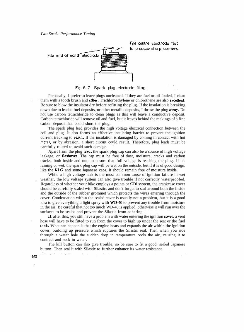
Two Stroke Performance Tuning
Fig. 6.7 Spark plug electrode filing.
Personally, I prefer to leave plugs uncleaned. If they are fuel or oil-fouled, I cleanthem with a tooth brush and ether. Trichloroethylene or chlorothene are also excellent.Be sure to blow the insulator dry before refitting the plug. If the insulation is breakingdown due to leaded fuel deposits, or other metallic deposits, I throw the plug away. Donot use carbon tetrachloride to clean plugs as this will leave a conductive deposit.Carbon tetrachloride will remove oil and fuel, but it leaves behind the makings of a finecarbon deposit that could short the plug.
The spark plug lead provides the high voltage electrical connection between thecoil and plug. It also forms an effective insulating barrier to prevent the ignitioncurrent tracking to earth. If the insulation is damaged by coming in contact with hotmetal, or by abrasion, a short circuit could result. Therefore, plug leads must becarefully routed to avoid such damage.
Apart from the plug lead, the spark plug cap can also be a source of high voltageleakage, or flashover. The cap must be free of dust, moisture, cracks and carbontracks, both inside and out, to ensure that full voltage is reaching the plug. If it'sraining or wet, the spark plug cap will be wet on the outside, but if it is of good design,like the KLG and some Japanese caps, it should remain free of moisture inside.
While a high voltage leak is the most common cause of ignition failure in wetweather, the low voltage system can also give trouble if not correctly waterproofed.Regardless of whether your bike employs a points or CDI system, the crankcase covershould be carefully sealed with Silastic, and don't forget to seal around both the insideand the outside of the rubber grommet which protects the wires entering through thecover. Condensation within the sealed cover is usually not a problem, but it is a goodidea to give everything a light spray with WD-40 to prevent any trouble from moisturein the air. Be careful that not too much WD-40 is applied, otherwise it will run over thesurfaces to be sealed and prevent the Silastic from adhering.
If, after this, you still have a problem with water entering the ignition cover, a venthose will have to be fitted to run from the cover to high up under the seat or the fueltank. What can happen is that the engine heats and expands the air within the ignitioncover, building up pressure which ruptures the Silastic seal. Then when you ridethrough a water hole the sudden drop in temperature cools the air, causing it tocontract and suck in water.
The kill button can also give trouble, so be sure to fit a good, sealed Japanesebutton. Then seal it with Silastic to further enhance its water resistance.
142

Chapter 7The Bottom End
THE BOTTOM END is certainly the least glamorous part of the two-strokeengine, and if you are like me it is also the part you would prefer to forget about untilsomething actually goes wrong. Because the two-stroke is so easy to dismantle, thebottom end seems difficult to get at by comparison.
Fortunately the modern day engine has a crankshaft-rod-bearing assembly that innormal service is very reliable and requires little attention. But this is not to say there isnothing that can be done to improve the crankshaft assembly. Your careful attention inthis area will not only pick up power and reduce fatigue induced by vibration, it willalso decrease the number of crank rebuilds required and lower the cost of being -competitive.
Most two-stroke crankshafts are a pressed together affair. During assembly at thefactory, or from useage, the crank can get out of alignment. This sets up vibration inthe engine which soaks up power, wrecks the bearings and fatigues you. The only wayto overcome the problem is to blueprint the crank assembly. If you have a singlecylinder engine this can wait until the bearings or crankpin are due for replacement.However, if your machine is a twin cylinder road racer, I would encourage you to setup properly even brand new crankshafts. When you do this you can be assured of 700miles trouble free from TZ250 and TZ350 crankshafts.
If you don't have a press, dial gauge and centres, you should take your crankshaftto a reputable firm to have the work done. However, don't assume every motorcycle orengineering shop will do the crankshaft work to the accuracy required. Before youhand your crank over, have a talk with the shop foreman, tell him what you requireand why you insist on accuracy. If he wants your job, he will probably show you othercrankshafts he has done and prove their accuracy.
The first step is to press the crankpin out and separate the crankwheels. Then havethe wheels magnaflux crack tested. Next, check each crankwheel for concentricity. Acrankwheel is concentric when the axle is exactly in the centre of the flywheel.Generally, the shafts are not exactly in the centre of the flywheels, which produces an 143

Two Stroke Performance Tuning
imbalance and vibration. For example, the radius from the shaft's centre to the top ofthe flywheel might be 2.498ins. The radius to the bottom of the flywheel might be2.502ins, indicating that the shaft is 0.002in off centre. The dial gauge would show therunout to be 0.004in. What we want is not more than O.OOlin runout, so thecrankwheel will require very light machining in the lathe to bring the radius of theflywheel to within O.OOOSin of centre.
After the wheels are true, the crankpin holes and crankpin diameter must bechecked to ensure an interference fit of 0.002-0.003in per inch of diameter. If the fit istoo loose, the crankshaft will not stay in alignment.
When a suitable crankpin is found, fit a new big end bearing on the pin, slip thecon-rod on and measure the small end side shake. The amount the small end movesfrom side to side indicates the big end radial clearance. Unfortunately, even all newparts at times indicate up to 0.055in small end movement, which is very close to what Iconsider to be the serviceable limit, 0.065in. A bearing, rod, pin combination with0.030-0.040in play should be sought. This will ensure relatively good big end life(FIGURE 7.1).
s
144

The Bottom End
For the ultimate in big end bearing reliability, a lot of painstaking work isrequired. Basically, the big end assembly will give the best service if the bearing rollersdo not skid on the pin or con rod eye. To achieve this ideal situation you will have towork the big end assembly to several very close tolerances.
Looking at TABLES 7.1 and 7.2 you will note the dimensions in which we areinterested. Naturally, we have to select components which not only fall into either ofthe two selective fit categories dimensionally but which also exhibit true parallelism. Ifthe pin or big end eye, or any of the individual rollers, are not parallel, the rollers willstill skid no matter how carefully we match these parts for fit.
Also, if we are to avoid skidding rollers, we must ensure that the connecting rodhas been machined true. To determine this you will have to make a pair of dummy pinsabout 100mm long to fit the little end and big end eyes. Measuring between both endsof the dummy pins will determine if the rod is bent or has the eyes machined out ofparallel (FIGURE 7.2). Next check that the eyes have been machined in the same plane(i.e., not twisted). To do this set the big end of the rod up with a dummy pin fitted, on apair of parallel V-blocks. Then, with a dial gauge, measure to see that both ends of thepin fitted in the little end are the same dimension from the surface plate. 145

Two Stroke Performance Tuning
144
146
Fig. 7.2 Checking con rod trueness.
In multi-cylinder engines crankshaft balance must be maintained to avoidvibration damage to the crankshaft and bearings. This means that the weight of eachbig end assembly must be equal, and the weight of each little end assembly must beequal. The big end assembly is made up of the crankpin, big end bearing and thrustwashers, and the rod big end. The little end assembly comprises the rod little end, thelittle end bearing and thrust washers, and piston pin. Unfortunately, few tuners havethe equipment to do this balancing themselves, so this usually means that all thesecomponents must be sent to some automotive firm for balancing. If this is true in yourcase, be sure to pack each con rod assembly in a separate plastic bag and instruct thefirm doing the balancing that under no circumstances are parts to be swapped from oneassembly to another, otherwise all the time spent on obtaining proper big endtolerances will have been wasted.
The pistons, of course, will also have to be balanced, using either an accurate pairof laboratory scales or a simple beam balance. When the lightest piston is found,remove metal from inside the piston skirt and around the pin bosses to reduce theweight of the other pistons to within 1 gram of the lightest piston.
Whenever the big end or main bearings are replaced, don't just use any bearingwhich will f i t . The loads experienced by the bearings in two-stroke engines demand theuse of high quality parts if reliability is to be maintained. Therefore only those bearings

The Bottom End
equivalent to, or superior to the original components, should be utilised.If you wish to use bearings better than those fitted as standard, you may be able to
obtain a suitable replacement from the German IN A bearing company. Their two-stroke bearings are the best available. Try to get main bearings with fatigue resistantplastic or fibre cages rather than riveted steel cages which seem prone to cracking up.
Main bearings with plastic cages demand plenty of lubrication to enable coolrunning. If the bearing overheats the plastic cage will distort or melt, causing bearingfailure. To improve lubrication you may have to drill an oil feed hole in the crankcaseto each bearing, similar to that illustrated in FIGURE 7.3. The hole should be aboutilin diameter, drilled from the transfer slot or the barrel spigot recess to the mainbearing housing*
Fig. 7.3 Main bearing oil feed.
The big end bearing must be as light as possible, otherwise the inertia generated bythe swinging of the con rod as it passes top and bottom dead centre will cause therollers to skid and over-heat the bearing and rod big end. A lightweight bearing can beaccelerated and decelerated quickly, but a heavy bearing will continue to rotate at amore constant speed, rather than staying synchronised with the relative rotationalspeed of the crankpin.
Most people are surprised to know just how much influence the angular swing ofthe con rod has on the rotational speed of the big end bearing. Normally, the bearing -should rotate at half the relative crankshaft rpm. On the surface it would appear that abig end bearing in a motor spinning at ll.OOOrpm would be rotating at 5,500rpm.However, when you look at FIGURE 7.4 you can see that this is not so. At TDC theangular swing of the rod is in the opposite direction to rotation, but in the samedirection at BDC. With a 2 to 1 rod length to stroke ratio (eg: engine stroke 54mm; rodlength centre to centre 108mm) the instantaneous rotational speed of the rod in relationto the crankpin is 25% greater or less than the crank speed. Thus, at an engine speed ofll.OOOrpm the relative rotational speed will be 13,750rpm at TDC, and 8,250rpm atBDC. Remembering that the bearing rotates at half these speeds, we can see that its 147

Two Stroke Performance lunmg
148
Fig. 7.4 Big-end bearing speed oscillates.
revolution rate must drop from 6,875rpm to 4,125rpm, and increase back again to6,875rpm twice per crankshaft revolution. If the bearing has enough weight, it willresist this rapid oscillation, forcing the rollers to skid.
Most modern two-strokes have steel big end bearing cages plated with tin orcopper, to provide a low friction surface. These can be beneficially replaced by verylight INA bearings with a special lightweight silver plated cage. Such a move could raisethe red line speed of a street engine modified for road racing by 2000rpm. The YamahaRD400 is very popular for road racing, but its standard bearings are not up to the task.The simple solution is to substitute big end bearings out of Yamaha's TZ250 roadracer. With these bearings, the RD400 will run reliably for hours at 10,000rpm.
From time to time a few tuners get hooked on the fad to lighten the crankshaft.They feel the flywheels should be machined to a 'T' or 'V shape to reduce their weightand increase engine acceleration. Acceleration will increase, but you will have tochange gears so much more that the machine will be slower around the track.
This is not to say all crankshaft lightening is a no no, as a very small number ofengines will benefit from a moderate reduction in rotating mass. Generally, we canforget about the majority of Japanese engines, as these already have very lightflywheels. The only exceptions would be some single cylinder 250cc motocross enginesand also the Yamaha RD400 when these are modified for road racing. The amount ofmetal removed is quite small, usually not more than 6oz from the inside of eachflywheel. This reduces the weight of the RD400 crank, for example, by l.Slbs.
Before the crank is reassembled, the rods (even if new) must be crack tested. If theengine has a history of rod failures, the rods should be polished along the beams and

The Bottom End
then shot peened. Also polish and radius any corners formed by the oiling slots in thebig-end (FIGURE 7.5).
j Radius & polish oil slot
Fig. 7.5 Con rod modification.
The tough skin formed on the con rod by forging gives it much of its strength andfatigue resistance. Therefore the rod should never be polished unless you intend tofollow up with shot peening to create another work toughened skin. I consider it awaste of time polishing the entire rod.
If you have a look at a rod you will see, along its edges, a rough band where metalappears to have been sawn away. That is where the excess metal called flash wassqueezed out from between the forging dies when the rod was being made. Later, mostof the flash is trimmed off, but a bead is left, as you can see. Of course, there is no hardskin along this ridge, in fact its roughness is a stress raiser, so the ridge should beremoved with a sanding belt. Give the entire beam a polish with fine emery cloth andthen follow up with buffing and shot peening.
After the rods have been prepared and the crankpins and bearings matched, thecrankwheels can be reassembled. Scrupulous cleanliness is essential, and care should betaken to ensure the wheels are started on the pin as accurately as possible. Use a 149

Two Stroke Performance Tuning
straight edge across the wheels to check this. If the pin is shouldered, the wheels arepressed hard home, but if a straight pin is used, the necessary rod side clearance mustbe maintained by inserting two feeler strips of the appropriate thickness, usually0.25-0.3mm, on either side of the big-end and pressing until the strips are justensnared.
The alignment should be checked between centres, using a dial gauge in contactwith the bearing seat of a crankwheel axle. Any runout is eliminated by holding onewheel and striking the other with a copper or lead hammer. Runout must be kept to amaximum of O.OOlSin, but O.OOlin is preferable (FIGURE 7.1).
Some people weld cranks to keep them in alignment but I do not agree with thispractice. Welding hardens steel and makes it prone to fatigue fractures. Therefore, Iuse Loctite on the fit between the crankpin and crankwheels. Apply a small amount ofLoctite to the pin, and a larger amount in the crankwheel holes, before pressing theshaft together. Take care that you do not allow Loctite into the bearing.
Before the crankshaft is refitted, the crankcase will require some reworking toreduce friction in the engine and increase piston and ring life. At all times the pistonshould be perpendicular to the crankshaft, but production tolerances being what theyare, this is seldom the case. For the piston to be 90° to the crankshaft the con rod mustbe straight, the cylinder bore axis must be at 90° to the base of the barrel, and the topof the crankcases must be parallel with the crankshaft centre.
To check the parallelism of the crankcase first loosely bolt the two halves together.Then fit the cylinder and evenly tension the cylinder retaining bolts to align the casehalves. Next tension the crankcase bolts. With this done, the cylinder can be removedand the cases measured for trueness. The simplest way to effect this with accuracy is tofit a mandrel in the main bearings and take a measurement from the mandrel to astraight edge laid across the top of the crankcase (FIGURE 7.6). The dimensionbetween the mandrel and straight edge must not differ by more than O.OOlin from oneside of the crankcase to the other. Usually, it will be found necessary to machine thetop of the cases to bring them into line with the crank.
When the crankcase has been trued, the crank, together with new main bearingsand seals, can be fitted. Take the time to lubricate the seals and bearings before fittingthe crankshaft. A dry start will quickly wreck any engine.
Engines with horizontally-split crankcases can experience problems with the mainbearings attempting to spin in their housings. The TZ250 Yamaha is particularly proneto this. The outer races do have little pips on them that fit into a small cavity where thecase halves join, but this hasn't stopped the trouble. About the best move is to go overall the holes in the case faces and chamfer them. Studs tend to pull metal up aroundtheir threads and this can stop the cases mating tightly. When the shaft is fitted applysome Loctite to retain the bearings in the case.
Possibly the part of a two-stroke that takes unequalled abuse and gives the tunerthe most trouble is the piston. Fortunately piston technology is constantly movingahead, and piston related unreliability can, to a large degree, be eliminated by regularpiston replacement and correct installation of the part in the first instance.
The largest improvement to be made to pistons came when the means werediscovered for adding large quantities of silicon to the aluminium alloy. This hasdrastically reduced the piston expansion rate, minimising the incidence of seizure.
150 Silicon also imparts more strength to aluminium at high temperatures and increases

The Bottom End
wear resistance.Quality pistons for competition use generally contain around 18-22% silicon.
Unfortunately, there are pistons being sold that do not contain very much silicon at all,even though the manufacturers claim they are racing pistons. This occurs because highsilicon content pistons are difficult to manufacture and expensive to machine.Consequently, I stick with the manufacturer's original pistons if the engine wasdesigned for road racing, enduro, motocross etc. in the first place. I have usually foundoriginal pistons to be of good quality. This particularly applies to Japanese pistons;they seem to be able to produce a very good product. >
There is one area for concern with standard replacement pistons which mustalways be checked; a large percentage are cracked from new. The best insuranceagainst this is to have all your new pistons Zy-Glo crack tested. If you can't find anengineering shop with Zy-Glo equipment, check out aircraft repair workshops in yourarea.
Another problem with standard replacement pistons is that many do not have anycirclip extractor slots. This means that only tail-type wire circlips can be used andunfortunately this type of circlip wrecks engines. The constant rubbing of the gudgeonpin against the circlip wears through the tail, allowing it to drop into the cylinder,scoring the bore and possibly seizing the motor. If tail-type circlips are replacedregularly, say after every second race meeting, this kind of damage can be avoided.
A better solutiort is to machine extractor slots into the piston so that tailless 151

Two Stroke Performance Tuning
circlips (or tail-type circlips with the tail cut off) can be fitted (FIGURE 7.7). The slotneed only be '/sin. wide to allow a small electrical screwdriver or the point of a scriberto fit under the circlip so that it can be flicked out. It should be cut in the positionshown, using a small round key file or a '/sin. dia. mounted grinding tip. Do not use ahacksaw blade or three cornered file to make the extractor slot, as the abrupt cornerwill form a stress point and eventually cause the piston to crack.
152
Fig. 7.7 Circ l ip extractor slot.
If you have an early model Yamaha you will not have to worry about machiningextractor slots into the pistons. From the G model on, Yamaha pistons have been madewith these slots, so when piston replacement is necessary substitute late model pistons.
We tend to think of pistons as being round, but actually the skirt is cam ground anoval shape. The piston also tapers from top to bottom (FIGURE 7.8). Both ovality andtaper are necessary to prevent seizure. The top of the piston gets twice as hot as thebottom of the skirt, therefore it expands more and, due to the extra material aroundthe pin bosses, more heat is directed to this area, elongating the piston across the pistonpin axis. To compensate for this, the piston is also ground oval. Therefore you must becareful to measure piston clearance only on the thrust faces, and at the bottom of theskirt.
Before the piston is fitted, there are several clearance checks to be made. The firstof these is the fit of the piston pin. It should be an easy slide fit, slipping through thepiston under its own weight. A tight pin is to be avoided as this will overload the sidesof the piston when the engine is running. At high engine speeds the crankshaft tends towhip and, if the pin is tight, this load will be transferred to the side of the piston,possibly distorting it and causing seizure.
A tight pin may also change the expansion characteristics of the piston and cause

The Bottom End
Fig. 7.8 Pistons are ground tapered & oval.
scuffing or seizure on the piston thrust faces. When the piston is unable to expandcorrectly along the pin axis it will expand at 90° to the pin and force the thrust faces ofthe piston hard against the cylinder wall.
When you are handling pistons take care not to drop them, as this can distort thepiston skirt and lead to engine seizure. Also keep in mind that you must never bang apiston pin out using a hammer and drift. Beside the risk of bending the rod if it is notproperly supported, you may easily push the piston out of shape. If the pin will notpush or tap out easily, heat the piston in boiling water or oil and then gently tap the pinout. Often you will find that the pin will not budge because the piston pin holes areslightly closed over by metal frazes. After the ends of the pin holes are cleaned out witha sharp knife or bearing scraper, the pin will push out effortlessly.
The clearance of the piston in the cylinder is most important. A piston withoutenough clearance will seize. A piston with too much clearance wears quickly, can'tmaintain a good ring seal, and overheats because heat transfer to the cylinder wall isreduced.
Just how much clearance the piston should have, varies from engine to engine.Dissimilar piston and cylinder materials expand at different rates. Large diameterpistons expand more than smaller pistons. Most manufacturers using cast iron lineredaluminium barrels specify a minimum clearance of 0.002-0.0025in. for cylinders up to56mm, 0.0025in-0.003in. up to 72mm, and 0.0028-0.0033in. up to 85mm. Engines withplated aluminium cylinders typically run at clearances up to O.OOlin. tighter.
Some engines do not have enough little end side clearance. If the clearance istighter than 0.25-0.3mm the top of the con rod tends to overheat. This is indicated byblueing of the little end or by the presence of burnt oil in the eye of the rod. Enginesfitted with thrust washers are easily cured by lapping the washers on 180 grit paper. Ifthe engine doesn't use washers, either the rod or piston will have to be machined toincrease the side clearance.
Because the two-stroke piston has to function with just the scantest amount oflubrication, some thought must be given to modifying the piston to encourage more oilup the cylinder walls. With the piston at TDC, only about 50% of the cylinder is 153
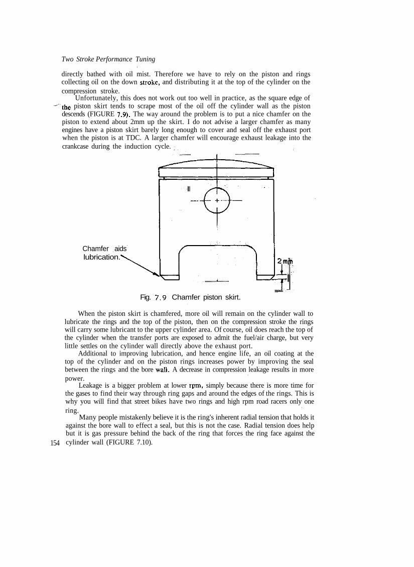
Two Stroke Performance Tuning
directly bathed with oil mist. Therefore we have to rely on the piston and ringscollecting oil on the down stroke, and distributing it at the top of the cylinder on thecompression stroke.
Unfortunately, this does not work out too well in practice, as the square edge of~the piston skirt tends to scrape most of the oil off the cylinder wall as the piston
descends (FIGURE 7.9). The way around the problem is to put a nice chamfer on thepiston to extend about 2mm up the skirt. I do not advise a larger chamfer as manyengines have a piston skirt barely long enough to cover and seal off the exhaust portwhen the piston is at TDC. A larger chamfer will encourage exhaust leakage into thecrankcase during the induction cycle.
Chamfer aidslubrication.
154
Fig. 7.9 Chamfer piston skirt.
When the piston skirt is chamfered, more oil will remain on the cylinder wall tolubricate the rings and the top of the piston, then on the compression stroke the ringswill carry some lubricant to the upper cylinder area. Of course, oil does reach the top ofthe cylinder when the transfer ports are exposed to admit the fuel/air charge, but verylittle settles on the cylinder wall directly above the exhaust port.
Additional to improving lubrication, and hence engine life, an oil coating at thetop of the cylinder and on the piston rings increases power by improving the sealbetween the rings and the bore wall. A decrease in compression leakage results in morepower.
Leakage is a bigger problem at lower rpm, simply because there is more time forthe gases to find their way through ring gaps and around the edges of the rings. This iswhy you will find that street bikes have two rings and high rpm road racers only onering.
Many people mistakenly believe it is the ring's inherent radial tension that holds itagainst the bore wall to effect a seal, but this is not the case. Radial tension does helpbut it is gas pressure behind the back of the ring that forces the ring face against thecylinder wall (FIGURE 7.10).

The Bottom End
There is a detrimental phenomenon that can occur in high rpm engines, called ringfloat or ring flutter. As the piston approaches TDC it is slowed by the con rod, but therings try to keep on moving. If they have enough weight they will leave contact with thelower side of the piston groove. When this happens, the ring seals off the gas pressurein the combustion chamber, preventing the gas getting behind the back of the ring topush it against the bore. Any gas pressure that may have been behind the ring quicklyleaks into the crankcase, and combustion pressure forces the ring to collapse inward,causing it to break contact with the cylinder wall. This allows the combustion gases toblow by into the crankcase (FIGURE 7.10).
Radial tension in the ring is unable to prevent this type of blow-by caused by ringflutter. However, a certain degree of radial tension is necessary for good sealing,otherwise the pressure at the back of the ring would only equal the pressure trying toforce the ring off the bore wall. This would allow blow-by, and it is this type we seeoccurring when the rings are badly worn and have lost their tension.
Ring flutter can also wreck engines due to an increase in piston temperature. Whenthe ring loses contact with the cylinder it is unable to conduct heat away from thepiston crown. This may lead to severe detonation and melted pistons.
The wider a ring for a given radial depth, the lower the engine speed at which ringflutter will occur. This is one of the reasons why thin rings are necessary in racingengines. Assuming the radial depth of the ring is l/26th the cylinder diameter, then themaximum piston acceleration for a ring 1mm wide is approximately 127,000ft/sec/secwith other widths in proportion i.e., 84,700 for 1.5mm rings, 105,800 for 1.2mm rings,158,750 for 0.8mm and 201,600 for 0.63mm rings.
Piston acceleration at TDC can be calculated using the formula:
G = 0.000457 xN 2
where N =S =L =
+ §_)ft/sec/sec2L
rpmstroke in inchescon rod length 155

Two Stroke Performance Tuning
In a racing engine it may be found that the standard rings are too wide foroperation at the engine speed at which we desire to run. This problem usually arisesonly when a street engine or motocross engine is modified for road racing. At times,the manufacturer makes a racing engine with the same size piston as the stock streetmotor. If this is the case it is a simple matter to substitute the racing piston in themodified motor. Some manufacturers have changed to thinner rings in later motors ofbasically the same design, and the later model piston and rings can be used.
Besides raising the speed at which flutter occurs, thin rings also reduce power lossdue to friction. This is really only significant when engine speed is in excess of9000rpm. The same can be said for single ring designs. Below about SOOOrpm a tworing setup gives marginally more power, but above 9500rpm the situation reverses.
In this day of advanced metal technology, ring breakage is rare, and can usually beattributed to one of the following causes: excessive piston to cylinder clearanceallowing the piston to rock and twist the rings as it passes TDC; worn piston ringgrooves that let the rings jump about; excessive bore taper causing radial ring flutter;exhaust port widened excessively or ground an incorrect shape; sharp edges left inexhaust and/or transfer ports; insufficient ring gap; ring grooves not properly cleanedbefore fitting new rings.
Generally, a two-stroke engine should be set up with groove clearances between0.04 and O.lmm. Tighter than 0.04mm clearance will cause the ring to stick in thepiston groove as carbon and varnish builds up. Before new rings are fitted, the pistongrooves must be carefully cleaned to remove all traces of carbon. Then when the ringsare fitted, measure the side clearance and ensure they are not jamming in the grooves.As a final check hold a straight edge along the side of the piston to confirm that therings are seating correctly in their grooves (FIGURE 7.11). If the grooves have not beenthoroughly cleaned, the rings will be flush or possibly even project past the ring lands.
When new rings are fitted they should be checked for end gap. Usually the ringgap is 0.1 to 0.12mm per inch of bore. This means an engine with a 54mm bore wouldneed a gap of 0.2 to 0.25mm. Engines with 0.63mm rings require a much wider gapthan this, as the rings are too narrow to lap over the ring locating pin. In this instancethe required gap must be increased by the diameter of the locating pin. Therefore, anengine with a 54mm bore and a pin 1.2mm in diameter will need a ring gap of 0.2 to0.25mm plus 1.2mm = 1.4 to 1.45mm.
The end gap of each ring should be measured with the ring fitted squarely into thetop of the cylinder bore. To ensure an accurate measurement, all traces of carbon mustbe removed from the bore, using a scraper. Then fit the ring in the unworn part nearthe top of the cylinder. If the gap is insufficient, carefully file the ring ends, using a wetoilstone or a very fine file.
If an engine is assembled with ring gaps that are too narrow, damage may easilyresult. When heated, the rings will expand and cause the ends to butt together. Thisresults in ring breakage or, if the pressure is not high enough to cause the rings tobreak, the cylinder wall will be scuffed.
It is always a sensible practice to dress the ring ends with an oilstone. Chamferingthe outside edges reduces the chances of the sharp ends scuffing the bore. It is also agood idea to stone the inside corners of the ring ends too. The slight radius formedhelps to stop any tendency the ring may have to pull the ring locating peg out of the
156 piston (FIGURE 7.12).


Two Stroke Performance Tuning
When rings are being fitted, care should be taken to avoid fitting them the wrongway up and to prevent damage by incorrect fitting technique. Piston rings can betwisted permanently if they are fitted in the groove at one end and then graduallyscrewed around until the entire ring is in place. Instead, they must be expandedsufficiently to fit over the piston and then allowed to drop into the groove. Specialexpander tools are available for this purpose but I prefer to use two 0.4mm feelerblades held between the ring and piston. The blades provide a bearing surface and stopthe ring digging into the piston.
It is obvious that type 'A' rings in FIGURE 7.13 can be fitted only one way up. Ifthe rings are upside down, the ends will foul on the locating pin, preventing the ringfrom seating in the groove.
\
158
Fig. 7. 13 Two methods of pinning piston rings.
On the other hand, type 'B' rings can be fitted incorrectly, so it is necessary toknow something of the theory behind the various ring sectional shapes so that you maydetermine which way up the rings should be fitted.
The first ring, shown in FIGURE 7.14, is the type most commonly used in racingengines. It is called a rectangular section ring, for obvious reasons. The edges areusually chamfered equally so this type of ring can be fitted either side up.
Thinner rectangular section rings (i.e., 0.63-1.Omm) may be ground with a barrelface to reduce friction and improve the gas seal. Again, this ring may be installed anyway up.
The keystone ring fitted in many motocross and road bikes is ground in the shapeof a keystone. The idea behind this design is to reduce the incidence of ring sticking. As

The Bottom End
Fig. 7. 14 Common two stroke piston rings.
the ring moves in the groove it is supposed to scrape the groove clean. The cutawaysection also provides a large space for the combustion gases to find their way into, topush the ring out against the bore wall. When fitting the keystone type ring, thechamfer should be uppermost. (Note — some keystone rings also have a slight taper onthe lower edge of about 7°).
A few rectangular section rings have an exaggerated chamfer on one inner edge.This type is called an unbalanced section or torsional twist ring. The chamfer causes aslight dish in the ring face so that the lower edge makes high pressure contact with thecylinder wall. Some rings of this design have a step cut into the inner edge instead of thelarge chamfer, but, whatever method is used to create a high pressure area on the ringface, the ring must be fitted on the piston with the large chamfer or step to the top.
Taper face rings work in the same way as the previously mentioned rings, but inthis instance the ring is made with a tapered face to exert a high pressure on the cylinder-wall. These rings are always marked TOP, to identify the side that should beuppermost.
The other type of ring used in two-stroke engines is the 'L' section ring designed byPaul de K.Dykes. Obviously this type cannot be incorrectly fitted but, none-the-less, itis good to know why it is made in such a shape. 159
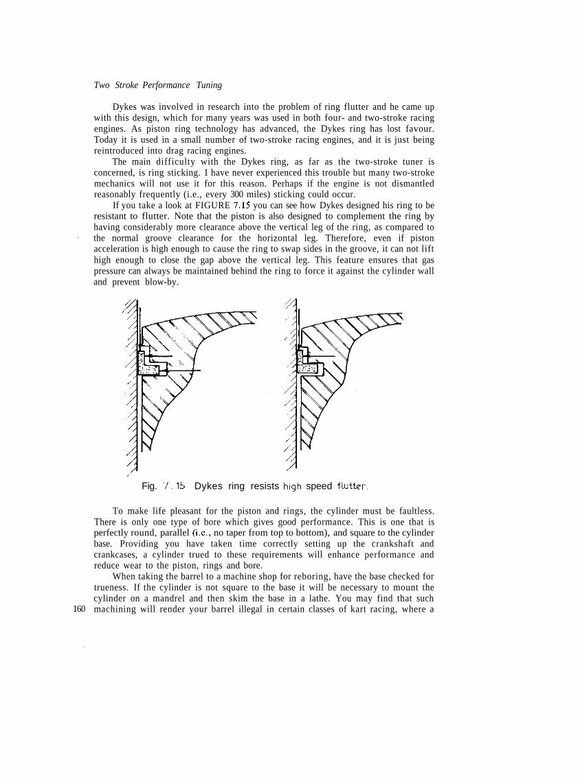
Two Stroke Performance Tuning
Dykes was involved in research into the problem of ring flutter and he came upwith this design, which for many years was used in both four- and two-stroke racingengines. As piston ring technology has advanced, the Dykes ring has lost favour.Today it is used in a small number of two-stroke racing engines, and it is just beingreintroduced into drag racing engines.
The main difficulty with the Dykes ring, as far as the two-stroke tuner isconcerned, is ring sticking. I have never experienced this trouble but many two-strokemechanics will not use it for this reason. Perhaps if the engine is not dismantledreasonably frequently (i.e., every 300 miles) sticking could occur.
If you take a look at FIGURE 7.15 you can see how Dykes designed his ring to beresistant to flutter. Note that the piston is also designed to complement the ring byhaving considerably more clearance above the vertical leg of the ring, as compared tothe normal groove clearance for the horizontal leg. Therefore, even if pistonacceleration is high enough to cause the ring to swap sides in the groove, it can not lifthigh enough to close the gap above the vertical leg. This feature ensures that gaspressure can always be maintained behind the ring to force it against the cylinder walland prevent blow-by.
160
Fig. 7.15 Dykes ring resists high speed flutter.
To make life pleasant for the piston and rings, the cylinder must be faultless.There is only one type of bore which gives good performance. This is one that isperfectly round, parallel (i.e., no taper from top to bottom), and square to the cylinderbase. Providing you have taken time correctly setting up the crankshaft andcrankcases, a cylinder trued to these requirements will enhance performance andreduce wear to the piston, rings and bore.
When taking the barrel to a machine shop for reboring, have the base checked fortrueness. If the cylinder is not square to the base it will be necessary to mount thecylinder on a mandrel and then skim the base in a lathe. You may find that suchmachining will render your barrel illegal in certain classes of kart racing, where a

The Bottom End
minimum cylinder height is specified in the regulations.After squaring, the cylinder can be rebored. Make certain the machinist
understands that the barrel base must be mounted directly on the boring jig's parallelbars. The barrel must never be shimmed to bring the cylinder in line with the boringbar. The bore should be taken to within O.lmm of the required size and then honed togive the necessary piston clearance.
The cross-hatch pattern the hone leaves on the cylinder walls is critical if the ringsare to bed-in quickly and last for a long life. Personally, I prefer a 45° Crosshatch witha finish of 10-12 microinches. This type of finish makes it necessary to run the rings in,but they will wear well and not leak. A smoother finish does not retain enough oil andconsequently allows a glaze to form on both the ring face and bore wall. Power is lostdue to the poor ring seal, allowing gas leakage into the crankcase. A finish rougherthan 12 microinches will greatly reduce the amount of time required to bed the rings,but ring life is shortened. Keep in mind that glazing can, again, be a real problem, butnot due to a lack of lubrication. A rough finish acts like a file on the rings, the extrafriction increases their temperature and causes glazing to form.
After being honed, the top lip of the cylinder should be chamfered to remove thesharp edge produced by boring. A smooth cut half round file is ideal for the job, buttake care that you do not let it slip and nick the bore wall. If the sharp lip is notremoved you will soon destroy the engine by pre-ignition or detonation.
Each time the engine is rebored, or even just honed, it is essential that all portopenings be carefully filed and then dressed, otherwise the sharp edge formed willdamage the rings and piston. To the naked eye the openings may appear smoothenough, but try running your finger around the edges and you will find just how razorsharp they are. '
This problem of razor-edged ports exists with some new engines too. I have foundthe TZ Yamahas particularly bad, so if you own one of these be sure to dress the portopenings before you run a new barrel. The idea is to smooth off the edges carefullywith a cigarette size oilstone. The stone should be either 180 grit silicon carbide or hardgrade Arkansas stone. The hard chrome in the bore of the TZ is not easy to dress,consequently this job can take up an entire day.
Barrels with iron cylinders are much easier to work with, even though it is equallydifficult to get at the port openings in cylinders with a bore of less than 60mm. Initially,I like to shape the edges of the port using either a high speed grinder or a Viin.chainsaw file. (Note — this step applies to cylinders with iron liners only, not thosewith any type of plating direct onto the aluminium.) This work with the grinder is donenot only to deburr the sharp port edges, but also to make life easier for the rings inanother way. If we put a chamfer around the port opening similar to that illustrated inFIGURE 7.16, the piston ring will be eased back into its groove as it closes over theport, reducing the possibility of ring bumping and/or breaking. The chamfer will beabout 1.5-2mm wide and taper to a maximum depth of 0.5mm around the exhaustport. Because the other ports are much smaller, the chamfer can be reduced to1.0-1.5mm wide and 0.3mm deep. After shaping the port edges, smooth them off withan oilstone.
When all the machining work is completed, the barrel must be thoroughly washedwith hot, soapy water. Be sure to get all traces of honing grit scrubbed out of thecylinder, using a bristle scrubbing brush. Next spray the cylinder with a water 161

162
dispersant such as WD-40 and blow it dry with compressed air. Apply another coat ofWD-40 to the bore.
As time passes, more racing engines are using barrels without any type of cylindersleeve. Some people have suggested that factories are doing this to make their bikeslighter, since an iron sleeve weighs a kilogram or more. Actually, the real reason isassociated with heat transfer.
Initially, manufacturers pressed the iron sleeve into the barrel, but the minute gapexisting between the two formed an insulating barrier which seriously limited heattransfer to the cylinder's cooling fins. This reduced the power potential of all two-stroke engines.
Later, the aluminium cylinder was cast around the iron sleeve and bonded to it.This resulted in improved heat transfer and a corresponding increase in performance.However, no matter how effectively the two materials are bonded, there is always lessthan perfect heat conduction from the cast iron sleeve to the barrel.
The next development involved the total elimination of the iron sleeve. Becausethe piston rings would quickly wear and score a plain aluminium cylinder, the bore isplated with porous hard chrome by a special process. The chrome plating is usually0.08-0.1mm thick and offers a reasonably long service life in racing engines. At timesthe chrome has been known to flake, and it is easily damaged by dirt inducted into themotor. Yamaha have been using chromed bores on their TZ range of motors for sometime now, and Honda went the chrome cylinder route when they introduced their newCR250R motocrosser in 1978.
The German Mahle firm has been working with a superior electro-chemical platingcalled Nikasil. This plating was originally developed for Mercedes when they werebuilding experimental Wankel rotary engines. Then Porsche began using Nikasil platedcylinders in the 630hp air cooled 917 model Le Mans racer. This engine later producedHOOhp in turbocharged form for the Can-Am series. Today, Nikasil cylinders are inuse on tens of thousands of chain saws and other industrial two-strokes throughoutEurope. It has proved to be very successful in racing two-strokes' engines also; the

The Bottom End
Morbidelli 125 and Rotax 125 and 250 production racer engines all exhibit excellent lowwear characteristics for the cylinder, piston and piston ring.
The Nikasil coating is a nickel and silicon carbide matrix about 0.07mm thick. Thenickel matrix is very hard, but it is comparatively ductile, whereas chrome is brittle.Dispersed through the nickel are particles of silicon carbide less than 4 microns in size.These extremely hard particles make up about 4% of the coating and form a multitudeof adhesion spots on which oil can collect. So beside providing a very long wearingsurface for the piston and rings to bear against, the silicon carbide particles alsocontribute to long engine life by ensuring good cylinder lubrication.
The latest advance in cylinder 'plating' was revealed to us at the release of theKawasaki KX125 and 250 motocross bikes. Their patented electrofusion processinvolves the exploding of wire inside the cylinder in order to plate the bore. After ahone, the coating is about 0.065mm thick. Fifteen separate explosions plate thecylinder, first with three layers of pure molybdenum, followed by six alternate coatingsof high carbon steel and molybdenum and then six layers of high carbon steel. Whenthe cylinder is honed, the last three coats are removed.
The two types of wire are exploded in the centre of the cylinder by a 15,000 voltburst of electricity, which gasifies the wire. The gas expands out to the cylinder wall,burning up any oxygen in its path. This eliminates any risk of oxidation and ensures agood bond between the cylinder and the plating.
Originally, the electrofusion plating was applied only to the Kawasaki motocrossengines, but now that the process has demonstrated its worth, Kawasaki are coatingtheir road-going two-stroke engines as well.
In the future I expect we will see some process similar to that used by Chevrolet fortheir Vega engine introduced to the two-stroke engine fraternity. The Vega uses analuminium cylinder block containing about 17% silicon. After being bored and honed,the aluminium bores are etched using a special technique. This removes enoughaluminium to expose pure silicon and aluminium particles, to form a proper anti-wearbore surface.
When you have prepared the piston, rings and barrel as outlined, these parts maybe fitted to the engine.
First, oil the little end bearing and the gudgeon pin, and then connect the piston tothe con rod, taking care to install it the correct way round. After the gudgeon pin hasbeen pushed in carefully fit the wire circlips. Always,use new circlips and be sure tostuff a clean rag into the top of the crankcase. If you happen to drop a circlip, youdon't want it falling down in there. Double check to ensure the circlips are properlyseated in their grooves.
Before fitting the cylinder, give the piston and rings, and also the bore, a liberalcoating of oil. Use straight oil and don't mix anything like STP with it, as piston ringsare not designed to cut through goo like this.
An engine that has been properly prepared can be run-in in about 45-60 minutes.Start running at reasonably low speeds with a rich mixture and additional oil in thefuel. If you normally use a 20:1 mix, run-in on an 18:1 ratio. After about 15 minutes ofoperation at a fairly constant speed, try varying your speed and occasionally use up toabout 3/4 throttle. Continue changing your speed for another 15 minutes, but take carenot to accelerate too briskly. Prolonged operation of a two-stroke at part throttlefollowed by a burst of full throttle may damage the engine. This occurs because only a 163

Two Stroke Performance Tuning
small amount of oil is present in the engine during constant light throttle running.Suddenly opening the throttle severely loads the engine but only a small quantity of oilis available to lubricate at slow speeds.
During the next 15 minutes gradually build up to racing speed, but do not use fullthrottle for more than two hundred yards on the main straight. Accelerate hard out ofthe corners for the last 15 minute segment, easing off after each burst to allow the ringsand piston time to cool before the next blast. The hard acceleration is necessary to bedthe rings into the bore. Do not hold full throttle for more than a few seconds or therings and bore could overheat and glaze.
Some engines begin to 'lock up' during the run-in period and then seize underactual race conditions. As a safeguard against this, I would recommend that youremove the barrel after running-in and examine the piston for any sign of scuffing. Ifyou find any high spots on the piston, remove it from the engine and, using a smoothcut millsaw file, gently file the high spots off the piston. This does not sound veryscientific, but I can assure you that it works.
Not many engines require this treatment but there are a few that always seizewhere the piston bears against the exhaust port bridge, and there are others which lockup just under the bottom ring land at two points about 30° around from the gudgeonpin. Increasing the piston clearance usually doesn't help with either of these problems(FIGURE 7.17).
164
Seizure points
Fig. 7 .17 Possible seizure points on exhaust side of piston.
When a street engine is radically modified for racing, you may find it necessary tomachine what we call a 'clearance band' around the top of the piston (FIGURE 7.18).This modification should be required only when the standard pistons are retained. Theactual band can be machined in a lathe. It should be about 0.06-0.1mm deep andextend from the top of the piston to a point approximately 3mm below the bottom ringgroove. Pistons in a racing engine operate at temperatures considerably higher thanthose experienced in street engines. The additional heat is concentrated in the pistoncrown and this results in abnormal expansion. The clearance band makes allowance forthe crown to expand more without risking a lock up.
A bottom end assembled as outlined should prove relatively reliable in

The Bottom End
Fig. 7.18 Piston clearance band.
competition, providing you keep an eye on the tachometer red line. Deciding what thered line rpm should be can only be determined by actual experience with that particularmake of engine.
You can not arbitrarily say, for example, that all single cylinder 125s can be safelyrun at 12,000rpm. As a starting point, run the engine initially at a speed equivalent to amean piston speed of 3800 feet per minute and work up from there to a maximum ofabout 4500 feet per minute.
The mean piston speed is calculated using the formula:-
There is one point you must keep in mind that could save you from expensiveengine damage. You already know how easy it is to over-rev the engine in first, secondand possibly even third gear, but did you realise that the rate of engine acceleration isso brisk in the lower gears that the tacho doesn't even have sufficient time to keeppace? In fact, the readout on the tacho dial will be at least 500 and possibly up to700rpm less than true engine speed. If you don't make an allowance for this, you couldprecipitate a blow up before you reach the first corner.
165
Chapter 8Lubricationand Cooling
THE RELIABILITY of any engine is closely related to adequate lubrication andefficient cooling. Unfortunately, it is in these areas that the two-stroke engine is mostvulnerable. It has to rely on just the scantiest supply of lubricating oil to resist pistonseizure in a cylinder badly distorted by the steep temperature gradient existing betweenthe hot exhaust side and the much cooler inlet side of the barrel.
The lubricating oil must be able to prevent metal to metal contact of movingengine parts and at the same time assist in conducting heat away from the piston crownto the cylinder wall. Additionally, it must form a seal between the piston rings andcylinder wall to contain the pressure of combustion effectively. If the oil film is toothin, blow-by will result, reducing the amount of energy available to power the pistondown.
There are basically three types of oil: mineral oil derived from crude stock;vegetable oil from the castor bean plant; and synthetic oil, which is man-made or manmodified and used straight or blended with mineral or vegetable oil.
Most motorcycle oils are mineral-based, with a variety of additives used toimprove them in certain functions. I would recommend mineral oils for all exceptcompetition two-stroke engines. My favourite mineral oil is Castrol Super TT. It willprovide very good lubrication and wear resistance, better I believe than any othermineral oil available and better than most synthetic and castor oils. Like all mineraloils, Super TT will dirty the plug, and leave some carbon on the piston crown and in thecombustion chamber.
In all of my competition engines, I specify Castrol R40 or R30 castor oil (R40 forair-cooled engines, R30 for water-cooled). This oil provides the best anti-wearprotection of any oil that I know. The mere fact that my engines produce tophorsepower testifies that it must be doing an excellent job of reducing friction bykeeping moving parts separated. When you strip a 12,000rpm road racing motor after300 racing miles and find the ring gaps opened up by only 0.007inch, and hone marks
166 still visible on the cylinder walls, then you know the oil you are using is good.

Lubrication and Cooling
Many tuners do not like castor oil or blended castor/synthetic because of someproblems associated with the use of an oil of this type. Some claim that castor gums upthe rings and causes ring sticking, but I have never found this problem, even on enginesthat are required to run 500 miles between rebuilds.
There is one area for concern, and this is the main reason why oil companies try todiscourage the use of castor oil. Castor-based oils are hygroscopic, which means theywill absorb moisture from the atmosphere. Therefore, once a container is opened, itsentire contents should be used, or if oil is left over this should be poured into a smallercontainer so that no air space is left above the oil from which to absorb moisture.Remember, too, that castor oil will also absorb moisture after it has been mixed withfuel. Therefore, do not use fuel more than three days old, and don't forget to drain thefuel from the tank and carburettor bowl.
While we are on the subject of castor bean oil, don't think for a minute that allcastor oils are as wear resistant as Castrol R. This all depends on how well themanufacturer de-gums the basic castor stock and on what additives are used. Somecastors provide wear protection no better than average mineral and synthetic oils.
Today, more and more people are turning to and advocating the use of syntheticlubricant. There are several points in favour of synthetics, namely: less exhaust smoke,less incidence of plug fouling and less build-up on the piston crown and in thecombustion chamber. Some also claim better wear protection and more power as a plusin favour of synthetic lubes, but in general my research has produced an oppositeresult. I have found some synthetic oils to have a wear factor twice as high as the bettercastor and mineral oils and I have never found a synthetic to allow an engine toproduce as much power as Castrol R. For these reasons, I could not recommend the useof synthetic oil in highly stressed competition engines.
The manufacturers of synthetic oils claim their oils will give better power becausethe amount of oil in the fuel can be reduced (eg: Bel-Ray MC-1 is mixed 50:1 ascompared to 20:1 for most mineral oils). But why should it ever be imagined that asmaller quantity of lubricant entering the engine will give a power increase? At theraces it almost seems as if there is as much glory to be gained from running a fuel/oilratio of 60:1 as there is in actually winning the race; by the pit bragging going on itwould seem to be so!
My experience has shown that the more oil you pour into a two-stroke, the harderit runs. Just how much you should pour in depends on several factors, but it usuallyworks out that the longer you hold the throttle wide open, the more oil you should use.This is due to the fact that the fuel/air ratio will be leaner at full throttle than at halfand three-quarter. Therefore, with less fuel entering the engine at full throttle,proportionally less oil will be available for lubricating the piston at a time when itrequires the most lubrication. Spelled out, it means that on a track with long straightsyou will have to use more oil than on a tight twisty track.
Keep in mind that your engine only needs enough oil to lubricate one stroke at atime and then the excess is burnt up. If your bike is dribbling oil out of the exhaust thenyou are running too much oil for its needs, or for your riding speed. A faster rider onthe same machine may need more oil, because he is holding full throttle for longerperiods.
When you start experimenting with oil ratios, always use the enginemanufacturer's recommendation as a reference point and work from there. If you go 167

Two Stroke Performance Tuning
too rich, the spark plug will be coated with black soot and the exhaust pipe will be wet.—« there is not enough oil, the plug could look white or grey, the pipe will be very dry,
the piston crown will be white or light grey, possibly with 'death ash' forming under thecrown. A'ny of these signs indicate that you are bordering on a seize up.
Generally, I would say that road racing engines will work best at a 16:1 to 20:1fuel/oil ratio, depending on the nature of the course. Desert racers require 16:1 but, ifplug fouling proves to be a problem, try 18:1 or 20:1. For enduro and motocross 20:1or 22:1 is the best ratio. Go-karts with fixed gearing, without a clutch operating onshort sprint tracks, will usually not tolerate more oil than 25:1 and, if you find that youare fouling plugs, you may have to drop as low as 30:1. Under no circumstances shouldyou run leaner than 32:1.
All of the above fuel/oil ratios are for mineral and castor oils. Synthetic oils are anentirely different kettle of fish. If you choose to use this type of oil you will have to runit at the ratio the oil manufacturer recommends. This is because the oil people load theoil up with additives, in an attempt to give it acceptable scuff resistance when mixed at50:1. Mixed at 25:1 there will be twice as much chemical additive and detergent beinginducted into your engine and this could very easily cause carbon build-up and plugsooting, serious enough to stop or even damage the engine.
It seems that the trend towards leaner and leaner oil ratios has resulted from thedesire of two-stroke engine manufacturers to eliminate plug fouling completely in two-stroke mower, outboard and chain saw engines. These engines are seldom serviced andthe plug is probably only changed each time the rings are replaced. To cut down onspark plug deposits, the manufacturers decided on less oil and, unfortunately, this ideahas carried over into competition two-stroke circles.
The results of my most recent oil testing are shown in TABLE 8.1. The engine wasa fully worked Suzuki RM 125C motocross unit. As you can see, reducing the oilcontent from 20:1 to 27:1 (I wasn't brave enough to lower it any further) resulted in apower loss of about 8% at the top of the power range — a heavy price for the sake of aclean plug. On top of that the piston showed signs of scuffing bad enough to deter mefrom testing at 32:1 which, according to a lot of tuners, is the best mix when using R40.
When the fuel/oil mix ratio was raised to 16:1, power was marginally improved byabout 2%, which is almost too small to measure on the dyno. However, the piston wasmuch cleaner and the rings showed no sign of gumming up.
Accuracy is of utmost importance when blending oil and fuel. It is of no usemixing one and a half beer cans of oil to each drum of fuel, you have to be precise. Formeasuring the oil you need either a laboratory measuring cylinder or a graduatedbeaker. Fill the measuring container with the required quantity of oil, and be sure toallow the oil plenty of time to drain out when you pour it into your drum of fuel. Keepthe measuring equipment clean, preferably in a dustproof plastic bag.
Determining how much fuel is in a drum is not easy. The drum may say that itcontains 20 litres, but this can vary considerably, even when the drums are factoryfilled, as in the case of racing fuel. If you mix your own racing fuel the inaccuracy maybe even worse, as a 20 litre drum will actually hold 22 litres filled nearly to the top.What I recommend is, assuming that you have brought your fuel in a drum that issupposed to contain 20 litres, drain the fuel from the drum and then refill it withprecisely 20 litres measured with a suitable, accurate, 1 or 2 litre measure. Then take a
168 rule and measure how many inches the fuel is from the top of the drum. Next make a

Lubrication and Cooling
gauge from light metal as shown in FIGURE 8.1, to fit in the neck of the drum andindicate the height of fuel for 20 litres. You can then use your gauge on any other 20litre drum of fuel that you buy, assuming the drum style doesn't change.
TABLE 8.1
rpm
8000850090009500
10000105001100011500
Suzuki RM125C horsepower/oil tests
Test 1 (hp) Test 2 (hp) Test 3 (hp)
15.718.820.421.321.922.623.217.3
15.418.720.521.722.122.923.617.6
16.018.719.219.620.320.721.415.8
Test 1 — Castrol R40 mixed at 20:1 with Shell 115 MB racing fuel. Champion N-57G plug— no sign of carbon. Light coat of 'varnish^ on sides of piston.
Test 2 — Castrol R40 mixed at 16:1 with Shell 115 MB racing fuel. Champion N-57G plug— slight trace of carbon on insulator, heavier deposits on plug shell and earthelectrode. Less 'varnish' on piston than with 20:1 mix.
•jest 3 _ Castrol R40 mixed at 27:1 with Shell 115 MB racing fuel. Champion N-57G plug— very clean — cleaner than plugs from 20:1 and 16:1 tests. Heavy 'varnish'coating right around ring lands and down exhaust side of piston.
169

Two Stroke Performance Tuning
When blending oil and fuel you must be careful not to be confused by volumeswhich, on the surface, appear similar. In the Imperial system one pint is 20 fluidounces, whereas in the US system one pint is 16 fluid ounces: considerably less. Toassist you with mixing for various fuel/oil ratios refer to TABLE 8.2.
Incompatibility/insolubility of oil and fuel can mean big trouble, so don't take itfor granted that all oils and fuels will mix properly. Mineral oils such as Castrol SuperTT will blend with any of the leaded and unleaded fuels available out of the pump atthe local garage, but it may not blend with some 100 or 115 octane racing fuels withoutthe addition of 5-15% of benzol, toluol or methyl benzine.
Castrol R will blend with some regular pump fuels, depending on whether theycontain a proportion of benzol or toluol. It will also blend with any 100 or 115 octaneracing fuel containing 15% toluol, methyl benzine or benzol.
When methanol is used, it is necessary to mix it with a specially formulated oil.Castrol M castor oil and Shell Super M castor oil are both soluble in methanol.
To determine the compatibility of your fuel/oil mix, make up a small sample atthe correct ratio in a clear glass bottle. Shake it well, as you should always do whenblending oil and fuel. Leave it to stand for 24 hours, and check for separation. If thereappears to be some insolubility, try mixing 5% toluol, benzol or methyl benzine. In
TABLE 8.2 Fuel/oil volume for fuel blending
Volume of oil for stated amount of fuelRatio Imperial (per gallon) US (per gallon)
floz cc floz ccMetric (per 5 litre)
cc
12:14:16:18:20:22:25:27:30:32:40:50:
1 13.311.4108.987.36.45.95.3543.2
37932528425322720718216815214211491
10.79.187.16.45.85.14.74.343.22.6
3172692372101891721511391271189577
417357313278250227200185167156125100
Note:1 Imperial fI oz = 28.4cc, 1 USfl oz = 29.6cc
extreme cases you may need up to 15% of these fuels added, to maintain solubility.At times the oil may not completely separate out of the fuel, but, instead, may
form in layers through it. When you find this problem, again try blending 5% methyl170 benzine, benzol or toluol with your mix.
Lubrication and Cooling
No matter what type of oil you run, or how well it is blended, you will still end upwith premature cylinder/piston wear and possibly even risk seizure if you don't allowthe engine to warm up before working it hard. I recommend that you don't ride offuntil the barrel is getting reasonably warm. This will ensure that piston and bore wear iskept to a minimum. I have seen engines seized by being operated too hard right afterbeing started. This occurs because the piston gets hot first and expands at a faster ratethan the barrel, which takes much longer to warm up and expand the correct amount toprovide the proper piston to cylinder working clearance.
Most two-stroke engines are air-cooled, but even water-cooled engines relyindirectly on air to stabilise the temperature of the cylinder head and barrel. Thecooling arrangement of every internal combustion engine performs the vital functionof dissipating heat in order to maintain normal engine operation.
The two-stroke engine is, in fact, a heat engine in that it relies on the conversion offuel into heat, and then into mechanical energy to produce power at the crankshaft.Only about 23% of the heat is converted into power, another 33% is lost through theexhaust, and the rest is eliminated through the cooling system.
Lately, a lot has been said about applying a ceramic insulating coating to thecombustion chamber and piston crown, to reduce to some extent the heat energy whichis lost to the cooling system. It was felt that since it was heat energy, produced by theburning of a fuel, which heated the gases in an engine and caused them to expand andforce the piston down, then reducing heat conduction to the cooling .system shouldincrease cylinder pressure, and result in more power.
In theory, ceramic coatings to thermally insulate the combustion chamber andpiston crown sound a logical way to increase power, but in practice it hasn't workedout. In many instances the reverse has occurred, due to the end gases detonating as aresult of increased pressure and temperature within the combustion chamber. I thinkmany tuners realise that a liquid-cooled engine operating at a coolant temperature of75°C will make significantly more power than if operated at 95°C, even though in thelatter case considerably less combustion heat energy is lost to the cooling system. Whyis this? Well, charge density will be superior with a cool engine and the combustionprocess will be more controlled, reducing the incidence of detonation.
Ceramic coatings are, I feel, only beneficial in low-speed engines and enginesoperated mainly at small throttle openings. Low-speed engines lose much more heatenergy to the cooling system than high-speed engines, because each combustion cycle islonger. In the case of engines operated at light throttle openings the combustionprocess is often retarded, due to excessive dilution of the fuel charge by residualexhaust gas. With a ceramic coating applied to the combustion chamber and pistoncrown, combustion will be faster and more complete, due to the increase in combustiontemperature.
The only other situation in which ceramic coatings may be beneficial is for coatingthe piston crown only in engines used for desert racing or those burning exotic fuel suchas nitro and nitrous oxide. Such engines seem particularly prone to piston burning and,under these circumstances, ceramic coatings appear to offer a degree of protection.
One company which applies ceramic coatings is Heany Industries in America.Using a plasma-spray system, a ceramic coating 0.012-0.014in. thick is applied. Theplasma coating process, called Heanium coating, utilises an electric arc device, intowhich argon gas is injected to generate a plasma stream of high temperature gas (up to 171

Two Stroke Performance Tuning
30,000°F). Powdered materials introduced into this plasma stream turn into a moltenspray as they are propelled towards the surface to be coated.
As the Heanium coating is 0.012-0.014in. thick, a piston which has had the crowncoated will cause an increase in the compression ratio and a decrease in the piston tohead (squish) clearance. To overcome both of these problems a thicker head gasket willhave to be used.
Heanium coating may also be applied to the exhaust port and the inlet port ofmotors with relatively straight ports. This will not do much to improve power, exceptthat inlet charge density may increase a little, but cylinder distortion and overheatingwill be reduced. Cylinder distortion is not such a problem with liquid-cooled barrels, soI feel that you would be wasting your money coating the ports of these engines. Air-cooled barrels definitely will benefit from Heanium coating in the exhaust and inletports. Coating the exhaust tract will reduce the amount of heat which the finning onthe exhaust side of the barrel has to dissipate. Hence that side of the motor will becooler and, as a result, the cylinder bore will distort less. Conversely, coating the inletport will increase the temperature of this side of the barrel because the insulatingbarrier will prevent the fuel charge from cooling the metal surround the inlet tract. Theend result will be a lower temperature differential between the exhaust and inlet sides ofthe cylinder, and less distortion.
Besides reducing the heat load on the cooling system by using Heanium-coatedports, air-cooled engines can have the heat radiating area of their cooling finsincreased. It has been found that blasting the head, barrel and crankcase withaluminium oxide increases the surface area about five times. If these parts are thensprayed with Kal-Guard coating and oven baked to keep the aluminium oxide on themetal surfaces, engine operating temperatures will be reduced by 10-13%. Of course,the cooling fin area can also be enlarged by more direct means. Both DG and Webcoproduce a range of replacement cylinder heads for Japanese engines. These heads havea bigger fin area to improve cooling and reduce any tendency for the engine to detonateor seize pistons.
It is essential to ensure that your cooling system is working at 100% capacity. Heatradiation from the cooling fins is retarded by the presence of oil and mud, so make surethey are clean. Fins and crankcases painted flat black radiate heat considerably betterthan shiny silver surfaces. Anything that is obstructing air flow onto the head andbarrel should, if possible, be relocated elsewhere. On road bikes, check to see that thehorn is not blocking air flow to the head. Also investigate to see if the exhaust can bebetter located, as the header pipe always seems to be in the way. Every move you maketo encourage air flow over the engine will help performance and reliability.
Water or liquid-cooling is now looked on as the answer to two-stroke coolingdifficulties. However, liquid-cooling is not without problems peculiar to itself. The twomajor deterrents to proper heat transfer from the combustion chamber and cylinder tothe liquid cooling medium are deposits and air in the cooling system.
Metallic oxides twelve thousandths of an inch thick formed in the water passageswill cut heat transfer by up to 40%. Therefore, in order to maintain optimum heattransfer, the cooling passages should be cleaned in a special bath that won't attackaluminium. Additionally, the system should contain an inhibitor that will keep coolantpassage surfaces clean and free of deposits.
172 There are two basic types of inhibitors: chromates and non-chromates. Sodium

Lubrication and Cooling
chromate and potassium dichromate are two of the best and most commonly usedwater-cooling system inhibitors. Both are toxic, so handle them with care.
Non-chromate inhibitors (borates, nitrates, nitrites) provide anti-corrosionprotection in either water or water and permanent anti-freeze systems. Chromates mustnot be used with anti-freeze.
If you decide to use a coolant other than water, ethylene glycol is to berecommended. Methyl alcohol-based anti-freeze should not be used because of its verylow boiling point and its damaging effect on radiator hoses and water pump seals.
When ethylene glycol anti-freeze is used in concentrations above 30%, additionalinhibitor protection against corrosion is not required. I do not recommend the use ofcooling solutions composed of more than two-thirds ethylene glycol and one-thirdwater, as heat transfer is adversely affected.
Anti-freeze containing cooling system sealer additives should not be used, as thesealer may plug the radiator core tubes and possibly even coolant passages in theengine. Stop leak or sealer of any description is not to be recommended, except in anemergency to get you home or to finish a race. Then, as soon as possible, it should becleaned out by a cooling system specialist, using a high pressure air and water flusher.
Petroleum-derived products such as soluble oil, often used as a water pumplubricant and corrosion inhibitor, should never be used. A 2% concentration of solubleoil can raise the cylinder head deck temperature by up to 10%, due to reduced heattransfer efficiency of the coolant. One popular radiator stop leak contains a highproportion of soluble oil, which is an additional reason for staying clear of radiatorsealers. Soluble oil turns water milky when it is added.
The presence of air bubbles in the coolant reduces the heat transfer capacity of thecoolant by acting as an insulator. Water pump efficiency is also reduced. Air can besucked into the system through a leaking hose and gas bubbles can form due tolocalised boiling around the combustion chamber. In the first case, air can be kept outof the cooling system by ensuring that there are no air or water leaks, and by keepingthe coolant at the proper level.
Gas bubbles or steam pockets are prevented by pressurising the system to thedegree necessary to prevent the water boiling. By pressurising the radiator to 14psi theboiling point of water is raised from 100°C to about 125°C. Normally, the wateraround the combustion chamber should not reach this temperature, but this gives asafety factor to permit normal operation at higher altitudes. Periodically the radiatorpressure cap should be inspected for deterioration of the seal and the 'blow-offpressure should be tested.
As the actual heat exchange between the cooling medium and air takes place at theradiator, it is important that it is free of bugs or any other debris that would restrict airflow and hence reduce cooling efficiency. The radiator should be painted matt black toprovide the best radiating surface, and also to minimise the effects of externalcorrosion.
It is a mistake to run the cooling system without some form of restrictor orthermostat, as the engine could be over-cooled. If too much heat is transferred to thecoolant, power will be lost. Therefore, do not let the engine run cooler than about75-80°C. Below about 70°C, cylinder wear increases to a level as serious as operatingthe engine at too high a temperature.
173

Chapter 9Power Measurementand Gearing
I AM CONSTANTLY surprised that so few two-stroke tuners ever spend any timetesting and developing their engines on a dynamometer. Now don't get me wrong,engine dynos are definitely not the 'be all and end all' of engine tuning. There areclearly definable limits to their usefulness, due to the static nature of the load appliedto the engine. On the dyno you can't, for instance, check an engine's rideability, howsmoothly it comes onto the power, or its throttle response: these factors can only bedetermined on the race circuit.
With dyno testing, you are in a good position to see precisely what influence achange in the spark advance will have on the power output. You can determine howmuch power increase, if any, a larger carburettor will give at maximum rpm andascertain what the hp loss is at lower speeds. Without the benefits of a dyno work-out,you can only tune according to instinct and/or past experience, and then rely on yourlap times or 'feel' through the seat of the pants to indicate if a particular modificationis successful or not. This takes a lot of time and is often inconclusive as, unfortunately,most of us can't feel a 5% difference in power.
There are two basic types of dynamometers: the rolling road and the engine dyno.The rolling road is not very popular for motorcycle engine tuning, as its worth is ratherlimited. With this type of dyno, the bike is tied down with the rear wheel on a pair ofrollers, which are connected to some sort of loading device (the brake). The engine isrun and, according to the twisting force applied through the rollers to the brake, thetorque and horsepower figures are calculated.
The main problem with the rolling road is that it can never be made sensitiveenough for engine development work. Because of tyre slip and friction on the rollers,the twisting force being transmitted to the brake is in a state of constant fluctuation.Therefore, to keep the readout needle fairly steady, it must be heavily damped,otherwise it would be bouncing back and forth so rapidly the operator wouldn't be ableto read it. As a result of the damping, the dyno becomes unresponsive to small changes
174 in power output, so it would be a waste of time checking the effect of a change in spark
Power Measurement and Gearing
advance or main jet size.The engine dyno, on the other hand, is quite sensitive and will give a clear
indication of precisely how much advance or what size main jet the engine prefers forbest power. With this type of dyno, the engine is coupled with the brake via a chain,driven from the countershaft sprocket. Therefore there is no slip (unless the clutch isslipping) and the frictional losses in the primary drive, gearbox and secondary driveremain fairly steady.
As I mentioned earlier, you can't check an engine's rideability on the dyno.Usually the areas where you will get caught out are with carburation and expansionchamber testing. For example, you may check three or four different brands and sizesof carburettors and find they give a seemingly identical performance on the dyno. Butat the race circuit there will generally be one setup which is superior to the rest,allowing improved lap times, or maybe just a better 'feel' when coming onto the poweras you exit a turn.
There are several types of engine dynos in use and, while all do a good job inenabling us to see which way our development work is going, you should not take a lotof notice of the power figures. Variations of up to 10% from one dyno to another arenot uncommon. The reason for this is that tuning companies do not have the money tospend on the latest, most accurate dynos. Instead, in many cases, they make do witholder, or maybe even new but less sophisticated, types. Also dyno manufacturers usevarious methods of calibration, which tend to give a different power reading from onebrand of dyno to another.
This in itself is not such a bad thing, providing all the tuning is done on the samedyno. Otherwise you might try out some new trick part and find it gives you 7% morepower on a dyno over the other side of town, when in truth you had lost power. It wasjust that this dyno is reading higher than the one on which the engine was originallytested (TABLE 9.1).
TABLE 9.1 Dyno comparison test of Yamaha YZ250
rpm
4000450050005500600065007000750080008500
Dyno Ahp
8.69.5
11.115.421.124.926.425.625.119.9
Torque fib/ft)
11.311.111.714.718.520.119.817.916.512.3
Dyno Bhp
8.810.011.617.723.027.130.030.329.122.3
Torque fib/ft)
11.511.712.216.920.121.922.521.219.113.8
Note: This motor was not altered in any way between the two tests. The hp and torque figureshave been corrected to compensate for changes in air density. 175

Two Stroke Performance Tuning
Something you are sure to have noticed is the variation between themanufacturer's claimed horsepower and the engine's power at the countershaftsprocket. For example, Yamaha quote the RD400 (the European model) as producing44hp at 7500rpm, whereas you will usually be able to roundup only about 36 of thosehorses during dyno testing. Where have the others strayed off to? First, somewhere uparound 12 to 15% will have been used in overcoming friction in the primary drive andgearbox, and also in the secondary chain driving from the countershaft to the dyno.(Manufacturers take their power figures at the crankshaft, not the countershaft). Thataccounts for 6 of the strays, and the other 2 are unaccounted for as the result ofdifferences in the test procedures and dyno calibration.
Unfortunately, few people realise how little the horsepower figures actually tellabout engine performance, or how well an engine has been modified. The true measureof engine performance is the torque and brake mean effective pressure figures. Theseindicate much more to us and show where we are heading with our modifications.
Torque is a measure of the twisting force at the crankshaft expressed aspounds-force foot (commonly called foot pounds). For example if an engine isproducing torque of 201bf ft it means that it will lift a load of 201b with a lever 1ft longconnected to the crankshaft. Now if the engine moves this load through one revolutionwork is being done; in this instance 126ft/lbs (twisting force x revolutions x lever lengthx 2ji). Power is the rate at which this work is being done hence,
In the Imperial system, power is measured in Ibs/ft per minute. However, theseunits are small, so the unit we know as horsepower (hp) is ttye one used today. Onehorsepower equals 33,000 Ibs/ft per minute. This was worked out as a result ofexperiments done by James Watt, using strong dray horses.
It is obvious, realising power is the rate at which work is done, that two motorsboth producing 20 Ibs/ft torque could have differing power outputs. In fact, if onemotor lifted its 20 Ibs load twice as quickly as the other, then it must be twice aspowerful, or have double the horsepower. Engine speed is measured in revolutions perminute, so this is the time unit we use in calculating horsepower, therefore:
Earlier, I mentioned that high horsepower figures can be misleading. We can end upwith a big power figure because the motor turns a lot of rpm, which should increase topspeed, but unless the engine produces a higher torque output over a wide rpm range laptimes could be slower due to poorer acceleration or an increase in the number of gearchanges required. For this reason we have a measure called brake mean effective
176 pressure (BMEP). This gives a true indication of how effectively the engine is operating

Power Measurement and Gearing
regardless of its capacity or its operating rpm. It is, in fact, a measure of the averagecylinder pressures generated during both engine strokes. We calculate the BMEP usingthe formulae:
The highest BMEP will occur at the point of maximum torque, which alsohappens to be where peak volumetric efficiency occurs.
A stock engine, intended for use in a sports or touring bike, will have a BMEP of80-90psi, depending on the cylinder size. With an increase in cylinder displacement theengine does not breathe as well, hence the BMEP falls. Typically a road bike with 125cccylinders will be working at a BMEP of 90psi, while a single cylinder 250's pressure willbe closer to SOpsi.
Enduro machines with a displacement of 175 to 400cc, and 350 to 450cc motocrossbikes, generally operate in the 90-98psi bracket. There are exceptions though: bikeswith the Rotax rotary valve engine will usually show a BMEP of 120 or HOpsidepending on whether the engine is a 175 or 250cc, as the rotary valve permits muchimproved breathing without any loss of tractability.
125 and 250cc motocross engines are a rather mixed bag. The Honda CR125R andCR250R both perform very creditably with BMEPs of 117 and 115psi respectively, andthe 250 can be tuned to work at a pressure of 122psi without making the bike hard tomanage on a motocross circuit. The Suzuki RM125 has a 123psi BMEP which isexcellent. The rest are only working at around 100 to 105psi for 250 and 125ccdisplacements, which indicates the respective manufacturers still have quite a way to goin engine development and/or expansion chamber design.
The 125 and 250 production road racers, such as the Honda MT125 and YamahaTZ250, generally run at a BMEP of 123-127psi, leaving little room for improvement asa BMEP of around 125-130psi can be considered about the maximum for aconventional piston-ported engine.
The exceptional rotary valve Rotax and Morbidelli 125 production racer enginesoperate at 137 and 142psi respectively, and the works Morbidelli is approaching 150psiBMEPs.
To give you an indication of how important the BMEP is, and to show how it givesa more meaningful expression of an engine's true performance level and its potentialfor future development, I have included some dyno figures for the Yamaha YZ125Eand Suzuki RM125C (TABLE 9.2 and FIGURE 9.1). As you can see, both engines putout about 22hp, but just look at the differences in the mid-range power and the widthof the power band. The Yamaha makes maximum power at ll.OOOrpm and then themotor proceeds promptly to drop dead, whereas the Suzuki, because it is working 177

Two Stroke Performance Tuning
TABLE 9.2 Dyno test of stock Suzuki RM125 Cand Yamaha YZ125 E
Suzuki RM125 Yamaha YZ125rpm hp Torque (Ib/ft) hp Torque (Ib/ft)
650070007500800085009000950010000105001100011500
7.810.013.116.119.421.121.721.520.615.19.9
6.37.59.210.612.012.312.011.310.37.24.5
7.47.38.712.515.417.517.919.220.421.811.6
6.05.56.18.29.510.29.910.110.210.45.3
Note: Maximum BMEP for RM 125 = 123psiMaximum BMEP for YR 125= 104.5psiBoth engines were tested on the same dyno and the figures have been corrected tocompensate for differences in air density.
much better (as evidenced by the high BMEP pressures), holds within a few percent ofits peak hp over a 2000rpm range (from 8500-10,500rpm) and it is still making goodpower at ll,000rpm and down at SOOOrpm.
An engine like this is easy to tune for much higher power outputs, withoutknocking the mid-range about too much. With just some porting and carburationchanges it can be made to produce significantly more top end power, as indicated inTABLE 9.3. Maximum power has not been lifted much, but at 10,500 and 1 l,000rpmthere is a 2hp and 3.1hp increase. Note also that the BMEP has been maintained at123psi. If it had slumped to 120psi this would be a sure indication that ourmodifications had actually upset the proper functioning of the engine.
TABLE 9.3 Dyno test of modified Suzuki RM125C
rpm hp Torque (Ib/ft)
178
700075008000850090009500100001050011.00011500
8.311.615.718.820.422.322.522.618.211.3
6.28.110.311.611.912.3 BMEP11.811.38.75.2
123psi
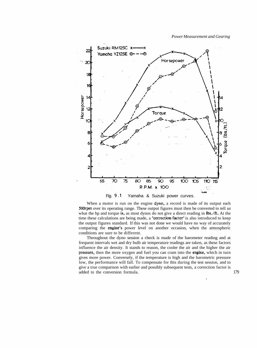
Power Measurement and Gearing
Fig. 9.1 Yamaha & Suzuki power curves.
When a motor is run on the engine dyno, a record is made of its output eachSOOrpm over its operating range. These output figures must then be converted to tell uswhat the hp and torque is, as most dynos do not give a direct reading in Ibs./ft. At thetime these calculations are being made, a 'correction factor' is also introduced to keepthe output figures standard. If this was not done we would have no way of accuratelycomparing the engine's power level on another occasion, when the atmosphericconditions are sure to be different.
Throughout the dyno session a check is made of the barometer reading and atfrequent intervals wet and dry bulb air temperature readings are taken, as these factorsinfluence the air density. It stands to reason, the cooler the air and the higher the airpressure, then the more oxygen and fuel you can cram into the engine, which in turngives more power. Conversely, if the temperature is high and the barometric pressurelow, the performance will fall. To compensate for this during the test session, and togive a true comparison with earlier and possibly subsequent tests, a correction factor isadded to the conversion formula. 179

Two Stroke Performance Tuning
The conversion formula to calculate the torque on one particular type of dyno is
The correction factor, in this example 1.016, is found from tables or graphs whichare readily available.
When the dyno session is over, don't go home and just file the dyno sheet away.The next thing you must do is work out your gear change points for maximumacceleration. In TABLE 9.4 I have listed the dyno test of a Honda MT125 R-3 roadracer. The standard engine makes fairly good power, but the power band is pathetic.No 125 can work very effectively with a ISOOrpm (9000-10,500rpm) power rangeregardless of how close the gear ratios are. The modified engine has a better powerspread of 2000rpm (9000-ll,000rpm), but it would still be hard work keeping theengine on the power around a tight road circuit.
TABLE 9.4 Dyno test of Honda MT125 R-3
Standard Modifiedrpm hp Torque (Ib/ft) hp Torque (Ib/ft)
180
850090009500100001050010750110001125011500
16.6718.219.921.9524.3913.010.05
10.310.6211.011.5312.26.354.8
14.1617.0319.5422.3725.0121.2518.6414.078.58
8.759.9410.811.7512.5110.388.96.573.92
For example, if the dyno indicated the twisting force (W) to be 2.18, and thebarometric pressure was 30.06ins., with a wet and dry bulb temperature of 48°F and68°F respectively, the engine would be producing the following torque:-

Power Measurement and Gearing
TABLE 9.5 indicates the overall gear ratios of the MT125 with the standard 17tooth to 32 tooth final drive.
Using the formula:
we can work out the bike's speed in various gears, and prepare a table similar toTABLE 9.6. You will note that this chart also has a column headed 'Torque'. There,figures are tabulated from multiplying the engine torque by the gear ratio.
TABLE 9.6 Stock Honda MT125 R-3 — rear wheel torque and road speed
rpm
85009000950010000105001075011000
1st gearTorque
1281321371431527960
12.42Speed
46485154565759
2nd gearTorque
1051081121171246449
10.15Speed
56596266697172
3rd gearTorque
9093971011075642
8.785Speed
65687276808283
rpm
85009000950010000105001075011000
4th gearTorque
81838690955038
7.82Speed
12788185909294
5th gearTorque
72747781854434
6.99Speed
81869195100103105
6th gearTorque
67697174794131
6.46Speed
889398103108111114 181

Two Stroke Performance Tuning
As you look over this table remember the higher the twisting force (torque) exertedon the rear wheel the faster the bike will accelerate. Some riders change up a gear whenthe engine reaches maximum hp revs., while others wind the engine way past this point.Most riders run the standard MT125 past ll,000rpm, but is there any benefit in doingthis? Well you can see there isn't, the engine drops dead just after 10,500rpm.
At 10,500rpm in low gear, the torque is 152 Ibs/ft If you run the engine to 11grand, the torque falls off to 60 Ibs/ft. However, if you change up to 2nd at 10,500, thetorque drops to 105 Ibs/ft, so there will be a significant improvement in acceleration.Checking right through the table you will see that this particular engine will pull best ifthe change-up speed is 10,500rpm. By way of comparison, the modified MT125 shouldbe changed up at ll,000rpm (TABLE 9.7). You will note that the gearing of themodified engine is too tall for a HOmph top speed, for which the standard bike isgeared. It should have a 16 tooth countershaft sprocket.
TABLE 9.7 Modified Honda MT125 R-3 rear wheel torque and road speed
rpm
850090009500100001050010750110001125011500
1st gearTorque
1091231341461551291118249
12.42Speed
464851545657596062
2nd gearTorque
89101110119127105906740
10.15Speed
565962666971727476
3rd gearTorque
11879510311091785834
8.785Speed
656872768082838587
rpm
850090009500100001050010750110001125011500
4th gearTorque
687884929881705131
7.82Speed
727881859092949698
5th gearTorque
616975828773624627
6.99Speed
81869195100103105107110
6th gearTorque
576470768167574225
6.46Speed
889398103108111114116119
Ideally, there should be little or no loss of torque in the change from one gear tothe next. With its 2000rpm power band, the modified engine comes very close, but the
182 standard motor is some way off the mark, particularly in the lower three gears. As the

Power Measurement and Gearing
Honda already has very close gears, the problem can be overcome only by modifyingthe engine to spread the power band or by adding extra gears, this latter being quiteimpractical.
Engine tune must always be kept compatible with the available gearbox ratios,otherwise the engine will dip out of the power band, and possibly 'load up', because ofthe gaps between gears. This fact must be kept in mind when you set about modifyingany two-stroke engine. Motocross engines are the most forgiving as they already havevery close gears (almost as close as a road racer), but street bikes and enduro bikes,because of their widely-spaced cogs, demand a wide power range.
To illustrate the type of problem that you are going to be up against when a two-stroke with wide spaced gear ratios is modified for competition, we will take a look atthe Yamaha MX175, which is a dual purpose trail/play bike. In standard tune theMX175 performs very well, and the engine can easily be modified to produce goodpower (TABLE 9.8) for enduro racing or high speed fire trail riding.
TABLE 9.8 Dyno test of Yamaha MX175
rpin
40004500500055006000650070007500800085009000950010000
hp
6.67.99.410.812.513.914.013.712.610.4
StandardTorque (Ib/ft)
8.79.29.910.310.911.210.59.68.36.4
hp
6.21.28.79.89.812.014.918.419.520.120.019.511.0
ModifiedTorque (Ib/ft)
8.18.49.19.48.69.711.212.912.812.411.710.85.8
TABLE 9.9 Yamaha MX175 gearing (14/49 sprockets)
1st 39.532nd 25.003rd 17.574th 13.455th 10.816th 9.04 183

Two Stroke Performance Tuning
Even though the modified engine is in a relatively mild state of tune and the powerband is quite wide (7000 to 9500rpm) the gearbox ratios are totally inadequate forenduro racing. Just take a look at TABLE 9.10 and notice the 'holes' between first andsecond, second and third, and third and fourth. Using a change up speed of 9,500rpm,which is probably SOOrpm higher than most riders would use, we drop from 427 Ibs/fttorque at the rear wheel down to 215 Ibs/ft torque on the change from first to second.As the engine makes best power above 7000rpm, we would want to keep above thatengine speed if possible; however, the gear spacing is so wide we fall down to 6000rpm,lOOOrpm out of the power band.
TABLE 9.10 Modified Yamaha MX175 rear wheel torque and road speed
rpm
40004500300055006000650070007500800085009600950010000
rpm
400045005000550060006500700075008000850090009500
184 10000
1st gearTorque
320332360372340383443510506490463427229
4th gearTorque
10911312212611613015117417216715714578
39.53Speed
18910111213141516171819
13.45Speed
23252831343740434548515457
2nd gearTorque
203210228235215243280323320310293270145
5th gearTorque
8891
-. 981029310512113913813412611763
25.00Speed
12141517182021232426272930
10.81Speed
28323539424649535660636770
3rd gearTorque
142148160165151170197227225218206190102
6th gearTorque
73768285788810111711611210698
....••52 ,
17.57Speed
17192224262830323537394143
9.04Speed
34384246505559636772758084
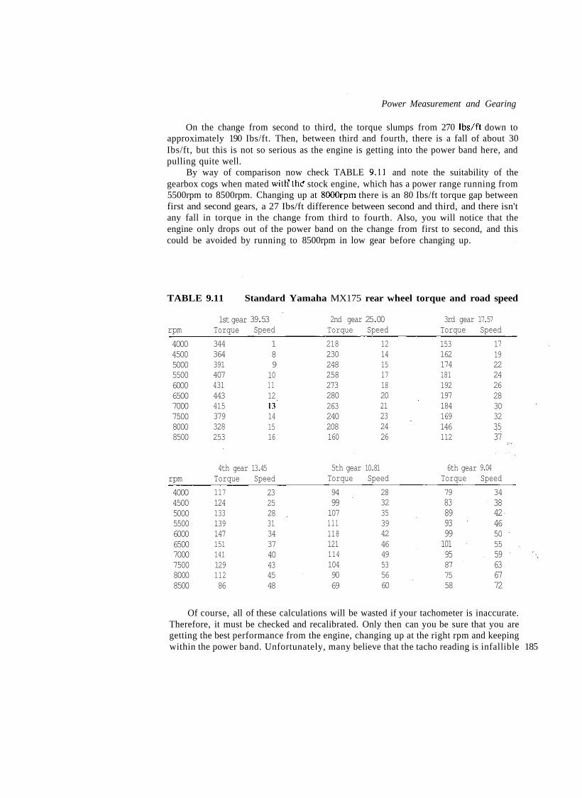
Power Measurement and Gearing
On the change from second to third, the torque slumps from 270 Ibs/ft down toapproximately 190 Ibs/ft. Then, between third and fourth, there is a fall of about 30Ibs/ft, but this is not so serious as the engine is getting into the power band here, andpulling quite well.
By way of comparison now check TABLE 9.11 and note the suitability of thegearbox cogs when mated with'the" stock engine, which has a power range running from5500rpm to 8500rpm. Changing up at SOOOrpm there is an 80 Ibs/ft torque gap betweenfirst and second gears, a 27 Ibs/ft difference between second and third, and there isn'tany fall in torque in the change from third to fourth. Also, you will notice that theengine only drops out of the power band on the change from first to second, and thiscould be avoided by running to 8500rpm in low gear before changing up.
TABLE 9.11 Standard Yamaha MX175 rear wheel torque and road speed
rpm
4000450050005500600065007000750080008500
1st gearTorque
344364391407431443415379328253
39.53Speed
18910111213141516
2nd gearTorque
218230248258273280263240208160
25.00Speed
12141517182021232426
3rd gearTorque
153162174181192197184169146112
17.57Speed
17192224262830323537
rpm
4000450050005500600065007000750080008500
4th gearTorque
11712413313914715114112911286
13.45Speed
23252831343740434548
5th gearTorque
94991071111181211141049069
10.81Speed
28323539424649535660
6th gearTorque
798389939910195877558
9.04Speed
34384246505559636772
Of course, all of these calculations will be wasted if your tachometer is inaccurate.Therefore, it must be checked and recalibrated. Only then can you be sure that you aregetting the best performance from the engine, changing up at the right rpm and keepingwithin the power band. Unfortunately, many believe that the tacho reading is infallible 185

Two Stroke Performance Tuning
and beyond question. However, I have not found this to be so; mechanical units aretypically 400-700rpm fast and electronic digital readout tachos can be all over theplace, depending on the ambient temperature and the quality of the unit.
Final tuning on the race track is also necessary, even after a full tuning session onthe dyno. This is because the load applied on the dyno may have been just a flashloading, i.e., just long enough to get a power reading. Such a brief run at full load maynot allow sufficient heat build-up in the piston crown, combustion chamber orcrankcase, to cause detonation. Under normal racing conditions, where full load maybe applied for a much longer period, detonation might occur due to the mixture being afraction lean, and in some instances the ignition advance may be a little early. At timesit will be found necessary to run even more advance on the race circuit than on thedyno, to get better throttle response and acceleration, when the jetting must beconsiderably richer to cool the piston.
Throughout the testing you should make one change at a time. This is the only waythat you are going to find out to what the engine is responding. With just one variableintroduced for each test it is often difficult to know just what step to take next, so youwill appreciate that the introduction of two or three changes will make it virtuallyimpossible to know where you are heading with your tuning.
At the start, race track tuning can be extremely frustrating, because you seem tokeep going up so many dead end streets. However, if you stick with it, and go aboutyour tuning in a systematic way, you are sure to have the engine responding better andmaking more power than before you started. The thing you must do is make just onechange at a time, keep accurate notes of any changes, and make sure that you have gota good stop watch operator who can be relied upon to time each lap accurately.
186

Appendix IIntroduction
This section of the book should enable you to understand clearly the practicalapplication of two-stroke principles expounded throughout the previous nine chapters.Each working example that I have chosen has its own story to tell. Some enginesdemand a great deal of modification before they are able to produce acceptableperformances; others, such as the big 400cc motocross and enduro engines, requireonly a clean up of the ports; for some (eg. go-kart engines) the best thing one can do isto 'blueprint' the motor.
Unfortunately, the engines used as examples will not be the current models by thetime you read this book. But the principles of modifying any of them will apply to two-strokes generally, for many years to come.
Usually, the modification of each engine is divided into two rider categories:namely 'average' and 'expert'. We have to face the fact that most of us fall into theaverage class. This means that we require an engine which gives a nice smooth deliveryof power over a wide rev range. On the other hand, an expert can tolerate a muchnarrower power band. He has the ability to control a quick rush of power and heseldom misses a gear change. Obviously if you are not one of the handful of riders towhom the latter description applies, then forget about the hotter 'expert' modificationsas they will prove to be a hindrance to you.
A Motocross ModificationsI Yamaha YZ80F
In standard tune, the YZ80F js a very quick, but difficult to ride, bike. The engineproduces excellent power (TABLE A.I) and it pulls cleanly over a wide rev range.However, the power comes on too suddenly, making control of the bike's rear endexceedingly difficult. The only way to make the bike easier to ride is by smoothingpower delivery to the rear tyre. ; - -'•' 187

Two Stroke Performance Tuning
TABLE A.I Yamaha YZ80F power output
rpmStandard
hp Torque (Ib/ft) hpModified
Torque fib/ft)
80008500900095001000010500110001150012000
8.79.911.112.112.913.314.27.7
5.76.156.56.76.756.656.83.5
7.810.410.811.912.314.214.613.811.1
5.16.46.36.66.457.16.956.34.85
This goal is realised in two ways: raising the transfer ports and modifying theexpansion chamber.
The transfer duration as delivered from the factory is far too short when matchedwith a relatively wild 197° exhaust open period. The simplest way to increase transferduration is to raise the barrel 1.0mm using a 0.7mm aluminium spacer plate and anadditional base gasket. This will give a transfer event of 129° as compared with thestandard duration of 121°. The boost port should be raised an extra 1.5mm to give aduration of 138°.
Raising the barrel will also lengthen the exhaust timing, in this instance to almost203° duration. In many engines this would be far too wild, but this unit will be runningto almost 12,000rpm so a long exhaust event is required.
The factory expansion chamber is an unusual design which works none too well.The header pipe tapers at a fairly steep 1.65° and then diverges into a 2.9° and 5.4°diffuser. The 'belly' section, which appears to diverge and then converge abruptly, is inreality a silencer, so do not be fooled by its odd shape. The baffle cone converges at afairly conventional 9.75°, but it is very badly deformed to clear the bike's frame(FIGURE A.I).
Rg. A . 1 Yamaha YZ8OF expansion chamber.
The expansion chamber could be replaced completely, but in this instance I believeit is much easier and just as effective to modify the factory chamber. As you will notice
188 in FIGURE A.2, this basically involves cutting a section out of the centre of the

Appendix I
chamber and welding in a new baffle cone and secondary diffuser. The standard headerpipe and stinger is retained, but as the new centre section is shorter than standard, a20mm length of pipe will have to be welded in to lengthen the stinger to reach the bafflecone.
The long secondary diffuser with a taper of 5° serves to improve mid-range andtop end power. Normally 5° would be too steep for a motocross engine of this size butworking in conjunction with the 90mm section of diffuser tapering at 2.9°, which wasretained, the resulting two stage diffuser works very well.
The baffle cone taper is reduced to 9° in the interests of widening and smoothingthe power band. It reduces top end power a little but this is a price that must sometimesbe paid. If the chamber is correctly formed it will not be necessary to notch the diffuserto clear the frame tubes.
Because the tuned length of the chamber has been reduced so that it now works atll.OOOrpm rather than 10,200rpm, the belly section is just 22mm long. You will notethat this section no longer does any silencing. Yet if the standard silencer attached onthe end of the stinger is retained, and the new cones are made of 1mm sheet steel, youwill find that the modified chamber provides much quieter running than standard.
After smoothing power delivery, we can now think about raising the YZSOF'spower level. This basically involves getting more air into the engine, particularly above10,500rpm.
The first thing we must do is rebore the standard 26mm Mikuni carburettor to27.3mm. Really the carb should be bigger, but this is the maximum to which thecarburettor can be bored. The jetting will not have to be altered, except that on veryfast tracks a 195 main jet may be required instead of the standard 190. Usually, I havefound it beneficial to lower the needle to the centre clip position as the engine tends torun a little rich on the factory 4th groove setting.
The reed valve assembly doesn't flow exceptionally well. It can be replaced by aNogucchi reed block, which will flow about 25% more air. As this assembly isphysically bigger than the standard reed block, the inlet port must be enlarged for it tofit.
Alternatively, the standard block can be modified as indicated in FIGURE A.3.First, the reed block openings must be carefully widened to remove the lip Yamahaleaves in manufacture. Then the openings can be increased in length to further increaseflow area. If phenolic reed petals are available, these should be fitted.
To improve air flow into the cylinder, the inlet port must be enlarged, but care isneeded here as excessive widening will allow the lower back wall of the cylinder to 189
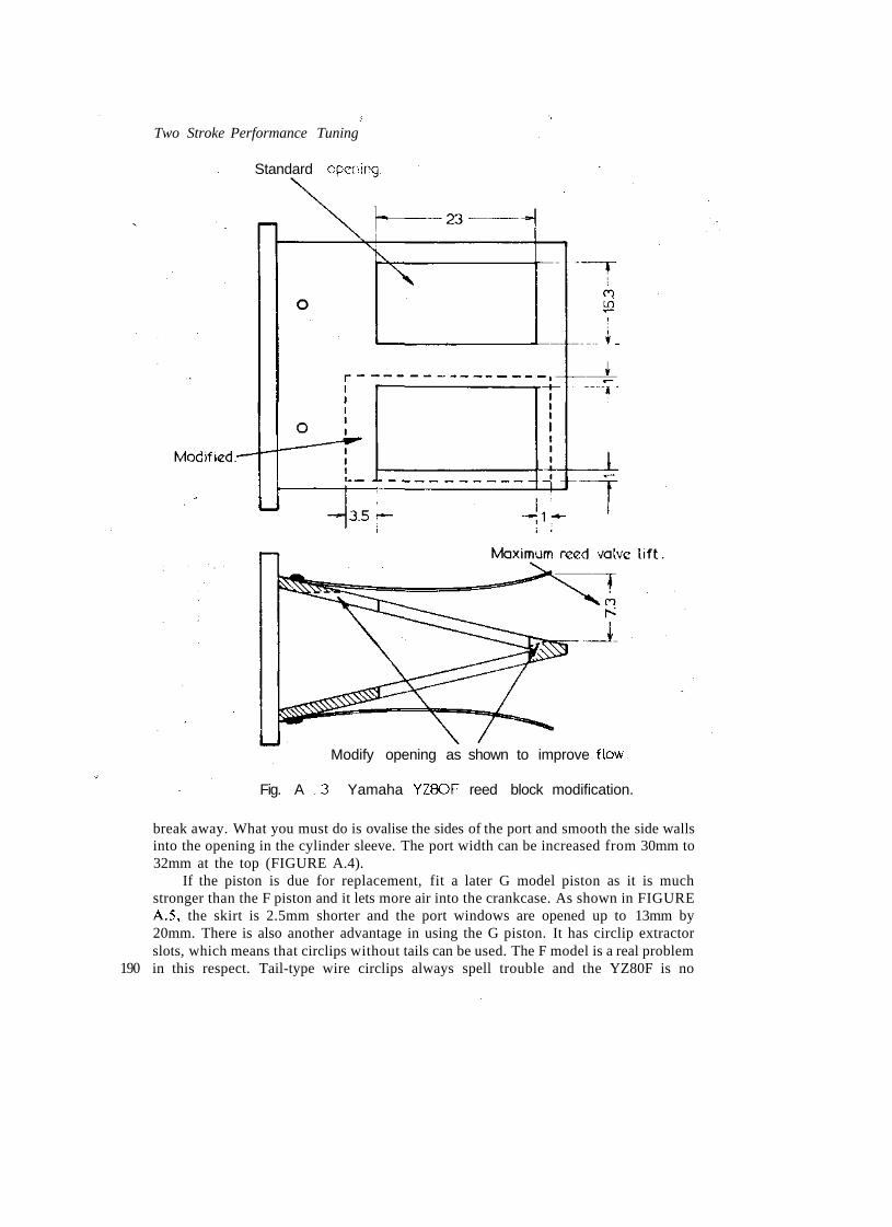
Two Stroke Performance Tuning
Standard opening.
190
Modify opening as shown to improve flow.
Fig. A .3 Yamaha YZ8OF reed block modification.
break away. What you must do is ovalise the sides of the port and smooth the side wallsinto the opening in the cylinder sleeve. The port width can be increased from 30mm to32mm at the top (FIGURE A.4).
If the piston is due for replacement, fit a later G model piston as it is muchstronger than the F piston and it lets more air into the crankcase. As shown in FIGUREA.5, the skirt is 2.5mm shorter and the port windows are opened up to 13mm by20mm. There is also another advantage in using the G piston. It has circlip extractorslots, which means that circlips without tails can be used. The F model is a real problemin this respect. Tail-type wire circlips always spell trouble and the YZ80F is no

Appendix I
' i i~j | iM 1~H 1mm. chamfer.
Fig. A . 5 Comparison of F & G model pistons.
exception. The constant rubbing of the gudgeon pin against the circlip wears throughthe tail, allowing it to drop into the cylinder, scoring the bore and possibly seizing themotor.
The piston modification to improve flow from the crankcase into the transferports is very simple and doesn't cause any trouble. Enlarging the cut-away below the 191
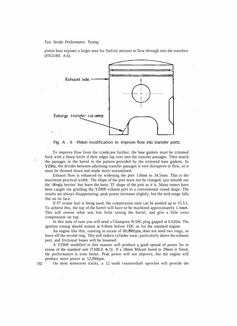
Two Stroke Performance Tuning
piston boss exposes a larger area for fuel/air mixture to flow through into the transfers(FIGURE A.6).
192
Fig. A . 6 Piston modification to improve flow into transfer ports.
To improve flow from the crankcase further, the base gaskets must be trimmedback with a sharp knife if their edges lap over into the transfer passages. Then matchthe passages in the barrel to the pattern provided by the trimmed base gaskets. InYZSOs, the divider between adjoining transfer passages is very disruptive to flow, so itmust be thinned down and made more streamlined.
Exhaust flow is enhanced by widening the port 1.0mm to 34.5mm. This is themaximum practical width. The shape of the port must not be changed, just smooth outthe 'dingle berries' but leave the basic 'D' shape of the port as it is. Many tuners havebeen caught out grinding the YZ80F exhaust port to a conventional round shape. Theresults are always disappointing: peak power increases slightly, but the mid-range fallsflat on its face.
If 97 octane fuel is being used, the compression ratio can be pushed up to 15.5:1.To achieve this, the top of the barrel will have to be machined approximately 1.1 mm.This will restore what was lost from raising the barrel, and give a little extracompression on top.
In this state of tune you will need a Champion N-59G plug gapped at 0.020in. Theignition timing should remain at 0.8mm before TDC as for the standard engine.
An engine like this, running in excess of 10,000rpm, does not need two rings, soleave off the second ring. This will reduce cylinder wear, particularly above the exhaustport, and frictional losses will be lessened.
A YZ80F modified in this manner will produce a good spread of power far inexcess of the standard unit (TABLE A.I). If a 28mm Mikuni bored to 29mm is fitted,the performance is even better. Peak power will not improve, but the engine willproduce more power at 12,000rpm.
On most motocross tracks, a 12 tooth countershaft sprocket will provide the

Appendix I
correct gearing. This is a considerable reduction on the 14 tooth sprocket fitted by thefactory. Riders under eight stone will be able to start in second gear, without boggingthe motor. Heavier juniors will have to use low gear, except for down-hill starts orwhere traction is poor.
2 Suzuki RM125CAs delivered from the factory, Suzuki RM125 engines have always been real little
gems. They produce a wide spread of easily managed power as well as excellent peakhp. Few other 125s can stay with them on any motocross track.
With careful porting modifications, the RM125 can be coaxed to deliver evenmore top end power without affecting the mid-range, but leave the expansion chamberalone as it cannot be improved upon. Any changes in the pipe to make it work better atthe top-end seem to kill the power band, so leave well alone.
Many tuners claim that the 32mm Mikuni fitted as standard is too small, but Idisagree. A 34mm Mikuni (or a 32 bored to 34mm) will not increase peak hp, but it willallow the engine to run to ll,500rpm with ease. With a 32mm carburettor the engineruns out of breath just past ll,000rpm. When tested on the dyno, an engine with a34mm Mikuni doesn't appear to lose low end power (i.e., at 9000rpm) when comparedwith a 32mm unit, but out in the real world of motocross racing throttle response doesnot appear to be quite as good.
The exception is when the RM is modified for expert riders. In this instance the32mm carburettor just cannot flow enough air to keep up with the demands of anengine with radical, almost road race, porting. At 11,000 and 11,500rpm a 34 or 35mmcarburettor is necessary to allow this wild porting to work. In the hands of an expertrider the resulting increase in power seems to compensate for what has been lost in themid-range.
Because it has a crankcase reed valve, the RM still relies on the piston skirt to openand close the inlet port. For this reason Suzuki have kept the inlet duration to a fairlytame 155°, about equivalent to a pre-reed valve enduro motor like the BultacoMatador. Lowering the inlet port 3.0mm increases the inlet event to 167°. The increasein duration gives the air more time to get into the motor, and grinding the floor of theport 3.0mm lower gives it a bigger, less restrictive hole to flow through. Cutting 3.0mmoff the piston skirt would also increase inlet duration to 167°, but the inlet port wouldremain a small restrictive tract. Before you leave the inlet port, increase its width by3.0mm to 40mm and then match up the inlet manifold with the port and thecarburettor bore (FIGURE A.7).
When working on the inlet port, you will notice that the reed valve doesn't matchvery well. What you have to do is remove the stainless steel petal and then grind theport and/or reed block to give air flowing into the crankcase via the reed valve a clear,unrestricted passage. Replace the stainless steel petal with two phenolic petals. Irecommend that two petals be fitted, as this improves crankcase filling at high rpm byeliminating petal flutter. Be sure to Loctite the screws retaining the reed stop andpetals. You don't want those screws falling out and dropping into the motor.
The RM125 transfer ports are a good size and shape, but unfortunately they arevery rough. Without altering their shape all the 'dingle berries' must be ground out ofthe ports, and when they have been smoothed they should be matched to the crankcasetransfer passages and base gasket. 193

Two Stroke Performance Tuning
194
Fig. A . 7 Suzuki RM125C porting modifications.
Probably the worst aspect of the RM engine is its exhaust port. It exits at a verybad angle, restricting gas flow quite severely. Fortunately, there is enough metal in thebarrel around the exhaust port to permit one half of the port to be ground much wider,to handle the bulk of exhaust gas exiting the cylinder. Standard, each half of the port is21mm wide. To increase gas flow the left exhaust window (viewed from the front of thebike) should be ground to increase its width, at the top, to 23mm. It can be made wider,but this half of the port exits at such a terrible angle you will be wasting your time. Theright window is the one on which to concentrate your efforts. It can be ground 25.5mmwide. Take care not to go any further than this, otherwise the piston will not be able toseal the crankcase from the exhaust port.
Do not increase the exhaust port width at the bottom. The port is already too closeto the transfers at this point, and making the port wider here would just allow morefuel/air mixture to spill out into the exhaust, particularly below 9000rpm.
Quite a few RM125 exhaust ports require lowering by 0.5-0.75mm, so that theydon't stand proud of the piston crown at TDC. While you are attending to this, alsogrind the 'bump' out of the exhaust port floor (FIGURE A.8).
The standard exhaust duration is about 192°. Raising the port 1.0mm increasesthis to 197° and lifts peak hp nicely.
When you have finished modifying the exhaust port, fit the exhaust header flangeand mate it to the port. Generally, the match is not good, so you will have to grind theflange evenly all the way around inside to increase its internal diameter, and don'tforget to trim the gasket to suit. The flange should be attached using Allen head screwswith a drop of Loctite on them.
If 97 octane fuel is used, the compression ratio can be brought up to 14.7:1. Thiscan be achieved by machining the head approximately 0.2mm or, if you are very

Appendix I
Fig. A . 8 Exhaust port modification.
careful, the head gasket may be thinned with a sheet of wet and dry paper on a piece ofplate glass.
In this state of tune the engine will require a Champion N-59G plug gapped at0.020in. (On very fast tracks an N-57G may be required). Leave the ignition timing at2.8mm before TDC.
To reduce frictional losses, use just the top compression ring. The second ringreally only helps below about SOOOrpm, so there is no point in fitting it as it reducespower and increases bore wear.
You should not have to alter the carburettor jetting in any way. On most tracks the240 main will be about right, but on slower circuits a 230 may give a slightly superiorthrottle response.
Expert riders will be able to handle more power and a narrower power band. Themain changes to achieve this goal involve increased exhaust and inlet opening periods.Raising the exhaust port an additional 0.5mm lifts duration to about 199°, which is thepractical maximum for motocross, although you can go another 0.5mm higher for TTracing.
The inlet port can be lowered an extra 1.5mm, giving 173° inlet duration. It can belowered a further 1.5mm for TT racing. This achieves an inlet event of 180° duration.
The 32mm Mikuni will have to be bored to 34mm or be replaced with a 34mmcarburettor. It will not require any jetting changes except for a 250 main jet.
The expansion chamber also has to be altered to work in tune with the 'hot' expertporting. You will have to cut 50mm out of the belly section of the chamber to reducethe overall tuned length.
Finally, replace the reed valve assembly with a DG reed block. The DG reed hastwice the flow area of the standard Suzuki valve. It won't do anything to pick upmid-range power, but peak hp is improved due to increased air flow into the motor. 195
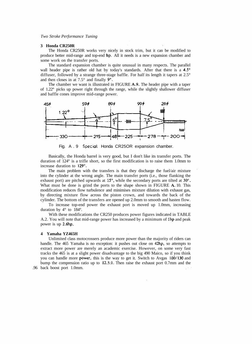
Two Stroke Performance Tuning
3 Honda CR250RThe Honda CR250R works very nicely in stock trim, but it can be modified to
produce better mid-range and top-end hp. All it needs is a new expansion chamber andsome work on the transfer ports.
The standard expansion chamber is quite unusual in many respects. The parallelwall header pipe is rather old hat by today's standards. After that there is a 4.5°diffuser, followed by a strange three-stage baffle. For half its length it tapers at 2.5°and then closes in at 7.5° and finally 9°.
The chamber we want is illustrated in FIGURE A.9. The header pipe with a taperof 1.22° picks up power right through the range, while the slightly shallower diffuserand baffle cones improve mid-range power.
.96
Fig. A . 9 Special Honda CR25OR expansion chamber.
Basically, the Honda barrel is very good, but I don't like its transfer ports. Theduration of 124° is a trifle short, so the first modification is to raise them 1.0mm toincrease duration to 129°.
The main problem with the transfers is that they discharge the fuel/air mixtureinto the cylinder at the wrong angle. The main transfer ports (i.e., those flanking theexhaust port) are pitched upwards at 15°, while the secondary ports are tilted at 30°.What must be done is grind the ports to the shape shown in FIGURE A. 10. Thismodification reduces flow turbulence and minimises mixture dilution with exhaust gas,by directing mixture flow across the piston crown, and towards the back of thecylinder. The bottom of the transfers are opened up 2.0mm to smooth and hasten flow.
To increase top-end power the exhaust port is moved up 1.0mm, increasingduration by 4° to 184°.
With these modifications the CR250 produces power figures indicated in TABLEA.2. You will note that mid-range power has increased by a minimum of Ihp and peakpower is up 2.6hp.
4 Yamaha YZ465HUnlimited class motocrossers produce more power than the majority of riders can
handle. The 465 Yamaha is no exception: it pushes out close on 42hp, so attempts toextract more power are merely an academic exercise. However, on some very fasttracks the 465 is at a slight power disadvantage to the big 490 Maico, so if you thinkyou can handle more power, this is the way to get it. Switch to Avgas 100/130 andbump the compression ratio up to 12.5:1. Then raise the exhaust port 0.7mm and theback boost port 1.0mm.

Main transfers
Appendix I
Auxiliary transfers.
TABLE A.2 Honda CR250R power output
Standard Modifiedrpm hp Torque (Ib/ft) hp Torque (Ib/ft)
4000450050005500600065007000750080008500
10.011.113.119.025.228.229.729.827.723.1
13.113.013.818.1322.122.7522.320.918.214.27
10.612.214.420.526.530.731.332.429.425.2
13.9514.2315.119.623.224.823.522.719.315.6
If your 465 is a dual purpose play/motocross bike, you may prefer to soften thepower delivery a little. There are a couple of ways you can go about this. By far theeasiest method is to fit two base gaskets under the barrel. This lowers the compressionratio and raises the transfers, de-tuning the engine. Alternatively, you can machine thecombustion chamber to lower the compression ratio to 11:1 and then raise the boostport 1.0mm. If the engine runs rich in the mid-range, fit a White Bros, reed blockspacer. 197

Two Stroke Performance Tuning
B Enduro modifications1 Yamaha IT175F
The IT175F has a very responsive engine. It produces good power and maintains awide power range. This makes it suitable for most enduro riders with some previousexperience of enduro machines. However, beginner riders starting out on an IT175 mayfind it just a little peaky in low speed situations, which call for a delicate application ofpower. All competition bikes have a tendency to lurch forward as the throttle is twistedopen. When the course is easy this is not a problem for a beginner, but in tightersections this tendency may intimidate a rider because of front wheel lift-off and/orrear-end sliding which usually results.
For beginners, 1 would suggest that you tame the engine in two ways. First, replacethe standard 34mm Mikuni with a 32mm unit. If you have a mate with a YZ125 youmay be able to do a swap. The 32mm carburettor will require jetting the same as the34mm carburettor. Since you are a beginner you will most likely have to fit a smaller340 main jet.
The other change required is to raise the boost port in the back of the cylinder1.0mm. This smooths the power curve without reducing maximum hp.
Most riders will want to leave the engine in the same tune it leaves the factory.However, if a little more top-end power is desired, this can be easily accommodated. Asimple clean-up of the ports to remove 'dingle berries', and matching the transfer portopenings to the crankcase, will increase maximum power by Ihp and improve power atpeak revs by almost 2hp.
Expert riders can pick up a little more power by boring the carburettor to 35mm(leave the jetting standard) and raising the exhaust port 1.0mm. If Avgas 100/130 fuelis used, the compression ratio should be increased to 14:1 to swell mid-range power(TABLE B.I). Really, the IT175 could do with a new expansion chamber in this degreeof tune. However, I don't feel that it is worth the trouble and expense. If you are goodenough to use the sort of power that a new pipe will release, then you should be on aCan-Am or SWM. These bikes are expensive but by the time you have bolted newsuspension units onto your IT to transmit all of this new found power to the ground,you will be in front financially with one of these exotic machines.
2 Suzuki PE175NThe Suzuki PE175 is a very nice bike, particularly for beginners. However, as the
rider's ability improves, he will soon notice that the PE cannot match other 175 enduromachines in sheer power.
The first modification that I would recommend for all riders is to remove the tworestrictors out of the exhaust. These were originally fitted to make the bike street legal,but as such a low noise level isn't required in competition, these must go. The restrictorfitted behind the exhaust flange is easy to remove. Just unscrew the three Phillips headscrews which hold the flange in place, and take out the restrictor. The other restrictor,situated inside the expansion chamber, is much more difficult to get at. It is located inthe baffle cone just before the stinger. You will have to cut the chamber open, then pullit out and reweld the pipe. With the restrictors out of the way the engine will gain Ihpfrom 7000rpm to 10,000rpm.
To give the PE a smooth power band, Suzuki have kept the inlet port area and198 duration very conservative. This problem can be overcome in two ways. By lowering
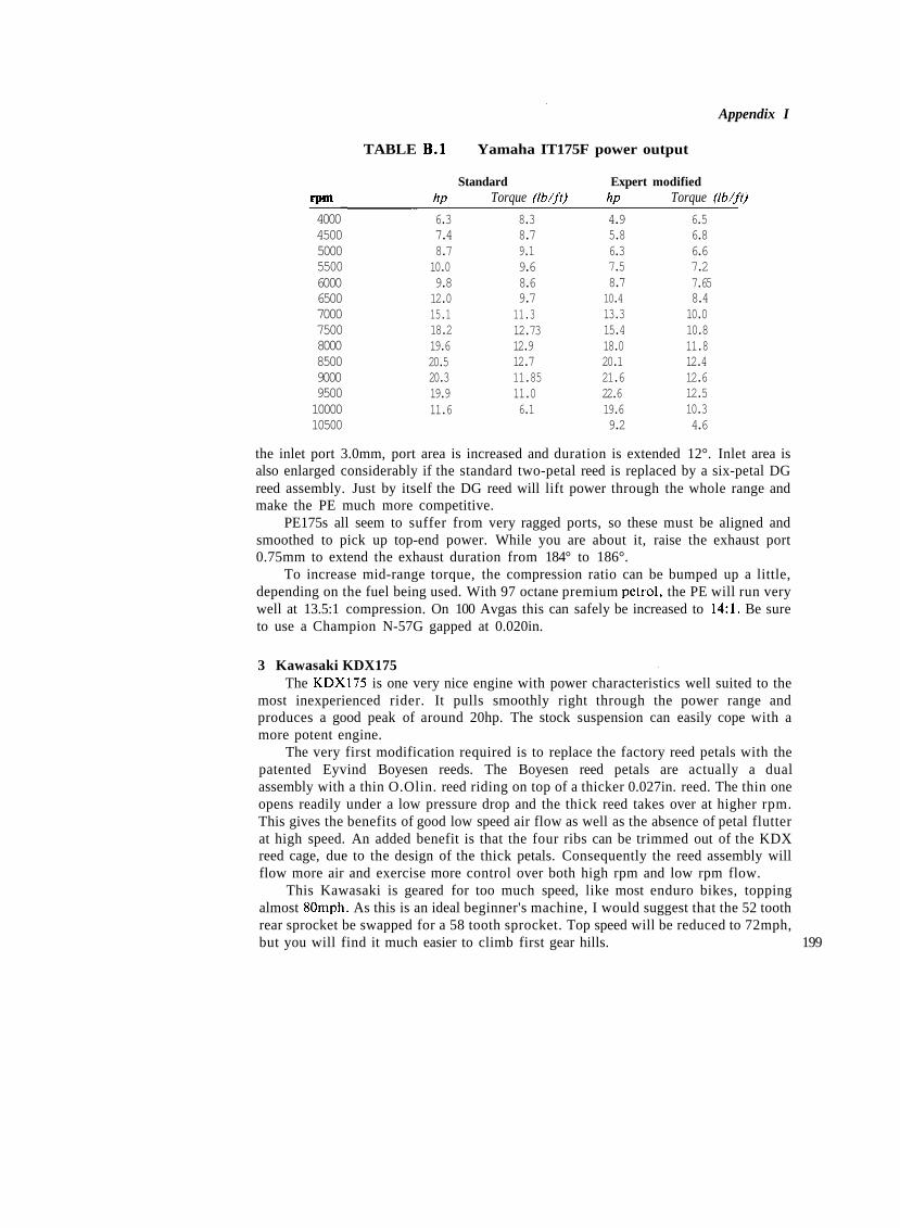
Appendix I
TABLE B.I Yamaha IT175F power output
Standard Expert modifiedrpm hp Torque (Ib/ft) hp Torque (Ib/ft)
4000450050005500600065007000750080008500900095001000010500
6.37.48.710.09.812.015.118.219.620.520.319.911.6
8.38.79.19.68.69.711.312.7312.912.711.8511.06.1
4.95.86.37.58.710.413.315.418.020.121.622.619.69.2
6.56.86.67.27.658.410.010.811.812.412.612.510.34.6
the inlet port 3.0mm, port area is increased and duration is extended 12°. Inlet area isalso enlarged considerably if the standard two-petal reed is replaced by a six-petal DGreed assembly. Just by itself the DG reed will lift power through the whole range andmake the PE much more competitive.
PE175s all seem to suffer from very ragged ports, so these must be aligned andsmoothed to pick up top-end power. While you are about it, raise the exhaust port0.75mm to extend the exhaust duration from 184° to 186°.
To increase mid-range torque, the compression ratio can be bumped up a little,depending on the fuel being used. With 97 octane premium petrol, the PE will run verywell at 13.5:1 compression. On 100 Avgas this can safely be increased to 14:1. Be sureto use a Champion N-57G gapped at 0.020in.
3 Kawasaki KDX175The KDX175 is one very nice engine with power characteristics well suited to the
most inexperienced rider. It pulls smoothly right through the power range andproduces a good peak of around 20hp. The stock suspension can easily cope with amore potent engine.
The very first modification required is to replace the factory reed petals with thepatented Eyvind Boyesen reeds. The Boyesen reed petals are actually a dualassembly with a thin O.Olin. reed riding on top of a thicker 0.027in. reed. The thin oneopens readily under a low pressure drop and the thick reed takes over at higher rpm.This gives the benefits of good low speed air flow as well as the absence of petal flutterat high speed. An added benefit is that the four ribs can be trimmed out of the KDXreed cage, due to the design of the thick petals. Consequently the reed assembly willflow more air and exercise more control over both high rpm and low rpm flow.
This Kawasaki is geared for too much speed, like most enduro bikes, toppingalmost SOmph. As this is an ideal beginner's machine, I would suggest that the 52 toothrear sprocket be swapped for a 58 tooth sprocket. Top speed will be reduced to 72mph,but you will find it much easier to climb first gear hills. 199

Two Stroke Performance Tuning
Because the KDX175 handles so well, expert riders will be able to use considerablymore power. Basically, the ports must be cleaned up and aligned and the exhaust andboost ports should be raised 1.2mm and 0.8mm respectively. Bore the carburettor to35mm (retain stock jetting) and raise the compression ratio to 14:1 for use on Avgas100/130 fuel (TABLE B.2).
TABLE B.2 Kawasaki KDX175 power output
Standard Expert modifiedrpm hp Torque (Ib/ft) hp Torque (Ib/ft)
3000350040004500500055006000650070007500800085009000950010000
3.34.36.06.97.88.510.411.813.316.017.218.118.219.713.9
5.76.57.98.08.28.19.19.510.011.211.311.210.610.97.3
2.73.54.95.87.28.49.511.913.616.418.018.819.521.416.8
4.85.36.46.87.68.08.39.610.211.511.811.611.411.88.8
4 Suzuki PE250TThis model PE Suzuki works very well as it comes from the factory. The ports
require a good clean-up and aligning with the crankcase. This will lift power byapproximately Ihp in the upper rev range from 5500 to 8500rpm. Unfortunately, dueto poorer fuel atomisation at lower rpm when the air speed is slow, bottom end poweris reduced a little.
To increase power right through the rpm range, the standard reed should bereplaced by a high flow unit. The six-petal DG reed assembly and the R & R Hi-Volumereed both flow significantly more air than the factory reed valve. After fitting eitherassembly, be sure to match the reed cage to the inlet passage in the cylinder.
Expert riders can pick-up more power by raising the exhaust port 0.75mm. To helprestore low rpm torque, the compression ratio will have to be increased to 13.7:1.When the compression is raised to this extent, it is necessary to use 100/130 Avgas toavoid engine overheating and detonation.
5 Can-Am 250 Qualifier IIIAlong with the 250 SWM, which shares a similar engine, the Can-Am 250 is the
most powerful enduro machine in this class. As well as having good peak power, therotary valve Rotax engine also has an excellent spread of power. The first step to obtainmore power is to remove the foam filter cover from around the stock K & N air filter.Then carefully match the barrel to the crankcase passages and clean up and align the
200 entire inlet tract. Next check the rotary valve timing. It should open 137° before TDC

Appendix I
and close 75° after TDC. After this, measure the compression ratio. Preferably itshould be about 13:1, if it is less than 12.5:1 machine the head to bring the compressionratio up to 13:1. Fit a Champion N-59G plug gapped at 0.5mm and set the timing at1.2mm before TDC.
If you are an expert rider, the engine can be modified for even more power.Running Avgas 100/130 the compression ratio can be bumped up to 13.8:1. Set thetiming at 1.2mm and use a Champion N-59G plug gapped at 0.5mm. For more highrpm power modify the rotary valve disc to close at 80° after TDC (leave the opening at137° before TDC). Then raise the exhaust port to increase the open period to 184°.
6 Can-Am 350 Qualifier IIIThe Rotax engine fitted to this bike is considered by many to be a misfit. In
actuality it is only 277cc, so it tends to be written off as an open class bike, However, Ido not agree. In tight or muddy going the little 350 Qualifier is an outright contenderand for a beginner it makes an excellent dual purpose play/enduro bike, due to theengine's smooth power delivery characteristics. Basically, the engine can be treated inexactly the same way as the 250, the only exception being that the timing should be setat 1.4mm before TDC.
Expert riders should rework the engine as follows. Switch to Avgas 100/130 andincrease the compression ratio to 13.5:1. Leave the ignition timing at 1.4mm beforeTDC. Raise the exhaust port to give 184° duration and modify the rotary valve disc toclose at 82° after TDC. Fit a Mikuni 34mm carburettor bored to 35.3mm, 310 main jet,P-6 needle jet, 6DH-7 needle 3rd groove, 3.0mm slide cutaway and 60 idle jet (TABLEB.3).
TABLE B.3 Can-Am 350 Qualifier III power output
Standard Expert modifiedrpm hp Torque (Ib/ft) hp Torque (Ib/ft)
2500300035004000450050005500600065007000750080008500
5.36.69.7
11.113.817.122.525.027.630.430.331.424.4
11.211.614.514.616.118.021.521.922.322.821.220.615.1
4.66.08.410.711.816.121.225.428.032.032.732.328.2
9.710.512.614.013.816.920.322.222.624.022.921.217.4
One problem with the 350 Qualifier is the large gap between first and second gears,which even this engine's wide spread of power will not cover. Therefore, I wouldsuggest that novice and play riders fit a 14 tooth countershaft sprocket in place of thestock 15 tooth sprocket if they do much riding in the lower gears.
If you have a 250 Can-Am, it can be uprated to 350 specifications very simply, and 201

Two Stroke Performance Tuning
as a bonus you will have the added benefit of a 6 speed transmission as opposed to the350's five speed uni t . All that is required is a 350 barrel and piston. Then the 250 headand cases will require machining to fit the 4mm larger barrel. The only other parts youwill require are a 350 head and base gasket and a 2.76 needle jet to replace the stock250's 2.73 jet.
7 Suzuki PE400TThis is one of those engines which are better left alone. It works well in standard
form, so spend your money on a pair of Ohilins shocks. If you want to do some workon the engine, clean up and match all the ports. Then fit a high flow reed valveassembly to increase power right through the range.
Expert riders who can handle a narrower power band and a sudden rush of power,can raise the exhaust port 0.8mm and bore the carburettor out to 37mm. Then raise thecompression ratio to 12.3:1. It will be necessary to run Avgas 100/130 to avoid engineoverheating or detonation.
C Road race modifications1 Yamal.a KT100S Kart
This engine is very popular in the beginner karting classes and, as such, mostruling bodies restrict the engine to stock tune. However, within the definition of stocktune, there is a considerable amount of modification which can be done. Basically, wehave to read the rules carefully and then modify the engine to take advantage of factorytolerances.
The first thing we must do is raise the compression ratio so that the engine pullsharder out of tight corners. Some engines have a compression ratio as low as 9.8:1,although about 10.2:1 is average. What we want is a compression ratio of 11.5:1.Higher than this the con rod tends to self-destruct.
The specifications state that the head gasket thickness should be 0.7 to 0.9mm.Obviously, we want the thin gasket; if yours is thicker, carefully dress it, using wet anddry paper on a sheet of glass. According to the rules the base gasket should be from0.25mm to 0.5mm thick. All the factory gaskets I've measured seem to be 0.4mm thick,so it will be necessary to buy some good quality 0.25mm gasket material and cut agasket to suit. FIGURE C.I illustrates the cylinder head requirements to which wemust work. As you can see, the minimum depth of the squish band must be 1.20mm. Ifthe squish band is deeper than this, have the head machined down. Now reassemble theengine and very carefully measure the combustion chamber volume with the piston atTDC. Hopefully, the volume will be about 9.5cc (or about 11.8cc if you measure to thetop of the spark plug hole). Engines with a combustion chamber volume greater than9.7cc will need additional measuring and machining.
The next move is to measure the distance from the head gasket recess in the barrelto the top of the exhaust port. The minimum allowable dimension is 26.3mm. Mostcylinders are very close to this standard (I've even seen a few under this figure) butoccasionally you will find a cylinder which measures out at 26.5mm. If you have such acylinder, have the recess cut 0.2mm deeper. Some people question this move, reasoningthat it would be preferable to raise the exhaust port and gain performance in this
202 manner. Let me assure you that the KT100S is one engine which does not need more

Appendix I
Fig. C . 1 Yamaha KT1OOS combustion chamber detail.
exhaust duration, in fact the engine would work better with about 5° less duration onshort, tight, sprint tracks.
Barrels which are already down to the minimum exhaust port to gasket recessdimension, should be measured to determine if the base of the barrel can be machinedto reduce its length. The minimum distance allowable is 80.4mm, measured from thecylinder base to the head gasket recess. If you cannot do any good here, the next moveis to check the crankcase deck height (FIGURE C.2). You will note that the minimumdimension permissible is 21.2mm. Finally, if the tolerances have not allowed you toraise the compression ratio up to 11.5:1 by this point, and you are really desperate toget the maximum performance out of your engine, you will have to split the crankcasesand measure the crankwheel diameters. The minimum diameter according to thespecifications is 86.6mm. As most crankwheels measure close to 87.0mm you can havethe wheels turned down, thus reducing the crankcase deck height and opening the waylegally to mill material from the crankcase deck.
203

Two Stroke Performance Tuning
If the rules allow the ports to be cleaned up and aligned, you should takeadvantage of this provision. First, match the transfer ports to the crankcase and, at thesame time, narrow down the bridge separating the transfer openings in the bottom ofthe barrel. Then fit a piston in the cylinder and check that both halves of the exhaustport are at the same height; as supplied, many barrels have uneven port heights. If theports are not opening together, the lower side will have to be raised, being very carefulto keep the height within legal limits.
The final work required on the barrel is the modification of the inlet port. Do notlower the inlet floor even if it is above the legal limit, as this will only lose bottom endpower. Instead, widen the port out to the legal limit of 34.8mm and square off the floorof the port. To minimise piston scuffing, a radius of at least 4mm will have to be left inthe bottom corners of the port. If the regulations do not specify what height the inletport should be (most do not), then it should be raised to the same level as the pistonskirt with the crank at TDC. However, before raising the inlet roof, be very careful tocheck that this modification will not expose the piston ring and allow it to snag in theinlet port when the piston moves to BDC.
When working the inlet port, you will notice that the phenolic spacer and thealuminium carburettor mounting plate do not line up very well with the inlet port or thecarburettor. The regulations specify a maximum hole size of 26.4mm and 26.3mmrespectively, for the spacer and the mounting plate, so if opening the holes out to themaximum does not rectify the misalignment, the mounting holes will have to beelongated to correct the problem.
The Walbro carburettor fitted to this engine should be measured to ensure that theventuri and throttle bore are 24.13mm and 25.65mm respectively. Be sure to check thefuel filter, located behind the pump diaphragm, regularly as it is prone to blockage.This will severely limit high speed fuel flow and could cause engine seizure.
On high speed circuits use a Champion N-59G gapped at 0.020in. Slower tracksusually require the use of an N-2G plug.
The expansion chamber required for this engine is illustrated in FIGURE C.3. Theheader tapers at 1.25°, followed by a two-stage diffuser with 3° and 5.5° tapers. Thebaffle cone has a very shallow 9° taper.
Fig C . 3 Special Yamaha KT1OOS expansion chamber.
204
2 DAP T72 lOOcc International KartFew International kart engines require modification to any extent, but all have to
be carefully 'blueprinted' to give a winning edge. As it comes from the factory, the T72
Two Stroke Performance Tuning
performance will drop due to excess drag occurring because of the cover and valvescuffing together. More than 0.3mm clearance increases leakage past the valve when itis closed, which also reduces power, especially at lower speeds. To decrease valveclearance, the mating face of the cover will have to be machined.
While you are working with the rotary valve cover, check that the inlet openingaligns with the inlet tract in the crankcase. Any mis-match here will knock top-endpower, so grind the cover inlet until perfect alignment is achieved.
Generally speaking, the port specifications should be left alone. The ports shouldbe cleaned up but retain stock timing, as the factory knows what it is doing. Fiddlingwith the ports and/or valve timing usually results in sluggish performance out of tightturns.
For circuits with relatively fast corners it is advantageous to have a spare rotaryvalve and barrel modified to l i f t maximum hp. The valve should be modified to open at50° after BDC and close 75° after TDC. The exhaust port should be raised to increaseexhaust port duration from 170° to 177° and the TT port and transfer ports should bemoved up to give open periods of 134° and 128° respectively.
Assuming that the head and barrel have been sandblasted (to increase fin surfacearea) and painted matt black, the ignition timing should be set at 2.5mm before TDCon Avgas 100/130 petrol. On a few very slow circuits you may have to retard the timingback to 2.2mm to avoid engine knock when pulling out of slow corners under full load.If you are right on the maximum weight limit, this is not usually a problem, butoverweight drivers can put a tremendous overload on an engine when hauling out oftight, uphill turns.
Most International drivers are happy with the Vevey expansion chamber andfactory header connected by a length of convolute tube (FIGURE C.4). However, 1believe the Vevey pipe leaves much to be desired, and the parallel wall header cancertainly be improved. I'm not at all in favour of the convolute interconnecting tubeeither. It usually leaks and its life expectancy is always short. One thing in its favour isthat the tuned length of the exhaust can easily be altered by using convolute tube ofvarying lengths.
Fig. C 4 Vevey expansion chamber
1 have found a pipe of an entirely different design to give much better performanceright through the power range (FIGURE C.5). This chamber is designed to make a slip-joint connection with the factory header pipe, which has been shortened by 100mm.You will note that the new pipe has a header taper of 1.5°, diffuser tapers of 4° and 8°and a baffle taper of 11.5°. The cone tapers are much shallower than the 7.6° diffuser
206 and 12.3° baffle tapers of the Vevey pipe. Also, the Vevey has a perforated baffle

Appendix I
Fig. C .5 Special rotary valve kart expansion chamber.
The pipe illustrated will work on most circuits, but on slower tracks the 'belly'length will have to be increased and on faster circuits it may need to be shortenedslightly. If you prefer, you may wish to construct this chamber with a slip-joint typebelly section, so that the tuned length can be changed quickly to suit the circuit(FIGURE C.6). When this is done, be sure to use two good quality hose clamps andthree light springs to prevent the chamber from falling apart. Also, to stop any leakage,seal the joint with Silastic. Exhaust jointing compounds may be used, but I have foundSilastic to be superior.
i ^-—Minimum overlap.—1Omm.—i
Seal joint with Silastic.
Fig. C . 6 Slip-joint type belly section.
3 Suzuki RM125BThe Suzuki RM125B motocross engine makes an excellent road race power plant.
In the right frame it can hold its own against the Honda and Yamaha production 207
Appendix 1
which reduces its effectiveness in returning a good pulse and, as it doesn't have astinger to create back pressure, the pipe does not have the ability to ram very muchescaped fuel/air mixture back into the cylinder.

Two Stroke Performance Tuning
racers. It is quite an inexpensive engine, as used units in reasonable condition can oftenbe purchased from motorcycle wreckers. This engine, like that of the later modelSuzukis (which are also just as suitable for modification), is very reliable. Piston andring wear is always incredibly small and the cylinder will stay true and show little signof wear, even after hundreds of miles of racing. The only problem is the big endbearing which Suzuki use. It has a copper-plated cage which does not like engine speedsmuch in excess of 11,500rpm. Therefore, engines in a very high state of tune must use abetter big end bearing. Lesser engines will also keep their bottom end intact if a silver-plated steel cage big end is used.
I haven't been able to find a bearing to suit the Suzuki's crankpin and con-rod, so1 use a bearing, thrust washers, crankpin and con rod from a Honda CR125M. Thischange-over is reasonably straight forward, but it does involve some very precisemachine work. Both rods are 100mm centre to centre and share the same size little end.However, the crankpin at 20mm diameter is 1.0mm larger than that of the Suzuki.Also, the big end bearing is 0.6mm wider. To fit the Honda parts, the crankpin holesmust be bored 1.0mm over-size, with a 0.05mm interference fit and a fine machinefinish. Additionally, the big end recess in each crank wheel must be machined 0.3mmdeeper to accommodate the wider bearing.
As may be expected, the major change to bring the RM125 up to road racespecifications involves the porting. The transfer ports and the reed valve port should betreated in exactly the same manner as the RM125C which was discussed earlier. Theinlet port should also be reworked along the same lines, but in this instance it should belowered 9.5mm. Care is required when lowering the port to this degree, otherwise theback of the cylinder could be severely weakened, allowing the bottom of it to breakaway. What you must do is leave a generous radius in the lower outside corners of the
208 Fig C . 7 Suzuki RM125B road race porting.
Appendix 1
port. This leaves more metal around the port and also makes the action of the pistonskirt against the lower lip of the port much more gentle (FIGURE C.7). Next, raise theinlet roof 1.0mm if you intend using only one compression ring.
The exhaust port is not good in the RM125B. It requires a drastic rework toencourage the type of hp we are after for a road racer. Novice riders should not raisethe exhaust windows more than 2.0mm. This increases the exhaust open period to201°. Expert riders can increase the duration to 203° by raising the ports 2.5mm. Go-karts, by virtue of the fact that they can operate on a razor-thin power band because oftheir fantastic cornering traction, can operate at up to 205° duration, using the portlayout shown in FIGURE C.7.
After grinding the exhaust windows to the correct height, the exhaust outlet (i.e.,the flange mating fact) must be raised and moved to the right to assist gas flow out ofthe cylinder (FIGURE C.8). If you break through the wall of the port doing this (it
20<

Two Stroke Performance Tuning
often happens), don't worry as the hole can be filled in when the floor of the port isbeing welded up to give the port its new shape. As you will notice in the illustration, theport diameter is increased to 38mm (from 37mm). It has been raised 4mm and moved3mm to the right. After welding (use only argon arc) check the barrel for distortion.
To encourage better air flow into the engine a bigger carburettor is required.Either the standard 32mm Mikuni can be bored to 35mm, or a 36mm carburettor takenout to 37mm may be used. Basically, the jetting will remain standard, with twoexceptions. A 35 pilot jet and a 260 or 270 main jet will be needed.
The reed valve assembly should be replaced by a six petal DG unit. It will flowconsiderably more air at high rpm than the standard reed block.
Expert riders and go-karters can also use a little more inlet port open duration, tofurther improve high speed cylinder filling. With a full length piston skirt, the portduration is 195° when the barrel is ported as shown in FIGURE C.7. Trimming 1,0mmoff the inlet side of the piston skirt increases this figure to a little over 199°. This is themaximum which I recommend for motorcycles and most go-karts. Some kart enginesseem to respond favourably to an inlet open period of 204°, achieved by cutting 2.0mmoff the piston.
There are two expansion chambers that I have found to work well with the RM 125in road race tune (FIGURE C.9). The chamber which suits the majority of riders andkart drivers on tighter circuits, is tuned to work at ll,500rpm and allow the engine topull strongly to 12,000rpm. It uses fairly shallow tapers of 1.45° for the header, 4.5°,7° and 9° for the diffuser and 11.5° for the baffle. The high speed kart pipe peaks theengine at approximately ll,800rpm and raises maximum engine speed to almost12,500rpm.
210 Fig. C .9 Special road race expansion chambers

Appendix I
An engine burning Avgas 100/130 may have the compression ratio raised slightlyto 14.5:1 by using a thinner 0.35mm head gasket. The spark advance should be left at2.8mm before TDC. Use a Champion N-57G plug gapped at 0.5mm. On very fastcircuits with a long main straight an N-55G may be necessary.
4 Rotax 124 LC KartThis little engine is one of the most advanced two-strokes available. It will win
races in the form in which it is delivered from the factory, but for the ultimate inperformance and reliability it should be blueprinted and all the ports must be smoothedand aligned. By giving careful attention to aligning the inlet passages in the primarycase, the rotary valve cover and the crankcase, you will pick up at least Ihp betweenlO.OOOrpm and 12,000rpm. Many engines have a 2 to 3mm misalignment between thevalve cover and left side crankcase opening, which disrupts air flow and causes the inletport to close 3° or 4° early. Obviously this lip in the crankcase has to be eliminated,either by filing or grinding (TABLE C.I).
TABLE C.I Rotax 124LC power output
rpm
8000850090009500
100001050011000115001200012500
hp11.013.818.320.422.524.026.226.728.121.2
Test 1Torque
-, (tb/fl) ., , . -JI.2 3
8.510.711.311.812.012.512.212.38.9
hp
11.713.418.521.023.424.627.027.829.524.0
Test 2Torquefib/ft)
7.78.3
10.811.612.312.412,912,7•i*,r10.1
hP9.7
14.417.120.124.225.227.629.830.625.7
Test 3Torquedb/ft)
6.48.9
10.011.112.712.613.213.613.410.8
Test 1 — Standard engine with factory VSK103 expansion chamber.
Test 2 — As above but with engine blueprinted and inlet port matched and modified asdetailed in FIGURE C 10.
Test 3 — Fully modified engine with high compression ratio, bored carburettor and specialexpansion chamber as detailed in FIGURE C 12.
You will also note that the machined left side of the crankcase inlet port does notmatch the cast right side and floor of the port (FIGURE C.10). What must be done isfill the floor of the port on the right side, using Devcon F epoxy, to bring it up levelwith the machined section. Then fill the right wall of the port to align with the port inthe valve cover as there is about a 16mm misalignment here. This misalignment comesabout due to the factory using crankcases designed for Can Am and SWM bikes with arear-mounted, rather than a side-mounted, carburettor.
?• While you are working on the crankcase you will notice a series of numbers cast 211

Two Stroke Performance Tuning
212
Fig. C . 1O Match inlet port to rotary valve cover.
into the transfer slots. Grind these out; they are only small but they do disrupt highrpm air flow. Also match the crankcase to the barrel and base gasket, and vice versa.
Initially, f i t a 50 pilot jet and a 390 main jet in the carburettor to begin testing.Also fit a 3.0 or 3.3 needle and seat as the standard item just will not flow enough fuelto keep the fuel bowl fu l l at high rpm. Although the standard 34mm Mikuni will allowthe engine to run well and produce good power at 12,000rpm, a carburettor bored to35.3mm will lift the hp output above ll,500rpm.
Set the ignition timing at 1.0mm before TDC and use a Champion N-57G pluggapped at 0.020in. If 100/130 Avgas is used, increase the compression ratio to 15.8:1and fit a Champion N-57G plug. Leave the timing at 1.0mm. On very fast circuits aN-55G plug will be required.
Late model engines employ a different Motoplat ignition unit which automaticallyretards the spark at higher engine speeds. The timing with this ignition should be set at3.76mm before TDC. Then check, using a strobe light, that the timing marks align atSOOOrpm.
Engines manufactured before mid-1980 can beneficially be converted to the laterignition by replacing the rotor, stator and coil. When this is done, the engine worksbetter below 10,700rpm and above 11 JOOrpm. With fixed timing the engine really onlyhas optimum ignition advance over a narrow rpm range.
One area for concern with this motor, and this applies to all liquid cooled two-strokes, is that water flow must be regulated by a thermostat or a restrictor to maintainthe water temperature at 75° to 82°C. If the water temperature is less than 70°C, thecarburettor will be impossible to tune and the engine will not pull very well. On theother hand, if the coolant temperature is higher than 85°C the engine will not bemaking best hp either.
Looking at FIGURE C. l l , you will note that the thermostat is located in thereturn hose between the cylinder head and the radiator. To stabilise head and cylinder
Appendix I
Water pump.
Fig. C . 11 Cooling system arrangement.
temperatures when the thermostat is closed, it is necessary to drill a 4mm by-pass holein the body of the thermostat to allow limited coolant circulation.
Before leaving the cooling system, check the coolant passage in the barrel belowthe exhaust port. This small, but critical, passage must not be obstructed by any castingslag. If coolant flow through here is restricted, the side of the cylinder opposite thewater inlet will overheat and distort.
Rotax supply two diagrams for suitable expansion chambers. One, the VSK095pipe, is now considered by the factory to be more suitable for the air-cooled kartengine, while the wide range VSK103 pipe is preferred for the liquid-cooled model.Personally, I like a chamber a little different to both of these designs (FIGURE C.I2).This expansion chamber will give more power above ll,500rpm than either pipe andextends the useable power band to almost 12,500rpm. On very high speed circuits thebelly section should be reduced to 80mm long.
Fig. C . 12 Special Rotax 124 LC kart expansion chamber.
The silencer detailed in the drawings supplied by Rotax is very quiet but,unfortunately, quite restrictive. An entirely different muffler should be fabricatedfollowing the details outlined in Chapter 4. If you are already using a silencer built tothe Rotax specifications, I would suggest that you cut the rear section of your exhaustopen and reduce the length of the perforated, fibreglass-filled section from 250mm to150mm. This modification will increase power and reduce the piston crowntemperature. L .
Although the standard engine makes good power, it can be modified to work 213
Two Stroke Performance Tuning
better at high rpm. You will note that the fifth transfer port, the boost port, is almostclosed off from the crankcase when the piston descends to BDC. To increase mixtureflow through this port at high rpm, modify the piston skirt as shown in FIGURE C 13.This modification weakens the piston but, on the positive side, little end lubricationand cooling is very much improved. If a caged little end bearing is being used, this is avery important consideration in an engine of this size, running at 12,000 to 12,500rpm.
•Chamfer.
Cut away piston skirt.
Fig. C . 13 Boost port feed cut-away.
For even more top end power increase the exhaust duration to 204° by raising theport 0.6mm and set the inlet timing at 126°/90° by modifying the rotary valve disc.
5 Yamaha TZ250 EThe Yamaha TZ250 is quite a good mass-produced engine. Straight out of the
crate some TZs will run well but most demand a lot of work before they will run fastand reliably. The basic design of the engine is good, but unfortunately Yamaha won'tspend the time assembling them to the correct tolerances. Therefore, the first thing youmust do is to blueprint the engine. Don't ever think about modifying the ports orchanging the carburettors until the basic motor has been brought up to specification.
After stripping the motor, check the crankshaft to determine what work itrequires. Generally, even brand new cranks need a full rebuild, so completely dismantleit and crack test and measure everything.
Beginning with the rods, measure their length. Ideally, they should both be thesame length, but up to O.lmm difference is acceptable. Then check that they are notbent and that the big end and little end bores have been machined parallel. Todetermine this you will have to make a pair of dummy pins about 100mm long to fit thelittle end and big end. Measuring between both ends of the dummy pins will determineif the rods are bent or have holes out of parallel. Next check that the rods have big ends
214 and little ends machined in the same plane (i.e., not twisted). To do this, set up the big

Appendix I
end of the rod on a pair of parallel V-blocks, with a dummy pin fitted. Then, with adial gauge, measure to see that both ends of the dummy pin fitted in the little end arethe same distance from the surface plate. Finally, see that both rods are balanced (i.e.,have little ends and big ends each of the same weight).
Next, measure and weigh the crankpins. They must be of the same diameter andweight. A heavy pin can be lightened by grinding on a sanding belt to bring it down tothe same weight as the light pin, but to find pins of the same diameter may take a gooddeal of searching through dealers' parts bins.
After this, you have to find big end bearings which give acceptable little end sideshake. Many bearings have so much radial clearance between the crankpin and rod thatthe little end of the rod can move up to 1.5mm from side to side. Try and find bearingswhich allow no more than 1.0mm side shake.
The crank wheels must all be checked for concentricity and be machined to thesame diameter. Variation in size and eccentricity in the wheels will cause crankshaftvibration. This robs the engine of power, cuts bearing life and in TZs will also damagethe crankcase.
After it has been determined that all crankshaft components meet specification,the crank may be assembled and trued. Hold run-out to a maximum of O.OOlin.
TZ pistons and cylinders are numbered by Yamaha to make assembly in thefactory quicker, but don't ever rely on this method when building your engine. Thepiston to bore clearance you want is 0.0017in. (±0.0001in.) or 0.043mm. Obviously theYamaha system doesn't work too well, as most new TZs seem to have 0.0025 toO.OOSin. clearance, which is the maximum service limit.
When you have selected a pair of pistons which give the correct clearance, be sureto have them crack tested and balanced. Then measure their skirt length andcompression height. Any variation in these measurements (assuming both rods are thesame length) will alter the port timing and compression ratio in each cylinder. Usuallythe difference isn't great, yet I have seen pistons up to 0.5mm longer or shorter, so it isa good idea to check as any difference over O.lmm is not acceptable.
Without altering the port timing, smooth and match all ports. Trim the basegasket to match the case transfer slots and grind the bottom of the transfer ports in thebarrel to match the gasket. Then very patiently deburr the edges of all the ports wherethey open into the bore. To the naked eye the port windows appear smooth enough,but actually they are very sharp and ragged. If left undressed they very quickly destroythe piston ring and prevent it from bedding in. Dress the port openings using a fine-grained Arkansas stone, or a 180 grit carborundum stone, the shape and size of acigarette. *
When barrel preparation has been completed, the engine may be assembled andthe squish clearance determined. If the clearance is more than 1.0mm, the head willhave to be machined to close up the clearance. Then cut the combustion chambers tolower the compression ratio back down to 15.5:1.
To allow more air into the motor at high rpm, bore the stock 34mm Mikunis t035.3mm diameter. Leave the jetting standard.
Yamaha recommend that the timing is set at 2.0mm before TDC. I have foundthat most engines will not tolerate more than 1.8 to 1.85mm advance on regular racingfuel. Burning Avgas 100/130, the'timing may be advanced to 2.1 to 2.2mm withoutsending the motor into detonation. • 215

Two Stroke Performance Tuning
Use Champion N-57G plugs gapped at 0.5mm. If the combustion chamber hasbeen modified to close-up the squish band, take care to fit thicker plug washers toprevent the plug seating too deeply into the combustion chamber.
Expert riders can go a little further than merely blueprinting their motors. Theexhaust ports may be raised 1 .Omm to increase duration to 202° and the inlet side of thepiston skirt can have 1.0mm cut off to add 4° to the inlet event.
In this tune you will probably need N-55G plugs on fast circuits. Also, you mayhave to fit a larger 159 Q-4 needle jet and drop the needle one groove to richen the mid-range a little.
The standard expansion chamber works fairly well right through the TZ's powerrange. For improved acceleration the standard pipe can be modified as illustrated inFIGURE C.14. Peak power will not be improved, but the bike will pull much better.Basically, the header is shortened by 69mm and the diffuser section is cut out of thestock chamber and replaced by a new section with tapers of 3.9° and 7.2°. The tunedlength is reduced by 24mm to raise peak power rpm. You will note the stinger isextended by 50mm to an overall length of 200mm.
420
Fig. C. 14 Modified Yamaha TZ25OD/E expansion chamber.
6 Yamaha TZ750EThis engine is in exactly the same form as the TZ250. It is a good motor, but for it
to work well and be reliable, it must be carefully assembled following the procedureoutlined for the 250.
Basically the 750 two-wheel class is a 'dead' category, so we will look at what canbe done to make the TZ perform well in the unlimited sidecar class. To be competitivehere, the engine must have exceptional mid-range power otherwise it will not acceleratestrongly out of tight corners. Other than cleaning up the ports, about the only changerequired in the porting is to raise the boost port 1.0mm. This will help smooth thepower curve right down to 5500rpm, and increase peak power at the same time.
The major change should be to the expansion chamber. On an outfit, there isn'tsuch a problem finding room for four fat pipes, so we can discard the slender twowheeler chambers and fabricate a much better exhaust (FIGURE C.I5). You will notethat the new pipes have a shorter header and a three-stage diffuser with tapers of 1.3°,and 3.6°, 6.3° and 8.2° respectively. Also, a two-stage baffle is utilised. The first
216 section converges at a very shallow 4.8° and finally necks down at 12°. The belly is now

Appendix I
Fig. C .15 Special Yamaha TZ75OE outfit expansion chamber.
25mm larger with a diameter of 105mm and the stinger has grown from 200m to235mm.
As you can see, this is a rather complex pipe comprising six cones in all. Theshallow diffuser and baffle sections help increase power in the 6000 to SOOOrpm range,while the steeper stages restore the power which these shallow sections would otherwisehave chopped off peak hp.
7 Yamaha TZ750E — SOOcc conversionThe TZ750 can be converted for 500 class racing quite easily. All that is required is
to lift off the 750 heads, barrels and pistons and replace them with TZ250 parts. (Note:for 650 class racing, use a 750 barrel on one half of the motor and a 250 barrel for theother side).
That is the easy part of the conversion. Unfortunately, the stock 750 pipes will notwork very well, so you will have to fabricate a set to the dimensions shown in FIGUREC.16. These pipes will suit the majority of engines being run up to about ll,000rpm.FIGURE C. 17 shows the pipe design required for outfits to extend the power band andpump up mid-range hp. Preferably, the sidecar chambers should be fabricated with aslip joint belly section so that the tuned length can be changed to suit the circuit. Onslower circuits the mid-section length may have to be increased up to 40mm, to help theengine pull out of tight, uphill corners.
Fig. C . 16 Special 5OO conversion expansion chamber.
Quite often, when a 750 is converted for 500 class sidecar use, you run into troubleactually getting the engine to fire up and to pull strongly out of slow corners. This 217

Two Stroke Performance Tuning
420 520 72?
1.3°
8CH 40^-125—-- 9O- — 16O
Fig. C. 17 Special 5OO conversion outfit expansion chamber.
occurs due to excessive spit-back in the inlet tract. To overcome the problem, the inletopen period has to be reduced by filling the floor of the inlet port with Devcon F epoxy.If you have a lightweight outfit, and you can give it a good strong push at the start of arace, try cutting the inlet duration down to 180° if you are having trouble with startingetc. If the outfit is very heavy, the inlet open period may have to dropdown to 173°. Tomake starting easier when the engine is cold, use a medical syringe to squirt l.Occ ofpetrol down each spark plug hole. The engine should fire the moment the clutch isengaged.
218

Appendix
219

Appendix

Appendix III
Limantour Corp.4539 Hamilton Blvd.Allentown, Pennsylvania 1803, USA
Mugen USA6878 Santa Fe Ave. EastHesperia, California 91744, USA
PK Racing Products525 N. Azusa Ave.La Puente, California 91744, USA
Protopipe Exhaust Systems100 Cristich LaneCampbell, California 95008, USA
R & R Racing208 W. FirstDanville, Illinois 61832, USA
Suzuki Motor Co.P.O.Box 116Hamamatsu, Japan
Yamaha Motor Co.2500 Shingai IwataShi-Shizuoka-Ken, Japan.
Boyesen reed petals
Air and water-cooled heads and cylinders forHonda motocross engines
Reed petals, expansion chambers, cylinderporting
Expansion chambers
Reed valves for RM and PE Suzukis
Two-stroke engines for bikes
Two-stroke engines for bikes, karts andsnowmobiles
221

IndexAcetone 119-121Advance—spark 14, 120, 128-133, 206Air:
bleed screw 94, 103, 105, 106cleaner 111-113, 200cooling 171, 172density 108-111, 179, 180flow 52, 55, 56, 117, 211—fuel ratio 93
Alcohol 94, 118, 119, 169Anti-freeze 173Avgas 117, 121-123
B
Balancing 146Bearings 144-148, 205, 208, 214Benzol 121, 169, 170Big end bearing 144, 145, 147, 148,
205, 208, 215Bing carburettor 63, 113Boost ports 45-48, 63, 64, 67Boring 160, 161Boyesen reed petals 63, 68, 199Brake mean effective pressure 175-179
222 Bultaco 10, 21, 45, 63

Index
Capacitor discharge ignition: 126, 128,129, 140
Carburettor:air screw 94, 103, 105, 106basic operation 94-97Bing 63, 113boring oversize 100float 94float level 94, 104McCulloch 113-115main jet 96, 100, 101, 107-109, 119Mikuni 96, 98, 111Mikuni Powerjet 97, 98needle 96, 102, 103, 106, 107needle jet 96, 101, 102, 104needle and seat 94, 119, 212pilot jet 94, 103, 105, 106, 120pulse type 113-115size 95, 96, 98-100slide 97, 106, 117, 120waterproofing 112, 113
Castor oil 166, 167, 169Ceramic coating 171, 172Clearance:
big end 144, 150, 205, 215little end 153, 205piston 16, 152, 153, 164piston pin 152, 153piston ring groove 156piston to head 17, 172, 215rotary valve disc 62, 205, 206
Coil 125, 127, 140Combustion chamber: 13-18
squish area 14, 16volume 20-22
Combustion rate: 14, 120, 124, 130,138
abnormal 13, 133, 134, 139Compression ratio: 17-24, 120, 202
calculation 20-23permissible 24, 120, 202
Condenser 125, 127 *Con-rod 10, 1.46, 147-149, 214, 215Cooling:
air 171, 172 223

Two Stroke Performance Tuning
water 172, 173, 212, 213Crankcase: 150
compression 41-44reed valve 65-69
Crankpin 144, 215Crankshaft: 143-146, 148-150, 205, 215
balancing 146run-out 150, 205, 215
Crankwheel 10, 143, 148, 205, 215Cylinder:
bore accuracy 160, 161, 205honing 161plating materials 162, 163
Cylinder head:fin pattern 13gasket 24sealant 26squish clearance 10, 14, 16-18, 172,
215tension 26
D
Detonation 13, 17, 122-124, 133, 134DKW 27Dynamometer 174, 175, 179, 180, 186
Efficiency-volumetric 177Electronic ignition 126, 128, 129, 140End gases 14, 134Ethanol 118, 119Exhaust:
flow 39, 86, 194, 209, 210port 8, 29, 31-39, 192, 194, 204port timing 34-36pulse waves 22, 37, 39, 42, 64, 70,
7 1 , 7 4 , 7 6 , 7 8 , 8 0 , 8 6 , 9 0sealant 91
Expansion chamber: 22, 35, 42, 71,188, 189, 198
baffle cone 78-81decoking 91, 92
224 diffuser cone 71, 76-78

Index
fabrication 85-87header pipe 72-75, 216stinger 81, 82
Filter-air 111-113, 200Float-carburettor 94, 104Flywheel:
concentricity 10, 143, 215lightening 148
Fuel: 117-124octane rating 117, 118, 121-124oil mixing 119, 167-170pump 115, 117
G
Gasket:head 24sealant 26
Gasoline 117, 121-123, 169, 170Gudgeon pin 152, 153
H
Header pipe 72-75, 216Hone-cylinder 161 **Honda 33, 43, 64, 65, 67, 72, 162,
180-182Horsepower 176Hylomar sealant 26
I
Idle jet 94, 103, 105, 106, 120Ignition:
abnormal 13, 122-124, 133, 134advance 14, 120, 128-130, 206capacitor discharge 126, 128, 129,
140coil 125, 127, 140condenser 125, 127 225

Two Stroke Performance Tuning
leads 128, 142magneto 126-128points 125, 127, 132, 133timing 128-133, 206waterproofing 142
Inhibitor-cooling system 172, 173Inlet:
manifold 52, 117port 8, 48-52, 55, 56, 189, 190,
193, 204, 211port timing 49, 50, 54-62pulse waves 49
Jet:idle 94, 103, 105, 106, 120main 96, 100, 101, 107-109, 119needle 96, 101, 102, 104power 97, 98
K
Kawasaki 33, 163
Little end bearing 153, 205, 214Lubrication 50, 147, 153, 154, 163,
166-170
M
McCulloch 24, 114, 115, 131Magneto 126-128Main bearing 147Main jet 96, 100, 101, 107-109, 119Methanol 94, 118, 119, 169Methyl benzine 121, 169, 170Mineral oil 166, 169Morbidelli 11, 35, 56, 163Muffler 87-89, 213
226 MZ 29, 43

Index
N
Needle 96, 102, 103, 106, 107Needle jet 96, 101, 102, 104Needle and seat 94, 119, 212Nikasil 162, 163Nitromethane 94, 120
O
Octane rating 117, 118, 121-124Oil:
castor 166, 167, 169—fuel ratios 119, 167-170mineral 166, 169synthetic 166, 167viscosity 166
Permatex sealant 26, 111Petrol 117, 121-123, 169, 170Piston: 17, 69, 146, 150-154
circlips 151, 152, 163clearance 16, 152, 153lubrication 153, 154, 163pin 152, 153rings 50, 154-160, 164
Points:ignition 125, 126, 132, 133magneto 126, 127, 132
Port:boost 45-48, 63, 64, 67exhaust 8, 29, 31-39, 192, 194, 204inlet 8, 48-52, 55, 56, 189, 190, 193,
204,211transfer 27, 29, 39-48, 188, 196
Power:jet 97, 98measurement 174-180valve 31, 38
Pre-ignition 122-124, 133, 134, 139Pressure: '
cooling system 173fuel 115-117 227

Two Stroke Performance Tuning
Pulse waves:exhaust 22, 37, 39, 42, 64, 70, 71,
74, 76, 78, 80, 86, 90inlet 49
Pump—fuel 115, 117
Radiator:inhibitor 172, 173mounting height 213sealant 173
Reboring:carburettor 100cylinder 160, 161
Reed valve 49, 62-69, 189, 193, 195,199
Relative air density 108-111, 179, 180Ring-piston: 154-160, 164
flutter 155, 156, 160gap 156
Rotary valve 52-62, 200, 201, 205,206, 214
Rotax 24, 29, 36, 59, 61, 129, 163RPM limit 165Running-in 163, 164
Sealant:cooling system 173exhaust flange 91head gasket 26Hylomar 26Permatex 26, 111Silastic 91, 111, 142
Shot peening 149Silastic 91, 111, 142Silencer 87-89, 213Soluble oil 173Spark advance 14, 120, 128-133, 206Spark plug: 133, 141
cap 142cleaning 141, 142
228 electrode style 136-139

Index
gap 139, 140heat range 134-138leads 128, 142reading 107, 108, 135
Squish 10, 14, 16-18, 215Suzuki 22, 23, 29, 33, 41, 42, 49,
65-69, 113, 177
Tachometer 165, 185, 186Temperature-water 171, 173, 212Tension-cylinder head 26Thermostat 173, 212Timing:
exhaust port 34-36, 202, 203ignition 128-133, 206inlet port 49, 50marks 131-133rotary valve 54-62, 200, 201, 206,
214transfer port 41, 43, 188
Toluol 121, 124, 169, 170Torque:
engine 176, 180rear wheel 182-185
Transfer ports 27, 29, 39-48, 188, 196
V
Volumetric efficiency 177
W
Water cooling 172, 173, 212, 213Waterproofing:
carburettor 112, 113ignition 142
Yamaha: 22, 24, 29, 31, 38, 41, 42, 50,62, 66-68, 111, 133, 143,148, 150, 152, 161, 162, 176,177, 183-185
power valve 31, 38 229