contents repair instructions - frank's hospital workshop · 5692.200 medical air compressor...
TRANSCRIPT

For
inte
rnal
use
onl
y. C
opyr
ight
res
erve
d.
Contents
R5
69
22
00
T01
IVZ
.fm
5692.200 Medical Air Compressor09/00 Repair Instructions Page I
Dräger Medizintechnik D
Repair Instructions
1 Service strategy 2
2 Front view of the medical air compressor 3
3 Rear view of the medical air compressor 4
4 Location of medical air compressor assemblies (1) 5
5 Location of medical air compressor assemblies (2) 6
6 Opening the medical air compressor 7
7 Replace the filter sleeves of the prefilter and main filter. 8
7.1 Removing the filter assembly ........................................................................................8
7.2 Replacing the prefilter sleeve .......................................................................................9
7.3 Replacing the main filter sleeve .................................................................................11
7.4 Replacing the suction filter ......................................................................................... 13
7.5 Installing the filter assembly ....................................................................................... 13
8 Standby switch of the medical air compressor (84 13 419) 14
8.1 Resetting the operating pressure range ..................................................................14
9 Change information 16
9.1 Prefilter housing ........................................................................................................... 16
9.2 Thermostat (part of starter relay 84 12 856) .......................................................... 16
9.3 Glow lamps .................................................................................................................... 16
9.4 Starter relay ................................................................................................................... 16
9.5 Filter unit, new (84 14 502 / see also Service Bulletin no. 1) ............................ 16
9.6 Standby, changed setting of operating pressure range .......................................17
9.7 Registration of compressors .......................................................................................17

5692.200 Medical Air Compressor 09/00 Repair Instructions Page 2
For
inte
rnal
use
onl
y. C
opyr
ight
res
erve
d.
R5
69
22
00
T01.
fm 0
8.1
1.0
0
Repair Instructions
1 Service strategy
Test Repair
Inspection Test Certificate Minor repairFilter replacement, if necessaryTubesFuses
On-site repair Test Certificate Assembly replacement
Branch/Agency (workshop) Test Certificate Assembly replacement
Lübeck (workshop) Test Certificate Assembly replacement
5692.200 Medical Air Compressor 09/00 Repair Instructions Page 3
For
inte
rnal
use
onl
y. C
opyr
ight
res
erve
d.
R5
69
22
00
T01.
fm 0
8.1
1.0
0
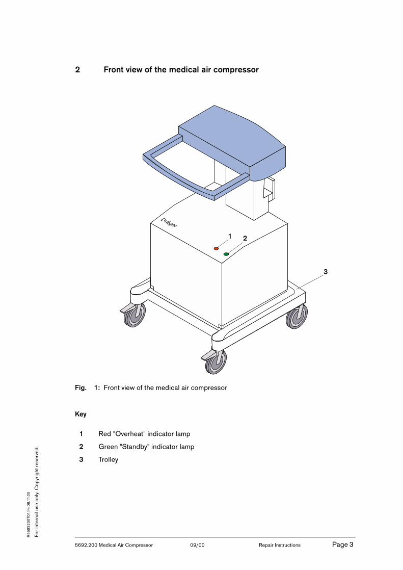
2 Front view of the medical air compressor
Fig. 1: Front view of the medical air compressor
Key
1 Red "Overheat" indicator lamp
2 Green "Standby" indicator lamp
3 Trolley
1 2
3

5692.200 Medical Air Compressor 09/00 Repair Instructions Page 4
For
inte
rnal
use
onl
y. C
opyr
ight
res
erve
d.
R5
69
22
00
T01.
fm 0
8.1
1.0
0
3 Rear view of the medical air compressor
Fig. 2: Rear view of the medical air compressor
Key
1 Connection for a ventilator
2 Standby (optional connection for central supply system)
3 Typeplate
4 Operating hours counter
5 Power fuses
6 Mains power connection
7 ON/OFF switch
8 Suction channel with filter
1
3
4
5
6
2
7
8

5692.200 Medical Air Compressor 09/00 Repair Instructions Page 5
For
inte
rnal
use
onl
y. C
opyr
ight
res
erve
d.
R5
69
22
00
T01.
fm 0
8.1
1.0
0
4 Location of medical air compressor assemblies (1)
Fig. 3: Location of medical air compressor assemblies (1)
Key
1 Protective cover 4 Fixing screws
2 Heat exchanger 5 Diaphragm drier
3 Pressure vessel 6 Pressure switch (switchover optional)
D
1
3
5
2
4
44
4
6

5692.200 Medical Air Compressor 09/00 Repair Instructions Page 6
For
inte
rnal
use
onl
y. C
opyr
ight
res
erve
d.
R5
69
22
00
T01.
fm 0
8.1
1.0
0
5 Location of medical air compressor assemblies (2)
Fig. 4: Location of medical air compressor assemblies (2)
Key
1 Compressor 5 Buzzer
2 Suction filter 6 Solenoid
3 Filter assembly (prefilter and main filter)
7 Cooling coil
4 Starting capacitor 8 Fan
1
2
3
4
6
7
8
5

5692.200 Medical Air Compressor 09/00 Repair Instructions Page 7
For
inte
rnal
use
onl
y. C
opyr
ight
res
erve
d.
R5
69
22
00
T01.
fm 0
8.1
1.0
0
6 Opening the medical air compressor
Hazardous voltage. Touching live components can lead to serious injury or death.Pull the power plug out of the AC outlet before opening the device.
• Remove the fixing screws from the cover (see "Location of medical air compressor assemblies (1)" on page 5)
• Carefully pull the protective cover back until the cable of the indicator lamp can be accessed.
• Unscrew the Phillips screw 1 from the connector.
• Remove the connector 2.
Remove the protective cover completely.
Fig. 5: Indicator lamp connector
1
2

5692.200 Medical Air Compressor 09/00 Repair Instructions Page 8
For
inte
rnal
use
onl
y. C
opyr
ight
res
erve
d.
R5
69
22
00
T01.
fm 0
8.1
1.0
0
7 Replace the filter sleeves of the prefilter and main filter.
The following replacement description of the prefilter and main filter refers to the maintenance kit 84 11 546 (see also "Change information" and Test Certificate).
For a replacement description of the new prefilter and mainfilter (maintenance kit 84 14 501), see the Instructions for Use under "Maintenance intervals/Removing the filter group".
7.1 Removing the filter assembly
• Unscrew the protective cover (see "Location of medical air compressor assemblies (1)" on page 5) and (see "Opening the medical air compressor" on page 7)
• Unscrew both Phillips screws 1.
Fig. 6: Removing the filter assembly
• Push ring 2 back and hold.
• Remove hoses 3.
• Remove the filter assembly.
Fig. 7: Removing the filter assembly
1 1
2
2
2
3
3
3
5692.200 Medical Air Compressor 09/00 Repair Instructions Page 9
For
inte
rnal
use
onl
y. C
opyr
ight
res
erve
d.
R5
69
22
00
T01.
fm 0
8.1
1.0
0
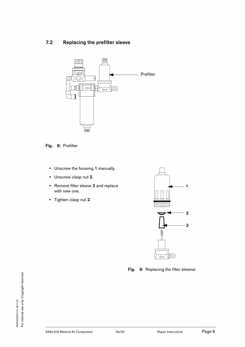
7.2 Replacing the prefilter sleeve
Fig. 8: Prefilter
• Unscrew the housing 1 manually.
• Unscrew clasp nut 2.
• Remove filter sleeve 3 and replace with new one.
• Tighten clasp nut 2.
Fig. 9: Replacing the filter sleeeve
Prefilter
1
2
3
5692.200 Medical Air Compressor 09/00 Repair Instructions Page 10
For
inte
rnal
use
onl
y. C
opyr
ight
res
erve
d.
R5
69
22
00
T01.
fm 0
8.1
1.0
0
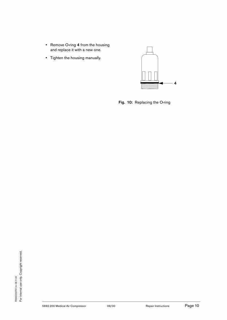
• Remove O-ring 4 from the housing and replace it with a new one.
• Tighten the housing manually.
Fig. 10: Replacing the O-ring
4

5692.200 Medical Air Compressor 09/00 Repair Instructions Page 11
For
inte
rnal
use
onl
y. C
opyr
ight
res
erve
d.
R5
69
22
00
T01.
fm 0
8.1
1.0
0
7.3 Replacing the main filter sleeve
Fig. 11: Main filter
• Pull interlock 1 downwards and hold.
• Rotate housing 2 until the markings (II) are aligned.
• Remove housing 2.
Fig. 12: Removing main filter housing
Main filter
1
2

5692.200 Medical Air Compressor 09/00 Repair Instructions Page 12
For
inte
rnal
use
onl
y. C
opyr
ight
res
erve
d.
R5
69
22
00
T01.
fm 0
8.1
1.0
0
• Unscrew clasp nut 4.
• Remove filter sleeve 3 and replace with new one.
• Tighten clasp nut 4.
Fig. 13: Replacing the filter sleeeve
• Remove O-ring 5 from housing and replace it with new one.
Fig. 14: O-ring of the main filter
• Insert housing 2 and rotate until markings (II) are aligned and the interlock 1 engages audibly.
• Pull housing 2 slightly downwards to check whether it is securely engaged.
Fig. 15: Engaging the main filter housing
4
3
5
1
2

5692.200 Medical Air Compressor 09/00 Repair Instructions Page 13
For
inte
rnal
use
onl
y. C
opyr
ight
res
erve
d.
R5
69
22
00
T01.
fm 0
8.1
1.0
0
7.4 Replacing the suction filter
• Unscrew both Allen screws 1.
• Unscrew pressure hose 2 using open-end wrench WAF 19.
• Pull compressor out until filter housing 3 can be accessed.
• Rotate filter housing 3 clockwise and remove.
• Remove suction filter 4 and replace with new one.
Fig. 16: Replacing the suction filter
• Re-install the suction filter.
• Re-install the compressor.
7.5 Installing the filter assembly
Reassemble the filter assembly using the reverse method as used for disassembly.
1
2
3
3
4

5692.200 Medical Air Compressor 09/00 Repair Instructions Page 14
For
inte
rnal
use
onl
y. C
opyr
ight
res
erve
d.
R5
69
22
00
T01.
fm 0
8.1
1.0
0
8 Standby switch of the medical air compressor (84 13 419)
8.1 Resetting the operating pressure range
• Set up a ventilator including test circuit.
• Connect to gas supply.
• Connect external pressure regulator/gauge to standby inlet.(Gas inlet connector is located at rear panel in the upper right area)
• Connect the AIR central supply hose to the pressure regulator hose.
• Connect the AIR supply of the compressor/ventilator.
• Remove the four screws from the rear panel of the compressor.
• Slide protective cover of compressor open (about 25 cm).
• Remove dark plastic cover from standby switch (located directly behind the transformer on the right side and is secured with 2 screws).
• Connect ventilator and compressor to mains power supply.
• Switch compressor on.
• Switch ventilator to standby mode and activate Service Mode to monitor internal pressures.
Do not connect to the O2 central supply. Do not connect to mains power supply yet.

5692.200 Medical Air Compressor 09/00 Repair Instructions Page 15
For
inte
rnal
use
onl
y. C
opyr
ight
res
erve
d.
R5
69
22
00
T01.
fm 0
8.1
1.0
0
• Measure current switching points and set delta P to < 15 psi / <1 bar (adjusting screws is located in the lower portion of the switch).
• Measure switching point and set starting pressure to 35 psi / 2.4 bar using external pressure regulator (adjusting screw is located in the center portion of the switch).
• Measure switching point and set switch-off pressure to 50 psi / 3.4 bar using external pressure regulator (adjusting screw is located in the center portion of the switch).
• Check settings of starting pressure (35 psi / 2,4 bar) and switch-off pressure (50 psi / 3,4 bar) under flow conditions as specified in the Test Certificate (ventilator settings: CMV, flow max. (AutoFlow off) , Vt max., rate 15, FiO2: 21).
• Reassemble standby switch and compressor.
• Remove external pressure regulator/gauge.
Compressor should start before the "AIR supply insufficient" alarm is triggered.
Increase/decrease operating pressure.
Delta P adjustment

5692.200 Medical Air Compressor 09/00 Repair Instructions Page 16
For
inte
rnal
use
onl
y. C
opyr
ight
res
erve
d.
R5
69
22
00
T01.
fm 0
8.1
1.0
0
9 Change information
9.1 Prefilter housing
As of serial number ARML0020, the prefilter housing will be made of metal.
9.2 Thermostat (part of starter relay 84 12 856)
To avoid frequent alarms, the thermostat has been set from 40 °C to 75 °C. This change has been implemented in devices from serial number ARMM0054 (84 13 900) or ARMN0101 (84 13 419), respectively.
9.3 Glow lamps
Due to a change in the circuit of 110 V compressors, defective glow lamps will be replaced only with 230 V glow lamps (Red glow lamp: 84 13 869, green glow lamp: 84 13 870).
9.4 Starter relay
The starter relay has been provided with a new timer. This change has implemented in series units starting with the following serial numbers: ARNJ 0088 (84 13 900), ARNJ 0017 (84 13 419), and ARNK 0031 (84 13 893).
9.5 Filter unit, new (84 14 502 / see also Service Bulletin no. 1)
To protect the diaphragm drier more efficiently, the filter unit has been equipped with a finer fine filter. A new maintenance kit is also available for the new filter unit. This change has implemented in series units starting with serial numbers ARMJ0020.
Further information: According to Service Bulletin no. 1, this filter unit has to be replaced when a defective diaphragm drier is replaced (a notice to do so has been attached on the outside of the unit) because the new maintenance kit, P/N 84 13 501, has to be installed in this case.
This change information is for information only, built-in components are only replaced with new versions in case of repair.
5692.200 Medical Air Compressor 09/00 Repair Instructions Page 17
For
inte
rnal
use
onl
y. C
opyr
ight
res
erve
d.
R5
69
22
00
T01.
fm 0
8.1
1.0
0
9.6 Standby, changed setting of operating pressure range
The pressure range has been changed (as described in the Repair Instructions, section 8) due to the pressure supply of 3 bar available in different countries. The pressure range has been changed in compressors from serial number ARPB 0001. At the same time, a modified non-return valve (no spare part) has been installed in the storage.
9.7 Registration of compressors
As of serial number ARPD 0001, compressors are subject to registration. The units are shipped with new Instructions for Use containing the changed pressure settings.

5692.200 Medical air compressor 03/98 Function Page 11
For
inte
rnal
use
onl
y. C
opyr
ight
res
erve
d.
GB
F56
92
20
0T0
1.fm
18
.06
.98
Dräger Medizintechnik D
Functional description
1 General information on medical air compressor
The medical air compressor drives ventilators which have a gas consumption rate of < 30 L/min.
If the medical air compressor and ventilator are installed in different rooms, make sure that the compressor is not in a warmer environment than the ven-tilator, as otherwise condensation on the ventilator is inevitable!
The start-up current of the medical air compressor is extremely high. Make sure that the power supply is adequately dimensioned if several compres-sors are connected.
Make sure the intake and exhaust never become contaminated or blocked, as otherwise the temperature in the compressor housing will increase and the medical air will no longer be adequately cooled.

5692.200 Medical air compressor 03/98 Function Page 12
For
inte
rnal
use
onl
y. C
opyr
ight
res
erve
d.
GB
F56
92
20
0T0
1.fm
18
.06
.98
Dräger Medizintechnik D
2 Functional description of medical air compressor
In the switch-on phase, the medical air compressor draws in ambient air through the intake filter 1. This air is compressed in the compressor 2 and cooled in the cooling coil 3.
To avoid start-up under increased pressure, the solenoid valve 4 is briefly opened to the atmosphere on start-up. On completion of this period, the solenoid valve 4 closes and the compressor builds up pressure.
The compressed air is cleaned by the prefilter 5. Condensate is collected and removed in the condensate trap 6. The air is re-heated by the heat exchanger 8 in order to convert any residual moisture in the vapour.
The air is dehumidified in the diaphragm dryer 9. The dehumidified air then passes through the restrictor nozzle 10 and non-return valve 11 into the pressure vessel 12. The air can be drawn off at the medical-air outlet 13.
In standby mode, the ventilator draws air from the central medical-air supply via the medical-air inlet 18, the non-return valve 15 and the self-closing medical-air outlet 13. In this case, the compressor 2 remains on standby.
If the pressure in the central medical-air supply drops below 2.7 bar, the pressure switch 16 switches on the compressor 2.
When the pressure in the central medical-air supply reaches 4 bar again, the pressure switch 16 switches off the compressor 2.
The pressure limiter 7 restricts the pressure in the system to max. 4 bar. The relief valve 14 protects the unit against excessively high pressure from the central medical-air supply.

5692.200 Medical air compressor 03/98 Function Page 13
For
inte
rnal
use
onl
y. C
opyr
ight
res
erve
d.
GB
F56
92
20
0T0
1.fm
18
.06
.98
Dräger Medizintechnik D
2.1 Block diagram of medical air compressor
Fig. 1: Block diagram of medical air compressor
Key
1 Intake filter 10 Restrictor nozzle
2 Kompressor 11 Non-return valve
3 Cooling coil 12 Pressure vessel
4 Solenoid valve 13 Medical-air outlet
5 Prefilter 14 Relief valve
6 Condensate trap 15 Non-return valve
7 Pressure limiter 16 Pressure switch
8 Heat exchanger 17 Fan
9 Diaphragm dryer 18 Input for standby mode
12
2
3 45
6
7
13
9
810 11
1
14
16
17
18
CCondensate
Exhaust air4 bar
P = 2.7 bar
15

5692.200 Medical air compressor 03/98 Function Page 14
For
inte
rnal
use
onl
y. C
opyr
ight
res
erve
d.
GB
F56
92
20
0T0
1.fm
18
.06
.98
Dräger Medizintechnik D
2.1.1 Diaphragm dryer
The entire drying procedure is a continuous operation. Moist compressed air flows through a bundle of highly selective hollow-fibre diaphragms 1 in the module. The inner side of these hollow-fibre diaphragms is provided with an ultra-thin layer through which only water vapour can penetrate.
On leaving the module, part of the compressed-air flow is diverted as flushing air 2 and its pressure reduced to atmospheric level. As a result, the flushing air is considerably drier than the compressed air entering the module. In the counterflow 3, this flushing air is routed along the outside of the hollow-fibre diaphragms, thus producing a water-vapour concentration gradient between the inner and outer side of the diaphragm. This difference in water vapour concentration between the compressed air and flushing air causes the water molecules to constantly migrate into the flushing air. Enriched with moisture, the flushing air exits from the module through a silencer.
Water vapour is extracted from the compressed air. This water vapour is dried before exiting from the module.
Fig. 2: Diaphragm dryer
OutletInlet
Moist flushing air
OutletDry compressed air
1
3
2
InletMoist compressed
air

5692.200 Medical air compressor 03/98 Function Page 15
For
inte
rnal
use
onl
y. C
opyr
ight
res
erve
d.
GB
F56
92
20
0T0
1.fm
18
.06
.98
Dräger Medizintechnik D
2.2 Compressor
The compressor is of the two-cylinder dry-running type and supplies a continuous flow of approx. V = 30 L/min at a pressure of P = 3 bar. An integrated temperature limitation circuit (NTC thermistor) in the motor winding prevents heat generation during operation.

5692.200 Medical air compressor 03/98 Function Page 16
For
inte
rnal
use
onl
y. C
opyr
ight
res
erve
d.
GB
F56
92
20
0T0
1.fm
18
.06
.98
Dräger Medizintechnik D
2.3 Power supply system
Fig. 3: Circuit diagram
Solenoid valve
Compressor
Fan
Temperature switch
Buzzer
Temperature switch LED
Operating hours
Power supply LED
Mains switch
Mains fuses
Terminal strip
Power supply
L N PE PE 1 2 3
F1 F2