continuous-flow mixer calypso d30 - bmi products · continuous-flow mixer calypso d30 220 v 60hz...
TRANSCRIPT
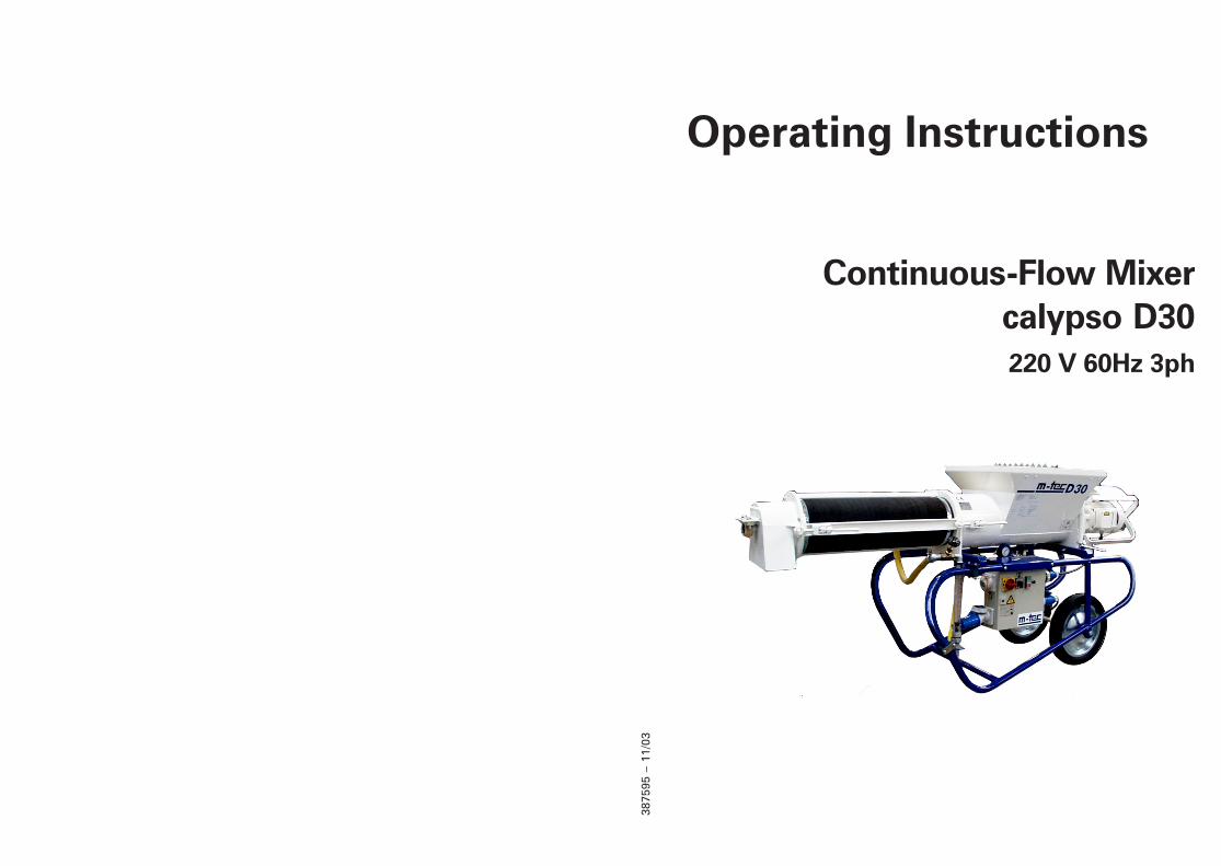
Continuous-Flow Mixercalypso D30220 V 60Hz 3ph
3875
95 –
11/
03
Operating Instructions
3875
95 –
11/
03
3875
95 –
11/
03
2 calypso D30
© 2003 m-tec mathis technik gmbh
Copyright in these operating instructions remains with m-tec mathis technik gmbh. These operating instructions areintended for the use of installation, operating and maintenance personnel. They contain technical regulations anddrawings which may not be copied, distributed, used for advertising purposes, or communicated to third partieseither in whole or in part without authorisation.
Technical development:The manufacturer reserves the right to adapt technical data without notification in order to reflect the current state oftechnical development. For information regarding the current status, alterations or additions to these operatinginstructions, please contact m-tec.
43
3875
95 –
11/
03
3875
95 –
11/
03
3
Type ________________________________________
Machine no. _________________________________
Year of manufacture__________________________
Power supply________________________________
Rated current (total) _________________________
Date of commissioning _______________________
Application _________________________________
Dear Customer,
this machine represents the most up to date technology and complies fully withgeneral standards and EEC guidelines. This is indicated by the CE symbol andthe enclosed declaration of conformity in the pocket on the machine.
Before starting the machine for the first time, please remove thedeclaration of conformity from the pocket and keep it in a safeplace.
Before commissioning the machine, please complete the form below. This is theeasiest way to familiarize yourself with the most important machine data, and tohave them ready at all times without having to refer to the rating plate on themachine. If you wish to contact us at any time, please have the information onthis page ready. The data you require can be found on the machine plate.
42 calypso D30
3875
95 –
11/
03
3875
95 –
11/
03
4 calypso D30
Table of contents
1 Safety ........................................................................................................................................... 61.1 Warning Symbols and Hazard Categories ....................................................................... 61.2 General Safety Instructions .............................................................................................. 81.3 Intended Use ..................................................................................................................... 101.4 Target Group ..................................................................................................................... 101.5 Qualified Personnel .......................................................................................................... 111.6 Instructions Book ............................................................................................................. 111.7 Safety at Work .................................................................................................................. 121.8 Personal Safety Equipment ............................................................................................. 14
2 Machine Description ................................................................................................................ 152.1 Function ............................................................................................................................. 152.2 Machine illustration ......................................................................................................... 162.3 Operating elements ......................................................................................................... 182.4 Water supply ..................................................................................................................... 192.5 Technical data ................................................................................................................... 202.6 Symbols on the machine ................................................................................................. 212.7 Components supplied ...................................................................................................... 21
3 Transport and Set-up .............................................................................................................. 223.1 Transport ........................................................................................................................... 223.2 Machine set-up ................................................................................................................. 23
4 Start-up ...................................................................................................................................... 244.1 Electrical connections ..................................................................................................... 244.2 Water connection ............................................................................................................. 254.3 Rotary direction ................................................................................................................ 264.4 Adjusting water flow ....................................................................................................... 27
5 Operation .................................................................................................................................. 285.1 Using bagged material .................................................................................................... 285.2 Using material from a hopper ........................................................................................ 295.3 Work interruptions ........................................................................................................... 305.4 Operation in winter .......................................................................................................... 305.5 Work termination ............................................................................................................. 31
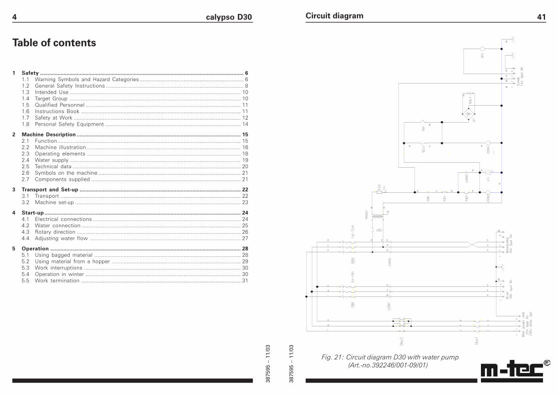
41Circuit diagram
Fig. 21: Circuit diagram D30 with water pump (Art.-no.392246/001-09/01)
3875
95 –
11/
03
3875
95 –
11/
03
5Table of contents
6 Cleaning .................................................................................................................................... 326.1 Cleaning after work termination ..................................................................................... 326.2 Cleaning prior to material change .................................................................................. 34
7 Maintenance ............................................................................................................................. 357.1 Lubrication schedule ....................................................................................................... 357.2 Oil change ......................................................................................................................... 367.3 Maintenance of water filters .......................................................................................... 37
8 Troubleshooting ...................................................................................................................... 38
9 Accessories/spare parts ........................................................................................................... 399.1 Accessories ...................................................................................................................... 399.2 Spare parts ....................................................................................................................... 39
10 Circuit diagram ......................................................................................................................... 40
40 calypso D30
10 Circuit diagram
Keys for fig. 21Keys for fig. 21Keys for fig. 21Keys for fig. 21Keys for fig. 21
Disc1 Main switch
Disc2 Reversing switch
CB1 Motor protecting switch mixer
CB2 Motor protecting switch waterpump
CON1 Main contro! re ois mixer
CON2 Main control relais woterpump
PB1 Push button off
PB2 Push button on
LT1 Lamp work
TGS1 Switch sensor on/off
TR1 Time relais sensor
SOL1 Solenoid volve
TRAN1 Transformator
FU1 Fusible
3875
95 –
11/
03
3875
95 –
11/
03
6 calypso D30
1 Safety
1.1 Warning Symbols and Hazard Categories
According to the standards defined in ANSI Z535.1-5,the following hazard categories are used in theseOperating Instructions, to draw attention to dangerspossibly occurring when operating the Continuous-Flow Mixer D30.
The hazard messages are divided into five categories,depending on the seriousness of the specified hazard.
The signal words (e.g. “Danger”) communicate the levelof hazard seriousness.
DANGERindicates an imminently hazardous situation which,if not avoided, will result in death or serious injury.
WARNINGindicates a potentially hazardous situation which, ifnot avoided, could result in death or serious injury.
CAUTIONindicates a potentially hazardous situation which, ifnot avoided, may result in minor or moderateinjuries.
CAUTIONis used without safety alert symbol to indicate apotentially hazardous situation which, if notavoided, may result in equipment damage.
NOTICEis used without safety alert symbol to indicate apotential situation which, if not avoided, mayresult in an undesirable event or state.
!
!
!
39
9 Accessories/spare parts
DANGERModifications of the machine are prohibited. Useonly spare parts and accessories supplied by m-tecmathis technik gmbh. m-tec mathis technik gmbhcan not be held liable for accidents and/or dam-ages resulting from the use of non-approved spareparts and accessories.
9.1 AccessoriesApplication range and handling of the Continuous-FlowMixer D30 can be considerably improved by usingaccessories supplied by m-tec mathis technik gmbh.The following accessories are available for thismachine:
• Connection cable 5 x 1,5 mm2,50 m, 400 V (16A 5pol 6h)
• Water pump 400 V incl. attachment• Filter hood incl. accessories• Conveyor screw D30 pitch 30• Conveyor screw D30 pitch 50• Conveyor screw D30 pitch 70• Additional water pump AD33, 230 V 1ph• Suction hose 3/4", 4 m complete• Water hose 3/4", 20 m with GEKA
flow meter, complete• Tarpaulin for material trough
9.2 Spare parts
For spare parts please refer to our spare-parts catalog.Send orders to:
m-tec mathis technik gmbh, Sales Dept.:Tel. no.: ++49 / 7631 / 709-112 or -216Fax no.: ++49 / 7631 / 709-116
Accessories/spare parts
!
3875
95 –
11/
03
3875
95 –
11/
03
7
The signal word is accompanied by a pictogramwhich can be of different shape to emphasize the kindof hazard. It is followed by a description of the hazard,the probable consequence of involvement with thehazard, and how the hazard can be avoided.
Special type sof pictograms and indicated kind ofhazard used in this operation instructions:
This symbol indicates that hazard is generated byelectric current.
This symbol indicates that hazard isgenerated byrotating machine components.
This symbol indicates that only RCD (ResidualCurrent protective Device)circuit breakers with thesymbol shown opposite should be used.
This symbol indicates that safety goggles must beworn. The frame of the goggles must comply withthe standard of the Occupational Safety & HealthAssosiation (OSHA).
Further symbols and signal words used in theseOperating Instructions:
ENVIRONMENTAL HAZARDThis symbol indicates that laws, rules, and regula-tions for environmental protection must be ob-served.
NOTEThis symbol draws your attention to important oradditional information relevant to the machine ordocumentation thereof.
Safety38 calypso D30
8 Troubleshooting
DANGERThe table „Troubleshooting“ is not intended toreplace the detailed instructions in the individualchapters of these Operating Instructions. Alwayscomply with the safety notes noted in each chapter!
Problem Cause RemedyMixer motor No power Check powerfails to run connection and fuses
Mortar hardened in Clean mixing pipemixing pipe (see section 6.1)Motor overload switch Open control panel, resettriggered overload switch (fig. 20)
No water Overload switch could Check motor overload switchbe triggered „mixer motor“ (fig. 20, 1)Solenoid valve Coil could be defective,
fails to open replace solenoid valveMortar too dry Insufficient water Check water supply. The
pressure must be at least2 bar. If necessary, installa water pump (available asaccessory for the D30,see section 9)
Overload switch of Check motor overload switchwater pump (option) „water pump“ (fig. 20, 2)was triggeredWater flow valve Increase opening of valveinsufficiently opened (see section 4.4)
Mortar too thin Too much Close water flow valvewater as required
(see section 4.4)
Consistency of Filter in pressure reducer, Clean filters (see section 7.3)material fluctuates inlet filter, or filter hood
fabric clogged Beat dust particles out of filterhood fabric (optional)
!
3875
95 –
11/
03
3875
95 –
11/
03
8 calypso D30
1.2 General Safety Instructions
DANGERFollow these safety instructions carefully. Failureto do so may increase the risk of accident or injury.These safety instructions apply to all directionsthroughout this manual, and must be applied to allaspects of the machine’s use, including, but notlimited to, transport, assembly, operation, mainte-nance or disassembly.
The Continuous-Flow Mixer D30 is designedaccording to the state-of-the-art, it is reliable inoperation and it has left the factory in perfectcondition. Nevertheless, it can pose a danger if ithas been installed improperly or contrary todirections (see Chapter 3 and 4), or if it is operatedby untrained/unauthorized personnel.
In order to protect the machine against damage,and to enable personnel to operate it properly andsafely, every operator must observe the followinginstructions prior to machine start-up:
••••• Read and understand the Operation and ServiceRead and understand the Operation and ServiceRead and understand the Operation and ServiceRead and understand the Operation and ServiceRead and understand the Operation and ServiceManual and familiarize yourselves with properManual and familiarize yourselves with properManual and familiarize yourselves with properManual and familiarize yourselves with properManual and familiarize yourselves with propermachine operation. Chapter “Safetymachine operation. Chapter “Safetymachine operation. Chapter “Safetymachine operation. Chapter “Safetymachine operation. Chapter “Safety” is of major” is of major” is of major” is of major” is of majorimportance.importance.importance.importance.importance.
••••• Observe applicable accident prevention regula-Observe applicable accident prevention regula-Observe applicable accident prevention regula-Observe applicable accident prevention regula-Observe applicable accident prevention regula-tions as well as other generally recognized rulestions as well as other generally recognized rulestions as well as other generally recognized rulestions as well as other generally recognized rulestions as well as other generally recognized rulesand regulations pertaining to industrial safetyand regulations pertaining to industrial safetyand regulations pertaining to industrial safetyand regulations pertaining to industrial safetyand regulations pertaining to industrial safetyand medical care.and medical care.and medical care.and medical care.and medical care.
••••• Prior to start-up of the machine be sure that anyPrior to start-up of the machine be sure that anyPrior to start-up of the machine be sure that anyPrior to start-up of the machine be sure that anyPrior to start-up of the machine be sure that anydifficulties are resolved (see the manufacturerdifficulties are resolved (see the manufacturerdifficulties are resolved (see the manufacturerdifficulties are resolved (see the manufacturerdifficulties are resolved (see the manufacturer’s’s’s’s’saddress on the back of the cover).address on the back of the cover).address on the back of the cover).address on the back of the cover).address on the back of the cover).
!
37
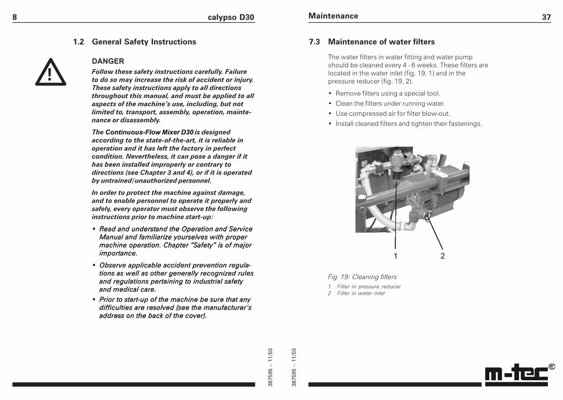
7.3 Maintenance of water filters
The water filters in water fitting and water pumpshould be cleaned every 4 - 6 weeks. These filters arelocated in the water inlet (fig. 19, 1) and in thepressure reducer (fig. 19, 2).
• Remove filters using a special tool.
• Clean the filters under running water.
• Use compressed air for filter blow-out.
• Install cleaned filters and tighten their fastenings.
Fig. 19: Cleaning filters1 Filter in pressure reducer2 Filter in water inlet
Maintenance
3875
95 –
11/
03
3875
95 –
11/
03
9
Modifications of the machine are not permitted. Allreplacement parts, accessories and lubricants mustbe furnished by m-tec mathis technik gmbh. Theuse of unauthorized parts, accessories or lubricantsmay result in death or serious injury, and couldcause damage of the machine, and will nullify allliability on the part of the manufacturer for result-ing damage.
This machine must be operated in compliance withall applicable federal, state and local laws, rules,and regulations at all times. This includes, but isnot limited to, the requirements of TITLE 29 of theCODE OF FEDERAL REGULATIONS, PART 1926 (29CFR 1926). Failure to operate this machinery incompliance with all applicable laws, rules, andregulations may result in death or serious injury.
When transporting, assembling, dismantling,operating, cleaning, and servicing the machine, allapplicable national and international safety laws,rules, and regulations must always be observed,even if such regulations are not explicitly men-tioned in these instructions.
The machine must be inspected by a specializedengineer in accordance with applicable safety laws,rules, and regulations. Such inspection should bescheduled at least once per year.
The proper use of this machinery requires theoperator to be in full control of the machinery at alltimes. None of this equipment must be used by anoperator under the influence of alcohol or drugs,including prescription drugs that may impair anoperator’s ability to safely operate this equipment.Failure to adhere to this requirement may result indeath or serious injury.
Safety36 calypso D30
7.2 Oil change
CAUTIONDo not replenish gear oil between oil changes.Over-lubrication could cause overheating of themachine.
Never mix different types of oil. This could causethe oils to decompose, leading to irreparabledamage of the gear unit.
ENVIRONMENTAL HAZARDAlways comply with environmental regulationswhen disposing of waste oil, grease and cleaningagents,.
The gear motors are furnished pre-lubricated, they aremaintenance-free up to
8000 hours of operation. They should then be cleanedthoroughly with a suitable rinsing oil, and refilled withfresh oil.
Recommended type of oil for the gear motor: ShellShellShellShellShellTivela Oil 82; quantity 400 cc.Tivela Oil 82; quantity 400 cc.Tivela Oil 82; quantity 400 cc.Tivela Oil 82; quantity 400 cc.Tivela Oil 82; quantity 400 cc.
One of the following substitute oil types can be used ifthe type specified above is not available:
ARAL Degol BG 220BP Energol GR-x P220CALYPSOL Bisol Oil MSR 114ESSO Sparton EP-220HOUGHTON Molygear 115MOBIL Mobilgear 630SHELL Omala 220
3875
95 –
11/
03
3875
95 –
11/
03
10 calypso D30
1.3 Intended Use
The Continuous-Flow Mixer D30 is suitable for universalmixing of dry mortars already mixed by themanufacturer. The Continuous-Flow Mixer D30 can beused for materials of the following types:
• Masonry mortar• Various rendering plasters• Adhesive mortar• Floor cement• Fine concrete
DANGERUse of the machine for any other purpose thanthose described above may result in bodily or evenfatal injury, and/or in damage of the equipment orother property.
It may also impair efficient functioning of themachine.
Use of the machine for any other purpose than thatdescribed above is prohibited!
Modifications to the machine are prohibited. Useonly spare parts and accessories supplied by m-tecmathis technik gmbh. If spare parts and accesso-ries of other types are used, m-tec mathis technikgmbh can not be held liable for occurringdamages.
1.4 Target Group
This document is intended for personnel in charge ofstart–up, operation and maintenance of the machine.Such personnel must be qualified according to speci-fications stated in chapter 1.5.
!
35
7 Maintenance
DANGERAlways switch the machine OFF, and disconnect itfrom the electrical supply network before workingon the machine. Certain parts of the machineremain live when the machine is switched OFF.The safe working condition of the machine mustbe verified in accordance with legal requirements(or at least once per year) by a specialist engineer.Use only spare parts and accessories supplied bym-tec mathis technik gmbh. m-tec mathis technikgmbh can not be held liable for injuries ordamages resulting from the use of non-approvedspare parts and accessories.
• Regularly remove mortar residues from the mixingpipe, and dispose of them according toenvironmental regulations.
• Regularly inspect hoses and cable connections toensure that they are in working condition.
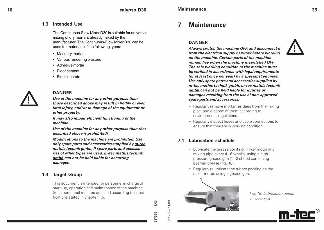
7.1 Lubrication schedule
• Lubricate the grease points on mixer motor andmixing pipe every 4 - 6 weeks, using a high-pressure grease gun (1 - 2 shots) containingbearing grease (fig. 18).
• Regularly relubricate the rubber packing on themixer motor, using a grease gun.
Maintenance
Fig. 18: Lubrication points1 Socket pin
!
3875
95 –
11/
03
3875
95 –
11/
03
11
1.5 Qualified Personnel
DANGERStart–up, operation and maintenance of the ma-chine carried out by unqualified personnel mayresult in bodily or even fatal injury, damage of theequipment or other property.
Start–up, operation and maintenance of the ma-chine may only be carried out by qualified person-nel.
It is the duty of the operator to have the operatingstaff thoroughly study and understand the operat-ing manual, especially chapter “Safety”, and thattheir qualification is adequate for safe operation ofthe machine.
Qualified persons are those who, through training and/or experience, have sufficient knowledge in the field ofmortar-feeding and mortar-spraying machines, andwho are sufficiently familiar with legislation regardingsafety, accident prevention, guidelines and generaltechnical procedures to allow them to assess the safecondition of such machines.
1.6 Instructions Book
NOTICEThe Operation and Service Manual must always bekept in the pocket on the machine provided for thispurpose, having it permanently accessible to allmachine operators. All personnel operating orservicing the machine must know where to findthis Manual.
!
Safety34 calypso D30
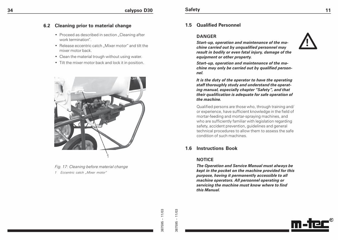
6.2 Cleaning prior to material change
• Proceed as described in section „Cleaning afterwork termination“.
• Release eccentric catch „Mixer motor“ and tilt themixer motor back.
• Clean the material trough without using water.
• Tilt the mixer motor back and lock it in position.
Fig. 17: Cleaning before material change1 Eccentric catch „Mixer motor“
3875
95 –
11/
03
3875
95 –
11/
03
12 calypso D30
All persons involved in operating the machine mustread the operating instructions, and ensure that anydifficulties are resolved prior to start-up (see manufac-turer’s address on the back of the cover).
They should also use the directions to familiarizethemselves with the operation and controls of thepump. This prevents damage and injury and ensuresefficient machine operation.
1.7 Safety at Work
DANGERSecure operating conditions can not be guaranteedif the safety regulations are disregarded.Failure to observe the following safety instructionsand notes can result in death or serious injury, and/or in damage of the machine or adjoining equip-ment.
Prior to every shift, carefully inspect the machine forobvious signs of damage, in particular electriccables, plugs, feed and air hoses. Any damage mustbe repaired before shift start.
Do not reach into the machine, or into the mixingpipe, as long as the power supply plug is connected(plugged-in); this could result in serious injuries.
WARNINGThe machine must be positioned:
• firmly on a level surface. It must be secured toprevent it from tilting or moving.
• in an area where no objects can fall onto it fromabove. If this is not possible, it must be protected bya safety guard.
• in such a way that all operating elements are easilyaccessible at all times.
!
!
33
• Tilt mixing pipe back (fig. 16)
Cleaning
Fig. 15: Mixing pipe1 Mixing shaft
Fig. 16: Mixing pipe tilted back1 Shaft coupling2 Dosage pipe3 Material trough
NOTICEKeep the shaft coupling (fig. 16, 1) clean, dry andfree of grease.
Do not allow water to flow into material trough ordosage pipe.
• Clean bearing cover, mixing pipe, and mixing shaftwith brush and water.
• Clean the dosage pipe (fig. 16, 2) while it is dry.
• Re-assemble the machine in reversed sequence.
3875
95 –
11/
03
3875
95 –
11/
03
13
DANGERBefore working on electrical components, alwayspull the power plug, as certain components remainlive when the machine is switched OFF.The Continuous-Flow Mixer must be connected toa regulation site distributor box with RCDautomatic circuit breaker. Use a 20A 4-pole 9hplug. The connecting cable must be of a crosssection of SJO 14/4 and a 16A fuse.
CAUTIONIn case of incorrect rotary direction immediatelyswitch the machine OFF at the red main switch,and pull the power supply plug.
The maximum operating pressure of the waterpump (optional) must not exceed 10 bar.
Work interruptions are to be kept to limited lengthin time. Keep the setting time of the material beingprocessed in mind when interrupting the work.Hardened mortar in the mixing pipe causesdifficulty in starting the motor and can causepermanent damage of the mixer. For extendedwork interruptions be sure the water fittings arecompletely drained.
The machine could be seriously damaged if thewater in the fittings freezes. At sub-zerotemperatures all water fittings of the machine mustbe emptied and dried. For extended workinterruptions be sure the water fittings arecompletely drained.
Do not replenish gear oil between oil changes.Overfilling the machine with lubricants can causeoverheating. Never mix different types of oil, as thiscan cause the oils to decompose and lead toirreparable damage of the gear unit.
Safety32 calypso D30
6 Cleaning
DANGERAlways switch the Continuous-Flow Mixer OFF, andpull the power supply plug before cleaning themachine!
ENVIRONMENTAL HAZARDDispose of mortar residues according toenvironmental regulations!
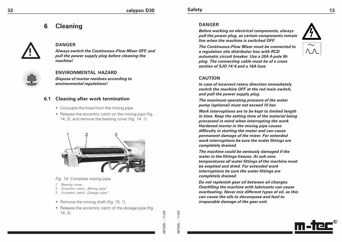
6.1 Cleaning after work termination
• Uncouple the hose from the mixing pipe.
• Release the eccentric catch on the mixing pipe (fig.14, 2), and remove the bearing cover (fig. 14, 1).
Fig. 14: Complete mixing pipe1 Bearing cover2 Eccentric catch „Mixing pipe“3 Eccentric catch „Dosage pipe“
• Remove the mixing shaft (fig. 15, 1).
• Release the eccentric catch of the dosage pipe (fig.14, 3).
!
3875
95 –
11/
03
3875
95 –
11/
03
14 calypso D30
!
ENVIRONMENTAL HAZARDAlways dispose residual mortar in accordance withthe regulations concerning building waste.Always observe environmental regulations whendisposing of used oil, grease, or cleaning agents.
1.8 Personal Safety Equipment
DANGERFailure to observe the following safety instructionscould result in serious injury.
Wear proper personal protective equipment, in-cluding, but not limited to, eye and hearingprotection at all times while operating themachinery. In order to prevent the risk of seriousinjury, keep hands, feet, hair and clothing awayfrom all moving parts of the equipment. Avoidwearing loose-fitting clothing or jewelry whennear the machine, and secure long hair in order tokeep it away from moving parts.
Always observe the following safety instructions:
• The proprietor/operator of the machine must providepersonal noise protection equipment for personnelusing the machine if the noise level at the place ofwork exceeds 85 dB (A).
• If the noise level at the place of work exceeds 90dB (A), the use of noise protection equipment bypersonnel is mandatory.
• Always wear safety goggles when removingblockages and during spraying work.
• The frame of the goggles must comply with thestandard of the Occupational Safety & HealthAssosiation (OSHA).
• During spraying work, always wear a safety helmetand safety shoes or boots.
31
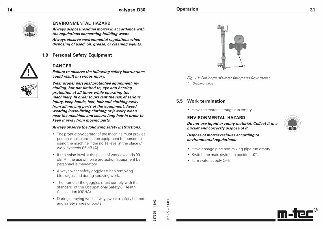
Fig. 13: Drainage of water fitting and flow meter1 Draining valve
5.5 Work termination
• Have the material trough run empty.
ENVIRONMENTAL HAZARDDo not use liquid or runny material. Collect it in abucket and correctly dispose of it.
Dispose of mortar residues according toenvironmental regulations.
• Have dosage pipe and mixing pipe run empty.
• Switch the main switch to position „0“.
• Turn water supply OFF.
Operation
3875
95 –
11/
03
3875
95 –
11/
03
15
2 Machine Description
2.1 Function
In its standard form, the Continuous-Flow Mixer D30 isdesigned for processing bagged mortar material.
The material is poured into the material trough. Thedosage screw carries the material from the trough intothe mixing pipe where it is mixed with water andconveyed to the discharge outlet.
The Continuous-Flow Mixer D30 can be provided witha water pump in order to protect the production ofmaterial against water pressure fluctuations. At lowwater main pressures, this auxiliary pump (which alsoincorporates a pressure reducer) retains a constantwater pressure of 2 bar.
The required quantity of water is adjusted manually atthe fine-control valve, water pressure can bemonitored by a flow meter (optional).
The Continuous-Flow Mixer D30 can also be used forhopper material, through installation of a filter hood(optional); (see „Spare parts and accessories“).
Machine description30 calypso D30
5.3 Work interruptions
CAUTIONThe length of work interruptions must be limited.Always keep the setting time of the mortar in mind.Hardened mortar in the mixing pipe causesdifficulty in starting the motor and may causepermanent damage of the mixer.
To prevent the mortar from setting, work interruptionsshould always be shorter than the setting time of thematerial. The Continuous-Flow Mixer D30 must bestopped and cleaned if the work interruption exceedsthe material’s setting time.
5.4 Operation in winter
CAUTIONThe machine could be seriously damaged if thewater in the fittings freezes. At sub-zerotemperatures all water fittings of the machine mustbe emptied and dried. For extended workinterruptions be sure the water fittings arecompletely drained.
• Turn water supply OFF.
• Drain the supply hose leading to water fitting orwater pump (optional), the connection hose betweenpump and fitting, and the water hose to and fromthe flow meter (optional).
• Open the draining valves of the water fitting (fig. 13,1), and of the flow meter (optional) (fig. 13, 2).
CAUTIONClose all draining valves before re-starting themachine.
3875
95 –
11/
03
3875
95 –
11/
03
16 calypso D30
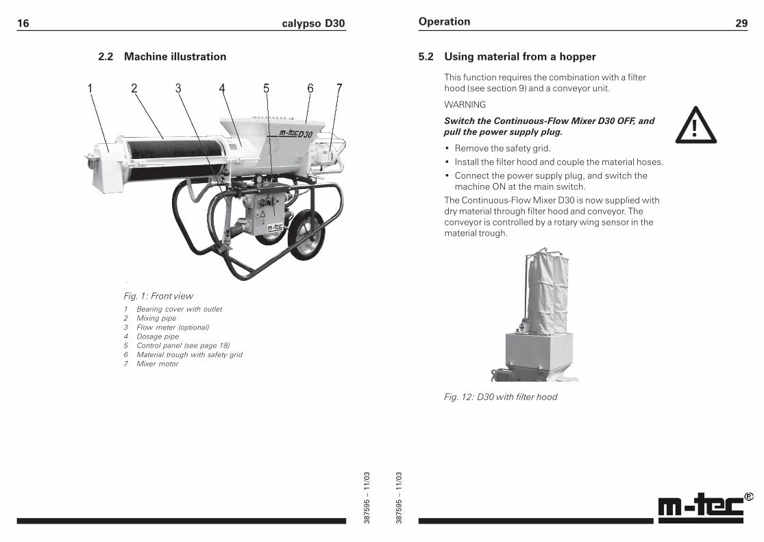
2.2 Machine illustration
Fig. 1: Front view1 Bearing cover with outlet2 Mixing pipe3 Flow meter (optional)4 Dosage pipe5 Control panel (see page 18)6 Material trough with safety grid7 Mixer motor
29
5.2 Using material from a hopper
This function requires the combination with a filterhood (see section 9) and a conveyor unit.
WARNING
Switch the Continuous-Flow Mixer D30 OFF, andpull the power supply plug.
• Remove the safety grid.
• Install the filter hood and couple the material hoses.
• Connect the power supply plug, and switch themachine ON at the main switch.
The Continuous-Flow Mixer D30 is now supplied withdry material through filter hood and conveyor. Theconveyor is controlled by a rotary wing sensor in thematerial trough.
Fig. 12: D30 with filter hood
Operation
!
3875
95 –
11/
03
3875
95 –
11/
03
17Machine description
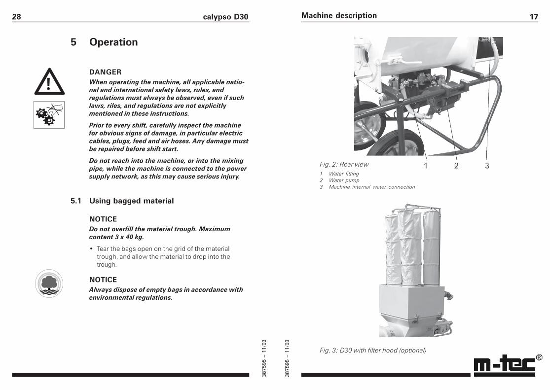
Fig. 3: D30 with filter hood (optional)
Fig. 2: Rear view1 Water fitting2 Water pump3 Machine internal water connection
28 calypso D30
5 Operation
DANGERWhen operating the machine, all applicable natio-nal and international safety laws, rules, andregulations must always be observed, even if suchlaws, riles, and regulations are not explicitlymentioned in these instructions.
Prior to every shift, carefully inspect the machinefor obvious signs of damage, in particular electriccables, plugs, feed and air hoses. Any damage mustbe repaired before shift start.
Do not reach into the machine, or into the mixingpipe, while the machine is connected to the powersupply network, as this may cause serious injury.
5.1 Using bagged material
NOTICEDo not overfill the material trough. Maximumcontent 3 x 40 kg.
• Tear the bags open on the grid of the materialtrough, and allow the material to drop into thetrough.
NOTICEAlways dispose of empty bags in accordance withenvironmental regulations.
!
3875
95 –
11/
03
3875
95 –
11/
03
18 calypso D30
2.3 Operating elements
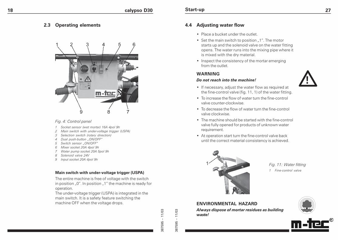
Fig. 4: Control panel1 Socket sensor (wet mortar) 16A 4pol 9h2 Main switch with under-voltage trigger (USPA)3 Selection switch (rotary direction)4 Dual push-button „ON/OFF“5 Switch sensor „ON/OFF“6 Mixer socket 20A 4pol 9h7 Water pump socket 20A 5pol 9h8 Solenoid valve 24V9 Input socket 20A 4pol 9h
Main switch with under-voltage trigger (USPA)The entire machine is free of voltage with the switchin position „0“. In position „1“ the machine is ready foroperation.The under-voltage trigger (USPA) is integrated in themain switch. It is a safety feature switching themachine OFF when the voltage drops.
27
4.4 Adjusting water flow
• Place a bucket under the outlet.
• Set the main switch to position „1“. The motorstarts up and the solenoid valve on the water fittingopens. The water runs into the mixing pipe where itis mixed with the dry material.
• Inspect the consistency of the mortar emergingfrom the outlet.
WARNINGDo not reach into the machine!
• If necessary, adjust the water flow as required atthe fine-control valve (fig. 11, 1) of the water fitting.
• To increase the flow of water turn the fine-controlvalve counter-clockwise.
• To decrease the flow of water turn the fine-controlvalve clockwise.
• The machine should be started with the fine-controlvalve fully opened for products of unknown waterrequirement.
• At operation start turn the fine-control valve backuntil the correct material consistency is achieved.
Start-up
Fig. 11: Water fitting1 Fine-control valve
ENVIRONMENTAL HAZARDAlways dispose of mortar residues as buildingwaste!
!
3875
95 –
11/
03
3875
95 –
11/
03
19Machine description
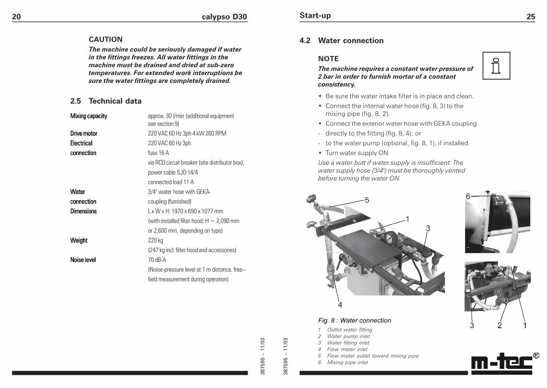
2.4 Water supply
CAUTIONThe machine requires a constant water pressure of2 bar.
The maximum operating pressure of the waterpump (optional) of 10 bar must not be exceeded!
In order to prevent operation problems caused bywater pressure fluctuations, the Continuous-Flow MixerD30 can be provided with a water pump (optional).The water pump retains the water pressure at aconstant level of 2 bar; an integrated pressure reduceris also used, if required.
The required quantity of water is adjusted manually atthe fine-control valve; it can be monitored using a flowmeter (optional).
6 Connection water fitting/ water pump7 Fine-control valve8 Connection water fitting/ mixing pipe9 External water connection to the water pump
Fig. 5: Water fitting1 Flow meter (optional)2 Drain valve3 Connection water fitting/ flow meter4 Pressure gauge5 Pressure reducer
26 calypso D30
4.3 Rotary direction
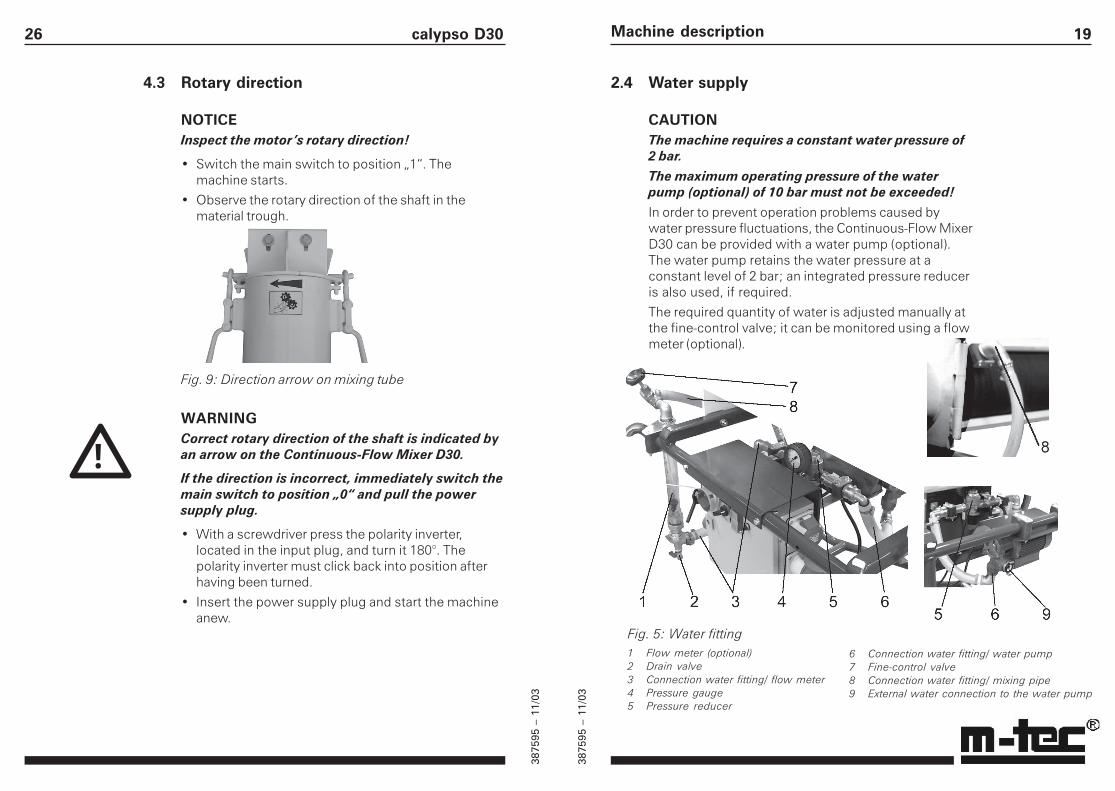
NOTICEInspect the motor’s rotary direction!
• Switch the main switch to position „1“. Themachine starts.
• Observe the rotary direction of the shaft in thematerial trough.
Fig. 9: Direction arrow on mixing tube
WARNINGCorrect rotary direction of the shaft is indicated byan arrow on the Continuous-Flow Mixer D30.
If the direction is incorrect, immediately switch themain switch to position „0“ and pull the powersupply plug.
• With a screwdriver press the polarity inverter,located in the input plug, and turn it 180°. Thepolarity inverter must click back into position afterhaving been turned.
• Insert the power supply plug and start the machineanew.
!
3875
95 –
11/
03
3875
95 –
11/
03
20 calypso D30
CAUTIONThe machine could be seriously damaged if waterin the fittings freezes. All water fittings in themachine must be drained and dried at sub-zerotemperatures. For extended work interruptions besure the water fittings are completely drained.
2.5 Technical data
Mixing capacityMixing capacityMixing capacityMixing capacityMixing capacity approx. 30 l/min (additional equipmentsee section 9)
Drive motorDrive motorDrive motorDrive motorDrive motor 220 VAC 60 Hz 3ph 4 kW 260 RPM
ElectricalElectricalElectricalElectricalElectrical 220 VAC 60 Hz 3ph
connectionconnectionconnectionconnectionconnection fuse 16 Avia RCD circuit breaker (site distributor box),
power cable SJO 14/4connected load 11 A
WaterWaterWaterWaterWater 3/4" water hose with GEKA-
connectionconnectionconnectionconnectionconnection coupling (furnished)
DimensionsDimensionsDimensionsDimensionsDimensions L x W x H: 1970 x 690 x 1077 mm(with installed filter hood: H = 2,090 mmor 2,600 mm, depending on type)
WeightWeightWeightWeightWeight 220 kg(247 kg incl. filter hood and accessories)
Noise levelNoise levelNoise levelNoise levelNoise level 70 dB-A(Noise-pressure level at 1 m distance, free--field measurement during operation)
25
4.2 Water connection
NOTEThe machine requires a constant water pressure of2 bar in order to furnish mortar of a constantconsistency.
• Be sure the water intake filter is in place and clean.
• Connect the internal water hose (fig. 8, 3) to themixing pipe (fig. 8, 2).
• Connect the exterior water hose with GEKA coupling
- directly to the fitting (fig. 8, 4); or
- to the water pump (optional, fig. 8, 1), if installed.
• Turn water supply ON
Use a water butt if water supply is insufficient. Thewater supply hose (3/4") must be thoroughly ventedbefore turning the water ON.
Start-up
Fig. 8 : Water connection1 Outlet water fitting2 Water pump inlet3 Water fitting inlet4 Flow meter inlet5 Flow meter outlet toward mixing pipe6 Mixing pipe inlet
3875
95 –
11/
03
3875
95 –
11/
03
21
2.6 Symbols on the machine
Operating instructions Phase inverter
Danger! Do not put hands Operation via RCD
into running machine! circuit breaker only
Drain water under
cold conditions!
2.7 Components supplied
The machine is furnished composed of the followingstandard items:
• Material trough incl. safety grid with bag opener
• Mixer motor
• Transport screw D30, pitch 40
• Mixer shaft
• 1 water hose 3/4" with GEKA coupling
Machine description24 calypso D30
4 Start-up
DANGERWhen transporting, assembling, dismantling, and/or operating the machine, all applicable nationaland international safety laws, rules, and regulationsmust always be observed, even if such laws, rules,and regulations are not explicitly mentioned inthese instructions.
Prior to every shift, carefully inspect the machinefor obvious signs of damage, in particular electriccables, plugs, feed and air hoses. Any damage mustbe repaired before shift start.
Do not reach into the machine, or into the mixingpipe, while the machine is connected to the powersupply network, as this may cause serious injury.
4.1 Electrical connections
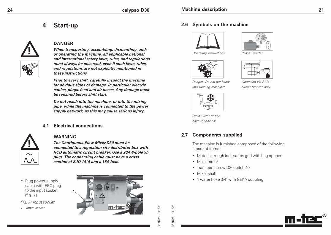
WARNINGThe Continuous-Flow Mixer D30 must beconnected to a regulation site distributor box withRCD automatic circuit breaker. Use a 20A 4-pole 9hplug. The connecting cable must have a crosssection of SJO 14/4 and a 16A fuse.
!
• Plug power supplycable with EEC plugto the input socket(fig. 7).
Fig. 7: Input socket1 Input socket
!
3875
95 –
11/
03
3875
95 –
11/
03
22 calypso D30
3 Transport and Set-up
DANGERWhen transporting, assembling, or dismantling themachine, all applicable national and internationalsafety laws, rules, and regulations must always beobserved, even if such laws. rules, and regulationsare not explicitly mentioned in these instructions.
3.1 Transport
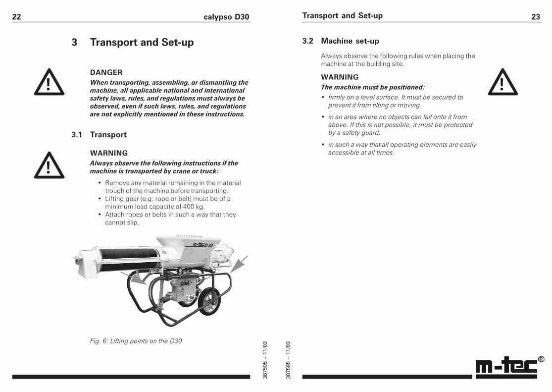
WARNINGAlways observe the following instructions if themachine is transported by crane or truck:
• Remove any material remaining in the materialtrough of the machine before transporting.
• Lifting gear (e.g. rope or belt) must be of aminimum load capacity of 400 kg.
• Attach ropes or belts in such a way that theycannot slip.
Fig. 6: Lifting points on the D30
!
!
23Transport and Set-up
3.2 Machine set-up
Always observe the following rules when placing themachine at the building site.
WARNINGThe machine must be positioned:
• firmly on a level surface. It must be secured toprevent it from tilting or moving.
• in an area where no objects can fall onto it fromabove. If this is not possible, it must be protectedby a safety guard.
• in such a way that all operating elements are easilyaccessible at all times.
!