continuous forms printers emc compliance - ieee · continuous forms printers emc compliance ... •...
TRANSCRIPT

Printing Systems
| Feb., 2004 | Rocky Mountain Chapter EMC Society Presentation © 2004 IBM Corporation
Continuous Forms Printers EMC Compliance
Larry ErnstIBMDistinguished EngineerFeb., 2004

Printing Systems
© 2004 IBM CorporationPage 2 of 43 | Rocky Mountain Chapter EMC Society Presentation | Larry Ernst | Feb. 2004 |
Agenda
§General Design Considerations§ESD, Internal EMI, External EMI, and
Electro-Mechanical Considerations§Flicker§Radiated Emissions§Organizational Considerations

Printing Systems
© 2004 IBM CorporationPage 3 of 43 | Rocky Mountain Chapter EMC Society Presentation | Larry Ernst | Feb. 2004 |
Duplex Continuous Forms Printer
2.65 m
1.55m

Printing Systems
© 2004 IBM CorporationPage 4 of 43 | Rocky Mountain Chapter EMC Society Presentation | Larry Ernst | Feb. 2004 |
Continuous Forms High Speed Printer
General Design Considerations

Printing Systems
© 2004 IBM CorporationPage 5 of 43 | Rocky Mountain Chapter EMC Society Presentation | Larry Ernst | Feb. 2004 |
General Design Considerations§ Electrophotographic printer is a complex device with numerous EMI compliance
failure points.• Real time controller utilizing a large commercial server
• Numerous electromechanical devices (paper handling)
• Electrophotographic device(s) (printing process)§ Large device
• Multiple radiating emission sources operating at different frequencies
• Cabling
• Resonant cavities
• Interface subsystems§ Non-functional noise sources
• Electrostatic discharge associated with paper handling
• Electrostatic discharge associated with voltage-biased metal members
• Electrostatic discharge and noise associated with coronas
• Noise associated with AC high voltage cabling§ Characteristics of radiated emission noise sources
• Narrowband noise (30 MHz and up)
• Impulse broadband noise (30 MHz and up)
Printing Systems
© 2004 IBM CorporationPage 6 of 43 | Rocky Mountain Chapter EMC Society Presentation | Larry Ernst | Feb. 2004 |
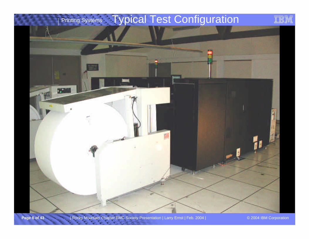
Typical Test Configuration

Printing Systems
© 2004 IBM CorporationPage 7 of 43 | Rocky Mountain Chapter EMC Society Presentation | Larry Ernst | Feb. 2004 |
Typical Test Configuration (continued)

Printing Systems
© 2004 IBM CorporationPage 8 of 43 | Rocky Mountain Chapter EMC Society Presentation | Larry Ernst | Feb. 2004 |
Typical Test Configuration (continued)
Printing Systems
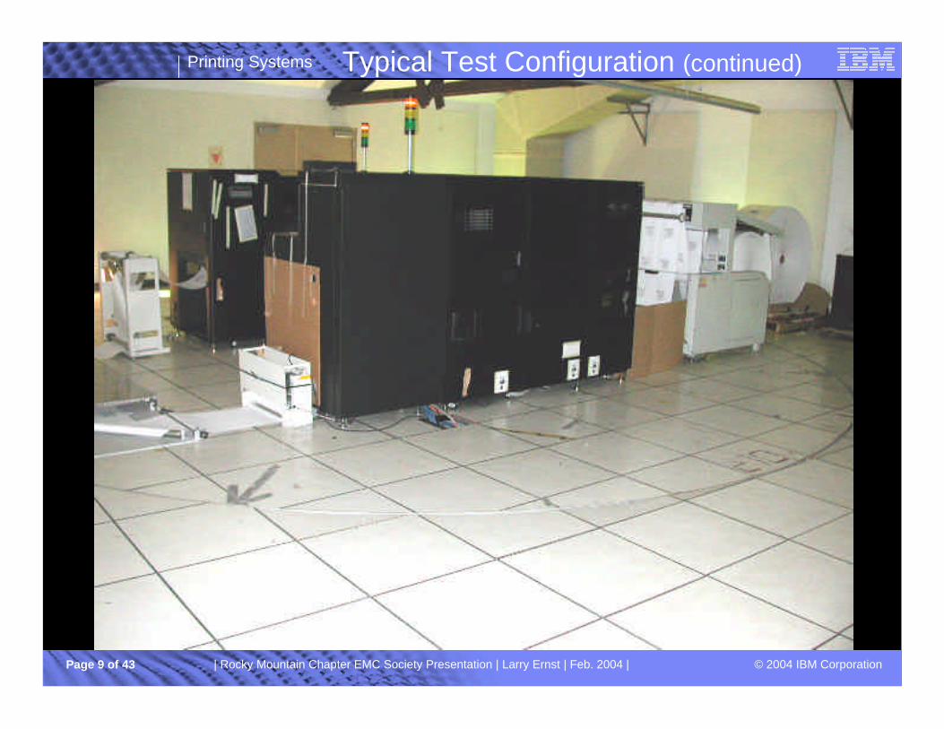
© 2004 IBM CorporationPage 9 of 43 | Rocky Mountain Chapter EMC Society Presentation | Larry Ernst | Feb. 2004 |
Typical Test Configuration (continued)
Printing Systems
© 2004 IBM CorporationPage 10 of 43 | Rocky Mountain Chapter EMC Society Presentation | Larry Ernst | Feb. 2004 |
ESD, Internal EMI, External EMI, and Electro-Mechanical
Considerations

Printing Systems
© 2004 IBM CorporationPage 11 of 43 | Rocky Mountain Chapter EMC Society Presentation | Larry Ernst | Feb. 2004 |
§ System Design• Printer internal EM interference is a significant consideration.
• Numerous electrostatic interference sources, e.g. corona arcs, paper handling discharge, etc.
• High dynamic current loads• Multiple layers of electromagnetic interference control is typically the best approach
• Electromagnetic interference control design inherently minimizes both ESD and radiated emissions
• References: ü Henry Ott; Noise Reduction Techniques In Electronic Systems; John Wiley; 1988ü Graf, W.; Vance, E.F.; “A Topological Approach to the Unification of Electromagnetic
Specification and Standards”; Proc. IEEE National Aerospace and Electronics Conference, Naecon; pp 4-10; 1982
§ Paper Handling• To prevent charging of rotating shafts, the shafts must be connected through an
impedance to a bias potential or ground
• To prevent charging of metal or conductive plates, the plates must be connected thought an impedance to a bias potential or ground
• Removal of electrostatic charge on paper
ESD and Electro-Mechanical Considerations
Printing Systems
© 2004 IBM CorporationPage 12 of 43 | Rocky Mountain Chapter EMC Society Presentation | Larry Ernst | Feb. 2004 |
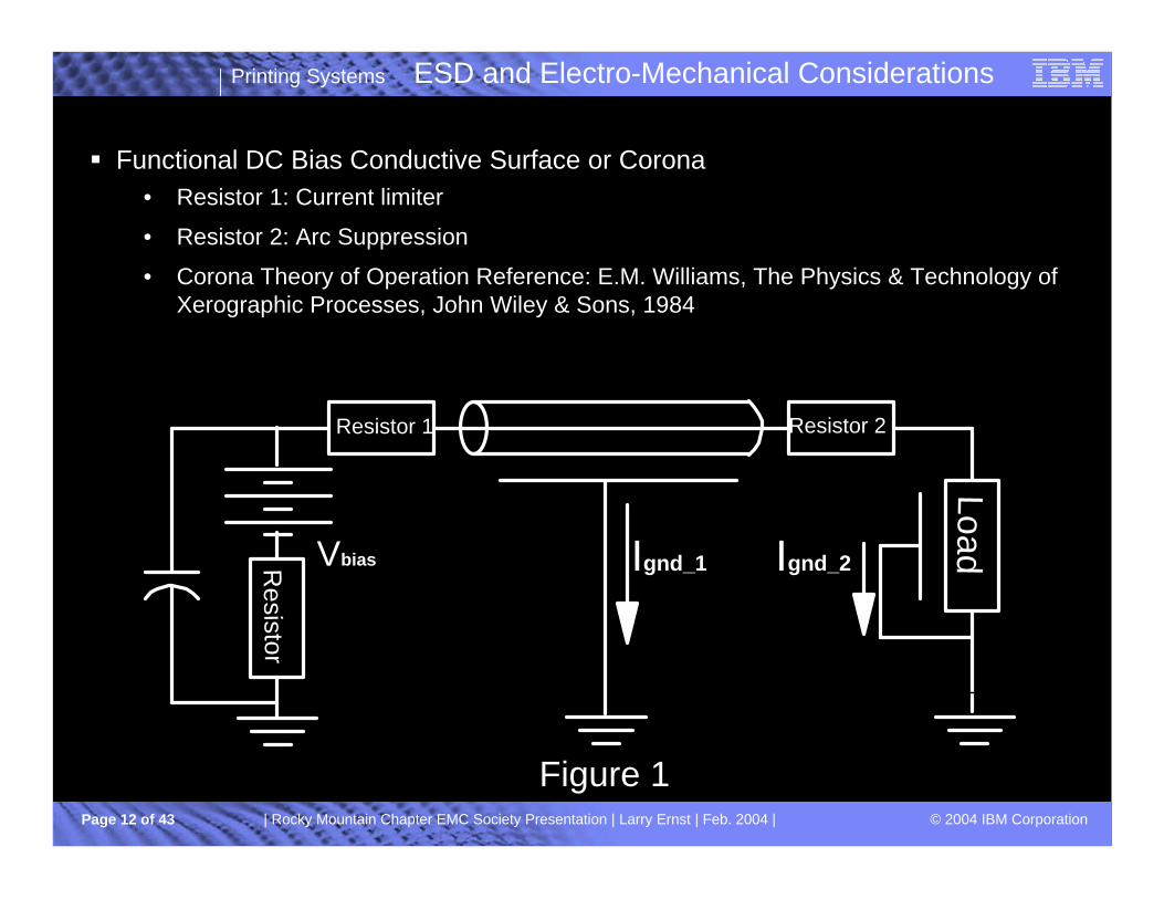
ESD and Electro-Mechanical Considerations
§ Functional DC Bias Conductive Surface or Corona• Resistor 1: Current limiter
• Resistor 2: Arc Suppression
• Corona Theory of Operation Reference: E.M. Williams, The Physics & Technology of Xerographic Processes, John Wiley & Sons, 1984
Resistor 1
LoadVbiasResistor
Ignd_1 Ignd_2
Figure 1
Resistor 2

Printing Systems
© 2004 IBM CorporationPage 13 of 43 | Rocky Mountain Chapter EMC Society Presentation | Larry Ernst | Feb. 2004 |
ESD and Electro-Mechanical Considerations (continued)
§ Functional AC Bias Conductive Surface or Corona• Vbias is a high voltage low frequency AC source
• Significant IGnd_1 capacitive current associated with the cabling dielectric.
• Cable dielectric surface may exceed the air voltage breakdown (noise source).Static Electric Field approximation in closed form is outlined in Ramo, Whinnery, and Van Duzer
book Fields and Waves in Communication Electronics, John Wiley & Sons, 1965.
• Resistor 1: Current limiter
• Corona Theory of Operation Reference: E.M. Williams, The Physics & Technology of Xerographic Processes, John Wiley & Sons, 1984
Load
Vbias
Resistor
Ignd_1 Ignd_2
Figure 2
Resistor 1 Resistor 2
• Resistor 2: Arc Suppression

Printing Systems
© 2004 IBM CorporationPage 14 of 43 | Rocky Mountain Chapter EMC Society Presentation | Larry Ernst | Feb. 2004 |
Flicker
Printing Systems
© 2004 IBM CorporationPage 15 of 43 | Rocky Mountain Chapter EMC Society Presentation | Larry Ernst | Feb. 2004 |
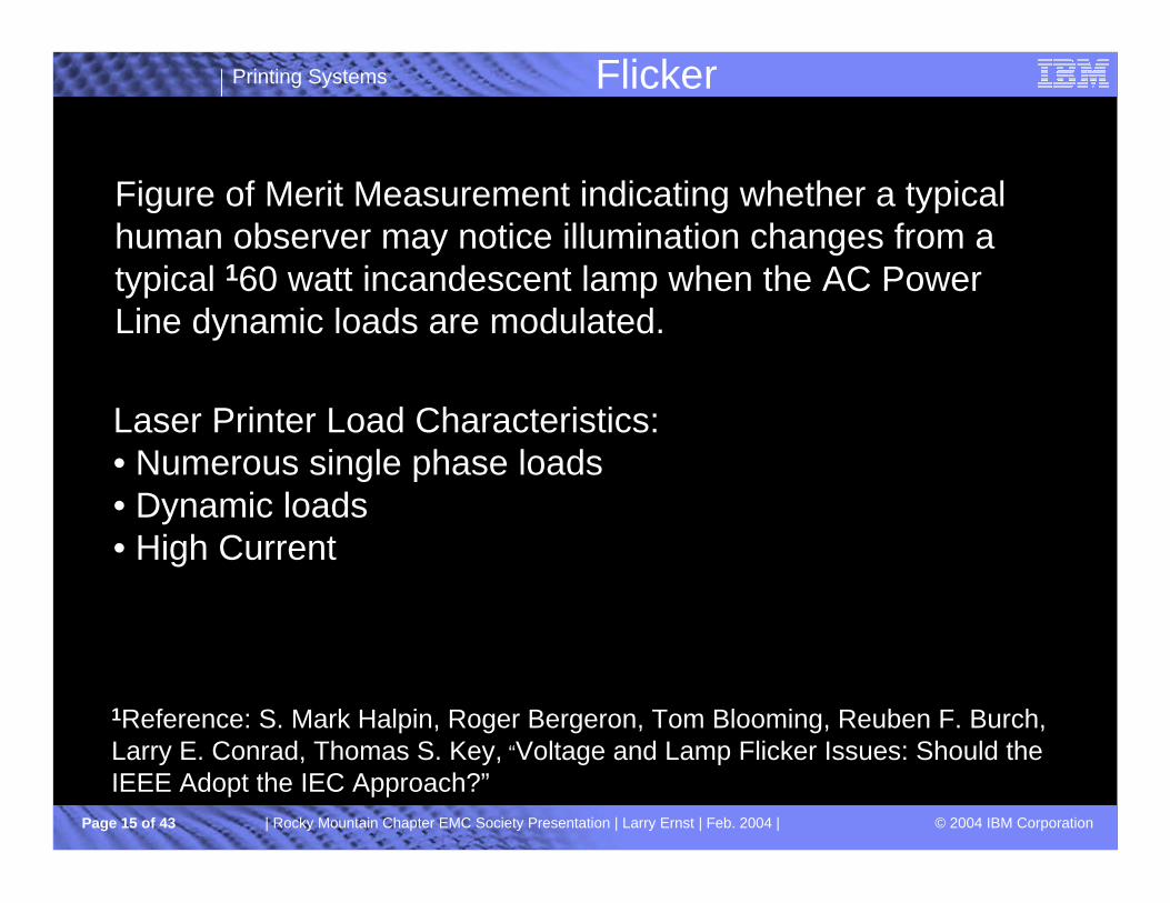
Flicker
Figure of Merit Measurement indicating whether a typical human observer may notice illumination changes from a typical 160 watt incandescent lamp when the AC Power Line dynamic loads are modulated.
Laser Printer Load Characteristics: • Numerous single phase loads• Dynamic loads • High Current
1Reference: S. Mark Halpin, Roger Bergeron, Tom Blooming, Reuben F. Burch, Larry E. Conrad, Thomas S. Key, “Voltage and Lamp Flicker Issues: Should the IEEE Adopt the IEC Approach?”
Printing Systems
© 2004 IBM CorporationPage 16 of 43 | Rocky Mountain Chapter EMC Society Presentation | Larry Ernst | Feb. 2004 |
Flicker Compliance
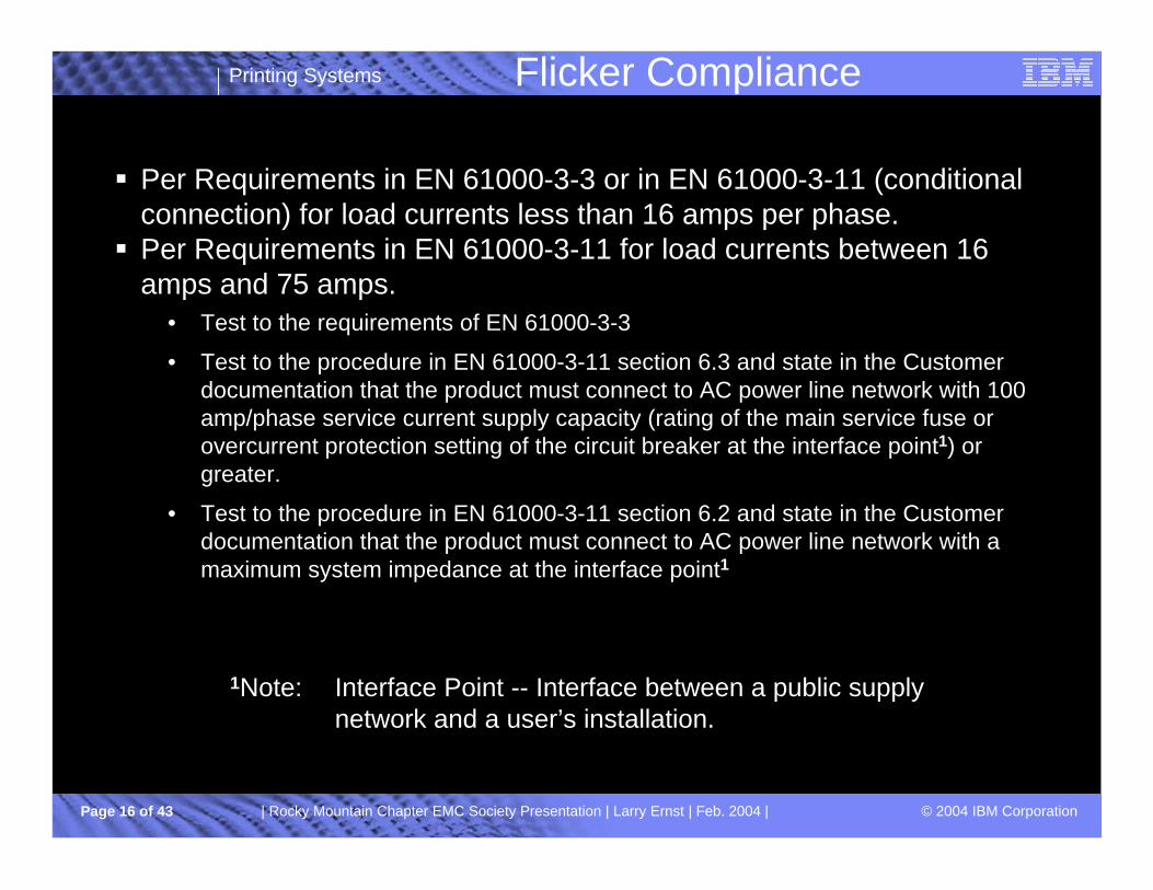
§ Per Requirements in EN 61000-3-3 or in EN 61000-3-11 (conditional connection) for load currents less than 16 amps per phase.§ Per Requirements in EN 61000-3-11 for load currents between 16
amps and 75 amps.• Test to the requirements of EN 61000-3-3
• Test to the procedure in EN 61000-3-11 section 6.3 and state in the Customer documentation that the product must connect to AC power line network with 100 amp/phase service current supply capacity (rating of the main service fuse or overcurrent protection setting of the circuit breaker at the interface point1) or greater.
• Test to the procedure in EN 61000-3-11 section 6.2 and state in the Customer documentation that the product must connect to AC power line network with a maximum system impedance at the interface point1
1Note: Interface Point -- Interface between a public supply network and a user’s installation.
Printing Systems
© 2004 IBM CorporationPage 17 of 43 | Rocky Mountain Chapter EMC Society Presentation | Larry Ernst | Feb. 2004 |
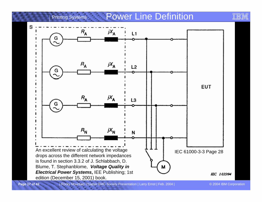
Power Line Definition
IEC 61000-3-3 Page 28An excellent review of calculating the voltage drops across the different network impedances is found in section 3.3.2 of J. Schlabbach, D. Blume, T. Stephanblome, Voltage Quality in Electrical Power Systems, IEE Publishing; 1st edition (December 15, 2001) book.
Printing Systems
© 2004 IBM CorporationPage 18 of 43 | Rocky Mountain Chapter EMC Society Presentation | Larry Ernst | Feb. 2004 |
Power Line Considerations
30
6.7
28.4
RatioLoad VoltageTo LineImpedance VoltageDrop(in phase)
31
6.5
30
RatioShort Circuit Current to Service Current Capacity
230volts
230volts
230volts
Phase to Neutral Voltage
780amps
650amps
487 amps
Single Phase Short CircuitCurrent
0.063Ohms@50 Hz
0.10ohms@50 Hz
0.10ohms@50 Hz
NeutralIndLn
0.10ohms
0.094ohms@50 Hz
0.15ohms
3.226%(3% to 5%)25 ampsload
0.10ohms
0.15 ohms @50 Hz
0.15ohms
100 amps(13% for 75 amp load)
0.16ohms
0.15ohms@50 Hz
0.24ohms
16 amps(3.4%)
NeutralResRn
Line IndLa
Line ResRa
ServiceCurrentCapacityOr PercentLine impedance drop
Single Phase
Printing Systems
© 2004 IBM CorporationPage 19 of 43 | Rocky Mountain Chapter EMC Society Presentation | Larry Ernst | Feb. 2004 |
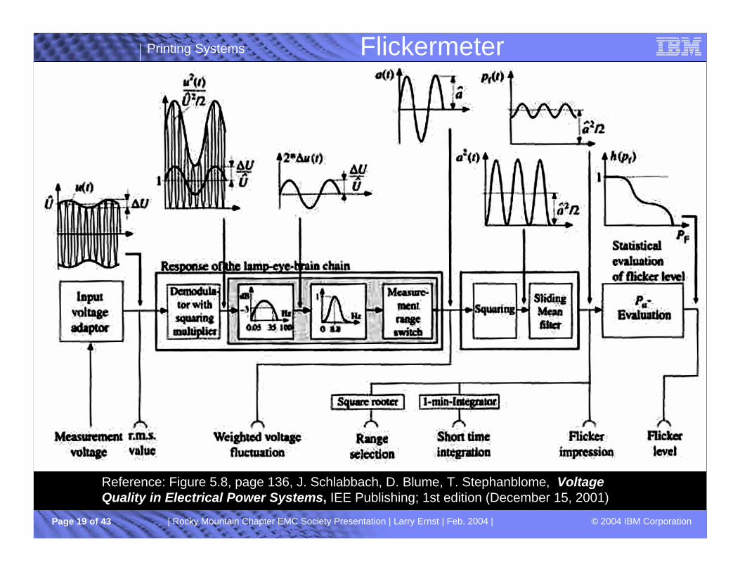
Flickermeter
Reference: Figure 5.8, page 136, J. Schlabbach, D. Blume, T. Stephanblome, Voltage Quality in Electrical Power Systems, IEE Publishing; 1st edition (December 15, 2001)

Printing Systems
© 2004 IBM CorporationPage 20 of 43 | Rocky Mountain Chapter EMC Society Presentation | Larry Ernst | Feb. 2004 |
Flicker Design Considerations
§ Load Balance especially during switching, i.e. minimize neutral current. § Amplitude Modulation Effects – varies
as the square• Softstart methodologies
• Etc§ Time effects
• Most sensitive switching frequency is 8.8 Hz.
• Minimize Switching, i.e. rate less than 1 Hz.
• Switch at high rates, i.e. above 25 Hz
• Avoid “cluster” switching, i.e. near simultaneous switching.
Flickermeter Output 5
§ For large machines, product designs should be basedon realistic power line network impedances.
Printing Systems
© 2004 IBM CorporationPage 21 of 43 | Rocky Mountain Chapter EMC Society Presentation | Larry Ernst | Feb. 2004 |
Radiated EmissionsMini/Partial Literature Review

Printing Systems
© 2004 IBM CorporationPage 22 of 43 | Rocky Mountain Chapter EMC Society Presentation | Larry Ernst | Feb. 2004 |
Radiated Emissions
• System Design • IC circuit/IC Package• Interconnection System• Ground/reference• Mechanical Layout • Component Placement• Filtering• Shielding• Operating System• µcode
• Clocking• Cabling• Power System• PCB Layout• Trace Currents• Trace Impedance• Decoupling• Balancing • Power Island • etc.
AC Input
DC Input
High Speed signals
Low Speed/Control
signals
1Printer Subsystem
Mini/Partial Literature Review
1Wireless not shown
Printing Systems
© 2004 IBM CorporationPage 23 of 43 | Rocky Mountain Chapter EMC Society Presentation | Larry Ernst | Feb. 2004 |
Radiated Emissions (continued)
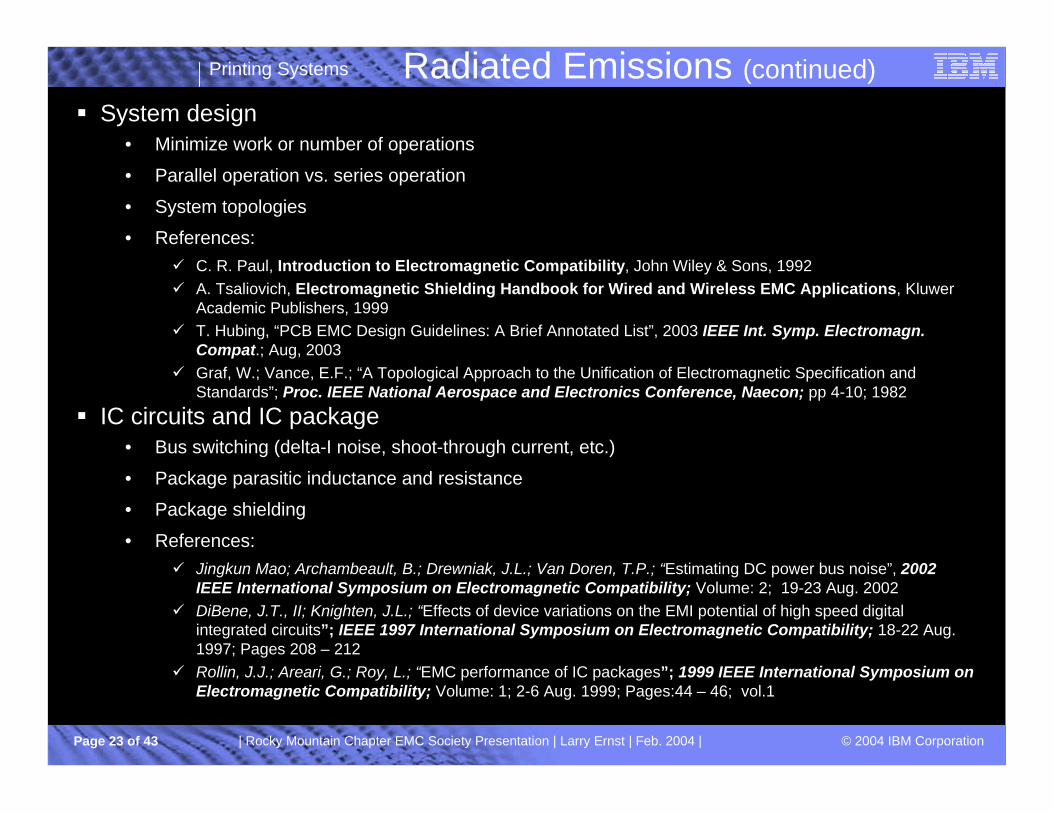
§ System design• Minimize work or number of operations
• Parallel operation vs. series operation
• System topologies
• References:ü C. R. Paul, Introduction to Electromagnetic Compatibility, John Wiley & Sons, 1992 ü A. Tsaliovich, Electromagnetic Shielding Handbook for Wired and Wireless EMC Applications, Kluwer
Academic Publishers, 1999ü T. Hubing, “PCB EMC Design Guidelines: A Brief Annotated List”, 2003 IEEE Int. Symp. Electromagn.
Compat.; Aug, 2003ü Graf, W.; Vance, E.F.; “A Topological Approach to the Unification of Electromagnetic Specification and
Standards”; Proc. IEEE National Aerospace and Electronics Conference, Naecon; pp 4-10; 1982
§ IC circuits and IC package• Bus switching (delta-I noise, shoot-through current, etc.)
• Package parasitic inductance and resistance
• Package shielding
• References:ü Jingkun Mao; Archambeault, B.; Drewniak, J.L.; Van Doren, T.P.; “Estimating DC power bus noise”, 2002
IEEE International Symposium on Electromagnetic Compatibility; Volume: 2; 19-23 Aug. 2002 ü DiBene, J.T., II; Knighten, J.L.; “Effects of device variations on the EMI potential of high speed digital
integrated circuits”; IEEE 1997 International Symposium on Electromagnetic Compatibility; 18-22 Aug. 1997; Pages 208 – 212
ü Rollin, J.J.; Areari, G.; Roy, L.; “EMC performance of IC packages”; 1999 IEEE International Symposium on Electromagnetic Compatibility; Volume: 1; 2-6 Aug. 1999; Pages:44 – 46; vol.1

Printing Systems
© 2004 IBM CorporationPage 24 of 43 | Rocky Mountain Chapter EMC Society Presentation | Larry Ernst | Feb. 2004 |
Radiated Emissions (continued)§ Clocking
• Minimize clock frequencies
• Minimize rise/fall times
• Skewing
• Spread spectrum clocking
• Stagger clock frequencies and harmonics
• References: ü B Deutschmann; G. Winkler; R. Jungreithmair; “Effects of Skewing Output Driver Switching on the
Electromagnetic Emission”; 2003 IEEE Int. Symp. Electromagn. Compat.; Aug, 2003 ü Hardin, K.B.; Fessler, J.T.; Bush, D.R.; “A study of the interference potential of spread spectrum clock
generation techniques”; IEEE International Symposium on Electromagnetic Compatibility; 14-18 Aug. 1995
§ Interconnection System and Cabling• Functional Requirements
ü Transmit information (signal integrity is critical)ü Transmit power (losses are critical)ü Intentionalü Unintentionalü Crosstalk
• References:ü C.R. Paul; Analysis of Multiconductor Transmission Lines; John Wiley & Sons; 1994ü T. Hubing; “Printed Circuit Board EMI Source Mechanisms”; IEEE Int. Symp. Electromagn. Compat.; Aug,
2003 ü Eroglu, K.; “A practical comparison of cabling effects on radiated emissions”; IEEE International Symposium
on Electromagnetic Compatibility; Volume: 2; 2-6 Aug. 1999

Printing Systems
© 2004 IBM CorporationPage 25 of 43 | Rocky Mountain Chapter EMC Society Presentation | Larry Ernst | Feb. 2004 |
Radiated Emissions (continued)
§ Ground/Reference and Power System• Current return paths must be explicitly designed into the overall system and clearly
defined in the documentation.
• Minimize the number of unintentional signal current paths
• Functional current return paths are low impedance designs with minimal or no discontinuity at operating frequencies
• References:ü Bruce Archambeault, PCB Design for Real-World EMI Control, Kluwer Academic Publishers,
2002ü Moongilan, D.; Palaniswamy, T.S.; “Backplane grounding models for controlling common-mode
noise and radiation”; 1999 IEEE International Symposium on Electromagnetic Compatibility; Volume: 1; 2-6 Aug. 1999
ü Tafjord, K.; “EMC aspects on grounding networks and DC power distribution in telecommunication systems”; Telecommunications Energy Conference; 1993. INTELEC '93. 15th International; Volume: 1; 27-30 Sept. 1993
§ Power Island • Reference: J. Chen; T.H. Hubing; T. P. Van Doren; R. E. DuBroff; “Power Bus Isolation
Using Power Islands in Printed Circuit Boards”; IEEE Trans. Electromagn. Compat.; vol. 44; No 2; May, 2002

Printing Systems
© 2004 IBM CorporationPage 26 of 43 | Rocky Mountain Chapter EMC Society Presentation | Larry Ernst | Feb. 2004 |
Radiated Emissions (continued)
§ Mechanical Layout, PCB Layout, Component Placement, Shielding and Balancing• The information paths and the mechanical layout should be consistent
• Typically, the information flows from the center (maximum information) outward in layers or zones with highest information toward center.
• Series Shields, i.e. classical shielding, partitions, etc.
• Parallel Shields, i.e. image planes, ground planes, guard traces, etc.
• Balance structures, i.e. twisted pair, etc.
• Symmetrical structures, i.e. coax, etc.
• References: ü P.A. Chatterton; M.A. Houlden; EMC: Electromagnetic Theory to Practical Design; John
Wiley & Sons; 1992.ü Parker, W.H.; “Electromagnetic interference: a tutorial”, 1996 IEEE Proceedings Aerospace
Applications Conference, 1996. Proceedings.; 1996 IEEE , Volume: 3 , 3-10 Feb. 1996 , Pages:177 - 186 vol.3
ü E.F. Vance; “Electromagnetic-Interference Control”; IEEE Transaction on Electromagnetic Compatability; Vol EMC-22; No. 4; Nov. 1980; pp.319-328
ü Das, S.K.; Smith, W.T.; Paul, C.R.; “Radiated Emissions Of Interconnect Cables”, IEEE International Symposium on Electromagnetic Compatibility, August 17-21, 1992
ü Fessler, J.T.; Whites, K.W.; Paul, C.R.; “Effect Of Image Plane Dimensions On Radiated Emissions”; IEEE 1992 International Symposium on Electromagnetic Compatibility; August 17-21, 1992; Pages:106 - 111

Printing Systems
© 2004 IBM CorporationPage 27 of 43 | Rocky Mountain Chapter EMC Society Presentation | Larry Ernst | Feb. 2004 |
§ PCB Trace Impedance and Trace Currents• Functional Requirements
• Optimization of signal integrity and minimization of trace currents
• Minimize trace discontinuities
• References:ü Eric Bogatin, Signal Integrity-Simplified, Prentice Hall, 2004ü Kaires, R.G.; “Radiated emissions from printed circuit board traces including the effect of vias, as a
function of source, termination and board characteristics”; 1998 IEEE International Symposium on Electromagnetic Compatibility; Volume: 2; 24-28 Aug. 1998; Pages:872 – 877; vol. 2
ü Kaires, R.G.; “The mythology of ground bounce”, 1999 IEEE International Symposium on Electromagnetic Compatibility; Volume: 1; 2-6 Aug. 1999; Pages:405 - 410
ü Bruce Archambeault, “Reduce EMI Emissions for FREE!”, http://www.mentor.com/highspeed/data/IE005.pdf
ü Roden, J.A.; Archambeault, B.; Lyle, R.D.; “Effect of stitching capacitor distance for critical traces crossing split reference planes”; 2003 IEEE International Symposium on Electromagnetic Compatibility; Volume: 2; Aug 18-22, 2003; Pages: 703 – 707
ü Jun Fan; Drewniak, J.L.; Knighten, J.L.; “Lumped-circuit model extraction for vias in multilayer substrates”; IEEE Transactions on Electromagnetic Compatibility; Volume: 45; Issue: 2; May 2003; Pages: 272 – 280
ü Qinglun Chen; Jin Zhao; “Via and return path discontinuity impact on high speed digital signal quality”; IEEE Conference on Electrical Performance of Electronic Packaging; 23-25 Oct. 2000
Radiated Emissions (continued)
Printing Systems
© 2004 IBM CorporationPage 28 of 43 | Rocky Mountain Chapter EMC Society Presentation | Larry Ernst | Feb. 2004 |
Radiated Emissions (continued)
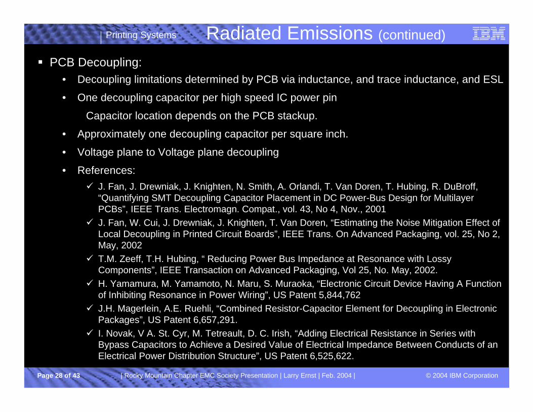
§ PCB Decoupling:• Decoupling limitations determined by PCB via inductance, and trace inductance, and ESL
• One decoupling capacitor per high speed IC power pin
Capacitor location depends on the PCB stackup.
• Approximately one decoupling capacitor per square inch.
• Voltage plane to Voltage plane decoupling
• References:ü J. Fan, J. Drewniak, J. Knighten, N. Smith, A. Orlandi, T. Van Doren, T. Hubing, R. DuBroff,
“Quantifying SMT Decoupling Capacitor Placement in DC Power-Bus Design for Multilayer PCBs”, IEEE Trans. Electromagn. Compat., vol. 43, No 4, Nov., 2001
ü J. Fan, W. Cui, J. Drewniak, J. Knighten, T. Van Doren, “Estimating the Noise Mitigation Effect of Local Decoupling in Printed Circuit Boards”, IEEE Trans. On Advanced Packaging, vol. 25, No 2, May, 2002
ü T.M. Zeeff, T.H. Hubing, “ Reducing Power Bus Impedance at Resonance with LossyComponents”, IEEE Transaction on Advanced Packaging, Vol 25, No. May, 2002.
ü H. Yamamura, M. Yamamoto, N. Maru, S. Muraoka, “Electronic Circuit Device Having A Function of Inhibiting Resonance in Power Wiring”, US Patent 5,844,762
ü J.H. Magerlein, A.E. Ruehli, “Combined Resistor-Capacitor Element for Decoupling in Electronic Packages”, US Patent 6,657,291.
ü I. Novak, V A. St. Cyr, M. Tetreault, D. C. Irish, “Adding Electrical Resistance in Series with Bypass Capacitors to Achieve a Desired Value of Electrical Impedance Between Conducts of an Electrical Power Distribution Structure”, US Patent 6,525,622.

Printing Systems
© 2004 IBM CorporationPage 29 of 43 | Rocky Mountain Chapter EMC Society Presentation | Larry Ernst | Feb. 2004 |
§ I/O Signal Filtering• Differential Mode
• Common Mode
• References:ü Paul, C.R.; “A comparison of the contributions of common-mode and differential-mode
currents in radiated emissions”, IEEE Transactions on Electromagnetic Compatibility, Volume: 31 , Issue: 2, May 1989, Pages:189 – 193
ü Henry Ott; Noise Reduction Techniques In Electronic Systems; John Wiley; 1988§ Operating System and µcode
• Realistic worst case customer test cases instead of contrived “Noisy” test cases.
• Efficient bus addressing and data schemes/algorithms
• Minimize unnecessary bus cycles
• Reference: A. Mutoh, S. Nitta, E. Takamura, T. Tsukagoshi, “The Influence of the Instruction Codes on Radiated Near-Magnetic-Fields—A Case Study on A5000, IEEE Int. Symp. Electromagn. Compat., Aug, 2002, pp 167-172
Radiated Emissions (continued)
Printing Systems
© 2004 IBM CorporationPage 30 of 43 | Rocky Mountain Chapter EMC Society Presentation | Larry Ernst | Feb. 2004 |
Organizational Considerations
Printing Systems
© 2004 IBM CorporationPage 31 of 43 | Rocky Mountain Chapter EMC Society Presentation | Larry Ernst | Feb. 2004 |
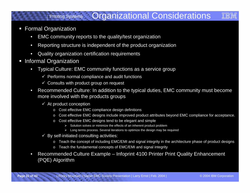
Organizational Considerations§ Formal Organization
• EMC community reports to the quality/test organization
• Reporting structure is independent of the product organization
• Quality organization certification requirements§ Informal Organization
• Typical Culture: EMC community functions as a service groupü Performs normal compliance and audit functionsü Consults with product group on request
• Recommended Culture: In addition to the typical duties, EMC community must become more involved with the products groupsü At product conception
o Cost effective EMC compliance design definitionso Cost effective EMC designs include improved product attributes beyond EMC compliance for acceptance.o Cost effective EMC designs tend to be elegant and simple
Ø Solution solves or minimize the effects of an inherent product problem Ø Long terms process. Several iterations to optimize the design may be required
ü By self-initiated consulting activities:o Teach the concept of including EMC/EMI and signal integrity in the architecture phase of product designs o Teach the fundamental concepts of EMC/EMI and signal integrity
• Recommended Culture Example – Infoprint 4100 Printer Print Quality Enhancement (PQE) Algorithm

Printing Systems
© 2004 IBM CorporationPage 32 of 43 | Rocky Mountain Chapter EMC Society Presentation | Larry Ernst | Feb. 2004 |
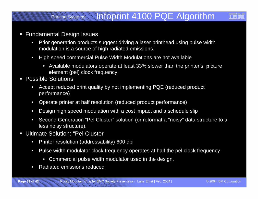
Infoprint 4100 PQE Algorithm
Printing Systems
© 2004 IBM CorporationPage 33 of 43 | Rocky Mountain Chapter EMC Society Presentation | Larry Ernst | Feb. 2004 |
Infoprint 4100 PQE Algorithm
§ Fundamental Design Issues• Prior generation products suggest driving a laser printhead using pulse width
modulation is a source of high radiated emissions.
• High speed commercial Pulse Width Modulations are not available
• Available modulators operate at least 33% slower than the printer’s picture element (pel) clock frequency.
§ Possible Solutions• Accept reduced print quality by not implementing PQE (reduced product
performance)
• Operate printer at half resolution (reduced product performance)
• Design high speed modulation with a cost impact and a schedule slip
• Second Generation “Pel Cluster” solution (or reformat a “noisy” data structure to a less noisy structure).
§ Ultimate Solution: “Pel Cluster”• Printer resolution (addressability) 600 dpi
• Pulse width modulator clock frequency operates at half the pel clock frequency
• Commercial pulse width modulator used in the design.• Radiated emissions reduced
Printing Systems
© 2004 IBM CorporationPage 34 of 43 | Rocky Mountain Chapter EMC Society Presentation | Larry Ernst | Feb. 2004 |
IP4100 PQE Algorithm (continued)
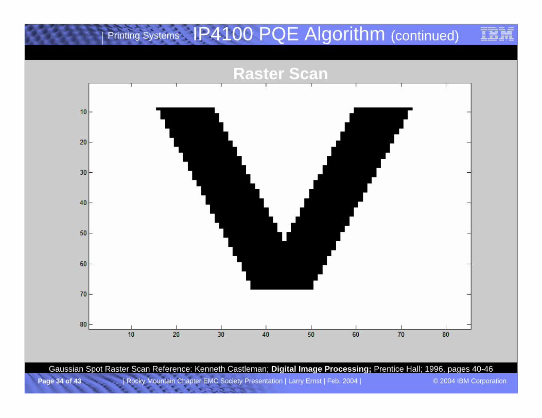
Raster Scan
Gaussian Spot Raster Scan Reference: Kenneth Castleman; Digital Image Processing; Prentice Hall; 1996, pages 40-46
Printing Systems
© 2004 IBM CorporationPage 35 of 43 | Rocky Mountain Chapter EMC Society Presentation | Larry Ernst | Feb. 2004 |
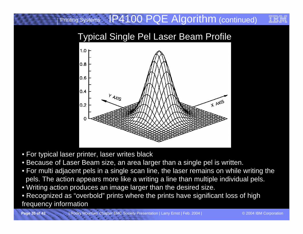
IP4100 PQE Algorithm (continued)
Typical Single Pel Laser Beam Profile
• For typical laser printer, laser writes black • Because of Laser Beam size, an area larger than a single pel is written.• For multi adjacent pels in a single scan line, the laser remains on while writing the
pels. The action appears more like a writing a line than multiple individual pels.• Writing action produces an image larger than the desired size.• Recognized as “overbold” prints where the prints have significant loss of high frequency information

Printing Systems
© 2004 IBM CorporationPage 36 of 43 | Rocky Mountain Chapter EMC Society Presentation | Larry Ernst | Feb. 2004 |
IP4100 PQE Algorithm (continued)
Pulse Width Modulation of an Individual pelWidth Single
Pelor
Pel Clock Period
LeftJustification
Right Justification
CenterJustification
Laser On Time

Printing Systems
© 2004 IBM CorporationPage 37 of 43 | Rocky Mountain Chapter EMC Society Presentation | Larry Ernst | Feb. 2004 |
Bits/Spot Through Image Data Pipeline
Rasterizer PQE Hardware
LaserPrinthead
Binary (1 Bit/Spot)
9 Bits/Spot (Digital PWM PQE)
IP4100 PQE Algorithm (continued)
| Rocky Mountain Chapter EMC Society Presentation | Larry Ernst | Feb. 2004 |

Printing Systems
© 2004 IBM CorporationPage 38 of 43 | Rocky Mountain Chapter EMC Society Presentation | Larry Ernst | Feb. 2004 |
IP4100 PQE Algorithm (continued)
white white
white black
black white
black black
No modulation
Leading Edge Black
Isolated Black Pel
Isolated Black Pel
Trailing Edge Black
Solid Black with aboveor below white
Several Simple Pel Cluster Examples
1/2 Pel Clock Frequency
Single PelWidth
Single PelWidth
black black Solid Black with aboveand below black

Printing Systems
© 2004 IBM CorporationPage 39 of 43 | Rocky Mountain Chapter EMC Society Presentation | Larry Ernst | Feb. 2004 |
IP4100 PQE Algorithm (continued)Original Image
30% of FFT MagnitudeComponent
Randomly Selected
30% of FFT AngleComponent
Randomly Selected
Image Quality relatively insensitive to Fourier Transform Magnitude changes.
Image Quality relatively sensitive to Fourier Transform Phase Angle changes.
Kenneth Castleman in his book Digital Image Processing, Prentice Hall, 1996, page 202, demonstrated the Fourier transform phase angle image quality sensitivity using an image of Jean Baptiste Joseph Fourier.
Image File Source: Adobe Photoshop

Printing Systems
© 2004 IBM CorporationPage 40 of 43 | Rocky Mountain Chapter EMC Society Presentation | Larry Ernst | Feb. 2004 |
IP4100 PQE Algorithm (continued)
Reference: C. R. Paul, Introduction to Electromagnetic Compatibility, John Wiley & Sons, 1992

Printing Systems
© 2004 IBM CorporationPage 41 of 43 | Rocky Mountain Chapter EMC Society Presentation | Larry Ernst | Feb. 2004 |
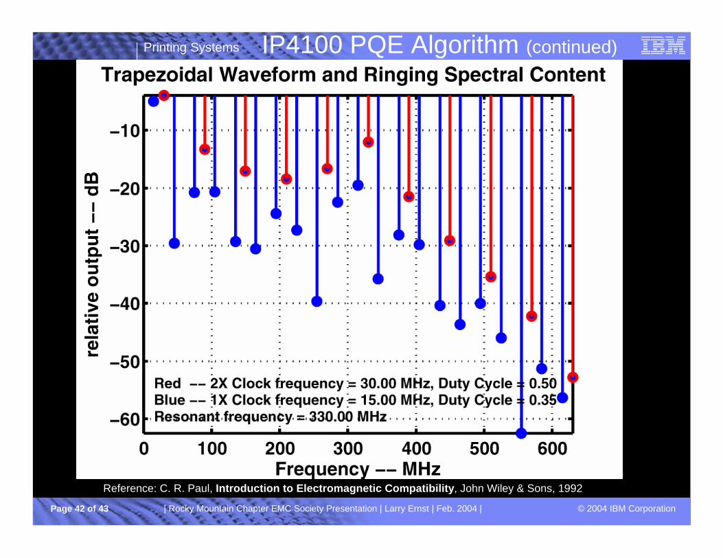
IP4100 PQE Algorithm (continued)
Reference: C. R. Paul, Introduction to Electromagnetic Compatibility, John Wiley & Sons, 1992
Printing Systems
© 2004 IBM CorporationPage 42 of 43 | Rocky Mountain Chapter EMC Society Presentation | Larry Ernst | Feb. 2004 |
IP4100 PQE Algorithm (continued)
Reference: C. R. Paul, Introduction to Electromagnetic Compatibility, John Wiley & Sons, 1992

Printing Systems
© 2004 IBM CorporationPage 43 of 43 | Rocky Mountain Chapter EMC Society Presentation | Larry Ernst | Feb. 2004 |
Summary
§ Economical Print Quality Solution§ Economical Radiated Emission Solution§ Analysis suggest worst case improvement approximately 3.5 dBµV/m
• Improvement is dependent on the Laser Driver resonant frequency
• Improvement is dependent on the relative duty cycle
§ Empirical validation suggest improvement approximately 10 dBµV/m§ Empirical image quality testing established the Pel Cluster solution does not
induce any image quality degradation
IP4100 PQE Algorithm (continued)