continuous gas analyzers, extractivecontinuous gas analyzers, extractive introduction 1/2 siemens pa...
TRANSCRIPT


Continuous Gas Analyzers, extractiveIntroduction
1/2 Siemens PA 01 · 2013
1 ■ Overview
Siemens process gas analyzers have been used in the process industry for more than 40 years, and are renowned for their quality, reliability and accuracy. The flexibility provided by the continuous process gas analyzers with respect to housing design, explosion protection, corrosion resistance and commu-nications capability means that optimum solutions can be found for all applications.
Nowadays, the communications capability of analyzers is becoming increasingly important. Siemens process gas analyzers are an integral component of Siemens’ "Totally
Integrated Automation" concept which is globally unique. This concept permits design of uniform process communication from the operations management level down to the field level. The simple integration of analyzers into the host control systems is the basis for a uniform automation and analysis solution.
Many years of experience in the development and production of analyzers as well as in the planning and installation of analyzer systems distinguishes Siemens as a solution provider - reliable, innovative and with global presence.
Schematic representation of the measuring setup of extractive site installations
SamplingSample
gasSample
preparation AnalyzerProcess
feedback/exhaust
Pro
cess
line
По вопросам продаж и поддержки обращайтесь:
Эл. почта: [email protected] || Сайт: http://simat.nt-rt.ru
Архангельск (8182)63-90-72 Астана +7(7172)727-132 Астрахань (8512)99-46-04 Барнаул (3852)73-04-60 Белгород (4722)40-23-64 Брянск (4832)59-03-52 Владивосток (423)249-28-31 Волгоград (844)278-03-48 Вологда (8172)26-41-59 Воронеж (473)204-51-73 Екатеринбург (343)384-55-89 Иваново (4932)77-34-06 Ижевск (3412)26-03-58 Казань (843)206-01-48
Калининград (4012)72-03-81 Калуга (4842)92-23-67 Кемерово (3842)65-04-62 Киров (8332)68-02-04 Краснодар (861)203-40-90 Красноярск (391)204-63-61 Курск (4712)77-13-04 Липецк (4742)52-20-81 Магнитогорск (3519)55-03-13 Москва (495)268-04-70 Мурманск (8152)59-64-93 Набережные Челны (8552)20-53-41 Нижний Новгород (831)429-08-12 Новокузнецк (3843)20-46-81
Новосибирск (383)227-86-73 Омск (3812)21-46-40 Орел (4862)44-53-42 Оренбург (3532)37-68-04 Пенза (8412)22-31-16 Пермь (342)205-81-47 Ростов-на-Дону (863)308-18-15 Рязань (4912)46-61-64 Самара (846)206-03-16 Санкт-Петербург (812)309-46-40 Саратов (845)249-38-78 Севастополь (8692)22-31-93 Симферополь (3652)67-13-56 Смоленск (4812)29-41-54
Сочи (862)225-72-31 Ставрополь (8652)20-65-13 Сургут (3462)77-98-35 Тверь (4822)63-31-35 Томск (3822)98-41-53 Тула (4872)74-02-29 Тюмень (3452)66-21-18 Ульяновск (8422)24-23-59 Уфа (347)229-48-12 Хабаровск (4212)92-98-04 Челябинск (351)202-03-61 Череповец (8202)49-02-64 Ярославль (4852)69-52-93

Continuous Gas Analyzers, extractiveIntroduction
1/3Siemens PA 01 · 2013
1Extractive procedures for process gas analysis
Extractive process gas analyzers are used for continuous deter-mination of the concentrations of one or more gases in a gas mixture. Determination of the concentration of gases in a process is used to control and monitor process flows, and is therefore decisive for the automation and optimization of processes and ensuring product quality. In addition, process gas analyzers are used to check emissions, thus making an important contribution to environmental protection, as well as for ensuring compliance with statutory directives.
With extractive measuring procedures, the sample to be analyzed is extracted from the process line and applied precon-ditioned to the analyzer via a sample line and a sample prepa-ration system. This system, for example, adjusts the pressure, temperature and flow of the sample, and frees the sample gas of dust and moisture if necessary. This guarantees that the measurement can be carried out under defined conditions. Furthermore, the analyzer is protected from damaging influ-ences.
Various measuring procedures with different physical and electrochemical methods are used depending on the type of components to be measured and the measuring point. Siemens offers a range of measuring procedures for extractive gas analysis in two types of devices, SIPROCESS GA700 and Series 6 / ULTRAMAT 23. Each type of device provides peak analytical performances for its class.
SIPROCESS GA700
The SIPROCESS GA700 range is the latest generation of Siemens gas analyzers, and features a modular design. The basic units are currently available with the OXYMAT 7 analyzer module for paramagnetic measurement of oxygen. Up to two analyzer modules can be used per basic unit.
Basic unit
The basic unit is available in two models: as a 19" rack unit with 3 height units, and in a housing for wall mounting. The commu-nication interfaces present in the basic units can be adapted to the respective process environment or the process control system using additional optionally available electronics modules.
Analyzer modules
Depending on the measuring task, the SIPROCESS GA700 can be individually adapted to the respective analytical or process requirements by fitting selectable analyzer modules.
Series 6 / ULTRAMAT 23
The classic analyzers from Siemens, Series 6 and ULTRAMAT 23, have been proven at our customers all over the globe in many years of use:• ULTRAMAT 6
For highly-selective measurement of infrared-active compo-nents such as CO, CO2, NO, SO2, NH3, H2O, CH4 and other hydrocarbons. The ULTRAMAT 6 is a high-end analyzer in 19" format or in a sturdy field housing for use in harsh atmospheres. The field of application basically comprises all types of emission measurements up to use in processes. These serve to control production processes and guarantee product quality, even in the presence of highly corrosive gases.
• ULTRAMAT 23The ULTRAMAT 23 is an innovative multi-component gas analyzer for measuring up to three infrared-sensitive gases using the NDIR principle. Measurement of oxygen (O2) is also possible through the use of electrochemical oxygen sensors or measuring cells operating according to the paramagnetic principle ("dumbbell"). The use of an additional electro-chemical H2S measuring cell permits use in biogas applica-tions.
• ULTRAMAT/OXYMAT 6For combined measurement of infrared-active components and oxygen in complex applications.
• OXYMAT 6For measurement of oxygen concentration according to the paramagnetic principle in complex applications. The OXYMAT 6 measures oxygen according to the paramagnetic alternating pressure principle. This guarantees absolute linearity and allows the use of very small measuring ranges from 0 to 0.5 % (detection limit 50 ppm), ranges up to 0 to 100 %, and even 99.5 to 100 % in one unit. Suitable materials in the gas path even permit the analyzers to be used for measurement of corrosive gas mixtures. The detector unit does not come into contact with the sample gas, and therefore permits use in harsh atmospheres while simulta-neously guaranteeing a long service life.
• OXYMAT 61For measurement of oxygen concentrations according to the paramagnetic principle in standard applications. Ambient air can be used as the reference gas for OXYMAT 61. This is supplied by a pump integrated in the analyzer enclosure.
• OXYMAT 64For measurement of oxygen concentrations in the trace range by means of ZrO2 sensors. The OXYMAT 64 can be used to measure very small traces of oxygen, down to the smallest measuring range of 0 to 10 ppm. This is particularly inter-esting in systems for air separation. A catalytically inactive ZrO2 sensor or a catalytically active ZrO2 sensor can be selected, depending on the application.
• CALOMAT 6For determining the concentration of hydrogen and inert gases in binary mixtures through measurement of thermal conductivity. The CALOMAT 6 features a high dynamic measuring range (e.g. 0 … 1 % and 0 … 100 % H2, parame-terizable) and a short T90 time.
• CALOMAT 62The CALOMAT 62 is a thermal conductivity analyzer that has been specially designed for applications with corrosive gases. It is possible to directly measure the concentration of gas components such as Cl2, HCl and NH3, as well as e.g. H2 and N2 in a corrosive atmosphere.
• FIDAMAT 6For measurement of total hydrocarbons according to the flame ionization principle. The FIDAMAT versions feature a highly varied field of appli-cation. From monitoring for traces of hydrocarbons in ultra-pure gases - made possible by the high resolution and small differences in response factors - up to measurements of total hydrocarbons in the % range.The widely adjustable operating temperature for the sample gas path and detector also allows measurement of high-boiling mixtures and of hydrocarbons at water vapor concen-trations up to 100 %.
• SIPROCESS UV600Gas analyzer based on UV resonance absorption spectrometry for measuring even very low NO, NO2, SO2, and H2S concentrations.
Analyzer module Measuring task
OXYMAT 7 The OXYMAT 7 module is used to measure oxygen between 0 to 0.5 % (smallest measuring range) and 0 to 100 % (largest measuring range). It is designed for use at ambient temperatures up to 50 °C and allows highly exact measurements through application of the paramagnetic alternating pressure principle. Thanks to the modular design, the analyzer module can be com-bined with a further OXYMAT 7 module.
Continuous Gas Analyzers, extractiveIntroduction
1/4 Siemens PA 01 · 2013
1 General information
Introducing flammable gases
Introducing frequently or permanently explosive gas/air mixtures to the gas analyzers mentioned in this chapter is not permitted.
The introduction of gases with flammable components at concentrations above the lower explosive limit (LEL) should only be carried out with analyzers fitted with piping. Purging of the enclosure as well as further measures must be provided depending on the application. When using SIPROCESS UV600, please contact the technical department. An inert gas must be used for purging (see manual for further information).
Cross-sensitivity
Exact measurement results with regard to the technical specifi-cations can only be expected if a sample gas is free to the greatest possible extent of gases exhibiting a cross-sensitivity with the measured component. The influences of these inter-fering components can be reduced using various measures. Please contact our specialists if you have any questions.
General installation guide and operating instructions• Protected against low temperatures and thermal radiation
(see technical specifications)• Protected against temperature variations• To achieve the best possible measuring quality, the installation
location should be free from vibrations• Protection of electronics from corrosive environments (use
field devices with purging if necessary)• Observation of directives for installation in hazardous areas
(see manual)• Observation of directives for measurement in the presence of
toxic gases, provide purging of enclosure and further safety measures if necessary (see manual)
• The analyzers in the basic version are set to a cross-influence of water vapor with a dew point of 4 °C (standard cooler temperature for sample preparation).
• When calibrating with zero gas and span gas, these must be connected via the sample gas cooler analogous to the sample gases to allow correct adjustment.
• In special cases (test measurements or long-term adjust-ments), it is recommendable to connect the calibration gases via a humidifier upstream of the cooler to avoid "drying-out" of the gas cooler and thus changes in the concentration of the water vapor.
• Correction of cross-interference which may be activated for a gas is canceled for the duration of a calibration procedure (zero point and sensitivity).
Calibration/adjustment
The Series 6 analyzers (ULTRAMAT 6, OXYMAT 6, CALOMAT 6) as well as the SIPROCESS GA700 analyzers (OXYMAT 7) should be calibrated with zero and calibration gas at least every 14 days.
Note: With OXYMAT 6/61 and OXYMAT 7, the zero gas and the reference gas must be the same.• Pre-purging of sample gas path via the sample gas inlet with
nitrogen (N2, quality 5.0), duration: min. 1 min, one further minute in addition for each 10 m of sample gas line.
• Calibration gases for zero point adjustment (ULTRAMAT 6, OXYMAT 6, CALOMAT 6, OXYMAT 7)Sufficient supply of inert gas via the sample gas inlet (free from measured component and free from gases with a cross-influence on the measured component), usually N2, quality 5.0.
• Gases for calibration of deflectionConnection of calibration gas via the sample gas inlet (approx. 60 to 90 % of the measuring range of the measured component with inert gas as the residual gas (e.g. N2, quality 5.0)).
• Gases for calibration of the CALOMAT 62Since every residual gas (including nitrogen) has a specific thermal conductivity, the gases used for calibrating the zero point and full-scale values of the CALOMAT 62 must take this into account. When calibrating e.g. H2 in HCl, HCl can be used as the zero gas (or an appropriate substitute in accor-dance with the data sheet enclosed with the device) and H2 in HCl (or a substitute gas) as the span gas.
You can find details on FIDAMAT 6, OXYMAT 64 and ULTRAMAT 23 (AUTOCAL) in the chapters describing the respective device.
Explosion protection
Refer to the separate manuals, references and standards concerning the topic of explosion protection.
Standard Zero gas N2 (5.0)
Calibration gas Sample gas with approx. 60 … 90 % of measuring range in residual N2 (5.0)
Continuous Gas Analyzers, extractiveSIPROCESS GA700
Basic device
1/5Siemens PA 01 · 2013
1■ Overview
The entire SIPROCESS GA700 device is configured in a modular fashion and consists of a basic unit and at least one – maximum two – analyzer modules. It can optionally be fitted with up to two interfaces modules (option modules).
■ Benefits
The basic unit provides:• Transmission and evaluation of measurement results • Display and transmission of device parameters• Operation (parameterization, configuration)
In addition to the analyzer modules, the basic unit contains the interfaces for the peripherals.
■ Application
Application areas
Depending on the analyzer modules installed, the device is predominantly used in the following sectors:• Chemical industry• Petrochemicals• Steel• Cement• Power generation• Environmental protection
■ Design
19" rack unit• 19" rack unit with 3 height units (HU) for installation
- in hinged frames- in cabinets with or without telescopic rails
• Gas connections for sample gas inlet and outlet: for pipe diameter 6 mm or 1/4"
• Purging gas connections 10 mm and 3/8" (optional)
Wall-mounted device• Gas connections for sample gas inlet and outlet: Pipe union
for pipe diameter 6 mm or 1/4" (directly on the analyzer modules)
• Purging gas connections (optional), purging gas connection for 6 mm or 1/4" hose (optional)
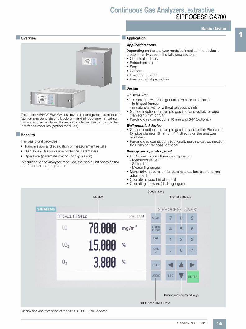
Display and operator panel• LCD panel for simultaneous display of:
- Measured value- Status line- Measuring ranges
• Menu-driven operation for parameterization, test functions, adjustment
• Operator support in plain text• Operating software (11 languages)
Display and operator panel of the SIPROCESS GA700 devices
Display
Special keys
Numeric keypad
Cursor and command keys
HELP and UNDO keys

Continuous Gas Analyzers, extractiveSIPROCESS GA700
Basic device
1/6 Siemens PA 01 · 2013
1 Inputs and outputs• 8 digital inputs, designed for 24 V, potential-free, freely config-
urable (e.g. for measurement range switchover, processing of external signals from sample preparation)
• 8 relay outputs, with changeover contacts, freely configurable (e.g. for faults, maintenance requests, limit alarms, external solenoid valves)
• Ethernet connection contained in the basic unit (connection on the rear side, Ethernet RJ 45, 100 MBit)
• Service interface (front side); Ethernet RJ 45, 100 MBit.
Interface modules • Option module 2.1:
one analog output per measured component (max. 6, 0 to 20 mA, 4 to 20 mA or parameter assignment in accordance with NAMUR), plus 6 digital outputs
■ Function
Essential characteristics• Measuring range identification• Storage of measured values possible during adjustments• Four freely parameterizable measuring ranges, also with
suppressed zero point• Autoranging possible; remote switching is also possible• Wide range of selectable time constants (static/dynamic noise
suppression); i.e. the response time of the analyzer can be matched to the respective measuring task
• Measuring point switchover for up to 12 measuring points (programmable)
• Parameterizable measuring point identification• Automatic, parameterizable measuring range calibration• Operation based on the NAMUR recommendation• Three control levels with their own authorization codes for the
prevention of accidental and unauthorized operator interven-tions
• Simple handling using a numerical membrane keyboard and operator prompting
• Customer-specific analyzer options such as:- Customer acceptance- TAG labels

Continuous Gas Analyzers, extractiveSIPROCESS GA700
Basic device
1/7Siemens PA 01 · 2013
1■ Technical specifications
19" rack unit Wall housing
General information
Operating position Horizontal
Conformity CE mark in accordance with EN 50081-1 and EN 50082-2
Design, enclosure
Weight without module 8.6 kg
Degree of protection IP20 according to EN 60529
Electrical characteristics
Power supply 100 to 240 V AC (nominal range of use 85 to 264 V), 50 to 60 Hz (nomi-nal range of use 47 to 63 Hz)
Power consumption 280 VA max.
EMC interference immunity (electromagnetic compatibility)
In accordance with the standard requirements of NAMUR NE21 (05/2006) and EN 61326-1 (01/2008)
Electrical safety In accordance with EN 61010-1, overvoltage category II
Electrical inputs and outputs
Relay outputs 8, with changeover contacts, can be freely parameterized, e.g. for mea-suring range identification; max. load: 24 V AC/DC/40 W (total load for all 8 relay outputs in continuous operation max. 160 W), potential-free, non-sparking
Digital inputs 8, designed for 24 V, potential-free, can be freely parameterized, e.g. for measurement range switchover
Analog output 0/4 ... 20 mA, potential-free
Ethernet interface (rear) Ethernet RJ 45, 100 MBit
Service interface (front) Ethernet RJ 45, 100 MBit
Option module 2.1 6 analog outputs, 0/4 to 20 mA, potential-free; maximum load 750 Ωand 6 additional relay outputs, load-ing capacity: 24 V AC/DC/40 W, potential-free, non-sparking
Climatic conditions
Permissible operating altitude 3 000 m above sea level
Permissible ambient temperature(with one module; application-depen-dent with two modules)
• -30 ... +70 °C during storage and transportation
• 0 ... 50 °C during operation with one or two OXYMAT 7 analyzer modules
Ventilation slits must not be covered (recommended minimum upward clearance from the next device when installing 2 analyzer modules and at maximum ambient tempera-ture: min. 1 HU)
Permissible humidity < 90 % RH (RH: relative humidity), during storage and transportation (dew point must not be undershot)
General information
Operating position Vertical
Conformity CE mark in accordance with EN 50081-1 and EN 50082-2
Design, enclosure
Weight without module 23 kg
Degree of protection IP65 in accordance with EN 60529, restricted breathing enclosure to EN 50021
Electrical characteristics
Power supply 100 to 240 V AC (nominal range of use 85 to 264 V), 50 to 60 Hz (nomi-nal range of use 47 to 63 Hz)
Power consumption 280 VA max.
EMC interference immunity (electro-magnetic compatibility)
In accordance with the standard requirements of NAMUR NE21 (05/2006) and EN 61326-1 (01/2008)
Electrical safety In accordance with EN 61010-1, overvoltage category II
Gas inlet conditions
Purging gas pressure• Permanent < 100 hPa above atmospheric pres-
sure• For short periods 165 hPa above atmospheric pres-
sure
Electrical inputs and outputs
Relay outputs 8, with changeover contacts, can be freely parameterized, e.g. for mea-suring range identification; max. load: 24 V AC/DC/40 W (total load for all 8 relay outputs in continuous operation max. 160 W), potential-free, non-sparking
Digital inputs 8, designed for 24 V, potential-free, can be freely parameterized, e.g. for measurement range switchover
Analog output 0/4 ... 20 mA, potential-free
Ethernet interface (bottom) Ethernet RJ 45, 100 MBit
Service interface (bottom) Ethernet RJ 45, 100 MBit
Option module 2.1 6 analog outputs, 0/4 to 20 mA, potential-free; maximum load 750 Ωand 6 additional relay outputs, load-ing capacity: 24 V AC/DC/40 W, potential-free, non-sparking
Climatic conditions
Permissible operating altitude 3 000 m above sea level
Permissible ambient temperature(with one module; application-depen-dent with two modules)
• -30 ... +65 °C during storage and transportation
• 0 ... 50 °C during operation with one or two OXYMAT 7 analyzer modules
Permissible humidity < 90 % RH (RH: relative humidity), during storage and transportation (dew point must not be undershot)

Continuous Gas Analyzers, extractiveSIPROCESS GA700
Basic device
1/8 Siemens PA 01 · 2013
1
1) Compact operating instructions 1 must always be selected when ordering.
Ordering examples
OXYMAT 7 module in rack unit enclosure "Example1"
7MB3000-0DX00-2AA0-Z + Y01 "Example1"
7MB3020-0AD00-0AA0-Z + Y01 "Example1"
OXYMAT 7 module in wall housing "Example2"
7MB3000-3DX00-2AA0-Z + Y01 "Example2"
7MB3020-0AD00-0AA0-Z + Y01 "Example2"
Selection and ordering data Order No.
SIPROCESS GA700 1) 7MB3000- 77777 - 7A77 Cannot be combined
Basic unit versions
Rack unit enclosure 0 0
Wall housing 3
Module, installation position 1
Without X X
OXYMAT 7 D
Module, installation position 2
Without X
OXYMAT 7 D D
Gas management (only with AM, with hoses)
No gas management, dummy plate without purging gas connection 0
No gas management, dummy plate with purging gas connection (on request)
Option module 1
Without 0
Option module 2
Without 0
Option module 2.1 (6 analog outputs and 6 digital outputs) 2
Ex version
Standard, set-up in non-hazardous zone A
Standard, set-up in non-hazardous zone with purging gas connection (wall structure) B B
Type
Standard 0
Selection and ordering data
Additional versions Order code
Add "-Z" to Order No. and specify order code
TAG labels (specific inscription based on customer information)
B03
Device name, ........(plain text) Y01
Compact operating instructions 1(must always be selected when ordering)
• German L50
• English L51
• French L52
• Italian L53
• Spanish L54
• Chinese (Simplified) L55
• Portuguese (Brazilian) L56
• Russian L57
• Korean L58
• Japanese L59
Compact operating instructions 2 (selectable as option)
• German L75
• English L76
• French L77
• Italian L78
• Spanish L79
• Chinese (Simplified) L80
• Portuguese (Brazilian) L81
• Russian L82
• Korean L83
• Japanese L84

Continuous Gas Analyzers, extractiveSIPROCESS GA700
Basic device
1/9Siemens PA 01 · 2013
1■ Dimensional drawings
SIPROCESS GA700, rack unit, dimensions in mm
421,5
419
170,8
48,583,5
108,5133,5
208,5300,5
392,5
482,3
10,313,5
37,7
57,1
5
132,
55
441,3
421,
5
Slot 1 Slot 2

Continuous Gas Analyzers, extractiveSIPROCESS GA700
Basic device
1/10 Siemens PA 01 · 2013
1
SIPROCESS GA700, wall housing, dimensions in mm
196450
98
0
0
408
425
200 370
0
493
280
549
164,
6
120,5
291,5
76,5
168,
5
260,
5
97,5132,5167,5202,5237,5272,5
338,3
567,6
Slot 1 Slot 2
Continuous Gas Analyzers, extractiveSIPROCESS GA700
Basic device
1/11Siemens PA 01 · 2013
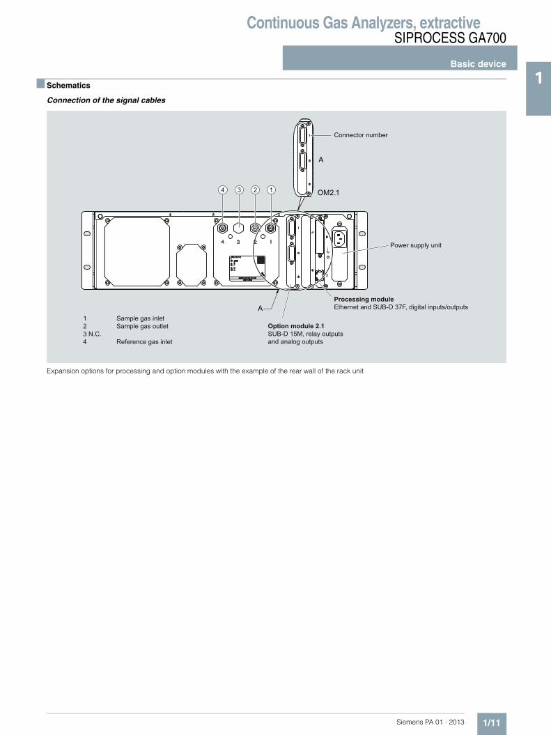
1■ Schematics
Connection of the signal cables
Expansion options for processing and option modules with the example of the rear wall of the rack unit
4 3 2 1
Connector number
Power supply unit
Processing moduleEthernet and SUB-D 37F, digital inputs/outputs
Option module 2.1SUB-D 15M, relay outputs and analog outputs
1 Sample gas inlet2 Sample gas outlet3 N.C.4 Reference gas inlet

Continuous Gas Analyzers, extractiveSIPROCESS GA700
Basic device
1/12 Siemens PA 01 · 2013
1 Pin assignments (rack unit enclosure)
Pin assignments of option module 2.1
11
10
9
15
14
13
12
11
10
9
15
14
13
12
8
7
6
3
2
1
5
4
8
7
6
3
2
1
5
4
Contact load max. 24 V/1.7 A, AC/DC; shown relay contacts: relay coil has zero current
Analog outputs floating(also from each other), RL: ≤ 750 Ω SUB-D 15M connector, pin assignments for
analyzer module 2
Analog output 21-P
Analog output 22-P
Analog output 22-N
Analog output 21-N
Analog output 23-P
Relay 12
Relay 14
Relay 13Analog output 23-N
SUB-D 15M connector, pin assignments for analyzer module 1
Analog output 11-P
Analog output 12-P
Analog output 12-N
Analog output 11-N
Analog output 13-P
Relay 9
Relay 11
Relay 10Analog output 13-N

Continuous Gas Analyzers, extractiveSIPROCESS GA700
Basic device
1/13Siemens PA 01 · 2013
1
Pin assignment of the processing module (basic unit)
GND
NCNC
GND
M
M
15
19
20
21
22
23
1
2
3
4
24
25
26
27
28
5
6
7
8
9
10
11
12
13
14
16
17
18
32
31
30
29
33
34
35
36
37
Contact load max. 24 V/1.7 A, AC/DC; shown relay contacts: relay coil has zero current
Floating via optocoupler"0" = 0 V (-3 ... +5 V)"1" = 24 V (15 ... 33 V)
Binary input 1 to 8-NBinary input 1-PBinary input 2-PBinary input 3-PBinary input 4-PBinary input 5-P Binary input 6-PBinary input 7-PBinary input 8-P
Relay 2
Relay 1
Relay 8
Relay 7
Relay 5
Relay 6
Relay 4
Relay 3
SUB-D 37F connector

Continuous Gas Analyzers, extractiveSIPROCESS GA700
Basic device
1/14 Siemens PA 01 · 2013
1 Terminal assignment (wall housing)
Terminal assignment, standard terminal block, terminal rows A and B
1213
7891011
45
171819
123
6
16
1415
1213
7891011
45
171819
123
6
16
1415
GND
NCNC
NC
M
Terminal row A
Terminal row B
Standard terminal block
Contact load max. 24 V/1.7 A, AC/DC; shown relay contacts: relay coil has zero current
Contact load max. 24 V/1.7 A, AC/DC; shown relay contacts: relay coil has zero current
Contact load max. 24 V/1.7 A, AC/DC; shown relay contacts: relay coil has zero current
Floating via optocoupler"0" = 0 V (-3 ... +5 V)"1" = 24 V (15 ... 33 V)
Relay 1
Relay 2
Relay 3
Relay 4
Relay 5
Relay 6
Relay 7
Binary input 1 to 8-N
Binary input 1 to 8-N
Binary input 1-PBinary input 2-PBinary input 3-PBinary input 4-PBinary input 5-PBinary input 6-PBinary input 7-PBinary input 8-P
Relay 8

Continuous Gas Analyzers, extractiveSIPROCESS GA700
Basic device
1/15Siemens PA 01 · 2013
1
Terminal assignment, standard terminal block, terminal rows C and D
Assignment between terminal block and analyzer module
Terminal row C
Relays 9 to 11 correspond to status display of analyzer module 1
Relays 12 to 14 correspond to status display of analyzer module 2
Terminal row D
Analog outputs 11 to 13 correspond to analyzer module 1
Analog outputs 21 to 23 correspond to analyzer module 2
1213
7891011
45
171819
123
6
16
1415
1213
7891011
45
171819
123
6
16
1415
M
M
M
GNDNCNCNCNCNC
NC
NC
Contact load max. 24 V/1.7 A, AC/DC; shown relay contacts: relay coil has zero current
Analog outputs floating(also from each other), RL: ≤ 750 Ω
Analog output 23-NAnalog output 23-PAnalog output 22-NAnalog output 22-PAnalog output 21-NAnalog output 21-PAnalog output 13-NAnalog output 13-PAnalog output 12-NAnalog output 12-PAnalog output 11-NAnalog output 11-P
Terminal row D
Terminal row C
Standard terminal block
Relay 14
Relay 13
Relay 12
Relay 11
Relay 10
Relay 9

Continuous Gas Analyzers, extractiveSIPROCESS GA700
Basic device
1/16 Siemens PA 01 · 2013
1
Terminal assignment, terminal block B, terminal rows A and B
1213
7891011
45
123
6
16
1415
1213
7891011
45
123
6
16
1415
NC
M GND
Terminal block B (optional)
Terminal row A
Terminal row B
Contact load max. 24 V/1.7 A, AC/DC; shown relay contacts: relay coil has zero current
Contact load max. 24 V/1.7 A, AC/DC; shown relay contacts: relay coil has zero current
Contact load max. 24 V/1.7 A, AC/DC; shown relay contacts: relay coil has zero current
Relay 21
Binary input 16-PBinary input 15-PBinary input 14-PBinary input 13-PBinary input 12-PBinary input 11-PBinary input 10-PBinary input 9-PBinary input 9 to 16-N
Relay 20
Floating via optocoupler"0" = 0 V (-3 ... +5 V)"1" = 24 V (15 ... 33 V)
Relay 19
Relay 18
Relay 17
Relay 16
Relay 15

Continuous Gas Analyzers, extractiveSIPROCESS GA700
Basic device
1/17Siemens PA 01 · 2013
1
Terminal assignment, terminal block B, terminal rows C and D
1213
7891011
45
123
6
16
1415
1213
7891011
45
123
6
16
1415
M
M
M
M
NC
GND
NC
M
Contact load max. 24 V/1.7 A, AC/DC; shown relay contacts: relay coil has zero current
Analog input 4-N
Analog input 1-PAnalog input 1-NAnalog input 2-PAnalog input 2-NAnalog input 3-PAnalog input 3-NAnalog input 4-P
Binary input 20-PBinary input 19-PBinary input 19 to 20-N
Binary input 18-PBinary input 17-PBinary input 17 to 18-N
Relay 26
Relay 25
Relay 24
Relay 23
Relay 22
Floating via optocoupler"0" = 0 V (-3 ... 5 V)"1" = 24 V (15 ... 33 V)
Floating via optocoupler"0" = 0 V (-3 ... 5 V)"1" = 24 V (15 ... 33 V)
Analog inputs non-floating,0 ... 20 mA/(internal resistance ≤ 100 Ω)
Terminal block B (optional)
Terminal row D
Terminal row C

Continuous Gas Analyzers, extractiveSIPROCESS GA700
Analyzer module OXYMAT 7
1/18 Siemens PA 01 · 2013
1 ■ Overview
The function of the OXYMAT 7 analyzer module is based on the paramagnetic alternating pressure method and is used to measure oxygen in gases.
■ Benefits
• Paramagnetic alternating pressure principle- Small measuring ranges (0 to 0.5 % or 99.5 to 100 % O2)- Absolute linearity
• Detector element has no contact with the sample gas- Applicable in the absence of corrosive sample gases- Long service life
• Physically suppressed zero point possible, e.g. in the measuring range 98 % or 99.5 % to 100 % O2
■ Application
Application areas• For boiler control in incineration plants• In chemical plants• For ultra-pure gas quality monitoring• In environmental protection• For quality control• Purity control/air separator
■ Design
Structure of high-pressure version, sample gas path with pipes
Designs – Parts wetted by sample gas, standard
Options
12
34
1 Sample gas inlet2 Sample gas outlet3 N.C.4 Reference gas inlet
Gas path Material
With hoses Bushing PVDF
Hose FKM (e.g. Viton)
Sample chamber
Stainless steel, mat. no. 1.4571
O-rings/seals FPM
Restrictor PTFE (e.g. Teflon)
With pipes Bushing Stainless steel, mat. no. 1.4571
Pipe Stainless steel, mat. no. 1.4571
Sample chamber
Stainless steel, mat. no. 1.4571
Sample gas restrictor
Stainless steel, mat. no. 1.4571
O-rings/seals FKM (Viton) or FFKM (Kalrez)
Special applications
Materials adapted to the application
Pressure switch
Diaphragm FKM (Viton)
Enclosure PA 6.3 T
Gas path Material

Continuous Gas Analyzers, extractiveSIPROCESS GA700
Analyzer module OXYMAT 7
1/19Siemens PA 01 · 2013
1Gas path
High-pressure version with optional pressure switch for monitoring reference gas pressure
Gas path plan, high-pressure version with optional pressure switch for monitoring reference gas pressure
Reference gas pressure 2 000 … 4 000 hPa above sample gas pressure, but max. 5 000 hPa
Sample gas pressure• With hoses Max. 1 500 hPa above atmospheric
pressure• With pipes Max. 2 500 hPa above atmospheric
pressure
Sample gas path With hoses or with pipes
7 6
2
3
15
1184
10
1 Sample gas inlet2 Sample gas outlet3 N. C.4 Reference gas inlet5 Sample gas restrictor
6 Pressure sensor p for sample gas pressure7 Analyzer unit8 Reference gas restrictor10 Pressure switch for reference gas monitoring
(optional)11 Reference gas fine filter

Continuous Gas Analyzers, extractiveSIPROCESS GA700
Analyzer module OXYMAT 7
1/20 Siemens PA 01 · 2013
1 Low-pressure version with external reference gas pump
Gas path plan, low-pressure with external reference gas pump, with hoses
Reference gas pressure 100 hPa above the sample gas pressure (low-pressure version) for the connection of an external pump
Sample gas pressure Atmospheric pressure ± 50 hPa
Sample gas path With hoses
Reference gas path With hoses
7
2
3
15
98 10
6
4
1 Sample gas inlet2 Sample gas outlet3 Bypass outlet4 Reference gas inlet, external pump,
delivery pressure approx. 100 hPa5 Sample gas restrictor
6 Pressure sensor p for sample gas pressure7 Analysis part8 Reference gas restrictor9 Bypass restrictor10 Damping restrictor

Continuous Gas Analyzers, extractiveSIPROCESS GA700
Analyzer module OXYMAT 7
1/21Siemens PA 01 · 2013
1■ Mode of operation
Oxygen is highly paramagnetic. This outstanding property of paramagnetism is used as a physical measuring effect for oxygen analysis.
Oxygen molecules in an inhomogeneous magnetic field always move toward the higher field strength. This results in a higher oxygen concentration where the field strength is higher (higher oxygen partial pressure). If two gases with differing oxygen content are combined in a magnetic field, a (O2 partial) pressure difference arises between them.
Since the measuring effect is always based on the difference of the oxygen content of the two gases, one refers to the sample and reference gases.
For measuring oxygen in the OXYMAT 7, the reference gas (N2, O2 or air) flows through two channels into the sample chamber (6). One of these partial flows enters the measuring chamber (7) in the area of the magnetic field. If the sample gas is O2-free, the reference gas can flow out freely. If the sample gas does contain O2, however, the oxygen molecules concentrate in the area of the magnetic field. The reference gas can then no longer flow off freely. An alternating pressure results between the two reference gas inlets. This pulsates in step with the magnetic field and depends on the oxygen concentration. This causes an alter-nating flow in the microflow sensor (4).
The microflow sensor consists of two nickel-plated grids heated to approximately 120ºC, which, along with two supplementary resistors, form a Wheatstone bridge. The alternating flow results in a change in the resistance of the nickel-plated grids. The resulting offset in the bridge is a measure of the concentration of oxygen in the sample gas.
Because the microflow sensor is located in the reference gas flow, the measurement is not influenced by the thermal conduc-tivity, the specific heat or the internal friction of the sample gas. Additionally, the microflow sensor is protected through this arrangement from corrosion caused by the sample gas.
Further information
The oscillating magnetic field (8) means that the basic flow at the microflow sensor is not detected. The measurement is, thus, independent of the module's operating position or the position of the sample chamber.
The sample chamber is directly in the sample path and has a small volume, and the microflow sensor is a low-lag sensor. As a result, extremely short response times are realized.
Vibrations at the installation site can interfere with the measured signal (e.g. large fluctuations in the output signal). This behavior can be compensated for by a second (optional) microflow sensor (10), which functions as a vibration sensor. Since large differences in density between the sample and reference gases further amplify the undesired influence of vibration, reference gas is channeled to both the compensation microflow sensor (10) and the sample microflow sensor (4).
The sample gases must be fed into the analyzers free of dust. Condensation in the sample chambers must be prevented. Therefore, the use of gas modified for the measuring task is necessary in most application cases.
Flowing reference gas prevents the microflow sensor from being damaged and maintains the measurement capability of the analysis module.
OXYMAT 7, principle of operation
5
4
2
1
3
6
9
1
11
10
2
7 8
1 Reference gas inlet2 Restrictors3 Reference gas channels4 Microflow sensor for measured signal5 Sample gas inlet6 Sample chamber7 Source of the paramagnetic measuring effect8 Electromagnet with alternating current strength9 Sample gas and reference gas outlet10 Microflow sensor in the vibration compensation system (order variant)11 Compensation circuit (optional)

Continuous Gas Analyzers, extractiveSIPROCESS GA700
Analyzer module OXYMAT 7
1/22 Siemens PA 01 · 2013
1 Essential characteristics
Technical features
Depending on the reference gas, the physical zero point can be set between 0 % and 100 % oxygen.• Smallest measuring spans (up to 0.5 % O2) possible• Measuring ranges with physically suppressed zero points
possible (e.g. 99.5 % to 100 %)• Short response time• Low long-term drift• Also suitable for use with highly corrosive sample gases
(material 1.4571 or Hastelloy C22)• Monitoring of reference gas pressure with reference gas
connection 3 000 to 5 000 hPa (abs.) (option)
Features• Electrically isolated measured value output 0/4 to 20 mA (also
inverted)• Internal pressure sensor for correction of pressure variations
in sample gas in the range from 500 to 2 500 hPa (absolute)• External pressure sensor - only with piping as the gas path -
can be connected for correction of variations in the sample gas pressure up to 3 000 hPa absolute (option)
• Monitoring of reference gas (option)• Analysis part with flow-type compensation circuit as an order
variant for reducing the vibration impact at the installation site• For sample gas path with hoses: Connection cable to the
pressure sensor with hoses• Hardware adapted to application• Customer-specific analyzer options such as:
- Drift recording- Clean for O2 service- Kalrez gaskets
• Sample chamber for use in presence of highly corrosive sample gases
Reference gases
Table 1: Reference gases for OXYMAT 7
Measuring range Recommended reference gas Reference gas connection pressure Comments
0 to ... vol.% O2 N2 2 000 … 4 000 hPa above sample gas pressure (max. 5 000 hPa absolute)
The reference gas flow is set auto-matically to 5 … 10 ml/min (up to 20 ml/min with flow-type compensa-tion branch)
... to 100 vol.% O2 (suppressed zero with full-scale value 100 vol.% O2)
O2
Around 21 vol.% O2 (suppressed zero point with 21 vol.% O2 within the mea-suring span)
Air 100 hPa with respect to sample gas pressure, which may vary by max. 50 hPa around the atmospheric pres-sure

Continuous Gas Analyzers, extractiveSIPROCESS GA700
Analyzer module OXYMAT 7
1/23Siemens PA 01 · 2013
1Correction of zero point error/cross-sensitivities
Table 2: Zero point error due to diamagnetism or paramagnetism of some carrier gases with nitrogen as the reference gas at 60 °C and 1 000 hPa absolute (according to IEC 1207/3)
Conversion to other temperatures:
The deviations from the zero point listed in Table 2 must be multiplied by a correction factor (k):• with diamagnetic gases: k = 333 K / (ϕ [°C] + 273 K)• with paramagnetic gases: k = [333 K / (ϕ [°C] + 273 K)]2
(All diamagnetic gases have a negative deviation from zero point).
Accompanying gas(concentration 100 vol.%)
Zero point deviation in vol.% O2 absolute
Organic gases
Ethane C2H6 -0,49
Ethene (ethylene) C2H4 -0,22
Ethine (acetylene) C2H2 -0,29
1.2 butadiene C4H6 -0,65
1.3 butadiene C4H6 -0,49
n-butane C4H10 -1,26
iso-butane C4H10 -1,30
1-butene C4H8 -0,96
iso-butene C4H8 -1,06
Dichlorodifluoromethane (R12) CCl2F2 -1,32
Acetic acid CH3COOH -0,64
n-heptane C7H16 -2,40
n-hexane C6H14 -2,02
Cyclo-hexane C6H12 -1,84
Methane CH4 -0,18
Methanol CH3OH -0,31
n-octane C8H18 -2,78
n-pentane C5H12 -1,68
iso-pentane C5H12 -1,49
Propane C3H8 -0,87
Propylene C3H6 -0,64
Trichlorofluoromethane (R11) CCl3F -1,63
Vinyl chloride C2H3Cl -0,77
Vinyl fluoride C2H3F -0,55
1.1 vinylidene chloride C2H2Cl2 -1,22
Inert gases
Helium He +0,33
Neon Ne +0,17
Argon Ar -0,25
Krypton Kr -0,55
Xenon Xe -1,05
Inorganic gases
Ammonia NH3 -0,20
Hydrogen bromide HBr -0,76
Chlorine Cl2 -0,94
Hydrogen chloride HCl -0,35
Dinitrogen monoxide N2O -0,23
Hydrogen fluoride HF +0,10
Hydrogen iodide HI -1,19
Carbon dioxide CO2 -0,30
Carbon monoxide CO +0,07
Nitrogen oxide NO +42,94
Nitrogen N2 0,00
Nitrogen dioxide NO2 +20,00
Sulfur dioxide SO2 -0,20
Sulfur hexafluoride SF6 -1,05
Hydrogen sulfide H2S -0,44
Water H2O -0,03
Hydrogen H2 +0,26

Continuous Gas Analyzers, extractiveSIPROCESS GA700
Analyzer module OXYMAT 7
1/24 Siemens PA 01 · 2013
1 ■ Technical specifications
The technical specifications are based on the definitions of DIN EN 61207-1.
Unless specified otherwise, the data listed below relates to the following measurement conditions:
Ambient temperature 25 °C
Atmospheric pressure Atmospheric (approx. 1 000 hPa)
Sample gas flow 0.6 l/min (or Nl/min)
Reference gas Nitrogen
Site of installation Vibration- and impact-free
General information
Weight Approx. 5.5 kg (standard version)
Measuring ranges
Number of measuring ranges Max. 4; parameters can be assigned freely
Parameters can be assigned in the measuring ranges• Smallest possible measuring spans 0.5 % (≥ 1 % for high-temperature
model), 2 % or 5 % O2• Largest possible measuring spans 100 % O2
Gas inlet conditions
Sample gas pressure• Devices with tubes 500 … 1 500 hPa (abs.)• Devices with pipes
- Without vibration compensation 500 to 3 000 hPa (abs.); short-term max. 5 000 hPa (abs.)
- With vibration compensation 500 to 2 500 hPa (abs.); short-term max. 5 000 hPa (abs.)
Correction of the internal pressure sensor
• Devices with tubes 500 … 1 450 hPa (abs.)
• Devices with pipes 500 … 2 450 hPa (abs.)
Reference gas pressure
• High-pressure connection 0.2 to 0.4 MPa above the sample gas pressure, but a maximum of 0.5 MPa (absolute)
- Without vibration compensation 2 000 … 3 500 hPa above sample gas pressure; max. 5 000 hPa (abs.)
- With vibration compensation 2 500 … 4 000 hPa above sample gas pressure; max. 5 000 hPa (abs.)
• Low-pressure connection with exter-nal reference gas pump (only for sample gas pressure 500 ... 1 500 hPa (absolute))
100 hPa above the sample gas pressure
Pressure loss between sample gas inlet and sample gas outlet
< 100 hPa at 1 l/min
Sample gas flow 18 … 60 l/h (0.3 … 1 l/min)
Sample gas temperature 0 … 60 °C
Sample gas humidity (rel. humidity) < 90 % (condensation inside the gas path is to be avoided)
Sample chamber temperature
Standard version Approx. 72 °C
Time response
Warm-up period at room temperature < 2 h
Dead time (T10) < 0.5 s
Signal rise time or fall time for a flow rate of 1 l/min, a static attenuation constant and a dynamic attenuation constant of 0 s
< 1 s
Time for device-internal signal processing
approx. 1 s
Delayed display T90 T90 < T10 + rise or fall time + signal processing time
Measuring response
Output signal fluctuation ≤ 0.5 % of the current measuring span (6 σ value) for a static attenua-tion constant of 0 s and a dynamic attenuation setting of 5 % / 10 s(with activated vibration compensa-tion: 1.5 times the value
Detection limit ≤ 1 % of smallest measuring span according to nameplate (with vibra-tion compensation activated: 1.5 times the value)
Measured-value drift ≤ 0.5 %/month of current measuring span or ≤ 50 vpm oxygen, which-ever is larger
Repeatability ≤ 0.5 % of current measuring span
Linearity error with ambient air as reference gas
≤ 0,1 %
Influencing variables
Ambient temperature
• At the zero point ≤ 0.5 % of smallest measuring span according to nameplate/10 K or ≤ 50 vpm O2/10 K, whichever is larger
• At span ≤ 0.5 % of the current measuring span/10 K or ≤ 50 vpm O2/10 K, whichever is larger
Sample gas pressure
• Without pressure compensation Deviation approx. 2 % of current measuring span/1 % pressure variation
• With pressure compensation switched on
≤ 0.2 % of the current measuring span/1 % pressure variation or ≤50 vpm O2/1 % pressure variation, whichever is larger
Sample gas flow ≤ 1 % of the current measuring span with a flow rate change of 0.1 l/min within the permissible flow range (0.3 ... 1 l/min)
Carrier gases Zero point deviation (cross-sensitiv-ity) in accordance with Table A.1 of EN 61207-3
Supply voltage (fluctuations of the supply voltage of the basic unit*) in the range of 90 to 253 V AC/47 to 63 Hz)
≤ 0.1 % of full-scale value of characteristic

Continuous Gas Analyzers, extractiveSIPROCESS GA700
Analyzer module OXYMAT 7
1/25Siemens PA 01 · 2013
1Electrical inputs and outputs
Analog and digital interfaces See basic unit
Gas connections
With hoses Plastic screw connection for plastic pipe or tube 4 mm/6 mm
With pipes Connection for threaded joint; ISO female thread 1/8"
Climatic conditions
Storage and transport -30 … 70 °C
Permissible ambient temperature (for operation in basic unit)
0 … 50 °C
Relative humidity (RH) during storage, transport or operation
< 90 % (condensation from the installed components is to be avoided)
Materials of wetted parts
Sample chamber Stainless steel:• Plates: Mat. No. 1.4571
(X6CrNiMoTi 17-12-2)• Screw-in glands: Mat. No. 1.4404
(X2CrNiMo17-12-2)
Hastelloy C22:• Plates: Mat. No. 2.4602
(NiCr21Mo14W)• Screw-in glands: Mat. No. 2.4819
(NiMo16Cr15W)
Gas path• With hoses FPM (e.g. Viton), connections PVDF
• With pipes Stainless steel:• Pipes: Mat. No. 1.4571
(X6CrNiMoTi 17-12-2)• Gas connections: Mat. No. 1.4404
(X2CrNiMo 17-12-2)
Hastelloy C22:• Pipes: Mat. No. 2.4602
(NiCr21Mo14W)• Gas connections: Mat. No. 2.4819
(NiMo16Cr15W)
Sealing material FPM (e.g. Viton) or FFKM Com-pound 2035 (e.g. Kalrez 2035 (see device certificate))
Special applications
Gas path• With pipes Materials adapted to the application

Continuous Gas Analyzers, extractiveSIPROCESS GA700
Analyzer module OXYMAT 7
1/26 Siemens PA 01 · 2013
1
1) With order code "W01", please specify option "0".
Ordering examples
OXYMAT 7 module in rack unit enclosure "Example1"
7MB3000-0DX00-2AA0-Z + Y01 "Example1"
7MB3020-0AD00-0AA0-Z + Y01 "Example1"
OXYMAT 7 module in wall housing "Example2"
7MB3000-3DX00-2AA0-Z + Y01 "Example2"
7MB3020-0AD00-0AA0-Z + Y01 "Example2"
Selection and ordering data Order No.
Analyzer module OXYMAT 7
For measurement of oxygen
7MB3020- 77770 - 7AA0 Cannot be combined
Integrated into basic unit1)
Rack unit 0
Wall-mounted device 1
Reference gas pressure
Low-pressure version 100 hPa (for the connection of an external pump; without pressure switch) A A A
High pressure (3 000 ... 5 000 hPa) (absolute pressure values) C
High pressure (3 000 ... 5 000 hPa) (absolute pressure values), with pressure switch D
Smallest measuring range Largest measuring range
0 ... 0,5 % 0 ... 100 % B B
0 ... 1 % 0 ... 100 % C C
0 ... 2 % 0 ... 100 % D
0 ... 5 % 0 ... 100 % E
Gas path
Material of gas path Material of sample chamber Temperature of analysis part
Hose made of FKM (Viton) Stainless steel (1.4571) 72 °C (thermostatted) 0
Pipe made of stainless steel (1.4571) Stainless steel (1.4571) 72 °C (thermostatted) 2 2
Vibration compensation
Without 0
Selection and ordering data
Additional versions Order code
Add "-Z" to Order No. and specify order code
Delivery
Supplied separately W01
Integrated into the basic unit pos. no. ... (plain text); slot 1 (see dimensional drawing) Y01
Integrated into the basic unit pos. no. ... (plain text); slot 2 (see dimensional drawing) Y02
Settings
Measuring range data in plain text, if different from the standard setting Y11

Continuous Gas Analyzers, extractiveSIPROCESS GA700
Analyzer module OXYMAT 7
1/27Siemens PA 01 · 2013
1■ Schematics
Gas connections
Version with pipes
The gas connections are equipped with screw-in glands (ISO female thread 1/8"). This ensures that threaded joints can be used for pipes with a diameter of 1/4" and also with a diameter of 6 mm.
The external gas lines are screwed on to the sample gas inlet (1), sample gas outlet (2) and reference gas inlet.
Version with hoses
The gas connections consist of PVDF. Tubes made of FPM (e.g. Viton) or of PTFE (Teflon) with an inner diameter of 4 mm and wall thickness of 1 mm can be connected to the gas connections. The tubes are fastened with the screw cap of the PVDF screwed gland.
The reference gas connection is a screw connection as with the piped version (see above).
4 3 2 1
1 Sample gas inlet2 Sample gas outlet3 N.C., bypass outlet for version with internal and external reference gas pump4 Reference gas inlet

Continuous Gas Analyzers, extractiveULTRAMAT 23
General information
1/28 Siemens PA 01 · 2013
1 ■ Overview
Up to four gas components can be measured simultaneously with the ULTRAMAT 23 gas analyzer: up to three infrared-active gases such as CO, CO2, NO, SO2, CH4, plus O2 with an electro-chemical oxygen sensor.
ULTRAMAT 23 basic versions for:• 1 infrared gas component with/without oxygen measurement• 2 infrared gas components with/without oxygen measurement• 3 infrared gas components with/without oxygen measurement• With the ULTRAMAT 23 gas analyzer for use in biogas plants,
up to four gas components can be measured continuously: two infrared-sensitive gases (CO2 and CH4), plus O2 and H2S with electrochemical measuring cells.
• With the ULTRAMAT 23 gas analyzer with paramagnetic oxygen cell, up to four gas components can be measured continuously: three infrared-active gases, plus O2 ("dumbbell" measuring cell).
■ Benefits
• AUTOCAL with ambient air (dependent on the measured component)Highly cost effective because calibration gases are not required
• High selectivity thanks to multi-layer detectors, e.g. low cross-sensitivity to water vapor
• Sample chambers can be cleaned as required on siteCost savings due to reuse after contamination
• Menu-assisted operation in plaintextOperator control without manual, high level of operator safety
• Service information and logbookPreventive maintenance; help for service and maintenance personnel, cost savings
• Coded operator level against unauthorized accessIncreased safety
• Open interface architecture (RS 485, RS 232, PROFIBUS, SIPROM GA)Simplified process integration; remote operation and control
Special benefits when used in biogas plants• Continuous measurement of all four important components,
including H2S• Long service life of the H2S sensor even at increased concen-
trations; no diluting or backflushing necessary• Introduction and measurement of flammable gases as
occurring in biogas plants (e.g. 70 % CH4), is permissible (TÜV certificate)
Continuous Gas Analyzers, extractiveULTRAMAT 23
General information
1/29Siemens PA 01 · 2013
1■ Application
Areas of application• Optimization of small firing systems• Monitoring of exhaust gas concentration from firing systems
with all types of fuel (oil, gas and coal) as well as operational measurements with thermal incineration plants
• Room air monitoring• Monitoring of air in fruit stores, greenhouses, fermenting
cellars and warehouses• Monitoring of process control functions• Atmosphere monitoring during heat treatment of steel• For use in non-potentially-explosive atmospheres
Application areas in biogas plants• Monitoring of fermenters for generating biogas (input and
pure sides)• Monitoring of gas-driven motors (power generation)• Monitoring of feeding of biogas into the commercial gas net-
work
Application area of paramagnetic oxygen sensor• Flue gas analysis• Inerting plants• Room air monitoring• Medical engineering
Further applications• Environmental protection• Chemical plants• Cement industry
Special versions• Separate gas paths
The ULTRAMAT 23 with 2 IR components without pump is also available with two separate gas paths. This allows the measurement of two measuring points as used e.g. for the NOx measurement before and after the NOx converter.The ULTRAMAT 23 gas analyzer can be used in emission measuring systems and for process and safety monitoring.
• TÜV version/QAL/MCERTSTÜV-approved versions of the ULTRAMAT 23 are available for measurement of CO, NO, SO2 and O2 according to 13th BlmSchV/27th BlmSchV/30th BImSchV (N2O) and TA Luft.Smallest TÜV-approved and permitted measuring ranges: - 1- and 2-component analyzer
CO: 0 to 150 mg/m3
NO: 0 to 100 mg/m3
SO2: 0 to 400 mg/m3
- 3-component analyzerCO: 0 to 250 mg/m3
NO: 0 to 400 mg/m3
SO2: 0 to 400 mg/m3
All larger measuring ranges are also approved.
Furthermore, the TÜV-approved versions of the ULTRAMAT 23 comply with the requirements of EN 14956 and QAL 1 accord-ing to EN 14181. Conformity of the analyzers with both stan-dards is TÜV-certified.
Determination of the analyzer drift according to EN 14181 (QAL 3) can be carried out manually or with a PC using the SIPROM GA maintenance and servicing software. In addition, selected manufacturers of emission evaluation computers of-fer the possibility for downloading the drift data via the ana-lyzer’s serial interface and to automatically record and process it in the evaluation computer.
• Version with reduced response timeThe connection between the two condensation traps is equipped with a stopper to lead the complete flow through the measuring cell (otherwise only 1/3 of the flow), i.e. the re-sponse time is 2/3 faster. The functions of all other compo-nents remain unchanged
• Chopper compartment flushing: consumption 100 ml/min (upstream pressure: approx. 3 000 hPa)

Continuous Gas Analyzers, extractiveULTRAMAT 23
General information
1/30 Siemens PA 01 · 2013
1 ■ Design
• 19" rack unit with 4 HU for installation - in hinged frame- in cabinets, with or without telescopic rails
• Flow indicator for sample gas on front plate; option: integrated sample gas pump (standard for bench-top version)
• Gas connections for sample gas inlet and outlet as well as zero gas; pipe diameter 6 mm or ¼"
• Gas and electrical connections at the rear (portable version: sample gas inlet at front)
Display and control panel• Operation based on NAMUR recommendation• Simple, fast parameterization and commissioning of analyzer• Large, backlit LCD for measured values• Menu-driven inputs for parameterization, test functions and
calibration• Washable membrane keyboard• User help in plain text• 6-language operating software
Inputs/outputs• Three binary inputs for sample gas pump On/Off, triggering of
AUTOCAL and synchronization of several devices• Eight relay outputs can be freely configured for fault, mainte-
nance request, maintenance switch, limits, measuring range identification and external solenoid valves
• Eight additional binary inputs and relay outputs as an option• Galvanically isolated analog outputs
Communication
RS 485 present in basic unit (connection from the rear).
Options• RS 485/RS 232 converter• RS 485/Ethernet converter• RS 485/USB converter• Incorporation in networks via PROFIBUS DP/PA interface• SIPROM GA software as service and maintenance tool
ULTRAMAT 23, membrane keyboard and graphic display
Immediate return tomeasurement mode
CAL key to start AUTOCALwith ambient air or N2
or air without CO2
Switch internal pump on and off;pump flowrate adjustable via menu
ENTER key to call themain menu or to saveentered values
↑↓ → Keys for menu control;increasing/decreasing numerical values
Scroll back in menu orcancel an input
Two columns reservedfor status displays
One line per component formeasured value, dimension
and component name
LED backlit display;brightness adjustable via menu
Dimension freely selectable(ppm, vpm, %, mg/m3)

Continuous Gas Analyzers, extractiveULTRAMAT 23
General information
1/31Siemens PA 01 · 2013
1Designs – parts wetted by sample gas
Gas path 19" rack unit Desktop unit
With hoses Condensation trap/gas inlet - PA (polyamide)
Condensation trap - PE (polyethylene)
Gas connections 6 mm PA (polyamide) PA (polyamide)
Gas connections ¼" Stainless steel, mat. no. 1.4571 Stainless steel, mat. no. 1.4571
Hose FPM (Viton) FPM (Viton)
Pressure switch FPM (Viton) + PA6-3-T (Trogamide) FPM (Viton) + PA6-3-T (Trogamide)
Flowmeter PDM/Duran glass/X10CrNiTi1810 PDM/Duran glass/X10CrNiTi1810
Elbows/T-pieces PA6 PA6
Internal pump, option PVDF/PTFE/EPDM/FPM/Trolene/ stainless steel, mat. no. 1.4571
PVDF/PTFE/EPDM/FPM/Trolene/ stainless steel, mat. no. 1.4571
Solenoid valve FPM70/Ultramide/ stainless steel, mat. no. 1.4310/1.4305
FPM70/Ultramide/ stainless steel, mat. no. 1.4310/1.4305
Safety condensation trap PA66/NBR/PA6 PA66/NBR/PA6
Analyzer chamber
• Body Aluminum Aluminum
• Lining Aluminum Aluminum
• Fitting Stainless steel, mat. no. 1.4571 Stainless steel, mat. no. 1.4571
• Window CaF2 CaF2
• Adhesive E353 E353
• O-ring FPM (Viton) FPM (Viton)
With pipes, only available in version "without pump"
Gas connections 6 mm / ¼" Stainless steel, mat. no. 1.4571
Pipes Stainless steel, mat. no. 1.4571
Analyzer chamber
• Body Aluminum
• Lining Aluminum
• Fitting Stainless steel, mat. no. 1.4571
• Window CaF2
• Adhesive E353
• O-ring FPM (Viton)

Continuous Gas Analyzers, extractiveULTRAMAT 23
General information
1/32 Siemens PA 01 · 2013
1
ULTRAMAT 23, design
Control keysfor menus
Optional O2 sensor, removable from front
Gas and electricalconnections on rearpanel (portable versionsimple gas at front)
Also availablewith slide rails
80-digit display(4 lines/20 characters)
Flowmeter in conjunction withpressure switch for monitoringthe sample gas flow
3 function keys formeasurement, pump On/Offand AUTOCAL
Dust-tight and washablemembrane keypad
ULTRAMAT 23 also available as bench-top unit:● 2 handles on top cover● 4 rubber feet for setting up● No mounting frame

Continuous Gas Analyzers, extractiveULTRAMAT 23
General information
1/33Siemens PA 01 · 2013
1Gas path
ULTRAMAT 23, portable, in sheet-steel housing with internal sample gas pump, condensation trap with safety filter on front plate, optional oxygen measurement
Legend for the gas path figures
1 Inlet for sample gas/calibration gas 10 Solenoid valve
2 Gas outlet 11 Sample gas pump
3 Inlet for AUTOCAL/zero gas or inlet for sample gas/calibration gas (channel 2)
12 Pressure switch
13 Flow indicator
4 Gas outlet (channel 2) 14 Analyzer unit
5 Enclosure flushing 15 Safety condensation trap
6 Inlet of atmospheric pressure sensor 16 Oxygen sensor (electrochemical)
7 Inlet of chopper compartment flushing 17 Atmospheric pressure sensor
8 Condensation trap with filter 18 Hydrogen sulfide sensor
9 Safety fine filter 19 Oxygen measuring cell (paramagnetic)
P
2
F
2
3
5
7
13
16
15
15
14
9
12
10
1
8
11
P
17 9
Gas outlet
Zero gas
Enclosureflushing
Choppercompartmentflushing
with O2
without O2

Continuous Gas Analyzers, extractiveULTRAMAT 23
General information
1/34 Siemens PA 01 · 2013
1
ULTRAMAT 23, 19" rack unit enclosure with internal sample gas pump, optional oxygen measurement
ULTRAMAT 23, 19" rack unit enclosure without internal sample gas pump, optional oxygen measurement
2
P
P
F1
2
3
4
5
6
7
13
16
17
15
14
9
9
9
12
1011
15
Gas inlet
Gas outlet
Zero gas
not used
EnclosureflushingInlet atmosphericpressure sensorChopperpurge
with O2
without O2
2
P
P
F
1
2
3
4
5
6
7
13
17
15
15
14
9
9
12
16
Gas inlet
Gas outlet
not used
not used
with O2
without O2
EnclosureflushingInlet atmosphericpressure sensorChopperpurge

Continuous Gas Analyzers, extractiveULTRAMAT 23
General information
1/35Siemens PA 01 · 2013
1
ULTRAMAT 23, 19" rack unit enclosure without internal sample gas pump, with separate gas path for the 2nd measured component or for the 2nd and 3rd measured components, optional oxygen measurement
ULTRAMAT 23, 19" rack unit enclosure, sample gas path version in pipes, optional separate gas path, always without sample gas pump, without safety filter and without safety condensation trap
2
P
P
F
PF
1
23
4
5
6
7
13
13
16
17
15
15
14
15
15
14
9
9
9
12
12
Gas inlet 1
Gas outlet 1 Gas inlet 2
Gas outlet 2
with O2
without O2
Enclosureflushing
Inlet atmosphericpressure sensor
Chopperpurge
P
1
2
3
4
5
6
7
17
14
14
9
Gas inlet 1
Gas outlet 1
Gas inlet 2
Gas outlet 2
Enclosure flushing
Inlet atmosphericpressure sensorChopperpurge

Continuous Gas Analyzers, extractiveULTRAMAT 23
General information
1/36 Siemens PA 01 · 2013
1
ULTRAMAT 23, 19" rack unit enclosure with internal sample gas pump and H2S sensor
ULTRAMAT 23, 19" rack unit enclosure with internal sample gas pump and paramagnetic oxygen measurement
Not used
Sample/calibration gas inlet
Gas outlet
Zero gas inlet
Enclosure flushing
Inlet of atmospheric pressure sensor
Inlet of chopper compartment flushing (option)
Not used
Sample/calibration gas inletGas outlet
Zero gas inlet
Enclosure flushing
Inlet of atmospheric pressure sensor
Inlet of chopper compartment flushing (option)

Continuous Gas Analyzers, extractiveULTRAMAT 23
General information
1/37Siemens PA 01 · 2013
1■ Function
The ULTRAMAT 23 uses two independent measuring principles which work selectively.
Infrared measurement
The measuring principle of the ULTRAMAT 23 is based on the molecule-specific absorption of bands of infrared radiation, which in turn is based on the "single-beam procedure". A radia-tion source (7) operating at 600 C emits infrared radiation, which is then modulated by a chopper (5) at 8 1/3 Hz.
The IR radiation passes through the sample chamber (4), into which sample gas is flowing, and its intensity is weakened as a function of the concentration of the measured component.
The reciever chamber - set up as a two- or three-layer detector - is filled with the component to be measured.
The first detector layer (11) primarily absorbs energy from the central sections of the sample gas IR bands. Energy from the pe-ripheral sections of the bands is absorbed by the second (2) and third (12) detector layers.
The microflow sensor generates a pneumatic connection be-tween the upper layer and the lower layers. Negative feedback from the upper layer and lower layers leads to an overall narrow-ing of the spectral sensitivity band. The volume of the third layer and, therefore, the absorption of the bands, can be varied using a "slide switch" (10), thereby increasing the selectivity of each in-dividual measurement.
The rotating chopper (5) generates a pulsating flow in the re-ciever chamber that the microflow sensor (3) converts into an electrical signal.
The microflow sensor consists of two nickel-plated grids heated to approximately 120 ºC, which, along with two supplementary resistors, form a Wheatstone bridge. The pulsating flow together with the dense arrangement of the Ni grids causes a change in resistance. This leads to an offset in the bridge, which is depen-dent on the concentration of the sample gas.
Note
The sample gases must be fed into the analyzers free of dust. Condensation in the sample chambers must be prevented. Therefore, the use of gas modified for the measuring task is nec-essary in most application cases.
As far as possible, the ambient air of the analyzer should not have a large concentration of the gas components to be mea-sured.
ULTRAMAT 23, principle of operation of the infrared channel (example with three-layer detector)
12
3
10
9
11
9
12
9
8
7
4
5
6
1 2 3 4 5 6
789
101112
Sample gasinlet
Sample gasoutlet
CapillarySecond detector layerMicroflow sensorSample cellChopper wheelChopper motor
IR sourceReflectorWindowSlideFirst detector layerThird detector layer

Continuous Gas Analyzers, extractiveULTRAMAT 23
General information
1/38 Siemens PA 01 · 2013
1 Automatic calibration with air (AUTOCAL)
The ULTRAMAT 23 can be calibrated using, for example, ambi-ent air. During this process (between 1 and 24 hours (adjust-able), 0 = no AUTOCAL), the chamber is purged with air. The de-tector then generates the largest signal U0 (no pre-absorption in the sample chamber). This signal is used as the reference signal for zero point calibration, and also serves as the initial value for calculating the full-scale value in the manner shown below.
As the concentration of the measured component increases, so too does absorption in the sample chamber. As a result of this preabsorption, the detectable radiation energy in the detector decreases, and thus also the signal voltage. For the single-beam procedure of the ULTRAMAT 23, the mathematical relationship between the concentration of the measured component and the measured voltage can be approximately expressed as the fol-lowing exponential function:
U = U0 ⋅ e-kc
c Concentrationk Device-specific constantU0 Basic signal with zero gas (sample gas without measured component)U Detector signal
Changes in the radiation power, contamination of the sample chamber, or aging of the detector components have the same effect on both U0 and U, and result in the following:
U’ = U’0 ⋅ e-kc
Apart from being dependent on concentration c, the measured voltage thus changes continuously as the IR source ages, or with persistent contamination.
Each AUTOCAL tracks the total characteristic until the currently valid value, thereby compensating for temperature and pressure influences.
The influences of contamination and aging, as mentioned above, will have a negligible influence on the measurement as long as U’ remains in a certain tolerance range monitored by the unit.
The tolerance "clamping width" between two or more AUTOCALs can be individually parameterized on the ULTRAMAT 23 and an alarm message output. A fault message is output when the value falls below the original factory setting of U0 < 50 % U. In most cases, this is due to the sample chamber being contaminated.
Calibration
The units can be set to automatically calibrate the zero point ev-ery 1 to 24 hours, using ambient air or nitrogen. The calibration point for the IR-sensitive components is calculated mathemati-cally from the newly determined U’o and the device-specific pa-rameters stored as default values. It is recommendable to check the calibration point once a year using a calibration gas. (For de-tails on TÜV measurements, see Table "Calibration intervals (TÜV versions)" under Selection and ordering data).
If an electrochemical sensor is installed, it is recommendable to use air for the AUTOCAL. In addition to calibration of the zero point of the IR-sensitive components, it is then also possible to simultaneously calibrate the calibration point of the electrochem-ical O2 sensor automatically. The characteristic of the O2 sensor is sufficiently stable following the single-point calibration such that the zero point of the electrochemical sensor needs only be checked once a year by connecting nitrogen.
Calibration
Oxygen measurement
The oxygen sensor operates according to the principle of a fuel cell. The oxygen is converted at the boundary layer between the cathode and electrolyte. An electron emission current flows be-tween the lead anode and cathode and via a resistor, where a measured voltage is present. This measured voltage is propor-tional to the concentration of oxygen in the sample gas.
The oxygen electrolyte used is less influenced by interference influences (particularly CO2, CO, H2 and CH4) than other sensor types.
Note: The oxygen sensor can be used for concentrations of both > 1 % and < 1 % O2. In the event of sudden changes from high concentrations to low concentrations (< 1 %), the sensor will, however, require longer running-in times to get a constant mea-sured value. This is to be taken into consideration when switch-ing between measuring points in particular, and appropriate rinsing times are to be set.
ULTRAMAT 23, principle of operation of the oxygen sensor

Continuous Gas Analyzers, extractiveULTRAMAT 23
General information
1/39Siemens PA 01 · 2013
1Electrochemical sensor for H2S determination
The hydrogen sulfide enters through the diffusion barrier (gas diaphragm) into the sensor and is oxidized at the working elec-trode. A reaction in the form of a reduction of atmospheric oxy-gen takes place on the counter electrode. The transfer of elec-trons can be tapped on the connector pins as a current which is directly proportional to the gas concentration.
Calibration
The zero point is automatically recalibrated by the AUTOCAL function when connecting e.g. nitrogen or air. It is recommend-able to check the calibration point after 3 months using calibra-tion gas (1 000 to 3 000 vpm).
The AUTOCAL (with ambient air, for example) must be per-formed every hour. In so doing, the ambient air must be satu-rated in accordance with a dew point of 11 °C.
Should this not be constantly guaranteed with dry ambient air, the adjustment gas is to be fed through a moisture vessel and subsequently through a cooler (dew point 11 °C).
The hydrogen sulfide sensor must not be used if the accompa-nying gas contains the following components:• Compounds containing chlorine• Compounds containing fluorine• Heavy metals• Aerosols• Alkaline components• NH3 > 300 vpm
Operating principle of the H2S sensor
Paramagnetic oxygen cell
In contrast to other gases, oxygen is highly paramagnetic. This property is used as the basis for the method of measurement.
Two permanent magnets generate an inhomogeneous magnetic field in the measuring cell. If oxygen molecules flow into the measuring cell (1), they are drawn into the magnetic field. This results in the two diamagnetic hollow spheres (2) being dis-placed out of the magnetic field. This rotary motion is recorded optically, and serves as the input variable for control of a com-pensation flow. This generates a torque opposite to the rotary motion around the two hollow spheres by means of a wire loop (3). The compensation current is proportional to the concentra-tion of oxygen.
Calibration
The calibration point is calibrated with the AUTOCAL function when processing air (in a similar way to calibration with the elec-trochemical O2 sensor). In order to comply with the technical data, the zero point of the paramagnetic measuring cell must be calibrated with nitrogen weekly in the case of measuring ranges < 5 % or every two months in the case of larger measuring ranges.
Alternatively, inert gases (such as nitrogen) can be used for AUTOCAL. As the limit point of the measuring range remains largely stable, an annual limit point adjustment will suffice.
Operating principle of the paramagnetic oxygen cell
H2S H2S
H2S H2S
H2SO4
Working electrode
Counterelectrode
Reference electrode
Connection pins
Gas diaphragm
electrolyte

Continuous Gas Analyzers, extractiveULTRAMAT 23
General information
1/40 Siemens PA 01 · 2013
1 Cross-interferences, paramagnetic oxygen cells
Cross-sensitivities (with accompanying gas concentration 100 %)
ULTRAMAT 23 essential characteristics• Practically maintenance-free thanks to AUTOCAL with ambi-
ent air (or with N2, only for units without an oxygen sensor); both the zero point and the sensitivity are calibrated in the pro-cess
• Calibration with calibration gas only required every twelve months, depending on the application
• Two measuring ranges per component can be set within specified limits; all measuring ranges linearized; autoranging with measuring range identification
• Automatic correction of variations in atmospheric pressure• Sample gas flow monitoring;
error message output if flow < 1 l/min (only with Viton sample gas path)
• Maintenance request alert• Two freely configurable undershooting or overshooting limit
values per measured component
Accompanying gas Formula Deviation at 20 °C
Deviation at 50 °C
Acetaldehyde C2H4O -0.31 -0.34
Acetone C3H6O -0.63 -0.69
Acetylene, ethyne C2H2 -0.26 -0.28
Ammonia NH3 -0.17 -0.19
Argon Ar -0.23 -0.25
Benzene C6H6 -1.24 -1.34
Bromine Br2 -1.78 -1.97
Butadiene C4H6 -0.85 -0.93
n-butane C4H10 -1.1 -1.22
Iso-butylene C4H8 -0.94 -1.06
Chlorine Cl2 -0.83 -0.91
Diacetylene C4H2 -1.09 -1.2
Dinitrogen monoxide N2O -0.2 -0.22
Ethane C2H6 -0.43 -0.47
Ethyl benzene C8H10 -1.89 -2.08
Ethylene, ethene C2H4 -0.2 -0.22
Ethylene glycol C2H6O2 -0.78 -0.88
Ethylene oxide C2H4O -0.54 -0.6
Furan C4H4O -0.9 -0.99
Helium He 0.29 0.32
n-hexane C6H14 -1.78 -1.97
Hydrogen chloride, hydrochloric acid
HCl -0.31 -0.34
Hydrogen fluoride, hydrofluoric acid
HF 0.12 0.14
Carbon dioxide CO2 -0.27 -0.29
Carbon monoxide CO -0.06 -0.07
Krypton Kr -0.49 -0.54
Methane CH4 -0.16 -0.17
Methanol CH4O -0.27 -0.31
Methylene chloride CH2Cl2 -1 -1.1
Monosilane, silane SiH4 -0.24 -0.27
Neon Ne 0.16 0.17
n-octane C8H18 -2.45 -2.7
Phenol C6H6O -1.4 -1.54
Propane C3H8 -0.77 -0.85
Propylene, propene C3H6 -0.57 -0.62
Propylene chloride C3H7Cl -1.42 -1.44
Propylene oxide C3H6O -0.9 -1
Oxygen O2 100 100
Sulfur dioxide SO2 -0.18 -0.2
Sulfur hexafluoride SF6 -0.98 -1.05
Hydrogen sulfide H2S -0.41 -0.43
Nitrogen N2 0 0
Nitrogen dioxide NO2 5 16
Nitrogen monoxide NO 42.7 43
Styrene C8H8 -1.63 -1.8
Toluene C7H8 -1.57 -1.73
Vinyl chloride C2H3Cl -0.68 -0.74
Vinyl fluoride C2H3F -0.49 -0.54
Water (vapor) H2O -0.03 -0.03
Hydrogen H2 0.23 0.26
Xenon Xe -0.95 -1.02
Accompanying gas Formula Deviation at 20 °C
Deviation at 50 °C

Continuous Gas Analyzers, extractiveULTRAMAT 23
19" rack unit and portable version
1/41Siemens PA 01 · 2013
1■ Technical specifications
General information
Measured components Maximum of 4, comprising three infrared-sensitive gases and oxy-gen
Measuring ranges Two per measured component
Display LCD with LED backlighting and contrast control; function keys; 80 characters (4 lines/20 charac-ters)
Operating position Front wall, vertical
Conformity CE symbol EN 61000-6-2, EN 61000-6-4
Design, enclosure
Weight Approximately 10 kg
Degree of protection, 19" rack unit and desktop model
IP20 according to EN 60529
Electrical characteristics
EMC (Electromagnetic Compatibility) (safety extra-low voltage (SELV) with safety isolation)
In accordance with standard requirements of NAMUR NE21 (08/98) or EN 50081-1, EN 50082-2
Power supply 100 V AC, +10 %/-15 %, 50 Hz, 120 V AC, +10 %/-15 %, 50 Hz, 200 V AC, +10 %/-15 %, 50 Hz, 230 V AC, +10 %/-15 %, 50 Hz, 100 V AC, +10 %/-15 %, 60 Hz, 120 V AC, +10 %/-15 %, 60 Hz, 230 V AC, +10 %/-15 %, 60 Hz
Power consumption Approx. 60 VA
Electrical inputs and outputs
Analog output Per component, 0/2/4 up to 20 mA, NAMUR, isolated, max. load 750 Ω
Relay outputs 8, with changeover contacts, freely parameterizable, e.g. for measuring range identification; 24 V AC/DC/1 A load, potential-free, non-sparking
Digital inputs 3, dimensioned for 24 V, potential-free
• Pump
• AUTOCAL
• Synchronization
Serial interface RS 485
AUTOCAL function Automatic unit calibration with ambient air (depending on mea-sured component); adjustable cycle time from 0 (1) … 24 hours
Options Add-on electronics, each with 8 additional digital inputs and relay outputs for e.g. triggering of auto-matic calibration and for PROFIBUS PA or PROFIBUS DP
Climatic conditions
Permissible ambient temperature
• During operation 5 … 45 °C
• During storage and transportation -20 ... +60 °C
Permissible ambient humidity < 90 % RH (relative humidity) dur-ing storage and transportation
Permissible pressure fluctuations 600 … 1 200 hPa
Gas inlet conditions
Sample gas pressure
• Without pump Unpressurized (< 1 200 hPa, absolute)
• With pump Depressurized suction mode, set in factory with 2 m hose at sample gas outlet; full-scale value cali-bration necessary under different venting conditions (800 ... 1 050 hPa, absolute)
Sample gas flow 72 … 120 l/h (1.2 … 2 l/min)
Sample gas temperature Min. 0 to max. 50 °C, but above the dew point
Sample gas humidity < 90 % RH (relative humidity), non-condensing
Technical data, infrared channel
So that the technical data can be complied with, a cycle time of ≤ 24 hours must be activated for the AUTOCAL. The cycle time of the AUTOCAL function must be ≤ 6 hours when measuring small NO and SO2 measuring ranges (≤ 400 mg/m³) on TÜV/QAL-certified systems.
Measuring ranges See ordering data
Chopper compartment flushing Upstream pressure approximately 3 000 hPa; purging gas con-sumption approximately 100 ml/min
Time response
Warm-up period Approximately 30 min (at room temperature) (the technical speci-fication will be met after 2 hours)
Delayed display (T90 time) Dependent on length of analyzer chamber, sample gas line and parameterizable attenuation
Attenuation(electrical time constant) Parameterizable from 0 … 99.9 s
Measuring response(relating to sample gas pressure 1 013 hPa absolute, 1.0 l/min sample gas flow and 25 °C ambient temperature)
Output signal fluctuation < ± 1 % of the current measuring range (see rating plate)
Detection limit 1 % of the current measuring range
Linearity error • In largest possible measuring range: < ± 1 % of the full-scale value
• In smallest possible measuring range: < ± 2 % of the full-scale value
Repeatability ≤ ± 1 % of the current measuring range
Drift
Zero point
• With AUTOCAL Negligible
• Without AUTOCAL < 2 % of the current measuring range/week
Full-scale value drift
• With AUTOCAL Negligible
• Without AUTOCAL < 2 % of the current measuring range/week

Continuous Gas Analyzers, extractiveULTRAMAT 23
19" rack unit and portable version
1/42 Siemens PA 01 · 2013
1 Influencing variables(relating to sample gas pressure 1 013 hPa absolute, 1.0 l/min sample gas flow and 25 °C ambient temperature)
Temperature Max. 2 % of the smallest possible measuring range according to rating plate per 10 K with an AUTOCAL cycle time of 6 h
Atmospheric pressure < 0.2 % of the current measuring range per 1 % pressure variation
Power supply < 0.1 % of the current measuring range with a change of ± 10 %
Technical data, oxygen channel (electrochemical)
Measuring ranges 0 … 5 % … 0 … 25 % O2, parameterizable
Service life Approximately 2 years at 21 % O2; continuous duty < 0.5 % O2 will destroy the measuring cell
Detection limit 1 % of the current measuring range
Time response
Delayed display (T90 time) Dependent on dead time and parameterizable attenuation, not > 30 s at approximately 1.2 l/min sample gas flow
Measuring response(relating to sample gas pressure 1 013 hPa absolute, 1.0 l/min sample gas flow and 25 °C ambient temperature)
Output signal fluctuation < ± 0.5 % of the current measur-ing range
Linearity error < ± 0.2 % of the current measur-ing range
Repeatability ≤ 0.05 % O2
Drift
• With AUTOCAL Negligible
• Without AUTOCAL 1 % O2/year in air, typical
Influencing variables(relating to sample gas pressure 1 013 hPa absolute, 1.0 l/min sample gas flow and 25 °C ambient temperature)
Temperature < ± 0.5 % O2 per 20 K, relating to a measured value at 20 °C
Atmospheric pressure < 0.2 % of the measured value per 1 % pressure variation
Oxygen content Intermittent operation < 0.5 % O2leads to falsification of the mea-sured value
Carrier gases The oxygen sensor must not be used if the accompanying gas contains the following compo-nents: Chlorine or fluorine com-pounds, heavy metals, aerosols, mercaptans, alkaline components (such as NH3 in % range)
Typical combustion exhaust gases Influence: < 0.05 % O2
Humidity H2O dew point ≥ 2 °C; the oxygen sensor must not be used with dry sample gases (however, no con-densation either)
Technical data, H2S channel for measuring ranges of 5 ... 50 vpm
Measured components Maximum of 4, comprising 1 or 2 infrared-sensitive gases, 1 oxy-gen component and 1 hydrogen sulfide component
Measuring ranges
• Smallest measuring range 0 ... 5 vpm
• Largest measuring range 0 ... 50 vpm
Service life of the sensor Approx. 12 months
Permissible atmospheric pressure 750 ... 1 200 hPa
Permissible operating temperature 5 ... 40 °C (41 ... 104 °F)
Operating mode Continuous measurement between 0 and 12.5 vpmDiscontinuous measurement between 12.5 and 50 vpm
Influencing variables
Carrier gases The hydrogen sulfide sensor must not be used if the accompanying gas contains the following com-ponents:• Compounds containing chlorine• Compounds containing fluorine• Heavy metals • Aerosols • Alkaline components
(e.g. NH3 > 5 %)
Cross-inferences (interfering gases)
1 360 vpm SO2 result in a cross-interference of < 20 vpm H2S
180 vpm NO result in a cross-interference of < 150 vpm H2S
No cross-interference of CH4, CO2 and H2 (1 000 vpm)
Drift < 1 % of the current measuring range per month
Temperature < 3 %/10 K relating to full-scale value
Atmospheric pressure < 0.2 % of the measured value per 1 % pressure variation
Measuring response
Delayed display (T90 time) < 40 s with sample gas flow of approx. 1 ... 1.2 l/min
Output signal noise < 2 % of smallest measuring range with an attenuation con-stant of 30 s
Display resolution < 0.01 vpm H2S
Output signal resolution < 1 % of smallest measuring range with an attenuation con-stant of 30 s
Repeatability < 4 % of smallest measuring range

Continuous Gas Analyzers, extractiveULTRAMAT 23
19" rack unit and portable version
1/43Siemens PA 01 · 2013
1Technical data, H2S channel for measuring ranges of 0 ... 500/5 000 vpm
Measured components Maximum of 4, comprising 1 or 2 infrared-sensitive gases, 1 oxy-gen component and 1 hydrogen sulfide component
Measuring ranges of H2S sensor MB 5000
• Smallest measuring range 0 ... 500 vpm
• Largest measuring range 0 ... 5 000 vpm
Service life of the sensor Approx. 12 months
Permissible atmospheric pressure 750 ... 1 200 hPa
Permissible operating temperature 5 ... 40 °C (41 ... 104 °F)
Influencing variables
Carrier gases The hydrogen sulfide sensor must not be used if the accompanying gas contains the following com-ponents:• Compounds containing chlorine• Compounds containing fluorine• Heavy metals • Aerosols • Alkaline components
(e.g. NH3 > 5 %)
Cross-inferences (interfering gases)
100 ppm SO2 result in a cross-interference of < 30 ppm H2S
Drift < 1 % of the current measuring range per month
Temperature < 3 %/10 K relating to full-scale value
Atmospheric pressure < 0.2 % of the measured value per 1 % pressure variation
Measuring response
Delayed display (T90 time) < 80 s with sample gas flow of approx. 1 ... 1.2 l/min
Output signal noise < 15 ppm H2S
Display resolution < 0.2 % of the full-scale value
Output signal resolution < 30 ppm H2S
Repeatability < 4 % referred to full-scale value
Technical data, paramagnetic oxygen cell
Measured components Maximum of 4, comprising up to 3 infrared-sensitive gases and an oxygen component
Measuring ranges 2 per component • Min. 0 ... 2 % vol O2
• Max. 0 ... 100 % vol O2
• Suppressed measuring range possible; e.g. 95 ... 100 %
Permissible atmospheric pressure 700 ... 1 200 hPa
Permissible operating temperature 5 ... 45 °C (41 ... 113 °F)
Cross-inferences (interfering gases) See Table "Cross-sensitivities"
Zero point drift • Measuring range 2 %: max. 0.1 % with weekly zero adjust-ment
• Measuring range 5 %: max. 0.1 % with weekly zero adjust-ment
• Measuring range 25 % or greater:max. 0.5 % with monthly zero adjustment
Measured-value drift Negligible with AUTOCAL
Temperature error < 2 %/10 K referred to measuring range 5 %
< 5 %/10 K referred to measuring range 2 %
Humidity error for N2 with 90 % rela-tive humidity after 30 min
< 0.6 % at 50 °C
Atmospheric pressure < 0.2 % of measured valueper 1 % pressure variation
Delayed display (T90 time) < 60 s
Output signal noise < 1 % of smallest measuring range
Repeatability < 1 % of smallest measuring range

Continuous Gas Analyzers, extractiveULTRAMAT 23
19" rack unit and portable version
1/44 Siemens PA 01 · 2013
1 Selection and ordering data Order No.
ULTRAMAT 23 gas analyzerFor measuring 1 infrared component, oxygen and hydrogen sulfide
7MB2335-77777 - 7A A7 Cannot be combined
Enclosure, version and gas paths19" rack unit for installation in cabinetsGas connections Gas path Internal sample gas pump
6 mm pipe Viton Without2) 0¼" pipe Viton Without2) 1
6 mm pipe Viton With 2¼" pipe Viton With 3
6 mm pipe Stainless steel, mat. no. 1.4571 Without2) 6 6 6¼" pipe Stainless steel, mat. no. 1.4571 Without2) 7 7 7
Portable, in sheet steel enclosure, 6 mm gas connections, Viton gas path,with integrated sample gas pump, condensation trap with safety filter on the front plate
8 8 8 8 E20
Measured component Possible with measuring range identificationCO D, E, F, G ... R, U, X ACO2
1) D6), G6), H6), J6), K ... R CCH4 E, H, L, N, P, R D
C2H4 K FC6H14 K MSO2 F ... L, W N
NO E, G ... J, T, V, W PN2O7) E SSF6 H V
Smallest measuring range Largest measuring range0 ... 50 vpm 0 ... 250 vpm D0 ... 100 vpm 0 ... 500 vpm E0 ... 150 vpm 0 ... 750 vpm F0 ... 200 vpm 0 ... 1 000 vpm G0 ... 500 vpm 0 ... 2 500 vpm H0 ... 1 000 vpm 0 ... 5 000 vpm J0 ... 2 000 vpm 0 ... 10 000 vpm K
0 ... 0,5 % 0 ... 2,5 % L0 ... 1 % 0 ... 5 % M0 ... 2 % 0 ... 10 % N N0 ... 5 % 0 ... 25 % P P0 ... 10 % 0 ... 50 % Q0 ... 20 % 0 ... 100 % R
0 ... 100 mg/m³ 0 ... 750 mg/m³
TÜV version
T0 ... 150 mg/m³ 0 ... 750 mg/m³ U0 ... 250 mg/m³ 0 ... 1 250 mg/m³ V0 ... 400 mg/m³ 0 ... 2 000 mg/m³ W
0 ... 50 vpm 0 ... 2 500 vpm X
Oxygen measurement5)
Without O2 sensor 0With O2 sensor 1 1With paramagnetic oxygen measuring cell 8 8 8 8
Hydrogen sulfide measurementWithout 0With H2S sensor 0 ... 5/50 ppm 1 1 1 1With H2S sensor 0 ... 500/5 000 ppm 3 3 3 3
Power supply100 V AC, 50 Hz 0120 V AC, 50 Hz 1
200 V AC, 50 Hz 2230 V AC, 50 Hz 3
100 V AC, 60 Hz 4120 V AC, 60 Hz 5
230 V AC, 60 Hz 6
Operating software, documentation3)
German 0English 1French 2Spanish 3Italian 4
Footnotes: See next page.
}

Continuous Gas Analyzers, extractiveULTRAMAT 23
19" rack unit and portable version
1/45Siemens PA 01 · 2013
1
1) For measuring ranges below 1 %, a CO2 absorber cartridge can be used for setting the zero point (see accessories)2) Without separate zero gas input or solenoid valve3) User language can be changed4) Standard setting: smallest measuring range, largest measuring range5) O2 sensor in gas path of infrared measured component 16) With chopper compartment purging (N2 approx. 3 000 hPa required for measuring ranges below 0.1 % CO2),
to be ordered separately (see order code C02 or C03)7) Not suitable for use with emission measurements since the cross-sensitivity is too high8) CO2 measurement in accompanying gas Ar or Ar/He (3:1); forming gas9) Only for version with Viton hose
Selection and ordering data
Additional versions Order code
Add "-Z" to Order No. and specify order code
Add-on electronics with 8 digital inputs/outputs, PROFIBUS PA interface A12
Add-on electronics with 8 digital inputs/outputs, PROFIBUS DP interface A13
Telescopic rails (2 units), 19" rack unit version only A31
Set of Torx screwdrivers A32
TAG labels (specific lettering based on customer information) B03
Gas path for short response time9) C01
Chopper compartment purging for 6 mm gas connection C02
Chopper compartment purging for ¼" gas connection C03
Presetting to reference temperature 0 °C for conversion into mg/m³, applies to all components D15
Certificate FM/CSA Class I, Div. 2, ATEX II 3 G E20
Calibration interval 5 months (TÜV/QAL), measuring ranges:
CO: 0 ... 150/750 mg/m³NO: 0 ... 100/750 mg/m³
E50
Measuring range indication in plain text4) Y11
Measurement of CO2 in forming gas8) (only in conjunction with measuring range 0 to 20/0 to 100 %) Y14
Accessories Order No.
CO2 absorber cartridge 7MB1933-8AA
Retrofitting sets
RS 485/Ethernet converter A5E00852383
RS 485/RS 232 converter C79451-Z1589-U1
RS 485 / USB converter A5E00852382
Add-on electronics with 8 digital inputs/outputs and PROFIBUS PA A5E00056834
Add-on electronics with 8 digital inputs/outputs and PROFIBUS DP A5E00057159

Continuous Gas Analyzers, extractiveULTRAMAT 23
19" rack unit and portable version
1/46 Siemens PA 01 · 2013
1 Selection and ordering data Order No.
ULTRAMAT 23 gas analyzerFor measuring 2 infrared components, oxygen and hydrogen sulfide
7MB2337- 77777 - 7777 Cannot be combined
Enclosure, version and gas paths19" rack unit for installation in cabinets
Gas connections Gas paths Internal sample gas pump
6 mm pipe Viton, not separate Without2) 0¼" pipe Viton, not separate Without2) 16 mm pipe Viton, not separate With 2
¼" pipe Viton, not separate With 36 mm pipe Viton, separate Without2) 4 4 A27, A29¼" pipe Viton, separate Without2) 5 5 A27, A29
6 mm pipe Stainless steel, mat. no. 1.4571, separate Without2) 6 6 6¼" pipe Stainless steel, mat. no. 1.4571, separate Without2) 7 7 7
Portable, in sheet steel enclosure, 6 mm gas connections, Viton gas path,with integrated sample gas pump, condensation trap with safety filter on the front plate
8 8 8 8 E20
1. infrared measured component
Measured component Possible with measuring range identificationCO D, E, F, G ... R, U, X ACO2
1) D6), G6), H6), J6), K ... R CCH4 E, H, L, N, P, R D
C2H4 K FC6H14 K MSO2 F ... L, W N
NO E, G ... J, T, V, W PN2O7) E SSF6 H V
Smallest measuring range Largest measuring range0 ... 50 vpm 0 ... 250 vpm D0 ... 100 vpm 0 ... 500 vpm E0 ... 150 vpm 0 ... 750 vpm F0 ... 200 vpm 0 ... 1 000 vpm G0 ... 500 vpm 0 ... 2 500 vpm H0 ... 1 000 vpm 0 ... 5 000 vpm J0 ... 2 000 vpm 0 ... 10 000 vpm K
0 ... 0,5 % 0 ... 2,5 % L0 ... 1 % 0 ... 5 % M0 ... 2 % 0 ... 10 % N N0 ... 5 % 0 ... 25 % P P0 ... 10 % 0 ... 50 % Q0 ... 20 % 0 ... 100 % R
0 ... 100 mg/m³ 0 ... 750 mg/m³
TÜV version
T0 ... 150 mg/m³ 0 ... 750 mg/m³ U0 ... 250 mg/m³ 0 ... 1 250 mg/m³ V0 ... 400 mg/m³ 0 ... 2 000 mg/m³ W
0 ... 50 vpm 0 ... 2 500 vpm X
Oxygen measurement5)
Without O2 sensor 0With O2 sensor 1 1With paramagnetic oxygen measuring cell 8 8 8 8
Hydrogen sulfide measurementWithout 0With H2S sensor 0 ... 5/50 ppm 1 1 1 1With H2S sensor 0 ... 500/5 000 ppm 3 3 3 3
Power supply100 V AC, 50 Hz 0120 V AC, 50 Hz 1
200 V AC, 50 Hz 2230 V AC, 50 Hz 3
100 V AC, 60 Hz 4120 V AC, 60 Hz 5
230 V AC, 60 Hz 6
}

Continuous Gas Analyzers, extractiveULTRAMAT 23
19" rack unit and portable version
1/47Siemens PA 01 · 2013
1
2. infrared measured component
Measured component Possible with measuring range identificationCO D, E, F, G ... R, U, X ACO2
1) D6), G6), H6), J6), K ... R CCH4 E, H, L, N, P, R D
C2H4 K FC6H14 K MSO2 F ... L, W N
NO E, G ... J, T, V, W PN2O E7), Y10) SSF6 H V
Smallest measuring range Largest measuring range0 ... 50 vpm 0 ... 250 vpm D0 ... 100 vpm 0 ... 500 vpm E0 ... 150 vpm 0 ... 750 vpm F0 ... 200 vpm 0 ... 1 000 vpm G0 ... 500 vpm 0 ... 2 500 vpm H0 ... 1 000 vpm 0 ... 5 000 vpm J0 ... 2 000 vpm 0 ... 10 000 vpm K
0 ... 0,5 % 0 ... 2,5 % L0 ... 1 % 0 ... 5 % M0 ... 2 % 0 ... 10 % N0 ... 5 % 0 ... 25 % P0 ... 10 % 0 ... 50 % Q0 ... 20 % 0 ... 100 % R
0 ... 100 mg/m³ 0 ... 750 mg/m³
TÜV version
T0 ... 150 mg/m³ 0 ... 750 mg/m³ U0 ... 250 mg/m³ 0 ... 1 250 mg/m³ V0 ... 400 mg/m³ 0 ... 2 000 mg/m³ W
0 ... 50 vpm 0 ... 2 500 vpm X0 ... 500 vpm 0 ... 5 000 vpm Y
Operating software, documentation3)
German 0English 1French 2Spanish 3Italian 4
Footnotes: See next page.
Selection and ordering data Order No.
ULTRAMAT 23 gas analyzerFor measuring 2 infrared components, oxygen and hydrogen sulfide
7MB2337- 77777 - 7777 Cannot be combined
}

Continuous Gas Analyzers, extractiveULTRAMAT 23
19" rack unit and portable version
1/48 Siemens PA 01 · 2013
1
1) For measuring ranges below 1 %, a CO2 absorber cartridge can be used for setting the zero point (see accessories)2) Without separate zero gas input or solenoid valve3) User language can be changed4) Standard setting: smallest measuring range, largest measuring range5) O2 sensor in gas path of infrared measured component 16) With chopper compartment purging (N2 approx. 3 000 hPa required for measuring ranges below 0.1 % CO2),
to be ordered separately (see order code C02 or C03)7) Not suitable for use with emission measurements since the cross-sensitivity is too high8) CO2 measurement in accompanying gas Ar or Ar/He (3:1); forming gas 9) Only for version with Viton hose10)Only in conjunction with CO2 measuring range 0 to 5 % to 0 to 25 % (CP)
Additional versions Order code
Add "-Z" to Order No. and specify order code
Add-on electronics with 8 digital inputs/outputs, PROFIBUS PA interface A12Add-on electronics with 8 digital inputs/outputs, PROFIBUS DP interface A13Stainless steel (mat. no. 1.4571) connection pipe, 6 mm, complete with screwed gland(cannot be combined with Viton hose)
A27
Stainless steel (mat. no. 1.4571) connection pipe, ¼", complete with screwed gland(cannot be combined with Viton hose)
A29
Telescopic rails (2 units, 19" rack unit version only) A31Set of Torx screwdrivers A32
TAG labels (specific lettering based on customer information) B03Gas path for short response time9) C01Chopper compartment purging for 6 mm gas connection C02
Chopper compartment purging for ¼" gas connection C03Presetting to reference temperature 0 °C for conversion into mg/m³, applies to all components D15Measuring range indication in plain text4) Y11
Certificate FM/CSA Class I, Div. 2, ATEX II 3 G E20
Calibration interval 5 months (TÜV/QAL), measuring ranges: CO: 0 ... 150/750 mg/m³NO: 0 ... 100/750 mg/m³
E50
Measurement of CO2 in forming gas8) (only in conjunction with measuring range 0 to 20/0 to 100 %)
Y14
Accessories Order No.
CO2 absorber cartridge 7MB1933-8AA
Retrofitting sets
RS 485/Ethernet converter A5E00852383RS 485/RS 232 converter C79451-Z1589-U1RS 485 / USB converter A5E00852382
Add-on electronics with 8 digital inputs/outputs and PROFIBUS PA A5E00056834
Add-on electronics with 8 digital inputs/outputs and PROFIBUS DP A5E00057159

Continuous Gas Analyzers, extractiveULTRAMAT 23
19" rack unit and portable version
1/49Siemens PA 01 · 2013
1Selection and ordering data Order No.
ULTRAMAT 23 gas analyzerfor measuring 3 infrared components and oxygen
7MB2338- 7777 0 - 7777 Cannot be combined
Enclosure, version and gas paths19" rack unit for installation in cabinetsGas connections Gas paths Internal sample gas pump6 mm pipe Viton, not separate Without2) 0¼" pipe Viton, not separate Without2) 16 mm pipe Viton, not separate With 2¼" pipe Viton, not separate With 36 mm pipe Viton, separate Without2) 4 4 A27, A29¼" pipe Viton, separate Without2) 5 5 A27, A296 mm pipe Stainless steel, mat. no. 1.4571,
separateWithout2) 6 6
¼" pipe Stainless steel, mat. no. 1.4571, separate
Without2) 7 7
Portable, in sheet steel enclosure, 6 mm gas connections, Viton gas path,with integrated sample gas pump, condensation trap with safety filter on the front plate
8 8
1. and 2nd infrared measured components
Measured component Smallest measuring range Largest measuring range
CO 0 ... 500 vpm 0 ... 2 500 vpm A ANO 0 ... 500 vpm 0 ... 2 500 vpm
CO 0 ... 2 000 vpm 0 ... 10 000 vpm A BNO 0 ... 1 000 vpm 0 ... 5 000 vpm
CO 0 ... 1 000 vpm 0 ... 5 000 vpm A CNO 0 ... 1 000 vpm 0 ... 5 000 vpm
CO 0 ... 1 % 0 ... 5 % A DNO 0 ... 1 000 vpm 0 ... 5000 vpm
CO 0 ... 250 mg/m³ 0 ... 1 250 mg/m³ TÜV version A KNO 0 ... 400 mg/m³ 0 ... 2 000 mg/m³
CO 0 ... 10 % 0 ... 50 % B ACO2 0 ... 10 % 0 ... 50 %
CO 0 ... 10 % 0 ... 50 % B BCO2 0 ... 0,5 % 0 ... 2,5 %
CO 0 ... 20 % 0 ... 100 % B DCO2 0 ... 20 % 0 ... 100 %
CO2 0 ... 5 % 0 ... 25 % B JCO 0 ... 100 vpm 0 ... 500 vpm
CO2 0 ... 10 % 0 ... 50 % B KCO 0 ... 0,5 % 0 ... 2,5 %
CO2 0 ... 5 % 0 ... 25 % B LCO 0 ... 75 mg/m³ 0 ... 750 mg/m³
CO2 0 ... 5 % 0 ... 25 % C ACH4 0 ... 1 % 0 ... 5 %
CO2 0 ... 5 % 0 ... 25 % C BCH4 0 ... 2 % 0 ... 10 %
CO2 0 ... 5 % 0 ... 25 % D CNO 0 ... 500 vpm 0 ... 2 500 vpm
Oxygen measurement5)
Without O2 sensor 0With O2 sensor 1 1With paramagnetic oxygen measuring cell 8 8 8Power supply100 V AC, 50 Hz 0120 V AC, 50 Hz 1200 V AC, 50 Hz 2
230 V AC, 50 Hz 3100 V AC, 60 Hz 4120 V AC, 60 Hz 5
230 V AC, 60 Hz 6
Footnotes: See page 1/51.

Continuous Gas Analyzers, extractiveULTRAMAT 23
19" rack unit and portable version
1/50 Siemens PA 01 · 2013
1
3. infrared measured componentMeasured component Possible with measuring range identificationCO D, E, F, G ... R, U, X ACO2
1) D6), G6), H6), J6), K ... R CCH4 E, H, L, N, P, R DC2H4 K FC6H14 K MSO2 F ... L, W NNO E, G ... J, V, W PN2O E7), S10) (biomass), Y11) SSF6 H V
Smallest measuring range Largest measuring range0 ... 50 vpm 0 ... 250 vpm D0 ... 100 vpm 0 ... 500 vpm E0 ... 150 vpm 0 ... 750 vpm F0 ... 200 vpm 0 ... 1 000 vpm G0 ... 500 vpm 0 ... 2 500 vpm H0 ... 1 000 vpm 0 ... 5 000 vpm J0 ... 2 000 vpm 0 ... 10 000 vpm K
0 ... 0,5 % 0 ... 2,5 % L0 ... 1 % 0 ... 5 % M0 ... 2 % 0 ... 10 % N0 ... 5 % 0 ... 25 % P0 ... 10 % 0 ... 50 % Q0 ... 20 % 0 ... 100 % R
0 ... 50 mg/m³ 0 ... 500 mg/m³
TÜV version
S0 ... 150 mg/m³ 0 ... 750 mg/m³ U0 ... 250 mg/m³ 0 ... 1 250 mg/m³ V0 ... 400 mg/m³ 0 ... 2 000 mg/m³ W
0 ... 50 vpm 0 ... 2 500 vpm X0 ... 500 vpm 0 ... 5 000 vpm Y
Operating software, documentation3)
German 0English 1French 2Spanish 3Italian 4Footnotes: See page 1/51.
Selection and ordering data Order No.
ULTRAMAT 23 gas analyzerfor measuring 3 infrared components and oxygen
7MB2338- 7777 0 - 7777 Cannot be combined
}
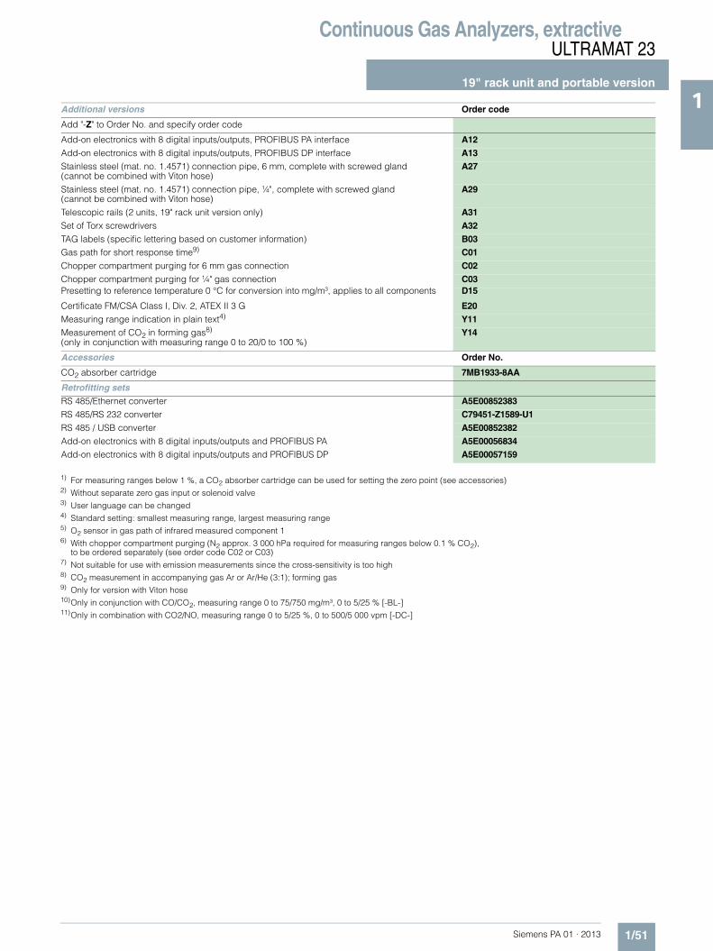
Continuous Gas Analyzers, extractiveULTRAMAT 23
19" rack unit and portable version
1/51Siemens PA 01 · 2013
1
1) For measuring ranges below 1 %, a CO2 absorber cartridge can be used for setting the zero point (see accessories)2) Without separate zero gas input or solenoid valve3) User language can be changed4) Standard setting: smallest measuring range, largest measuring range5) O2 sensor in gas path of infrared measured component 16) With chopper compartment purging (N2 approx. 3 000 hPa required for measuring ranges below 0.1 % CO2),
to be ordered separately (see order code C02 or C03)7) Not suitable for use with emission measurements since the cross-sensitivity is too high8) CO2 measurement in accompanying gas Ar or Ar/He (3:1); forming gas9) Only for version with Viton hose10)Only in conjunction with CO/CO2, measuring range 0 to 75/750 mg/m³, 0 to 5/25 % [-BL-]11)Only in combination with CO2/NO, measuring range 0 to 5/25 %, 0 to 500/5 000 vpm [-DC-]
Additional versions Order code
Add "-Z" to Order No. and specify order code
Add-on electronics with 8 digital inputs/outputs, PROFIBUS PA interface A12
Add-on electronics with 8 digital inputs/outputs, PROFIBUS DP interface A13Stainless steel (mat. no. 1.4571) connection pipe, 6 mm, complete with screwed gland(cannot be combined with Viton hose)
A27
Stainless steel (mat. no. 1.4571) connection pipe, ¼", complete with screwed gland(cannot be combined with Viton hose)
A29
Telescopic rails (2 units, 19" rack unit version only) A31
Set of Torx screwdrivers A32
TAG labels (specific lettering based on customer information) B03Gas path for short response time9) C01
Chopper compartment purging for 6 mm gas connection C02
Chopper compartment purging for ¼" gas connection C03Presetting to reference temperature 0 °C for conversion into mg/m³, applies to all components D15
Certificate FM/CSA Class I, Div. 2, ATEX II 3 G E20
Measuring range indication in plain text4) Y11Measurement of CO2 in forming gas8) (only in conjunction with measuring range 0 to 20/0 to 100 %)
Y14
Accessories Order No.
CO2 absorber cartridge 7MB1933-8AA
Retrofitting sets
RS 485/Ethernet converter A5E00852383
RS 485/RS 232 converter C79451-Z1589-U1
RS 485 / USB converter A5E00852382
Add-on electronics with 8 digital inputs/outputs and PROFIBUS PA A5E00056834Add-on electronics with 8 digital inputs/outputs and PROFIBUS DP A5E00057159

Continuous Gas Analyzers, extractiveULTRAMAT 23
19" rack unit and portable version
1/52 Siemens PA 01 · 2013
1 Ordering notes
Special selection rules must be observed when measuring some components.
Measured component N2O
7MB2335, 7MB2337 and 7MB2338 (application: Si chip production)• Measuring range 0 to 100 / 500 ppm (MB designation "E")• Can only be used to measure N2O in ultra-pure gases
7MB2337 and 7MB2338 (application: measurement in accordance with the requirements of the Kyoto protocol)• Measuring range 0 to 500 / 5 000 vpm (MB designation "Y")• Requires simultaneous measurement of CO2 for correction of
cross-interference
7MB2337-*CP*0-*SY* or7MB2338-*DC*0-*SY* (including NO measurement)
7MB2338 (application in accordance with the requirements of the 30th BImSchV, "biomass")• Measuring range 0 to 50 / 500 mg/m³ (MB designation "S")• Requires simultaneous measurement of CO2 and CO for
correction of cross-interference
7MB2338-*BL*0-*SS*
7MB2337 and 7MB2338 (application with paramagnetic oxygen measuring cell and separate gas path)
7MB2337-4**80-**** - Z + C117MB2337-5**80-**** - Z + C11
7MB2338-4**80-**** - Z + C117MB2338-5**80-**** - Z + C11
Measured component SF6
7MB2335, 7MB2337 and 7MB2338 (application: SI chip production)• Measuring range 0 to 500 / 2 500 ppm (MB designation "H")• Can only be used to measure SF6 in inert gases
Calibration interval (TÜV versions)
Calibration intervals, standard devices
Component Smallest measuring range (TÜV)
Calibration interval Remarks Z suffix
CO 0 … 150 mg/m³ 5 months 13./27. BImSchV E50
CO 0 … 250 mg/m³ 12 months 13./27. BImSchV
NO 0 … 100 mg/m³ 5 months 13./27. BImSchV E50
NO 0 … 250 mg/m³ 12 months 13./27. BImSchV
SO2 0 … 400 mg/m³ 12 months 13./27. BImSchV
N2O 0 … 500 ppm Kyoto protocol
N2O 0 … 50 mg/m³ 6 months 30. BImSchV
AUTOCAL(ambient air)
AUTOCAL(inert gas e.g. N2)
Calibration with calibration gas Comment (keep to technical
specs)Zero point Calibration point Zero point Calibration point Zero point Calibration point
Hours Weeks
IR components 3 ... 24 3 ... 24 o 52
O2 - electrical chemical sensor
Stable 3 ... 24 Stable - 52 o
O2 paramagnetic Cell
- 3 ... 24 1 o at MB < 5 %
- 3 ... 24 8 o at MB > 5 %
O2 paramagnetic Cell
3 ... 24 - o 52 at MB < 5 %
3 ... 24 - o 52 at MB > 5 %
H2S sensor 3 - 3 - o 12
o = with AUTOCAL

Continuous Gas Analyzers, extractiveULTRAMAT 23
19" rack unit and portable version
1/53Siemens PA 01 · 2013
1■ Dimensional drawings
ULTRAMAT 23, 19“ unit, dimensions in mm

Continuous Gas Analyzers, extractiveULTRAMAT 23
19" rack unit and portable version
1/54 Siemens PA 01 · 2013
1
ULTRAMAT 23, desktop unit, dimensions in mm
2357

Continuous Gas Analyzers, extractiveULTRAMAT 23
19" rack unit and portable version
1/55Siemens PA 01 · 2013
1■ Schematics
Pin assignment (electrical and gas connections)
ULTRAMAT 23, pin assignment (standard)

Continuous Gas Analyzers, extractiveULTRAMAT 23
19" rack unit and portable version
1/56 Siemens PA 01 · 2013
1
ULTRAMAT 23, pin assignment of the optional PROFIBUS interface board
37
36
35
34
33
29
30
31
32
18
17
16
14
13
12
11
10
9
8
7
6
5
28
27
26
25
24
4
3
2
1
23
22
21
20
19
15
1
2
3
4
5
6
7
8
9
1
2
3
4
5
6
7
8
9
M
M
Connector SUB-D 9F-X90PROFIBUS DP
VP /+ 5 V
DGND
RxD/TxD-P (B)
CNTR-P/direction control
Connector SUB-D 9M-X90PROFIBUS PA
PA-P(+)PA-N(-)
optional
Contact loadmax. 24 V/1 A, AC/DC
for shownrelay contact position,the relay has zero current
Isolatedvia optocoupler"0" = 0 V (0 ... 4.5 V)"1" = 24 V (13 ... 33 V)
Safety extra-low voltage (SELV) with safe electrical isolation.
Safety extra-low voltage (SELV) with safe electrical isolation.
GND
Relay 11
Relay 12
Relay 13
Relay 14
Relay 15
Relay 16
Relay 9
Relay 10
Binary input 8-PNCNC
GND
Binary input 7-PBinary input 6-PBinary input 5-PBinary input 4-PBinary input 3-PBinary input 2-PBinary input 1-PBinary input 1 to 8-N
Connector SUB-D 37F (option) -X50
CNTR-N
RxD/TxD-N (A)
Note:All cables to the connectors or terminal blocks must be shielded and rest against the enclosure potential.

Continuous Gas Analyzers, extractiveULTRAMAT 23
19" rack unit and portable version
1/57Siemens PA 01 · 2013
119“ unit
ULTRAMAT 23, 19“ unit, e.g. one infrared component with oxygen measurement
Desktop unit
ULTRAMAT 23, portable unit, in sheet-steel housing, gas and electrical connections
2 134567
Power supplyand fuse
Gas connections: stubs 6 mm or ¼"
-X459-pin socket
RS 485
-X909-pin interface
socket (option): e.g. PROFIBUS
-X5037-pin socketoption modulebinary inputs/relay outputs
-X8037-pin socketanalog and digitalinputs/outputs
57 3 2
-X8037-pin socketanalog and digitalinputs/outputs
-X5037-pin socketoption modulebinary inputs/relay outputs
-X459-pin socket
RS 485
Power switch Power supplyand fuse
-X909-pin interface
socket (option): e.g. PROFIBUSGas connections: stubs 6 mm
(gas inlet on front side)
When installing in a cabinet, mount only on support rails.

Continuous Gas Analyzers, extractiveULTRAMAT 23
19" rack unit and portable version
1/58 Siemens PA 01 · 2013
1
ULTRAMAT 23, designation of the different labels
1
2
3
4
5
6
7
1
2
3
4
5
6
7
1
2
3
4
5
6
7
2
3
5
7
Messgas/Prüfgas 1Sample gas/Span gasGaz de mesure/d’ajustage 1
Messgas/Prüfgas 2Sample gas/Span gas 2Gaz de mesure/d’ajustage 2
GehäusebespülungEnclosure purgeBalayage de l’appareilatmosphärischer Druckaufnehmeratmospherical pressure transducercapteur de pression atmosphériqueChopperraumbespülungChopper purgeBalayage de l’obturateur
Messgas/PrüfgasSample gas/Span gasGaz de mesure/d’ajustage
nicht belegtnot usednon utilisé
GehäusebespülungEnclosure purgeBalayage de l’appareilatmosphärischer Druckaufnehmeratmospherical pressure transducercapteur de pression atmosphériqueChopperraumbespülungChopper purgeBalayage de l’obturateur
Messgas/PrüfgasSample gas/Span gasGaz de mesure/d’ajustage
nicht belegtnot usednon utilisé
GehäusebespülungEnclosure purgeBalayage de l’appareilatmosphärischer Druckaufnehmeratmospherical pressure transducercapteur de pression atmosphériqueChopperraumbespülungChopper purgeBalayage de l’obturateur
AUTOCAL-Gas/NullgasAUTOCAL gas/Zero gasGaz AUTOCAL/zéro
Messgas/PrüfgasSample gas/Span gasGaz de mesure/d’ajustage
GehäusebespülungEnclosure purgeBalayage de l’appareil
ChopperraumbespülungChopper purgeBalayage de l’obturateur
AUTOCAL-Gas/NullgasAUTOCAL gas/Zero gasGaz AUTOCAL/zéro
Key to symbolsULTRAMAT 2319” rack unitwith two separategas paths or pipe version
Key to symbolsULTRAMAT 2319” rack unitwithout sample gas pump
Key to symbolsULTRAMAT 2319” rack unitwith sample gas pump
Key to symbolsULTRAMAT 23portable, in sheet-steel housing

Continuous Gas Analyzers, extractiveULTRAMAT 23
Documentation
1/59Siemens PA 01 · 2013
1■ Selection and ordering data
■ Selection and ordering data
Operating instructions Order No.
ULTRAMAT 23Gas analyzer for IR-absorbing gases and oxygen
• German C79000-B5200-C216
• English C79000-B5276-C216
• French C79000-B5277-C216
• Spanish C79000-B5278-C216
• Italian C79000-B5272-C216
Suggestions for spare parts
Description Quantity for 2 years
Quantity for 5 years
Order No.
Analyzer unit
O-ring for analyzer chamber: 180, 90, 60, 20 mm 2 4 C71121-Z100-A99
Chopper
• With motor, for 1 IR channel (7MB2335-...) 1 1 C79451-A3468-B515
• With motor, for 2 IR channels (7MB2337-..., 7MB2338-...) 1 1 C79451-A3468-B516
Electronics
Motherboard, with firmware - 1 C79451-A3494-D501
Keypad 1 1 C79451-A3492-B605
LCD module 1 1 C79451-A3494-B16
Connector filter - 1 W75041-E5602-K2
Line switch (portable analyzer) - 1 W75050-T1201-U101
Fusible element 220 ... 240 V 2 4 W79054-L1010-T630
Fusible element 100 ... 120 V 2 4 W79054-L1011-T125
Other
Safety filter (zero gas), internal 2 2 A5E00059149
Safety filter (sample gas), internal 2 3 C79127-Z400-A1
Pressure switch 1 2 C79302-Z1210-A2
Flowmeter 1 2 C79402-Z560-T1
Set of gaskets for sample gas pump 2 5 C79402-Z666-E20
Condensation trap (for portable unit, in sheet steel enclosure) 1 2 C79451-A3008-B43
Filter (for portable unit, in sheet steel enclosure) 1 2 C79451-A3008-B60
Oxygen sensor 1 1 C79451-A3458-B55
Sample gas pump 50 Hz 1 1 C79451-A3494-B10
Sample gas pump 60 Hz 1 1 C79451-A3494-B11
Solenoid valve 1 1 C79451-A3494-B33

Continuous Gas Analyzers, extractiveULTRAMAT 6
General information
1/60 Siemens PA 01 · 2013
1 ■ Overview
The ULTRAMAT 6 single-channel or dual-channel gas analyzers operate according to the NDIR two-beam alternating light princi-ple and measure gases highly selectively whose absorption bands lie in the infrared wavelength range from 2 to 9 μm, such as CO, CO2, NO, SO2, NH3, H2O as well as CH4 and other hydrocarbons.
Single-channel analyzers measure up to 2 gas components, dual-channel analyzers up to 4 gas components simultaneously.
■ Benefits
• High selectivity with double-layer detector and optical coupler - Reliable measurements even in complex gas mixtures
• Low detection limits - Measurements with low concentrations
• Corrosion-resistant materials in gas path (option) - Measurement possible in highly corrosive sample gases
• Analyzer cells can be cleaned as required on site - Cost savings due to reuse after contamination
• Electronics and physics: gas-tight isolation, purging is possible, IP65 - Long service life even in harsh environments
• Heated versions (option) - Use also in presence of gases condensing at low
temperature• EEx(p) for zones 1 and 2 (according to ATEX 2G and ATEX 3G)
■ Application
Areas of application• Measurement for boiler control in incineration plants• Emission measurements in incineration plants• Measurement in the automotive industry (test benches)• Warning equipment• Process gas concentrations in chemical plants• Trace measurements in pure gas processes• Environmental protection• TLV (Threshold Limit Value) monitoring at the workplace• Quality monitoring• Ex versions for analyzing flammable and non-flammable
gases or vapors for use in hazardous areas
Special versions
Special applications
Besides the standard combinations, special applications con-cerning material in the gas path, material in the sample cells (e.g. Titan, Hastelloy C22) and measured components are also available on request
TÜV version/QAL
TÜV-approved versions are available for measurement of CO, NO and SO2 according to 13th and 17th BlmSchV and TA Luft.Smallest TÜV-approved and permitted measuring ranges:• 1-component analyzer
CO: 0 to 50 mg/m3
NO: 0 to 100 mg/m3
SO2: 0 to 75 mg/m3
• 2-component analyzer (series connection)CO: 0 to 75 mg/m3
NO: 0 to 200 mg/m3.Furthermore, the TÜV-approved versions of the ULTRAMAT 6 comply with the requirements of EN 14956 and QAL 1 in ac-cordance with EN 14181. Conformity of the analyzers with both standards is TÜV-certified.The analyzer drift can be determined in accordance with EN 14181 (QAL 3) either manually or with a PC using the SIPROM GA maintenance and servicing software. In addition, selected manufacturers of emission evaluation computers offer the possibility for downloading the drift data via the ana-lyzer’s serial interface and to automatically record and pro-cess it in the evaluation computer.
Flow-type reference compartment• The flow through the reference compartment should be
adapted to the sample gas flow• The gas supply of the reduced flow-type reference compart-
ment should have an upstream pressure of 3 000 to 5 000 hPa (abs.). Then a restrictor will automatically adjust the flow to approximately 8 ml/min
■ Design
19" rack unit• 19" rack unit with 4 HU for installation
- in hinged frame- in cabinets with or without telescopic rails
• Front plate for service purposes can be pivoted down (laptop connection)
• Internal gas paths: hose made of FKM (Viton) or pipe made of titanium or stainless steel
• Gas connections for sample gas inlet and outlet: pipe diame-ter 6 mm or 1/4"
• Flow indicator for sample gas on front plate (option)• Pressure switch in sample gas path for flow monitoring
(option)
Field device• Two-door enclosure with gas-tight separation of analyzer and
electronics sections from gas path• Individually purgeable enclosure halves• Parts in contact with sample gas can be heated up to 65 °C
(option)• Gas path: hose made of FKM (Viton) or pipe made of titanium
or stainless steel (further materials possible as special appli-cations)
• Gas connections for sample gas inlet and outlet: pipe union for pipe diameter 6 mm or 1/4"
• Purging gas connections: pipe diameter 10 mm or 3/8"

Continuous Gas Analyzers, extractiveULTRAMAT 6
General information
1/61Siemens PA 01 · 2013
1Display and control panel• Large LCD field for simultaneous display of:
- Measured value (digital and analog displays)- Status bar- Measuring ranges
• Contrast of the LCD field adjustable via the menu• Washable membrane keyboard with five softkeys• Menu-driven operator control for parameterization, test func-
tions, adjustment• Operator support in plain text• Graphic display of concentration trend; programmable time
intervals• Bilingual operating software:
German/English, English/Spanish, French/English, Spanish/English, Italian/English
Input and outputs• One analog output per medium (from 0, 2, 4 to 20 mA;
NAMUR parameterizable)• Two analog inputs freely configurable (e.g. correction of
cross-interferences or external pressure sensor)
• Six binary inputs freely configurable (e.g. measurement range changeover, processing of external signals from the sample preparation)
• Six relay outputs freely configurable e.g. for fault, mainte-nance request, limit alarm, external solenoid valves)
• Expansion by eight additional binary inputs and eight addi-tional relay outputs e.g. for autocalibration with up to four test gases
Communication
RS 485 present in the basic unit (connection at the rear; for the rack unit also behind the front plate).
Options• AK interface for the automotive industry with extended
functions• RS 485/RS 232 converter• RS 485/Ethernet converter• RS 485/USB converter• Connection to networks via PROFIBUS DP/PA interface• SIPROM GA software as the service and maintenance tool
ULTRAMAT 6, membrane keyboard and graphic display
Status line for display of analyzer status(programmable)
LED backlit graphicdisplay and membrane keyboardwith noticeable click
Two code levelsaccording to NAMUR(maintenance andspecialist level)
MEAS key to return tomeasurement mode
Easy operation with menu controlusing five softkeys
Display of currentmeasuring ranges
ESC keyto abort inputs
INFO keyfor help in plain text
CLEAR key to delete inputs
Keyboard toenter values
Display ofconcentrations asnumbers and bargraphfor channel 1
ENTER key to accept input values
Display of start-of-scale and full-scale values
Display ofconcentrations asnumbers and bargraphfor channel 2 Status line for channel 2
to display the unitstatus (programmable)

Continuous Gas Analyzers, extractiveULTRAMAT 6
General information
1/62 Siemens PA 01 · 2013
1 Designs – Parts wetted by sample gas, standard
Options
Versions – Parts wetted by sample gas, special applications (examples)
Gas path 19" rack unit Field device Field device Ex
With hoses Bushing Stainless steel, mat. no. 1.4571 -
Hose FKM (e.g. Viton)
Sample chamber:
• Body Aluminum
• Lining Aluminum
• Fitting Stainless steel, mat. no. 1.4571, O-ring: FKM (e.g. Viton) or FFKM (Kalrez)
• Window CaF2, adhesive: E353, O-ring: FKM (e.g. Viton) or FFKM (Kalrez)
With pipes Bushing Titanium
Pipe Titanium, O-ring: FKM (e.g. Viton) or FFKM (Kalrez)
Sample chamber:
• Body Aluminum
• Lining Tantalum (only for cell length 20 mm to 180 mm)
• Window CaF2, adhesive: E353, O-ring: FKM (e.g. Viton) or FFKM (Kalrez)
With pipes Bushing Stainless steel, mat. no. 1.4571
Pipe Stainless steel, mat. no. 1.4571, O-ring: FKM (e.g. Viton) or FFKM (Kalrez)
Sample chamber:
• Body Aluminum
• Lining Aluminum or tantalum (tantalum only for cell length 20 mm to 180 mm)
• Window CaF2, adhesive: E353, O-ring: FKM (e.g. Viton) or FFKM (Kalrez)
Gas path 19" rack unit Field device Field device Ex
Flow indicator Measurement pipe Duran glass - -
Variable area Duran glass
Suspension boundary PTFE (Teflon)
Angle pieces FKM (e.g. Viton)
Pressure switch Membrane FKM (e.g. Viton) - -
Enclosure PA 6.3T
Gas path 19" rack unit Field device Field device Ex
With pipes Bushing e.g. Hastelloy C22
Pipe e.g. Hastelloy C22, O-ring: FKM (e.g. Viton) or FFKM (Kalrez)
Sample chamber:
• Body e.g. Hastelloy C22
• Window CaF2, without adhesiveO-ring: FKM (e.g. Viton) or FFKM (Kalrez)

Continuous Gas Analyzers, extractiveULTRAMAT 6
General information
1/63Siemens PA 01 · 2013
1Gas path (19" rack unit)
Gas path ULTRAMAT 6, single-channel unit, 19" unit, with flow-type reference cell (option)
Gas path ULTRAMAT 6, dual-channel unit, 19" unit
Legend for the gas path figures
1 Sample gas inlet channel 1 8 Restrictor
2 Sample gas outlet channel 1 9 Purge gas inlet
3 Reference gas outlet (option) 10 Gas inlet atmospheric pressure sensor
4 Reference gas inlet (option) 11 Atmospheric pressure sensor
5 Sample gas inlet channel 2 12 Flow indicator in sample gas path (option)
6 Sample gas outlet channel 2 13 Pressure switch in sample gas path (option)
7 IR physical system
PF
P
9 10 12 34
11
138
7
12

Continuous Gas Analyzers, extractiveULTRAMAT 6
General information
1/64 Siemens PA 01 · 2013
1 Gas path (field device)
Gas path ULTRAMAT 6, field unit, with flow-type reference cell (option)
Legend for the gas path figures
1 Sample gas inlet 7 Purging gas outlet (analyzer side)
2 Sample gas outlet 8 Purging gas inlet (analyzer side)
3 Reference gas inlet (option) 9 Connection of atmospheric pressure sensor
4 Reference gas outlet (option) 10 IR physical system
5 Purging gas inlet (electronics side) 11 Atmospheric pressure sensor
6 Purging gas outlet (electronics side)

Continuous Gas Analyzers, extractiveULTRAMAT 6
General information
1/65Siemens PA 01 · 2013
1■ Function
Principle of operation
The ULTRAMAT 6 gas analyzer operates according to the infra-red two-beam alternating light principle with double-layer detec-tor and optical coupler.
The measuring principle is based on the molecule-specific absorption of bands of infrared radiation. The absorbed wave-lengths are characteristic to the individual gases, but may par-tially overlap. This results in cross-sensitivities which are re-duced to a minimum in the ULTRAMAT 6 gas analyzers by the following measures:• Gas-filled filter cell (beam divider)• Double-layer detector with optical coupler• Optical filters if necessary
The figure shows the measuring principle. An IR source (1) which is heated to approx. 700 ºC and which can be shifted to balance the system is divided by the beam divider (3) into two equal beams (sample and reference beams). The beam divider also acts as a filter cell.
The reference beam passes through a reference cell (8) filled with N2 (a non-infrared-active gas) and reaches the right-hand side of the detector (11) practically unattenuated. The sample beam passes through the sample chamber (7) through which the sample gas flows and reaches the left-hand side of the de-tector (10) attenuated to a lesser or greater extent depending on the concentration of the sample gas. The detector is filled with a defined concentration of the gas component to be measured.
The detector is designed as a double-layer detector. The center of the absorption band is preferentially absorbed in the upper detector layer, the edges of the band are absorbed to approxi-mately the same extent in the upper and lower layers. The upper and lower detector layers are connected together via the micro-flow sensor (12). This coupling means that the spectral sensitiv-ity has a very narrow band.
The optical coupler (13) lengthens the lower receiver cell layer optically. The infrared absorption in the second detector layer is varied by changing the slider position (14). It is thus possible to individually minimize the influence of interfering components.
A chopper (5) rotates between the beam divider and the sample chamber and interrupts the two beams alternately and periodi-cally. If absorption takes place in the sample chamber, a pulsat-ing flow is generated between the two detector levels which is converted by the microflow sensor (12) into an electric signal.
The microflow sensor consists of two nickel-plated grids heated to approximately 120 ºC, which, along with two supplementary resistors, form a Wheatstone bridge. The pulsating flow together with the dense arrangement of the Ni grids causes a change in resistance. This leads to an offset in the bridge, which is depen-dent on the concentration of the sample gas.
Notes
The sample gases must be fed into the analyzers free of dust. Condensation should be prevented from occurring in the sample chambers. Therefore, the use of gas modified for the measuring task is necessary in most application cases.
As far as possible, the ambient air of the analyzer should not have a large concentration of the gas components to be mea-sured.
Flow-type reference sides with reduced flow must not be oper-ated with flammable or toxic gases.
Flow-type reference sides with reduced flow and an O2 content > 70 % may only be used together with Y02 (Clean for O2).
ULTRAMAT 6, principle of operation
Channels with electronically suppressed zero point only differ from the standard version in the measuring range parameteriza-tion.
Physically suppressed zeros can be provided as a special ap-plication.
1
2
3
5
6
7
4
8
9
10 11
13
14
12
1 IR source, adjustable 8 Reference cell2 Optical filter 9 Sample gas outlet3 Beam divider 10 Detector, meas. side4 Eddy current drive 11 Detector, reference side
5 Chopper 12 Microflow sensor6 Sample gas inlet 13 Optical coupler7 Sample cell 14 Slider, adjustable

Continuous Gas Analyzers, extractiveULTRAMAT 6
General information
1/66 Siemens PA 01 · 2013
1 Essential characteristics• Dimension of measured value freely selectable
(e.g. vpm, mg/m3)• Four freely-parameterizable measuring ranges per
component • Measuring ranges with suppressed zero point possible• Measuring range identification• Galvanically isolated signal output 0/2/4 to 20 mA per compo-
nent• Automatic or manual measuring range switchover selectable;
remote switching is also possible• Differential measuring ranges with flow-type reference cell• Storage of measured values possible during adjustments• Time constants selectable within wide limits (static/dynamic
noise suppression); i.e. the response time of the analyzer or component can be matched to the respective measuring task
• Short response time• Low long-term drift• Measuring point switchover for up to 6 measuring points
(programmable)• Measuring point identification• Monitoring of sample gas flow (option)• Internal pressure sensor for correction of variations in atmo-
spheric pressure in the range 700 to 1 200 hPa absolute• External pressure sensor can be connected for correction of
variations in the process gas pressure in the range 700 to 1 500 hPa absolute (option)
• Two control levels with separate authorization codes to pre-vent unintentional and unauthorized inputs
• Automatic, parameterizable measuring range calibration• Simple handling using a numerical membrane keyboard and
operator prompting• Operation based on NAMUR recommendation• Customer-specific analyzer options such as:
- Customer acceptance- TAG labels- Drift recording
• Easy device replacement since electric connections can be simply disconnected from the device
• Sample chambers for use in presence of highly corrosive sam-ple gases (e.g. tantalum layer or Hastelloy C22)
Additional features, dual-channel version• Separate design of physical unit, electronics, inputs/outputs
and power supply for each channel• Display and operation via common LCD panel and keyboard• Measurement channels 1 and 2 can be converted to series
connection (linking of gas connections from channel 1 to channel 2 on rear)

Continuous Gas Analyzers, extractiveULTRAMAT 6
19" rack unit
1/67Siemens PA 01 · 2013
1■ Technical specifications
General information
Measuring ranges 4, internally and externally switch-able; autoranging is also possible
Smallest possible measuring range Dependent on the application: e.g. CO: 0 … 10 vpm, CO2: 0 … 5 vpm
Largest possible measuring span Dependent on the application
Measuring range with suppressed zero point
Any zero point within 0 … 100 vol.% can be imple-mented; smallest possible span 20 %
Operating position Front wall, vertical
Conformity CE mark in accordance with EN 50081-1, EN 50082-2
Influence of interfering gases must be considered separately
Design, enclosure
Weight Approx. 15 kg (with one IR channel) Approx. 21 kg (with two IR channels)
Degree of protection IP20 according to EN 60529
Electrical characteristics
EMC (Electromagnetic Compatibility)
In accordance with standard requirements of NAMUR NE21 (08/98)
Electrical safety According to EN 61010-1, overvoltage category III
Power supply 100 … 120 V AC (nominal range of use 90 … 132 V), 47 … 63 Hz or 200 … 240 V AC (nominal range of use 180 … 264 V), 47 … 63 Hz
Power consumption 1-channel unit: Approx. 40 VA2-channel unit: Approx. 70 VA
Fuse values
• 100 ... 120 V 1 T/250 (7MB2121)1.6 T/250 (7MB2123)
• 200 ... 240 V 0.63 T/250 (7MB2121)1 T/250 (7MB2123)
Gas inlet conditions
Permissible sample gas pressure
• With hoses
- Without pressure switch 600 … 1 500 hPa (absolute)
- With pressure switch 700 … 1 300 hPa (absolute)
• With pipes (without pressure switch) 600 … 1 500 hPa (absolute)
Sample gas flow 18 … 90 l/h (0.3 … 1.5 l/min)
Sample gas temperature Min. 0 ... max. 50 °C, but above the dew point
Sample gas humidity < 90 % RH (relative humidity), or dependent on measuring task, non-condensing
Dynamic response
Warm-up period At room temperature < 30 min (the technical specification will be met after 2 hours)
Delayed display (T90-time) Dependent on length of analyzer chamber, sample gas line and parameterizable damping
Damping (electrical time constant) 0 … 100 s, parameterizable
Dead time (purging time of the gas path in the unit at 1 l/min)
Approximately 0.5 ... 5 s, depending on version
Time for device-internal signal processing
< 1 s
Pressure correction range
Pressure sensor
• Internal 700 … 1 200 hPa absolute
• External 700 … 1 500 hPa absolute
Measuring response (relating to sample gas pressure 1 013 hPa absolute, 0.5 l/min sample gas flow and 25 °C ambient temperature)
Output signal fluctuation < ± 1 % of the smallest possible measuring range according to rating plate
Zero point drift <± 1 % of the current measuring range/week
Measured-value drift <± 1 % of the current measuring range/week
Repeatability ≤ 1 % of the current measuring range
Detection limit 1 % of the smallest possible mea-suring range
Linearity error < 0.5 % of the full-scale value
Influencing variables (relating to sample gas pressure 1 013 hPa absolute, 0.5 l/min sample gas flow and 25 °C ambient temperature)
Ambient temperature < 1 % of current measuring range/10 K (with constant receiver cell temperature)
Sample gas pressure • When pressure compensation has been switched on: < 0.15 % of the span/1 % change in atmo-spheric pressure
• When pressure compensation has been switched off: < 1.5 % of the span/1 % change in atmo-spheric pressure
Sample gas flow Negligible
Power supply < 0.1 % of the current measuring range with rated voltage ± 10 %
Environmental conditions Application-specific measuring influences possible if ambient air contains measured components or cross interference-sensitive gases
Electrical inputs and outputs
Analog output 0/2/4 ... 20 mA, isolated; load ≤ 750 Ω
Relay outputs 6, with changeover contacts, freely parameterizable, e.g. for measuring range identification; load: 24 V AC/DC/1 A, isolated, non-sparking
Analog inputs 2, dimensioned for 0/2/4 ... 20 mA for external pressure sensor and accompanying gas influence cor-rection (correction of cross-inter-ference)
Binary inputs 6, designed for 24 V, isolated, freely parameterizable, e.g. for measuring range switchover
Serial interface RS 485
Options AUTOCAL function with 8 addi-tional binary inputs and relay out-puts, also with PROFIBUS PA or PROFIBUS DP
Climatic conditions
Permissible ambient temperature -30 ... +70 °C during storage and transportation, 5 ... 45 °C during operation
Permissible humidity < 90 % RH (relative humidity) as annual average, during storage and transportation (dew point must not be undershot)

Continuous Gas Analyzers, extractiveULTRAMAT 6
19" rack unit
1/68 Siemens PA 01 · 2013
1
Footnotes: see next page
■ Selection and ordering data Order No.
ULTRAMAT 6 gas analyzerSingle-channel 19" rack unit for installation in cabinets
7MB2121- 77777- 7A A7 Cannot be combined
Gas connections for sample gas and reference gasPipe with 6 mm outer diameter 0 0 A21Pipe with ¼" outer diameter 1 1 A20
Measured component Possible with measuring range identification
CO 11 ... 30 ACO highly selective (with optical filter) 12 ... 30 BCO (TÜV; see table "TÜV single component", page 1/53) X
CO2 10 ... 30 CCH4 13 ... 30 DC2H2 15 ... 30 E
C2H4 15 ... 30 FC2H6 14 ... 30 GC3H6 14 ... 30 H
C3H8 13 ... 30 JC4H6 15 ... 30 KC4H10 14 ... 30 L
C6H14 14 ... 30 MSO2 (TÜV; see table "TÜV single component", page 1/53)
13 ... 30 N
NO (TÜV; see table "TÜV single component", page 1/53)
14 ... 20, 22 P
NH3 (dry) 14 ... 30 Q QH2O 17 ... 20, 22 R RN2O 13 ... 30 S
Smallest measuring range
Largest measuring range
Measuring range identification
0 ... 5 vpm 0 ... 100 vpm 10 A0 ... 10 vpm 0 ... 200 vpm 11 B0 ... 20 vpm 0 ... 400 vpm 12 C
0 ... 50 vpm 0 ... 1 000 vpm 13 D0 ... 100 vpm 0 ... 1 000 vpm 14 E0 ... 300 vpm 0 ... 3 000 vpm 15 F
0 ... 500 vpm 0 ... 5 000 vpm 16 G0 ... 1 000 vpm 0 ... 10 000 vpm 17 H0 ... 3 000 vpm 0 ... 10 000 vpm 18 J
0 ... 3 000 vpm 0 ... 30 000 vpm 19 K0 ... 5 000 vpm 0 ... 15 000 vpm 20 L0 ... 5 000 vpm 0 ... 50 000 vpm 21 M
0 ... 1 % 0 ... 3 % 22 N0 ... 1 % 0 ... 10 % 23 P0 ... 3 % 0 ... 10 % 24 Q
0 ... 3 % 0 ... 30 % 25 R0 ... 5 % 0 ... 15 % 26 S0 ... 5 % 0 ... 50 % 27 T
0 ... 10 % 0 ... 30 % 28 U0 ... 10 % 0 ... 100 % 29 V0 ... 30 % 0 ... 100 % 30 W
Internal gas paths Sample chamber1)
(lining)Reference chamber(flow-type)
Hose made of FKM(Viton)
Aluminum Non-flow-type 0 0 0 A20, A21Aluminum Flow-type 1 1
Pipe made of titanium Tantalum Non-flow-type 4 4 A20, A21, Y02Tantalum Flow-type 5 5 Y02
Stainless steel pipe(mat. no. 1.4571)
Aluminum Non-flow-type 6 6 A20, A21Tantalum Non-flow-type 8 8 A20, A21
With sample gas monitoring
Hose made of FKM(Viton)
Aluminum Non-flow-type 2 2 2 A20, A21Aluminum Flow-type 3 3

Continuous Gas Analyzers, extractiveULTRAMAT 6
19" rack unit
1/69Siemens PA 01 · 2013
1
1) Only for cell length 20 to 180 mm
■ Selection and ordering data Order No.
ULTRAMAT 6 gas analyzerSingle-channel 19" rack unit for installation in cabinets
7MB2121- 77777- 7A A7 Cannot be combined
Add-on electronicsWithout 0AUTOCAL function• With 8 additional digital inputs/outputs 1• With serial interface for the automotive industry (AK) 3 3 E20• With 8 digital inputs/outputs, PROFIBUS PA interface 6• With 8 digital inputs/outputs, PROFIBUS DP interface 7
Power supply100 ... 120 V AC, 47 ... 63 Hz 0200 ... 240 V AC, 47 ... 63 Hz 1
Operating software and documentationGerman 0English 1French 2Spanish 3Italian 4
Additional versions Order code
Add "-Z" to Order No. and specify order code
Flow-type reference cell with reduced flow, 6 mm A20
Flow-type reference cell with reduced flow, ¼" A21
Telescopic rails (2 units) A31
Set of Torx screwdrivers A32
TAG labels (specific lettering based on customer information) B03
Kalrez gaskets in sample gas path B04
FM/CSA certificate – Class I Div 2 E20
Clean for O2 service (specially cleaned gas path) Y02
Measuring range indication in plain text, if different from the standard setting Y11
Special setting (only in conjunction with an application no., e.g. extended measuring range)
Y12
Extended special setting (only in conjunction with an application no., e.g. determination of cross-interferences)
Y13
TÜV version acc. to 13th and 17th BlmSchV Y17
Retrofitting sets Order No.
RS 485/Ethernet converter A5E00852383
RS 485/RS 232 converter C79451-Z1589-U1
RS 485 / USB converter A5E00852382
AUTOCAL function with serial interface for the automotive industry (AK) C79451-A3480-D512
AUTOCAL function with 8 digital inputs/outputs C79451-A3480-D511
AUTOCAL function with 8 digital inputs/outputs and PROFIBUS PA A5E00057307
AUTOCAL function with 8 digital inputs/outputs and PROFIBUS DP A5E00057312

Continuous Gas Analyzers, extractiveULTRAMAT 6
19" rack unit
1/70 Siemens PA 01 · 2013
1 ■ Selection and ordering data Order No.
ULTRAMAT 6 gas analyzerTwo-channel 19" rack unit for installation in cabinetsfor measuring 2 IR components
7MB2123-77777 - 7777 Cannot be combined
Gas connections for sample gas and reference gasPipe with 6 mm outer diameter 0 0 A21, A41Pipe with ¼" outer diameter 1 1 A20, A40
Channel 1 Measured component
Possible with measuring range identification
CO 11 ... 30 ACO highly selective (with optical filter) 12 ... 30 BCO (TÜV; see table "TÜV single component", page 1/53) XCO2 10 ... 30 CCH4 13 ... 30 DC2H2 15 ... 30 EC2H4 15 ... 30 FC2H6 14 ... 30 GC3H6 14 ... 30 HC3H8 13 ... 30 JC4H6 15 ... 30 KC4H10 14 ... 30 LC6H14 14 ... 30 MSO2 (TÜV; see table "TÜV single component", page 1/53)
13 ... 30 N
NO (TÜV; see table "TÜV single component", page 1/53)
14 ... 20, 22 P
NH3 (dry) 14 ... 30 Q QH2O 17 ... 20, 22 R RN2O 13 ... 30 S
Smallest measuring range Largest measuring range
Measuring range identification
0 ... 5 vpm 0 ... 100 vpm 10 A0 ... 10 vpm 0 ... 200 vpm 11 B0 ... 20 vpm 0 ... 400 vpm 12 C0 ... 50 vpm 0 ... 1 000 vpm 13 D0 ... 100 vpm 0 ... 1 000 vpm 14 E0 ... 300 vpm 0 ... 3 000 vpm 15 F0 ... 500 vpm 0 ... 5 000 vpm 16 G0 ... 1 000 vpm 0 ... 10 000 vpm 17 H0 ... 3 000 vpm 0 ... 10 000 vpm 18 J0 ... 3 000 vpm 0 ... 30 000 vpm 19 K0 ... 5 000 vpm 0 ... 15 000 vpm 20 L0 ... 5 000 vpm 0 ... 50 000 vpm 21 M
0 ... 1 % 0 ... 3 % 22 N0 ... 1 % 0 ... 10 % 23 P0 ... 3 % 0 ... 10 % 24 Q0 ... 3 % 0 ... 30 % 25 R0 ... 5 % 0 ... 15 % 26 S0 ... 5 % 0 ... 50 % 27 T0 ... 10 % 0 ... 30 % 28 U0 ... 10 % 0 ... 100 % 29 V0 ... 30 % 0 ... 100 % 30 W
Internal gas paths Sample chamber1)
(lining)Reference chamber(flow-type)
Hose made of FKM(Viton)
Aluminum Non-flow-type 0 0 0 A20, A21, A40, A41Aluminum Flow-type 1 1
Pipe made of titanium Tantalum Non-flow-type 4 4 A20, A21, A40, A41, Y02Tantalum Flow-type 5 5 Y02
Stainless steel pipe(mat. no. 1.4571)
Aluminum Non-flow-type 6 6 A20, A21, A40, A41Tantalum Non-flow-type 8 8 A20, A21, A40, A41
With sample gas monitoring
Hose made of FKM(Viton)
Aluminum Non-flow-type 2 2 2 A20, A21, A40, A41Aluminum Flow-type 3 3
1) Only for cell length 20 to 180 mm

Continuous Gas Analyzers, extractiveULTRAMAT 6
19" rack unit
1/71Siemens PA 01 · 2013
1
Add-on electronics
Without 0
AUTOCAL function• With 8 additional digital inputs/outputs each for channel 1 1• With 8 additional digital inputs/outputs each for channel 2 2• With 8 additional digital inputs/outputs each for channel 1 and channel 2 3• With serial interface for the automotive industry (AK) 5 5 E20• With 8 additional digital inputs/outputs each for channel 1 and channel 2
and PROFIBUS PA interface6
• With 8 additional digital inputs/outputs each for channel 1 and channel 2 and PROFIBUS DP interface
7
Power supply100 ... 120 V AC, 48 ... 63 Hz 0200 ... 240 V AC, 48 ... 63 Hz 1
Channel 2 Measured component
Possible with measuring range identification
CO 11 ... 30 ACO highly selective (with optical filter) 12 ... 30 BCO (TÜV; see table "TÜV single component", page 1/53) XCO2 10 ... 30 CCH4 13 ... 30 DC2H2 15 ... 30 EC2H4 15 ... 30 FC2H6 14 ... 30 GC3H6 14 ... 30 HC3H8 13 ... 30 JC4H6 15 ... 30 KC4H10 14 ... 30 LC6H14 14 ... 30 MSO2 (TÜV; see table "TÜV single component", page 1/53)
13 ... 30 N
NO (TÜV; see table "TÜV single component", page 1/53)
14 ... 20, 22 P
NH3 (dry) 14 ... 30 Q QH2O 17 ... 20, 22 R RN2O 13 ... 30 S
Smallest measuring range Largest measuring range
Measuring range identification
0 ... 5 vpm 0 ... 100 vpm 10 A0 ... 10 vpm 0 ... 200 vpm 11 B0 ... 20 vpm 0 ... 400 vpm 12 C0 ... 50 vpm 0 ... 1 000 vpm 13 D0 ... 100 vpm 0 ... 1 000 vpm 14 E0 ... 300 vpm 0 ... 3 000 vpm 15 F0 ... 500 vpm 0 ... 5 000 vpm 16 G0 ... 1 000 vpm 0 ... 10 000 vpm 17 H0 ... 3 000 vpm 0 ... 10 000 vpm 18 J0 ... 3 000 vpm 0 ... 30 000 vpm 19 K0 ... 5 000 vpm 0 ... 15 000 vpm 20 L0 ... 5 000 vpm 0 ... 50 000 vpm 21 M
0 ... 1 % 0 ... 3 % 22 N0 ... 1 % 0 ... 10 % 23 P0 ... 3 % 0 ... 10 % 24 Q0 ... 3 % 0 ... 30 % 25 R0 ... 5 % 0 ... 15 % 26 S0 ... 5 % 0 ... 50 % 27 T0 ... 10 % 0 ... 30 % 28 U0 ... 10 % 0 ... 100 % 29 V0 ... 30 % 0 ... 100 % 30 W
Operating software and documentationGerman 0English 1French 2Spanish 3Italian 4
■ Selection and ordering data Order No.
ULTRAMAT 6 gas analyzerTwo-channel 19" rack unit for installation in cabinetsfor measuring 2 IR components
7MB2123-77777 - 7777 Cannot be combined

Continuous Gas Analyzers, extractiveULTRAMAT 6
19" rack unit
1/72 Siemens PA 01 · 2013
1 ■ Selection and ordering data
Additional versions Order code Cannot be combined
Add "-Z" to Order No. and specify order codes.
Flow-type reference cell with reduced flow, 6 mm (channel 1) A20
Flow-type reference cell with reduced flow, ¼" (channel 1) A21
Flow-type reference cell with reduced flow, 6 mm (channel 2) A40
Flow-type reference cell with reduced flow, ¼" (channel 2) A41
Connection pipe(can only be combined with the appropriate gas connection diameter and internal gas path materials)
• Made of titanium, 6 mm, complete with screwed gland, for sample gas side A22
• Made of titanium, 6 mm, complete with screwed gland, for reference gas side A23
• Made of titanium, ¼", complete with screwed gland, for sample gas side A24
• Made of titanium, ¼", complete with screwed gland, for reference gas side A25
• Made of stainless steel (mat. no. 1.4571), 6 mm, complete with screwed gland, for sample gas side A27
• Made of stainless steel (mat. no. 1.4571), 6 mm, complete with screwed gland, for reference gas side A28
• Made of stainless steel (mat. no. 1.4571), ¼", complete with screwed gland, for sample gas side A29
• Made of stainless steel (mat. no. 1.4571), ¼", complete with screwed gland, for reference gas side A30
Telescopic rails (2 units) A31
Set of Torx screwdrivers A32
TAG labels (specific lettering based on customer information) B03
Kalrez gaskets in sample gas path (channel 1) B04
Kalrez gaskets in sample gas path (channel 2) B05
FM/CSA certificate – Class I Div 2 E20
Clean for O2 service (specially cleaned gas path; channels 1 + 2) Y02
Measuring range indication in plain text, if different from the standard setting Y11
Special setting (only in conjunction with an application no., e.g. extended measuring range) Y12
Extended special setting (only in conjunction with an application no., e.g. determination of cross-interferences)
Y13
TÜV version acc. to 13th and 17th BlmSchV (1st channel) Y17
TÜV version acc. to 13th and 17th BlmSchV (2nd channel) Y18
Retrofitting sets Order No.
RS 485/Ethernet converter A5E00852383
RS 485/RS 232 converter C79451-Z1589-U1
RS 485 / USB converter A5E00852382
AUTOCAL function with serial interface for the automotive industry (AK) C79451-A3480-D33
AUTOCAL function with 8 digital inputs/outputs for channel 1 or channel 2 C79451-A3480-D511
AUTOCAL function with 8 digital inputs/outputs and PROFIBUS PA for channel 1 or channel 2 A5E00057307
AUTOCAL function with 8 digital inputs/outputs and PROFIBUS DP for channel 1 or channel 2 A5E00057312

Continuous Gas Analyzers, extractiveULTRAMAT 6
19" rack unit
1/73Siemens PA 01 · 2013
1■ Selection and ordering data Order No.
ULTRAMAT 6 gas analyzerSingle-channel or dual-channel 19" rack unit for installation in cabinetsfor measuring 2 or 3 IR components
7MB2124- 77777 - 7777 Cannot be combined
Gas connections for sample gas and reference gasPipe with 6 mm outer diameter 0 0 A21, A41Pipe with ¼" outer diameter 1 1 A20, A40
Measured component Smallest measuring range
Largest measuring range
CO 0 ... 100 vpm 0 ... 1 000 vpm A ANO 0 ... 100 vpm 0 ... 1 000 vpm
CO 0 ... 300 vpm 0 ... 3 000 vpm A BNO 0 ... 300 vpm 0 ... 3 000 vpm
CO 0 ... 1 000 vpm 0 ... 10 000 vpm A CNO 0 ... 1 000 vpm 0 ... 10 000 vpm
For CO/NO (TÜV; table "TÜV, 2 components in series", page 1/76)
CO2 0 ... 100 vpm 0 ... 1 000 vpm B ACO 0 ... 100 vpm 0 ... 1 000 vpm
CO2 0 ... 300 vpm 0 ... 3 000 vpm B BCO 0 ... 300 vpm 0 ... 3 000 vpm
CO2 0 ... 1 000 vpm 0 ... 10 000 vpm B CCO 0 ... 1 000 vpm 0 ... 10 000 vpm
CO2 0 ... 3 000 vpm 0 ... 30 000 vpm B DCO 0 ... 3 000 vpm 0 ... 30 000 vpm
CO2 0 ... 1 % 0 ... 10 % B ECO 0 ... 1 % 0 ... 10 %
CO2 0 ... 3 % 0 ... 30 % B FCO 0 ... 3 % 0 ... 30 %
CO2 0 ... 10 % 0 ... 100 % B GCO 0 ... 10 % 0 ... 100 %
CO2 0 ... 10 % 0 ... 100 % C GCH4 0 ... 10 % 0 ... 100 %
CO2 0 ... 300 vpm 0 ... 3 000 vpm D BNO 0 ... 300 vpm 0 ... 3 000 vpm
Internal gas paths Sample chamber1)
(lining)Reference chamber(flow-type)
Hose made of FKM(Viton)
Aluminum Non-flow-type 0 0 0 A20, A21, A40, A41Aluminum Flow-type 1 1
Pipe made of titanium Tantalum Non-flow-type 4 4 A20, A21, A40, A41, Y02Tantalum Flow-type 5 5 Y02
Stainless steel pipe(mat. no. 1.4571)
Aluminum Non-flow-type 6 6 A20, A21, A40, A41Tantalum Non-flow-type 8 8 A20, A21, A40, A41
With sample gas monitoringHose made of FKM(Viton)
Aluminum Non-flow-type 2 2 2 A20, A21, A40, A41Aluminum Flow-type 3 3
Add-on electronicsWithout 0AUTOCAL function• With 8 additional digital inputs/outputs each for channel 1 1• With 8 additional digital inputs/outputs each for channel 1 and channel 2 2 2• With serial interface for the automotive industry (AK), channel 1 3 3 E20• With serial interface for the automotive industry (AK),
channel 1 and channel 24 4 E20
• With 8 additional digital inputs/outputs for channel 1and PROFIBUS PA interface
5
• With 8 additional digital inputs/outputs each for channel 1 and channel 2 and PROFIBUS PA interface
6 6
• With 8 additional digital inputs/outputs for channel 1and PROFIBUS DP interface
7
• With 8 additional digital inputs/outputs each for channel 1 and channel 2 and PROFIBUS DP interface
8 8
1) Only for cell length 20 to 180 mm

Continuous Gas Analyzers, extractiveULTRAMAT 6
19" rack unit
1/74 Siemens PA 01 · 2013
1
Power supply100 ... 120 V AC, 47 ... 63 Hz 0200 ... 240 V AC, 47 ... 63 Hz 1
Channel 2 Measured component
Possible with measuring range identification
Without channel 2 W WCO 11 ... 30 ACO highly selective (with optical filter) 12 ... 30 BCO (TÜV; see table "TÜV single component", page 1/53) XCO2 10 ... 30 CCH4 13 ... 30 DC2H2 15 ... 30 EC2H4 15 ... 30 FC2H6 14 ... 30 GC3H6 14 ... 30 HC3H8 13 ... 30 JC4H6 15 ... 30 KC4H10 14 ... 30 LC6H14 14 ... 30 MSO2 (TÜV; see table "TÜV single component", page 1/53)
13 ... 30 N
NO (TÜV; see table "TÜV single component", page 1/53)
14 ... 20, 22 P
NH3 (dry) 14 ... 30 Q QH2O 17 ... 20, 22 R RN2O 13 ... 30 S
Smallest measuring range
Largest measuring range
Measuring range identification
Without channel 2 X X A40, A41, B05
0 ... 5 vpm 0 ... 100 vpm 10 A0 ... 10 vpm 0 ... 200 vpm 11 B0 ... 20 vpm 0 ... 400 vpm 12 C0 ... 50 vpm 0 ... 1 000 vpm 13 D0 ... 100 vpm 0 ... 1 000 vpm 14 E0 ... 300 vpm 0 ... 3 000 vpm 15 F0 ... 500 vpm 0 ... 5 000 vpm 16 G0 ... 1 000 vpm 0 ... 10 000 vpm 17 H0 ... 3 000 vpm 0 ... 10 000 vpm 18 J0 ... 3 000 vpm 0 ... 30 000 vpm 19 K0 ... 5 000 vpm 0 ... 15 000 vpm 20 L0 ... 5 000 vpm 0 ... 50 000 vpm 21 M
0 ... 1 % 0 ... 3 % 22 N0 ... 1 % 0 ... 10 % 23 P0 ... 3 % 0 ... 10 % 24 Q0 ... 3 % 0 ... 30 % 25 R0 ... 5 % 0 ... 15 % 26 S0 ... 5 % 0 ... 50 % 27 T0 ... 10 % 0 ... 30 % 28 U0 ... 10 % 0 ... 100 % 29 V0 ... 30 % 0 ... 100 % 30 W
Operating software and documentationGerman 0English 1French 2Spanish 3Italian 4
■ Selection and ordering data Order No.
ULTRAMAT 6 gas analyzerSingle-channel or dual-channel 19" rack unit for installation in cabinetsfor measuring 2 or 3 IR components
7MB2124- 77777 - 7777 Cannot be combined

Continuous Gas Analyzers, extractiveULTRAMAT 6
19" rack unit
1/75Siemens PA 01 · 2013
1■ Selection and ordering dataAdditional versions Order code Cannot be
combined
Add "-Z" to Order No. and specify order codes.
Flow-type reference cell with reduced flow, 6 mm (channel 1) A20
Flow-type reference cell with reduced flow, ¼" (channel 1) A21
Flow-type reference cell with reduced flow, 6 mm (channel 2) A40
Flow-type reference cell with reduced flow, ¼" (channel 2) A41
Connection pipe(can only be combined with the appropriate gas connection diameter and internal gas path materials)
• Made of titanium, 6 mm, complete with screwed gland, for sample gas side A22
• Made of titanium, 6 mm, complete with screwed gland, for reference gas side A23
• Made of titanium, ¼", complete with screwed gland, for sample gas side A24
• Made of titanium, ¼", complete with screwed gland, for reference gas side A25
• Made of stainless steel (mat. no. 1.4571), 6 mm, complete with screwed gland, for sample gas side A27
• Made of stainless steel (mat. no. 1.4571), 6 mm, complete with screwed gland, for reference gas side A28
• Made of stainless steel (mat. no. 1.4571), ¼", complete with screwed gland, for sample gas side A29
• Made of stainless steel (mat. no. 1.4571), ¼", complete with screwed gland, for reference gas side A30
Telescopic rails (2 units) A31
Set of Torx screwdrivers A32
TAG labels (specific lettering based on customer information) B03
Kalrez gaskets in sample gas path (channel 1) B04
Kalrez gaskets in sample gas path (channel 2) B05
FM/CSA certificate – Class I Div 2 E20
Clean for O2 service (specially cleaned gas path; channels 1 + 2) Y02
Measuring range indication in plain text, if different from the standard setting Y11
Special setting (only in conjunction with an application no., e.g. extended measuring range) Y12
Extended special setting (only in conjunction with an application no., e.g. determination of cross-interferences)
Y13
TÜV version acc. to 13th and 17th BlmSchV (channel 1) Y17
TÜV version acc. to 13th and 17th BlmSchV (channel 2) Y18
Retrofitting sets Order No.
RS 485/Ethernet converter A5E00852383
RS 485/RS 232 converter C79451-Z1589-U1
RS 485 / USB converter A5E00852382
AUTOCAL function with serial interface for the automotive industry (AK) C79451-A3480-D33
AUTOCAL function with 8 digital inputs/outputs for channel 1 or channel 2 C79451-A3480-D511
AUTOCAL function with 8 digital inputs/outputs and PROFIBUS PA for channel 1 or channel 2 A5E00057307
AUTOCAL function with 8 digital inputs/outputs and PROFIBUS DP for channel 1 or channel 2 A5E00057312

Continuous Gas Analyzers, extractiveULTRAMAT 6
19" rack unit
1/76 Siemens PA 01 · 2013
1 TÜV single component
Example for ordering
ULTRAMAT 6, TÜVComponent: COMeasuring range: 0 to 50 / 1 000 mg/m3
with hoses, non-flow-type reference compartmentwithout automatic adjustment (AUTOCAL)230 V AC; German7MB2121-0XD00-1AA0-Z +Y17
TÜV, 2 components in series
Example for ordering
ULTRAMAT 6, TÜV, 2-component unitComponents: CO/NO + SO2Measuring range: CO: 0 to 75 / 1 000 mg/m3, NO: 0 to 200 / 2 000 mg/m3, SO2: 0 to 75 / 1 500 mg/m3
with hoses, non-flow-type reference compartmentwithout automatic adjustment (AUTOCAL)230 V AC; German7MB2124-0AA00-1NC0-Z +Y17+Y18
Note: for 3 components take both tables into consideration.
Ordering information measured component N2O
Certification in accordance with AM0028 and AM0034 (Kyoto Protocol) for measuring N2O, measuring range 0 ... 300 ppm / 3 000 ppm.
Version: Standard device
Component CO (TÜV) SO2 (TÜV) NO (TÜV)
Measuring range identification
Smallest measuring range from 0 to ...
Largest measuring range from 0 to ...
Smallest measuring range from 0 to ...
Largest measuring range from 0 to ...
Smallest measuring range from 0 to ...
Largest measuring range from 0 to ...
C 75 mg/m3 1 500 mg/m3
D 50 mg/m3 1 000 mg/m3 300 mg/m3 3 000 mg/m3
E 500 mg/m3 5 000 mg/m3 100 mg/m3 2 000 mg/m3
F 300 mg/m3 3 000 mg/m3 1 000 mg/m3 10 000 mg/m3 300 mg/m3 3 000 mg/m3
G 500 mg/m3 5 000 mg/m3 500 mg/m3 5 000 mg/m3
H 1 000 mg/m3 10 000 mg/m3 3 000 mg/m3 30 000 mg/m3 1 000 mg/m3 10 000 mg/m3
K 3 000 mg/m3 30 000 mg/m3 10 g/m3 100 g/m3 3 000 mg/m3 30 000 mg/m3
P 10 g/m3 100 g/m3 30 g/m3 300 g/m3 10 g/m3 100 g/m3
R 30 g/m3 300 g/m3 100 g/m3 1 000 g/m3 30 g/m3 300 g/m3
V 100 g/m3 1 160 g/m3 300 g/m3 2 630 g/m3 100 g/m3 1 250 g/m3
Component CO (TÜV) NO (TÜV)
Measuring range identification
Smallest measuring range from 0 to ...
Largest measuring range from 0 to ...
Smallest measuring range from 0 to ...
Largest measuring range from 0 to ...
AA 75 mg/m3 1 000 mg/m3 200 mg/m3 2 000 mg/m3
AB 300 mg/m3 3 000 mg/m3 300 mg/m3 3 000 mg/m3
AC 1 000 mg/m3 10 000 mg/m3 1 000 mg/m3 10 000 mg/m3

Continuous Gas Analyzers, extractiveULTRAMAT 6
19" rack unit
1/77Siemens PA 01 · 2013
1■ Dimensional drawings
ULTRAMAT 6, 19“ unit, dimensions in mm (example: 1-channel version)
s

Continuous Gas Analyzers, extractiveULTRAMAT 6
19" rack unit
1/78 Siemens PA 01 · 2013
1 ■ Schematics
Pin assignment (electrical and gas connections)
ULTRAMAT 6, 19“ unit, pin assignment
M
GND
GND
M
GND
NCNC
GND
M
M
M
M
NCRD/TD-NRD/TD-P
NC
GNDNC
GNDM
M
GND
+5 V
4
512
13
14
15
1
2
3
6
7
8
9
10
11
12
13
7
8
9
10
11
4
517
18
19
1
2
3
6
16
21
14
20
15
22
23
24
25
1
2
3
4
5
6
7
8
9
Isolated via optocoupler"0" = 0 V (0 ... 4.5 V)"1" = 24 V (13 ... 33 V)
Binary input 1 to 4-NBinary input 1-PBinary input 2-PBinary input 3-PBinary input 4-P
Relay 1
Relay 2
Relay 3
Relay 4
Relay 5
Relay 6
SUB-D 25F connector
Correction of cross-interferenceCorrection of cross-interference
Pressure correctionPressure correction
Analog outputs isolated(also from each other), RL: ≤ 750 Ω
Analog inputsnon-isolated,0 ... 20 mA/500 Ωor 0 ... 10 V(low-resistance)
Analog output 2-PAnalog output 2-NAnalog output 1-PAnalog output 1-N
Analog input 2-PAnalog input 2-NAnalog input 1-PAnalog input 1-NBinary input 6-PBinary input 5-PBinary input 5 to 6-N
SUB-D 15F connector
R_Level-P-
R_Level-N-It is possible to connect bus terminating resistorsto pins 7 and 9.
SUB-D 9F connector (RS 485)
For 2-component version onlyof the ULTRAMAT part
Isolated via optocoupler"0" = 0 V (0 ... 4.5 V)"1" = 24 V (13 ... 33 V)
Contact load max. 24 V/1 A, AC/DC; relay contacts shown: relay coil has zero current

Continuous Gas Analyzers, extractiveULTRAMAT 6
19" rack unit
1/79Siemens PA 01 · 2013
1
ULTRAMAT 6, 19“ unit, pin assignment of AUTOCAL board and PROFIBUS connectors

Continuous Gas Analyzers, extractiveULTRAMAT 6
19" rack unit
1/80 Siemens PA 01 · 2013
1
ULTRAMAT 6, 19“ unit, gas and electrical connections (example: 2-channel version)

Continuous Gas Analyzers, extractiveULTRAMAT 6
Field device
1/81Siemens PA 01 · 2013
1■ Technical specifications
General information
Measuring ranges 4, internally and externally switch-able; autoranging is also possible
Smallest possible measuring range Dependent on the application, e.g. CO: 0 … 10 vpm, CO2 : 0 … 5 vpm
Largest possible measuring range Dependent on the application
Measuring range with suppressed zero point
Any zero point within 0 … 100 vol.% can be implemented; smallest possible span 20 %
Heated version 65 °C
Operating position Front wall, vertical
Conformity CE mark in accordance with EN 50081-1, EN 50082-2
Influence of interfering gases must be considered separately
Design, enclosure
Weight Approx. 32 kg
Degree of protection IP65 in accordance with EN 60529, restricted breathing enclosure to EN 50021
Electrical characteristics
Power supply 100 … 120 V AC (nominal range of use 90 … 132 V), 47 … 63 Hz or 200 … 240 V AC (nominal range of use 180 … 264 V), 47 … 63 Hz
Power consumption Approx. 35 VA; approx. 330 VA with heated version
EMC(Electromagnetic Compatibility)
In accordance with standard requirements of NAMUR NE21 (08/98)
Electrical safety In accordance with EN 61010-1
• Heated units Overvoltage category II
• Unheated units Overvoltage category III
Fuse values (unheated unit)
• 100 ... 120 V F3: 1 T/250; F4: 1 T/250
• 200 ... 240 V F3: 0.63 T/250; F4: 0.63 T/250
Fuse values (heated unit)
• 100 ... 120 V F1: 1 T/250; F2: 4 T/250F3: 4 T/250; F4: 4 T/250
• 200 ... 240 V F1: 0.63 T/250; F2: 2.5 T/250F3: 2.5 T/250; F4: 2.5 T/250
Gas inlet conditions
Permissible sample gas pressure
• With hoses (without pressure switch)
600 … 1 500 hPa (absolute)
• With pipes (without pressure switch)
600 … 1 500 hPa (absolute)
- Ex (leakage compensation) 600 … 1 160 hPa (absolute)
- Ex (continuous purging) 600 … 1 500 hPa (absolute)
Purging gas pressure
• Permanent < 165 hPa above ambient pres-sure
• For short periods 250 hPa above ambient pressure
Sample gas flow 18 … 90 l/h (0.3 … 1.5 l/min)
Sample gas temperature Min. 0 ... max. 50 °C, but above the dew point, for heated version min. 0 … max. 80 °C
Sample gas humidity < 90 % RH (RH: relative humidity) or dependent on measuring task
Dynamic response
Warm-up period At room temperature < 30 min (the technical specification will be met after 2 hours)
Delayed display (T90-time) Dependent on length of analyzer chamber, sample gas line and parameterizable damping
Damping (electrical time constant) 0 … 100 s, parameterizable
Dead time (purging time of the gas path in the unit at 1 l/min)
Approximately 0.5 ... 5 s, depending on version
Time for device-internal signal pro-cessing
< 1 s
Pressure correction range
Pressure sensor
• Internal 700 … 1 200 hPa absolute
• External 700 … 1 500 hPa absolute
Measuring response (relating to sample gas pressure 1 013 hPa absolute, 0.5 l/min sample gas flow and 25 °C ambient temperature)
Output signal fluctuation < ± 1 % of the smallest possible measuring range according to rating plate
Zero point drift <± 1 % of the current measuring range/week
Measured-value drift <± 1 % of the current measuring range/week
Repeatability ≤ 1 % of the current measuring range
Detection limit 1 % of the smallest possible mea-suring range
Linearity error < 0.5 % of the full-scale value

Continuous Gas Analyzers, extractiveULTRAMAT 6
Field device
1/82 Siemens PA 01 · 2013
1 Influencing variables (relating to sample gas pressure 1 013 hPa absolute, 0.5 l/min sample gas flow and 25 °C ambient temperature)
Ambient temperature < 1 % of current measuring range/10 K (with constant receiver cell temperature)
Sample gas pressure When pressure compensation has been switched on: < 0.15 % of setpoint/1 % atmospheric pres-sure change
Sample gas flow Negligible
Power supply < 0.1 % of the current measuring range with rated voltage ± 10 %
Environmental conditions Application-specific measuring influences possible if ambient air contains measured component or cross interference-sensitive gases
Electrical inputs and outputs
Analog output 0/2/4 … 20 mA, isolated; load 750 Ω
Relay outputs 6, with changeover contacts, freely parameterizable, e.g. for measuring range identification; load: 24 V AC/DC/1 A, isolated, non-sparking
Analog inputs 2, dimensioned for 0/2/4 ... 20 mA for external pressure sensor and accompanying gas influence cor-rection (correction of cross-inter-ference)
Binary inputs 6, designed for 24 V, isolated, freely parameterizable, e.g. for measuring range switchover
Serial interface RS 485
Options AUTOCAL function with 8 addi-tional binary inputs and relay out-puts, also with PROFIBUS PA or PROFIBUS DP
Climatic conditions
Permissible ambient temperature -30 … +70 °C during storage and transportation; 5 … 45 °C during operation
Permissible humidity < 90 % RH (RH: relative humidity) within average annual value, dur-ing storage and transportation (dew point must not be under-shot)

Continuous Gas Analyzers, extractiveULTRAMAT 6
Field device
1/83Siemens PA 01 · 2013
1■ Selection and ordering data Order No.
ULTRAMAT 6 gas analyzerFor installation in the field, single-channel, 1 component
7MB2111- 77777 - 77A7 Cannot be combined
Gas connectionsFerrule screw connection for pipe, outer diameter 6 mm 0 0 A29Ferrule screw connection for pipe, outer diameter ¼" 1 1 A28
Measured component Possible with measuring range identification
CO 11 ... 30 ACO highly selective (with optical filter) 12 ... 30 BCO (TÜV; see table "TÜV single component", page 1/88) X
CO2 10 ... 30 CCH4 13 ... 30 DC2H2 15 ... 30 E
C2H4 15 ... 30 FC2H6 14 ... 30 GC3H6 14 ... 30 H
C3H8 13 ... 30 JC4H6 15 ... 30 KC4H10 14 ... 30 L
C6H14 14 ... 30 MSO2 (TÜV; see table "TÜV single component", page 1/88)
13 ... 30 N
NO (TÜV; see table "TÜV single component", page 1/88)
14 ... 20, 22 P
NH3 (dry) 14 ... 30 Q QH2O 17 ... 20; 22
(17 to 24, 26; heated)R R
N2O 13 ... 30 S
Smallest measuring range
Largest measuring range
Measuring range identification
0 ... 5 vpm 0 ... 100 vpm 10 A0 ... 10 vpm 0 ... 200 vpm 11 B0 ... 20 vpm 0 ... 400 vpm 12 C
0 ... 50 vpm 0 ... 1 000 vpm 13 D0 ... 100 vpm 0 ... 1 000 vpm 14 E0 ... 300 vpm 0 ... 3 000 vpm 15 F
0 ... 500 vpm 0 ... 5 000 vpm 16 G0 ... 1 000 vpm 0 ... 10 000 vpm 17 H0 ... 3 000 vpm 0 ... 10 000 vpm 19 J
0 ... 3 000 vpm 0 ... 30 000 vpm 19 K0 ... 5 000 vpm 0 ... 15 000 vpm 20 L0 ... 5 000 vpm 0 ... 50 000 vpm 21 M
0 ... 1 % 0 ... 3 % 22 N0 ... 1 % 0 ... 10 % 23 P0 ... 3 % 0 ... 10 % 24 Q
0 ... 3 % 0 ... 30 % 25 R0 ... 5 % 0 ... 15 % 26 S0 ... 5 % 0 ... 50 % 27 T
0 ... 10 % 0 ... 30 % 28 U0 ... 10 % 0 ... 100 % 29 V0 ... 30 % 0 ... 100 % 30 W

Continuous Gas Analyzers, extractiveULTRAMAT 6
Field device
1/84 Siemens PA 01 · 2013
1
1) Only for cell length 20 to 180 mm2) Only in connection with an approved purging unit
Internal gas paths Sample chamber (lining)
Reference chamber (flow-type)
Hose made of FKM(Viton)
Aluminum Non-flow-type 0 0 0 0 A28, A29
Aluminum Flow-type 1 1 1
Pipe made of titanium Tantalum1) Non-flow-type 2 2 A28, A29, Y02Tantalum1) Flow-type 3 3 Y02
Stainless steel pipe(mat. no. 1.4571)
Aluminum Non-flow-type 6 6 A28, A29
Tantalum1) Non-flow-type 8 8 A28, A29
Add-on electronicsWithout 0AUTOCAL function• With 8 additional digital inputs/outputs 1• With 8 digital inputs/outputs and PROFIBUS PA interface 6 6 E12• With 8 digital inputs/outputs and PROFIBUS DP interface 7 7 E12• With 8 digital inputs/outputs and PROFIBUS PA Ex i 8 8
Power supply
Standard unit and acc. to ATEX II 3G version (Zone 2)• 100 ... 120 V AC, 48 ... 63 Hz 0 0• 200 ... 240 V AC, 48 ... 63 Hz 1 1
ATEX II 2G versions (Zone 1), incl. certificate• 100 ... 120 V AC, 48 ... 63 Hz, according to ATEX II 2G2)
(operating mode: leakage compensation)2 2 2
• 200 ... 240 V AC, 48 ... 63 Hz, according to ATEX II 2G2)
(operating mode: leakage compensation)3 3 3
• 100 ... 120 V AC, 48 ... 63 Hz, according to ATEX II 2G2)
(operating mode: continuous purging)6 6 6
• 200 ... 240 V AC, 48 ... 63 Hz, according to ATEX II 2G2)
(operating mode: continuous purging)7 7 7
Heating of internal gas paths and analyzer unitWithout AWith (max. 65 °C) B
Language (supplied documentation, software)German 0English 1French 2Spanish 3Italian 4
■ Selection and ordering data Order No.
ULTRAMAT 6 gas analyzerFor installation in the field, single-channel, 1 component
7MB2111- 77777 - 77A7 Cannot be combined

Continuous Gas Analyzers, extractiveULTRAMAT 6
Field device
1/85Siemens PA 01 · 2013
1■ Selection and ordering data
1) Only in connection with an approved purging unit
Additional versions Order code
Add "-Z" to Order No. and specify order codes.
Flow-type reference cell with reduced flow, 6 mm A28
Flow-type reference cell with reduced flow, ¼" A29
Set of Torx screwdrivers A32
TAG labels (specific lettering based on customer information) B03
Kalrez gaskets in sample gas path B04
Ex versionsPossible combinations: see: Table "Ex configurations – principle selection criteria", page 5/16
ATEX II 3G certificate; restricted breathing enclosure, non-flammable gases E11
ATEX II 3G certificate; flammable gases E12
FM/CSA certificate – Class I Div 2 E20
ATEX II 3D certificate; potentially explosive dust atmospheres
• In non-hazardous gas zone E40
• In Ex zone acc. to ATEX II 3G, non-flammable gases E41
• In Ex zone acc. to ATEX II 3G, flammable gases1) E42
Clean for O2 service (specially cleaned gas path) Y02
Measuring range indication in plain text, if different from the standard setting Y11
Special setting (only in conjunction with an application no., e.g. extended measuring range) Y12
Extended special setting (only in conjunction with an application no., e.g. determination of cross-interferences)
Y13
TÜV version acc. to 13th and 17th BlmSchV Y17
Additional units for Ex versions Order No.
Category ATEX II 2G (zone 1)
BARTEC EEx p control unit, 230 V, "leakage compensation" 7MB8000-2BA
BARTEC EEx p control unit, 115 V, "leakage compensation" 7MB8000-2BB
BARTEC EEx p control unit, 230 V, "continuous purging" 7MB8000-2CA
BARTEC EEx p control unit, 115 V, "continuous purging" 7MB8000-2CB
Ex isolation amplifier 7MB8000-3AB
Ex isolating relay, 230 V 7MB8000-4AA
Ex isolating relay, 110 V 7MB8000-4AB
Differential pressure switch for corrosive and non-corrosive gases 7MB8000-5AA
Stainless steel flame arrestor 7MB8000-6BA
Hastelloy flame arrestor 7MB8000-6BB
Category ATEX II 3G (Zone 2)
BARTEC EEx p control unit, 230 V, "continuous purging" 7MB8000-2CA
BARTEC EEx p control unit, 115 V, "continuous purging" 7MB8000-2CB
FM/CSA (Class I Div. 2)
Ex purging unit MiniPurge FM 7MB8000-1AA
Retrofitting sets Order No.
RS 485/Ethernet converter A5E00852383
RS 485/RS 232 converter C79451-Z1589-U1
RS 485 / USB converter A5E00852382
AUTOCAL function with 8 digital inputs/outputs A5E00064223
AUTOCAL function with 8 digital inputs/outputs and PROFIBUS PA A5E00057315
AUTOCAL function with 8 digital inputs/outputs and PROFIBUS DP A5E00057318
AUTOCAL function with 8 digital inputs/outputs and PROFIBUS PA Ex i (firmware 4.1.10 required) A5E00057317

Continuous Gas Analyzers, extractiveULTRAMAT 6
Field device
1/86 Siemens PA 01 · 2013
1■ Selection and ordering data Order No.
ULTRAMAT 6 gas analyzerFor installation in the field, single-channel, 2 components
7MB2112- 77777 - 77 A7 Cannot be combined
Gas connectionsFerrule screw connection for pipe, outer diameter 6 mm 0 0 A29Ferrule screw connection for pipe, outer diameter ¼" 1 1 A28
Measured component Smallest measuring range
Largest measuring range
CO 0 ... 100 vpm 0 ... 1 000 vpm A ANO 0 ... 100 vpm 0 ... 1 000 vpm
CO 0 ... 300 vpm 0 ... 3 000 vpm A BNO 0 ... 300 vpm 0 ... 3 000 vpm
CO 0 ... 1 000 vpm 0 ... 10 000 vpm A CNO 0 ... 1 000 vpm 0 ... 10 000 vpmFor CO/NO (TÜV; see table "TÜV, 2 components in series", page 1/88)
CO2 0 ... 100 vpm 0 ... 1 000 vpm B ACO 0 ... 100 vpm 0 ... 1 000 vpm
CO2 0 ... 300 vpm 0 ... 3 000 vpm B BCO 0 ... 300 vpm 0 ... 3 000 vpm
CO2 0 ... 1 000 vpm 0 ... 10 000 vpm B CCO 0 ... 1 000 vpm 0 ... 10 000 vpm
CO2 0 ... 3 000 vpm 0 ... 30 000 vpm B DCO 0 ... 3 000 vpm 0 ... 30 000 vpm
CO2 0 ... 1 % 0 ... 10 % B ECO 0 ... 1 % 0 ... 10 %
CO2 0 ... 3 % 0 ... 30 % B FCO 0 ... 3 % 0 ... 30 %
CO2 0 ... 10 % 0 ... 100 % B GCO 0 ... 10 % 0 ... 100 %
CO2 0 ... 10 % 0 ... 100 % C GCH4 0 ... 10 % 0 ... 100 %
CO2 0 ... 100 vpm 0 ... 1 000 vpm D ANO 0 ... 100 vpm 0 ... 1 000 vpm
CO2 0 ... 300 vpm 0 ... 3 000 vpm D BNO 0 ... 300 vpm 0 ... 3 000 vpmInternal gas paths Sample chamber (lining) Reference chamber
(flow-type)Hose made of FKM(Viton)
Aluminum Non-flow-type 0 0 0 A28, A29Aluminum Flow-type 1 1
Pipe made of titanium Tantalum1) Non-flow-type 2 2 A28, A29, Y02Tantalum1) Flow-type 3 3 Y02
Stainless steel pipe(mat. no. 1.4571)
Aluminum Non-flow-type 6 6 A28, A29Tantalum1) Non-flow-type 8 8 A28, A29
Add-on electronicsWithout 0AUTOCAL function• With 8 additional digital inputs/outputs 1• With 8 digital inputs/outputs and PROFIBUS PA interface 6 6• With 8 digital inputs/outputs and PROFIBUS DP interface 7 7• With 8 digital inputs/outputs and PROFIBUS PA Ex i 8 8
Power supply
Standard unit and acc. to ATEX II 3G version (Zone 2)• 100 ... 120 V AC, 48 ... 63 Hz 0 0• 200 ... 240 V AC, 48 ... 63 Hz 1 1
ATEX II 2G versions (Zone 1), incl. certificate• 100 ... 120 V AC, 48 ... 63 Hz, according to ATEX II 2G2)
(operating mode: leakage compensation)2 2 2
• 200 ... 240 V AC, 48 ... 63 Hz, according to ATEX II 2G2)
(operating mode: leakage compensation)3 3 3
• 100 ... 120 V AC, 48 ... 63 Hz, according to ATEX II 2G2)
(operating mode: continuous purging)6 6 6
• 200 ... 240 V AC, 48 ... 63 Hz, according to ATEX II 2G2)
(operating mode: continuous purging)7 7 7
Heating of internal gas paths and analyzer unitnone AWith (max. 65 °C) B

Continuous Gas Analyzers, extractiveULTRAMAT 6
Field device
1/87Siemens PA 01 · 2013
1
1) Only for cell length 20 to 180 mm.2) See also next page "Additional units for Ex versions".
■ Selection and ordering data Order No.
ULTRAMAT 6 gas analyzerFor installation in the field, single-channel, 2 components
7MB2112- 77777 - 77 A7 Cannot be combined
Language (supplied documentation, software)
German 0
English 1
French 2
Spanish 3
Italian 4
Additional versions Order code
Add "-Z" to Order No. and specify order codes.
Flow-type reference cell with reduced flow, 6 mm A28
Flow-type reference cell with reduced flow, ¼" A29
Set of Torx screwdrivers A32
TAG labels (specific lettering based on customer information) B03
Kalrez gaskets in sample gas path B04
Ex versionsPossible combinations: see: Table "Ex configurations – principle selection criteria", page 5/16
ATEX II 3G certificate; restricted breathing enclosure, non-flammable gases E11
ATEX II 3G certificate; flammable gases E12
CSA certificate – Class I Div 2 E20
ATEX II 3D certificate; potentially explosive dust atmospheres
• In non-hazardous gas zone E40
• In Ex zone acc. to ATEX II 3G, non-flammable gases E41
• In Ex zone acc. to ATEX II 3G, flammable gases E42
Clean for O2 service (specially cleaned gas path) Y02
Measuring range indication in plain text, if different from the standard setting Y11
Special setting (only in conjunction with an application no., e.g. extended measuring range) Y12
Extended special setting (only in conjunction with an application no., e.g. determination of cross-interferences)
Y13
TÜV version acc. to 13th and 17th BlmSchV Y17
Additional units for Ex versions Order No.
Category ATEX II 2G (zone 1)
BARTEC EEx p control unit, 230 V, "leakage compensation" 7MB8000-2BA
BARTEC EEx p control unit, 115 V, "leakage compensation" 7MB8000-2BB
BARTEC EEx p control unit, 230 V, "continuous purging" 7MB8000-2CA
BARTEC EEx p control unit, 115 V, "continuous purging" 7MB8000-2CB
Ex isolation amplifier 7MB8000-3AB
Ex isolating relay, 230 V 7MB8000-4AA
Ex isolating relay, 110 V 7MB8000-4AB
Differential pressure switch for corrosive and non-corrosive gases 7MB8000-5AA
Stainless steel flame arrestor 7MB8000-6BA
Hastelloy flame arrestor 7MB8000-6BB
Category ATEX II 3G (Zone 2)
BARTEC EEx p control unit, 230 V, "continuous purging" 7MB8000-2CA
BARTEC EEx p control unit, 115 V, "continuous purging" 7MB8000-2CB
FM/CSA (Class I Div. 2)
Ex purging unit MiniPurge FM 7MB8000-1AA
Retrofitting sets Order No.
RS 485/Ethernet converter A5E00852383
RS 485/RS 232 converter C79451-Z1589-U1
RS 485 / USB converter A5E00852382
AUTOCAL function with 8 digital inputs/outputs A5E00064223
AUTOCAL function with 8 digital inputs/outputs and PROFIBUS PA A5E00057315
AUTOCAL function with 8 digital inputs/outputs and PROFIBUS DP A5E00057318
AUTOCAL function with 8 digital inputs/outputs and PROFIBUS PA Ex i (firmware 4.1.10 required) A5E00057317

Continuous Gas Analyzers, extractiveULTRAMAT 6
Field device
1/88 Siemens PA 01 · 2013
1 TÜV, single component (only with additional suffix Z (Y17, Y18))
Example for ordering
ULTRAMAT 6, TÜV (1-component unit)Component: COMeasuring range: 0 to 50 / 1 000 mg/m3
with hoses, non-flow-type reference compartmentwithout automatic adjustment (AUTOCAL)230 V AC; without heating, German7MB2111-0XD00-1AA0-Z +Y17
TÜV, 2 components in series
Example for ordering
ULTRAMAT 6, TÜV (2 components in series)Components: CO/NOMeasuring range CO: 0 to 75 / 1 000 mg/m3, NO: 0 to 200 / 2 000 mg/m3
with hoses, non-flow-type reference compartmentwithout automatic adjustment (AUTOCAL)230 V AC; without heating, German7MB2112-0AA00-1AA0-Z +Y17
Note: for 3 components take both tables into consideration.
Ordering information measured component N2O
Certification in accordance with AM0028 and AM0034 (Kyoto Protocol) for measuring N2O, measuring range 0 to 300 ppm / 3 000 ppm.
Version: Standard device
Component CO (TÜV) SO2 (TÜV) NO (TÜV)
Measuring range identification
Smallest measuring range from 0 to ...
Largest measuring range from 0 to ...
Smallest measuring range from 0 to ...
Largest measuring range from 0 to ...
Smallest measuring range from 0 to ...
Largest measuring range from 0 to ...
C 75 mg/m3 1 500 mg/m3
D 50 mg/m3 1 000 mg/m3 300 mg/m3 3 000 mg/m3
E 500 mg/m3 5 000 mg/m3 100 mg/m3 2 000 mg/m3
F 300 mg/m3 3 000 mg/m3 1 000 mg/m3 10 000 mg/m3 300 mg/m3 3 000 mg/m3
G 500 mg/m3 5 000 mg/m3 500 mg/m3 5 000 mg/m3
H 1 000 mg/m3 10 000 mg/m3 3 000 mg/m3 30 000 mg/m3 1 000 mg/m3 10 000 mg/m3
K 3 000 mg/m3 30 000 mg/m3 10 g/m3 100 g/m3 3 000 mg/m3 30 000 mg/m3
P 10 g/m3 100 g/m3 30 g/m3 300 g/m3 10 g/m3 100 g/m3
R 30 g/m3 300 g/m3 100 g/m3 1 000 g/m3 30 g/m3 300 g/m3
V 100 g/m3 1 160 g/m3 300 g/m3 2 630 g/m3 100 g/m3 1 250 g/m3
Component CO (TÜV) NO (TÜV)
Measuring range identification
Smallest measuring range from 0 to ...
Largest measuring range from 0 to ...
Smallest measuring range from 0 to ...
Largest measuring range from 0 to ...
AA 75 mg/m3 1 000 mg/m3 200 mg/m3 2 000 mg/m3
AB 300 mg/m3 3 000 mg/m3 300 mg/m3 3 000 mg/m3
AC 1 000 mg/m3 10 000 mg/m3 1 000 mg/m3 10 000 mg/m3

Continuous Gas Analyzers, extractiveULTRAMAT 6
Field device
1/89Siemens PA 01 · 2013
1■ Dimensional drawings
ULTRAMAT 6, field unit, dimensions in mm
s ULTRAMAT 6
14
0 20 42 77 112
148
184
250
259
394
418
271
253237222
201
127
6558
438
328
311
20
440
480
14
26.5

Continuous Gas Analyzers, extractiveULTRAMAT 6
Field device
1/90 Siemens PA 01 · 2013
1 ■ Schematics
Pin assignment (electrical and gas connections)
ULTRAMAT 6, field device, pin and terminal assignment
ΩΩ

Continuous Gas Analyzers, extractiveULTRAMAT 6
Field device
1/91Siemens PA 01 · 2013
1
ULTRAMAT 6, field device, pin and terminal assignment of the AUTOCAL board and PROFIBUS connectors

Continuous Gas Analyzers, extractiveULTRAMAT 6
Field device
1/92 Siemens PA 01 · 2013
1
ULTRAMAT 6, field device, gas connections and electrical connections
■ Selection and ordering data
8
1
2
6
7a b c d
e
53
49
1
2
85
3
-
4
a - c
d
e
9
Interface connection: (Ø 7 ... 12 mm)cable gland M20x1.5
Sample gas inlet
Sample gas outlet
Reference gas inlet (option)
Reference gas outlet (option)
Purging gas inlets/outlets, stubs Ø 10 mm or 3/8"
Clampinggland for pipeØ 6 mm or ¼"
Signal cable (Ø 10 ... 14 mm)(analog + digital): cable gland M20x1.5
Gas connections Electrical connections
Power supply: (Ø 7 ... 12 mm)cable gland M20x1.5
Connection atmospheric pressure sensor, stubs Ø ¼"
Documentation
Operating instructions Order No.
ULTRAMAT 6 / OXYMAT 6Gas analyzer for IR-absorbing gases and oxygen
• German C79000-G5200-C143
• English C79000-G5276-C143
• French C79000-G5277-C143
• Spanish C79000-G5278-C143
• Italian C79000-G5272-C143

Continuous Gas Analyzers, extractiveULTRAMAT 6
Suggestions for spare parts
1/93Siemens PA 01 · 2013
1■ Selection and ordering data
If the ULTRAMAT 6 is supplied with a specially cleaned gas path for high oxygen content ("Cleaned for O2 service"), please ensure that you specify this when ordering spare parts. This is the only way to guarantee that the gas path will continue to comply with the special requirements for this version.
Description
7MB
-212
1
7MB
-212
3
7MB
-212
4
7MB
-211
1
7MB
-211
2
7MB
-211
1/2
Ex 2 years
(quantity) 5 years (quantity)
Order No.
Analyzer unit
O-ring for cover (window) x x x x x x 2 4 C79121-Z100-A24
Cover (cell length 20 ... 180 mm) x x x x x x 2 2 C79451-A3462-B151
Cover (cell length 0.2 ... 6 mm) x x x x x x 2 2 C79451-A3462-B152
O-rings, set x x x x x x 1 C79451-A3462-D501
Sample gas path
O-ring (hose clip) x x x 2 4 C71121-Z100-A159
Pressure switch x x x 1 2 C79302-Z1210-A2
Flow indicator x x x 1 2 C79402-Z560-T1
Hose clip x x x x x x 1 C79451-A3478-C9
Heating cartridge (heated unit) x x x 1 W75083-A1004-F120
Electronics
Temperature fuse (heated unit) x x 1 W75054-T1001-A150
Fuse (device fuse) x 1 2 A5E00061505
Temperature controller - electronics, 230 V AC
x x x 1 A5E00118527
Temperature controller - electronics, 115 V AC
x x x 1 A5E00118530
Fan, 24 V DC (heated unit) x x x 1 A5E00302916
Front plate with keyboard x x x 1 1 C79165-A3042-B504
Temperature sensor x x x 1 C79165-A3044-B176
Adapter plate, LCD/keyboard x x x x x 1 1 C79451-A3474-B605
Motherboard, with firmware: see spare parts list
x x x x x x 1
LC display x x x x x 1 1 W75025-B5001-B1
Connector filter x x x x x 1 W75041-E5602-K2
Fusible element, T 0.63 A/250 V x x x x x 2 3 W79054-L1010-T630
Fusible element, T 1 A/250 V x x x x x x 2 3 W79054-L1011-T100
Fusible element, T 1.6 A/250 V x x 2 3 W79054-L1011-T160
Fusible element, T 2.5 A/250 V x x x 2 3 W79054-L1011-T250

Continuous Gas Analyzers, extractiveULTRAMAT/OXYMAT 6
General information
1/94 Siemens PA 01 · 2013
1 ■ Overview
The ULTRAMAT/OXYMAT 6 gas analyzer is a practical combina-tion of the ULTRAMAT 6 and OXYMAT 6 analyzers in a single en-closure.
The ULTRAMAT 6 channel operates according to the NDIR two-beam alternating light principle and measures one or two gases highly selectively whose absorption bands lie in the infrared wavelength range from 2 to 9 μm, such as CO, CO2, NO, SO2, NH3, H2O as well as CH4 and other hydrocarbons.
The OXYMAT 6 channel is based on the paramagnetic alternat-ing pressure method and is used to measure oxygen in gases.
■ Benefits
• Corrosion-resistant materials in gas path (option) - Measurement possible in highly corrosive sample gases
• Sample chambers can be cleaned as required on site - Cost savings due to reuse after contamination
• Open interface architecture (RS 485, RS 232, PROFIBUS)• SIPROM GA network for maintenance and servicing informa-
tion (option)
ULTRAMAT channel• High selectivity with double-layer detector and optical coupler
- Reliable measurements even in complex gas mixtures• Low detection limits
- Measurements with low concentrations
OXYMAT channel• Paramagnetic alternating pressure principle
- Small measuring ranges (0 to 0.5 % or 99.5 to 100 % O2)- Absolute linearity
• Detector element has no contact with the sample gas - Can be used to measure corrosive gases- Long service life
• Physically suppressed zero through suitable selection of refer-ence gas (air or O2), e.g. 98 to 100 % O2 for purity monitor-ing/air separation
■ Application
Fields of application• Measurement for boiler control in incineration plants• Emission measurements in incineration plants• Measurement in the automotive industry (test benches)• Process gas concentrations in chemical plants• Trace measurements in pure gas processes• Environmental protection• TLV (Threshold Limit Value) monitoring at places of work• Quality monitoring
Special versions• Special applications
Besides the standard combinations, special applications con-cerning material in the gas path, material in the sample cells (e.g. Titan, Hastelloy C22) and sample components are also available on request.
• TÜV version/QALTÜV-approved versions of the ULTRAMAT/OXYMAT 6 are available for measurement of CO, NO, SO2 and O2 according to 13th and 17th BlmSchV and TA Luft.Smallest TÜV-approved and permitted measuring ranges: - 1-component analyzer
CO: 0 to 50 mg/m3
NO: 0 to 100 mg/m3
SO2: 0 to 75 mg/m3
- 2-component analyzer (series connection)CO: 0 to 75 mg/m3
NO: 0 to 200 mg/m3
All larger measuring ranges are also approved.
Furthermore, the TÜV-approved versions of the ULTRAMAT/OXYMAT 6 comply with the requirements of EN 14956 and QAL 1 according to EN 14181. Conformity of the devices with both standards is TÜV-certified.
Determination of the analyzer drift according to EN 14181 (QAL 3) can be carried out manually or also with a PC using the SIPROM GA maintenance and servicing software. In addition, selected manufacturers of emission evaluation computers offer the possibility for downloading the drift data via the analyzer’s serial interface and to automatically record and process it in the evaluation computer.• Flow-type reference compartment
- The flow through the reference compartment should be adapted to the sample gas flow
- The gas supply of the reduced flow-type reference compartment should have an upstream pressure of 3 000 to 5 000 hPa (abs.). Then a restrictor will automatically adjust the flow to approximately 8 hPa
■ Design
19" rack unit• 19" rack unit with 4 HU for installation
- in hinged frame- in cabinets with or without telescopic rails
• Front plate can be swung down for servicing purposes (laptop connection)
• Internal gas paths: hose made of FKM (Viton) or pipe made of titanium or stainless steel
• Gas connections for sample gas inlet and outlet: pipe diame-ter 6 mm or 1/4"
• Flow indicator for sample gas on front plate (option)• Sample chamber (OXYMAT channel) – with or without flow-
type compensation branch – made of stainless steel (mat. no. 1.4571) or of tantalum for highly corrosive sample gases (e.g. HCl, Cl2, SO2, SO3, etc.)
• Monitoring (option) of sample gas and/or reference gas (both channels)

Continuous Gas Analyzers, extractiveULTRAMAT/OXYMAT 6
General information
1/95Siemens PA 01 · 2013
1Display and control panel• Large LCD panel for simultaneous display of:
- Measured value (digital and analog displays)- Status bar- Measuring ranges
• Contrast of LCD panel adjustable using menu• Permanent LED backlighting• Washable membrane keyboard with five softkeys• Menu-driven operation for parameterization, test functions,
adjustment• User help in plain text• Graphic display of concentration trend; programmable time
intervals• Bilingual operating software:
German/English, English/Spanish, French/English, Italian/English, Spanish/English
Inputs and outputs (per channel)• One analog output for each measured component• Two analog inputs freely configurable (e.g. correction of
cross-interference or external pressure sensor)• Six binary inputs freely configurable (e.g. for measurement
range switchover, processing of external signals from sample preparation)
• Six relay outputs freely configurable e.g. for fault, mainte-nance request, limit alarm, external solenoid valves)
• Expansion by eight additional binary inputs and eight addi-tional relay outputs e.g. for autocalibration with up to four calibration gases
Communication
RS 485 present in the basic unit (connection at the rear; for the rack unit also behind the front plate).
Options• AK interface for the automotive industry with extended func-
tions• RS 485/RS 232 converter• RS 485/Ethernet converter• RS 485/USB converter• Connection to networks via PROFIBUS DP/PA interface• SIPROM GA software as the service and maintenance tool
ULTRAMAT/OXYMAT 6, membrane keyboard and graphic display
LED backlit graphicdisplay and membrane keyboardwith noticeable click
Two code levelsaccording to NAMUR(maintenance andspecialist level)
MEAS key to return tomeasurement mode
Operation with menu controlusing five softkeys
Display of currentmeasuring ranges
ESC keyto abort inputs
INFO keyfor help in plain text
CLEAR key to delete inputs
Keyboard toenter values
Display of start-of-scale and full-scale values
Display ofconcentrations asnumbers and bargraph(OXYMAT channel)
ENTER key to accept input values
Status line for OXYMAT channelto display theunit status(programmable)
Dimensionsselectable(e.g. ppm, vpm,%, mg/m³)
Display ofconcentrations asnumbers and bargraph(ULTRAMAT channel)
Status line for ULTRAMAT channel to display theunit status (programmable)

Continuous Gas Analyzers, extractiveULTRAMAT/OXYMAT 6
General information
1/96 Siemens PA 01 · 2013
1 Designs – Parts touched by sample gas, standard
Options
Versions – Parts wetted by sample gas, special applications (examples)
Gas path ULTRAMAT channel 19" rack unit
With hoses Bushing Stainless steel, mat. no. 1.4571
Hose FKM (e.g. Viton)
Sample chamber:
• Body Aluminum
• Lining Aluminum
• Fitting Stainless steel, mat. no. 1.4571, O-ring: FKM (e.g. Viton) or FFKM (Kalrez)
• Window CaF2, adhesive: E353, O-ring: FKM (e.g. Viton) or FFKM (Kalrez)
With pipes Bushing Titanium
Pipe Titanium, O-ring: FKM (e.g. Viton) or FFKM (Kalrez)
Sample chamber:
• Body Aluminum
• Lining Tantalum (only for cell length 20 mm to 180 mm)
• Window CaF2, adhesive: E353, O-ring: FKM (e.g. Viton) or FFKM (Kalrez)
With pipes Bushing Stainless steel, mat. no. 1.4571
Pipe Stainless steel, mat. no. 1.4571, O-ring: FKM (e.g. Viton) or FFKM (Kalrez)
Sample chamber:
• Body Aluminum
• Lining Aluminum or tantalum (Ta: only for cell length 20 mm to 180 mm)
• Window CaF2, adhesive: E353, O-ring: FKM (e.g. Viton) or FFKM (Kalrez)
Flow indicator Measurement pipe Duran glass
Variable area Duran glass
Suspension boundary PTFE (Teflon)
Angle pieces FKM (e.g. Viton)
Pressure switch Membrane FKM (e.g. Viton)
Enclosure PA 6.3T
Gas path ULTRAMAT channel 19" rack unit
Flow indicator Measurement pipe Duran glass
Variable area Duran glass
Suspension boundary PTFE (Teflon)
Angle pieces FKM (e.g. Viton)
Pressure switch Membrane FKM (e.g. Viton)
Enclosure PA 6.3T
Gas path ULTRAMAT channel 19" rack unit
With pipes Bushing e.g. Hastelloy C22
Pipe e.g. Hastelloy C22, O-ring: FKM (e.g. Viton) or FFKM (Kalrez)
Sample chamber:
• Body e.g. Hastelloy C22
• Window CaF2, without adhesiveO-ring: FKM (e.g. Viton) or FFKM (Kalrez)

Continuous Gas Analyzers, extractiveULTRAMAT/OXYMAT 6
General information
1/97Siemens PA 01 · 2013
1Designs – Parts touched by sample gas, standard
Options
Gas path OXYMAT channel 19" rack unit
With hoses BushingHoseSample chamberFittings for sample chamberRestrictorO-rings
Stainless steel, mat. no. 1.4571FKM (e.g. Viton)Stainless steel, mat. no. 1.4571 or tantalumStainless steel, mat. no. 1.4571PTFE (e.g. Teflon)FKM (e.g. Viton)
With pipes BushingPipeSample chamberRestrictorO-rings
TitaniumTitaniumStainless steel, mat. no. 1.4571 or TantalumTitaniumFKM (Viton) or FFKM (Kalrez)
With pipes BushingPipeSample chamberRestrictorO-rings
Stainless steel, mat. no. 1.4571Stainless steel, mat. no. 1.4571Stainless steel, mat. no. 1.4571 or TantalumStainless steel, mat. no. 1.4571FKM (Viton) or FFKM (Kalrez)
With pipes BushingPipeSample chamberRestrictorO-rings
Hastelloy C 22Hastelloy C 22Stainless steel, mat. no. 1.4571 or TantalumHastelloy C 22FKM (e.g. Viton) or FFKM (e.g. Kalrez)
Gas path ULTRAMAT channel and OXYMAT channel
19" rack unit
Flow indicator Measurement pipe Duran glass
Variable area Duran glass
Suspension boundary PTFE (Teflon)
Angle pieces FKM (e.g. Viton)
Pressure switch Membrane FKM (e.g. Viton)
Enclosure PA 6.3T

Continuous Gas Analyzers, extractiveULTRAMAT/OXYMAT 6
General information
1/98 Siemens PA 01 · 2013
1 Gas path
ULTRAMAT/OXYMAT 6, gas path (example) IR channel without flow-type reference side
ULTRAMAT/OXYMAT 6, gas path (example) IR channel with flow-type reference side
Legend for the gas path figures
1 Sample gas inlet (OXYMAT channel) 10 Connection of pressure sensor (ULTRAMAT channel)
2 Sample gas outlet (OXYMAT channel) 11 Restrictor (in reference gas inlet)
3 Not used 12 O2 physical system
4 Reference gas inlet 13 Pressure sensor
5 Sample gas inlet (ULTRAMAT channel) 14 Pressure switch in sample gas path (option)
6 Sample gas outlet (ULTRAMAT channel) 15 Flow indicator in sample gas path (option)
7 Reference gas outlet (ULTRAMAT channel, option) 16 IR physical system
8 Reference gas inlet (ULTRAMAT channel, option) 17 Filter
9 Purging gas 18 Pressure switch (reference gas) (option)
PF F
PP
P
P
9 10 5 6 1 2 4
13
15 15
14
16
18
11
1213
14
17
PF F
PP
P
P
9 10 5 6 1 2 4
13
15 15
14
16
18
11
12
13
14
17
8 7

Continuous Gas Analyzers, extractiveULTRAMAT/OXYMAT 6
General information
1/99Siemens PA 01 · 2013
1■ Function
Principle of operation, ULTRAMAT channel
The ULTRAMAT channel operates according to the infrared two-beam alternating light principle with double-layer detector and optical coupler.
The measuring principle is based on the molecule-specific ab-sorption of bands of infrared radiation. The absorbed wave-lengths are characteristic to the individual gases, but may par-tially overlap. This results in cross-sensitivities which are reduced to a minimum by the following measures:• Gas-filled filter cell (beam divider)• Double-layer detector with optical coupler• Optical filters if necessary
The figure shows the measuring principle. An IR source (1) which is heated to approx. 700 ºC and which can be shifted to balance the system is divided by the beam divider (3) into two equal beams (sample and reference beams). The beam divider also acts as a filter cell.
The reference beam passes through a reference cell (8) filled with N2 (a non-infrared-active gas) and reaches the right-hand side of the detector (11) practically unattenuated. The sample beam passes through the sample chamber (7) through which the sample gas flows and reaches the left-hand side of the de-tector (10) attenuated to a lesser or greater extent depending on the concentration of the sample gas. The detector is filled with a defined concentration of the gas component to be measured.
The detector is designed as a double-layer detector. The center of the absorption band is preferentially absorbed in the upper detector layer, the edges of the band are absorbed to approxi-mately the same extent in the upper and lower layers. The upper and lower detector layers are connected together via the micro-flow sensor (12). This coupling means that the spectral sensitiv-ity has a very narrow band.
The optical coupler (13) lengthens the lower receiver cell layer optically. The infrared absorption in the second detector layer is varied by changing the slider position (14). It is thus possible to individually minimize the influence of interfering components.
A chopper (5) rotates between the beam divider and the sample chamber and interrupts the two beams alternately and periodi-cally. If absorption takes place in the sample chamber, a pulsat-ing flow is generated between the two detector levels which is converted by the microflow sensor (12) into an electric signal.
The microflow sensor consists of two nickel-plated grids heated to approximately 120 ºC, which, along with two supplementary resistors, form a Wheatstone bridge. The pulsating flow together with the dense arrangement of the Ni grids causes a change in resistance. This leads to an offset in the bridge, which is depen-dent on the concentration of the sample gas.
Note
The sample gases must be fed into the analyzers free of dust. Condensation should be prevented from occurring in the sample chambers. Therefore, the use of gas modified for the measuring task is necessary in most application cases.
As far as possible, the ambient air of the analyzer should not have a large concentration of the gas components to be mea-sured.
Flow-type reference sides with reduced flow must not be oper-ated with flammable or toxic gases.
Flow-type reference sides with reduced flow and an O2 content > 70 % may only be used together with Y02.
ULTRAMAT channel, principle of operation
Channels with electronically suppressed zero point only differ from the standard version in the measuring range parameteriza-tion.
Physically suppressed zeros can be provided as a special ap-plication.
1
2
3
5
6
7
4
8
9
10 11
13
14
12
1 IR source, adjustable 8 Reference cell2 Optical filter 9 Sample gas outlet3 Beam divider 10 Detector, meas. side4 Eddy current drive 11 Detector, reference side
5 Chopper 12 Microflow sensor6 Sample gas inlet 13 Optical coupler7 Sample cell 14 Slider, adjustable

Continuous Gas Analyzers, extractiveULTRAMAT/OXYMAT 6
General information
1/100 Siemens PA 01 · 2013
1 Principle of operation, OXYMAT channel
In contrast to almost all other gases, oxygen is paramagnetic. This property is utilized as the measuring principle by the OXYMAT channel.
Oxygen molecules in an inhomogeneous magnetic field are drawn in the direction of increased field strength due to their paramagnetism. When two gases with different oxygen contents meet in a magnetic field, a pressure difference is produced between them.
One gas (1) is a reference gas (N2, O2 or air), the other is the sample gas (5). The reference gas is introduced into the sample chamber (6) through two channels (3). One of these reference gas streams meets the sample gas within the area of a magnetic field (7). Because the two channels are connected, the pressure, which is proportional to the oxygen content, causes a cross flow. This flow is converted into an electric signal by a microflow sen-sor (4).
The microflow sensor consists of two nickel-plated grids heated to approximately 120 ºC, which, along with two supplementary resistors, form a Wheatstone bridge. The pulsating flow results in a change in the resistance of the Ni grids. This leads to an off-set in the bridge which is dependent on the oxygen concentra-tion of the sample gas.
Because the microflow sensor is located in the reference gas stream, the measurement is not influenced by the thermal con-ductivity, the specific heat or the internal friction of the sample gas. This also provides a high degree of corrosion resistance because the microflow sensor is not exposed to the direct influ-ence of the sample gas.
By using a magnetic field with alternating strength (8), the effect of the background flow in the microflow sensor is not detected, and the measurement is thus independent of the instrument’s operating position.
The sample chamber is directly in the sample path and has a small volume, and the microflow sensor is a low-lag sensor. This results in a very short response time.
Vibrations frequently occur at the place of installation and may falsify the measured signal (noise). A further microflow sensor (10) through which no gas passes acts as a vibration sensor. Its signal is applied to the measured signal as compensation.
If the density of the sample gas deviates by more than 50 % from that of the reference gas, the compensation microflow sensor (10) is flushed with reference gas just like the measuring sensor (4) (option).
Note
The sample gases must be fed into the analyzers free of dust. Condensation should be prevented from occurring in the sample chambers. Therefore, gas modified for the measuring tasks is necessary in most application cases.
OXYMAT channel, principle of operation
D
1 Reference gas inlet2 Restrictors3 Reference gas channels4 Microflow sensor for measurement5 Sample gas inlet6 Sample cell7 Paramagnetic effect8 Electromagnet with alternating field strength9 Sample gas and reference gas outlet10 Microflow sensor in compensation system (without flow)

Continuous Gas Analyzers, extractiveULTRAMAT/OXYMAT 6
General information
1/101Siemens PA 01 · 2013
1Essential characteristics• Dimension of measured value freely selectable (e.g. vpm,
mg/m3)• Four freely-parameterizable measuring ranges per compo-
nent • Measuring ranges with suppressed zero point possible• Measuring range identification• Galvanically isolated signal output 0/2/4 to 20 mA per compo-
nent• Automatic or manual measuring range switchover selectable;
remote switching is also possible• Storage of measured values possible during adjustments• Time constants selectable within wide limits (static/dynamic
noise suppression); i.e. the response time of the analyzer or component can be matched to the respective measuring task
• Short response time• Low long-term drift• Measuring point switchover for up to 6 measuring points
(programmable)• Measuring point identification• Monitoring of sample gas flow (option)• Two control levels with separate authorization codes to pre-
vent unintentional and unauthorized inputs• Automatic, parameterizable measuring range calibration• Simple handling using a numerical membrane keyboard and
operator prompting• Operation based on NAMUR recommendation• Customer-specific analyzer options such as:
- Customer acceptance- TAG labels- Drift recording
ULTRAMAT channel• Differential measuring ranges with flow-type reference cell• Internal pressure sensor for correction of variations in atmo-
spheric pressure in the range 700 to 1 200 hPa absolute• External pressure sensor - only with piping as the gas path -
can be connected for correction of variations in the process gas pressure in the range 700 to 1 500 hPa absolute (option)
• Sample chambers for use in presence of highly corrosive sam-ple gases (e.g. tantalum layer or Hastelloy C22)
OXYMAT channel• Monitoring of sample gas and/or reference gas (option)• Different smallest measuring ranges (0.5 %, 2.0 % or
5.0 % O2)• Analyzer unit with flow-type compensation circuit (option): a
flow is passed through the compensation branch to reduce the vibration dependency in the case of highly different densi-ties of the sample and reference gases
• Internal pressure sensor for correction of pressure variations in sample gas (range 500 to 2 000 hPa absolute)
• External pressure sensor - only with piping as the gas path - can be connected for correction of variations in the sample gas pressure up to 3 000 hPa absolute (option)
• Monitoring of reference gas with reference gas connection 3 000 to 5 000 hPa (option), absolute
• Sample chamber for use in presence of highly corrosive sam-ple gases

Continuous Gas Analyzers, extractiveULTRAMAT/OXYMAT 6
General information
1/102 Siemens PA 01 · 2013
1 Reference gases
Table 1: Reference gases for OXYMAT channel
Correction of zero error / cross-sensitivities (OXYMAT channel)
Table 2: Zero point error due to diamagnetism or paramagnetism of some accompanying gases with reference to nitrogen at 60 °C und 1 000 hPa absolute (according to IEC 1207/3)
Conversion to other temperatures:
The deviations from the zero point listed in Table 2 must be multiplied by a correction factor (k):• with diamagnetic gases: k = 333 K / (ϑ [°C] + 273 K)• with paramagnetic gases: k = [333 K / (ϑ [°C] + 273 K)]2
(All diamagnetic gases have a negative deviation from zero point)
Measuring range Recommended reference gas Reference gas connection pressure
Remarks
0 to ... vol.% O2 N2 2 000 … 4 000 hPa above sample gas pressure (max. 5 000 hPa absolute)
The reference gas flow is set auto-matically to 5 … 10 ml/min (up to 20 ml/min with flow-type compensa-tion branch)
... to 100 vol.% O2 (suppressed zero point with full-scale value 100 vol. % O2)
O2
Around 21 vol.% O2 (suppressed zero point with 21 vol.% O2 within the measuring span)
Air 100 hPa with respect to sample gas pressure which may vary by max. 50 hPa around the atmospheric pressure
Accompanying gas (concentration 100 vol.%)
Deviation from zero point in vol.% O2 absolute
Accompanying gas (concentration 100 vol.%)
Deviation from zero point in vol.% O2 absolute
Organic gases Inert gases
Ethane C2H6 -0.49 Helium He +0.33
Ethene (ethylene) C2H4 -0.22 Neon Ne +0.17
Ethine (acetylene) C2H2 -0.29 Argon Ar -0.25
1.2 butadiene C4H6 -0.65 Krypton Kr -0.55
1.3 butadiene C4H6 -0.49 Xenon Xe -1.05
n-butane C4H10 -1.26
iso-butane C4H10 -1.30 Inorganic gases
1-butene C4H8 -0.96 Ammonia NH3 -0.20
iso-butene C4H8 -1.06 Hydrogen bromide HBr -0.76
Dichlorodifluoromethane (R12) CCl2F2 -1.32 Chlorine Cl2 -0.94
Acetic acid CH3COOH -0.64 Hydrogen chloride HCl -0.35
n-heptane C7H16 -2.40 Dinitrogen monoxide N2O -0.23
n-hexane C6H14 -2.02 Hydrogen fluoride HF +0.10
Cyclo-hexane C6H12 -1.84 Hydrogen iodide HI -1.19
Methane CH4 -0.18 Carbon dioxide CO2 -0.30
Methanol CH3OH -0.31 Carbon monoxide CO +0.07
n-octane C8H18 -2.78 Nitrogen oxide NO +42.94
n-pentane C5H12 -1.68 Nitrogen N2 0.00
iso-pentane C5H12 -1.49 Nitrogen dioxide NO2 +20.00
Propane C3H8 -0.87 Sulfur dioxide SO2 -0.20
Propylene C3H6 -0.64 Sulfur hexafluoride SF6 -1.05
Trichlorofluoromethane (R11) CCl3F -1.63 Hydrogen sulfide H2S -0.44
Vinyl chloride C2H3Cl -0.77 Water H2O -0.03
Vinyl fluoride C2H3F -0.55 Hydrogen H2 +0.26
1.1 vinylidene chloride C2H2Cl2 -1.22

Continuous Gas Analyzers, extractiveULTRAMAT/OXYMAT 6
19" rack unit
1/103Siemens PA 01 · 2013
1■ Technical specifications
ULTRAMAT/OXYMAT 6, 19" rack unit
General information
Operating position Front wall, vertical
Conformity CE mark in accordance with EN 50081-1, EN 50082-2
Design, enclosure
Weight Approx. 21 kg
Degree of protection IP20 according to EN 60529
Electrical characteristics
EMC (Electromagnetic Compatibility)
In accordance with standard requirements of NAMUR NE21 (08/98)
Electrical safety According to EN 61010-1, overvoltage category III
Power supply 100 ... 120 V AC (nominal range of use 90 ... 132 V), 48 ... 63 Hz or200 ... 240 V AC (nominal range of use 180 ... 264 V), 48 ... 63 Hz
Power consumption Approx. 70 VA
Fuse values 120 ... 120 V: F1/F2 = T 1.6 A200 ... 240 V: F1/F2 = T 1 A
Electrical inputs and outputs (per channel)
Analog output 0/2/4 ... 20 mA, isolated; max. load 750 Ω
Relay outputs 6, with changeover contacts, freely parameterizable, e.g. for measuring range identification; load: 24 V AC/DC/1 A, isolated, non-sparking
Analog inputs 2, dimensioned for 0/2/4 … 20 mA for external pres-sure sensor and correction of influence of accompanying gas (correction of cross-interference)
Binary inputs 6, designed for 24 V, isolated, freely parameterizable, e.g. for measuring range switchover
Serial interface RS 485
Options AUTOCAL function each with 8 additional binary inputs and relay outputs, also with PROFIBUS PA or PROFIBUS DP
Climatic conditions
Permissible ambient temperature -30 ... +70 °C during storage and transportation, 5 … 45 °C during operation
Permissible humidity < 90 % relative humidity, during storage and transportation (dew point must not be undershot)
Technical data, ULTRAMAT channel
Measuring ranges 4, internally and externally switch-able; autoranging is also possible
Smallest possible measuring range Dependent on the application, e.g.CO: 0 ... 10 vpmCO2: 0 ... 5 vpm
Largest possible measuring range Dependent on the application
Measuring ranges with suppressed zero point
Any zero point within 0 ... 100 vol.% can be implemented; small-est possible span 20 %
Characteristic Linearized
Influence of interfering gases must be considered separately
Gas inlet conditions
Permissible sample gas pressure
• Without pressure switch 700 ... 1 500 hPa (absolute)
• With integrated pressure switch 700 ... 1 300 hPa (absolute)
Sample gas flow 18 ... 90 l/h (0.3 ... 1.5 l/min)
Sample gas temperature Min. 0 to max. 50 °C, but above the dew point
Sample gas humidity < 90 % (relative humidity), or dependent on measuring task, non-condensing
Dynamic response
Warm-up period At room temperature < 30 min (the technical specification will be met after 2 hours)
Delayed display (T90-time) Dependent on length of analyzer chamber, sample gas line and parameterizable damping
Damping (electrical time constant) 0 ... 100 s, parameterizable
Dead time (purging time of the gas path in the unit at 1 l/min)
Approx. 0.5 ... 5 s, depending on version
Time for device-internal signal processing
< 1 s
Pressure correction range
Pressure sensor
• Internal 700 ... 1 200 hPa absolute
• External 700 ... 1 500 hPa absolute
Measuring response (relating to sample gas pressure 1 013 hPa absolute, 0.5 l/min sample gas flow and 25 °C ambient temperature)
Output signal fluctuation < ± 1 % of the smallest possible measuring range according to rating plate
Zero point drift < ± 1 % of the current measuring range/week
Measured-value drift < ± 1 % of the current measuring range/week
Repeatability ≤ 1 % of the current measuring range
Detection limit 1 % of the smallest possible measuring range
Linearity error < 0.5 % of the full-scale value

Continuous Gas Analyzers, extractiveULTRAMAT/OXYMAT 6
19" rack unit
1/104 Siemens PA 01 · 2013
1 Influencing variables (relating to sample gas pressure 1 013 hPa absolute, 0.5 l/min sample gas flow and 25 °C ambient temperature)
Ambient temperature < 1 % of current measuring range/10 K (with constant receiver cell temperature)
Sample gas pressure • When pressure compensation has been switched on: < 0.15 % of the span/1 % change in atmo-spheric pressure
• When pressure compensation has been switched off: < 1.5 % of the span/1 % change in atmo-spheric pressure
Sample gas flow Negligible
Power supply < 0.1 % of the current measuring range with rated voltage ± 10 %
Environmental conditions Application-specific measuring influences possible if ambient air contains measured component or cross interference-sensitive gases
Technical data, OXYMAT channel
Measuring ranges 4, internally and externally switch-able; automatic measuring range switchover also possible
Smallest possible span (relating to sample gas pressure 1 000 hPa absolute, 0.5 l/min sample gas flow and 25 °C ambient temperature)
0.5 vol.%, 2 vol.% or 5 vol.% O2
Largest possible measuring range 100 vol.% O2
Measuring ranges with suppressed zero point
Any zero point within 0 ... 100 vol.% can be imple-mented, provided that a suitable reference gas is used
Gas inlet conditions
Permissible sample gas pressure
• With pipes 500 ... 3 000 hPa absolute
• With hoses
- Without pressure switch 500 ... 1 500 hPa absolute
- With pressure switch 500 ... 1 300 hPa absolute
Sample gas flow 18 ... 60 l/h (0.3 ... 1 l/min)
Sample gas temperature 0 ... 50 ºC
Sample gas humidity < 90 % RH (relative humidity)
Reference gas pressure (high-pressure version)
2 000 ... 4 000 hPa above sam-ple gas pressure, but max. 5 000 hPa
Reference gas pressure (low-pressure version)
Min. 100 hPa above sample gas pressure
Dynamic response
Warm-up period At room temperature < 30 min (the technical specification will be met after 2 hours)
Delayed display (T90 time) Min. 1.5 ... 3.5 s, depending on version
Damping (electrical time constant) 0 ... 100 s, parameterizable
Dead time (purging time of the gas path in the unit at 1 l/min)
Approx. 0.5 ... 2.5 s, depending on version
Time for device-internal signal processing
< 1 s
Pressure correction range
Pressure sensor
• Internal 500 ... 2 000 hPa absolute
• External 500 ... 3 000 hPa absolute
Measuring response (relating to sample gas pressure 1 013 hPa absolute, 0.5 l/min sample gas flow and 25 °C ambient temperature)
Output signal fluctuation < 0.75 % of the smallest possible measuring range according to rating plate, with electronic damping constant of 1 s (corre-sponds to ± 0.25 % at 2σ)
Zero point drift < 0.5 %/month of the smallest possible measuring span accord-ing to rating plate
Measured-value drift ≤ 0.5 %/month of the current mea-suring range
Repeatability ≤ 1 %/month of the current mea-suring range
Detection limit 1 % of the current measuring range
Linearity error 1 % of the current measuring range
Influencing variables (relating to sample gas pressure 1 013 hPa absolute, 0.5 l/min sample gas flow and 25 °C ambient temperature)
Ambient temperature • < 0.5 %/10 K referred to smallest possible span according to rat-ing plate
• With measuring span 0.5 %: 1 %/10 K
Sample gas pressure (with air (100 hPa) as reference gas, correc-tion of the atmospheric pressure fluctuations is only possible if the sample gas can vent to ambient air)
• When pressure compensation has been switched off: < 2 % of the current measuring range/ 1 % atmospheric pressure change
• When pressure compensation has been switched on: < 0.2 % of the current measuring range/ 1 % atmospheric pressure change
Accompanying gases Deviation from zero point corre-sponding to paramagnetic or dia-magnetic deviation of accompanying gas
Sample gas flow < 1 % of the smallest possible span according to rating plate with a change in flow of 0.1 l/min within the permissible flow range
Power supply < 0.1 % of the current measuring range with rated voltage ± 10 %

Continuous Gas Analyzers, extractiveULTRAMAT/OXYMAT 6
19" rack unit
1/105Siemens PA 01 · 2013
1■ Selection and ordering data Order No.
ULTRAMAT/OXYMAT 6 gas analyzer19" rack unit for installation in cabinetsCombined measurement of IR-absorbing gas and O2
7MB2023- 77777- 7777 Cannot be combined
Gas connections for sample gas and reference gasPipe with 6 mm outer diameter 0 0 A21Pipe with ¼" outer diameter 1 1 A20
Smallest possible measuring span O20,5 % reference gas pressure 3 000 hPa A0,5 % reference gas pressure 100 hPa (external pump) B B B A26, Y022 % reference gas pressure 3 000 hPa C
2 % reference gas pressure 100 hPa (external pump) D D D A26, Y02
5% reference gas pressure 3 000 hPa E5% reference gas pressure 100 hPa (external pump) F F F A26, Y02
Sample chamber (OXYMAT channel)
Non-flow-type compensation branch• Made of stainless steel, mat. no. 1.4571 A• Made of tantalum B
Flow-type compensation branch• Made of stainless steel, mat. no. 1.4571 C C• Made of tantalum D D
Internal gas paths
(both channels)
Sample chamber1)
(lining) (ULTRAMAT channel)
Reference chamber(flow-type) (ULTRAMAT channel)
Hose made of FKM(Viton)
Aluminum Non-flow-type 0 0 0 A20, A21Aluminum Flow-type 1 1
Pipe made of titanium Tantalum Non-flow-type 4 4 A20, A21, Y02Tantalum Flow-type 5 5 Y02
Stainless steel pipe(mat. no. 1.4571)
Aluminum Non-flow-type 6 6 A20, A21Tantalum Non-flow-type 8 8 A20, A21
With sample gas monitoring (both channels)
Hose made of FKM(Viton)
Aluminum Non-flow-type 2 2 2 A20, A21Aluminum Flow-type 3 3
Add-on electronicsWithout 0AUTOCAL function• With 8 additional digital inputs and outputs for OXYMAT channel 1• With 8 additional digital inputs and outputs for ULTRAMAT channel 2• With 8 additional digital inputs and 8 additional digital outputs for
ULTRAMAT channel and OXYMAT channel3
• With serial interface for the automotive industry (AK) 5 5 Y02• With 8 additional digital inputs/outputs
and PROFIBUS PA interface forULTRAMAT channel and OXYMAT channel
6
• With 8 additional digital inputs/outputs and PROFIBUS DP interface forULTRAMAT channel and OXYMAT channel
7
Power supply100 ... 120 V AC, 48 ... 63 Hz 0200 ... 240 V AC, 48 ... 63 Hz 1
Footnotes, see next page

Continuous Gas Analyzers, extractiveULTRAMAT/OXYMAT 6
19" rack unit
1/106 Siemens PA 01 · 2013
1
1) Only for cell length 20 to 180 mm2) Can be ordered as special application (no. 3100 with order code Y12)
ULTRAMAT channelMeasured component
Possible with measuring range identification
CO 112), 12 ... 30 ACO highly selective (with optical filter) 122), 13 ... 30 BCO (TÜV; see table "TÜV single component (IR channel)", page 1/111) X
CO2 102), 11 ... 30 CCH4 132), 14 ... 30 DC2H2 152), 16 ... 30 E
C2H4 152), 16 ... 30 FC2H6 142), 15 ... 30 GC3H6 142), 15 ... 30 H
C3H8 132), 14 ... 30 JC4H6 152), 16 ... 30 KC4H10 142), 15 ... 30 L
C6H14 142), 15 ... 30 MSO2 (TÜV; see table "TÜV single component (IR channel)", page 1/111)
132), 14 ... 30 N
NO (TÜV; see table "TÜV single component (IR channel)", page 1/111)
142), 15 ... 20, 22 P
NH3 (dry) 142), 15 ... 30 Q QH2O 172), 18 ... 20, 22 R RN2O 132), 14 ... 30 S
Smallest measuring range
Largest measuring range
Measuring range identification
0 ... 5 vpm 0 ... 100 vpm 10 A0 ... 10 vpm 0 ... 200 vpm 11 B0 ... 20 vpm 0 ... 400 vpm 12 C
0 ... 50 vpm 0 ... 1 000 vpm 13 D0 ... 100 vpm 0 ... 1 000 vpm 14 E0 ... 300 vpm 0 ... 3 000 vpm 15 F
0 ... 500 vpm 0 ... 5 000 vpm 16 G0 ... 1 000 vpm 0 ... 10 000 vpm 17 H0 ... 3 000 vpm 0 ... 10 000 vpm 18 J
0 ... 3 000 vpm 0 ... 30 000 vpm 19 K0 ... 5 000 vpm 0 ... 15 000 vpm 20 L0 ... 5 000 vpm 0 ... 50 000 vpm 21 M
0 ... 1 % 0 ... 3 % 22 N0 ... 1 % 0 ... 10 % 23 P0 ... 3 % 0 ... 10 % 24 Q
0 ... 3 % 0 ... 30 % 25 R
0 ... 5 % 0 ... 15 % 26 S0 ... 5 % 0 ... 50 % 27 T
0 ... 10 % 0 ... 30 % 28 U0 ... 10 % 0 ... 100 % 29 V0 ... 30 % 0 ... 100 % 30 W
Operating software and documentationGerman 0English 1French 2Spanish 3Italian 4
■ Selection and ordering data Order No.
ULTRAMAT/OXYMAT 6 gas analyzer19" rack unit for installation in cabinetsCombined measurement of IR-absorbing gas and O2
7MB2023- 77777- 7777 Cannot be combined

Continuous Gas Analyzers, extractiveULTRAMAT/OXYMAT 6
19" rack unit
1/107Siemens PA 01 · 2013
1■ Selection and ordering data
1) Cannot be combined with non-flow-type reference cell.2) Standard setting: Smallest measuring range
25 % of largest measuring range in % or50 % of largest measuring range ppm (vpm)Largest measuring range
Additional versions Order code Cannot be combined
Add "-Z" to Order No. and specify order codes.
Flow-type reference cell with reduced flow, 6 mm (ULTRAMAT channel)1)
A20
Flow-type reference cell with reduced flow, ¼" (ULTRAMAT channel)1)
A21
Reference gas monitoring (pressure switch ... 3 000 hPa), for OXYMAT channel only
A26
Connection pipes (can only be combined with the appropriate gas connection diameter and internal gas path materials)
• Titanium connection pipe, 6 mm, complete with screwed gland, for sample gas side
A22
• Titanium connection pipe, ¼", complete with screwed gland, for sample gas side
A24
• Stainless steel connection pipe (mat. no. 1.4571), 6 mm, complete with screwed gland, for sample gas side
A27
• Stainless steel connection pipe (mat. no. 1.4571), ¼", complete with screwed gland, for sample gas side
A29
Telescopic rails (2 units) A31
Set of Torx screwdrivers A32
Kalrez gaskets in sample gas path (O2 side) B01
TAG labels (specific lettering based on customer information) B03
Kalrez gaskets in sample gas path (IR side) B04
FM/CSA certificate – Class I Div 2 E20
Clean for O2 service (specially cleaned gas path) (ULTRAMAT channel and OXYMAT channel)
Y02
Measuring range indication in plain text2), if different from the standard setting Y11
Special setting (only in conjunction with an application no., e.g. extended measuring range, only ULTRAMAT channel)
Y12
Extended special setting (only in conjunction with an application no., e.g. determination of inter-ference influences, only ULTRAMAT channel)
Y13
TÜV version acc. to 13th and 17th BlmSchV (only ULTRAMAT channel) Y17 E20
Retrofitting sets Order No.
RS 485/Ethernet converter A5E00852383
RS 485/RS 232 converter C79451-Z1589-U1
RS 485 / USB converter A5E00852382
AUTOCAL function with serial interfaces for the automotive industry (AK) C79451-A3480-D33
AUTOCAL function with 8 digital inputs/outputs for ULTRAMAT channel or OXYMAT channel
C79451-A3480-D511
AUTOCAL function with 8 digital inputs/outputs and PROFIBUS PA for ULTRAMAT channel or OXYMAT channel
A5E00057307
AUTOCAL function with 8 digital inputs/outputs and PROFIBUS DP for ULTRAMAT channel or OXYMAT channel
A5E00057312
}

Continuous Gas Analyzers, extractiveULTRAMAT/OXYMAT 6
19" rack unit
1/108 Siemens PA 01 · 2013
1■ Selection and ordering data Order No.
ULTRAMAT/OXYMAT 6 gas analyzer19" rack unit for installation in cabinetsCombined measurement of IR-absorbing gas and O2
7MB2024- 77777 - 7777 Cannot be combined
Gas connections for sample gas and reference gasPipe with 6 mm outer diameter 0 0 A21Pipe with ¼" outer diameter 1 1 A20
Smallest possible measuring span O20,5 % reference gas pressure 3 000 hPa A0,5 % reference gas pressure 100 hPa (external pump) B B B A26, Y02
2 % reference gas pressure 3 000 hPa C2 % reference gas pressure 100 hPa (external pump) D D D A26, Y02
5 % reference gas pressure 3 000 hPa5 % reference gas pressure 100 hPa (external pump)
EF F F A26, Y02
Sample chamber (OXYMAT channel)
Non-flow-type compensation branch• Made of stainless steel, mat. no. 1.4571 A• Made of tantalum B
Flow-type compensation branch- Made of stainless steel, mat. no. 1.4571 C C- Made of tantalum D D
Internal gas paths
(both channels)
Sample chamber1)
(lining)(ULTRAMAT channel)
Reference chamber(flow-type) (ULTRAMAT channel)
Hose made of FKM(Viton)
Aluminum Non-flow-type 0 0 A20, A21Aluminum Flow-type 1
Pipe made of titanium Tantalum Non-flow-type 4 4 A20, A21, Y02Tantalum Flow-type 5 5 Y02
Stainless steel pipe(mat. no. 1.4571)
Aluminum Non-flow-type 6 6 A20, A21Tantalum Non-flow-type 8 8 A20, A21
With sample gas monitoring (both channels)
Hose made of FKM(Viton)
Aluminum Non-flow-type 2 2 A20, A21Aluminum Flow-type 3
Add-on electronicsWithout 0AUTOCAL function• With 8 additional digital inputs and outputs for
ULTRAMAT channel and OXYMAT channel1
• With serial interface for the automotive industry (AK) 5 5 Y02• With 8 additional digital inputs/outputs and PROFIBUS PA interface for
ULTRAMAT channel and OXYMAT channel6
• With 8 additional digital inputs/outputs and PROFIBUS DP interface forULTRAMAT channel and OXYMAT channel
7
Power supply100 ... 120 V AC, 48 ... 63 Hz 0200 ... 240 V AC, 48 ... 63 Hz 1
Footnote, see next page
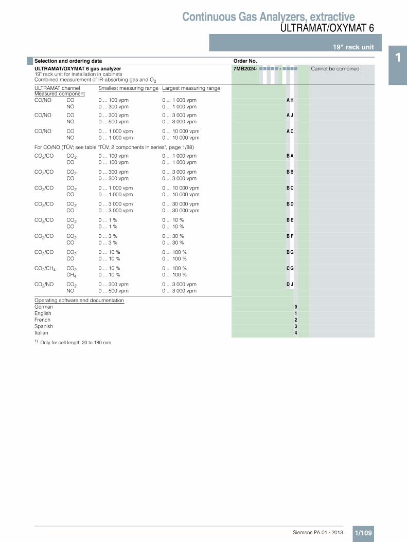
Continuous Gas Analyzers, extractiveULTRAMAT/OXYMAT 6
19" rack unit
1/109Siemens PA 01 · 2013
1
1) Only for cell length 20 to 180 mm
ULTRAMAT channelMeasured component
Smallest measuring range Largest measuring range
CO/NO CO 0 ... 100 vpm 0 ... 1 000 vpm A HNO 0 ... 300 vpm 0 ... 1 000 vpm
CO/NO CO 0 ... 300 vpm 0 ... 3 000 vpm A JNO 0 ... 500 vpm 0 ... 3 000 vpm
CO/NO CO 0 ... 1 000 vpm 0 ... 10 000 vpm A CNO 0 ... 1 000 vpm 0 ... 10 000 vpm
For CO/NO (TÜV; see table "TÜV, 2 components in series", page 1/88)
CO2/CO CO2 0 ... 100 vpm 0 ... 1 000 vpm B ACO 0 ... 100 vpm 0 ... 1 000 vpm
CO2/CO CO2 0 ... 300 vpm 0 ... 3 000 vpm B BCO 0 ... 300 vpm 0 ... 3 000 vpm
CO2/CO CO2 0 ... 1 000 vpm 0 ... 10 000 vpm B CCO 0 ... 1 000 vpm 0 ... 10 000 vpm
CO2/CO CO2 0 ... 3 000 vpm 0 ... 30 000 vpm B DCO 0 ... 3 000 vpm 0 ... 30 000 vpm
CO2/CO CO2 0 ... 1 % 0 ... 10 % B ECO 0 ... 1 % 0 ... 10 %
CO2/CO CO2 0 ... 3 % 0 ... 30 % B FCO 0 ... 3 % 0 ... 30 %
CO2/CO CO2 0 ... 10 % 0 ... 100 % B GCO 0 ... 10 % 0 ... 100 %
CO2/CH4 CO2 0 ... 10 % 0 ... 100 % C GCH4 0 ... 10 % 0 ... 100 %
CO2/NO CO2 0 ... 300 vpm 0 ... 3 000 vpm D JNO 0 ... 500 vpm 0 ... 3 000 vpm
Operating software and documentationGerman 0English 1French 2Spanish 3Italian 4
■ Selection and ordering data Order No.
ULTRAMAT/OXYMAT 6 gas analyzer19" rack unit for installation in cabinetsCombined measurement of IR-absorbing gas and O2
7MB2024- 77777 - 7777 Cannot be combined

Continuous Gas Analyzers, extractiveULTRAMAT/OXYMAT 6
19" rack unit
1/110 Siemens PA 01 · 2013
1 ■ Selection and ordering data
1) Cannot be combined with non-flow-type reference cell.2) Standard setting: Smallest measuring range
25 % of largest measuring range in % or50 % of largest measuring range ppm (vpm)Largest measuring range
Additional versions Order code Cannot be combined
Add "-Z" to Order No. and specify order codes.
Flow-type reference cell with reduced flow, 6 mm (ULTRAMAT channel)1) A20
Flow-type reference cell with reduced flow, ¼" (ULTRAMAT channel)1) A21
Reference gas monitoring (pressure switch ... 3 000 hPa), for OXYMAT channel only A26
Connection pipes (can only be combined with the appropriate gas connection diameter and internal gas path materials)
• Titanium connection pipe, 6 mm, complete with screwed gland, for sample gas side A22
• Titanium connection pipe, ¼", complete with screwed gland, for sample gas side A24
• Stainless steel connection pipe (mat. no. 1.4571), 6 mm, complete with screwed gland, for sample gas side
A27
• Stainless steel connection pipe (mat. no. 1.4571), ¼", complete with screwed gland,for sample gas side
A29
Telescopic rails (2 units) A31
Set of Torx screwdrivers A32
Kalrez gaskets in sample gas path (O2 side) B01
TAG labels (specific lettering based on customer information) B03
Kalrez gaskets in sample gas path (IR side) B04
FM/CSA certificate – Class I Div 2 E20
Clean for O2 service (specially cleaned gas path) (ULTRAMAT channel and OXYMAT channel)
Y02
Measuring range indication in plain text2), if different from the standard setting Y11
Special setting (only in conjunction with an application no., e.g. extended measuring range, only ULTRAMAT channel)
Y12
Extended special setting (only in conjunction with an application no., e.g. determination of interference influences, only ULTRAMAT channel)
Y13
TÜV version acc. to 13th and 17th BlmSchV (only ULTRAMAT channel) Y17 E20
Retrofitting sets Order No.
RS 485/Ethernet converter A5E00852383
RS 485/RS 232 converter C79451-Z1589-U1
RS 485 / USB converter A5E00852382
AUTOCAL function with serial interfaces for the automotive industry (AK)
C79451-A3480-D33
AUTOCAL function with 8 digital inputs/outputs for ULTRAMAT channel or OXYMAT channel
C79451-A3480-D511
AUTOCAL function with 8 digital inputs/outputs and PROFIBUS PA for ULTRAMAT channel or OXYMAT channel
A5E00057307
AUTOCAL function with 8 digital inputs/outputs and PROFIBUS DP for ULTRAMAT channel or OXYMAT channel
A5E00057312
}

Continuous Gas Analyzers, extractiveULTRAMAT/OXYMAT 6
19" rack unit
1/111Siemens PA 01 · 2013
1TÜV, single component (IR channel)
Example for ordering
ULTRAMAT/OXYMAT 6, TÜVIR channelComponent: COMeasuring range: 0 to 50/1 000 mg/m3
with hoses, non-flow-type reference compartmentwithout automatic adjustment (AUTOCAL)230 V AC; German7MB2023-0EA00-1XD0-Z +Y17
TÜV, two components in series
Example for ordering
ULTRAMAT/OXYMAT 6, TÜVIR channelComponents: CO/NOMeasuring range CO: 0 to 75 / 1 000 mg/m3, NO: 0 to 200/2 000 mg/m3
with hoses, non-flow-type reference cellwithout automatic adjustment (AUTOCAL)230 V AC; German7MB2024-0EA00-1AH0-Z +Y17
Component CO (TÜV) SO2 (TÜV) NO (TÜV)
Measuring range identification
Smallest measuring range from 0 to ...
Largest measuring range from 0 to ...
Smallest measuring range from 0 to ...
Largest measuring range from 0 to ...
Smallest measuring range from 0 to ...
Largest measuring range from 0 to ...
C 75 mg/m3 1 500 mg/m3
D 50 mg/m3 1 000 mg/m3 300 mg/m3 3 000 mg/m3
E 500 mg/m3 5 000 mg/m3 100 mg/m3 2 000 mg/m3
F 300 mg/m3 3 000 mg/m3 1 000 mg/m3 10 000 mg/m3 300 mg/m3 3 000 mg/m3
G 500 mg/m3 5 000 mg/m3 500 mg/m3 5 000 mg/m3
H 1 000 mg/m3 10 000 mg/m3 3 000 mg/m3 30 000 mg/m3 1 000 mg/m3 10 000 mg/m3
K 3 000 mg/m3 30 000 mg/m3 10 g/m3 100 g/m3 3 000 mg/m3 30 000 mg/m3
P 10 g/m3 100 g/m3 30 g/m3 300 g/m3 10 g/m3 100 g/m3
R 30 g/m3 300 g/m3 100 g/m3 1 000 g/m3 30 g/m3 300 g/m3
V 100 g/m3 1 160 g/m3 300 g/m3 2 630 g/m3 100 g/m3 1 250 g/m3
Component CO (TÜV) NO (TÜV)
Measuring range identification
Smallest measuring range from 0 to ...
Largest measuring range from 0 to ...
Smallest measuring range from 0 to ...
Largest measuring range from 0 to ...
AH 75 mg/m3 1 000 mg/m3 200 mg/m3 2 000 mg/m3
AJ 300 mg/m3 3 000 mg/m3 500 mg/m3 3 000 mg/m3
AC 1 000 mg/m3 10 000 mg/m3 1 000 mg/m3 10 000 mg/m3

Continuous Gas Analyzers, extractiveULTRAMAT/OXYMAT 6
19" rack unit
1/112 Siemens PA 01 · 2013
1 ■ Dimensional drawings
ULTRAMAT/OXYMAT 6, 19“ unit, dimensions in mm
s

Continuous Gas Analyzers, extractiveULTRAMAT/OXYMAT 6
19" rack unit
1/113Siemens PA 01 · 2013
1■ Schematics
Pin assignment (electrical and gas connections)
ULTRAMAT/OXYMAT 6, 19“ unit, pin assignment
M
GND
GND
M
GND
NCNC
GND
M
M
M
M
NCRD/TD-NRD/TD-P
NC
GNDNC
GNDM
M
GND
+5 V
4
512
13
14
15
1
2
3
6
7
8
9
10
11
12
13
7
8
9
10
11
4
517
18
19
1
2
3
6
16
21
14
20
15
22
23
24
25
1
2
3
4
5
6
7
8
9
Isolated via optocoupler"0" = 0 V (0 ... 4.5 V)"1" = 24 V (13 ... 33 V)
Binary input 1 to 4-NBinary input 1-PBinary input 2-PBinary input 3-PBinary input 4-P
Relay 1
Relay 2
Relay 3
Relay 4
Relay 5
Relay 6
SUB-D 25F connector
Correction of cross-interferenceCorrection of cross-interference
Pressure correctionPressure correction
Analog outputs isolated(also from each other), RL: ≤ 750 Ω
Analog inputsnon-isolated,0 ... 20 mA/500 Ωor 0 ... 10 V(low-resistance)
Analog output 2-PAnalog output 2-NAnalog output 1-PAnalog output 1-N
Analog input 2-PAnalog input 2-NAnalog input 1-PAnalog input 1-NBinary input 6-PBinary input 5-PBinary input 5 to 6-N
SUB-D 15F connector
R_Level-P-
R_Level-N-It is possible to connect bus terminating resistorsto pins 7 and 9.
SUB-D 9F connector (RS 485)
For 2-component version onlyof the ULTRAMAT part
Isolated via optocoupler"0" = 0 V (0 ... 4.5 V)"1" = 24 V (13 ... 33 V)
Contact load max. 24 V/1 A, AC/DC; relay contacts shown: relay coil has zero current

Continuous Gas Analyzers, extractiveULTRAMAT/OXYMAT 6
19" rack unit
1/114 Siemens PA 01 · 2013
1
ULTRAMAT/OXYMAT 6, 19“ unit, pin assignment of AUTOCAL board and PROFIBUS connectors

Continuous Gas Analyzers, extractiveULTRAMAT/OXYMAT 6
19" rack unit
1/115Siemens PA 01 · 2013
1
ULTRAMAT/OXYMAT 6, 19“ unit, gas and electrical connections
■ Selection and ordering data
124 8 7 6 5
Gas connections: stubs 6 mm or ¼"
9-pin interfaceconnector (option): e.g.PROFIBUS
Power supplyand miniaturefuses
37-pin connector:binary inputs andrelay outputs(optional board)
25-pin connector:binary inputs andrelay outputs
OXYMAT channel ULTRAMAT channelOXYMATchannel
9-pin connector:RS 485
15-pin connector:binary inputs andanalog inputs/outputs
Sample gas inlet
Referencegas inlet
Sample gas outlet Reference gas outlet
Referencegas inlet
Samplegas outlet
Samplegas inlet
ULTRAMATchannel
Purging gasinlet
Documentation
Operating instructions Order No.
ULTRAMAT 6 / OXYMAT 6Gas analyzer for IR-absorbing gases and oxygen
• German C79000-G5200-C143
• English C79000-G5276-C143
• French C79000-G5277-C143
• Spanish C79000-G5278-C143
• Italian C79000-G5272-C143

Continuous Gas Analyzers, extractiveULTRAMAT/OXYMAT 6
Suggestions for spare parts
1/116 Siemens PA 01 · 2013
1 ■ Selection and ordering data
If the device was supplied with a specially cleaned gas path for high oxygen context ("Clean for O2 service"), please ensure that you specify this when ordering spare parts. This is the only way to guarantee that the gas path will continue to comply with the special requirements for this version.
Description 7MB2023 7MB2024 2 years (quantity)
5 years (quantity)
Order No.
Analyzer unit
Analyzer unit, ULTRAMAT channel
• O-ring for cover (window, rear) x x 2 2 C79121-Z100-A24
• Cover (cell length 20 ... 180 mm) x x 2 2 C79451-A3462-B151
• Cover (cell length 0.2 ... 6 mm) x x 2 2 C79451-A3462-B152
• O-rings, set (ULTRAMAT) x x — 1 C79451-A3462-D501
Analyzer unit, OXYMAT channel
• O-ring x x 1 2 C74121-Z100-A6
• O-ring (measuring head) x x 2 4 C79121-Z100-A32
• O-ring x x 2 4 C71121-Z100-A159
• Sample chamber, stainless steel, mat. no. 1.4571; non-flow-type compensation branch
x x — 1 C79451-A3277-B535
• Sample chamber, tantalum, non-flow-type compensation branch
x x — 1 C79451-A3277-B536
• Sample chamber, stainless steel, mat. no. 1.4571; flow-type compensation branch
x x — 1 C79451-A3277-B537
• Sample chamber, tantalum, flow-type compensation branch
x x — 1 C79451-A3277-B538
• Measuring head, non-flow-type compensation branch
x x 1 1 C79451-A3460-B525
• Measuring head, flow-type compensation branch
x x 1 1 C79451-A3460-B526
Sample gas path
Pressure switch x x 1 2 C79302-Z1210-A2
Restrictor, stainless steel, mat. no. 1.4571; hose gas path
x x 2 2 C79451-A3480-C10
Flow indicator x x 1 2 C79402-Z560-T1
Sample gas path, ULTRAMAT channel
• Hose clip x x — 1 C79451-A3478-C9
Sample gas path, OXYMAT channel
• Restrictor, titanium, pipe gas path x x 2 2 C79451-A3480-C37
• Reference gas path, 3000 hPa x x 1 1 C79451-A3480-D518
• Capillary, 100 hPa, connection set x x 1 1 C79451-A3480-D519
• Restrictor, stainless steel, mat. no. 1.4571; pipe gas path
x x 1 1 C79451-A3520-C5
Electronics
Front plate with keyboard x x 1 1 C79165-A3042-B506
Adapter plate, LCD/keyboard x x 1 1 C79451-A3474-B605
LC display x x 1 1 W75025-B5001-B1
Connector filter x x — 1 W75041-E5602-K2
Fusible element, T 0.63 A/250 V x x 2 3 W79054-L1010-T630
Fusible element, T 1 A/250 V x x 2 3 W79054-L1011-T100
Fusible element, T 2.5 A/250 V x x 2 3 W79054-L1011-T250
Electronics, ULTRAMAT channel
• Motherboard, with firmware: see spare parts list x x — 1
Electronics, OXYMAT channel
• Motherboard, with firmware: see spare parts list x x — 1

Continuous Gas Analyzers, extractiveOXYMAT 6
General information
1/117Siemens PA 01 · 2013
1■ Overview
The function of the OXYMAT 6 gas analyzers is based on the paramagnetic alternating pressure method and are used to measure oxygen in gases.
■ Benefits
• Paramagnetic alternating pressure principle - Small measuring ranges (0 to 0.5 % or 99.5 to 100 % O2)- Absolute linearity
• Detector element has no contact with the sample gas - Can be used under harsh conditions- Long service life
• Physically suppressed zero through suitable selection of reference gas (air or O2), e.g. 98 to 100 % O2 for purity moni-toring/air separation
• Open interface architecture (RS 485, RS 232, PROFIBUS)• SIPROM GA network for maintenance and service information
(option)• Electronics and physics: gas-tight isolation, purging is possi-
ble, IP65, long service life even in harsh environments (field device only)
• Heated versions (option), use also in presence of gases con-densing at low temperature (field device only)
• EEx(p) for zones 1 and 2 according to ATEX 2G and ATEX 3G (field device only)
■ Application
Fields of application• For boiler control in incineration plants• In safety-related areas• In the automotive industry (testbed systems)• Warning equipment• In chemical plants• For ultra-pure gas quality monitoring• Environmental protection• Quality monitoring• Inert gas monitoring with certified gas warning equipment
(DMT certificate)• Versions for analyzing flammable and non-flammable gases
or vapors for use in hazardous areas
Special versions
Special applications
Besides the standard combinations, special applications con-cerning material in the gas path, material in the sample cells are also available on request
TÜV version QAL
As a reference variable for emission measurements according to TA-Luft, 13th and 17th BlmSchV
■ Design
19" rack unit• With 4 HU for installation
- in hinged frame- in cabinets with or without telescopic rails
• Front plate can be swung down for servicing purposes (laptop connection)
• Internal gas paths: hose made of FKM (Viton) or pipe made of titanium or stainless steel (mat. no. 1.4571)
• Gas connections for sample gas inlet and outlet and for refer-ence gas: fittings, pipe diameter of 6 mm or ¼"
• Flow indicator for sample gas on front plate (option)• Pressure switch in sample gas path for flow monitoring
(option)
Field device• Two-door enclosure with gas-tight separation of analyzer and
electronics sections• Each half of the enclosure can be purged separately• Analyzer unit and piping can be heated up to 130 °C (option)• Gas path and stubs made of stainless steel (mat. no. 1.4571)
or titanium, Hastelloy C22• Purging gas connections: pipe diameter 10 mm or 3/8"• Gas connections for sample gas inlet and outlet and for refer-
ence gas: clamping ring connection for a pipe diameter of 6 mm or ¼"
Display and control panel• Large LCD panel for simultaneous display of:
- Measured value (digital and analog displays)- Status bar- Measuring ranges
• Contrast of LCD panel adjustable using menu• Permanent LED backlighting• Washable membrane keyboard with five softkeys• Menu-driven operation for parameterization, test functions,
adjustment• User help in plain text• Graphic display of concentration trend; programmable time
intervals• Bilingual operating software German/English,
English/Spanish, French/English, Spanish/English, Italian/English

Continuous Gas Analyzers, extractiveOXYMAT 6
General information
1/118 Siemens PA 01 · 2013
1 Input and outputs• One analog output per measured component (from 0, 2, 4 to
20 mA; NAMUR parameterizable)• Two analog inputs configurable (e.g. correction of cross-inter-
ference, external pressure sensor)• Six binary inputs freely configurable (e.g. for measurement
range switchover, processing of external signals from sample preparation)
• Six relay outputs freely configurable (failure, maintenance re-quest, maintenance switch, threshold alarm, external mag-netic valves)
• Expansion: by eight additional binary inputs and eight addi-tional relay outputs each, e.g. for autocalibration with up to four calibration gases
Communication
RS 485 present in the basic unit (connection at the rear; for the rack unit also behind the front plate).
Options• AK interface for the automotive industry with extended func-
tions• RS 485/RS 232 converter• RS 485/Ethernet converter• RS 485/USB converter• Connection to networks via PROFIBUS DP/PA interface• SIPROM GA software as the service and maintenance tool
OXYMAT 6, membrane keyboard and graphic display
Status line for display of analyzer status(programmable)
LED backlit graphicdisplay and membrane keyboardwith noticeable click
Two code levelsaccording to NAMUR(maintenance andspecialist level)
MEAS key to return tomeasurement mode
Easy operation with menu controlusing five softkeys
Display of currentmeasuring ranges
ESC keyto abort inputs
INFO keyfor help in plain text
CLEAR key to delete inputs
Keyboard toenter values
Display of start-of-scale and full-scale values
Display ofconcentrations asnumbers and bargraph
ENTER key to accept input values

Continuous Gas Analyzers, extractiveOXYMAT 6
General information
1/119Siemens PA 01 · 2013
1Designs – Parts touched by sample gas, standard
Options
Gas path 19" rack unit Field device Field device Ex
With hoses Bushing
HoseSample chamber
Fittings for sample chamberRestrictorO-rings
Stainless steel, mat. no. 1.4571FKM (e.g. Viton)Stainless steel, mat. no. 1.4571 or TantalumStainless steel, mat. no. 1.4571PTFE (e.g. Teflon)FKM (e.g. Viton)
- -
With pipes BushingPipeSample chamberRestrictorO-rings
TitaniumTitaniumStainless steel, mat. no. 1.4571 or TantalumTitaniumFKM (Viton) or FFKM (Kalrez)
With pipes BushingPipeSample chamberRestrictorO-rings
Stainless steel, mat. no. 1.4571Stainless steel, mat. no. 1.4571Stainless steel, mat. no. 1.4571 or tantalumStainless steel, mat. no. 1.4571FKM (Viton) or FFKM (Kalrez)
With pipes BushingPipeSample chamberRestrictorO-rings
Hastelloy C 22Hastelloy C 22Stainless steel, mat. no. 1.4571 or tantalumHastelloy C 22FKM (e.g. Viton) or FFKM (e.g. Kalrez)
Flow indicator Measurement pipeVariable areaSuspension boundaryAngle pieces
Duran glassDuran glass, blackPTFE (Teflon)FKM (Viton)
- -
Pressure switch MembraneEnclosure
FKM (Viton)PA 6.3 T
- -

Continuous Gas Analyzers, extractiveOXYMAT 6
General information
1/120 Siemens PA 01 · 2013
1 Gas path (19" rack unit)
Gas path, reference gas connection 1 100 hPa, absolute
Gas path, reference gas connection 3 000 to 5 000 hPa, absolute
Legend for the gas path figures
1 Sample gas inlet 8 Pressure switch in sample gas path (option)
2 Sample gas outlet 9 Purging gas
3 Not used 10 Pressure switch in reference gas path (option)
4 Reference gas inlet 11 Pressure sensor
5 Restrictor in reference gas inlet 12 Filter
6 O2 physical system 13 Flow indicator in sample gas path (option)
7 Restrictor in sample gas path 14 Outlet restrictor
P
P
F
12
10
8
11
13
5
P
67
1
2
4
9

Continuous Gas Analyzers, extractiveOXYMAT 6
General information
1/121Siemens PA 01 · 2013
1Gas path (field device)
Gas path, reference gas connection 1 100 hPa, absolute
Gas path, reference gas connection 3 000 to 5 000 hPa, absolute
Legend for the gas path figures
1 Not used 8 Purging gas inlet (analyzer side)
2 Sample gas inlet 9 Pressure sensor
3 Reference gas inlet 10 O2 physical system
4 Sample gas outlet 11 Restrictor in sample gas path
5 Purging gas inlet (electronics side) 12 Pressure sensor in reference gas path (option)
6 Purging gas outlet (electronics side) 13 Restrictor
7 Purging gas outlet (analyzer side) 14 Outlet restrictor

Continuous Gas Analyzers, extractiveOXYMAT 6
General information
1/122 Siemens PA 01 · 2013
1 ■ Function
Principle of operation
In contrast to almost all other gases, oxygen is paramagnetic. This property is utilized as the measuring principle by the OXYMAT 6 gas analyzers.
Oxygen molecules in an inhomogeneous magnetic field are drawn in the direction of increased field strength due to their paramagnetism. When two gases with different oxygen contents meet in a magnetic field, a pressure difference is produced be-tween them.
In the case of OXYMAT 6, one gas (1) is a reference gas (N2, O2or air), the other is the sample gas (5). The reference gas is in-troduced into the sample chamber (6) through two channels (3). One of these reference gas streams meets the sample gas within the area of a magnetic field (7). Because the two channels are connected, the pressure, which is proportional to the oxygen content, causes a cross flow. This flow is converted into an elec-tric signal by a microflow sensor (4).
The microflow sensor consists of two nickel-plated grids heated to approximately 120 ºC, which, along with two supplementary resistors, form a Wheatstone bridge. The pulsating flow results in a change in the resistance of the Ni grids. This leads to an off-set in the bridge which is dependent on the oxygen concentra-tion of the sample gas.
Because the microflow sensor is located in the reference gas stream, the measurement is not influenced by the thermal con-ductivity, the specific heat or the internal friction of the sample gas. This also provides a high degree of corrosion resistance because the microflow sensor is not exposed to the direct influ-ence of the sample gas.
By using a magnetic field with alternating strength (8), the effect of the background flow in the microflow sensor is not detected, and the measurement is thus independent of the instrument’s operating position.
The sample chamber is directly in the sample path and has a small volume, and the microflow sensor is a low-lag sensor. This results in a very short response time for the OXYMAT 6.
Vibrations frequently occur at the place of installation and may falsify the measured signal (noise). A further microflow sensor (10) through which no gas passes acts as a vibration sensor. Its signal is applied to the measured signal as compensation.
If the density of the sample gas deviates by more than 50 % from that of the reference gas, the compensation microflow sensor (10) is flushed with reference gas just like the measuring sensor (4).
Note
The sample gases must be fed into the analyzers free of dust. Condensation should be prevented from occurring in the sample chambers. Therefore, the use of gas modified for the measuring task is necessary in most application cases.
OXYMAT 6, principle of operation
D
1 Reference gas inlet2 Restrictors3 Reference gas channels4 Microflow sensor for measurement5 Sample gas inlet6 Sample cell7 Paramagnetic effect8 Electromagnet with alternating field strength9 Sample gas and reference gas outlet10 Microflow sensor in compensation system (without flow)

Continuous Gas Analyzers, extractiveOXYMAT 6
General information
1/123Siemens PA 01 · 2013
1Advantages of the function-based application of reference gas• The zero point can be defined specific to the application. It is
then also possible to set "physically" suppressed zero points. For example, it is possible when using pure oxygen as the zero gas to set a measuring range of 99.5 to 100 % O2 with a resolution of 50 ppm.
• The sensor (microflow sensor) is located outside the sample gas. Through use of an appropriate material in the gas path this also allows measurements in highly corrosive gases.
• Pressure variations in the sample gas can be compensated better since the reference gas is subjected to the same fluctu-ations.
• No influences on the thermal conductivity of the sample gas since the sensor is positioned on the reference gas side.
• The same gas is used for the serial gas calibration and as the reference gas. As a result of the low consumption of reference gas (3 to 10 ml/min), one calibration cylinder can be used for both gases.
• No measuring effect is generated in the absence of oxygen. The measured signal need not therefore be set electronically to zero, and is thus extremely stable with regard to tempera-ture and electronic influences.
Essential characteristics• Four freely parameterizable measuring ranges, also with sup-
pressed zero point, all measuring ranges linear• Measuring ranges with physically suppressed zero point pos-
sible• Measuring range identification• Galvanically isolated measured-value output 0/2/4 to 20 mA
(also inverted)• Autoranging possible; remote switching is also possible• Storage of measured values possible during adjustments• Wide range of selectable time constants (static/dynamic noise
suppression); i.e. the response time of the analyzer can be matched to the respective measuring task
• Short response time• Low long-term drift• Measuring point switchover for up to 6 measuring points
(programmable)• Measuring point identification• Internal pressure sensor for correction of pressure variations
in sample gas range 500 to 2 000 hPa (abs.)• External pressure sensor - only with piping as the gas path -
can be connected for correction of variations in the sample gas pressure up to 3 000 hPa absolute (option)
• Monitoring of sample gas flow (option for version with hoses)• Monitoring of sample gas and/or reference gas (option)• Monitoring of reference gas with reference gas connection
3 000 to 5 000 hPa (abs.) (option)• Automatic, parameterizable measuring range calibration• Operation based on the NAMUR recommendation• Two control levels with their own authorization codes for the
prevention of accidental and unauthorized operator interven-tions
• Simple handling using a numerical membrane keyboard and operator prompting
• Customer-specific analyzer options such as: - Customer acceptance- TAG labels- Drift recording- Clean for O2 service- Kalrez gaskets
• Analyzer unit with flow-type compensation branch: a flow is passed through the compensation branch (option) to reduce the vibration dependency in the case of highly different densi-ties of the sample and reference gases
• Sample chamber for use in presence of highly corrosive sam-ple gases

Continuous Gas Analyzers, extractiveOXYMAT 6
General information
1/124 Siemens PA 01 · 2013
1 Reference gases
Table 1: Reference gases for OXYMAT 6
Correction of zero point error / cross-sensitivities
Table 2: Zero point error due to diamagnetism or paramagnetism of some accompanying gases with reference to nitrogen at 60 °C und 1 000 hPa absolute (according to IEC 1207/3)
Conversion to other temperatures:
The deviations from the zero point listed in Table 2 must be multiplied by a correction factor (k):• with diamagnetic gases: k = 333 K / (ϑ [°C] + 273 K)• with paramagnetic gases: k = [333 K / (ϑ [°C] + 273 K)]2
(all diamagnetic gases have a negative deviation from zero point)
Measuring range Recommended reference gas Reference gas connection pressure
Remarks
0 to ... vol.% O2 N2 2 000 … 4 000 hPa above sample gas pressure (max. 5 000 hPa absolute)
The reference gas flow is set auto-matically to 5 … 10 ml/min (up to 20 ml/min with flow-type compensa-tion branch)
... to 100 vol.% O2 (suppressed zero point with full-scale value 100 vol.% O2)
O2
Around 21 vol.% O2 (suppressed zero point with 21 vol.% O2 within the measuring span)
Air 100 hPa with respect to sample gas pressure which may vary by max. 50 hPa around the atmospheric pressure
Accompanying gas (concentration 100 vol. %)
Deviation from zero point in vol. % O2 absolute
Accompanying gas (concentration 100 vol. %)
Deviation from zero point in vol. % O2 absolute
Organic gases Inert gases
Ethane C2H6 -0.49 Helium He +0.33
Ethene (ethylene) C2H4 -0.22 Neon Ne +0.17
Ethine (acetylene) C2H2 -0.29 Argon Ar -0.25
1.2 butadiene C4H6 -0.65 Krypton Kr -0.55
1.3 butadiene C4H6 -0.49 Xenon Xe -1.05
n-butane C4H10 -1.26
iso-butane C4H10 -1.30 Inorganic gases
1-butene C4H8 -0.96 Ammonia NH3 -0.20
iso-butene C4H8 -1.06 Hydrogen bromide HBr -0.76
Dichlorodifluoromethane (R12) CCl2F2 -1.32 Chlorine Cl2 -0.94
Acetic acid CH3COOH -0.64 Hydrogen chloride HCl -0.35
n-heptane C7H16 -2.40 Dinitrogen monoxide N2O -0.23
n-hexane C6H14 -2.02 Hydrogen fluoride HF +0.10
Cyclo-hexane C6H12 -1.84 Hydrogen iodide HI -1.19
Methane CH4 -0.18 Carbon dioxide CO2 -0.30
Methanol CH3OH -0.31 Carbon monoxide CO +0.07
n-octane C8H18 -2.78 Nitrogen oxide NO +42.94
n-pentane C5H12 -1.68 Nitrogen N2 0.00
iso-pentane C5H12 -1.49 Nitrogen dioxide NO2 +20.00
Propane C3H8 -0.87 Sulfur dioxide SO2 -0.20
Propylene C3H6 -0.64 Sulfur hexafluoride SF6 -1.05
Trichlorofluoromethane (R11) CCl3F -1.63 Hydrogen sulfide H2S -0.44
Vinyl chloride C2H3Cl -0.77 Water H2O -0.03
Vinyl fluoride C2H3F -0.55 Hydrogen H2 +0.26
1.1 vinylidene chloride C2H2Cl2 -1.22

Continuous Gas Analyzers, extractiveOXYMAT 6
19" rack unit
1/125Siemens PA 01 · 2013
1■ Technical specifications
General information
Measuring ranges 4, internally and externally switch-able; autoranging is also possible
Smallest possible span (relating to sample gas pressure 1 000 hPa absolute, 0.5 l/min sample gas flow and 25 °C ambient temperature)
0.5 vol.%, 2 vol.% or 5 vol.% O2
Largest possible measuring span 100 vol.% O2 (for a pressure above 2 000 hPa: 25 vol.% O2)
Measuring ranges with suppressed zero point
Any zero point can be imple-mented within 0 … 100 vol.%, provided that a suitable reference gas is used (see Table 1 in "Function")
Operating position Front wall, vertical
Conformity CE mark in accordance with EN 50081-1, EN 50082-2
Design, enclosure
Degree of protection IP20 according to EN 60529
Weight Approx. 13 kg
Electrical characteristics
Power supply 100 … 120 V AC (nominal range of use 90 … 132 V), 48 … 63 Hz or 200 … 240 V AC (nominal range of use 180 … 264 V), 48 … 63 Hz
Power consumption Approx. 35 VA
EMC (Electromagnetic Compatibility)
In accordance with standard requirements of NAMUR NE21 (08/98), EN 61326, EN 50270 (with gas warning unit)
Electrical safety According to EN 61010-1, overvoltage category III
Fuse values 100 ... 120 V: 1.0 T/250200 ... 240 V: 0.63 T/250
Gas inlet conditions
Permissible sample gas pressure
• With pipes 500 … 3 000 hPa absolute
• With hoses
- Without pressure switch 500 … 1 500 hPa absolute
- With pressure switch 500 … 1 300 hPa absolute
Sample gas flow 18 … 60 l/h (0.3 … 1 l/min)
Sample gas temperature Min. 0 ... max. 50 °C, but above the dew point
Sample gas humidity < 90 % RH (RH: relative humidity)
Reference gas pressure (high-pressure version)
2 000 ... 4 000 hPa above sample gas pressure, but max. 5 000 hPa
Reference gas pressure (low-pressure version)
Min. 100 hPa above sample gas pressure
Dynamic response
Warm-up period At room temperature < 30 min (the technical specification will be met after 2 hours)
Delayed display (T90-time) Min. 1.5 … 3.5 s, depending on version
Damping (electrical time constant) 0 … 100 s, parameterizable
Dead time (purging time of the gas path in the unit at 1 l/min)
Approximately 0.5 ... 2.5 s, depending on version
Time for device-internal signal processing
< 1 s
Pressure correction range
Pressure sensor
• Internal 500 … 2 000 hPa absolute
• External 500 … 3 000 hPa absolute
Measuring response (relating to sample gas pressure 1 013 hPa absolute, 0.5 l/min sample gas flow and 25 °C ambient temperature)
Output signal fluctuation < ± 0.75 % of the smallest possi-ble measuring range according to rating plate, with electronic damping constant of 1 s (corre-sponds to ± 0.25 % at 2 σ)
Zero point drift < ± 0.5 %/month of the smallest possible span according to rating plate
Measured-value drift < ± 0.5 %/month of the current measuring range
Repeatability < 1 % of the current measuring range
Detection limit 1 % of the current measuring range
Linearity error < 0.1 % of the current measuring range
Influencing variables (relating to sample gas pressure 1 013 hPa absolute, 0.5 l/min sample gas flow and 25 °C ambient temperature)
Ambient temperature < 0.5 %/10 K relating to the small-est possible measuring range according to rating plate, with measuring span 0.5 %: 1 %/10 K
Sample gas pressure (with air (100 hPa) as reference gas, correc-tion of the atmospheric pressure fluctuations is only possible if the sample gas can vent to ambient air)
• When pressure compensation is switched off: < 2 % of the current measuring range/1 % pressure change
• When pressure compensation is switched on: < 0.2 % of the cur-rent measuring range/1 % pres-sure change
Carrier gases Deviation from zero point corre-sponding to paramagnetic or dia-magnetic deviation of carrier gas
Sample gas flow at zero point < 1 % of the current measuring range according to rating plate with a change in flow of 0.1 l/min within the permissible flow range
Power supply < 0.1 % of the current measuring range with rated voltage ± 10 %

Continuous Gas Analyzers, extractiveOXYMAT 6
19" rack unit
1/126 Siemens PA 01 · 2013
1 Electrical inputs and outputs
Analog output 0/2/4 … 20 mA, isolated; max. load 750 Ω
Relay outputs 6, with changeover contacts, freely parameterizable, e.g. for measuring range identification; load: 24 V AC/DC/1 A, isolated
Analog inputs 2, dimensioned for 0/2/4 ... 20 mA for external pressure sensor and residual gas influence correction (correction of cross-interference)
Binary inputs 6, designed for 24 V, isolated, freely parameterizable, e.g. for measuring range switchover
Serial interface RS 485
Options AUTOCAL function with 8 addi-tional binary inputs and relay out-puts each, also with PROFIBUS PA or PROFIBUS DP
Climatic conditions
Permissible ambient temperature -30 … +70 °C during storage and transportation, 5 … 45 °C during operation
Permissible humidity < 90 % RH (RH: relative humidity) within average annual value, dur-ing storage and transportation (dew point must not be under-shot)

Continuous Gas Analyzers, extractiveOXYMAT 6
19" rack unit
1/127Siemens PA 01 · 2013
1Selection and ordering data Order No.
OXYMAT 6 gas analyzer19" rack unit for installation in cabinets
7MB2021- 7777 0 - 7777 Cannot be combined
Gas connectionsPipe with 6 mm outer diameter 0Pipe with ¼" outer diameter 1
Smallest possible measuring span O20,5 % reference gas pressure 3 000 hPa A A E300,5 % reference gas pressure 100 hPa (external pump) B B B B E30, Y022 % reference gas pressure 3 000 hPa C
2 % reference gas pressure 100 hPa (external pump) D D D D E30, Y025% reference gas pressure 3 000 hPa E5% reference gas pressure 100 hPa (external pump) F F F F E30, Y02
Sample chamberNon-flow-type compensation branch• Made of stainless steel, mat. no. 1.4571 A• Made of tantalum B
Flow-type compensation branch• Made of stainless steel, mat. no. 1.4571 C C• Made of tantalum D D
Internal gas pathsHose made of FKM (Viton) 0Pipe made of titanium 1 1 1 Y02Pipe made of stainless steel, mat. no. 1.4571 2 2
Power supply100 ... 120 V AC, 48 ... 63 Hz 0200 ... 240 V AC, 48 ... 63 Hz 1
Monitoring (reference gas, sample gas)Without A A E30Reference gas only B BReference gas and sample gas (with flow indicator and pressure switch for sample gas)
C C C C E30
Sample gas only D D D E30
Add-on electronicsWithout AAUTOCAL function• With 8 additional digital inputs/outputs B• With serial interface for the automotive industry (AK) D D E20• With 8 additional digital inputs/outputs and PROFIBUS PA interface E• With 8 additional digital inputs/outputs and PROFIBUS DP interface F
LanguageGerman 0English 1French 2Spanish 3Italian 4
Additional versions Order code Cannot be combined
Add "-Z" to Order No. and specify order codes.
Telescopic rails (2 units) A31
Kalrez gaskets in sample gas path B01
TAG labels (specific lettering based on customer information) B03
FM/CSA certificate – Class I Div 2 E20 E30
ATEX II G certificate; safety-related measurements in non-hazardous gas zone E30 E20
Clean for O2 service (specially cleaned gas path) Y02
Measuring range indication in plain text, if different from the standard setting Y11

Continuous Gas Analyzers, extractiveOXYMAT 6
19" rack unit
1/128 Siemens PA 01 · 2013
1 ■ Selection and ordering data
■ Dimensional drawings
OXYMAT 6, 19“ unit, dimensions in mm
Retrofitting sets Order No.
RS 485/Ethernet converter A5E00852383
RS 485/RS 232 converter C79451-Z1589-U1
RS 485 / USB converter A5E00852382
AUTOCAL function with serial interface for the automotive industry (AK) C79451-A3480-D512
AUTOCAL function with 8 digital inputs/outputs C79451-A3480-D511
AUTOCAL function with 8 digital inputs/outputs and PROFIBUS PA A5E00057307
AUTOCAL function with 8 digital inputs/outputs and PROFIBUS DP A5E00057312

Continuous Gas Analyzers, extractiveOXYMAT 6
19" rack unit
1/129Siemens PA 01 · 2013
1■ Schematics
Pin assignment (electrical and gas connections)
OXYMAT 6, 19“ unit, pin assignment
Ω
Ω

Continuous Gas Analyzers, extractiveOXYMAT 6
19" rack unit
1/130 Siemens PA 01 · 2013
1
OXYMAT 6, 19“ unit, pin assignment of AUTOCAL board and PROFIBUS connectors

Continuous Gas Analyzers, extractiveOXYMAT 6
19" rack unit
1/131Siemens PA 01 · 2013
1
OXYMAT 6, 19“ unit, gas and electrical connections
124
Gas connections: stubs 6 mm or ¼"
Power supplyand fuses
37-pin connectorBinary inputs andrelay outputs (option)
9-pininterfaceconnector(option): e.g.PROFIBUS
9-pinconnector:RS 485
15-pin connectorBinary inputs andrelay outputs
Sample gas inlet
Reference gas inlet
Sample gas outlet
25-pin connectorBinary inputs andrelay outputs
Purging gasinlet

Continuous Gas Analyzers, extractiveOXYMAT 6
Field device
1/132 Siemens PA 01 · 2013
1 ■ Technical specifications
General information
Measuring ranges 4, internally and externally switch-able; autoranging is also possible
Smallest possible span (relating to sample gas pressure 1 000 hPa absolute, 0.5 l/min sam-ple gas flow and 25 °C ambient temperature), smallest possible span with heated version: 0.5 % (< 65 °C); 0.5 … 1 % (65 … 90 °C); 1 … 2 % (90 … 130 °C))
0.5 vol.%, 2 vol.% or 5 vol.% O2
Largest possible measuring span 100 vol.% O2 (for a pressure above 2 000 hPa: 25 vol.% O2)
Measuring ranges with suppressed zero point
Any zero point can be imple-mented within 0 … 100 vol.%, provided that a suitable reference gas is used (see Table 1 in "Function")
Operating position Front wall, vertical
Conformity CE mark in accordance with EN 50081-1, EN 50082-2
Design, enclosure
Degree of protection IP65 in accordance with EN 60529, restricted breathing enclosure to EN 50021
Weight Approx. 28 kg
Electrical characteristics
Power supply 100 … 120 V AC (nominal range of use 90 … 132 V), 48 … 63 Hz or 200 … 240 V AC (nominal range of use 180 … 264 V), 48 … 63 Hz
Power consumption Approx. 35 VA, approx. 330 VA with heated version
EMC (Electromagnetic Compatibility)
In accordance with standard requirements of NAMUR NE21 (08/98), EN 61326, EN 50270 (with gas warning unit)
Electrical safety In accordance with EN 61010-1
• Heated units Overvoltage category II
• Unheated units Overvoltage category III
Fuse values (unheated unit)
• 100 ... 120 V F3: 1 T/250; F4: 1 T/250
• 200 ... 240 V F3: 0.63 T/250; F4: 0.63 T/250
Fuse values (heated unit)
• 100 ... 120 V F1: 1 T/250; F2: 4 T/250F3: 4 T/250; F4: 4 T/250
• 200 ... 240 V F1: 0.63 T/250; F2: 2.5 T/250F3: 2.5 T/250; F4: 2.5 T/250
Gas inlet conditions
Permissible sample gas pressure
• With pipes 500 … 3 000 hPa absolute
• With pipes, Ex version
- Leakage compensation 500 … 1 160 hPa absolute
- Continuous purging 500 … 3 000 hPa absolute
Reference gas pressure (high-pressure version)
2 000 ... 4 000 hPa above sample gas pressure, but max. 5 000 hPa
Reference gas pressure (low-pressure version)
Min. 100 hPa above sample gas pressure
Purging gas pressure
• Permanent < 165 hPa above ambient pres-sure
• For short periods Max. 250 hPa above ambient pressure
Sample gas flow 18 … 60 l/h (0.3 … 1 l/min)
Sample gas temperature • Min. 0 to max. 50 °C, but above the dew point (unheated)
• 15 °C above temperature ana-lyzer unit (heated)
Sample gas humidity < 90 % relative humidity
Dynamic response
Warm-up period At room temperature < 30 min (the technical specification will be met after 2 hours)
Delayed display (t90-time) < 1.5 s
Damping (electrical time constant) 0 … 100 s, parameterizable
Dead time (purging time of the gas path in the unit at 1 l/min)
Approx. 0.5 s
Time for device-internal signal processing
< 1 s
Pressure correction range
Pressure sensor
• Internal 500 … 2 000 hPa absolute
• External 500 … 3 000 hPa absolute
Measuring response (relating to sample gas pressure 1 013 hPa absolute, 0.5 l/min sample gas flow and 25 °C ambient temperature)
Output signal fluctuation < ± 0.75 % of the smallest possi-ble measuring range according to rating plate, with electronic damping constant of 1 s (corre-sponds to ± 0.25 % at 2 σ)
Zero point drift < ± 0.5 %/month of the smallest possible span according to rating plate
Measured-value drift < ± 0.5 %/month of the current measuring range
Repeatability < 1 % of the current measuring range
Detection limit 1 % of the current measuring range
Linearity error < 0.1 % of the current measuring range

Continuous Gas Analyzers, extractiveOXYMAT 6
Field device
1/133Siemens PA 01 · 2013
1Influencing variables (relating to sample gas pressure 1 013 hPa absolute, 0.5 l/min sample gas flow and 25 °C ambient temperature)
Ambient temperature < 0.5 %/10 K relating to the small-est possible measuring range according to rating plate, with measuring span 0.5 %: 1 %/10 K
Sample gas pressure (with air (100 hPa) as reference gas, correc-tion of the atmospheric pressure fluctuations is only possible if the sample gas can vent to ambient air)
• When pressure compensation is switched off: < 2 % of the current measuring range/1 % pressure change
• When pressure compensation is switched on: < 0.2 % of the cur-rent measuring range/1 % pres-sure change
Carrier gases Deviation from zero point corre-sponding to paramagnetic or dia-magnetic deviation of carrier gas
Sample gas flow at zero point < 1 % of the current measuring range according to rating plate with a change in flow of 0.1 l/min within the permissible flow range; heated version up to double error
Power supply < 0.1 % of the current measuring range with rated voltage ± 10 %
Electrical inputs and outputs
Analog output 0/2/4 … 20 mA, isolated; max. load 750 Ω
Relay outputs 6, with changeover contacts, freely parameterizable, e.g. for measuring range identification; load: 24 V AC/DC/1 A, isolated
Analog inputs 2, dimensioned for 0/2/4 ... 20 mA for external pressure sensor and residual gas influence correction (correction of cross-interference)
Binary inputs 6, designed for 24 V, isolated, freely parameterizable, e.g. for measuring range switchover
Serial interface RS 485
Options AUTOCAL function with 8 additional binary inputs and relay outputs each, also with PROFIBUS PA or PROFIBUS DP
Climatic conditions
Permissible ambient temperature -30 … +70 °C during storage and transportation, 5 … 45 °C during operation
Permissible humidity < 90 % RH (relative humidity) as annual average (maximum accu-racy achieved after 2 hours), dur-ing storage and transportation (dew point must not be under-shot)

Continuous Gas Analyzers, extractiveOXYMAT 6
Field device
1/134 Siemens PA 01 · 2013
1
1) See also next page, "Additional units for Ex versions".
■ Selection and ordering data Order No.
OXYMAT 6 gas analyzerFor field installation
7MB2011- 777 0 7 - 7777 Cannot be combined
Gas connections for sample gas and reference gasFerrule screw connection made of stainless steel (mat. no. 1.4571)• Pipe with 6 mm outer diameter 0 0 D02• Pipe with ¼" outer diameter 1 1 D01
Ferrule screw connection made of titanium• Pipe with 6 mm outer diameter 2 2 D01, D02, Y02• Pipe with ¼" outer diameter 3 3 D01, D02, Y02Piping and gas connections made of Hastelloy C22:7MB2011-0/1.... + order code D01 or D02
Smallest possible measuring span O20.5 % reference gas pressure 3 000 hPa A A E30 ... E330.5 % reference gas pressure 100 hPa (external pump) B B B B B B Y02, E30 ... E332 % reference gas pressure 3 000 hPa C
2 % reference gas pressure 100 hPa (external pump) D D D D D Y02, E30 ... E335% reference gas pressure 3 000 hPa E5% reference gas pressure 100 hPa (external pump) F F F F F Y02, E30 ... E33
Sample chamberNon-flow-type compensation branch• Made of stainless steel, mat. no. 1.4571 A• Made of tantalum BFlow-type compensation branch• Made of stainless steel, mat. no. 1.4571 C C• Made of tantalum D D
Heating of internal gas paths and analyzer unitNone 0With (65 ... 130 °C) 1 1
Power supply
Standard unit and acc. to ATEX II 3G version (Zone 2)• 100 ... 120 V AC, 48 ... 63 Hz 0 0• 200 ... 240 V AC, 48 ... 63 Hz 1 1
ATEX II 2G versions (Zone 1), incl. certificate• 100 ... 120 V AC, 48 ... 63 Hz, according to ATEX II 2G1)
(operating mode: leakage compensation)2 2 2 2 E11, E12
• 200 ... 240 V AC, 48 ... 63 Hz, according to ATEX II 2G1)
(operating mode: leakage compensation)3 3 3 3 E11, E12
• 100 ... 120 V AC, 48 ... 63 Hz, according to ATEX II 2G1)
(operating mode: continuous purging)6 6 6 6 E11, E12
• 200 ... 240 V AC, 48 ... 63 Hz, according to ATEX II 2G1)
(operating mode: continuous purging)7 7 7 7 E11, E12
Reference gas monitoringWithout A AWith B B
Add-on electronicsWithout AAUTOCAL function• With 8 additional digital inputs and 8 additional relay outputs B• With 8 additional digital inputs/outputs and PROFIBUS PA interface E E E12• With 8 additional digital inputs/outputs and PROFIBUS DP interface F F E12• With 8 additional digital inputs/outputs and PROFIBUS PA Ex-i G G
LanguageGerman 0English 1French 2Spanish 3Italian 4

Continuous Gas Analyzers, extractiveOXYMAT 6
Field device
1/135Siemens PA 01 · 2013
1■ Selection and ordering data
1) Only in connection with an approved purging unit
Additional versions Order code Cannot be combined
Add "-Z" to Order No. and specify order codes.
Set of Torx screwdrivers A32
Kalrez gaskets in sample gas path B01
TAG labels (specific lettering based on customer information) B03
Gas connections and piping made of Hastelloy C22• Outer diameter 6 mm D01 E20• Outer diameter ¼" D02 E20
Ex versionsFor possible combinations, see Table "Ex configurations – principle selection criteria", page 5/16
ATEX II 3G certificate; restricted breathing enclosure, non-flammable gases E11
ATEX II 3G certificate; flammable gases E12
FM/CSA certificate – Class I Div 2 E20
ATEX II G certificate; safety-related measurements
• In non-hazardous gas zone E30
• In Ex zone acc. to ATEX II 2G, leakage compensation E31
• In Ex zone acc. to ATEX II 2G, continuous purging E32
• In Ex zone acc. to ATEX II 3G, flammable and non-flammable gases E33
- Extended element with heated units; 110/120 V E38
- Extended element with heated units; 220/240 V E39
ATEX II 3D certificate; potentially explosive dust atmospheres
• In non-hazardous gas zone E40
• In Ex zone acc. to ATEX II 3G, non-flammable gases E41
• In Ex zone acc. to ATEX II 3G, flammable gases1) E42
Clean for O2 service (specially cleaned gas path) Y02
Measuring range indication in plain text, if different from the standard setting Y11
Additional units for Ex versions Order No.
Category ATEX II 2G (zone 1)
BARTEC EEx p control unit, 230 V, "leakage compensation" 7MB8000-2BABARTEC EEx p control unit, 115 V, "leakage compensation" 7MB8000-2BB
BARTEC EEx p control unit, 230 V, "continuous purging" 7MB8000-2CABARTEC EEx p control unit, 115 V, "continuous purging" 7MB8000-2CB
Ex isolation amplifier 7MB8000-3ABEx isolating relay, 230 V 7MB8000-4AAEx isolating relay, 110 V 7MB8000-4AB
Differential pressure switch for corrosive and non-corrosive gases 7MB8000-5AA
Stainless steel flame arrestor 7MB8000-6BAHastelloy flame arrestor 7MB8000-6BB
Category ATEX II 3G (Zone 2)
BARTEC EEx p control unit, 230 V, "continuous purging" 7MB8000-2CABARTEC EEx p control unit, 115 V, "continuous purging" 7MB8000-2CB
FM/CSA (Class I Div. 2)
Ex purging unit MiniPurge FM 7MB8000-1AA
Retrofitting sets
RS 485/Ethernet converter A5E00852383RS 485/RS 232 converter C79451-Z1589-U1RS 485 / USB converter A5E00852382
AUTOCAL function with 8 digital inputs/outputs A5E00064223AUTOCAL function with 8 digital inputs/outputs and PROFIBUS PA A5E00057315
AUTOCAL function with 8 digital inputs/outputs and PROFIBUS DP A5E00057318AUTOCAL function with 8 digital inputs/outputs and PROFIBUS PA Ex i (firmware 4.1.10 required)
A5E00057317

Continuous Gas Analyzers, extractiveOXYMAT 6
Field device
1/136 Siemens PA 01 · 2013
1 ■ Dimensional drawings
OXYMAT 6, field unit, dimensions in mm
s

Continuous Gas Analyzers, extractiveOXYMAT 6
Field device
1/137Siemens PA 01 · 2013
1■ Schematics
Pin assignment (electrical and gas connections)
OXYMAT 6, field unit, connector and terminal assignment
ΩΩ

Continuous Gas Analyzers, extractiveOXYMAT 6
Field device
1/138 Siemens PA 01 · 2013
1
OXYMAT 6, field unit, connector and terminal assignment of the AUTOCAL board and PROFIBUS connectors

Continuous Gas Analyzers, extractiveOXYMAT 6
Field device
1/139Siemens PA 01 · 2013
1
OXYMAT 6, field unit, gas and electrical connections
■ Selection and ordering data
1
2
85
3
-
4
a - c
d
e
8
1
2
7a b c d
e
53
4
6
Interface connection: (Ø 7 ... 12 mm)cable gland M20x1.5
not usedSample gas inlet
Reference gas inlet
Sample gas outlet
Purging gas inlets/outlets stubs Ø 10 mm or 3/8 "
Clampinggland for pipeØ 6 mm or ¼"
Signal cable (Ø 10 ... 14 mm)(analog + digital): cable gland M20x1.5
Gas connections Electrical connections
Power supply: (Ø 7 ... 12 mm)cable gland M20x1.5
Documentation
Operating instructions Order No.
ULTRAMAT 6 / OXYMAT 6Gas analyzer for IR-absorbing gases and oxygen
• German C79000-G5200-C143
• English C79000-G5276-C143
• French C79000-G5277-C143
• Spanish C79000-G5278-C143
• Italian C79000-G5272-C143

Continuous Gas Analyzers, extractiveOXYMAT 6
Suggestions for spare parts
1/140 Siemens PA 01 · 2013
1 ■ Selection and ordering data
If the OXYMAT 6 was supplied with a specially cleaned gas path for high oxygen context ("Clean for O2 service"), please ensure that you specify this when ordering spare parts. This is the only way to guarantee that the gas path will continue to comply with the special requirements for this version.
Description 7MB2021 7MB2011 7MB2011 Ex 2 years (quantity)
5 years (quantity)
Order No.
Analyzer unit
O ring (sample cell) x x x 2 4 C71121-Z100-A159
O ring (fitting) x x x 1 2 C74121-Z100-A6
O-ring (measuring head) x x x 2 4 C79121-Z100-A32
Spacer x x - 1 C79451-A3277-B22
Sample chamber, stainless steel, mat. no. 1.4571; non-flow-type compensation branch
x x x - 1 C79451-A3277-B535
Sample chamber, tantalum, non-flow-type compensation branch
x x x - 1 C79451-A3277-B536
Sample chamber, stainless steel, mat. no. 1.4571; flow-type compensation branch
x x x - 1 C79451-A3277-B537
Sample chamber, tantalum, flow-type compensation branch
x x x - 1 C79451-A3277-B538
Measuring head, non-flow-type compensation branch
x x x 1 1 C79451-A3460-B525
Measuring head, flow-type compensation branch x x x 1 1 C79451-A3460-B526
Magnetic field connection plate x x x - 1 C79451-A3474-B606
Temperature sensor x x - 1 C79451-A3480-B25
Heating cartridge x x - 1 W75083-A1004-F120
Sample gas path
Pressure switch (sample gas) x 1 2 C79302-Z1210-A2
Flowmeter x 1 2 C79402-Z560-T1
Restrictor, stainless steel, mat. no. 1.4571; hose gas path
x 2 2 C79451-A3480-C10
Restrictor, titanium, pipe gas path x x x 2 2 C79451-A3480-C37
Reference gas path, 3000 hPa x x x 1 1 C79451-A3480-D518
Capillary, 100 hPa, connection set x x x 1 1 C79451-A3480-D519
Restrictor, stainless steel, mat. no. 1.4571; pipe gas path
x x x 1 1 C79451-A3520-C5
Electronics
Temperature controller - electronics, 230 V AC x x - 1 A5E00118527
Temperature controller - electronics, 115 V AC x x - 1 A5E00118530
Fusible element (analyzer fuse) T 0.125 A/250 V x 1 2 A5E00061505
Front plate with keyboard x 1 1 C79165-A3042-B505
Motherboard, with firmware: see spare parts list x x x - 1
Adapter plate, LCD/keyboard x x 1 1 C79451-A3474-B605
LC display x x 1 1 W75025-B5001-B1
Connector filter x x x - 1 W75041-E5602-K2
Temperature fuse (heated version only) x - 1 W75054-T1001-A150
Fusible element, T 0.63 A/250 V x x x 2 3 W79054-L1010-T630
Fusible element, T 1 A/250 V x x x 2 3 W79054-L1011-T100
Fusible element, T 2.5 A/250 V x x 2 3 W79054-L1011-T250

Continuous Gas Analyzers, extractiveOXYMAT 61
General information
1/141Siemens PA 01 · 2013
1■ Overview
The measuring principle of the OXYMAT 61 gas analyzers is based on the paramagnetic alternating pressure method and is used to measure oxygen in gases in standard applications.
■ Benefits
• Integrated pump for reference gas (option, e.g. ambient air)• High linearity• Compact design• Physically suppressed zero possible
■ Application
Application areas• Environmental protection• Boiler control in firing systems• Quality monitoring (e.g. in ultra-pure gases)• Process exhaust monitoring• Process optimization
Further applications• Chemical plants• Gas manufacturers• Research and development
■ Design
• 19" rack unit with 4 HU for installation - in hinged frame- in cabinets with or without telescope rails
• Front plate can be swung down for servicing purposes(laptop connection)
• Gas connections for sample gas inlet and outlet; pipe diameter 6 mm or ¼"
• Gas and electrical connections at the rear
Display and control panel• Large LCD field for simultaneous display of:
- Measured value- Status bar- Measuring ranges
• Contrast of LCD panel adjustable using menu• Permanent LED backlighting• Washable membrane keyboard with five softkeys• Menu-driven operation for parameterization, test functions,
adjustment• User help in plain text• Graphic display of concentration trend; programmable time
intervals• Bilingual operating software German/English, English/
Spanish, French/English, Spanish/English, Italian/English
Input and outputs• One analog output per medium (from 0, 2, 4 to 20 mA; NAMUR
parameterizable)• Six binary inputs freely configurable (e.g. for measurement
range switchover, processing of external signals from sample preparation)
• Six relay outputs freely configurable (failure, maintenance re-quest, maintenance switch, threshold alarm, external mag-netic valves)
• Two analog inputs configurable (e.g. correction of cross-inter-ference, external pressure sensor)
• Extension with eight additional binary inputs and eight addi-tional relay outputs, e.g. for autocalibration with up to four cal-ibration gases
Communication
RS 485 present in basic unit (connection from the rear).
Options• RS 485/RS 232 converter• RS 485/Ethernet converter• RS 485/USB converter• Connection to networks via PROFIBUS DP/PA interface• SIPROM GA software as service and maintenance tool

Continuous Gas Analyzers, extractiveOXYMAT 61
General information
1/142 Siemens PA 01 · 2013
1
OXYMAT 61, membrane keyboard and graphic display
Designs – Parts touched by sample gas, standard
Status line to display the analyzer status(programmable)
LED backlit graphic display and membrane keyboard with noticeable click
Display ofconcentrations asnumbers and bargraph
Display ofstart-of-scale andfull-scale values
Keyboard toenter values
CLEAR keyto delete inputs ENTER key
to acceptinput values
MEAS key to return tomeasurement mode
INFO keyfor help in plain text
ESC keyto abort inputs
Display of currentmeasuring ranges
Easy operation menu controlusing the softkeys
Two code levelsaccording to NAMUR(maintenance andspecialist level)
Gas path 19" rack unit
With hoses Bushing Stainless steel, mat. no. 1.4571
Hose FKM (Viton)
Sample chamber Stainless steel, mat. no. 1.4571
Fittings for sample chamber Stainless steel, mat. no. 1.4571
Restrictor PTFE (Teflon)
O-rings FKM (Viton)
Hose coupling Polyamide 6
Options
Flow indicator Measurement pipeVariable areaSuspension boundaryAngle pieces
Duran glassDuran glass, blackPTFE (Teflon)FKM (Viton)
Pressure switch MembraneEnclosure
FKM (Viton)PA 6.3 T

Continuous Gas Analyzers, extractiveOXYMAT 61
General information
1/143Siemens PA 01 · 2013
1Gas path
Gas path OXYMAT 61 with integrated reference gas pump (connection for 1 100 hPa, absolute)
Gas path OXYMAT 61 with reference gas connection 3 000 to 5 000 hPa, absolute
Legend for the gas path figures
1 Sample gas inlet 9 Purging gas
2 Sample gas outlet 10 Restrictor in reference gas path (outlet)
3 Not used 11 Pressure switch for reference gas monitoring
4 Reference gas inlet 12 Pump
5 Restrictor in reference gas path 13 Filter
6 O2 physical system 14 Flow indicator in sample gas path (option)
7 Restrictor in sample gas path 15 Pressure sensor
8 Pressure switch in sample gas path (option)
P
P
F
1312
11
8
5
6
714
10
15
4
2
1
9
PF
13
8
5
156
714
4
2
1
9

Continuous Gas Analyzers, extractiveOXYMAT 61
General information
1/144 Siemens PA 01 · 2013
1 ■ Function
In contrast to almost all other gases, oxygen is paramagnetic. This property is utilized as the measuring principle by the OXYMAT 61 gas analyzers.
Oxygen molecules in an inhomogeneous magnetic field are drawn in the direction of increased field strength due to their paramagnetism. When two gases with different oxygen contents meet in a magnetic field, a pressure difference is produced be-tween them.
In the case of OXYMAT 61, one gas (1) is a reference gas (N2, O2 or air), the other is the sample gas (5). The reference gas is introduced into the sample chamber (6) through two channels (3). One of these reference gas streams meets the sample gas within the area of a magnetic field (7). Because the two channels are connected, the pressure, which is proportional to the oxygen content, causes a cross flow. This flow is converted into an elec-tric signal by a microflow sensor (4).
OXYMAT 61, principle of operation
The microflow sensor consists of two nickel-plated grids heated to approximately 120 ºC, which, along with two supplementary resistors, form a Wheatstone bridge. The pulsating flow results in a change in the resistance of the Ni grids. This leads to an off-set in the bridge which is dependent on the oxygen concentra-tion of the sample gas.
Because the microflow sensor is located in the reference gas stream, the measurement is not influenced by the thermal con-ductivity, the specific heat or the internal friction of the sample gas. This also provides a high degree of corrosion resistance because the microflow sensor is not exposed to the direct influ-ence of the sample gas.
By using a magnetic field with alternating strength (8), the effect of the background flow in the microflow sensor is not detected, and the measurement is thus independent of the instrument’s operating position.
The sample chamber is directly in the sample path and has a small volume, and the microflow sensor is a low-lag sensor. This results in a very short response time for the OXYMAT 61.
Note
The sample gases must be fed into the analyzers free of dust. Condensation should be prevented from occurring in the sample chambers. Therefore, gas modified for the measuring tasks is necessary in most application cases.
Essential characteristics• Four freely parameterizable measuring ranges, also with sup-
pressed zero point, all measuring ranges linear• Galvanically isolated measured-value output 0/2/4 to 20 mA
(also inverted)• Autoranging possible; remote switching is also possible• Storage of measured values possible during adjustments• Wide range of selectable time constants (static/dynamic noise
suppression); i.e. the response time of the device can be adapted to the respective measuring task
• Easy handling thanks to menu-driven operation• Low long-term drift• Two control levels with their own authorization codes for the
prevention of accidental and unauthorized operator interven-tions
• Automatic, parameterizable measuring range calibration• Operation based on the NAMUR recommendation• Monitoring of sample gas (option)
OXYMAT 61, principle of operation
• Customer-specific analyzer options such as: - Customer acceptance- TAG labels- Drift recording
• Simple handling using a numerical membrane keyboard and operator prompting
• Short response time• Reference gas supply either externally (N2, O2 or air, approx.
3 000 hPa) or via built-in reference gas pump (ambient air, approx. 1 100 hPa abs.)
• Monitoring of reference gas with reference gas connection; only on version with built-in reference gas pump
• Different smallest measuring ranges, depending on version 2.0 % or 5.0 % O2
• Internal pressure sensor for correction of fluctuations in the sample gas pressure
1
2
3
4
5
6
7 8
9
2
3DP
O2O2
O2O2
O2
1 Reference gas inlet2 Restrictors3 Reference gas channels4 Microflow sensor for measurement5 Sample gas inlet6 Sample cell7 Paramagnetic effect8 Electromagnet with alternating field strength9 Sample gas and reference gas outlet
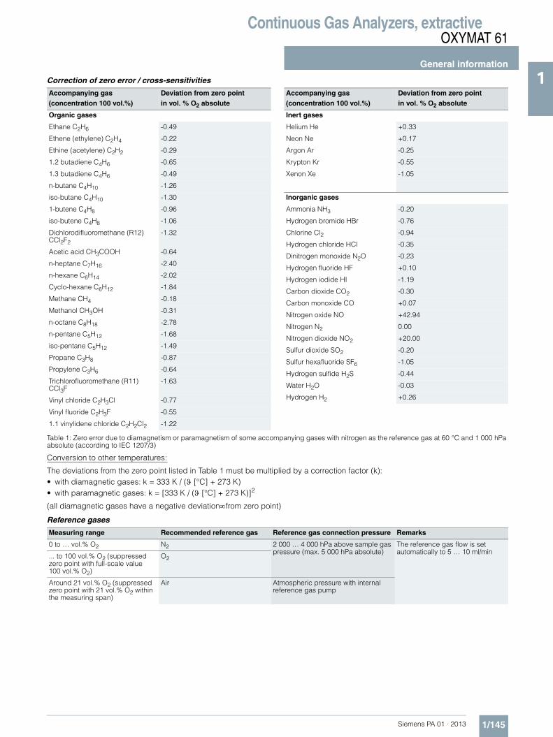
Continuous Gas Analyzers, extractiveOXYMAT 61
General information
1/145Siemens PA 01 · 2013
1Correction of zero error / cross-sensitivities
Table 1: Zero error due to diamagnetism or paramagnetism of some accompanying gases with nitrogen as the reference gas at 60 °C and 1 000 hPa absolute (according to IEC 1207/3)
Conversion to other temperatures:
The deviations from the zero point listed in Table 1 must be multiplied by a correction factor (k):• with diamagnetic gases: k = 333 K / (ϑ [°C] + 273 K)• with paramagnetic gases: k = [333 K / (ϑ [°C] + 273 K)]2
(all diamagnetic gases have a negative deviation∞from zero point)
Reference gases
Accompanying gas(concentration 100 vol.%)
Deviation from zero pointin vol. % O2 absolute
Organic gases
Ethane C2H6 -0.49
Ethene (ethylene) C2H4 -0.22
Ethine (acetylene) C2H2 -0.29
1.2 butadiene C4H6 -0.65
1.3 butadiene C4H6 -0.49
n-butane C4H10 -1.26
iso-butane C4H10 -1.30
1-butene C4H8 -0.96
iso-butene C4H8 -1.06
Dichlorodifluoromethane (R12) CCl2F2
-1.32
Acetic acid CH3COOH -0.64
n-heptane C7H16 -2.40
n-hexane C6H14 -2.02
Cyclo-hexane C6H12 -1.84
Methane CH4 -0.18
Methanol CH3OH -0.31
n-octane C8H18 -2.78
n-pentane C5H12 -1.68
iso-pentane C5H12 -1.49
Propane C3H8 -0.87
Propylene C3H6 -0.64
Trichlorofluoromethane (R11) CCl3F
-1.63
Vinyl chloride C2H3Cl -0.77
Vinyl fluoride C2H3F -0.55
1.1 vinylidene chloride C2H2Cl2 -1.22
Accompanying gas(concentration 100 vol.%)
Deviation from zero pointin vol. % O2 absolute
Inert gases
Helium He +0.33
Neon Ne +0.17
Argon Ar -0.25
Krypton Kr -0.55
Xenon Xe -1.05
Inorganic gases
Ammonia NH3 -0.20
Hydrogen bromide HBr -0.76
Chlorine Cl2 -0.94
Hydrogen chloride HCl -0.35
Dinitrogen monoxide N2O -0.23
Hydrogen fluoride HF +0.10
Hydrogen iodide HI -1.19
Carbon dioxide CO2 -0.30
Carbon monoxide CO +0.07
Nitrogen oxide NO +42.94
Nitrogen N2 0.00
Nitrogen dioxide NO2 +20.00
Sulfur dioxide SO2 -0.20
Sulfur hexafluoride SF6 -1.05
Hydrogen sulfide H2S -0.44
Water H2O -0.03
Hydrogen H2 +0.26
Measuring range Recommended reference gas Reference gas connection pressure Remarks
0 to … vol.% O2 N2 2 000 … 4 000 hPa above sample gas pressure (max. 5 000 hPa absolute)
The reference gas flow is set automatically to 5 … 10 ml/min
... to 100 vol.% O2 (suppressed zero point with full-scale value 100 vol.% O2)
O2
Around 21 vol.% O2 (suppressed zero point with 21 vol.% O2 within the measuring span)
Air Atmospheric pressure with internal reference gas pump

Continuous Gas Analyzers, extractiveOXYMAT 61
19" rack unit
1/146 Siemens PA 01 · 2013
1 ■ Technical specifications
General information
Measuring ranges 4, internally and externally switch-able; autoranging is also possible
Smallest possible span (relating to sample gas pressure 1 000 hPa absolute, 0.5 l/min sample gas flow and 25 °C ambient temperature)
2 vol. % or 5 vol. % O2
Largest possible measuring span 100 vol. % O2
Measuring ranges with suppressed zero point
Any zero point within0 ... 100 vol.% can be imple-mented, provided that a suitable reference gas is used
Operating position Front wall, vertical
Conformity CE mark in accordance with EN 50081-1, EN 50082-2
Design, enclosure
Degree of protection IP20 according to EN 60529
Weight Approx. 13 kg
Electrical characteristics
Power supply 100 … 120 V AC (nominal range of use 90 … 132 V), 47 … 63 Hz or 200 … 240 V AC (nominal range of use 180 … 264 V), 47 … 63 Hz
Power consumption Approx. 37 VA
EMC (Electromagnetic Compatibility)
In accordance with standard requirements of NAMUR NE21 (08/98)
Electrical safety According to EN 61010-1, overvoltage category III
Fuse values 100 ... 120 V: 1.0 T/250200 ... 240 V: 0.63 T/250
Gas inlet conditions
Permissible sample gas pressure
• External reference gas supply 800 … 1 200 hPa absolute
• With integrated pump Atmospheric pressure ±50 hPa
Sample gas flow 18 … 60 l/h (0.3 … 1 l/min)
Sample gas temperature Min. 0 to max. 50 °C, but above the dew point
Sample gas humidity < 90 % relative humidity
Reference gas pressure (high-pres-sure version)
2 000 ... 4 000 hPa above sam-ple gas pressure, but max. 5 000 hPa absolute (version without reference gas pump)
Reference gas pressure (low-pres-sure version) with external pump
Min. 100 hPa above sample gas pressure
Dynamic response
Warm-up period At room temperature < 30 min (the technical specification will be met after 2 hours)
Delayed display (T90) 3.5 s
Damping (electrical time constant) 0 … 100 s, parameterizable
Dead time (purging time of the gas path in the unit at 1 l/min)
Approximately 0.5 ... 2.5 s, depending on version
Time for device-internal signal pro-cessing
< 1 s
Pressure correction range
Pressure sensor internal 500 … 2 000 hPa, absolute(see gas inlet conditions for per-missible sample gas pressure)
Measuring response (relating to sample gas pressure 1 013 hPa absolute, 0.5 l/min sample gas flow and 25 °C ambient temperature)
Output signal fluctuation < ± 0.75 % of the smallest possi-ble measuring range according to rating plate, with electronic damping constant of 1 s (corre-sponds to ± 0.25 % at 2 σ)
Zero point drift < ± 0.5 %/month of the smallest possible span according to rating plate
Measured-value drift < ± 0.5 %/month of the current measuring range
Repeatability < 1 % of the current measuring range
Detection limit 1 % of the current measuring range
Linearity error < 1 % of the current measuring range
Influencing variable (relating to sample gas pressure 1 013 hPa absolute, 0.5 l/min sample gas flow and 25 °C ambient temperature)
Ambient temperature < 2 %/10 K with span 5 %
Sample gas pressure (with air (100 hPa) as internal reference gas supply, correction of the atmo-spheric pressure fluctuations is only possible if the sample gas can vent to ambient air.)
• When pressure compensation has been switched off: < 2 % of the current measuring range/1 % pressure change
• When pressure compensation has been switched on: < 0.2 % of the current measuring range/1 % pressure change
Accompanying gases Deviation from zero point corre-sponding to paramagnetic or dia-magnetic deviation of accompanying gas (see table)
Sample gas flow at zero point < 1 % of the current measuring range according to rating plate with a change in flow of 0.1 l/min within the permissible flow range
Power supply < 0.1 % of the current measuring range with rated voltage ± 10 %
Electrical inputs and outputs
Analog output 0/2/4 … 20 mA, isolated; max. load 750 Ω
Relay outputs 6, with changeover contacts, freely parameterizable, e.g. for measuring range identification; load: 24 V AC/DC/1 A, potential-free
Analog inputs 2, dimensioned for 0/2/4 … 20 mA for external pres-sure sensor and accompanying gas influence correction (correc-tion of cross-interference)
Binary inputs 6, designed for 24 V, isolated, freely parameterizable, e.g. for measuring range switchover
Serial interface RS 485
Options AUTOCAL function with 8 addi-tional binary inputs and relay out-puts, also with PROFIBUS PA or PROFIBUS DP
Climatic conditions
Permissible ambient temperature -30 … +70 °C during storage and transportation5 … 45 °C during operation
Permissible humidity < 90 % relative humidity as annual average, during storage and transportation (must not fall below dew point)

Continuous Gas Analyzers, extractiveOXYMAT 61
19" rack unit
1/147Siemens PA 01 · 2013
1
1) Standard setting: Measuring range 1: 0 to smallest measuring spanMeasuring range 2: 0 to 10 %Measuring range 3: 0 to 25 %Measuring range 4: 0 to 100 %
Selection and ordering data Order No.
OXYMAT 61 gas analyzer19" rack unit for installation in cabinets
7MB2001- 77A 0 0 - 7777 Cannot be combined
Gas connections for sample gas and reference gasPipe with 6 mm outer diameter 0Pipe with ¼" outer diameter 1
Smallest possible measuring span O22 % Reference gas pressure 3 000 hPa C2 % reference gas supply with internal pump D D Y025 % Reference gas pressure 3 000 hPa E5 % reference gas supply with internal pump F F Y02
Power supply
100 to 120 V AC, 47 to 63 Hz 0200 to 240 V AC, 47 to 63 Hz 1
Sample gas monitoring
Without AWith (incl. flow indicator and pressure switch) D
Add-on electronics
Without A
AUTOCAL function
• With 8 additional digital inputs/outputs B• With serial interface for the automotive industry (AK) D
• With 8 additional digital inputs/outputs and PROFIBUS PA interface E• With 8 additional digital inputs/outputs and PROFIBUS DP interface F
LanguageGerman 0English 1French 2Spanish 3Italian 4
Additional versions Order code
Add "-Z" to Order No. and specify order code
Telescopic rails (2 units) A31
Set of Torx screwdrivers A32
TAG labels (specific lettering based on customer information) B03
Attenuation element for sample gas B04 Y02
Clean for O2 service (specially cleaned gas path) Y02
Measuring range indication in plain text, if different from the standard setting1) Y11
Retrofitting sets Order No.
RS 485/Ethernet converter A5E00852383RS 485/RS 232 converter C79451-Z1589-U1RS 485 / USB converter A5E00852382
AUTOCAL function each with 8 digital inputs/outputs C79451-A3480-D511AUTOCAL function 8 digital inputs/outputs each and PROFIBUS PA A5E00057307AUTOCAL function 8 digital inputs/outputs each and PROFIBUS DP A5E00057312

Continuous Gas Analyzers, extractiveOXYMAT 61
19" rack unit
1/148 Siemens PA 01 · 2013
1 ■ Dimensional drawings
OXYMAT 61, 19“ unit, dimensions in mm
s
MMM444
86.5
384.5
27.515.6
173 128
172
149.
5
82
4400 36 10
413
2
320
345
411.
5
4
351.5
465
483
37.7
101.
6
177

Continuous Gas Analyzers, extractiveOXYMAT 61
19" rack unit
1/149Siemens PA 01 · 2013
1■ Schematics
Pin assignment (electrical connections)
OXYMAT 61, 19“ unit, pin assignment

Continuous Gas Analyzers, extractiveOXYMAT 61
19" rack unit
1/150 Siemens PA 01 · 2013
1 Pin assignment (electrical connections)
OXYMAT 61, 19“ unit, pin assignment of the AUTOCAL board and PROFIBUS connectors
37
36
35
34
33
29
30
31
32
18
17
16
14
13
12
11
10
9
8
7
6
5
28
27
26
25
24
4
3
2
1
23
22
21
20
19
15
1
2
3
4
5
6
7
8
9
1
2
3
4
5
6
7
8
9
M
Connector SUB-D 37F (option)
M
Relay 9
Relay 10
Relay 11
Relay 12
Relay 13
Relay 14
Relay 7
Relay 8
GND
Contact loadmax. 24 V/1 A, AD/DC
for shownrelay contact position,the relay has zero current
GND
Binary input 14-PNCNC
Isolatedvia optocoupler"0" = 0 V (0 ... 4.5 V)"1" = 24 V (13 ... 33 V)
Binary input 13-PBinary input 12-PBinary input 11-PBinary input 10-PBinary input 9-PBinary input 8-PBinary input 7-PBinary input 7 to 14-N
Connector SUB-D 9F-X90PROFIBUS DP
Connector SUB-D 9M-X90PROFIBUS PAOptional
VP /+ 5 V
DGND
RxD/TxD-P (B)RxD/TxD-N (A)CNTR-P/direction control
PA-P(+)PA-N(-)
CNTR-N

Continuous Gas Analyzers, extractiveOXYMAT 61
19" rack unit
1/151Siemens PA 01 · 2013
1Gas and electrical connections
OXYMAT 61, 19“ unit, gas and electrical connections
■ Selection and ordering data
124
Gas connections: stubs 6 mm or ¼"
Power supply and fuses
37-pin connector:Binary inputs andrelay outputs (option)
25-pin connector:Binary inputs andrelay outputs
9-pin interface connector (option): e.g. PROFIBUS
9-pin connector:RS 485
15-pin connector:Binary inputs andanalog inputs/outputs
Sample gas inlet
Reference gas inlet
Sample gas outlet
Purging gasinlet
Documentation
Operating instructions Order No.
OXYMAT 61Gas analyzer for measurement of oxygen
• German A5E00123066
• English A5E00123067
• French A5E00123068
• Spanish A5E00123069
• Italian A5E00123070

Continuous Gas Analyzers, extractiveOXYMAT 61
Suggestions for spare parts
1/152 Siemens PA 01 · 2013
1 ■ Selection and ordering data
If the OXYMAT 61 was supplied with a specially cleaned gas path for high oxygen context ("Clean for O2 service"), please ensure that you specify this when ordering spare parts. This is the only way to guarantee that the gas path will continue to comply with the special requirements for this version.
Description Quantity for 2 years
Quantity for 5 years
Order No.
Analyzer unit
Reference gas supply (pump, restrictor, pressure switch, hose) 1 1 A5E00114838
O-ring 1 2 C74121-Z100-A6
Pressure switch (sample gas) 1 2 C79302-Z1210-A2
Flowmeter 1 2 C79402-Z560-T1
Sample chamber
• Stainless steel, mat. no. 1.4571; non-flow-type compensation branch - 1 C79451-A3277-B535
• O-ring (measuring head) 2 4 C79121-Z100-A32
• O ring (fitting) 2 4 C71121-Z100-A159
Measuring head (non-flow-type compensation branch) 1 1 C79451-A3460-B525
Restrictor for sample gas path, hose 2 2 C79451-A3480-C10
Reference gas path, 3000 hPa (set of parts) 1 1 C79451-A3480-D518
Electronics
Front plate with keyboard 1 1 A5E00259978
Motherboard, with firmware: see spare parts list - 1
Adapter plate, LCD/keyboard 1 1 C79451-A3474-B605
Magnetic field connection plate - 1 C79451-A3474-B606
LC display 1 1 W75025-B5001-B1
Connector filter - 1 W75041-E5602-K2
Fuse
• 0.63 A/250 V (230 V version) 2 3 W79054-L1010-T630
• 1.0 A/250 V (110 V version) 2 3 W79054-L1011-T100

Continuous Gas Analyzers, extractiveOXYMAT 64
General information
1/153Siemens PA 01 · 2013
1■ Overview
The OXYMAT 64 gas analyzer is used for the trace measurement of oxygen.
■ Benefits
• High linearity• Compact design• Open interface architecture (RS 485, RS 232, PROFIBUS)• SIPROM GA network for maintenance and service information
(option)
■ Application
• Production of technical gases - Measurements in N2 and CO2
• Welding- Measurements in protective gases during welding of highly
alloyed steels, titanium, etc.• Systems for air separation
- Measurements in N2 and in inert gases (e.g. Ne, Ar)- Measurements in CO2
• Food production - Measurement in CO2 (e.g. breweries)
• Electronics industry - Low-pressure version with pump
• Flow soldering systems
■ Design
• 19" rack unit with 4 HU for installation - in hinged frames- in cabinets with or without telescopic rails
• Front plate for service purposes can be pivoted down(laptop connection)
• Connections for sample gas - Input: Clamping ring connection for a pipe diameter of 6 mm
or ¼"- Output: Pipe connection with diameter 6 mm or ¼"
• High-pressure and low-pressure versions• Catalytically active and inactive cell
Display and control panel• Large LCD field for simultaneous display of
- Measured value- Status bar- Measuring ranges
• Contrast of the LCD field adjustable via the menu• Permanent LED backlighting• Washable membrane keyboard with five softkeys• Five-digit measured-value display
(decimal point counts as one digit)• Menu-driven operation for parameterization, configuration,
test functions, adjustment• Operator support in plain text• Graphical display of the concentration progression; time inter-
vals parameterizable• Bilingual operating software German/English,
English/Spanish, French/English, Spanish/English, Italian/English
• Switchover from ppm measuring range to % measuring range
Inputs and outputs• One analog output per medium (from 0, 2, 4 to 20 mA; NAMUR
parameterizable)• Six binary inputs freely configurable (e.g. for measurement
range switchover, processing of external signals from sample preparation)
• Six relay outputs freely configurable (failure, maintenance re-quest, maintenance switch, threshold alarm, external solenoid valves)
• Two analog inputs configurable (e.g. correction of cross-inter-ference, external pressure sensor)
• Extension with eight additional binary inputs and eight addi-tional relay outputs, e.g. for autocalibration with up to four cal-ibration gases
Communication
RS 485 present in basic unit (connection from the rear).
Options• RS 485/RS 232 converter• RS 485/Ethernet converter• RS 485/USB converter• Connection to networks via PROFIBUS DP/PA interface• SIPROM GA software as the service and maintenance tool

Continuous Gas Analyzers, extractiveOXYMAT 64
General information
1/154 Siemens PA 01 · 2013
1
OXYMAT 64, membrane keyboard and graphic display
Designs – Parts wetted by sample gas, standard
Status line to display the analyzer status(programmable)
LED backlit graphic display and membrane keyboard with noticeable click
Display ofconcentrations asnumbers and bargraph
Display ofstart-of-scale andfull-scale values
Keyboard toenter values
CLEAR keyto delete inputs
ENTER keyto acceptinput values
MEAS key to return tomeasurement mode
INFO keyfor help in plain text
ESC keyto abort inputs
Display of currentmeasuring ranges
Easy operation menu controlusing the softkeys
Two code levelsaccording to NAMUR(maintenance andspecialist level)
Gas path 19" rack unit
Sample gas path BushingPipe inletO2 sensorBypass lineConnection pieces
Stainless steel, mat. no. 1.4571Stainless steelZrO2 ceramicFPM (Viton)PTFE (Teflon)
Pressure sensor EnclosureMembraneSensor adapterBypass restrictor
Polycarbonate SiO4
Aluminum Stainless steel, mat. no. 1.4571
Flow indicator Measurement pipeVariable areaSuspension boundaryAngle pieces
Duran glassDuran glass, blackPTFE (Teflon)FKM (Viton)
Pressure switch EnclosureMembrane
PolycarbonateNBR

Continuous Gas Analyzers, extractiveOXYMAT 64
General information
1/155Siemens PA 01 · 2013
1Gas path (high-pressure version)
Gas path OXYMAT 64, high-pressure version
The sample gas pressure (2 000 to 6 000 hPa) is regulated by the pressure regulator (3) at approx. 2 000 hPa or is provided by the operator with 2 000 hPa. This pressure is applied at the restrictor (10). The restrictor (10) reduces the pressure such that a sample gas flow of 15 to 30 l/h is created. This flow is subdivided via the sample gas restrictor (11) and the adjustable bypass restrictor (6) such that there is a sample gas flow of 7.5 l/h through the sensor.
If the sample gas can flow off into the atmosphere unhampered, the sample gas pressure corresponds to the atmospheric pressure. If the sample gas flows off via an exhaust gas line, it works like a flow resistance. If the resulting dynamic pressure exceeds 100 hPa (rel.), a maintenance request is output.
Legend for the gas path figure
1 Sample gas inlet; inlet pressure 5 Pressure sensor
- without internal pressure regulator: 2 000 hPa (abs.), regulated 6 Bypass restrictor
- with internal pressure regulator: 2 000 ... 6 000 hPa (abs.) 7 Pressure switch
2 Sample gas outlet; sample gas flows off free of dynamic pressure 8 Flow measuring tube
3 Pressure regulator (order version) 9 Purging gas connection
4 O2 sensor 10 Restrictor
F
P
9 1
10 10
2
6
4
7
8
3
5
O2 sensor(KAZ /KIZ)

Continuous Gas Analyzers, extractiveOXYMAT 64
General information
1/156 Siemens PA 01 · 2013
1 Gas path (low pressure)
Gas path OXYMAT 64, low-pressure version
With the low-pressure version, the sample gas flow must be set externally to 125 ml/min. With a built-in pressure switch, the sample gas pressure is approx. 30 hPa above the current atmospheric pressure since the sample gas flows off via a restrictor. If the resulting dynamic pressure exceeds 100 hPa (rel.), a maintenance request is output. In order to reduce the 90 % time, we recommend instal-lation of a bypass upstream of the gas inlet which then provides a faster exchange of gas. This is particularly important with long sample gas lines between the gas sampling point and the analyzer. Please make absolutely sure that the flow in the OXYMAT 64 does not exceed 125 ml/min.
Legend for the gas path figure
1 Sample gas inlet; flow 125 ml/min (7.5 l/h) 5 Pressure switch
2 Sample gas outlet; sample gas flows off free of dynamic pressure 6 Flow measuring tube
3 O2 sensor 7 Purging gas connection
4 Pressure sensor 8 Restrictor
F
P
7 1
8
2
3
5
6
4
O2 sensor(KAZ /KIZ)

Continuous Gas Analyzers, extractiveOXYMAT 64
General information
1/157Siemens PA 01 · 2013
1
Low-pressure version with integral sample gas pump
The analyzer version "QXYMAT 64 low-pressure with pump" is equipped with a sample gas pump which automatically provides a constant sample gas flow of 125 ml/min through the sensor. By means of an internal bypass, the total flow of sample gas through the analyzer is increased to approx. 0.4 l/min. This mea-sure significantly improves the analyzer’s response time.
9 1 2
T1
T2
Δp
T4T3
F
Purging gas Sample gas
Pump
Oxy
gen
sens
or m
odul
e,
com
plet
ePressure sensor
O2 sensorCIZ/CAZNeedle
valve
Restrictor 1

Continuous Gas Analyzers, extractiveOXYMAT 64
General information
1/158 Siemens PA 01 · 2013
1 ■ Function
The measuring cell consists of a cylindrical (pipe-shaped) ZrO2 membrane. The sample gas (low O2 content) flows at a constant rate through the inside of the membrane, which is regulated at 650 °C. The exterior of the sensor is exposed to the ambient air (approx. 21 % O2).
Both sides of the ZrO2 membrane are coated with thin platinum films that act as electrodes. This forms a solid, electrochemical cell. The amount of oxygen atoms ionized depends on the oxy-gen concentration at the electrodes.
The differences in concentration at each side means that a dif-ferential partial pressure prevails. Since ZrO2 conducts ions at 650 °C, ionic migration takes place in the direction of the lower partial pressure.
An oxygen gradient arises across the width of the ZrO2 mem-brane, which, according to equation (1), results in an electrical potential difference between the platinum electrodes.
Defects in the crystal lattice, caused by contamination of the ZrO2 material with Y2O3 and/or CaO (introduced originally to prevent cracks forming in ceramic material) make it easier for O2 ions to diffuse in the ZrO2 grid.
Catalytically active ZrO2 sensor (CAZ)
The electrode material is made of platinum (Pt). This type of sen-sor has a higher cross-sensitivity when flammable accompany-ing gas components are present.
Catalytically inactive ZrO2 sensor (CIZ)
The catalytically inactive sensor has the same general design as the CAZ. The contacts and electrode surface inside the pipe are made of a specially developed material which largely prevents catalytic oxidation except of H2, CO and CH4.
OXYMAT 64, principle of operation
Measuring effect
U = UA + RT/4F (In [O2,air] - In [O2] (equation 1)U measuring effectUA asymmetric voltage (voltage, at [O2] = [O2,air]T ceramic temperature[O2,air] O2 concentration in the air[O2] O2 concentration in sample gas
Note
The sample gas must be fed into the analyzer free of dust. Con-densation should be avoided. Therefore, gas modified for the measuring tasks is necessary in most application cases.
Calibration
Calibration of the calibration point is carried out as with the other analyzers of Series 6 after a maximum of 14 days by connecting the calibration gas O2 in residual N2 at concentrations of approx. 60 to 90 % of the master measuring range.
Contrary to the other analyzers of Series 6, the zero point calibra-tion cannot be carried out using pure nitrogen, but with a "small" concentration of oxygen in nitrogen appropriate to the selected measuring range (e.g.: measuring range 0 to 10 vpm; calibration gas approx. 2 ppm O2 in residual N2).
Essential characteristics• Four measurement ranges freely parameterizable, all mea-
surement ranges linear• Galvanically isolated measurement value output 0/2/4 through
20 mA (also inverted) and as per NAMUR• Autoranging selectable; possibility of remote switching• Storage of measured values possible during adjustments• Wide range of selectable time constants (static/dynamic noise
suppression); i.e. the response time of the device can be adapted to the respective measuring task
• Easy handling thanks to menu-driven operation• Low long-term drift• Two control levels with their own authorization codes for the
prevention of accidental and unauthorized operator interven-tions
• Automatic, parameterizable measuring range calibration• Operation based on the NAMUR recommendation• Monitoring of the sample gas (via pressure switch)• Customer-specific analyzer options such as:
- Customer acceptance- TAG labels- Drift recording
• Simple handling using a numerical membrane keyboard and operator prompting
• Smallest span 0 to 10 vpm O2• Largest span 0 to 100 % (testing with ambient air)• Internal pressure sensor for correction of the influence of sam-
ple gas pressure fluctuations1
2 3 4 5 6 7
Pipe made of ZrO2 and Y2O3 orceramic CaO-mixed oxideCeramic protective coatingSample electrode (Pt)Reference electrode (Pt)ThermoelementContact to reference electrodeContact to sample electrode

Continuous Gas Analyzers, extractiveOXYMAT 64
General information
1/159Siemens PA 01 · 2013
1Influence of interfering gas
Catalytically active sensor (CAZ)
Very large cross-interference of all combustible accompanying gases. Thus not suitable for use with combustible accompany-ing gases!
Catalytically inactive sensor (CIZ)
There is only a slight cross-interference in the case of accompa-nying gases with a concentration in the range of the O2 concen-tration. H2, CO and CH4 still have a noticeable effect in the case of flammable accompanying gas components.
Examples of typical diagonal gas offsets on a catalytically inactive sensor
The listed deviations depend on the exemplar and can deviate up to ± 0.2 vpm. The actual deviation must be determined indi-vidually or the error will be eliminated through a corresponding calibration measure (displacement of the diagonal gas offset).
Measured component / interfering gas Diagonal gas offset
78 vpm O2/140 vpm CO -6.1 vpm
10 vpm O2/10 vpm CO -0.6 vpm
74 vpm O2 / 25 vpm CH4 -0.3 vpm
25 vpm O2 / 357 vpm CH4 -1.1 vpm
25 vpm O2 / 70 vpm H2 -3 vpm
5 vpm O2 / 9.6 vpm H2 -0.55 vpm
170 vpm O2 / 930 vpm C2H4 -118 vpm

Continuous Gas Analyzers, extractiveOXYMAT 64
19" rack unit
1/160 Siemens PA 01 · 2013
1 ■ Technical specifications
General
Measurement ranges 4, internally and externally switch-able; automatic measuring range switchover also possible
Smallest possible span (relating to sample gas pressure 1 000 hPa absolute, 0.5 l/min sample gas flow, and 25 °C ambient temperature)
0 ... 10 vpm O2
Largest possible measuring span 0 ... 100 %
Operating position Front wall vertical
Conformity CE mark in accordance with EN 50081-1, EN 50082-2 and RoHS
Design, enclosure
Degree of protection IP20 according to EN 60529
Weight Approx. 11 kg
Electrical characteristics
EMC (Electromagnetic Compatibility)
In accordance with standard requirements of NAMUR NE21 (08/98) and EN 61326
Electrical safety In accordance with EN 61010-1, overvoltage category II
Power supply 100 ... 120 V AC (nominal range of use 90 ... 132 V), 48 ... 63 Hz or200 ... 240 V AC (nominal range of use 180 ... 264 V), 48 ... 63 Hz
Power consumption Approx. 37 VA
Fuse values 100 ... 120 V: 1.0T/250200 ... 240 V: 0.63T/250
Gas inlet conditions
Sample gas flow
• through the sensor 7.5 l/h
• Overall consumption 15 ... 30 l/h
Permissible sample gas pressure
• without internal pressure regulator 2 000 hPa (abs.)
• with internal pressure regulator 2 000 ... 6 000 hPa (abs.)
Sample gas temperature Min. 0 ... max. 50 °C, but above the dew point
Sample gas humidity < 1 % relative humidity
Dynamic response
Warm-up period At room temperature < 30 min (the technical specification will be met after 2 hours)
Damping (electrical time constant) 0 ... 100 s, parameterizable
Dead time (high-pressure version) (purging time of the gas path in the unit at 125 ml/min)
10 ... 30 s
Dead time (low-pressure version without pump)
< 5 s
Dead time (low-pressure version with pump)
< 10 s
Time for device-internal signal processing
< 1 s
Pressure correction range
Pressure sensor internal 800 ... 1 100 hPa (abs.)
Measuring response (referred to sample gas pressure 1 013 hPa absolute, sample gas flow 7.5 l/min, and ambient temperature 25 °C)
Output signal fluctuation < ± 1 % of the smallest possible measuring range according to rat-ing plate, with electronic damping constant of 1 s
Zero point drift < ± 1 % of the current span/month
Measured-value drift < ± 1 % of the current span/month
Repeatability < 3 % of the current measuring span
Detection limit 1 % of current measuring range,< 0.1 vpm in measuring range 0 ... 10 vpm
Linearity error < 2 % of the current measuring span
Influencing variables (relating to sample gas pressure 1 013 hPa absolute, 7.5 l/min sample gas flow and 25 °C ambient temperature)
Ambient temperature < 2 %/10 K referred to current measuring span
Sample gas pressure only possible if the sample gas can flow out into the ambient air
• When pressure compensation has been switched off: < 1 % of current span/1 % pressure change
• When pressure compensation has been switched on: < 0.2 % of current span/1 % pressure change
Residual gases, deviation from zero point
• Catalytically active sensor (CAZ) Only gases with non-combustible residual gas components can be introduced
• Catalytically inactive sensor (CIZ) Residual gas concentration of 10 vpm H2; CO and CH4 have a lower cross-interference; higher HCs are negligible
Sample gas flow < 2 % of the smallest possible span with a change in flow of 10 ml/min
Power supply < 0.1 % of the current measuring range with rated voltage ± 10 %
Electrical inputs and outputs
Analog output 0/2/4 ... 20 mA, 4 … 20 mA (NAMUR), isolated; max. load 750 Ω
Relay outputs 6, with changeover contacts, freely parameterizable, e.g. for measur-ing range identification; load: 24 V AC/DC/1 A, isolated
Analog inputs 2, dimensioned for 0/2/4 … 20 mA for external pressure sensor and correction of influence of residual gas (correction of cross-interfer-ence)
Binary inputs 6, designed for 24 V, isolated, freely parameterizable, e.g. for measurement range switchover
Serial interface RS 485
Options AUTOCAL function each with 8 additional binary inputs and relay outputs, also with PROFIBUS PA or PROFIBUS DP
Climatic conditions
Permissible ambient temperature -40 ... +70 °C during storage and transportation, 5 … 45 °C during operation
Permissible humidity < 90 % relative humidity as annual average, during storage and trans-portation (must not fall below dew point)

Continuous Gas Analyzers, extractiveOXYMAT 64
19" rack unit
1/161Siemens PA 01 · 2013
1Selection and ordering data Order No.
OXYMAT 64 gas analyzer19" rack unit for installation in cabinets
7MB2041- 7771 7 - 7A77 Cannot be combined
SensorZrO2: Catalytically active cell (CAC) 0 0ZrO2: Catalytically inactive cell (CIC) 1 1
ZrO2: Catalytically active cell (CAC); with differential pressure sensor 2 2ZrO2: Catalytically inactive cell (CIC); with differential pressure sensor 3 3
Sample gas pressureHigh pressure, without pressure regulator 2 000 hPa (abs.) A AHigh pressure, with pressure regulator 2 000 ... 6 000 hPa (abs.) B B
Low pressure, with pump Atmosphere C CLow pressure, without suction pump Atmosphere D D
Gas connectionInput Clamping ring connection 6 mm AOutput Fittings 6 mm
Input Clamping ring connection ¼" BOutput Fitting ¼"
Add-on electronicsWithout 0AUTOCAL function• With 8 additional digital inputs/outputs 1• With 8 additional digital inputs/outputs and PROFIBUS PA interface 6• With 8 additional digital inputs/outputs and PROFIBUS DP interface 7
Power supply
100 to 120 V AC, 48 to 63 Hz 0
200 to 240 V AC, 48 to 63 Hz 1
Explosion protection
Without A
LanguageGerman 0English 1French 2Spanish 3Italian 4
Additional versions Order code
Add "-Z" to Order No. and specify order code
Telescopic rails (2 units) A31
TAG labels (specific lettering based on customer information) B03
Clean for O2 service (specially cleaned gas path) Y02
Measuring range indication in plain text, if different from the standard setting Y11
Special setting (only in conjunction with an application no., e.g. extended measuring range)
Y12
Extended special setting (only in conjunction with an application no., e.g. determination of cross-interfer-ences)
Y13
Retrofitting sets Order No.
RS 485/Ethernet converter A5E00852383
RS 485/RS 232 converter C79451-Z1589-U1
RS 485 / USB converter A5E00852382
AUTOCAL function each with 8 digital inputs/outputs C79451-A3480-D511
AUTOCAL function 8 digital inputs/outputs each and PROFIBUS PA A5E00057307
AUTOCAL function 8 digital inputs/outputs each and PROFIBUS DP A5E00057312

Continuous Gas Analyzers, extractiveOXYMAT 64
19" rack unit
1/162 Siemens PA 01 · 2013
1 ■ Dimensional drawings
OXYMAT 64, 19" rack unit, size in mm
s
MMM444
86.5
384.5
27.515.6
173 128
172
149.
5
82
4400 36 10
413
2
320
345
411.
5
4
351.5
465
483
37.7
101.
6
177

Continuous Gas Analyzers, extractiveOXYMAT 64
19" rack unit
1/163Siemens PA 01 · 2013
1■ Schematics
Pin assignment (electrical connections)
OXYMAT 64, 19" rack unit, pin assignment

Continuous Gas Analyzers, extractiveOXYMAT 64
19" rack unit
1/164 Siemens PA 01 · 2013
1
OXYMAT 64, 19" rack unit, pin assignment of the AUTOCAL plate and PROFIBUS plug
37
36
35
34
33
29
30
31
32
18
17
16
14
13
12
11
10
9
8
7
6
5
28
27
26
25
24
4
3
2
1
23
22
21
20
19
15
1
2
3
4
5
6
7
8
9
1
2
3
4
5
6
7
8
9
M
Connector SUB-D 37F (option)
M
Relay 9
Relay 10
Relay 11
Relay 12
Relay 13
Relay 14
Relay 7
Relay 8
GND
Contact loadmax. 24 V/1 A, AD/DC
for shownrelay contact position,the relay has zero current
GND
Binary input 14-PNCNC
Isolatedvia optocoupler"0" = 0 V (0 ... 4.5 V)"1" = 24 V (13 ... 33 V)
Binary input 13-PBinary input 12-PBinary input 11-PBinary input 10-PBinary input 9-PBinary input 8-PBinary input 7-PBinary input 7 to 14-N
Connector SUB-D 9F-X90PROFIBUS DP
Connector SUB-D 9M-X90PROFIBUS PAOptional
VP /+ 5 V
DGND
RxD/TxD-P (B)RxD/TxD-N (A)CNTR-P/direction control
PA-P(+)PA-N(-)
CNTR-N

Continuous Gas Analyzers, extractiveOXYMAT 64
19" rack unit
1/165Siemens PA 01 · 2013
1Gas connections and pin assignment
OXYMAT 64, 19" rack unit, gas connections and electrical connections
12
Gas connectionsSample gas inlet: Clamping ring connection 6 mm or ¼"Sample gas outlet: Fittings 6 mm or ¼"
Mains connectionand miniaturefuses
37-pin connector:Binary inputs andrelay outputs (optional)
25-pin connector:Binary inputs andrelay outputs
9-pininterface connector(Optional): e.g.PROFIBUS
9-pin connector:RS 485
15-pin connector:Binary inputs andanalog inputs/outputs
Sample gas inletSample gas outlet
Purge gasinlet

Continuous Gas Analyzers, extractiveOXYMAT 64
Documentation
1/166 Siemens PA 01 · 2013
1 ■ Selection and ordering data
■ Selection and ordering data
Operating instructions Order No.
OXYMAT 64Gas analyzer for measuring trace oxygen
• German A5E00880382
• English A5E00880383
• French A5E00880384
• Spanish A5E00880385
• Italian A5E00880386
Gas analyzers of Series 6 and ULTRAMAT 23
Schnittstelle/Interface PROFIBUS DP/PA
• German and English A5E00054148
Suggestions for spare parts
Description 7MB2041 2 years (quantity)
5 years (quantity)
Order No.
Pressure regulator as spare part x – 1 A5E01008972
Flowmeter x – 1 A5E01061561
Adapter plate, LC display/keypad x 1 1 C79451-A3474-B605
LC display x – 1 W75025-B2001-B1
Connector filter x – 1 W75041-E5602-K2
Fuse, T 0.63 A, line voltage 200 … 240 V x 2 4 W79054-L1010-T630
Fuse, T 1 A, line voltage 200 … 240 V x 2 4 W79054-L1011-T100

Continuous Gas Analyzers, extractiveCALOMAT 6
General information
1/167Siemens PA 01 · 2013
1■ Overview
The CALOMAT 6 gas analyzer is primarily used for quantitative determination of H2or He in binary or quasi-binary non-corrosive gas mixtures.
Concentrations of other gases can also be measured if their thermal conductivities differ significantly from the residual gases like Ar, CO2, CH4, NH3.
■ Benefits
• Small T90 time due to micromechanical-produced Si sensor• Universally applicable hardware basis, high measuring range
dynamics (e.g. 0 to 1 %, 0 to 100 %, 95 to 100 % H2)• Integrated correction of cross-interference, no external calcu-
lation required• Open interface architecture (RS 485, RS 232, PROFIBUS)• SIPROM GA network for maintenance and service information
(option)• Electronics and analyzer part: gas-tight separation, purge-
able, IP65, long service life even in harsh environments• EEx(p) for Zones 1 and 2 (in accordance with 94/9/EC
(ATEX 2G and ATEX 3G), and Class I Div 2 (CSA) Ex(n)
■ Application
Fields of application• Pure gas monitoring (0 to 1 % H2 in Ar)• Protective gas monitoring (0 to 2 % He in N2)• Hydroargon gas monitoring (0 to 25 % H2 in Ar)• Forming gas monitoring (0 to 25 % H2 in N2)• Gas production:
- 0 to 2 % He in N2- 0 to 10 % Ar in O2
• Chemical applications: - 0 to 2 % H2 in NH3- 50 to 70 % H2 in N2
• Wood gasification (0 to 30 % H2 in CO/CO2/CH4)• Blast furnace gas (0 to 5 % H2 in CO/CO2/CH4/N2)• Bessemer converter gas (0 to 20 % H2 in CO/CO2)• Monitoring equipment for hydrogen-cooled turbo-alternators:
- 0 to 100 % CO2/Ar in air- 0 to 100 % H2 in CO2/Ar- 80 to 100 % H2 in air
• Versions for the analysis of flammable and non-flammable gases or vapors for use in hazardous areas (Zone 1 and Zone 2)
Special versions
Special applications
In addition to the standard combinations, special applications are also available upon request (e.g. higher sample gas pres-sure up to 2 000 hPa absolute).
■ Design
19" rack unit• With 4 HU for installation
- in hinged frame- in cabinets with or without telescopic rails
• Front plate for service purposes can be pivoted down(laptop connection)
• Internal gas paths: stainless steel pipe (mat. no. 1.4571)• Gas connections for sample gas inlet and outlet and for purg-
ing gas: fittings, pipe diameter of 6 mm or ¼"
Field device• Two-door enclosure (IP65) with gas-tight separation of ana-
lyzer and electronics sections• Individually purgeable enclosure halves• Stainless steel gas path and stubs (mat. no. 1.4571)• Purging gas connections: pipe diameter 10 mm or 3/8"• Gas connections for sample gas inlet and outlet: clamping
ring connection for a pipe diameter of 6 mm or ¼"
Display and control panel• Large LCD panel for simultaneous display of:
- Measured value (digital and analog displays)- Status bar- Measuring ranges
• Contrast of LCD panel adjustable using menu• Permanent LED backlighting• Washable membrane keyboard with five softkeys• Menu-driven operation for parameterization, test functions,
adjustment• User help in plain text• Graphic display of concentration trend; programmable time
intervals• Bilingual operating software German/English, English/
Spanish, French/English, Spanish/English, Italian/English
Input and outputs• One analog output per medium (from 0, 2, 4 to 20 mA; NAMUR
parameterizable)• Two analog inputs configurable (e.g. correction of cross-inter-
ference or external pressure sensor)• Six binary inputs freely configurable (e.g. for measurement
range switchover, processing of external signals from sample preparation)
• Six relay outputs freely configurable (e.g. failure, maintenance request, limit alarm, external solenoid valves)
• Each can be expanded by eight additional binary inputs and re-lay outputs (e.g. for autocalibration with max. four test gases)
Communication
RS 485 present in basic unit (connection from the rear; for the rack unit also behind the front plate).
Options• RS 485/RS 232 converter• RS 485/Ethernet converter• RS 485/USB converter• Connection to networks via PROFIBUS DP/PA interface• SIPROM GA software as the service and maintenance tool

Continuous Gas Analyzers, extractiveCALOMAT 6
General information
1/168 Siemens PA 01 · 2013
1
CALOMAT 6, membrane keyboard and graphic display
Designs – parts wetted by sample gas
Status line for display of analyzer status(programmable)
LED backlit graphicdisplay and membrane keyboardwith noticeable click
Two code levelsaccording to NAMUR(maintenance andspecialist level)
MEAS key to return tomeasurement mode
Easy operation with menu controlusing five softkeys
Display of currentmeasuring ranges
ESC keyto abort inputs
INFO keyfor help in plain text
CLEAR key to delete inputs
Keyboard toenter values
Display of start-of-scale and full-scale values
Display ofconcentrations asnumbers and bargraph
ENTER key to accept input values
Gas path 19" rack unit Field device Field device Ex
With pipes Bushing Stainless steel, mat. no. 1.4571
Pipe Stainless steel, mat. no. 1.4571
Sample cell body Stainless steel, mat. no. 1.4571
O-rings FFKM-Chemraz
Sensor Si, SiOxNy, AU, epoxy resin, glass
Tightness Leakage < 1 μl/s

Continuous Gas Analyzers, extractiveCALOMAT 6
General information
1/169Siemens PA 01 · 2013
1
CALOMAT 6, 19" rack unit, gas path
CALOMAT 6, field device, gas path

Continuous Gas Analyzers, extractiveCALOMAT 6
General information
1/170 Siemens PA 01 · 2013
1 ■ Function
Principle of operation
The measuring principle is based on the different thermal con-ductivity of gases.
The CALOMAT 6 works with a micromechanically produced Si chip whose measuring membrane is equipped with thin-film resistors.
The resistors are kept at a constant temperature. This requires an current intensity depending on the thermal conductivity of the sample gas. This "raw value" is processed further electronically to calculate the gas concentration.
The sensor is located in a thermostatically-controlled stainless steel enclosure in order to prevent the influence of changes in ambient temperature.
To prevent the influence of changes in flow, the sensor is posi-tioned in a bore located to the side of the main flow.
Note
The sample gases must be fed into the analyzers free of dust. Condensation (dew point sample gas < ambient temperature) is to be avoided in the measurement chambers. Therefore, the use of gas modified for the measuring tasks is necessary in most ap-plication cases.
CALOMAT, principle of operation
Essential characteristics• Four freely parameterizable measuring ranges, also with sup-
pressed zero point, all measuring ranges linear• Smallest measuring spans up to 1 % H2 (with disabled zero
point: 95 to 100 % H2) possible• Measuring range identification• Galvanically isolated measured-value output 0/2/4 to 20 mA
(also inverted)• Autoranging or manual measurement range switchover possi-
ble; remote switching is also possible• Storage of measured values possible during adjustments• Wide range of selectable time constants (static/dynamic noise
suppression); i.e. the response time of the analyzer can be matched to the respective measuring task
• Short response time• Low long-term drift• Measuring point switchover for up to 6 measuring points
(programmable)• Measuring range identification• Measuring point identification• External pressure sensor can be connected – for the correc-
tion of sample gas fluctuations• Automatic range calibration can be parameterized• Operation based on the NAMUR recommendation
• Two control levels with their own authorization codes for the prevention of accidental and unauthorized operator interven-tions
• Simple handling using a numerical membrane keyboard and operator prompting
• Customer-specific analyzer options such as: - Customer acceptance- TAG labels- Drift recording- Clean for O2 service
Measuring spans
The smallest and largest possible spans depend on both the measured component (type of gas) and the respective applica-tion.
The smallest possible spans listed below refer to N2 as the resid-ual gas. With other gases which have a larger/smaller thermal conductivity than N2, the smallest possible span is also larger/smaller.
Influence of interfering gases
Knowledge of the sample gas composition is necessary to de-termine the influence of residual gases with several interfering components.
The following table lists the zero offsets expressed in % H2 re-sulting from 10 % residual gas (interfering gas) in each case.
For residual gas concentrations differing from 10 %, the corre-sponding multiple of the associated value in the table provides an acceptable approximation. This is valid for for residual gas concentrations up to 25 % (dependent on type of gas).
The thermal conductivity of most gas mixtures has a non-linear response. Even ambiguous results, such as e.g. with NH3/N2 mixtures, can occur within a specific concentration range.
Sample gas
Measuringmembrane with thin-film resistors
Component Smallest possible span
H2 0 ... 1 % (95 ... 100 %)
He 0 ... 2 %
Ar 0 ... 10 %
CO2 0 ... 20 %
CH4 0 ... 15 %
H2 in blast furnace gas 0 ... 10 %
H2 in converter gas 0 ... 20 %
H2 with wood gasification 0 ... 30 %
Component Zero offset
Ar -1.28 %
CH4 +1.59 %
C2H6 (non-linear response) +0.04 %
C3H8 -0.80 %
CO -0.11 %
CO2 -1.07 %
He +6.51 %
H2O (non-linear response) +1.58 %
NH3 (non-linear response) +1.3 %
O2 -0.18 %
SF6 -2.47 %
SO2 -1.34 %
Air (dry) +0.50 %

Continuous Gas Analyzers, extractiveCALOMAT 6
General information
1/171Siemens PA 01 · 2013
1In addition to a zero offset, it should also be noted that the gra-dient of the characteristic is influenced by the residual gas. How-ever, this effect is negligible for most gases.
In case of correction of the influence of interfering gases with ad-ditional analyzers (ULTRAMAT 6/ULTRAMAT 23), the resulting measuring error can – depending on the application – amount up to 5 % of the smallest measuring range of the respective ap-plication.
Example of correction of cross-interference
Specification for the interface cable
Bus terminating resistors
Pins 3-7 and 8-9 of the first and last connectors of a bus cable must be bridged (see image).
Note
It is advisable to install a repeater on the device side in the case of a cable length of more than 500 m or with high interferences.
Up to four components can be corrected via the ELAN bus, cor-rection of cross-interference can be carried out for one or two components via the analog input.
Bus cable with plug connections, example
Surge impedance 100 ... 300 Ω, with a measuring frequency of > 100 kHz
Cable capacitance Typ. < 60 pF/m
Core cross-section > 0.22 mm2, corresponds to AWG 23
Cable type Twisted pair, 1 x 2 conductors of cable section
Signal attenuation Max. 9 dB over the whole length
Shielding Copper braided shield or braided shield and foil shield
Connection Pin 3 and pin 8
9-pin connector (RS 485)(device 3)
9-pin connector (RS 485)(device 2)
9-pin connector (RS 485)(device 1)

Continuous Gas Analyzers, extractiveCALOMAT 6
19" rack unit
1/172 Siemens PA 01 · 2013
1 ■ Technical specifications
General (based on EN 61207/IEC 1207. All data refers to the binary mixture H2 in N2)
Measuring ranges 4, internally and externally switch-able; automatic measurement range switchover also possible
Largest possible measuring span 100 vol.% H2 (for smallest mea-suring span, see "Function")
Measuring ranges with suppressed zero point
Any zero point within 0 ... 100 vol.% can be implemented, smallest possible measuring span: 5 % H2
Operating position Front wall, vertical
Conformity CE mark in accordance with EN 61326/A1 and EN 61010/1
Design, enclosure
Degree of protection IP20 according to EN 60529
Weight Approx. 10 kg
Electrical characteristics
EMC (Electromagnetic Compatibility) (All signal lines must be shielded. Measured value deviations of up to 4 % of the smallest measuring range may occur in ranges with strong electromagnetic interfer-ence.)
In accordance with standard requirements of NAMUR NE21 (08/98)
Electrical safety In accordance with EN 61010-1; overvoltage category II
Power supply (see rating plate) 100 V -10 % ... 120 V +10 % AC, 47 ... 63 Hz or 200 V -10 % ... 240 V +10 % AC, 47 ... 63 Hz
Power consumption Approx. 20 VA
Fuse values 100 ... 120 V: 1.0T/250200 ... 240 V: 0.63 T/250
Gas inlet conditions
Sample gas pressure 800 ... 1 100 hPa (absolute)
Sample gas flow 30 ... 90 l/h (0.5 ... 1.5 l/min)
Sample gas temperature Min. 0 to max. 50 °C, but above the dew point
Temperature of the measuring cell Approx. 60 ºC
Sample gas humidity < 90 % relative humidity
Dynamic response
Warm-up period < 30 min (the technical specifica-tion will be met after 2 hours)
Delayed display (T90) < 5 s
Damping (electrical time constant) 0 ... 100 s, parameterizable
Dead time (purging time of the gas path in the unit at 1 l/min)
Approx. 0.5 s
Measuring response (relating to sample gas pressure 1 013 hPa absolute, 0.5 l/min sample gas flow and 25 °C ambient temperature)
Output signal fluctuation < ± 0.75 % of the smallest possi-ble measuring range according to rating plate, with electronic damping constant of 1 s (σ = 0.25 %)
Zero point drift < ± 1 %/week of the smallest pos-sible measuring span according to rating plate
Measured-value drift < ± 1 %/week of the smallest pos-sible measuring span according to rating plate
Repeatability < 1 % of the current measuring range
Detection limit 1 % of the current measuring range
Linearity error < ± 1 % of the current measuring range
Influencing variable (relating to sample gas pressure 1 013 hPa absolute, 0.5 l/min sample gas flow and 25 °C ambient temperature)
Ambient temperature < 1 %/10 K referred to smallest possible measuring span accord-ing to rating plate
Carrier gases Deviation from zero point (for influence of interfering gas see paragraph titled "Interference influences")
Sample gas flow < 0.2 % of the smallest possible span according to rating plate with a change in flow of 0.1 l/min within the permissible flow range
Sample gas pressure < 1 % of the current measuring range with a pressure change of 100 hPa
Power supply < 0.1 % of the current measuring range with rated voltage ± 10 %
Electrical inputs and outputs
Analog output 0/2/4 ... 20 mA, isolated; load max. 750 Ω
Relay outputs 6, with changeover contacts, freely parameterizable, e.g. for measuring range identification; load: 24 V AC/DC/1 A, isolated
Analog inputs 2, dimensioned for 0/2/4 … 20 mA for external pres-sure sensor and correction of cross-interference
Binary inputs 6, designed for 24 V, isolated, freely parameterizable, e.g. for measurement range switchover
Serial interface RS 485
Options AUTOCAL function with 8 additional binary inputs and relay outputs each, also with PROFIBUS PA or PROFIBUS DP
Climatic conditions
Permissible ambient temperature -30 … +70 °C during storage and transportation, 5 … 45 °C during operation
Permissible humidity (dew point must not be undershot)
< 90 % relative humidity as annual average, during storage and transportation

Continuous Gas Analyzers, extractiveCALOMAT 6
19" rack unit
1/173Siemens PA 01 · 2013
1
1) Ready to enter external correction of cross-interferences for CO, CO2 and CH4 (CH4 only for blast furnace gas and wood gasification).
Selection and ordering data Order No.
CALOMAT 6 gas analyzer19" rack unit for installation in cabinets
7MB2521- 777 000000 7- 7A 7 7 Cannot be combined
Connections for sample gasPipe with 6 mm outer diameterPipe with 1/4" outer diameter
01
Measured component Smallest/largest measuring range
H2 in N2 0 ... 1/100 % A AH2 in N2 (blast furnace gas measurement)1) 0 ... 5/100 % AW
H2 in N2 (converter measurement)1) 0 ... 5/100 % A XH2 in N2 (wood gasification)1) 0 ... 5/100 % A Y
H2 in Ar 0 ... 1/100 % A BH2 in NH3 0 ... 1/100 % A C
He in N2 0 ... 2/100 % B AHe in Ar 0 ... 2/100 % B B
He in H2 0 ... 10/80 % B C
Ar in N2 0 ... 10/100 % C AAr in O2 0 ... 10/100 % C B
CO2 in N2 0 ... 20/100 % D A
CH4 in Ar 0 ... 15/100 % E A
NH3 in N2 0 ... 10/30 % F A
H2 monitoring (turbo generators) G A GA• CO2 in air 0 ... 100 %• H2 in CO2 0 ... 100 %• H2 in air 80 ... 100 %
Add-on electronicsWithout 0AUTOCAL function• With 8 additional digital inputs and outputs 1• With 8 additional digital inputs/outputs and PROFIBUS PA interface 6 6• With 8 additional digital inputs/outputs and PROFIBUS DP interface 7 7
Power supply100 ... 120 V AC, 47 ... 63 Hz 0200 ... 240 V AC, 47 ... 63 Hz 1
Explosion protectionWithout ACertificate: ATEX II 3G, flammable and non-flammable gases BFM/CSA certificate – Class I Div 2 D
Language (supplied documentation, software)German 0English 1French 2Spanish 3Italian 4

Continuous Gas Analyzers, extractiveCALOMAT 6
19" rack unit
1/174 Siemens PA 01 · 2013
1 ■ Selection and ordering data
Additional versions Order code
Add "-Z" to Order No. and specify order codes.
Telescopic rails (2 units) A31
Set of Torx screwdrivers A32
TAG labels (specific lettering based on customer information) B03
Clean for O2 service (specially cleaned gas path) Y02
Measuring range indication in plain text, if different from the standard setting Y11
Retrofitting sets Order No.
RS 485/Ethernet converter A5E00852383
RS 485/RS 232 converter C79451-Z1589-U1
RS 485 / USB converter A5E00852382
AUTOCAL function with 8 digital inputs/outputs C79451-A3480-D511
AUTOCAL function with 8 digital inputs/outputs and PROFIBUS PA A5E00057307
AUTOCAL function with 8 digital inputs/outputs and PROFIBUS DP A5E00057312

Continuous Gas Analyzers, extractiveCALOMAT 6
19" rack unit
1/175Siemens PA 01 · 2013
1■ Dimensional drawings
CALOMAT 6, 19“ unit, dimensions in mm
s

Continuous Gas Analyzers, extractiveCALOMAT 6
19" rack unit
1/176 Siemens PA 01 · 2013
1 ■ Schematics
Pin assignment (electrical and gas connections)
CALOMAT 6, 19“ unit, pin assignment
Ω
Ω

Continuous Gas Analyzers, extractiveCALOMAT 6
19" rack unit
1/177Siemens PA 01 · 2013
1
CALOMAT 6, 19“ unit, pin assignment of AUTOCAL board and PROFIBUS connectors

Continuous Gas Analyzers, extractiveCALOMAT 6
19" rack unit
1/178 Siemens PA 01 · 2013
1
CALOMAT 6, 19“ unit, gas and electrical connections
Gas connections: stubs 6 mm or ¼"
Power supplyand fuses
37-pin connectorBinary inputs andrelay outputs (option)
9-pininterfaceconnector(option): e.g.PROFIBUS
9-pinconnector:RS 485
15-pin connectorBinary inputs andrelay outputs
Sample gas inletPurging gas inlet
Sample gas outlet
25-pin connectorBinary inputs andrelay outputs

Continuous Gas Analyzers, extractiveCALOMAT 6
Field device
1/179Siemens PA 01 · 2013
1■ Technical specifications
General (based on DIN EN 61207 / IEC 1207. All data refers to the binary mixture H2 in N2)
Measuring ranges 4, internally and externally switch-able; automatic measuring range changeover also possible
Largest possible measuring span 100 vol.% H2 (for smallest mea-suring span, see "Function")
Measuring ranges with suppressed zero point
Any zero point within 0 ... 100 vol.% can be implemented; smallest possible measuring span: 5 % H2
Operating position Front wall, vertical
Conformity CE mark in accordance with EN 61326/A1 and EN 61010/1
Design, enclosure
Degree of protection IP65 according to EN 60529
Weight Approx. 25 kg
Electrical characteristics
EMC (Electromagnetic Compatibility) (All signal lines must be shielded. Measured value deviations of up to 4 % of the smallest measuring range may occur in ranges with strong electromagnetic interfer-ence.)
In accordance with standard requirements of NAMUR NE21 (08/98)
Electrical safety In accordance with EN 61010-1; overvoltage category II
Power supply (see rating plate) 100 V -10 % ... 120 V +10 % AC, 47 ... 63 Hz or 200 V -10 % ... 240 V +10 % AC, 47 ... 63 Hz
Power consumption (unit) Approx. 20 VA
Fuse values 100 ... 120 V: 1.0T/250200 ... 240 V: 0.63 T/250
Gas inlet conditions
Sample gas pressure 800 ... 1 100 hPa (absolute)
Sample gas flow 30 ... 90 l/h (0.5 ... 1.5 l/min)
Sample gas temperature Min. 0 to max. 50 °C, but above the dew point
Temperature of the measuring cell Approx. 60 ºC
Sample gas humidity < 90 % relative humidity
Purging gas pressure
• Permanent 165 hPa above ambient pressure
• For short periods Max. 250 hPa above ambient pressure
Dynamic response (relating to sample gas pressure 1 000 hPa absolute, 0.5 l/min sample gas flow and 25 °C ambient temperature)
Warm-up period < 30 min (the technical specifica-tion will be met after 2 hours)
Delayed display (T90) < 5 s
Electrical damping 0 ... 100 s, parameterizable
Dead time (at 1 l/min) Approx. 0.5 s
Measuring response (relating to sample gas pressure 1 013 hPa absolute, 0.5 l/min sample gas flow and 25 °C ambient temperature)
Output signal fluctuation (maximum accuracy achieved after 2 hours)
< ± 0.75 % of the smallest possi-ble measuring range according to rating plate, with electronic damping constant of 1 s (σ = 0.25 %)
Zero point drift < ± 1 %/week of the smallest pos-sible measuring span according to rating plate
Measured-value drift < ± 1 %/week of the smallest pos-sible measuring span according to rating plate
Repeatability < 1 % of the current measuring range
Detection limit 1 % of the current measuring range
Linearity error < ± 1 % of the current measuring range
Influencing variables (relating to sample gas pressure 1013 hPa absolute, 0.5 l/min sample gas flow and 25 °C ambient temperature)
Ambient temperature < 1 %/10 K referred to smallest possible measuring span accord-ing to rating plate
Carrier gases Deviation from zero point (for influence of interfering gas see paragraph titled "Interference influences")
Sample gas flow < 0.2 % of the smallest possible span according to rating plate with a change in flow of 0.1 l/min within the permissible flow range
Sample gas pressure < 1 % of the current measuring range with a pressure change of 100 hPa
Electrical inputs and outputs
Analog output 0/2/4 ... 20 mA, isolated; load max. 750 Ω
Relay outputs 6, with changeover contacts, freely parameterizable, e.g. for measuring range identification; load: 24 V AC/DC/1 A, isolated
Analog inputs 2, dimensioned for 0/2/4 ... 20 mA for external pressure sensor and correction of cross-interference
Binary inputs 6, designed for 24 V, isolated, freely parameterizable, e.g. for measurement range switchover
Serial interface RS 485
Options AUTOCAL function with 8 additional binary inputs and relay outputs each, also with PROFIBUS PA or PROFIBUS DP
Climatic conditions
Permissible ambient temperature -30 ... +70 °C during storage and transportation, 5 … 45 °C during operation
Permissible humidity (dew point must not be undershot)
< 90 % relative humidity as annual average, during storage and transportation

Continuous Gas Analyzers, extractiveCALOMAT 6
Field device
1/180 Siemens PA 01 · 2013
1
1) Ready to enter external correction of cross-interferences for CO, CO2 and CH4 (CH4 only for blast furnace gas and wood gasification).2) Only in connection with an approved purging unit.
Selection and ordering data Order No.
CALOMAT 6 gas analyzerFor field installation
7MB2511- 777 000000 7- 7A 7 7 Cannot be combined
Connections for sample gasFerrule screw connection for pipe, outer diameter 6 mmFerrule screw connection for pipe, outer diameter 1/4"
01
Measured component Smallest/largest measuring range
H2 in N2 0 ... 1/100 % A A A AH2 in N2 (blast furnace gas measurement)1) 0 ... 5/100 % AW AW
H2 in N2 (converter measurement)1) 0 ... 5/100 % A X A XH2 in N2 (wood gasification)1) 0 ... 5/100 % A Y A Y
H2 in Ar 0 ... 1/100 % A B A BH2 in NH3 0 ... 1/100 % A C A C
He in N2 0 ... 2/100 % B AHe in Ar 0 ... 2/100 % B BHe in H2 0 ... 10/80 % B C B C
Ar in N2 0 ... 10/100 % C AAr in O2 0 ... 10/100 % C B
CO2 in N2 0 ... 20/100 % D A
CH4 in Ar 0 ... 15/100 % E A E ANH3 in N2 0 ... 10/30 % F A F A
H2 monitoring (turbo generators) G A G A GA• CO2 in air 0 ... 100 %• H2 in CO2 0 ... 100 %• H2 in air 80 ... 100 %
Add-on electronicsWithout 0AUTOCAL function• With 8 additional digital inputs and outputs 1• With 8 additional digital inputs/outputs and PROFIBUS PA interface 6 6 6
• With 8 additional digital inputs/outputs and PROFIBUS DP interface 7 7 7• With 8 additional digital inputs/outputs and PROFIBUS PA Ex-i interface 8 8 8
Power supply100 ... 120 V AC, 47 ... 63 Hz 0200 ... 240 V AC, 47 ... 63 Hz 1
Explosion protection, incl. certificateWithout AAcc. to ATEX II 3G, non-flammable gases B BAcc. to ATEX II 3G; flammable gases2) CFM/CSA certificate – Class I Div 2 D DAccording to ATEX II 2G, leakage compensation2) E EAccording to ATEX II 2G, continuous purging2) F FATEX II 3D certificate; potentially explosive dust atmospheres• In non-hazardous gas zone G• In Ex zone acc. to ATEX II 3G, non-flammable gases H• In Ex zone acc. to ATEX II 3G, flammable gases2) J
Language (supplied documentation, software)German 0English 1French 2Spanish 3Italian 4

Continuous Gas Analyzers, extractiveCALOMAT 6
Field device
1/181Siemens PA 01 · 2013
1■ Selection and ordering data
Additional versions Order code
Add "-Z" to Order No. and specify order codes.
Set of Torx screwdrivers A32
TAG labels (specific lettering based on customer information) B03
Clean for O2 service (specially cleaned gas path) Y02
Measuring range indication in plain text, if different from the standard setting Y11
Additional units for Ex versions Order No.
ATEX Category II 2G (zone 1)
BARTEC EEx p control unit, 230 V, "leakage compensation" 7MB8000-2BA
BARTEC EEx p control unit, 115 V, "leakage compensation" 7MB8000-2BB
BARTEC EEx p control unit, 230 V, "continuous purging" 7MB8000-2CA
BARTEC EEx p control unit, 115 V, "continuous purging" 7MB8000-2CB
Ex isolation amplifier 7MB8000-3AB
Ex isolating relay, 230 V 7MB8000-4AA
Ex isolating relay, 110 V 7MB8000-4AB
Differential pressure switch for corrosive and non-corrosive gases 7MB8000-5AA
Stainless steel flame arrestor 7MB8000-6BA
Hastelloy flame arrestor 7MB8000-6BB
ATEX Category II 3G (zone 2)
BARTEC EEx p control unit, 230 V, "continuous purging" 7MB8000-2CA
BARTEC EEx p control unit, 115 V, "continuous purging" 7MB8000-2CB
FM/CSA (Class I Div. 2)
Ex purging unit Minipurge FM 7MB8000-1AA
Retrofitting sets
RS 485/Ethernet converter A5E00852383
RS 485/RS 232 converter C79451-Z1589-U1
RS 485 / USB converter A5E00852382
AUTOCAL function with 8 digital inputs/outputs A5E00064223
AUTOCAL function with 8 digital inputs/outputs and PROFIBUS PA A5E00057315
AUTOCAL function with 8 digital inputs/outputs and PROFIBUS DP A5E00057318
AUTOCAL function with 8 digital inputs/outputs and PROFIBUS PA Ex i (firmware 4.1.10 required) A5E00057317

Continuous Gas Analyzers, extractiveCALOMAT 6
Field device
1/182 Siemens PA 01 · 2013
1 ■ Dimensional drawings
CALOMAT 6, field unit, dimensions in mm
s
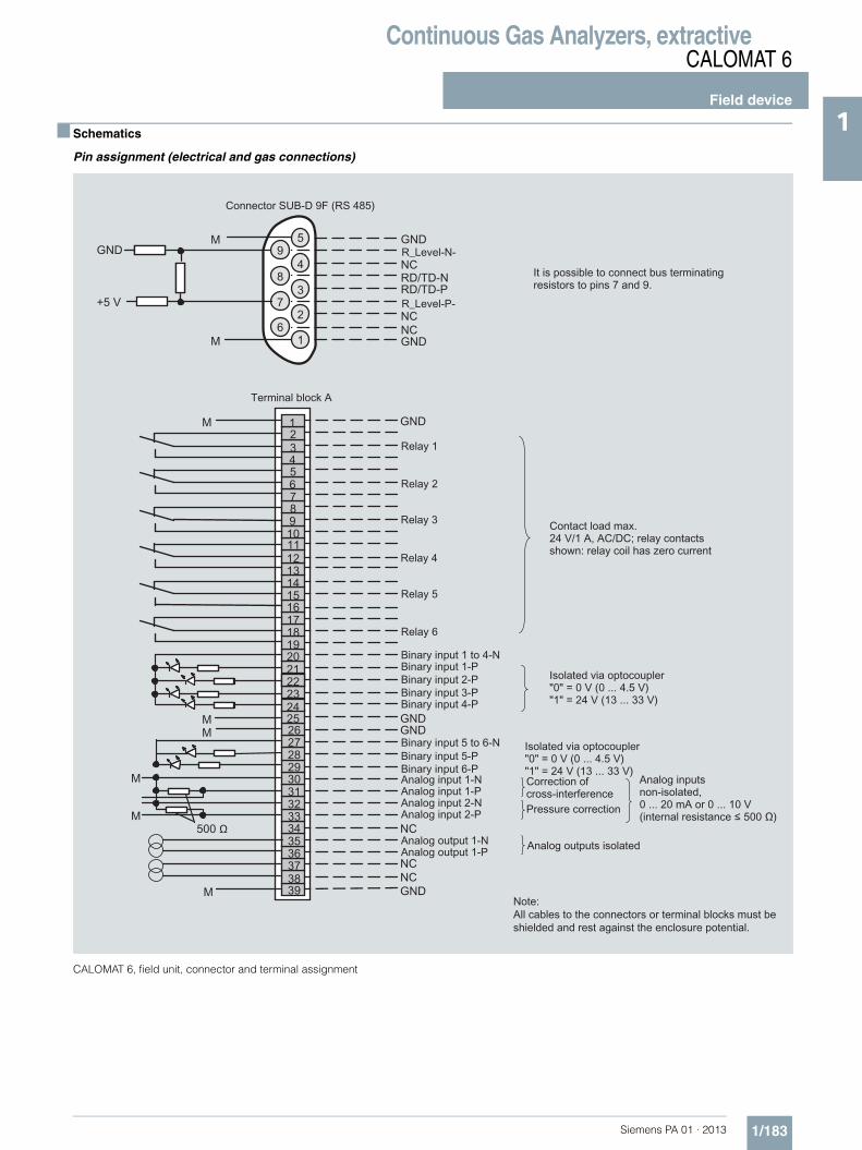
Continuous Gas Analyzers, extractiveCALOMAT 6
Field device
1/183Siemens PA 01 · 2013
1■ Schematics
Pin assignment (electrical and gas connections)
CALOMAT 6, field unit, connector and terminal assignment
ΩΩ

Continuous Gas Analyzers, extractiveCALOMAT 6
Field device
1/184 Siemens PA 01 · 2013
1
CALOMAT 6, field unit, connector and terminal assignment of the AUTOCAL board and PROFIBUS connectors

Continuous Gas Analyzers, extractiveCALOMAT 6
Field device
1/185Siemens PA 01 · 2013
1
CALOMAT 6, field unit, gas and electrical connections
8
1
2
6
7a b c d
e
5
3
4
1
2
85
3
-
4
a - c
d
e
not usedSample gas inlet
not used
Sample gas outlet
Purging gas inlets/outlets stubs Ø 10 mm or 3/8 "
Clampinggland for pipeØ 6 mm or ¼"
Gas connections Electrical connections
Interface connection: (Ø 7 ... 12 mm)cable gland M20x1.5
Signal cable (Ø 10 ... 14 mm)(analog + digital): cable gland M20x1.5
Power supply: (Ø 7 ... 12 mm)cable gland M20x1.5

Continuous Gas Analyzers, extractiveCALOMAT 6
Documentation
1/186 Siemens PA 01 · 2013
1 ■ Selection and ordering data
■ Selection and ordering data
If the CALOMAT 6 is supplied with a specially cleaned gas path for high oxygen context ("Cleaned for O2 service"), please ensure that you specify this when ordering spare parts. This is the only way to guarantee that the gas path will continue to comply with the special requirements for this version.
Operating instructions Order No.
CALOMAT 6Thermal conductivity gas analyzer
• German A5E00116454
• English A5E00116455
• French A5E00116456
• Italian A5E00116457
• Spanish A5E00116458
Gas analyzers of Series 6 and ULTRAMAT 23
Schnittstelle/Interface PROFIBUS DP/PA
• German and English A5E00054148
Suggestions for spare parts
7MA2521 7MB2511 7MB2511 Ex 2 years (quantity)
5 years (quantity)
Order No.
Analyzer unit
Measuring cell x x x 1 1 A5E00095332
O ring (set of 4) x x x 1 2 A5E00124182
Electronics
Fuse (device fuse) x 1 2 A5E00061505
Front plate without LC display x 1 1 C79165-A3042-B508
Motherboard, with firmware: see spare parts list
x x x - 1
Adapter plate, LCD/keyboard x x 1 1 C79451-A3474-B605
LC display (non-Ex version) x 1 1 W75025-B5001-B1
Line transformer, 115 V x x x - 1 W75040-B21-D80
Line transformer, 230 V x x x - 1 W75040-B31-D80
Connector filter x x x - 1 W75041-E5602-K2
Fusible element, T 0.63/250 V x x 2 3 W79054-L1010-T630
Fusible element, 1 A, 110/120 V x x x 2 3 W79054-L1011-T100

Continuous Gas Analyzers, extractiveCALOMAT 62
General information
1/187Siemens PA 01 · 2013
1■ Overview
The CALOMAT 62 gas analyzer is primarily used for quantitative determination of one gas component (e.g. H2, N2, Cl2, HCl, NH3) in binary or quasi-binary gas mixtures.
The CALOMAT 62 is specially designed for use in corrosive gas mixtures.
■ Benefits
• Universally applicable hardware basis• Integrated correction of cross-interference, no external calcu-
lation required• Open interface architecture (RS 485, RS 232, PROFIBUS)• SIPROM GA network for maintenance and servicing informa-
tion (option)• Electronics and analyzer unit: gas-tight isolation, purging is
possible, IP65, long service life even in harsh environments (field device)
■ Application
Fields of application• Chlorine-alkali electrolysis• Metallurgy (steel production and processing)• H2 measurement in LNG (Liquefied Natural Gas) process• Ammonia synthesis• Fertilizer production• Petrochemicals
Special versions
Special applications
In addition to the standard combinations, special applications are also available upon request (e.g. higher sample gas pres-sure up to 2 000 hPa absolute).
■ Design
19" rack unit• With 4HE for installation
- in hinged frame- in cabinets with or without telescope rails- With closed or flow-type reference chambers
• Front plate for service purposes can be pivoted down (laptop connection)
• IP20 degree of protection, with purging gas connection• Internal gas routes: Pipe made of stainless steel
(mat. no. 1.4571)• Gas connections for sample gas inlet and outlet and for refer-
ence gas: Internal thread 1/8" – 27 NPT• Purging gas connections: Pipe diameter 6 mm or 1/4"• With closed or flow-type reference chambers
Field device• Two-door enclosure (IP65) for wall mounting with gas-tight
separation of analyzer and electronic parts, purgeable• Individually purgeable enclosure halves• Gas path with screw pipe connection made of stainless steel
(mat. no. 1.4571), or Hastelloy C22• Purging gas connections: Pipe diameter 10 mm or 3/8"• Gas connections for sample gas inlet and outlet and for refer-
ence gas: Internal thread 1/8" – 27 NPT• With closed or flow-type reference chambers
Display and control panel• Large LCD field for simultaneous display of:
- Measured value (digital and analog displays)- Status bar- Measuring ranges
• Contrast of the LCD field adjustable via the menu• Permanent LED backlighting• Washable membrane keyboard with five softkeys• Menu-driven operator control for parameterization, test func-
tions, adjustment• Operator support in plain text• Graphical display of the concentration progression; time inter-
vals parameterizable• Bilingual operating software German/English,
English/Spanish, French/English, Spanish/English, Italian/English
Input and outputs• One analog output per medium (from 0, 2, 4 to 20 mA; NAMUR
parameterizable)• Two analog inputs configurable (e.g. correction of cross-inter-
ference or external pressure sensor)• Six binary inputs freely configurable (e.g. measurement range
changeover, processing of external signals from the sample preparation)
• Six relay outputs, freely configurable (e.g. failure, mainte-nance request, threshold alarm, external magnetic valves)
• Each can be expanded by eight additional binary inputs and relay outputs (e.g. for autocalibration with max. four test gases)

Continuous Gas Analyzers, extractiveCALOMAT 62
General information
1/188 Siemens PA 01 · 2013
1 Communication
RS 485 present in basic unit (connection from the rear; for the rack unit also behind the front plate).
Options• RS 485/RS 232 converter• RS 485/Ethernet converter• RS 485/USB converter• Connection to networks via PROFIBUS DP/PA interface• SIPROM GA software as the service and maintenance tool
CALOMAT 62, membrane keyboard and graphic display
Designs – parts wetted by sample gas
Gas connection 19" rack unit Field device
Input block with gas connection Stainless steel, mat. no. 1.4571 Stainless steel, mat. no. 1.4571
Seal FPM (e.g. Viton) or FFPM FPM (e.g. Viton) or FFPM
Sensor Glass Glass
Input block with gas connection Hastelloy C22
Seal FFPM (e.g. Kalrez)
Sensor Glass

Continuous Gas Analyzers, extractiveCALOMAT 62
General information
1/189Siemens PA 01 · 2013
1
CALOMAT 62, 19" rack unit, gas path
CALOMAT 62, field device, gas path
9 22 21 12 11Sample gasPurging gas Reference gas
5 6 22 21 12 117 8Purging gas Sample gasPurging gas
Electronics side Analyzing side
Reference gas(flow-type, option)

Continuous Gas Analyzers, extractiveCALOMAT 62
General information
1/190 Siemens PA 01 · 2013
1 ■ Function
Principle of operation
The measuring principle is based on the different thermal con-ductivity of gases.
The temperature of a heated resistor surrounded by gas is de-termined by the thermal conductivity of the gas. Four such resis-tors are connected as a bridge.
Sample gas flows around two of them, reference gas surrounds the other two. A constant DC voltage heats the resistors above the temperature of the measurement block.
The different thermal conductivities of the sample and reference gases result in different temperatures of the resistors. A change in the composition of the sample gas thus also causes a change in the resistance values.
The electrical equilibrium of the measuring bridge is disrupted, and a voltage is generated in the bridge diagonal. This is a mea-sure of the concentration of the measured component.
Note
The sample gases must be fed into the analyzers free of oil, grease, and dust. The formation of condensation in the sample chambers (dew point of sample gas < ambient temperature) must be avoided. Therefore, gas prepared for the respective task must be provided in most applications.
CALOMAT 62, principle of operation, example of a non-flow-type refer-ence chamber
Important features• Four freely-programmable measuring ranges, also with sup-
pressed zero, all ranges linear• Smallest spans down to 1 % H2 (with suppressed zero: 99 to
100 % H2) possible• Measuring range identification• Electrically isolated measured-value output 0/2/4 to 20 mA
(also inverted)• Automatic or manual measuring range switchover selectable;
remote switching is also possible• Measured value can be saved during adjustment
• Time constants are selectable within wide ranges (static/dy-namic noise suppression); i.e. the response time of the ana-lyzer can be adapted to the respective task
• Short response time• Low long-term drift• Measuring point switchover for up to 6 measuring points
(parameterizable)• Measuring point identification• External pressure sensor can be connected – for correction of
variations in sample gas pressure• Possibility for correcting the influence of residual gases
(correction of cross-interference)• Automatic measuring range calibration can be programmed• Operation based on the NAMUR recommendation• Two operator input levels with their own authorization codes to
prevent unintentional and unauthorized interventions• Simple handling using a numerical membrane keyboard and
operator prompting• Customer-specific device versions, such as:
- Customer acceptance- TAG labels- Drift recording- Clean for O2 service
Spans
The smallest and largest possible spans depend on both the measured component (gas type) and the respective application (see ordering data).
Cross-interferences
Information on the sample gas composition is required in order to determine the cross-interference of residual gases with sev-eral interfering components.
The zero offsets in % H2 which result from 1 % residual gas (interfering gas) are listed in the following table; the specified values are approximate values.
It should be noted that the influence of interfering gas is not lin-ear to its concentration. Information on the sample gas compo-sition is required in order to determine the cross-interference of residual gases with several interfering components.
Effect of 1 % gas component with nitrogen as the residual gas, expressed in % H2
Moreover, it must be noted that - in addition to a zero offset - the gradient of the characteristic can also be affected by the resid-ual gas. However, this effect is negligible in the case of variations in the interfering gas concentration below 10 %.
Taking these facts into consideration and due to the fact that the cross-interference analyzers cause further measuring inaccura-cies, a larger error in measurement occurs than with binary gas mixtures despite correction of cross-interference.
U
M V
MV
Measurement block
Measurement chamberReference gas chamber (optional: flow-type)
Ar Approx. -0.15 %
O2 Approx. +0.02 %
CO2 Approx. -0.13 %
CH4 Approx. +0.17 %
SO2 Approx. -0.31 %
Air (dry) Approx. +0.25 %

Continuous Gas Analyzers, extractiveCALOMAT 62
General information
1/191Siemens PA 01 · 2013
1Specification for the interface cable Bus terminating resistors
Pins 3-7 and 8-9 of the first and last connectors of a bus cable must be bridged (see figure).
Note
It is advisable to install a repeater on the device side in the case of a cable length of more than 500 m or with high interferences.
Up to four components can be corrected via the ELAN bus, cor-rection of cross-interference can be carried out for one or two components via the analog input.
Bus cable with plug connections, example
Surge impedance 100 ... 300 Ω, with a measuring frequency of > 100 kHz
Cable capacitance Typ. < 60 pF/m
Core cross-section > 0.22 mm2, corresponds to AWG 23
Cable type Twisted pair, 1 x 2 conductors of cable section
Signal attenuation Max. 9 dB over the whole length
Shielding Copper braided shield or braided shield and foil shield
Connection Pin 3 and pin 8
9-pin connector (RS 485)(device 3)
9-pin connector (RS 485)(device 2)
9-pin connector (RS 485)(device 1)

Continuous Gas Analyzers, extractiveCALOMAT 62
19" rack unit
1/192 Siemens PA 01 · 2013
1 ■ Technical specifications
General (based on DIN EN 61207/IEC 1207. All data refers to the binary gas mixture H2 in N2)
Measuring ranges 4, internally and externally switch-able; automatic measuring range switchover also possible
Span Application-dependent(see ordering data)
Measuring ranges with suppressed zero point
Application-dependent(see ordering data)
Operating position Front wall, vertical
Conformity CE marking in accordance with EN 50081-1/EN 50081-2 and RoHS
Design, enclosure
Degree of protection IP20 according to EN 60529
Weight Approx. 13 kg
Electrical characteristics
EMC (Electromagnetic Compatibility)
In accordance with standard requirements of NAMUR NE21 (08/98) and EN 61326
Electrical safety In accordance with EN 61010-1; overvoltage category II
Power supply (see nameplate) 100 V AC -10 % ... 120 V AC +10 %, 47 ... 63 Hz or 200 V AC -10 % ... 240 V AC +10 %, 47 ... 63 Hz
Power consumption Approx. 30 VA
Fuse values 100 ... 120 V: 1.0T/250200 ... 240 V: 0.63T/250
Gas inlet conditions
Sample gas pressure 800 ... 1 100 hPa (absolute)
Sample gas flow 30 ... 90 l/h
Sample gas temperature Min. 0 to max. 50 °C, but above the dew point
Temperature of the measuring cell 70 ºC
Dynamic response (the dynamic and measuring response refers to the measurement of H2 in N2)
Warm-up period < 30 min at room temperature (the technical specification will be met after 2 hours)
Delayed display (T90) Approx. 35 s (including dead time)
Damping (electrical time constant) 0 ... 100 s, parameterizable
Dead time (the diffusion to the probes is the determining variable)
Approx. 34 s
Dead time (special application) < 10 s
Measuring response(the dynamic and measuring response refers to the measurement of H2 in N2) (referred to sample gas pressure 1 000 hPa absolute, sample gas flow 0.5 l/min, and ambient tempera-ture 25 °C)
Output signal fluctuation (3σ value) < ± 1 % of the smallest possible span according to rating plate, with electronic damping constant of 1 s
Zero point drift < ± 1 % of the current span/week
Measured-value drift < ± 1 % of the smallest possible span (according to rating plate)/week
Repeatability < ± 1 % of the current span
Detection limit 1% of the smallest possible span according to rating plate
Linearity error < ± 1 % of the current span
Influencing variables (referred to sample gas pressure 1 000 hPa absolute, sample gas flow 0.5 l/min, and ambient temperature 25 °C)
Ambient temperature < 2 %/10 K referred to smallest possible span according to label
Accompanying gases Deviation from zero point (for influence of interfering gas, see section "Cross-interference")
Sample gas flow 0.2 % of the current measuring span with a change in flow of 0.1 l/min within the permissible flow range
Sample gas pressure < 1 % of the current span with a change in pressure of 100 hPa
Power supply < 0.1 % of the current span with rated voltage ± 10 %
Electrical inputs and outputs
Analog output 0/2/4 ... 20 mA, isolated; max. load 750 Ω
Relay outputs 6, with changeover contacts, freely parameterizable, e.g. for measuring range identification; load: 24 V AC/DC/1 A, isolated
Analog inputs 2, dimensioned for 0/2/4 ... 20 mA for external pressure sensor and correction of cross-interference
Binary inputs 6, designed for 24 V, isolated, freely parameterizable, e.g. for measuring range switchover
Serial interface RS 485
Options AUTOCAL function with 8 addi-tional binary inputs and 8 addi-tional relay outputs, also with PROFIBUS PA (on request) or PROFIBUS DP (on request)
Climatic conditions
Permissible ambient temperature -40 ... +70 °C during storage and transportation, 5 ... 45 °C during operation
Permissible humidity (dew point must not be fallen below)
< 90 % relative humidity as annual average, during storage and transportation

Continuous Gas Analyzers, extractiveCALOMAT 62
19" rack unit
1/193Siemens PA 01 · 2013
1Selection and ordering data Order No.
CALOMAT 62 gas analyzer19" rack unit for installation in cabinets
7MB2541- 777700000 7 - 7A 7 7
Material of sample gas pathStainless steel, mat. no. 1.4571; non-flow-type reference chamber, 1/8''-27 NPT
Purging gas stub 6 mm 0
Stainless steel, mat. no. 1.4571; non-flow-type reference chamber, 1/8''-27 NPT
Purging gas stub 1/4" 4
Application Possible with measuring range identification
H2 in N2 0; 5 A N
SO2 in air 1; 6 E L
CO2 in H2 0; 5 K A
CO2 in N2 1; 6 K N
Smallest Largestmeasuring range measuring range
Reference gasor filling gas
0 ... 1 % 0 ... 100 %
Accompanying gas component
00 ... 5 % 0 ... 100 % 10 ... 5 % 0 ... 60 % 20 ... 10 % 0 ... 100 % 30 ... 20 % 0 ... 40 % 4
100 ... 99 % 100 ... 0 %Sample gas component
5100 ... 95 % 100 ... 0 % 6100 ... 90 % 100 ... 0 % 7100 ... 80 % 100 ... 60 % 8
Add-on electronicsWithout 0AUTOCAL function• With 8 additional digital inputs and outputs 1• With 8 additional 8 digital inputs/outputs and PROFIBUS PA interface 6• With 8 additional digital inputs/outputs and PROFIBUS DP interface 7
Power supply100 ... 120 V AC, 47 ... 63 Hz 0200 ... 240 V AC, 47 ... 63 Hz 1
Explosion protectionWithout A
Language (supplied documentation, software)German 0English 1French 2Spanish 3Italian 4
Additional versions Order code
Add "-Z" to Order No. and specify order codes.
TAG labels (specific lettering based on customer information) B03
Clean for O2 service (specially cleaned gas path) Y02
Measuring range indication in plain text, if different from the standard setting Y11
Special setting (only in conjunction with an application no., e.g. extended measuring range) Y12
Extended special setting (only in conjunction with an application no., e.g. determination of cross-interferences)
Y13
Retrofitting sets Order No.
RS 485/Ethernet converter A5E00852383
RS 485/RS 232 converter C79451-Z1589-U1
RS 485 / USB converter A5E00852382
AUTOCAL function with 8 digital inputs/outputs C79451-A3480-D511
AUTOCAL function with 8 digital inputs/outputs and PROFIBUS PA A5E00057307
AUTOCAL function with 8 digital inputs/outputs and PROFIBUS DP A5E00057312

Continuous Gas Analyzers, extractiveCALOMAT 62
19" rack unit
1/194 Siemens PA 01 · 2013
1 ■ Dimensional drawings
CALOMAT 62, 19" rack unit, dimensions in mm
465
483
440
128173
0 55 91 320
345
4
173
177
9
420
20
M4
CALOMAT 6
27.5351.5
384.5
86.5
149.
5
101.
6
37.7
106.
5
70.5

Continuous Gas Analyzers, extractiveCALOMAT 62
19" rack unit
1/195Siemens PA 01 · 2013
1■ Schematics
Pin assignment (electrical and gas connections)
CALOMAT 62, 19" rack unit, pin assignment
Ω
Ω

Continuous Gas Analyzers, extractiveCALOMAT 62
19" rack unit
1/196 Siemens PA 01 · 2013
1
CALOMAT 62, 19" rack unit, pin assignment of the AUTOCAL board and PROFIBUS connectors

Continuous Gas Analyzers, extractiveCALOMAT 62
19" rack unit
1/197Siemens PA 01 · 2013
1
CALOMAT 62, 19" rack unit, gas connections and electrical connections

Continuous Gas Analyzers, extractiveCALOMAT 62
Field device
1/198 Siemens PA 01 · 2013
1 ■ Technical specifications
General (based on DIN EN 61207/IEC 1207. All data refers to the binary gas mixture H2 in N2)
Measuring ranges 4, internally and externally switch-able; automatic measuring range switchover also possible
Span Application-dependent(see ordering data)
Measuring ranges with suppressed zero point
Application-dependent (see ordering data)
Operating position Front wall, vertical
Conformity CE marking in accordance with EN 50081-1/EN 50081-2 and RoHS
Design, enclosure
Degree of protection IP65 according to EN 60529
Weight Approx. 25 kg
Electrical characteristics
EMC (Electromagnetic Compatibility)
In accordance with standard requirements of NAMUR NE21 (08/98) and EN 61326
Electrical safety In accordance with EN 61010-1; overvoltage category II
Power supply (see nameplate) 100 AC -10 % ... 120 V AC +10 %, 47 ... 63 Hz or 200 AC -10 % ... 240 V AC +10 %, 47 ... 63 Hz
Power consumption • Approx. 25 VA (gas connection block unheated)
• Approx. 330 VA (gas connection block heated)
Fuse values (gas connection unheated)
100 ... 120 V F3 1T/250F4 1T/250200 ... 240 V F3 0.63T/250F4 0.63T/250
Fuse values (gas connection heated)
100 ... 120 V F1 1T/250F2 4T/250F3 4T/250F4 4T/250200 ... 240 V F1 0.63T/250F2 2.5T/250F3 2.5T/250F4 2.5T/250
Gas inlet conditions
Sample gas pressure 800 ... 1 100 hPa (absolute)
Sample gas flow 30 ... 90 l/h
Sample gas temperature Min. 0 to max. 50 °C, but above the dew point
Temperature
• of the measuring cell (sensor) 70 ºC• of the measureming cell block
(base)80 ºC (heated)
Sample gas humidity < 90 % relative humidity
Purging gas pressure
• Permanent 165 hPa above ambient pressure• For short periods Max. 250 hPa above ambient pres-
sure
Dynamic response(the dynamic and measuring response refers to the measurement of H2 in N2) (referred to sample gas pressure 1 000 hPa absolute, sample gas flow 0.5 l/min, and ambient temperature 25 °C)
Warm-up period < 30 min at room temperature (the technical specification will be met after 2 hours)
Delayed display (T90) Approx. 35 s (including dead time)
Electrical damping 0 ... 100 s, parameterizable
Dead time (the diffusion to the probes is the determining variable)
Approx. 34 s
Measuring response (the dynamic and measuring response refers to the measurement of H2 in N2) (referred to sample gas pressure 1 000 hPa absolute, sample gas flow 0.5 l/min, and ambient tempera-ture 25 °C)
Output signal fluctuation (3σ value)
< ± 1 % of the smallest possible span according to rating plate with electronic damping constant of 1 s
Zero point drift < ± 1 % of the current span/week
Measured-value drift < ± 1 % of the smallest possible span (according to rating plate)/week
Repeatability < ± 1 % of the current span
Detection limit 1 % of the smallest possible span according to rating plate
Linearity error < ± 1 % of the current span
Influencing variables (referred to sample gas pressure 1 000 hPa absolute, sample gas flow 0.5 l/min, and ambient temperature 25 °C)
Ambient temperature < 2 %/10 K referred to smallest pos-sible span according to rating plate
Accompanying gases Deviation from zero point (for influ-ence of interfering gas, see section "Cross-interference")
Sample gas flow 0.2 % of the current measuring span with a change in flow of 0.1 l/min within the permissible flow range
Sample gas pressure < 1 % of the span with a change in pressure of 100 hPa
Power supply < 0.1 % of the output signal span with rated voltage ± 10 %
Electrical inputs and outputs
Analog output 0/2/4 ... 20 mA, isolated; max. load 750 Ω
Relay outputs 6, with changeover contacts, freely parameterizable, e.g. for measuring range identification; load: 24 V AC/DC/1 A, isolated
Analog inputs 2, dimensioned for 0/2/4 … 20 mA for external pressure sensor and correction of cross-interference
Binary inputs 6, designed for 24 V, isolated, freely parameterizable, e.g. for measur-ingrange switchover
Serial interface RS 485
Options AUTOCAL function with 8 additional binary inputs and 8 additional relay outputs, also with PROFIBUS PA(on request) or PROFIBUS DP(on request)
Climatic conditions
Permissible ambient temperature -40 ... +70 °C during storage and transportation, 5 … 45 °C during operation
Permissible humidity (dew point must not be fallen below)
< 90 % relative humidity as annual average, during storage and trans-portation

Continuous Gas Analyzers, extractiveCALOMAT 62
Field device
1/199Siemens PA 01 · 2013
1
1) Only in connection with an approved purging unit.
Selection and ordering data Order No.
CALOMAT 62 gas analyzerFor field installation
7MB2531- 777700000 7 - 777 7 Cannot be combined
Material of sample gas path
Stainless steel, mat. no. 1.4571; non-flow-type reference chamber, 1/8"-27 NPT
Purging gas stub 10 mm 0 00000000
Hastelloy C22; non-flow-type reference chamber, 1/8"-27 NPT 2Hastelloy C22; flow-type reference chamber, 1/8"-27 NPT 3 3
Stainless steel, mat. no. 1.4571; non-flow-type reference chamber, 1/8"-27 NPT
Purging gas stub 3/8" 4 4
Hastelloy C22; non-flow-type reference chamber, 1/8"-27 NPT 6Hastelloy C22; flow-type reference chamber, 1/8"-27 NPT 7 7
Application Possible with measuring range identification
H2 in N2 0; 5 A N ANH2 in Cl2 0; 5 A B ABH2 in HCl 0; 5 A C AC
Cl2 in air 1; 6 B L BLCl2 in HCl 3; 7 B C BC
HCl in air 1; 6 C L CLNH3 in N2 4; 8 D N DNSO2 in air 1; 6 E L EL
CO2 in H2 0; 5 K A KACO2 in N2 1; 6 K N KN
Smallest Largestmeasuring range measuring range
Reference gasor filling gas
0 ... 1 % 0 ... 100 %
Accompanying gas component
00 ... 5 % 0 ... 100 % 10 ... 5 % 0 ... 60 % 20 ... 10 % 0 ... 100 % 30 ... 20 % 0 ... 40 % 4
100 ... 99 % 100 ... 0 %Sample gas component
5100 ... 95 % 100 ... 0 % 6100 ... 90 % 100 ... 0 % 7100 ... 80 % 100 ... 60 % 8
Add-on electronicsWithout 0AUTOCAL function• With 8 additional digital inputs and outputs 1• With 8 additional 8 digital inputs/outputs and PROFIBUS PA interface 6• With 8 additional digital inputs/outputs and PROFIBUS DP interface 7
Power supply100 ... 120 V AC, 47 ... 63 Hz 0200 ... 240 V AC, 47 ... 63 Hz 1
Heating of internal gas paths and analyzer unitWithout AWith (max. 80 °C) B
Explosion protectionWithout AAccording to ATEX II 2G, leakage compensation1) EAccording to ATEX II 2G, continuous purging1) F
Language (supplied documentation, software)German 0English 1French 2Spanish 3Italian 4

Continuous Gas Analyzers, extractiveCALOMAT 62
Field device
1/200 Siemens PA 01 · 2013
1 ■ Selection and ordering data
Additional versions Order code
Add "-Z" to Order No. and specify order codes.
TAG labels (specific lettering based on customer information) B03
Clean for O2 service (specially cleaned gas path) Y02
Measuring range indication in plain text, if different from the standard setting Y11
Special setting (only in conjunction with an application no., e.g. extended measuring range) Y12
Extended special setting (only in conjunction with an application no., e.g. determination of cross-inter-ferences)
Y13
Retrofitting sets Order No.
RS 485/Ethernet converter A5E00852383
RS 485/RS 232 converter C79451-Z1589-U1
RS 485 / USB converter A5E00852382
AUTOCAL function with 8 digital inputs/outputs A5E00064223
AUTOCAL function with 8 digital inputs/outputs and PROFIBUS PA A5E00057315
AUTOCAL function with 8 digital inputs/outputs and PROFIBUS DP A5E00057318

Continuous Gas Analyzers, extractiveCALOMAT 62
Field device
1/201Siemens PA 01 · 2013
1■ Dimensional drawings
CALOMAT 62, field device, dimensions in mm
s

Continuous Gas Analyzers, extractiveCALOMAT 62
Field device
1/202 Siemens PA 01 · 2013
1 ■ Schematics
Pin assignment (electrical and gas connections)
CALOMAT 62, field device, pin and terminal assignment
ΩΩ

Continuous Gas Analyzers, extractiveCALOMAT 62
Field device
1/203Siemens PA 01 · 2013
1
CALOMAT 62, field device, pin and terminal assignment of the AUTOCAL board and PROFIBUS connectors

Continuous Gas Analyzers, extractiveCALOMAT 62
Field device
1/204 Siemens PA 01 · 2013
1
CALOMAT 62, field device, gas connections and electrical connections
11
12
21
22
86
7a b c d
e
5
9
10
11
85 -
9
10
12
21
22
a - c
d
e
Sample gas outlet
Sample gas inlet
Reference gas outlet
Reference gas inlet
Purge gas inlets/outlets
Internal thread1/8" - 27 NPT
Fittings Ø 10 mm or 3/8"
Gas connections Electrical connections
Unassigned
Unassigned
Interface connection: (Ø 7 ... 12 mm)cable gland M20x1.5
Signal cable (Ø 10 ... 14 mm)(analog + digital): cable gland M20x1.5
Power supply: (Ø 7 ... 12 mm)cable gland M20x1.5

Continuous Gas Analyzers, extractiveCALOMAT 62
Documentation
1/205Siemens PA 01 · 2013
1■ Selection and ordering data
■ Selection and ordering data
Operating instructions Order No.
CALOMAT 62Thermal conductivity gas analyzer
• German A5E00881392
• English A5E00881393
• French A5E00881395
• Italian A5E00881398
• Spanish A5E00881396
Gas analyzers of Series 6 and ULTRAMAT 23
Schnittstelle/Interface PROFIBUS DP/PA
• German and English A5E00054148
Suggestions for spare parts
Description 7MB2541 7MB2531 2 years (quantity)
5 years (quantity)
Order No.
Temperature limiter x – 1 A5E00891855
Adapter plate, LC display/keypad x x 1 1 C79451-A3474-B605
Temperature sensor x – 1 C79451-A3480-B25
LC display x – 1 W75025-B5001-B1
Line transformer, 115 V x x – 1 W75040-B21-D80
Line transformer, 230 V x x – 1 W75040-B31-D80
Fuse, T 0.63 A, line voltage 200 … 240 V x x 2 3 W79054-L1010-T630
Fuse, T 1 A, supply voltage 100 … 120 V x x 2 3 W79054-L1011-T100
Heating cartridge x – 1 W75083-A1004-F120

Continuous Gas Analyzers, extractiveFIDAMAT 6
General information
1/206 Siemens PA 01 · 2013
1 ■ Overview
The FIDAMAT 6 gas analyzer is suitable for the determination of the total hydrocarbon content in the air and high-boiling gas mix-tures.
■ Benefits
The FIDAMAT 6 gas analyzer is distinguished by its wide range of applications:• In the presence of up to 100 % H2O vapor• In ultra-pure gas applications• With high-boiling components (up to 200 °C)• In the presence of corrosive gases (with preliminary filter).
The FIDAMAT 6 exhibits:• Extremely low cross-sensitivity to interfering gases• Low consumption of combustion air• Low influence of oxygen on measured value
The analyzer is additionally equipped with warning and fault messages:• For failure of combustion gas• If the flame is extinguished• To indicate pump and filter faults
■ Application
Areas of application• Environmental protection• Wastewater (in conjunction with a stripping device, verification
of the hydrocarbon content of liquids)• TLV (Threshold Limit Value) monitoring at places of work• Quality monitoring• Process exhaust monitoring• Ultra-pure gas measurements in media such as O2, CO2,
inert gases and cold sample gases• Measurement of corrosive and condensing gases• Process optimization
Further applications• Chemical plants• Gas manufacturers (ultra-pure gas monitoring)• Research and development• Cement industry (measurement of emissions)• Paint shops and dry-cleaning systems• Refineries (tank farms, wastewater)• Drying systems• Solvent recovery systems• Pharmaceutical industry• Automotive industry (engine development, engine and trans-
mission development and certification)
Special applications
Special applications
Special applications are available on request in addition to the standard combinations, e.g. measuring range 0 to 100 %.
TÜV version
Measurement of flue gases according to 13th BlmSchV/17th BlmSchV and TA Luft for oil, coal, gas, and waste as fuels.
Furthermore, the TÜV-approved versions of the FIDAMAT 6 com-ply with the requirements of EN 14956 and QAL 1 according to EN 14181. Conformity of the analyzers with both standards is TÜV-certified.
Determination of the analyzer drift according to EN 14181 (QAL 3) can be carried out manually or also with a PC using the SIPROM GA maintenance and servicing software. In addition, selected manufacturers of emission evaluation computers offer the possibility for downloading the drift data via the analyzer’s serial interface and to automatically record and process it in the evaluation computer.

Continuous Gas Analyzers, extractiveFIDAMAT 6
General information
1/207Siemens PA 01 · 2013
1■ Design
• 19" rack unit with 4 HU for installation - in hinged frame- in cabinets with or without telescopic rails
• Front plate can be swung down for servicing purposes(laptop connection)
• Gas connections for sample gas inlet and outlet as well as combustion gas and combustion air; pipe diameter 6 mm or ¼"
• Gas and electrical connections at the rear• Internal gas paths: stainless steel (mat. no. 1.4571)
Display and control panel• Large LCD field for simultaneous display of:
- Measured value- Status bar- Measuring ranges
• Contrast of LCD panel adjustable using menu• Permanent LED backlighting• Washable membrane keyboard with five softkeys• Menu-driven operation for parameterization, test functions,
adjustment• User help in plain text• Graphic display of concentration trend; programmable time
intervals
Input and outputs• One analog output for each measured component• Two programmable analog inputs• Six binary inputs freely configurable (e.g. for measurement
range switchover, processing of external signals from sample preparation)
• Six relay outputs freely configurable (failure, maintenance re-quest, maintenance switch, limit alarm, external solenoid valves, measuring point switchover)
• Extension with eight additional binary inputs and eight addi-tional relay outputs for autocalibration with up to four calibra-tion gases
Communication
RS 485 present in basic unit (connection from the rear).
Options• RS 485/RS 232 converter• RS 485/Ethernet converter• RS 485/USB converter• Incorporation in networks via PROFIBUS DP/PA interface• SIPROM GA software as service and maintenance tool
FIDAMAT 6, membrane keyboard and graphic display
Status line for display of analyzer status(programmable)
LED backlit graphicdisplay and membrane keyboardwith noticeable click
Two code levelsaccording to NAMUR(maintenance andspecialist level)
MEAS key to return tomeasurement mode
Operation with menu controlusing five softkeys
Display of currentmeasuring ranges
ESC keyto abort inputs
INFO keyfor help in plain text
CLEAR key to delete inputs
Keypad toenter values
Display of concentrations as numbers and bargraph
Display of start-of-scale and full-scale values
ENTER key to accept input values

Continuous Gas Analyzers, extractiveFIDAMAT 6
General information
1/208 Siemens PA 01 · 2013
1 Designs – parts wetted by sample gas
Gas path
FIDAMAT 6 total hydrocarbon analyzer, gas path with pump and with connection for combustion air
Gas path Material
Piping Stainless steel, mat. no. 1.4571
Gas inlet Stainless steel, mat. no. 1.4571
Gaskets Graphite
Sample gas restrictor Quartz
Auxiliary gas restrictors Stainless steel, mat. no. 1.4571
Pump membrane PTFE
Pump head Stainless steel, mat. no. 1.4571
Detector
• Nozzle Quartz
• FID housing Stainless steel, mat. no. 1.4571
Zero gas
Calibrationgas
Sample gas
Pump 1Damping
Restrictor
Sample chamberPressure sensor
Solenoidvalve
Mechan.pressure regulator
Pressure sensor
Combustion air
Gas outlet
Combustiongas H2
Filter
Restrictor
Mechan.pressure regulator

Continuous Gas Analyzers, extractiveFIDAMAT 6
General information
1/209Siemens PA 01 · 2013
1
FIDAMAT 6 total hydrocarbon analyzer, gas path without pump and with connection for combustion air
Sample gas
Restrictor
Sample chamberPressure sensor
valveSolenoid Mechan.
pressure regulators
Pressure sensorMechanical
pressure regulators
Combustion air
Gas outlet
Combustion gas H2
Restrictor
Zero gas
Calibration gas
Purging

Continuous Gas Analyzers, extractiveFIDAMAT 6
General information
1/210 Siemens PA 01 · 2013
1 ■ Function
Principle of operation
The FIDAMAT 6 carries out substance-specific measurements and not component-specific measurements. It measures the to-tal of all hydrocarbons in a sample gas, but with different weight-ing of the hydrocarbon molecules. To a first approximation, the display is proportional to the number of C atoms in the respec-tive molecule. However, there are fluctuations in practice. The display deviation for the respective molecule is expressed by the response factor.
The sample gas is supplied to the FIDAMAT 6 through overpres-sure or drawn in by the built-in diaphragm pump (optionally via a heated line and an additional filter) and passed on to the flame ionization detector via an obstruction-proof fused-silica restric-tor.
In the detector, the hydrocarbons in the sample gas are burned in an oxyhydrogen gas flame. Burning partially ionizes the pro-portion of organically-bound hydrocarbons. The released ions are converted into an ionic current by the voltage present be-tween two electrodes, and measured using a highly sensitive amplifier. The current measured is proportional to the quantity of organically-bound C atoms in the sample gas.
A pressure regulator keeps the combustion gas pressure con-stant. The balanced system of pump, capillary tubes, and pres-sure regulator for combustion air ensures that the sample gas pressure is kept constant.
When the analyzer is switched on, ignition is carried out auto-matically when the setpoint temperature has been reached and, for versions "with pump", the pump is also started up.
FIDAMAT 6, principle of operation
The FIDAMAT 6 provides various messages in the form of float-ing contacts:• Maintenance request
E.g. sample gas flow (filter/pump)Fan failure (advance warning for measuring accuracy)The measured value remains unaffected.
• FaultE.g. hydrogen, combustion air and sample gas pressures, temperature, analyzer part and pump, fault in the electronics (temperature).The measured value may be influenced.
• FailureIn the event of failure of, for example, the electronics, power supply, combustion gas, combustion air or sample gas, the analyzer automatically shuts down (the combustion gas valve is closed).
Note
The sample gases must be fed into the analyzers free of dust. Condensation should be avoided. Therefore, the use of gas modified for the measuring task is necessary in most application cases.
Calibration
Calibration of the calibration point is carried out as with the other analyzers of Series 6 after a maximum of 14 days by connecting the calibration gas N2 in residual H2 at concentrations of approx. 60 to 90 % of the master measuring range. The concentration of residual hydrocarbons may not exceed 1 % of the smallest mea-suring span.
Example: Measuring range 0 to 10 ppm C2H8: N2 7.0 or higher required
Contrary to the other analyzers of Series 6, the zero point calibra-tion cannot be carried out using pure nitrogen, but with a "small" concentration of oxygen in nitrogen appropriate to the selected measuring range (e.g.: measuring range 0 to 10 vpm; calibration gas approx. 2 ppm O2 in residual N2).
Inert gas: Standard N2
Exceptions: with measurements of concentrations of hydrocar-bons in a range < 5000 ppm. With measurements of, for exam-ple, a hydrocarbon in residual H2 the calibration gas in residual H2 should also be selected.
Essential characteristics• Four freely parameterizable measuring ranges, also with sup-
pressed zero, all measuring ranges linear• Galvanically isolated measured-value output 0/2/4 to 20 mA
(also inverted)• Autoranging possible; remote switching is also possible• Storage of measured values possible during adjustments• Measuring range identification• Measuring point switchover for up to 6 measuring points• Measuring point identification• Wide range of selectable time constants (static/dynamic noise
suppression); i.e. the response time of the device can be adapted to the respective measuring task
• Easy handling thanks to menu-driven operation• Low long-term drift• Two control levels with their own authorization codes for the
prevention of accidental and unauthorized operator interven-tions
• Automatic, parameterizable measuring range calibration• Operation based on the NAMUR recommendation
Exhaust gas
Combus-tion air
Sample gas
Combus-tion gas
OVEN
200 V DC

Continuous Gas Analyzers, extractiveFIDAMAT 6
General information
1/211Siemens PA 01 · 2013
1• Customer-specific analyzer options such as: - Customer acceptance- TAG labels- Drift recording
• Wear-free, corrosion-proof filter housing• No blocking of the sample gas capillaries through the use of a
quartz restrictor• Purge function in the event of analyzer or power supply failure
(avoids build-up of toxic and corrosive substances in the de-vice)
• Low consumption of combustion air• Response factors comply with the minimum requirements in
accordance with German air purity guidelines and the Work-ing Group of the German automotive Industry
• Simple handling using a numerical membrane keyboard and operator prompting
Response factors (examples, mean values)
Cross-interferences (examples)1)
1) With measuring range 0 to 15 mg/m3.
Substance Mean response factor
n-butane 1.00
n-propane 1.00
n-heptane 1.00
Cyclohexane 1.08
Isopropanol 0.81
Toluene 1.06
Acetone 0.92
Ethyl acetate 0.76
Isobutyl acetate 0.83
Methane 1.06
Ethane 0.99
n-hexane 1.01
iso-octane 1.04
Ethine (acetylene) 0.91
Propene 0.84
Methanol 0.87
Ethanol 0.83
Ethanoic acid 1.13
Methyl acetate 0.67
Benzene 1.01
Ethyl benzene 0.96
p-xylene 1.03
Dichloromethane 1.13
Trichloroethene 1.01
Tetrachlorethene 1.07
Chloroform 0.72
Chlorobenzene 1.15
Interfering component
Concentration of the interfering component
Induced cross-interference
O2 in N2 (21 vol. %) < 0.3 mg/m3
SO2 in N2 (258 mg/m3) < 0.15 mg/m3
NO in N2 (310 mg/m3) < 0.5 mg/m3
NO2 in synth. air (146 mg/m3) < 0.1 mg/m3
CO in N2 (461 mg/m3) < 0.15 mg/m3
CO2 in N2 (18 vol. %) < 0.1 mg/m3
HCl in N2 (78 mg/m3) < 0.3 mg/m3

Continuous Gas Analyzers, extractiveFIDAMAT 6
19" rack unit
1/212 Siemens PA 01 · 2013
1 ■ Technical specifications
*) 100 % as special application
General information
Measuring ranges 4, internally and externally switch-able; manual and autoranging possible
Smallest possible measuring span 0 ... 10 vpm
Largest possible measuring span 99.999 vpm*)
Concentration units ppm, C1, C3, C6 or mgC/m3
Autoranging Hysteresis, selectable
Measured-value display Digital concentration display (5 digits with floating point)
Resolution of digital display 0.1 % of measured value
Operating position Front wall, vertical
Conformity CE mark in accordance with EN 50081-1, EN 50082-2
Oven temperature Adjustable, 100 ... 200 °C
Design, enclosure
Degree of protection IP20 according to EN 60529
Weight Approx. 23 kg
Electrical characteristics
Power supply 100 ... 120 V AC (nominal range of use 90 ... 132 V), 48 ... 63 Hz or200 ... 240 V AC (nominal range of use 180 ... 264 V), 48 ... 63 Hz
Power consumption • Approx. 150 VA during opera-tion,
• Approx. 350 VA during warm-up phase
EMC (Electromagnetic Compatibility)
In accordance with standard requirements of NAMUR NE21 (08/98)
Electrical safety In accordance with EN 61010-1, overvoltage category II
Fuse values • 100 ... 120 V: 4.0T/250• 200 ... 240 V: 2.5 T/250
Gas inlet conditions
Permissible sample gas pressure
• Without pump < 2 000 hPa abs.
• With integrated pump 600 ... 1 100 hPa
Sample gas flow 18 ... 60 l/h (0.3 ... 1 l/min)
Sample gas temperature 0 ... 200 °C
Sample gas humidity < 90 % RH (RH: relative humidity)
Dynamic response
Warm-up period At room temperature, approx. 2 ... 3 h
Delayed display (T90) 2 ... 3 s
Damping (electrical time constant) 0 ... 100 s, parameterizable
Dead time (purging time of the gas path in the unit at 1 l/min)
With filter, 2 ... 3 s
Time for device-internal signal processing
< 1 s
Measuring response(relating to sample gas pressure 1 013 hPa absolute, 0.5 l/min sample gas flow and 25 °C ambient temperature)
Output signal fluctuation < 0.75 % of the smallest possible measuring range according to rating plate, with electronic damping constant of 1 s (corre-sponds to ± 0.25 % at 2 σ)
Zero point drift < 0.5 %/month of the smallest possible measuring span accord-ing to rating plate
Measured-value drift < 1 %/week of the current mea-suring range
Repeatability < 1 % of the current measuring range
Detection limit 0.1 ppm (version for ultra-pure gas measurement: 50 ppb)
Linearity error < 1 % of the current measuring range
Influencing variables (relating to sample gas pressure 1 013 hPa absolute, 0.5 l/min sample gas flow and 25 °C ambient temperature)
Ambient temperature < 1 %/10 K referred to smallest possible span according to rating plate
Atmospheric pressure < 1 %/50 hPa
Sample gas pressure < 2 % of the current measuring range range/1 % pressure change (within 600 ... 1 100 hPa)
Power supply < 1 % of the current measuring range with rated voltage ± 10 %
Position influence < 1 % with < 15° inclination
Electrical inputs and outputs
Analog output 0/2/4 ... 20 mA, isolated; max. load 750 Ω
Relay outputs 6, with changeover contacts, freely parameterizable, e.g. for measuring range identification; load: 24 V AC/DC/1 A, potential-free
Analog inputs 2, dimensioned for 0/2/4 to 20 mA for external pressure sensor and correction of influence of accom-panying gas (correction of cross-interference)
Binary inputs 6, designed for 24 V, floating, freely parameterizable, e.g. for measuring range switchover
Serial interface RS 485
Options AUTOCAL function with 8 addi-tional binary inputs and relay out-puts each, also with PROFIBUS PA or PROFIBUS DP
Climatic conditions
Permissible ambient temperature 5 ... 45 °C during operation, -30 ... +70 °C during storage and transportation
Permissible humidity < 90 % RH (RH: relative humidity) as annual average, during stor-age and transportation (must not fall below dew point)

Continuous Gas Analyzers, extractiveFIDAMAT 6
19" rack unit
1/213Siemens PA 01 · 2013
1
The supply gases (combustion gas, combustion air) must have a degree of purity of 5.0 in order to guarantee correct measurements. The degree of purity must be increased in the case of very small hydrocarbon concentrations (< 1 ppm).
FIDAMAT 6 with pump and heated oven, with combustion air connection
Gases Operating pressure
Inlet pressure Pump startup Flow through FID Flow through bypass
Without With
hPa (abs.) hPa (abs.) hPa (abs.) ml/min ml/min
Combustion gas 3 000 ... 5 000 2 000 ± 20 ~ 25 —
Combustion air 3 000 ... 5 000 1 420 ± 20 1 500 ~ 320 ~ 500
Sample gas ~ 1000 — 1 500 ± 2 ~ 3 ~ 1 000
Zero gas 3 500 ... 4 000 — 1 500 ± 2 ~ 3 ~ 1 000
Calibration gas 3 500 ... 4 000 — 1 500 ± 2 ~ 3 ~ 1 000
FIDAMAT 6 without pump, with heated oven, with combustion air connection
Gases Operating pressure
Inlet pressure Sample/calibration gas Flow through FID Flow through bypass
Without With
hPa (abs.) hPa (abs.) hPa (abs.) ml/min ml/min
Combustion gas 3 000 ... 5 000 2 000 ± 20 ~ 25 —
Combustion air 3 000 ... 5 000 1 480 ± 5 — ~ 320 ~ 300
Sample gas 1 500 ... 2 000 — 1 500 ± 2 ~ 3 ~ 500
Zero gas 1 500 ... 2 000 — 1 500 ± 2 ~ 3 ~ 500
Calibration gas 1 500 ... 2 000 — 1 500 ± 2 ~ 3 ~ 500

Continuous Gas Analyzers, extractiveFIDAMAT 6
19" rack unit
1/214 Siemens PA 01 · 2013
1
1) On request.
■ Selection and ordering data Order No.
FIDAMAT 6 gas analyzer19" rack unit for installation in cabinets
7MB2421- 77777- 77A7
Gas connectionsPipe with 6 mm outer diameter 0Pipe with ¼" outer diameter 1
VersionWithout pump, for sample gas with overpressure1) AWithout pump, for sample gas with overpressure; ultra-pure gas measurement BWith heated pump, for sample gas with atm. pressure DWith heated pump, for sample gas with atm. pressure, ultra-pure gas measurement O2 E
Combustion air feedWith connection for combustion air A
Number of channels1-channel version 1
Add-on electronicsWithout 0AUTOCAL function• With 8 additional digital inputs/outputs 1• With 8 digital inputs/8 digital outputs, PROFIBUS PA interface 6• With 8 digital inputs/8 digital outputs, PROFIBUS DP interface 7
Power supply100 ... 120 V AC, 48 ... 63 Hz 0200 ... 240 V AC, 48 ... 63 Hz 1
Combustion gasesH2 A
Language (supplied documentation, software)German 0English 1French 2Spanish 3Italian 4
Additional versions Order code
Add "-Z" to Order No. and specify order code
Telescopic rails (2 units) A31
Set of Torx screwdrivers A32
TAG labels (specific lettering based on customer information) B03
Clean for O2 service (specially cleaned gas path) Y02
Measuring range indication in plain text, if different from the standard setting Y11
Special setting (only in conjunction with an application No.) Y12
Extended special setting (only in conjunction with an application No.) Y13
TÜV version acc. to 17th BlmSchV Y17
Retrofitting sets Order No.
RS 485/Ethernet converter A5E00852383
RS 485/RS 232 converter C79451-Z1589-U1
RS 485 / USB converter A5E00852382
AUTOCAL function each with 8 digital inputs/outputs C79451-A3480-D511
AUTOCAL function 8 digital inputs/outputs each and PROFIBUS PA A5E00057307
AUTOCAL function 8 digital inputs/outputs each and PROFIBUS DP A5E00057312

Continuous Gas Analyzers, extractiveFIDAMAT 6
19" rack unit
1/215Siemens PA 01 · 2013
1■ Dimensional drawings
FIDAMAT 6, 19“ unit, dimensions in mm
s
27.5155.5M4
347426.5
177
4654839
Front view Side view
44042
6.5
446
0 80 155 234.5 264.5 370 395
Top view Rear view
101.
6
86.5

Continuous Gas Analyzers, extractiveFIDAMAT 6
19" rack unit
1/216 Siemens PA 01 · 2013
1 ■ Schematics
Pin assignment (electrical and gas connections)
FIDAMAT 6, 19" rack unit, pin assignment
Ω
Ω

Continuous Gas Analyzers, extractiveFIDAMAT 6
19" rack unit
1/217Siemens PA 01 · 2013
1
FIDAMAT 6, 19" rack unit, pin assignment of the AUTOCAL board and PROFIBUS connectors

Continuous Gas Analyzers, extractiveFIDAMAT 6
19" rack unit
1/218 Siemens PA 01 · 2013
1
FIDAMAT 6, gas connections and pin assignment, version with pump
FIDAMAT 6, gas connections and pin assignment, version with pump
1
2 3
4 58
6 7
Sample gas inlet
Sample gas outlet
Calibration gas
Combustion gasCombus-tion air
Zero gas
Gas connections1 ... 7 Swagelok, 6 mm or ¼ “8 Stubs , 6 mm or ¼ “
Power supplyand fuses
15-pin connector:binary inputs andanalog inputs/outputs
9-pinconnector:RS 485
25-pin connector:binary inputs andrelay outputs
9-pin interfaceconnector (option)(e.g. PROFIBUS)
37-pin connector:binary inputs andrelay outputs(option board)
2 3
4 58
6 7
Sample gas outlet
Calibration gas Combustion gasCombustion air
Zero gas
Gas connections2 ... 7 Swagelok, 6 mm or ¼ “8 Stubs , 6 mm or ¼ “
Power supplyand fuses
15-pin connector:binary inputs andanalog inputs/outputs
9-pinconnector:RS 485
25-pin connector:binary inputs andrelay outputs
9-pin interfaceconnector (option)(e.g. PROFIBUS)
37-pin connector:binary inputs andrelay outputs(option board)
FlushingOutlet
Sample inlet

Continuous Gas Analyzers, extractiveFIDAMAT 6
Documentation
1/219Siemens PA 01 · 2013
1■ Selection and ordering data
Operating instructions Order No.
FIDAMAT 6Gas analyzer for determination of total hydrocarbon concentration
• German A5E00221703
• English A5E00222135
• French A5E00222138
• Spanish A5E00222141
• Italian A5E00222144
FIDAMAT 6-GGas analyzer for determination of total hydrocarbon content
• German A5E00476038
• English A5E00478463
• French A5E00478466
• Spanish A5E00478468
• Italian A5E00478469

Continuous Gas Analyzers, extractiveFIDAMAT 6
Suggestions for spare parts
1/220 Siemens PA 01 · 2013
1 ■ Selection and ordering data
If the device was supplied with a specially cleaned gas path for high oxygen context ("Clean for O2 service"), please ensure that you specify this when ordering spare parts. This is the only way to guarantee that the gas path will continue to comply with the special requirements for this version.
Order No. FIDAMAT 6
Description 2 years (quantity)
5 years (quantity)
With pump Without pump
Analyzer unit
FI detector, complete 1 A5E00295816 A5E00295816
Sample gas path
Pump (KNF) 1 1 A5E00882121
Set of gaskets for pump (KNF) 4 10 A5E03792459
Filter, with gasket for sample gas 1 3 A5E00248845
Pressure regulators 1 1 A5E00248851 A5E00248851
Gasket for pressure regulator 1 2 A5E00295107 A5E00295107
Filter, complete (sample gas inlet, 6 mm) 1 A5E00295928
Filter, complete (sample gas inlet, ¼") 1 A5E00295976
Solenoid valve (1-way) 1 2 A5E00296562 A5E00296562
Solenoid valve (2-way) 1 2 A5E00296565
Gasket, PTFE, 1.5 mm (20 units) 1 2 C79451-A3040-D101 C79451-A3040-D101
Gasket, graphite, 0.5 to 1 mm (20 units) 1 2 C79451-A3040-D102 C79451-A3040-D102
Gasket, graphite, 1.5 mm (20 units) 1 2 C79451-A3040-D103 C79451-A3040-D103
Gasket, graphite, 3 mm (20 units) 1 2 C79451-A3040-D105 C79451-A3040-D105
Pressure ring, 1 mm (20 units) 1 C79451-A3040-D112 C79451-A3040-D112
Pressure ring, 1.5 mm (20 units) 1 C79451-A3040-D113 C79451-A3040-D113
Pressure ring, 3 mm (20 units) 1 A5E00295333 A5E00295333
Outer rings, 0.5 … 1 mm (20 units) 1 C79451-A3040-D121 C79451-A3040-D121
Outer rings, 1.5 … 3 mm (1/8") (20 units) 1 C79451-A3040-D122 C79451-A3040-D122
Electronics
Front plate 1 1 A5E00248790 A5E00248790
Adapter plate 1 1 A5E00248795 A5E00248795
Temperature fuse (retrofitting set) 1 2 A5E01040317 A5E01040317
Temperature fuse (spare part), from N1-V3-940 onwards
A5E01040312 A5E01040312
Fusible element, 230 V AC 2 3 A5E00248819 A5E00248819
Fusible element, 110 V AC 2 3 A5E00248822 A5E00248822
LC display 1 1 A5E00248920 A5E00248920
Cable, temperature sensor for oven 1 A5E00283770 A5E00283770
Cable, temperature sensor for analyzer part 1 A5E00283780 A5E00283780
Cable, magnetic distributor 1 A5E00283800 A5E00283800
Cable, heater for oven, 230 V AC 1 A5E00283817 A5E00283817
Cable, heater for oven, 110 V AC 1 A5E00295469 A5E00295469
Cable, electrode voltage, complete 1 A5E00284092 A5E00284092
Cable, signal cable 1 A5E00284094 A5E00284094
Cable, connecting cable (4-pole) 1 1 A5E00284095 A5E00284095
Cable, connecting cable (5-pole) 1 1 A5E00284096 A5E00284096
Axial-flow fan, 24 V DC 1 A5E00313839 A5E00313839

Continuous Gas Analyzers, extractiveSIPROCESS UV600
1/221Siemens PA 01 · 2013
1■ Overview
The function of the SIPROCESS UV600 gas analyzer is based on UV resonance absorption spectrometry. It also is used to measure very low NO, NO2, SO2 or H2S concentrations in gases.
■ Benefits
• Very low cross-sensitivity with other gases • All modules are thermostatically-controlled, and thus
independent of the ambient temperature • Simultaneous measurement of NO and NO2 with subsequent
calculation of total. Therefore neither an NO2 converter nor a CLD analyzer is required.
• Measurement in the UV range: - No cross-sensitivity with H2O and CO2- Very low SO2 and NO measuring ranges possible
• UV resonance absorption spectrometry:- Measurement of very low NO concentrations- Very low cross-sensitivity possible
• Very long service life of UV lamp (usually 2 years)• Low drifts and high stability thanks to four-channel measuring
method with double generation of quotient• True reference measurement for low-drift, stable results• Interface for remote monitoring in networks and linking to
process control systems• Optional calibration unit
- Filter wheel with calibration cells which can be automatically swung into the optical path
- Low consumption of calibration gas- Manual or automatic calibration possible
■ Application
Fields of application• Emission measurements
- Measurement of low NO concentrations in power plants or gas turbines
- Monitoring of NOx in denitrification plants by direct measurement of NO and NO2, as well as summation to NOx in the analyzer
- Efficient measurement in desulfurization plants - Monitoring of very small SO2 and NO concentrations- Emission measurements in the paper and cellulose indus-
tries• Process monitoring
- Measurement of SO2 in process gases in the paper and petrochemical industries
- Optimization of NOx emissions in exhaust gas in the automotive industry
- H2S and SO2 measurements in the residual gas purification of sulfur recovery units
Special versions
Special applications
In addition to the standard combinations, special applications are also available upon request, e.g. as regards the material in the gas path and the sample chambers.

Continuous Gas Analyzers, extractiveSIPROCESS UV600
1/222 Siemens PA 01 · 2013
1 ■ Design
• 19" rack unit with 4 HU for installation- in hinged frame- in cabinets with or without telescopic rails
• Internal gas paths: hose made of FKM (VitonTM) or pipe made of PTFE or stainless steel
• Gas connections for sample gas inlet and outlet and for reference gas: fittings, pipe diameter of 6 mm or ¼"
Display and control panel• Large LCD panel for simultaneous display of measured value
and device status• Sensor buttons with context-based functions• Display protected by glass pane• Contrast of the LC display can be adjusted
SIPROCESS UV600, display and control panel
Inputs and outputs• 2 configurable analog inputs• 4 configurable analog outputs • 8 digital inputs • 8 digital outputs
Communications
Connection via SIPROCESS-UV600-specific software tool
Materials wetted by sample gas
1) Depending on the version
Gas flow chart
SIPROCESS UV600, gas flow chart
Component Material
Analyzer unit (sample chamber) Aluminum or stainless steel mat. no. 1.44041), epoxy resin
Optical window CaF2 or quartz1), epoxy resin
Gas path, gaskets FKM (Viton), PTFE, stainless steel mat. no. 1.45711)
Chamber Aluminum or stainless steel1)
Gas inlet/outlet PVDF, stainless steel, mat. no. 1.44011)
Moisture sensor Stainless steel mat. no. 1.4571, platinum, epoxy resin
Diaphragm pump• Central body PVDF• Diaphragm FKM (Viton), EPDM
Sample gas inlet
Sample gas outletMoisture sensor
(optional)
Filter(optional)
UVmodule

Continuous Gas Analyzers, extractiveSIPROCESS UV600
1/223Siemens PA 01 · 2013
1■ Mode of operation
The measuring principle of the SIPROCESS UV600 is based on the molecule-specific absorption of gases in the ultraviolet wavelength range. Radiation of a wavelength appropriate to the measurement is passed through the sample, and the selective absorption which is proportional to the concentration of the measured component is determined.
Measuring method
An electrodeless discharge lamp (1) emits broadband in the ultraviolet spectral range. A filter wheel unit (2) generates the ultraviolet radiation suitable for the respective measured component. Either interference filter correlation (IFC) or gas filter correlation (GFC), or a combination of the two methods, can be used for this purpose.
Interference filter correlation (IFC)
The sample and reference radiations are generated alternately with two different interference filters being swung into the beam path (filter wheel 2a).
Gas filter correlation (GFC)
Especially when NO is the measured component, the reference radiation is generated by swinging in a gas filter which is filled with the associated gas (filter wheel 2b).
IFC and GFC
The two filter wheels are combined in order to measure NO in combination with other measured components.
Design of the analyzer module
After passing through the filter unit, the beam is directed via a lens (3), a beam divider (4) and a mirror (4) into the sample chamber (6) and reference chamber (7).
The sample beam passes through the sample chamber (6), into which sample gas flows, and its intensity is weakened in line with the concentration of the measured component. The reference beam is directed via a mirror (5) into the reference chamber (7). This is filled with a neutral gas.
The detectors (9) receive the sample and reference beams in succession. These measured signals are amplified and evaluated using electronics.
The measuring system is temperature-controlled to minimize external temperature influences.
The physical state of the measuring system is recorded simulta-neously through time-offset detection of the reference beam, and compensated if necessary.
A quotient is generated for each detector from the determined signal values, and the ratio of these quotients determined. This double generation of quotients means that symmetrical signal drifts are compensated in the best possible manner in addition to proportional signal drifts.
Note
The sample gases must be fed into the analyzers free of dust. Condensation in the sample chambers must be prevented. Therefore, the use of gas modified for the measuring task is necessary in most application cases.
Additional measures depending on the application must be taken when introducing gases with flammable components at concentrations above the lower explosive limit (LEL). Please contact the technical department in such cases.

Continuous Gas Analyzers, extractiveSIPROCESS UV600
1/224 Siemens PA 01 · 2013
1 ■ Function
SIPROCESS UV600, operating principle
9
M
2aIFC
GFC 2b
M
IFC + GFC
M
M
2b2a
M
10
1
2
3
5
4 9
2a2b
6
7
8
8
M
M
1 UV lamp2 Filter wheel unit2a Filter wheel 12b Filter wheel 23 Collimator lens4 Beam divider
GFC Gas filter correlationIFC Interference filter correlationM Motor
5 Mirror6 Sample chamber7 Reference chamber8 Focus lens9 Detector10 Optional calibration unit

Continuous Gas Analyzers, extractiveSIPROCESS UV600
1/225Siemens PA 01 · 2013
1■ Technical specifications
1) Only for daily recalibration and air-conditioned environment ( +/- 2 °C)
General information
Measuring ranges 3, automatic measuring range switching
Detection limit (2σ) < 1% of span
Smallest possible span Dependent on order configurationNO: 0 ... 10 / 0 … 20 / 0 … 25 / 0 … 50 vpmNO2: 0 … 101) / 0 ... 20 / 0 … 25 / 0 … 50 vpmSO2: 0 … 101) / 0 ... 20 / 0 … 25 / 0 … 50 vpmH2S: 0 … 25 / 0 … 50 vpm
Largest possible span Dependent on order configurationNO, NO2, SO2: 0 … 300 to 0 ... 1 000 vpmH2S: 0 … 500 to 0 ... 1 000 vpm
UV lamp• Design EDL, electrodeless discharge lamp • Service life ≈ 2 years (17 500 h)
Conformity CE mark
Design, enclosure
Degree of protection IP40
Weight approx. 17 kg
Requirements of location of use
Installation location Within closed building
Atmospheric pressure in the environment
700 …1 200 hPa
Relative humidity 10 ... 95%, non-condensing
Permissible contamination Pollution degree 1
Maximum geographic altitude of location of use
2 500 m above sea level
Permissible ambient temperature • Operation +5 ... +45 °C (41 ... 113 °F)• Transport and storage -10 ... +70 °C (14 ... 158 °F)
Operating position Front wall, vertical, max. ± 15° angle for each spatial axis(maximum permissible inclination of the base surface during operation wtih constant operating position)
Permissible vibration/shock• Vibration displacement 0.035 mm (in the range 5 ... 59 Hz)• Amplitude of the starting accelera-
tion5 m/s2 (in the range 59 … 160 Hz)
Electrical characteristics
Line voltage (optional, see nameplate) 93 ... 132 V AC, 186 ... 264 V AC
Line frequency (AC) 47 ... 63 Hz
Permissible overvoltages (transient surges in the power supply network)
Up to overvoltage category II in accordance with IEC 60364-4-443
Power consumption Approx. 50 VA, max. 300 VA
EMC interference immunity (electromagnetic compatibility)
In accordance with EN 61326-1, EN 61326-2-1, EN 61000-6-2, EN 61000-6-4 and EU Directive 2004/108/EC. In the case of electro-magnetic radiation in the frequency range from 750 MHz ± 20 MHz, increased measuring errors can occur for small measuring ranges
Electrical safety In accordance with EN 61010-1
Internal line fuses• primary 6.3 A, not replaceable• secondary 8 A
Gas inlet conditions
Permissible sample gas pressure Relative to ambient/atmospheric air pressure:
-200 ... +300 hPa (-0.2 ... +0.3 bar)
Sample gas flow 20 ... 120 l/h (333 ... 2 000 ml/min)
Sample gas temperature 5 ... 55 °C
Measuring response
(relating to sample gas pressure 1 013 hPa absolute, 0.5 l/min sample gas flow and 25 °C ambient temperature)
Reference point drift < ±1%/week of respective span
Zero point drift • Standard measuring ranges < ± 1%/week of respective span• Small measuring ranges
(≤ 2x smallest measuring range)< ± 2%/week of respective span
• Measured components NO, NO2, SO2
< ±1%/day of respective span
Repeatability (reproducibility) < ± 1% of respective span
Linearity error < ± 1% of respective span
Electric inputs and outputs
Analog output 4, 0 ... 24 mA; floating (electrically isolated), residual ripple 0.02 mA, resolution 0.1% (20 μA), max. load 500 Ω, max. voltage ± 50 V
Relay outputs 8, with changeover contacts, max. voltage ± 50 V loading capacity: Max. 30 V AC / max. 48 V DC / max. 500 mA
Analog inputs 2, 0 ... 20 mA, reference potential GND, signal strength max. 30 mA, overcurrent protection max. ± 1 A, voltage max. ± 50 V
Digital inputs 8, switching range 14 ... 42 V(external control voltage), max. voltage ± 50 V
Serial interface RS485, Ethernet (LAN)

Continuous Gas Analyzers, extractiveSIPROCESS UV600
1/226 Siemens PA 01 · 2013
1 ■ Selection and ordering data
Product description Order No.
SIPROCESS UV600 gas analyzer, incl. gas module and barometric pressure compensation
7MB2621- Cannot be combined
7 7 7 7 7 - 0 7 7 7
Enclosure, version and gas paths 19" rack unit for installation in cabinets
Gas connections Gas connections Gas paths
Diameter Material Material • 6 mm pipe • PVDF • Hose / Viton 0 0• 6 mm pipe • Swagelok • PTFE 1 • 6 mm pipe • Swagelok • Stainless steel, with pipes 2 • 1/4" pipe • Swagelok • Stainless steel, with pipes 3
1. UV measured component
Measured component
Smallest/largestmeasuring range
corresponds to
NO 0 ... 10 / 0 ... 300 ppmv 0 … 15 / 0 ... 450 mg/m3 A A A A Y170 ... 20 / 0 ... 400 ppmv 0 … 25 / 0 ... 500 mg/m3 A B A B Y170 ... 25 / 0 ... 500 ppmv 0 … 35 / 0 … 700 mg/m3 A C 0 ... 50 / 0 ... 1 000 ppmv 0 … 50 / 0 ... 1 000 mg/m3 A D
NO2 0 ... 10 / 0 ... 300 ppmv1) 0 … 20 / 0 … 600 mg/m3 1) B A B A B A B A Y170 ... 20 / 0 ... 400 ppmv 0 … 40 / 0 … 800 mg/m3 B B B B B B B B Y170 ... 25 / 0 ... 500 ppmv 0 … 50 / 0 … 1 000 mg/m3 B C B C B C0 ... 50 / 0 ... 1 000 ppmv 0 … 100 / 0 ... 2 000 mg/m3 B D B D B D
SO2 0 ... 10 / 0 ... 300 ppmv1) 0 … 25 / 0 … 750 mg/m3 1) C A C A C A Y170 ... 20 / 0 ... 400 ppmv 0 … 50 / 0 … 1 000 mg/m3 C B C B C B Y170 ... 25 / 0 ... 500 ppmv 0 … 75 / 0 … 1 500 mg/m3 C C C C0 ... 50 / 0 ... 1 000 ppmv 0 … 130 / 0 … 2 600 mg/m3 C D C D
H2S 0 ... 25 / 0 ... 500 ppmv 0 … 40 / 0 … 800 mg/m3 D C D C D C D C Y170 ... 50 / 0 ... 1 000 ppmv 0 … 75 / 0 ... 1 500 mg/m3 D D D D D D D D Y17
2. UV measured component
Measured component
Smallest/largest measuring range
none 0 0 0 0
NO2 0 ... 10 / 0 ... 300 ppmv1) 0 … 20 / 0 … 600 mg/m3 1) 2 1 2 1 2 1 2 1 Y170 ... 20 / 0 ... 400 ppmv 0 … 40 / 0 … 800 mg/m3 2 2 2 2 2 2 2 2 Y170 ... 25 / 0 ... 500 ppmv 0 … 50 / 0 … 1 000 mg/m3 2 3 2 3 2 30 ... 50 / 0 ... 1 000 ppmv 0 … 100 / 0 ... 2 000 mg/m3 2 4 2 4 2 4
SO2 0 ... 10 / 0 ... 300 ppmv1) 0 … 25 / 0 … 750 mg/m3 1) 3 1 3 1 3 1 Y170 ... 20 / 0 ... 400 ppmv 0 … 50 / 0 … 1 000 mg/m3 3 2 3 2 3 2 Y170 ... 25 / 0 ... 500 ppmv 0 … 75 / 0 … 1 500 mg/m3 3 3 3 30 ... 50 / 0 ... 1 000 ppmv 0 … 130 / 0 … 2 600 mg/m3 3 4 3 4
H2S 0 ... 25 / 0 ... 500 ppmv 0 … 40 / 0 … 800 mg/m3 4 3 4 3 4 3 4 3 Y170 ... 50 / 0 ... 1 000 ppmv 0 … 75 / 0... 1 500 mg/m3 4 4 4 4 4 4 4 4 Y17
3. UV measured component
Measured component
Smallest/largest measuring range
none X X
SO2 0 ... 10 / 0 ... 300 ppmv1) 0 … 25 / 0 … 750 mg/m3 1) C A C A C A C A Y170 ... 20 / 0 ... 400 ppmv 0 … 50 / 0 … 1 000 mg/m3 C B C B C B C B Y170 ... 25 / 0 ... 500 ppmv 0 … 75 / 0 … 1 500 mg/m3 C C C C C C0 ... 50 / 0 ... 1000 ppmv 0 … 130 / 0 … 2 600 mg/m3 C D C D C D
H2S 0 ... 25 / 0 ... 500 ppmv 0 … 40 / 0 … 800 mg/m3 D C D C D C D C D C Y170 ... 50 / 0 ... 1 000 ppmv 0 … 75 / 0 ... 1 500 mg/m3 D D D D D D D D D D Y17
Power cordEU standard, straight 0UK standard 1US standard 21) Smallest measuring range 0...10 ppmv requires daily calibration and temperature-controlled environment (± 2 °C). Use of an additional calibration unit
(B11, B12 or B13) recommended. 2 measured-value outputs are required on the I/O module for this measurement range switchover. A maximum of 4 measured-value outputs are available per I/O module. For versions with 3 sample gas components - including more than 1 component with measuring range 0...10/0...300 vpm - a second I/O module (option: A13) is required!

Continuous Gas Analyzers, extractiveSIPROCESS UV600
1/227Siemens PA 01 · 2013
■ Selection and ordering data (continued) 1Product description
Additional versions Order code
Please add "-Z" to Order No. and specify order code.
Second IO module A13
Calibration unit for 1st sample gas component B11
Calibration unit for 1st and 2nd sample gas components B12
Calibration unit for all 3 sample gas components B13
Flow monitor C11
Humidity monitor C12
Pressure sensor (sample gas) C14
Special setting (only in conjunction with an application no., e.g. special measuring range)
Y12
Extended special setting (only in conjunction with an application no., e.g. determination of cross-interferences)
Y13
Prepared for QAL1 (MCERTS), standard measured-value output in mg/m3 Y17
Description Quantity for 2 years
Quantity for 5 years
Order No.
Safety filter FI64 1 2 A5E03707235
Power supply units, 24 V DC, 10 A 1 A5E03707236
Distribution board 1 A5E03707240
FKM hose d = 3/5, length = 1 m 2 5 A5E03707757
MEDL UV lamp with heater 1 2 A5E03707918
Motor flange 3 1 A5E03707919
Motor flange 2 1 A5E03707920
Gas filter with holder, for measurement of NO 1 2 A5E03707921
SIPROCESS UV600 chamber H = 300 mm, aluminum 1 A5E03707925
Calibration chamber with holder for NO 1 A5E03707941
Calibration chamber with holder for SO2 and H2S 1 A5E03707942
Calibration chamber with holder for NO2 1 A5E03707943
Heater with 380 mm long cable, for SIPROCESS UV600: MEDL, chamber, motor flange
1 2 A5E03707968
Moisture sensor 1 2 A5E03707969
Spare parts set - pressure sensor with gasket and O-ring 1 A5E03707970
Flow sensor with temperature sensor 1 2 A5E03707971
Diaphragm pump type 123, 24 V DC / 50 Hz 1 A5E03707986
Diaphragm assembly, EPDM for types 110-125 1 2 A5E03707987
O-ring for gas pump suspension 1 2 A5E03707988

Continuous Gas Analyzers, extractiveSIPROCESS UV600
1/228 Siemens PA 01 · 2013
1 ■ Dimensional drawings
SIPROCESS UV600, 19" rack unit, dimensions in mm

Continuous Gas Analyzers, extractiveSIPROCESS UV600
1/229Siemens PA 01 · 2013
1■ Schematics
Electrical connections
SIPROCESS UV600, gas connections and electrical connections
The SIPROCESS UV600 is supplied as standard with one or (optionally) two input/output modules. The logic function of the signal connections can be configured individually with the service and maintenance software specific to SIPROCESS UV600.
The signal connections are available at terminal strips X3, X4, X5 and X7 on the 12-pin plug connectors of the input/output modules. The scope of delivery includes the corresponding counterparts (plug connectors) with screw terminals.
SIPROCESS UV600, signal connections and plug connectors
A
B
DC
SIEMENS
Power connection
Interfaces:A RS 485 / external input/outputB RS 485 / external input/outputC Reserved for serviceD Ethernet (LAN)
Signal connections of the second, internal input/output module (optional)
Signal connections of the internal input/output module (standard)
Internal input/output module (standard) with terminal strips X3, X4, X5 and X7Connection plug
