continuous loading – a safe, efficient, and productive ... unique atlas copco continuous loading...
TRANSCRIPT
CONTINUOUS LOADING 281
Introduction to continuous loadingThe unique Atlas Copco continuous loading system hasproven to be highly productive, economical, and a moresustainable choice; superior when compared to otherloading methods in small- to medium-sized drifts. Due toits design and compact size the Häggloader eliminates theneed for loading bays, and through its high capacity itcontributes in major way to completing civil/miningprojects on time and below cost. The Häggloader system isdesigned and developed to load hard abrasive rock and caneasily be matched with traditional mining methods.
Loading methodThrough the system of digging arms, dozer blade, and aconveyer, material is shovelled from the rock face onto theloader’s conveyer for transfer to the rock transport vehicle.
Main features and benefits of continuous loadingThe main features and benefit of this continuous loadingsystem can be listed as follows:
• The high-capacity continuous loading system reducescycle times between rounds and eliminates the need forloading bays/niches
• Electrical operation reduces ventilation investment andrunning cost
• Diesel consumption is reduced and logistical issues areminimized as the unit is powered electrically. Thiscontributes to ‘green tunnelilng’. The unit is ofcompact design, with four-wheel (crab) steeringoptimized for narrow drifts and tight cornering
• Stationary position during loading reduces running costcompared to traditional loading equipment
• Excellent operator’s environment and ergonomicsallow for a safe and comfortable operation.
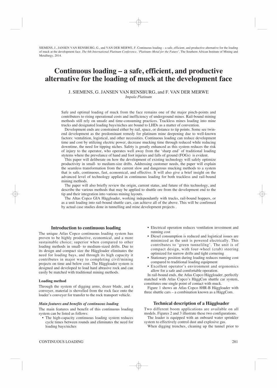
In rail-bound ends, the Atlas Copco Häggloader, perfectlymatched with Atlas Copco’s HäggCon shuttle car system,constitutes one single point of contact with muck.
Figure 1 shows an Atlas Copco 8HR-B Häggloader withthree shuttle cars – a combination known as a HäggCom.
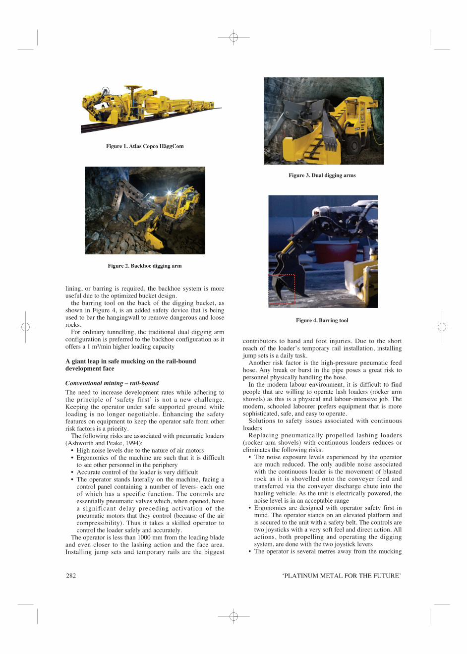
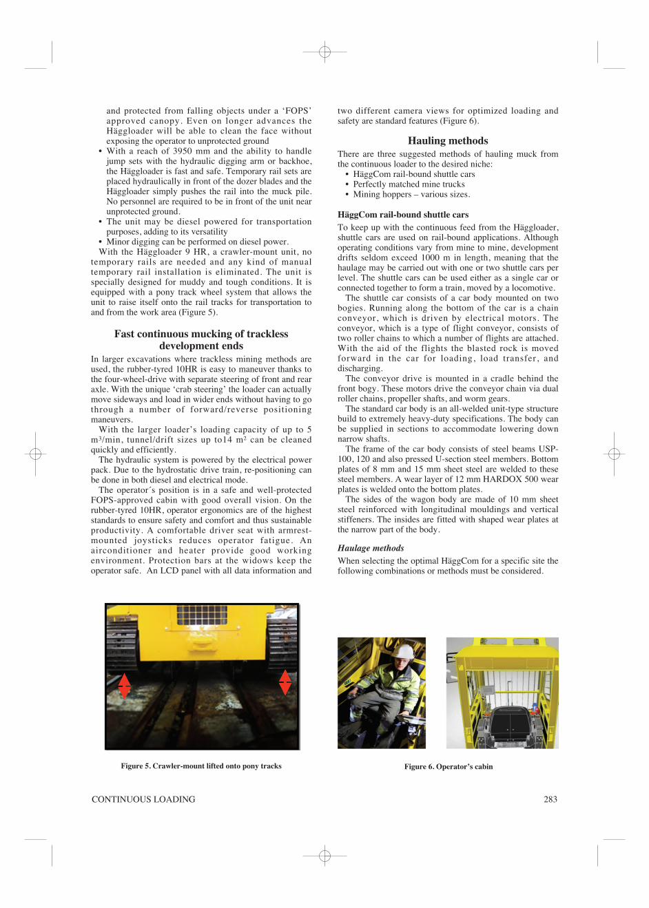
Technical description of a HäggloaderTwo different boom applications are available on allmodels. Figures 2 and 3 illustrate these two configurations.
The loader is equipped with an onboard water sprinklersystem to effectively control dust and explosive gas.
When digging trenches, cleaning up the tunnel prior to
SIEMENS, J., JANSEN VAN RENSBURG, G., and VAN DER MERWE, F. Continuous loading – a safe, efficient, and productive alternative for the loadingof muck at the development face. The 6th International Platinum Conference, ‘Platinum–Metal for the Future’, The Southern African Institute of Mining andMetallurgy, 2014.
Continuous loading – a safe, efficient, and productivealternative for the loading of muck at the development face
J. SIEMENS, G. JANSEN VAN RENSBURG, and F. VAN DER MERWEImpala Platinum
Safe and optimal loading of muck from the face remains one of the major pinch-points andcontributers to rising operational costs and inefficiency of underground mines. Rail-bound miningmethods still rely on unsafe and time-consuming practices. Trackless mines loading into minetrucks and designated loading bays/niches are bound to LHDs as a matter of convention.
Development ends are constrained either by rail, space, or distance to tip points. Some see twin-end development as the predominant remedy for platinum mine deepening due to well-knownfactors: ventalition, logistical, and other necessities. Continuous loading can reduce developmenttime and cost by utilizing electric power, decrease mucking time through reduced while reducingdowntime, the need for tipping niches. Safety is greatly enhanced as this system reduces the riskof injury to the operator, who operates well away from the ‘sharp end’ of traditional loadingstytems where the prevelance of hand and foot injuries and falls of ground (FOGs) is evident.
This paper will deliberate on how the development of existing technology will safely optimizeproductivity in small- to medium-size drifts. Addressing customer needs, the paper will explainthe seamless transformation from the current slow and dangerous mucking methods to a systemthat is safe, continuous, fast, economical, and effective. It will also give a brief insight on theadvanced level of technology applied in continuous loading for both trackless and rail-boundmining methods.
The paper will also briefly review the origin, current status, and future of this technology, anddescribe the various methods that may be applied to shuttle ore from the development end to thetip and their integration into various mining layouts.
The Altas Copco GIA Häggloader, working independantly with trucks, rail-bound hoppers, oras a unit loading into rail-bound shuttle cars, can achieve all of the above. This will be confirmedby actual case studies done in tunnelling and mine development projects .
‘PLATINUM METAL FOR THE FUTURE’282
lining, or barring is required, the backhoe system is moreuseful due to the optimized bucket design.
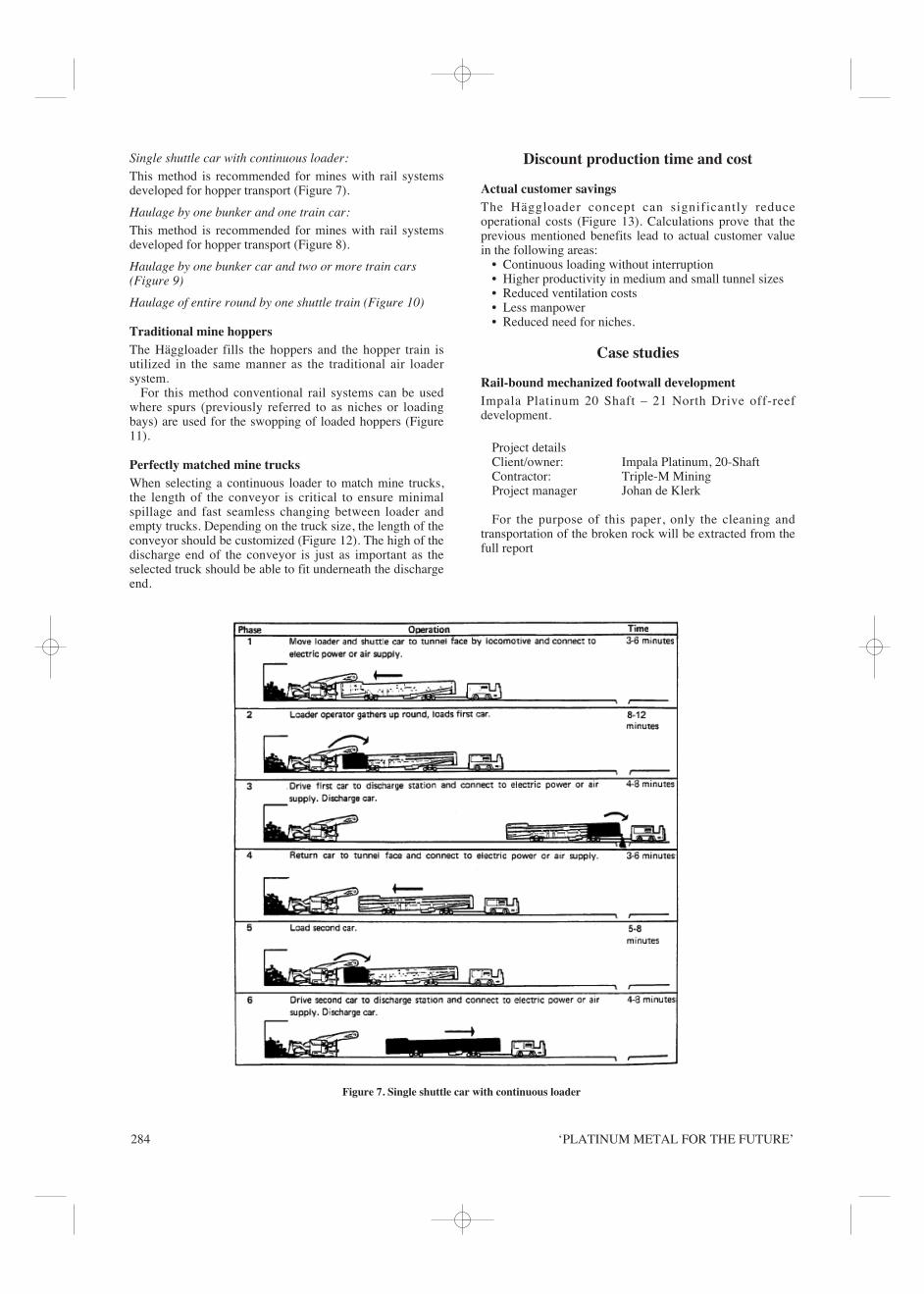
the barring tool on the back of the digging bucket, asshown in Figure 4, is an added safety device that is beingused to bar the hangingwall to remove dangerous and looserocks.
For ordinary tunnelling, the traditional dual digging armconfiguration is preferred to the backhoe configuration as itoffers a 1 m³/min higher loading capacity
A giant leap in safe mucking on the rail-bounddevelopment face
Conventional mining – rail-boundThe need to increase development rates while adhering tothe principle of ‘safety first’ is not a new challenge.Keeping the operator under safe supported ground whileloading is no longer negotiable. Enhancing the safetyfeatures on equipment to keep the operator safe from otherrisk factors is a priority.
The following risks are associated with pneumatic loaders(Ashworth and Peake, 1994):
• High noise levels due to the nature of air motors• Ergonomics of the machine are such that it is difficult
to see other personnel in the periphery• Accurate control of the loader is very difficult • The operator stands laterally on the machine, facing a
control panel containing a number of levers- each oneof which has a specific function. The controls areessentially pneumatic valves which, when opened, havea significant delay preceding activation of thepneumatic motors that they control (because of the aircompressibility). Thus it takes a skilled operator tocontrol the loader safely and accurately.
The operator is less than 1000 mm from the loading bladeand even closer to the lashing action and the face area.Installing jump sets and temporary rails are the biggest
contributors to hand and foot injuries. Due to the shortreach of the loader’s temporary rail installation, installingjump sets is a daily task.
Another risk factor is the high-pressure pneumatic feedhose. Any break or burst in the pipe poses a great risk topersonnel physically handling the hose.
In the modern labour environment, it is difficult to findpeople that are willing to operate lash loaders (rocker armshovels) as this is a physical and labour-intensive job. Themodern, schooled labourer prefers equipment that is moresophisticated, safe, and easy to operate.
Solutions to safety issues associated with continuousloaders
Replacing pneumatically propelled lashing loaders(rocker arm shovels) with continuous loaders reduces oreliminates the following risks:
• The noise exposure levels experienced by the operatorare much reduced. The only audible noise associatedwith the continuous loader is the movement of blastedrock as it is shovelled onto the conveyer feed andtransferred via the conveyer discharge chute into thehauling vehicle. As the unit is electrically powered, thenoise level is in an acceptable range
• Ergonomics are designed with operator safety first inmind. The operator stands on an elevated platform andis secured to the unit with a safety belt. The controls aretwo joysticks with a very soft feel and direct action. Allactions, both propelling and operating the diggingsystem, are done with the two joystick levers
• The operator is several metres away from the mucking
Figure 1. Atlas Copco HäggCom
Figure 2. Backhoe digging arm
Figure 3. Dual digging arms
Figure 4. Barring tool
CONTINUOUS LOADING 283
and protected from falling objects under a ‘FOPS’approved canopy. Even on longer advances theHäggloader will be able to clean the face withoutexposing the operator to unprotected ground
• With a reach of 3950 mm and the ability to handlejump sets with the hydraulic digging arm or backhoe,the Häggloader is fast and safe. Temporary rail sets areplaced hydraulically in front of the dozer blades and theHäggloader simply pushes the rail into the muck pile.No personnel are required to be in front of the unit nearunprotected ground.
• The unit may be diesel powered for transportationpurposes, adding to its versatility
• Minor digging can be performed on diesel power.With the Häggloader 9 HR, a crawler-mount unit, no
temporary rails are needed and any kind of manualtemporary rail installation is eliminated. The unit isspecially designed for muddy and tough conditions. It isequipped with a pony track wheel system that allows theunit to raise itself onto the rail tracks for transportation toand from the work area (Figure 5).
Fast continuous mucking of tracklessdevelopment ends
In larger excavations where trackless mining methods areused, the rubber-tyred 10HR is easy to maneuver thanks tothe four-wheel-drive with separate steering of front and rearaxle. With the unique ‘crab steering’ the loader can actuallymove sideways and load in wider ends without having to gothrough a number of forward/reverse positioningmaneuvers.
With the larger loader’s loading capacity of up to 5m3/min, tunnel/drift sizes up to14 m² can be cleanedquickly and efficiently.
The hydraulic system is powered by the electrical powerpack. Due to the hydrostatic drive train, re-positioning canbe done in both diesel and electrical mode.
The operator´s position is in a safe and well-protectedFOPS-approved cabin with good overall vision. On therubber-tyred 10HR, operator ergonomics are of the higheststandards to ensure safety and comfort and thus sustainableproductivity. A comfortable driver seat with armrest-mounted joysticks reduces operator fatigue. Anairconditioner and heater provide good workingenvironment. Protection bars at the widows keep theoperator safe. An LCD panel with all data information and
two different camera views for optimized loading andsafety are standard features (Figure 6).
Hauling methodsThere are three suggested methods of hauling muck fromthe continuous loader to the desired niche:
• HäggCom rail-bound shuttle cars• Perfectly matched mine trucks• Mining hoppers – various sizes.
HäggCom rail-bound shuttle cars To keep up with the continuous feed from the Häggloader,shuttle cars are used on rail-bound applications. Althoughoperating conditions vary from mine to mine, developmentdrifts seldom exceed 1000 m in length, meaning that thehaulage may be carried out with one or two shuttle cars perlevel. The shuttle cars can be used either as a single car orconnected together to form a train, moved by a locomotive.
The shuttle car consists of a car body mounted on twobogies. Running along the bottom of the car is a chainconveyor, which is driven by electrical motors. Theconveyor, which is a type of flight conveyor, consists oftwo roller chains to which a number of flights are attached.With the aid of the flights the blasted rock is movedforward in the car for loading, load transfer, anddischarging.
The conveyor drive is mounted in a cradle behind thefront bogy. These motors drive the conveyor chain via dualroller chains, propeller shafts, and worm gears.
The standard car body is an all-welded unit-type structurebuild to extremely heavy-duty specifications. The body canbe supplied in sections to accommodate lowering downnarrow shafts.
The frame of the car body consists of steel beams USP-100, 120 and also pressed U-section steel members. Bottomplates of 8 mm and 15 mm sheet steel are welded to thesesteel members. A wear layer of 12 mm HARDOX 500 wearplates is welded onto the bottom plates.
The sides of the wagon body are made of 10 mm sheetsteel reinforced with longitudinal mouldings and verticalstiffeners. The insides are fitted with shaped wear plates atthe narrow part of the body.
Haulage methodsWhen selecting the optimal HäggCom for a specific site thefollowing combinations or methods must be considered.
Figure 6. Operator’s cabinFigure 5. Crawler-mount lifted onto pony tracks
‘PLATINUM METAL FOR THE FUTURE’284
Single shuttle car with continuous loader:
This method is recommended for mines with rail systemsdeveloped for hopper transport (Figure 7).
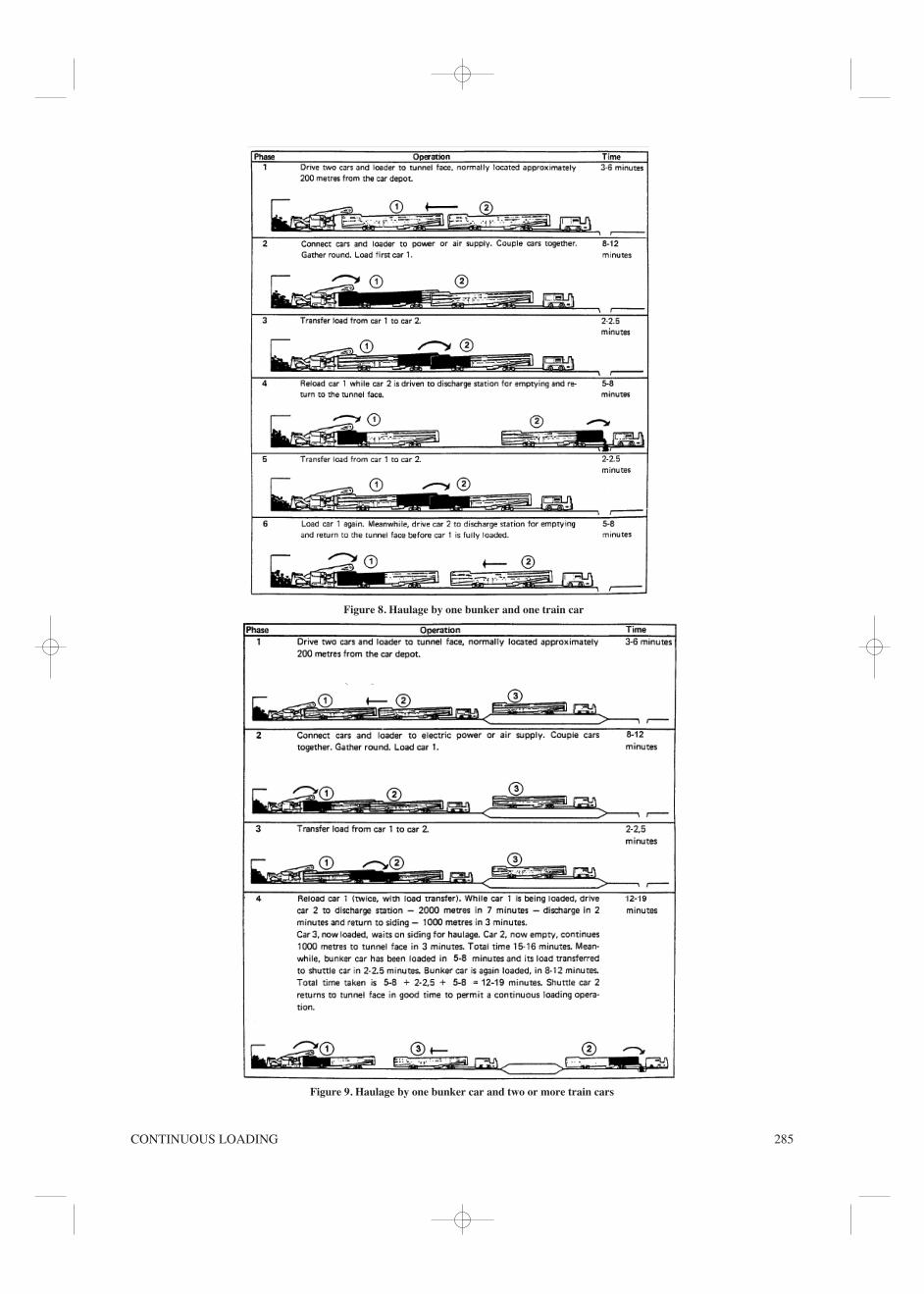
Haulage by one bunker and one train car:
This method is recommended for mines with rail systemsdeveloped for hopper transport (Figure 8).
Haulage by one bunker car and two or more train cars(Figure 9)
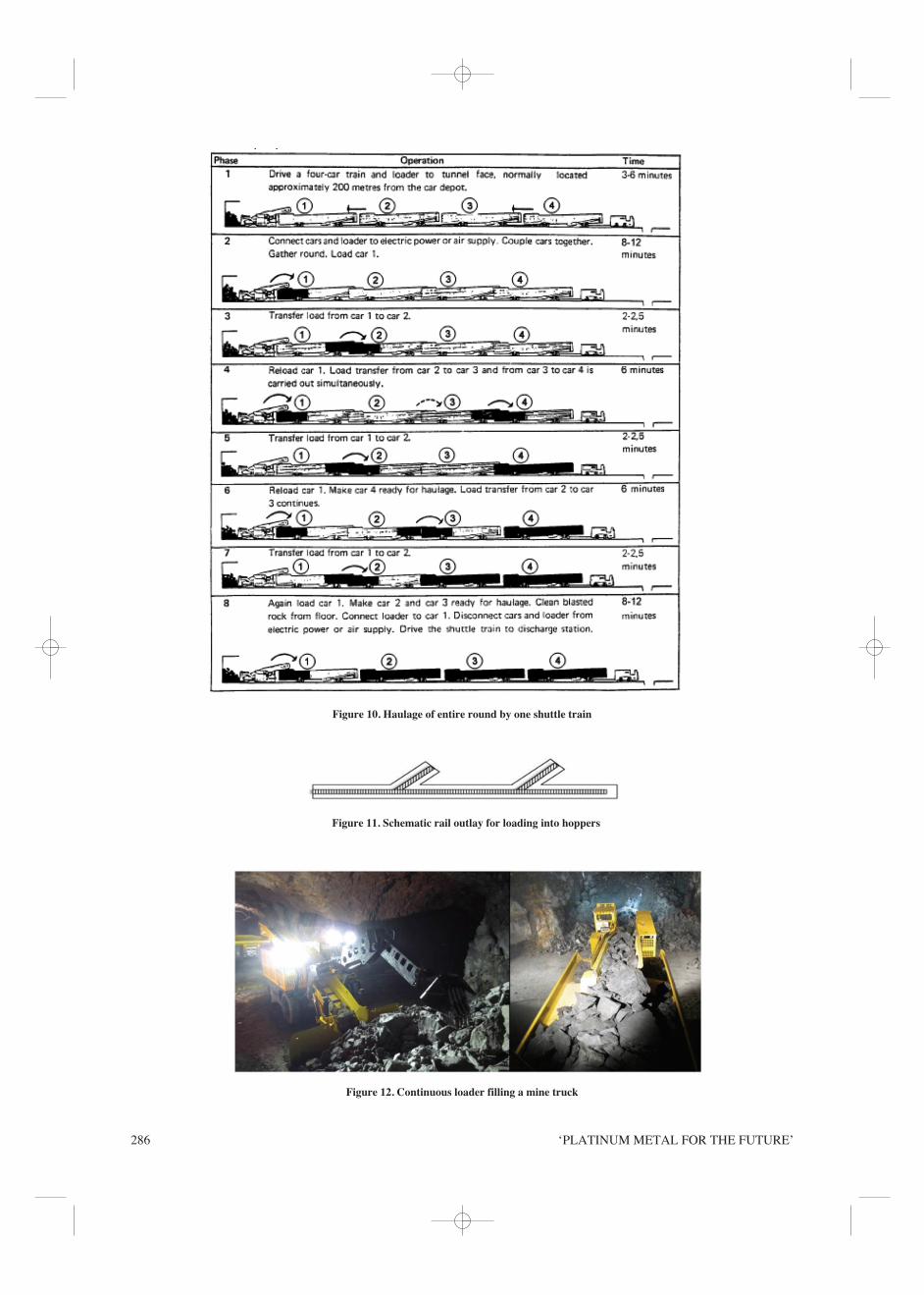
Haulage of entire round by one shuttle train (Figure 10)
Traditional mine hoppers The Häggloader fills the hoppers and the hopper train isutilized in the same manner as the traditional air loadersystem.
For this method conventional rail systems can be usedwhere spurs (previously referred to as niches or loadingbays) are used for the swopping of loaded hoppers (Figure11).
Perfectly matched mine trucksWhen selecting a continuous loader to match mine trucks,the length of the conveyor is critical to ensure minimalspillage and fast seamless changing between loader andempty trucks. Depending on the truck size, the length of theconveyor should be customized (Figure 12). The high of thedischarge end of the conveyor is just as important as theselected truck should be able to fit underneath the dischargeend.
Discount production time and cost
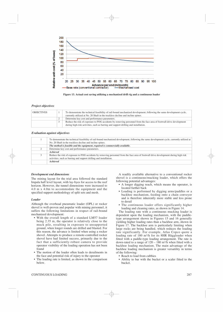
Actual customer savingsThe Häggloader concept can significantly reduceoperational costs (Figure 13). Calculations prove that theprevious mentioned benefits lead to actual customer valuein the following areas:
• Continuous loading without interruption• Higher productivity in medium and small tunnel sizes• Reduced ventilation costs• Less manpower• Reduced need for niches.
Case studies
Rail-bound mechanized footwall development Impala Platinum 20 Shaft – 21 North Drive off-reefdevelopment.
Project detailsClient/owner: Impala Platinum, 20-ShaftContractor: Triple-M MiningProject manager Johan de Klerk
For the purpose of this paper, only the cleaning andtransportation of the broken rock will be extracted from thefull report
Figure 7. Single shuttle car with continuous loader
CONTINUOUS LOADING 285
Figure 8. Haulage by one bunker and one train car
Figure 9. Haulage by one bunker car and two or more train cars
‘PLATINUM METAL FOR THE FUTURE’286
Figure 10. Haulage of entire round by one shuttle train
Figure 11. Schematic rail outlay for loading into hoppers
Figure 12. Continuous loader filling a mine truck
CONTINUOUS LOADING 287
Development end dimensionsThe mining layout for the trial area followed the standardImpala half level layout, with lay-byes for access to the reefhorizon. However, the tunnel dimensions were increased to4.0 m x 4.0m to accommodate the equipment and thespecified support methodology of split sets and mesh.
LoaderAlthough the overhead pneumatic loader (OPL) or rockershovel is well-proven and popular with mining personnel, itsuffers the following limitations in respect of rail-boundmechanized development:
• With the overall length of a standard LM57 loaderbeing 2.35 m, the operator is relatively close to themuck pile, resulting in exposure to unsupportedground, when longer rounds are drilled and blasted. Forthis reason, the advance is limited when using a rockershovel. Attempts to produce a remote-controlled rockershovel have had limited success, primarily due to thefact that a sufficiently-robust camera to provideoperator visibility of the loading operation has not beenfound
• The motion of the loader often leads to derailments inthe face and potential risk of injury to the operator
• The loading rate is limited, as shown in the comparisonbelow.
A readily available alternative to a conventional rockershovel is a continuous/mucking loader, which offers thefollowing potential advantages:
• A longer digging reach, which means the operator, islocated further back
• Loading is performed by digging arms/paddles or abackhoe mechanism, feeding onto a chain conveyorand is therefore inherently more stable and less proneto derail
• The continuous loader offers significantly higherloading and cleaning rates, as shown in Figure 14.
The loading rate with a continuous mucking loader isdependent upon the loading mechanism, with the paddle-type arrangement shown in Figures 15 and 16 generallyyielding higher loading rates than a backhoe arm, shown inFigure 17. The backhoe arm is particularly limiting whenlarge rocks are being handled, which reduces the loadingrate significantly. For example, Atlas Copco quote aloading rate of 180 m3/h for its 8HR Häggloader whenfitted with a paddle-type loading arrangement. The rate isdown-rated to a range of 120 – 180 m3/h when fitted with abackhoe loading mechanism. The main advantage of thebackhoe loading mechanism is greater versatility in termsof the following:
• Reach to load from cubbies• Ability to bar with the bucket or a scaler fitted to the
bucket.
Figure 13. Actual cost saving utilizing a mechanized drill rig and a continuous loader
Project objectives
OBJECTIVES 1 To demonstrate the technical feasibility of rail-bound mechanized development, following the same development cycle, currently utilized at No. 20 Shaft in the trackless decline and incline spines.
2 Determine key cost and performance parameters.3 Reduce the risk of exposure to FOG accidents by removing personnel from the face area of footwall drive development
during high-risk activities, such as barring and support drilling and installation.
Evaluation against objectives
1 To demonstrate the technical feasibility of rail-bound mechanized development, following the same development cycle, currently utilized atNo. 20 Shaft in the trackless decline and incline spines.The method is feasible and the equipment, required is commercially available.
2 Determine key cost and performance parameters.Achieved
3 Reduce the risk of exposure to FOG accidents by removing personnel from the face area of footwall drive development during high riskactivities, such as barring and support drilling and installation.Achieved

‘PLATINUM METAL FOR THE FUTURE’288
The loaders are also produced in rubber tyre, rail-bound,and dozer track configuration.
The system utilized in the trial at No. 20 Shaft was an8HR rail-bound Häggloader from Atlas Copco, fitted withpaddle arms to facilitate a high loading rate, as shown inFigure 18.
The cleaning rate is dependent on both the loading rate ofthe mucking loader and the rate at which rock can betrammed to the tips. It is therefore common in high-speeddevelopment applications to utilize a set of shuttle cars(Figure 19) as shown previously, in combination with amucking loader.
ConclusionsThe trial demonstrated that the method, currently used forthe trackless incline/decline development at No. 20 Shaft,can be implemented for footwall drive development,utilizing rail-bound equipment. The method effectivelyremoves personnel from the face area during all activities,except mark-up and charge-up, and is therefore inherentlysafer. A rate of advance of at least 60 m per month isachievable (De Wet, 2013).
Holsbru Kraftverk Project, Norsk Hydro, Norway, 2011
Project detailsTunnelling contract: US$36 millionClient/Owner: Norsk HydroContractor: Haehre Entrepenor
Figure 14. Cleaning and loading rate comparison (source: resultsfrom Deep Mine Project)
Figure 15. Mucking loader with paddle arms, tyre-based (AtlasCopco)
Figure 16. Mucking loader with paddle arms, rail-bound (AtlasCopco)
Figure 17. Mucking loader with backhoe arrangement, crawler-based (Atlas Copco)
Figure 18. Häggloader underground at No. 20 Shaft
Figure 19. Shuttle car (typically three or more are used with aHäggloader
CONTINUOUS LOADING 289
Site Manager: Emst Ove JohansenSite Engineer: Elisabeth HolsbrekkenEngineering Consultant: Multiconsult, Norway
Norwegian hydropower producer Norsk Hydro isbuilding a new feeder tunnel to increase feed to the existingHolsbru Kraftverk project in Sogun country, 300 kmnorthwest of Oslo.
The drill and blast part of the tunnel complex will be6000 m tunnels, 4 m x 5 m high. Overburden will be 40-50m while the head at the power station will be about 740 m.
The tunnels are excavated at multiple facessimultaneously, with around three drill and blast cycles perface per day, each blast resulting in a 4.0 to 4.5 m advance.An Atlas Copco GIA 10HR-B electro-hydraulic tracklessHäggloader is used to scoop the spoil onto a conveyorsystem feeding the trucks without the need of any loadingsystem (Figure 19).
Once the face is clean, the Häggloader is driven to thenext end with the onboard diesel engine.
According to Mr Emst Johansen, the site manager, theHäggloader can clean the face in only 2 hours, loadingbetween 20 and 25 dump truck loads in the process. MrJohansen told World Tunnelling: ’The Häggloader may bea fast unit, but is also very good for emissions as it is aclean machine, which is important if you are working in along tunnel. In addition the clean environment means lessventilation is required. Typically loading rates are 3-4m³/min, which is very fast as the Häggloader fills thedumper trucks continuously trough the chain conveyor’(Demitri, 2011).
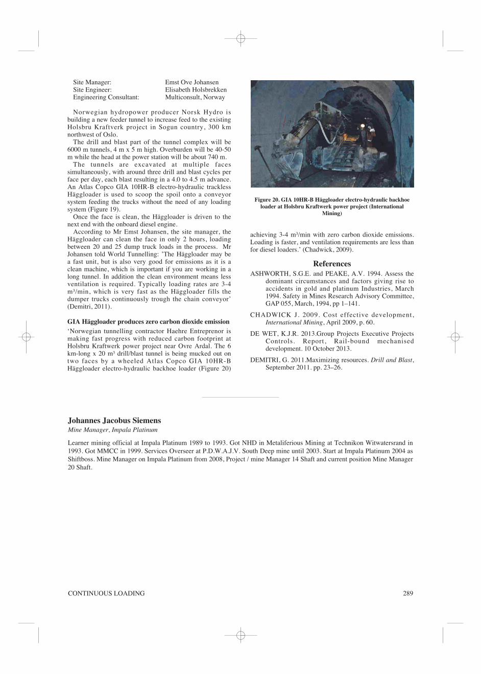
GIA Häggloader produces zero carbon dioxide emission‘Norwegian tunnelling contractor Haehre Entreprenor ismaking fast progress with reduced carbon footprint atHolsbru Kraftwerk power project near Ovre Ardal. The 6km-long x 20 m³ drill/blast tunnel is being mucked out ontwo faces by a wheeled Atlas Copco GIA 10HR-BHäggloader electro-hydraulic backhoe loader (Figure 20)
achieving 3-4 m³/min with zero carbon dioxide emissions.Loading is faster, and ventilation requirements are less thanfor diesel loaders.’ (Chadwick, 2009).
ReferencesASHWORTH, S.G.E. and PEAKE, A.V. 1994. Assess the
dominant circumstances and factors giving rise toaccidents in gold and platinum Industries, March1994. Safety in Mines Research Advisory Committee,GAP 055, March, 1994, pp 1–141.
CHADWICK J. 2009. Cost effective development,International Mining, April 2009, p. 60.
DE WET, K.J.R. 2013.Group Projects Executive ProjectsControls. Report, Rail-bound mechaniseddevelopment. 10 October 2013.
DEMITRI, G. 2011.Maximizing resources. Drill and Blast,September 2011. pp. 23–26.
Figure 20. GIA 10HR-B Häggloader electro-hydraulic backhoeloader at Holsbru Kraftwerk power project (International
Mining)
Johannes Jacobus Siemens Mine Manager, Impala Platinum
Learner mining official at Impala Platinum 1989 to 1993. Got NHD in Metaliferious Mining at Technikon Witwatersrand in1993. Got MMCC in 1999. Services Overseer at P.D.W.A.J.V. South Deep mine until 2003. Start at Impala Platinum 2004 asShiftboss. Mine Manager on Impala Platinum from 2008, Project / mine Manager 14 Shaft and current position Mine Manager20 Shaft.

‘PLATINUM METAL FOR THE FUTURE’290