contra-recuos denflex - nvd discflex … · acoplamento hidrodinÂmico contra-recuos denflex - nvd...
TRANSCRIPT
ACOPLAMENTO HIDRODINÂMICOCONTRA-RECUOSDENFLEX - NVDDISCFLEXEMBREAGENS INDUSTRIAIS
FLEXOMAX GBNFLEXOMAX GSNPINOFLEX - NPSPEFLEX - NVULBRAFLEX VBVULKARDAN - EVUL-MEX
F LEXOMAX G
2009/01
02
We reserve the right of technical alterations without previous notice.
FLEXOMAX G
GENERALITIES
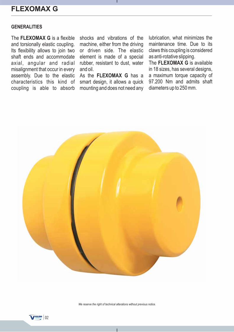
The is a flexibletorsionally elastic coupling.
Its flexibility allows to join twoshaft ends and accommodateaxial, angular and radialmisalignment that occur in everyassembly. Due to the elasticcharacteristics this kind ofcoupling is able to absorb
FLEXOMAX G
andshocks and vibrations of themachine, either from the drivingor driven side. The elasticelement is made of a specialrubber, resistant to dust, waterand oil.As the has asmart design, it allows a quickmounting and does not need any
FLEXOMAX G
lubrication, what minimizes themaintenance time. Due to itsclaws this coupling is consideredas anti-rotative slipping.The is availablein 18 sizes, has several designs,a maximum torque capacity of97.200 Nm and admits shaftdiameters up to 250 mm.
FLEXOMAX G
Reservamo-nos o direito de alterações sem prévio aviso.
FLEXOMAX G
GENERALIDADES
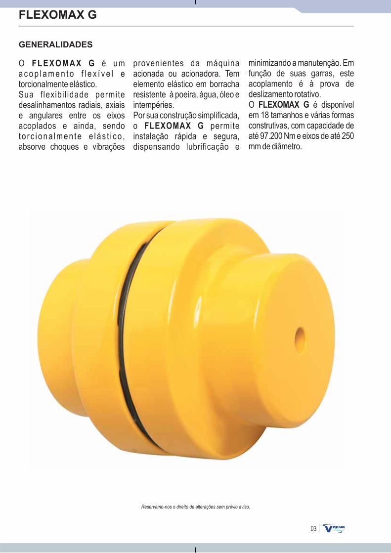
O é u ma c o p l a m e n t o f l e x í v e l etorcionalmente elástico.Sua flexibi l idade permitedesalinhamentos radiais, axiaise angulares entre os eixosacoplados e ainda, sendoto r c i ona lmen te e lás t i co ,absorve choques e vibrações
F L E X O M A X G provenientes da máquinaacionada ou acionadora. Temelemento elástico em borracharesistente à poeira, água, óleo eintempéries.Por sua construção simplificada,o permiteinstalação rápida e segura,dispensando lubrificação e
FLEXOMAX G
minimizando a manutenção. Emfunção de suas garras, esteacoplamento é à prova dedeslizamento rotativo.O é disponívelem 18 tamanhos e várias formasconstrutivas, com capacidade deaté 97.200 Nm e eixos de até 250mm de diâmetro.
FLEXOMAX G
03
04
FLEXOMAX G
SELECTION PROCEDURE
Nos reservamos el derecho a las alteraciones sin previo aviso.We reserve the right of technical alterations without previous notice.
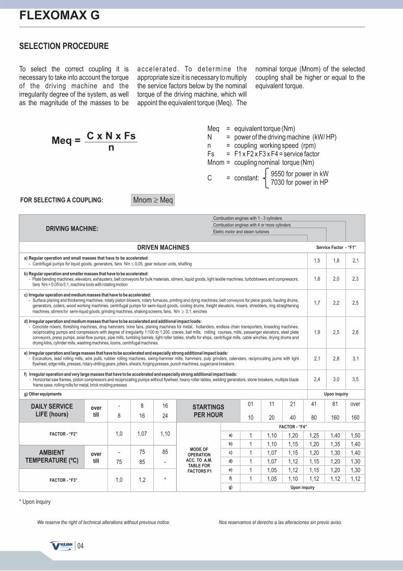
To select the correct coupling it isnecessary to take into account the torqueof the driving machine and theirregularity degree of the system, as wellas the magnitude of the masses to be
acce le ra ted . To dete rmine theappropriate size it is necessary to multiplythe service factors below by the nominaltorque of the driving machine, which willappoint the equivalent torque (Meq). The
nominal torque (Mnom) of the selectedcoupling shall be higher or equal to theequivalent torque.
Meq = equivalent torque (Nm)N = power of the driving machine (kW/ HP)n = coupling working speed (rpm)Fs = F1 x F2 x F3 x F4 = service factorMnom = coupling nominal torque (Nm)
Meq = C x N x Fsn
9550 for power in kW7030 for power in HP
C = constant:
FOR SELECTING A COUPLING: Mnom Meq�
DRIVING MACHINE:
Combustion engines with 1 - 3 cylinders
Combustion engines with 4 or more cylinders
Eletric motor and steam turbines
DRIVEN MACHINES Service Factor - “F1”
a) Regular operation and small masses that have to be accelerated:
- Centrifugal pumps for liquid goods, generators, fans N/n 0,05, gear reducer units, shafting�
b) Regular operation and smaller masses that have to be accelerated:
- Plate bending machines, elevators, exhausters, belt conveyors for bulk materials, stirrers, liquid goods, light textile machines, turboblowers and compressors,fans N/n = 0,05 to 0,1, machine tools with rotating motion
c) Irregular operation and medium masses that have to be accelerated:
- Surface planing and thickening machines, rotaty piston blowers, rotary furnaces, printing and dying machines, belt conveyors for piece goods, hauling drums,generators, coilers, wood working machines, centrifugal pumps for semi-liquid goods, cooling drums, freight elevators, mixers, shredders, ring straightening
machines, stirrers for semi-liquid goods, grinding machines, shaking screens, fans, N/n 0,1, winches�
d) Irregular operation and medium masses that have to be accelerated and additional impact loads:
- Concrete mixers, threshing machines, drop hammers, mine fans, planing machines for metal, hollanders, endless chain transporters, kneading machines,reciprocating pumps and compressors with degree of irregularity 1:100 to 1:200, cranes, ball mills, milling courses, mills, passenger elevators, steel plateconveyors, press pumps, axial-flow pumps, pipe mills, tumbling barrels, light roller tables, shafts for ships, centrifugal mills, cable winches, drying drums anddrying kilns, cylinder mills, washing machines, looms, centrifugal machines.
e) Irregular operation and large masses that have to be accelerated and especially strong additional impact loads:
- Excavators, lead rolling mills, wire pulls, rubber rolling machines, swing-hammer mills, hammers, pulp grinders, calendars, reciprocating pums with lightflywheel, edge mills, presses, rotary-drilling gears, jolters, shears, forging presses, punch machines, sugarcane breakers.
f) Irregular operation and very large masses that have to be accelerated and especially strong additional impact loads:
- Horizontal saw frames, piston compressors and reciprocating pumps without flywheel, heavy roller tables, welding generators, stone breakers, multiple bladeframe saws, rolling mills for metal, brick molding presses
g) Other equipments Upon inquiry
1,5
1,6
1,8 2,1
2,0 2,3
1,7 2,2 2,5
1,9 2,5 2,8
2,1 2,8 3,1
2,4 3,0 3,5
DAILY SERVICE
LIFE (hours)
AMBIENT
TEMPERATURE (ºC)
FACTOR - “F2”
FACTOR - “F3”
over
till
over
till
-
8
1,0
-
75
1,0
8
16
1,07
75
85
1,2
16
24
01
10
11
20
21
40
41
80
81
160
1,10
85
-
*
STARTINGS
PER HOUR
MODE OF
OPERATION
ACC. TO A.M.
TABLE FOR
FACTORS F1
FACTOR - “F4”
a)
b)
c)
d)
e)
f)
g)
1 1,10 1,20 1,25 1,40 1,50
1 1,10 1,15 1,20 1,35 1,40
1 1,07 1,15 1,20 1,30 1,40
1 1,07 1,12 1,15 1,20 1,30
1 1,05 1,12 1,15 1,20 1,30
1 1,05 1,10 1,12 1,12 1,12
Upon inquiry
* Upon inquiry
over
160
05
FLEXOMAX G
Nos reservamos el derecho a las alteraciones sin previo aviso.We reserve the right of technical alterations without previous notice.
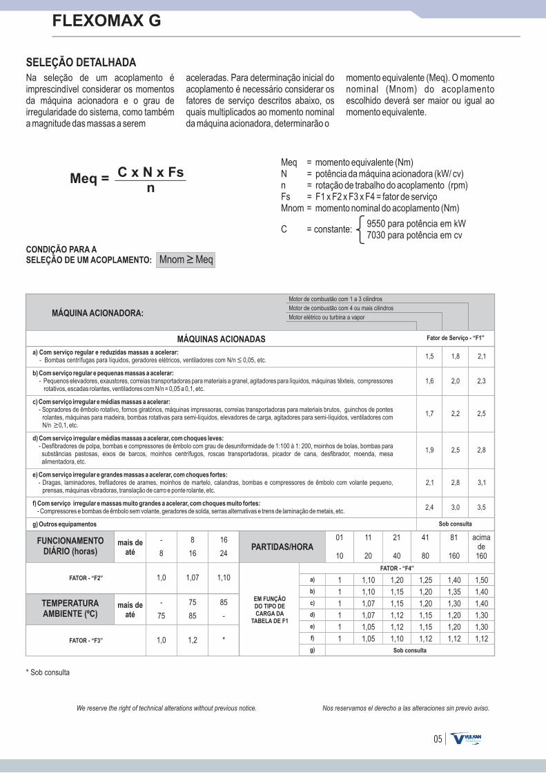
SELEÇÃO DETALHADANa seleção de um acoplamento é imprescindível considerar os momentos da máquina acionadora e o grau de irregularidade do sistema, como também a magnitude das massas a serem
aceleradas. Para determinação inicial do acoplamento é necessário considerar os fatores de serviço descritos abaixo, os quais multiplicados ao momento nominal da máquina acionadora, determinarão o
momento equivalente (Meq). O momento nominal (Mnom) do acoplamento escolhido deverá ser maior ou igual ao momento equivalente.
Meq = C x N x Fsn
Meq = momento equivalente (Nm)N = potência da máquina acionadora (kW/ cv)n = rotação de trabalho do acoplamento (rpm)Fs = F1 x F2 x F3 x F4 = fator de serviçoMnom = momento nominal do acoplamento (Nm)
9550 para potência em kW7030 para potência em cv
C = constante:
CONDIÇÃO PARA ASELEÇÃO DE UM ACOPLAMENTO: Mnom Meq
* Sob consulta
MÁQUINA ACIONADORA:
Motor de combustão com 1 a 3 cilindros
Motor de combustão com 4 ou mais cilindros
Motor elétrico ou turbina a vapor
MÁQUINAS ACIONADAS Fator de Serviço - “F1”
a) Com serviço regular e reduzidas massas a acelerar:- Bombas centrífugas para líquidos, geradores elétricos, ventiladores com N/n 0,05, etc.
b) Com serviço regular e pequenas massas a acelerar:- Pequenos elevadores, exaustores, correias transportadoras para materiais a granel, agitadores para líquidos, máquinas têxteis, compressores
rotativos, escadas rolantes, ventiladores com N/n = 0,05 a 0,1, etc.
c) Com serviço irregular e médias massas a acelerar:- Sopradores de êmbolo rotativo, fornos giratórios, máquinas impressoras, correias transportadoras para materiais brutos, guinchos de pontes
rolantes, máquinas para madeira, bombas rotativas para semi-líquidos, elevadores de carga, agitadores para semi-líquidos, ventiladores com N/n 0,1, etc.
d) Com serviço irregular e médias massas a acelerar, com choques leves:- Desfibradores de polpa, bombas e compressores de êmbolo com grau de desuniformidade de 1:100 à 1: 200, moinhos de bolas, bombas para substâncias pastosas, eixos de barcos, moinhos centrífugos, roscas transportadoras, picador de cana, desfibrador, moenda, mesa alimentadora, etc.
e) Com serviço irregular e grandes massas a acelerar, com choques fortes:- Dragas, laminadores, trefiladores de arames, moinhos de martelo, calandras, bombas e compressores de êmbolo com volante pequeno,
prensas, máquinas vibradoras, translação de carro e ponte rolante, etc.
f) Com serviço irregular e massas muito grandes a acelerar, com choques muito fortes:- Compressores e bombas de êmbolo sem volante, geradores de solda, serras alternativas e trens de laminação de metais, etc.
g) Outros equipamentos Sob consulta
1,5
1,6
1,8 2,1
2,0 2,3
1,7 2,2 2,5
1,9 2,5 2,8
2,1 2,8 3,1
2,4 3,0 3,5
FUNCIONAMENTODIÁRIO (horas)
TEMPERATURAAMBIENTE (ºC)
FATOR - “F2”
FATOR - “F3”
mais deaté
mais deaté
-
8
1,0
-
75
1,0
8
16
1,07
75
85
1,2
16
24
01
10
11
20
21
40
41
80
81
160
acimade160
1,10
85
-
*
PARTIDAS/HORA
EM FUNÇÃODO TIPO DECARGA DA
TABELA DE F1
FATOR - “F4”
a)
b)
c)
d)
e)
f)
g)
1 1,10 1,20 1,25 1,40 1,50
1 1,10 1,15 1,20 1,35 1,40
1 1,07 1,15 1,20 1,30 1,40
1 1,07 1,12 1,15 1,20 1,30
1 1,05 1,12 1,15 1,20 1,30
1 1,05 1,10 1,12 1,12 1,12
Sob consulta
06
FLEXOMAX G
DESIGN / FORMAS CONSTRUCTIVAS
Nos reservamos el derecho a las alteraciones sin previo aviso.We reserve the right of technical alterations without previous notice.
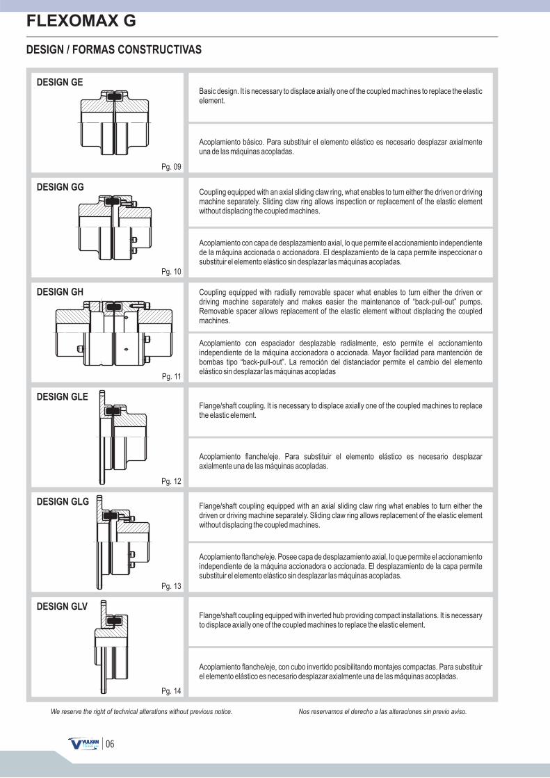
DESIGN GE
DESIGN GG
DESIGN GH
DESIGN GLE
DESIGN GLG
DESIGN GLV
Pg. 09
Pg. 10
Pg. 11
Pg. 12
Pg. 13
Pg. 14
Basic design. It is necessary to displace axially one of the coupled machines to replace the elasticelement.
Flange/shaft coupling. It is necessary to displace axially one of the coupled machines to replacethe elastic element.
Flange/shaft coupling equipped with inverted hub providing compact installations. It is necessaryto displace axially one of the coupled machines to replace the elastic element.
Flange/shaft coupling equipped with an axial sliding claw ring what enables to turn either thedriven or driving machine separately. Sliding claw ring allows replacement of the elastic elementwithout displacing the coupled machines.
Acoplamiento básico. Para substituir el elemento elástico es necesario desplazar axialmenteuna de las máquinas acopladas.
Acoplamiento flanche/eje. Para substituir el elemento elástico es necesario desplazaraxialmente una de las máquinas acopladas.
Acoplamiento flanche/eje, con cubo invertido posibilitando montajes compactas. Para substituirel elemento elástico es necesario desplazar axialmente una de las máquinas acopladas.
Acoplamiento flanche/eje. Posee capa de desplazamiento axial, lo que permite el accionamientoindependiente de la máquina accionadora o accionada. El desplazamiento de la capa permitesubstituir el elemento elástico sin desplazar las máquinas acopladas.
Coupling equipped with an axial sliding claw ring, what enables to turn either the driven or drivingmachine separately. Sliding claw ring allows inspection or replacement of the elastic elementwithout displacing the coupled machines.
Coupling equipped with radially removable spacer what enables to turn either the driven ordriving machine separately and makes easier the maintenance of “back-pull-out” pumps.Removable spacer allows replacement of the elastic element without displacing the coupledmachines.
Acoplamiento con capa de desplazamiento axial, lo que permite el accionamiento independientede la máquina accionada o accionadora. El desplazamiento de la capa permite inspeccionar osubstituir el elemento elástico sin desplazar las máquinas acopladas.
Acoplamiento con espaciador desplazable radialmente, esto permite el accionamientoindependiente de la máquina accionadora o accionada. Mayor facilidad para mantención debombas tipo “back-pull-out”. La remoción del distanciador permite el cambio del elementoelástico sin desplazar las máquinas acopladas
07
FLEXOMAX G
Reservamo-nos o direito de alterações sem prévio aviso.We reserve the right of technical alterations without previous notice.
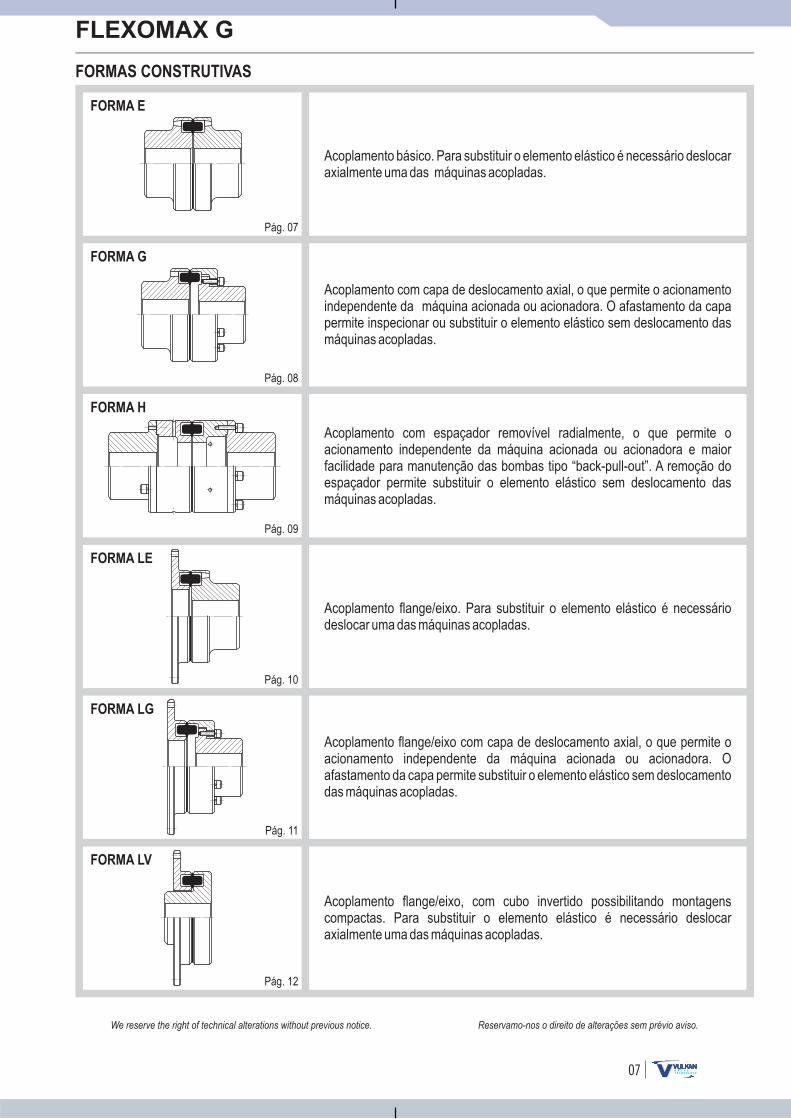
FORMAS CONSTRUTIVAS
FORMA E
FORMA G
FORMA H
FORMA LE
FORMA LG
FORMA LV
Pág. 07
Pág. 08
Pág. 09
Pág. 10
Pág. 11
Pág. 12
Acoplamento básico. Para substituir o elemento elástico é necessário deslocaraxialmente uma das máquinas acopladas.
Acoplamento flange/eixo. Para substituir o elemento elástico é necessáriodeslocar uma das máquinas acopladas.
Acoplamento flange/eixo, com cubo invertido possibilitando montagenscompactas. Para substituir o elemento elástico é necessário deslocaraxialmente uma das máquinas acopladas.
Acoplamento flange/eixo com capa de deslocamento axial, o que permite oacionamento independente da máquina acionada ou acionadora. Oafastamento da capa permite substituir o elemento elástico sem deslocamentodas máquinas acopladas.
Acoplamento com capa de deslocamento axial, o que permite o acionamentoindependente da máquina acionada ou acionadora. O afastamento da capapermite inspecionar ou substituir o elemento elástico sem deslocamento dasmáquinas acopladas.
Acoplamento com espaçador removível radialmente, o que permite oacionamento independente da máquina acionada ou acionadora e maiorfacilidade para manutenção das bombas tipo “back-pull-out”. A remoção doespaçador permite substituir o elemento elástico sem deslocamento dasmáquinas acopladas.
08
FLEXOMAX G
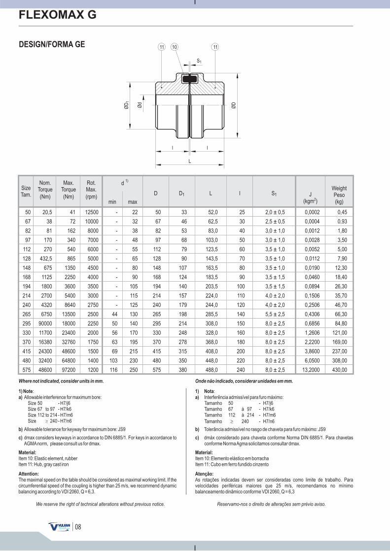
DESIGN/FORMA GE
Reservamo-nos o direito de alterações sem prévio aviso.We reserve the right of technical alterations without previous notice.
Where not indicated, consider units in mm. Onde não indicado, considerar unidades em mm.
1) Note
a)
:Allowable interference for maximum bore:
Size 50 - H7/j6Size 67 to 97 - H7/k6
Size 240 - H7/n6Size 112 to 214 - H7/m6
�
1) Nota
a)
:Interferência admissível para furo máximo:Tamanho 50 - H7/j6Tamanho 67 à 97 - H7/k6Tamanho 112 à 214 - H7/m6
Tamanho 240 - H7/n6�
lSizeTam. J
(kgm )2
WeightPeso(kg)min max
d1)
D S1L
50
67
82
97
112
128
148
168
194
214
240
265
295
330
370
415
480
575
12500
10000
8000
7000
6000
5000
4500
4000
3500
3000
2750
2500
2250
2000
1750
1500
1400
1200
D1
-
-
-
-
-
-
-
-
-
-
-
44
50
56
63
69
103
116
22
32
38
48
55
65
80
90
105
115
125
130
140
170
195
215
230
250
50
67
82
97
112
128
148
168
194
214
240
265
295
330
370
415
480
575
33
46
53
68
79
90
107
124
140
157
179
198
214
248
278
315
350
380
52,0
62,5
83,0
103,0
123,5
143,5
163,5
183,5
203,5
224,0
244,0
285,5
308,0
328,0
368,0
408,0
448,0
488,0
25
30
40
50
60
70
80
90
100
110
120
140
150
160
180
200
220
240
2,0 ± 0,5
2,5 ± 0,5
3,0 ± 1,0
3,0 ± 1,0
3,5 ± 1,0
3,5 ± 1,0
3,5 ± 1,0
3,5 ± 1,5
3,5 ± 1,5
4,0 ± 2,0
4,0 ± 2,0
5,5 ± 2,5
8,0 ± 2,5
8,0 ± 2,5
8,0 ± 2,5
8,0 ± 2,5
8,0 ± 2,5
8,0 ± 2,5
0,0002
0,0004
0,0012
0,0028
0,0052
0,0112
0,0190
0,0460
0,0894
0,1506
0,2506
0,4306
0,6856
1,2606
2,2200
3,8600
6,0500
13,2000
0,45
0,93
1,80
3,50
5,00
7,90
12,30
18,40
26,30
35,70
46,70
66,30
84,80
121,00
169,00
237,00
308,00
430,00
b) Allowable tolerance for keyway for maximum bore: JS9
c) dmax considers keyways in accordance to DIN 6885/1. For keys in accordance toAGMAnorm, please consult us for dmax.
Material:
Item 10: Elastic element, rubberItem 11: Hub, gray cast iron
Attention:
The maximal speed on the table should be considered as maximal working limit. If thecircumferential speed of the coupling is higher than 25 m/s, we recommend dynamicbalancing according to VDI 2060, Q = 6,3.
b) Tolerância admissível no rasgo de chaveta para furo máximo: JS9
c) dmáx considerado para chaveta conforme Norma DIN 6885/1. Para chavetasconforme NormaAgma solicitamos consultar dmax.
Material:
Item 10: Elemento elástico em borrachaItem 11: Cubo em ferro fundido cinzento
Atenção:
As rotações indicadas devem ser consideradas como limite de trabalho. Paravelocidades periféricas maiores que 25 m/s, recomendamos no mínimobalanceamento dinâmico conforme VDI 2060, Q = 6,3
20,5
38
81
170
270
432,5
675
1125
1800
2700
4320
6750
90000
11700
16380
24300
32400
48600
41
72
162
340
540
865
1350
2250
3600
5400
8640
13500
18000
23400
32760
48600
64800
97200
(Nm)(Nm) (rpm)
Max.Torque
Nom.Torque
Rot.Max.
Ød
1011 11
ØD
1
ØD
l l
L
S1
09
FLEXOMAX G
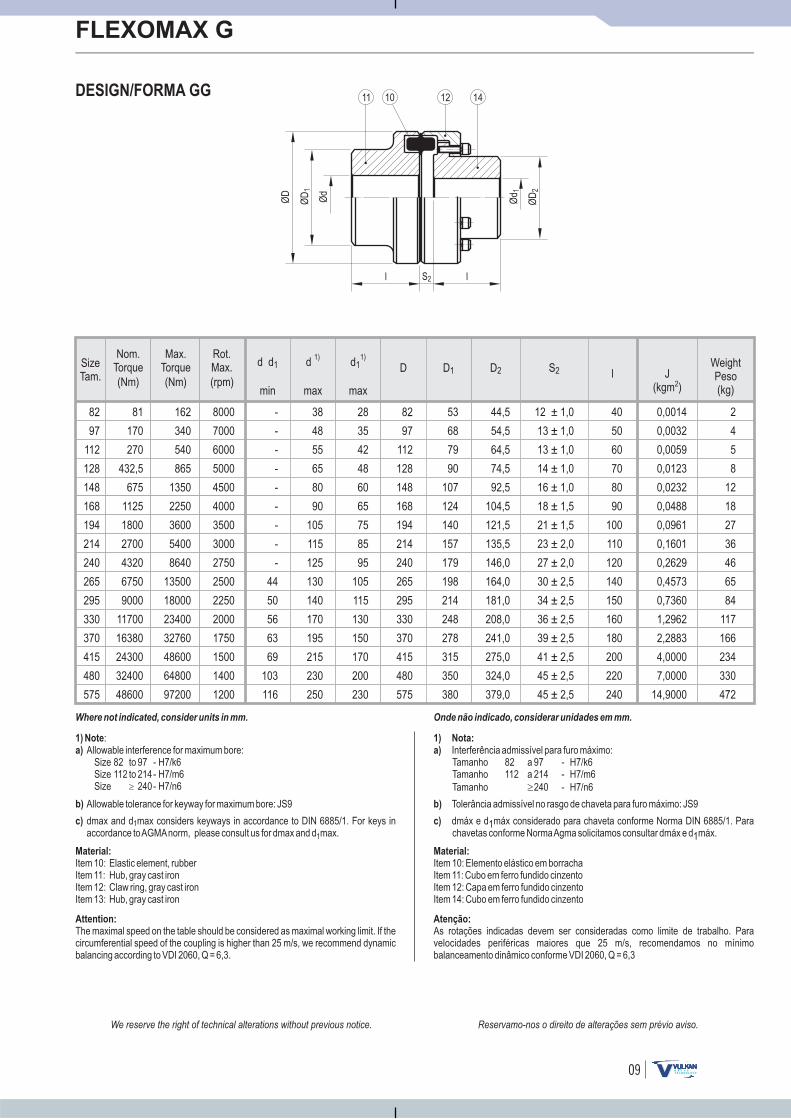
DESIGN/FORMA GG
Reservamo-nos o direito de alterações sem prévio aviso.We reserve the right of technical alterations without previous notice.
Onde não indicado, considerar unidades em mm.
l lSizeTam. J
(kgm )2
WeightPeso(kg)min max
D S2 lD1
82
97
112
128
148
168
194
214
240
265
295
330
370
415
480
575
162
340
540
865
1350
2250
3600
5400
8640
13500
18000
23400
32760
48600
64800
97200
81
170
270
432,5
675
1125
1800
2700
4320
6750
9000
11700
16380
24300
32400
48600
8000
7000
6000
5000
4500
4000
3500
3000
2750
2500
2250
2000
1750
1500
1400
1200
d1)
d d1 d11)
max
D2
-
-
-
-
-
-
-
-
-
44
50
56
63
69
103
116
38
48
55
65
80
90
105
115
125
130
140
170
195
215
230
250
28
35
42
48
60
65
75
85
95
105
115
130
150
170
200
230
82
97
112
128
148
168
194
214
240
265
295
330
370
415
480
575
53
68
79
90
107
124
140
157
179
198
214
248
278
315
350
380
44,5
54,5
64,5
74,5
92,5
104,5
121,5
135,5
146,0
164,0
181,0
208,0
241,0
275,0
324,0
379,0
12 ± 1,0
13 ± 1,0
13 ± 1,0
14 ± 1,0
16 ± 1,0
18 ± 1,5
21 ± 1,5
23 ± 2,0
27 ± 2,0
30 ± 2,5
34 ± 2,5
36 ± 2,5
39 ± 2,5
41 ± 2,5
45 ± 2,5
45 ± 2,5
40
50
60
70
80
90
100
110
120
140
150
160
180
200
220
240
0,0014
0,0032
0,0059
0,0123
0,0232
0,0488
0,0961
0,1601
0,2629
0,4573
0,7360
1,2962
2,2883
4,0000
7,0000
14,9000
2
4
5
8
12
18
27
36
46
65
84
117
166
234
330
472
1) Note
a)
:Allowable interference for maximum bore:
Size 82 to 97 - H7/k6Size 112 to 214- H7/m6Size 240- H7/n6�
1) Nota:
a) Interferência admissível para furo máximo:Tamanho 82 a 97 - H7/k6Tamanho 112 a 214 - H7/m6
Tamanho 240 - H7/n6�
Where not indicated, consider units in mm.
b) Allowable tolerance for keyway for maximum bore: JS9
c) dmax and d max considers keyways in accordance to DIN 6885/1. For keys inaccordance toAGMAnorm, please consult us for dmax and d max.
1
1
Material:
Item 10: Elastic element, rubberItem 11: Hub, gray cast ironItem 12: Claw ring, gray cast ironItem 13: Hub, gray cast iron
Attention:
The maximal speed on the table should be considered as maximal working limit. If thecircumferential speed of the coupling is higher than 25 m/s, we recommend dynamicbalancing according to VDI 2060, Q = 6,3.
b) Tolerância admissível no rasgo de chaveta para furo máximo: JS9
c) dmáx e d1máx considerado para chaveta conforme Norma DIN 6885/1. Parachavetas conforme NormaAgma solicitamos consultar dmáx e d1máx.
Material:
Item 10: Elemento elástico em borrachaItem 11: Cubo em ferro fundido cinzentoItem 12: Capa em ferro fundido cinzentoItem 14: Cubo em ferro fundido cinzento
Atenção:
As rotações indicadas devem ser consideradas como limite de trabalho. Paravelocidades periféricas maiores que 25 m/s, recomendamos no mínimobalanceamento dinâmico conforme VDI 2060, Q = 6,3
(Nm)(Nm) (rpm)
Max.Torque
Nom.Torque
Rot.Max.
Ød
ØD
1
ØD
l lS2
1011 14
ØD
2
Ød 1
12
10
FLEXOMAX G
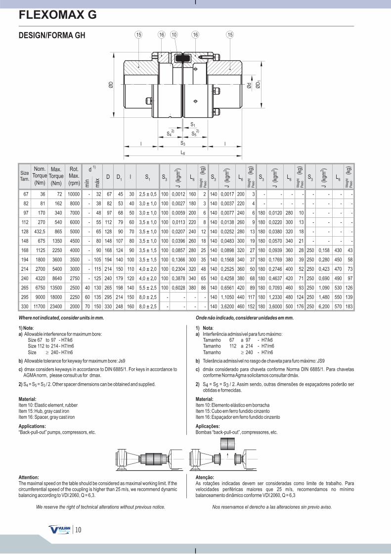
DESIGN/FORMA GH
Nos reservamos el derecho a las alteraciones sin previo aviso.We reserve the right of technical alterations without previous notice.
Onde não indicado, considerar unidades em mm.
1) Note
a)
:Allowable interference for maximum bore:
Size 67 to 97 - H7/k6Size 112 to 214 - H7/m6
Size 240 - H7/n6�
1) Nota
a)
:Interferência admissível para furo máximo:Tamanho 67 a 97 - H7/k6Tamanho 112 a 214 - H7/m6
Tamanho 240 - H7/n6�
Where not indicated, consider units in mm.
b) Allowable tolerance for keyway for maximum bore: Js9
c) dmax considers keyways in accordance to DIN 6885/1. For keys in accordance toAGMAnorm, please consult us for dmax.
2) S = S = S / 2. Other spacer dimensions can be obtained and supplied.4 5 3
Material:
Item 10: Elastic element, rubberItem 15: Hub, gray cast ironItem 16: Spacer, gray cast iron
Applications:
“Back-pull-out” pumps, compressors, etc.
Attention:
The maximal speed on the table should be considered as maximal working limit. If thecircumferential speed of the coupling is higher than 25 m/s, we recommend dynamicbalancing according to VDI 2060, Q = 6,3.
b) Tolerância admissível no rasgo de chaveta para furo máximo: JS9
c) dmáx considerado para chaveta conforme Norma DIN 6885/1. Para chavetasconforme NormaAgma solicitamos consultar dmáx.
2) S4 = S5 = S3 / 2. Assim sendo, outras.
dimensões de espaçadores poderão serobtidas e fornecidas
Material:
Item 10: Elemento elástico em borrachaItem 15: Cubo em ferro fundido cinzentoItem 16: Espaçador em ferro fundido cinzento
Aplicações:
Bombas “back-pull-out”, compressores, etc.
Atenção:
As rotações indicadas devem ser consideradas como limite de trabalho. Paravelocidades periféricas maiores que 25 m/s, recomendamos no mínimobalanceamento dinâmico conforme VDI 2060, Q = 6,3
L6
S3
-
-
-
-
-
-
250
250
250
250
250
250
250
J(k
gm)2
J(k
gm)2
J(k
gm)2
S1
S3
L6
L6
L6
S3
(kg)
(kg)
SizeTam.
mín
máx
d1)
D D1
67
82
97
112
128
148
168
194
214
240
265
295
330
l S3
36
81
170
270
432,5
675
1125
1800
2700
4320
6750
9000
11700
72
162
340
540
865
1350
2250
3600
5400
8640
13500
18000
23400
10000
8000
7000
6000
5000
4500
4000
3500
3000
2750
2500
2250
2000
-
-
-
-
-
-
-
-
-
-
40
60
70
32
38
48
55
65
80
90
105
115
125
130
135
150
67
82
97
112
128
148
168
194
214
240
265
295
330
45
53
68
79
90
107
124
140
150
179
198
214
248
30
40
50
60
70
80
90
100
110
120
140
150
160
2,5 ± 0,5
3,0 ± 1,0
3,0 ± 1,0
3,5 ± 1,0
3,5 ± 1,0
3,5 ± 1,0
3,5 ± 1,5
3,5 ± 1,5
4,0 ± 2,0
4,0 ± 2,0
5,5 ± 2,5
8,0 ± 2,5
8,0 ± 2,5
100
100
100
100
100
100
100
100
100
100
100
-
-
0,0012
0,0027
0,0059
0,0113
0,0207
0,0396
0,0857
0,1366
0,2304
0,3878
0,6028
-
-
2
3
6
8
12
18
25
35
48
65
86
-
-
140
140
140
140
140
140
140
140
140
140
140
140
140
0,0017
0,0037
0,0077
0,0138
0,0252
0,0483
0,0898
0,1568
0,2525
0,4258
0,6561
1,1050
3,6200
3
4
6
9
13
19
27
37
50
68
89
117
152
-
-
180
180
180
180
180
180
180
180
180
180
180
-
-
0,0120
0,0220
0,0380
0,0570
0,0939
0,1769
0,2746
0,4637
0,7093
1,2330
3,6000
-
-
10
13
18
21
28
39
52
71
93
124
176
160
180
200
220
240
260
280
300
320
340
380
-
-
200
220
240
260
280
300
320
340
360
380
420
440
460
-
-
280
300
320
340
360
380
400
420
460
480
500
J(k
gm)2
-
-
-
-
-
-
0,158
0,280
0,423
0,690
1,090
1,480
6,200
-
-
-
-
-
-
430
450
470
490
530
550
570
-
-
-
-
-
-
43
58
73
97
126
139
183
Wei
ght
Pes
o
Wei
ght
Pes
o
(kg)
Wei
ght
Pes
o
(kg)
Wei
ght
Pes
o
Ød
ØD
1
ØD
l lS3
1015 15
L6
S1
S42)
S52)
16 16
(Nm)
Max.Torque
(Nm)
Nom.Torque
(rpm)
Rot.Max.
11
FLEXOMAX G
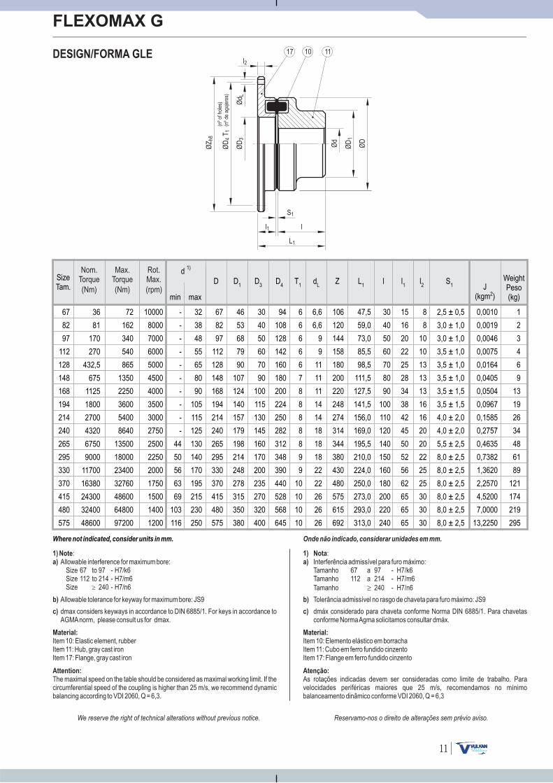
DESIGN/FORMA GLE
Reservamo-nos o direito de alterações sem prévio aviso.We reserve the right of technical alterations without previous notice.
1) Note
a)
:Allowable interference for maximum bore:
Size 67 to 97 - H7/k6Size 112 to 214 - H7/m6Size 240 - H7/n6�
1) Nota
a)
:Interferência admissível para furo máximo:Tamanho 67 a 97 - H7/k6Tamanho 112 a 214 - H7/m6
Tamanho 240 - H7/n6�
Onde não indicado, considerar unidades em mm.
SizeTam. J
(kgm )2min max
d1)
D D1
D3
D4
67
82
97
112
128
148
168
194
214
240
265
295
330
370
415
480
575
10000
8000
7000
6000
5000
4500
4000
3500
3000
2750
2500
2250
2000
1750
1500
1400
1200
lT1
dL
L1
l1
l2
S1
Z
-
-
-
-
-
-
-
-
-
-
44
50
56
63
69
103
116
32
38
48
55
65
80
90
105
115
125
130
140
170
195
215
230
250
67
82
97
112
128
148
168
194
214
240
265
295
330
370
415
480
575
46
53
68
79
90
107
124
140
157
179
198
214
248
278
315
350
380
30
40
50
60
70
90
100
115
130
145
160
170
200
235
270
320
400
94
108
128
142
160
180
200
224
250
282
312
348
390
440
528
568
645
6
6
6
6
6
7
8
8
8
8
8
9
9
10
10
10
10
6,6
6,6
9
9
11
11
11
14
14
18
18
18
22
22
26
26
26
106
120
144
158
180
200
220
248
274
314
344
380
430
480
575
615
692
47,5
59,0
73,0
85,5
98,5
111,5
127,5
141,5
156,0
169,0
195,5
210,0
224,0
250,0
273,0
293,0
313,0
30
40
50
60
70
80
90
100
110
120
140
150
160
180
200
220
240
15
16
20
22
25
28
34
38
42
45
50
52
56
62
65
65
65
8
8
10
10
13
13
13
16
16
20
20
22
25
25
30
30
30
2,5 ± 0,5
3,0 ± 1,0
3,0 ± 1,0
3,5 ± 1,0
3,5 ± 1,0
3,5 ± 1,0
3,5 ± 1,5
3,5 ± 1,5
4,0 ± 2,0
4,0 ± 2,0
5,5 ± 2,5
8,0 ± 2,5
8,0 ± 2,5
8,0 ± 2,5
8,0 ± 2,5
8,0 ± 2,5
8,0 ± 2,5
0,0010
0,0019
0,0046
0,0075
0,0164
0,0405
0,0504
0,0967
0,1585
0,2757
0,4635
0,7382
1,3620
2,2570
4,5200
7,0000
13,2250
1
2
3
4
6
9
13
19
26
34
48
61
89
121
174
219
295
WeightPeso(kg)
Where not indicated, consider units in mm.
b) Allowable tolerance for keyway for maximum bore: JS9
c) dmax considers keyways in accordance to DIN 6885/1. For keys in accordance toAGMAnorm, please consult us for dmax.
Material:
Item 10: E , rItem 11: Hub, gray cast ironItem 17: Flange, gray cast iron
lastic element ubber
Attention:
The maximal speed on the table should be considered as maximal working limit. If thecircumferential speed of the coupling is higher than 25 m/s, we recommend dynamicbalancing according to VDI 2060, Q = 6,3.
b) Tolerância admissível no rasgo de chaveta para furo máximo: JS9
c) dmáx considerado para chaveta conforme Norma DIN 6885/1. Para chavetasconforme NormaAgma solicitamos consultar dmáx.
Material:
Item 10: Elemento elástico em borrachaItem 11: Cubo em ferro fundido cinzentoItem 17: Flange em ferro fundido cinzento
Atenção:
As rotações indicadas devem ser consideradas como limite de trabalho. Paravelocidades periféricas maiores que 25 m/s, recomendamos no mínimobalanceamento dinâmico conforme VDI 2060, Q = 6,3
36
81
170
270
432,5
675
1125
1800
2700
4320
6750
9000
11700
16380
24300
32400
48600
72
162
340
540
865
1350
2250
3600
5400
8640
13500
18000
23400
32760
48600
64800
97200
(Nm)(Nm) (rpm)
Max.Torque
Nom.Torque
Rot.Max.
ØD
l2
Ød
ØZ
h8
ØD
3Ø
d L
ØD
1
L1
l1
S1
ØD
T4
(nº
deag
ujer
os)
1
(nº
ofho
les)
1017 11
l
12
FLEXOMAX G
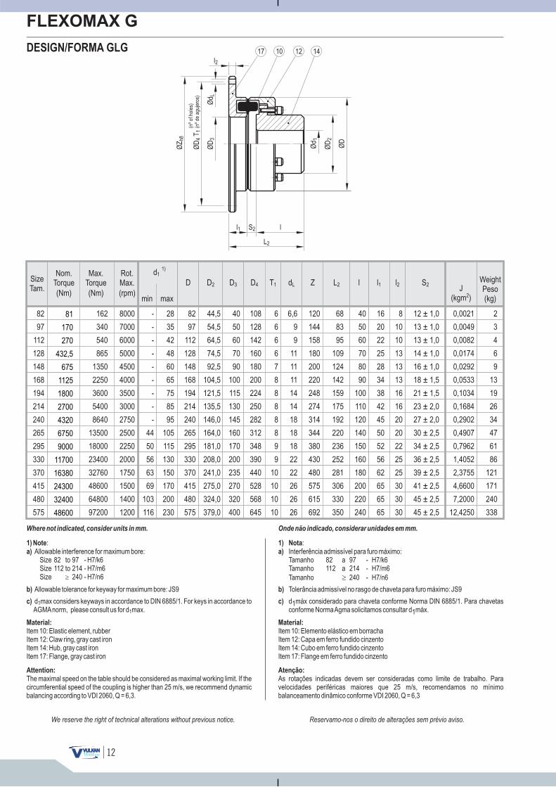
DESIGN/FORMA GLG
Reservamo-nos o direito de alterações sem prévio aviso.We reserve the right of technical alterations without previous notice.
min max
d11)
D
1) Note
a)
:Allowable interference for maximum bore:
Size 82 to 97 - H7/k6Size 112 to 214 - H7/m6Size 240 - H7/n6�
1) Nota
a)
:Interferência admissível para furo máximo:Tamanho 82 a 97 - H7/k6Tamanho 112 a 214 - H7/m6
Tamanho 240 - H7/n6�
Onde não indicado, considerar unidades em mm.
J(kgm )2
D2 D3 D4 lT1 dL L2 l1 l2 S2Z
82
97
112
128
148
168
194
214
240
265
295
330
370
415
480
575
8000
7000
6000
5000
4500
4000
3500
3000
2750
2500
2250
2000
1750
1500
1400
1200
-
-
-
-
-
-
-
-
-
44
50
56
63
69
103
116
28
35
42
48
60
65
75
85
95
105
115
130
150
170
200
230
82
97
112
128
148
168
194
214
240
265
295
330
370
415
480
575
44,5
54,5
64,5
74,5
92,5
104,5
121,5
135,5
146,0
164,0
181,0
208,0
241,0
275,0
324,0
379,0
40
50
60
70
90
100
115
130
145
160
170
200
235
270
320
400
108
128
142
160
180
200
224
250
282
312
348
390
440
528
568
645
6
6
6
6
7
8
8
8
8
8
9
9
10
10
10
10
6,6
9
9
11
11
11
14
14
18
18
18
22
22
26
26
26
120
144
158
180
200
220
248
274
314
344
380
430
480
575
615
692
68
83
95
109
124
142
159
175
192
220
236
252
281
306
330
350
40
50
60
70
80
90
100
110
120
140
150
160
180
200
220
240
16
20
22
25
28
34
38
42
45
50
52
56
62
65
65
65
8
10
10
13
13
13
16
16
20
20
22
25
25
30
30
30
12 ± 1,0
13 ± 1,0
13 ± 1,0
14 ± 1,0
16 ± 1,0
18 ± 1,5
21 ± 1,5
23 ± 2,0
27 ± 2,0
30 ± 2,5
34 ± 2,5
36 ± 2,5
39 ± 2,5
41 ± 2,5
45 ± 2,5
45 ± 2,5
0,0021
0,0049
0,0082
0,0174
0,0292
0,0533
0,1034
0,1684
0,2902
0,4907
0,7962
1,4052
2,3755
4,6600
7,2000
12,4250
2
3
4
6
9
13
19
26
34
47
61
86
121
171
240
338
ØD
l2
ØZ
h8
ØD
3Ø
d L
ØD
2
Ød 1
SizeTam.
WeightPeso(kg)
Where not indicated, consider units in mm.
ØD
T4
1(n
ºde
aguj
eros
)(n
ºof
hole
s)
ll1
L2
S2
17 12 1410
b) Allowable tolerance for keyway for maximum bore: JS9
c) d max considers keyways in accordance to DIN 6885/1. For keys in accordance toAGMAnorm, please consult us for d max.
1
1
Material:
Item 10: Elastic element, rubberItem 12: Claw ring, gray cast ironItem 14: Hub, gray cast ironItem 17: Flange, gray cast iron
Attention:
The maximal speed on the table should be considered as maximal working limit. If thecircumferential speed of the coupling is higher than 25 m/s, we recommend dynamicbalancing according to VDI 2060, Q = 6,3.
b) Tolerância admissível no rasgo de chaveta para furo máximo: JS9
c) d1máx considerado para chaveta conforme Norma DIN 6885/1. Para chavetasconforme NormaAgma solicitamos consultar d1máx.
Material:
Item 10: Elemento elástico em borrachaItem 12: Capa em ferro fundido cinzentoItem 14: Cubo em ferro fundido cinzentoItem 17: Flange em ferro fundido cinzento
Atenção:
As rotações indicadas devem ser consideradas como limite de trabalho. Paravelocidades periféricas maiores que 25 m/s, recomendamos no mínimobalanceamento dinâmico conforme VDI 2060, Q = 6,3
162
340
540
865
1350
2250
3600
5400
8640
13500
18000
23400
32760
48600
64800
97200
(Nm)(Nm) (rpm)
Max.Torque
Nom.Torque
Rot.Max.
81
170
270
432,5
675
1125
1800
2700
4320
6750
9000
11700
16380
24300
32400
48600
13
FLEXOMAX G
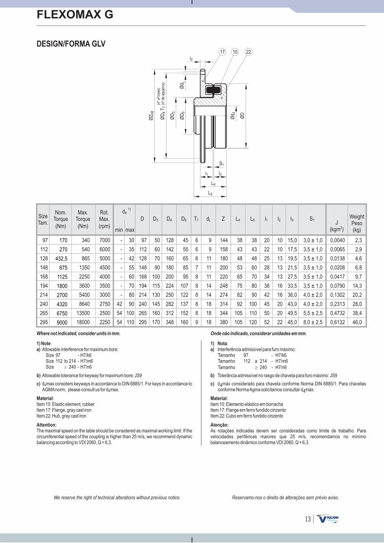
DESIGN/FORMA GLV
Reservamo-nos o direito de alterações sem prévio aviso.We reserve the right of technical alterations without previous notice.
D D6D3 D4
min max
d41)
1) Note
a)
:Allowable interference for maximum bore:
Size 97 - H7/k6Size 112 to 214 - H7/m6Size 240 - H7/n6�
1) Nota
a)
:Interferência admissível para furo máximo:Tamanho 97 - H7/k6Tamanho 112 a 214 - H7/m6
Tamanho 240 - H7/n6�
Onde não indicado, considerar unidades em mm.
J(kgm )2
T1 dL L4 l2 S1Z L5 l1 l3
-
-
-
-
-
-
-
42
54
54
340
540
865
1350
2250
3600
5400
8640
13500
18000
7000
6000
5000
4500
4000
3500
3000
2750
2500
2250
97
112
128
148
168
194
214
240
265
295
30
35
42
55
60
70
80
90
100
110
97
112
128
148
168
194
214
240
265
295
50
60
70
90
100
115
130
145
160
170
128
142
160
180
200
224
250
282
312
348
45
55
65
85
95
107
122
137
152
160
6
6
6
7
8
8
8
8
8
9
9
9
11
11
11
14
14
18
18
18
144
158
180
200
220
248
274
314
344
380
38
43
48
53
65
75
82
92
105
105
38
43
48
60
70
80
90
100
110
120
20
22
25
28
34
38
42
45
50
52
10
10
13
13
13
16
16
20
20
22
15,0
17,5
19,5
21,5
27,5
33,5
36,0
43,0
49,5
45,0
3,0 ± 1,0
3,5 ± 1,0
3,5 ± 1,0
3,5 ± 1,0
3,5 ± 1,0
3,5 ± 1,0
4,0 ± 2,0
4,0 ± 2,0
5,5 ± 2,5
8,0 ± 2,5
0,0040
0,0065
0,0138
0,0208
0,0417
0,0790
0,1302
0,2313
0,4732
0,6132
2,3
2,9
4,6
6,8
9,7
14,3
20,2
28,0
38,4
46,0
ØD
l2
ØD
3
Ød L
L5
l1
S1
Ød 4
ØZ
h8
ØD
6
l3
L4
ØD
T4
1(n
ºde
aguj
eros
)(n
ºof
hole
s)
SizeTam.
WeightPeso(kg)
Where not indicated, consider units in mm.
1017 22
b) Allowable tolerance for keyway for maximum bore: JS9
c) d max considers keyways in accordance to DIN 6885/1. For keys in accordance toAGMAnorm, please consult us for d max.
4
4
Material:
Item 10: Elastic element, rubberItem 17: Flange, gray cast ironItem 22: Hub, gray cast iron
Attention:
The maximal speed on the table should be considered as maximal working limit. If thecircumferential speed of the coupling is higher than 25 m/s, we recommend dynamicbalancing according to VDI 2060, Q = 6,3.
b) Tolerância admissível no rasgo de chaveta para furo máximo: JS9
c) d4máx considerado para chaveta conforme Norma DIN 6885/1. Para chavetasconforme NormaAgma solicitamos consultar d4máx.
Material:
Item 10: Elemento elástico em borrachaItem 17: Flange em ferro fundido cinzentoItem 22: Cubo em ferro fundido cinzento
Atenção:
As rotações indicadas devem ser consideradas como limite de trabalho. Paravelocidades periféricas maiores que 25 m/s, recomendamos no mínimobalanceamento dinâmico conforme VDI 2060, Q = 6,3
(Nm)(Nm) (rpm)
Max.Torque
Nom.Torque
Rot.Max.
170
270
432,5
675
1125
1800
2700
4320
6750
9000
14
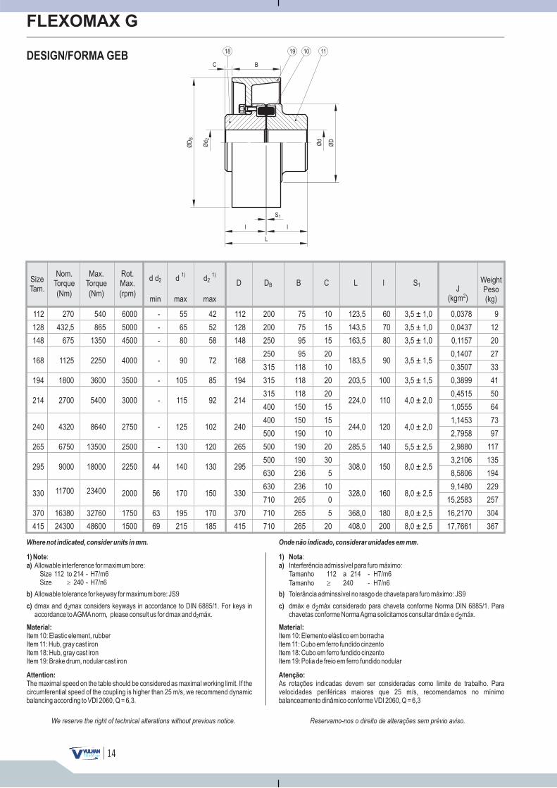
FLEXOMAX G
DESIGN/FORMA GEB
Reservamo-nos o direito de alterações sem prévio aviso.We reserve the right of technical alterations without previous notice.
d d2
1) Note
a)
:Allowable interference for maximum bore:
Size 112 to 214 - H7/m6Size 240 - H7/n6�
1) Nota
a)
:Interferência admissível para furo máximo:Tamanho 112 a 214 - H7/m6
Tamanho 240 - H7/n6�
Onde não indicado, considerar unidades em mm.
J(kgm )2
DB
112
128
148
168
194
214
240
265
295
330
370
415
270
432,5
675
540
865
1350
1125 2250
2700 5400
4320 8640
6750 13500
1800 3600
9000 18000
11700 23400
16380
24300
32760
48600
1750
1500
2000
2250
2500
2750
3000
3500
4000
6000
5000
4500
min max max
d1)
d21)
D B C L l S1
-
-
-
63
69
56
44
-
-
-
-
-
55
65
80
195
215
170
140
130
125
115
105
90
42
52
58
170
185
150
130
120
102
92
85
72
112
128
148
370
415
330
295
265
240
214
194
168
200
200
250
250
315
315
315
400
400
500
500
500
630
630
710
710
710
75
75
95
95
118
118
118
150
150
190
190
190
236
236
265
265
265
10
15
15
20
10
20
20
15
15
10
20
30
5
10
0
5
20
123,5
143,5
163,5
368,0
408,0
328,0
308,0
285,5
244,0
224,0
203,5
183,5
60
70
80
180
200
160
150
140
120
110
100
90
3,5 ± 1,0
3,5 ± 1,0
3,5 ± 1,0
8,0 ± 2,5
8,0 ± 2,5
8,0 ± 2,5
8,0 ± 2,5
5,5 ± 2,5
4,0 ± 2,0
4,0 ± 2,0
3,5 ± 1,5
3,5 ± 1,5
0,0378
0,0437
0,1157
0,1407
0,3507
0,3899
0,4515
1,0555
1,1453
2,7958
2,9880
3,2106
8,5806
9,1480
15,2583
16,2170
17,7661
9
12
20
27
33
41
50
64
73
97
117
135
194
229
257
304
367
SizeTam.
WeightPeso(kg)
Where not indicated, consider units in mm.
b) Allowable tolerance for keyway for maximum bore: JS9
c) dmax and d max considers keyways in accordance to DIN 6885/1. For keys inaccordance toAGMAnorm, please consult us for dmax and d máx.
2
2
Material:
Item 10: Elastic element, rubberItem 11: Hub, gray cast ironItem 18: Hub, gray cast ironItem 19: Brake drum, nodular cast iron
Attention:
The maximal speed on the table should be considered as maximal working limit. If thecircumferential speed of the coupling is higher than 25 m/s, we recommend dynamicbalancing according to VDI 2060, Q = 6,3.
b) Tolerância adminssível no rasgo de chaveta para furo máximo: JS9
c) dmáx e d2máx considerado para chaveta conforme Norma DIN 6885/1. Parachavetas conforme NormaAgma solicitamos consultar dmáx e d2máx.
Material:
Item 10: Elemento elástico em borrachaItem 11: Cubo em ferro fundido cinzentoItem 18: Cubo em ferro fundido cinzentoItem 19: Polia de freio em ferro fundido nodular
Atenção:
As rotações indicadas devem ser consideradas como limite de trabalho. Paravelocidades periféricas maiores que 25 m/s, recomendamos no mínimobalanceamento dinâmico conforme VDI 2060, Q = 6,3
(Nm)(Nm) (rpm)
Max.Torque
Nom.Torque
Rot.Max.
ØD
B
S1
Ød 2
C B
L
ll
18 19 1110
Ød
ØD
15
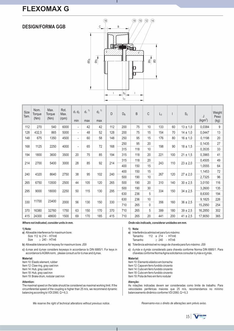
FLEXOMAX G
DESIGN/FORMA GGB
Reservamo-nos o direito de alterações sem prévio aviso.We reserve the right of technical alterations without previous notice.
d d1 2
1) Note
a)
:Allowable interference for maximum bore:
Size 112 to 214 - H7/m6Size 240 - H7/n6�
1) Nota
a)
:Interferência admissível para furo máximo:Tamanho 112 a 214 - H7/m6
Tamanho 240 - H7/n6�
Onde não indicado, considerar unidades em mm.
J(kgm )2
DB
112
128
148
168
194
214
240
265
295
330
370
415
1750
1500
2000
2250
2500
2750
3000
3500
4000
6000
5000
4500
min max max
d11)
d21)
D B C L3 l S2
42
52
58
170
185
150
130
120
102
92
85
72
112
128
148
370
415
330
295
265
240
214
194
168
200
200
250
250
315
315
315
400
400
500
500
500
630
630
710
710
710
75
75
95
95
118
118
118
150
150
190
190
190
236
236
265
265
265
10
15
15
20
10
20
20
15
15
10
20
30
5
10
0
5
20
60
70
80
180
200
160
150
140
120
110
100
90
-
-
-
63
69
56
50
44
38
28
20
-
42
48
60
150
170
130
115
105
95
85
75
65
133
154
176
399
441
356
334
310
267
243
221
198
13 ± 1,0
14 ± 1,0
16 ± 1,0
39 ± 2,5
41 ± 2,5
36 ± 2,5
34 ± 2,5
30 ± 2,5
27 ± 2,0
23 ± 2,0
21 ± 1,5
18 ± 1,5
0,0384
0,0447
0,1198
0,1435
0,3535
0,3965
0,4505
1,0555
1,1453
2,7325
3,0150
3,2600
8,6300
9,1825
15,2950
16,2850
17,9050
9
13
20
27
33
41
49
64
72
96
116
135
194
226
254
302
365
ØD
B
ØD
S2Ø
d 2
C B
L3
Ød 1
SizeTam.
WeightPeso(kg)
Where not indicated, consider units in mm.
18 19 1210 14
l l
b) Allowable tolerance for keyway for maximum bore: JS9
c) d max and d max considers keyways in accordance to DIN 6885/1. For keys inaccordance toAGMAnorm, please consult us for d max and d max.
1 2
1 2
Material:
Item 10: Elastic element, rubberItem 12: Claw ring, gray cast ironItem 14: Hub, gray cast ironItem 18: Hub, gray cast ironItem 19: Brake drum, nodular cast iron
Attention:
The maximal speed on the table should be considered as maximal working limit. If thecircumferential speed of the coupling is higher than 25 m/s, we recommend dynamicbalancing according to VDI 2060, Q = 6,3.
b) Tolerância admissível no rasgo de chaveta para furo máximo: JS9
c) d1máx e d2máx considerado para chaveta conforme Norma DIN 6885/1. Parachavetas conforme NormaAgma solicitamos consultar d1máx e d2máx.
Material:
Item 10: Elemento elástico em borrachaItem 12: Capa em ferro fundido cinzentoItem 14: Cubo em ferro fundido cinzentoItem 18: Cubo em ferro fundido cinzentoItem 19: Polia de freio em ferro nodular
Atenção:
As rotações indicadas devem ser consideradas como limite de trabalho. Paravelocidades periféricas maiores que 25 m/s, recomendamos no mínimobalanceamento dinâmico conforme VDI 2060, Q = 6,3
(Nm)(Nm) (rpm)
Max.Torque
Nom.Torque
Rot.Max.
540
865
1350
2250
5400
8640
13500
3600
18000
23400
32760
48600
270
432,5
675
1125
2700
4320
6750
1800
9000
11700
16380
24300
16
FLEXOMAX G
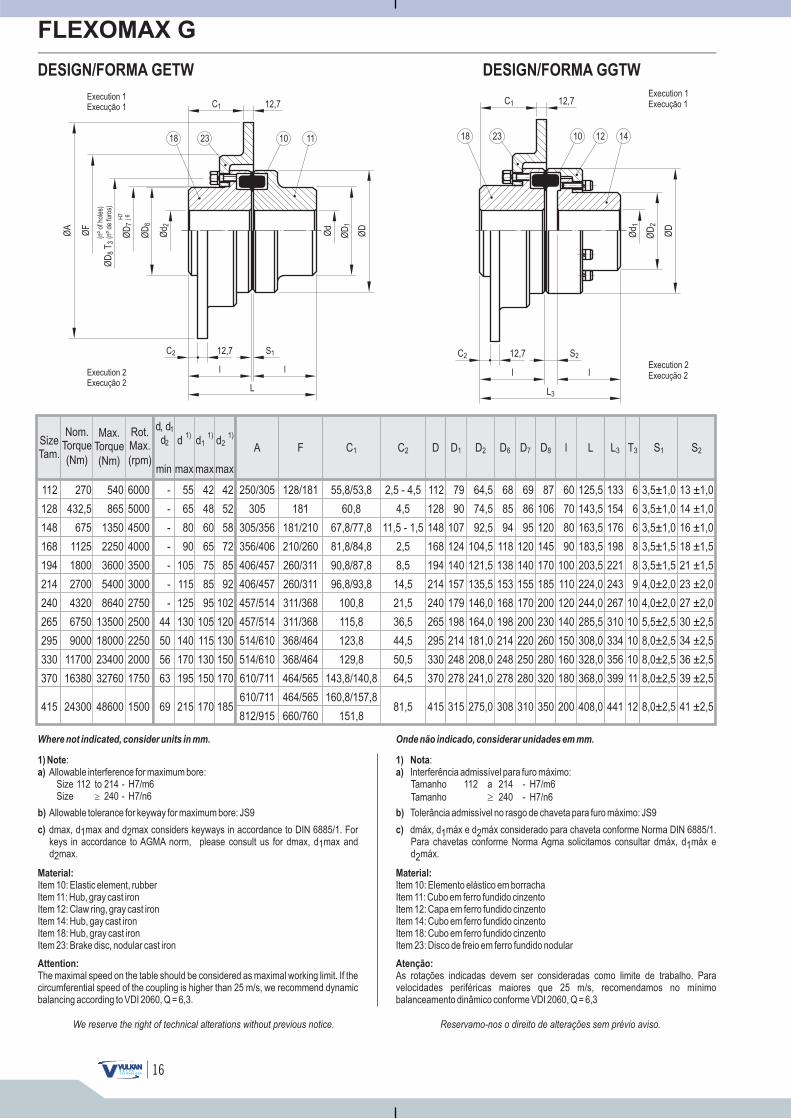
DESIGN/FORMA GETW
Reservamo-nos o direito de alterações sem prévio aviso.We reserve the right of technical alterations without previous notice.
1) Note
a)
:Allowable interference for maximum bore:
Size 112 to 214 - H7/m6Size 240 - H7/n6�
1) Nota
a)
:Interferência admissível para furo máximo:Tamanho 112 a 214 - H7/m6
Tamanho 240 - H7/n6�
Onde não indicado, considerar unidades em mm.
DESIGN/FORMA GGTW
Where not indicated, consider units in mm.
ØD
S2
Ød 1
ØD
2
12,7C2
12,7C1
L3
Execution 11Execução
Execution 22Execução
18 23 1210 14
ll
b) Allowable tolerance for keyway for maximum bore: JS9
c) dmax, d1max and d2max considers keyways in accordance to DIN 6885/1. Forkeys in accordance to AGMA norm, please consult us for dmax, d1max andd2max.
Material:
Item 10: Elastic element, rubberItem 11: Hub, gray cast ironItem 12: Claw ring, gray cast ironItem 14: Hub, gay cast ironItem 18: Hub, gray cast ironItem 23: Brake disc, nodular cast iron
Attention:
The maximal speed on the table should be considered as maximal working limit. If thecircumferential speed of the coupling is higher than 25 m/s, we recommend dynamicbalancing according to VDI 2060, Q = 6,3.
b) Tolerância admissível no rasgo de chaveta para furo máximo: JS9
c) dmáx, d1máx e d2máx considerado para chaveta conforme Norma DIN 6885/1.Para chavetas conforme Norma Agma solicitamos consultar dmáx, d1máx ed2máx.
Material:
Item 10: Elemento elástico em borrachaItem 11: Cubo em ferro fundido cinzentoItem 12: Capa em ferro fundido cinzentoItem 14: Cubo em ferro fundido cinzentoItem 18: Cubo em ferro fundido cinzentoItem 23: Disco de freio em ferro fundido nodular
Atenção:
As rotações indicadas devem ser consideradas como limite de trabalho. Paravelocidades periféricas maiores que 25 m/s, recomendamos no mínimobalanceamento dinâmico conforme VDI 2060, Q = 6,3
max
d1)
55
65
80
90
105
115
125
130
140
170
195
215
max
d11)
42
48
60
65
75
85
95
105
115
130
150
170
max
d21)
42
52
58
72
85
92
102
120
130
150
170
185
D l LD1 D2 D6 D7 D8 L3 T3C1 C2SizeTam.
S1A F S2
112
128
148
168
194
214
240
265
295
330
370
415
6000
5000
4500
4000
3500
3000
2750
2500
2250
2000
1750
1500
d, dd
1
2
min
-
-
-
-
-
-
-
44
50
56
63
69
250/305
305
305/356
356/406
406/457
406/457
457/514
457/514
514/610
514/610
610/711
610/711
812/915
128/181
181
181/210
210/260
260/311
260/311
311/368
311/368
368/464
368/464
464/565
464/565
660/760
55,8/53,8
60,8
67,8/77,8
81,8/84,8
90,8/87,8
96,8/93,8
100,8
115,8
123,8
129,8
143,8/140,8
160,8/157,8
151,8
2,5 - 4,5
4,5
11,5 - 1,5
2,5
8,5
14,5
21,5
36,5
44,5
50,5
64,5
81,5
112
128
148
168
194
214
240
265
295
330
370
415
79
90
107
124
140
157
179
198
214
248
278
315
64,5
74,5
92,5
104,5
121,5
135,5
146,0
164,0
181,0
208,0
241,0
275,0
68
85
94
118
138
153
168
198
214
248
278
308
69
86
95
120
140
155
170
200
220
250
280
310
87
106
120
145
170
185
200
230
260
280
320
350
60
70
80
90
100
110
120
140
150
160
180
200
125,5
143,5
163,5
183,5
203,5
224,0
244,0
285,5
308,0
328,0
368,0
408,0
133
154
176
198
221
243
267
310
334
356
399
441
6
6
6
8
8
9
10
10
10
10
11
12
3,5±1,0
3,5±1,0
3,5±1,0
3,5±1,5
3,5±1,5
4,0±2,0
4,0±2,0
5,5±2,5
8,0±2,5
8,0±2,5
8,0±2,5
8,0±2,5
13 ±1,0
14 ±1,0
16 ±1,0
18 ±1,5
21 ±1,5
23 ±2,0
27 ±2,0
30 ±2,5
34 ±2,5
36 ±2,5
39 ±2,5
41 ±2,5
270
432,5
675
1125
1800
2700
4320
6750
9000
11700
16380
24300
540
865
1350
2250
3600
5400
8640
13500
18000
23400
32760
48600
(Nm)
Max.Torque
(Nm)
Nom.Torque
(rpm)
Rot.Max.
18 23Ø
D6
ØD
S1
Ød
Ød 2
11
ØF
ØA
ØD
112,7C2
12,7C1
ØD
7
H7
j6
Execution 11Execução
Execution 22Execução
L
l l
ØD
T8
3(n
ºde
furo
s)
(nº
ofho
les)
10
17
FLEXOMAX G
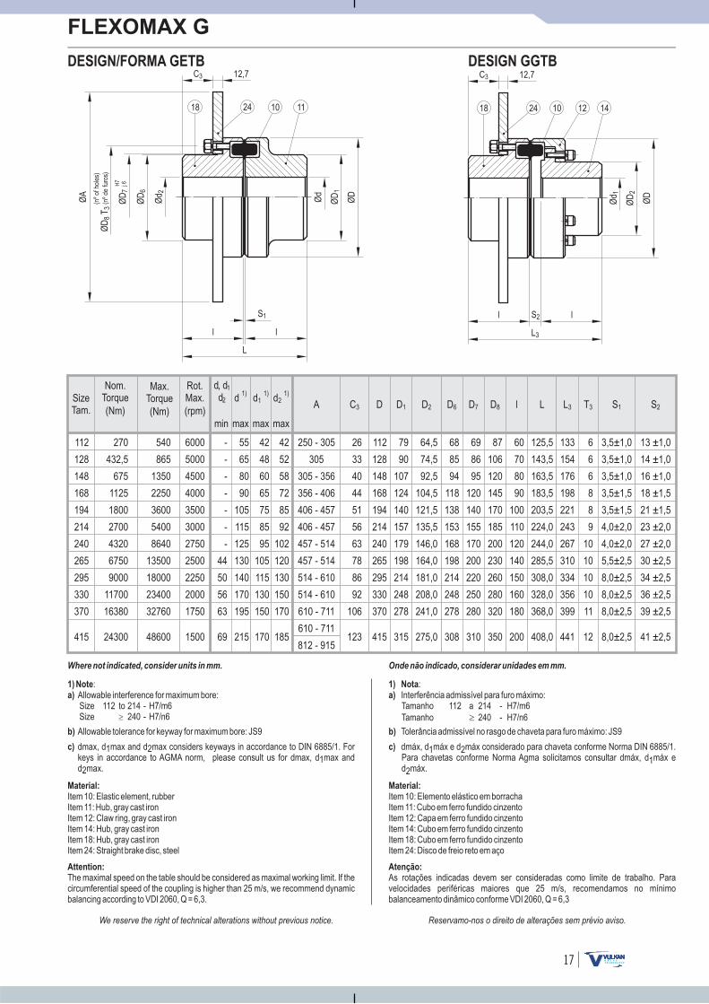
DESIGN/FORMA GETB
Reservamo-nos o direito de alterações sem prévio aviso.We reserve the right of technical alterations without previous notice.
540
865
1350
2250
3600
5400
8640
13500
18000
23400
32760
48600
D l LD1 D2 D6 D7 D8 L3 T3 S1
112
128
148
168
194
214
240
265
295
330
370
415
79
90
107
124
140
157
179
198
214
248
278
315
64,5
74,5
92,5
104,5
121,5
135,5
146,0
164,0
181,0
208,0
241,0
275,0
68
85
94
118
138
153
168
198
214
248
278
308
69
86
95
120
140
155
170
200
220
250
280
310
87
106
120
145
170
185
200
230
260
280
320
350
60
70
80
90
100
110
120
140
150
160
180
200
125,5
143,5
163,5
183,5
203,5
224,0
244,0
285,5
308,0
328,0
368,0
408,0
133
154
176
198
221
243
267
310
334
356
399
441
6
6
6
8
8
9
10
10
10
10
11
12
3,5±1,0
3,5±1,0
3,5±1,0
3,5±1,5
3,5±1,5
4,0±2,0
4,0±2,0
5,5±2,5
8,0±2,5
8,0±2,5
8,0±2,5
8,0±2,5
A
250 - 305
305
305 - 356
356 - 406
406 - 457
406 - 457
457 - 514
457 - 514
514 - 610
514 - 610
610 - 711
610 - 711
812 - 915
max
d1)
55
65
80
90
105
115
125
130
140
170
195
215
max
d11)
42
48
60
65
75
85
95
105
115
130
150
170
max
d21)
42
52
58
72
85
92
102
120
130
150
170
185
C3
1) Note
a)
:Allowable interference for maximum bore:Size 112 to 214 - H7/m6Size 240 - H7/n6�
1) Nota
a)
:Interferência admissível para furo máximo:Tamanho 112 a 214 - H7/m6
Tamanho 240 - H7/n6�
Onde não indicado, considerar unidades em mm.
DESIGN GGTB
S2
112
128
148
168
194
214
240
265
295
330
370
415
6000
5000
4500
4000
3500
3000
2750
2500
2250
2000
1750
1500
13 ±1,0
14 ±1,0
16 ±1,0
18 ±1,5
21 ±1,5
23 ±2,0
27 ±2,0
30 ±2,5
34 ±2,5
36 ±2,5
39 ±2,5
41 ±2,5
26
33
40
44
51
56
63
78
86
92
106
123Ø
D
S2
Ød 1
ØD
2
12,7C3
L3
l l
SizeTam.
Where not indicated, consider units in mm.
18 24 1210 14
b) Allowable tolerance for keyway for maximum bore: JS9
c) dmax, d max and d max considers keyways in accordance to DIN 6885/1. Forkeys in accordance to AGMA norm, please consult us for dmax, d max andd max.
1 21
2
Material:
Item 10: Elastic element, rubberItem 11: Hub, gray cast ironItem 12: Claw ring, gray cast ironItem 14: Hub, gray cast ironItem 18: Hub, gray cast ironItem 24: Straight brake disc, steel
Attention:
The maximal speed on the table should be considered as maximal working limit. If thecircumferential speed of the coupling is higher than 25 m/s, we recommend dynamicbalancing according to VDI 2060, Q = 6,3.
b) Tolerância admissível no rasgo de chaveta para furo máximo: JS9
c) dmáx, d1máx e d2máx considerado para chaveta conforme Norma DIN 6885/1.Para chavetas conforme Norma Agma solicitamos consultar dmáx, d1máx ed2máx.
Material:
Item 10: Elemento elástico em borrachaItem 11: Cubo em ferro fundido cinzentoItem 12: Capa em ferro fundido cinzentoItem 14: Cubo em ferro fundido cinzentoItem 18: Cubo em ferro fundido cinzentoItem 24: Disco de freio reto em aço
Atenção:
As rotações indicadas devem ser consideradas como limite de trabalho. Paravelocidades periféricas maiores que 25 m/s, recomendamos no mínimobalanceamento dinâmico conforme VDI 2060, Q = 6,3
min
-
-
-
-
-
-
-
44
50
56
63
69
d, dd
1
2
270
432,5
675
1125
1800
2700
4320
6750
9000
11700
16380
24300
(Nm)
Max.Torque
(Nm)
Nom.Torque
(rpm)
Rot.Max.
ØD
6
ØD
S1Ø
d
Ød 2
ØA
ØD
1
12,7C3
ØD
7H
7j6
L
ll
ØD
T8
3(n
ºde
furo
s)
(nº
ofho
les)
18 24 1110
18
FLEXOMAX G
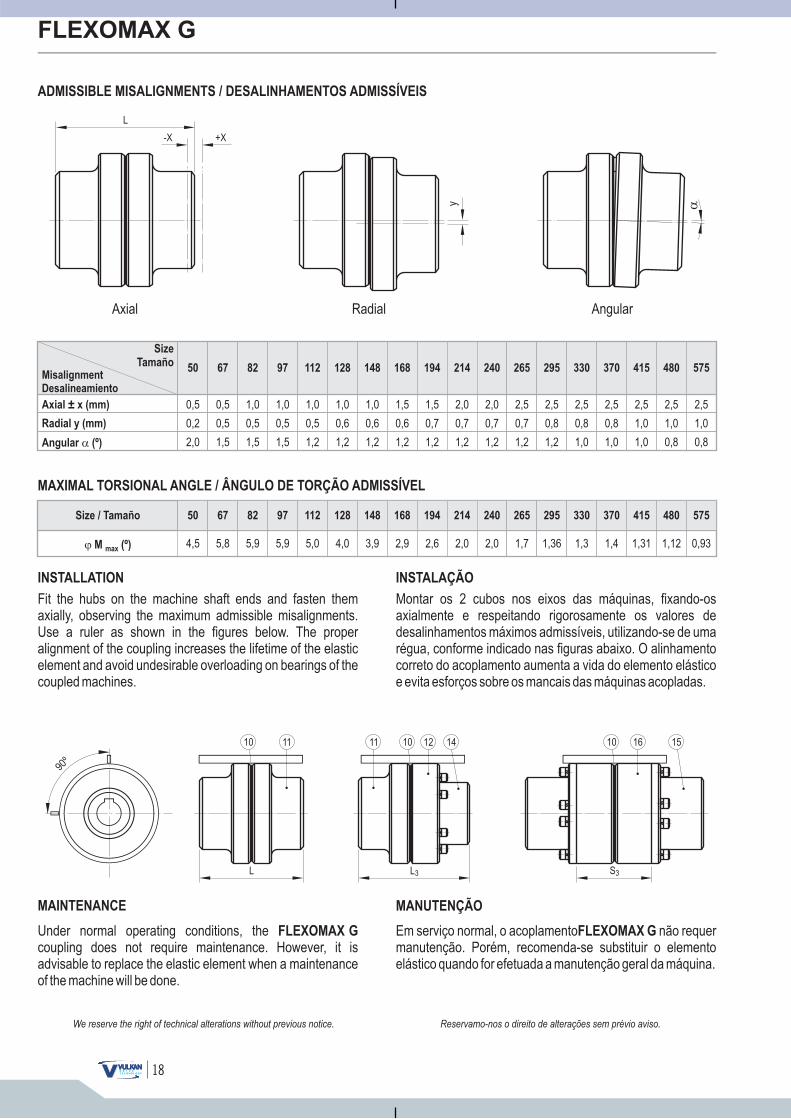
ADMISSIBLE MISALIGNMENTS / DESALINHAMENTOS ADMISSÍVEIS
Reservamo-nos o direito de alterações sem prévio aviso.We reserve the right of technical alterations without previous notice.
Axial ± x (mm)
Radial y (mm)
Angular (º)�
Misalignment
Desalineamiento
Size
Tamaño50 67 82 97 112 128 148 168 194 214 240 265 295 330 370 415 480 575
0,5
0,2
2,0
MAXIMAL TORSIONAL ANGLE / ÂNGULO DE TORÇÃO ADMISSÍVEL
Size / Tamaño
� M (º)max
INSTALLATION
Fit the hubs on the machine shaft ends and fasten themaxially, observing the maximum admissible misalignments.Use a ruler as shown in the figures below. The properalignment of the coupling increases the lifetime of the elasticelement and avoid undesirable overloading on bearings of thecoupled machines.
Montar os 2 cubos nos eixos das máquinas, fixando-osaxialmente e respeitando rigorosamente os valores dedesalinhamentos máximos admissíveis, utilizando-se de umarégua, conforme indicado nas figuras abaixo. O alinhamentocorreto do acoplamento aumenta a vida do elemento elásticoe evita esforços sobre os mancais das máquinas acopladas.
INSTALAÇÃO
Em serviço normal, o acoplamento não requermanutenção. Porém, recomenda-se substituir o elementoelástico quando for efetuada a manutenção geral da máquina.
FLEXOMAX GUnder normal operating conditions, thecoupling does not require maintenance. However, it isadvisable to replace the elastic element when a maintenanceof the machine will be done.
FLEXOMAX G
MAINTENANCE MANUTENÇÃO
RadialAxial Angular
0,5
0,5
1,5
1,0
0,5
1,5
1,0
0,5
1,5
1,0
0,5
1,2
1,0
0,6
1,2
1,0
0,6
1,2
1,5
0,6
1,2
1,5
0,7
1,2
2,0
0,7
1,2
2,0
0,7
1,2
2,5
0,7
1,2
2,5
0,8
1,2
2,5
0,8
1,0
2,5
0,8
1,0
2,5
1,0
1,0
2,5
1,0
0,8
2,5
1,0
0,8
50 67 82 97 112 128 148 168 194 214 240 265 295 330 370 415 480 575
4,5 5,8 5,9 5,9 5,0 4,0 3,9 2,9 2,6 2,0 2,0 1,7 1,36 1,3 1,4 1,31 1,12 0,93
L S3L3
90º
�
-X +X
L
y
10 16 151011 12 1410 11
19
FLEXOMAX G
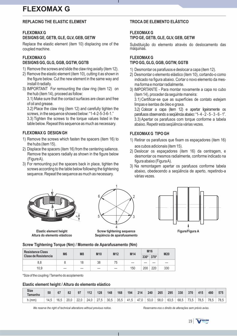
REPLACING THE ELASTIC ELEMENT
Reservamo-nos o direito de alterações sem prévio aviso.We reserve the right of technical alterations without previous notice.
FLEXOMAX G
DESIGNS GE, GETB, GLE, GLV, GEB, GETW
FLEXOMAX G
TIPO GE, GETB, GLE, GLV, GEB, GETW
TROCA DE ELEMENTO ELÁSTICO
Resistance Class
Clase de ResistenciaM8 M10 M12 M14
M16M20
8 18 38 75 --- --- ---
--- --- --- --- 150 200 33010,9
8,8
Screw Tightening Torque (Nm) / Momento de Aparafusamento (Nm)
*Size of the coupling / Tamanho do acoplamento
Size
Tamanho
h (mm)
Elastic element height / Altura do elemento elástico
50 67 82 97 112 128 148 168 194 214 240 265 295 330 370 415 480 575
14,5 16,5 20,0 22,0 24,0 27,5 30,5 35,5 41,5 47,0 53,0 58,0 63,5 68,5 73,5 78,5 78,5 78,5
M6330* 370*
---
220
6 2
1
3
4
5
Elastic element height
Altura do elemento elásticoo
Screw tightening sequence
Seqüência de aparafusamento
Figure/Figura A
h
Replace the elastic element (item 10) displacing one of thecoupled machine.
FLEXOMAX G
DESIGNS GG, GLG, GGB, GGTW, GGTB
1) Remove the screws and slide the claw ring axially (item 12).2) Remove the elastic element (item 10), cutting it as shown in
the figure below. Cut the new element in the same way andinstall it radially.
3) IMPORTANT For remounting the claw ring (item 12) onthe hub (item 14), proceed as follow:3.1) Make sure that the contact surfaces are clean and freeof oil and grease.3.2) Place the claw ring (item 12) and carefully tighten thescrews, in the sequence showed below: “1-4-2-5-3-6-1.”3.3) Tighten the screws to the torque values listed in thetable below. Repeat this sequence as much as necessary.
FLEXOMAX G DESIGN GH
1) Remove the screws which fasten the spacers (item 16) tothe hubs (item 15).
2) Displace the spacers (item 16) from the centering salience.Remove the spacers radially as shown in the figure below(FigureA).
3) For remounting put the spacers back in place, tighten thescrews according to the table below following the tighteningsequence. Repeat the sequence as much as necessary.
Substituição do elemento através do deslocamento dasmáquinas.
FLEXOMAX G
TIPO GG, GLG, GGB, GGTW, GGTB
1) Desmontar os parafusos e deslocar a capa (item 12).2) Desmontar o elemento elástico (item 10), cortando-o como
indicado na figura abaixo. Cortar o novo elemento da mes-ma forma e montar radialmente.
3) IMPORTANTE - Para montar novamente a capa no cubo(item 14), proceder da seguinte maneira:3.1) Certificar-se que as superfícies de contato estejamlimpas e isentas de óleo e graxa.3.2) Colocar a capa (item 12) e apertar ligeiramente osparafusos observando a seqüência abaixo: “1- 4 - 2 - 5 - 3 - 6 - 1”.3.3) Apertar os parafusos com torque conforme a tabelaabaixo. Repetir esta seqüência várias vezes.
FLEXOMAX G TIPO GH
1) Retirar os parafusos que fixam os espaçadores (item 16)
aos cubos adicionais (item 15).2) Deslocar os espaçadores (item 16) da centragem, e
desmontar os mesmos radialmente, conforme indicado nafigura abaixo (FiguraA).
3) Na remontagem apertar os parafusos conforme tabelaabaixo, obedecendo a seqüência de aperto, repetindo-avárias vezes.
20
FLEXOMAX G
Reservamo-nos o direito de alterações sem prévio aviso.We reserve the right of technical alterations without previous notice.
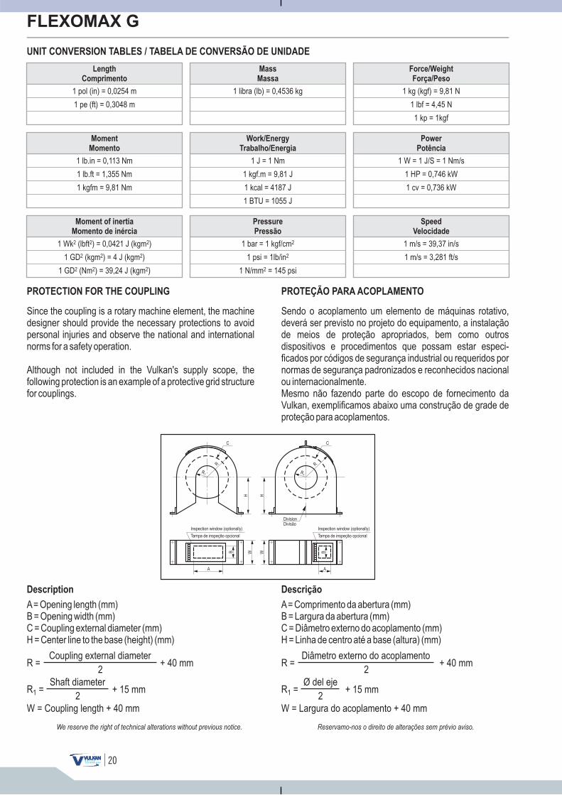
UNIT CONVERSION TABLES / TABELA DE CONVERSÃO DE UNIDADE
Since the coupling is a rotary machine element, the machinedesigner should provide the necessary protections to avoidpersonal injuries and observe the national and internationalnorms for a safety operation.
Although not included in the Vulkan's supply scope, thefollowing protection is an example of a protective grid structurefor couplings.
Sendo o acoplamento um elemento de máquinas rotativo,deverá ser previsto no projeto do equipamento, a instalaçãode meios de proteção apropriados, bem como outrosdispositivos e procedimentos que possam estar especi-ficados por códigos de segurança industrial ou requeridos pornormas de segurança padronizados e reconhecidos nacionalou internacionalmente.Mesmo não fazendo parte do escopo de fornecimento daVulkan, exemplificamos abaixo uma construção de grade deproteção para acoplamentos.
Length
Comprimento
1 pol (in) = 0,0254 m
1 pe (ft) = 0,3048 m
Moment
Momento
Moment of inertia
Momento de inércia
1 lb.in = 0,113 Nm
1 Wk (lbft ) = 0,0421 J (kgm )2 2 2
1 lb.ft = 1,355 Nm
1 GD (kgm ) = 4 J (kgm )2 2 2
Force/Weight
Força/Peso
Power
Potência
Speed
Velocidade
1 kg (kgf) = 9,81 N
1 W = 1 J/S = 1 Nm/s
1 m/s = 39,37 in/s
1 lbf = 4,45 N
1 HP = 0,746 kW
1 = 3,281 ft/sm/s
Mass
Massa
Work/Energy
Trabalho/Energia
Pressure
Pressão
1 libra (lb) = 0,4536 kg
1 J = 1 Nm
1 bar = 1 kgf/cm2
1 kp = 1kgf
1 cv = 0,736 kW1 kgfm = 9,81 Nm
1 GD (Nm ) = 39,24 J (kgm )2 2 2
1 kgf.m = 9,81 J
1 psi = 1lb/in2
1 kcal = 4187 J
1 N/mm = 145 psi2
1 BTU = 1055 J
PROTECTION FOR THE COUPLING
A= Opening length (mm)B = Opening width (mm)C = Coupling external diameter (mm)H = Center line to the base (height) (mm)
Description Descrição
Coupling external diameter+ 40 mm
2R =
Shaft diameter+ 15 mm
2R =1
W = Coupling length + 40 mm
A= Comprimento da abertura (mm)B = Largura da abertura (mm)C = Diâmetro externo do acoplamento (mm)H = Linha de centro até a base (altura) (mm)
Diâmetro externo do acoplamento+ 40 mm
2R =
Ø del eje+ 15 mm
2R =1
W = Largura do acoplamento + 40 mm
PROTEÇÃO PARA ACOPLAMENTO
R
R1
C
H H
C
R
R1
DivisionDivisão
Tampa de inspeção opcional
Inspection window (optionally)
Tampa de inspeção opcional
B W
A
W B
A
Inspection window (optionally)
OUTROS PRODUTOS VULKAN
VULKAN Drive Tecnology - Divisão Industrial
Vulkan do Brasil Ltda Vulkan-Sime Sistemas de Frenagem Ltda
A Vulkan reserva-se o direito de alteracões no catálogo sem aviso prévio.
ACOPLAMENTOS, CONTRA-RECUOS, EMBREAGENS E RODAS-LIVRES
FREIOS, GRAMPOS DE ANCORAGEM E ATUADORES ELETROMECÂNICOS
Atuadores Eletromecânicos Freios Eletrohidráulicos a Disco Freios Industriais de Sapatas Freios Eletromagnéticos a Disco Grampos de Ancoragem
Freios Hidráulicos a Disco Freios Pneumáticos a Disco
A Vulkan é uma empresacertificada conforme normas:
ISO 9001 and ISO 14001
Av. Tamboré, 1113 - Alphaville Industrial - Barueri - SP - BRACEP 06460-915 - PABX +(55 11) 4166-6600
Vendas +(55 11) 4166-6633 - Fax +(55 11) 4195-1569www.vulkan.com.br
Rod. Eng. Const. Cintra Km 91 - B. da Ponte CEP 13252-200 - Caixa Postal 141 - Itatiba - SP - BRA
PABX: +(55 11) 4894-7300 - Fax: +(55 11) 4894-7329www.sime.com.br
Flexomax G Flexomax GBN Flexomax GSN Contra-Recuos eRodas-Livres
Vulbraflex VB Speflex - NVulkardan-E Discflex Embreagens Industriais Pinoflex - NP
Denflex NVD Vul-Mex